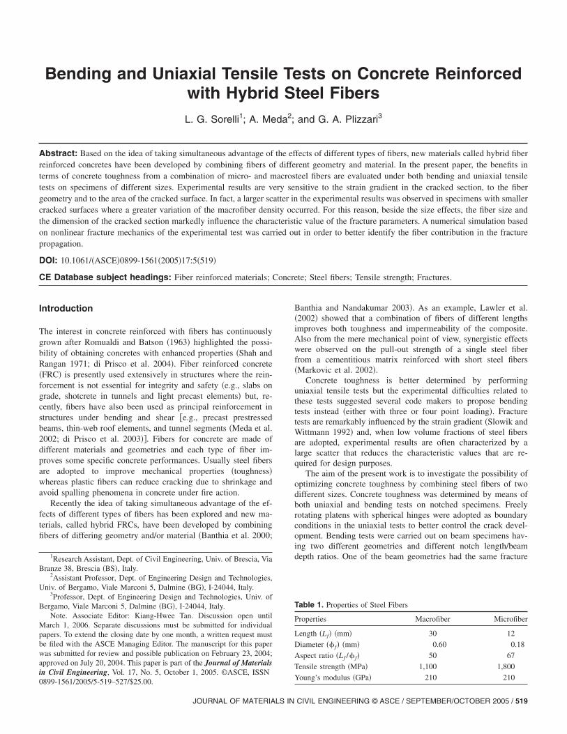
Bending and Uniaxial Tensile Tests on Concrete Reinforced with Hybrid Steel Fibers L. G. Sorelli 1 ; A. Meda 2 ; and G. A. Plizzari 3 Abstract: Based on the idea of taking simultaneous advantage of the effects of different types of fibers, new materials called hybrid fiber reinforced concretes have been developed by combining fibers of different geometry and material. In the present paper, the benefits in terms of concrete toughness from a combination of micro- and macrosteel fibers are evaluated under both bending and uniaxial tensile tests on specimens of different sizes. Experimental results are very sensitive to the strain gradient in the cracked section, to the fiber geometry and to the area of the cracked surface. In fact, a larger scatter in the experimental results was observed in specimens with smaller cracked surfaces where a greater variation of the macrofiber density occurred. For this reason, beside the size effects, the fiber size and the dimension of the cracked section markedly influence the characteristic value of the fracture parameters. A numerical simulation based on nonlinear fracture mechanics of the experimental test was carried out in order to better identify the fiber contribution in the fracture propagation. DOI: 10.1061/ASCE0899-1561200517:5519 CE Database subject headings: Fiber reinforced materials; Concrete; Steel fibers; Tensile strength; Fractures. Introduction The interest in concrete reinforced with fibers has continuously grown after Romualdi and Batson 1963 highlighted the possi- bility of obtaining concretes with enhanced properties Shah and Rangan 1971; di Prisco et al. 2004. Fiber reinforced concrete FRC is presently used extensively in structures where the rein- forcement is not essential for integrity and safety e.g., slabs on grade, shotcrete in tunnels and light precast elements but, re- cently, fibers have also been used as principal reinforcement in structures under bending and shear e.g., precast prestressed beams, thin-web roof elements, and tunnel segments Meda et al. 2002; di Prisco et al. 2003. Fibers for concrete are made of different materials and geometries and each type of fiber im- proves some specific concrete performances. Usually steel fibers are adopted to improve mechanical properties toughness whereas plastic fibers can reduce cracking due to shrinkage and avoid spalling phenomena in concrete under fire action. Recently the idea of taking simultaneous advantage of the ef- fects of different types of fibers has been explored and new ma- terials, called hybrid FRCs, have been developed by combining fibers of differing geometry and/or material Banthia et al. 2000; Banthia and Nandakumar 2003. As an example, Lawler et al. 2002 showed that a combination of fibers of different lengths improves both toughness and impermeability of the composite. Also from the mere mechanical point of view, synergistic effects were observed on the pull-out strength of a single steel fiber from a cementitious matrix reinforced with short steel fibers Markovic et al. 2002. Concrete toughness is better determined by performing uniaxial tensile tests but the experimental difficulties related to these tests suggested several code makers to propose bending tests instead either with three or four point loading. Fracture tests are remarkably influenced by the strain gradient Slowik and Wittmann 1992 and, when low volume fractions of steel fibers are adopted, experimental results are often characterized by a large scatter that reduces the characteristic values that are re- quired for design purposes. The aim of the present work is to investigate the possibility of optimizing concrete toughness by combining steel fibers of two different sizes. Concrete toughness was determined by means of both uniaxial and bending tests on notched specimens. Freely rotating platens with spherical hinges were adopted as boundary conditions in the uniaxial tests to better control the crack devel- opment. Bending tests were carried out on beam specimens hav- ing two different geometries and different notch length/beam depth ratios. One of the beam geometries had the same fracture 1 Research Assistant, Dept. of Civil Engineering, Univ. of Brescia, Via Branze 38, Brescia BS, Italy. 2 Assistant Professor, Dept. of Engineering Design and Technologies, Univ. of Bergamo, Viale Marconi 5, Dalmine BG, I-24044, Italy. 3 Professor, Dept. of Engineering Design and Technologies, Univ. of Bergamo, Viale Marconi 5, Dalmine BG, I-24044, Italy. Note. Associate Editor: Kiang-Hwee Tan. Discussion open until March 1, 2006. Separate discussions must be submitted for individual papers. To extend the closing date by one month, a written request must be filed with the ASCE Managing Editor. The manuscript for this paper was submitted for review and possible publication on February 23, 2004; approved on July 20, 2004. This paper is part of the Journal of Materials in Civil Engineering, Vol. 17, No. 5, October 1, 2005. ©ASCE, ISSN 0899-1561/2005/5-519–527/$25.00. Table 1. Properties of Steel Fibers Properties Macrofiber Microfiber Length L f mm 30 12 Diameter f mm 0.60 0.18 Aspect ratio L f / f 50 67 Tensile strength MPa 1,100 1,800 Young’s modulus GPa 210 210 JOURNAL OF MATERIALS IN CIVIL ENGINEERING © ASCE / SEPTEMBER/OCTOBER 2005 / 519

Welcome message from author
This document is posted to help you gain knowledge. Please leave a comment to let me know what you think about it! Share it to your friends and learn new things together.
Transcript
Bending and Uniaxial Tensile Tests on Concrete Reinforcedwith Hybrid Steel FibersL. G. Sorelli1; A. Meda2; and G. A. Plizzari3
Abstract: Based on the idea of taking simultaneous advantage of the effects of different types of fibers, new materials called hybrid fiberreinforced concretes have been developed by combining fibers of different geometry and material. In the present paper, the benefits interms of concrete toughness from a combination of micro- and macrosteel fibers are evaluated under both bending and uniaxial tensiletests on specimens of different sizes. Experimental results are very sensitive to the strain gradient in the cracked section, to the fibergeometry and to the area of the cracked surface. In fact, a larger scatter in the experimental results was observed in specimens with smallercracked surfaces where a greater variation of the macrofiber density occurred. For this reason, beside the size effects, the fiber size andthe dimension of the cracked section markedly influence the characteristic value of the fracture parameters. A numerical simulation basedon nonlinear fracture mechanics of the experimental test was carried out in order to better identify the fiber contribution in the fracturepropagation.
DOI: 10.1061/�ASCE�0899-1561�2005�17:5�519�
CE Database subject headings: Fiber reinforced materials; Concrete; Steel fibers; Tensile strength; Fractures.
Introduction
The interest in concrete reinforced with fibers has continuouslygrown after Romualdi and Batson �1963� highlighted the possi-bility of obtaining concretes with enhanced properties �Shah andRangan 1971; di Prisco et al. 2004�. Fiber reinforced concrete�FRC� is presently used extensively in structures where the rein-forcement is not essential for integrity and safety �e.g., slabs ongrade, shotcrete in tunnels and light precast elements� but, re-cently, fibers have also been used as principal reinforcement instructures under bending and shear �e.g., precast prestressedbeams, thin-web roof elements, and tunnel segments �Meda et al.2002; di Prisco et al. 2003��. Fibers for concrete are made ofdifferent materials and geometries and each type of fiber im-proves some specific concrete performances. Usually steel fibersare adopted to improve mechanical properties �toughness�whereas plastic fibers can reduce cracking due to shrinkage andavoid spalling phenomena in concrete under fire action.
Recently the idea of taking simultaneous advantage of the ef-fects of different types of fibers has been explored and new ma-terials, called hybrid FRCs, have been developed by combiningfibers of differing geometry and/or material �Banthia et al. 2000;
1Research Assistant, Dept. of Civil Engineering, Univ. of Brescia, ViaBranze 38, Brescia �BS�, Italy.
2Assistant Professor, Dept. of Engineering Design and Technologies,Univ. of Bergamo, Viale Marconi 5, Dalmine �BG�, I-24044, Italy.
3Professor, Dept. of Engineering Design and Technologies, Univ. ofBergamo, Viale Marconi 5, Dalmine �BG�, I-24044, Italy.
Note. Associate Editor: Kiang-Hwee Tan. Discussion open untilMarch 1, 2006. Separate discussions must be submitted for individualpapers. To extend the closing date by one month, a written request mustbe filed with the ASCE Managing Editor. The manuscript for this paperwas submitted for review and possible publication on February 23, 2004;approved on July 20, 2004. This paper is part of the Journal of Materialsin Civil Engineering, Vol. 17, No. 5, October 1, 2005. ©ASCE, ISSN
0899-1561/2005/5-519–527/$25.00.JOURNAL OF MATERIALS IN
Banthia and Nandakumar 2003�. As an example, Lawler et al.�2002� showed that a combination of fibers of different lengthsimproves both toughness and impermeability of the composite.Also from the mere mechanical point of view, synergistic effectswere observed on the pull-out strength of a single steel fiberfrom a cementitious matrix reinforced with short steel fibers�Markovic et al. 2002�.
Concrete toughness is better determined by performinguniaxial tensile tests but the experimental difficulties related tothese tests suggested several code makers to propose bendingtests instead �either with three or four point loading�. Fracturetests are remarkably influenced by the strain gradient �Slowik andWittmann 1992� and, when low volume fractions of steel fibersare adopted, experimental results are often characterized by alarge scatter that reduces the characteristic values that are re-quired for design purposes.
The aim of the present work is to investigate the possibility ofoptimizing concrete toughness by combining steel fibers of twodifferent sizes. Concrete toughness was determined by means ofboth uniaxial and bending tests on notched specimens. Freelyrotating platens with spherical hinges were adopted as boundaryconditions in the uniaxial tests to better control the crack devel-opment. Bending tests were carried out on beam specimens hav-ing two different geometries and different notch length/beamdepth ratios. One of the beam geometries had the same fracture
Table 1. Properties of Steel Fibers
Properties Macrofiber Microfiber
Length �Lf� �mm� 30 12
Diameter �� f� �mm� 0.60 0.18
Aspect ratio �Lf /� f� 50 67
Tensile strength �MPa� 1,100 1,800
Young’s modulus �GPa� 210 210
CIVIL ENGINEERING © ASCE / SEPTEMBER/OCTOBER 2005 / 519
surface of the uni-axial specimens to better study the strain gra-dient effects �Slowik and Wittmann 1992�.
Numerical simulations based on nonlinear fracture mechanics�Hillerborg et al. 1976� with a discrete crack approach were car-ried out in order to characterize the fracture properties of thematerial in a better way. The determination of a good approxima-tion of the post-cracking behavior based on a polylinear law wasinvestigated and the suitability of adopting a bilinear law �forconcrete with a single type of fiber� and a trilinear law �for con-crete with two types of fiber� has been studied. In fact, sincefibers of different lengths become efficient at different stages ofthe cracking process, the smaller fibers control the microcrackgrowth whereas the longer fibers become active for larger crackopenings.
Experiments
Materials
Experiments were carried out on specimens made of a normalstrength concrete with 355 kg/m3 of cement �CEM II/A-LL32.5R according to UNI-EN 197 �CEN 2000��, 180 kg/m3 ofwater �water-cement ratio of 0.55�, 3.9 L/m3 of superplasticiser,and 1,900 kg/m3 of aggregates with a maximum size of 15 mm.A grain size distribution close to the Bolomey curve was used.
Two different types of steel fibers were adopted: the first onehad a length �Lf� of 30 mm and a diameter �� f� of 0.6 mmwhereas the second one was a shorter fiber having a length of
Table 2. Fiber Combinations, Compressive Strength, and Workability�Slump� for the Concrete Adopted
Material
Steel fiber Total volumefraction
Vf ,tot
�%�vol.
Compressivestrength
fc,cube
�MPa�
Slumps
�mm�30/0.6�%�vol.
12/0.18�%�vol.
Plain — — — 28.3 150
Macrofiber 0.38 — 0.38 29.3 110
Microfiber — 0.38 0.38 31.9 130
Hybrid 0.19 0.19 0.38 33.0 130
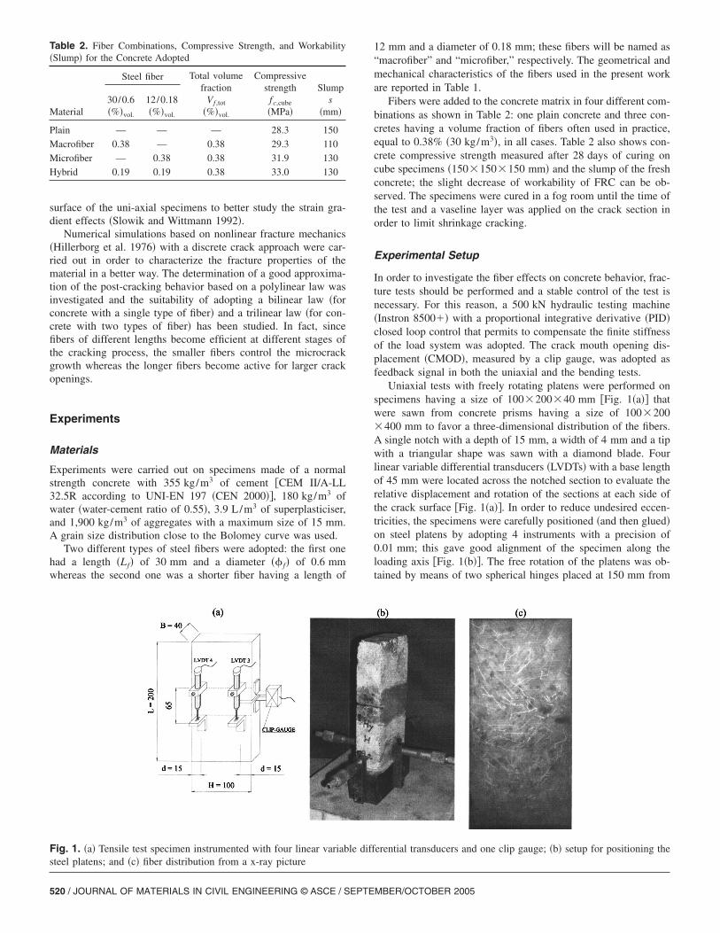
Fig. 1. �a� Tensile test specimen instrumented with four linear variabsteel platens; and �c� fiber distribution from a x-ray picture
520 / JOURNAL OF MATERIALS IN CIVIL ENGINEERING © ASCE / SEPTE
12 mm and a diameter of 0.18 mm; these fibers will be named as“macrofiber” and “microfiber,” respectively. The geometrical andmechanical characteristics of the fibers used in the present workare reported in Table 1.
Fibers were added to the concrete matrix in four different com-binations as shown in Table 2: one plain concrete and three con-cretes having a volume fraction of fibers often used in practice,equal to 0.38% �30 kg/m3�, in all cases. Table 2 also shows con-crete compressive strength measured after 28 days of curing oncube specimens �150�150�150 mm� and the slump of the freshconcrete; the slight decrease of workability of FRC can be ob-served. The specimens were cured in a fog room until the time ofthe test and a vaseline layer was applied on the crack section inorder to limit shrinkage cracking.
Experimental Setup
In order to investigate the fiber effects on concrete behavior, frac-ture tests should be performed and a stable control of the test isnecessary. For this reason, a 500 kN hydraulic testing machine�Instron 8500�� with a proportional integrative derivative �PID�closed loop control that permits to compensate the finite stiffnessof the load system was adopted. The crack mouth opening dis-placement �CMOD�, measured by a clip gauge, was adopted asfeedback signal in both the uniaxial and the bending tests.
Uniaxial tests with freely rotating platens were performed onspecimens having a size of 100�200�40 mm �Fig. 1�a�� thatwere sawn from concrete prisms having a size of 100�200�400 mm to favor a three-dimensional distribution of the fibers.A single notch with a depth of 15 mm, a width of 4 mm and a tipwith a triangular shape was sawn with a diamond blade. Fourlinear variable differential transducers �LVDTs� with a base lengthof 45 mm were located across the notched section to evaluate therelative displacement and rotation of the sections at each side ofthe crack surface �Fig. 1�a��. In order to reduce undesired eccen-tricities, the specimens were carefully positioned �and then glued�on steel platens by adopting 4 instruments with a precision of0.01 mm; this gave good alignment of the specimen along theloading axis �Fig. 1�b��. The free rotation of the platens was ob-tained by means of two spherical hinges placed at 150 mm from
erential transducers and one clip gauge; �b� setup for positioning the
le diffMBER/OCTOBER 2005
the glued surface: in this way it was possible to localize the centerof rotation at the specimen ends. The tests were carried out byimposing a CMOD rate of 1 �m/min until the load–displacementcurve had passed the peak and the fiber started activating. After-wards, the CMOD rate was set to 2 �m/min. Although it includesthe elastic deformations of concrete, the average value of thedisplacement measured by the two LVDTs astride the notch wasconventionally assumed as the crack tip opening displacement�CTOD� �Fig. 1�a��. The fiber distribution in a few specimenswere checked before testing by means of x ray. From the x-rayimage �Fig. 1�c�� it is possible to observe the random distributionof fibers with the shadows of the macrofibers and the faint tracesof the microfibers.
Four point bending tests were performed on two different
Table 3. Average Number of Fibers Intercepted on the Crack SectionMaterial
Test Macrofiber �macrofibers/cm2� Micr
Uniaxial 0.33 �±33% �4PBT—small beams 0.68 �±30% �4PBT—large beams 0.32 �±13% �All tests 0.44
*
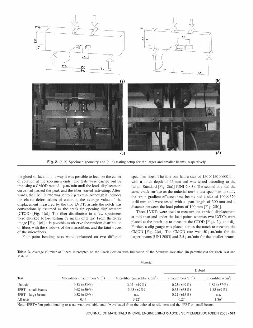
Fig. 2. �a, b� Specimen geometry and �c, d� testi
Note: 4PBT=four point bending test; n.a.=not available; and =evaluated from
JOURNAL OF MATERIALS IN
specimen sizes. The first one had a size of 150�150�600 mmwith a notch depth of 45 mm and was tested according to theItalian Standard �Fig. 2�a�� �UNI 2003�. The second one had thesame crack surface as the uniaxial tensile test specimen to studythe strain gradient effects: these beams had a size of 100�320�40 mm and were tested with a span length of 300 mm and adistance between the load points of 100 mm �Fig. 2�b��.
Three LVDTs were used to measure the vertical displacementat mid-span and under the load points whereas two LVDTs wereplaced at the notch tip to measure the CTOD �Figs. 2�c and d��.Further, a clip gauge was placed across the notch to measure theCMOD �Fig. 2�c��. The CMOD rate was 50 �m/min for thelarger beams �UNI 2003� and 2.5 �m/min for the smaller beams.
dication of the Standard Deviation �in parentheses� for Each Test and
Material
�microfibers/cm2�
Hybrid
�macrofibers/cm2� �microfibers/cm2�
2 �±19% � 0.25 �±49% � 1.88 �±37% �3 �±9% � 0.35 �±33% � 1.85 �±9% �n.a. 0.22 �±15% � n.a.
3.22* 0.27 1.86*
p for the larger and smaller beams, respectively
with In
ofiber
3.0
3.4
ng setu
the uniaxial tensile tests and the 4PBT on small beams.
CIVIL ENGINEERING © ASCE / SEPTEMBER/OCTOBER 2005 / 521
Results
In order to obtain a clearer comparison between the differentspecimen geometries, experimental results from the uni-axial ten-sile and bending tests are reported in terms of nominal stress ��N�defined according to a linear stress distribution as
�N =F
Bs�Hs − a0�+
Fa0/2
�1/6�Bs�Hs − a0�2 �1�
for the uniaxial tensile test, where F=force; Bs and Hs
=thickness and the height of the specimen respectively; and a0
=notch depth �Fig. 1�a��.For the four point bending test, the nominal stress is given by
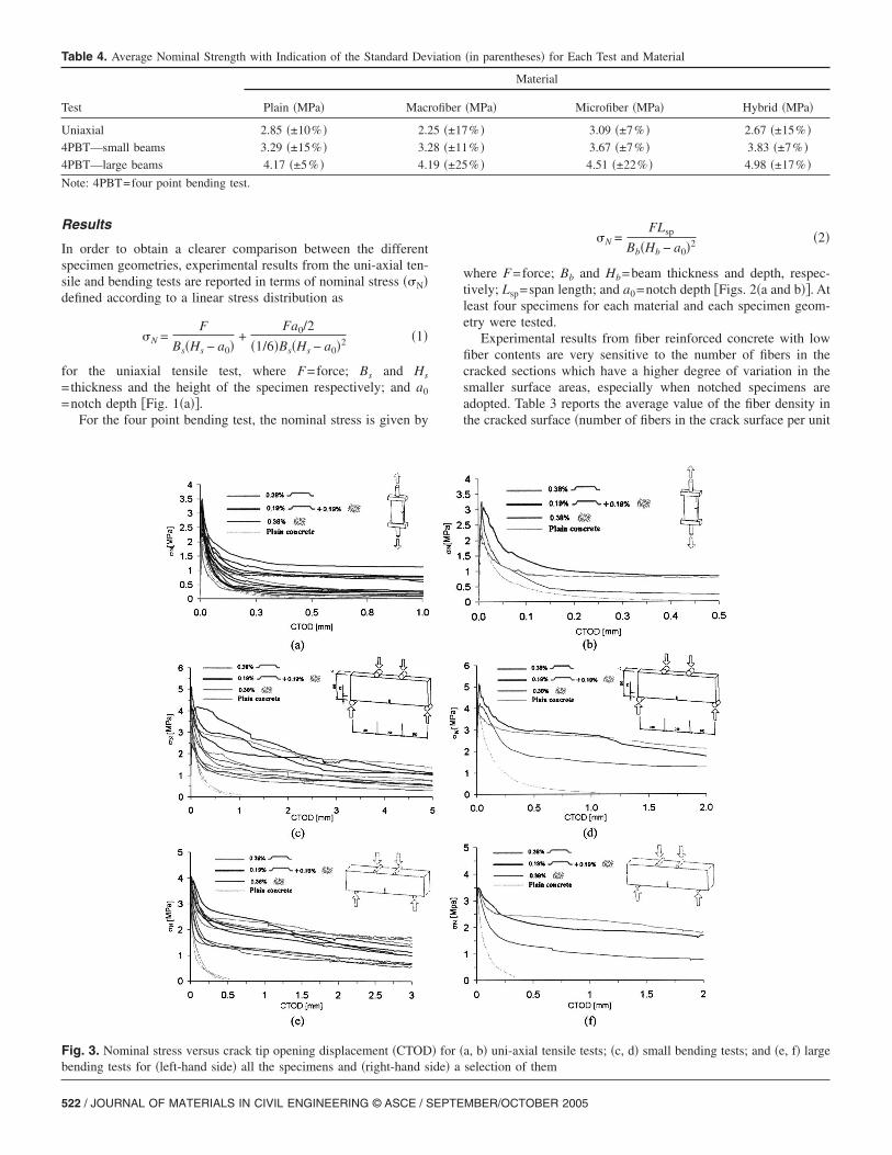
Fig. 3. Nominal stress versus crack tip opening displacement �CTODbending tests for �left-hand side� all the specimens and �right-hand s
Table 4. Average Nominal Strength with Indication of the Standard Dev
Test Plain �MPa� Macr
Uniaxial 2.85 �±10% � 2.2
4PBT—small beams 3.29 �±15% � 3.2
4PBT—large beams 4.17 �±5% � 4.1
Note: 4PBT=four point bending test.
522 / JOURNAL OF MATERIALS IN CIVIL ENGINEERING © ASCE / SEPTE
�N =FLsp
Bb�Hb − a0�2 �2�
where F=force; Bb and Hb=beam thickness and depth, respec-tively; Lsp=span length; and a0=notch depth �Figs. 2�a and b��. Atleast four specimens for each material and each specimen geom-etry were tested.
Experimental results from fiber reinforced concrete with lowfiber contents are very sensitive to the number of fibers in thecracked sections which have a higher degree of variation in thesmaller surface areas, especially when notched specimens areadopted. Table 3 reports the average value of the fiber density inthe cracked surface �number of fibers in the crack surface per unit
a, b� uni-axial tensile tests; �c, d� small bending tests; and �e, f� largeselection of them
�in parentheses� for Each Test and Material
Material
�MPa� Microfiber �MPa� Hybrid �MPa�
% � 3.09 �±7% � 2.67 �±15% �% � 3.67 �±7% � 3.83 �±7% �% � 4.51 �±22% � 4.98 �±17% �
� for �ide� a
iation
ofiber
5 �±17
8 �±11
9 �±25
MBER/OCTOBER 2005
area� for each specimen type and material, as well as the standarddeviation. Because of the larger fractured surface, it was not pos-sible to count the number of microfibers in the larger beams. Itwill be noticed that the average density of macrofibers is around0.3–0.4 fibers/cm2 for both the uniaxial specimens and the largerbeams and that larger fibers and smaller crack surfaces are char-acterized by a higher scatter in the fiber density. For this reason,in addition to the size effects, the dimensions of the fiber and thecracked section markedly influence the characteristic value of thefracture parameters. Specimens with microfibers are characterizedby a lower variation of the fiber density; this is due to the greaternumber of microfibers that cross the cracked section with respectto the macrofibers; in these specimens, the standard deviation ofthe peak-load value is reduced �Table 4�.
The scatter of the experimental results markedly influences the
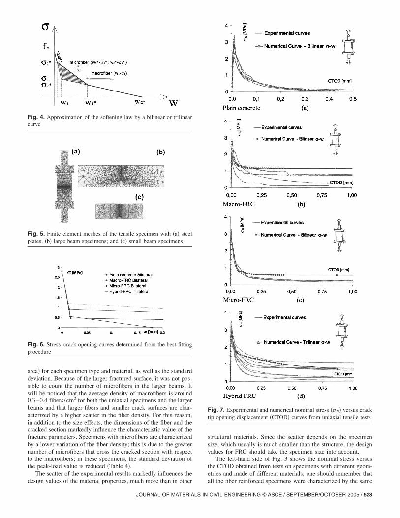
Fig. 4. Approximation of the softening law by a bilinear or trilinearcurve
Fig. 5. Finite element meshes of the tensile specimen with �a� steelplates; �b� large beam specimens; and �c� small beam specimens
Fig. 6. Stress–crack opening curves determined from the best-fittingprocedure
design values of the material properties, much more than in other
JOURNAL OF MATERIALS IN
structural materials. Since the scatter depends on the specimensize, which usually is much smaller than the structure, the designvalues for FRC should take the specimen size into account.
The left-hand side of Fig. 3 shows the nominal stress versusthe CTOD obtained from tests on specimens with different geom-etries and made of different materials; one should remember that
Fig. 7. Experimental and numerical nominal stress ��N� versus cracktip opening displacement �CTOD� curves from uniaxial tensile tests
all the fiber reinforced specimens were characterized by the same
CIVIL ENGINEERING © ASCE / SEPTEMBER/OCTOBER 2005 / 523
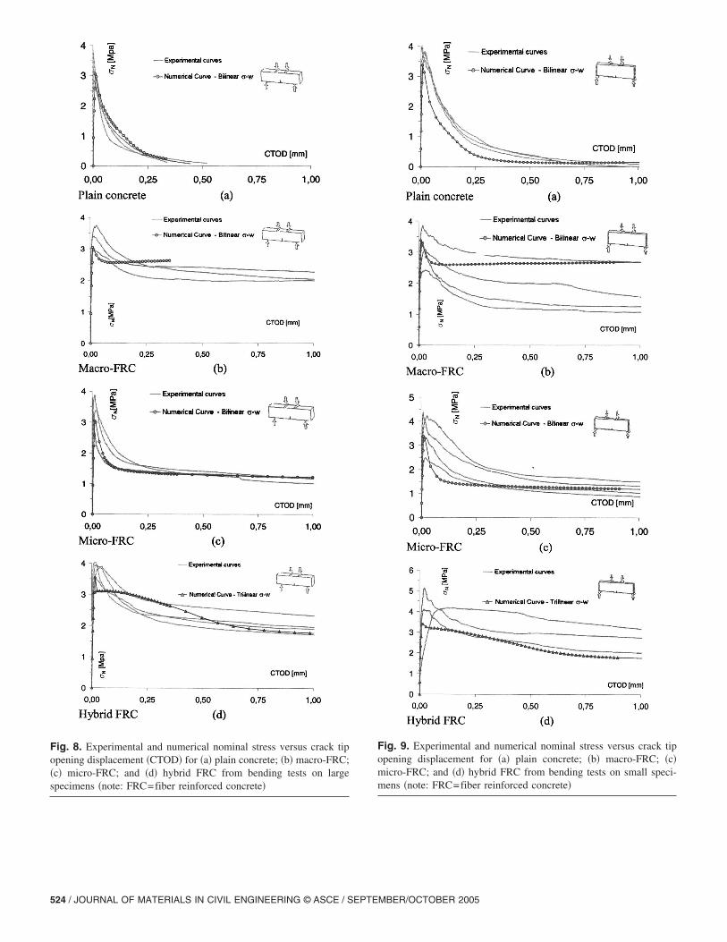
Fig. 8. Experimental and numerical nominal stress versus crack tipopening displacement �CTOD� for �a� plain concrete; �b� macro-FRC;�c� micro-FRC; and �d� hybrid FRC from bending tests on largespecimens �note: FRC=fiber reinforced concrete�
524 / JOURNAL OF MATERIALS IN CIVIL ENGINEERING © ASCE / SEPTE
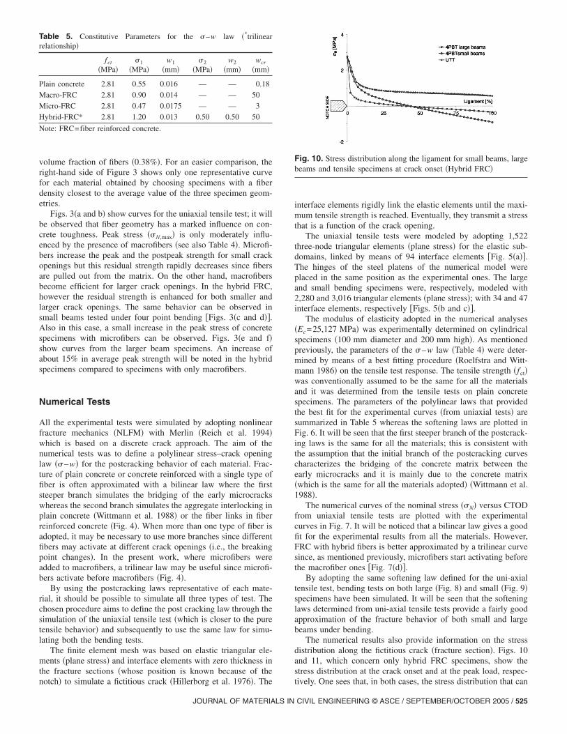
Fig. 9. Experimental and numerical nominal stress versus crack tipopening displacement for �a� plain concrete; �b� macro-FRC; �c�micro-FRC; and �d� hybrid FRC from bending tests on small speci-mens �note: FRC=fiber reinforced concrete�
MBER/OCTOBER 2005
volume fraction of fibers �0.38%�. For an easier comparison, theright-hand side of Figure 3 shows only one representative curvefor each material obtained by choosing specimens with a fiberdensity closest to the average value of the three specimen geom-etries.
Figs. 3�a and b� show curves for the uniaxial tensile test; it willbe observed that fiber geometry has a marked influence on con-crete toughness. Peak stress ��N,max� is only moderately influ-enced by the presence of macrofibers �see also Table 4�. Microfi-bers increase the peak and the postpeak strength for small crackopenings but this residual strength rapidly decreases since fibersare pulled out from the matrix. On the other hand, macrofibersbecome efficient for larger crack openings. In the hybrid FRC,however the residual strength is enhanced for both smaller andlarger crack openings. The same behavior can be observed insmall beams tested under four point bending �Figs. 3�c and d��.Also in this case, a small increase in the peak stress of concretespecimens with microfibers can be observed. Figs. 3�e and f�show curves from the larger beam specimens. An increase ofabout 15% in average peak strength will be noted in the hybridspecimens compared to specimens with only macrofibers.
Numerical Tests
All the experimental tests were simulated by adopting nonlinearfracture mechanics �NLFM� with Merlin �Reich et al. 1994�which is based on a discrete crack approach. The aim of thenumerical tests was to define a polylinear stress–crack openinglaw ��–w� for the postcracking behavior of each material. Frac-ture of plain concrete or concrete reinforced with a single type offiber is often approximated with a bilinear law where the firststeeper branch simulates the bridging of the early microcrackswhereas the second branch simulates the aggregate interlocking inplain concrete �Wittmann et al. 1988� or the fiber links in fiberreinforced concrete �Fig. 4�. When more than one type of fiber isadopted, it may be necessary to use more branches since differentfibers may activate at different crack openings �i.e., the breakingpoint changes�. In the present work, where microfibers wereadded to macrofibers, a trilinear law may be useful since microfi-bers activate before macrofibers �Fig. 4�.
By using the postcracking laws representative of each mate-rial, it should be possible to simulate all three types of test. Thechosen procedure aims to define the post cracking law through thesimulation of the uniaxial tensile test �which is closer to the puretensile behavior� and subsequently to use the same law for simu-lating both the bending tests.
The finite element mesh was based on elastic triangular ele-ments �plane stress� and interface elements with zero thickness inthe fracture sections �whose position is known because of the
Table 5. Constitutive Parameters for the �–w law �*trilinearrelationship�
fct
�MPa��1
�MPa�w1
�mm��2
�MPa�w2
�mm�wcr
�mm�
Plain concrete 2.81 0.55 0.016 — — 0.18
Macro-FRC 2.81 0.90 0.014 — — 50
Micro-FRC 2.81 0.47 0.0175 — — 3
Hybrid-FRC* 2.81 1.20 0.013 0.50 0.50 50
Note: FRC=fiber reinforced concrete.
notch� to simulate a fictitious crack �Hillerborg et al. 1976�. The
JOURNAL OF MATERIALS IN
interface elements rigidly link the elastic elements until the maxi-mum tensile strength is reached. Eventually, they transmit a stressthat is a function of the crack opening.
The uniaxial tensile tests were modeled by adopting 1,522three-node triangular elements �plane stress� for the elastic sub-domains, linked by means of 94 interface elements �Fig. 5�a��.The hinges of the steel platens of the numerical model wereplaced in the same position as the experimental ones. The largeand small bending specimens were, respectively, modeled with2,280 and 3,016 triangular elements �plane stress�; with 34 and 47interface elements, respectively �Figs. 5�b and c��.
The modulus of elasticity adopted in the numerical analyses�Ec=25,127 MPa� was experimentally determined on cylindricalspecimens �100 mm diameter and 200 mm high�. As mentionedpreviously, the parameters of the �–w law �Table 4� were deter-mined by means of a best fitting procedure �Roelfstra and Witt-mann 1986� on the tensile test response. The tensile strength �fct�was conventionally assumed to be the same for all the materialsand it was determined from the tensile tests on plain concretespecimens. The parameters of the polylinear laws that providedthe best fit for the experimental curves �from uniaxial tests� aresummarized in Table 5 whereas the softening laws are plotted inFig. 6. It will be seen that the first steeper branch of the postcrack-ing laws is the same for all the materials; this is consistent withthe assumption that the initial branch of the postcracking curvescharacterizes the bridging of the concrete matrix between theearly microcracks and it is mainly due to the concrete matrix�which is the same for all the materials adopted� �Wittmann et al.1988�.
The numerical curves of the nominal stress ��N� versus CTODfrom uniaxial tensile tests are plotted with the experimentalcurves in Fig. 7. It will be noticed that a bilinear law gives a goodfit for the experimental results from all the materials. However,FRC with hybrid fibers is better approximated by a trilinear curvesince, as mentioned previously, microfibers start activating beforethe macrofiber ones �Fig. 7�d��.
By adopting the same softening law defined for the uni-axialtensile test, bending tests on both large �Fig. 8� and small �Fig. 9�specimens have been simulated. It will be seen that the softeninglaws determined from uni-axial tensile tests provide a fairly goodapproximation of the fracture behavior of both small and largebeams under bending.
The numerical results also provide information on the stressdistribution along the fictitious crack �fracture section�. Figs. 10and 11, which concern only hybrid FRC specimens, show thestress distribution at the crack onset and at the peak load, respec-
Fig. 10. Stress distribution along the ligament for small beams, largebeams and tensile specimens at crack onset �Hybrid FRC�
tively. One sees that, in both cases, the stress distribution that can
CIVIL ENGINEERING © ASCE / SEPTEMBER/OCTOBER 2005 / 525
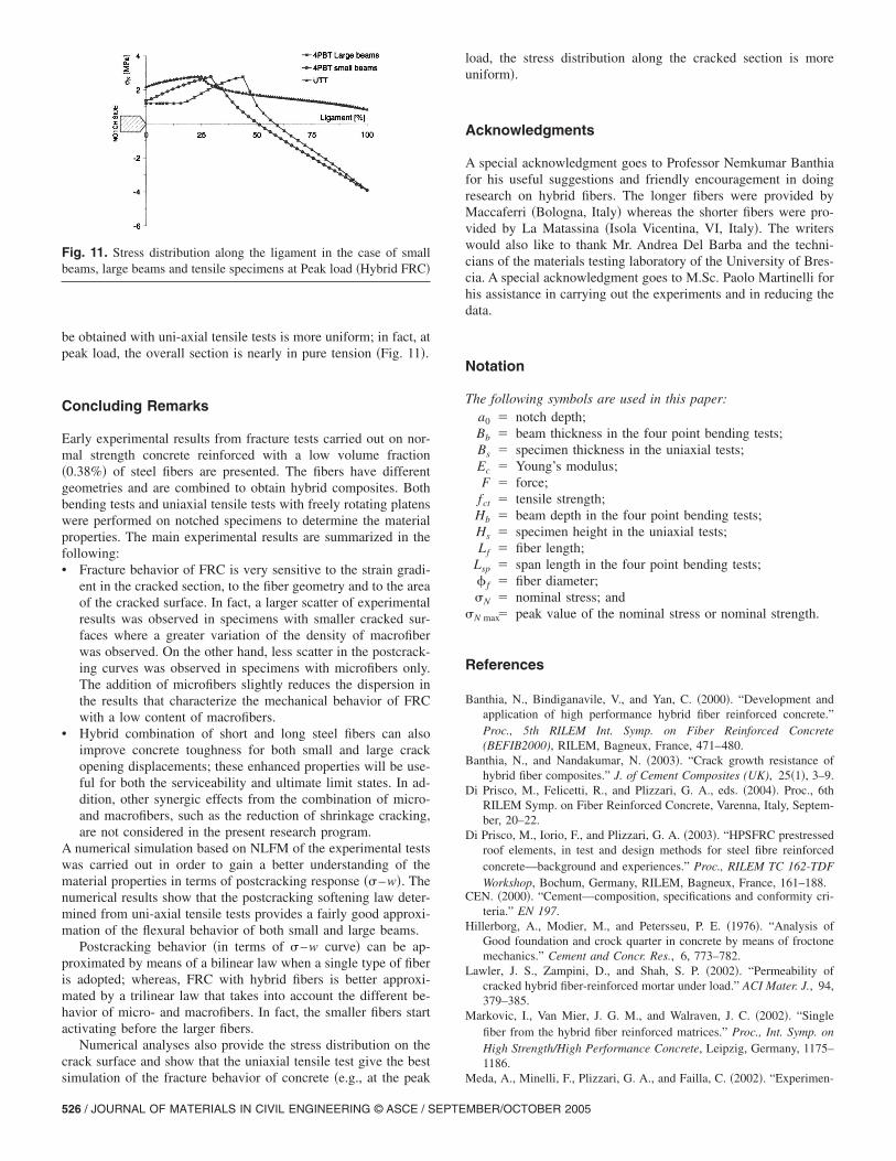
be obtained with uni-axial tensile tests is more uniform; in fact, atpeak load, the overall section is nearly in pure tension �Fig. 11�.
Concluding Remarks
Early experimental results from fracture tests carried out on nor-mal strength concrete reinforced with a low volume fraction�0.38%� of steel fibers are presented. The fibers have differentgeometries and are combined to obtain hybrid composites. Bothbending tests and uniaxial tensile tests with freely rotating platenswere performed on notched specimens to determine the materialproperties. The main experimental results are summarized in thefollowing:• Fracture behavior of FRC is very sensitive to the strain gradi-
ent in the cracked section, to the fiber geometry and to the areaof the cracked surface. In fact, a larger scatter of experimentalresults was observed in specimens with smaller cracked sur-faces where a greater variation of the density of macrofiberwas observed. On the other hand, less scatter in the postcrack-ing curves was observed in specimens with microfibers only.The addition of microfibers slightly reduces the dispersion inthe results that characterize the mechanical behavior of FRCwith a low content of macrofibers.
• Hybrid combination of short and long steel fibers can alsoimprove concrete toughness for both small and large crackopening displacements; these enhanced properties will be use-ful for both the serviceability and ultimate limit states. In ad-dition, other synergic effects from the combination of micro-and macrofibers, such as the reduction of shrinkage cracking,are not considered in the present research program.
A numerical simulation based on NLFM of the experimental testswas carried out in order to gain a better understanding of thematerial properties in terms of postcracking response ��–w�. Thenumerical results show that the postcracking softening law deter-mined from uni-axial tensile tests provides a fairly good approxi-mation of the flexural behavior of both small and large beams.
Postcracking behavior �in terms of �–w curve� can be ap-proximated by means of a bilinear law when a single type of fiberis adopted; whereas, FRC with hybrid fibers is better approxi-mated by a trilinear law that takes into account the different be-havior of micro- and macrofibers. In fact, the smaller fibers startactivating before the larger fibers.
Numerical analyses also provide the stress distribution on thecrack surface and show that the uniaxial tensile test give the best
Fig. 11. Stress distribution along the ligament in the case of smallbeams, large beams and tensile specimens at Peak load �Hybrid FRC�
simulation of the fracture behavior of concrete �e.g., at the peak
526 / JOURNAL OF MATERIALS IN CIVIL ENGINEERING © ASCE / SEPTE
load, the stress distribution along the cracked section is moreuniform�.
Acknowledgments
A special acknowledgment goes to Professor Nemkumar Banthiafor his useful suggestions and friendly encouragement in doingresearch on hybrid fibers. The longer fibers were provided byMaccaferri �Bologna, Italy� whereas the shorter fibers were pro-vided by La Matassina �Isola Vicentina, VI, Italy�. The writerswould also like to thank Mr. Andrea Del Barba and the techni-cians of the materials testing laboratory of the University of Bres-cia. A special acknowledgment goes to M.Sc. Paolo Martinelli forhis assistance in carrying out the experiments and in reducing thedata.
Notation
The following symbols are used in this paper:a0 � notch depth;Bb � beam thickness in the four point bending tests;Bs � specimen thickness in the uniaxial tests;Ec � Young’s modulus;F � force;fct � tensile strength;Hb � beam depth in the four point bending tests;Hs � specimen height in the uniaxial tests;Lf � fiber length;
Lsp � span length in the four point bending tests;� f � fiber diameter;�N � nominal stress; and
�N max� peak value of the nominal stress or nominal strength.
References
Banthia, N., Bindiganavile, V., and Yan, C. �2000�. “Development andapplication of high performance hybrid fiber reinforced concrete.”Proc., 5th RILEM Int. Symp. on Fiber Reinforced Concrete(BEFIB2000), RILEM, Bagneux, France, 471–480.
Banthia, N., and Nandakumar, N. �2003�. “Crack growth resistance ofhybrid fiber composites.” J. of Cement Composites (UK), 25�1�, 3–9.
Di Prisco, M., Felicetti, R., and Plizzari, G. A., eds. �2004�. Proc., 6thRILEM Symp. on Fiber Reinforced Concrete, Varenna, Italy, Septem-ber, 20–22.
Di Prisco, M., Iorio, F., and Plizzari, G. A. �2003�. “HPSFRC prestressedroof elements, in test and design methods for steel fibre reinforcedconcrete—background and experiences.” Proc., RILEM TC 162-TDFWorkshop, Bochum, Germany, RILEM, Bagneux, France, 161–188.
CEN. �2000�. “Cement—composition, specifications and conformity cri-teria.” EN 197.
Hillerborg, A., Modier, M., and Petersseu, P. E. �1976�. “Analysis ofGood foundation and crock quarter in concrete by means of froctonemechanics.” Cement and Concr. Res., 6, 773–782.
Lawler, J. S., Zampini, D., and Shah, S. P. �2002�. “Permeability ofcracked hybrid fiber-reinforced mortar under load.” ACI Mater. J., 94,379–385.
Markovic, I., Van Mier, J. G. M., and Walraven, J. C. �2002�. “Singlefiber from the hybrid fiber reinforced matrices.” Proc., Int. Symp. onHigh Strength/High Performance Concrete, Leipzig, Germany, 1175–1186.
Meda, A., Minelli, F., Plizzari, G. A., and Failla, C. �2002�. “Experimen-
MBER/OCTOBER 2005
tal study on shear behaviour of prestressed SFRC beams.” Proc., Int.Symp. on High Strength/High Performance Concrete, Leipzig, Ger-many, 369–382.
Reich, R. W., Cervenka, J., and Saouma, V. E. �1994�. “Merlin, A three-dimensional finite element program based on a mixed-iterative solu-tion strategy for problems in elasticity, plasticity, and linear and non-linear fracture mechanics.” EPRI, Palo Alto, Calif. �http://civil.colorado.edu/�saouma/Merlin�.
Roelfstra, P. E., and Wittmann, F. H. �1986�. “Numerical method to linkstrain softening with failure of concrete.” Proc., Fracture Toughnessand Fracture Energy, Elsevier, Amsterdam, 163–175.
Romualdi, J. P., and Batson, G. B. �1963�. “Mechanics of crack arrest inconcrete beam with closely spaced reinforcement.” J. Am. Inst., 60,
775–789.JOURNAL OF MATERIALS IN
Shah, S. P., and Rangan, B. V. �1971�. “Fibre reinforced concrete prop-erties.” ACI J. Proc., 68�2�, 126–134.
Slowik, V., and Wittmann, F. H. �1992�. “Influence of strain gradient on
fracture energy.” Proc., Int. Conf. on Fracture Mechanics of Concrete
and Concrete Structures, FrerMCoS, Breckenridge, Co., 424–429.UNI. �2003�. “Steel fibre reinforced concrete—Part I: Definitions, classi-
fication specification and conformity—Part II: test method for mea-suring first crack strength and ductility indexes.” UNI 11039, ItalianBoard for Standardization, Italy.
Wittmann, F. H., Rokugo, K., Brühwiler, E., Mihashi, H., and Simonin, P.�1988�. “Fracture energy and strain softening of concrete as deter-mined by means of compact tension specimens.” Mater. Struct., 21,21–32.
CIVIL ENGINEERING © ASCE / SEPTEMBER/OCTOBER 2005 / 527
Related Documents