Local regulations may restrict the use of this product to below the conditions quoted. In the interests of development and improvement of the product, we reserve the right to change the specification without notice. © Copyright 2018 Page 1 of 17 BBV Automatic or Manually Actuated Boiler Blowdown Valves DN15 to DN65 Principal features: - Easily upgraded from manual to automatic operation. - Dedicated self-adjusting and self-cleaning spindle seals. - Engineered for the specific application of bottom blowdown. - Flow pressure assists closing. Available types of boiler blowdown valve: Air / water pneumatically actuated supplied with a manual actuation lever BBV43 PN / M Steel body BBV63 PN / M Stainless steel body BBV83 PN / M Alloy steel body Manually actuated complete with a manual actuation lever BBV43 M Steel body BBV63 M Stainless steel body BBV83 M Alloy steel body Please note: All of the ' M' versions can be automated to ' PN / M'. Optional extras: - Automatic bottom blowdown timer controller. - Mechanical switch (with mounting kit). - Pneumatic actuator upgrade kit. - Physical lock kit Standards This product range fully complies with the requirements of the European Pressure Equipment Directive 97 / 23 / EC. Certification This product is available with material certification to EN 10204 3.1. Note: All certification / inspection requirements must be stated at the time of order placement. Size and pipe connections: DN15, DN20, DN25, DN32, DN40, DN50 and DN65 ½", ¾", 1", 1¼", 1½", 2" and 2½" Flanged EN 1092 PN40, PN63 and PN100 Flanged ASME 300 and ASME 600 Other available options: Butt weld Socket weld JIS / KS 30 and JIS / KS 40 For alternative connections to those stated above please contact Spirax Sarco. Description The BBV is specifically designed for the removal of suspended / deposited solids and water from the bottom of steam boilers. The BBV is available in air / water actuated and manual versions. The air / water-actuated version is supplied with a manual hand lever. The valve is spring-to-close on power failure and the manual version can easily be upgraded to an automatic version. When used with a Spirax Sarco blowdown controller the automatic version provides timed control of blowdown, ensuring that the recommended blowdown occurs with the minimum of heat loss and avoids duplication and omissions. The valve can be fitted with a mechanical switchbox. This can be linked to the blowdown controller or a BMS system to indicate when the valve has not closed. DN15 BBV_3 PN / M shown TI-P405-51 EMM Issue 2

Welcome message from author
This document is posted to help you gain knowledge. Please leave a comment to let me know what you think about it! Share it to your friends and learn new things together.
Transcript
Local regulations may restrict the use of this product to below the conditions quoted. In the interests of development and improvement of the product, we reserve the right to change the specification without notice. © Copyright 2018
Page 1 of 17
BBVAutomatic or Manually Actuated
Boiler Blowdown Valves DN15 to DN65
Principal features:- Easily upgraded from manual to automatic operation.- Dedicated self-adjusting and self-cleaning spindle seals.- Engineered for the specific application of bottom blowdown.- Flow pressure assists closing.
Available types of boiler blowdown valve:
Air / water pneumatically actuated supplied with a manual actuation lever
BBV43 PN / M Steel body
BBV63 PN / M Stainless steel body
BBV83 PN / M Alloy steel body
Manually actuated complete with a manual actuation lever
BBV43 M Steel body
BBV63 M Stainless steel body
BBV83 M Alloy steel body
Please note: All of the 'M' versions can be automated to ' PN / M'.
Optional extras:- Automatic bottom blowdown timer controller.- Mechanical switch (with mounting kit).- Pneumatic actuator upgrade kit.- Physical lock kit
StandardsThis product range fully complies with the requirements of the European Pressure Equipment Directive 97 / 23 / EC.
CertificationThis product is available with material certification to EN 10204 3.1.Note: All certification / inspection requirements must be stated at the time of order placement.
Size and pipe connections:DN15, DN20, DN25, DN32, DN40, DN50 and DN65½", ¾", 1", 1¼", 1½", 2" and 2½"Flanged EN 1092 PN40, PN63 and PN100Flanged ASME 300 and ASME 600Other available options:Butt weldSocket weldJIS / KS 30 and JIS / KS 40 For alternative connections to those stated above please contact Spirax Sarco.
DescriptionThe BBV is specifically designed for the removal of suspended / deposited solids and water from the bottom of steam boilers.The BBV is available in air / water actuated and manual versions. The air / water-actuated version is supplied with a manual hand lever. The valve is spring-to-close on power failure and the manual version can easily be upgraded to an automatic version.When used with a Spirax Sarco blowdown controller the automatic version provides timed control of blowdown, ensuring that the recommended blowdown occurs with the minimum of heat loss and avoids duplication and omissions.The valve can be fitted with a mechanical switchbox. This can be linked to the blowdown controller or a BMS system to indicate when the valve has not closed.
DN15BBV_3 PN / Mshown
TI-P405-51EMM Issue 2
Page 2 of 17
BBV Automatic or Manually Actuated Boiler Blowdown Valves DN15 to DN65
TI-P405-51 EMM Issue 2
DN15 BBV_3 PN / M shown
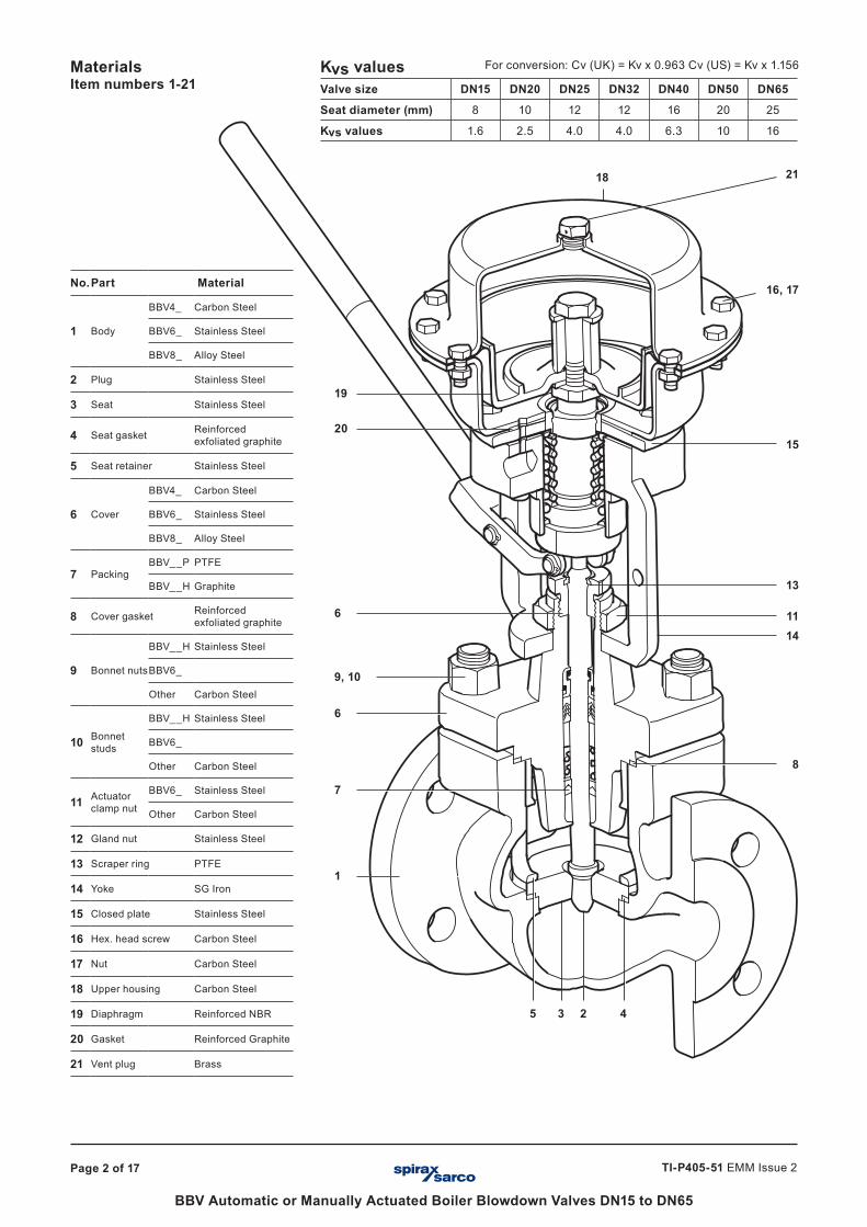
1
45 3 2
7
13
11
18
14
8
6
9, 10
6
15
16, 17
21
20
19
No.Part Material
1 Body
BBV4_ Carbon Steel
BBV6_ Stainless Steel
BBV8_ Alloy Steel
2 Plug Stainless Steel
3 Seat Stainless Steel
4 Seat gasket Reinforced exfoliated graphite
5 Seat retainer Stainless Steel
6 Cover
BBV4_ Carbon Steel
BBV6_ Stainless Steel
BBV8_ Alloy Steel
7 PackingBBV__P PTFE
BBV__H Graphite
8 Cover gasket Reinforced exfoliated graphite
9 Bonnet nuts
BBV__H Stainless Steel
BBV6_
Other Carbon Steel
10 Bonnet studs
BBV__H Stainless Steel
BBV6_
Other Carbon Steel
11 Actuator clamp nut
BBV6_ Stainless Steel
Other Carbon Steel
12 Gland nut Stainless Steel
13 Scraper ring PTFE
14 Yoke SG Iron
15 Closed plate Stainless Steel
16 Hex. head screw Carbon Steel
17 Nut Carbon Steel
18 Upper housing Carbon Steel
19 Diaphragm Reinforced NBR
20 Gasket Reinforced Graphite
21 Vent plug Brass
Kvs valuesValve size DN15 DN20 DN25 DN32 DN40 DN50 DN65
Seat diameter (mm) 8 10 12 12 16 20 25
Kvs values 1.6 2.5 4.0 4.0 6.3 10 16
For conversion: Cv (UK) = Kv x 0.963 Cv (US) = Kv x 1.156MaterialsItem numbers 1-21
Page 3 of 17
BBV Automatic or Manually Actuated Boiler Blowdown Valves DN15 to DN65
TI-P405-51 EMM Issue 2
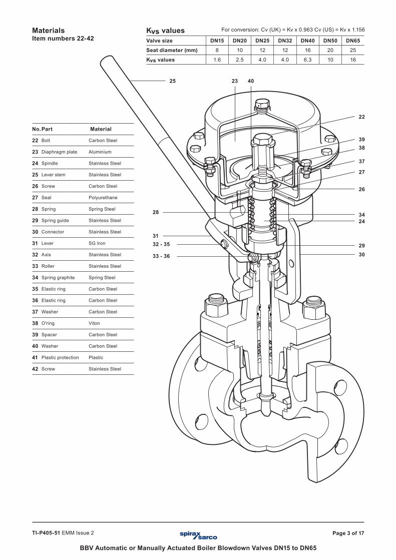
DN15 BBV_3 PN / M shown
25
24
2930
26
34
27
38
37
39
22
4023
33 - 36
32 - 3531
28
No.Part Material
22 Bolt Carbon Steel
23 Diaphragm plate Aluminium
24 Spindle Stainless Steel
25 Lever stem Stainless Steel
26 Screw Carbon Steel
27 Seal Polyurethane
28 Spring Spring Steel
29 Spring guide Stainless Steel
30 Connector Stainless Steel
31 Lever SG Iron
32 Axis Stainless Steel
33 Roller Stainless Steel
34 Spring graphite Spring Steel
35 Elastic ring Carbon Steel
36 Elastic ring Carbon Steel
37 Washer Carbon Steel
38 O'ring Viton
39 Spacer Carbon Steel
40 Washer Carbon Steel
41 Plastic protection Plastic
42 Screw Stainless Steel
Kvs valuesValve size DN15 DN20 DN25 DN32 DN40 DN50 DN65
Seat diameter (mm) 8 10 12 12 16 20 25
Kvs values 1.6 2.5 4.0 4.0 6.3 10 16
For conversion: Cv (UK) = Kv x 0.963 Cv (US) = Kv x 1.156MaterialsItem numbers 22-42
Page 4 of 17
BBV Automatic or Manually Actuated Boiler Blowdown Valves DN15 to DN65
TI-P405-51 EMM Issue 2
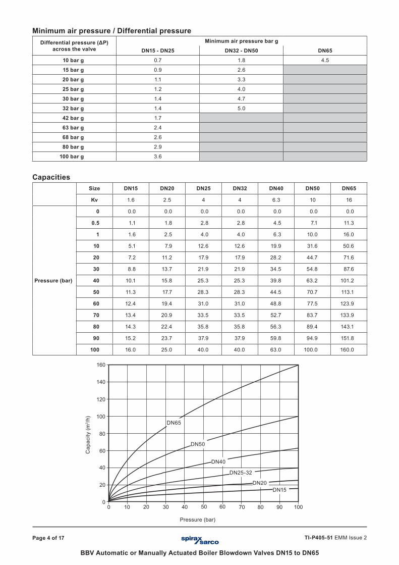
Minimum air pressure / Differential pressureDifferential pressure (ΔP)
across the valveMinimum air pressure bar g
DN15 - DN25 DN32 - DN50 DN65
10 bar g 0.7 1.8 4.5
15 bar g 0.9 2.6
20 bar g 1.1 3.3
25 bar g 1.2 4.0
30 bar g 1.4 4.7
32 bar g 1.4 5.0
42 bar g 1.7
63 bar g 2.4
68 bar g 2.6
80 bar g 2.9
100 bar g 3.6
CapacitiesSize DN15 DN20 DN25 DN32 DN40 DN50 DN65
Kv 1.6 2.5 4 4 6.3 10 16
Pressure (bar)
0 0.0 0.0 0.0 0.0 0.0 0.0 0.0
0.5 1.1 1.8 2.8 2.8 4.5 7.1 11.3
1 1.6 2.5 4.0 4.0 6.3 10.0 16.0
10 5.1 7.9 12.6 12.6 19.9 31.6 50.6
20 7.2 11.2 17.9 17.9 28.2 44.7 71.6
30 8.8 13.7 21.9 21.9 34.5 54.8 87.6
40 10.1 15.8 25.3 25.3 39.8 63.2 101.2
50 11.3 17.7 28.3 28.3 44.5 70.7 113.1
60 12.4 19.4 31.0 31.0 48.8 77.5 123.9
70 13.4 20.9 33.5 33.5 52.7 83.7 133.9
80 14.3 22.4 35.8 35.8 56.3 89.4 143.1
90 15.2 23.7 37.9 37.9 59.8 94.9 151.8
100 16.0 25.0 40.0 40.0 63.0 100.0 160.0
� �� �� ������ ����
���
��
�����
��
���
��
��
���
���
���
DN65
DN50
DN40
DN25-32
DN20DN15
Pressure (bar)
Cap
acity
(m3 /h
)
Page 5 of 17
BBV Automatic or Manually Actuated Boiler Blowdown Valves DN15 to DN65
TI-P405-51 EMM Issue 2
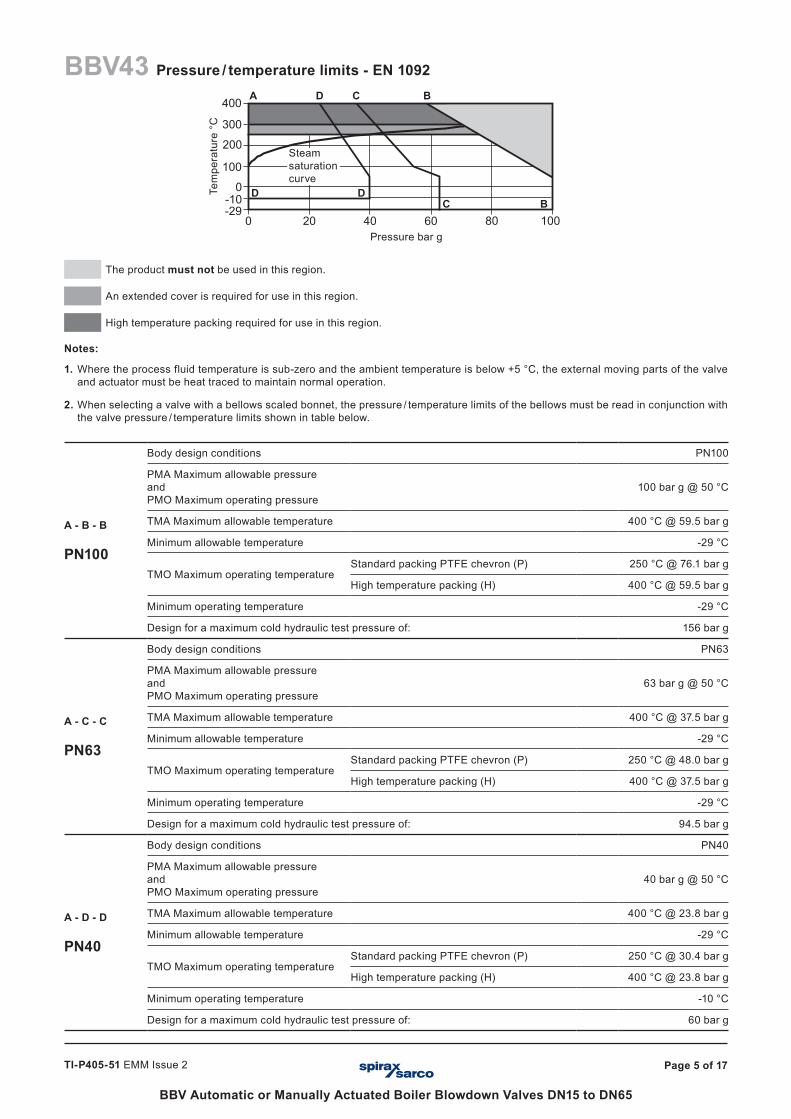
The product must not be used in this region.
An extended cover is required for use in this region.
High temperature packing required for use in this region.
Notes:
1. Where the process fluid temperature is sub-zero and the ambient temperature is below +5 °C, the external moving parts of the valve and actuator must be heat traced to maintain normal operation.
2. When selecting a valve with a bellows scaled bonnet, the pressure / temperature limits of the bellows must be read in conjunction with the valve pressure / temperature limits shown in table below.
A - B - B
PN100
Body design conditions PN100
PMA Maximum allowable pressure and PMO Maximum operating pressure
100 bar g @ 50 °C
TMA Maximum allowable temperature 400 °C @ 59.5 bar g
Minimum allowable temperature -29 °C
TMO Maximum operating temperature Standard packing PTFE chevron (P) 250 °C @ 76.1 bar g
High temperature packing (H) 400 °C @ 59.5 bar g
Minimum operating temperature -29 °C
Design for a maximum cold hydraulic test pressure of: 156 bar g
A - C - C
PN63
Body design conditions PN63
PMA Maximum allowable pressure and PMO Maximum operating pressure
63 bar g @ 50 °C
TMA Maximum allowable temperature 400 °C @ 37.5 bar g
Minimum allowable temperature -29 °C
TMO Maximum operating temperature Standard packing PTFE chevron (P) 250 °C @ 48.0 bar g
High temperature packing (H) 400 °C @ 37.5 bar g
Minimum operating temperature -29 °C
Design for a maximum cold hydraulic test pressure of: 94.5 bar g
A - D - D
PN40
Body design conditions PN40
PMA Maximum allowable pressure and PMO Maximum operating pressure
40 bar g @ 50 °C
TMA Maximum allowable temperature 400 °C @ 23.8 bar g
Minimum allowable temperature -29 °C
TMO Maximum operating temperature Standard packing PTFE chevron (P) 250 °C @ 30.4 bar g
High temperature packing (H) 400 °C @ 23.8 bar g
Minimum operating temperature -10 °C
Design for a maximum cold hydraulic test pressure of: 60 bar g
BBV43 Pressure / temperature limits - EN 1092
Pressure bar g
Tem
pera
ture
°C
Steam saturation curve
C
A
DD
D C B
B
Page 6 of 17
BBV Automatic or Manually Actuated Boiler Blowdown Valves DN15 to DN65
TI-P405-51 EMM Issue 2
�
�
���
���
���
���
�� �� �� �� ��������
� ��� ��� ��� ��� ���� ���� ����
���������������������
�
���
� � � � � �� �� �� �� �� �� �� �� �� �� �� �� �� �� �� �� �� �� �� �� �� �� �� �� �� �� �� �� �� �� �� �� �� �� �� �� �� �� �� �� �� �� �� �� �� ��� ���
�
��
��
��
���
���
���
���
���
���
���
���
���
���
���
���
���
���
The product must not be used in this region.
An extended cover is required for use in this region.
High temperature packing required for use in this region.
Notes:
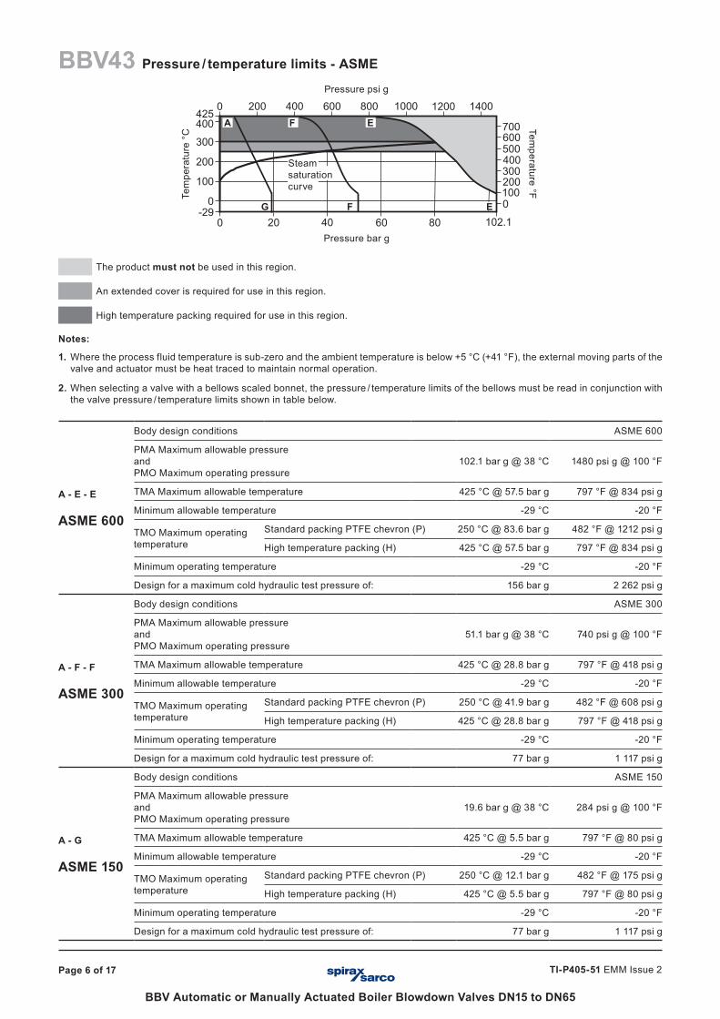
1. Where the process fluid temperature is sub-zero and the ambient temperature is below +5 °C (+41 °F), the external moving parts of the valve and actuator must be heat traced to maintain normal operation.
2. When selecting a valve with a bellows scaled bonnet, the pressure / temperature limits of the bellows must be read in conjunction with the valve pressure / temperature limits shown in table below.
A - E - E
ASME 600
Body design conditions ASME 600
PMA Maximum allowable pressure and PMO Maximum operating pressure
102.1 bar g @ 38 °C 1480 psi g @ 100 °F
TMA Maximum allowable temperature 425 °C @ 57.5 bar g 797 °F @ 834 psi g
Minimum allowable temperature -29 °C -20 °F
TMO Maximum operating temperature
Standard packing PTFE chevron (P) 250 °C @ 83.6 bar g 482 °F @ 1212 psi g
High temperature packing (H) 425 °C @ 57.5 bar g 797 °F @ 834 psi g
Minimum operating temperature -29 °C -20 °F
Design for a maximum cold hydraulic test pressure of: 156 bar g 2 262 psi g
A - F - F
ASME 300
Body design conditions ASME 300
PMA Maximum allowable pressure and PMO Maximum operating pressure
51.1 bar g @ 38 °C 740 psi g @ 100 °F
TMA Maximum allowable temperature 425 °C @ 28.8 bar g 797 °F @ 418 psi g
Minimum allowable temperature -29 °C -20 °F
TMO Maximum operating temperature
Standard packing PTFE chevron (P) 250 °C @ 41.9 bar g 482 °F @ 608 psi g
High temperature packing (H) 425 °C @ 28.8 bar g 797 °F @ 418 psi g
Minimum operating temperature -29 °C -20 °F
Design for a maximum cold hydraulic test pressure of: 77 bar g 1 117 psi g
A - G
ASME 150
Body design conditions ASME 150
PMA Maximum allowable pressure and PMO Maximum operating pressure
19.6 bar g @ 38 °C 284 psi g @ 100 °F
TMA Maximum allowable temperature 425 °C @ 5.5 bar g 797 °F @ 80 psi g
Minimum allowable temperature -29 °C -20 °F
TMO Maximum operating temperature
Standard packing PTFE chevron (P) 250 °C @ 12.1 bar g 482 °F @ 175 psi g
High temperature packing (H) 425 °C @ 5.5 bar g 797 °F @ 80 psi g
Minimum operating temperature -29 °C -20 °F
Design for a maximum cold hydraulic test pressure of: 77 bar g 1 117 psi g
BBV43 Pressure / temperature limits - ASME
Pressure psi g
Temperature °F
Pressure bar g
Tem
pera
ture
°C
G
A F E
F E
Steam saturation curve
Page 7 of 17
BBV Automatic or Manually Actuated Boiler Blowdown Valves DN15 to DN65
TI-P405-51 EMM Issue 2
� � � � � �� �� �� �� �� �� �� �� �� �� �� �� �� �� �� �� �� �� �� �� �� �� �� �� �� �� �� �� �� ���
������
������������������������������������������
� �� �� ����
�
���
���
���
�����
���
�� ��
���
The product must not be used in this region.
An extended cover is required for use in this region.
High temperature packing required for use in this region.
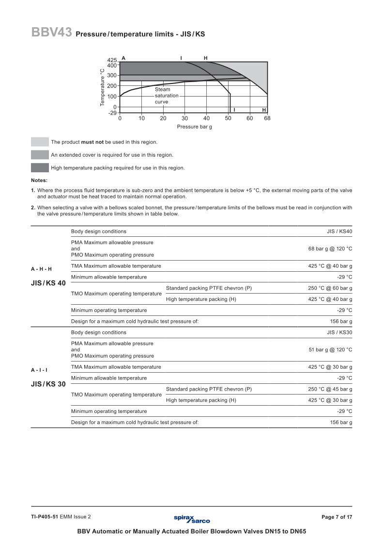
Notes:
1. Where the process fluid temperature is sub-zero and the ambient temperature is below +5 °C, the external moving parts of the valve and actuator must be heat traced to maintain normal operation.
2. When selecting a valve with a bellows scaled bonnet, the pressure / temperature limits of the bellows must be read in conjunction with the valve pressure / temperature limits shown in table below.
A - H - H
JIS / KS 40
Body design conditions JIS / KS40
PMA Maximum allowable pressure and PMO Maximum operating pressure
68 bar g @ 120 °C
TMA Maximum allowable temperature 425 °C @ 40 bar g
Minimum allowable temperature -29 °C
TMO Maximum operating temperature Standard packing PTFE chevron (P) 250 °C @ 60 bar g
High temperature packing (H) 425 °C @ 40 bar g
Minimum operating temperature -29 °C
Design for a maximum cold hydraulic test pressure of: 156 bar g
A - I - I
JIS / KS 30
Body design conditions JIS / KS30
PMA Maximum allowable pressure and PMO Maximum operating pressure
51 bar g @ 120 °C
TMA Maximum allowable temperature 425 °C @ 30 bar g
Minimum allowable temperature -29 °C
TMO Maximum operating temperature Standard packing PTFE chevron (P) 250 °C @ 45 bar g
High temperature packing (H) 425 °C @ 30 bar g
Minimum operating temperature -29 °C
Design for a maximum cold hydraulic test pressure of: 156 bar g
Pressure bar g
Tem
pera
ture
°C
A
HI
BBV43 Pressure / temperature limits - JIS / KS
I H
Steam saturation curve
Page 8 of 17
BBV Automatic or Manually Actuated Boiler Blowdown Valves DN15 to DN65
TI-P405-51 EMM Issue 2
���
�
�
���
������
���
�� �� �� �����
���
���
The product must not be used in this region.
An extended cover is required for use in this region.
High temperature packing required for use in this region.
Notes:
1. Where the process fluid temperature is sub-zero and the ambient temperature is below +5 °C, the external moving parts of the valve and actuator must be heat traced to maintain normal operation.
2. When selecting a valve with a bellows scaled bonnet, the pressure / temperature limits of the bellows must be read in conjunction with the valve pressure / temperature limits shown in table below.
A - J - J
PN100
Body design conditions PN100
PMA Maximum allowable pressure and PMO Maximum operating pressure
100 bar g @ 100 °C
TMA Maximum allowable temperature 580 °C @ 62.7 bar g
Minimum allowable temperature -29 °C
TMO Maximum operating temperature Standard packing PTFE chevron (P) 250 °C @ 79.6 bar g
High temperature packing (H) 580 °C @ 62.7 bar g
Minimum operating temperature -29 °C
Design for a maximum cold hydraulic test pressure of: 156 bar g
A - K - K
PN63
Body design conditions PN63
PMA Maximum allowable pressure and PMO Maximum operating pressure
63 bar g @ 100 °C
TMA Maximum allowable temperature 580 °C @ 39.5 bar g
Minimum allowable temperature -29 °C
TMO Maximum operating temperature Standard packing PTFE chevron (P) 250 °C @ 50.1 bar g
High temperature packing (H) 580 °C @ 39.5 bar g
Minimum operating temperature -29 °C
Design for a maximum cold hydraulic test pressure of: 156 bar g
A - L - L
PN40
Body design conditions PN40
PMA Maximum allowable pressure and PMO Maximum operating pressure
40 bar g @ 100 °C
TMA Maximum allowable temperature 400 °C @ 27.4 bar g
Minimum allowable temperature -29 °C
TMO Maximum operating temperature Standard packing PTFE chevron (P) 250 °C @ 31.8 bar g
High temperature packing (H) 400 °C @ 27.4 bar g
Minimum operating temperature -29 °C
Design for a maximum cold hydraulic test pressure of: 60 bar g
Pressure bar g
Tem
pera
ture
°C
A K
A L
J
J
BBV63 Pressure / temperature limits - EN 1092
L K
Steam saturation curve
Page 9 of 17
BBV Automatic or Manually Actuated Boiler Blowdown Valves DN15 to DN65
TI-P405-51 EMM Issue 2
� �� �� �� �� ����
� ��� ��� ��� ��� ���� ���� ����
���
���
���
����
�������
������
������
���
����
Pressure bar g
Tem
pera
ture
°C
M
O N M
N
Pressure psi g
Temperature °F
BBV63 Pressure / temperature limits - ASME
A
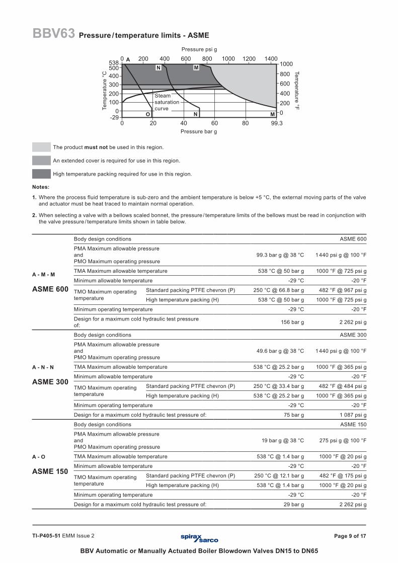
The product must not be used in this region.
An extended cover is required for use in this region.
High temperature packing required for use in this region.
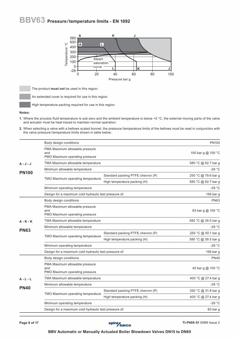
Notes:
1. Where the process fluid temperature is sub-zero and the ambient temperature is below +5 °C, the external moving parts of the valve and actuator must be heat traced to maintain normal operation.
2. When selecting a valve with a bellows scaled bonnet, the pressure / temperature limits of the bellows must be read in conjunction with the valve pressure / temperature limits shown in table below.
A - M - M
ASME 600
Body design conditions ASME 600
PMA Maximum allowable pressure and PMO Maximum operating pressure
99.3 bar g @ 38 °C 1 440 psi g @ 100 °F
TMA Maximum allowable temperature 538 °C @ 50 bar g 1000 °F @ 725 psi g
Minimum allowable temperature -29 °C -20 °F
TMO Maximum operating temperature
Standard packing PTFE chevron (P) 250 °C @ 66.8 bar g 482 °F @ 967 psi g
High temperature packing (H) 538 °C @ 50 bar g 1000 °F @ 725 psi g
Minimum operating temperature -29 °C -20 °F
Design for a maximum cold hydraulic test pressure of: 156 bar g 2 262 psi g
A - N - N
ASME 300
Body design conditions ASME 300
PMA Maximum allowable pressure and PMO Maximum operating pressure
49.6 bar g @ 38 °C 1 440 psi g @ 100 °F
TMA Maximum allowable temperature 538 °C @ 25.2 bar g 1000 °F @ 365 psi g
Minimum allowable temperature -29 °C -20 °F
TMO Maximum operating temperature
Standard packing PTFE chevron (P) 250 °C @ 33.4 bar g 482 °F @ 484 psi g
High temperature packing (H) 538 °C @ 25.2 bar g 1000 °F @ 365 psi g
Minimum operating temperature -29 °C -20 °F
Design for a maximum cold hydraulic test pressure of: 75 bar g 1 087 psi g
A - O
ASME 150
Body design conditions ASME 150
PMA Maximum allowable pressure and PMO Maximum operating pressure
19 bar g @ 38 °C 275 psi g @ 100 °F
TMA Maximum allowable temperature 538 °C @ 1.4 bar g 1000 °F @ 20 psi g
Minimum allowable temperature -29 °C -20 °F
TMO Maximum operating temperature
Standard packing PTFE chevron (P) 250 °C @ 12.1 bar g 482 °F @ 175 psi g
High temperature packing (H) 538 °C @ 1.4 bar g 1000 °F @ 20 psi g
Minimum operating temperature -29 °C -20 °F
Design for a maximum cold hydraulic test pressure of: 29 bar g 2 262 psi g
Steam saturation curve
Page 10 of 17
BBV Automatic or Manually Actuated Boiler Blowdown Valves DN15 to DN65
TI-P405-51 EMM Issue 2
� �� �� ����
�
���
���
���
�����
���
�� ��
���
The product must not be used in this region.
An extended cover is required for use in this region.
High temperature packing required for use in this region.
Notes:
1. Where the process fluid temperature is sub-zero and the ambient temperature is below +5 °C, the external moving parts of the valve and actuator must be heat traced to maintain normal operation.
2. When selecting a valve with a bellows scaled bonnet, the pressure / temperature limits of the bellows must be read in conjunction with the valve pressure / temperature limits shown in table below.
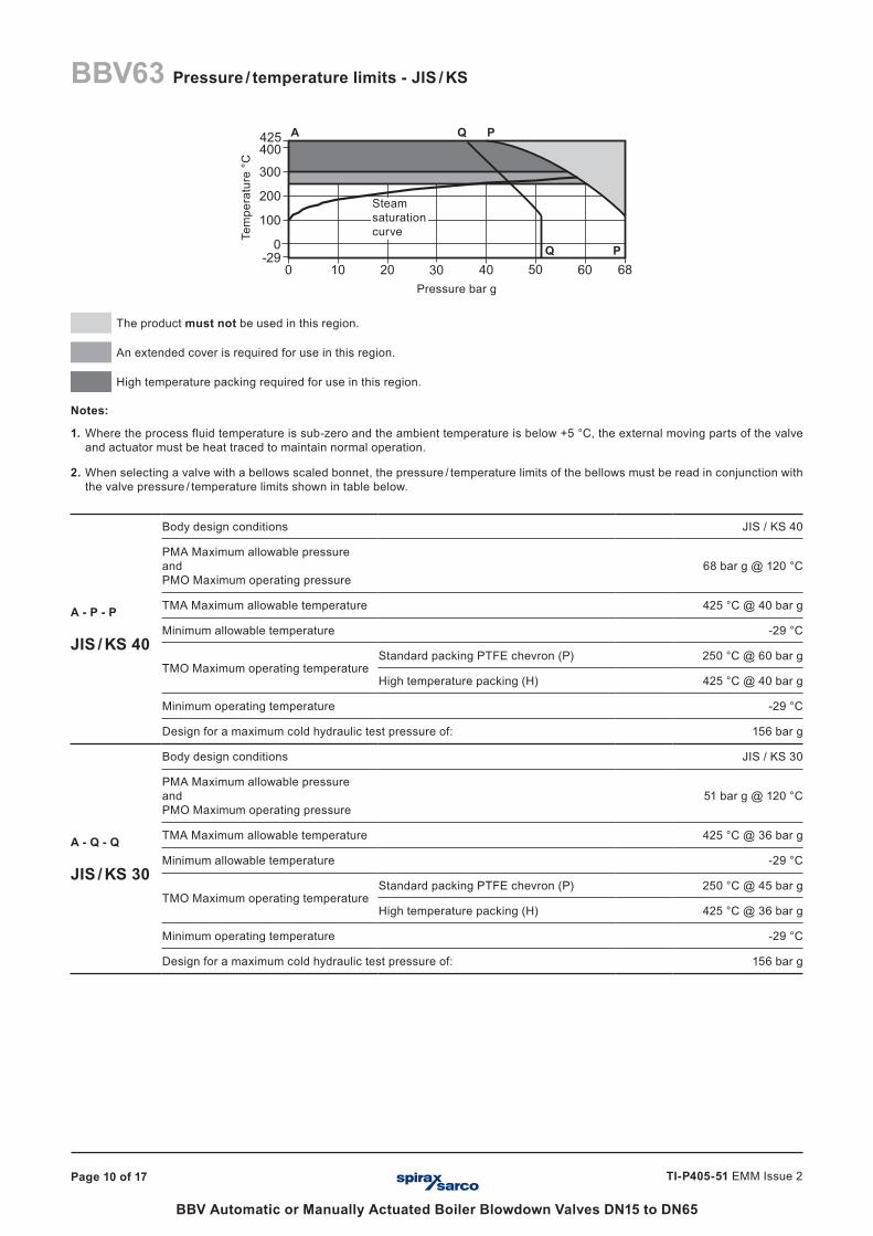
A - P - P
JIS / KS 40
Body design conditions JIS / KS 40
PMA Maximum allowable pressure and PMO Maximum operating pressure
68 bar g @ 120 °C
TMA Maximum allowable temperature 425 °C @ 40 bar g
Minimum allowable temperature -29 °C
TMO Maximum operating temperature Standard packing PTFE chevron (P) 250 °C @ 60 bar g
High temperature packing (H) 425 °C @ 40 bar g
Minimum operating temperature -29 °C
Design for a maximum cold hydraulic test pressure of: 156 bar g
A - Q - Q
JIS / KS 30
Body design conditions JIS / KS 30
PMA Maximum allowable pressure and PMO Maximum operating pressure
51 bar g @ 120 °C
TMA Maximum allowable temperature 425 °C @ 36 bar g
Minimum allowable temperature -29 °C
TMO Maximum operating temperature Standard packing PTFE chevron (P) 250 °C @ 45 bar g
High temperature packing (H) 425 °C @ 36 bar g
Minimum operating temperature -29 °C
Design for a maximum cold hydraulic test pressure of: 156 bar g
Pressure bar g
Tem
pera
ture
°C
A
Q P
Q P
BBV63 Pressure / temperature limits - JIS / KS
Steam saturation curve
Page 11 of 17
BBV Automatic or Manually Actuated Boiler Blowdown Valves DN15 to DN65
TI-P405-51 EMM Issue 2
���� ���� �� �����
�
���
���
���
������
Pressure bar g
Tem
pera
ture
°C
The product must not be used in this region.
An extended cover is required for use in this region.
High temperature packing required for use in this region.
Notes:
1. Where the process fluid temperature is sub-zero and the ambient temperature is below +5 °C, the external moving parts of the valve and actuator must be heat traced to maintain normal operation.
2. When selecting a valve with a bellows scaled bonnet, the pressure / temperature limits of the bellows must be read in conjunction with the valve pressure / temperature limits shown in table below.
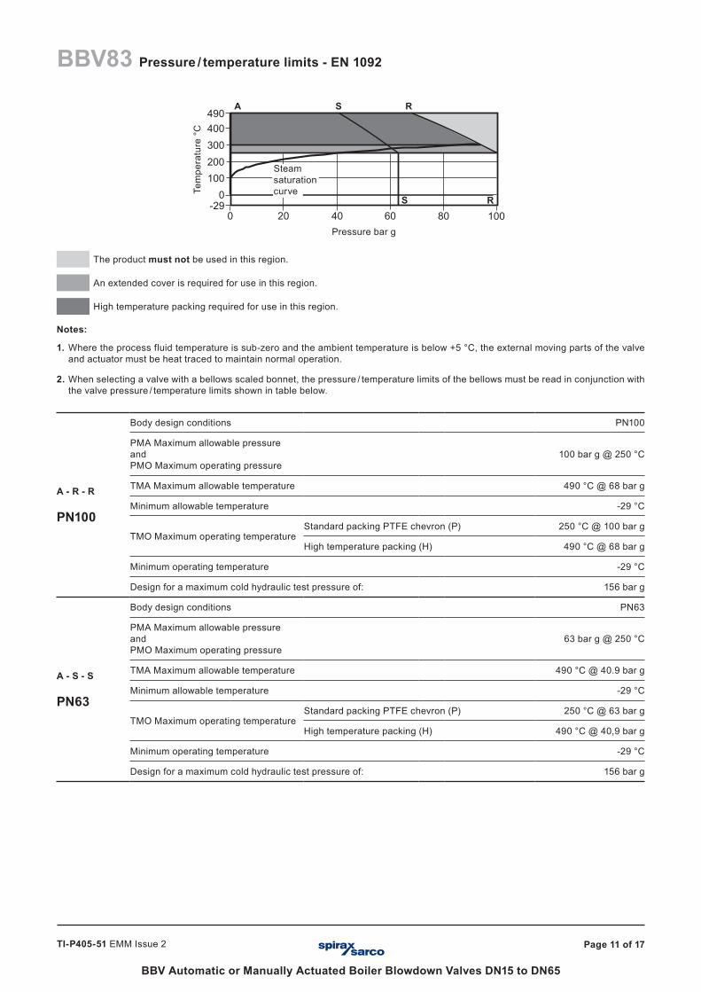
A - R - R
PN100
Body design conditions PN100
PMA Maximum allowable pressure and PMO Maximum operating pressure
100 bar g @ 250 °C
TMA Maximum allowable temperature 490 °C @ 68 bar g
Minimum allowable temperature -29 °C
TMO Maximum operating temperature Standard packing PTFE chevron (P) 250 °C @ 100 bar g
High temperature packing (H) 490 °C @ 68 bar g
Minimum operating temperature -29 °C
Design for a maximum cold hydraulic test pressure of: 156 bar g
A - S - S
PN63
Body design conditions PN63
PMA Maximum allowable pressure and PMO Maximum operating pressure
63 bar g @ 250 °C
TMA Maximum allowable temperature 490 °C @ 40.9 bar g
Minimum allowable temperature -29 °C
TMO Maximum operating temperature Standard packing PTFE chevron (P) 250 °C @ 63 bar g
High temperature packing (H) 490 °C @ 40,9 bar g
Minimum operating temperature -29 °C
Design for a maximum cold hydraulic test pressure of: 156 bar g
A S R
S R
BBV83 Pressure / temperature limits - EN 1092
Steam saturation curve
Page 12 of 17
BBV Automatic or Manually Actuated Boiler Blowdown Valves DN15 to DN65
TI-P405-51 EMM Issue 2
���
���
���
�
������ ���� �� �����
�������
������
������
� ��� ��� ��� ��� ���� ���� ����
���
����
� � � � � � � � � � �� �� �� �� �� �� �� �� �� �� �� �� �� �� �� �� �� �� �� �� �� �� �� �� �� �� �� �� �� �� �� �� �� �� �� �� �� �� �� �� �� �� �� �� �� �� �� �� �� �� �� �� �� �� �� �� �� �� �� �� �� �� �� �� �� �� �� �� �� �� �� �� �� �� �� �� �� �� �� �� �� �� �� �� �� �� �� �� �� �� ��� ��� ��� ���
�
����
�����
�����
�����
���
�����
�����
�����
�����
���
Pressure bar g
Tem
pera
ture
°C
The product must not be used in this region.
An extended cover is required for use in this region.
High temperature packing required for use in this region.
Notes:
1. Where the process fluid temperature is sub-zero and the ambient temperature is below +5 °C (+41 °F), the external moving parts of the valve and actuator must be heat traced to maintain normal operation.
2. When selecting a valve with a bellows scaled bonnet, the pressure / temperature limits of the bellows must be read in conjunction with the valve pressure / temperature limits shown in table below.
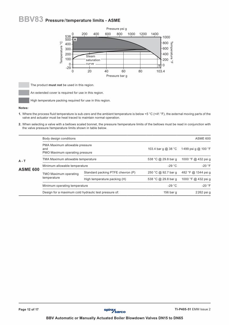
A - T
ASME 600
Body design conditions ASME 600
PMA Maximum allowable pressure and PMO Maximum operating pressure
103.4 bar g @ 38 °C 1 499 psi g @ 100 °F
TMA Maximum allowable temperature 538 °C @ 29.8 bar g 1000 °F @ 432 psi g
Minimum allowable temperature -29 °C -20 °F
TMO Maximum operating temperature
Standard packing PTFE chevron (P) 250 °C @ 92.7 bar g 482 °F @ 1344 psi g
High temperature packing (H) 538 °C @ 29.8 bar g 1000 °F @ 432 psi g
Minimum operating temperature -29 °C -20 °F
Design for a maximum cold hydraulic test pressure of: 156 bar g 2 262 psi g
A
T
Pressure psi g
Temperature °F
BBV83 Pressure / temperature limits - ASME
Steam saturation curve
Page 13 of 17
BBV Automatic or Manually Actuated Boiler Blowdown Valves DN15 to DN65
TI-P405-51 EMM Issue 2
� � � � � �� �� �� �� �� �� �� �� �� �� �� �� �� �� �� �� �� �� �� �� �� �� �� �� �� �� �� �� �� ��
�������������������
������������������������������������������������������������������������������������������������������������������������������
��� ���� �� �����
�
���
���
���
���
���
�� ��
���
Pressure bar g
Tem
pera
ture
°C
The product must not be used in this region.
An extended cover is required for use in this region.
High temperature packing required for use in this region.
Notes:
1. Where the process fluid temperature is sub-zero and the ambient temperature is below +5 °C, the external moving parts of the valve and actuator must be heat traced to maintain normal operation.
2. When selecting a valve with a bellows scaled bonnet, the pressure / temperature limits of the bellows must be read in conjunction with the valve pressure / temperature limits shown in table below.
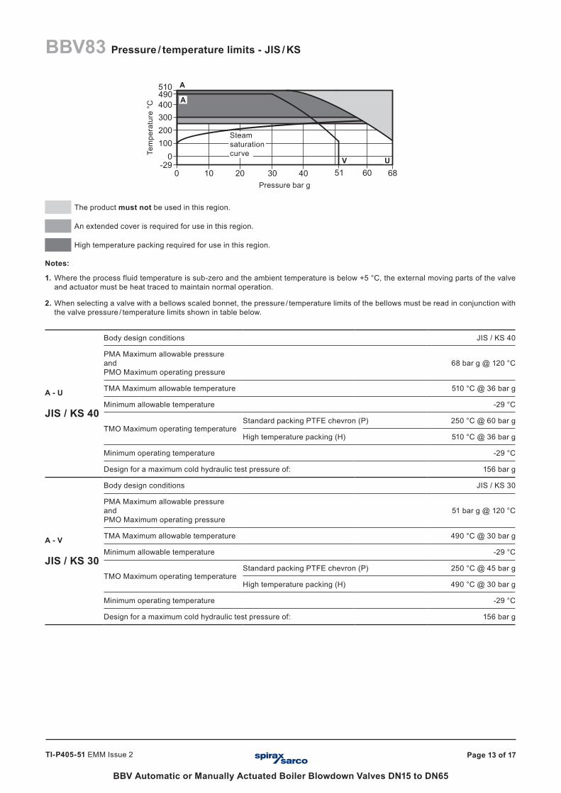
A - U
JIS / KS 40
Body design conditions JIS / KS 40
PMA Maximum allowable pressure and PMO Maximum operating pressure
68 bar g @ 120 °C
TMA Maximum allowable temperature 510 °C @ 36 bar g
Minimum allowable temperature -29 °C
TMO Maximum operating temperature Standard packing PTFE chevron (P) 250 °C @ 60 bar g
High temperature packing (H) 510 °C @ 36 bar g
Minimum operating temperature -29 °C
Design for a maximum cold hydraulic test pressure of: 156 bar g
A - V
JIS / KS 30
Body design conditions JIS / KS 30
PMA Maximum allowable pressure and PMO Maximum operating pressure
51 bar g @ 120 °C
TMA Maximum allowable temperature 490 °C @ 30 bar g
Minimum allowable temperature -29 °C
TMO Maximum operating temperature Standard packing PTFE chevron (P) 250 °C @ 45 bar g
High temperature packing (H) 490 °C @ 30 bar g
Minimum operating temperature -29 °C
Design for a maximum cold hydraulic test pressure of: 156 bar g
A
A
V
BBV83 Pressure / temperature limits - JIS / KS
U
Steam saturation curve
Page 14 of 17
BBV Automatic or Manually Actuated Boiler Blowdown Valves DN15 to DN65
TI-P405-51 EMM Issue 2
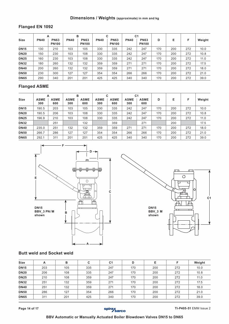
Dimensions / Weights (approximate) in mm and kg
Flanged EN 1092
SizeA B C C1
D E F WeightPN40 PN63 PN40 PN63 PN40 PN63 PN40 PN63PN100 PN100 PN100 PN100
DN15 130 210 103 105 330 335 242 247 170 200 272 10.0DN20 150 230 103 108 330 335 242 247 170 200 272 10.8DN25 160 230 103 108 330 335 242 247 170 200 272 11.0DN32 180 260 132 132 359 359 271 271 170 200 272 17.5DN40 200 260 132 132 359 359 271 271 170 200 272 18.0DN50 230 300 127 127 354 354 266 266 170 200 272 21.0DN65 290 340 201 201 425 425 340 340 170 200 272 39.0
Flanged ASME
SizeA B C C1
D E F WeightASME 300
ASME 600
ASME 300
ASME 600
ASME 300
ASME 600
ASME 300
ASME 600
DN15 190.5 203 103 105 330 335 242 247 170 200 272 10.0DN20 190.5 206 103 108 330 335 242 247 170 200 272 10.8DN25 196.9 210 103 108 330 335 242 247 170 200 272 11.0DN32 251 132 359 271 200 17.5DN40 235.0 251 132 132 359 359 271 271 170 200 272 18.0DN50 266.7 286 127 127 354 354 266 266 170 200 272 21.0DN65 292.1 311 201 201 425 425 340 340 170 200 272 39.0
E
F
D
B
A
C
C1
DN15BBV_3 PN / Mshown
DN15BBV_3 Mshown
Butt weld and Socket weld
Size A B C C1 D E F WeightDN15 203 105 335 247 170 200 272 10.0DN20 206 108 335 247 170 200 272 10.8DN25 210 108 359 247 170 200 272 11.0DN32 251 132 359 271 170 200 272 17.5DN40 251 132 359 271 170 200 272 18.0DN50 286 127 354 266 170 200 272 21.0DN65 311 201 425 340 170 200 272 39.0
Page 15 of 17
BBV Automatic or Manually Actuated Boiler Blowdown Valves DN15 to DN65
TI-P405-51 EMM Issue 2
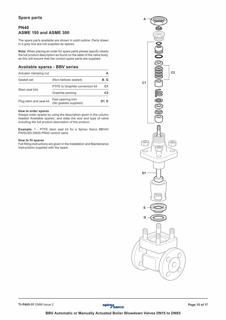
Spare parts
PN40ASME 150 and ASME 300The spare parts available are shown in solid outline. Parts drawn in a grey line are not supplied as spares.
Note: When placing an order for spare parts please specify clearly the full product description as found on the label of the valve body, as this will ensure that the correct spare parts are supplied.
Available spares - BBV seriesActuator clamping nut A
Gasket set (Non-bellows sealed) B, G
Stem seal kitsPTFE to Graphite conversion kit C1
Graphite packing C2
Plug stem and seat kit Fast opening trim (No gaskets supplied) D1, E
How to order sparesAlways order spares by using the description given in the column headed 'Available spares', and state the size and type of valve including the full product description of the product.
Example: 1 - PTFE stem seal kit for a Spirax Sarco BBV43 PWSUSS DN25 PN40 control valve.
How to fit sparesFull fitting instructions are given in the Installation and Maintenance Instructions supplied with the spare.
D1
E
G
A
C1
C2
Page 16 of 17
BBV Automatic or Manually Actuated Boiler Blowdown Valves DN15 to DN65
TI-P405-51 EMM Issue 2
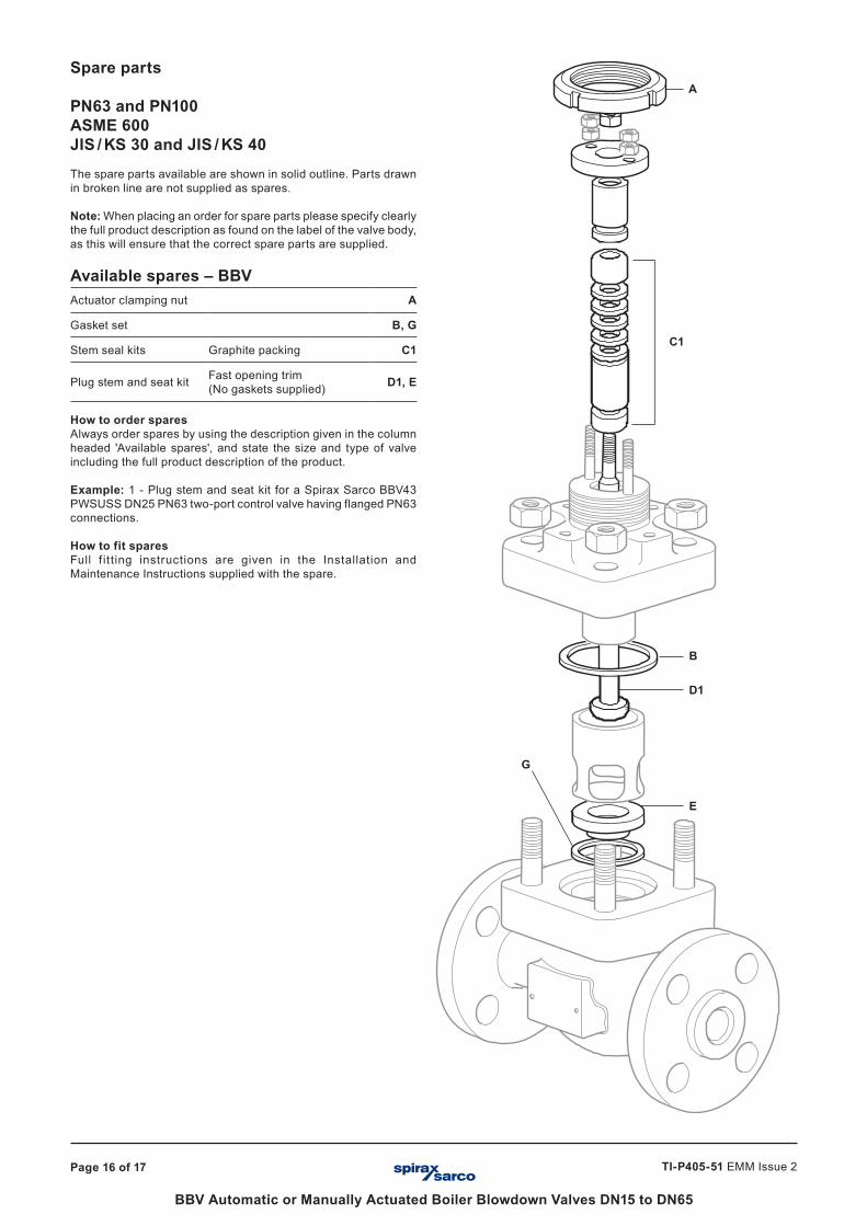
Spare parts
PN63 and PN100ASME 600JIS / KS 30 and JIS / KS 40The spare parts available are shown in solid outline. Parts drawn in broken line are not supplied as spares.
Note: When placing an order for spare parts please specify clearly the full product description as found on the label of the valve body, as this will ensure that the correct spare parts are supplied.
Available spares – BBVActuator clamping nut A
Gasket set B, G
Stem seal kits Graphite packing C1
Plug stem and seat kit Fast opening trim(No gaskets supplied) D1, E
How to order sparesAlways order spares by using the description given in the column headed 'Available spares', and state the size and type of valve including the full product description of the product.
Example: 1 - Plug stem and seat kit for a Spirax Sarco BBV43 PWSUSS DN25 PN63 two-port control valve having flanged PN63 connections.
How to fit sparesFull f it ting instructions are given in the Installation andMaintenance Instructions supplied with the spare.
D1
A
H
B
D1
E
G
C1
Page 17 of 17
BBV Automatic or Manually Actuated Boiler Blowdown Valves DN15 to DN65
TI-P405-51 EMM Issue 2
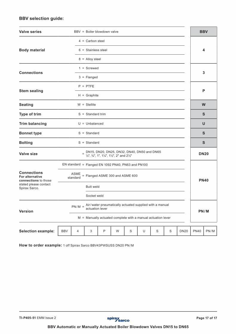
BBV selection guide:
Valve series BBV = Boiler blowdown valve BBV
Body material
4 = Carbon steel
46 = Stainless steel
8 = Alloy steel
Connections1 = Screwed
33 = Flanged
Stem sealingP = PTFE
PH = Graphite
Seating W = Stellite W
Type of trim S = Standard trim S
Trim balancing U = Unbalanced U
Bonnet type S = Standard S
Bolting S = Standard S
Valve size = DN15, DN20, DN25, DN32, DN40, DN50 and DN65½", ¾", 1", 1¼", 1½", 2" and 2½" DN20
ConnectionsFor alternative connections to those stated please contact Spirax Sarco.
EN standard = Flanged EN 1092 PN40, PN63 and PN100
PN40ASME
standard = Flanged ASME 300 and ASME 600
Butt weld
Socket weld
VersionPN / M = Air / water pneumatically actuated supplied with a manual
actuation leverPN / M
M = Manually actuated complete with a manual actuation lever
Selection example: BBV 4 3 P W S U S S DN20 PN40 PN / M
How to order example: 1 off Spirax Sarco BBV43PWSUSS DN20 PN / M
Related Documents