AutoCAD® Structural Detailing 2010 Getting Started with AutoCAD® Structural Detailing, Steel module

Welcome message from author
This document is posted to help you gain knowledge. Please leave a comment to let me know what you think about it! Share it to your friends and learn new things together.
Transcript
AutoCAD® Structural Detailing 2010
Getting Started with AutoCAD® Structural Detailing, Steel module
© 2009 Autodesk, Inc. All Rights Reserved. Except as otherwise permitted by Autodesk, Inc., this publication, or parts thereof, may not be reproduced in any form, by any method, for any purpose. Certain materials included in this publication are reprinted with the permission of the copyright holder. Disclaimer THIS PUBLICATION AND THE INFORMATION CONTAINED HEREIN IS MADE AVAILABLE BY AUTODESK, INC. “AS IS.” AUTODESK, INC. DISCLAIMS ALL WARRANTIES, EITHER EXPRESS OR IMPLIED, INCLUDING BUT NOT LIMITED TO ANY IMPLIED WARRANTIES OF MERCHANTABILITY OR FITNESS FOR A PARTICULAR PURPOSE REGARDING THESE MATERIALS. Trademarks The following are registered trademarks of Autodesk, Inc., in the USA and/or other countries: Autodesk Robot Structural Analysis, Autodesk Concrete Building Structures, Spreadsheet Calculator, ATC, AutoCAD, Autodesk, Autodesk Inventor, Autodesk (logo), Buzzsaw, Design Web Format, DWF, ViewCube, SteeringWheels, and Autodesk Revit. All other brand names, product names or trademarks belong to their respective holders. Third Party Software Program Credits ACIS Copyright© 1989-2001 Spatial Corp. Portions Copyright© 2002 Autodesk, Inc. Copyright© 1997 Microsoft Corporation. All rights reserved. International CorrectSpell™ Spelling Correction System© 1995 by Lernout & Hauspie Speech Products, N.V. All rights reserved. InstallShield™ 3.0. Copyright© 1997 InstallShield Software Corporation. All rights reserved. PANTONE® and other Pantone, Inc. trademarks are the property of Pantone, Inc.© Pantone, Inc., 2002. Portions Copyright© 1991-1996 Arthur D. Applegate. All rights reserved. Portions relating to JPEG © Copyright 1991-1998 Thomas G. Lane. All rights reserved. Portions of this software are based on the work of the Independent JPEG Group. Portions relating to TIFF © Copyright 1997-1998 Sam Leffler. © Copyright 1991-1997 Silicon Graphics, Inc. All rights reserved. Government Use Use, duplication, or disclosure by the U.S. Government is subject to restrictions as set forth in FAR 12.212 (Commercial Computer Software-Restricted Rights) and DFAR 227.7202 (Rights in Technical Data and Computer Software), as applicable.
Contents
Getting Started Guide ...................................................................................................................... 1
Getting Started ............................................................................................................................. 1
Exploring the User Interface ......................................................................................................... 1
Program Preferences .................................................................................................................... 3
Creating a Steel Structure ............................................................................................................. 4
Creating a New Project ............................................................................................................. 5
Adding Workframes .................................................................................................................. 5
Adding Columns ........................................................................................................................ 9
Adding Beams ......................................................................................................................... 12
Adding Connections ................................................................................................................ 15
Adding Bracing ........................................................................................................................ 27
Adding Purlins ......................................................................................................................... 32
Creating Assemblies .................................................................................................................... 35
Autopositioning .......................................................................................................................... 37
Generating Drawings .................................................................................................................. 38
Getting Started Guide Thank you for choosing AutoCAD® Structural Detailing. The Steel module is a tool for generating fabrication workshop documentation, including drawings and bills of materials. The exercises in this guide give you a starting point for preparation of your own projects.
Getting Started
Before beginning the exercises, you need to install and register the software. AutoCAD ® Structural Detailing software comes with the AutoCAD® Revit® Structure Suite. This software is only available for 32‐bit Windows XP/Vista systems and cannot be installed on 64‐bit machines.
Exploring the User Interface
Open AutoCAD ® Structural Detailing, Steel module, and take a minute to view the different areas of the interface.
Ribbon
At the top of the interface is the standard Microsoft® Windows® element ‐ ribbon. The ribbon is an element of the user interface which replaces the traditional menu and toolbars and allows easy managing and adjusting the workspace. The ribbon consists of several panels, grouped on tabs that are named by task or subject. The ribbon panels include many AutoCAD ® Structural Detailing commands that have been on toolbars and in dialogs so far, such as icons, drop‐down lists, sliders, text fields and other elements characteristic of a given tab.
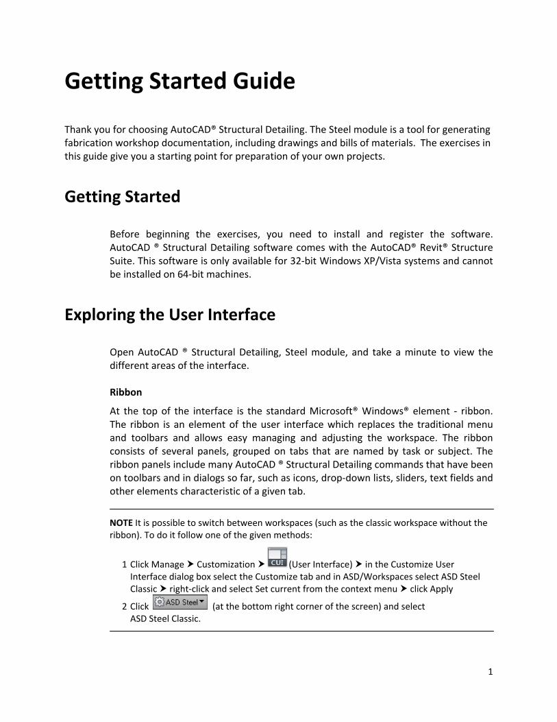
NOTE It is possible to switch between workspaces (such as the classic workspace without the ribbon). To do it follow one of the given methods:
1 Click Manage Customization (User Interface) in the Customize User Interface dialog box select the Customize tab and in ASD/Workspaces select ASD Steel Classic right‐click and select Set current from the context menu click Apply
2 Click (at the bottom right corner of the screen) and select ASD Steel Classic.
1
Object Inspector
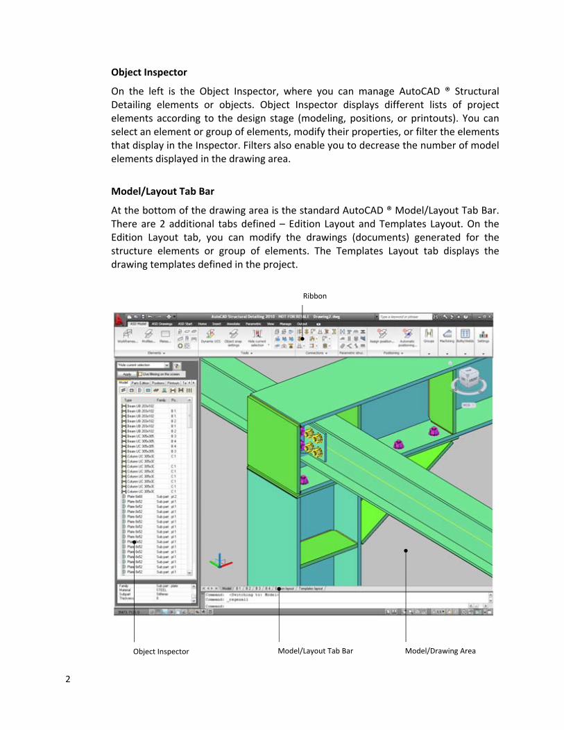
On the left is the Object Inspector, where you can manage AutoCAD ® Structural Detailing elements or objects. Object Inspector displays different lists of project elements according to the design stage (modeling, positions, or printouts). You can select an element or group of elements, modify their properties, or filter the elements that display in the Inspector. Filters also enable you to decrease the number of model elements displayed in the drawing area.
Model/Layout Tab Bar
At the bottom of the drawing area is the standard AutoCAD ® Model/Layout Tab Bar. There are 2 additional tabs defined – Edition Layout and Templates Layout. On the Edition Layout tab, you can modify the drawings (documents) generated for the structure elements or group of elements. The Templates Layout tab displays the drawing templates defined in the project.
Ribbon
Model/Layout Tab Bar Model/Drawing Area Object Inspector
2
Program Preferences
Preferences
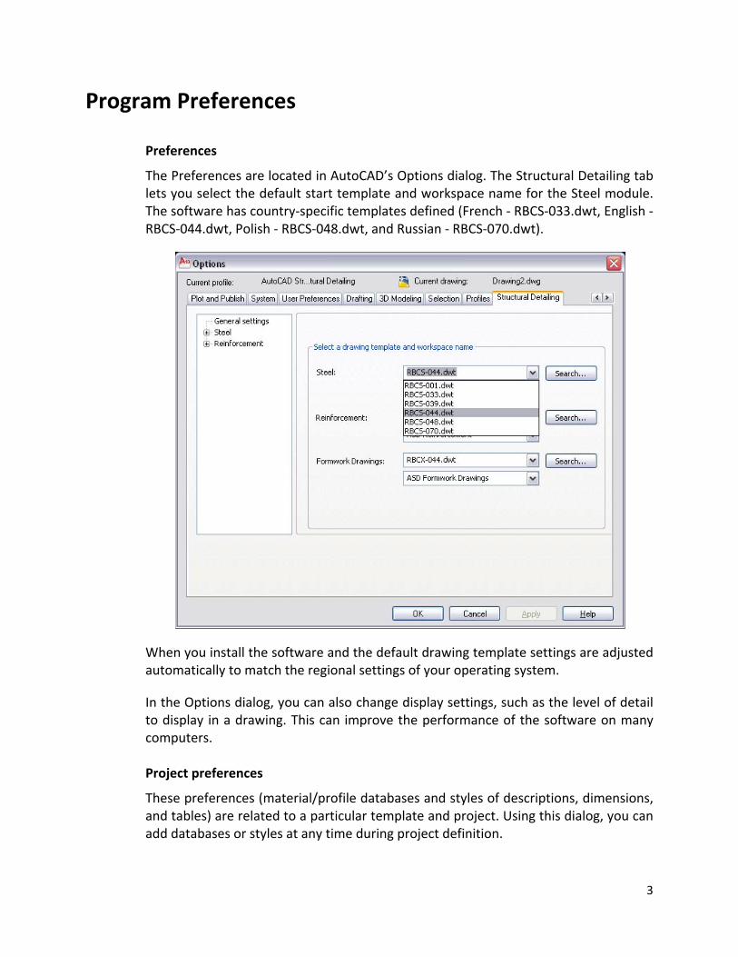
The Preferences are located in AutoCAD’s Options dialog. The Structural Detailing tab lets you select the default start template and workspace name for the Steel module. The software has country‐specific templates defined (French ‐ RBCS‐033.dwt, English ‐ RBCS‐044.dwt, Polish ‐ RBCS‐048.dwt, and Russian ‐ RBCS‐070.dwt).
When you install the software and the default drawing template settings are adjusted automatically to match the regional settings of your operating system.
In the Options dialog, you can also change display settings, such as the level of detail to display in a drawing. This can improve the performance of the software on many computers. Project preferences
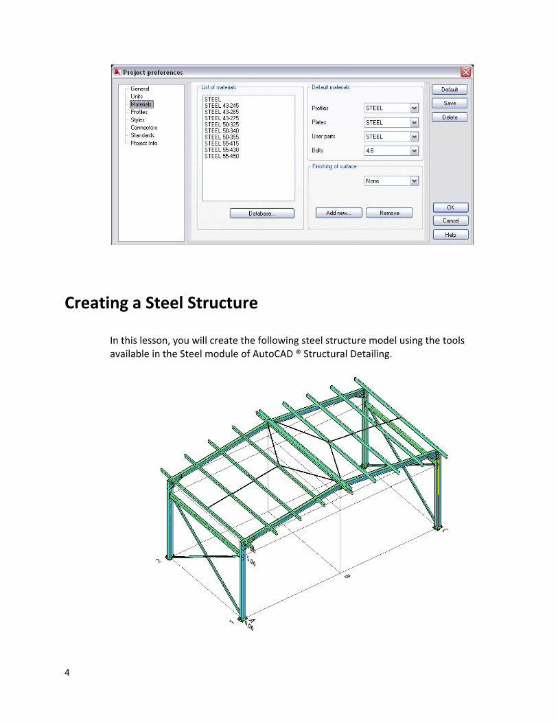
These preferences (material/profile databases and styles of descriptions, dimensions, and tables) are related to a particular template and project. Using this dialog, you can add databases or styles at any time during project definition.
3
Creating a Steel Structure
In this lesson, you will create the following steel structure model using the tools available in the Steel module of AutoCAD ® Structural Detailing.
4
Creating a New Project
In this exercise, you will create and name a project in which you will define a steel structure.
1 Start the Steel module of AutoCAD® Structural Detailing:
Click ASD Start (Steel).
2 Click New. 3 In the Select template dialog, select RBCS‐044.dwt (English template),
and click Open.
4 Click Save. 5 In the Save Drawing As dialog:
• Navigate to the desired location. • For File name, enter Getting_Started_Steel. • Click Save.
6 Proceed to the next exercise, Adding Workframes.
Adding Workframes
In this exercise, you will create 3D workframes for the main part of the structure and for the roof.
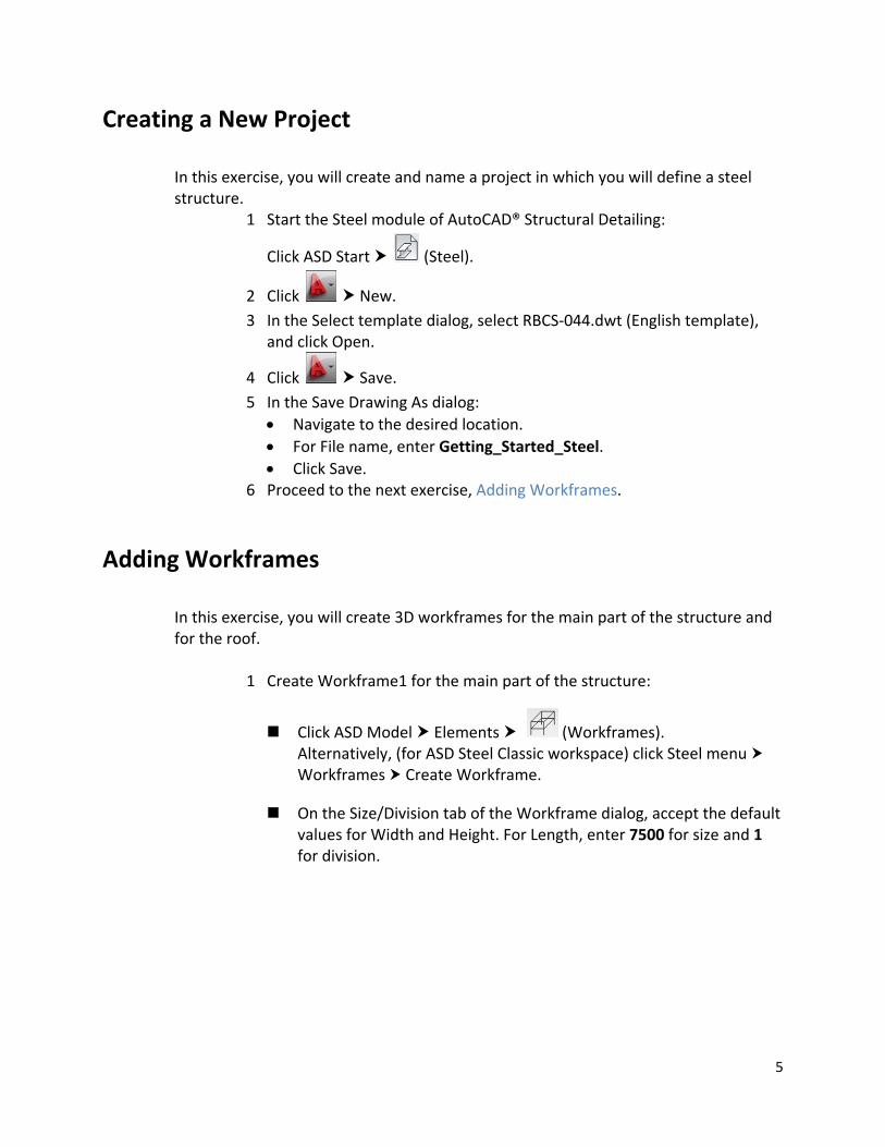
1 Create Workframe1 for the main part of the structure:
Click ASD Model Elements (Workframes). Alternatively, (for ASD Steel Classic workspace) click Steel menu Workframes Create Workframe.
On the Size/Division tab of the Workframe dialog, accept the default values for Width and Height. For Length, enter 7500 for size and 1 for division.
5
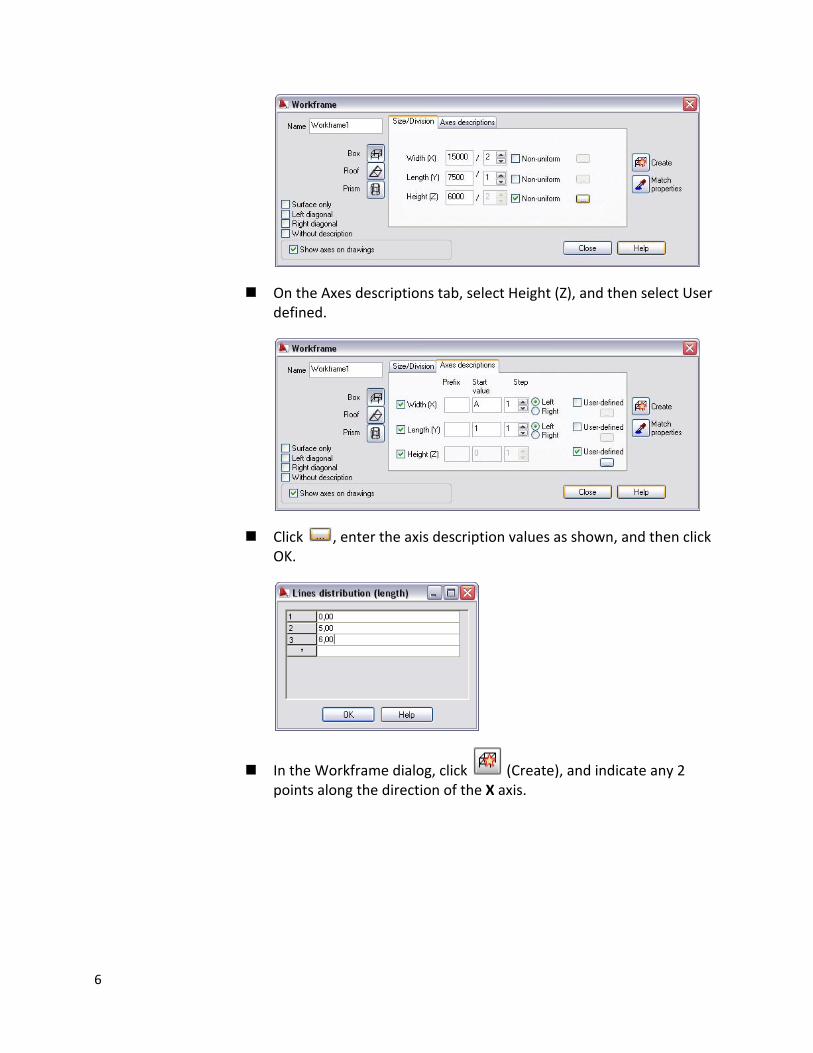
On the Axes descriptions tab, select Height (Z), and then select User defined.
Click , enter the axis description values as shown, and then click OK.
In the Workframe dialog, click (Create), and indicate any 2 points along the direction of the X axis.
6
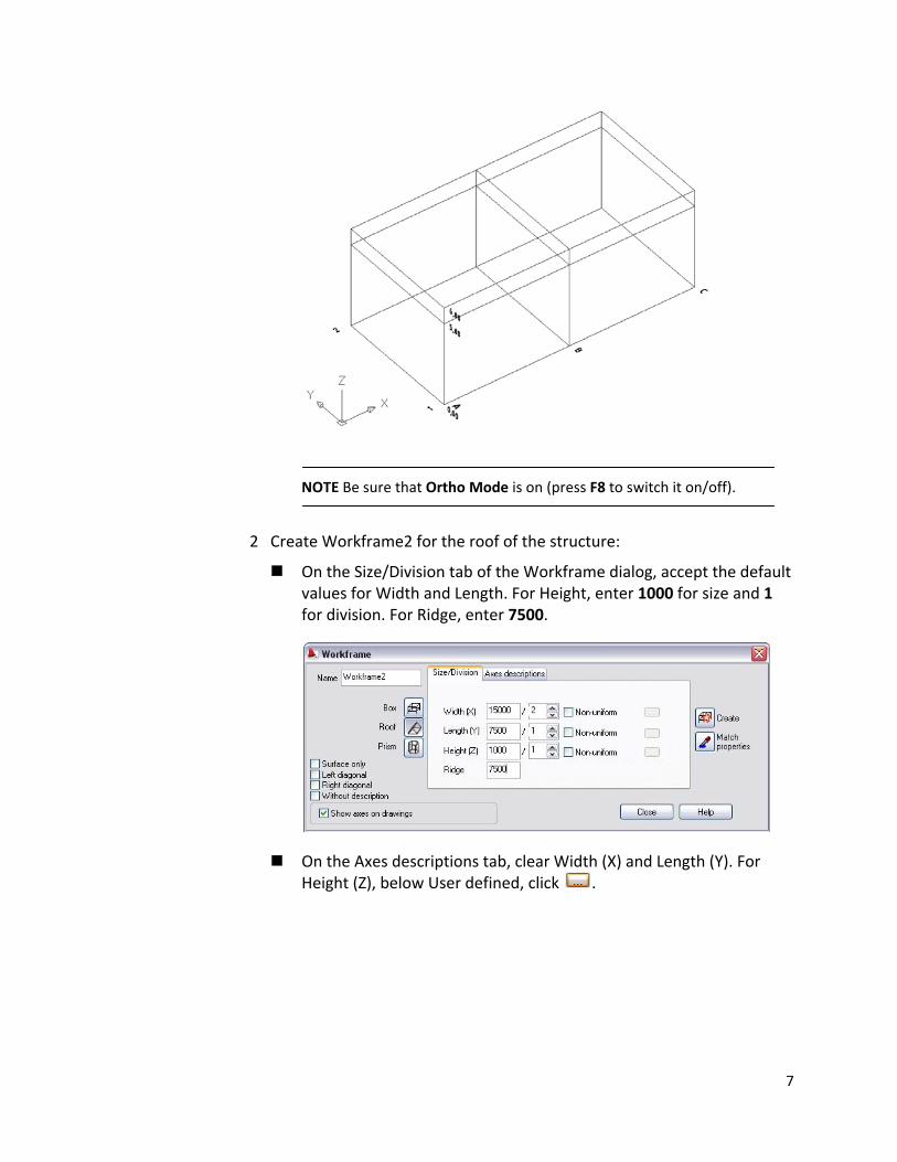
NOTE Be sure that Ortho Mode is on (press F8 to switch it on/off).
2 Create Workframe2 for the roof of the structure:
On the Size/Division tab of the Workframe dialog, accept the default values for Width and Length. For Height, enter 1000 for size and 1 for division. For Ridge, enter 7500.
On the Axes descriptions tab, clear Width (X) and Length (Y). For Height (Z), below User defined, click .
7
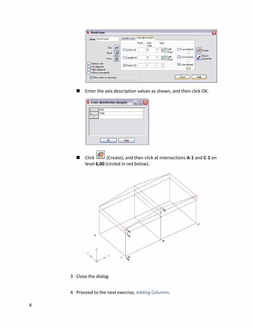
Enter the axis description values as shown, and then click OK.
Click (Create), and then click at intersections A‐1 and C‐1 on level 6,00 (circled in red below).
3 Close the dialog.
4 Proceed to the next exercise, Adding Columns.
8
Adding Columns
In this exercise, you will load a profiles database into the project, and then add new types of profiles. You also define columns and place them at specific axis intersections.
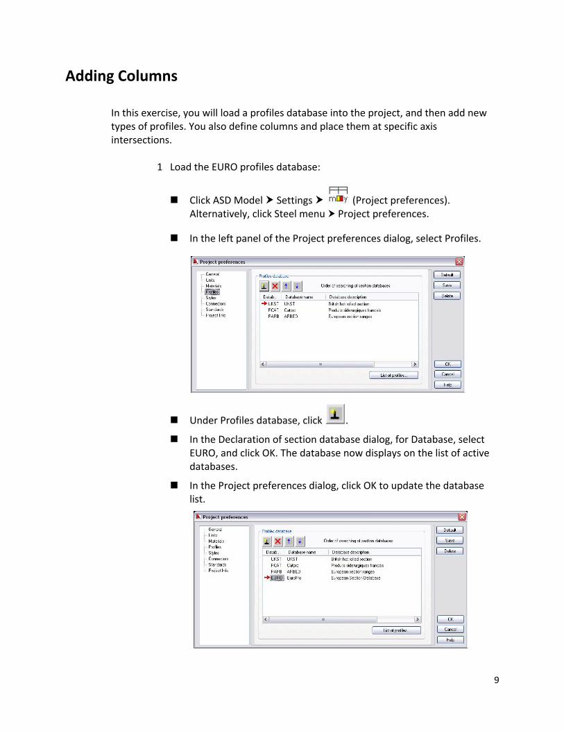
1 Load the EURO profiles database:
Click ASD Model Settings (Project preferences). Alternatively, click Steel menu Project preferences.
In the left panel of the Project preferences dialog, select Profiles.
Under Profiles database, click .
In the Declaration of section database dialog, for Database, select EURO, and click OK. The database now displays on the list of active databases.
In the Project preferences dialog, click OK to update the database list.
9
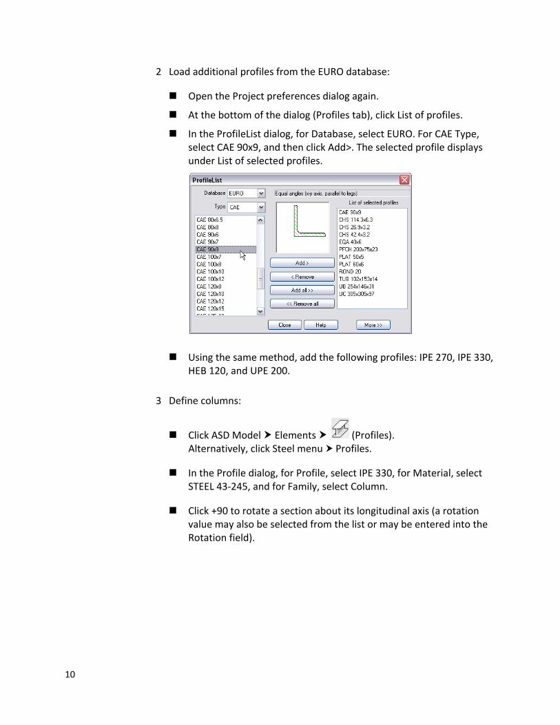
2 Load additional profiles from the EURO database:
Open the Project preferences dialog again.
At the bottom of the dialog (Profiles tab), click List of profiles.
In the ProfileList dialog, for Database, select EURO. For CAE Type, select CAE 90x9, and then click Add>. The selected profile displays under List of selected profiles.
Using the same method, add the following profiles: IPE 270, IPE 330, HEB 120, and UPE 200.
3 Define columns:
Click ASD Model Elements (Profiles). Alternatively, click Steel menu Profiles.
In the Profile dialog, for Profile, select IPE 330, for Material, select STEEL 43‐245, and for Family, select Column.
Click +90 to rotate a section about its longitudinal axis (a rotation value may also be selected from the list or may be entered into the Rotation field).
10
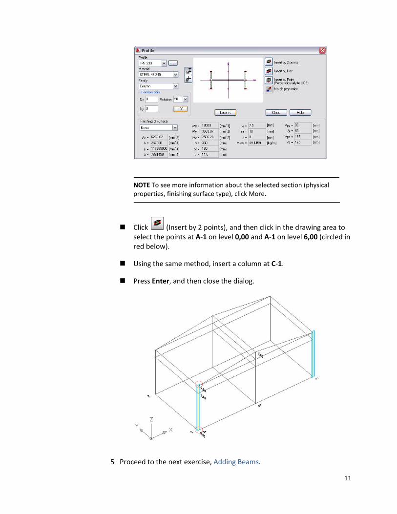
NOTE To see more information about the selected section (physical properties, finishing surface type), click More.
Click (Insert by 2 points), and then click in the drawing area to select the points at A‐1 on level 0,00 and A‐1 on level 6,00 (circled in red below).
Using the same method, insert a column at C‐1.
Press Enter, and then close the dialog.
5 Proceed to the next exercise, Adding Beams.
11
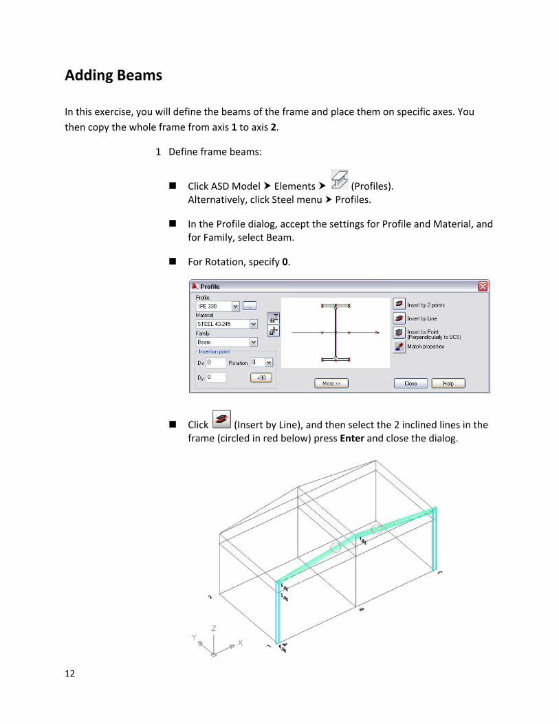
Adding Beams In this exercise, you will define the beams of the frame and place them on specific axes. You then copy the whole frame from axis 1 to axis 2.
1 Define frame beams:
Click ASD Model Elements (Profiles). Alternatively, click Steel menu Profiles.
In the Profile dialog, accept the settings for Profile and Material, and for Family, select Beam.
For Rotation, specify 0.
Click (Insert by Line), and then select the 2 inclined lines in the frame (circled in red below) press Enter and close the dialog.
12
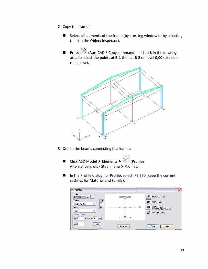
22 Copy the frame:
Selecthem
ct all elemenm in the Obje
nts of the fraect Inspector
ame (by crosr).
ssing windoww or by seleccting
3
Pressarea red b
s (Autoto select thebelow).
oCAD ® Copye points at B
command),B‐1 then at B
, and click inB‐2 on level 0
3 Define th
Click Alter
In thesettin
e beams con
ASD Model rnatively, clic
e Profile diangs for Mate
nnecting the
Elementsck Steel men
log, for Proferial and Fam
e frames:
s (Pronu Profiles
file, select IPmily).
ofiles). s.
PE 270 (keep
the drawing0,00 (circled
g d in
p the currentt
13
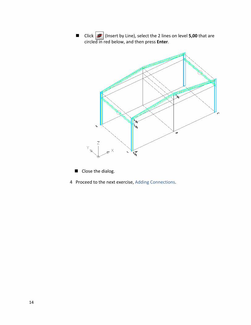
Click (Insert by Line), select the 2 lines on level 5,00 that are circled in red below, and then press Enter.
Close the dialog.
4 Proceed to the next exercise, Adding Connections.
14
Adding Connections In this exercise, you will define four types of element connections. Then you learn how to copy the defined connection.
1 Define column base connection:
Click ASD Model Connections (Column base‐fixed). Alternatively, click Steel menu Connections Automatic connections I Column base ‐ fixed.
Click the intersection of axes A and 1 to specify the bottom part of the column.
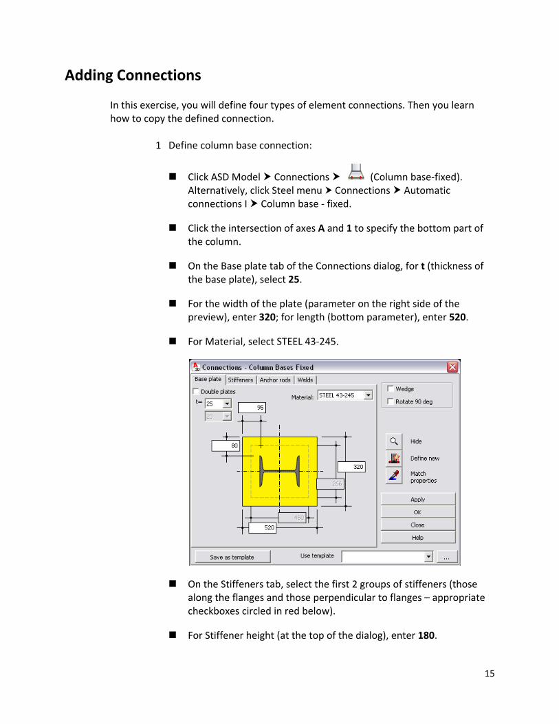
On the Base plate tab of the Connections dialog, for t (thickness of the base plate), select 25.
For the width of the plate (parameter on the right side of the preview), enter 320; for length (bottom parameter), enter 520.
For Material, select STEEL 43‐245.
On the Stiffeners tab, select the first 2 groups of stiffeners (those along the flanges and those perpendicular to flanges – appropriate checkboxes circled in red below).
For Stiffener height (at the top of the dialog), enter 180.
15
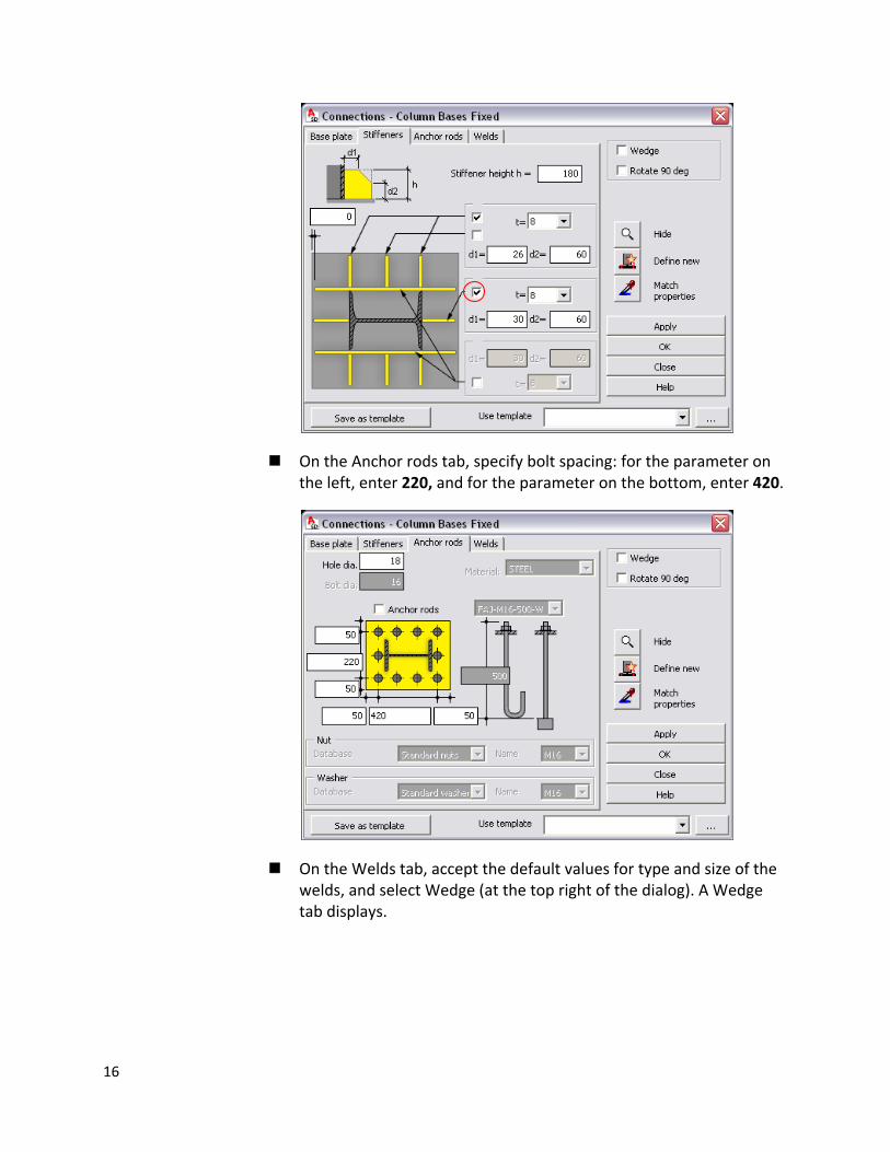
On the Anchor rods tab, specify bolt spacing: for the parameter on the left, enter 220, and for the parameter on the bottom, enter 420.
On the Welds tab, accept the default values for type and size of the welds, and select Wedge (at the top right of the dialog). A Wedge tab displays.
16
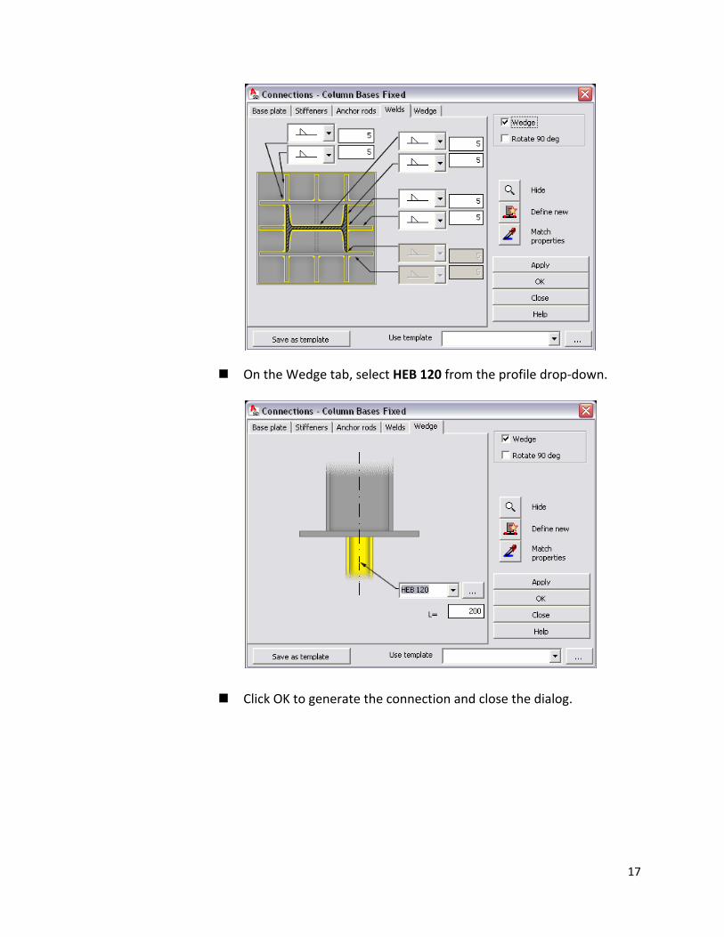
On the Wedge tab, select HEB 120 from the profile drop‐down.
Click OK to generate the connection and close the dialog.
17
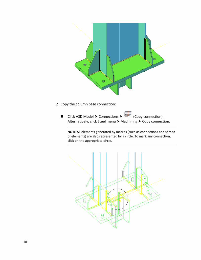
2 Copy the column base connection:
Click ASD Model Connections (Copy connection). Alternatively, click Steel menu Machining Copy connection.
NOTE All elements generated by macros (such as connections and spread of elements) are also represented by a circle. To mark any connection, click on the appropriate circle.
18
Click the circle that represents the generated base of the column connection, and then select the bottom parts of the remaining columns.
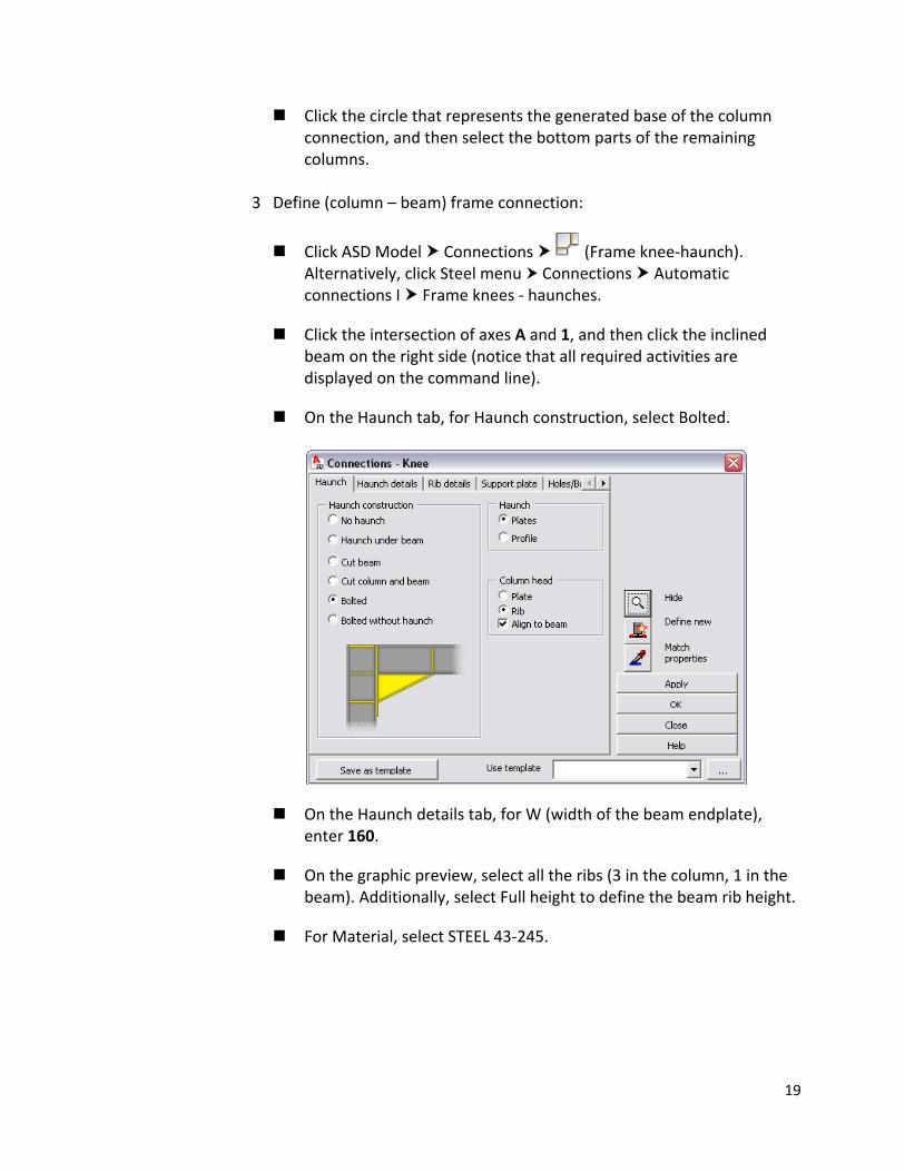
3 Define (column – beam) frame connection:
Click ASD Model Connections (Frame knee‐haunch). Alternatively, click Steel menu Connections Automatic connections I Frame knees ‐ haunches.
Click the intersection of axes A and 1, and then click the inclined beam on the right side (notice that all required activities are displayed on the command line).
On the Haunch tab, for Haunch construction, select Bolted.
On the Haunch details tab, for W (width of the beam endplate), enter 160.
On the graphic preview, select all the ribs (3 in the column, 1 in the beam). Additionally, select Full height to define the beam rib height.
For Material, select STEEL 43‐245.
19
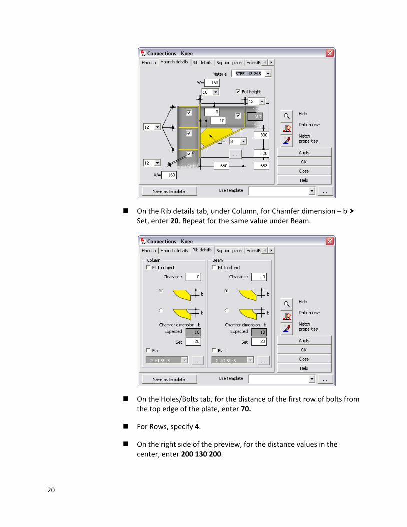
On the Rib details tab, under Column, for Chamfer dimension – b Set, enter 20. Repeat for the same value under Beam.
On the Holes/Bolts tab, for the distance of the first row of bolts from the top edge of the plate, enter 70.
For Rows, specify 4.
On the right side of the preview, for the distance values in the center, enter 200 130 200.
20
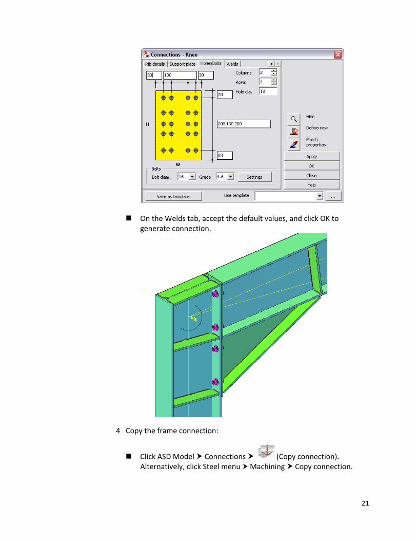
On the Welds tab, accept the default values, and click OK to generate connection.
4 Copy the frame connection:
Click ASD Model Connections (Copy connection). Alternatively, click Steel menu Machining Copy connection.
21
Click the circle that represents the frame connection, and then select the remaining columns and inclined beams.
NOTE Because connections are copied only for elements meeting the same criteria (element type, size, geometry), you don’t need to select individual elements. You can select the entire structure, and the proper elements will be recognized automatically.
5 Define inclined beams connection (in apex):
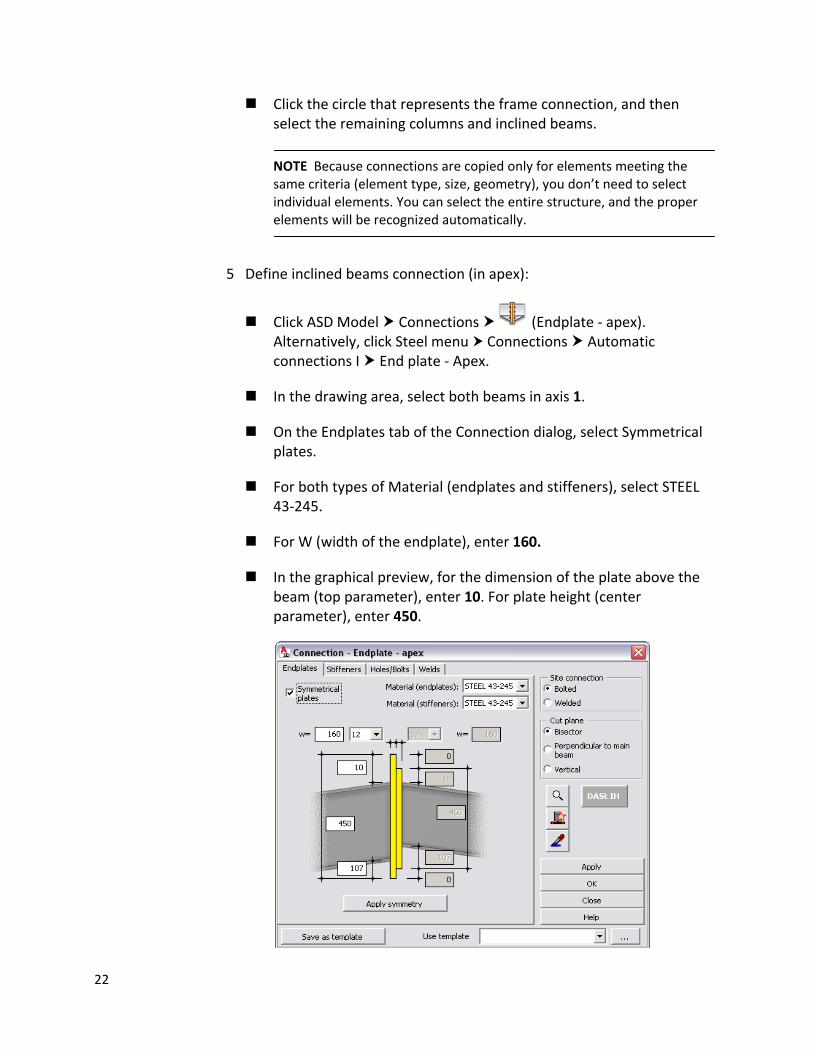
Click ASD Model Connections (Endplate ‐ apex). Alternatively, click Steel menu Connections Automatic connections I End plate ‐ Apex.
In the drawing area, select both beams in axis 1.
On the Endplates tab of the Connection dialog, select Symmetrical plates.
For both types of Material (endplates and stiffeners), select STEEL 43‐245.
For W (width of the endplate), enter 160.
In the graphical preview, for the dimension of the plate above the beam (top parameter), enter 10. For plate height (center parameter), enter 450.
22
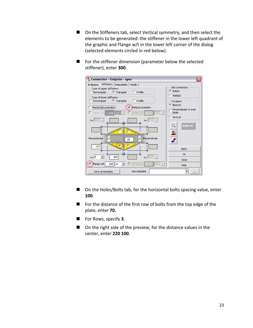
On the Stiffeners tab, select Vertical symmetry, and then select the elements to be generated: the stiffener in the lower left quadrant of the graphic and Flange w/t in the lower left corner of the dialog (selected elements circled in red below).
For the stiffener dimension (parameter below the selected stiffener), enter 300.
On the Holes/Bolts tab, for the horizontal bolts spacing value, enter 100.
For the distance of the first row of bolts from the top edge of the plate, enter 70.
For Rows, specify 3.
On the right side of the preview, for the distance values in the center, enter 220 100.
23
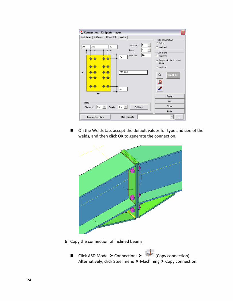
On the Welds tab, accept the default values for type and size of the welds, and then click OK to generate the connection.
6 Copy the connection of inclined beams:
Click ASD Model Connections (Copy connection). Alternatively, click Steel menu Machining Copy connection.
24

In the drawing area, click the circle that represents the connection between the inclined beams.
As the profiles to which connection is to be applied select the inclined beams in the second frame.
7 Define the beam‐to‐column connection:
Click ASD Model Connections click and hold the icon , and
on the flyout, click (Endplate‐beam/column web). Alternatively, click Steel menu Connections Automatic connections I End plate – beam/column web.
Click the intersection of axes A and 2, and then click the beam on level 5,0 on axis A.
On the Endplates tab, for the endplate thickness value (parameter on the top left corner), select 10, and then for width (w), enter 150.
For Material, select STEEL 43‐245.
For the placement of plate above the beam, enter 15.
On the right side of the preview, for the height value in the center, enter 475.
25
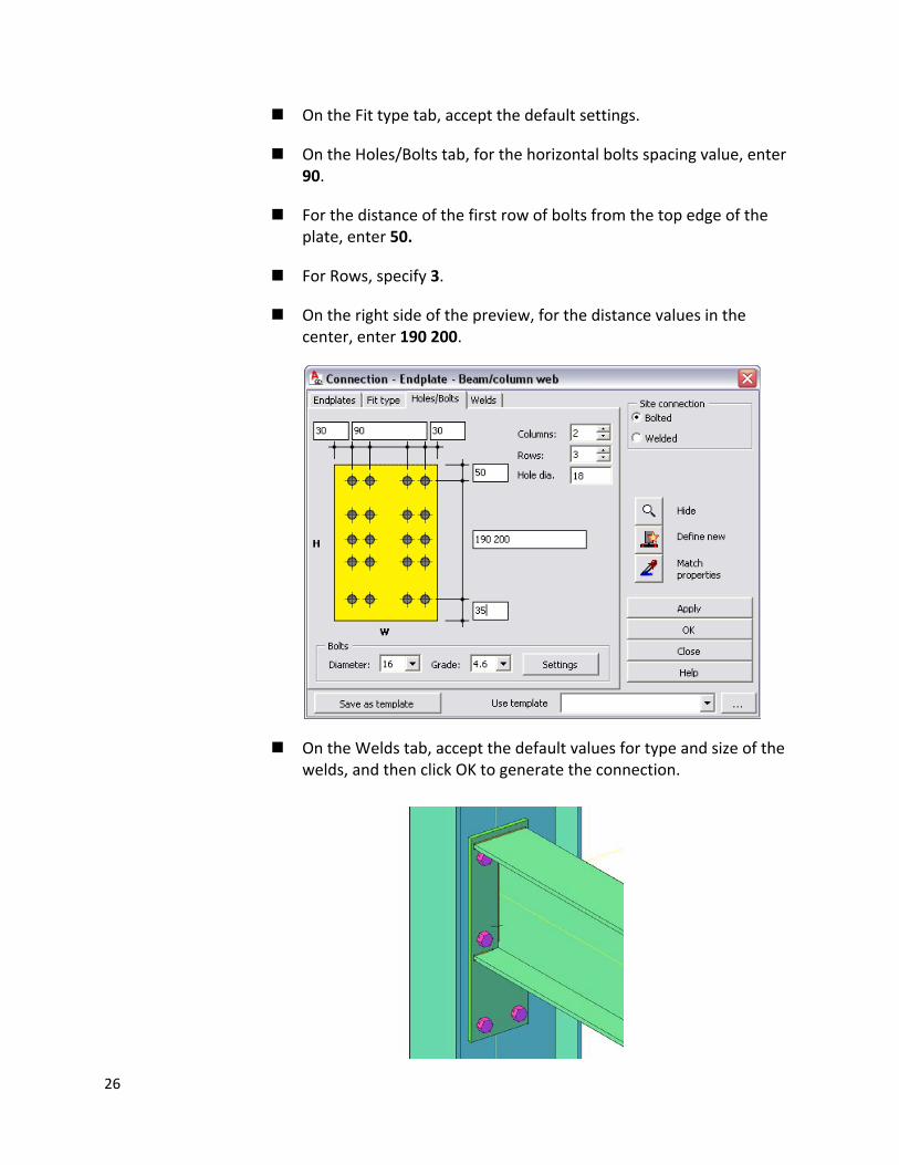
On the Fit type tab, accept the default settings.
On the Holes/Bolts tab, for the horizontal bolts spacing value, enter 90.
For the distance of the first row of bolts from the top edge of the plate, enter 50.
For Rows, specify 3.
On the right side of the preview, for the distance values in the center, enter 190 200.
On the Welds tab, accept the default values for type and size of the welds, and then click OK to generate the connection.
26
8 Copy the beam‐to‐column connection:
Click ASD Model Connections (Copy connection). Alternatively, click Steel menu Machining Copy connection.
Click the circle that represents the beam‐to‐column connection, and then select the remaining columns and beams.
9 Proceed to the next exercise, Adding Bracing.
Adding Bracing
In this exercise, you will define bracing using one of the Parametric Structures macros. To do this, you draw auxiliary bracing lines first, and then use filters to decrease the number of elements that display on the screen.
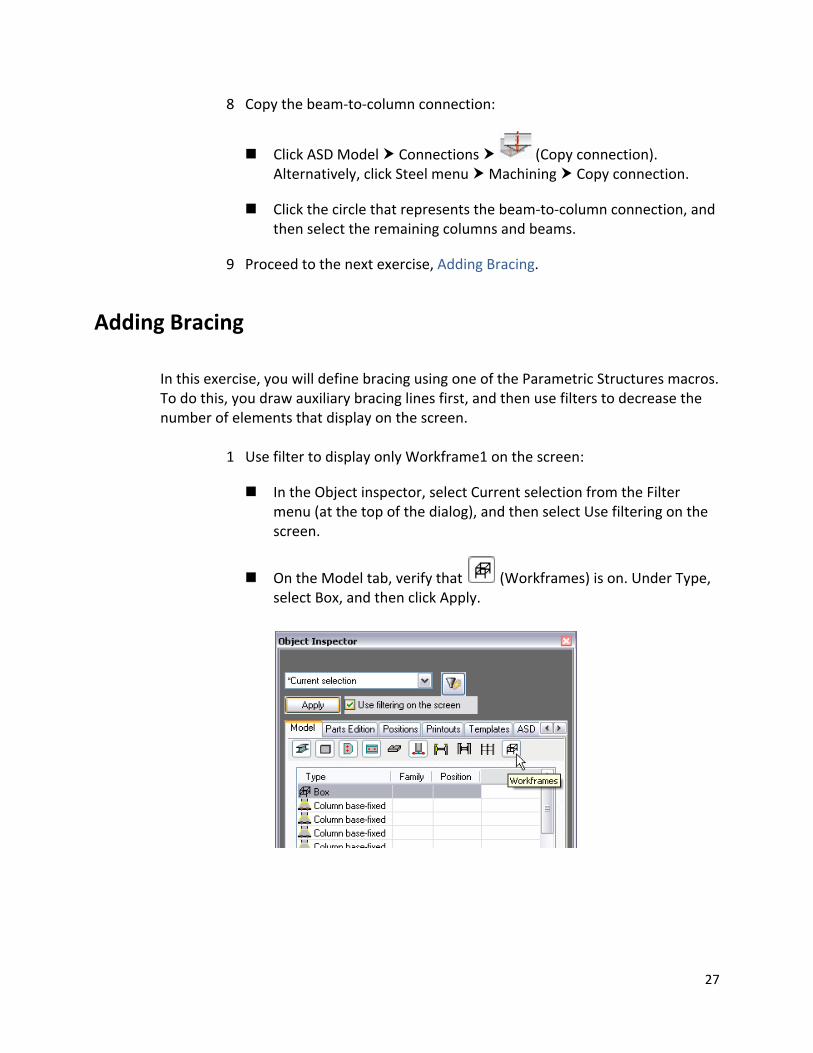
1 Use filter to display only Workframe1 on the screen:
In the Object inspector, select Current selection from the Filter menu (at the top of the dialog), and then select Use filtering on the screen.
On the Model tab, verify that (Workframes) is on. Under Type, select Box, and then click Apply.
27
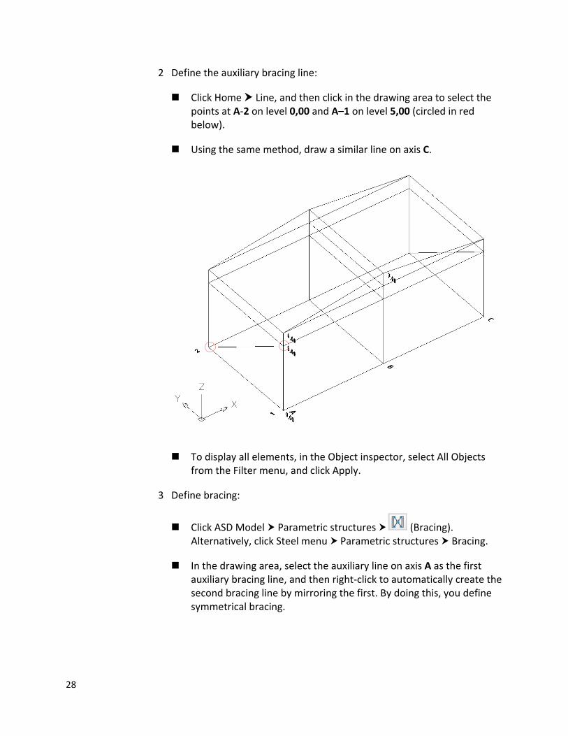
2 Define the auxiliary bracing line:
Click Home Line, and then click in the drawing area to select the points at A‐2 on level 0,00 and A–1 on level 5,00 (circled in red below).
Using the same method, draw a similar line on axis C.
To display all elements, in the Object inspector, select All Objects from the Filter menu, and click Apply.
3 Define bracing:
Click ASD Model Parametric structures (Bracing). Alternatively, click Steel menu Parametric structures Bracing.
In the drawing area, select the auxiliary line on axis A as the first auxiliary bracing line, and then right‐click to automatically create the second bracing line by mirroring the first. By doing this, you define symmetrical bracing.
28
Click column on the intersection of axes A and 2 to specify the location of the first column, and then click the column on the intersection of axes A and 1 to specify the location of the second column.
To specify the horizontal limitations, click the beam on level 5,0 and axis A, and then the base plates of both columns selected previously. Right‐click to accept the selection.
To specify the vertical limitations, click both endplates of the beam on level 5,0 and axis A.
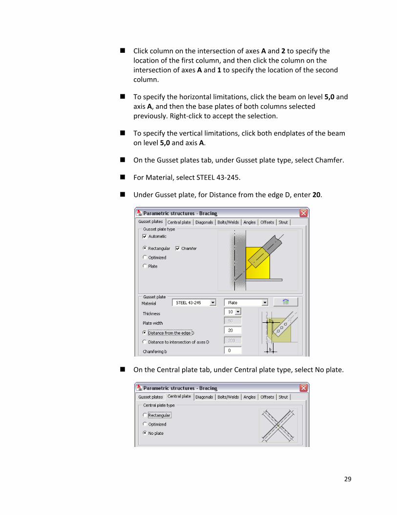
On the Gusset plates tab, under Gusset plate type, select Chamfer.
For Material, select STEEL 43‐245.
Under Gusset plate, for Distance from the edge D, enter 20.
On the Central plate tab, under Central plate type, select No plate.
29
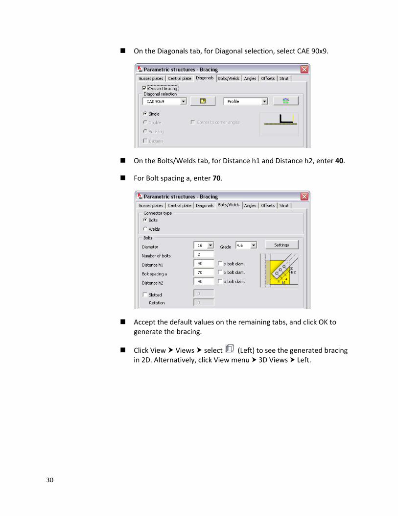
On the Diagonals tab, for Diagonal selection, select CAE 90x9.
On the Bolts/Welds tab, for Distance h1 and Distance h2, enter 40.
For Bolt spacing a, enter 70.
Accept the default values on the remaining tabs, and click OK to generate the bracing.
Click View Views select (Left) to see the generated bracing in 2D. Alternatively, click View menu 3D Views Left.
30
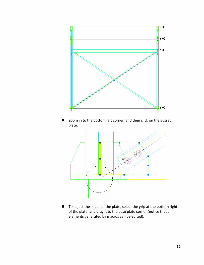
Zoom in to the bottom left corner, and then click on the gusset plate.
To adjust the shape of the plate, select the grip at the bottom right of the plate, and drag it to the base plate corner (notice that all elements generated by macros can be edited).
31
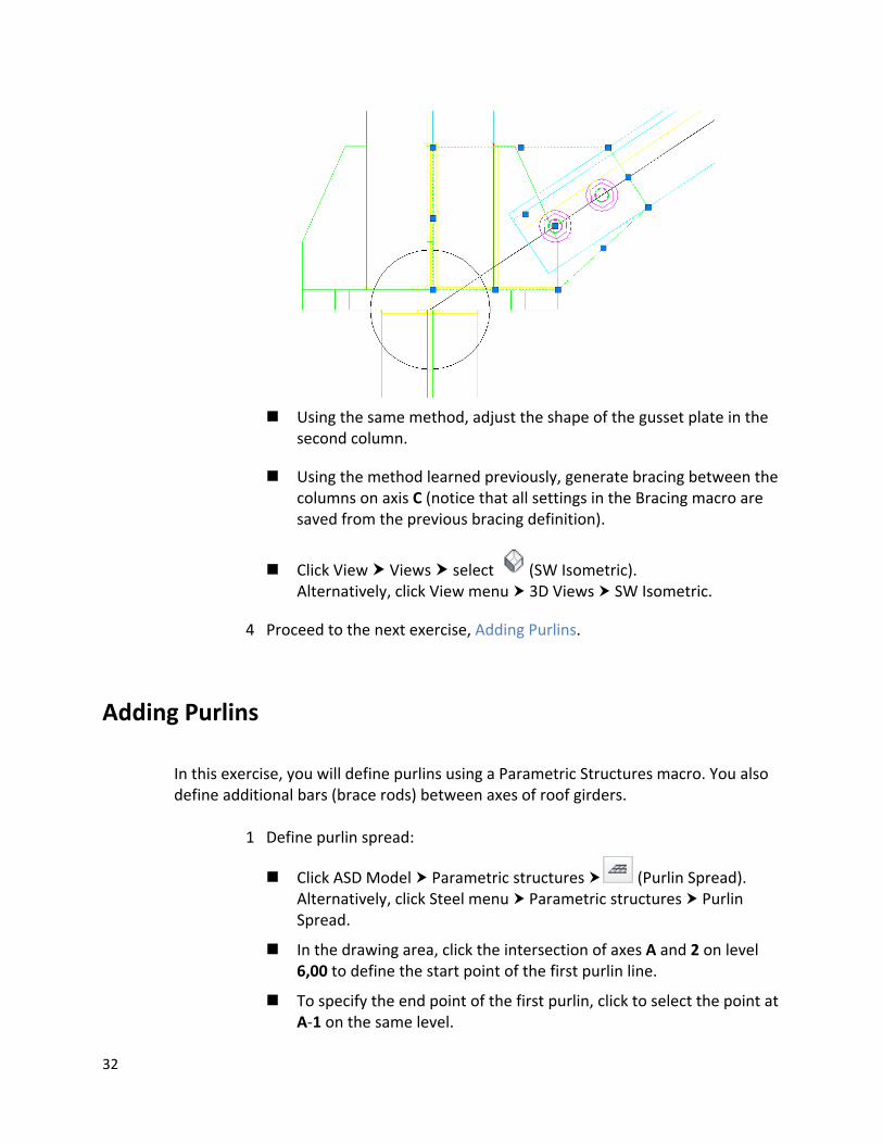
Using the same method, adjust the shape of the gusset plate in the second column.
Using the method learned previously, generate bracing between the columns on axis C (notice that all settings in the Bracing macro are saved from the previous bracing definition).
Click View Views select (SW Isometric). Alternatively, click View menu 3D Views SW Isometric.
4 Proceed to the next exercise, Adding Purlins.
Adding Purlins
In this exercise, you will define purlins using a Parametric Structures macro. You also define additional bars (brace rods) between axes of roof girders.
1 Define purlin spread:
Click ASD Model Parametric structures (Purlin Spread). Alternatively, click Steel menu Parametric structures Purlin Spread.
In the drawing area, click the intersection of axes A and 2 on level 6,00 to define the start point of the first purlin line.
To specify the end point of the first purlin, click to select the point at A‐1 on the same level.
32
Click B‐1 on level 7,00 to specify the point on the last purlin.
NOTE Zoom in as necessary to select points precisely.
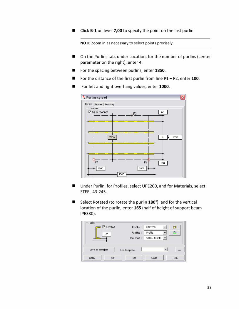
On the Purlins tab, under Location, for the number of purlins (center parameter on the right), enter 4.
For the spacing between purlins, enter 1850.
For the distance of the first purlin from line P1 – P2, enter 100.
For left and right overhang values, enter 1000.
Under Purlin, for Profiles, select UPE200, and for Materials, select STEEL 43‐245.
Select Rotated (to rotate the purlin 180°), and for the vertical location of the purlin, enter 165 (half of height of support beam IPE330).
33
2 Define brace rods:
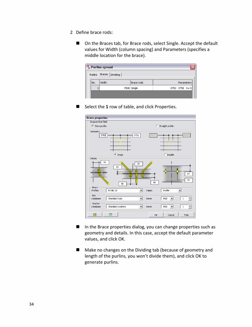
On the Braces tab, for Brace rods, select Single. Accept the default values for Width (column spacing) and Parameters (specifies a middle location for the brace).
Select the 1 row of table, and click Properties.
In the Brace properties dialog, you can change properties such as geometry and details. In this case, accept the default parameter values, and click OK.
Make no changes on the Dividing tab (because of geometry and length of the purlins, you won’t divide them), and click OK to generate purlins.
34
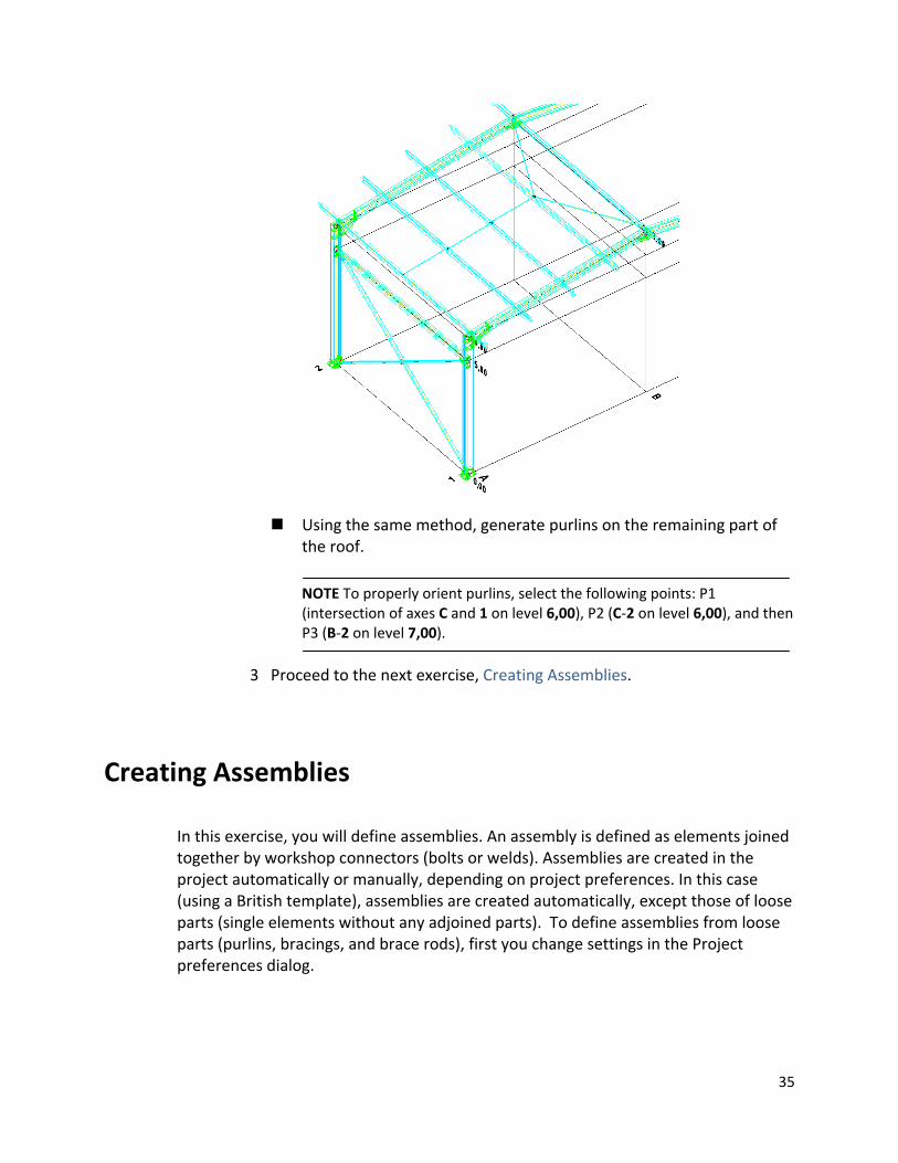
Using the same method, generate purlins on the remaining part of the roof.
NOTE To properly orient purlins, select the following points: P1 (intersection of axes C and 1 on level 6,00), P2 (C‐2 on level 6,00), and then P3 (B‐2 on level 7,00).
3 Proceed to the next exercise, Creating Assemblies.
Creating Assemblies
In this exercise, you will define assemblies. An assembly is defined as elements joined together by workshop connectors (bolts or welds). Assemblies are created in the project automatically or manually, depending on project preferences. In this case (using a British template), assemblies are created automatically, except those of loose parts (single elements without any adjoined parts). To define assemblies from loose parts (purlins, bracings, and brace rods), first you change settings in the Project preferences dialog.
35
1 Create assemblies from loose parts:
Click ASD Model Settings (Project preferences). Alternatively, click Steel menu Project preferences).
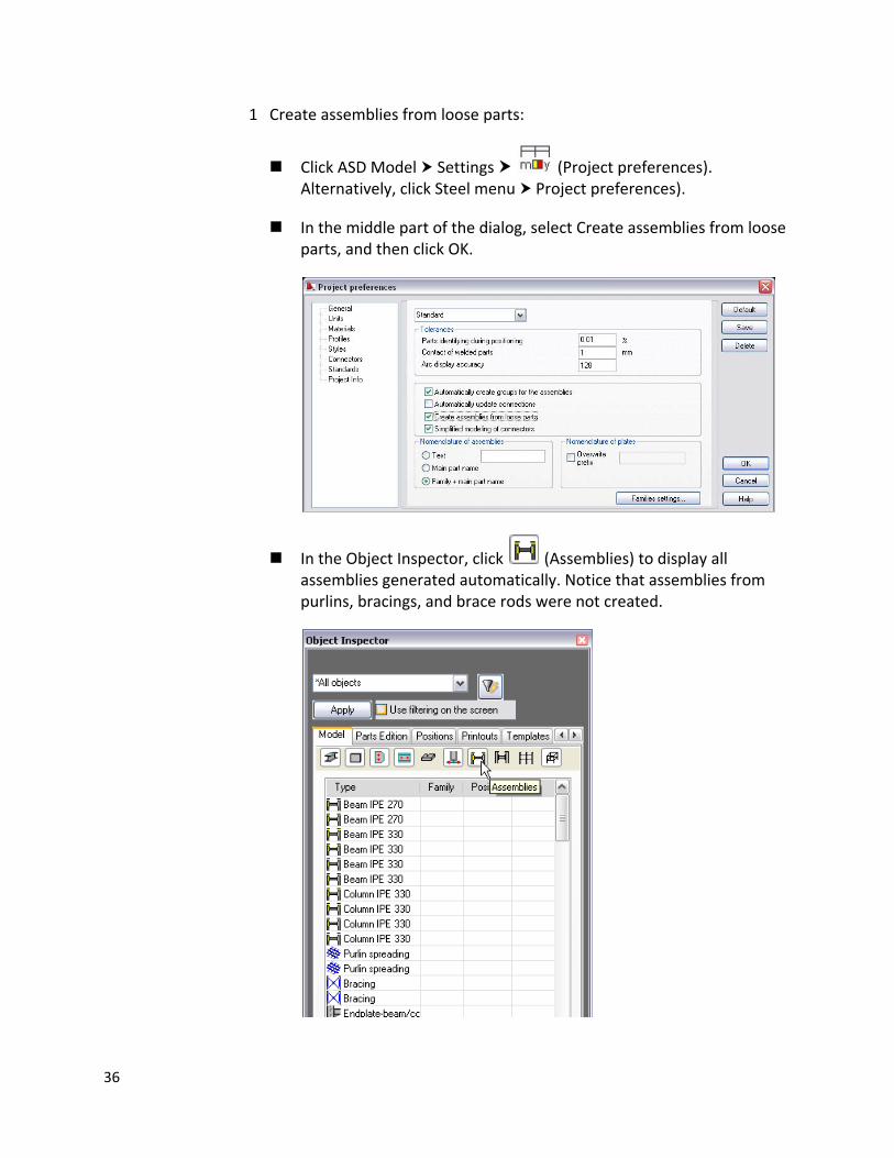
In the middle part of the dialog, select Create assemblies from loose parts, and then click OK.
In the Object Inspector, click (Assemblies) to display all assemblies generated automatically. Notice that assemblies from purlins, bracings, and brace rods were not created.
36
2 Define assemblies:
Click ASD Model Groups (Group assemblies). Alternatively, click Steel menu Tools Group assemblies.
Press Enter to remove assemblies already defined. Notice that new assemblies display in the Object Inspector.
3 Proceed to the next exercise, Autopositioning.
Autopositioning
In this exercise, you will automatically assign names (positions) to all model elements. This process is known as positioning.
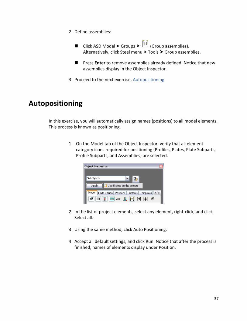
1 On the Model tab of the Object Inspector, verify that all element category icons required for positioning (Profiles, Plates, Plate Subparts, Profile Subparts, and Assemblies) are selected.
2 In the list of project elements, select any element, right‐click, and click Select all.
3 Using the same method, click Auto Positioning.
4 Accept all default settings, and click Run. Notice that after the process is
finished, names of elements display under Position.
37
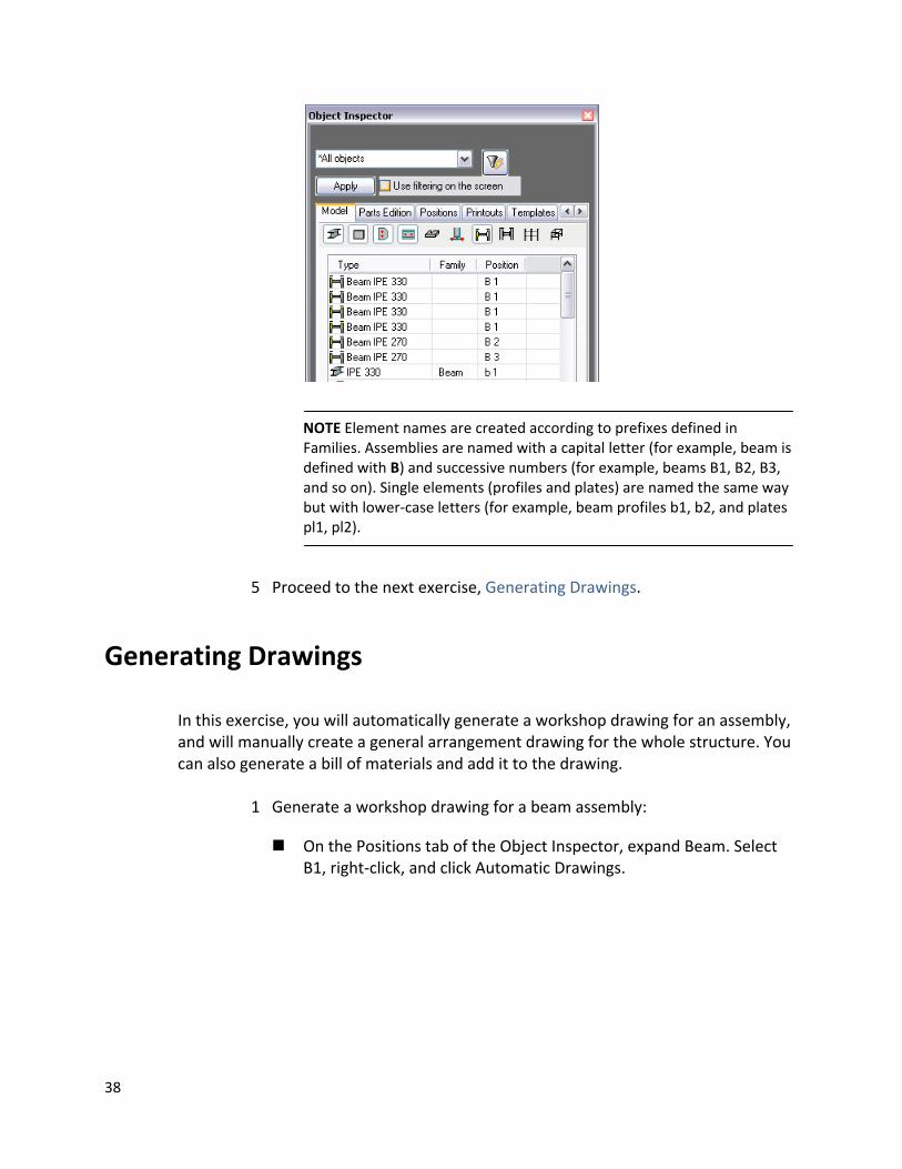
NOTE Element names are created according to prefixes defined in Families. Assemblies are named with a capital letter (for example, beam is defined with B) and successive numbers (for example, beams B1, B2, B3, and so on). Single elements (profiles and plates) are named the same way but with lower‐case letters (for example, beam profiles b1, b2, and plates pl1, pl2).
5 Proceed to the next exercise, Generating Drawings.
Generating Drawings
In this exercise, you will automatically generate a workshop drawing for an assembly, and will manually create a general arrangement drawing for the whole structure. You can also generate a bill of materials and add it to the drawing.
1 Generate a workshop drawing for a beam assembly:
On the Positions tab of the Object Inspector, expand Beam. Select B1, right‐click, and click Automatic Drawings.
38
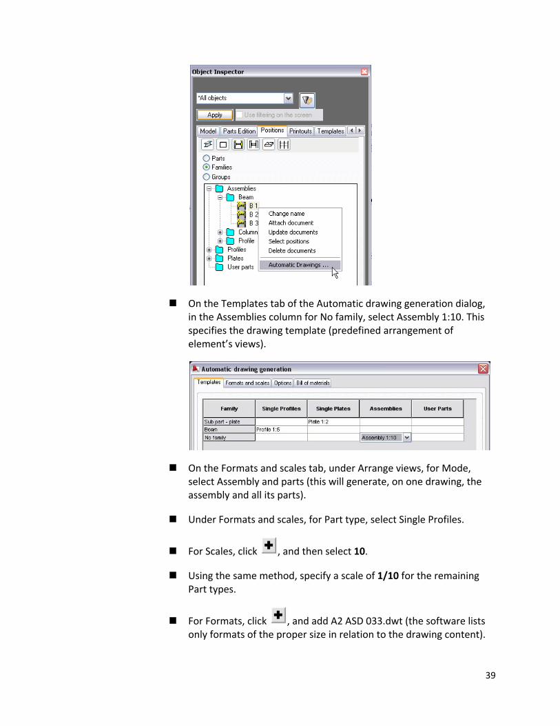
On the Templates tab of the Automatic drawing generation dialog, in the Assemblies column for No family, select Assembly 1:10. This specifies the drawing template (predefined arrangement of element’s views).
On the Formats and scales tab, under Arrange views, for Mode, select Assembly and parts (this will generate, on one drawing, the assembly and all its parts).
Under Formats and scales, for Part type, select Single Profiles.
For Scales, click , and then select 10.
Using the same method, specify a scale of 1/10 for the remaining Part types.
For Formats, click , and add A2 ASD 033.dwt (the software lists only formats of the proper size in relation to the drawing content).
39
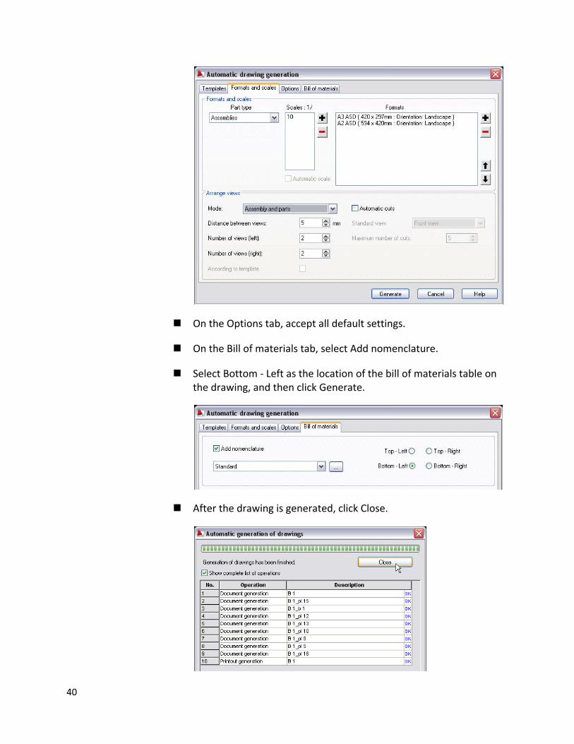
On the Options tab, accept all default settings.
On the Bill of materials tab, select Add nomenclature.
Select Bottom ‐ Left as the location of the bill of materials table on the drawing, and then click Generate.
After the drawing is generated, click Close.
40
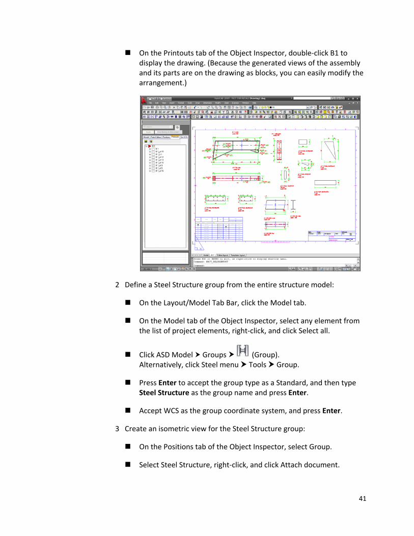
On the Printouts tab of the Object Inspector, double‐click B1 to display the drawing. (Because the generated views of the assembly and its parts are on the drawing as blocks, you can easily modify the arrangement.)
2 Define a Steel Structure group from the entire structure model:
On the Layout/Model Tab Bar, click the Model tab.
On the Model tab of the Object Inspector, select any element from the list of project elements, right‐click, and click Select all.
Click ASD Model Groups (Group). Alternatively, click Steel menu Tools Group.
Press Enter to accept the group type as a Standard, and then type Steel Structure as the group name and press Enter.
Accept WCS as the group coordinate system, and press Enter.
3 Create an isometric view for the Steel Structure group:
On the Positions tab of the Object Inspector, select Group.
Select Steel Structure, right‐click, and click Attach document.
41
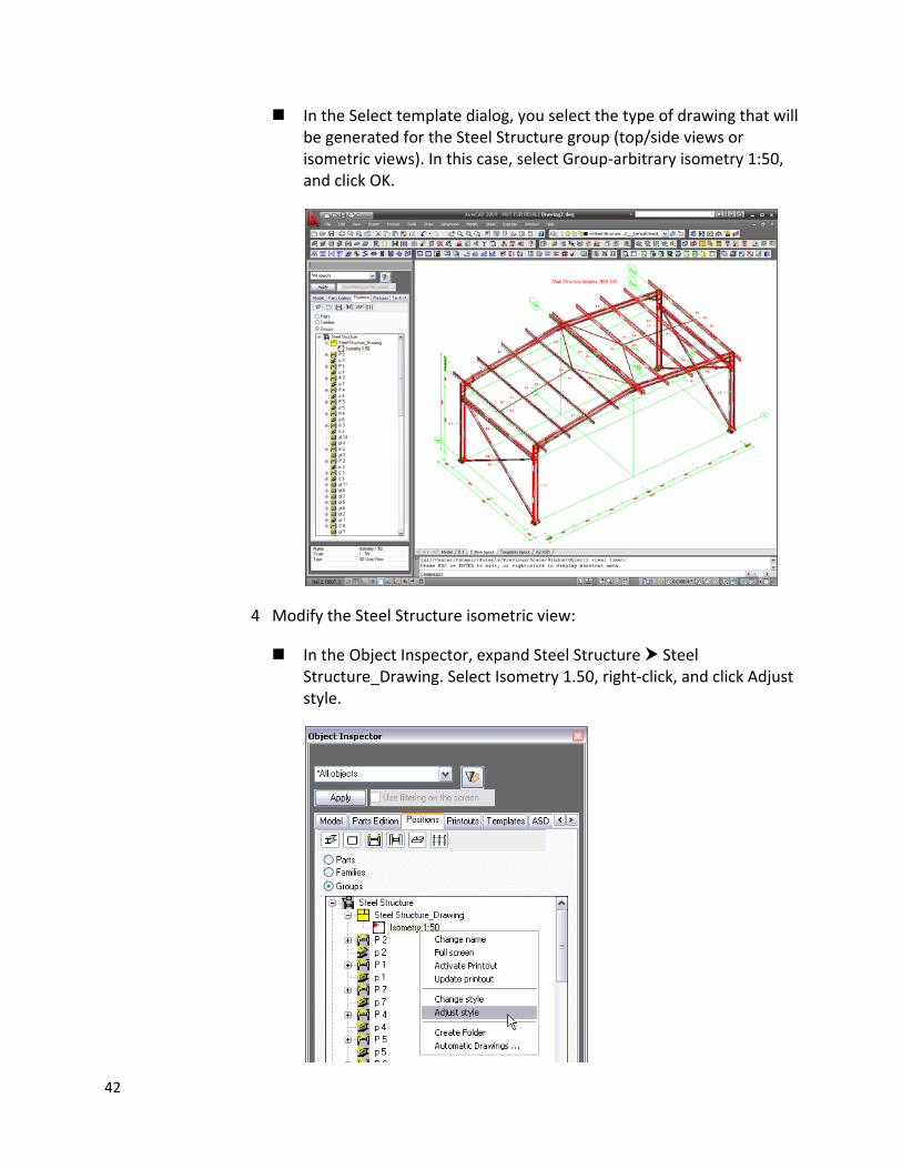
In the Select template dialog, you select the type of drawing that will be generated for the Steel Structure group (top/side views or isometric views). In this case, select Group‐arbitrary isometry 1:50, and click OK.
4 Modify the Steel Structure isometric view:
In the Object Inspector, expand Steel Structure Steel Structure_Drawing. Select Isometry 1.50, right‐click, and click Adjust style.
42
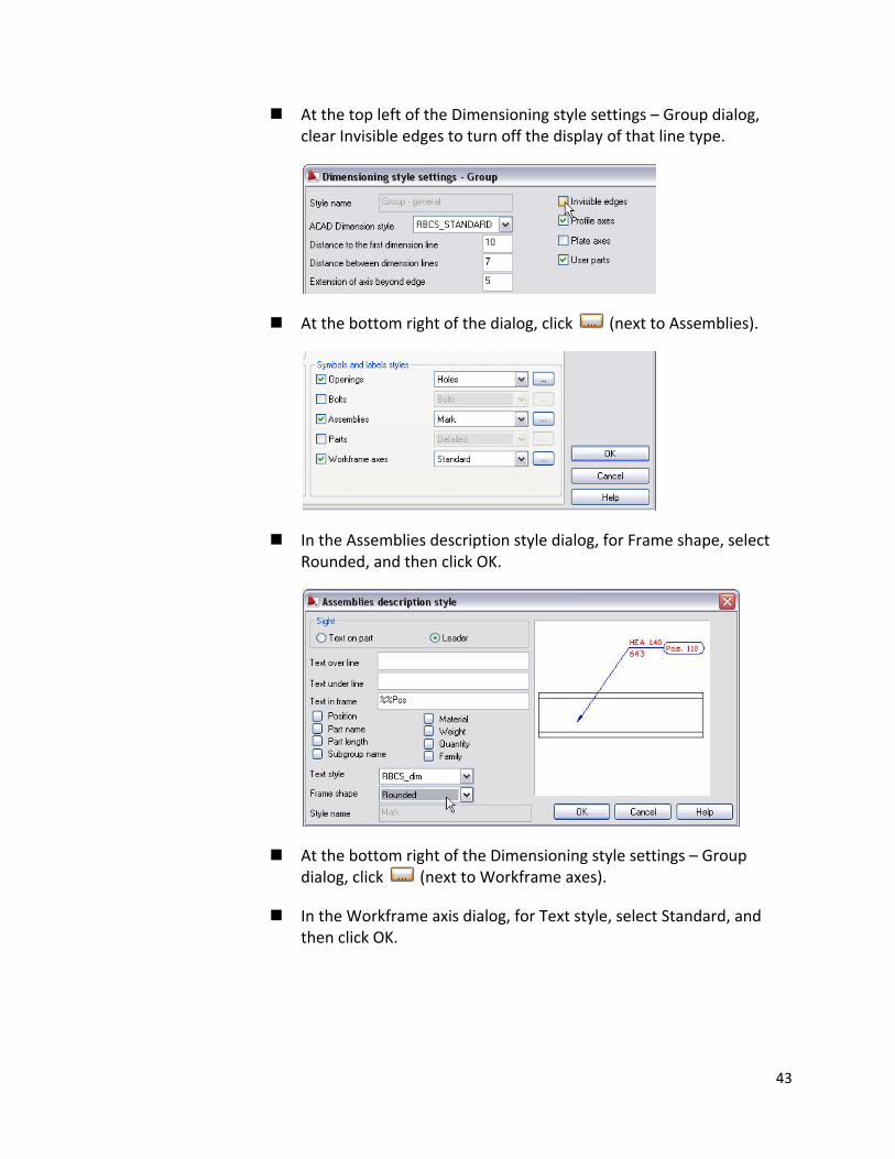
At the top left of the Dimensioning style settings – Group dialog, clear Invisible edges to turn off the display of that line type.
At the bottom right of the dialog, click (next to Assemblies).
In the Assemblies description style dialog, for Frame shape, select Rounded, and then click OK.
At the bottom right of the Dimensioning style settings – Group dialog, click (next to Workframe axes).
In the Workframe axis dialog, for Text style, select Standard, and then click OK.
43
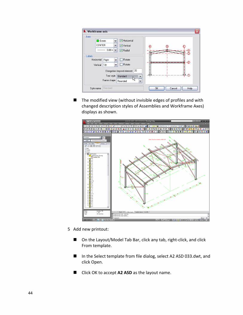
The modified view (without invisible edges of profiles and with changed description styles of Assemblies and Workframe Axes) displays as shown.
5 Add new printout:
On the Layout/Model Tab Bar, click any tab, right‐click, and click From template.
In the Select template from file dialog, select A2 ASD 033.dwt, and click Open.
Click OK to accept A2 ASD as the layout name.
44
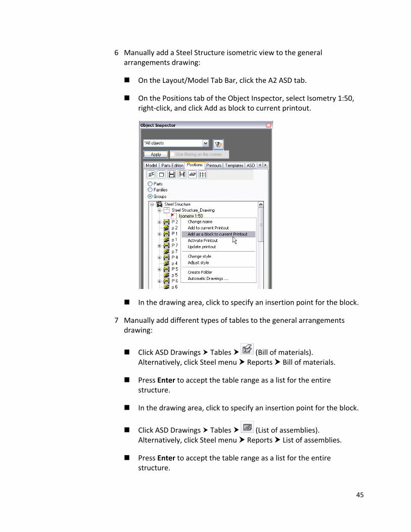
6 Manually add a Steel Structure isometric view to the general arrangements drawing:
On the Layout/Model Tab Bar, click the A2 ASD tab.
On the Positions tab of the Object Inspector, select Isometry 1:50, right‐click, and click Add as block to current printout.
In the drawing area, click to specify an insertion point for the block.
7 Manually add different types of tables to the general arrangements drawing:
Click ASD Drawings Tables (Bill of materials). Alternatively, click Steel menu Reports Bill of materials.
Press Enter to accept the table range as a list for the entire structure.
In the drawing area, click to specify an insertion point for the block.
Click ASD Drawings Tables (List of assemblies). Alternatively, click Steel menu Reports List of assemblies.
Press Enter to accept the table range as a list for the entire structure.
45
46
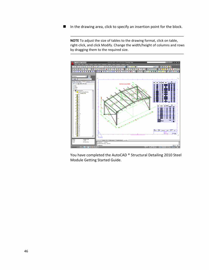
In the drawing area, click to specify an insertion point for the block.
NOTE To adjust the size of tables to the drawing format, click on table, right‐click, and click Modify. Change the width/height of columns and rows by dragging them to the required size.
You have completed the AutoCAD ® Structural Detailing 2010 Steel Module Getting Started Guide.
Related Documents