ATyS UL 1008 Transfer Switching Equipment 100, 200, 260, 400A EN INSTRUCTION MANUAL www.socomec.com http://www.socomec.com/en/atys-ul-1008 To download, brochures, catalogues and technical manuals.

Welcome message from author
This document is posted to help you gain knowledge. Please leave a comment to let me know what you think about it! Share it to your friends and learn new things together.
Transcript
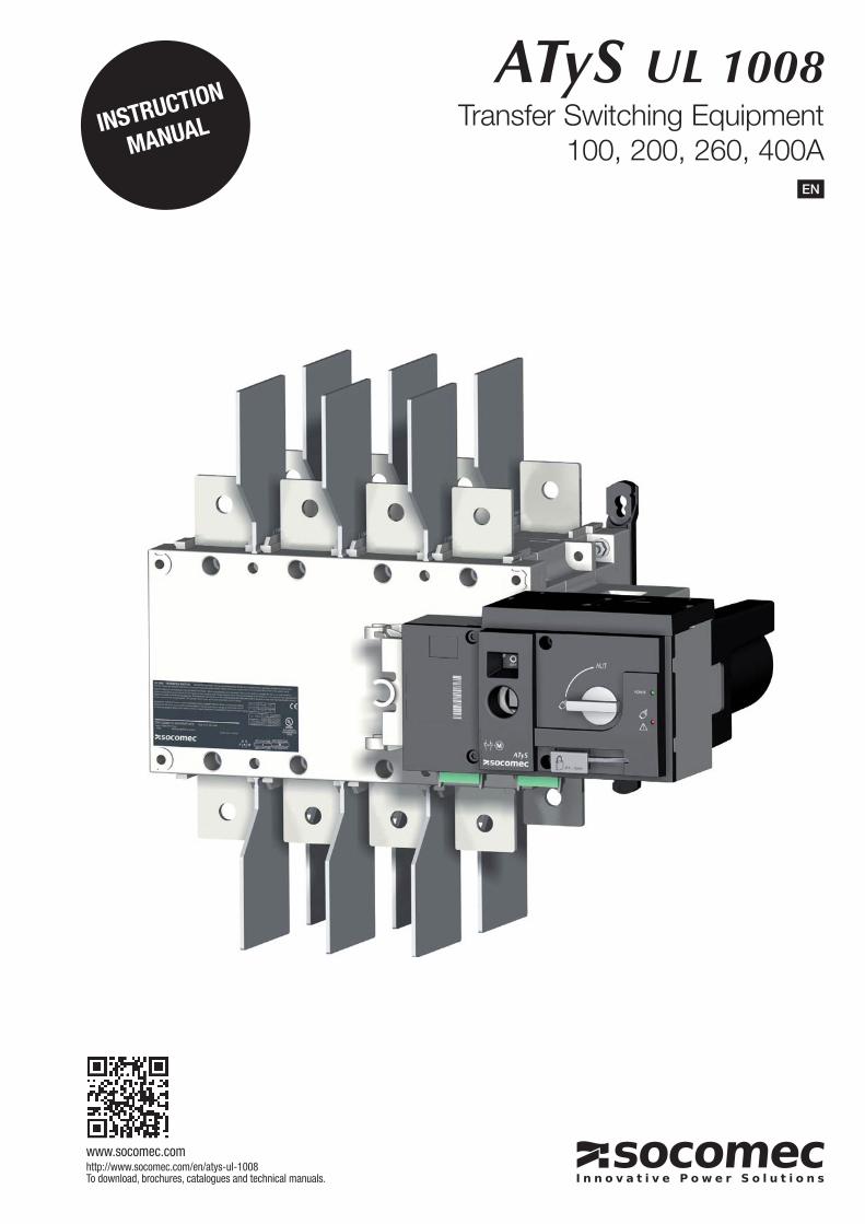
ATyS UL 1008Transfer Switching Equipment
100, 200, 260, 400AEN
INSTRUCTION
MANUAL
www.socomec.comhttp://www.socomec.com/en/atys-ul-1008To download, brochures, catalogues and technical manuals.
2 EN ���������� ����������� ��������
INDEX
1. GENERAL SAFETY INSTRUCTIONS . . . . . . . . . . . . . . . . . . . . . . . . . . . . . . . . . . . . . . . . . . . . . . . . . . . . . . .4
2. INTRODUCTION . . . . . . . . . . . . . . . . . . . . . . . . . . . . . . . . . . . . . . . . . . . . . . . . . . . . . . . . . . . . . . . . . . . . . . . . . . . . .5
3. QUICK START . . . . . . . . . . . . . . . . . . . . . . . . . . . . . . . . . . . . . . . . . . . . . . . . . . . . . . . . . . . . . . . . . . . . . . . . . . . . . . .6
����������� ��� �������������� ���������������� ������� � . . . . . . . . . . . . . . . . . . . . . . . . . . . . . . .6
�������� ���������! . . . . . . . . . . . . . . . . . . . . . . . . . . . . . . . . . . . . . . . . . . . . . . . . . . . . . . . . . . . . . . . . . . . . .10
�����"��#��������#����� . . . . . . . . . . . . . . . . . . . . . . . . . . . . . . . . . . . . . . . . . . . . . . . . . . . . . . . . . . . . . . . .10
��$��"��#����#������ ���� . . . . . . . . . . . . . . . . . . . . . . . . . . . . . . . . . . . . . . . . . . . . . . . . . . . . . . . . . . . . . . .11
���������������� � . . . . . . . . . . . . . . . . . . . . . . . . . . . . . . . . . . . . . . . . . . . . . . . . . . . . . . . . . . . . . . . . . . . . . . . .12
4.3.1. IP RATING IEC 60529 . . . . . . . . . . . . . . . . . . . . . . . . . . . . . . . . . . . . . . . . . . . . . . . . . . . . . . . . . . . . . . . . .12
4.3.2. OPERATING CONDITIONS . . . . . . . . . . . . . . . . . . . . . . . . . . . . . . . . . . . . . . . . . . . . . . . . . . . . . . . . . . . .12
��������������������� . . . . . . . . . . . . . . . . . . . . . . . . . . . . . . . . . . . . . . . . . . . . . . . . . . . . . . . . . . . . . . . . .12
�������������������� . . . . . . . . . . . . . . . . . . . . . . . . . . . . . . . . . . . . . . . . . . . . . . . . . . . . . . . . . . . . . . . . . .12
������������������ . . . . . . . . . . . . . . . . . . . . . . . . . . . . . . . . . . . . . . . . . . . . . . . . . . . . . . . . . . . . . . . . . . . . . .12
4.3.3. STORAGE CONDITIONS . . . . . . . . . . . . . . . . . . . . . . . . . . . . . . . . . . . . . . . . . . . . . . . . . . . . . . . . . . . . .12
������������������� . . . . . . . . . . . . . . . . . . . . . . . . . . . . . . . . . . . . . . . . . . . . . . . . . . . . . . . . . . . . . . . . . .12
������������������������!������� . . . . . . . . . . . . . . . . . . . . . . . . . . . . . . . . . . . . . . . . . . . . . . . . . . . . . .12
������������������������!� . . . . . . . . . . . . . . . . . . . . . . . . . . . . . . . . . . . . . . . . . . . . . . . . . . . . . . . . . . . . .12
4.3.4. VOLUME AND SHIPPING WEIGHTS BY REFERENCE ATYS . . . . . . . . . . . . . . . . . . . . . . . . . . . . . . .13
4.3.5. UL MARKING . . . . . . . . . . . . . . . . . . . . . . . . . . . . . . . . . . . . . . . . . . . . . . . . . . . . . . . . . . . . . . . . . . . . . . . .13
4.3.6. CE MARKING . . . . . . . . . . . . . . . . . . . . . . . . . . . . . . . . . . . . . . . . . . . . . . . . . . . . . . . . . . . . . . . . . . . . . . . .13
4.3.7. 2011/65/EU ROHS . . . . . . . . . . . . . . . . . . . . . . . . . . . . . . . . . . . . . . . . . . . . . . . . . . . . . . . . . . . . . . . . . . .13
������� �� ���� . . . . . . . . . . . . . . . . . . . . . . . . . . . . . . . . . . . . . . . . . . . . . . . . . . . . . . . . . . . . . . . . . . . . . . . . . . . . .14
�����"��#���#���������%��� ���������������� ������� � . . . . . . . . . . . . . . . . . . . . . . . . . . . . . . . . . .14
��$����������������� ���� . . . . . . . . . . . . . . . . . . . . . . . . . . . . . . . . . . . . . . . . . . . . . . . . . . . . . . . . . . . . . . . . .15
�����"��#���������������� . . . . . . . . . . . . . . . . . . . . . . . . . . . . . . . . . . . . . . . . . . . . . . . . . . . . . . . . . . . . . .15
����� �������������������������#� �������� . . . . . . . . . . . . . . . . . . . . . . . . . . . . . . . . . . . . . .15
5.4.1. BRIDGING BARS (OPTIONAL ACCESSORY) . . . . . . . . . . . . . . . . . . . . . . . . . . . . . . . . . . . . . . . . . . . .15
5.4.2. MOUNTING OF TERMINAL COVERS (OPTIONAL ACCESSORY) . . . . . . . . . . . . . . . . . . . . . . . . . . .16
�������������!�����"���#���� ��� . . . . . . . . . . . . . . . . . . . . . . . . . . . . . . . . . . . . . . . . . . . . . . . . . .16
��������������!�����"���#������ ��� . . . . . . . . . . . . . . . . . . . . . . . . . . . . . . . . . . . . . . . . . . . . . . . . . .16
5.4.3. MOUNTING OF ADDITIONAL AUXILIARY CONTACTS (OPTIONAL ACCESSORIES) . . . . . . . . . .17
5.4.4. POWER TERMINAL CONNECTIONS (OPTIONAL ACCESSORIES) . . . . . . . . . . . . . . . . . . . . . . . . .17
������������������ . . . . . . . . . . . . . . . . . . . . . . . . . . . . . . . . . . . . . . . . . . . . . . . . . . . . . . . . . . . . . . . . . . . . . .18
5.5.1. TYPICAL ATYS WIRING . . . . . . . . . . . . . . . . . . . . . . . . . . . . . . . . . . . . . . . . . . . . . . . . . . . . . . . . . . . . . . .18
5.5.2. ATYS INPUT AND OUTPUT CONTACTS . . . . . . . . . . . . . . . . . . . . . . . . . . . . . . . . . . . . . . . . . . . . . . . .19
�������������!�����!���!����!$�����������!��!������������������ . . . . . . . . . . . . . . . . . . . . . . .19
3EN���������� ����������� ��������
&�� �����"�� �������#�� . . . . . . . . . . . . . . . . . . . . . . . . . . . . . . . . . . . . . . . . . . . . . . . . . . . . . . . . . . . . . . . .20
&����� �� ���"�� ���� . . . . . . . . . . . . . . . . . . . . . . . . . . . . . . . . . . . . . . . . . . . . . . . . . . . . . . . . . . . . . . . . . . . . .21
&�$��" #����� . . . . . . . . . . . . . . . . . . . . . . . . . . . . . . . . . . . . . . . . . . . . . . . . . . . . . . . . . . . . . . . . . . . . . . . . . . . .21
&���������� ���"�� ���� . . . . . . . . . . . . . . . . . . . . . . . . . . . . . . . . . . . . . . . . . . . . . . . . . . . . . . . . . . . . . . . . .22
6.3.1. POWER SUPPLY . . . . . . . . . . . . . . . . . . . . . . . . . . . . . . . . . . . . . . . . . . . . . . . . . . . . . . . . . . . . . . . . . . . . .22
6.3.2. FIXED INPUTS . . . . . . . . . . . . . . . . . . . . . . . . . . . . . . . . . . . . . . . . . . . . . . . . . . . . . . . . . . . . . . . . . . . . . .22
������������������!� . . . . . . . . . . . . . . . . . . . . . . . . . . . . . . . . . . . . . . . . . . . . . . . . . . . . . . . . . . . . . . . . . . .22
�������������!����������%#�&����!����' . . . . . . . . . . . . . . . . . . . . . . . . . . . . . . . . . . . . . . . . . . . . . . . . . . .23
�����������!���������� . . . . . . . . . . . . . . . . . . . . . . . . . . . . . . . . . . . . . . . . . . . . . . . . . . . . . . . . . . . . . . . .23
6.3.3. FIXED OUTPUTS - DRY CONTACTS . . . . . . . . . . . . . . . . . . . . . . . . . . . . . . . . . . . . . . . . . . . . . . . . . . . .24
������������������! . . . . . . . . . . . . . . . . . . . . . . . . . . . . . . . . . . . . . . . . . . . . . . . . . . . . . . . . . . . . . . . . . . .24
����������������!���&���������!���� . . . . . . . . . . . . . . . . . . . . . . . . . . . . . . . . . . . . . . . . . . . . . . . . . . . . .24
�����������������������"���������������%�����������!' . . . . . . . . . . . . . . . . . . . . . . . . . . . . . . . . . .24
�������������!����������%#�&����������' . . . . . . . . . . . . . . . . . . . . . . . . . . . . . . . . . . . . . . . . . . . . . . . . .25
7. CHARACTERISTICS . . . . . . . . . . . . . . . . . . . . . . . . . . . . . . . . . . . . . . . . . . . . . . . . . . . . . . . . . . . . . . . . . . . . . . .26
���"����������� ����� �� . . . . . . . . . . . . . . . . . . . . . . . . . . . . . . . . . . . . . . . . . . . . . . . . . . . . . . . . . . . . .27
'�����������(����������#� . . . . . . . . . . . . . . . . . . . . . . . . . . . . . . . . . . . . . . . . . . . . . . . . . . . . . . . . . . . . .27
�����(�� ����� ���� . . . . . . . . . . . . . . . . . . . . . . . . . . . . . . . . . . . . . . . . . . . . . . . . . . . . . . . . . . . . . . . . . . . . . . . .28
�������(�� ����� ��������� ����� . . . . . . . . . . . . . . . . . . . . . . . . . . . . . . . . . . . . . . . . . . . . . . . . . . . . . . . .28
���� ����� ����%���#������������ ���� . . . . . . . . . . . . . . . . . . . . . . . . . . . . . . . . . . . . . . . . . . . . . .30
� EN ���������� ����������� ��������
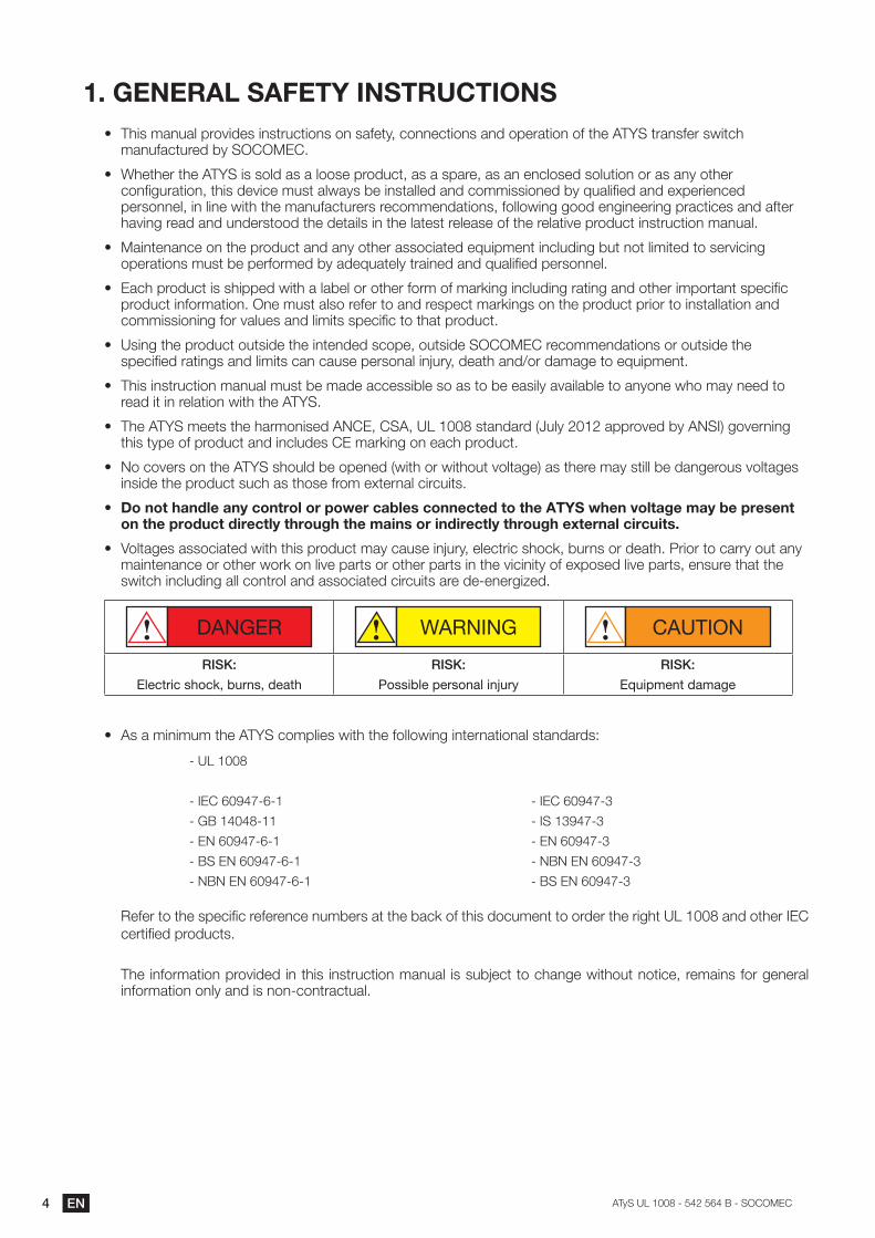
1. GENERAL SAFETY INSTRUCTIONS(� This manual provides instructions on safety, connections and operation of the ATYS transfer switch
)*+-.*/3-578�9����������
(� Whether the ATYS is sold as a loose product, as a spare, as an enclosed solution or as any other /:+;<-5*3=:+$�3>=?�87@=/7�)-?3�*BC*�?�97�=+?3*BB78�*+8�/:))=??=:+78�9��D-*B=;78�*+8�7FG75=7+/78�personnel, in line with the manufacturers recommendations, following good engineering practices and after having read and understood the details in the latest release of the relative product instruction manual.
(� ��*=+37+*+/7�:+�3>7�G5:8-/3�*+8�*+��:3>75�*??:/=*378�7D-=G)7+3�=+/B-8=+<�9-3�+:3�B=)=378�3:�?75@=/=+<�:G75*3=:+?�)-?3�97�G75.:5)78�9��*87D-*37B��35*=+78�*+8�D-*B=;78�G75?:++7B�
(� ��*/>�G5:8-/3�=?�?>=GG78�C=3>�*�B*97B�:5�:3>75�.:5)�:.�)*5I=+<�=+/B-8=+<�5*3=+<�*+8�:3>75�=)G:53*+3�?G7/=;/�G5:8-/3�=+.:5)*3=:+���+7�)-?3�*B?:�57.75�3:�*+8�57?G7/3�)*5I=+<?�:+�3>7�G5:8-/3�G5=:5�3:�=+?3*BB*3=:+�*+8�/:))=??=:+=+<�.:5�@*B-7?�*+8�B=)=3?�?G7/=;/�3:�3>*3�G5:8-/3�
(� ��?=+<�3>7�G5:8-/3�:-3?=87�3>7�=+37+878�?/:G7$�:-3?=87���������57/:))7+8*3=:+?�:5�:-3?=87�3>7�?G7/=;78�5*3=+<?�*+8�B=)=3?�/*+�/*-?7�G75?:+*B�=+J-5�$�87*3>�*+8K:5�8*)*<7�3:�7D-=G)7+3��
(� This instruction manual must be made accessible so as to be easily available to anyone who may need to read it in relation with the ATYS.
(� The ATY��)773?�3>7�>*5):+=?78��!��$����$������?3*+8*58�%L-B�����*GG5:@78�9���!��'�<:@75+=+<�3>=?�3�G7�:.�G5:8-/3�*+8�=+/B-87?����)*5I=+<�:+�7*/>�G5:8-/3�
(� �!:�/:@75?�:+�3>7������?>:-B8�97�:G7+78�%C=3>�:5�C=3>:-3�@:B3*<7'�*?�3>757�)*��?3=BB�97�8*+<75:-?�@:B3*<7?�=+?=87�3>7�G5:8-/3�?-/>�*?�3>:?7�.5:)�7F375+*B�/=5/-=3?��
(� Do not handle any control or power cables connected to the ATYS when voltage may be present on the product directly through the mains or indirectly through external circuits.
(� �":B3*<7?�*??:/=*378�C=3>�3>=?�G5:8-/3�)*��/*-?7�=+J-5�$�7B7/35=/�?>:/I$�9-5+?�:5�87*3>���5=:5�3:�/*55��:-3�*+��)*=+37+*+/7�:5�:3>75�C:5I�:+�B=@7�G*53?�:5�:3>75�G*53?�=+�3>7�@=/=+=3��:.�7FG:?78�B=@7�G*53?$�7+?-57�3>*3�3>7�?C=3/>�=+/B-8=+<�*BB�/:+35:B�*+8�*??:/=*378�/=5/-=3?�*57�87 7+75<=M78�
DANGER WARNING CAUTION
RISK%
Electric shock, burns, death
���%
Possible personal injury
���%
Equipment damage
(� As a minimum the ATYS complies with the following international standards:
�����
������O�P �
�������
��!��O�P �
�����!��O�P �
�!�!��!��O�P �
������O�P �
�����O�P �
��!��O�P �
�!�!��!��O�P �
�����!��O�P � �7.75�3:�3>7�?G7/=;/�57.757+/7�+-)975?�*3�3>7�9*/I�:.�3>=?�8:/-)7+3�3:�:5875�3>7�5=<>3������*+8�:3>75�����/753=;78�G5:8-/3?� �>7�=+.:5)*3=:+�G5:@=878�=+�3>=?�=+?35-/3=:+�)*+-*B� =?�?-9J7/3�3:�/>*+<7�C=3>:-3�+:3=/7$�57)*=+?�.:5�<7+75*B�=+.:5)*3=:+�:+B��*+8�=?�+:+ /:+35*/3-*B�
�EN���������� ����������� ��������
2. INTRODUCTION
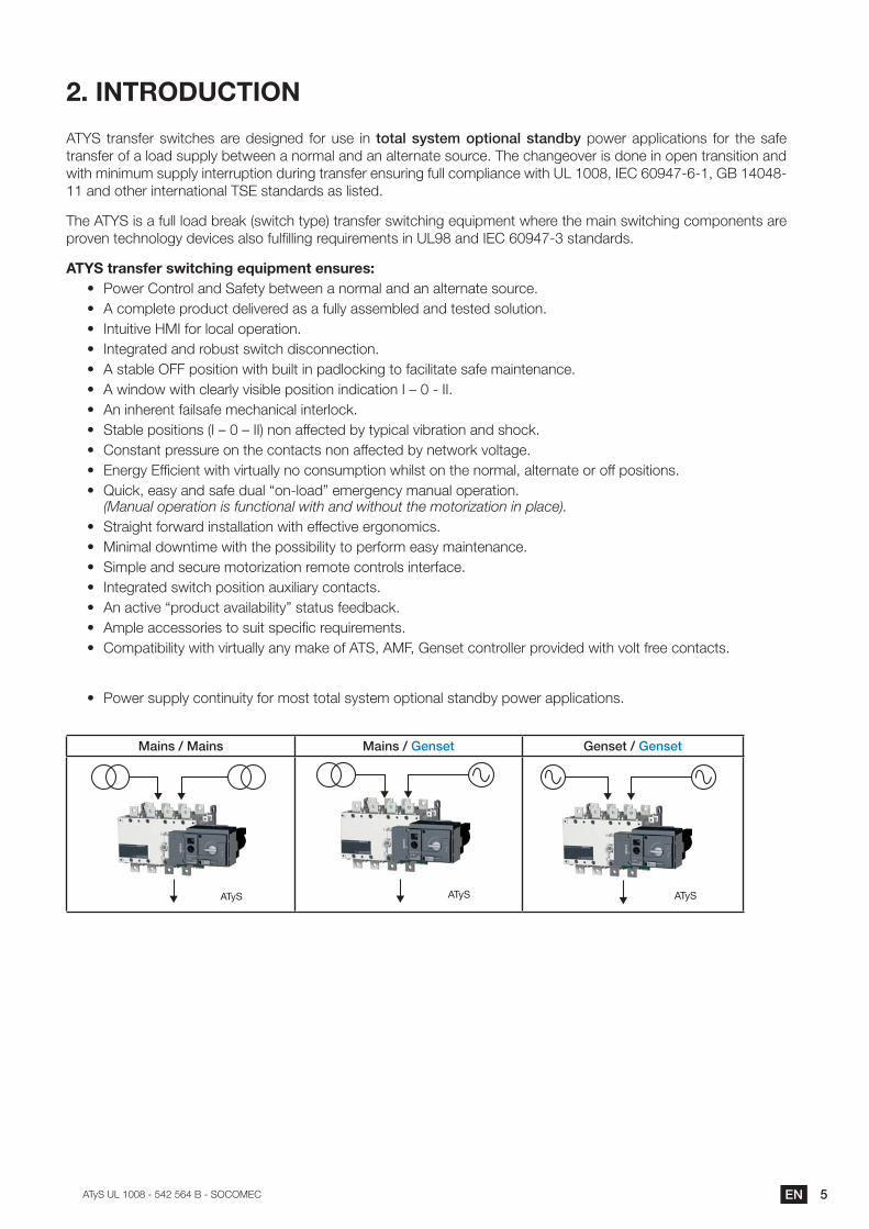
ATYS transfer switches are designed for use in total system optional standby power applications for the safe transfer of a load supply between a normal and an alternate source. The changeover is done in open transition and C=3>�)=+=)-)�?-GGB��=+3755-G3=:+�8-5=+<�35*+?.75�7+?-5=+<�.-BB�/:)GB=*+/7�C=3>�����$������O�P � $������� 11 and other international TSE standards as listed.
The ATY��=?�*�.-BB�B:*8�957*I�%?C=3/>�3�G7'�35*+?.75�?C=3/>=+<�7D-=G)7+3�C>757�3>7�)*=+�?C=3/>=+<�/:)G:+7+3?�*57�G5:@7+�37/>+:B:<��87@=/7?�*B?:�.-B;BB=+<�57D-=57)7+3?�=+���O��*+8������O�P ��?3*+8*58?��
ATYS transfer switching equipment ensures:(� �:C75��:+35:B�*+8��*.73��973C77+�*�+:5)*B�*+8�*+�*B375+*37�?:-5/7��(� A complete product delivered as a fully assembled and tested solution.(� �+3-=3=@7�����.:5�B:/*B�:G75*3=:+�(� �+37<5*378�*+8�5:9-?3�?C=3/>�8=?/:++7/3=:+�(� ��?3*9B7��##�G:?=3=:+�C=3>�9-=B3�=+�G*8B:/I=+<�3:�.*/=B=3*37�?*.7�)*=+37+*+/7�(� ��C=+8:C�C=3>�/B7*5B��@=?=9B7�G:?=3=:+�=+8=/*3=:+���Q�� �����(� An inherent failsafe mechanical interlock.(� �3*9B7�G:?=3=:+?�%��Q��Q���'�+:+�*..7/378�9��3�G=/*B�@=95*3=:+�*+8�?>:/I�(� �:+?3*+3�G57??-57�:+�3>7�/:+3*/3?�+:+�*..7/378�9��+73C:5I�@:B3*<7�(� �+75<���.;/=7+3�C=3>�@=53-*BB��+:�/:+?-)G3=:+�C>=B?3�:+�3>7�+:5)*B$�*B375+*37�:5�:..�G:?=3=:+?�(� �R-=/I$�7*?��*+8�?*.7�8-*B�U:+ B:*8V�7)75<7+/��)*+-*B�:G75*3=:+�
(Manual operation is functional with and without the motorization in place).(� Straight forward installation with effective ergonomics.(� �=+=)*B�8:C+3=)7�C=3>�3>7�G:??=9=B=3��3:�G75.:5)�7*?��)*=+37+*+/7�(� �=)GB7�*+8�?7/-57�):3:5=M*3=:+�57):37�/:+35:B?�=+375.*/7�(� �+37<5*378�?C=3/>�G:?=3=:+�*-F=B=*5��/:+3*/3?�(� �+�*/3=@7�UG5:8-/3�*@*=B*9=B=3�V�?3*3-?�.7789*/I�(� �)GB7�*//7??:5=7?�3:�?-=3�?G7/=;/�57D-=57)7+3?�(� ��:)G*3=9=B=3��C=3>�@=53-*BB��*+��)*I7�:.����$���#$��7+?73�/:+35:BB75�G5:@=878�C=3>�@:B3�.577�/:+3*/3?�
(� �:C75�?-GGB��/:+3=+-=3��.:5�):?3�3:3*B�?�?37)�:G3=:+*B�?3*+89��G:C75�*GGB=/*3=:+?�
�)*+,�-��)*+, �)*+,�-�Genset �/+,/0�-�Genset
ATyS ATyS ATyS
6 EN ���������� ����������� ��������
ATySTransfer Switch UL 1008: Optional Standby Power
542 563 B - 08/14 - EN
QUICK START
100A, 200A, 260A, 400A
Printing informations: 1 color Black. White paper 90g/m2. Printing size: 420x297. Final size 210x297. This page visible first.
Non contractual document.Subject to change without notice.
www.socomec.comTo download, brochures, catalogues and technical manuals:
http://www.socomec.com/en/ atys-ul-1008
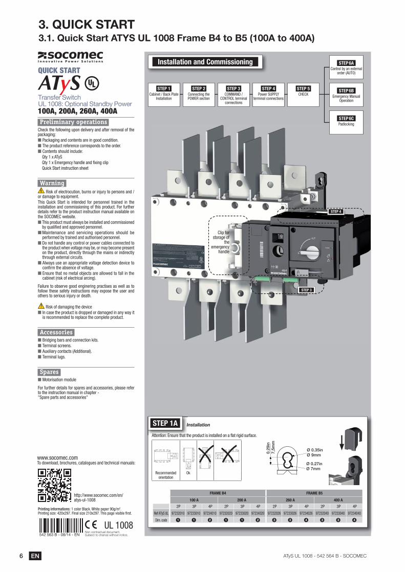
Preliminary operations Check the following upon delivery and after removal of the packaging:■ Packaging and contents are in good condition.■ The product reference corresponds to the order.■ Contents should include:
Qty 1 x ATySQty 1 x Emergency handle and fixing clipQuick Start instruction sheet
Warning Risk of electrocution, burns or injury to persons and /
or damage to equipment.This Quick Start is intended for personnel trained in the installation and commissioning of this product. For further details refer to the product instruction manual available on the SOCOMEC website.■ This product must always be installed and commissioned
by qualified and approved personnel.■ Maintenance and servicing operations should be
performed by trained and authorised personnel.■ Do not handle any control or power cables connected to
the product when voltage may be, or may become present on the product, directly through the mains or indirectly through external circuits.
■ Always use an appropriate voltage detection device to confirm the absence of voltage.
■ Ensure that no metal objects are allowed to fall in the cabinet (risk of electrical arcing).
Failure to observe good enginering practises as well as to follow these safety instructions may expose the user and others to serious injury or death.
Risk of damaging the device
■ In case the product is dropped or damaged in any way it is recommended to replace the complete product.
Accessories ■ Bridging bars and connection kits.■ Terminal screens.■ Auxiliary contacts (Additional).■ Terminal lugs.
Spares ■ Motorisation module
For further details for spares and accessories, please refer to the instruction manual in chapter - "Spare parts and accessories"
STEP 1 Cabinet / Back Plate
Installation
STEP 3 COMMAND /
CONTROL terminal connections
STEP 2 Connecting the POWER section
STEP 4 Power SUPPLY
terminal connections
STEP 5 CHECK
Installation and Commissioning
Clip for storage of
the emergency
handle
STEP 3
STEP 6A Control by an external
order (AUTO)
STEP 6C Padlocking
STEP 6B Emergency Manual
Operation
STEP 4
UL 1008
STEP 1A Installation
Attention: Ensure that the product is installed on a flat rigid surface.
Recommended orientation
Ok
0.29
in7,
5mm
Ø 0.35inØ 9mm
Ø 0.27inØ 7mm
FRAME B4 FRAME B5
100 A 200 A 260 A 400 A
2P 3P 4P 2P 3P 4P 2P 3P 4P 2P 3P 4P
Ref ATyS UL 97232010 97233010 97234010 97232020 97233020 97234020 97232026 97233026 97234026 97232040 97233040 97234040
Dim. code 1 1 2 1 1 2 3 3 4 3 3 4
3. QUICK START3.1. Quick Start ATY����������� �������������������������
7EN���������� ����������� ��������
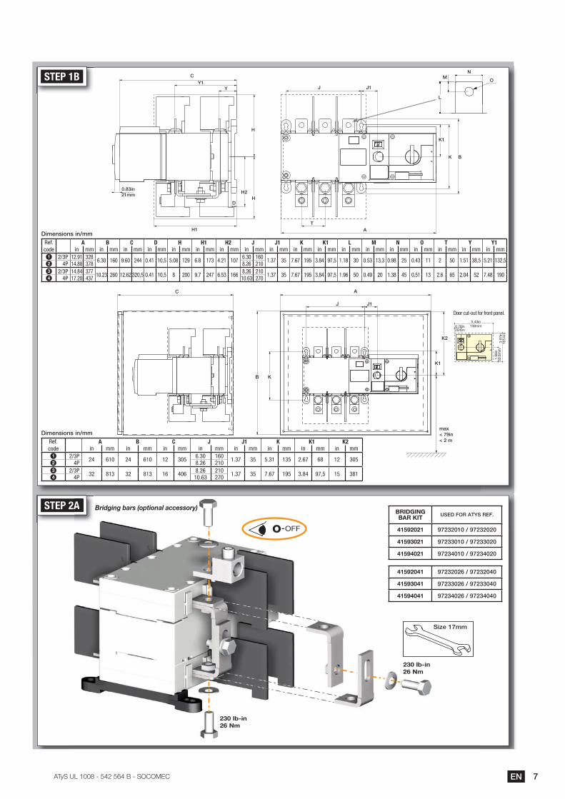
STEP 2AA
O OFF-
230 lb-in26 Nm
BRIDGING BAR KIT USED FOR ATYS REF.
41592021 97232010 / 97232020
41593021 97233010 / 97233020
41594021 97234010 / 97234020
41592041 97232026 / 97232040
41593041 97233026 / 97233040
41594041 97234026 / 97234040
Bridging bars (optional accessory)
230 lb-in26 Nm
Size 17mm
STEP 1B
Dimensions in/mmRef. code
A B C D H H1 H2 J J1 K K1 L M N O T Y Y1in mm in mm in mm in mm in mm in mm in mm in mm in mm in mm in mm in mm in mm in mm in mm in mm in mm in mm
1 2/3P 12.91 3286.30 160 9.60 244 0.41 10,5 5.08 129 6.8 173 4.21 107
6.30 1601.37 35 7.67 195 3.84 97,5 1.18 30 0.53 13,3 0.98 25 0.43 11 2 50 1.51 38,5 5.21 132,5
2 4P 14.88 378 8.26 2103 2/3P 14.84 377
10.23 260 12.62 320,5 0.41 10,5 8 200 9.7 247 6.53 1668.26 210
1.37 35 7.67 195 3.84 97,5 1.96 50 0.49 20 1.38 45 0.51 13 2.6 65 2.04 52 7.48 1904 4P 17.20 437 10.63 270
AC
J J1
max< 79in >�$�?
KB
L
MN
O
Door cut-out for front panel.
1.98
in50
,5m
m
0.78in20mm
5.43in138mm
3.97
in10
1mm
Dimensions in/mmRef. code
A B C J J1 K K1 K2in mm in mm in mm in mm in mm in mm in mm in mm
1 2/3P24 610 24 610 12 305
6.30 1601.37 35 5.31 135 2.67 68 12 305
2 4P 8.26 2103 2/3P
32 813 32 813 16 4068.26 210
1.37 35 7.67 195 3.84 97,5 15 3814 4P 10.63 270
K1
K2
C
YY1
H1
H
HD
H2
B
J J1
K
K1
T
0.83in21mm
A
� EN ���������� ����������� ��������
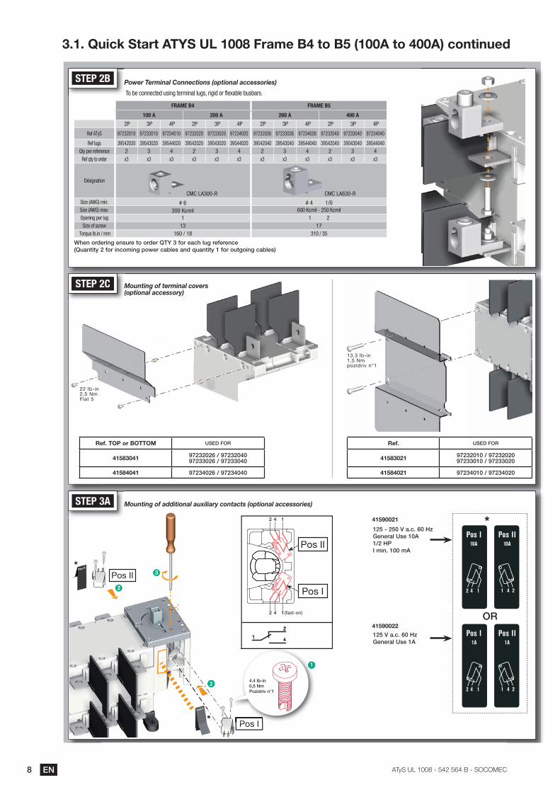
STEP 3A
2
2
4
4
1
1 (fast-on)
Pos II
Pos I
OR
*125 - 250 V a.c. 60 HzGeneral Use 10A1/2 HPI min. 100 mA
41590021
125 V a.c. 60 HzGeneral Use 1A
41590022
Pos I
Pos II
Pos I
Pos II
*
*
2
2
3
1
P I
1
4.4 lb-in0,5 NmPozidriv n°1
Pos I
*****Pos I
2
Mounting of additional auxiliary contacts (optional accessories)
STEP 2B
STEP 2C
Power Terminal Connections (optional accessories)
Mounting of terminal covers (optional accessory)
FRAME B4 FRAME B5
100 A 200 A 260 A 400 A
2P 3P 4P 2P 3P 4P 2P 3P 4P 2P 3P 4P
Ref ATyS 97232010 97233010 97234010 97232020 97233020 97234020 97232026 97233026 97234026 97232040 97233040 97234040
Ref lugs 39542020 39543020 39544020 39542020 39543020 39544020 39542040 39543040 39544040 39542040 39543040 39544040Qty per reference 2 3 4 2 3 4 2 3 4 2 3 4
Ref qty to order x3 x3 x3 x3 x3 x3 x3 x3 x3 x3 x3 x3
Désignation
CMC LA300-R CMC LA630-RSize (AWG) min. # 6 # 4 1/0 Size (AWG) max. 300 Kcmil 600 Kcmil - 250 KcmilOpening per lug 1 1 2Size of screw 13 17
Torque lb.in / mm 160 / 18 310 / 35
To be connected using terminal lugs, rigid or flexable busbars.
When ordering ensure to order QTY 3 for each lug reference (Quantity 2 for incoming power cables and quantity 1 for outgoing cables)
STEP 2C Mounting of termM(optional access
covers
22 lb-in2,5 NmFlat 5
13.3 lb-in1,5 Nmpozidriv n°1
Ref. TOP or BOTTOM USED FOR
41583041 97232026 / 97232040 97233026 / 97233040
41584041 97234026 / 97234040
Ref. USED FOR
41583021 97232010 / 9723202097233010 / 97233020
41584021 97234010 / 97234020
3.1. Quick Start ATY����������� �����������������������������������
9EN���������� ����������� ��������
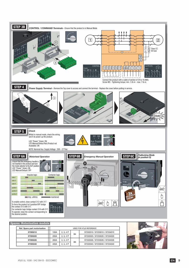
Whilst in manual mode, check the wiring and if ok power up the product.
LED “Power” Green: ON���������� ������������������Available): ON
Wa
STEP 5 Check
Ensure that the emergency handle is not inserted in the product and turn the mode selector to the AUT position.LED “Power” Green: ONLED Manuel/Default: OFF ___________________________________________________________
Ensure that the emergen
STEP 6A Motorised Operation
To enable control, close contact 312 with 317.To force the product to 0 position/OFF bridge the contact 313 with 317.For contactor logic bridge contact 316 with 317.To operate: close the contact corresponding to the desired position.
������������������� maintened
order I
position I
order 0
position 0
order II
position II
Contactor logicImpulse logic
STEP 6C Padlocking Mode (in position O)
3xØ 4-8 mmØ 0.15-0.31 in
CONTROL / COMMAND Terminals - Ensure that the product is in Manual Mode.CSTEP 3B
STEP 4 Power Supply Terminal - Remove the Top cover to access and connect the terminal - Replace the cover before putting in service.
1
2
3
Connect the product with a cable of section of 24 to 16 AWG.Screw M3 - Tightening torque: min.: 5 lb-in - max. 7 lb-in.
1 2
3013
022
312 313 314 315 316 317 63A 64A 24 14 04 13
1
2
Class CC 4A fuse
Spares: Motorisation module
AUTAUUAUT
90° 90°
I II
00STEP 6B Emergency Manual Operation
AUTAUUAUT
IIIIIIIIIIIIIIIIIIIIIIIIIIIIIIIIIIIIIIIIII
AUT
Ref. Spare part motorisation USED FOR ATyS REFERENCE
97095010 100A 2, 3, 4 PB4
97232010 / 97233010 / 97234010
97095020 200A 2, 3, 4 P 97232020 / 97233020 / 97234020
97095026 260A 2, 3, 4 PB5
97232026 / 97233026 / 97234026
97095040 400A 2, 3, 4 P 97232040 / 97233040 / 97234040
NOTE: Nominal Aux. Supply Voltage : 208 – 277Vac
�� EN ���������� ����������� ��������
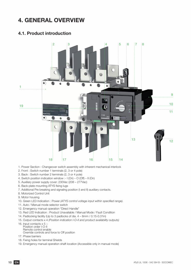
���GENERAL OVERVIEW
�����Product introduction
1
9
��
11
13
����16�� 17
19
2 3 � 6 7 ��
12
���:C75��7/3=:+�`��>*+<7:@75�?C=3/>�*??7)9B��C=3>�=+>757+3�)7/>*+=/*B�=+375B:/I���#5:+3�`��C=3/>�+-)975��375)=+*B?�%�$���:5���G:B7'����*/I�`��C=3/>�+-)975���375)=+*B?�%�$���:5���G:B7'����C=3/>�G:?=3=:+�=+8=/*3=:+�C=+8:C�` ���%�+'�Q���%�..'�Q����%�+'����-F=B=*5��G:C75�?-GGB��/:@75`���"*/�%���Q��PP"*/'����*/I GB*37�):-+3=+<������;F=+<�B-<?P���88=3=:+*B��57�957*I=+<�*+8�?=<+*B=+<�G:?=3=:+�%��*+8���'�*-F=B=*5��/:+3*/3?�����:3:5=M78��:+35:B��+=3�O���:3:5�>:-?=+<���577+������+8=/*3=:+�`��:C75���������� �� ����������������������������������-3:�K��*+-*B�):87�?7B7/3:5�?C=3/>����)75<7+/��)*+-*B�:G75*3=:+�U�=57/3��*+8B7V����78������+8=/*3=:+�`��5:8-/3��+*@*=B*9B7�K��*+-*B��:87�K�#*-B3��:+8=3=:+����*8B:/I=+<�.*/=B=3��%�G�3:���G*8B:/I?�:.�8=*����Q��))�K��� ��=+'����-3G-3�/:+3*/3?�F���(Position indication I-O-II and product availability outputs)�����+G-3�/:+3*/3?�F���` �
�:?=3=:+�:5875�� � �� �7):37�/:+35:B�7+*9B7 �@755=87�/:+35:B?�*+8�.:5/7�3:��..�G:?=3=:+
P���>*?7�9*55=75?���#=F=+<�>:B7?�.:5�375)=+*B��>=7B8?O���)75<7+/��)*+-*B�:G75*3=:+�?>*.3�B:/*3=:+�%�//7??=9B7�:+B��=+�)*+-*B�):87'
11EN���������� ����������� ��������
��������������������������
6
7�
1
2 3 ��
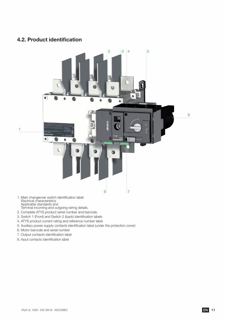
����*=+�/>*+<7:@75�?C=3/>�=87+3=;/*3=:+�B*97B`� Electrical characteristics Applicable standards and Terminal incoming and outgoing wiring details.
����:)GB737������G5:8-/3�?75=*B�+-)975�*+8�9*5/:87�����C=3/>��%#5:+3'�*+8��C=3/>���%9*/I'�=87+3=;/*3=:+�B*97B?4. ATYS product current rating and reference number label����-F=B=*5��G:C75�?-GGB��/:+3*/3?�=87+3=;/*3=:+�B*97B�%-+875�3>7�G5:37/3=:+�/:@75'����:3:5�9*5/:87�*+8�?75=*B�+-)975P���-3G-3�/:+3*/3?�=87+3=;/*3=:+�B*97B����+G-3�/:+3*/3?�=87+3=;/*3=:+�B*97B
12 EN ���������� ����������� ��������
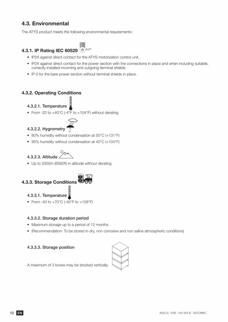
��!��EnvironmentalThe ATYS product meets the following environmental requirements:
��!����"��#����$�"%&�'���(ø 1 mm
(� ���&�*<*=+?3�8=57/3�/:+3*/3�.:5�3>7���Y��):3:5=M*3=:+�/:+35:B�-+=3�
(� ����&�*<*=+?3�8=57/3�/:+3*/3�.:5�3>7�G:C75�?7/3=:+�C=3>�3>7�/:++7/3=:+?�=+�GB*/7�*+8�C>7+�=+/B-8=+<�?-=3*9B7$�correctly installed incoming and outgoing terminal shields.
(� ����.:5�3>7�9*57�G:C75�?7/3=:+�C=3>:-3�375)=+*B�?>=7B8?�=+�GB*/7�
��!����Operating Conditions
����$����Temperature
(� #5:)� ��3:�x�z��% �z#�3:�x�z#'�C=3>:-3�875*3=+<
����$�$��Hygrometry
(� �{�>-)=8=3��C=3>:-3�/:+87+?*3=:+�*3���z��%x�z#'
(� O�{�>-)=8=3��C=3>:-3�/:+87+?*3=:+�*3��z��%x�z#'
����$����Altitude
(� �G�3:��)�%����.3'�=+�*B3=3-87�C=3>:-3�875*3=+<
��!�!��Storage Conditions
���������Temperature
(� #5:)� ��3:�xPz��% �z#�3:�x��z#'
������$��Storage duration period
(� �*F=)-)�?3:5*<7�-G�3:�*�G75=:8�:.���):+3>?�
(� %�7/:))7+8*3=:+`��:�97�?3:578�=+�85�$�+:+�/:55:?=@7�*+8�+:+�?*B=+7�*3):?G>75=/�/:+8=3=:+?'
���������Storage position
��)*F=)-)�:.���9:F7?�)*��97�?3:/I78�@753=/*BB����
13EN���������� ����������� ��������
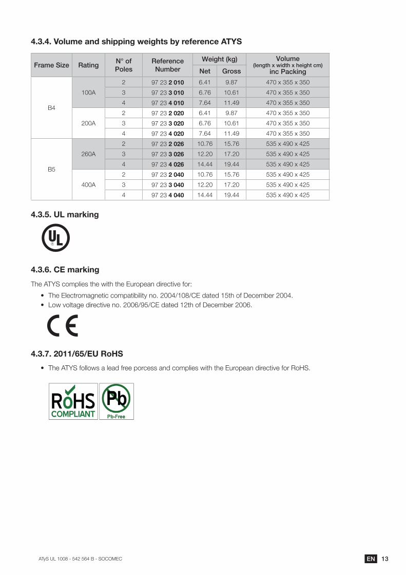
��!����Volume and shipping weights by reference ATYS
Frame Size RatingN° of "[\/,
Reference Number
!/*]^0��_]� �[\`?/� �\/+]0^�j�k*{0^�j�^/*]^0�|?�
*+|�")|_*+]Net Gross
��
100A
2 OP��������� 6.41 O��P �P�F�����F���
3 OP����!���� ��P� 10.61 �P�F�����F���
4 OP��������� P��� ��O �P�F�����F���
200A
2 OP��������� 6.41 O��P �P�F�����F���
3 OP����!���� ��P� 10.61 �P�F�����F���
4 OP��������� P��� ��O �P�F�����F���
��
260A
2 OP��������' �P� ��P� ����F��O�F����
3 OP����!���' 12.20 P�� ����F��O�F����
4 OP��������' 14.44 O��� ����F��O�F����
400A
2 OP��������� �P� ��P� ����F��O�F����
3 OP����!���� 12.20 P�� ����F��O�F����
4 OP��������� 14.44 O��� ����F��O�F����
��!����UL marking
��!�'��CE marking
The ATYS complies the with the European directive for:
(� �>7��B7/35:)*<+73=/�/:)G*3=9=B=3��+:����K�K���8*378��3>�:.��7/7)975����(� �:C�@:B3*<7�8=57/3=@7�+:����KO�K���8*378��3>�:.��7/7)975����
��!�)������*'�*%��#�+�
(� The ATY��.:BB:C?�*�B7*8�.577�G:5/7??�*+8�/:)GB=7?�C=3>�3>7��-5:G7*+�8=57/3=@7�.:5��:���
�� EN ���������� ����������� ��������
���INSTALLATION
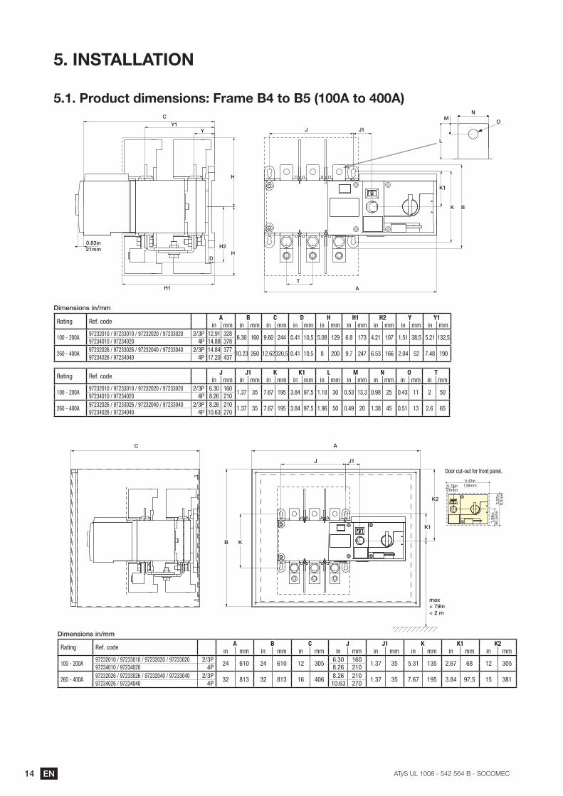
��������������� ��,���,/��� �������������������������
L
�N
OC
YY1
H1
H
HD
H2
�
J J1
K
K1
T
����*+21mm
A
#*?/+,*[+,�*+-??
Rating Ref. code A B C D H H1 H2 Y Y1in mm in mm in mm in mm in mm in mm in mm in mm in mm
100 - 200A97232010 / 97233010 / 97232020 / 97233020 2/3P 12.91 328
6.30 160 9.60 244 0.41 10,5 5.08 129 6.8 173 4.21 107 1.51 38,5 5.21 132,597234010 / 97234020 4P 14.88 378
260 - 400A97232026 / 97233026 / 97232040 / 97233040 2/3P 14.84 377
10.23 260 12.62320,5 0.41 10,5 8 200 9.7 247 6.53 166 2.04 52 7.48 19097234026 / 97234040 4P 17.20 437
Rating Ref. code J J1 K K1 L M N O Tin mm in mm in mm in mm in mm in mm in mm in mm in mm
100 - 200A97232010 / 97233010 / 97232020 / 97233020 2/3P 6.30 160
1.37 35 7.67 195 3.84 97,5 1.18 30 0.53 13,3 0.98 25 0.43 11 2 5097234010 / 97234020 4P 8.26 210
260 - 400A97232026 / 97233026 / 97232040 / 97233040 2/3P 8.26 210
1.37 35 7.67 195 3.84 97,5 1.96 50 0.49 20 1.38 45 0.51 13 2.6 6597234026 / 97234040 4P 10.63 270
AC
J J1
?)j< 79in >�$�?
K�
Door cut-out for front panel.
1.98
in50
,5m
m
0.78in20mm
5.43in138mm
3.97
in10
1mm
#*?/+,*[+,�*+-??
Rating Ref. code A B C J J1 K K1 K2in mm in mm in mm in mm in mm in mm in mm in mm
100 - 200A97232010 / 97233010 / 97232020 / 97233020 2/3P
24 610 24 610 12 3056.30 160
1.37 35 5.31 135 2.67 68 12 30597234010 / 97234020 4P 8.26 210
260 - 400A97232026 / 97233026 / 97232040 / 97233040 2/3P
32 813 32 813 16 4068.26 210
1.37 35 7.67 195 3.84 97,5 15 38197234026 / 97234040 4P 10.63 270
K1
K2
��EN���������� ����������� ��������
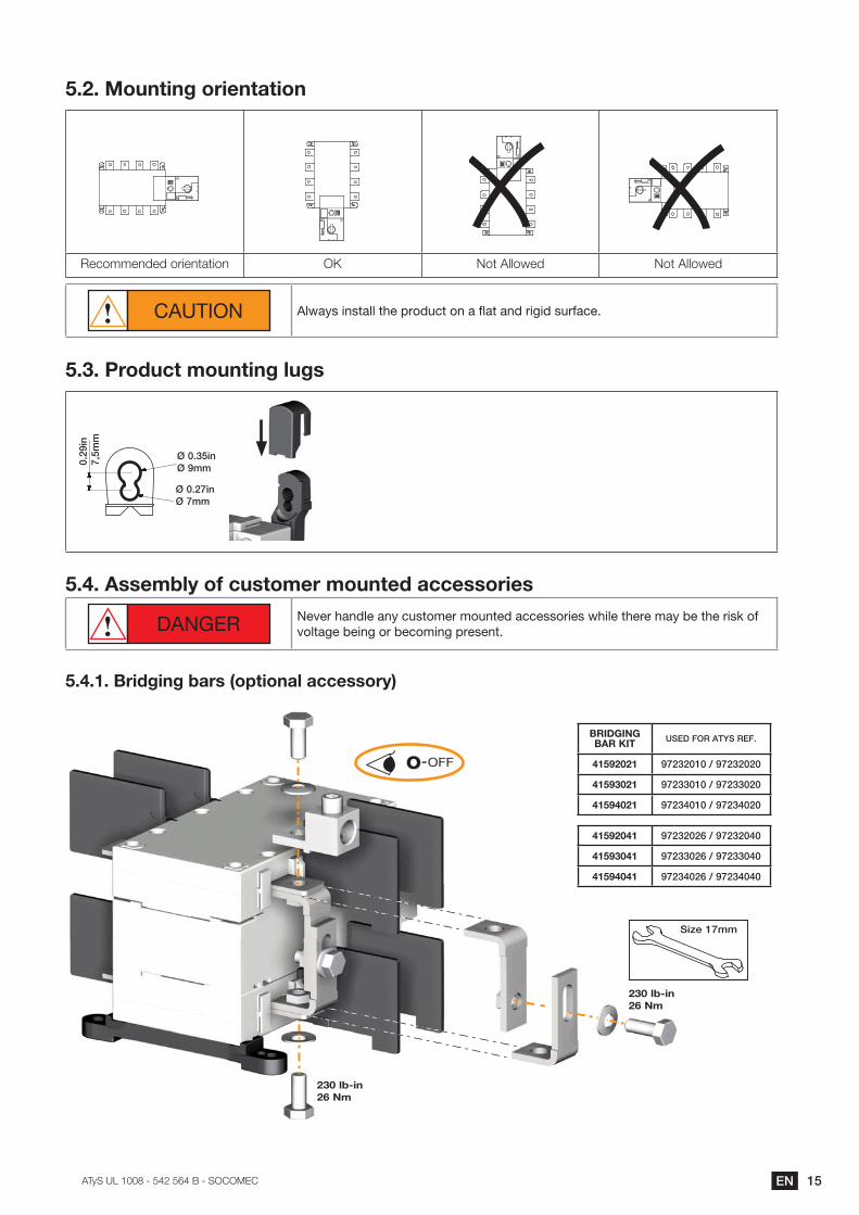
�����Mounting orientation
�7/:))7+878�:5=7+3*3=:+ �} !:3��BB:C78 !:3��BB:C78
CAUTION Always install the product on a flat and rigid surface.
��!��Product mounting lugs
��$'
*+}~
�??
������*+Ø 9mm
����$}*+Ø 7mm
�����Assembly of customer mounted accessories
DANGER Never handle any customer mounted accessories while there may be the risk of voltage being or becoming present.
�����������$��$�;��,���<�����=�����,,��>�
O OFF-
�!��=;?��26 Nm
�#"@H"JH���#�Z"[ USED FOR ATYS REF.
���(���� '}$�$����-�'}$�$�$�
���(!��� '}$������-�'}$���$�
���(���� '}$������-�'}$���$�
���(���� '}$�$�$&�-�'}$�$���
���(!��� '}$���$&�-�'}$�����
���(���� '}$���$&�-�'}$�����
�!��=;?��26 Nm
Size 17mm
16 EN ���������� ����������� ��������
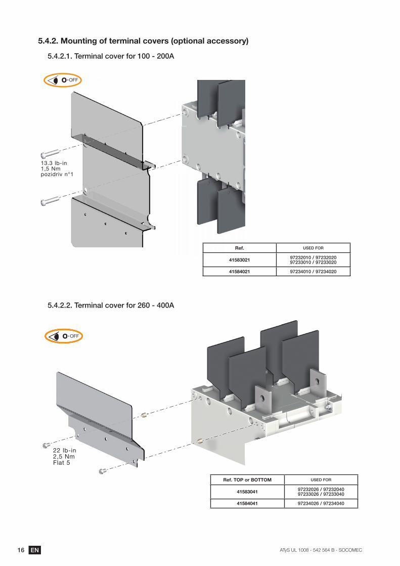
�������\������$��]���� ���=���^��,���<�����=�����,,��>�
����$�����/�?*+)\�|[�/���[��������$��
13.3 lb-in1,5 Nmpozidriv n°1
Ref. USED FOR
���!��� '}$�$����-�'}$�$�$�'}$������-�'}$���$�
������� '}$������-�'}$���$�
O OFF-
����$�$���/�?*+)\�|[�/���[��$&�������
O OFF-O OFF-
22 lb-in2,5 NmFlat 5
#�]��[_������_[[_\ USED FOR
���!��� '}$�$�$&�-�'}$�$��� '}$���$&�-�'}$�����
������� '}$���$&�-�'}$�����
17EN���������� ����������� ��������
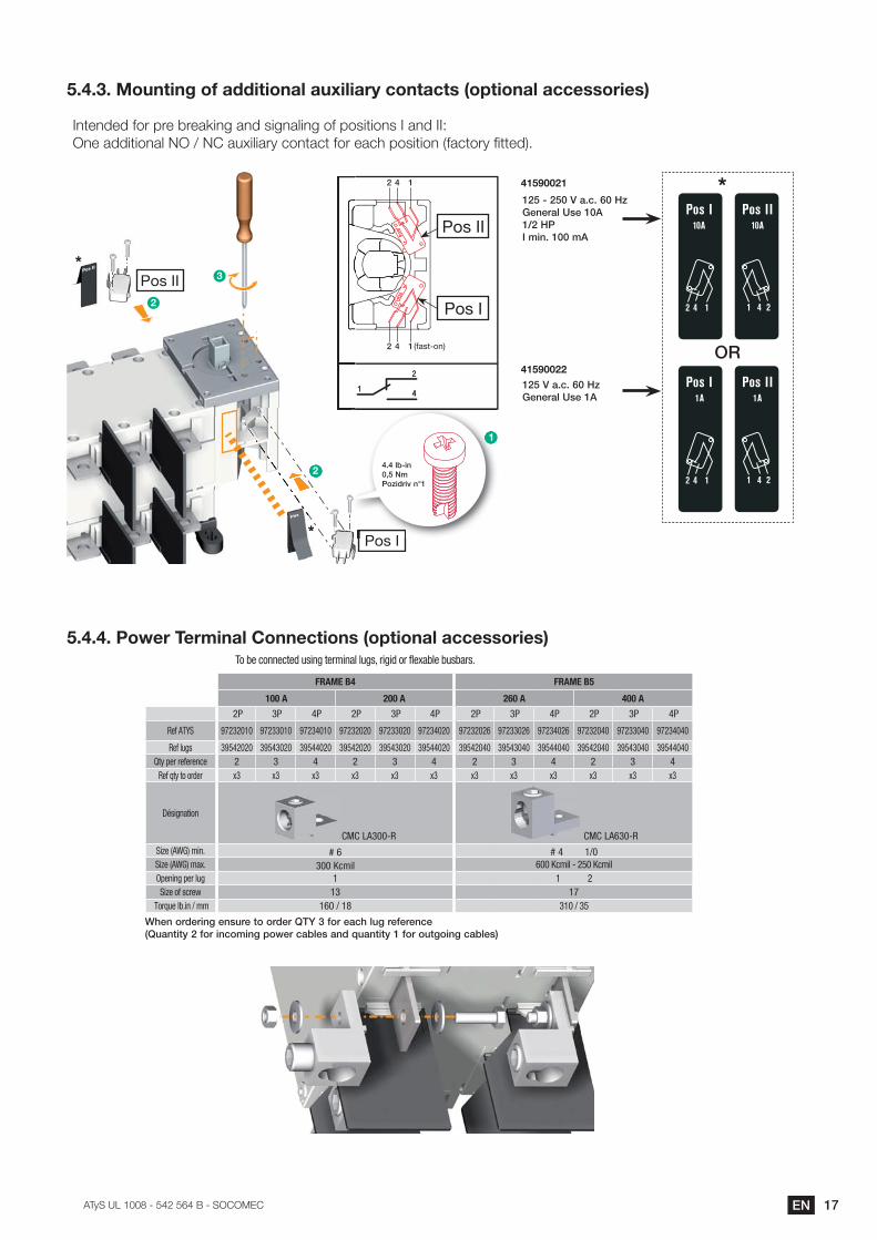
����!��\������$��]����������=���`�=���>��������,���<�����=�����,,����,�
�+37+878�.:5�G57�957*I=+<�*+8�?=<+*B=+<�:.�G:?=3=:+?���*+8���`��+7�*88=3=:+*B�!��K�!��*-F=B=*5��/:+3*/3�.:5�7*/>�G:?=3=:+�%.*/3:5��;3378'�
2
2
�
�
1
1 (fast-on)
Pos II
Pos I
OR
*�$����$�����)�|��&��(��/+/�)\��,/��� �-$�("��?*+������?
���(����
�$����)�|��&��(�General Use 1A
���(����
Pos I
Pos II
Pos I
Pos II
*
*
2
2
3
1
P I
1
����\��*+�~���?"[�*{�*��+��
Pos I
****Pos I
2
���������j���[�� ���=�&���������,���<�����=�����,,����,�
FRAME B4 FRAME B5
100 A 200 A 260 A 400 A
2P 3P 4P 2P 3P 4P 2P 3P 4P 2P 3P 4P
Ref ATYS 97232010 97233010 97234010 97232020 97233020 97234020 97232026 97233026 97234026 97232040 97233040 97234040
Ref lugs 39542020 39543020 39544020 39542020 39543020 39544020 39542040 39543040 39544040 39542040 39543040 39544040Qty per reference 2 3 4 2 3 4 2 3 4 2 3 4
Ref qty to order x3 x3 x3 x3 x3 x3 x3 x3 x3 x3 x3 x3
Désignation
CMC LA300-R CMC LA630-RSize (AWG) min. # 6 # 4 1/0 Size (AWG) max. 300 Kcmil 600 Kcmil - 250 KcmilOpening per lug 1 1 2Size of screw 13 17
Torque lb.in / mm 160 / 18 310 / 35
To be connected using terminal lugs, rigid or flexable busbars.
!^/+�[�{/�*+]�/+,`�/�0[�[�{/���������[��/)|^�\`]��/�/�/+|/� ��`)+0*0��$��[��*+|[?*+]��[k/��|)�\/,�)+{��`)+0*0�����[��[`0][*+]�|)�\/,�
�� EN ���������� ����������� ��������
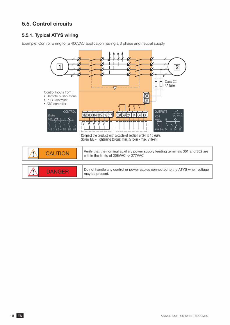
�����Control circuits
�������Typical ATYS wiring
�F*)GB7`��:+35:B�C=5=+<�.:5�*��"���*GGB=/*3=:+�>*@=+<�*���G>*?7�*+8�+7-35*B�?-GGB��
Connect the product with a cable of section of 24 to 16 AWG.Screw M3 - Tightening torque: min.: 5 lb-in - max. 7 lb-in.
1 2
3013
022
312 313 314 315 316 317 63A 64A 24 14 04 13
Class CC 4A fuse
�:+35:B��+G-3?�.5:)�`(��7):37�G-?>9-33:+?�(������:+35:BB75( ATS controller
CAUTION Verify that the nominal auxiliary power supply feeding terminals 301 and 302 are within the limits of 208VAC -> 277VAC
DANGER Do not handle any control or power cables connected to the ATYS when voltage may be present.
19EN���������� ����������� ��������
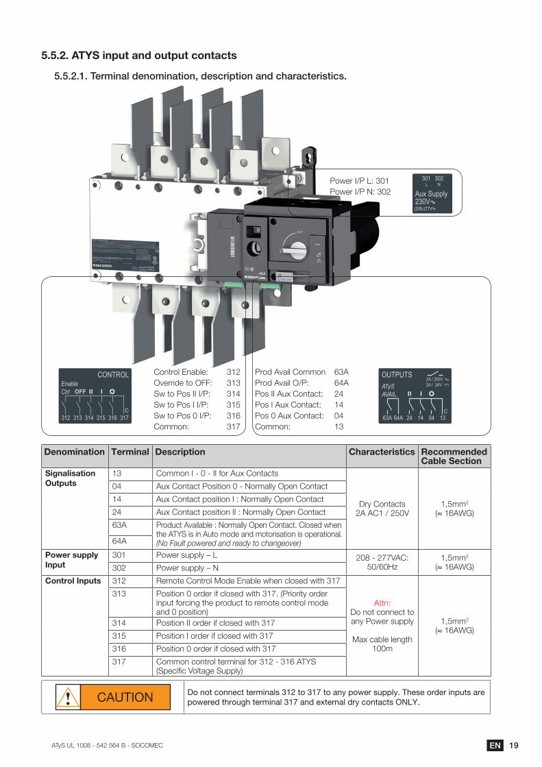
�������ATYS input and output contacts
����$�����/�?*+)\�{/+[?*+)0*[+~�{/,|�*�0*[+�)+{�|^)�)|0/�*,0*|,�
�:+35:B��+*9B7`� ���@755=87�3:��##`� ���C�3:��:?�����K�`� ���C�3:��:?����K�`�� ���C�3:��:?���K�`� ���:)):+`� �P
�5:8��@*=B��:)):+� ����5:8��@*=B��K�`� ����:?�����-F��:+3*/3`� ���:?����-F��:+3*/3`�� ��:?���-F��:+3*/3`� ��:)):+`� �
�:C75��K���`���:C75��K��!`���
Denomination Terminal Description Characteristics Recommended Cable Section
Signalisation Outputs
13 �:)):+��� �� ����.:5��-F��:+3*/3?
�5���:+3*/3?�������K���"
$�))2
%~�����'
04 �-F��:+3*/3��:?=3=:+�� �!:5)*BB���G7+��:+3*/3
14 �-F��:+3*/3�G:?=3=:+���`�!:5)*BB���G7+��:+3*/3
24 �-F��:+3*/3�G:?=3=:+����`�!:5)*BB���G7+��:+3*/3
63A �5:8-/3��@*=B*9B7�`�!:5)*BB���G7+��:+3*/3���B:?78�C>7+�the ATYS is in Auto mode and motorisation is operational. (No Fault powered and ready to changeover)64A
Power supply Input
301 �:C75�?-GGB��Q�� ��� ��PP"��`��K��M
$�))2
%~�����'302 �:C75�?-GGB��Q�!
Control Inputs 312 �7):37��:+35:B��:87��+*9B7�C>7+�/B:?78�C=3>��P
Attn: �:�+:3�/:++7/3�3:�*+���:C75�?-GGB��
�*F�/*9B7�B7+<3>�100m
$�))2
%~�����'
313 �:?=3=:+��:5875�=.�/B:?78�C=3>��P��%�5=:5=3��:5875�input forcing the product to remote control mode *+8��G:?=3=:+'
314 �:?=3=:+����:5875�=.�/B:?78�C=3>��P
�� �:?=3=:+���:5875�=.�/B:?78�C=3>��P
316 �:?=3=:+��:5875�=.�/B:?78�C=3>��P
�P �:)):+�/:+35:B�375)=+*B�.:5���� ������YS %�G7/=;/�":B3*<7��-GGB�'
CAUTION Do not connect terminals 312 to 317 to any power supply. These order inputs are powered through terminal 317 and external dry contacts ONLY.
$� EN ���������� ����������� ��������
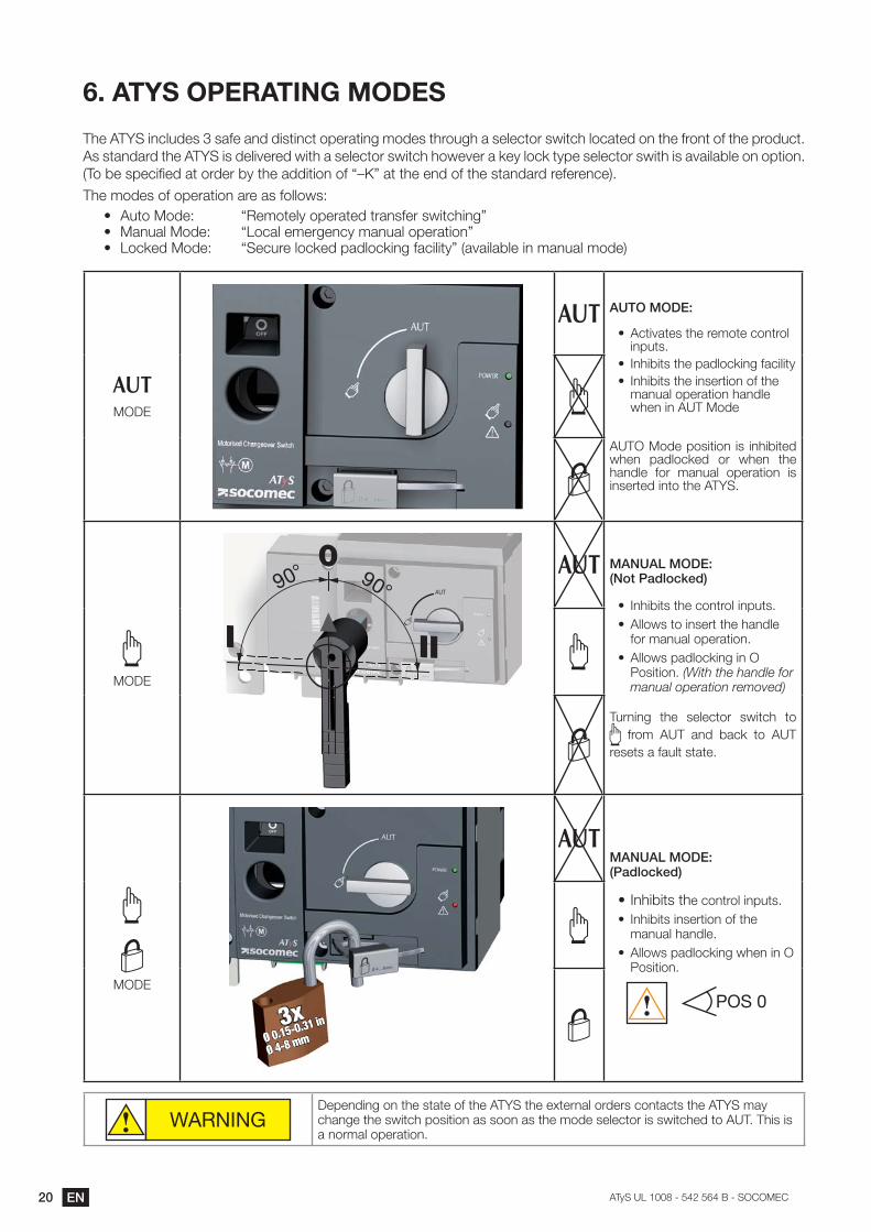
6. ATYS OPERATING MODES
The ATYS includes 3 safe and distinct operating modes through a selector switch located on the front of the product. As standard the ATYS is delivered with a selector switch however a key lock type selector swith is available on option. %�:�97�?G7/=;78�*3�:5875�9��3>7�*88=3=:+�:.�UQ}V�*3�3>7�7+8�:.�3>7�?3*+8*58�57.757+/7'�
The modes of operation are as follows:(� �-3:��:87`� U�7):37B��:G75*378�35*+?.75�?C=3/>=+<V(� �*+-*B��:87`� U�:/*B�7)75<7+/��)*+-*B�:G75*3=:+V(� �:/I78��:87`� U�7/-57�B:/I78�G*8B:/I=+<�.*/=B=3�V�%*@*=B*9B7�=+�)*+-*B�):87'
����
������#�%
(� Activates the remote control inputs.
(� ��+>=9=3?�3>7�G*8B:/I=+<�.*/=B=3�(� ��+>=9=3?�3>7�=+?753=:+�:.�3>7�
manual operation handle C>7+�=+������:87
������:87�G:?=3=:+� =?� =+>=9=378�when padlocked or when the handle for manual operation is inserted into the ATYS.
����
90° 90°
I II
0AUT
� �� ����#�%���[0�"){\[|_/{�
(� �+>=9=3?�3>7�/:+35:B�=+G-3?�(� Allows to insert the handle
for manual operation. (� ��BB:C?�G*8B:/I=+<�=+���
�:?=3=:+��(With the handle for manual operation removed)
Turning the selector switch to � .5:)� ���� *+8� 9*/I� 3:� ����
resets a fault state.
����
3xØ 4-8 mmØ 0.15-0.31 in
� �� ����#�% �"){\[|_/{�
(���+>=9=3?�3>e control inputs.(� ��+>=9=3?�=+?753=:+�:.�3>7�
manual handle.(� ��BB:C?�G*8B:/I=+<�C>7+�=+���
�:?=3=:+��
POS 0
WARNING�7G7+8=+<�:+�3>7�?3*37�:.�3>7������3>7�7F375+*B�:5875?�/:+3*/3?�3>7������)*��/>*+<7�3>7�?C=3/>�G:?=3=:+�*?�?::+�*?�3>7�):87�?7B7/3:5�=?�?C=3/>78�3:�������>=?�=?�a normal operation.
21EN���������� ����������� ��������
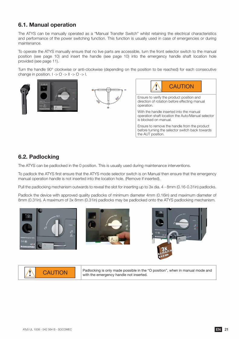
6.1. Manual operationThe ATY��/*+�97�)*+-*BB��:G75*378�*?�*� U�*+-*B��5*+?.75��C=3/>V�C>=B?3� 573*=+=+<� 3>7�7B7/35=/*B�/>*5*/375=?3=/?�and performance of the power switching function. This function is usually used in case of emergencies or during maintenance.
To operate the ATYS manually ensure that no live parts are accessible, turn the front selector switch to the manual G:?=3=:+� %?77� G*<7� '� *+8� =+?753� 3>7� >*+8B7� %?77� G*<7� '� =+3:� 3>7� 7)75<7+/�� >*+8B7� ?>*.3� B:/*3=:+� >:B7�G5:@=878�%?77�G*<7�'�
�-5+�3>7�>*+8B7�Oz�/B:/IC=?7�:5�*+3= /B:/IC=?7�%87G7+8=+<�:+�3>7�G:?=3=:+�3:�97�57*/>78'�.:5�7*/>�/:+?7/-3=@7�/>*+<7�=+�G:?=3=:+���� ���� ����� ���� ����
CAUTION
Ensure to verify the product position and direction of rotation before effecting manual operation.
With the handle inserted into the manual :G75*3=:+�?>*.3�B:/*3=:+�3>7��-3:K�*+-*B�?7B7/3:5�is blocked on manual.
Ensure to remove the handle from the product before turning the selector switch back towards 3>7�����G:?=3=:+�
6.2. PadlockingThe ATYS can be padlocked in the 0 position. This is usually used during maintenance interventions.
To padlock the ATY��;5?3�7+?-57�3>*3�3>7���Y��):87�?7B7/3:5�?C=3/>�=?�:+��*+-*B�3>7+�7+?-57�3>*3�3>7�7)75<7+/��)*+-*B�:G75*3=:+�>*+8B7�=?�+:3�=+?75378�=+3:�3>7�B:/*3=:+�>:B7��%�7):@7�=.�=+?75378'�
�-BB�3>7�G*8B:/I=+<�)7/>*+=?)�:-3C*58?�3:�57@7*B�3>7�?B:3�.:5�=+?753=+<�-G�3:��F�8=*���� ��))�%�� ��=+'�G*8B:/I?�
�*8B:/I�3>7�87@=/7�C=3>�*GG5:@78�D-*B=3��G*8B:/I?�:.�)=+=)-)�8=*)7375��))�%��=+'�*+8�)*F=)-)�8=*)7375�:.��))�%��=+'����)*F=)-)�:.��F��))�%��=+'�G*8B:/I?�)*��97�G*8B:/I78�:+3:�3>7���YS padlocking mechanism.
3xØ 4-8 mmØ 0.15-0.31 in
CAUTION Padlocking is only made possible in the “O position”, when in manual mode and with the emergency handle not inserted.
22 EN ���������� ����������� ��������
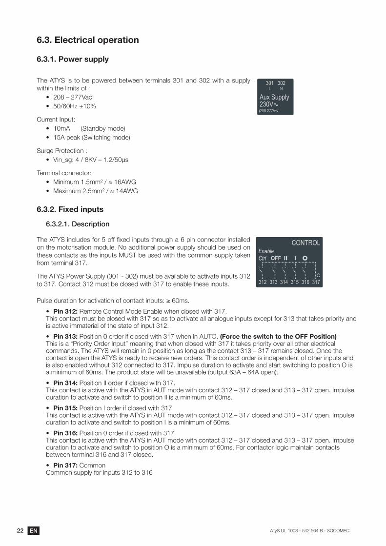
6.3. Electrical operation
6.3.1. Power supply
The ATYS is to be powered between terminals 301 and 302 with a supply within the limits of :
(� ���Q��PP"*/(� �K��M��{
�-557+3��+G-3`�(� )�������%�3*+89��):87'(� ���G7*I�%�C=3/>=+<�):87'
�-5<7��5:37/3=:+�`�(� "=+�?<`���K��}"�Q���K��?�
Terminal connector: (� �=+=)-)���))��K�~�����(� �*F=)-)����))��K�~�����
6.3.2. Fixed inputs
6.3.2.1. Description
The ATY��=+/B-87?�.:5���:..�;F78�=+G-3?�3>5:-<>�*���G=+�/:++7/3:5�=+?3*BB78�:+�3>7�):3:5=?*3=:+�):8-B7��!:�*88=3=:+*B�G:C75�?-GGB��?>:-B8�97�-?78�:+�3>7?7�/:+3*/3?�*?�3>7�=+G-3?������97�-?78�C=3>�3>7�/:)):+�?-GGB��3*I7+�.5:)�375)=+*B��P�
The ATY���:C75��-GGB��%�� ���'�)-?3�97�*@*=B*9B7�3:�*/3=@*37�=+G-3?����3:��P���:+3*/3����)-?3�97�/B:?78�C=3>��P�3:�7+*9B7�3>7?7�=+G-3?��
�-B?7�8-5*3=:+�.:5�*/3=@*3=:+�:.�/:+3*/3�=+G-3?`����)?�
(� Pin 312: �7):37��:+35:B��:87��+*9B7�C>7+�/B:?78�C=3>��P�� �>=?�/:+3*/3�)-?3�97�/B:?78�C=3>��P�?:�*?�3:�*/3=@*37�*BB�*+*B:<-7�=+G-3?�7F/7G3�.:5����3>*3�3*I7?�G5=:5=3��*+8�is active immaterial of the state of input 312.
(� Pin 313:��:?=3=:+��:5875�=.�/B:?78�C=3>��P�C>7+�=+��������������z��,j���z�����z��_���,������ �>=?�=?�*�U�5=:5=3���5875��+G-3V�)7*+=+<�3>*3�C>7+�/B:?78�C=3>��P�=3�3*I7?�G5=:5=3��:@75�*BB�:3>75�7B7/35=/*B�commands. The ATY��C=BB�57)*=+�=+��G:?=3=:+�*?�B:+<�*?�3>7�/:+3*/3����Q��P�57)*=+?�/B:?78���+/7�3>7�contact is open the ATYS is ready to receive new orders. This contact order is independent of other inputs and =?�*B?:�7+*9B78�C=3>:-3����/:++7/378�3:��P���)G-B?7�8-5*3=:+�3:�*/3=@*37�*+8�?3*53�?C=3/>=+<�3:�G:?=3=:+���=?�*�)=+=)-)�:.��)?���>7�G5:8-/3�?3*37�C=BB�97�-+*@*=B*9B7�%:-3G-3�����Q�����:G7+'�
(� ����!��/��:?=3=:+����:5875�=.�/B:?78�C=3>��P� This contact is active with the ATY��=+�����):87�C=3>�/:+3*/3����Q��P�/B:?78�*+8����Q��P�:G7+���)G-B?7�8-5*3=:+�3:�*/3=@*37�*+8�?C=3/>�3:�G:?=3=:+����=?�*�)=+=)-)�:.��)?�
(� ����!��/��:?=3=:+���:5875�=.�/B:?78�C=3>��P This contact is active with the ATY��=+�����):87�C=3>�/:+3*/3����Q��P�/B:?78�*+8����Q��P�:G7+���)G-B?7�8-5*3=:+�3:�*/3=@*37�*+8�?C=3/>�3:�G:?=3=:+���=?�*�)=+=)-)�:.��)?�
(� Pin 316:��:?=3=:+��:5875�=.�/B:?78�C=3>��P This contact is active with the ATY��=+�����):87�C=3>�/:+3*/3����Q��P�/B:?78�*+8����Q��P�:G7+���)G-B?7�8-5*3=:+�3:�*/3=@*37�*+8�?C=3/>�3:�G:?=3=:+���=?�*�)=+=)-)�:.��)?��#:5�/:+3*/3:5�B:<=/�)*=+3*=+�/:+3*/3?�973C77+�375)=+*B����*+8��P�/B:?78�
(� ����!�)/��:)):+� �:)):+�?-GGB��.:5�=+G-3?����3:���
23EN���������� ����������� ��������
6.3.2.2. �/|^+*|)\�{)0)���j/{�*+�`0,�
Motorisation Module�+G-3�R3�` ��=57/3��-557+3��=+` ����3:���)��=+7�57?=?3*+/7` I��=+7�B7+<3>�` )�%�=+��C=57���))�������'�=+=)-)�G-B?7�8-5*3=:+` 60ms�:C75�G75��+G-3` ��"��-5<7�G5:37/3=:+�"=+�?<` ���I"�%��K��?�?-5<7'�����C=3>?3*+8�@:B3*<7�%�:+3*/3K*=5' �K�I"�+?-B*3=:+�%�:)):+�):87'� ���I"���
%�73C77+��K��*+8�*BB�/:)):+�G*53?'Terminal connector: ��))��%~�����' )=+=)-)�K����))��%~�����'�)*FThighten torque: �=+���B9 =+$�)*F��PB9 =+
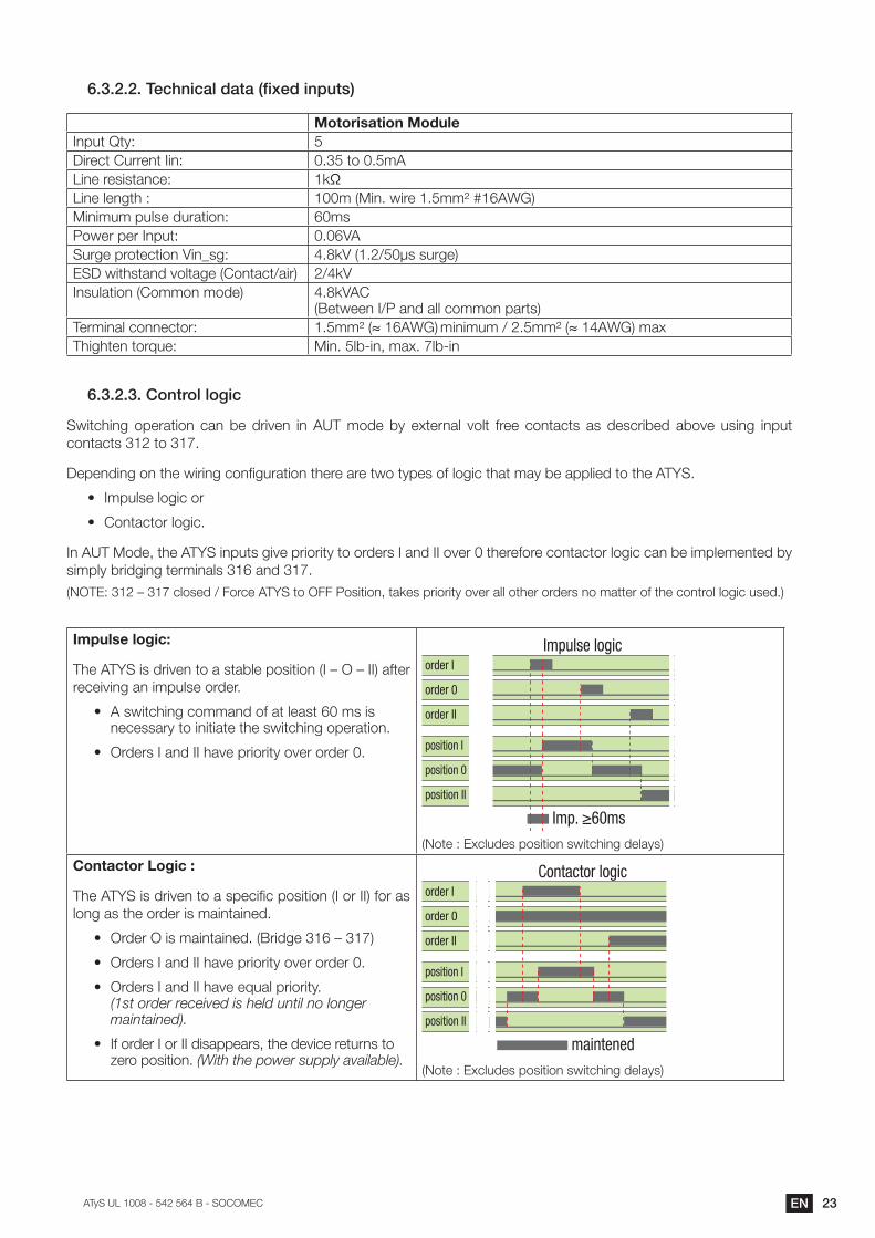
6.3.2.3. Control logic
�C=3/>=+<� :G75*3=:+� /*+� 97� 85=@7+� =+� ���� ):87� 9�� 7F375+*B� @:B3� .577� /:+3*/3?� *?� 87?/5=978� *9:@7� -?=+<� =+G-3�/:+3*/3?����3:��P�
�7G7+8=+<�:+�3>7�C=5=+<�/:+;<-5*3=:+�3>757�*57�3C:�3�G7?�:.�B:<=/�3>*3�)*��97�*GGB=78�3:�3>7���YS.
(� �)G-B?7�B:<=/�:5�
(� �:+3*/3:5�B:<=/�
�+������:87$�3>7���Y��=+G-3?�<=@7�G5=:5=3��3:�:5875?���*+8����:@75��3>757.:57�/:+3*/3:5�B:<=/�/*+�97�=)GB7)7+378�9��?=)GB��95=8<=+<�375)=+*B?����*+8��P�%!���`����Q��P�/B:?78�K�#:5/7������3:��##��:?=3=:+$�3*I7?�G5=:5=3��:@75�*BB�:3>75�:5875?�+:�)*3375�:.�3>7�/:+35:B�B:<=/�-?78�'�
Impulse logic:
The ATY��=?�85=@7+�3:�*�?3*9B7�G:?=3=:+�%��Q���Q���'�*.375�receiving an impulse order.
(� A switching command of at least 60 ms is necessary to initiate the switching operation.
(� �5875?���*+8����>*@7�G5=:5=3��:@75�:5875��
�����������
order I
position I
order 0
position 0
order II
position II
Impulse logic
%!:37�`��F/B-87?�G:?=3=:+�?C=3/>=+<�87B*�?'
&�����������$���/
The ATY��=?�85=@7+�3:�*�?G7/=;/�G:?=3=:+�%��:5���'�.:5�*?�long as the order is maintained.
(� �5875���=?�)*=+3*=+78��%�5=8<7����Q��P'
(� �5875?���*+8����>*@7�G5=:5=3��:@75�:5875��
(� ��5875?���*+8����>*@7�7D-*B�G5=:5=3��� (1st order received is held until no longer maintained).
(� ��.�:5875���:5����8=?*GG7*5?$�3>7�87@=/7�573-5+?�3:�M75:�G:?=3=:+� (With the power supply available).
maintened
order I
position I
order 0
position 0
order II
position II
Contactor logic
%!:37�`��F/B-87?�G:?=3=:+�?C=3/>=+<�87B*�?'
$� EN ���������� ����������� ��������
6.3.3. Fixed outputs - Dry contacts
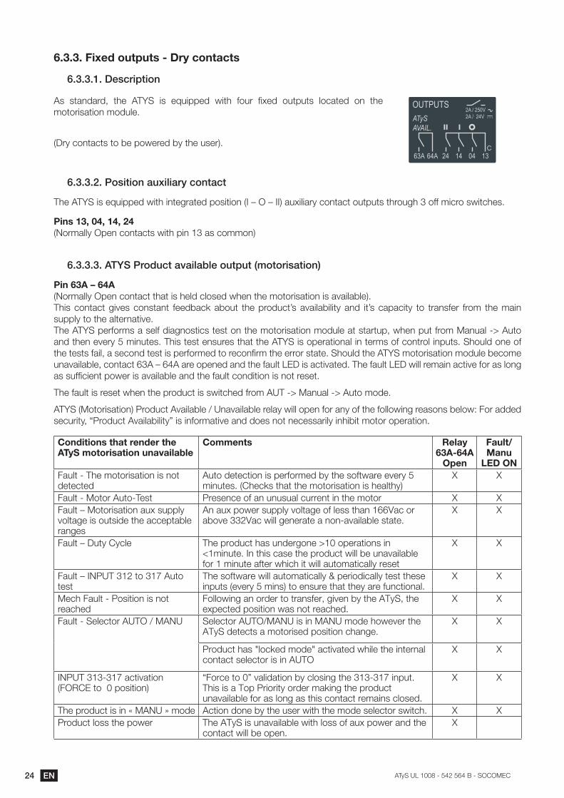
6.3.3.1. Description
As standard, the ATY�� =?� 7D-=GG78� C=3>� .:-5� ;F78� :-3G-3?� B:/*378� :+� 3>7�motorisation module.
%�5��/:+3*/3?�3:�97�G:C7578�9��3>7�-?75'�
6.3.3.2. "[,*0*[+�)`j*\*)���|[+0)|0
The ATY��=?�7D-=GG78�C=3>�=+37<5*378�G:?=3=:+�%��Q���Q���'�*-F=B=*5��/:+3*/3�:-3G-3?�3>5:-<>���:..�)=/5:�?C=3/>7?�
���,��!{���{���{���%!:5)*BB���G7+�/:+3*/3?�C=3>�G=+���*?�/:)):+'
6.3.3.3. ����"�[{`|0�)�)*\)�\/�[`0�`0��?[0[�*,)0*[+�
����'!��|�'�� %!:5)*BB���G7+�/:+3*/3�3>*3�=?�>7B8�/B:?78�C>7+�3>7�):3:5=?*3=:+�=?�*@*=B*9B7'��This contact gives constant feedback about the product’s availability and it’s capacity to transfer from the main supply to the alternative.The ATY��G75.:5)?�*�?7B.�8=*<+:?3=/?�37?3�:+�3>7�):3:5=?*3=:+�):8-B7�*3�?3*53-G$�C>7+�G-3�.5:)��*+-*B� ���-3:�*+8�3>7+�7@75����)=+-37?���>=?�37?3�7+?-57?�3>*3�3>7���YS is operational in terms of control inputs. Should one of 3>7�37?3?�.*=B$�*�?7/:+8�37?3�=?�G75.:5)78�3:�57/:+;5)�3>7�755:5�?3*37���>:-B8�3>7���YS motorisation module become -+*@*=B*9B7$�/:+3*/3�����Q�����*57�:G7+78�*+8�3>7�.*-B3�����=?�*/3=@*378���>7�.*-B3�����C=BB�57)*=+�*/3=@7�.:5�*?�B:+<�*?�?-.;/=7+3�G:C75�=?�*@*=B*9B7�*+8�3>7�.*-B3�/:+8=3=:+�=?�+:3�57?73�
�>7�.*-B3�=?�57?73�C>7+�3>7�G5:8-/3�=?�?C=3/>78�.5:)����� ���*+-*B� ���-3:�):87��
ATY��%�:3:5=?*3=:+'��5:8-/3��@*=B*9B7�K��+*@*=B*9B7�57B*��C=BB�:G7+�.:5�*+��:.�3>7�.:BB:C=+<�57*?:+?�97B:C`�#:5�*8878�?7/-5=3�$�U�5:8-/3��@*=B*9=B=3�V�=?�=+.:5)*3=@7�*+8�8:7?�+:3�+7/7??*5=B��=+>=9=3�):3:5�:G75*3=:+�
Conditions that render the ATyS motorisation unavailable
Comments Relay '!�?'���
Open
��=�*Manu
LED ON#*-B3� ��>7�):3:5=?*3=:+�=?�+:3�detected
�-3:�8737/3=:+�=?�G75.:5)78�9��3>7�?:.3C*57�7@75����)=+-37?��%�>7/I?�3>*3�3>7�):3:5=?*3=:+�=?�>7*B3>�'
& &
#*-B3� ��:3:5��-3: �7?3 �57?7+/7�:.�*+�-+-?-*B�/-557+3�=+�3>7�):3:5 & &#*-B3�Q��:3:5=?*3=:+�*-F�?-GGB��voltage is outside the acceptable ranges
�+�*-F�G:C75�?-GGB��@:B3*<7�:.�B7??�3>*+���"*/�:5�*9:@7����"*/�C=BB�<7+75*37�*�+:+ *@*=B*9B7�?3*37�
& &
#*-B3�Q��-3����/B7 �>7�G5:8-/3�>*?�-+875<:+7���:G75*3=:+?�=+��)=+-37���+�3>=?�/*?7�3>7�G5:8-/3�C=BB�97�-+*@*=B*9B7�for 1 minute after which it will automatically reset
& &
#*-B3�Q��!�������3:��P��-3:�test
The software will automatically & periodically test these =+G-3?�%7@75����)=+?'�3:�7+?-57�3>*3�3>7��*57�.-+/3=:+*B�
& &
�7/>�#*-B3� ��:?=3=:+�=?�+:3�reached
#:BB:C=+<�*+�:5875�3:�35*+?.75$�<=@7+�9��3>7�����$�3>7�7FG7/378�G:?=3=:+�C*?�+:3�57*/>78�
& &
#*-B3� ��7B7/3:5������K���!� �7B7/3:5�����K��!��=?�=+���!��):87�>:C7@75�3>7�ATyS detects a motorised position change.
& &
�5:8-/3�>*?��B:/I78�):87��*/3=@*378�C>=B7�3>7�=+375+*B�/:+3*/3�?7B7/3:5�=?�=+�����
& &
�!������ �P�*/3=@*3=:+%#�����3:���G:?=3=:+'
U#:5/7�3:�V�@*B=8*3=:+�9��/B:?=+<�3>7��� �P�=+G-3��>=?�=?�*��:G��5=:5=3��:5875�)*I=+<�3>7�G5:8-/3�unavailable for as long as this contact remains closed.
& &
�>7�G5:8-/3�=?�=+�����!����):87 Action done by the user with the mode selector switch. & &�5:8-/3�B:??�3>7�G:C75 �>7������=?�-+*@*=B*9B7�C=3>�B:??�:.�*-F�G:C75�*+8�3>7�
contact will be open. &
$�EN���������� ����������� ��������
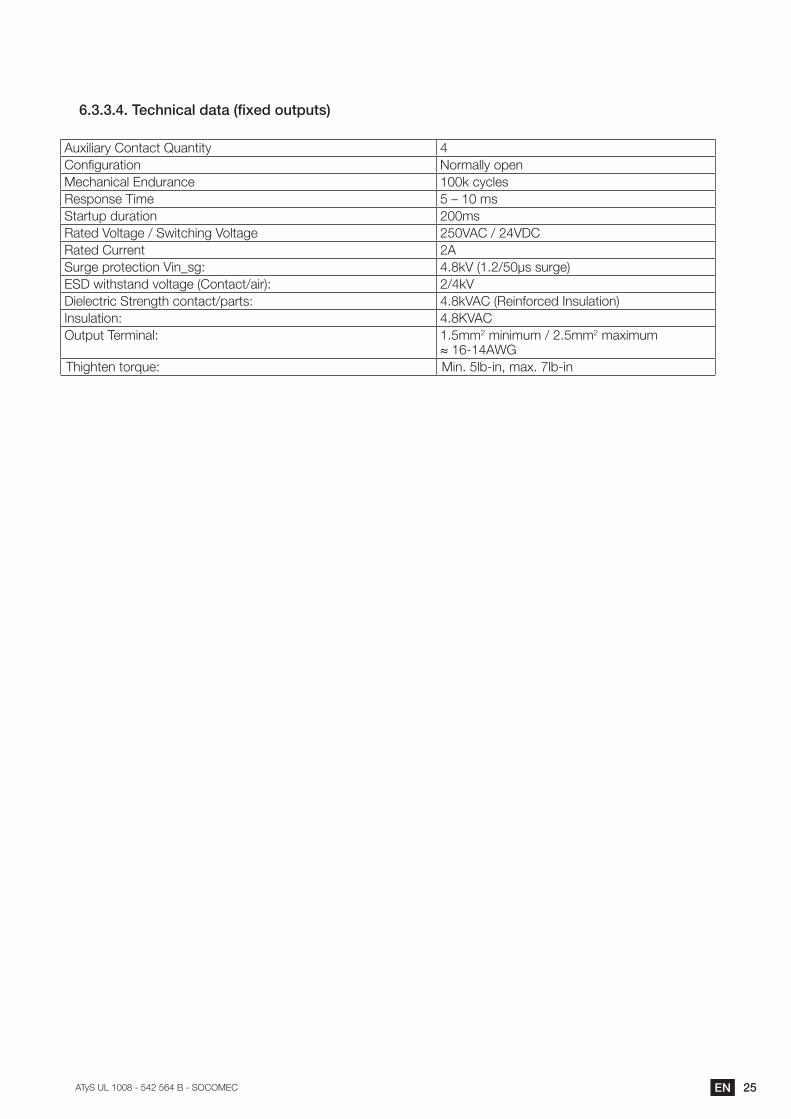
&���������/|^+*|)\�{)0)���j/{�[`0�`0,�
�-F=B=*5���:+3*/3�R-*+3=3� 4�:+;<-5*3=:+� !:5)*BB��:G7+�7/>*+=/*B��+8-5*+/7 100k cycles�7?G:+?7��=)7 ��Q��)?Startup duration 200ms�*378�":B3*<7�K��C=3/>=+<�":B3*<7� ��"���K���"���*378��-557+3 2A�-5<7�G5:37/3=:+�"=+�?<` ���I"�%��K��?�?-5<7'����C=3>?3*+8�@:B3*<7�%�:+3*/3K*=5'` �K�I"�=7B7/35=/��357+<3>�/:+3*/3KG*53?` ���I"���%�7=+.:5/78��+?-B*3=:+'�+?-B*3=:+` ���}"���-3G-3��75)=+*B` ��))2�)=+=)-)�K����))2�)*F=)-)
~�� ����Thighten torque: �=+���B9 =+$�)*F��PB9 =+
26 EN ���������� ����������� ��������
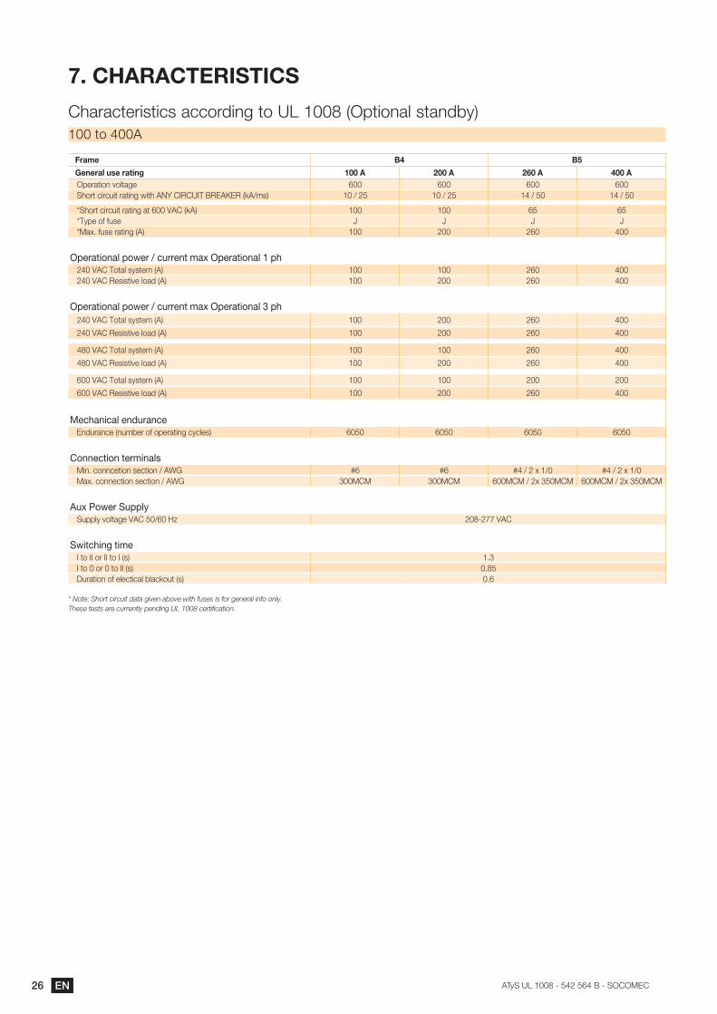
)��&+�#�&[%#"�["&�
�>*5*/375=?3=/?�*//:58=+<�3:������%�G3=:+*B�?3*+89�'100 to 400A
Frame �� ��
General use rating ����� ����� �'��� ������G75*3=:+�@:B3*<7 600 600 600 600�>:53�/=5/-=3�5*3=+<�C=3>��!��������������}���%I�K)?' �K��� �K��� ��K�� ��K��
��>:53�/=5/-=3�5*3=+<�*3���"���%I�' 100 100 �� ��*Type of fuse L L L L��*F��.-?7�5*3=+<�%�' 100 200 260 400
Operational power / current max Operational 1 ph���"����:3*B�?�?37)�%�' 100 100 260 400���"����7?=?3=@7�B:*8�%�' 100 200 260 400
Operational power / current max Operational 3 ph���"����:3*B�?�?37)�%�' 100 200 260 400
���"����7?=?3=@7�B:*8�%�' 100 200 260 400
���"����:3*B�?�?37)�%�' 100 100 260 400
���"����7?=?3=@7�B:*8�%�' 100 200 260 400
��"����:3*B�?�?37)�%�' 100 100 200 200
��"����7?=?3=@7�B:*8�%�' 100 200 260 400
Mechanical endurance�+8-5*+/7�%+-)975�:.�:G75*3=+<�/�/B7?' �� �� �� ��
Connection terminals�=+��/:++/73=:+�?7/3=:+�K���� �� �� ���K���F�K ���K���F�K�*F��/:++7/3=:+�?7/3=:+�K���� ���� ���� �����K��F������ �����K��F������
Aux Power Supply�-GGB��@:B3*<7�"����K���M �� �PP�"��
Switching time��3:����:5����3:���%?' 1.3��3:��:5��3:����%?' 0����-5*3=:+�:.�7B7/3=/*B�9B*/I:-3�%?' 0.6
* Note: Short circuit data given above with fuses is for general info only. ���������������������� �����������!""#������$������
27EN���������� ����������� ��������
��PREVENTIVE MAINTENANCE
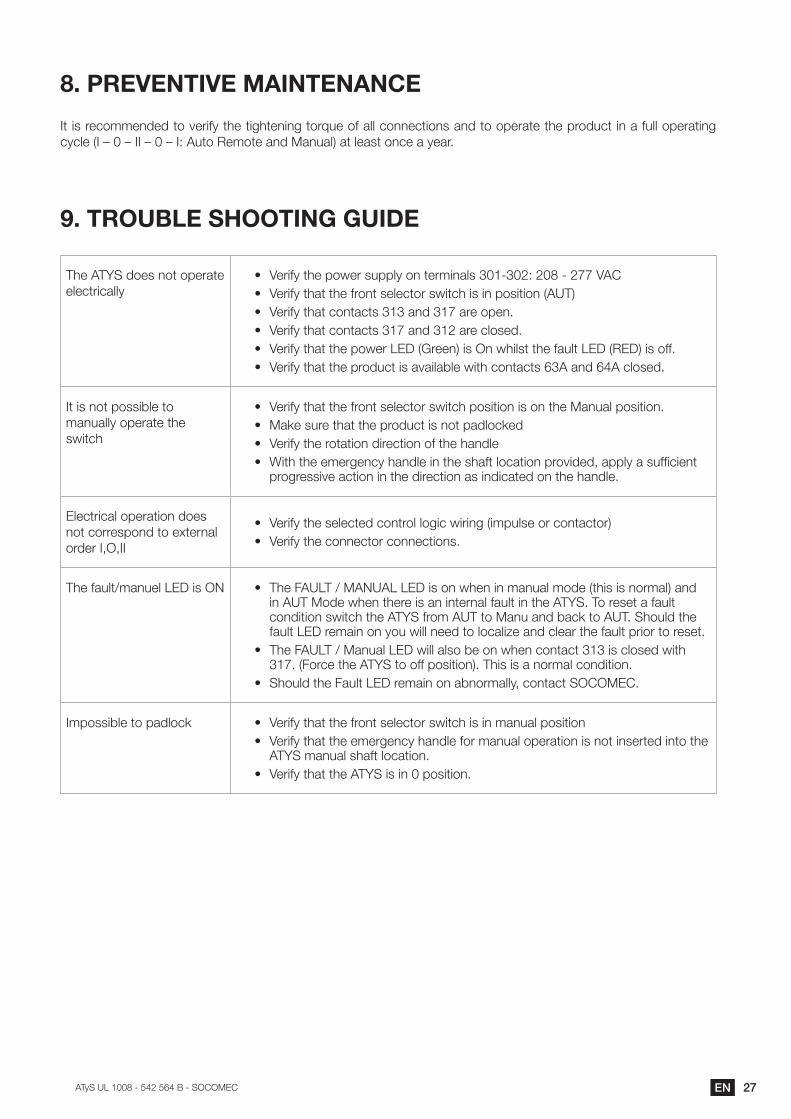
�3�=?�57/:))7+878�3:�@75=.��3>7�3=<>37+=+<�3:5D-7�:.�*BB�/:++7/3=:+?�*+8�3:�:G75*37�3>7�G5:8-/3�=+�*�.-BB�:G75*3=+<�/�/B7�%��Q��Q����Q��Q��`��-3:��7):37�*+8��*+-*B'�*3�B7*?3�:+/7�*��7*5�
(��[#_���%��+__["JH�H�"@%
The ATYS does not operate electrically
(� �"75=.��3>7�G:C75�?-GGB��:+�375)=+*B?�� ��`���� ��PP�"��(� �"75=.��3>*3�3>7�.5:+3�?7B7/3:5�?C=3/>�=?�=+�G:?=3=:+�%���'(� �"75=.��3>*3�/:+3*/3?����*+8��P�*57�:G7+�(� "75=.��3>*3�/:+3*/3?��P�*+8����*57�/B:?78�(� �"75=.��3>*3�3>7�G:C75�����%�577+'�=?��+�C>=B?3�3>7�.*-B3�����%���'�=?�:..�(� �"75=.��3>*3�3>7�G5:8-/3�=?�*@*=B*9B7�C=3>�/:+3*/3?�����*+8�����/B:?78�
�3�=?�+:3�G:??=9B7�3:�manually operate the switch
(� �"75=.��3>*3�3>7�.5:+3�?7B7/3:5�?C=3/>�G:?=3=:+�=?�:+�3>7��*+-*B�G:?=3=:+�(� ��*I7�?-57�3>*3�3>7�G5:8-/3�=?�+:3�G*8B:/I78(� �"75=.��3>7�5:3*3=:+�8=57/3=:+�:.�3>7�>*+8B7(� ��=3>�3>7�7)75<7+/��>*+8B7�=+�3>7�?>*.3�B:/*3=:+�G5:@=878$�*GGB��*�?-.;/=7+3�
progressive action in the direction as indicated on the handle.
Electrical operation does +:3�/:557?G:+8�3:�7F375+*B�:5875��$�$��
(� �"75=.��3>7�?7B7/378�/:+35:B�B:<=/�C=5=+<�%=)G-B?7�:5�/:+3*/3:5'(� �"75=.��3>7�/:++7/3:5�/:++7/3=:+?�
�>7�.*-B3K)*+-7B�����=?��! (� ��>7�#�����K���!��������=?�:+�C>7+�=+�)*+-*B�):87�%3>=?�=?�+:5)*B'�*+8�=+������:87�C>7+�3>757�=?�*+�=+375+*B�.*-B3�=+�3>7���YS. To reset a fault condition switch the ATY��.5:)�����3:��*+-�*+8�9*/I�3:�������>:-B8�3>7�.*-B3�����57)*=+�:+��:-�C=BB�+778�3:�B:/*B=M7�*+8�/B7*5�3>7�.*-B3�G5=:5�3:�57?73�
(� ��>7�#�����K��*+-*B�����C=BB�*B?:�97�:+�C>7+�/:+3*/3����=?�/B:?78�C=3>��P��%#:5/7�3>7���Y��3:�:..�G:?=3=:+'���>=?�=?�*�+:5)*B�/:+8=3=:+�
(� �>:-B8�3>7�#*-B3�����57)*=+�:+�*9+:5)*BB�$�/:+3*/3���������
�)G:??=9B7�3:�G*8B:/I (� �"75=.��3>*3�3>7�.5:+3�?7B7/3:5�?C=3/>�=?�=+�)*+-*B�G:?=3=:+(� �"75=.��3>*3�3>7�7)75<7+/��>*+8B7�.:5�)*+-*B�:G75*3=:+�=?�+:3�=+?75378�=+3:�3>7�
ATYS manual shaft location.(� �"75=.��3>*3�3>7���YS is in 0 position.
$� EN ���������� ����������� ��������
����[+%��[YS FAMILY
The ATY��>*?�977+�7+<=+77578�9��3>7���������/7+357�:.�7F/7BB7+/7�=+�#5*+/7�3>*3�9:*?3?�=3�?�@75��:C+�=+ >:-?7��"��=+?3*+3*+7:-?�G:C75�37?3�B*9�*//578=378�9����#����*+8�C:5I=+<�=+�G*53+75?>=G�C=3>`�}���$������$���$����$�����$��B:�8�?��7<=?375�:.��>=GG=+<$��-57*-�"�5=3*?$���L ���$����$����� ���*+8�:3>75?�
��������>*?�977+�)*+-.*/3-5=+<�G:C75�/:+35:B�*+8�?*.73��G5:8-/3?�?=+/7�O�����>7�;5?3�<7+75*3=:+���������U35*+?.75�?C=3/>7?V�C757�=+35:8-/78�=+�OO�*+8�3:8*��3>7���Y��95*+8�>*?�97/:)7�35-?378�9��)*J:5�GB*�75?�=+�3>7�power industry worldwide.
The ATY��#*)=B��=+/B-87?�*�/:)GB737�5*+<7�:.�:G7+�35*+?=3=:+�57):37B��:G75*378�35*+?.75�?C=3/>�7D-=G)7+3�*?�C7BB�as automatic fully integrated products and solutions. Selecting the right ATYS will depend on the application as well as the nature of installation in which the ATYS will be installed.
�>=?� =+?35-/3=:+�)*+-*B� =+/B-87?�873*=B?�*+8�=+?35-/3=:+?�?G7/=;/�3:�3>7�U��Y�V������35*+?.75�?C=3/>�:+B���#:5�all other ATY��.*)=B��:.�G5:8-/3?�%����5*+<7'�GB7*?7�57.75�3:�3>7�?G7/=;/�=+?35-/3=:+�)*+-*B�57B*378�3:�3>*3�G5:8-/3��%�@*=B*9B7�.:5�8:C+B:*8�:+�www.socomec.com'
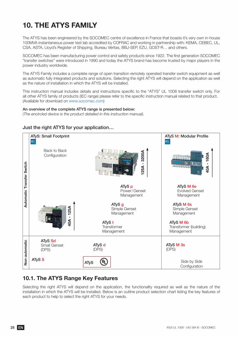
+�[�/��*/k�[��0^/�|[?�\/0/� �Y���)+]/�*,���/,/+0/{��/\[k%(The encircled device is the product detailed in this instruction manual).
�`,0�0^/��*]^0� �����[���[`��)��\*|)0*[+�
Aut
om
atic
Tra
nsfe
r S
wit
ch
���%��?)\\��[[0��*+0
�*/I�3:��*/I �:+.=<-5*3=:+
����
�?�!
����
ATyS �%��[{`\)��"�[�*\/
���
�?��
'��
���
�?��
���
ATyS p �:C75�K��7+?73��*+*<7)7+3
ATyS g Simple Genset �*+*<7)7+3
ATyS t Transformer �*+*<7)7+3
ATyS ��&/ Evolved Genset �*+*<7)7+3
ATyS ��&, Simple Genset �*+*<7)7+3
ATyS ��&� �5*+?.:5)75�%9-=B8=+<' �*+*<7)7+3
No
n-au
tom
atic ATyS Sd
Small Genset %���'
ATyS S
ATyS d %���'
ATyS
ATyS ���, %���'
Side by Side �:+.=<-5*3=:+
������The ATYS Range Key FeaturesSelecting the right ATYS will depend on the application, the functionality required as well as the nature of the installation in which the ATY��C=BB�97�=+?3*BB78���7B:C�=?�*+�:-3B=+7�G5:8-/3�?7B7/3=:+�/>*53�B=?3=+<�3>7�I7��.7*3-57?�:.�each product to help to select the right ATYS for your needs.
29EN���������� ����������� ��������
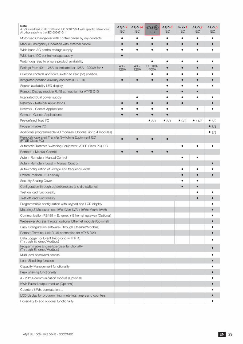
Note: ������=?�/753=.=78�3:������*+8������O�P � �C=3>�?G7/=.=/�57.757+/7?� �BB�:3>75�?*3=?.��3:�3>7������O�P � �
ATyS SIEC
ATyS SdIEC
ATyS IEC
ATyS dIEC
ATyS tIEC
ATyS gIEC
ATyS pIEC
�:3:5=?78��>*+<7:@75�C=3>�/:+35:B�85=@7+�9��85��/:+3*/3? } } } } } } }�*+-*B��)75<7+/���G75*3=:+�C=3>�7F375+*B�>*+8B7 } } } } } } }�=87�9*+8����/:+35:B�@:B3*<7�?-GGB� } } } } } } }�=87�9*+8����/:+35:B�@:B3*<7�?-GGB� }Watchdog relay to ensure product availability } } } } }�*3=+<?�.5:)���Q�����*?�=+8=/*378�:5����� �����.:5�( ��Q�
�����Q����
��� 400A } } } }
�@755=87�/:+35:B?�*+8�.:5/7�?C=3/>�3:�M75:�%:..'�G:?=3=:+ } } } } }�+37<5*378�G:?=3=:+�*-F=B=*5��/:+3*/3?�%�� ��� ���' } } } } } } }�:-5/7�*@*=B*9=B=3������8=?GB*� } } } }�7):37��=?GB*��):8-B7��L���/:++7/3=:+�.:5���Y��� } } }�+37<5*378��-*B�G:C75�?-GGB� } } } } }!73C:5I� �!73C:5I��GGB=/*3=:+? } } } } } }!73C:5I� ��7+?73��GGB=/*3=:+? } } } } } }�7+?73� ��7+?73��GGB=/*3=:+? } } } }�57 87.=+78�.=F78��K� }��K }��K }�OK� }�K� }��K�
�5:<5*))*9B7��K� }��K
�88=3=:+*B�G5:<5*))*9B7��K��):8-B7?�%�G3=:+*B�-G�3:���):8-B7?' }��K�
�7):37B��:G75*378��5*+?.75��C=3/>=+<��D-=G)7+3���� %������B*??���' } } } }�-3:)*3=/��5*+?.75��C=3/>=+<��D-=G)7+3�%������B*??���'���� } } }�7):37�x��*+-*B��:+35:B } } } }�-3:�x��7):37�x��*+-*B��:+35:B } }�-3:�x��7):37�x��:/*B�x��*+-*B��:+35:B }�-3: /:+.=<-5*3=:+�:.�@:B3*<7�*+8�.57D-7+/��B7@7B? } } }�C=3/>��:?=3=:+�����8=?GB*� } } }�7/-5=3���7*B=+<��:@75 } }�:+.=<-5*3=:+�3>5:-<>�G:37+3=:)7375?�*+8�8=G�?C=3/>7? } }Test on load functionality } }Test off load functionality } }�5:<5*))*9B7�/:+.=<-5*3=:+�C=3>�I7�G*8�*+8�����8=?GB*� }�7375=+<����7*?-57)7+3`�I���I"*5��I"��x�I�>��I"*5>��I"�> }�:))-+=/*3=:+�������x��3>75+73�x��3>75+73�<*37C*��%�G3=:+*B' }�79?75@75��//7??�3>5:-<>�:G3=:+*B��3>75+73�):8-B7�%�G3=:+*B' }�*?���:+.=<-5*3=:+�?:.3C*57�%�>5:-<>��3>75+73K�:89-?' }�7):37��75)=+*B��+=3��L���/:++7/3=:+�.:5���Y���� }�*3*��:<<75�.:5��@7+3��7/:58=+<�C=3>����� %�>5:-<>��3>75+73K�:89-?' }�5:<5*))*9B7��+<=+7��F75/=?75�.-+/3=:+*B=3�� %�>5:-<>��3>75+73K�:89-?' }�-B3=�B7@7B�G*??C:58�*//7?? }�:*8��>788=+<�.-+/3=:+ }�*G*/=3���*+*<7)7+3�.-+/3=:+*B=3� }�7*I�?>*@=+<�.-+/3=:+*B=3� }�� ��)��/:))-+=/*3=:+�):8-B7�%�G3=:+*B' }}�>��-B?78�:-3G-3�):8-B7�%�G3=:+*B' }�:-+375?�}�>$�G75)-3*3=:+� }����8=?GB*��.:5�G5:<5*))=+<$�)7375=+<$�3=)75?�*+8�/:-+375? }�:??=9=B=3��3:�*88�:G3=:+*B�.-+/3=:+*B=3� }
�� EN ���������� ����������� ��������
11. ATYS Family: ORDERING INFORMATION
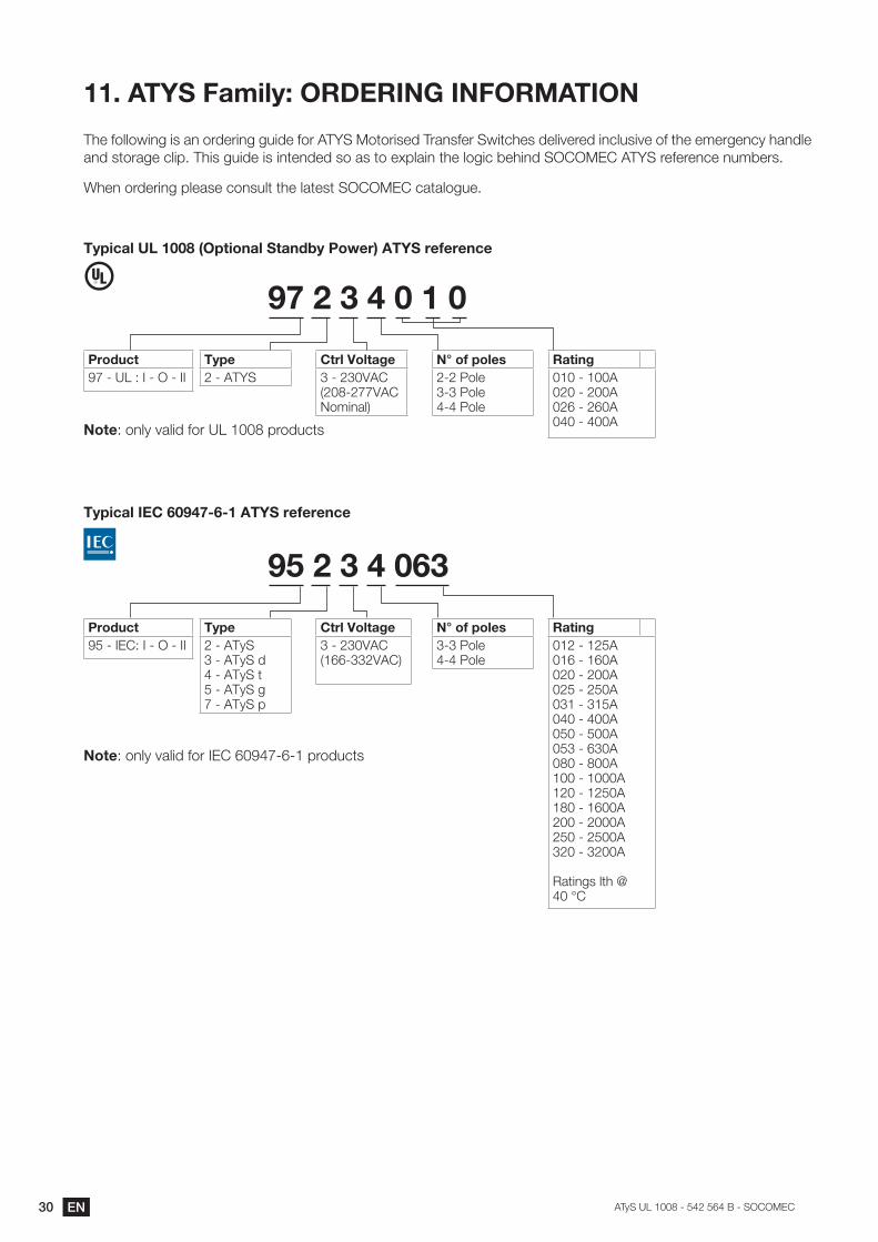
The following is an ordering guide for ATY���:3:5=?78��5*+?.75��C=3/>7?�87B=@7578�=+/B-?=@7�:.�3>7�7)75<7+/��>*+8B7�*+8�?3:5*<7�/B=G���>=?�<-=87�=?�=+37+878�?:�*?�3:�7FGB*=+�3>7�B:<=/�97>=+8�����������YS reference numbers.
�>7+�:5875=+<�GB7*?7�/:+?-B3�3>7�B*37?3���������/*3*B:<-7�
[><���=���������_<�����=������;>���j�����[~����]������
ProductOP� ����`��� ��� ���
Type�� �����
Ctrl Voltage�� ���"�� %�� �PP"���!:)=+*B'
N° of poles� ���:B7� ���:B7�� ���:B7
Rating� ���� ������ ������ ���
()���!��������
Note`�:+B��@*B=8�.:5������G5:8-/3?
[><���=�"%&�'�(�)?'?���[~����]������
ProductO�� ����`��� ��� ���
Type�� ������� ������8�� ������3�� ����S gP� ������G
Ctrl Voltage�� ���"�� %�� ���"��'
N° of poles� ���:B7�� ���:B7
Rating�� ������ ����� ������ ������ ������ ����� ������ ������ ���� ���� ������ ����� ������ ������� ����
�*3=+<?�B3>�����z�
(����!����'!�
Note`�:+B��@*B=8�.:5������O�P � �G5:8-/3?

31EN���������� ����������� ��������

www.socomec.us
HEAD OFFICE
SOCOMEC GROUPSAS SOCOMEC capital 10 816 800€ R.C.S. Strasbourg B 548 500 149 B.P. 60010 - 1, rue de Westhouse F-67235 Benfeld Cedex - FRANCE Tel. +33 3 88 57 41 41 Fax +33 3 88 74 08 00 [email protected]
Socomec worldwide
BELGIUMCritical Power / Power Control & Safety / �������������� ������������[email protected]
FRANCECritical Power / Power Control & Safety / �������������� ������������[email protected]
GERMANYCritical [email protected] Control & Safety / Energy [email protected]
ITALYCritical Power [email protected] Control & Safety / Energy [email protected] [email protected]
NETHERLANDSCritical Power / Power Control & Safety / �������������� ������������[email protected]
POLANDCritical [email protected] Control & Safety / Energy [email protected]
PORTUGALCritical Power / Power Control & Safety / �������������� ������������[email protected]
ROMANIACritical Power / Power Control & Safety / �������������� ������������[email protected]
RUSSIACritical Power / Power Control & Safety / �������������� ������������[email protected]
SLOVENIACritical Power / Power Control & Safety / �������������� ������������[email protected]
SPAINCritical Power / Power Control & Safety / �������������� ������������[email protected]
TURKEYCritical Power / Power Control & Safety / �������������� ������������[email protected]
UNITED KINGDOMCritical [email protected] Control & Safety / Energy [email protected]
Non
con
trac
tual
doc
umen
t. ©
201
4, S
ocom
ec S
AS
. All
right
s re
serv
ed. -
Doc
umen
t prin
ted
on p
aper
from
sus
tain
ably
man
aged
fore
sts.
YOUR DISTRIBUTOR
IN ASIA PACIFIC
AUSTRALIACritical Power / Power Control & [email protected]
CHINACritical Power / Power Control & Safety / Energy [email protected]
INDIACritical [email protected] Control & Safety / Energy [email protected] [email protected]
SINGAPORE Critical Power / Power Control & Safety / Energy [email protected]
THAILANDCritical [email protected]
VIETNAMCritical [email protected]
IN MIDDLE EAST
UNITED ARAB EMIRATESCritical Power / Power Control & Safety / �������������� ������������[email protected]
OTHER COUNTRIES
NORTH AFRICAAlgeria / Morocco / [email protected]
AFRICAOther [email protected]
SOUTH EUROPECyprus / Greece / Israel / [email protected]
SOUTH [email protected]
MORE DETAILSwww.socomec.us/worldwide
IN EUROPE
USA, CANADA & MEXICOCritical Power / Power Control & Safety / Energy Efficiency222 Third Street - Suite 1221 Cambridge, MA 02142 USA Tel. 617 245 0447 Fax 617 245 0437 [email protected]
NORTH AMERICA
��.
�����
����
���
��!
� �
�K�
Related Documents