User's manual Retain for future use Altivar ® 61 APOGEE ® FLN P1 card VW3A3314

Welcome message from author
This document is posted to help you gain knowledge. Please leave a comment to let me know what you think about it! Share it to your friends and learn new things together.
Transcript
User's manual
Retain for future use
Altivar® 61
APOGEE® FLN P1 card
VW3A3314

3
Contents
1. Important Information _______________________________________________________________________________________ 4
2. Before you begin___________________________________________________________________________________________ 5
3. Introduction_______________________________________________________________________________________________ 7
4. Documentation structure_____________________________________________________________________________________ 8
5. Notation _________________________________________________________________________________________________ 9
6. Quick start_______________________________________________________________________________________________ 10
7. Hardware setup __________________________________________________________________________________________ 117. 1. Receipt ____________________________________________________________________________________________ 117. 2. Hardware description _________________________________________________________________________________ 117. 3. Bus voltage measurement procedure_____________________________________________________________________ 127. 4. Installing the card in the drive___________________________________________________________________________ 12
8. Connecting to the bus______________________________________________________________________________________ 138. 1. Cable routing practices________________________________________________________________________________ 138. 2. Network configuration_________________________________________________________________________________ 148. 3. Card connector pinout ________________________________________________________________________________ 14
9. Configuration ____________________________________________________________________________________________ 159. 1. Communication parameters ____________________________________________________________________________ 159. 2. Control ____________________________________________________________________________________________ 169. 3. Communication configuration ___________________________________________________________________________ 239. 4. Monitored parameters_________________________________________________________________________________ 24
10. Diagnostics _____________________________________________________________________________________________ 2510. 1. Checking the address________________________________________________________________________________ 2510. 2. Checking the communication __________________________________________________________________________ 2510. 3. LEDs_____________________________________________________________________________________________ 2510. 4. Control - Command _________________________________________________________________________________ 2610. 5. Communication interruptions __________________________________________________________________________ 2710. 6. Option card hardware conditions _______________________________________________________________________ 27
11. Network objects _________________________________________________________________________________________ 2811. 1. Logical Analog Input (LAI) Summary ____________________________________________________________________ 2811. 2. Logical Analog Output (LAO) Summary __________________________________________________________________ 3011. 3. Logical Digital Input (LDI) Summary_____________________________________________________________________ 3111. 4. Logical Digital Output (LDO) Summary __________________________________________________________________ 33
12. Message box function points _______________________________________________________________________________ 3512. 1. ATV61 Parameter access point table ____________________________________________________________________ 3512. 2. FLN P1 Status Code_________________________________________________________________________________ 35
13. Reports ________________________________________________________________________________________________ 36
While every precaution has been taken in the preparation of this document, Schneider Electric SA assumes no liability for any omissions or errors it may contain, nor for any damages resulting from the application or use of the information herein.
The products described in this document may be changed or modified at any time, either from a technical point of view or in the way they are operated. Their description can in no way be considered contractual.
1. Important Information
NOTICE
Read these instructions carefully, and look at the equipment to become familiar with the device before trying to install, operate, or maintain it. The following special messages may appear throughout this documentation or on the equipment to warn of potential hazards or to call attention to information that clarifies or simplifies a procedure.
PLEASE NOTE
The word "drive" as it is used in this manual refers to the controller portion of the adjustable speed drive as defined by NEC.
Electrical equipment should be installed, operated, serviced, and maintained only by qualified personnel. No responsibility is assumed by Schneider Electric for any consequences arising out of the use of this material.
© 2008 Schneider Electric All Rights Reserved Reserved.
DANGERDANGER indicates an imminently hazardous situation, which, if not avoided, will result in death or serious injury.
WARNINGWarning indicates a potentially hazardous situation, which, if not avoided, can result in death, serious injury, or equipment damage.
CAUTIONCAUTION indicates a potentially hazardous situation, which, if not avoided, can result in injury or equipment damage.
The addition of this symbol to a Danger or Warning safety label indicates that an electrical hazard exists, which will result in personnal if the instruction are not followed.
This is the safety alert symbol. It is used to alert you to potential personal injury hazards. Obey all safety messages that follow this symbol to avoid possible injury or death.
4
2. Before you begin
Read and understand these instructions before performing any procedure with this drive.
DANGERHAZARD OF ELECTRIC SHOCK, EXPLOSION, OR ARC FLASH• Read and understand this manual before installing or operating the Altivar 61 drive. Installation, adjustment, repair, and
maintenance must be performed by qualified personnel.
• The user is responsible for compliance with all international and national electrical code requirements with respect to grounding of all equipment.
• Many parts of this drive, including the printed circuit boards, operate at the line voltage. DO NOT TOUCH. Use only electrically insulated tools.
• DO NOT touch unshielded components or terminal strip screw connections with voltage present.
• DO NOT short across terminals PA/+ and PC/– or across the DC bus capacitors.
• Before servicing the drive:
- Disconnect all power, including external control power that may be present.- Place a “DO NOT TURN ON” label on all power disconnects.- Lock all power disconnects in the open position.- WAIT 15 MINUTES to allow the DC bus capacitors to discharge. Then follow the “Bus Voltage Measurement
Procedure” page 12 to verify that the DC voltage is less than 42 V. The drive LEDs are not indicators of the absence of DC bus voltage.
• Install and close all covers before applying power or starting and stopping the drive.
Failure to follow these instructions will result in death or serious injury.
DANGERUNINTENDED EQUIPMENT OPERATION• Test and ensure that any changes made to the parameter settings do not present any danger to personnel and
equipment during drive operation.• Do not use this APOGEE® FLN P1 option card with ATV61 drive firmware earlier than Version V1.6IE18. These versions
will not detect an inoperative card.
Failure to follow these instructions will result in death or serious injury.
WARNINGDAMAGED DRIVE EQUIPMENTDo not operate or install any drive or drive accessory that appears damaged.
Failure to follow these instructions can result in death, serious injury or additional equipment damage.
5
2. Before you begin
WARNINGLOSS OF CONTROL• The designer of any control scheme must consider the potential failure modes of control paths and, for certain critical
control functions, provide a means to achieve a safe state during and after a path failure. Examples of critical control functions are emergency stop and overtravel stop.
• Separate or redundant control paths must be provided for critical control functions.• System control paths may include communication links. Consideration must be given to the implications of
unanticipated transmission delays or failures of the link.a• Each implementation of an ATV61 APOGEE® FLN P1 option card must be individually and thoroughly tested for proper
operation before being placed into service.
Failure to follow these instructions can result in death, serious injury, or additional equipment damage.
a. For additional information, refer to NEMA ICS 1.1 (latest edition), “Safety Guidelines for the Application, Installation, and Maintenance of Solid State Control” and to NEMA ICS 7.1 (latest edition), “Safety Standards for Construction and Guide for Selection, Installation and Operation of Adjustable-Speed Drive Systems.”
6

3. Introduction
Thank you for purchasing the APOGEE® FLN P1 option card (VW3A3314) for Altivar 61 drive.
IMPORTANT: this communication option card is fully supported with the version V1.6 IE 18 of the Altivar 61 firmware.
By Installing this board into the Altivar 61, data communication can be made with a host computer or other device via APOGEE® FLN P1 network.
The communication card has a 4 pole open style connector for connection to the network: A, B, GND, SCR.
Data exchanges give access to these Altivar 61 functions:• Control (start, stop, reset, setpoint),• Monitoring (status, current, voltage, thermal state...),• Diagnostics (alarms).
The graphic display terminal or the integrated display terminal can be used to access numerous functions for communication configuration and diagnostics.
7
4. Documentation structure
b APOGEE® FLN P1 manualThe present APOGEE® FLN P1 user manual describes:• connection to APOGEE® FLN P1,• configuration of the communication-specific parameters via the integrated HMI or the graphic HMI,• diagnostics,• networks variables.
You will also find important information in other Altivar 61 technical documents. They are available on the Web site www.schneider-electric.com and on the CDROM delivered with each drive.
b Installation manualThe installation manual describes:• how to assemble the drive (particularly how to mount the APOGEE® FLN P1 card),• how to connect the drive.
b Programming manualThe programming manual describes:• the functions and parameters of the drive,• how to use the drive HMI (integrated HMI and graphic HMI).
b Communication parameters manualThe Communication parameters manual describes:• the operating modes specific to communication (CiA 402 state chart),• the interaction between communication and local control (HMI and terminals),• the drive parameters with specific information for use via a communication network (addresses, formats, etc).
When using the APOGEE® FLN P1 card, some sections of the Communication parameters manual are not relevant :- profiles,- I/O profile- CiA 402 profile.
The description of drive parameters is useful only if you use the parameters access function of the APOGEE® FLN P1 (MBOX READ, MBOX WRITE, MBOX PARAM, MBOX DATA).
8
5. Notation
b Drive terminal displaysThe graphic display terminal menus are shown in square brackets. Example: [1.9 COMMUNICATION].
The integrated 7-segment display terminal menus are shown in round brackets with a "-" at the end.Example: (COM-).
Parameter names displayed on the graphic display terminal are written in square brackets.Example: [Fallback speed]
Parameter codes displayed on the integrated 7-segment display terminal are written in round brackets.Example: (LFF).
b FormatsHexadecimal values are written as follows: 16# or 0xBinary values are written as follows: 2#
b AbbreviationsO = OptionalM = Mandatory
9
6. Quick start
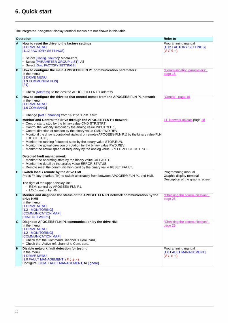
The integrated 7-segment display terminal menus are not shown in this table.
Operation Refer toA How to reset the drive to the factory settings:
[1 DRIVE MENU][1.12 FACTORY SETTINGS]
• Select [Config. Source]: Macro-conf,• Select [PARAMETER GROUP LIST]: All• Select [Goto FACTORY SETTINGS]
Programming manual[1.12 FACTORY SETTINGS] (FCS-)
B How to configure the main APOGEE® FLN P1 communication parameters:In the menu: [1 DRIVE MENU][1.9 COMMUNICATION][P1]
• Check [Address] to the desired APOGEE® FLN P1 address
“Communication parameters”, page 15
C How to configure the drive so that control comes from the APOGEE® FLN P1 networkIn the menu: [1 DRIVE MENU][1.6 COMMAND]
• Change [Ref.1 channel] from "AI1" to "Com. card"
“Control”, page 16
D Monitor and Control the drive through the APOGEE FLN P1 network• Control start / stop by the binary value CMD STP.STRT,• Control the velocity setpoint by the analog value INPUTREF 1,• Control direction of rotation by the binary value CMD FWD.REV,• Monitor if the drive is controlled via local or remote (APOGEE® FLN P1) by the binary value FLN
LOC CTL ACT,• Monitor the running / stopped state by the binary value STOP.RUN,• Monitor the actual direction of rotation by the binary value FWD.REV,• Monitor the actual speed or frequency by the analog value SPEED or PCT OUTPUT.
Detected fault management:• Monitor the operating state by the binary value OK.FAULT,• Monitor the detail by the analog value ERROR STATUS,• Remote reset the communication card by the binary value RESET FAULT.
11. Network objects page 28
E Switch local / remote by the drive HMIPress F4 key (marked TK) to switch alternately from between APOGEE® FLN P1 and HMI.
The right of the upper display line:- REM: control by APOGEE® FLN P1,- LOC: control by HMI.
Programming manualGraphic display terminalDescription of the graphic screen
F Monitor and diagnose the status of the APOGEE FLN P1 network communication by the drive HMIIIn the menu: [1 DRIVE MENU][1.2 - MONITORING][COMMUNICATION MAP][DIAG NETWORK]
“Checking the communication”, page 25
G Diagnose APOGEE® FLN P1 communication by the drive HMIIn the menu: [1 DRIVE MENU][1.2 - MONITORING][COMMUNICATION MAP]• Check that the Command Channel is Com. card,• Check that Active ref. channel is Com. card.
“Checking the communication”, page 25
H Disable network fault detection for testingIn the menu: [1 DRIVE MENU][1.8 FAULT MANAGEMENT] (FLt-) Configure [COM. FAULT MANAGEMENT] to [Ignore].
Programming manual[1.8 FAULT MANAGEMENT] (FLt-)
10
7. Hardware setup
7. 1. Receipt• Check that the card reference printed on the label is the same as that on the delivery note corresponding to the purchase order.• Remove the option card from its packaging and check that it has not been damaged in transit.
Electrostatic Precautions
Observe the following precautions for handling static-sensitive components:• Keep static-producing material such as plastic, upholstery, and carpeting out of the immediate work area.• Store the APOGEE® FLN P1 card in its protective packaging when it is not installed in the drive.• When handling the APOGEE® FLN P1 card, wear a conductive wrist strap connected to the card through a minimum of 1 megohm
resistance.• Avoid touching exposed conductors and component leads with skin or clothing.
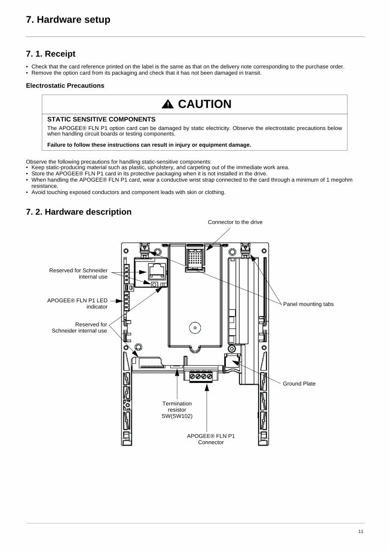
7. 2. Hardware description
CAUTIONSTATIC SENSITIVE COMPONENTSThe APOGEE® FLN P1 option card can be damaged by static electricity. Observe the electrostatic precautions below when handling circuit boards or testing components.
Failure to follow these instructions can result in injury or equipment damage.
Ground Plate
Reserved for Schneider internal use
Terminationresistor
SW(SW102)
APOGEE® FLN P1 Connector
Reserved for Schneider internal use
APOGEE® FLN P1 LED indicator
Connector to the drive
Panel mounting tabs
11
7. Hardware setup
7. 3. Bus voltage measurement procedure
Before working on the drive, remove all power and wait 15 minutes to allow the DC bus to discharge. Then measure the DC bus voltage between the PA/+ and PC/– terminals.
The DC bus voltage can exceed 1,000 Vdc. Use a properly rated voltage-sensing device when performing this procedure. To measure the DC bus voltage:
1 Disconnect all power.
2 Wait 15 minutes to allow the DC bus to discharge.
3 Measure the voltage of the DC bus between the PA/+ and PC/– terminals to ensure that the voltage is less than 42 Vdc.
4 If the DC bus capacitors do not discharge completely, contact your local Schneider Electric representative. Do not repair or operate the drive.
7. 4. Installing the card in the driveRefer to the Installation manual.
DANGERHAZARD OF ELECTRIC SHOCK, EXPLOSION, OR ARC FLASHRead and understand the precautions in “Before you begin” on page 5 before performing this procedure.
Failure to follow these instructions will result in death or serious injury.
12
8. Connecting to the bus
8. 1. Cable routing practices
When wiring Altivar 61 drives to a APOGEE® FLN P1 network, follow all wiring practices required by national and local electrical codes. Also observe the following guidelines:• Avoid areas of high temperature, moisture, vibration, or other mechanical stress.• Secure the cable where necessary to prevent its weight and the weight of other cables from pulling or twisting the cable.• Use cable ducts, raceways, or other structures to protect the cable. Use these structures for signal wiring paths. They must not contain
power wiring.• Avoid sources of electrical interference that can induce noise into the cable. Use the maximum practicable separation from such sources.
When planning cable routing within a building, follow these guidelines:• Maintain a minimum separation of 1 m (3.3 ft) from the following equipment:
- air conditioners and large blowers,- elevators and escalators,- radios and televisions,- intercom and security systems,- fluorescent, incandescent, and neon lighting fixtures.
• Maintain a minimum separation of 3 m (9.8 ft) from the following equipment:- line and motor power wiring,- transformers,- generators,- alternators.
When wiring in electrical equipment rooms or large electrical equipment line-ups, observe the following guidelines for cable segregation and separation of circuits:• Use metallic conduit for drive wiring. Do not run control network and power wiring in the same conduit.• Separate non-metallic conduits or cable trays used to carry power wiring from metallic conduit carrying low-level control network wiring
by at least 300 mm (12 in).• Separate metallic conduits carrying power wiring or low-level control network wiring by at least 80 mm (3 in).• Cross the metallic conduits and non-metallic conduits at right angles whenever power and control network wiring cross.• Attenuate conducted emissions from the drive to the line in some installations to help prevent interference with telecommunication, radio,
and sensitive electronic equipment. Such instances may require attenuating filters. Consult the Altivar catalog for selection and application of these filters.
Maximum length of bus 1000 m (3280 ft) at 19,200 bps (9600 bps max. with APOGEE® FLN P1)Maximum number of stations 32 stations, i.e, 31 slaves (without repeater)
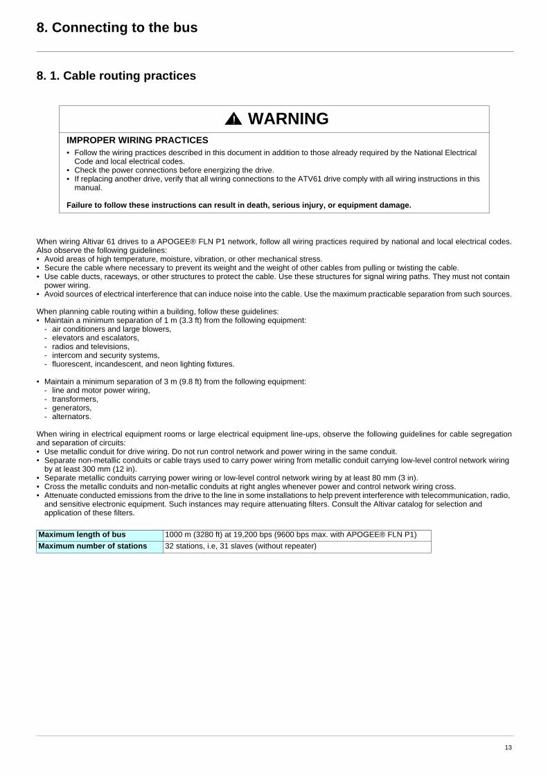
WARNINGIMPROPER WIRING PRACTICES• Follow the wiring practices described in this document in addition to those already required by the National Electrical
Code and local electrical codes.• Check the power connections before energizing the drive.• If replacing another drive, verify that all wiring connections to the ATV61 drive comply with all wiring instructions in this
manual.
Failure to follow these instructions can result in death, serious injury, or equipment damage.
13
8. Connecting to the bus
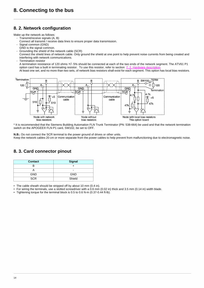
8. 2. Network configurationMake up the network as follows:
- Transmit/receive signals (A, B) Connect all transmit / receive data lines to ensure proper data transmission.
- Signal common (GND) GND is the signal common.
- Grounding the shield of the network cable (SCR) Connect the shield lines of network cable. Only ground the shield at one point to help prevent noise currents from being created and interfering with network communications.
- Termination resistor A termination resistance of 120 ohms +/- 5% should be connected at each of the two ends of the network segment. The ATV61 P1 option card has a built in terminating resistor. To use this resistor, refer to section 7. 2. Hardware description. At least one set, and no more than two sets, of network bias resistors shall exist for each segment. This option has local bias resistors.
* It is recommended that the Siemens Building Automation FLN Trunk Terminator (PN: 538-664) be used and that the network termination switch on the APOGEE® FLN P1 card, SW102, be set to OFF.
N.B.: Do not connect the SCR terminal to the power ground of drives or other units.Keep the network cables 20 cm or more separate from the power cables to help prevent from malfunctioning due to electromagnetic noise.
8. 3. Card connector pinout
• The cable sheath should be stripped off by about 10 mm (0.4 in).• For wiring the terminals, use a slotted screwdriver with a 0.6 mm (0.02 in) thick and 3.5 mm (0.14 in) width blade.• Tightening torque for the terminal block is 0.5 to 0.6 N·m (0.37-0.44 ft·lb).
Contact SignalB +A -
GND GNDSCR Shield
14
9. Configuration
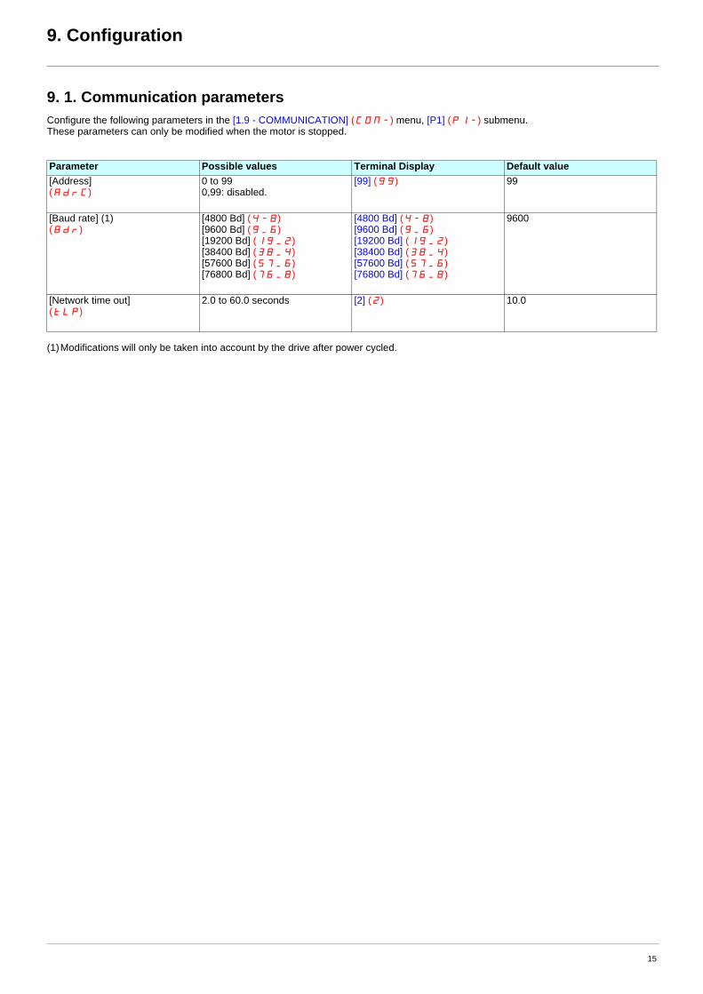
9. 1. Communication parametersConfigure the following parameters in the [1.9 - COMMUNICATION] (COM-) menu, [P1] (P1-) submenu.These parameters can only be modified when the motor is stopped.
(1)Modifications will only be taken into account by the drive after power cycled.
Parameter Possible values Terminal Display Default value[Address](AdrC)
0 to 990,99: disabled.
[99] (99) 99
[Baud rate] (1)(Bdr)
[4800 Bd] (4-8)[9600 Bd] (9_6)[19200 Bd] (19_2)[38400 Bd] (38_4)[57600 Bd] (57_6)[76800 Bd] (76_8)
[4800 Bd] (4-8)[9600 Bd] (9_6)[19200 Bd] (19_2)[38400 Bd] (38_4)[57600 Bd] (57_6)[76800 Bd] (76_8)
9600
[Network time out](tLP)
2.0 to 60.0 seconds [2] (2) 10.0
15
9. Configuration
9. 2. ControlNumerous configurations are possible. For more information, refer to the Programming manual and the Communication parameters manual.The following configurations are just some of the possibilities available.
b Allowed configurationsIf the drive is only monitored by APOGEE® FLN P1:There is no configuration constraint.
If the drive is controlled by APOGEE® FLN P1:The parameter [Profile] (CHCF) must be configured to [Not separ.] (SIM) or [Separate] (SEP). [Not separ.] (SIM) is the default value.It is not allowed to configure the parameter [Profile] (CHCF) to the value [8 serie] (SE8) or [I/O profile] (IO).If an unallowed configuration is set, the drive will trip on [External fault com.] (EPF2).However, if the I/O profile is configured and no command channels are assigned to the communication card, the drive will not trip.
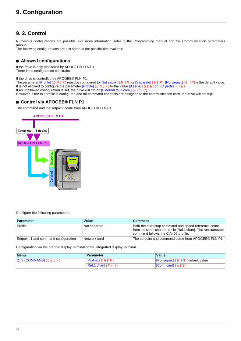
b Control via APOGEE® FLN P1The command and the setpoint come from APOGEE® FLN P1.
Configure the following parameters:
Configuration via the graphic display terminal or the integrated display terminal:
Parameter Value CommentProfile Not separate Both the start/stop command and speed reference come
from the same channel set in [Ref.1 chan]. The run start/stop command follows the CiA402 profile.
Setpoint 1 and command configuration Network card The setpoint and command come from APOGEE® FLN P1.
Menu Parameter Value[1.6 - COMMAND] (CtL-) [Profile] (CHCF) [Not separ.] (SIM): default value
[Ref.1 chan] (Fr1) [Com. card] (nEt)
APOGEE® FLN P1
APOGEE® FLN P1
16
9. Configuration
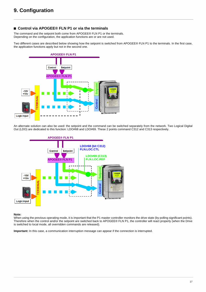
b Control via APOGEE® FLN P1 or via the terminalsThe command and the setpoint both come from APOGEE® FLN P1 or the terminals. Depending on the configuration, the application functions are or are not used.
Two different cases are described below showing how the setpoint is switched from APOGEE® FLN P1 to the terminals. In the first case, the application functions apply but not in the second one.
An alternate solution can also be used: the setpoint and the command can be switched separately from the network. Two Logical Digital Out (LDO) are dedicated to this function: LDO#68 and LDO#69. These 2 points command C312 and C313 respectively.
Note:When using the previous operating mode, it is important that the P1 master controller monitors the drive state (by polling significant points). Therefore when the control and/or the setpoint are switched back to APOGEE® FLN P1, the controller will react properly (when the Drive is switched to local mode, all overridden commands are released).
Important: In this case, a communication interruption message can appear if the connection is interrupted.
APOGEE® FLN P1
APOGEE® FLN P1
APOGEE® FLN P1
APOGEE® FLN P1
LDO#68 (bit C312)FLN.LOC.CTL
LDO#69 (C313)FLN.LOC.REF
17
9. Configuration
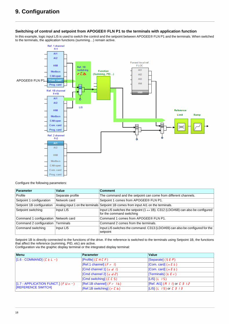
Switching of control and setpoint from APOGEE® FLN P1 to the terminals with application functionIn this example, logic input LI5 is used to switch the control and the setpoint between APOGEE® FLN P1 and the terminals. When switched to the terminals, the application functions (summing…) remain active.
Configure the following parameters:
Setpoint 1B is directly connected to the functions of the drive. If the reference is switched to the terminals using Setpoint 1B, the functions that affect the reference (summing, PID, etc) are active.Configuration via the graphic display terminal or the integrated display terminal:
Parameter Value CommentProfile Separate profile The command and the setpoint can come from different channels.Setpoint 1 configuration Network card Setpoint 1 comes from APOGEE® FLN P1.Setpoint 1B configuration Analog input 1 on the terminals Setpoint 1B comes from input AI1 on the terminals.Setpoint switching Input LI5 Input LI5 switches the setpoint (1 ↔ 1B). C312 (LDO#68) can also be configured
for the command switchingCommand 1 configuration Network card Command 1 comes from APOGEE® FLN P1.Command 2 configuration Terminals Command 2 comes from the terminals.Command switching Input LI5 Input LI5 switches the command. C313 (LDO#69) can also be configured for the
setpoint
Menu Parameter Value[1.6 - COMMAND] (CtL-) [Profile] (CHCF) [Separate] (SEP)
[Ref.1 channel] (Fr1) [Com. card] (nEt)[Cmd channel 1] (cd1) [Com. card] (nEt)[Cmd channel 2] (cd2) [Terminals] (tEr)[Cmd switching] (CCS) [LI5] (LI5)
[1.7 - APPLICATION FUNCT.] (FUn-)[REFERENCE SWITCH]
[Ref.1B channel] (Fr1b) [Ref. AI1] (AI1) or C312
[Ref.1B switching] (rCb) [LI5] (LI5) or C313
APOGEE® FLN P1
18
9. Configuration
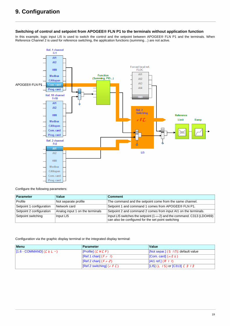
Switching of control and setpoint from APOGEE® FLN P1 to the terminals without application functionIn this example, logic input LI5 is used to switch the control and the setpoint between APOGEE® FLN P1 and the terminals. When Reference Channel 2 is used for reference switching, the application functions (summing…) are not active.
Configure the following parameters:
Configuration via the graphic display terminal or the integrated display terminal:
Parameter Value CommentProfile Not separate profile The command and the setpoint come from the same channel.Setpoint 1 configuration Network card Setpoint 1 and command 1 comes from APOGEE® FLN P1.Setpoint 2 configuration Analog input 1 on the terminals Setpoint 2 and command 2 comes from input AI1 on the terminals.Setpoint switching Input LI5 Input LI5 switches the setpoint (1 ↔ 2) and the command. C313 (LDO#69)
can also be configured for the set point switching
Menu Parameter Value[1.6 - COMMAND] (CtL-) [Profile] (CHCF) [Not separ.] (SIM): default value
[Ref.1 chan] (Fr1) [Com. card] (nEt)[Ref.2 chan] (Fr2) [AI1 ref.] (AI1)[Ref.2 switching] (rFC) [LI5] (LI5) or [C313] C313
APOGEE® FLN P1
19
9. Configuration
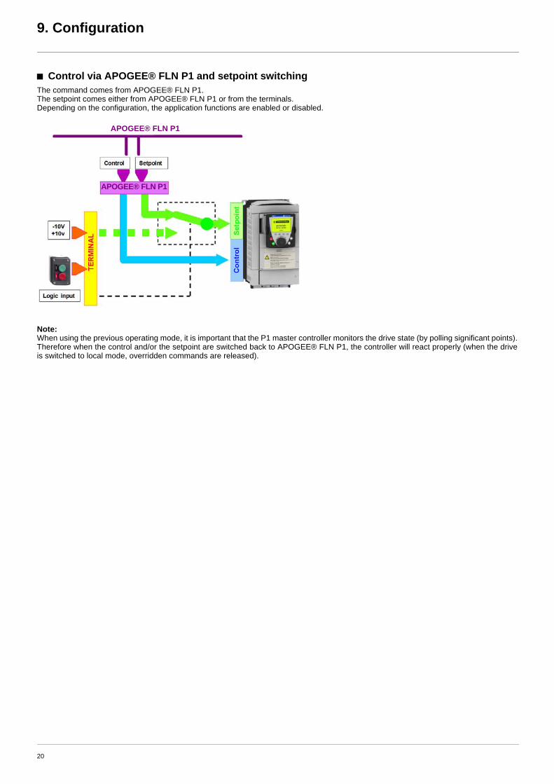
b Control via APOGEE® FLN P1 and setpoint switchingThe command comes from APOGEE® FLN P1.The setpoint comes either from APOGEE® FLN P1 or from the terminals. Depending on the configuration, the application functions are enabled or disabled.
Note:When using the previous operating mode, it is important that the P1 master controller monitors the drive state (by polling significant points). Therefore when the control and/or the setpoint are switched back to APOGEE® FLN P1, the controller will react properly (when the drive is switched to local mode, overridden commands are released).
APOGEE® FLN P1
APOGEE® FLN P1
20
9. Configuration
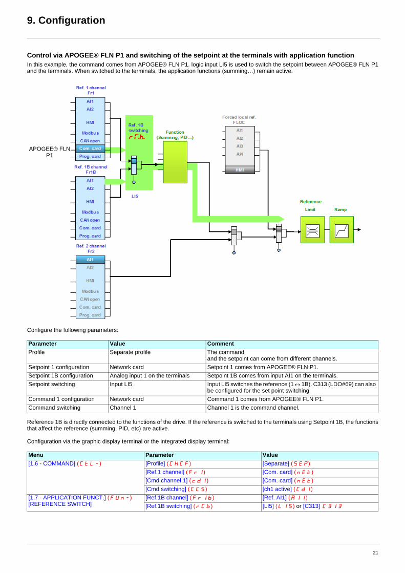
Control via APOGEE® FLN P1 and switching of the setpoint at the terminals with application functionIn this example, the command comes from APOGEE® FLN P1. logic input LI5 is used to switch the setpoint between APOGEE® FLN P1 and the terminals. When switched to the terminals, the application functions (summing…) remain active.
Configure the following parameters:
Reference 1B is directly connected to the functions of the drive. If the reference is switched to the terminals using Setpoint 1B, the functions that affect the reference (summing, PID, etc) are active.
Configuration via the graphic display terminal or the integrated display terminal:
Parameter Value CommentProfile Separate profile The command
and the setpoint can come from different channels.Setpoint 1 configuration Network card Setpoint 1 comes from APOGEE® FLN P1.Setpoint 1B configuration Analog input 1 on the terminals Setpoint 1B comes from input AI1 on the terminals.Setpoint switching Input LI5 Input LI5 switches the reference (1 ↔ 1B). C313 (LDO#69) can also
be configured for the set point switching.Command 1 configuration Network card Command 1 comes from APOGEE® FLN P1.Command switching Channel 1 Channel 1 is the command channel.
Menu Parameter Value[1.6 - COMMAND] (CtL-) [Profile] (CHCF) [Separate] (SEP)
[Ref.1 channel] (Fr1) [Com. card] (nEt)[Cmd channel 1] (cd1) [Com. card] (nEt)[Cmd switching] (CCS) [ch1 active] (Cd1)
[1.7 - APPLICATION FUNCT.] (FUn-)[REFERENCE SWITCH]
[Ref.1B channel] (Fr1b) [Ref. AI1] (AI1)[Ref.1B switching] (rCb) [LI5] (LI5) or [C313] C313
APOGEE® FLN P1
21
9. Configuration
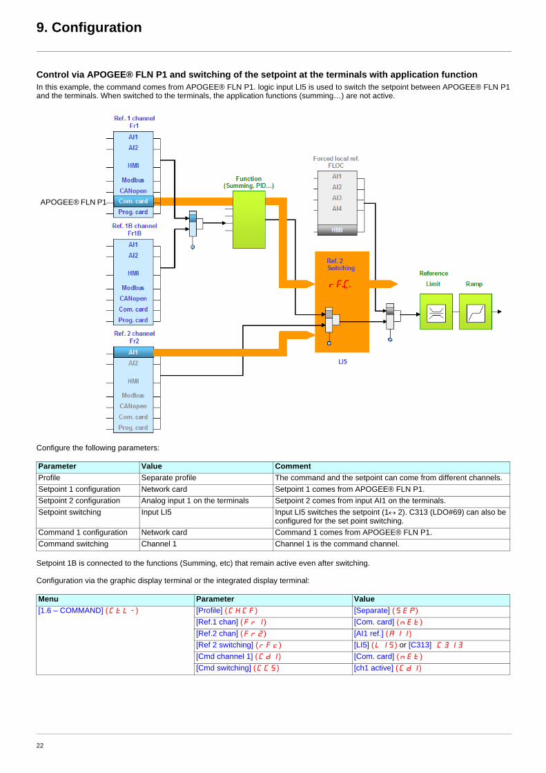
Control via APOGEE® FLN P1 and switching of the setpoint at the terminals with application functionIn this example, the command comes from APOGEE® FLN P1. logic input LI5 is used to switch the setpoint between APOGEE® FLN P1 and the terminals. When switched to the terminals, the application functions (summing…) are not active.
Configure the following parameters:
Setpoint 1B is connected to the functions (Summing, etc) that remain active even after switching.
Configuration via the graphic display terminal or the integrated display terminal:
Parameter Value CommentProfile Separate profile The command and the setpoint can come from different channels.Setpoint 1 configuration Network card Setpoint 1 comes from APOGEE® FLN P1.Setpoint 2 configuration Analog input 1 on the terminals Setpoint 2 comes from input AI1 on the terminals.Setpoint switching Input LI5 Input LI5 switches the setpoint (1↔ 2). C313 (LDO#69) can also be
configured for the set point switching.Command 1 configuration Network card Command 1 comes from APOGEE® FLN P1.Command switching Channel 1 Channel 1 is the command channel.
Menu Parameter Value[1.6 – COMMAND] (CtL-) [Profile] (CHCF) [Separate] (SEP)
[Ref.1 chan] (Fr1) [Com. card] (nEt)[Ref.2 chan] (Fr2) [AI1 ref.] (AI1)[Ref 2 switching] (rFc) [LI5] (LI5) or [C313] C313
[Cmd channel 1] (Cd1) [Com. card] (nEt)[Cmd switching] (CCS) [ch1 active] (Cd1)
APOGEE® FLN P1
22
9. Configuration
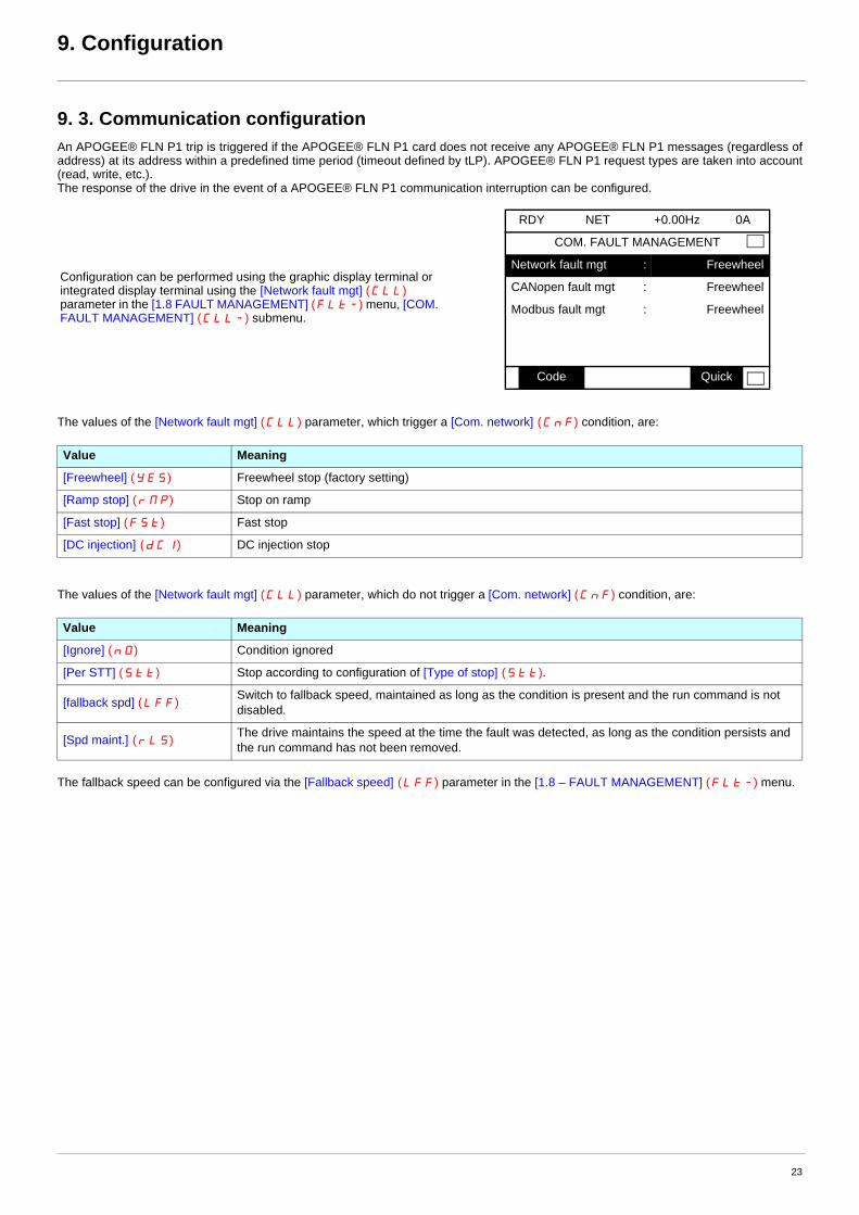
9. 3. Communication configurationAn APOGEE® FLN P1 trip is triggered if the APOGEE® FLN P1 card does not receive any APOGEE® FLN P1 messages (regardless of address) at its address within a predefined time period (timeout defined by tLP). APOGEE® FLN P1 request types are taken into account (read, write, etc.).The response of the drive in the event of a APOGEE® FLN P1 communication interruption can be configured.
The values of the [Network fault mgt] (CLL) parameter, which trigger a [Com. network] (CnF) condition, are:
The values of the [Network fault mgt] (CLL) parameter, which do not trigger a [Com. network] (CnF) condition, are:
The fallback speed can be configured via the [Fallback speed] (LFF) parameter in the [1.8 – FAULT MANAGEMENT] (FLt-) menu.
Configuration can be performed using the graphic display terminal or integrated display terminal using the [Network fault mgt] (CLL) parameter in the [1.8 FAULT MANAGEMENT] (FLt-) menu, [COM. FAULT MANAGEMENT] (CLL-) submenu.
RDY NET +0.00Hz 0A
COM. FAULT MANAGEMENT
Network fault mgt : Freewheel
CANopen fault mgt : Freewheel
Modbus fault mgt : Freewheel
Code Quick
Value Meaning
[Freewheel] (YES) Freewheel stop (factory setting)
[Ramp stop] (rMP) Stop on ramp
[Fast stop] (FSt) Fast stop
[DC injection] (dCI) DC injection stop
Value Meaning
[Ignore] (nO) Condition ignored
[Per STT] (Stt) Stop according to configuration of [Type of stop] (Stt).
[fallback spd] (LFF) Switch to fallback speed, maintained as long as the condition is present and the run command is not disabled.
[Spd maint.] (rLS) The drive maintains the speed at the time the fault was detected, as long as the condition persists and the run command has not been removed.
23
9. Configuration
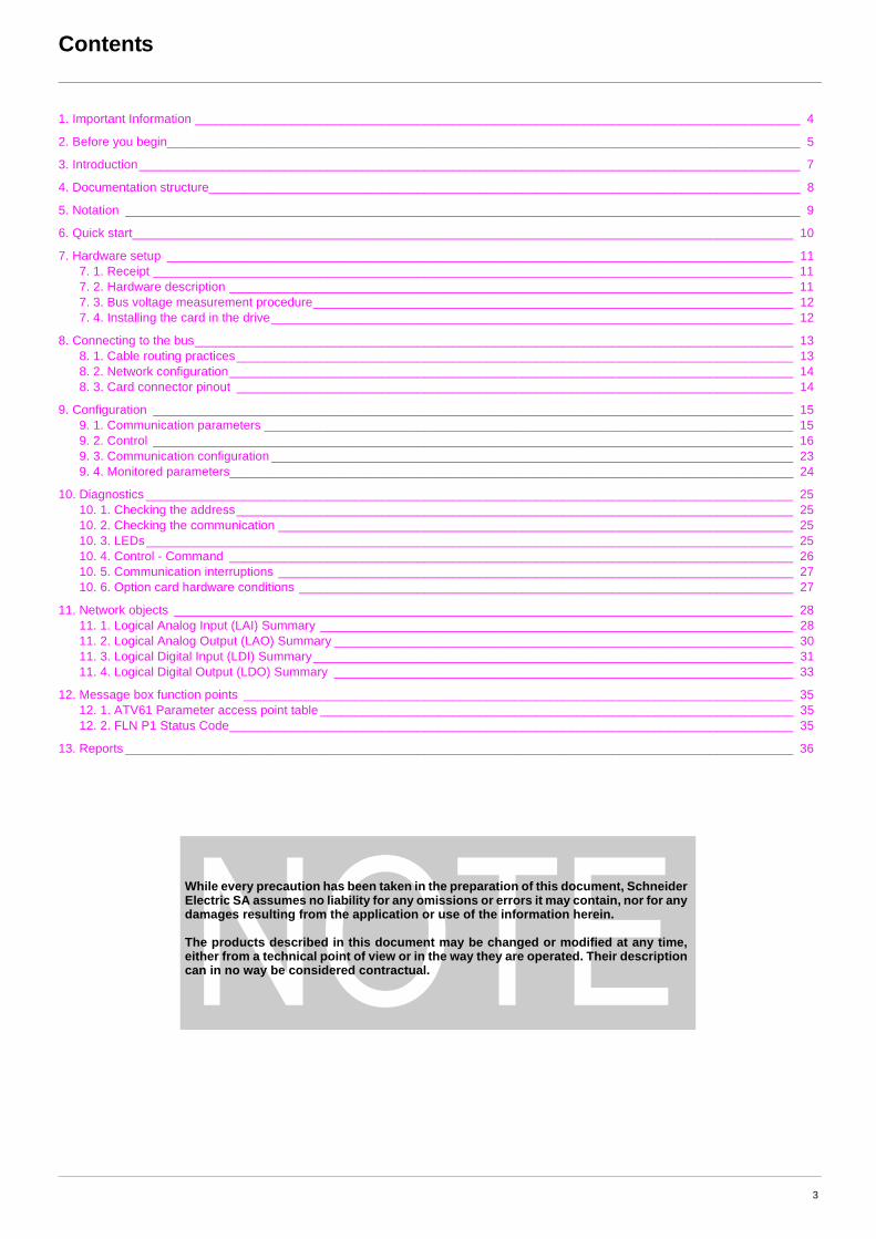
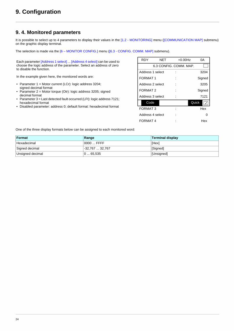
9. 4. Monitored parametersIt is possible to select up to 4 parameters to display their values in the [1.2 - MONITORING] menu ([COMMUNICATION MAP] submenu) on the graphic display terminal.
The selection is made via the [6 – MONITOR CONFIG.] menu ([6.3 - CONFIG. COMM. MAP] submenu).
One of the three display formats below can be assigned to each monitored word:
Each parameter [Address 1 select] ... [Address 4 select] can be used to choose the logic address of the parameter. Select an address of zero to disable the function.
In the example given here, the monitored words are:
• Parameter 1 = Motor current (LCr): logic address 3204; signed decimal format
• Parameter 2 = Motor torque (Otr): logic address 3205; signed decimal format
• Parameter 3 = Last detected fault occurred (LFt): logic address 7121; hexadecimal format
• Disabled parameter: address 0; default format: hexadecimal format
RDY NET +0.00Hz 0A
6.3 CONFIG. COMM. MAP.
Address 1 select : 3204
FORMAT 1 : Signed
Address 2 select : 3205
FORMAT 2 : Signed
Address 3 select : 7121
Code Quick
FORMAT 3 : Hex
Address 4 select : 0
FORMAT 4 : Hex
Format Range Terminal displayHexadecimal 0000 ... FFFF [Hex]Signed decimal -32,767 ... 32,767 [Signed]Unsigned decimal 0 ... 65,535 [Unsigned]
24
10. Diagnostics
10. 1. Checking the addressOn the graphic display terminal or integrated display terminal, check the address that has been set correctly using the [Address] (AdrC)parameter in the [1.9 COMMUNICATION] (COM-) menu, [P1] (MEt) submenu.
10. 2. Checking the communicationOn the graphic display terminal, in the [1.2 - MONITORING] (SUP) menu [COMMUNICATION MAP] (CMM-) menu [DIAG NETWORK](nEt):
Contents of the DIAG NETWORK sub menu with a APOGEE® FLN P1 communication board:
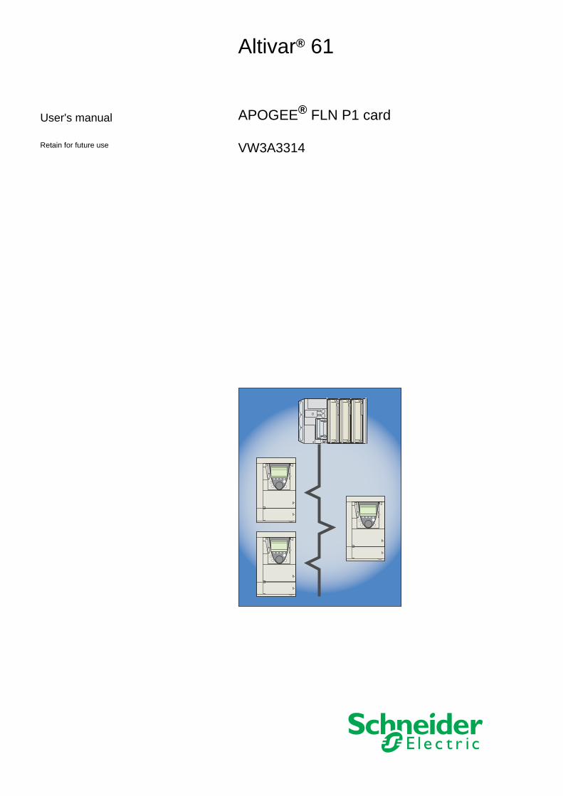
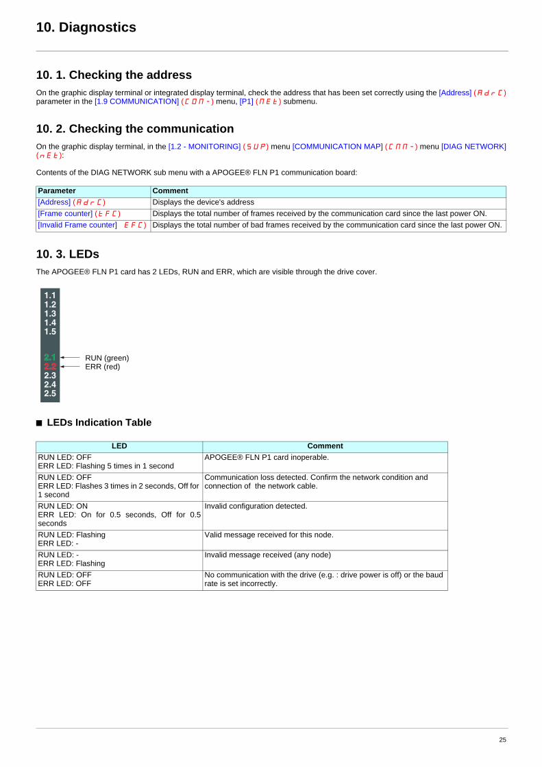
10. 3. LEDsThe APOGEE® FLN P1 card has 2 LEDs, RUN and ERR, which are visible through the drive cover.
b LEDs Indication Table
Parameter Comment[Address] (AdrC) Displays the device's address [Frame counter] (tFC) Displays the total number of frames received by the communication card since the last power ON.[Invalid Frame counter] �EFC) Displays the total number of bad frames received by the communication card since the last power ON.
LED CommentRUN LED: OFFERR LED: Flashing 5 times in 1 second
APOGEE® FLN P1 card inoperable.
RUN LED: OFFERR LED: Flashes 3 times in 2 seconds, Off for 1 second
Communication loss detected. Confirm the network condition and connection of the network cable.
RUN LED: ONERR LED: On for 0.5 seconds, Off for 0.5 seconds
Invalid configuration detected.
RUN LED: FlashingERR LED: -
Valid message received for this node.
RUN LED: -ERR LED: Flashing
Invalid message received (any node)
RUN LED: OFFERR LED: OFF
No communication with the drive (e.g. : drive power is off) or the baud rate is set incorrectly.
1.11.21.31.41.5
2.12.22.32.42.5
RUN (green)ERR (red)
25
10. Diagnostics
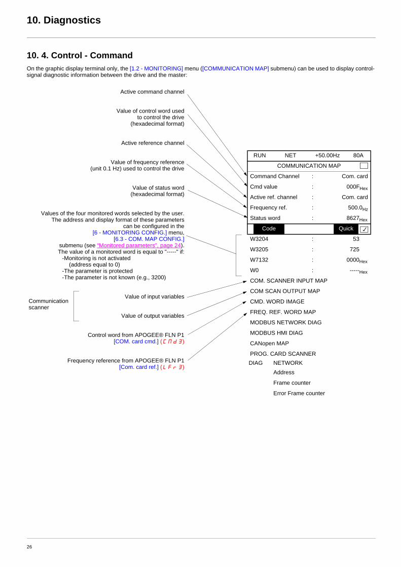
10. 4. Control - CommandOn the graphic display terminal only, the [1.2 - MONITORING] menu ([COMMUNICATION MAP] submenu) can be used to display control-signal diagnostic information between the drive and the master:
RUN NET +50.00Hz 80A
COMMUNICATION MAP
Command Channel : Com. card
Cmd value : 000FHex
Active ref. channel : Com. card
Frequency ref. : 500.0Hz
Status word : 8627Hex
Code Quick
W3204 : 53
W3205 : 725
W7132 : 0000Hex
W0 : -----Hex
COM. SCANNER INPUT MAP
COM SCAN OUTPUT MAP
CMD. WORD IMAGE
FREQ. REF. WORD MAP
MODBUS NETWORK DIAG
MODBUS HMI DIAG
CANopen MAP
PROG. CARD SCANNERDIAG NETWORK
Address
Frame counter
Error Frame counter
Active command channel
Value of control word used to control the drive
(hexadecimal format)
Active reference channel
Value of frequency reference (unit 0.1 Hz) used to control the drive
Value of status word (hexadecimal format)
Values of the four monitored words selected by the user.The address and display format of these parameters
can be configured in the [6 - MONITORING CONFIG.] menu,
[6.3 - COM. MAP CONFIG.] submenu (see “Monitored parameters”, page 24).The value of a monitored word is equal to "-----" if:
-Monitoring is not activated (address equal to 0)
-The parameter is protected-The parameter is not known (e.g., 3200)
Value of input variables
Value of output variables
Control word from APOGEE® FLN P1 [COM. card cmd.] (CMd3)
Frequency reference from APOGEE® FLN P1 [Com. card ref.] (LFr3)
Communication scanner
26
10. Diagnostics
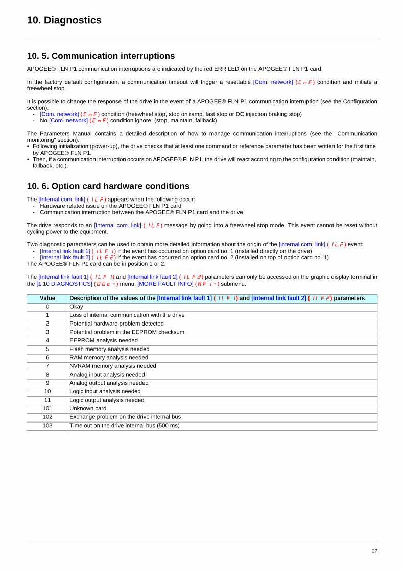
10. 5. Communication interruptionsAPOGEE® FLN P1 communication interruptions are indicated by the red ERR LED on the APOGEE® FLN P1 card.
In the factory default configuration, a communication timeout will trigger a resettable [Com. network] (CnF) condition and initiate a freewheel stop.
It is possible to change the response of the drive in the event of a APOGEE® FLN P1 communication interruption (see the Configuration section).
- [Com. network] (CnF) condition (freewheel stop, stop on ramp, fast stop or DC injection braking stop)- No [Com. network] (CnF) condition ignore, (stop, maintain, fallback)
The Parameters Manual contains a detailed description of how to manage communication interruptions (see the "Communication monitoring" section).• Following initialization (power-up), the drive checks that at least one command or reference parameter has been written for the first time
by APOGEE® FLN P1.• Then, if a communication interruption occurs on APOGEE® FLN P1, the drive will react according to the configuration condition (maintain,
fallback, etc.).
10. 6. Option card hardware conditionsThe [Internal com. link] (ILF) appears when the following occur:
- Hardware related issue on the APOGEE® FLN P1 card- Communication interruption between the APOGEE® FLN P1 card and the drive
The drive responds to an [Internal com. link] (ILF) message by going into a freewheel stop mode. This event cannot be reset without cycling power to the equipment.
Two diagnostic parameters can be used to obtain more detailed information about the origin of the [internal com. link] (ILF) event:- [Internal link fault 1] (ILF1) if the event has occurred on option card no. 1 (installed directly on the drive)- [Internal link fault 2] (ILF2) if the event has occurred on option card no. 2 (installed on top of option card no. 1)
The APOGEE® FLN P1 card can be in position 1 or 2.
The [Internal link fault 1] (ILF1) and [Internal link fault 2] (ILF2) parameters can only be accessed on the graphic display terminal in the [1.10 DIAGNOSTICS] (DGt-) menu, [MORE FAULT INFO] (AFI-) submenu.
Value Description of the values of the [Internal link fault 1] (ILF1) and [Internal link fault 2] (ILF2) parameters0 Okay1 Loss of internal communication with the drive2 Potential hardware problem detected3 Potential problem in the EEPROM checksum4 EEPROM analysis needed5 Flash memory analysis needed6 RAM memory analysis needed7 NVRAM memory analysis needed8 Analog input analysis needed9 Analog output analysis needed
10 Logic input analysis needed11 Logic output analysis needed101 Unknown card102 Exchange problem on the drive internal bus103 Time out on the drive internal bus (500 ms)
27
11. Network objects
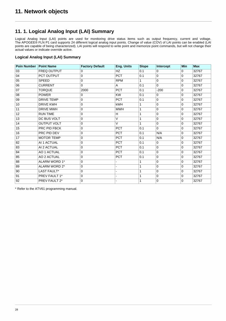
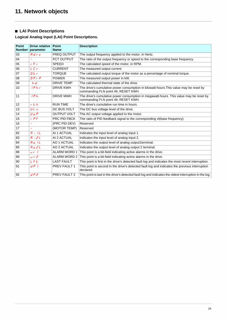
11. 1. Logical Analog Input (LAI) SummaryLogical Analog Input (LAI) points are used for monitoring drive status items such as output frequency, current and voltage. The APOGEE® FLN P1 card supports 24 different logical analog input points. Change of value (COV) of LAI points can be enabled (LAI points are capable of being characterized). LAI points will respond to write point and memorize point commands, but will not change their actual values or indicate override active.
Logical Analog Input (LAI) Summary
* Refer to the ATV61 programming manual.
Poin Number Point Name Factory Default Eng. Units Slope Intercept Min Max03 FREQ OUTPUT 0 HZ 0.1 0 0 3276704 PCT OUTPUT 0 PCT 0.1 0 0 3276705 SPEED 0 RPM 1 0 0 3276706 CURRENT 0 A 0.1 0 0 3276707 TORQUE 2000 PCT 0.1 -200 0 3276708 POWER 0 KW 0.1 0 0 3276709 DRIVE TEMP 0 PCT 0.1 0 0 3276710 DRIVE KWH 0 kWH 1 0 0 3276711 DRIVE MWH 0 MWH 1 0 0 3276712 RUN TIME 0 H 1 0 0 3276713 DC BUS VOLT 0 V 1 0 0 3276714 OUTPUT VOLT 0 V 1 0 0 3276715 PRC PID FBCK 0 PCT 0.1 0 0 3276716 PRC PID DEV 0 PCT 0.1 N/A 0 3276717 MOTOR TEMP 0 PCT 0.1 N/A 0 3276782 AI 1 ACTUAL 0 PCT 0.1 0 0 3276783 AI 2 ACTUAL 0 PCT 0.1 0 0 3276784 AO 1 ACTUAL 0 PCT 0.1 0 0 3276785 AO 2 ACTUAL 0 PCT 0.1 0 0 3276788 ALARM WORD 1* 0 - 1 0 0 3276789 ALARM WORD 2* 0 - 1 0 0 3276790 LAST FAULT* 0 - 1 0 0 3276791 PREV FAULT 1* 0 - 1 0 0 3276792 PREV FAULT 2* 0 - 1 0 0 32767
28
11. Network objects
b LAI Point DescriptionsLogical Analog Input (LAI) Point Descriptions.
Point Number
Drive relative parameter
Point Name
Description
03 Adrc FREQ OUTPUT The output frequency applied to the motor, in Hertz.04 - PCT OUTPUT The ratio of the output frequency or speed to the corresponding base frequency.05 rFr SPEED The calculated speed of the motor, in RPM.06 LCr CURRENT The measured output current.07 Otr TORQUE The calculated output torque of the motor as a percentage of nominal torque.08 Oprp POWER The measured output power in kW. 09 �hd DRIVE TEMP The calculated thermal state of the drive.10 Iphr DRIVE KWH The drive's cumulative power consumption in kilowatt-hours.This value may be reset by
commanding FLN point 49, RESET KWH.11 Iph DRIVE MWH The drive's cumulative power consumption in megawatt-hours. This value may be reset by
commanding FLN point 49, RESET KWH.12 rth RUN TIME The drive's cumulative run time in hours. 13 ULn DC BUS VOLT The DC bus voltage level of the drive.14 Uop OUTPUT VOLT The AC output voltage applied to the motor.15 rpF PRC PID FBCK The ratio of PID feedback signal to the corresponding vl(base frequency).16 - (PRC PID DEV) Reserved 17 - (MOTOR TEMP) Reserved 82 Ai1L AI 1 ACTUAL Indicates the input level of analog input 1. 83 Ai2L AI 2 ACTUAL Indicates the input level of analog input 2.84 Ao1L AO 1 ACTUAL Indicates the output level of analog output1terminal.85 Ao2L AO 2 ACTUAL Indicates the output level of analog output 2 terminal.88 ur1 ALARM WORD 1 This point is a bit-field indicating active alarms in the drive.89 ur2 ALARM WORD 2 This point is a bit-field indicating active alarms in the drive.90 LFt LAST FAULT This point is first in the drive's detected fault log and indicates the most recent interruption. 91 dp1 PREV FAULT 1 This point is second in the drive's detected fault log and indicates the previous interruption
declared.92 dp2 PREV FAULT 2 This point is last in the drive's detected fault log and indicates the oldest interruption in the log.
29
11. Network objects
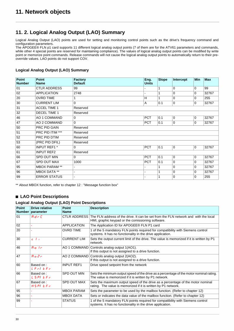
11. 2. Logical Analog Output (LAO) SummaryLogical Analog Output (LAO) points are used for setting and monitoring control points such as the drive's frequency command and configuration parameters.The APOGEE® FLN p1 card supports 11 different logical analog output points (7 of them are for the ATV61 parameters and commands, while other 4 special points are reserved for maintaining compliance). The values of logical analog output points can be modified by write point or memorize point commands. Release commands will not cause the logical analog output points to automatically return to their pre-override values. LAO points do not support COV.
Logical Analog Output (LAO) Summary
** About MBOX function, refer to chapter 12 : "Message function box"
b LAO Point DescriptionsLogical Analog Output (LAO) Point Descriptions
Point Number
Point Name
Factory Default
Eng. Units
Slope Intercept Min Max
01 CTLR ADDRESS 99 - 1 0 0 9902 APPLICATION 2748 - 1 0 0 3276720 OVRD TIME 1 H 1 0 0 25530 CURRENT LIM 0 A 0.1 0 0 3276731 ACCEL TIME 1 Reserved32 DECEL TIME 1 Reserved46 AO 1 COMMAND 0 PCT 0.1 0 0 3276747 AO 2 COMMAND 0 PCT 0.1 0 0 3276750 PRC PID GAIN Reserved51 PRC PID ITIM *** Reserved52 PRC PID DTIM Reserved53 (PRC PID DFIL) Reserved60 INPUT REF1 * 0 PCT 0.1 0 0 3276761 INPUT REF2 Reserved66 SPD OUT MIN 0 PCT 0.1 0 0 3276767 SPD OUT MAX 1000 PCT 0.1 0 0 3276795 MBOX PARAM ** - - 1 0 0 3276796 MBOX DATA ** - - 1 0 0 3276799 ERROR STATUS - - 1 0 0 255
Point Number
Drive relative parameter
Point Name
Description
01 AdrC CTLR ADDRESS The FLN address of the drive. It can be set from the FLN network and with the local HMI, graphic keypad or the comissioning software.
02 - APPLICATION The Application ID for APOGEE® FLN P1 card20 - OVRD TIME 1 of the 5 mandatory FLN points required for compatibility with Siemens control
systems. It has no functionality in the drive application.30 cli CURRENT LIM Sets the output current limit of the drive. The value is memorized if it is written by P1
network.46 Ao1r AO 1 COMMAND Controls analog output 1(AO1).
If this output is not assigned to a drive function. 47 Ao2r AO 2 COMMAND Controls analog output 2(AO2).
If this output is not assigned to a drive function. 60 Based on :
LFr/�tFr
INPUT REF1 Drive speed setpoint from the network
66 Based on : LSp/�tFr
SPD OUT MIN Sets the minimum output speed of the drive as a percentage of the motor nominal rating. The value is memorized if it is written by P1 network.
67 Based on : HSp/�tFr
SPD OUT MAX Sets the maximum output speed of the drive as a percentage of the motor nominal rating. The value is memorized if it is written by P1 network.
95 - MBOX PARAM Sets the parameter to be used by the mailbox function. (Refer to chapter 12)96 - MBOX DATA Sets or indicates the data value of the mailbox function. (Refer to chapter 12)99 - STATUS 1 of the 5 mandatory FLN points required for compatibility with Siemens control
systems. It has no functionality in the drive application.
30
11. Network objects
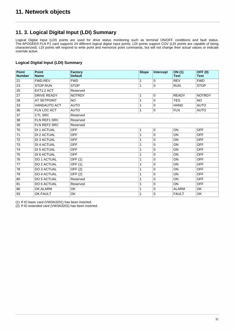
11. 3. Logical Digital Input (LDI) SummaryLogical Digital Input (LDI) points are used for drive status monitoring such as terminal ON/OFF conditions and fault status. The APOGEE® FLN P1 card supports 24 different logical digital input points. LDI points support COV (LDI points are capable of being characterized). LDI points will respond to write point and memorize point commands, but will not change their actual values or indicate override active.
Logical Digital Input (LDI) Summary
(1) If IO basic card (VW3A3201) has been inserted.(2) If IO extended card (VW3A3202) has been inserted.
Point Number
Point Name
Factory Default
Slope Intercept ON (1) Text
OFF (0) Test
21 FWD.REV FWD 1 0 REV FWD23 STOP.RUN STOP 1 0 RUN STOP25 EXT1.2 ACT Reserved27 DRIVE READY NOTRDY 1 0 READY NOTRDY28 AT SETPOINT NO 1 0 YES NO33 HANDAUTO ACT AUTO 1 0 HAND AUTO36 FLN LOC ACT AUTO 1 0 FLN AUTO37 CTL SRC Reserved38 FLN REF1 SRC Reserved39 FLN REF2 SRC Reserved70 DI 1 ACTUAL OFF 1 0 ON OFF71 DI 2 ACTUAL OFF 1 0 ON OFF72 DI 3 ACTUAL OFF 1 0 ON OFF73 DI 4 ACTUAL OFF 1 0 ON OFF74 DI 5 ACTUAL OFF 1 0 ON OFF75 DI 6 ACTUAL OFF 1 0 ON OFF76 DO 1 ACTUAL OFF (1) 1 0 ON OFF77 DO 2 ACTUAL OFF (1) 1 0 ON OFF78 DO 3 ACTUAL OFF (2) 1 0 ON OFF79 DO 4 ACTUAL OFF (2) 1 0 ON OFF80 DO 5 ACTUAL Reserved 1 0 ON OFF81 DO 6 ACTUAL Reserved 1 0 ON OFF86 OK.ALARM OK 1 0 ALARM OK93 OK.FAULT OK 1 0 FAULT OK
31
11. Network objects
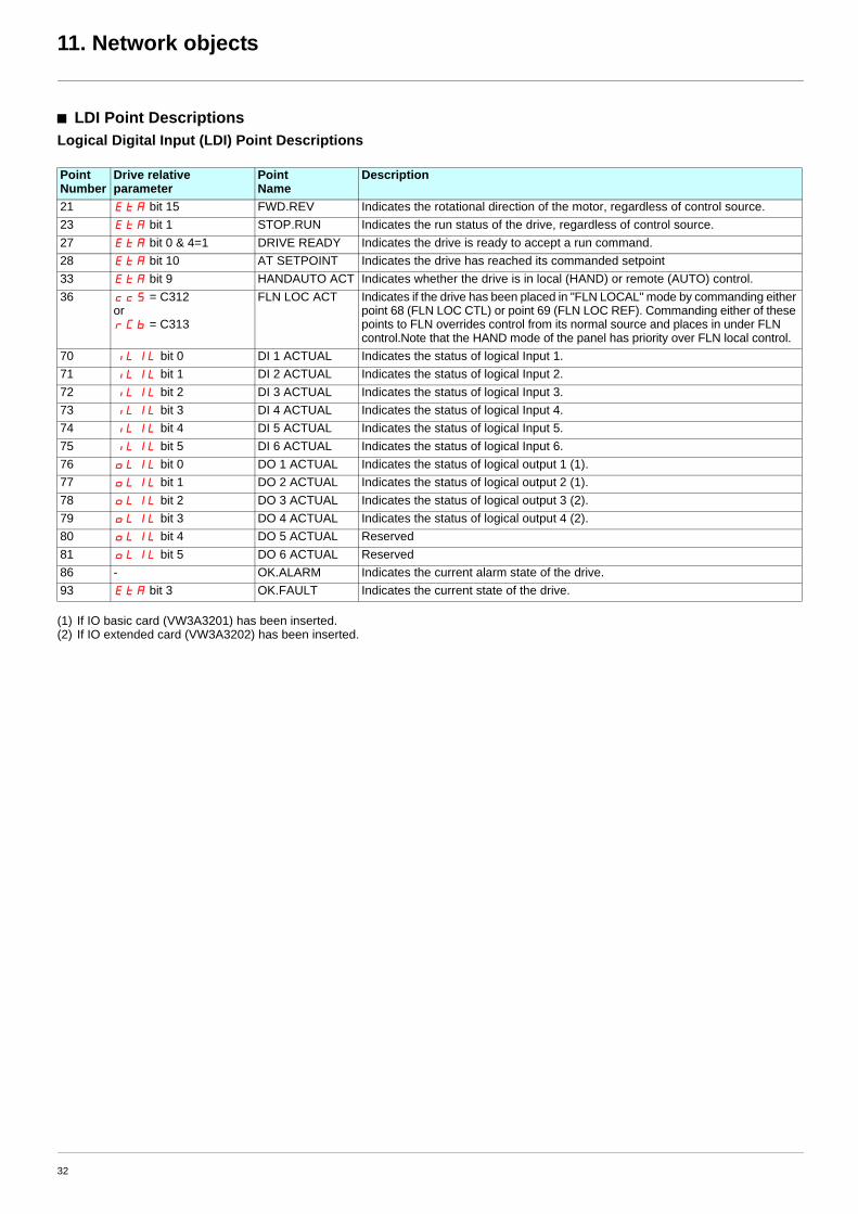
b LDI Point DescriptionsLogical Digital Input (LDI) Point Descriptions
(1) If IO basic card (VW3A3201) has been inserted.(2) If IO extended card (VW3A3202) has been inserted.
Point Number
Drive relative parameter
Point Name
Description
21 EtA bit 15 FWD.REV Indicates the rotational direction of the motor, regardless of control source. 23 EtA bit 1 STOP.RUN Indicates the run status of the drive, regardless of control source. 27 EtA bit 0 & 4=1 DRIVE READY Indicates the drive is ready to accept a run command. 28 EtA bit 10 AT SETPOINT Indicates the drive has reached its commanded setpoint 33 EtA bit 9 HANDAUTO ACT Indicates whether the drive is in local (HAND) or remote (AUTO) control. 36 ccS = C312
or rCb = C313
FLN LOC ACT Indicates if the drive has been placed in "FLN LOCAL" mode by commanding either point 68 (FLN LOC CTL) or point 69 (FLN LOC REF). Commanding either of these points to FLN overrides control from its normal source and places in under FLN control.Note that the HAND mode of the panel has priority over FLN local control.
70 iL1L bit 0 DI 1 ACTUAL Indicates the status of logical Input 1. 71 iL1L bit 1 DI 2 ACTUAL Indicates the status of logical Input 2. 72 iL1L bit 2 DI 3 ACTUAL Indicates the status of logical Input 3.73 iL1L bit 3 DI 4 ACTUAL Indicates the status of logical Input 4.74 iL1L bit 4 DI 5 ACTUAL Indicates the status of logical Input 5.75 iL1L bit 5 DI 6 ACTUAL Indicates the status of logical Input 6.76 oL1L bit 0 DO 1 ACTUAL Indicates the status of logical output 1 (1).77 oL1L bit 1 DO 2 ACTUAL Indicates the status of logical output 2 (1).78 oL1L bit 2 DO 3 ACTUAL Indicates the status of logical output 3 (2).79 oL1L bit 3 DO 4 ACTUAL Indicates the status of logical output 4 (2).80 oL1L bit 4 DO 5 ACTUAL Reserved81 oL1L bit 5 DO 6 ACTUAL Reserved86 - OK.ALARM Indicates the current alarm state of the drive.93 EtA bit 3 OK.FAULT Indicates the current state of the drive.
32
11. Network objects
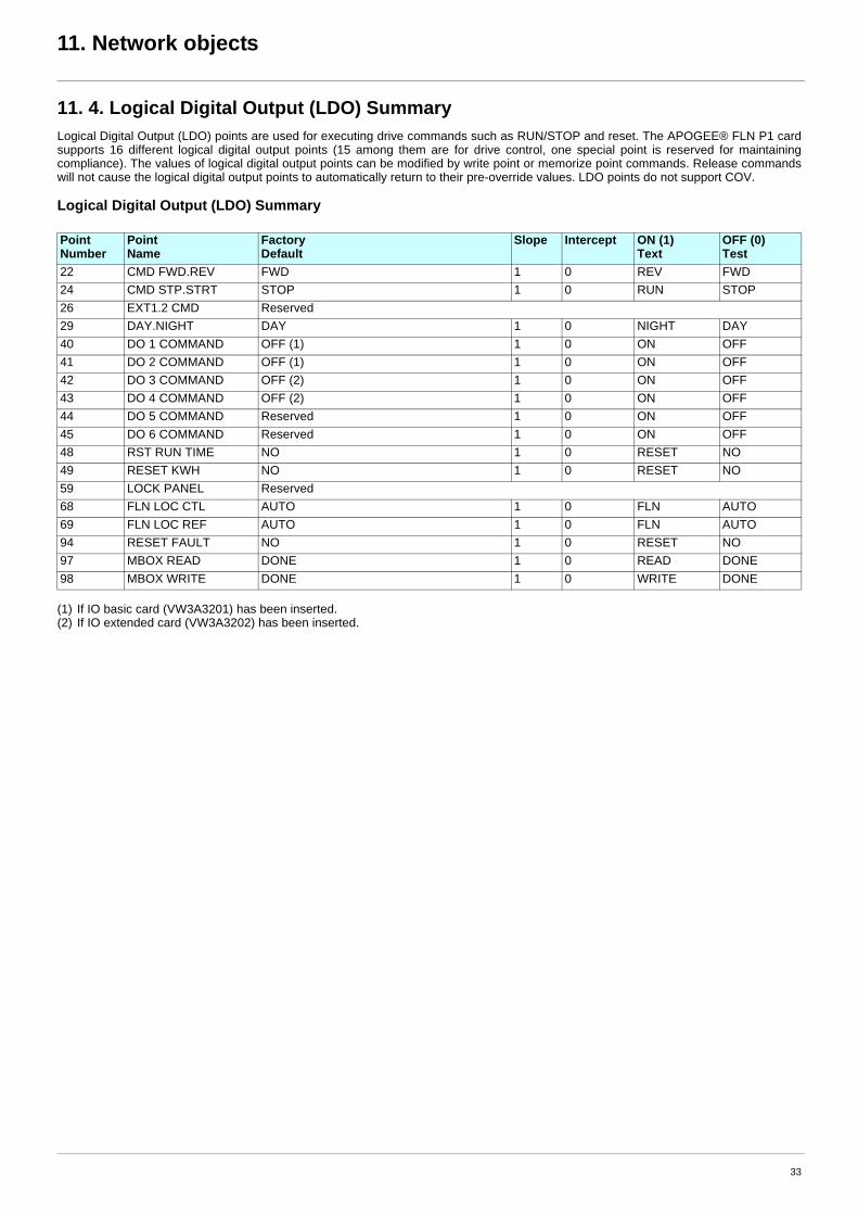
11. 4. Logical Digital Output (LDO) SummaryLogical Digital Output (LDO) points are used for executing drive commands such as RUN/STOP and reset. The APOGEE® FLN P1 card supports 16 different logical digital output points (15 among them are for drive control, one special point is reserved for maintaining compliance). The values of logical digital output points can be modified by write point or memorize point commands. Release commands will not cause the logical digital output points to automatically return to their pre-override values. LDO points do not support COV.
Logical Digital Output (LDO) Summary
(1) If IO basic card (VW3A3201) has been inserted.(2) If IO extended card (VW3A3202) has been inserted.
Point Number
Point Name
Factory Default
Slope Intercept ON (1) Text
OFF (0) Test
22 CMD FWD.REV FWD 1 0 REV FWD24 CMD STP.STRT STOP 1 0 RUN STOP26 EXT1.2 CMD Reserved29 DAY.NIGHT DAY 1 0 NIGHT DAY40 DO 1 COMMAND OFF (1) 1 0 ON OFF41 DO 2 COMMAND OFF (1) 1 0 ON OFF42 DO 3 COMMAND OFF (2) 1 0 ON OFF43 DO 4 COMMAND OFF (2) 1 0 ON OFF44 DO 5 COMMAND Reserved 1 0 ON OFF45 DO 6 COMMAND Reserved 1 0 ON OFF48 RST RUN TIME NO 1 0 RESET NO49 RESET KWH NO 1 0 RESET NO59 LOCK PANEL Reserved68 FLN LOC CTL AUTO 1 0 FLN AUTO69 FLN LOC REF AUTO 1 0 FLN AUTO94 RESET FAULT NO 1 0 RESET NO97 MBOX READ DONE 1 0 READ DONE98 MBOX WRITE DONE 1 0 WRITE DONE
33
11. Network objects
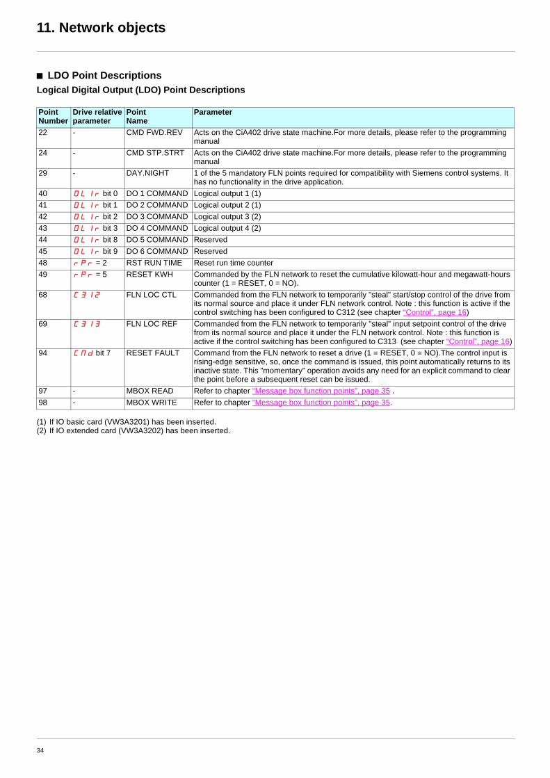
b LDO Point DescriptionsLogical Digital Output (LDO) Point Descriptions
(1) If IO basic card (VW3A3201) has been inserted.(2) If IO extended card (VW3A3202) has been inserted.
Point Number
Drive relative parameter
Point Name
Parameter
22 - CMD FWD.REV Acts on the CiA402 drive state machine.For more details, please refer to the programming manual
24 - CMD STP.STRT Acts on the CiA402 drive state machine.For more details, please refer to the programming manual
29 - DAY.NIGHT 1 of the 5 mandatory FLN points required for compatibility with Siemens control systems. It has no functionality in the drive application.
40 OL1r bit 0 DO 1 COMMAND Logical output 1 (1)41 OL1r bit 1 DO 2 COMMAND Logical output 2 (1)42 OL1r bit 2 DO 3 COMMAND Logical output 3 (2)43 OL1r bit 3 DO 4 COMMAND Logical output 4 (2)44 OL1r bit 8 DO 5 COMMAND Reserved45 OL1r bit 9 DO 6 COMMAND Reserved48 rpr = 2 RST RUN TIME Reset run time counter49 rpr = 5 RESET KWH Commanded by the FLN network to reset the cumulative kilowatt-hour and megawatt-hours
counter (1 = RESET, 0 = NO).68 C312 FLN LOC CTL Commanded from the FLN network to temporarily "steal" start/stop control of the drive from
its normal source and place it under FLN network control. Note : this function is active if the control switching has been configured to C312 (see chapter “Control”, page 16)
69 C313 FLN LOC REF Commanded from the FLN network to temporarily "steal" input setpoint control of the drive from its normal source and place it under the FLN network control. Note : this function is active if the control switching has been configured to C313 (see chapter “Control”, page 16)
94 CMd bit 7 RESET FAULT Command from the FLN network to reset a drive (1 = RESET, 0 = NO).The control input is rising-edge sensitive, so, once the command is issued, this point automatically returns to its inactive state. This "momentary" operation avoids any need for an explicit command to clear the point before a subsequent reset can be issued.
97 - MBOX READ Refer to chapter “Message box function points”, page 35 .98 - MBOX WRITE Refer to chapter “Message box function points”, page 35.
34
12. Message box function points
12. 1. ATV61 Parameter access point table
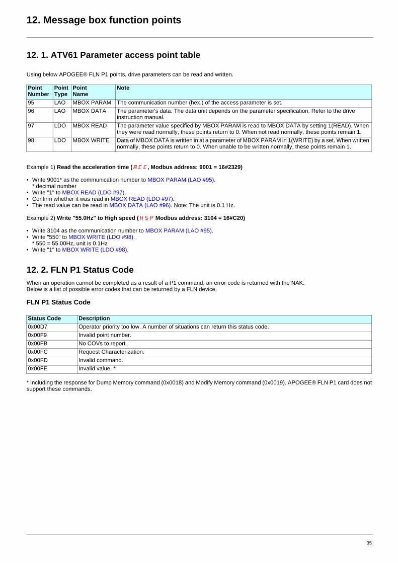
Using below APOGEE® FLN P1 points, drive parameters can be read and written.
Example 1) Read the acceleration time (ACC, Modbus address: 9001 = 16#2329)
• Write 9001* as the communication number to MBOX PARAM (LAO #95). * decimal number
• Write "1" to MBOX READ (LDO #97).• Confirm whether it was read in MBOX READ (LDO #97).• The read value can be read in MBOX DATA (LAO #96). Note: The unit is 0.1 Hz.
Example 2) Write "55.0Hz" to High speed (HSP Modbus address: 3104 = 16#C20)
• Write 3104 as the communication number to MBOX PARAM (LAO #95).• Write "550" to MBOX WRITE (LDO #98).
* 550 = 55.00Hz, unit is 0.1Hz• Write "1" to MBOX WRITE (LDO #98).
12. 2. FLN P1 Status CodeWhen an operation cannot be completed as a result of a P1 command, an error code is returned with the NAK.Below is a list of possible error codes that can be returned by a FLN device.
FLN P1 Status Code
* Including the response for Dump Memory command (0x0018) and Modify Memory command (0x0019). APOGEE® FLN P1 card does not support these commands.
Point Number
Point Type
Point Name
Note
95 LAO MBOX PARAM The communication number (hex.) of the access parameter is set.96 LAO MBOX DATA The parameter's data. The data unit depends on the parameter specification. Refer to the drive
instruction manual.97 LDO MBOX READ The parameter value specified by MBOX PARAM is read to MBOX DATA by setting 1(READ). When
they were read normally, these points return to 0. When not read normally, these points remain 1.98 LDO MBOX WRITE Data of MBOX DATA is written in at a parameter of MBOX PARAM in 1(WRITE) by a set. When written
normally, these points return to 0. When unable to be written normally, these points remain 1.
Status Code Description0x00D7 Operator priority too low. A number of situations can return this status code.0x00F9 Invalid point number.0x00FB No COVs to report.0x00FC Request Characterization.0x00FD Invalid command.0x00FE Invalid value. *
35
13. Reports
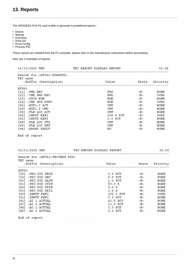
The APOGEE® FLN P1 card is able to generate 6 predefined reports :
• Device• Startup• Overview• Drive I/O• Drive Config• Process PID
These reports are initiated from the P1 controller, please refer to the manufacturer instructions before proceeding.
Here are 2 examples of reports:
36

2008-08
atv61_Apogée_FLN_P1_en_v2
Related Documents