APPLICATION NOTE Atmel AT02346: Using the MPU on Atmel Cortex-M3 / Cortex -M4 based Microcontrollers Atmel 32-bit Microcontroller This application note helps users to get familiar wth the MPU in the SAM3/4 device series. By running the demostration application on SAM3X, users can quickly understand the usages of the MPU, such as peripheral protection, data access protection and instruction protection. Features • Atmel ® SAM3/4 microcontroller with Memory Protection Unit (MPU) • MPU introduction • Peripheral protection with MPU • Data access protection with MPU • Instruction protection with MPU 42128A-SAM-04/2013

Welcome message from author
This document is posted to help you gain knowledge. Please leave a comment to let me know what you think about it! Share it to your friends and learn new things together.
Transcript
APPLICATION NOTE
Atmel AT02346: Using the MPU on Atmel Cortex-M3 / Cortex-M4 based Microcontrollers
Atmel 32-bit Microcontroller
This application note helps users to get familiar wth the MPU in the SAM3/4 device series. By running the demostration application on SAM3X, users can quickly understand the usages of the MPU, such as peripheral protection, data access protection and instruction protection.
Features
• Atmel® SAM3/4 microcontroller with Memory Protection Unit (MPU) • MPU introduction • Peripheral protection with MPU • Data access protection with MPU • Instruction protection with MPU
42128A-SAM-04/2013
Atmel AT02346: Using the MPU on Atmel Cortex-M3 / Cortex-M4 based Microcontrollers 42128A-SAM-04/2013
2
Table of Contents
1. Introduction ........................................................................................ 3
2. Reference .......................................................................................... 4
3. Introduction to the MPU of Cortex-M3/4 ............................................. 5 3.1 MPU of the Cortex-M3/4 ................................................................................... 5 3.2 MPU Software Foundations .............................................................................. 5
3.2.1 Memory Type Introduction .................................................................. 5 3.2.2 MPU Region Attributes ....................................................................... 6 3.2.3 Memory access ................................................................................... 6 3.2.4 MPU Region Update ........................................................................... 7
4. Software Implementation.................................................................... 7 4.1 Purpose ............................................................................................................. 7 4.2 MPU Software Interface .................................................................................... 7
4.2.1 MPU_Enable ....................................................................................... 7 4.2.2 MPU_SetRegionNum.......................................................................... 8 4.2.3 MPU_DisableRegion........................................................................... 8 4.2.4 MPU_SetRegion ................................................................................. 8
4.3 Setup MPU Regions .......................................................................................... 9 4.3.1 Protected Memory Regions ................................................................ 9 4.3.2 Protected Peripherals ......................................................................... 9 4.3.3 Enable the MPU ................................................................................ 10
4.4 Update MPU Region ....................................................................................... 10 4.5 Memory Management Fault Handler ............................................................... 11 4.6 Example Main Routine .................................................................................... 11
4.6.1 Major routines ................................................................................... 11 4.6.2 Peripheral Protection Usage ............................................................. 12 4.6.3 Data Access Protection Usage ......................................................... 14 4.6.4 Instruction Protection ........................................................................ 16
5. Revision History ............................................................................... 19
Atmel AT02346: Using the MPU on Atmel Cortex-M3 / Cortex-M4 based Microcontrollers 42128A-SAM-04/2013
3
1. Introduction This document is intended to get the user familiar with the Memory Protection Unit (MPU) provided by most of the Atmel SAM3/4 series, which include SAM3X, SAM3S, SAM3U, SAM4S, SAM4L and SAM4E. The SAM3N does not have the MPU component.
The processor MPU is a component for memory protection. It divides the memory map into a number of regions with privilege permissions and access rules. Through the MPU provided by the SAM3/4 series, it is easy to implement a security system with some of the system spaces reserved for privilege access.
A demonstration program is provided with this application note. This demo application is based on SAM3X and the words of SAM3/4 series in this document do not include the SAM3N.
The following of the document describes how to use the MPU provided by the SAM3/4 series.
Atmel AT02346: Using the MPU on Atmel Cortex-M3 / Cortex-M4 based Microcontrollers 42128A-SAM-04/2013
4
2. Reference Atmel: SAM3/4 datasheets
ARM®: Application Note 179: Cortex™-M3 Embedded Software Development
Atmel AT02346: Using the MPU on Atmel Cortex-M3 / Cortex-M4 based Microcontrollers 42128A-SAM-04/2013
5
3. Introduction to the MPU of Cortex-M3/4 This section describes the MPU of the Cortex™-M3/4 implemented in the SAM3/4 series.
3.1 MPU of the Cortex-M3/4 The MPU implemented in the SAM3/4 series supports the standard ARMv7 Protected Memory System Architecture (PMSAv7) model. It provides eight separate memory regions. Each of the regions could be divided into eight sub regions for more flexible usages. The attribute settings of these regions can be independent. The MPU memory map is unified, it means the instruction access and data access have the same region attributes.
3.2 MPU Software Foundations The functions provided with the MPU are based on the unit of region. A region is a part of the memory map with individual access rules. The memory type and attributes determine the behavior of the access to a region.
3.2.1 Memory Type Introduction The system could have the following memory types:
• Normal
• Device
• Strongly-ordered
• Shareable
• Execute Never (XN)
Device or Strongly-ordered usually means the memory region is not cacheable or bufferable.
Shareable means the memory region can be accessed by multiple bus masters concurrently without errors.
XN stands for any attempt to execute an instruction in that region results in permission fault.
Refer to the SAM3/4 datasheets series for more information on these types.
The memory mapping of each SAM3/4 series defines the general memory spaces. Each memory space has a definite memory type in logical operations. This is the default value for the memory type bits in the MPU region attribute register and also the basic design principle of an MPU system.
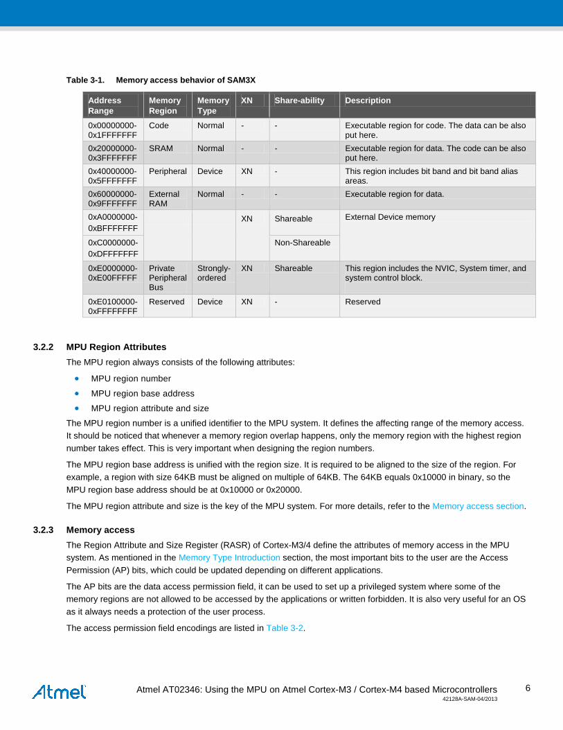
Take SAM3X for example, the basic memory access behaviors are listed in the Table 3-1. All the region attributes for the memory type must follow this table, for example, the peripheral region can never be set as a non-XN type, and it is always set as device type, non cacheable, non bufferable, non shareable and non executable. This definition is common for the other SAM3/4 device series.
Atmel AT02346: Using the MPU on Atmel Cortex-M3 / Cortex-M4 based Microcontrollers 42128A-SAM-04/2013
6
Table 3-1. Memory access behavior of SAM3X
Address Range
Memory Region
Memory Type
XN Share-ability Description
0x00000000- 0x1FFFFFFF
Code Normal - - Executable region for code. The data can be also put here.
0x20000000- 0x3FFFFFFF
SRAM Normal - - Executable region for data. The code can be also put here.
0x40000000- 0x5FFFFFFF
Peripheral Device XN - This region includes bit band and bit band alias areas.
0x60000000- 0x9FFFFFFF
External RAM
Normal - - Executable region for data.
0xA0000000- 0xBFFFFFFF
XN Shareable External Device memory
0xC0000000- 0xDFFFFFFF
Non-Shareable
0xE0000000- 0xE00FFFFF
Private Peripheral Bus
Strongly-ordered
XN Shareable This region includes the NVIC, System timer, and system control block.
0xE0100000- 0xFFFFFFFF
Reserved Device XN - Reserved
3.2.2 MPU Region Attributes The MPU region always consists of the following attributes:
• MPU region number
• MPU region base address
• MPU region attribute and size
The MPU region number is a unified identifier to the MPU system. It defines the affecting range of the memory access. It should be noticed that whenever a memory region overlap happens, only the memory region with the highest region number takes effect. This is very important when designing the region numbers.
The MPU region base address is unified with the region size. It is required to be aligned to the size of the region. For example, a region with size 64KB must be aligned on multiple of 64KB. The 64KB equals 0x10000 in binary, so the MPU region base address should be at 0x10000 or 0x20000.
The MPU region attribute and size is the key of the MPU system. For more details, refer to the Memory access section.
3.2.3 Memory access The Region Attribute and Size Register (RASR) of Cortex-M3/4 define the attributes of memory access in the MPU system. As mentioned in the Memory Type Introduction section, the most important bits to the user are the Access Permission (AP) bits, which could be updated depending on different applications.
The AP bits are the data access permission field, it can be used to set up a privileged system where some of the memory regions are not allowed to be accessed by the applications or written forbidden. It is also very useful for an OS as it always needs a protection of the user process.
The access permission field encodings are listed in Table 3-2.

Atmel AT02346: Using the MPU on Atmel Cortex-M3 / Cortex-M4 based Microcontrollers 42128A-SAM-04/2013
7
Table 3-2. AP encoding
AP[2:0] Privileged permissions
Unprivileged permissions
Description
000 No access No access All access generate a permission fault
001 RW No access Access from privileged software only
010 RW RO Writes by unprivileged software generate a permission fault
011 RW RW Full access
100 Unpredictable Unpredictable Reserved
101 RO No access Read by privileged
110 RO RO Read only, by privileged or unprivileged software
111 RO RO Read only, by privileged or unprivileged software
3.2.4 MPU Region Update The MPU region attribute can be updated at runtime to satisfy different requirements. To update a region’s attribute, the following actions should be taken:
• The region must be disabled before changing the attributes.
• To avoid unexpected behavior, the interrupt routine must be disabled before the update.
• The access to the MPU registers should be aligned. A DSB and ISB instruction are required before MPU updating, which means to make sure the outstanding memory transfers are finished. This memory barrier instructions are not required if the update procedure happens in an exception handler, the memory barrier behavior would automatically take place in an exception entry and return.
For more information, refer to the datasheet SAM3/4 datasheets.
4. Software Implementation
4.1 Purpose The demonstration application provided with this application note shows how to setup an MPU system and the basic usages of the memory protection.
It has sample code to set up the MPU regions, update attributes of a MPU region. It also demonstrates three common usages for MPU: memory protection, peripheral protection and privileged code access protection.
The demonstration application is based on IAR Embedded Workbench® 5.50.
4.2 MPU Software Interface The following are the MPU software interfaces available in the application. For more details, refer to the mpu.c in the demo application.
4.2.1 MPU_Enable This function is used to enable/disable the MPU module.
Atmel AT02346: Using the MPU on Atmel Cortex-M3 / Cortex-M4 based Microcontrollers 42128A-SAM-04/2013
8
The function prototype is:
void MPU_Enable( uint32_t dwMPUEnable )
• Parameter Description:
dwMPUEnable: Enable/Disable the MPU module.
• Return value:
None
4.2.2 MPU_SetRegionNum This function is used to set the current active region number. After setting the active region number, the selected region can be disabled or the region attribute can be updated.
The function prototype is:
void MPU_SetRegionNum( uint32_t dwRegionNum )
• Parameter Description:
dwRegionNum: The region number of the target memory.
• Return value:
None
4.2.3 MPU_DisableRegion This function is used to disable the current active memory region. The active memory region number could be gotten from the Region Number Register (RNR) of Cortex-M3. This function is always following the function MPU_SetRegionNum.
The function prototype is:
void MPU_DisableRegion( void )
• Parameter Description:
None
• Return value:
None
4.2.4 MPU_SetRegion This function is used to setup a MPU region.
The function prototype is:
void void MPU_SetRegion( uint32_t dwRegionBaseAddr, uint32_t dwRegionAttr )
• Parameter Description:
dwRegionBaseAddr: The base address of the MPU region selected by the region number; it also updates the region number. dwRegionAttr: MPU region attributes of the selected region by the region number. It defines the access privilege of a memory region.
Atmel AT02346: Using the MPU on Atmel Cortex-M3 / Cortex-M4 based Microcontrollers 42128A-SAM-04/2013
9
• Return value:
None
4.3 Setup MPU Regions The MPU regions should be set up during the chip initialization. A good location is at the beginning of the main() function. MPU configuration is a three-step operation: protected memory regions are defined first, then peripherals and finally, the MPU is enabled.
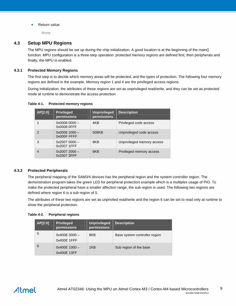
4.3.1 Protected Memory Regions The first step is to decide which memory areas will be protected, and the types of protection. The following four memory regions are defined in the example. Memory region 1 and 4 are the privileged access regions.
During initialization, the attributes of these regions are set as unprivileged read/write, and they can be set as protected mode at runtime to demonstrate the access protection.
Table 4-1. Protected memory regions
AP[2:0] Privileged permissions
Unprivileged permissions
Description
1 0x0008 0000 – 0x0008 0FFF
4KB Privileged code access
2 0x0008 1000 – 0x000F FFFF
508KB Unprivileged code access
3 0x2007 0000 – 0x2007 1FFF
8KB Unprivileged memory access
4 0x2007 2000 – 0x2007 3FFF
8KB Privileged memory access
4.3.2 Protected Peripherals The peripheral mapping of the SAM3/4 devices has the peripheral region and the system controller region. The demonstration program takes the green LED for peripheral protection example which is a multiplex usage of PIO. To make the protected peripheral have a smaller affection range, the sub region is used. The following two regions are defined where region 6 is a sub region of 5.
The attributes of these two regions are set as unpriviled read/write and the region 6 can be set to read only at runtime to show the peripheral protection.
Table 4-2. Peripheral regions
AP[2:0] Privileged permissions
Unprivileged permissions
Description
5 0x400E 0000 – 0x400E 1FFF
8KB Base system controller region
6 0x400E 1000 – 0x400E 13FF
1KB Sub region of the base

Atmel AT02346: Using the MPU on Atmel Cortex-M3 / Cortex-M4 based Microcontrollers 42128A-SAM-04/2013
10
4.3.3 Enable the MPU The memory management fault exception must be set before enable the MPU module; the system will enter the memory management fault handler if an illegal access happens.
/* Enable the memory management fault exception */ SCB->SHCSR |= SCB_SHCSR_MEMFAULTENA_Msk; /* Enable the MPU region */ MPU_Enable( MPU_ENABLE | MPU_BGENABLE );
4.4 Update MPU Region According to the MPU region update theory described in the MPU Region Update section, the MPU region update procedure in Figure 4-1 should be followed:
Figure 4-1. MPU Update Procedure
Prepare for MPU update
in exceptionhandler?
Disable interrupt
Clean upmemory transfer
Disable region
YES
NO
in exceptionhandler?
Clean upmemory transfer
Enable region
Update memoryregion attributes
Enable interrupt
NO
YES

Atmel AT02346: Using the MPU on Atmel Cortex-M3 / Cortex-M4 based Microcontrollers 42128A-SAM-04/2013
11
The MPU registers can only be modified under privileged mode, so the software must switch the system to the privileged mode before the procedure described in Figure 4-1. The unprivileged mode can’t be switched to the privileged mode directly because the switch instructions only valid under privileged mode. It can be solved by an exception. An exception handler is always under privileged mode in the Cortex-M3/4 architecture, so this switch can be done through a supervisor call: SVC.
The demo application calls the SVC, and then the system mode can be changed to the privileged.
/* Call the supervisor call to enter the privilege mode */ __SVC(); /* Supervisor call handler, switched to the privileged mode */ void SVC_Handler(void) { __set_CONTROL(PRIVILEGE_MODE); }
4.5 Memory Management Fault Handler The exception handler for the MPU is the dedicated memory management fault exception handler. The memory management fault is a system level exception, with system handler number four and its exception priority is configurable.
The memory management fault status register will indicate the cause of the faults. Depending on different causes, individual handler should be implemented to handle the causes. For example, when a data access violation happened, the PC value is stacked for the exception return points to the faulting instruction. The processor saves the address of the attempted access to the memory management fault address register, the PC value will not be adjusted by the processor automatically, if the program needs to go back to the next instruction after the memory management fault, the PC value which has been stacked must be adjusted manually. Or the program will loop forever because after returning from the exception, the next instruction is the original fault access again.
There is a weak handler in the SAM3/4 serial code by default and if the MPU feature is enabled, it must be implemented with the actual handler. In the demo application, it will print the trace logs, save the current memory fault handler information, clean up the related registers and go back to the user program.
void MemManage_Handler( void ) { printf("Memory Exceptions!\n\r"); /* adjust the code to exit the mmf */ ExitMMFHandler(); printf("Exit Memory Exceptions!\n\r"); }
More information could be referred in the example file of main.c.
4.6 Example Main Routine The demo application consists of three parts: the peripheral protection, the data access protection and the instruction protection.
4.6.1 Major routines The initial procedure of the MPU can be found at the function _SetupMPU() which set up the general eight memory regions. The function of _UpdateMPU is used to demonstrate the MPU region update procedure.
The main routine is an interactive interface. Through the input commands from the UART, it can easily experience the usages of the MPU.
Atmel AT02346: Using the MPU on Atmel Cortex-M3 / Cortex-M4 based Microcontrollers 42128A-SAM-04/2013
12
printf(" Choose an option below:\n\r"); printf(" 1. Protect the green LED region\n\r"); printf(" 2. Unprotect the green LED region\n\r"); printf(" 3. Toggle the green LED\n\r"); printf(" 4. Set the RAM region to read only \n\r"); printf(" 5. Set the RAM region to read/write\n\r"); printf(" 6. Read the RAM content at offset 0\n\r"); printf(" 7. Write the RAM context at offset 0\n\r"); printf(" 8. Access privileged functions \n\r"); printf(" 9. Quit the external program\n\r");
These options are based on the SAM3X-EK and if user wants to switch to other SAM3/4 boards, the only file need to be changed is the mpu.h which should be modified according to the memory map of the device.
4.6.2 Peripheral Protection Usage The peripheral protection is demonstrated by protecting the peripheral of the green LED.
On the SAM3X-EK board, the green LED is connected to the PIOB13. So the memory space of PIOB is needed to be set as a separate memory region. But as the memory map of the system controller includes all the peripherals’ controller, it is not a good idea to set the whole range as an individual region. It is better to divide this large space into small ones. The sub region in MPU will satisfy this. As a region can be divided into eight equal sub regions, the following regions can be defined.
#define MPU_PERIPHERALS_REGION ( 0 ) #define MPU_PROTECT_PIO_REGION_REGION ( 1 ) #define PERIPHERALS_START_ADDRESS 0x400E0000UL #define PERIPHERALS_END_ADDRESS 0x400E1FFFUL #define PROTECT_PIO_REGION_START_ADDRESS 0x400E1000UL #define PROTECT_PIO_REGION_END_ADDRESS 0x400E13FFUL
During the system startup phase, these two regions are required to be initialized:
/* Peripheral memory region */ dwRegionBaseAddr = UART_REGION_START_ADDRESS | MPU_REGION_VALID | MPU_UART_REGION_REGION; dwRegionAttr = MPU_REGION_READ_WRITE | MPU_REGION_EXECUTE_NEVER | _CalMPURegionSize(UART_REGION_END_ADDRESS - UART_REGION_START_ADDRESS) | MPU_REGION_ENABLE; MPU_SetRegion( dwRegionBaseAddr, dwRegionAttr); /* Protected PIO region */ dwRegionBaseAddr = PERIPHERALS_START_ADDRESS | MPU_REGION_VALID | MPU_PERIPHERALS_REGION; dwRegionAttr = MPU_REGION_READ_WRITE | MPU_REGION_EXECUTE_NEVER | (PROTECT_PIO_SUBREGION)<< MPU_RASR_SRD_Pos | _CalMPURegionSize(PERIPHERALS_END_ADDRESS - PERIPHERALS_START_ADDRESS) | MPU_REGION_ENABLE;

Atmel AT02346: Using the MPU on Atmel Cortex-M3 / Cortex-M4 based Microcontrollers 42128A-SAM-04/2013
13
MPU_SetRegion( dwRegionBaseAddr, dwRegionAttr);
It should be noticed that the region number of the protected PIO is larger than the peripheral region, the MPU attribute only affected by the highest region number as mentioned in the MPU Region Attributes section.
Through these settings, the green LED can be turned on/off by the application as the original attribute of the protected PIO region is set to read/write in unprivileged mode. If pressed ‘1’ on the debug monitor, the MPU region attributes will be updated to the privileged read/write.
_UpdateMPU(MPU_UART_REGION_REGION, UART_REGION_START_ADDRESS | MPU_REGION_VALID | MPU_UART_REGION_REGION, MPU_REGION_PRIVILEGED_READ_WRITE | MPU_REGION_EXECUTE_NEVER | _CalMPURegionSize(UART_REGION_END_ADDRESS - UART_REGION_START_ADDRESS) | MPU_REGION_ENABLE);
Now the region of the green LED is set to the attribute of privileged read/write. If a task tries to access the green LED while the program is running at the unprivileged mode, a memory management fault will happen.
To handle this fault, because all the instructions in this privileged region will generate the memory management fault under unprivileged access, the demo example will raise the privilege of the application to keep the program alive.
push {r4-r7} ; load msp to r0 mrs r0, msp ; load last EXEC_RETURN to r1 ldr r1, [r0,#0x14] ; check the enter stack pointer type tst r1, #4 ite eq mrseq r0, msp mrsne r0, psp ; load the stacked PC value ldr r1, [r0, #0x18] mov r3, #0 mov r5, #0 ; read the status register to get the fault reason ldr r2, =0xE000ED28 ldr r3, [r2] mov r6, r3 ; get memory management fault address ldr r4, =0xE000ED34 ldr r5, [r4]
Atmel AT02346: Using the MPU on Atmel Cortex-M3 / Cortex-M4 based Microcontrollers 42128A-SAM-04/2013
14
; if instruction violation and.w r6, r6, #2 cmp r6, #2 ; if data violation, raise the privilege to keep the program alive bne JumptoRaisePrivilege mov r7, r5 ; if SDRAM region access fault and.w r5, r5, #0x70000000 cmp r5, #0x70000000 beq AdjustPC ; System controller region access fault and.w r7, r7, #0x40000000 cmp r7, #0x40000000 ; if data violation, raise the privilege to keep the program alive beq JumptoRaisePrivilege JumptoRaisePrivilege: str r3, [r2] ldr r2, =_RaisePrivilege pop {r4-r7} bx r2
Design hints:
The background region has the same attributes as the default memory map, but is accessible from privilege software only. If one of the memory spaces within the whole peripherals’ memory map is controlled by the MPU, the other space will become the background region, which means it can be accessed in the privileged mode only. Access in an unprivileged mode will generate a memory management fault.
4.6.3 Data Access Protection Usage The data access protection usage is demonstrated by protecting the specific address of the internal RAM.
The data access protection can be very useful to an embedded OS. The OS can easily achieve the privilege stack protection. For example, if changing the privileged RAM region of the demo application to a process stack of the OS, any access without privilege will cause a memory management fault.
According to the SAM3X-EK board and the internal RAM configuration file, the application will use the internal RAM range from 0x20072000 to 0x20074000. The upper space is not used for the application, so this space can be used as the privileged region.
#define MPU_UNPRIVILEGED_RAM_REGION ( 2 ) #define MPU_PRIVILEGE_RAM_REGION ( 3 ) #define SRAM_START_ADDRESS 0x20070000UL #define SRAM_UNPRIVILEGE_START_ADDRESS (SRAM_START_ADDRESS+0) #define SRAM_UNPRIVILEGE_END_ADDRESS (SRAM_START_ADDRESS+0x1fff) #define SRAM_PRIVILEGE_START_ADDRESS (SRAM_START_ADDRESS+0x2000) #define SRAM_PRIVILEGE_END_ADDRESS (SRAM_START_ADDRESS+0x3fff)
Atmel AT02346: Using the MPU on Atmel Cortex-M3 / Cortex-M4 based Microcontrollers 42128A-SAM-04/2013
15
During the system startup phase, these two regions will be initialized.
/* SRAM memory unprivilege region */ dwRegionBaseAddr = SRAM_UNPRIVILEGE_START_ADDRESS | MPU_REGION_VALID | MPU_UNPRIVILEGED_RAM_REGION; dwRegionAttr = MPU_REGION_READ_WRITE | MPU_REGION_CACHEABLE | MPU_REGION_BUFFERABLE | MPU_REGION_SHAREABLE | _CalMPURegionSize(SRAM_UNPRIVILEGE_END_ADDRESS - SRAM_UNPRIVILEGE_START_ADDRESS) | MPU_REGION_ENABLE; MPU_SetRegion( dwRegionBaseAddr, dwRegionAttr); /* SRAM memory privilege region */ dwRegionBaseAddr = SRAM_PRIVILEGE_START_ADDRESS | MPU_REGION_VALID | MPU_PRIVILEGE_RAM_REGION; dwRegionAttr = MPU_REGION_READ_WRITE | MPU_REGION_CACHEABLE | MPU_REGION_BUFFERABLE | MPU_REGION_SHAREABLE | _CalMPURegionSize(SRAM_PRIVILEGE_END_ADDRESS - SRAM_PRIVILEGE_START_ADDRESS) | MPU_REGION_ENABLE; MPU_SetRegion( dwRegionBaseAddr, dwRegionAttr);
Through these settings, the privileged SRAM region can be written by the application as the attribute is set to read/write permission. If pressed ‘7’ on the debug monitor, the region attributes will be updated to read only.
_UpdateMPU(MPU_PRIVILEGE_RAM_REGION, SRAM_PRIVILEGE_START_ADDRESS | MPU_REGION_VALID | MPU_PRIVILEGE_RAM_REGION, MPU_REGION_READ_ONLY | MPU_REGION_CACHEABLE | MPU_REGION_BUFFERABLE | MPU_REGION_SHAREABLE | _CalMPURegionSize(SRAM_PRIVILEGE_END_ADDRESS - SRAM_PRIVILEGE_START_ADDRESS) | MPU_REGION_ENABLE);
Now the region of the privileged internal RAM region is set to read only. If a task tries to write the region, a memory management fault will happen.
To handler this fault, as the requirement of this demo example is to keep the program alive. The PC value stacked is manually adjusted to the next instruction.
push {r4-r7}

Atmel AT02346: Using the MPU on Atmel Cortex-M3 / Cortex-M4 based Microcontrollers 42128A-SAM-04/2013
16
; load msp to r0 mrs r0, msp ; load last EXEC_RETURN to r1 ldr r1, [r0,#0x14] ; check the enter stack pointer type tst r1, #4 ite eq mrseq r0, msp mrsne r0, psp ; load the stacked PC value ldr r1, [r0, #0x18] mov r3, #0 mov r5, #0 ; read the status register to get the fault reason ldr r2, =0xE000ED28 ldr r3, [r2] ; Adjust the stacked PC value add r1,r1, #0x2 ; store back the stacked PC str r1,[r0, #0x18] ; Clear status str r3, [r2] ; return pop {r4-r7} bx lr
4.6.4 Instruction Protection Instruction protection usage is demonstrated by accessing a privileged function in the system.
The instruction protection is another important usage for an embedded OS. The application can only accesses authenticate functions. The behaviour of null pointer or wild pointer in an embedded OS could be regard as an illegal instruction access. So these two behaviours can be detected and handled.
The function location information is defined in the linker file of the IAR compiler, flash.icf, which located in the folder:
./sam3x_mpu/examples/mpu/build/ewarm_550/config.
In the demo application, the first 4k bytes of code are supposed be set to privileged region, where the privileged function is located, and can not be accessed in the unprivileged mode. The following sections should be defined in the file of flash.icf.
/*- Privileged Flash region -*/ define symbol __region_privilege_size__ = 0x00001000 ; define symbol __region_privilege_start__ = 0x00080000 ; define symbol __region_privilege_end__ = __region_privilege_start__+__region_privilege_size__-1 ; /*- Unprivileged Flash region -*/ define symbol __region_ROM_size__ = 0x0007f000 ;
Atmel AT02346: Using the MPU on Atmel Cortex-M3 / Cortex-M4 based Microcontrollers 42128A-SAM-04/2013
17
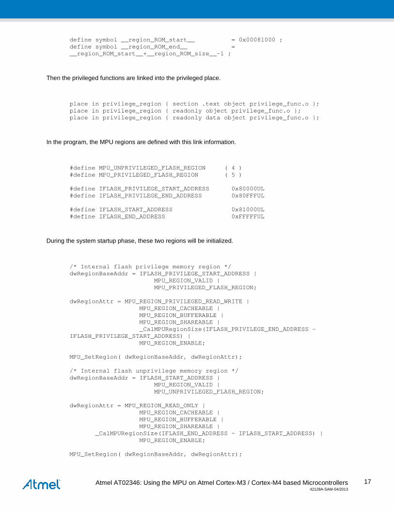
define symbol __region_ROM_start__ = 0x00081000 ; define symbol __region_ROM_end__ = __region_ROM_start__+__region_ROM_size__-1 ;
Then the privileged functions are linked into the privileged place.
place in privilege_region { section .text object privilege_func.o }; place in privilege_region { readonly object privilege_func.o }; place in privilege_region { readonly data object privilege_func.o };
In the program, the MPU regions are defined with this link information.
#define MPU_UNPRIVILEGED_FLASH_REGION ( 4 ) #define MPU_PRIVILEGED_FLASH_REGION ( 5 ) #define IFLASH_PRIVILEGE_START_ADDRESS 0x80000UL #define IFLASH_PRIVILEGE_END_ADDRESS 0x80FFFUL #define IFLASH_START_ADDRESS 0x81000UL #define IFLASH_END_ADDRESS 0xFFFFFUL
During the system startup phase, these two regions will be initialized.
/* Internal flash privilege memory region */ dwRegionBaseAddr = IFLASH_PRIVILEGE_START_ADDRESS | MPU_REGION_VALID | MPU_PRIVILEGED_FLASH_REGION; dwRegionAttr = MPU_REGION_PRIVILEGED_READ_WRITE | MPU_REGION_CACHEABLE | MPU_REGION_BUFFERABLE | MPU_REGION_SHAREABLE | _CalMPURegionSize(IFLASH_PRIVILEGE_END_ADDRESS - IFLASH_PRIVILEGE_START_ADDRESS) | MPU_REGION_ENABLE; MPU_SetRegion( dwRegionBaseAddr, dwRegionAttr); /* Internal flash unprivilege memory region */ dwRegionBaseAddr = IFLASH_START_ADDRESS | MPU_REGION_VALID | MPU_UNPRIVILEGED_FLASH_REGION; dwRegionAttr = MPU_REGION_READ_ONLY | MPU_REGION_CACHEABLE | MPU_REGION_BUFFERABLE | MPU_REGION_SHAREABLE | _CalMPURegionSize(IFLASH_END_ADDRESS - IFLASH_START_ADDRESS) | MPU_REGION_ENABLE; MPU_SetRegion( dwRegionBaseAddr, dwRegionAttr);
Atmel AT02346: Using the MPU on Atmel Cortex-M3 / Cortex-M4 based Microcontrollers 42128A-SAM-04/2013
18
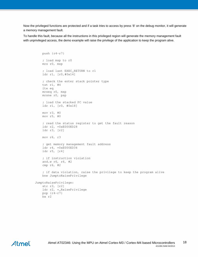
Now the privileged functions are protected and if a task tries to access by press ‘8’ on the debug monitor, it will generate a memory management fault.
To handle this fault, because all the instructions in this privileged region will generate the memory management fault with unprivileged access, the demo example will raise the privilege of the application to keep the program alive.
push {r4-r7} ; load msp to r0 mrs r0, msp ; load last EXEC_RETURN to r1 ldr r1, [r0,#0x14] ; check the enter stack pointer type tst r1, #4 ite eq mrseq r0, msp mrsne r0, psp ; load the stacked PC value ldr r1, [r0, #0x18] mov r3, #0 mov r5, #0 ; read the status register to get the fault reason ldr r2, =0xE000ED28 ldr r3, [r2] mov r6, r3 ; get memory management fault address ldr r4, =0xE000ED34 ldr r5, [r4] ; if instruction violation and.w r6, r6, #2 cmp r6, #2 ; if data violation, raise the privilege to keep the program alive bne JumptoRaisePrivilege JumptoRaisePrivilege: str r3, [r2] ldr r2, =_RaisePrivilege pop {r4-r7} bx r2

Atmel AT02346: Using the MPU on Atmel Cortex-M3 / Cortex-M4 based Microcontrollers 42128A-SAM-04/2013
19
5. Revision History Doc. Rev. Date Comments
42128A 04/2013 Initial document

Atmel Corporation 2325 Orchard Parkway San Jose, CA 95131 USA Tel: (+1)(408) 441-0311 Fax: (+1)(408) 487-2600 www.atmel.com
Atmel Asia Limited Unit 01-5 & 16, 19F BEA Tower, Millennium City 5 418 Kwun Tong Road Kwun Tong, Kowloon HONG KONG Tel: (+852) 2245-6100 Fax: (+852) 2722-1369
Atmel Munich GmbH Business Campus Parkring 4 D-85748 Garching b. Munich GERMANY Tel: (+49) 89-31970-0 Fax: (+49) 89-3194621
Atmel Japan G.K. 16F Shin-Osaki Kangyo Building 1-6-4 Osaki Shinagawa-ku, Tokyo 141-0032 JAPAN Tel: (+81)(3) 6417-0300 Fax: (+81)(3) 6417-0370
© 2013 Atmel Corporation. All rights reserved. / Rev.: 42128A-SAM-04/2013
Atmel®, Atmel logo and combinations thereof, Enabling Unlimited Possibilities®, and others are registered trademarks or trademarks of Atmel Corporation or its subsidiaries. ARM® and others are the registered trademarks or trademarks of ARM Ltd. Other terms and product names may be the trademarks of others.
Disclaimer: The information in this document is provided in connection with Atmel products. No license, express or implied, by estoppel or otherwise, to any intellectual property right is granted by this document or in connection with the sale of Atmel products. EXCEPT AS SET FORTH IN THE ATMEL TERMS AND CONDITIONS OF SALES LOCATED ON THE ATMEL WEBSITE, ATMEL ASSUMES NO LIABILITY WHATSOEVER AND DISCLAIMS ANY EXPRESS, IMPLIED OR STATUTORY WARRANTY RELATING TO ITS PRODUCTS INCLUDING, BUT NOT LIMITED TO, THE IMPLIED WARRANTY OF MERCHANTABILITY, FITNESS FOR A PARTICULAR PURPOSE, OR NON-INFRINGEMENT. IN NO EVENT SHALL ATMEL BE LIABLE FOR ANY DIRECT, INDIRECT, CONSEQUENTIAL, PUNITIVE, SPECIAL OR INCIDENTAL DAMAGES (INCLUDING, WITHOUT LIMITATION, DAMAGES FOR LOSS AND PROFITS, BUSINESS INTERRUPTION, OR LOSS OF INFORMATION) ARISING OUT OF THE USE OR INABILITY TO USE THIS DOCUMENT, EVEN IF ATMEL HAS BEEN ADVISED OF THE POSSIBILITY OF SUCH DAMAGES. Atmel makes no representations or warranties with respect to the accuracy or completeness of the contents of this document and reserves the right to make changes to specifications and products descriptions at any time without notice. Atmel does not make any commitment to update the information contained herein. Unless specifically provided otherwise, Atmel products are not suitable for, and shall not be used in, automotive applications. Atmel products are not intended, authorized, or warranted for use as components in applications intended to support or sustain life.
Related Documents