ORIGINAL ARTICLE Asynchronous implementation of discrete event controllers based on safe automation Petri nets Murat Uzam & İ. Burak Koç & Gökhan Gelen & B. Hakan Aksebzeci Received: 10 April 2007 / Accepted: 26 March 2008 / Published online: 17 June 2008 # Springer-Verlag London Limited 2008 Abstract In this paper, a new method is proposed for digital hardware implementation of Petri net-based specifi- cations. The purpose of this paper is to introduce a new discrete event control system paradigm, where the control system is modeled with extended Petri nets and imple- mented as an asynchronous controller using circuit ele- ments. The applicability of the proposed method is demonstrated by an asynchronous implementation of a Petri net-based discrete event control system (DECS) for an experimental manufacturing system using a Xilinx field programmable gate array (FPGA). Unlike microprocessor, microcontroller or programmable logic controller (PLC)- based software implementations or hardware-based syn- chronous implementations, the implementation method used in this paper is asynchronous and based on hardware offering very high speed to control fast plants at low cost. This paper is expected to serve as a guideline to show how to obtain very high speed, concurrent and asynchronous Petri net-based controllers. Keywords Petri nets . Discrete event systems . Hardware implementation . Field programmable gate arrays (FPGA) . Manufacturing systems . Discrete event control system 1 Introduction Discrete event systems (DES), examples of which include communication networks, manufacturing systems, computer networks, various transportation systems, robots, etc., exhibit properties such as non-determinism, asynchronous operations, conflict, and concurrency. The study, i.e., design, analysis, synthesis, etc., of DES has been carried out mainly by using two modeling techniques: finite state machines (FSM) and Petri nets. FSM-based studies suffer from so called state explosion problem. FSMs provide sequential models. When using FSMs graphical visualization of the modeled system can not be realized easily [1]. Petri nets have been used as an alternative formalism for the study of DESs due to their easily understood graphical representa- tion in addition to their well-formed mathematical for- malism. For the Petri net basics, the reader is referred to [2]. In this paper, the main concern is the control of DES by using Petri net-based specifications. The control of DESs is done firstly by modelling the controller as a Petri net and then by implementing it in software or hardware. The implementation is carried out by simulating the Petri net model in terms of software or hardware structures. The software implementation has been done using either high or low level languages. Examples of software implementations may be found in [3, 4]. Some important literatures on PLC-based software implementation are found in [5–9]. Synchronous or asynchronous controllers of Petri net-based specifications have been obtained as hardware implemen- tation. For detailed information on Petri nets and digital hardware design, the reader is referred to [10]. Examples of synchronous hardware implementations may be found in [11, 12]. Program statements in software-based implemen- tations run in a sequential manner by following a sequence of commands. Therefore, they do not actually capture the concurrency and asynchronous characteristics of the modeled DES. Unlike a synchronous hardware circuit, in an asynchronous circuit, there is no global clock, i.e., they are self timed. Asynchronous circuits can be viewed as Int J Adv Manuf Technol (2009) 41:595–612 DOI 10.1007/s00170-008-1497-2 M. Uzam (*) : İ. B. Koç : G. Gelen : B. H. Aksebzeci Niğde University, Mühendislik-Mimarlık Fakültesi, Elektrik-Elektronik Mühendisliği Bölümü, 51200 Niğde, Turkey e-mail: [email protected]

Welcome message from author
This document is posted to help you gain knowledge. Please leave a comment to let me know what you think about it! Share it to your friends and learn new things together.
Transcript
ORIGINAL ARTICLE
Asynchronous implementation of discrete eventcontrollers based on safe automation Petri nets
Murat Uzam & İ. Burak Koç & Gökhan Gelen &
B. Hakan Aksebzeci
Received: 10 April 2007 /Accepted: 26 March 2008 / Published online: 17 June 2008# Springer-Verlag London Limited 2008
Abstract In this paper, a new method is proposed fordigital hardware implementation of Petri net-based specifi-cations. The purpose of this paper is to introduce a newdiscrete event control system paradigm, where the controlsystem is modeled with extended Petri nets and imple-mented as an asynchronous controller using circuit ele-ments. The applicability of the proposed method isdemonstrated by an asynchronous implementation of aPetri net-based discrete event control system (DECS) for anexperimental manufacturing system using a Xilinx fieldprogrammable gate array (FPGA). Unlike microprocessor,microcontroller or programmable logic controller (PLC)-based software implementations or hardware-based syn-chronous implementations, the implementation methodused in this paper is asynchronous and based on hardwareoffering very high speed to control fast plants at low cost.This paper is expected to serve as a guideline to show howto obtain very high speed, concurrent and asynchronousPetri net-based controllers.
Keywords Petri nets . Discrete event systems . Hardwareimplementation . Field programmable gate arrays (FPGA) .
Manufacturing systems . Discrete event control system
1 Introduction
Discrete event systems (DES), examples of which includecommunication networks, manufacturing systems, computer
networks, various transportation systems, robots, etc.,exhibit properties such as non-determinism, asynchronousoperations, conflict, and concurrency. The study, i.e., design,analysis, synthesis, etc., of DES has been carried out mainlyby using two modeling techniques: finite state machines(FSM) and Petri nets. FSM-based studies suffer from socalled state explosion problem. FSMs provide sequentialmodels. When using FSMs graphical visualization of themodeled system can not be realized easily [1]. Petri netshave been used as an alternative formalism for the study ofDESs due to their easily understood graphical representa-tion in addition to their well-formed mathematical for-malism. For the Petri net basics, the reader is referred to [2].In this paper, the main concern is the control of DES byusing Petri net-based specifications. The control of DESs isdone firstly by modelling the controller as a Petri net andthen by implementing it in software or hardware. Theimplementation is carried out by simulating the Petri netmodel in terms of software or hardware structures. Thesoftware implementation has been done using either high orlow level languages. Examples of software implementationsmay be found in [3, 4]. Some important literatures onPLC-based software implementation are found in [5–9].Synchronous or asynchronous controllers of Petri net-basedspecifications have been obtained as hardware implemen-tation. For detailed information on Petri nets and digitalhardware design, the reader is referred to [10]. Examples ofsynchronous hardware implementations may be found in[11, 12]. Program statements in software-based implemen-tations run in a sequential manner by following a sequenceof commands. Therefore, they do not actually capturethe concurrency and asynchronous characteristics of themodeled DES. Unlike a synchronous hardware circuit, in anasynchronous circuit, there is no global clock, i.e., they areself timed. Asynchronous circuits can be viewed as
Int J Adv Manuf Technol (2009) 41:595–612DOI 10.1007/s00170-008-1497-2
M. Uzam (*) : İ. B. Koç :G. Gelen :B. H. AksebzeciNiğde University, Mühendislik-Mimarlık Fakültesi,Elektrik-Elektronik Mühendisliği Bölümü,51200 Niğde, Turkeye-mail: [email protected]
hardwired versions of parallel and distributed programs.The program statements are physical components, i.e., logicgates, memory elements, etc. Asynchronous circuits arebetter than the synchronous counterparts in terms ofperformance, robustness, low power, low electromagneticemission, modularity and re-use, and testability [10]. In thispaper, asynchronous circuit implementation of Petri net-based specifications is considered. This type of implemen-tation is carried out based on the idea of “physicalsimulation” and achieved by associating each place in thePetri net with a memory latch. Examples of this style can befound in [13–16].
In this paper, a new method is proposed for the digitalhardware implementation of Petri net-based specifications.The purpose of this paper is to introduce a new discreteevent control system paradigm, where the control system ismodeled with extended Petri nets and implemented as anasynchronous controller using circuit elements. The digitalhardware implementation of Petri net transitions proposedin this paper may be viewed as a better version of apreviously introduced method [15]. In addition, the hard-ware implementation of the timed-transition is proposed.Moreover, the applicability of the proposed method isdemonstrated by a successful implementation of a Petri net-based DECS for an experimental manufacturing system byusing a Xilinx FPGA. This paper can be regarded as anextended version of the previous work presented in [17, 18].
The remainder of this paper is organized as follows: Thenext section defines safe automation Petri nets (SAPN). Inthe Sect. 3, the digital hardware implementation of SAPN isexplained by considering some important Petri net struc-tures. Section 4 defines the Xilinx Spartan 2 XC2S200FPGA and the Digilab 2 (D2) FPGA-based developmentboard. Section 5 describes the necessary technical arrange-ments carried out in order to connect the Spartan 2XC2S200 FPGA to the real world as a logic controller.Xilinx FPGA implementation of the timed-transition isproposed in Sect. 6. The experimental discrete manufactur-ing system is introduced in Sect. 7. In Sect. 8, the SAPN
model of the DECS for the discrete manufacturing systemis described. The digital hardware implementation of theSAPN model is explained in Sect. 9. Finally, conclusionsare given in the last section.
2 Safe automation Petri nets
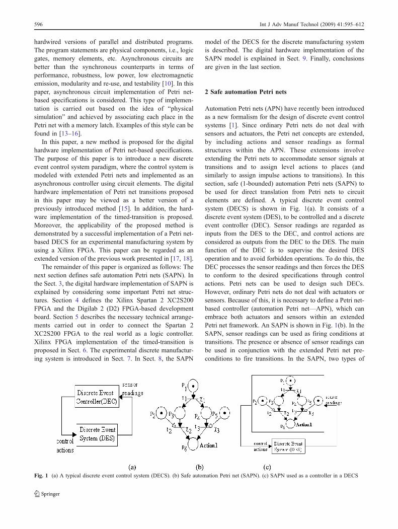
Automation Petri nets (APN) have recently been introducedas a new formalism for the design of discrete event controlsystems [1]. Since ordinary Petri nets do not deal withsensors and actuators, the Petri net concepts are extended,by including actions and sensor readings as formalstructures within the APN. These extensions involveextending the Petri nets to accommodate sensor signals attransitions and to assign level actions to places (andsimilarly to assign impulse actions to transitions). In thissection, safe (1-bounded) automation Petri nets (SAPN) tobe used for direct translation from Petri nets to circuitelements are defined. A typical discrete event controlsystem (DECS) is shown in Fig. 1(a). It consists of adiscrete event system (DES), to be controlled and a discreteevent controller (DEC). Sensor readings are regarded asinputs from the DES to the DEC, and control actions areconsidered as outputs from the DEC to the DES. The mainfunction of the DEC is to supervise the desired DESoperation and to avoid forbidden operations. To do this, theDEC processes the sensor readings and then forces the DESto conform to the desired specifications through controlactions. Petri nets can be used to design such DECs.However, ordinary Petri nets do not deal with actuators orsensors. Because of this, it is necessary to define a Petri net-based controller (automation Petri net—APN), which canembrace both actuators and sensors within an extendedPetri net framework. An SAPN is shown in Fig. 1(b). In theSAPN, sensor readings can be used as firing conditions attransitions. The presence or absence of sensor readings canbe used in conjunction with the extended Petri net pre-conditions to fire transitions. In the SAPN, two types of
Fig. 1 (a) A typical discrete event control system (DECS). (b) Safe automation Petri net (SAPN). (c) SAPN used as a controller in a DECS
596 Int J Adv Manuf Technol (2009) 41:595–612
actuations can be considered, namely impulse actions andlevel actions. Level actions are associated with places,while impulse actions are associated with transitions. Withthese additional features, it is possible to design discreteevent control systems. Figure 1(c) shows how an SAPN canbe used as a DEC in a DECS.
Formally, a safe automation Petri net can be defined asfollows:
SAPN ¼ P;T; Pre; Post; In;En;χ;Q;M0ð Þwhere
– P = {p1, p2,..., pn} is a finite, nonempty set of places,– T = {t1, t2,..., tm} is a finite, nonempty set of
transitions, P ∪ Τ ≠ ∅ and P ∩ T = ∅,– Pre: (P×T) → {0,1} is an input function that defines
ordinary arcs from places to transitions.– Post: (T×P) → {0,1} is an output function that defines
ordinary arcs from transitions to places.– In: (P×T) → {0,1} is an inhibitor input function that
defines inhibitor arcs from places to transitions.– En: (P×T) → {0,1} is an enabling input function that
defines enabling arcs from places to transitions.– c = {c1, c2,..., cm} is a finite, nonempty set of firing
conditions associated with transitions.– Q = {q1, q2,..., qn} is a finite set of level actions that
might be assigned to places or impulse actions thatmight be assigned to transitions.
– M0: P → {0,1} is the initial marking.
The SAPN consists of two types of nodes called places,represented by circles (○), and transitions, represented bybars (─). There are three types of arcs used in the SAPN,namely, ordinary arcs, represented by a directed arrow (→),inhibitor arcs, represented by an arc, whose end is a circle(⊸), and finally enabling arcs, represented by a directedarrow, whose end is empty (⇾). Directed ordinary arcsconnect places to transitions and vice versa, while enablingand inhibitor arcs connect only places to transitions. Thenumber of tokens in places represents the current state ofthe system and firing of a transition represents themovement of the system from one state to another state.Each transition has a set of input and output places, whichrepresent the pre-condition and post-condition of thetransition. The level actions (Q), may be assigned to places,and the impulse actions may be assigned to transitions.Level actions may be enabled when there is a token at aplace, while impulse actions may be enabled at the instantwhen a transition is fired. More than one action may beassigned to a place or transition. Firing conditions in theSAPN are recognized by external events (signals) such assensor readings, switch positions, etc. The firing conditionc is a Boolean variable that can be 0, in which case relatedtransition t is not allowed to fire, or it can be 1, in which
case t is allowed to fire if it is enabled, i.e., all input placeshave one token each. The marking of the SAPN isrepresented by the number of tokens in places. Tokens arerepresented by black dots (•). Movement of tokens betweenplaces describes the evolution of the SAPN and isaccomplished by the firing of the enabled transitions. Thefollowing rules are used to govern the flow of tokens:
Enabling rules:
1. If the input place p1 of a transition t1 is connected to t1with an ordinary arc Pre(p1, t1), then t1 is said to beenabled when p1 contains a token, i.e., M(p1) = 1.
2. If the input place p1 of a transition t1 is connected to t1with an enabling arc En(p1, t1), then t1 is said to beenabled when p1 contains a token, i.e., M(p1) = 1.
3. If the input place p1 of a transition t1 is connected to t1with an inhibitor arc In(p1, t1), then t1 is said to beenabled when p1 contains no token, i.e., M(p1) = 0.
Firing rules: In the SAPN, an enabled transition t can orcan not fire depending on the external firing condition χ oft. A firing condition of a transition t may include more thanone sensor reading with ‘AND’, ‘OR’ and ‘NOT’ logicaloperators. When dealing with more than one sensor readingas a firing condition, the logical operators of firing con-ditions must be taken into account accordingly. In thespecial case, where c = 1, transition t is always allowed tofire when it is enabled. When an enabled transition t fireswith a related firing condition c, it removes one token fromeach input place pi and deposits, at the same time, onetoken to each output place po. It should be noted that, thefiring of an enabled transition t does not change themarking of the input places that are connected to t onlyby an enabling or an inhibitor arc.
3 Digital hardware implementation of safe automationPetri nets (SAPN): direct translation from SAPNto circuit elements
The direct translation method from SAPN to circuitelements, proposed in this paper, is based on the idea ofphysical simulation of every Petri net marking reachablefrom the initial marking in terms of the state of the circuit.In order to achieve the direct translation, the following threesteps are followed: i) each place in the SAPN is associatedwith a memory element, i.e., an SR-flip-flop (SR-latch), ii)each transition in the SAPN is implemented with a logicalgate (NAND gate), and iii) the initial marking is set-up byusing an RC (resistor and capacitor) element. Let us nowconsider each of these three steps:
The first step in achieving the direct translation is to usea memory element to represent the presence or absence of a
Int J Adv Manuf Technol (2009) 41:595–612 597

token in a place. If there is a token in a place then theoutput of the memory element is set to 1. In contrast, ifthere is no token in a place then the output of the memoryelement is reset to 0. In order to implement this operation,an SR-flip-flop, shown in Fig. 2(a) is used. An SR-flip-flopis constructed from two NAND gates connected back toback. The cross-coupled connections from the output of onegate to the input of the other gate constitute a feedbackpath. Therefore, the circuit is classified as asynchronous.Each flip-flop has two outputs; Q and Q, and two inputs;set (S) and reset (R). The truth table of the SR-flip-flop isgiven in Fig. 2(d). The application of a momentary 0 to theS input causes output Q to go to 1 and Q to go to 0. Theoutputs of the circuit do not change when the S inputreturns to 1. A momentary 0 applied to the R input causesan output of Q = 0 and Q ¼ 1. The state of the flip-flop isalways taken from the value of its normal output Q. WhenQ = 1, it is said that the flip-flop stores a 1 and is in the setstate. When Q = 0, it is said that the flip-flop stores a 0 andis in the reset state. The SR-flip-flop manifests anundesirable condition if both inputs go to 0 simultaneously.When both inputs are 0, outputs Q and Q will go to 1, acondition which is normally meaningless in flip-flopoperation. In Fig. 2(b) an SAPN is shown, in which thereare two places; p1 and its complement p1, and twotransitions; t1 and t2, with firing conditions c1 and c2,
respectively. This is an explicit representation of the safeplace p1. The implementation of places using the SR-flip-flop is shown in Fig. 2(c) Output Q of the SR-flip-flop isused to represent place p1 and output Q is used to representplace p1. When there is a token in p1, the SR-flip-flop isset, i.e., Q = 1 and Q ¼ 0. When there is a token in p1, theSR-flip-flop is reset, i.e., Q = 0 and Q ¼ 1. It is assumedthat the model will not permit both outputs becoming Q = 1and Q ¼ 1. That is to say that the designer must take someaction to assure that S = R = 0 will never occur.
ii) The second step in achieving the direct translation isto use a NAND gate to implement transition in SAPN. Thebehavior of a transition in SAPN may be summarized asfollows: IF there is a token each in the input places of atransition t AND the firing condition c of t occurs, THENall the tokens are removed from the input places and onetoken each is deposited to the output places of t. To showhow this behavior is implemented, the SAPN shown inFig. 3(a) is used. In this case, the transition t fires when allinput places p1, p2, p3,... have one token each and thefiring condition c occurs. When t fires it removes all thetokens from the input places p1, p2, p3,..., and at the sametime, it deposits one token each to the output places, p11,p12, p13, etc. To implement the transition t, the structureshown in Fig. 3(b) is used. In this case, when all input flip-flops are set and c occurs t is fired by resetting all the inputflip-flops and at the same time by setting all the output flip-flops. Please note that the difference between the proposedapproach and [15] is that, in [15] the removal of tokensfrom input places and adding tokens to output places has aduration and there is an intermediate state between the twooperations, while in the proposed approach the removal oftokens from input places and adding tokens to output placesis instantaneous. Figure 3(c) shows the implementation oftransitions t1 and t2 of Fig. 2(c). In the SAPN, t1 fires whenthere is a token in p1 and c1 occurs. When fired, t1removes the token from p1 and deposits a token in p1. TheNAND gate 1 implements t1 as follows: when output p1 ¼1 and c1 occurs, i.e., c1 becomes 1, p1 is set to 1 byapplying an instantaneous 0 from the output of the NANDgate 1 to the S input of the flip-flop and at the same timethe output p1 is reset, i.e., p1 ¼ 0. The same applies to t2 ina similar manner.
iii) The third and last step is about setting-up the initialmarking by using an RC (resistor and capacitor) element. Itis necessary for proper functioning to set-up the initialmarking before operating the circuit. It is a commonpractice to use an RC element to establish the power onreset (POR) and at the same time to use a button connectedparallel to the capacitor such that at any time desired bypressing the button it is possible to set the system back tothe initial marking. The time delay τ = R.C defines howlong the setting-up time will be for the initial marking.
Fig. 2 a) An SR-flip-flop, b) an SAPN, c) The implementation of aplace with an SR-flip-flop. d) The truth table of the SR-flip-flop
598 Int J Adv Manuf Technol (2009) 41:595–612
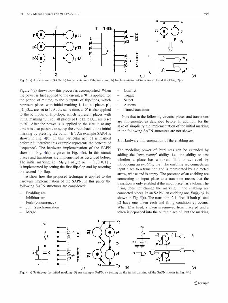
Figure 4(a) shows how this process is accomplished. Whenthe power is first applied to the circuit, a ‘0’ is applied, forthe period of τ time, to the S inputs of flip-flops, whichrepresent places with initial marking 1, i.e., all places p1,p2, p3,... are set to 1. At the same time, a ‘0’ is also appliedto the R inputs of flip-flops, which represent places withinitial marking ‘0’, i.e., all places p11, p12, p13,... are resetto ‘0’. After the power is is applied to the circuit, at anytime it is also possible to set up the circuit back to the initialmarking by pressing the button ‘B’. An example SAPN isshown in Fig. 4(b). In this particular net, p1 is markedbefore p2; therefore this example represents the concept of‘sequence’. The hardware implementation of the SAPNshown in Fig. 4(b) is given in Fig. 4(c). In this circuitplaces and transitions are implemented as described before.The initial marking, i.e., M0 p1; p1; p2; p2
� � ¼ 1; 0; 0; 1ð ÞT,is implemented by setting the first flip-flop and by resettingthe second flip-flop.
To show how the proposed technique is applied to thehardware implementation of the SAPN, in this paper thefollowing SAPN structures are considered:
– Enabling arc– Inhibitor arc– Fork (concurrency)– Join (synchronization)– Merge
– Conflict– Toggle– Select– Actions– Timed-transition
Note that in the following circuits, places and transitionsare implemented as described before. In addition, for thesake of simplicity the implementation of the initial markingin the following SAPN structures are not shown.
3.1 Hardware implementation of the enabling arc
The modeling power of Petri nets can be extended byadding the ‘one testing’ ability, i.e., the ability to testwhether a place has a token. This is achieved byintroducing an enabling arc. The enabling arc connects aninput place to a transition and is represented by a directedarrow, whose end is empty. The presence of an enabling arcconnecting an input place to a transition means that thetransition is only enabled if the input place has a token. Thefiring does not change the marking in the enabling arcconnected places. In an SAPN, an enabling arc, En(p2,t2), isshown in Fig. 5(a). The transition t2 is fired if both p1 andp2 have one token each and firing condition c2 occurs.When t2 is fired, a token is removed from place p1 and atoken is deposited into the output place p3, but the marking
Fig. 3 a) A transition in SAPN. b) Implementation of the transition, b) Implementation of transitions t1 and t2 of Fig. 2(c)
Fig. 4 a) Setting-up the initial marking. B) An example SAPN. c) Setting up the initial marking of the SAPN shown in Fig. 4(b)
Int J Adv Manuf Technol (2009) 41:595–612 599

of enabling arc connected place p2 does not change.Transition t2 is not enabled to fire, if there is no token inplace p2. Figure 5(b) shows the representation of thisSAPN with complement places. The hardware implemen-tation of the SAPN shown in Fig. 5(b) is given in Fig. 5(c).
3.2 Hardware implementation of the inhibitor arc
The modeling power of Petri nets can be extended byadding the ‘zero testing’ ability, i.e., the ability to testwhether a place has no token. This is achieved by aninhibitor arc. The inhibitor arc connects an input place to atransition and is represented by an arc, whose end is acircle. The presence of an inhibitor arc connecting an inputplace to a transition means that the transition is enabled ifthe input place has no token. The firing does not change themarking in the inhibitor arc connected places. In an SAPN,an inhibitor arc, In(p2,t2), is shown in Fig. 6(a). Thetransition t2 is fired if place p1 has a token and p2 has notoken and firing condition c2 occurs. When t2 is fired, atoken is removed from the input place p1 and a token isdeposited into the output place p3, but the marking ofinhibitor arc connected place p2 does not change. Thetransition t2 is not enabled to fire, if there is a token in placep2. Figure 6(b) shows the representation of this SAPN withcomplement places. Note that the inhibitor arc In(p2,t2),shown in Fig. 6(a), can be replaced by the enabling arc
En(p2,t2). The hardware implementation of the SAPNshown in Fig. 6(b) is given in Fig. 6(c).
3.3 Hardware implementation of fork (concurrency)
A fork (concurrency) represents two or more concurrentprocesses. In Petri nets, the concept of fork can be modeledeasily, as shown in Fig. 7, where p1 and p2 represent twoconcurrent activities. When p1 is not marked, i.e., there isno token in p1, and the firing condition c1 occurs, a token isput in p1. When p1 is marked, both p2 and p3 are notmarked and the firing condition c2 occurs, the token isremoved from p1 and at the same time one token each isdeposited in p2 and p3. This means that with the firing oft1, two concurrent processes are initiated by depositing onetoken each in p2 and p3. Figure 7(b) shows the represen-tation of this SAPN with complement places. The hardwareimplementation of the SAPN shown in Fig. 7(b) is given inFig. 7(c).
3.4 Hardware implementation of join (synchronization)
A join Petri net is used to synchronize two or more ongoingprocesses. An example is shown in Fig. 8, where p1 and p2represent two separate activities synchronized by means oft3. When p1 is not marked, i.e., there is no token in p1, andthe firing condition c1 occurs, a token is put in p1.
Fig. 5 a) An enabling arc,En(p22), in an SAPN. b)Representation of the SAPNwith complement places.c) Hardware implementation ofthe SAPN shown in Fig. 5(b)
600 Int J Adv Manuf Technol (2009) 41:595–612

Fig. 7 a) Fork (concurrency) inan SAPN. b) Representation ofthe SAPN with complementplaces. c) Hardware implemen-tation of the SAPN shown inFig. 7(b)
Fig. 6 a) An inhibitor arc,In(p2,t2), in an SAPN. b) Rep-resentation of the SAPN withcomplement places. c) Hardwareimplementation of the SAPNshown in Fig. 6(b)
Int J Adv Manuf Technol (2009) 41:595–612 601

Similarly, when p2 is not marked and the firing conditionc2 occurs, a token is deposited in p2. In order to fire t3 bothp1 and p2 must have one token each. When both p1 and p2are marked, and p3 is not marked and the firing conditionc3 occurs, t3 fires by depositing a token in p1 and at thesame time by removing the tokens from p2 and p3. Thismeans that with the firing of t3, two concurrent processes,represented by p1 and p2 are synchronized. Figure 8(b)shows the representation of this SAPN with complementplaces. The hardware implementation of the SAPN shownin Fig. 8(b) is given in Fig. 8(c).
3.5 Hardware implementation of merge
Two or more activities (processes) can be merged in Petrinets. An example is shown in Fig. 9, where p1 and p2represent two separate activities merged by means of p3.When p1 is not marked, i.e., there is no token in p1, and thefiring condition c1 occurs, a token is put in p1. Similarly,when p2 is not marked and the firing condition c2 occurs, atoken is deposited in p2. When p1 is marked and p3 is notmarked, and the firing condition c3 occurs, t3 fires bydepositing a token in p3 and at the same time by removingthe token from p1. Similarly, when p2 is marked and p3 isnot marked, and the firing condition c4 occurs, t4 fires bydepositing a token in p3 and at the same time by removingthe token from p2. Note that only one token can be
deposited in p3, when it is not marked. This means that p3receives one token from the merged places p1 or p2.Figure 9(b) shows the representation of this SAPN withcomplement places. The hardware implementation of theSAPN shown in Fig. 9(b) is given in Fig. 9(c).
3.6 Conflict
In a system, when two or more users share the sameresource and both try to access it at the same time, thissituation leads to conflict. In a Petri net, a conflict situationoccurs when a place enables more than one transition at thesame time. In conflict, only one transition can fire. Aconflict in SAPN is shown in Fig. 10. As can be seen fromFig. 10, when there is a token in place p1, both transitionst2 and t3 are enabled. Since only one transition can fire inthe case of conflict, any conflict, arising in a Petri net, mustbe resolved. The conflict can be resolved by assigning apriority scheme between the conflicting transitions. In thispaper two such conflict resolution schemes, namely toggleand select, are considered.
3.7 Hardware implementation of toggle
One of the approaches for resolving conflict between thetwo transitions is called ‘toggle’. In this approach with thehelp of the added net elements the conflicting transitions
Fig. 8 a) Join (concurrency) inan SAPN. b) Representation ofthe SAPN with complementplaces. c) Hardware implemen-tation of the SAPN shown inFig. 8(b)
602 Int J Adv Manuf Technol (2009) 41:595–612

fire one after another. Toggle conflict resolution method isshown in Fig. 11(a): p4 is the complement place of p4, i.e.,M p4ð Þ þM p4
� � ¼ 1. This means that the sum of tokens inp4 and will always be 1. Initially, there is a token in p4.Therefore, when a token is deposited in p1 only t2 isenabled to fire, because M(p1) = 1 and M(p4) = 1. In thiscase, when t2 is fired with the firing condition c2, thetokens are removed from p1 and p4 and at the same timeone token each is deposited to p2 and p4. Thus, it is theturn of t3 to fire. Therefore, when M(p1) = 1, M p4
� � ¼ 1,and the firing condition c3 occurs, t3 is fired by removingtokens from p1 and p4, and at the same time by depositingone token each in p3 and p4. Figure 11(b) shows the
representation of this SAPN with complement places. Thehardware implementation of the SAPN shown in Fig. 11(b)is given in Fig. 11(c).
3.8 Hardware implementation of select
Another approach for resolving conflict between the twotransitions is called ‘select’. In this approach a selection hasbeen made between the two conflicting transitions with thehelp of a firing condition ‘S’. Select-conflict-resolution-method is shown in Fig. 12(a) As can be seen, the firingcondition of t2 is c2 = S, while the firing condition of t3 is#3 ¼ S. This means that whenever a token is deposited inp1, if S = 1 then t2 will fire. On the other hand, whenever atoken is deposited in p1, if S = 0 then t3 will fire. In thisconfiguration t2 and t3 can never fire at the same time.Figure 12(b) shows the representation of this SAPN withcomplement places. The hardware implementation of theSAPN shown in Fig. 12(b) is given in Fig. 12(c).
3.9 Hardware implementation of actions
In the SAPN, two types of actuations can be considered,namely impulse actions and level actions. Impulse actionsare associated with transitions and they are enabled at the
Fig. 9 a) Merge in an SAPN. b)Representation of the SAPNwith complement places. c)Hardware implementation of theSAPN shown in Fig. 9(b)
Fig. 10 Conflict in an SAPN
Int J Adv Manuf Technol (2009) 41:595–612 603
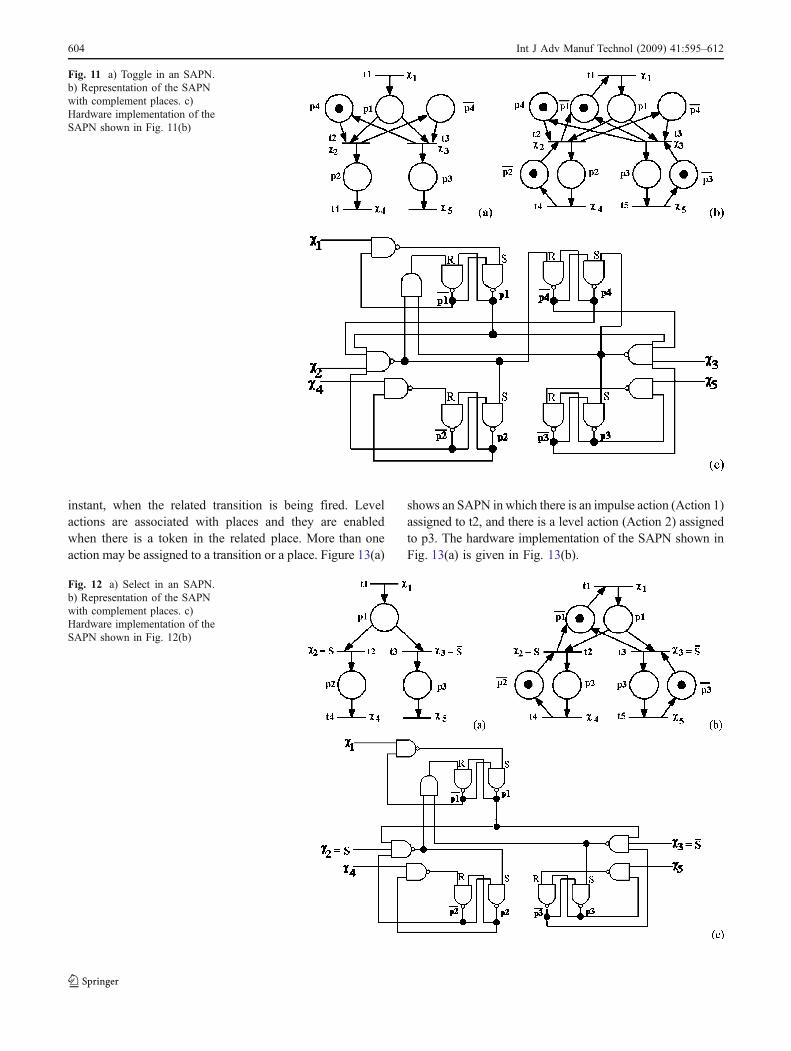
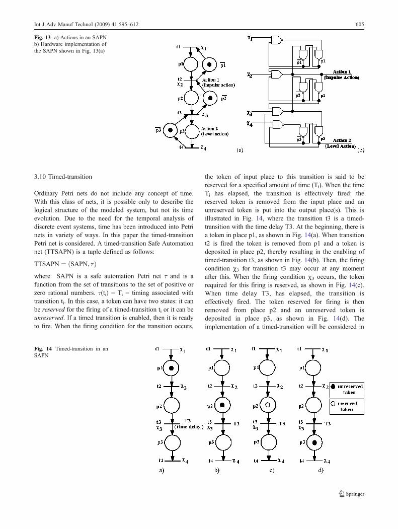
instant, when the related transition is being fired. Levelactions are associated with places and they are enabledwhen there is a token in the related place. More than oneaction may be assigned to a transition or a place. Figure 13(a)
shows an SAPN in which there is an impulse action (Action 1)assigned to t2, and there is a level action (Action 2) assignedto p3. The hardware implementation of the SAPN shown inFig. 13(a) is given in Fig. 13(b).
Fig. 11 a) Toggle in an SAPN.b) Representation of the SAPNwith complement places. c)Hardware implementation of theSAPN shown in Fig. 11(b)
Fig. 12 a) Select in an SAPN.b) Representation of the SAPNwith complement places. c)Hardware implementation of theSAPN shown in Fig. 12(b)
604 Int J Adv Manuf Technol (2009) 41:595–612
3.10 Timed-transition
Ordinary Petri nets do not include any concept of time.With this class of nets, it is possible only to describe thelogical structure of the modeled system, but not its timeevolution. Due to the need for the temporal analysis ofdiscrete event systems, time has been introduced into Petrinets in variety of ways. In this paper the timed-transitionPetri net is considered. A timed-transition Safe Automationnet (TTSAPN) is a tuple defined as follows:
TTSAPN ¼ SAPN; τð Þwhere SAPN is a safe automation Petri net τ and is afunction from the set of transitions to the set of positive orzero rational numbers. τ(ti) = Ti = timing associated withtransition ti. In this case, a token can have two states: it canbe reserved for the firing of a timed-transition ti or it can beunreserved. If a timed transition is enabled, then it is readyto fire. When the firing condition for the transition occurs,
the token of input place to this transition is said to bereserved for a specified amount of time (Ti). When the timeTi has elapsed, the transition is effectively fired: thereserved token is removed from the input place and anunreserved token is put into the output place(s). This isillustrated in Fig. 14, where the transition t3 is a timed-transition with the time delay T3. At the beginning, there isa token in place p1, as shown in Fig. 14(a). When transitiont2 is fired the token is removed from p1 and a token isdeposited in place p2, thereby resulting in the enabling oftimed-transition t3, as shown in Fig. 14(b). Then, the firingcondition c3 for transition t3 may occur at any momentafter this. When the firing condition χ3 occurs, the tokenrequired for this firing is reserved, as shown in Fig. 14(c).When time delay T3, has elapsed, the transition iseffectively fired. The token reserved for firing is thenremoved from place p2 and an unreserved token isdeposited in place p3, as shown in Fig. 14(d). Theimplementation of a timed-transition will be considered in
Fig. 13 a) Actions in an SAPN.b) Hardware implementation ofthe SAPN shown in Fig. 13(a)
Fig. 14 Timed-transition in anSAPN
Int J Adv Manuf Technol (2009) 41:595–612 605
a further section as it depends on the chosen implementa-tion technology.
4 Xilinx Spartan 2 XC2S200 FPGA and the Digilab 2(D2) FPGA-based development board
The Spartan-II 2.5V field-programmable gate array familyprovides high performance, abundant logic resources, and arich feature set, all at a very low price [19]. Systemperformance is supported up to 200 MHz. Features ofXilinx Spartan 2 XC2S200 FPGA include 56K bits blockRAM, 75,264 bits distributed RAM, 16 selectable I/Ostandards, and four DLLs. The Spartan-II family is asuperior alternative to mask-programmed application spe-cific integrated circuits (ASICs). The FPGA avoids theinitial cost, lengthy development cycles, and inherent riskof conventional ASICs. Also, FPGA programmabilitypermits design upgrades in the field with no hardwarereplacement necessary (impossible with ASICs). TheDigilab 2 (D2) FPGA-based development board (http://www.digilentinc.com) makes an excellent prototypingplatform for moderate to complex digital circuits and
systems. The D2 board features a 200K-gate Xilinx Spartan2 XC2S200 FPGA in a PQ208 package that provides 143user I/Os. All available I/O signals are routed either to theexpansion connectors, or to the ports and other on-boarddevices.
5 Connecting the Xilinx spartan 2 XC2S200FPGA to the real-world
In this section, let us briefly describe how a Xilinx Spartan2 XC2S200 FPGA accommodated in a Digilab 2 (D2)FPGA-based development board is connected to the real-world as a logic controller. D2 board provides only the 143user I/Os of the FPGA. In order to protect the FPGA fromhigh voltage levels and large voltage spikes and use it as alogic controller it is necessary to electrically isolate it fromthe real-world. This is accomplished by using opticalcouplers. To be able to connect 5V or 24V DC inputs tothe FPGA as an input, a voltage level converter is designedfor the inputs. Another important issue for the inputs wasthe problem of so called “contact bounce problem”. When acontact is closed or opened, it will close and open(technically speaking make and break), many times beforefinally settling in a stable state. This behavior of a contact isinterpreted as multiple false input signals and a digitalcircuit will respond to each of these on-off or off-ontransitions. This problem is known as ‘contact bounce’ andhas always been a very important problem when interfacingswitches, relays, etc. to a digital control system. In someindustrial applications debouncing is required to eliminateboth mechanical and electrical effects. To solve the contactbounce problem for the input of the FPGA, a PIC16F628
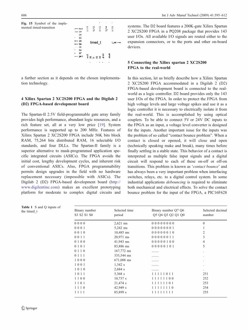
Fig. 15 Symbol of the imple-mented timed-transition
Table 1 S and Q inputs ofthe timed_t Binary number
S3 S2 S1 S0Selected timeperiod
Binary number Q7 Q6Q5 Q4 Q3 Q2 Q1 Q0
Selected decimalnumber
0 0 0 0 2,621 ms 0 0 0 0 0 0 0 0 00 0 0 1 5,242 ms 0 0 0 0 0 0 0 1 10 0 1 0 10,485 ms 0 0 0 0 0 0 1 0 20 0 1 1 20,971 ms 0 0 0 0 0 0 1 1 30 1 0 0 41,943 ms 0 0 0 0 0 1 0 0 40 1 0 1 83,886 ms 0 0 0 0 0 1 0 1 50 1 1 0 167,772 ms ........ .0 1 1 1 335,544 ms ........ .1 0 0 0 671,088 ms ........ .1 0 0 1 1,342 s ........ .1 0 1 0 2,684 s ........ .1 0 1 1 5,368 s 1 1 1 1 1 0 1 1 2511 1 0 0 10,737 s 1 1 1 1 1 1 0 0 2521 1 0 1 21,474 s 1 1 1 1 1 1 0 1 2531 1 1 0 42,949 s 1 1 1 1 1 1 1 0 2541 1 1 1 85,899 s 1 1 1 1 1 1 1 1 255
606 Int J Adv Manuf Technol (2009) 41:595–612
microcontroller (www.microchip.com)-based debouncerhas been developed and used [20]. Similar arrangementshave been carried out for interfacing the FPGA to theoutputs. When using too many discrete outputs, FPGA cannot provide the necessary output current for properoperation; therefore it is necessary to use an interface inorder to provide necessary amount of current for all discreteoutputs. To serve as a current amplifier, the integratedcircuit 74HC373, three-state octal D-type latch is used.Then, in order to drive discrete outputs of 5V or 24V DClevels, an output voltage level converter is designed for theoutputs. All these mentioned signal conditioning arrange-ments have been implemented on a printed circuit board,which served as a I/O buffer between the FPGA and thesystem to be controlled.
6 Xilinx FPGA implementation of the timed-transition
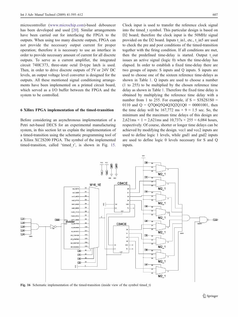
Before considering an asynchronous implementation of aPetri net-based DECS for an experimental manufacturingsystem, in this section let us explain the implementation ofa timed-transition using the schematic programming tool ofa Xilinx XC2S200 FPGA. The symbol of the implementedtimed-transition, called ‘timed_t’, is shown in Fig. 15.
Clock input is used to transfer the reference clock signalinto the timed_t symbol. This particular design is based onD2 board; therefore the clock input is the 50MHz signalprovided on the D2 board. Inputs t_in1, etc., t_in5 are usedto check the pre and post conditions of the timed-transitiontogether with the firing condition. If all conditions are met,then the predefined time-delay is started. Output t_outissues an active signal (logic 0) when the time-delay haselapsed. In order to establish a fixed time-delay there aretwo groups of inputs: S inputs and Q inputs. S inputs areused to choose one of the sixteen reference time-delays asshown in Table 1. Q inputs are used to choose a number(1 to 255) to be multiplied by the chosen reference timedelay as shown in Table 1. Therefore the fixed time delay isobtained by multiplying the reference time delay with anumber from 1 to 255. For example, if S = S3S2S1S0 =0110 and Q = Q7Q6Q5Q4Q3Q2Q1Q0 = 00001001, thenthe time delay will be 167,772 ms × 9 ≈ 1.5 sec. So, theminimum and the maximum time delays of this design are2,621ms × 1 = 2,621ms and 10,737s × 255 ≈ 6,084 hours,respectively. Of course, shorter or longer time delays can beachieved by modifying the design. vcc1 and vcc2 inputs areused to define logic 1 levels, while gnd1 and gnd2 inputsare used to define logic 0 levels necessary for S and Qinputs.
Fig. 16 Schematic implementation of the timed-transition (inside view of the symbol timed_t)
Int J Adv Manuf Technol (2009) 41:595–612 607
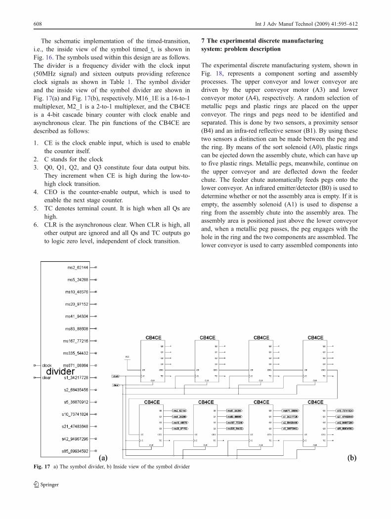
The schematic implementation of the timed-transition,i.e., the inside view of the symbol timed_t, is shown inFig. 16. The symbols used within this design are as follows.The divider is a frequency divider with the clock input(50MHz signal) and sixteen outputs providing referenceclock signals as shown in Table 1. The symbol dividerand the inside view of the symbol divider are shown inFig. 17(a) and Fig. 17(b), respectively. M16_1E is a 16-to-1multiplexer, M2_1 is a 2-to-1 multiplexer, and the CB4CEis a 4-bit cascade binary counter with clock enable andasynchronous clear. The pin functions of the CB4CE aredescribed as follows:
1. CE is the clock enable input, which is used to enablethe counter itself.
2. C stands for the clock3. Q0, Q1, Q2, and Q3 constitute four data output bits.
They increment when CE is high during the low-to-high clock transition.
4. CEO is the counter-enable output, which is used toenable the next stage counter.
5. TC denotes terminal count. It is high when all Qs arehigh.
6. CLR is the asynchronous clear. When CLR is high, allother output are ignored and all Qs and TC outputs goto logic zero level, independent of clock transition.
7 The experimental discrete manufacturingsystem: problem description
The experimental discrete manufacturing system, shown inFig. 18, represents a component sorting and assemblyprocesses. The upper conveyor and lower conveyor aredriven by the upper conveyor motor (A3) and lowerconveyor motor (A4), respectively. A random selection ofmetallic pegs and plastic rings are placed on the upperconveyor. The rings and pegs need to be identified andseparated. This is done by two sensors, a proximity sensor(B4) and an infra-red reflective sensor (B1). By using thesetwo sensors a distinction can be made between the peg andthe ring. By means of the sort solenoid (A0), plastic ringscan be ejected down the assembly chute, which can have upto five plastic rings. Metallic pegs, meanwhile, continue onthe upper conveyor and are deflected down the feederchute. The feeder chute automatically feeds pegs onto thelower conveyor. An infrared emitter/detector (B0) is used todetermine whether or not the assembly area is empty. If it isempty, the assembly solenoid (A1) is used to dispense aring from the assembly chute into the assembly area. Theassembly area is positioned just above the lower conveyorand, when a metallic peg passes, the peg engages with thehole in the ring and the two components are assembled. Thelower conveyor is used to carry assembled components into
Fig. 17 a) The symbol divider, b) Inside view of the symbol divider
608 Int J Adv Manuf Technol (2009) 41:595–612
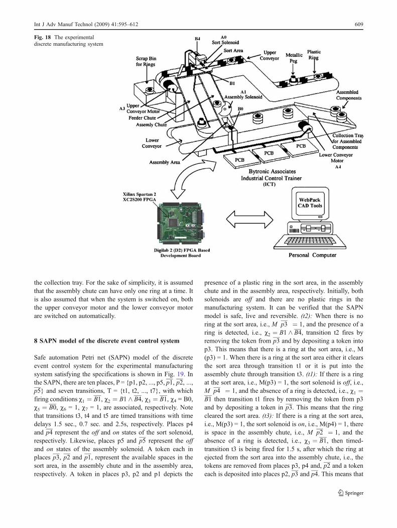
the collection tray. For the sake of simplicity, it is assumedthat the assembly chute can have only one ring at a time. Itis also assumed that when the system is switched on, boththe upper conveyor motor and the lower conveyor motorare switched on automatically.
8 SAPN model of the discrete event control system
Safe automation Petri net (SAPN) model of the discreteevent control system for the experimental manufacturingsystem satisfying the specifications is shown in Fig. 19. Inthe SAPN, there are ten places, P = {p1, p2, ..., p5, p1, p2, ...,p5} and seven transitions, T = {t1, t2, ..., t7}, with whichfiring conditions c1 ¼ B1, c2 ¼ B1 ^ B4, c3 ¼ B1, c4 = Β0,c5 ¼ B0, c6 = 1, c7 = 1, are associated, respectively. Notethat transitions t3, t4 and t5 are timed transitions with timedelays 1.5 sec., 0.7 sec. and 2.5s, respectively. Places p4and p4 represent the off and on states of the sort solenoid,respectively. Likewise, places p5 and p5 represent the offand on states of the assembly solenoid. A token each inplaces p3, p2 and p1, represent the available spaces in thesort area, in the assembly chute and in the assembly area,respectively. A token in places p3, p2 and p1 depicts the
presence of a plastic ring in the sort area, in the assemblychute and in the assembly area, respectively. Initially, bothsolenoids are off and there are no plastic rings in themanufacturing system. It can be verified that the SAPNmodel is safe, live and reversible. (t2): When there is noring at the sort area, i.e., M p3
� � ¼ 1, and the presence of aring is detected, i.e., c2 ¼ B1 ^ B4, transition t2 fires byremoving the token from p3 and by depositing a token intop3. This means that there is a ring at the sort area, i.e., M(p3) = 1. When there is a ring at the sort area either it clearsthe sort area through transition t1 or it is put into theassembly chute through transition t3. (t1): If there is a ringat the sort area, i.e., M(p3) = 1, the sort solenoid is off, i.e.,M p4� � ¼ 1, and the absence of a ring is detected, i.e., c1 ¼
B1 then transition t1 fires by removing the token from p3and by depositing a token in p3. This means that the ringcleared the sort area. (t3): If there is a ring at the sort area,i.e., M(p3) = 1, the sort solenoid is on, i.e., M(p4) = 1, thereis space in the assembly chute, i.e., M p2
� � ¼ 1, and theabsence of a ring is detected, i.e., c3 ¼ B1, then timed-transition t3 is being fired for 1.5 s, after which the ring atejected from the sort area into the assembly chute, i.e., thetokens are removed from places p3, p4 and, p2 and a tokeneach is deposited into places p2, p3 and p4. This means that
Fig. 18 The experimentaldiscrete manufacturing system
Int J Adv Manuf Technol (2009) 41:595–612 609

the ring at the sort area is put into the assembly chute bymeans of the sort solenoid and this process takes 1.5 sec.(t4): If there is a ring in the assembly chute, i.e., M(p2) = 1,there is space at the assembly area, i.e., M p1
� � ¼ 1, theassembly solenoid is on, i.e., M(p5) = 1, and the presenceof a ring is detected, i.e., c4 = B1, then timed-transition t4 isbeing fired for 0.7 sec., after which the ring is dispensedfrom the assembly chute to the assembly area, i.e., thetokens are removed from places p2, p5 and and p1 a tokeneach is deposited into places p1, p2 and p5. (t5): If there isa ring at the assembly area, i.e., M (p1) = 1, and a pegengages with the hole in the ring, i.e., c5 ¼ B0, then it takes2.5 sec. for the ring and the peg to be assembled and toclear the assembly area. After this, there is space at theassembly area, i.e., M (p1) = 0 and M p1
� � ¼ 1. Action A0is assigned to p4. When there is a token in p4, A0 is 1which is used to switch the sort solenoid on. (t6): If there isa ring at the sort area, i.e., M(p3) = 1, there is space in theassembly chute, i.e., M p2
� � ¼ 1, and the sort solenoid isoff, i.e., M p4
� � ¼ 1, then the sort solenoid is switched on,by removing the token from p4 and by depositing a tokenin p4. Action A1 is assigned to p5. When there is a token inp5, A1 is 1 which is used to switch the assembly solenoid on.(t7): If there is a ring in the assembly chute, i.e., M(p2) = 1,there is space in the assembly area, i.e., M p1
� � ¼ 1, andthe assembly solenoid is off, i.e., M p5
� � ¼ 1, then the
assembly solenoid is switched on, by removing the tokenfrom p5 and by depositing a token in p5.
9 Asynchronous digital hardware implementationof the SAPN model
The SAPN model of the DECS shown in Fig. 19 wasconverted into the related schematic using the proposeddirect translation method. The obtained asynchronousdigital hardware schematic of the SAPN is shown inFig. 20. On board 50 MHz clock signal is used to obtainthe necessary time delays. After converting the SAPNmodel into the asynchronous digital hardware schematicshown in Fig. 20, this design was implemented by usingXilinx Project Navigator 6.3.i software as a schematicprogram. The schematic program was then downloaded intothe Xilinx Spartan 2 XC2S200 FPGA of the D2 develop-ment board and the experimental discrete manufacturingsystem shown in Fig. 18 has been controlled successfully.The following shows the used system resources of theXC2S200 FPGA for the implementation of the controller.
10 Design summary
11 Conclusions and further research
In this paper, a new method has been proposed for thedigital hardware implementation of Petri net-based specifi-cations. The purpose of this paper has been to introduce anew discrete event control system paradigm, where thecontrol system is modeled with extended Petri nets andimplemented as an asynchronous controller using circuitelements. When compared with the existing software andhardware-based synchronous implementations, the asyn-chronous hardware-based implementation method proposedin this paper offers an alternative approach for theimplementation of discrete event controllers. It is expectedthat the discrete event controllers obtained by the proposedmethod would be very useful for time-critical-systems,where the decision speed offered by the discrete eventcontroller is required to be much faster than the controlledprocess. An experimental manufacturing system has beenused to show the applicability of the proposed method to
t1 t2
t5
p1
t3
t4
t6
t7
p3
T1
T2
χ 1 = B1 χ 2 = B1 Λ B4 χ 3 = B1 χ 4 = B0 χ 5 = B0 χ 6 = 1 χ 7 = 1
T1: 1.5 sec. T2: 0.7 sec. T3: 2.5 sec.
p4 ==> A0p5 ==> A1
χ 1 χ 2
χ 3
χ 4
χ 5
χ7
χ 6
p1
p2
p3
p2
p4
p4
p5
p5
T3
Fig. 19 Safe automation Petri net (SAPN) model of discrete eventcontrol system for the experimental manufacturing system satisfyingthe specifications
Logic utilization:Number of slice flip flops: 155 out of 4,704 3%Number of four input LUTs: 194 out of 4,704 4%
610 Int J Adv Manuf Technol (2009) 41:595–612
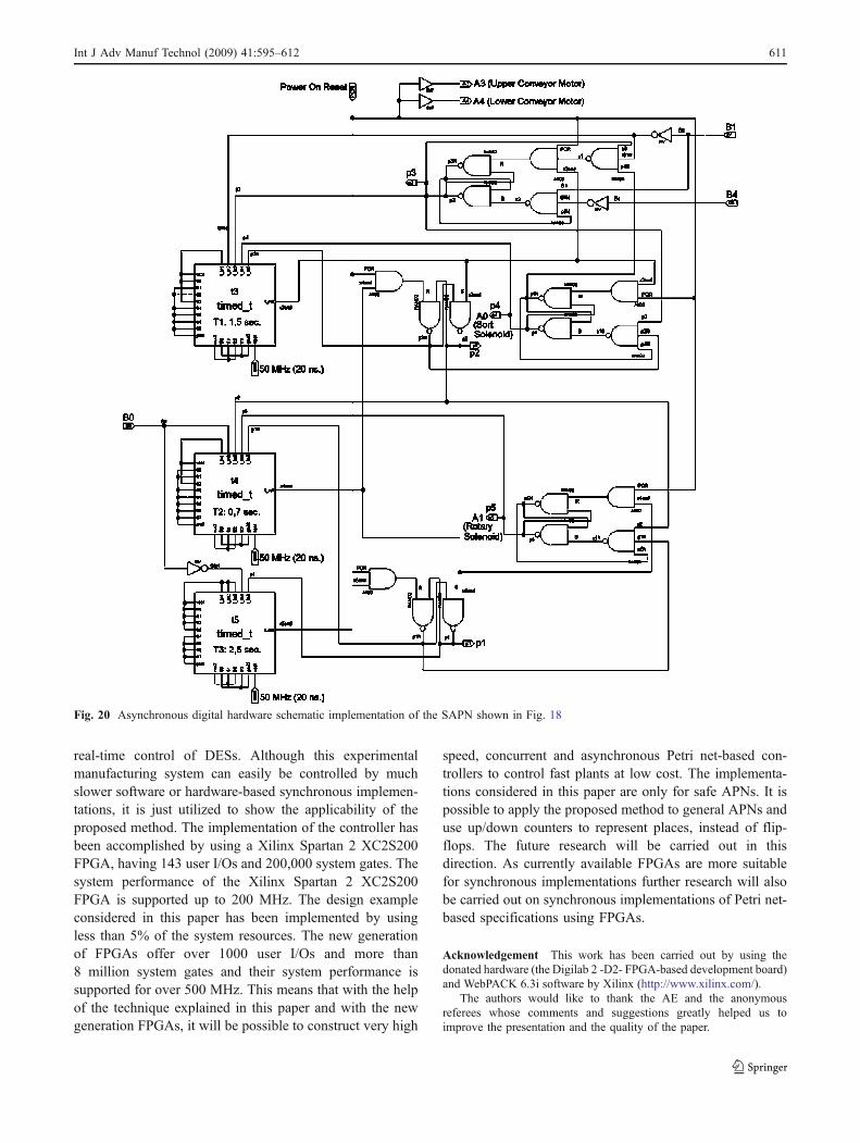
real-time control of DESs. Although this experimentalmanufacturing system can easily be controlled by muchslower software or hardware-based synchronous implemen-tations, it is just utilized to show the applicability of theproposed method. The implementation of the controller hasbeen accomplished by using a Xilinx Spartan 2 XC2S200FPGA, having 143 user I/Os and 200,000 system gates. Thesystem performance of the Xilinx Spartan 2 XC2S200FPGA is supported up to 200 MHz. The design exampleconsidered in this paper has been implemented by usingless than 5% of the system resources. The new generationof FPGAs offer over 1000 user I/Os and more than8 million system gates and their system performance issupported for over 500 MHz. This means that with the helpof the technique explained in this paper and with the newgeneration FPGAs, it will be possible to construct very high
speed, concurrent and asynchronous Petri net-based con-trollers to control fast plants at low cost. The implementa-tions considered in this paper are only for safe APNs. It ispossible to apply the proposed method to general APNs anduse up/down counters to represent places, instead of flip-flops. The future research will be carried out in thisdirection. As currently available FPGAs are more suitablefor synchronous implementations further research will alsobe carried out on synchronous implementations of Petri net-based specifications using FPGAs.
Acknowledgement This work has been carried out by using thedonated hardware (the Digilab 2 -D2- FPGA-based development board)and WebPACK 6.3i software by Xilinx (http://www.xilinx.com/).
The authors would like to thank the AE and the anonymousreferees whose comments and suggestions greatly helped us toimprove the presentation and the quality of the paper.
Fig. 20 Asynchronous digital hardware schematic implementation of the SAPN shown in Fig. 18
Int J Adv Manuf Technol (2009) 41:595–612 611
References
1. Uzam M (1998) Petri-Net-based supervisory control of discreteevent systems and their ladder logic diagram implementations.PhD Dissertation, The University of Salford, UK, 395 pages
2. Murata T (1989) Petri nets: properties, analysis and application.Proc of IEEE 77(4):541–579 DOI 10.1109/5.24143
3. Hendry DC (1994) Heterogeneous Petri net methodology fordesign of complex controllers. IEE Proc Comput Digt Tech 141(5):293–297 DOI 10.1049/ip-cdt:19941270
4. Stefano AD, Mirabella O (1994) A fast Petri-net-based sequencecontroller implemented on a DSP. Int J of Adv Manuf Tech9:375–381 DOI 10.1007/BF01748482
5. Zhou MC, DiCesare F, Rudolph D (1992) Design and implemen-tation of a Petri net based supervisor for a flexible manufacturingsystem. Automatica 28(6):1199–1208 DOI 10.1016/0005
6. Zhou MC, Twiss E (1998) Design of industrial automated systemsvia relay ladder logic programming and Petri nets. IEEE Trans. onSystems, Man, and Cybernetics 28(1):137–150 DOI 10.1109/5326.661096
7. Peng SS, Zhou MC (2003) Sensor-based stage Petri net modelingof PLC logic programs for discrete-event control design. Int JProd Res 41(3):629–644 DOI 10.1080/0020754021000042364
8. Peng S-S, Zhou MC (2004) Ladder diagram and Petri net baseddiscrete-event control design methods. IEEE Trans. on Systems,Man, and Cybernetic-Part C 34(4):523–531
9. Uzam M, Jones AH (1998) Discrete event control system designusing automation Petri nets and their ladder diagram implemen-tation. Int J of Adv Manuf Tech 14(10):716–728 DOI 10.1007/BF01438224
10. Yakovlev AV, Koelmans AB (1998) Petri nets and digitalhardware design. In: Reisig W, Rozenberg G (eds) LNCS,Lectures on Petri Nets II: Applications, Advances in Petri Nets.Springer, Heidelberg, pp 154–236.
11. Chang N, Kwon WH, Park J (1998) Hardware implementation ofreal-time Petri-net-based controllers. Control Eng Pract 6(7):889–895 DOI: 10.1016/S0967
12. Bulanch S, Brauchle A, Pfleiderer H-J, Kucerovsky Z (2002)Design and implementation of discrete event control systems: aPetri net based hardware approach. Discrete Event Dyn Syst 12(3):287–309
13. Varshavsky V, Kishinevsky M, Marakhovsky V, Peschansky V,Rosenblum R, Taubin A, Tzirlin B (1990) Self-timed control ofconcurrent processes. In: Varshavsky, VI (ed), Kluwer, Dordretch
14. Hollaar LA (1982) Direct implementation of asynchronous controlcircuits. IEEE Trans Comput C-31(12):1133–1141 DOI 10.1109/TC.1982.1675937
15. Varshavsky V, Marakhowsky V (1996) Hardware support fordiscrete event coordination. In: Proc. of Int. workshop ondiscrete event systems (WODES’96), Edinburgh, UK, August1996, (pp. 332–340)
16. Varshavsky V, Marakhowsky V (1996) Asynchronous controldevice design by net model behaviour simulation. LNCS, Vol.1091: Proc. of the 17th Int. conf. on applications and theory ofPetri nets, Osaka, Springer, (pp. 497–515)
17. Uzam M, Yalçın MK, Avcı M (2001) Digital hardware imple-mentation of Petri net based specifications: direct translation fromsafe automation Petri nets to circuit elements. In: Proceedings ofthe international workshop on discrete event systems design,Przytok near Zielona Gora, Poland (pp. 25–33)
18. Uzam M, Koç İB, Gelen G, Aksebzeci BH (2005) Asynchronousimplementation of a Petri net based discrete event control systemusing a Xilinx FPGA. In: Proceedings of the 35th Inter. Conf. oncomputers and industrial engineering, Istanbul, Turkey, June 20–22, vol. II, (pp. 2025–2030)
19. Xilinx (2003) Spartan-II 2.5V FPGA Family: Complete datasheet, DS001–1, http://www.xilinx.com/
20. Uzam M (2006) General purpose, cheap and flexible contactdebouncer. Electron World 112(1848):41–48
612 Int J Adv Manuf Technol (2009) 41:595–612
Related Documents


![Discrete timed Petri nets - Pure - Aanmelden · colored Petri nets. We also do not consider continuous Petri nets (cf [31]) because the underlying untimed net is not a classical Petri](https://static.cupdf.com/doc/110x72/601b8a6f707ca30c043d37a8/discrete-timed-petri-nets-pure-aanmelden-colored-petri-nets-we-also-do-not.jpg)