Proceedings of the IEEE, Vol. 83, No. 1, pp. 69-93, January, 1995. Asynchronous Design Methodologies: An Overview Scott Hauck Department of Computer Science and Engineering University of Washington Seattle, WA 98195 Abstract Asynchronous design has been an active area of research since at least the mid 1950's, but has yet to achieve widespread use. We examine the benefits and problems inherent in asynchronous computations, and in some of the more notable design methodologies. These include Huffman asynchronous circuits, burst-mode circuits, micropipelines, template-based and trace theory-based delay-insensitive circuits, signal transition graphs, change diagrams, and compilation-based quasi- delay-insensitive circuits. 1. Introduction Much of today’s logic design is based on two major assumptions: all signals are binary, and time is discrete. Both of these assumptions are made in order to simplify logic design. By assuming binary values on signals, simple Boolean logic can be used to describe and manipulate logic constructs. By assuming time is discrete, hazards and feedback can largely be ignored. However, as with many simplifying assumptions, a system that can operate without these assumptions has the potential to generate better results. Asynchronous circuits keep the assumption that signals are binary, but remove the assumption that time is discrete. This has several possible benefits: No clock skew - Clock skew is the difference in arrival times of the clock signal at different parts of the circuit. Since asynchronous circuits by definition have no globally distributed clock, there is no need to worry about clock skew. In contrast, synchronous systems often slow down their circuits to accommodate the skew. As feature sizes decrease, clock skew becomes a much greater concern. Lower power - Standard synchronous circuits have to toggle clock lines, and possibly precharge and discharge signals, in portions of a circuit unused in the current computation. For example, even though a floating- point unit on a processor might not be used in a given instruction stream, the unit still must be operated by the clock. Although asynchronous circuits often require more transitions on the computation path than synchronous circuits, they generally have transitions only in areas involved in the current computation. Note that there are techniques being used in synchronous designs to address this issue as well. Average-case instead of worst-case performance - Synchronous circuits must wait until all possible computations have completed before latching the results, yielding worst-case performance. Many asynchronous systems sense when a computation has completed, allowing them to exhibit average-case performance. For circuits such as ripple-carry adders where the worst-case delay is significantly worse than the average-case delay, this can result in a substantial savings. Easing of global timing issues - In systems such as a synchronous microprocessor, the system clock, and thus system performance, is dictated by the slowest (critical) path. Thus, most portions of a circuit must be carefully optimized to achieve the highest clock rate, including rarely used portions of the system. Since

Welcome message from author
This document is posted to help you gain knowledge. Please leave a comment to let me know what you think about it! Share it to your friends and learn new things together.
Transcript
Proceedings of the IEEE, Vol. 83, No. 1, pp. 69-93, January, 1995.
Asynchronous Design Methodologies: An Overview
Scott HauckDepartment of Computer Science and EngineeringUniversity of WashingtonSeattle, WA 98195
AbstractAsynchronous design has been an active area of research since at least the mid 1950's, but has
yet to achieve widespread use. We examine the benefits and problems inherent in asynchronouscomputations, and in some of the more notable design methodologies. These include Huffmanasynchronous circuits, burst-mode circuits, micropipelines, template-based and trace theory-baseddelay-insensitive circuits, signal transition graphs, change diagrams, and compilation-based quasi-delay-insensitive circuits.
1. IntroductionMuch of today’s logic design is based on two major assumptions: all signals are binary, and time is discrete.
Both of these assumptions are made in order to simplify logic design. By assuming binary values on signals,simple Boolean logic can be used to describe and manipulate logic constructs. By assuming time is discrete, hazardsand feedback can largely be ignored. However, as with many simplifying assumptions, a system that can operatewithout these assumptions has the potential to generate better results.
Asynchronous circuits keep the assumption that signals are binary, but remove the assumption that time isdiscrete. This has several possible benefits:
No clock skew - Clock skew is the difference in arrival times of the clock signal at different parts of the circuit.Since asynchronous circuits by definition have no globally distributed clock, there is no need to worryabout clock skew. In contrast, synchronous systems often slow down their circuits to accommodate theskew. As feature sizes decrease, clock skew becomes a much greater concern.
Lower power - Standard synchronous circuits have to toggle clock lines, and possibly precharge and dischargesignals, in portions of a circuit unused in the current computation. For example, even though a floating-point unit on a processor might not be used in a given instruction stream, the unit still must be operated bythe clock. Although asynchronous circuits often require more transitions on the computation path thansynchronous circuits, they generally have transitions only in areas involved in the current computation.Note that there are techniques being used in synchronous designs to address this issue as well.
Average-case instead of worst-case performance - Synchronous circuits must wait until all possiblecomputations have completed before latching the results, yielding worst-case performance. Manyasynchronous systems sense when a computation has completed, allowing them to exhibit average-caseperformance. For circuits such as ripple-carry adders where the worst-case delay is significantly worse thanthe average-case delay, this can result in a substantial savings.
Easing of global timing issues - In systems such as a synchronous microprocessor, the system clock, and thussystem performance, is dictated by the slowest (critical) path. Thus, most portions of a circuit must becarefully optimized to achieve the highest clock rate, including rarely used portions of the system. Since
Mingjie Lin
Mingjie Lin
Mingjie Lin
Mingjie Lin
Mingjie Lin
Mingjie Lin
Mingjie Lin
Mingjie Lin
Mingjie Lin
Mingjie Lin
2
many asynchronous systems operate at the speed of the circuit path currently in operation, rarely usedportions of the circuit can be left unoptimized without adversely affecting system performance.
Better technology migration potential - Integrated circuits will often be implemented in several differenttechnologies during their lifetime. Early systems may be implemented with gate arrays, while laterproduction runs may migrate to semi-custom or custom ICs. Greater performance for synchronous systemscan often only be achieved by migrating all system components to a new technology, since again theoverall system performance is based on the longest path. In many asynchronous systems, migration ofonly the more critical system components can improve system performance on average, since performanceis dependent on only the currently active path. Also, since many asynchronous systems sense computationcompletion, components with different delays may often be substituted into a system without altering otherelements or structures.
Automatic adaptation to physical properties - The delay through a circuit can change with variations infabrication, temperature, and power-supply voltage. Synchronous circuits must assume that the worstpossible combination of factors is present and clock the system accordingly. Many asynchronous circuitssense computation completion, and will run as quickly as the current physical properties allow.
Robust mutual exclusion and external input handling - Elements that guarantee correct mutual exclusion ofindependent signals and synchronization of external signals to a clock are subject to metastability [1]. Ametastable state is an unstable equilibrium state, such as a pair of cross-coupled CMOS inverters at 2.5V,which a system can remain in for an unbounded amount of time [2]. Synchronous circuits require allelements to exhibit bounded response time. Thus, there is some chance that mutual exclusion circuits willfail in a synchronous system. Most asynchronous systems can wait an arbitrarily long time for such anelement to complete, allowing robust mutual exclusion. Also, since there is no clock with which signalsmust be synchronized, asynchronous circuits more gracefully accommodate inputs from the outside world,which are by nature asynchronous.
With all of the potential advantages of asynchronous circuits, one might wonder why synchronous systemspredominate. The reason is that asynchronous circuits have several problems as well. Primarily, asynchronouscircuits are more difficult to design in an ad hoc fashion than synchronous circuits. In a synchronous system, adesigner can simply define the combinational logic necessary to compute the given functions, and surround it withlatches. By setting the clock rate to a long enough period, all worries about hazards (undesired signal transitions) andthe dynamic state of the circuit are removed. In contrast, designers of asynchronous systems must pay a great deal ofattention to the dynamic state of the circuit. Hazards must also be removed from the circuit, or not introduced in thefirst place, to avoid incorrect results. The ordering of operations, which was fixed by the placement of latches in asynchronous system, must be carefully ensured by the asynchronous control logic. For complex systems, theseissues become too difficult to handle by hand. Unfortunately, asynchronous circuits in general cannot leverage off ofexisting CAD tools and implementation alternatives for synchronous systems. For example, some asynchronousmethodologies allow only algebraic manipulations (associative, commutative, and DeMorgan's Law) for logicdecomposition, and many do not even allow these. Placement, routing, partitioning, logic synthesis, and most otherCAD tools either need modifications for asynchronous circuits, or are not applicable at all.
Finally, even though most of the advantages of asynchronous circuits are towards higher performance, it isn'tclear that asynchronous circuits are actually any faster in practice. Asynchronous circuits generally require extra timedue to their signaling policies, thus increasing average-case delay. Whether this cost is greater or less than thebenefits listed previously is unclear, and more research in this area is necessary.
Mingjie Lin
Mingjie Lin
Mingjie Lin
Mingjie Lin
Mingjie Lin
Mingjie Lin
Mingjie Lin
Mingjie Lin
Mingjie Lin
3
Even with all of the problems listed above, asynchronous design is an important research area. Regardless ofhow successful synchronous systems are, there will always be a need for asynchronous systems. Asynchronouslogic may be used simply for the interfacing of a synchronous system to its environment and other synchronoussystems, or possibly for more complete applications. Also, although ad hoc design of asynchronous systems isimpractical, there are several methodologies and CAD algorithms developed specifically for asynchronous design.Several of the main approaches are profiled in this paper. Note that we do not catalog all methodologies everdeveloped, nor do we explore every subtlety of the methodologies included. Attempting either of these tasks wouldfill hundreds of pages, obscuring the significant issues involved. Instead, we discuss the essential aspects of someof the more well-known asynchronous design systems. This will hopefully provide the reader a solid framework inwhich to further pursue the topics of interest. We likewise do not cover many of the related areas, such asverification and testing, which are very important to asynchronous design, yet too complex to be handled adequatelyhere. Interested readers are directed elsewhere for details on asynchronous verification [3] and testing [4].
Asynchronous design methodologies can most easily be categorized by the timing models they assume, and thispaper is organized along these lines. Section 2 covers systems using bounded-delay models, including fundamental-mode Huffman circuits, extensions of these circuits to non-fundamental mode, and burst-mode circuits. Section 3focuses on micropipelines. Section 4 details delay-insensitive circuits, including template or module based systems,and trace Theory. Section 5 combines speed-independent and quasi-delay-insensitive circuits, including signaltransition graphs, change diagrams, and communicating processes compilation. Finally, we conclude in Section 6with a general comparison of the methods discussed.
2. Bounded-Delay ModelsThe most obvious model to use for asynchronous circuits is the same model used for synchronous circuits.
Specifically, it is assumed that the delay in all circuit elements and wires is known, or at least bounded. Circuitsdesigned with this model (usually coupled with the fundamental mode assumption discussed below) are generallyreferred to as Huffman circuits, after D. A. Huffman, who developed many of the early concepts of these circuits.
2.1 Fundamental Mode Huffman CircuitsIn this model, circuits are designed in much the same way as synchronous circuits. The circuit to be synthesized
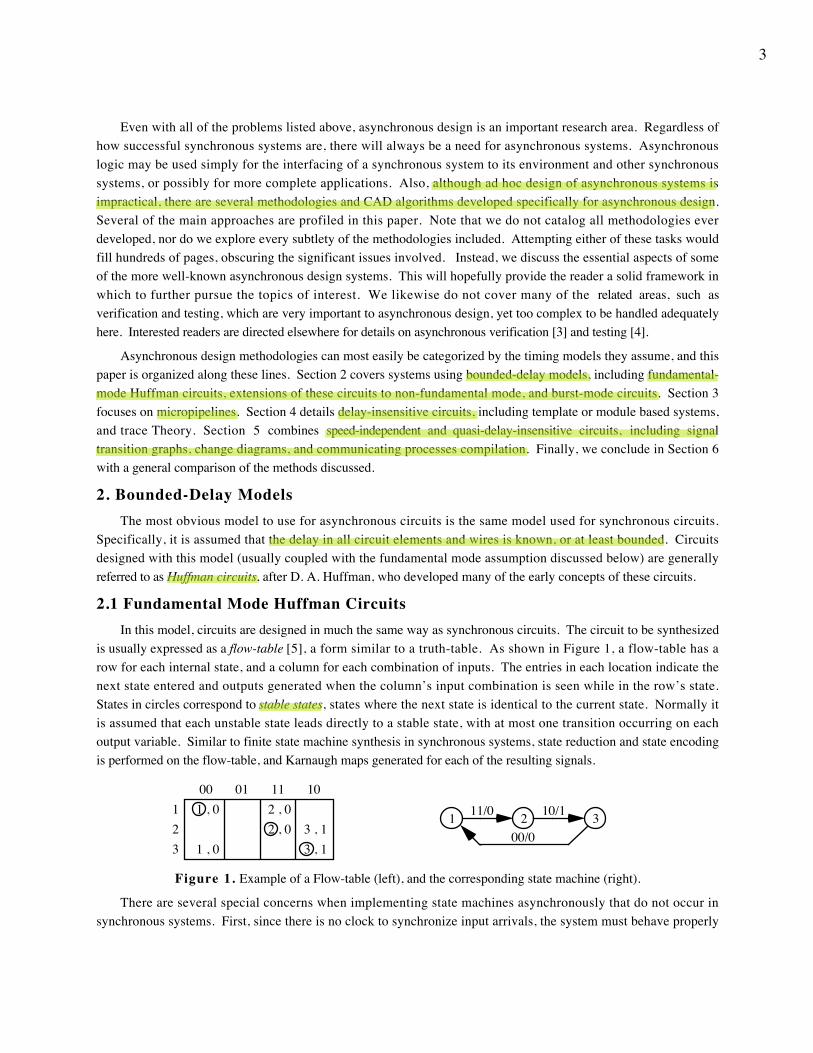
is usually expressed as a flow-table [5], a form similar to a truth-table. As shown in Figure 1, a flow-table has arow for each internal state, and a column for each combination of inputs. The entries in each location indicate thenext state entered and outputs generated when the column’s input combination is seen while in the row’s state.States in circles correspond to stable states, states where the next state is identical to the current state. Normally itis assumed that each unstable state leads directly to a stable state, with at most one transition occurring on eachoutput variable. Similar to finite state machine synthesis in synchronous systems, state reduction and state encodingis performed on the flow-table, and Karnaugh maps generated for each of the resulting signals.
11/0 10/1
00/01 32
00 11 01 10
3 , 13 , 12 , 0
2 , 0
1 , 0
1 , 0
321
Figure 1. Example of a Flow-table (left), and the corresponding state machine (right).
There are several special concerns when implementing state machines asynchronously that do not occur insynchronous systems. First, since there is no clock to synchronize input arrivals, the system must behave properly
Mingjie Lin
Mingjie Lin
Mingjie Lin
Mingjie Lin
Mingjie Lin
Mingjie Lin
Mingjie Lin
Mingjie Lin
Mingjie Lin
4
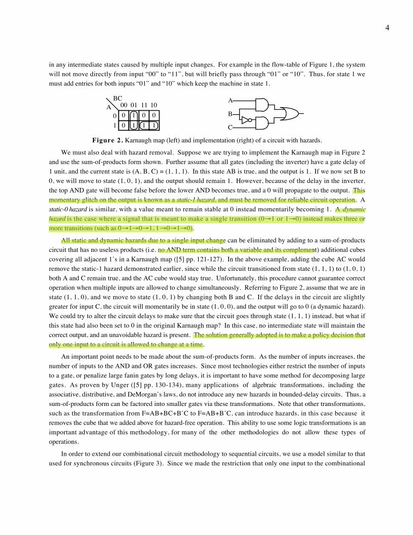
in any intermediate states caused by multiple input changes. For example in the flow-table of Figure 1, the systemwill not move directly from input “00” to “11”, but will briefly pass through “01” or “10”. Thus, for state 1 wemust add entries for both inputs “01” and “10” which keep the machine in state 1.
B
A
C11010
BCA 00 01 11 10
0 0011
Figure 2. Karnaugh map (left) and implementation (right) of a circuit with hazards.
We must also deal with hazard removal. Suppose we are trying to implement the Karnaugh map in Figure 2and use the sum-of-products form shown. Further assume that all gates (including the inverter) have a gate delay of1 unit, and the current state is (A, B, C) = (1, 1, 1). In this state AB is true, and the output is 1. If we now set B to0, we will move to state (1, 0, 1), and the output should remain 1. However, because of the delay in the inverter,the top AND gate will become false before the lower AND becomes true, and a 0 will propagate to the output. Thismomentary glitch on the output is known as a static-1 hazard, and must be removed for reliable circuit operation. Astatic-0 hazard is similar, with a value meant to remain stable at 0 instead momentarily becoming 1. A dynamichazard is the case where a signal that is meant to make a single transition (0→1 or 1→0) instead makes three ormore transitions (such as 0→1→0→1, 1→0→1→0).
All static and dynamic hazards due to a single input change can be eliminated by adding to a sum-of-productscircuit that has no useless products (i.e. no AND term contains both a variable and its complement) additional cubescovering all adjacent 1’s in a Karnaugh map ([5] pp. 121-127). In the above example, adding the cube AC wouldremove the static-1 hazard demonstrated earlier, since while the circuit transitioned from state (1, 1, 1) to (1, 0, 1)both A and C remain true, and the AC cube would stay true. Unfortunately, this procedure cannot guarantee correctoperation when multiple inputs are allowed to change simultaneously. Referring to Figure 2, assume that we are instate (1, 1, 0), and we move to state (1, 0, 1) by changing both B and C. If the delays in the circuit are slightlygreater for input C, the circuit will momentarily be in state (1, 0, 0), and the output will go to 0 (a dynamic hazard).We could try to alter the circuit delays to make sure that the circuit goes through state (1, 1, 1) instead, but what ifthis state had also been set to 0 in the original Karnaugh map? In this case, no intermediate state will maintain thecorrect output, and an unavoidable hazard is present. The solution generally adopted is to make a policy decision thatonly one input to a circuit is allowed to change at a time.
An important point needs to be made about the sum-of-products form. As the number of inputs increases, thenumber of inputs to the AND and OR gates increases. Since most technologies either restrict the number of inputsto a gate, or penalize large fanin gates by long delays, it is important to have some method for decomposing largegates. As proven by Unger ([5] pp. 130-134), many applications of algebraic transformations, including theassociative, distributive, and DeMorgan’s laws, do not introduce any new hazards in bounded-delay circuits. Thus, asum-of-products form can be factored into smaller gates via these transformations. Note that other transformations,such as the transformation from F=AB+BC+B’C to F=AB+B’C, can introduce hazards, in this case because itremoves the cube that we added above for hazard-free operation. This ability to use some logic transformations is animportant advantage of this methodology, for many of the other methodologies do not allow these types ofoperations.
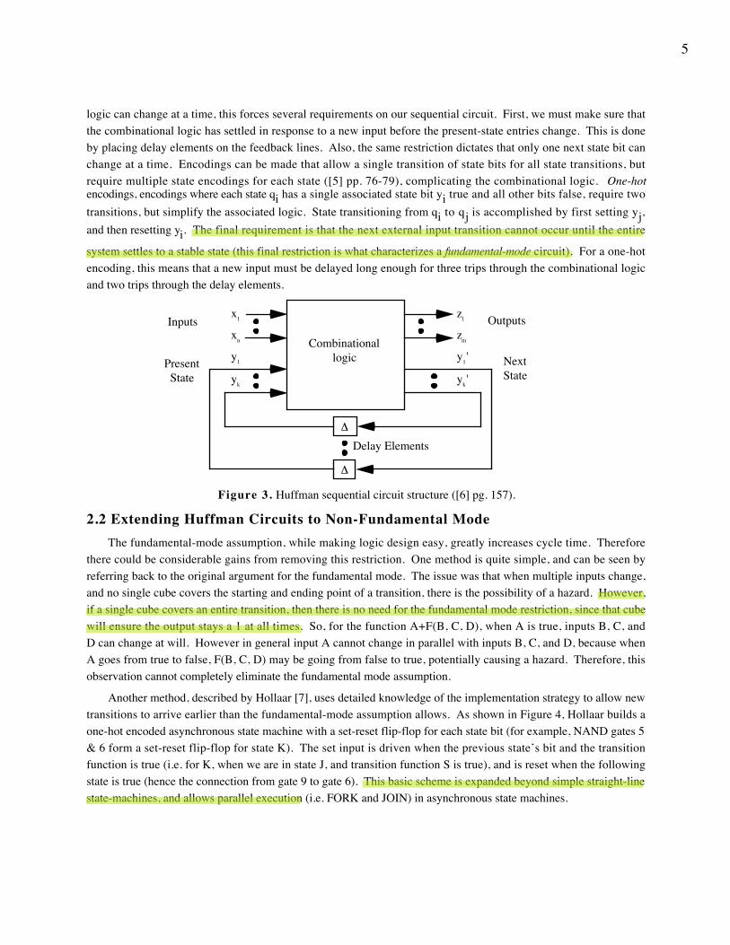
In order to extend our combinational circuit methodology to sequential circuits, we use a model similar to thatused for synchronous circuits (Figure 3). Since we made the restriction that only one input to the combinational
Mingjie Lin
Mingjie Lin
Mingjie Lin
Mingjie Lin
Mingjie Lin
5
logic can change at a time, this forces several requirements on our sequential circuit. First, we must make sure thatthe combinational logic has settled in response to a new input before the present-state entries change. This is doneby placing delay elements on the feedback lines. Also, the same restriction dictates that only one next state bit canchange at a time. Encodings can be made that allow a single transition of state bits for all state transitions, butrequire multiple state encodings for each state ([5] pp. 76-79), complicating the combinational logic. One-hotencodings, encodings where each state qi has a single associated state bit yi true and all other bits false, require twotransitions, but simplify the associated logic. State transitioning from qi to qj is accomplished by first setting yj,and then resetting yi. The final requirement is that the next external input transition cannot occur until the entire
system settles to a stable state (this final restriction is what characterizes a fundamental-mode circuit). For a one-hotencoding, this means that a new input must be delayed long enough for three trips through the combinational logicand two trips through the delay elements.
x1
xn
y1
yk
z1
zm
y1'
yk'
Inputs Outputs
Present State
Next State
Combinational logic
∆
∆
Delay Elements
Figure 3. Huffman sequential circuit structure ([6] pg. 157).
2.2 Extending Huffman Circuits to Non-Fundamental ModeThe fundamental-mode assumption, while making logic design easy, greatly increases cycle time. Therefore
there could be considerable gains from removing this restriction. One method is quite simple, and can be seen byreferring back to the original argument for the fundamental mode. The issue was that when multiple inputs change,and no single cube covers the starting and ending point of a transition, there is the possibility of a hazard. However,if a single cube covers an entire transition, then there is no need for the fundamental mode restriction, since that cubewill ensure the output stays a 1 at all times. So, for the function A+F(B, C, D), when A is true, inputs B, C, andD can change at will. However in general input A cannot change in parallel with inputs B, C, and D, because whenA goes from true to false, F(B, C, D) may be going from false to true, potentially causing a hazard. Therefore, thisobservation cannot completely eliminate the fundamental mode assumption.
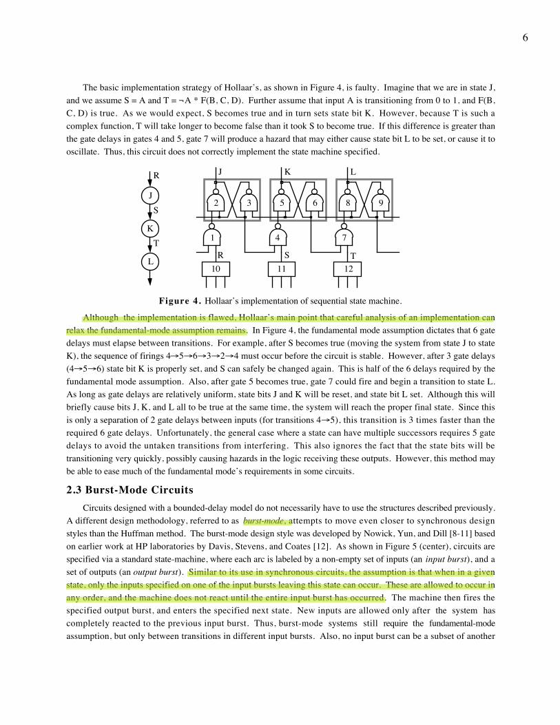
Another method, described by Hollaar [7], uses detailed knowledge of the implementation strategy to allow newtransitions to arrive earlier than the fundamental-mode assumption allows. As shown in Figure 4, Hollaar builds aone-hot encoded asynchronous state machine with a set-reset flip-flop for each state bit (for example, NAND gates 5& 6 form a set-reset flip-flop for state K). The set input is driven when the previous state’s bit and the transitionfunction is true (i.e. for K, when we are in state J, and transition function S is true), and is reset when the followingstate is true (hence the connection from gate 9 to gate 6). This basic scheme is expanded beyond simple straight-linestate-machines, and allows parallel execution (i.e. FORK and JOIN) in asynchronous state machines.
Mingjie Lin
Mingjie Lin
Mingjie Lin
6
The basic implementation strategy of Hollaar’s, as shown in Figure 4, is faulty. Imagine that we are in state J,and we assume S = A and T = ¬A * F(B, C, D). Further assume that input A is transitioning from 0 to 1, and F(B,C, D) is true. As we would expect, S becomes true and in turn sets state bit K. However, because T is such acomplex function, T will take longer to become false than it took S to become true. If this difference is greater thanthe gate delays in gates 4 and 5, gate 7 will produce a hazard that may either cause state bit L to be set, or cause it tooscillate. Thus, this circuit does not correctly implement the state machine specified.
J
K
L
R
S
TSR T
J K L
1
2 3
4
5 6
7
8 9
10 11 12
Figure 4. Hollaar’s implementation of sequential state machine.
Although the implementation is flawed, Hollaar’s main point that careful analysis of an implementation canrelax the fundamental-mode assumption remains. In Figure 4, the fundamental mode assumption dictates that 6 gatedelays must elapse between transitions. For example, after S becomes true (moving the system from state J to stateK), the sequence of firings 4→5→6→3→2→4 must occur before the circuit is stable. However, after 3 gate delays(4→5→6) state bit K is properly set, and S can safely be changed again. This is half of the 6 delays required by thefundamental mode assumption. Also, after gate 5 becomes true, gate 7 could fire and begin a transition to state L.As long as gate delays are relatively uniform, state bits J and K will be reset, and state bit L set. Although this willbriefly cause bits J, K, and L all to be true at the same time, the system will reach the proper final state. Since thisis only a separation of 2 gate delays between inputs (for transitions 4→5), this transition is 3 times faster than therequired 6 gate delays. Unfortunately, the general case where a state can have multiple successors requires 5 gatedelays to avoid the untaken transitions from interfering. This also ignores the fact that the state bits will betransitioning very quickly, possibly causing hazards in the logic receiving these outputs. However, this method maybe able to ease much of the fundamental mode’s requirements in some circuits.
2.3 Burst-Mode CircuitsCircuits designed with a bounded-delay model do not necessarily have to use the structures described previously.
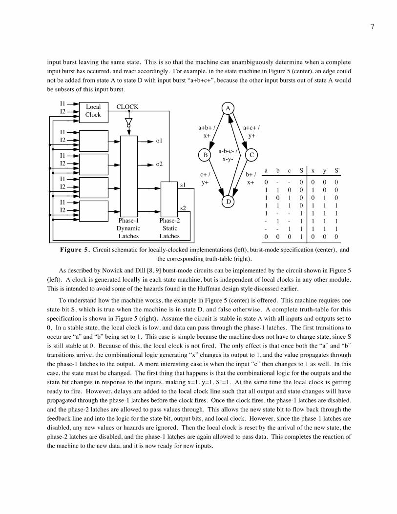
A different design methodology, referred to as burst-mode, attempts to move even closer to synchronous designstyles than the Huffman method. The burst-mode design style was developed by Nowick, Yun, and Dill [8-11] basedon earlier work at HP laboratories by Davis, Stevens, and Coates [12]. As shown in Figure 5 (center), circuits arespecified via a standard state-machine, where each arc is labeled by a non-empty set of inputs (an input burst), and aset of outputs (an output burst). Similar to its use in synchronous circuits, the assumption is that when in a givenstate, only the inputs specified on one of the input bursts leaving this state can occur. These are allowed to occur inany order, and the machine does not react until the entire input burst has occurred. The machine then fires thespecified output burst, and enters the specified next state. New inputs are allowed only after the system hascompletely reacted to the previous input burst. Thus, burst-mode systems still require the fundamental-modeassumption, but only between transitions in different input bursts. Also, no input burst can be a subset of another
Mingjie Lin
Mingjie Lin
Mingjie Lin
7
input burst leaving the same state. This is so that the machine can unambiguously determine when a completeinput burst has occurred, and react accordingly. For example, in the state machine in Figure 5 (center), an edge couldnot be added from state A to state D with input burst “a+b+c+”, because the other input bursts out of state A wouldbe subsets of this input burst.
I1I2
o1
o2
CLOCK
s1
s2
Phase-1 Dynamic Latches
Phase-2 Static
Latches
Local Clock
I1I2
I1I2
I1I2
I1I2
B
A
D
C
a+b+ / x+
a+c+ / y+
c+ / y+
a-b-c- / x-y-
b+ / x+
a
01111--0
S
00001111
c
-011--10
x
01011110
S'
00011110
b
-101-1-0
y
00111110
Figure 5. Circuit schematic for locally-clocked implementations (left), burst-mode specification (center), andthe corresponding truth-table (right).
As described by Nowick and Dill [8, 9] burst-mode circuits can be implemented by the circuit shown in Figure 5(left). A clock is generated locally in each state machine, but is independent of local clocks in any other module.This is intended to avoid some of the hazards found in the Huffman design style discussed earlier.
To understand how the machine works, the example in Figure 5 (center) is offered. This machine requires onestate bit S, which is true when the machine is in state D, and false otherwise. A complete truth-table for thisspecification is shown in Figure 5 (right). Assume the circuit is stable in state A with all inputs and outputs set to0. In a stable state, the local clock is low, and data can pass through the phase-1 latches. The first transitions tooccur are “a” and “b” being set to 1. This case is simple because the machine does not have to change state, since Sis still stable at 0. Because of this, the local clock is not fired. The only effect is that once both the “a” and “b”transitions arrive, the combinational logic generating “x” changes its output to 1, and the value propagates throughthe phase-1 latches to the output. A more interesting case is when the input “c” then changes to 1 as well. In thiscase, the state must be changed. The first thing that happens is that the combinational logic for the outputs and thestate bit changes in response to the inputs, making x=1, y=1, S’=1. At the same time the local clock is gettingready to fire. However, delays are added to the local clock line such that all output and state changes will havepropagated through the phase-1 latches before the clock fires. Once the clock fires, the phase-1 latches are disabled,and the phase-2 latches are allowed to pass values through. This allows the new state bit to flow back through thefeedback line and into the logic for the state bit, output bits, and local clock. However, since the phase-1 latches aredisabled, any new values or hazards are ignored. Then the local clock is reset by the arrival of the new state, thephase-2 latches are disabled, and the phase-1 latches are again allowed to pass data. This completes the reaction ofthe machine to the new data, and it is now ready for new inputs.
8
The major claim of this implementation is that by having a local clock, many of the hazards encountered bynormal Huffman circuits are avoided, and standard synchronous state assignment techniques can be employed.However, it turns out that not all hazards can be ignored. In all transitions, the outputs are generated directly inresponse to the inputs, and the local clock offers no hazard protection. Thus, the redundant cubes necessary inHuffman circuits are also needed for the output logic, and special care must be taken to avoid dynamic hazards [13].The local clock generation logic may also contain similar hazards. Although this signal is not directly seen by theenvironment, a hazard on the clock lines could cause the state to change partially or completely when no change wasintended.
The locally-clocked structure as presented so far cannot use standard state encoding schemes, since a standardstate encoding can cause multiple state bits to change at a time. These state bits may then cause hazards in the localclock logic which cannot be removed simply by redundant cubes (note however that output hazards cannot be directlycaused by state bits changing because the phase-1 latches are disabled during state bit transitions). However, specialhardware can be added to the local clock logic to make sure all AND products involving the previous state aredisabled before the next state bits arrive [9]. This eliminates hazards due to multiple state bit transitions, at theexpense of more complicated internal timing constraints. In this way, synchronous state encoding schemes can beused, possibly with a significant decrease in the required number of state bits.
As described by Yun, Nowick, and Dill [10, 11], burst-mode circuits can also be implemented by usingtechniques similar to those of Huffman circuits. Since burst-mode circuits allow multiple input changes, one wouldexpect to have the same hazard problems that motivated the single-input-change restriction in the Huffman circuits.However, since the burst-mode specification only allows outputs to change after an entire input burst, and sincetransitions from the next input burst are not allowed to arrive until the circuit has finished reacting to the previousburst, there are no unavoidable hazards in the circuit. Thus, the technique of adding redundant cubes to a sum-of-products form used in Huffman circuits to remove hazards is sufficient to implement burst-mode circuits. As provenby Yun, Dill and Nowick [11], these must include a cube covering the initial and final states of an input burst wherethe output variable remains true. Thus, this cube will remain true during the entire input burst, and the output willbe hazard-free. Also, any cube covering any part of an input burst that causes an output variable to change from 1 to0 must also cover the initial state of the input burst. Thus, all cubes that can be true during the input burst will betrue at the start of the burst, so that once the output variable becomes false all of the cubes leading to it are stable.Finally, these circuits must use the same special state encodings (though not necessarily 1-hot encodings) and delayson the feedback lines as Huffman circuits to avoid hazards in the combinational logic.
2.4 Problems With Bounded-Delay MethodologiesAlthough the bounded-delay design methodologies discussed so far use a delay model successfully applied to
complex synchronous systems, there are some common problems that restrict these asynchronous methodologies.They are generally due to the fact that circuits are often not simply single small state machines, but instead arecomplex systems with multiple control state machines and datapath elements combining to implement the desiredfunctionality. Unfortunately, none of the methodologies discussed so far address the issue of system decomposition.Also, these methodologies cannot design datapath elements. This is because datapath elements tend to have multipleinput signals changing in parallel, and the fundamental-mode assumption would unreasonably restrict the parallelismin datapath elements.
Even for circuits that the previous systems can handle, there can be performance problems with these designstyles. Most obviously, the fundamental-mode and burst-mode circuits explicitly add delays to avoid certain hazardcases, decreasing performance. Also, the modules must assume the worst-case in both input data and physical
9
properties when inserting delays, thus leading to worst-case behavior. Finally, these circuits exhibit what can becalled additive skew. Imagine that there are three state machines, designed in either fundamental, Hollaar, or burstmode structures, connected in series. Inputs to the first machine must obey not only the input timing constraints ofthe first machine, but also those of all following stages. Since there will be some difference between the minimumand maximum propagation delays through the stages (the skew), in order to respect the second stage’s inputconstraints the first stage’s inputs must be spaced by at least the second stage’s input constraint plus the first stage’sskew. Even worse are the constraints imposed by the third stage, because the first input could take the maximumamount of time through the first two stages, while the second input takes the minimum time through these stages.Thus, the first stage must space inputs by the third stage’s input constraint plus the skews of both preceding stages.When one considers an entire pipelined microprocessor with large numbers of cascaded stages, it is clear that thethroughput of the system will be extremely poor. This also means that work such as Hollaar’s, which attempts toincrease throughput by allowing greatly varying input rates, will increase the skew and possibly degradeperformance. This last problem, that of additive skew, can be overcome by adding explicit flow-control to thesystem. As will be described later, asynchronous elements can be connected by a request-acknowledgment protocolwhich adds flow-control to these circuits. For burst-mode circuits at least, these signals can be incorporated intoeach input burst, and the problem of additive skew can be overcome. Unfortunately, this does mean incurring theoverheads of both inserted delays and request-acknowledgment signaling, which may cause performance penalties.Higher-performance designs can reach a compromise between latency and bandwidth in these systems by groupingtogether several stages of burst-mode circuits, and only apply the request-acknowledge protocol to this group’sexternal interfaces. Also, for circuits that do not require many levels of logic, the ability to choose whether or not touse request-acknowledge protocols, as well as the fast response of burst-mode circuits to some inputs, can generatefast circuits.
∆
Pulse Generator
∆
Pulse Detector
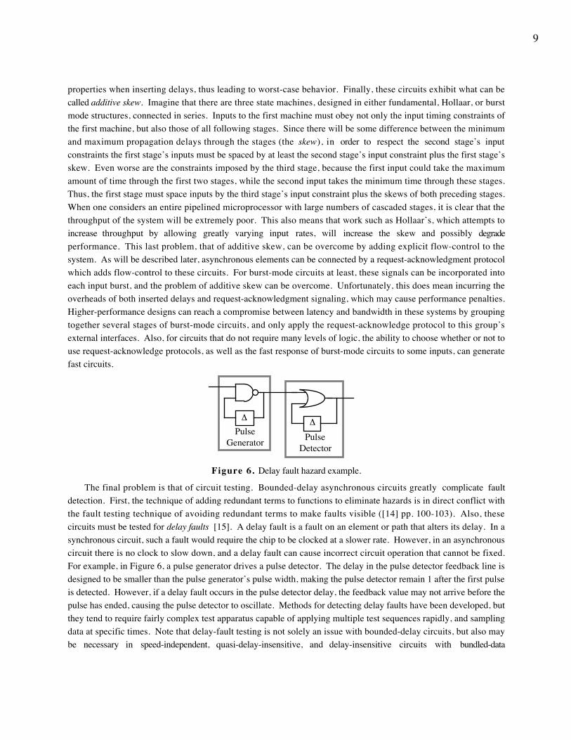
Figure 6. Delay fault hazard example.
The final problem is that of circuit testing. Bounded-delay asynchronous circuits greatly complicate faultdetection. First, the technique of adding redundant terms to functions to eliminate hazards is in direct conflict withthe fault testing technique of avoiding redundant terms to make faults visible ([14] pp. 100-103). Also, thesecircuits must be tested for delay faults [15]. A delay fault is a fault on an element or path that alters its delay. In asynchronous circuit, such a fault would require the chip to be clocked at a slower rate. However, in an asynchronouscircuit there is no clock to slow down, and a delay fault can cause incorrect circuit operation that cannot be fixed.For example, in Figure 6, a pulse generator drives a pulse detector. The delay in the pulse detector feedback line isdesigned to be smaller than the pulse generator’s pulse width, making the pulse detector remain 1 after the first pulseis detected. However, if a delay fault occurs in the pulse detector delay, the feedback value may not arrive before thepulse has ended, causing the pulse detector to oscillate. Methods for detecting delay faults have been developed, butthey tend to require fairly complex test apparatus capable of applying multiple test sequences rapidly, and samplingdata at specific times. Note that delay-fault testing is not solely an issue with bounded-delay circuits, but also maybe necessary in speed-independent, quasi-delay-insensitive, and delay-insensitive circuits with bundled-data
10
constraints. Each of these models will be discussed later in this paper. However, each of these models tend to haveless pervasive timing assumptions, possibly making them easier to test.
3. MicropipelinesMicropipelines were introduced in Ivan Sutherland’s Turing Award lecture [16] primarily as an asynchronous
alternative to synchronous elastic pipelines (pipelines where the amount of data contained in them can vary).However, they also serve as a powerful method for implementing general computations. Although often categorizedas a delay-insensitive methodology with bundled data (both terms defined in the next section), they are actuallycomposed of a bounded-delay datapath moderated by a delay-insensitive control circuit. Note that the timingconstraints in this system are not simply bundled data (defined later), since the timing of all computation elementsare important, not just those in the communication interfaces. Since it shares features of both delay-insensitive andbounded-delay circuits, we ignore the classification issue by placing it here in its own section.
R(out)
A(out)C
C
CR(in)
A(in)
SENDER
RECIEVER
C ∆
REG
C
Cd P
Pd
REG
Cd
C Pd
P
LOGIC
LOGIC
C∆
∆
REG
Cd
C Pd
P
LOGIC
C
D(in) D(out)
R(in)
R(out)A(in)
A(out)
SENDER
RECIEVER
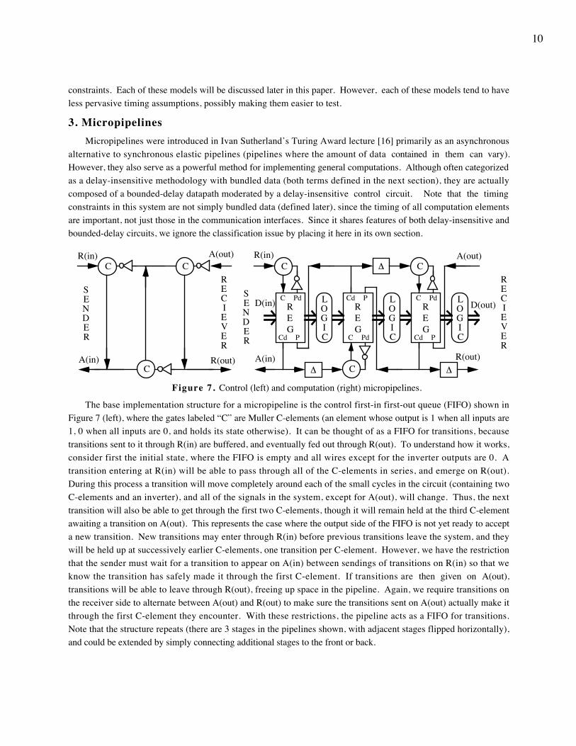
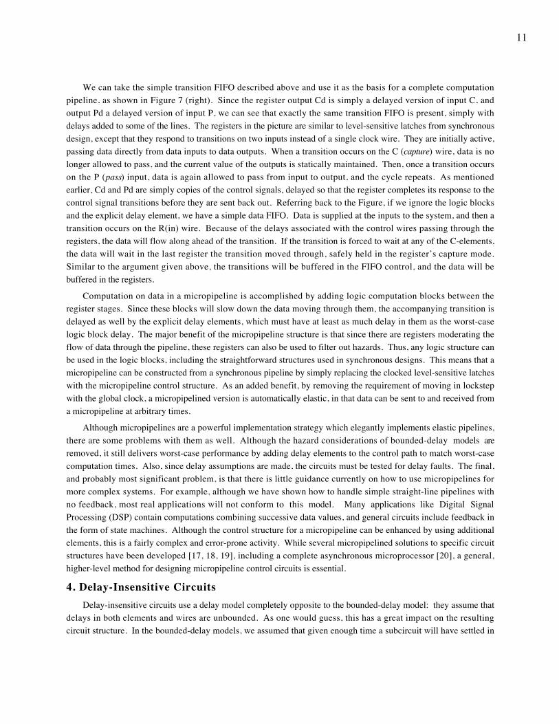
Figure 7. Control (left) and computation (right) micropipelines.
The base implementation structure for a micropipeline is the control first-in first-out queue (FIFO) shown inFigure 7 (left), where the gates labeled “C” are Muller C-elements (an element whose output is 1 when all inputs are1, 0 when all inputs are 0, and holds its state otherwise). It can be thought of as a FIFO for transitions, becausetransitions sent to it through R(in) are buffered, and eventually fed out through R(out). To understand how it works,consider first the initial state, where the FIFO is empty and all wires except for the inverter outputs are 0. Atransition entering at R(in) will be able to pass through all of the C-elements in series, and emerge on R(out).During this process a transition will move completely around each of the small cycles in the circuit (containing twoC-elements and an inverter), and all of the signals in the system, except for A(out), will change. Thus, the nexttransition will also be able to get through the first two C-elements, though it will remain held at the third C-elementawaiting a transition on A(out). This represents the case where the output side of the FIFO is not yet ready to accepta new transition. New transitions may enter through R(in) before previous transitions leave the system, and theywill be held up at successively earlier C-elements, one transition per C-element. However, we have the restrictionthat the sender must wait for a transition to appear on A(in) between sendings of transitions on R(in) so that weknow the transition has safely made it through the first C-element. If transitions are then given on A(out),transitions will be able to leave through R(out), freeing up space in the pipeline. Again, we require transitions onthe receiver side to alternate between A(out) and R(out) to make sure the transitions sent on A(out) actually make itthrough the first C-element they encounter. With these restrictions, the pipeline acts as a FIFO for transitions.Note that the structure repeats (there are 3 stages in the pipelines shown, with adjacent stages flipped horizontally),and could be extended by simply connecting additional stages to the front or back.
11
We can take the simple transition FIFO described above and use it as the basis for a complete computationpipeline, as shown in Figure 7 (right). Since the register output Cd is simply a delayed version of input C, andoutput Pd a delayed version of input P, we can see that exactly the same transition FIFO is present, simply withdelays added to some of the lines. The registers in the picture are similar to level-sensitive latches from synchronousdesign, except that they respond to transitions on two inputs instead of a single clock wire. They are initially active,passing data directly from data inputs to data outputs. When a transition occurs on the C (capture) wire, data is nolonger allowed to pass, and the current value of the outputs is statically maintained. Then, once a transition occurson the P (pass) input, data is again allowed to pass from input to output, and the cycle repeats. As mentionedearlier, Cd and Pd are simply copies of the control signals, delayed so that the register completes its response to thecontrol signal transitions before they are sent back out. Referring back to the Figure, if we ignore the logic blocksand the explicit delay element, we have a simple data FIFO. Data is supplied at the inputs to the system, and then atransition occurs on the R(in) wire. Because of the delays associated with the control wires passing through theregisters, the data will flow along ahead of the transition. If the transition is forced to wait at any of the C-elements,the data will wait in the last register the transition moved through, safely held in the register’s capture mode.Similar to the argument given above, the transitions will be buffered in the FIFO control, and the data will bebuffered in the registers.
Computation on data in a micropipeline is accomplished by adding logic computation blocks between theregister stages. Since these blocks will slow down the data moving through them, the accompanying transition isdelayed as well by the explicit delay elements, which must have at least as much delay in them as the worst-caselogic block delay. The major benefit of the micropipeline structure is that since there are registers moderating theflow of data through the pipeline, these registers can also be used to filter out hazards. Thus, any logic structure canbe used in the logic blocks, including the straightforward structures used in synchronous designs. This means that amicropipeline can be constructed from a synchronous pipeline by simply replacing the clocked level-sensitive latcheswith the micropipeline control structure. As an added benefit, by removing the requirement of moving in lockstepwith the global clock, a micropipelined version is automatically elastic, in that data can be sent to and received froma micropipeline at arbitrary times.
Although micropipelines are a powerful implementation strategy which elegantly implements elastic pipelines,there are some problems with them as well. Although the hazard considerations of bounded-delay models areremoved, it still delivers worst-case performance by adding delay elements to the control path to match worst-casecomputation times. Also, since delay assumptions are made, the circuits must be tested for delay faults. The final,and probably most significant problem, is that there is little guidance currently on how to use micropipelines formore complex systems. For example, although we have shown how to handle simple straight-line pipelines withno feedback, most real applications will not conform to this model. Many applications like Digital SignalProcessing (DSP) contain computations combining successive data values, and general circuits include feedback inthe form of state machines. Although the control structure for a micropipeline can be enhanced by using additionalelements, this is a fairly complex and error-prone activity. While several micropipelined solutions to specific circuitstructures have been developed [17, 18, 19], including a complete asynchronous microprocessor [20], a general,higher-level method for designing micropipeline control circuits is essential.
4. Delay-Insensitive CircuitsDelay-insensitive circuits use a delay model completely opposite to the bounded-delay model: they assume that
delays in both elements and wires are unbounded. As one would guess, this has a great impact on the resultingcircuit structure. In the bounded-delay models, we assumed that given enough time a subcircuit will have settled in
12
response to an input, and a new input can then safely be sent. With a delay-insensitive model, no matter how long acircuit waits there is no guarantee that the input will be properly received. This forces the recipient of a signal toinform the sender when it has received the information. This function is performed by completion detectioncircuitry in the receiver. The sender in this protocol is required to wait until it gets the completion signal beforesending the next data item.
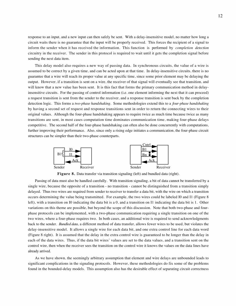
This delay model also requires a new way of passing data. In synchronous circuits, the value of a wire isassumed to be correct by a given time, and can be acted upon at that time. In delay-insensitive circuits, there is noguarantee that a wire will reach its proper value at any specific time, since some prior element may be delaying theoutput. However, if a transition is sent on a wire, the receiver of that signal will eventually see that transition, andwill know that a new value has been sent. It is this fact that forms the primary communication method in delay-insensitive circuits. For the passing of control information (i.e. one element informing the next that it can proceed)a request transition is sent from the sender to the receiver, and a response transition is sent back by the completiondetection logic. This forms a two-phase handshaking. Some methodologies extend this to a four-phase handshakingby having a second set of request and response transitions sent in order to return the connecting wires to theiroriginal values. Although the four-phase handshaking appears to require twice as much time because twice as manytransitions are sent, in most cases computation time dominates communication time, making four-phase delayscompetitive. The second half of the four-phase handshaking can often also be done concurrently with computations,further improving their performance. Also, since only a rising edge initiates a communication, the four-phase circuitstructures can be simpler than their two-phase counterparts.
Sender Receiver
Ack
I0I1B1{
Cntrl
BnB1
Sender Receiver
Ack
Figure 8. Data transfer via transition signaling (left) and bundled data (right).
Passing of data must also be handled carefully. With transition signaling, a bit of data cannot be transferred by asingle wire, because the opposite of a transition - no transition - cannot be distinguished from a transition simplydelayed. Thus two wires are required from sender to receiver to transfer a data bit, with the wire on which a transitionoccurs determining the value being transmitted. For example, the two wires could be labeled I0 and I1 (Figure 8left), with a transition on I0 indicating the data bit is a 0, and a transition on I1 indicating the data bit is 1. Othervariations on this theme are possible, but beyond the scope of this discussion. Note that both two-phase and four-phase protocols can be implemented, with a two-phase communication requiring a single transition on one of thetwo wires, where a four-phase requires two. In both cases, an additional wire is required to send acknowledgmentsback to the sender. Bundled data, a different method of data transfer, allows fewer wires to be used, but violates thedelay-insensitive model. It allows a single wire for each data bit, and one extra control line for each data word(Figure 8 right). It is assumed that the delay in the extra control wire is guaranteed to be longer than the delay ineach of the data wires. Thus, if the data bit wires’ values are set to the data values, and a transition sent on thecontrol wire, then when the receiver sees the transition on the control wire it knows the values on the data lines havealready arrived.
As we have shown, the seemingly arbitrary assumption that element and wire delays are unbounded leads tosignificant complications in the signaling protocols. However, these methodologies do fix some of the problemsfound in the bounded-delay models. This assumption also has the desirable effect of separating circuit correctness
13
from specific delays, so that delay optimization via transistor sizing and similar improvements can be appliedwithout affecting circuit correctness.
4.1 Delay-Insensitive Circuits with Single-Output Gates
A's Logic
Shared Logic
B's Logic
A
B
XG
Figure 9. Delay-insensitive environment for a single-output gate.
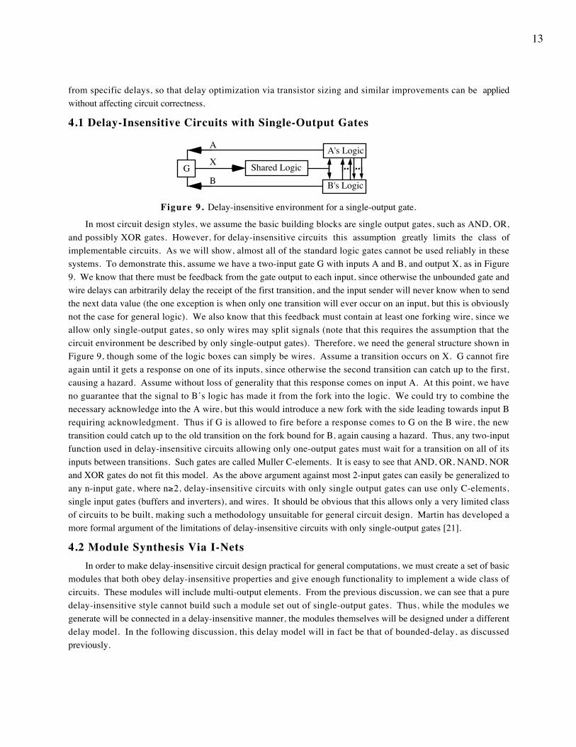
In most circuit design styles, we assume the basic building blocks are single output gates, such as AND, OR,and possibly XOR gates. However, for delay-insensitive circuits this assumption greatly limits the class ofimplementable circuits. As we will show, almost all of the standard logic gates cannot be used reliably in thesesystems. To demonstrate this, assume we have a two-input gate G with inputs A and B, and output X, as in Figure9. We know that there must be feedback from the gate output to each input, since otherwise the unbounded gate andwire delays can arbitrarily delay the receipt of the first transition, and the input sender will never know when to sendthe next data value (the one exception is when only one transition will ever occur on an input, but this is obviouslynot the case for general logic). We also know that this feedback must contain at least one forking wire, since weallow only single-output gates, so only wires may split signals (note that this requires the assumption that thecircuit environment be described by only single-output gates). Therefore, we need the general structure shown inFigure 9, though some of the logic boxes can simply be wires. Assume a transition occurs on X. G cannot fireagain until it gets a response on one of its inputs, since otherwise the second transition can catch up to the first,causing a hazard. Assume without loss of generality that this response comes on input A. At this point, we haveno guarantee that the signal to B’s logic has made it from the fork into the logic. We could try to combine thenecessary acknowledge into the A wire, but this would introduce a new fork with the side leading towards input Brequiring acknowledgment. Thus if G is allowed to fire before a response comes to G on the B wire, the newtransition could catch up to the old transition on the fork bound for B, again causing a hazard. Thus, any two-inputfunction used in delay-insensitive circuits allowing only one-output gates must wait for a transition on all of itsinputs between transitions. Such gates are called Muller C-elements. It is easy to see that AND, OR, NAND, NORand XOR gates do not fit this model. As the above argument against most 2-input gates can easily be generalized toany n-input gate, where n≥2, delay-insensitive circuits with only single output gates can use only C-elements,single input gates (buffers and inverters), and wires. It should be obvious that this allows only a very limited classof circuits to be built, making such a methodology unsuitable for general circuit design. Martin has developed amore formal argument of the limitations of delay-insensitive circuits with only single-output gates [21].
4.2 Module Synthesis Via I-NetsIn order to make delay-insensitive circuit design practical for general computations, we must create a set of basic
modules that both obey delay-insensitive properties and give enough functionality to implement a wide class ofcircuits. These modules will include multi-output elements. From the previous discussion, we can see that a puredelay-insensitive style cannot build such a module set out of single-output gates. Thus, while the modules wegenerate will be connected in a delay-insensitive manner, the modules themselves will be designed under a differentdelay model. In the following discussion, this delay model will in fact be that of bounded-delay, as discussedpreviously.
14
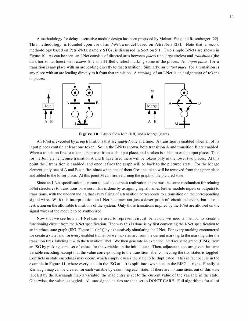
A methodology for delay-insensitive module design has been proposed by Molnar, Fang and Rosenberger [22].This methodology is founded upon use of an I-Net, a model based on Petri Nets [23]. Note that a secondmethodology based on Petri-Nets, namely STGs, is discussed in Section 5.1. Two simple I-Nets are shown inFigure 10. As can be seen, an I-Net consists of directed arcs between places (the large circles) and transitions (thedark horizontal lines), with tokens (the small filled circles) marking some of the places. An input place for atransition is any place with an arc leading directly to that transition. Similarly, an output place for a transition isany place with an arc leading directly to it from that transition. A marking of an I-Net is an assignment of tokensto places.
A B
J M
A BJoin
A B
J
Merge
A B
M
Figure 10. I-Nets for a Join (left) and a Merge (right).
An I-Net is executed by firing transitions that are enabled, one at a time. A transition is enabled when all of itsinput places contain at least one token. So, in the I-Nets shown, both transition A and transition B are enabled.When a transition fires, a token is removed from each input place, and a token is added to each output place. Thusfor the Join element, once transition A and B have fired there will be tokens only in the lower two places. At thispoint the J transition is enabled, and once it fires the graph will be back to the pictured state. For the Mergeelement, only one of A and B can fire, since when one of them fires the token will be removed from the upper placeand added to the lower place. At this point M can fire, returning the graph to the pictured state.
Since an I-Net specification is meant to lead to a circuit realization, there must be some mechanism for relatingI-Net structures to transitions on wires. This is done by assigning signal names (either module inputs or outputs) totransitions, with the understanding that every firing of a transition corresponds to a transition on the correspondingsignal wire. With this interpretation an I-Net becomes not just a description of circuit behavior, but also arestriction on the allowable transitions of the system. Only those transitions implied by the I-Net are allowed on thesignal wires of the module to be synthesized.
Now that we see how an I-Net can be used to represent circuit behavior, we need a method to create afunctioning circuit from the I-Net specification. The way this is done is by first converting the I-Net specification toan interface state graph (ISG, Figure 11 (left)) by exhaustively simulating the I-Net. For every marking encounteredwe create a state, and for every enabled transition we make an arc from the current marking to the marking after thetransition fires, labeling it with the transition label. We then generate an extended interface state graph (EISG) froman ISG by picking some set of values for the variables in the initial state. Then, adjacent states are given the samevariable encoding, except that the value corresponding to the transition label connecting the two states is toggled.Conflicts in state encodings may occur, which simply causes the state to be duplicated. This in fact occurs in theexample in Figure 11, where every state in the ISG at left is split into two states in the EISG at right. Finally, aKarnaugh map can be created for each variable by examining each state. If there are no transitions out of this statelabeled by the Karnaugh map’s variable, the map entry is set to the current value of the variable in the state.Otherwise, the value is toggled. All unassigned entries are then set to DON’T CARE. Full algorithms for all of

15
these steps are presented elsewhere ([24] pp. 7.23 - 7.27). Note that although these algorithms can be exponential inthe number of places (since they enumerate all markings, and there can be an exponential number of unique markingsfor an I-Net), most modules are simple enough that the number of markings will be close to linear, and the numberof places small. However, this does mean that this synthesis system is inappropriate for large circuits with complexI-Nets.
Another issue is that while the Karnaugh map generation algorithm implicitly assumes that each state in anEISG will have a unique encoding of variable assignments, this is not always the case. This is important, because iftwo states share the same encoding, there will be no way of telling the two states apart, and transitions allowed inone state could occur after entering the other state. The solution to this is to add extra state variables to distinguishthe conflicting states. Although an ad-hoc method for designers to explicitly add extra state variables has beendeveloped ([24] pp. 7.15 - 7.16), the methodology contains no automatic method for handling these situations. Notehowever that some of the techniques developed for STGs (Section 5.1) may also be applicable to I-Net state variableinsertion.
A
A
B
J
B
100
010
110 111
011
001
101
A
B
B
A
A
B
J
B
AJ
ABJ = 000
Figure 11. ISG (left) and EISG (right) for the Join element.
Before we discuss specific implementation structures, it is important to realize that not all I-Nets properlyrepresent delay-insensitive circuits. For example, an I-Net could easily have two consecutive transitions on a singlewire, which is an output hazard, and thus is not delay-insensitive. What is necessary is a general constraint onallowable I-Net structures. Luckily, the so-called Foam Rubber Wrapper constraint [22] does exactly that. It statesthat for any delay-insensitive circuit we must be able to attach arbitrary delays on the input and output lines, and thenew interface created must have the exact same behavior as the original module, with no hazards. If introducingthese delays allows behaviors not present in the original circuit, the circuit is not delay-insensitive. Note that thesame requirement can be expressed as local constraints on ISGs [25].
x1
xn
y1
yk
z1
zm
y1'
yk'
Combinational logic
∆
∆
∆
∆
x1
xn
y1
yk
z1
zm
y1'
yk'
Combinational logic
Q-clock Control
Q
Q
Q
Q
Q
Q
Figure 12. Clock-Free (left) and Locally-Clocked (right) module implementation structures.
16
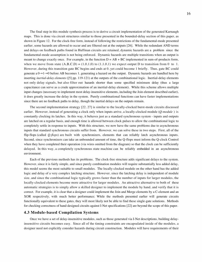
The final step in this module synthesis process is to derive a circuit implementation of the generated Karnaughmaps. This is done via circuit structures similar to those presented in the bounded-delay section of this paper, asshown in Figure 12. For the clock-free form, instead of following the restrictions of the fundamental-mode presentedearlier, some hazards are allowed to occur and are filtered out at the outputs [26]. While the redundant AND termsand delays on feedback paths found in Huffman circuits are retained, dynamic hazards are a problem since thefundamental-mode assumption is not being enforced. Dynamic hazards are multiple transitions when an output ismeant to change exactly once. For example, in the function D = AB + BC implemented in sum-of-products form,when we move from state (A,B,C,D) = (1,0,1,0) to (1,1,0,1) we expect output D to transition from 0 to 1.However, during this transition gate BC begins and ends at 0, yet could become 1 briefly. Thus, gate BC couldgenerate a 0→1→0 before AB becomes 1, generating a hazard on the output. Dynamic hazards are handled here byinserting inertial-delay elements ([5] pp. 119-121) at the outputs of the combinational logic. Inertial-delay elementsnot only delay signals, but also filter out hazards shorter than some specified minimum delay (thus a largecapacitance can serve as a crude approximation of an inertial-delay element). While this scheme allows multipleinput changes (necessary to implement most delay-insensitive elements, including the Join element described earlier),it does greatly increase the delay in the system. Purely combinational functions can have faster implementationssince there are no feedback paths to delay, though the inertial delays on the outputs remain.
The second implementation strategy [22, 27] is similar to the locally-clocked burst-mode circuits discussedearlier. However, instead of generating a clock only when inputs arrive, a locally-clocked module (Q-module ) isconstantly clocking its latches. In this way, it behaves just as a standard synchronous system - inputs and outputsare latched on a regular basis, and enough time is allowed between clock pulses to allow the combinational logic tocompletely settle in response to inputs. With this structure, we now have the same problems due to asynchronousinputs that standard synchronous circuits suffer from. However, we can solve these in two steps. First, all of theflip-flops (called Q-flops) are built with synchronizers, elements that can reliably latch asynchronous inputs.Second, since synchronizers can take an unbounded amount of time, the Q-flops must inform the Q-clock Controlwhen they have completed their operation (via wires omitted from the diagram) so that the clock can be sufficientlydelayed. In this way, a completely synchronous state machine can be reliably embedded in an asynchronousenvironment.
Each of the previous methods has its problems. The clock-free structure adds significant delays to the system.However, since it is fairly simple, and since purely combination modules will require substantially less added delay,this model seems the most suitable to small modules. The locally-clocked module on the other hand has the addedlogic and delay of a very complex latching structure. However, since the latching delay is independent of modulesize, and since the combinational logic typically grows faster than the number of inputs for larger modules, thelocally-clocked elements become more attractive for larger modules. An attractive alternative to both of theseautomatic strategies is to simply allow a skilled designer to implement the module by hand, and verify that it iscorrect. For example, it is clear that a designer could implement the Join and Merge elements by a C-element and anXOR respectively, with much better performance; While the methods presented earlier will generate circuitsfunctionally equivalent to these gates, they will most likely not be able to find these single-gate solutions. Methodsfor checking correctness of hand-designed circuits against I-Net specifications [22] are beyond the scope of this paper.
4.3 Module-based Compilation SystemsOnce we have a set of delay-insensitive modules, such as those generated via I-Net descriptions, building delay-
insensitive circuits becomes easy. Since all of the timing constraints are encapsulated inside of the modules, adesigner need not explicitly consider hazards during circuit construction. Modules will have requirements of their
17
environment that must be met, and which will restrict how the modules are used. For example, a Join elementcannot be used in the same place as a Merge, since they require different numbers of input transitions beforegenerating an output transition. However, such restrictions are much simpler than those of most othermethodologies, and the proper module will usually be obvious from the functionality required.
Although we have seen that module-based systems can ease manual design, their main power is seen when theyare coupled with a high-level language and automatic translation software. As described by Brunvand and Sproull[28], what is necessary is to choose a language applicable to describing asynchronous circuits (in this case it is asubset of Occam, a language based on Communicating Sequential Processes), and then provide delay-insensitivemodules for each of the language constructs. For example a while loop in the language would require a WHILEelement, which has connection terminals for a conditional test, a loop body, and an interface to the surroundingenvironment. It is then a straightforward process to convert parse trees for the input language into circuit structuresbuilt out of delay-insensitive modules. Techniques similar to peephole optimization in software compilers can thenbe applied to the circuit to improve area and delay. For example, a WHILE element with its condition always truecan be replaced with an infinite loop element. Finally, the circuit can be implemented by interconnecting themodules as specified by the program translation.
This approach is very similar to standard cell synthesis, and has similar advantages and disadvantages. Sincemodules are standardized, they can be pre-certified. Then, circuits that use them can safely assume they are correct,and worry only about testing their interconnections. Also, since modules can be developed initially by skilleddesigners, and tend to be fairly simple, the methods used to synthesize the modules need not be efficient. Thus, theexponential algorithm for converting I-Nets to ISGs is acceptable for module synthesis. Unfortunately, since we arerequired to use preset modules, we usually cannot perform optimizations on the module structures themselves.Thus, some possible optimizations will be ruled out because we do not have the required simpler modules. Also, foreach implementation technology we wish to use, we may need to generate a new set of modules. While the specificdesign rules of a different process may not change things enough to require new modules, technologies such asMask- and Field-Programmable Gate Arrays, and even specific architectures within these technologies, may eachrequire their own module sets. Thus, the initial effort of creating module sets may be greatly magnified by thenumber of technologies being used, or may restrict the choice of technologies. One final problem is that while strictdelay-insensitive designs will encapsulate timing issues within modules, some methodologies [28] use bundled dataprotocols. Bundled data involves timing constraints between modules, complicating circuit implementation.
4.4 Trace-Based CircuitsA method for delay-insensitive circuit design has been proposed by Ebergen [29, 30] which uses a unified model
for both module specification and circuit design. It is based on trace theory, a model similar to regular expressions.A trace is an alphabet and a set of strings which describe the desired circuit functionality. Each symbol in thealphabet corresponds to a signal in the circuit, and the appearance of the symbol in a string represents a transition onthat signal. Usually the alphabet is broken into input, output, internal, and environment alphabets, which gives thesymbol the implied signal meaning. Note that normally a circuit will be described only by its interface, and thusinternal and environment alphabets will only be used during the circuit realization process.
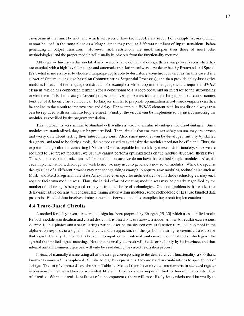
Instead of manually enumerating all of the strings corresponding to the desired circuit functionality, a shorthandknown as commands is employed. Similar to regular expressions, they are used in combinations to specify sets ofstrings. The set of commands are shown in Table 1. Most of them have obvious counterparts in standard regularexpressions, while the last two are somewhat different. Projection is an important tool for hierarchical constructionof circuits. When a circuit is built out of subcomponents, there will most likely be symbols used internally to
18
interconnect components which have no connections to the environment. By projecting the hierarchy onto thecombined input and output alphabets of the overall circuit, these internal symbols are removed. The weave operatoris used to express concurrent actions and synchronization. Those symbols common to both commands being weavedserve as synchronization between the commands. For a concrete example, one trace for a Join element (shown inFigure 10) with inputs a and b and output j is pref *[ (a?; j!) || (b?; j!) ]. Although the concatenation operationssimply enforce individually that an input precede an output, the fact that the j output is shared between commands inthe weave, and thus synchronizes the two commands, ensures that both inputs must occur before the output canoccur. The repetition and the prefix-closure allow the element to fire an arbitrary number of times, followedpossibly by a single partial firing. Note that the Join element can be more clearly stated as pref *[ (a? || b?); j! ] orpref *[ (a?; b?; j!) | (b?; a?; j!) ].
Name Syntax Meaning Example
Input <sym> ? <sym> ∈ Input Alph & occurs in string a? = { “a” }
Output <sym> ! <sym> ∈ Output Alph & occurs in string a! = { “a” }
Concatenation <cmd1> ; <cmd2> <cmd2> follows <cmd1> a; b = { “ab” }
Union <cmd1> | <cmd2> either <cmd1> or <cmd2> a | b = { “a”, “b” }
Repetition * [ <cmd> ] zero or more concatenations of <cmd> *[ a ] = { ε, “a”, “aa”, ... }
Prefix-closure pref <cmd> Any prefix of <cmd> pref(“ab”) = { ε, “a”, “ab” }
Projection <cmd> ↓ <alph> Remove all symbols from <cmd> notcontained in <alph>
abc ↓ {a, c} = { “ac” }
Weave <cmd1> || <cmd2> Shuffling of <cmd1> and <cmd2>, withshared symbols occurring simultaneously
abd || acd = { “abcd”, “acbd” }
Table 1. Trace theory commands.
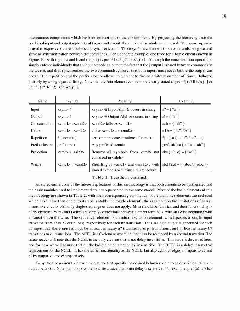
As stated earlier, one of the interesting features of this methodology is that both circuits to be synthesized andthe basic modules used to implement them are represented in the same model. Most of the basic elements of thismethodology are shown in Table 2, with their corresponding commands. Note that since elements are includedwhich have more than one output (most notably the toggle element), the argument on the limitations of delay-insensitive circuits with only single-output gates does not apply. Most should be familiar, and their functionality isfairly obvious. Wires and IWires are simply connections between element terminals, with an IWire beginning witha transition on the wire. The sequencer element is a mutual exclusion element, which passes a single inputtransition from a? or b? out p! or q! respectively for each n? transition. Thus, a single output is generated for eachn? input, and there must always be at least as many a? transitions as p! transitions, and at least as many b?transitions as q! transitions. The NCEL is a C-element where an input can be rescinded by a second transition. Theastute reader will note that the NCEL is the only element that is not delay-insensitive. This issue is discussed later,and for now we will assume that all the basic elements are delay-insensitive. The RCEL is a delay-insensitivereplacement for the NCEL. It has the same functionality as the NCEL, but also acknowledges all inputs to a? andb? by outputs d! and e! respectively.
To synthesize a circuit via trace theory, we first specify the desired behavior via a trace describing its input-output behavior. Note that it is possible to write a trace that is not delay-insensitive. For example, pref (a!; a!) has
19
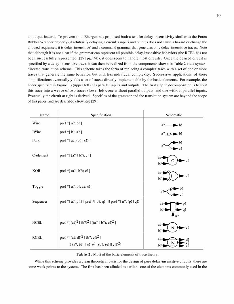
an output hazard. To prevent this, Ebergen has proposed both a test for delay-insensitivity similar to the FoamRubber Wrapper property (if arbitrarily delaying a circuit’s inputs and outputs does not cause a hazard or change theallowed sequences, it is delay-insensitive) and a command grammar that generates only delay-insensitive traces. Notethat although it is not clear if the grammar can represent all possible delay-insensitive behaviors (the RCEL has notbeen successfully represented ([29] pg. 74)), it does seem to handle most circuits. Once the desired circuit isspecified by a delay-insensitive trace, it can then be realized from the components shown in Table 2 via a syntax-directed translation scheme. This scheme takes the form of replacing a complex trace with a set of one or moretraces that generate the same behavior, but with less individual complexity. Successive applications of thesesimplifications eventually yields a set of traces directly implementable by the basic elements. For example, theadder specified in Figure 13 (upper left) has parallel inputs and outputs. The first step in decomposition is to splitthis trace into a weave of two traces (lower left), one without parallel outputs, and one without parallel inputs.Eventually the circuit at right is derived. Specifics of the grammar and the translation system are beyond the scopeof this paper, and are described elsewhere [29].
Name Specification Schematic
Wire pref *[ a?; b! ] a? b!
IWire pref *[ b!; a? ] a? b!
Fork pref *[ a?; (b! || c!) ]
c!a?
b!
C-element pref *[ (a? || b?); c! ] a?c!
b?C
XOR pref *[ (a? | b?); c! ] a?c!
b?
Toggle pref *[ a?; b!; a?; c! ]a?
c!b!
Sequencer pref *[ a?; p! ] || pref *[ b?; q! ] || pref *[ n?; (p! | q!) ]
q!p!a?
b?
n?
NCEL pref *[ (a?)2 | (b?)2 | ((a? || b?); c!)2 ] a?c!
b?N
RCEL pref *[ (a?; d!)2 | (b?; e!)2 |
( (a?; (d! || c!))2 || (b?; (e! || c!))2)] e!
a?c!
b?R
d!
Table 2. Most of the basic elements of trace theory.
While this scheme provides a clean theoretical basis for the design of pure delay-insensitive circuits, there aresome weak points to the system. The first has been alluded to earlier - one of the elements commonly used in the
20
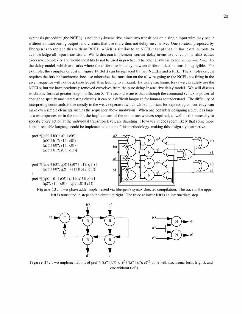
synthesis procedure (the NCEL) is not delay-insensitive, since two transitions on a single input wire may occurwithout an intervening output, and circuits that use it are thus not delay-insensitive. One solution proposed byEbergen is to replace this with an RCEL, which is similar to an NCEL except that it has extra outputs toacknowledge all input transitions. While this can implement correct delay-insensitive circuits, it also causesexcessive complexity and would most likely not be used in practice. The other answer is to add isochronic forks tothe delay model, which are forks where the difference in delay between different destinations is negligible. Forexample, the complex circuit in Figure 14 (left) can be replaced by two NCELs and a fork. The simpler circuitrequires the fork be isochronic, because otherwise the transition on the a? wire going to the NCEL not firing in thegiven sequence will not be acknowledged, thus leading to a hazard. By using isochronic forks we can safely use theNCELs, but we have obviously removed ourselves from the pure delay-insensitive delay model. We will discussisochronic forks at greater length in Section 5. The second issue is that although the command syntax is powerfulenough to specify most interesting circuits, it can be a difficult language for humans to understand. The difficulty ofinterpreting commands is due mostly to the weave operator, which while important for expressing concurrency, canmake even simple elements such as the sequencer above unobvious. When one considers designing a circuit as largeas a microprocessor in the model, the implications of the numerous weaves required, as well as the necessity tospecify every action at the individual transition level, are daunting. However, it does seem likely that some morehuman-readable language could be implemented on top of this methodology, making this design style attractive.
pref *[(a0? || b0?; s0! || c0!) | (a0? || b1?; s1! || c0!) | (a1? || b0?; s1! || c0!) | (a1? || b1?; s0! || c1!)]
pref *[(a0? || b0?; q0!) | (a0? || b1?; q1!) | (a1? || b0?; q2!) | (a1? || b1?; q3!)]||pref *[(q0?; s0! || c0!) | (q1?; s1! || c0!) | (q2?; s1! || c0!) | (q3?; s0! || c1!)]
=
q0
q1
q2
a0
b0
a1
b1
N
N
N
N
=
=
=q3
c0
c1
s1
s0
Figure 13. Two-phase adder implemented via Ebergen’s syntax-directed compilation. The trace in the upperleft is translated in steps to the circuit at right. The trace at lower left is an intermediate step.
b?d!N
e!c?
N
a? =
a? CR R
RR
b? c?
d! e!
Figure 14. Two implementations of pref *[((a? || b?); d!)2 | ((a? || c?); e!)2], one with isochronic forks (right), andone without (left).
21
4.5 Delay-Insensitive Versus Bounded-Delay CircuitsFrom our previous discussion, a rather peculiar conclusion could be reached: by taking information away from a
synthesis methodology - which is essentially what happens when we switch from bounded-delay to delay-insensitivecircuits - we derive some benefit. As opposed to most bounded-delay circuits, delay-insensitive circuits handledatapath circuits such as adders naturally, tend to give average-case instead of worst-case performance, and do notsuffer from additive skew (Section 2.4). However, these benefits are not due to the fact that delay-insensitive circuitscan be built differently than bounded-delay circuits, since a bounded-delay methodology could choose simply toignore the delay bounds provided to it.
An explanation for why delay-insensitive methodologies have some benefits over bounded-delay methodologiesis that the former delay model forces the designs to use conventions important to good asynchronous circuitstructure. Specifically, these conventions are completion signals and transition signaling. Completion signals serveto eliminate additive skew by adding flow control to the circuits. If an element finishes early, it can accept a newinput early, while if it requires extra processing time it simply stalls the previous stage. Thus, it also tends to giveaverage-case behavior. Transition signaling, including that used for the control signal in bundled data, gives a clearindication of when to begin processing data. Outputs are not altered until the required input transitions all occur, atwhich point the environment will produce no new input transitions until the element responds with a completionsignal. Thus hazard avoidance is much simpler, since when output transitions are required, conflicting inputtransitions are disallowed. For an adder, this means the element will not start processing a half-completed input set,and then generate a hazard when the other inputs change. A delay-insensitive adder requires transitions on both inputoperands, even when an operand bit remains constant. Thus, instead of an XOR structure for the bit evaluation, withthe attendant risk of hazards, a C-element structure which waits for both inputs to fire is used, with much betterhazard properties. As implied earlier, completion detection and transition signaling are not prohibited by bounded-delay circuits. In fact, the micropipeline approach discussed previously does essentially that. This methodologycombines completion signals, transition signaling, and bundled data with bounded-delay computation elementscapable of building most datapath structures while avoiding additive skew. Standard bounded-delay methodologiescan also use these constructs, and the ability to choose when to use each feature and when not to yields a flexibilitythat may generate better results than delay-insensitive circuits, which require completion detection at all levels.
5. Speed-Independent and Quasi-Delay-Insensitive CircuitsIn this section we will consider the last two delay models for asynchronous circuit design. Speed-independent
circuits, associated with D. E. Muller for his pioneering work on this model, make the assumption that while gatedelays are unbounded, all wire delays are negligible (less than the minimum gate delay). Quasi-delay-insensitivecircuits adopt the delay-insensitive assumptions that both gate and wire delays are unbounded, but augment this withisochronic forks [31]. As mentioned earlier, isochronic forks are forking wires where the difference in delays betweendestinations is negligible. The reason that both of these models will be discussed together in this section is that forall practical purposes they are identical. We can see this in Figure 15, where a general 2-output isochronic fork isrestated in an equivalent speed-independent form.
Although the isochronic fork extension to delay-insensitive circuits may not seem to be significant, it doesconsiderably change the properties of the model. In Section 4.1, we showed how limited delay-insensitive circuitswith only single-output gates are, based mainly on the fact that all ends of a fork must be sensed in order to avoidhazards. However, by making forks isochronic we need sense only one end of a fork, since by the time the sensinggate has fired the signal must have reached all ends of the fork according to the delay assumptions. For example, the
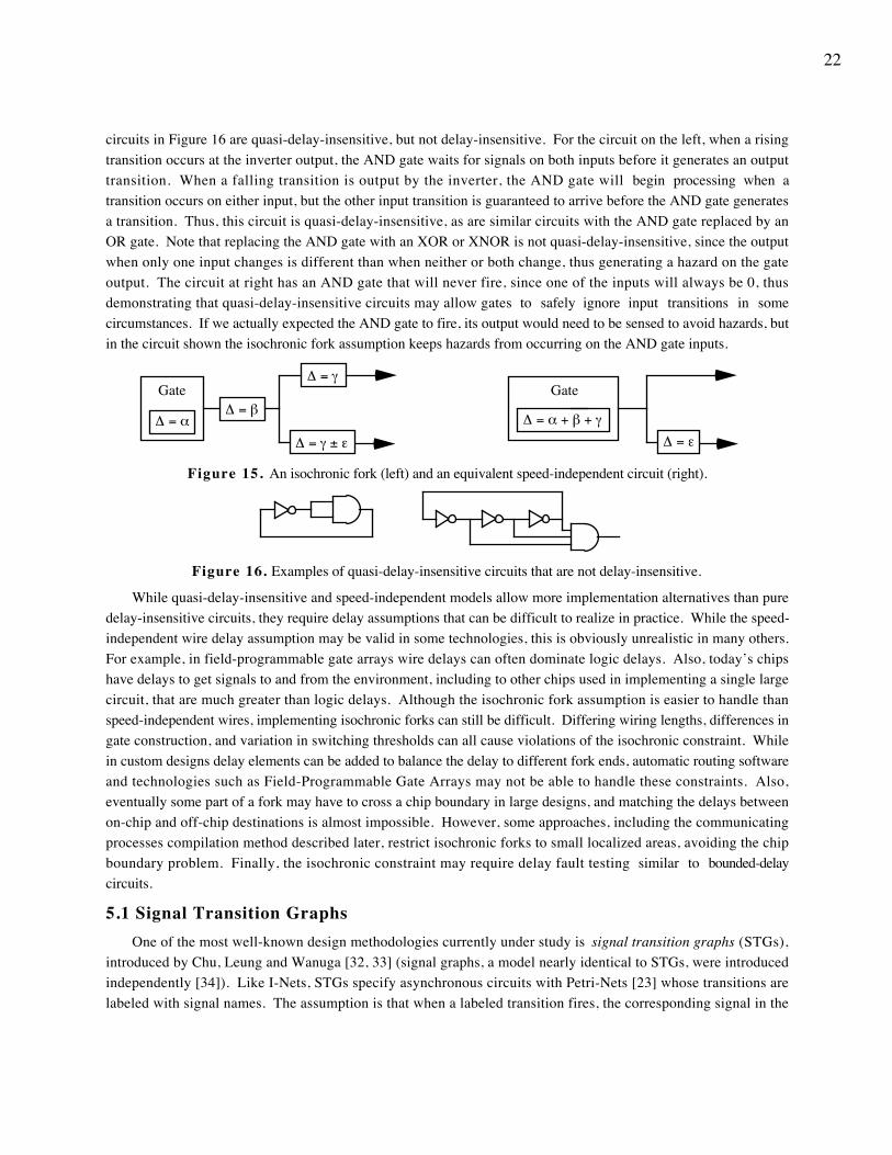
22
circuits in Figure 16 are quasi-delay-insensitive, but not delay-insensitive. For the circuit on the left, when a risingtransition occurs at the inverter output, the AND gate waits for signals on both inputs before it generates an outputtransition. When a falling transition is output by the inverter, the AND gate will begin processing when atransition occurs on either input, but the other input transition is guaranteed to arrive before the AND gate generatesa transition. Thus, this circuit is quasi-delay-insensitive, as are similar circuits with the AND gate replaced by anOR gate. Note that replacing the AND gate with an XOR or XNOR is not quasi-delay-insensitive, since the outputwhen only one input changes is different than when neither or both change, thus generating a hazard on the gateoutput. The circuit at right has an AND gate that will never fire, since one of the inputs will always be 0, thusdemonstrating that quasi-delay-insensitive circuits may allow gates to safely ignore input transitions in somecircumstances. If we actually expected the AND gate to fire, its output would need to be sensed to avoid hazards, butin the circuit shown the isochronic fork assumption keeps hazards from occurring on the AND gate inputs.
∆ = α
Gate∆ = β
∆ = γ
∆ = γ ± ε
∆ = α + β + γ
Gate
∆ = ε
Figure 15. An isochronic fork (left) and an equivalent speed-independent circuit (right).
Figure 16. Examples of quasi-delay-insensitive circuits that are not delay-insensitive.
While quasi-delay-insensitive and speed-independent models allow more implementation alternatives than puredelay-insensitive circuits, they require delay assumptions that can be difficult to realize in practice. While the speed-independent wire delay assumption may be valid in some technologies, this is obviously unrealistic in many others.For example, in field-programmable gate arrays wire delays can often dominate logic delays. Also, today’s chipshave delays to get signals to and from the environment, including to other chips used in implementing a single largecircuit, that are much greater than logic delays. Although the isochronic fork assumption is easier to handle thanspeed-independent wires, implementing isochronic forks can still be difficult. Differing wiring lengths, differences ingate construction, and variation in switching thresholds can all cause violations of the isochronic constraint. Whilein custom designs delay elements can be added to balance the delay to different fork ends, automatic routing softwareand technologies such as Field-Programmable Gate Arrays may not be able to handle these constraints. Also,eventually some part of a fork may have to cross a chip boundary in large designs, and matching the delays betweenon-chip and off-chip destinations is almost impossible. However, some approaches, including the communicatingprocesses compilation method described later, restrict isochronic forks to small localized areas, avoiding the chipboundary problem. Finally, the isochronic constraint may require delay fault testing similar to bounded-delaycircuits.
5.1 Signal Transition GraphsOne of the most well-known design methodologies currently under study is signal transition graphs (STGs),
introduced by Chu, Leung and Wanuga [32, 33] (signal graphs, a model nearly identical to STGs, were introducedindependently [34]). Like I-Nets, STGs specify asynchronous circuits with Petri-Nets [23] whose transitions arelabeled with signal names. The assumption is that when a labeled transition fires, the corresponding signal in the
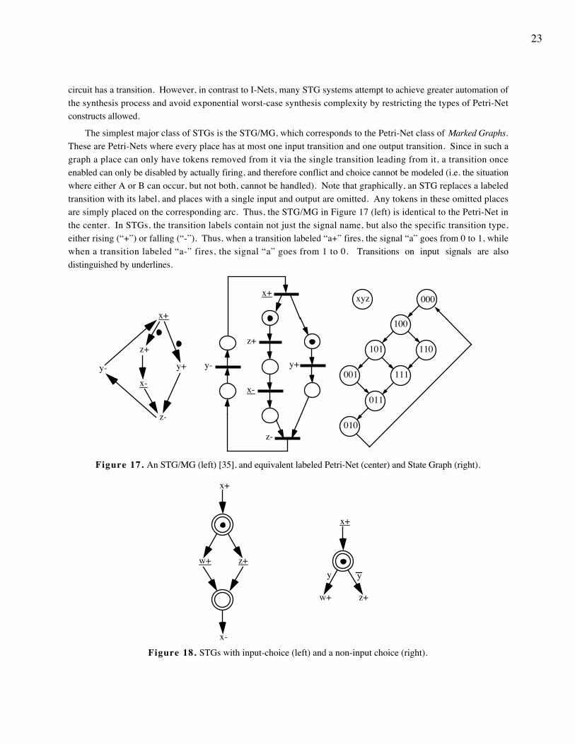
23
circuit has a transition. However, in contrast to I-Nets, many STG systems attempt to achieve greater automation ofthe synthesis process and avoid exponential worst-case synthesis complexity by restricting the types of Petri-Netconstructs allowed.
The simplest major class of STGs is the STG/MG, which corresponds to the Petri-Net class of Marked Graphs.These are Petri-Nets where every place has at most one input transition and one output transition. Since in such agraph a place can only have tokens removed from it via the single transition leading from it, a transition onceenabled can only be disabled by actually firing, and therefore conflict and choice cannot be modeled (i.e. the situationwhere either A or B can occur, but not both, cannot be handled). Note that graphically, an STG replaces a labeledtransition with its label, and places with a single input and output are omitted. Any tokens in these omitted placesare simply placed on the corresponding arc. Thus, the STG/MG in Figure 17 (left) is identical to the Petri-Net inthe center. In STGs, the transition labels contain not just the signal name, but also the specific transition type,either rising (“+”) or falling (“-”). Thus, when a transition labeled “a+” fires, the signal “a” goes from 0 to 1, whilewhen a transition labeled “a-” fires, the signal “a” goes from 1 to 0. Transitions on input signals are alsodistinguished by underlines.
z+
x-
y+
z-
x+
y-
x+
y+
z+
x-y-
z-
000xyz
100
101 110
011
111001
010
Figure 17. An STG/MG (left) [35], and equivalent labeled Petri-Net (center) and State Graph (right).
x+
x-
z+w+y
x+
z+w+
y
Figure 18. STGs with input-choice (left) and a non-input choice (right).
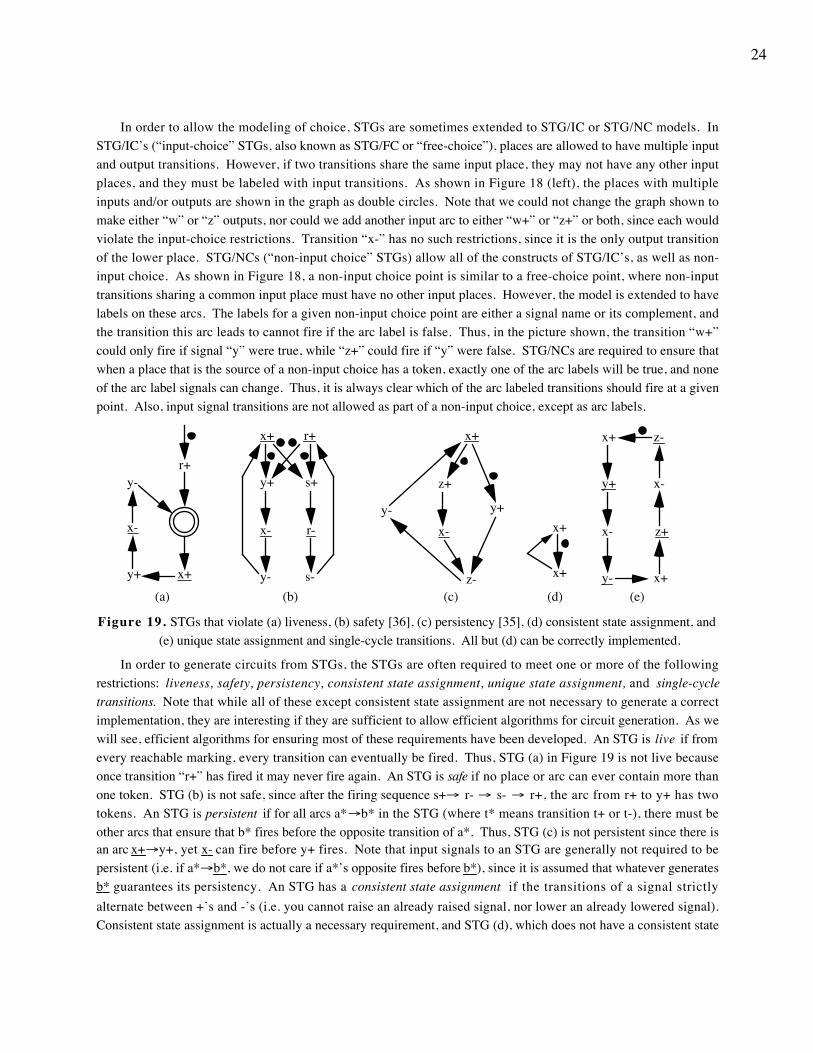
24
In order to allow the modeling of choice, STGs are sometimes extended to STG/IC or STG/NC models. InSTG/IC’s (“input-choice” STGs, also known as STG/FC or “free-choice”), places are allowed to have multiple inputand output transitions. However, if two transitions share the same input place, they may not have any other inputplaces, and they must be labeled with input transitions. As shown in Figure 18 (left), the places with multipleinputs and/or outputs are shown in the graph as double circles. Note that we could not change the graph shown tomake either “w” or “z” outputs, nor could we add another input arc to either “w+” or “z+” or both, since each wouldviolate the input-choice restrictions. Transition “x-” has no such restrictions, since it is the only output transitionof the lower place. STG/NCs (“non-input choice” STGs) allow all of the constructs of STG/IC’s, as well as non-input choice. As shown in Figure 18, a non-input choice point is similar to a free-choice point, where non-inputtransitions sharing a common input place must have no other input places. However, the model is extended to havelabels on these arcs. The labels for a given non-input choice point are either a signal name or its complement, andthe transition this arc leads to cannot fire if the arc label is false. Thus, in the picture shown, the transition “w+”could only fire if signal “y” were true, while “z+” could fire if “y” were false. STG/NCs are required to ensure thatwhen a place that is the source of a non-input choice has a token, exactly one of the arc labels will be true, and noneof the arc label signals can change. Thus, it is always clear which of the arc labeled transitions should fire at a givenpoint. Also, input signal transitions are not allowed as part of a non-input choice, except as arc labels.
x+
x-
r+y-
y+
(a)
x+
x-
y-
y+
r+
r-
s-
s+
(b)
x+
y+
z+
x-y-
z-(c)
x+
x+
(d)
y+
x+
x-
y-
z-
z+
x+
x-
(e)
Figure 19. STGs that violate (a) liveness, (b) safety [36], (c) persistency [35], (d) consistent state assignment, and(e) unique state assignment and single-cycle transitions. All but (d) can be correctly implemented.
In order to generate circuits from STGs, the STGs are often required to meet one or more of the followingrestrictions: liveness, safety, persistency, consistent state assignment, unique state assignment, and single-cycletransitions. Note that while all of these except consistent state assignment are not necessary to generate a correctimplementation, they are interesting if they are sufficient to allow efficient algorithms for circuit generation. As wewill see, efficient algorithms for ensuring most of these requirements have been developed. An STG is live if fromevery reachable marking, every transition can eventually be fired. Thus, STG (a) in Figure 19 is not live becauseonce transition “r+” has fired it may never fire again. An STG is safe if no place or arc can ever contain more thanone token. STG (b) is not safe, since after the firing sequence s+→ r- → s- → r+, the arc from r+ to y+ has twotokens. An STG is persistent if for all arcs a*→b* in the STG (where t* means transition t+ or t-), there must beother arcs that ensure that b* fires before the opposite transition of a*. Thus, STG (c) is not persistent since there isan arc x+ →y+, yet x- can fire before y+ fires. Note that input signals to an STG are generally not required to bepersistent (i.e. if a*→ b* , we do not care if a*’s opposite fires before b* ), since it is assumed that whatever generates b* guarantees its persistency. An STG has a consistent state assignment if the transitions of a signal strictlyalternate between +’s and -’s (i.e. you cannot raise an already raised signal, nor lower an already lowered signal).Consistent state assignment is actually a necessary requirement, and STG (d), which does not have a consistent state
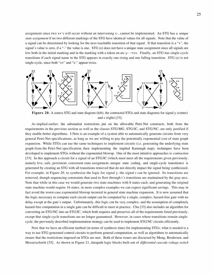
25
assignment since two x+’s will occur without an intervening x-, cannot be implemented. An STG has a uniquestate assignment if no two different markings of the STG have identical values for all signals. Note that the value ofa signal can be determined by looking for the next reachable transition of that signal. If that transition is a “+”, thesignal’s value is zero, if a “-” the value is one. STG (e) does not have a unique state assignment since all signals arelow both in the initial marking and in the marking with a token on arc y- →x+. Finally, an STG has single-cycletransitions if each signal name in the STG appears in exactly one rising and one falling transition. STG (e) is notsingle-cycle, since both “x+” and “x-” appear twice.
y+
x+
x-
y-
r+
r-
s-
s+y+
x+
x+
x-
y-r-
s-
s+
r+
y+
x+
x-
y- s-
s+s+
y+
x+
x+
x-
y-s-
y+
y-
r+
r-
s-
s+ r+y+
y- r-
s-
s+
Figure 20. A source STG and state diagram (left), the contracted STGs and state diagrams for signal y (center)and s (right) [33].
As implied earlier, the substantial restrictions put on the allowable Petri-Net constructs, both from therequirements in the previous section as well as the classes STG/MG, STG/IC, and STG/NC, are only justified ifthey enable better algorithms. I-Nets is an example of a system able to automatically generate circuits from verygeneral Petri-Net specifications, as long as we are willing to pay the potentially exponential cost of state graphexpansion. While STGs can use the same techniques to implement circuits (i.e. generating the underlying stategraph from the Petri-Net specification, then implementing the implied Karnaugh map), techniques have beendeveloped to implement STGs without the exponential blowup. One of the most intuitive approaches is contraction[33]. In this approach a circuit for a signal of an STG/IC (which must meet all the requirements given previously,namely live, safe, persistent, consistent state assignment, unique state coding, and single-cycle transitions) isgenerated by creating an STG with all transitions removed that do not directly impact the signal being synthesized.For example, in Figure 20, to synthesize the logic for signal y, the signal r can be ignored. Its transitions areremoved, though sequencing constraints that used to flow through r’s transitions are maintained by the gray arcs.Note that while in this case we would generate two state machines with 8 states each, and generating the originalstate machine would require 16 states, in more complex examples we can expect significant savings. This may infact avoid the worst-case exponential blowup incurred in general state machine expansion. It is now assumed thatthe logic necessary to compute each circuit output can be computed by a single, complex, hazard-free gate with nodelay except at the gate’s output. Unfortunately, this logic can be very complex, and the assumption of completelyhazard-free computation in a single gate can be difficult to meet in practice. Chu [33] also includes an algorithm forconverting an STG/NC into an STG/IC, which both requires and preserves all of the requirements listed previously,except that single-cycle transitions are no longer guaranteed. However, in cases where transitions remain single-cycle, the previously described implementation strategy can be used to implement STG/NC circuits efficiently.
Now that we have an efficient method (in terms of synthesis time) for implementing STGs, what is needed is away to use STG-generated control circuits to perform general computation, as well as algorithms to automaticallyensure that the restrictions imposed on STGs are met. Both of these issues are discussed by Meng, Brodersen, andMesserschmitt [35]. As shown in Figure 21, datapath logic blocks built out of differential cascode voltage switch
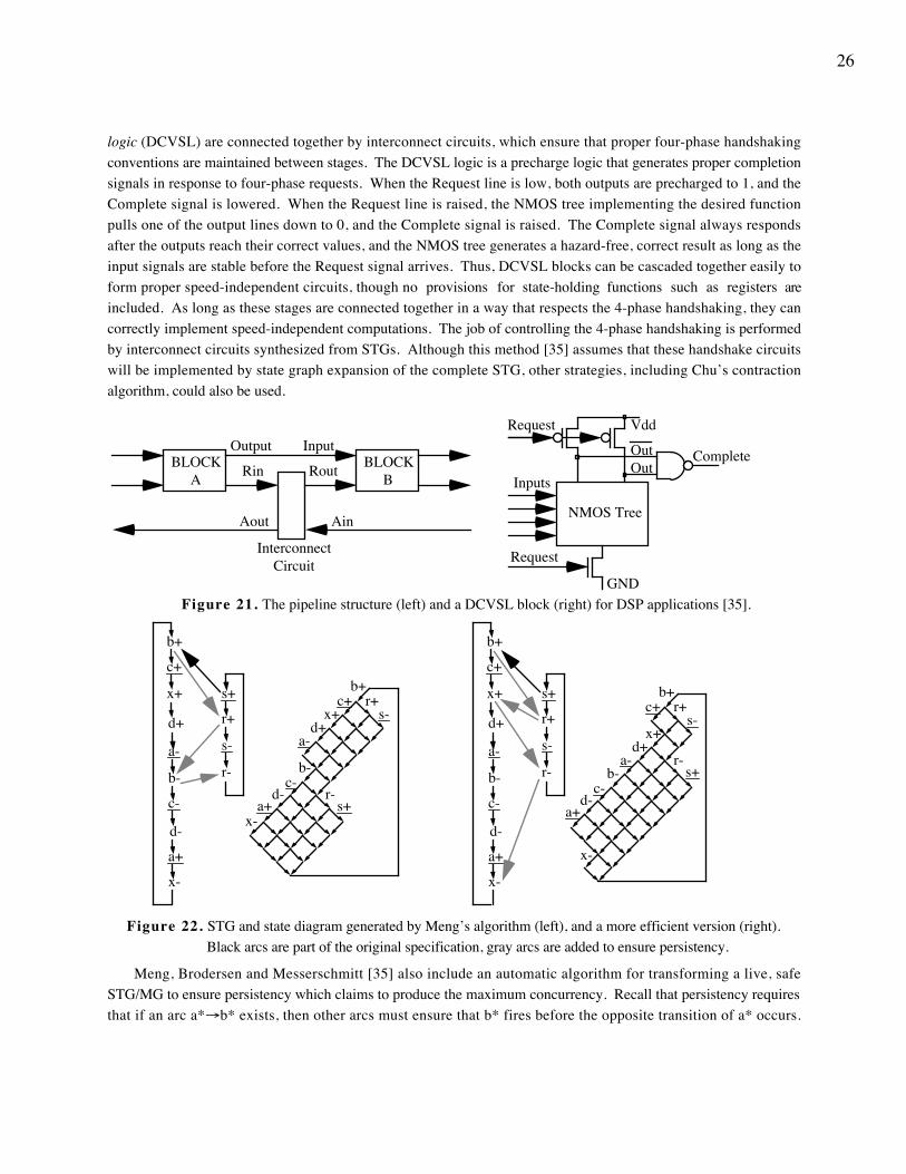
26
logic (DCVSL) are connected together by interconnect circuits, which ensure that proper four-phase handshakingconventions are maintained between stages. The DCVSL logic is a precharge logic that generates proper completionsignals in response to four-phase requests. When the Request line is low, both outputs are precharged to 1, and theComplete signal is lowered. When the Request line is raised, the NMOS tree implementing the desired functionpulls one of the output lines down to 0, and the Complete signal is raised. The Complete signal always respondsafter the outputs reach their correct values, and the NMOS tree generates a hazard-free, correct result as long as theinput signals are stable before the Request signal arrives. Thus, DCVSL blocks can be cascaded together easily toform proper speed-independent circuits, though no provisions for state-holding functions such as registers areincluded. As long as these stages are connected together in a way that respects the 4-phase handshaking, they cancorrectly implement speed-independent computations. The job of controlling the 4-phase handshaking is performedby interconnect circuits synthesized from STGs. Although this method [35] assumes that these handshake circuitswill be implemented by state graph expansion of the complete STG, other strategies, including Chu’s contractionalgorithm, could also be used.
Rin Rout
Aout Ain
Interconnect Circuit
InputOutputBLOCK
ABLOCK
BCompleteOut
Out
Request
Inputs
NMOS Tree
Vdd
GND
Request
Figure 21. The pipeline structure (left) and a DCVSL block (right) for DSP applications [35].
a+
a-
b+
b-
c+
c-
d+
d-
x+
x-
s+
s-
r+
r-
a+
a-
b+
b-
c+
c-
d+
d-
x+
x-
s+
s-
r+
r-
b+
b-
a+
a-
c+
c-
d+
d-
x+
x-s+
s-r+
r-
b+
b-
a+
a-
c+
c-
d+
d-
x+
x-
s+
s-r+
r-
Figure 22. STG and state diagram generated by Meng’s algorithm (left), and a more efficient version (right).Black arcs are part of the original specification, gray arcs are added to ensure persistency.
Meng, Brodersen and Messerschmitt [35] also include an automatic algorithm for transforming a live, safeSTG/MG to ensure persistency which claims to produce the maximum concurrency. Recall that persistency requiresthat if an arc a*→b* exists, then other arcs must ensure that b* fires before the opposite transition of a* occurs.
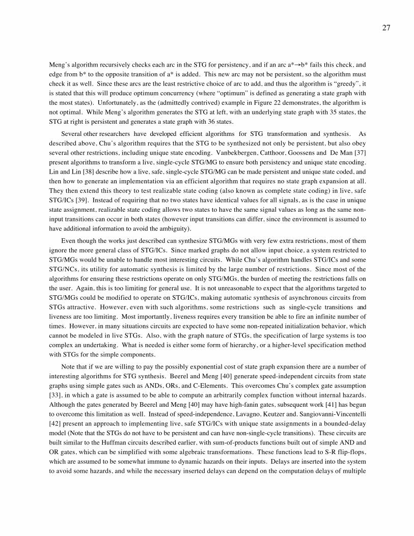
27
Meng’s algorithm recursively checks each arc in the STG for persistency, and if an arc a*→b* fails this check, andedge from b* to the opposite transition of a* is added. This new arc may not be persistent, so the algorithm mustcheck it as well. Since these arcs are the least restrictive choice of arc to add, and thus the algorithm is “greedy”, itis stated that this will produce optimum concurrency (where “optimum” is defined as generating a state graph withthe most states). Unfortunately, as the (admittedly contrived) example in Figure 22 demonstrates, the algorithm isnot optimal. While Meng’s algorithm generates the STG at left, with an underlying state graph with 35 states, theSTG at right is persistent and generates a state graph with 36 states.
Several other researchers have developed efficient algorithms for STG transformation and synthesis. Asdescribed above, Chu’s algorithm requires that the STG to be synthesized not only be persistent, but also obeyseveral other restrictions, including unique state encoding. Vanbekbergen, Catthoor, Goossens and De Man [37]present algorithms to transform a live, single-cycle STG/MG to ensure both persistency and unique state encoding.Lin and Lin [38] describe how a live, safe, single-cycle STG/MG can be made persistent and unique state coded, andthen how to generate an implementation via an efficient algorithm that requires no state graph expansion at all.They then extend this theory to test realizable state coding (also known as complete state coding) in live, safeSTG/ICs [39]. Instead of requiring that no two states have identical values for all signals, as is the case in uniquestate assignment, realizable state coding allows two states to have the same signal values as long as the same non-input transitions can occur in both states (however input transitions can differ, since the environment is assumed tohave additional information to avoid the ambiguity).
Even though the works just described can synthesize STG/MGs with very few extra restrictions, most of themignore the more general class of STG/ICs. Since marked graphs do not allow input choice, a system restricted toSTG/MGs would be unable to handle most interesting circuits. While Chu’s algorithm handles STG/ICs and someSTG/NCs, its utility for automatic synthesis is limited by the large number of restrictions. Since most of thealgorithms for ensuring these restrictions operate on only STG/MGs, the burden of meeting the restrictions falls onthe user. Again, this is too limiting for general use. It is not unreasonable to expect that the algorithms targeted toSTG/MGs could be modified to operate on STG/ICs, making automatic synthesis of asynchronous circuits fromSTGs attractive. However, even with such algorithms, some restrictions such as single-cycle transitions andliveness are too limiting. Most importantly, liveness requires every transition be able to fire an infinite number oftimes. However, in many situations circuits are expected to have some non-repeated initialization behavior, whichcannot be modeled in live STGs. Also, with the graph nature of STGs, the specification of large systems is toocomplex an undertaking. What is needed is either some form of hierarchy, or a higher-level specification methodwith STGs for the simple components.
Note that if we are willing to pay the possibly exponential cost of state graph expansion there are a number ofinteresting algorithms for STG synthesis. Beerel and Meng [40] generate speed-independent circuits from stategraphs using simple gates such as ANDs, ORs, and C-Elements. This overcomes Chu’s complex gate assumption[33], in which a gate is assumed to be able to compute an arbitrarily complex function without internal hazards.Although the gates generated by Beerel and Meng [40] may have high-fanin gates, subsequent work [41] has begunto overcome this limitation as well. Instead of speed-independence, Lavagno, Keutzer and. Sangiovanni-Vincentelli[42] present an approach to implementing live, safe STG/ICs with unique state assignments in a bounded-delaymodel (Note that the STGs do not have to be persistent and can have non-single-cycle transitions). These circuits arebuilt similar to the Huffman circuits described earlier, with sum-of-products functions built out of simple AND andOR gates, which can be simplified with some algebraic transformations. These functions lead to S-R flip-flops,which are assumed to be somewhat immune to dynamic hazards on their inputs. Delays are inserted into the systemto avoid some hazards, and while the necessary inserted delays can depend on the computation delays of multiple
28
signals, a linear-programming algorithm for optimally inserting delays exists [43]. While this approach shares theproblem of delay-fault testing with the bounded-delay circuits presented earlier, algorithms have been developed forhandling this issue [44]. Finally, both Lavagno, Moon, Brayton and. Sangiovanni-Vincentelli [45] andVanbekbergen, Lin, Goossens and De Man [46] handle state-variable insertion, with the former operating on live,safe STG/ICs, while the latter allows any state graph that is at least finite, connected, and has a consistent stateassignment.
5.2 Change DiagramsChange diagrams (CDs) [47] are a model similar to STGs, but which avoids some of the restrictions found in
STGs. Like STGs, a CD has nodes labeled by transitions, and arcs between transitions that define the allowedsequences of transition firings. As shown in Figure 23, CDs have three different types of arcs: strong precedence(normal), weak precedence (gray), and disengageable strong precedence (normal with cross). Similar to an I-Net, aCD has an initial marking of tokens, though tokens are placed on transitions in CDs instead of places. Note thatany transition with no edges pointing to it (such as node r+) is assumed to be initially enabled. Strong precedencearcs can be thought of as AND arcs, since a transition cannot fire until all strong precedence arcs pointing to it aremarked with a token. These arcs are similar to the arcs in STGs. Weak precedence arcs are OR arcs, in that atransition can fire whenever any transition with a weak precedence arc to it is marked with a token (note that atransition can have only strong or weak arcs leading to it, not both). When either strong or weak precedence arcscause a transition to fire, all arcs pointing to that transition have a token removed from them, and a token is placedon all arcs leaving the fired transition. Since a transition with weak precedence arcs leading to it can fire before allarcs have tokens, tokenless arcs have open circles added to them to indicate a “debt” of one token. When a tokenarrives at an arc with a debt, the token and the debt cancel out. Thus, if a token arrives onto each input weakprecedence arc to a node (assuming none of these arcs are initially marked with tokens or open circles), it will fireonly once, and can do so as soon as the first token arrives. This is demonstrated in Figure 23, where the transitionsequences r+ → a+ → c+ → b+, r+ → a+ → b+ → c+, r+ → b+ → a+ → c+ and r+ → b+ → c+ → a+ areallowed, but r+ → a+ → c+ → b+ → c+ is not. Finally, disengageable strong precedence arcs are identical tostrong precedence arcs, except that after the transition it leads to fires, the arc no longer constrains the system (it isconsidered to be removed from the CD). Thus, these arcs can be used to connect an initial, non-repeating set oftransitions to an infinitely-repeating cycle. In the example of Figure 23, the first transition to fire must be r+,which then enables the concurrent firings of a+ and b+. After either a+ or b+ fire, the arc from r+ to that transitionis removed, and will not constrain further firings of that transition.
Disengageable arcs are one definite improvement over the STG model, since they allow the modeling of initial,nonrepeating transitions, something that STGs cannot do. Just as important is the fact that many of the restrictiverequirements on STGs are not present in change diagrams. STG liveness, which requires all transitions topotentially fire infinitely often, is replaced with the requirement that all transitions must be able to fire at least once.STG persistency, which requires that the inverse of a transition not fire until all transitions enabled by it have fired,is replaced by the requirement that an enabled transition can only be disabled by its firing. Most of theserequirements, as well as the requirement that weak and strong precedence arcs not constrain the same transition, areeither all necessary to generate proper speed-independent circuits, or do not restrict the expressiveness of the language(an example of the latter is the fact that any CD that fails the liveness constraint can be represented by an equivalent,correct CD by simply removing the failing transitions). Just as important is the fact that all CD correctnessconstraints can be checked in time polynomial in the diagram size. These correctness constraints include thosepreviously mentioned, as well as connectedness (all transitions connected by some series of arcs) and switchover
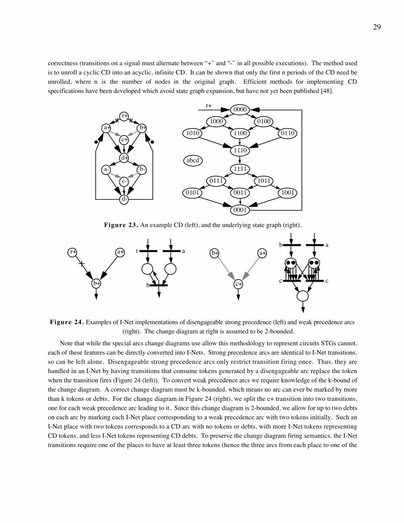
29
correctness (transitions on a signal must alternate between “+” and “-” in all possible executions). The method usedis to unroll a cyclic CD into an acyclic, infinite CD. It can be shown that only the first n periods of the CD need beunrolled, where n is the number of nodes in the original graph. Efficient methods for implementing CDspecifications have been developed which avoid state graph expansion, but have not yet been published [48].
b-
b+
r+
d-
d+
c-
c+
a-
a+
0000
01001000
011011001010
1110
1111
10110111
100100110101
0001
r+
abcd
Figure 23. An example CD (left), and the underlying state graph (right).
r a
b
a+
b+
r+ b+ a+
c+
b a
c c
Figure 24. Examples of I-Net implementations of disengageable strong precedence (left) and weak precedence arcs(right). The change diagram at right is assumed to be 2-bounded.
Note that while the special arcs change diagrams use allow this methodology to represent circuits STGs cannot,each of these features can be directly converted into I-Nets. Strong precedence arcs are identical to I-Net transitions,so can be left alone. Disengageable strong precedence arcs only restrict transition firing once. Thus, they arehandled in an I-Net by having transitions that consume tokens generated by a disengageable arc replace the tokenwhen the transition fires (Figure 24 (left)). To convert weak precedence arcs we require knowledge of the k-bound ofthe change diagram. A correct change diagram must be k-bounded, which means no arc can ever be marked by morethan k tokens or debts. For the change diagram in Figure 24 (right), we split the c+ transition into two transitions,one for each weak precedence arc leading to it. Since this change diagram is 2-bounded, we allow for up to two debtson each arc by marking each I-Net place corresponding to a weak precedence arc with two tokens initially. Such anI-Net place with two tokens corresponds to a CD arc with no tokens or debts, with more I-Net tokens representingCD tokens, and less I-Net tokens representing CD debts. To preserve the change diagram firing semantics, the I-Nettransitions require one of the places to have at least three tokens (hence the three arcs from each place to one of the
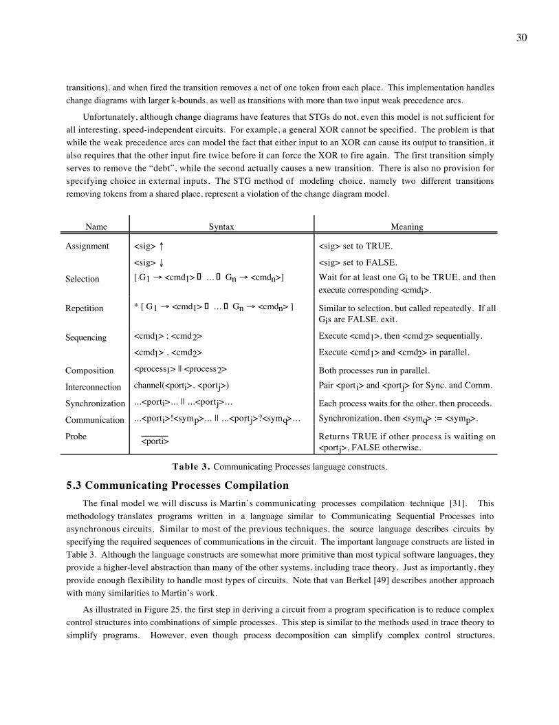
30
transitions), and when fired the transition removes a net of one token from each place. This implementation handleschange diagrams with larger k-bounds, as well as transitions with more than two input weak precedence arcs.
Unfortunately, although change diagrams have features that STGs do not, even this model is not sufficient forall interesting, speed-independent circuits. For example, a general XOR cannot be specified. The problem is thatwhile the weak precedence arcs can model the fact that either input to an XOR can cause its output to transition, italso requires that the other input fire twice before it can force the XOR to fire again. The first transition simplyserves to remove the “debt”, while the second actually causes a new transition. There is also no provision forspecifying choice in external inputs. The STG method of modeling choice, namely two different transitionsremoving tokens from a shared place, represent a violation of the change diagram model.
Name Syntax Meaning
Assignment <sig> ↑
<sig> ↓
<sig> set to TRUE.
<sig> set to FALSE.
Selection [ G1 → <cmd1> ... Gn → <cmdn>] Wait for at least one Gi to be TRUE, and thenexecute corresponding <cmdi>.
Repetition * [ G1 → <cmd1> ... Gn → <cmdn> ] Similar to selection, but called repeatedly. If allGis are FALSE, exit.
Sequencing <cmd1> ; <cmd2>
<cmd1> , <cmd2>
Execute <cmd1>, then <cmd2> sequentially.
Execute <cmd1> and <cmd2> in parallel.
Composition <process1> || <process2> Both processes run in parallel.
Interconnection channel(<porti>, <portj>) Pair <porti> and <portj> for Sync. and Comm.
Synchronization ...<porti>... || ...<portj>... Each process waits for the other, then proceeds.
Communication ...<porti>!<symp>... || ...<portj>?<symq>... Synchronization, then <symq> := <symp>.
Probe <porti> Returns TRUE if other process is waiting on<portj>, FALSE otherwise.
Table 3. Communicating Processes language constructs.
5.3 Communicating Processes CompilationThe final model we will discuss is Martin’s communicating processes compilation technique [31]. This
methodology translates programs written in a language similar to Communicating Sequential Processes intoasynchronous circuits. Similar to most of the previous techniques, the source language describes circuits byspecifying the required sequences of communications in the circuit. The important language constructs are listed inTable 3. Although the language constructs are somewhat more primitive than most typical software languages, theyprovide a higher-level abstraction than many of the other systems, including trace theory. Just as importantly, theyprovide enough flexibility to handle most types of circuits. Note that van Berkel [49] describes another approachwith many similarities to Martin’s work.
As illustrated in Figure 25, the first step in deriving a circuit from a program specification is to reduce complexcontrol structures into combinations of simple processes. This step is similar to the methods used in trace theory tosimplify programs. However, even though process decomposition can simplify complex control structures,
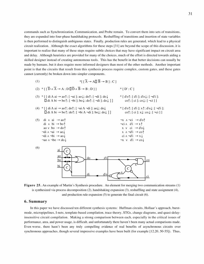
31
commands such as Synchronization, Communication, and Probe remain. To convert them into sets of transitions,they are expanded into four-phase handshaking protocols. Reshuffling of transitions and insertion of state variablesis then performed to distinguish ambiguous states. Finally, production rules are generated, which lead to a physicalcircuit realization. Although the exact algorithms for these steps [31] are beyond the scope of this discussion, it isimportant to realize that many of these steps require subtle choices that may have significant impact on circuit areaand delay. Although heuristics are provided for many of the choices, much of the effort is directed towards aiding askilled designer instead of creating autonomous tools. This has the benefit in that better decisions can usually bemade by humans, but it does require more informed designers than most of the other methods. Another importantpoint is that the circuits that result from this synthesis process require complex, custom gates, and these gatescannot (currently) be broken down into simpler components.
* [ D' ; C ]
*[ [ A → A B → B ] ; C ]
* [ [ D ∧ A → A ; D D ∧ B → B ; D ] ]
* [ d'o↑; [ d'i ]; d'o↓; [ ¬d'i ]; co↑; [ ci ]; co↓; [ ¬ci ] ]
* [ [ di Λ ai → ao↑; [ ¬ai ]; ao↓; do↑; [ ¬di ]; do↓ di Λ bi → bo↑; [ ¬bi ]; bo↓; do↑; [ ¬di ]; do↓ ] ]
* [ [ di Λ ai → ao↑; do↑; [ ¬ai Λ ¬di ]; ao↓; do↓ di Λ bi → bo↑; do↑; [ ¬bi Λ ¬di ]; bo↓; do↓ ] ]
* [ d'o↑; [ d'i ]; x↑; d'o↓; [ ¬d'i ]; co↑; [ ci ]; x↓; co↓; [ ¬ci ] ]
di ∧ ai → ao↑ di ∧ bi → bo↑ ao ∨ bo → do↑¬di ∧ ¬ai → ao↓¬di ∧ ¬bi → ao↓¬ao ∧ ¬bo → do↓
¬x ∧ ¬ci → d'o↑¬ci ∧ d'i → x↑ x ∨ ci → d'o↓ x ∧ ¬d'i → co↑ ci ∧ ¬d'i → x↓¬x ∨ d'i → co↓
(1)
(2)
(3)
(4)
(5)
(6)
C
ci
cod'i
d'o
x
x
ai
ao
bi
bo
di
do
C
C
Figure 25. An example of Martin’s Synthesis procedure. An element for merging two communication streams (1)is synthesized via process decomposition (2), handshaking expansion (3), reshuffling and state assignment (4),
and production rule expansion (5) to generate the final circuit (6).
6. SummaryIn this paper we have discussed ten different synthesis systems: Huffman circuits, Hollaar’s approach, burst-
mode, micropipelines, I-nets, template-based compilation, trace theory, STGs, change diagrams, and quasi-delay-insensitive circuit compilation. Making a strong comparison between each, especially in the critical issues ofperformance, area, and power usage, is difficult, and unfortunately there haven’t been many actual comparisons made.Even worse, there hasn’t been any truly compelling evidence of real benefits of asynchronous circuits oversynchronous approaches, though several impressive examples have been built (for example [12,20, 50-55]). Thus,
32
while we can make some comparisons between approaches (which we will do in this section), the fundamental issueof which approach is best in performance or area or power among the asynchronous styles, as well as if anyasynchronous approach is worth the extra effort of abandoning the prevalent synchronous model, is still open.
The bounded-delay models seem to be the obvious choice for designing asynchronous circuits, and severalapproaches have been tried. However, as we have seen the approaches tend to limit concurrency, especially thosethat use the fundamental-mode assumption, and need to insert extra delays to deal with hazards. The restrictions onconcurrency mean that these approaches in general cannot build datapaths. While this might be overcome by usingother approaches for the datapath elements, it is unclear how to combine different asynchronous methodologiestogether. While these downsides may seem significant, these approaches have the benefit of using many algebraictransformations, allowing both optimization opportunities and a resynthesis ability for the mapping to semi-customdevices such as field-programmable and mask-programmable gate arrays. Also, while at least the burst-modeapproach can synthesize circuits that support request-acknowledge handshaking protocols, and thus build complex,multi-level circuits, the ability to choose at what level to apply these protocols may also generate better circuits.Note however that Huffman and Hollaar circuits probably cannot build reasonable circuits with request-acknowledgeprotocols because of their limited concurrency, leading to significant performance problems from additive skew incomplex, multi-level designs. Finally, the use of the same delay model as synchronous circuits, as well as the fastresponse to inputs in burst-mode circuits, makes these approaches attractive for interfacing to synchronous circuits.
Micropipelines, while using a significant amount of delay information in its circuits, has little in common withthe bounded-delay methodologies. It handles datapaths well, and has the two-phase handshaking as a fundamentalpart of the implementation strategy. While it does have to insert delays to handle hazards, the datapaths are veryunconstrained, and can be built similar to standard synchronous datapaths. This yields significant optimizationopportunities, and a greater simplicity than any of the other approaches. It may also be a good candidate for use in amixed synchronous/asynchronous design. The main problem however is in the construction of the control circuitsto manage the dataflow, where little guidance or support is given. While straight-line pipelines are easy toconstruct, pipelines with feedback or even more general dataflow can require complex control circuits, circuitsmicropipelines gives little help in synthesizing. However, since the control circuits are only required to supporttwo-phase transition signaling, and to take at least as much time as the datapath computations they are controlling,many of the other approaches described here might be able to synthesize the required control circuits.
STGs are one of the most popular design styles currently (at least from the research standpoint), probably due totheir intuitive and clear graphical descriptions, as well as their strong theoretical background. Unfortunately, muchof the work has focused on the synthesis of STG/MGs, which while yielding efficient synthesis algorithms, lack thecritical ability of supporting general external inputs, and often require the somewhat unrealistic assumption ofcomplex, hazard-free gate implementations of arbitrary functions. Other algorithms, which work on the state graphlevel, have the promise of supporting very general specifications. Not only can they handle STG/ICs, which allowgeneral external inputs, but some may be able to handle even the very generic specifications generated in I-Nets.Also, these approaches generally discard the complex gate assumption, and instead use simple AND, and OR gates,as well as flip-flops or C-elements. With the addition of DCVSL logic for datapaths, these approaches may be ableto handle fairly general circuit implementation. Unfortunately, these approaches cannot handle issues ofarbitration/mutual exclusion, DCVSL cannot implement stateholding functions in the datapaths, and most of themore general algorithms may suffer from the exponential blowup of going to the state graph form.
Change diagrams share much in common with STGs, including the graphical description and the theoreticalbackground. They also provide interesting additions to the specification, especially the disengageable strong
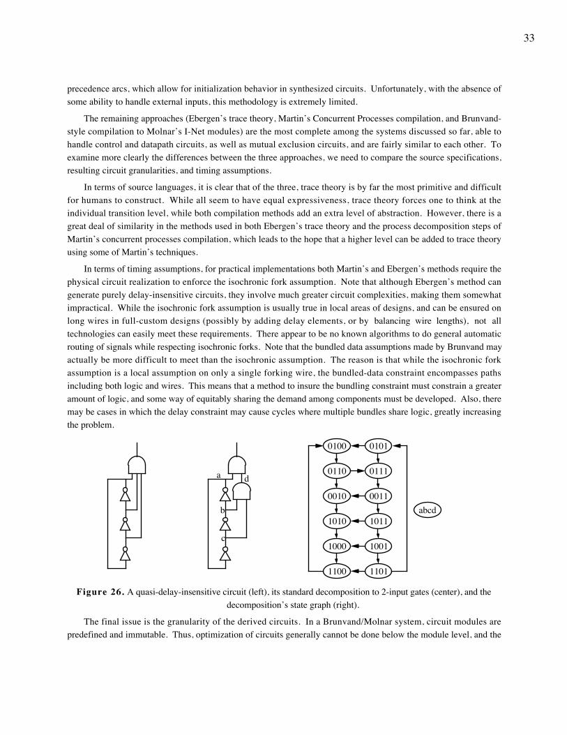
33
precedence arcs, which allow for initialization behavior in synthesized circuits. Unfortunately, with the absence ofsome ability to handle external inputs, this methodology is extremely limited.
The remaining approaches (Ebergen’s trace theory, Martin’s Concurrent Processes compilation, and Brunvand-style compilation to Molnar’s I-Net modules) are the most complete among the systems discussed so far, able tohandle control and datapath circuits, as well as mutual exclusion circuits, and are fairly similar to each other. Toexamine more clearly the differences between the three approaches, we need to compare the source specifications,resulting circuit granularities, and timing assumptions.
In terms of source languages, it is clear that of the three, trace theory is by far the most primitive and difficultfor humans to construct. While all seem to have equal expressiveness, trace theory forces one to think at theindividual transition level, while both compilation methods add an extra level of abstraction. However, there is agreat deal of similarity in the methods used in both Ebergen’s trace theory and the process decomposition steps ofMartin’s concurrent processes compilation, which leads to the hope that a higher level can be added to trace theoryusing some of Martin’s techniques.
In terms of timing assumptions, for practical implementations both Martin’s and Ebergen’s methods require thephysical circuit realization to enforce the isochronic fork assumption. Note that although Ebergen’s method cangenerate purely delay-insensitive circuits, they involve much greater circuit complexities, making them somewhatimpractical. While the isochronic fork assumption is usually true in local areas of designs, and can be ensured onlong wires in full-custom designs (possibly by adding delay elements, or by balancing wire lengths), not alltechnologies can easily meet these requirements. There appear to be no known algorithms to do general automaticrouting of signals while respecting isochronic forks. Note that the bundled data assumptions made by Brunvand mayactually be more difficult to meet than the isochronic assumption. The reason is that while the isochronic forkassumption is a local assumption on only a single forking wire, the bundled-data constraint encompasses pathsincluding both logic and wires. This means that a method to insure the bundling constraint must constrain a greateramount of logic, and some way of equitably sharing the demand among components must be developed. Also, theremay be cases in which the delay constraint may cause cycles where multiple bundles share logic, greatly increasingthe problem.
a
b
c
d
01010100
1000
0110
1100
1010 1011
0111
1001
0010
1101
0011abcd
Figure 26. A quasi-delay-insensitive circuit (left), its standard decomposition to 2-input gates (center), and thedecomposition’s state graph (right).
The final issue is the granularity of the derived circuits. In a Brunvand/Molnar system, circuit modules arepredefined and immutable. Thus, optimization of circuits generally cannot be done below the module level, and the
34
potentially large module set must be separately implemented for each target technology. Ebergen’s trace theory isbetter in this respect, because although it still uses predefined modules, the set of required elements is small and notoverly complex. As to Martin’s method, the results are mixed. Circuit derivation works essentially at the transistorlevel, with gates built up transistor by transistor in response to program specifications. However, it turns out thatonce these gates are built, they generally cannot be further restructured into smaller gates, as is done in standardsequential logic synthesis. Take for example the circuit first introduced in Figure 16 (right), which is repeated inFigure 26 (left). In this example, there is a ring of inverters oscillating, and an AND gate which should never fire.If we use standard logic decomposition techniques to map to gates with at most 2 inputs, we generate the circuitshown in Figure 26 (center). It turns out that this circuit is incorrect, because under the quasi-delay-insensitive delayassumptions, the output AND gate can in fact fire. To see this, notice the sequence 0110→0111→0011→1011,which leads from a correct state of the original circuit to a state where the top AND gate can fire. While a correctcircuit can in fact be derived by replacing two of the inverters with C-elements, which serves to require that the lowerAND gate reacts to the current state of the inverter ring before the ring continues on, we are unaware of anyalgorithms for doing this in the general case. Thus, while Martin’s method is able to optimize down to thetransistor level, it will have trouble migrating to non-full-custom technologies because of gate sizes and structure.
7. Concluding RemarksAs we have seen, asynchronous design is a rich area of research, with many different approaches to circuit
synthesis. In fact, what has been discussed in this paper is only a portion of the complete work in this field. Itbears repeating that the goal of this paper has not been to be an exhaustive treatment of the field, but instead ismeant as an overview of several approaches. Many interesting techniques have been omitted, important areas such asverification and testing largely ignored, and even those methodologies discussed haven’t been explored in the depthnecessary to actually design circuits. The hope is that this work gives the background necessary to put furtherreadings in proper context. I apologize to those researchers whose works have not been included, hoping that someof their flavor has been represented by what has been covered.
AcknowledgmentsThis paper has been greatly improved by a number of patient readers, including Gaetano Borriello, John
Brzozowski, Al Davis, David Dill, Carl Ebeling, Jo Ebergen, Henrik Hulgaard, Carl Seger, Elizabeth Walkup,Steven Nowick, Ivan Sutherland, and especially Steven Burns.
ReferencesThe references listed here include only those papers actually referenced in this text. For a more complete
bibliography of the field, the interested reader is directed to the public bibliography being maintained at EindhovenUniversity of Technology. E-mail inquiries should be sent to “[email protected]”.
[1] T. J. Chaney, C. E. Molnar, “Anomalous Behavior of Synchronizers and Arbiters”, IEEE Transactions onComputers, vol. C-22, pp. 421-422, Apr. 1973.
[2] C. Mead, L. Conway, Introduction to VLSI Systems. Reading Mass: Addison-Wesley Publishing Co.,1980.
[3] D. L. Dill, Trace Theory for Automatic Hierarchical Verification of Speed-independent Circuits. Cambridge,Mass: MIT Press, 1989.
[4] H. Hulgaard, S. M. Burns, G. Borriello, “Testing Asynchronous Circuits: A Survey”, University ofWashington, Dept. of CSE Internal Report, 1991. Also available as TR # 94-03-06.
35
[5] S. H. Unger, Asynchronous Sequential Switching Circuits. New York NY: Wiley-Interscience, 1969.
[6] R. E. Miller, Switching Theory Volume II: Sequential Circuits and Machines. New York NY: John Wiley& Sons, 1965.
[7] L. A. Hollaar, “Direct Implementation of Asynchronous Control Units”, IEEE Transactions on Computers,vol. C-31, No. 12, pp. 1133-1141, Dec. 1982.
[8] S. M. Nowick, D. L. Dill, “Automatic Synthesis of Locally-Clocked Asynchronous State Machines”, inProceedings of ICCAD, pp. 318-321, 1991.
[9] S. M. Nowick, D. L. Dill, “Synthesis of Asynchronous State Machines Using a Local Clock”, inProceedings of ICCD, pp. 192-197, 1991.
[10] K. Yun, D. Dill, “Automatic Synthesis of 3D Asynchronous State Machines”, in Proceedings of ICCAD,pp. 576-580, 1992.
[11] K. Yun, D. Dill, S. M. Nowick, “Synthesis of 3D Asynchronous State Machines”, in Proceedings ofICCD, pp. 346-350, 1992.
[12] A. Davis, B. Coates, K. Stevens, “The Post Office Experience: Designing a Large Asynchronous Chip”,in Proceedings of the 26th Annual Hawaii International Conference on Systems Sciences, Vol. I, pp. 409-418,1993.
[13] S. M. Nowick, D. L. Dill, “Exact Two-Level Minimization of Hazard-Free Logic with Multiple-InputChanges”, in Proceedings of ICCAD, pp. 626-630, 1992.
[14] M. Abramovici, M. A. Breuer, A. D. Friedman, Digital Systems Testing and Testable Design. New YorkNY: Computer Science Press, 1990.
[15] G. L. Smith, “Model For Delay Faults Based Upon Paths”, in Proceedings of International TestConference, pp. 342-349, 1985.
[16] I. E. Sutherland, “Micropipelines”, Communications of the ACM, vol. 32, no. 6, pp. 720-738, June1989.
[17] S. Karthik, I. de Souza, J. T. Rahmeh, J. A. Abraham, “Interlock Schemes for Micropipelines: Applicationto a Self-Timed Rebound Sorter”, in Proceedings of ICCD, pp. 393-396, 1991.
[18] A. Liebchen, G. Gopalakrishnan, “Dynamic Reordering of High Latency Transactions Using a ModifiedMicropipeline”, in Proceedings of ICCD, pp. 336-340, 1992.
[19] J. Sparsø, C. D. Nielsen, L. S. Nielsen, J. Staunstrup, “Design of Self-timed Multipliers: A Comparison”,Technical University of Denmark, Department of Computer Science Tech. Rep., 1992.
[20] D. Pountain, “Computing Without Clocks”, BYTE, Vol. 18, No. 1, pp. 145-150, January, 1993.
[21] A. J. Martin, “The Limitations to Delay-Insensitivity in Asynchronous Circuits”, in Proceedings of the1990 MIT Conference on Advanced Research in VLSI, pp. 263-278, 1990.
[22] C. E. Molnar, T. P. Fang, F. U. Rosenberger, “Synthesis of Delay-Insensitive Modules”, in Proceedingsof the 1985 Chapel Hill Conference on Advanced Research in VLSI, pp. 67-86, 1985.
[23] T. Murata, “Petri Nets: Properties, Analysis and Applications”, Proceedings of the IEEE, vol. 77, no. 4,pp. 541-580, 1989.
36
[24] R. F. Sproull, I. E. Sutherland, Asynchronous Systems Volume I: Introduction, Sutherland, Sproull &Associates, Inc. Tech. Rep. SSA #4706, 1986.
[25] J. T. Udding, “A Formal Model for Defining and Classifying Delay-insensitive Circuits and Systems”,Distributed Computing, vol 1, no. 4, pp. 197-204, 1986.
[26] T. P. Fang, C. E. Molnar, “Synthesis of Reliable Speed-Independent Circuit Modules: II. Circuit and DelayConditions to Ensure Operation Free of Problems from Races and Hazards”, Computer Systems Laboratory,Washington University Tech. Memorandum 298, 1983.
[27] F. U. Rosenberger, C. E. Molnar, T. J. Chaney, T.-P. Fang, “Q-Modules: Internally Clocked Delay-Insensitive Modules”, IEEE Transactions on Computers, vol. 37, no. 9, pp. 1005-1018, 1988.
[28] E. Brunvand, R. F. Sproull, “Translating Concurrent Programs into Delay-Insensitive Circuits”, inProceedings of ICCAD, pp. 262-265, 1989.
[29] J. C. Ebergen, Translating Programs into Delay-Insensitive Circuits, Centre for Mathematics andComputer Science, Amsterdam CWI Tract 56, 1989.
[30] J. C. Ebergen, “A Formal Approach to Designing Delay-Insensitive Circuits”, Distributed Computing,vol. 5, no. 3, pp. 107-119, July 1991.
[31] A. J. Martin, “Programming in VLSI: From Communicating Processes to Delay-Insensitive Circuits”, inUT Year of Programming Institute on Concurrent Programming, C. A. R. Hoare, Ed. MA: Addison-Wesley, 1989,pp. 1-64.
[32] T. A. Chu, C. K. C. Leung, T. S. Wanuga, “A Design Methodology for Concurrent VLSI Systems”, inProceedings of ICCD, pp. 407-410, 1985.
[33] T. A. Chu, “Synthesis of Self-timed VLSI Circuits from Graph-Theoretic Specifications”, M.I.T. Tech.Rep. MIT/LCS/TR-393, June 1987.
[34] L. Y. Rosenblum, A. V. Yakovlev, “Signal Graphs: From Self-timed to Timed Ones”, in InternationalWorkshop on Timed Petri Nets, Torino, Italy, pp. 199-206, 1985.
[35] T. H. Y. Meng, R. W. Brodersen, D. G. Messerschmitt, “Automatic Synthesis of Asynchronous Circuitsfrom High-Level Specifications”, IEEE Transactions on CAD, vol. 8, no. 11, pp. 1185-1205, Nov. 1989.
[36] A. V. Yakovlev, “On Limitations and Extensions of STG Model for Designing Asynchronous ControlCircuits”, in Proceedings of ICCD, pp. 396-400, 1992.
[37] P. Vanbekbergen, F. Catthoor, G. Goossens, H. De Man, “Time & Area Performant Synthesis ofAsynchronous Control Circuits”, in Proceedings of TAU’90, 1990.
[38] K. J. Lin, C. S. Lin, “A Realization Algorithm of Asynchronous Circuits from STG”, in Proceedings ofEDAC, pp. 322-326, 1992.
[39] K. J. Lin, C. S. Lin, “On the Verification of State-Coding in STGs”, in Proceedings of ICCAD, pp. 118-122, 1992.
[40] P. A. Beerel, T. H. Y. Meng, “Automatic Gate-Level Synthesis of Speed-Independent Circuits”, inProceedings of ICCAD, pp. 581-586, 1992.
[41] P. A. Beerel, T. H. Y. Meng, “Logic Transformations and Observability Don’t Cares in Speed-IndependentCircuits”, in Proceedings of TAU, 1993.
37
[42] L. Lavagno, K. Keutzer, A. Sangiovanni-Vincentelli, “Algorithms for Synthesis of Hazard-freeAsynchronous Circuits”, in Proceedings of DAC, pp. 302-308, 1991.
[43] L. Lavagno, A. Sangiovanni-Vincentelli, “Linear Programming for Optimum Hazard Elimination inAsynchronous Circuits”, in Proceedings of ICCD, pp. 275-278, 1992.
[44] K. Keutzer, L. Lavagno, A. Sangiovanni-Vincentelli, “Synthesis for Testability Techniques forAsynchronous Circuits”, in Proceedings of ICCAD, pp. 326-329, 1991.
[45] L. Lavagno, C. W. Moon, R. K. Brayton, A. Sangiovanni-Vincentelli, “Solving the State AssignmentProblem for Signal Transition Graphs”, in Proceedings of DAC, pp. 568-572, 1992.
[46] P. Vanbekbergen, B. Lin, G. Goossens, H. De Man, “A Generalized State Assignment Theory forTransformations on Signal Transition Graphs”, in Proceedings of ICCAD, pp. 112-117, 1992.
[47] M. A. Kishinevsky, A. Y. Kondratyev, A. R. Taubin, V. I. Varshavsky, “On Self-Timed BehaviorVerification”, in Proceedings of TAU’92, March 1992.
[48] M. A. Kishinevsky, Private Communications, March 1993.
[49] K. van Berkel, Handshake circuits: an intermediary between communicating processes and VLSI,Technische Universiteit Eindhoven, 1992.
[50] A. J. Martin, S. M. Burns, T. K. Lee, D. Borkovic, P. J. Hazewindus, “The Design of an AsynchronousMicroprocessor”, in C. L. Seitz, Ed., Advanced Research in VLSI: Proceedings of the Decennial CaltechConference, pp. 351-373, 1989.
[51] G. M. Jacobs, R. W. Brodersen, “A Fully Asynchronous Digital Signal Processor Using Self-TimedCircuits”, IEEE Journal of Solid-State Circuits, Vol. 25, No. 6, pp. 1526-1537, Dec. 1990.
[52] T. Williams, “A Zero-Overhead Self-Timed 160-ns 54-b CMOS Divider”, Journal of Solid-State Circuits,Vol. 26, No. 11, pp. 1651-1661, Nov. 1991.
[53] J. Kessels, K. van Berkel, R. Burgess, M. Roncken, F. Schalij, “An Error Decoder for the Compact DiscPlayer as an Example of VLSI Programming”, Proceedings of the European Conference on Design Automation, pp.69-74, 1992.
[54] M. R. Greenstreet, “STARI: A Technique for High-Bandwidth Communication”, Ph.D. Thesis, PrincetonUniversity, 1993.
[55] C. L. Seitz, W.-K. Su, “A Family of Routing and Communication Chips Based on the Mosaic”, in G.Borriello, C. Ebeling, Ed., Research on Integrated Systems: Proceedings of the 1993 Symposium, pp. 320-337,1993.
Related Documents