XA9743917 IAEA/NENS/ASSET/94/A/04 TC Project ROM/9/016 IAEA-TA-2468 ORIGINAL: ENGLISH INTERNATIONAL ATOMIC ENERGY AGENCY REPORT OF THE ASSET (ASSESSMENT OF SAFETY SIGNIFICANT EVENTS TEAM) MISSION TO THE CERNAVODA NUCLEAR POWER PLANT IN ROMANIA 8 - 12 AUGUST 1994 DIVISION OF NUCLEAR SAFETY ROOT CAUSE ANALYSIS OF A SIGNIFICANT EVENT THAT OCCURRED DURING COMMISSIONING OF UNIT 1 NUCLEAR SAFETY REVIEW MISSION UNDER TC PROJECT (ROM 9/016/02) DIVISION OF TECHNICAL CO-OPERATION PROGRAMMES VOL 28111

Welcome message from author
This document is posted to help you gain knowledge. Please leave a comment to let me know what you think about it! Share it to your friends and learn new things together.
Transcript
XA9743917
IAEA/NENS/ASSET/94/A/04TC Project ROM/9/016IAEA-TA-2468ORIGINAL: ENGLISH
INTERNATIONAL ATOMIC ENERGY AGENCY
REPORT OF THE
ASSET(ASSESSMENT OF SAFETY SIGNIFICANT EVENTS TEAM)
MISSIONTO THE
CERNAVODANUCLEAR POWER PLANT
IN
ROMANIA8 - 12 AUGUST 1994
DIVISION OF NUCLEAR SAFETY
ROOT CAUSE ANALYSIS OF A SIGNIFICANT EVENT THATOCCURRED DURING COMMISSIONING OF UNIT 1
NUCLEAR SAFETY REVIEW MISSION
UNDER TC PROJECT (ROM 9/016/02)DIVISION OF TECHNICAL CO-OPERATION PROGRAMMES
VOL 2 8 1 1 1
PREAMBLE
This IAEA Assessment of Safety Significant Events Team (ASSET) Report
presents the result of an ASSET team's investigation of a significant event that occurred
during commissioning of Unit 1 of Cernavoda nuclear power plant. The results,
conclusions and suggestions presented herein reflect the views of the ASSET experts.
They are provided for consideration by the responsible authorities in Romania. The
ASSET team's views presented in this report are based on visits to the plant, on review
of documentation made available by the operating organization and on discussions with
utility personnel. The report is intended to enhance operational safety at Cernavoda by
proposing improvements to the policy for the prevention of incidents at the plant.
The report includes, as a usual practice, the official responses of the Regulatory
Body and Operating Organization to the ASSET recommendations.
Distribution of the ASSET report is left at the discretion of the Government of
Romania; this includes the removal of any initial restriction.
Any use of or reference to the views expressed in this report that may be made
by the competent national organizations is solely their responsibility.
EXECUTIVE SUMMARY
The IAEA was requested by the Romanian authorities to conduct an ASSET rootcause analysis of a significant event that occurred during commissioning of Unit1 of the Cernavoda NPP on March 17, 1994.
Because the event took place prior to the first fuel load, the event in itself wasnot relevant to nuclear safety. However, the event was considered to besignificant in that it had the potential to provide lessons to be learned for thebenefit of future safe and reliable operation of the plant.
The event title was chosen to be: "Failure of the raw service water pipework asa result of a sustained water hammer, during commissioning, prior to first fuelload".
Analysis of the event led to the conclusion that design deficiencies were involvedas well as deficiencies in documentation.
Commissioning staff recognized the design deficiencies, however, due to lack ofdirect experience and lack of clear instructions, personnel in some instances failedto perform in the expected way. A contributing factor being the difficulty ofensuring adequate communication in a multilingual team.
Corrective actions as defined by ASSET focus on improving practical training,instruction to commissioning staff and improvements in the content andstructuring of documentation.
ASSET concluded that, essentially, the ASSET recommendations as derived fromanalysis of the event of 17 March 1994, are covered by the corrective actionsinitiated by the operator of the plant.
ASSET observed the good practice of the responsible organization to do analysisof unplanned events experienced during the commissioning period.
ASSET recognized the professional approach adopted by the organizationresponsible for commissioning and operation of the plant, as well as thededication of the licensing authority
However, taking into account the differences in background and history of theCernavoda project as compared with similar projects elsewhere, the differencesof background of institutions and people involved in the project, it is essential thata strong sense of co-operation and co-ordination is established and maintainedbetween all parties involved if successful completion of the project is to beachieved.
FOREWORD
BY THE DIRECTOR GENERAL
The IAEA Assessment of Safety Significant Events Team (ASSET) Service assists
Member States by advising them on enhancing operational safety through an
effective policy of prevention of incidents at nuclear power plants. Although good
design, manufacture and construction are prerequisites, safety ultimately depends
on the ability of operating personnel and the attitude and conscientiousness with
which they carry out their duties. ASSET missions concentrate on these aspects
in assessing the policy for the prevention of incidents against successful policies
in other countries and in exchanging, at the working level, ideas for improving it.
An ASSET review is undertaken at the request of operating or regulatory
organizations of a Member State but it is not a regulatory type of inspection to
determine compliance with national requirements. An ASSET review can
complement national efforts by providing an independent, international
assessment which may identify areas for improvement that have been overlooked.
An ASSET mission affords an opportunity for ASSET team members and
operating personnel to exchange knowledge and experience, to update the
knowledge of regulatory personnel of the host country assigned to follow the
ASSET review and to train personnel through observation of the experts
participating in the ASSET review. This can contribute to the attainment of an
international standard of excellence in the prevention of incidents, not through
regulatory requirements, but through an exchange of information on, and
voluntary endorsement of, successful and effective practices.
The IAEA Safety Series documents, including the Codes and Guides of the
Nuclear Safety Standards (NUSS) Programme for Nuclear Power Plants and the
International Nuclear Safety Advisory Group's Basic Safety Principles for Nuclear
Power Plants (Safety Series No. 75-INSAG-3) (1988)) and Report of Safety
Culture (Safety Series No. 75-INSAG-4) (1991), together with the expertise of the
ASSET team members themselves, form the basis for an ASSET review. The
review is performed by detailed and systematic investigatory methods that ensure
the thoroughness of the analysis for the identification of the root causes of
incidents and the determination of appropriate corrective actions.
An ASSET review is tailored in scope to the specific needs of the particular
facility and is concentrated on areas of operating experience that are of special
interest for the plant management's policy for the prevention of incidents.
In formulating their views, the ASSET team members discuss their observations
with their utility counterparts and consider comments made by other team
members. They record their observations and conclusions to prepare for their
presentations at the concluding meeting with utility and regulatory managers.
These notes are also an input to the ASSET Report to highlight the more
significant matters for the utility. The report is prepared after completion of the
ASSET review and submitted to the host organization through official channels.
The conclusions of the review and proposals for improvements are conveyed in
the ASSET Report to the operating organization, which reviews and analyses
them to determine what further actions may be appropriate. The proposals made
may carry different weights. Their substance rather than their number determines
their contribution to enhancing operational safety. Priorities for response may be
indicated by the operating organization. No assessment of the plant's general
safety status is made or implied.
1
CONTENTS
1. INTRODUCTION
1.1 The ASSET mission to Cernavoda NPP
1.2 General information regarding the Cernavoda NPP
1.2.1 The Nuclear Power Plant1.2.2 The Operating Organization1.2.3 Organizational structure and responsibilities during commissioning1.2.4 Status of commissioning of the plant during the ASSET mission
2. IDENTIFICATION OF THE ROOT CAUSES OF THE EVENT
2.1 Description of the event2.2 Chronological sequence of the event2.3 Logic tree of occurrences2.4 Selection of occurrences for in depth analysis
2.5W Root cause analysis of occurrence "W"
2.5W.1 Root cause analysis form
2.5W.2 Discussion
2.5X Root cause analysis of occurrence "X"
2.5X.1 Root cause analysis form2.5X.2 Discussion
2.5Y Root cause analysis of occurrence "Y"
2.5Y. 1 Root cause analysis form2.5Y.2 Discussion
2.5Z Root cause analysis of occurrence "Z"
2.5Z.1 Root cause analysis form2.5Z.2 Discussion
2.6 Rcommendations based on ASSET root cause analysis of occurrences W,X, Y and Z
2.7 Plant root cause analysis of the event
2.7.1 Plant root cause analysis methodology2.7.2 Direct and root causes as identified by the plant2.7.3 Corrective actions as implemented by the plant
3. RESPONSE BY THE REGULATORY AND OPERATING ORGANIZATIONSTO THE ASSET RECOMMENDATIONS
3.1 Response by regulatory organization3.2 Response by operating organization
ACKNOWLEDGEMENTS
ANNEX 1 List of participants
Plant counterparts
ASSET members
ANNEX 2 Schedule of activities
ANNEX 3 The ASSET review procedure
ATTACHMENTS
1. Short technical description of the Cernavoda NPP
2. Short description of the Cernavoda NPP organizational structure and
responsibilities during commissioning
3. Flow Chart of Raw Service Water System
4. Information report "Raw Service Water System - Resolutions of
Outstanding Problems", 1994-07-31.
5. Station Instruction on Commissioning Unplanned Event Reports (SI-1365-
C7, Rev. 1), 1994-06-29
1. INTRODUCTION
1.1 THE ASSET MISSION TO CERNAVODA NPP
At the invitation of the Government of Romania, the IAEA Assessment of Safety
Significant Events Team (ASSET) conducted a root cause analysis mission at the
Cernavoda nuclear power plant, from 8 to 12 August 1994.
The goal of this ASSET mission was to analyze a significant event that occurred
during commissioning of Unit l,on 17 March 1994.
The ASSET mission concentrated on the root cause analysis of the event.
The ASSET review was concluded by the provision of detailed recommendations
and generic lessons offered to the Regulator and to the Operating Organization.
The analysis carried out according to the ASSET root cause analysis methodology
was conducted jointly by plant staff and the ASSET team members.
The ASSET team comprised three external experts from Bulgaria, France and
United Kingdom recruited specifically for their long experience of nuclear power
plant operation and management in their various countries, their knowledge of
analytical techniques and their awareness of the importance of human and
organizational aspects of incidents and accidents.
1.2 GENERAL INFORMATION REGARDING THE CERNAVODA NPP
1.2.1 The Nuclear Power Plant
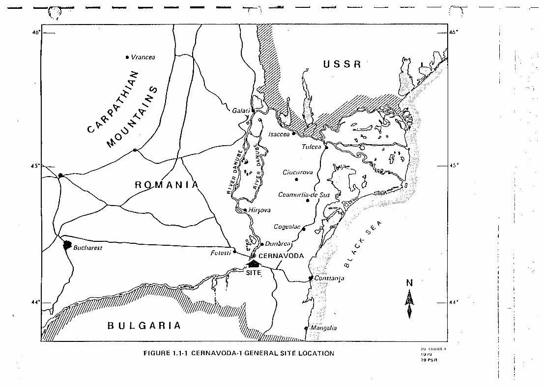
The Cemavoda NPP is located on the bank of the Danube River, 3.8 km from
Cernavoda town, 65 km west of the city Constanza at the Black Sea.
5
The original Cernavoda contract was signed in 1978 with the Atomic Energy of
Canada Limited (AECL). Site work started in April 1979, but construction was
hampered due to lack of resources. In August 1991 a contract was signed with
an AECL-Ansaldo Consortium (AAC) for management of continued construction
of Unit 1 and preservation work for the other 4 Units of the project. Significant
progress has been made since then.
Initially, the programme envisaged construction of five CANDU-600 MWe units.
Each unit contains a reactor using heavy water (PHW) as moderator and coolant.
Fuel is made up of natural uranium and refueling is performed during "on-power"
operation. A closed-loop cooling circuit transfers heat from the reactor to produce
light water steam in steam generators, a turbine generator delivers a net electrical
output of 624.3 MWe. (Attachment 1)
The units of Cernavoda NPP are now in various stages of completion. Work on
Unit 1 is well advanced. (About 94%).
1.2.2 The Operating Organization
The state-owned company "Regia Nationala de Electricitate (RENEL)" is the
owner and has the overall responsibility for construction, commissioning and
operation of the Cernavoda NPP Unit 1 in front of the Rumanian authorities.
The ultimate responsibility for safe operation of the Cernavoda Unit 1 rests with
the President of RENEL, who will be the holder of the operational license.
The AAC has got the full authority and responsibility according to the contract
for managing the project, including commissioning and initial operation during the
first 18 month period after putting Unit 1 in service. However, RENEL as the
owner retains the ultimate authority and delegates to RENEL's Grupul de
Energetica Nucleara (RENEL-GEN) to co-ordinate the interfaces with the
Rumanian authorities, and to conduct audits on how the contractual provisions
are respected by parties.
6
The National Commission for Nuclear Activities Control (CNCAN) is the nuclear
regulatory body, which was set up in 1974 under the Rumanian Atomic Energy
Act and based on the IAEA Safety Standard 50-C-G: Governmental Organization.
The CNCAN is responsible for licensing of Cernavoda NPP, including site,
construction and operation, as well as licensing of reactor operators.
1.2.3 Organizational structure and responsibilities during commissioning
The AAC project manager has the primary responsibility and full authority for
directing and managing all activities related to safe, reliable and economic
operation of the Cernavoda NPP Unit 1 within the terms and conditions of the
commissioning/initial operation license.
The AAC Commissioning/Technical Manager is responsible for ensuring that the
station systems meet design intent and requirements.
The Unit 1 is being commissioned and operated by a joint AAC-FCNEC team
under direction of the AAC staff. The joined team will operate the plant for a
period of 18 months after beginning of commercial operation. At the end of this
period, the responsibility for operation will be transferred to the Rumanian
RENEL staff. The transfer of responsibility will take place gradually, starting
from lower level staff to the Station Manager as the training and expertise of the
Rumanian staff are deemed appropriate. (Attachment 2).
1.2.4 Status of commissioning of the plant during the ASSET mission
The leakage rate testing of the containment of Unit 1 started in November 1993.
So far more than 60 % of the systems are turned over from construction to
commissioning. During the period the ASSET mission was on site, some
important safety systems were under cold performance tests, e.g., shutdown
systems and the ECCS system. The fuel loading is scheduled for November 1994,
7
first criticality for February 1995. The Unit is expected to be connected to the
grid at the end of March 1995.
The raw service water system, subject to the ASSET root cause analysis, was only
partly turned-over at the time of the event.
2. IDENTIFICATION OF THE ROOT CAUSES OF THE EVENT
2.1 Description of the event
Event: Failure of the raw service water pipework as a result of a sustained water
hammer, during commissioning, prior to first fuel load.
Date: 17 March 1994
Note: The raw service water system after fuel load will be an essential safety
related system.
Summary: The raw service water system (RSW) was being tested with RSW pump
No.3 (P3) in service together with RSW heat exchanger (HX) 1 and 2.
The commissioning engineer, local to the HX's, noticed that the vacuum
breakers installed downstream of the RSW HX's were allowing air ingress.
The commissioning team discussed this point but did not consider it to be
serious. Consequently, a further RSW PI was started with its discharge
valve in the fully open position, as required by the pump designer.
Approximately one minute after starting RSW pump No. 1, the
commissioning engineer observed large fluctuations on the RSW system
pressure gauge and from this he deduced that a water hammer condition
existed on the system. At this point the decision was made to shut down
the two RSW pumps using an indirect radio link to the main control room.
Due to background noise, radio link problems and confusion of the control
room operator the pumps were not shut down for a period of 3 1/2 mins.
As a result the water hammer can be considered to have been present for
a period of approximately 4 1/2 mins at a periodicity of 30 seconds,
subjecting the pipework and equipment to approximately 9 excess pressure
transients.
9
The system was shutdown to terminate the transients. Subsequent
inspection revealed that a large water leak was present through a
circumferential crack that had been generated on a flange on the 52"diam.
RSW pipework upstream of valve V030. Damage was also observed on
the pipe hangers together with distortion of the pipework on the upstream
side of the HX's. In addition it was noted that some damage had occurred
on the pipework to the chillers as a result of the pipe movement on
the RSW HX's system. (Attachments 3 and 4).
2.2 Chronological sequence of the event
94 Mar. 6 RSW pumps 1 and 3 and 7134-HX1 & 2 filled using a fire water hose.
HX downstream valves V030, V034 and VO35 and PCV313 were fully
closed and PCV312 fully open. The delta P control loops for NSP
(Nuclear System Plant) loads were not in service as they were not yet
turned over from construction.
94 Mar. 8 HX1 valved out. V034 was opened to line up the circuit for start of RSW
PI. Vacuum breakers on HX2, 7134-V287 and V288, opened
automatically following opening of V034 which resulted in draining of HX2
to the siphon basin.
94 Mar. 8 PI started at 17:50 successfully with HX2 in service. HX2 Vacuum
breakers closed after a few seconds and then opened once the flow was
stabilized. Pump run for one hour and then shutdown.
94 Mar. 9 PI restarted at 16:15 successfully and shutdown on 94 Mar. 16 at 17:20 on
high winding temperature.
94 Mar. 17 P3 started at 11:40 with HX1 in service. Vacuum breakers reported open
and sucking in air. HX1 inlet and outlet pressures were 1.1 bar and 0.5
bar respectively.
10
HX2 valved in parallel with HX1. Vacuum breakers reported open and
sucking in air. P3 discharge pressure was 2.8 bar. HX1 inlet and outlet
pressures were 0.5 bar and 0.27 bar respectively. HX2 inlet and outlet
pressures were 0.65 bar and 0.35 bar respectively.
PI started in parallel with P3 at 15:45. Vacuum breakers on both HXs
(7134-V285 to V288) were observed open. As soon as PI was started,
discharge pressure reading of both PI and P3 began to oscillate and
stabilized at 3.5bar after a few seconds. Water hammer started about one
minute into the run, both discharge pressure indicators started to oscillate
between 0 and 3.5 bar. PI was requested to be shut down via an indirect
radio communication link to the Main Control Room. The water hammer
continued with a period of out 30 s and was terminated when both pumps
were shut down from the Main Control Room about 3.5 minutes after the
initial request was issued by the field Commissioning Engineer located at
the RSW PL

11
2.3 Logic tree of occurrences
EVENT
Failure of a 52" RSW pipe flange
Operator in MCR failed to respondquickly to the request for switchingoff the RSW pumps
IWater hammer in RSW
Equipment
Personnel
RSW system failed to allow"solid"start up of pumps
Equipment
Equipment RSW system failed to allow start up ofpumps with closed discharge valve
Commissioning staff failed torecognize consequence of airingress through vacuum breakers
Personnel
Commissioning procedure failed togive adequate guidance
Procedure
Fragmented and incomplete documentation failedto provide the commissioning engineer withsufficient information to perform thecommissioning test
Commissioning team failed to identify, obtain anduse adequate available documentation
Procedure
Personnel
12
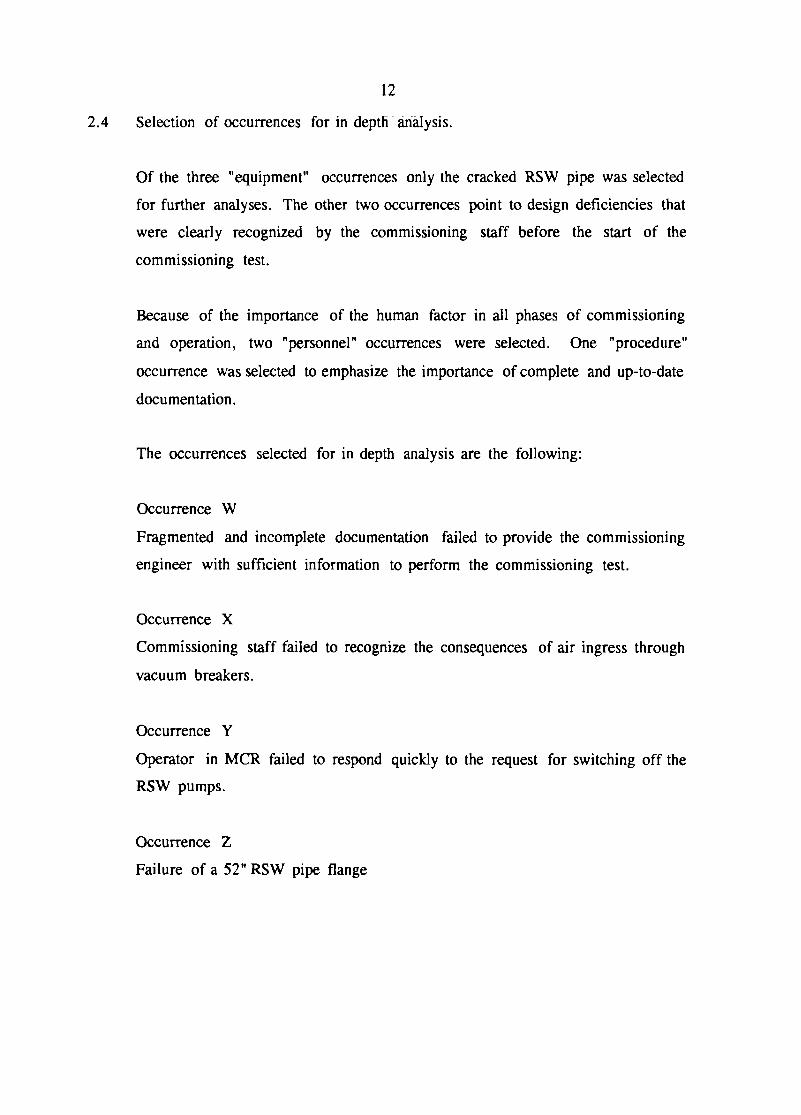
2.4 Selection of occurrences for in depth analysis.
Of the three "equipment" occurrences only the cracked RSW pipe was selected
for further analyses. The other two occurrences point to design deficiencies that
were clearly recognized by the commissioning staff before the start of the
commissioning test.
Because of the importance of the human factor in all phases of commissioning
and operation, two "personnel" occurrences were selected. One "procedure"
occurrence was selected to emphasize the importance of complete and up-to-date
documentation.
The occurrences selected for in depth analysis are the following:
Occurrence W
Fragmented and incomplete documentation failed to provide the commissioning
engineer with sufficient information to perform the commissioning test.
Occurrence X
Commissioning staff failed to recognize the consequences of air ingress through
vacuum breakers.
Occurrence Y
Operator in MCR failed to respond quickly to the request for switching off the
RSW pumps.
Occurrence Z
Failure of a 52" RSW pipe flange
13
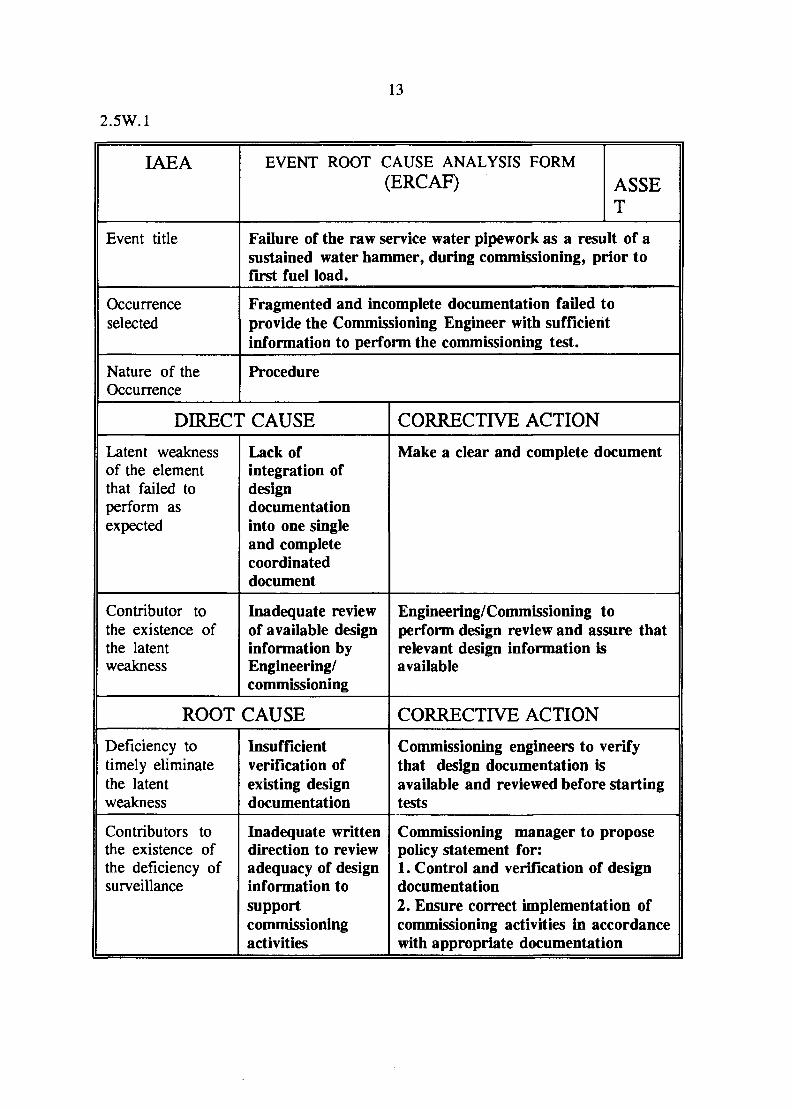
2.5W.1
IAEA
Event title
Occurrenceselected
Nature of theOccurrence
EVENT ROOT CAUSE ANALYSIS FORM(ERCAF) ASSE
T
Failure of the raw service water pipework as a result of asustained water hammer, during commissioning, prior tofirst fuel load.
Fragmented and incomplete documentation failed toprovide the Commissioning Engineer with sufficientinformation to perform the commissioning test.
Procedure
DIRECT CAUSE
Latent weaknessof the elementthat failed toperform asexpected
Contributor tothe existence ofthe latentweakness
Lack ofintegration ofdesigndocumentationinto one singleand completecoordinateddocument
Inadequate reviewof available designinformation byEngineering/commissioning
ROOT CAUSE
Deficiency totimely eliminatethe latentweakness
Contributors tothe existence ofthe deficiency ofsurveillance
Insufficientverification ofexisting designdocumentation
Inadequate writtendirection to reviewadequacy of designinformation tosupportcommissioningactivities
CORRECTIVE ACTION
Make a clear and complete document
Engineering/Commissioning toperform design review and assure thatrelevant design information isavailable
CORRECTIVE ACTION
Commissioning engineers to verifythat design documentation isavailable and reviewed before startingtests
Commissioning manager to proposepolicy statement for:1. Control and verification of designdocumentation2. Ensure correct implementation ofcommissioning activities in accordancewith appropriate documentation
14
2.5W.2 Discussion
This occurrence was selected as it demonstrates the importance of providing an
up to date and complete package of information from the engineering group to
the commissioning group.
Due to the changes between the Canadian plants and Cernavoda, this package
should contain an overview of the design and highlighting such changes.
Guidance should be given to the commissioning group on any extra requirements
that may be required due to the changes, eg. training, different approach,
communication across language groups.
15
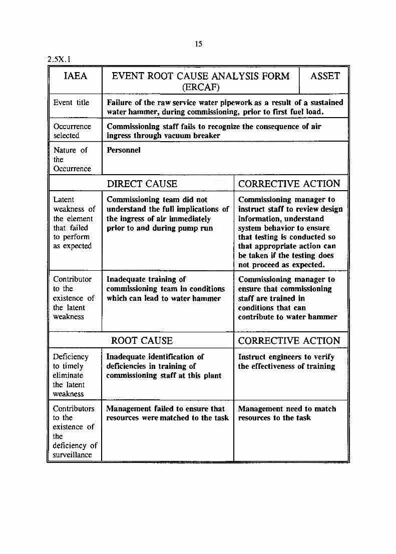
2.5X.1
IAEA
Event title
Occurrenceselected
Nature oftheOccurrence
EVENT ROOT CAUSE ANALYSIS FORM(ERCAF)
ASSET
Failure of the raw service water pipework as a result of a sustainedwater hammer, during commissioning, prior to first fuel load.
Commissioning staff fails to recognize the consequence of airingress through vacuum breaker
Personnel
DIRECT CAUSE
Latentweakness ofthe elementthat failedto performas expected
Contributorto theexistence ofthe latentweakness
Commissioning team did notunderstand the full implications ofthe ingress of air immediatelyprior to and during pump run
Inadequate training ofcommissioning team in conditionswhich can lead to water hammer
ROOT CAUSE
Deficiencyto timelyeliminatethe latentweakness
Contributorsto theexistence ofthedeficiency ofsurveillance
Inadequate identification ofdeficiencies in training ofcommissioning staff at this plant
Management failed to ensure thatresources were matched to the task
CORRECTIVE ACTION
Commissioning manager toinstruct staff to review designinformation, understandsystem behavior to ensurethat testing is conducted sothat appropriate action canbe taken if the testing doesnot proceed as expected.
Commissioning manager toensure that commissioningstaff are trained inconditions that cancontribute to water hammer
CORRECTIVE ACTION
Instruct engineers to verifythe effectiveness of training
Management need to matchresources to the task
16
2.5X.2 Discussion
The commissioning staff were not completely aware of the normal and abnormal
operation of the system and its interaction with the systems it serves and in
particular the potential problems which the vacuum breakers could cause in the
process of performing the test.
Specific practical training might have given better insight in the phenomena of air
ingress in the system. More important might have been if the team had been
instructed not to accept unexplained phenomena before performing a test.
The corrective actions aim at better preparation of commissioning staff to achieve
better results without time consuming disturbances.
17
2.5Y.1
IAEA
Event title
Occurrenceselected
Nature oftheOccurrence
EVENT ROOT CAUSE ANALYSIS FORM(ERCAF)
ASSET
Failure of the raw service water pipework as a result of a sustainedwater hammer, during commissioning, prior to first fuel load.
Operator in MCR failed to respondswitching off the pump
Personnel deficiency
DIRECT CAUSE
Latentweakness ofthe elementthat failedto performas expected
Contributorto theexistence ofthe latentweakness
Lack of clear authority of theoperator acting in the MCR
Lack of instruction beforeperforming the test
ROOT CAUSE
Deficiencyto timelyeliminatethe latentweakness
Contributorsto theexistence ofthedeficiency ofsurveillance
Person responsible for the test didnot make sure that all participantswere aware of their responsibilities
Surveillance policy is notsufficiently clear
quickly to the request for
CORRECTIVE ACTION
Shift Supervisor to discusswith operator his authoritywhen participating incommissioning tests
Commissioning engineer tomake it clear that instructingall participants in testing isobligatory.
CORRECTIVE ACTION
Commissioning engineers tocheck their teams on theirperception of theirresponsibilities
Commissioning Manager tomake clear his policy, on"surveilling"the team'sperception of responsibilitiestaking into consideration theproblem of languages
18
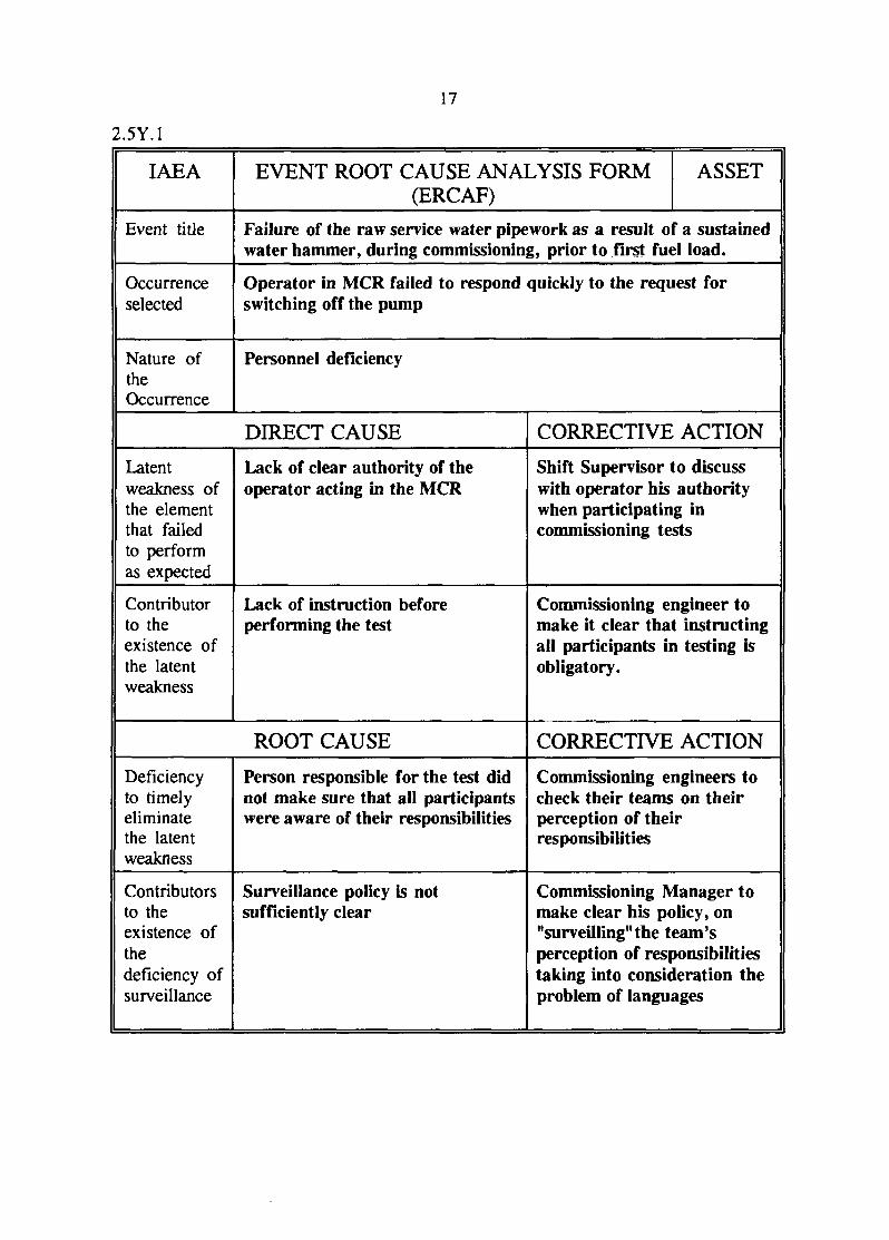
2.5Y.2 Discussion
Participants in a test can only be expected to act quickly and in the right way if
they have been instructed before; of their role and of the role of the other
members of the team.
Moreover it is necessary for the person in charge of a test to verify (survey) if
every participant in the test has the right perception of his responsibilities.
For the commissioning engineers to do the verification and to take time for it, it
is necessary that the organization's policy regarding this approach is clear taking
into account specific local difficulties as for example language barriers.
19
2.5Z.1
IAEA
Event title
Occurrenceselected
Nature oftheOccurrence
EVENT ROOT CAUSE ANALYSIS FORM(ERCAF)
ASSET
Failure of the raw service water pipework as a result of a sustainedwater hammer, during commissioning, prior to first fuel load.
Failure of a 52" RSW pipe flange
Equipment
DIRECT CAUSE
Latentweakness ofthe elementthat failedto performas expected
Contributorto theexistence ofthe latentweakness
Inclusion defect in parent metal offlange
Inadequate QC and acceptancecriteria not sufficiently defined
ROOT CAUSE
Deficiencyto timelyeliminatethe latentweakness
Contributorsto theexistence ofthedeficiency ofsurveillance
CORRECTIVE ACTION
Repair or replace flangeaccording to authorizedprocedures
Engineering/QS to reviewQC procedures andacceptance criteria andcorrect as necessary.
CORRECTIVE ACTION
20
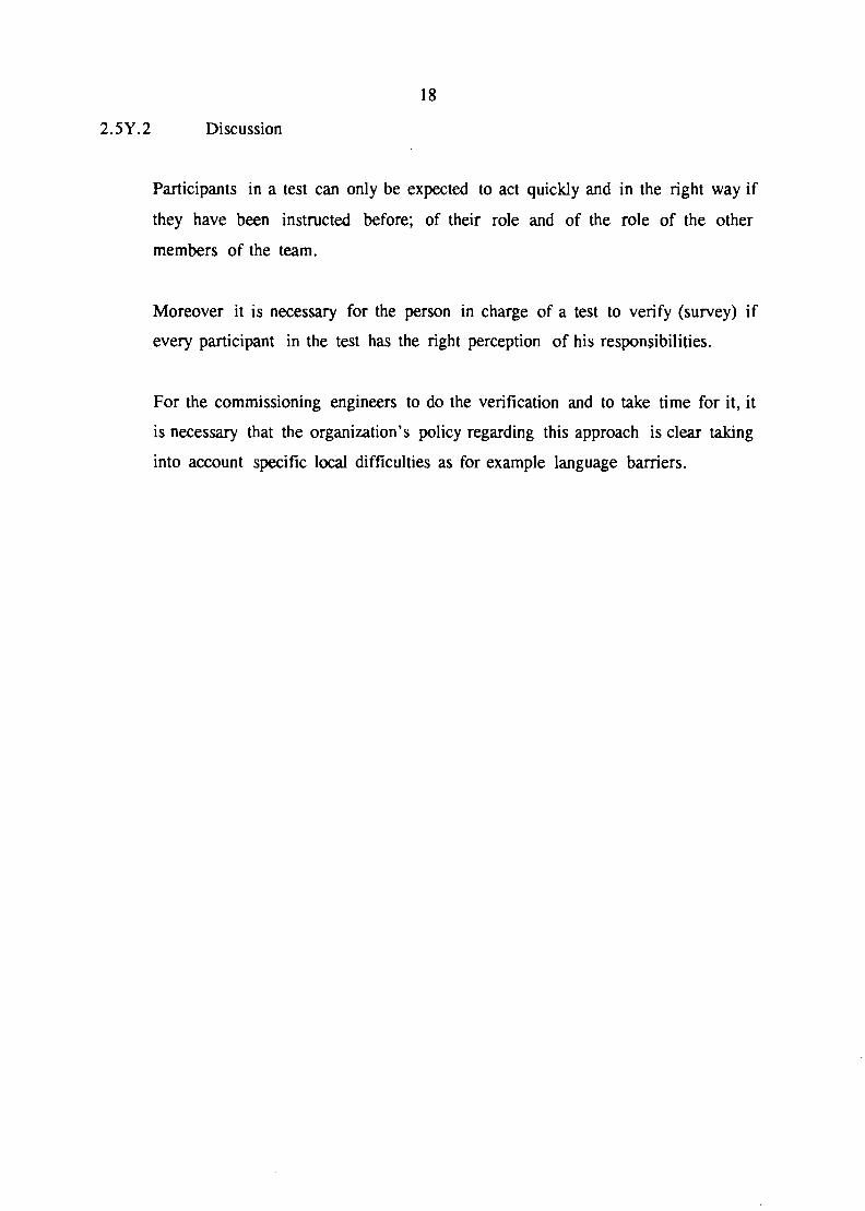
2.5Z.2 Discussion
This occurrence was chosen because it was a key contributor to the event and
because the deficiency in the flange had existed for a considerable time.
This occurrence also highlights the importance of providing a well defined Quality
Surveillance programme.
The repair and/or replacement of the faulty flange needs to be controlled in a
manner that reflects its safety importance by an adequate design change request
(modification) procedures that is accepted by the Consortium, Operator and
Regulator.
21
2.6 Recommendations based on ASSET root cause analysis of occurrences W, X,
Y and Z
The following recommendations are made to the responsible
operating/commissioning organization. They have been derived from the
application of the ASSET root cause analysis methodology to the event of 17
March 1994.
Recommendations
a) It is recommended that a review of radio and telecommunications is
carried out and improvements initiated if found necessary.
b) Consideration should be given to reviewing the NDE inspection for
pipework systems that have safety significance, particularly those systems
that have been in place for a number of years.
c) It is recommended that the person in charge of the commissioning test
provides instructions to the team on the test being conducted, particularly
for partial system turnovers, and that each person in the team is briefed
on the role they will have to play. For multilingual teams particular
attention must be given to communication aspects of any test.
d) It is recommended that following the team briefing that the person in
charge verifies that members of the team understand their role.
e) Consideration should be given to locating the commissioning test leader
in a place where he or she can control the test and that has good
communication links.
f) It is recommended that members of the commissioning staff are
encouraged to review design information and understand system behavior
22
to ensure that testing is adequately conducted so that appropriate action
can be taken if testing does not proceed as expected.
g) A review of training should be completed for commissioning staff to
ensure that they question design features and evaluate potential for
unexpected system behavior.
h) It is recommended that management match resources to the task.
i) The flange involved in the event should be repaired or replaced and
subsequently tested to the applicable NDE requirements.
23
2.7 PLANT ROOT CAUSE ANALYSIS
2.7.1 Plant root cause analysis methodology
The AAC revised the Station Instruction "Commissioning Unplanned Event
Reports (CUER)" (Attachment 5) and it was approved on 29 June 1994 by the
Station Manager. This instruction establishes requirements for reporting
unplanned events to document the course of the event, to assess its root cause
and to formulate corrective actions.
This instruction includes the criteria and process of reporting unplanned events
during commissioning, but does not provide requirements for classification of
events according to their safety significance. However, at approach to criticality
the operational event reporting procedure will be implemented which includes
classification of events.
This instruction indicates that an unplanned event may result from "equipment
failure, design deficiencies, abnormal conditions, procedural deficiencies, or
human error". They are in line with the direct causes of the ASSET methodology.
However, this instruction does not provide guidance to answer the question "Why
were these occurrences not prevented?" Therefore, it may not provide a
comprehensive methodology to analyze the root causes of occurrences, to identify
deficiencies or weaknesses in the management systems for prevention of incidents.
2.7.2 Direct causes and root causes as indicated by the plant
In the analysis of the event the plant did not distinguish between direct causes
and root causes.
Regarding the root cause of the event the conclusion of the plant is that: "Starting
the second RSW pump with piping downstream of the heat exchangers partially
filled with air is the most likely cause of the water hammer in the main circuit".
24
2.7.3 Corrective measures as indicated by the plant.
A comprehensive list of corrective measures was made by the plant. The list
indicates a total of 10 short term actions in the categories of human factors and
physical hardware. Medium term actions, a total number of 18, comprise
hardware issues with involvement of Design and Engineering.
In the list of corrective measures, dates for completion and responsible persons
are indicated. An established procedure for follow-up of outstanding issues has
to guarantee timely implementation.
Some of the corrective measures are discussed in Attachment 4.
ASSET concluded that, essentially, the ASSET recommendations as derived from
analysis of the event of 17 March 1994, are covered by the corrective actions
initiated by the plant.
25
3. RESPONSE BY THE REGULATORY AND OPERATING ORGANIZATIONS
TO THE ASSET RECOMMENDATIONS
3.1 Response by regulatory organization
As the regulatory authority, which has the responsibility to licenceCernavoda NPP Unit 1, the Romanian National Commission for NuclearActivities Control considers the ASSET mission report as an important tool inthe licensing process.
CNCAN considers the evaluation of the unplanned events during commissioningusing the results of the root cause ASSET methodology as being very importantfor the licensing decision making process.
CNCAN considers that the expert conclusions included in the report are quitesimilar to those emerging from the Romanian regulatory authority analysisprocess, as they are included in the CNCAN document "Technical Report of theNational Commission for Nuclear Activities Control for the IAEA ASSETMission to the Cernavoda NPP Unit 1 8-12 August 1994 ", submitted to theteam in the begining of the mission.
The root cause analysis performed by the team has strenghned the CNCANanalysis of the event.
CNCAN will require to the licensee the implementation of all the IAEA ASSETmission corrective actions and recommandations by the licensee.
We hope that a follow-up mission will be scheduled in due time to review theimplementation of the corrective actions while Cernavoda NPP Unit 1 will bestill in the commissioning phase.
We would like to thank very much IAEA for its promptness in organizing thismission.
We would like to thank the IAEA ASSET team for its dedicated work duringthis mission.
In the meantime, we would like to thank the licensee for its support in thepreparations for this mission and during it.
26
3.2 Response by operating organization
3.2 .1 General
During the ASSET analysis, full and frank discussions
were held with the ASSET team relating to the root causes
of the event. The ASSET methodology was proven to be a
useful tool to quickly uncover the fundamental issues and
highlight potential corrective actions. In general, the
identified corrective actions were encompassed by the
follow-up actions identified in the AAC reports Reference
1 and 2 as shown in Section 3.2.2.
Although the ASSET methodology was developed to review
safety significant events occurring in operational
plants, it is clearly possible to apply the same
methodology to Commissioning events. However
Commissioning itself plays an important role in the
overall process to develop and demonstrate quality of
equipment, procedures, personnel and management systems
prior to taking the plant critical. In this regard, it is
clearly a phase during which equipment weaknesses are
uncovered and corrected, procedures are developed and
validated, personnel training is conducted (both formal
and "on-the-job") in an environment where system
interfaces (due to construction and commissioning
proceeding in parallel) are much more complex. As a
result, although ASSET methodology may be sound, the
safety significance of any event is difficult to
quantify. Notwithstanding this, the reaffirmation by the
27
ASSET team of the basic conclusions and actions
identified by the Plant will serve to reassure the
Regulator, CNCAN, that appropriate controls are in place
to fully assess incidents occurring during Commissioning
phase of the Cernavoda Project.
Ref.l: AAC-PMT Commissioning Unplanned Event Report
94-016 along with Investigation Report dated
94 April 15.
Ref.2: AAC-PMT Information Report, Raw Service Water
System-Resolution of Outstanding Problems"
dated 94 July 31.
3.2.2 Status of Actions by the Operator in Response to ASSET
Recommendations
The essential elements of all the ASSET Recommendations
listed in Sec. 2.6 are covered by the Plant in compliance
with the reguirements of the Station Instruction on
Commissioning Unplanned Event Reports, SI-01365-C7.
In the following, each of the ASSET recommendation is
compared with the intent of the relevant recommendation
and follow-up actions identified in Ref. 1 and 2.
3.2.2.1 ASSET Recommendations 2.6 a)
It is covered by Ref.l above, item 5.1.1 d).
Following the event, establishment of adequate
communications was established as a prerequisite before
executing commissioning tests. This is reflected in
Station Instruction SI-01365-C1, Rev.2. This
recommendation is also addressed in Unplanned Event
28
Follow-up Report (UEFR) 94-016/1.d. Implementation is on-
going and should be completed in August 1994.
3.2.2.2 ASSET Recommendation #2.6 (b) and 2.6 (i)
These are covered by Ref.l item 5.1.2 (a) and Ref.2 items
4.3.1 to 4.3.5 and addressed in UEFR-94-016/1.f and l.h.
The status of work is as follows:
Necessary visual inspections and NDE have been
completed on RSW pipework in Turbine Building and
Chiller Building.
The 52" diameter flange upstream of valve 7131-V030
has been repaired.
Damaged RSW supply pipe to Odd Chillers has been
replaced.
Necessary inspections and pressure testing
have been done in accordance with relevant
requirements.
Re-examination of previous NDE records of all
RSW pipework has been completed. This review
showed four defect indications on flange welds
at 7131-MV304, MV305, 306, 307 in the
Pumphouse. Repair Work is in progress to
replace these flanges with a completion target
of mid-September 1994.
3.2.2.3 ASSET Recommendation 2.6 c)
It is covered by Ref.l above, item 5.1.1 d). It is also
addressed in UEFR 94-016/1.d.
Part of commissioning staff have been briefed on the
29
subject so far.
Implementation of the recommendation is on-going, and
should be completed in August 1994.
3.2.2.4 ASSET Recommendation 2.6 d)
It is covered by Ref.l above, item 5.1.1 d). It is also
addressed in UEFR-94-016/1.d.
Implementation of the recommendation is on-going and
should be completed in August 1994 in conjunction with
proceeding recommendation.
3.2.2.5 ASSET Recommendation 2.6 e)
It is essentially covered by Ref.l above, item 5.1.1 d).
Nevertheless it will be better reflected in Station
Instruction SI-01365-C6 and implementation will be
completed in September 1994.
3.2.2.6 ASSET Recommendation 2.6 f)
It is covered by Ref.l above item 5.1.1 b). It is also
addressed in UEFR-94-016/1.b and UEFR-94-016/1.e.
Implementation of this recommendation is on-going and
should be completed in September 1994. QA documentation
adequately reflects this recommendation.
3.2.2.7 ASSET Recommendations 2.6 g) and 2.6 h)
These recommendations are implicitly covered by Ref.l
above, item 5.1.1 b). It is also addressed in UEFR-94-
016/1. e and covered in Station Instruction SI-01365-C6
item 6.1.2 b).
Station Instruction SI-01365-TR4 fully describes the
training program for the Commissioning staff.
30
Implementation of the training program as defined in
paragraph 6.3 of this Station Instruction, is in
progress.
We are currently completing the evaluation of the
training level achieved by the Commissioning staff
against the requirements for their tasks.
31
ACKNOWLEDGEMENTS
The Operating Organization and its Cernavoda nuclear power plant provided
valuable support to the ASSET. The close co-operation of Romania with the IAEA in
all nuclear safety activities, had already established many personal contacts and a
common basis for continuing work. In accordance with the discussions at a preparatory
meeting, well selected and prepared information was made available in advance to
familiarize the ASSET members with their assignments. Throughout the whole mission,
plant counterparts were open-minded, co-operative and helpful in locating persons and
information. They were instrumental in establishing a highly effective working
relationship with the ASSET members. It extended occasionally beyond working hours
and will not be terminated with the submission of the report. The efforts of the liaison
officer and the secretarial support were outstanding. The Cernavoda ASSET wishes to
express its gratitude to all concerned for the prior efforts and for the excellent working
conditions during the review.
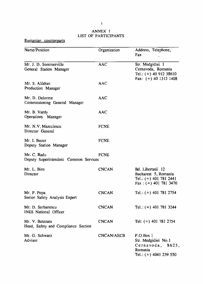
Rumanian counterparts
ANNEX 1LIST OF PARTICIPANTS
Name/Position Organization Address, Telephone,Fax
Mr. J. D. SommervilleGeneral Station Manager
Mr. S. AlikhanProduction Manager
Mr. D. DelormeCommissioning General Manager
Mr. B. VardyOperations Manager
Mr. N.V. MarculescuDirector General
Mr. I. BucurDeputy Station Manager
AAC
AAC
AAC
AAC
FCNE
FCNE
Mr. C. Radu FCNEDeputy Superintendent Common Services
Mr. L. BiroDirector
Mr. P. PopaSenior Safety Analysis Expert
Mr. D. SerbanescuINES National Officer
Mr. V. BotezatuHead, Safety and Compliance Section
Mr. G. SchwarzAdvisor
CNCAN
CNCAN
CNCAN
CNCAN
CNCAN/AECB
Str. Medgidiei 1Cernavoda, RomaniaTel.:(+) 40 912 38610Fax: (+) 40 1312 1408
Bd. Libertatii 12Bucharest 5, RomaniaTel.: (+) 401 781 2441Fax : (+) 401 781 3476
Tel.: (+) 401 781 2754
Tel.: (+) 401 781 3244
Tel: (+) 401 781 2754
P.O.Box 1Str. Medgidiei No. 1C e r n a v o d a , 8625 ,RomaniaTel.:(+) 4041 239 550
11
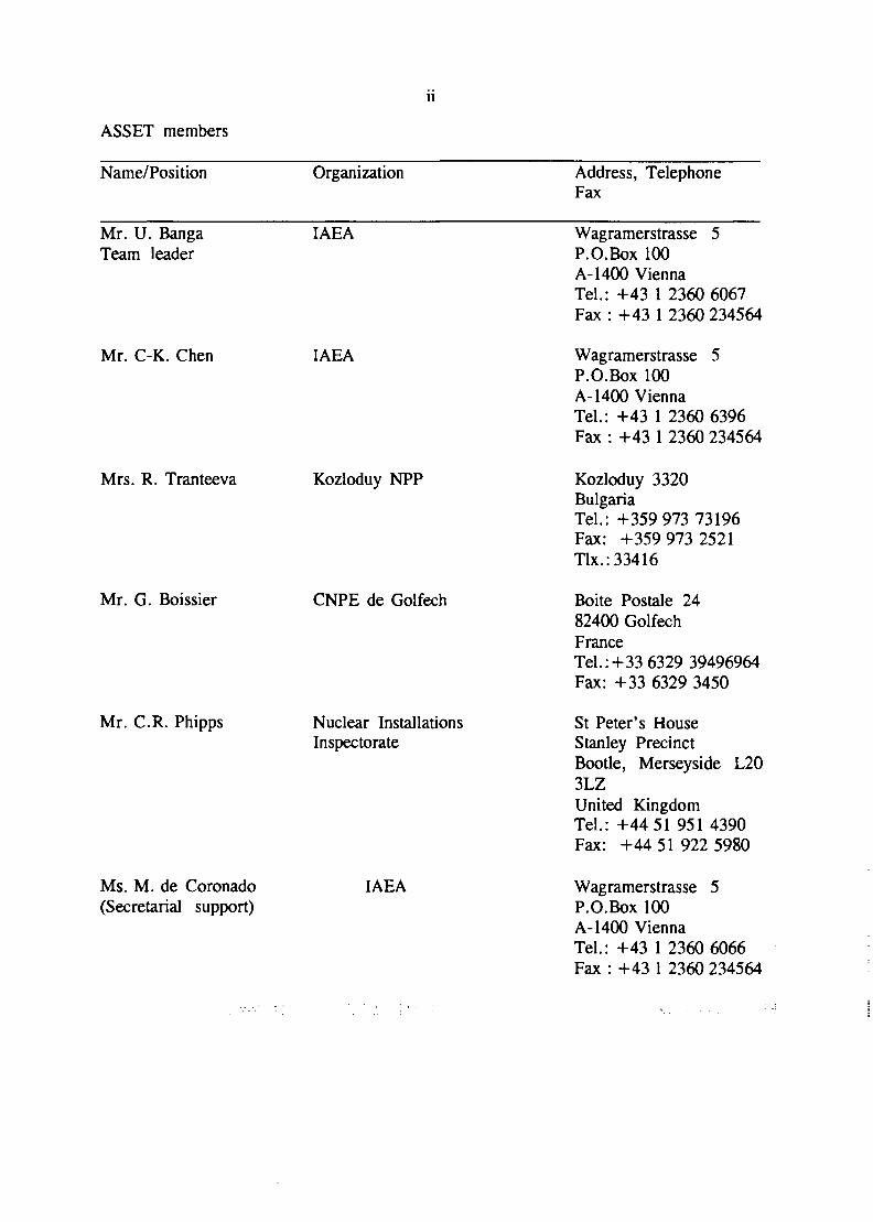
ASSET members
Name/Position Organization Address, TelephoneFax
Mr. U. BangaTeam leader
IAEA
Mr. C-K. Chen IAEA
Mrs. R. Tranteeva Kozloduy NPP
Mr. G. Boissier CNPE de Golfech
Mr. C.R. Phipps Nuclear InstallationsInspectorate
Ms. M. de Coronado(Secretarial support)
IAEA
Wagramerstrasse 5P.O.Box 100A-1400 ViennaTel.: +43 1 2360 6067Fax : +43 1 2360 234564
Wagramerstrasse 5P.O.Box 100A-1400 ViennaTel.: +43 1 2360 6396Fax : +43 1 2360 234564
Kozloduy 3320BulgariaTel.: +359 973 73196Fax: +359 973 2521Tlx.: 33416
Boite Postale 2482400 GolfechFranceTel.:+33 6329 39496964Fax: +33 6329 3450
St Peter's HouseStanley PrecinctBootle, Merseyside L203LZUnited KingdomTel.: +44 51 951 4390Fax: +44 51 922 5980
Wagramerstrasse 5P.O.Box 100A-1400 ViennaTel.: +43 1 2360 6066Fax : +43 1 2360 234564
Ill
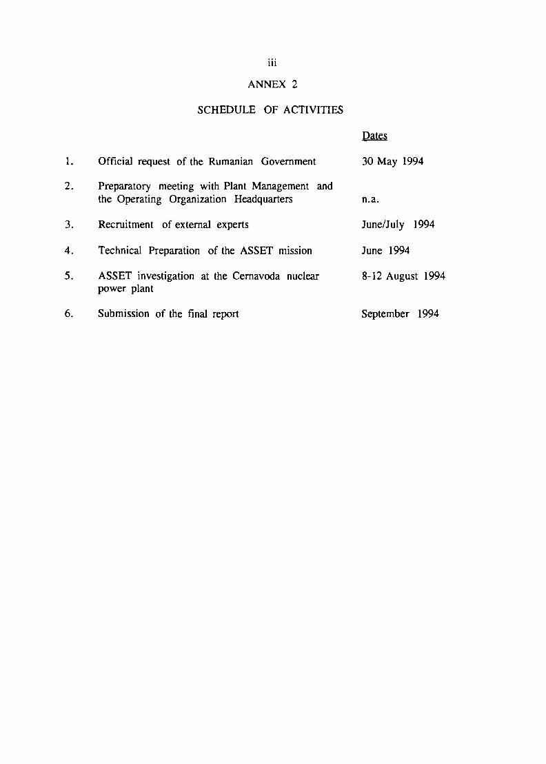
ANNEX 2
SCHEDULE OF ACTIVITIES
1. Official request of the Rumanian Government
2. Preparatory meeting with Plant Management andthe Operating Organization Headquarters
3. Recruitment of external experts
4. Technical Preparation of the ASSET mission
5. ASSET investigation at the Cernavoda nuclearpower plant
Dates
30 May 1994
n.a.
June/July 1994
June 1994
8-12 August 1994
6. Submission of the final report September 1994
ANNEX 3
THE ASSET REVIEW PROCEDURE
THE ASSET APPROACH(Assessment of Safety Significant Events Team)
LEARNING
FROM
DEVIATIONS
TO PREVENT
OCCURRENCE OF
INCIDENTS
(accidents are unacceptable)
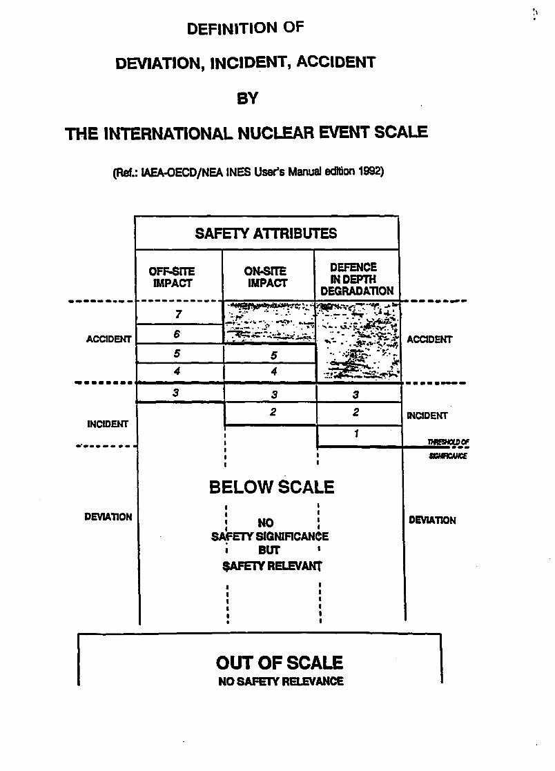
DEFINITION OF
DEVIATION, INCIDENT, ACCIDENT
BY
THE INTERNATIONAL NUCLEAR EVENT SCALE
(Ref.: IAEA-OECD/NEA INES User's Manual edition 1992)
ACCIDENT
INCIDENT
DEVIATION
SAFETY ATTRIBUTES
OFF-SITEIMPACT
ON-STTEIMPACT IN DEPTH
DEGRADATION
•» .
BELOW SCALEi i
| NO !SAFETY S1GN1RCANCE
i BUT «SAFETY RELEVANT
ACCIDENT
INCIDENT
VKSHOLOOF
DEVIATION
OUT OF SCALENO SAFETY RELEVANCE
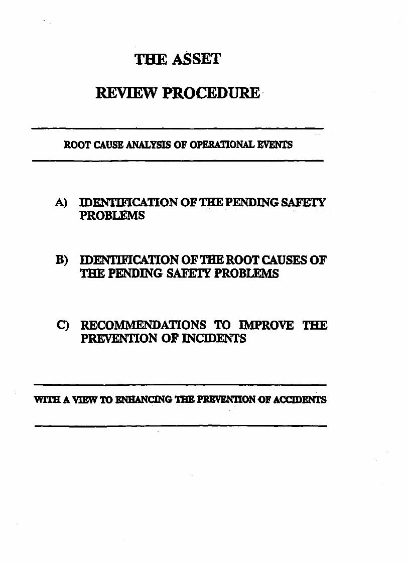
THE ASSET
REVIEW PROCEDURE
ROOT CAUSE ANALYSIS OF OPERATIONAL EVENTS
A) IDENTIFICATION OF TEE PENDING SAFETYPROBLEMS
B) IDENTIFICATION OF THE ROOT CAUSES OFTHE PENDING SAFETY PROBLEMS
C) RECOMMENDATIONS TO IMPROVE THEPREVENTION OF INCIDENTS
WITH: A VIEW TO ENHANCING THE PREVENTION OF
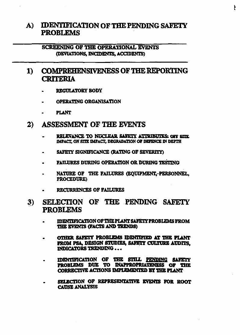
A) IDENTIFICATION OF THE PENDING SAFETYPROBLEMS
SCREENING OF THE OPERATIONAL EVENTS(DEVIATIONS, INCIDENTS, ACCIDENTS)
CRITERIAREGULATORY BODY
OPERATING ORGANISATION
PIANT
2) ASSESSMENT OF THE EVENTSRELEVANCE TO NUCLEAR SAFETY ATTRIBUTES: ore SHE.IMPACT, ON SITE IMPACT, DEGRADATION OF DEFENCE IN DEPTH
SAFETY SIGNIFICANCE (RATING OF SEVERITY)
FAILURES DURING OPERATION OR DURING TESTING
NATURE OF THE FAILURES (EQUIPMENTS-PERSONNEL,PROCEDURE)
RECURRENCES OF FAILURES
3) SELECTION OF THE PENDING SAFETYPROBLEMS
IDENTIFICATION OF THE PIANT SAFETYPROBLEMS FROMTHE EVENTS (FACTS AND TRENDS)
SAFETY PROBLEMS IDENITFDQ) AT THE PLANTFROM PSA, DESIGN STUDIES, SAFETY CULTURE AUDITS,INDICATORS TRENDING.. .
IDENTIFICATION OF THE STILL PENDING SAFETYPROBLEMS DUE TO INAPPROPRIATENESS OF ****CORRECTIVE ACTIONS IMPLEMENTED BY THE PLANT
SELECTION OF REPRESENTATIVE EVENTS FOR ROOTCAUSE ANALYSIS

B) roENTEBICATION OF THE ROOT CAUSES OFTHE PENDING SAFETY PROBLEMS
ROOT CAUSE ANALYSIS OF THE SELECTED EVENTS
1) WHAT HAS HAPPENED? « OCCURRENCES
(FAILURES TO PERFORM AS EXPECTED WHENREQUESTED TO WORE: EQUIPMENT, PERSONNEL,PROCEDURE)
• NARRATIVE
• LOGIC TREE OF OCCURRENCES
• SELECTION OF OCCURRENCES FOR IN DEPTH ANALYSIS
2) WHY DID IT HAPPEN? « DIRECT CAUSE
(LATENT WEAKNESS OF EQUIPMENT, PERSONNEL,PROCEDURE)
3) WHY WAS IT NOT PREVENTED? « ROOT CAUSE
(DEFICIENCY OF THE PLANT PROGRAMMES FORPREVENTION OF LATENT WEAKNESSES)
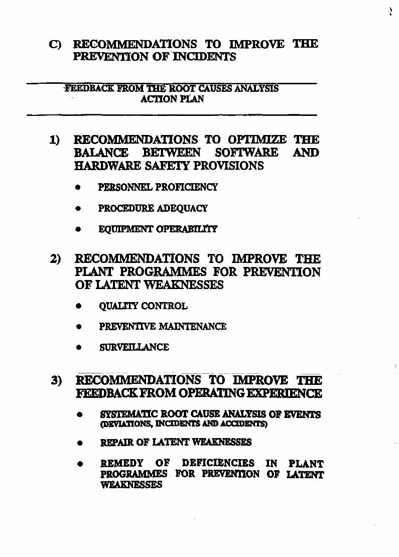
C) RECOMMENDATIONS TO IMPROVE THEPREVENTION OF INCIDENTS
)BACK FROM THE ROOT CAUSES ANALYSISACTION PLAN
1) RECOMMENDATIONS TO OPTIMIZE THEBALANCE BETWEEN SOFTWARE ANDHARDWARE SAFETY PROVISIONS
• PERSONNEL PROFICIENCY
• PROCEDURE ADEQUACY
• EQUIPMENT OPERABHHY
2) RECOMMENDATIONS TO IMPROVE THEPLANT PROGRAMMES FOR PREVENTIONOF LATENT WEAKNESSES
• QUALITY CONTROL
• PREVENTIVE MAINTENANCE
• SURVEILLANCE
3) RECOMMENDATIONS TO IMPROVE THE
SYSTEMATIC ROOT CAUSE ANALYSIS OF EVENTS(DEVIATIONS, INCIDENTS AND ACCIDENTS)
REPAIR OF LATENT WEAKNESSES
REMEDY OF DEFICIENCIES IN PLANTPROGRAMMES FOR PREVENTION OF LATENTWEAKNESSES
ATTACHMENT 1
Short Technical Description of the Cernavoda NPP
1.1-1
i
1. INTRODUCTION AND SUMMARY DESCRIPTION
1.1 INTRODUCTION AND SUMMARY DATA
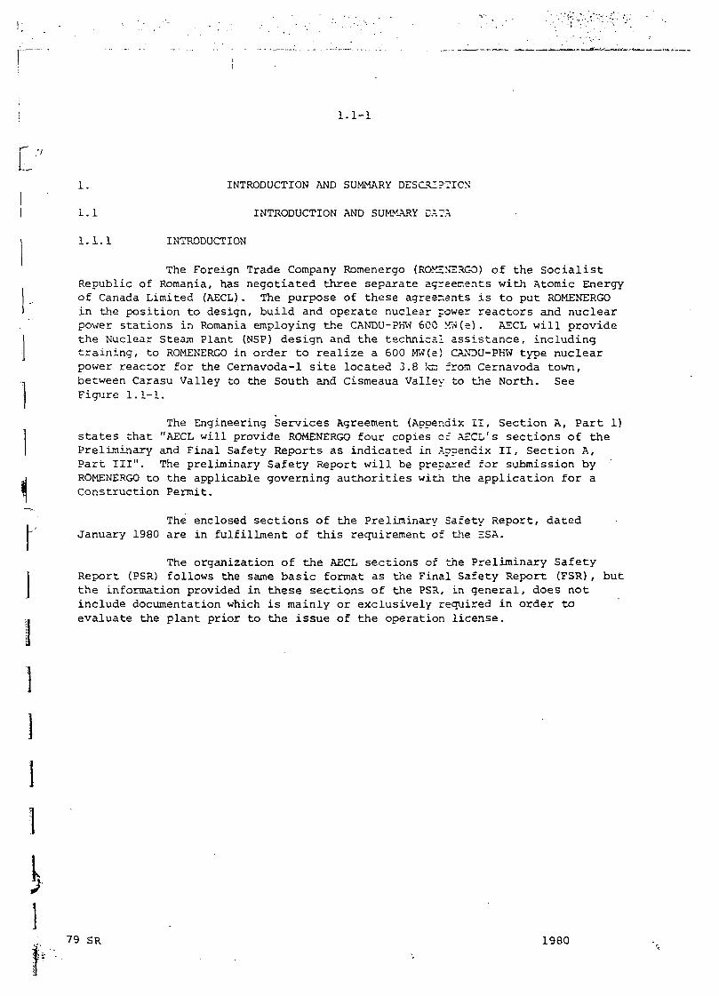
1.1 .1 INTRODUCTION
The Foreign Trade Company Romenergo (ROMINSRGO) of t h e S o c i a l i s tRepublic of Romania, has n e g o t i a t e d t h r e e s e p a r a t e agreements w i th Atomic Energyof Canada Limited (AECL) . The purpose of t h e s e agreenants i s t o pu t ROMENERGOin the position to design, build and operate nuclear power reactors and nuclearpower stations in Romania employing the CANDU-PHW 600 MW(e) . AECL will providethe Nuclear Steam Plant (NSP) design and the technical assistance, includingtraining, to ROMENERGO in order to realize a 600 MW(e) CANOU-PHW type nuclearpower reactor for the Cernavoda-1 site located 3.8 ta from Cernavoda town,between Carasu Valley to the South and Cismeaua Valley to the North. SeeFigure 1.1-1.
The Engineering Services Agreement (Appendix I I , Section A, Part 1)states that "AECL will provide ROMENERGO four copies of AECL's sections of thePreliminary and Final Safety Reports as indicated in Appendix I I , Section A,Part I II" . The preliminary Safety Report will be prepared for submission byROMENERGO to the applicable governing authorities with the application for aConstruction Permit.
The enclosed sections of the Preliminary Safety Report, datedJanuary 1980 are in fulfillment of this requirement of the ESA.
The organization of the AECL sections of the Preliminary SafetyReport (PSR) follows the same basic format as the Final Safety Report (FSR), butthe information provided in these sections of the PSR, in general, does notinclude documentation which is mainly or exclusively required in order toevaluate the plant prior to the issue of the operation license.
79 SR 1980
1.1-2
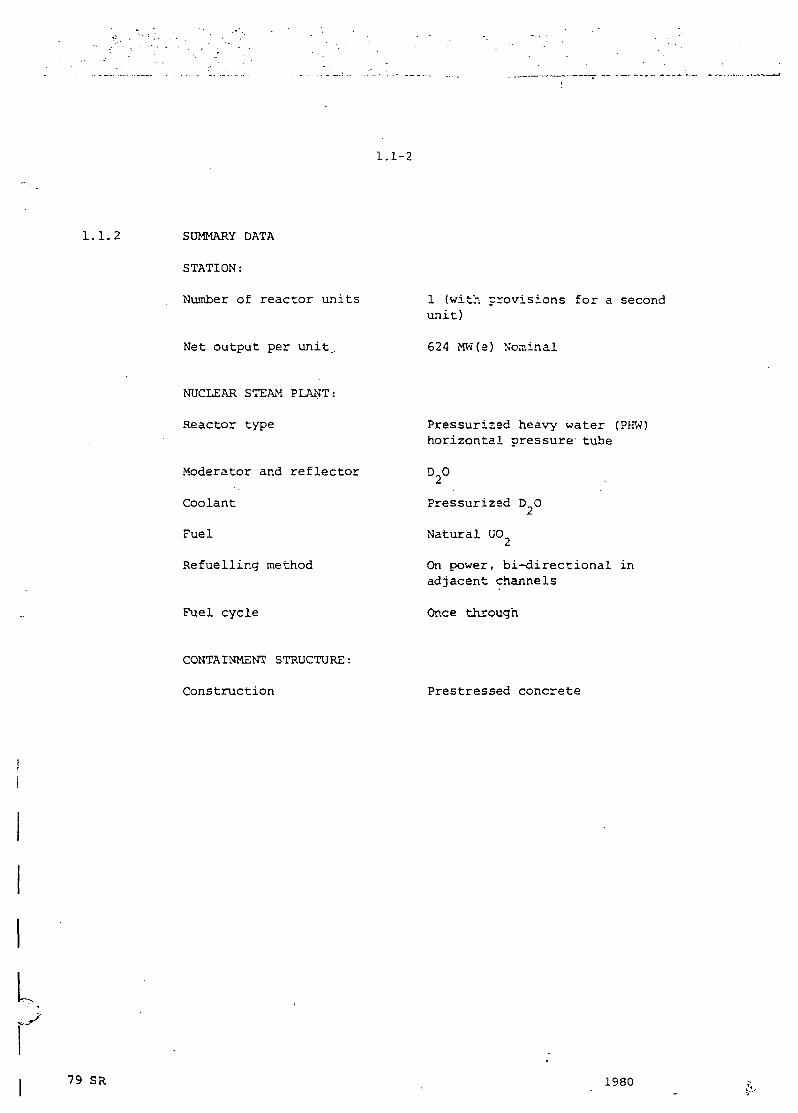
1.1.2 SUMMARY DATA
STATION:
Number of reactor units
Net output per unit.
1 (with provisions for a secondunit)
624 MW(e) Nominal
L
NUCLEAR STEAM PLANT:
Reactor type
Moderator and reflectoi
Coolant
Fuel
Refuelling method
Fuel cycle
Pressurized heavy water (PHW)horizontal nressure tube
Pressurized D O
Natural U0_
On power, bi-directional inadjacent channels
Once through
CONTAINMENT STRUCTURE:
Construction Prestressed concrete
79 SR 1980
46*
44*
• Vrancea
R CLM A N I A
Hir$ova
Cogea/ac
Dunarcu
B U L G A R I A :Mangalia
45*
4<r
FIGURE 1.1-1 CERNAVODA-1 GENERAL SITE LOCATION7!) 10(100 1l'J/'J7U PSH
1.2-1
r
1.2 SUMMARY DESCRIPTION
i.2.0 GENERAL
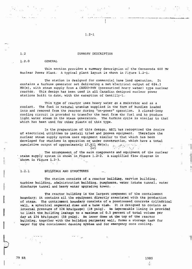
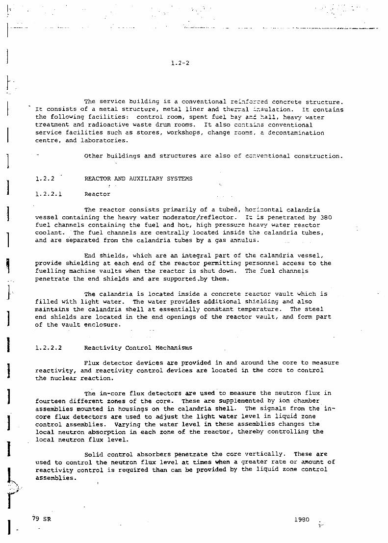
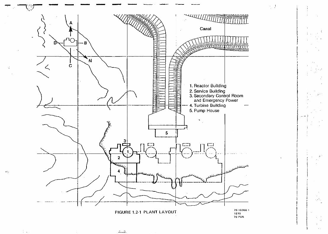
This section provides a summary description of the Cernavoda 600 MWNuclear Power Plant. A typical plant layout is shovn in Figure 1.2-1.
The station is designed for commercial base load operation. Itcontains a turbine generator set delivering a net electrical output of 624.3MW(e), with steam supply from a CANDU-PHW (pressurized heavy water) type nuclearreactor. This design has been used in all Canadian designed nuclear powerstations built to date, with the exception of Gentilly-1.
This type of reactor uses heavy water as a moderator and as acoolant. The fuel is natural uranium supplied in the fora of bundles loadedinto and removed from the reactor during "on-power" operation. A closed-loopcooling circuit is provided to transfer the heat from the fuel and to producelight water steam in the steam generators. The turbine cycle is similar to thatwhich has been used for other plants of this type.
In the preparation of this design, AECL has recognized the desireof electrical utilities to install tried and proven equipment. Therefore thenuclear steam supply system uses equipment similar to that which has beendeveloped for stations in operation or under construction, which have a totalcumulative output of approximately 17,611 MW(e).
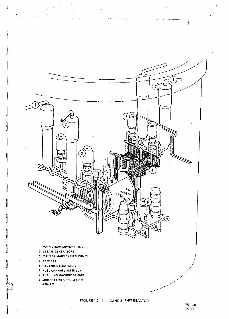
The arrangement of the main components and equipment of the nuclear• steam supply system is shown in Figure 1.2-2. A simplified flow diagram isshown in Figure 1.2-3- .
1.2.1 BUILDINGS AND STRUCTURES
The station consists of a reactor building, service building,turbine building, administration building, pumphouse, water intake tunnel, waterdischarge tunnel and heavy water upgrading tower.
The reactor building is the largest component of the containmentboundary; it contains all the equipment directly associated with the productionof steam. The containment boundary consists of a prestressed concrete cylindricalwall, a spherical segmental dome and a base slab. It is designed to contain aninternal pressure of 124 kPa(gauge) (18 psig). An impermeable lining is providedto limit the building leakage to a maximum of 0.5 percent of total volume perday at 124 kPa(gauge) (18 psig). An inner dome at the top of the reactorbuilding, together with the building perimeter wall, forms a storage tank forwater for the containment dousing system and for emergency core cooling.
79 SR . • 1980
1.2-2
h
1\I3I
1
fI
The service building is a conventional rei.ifcreed concrete structure.It consists of a metal structure, metal liner and therr.al ir.sulation. It containsthe following facilities: control room, spent fuel bay and hall, heavy watertreatment and radioactive waste drum rooms. It also contains conventionalservice facilities such as stores, workshops, change rcoir.s, a. decontaminationcentre, and laboratories.
Other buildings and structures are also of conventional construction.
1.2.2 ' REACTOR AND AUXILIARY SYSTEMS
1.2.2.1 Reactor
The reactor consists primarily of a tubed, horizontal calandriavessel containing the heavy water moderator/reflector. It is penetrated by 380fuel channels containing the fuel and hot, high pressure heavy water reactorcoolant. The fuel channels are centrally located inside the calandria tubes,and are separated from the calandria tubes by a gas annulus.
End shields, which are an integral part of the calandria vessel,provide shielding at each end of the reactor permitting personnel access to thefuelling machine vaults when the reactor is shut down. The fuel channelspenetrate the end shields and are supported-.by them.
The calandria is located inside a concrete reactor vault which isfilled with light water. The water provides additional shielding and alsomaintains the calandria shell at essentially constant temperature. The steelend shields are located in the end openings of the reactor vault, and form partof the vault enclosure.
1.2.2.2 Reactivity Control Mechanisms
Flux detector devices are provided in and around the core to measurereactivity, and reactivity control devices are located in the core to controlthe nuclear reaction.
The in-core flux detectors are used to measure the neutron flux infourteen different zones of the core. These are supplemented by ion chamberassemblies mounted in housings on the calandria shell. The signals from the in-core flux detectors are used to adjust the light water level in liquid zonecontrol assemblies. Varying the water level in these assemblies changes thelocal neutron absorption in each zone of the reactor, thereby controlling thelocal neutron flux level.
Solid control absorbers penetrate the core vertically. These areused to control the neutron flux level at times when a greater rate or amount ofreactivity control is required than can be provided by the liquid zone controlassemblies.
79 SR . 19S0
:T
1. Reactor Building2. Service Building3. Secondary Control Room
and Emergency Power— 4. Turbine Building
5. Pump House
FIGURE 1.2-1 PLANT LAYOUT 7'J-10200 I107079 FSR
1,
1 MAIN STEAM SUPPLY PIPING
2 STEAM GENERATORS3 MAIN PRIMARY SYSTEM PUMPS
4 FEEDERS5 CALANDRIA ASSEMBLY
6 FUEL CHANNEL ASSEMBLY
7 FUELLING MACHINE BRIDGE
8 MODERATOR CIRCULATIONSYSTEM
FIGURE 1.2-2 CANDU - PHW REACTOR79-SR1980
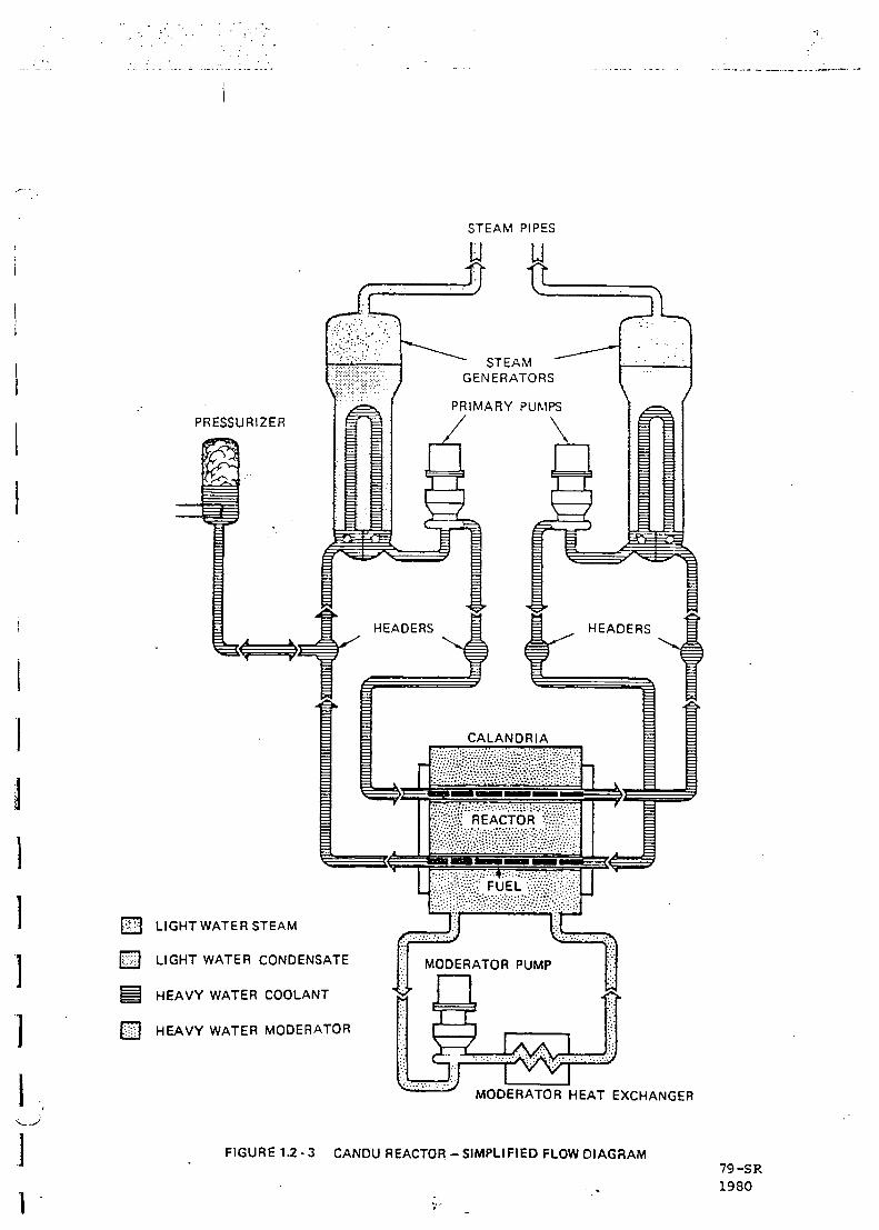
STEAM PIPES
LIGHT WATER STEAM
LIGHT WATER CONDENSATE
HEAVY WATER COOLANT
HEAVY WATER MODERATOR
MODERATOR HEAT EXCHANGER
FIGURE 1.2 - 3 CANDU REACTOR - SIMPLIFIED FLOW DIAGRAM79 -SR1980
\
Y
r
1.2-3
Slow or long term reactivity variations are controlled by theaddition of a neutron absorbing liquid to the moderator. Ccr.trol is achieved byvarying the concentration of this "poison" in the moderator. For example, theliquid "poison" is used to compensate for the excess reactivity which existswith a full core of fresh fuel at reactor startup.
Tubular stainless steel adjuster rods are used for flux flattening.Removal of these adjuster rods provides the excess reactivity necessary toovercome the buildup of the neutron absorbing isotope xanon-135 following apower reduction.
Two independent reactor shutdown systems are provided, each ofwhich is capable of shutting down the reactor for any postulated loss-of-coolantaccident. The first shutdown system consists of shutoff rods, which drop intothe core by gravity on receipt of a shutdown signal from the protective system.The second shutdown system uses the injection of a neutron absorbing solutioninto the moderator. The second shutdown system is actuated by variables withhigher trip setpoints than those of the first shutdown system.
1.2.2.3 Heat Transport System
The heat transport system is designed to circulate pressurizedheavy water through the fuel channels to remove the heat produced in the fuel.This heat is transferred to ordinary water in the steam generators locatedinside the reactor building. The light water in the steam generators, at alower temperature and pressure, boils to produce the steam to drive the turbine-ger.erator.
The heat transport system includes the circulating pumps, headers,feeder pipes to and from each fuel channel, the primary side of the steamgenerators, and a pressurizer. System pressure control is provided by thepressurizer. Water chemistry is closely controlled to limit the buildup ofactive corrosion products. Close attention is given to minimizing the escape ofheavy water from the system and the collection of heavy water liquid or vapourwhich does escape.
1.2.2.4 Moderator System
The heavy water moderator is circulated through the calandria andcooled in a relatively low temperature, low pressure system. The moderator heatexchangers remove the nuclear heat generated in the moderator and the heattransferred to the moderator from the fuel channels. Helium is used as a covergas over the heavy water. Chemistry control of the moderator water is maintainedby the moderator purification circuit.
79 SR 1980V'-'-
1.2-4
i"~
1.2.2.5 Auxiliary Systems
There are a number of auxiliary systems associated with the heattransport, moderator and reactor control systems. The ~osr significant auxiliarysystems are as follows:
(a) shield cooling system
(b) containment dousing system
(c) emergency core cooling system
(d) spent fuel bay cooling and purification system
(e) liquid zone control system
(f) annulus gas system
(g) moderator liquid poison system
(h) shutdown cooling system ;:
(i) resin handling system
(j) heat transport and moderator purification systems
(k) D O collection systems
(1) D O management systems
(m) D O sampling systems
(n) emergency water system
(o) emergency power supply system
1.2.2.6 Fuel Handling
The reactor is refuelled on-power by two remotely controlled fuellingmachines, with one located at each end of the reactor. The fuelling machines,working at opposite ends of the same fuel channel, remove spent fuel and insertnew fuel while the reactor continues to operate at power.
Spent fuel is transferred underwater, through a canal, to the spentfuel bay which is located in the service building. The spent fuel bay has astorage capacity for ten years' accumulation of spent fuel and one reactor corefuel charge.
1.2.2.7 Fuel
The fuel design has evolved from the fuel used in the NPD, DouglasPoint and Pickering reactors, and is the same as the fuel used in the Brucereactors. It is in the form of natural uranium dioxide pellets, sheathed andsealed in zirconium alloy tubes. The tubes are assembled between end plates toform fuel bundles. Each of the 380 channels contains 12 bundles, to give atotal of 4560 bundles in the reactor.
79 SR f- 1 9 8 0
\
1.2-5
1.2.3 TURBINE GENERATOR SET AND AUXILIARY SYSTEMS
(Romenergo's responsibility)
1.2.4 POWER SYSTEMS
The power supply and distribution systems are generally similar tothose for conventional thermal power stations' with one generator output (step-up) transformer and two service transformers for the auxiliaries; they includethe reliability and standby power supply capacity features specific to nuclearpower stations. •
The station output is supplied to the utility grid through aswitchyard located at the site.
Diesel generator sets, static inverters and batteries supply power •to the station services in case of emergency.
1.2-5 INSTRUMENTATION AND CONTROL SYSTEMS
The amount of automation provided is sufficient to ensure safe andreliable station operation. A main control room is provided for remote monitoringand control of major variables and equipment. Provision is made to ensurecontinuous operation of main instrumentation and control equipment in case offailure of normal station power supplies. A two-computer system forms part ofthe station control system. Either computer alone is capable of providing safeand reliable control of the plant. A secondary control area is provided toensure necessary control under accident conditions which might disable the maincontrol area.
79 SR " - 1 9 8 0
1.2-6
1III1i
1.2.6 COMMON PROCESSES AND SERVICES
The station process and service systems include the following:
condenser cooling water system
- service water system
- fire protection system
- domestic water system
demineralized water system
- radioactive and non-radioactive liquid waste drainage system
- sanitary drainage system
- ventilation, air conditioning and heating systems
- compressed air systems
gas systems (H2, C02, N2)
handling equipment
miscellaneous equipment (laundry, etc.)
radioactive waste management systems.
79 SR ,' 1980
1.3-1
b1.3
1.3.1
COMPARISON WITH OTHER CANADIAN DESIGNED PL.-.NTS
INTRODUCTION
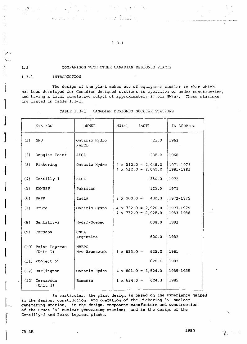
The design of the plant makes use of equipment similar to that whichhas been developed for Canadian designed stations in opera-ion or under construction,and having a total cumulative output of approximately 17,611 MW(e). These stationsare listed in Table 1.3-1.
TABLE 1.3-1 CANADIAN DESIGNED NUCLEAR STATIONS
(1)
(2)
(3)
(4)
(5)
(6)
(7)
(8)
(9)
(10)
(11)
(12)
(13)
STATION
NPD
Douglas Point
Pickering
Gentilly-1
KANUPP
RAPP
Bruce
Gentilly-2
Cordoba
Point Lepreau(Unit 1)
Project 59
Darlington
Cernavoda(Unit 1)
OWNER
Ontario Hydro/AECL
AECL
Ontario Hydro
AECL
Pakistan
India
Ontario Hydro
Hydro-Quebec
CNEAArgentina
NBEPCNew Brunswick
Ontario Hydro
Romania
MW(e)
44
2
44
1
4
1
x 512.0x 512.0
x 200.0
x 732.0x 732.0
x 635.0
x 881.0
x 624.3
(NET)
22.0
208.0
= 2,O4S.O= 2,O4S.O
• 250.0
125.0
400.0
= 2,928.0= 2,928.0
638.0
600.0
635.0
628.6
= 3,524.0
624.3
IN SERVICE
1962
1968
1971-19731981-1983
1972
1971
1972-1975
1977-19791983-1986
1982
1982
1981
1982
1985-1988
1985
In particular, the plant design is based on the experience gainedin the design, construction, and operation of the Pickering 'A1 nucleargenerating station; in the design, component manufacture and constructionof the Bruce 'A' nuclear generating station; and in the design of theGentilly-2 and Point Lepreau plants.
79 SR 1980
ATTACHMENT 2
Short Description of the Cernavoda NPP Organizational
Structure and Responsibilities during Commissioning
1 3 - 1
1 3 . 1 ORGANIZATIONAL STRUCTURE
13.1.1 General
The "Regia Autonoma de Electricitate (RENEL)" is the owner andhas the overall responsibility for operating Cernavoda NPP, Unit1.
RENEL has, through the Project Management Contract (see reference13.1-1) delegated to AECL-ANSALDO Consortium full authority forthe management of the Project on its behalf includingcommissioning and operation during the initial period of the 18months after in-service.
Notwithstanding the delegation of Project Management authorityto AACf RENEL, as the owner of the Station has the ultimateauthority with respect to all aspects of its commissioning andoperation.
RENEL is also responsible for exercising patrimony over allassets and property of RENEL associated with the Station, and,for this purpose, has designated RENEL's Grupul de EnergeticaNucleara ("RENEL-GEN") and its Site Representative organi2ation,Filiala CNE Cernavoda (FCNEC) to act on its behalf.
RENEL-GEN represents the Division responsible for coordinatingall activities related to the RENEL nuclear generation programand, its organization is shown in the RENEL-GEN QAM-01 rev.O (seefig.l, 2 and 3 from the reference 13.1-2).
The AAC organization associated with the commissioning/operatingactivities is shown in the AAC-C/O QAM-001.02 rev.1 (reference13.1.3)
13.1.2 Corporate Organization
For the Cernavoda FSAR phase 1 purpose this chapter outlines onlythe safety (technical) related aspects of the RENEL Corporateorganization with respect to the operation of the Ul CernavodaNPP.
The key organizational units relevant for the initial operationof Cernavoda Dl are shown in the fig. 13.1-1.
The ultimate responsibility for safe operation of the CernavodaUl rests with RENEL President, the future commissioning/initialoperating license holder.
The AAC Station Manager, as approved by CNCAN, has the primaryresponsibility and full authority to conduct all aspects ofstation operation within the terms and conditions ofcommissioning/initial operating license (see also section13.1.3).
CERNAVODA 1, FSAR 1994
13-2
Within the envelope defined by these two principles and accordingto the Project Management Contract provisions, the RENEL VicePresident is responsible to the RENEL President for the generalmanagement of the safe and reliable initial operation of theStation and through RENEL-GEN in house organization including itsSite Representative organization, FCNEC, mainly provides:
- direct interface with AAC for all matters related toProject Management Contract including:
- consultation and advise of the operation of Romanianlaws and regulations.- the transfer of responsibilities from AAC to RENELstaff.
- direct interface with other Romanian Authorities, such asCNCAN to obtain and maintain the necessary licenses.
-: coordination of the Research & Development Program (R&D)to support long term operation.
- coordination and conduct audits to ensure that basicprinciples and requirements of the QA program are met byGEN and its subordinate organizations involved in stationoperation.
- interface, directly or through other nationalorganization, with international organizations (IAEA, WANO,etc.) in order to obtain necessary experience of others.
- public information regarding operation, safety aspectsand the impact of Cernavoda NPP on population andenvironment.
The RENEL-GEN Divisions (see fig. 13.1-1) especially through theInvestment Director and FCNEC Director provide the directinterface with AAC, as generally established in the ProjectManagement Contract and further detailed in the QA Manuals andinterface procedures.
The primary means of conducting this interface in the actualphase of the Project are presented in the interface procedurescodes AQ-79-1.8.1/AQ-79-1.8.3/AQ-79-1.8.8 and AQ-79-2.1.1 (seereferences 13.1.-4, 13.1-5, 13.1-6), approved by CNCAN.
For the operation phase of the Cernavoda Project RENEL-GENDivisions will gradually extend their Operating PreparednessSections to ensure at least the following technical supportservices to the Station Operation:
(i) D20/Fuel Procurement
(ii) Spare Parts/Consumable Procurement
CERNAVODA 1, FSAR 1994
13-3
(iii) Logistical support during outages (human resources,special tools etc.) when required
(iv) Engineering activities, on an as required basis.
(v) short and medium (up to 18 months initial operation)technical support for reactor physics and safety analysison an as required basis.
(vi) long term research and development programs, etc.
The activities (i)-(iv) will be fully documented in the updatedinterface procedures by the time of the FSAR phase II production.
The long term R&D program will be submitted separately to CNCANfor approval during the initial operating of the Cernavoda ui.
The short and medium reactor physics and safety analysis program(activity (v)) will be also submitted and documented separatelyto CNCAN before critical.
RENEL-GEN Divisions and FCNEC Director through its Control Group(see fig. 13.1-1) will also play an important role in monitoringand verifying the turnover process from AAC to Romanian staff,as described in section 13.1.4.
Safety & Licensing Department, independent from the otherproduction oriented RENEL-GEN Division, directly reports to theVice President and is responsible to manage and conductactivities for obtaining the commissioning/initial operatinglicense.
In this process, Safety & Licensing analyses, accepts and submitsto CNCAN for approval all the support safety relateddocumentation produced and approved by the Station Manager.
Safety & Licensing, directly interfaces with CNCAN and StationManager on all safety related issues (for details see reference13.1-5).
Safety & Licensing Department will also ensure through the RENEL-GEN Divisions the necessary coordination of the interfacebetween Design (ISPE DN) and Research (ICH Pitesti) organizationsto support the medium and long term reactor physics and safetyanalysis program as defined for the Cernavoda NPP.
Quality Assurance Department which also reports directly to theVice President, is responsible to coordinate and conduct auditsto ensure that basic principles and requirements of the QAprogram are met by GEN and its subordinate organizations involvedin station operation.
CERNAVODA 1, FSAR 1994
13-4
The detailed responsibilities of the QA Department are detailedin the RENEL-GEN QA Manual, periodically reviewed, updated andsubmitted for approval to CNCAN.
International Relations Section, represents RENEL Vice Presidentin international relations with other nuclear organizations(IAEA, COG, WANO, etc.) and coordinates the cooperation programsbetween these organizations and RENEL-GEN.
CERNAVODA 1 , FSAR 1994
13-5
Public Relations Office is responsible in operation to:
(i) inform the public regarding station operation, safetyaspects and the impact of Cernavoda NPP on population andenvironment.
(ii) organize educational programs to encourage people tofeel comfortable with nuclear activities in Romania.
(iii) organize opinion polls on nuclear generation inRomania and provide reports"on these polls.
13.1.3 Operating Organization
13.1.3.1 Plant Organization Chart
Figure 13.1-2 is taken from AAC-C/O QAM-001.02 rev.l and showsthe station organization chart at maturity at the end ofcommissioning phase. (For commissioning organization see FSARPhase I Chapter 14).
All positions are not shown on this figure - only those neededto illustrate the core requirements of each function and thereporting relationships.
The staff involved in the Ceraavoda NPP operation is nominatedin the detailed station organization charts which areperiodically updated and submitted for information to CNCAN.
13.1.3.2 Plant Personnel Responsibilities and Authorities
The Operations staff are integrated into a joint AAC-FCNEC team.The AAC expatriate staff provide the required management andsupervision to conduct all aspects of plant operation in astructured environment in accordance with the prescribed safetyand quality assurance requirements. In addition, they areresponsible for developing and implementing the necessaryacademic and on-the-job training in order to develop the Romanianstaff into a competent team to manage all aspects of stationoperation within the framewprlc of the Project Management Contract(see also section 13.1.4). The Station complement consists of 110expatriates supported by 656 Romanian staff out of which 92 havereceived specific training in their field of work at PointLepreau Generating station, the rest will receive trainingappropriate to their position at Cernavoda NPP, according toSection 13.2.
Station Manager
The Station Manager is responsible for directing and managing allactivities related to safe, reliable and economic operation ofthe Plant and, through line management and supervision, ensuresthat station personnel comply with the Operating License,
CERNAVODA 1, FSAR 1994
13-6
Operating Policies and Principles, healrh and safety regulationsand other applicable rules and regulations. The Deputy to StationManager is a Romanian who has completed his training at PointLepreau G.S.
Production Manager
The Production Manager is responsible to theStation Manager for plant operation, maintenance, chemicalcontrol and fuel handling activities. In the absence of theStation Manager, the Production Manager is qualified to assumethe duties and responsibilities of the Station Manager. Reportingto the Production Manager are the following positions:
Operating Superintendent, responsible for safe andefficient operation of the plant through approvedprocedures in accordance with the requirements of theOperating License and the Operating Policies andPrinciples. He will supervise a crew of five shifts, eachheaded by a licensed shift supervisor supported by alicensed senior operator in the main control room, onesenior field operator and a team of experienced persons tooperate Unit 0 and Unit 1. Other on-shift persons includetwo mechanical maintainers, two E'.I.&C maintainers, twochemical technicians and one stores person. Each shift willhave a designated response emergency response team headedby the Senior Field Operator supported by three qualifiedfield operators and two maintainers. This group consists of31 expatriate staff supported by 153 Romanians out of which43 have received training in Canada at Point LepreauGenerating Station
Maintenance Superintendent, responsible^ f̂ or safe andefficient maintenance of the plant in accordance with goodindustry standards while minimizing industrials jrisks andradiation exposure . tgu_the, workers^. Jhf „ joain^ehancedepartment consists of three groups: the mechanical groupconsisting of 4 • expatriates and 66 Romanians, tlie E.I. & Cgroup consisting of 5 expatriates ajnd.JO .Romaniaij jjid theService Maintenance consisting of one expatriate and 61Romanian. A total of 2 maintenance engineers have receivedtraining in Canada at Point Lepreau Generating Station.
Chemical Control Superintendent, responsible for developingand implementing a quality chemical control program andmonitoring its effectiveness. The Department consists of 3expatriates and 29 Romanians, out of which one has receivedtraining in Canada at Point Lepreau G.S.
Fuel Handling Superintendent, responsible for operation,maintenance and technical support of reactor structures,fuel handling and storage systems. The Department consists
CERNAVODA 1, FSAR 1994
13-7
i of 8 expatriates and 27 Romanians, out of which 14 have! received training in Canada at Point Lepreau Generatingj Station.
ITechnical Manager
The Technical Manager is responsible to the Station Manager forproviding full scope technical support services including systemsengineering including the production of operating manuals andtest procedures, generic equipment engineering, computer programdevelopment and maintenance, periodic and in-service inspectionand management of nuclear materials. He is supported by aRomanian deputy who has completed his training at Point LepreauG.S. The Technical Unit will be evolved in a coordinated manneras commissioning activity is completed with Commissioning staffbeing demobilized (for details see chapter 14) and organizedinto 3 departments as follows:
- Mechanical department responsible for most of the processsystems and mechanical special safety systems (ECCS andContainment). This group consists of 20 expatriates and 33Romanian staff out of which 6 have received training atPoint Lepreau G.S.
E. I. & C department responsible for electrical, control andinstrumentation systems and computer software as well asShutdown Systems. This group consists of 16 expatriates and31 Romanian staff out of which 10 have received training atPoint Lepreau G.S.
- Nuclear Services department with the responsibility fornuclear material management, plant performance assessmentand reporting, in-service inspection and drafting services.This group consists of 4 expatriates and 34 Romanian staff.
Safety and Compliance Superintendent
The Safety and Compliance Superintendent is responsible to theStation Manager for supervising all the licensing interface withthe relevant jurisdictions, performing safety analysis program,performing reliability analysis for special safety systems andkey safety related systems, conducting safety performanceassessment and reporting to CNCAN, performing core performanceanalysis and fuel Management services. This department consistsof 4 expatriates and 32 Romanians out of which 5 have receivedtraining in Canada at Point Lepreau G.S., which includes theDeputy to the Safety and Compliance Superintendent.
Health Physics Manager
The Health Physics Manager is responsible to the Station Managerfor ensuring that the required health and safety program isdeveloped and implemented at the station, including radiation
CERNAVODA 1, FSAR 1994
13-8
protection and industrial safety. This department consists of 3expatriates and 2 9 Romanian staff. Two of the Romanian staff havereceived training in Canada at Point Lepreau G.S. and other CANDUestablishments including the Deputy to the Health PhysicsManager. The staff will provide radiation protection services atSite as well as run the dosimetry service and environmentallaboratory besides administering all on-site radiation protectionand industrial safety training at Site. They are also responsiblefor developing and coordinating emergency preparedness programin response to radiation and other contingencies at the Station.
Planning Superintendent
The Planning Superintendent will be responsible to the StationManager for planning and scheduling all work performed by theProduction Unit. He will issue the Daily Work Plan, the PoisonOutage Plan, the Short Term Plan, the Long Term Plan as well asspecific plans for implementing special projects. In addition,they will prepare the Annual Outage Plan to be managed by anOutage Management team drawn from the Operating Department. Thisdepartment will consist of 2 expatriates and 11 Romanian, out ofwhich one has received training at Point Lepreau G.S.
Training Manager
The Training Manager is responsible to the Station Manager fordeveloping and implementing necessary programs related toacademic training, generic skills training, and authorizationtraining for the licensed staff. The availability of Simulatortowards: the end of 1994 will add a significant new dimension tothe scope of the training program. The department will consistof 5 expatriates and 37 Romanian staff, some of whom havereceived training abroad.
Quality Assurance Supervisor
The Quality Assurance Supervisor is responsible to the StationManager for ensuring that the QA Manual and program is developedin accordance with Romanian Norms and CSA Standards. They willperform all the QA surveillance and audit functions as well ascoordinate external audits from CNCAN and other internationalorganizations like IAEA and WANO. The group consists of 1expatriate and 8 Romanians out of which one has already receivedtraining at Point Lepreau G.S.
13.1.3.3 Operating Shift Crews
a) Composition
The plant will be operated through five shifts to allow routinetraining, vacations, time lost due to sicknesses and to cater forsecondment of operating expertise to such projects as outage
CERNAVODA 1, FSAR 1994
13-9
management, development of overall plar.n procedures etc. Eachoperating shift will normally consist cf:
one expatriate licensed shift supervisor and his Romaniandeputyone expatriate licensed control room operator and hisRomanian deputyone expatriate senior nuclear operator (preferablylicensed) and his Romanian deputy1 nuclear operator in Work Control Area1 nuclear operator in the Control Room4 nuclear operators in the field12 assistant nuclear operators4 electrical operators (until nuclear operators arequalified as electrical operators)
In addition, the following support staff will be provided on-shift:
2 mechanical maintainers2 E.I. & C maintainers2- Chemical technicians
- 1 stores keeper
For further details see SI-01365-P38, Shift Operation andfig.13.1-3 (reference 13.1-7)
b) Minimum Complement
The plant will be operated with less than normal complement onsome occasions due to sickness, accident and vacation absences.There shall always be on site sufficient staff to carry outemergency procedures and to safely shut down the unit ifrequired. This minimum will consist of :
- one licensed shift supervisor-- one licensed control room operator- three nuclear operators- six assistant nuclear operators- three electrical operators (until nuclear operatorsare qualified as electrical operators)- one mechanical maintainer- one E.I.& C. technician- one chemical technician
(see also reference 13.1-7)
13.1.3.4 Technical Support to Operations
13.1.3.4.1 Technical Service
As described in the chapter 14 FSAR phase 1,during the Commissioning phase, technical support is provided by
CERNAVODA 1, FSAR 1994
13-10
the responsible Commissioning Departments, each headed by aSuperintendent, covering the full scope of the Plant. Theresponsible Departments are :
- Common Services- Nuclear Steam Plant System- Thermal Cycle System- Electrical System- Reactor Systems and Fuel Handling- Control and Instrumentation
Following turnover of the systems to Operations, the technicalfunctions will be transferred to the Technical Unit in a phasedmanner such that the Commissioning Department will transform intothe following Technical Departments.
Technical Mechanical responsible for Technical supportservices in the areas of : Nuclear mechanical systems,Turbine-generator and auxiliaries, steam condensingand feedheating, mechanical special safety systems.(ECC, Dousing, Airlock, Containment, EWS) , Heavy WaterSystems, Diesel Generator, HVAC and Common Services(Cooling Water, Fire Protection, Compressed gases,Water Treatment etc.)
Technical Services; responsible for non-destructiveexaminations (Periodic Inspection, Erosion-CorrosionProgram, Vibration Analysis), generic-mechanicalservices eg. pressure vessels, piping and supports,safety/relief device, rotating equipment, seals, valvesetc ; nuclear materials/radioactive wastes management,fuel procurement and accounting, spent fuel managementand technical administration ( reporting, changecontrol, liaison with outside agencies etc.)
- Technical EI&C Department responsible for ControlComputers hardware and software, Shutdown Systems(SDS1, SDS2), Liquid Zone Control, Electrical Systems(high, medium, * and low voltage), generators, Unitprotection, fault recorders, sequences ; and genericEI&C services (Calibration program, Environmentalqualification, DICON, load list, etc.)
The technical responsibility for reactor components and Fuelhandling equipment will be transferred to Production Departmentalong with the responsibility for operations and maintenance.
Generic functions of each technical department are asfollows :
1. Promote the technical well being of the stationwith respect to designated plant systems/componentsand overall operational characteristics by ensuring
CERNAVODA 1, FSAR 1994
13-11
compliance with relevant design requirements, codesand standards, regulations and licensing requirements.
2. Maintain technical overview of operations andmaintenance pertaining to routine operation of thestation. Evaluate performance cf the plant withreference to design intent and prescribed operatingdocumentation; analyse abnormal events and ini t iatenecessary corrective actions.
3. Ensure that necessary testing, calibrations,preventive and predictive maintenance and spare partsrequirements are identified, implemented and resultsreviewed for acceptability.
4. Prepare and upkeep necessary operationaldocumentation to ensure safe and reliable plantoperation. This documentation includes operatingmanuals, flowsheets, control logic and wiringdiagrams, testing procedures, training manuals, andspecified emergency operating procedures.
5. Perform necessary design changes to the plant inorder to resolve problems in operability,maintainability, improving station safety, reliabilityand licensibility. This includes all activit ies todevelop alternative options, cost-benefit assessmentanalysis and design work to meet the prescribed codesand standards and upkeep of associated designdocumentation.
6. Minimize unplanned outages and optimi2e plannedoutages by ensuring timely assessment of problems andapproach to resolution, optimizing resourceavailability and providing technical assistance inimplementation of work.
7. Ensure that al l technical support work isperformed in accordance with the operations qualityassurance requirements as identified in station policydocument.
This approach to the organization of the technical support tooperation with the Technical Unit acting as Design Authority issimilar to that practiced in Canada at Point Lepreau NGS, and hasbeen proven to be successful.
13.1.3.4.2 Back-lip' TechnicaT" Support A
During operation, specific circumstances such as design relatedissues, special analysis required by CNCAH to maintain operatinglicense, complex unplanned events requiring detailed analysis to
CERNAVODA 1, FSAR 1994
I 13-12
determine root causes, etc. may involve off-site technicalsupport.
Generally speaking these issues will be directly addressedthrough the three home-office design organizations:
AECL-CANDU, Sheridan Park for NSPANSALDO GENOA, for Balance of Plant (BOP) includinginterface with GENERAL ELECTRIC on Turbine GeneratorISPE Bucharest, for Support Systems,and/or RENEL-GEN head office through its subordinateorganizations (ISPE-DN and ICN Pitesti) (see also section13.1.2).
In addition, there is a large body of technical support availablefrom other CANDU utilities, eg. NB Power, Hydro Quebec andOntario Hydro, AECL-Research, other consulting organizations andequipment suppliers. These services will be requested as and whenrequired.
13.1.4 AAC/Owner Turn-over
Turnover from AAC to Romanian Staff
Cernavoda NPP Unit 1, is being commissioned and is being operatedfor 18 months by/or under direction of Ex-Patriot Staff fromAECL/Ansaldo Consortium (AAC). At the end of this period,responsibility for operation of Cernavoda NPP Unit 1 will betransferred to the Romanian Staff of RENEL.The transfer of control to the RENEL staff will take placegradually, as their training and expertise is deemed appropriatefor transfer of control, and will end as the last few Expatriatestaff leave. The transfer is composed of three elements:
i) Training and Job Experience
ii) System and Job Functions !,.
iii) Process
i) Training and Job Experience:
Formal training will be given to Romanian Staff as described inFSAR chapter 13.2, and the training overview document Cernavoda1 Operations Training Plan (see reference 13.2-1)
The other aspect of training is "on-the-job" training or jobexperience. This will be done by involvement of the RomanianStaff in the commissioning and initial operation phases ofCernavoda Unit 1 under direct guidance of Expatriate staff.
CERNAVODA 1, FSAR 1994
13-13
The Romanian staff will gain experience through activeparticipation until they are deemed capable of performing'the jobas described in the job description document by their supervisor.This level of capability will be documented by che AAC supervisorand accepted by RENEL management.
ii) Station Systems and Job Functions
Responsibility for Station System wj.ll be handed over to theRomanian Staff following a documented process. The systemengineer would ensure that a check list is filled out containingstatus of system documentation, records, DCNs, major outstandingdeficiencies and this status summary would be accepted by theRomanian System engineer at supervisory level.
For Supervisors who have job function responsibility, the sameprocess would take place with a check list that is appropriateto the job, but that would cover such subjects as sectiondocumentation, section work programs, section personnel status,major . ongoing section activities. The check list would beaccepted by the Romanian supervisor.
iii) Process
The process will consist of a series of turnovers from ExpatriateStaff to Romanian staff starting at the lower levels cascadingupwards and finishing at the Station Manager level. The processwill not be uniform, but will depend upon the status of thesystem/job function and readiness of the Romanian acceptor. Theprocess will be formally documented at each level, and will beverified by the appropriate supervisors both Expatriate andRomanian. Any transfer issues that can not be resolved at thatlevel will be formally documented and taken up the line to beresolved.
The final handover at Station Manager level will be verified byAAC/RENEL senior management.
The principles of turnover to the Romanian Staff are statedabove, and the detailed process to be followed includingresponsibilities are documented in the Station document Turnoverfrom AAC to RENEL (see reference 13.1-8)
CERNAVODA 1, FSAR 1994
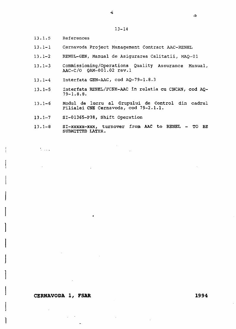
13-14
13.1.5 References
13.1-1 Cernavoda Project Management Contract AAC-RENEL
13.1-2 RENEL-GEN, Manual de Asigurarea Calitatii, MAQ-01
13.1-3 Commissioning/Operations Quality Assurance Manual,AAC-C/O QAM-001.02 rev.l
13.1-4 Interfata GEN-AAC, cod AQ-79-1.8.3
13.1-5 Interfata RENEL/FCNE-AAC In relatia cu CNCAN, cod AQ-79-1.8.8.
13.1-6 Modul de lucru al Grupului de Control din cadrulFilialei CNE Cernavoda, cod 79-2.1.1.
13.1-7 SI-01365-P38, Shift Operation
13.1-8 SI-xxxxx-xxx, turnover from AAC to RENEL - TO BESUBMITTED LATER.
CERNAVODA 1, FSAR 1994
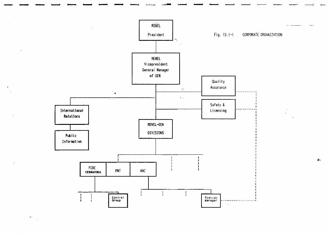
RENEL
President Fig. 13.1-1 CORPORATE ORGANIZATION
RENELVicepresldent
General Managerof GEN
InternationalRelations
QualityAssurance
Safety &Licensing
RENEL-GEN
DIVISIONS
FCNECERNAVOOA PMT AAC
ControlGroup
StationManager
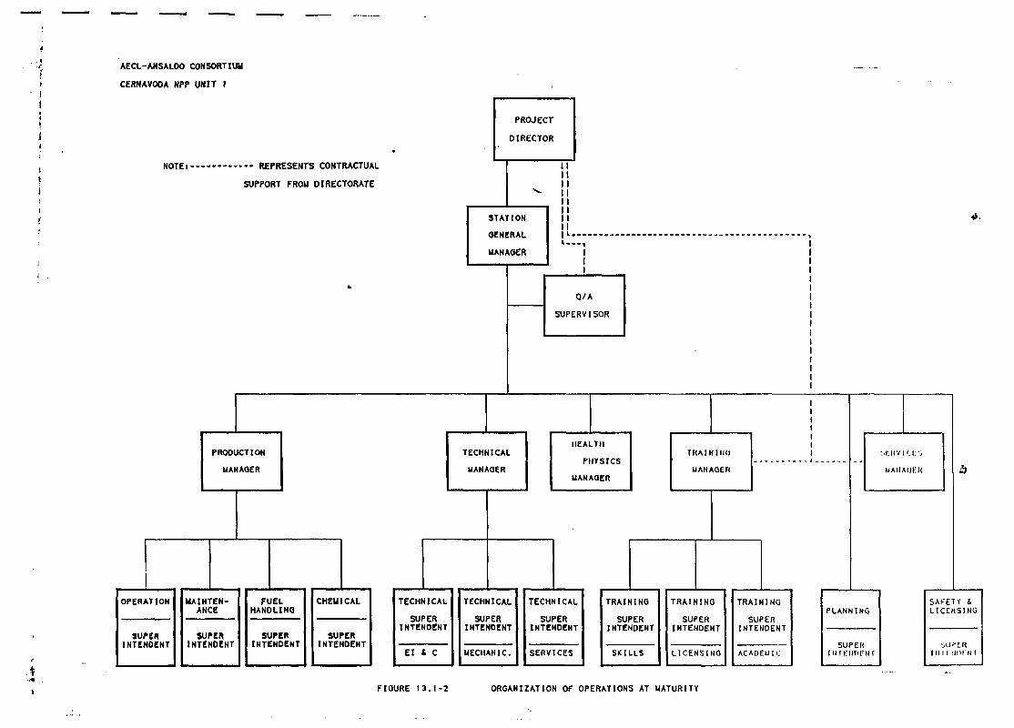
AECL-ANSALDO CONSORTIUM
CERNAVOOA NPP UNIT 1
NOTEi• --- REPRESENTS CONTRACTUAL
SUPPORT FROM DIRECTORATE
PROJECT
DIRECTOR
STATION
OENERAL
MANAGER
PRODUCTION
MANAOER
OPERATION
SUPERINTENOCNT
II
I
Q/A
SUPERVISOR
TECHNICAL
MANAOER
MAINTEN-ANCE
SUPERINTENDENT
FUELHANDLING
SUPERINTENDENT
CHEMICAL
SUPERINTENDENT
TECHNICAL
SUPERINTENOENT
El 1 C
HEALTH
PHYSICS
MANAGER
TECHNICAL
SUPERINTEHDENT
MECHANIC.
TECHNICAL
SUPERtNTENOENT
SERVICES
FIGURE 13 .1 -2 ORGANIZATION OF OPERATIONS AT MATURITY
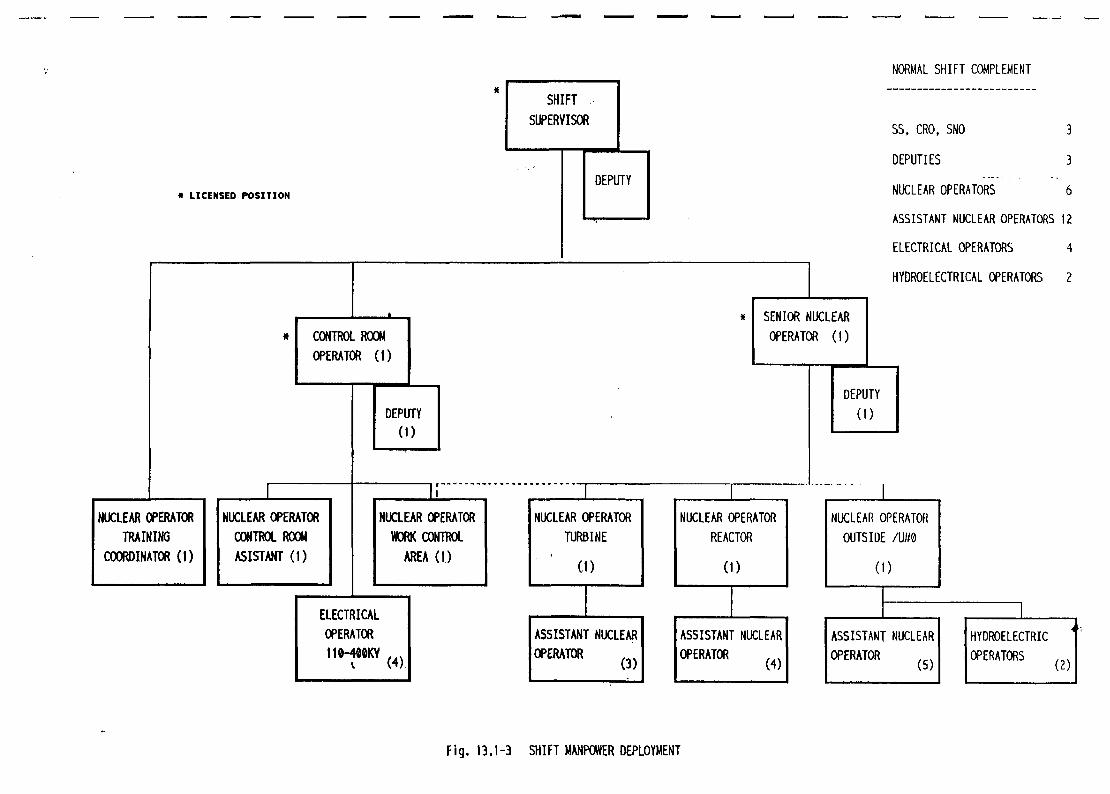
• LICENSED POSITION
CONTROL ROOMOPERATOR (I)
NUCLEAR OPERATORTRAINING
COORDINATOR (I)
1NUCLEAR OPERATORCONTROL ROOMASISTANT (1)
DEPUTY(I)
NUCLEAR OPERATORWORK CONTROL
AREA (I)
ELECTRICALOPERATOR110-400KY
(4)
1NUCLEAR OPERATOR
TURBINE
(I)
ASSISTANT NUCLEAROPERATOR
SENIOR NUCLEAROPERATOR (1)
DEPUTY(I)
NORMAL SHIFT COMPLEMENT
SS, CRO, SNO 3
DEPUTIES 3
NUCLEAR OPERATORS 6
ASSISTANT NUCLEAR OPERATORS 12
ELECTRICAL OPERATORS 4
HYDROELECTRICAL OPERATORS 2
NUCLEAR OPERATORREACTOR
(0
INUCLEAR OPERATOROUTSIDE /U«0
(I)
ASSISTANT NUCLEAROPERATOR
(4)
ASSISTANT NUCLEAROPERATOR
HYDROELECTRICOPERATORS (2)
Fig. 13.1-3 SHIFT MANPOWER DEPLOYMENT
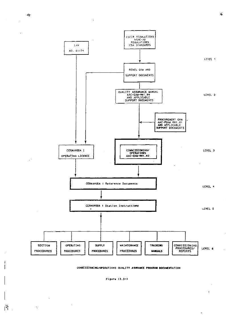
4-r
LAV.
NO. 61/74
ISCIR .-.EC-OLATICNS
REGULATIONSCSA STAXOAROS
LEVEL I
RENcL CAM AND
SUPPORT DOCUMENTS
QUALITY ASSURANCE MAKUALAAC-QAU-M1 .00ANO APPLICABLE
SUPPORT DOCUMENTS
LEVEL 2
PROCUREMENT QAMAAC-PQAM 001.01ANO APPLICABLE
SUPPORT DOCUMENTS
CERNAVOOA I
OPERATING LICENCE
i
COMMISSIONING/OPERATIONS
AAC-QAM-*««.«2
1CERNAVOOA ! Reference Documents 1
LEVEL 3
LEVEL
CERNAVOOA 1 S t a t i o n I n s t r u c t i o n s•-EVEL 5
SECTION
PROCEDURES
OPERATING
PROCEDURES
SUPPLY
PROCEDURES
MAINTENANCE
PROCEDURES
TRAINING
UAHUALS
COMMISSIONINGPROCEDURES/
REPORTSLEVEL 6
COUMISSIOKING/OPERATIONS QUALITY ASURAJKE PROGRAK OOCUUEKTATIOH
Figure 13.3-1
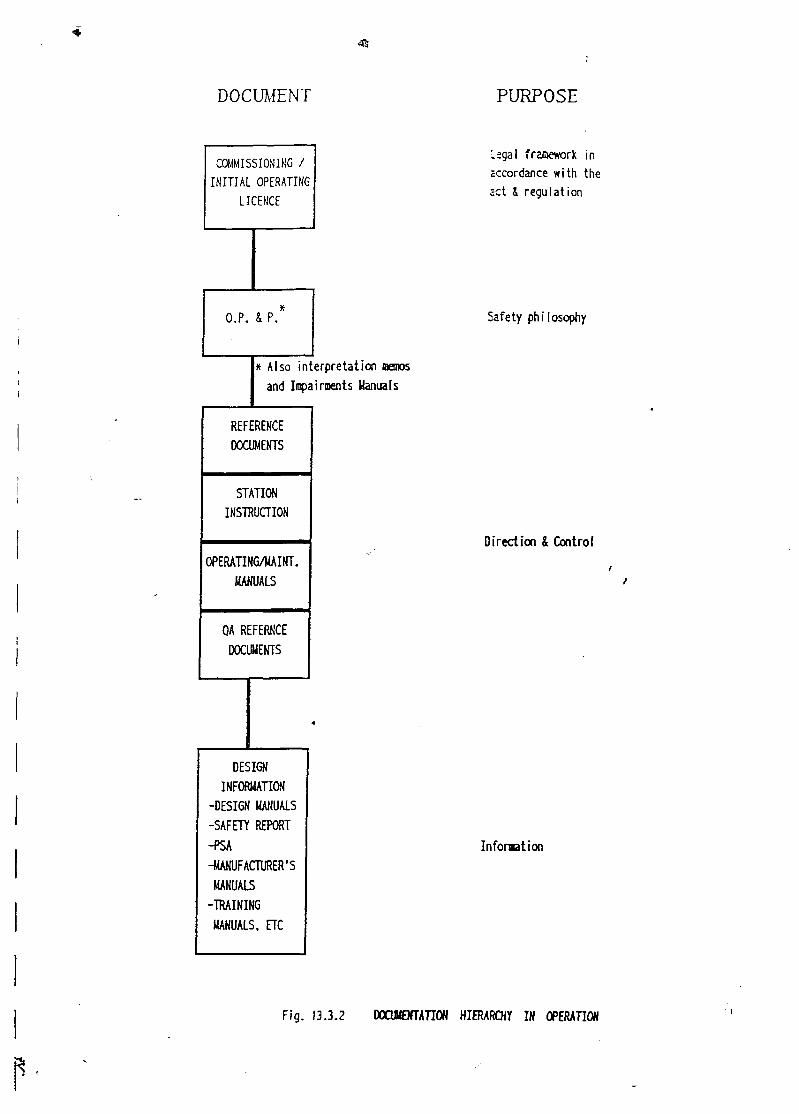
•Sir
DOCUMENT PURPOSE
COMMISSIONING /INITIAL OPERATING
LICENCE
Legal framework inaccordance with the;ct i regulation
O.P. & P. Safety philosophy
* Also interpretation nemosand Impairments Manuals
REFERENCEDOCUMENTS
STATIONINSTRUCTION
OPERATING/MAINT.MANUALS
QA REFERKCEDOCUMENTS
DESIGNINFORMATION
-DESIGN MANUALS-SAFETY REPORT-PSA-MANUFACTURER'SMANUALS
-TRAININGMANUALS, ETC
Direction & Control
Information
Fig. 13.3.2 DOCUMENTATION HIERARCHY IN OPERATION
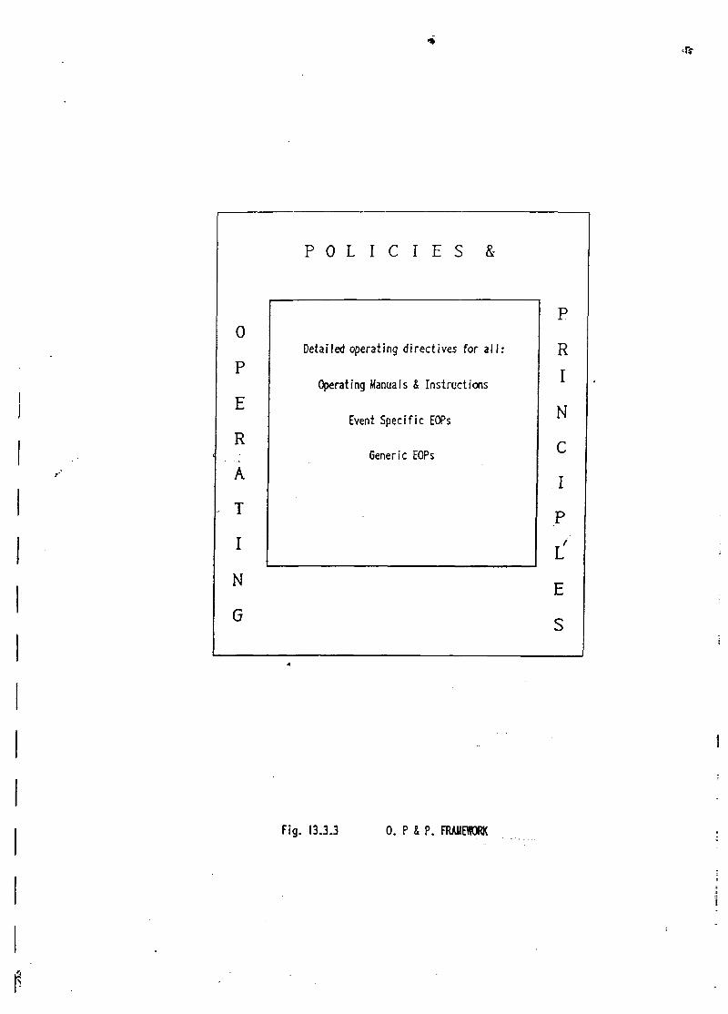
0
p
E
R
A
T
I
N
G
P O L I C I E S &
Detailed operating directives for a l l :
Operating Manuals & Instructions
Event Specific EOPs
Generic EOPs
-
P
R
I
N
C
I
P
L
E
S
Fig. 13.3.3 0 . P 4 P . FRAMEWORK
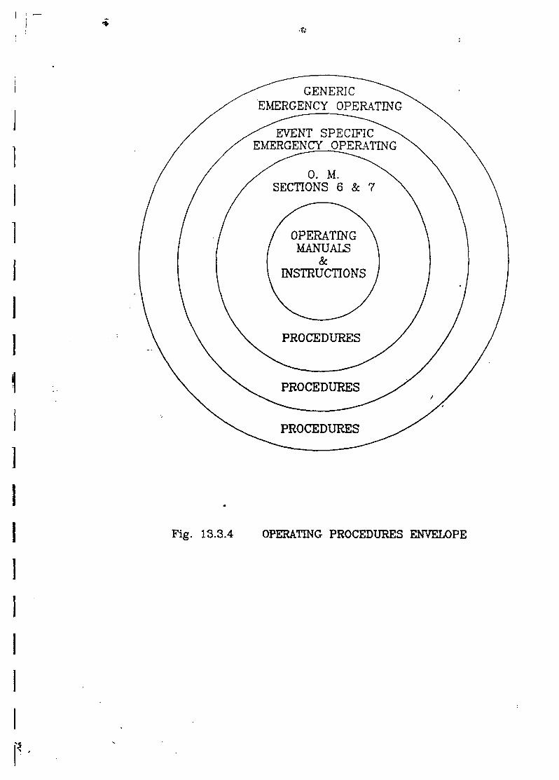
GENERICEMERGENCY OPERATING
EVENT SPECIFICEMERGENCY OPERATING
0. M.SECTIONS 6 & 7
OPERATINGMANUALS
&INSTRUCTIONS
PROCEDURES
PROCEDURES
PROCEDURES
Fig. 13.3.4 OPERATING PROCEDURES ENVELOPE
if
ATTACHMENT 3
Flow Chart of Raw Service Water Systems
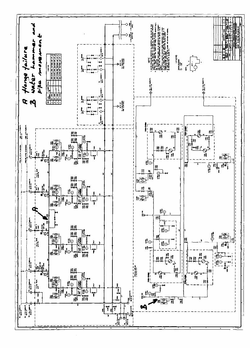
ATTACHMENT 4
Information Report "Raw Service Water Systems -
Resolution of Outstanding Problems"
1994-07-31
ECL-ANSALDO ConsortiumProject Management Team
IR-71310-01Rev.0.
INFORMATION REPORT
RAW SERVICE WATER SYSTEM
RESOLUTION OF OUTSTANDING PROBLEMS
PREPARED BY:
REVIEWED BY:
APPROVED BY:
S. ALIKHANPRODUCTION MANAGER
C. GAROFALODEPUTY GENERAL MANAGER (ENGG./QS)
J.D. SOMMERVILLESTATION GENERAL MANAGER
DATED: 94 JULY 31
AECL-ANSALDO CONSORTIUM IR-71310-01Rev.0.
TABLE OF CONTENTS
0 INTRODUCTION
1. PROTECTION AGAINST WATER HAMMER-AIR INGRESS
2. SYSTEM VENTING AND MONITORING CAPABILITY
3. PROTECTION AGAINST WATER HAMMER DUE TO PHASESEPARATION
4. REVIEWING INTEGRITY OF PRESSURE BOUNDARY
5. PROTECTION AGAINST LOW FLOW OPERATION OF RSW PUMP
6. RELIABILITY OF PUMP DISCHARGE MV OPERATION
7. RELIABILITY OF PRESSURE CONTROL VALVES, PCV-310 TO 313
8. RELIABILITY OF PUMP BEARING COOLING SYSTEM
9. RSW SYSTEM INITIAL FILL PROCEDURE
10. HANDLING SCREEN WASH DEBRIS
11. RELIABILITY OF FIELD INSTRUMENTATION
12. RELIABILITY OF MECHANICAL EQUIPMENT
13. PROVISION OF BACK-UP COOLING ON LOSS OF RSW
14. DESIGN DOCUMENTATION
Page 2 of 20
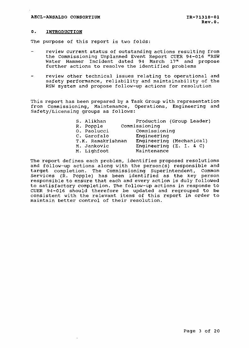
AECL-ANSALDO CONSORTIUM IR-71310-01
Rev.0.
0. INTRODUCTION
The purpose of this report is two folds:review current status of outstanding actions resulting fromthe Commissioning Unplanned Event Report CUER 94-016 "RSWWater Hammer Incident dated 94 March 17" and proposefurther actions to resolve the identified problems
review other technical issues relating to operational andsafety performance, reliability and maintainability of theRSW system and propose follow-up actions for resolution
This report has been prepared by a Task Group with representationfrom Commissioning, Maintenance, Operations, Engineering andSafety/Licensing groups as follows:
S. Alikhan Production (Group Leader)R. Popple CommissioningO. Paolucci CommissioningC. Garofalo EngineeringT.K. Ramakrishnan Engineering (Mechanical)M. Jankovic Engineering (E. I. & C)M. Lighfoot Maintenance
The report defines each problem, identifies proposed resolutionsand follow-up actions along with the person(s) responsible andtarget completion. The Commissioning Superintendent, CommonServices (R. Popple) has been identified as the key personresponsible to ensure that each and every action is duly followedto satisfactory completion. The follow-up actions in response toCUER 94-016 should therefore be updated and regrouped to beconsistent with the relevant items of this report in order tomaintain better control of their resolution.
Page 3 of 20
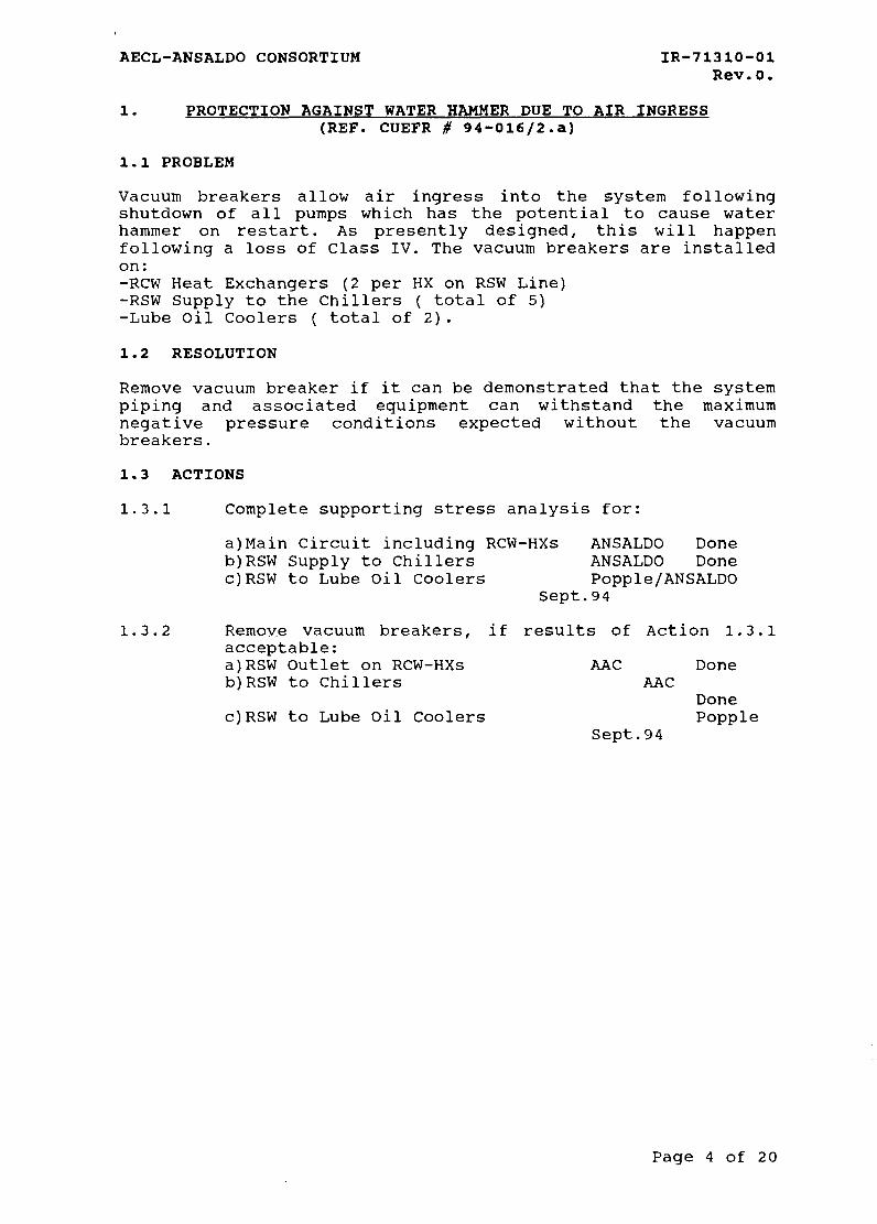
AECL-ANSALDO CONSORTIUM IR-71310-01Rev.O.
1. PROTECTION AGAINST WATER HAMMER DUE TO AIR INGRESS
(REF. CUEFR # 94-016/2.a)
1.1 PROBLEM
Vacuum breakers allow air ingress into the system followingshutdown of all pumps which has the potential to cause waterhammer on restart. As presently designed, this will happenfollowing a loss of Class IV. The vacuum breakers are installedon:-RCW Heat Exchangers (2 per HX on RSW Line)-RSW Supply to the Chillers ( total of 5)-Lube Oil Coolers ( total of 2).1.2 RESOLUTION
Remove vacuum breaker if it can be demonstrated that the systempiping and associated equipment can withstand the maximumnegative pressure conditions expected without the vacuumbreakers.
1.3 ACTIONS
1.3.1 Complete supporting stress analysis for:
a)Main Circuit including RCW-HXs ANSALDO Doneb)RSW Supply to Chillers ANSALDO Donec)RSW to Lube Oil Coolers Popple/ANSALDO
Sept.94
1.3.2 Remove vacuum breakers, if results of Action 1.3.1acceptable:a)RSW Outlet on RCW-HXs AAC Doneb)RSW to Chillers AAC
Donec)RSW to Lube Oil Coolers Popple
Sept.94
Page 4 of 2 0
AECL-ANSALDO CONSORTIUM IR-71310-01Rev.O.
2. SYSTEM VENTING AND MONITORING CAPABILITY(REF. CUEFR # 94-016/lg,li,2b,2c,3a)
2.1 PROBLEM
Inadequate venting capability to ensure system is free fromentrained air. Also there are no means designed to monitor thatthe system is in fact free from air during normal operation,except for the line downstream of ECC-HX.
2.2 RESOLUTION
Design and install suitable vent lines at all high points in thesystem which have the potential for accumulation entrained air.Also install sight glasses at strategic locations for theoperator to monitor system status and take necessary action torefill the system, as required. Where operator access is notfacilitated, install level switches (conductivity probes) similarto what has already been provided for return line from ECC-HX.Ensure that all vents operating normally under vacuum areprovided with double isolating valves and a screwed cap inaccording with ANSALDO 71310-N001-ST Sec. 3.1.1.1.
2.3 ACTIONS
2.3.1 Determine vent locations based on detailed fieldinspection of the system layout, including thefollowing:-RSW pump discharge-Main Headers to T/B-RCW Heat Exchangers Inlet/Outlet-RCW HX outlet Header-Supply to Chillers-Supply to Lube Oil Coolers
Popple/Capello July 94
2.3.2 Design and install vent lines to meet the requirementsof Section 2.2 above.
Popple/Capello Sept. 94
2.3.3 Design and install sight glasses or level switches tomeet the requirements of Section 2.2 above.
Popple/Jankovic Sept. 94
Page 5 of 20
AECL-ANSALDO CONSORTIUM IR-71310-01Rev.0.
3. PROTECTION AGAINST WATER HAMMER DUE TO PHASE SEPARATION(CUEFR # 94-016/4a,4b,4a,4e,4f,5a,5b,6a)
3.1 PROBLEM
Following RSW pump trip and closure of its discharge check valve,a rarefaction wave is potentially generated downstream becauseof the high momentum associated with the flow, creating a vapourcavity that subsequently collapses under impingement of theliquid column when the flow begins to reverse. Key parameter thataffects the resulting pressure pulse is the speed at which thecheck valve closes. The existence of vacuum breakers do notsignificantly affect this phenomenon. It is therefore importantto ensure that the closure time of the check valves is set to thedesign value of equal to or greater than 8 seconds.Without the vacuum breakers, phase separation at high points inthe system could lead to water hammer on pump restart. Thisphenomenon is not of concern in the main RSW circuit includingthe RCW Heat Exchangers and the Chillers and the ECC HeatExchangers as the minimum pressure reached is well above thesaturation pressure of the water thereby precluding any vapourformation. The lube oil circuit present a potential concern sinceits piping is located at much higher elevation (113 m) . Thisconcern is addressed in Section 3.2.3 below.
3.2 RESOLUTION
3.2.1 Ensure that the RSW Pump discharge check valve are setto close slowly. This will "soften" the dynamicpressure transient downstream of the check valve onpump shutdown. Ansaldo analysis has shown that theresulting pressure pulse is well within the designcapability with an 8 second closing time of the checkvalve as specified by design. The check valve closuretime can be tested and adjusted using the hydraulicdamper mechanism.
3.2.2 Start the RSW Pump with its discharge MV closed butdesigned to open simultaneously. This will allow a"soft" restart and avoid potential pressure transientsin the system. (Note that the pump manufacturer,AVERSA, has now agreed to starting the pump with itsdischarge MV initially closed but signalled to opensimultaneously to full open position within 60seconds). The discharge MV would also be designed toautomatically close on a Pump trip to avoid anyreverse flow should the discharge valve fail to close.This feature would simplify the design and eliminatethe need for additional logic provided to close MV ondifferential pressure across the RSW Pump.
3.2.3 Automatically close Lube Oil Coolers TCV-315/316 onloss of pressure downstream of Lube Oil Cooling Pumps(P09 and P10) and reset when the pressure is restored.This will box-up the piping upstream therebyminimizing the tendency for the piping to drain to theSiphon Basin.
Page 6 of 20
AECL-ANSALDO CONSORTIUM IR-71310-01Rev.O.
The Lube Oil Cooling Pumps are MCC loads. As presentlydesigned, they would start automatically onrestoration of Class III. This is undesirable for tworeasons:-water hammer may result due to presence of potential2-phase mixture at high points in the piping-the pumps will start before RSW Pumps are sequencedin, without adequate suction pressure conditions.These pumps are not required for service followingloss of Class IV (Ref. Ansaldo 71310-N001-ST Section3.2.1.3). and therefore should be removed fromautomatic restart on restoration of Class III. Theoperator will manually start these pumps afterensuring that the piping is refilled using RSW Pumphead.
3.3 ACTIONS
3.3.1 Confirm closing time of RSW Pump discharge CheckValves to be equal to or greater than 8 seconds.
Popple August 94
3.3.2 Confirm closing and opening time of Pump discharge MVsto be of the order of 30 seconds.
Popple August 94
3.3.3 Modify RSW Pump start to be conditioned on itsdischarge MV closed. The MV to be designed to open andclose automatically as function of Pump status i.e.signalled to open on pump start and to close on pumpshutdown. The MV handswitch to be located on PL # 14in MCR where the RSW Pump handswitch is alreadylocated.
Popple/Jankovic S e p t .94
3.3.4 Delete existing logic for closing pump discharge MV onpump differential pressure. It is no longer requiredin the light of modification proposed in Section 3.2.2above.
Popple/Jankovic Sept.94
3.3.5 Provide an over-ride permissive on Lube Oiltemperature control valves (TCV-315/316) to close onloss of pressure downstream of Lube Oil Cooling PumpsP09/P10 to be automatically reset on restoration ofpressure.
Popple/Jankovic S e p t .94
3.3.6 Prevent automatic restart of Lube Oil Cooling Pumps(P09 and P10) on restoration of Class III. TheOperator will manually restart these pumps afterensuring that the piping is fully vented.
Popple/Jankovic Sept. 94
3.3.7 Review and confirm operating strategy for lube oilcooling system following loss of Class IV as proposedin Section 2.3 above.
Page 7 of 20
AECL-ANSALDO CONSORTIUM
Popple/Ansaldo
IR-71310-01Rev.0.
S e p t .94
4. REVIEWING INTEGRITY OF PRESSURE BOUNDARY(REF. CUEFR 94-016/lf)
4.1 PROBLEM
The integrity of the equipment and piping should be demonstratedto be acceptable for service following the water hammer. Performnecessary remedial work and pressure testing to demonstrateavailability for service.
4.2 RESOLUTION
4.2.1 Perform necessary inspections, NDE and pressuretesting of the equipment, mechanical andinstrumentation, as well piping and hangers toascertain their integrity. The scope of work shouldcover the portions of the system located in theTurbine Building, Chiller Building and Pump Housesubjected to water hammer forces.
4.2.2 Perform detailed examination of failed flange (valve7131-V3 0) in Turbine Building and determine the needfor further inspections of the piping system.
4.2.3 Perform necessary repairs and subsequent NDE/pressuretesting to confirm acceptability for service.
4.3 ACTIONS
4.3.1 Complete visual and radiographic examination offlanges similar to the one failed during the incidentfor valves located in the Turbine Building.
Popple/Pastorino Done
4.3.2 Complete metallographic examination of the failedflange to determine possible intiation of the crack.
Pastoprino/Ansaldo Done
4.3.3 Review historical NDE records for potential problemsduring the construction phase and identify the needfor further inspections.
Pastorino Done
4.3.4 Perform additional field inspections and NDE toconfirm findings in Action 4.3.3.
Popple/Pastorino August 94
4.3.5 Complete necessary repairs with additionalconfirmatory NDE to ascertain suitability for service.
Popple/Pastorino August 94
Page 8 of 20
AECL-ANSALDO CONSORTIUM IR-71310-01
Rev.0.
5. PROTECTION AGAINST LOW FLOW OPERATION OF RSW PUMP
5.1 PROBLEMThe RSW Pumps must be tripped automatically in case the ratedflow is not achieved within 60 seconds of the pump start. Thepumps are not designed to run stably under partial flowconditions.
5.2 RESOLUTION
The Pump flow would be affected if its discharge MV or the PCVsdownstream of the RCW Heat Exchangers are not sufficiently opento allow rated flow through the pump. One way to protect the pumpagainst this situation is to automatically trip it in case itsdischarge pressure is higher than its nominal value for safeoperation for more than 60 seconds.
5.3 ACTIONS
5.3.1 Determine suitable setpoint for pump high pressuretrip.
Popple/Ramakrishnan Aug. 94
5.3.2 Implement sustained high discharge pressure trip logicusing existing instrumentation provided for each pump(DPT-501 A & C to DPT-504 A & C for PI to P4respectively)
Popple/Jankovic Sept. 94
5.3.3 Provide Analog Input indication and alarm on high andlow pressure. Low alarm to be conditioned in 10seconds following pump start.
Popple/Jankovic Sept. 94
Page 9 of 20
AECL-ANSALDO CONSORTIUM IR-71310-01Rev.0.
6. RELIABILITY OF PUMP DISCHARGE MV OPERATION
6.1 PROBLEM
Present design requires the motorized bypass valve to be openbefore the Pump discharge MV can be opened. Also the Pump cannotbe started unless the discharge MV is fully open. The controlhandswitches for the main MV and its bypass are located in thePumphouse while the Pump handswitch is located in the MainControl Room. The valve limit switches are unreliable. All ofthis makes the design unnecessarily complicated and unreliable.
6.2 RESOLUTION
The interlock between the main MV and its bypass can beeliminated if it can be demonstrated that the main MV can beopened with its bypass MV closed on Pump start. If this is notfeasible, the bypass MV could be left open with its isolatingvalve partially open provided this configuration is acceptablefrom a safety point of view, i.e. loss of RSW flow from thesystem should the check valve fails open on a pump trip.
6.3 ACTIONS
6.3.1 Test opening capability of the Pump main discharge MVagainst system pressure while monitoring margin tovalve trip on motor overload and or torque.
Popple August 94
6.3.2 Review the test results and determine further actionrequired to achieve acceptable level of reliable valveperformance. This may include:-maintaining bypass closed if above test is successful-maintaining bypass line throttled open sufficient toequalize pressure but not to adversely affect systemflow in case of stuck open check valve.
Popple/Ramakrishnan August 946.3.3 Delete interlock between the main MV and its bypass.
Popple/Jankovic August 94
Page 10 of 20
AECL-ANSALDO CONSORTIUM IR-71310-01Rev.0.
7. RELIABILITY OF PRESSURE CONTROL VALVES PCV-310 TO 313(REF: CUEFR 94-016/lj)
7.1 PROBLEM
The Pressure Control Valves downstream of the RCW Heat Exchangershave yet to demonstrate reliable operation on a long term basis.The problems include jerky actuator movement, actuator vibrationwhen valve is operating in throttled condition, anduncertain/long response time. The valve actuators may be undersized for the application. Also the configuration of the actuatorshaft to the valve stem may need to be modified to achieve smoothtransfer of forces. Two of the four PCVs are Fisher Valvesimported from Italy and the other two are local Romanianmanufacture. Both the Romanian Valves (PCV312/313) are presentlyunserviceable.
7.2 RESOLUTION
Replace the two Romanian PCVs with Fisher Valves from Unit 2. Inconsultation with Fisher Control, review in detail thecommissioning experience to date to establish root cause(s) ofthe problems. This coupled with experience feedback from othersimilar applications should provide the necessary information totroubleshoot known and potential problems to assure long termreliability of the PCVs.
7.3 ACTIONS
7.3.1 Determine PCV flow/position characteristics todetermine optimum range for smooth control (Ref. memoEQSGM # 2431).
Popple/Ramakrishnan Aug. 94
7.3.2 In consultation with Fisher Control, determineadequacy of actuator design and associated air linesand controls to perform acceptably. Make necessarymodifications,if possible, or procure alternateactuator to resolve the problem.
Popple/Ramakrishnan August 94
7.3.3 Replace the Romanian made PCVs with Fisher Valves fromUnit# 2.
Popple August 94
Page 11 of 20
AECL-ANSALDO CONSORTIUM IR-71310-01Rev.0.
8. RELIABILITY OF PUMP BEARING COOLING SYSTEM
8.1 PROBLEM
The RSW Pump trips on loss of flow from the bearing cooling pumpsin spite of the fact that the Pumps are designed to provide theirown back up bearing cooling should the external supply fail. Theflow switches are located on the external supply line only anddo not "see" the flow from the Pump itself should the externalsupply fail. Besides, the flow switches are unreliable and aredifficult to be calibrated in a repeatable manner. The back-upcooling supply is unfiltered and has the potential to causebearing damage if used for an extended period of time.
8.2. RESOLUTION
The flow switches should be deleted from design. The adequacy ofbearing supply should be determined from the pressure signalinstalled in the common line between the external source and thebearing cooling flow generated by the pump itself. The Pumpshould be designed to trip on low bearing cooling pressure witha 10 s time delay. This would allow RSW Pump start withoutexternal bearing cooling supply. Also consideration should begiven to installing a duplex strainer on the back-up bearingcooling supply from the RSW pump itself.
8.3. ACTIONS
8.3.1 Delete low flow switches installed on the externalbearing cooling supply line as well as low flow alarmand trip.
Popple/Jankovic Sept. 94
8.3.2 Determine suitable set point for bearing cooling lowpressure alarm and trip.
Popple/Ramakrishnan August 94
8.3.3 Provide low pressure alarm and trip with 10 secondtime delay.
Popple/Jankovic Sept. 94
8.3.4 Review the need and feasibility for installing aduplex strainer to clean the Pump supplied bearingcooling flow.
Popple/Ramakrishnan August 94
Page 12 of 20
AECL-ANSALDO CONSORTIUM IR-71310-01Rev.0.
9. RSW SYSTEM INITIAL FILL PROCEDURE
9.1 PROBLEM
At the present time, there is no safe method for initiallyfilling the system from a drained state. Normal procedureinvolves running the pump with its small discharge bypass valveopen (main MV closed) to fill the system slowly. This is howevernot feasible at Cernavoda since the RSW Pumps are not designedto run for extended periods at low flow conditions. To date thesystem has been filled using external source from fire waterwhich is very tedious and time consuming. A viable procedure isrequired to fill the system in a reasonable time frame withoutrunning the risk of pump damage due to low flow operation orcreating the potential for water hammer.
9.2. RESOLUTION
The problem exists only when the system is drained and no pumpsare in service. As long as at least one pump is in service, whichwill be case for normal plant operation, any portion of thesystem drained down for maintenance can be filled by controllingthe supply and vent valves. Therefore the problem exists only forinitial fill or refills during Phase A commissioning, and whenthe system is completely removed for service for periodicinspection during normal operation every 5 years or so dependingon actual experience.
There are three possible options to resolve this problem:
9.2.1 Using one RSW Pump to fill the system. The main systemconfiguration will include three heat exchangers inservice with their vent valves fully open and allother system valves and PCV selected open to thesiphon basin. The Pump is started with its dischargeMV closed and selected auto to open simultaneouslywith the Pump start to allow the flow to build throughthe circuit over 30 seconds or so. The system flow isexpected to correspond to "channel flow" with littleor no entrained pockets of air. Once the flow isstabilized, gradually throttle close on the PCVs inservice to raise back pressure in the system, whileobserving pump discharge pressure to remain withinacceptable limits, to complete the venting process. Itis worth noting that this mode of operation hasalready been demonstrated during the runs with onepump in service without any problem. The water hammeron 94 March 17 resulted when the second pump wasstarted without first fully venting the system whichchanged the system flow conditions from an openchannel to forced circulation leading to pockets ofair trapped in the piping downstream of the RCW heatexchangers.
9.2.2 Use an external vacuum priming source to fill thesystem before starting the pump. Consider using theCondenser waterbox priming system as a means toachieve this objective.
Page 13 of 20
AECL-ANSALDO CONSORTIUM IR-71310-01Rev.0.
9.3. ACTIONS
9.3.1 Perform analytical assessment of Option 2.1 to confirmthe suitability of the proposed initial fill procedureusing one RSW Pump.
Popple/Ansaldo Aug. 94
9.3.2 Subject to acceptable results of Action 3.1, developthe necessary procedures for field demonstration.
Popple Aug. 94
9.3.3 Investigate the feasibility of connecting theCondenser Waterbox priming system to prime the RCWheat exchangers for potential consideration shouldAction 3.1 not prove to be acceptable.
Popple/Ramakrishnan Sept. 94
Page 14 of 20
AECL-ANSALDO CONSORTIUM IR-71310-01Rev.0.
10. HANDLING SCREEN WASH DEBRIS
10.1 PROBLEM
The Screen wash debris handling system gets clogged and must beimproved to avoid flooding the channel in the pump house atelevation 100 m.
10.2. RESOLUTION
Increase the mesh size of the flat screens and the debriscollection cone to minimize unnecessary plugging.
10.3. ACTIONS
10.3.1 Raise an NCR to increase the mesh size of the screensand the debris collection cone consistent with thesize of the travelling screens.
Popple/Ramakrishnan Aug. 94
Page 15 of 20
AECL-ANSALDO CONSORTIUM IR-71310-01Rev.O.
11. RELIABILITY OF FIELD INSTRUMENTATION
11.1 PROBLEM
Field Instrumentation are generally of poor quality which leadto increased maintenance and unreliability. Control Panels inPumphouse run very warm due to lack of ventilation. Levelswitches in sumps are not suitable for operation in humidenvironment and fail frequently.
11.2. RESOLUTION
Resolve the problems through NCR or Site Disposition where theequipment does not meet the design requirements in terms ofcapability or reliability.
11.3. ACTIONS
11.3.1 Prepare a comprehensive list of equipment problems,known and potential, for review by the Task Group.
Popple Aug. 94
11.3.2 Raise NCR on equipment that do not meet the designrequirement for performance and reliability.
Popple Aug. 94
11.3.3 Disposition NCR and or raise necessary SD/DCN toresolve problems with control panels, level switches,indicating bulbs etc.
Popple/Jankovic Sept. 94
Page 16 of 20
AECL-ANSALDO CONSORTIUM IR-71310-01Rev.0.
12. RELIABILITY OF MECHANICAL EQUIPMENT
12.1 PROBLEM
Some of the Romanian supplied mechanical equipment are veryunreliable and require excessive maintenance attention. Thisincludes the "Timpuri Noi" air compressor units in the Pump house(used to supply air to the brakes for CCW Pumps and to thebubbler units to measure water levels) as well as the AVERSA/UMEBsump pumps. In the former case, it has not been possible to buyspares to continue maintenance.
12.2. RESOLUTION
Review performance history of equipment to date. Plan to replaceitems which have not demonstrated acceptable level ofperformance.Regarding the reliability of instrument air in the Pump House,there two possible options:
Provide instrument air from Service BuildingReplace existing compressor units with more reliable unitswith proven performance and availability of spares.
12.3. ACTIONS
12.3.1 Prepare a detailed assessment of equipmentperformance. Raise NCR where the equipment is notcapable of meeting the design requirements.
Popple Aug. 94
12.3.2 Perform engineering feasibility study with costestimates and schedule implications on the two optionsto improve availability of instrument air in the PumpHouse.
a) Supply from Service Building to a storage tank locatedin the Pump House from where the air can bedistributed to various loads
b) Replacing existing Compressors with more reliablepackageunits.
Popple/Ramakrishnan August 94
12.3.3 Based on the results of Action 3.2, raise necessarydesign documentation for field implementation.
Popple/Ramakrishnan Sept. 94
Page 17 of 20
AECL-ANSALDO CONSORTIUM IR-71310-01
Rev.0.
13. BACK-UP COOLING ON LOSS OF RSW
13.1 PROBLEMThe present design does not ensure continued availability of theClass III diesels and the Chillers following a loss of RSW. Arecent design change (DCN # 229) has provided a back-up firewatersupply to the Instrument Air Compressors which can be valved inby the operator within one hour following a loss of ChilledWater. The loss of Chilled Water to essential loads, eg. the MCRand the Electrical Bay, would adversely impact on theavailability of electrical supplies and therefore theavailability of group 1 heat sink. The only back-up heat sink isthe automatic Boiler Make-up Water from Dousing Tank (BMW) andEWS powered through EPS to supply water to the boilers. Thisleads to unacceptably high event frequency for core damage dueto loss of heat sink. Loss of RSW to Standby Diesel Generatorsmakes them unavailable to provide Class III power in case of lossof Class IV. Cross links between safety related systems shouldnot be allowed by design according to the AECL Design Guide # 9" B.O.P. Safety Related Systems Performance Requirements". (Alsorefer to RENEL Letter # 42/14.1.94, Rotaru to Boucher AAC # 15715dated 94.01.18 and memo McQuade to Ramakrishnan File 79-00101,DGM(Eng)-1065). Back-up cooling to two of the four Class IIIDiesels and one Chiller is required to meet the safety designrequirements.
Note that the design does provide for isolating the odd and evenloops in the Pumphouse by automatically closing the motorizedvalves MV-308 and MV-309 in an attempt to isolate the failedloop. This is however inconsequential as the two loops areconnected via manual valves in the Turbine Building. Also thereare other common mode events related to the screen houseperformance which can lead to total loss of RSW System. Thereforea back-up to RSW is necessary to meet the safety designrequirements.
13.2. RESOLUTION
Back-up cooling requirements to four Class III Diesels and oneChiller are calculated to be 790 m3/h (4*110+350) and can beprovided using two of the four WTP raw water supply pumps (7161-P033 to 036) located in the Pump house "Pila Dubla". Necessarycontrol logic will have to be automatically initiated to divertany flow to the Water Treatment Plant Tank 71610-TK1.1) toprovide back-up cooling on loss of RSW header pressure with anappropriate time delay to avoid starting the back-up systemunnecessarily following a loss of Class IV.
Also automatic load shedding feature will have to be provided onthe Chilled Water system to ensure that, under these conditions,only the essential safety related loads are served which areestimated to be met with less than one Chiller capacity.
Page 18 of 20
AECL-ANSALDO CONSORTIUM IR-71310-01Rev.0.
13.3. ACTIONS
13.3.1 Define design requirements for back-up cooling toClass III Diesels and Chillers.
Popple/McQuade/Conquest July 94
13.3.2 Develop conceptual design to meet these requirements.This includes using the four raw water supply pumps toWTP located in Pila Dubla. Necessary load sheddinglogic will be designed to ensure that only essentialsafety related loads are served. Also only one Chillershould be allowed for operation following loss of RSWand only its RSW flow PV shall be automatically resetto permit back-up cooling.
Popple/Ramakrishnan/Jankovic August 94
13.3.3 Perform confirmatory safety assessment to demonstratethat the DCN meets the safety design requirement.
Popple/Conquest/McQuade August 94
13.3.4 Raise a DCN for management approval and prepare thenecessary design package for field implementation.
Popple/Ramakrishnan/Jankovic Sept. 94
13.3.5 Review the need for existing logic to automaticallyclose MV308 and MV309 with a view to deleting it if itis not required to provide its intended safetyfunction.
Popple/Jankovic/Conquest Sept. 94
Page 19 of 20
AECL-ANSALDO CONSORTIUM IR-71310-01
Rev.0.
14. DESIGN DOCUMENTATION
14.1 PROBLEMThe available design documentation are out of date and do notreflect the as constructed status, especially for theB.O.P.portion of the system design. The design changes proposedin this report will further add to the obsolescence of theavialable design documentation. The reliability report will needto be updated to reflect the impact of design changes proposedhere and to demontrate compliance with the safety performancetargets.
14.2 RESOLUTION
Review, consolidate and update the existing design informationfor B.O.P portion (Turbine Building and Pump House) presentlyavailable through ANSALDO and ISPE. This includes designrequirements, description and the Reliability study.
14.3 ACTIONS
14.3.1 Revise the ANSALDO Design documentation to reflectcurrent status of design, amalgamating the TurbineBuilding and Pump House portion of the system into onedocument.
Popple/Garofalo/ANSALDO Sept. 94
14.3.2 Revise the ANSALDO reliability report to reflect thedesign changes proposed in this Report.
Popple/Garofalo/ANSALDO Sept. 94
Page 20 of 20
ATTACHMENT 5
Station Instruction on Commissioning
Unplanned Event Reports (SI-1365-C7, Rev.1)
1994-06-29
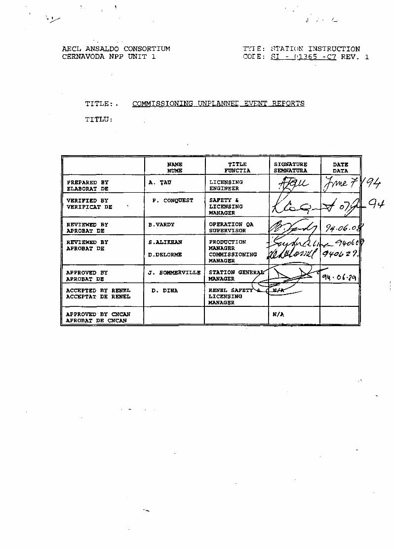
V i.
AECL ANSALDO CONSORTIUMCERNAVODA NPP UNIT 1
TYIE: STATION INSTRUCTIONCOrE: SI - 013 65 -C7 REV. 1
TITLE: -
TITLU:
COMMISSIONING UNPLANNED EVENT REPORTS
PREPARED BYELABORAT DE
VERIFIED BYVERIFICAT DE
REVIEWED BYAPROBAT DE
REVIEWED BYAPROBAT DE
APPROVED BYAPROBAT DE
ACCEPTED BY RENELACCEPTAT DE RENEL
APPROVED BY CNCANAPROBAT DE CNCAN
NAMENOME
A. TAU
P. CONQUEST
B.VARDY
S.ALIKHAN
D.DELORME
J. SOMMERVILLE
D. DINA
TITLEFUNCTIA
LICENSINGENGINEER
SAFETY &LICENSINGMANAGER
OPERATION QASUPERVISOR
PRODUCTIONMANAGERCOMMISSIONINGMANAGER
STATION GENERAZ^MANAGER /
RENEL SAFETY^Si- (LICENSINGMANAGER
SIGNATURESEMNATURA
N/A
DATEDATA
REVISION/DATAREVIZIA/DATA
COMMENTSCOMENTARII
REV. 0 / DEC.93REV.l / JUNE 94 Revise Section 6.5.
AECL/ANSALDO CONSORTIUM SI-01365-C7CERNAVODA NPP UNIT 1 REV.l
CONTENTS
1.0 PURPOSE
2.0 SCOPE
3.0 DEFINITIONS ANDABBREVIATIONS
4.0 REFERENCES
5.0 RESPONSIBILITIES
6.0 PROCEDURE
7.0 FORMS
8.0 APPENDICES
Page 1 of 20
AECL/ANSALDO CONSORTIUM SI-01365-C7CERNAVODA NPP UNIT 1 REV.l
1.0 PURPOSE
This document establishes therequirements for reportingunplanned events duringcommissioning for the followingreasons:
a) to provide documentation ofthe course of the event and thecircumstances surrounding theevent.
b) to provide an assessment onthe root cause(s) of the event.
c) to provide a formal mechanismfor follow-up actions that mightminimize the chances ofrecurrence and/or minimize theimpact of recurrence of suchevents.
2.0
An unplanned event may resultfrom such circumstances asequipment failure, designdeficiencies, abnormalconditions, proceduraldeficiencies, or human error.The event may have caused, orhad the potential to causeinjury, significant economicloss, degradation of plantsafety or Commissioning scheduleslippage. Specific criteriawhich define the eventsrequiring the submission of aCUER are provided in Appendix A.
This document will be supersededby SI-01365-P13_ on the date thecommissioning license is grantedby CNCAN and becomes effective.
Page 2 of 20
AECL/ANSALDO CONSORTIUM SI-01365-C7CERNAVODA NPP UNIT 1 REV.l
3 . 0 D E F I N I T I O N S A N DABBREVIATIONS
3.1 Commissioning UnplannedEvent Report (CUER):
The immediate informationregarding the occurrence ofincidents which requirereporting as defined in this SI,prepared in a pre-printed formatas shown in Section 7.1.
3.2 Unplanned Event Follow-upReport (UEFR)
The report that records theaction taken to respond toassigned follow-up actions,prepared in a pre-printed formatas shown in Section 7.2.
4.0 REFERENCES
4.1 Point Lepreau RD-01364-P5Unplanned Event Reports.
4.2 CernavodS NPP SI-01365-P13Unplanned Event Reports.
5.0 RESPONSIBILITIES
5.1 Station General Manager
Approves and issues CUER, UEFRPackage after applicablereviews.
5.2 Production Manager orCommissioning Manager
Pre-issue review/comment of CUERPackage.
Assigns follow-up actions.
5.3 Operations Superintendent
Pre-issue review/comment of CUERPackage.
Page 3 of 20
KECL/ANSALDO CONSORTIUM SI-013 65-C7CERNAVODA NPP UNIT 1 REV.l
5..4 Originator (Normally ShiftSupervisor or CommissioningSuperintendent)
R e s p o n s i b l e for CUERpreparation.
Submits CUER Form to LicensingSupervisor within a week of theevent or realization of theevent.
Ensures the parties involved areinterviewed in a timely mannerto permit identification of theloot cause (s) of the errors forevents involving human error.
5.5 Licensing Supervisor (orRelegate)
t>n receiving a completed CUERform and within one working day:
*) assigns serial number to CUER
h>) forwards CUER Package forStation Management approval
va
Kfter meeting with Managersassigns formal follow-up actionsby UEFR.mBpon formal issue of the CUER byE|peration Document Centre andnormally within one week,parepares a status report of alloverdue follow-up actions on a•onthly basis for theCommissioning Manager and theproduction Manager.•Issues CUER Index to OperationDocument Centre periodically.
Page 4 of 20
AECL/ANSALDO CONSORTIUMCERNAVODA NPP UNIT 1
6.0 PROCEDURE
6.1 Internal Notification
When a Commissioning UnplannedEvent occurs, the ShiftSupervisor or CommissioningSuperintendent is responsiblefor notifying "on-call" StationManagement or delegate as soonas practical after the event.The nature of the event shoulddictate whether immediate verbalnotification (for example,serious injury) is necessary orwhether notification on the nextwork day is acceptable.Notification on the next workingday by the submission of a CUERis generally adequate.
6.2 Report Preparation
For any of the events listed inAppendix A, the Shift Supervisor/ Commissioning Superintendentis normally responsible toensure that a CommissioningUnplanned Event Report Form iscompleted (Originator). Thereports for events which do notinvolve equipment or personnelunder Shift Supervisor controlwill normally be prepared by therelevant System Engineer.
For events which involve humanerror, the Originator will beresponsible for ensuring thatthe parties involved areinterviewed in a timely mannerto permit identification of theroot cause (s) of the errors.
The report is to be submitted tothe Licensing Supervisor, withinone week of the event orrealization of the event.
Guidelines to assist staff inthe completion of CUER Form asfollows:
SI-01365-C7REV.l
Page 5 of 20
AECL/ANSALDO CONSORTIUMCERNAVODA NPP UNIT:1
a) Event Summary ;•
This section shouli include onlya brief summary of the event.Details of the ;•- event aredocumented in section c) on thesecond page.
b) Conditions Priajr to Event£
List of condition* which had abearing on the Unplanned Event,on the sequence of events, or onthe action taken. ;.
c) Description of
The equipment affected should beincluded. Proceasf transients,initial operator ^actions andresponse of affected systemsshould be described. Thedescription should include timesand be in chronological order.
d) Action Taken
A brief summary affections takento ameliorate the incident. Thissection should provide detailson the time to rectify equipmentproblems, if applicable.
e) Outstanding actions andrecommendations
This section shonGfl itemize thel is t of immediate follow-uprecommendations «jhich mightmitigate future occurrences ofthe incident 3 (proceduralchanges, design changes, etc.)or which would lead to a betterunderstanding of tifee event.
f) Support data
A list of relevant alarmsummaries, WRs, Procedure mark-up and other relevantattachments to CCER should besummarized in this section.
SI-01365-C7REV.l
Page 6 of 20
AECL/ANSALDO CONSORTIUM SI-01365-C7CERNAVODA NPP UNIT 1 REV.l
g) Originator signature
Provision made for signature ofCUER originator.
g) Management review andapproval
Provision is made for StationManagement review and listing ofrecommendations as deemedappropriate, and for the StationManager's approval.
NOTE: Recommendations in theCUER will reflect informationand conditions at time of event;subsequent investigations mayprove some statements andrecommendations to be invalid orunnecessary.
A copy of the standard form usedfor a CUER is presented inSection 7.
Information should be informal,frank in nature and shouldinclude details of the event,actual or potential consequencesof the event, initial actionstaken, immediate follow-upactions (issued WRs, ifapplicable) and recommendedfollow-up actions. Relevantp r i n t - o u t s , m a r k e d - u pprocedures, or flowsheets shouldbe attached as backgroundinformation. Names of personnelinvolved in the incident willnot normally be mentioned andshould be removed from anysupporting documents submittedwith CUER. _However, whererelevant, the CUER originatorshall retain a record ofpersonnel involved forsubsequent follow-up.
The original of CUER is thenrouted for review to theOperations Superintendent, the
•"- /j^ Page 7 of 20
AECL/ANSALDO CONSORTIUMCERNAVODA NPP UNIT 1
Production Manager,Commissioning Manager.
SI-01365-C7REV.l
the
Upon completion of the reviewprocess as described above, theStation General Manager willapprove the CUER for issue byOperation Document Centre.
The Licensing Supervisor willcall a meeting with thefollowing committee, normallywithin one week after the issueof CUER, to review the event,assess root causes and issueappropriate follow-up actions:- Production Manager- Commissioning Manager- Safety & Compliance Manager- other as required.
Note: including Deputies, whereavailable
For certain events, a specialinvestigation team may be set upto make a comprehensive reportto the committee and the StationManager.
Figure 1 represents a simplifiedflowsheet of the sequence androuting of the CUER.
6.3 Event Follow-up Report
From the meeting withCommissioning Manager and/orProduction Manager, theLicensing Supervisor will issueto the relevant Departmentsuperintendents formal follow-upactions.
Each UEFR will clearly identifythe discrete action required andwill assign responsibility tothe head of the relevantdepartment. Guidelines to beused when completing the UEFRform are as follows:
Page 8 of 20
AECL/ANSALDO CONSORTIUMCERNAVODA NPP UNIT 1
a ) U n p l a n n e d E v e n tIdentif icat ion
Provisions is made for CUERnumber and title to facilitatefiling and monitoring of thefollow-up actions.
b) Follow-up Action Required
Actions delegated by the Managerresponsible are to be listed inthis section. The Managerresponsible will assign one ofthree priorities to the follow-up action based on theprobability of recurrence andthe significance of theshortcomings. In addition, atarget completion date which isconsistent with the assignedpriority will be assigned by themanager responsible.
c) Details of Actions Taken
Brief description of actionstaken together with completiondates. If actions aresignificantly different thanrequested, appropriate rationaleshould be stated. Investigationreports, memos, etc., ifapplicable, should be attached.If the assigned action is a longterm project, then this sectioncan be used as an update whensignificant progress has beenmade, however, it will remain asan outstanding action untilcompleted.
d) Relevant Support Data
List of relevant reports, memos,diagrams, marked-up flowsheets,WRs, revised OperatingProcedures and Tests, etc., isto be provided in this section.Support data to be attached toUEFR.
SI-01365-C7REV.l
Page 9 of 20
AECL/ANSALDO CONSORTIUMCERNAVODA NPP UNIT 1
e) Action Status
This section is completed by theManager responsible. Theacceptability of the actiontaken is indicated here.Normally, the UEFR is submittedto the Manager responsible whenthe action is consideredcomplete, however, for long termactions progress updates may besubmitted vgfcen appropriate. Insome cases, if the short termaction is Acceptable, but afurther long term action isindicated, -then provision ismade for the short term actionto be closed - and the furtherlong term • action to beidentified. A new UEFR isassigned for the long termaction to provide for follow-upmonitoring. ~
The original-of the UEFR will beforwarded to the OperationsDocument Centre for filing withthe CUER and copies sent to theactionee and LicensingSupervisor. -A copy of the UEFRform is attached in Section 7.2.
Upon completion of the follow-upaction, theactionee submits theUEFR to him Manager who shallagree that the disposition issatisfactorily and verifiablycompleted. -Copies are thenrouted tD- the LicensingSupervisor and actionee. Theoriginal of "the completed UEFRis forwarded to the OperationDocument Centre for filing withthe CUER, with a copy circulatedto Station Management forinformation.1
The Licensing Supervisor shallmaintain a record of all follow-up recommendations (UEFRs) andtheir currant status. A statusreport of all overdue follow-upactions will be forwarded to the
SI-01365-C7REV.l
POOR QUALITYORIGINAL
Page 10 of 20
AECL/ANSALDO CONSORTIUMCERNAVODA NPP UNIT 1
Technical Manager and ProductionManager on a monthly basis.
6.4 Report ̂ Registration
Serial numbers for the CUERs areassigned by the LicensingSupervisor and are registeredwith Operation Document Centre.
Periodically, the LicensingGroup will issue an updated CUERindex to Operation DocumentCentre.
Reports will be numbered asfollows:
CUER - YEAR - SERIAL NUMBER (C)
6 . 5 Distribution of the Reports
Normal distribution of the CUERsUEFR will be as follows:
Station Management (1 copy)Operations Superintendent (1copy)Commissioning Superintendents(circulation 1 copy)Safety & Compliance Manager (1copy)Operations Superintendents[Chemistry, Health Physics,Training, Maintenance](circulation 1 copy)Operations Quality Assurance (1copy)FCNE Director (1 copy)CNCAN Site Representative (2copies)RENEL-GEN Director (1 copy)Operation Document Centre(Original to File)
[Author (normally Shift•Supervisor) (1 copy)
The distribution of thesereports is limited to the abovelist. Distribution to otherstaff memebers is done only onan "as required" basis.
SI-01365-C7REV.l
Page 11 of 20
AECL/ANSALDO CONSORTIUM SI-01365-C7CERNAVODA NPP UNIT 1 REV.l
Distribution of these reports toothers will be at the discretionof Management
6.6 Records
The original of CUER, UEFR andsupporting data will be filed inpermanent station records.
7.0
7.1 Commissioning UnplannedEvent Report
7.2 Unplanned Event Follow-upReport
Page 12 of 20
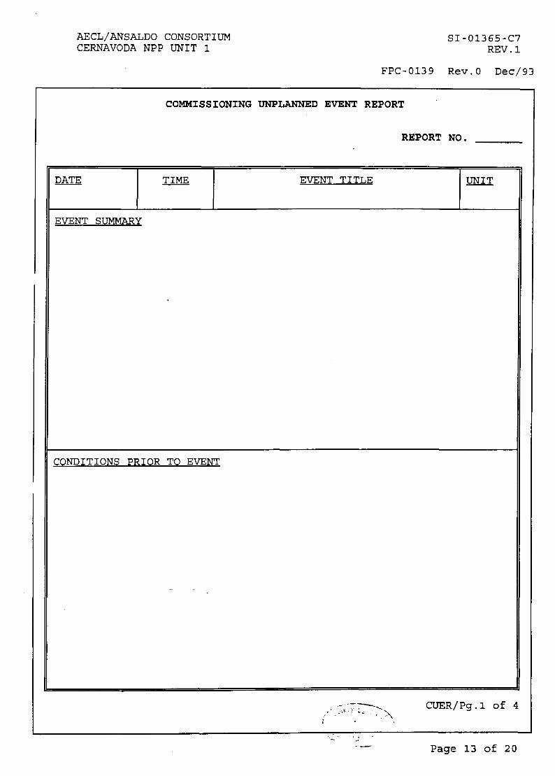
AECL/ANSALDO CONSORTIUMCERNAVODA NPP UNIT 1
SI-01365-C7REV.l
FPC-0139 Rev.O Dec/93
COMMISSIONING UNPLANNED EVENT REPORT
REPORT NO.
EVENT TITLE UNIT
EVENT SUMMARY
CONDITIONS PRIOR TO EVENT
CUER/Pg.l of 4
Page 13 of 20
AECL/ANS*LDO CONSORTIUMCERNAVOD* NPP UNIT 1
SI-01365-C7REV.l
FPC-0139 Rev.O Dec/93
COMMISSIONING UNPLANNED EVENT REPORT
REPORT NO.
DESCRIPTION.1^ EVENT
CUER/Pg.2 of 4
"A \
Page 14 of 20
AECL/ANSALDO CONSORTIUMCERNAVODA NPP UNIT 1
SI-01365-C7REV.l
FPC-0139 Rev.O Dec/93
COMMISSIONING UNPLANNED EVENT REPORT
REPORT NO.
ACTION TAKEN
•>
OUTSTANDING ACTIONS AND RECOMMENDATIONS
SUPPORT DATA
- - -.
PREPARED BY: SIGNATURE: DATE:
CUER/Pg.3 of 4
- «•
Page 15 of 20
AECL/ANSALDO CONSORTIUMCERNAVODA NPP UNIT 1
SI-01365-C7REV.l
FPC-0139 Rev.O Dec/93
COMMISSIONING UNPLANNED EVENT REPORT
REPORT NO.
OPERATIONSSUP'T REVIEW
PRODUCTIONMANAGER REVIEW
COMMISSIONINGMANAGER REVIEW
APPROVAL
-
STATION GENERAL MANAGER DATE
CUER/Pg.4 of 4
Page 16 of 20
AECL/ANSALDO CONSORTIUMCERNAVODA NPP UNIT 1
SI-01365-C7REV.l
FPC-0140 Rev.O Dec/93
UNPLANNED EVENT FOLLOW-UP REPORT
CUER No.
Event date:
TITLE BSI
UEFR No,
Assigned to:(Suptd.)
Priority TargetCompletion
Assignedby:
Date
DETAILS OF ACTION TAKEN:
Relevant support information (Report, DCN, WR, OM, etc)
FURTHER RECOMMENDED ACTION (IF ANY)
Action completed(Suptd.)
Managementapproval
Further Action Req'd?
YesAction No.
No
Page 17 of 20
AECL/ANSALDO CONSORTIUM SI-013 65-C7
CERNAVODA NPP UNIT 1 REV.l
8.0 Appendices
8.1 Appendix A
EVENTS REQUIRING CUERA table of events which requirethe submission of a CUER isprovided in this Appendix.
9.0 Figures
9.1 Flowchart for CUER
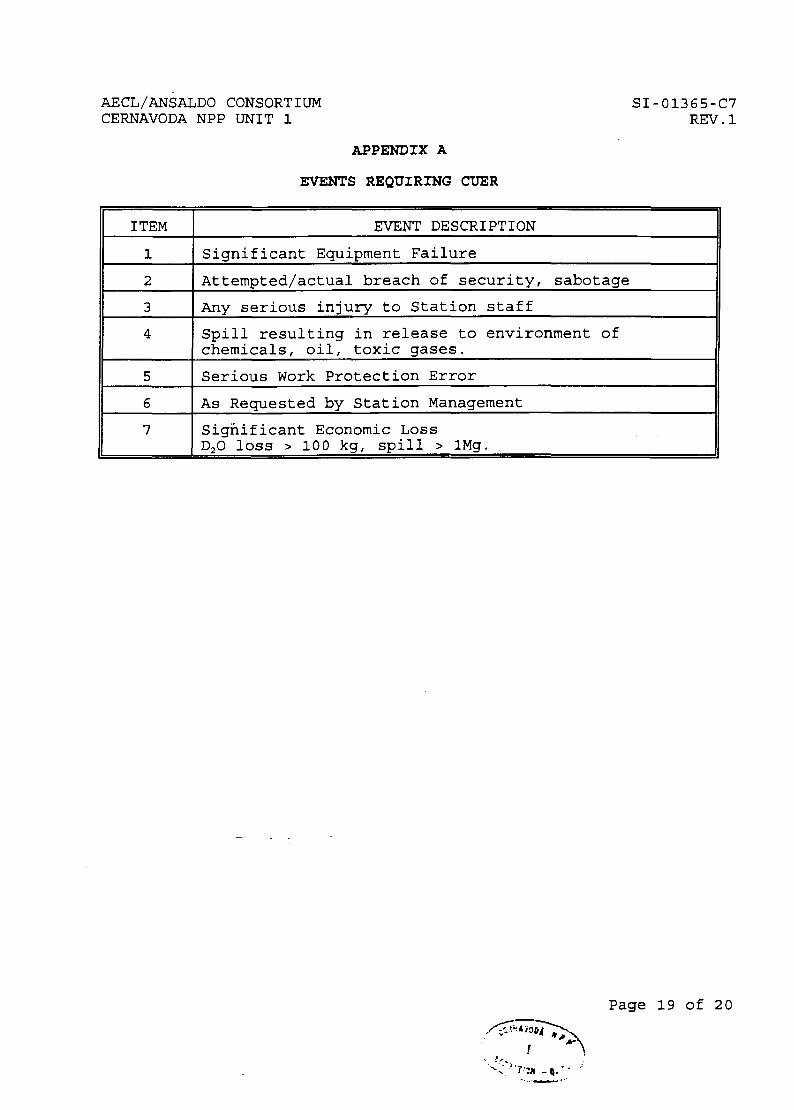
AECL/ANSALDO CONSORTIUMCERNAVODA NPP UNIT 1
SI-01365-C7REV.l
APPENDIX A
EVENTS REQUIRING CUER
ITEM
1
2
3
4
5
6
7
EVENT DESCRIPTION
Significant Equipment Failure
Attempted/actual breach of security, sabotage
Any serious injury to Station staff
Spill resulting in release to environment ofchemicals, oil, toxic gases.
Serious Work Protection Error
As Requested by Station Management
Significant Economic LossD20 loss > 100 kg, spill > lMg.
Page 19 of 20
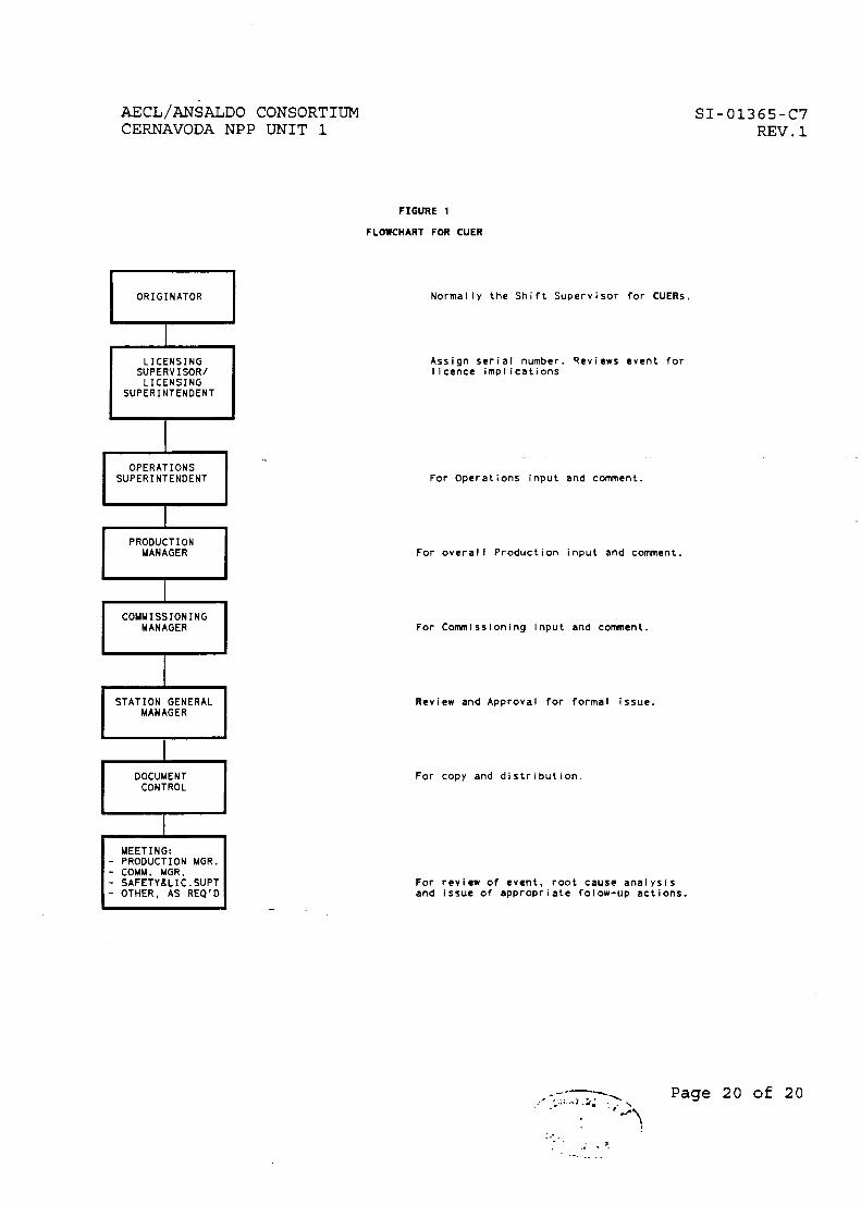
AECL/ANSALDO CONSORTIUMCERNAVODA NPP UNIT 1
SI-01365-C7REV.l
FIGURE 1
FLOWCHART FOR CUER
ORIGINATOR
LICENSINGSUPERVISOR/LICENSING
SUPERINTENDENT
OPERATIONSSUPERINTENDENT
PRODUCTIONMANAGER
COMMISSIONINGMANAGER
STATION GENERALMANAGER
DOCUMENTCONTROL
MEETING:- PRODUCTION MGR.- COMM. MGR.- SAFETY&LIC.SUPT- OTHER, AS REQ'D
Normally the Shift Supervisor for CUERs.
Assign serial number. Reviews event fori I cence implications
For Operations input and comment.
For overall Production input and comment.
For Commissioning Input and comment.
Review and Approval for formal issue.
For copy and distribution.
For review of event, root cause analysisand issue of appropriate folow-up actions.
Page 2 0 of 20
Related Documents