Assembly Manual Mike Fortney 06/26/2006 CricketSat Receiver

Assembly Manual Mike Fortney 06/26/2006 CricketSat Receiver.
Dec 21, 2015
Welcome message from author
This document is posted to help you gain knowledge. Please leave a comment to let me know what you think about it! Share it to your friends and learn new things together.
Transcript
Assembly Manual
Mike Fortney
06/26/2006
CricketSat Receiver
Index• Receiver Parts Map
• Receiver Circuit Board Assembly
• Testing
• Troubleshooting
• Contact Info
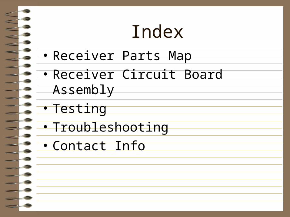
Parts MapPrint out the Parts Map on the following
page.Lay components on respective images to aid
in identification during assembly.
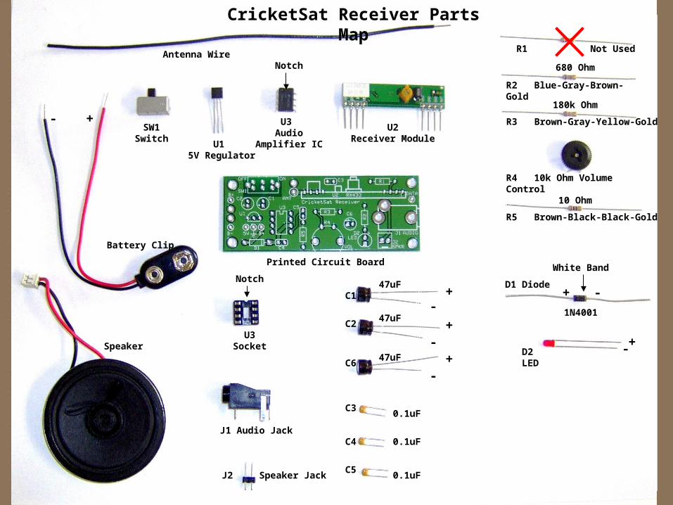
SW1
U1
U3U2
Antenna Wire
+-
Switch
5V Regulator
Audio Amplifier IC
Receiver Module
R1
R2 Blue-Gray-Brown-Gold
R3 Brown-Gray-Yellow-Gold
R4 10k Ohm Volume Control
R5 Brown-Black-Black-Gold
C1
C2
C6
C3
C4
C5
+-
+-
+-
+-
+ -
Speaker
Printed Circuit Board
Battery Clip
J2
U3 Socket
Speaker Jack
D2 LED
D1 Diode
Notch
NotchWhite Band
CricketSat Receiver Parts Map
Not Used
J1 Audio Jack
680 Ohm
180k Ohm
10 Ohm
47uF
47uF
47uF
0.1uF
0.1uF
0.1uF
1N4001
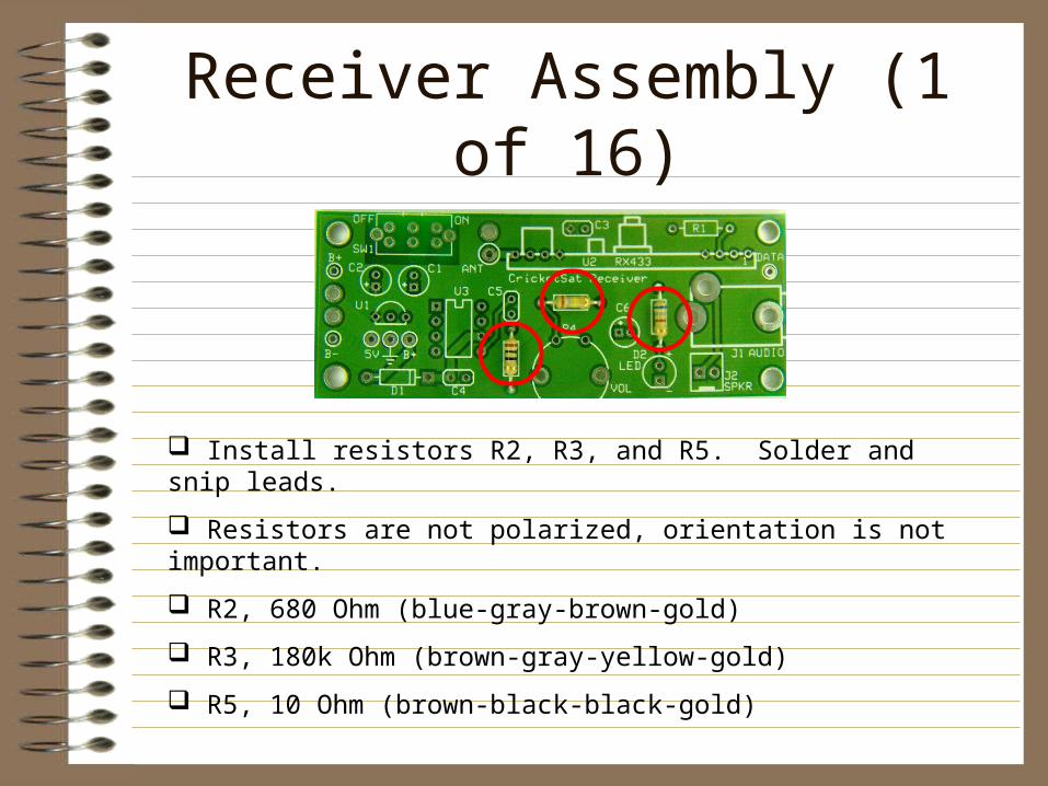
Receiver Assembly (1 of 16)
Install resistors R2, R3, and R5. Solder and snip leads.
Resistors are not polarized, orientation is not important.
R2, 680 Ohm (blue-gray-brown-gold)
R3, 180k Ohm (brown-gray-yellow-gold)
R5, 10 Ohm (brown-black-black-gold)
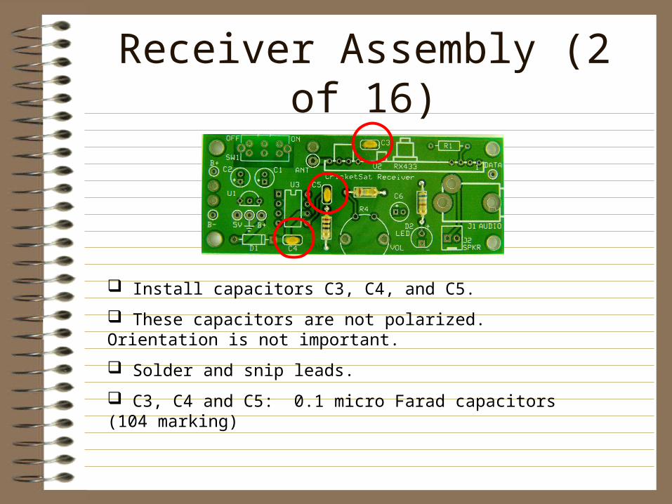
Receiver Assembly (2 of 16)
Install capacitors C3, C4, and C5.
These capacitors are not polarized. Orientation is not important.
Solder and snip leads.
C3, C4 and C5: 0.1 micro Farad capacitors (104 marking)
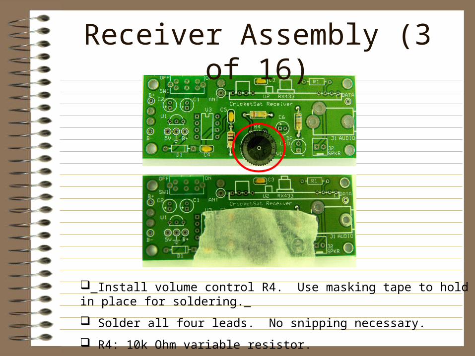
Receiver Assembly (3 of 16)
Install volume control R4. Use masking tape to hold in place for soldering.
Solder all four leads. No snipping necessary.
R4: 10k Ohm variable resistor.
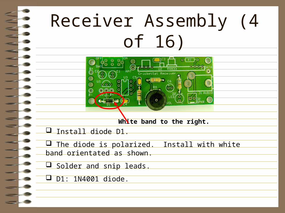
Receiver Assembly (4 of 16)
Install diode D1.
The diode is polarized. Install with white band orientated as shown.
Solder and snip leads.
D1: 1N4001 diode.
White band to the right.
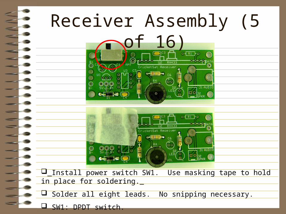
Receiver Assembly (5 of 16)
Install power switch SW1. Use masking tape to hold in place for soldering.
Solder all eight leads. No snipping necessary.
SW1: DPDT switch.
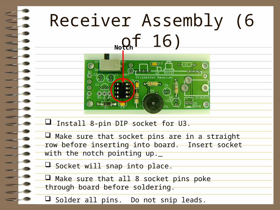
Receiver Assembly (6 of 16)
Install 8-pin DIP socket for U3.
Make sure that socket pins are in a straight row before inserting into board. Insert socket with the notch pointing up.
Socket will snap into place.
Make sure that all 8 socket pins poke through board before soldering.
Solder all pins. Do not snip leads.
Notch
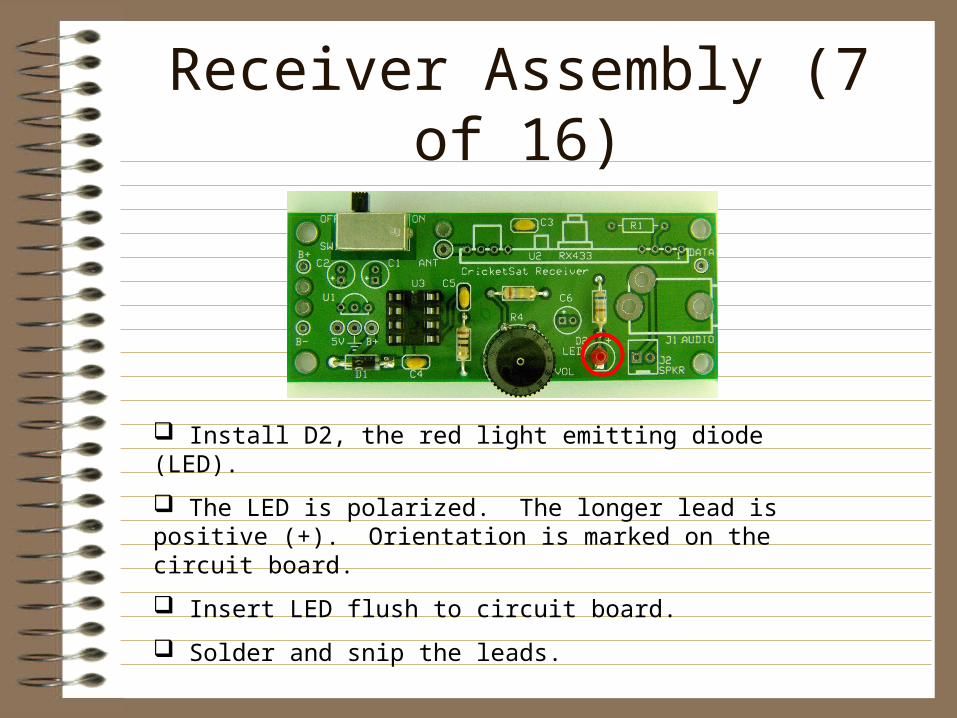
Receiver Assembly (7 of 16)
Install D2, the red light emitting diode (LED).
The LED is polarized. The longer lead is positive (+). Orientation is marked on the circuit board.
Insert LED flush to circuit board.
Solder and snip the leads.
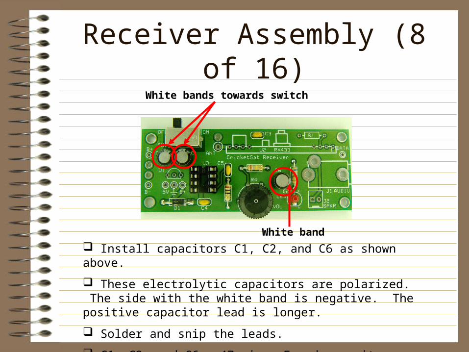
Receiver Assembly (8 of 16)
Install capacitors C1, C2, and C6 as shown above.
These electrolytic capacitors are polarized. The side with the white band is negative. The positive capacitor lead is longer.
Solder and snip the leads.
C1, C2, and C6: 47 micro Farad capacitors
White bands towards switch
White band
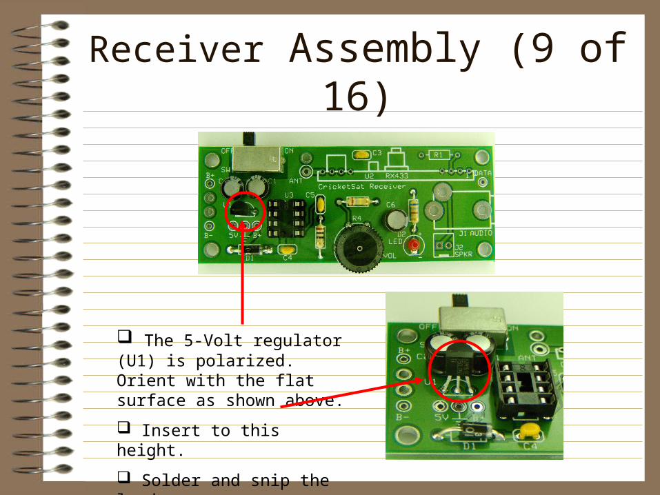
Receiver Assembly (9 of 16)
The 5-Volt regulator (U1) is polarized. Orient with the flat surface as shown above.
Insert to this height.
Solder and snip the leads.
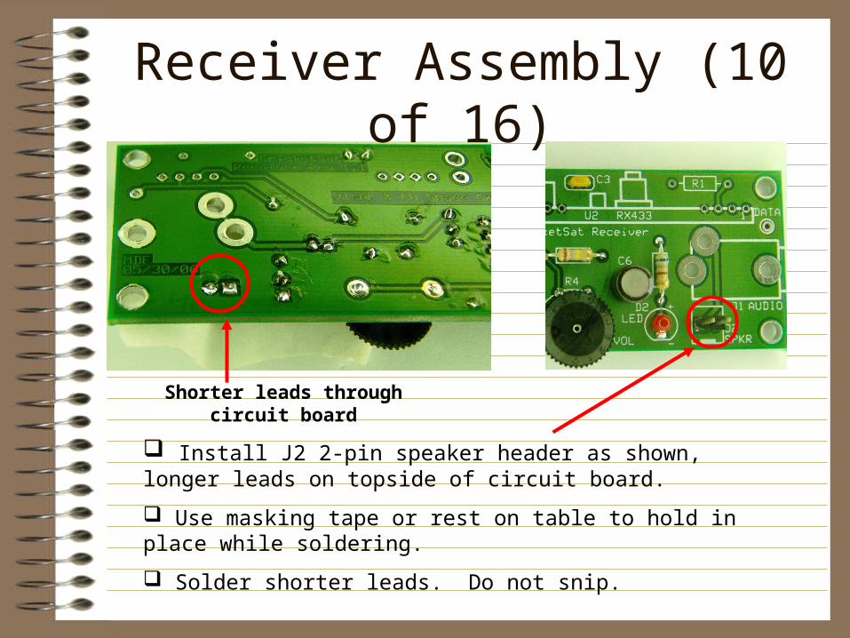
Receiver Assembly (10 of 16)
Install J2 2-pin speaker header as shown, longer leads on topside of circuit board.
Use masking tape or rest on table to hold in place while soldering.
Solder shorter leads. Do not snip.
Shorter leads through circuit board
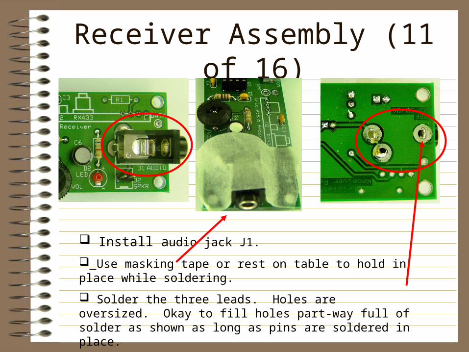
Receiver Assembly (11 of 16)
Install audio jack J1.
Use masking tape or rest on table to hold in place while soldering.
Solder the three leads. Holes are oversized. Okay to fill holes part-way full of solder as shown as long as pins are soldered in place.
Pins may be snipped.
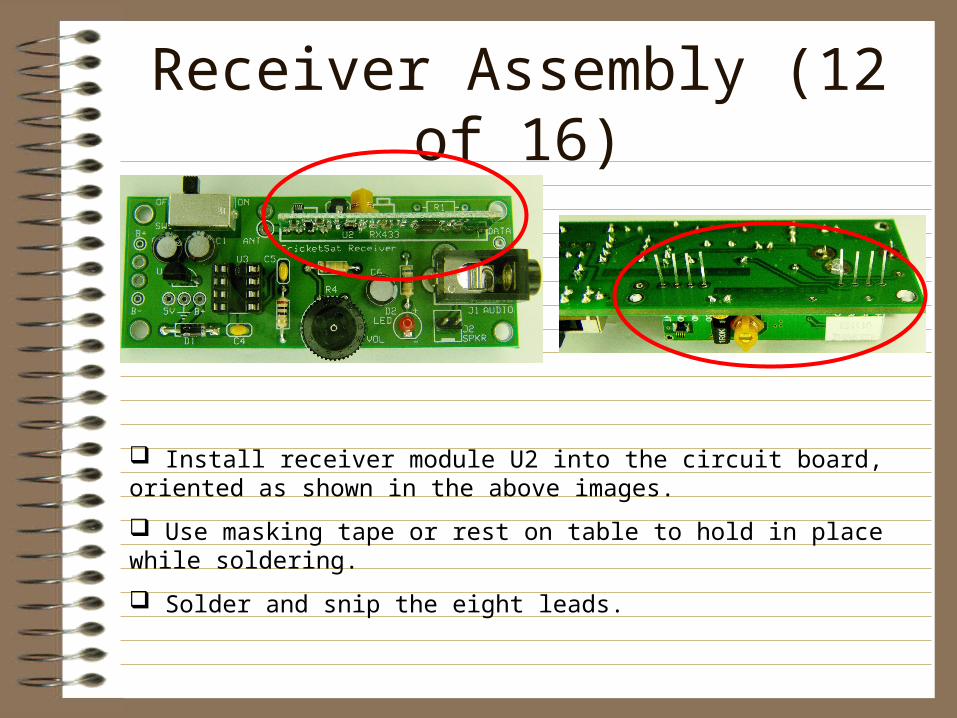
Receiver Assembly (12 of 16)
Install receiver module U2 into the circuit board, oriented as shown in the above images.
Use masking tape or rest on table to hold in place while soldering.
Solder and snip the eight leads.
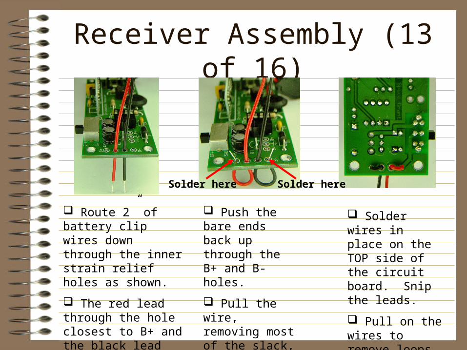
Receiver Assembly (13 of 16)
Route 2” of battery clip wires down through the inner strain relief holes as shown.
The red lead through the hole closest to B+ and the black lead closest to B-.
Push the bare ends back up through the B+ and B- holes.
Pull the wire, removing most of the slack, leaving small loops.
Solder wires in place on the TOP side of the circuit board. Snip the leads.
Pull on the wires to remove loops.
Solder hereSolder here
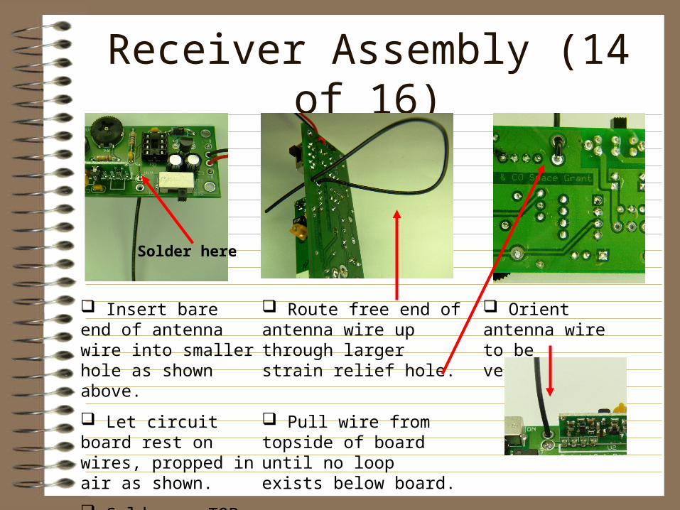
Receiver Assembly (14 of 16)
Insert bare end of antenna wire into smaller hole as shown above.
Let circuit board rest on wires, propped in air as shown.
Solder on TOP side of board and snip lead.
Route free end of antenna wire up through larger strain relief hole.
Pull wire from topside of board until no loop exists below board.
Orient antenna wire to be vertical.
Solder here
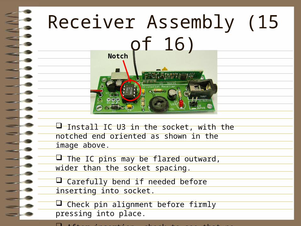
Receiver Assembly (15 of 16)
Install IC U3 in the socket, with the notched end oriented as shown in the image above.
The IC pins may be flared outward, wider than the socket spacing.
Carefully bend if needed before inserting into socket.
Check pin alignment before firmly pressing into place.
After insertion, check to see that no pins were bent.
Do not snip leads.
Notch
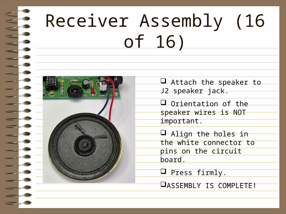
Receiver Assembly (16 of 16)
Attach the speaker to J2 speaker jack.
Orientation of the speaker wires is NOT important.
Align the holes in the white connector to pins on the circuit board.
Press firmly.
ASSEMBLY IS COMPLETE!
Testing• Slide power switch to “OFF” position.• Rotate volume control (R4) all the way clockwise (max
volume)• Attach a 9-Volt battery• Slide power switch to “ON” position.• A loud hiss should be produced and the red LED should
light and vary in brightness.• If neither happens, TURN OFF IMMEDIATELY and
proceed to the following slide “Troubleshooting”• Adjust the volume control to a comfortable listening level.• Test the unit with a CricketSat sensor. You should hear
CricketSat sensors several hundred feet away. May need to wait 30 seconds for first transmission.
• The range for balloon flights may exceed one mile.
Troubleshooting• No sound or lights, no smoke
– Insure that slide switch is working properly– Check if battery leads are correctly attached to board, red +, black -– Check if D1 diode is properly installed, white band is “-”– Check if U1, U2 and U3 are installed properly– Try another battery
• Sound, but no lights– LED may be installed backwards
• Lights, but no sound– Turn volume control to a median setting. Should hear hissing
sound.– U3 may be installed backwards. Check orientation.
• Does not receive CricketSat tones– Receiver module may be faulty or need tuning
Contact Info
• Michael Fortney– [email protected]
• UVM CricketSat Website– http://www.uvm.edu/~cricksat
Related Documents