Bound-T time and stack analyser Application Note ARM7 Version 1 TR-AN-ARM7-001 2010-02-20 Tidorum Ltd. Tid rum brought to you by CORE View metadata, citation and similar papers at core.ac.uk provided by CiteSeerX

Welcome message from author
This document is posted to help you gain knowledge. Please leave a comment to let me know what you think about it! Share it to your friends and learn new things together.
Transcript

BoundT time and stack analyser
Application Note
ARM7
Version 1TRANARM7001 20100220 Tidorum Ltd.
Tidrum
brought to you by COREView metadata, citation and similar papers at core.ac.uk
provided by CiteSeerX
Tidorum Ltdwww.tidorum.fiTiirasaarentie 32FI00200 HelsinkiFinland
This document was written at Tidorum Ltd. by Niklas Holsti.The document is currently maintained by the same persons.
Copyright © 20042010 Tidorum Ltd.This document can be copied and distributed freely, in any format, provided that it is kept entire, with no deletions, insertions or changes, and that this copyright notice is included, prominently displayed, and made applicable to all copies.
Document reference: TRANARM7001Document issue: Version 1Document issue date: 20100220BoundT version: 4b3Last change included: BTCH0219Web location: http://www.boundt.com/appnotes/anarm7.pdf
Trademarks:BoundT is a trademark of Tidorum Ltd.ARM is a trademark of ARM Advanced RISC Machines Ltd.
Credits:This document was created with the free OpenOffice.org software, http://www.openoffice.org/.
ii
Tidrum

Preface
The information in this document is believed to be complete and accurate when the document is issued. However, Tidorum Ltd. reserves the right to make future changes in the technical specifications of the product BoundT described here. For the most recent version of this document, please refer to the web address http://www.boundt.com/.
If you have comments or questions on this document or the product, they are welcome via electronic mail to the address [email protected], or via telephone, fax or ordinary mail to the address given below.
Please note that our office is located in the timezone GMT + 2 hours, and office hours are 9:00 16:00 local time. In summer daylight savings time makes the local time equal GMT + 3 hours.
Cordially,
Tidorum Ltd.
Telephone: +358 (0) 40 563 9186Fax: +358 (0) 42 563 9186Email: [email protected]: http://www.tidorum.fi/
http://www.boundt.com/
Mail: Tiirasaarentie 32FI00200 HELSINKIFinland
Credits
The BoundT tool was first developed by Space Systems Finland Ltd. (http://www.ssf.fi) with support from the European Space Agency (ESA/ESTEC). Free software has played an important role; we are grateful to Ada Core Technology for the Gnat compiler, to William Pugh and his group at the University of Maryland for the Omega system, to Michel Berkelaar for the lpsolve program, to Mats Weber and EPFLDILGL for Ada component libraries, to Ted Dennison for the OpenToken package, and to Marc Criley for the XML EZ_Out package. Callgraphs and flowgraphs from BoundT are displayed with the dot tool that is a part of the GraphViz package from AT&T Bell Laboratories.
iii
Contents
1 INTRODUCTION 1
1.1 Purpose and scope.....................................................................................................11.2 Overview...................................................................................................................11.3 References.................................................................................................................21.4 Abbreviations and acronyms......................................................................................21.5 Glossary of terms.......................................................................................................31.6 Typographic Conventions...........................................................................................4
2 USING BOUND-T FOR ARM7 5
2.1 Overview...................................................................................................................52.2 Supported ARM7 features and tools...........................................................................52.3 Input formats.............................................................................................................62.4 Command arguments and options.............................................................................62.5 Outputs....................................................................................................................12
3 WRITING ASSERTIONS ON ARM7 PROGRAMS 14
3.1 Overview.................................................................................................................143.2 Symbolic names.......................................................................................................143.3 Naming items by address.........................................................................................153.4 Instruction roles.......................................................................................................163.5 Assertable properties................................................................................................173.6 Defining the state (ARM or Thumb) of dynamic callees...........................................183.7 Stacks......................................................................................................................19
4 THE ARM7 AND TIMING ANALYSIS 21
4.1 Overview.................................................................................................................214.2 The ARM7................................................................................................................214.3 Static execution time analysis on the ARM7.............................................................23
5 SUPPORTED ARM7 FEATURES 24
5.1 Overview.................................................................................................................245.2 Operating state and the BX instruction....................................................................255.3 Operating mode and the MSR and SWI instructions................................................265.4 Controltransfer instructions....................................................................................265.5 Computational operations........................................................................................325.6 Condition codes.......................................................................................................325.7 Memory data...........................................................................................................335.8 Coprocessors............................................................................................................335.9 Time accuracy and approximations..........................................................................34
6 PROCEDURE CALLING STANDARDS 35
6.1 Procedure calls in the ARM7....................................................................................356.2 Model of calling standard in BoundT......................................................................35
7 WARNINGS AND ERRORS FOR ARM7 36
7.1 Warning messages...................................................................................................367.2 Error messages.........................................................................................................43
8 PATCH FILES 54
iv

TablesTable 1: Supported ARM7 features, tools, formats.....................................................................................5Table 2: Device selection options...............................................................................................................7Table 3: Program loading options for ARM7..............................................................................................7Table 4: Instruction modelling options for ARM7......................................................................................8Table 5: Coprocessor modelling options for ARM7..................................................................................11Table 6: Coprocessor instruction abbreviations........................................................................................11Table 7: ARM7specific trace items.........................................................................................................12Table 8: ARM7specific warn items.........................................................................................................12Table 9: Naming storage cells...................................................................................................................15Table 10: Instruction roles per instruction...............................................................................................16Table 11: Assertable properties for ARM7................................................................................................17Table 12: Generic limitations of BoundT.................................................................................................24Table 13: Models of dynamic transfer of control......................................................................................28Table 14: Idiomatic instruction pairs and their roles................................................................................28Table 15: Modelling ARM7 controltransfer instructions.........................................................................29Table 16: Resolving dynamic transfer of control......................................................................................31Table 17: Approximations for instruction times.......................................................................................34Table 18: Invariance of registers and other storage cells in calls.............................................................35Table 19: Warning messages from BoundT/ARM7.................................................................................36Table 20: Error messages from BoundT/ARM7.......................................................................................43Table 21: Patch formats............................................................................................................................54
v

This page is almost blank on purpose.
vi

1 INTRODUCTION
1.1 Purpose and scope
BoundT is a tool for computing bounds on the worstcase execution time and stack usage of realtime programs; see references [1] and [2]. There are different versions of BoundT for different target processors. This Application Note supplements the BoundT User Guide and Reference Manual [1, 2] and the BoundT Assertion Language manual [3] by giving additional information and advice on using BoundT for one particular target processor, the processor architecture known as the ARM7TDMI [4].
There are several physical processor implementations (chips, devices) that use the ARM7TDMI core architecture, with possibly different execution timing. BoundT can model the execution timing of some of these processors, but certainly not all of them.
1.2 Overview
The reader is assumed to be familiar with the general principles and usage of BoundT, as described in the BoundT User Guide and Reference Manual [1, 2]. The User Guide [1] also contains a glossary of terms, many of which will be used in this Application Note.
In a nutshell, here is how BoundT bounds the worstcase execution time (WCET) of a subprogram: Starting from the executable, binary form of the program, BoundT decodes the ARM7 machine instructions, constructs the controlflow graph, identifies loops, and (partially) interprets the arithmetic operations to find the “loopcounter” variables that control the loops, such as n in “for (n = 1; n < 20; n++) { ... }”.
By comparing the initial value, step and limit value of the loopcounter variables, BoundT computes an upper bound on the number of times each loop is repeated. Combining the looprepetition bounds with the execution times of the subprogram's instructions gives an upper bound on the worstcase execution time of the whole subprogram. If the subprogram calls other subprograms, BoundT constructs the callgraph and bounds the worstcase execution time of the called subprograms in the same way.
This Application Note explains how to use BoundT to analyse ARM7 programs and how BoundT models the architecture of this processor. To make full use of this information, the reader should be familiar with the register set and instruction set of this processor, as presented in reference [4].
The remainder of this Application Note is divided into a user guide part and reference part.The user guide part consists of chapters 2 through 3 and is structured as follows:
• Chapter 2 shows how to use the ARM7 version of BoundT. It briefly lists the supported ARM7 features and crosscompilers and fully explains those BoundT command arguments and options that are wholly specific to the ARM7, or that have a specific interpretation for this processor.
• Chapter 3 addresses the userdefined assertions on target program behaviour and explains the possibilities and limitations in the context of the ARM7 and its crosscompilers.
The remainder of the Application Note forms the reference part as follows:
• Chapter 4 describes the main features of the ARM7 architecture and how BoundT models them in general.
• Chapter 5 defines in detail the set of ARM7 instructions and registers that is supported by BoundT.
BoundT for ARM7 Introduction 1
• Chapter 6 concentrates on procedure calling standards (parameterpassing methods) and explains how BoundT models and analyses the calling standards used by various compilers.
• Chapter 7 listst all ARM7specific warnings and error messages that BoundT can issue and explains the possible reasons and remedies for each.
• Chapter 8 describes the syntax of patch files for analysis of ARM7 programs.
1.3 References
[1] BoundT User Guide.Tidorum Ltd., Doc.ref. TRUG001.http://www.boundt.com/manuals/userguide.pdf
[2] BoundT Reference Manual.Tidorum Ltd., Doc.ref. TRRM001.http://www.boundt.com/manuals/refmanual.pdf
[3] BoundT Assertion Language.Tidorum Ltd., Doc.ref. TRUM003.http://www.boundt.com/manuals/assertionlang.pdf
[4] ARM7TDMI Data Sheet.ARM Ltd., Doc number ARM DDI 0029E, August 1995.
[5] Procedure Call Standard for the ARM® Architecture.ARM Ltd., Doc number ARM IHI 0042B, 2 April, 2008. ABI release 2.06.
[6] The ARMThumb Procedure Call Standard.ARM Ltd., Doc number SWS ESPC 0002 B01, 24 October, 2000.
[7] Intel® Hex as input to BoundT.BoundT Technical Note, Tidorum Ltd., Doc.ref. TRTNIHEX001.http://www.boundt.com/tech_notes/tnihex.pdf
1.4 Abbreviations and acronyms
See also reference [1] for abbreviations specific to BoundT and reference [4] for the mnemonic operation codes and register names of the ARM7.
ABT Abort Mode (see [4], section 3.6)AAPCS Procedure Call Standard for the ARM Architecture [5]ATPCS ARMThumb Procedure Call Standard [6]ARM 1. Advanced RISC Machines Ltd.
2. The 32bit instruction set, as opposed to the 16bit Thumb instruction set.3. The processor state that uses the 32bit ARM instruction set.
BTA Branch via table of addresses. See Table 13.C 1. Carry flag (in the CPSR)
2. The C programming languageCPSR Current Program Status RegisterDAB Dynamic affine branch. See Table 13.DC Dynamic call. See Table 13.FIQ Fast Interrupt Request Mode (see [4], section 3.6)GDT General dynamic transfer of control. See Table 13.IRQ Interrupt Request Mode (see [4], section 3.6)N Negative flag (in the CPSR)
2 Introduction BoundT for ARM7
SP Stack Pointer (R13)LR Link Register (R14)PC Program Counter (R15)PSR Program Status RegisterSPSR Saved Program Status RegisterSTO Skip by table of offsets. See Table 13.SVC Supervisor Mode (see [4], section 3.6)SWI SoftWare Interrupt (an ARM7 instruction)SYS System Mode (see [4], section 3.6)TBA To Be AddedTBC To Be ConfirmedTBD To Be DeterminedUND Undefined Instruction Mode (see [4], section 3.6)USR User Mode (see [4], section 3.6)Thumb 1. The 16bit instruction set, as opposed to the 32bit ARM instruction set.
2. The processor state that uses the 16bit Thumb instruction set.TPCS Thumb Procedure Calling StandardV Overflow flag (in the CPSR)WCET WorstCase Execution TimeZ Zero flag (in the CPSR)
1.5 Glossary of terms
The following list contains only terms specific to the ARM7 version of BoundT as described in the present document. See also reference [1] for general terms used in static executiontime analysis and BoundT in general.
Banked registerAn ARM7 register that has different instances for different operating modes so that each mode uses its own register. For example, each operating mode has a different instance of register R13 = SP, except that User Mode and System Mode share the same instance.
Coprocessor An additional processing element, for example a floatingpoint computation unit, intimately connected to and controlled by an ARM7 processor. Specific ARM7 instructions can move data from or to the coprocessor or make the coprocessor execute an operation. A coprocessor can also extend the instruction set by accepting and executing instructions that the basic ARM7 would reject as undefined instruction codes.
Exception vectorA location in the ARM7 memory in the address range 0 .. 1F hexadecimal. When an exception or interrupt occurs, the ARM7 diverts execution to the corresponding address in this area. For example, the SWI instruction invokes the exception vector at address 8.
Mode The operating mode of an ARM7 processor. See [4], section 3.6. Normally the processor is operating in User Mode (USR). During interrupt handling it may be operating in Interrupt Request Mode (IRQ); during kernel calls in Supervisor Mode (SVC), and so no.
State The operating state of an ARM7TDMI processor, which is either ARM state (32bit instruction set) or Thumb state (16bit instruction set). See [4], section 3.1.
BoundT for ARM7 Introduction 3
Thumb See the "Thumb" acronym (this term inherits honorary acronym status by analogy from the acronym ARM).
1.6 Typographic Conventions
We use the following fonts and styles to show the role of pieces of the text:
Register The name of a ARM7 register embedded in prose.
INSTRUCTION An ARM7 instruction (32bit or 16bit).
option A commandline option for BoundT.
symbol A mathematical symbol or variable.
text Text quoted from a text / source file or command.
4 Introduction BoundT for ARM7
2 USING BOUND-T FOR ARM7
2.1 Overview
This chapter begins the “user guide” part of this Application Note. It starts by giving an overview of the ARM7 features that BoundT currently supports, and continues by listing and explaining all ARM7specific commandline options and other inputs to BoundT.
2.2 Supported ARM7 features and tools
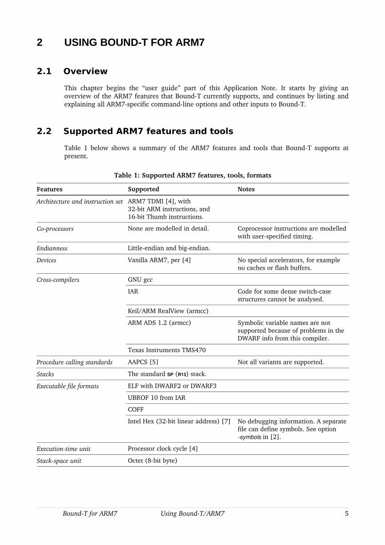
Table 1 below shows a summary of the ARM7 features and tools that BoundT supports at present.
Table 1: Supported ARM7 features, tools, formats
Features Supported Notes
Architecture and instruction set ARM7 TDMI [4], with32bit ARM instructions, and16bit Thumb instructions.
Coprocessors None are modelled in detail. Coprocessor instructions are modelled with userspecified timing.
Endianness Littleendian and bigendian.
Devices Vanilla ARM7, per [4] No special accelerators, for example no caches or flash buffers.
Crosscompilers GNU gcc
IAR Code for some dense switchcase structures cannot be analysed.
Keil/ARM RealView (armcc)
ARM ADS 1.2 (armcc) Symbolic variable names are not supported because of problems in the DWARF info from this compiler.
Texas Instruments TMS470
Procedure calling standards AAPCS [5] Not all variants are supported.
Stacks The standard SP (R13) stack.
Executable file formats ELF with DWARF2 or DWARF3
UBROF 10 from IAR
COFF
Intel Hex (32bit linear address) [7] No debugging information. A separate file can define symbols. See option symbols in [2].
Executiontime unit Processor clock cycle [4]
Stackspace unit Octet (8bit byte)
BoundT for ARM7 Using BoundT/ARM7 5
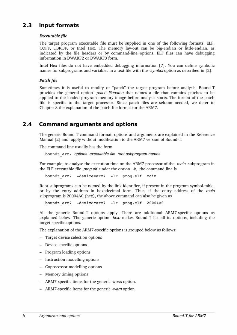
2.3 Input formats
Executable file
The target program executable file must be supplied in one of the following formats: ELF, COFF, UBROF, or Intel Hex. The memory layout can be bigendian or littleendian, as indicated by the file headers or by commandline options. ELF files can have debugging information in DWARF2 or DWARF3 form.
Intel Hex files do not have embedded debugging information [7]. You can define symbolic names for subprograms and variables in a text file with the symbol option as described in [2].
Patch file
Sometimes it is useful to modify or “patch” the target program before analysis. BoundT provides the general option patch filename that names a file that contains patches to be applied to the loaded program memory image before analysis starts. The format of the patch file is specific to the target processor. Since patch files are seldom needed, we defer to Chapter 8 the explanation of the patchfile format for the ARM7.
2.4 Command arguments and options
The generic BoundT command format, options and arguments are explained in the Reference Manual [2] and apply without modification to the ARM7 version of BoundT.
The command line usually has the form
boundt_arm7 options executablefile rootsubprogramnames
For example, to analyse the execution time on the ARM7 processor of the main subprogram in the ELF executable file prog.elf under the option lr, the command line is
boundt_arm7 device=arm7 lr prog.elf main
Root subprograms can be named by the link identifier, if present in the program symboltable, or by the entry address in hexadecimal form. Thus, if the entry address of the main subprogram is 20004A0 (hex), the above command can also be given as
boundt_arm7 device=arm7 lr prog.elf 20004A0
All the generic BoundT options apply. There are additional ARM7specific options as explained below. The generic option help makes BoundT list all its options, including the targetspecific options.
The explanation of the ARM7specific options is grouped below as follows:
– Target device selection options
– Devicespecific options
– Program loading options
– Instruction modelling options
– Coprocessor modelling options
– Memory timing options
– ARM7specific items for the generic trace option.
– ARM7specific items for the generic warn option.
6 Arguments and options BoundT for ARM7
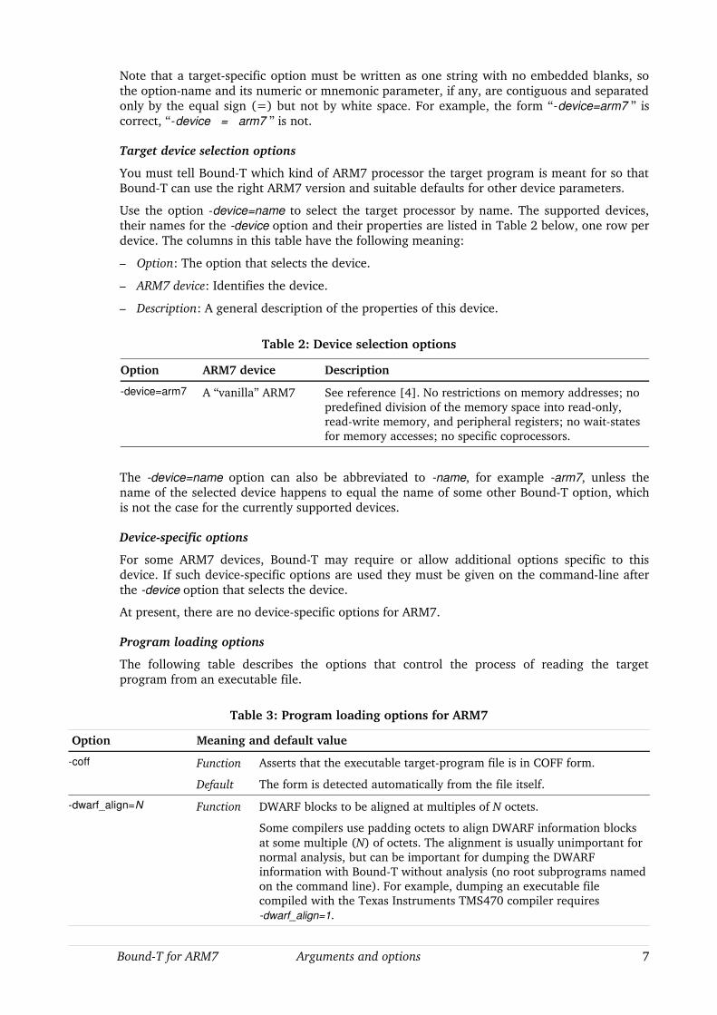
Note that a targetspecific option must be written as one string with no embedded blanks, so the optionname and its numeric or mnemonic parameter, if any, are contiguous and separated only by the equal sign (=) but not by white space. For example, the form “device=arm7 ” is correct, “device = arm7 ” is not.
Target device selection options
You must tell BoundT which kind of ARM7 processor the target program is meant for so that BoundT can use the right ARM7 version and suitable defaults for other device parameters.
Use the option device=name to select the target processor by name. The supported devices, their names for the device option and their properties are listed in Table 2 below, one row per device. The columns in this table have the following meaning:
– Option: The option that selects the device.
– ARM7 device: Identifies the device.
– Description: A general description of the properties of this device.
Table 2: Device selection options
Option ARM7 device Description
device=arm7 A “vanilla” ARM7 See reference [4]. No restrictions on memory addresses; no predefined division of the memory space into readonly, readwrite memory, and peripheral registers; no waitstates for memory accesses; no specific coprocessors.
The device=name option can also be abbreviated to name, for example arm7, unless the name of the selected device happens to equal the name of some other BoundT option, which is not the case for the currently supported devices.
Devicespecific options
For some ARM7 devices, BoundT may require or allow additional options specific to this device. If such devicespecific options are used they must be given on the commandline after the device option that selects the device.
At present, there are no devicespecific options for ARM7.
Program loading options
The following table describes the options that control the process of reading the target program from an executable file.
Table 3: Program loading options for ARM7
Option Meaning and default value
coff Function Asserts that the executable targetprogram file is in COFF form.
Default The form is detected automatically from the file itself.
dwarf_align=N Function DWARF blocks to be aligned at multiples of N octets.
Some compilers use padding octets to align DWARF information blocks at some multiple (N) of octets. The alignment is usually unimportant for normal analysis, but can be important for dumping the DWARF information with BoundT without analysis (no root subprograms named on the command line). For example, dumping an executable file compiled with the Texas Instruments TMS470 compiler requires dwarf_align=1.
BoundT for ARM7 Arguments and options 7
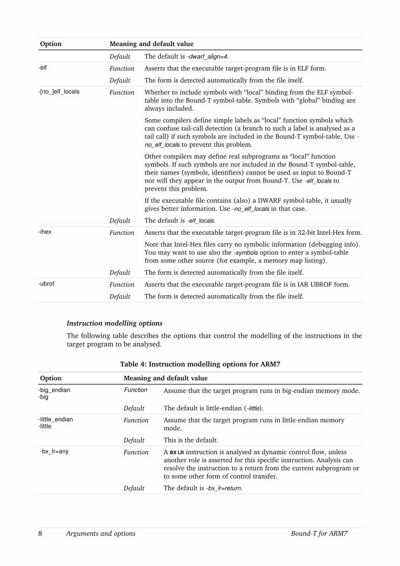
Option Meaning and default value
Default The default is dwarf_align=4.
elf Function Asserts that the executable targetprogram file is in ELF form.
Default The form is detected automatically from the file itself.
[no_]elf_locals Function Whether to include symbols with “local” binding from the ELF symboltable into the BoundT symboltable. Symbols with “global” binding are always included.
Some compilers define simple labels as “local” function symbols which can confuse tailcall detection (a branch to such a label is analysed as a tail call) if such symbols are included in the BoundT symboltable. Use no_elf_locals to prevent this problem.
Other compilers may define real subprograms as “local” function symbols. If such symbols are not included in the BoundT symboltable, their names (symbols, identifiers) cannot be used as input to BoundT nor will they appear in the output from BoundT. Use elf_locals to prevent this problem.
If the executable file contains (also) a DWARF symboltable, it usually gives better information. Use no_elf_locals in that case.
Default The default is elf_locals.
ihex Function Asserts that the executable targetprogram file is in 32bit IntelHex form.
Note that IntelHex files carry no symbolic information (debugging info). You may want to use also the symbols option to enter a symboltable from some other source (for example, a memory map listing).
Default The form is detected automatically from the file itself.
ubrof Function Asserts that the executable targetprogram file is in IAR UBROF form.
Default The form is detected automatically from the file itself.
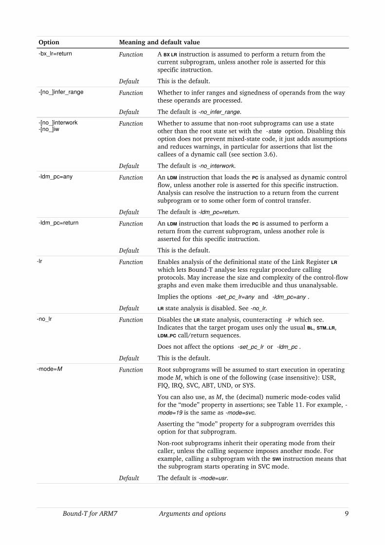
Instruction modelling options
The following table describes the options that control the modelling of the instructions in the target program to be analysed.
Table 4: Instruction modelling options for ARM7
Option Meaning and default value
big_endianbig
Function Assume that the target program runs in bigendian memory mode.
Default The default is littleendian (little).
little_endianlittle
Function Assume that the target program runs in littleendian memory mode.
Default This is the default.
bx_lr=any Function A BX LR instruction is analysed as dynamic control flow, unless another role is asserted for this specific instruction. Analysis can resolve the instruction to a return from the current subprogram or to some other form of control transfer.
Default The default is bx_lr=return.
8 Arguments and options BoundT for ARM7
Option Meaning and default value
bx_lr=return Function A BX LR instruction is assumed to perform a return from the current subprogram, unless another role is asserted for this specific instruction.
Default This is the default.
[no_]infer_range Function Whether to infer ranges and signedness of operands from the way these operands are processed.
Default The default is no_infer_range.
[no_]interwork[no_]iw
Function Whether to assume that nonroot subprograms can use a state other than the root state set with the state option. Disabling this option does not prevent mixedstate code, it just adds assumptions and reduces warnings, in particular for assertions that list the callees of a dynamic call (see section 3.6).
Default The default is no_interwork.
ldm_pc=any Function An LDM instruction that loads the PC is analysed as dynamic control flow, unless another role is asserted for this specific instruction. Analysis can resolve the instruction to a return from the current subprogram or to some other form of control transfer.
Default The default is ldm_pc=return.
ldm_pc=return Function An LDM instruction that loads the PC is assumed to perform a return from the current subprogram, unless another role is asserted for this specific instruction.
Default This is the default.
lr Function Enables analysis of the definitional state of the Link Register LR
which lets BoundT analyse less regular procedure calling protocols. May increase the size and complexity of the controlflow graphs and even make them irreducible and thus unanalysable.
Implies the options set_pc_lr=any and ldm_pc=any .
Default LR state analysis is disabled. See no_lr.
no_lr Function Disables the LR state analysis, counteracting lr which see. Indicates that the target progam uses only the usual BL, STM..LR, LDM..PC call/return sequences.
Does not affect the options set_pc_lr or ldm_pc .
Default This is the default.
mode=M Function Root subprograms will be assumed to start execution in operating mode M, which is one of the following (case insensitive): USR, FIQ, IRQ, SVC, ABT, UND, or SYS.
You can also use, as M, the (decimal) numeric modecodes valid for the “mode” property in assertions; see Table 11. For example, mode=19 is the same as mode=svc.
Asserting the “mode” property for a subprogram overrides this option for that subprogram.
Nonroot subprograms inherit their operating mode from their caller, unless the calling sequence imposes another mode. For example, calling a subprogram with the SWI instruction means that the subprogram starts operating in SVC mode.
Default The default is mode=usr.
BoundT for ARM7 Arguments and options 9
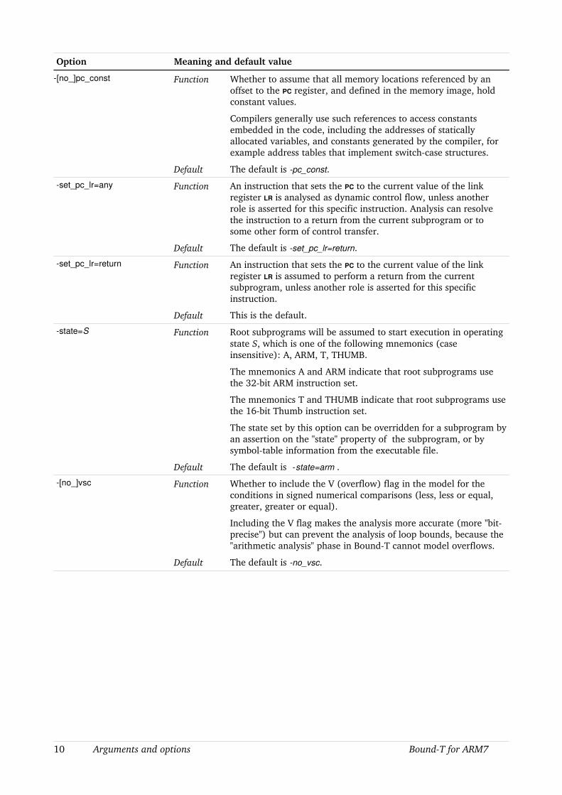
Option Meaning and default value
[no_]pc_const Function Whether to assume that all memory locations referenced by an offset to the PC register, and defined in the memory image, hold constant values.
Compilers generally use such references to access constants embedded in the code, including the addresses of statically allocated variables, and constants generated by the compiler, for example address tables that implement switchcase structures.
Default The default is pc_const.
set_pc_lr=any Function An instruction that sets the PC to the current value of the link register LR is analysed as dynamic control flow, unless another role is asserted for this specific instruction. Analysis can resolve the instruction to a return from the current subprogram or to some other form of control transfer.
Default The default is set_pc_lr=return.
set_pc_lr=return Function An instruction that sets the PC to the current value of the link register LR is assumed to perform a return from the current subprogram, unless another role is asserted for this specific instruction.
Default This is the default.
state=S Function Root subprograms will be assumed to start execution in operating state S, which is one of the following mnemonics (case insensitive): A, ARM, T, THUMB.
The mnemonics A and ARM indicate that root subprograms use the 32bit ARM instruction set.
The mnemonics T and THUMB indicate that root subprograms use the 16bit Thumb instruction set.
The state set by this option can be overridden for a subprogram by an assertion on the "state" property of the subprogram, or by symboltable information from the executable file.
Default The default is state=arm .
[no_]vsc Function Whether to include the V (overflow) flag in the model for the conditions in signed numerical comparisons (less, less or equal, greater, greater or equal).
Including the V flag makes the analysis more accurate (more "bitprecise") but can prevent the analysis of loop bounds, because the "arithmetic analysis" phase in BoundT cannot model overflows.
Default The default is no_vsc.
10 Arguments and options BoundT for ARM7

Coprocessor modelling options
The following table describes the options that control the modelling of the coprocessor(s) that may be connected to and controlled by the ARM7 processor. At present, BoundT has no model for any specific coprocessor. These options let you define the worstcase execution time assumed for the instructions that access the coprocessor(s) and the number of words transferred by the “load coprocessor” and “store coprocessor” instructions.
Table 5: Coprocessor modelling options for ARM7
Option Meaning and default value
instr_wait=C Function Assume C number of cycles for busywait looping in the coprocessor instruction instr (see Table 6 below for the possible forms of instr).
Example: cdp_wait=3
Default The default is zero busywait cycles for all coprocessor instructions, for example cdp_wait=0.
ldc_short=Wstc_short=W
Function Assume W number of 32bit words are transferred in the coprocessor data transfer instructions LDC or STC when a “short” transfer is specified.
Example: stc_short=2
Default The default is one word: ldc_short=1 and stc_short=1.
ldc_long=Wstc_long=W
Function Assume W number of 32bit words are transferred in the coprocessor data transfer instructions LDC or STC when a “long” transfer is specified.
Example: ldc_long=4
Default The default is two words: ldc_long=2 and stc_long=2.
The number of words transferred in the LDC and STC instructions affects both the execution time of these instructions and their role in the computation (their effect on memory data).
Table 6 below lists the coprocessor instruction abbreviations (instr) that can occur in the instr_wait option.
Table 6: Coprocessor instruction abbreviations
Abbreviation Meaning
cdp Coprocessor Data Operation
ldc Coprocessor Load Data
stc Coprocessor Store Data
mrc Move Coprocessor Register to ARM7 Register
mcr Move ARM7 Register to Coprocessor Register
A coprocessor can also erxtend the instruction set by accepting and defining instructions (instruction words) that the basic ARM7 rejects as undefined instruction codes. BoundT considers such instruction codes undefined and will report them as errors.
BoundT for ARM7 Arguments and options 11
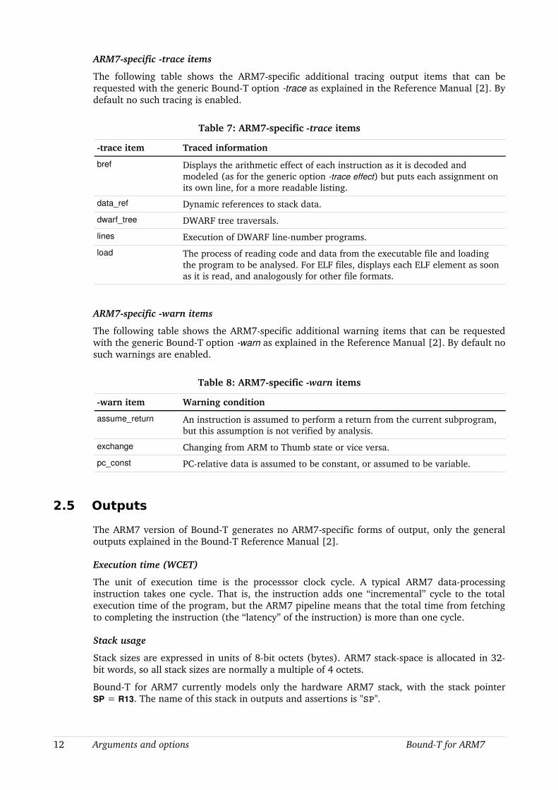
ARM7specific trace items
The following table shows the ARM7specific additional tracing output items that can be requested with the generic BoundT option trace as explained in the Reference Manual [2]. By default no such tracing is enabled.
Table 7: ARM7specific trace items
trace item Traced information
bref Displays the arithmetic effect of each instruction as it is decoded and modeled (as for the generic option trace effect) but puts each assignment on its own line, for a more readable listing.
data_ref Dynamic references to stack data.
dwarf_tree DWARF tree traversals.
lines Execution of DWARF linenumber programs.
load The process of reading code and data from the executable file and loading the program to be analysed. For ELF files, displays each ELF element as soon as it is read, and analogously for other file formats.
ARM7specific warn items
The following table shows the ARM7specific additional warning items that can be requested with the generic BoundT option warn as explained in the Reference Manual [2]. By default no such warnings are enabled.
Table 8: ARM7specific warn items
warn item Warning condition
assume_return An instruction is assumed to perform a return from the current subprogram, but this assumption is not verified by analysis.
exchange Changing from ARM to Thumb state or vice versa.
pc_const PCrelative data is assumed to be constant, or assumed to be variable.
2.5 Outputs
The ARM7 version of BoundT generates no ARM7specific forms of output, only the general outputs explained in the BoundT Reference Manual [2].
Execution time (WCET)
The unit of execution time is the processsor clock cycle. A typical ARM7 dataprocessing instruction takes one cycle. That is, the instruction adds one “incremental” cycle to the total execution time of the program, but the ARM7 pipeline means that the total time from fetching to completing the instruction (the “latency” of the instruction) is more than one cycle.
Stack usage
Stack sizes are expressed in units of 8bit octets (bytes). ARM7 stackspace is allocated in 32bit words, so all stack sizes are normally a multiple of 4 octets.
BoundT for ARM7 currently models only the hardware ARM7 stack, with the stack pointer SP = R13. The name of this stack in outputs and assertions is "SP".
12 Arguments and options BoundT for ARM7

Disassembled instructions (trace decode)
The generic options trace decode and trace effect (and the ARM7specific option trace bref) make BoundT display each analysed instruction in disassembled form, on the fly as the instructions are located, fetched from the memory image, and decoded. Currently, all ARM7 instructions are disassembled into ARM (32bit) form, whether the instructions were encoded in the program as 32bit ARM instructions or as 16bit Thumb instructions. Moreover, instruction mnemonics and register names are displayed in lower case. For example, the Thumb instruction POP {R4} is disassembled into "ldm sp!,{r4}".
The only exception to the ARM disassembly is the Thumb BL instruction, which in fact consists of two consecutive 16bit instructions. BoundT disassembles the two 16bit instructions separately, using the mnemonics "tbl1" and "tbl2" respectively. These are not official mnemonics and cannot be used in Thumb assembly language, where a single BL mnemonic generates the complete pair of 16bit instructions.
BoundT for ARM7 Arguments and options 13

3 WRITING ASSERTIONS ON ARM7 PROGRAMS
3.1 Overview
If you use BoundT to analyse nontrivial programs you nearly always have to write assertions to control and guide the analysis. The most common role of assertions is to set bounds on some aspects of the behaviour of the target program, for example bounds on loop iterations, that BoundT cannot deduce automatically. Assertions must identify the relevant parts of the target program, for example subprograms and variables. The BoundT assertion language has a generic highlevel syntax [3] in which some elements with targetspecific syntax appear as the contents of quoted strings:
• subprogram names,
• code addresses and address offsets,
• variable names,
• data addresses and register names,
• instruction roles, and
• names of targetspecific properties of program parts.
In practice the names (identifiers) of subprograms and variables are either identical to the names used in the source code, or some “mangled” form of the sourcecode identifiers where the mangling depends on the crosscompiler and not on BoundT. However, BoundT defines a targetspecific way to write the addresses of code and data in assertions. Register names are considered a kind of “data address” and are targetspecific.
This chapter continues the userguide part of this Application Note by defining the ARM7specific aspects of the assertion language. In addition to the targetspecific syntax items listed above, we also discuss a "semantic" ARM7 peculiarity: the existence of two different instruction sets, the 32bit ARM set and the 16bit Thumb set, which must be taken into account when asserting the possible callees of a dynamic call.
3.2 Symbolic names
Linkage symbols
When the target program is compiled with debugging, the executable file usually contains a symboltable that BoundT can use to connect the symbolic names of subprograms and variables to their machinelevel addresses for the analysis. You can then write assertions using the symbolic names.
As in most versions of BoundT, you must use the linkage symbols, not the sourcecode identifiers, to name subprograms and variables. Depending on the compiler and linker, the linkage symbols may be the same as the sourcecode identifiers or they may have some additional decoration or mangling. For example, some C compilers add an underscore at the front of the sourcecode identifier, so a C function called foo will have the linkage symbol _foo. The assertions must use the latter form, for example
subprogram "_foo" ... end "_foo";
Scopes
Programs often contain many variables with the same name, in different lexical scopes, that is, in different subprograms, blocks, or file scopes. In the assertion language, the symbolic name of a subprogram or variable can be prefixed with a scope string to show which of the several entities with this name is meant.
14 Writing assertions BoundT for ARM7

The ARM7 version of BoundT uses the normal lexical scopes of symbolic identifiers, which are sourcefile (or module) name, subprogram name, and block name. Details may depend on the compiler and executable file format.
For example, if the C functions foo and bar both contain a variable num, you would write, in an assertion, "foo|num" for the first, and "bar|num" for the second.
3.3 Naming items by address
Subprograms, labels, exception vectors
Subprograms and labels can be named (identified) by the hexadecimal address, in quotes, without any prefixes like “0x” or the like. For example, if subprogram foo is located at 12AC hex (that is, this is the entry address of foo) then foo can be identified by "12AC" or "12ac". For another example, the SWI handler is the subprogram "8", that is, the subprogram that starts at address 8, the SWI exception vector.
Codeaddress offsets
Some forms of assertions define code addresses by giving a code offset relative to a base address. For BoundT/ARM7 a code offset is written as a hexadecimal number possibly preceded by a sign, '–' or '+', to indicate a negative or positive offset. If there is no sign the offset is considered positive.
Assume, for example, that the subprogram Rerun has the entry address 14AC hexadecimal and the subprogram Abandon has the entry address 15A0 hexadecimal. The subprogram with the entry address 14D4 hexadecimal can then be identified in any of the following ways, among many others:
• Using the absolute address:
subprogram address "14D4"
• Using a positive hexadecimal offset relative to the entry point of Rerun:
subprogram "Rerun" offset "28"
• Using a negative hexadecimal offset relative to the entry point of Abandon:
subprogram "Abandon" offset "CC"
Note that the sign, if used, is placed within the string quotes, not before the string.
Variables, registers, memory locations
The registers and other machinelevel storage cells are named in assertions with the “address” keyword, followed by a quoted string that names the cell. Table 9 below lists the nameable storage cells and describes the syntax of their names, with examples. The names are caseinsensitive. The table omits the quotes that must enclose the string.
Table 9: Naming storage cells
Storage cell Syntax (without quotes) Example Meaning
Register R0 .. R15 R<number>
where the number is the number of the regisgter, in decial, 0 .. 15.
R7 Register R7
Condition flag N, Z, C, V Z The Z flag in the CPSR
BoundT for ARM7 Writing assertions 15
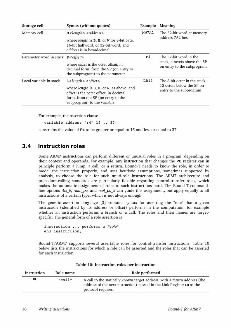
Storage cell Syntax (without quotes) Example Meaning
Memory cell M<length><address>
where length is B, H, or W for 8bit byte, 16bit halfword, or 32bit word, and address is in hexadecimal
MW7A2 The 32bit word at memory address 7A2 hex
Parameter word in stack P<offset>
where offset is the octet offset, in decimal form, from the SP (on entry to the subprogram) to the parameter
P4 The 32bit word in the stack, 4 octets above the SP on entry to the subprogram
Local variable in stack L<length><offset>
where length is B, H, or W, as above, and offset is the octet offset, in decimal form, from the SP (on entry to the subprogram) to the variable
LB12 The 8bit octet in the stack, 12 octets below the SP on entry to the subprogram
For example, the assertion clause
variable address "r4" 15 .. 37;
constrains the value of R4 to be greater or equal to 15 and less or equal to 37.
3.4 Instruction roles
Some ARM7 instructions can perform different or unusual roles in a program, depending on their context and operands. For example, any instruction that changes the PC register can in principle perform a jump, a call, or a return. BoundT needs to know the role, in order to model the instruction properly, and uses heuristic assumptions, sometimes supported by analysis, to choose the role for such multirole instructions. The ARM7 architecture and procedurecalling standards are particularly flexible regarding controltransfer roles, which makes the automatic assignment of roles to such instructions hard. The BoundT commandline options bx_lr, ldm_pc, and set_pc_lr can guide this assignment, but apply equally to all instructions of a certain type, which is not always enough.
The generic assertion language [3] contains syntax for asserting the "role" that a given instruction (identified by its address or offset) performs in the computation, for example whether an instruction performs a branch or a call. The roles and their names are targetspecific. The general form of a role assertion is
instruction ... performs a "role"end instruction;
BoundT/ARM7 supports several assertable roles for controltransfer instructions. Table 10 below lists the instructions for which a role can be asserted and the roles that can be asserted for each instruction.
Table 10: Instruction roles per instruction
Instruction Role name Role performed
BL "call" A call to the statically known target address, with a return address (the address of the next instruction) passed in the Link Register LR as the protocol requires.
16 Writing assertions BoundT for ARM7
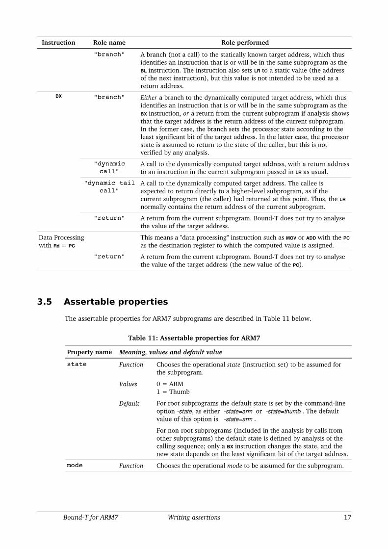
Instruction Role name Role performed
"branch" A branch (not a call) to the statically known target address, which thus identifies an instruction that is or will be in the same subprogram as the BL instruction. The instruction also sets LR to a static value (the address of the next instruction), but this value is not intended to be used as a return address.
BX "branch" Either a branch to the dynamically computed target address, which thus identifies an instruction that is or will be in the same subprogram as the BX instruction, or a return from the current subprogram if analysis shows that the target address is the return address of the current subprogram. In the former case, the branch sets the processor state according to the least significant bit of the target address. In the latter case, the processor state is assumed to return to the state of the caller, but this is not verified by any analysis.
"dynamic call"
A call to the dynamically computed target address, with a return address to an instruction in the current subprogram passed in LR as usual.
"dynamic tail call"
A call to the dynamically computed target address. The callee is expected to return directly to a higherlevel subprogram, as if the current subprogram (the caller) had returned at this point. Thus, the LR
normally contains the return address of the current subprogram.
"return" A return from the current subprogram. BoundT does not try to analyse the value of the target address.
Data Processingwith Rd = PC
This means a "data processing" instruction such as MOV or ADD with the PC
as the destination register to which the computed value is assigned.
"return" A return from the current subprogram. BoundT does not try to analyse the value of the target address (the new value of the PC).
3.5 Assertable properties
The assertable properties for ARM7 subprograms are described in Table 11 below.
Table 11: Assertable properties for ARM7
Property name Meaning, values and default value
state Function Chooses the operational state (instruction set) to be assumed for the subprogram.
Values 0 = ARM1 = Thumb
Default For root subprograms the default state is set by the commandline option state, as either state=arm or state=thumb . The default value of this option is state=arm .
For nonroot subprograms (included in the analysis by calls from other subprograms) the default state is defined by analysis of the calling sequence; only a BX instruction changes the state, and the new state depends on the least significant bit of the target address.
mode Function Chooses the operational mode to be assumed for the subprogram.
BoundT for ARM7 Writing assertions 17

Property name Meaning, values and default value
Values Encoded as in the mode bits M[4:0] of the ARM7 CPSR:
16 = USR = User Mode17 = FIQ = FIQ Mode18 = IRQ = IRQ Mode19 = SVC = Supervisor Mode23 = ABT = Abort Mode27 = UND = Undefined Mode31 = SYS = System Mode
Default For root subprograms the default is 16 = User, or the mode set with the commandline option mode. For nonroot subprograms the default mode is the same as the caller's mode, unless the calling sequence defines another mode, as for example a call with the SWI instruction for which the callee is entered in SVC mode.
For example, the assertion block
subprogram "svc_handler"property "mode" = 19;property "state" = 0;
end “svc_handler”;
makes BoundT analyse the subprogram svc_handler in Supervisor Mode and the ARM state (32bit instructions).
3.6 Defining the state (ARM or Thumb) of dynamic callees
The BoundT assertion language lets you assert which subprograms can be called by a given dynamic call instruction, such as a call via a "function pointer" in the C language. For example, the following assertion lists the functions foo, bar, and gamma as the possible callees:
dynamic call calls "foo" or "bar" or "gamma"; end call;
The callees can be identified by their symbolic names, as in the above example, or by their machine addresses. Of course it is easier and more robust to use the symbolic names, but this also has a problem, as follows.
In ARM7 programs the BX instruction is often used to implement a dynamic call. However, this instruction also changes the operating state, depending on the least significant bit of the target address: a zero selects ARM state, a one selects Thumb state.
If the possible callees of a dynamic BX call are asserted and identified in the assertion by their symbolic names, BoundT looks up their machine addresses in the symboltable (debugging information) from the executable program file. However, for many compilers the address of a Thumb subprogram in the symboltable is the actual (even, 16bitaligned) entry address, not the odd address required by the BX instruction to switch into Thumb state. Thus, the address of a Thumb subprogram can look like the address of an ARM subprogram (a 32bit aligned address). Presumably, all Thumbcapable ARM7 compilers do somehow enter the state of each subprogram in their symboltables, but BoundT does not (yet) understand or use this compilerspecific information.
The problem, then, is how to tell BoundT which state to use for the asserted callee subprograms, when the state is not identified by the leastsignificant bit of the symboltable address. There are several methods, as follows.
18 Writing assertions BoundT for ARM7
Asserting the callee state
The surest method to specify the state of a (callee) subprogram is to write an assertion on the "state" property for this subprogram. For example, if foo is a Thumb subprogram, you write:
subprogram "foo" property "state" = 1; end "foo";
If bar, on the other hand, is an ARM subprogram, you write:
subprogram "bar" property "state" = 0; end "bar";
Singlestate programs
If your program (mainly) uses a single state, you can use the BoundT option no_interwork (or no_iw) which in fact is the default. This makes BoundT assume (in the absence of other information, such as a "state" assertion) that all callees of a dynamic call use the same state as the caller.
Under the opposite option interwork (or iw) BoundT makes the same assumption, but also issues a warning every time it makes this assumption.
Adding the '1' bit by an offset
This method is rather tricksy and perhaps not to be recommended. If you know that the symboltable address associated with a Thumb callee, foo say, is the 16bitaligned, even address, you can use an offset in the callee assertion to mark this callee as a Thumb subprogram:
dynamic call calls "foo" offset "1" or "bar" or "gamma"; end call;
BoundT looks up the (even) address of foo in the symboltable, adds the offset 1, finds that the result is an odd address, and thus knows that foo runs in Thumb state.
Identifying callees by machine address
You can also identify the callees for a dynamic call directly by their machine addresses, as in:
dynamic call calls address "80C9" or address "A77C"; end call;
You should then follow the BX rule: use an odd address for Thumb callees and an even address for ARM callees. Thus, BoundT will use Thumb state for the callee at 80C9 (real entry address 80C8). However, BoundT will still not be sure that an even address indicates ARM state and so will assume that the callee at A77C uses the same state as the caller (and warn about this assumption, if you use the interwork option).
3.7 Stacks
Currently BoundT for ARM7 supports only the standard ARM7 stack, pointed to by the SP register (R13) as defined in the AAPCS [5]. This stack is called “SP”, which is the stackname to be used in stackusage assertions. However, since only one stack is defined, stackusage assertions can also omit the stackname.
The SP register is a “banked” register which means that the ARM7 has a separate instance of the register for each mode, except that User Mode and System Mode use the same instance. Thus, a typical ARM7 program has at least two stack areas: one for User Mode, and one or several for other modes. When an interrupt or exception occurs, the ARM7 automatically switches to the corresponding mode, and the handler executes in that mode and with the SP of that mode. Thus, the handler uses space from the stack for its own mode, not from the stack of the interrupted mode.
BoundT for ARM7 Writing assertions 19
The single stack that BoundT models applies in principle only to one mode, the current mode. In the BoundT model, the SWI instruction is currently the only instruction that can cause sequential (uninterrupted) execution to switch from one mode to another, usually from User Mode to Supervisor Mode and back. (BoundT assumes that no MSR instruction changes the mode.). If a subprogram involves an SWI, the BoundT stackusage analysis will add the (User Mode) stack usage at the point of the SWI to the (Supervisor Mode) stack usage of the SWI handler, which causes an overestimate of the (User Mode) stack usage. However, BoundT also computes and displays the (Supervisor Mode) stack usage of the SWI handler alone, so the correct User Mode stack usage is easily computed manually by subtracting the SWI handler's usage from the total.
Compilerdefined or applicationdefined stacks cannot be analysed at present.
20 Writing assertions BoundT for ARM7

4 THE ARM7 AND TIMING ANALYSIS
4.1 Overview
This chapter begins the “reference manual” part of this Application Note. This chapter gives an overview of the ARM7 processor, focusing on the aspects that affect timing analysis. Chapter 5 explains in detail which ARM7 hardware features BoundT currently supports and how. Chapter 6 moves to the software side and discusses the procedure calling standards (calling protocols, binary interface standards) that BoundT can analyse for ARM7 programs from various crosscompilers. Chapter 7 lists and explains all ARM7specific warning and error messages that BoundT can emit. Finally, Chapter 8 describes the form and meaning of patch files for the patch option.
4.2 The ARM7
Instruction sets
The ARM7TDMI [4] is a 32bit microcontroller core. It has a “von Neumann” architecture with a combined program and data memory space. While many microcontroller implementations have a flash memory for the code, and RAM memory for the data, it is almost always possible to execute code from the RAM, too, and sometimes it is significantly faster than executing flashresident code.
The ARM7TDMI core has pipelined fetch, decode and execute cycles. A special feature of this processor is the ability to operate in two states: the ARM state and the Thumb state. ARM state instructions are 32 bits wide and are typically used in timecritical code. Thumb instructions are 16 bits wide and are typically used in bulk code to reduce the code size.
Integer addition, subtraction and multiplication are supported in hardware but division is not. The core ARM7 does not support hardware floating point operations, but coprocessors can be attached for this.
General registers
In ARM state, there are sixteen main 32bit registers, R0 through R15, but two registers have hardwareassigned special roles: R15 is the Program Counter (PC) and R14 is the Link Register (LR) which holds the return address when a subprogram call occurs. Moreover, R13 is conventionally used as the Stack Pointer (SP), although the push and pop instructions (Load LDR, Load Multiple LDM, Store STR, Store Multiple STM) can use any of R0 R14 to address memory. If the return address is saved elsewhere (for example in the stack) R14 can be used as a general working register.
Since the PC is an addressable register (R15), any instruction that stores a new value in the PC acts like a control transfer and can implement a branch, a call, or a return. Subprogram calls are most directly implemented by the Branch and Link instruction (BL), but for the ARM state the procedure calling standard [5] also allows any code sequence that places the return address in LR and the callee entry address in PC. There is no specific returnfromsubprogram instruction; the callee simply branches to the return address (which is usually saved and recovered from the stack, if not kept in the LR). Programs that mix ARM code with Thumb code are more constrained (see below).
The stack usage and stack layout is defined in software. The procedure calling standard [5] is complex and has many variants depending on the performance goals and the presence of coprocessors. The use of a framepointer register is optional, which means that stackbased parameters and local variables can be accessed in different ways by different compilers.
BoundT for ARM7 ARM7 timing analysis 21
In Thumb state, the registers R0 through R7 can be directly accessed. The PC, LR and SP are accessed by specific instructions (not in the Rn sequence). Nearly all Thumb instructions can be translated to an exactly equivalent ARM instruction.
Instruction alignment and ARM/Thumb state transitions
ARM instructions are aligned on 32bit boundaries, so the lowest two bits of the PC are always zero in ARM state. Thumb instructions are aligned on 16bit boundaries, so the lowest PC bit is zero in Thumb state.
Transition between ARM state and Thumb state is effected by a special instruction, Branch and Exchange (BX), where the lowest bit of the target code address defines the new state: Thumb state is entered if this bit is one, ARM state if this bit is zero (in which case also the next to lowest bit must be zero). Even for Thumb state the actual address that BX loads into the PC has zero in the lowest bit.
The status register and condition flags
The status register (CPSR) contains the conventional condition flags (Z = zero, N = negative, C = carry, V = overflow).
In ARM state, most instructions have an option to set the flags or leave them unchanged. This is indicated in assembly language by an S suffix, for example MOVS sets the flags, but MOV does not. All ARM instructions have a conditioncode field to specify conditional execution of the instruction. The condition is indicated in assembly language by a twoletter suffix, for example MOVEQ = MOV if the Z flag is set.
In Thumb state, most instructions set the condition flags, but only the conditional branch instruction can use them to control program flow. Other Thumb instructions do not have a conditioncode field, so conditional branches must be used for all conditional operations.
Memory
Memory is byteaddressed. Multibyte instructions and operands must usually be aligned on natural boundaries (multiple of item length).
An unusual feature of the ARM7 is the ability to use either littleendian or bigendian memory layout formats for multibyte items. The memory endianness format is selected by a processor input pin and is usually constant for a given system.
Load and store instructions can operate on 32bit quantities or on signed or unsigned 16bit and 8bit quantities, with automatic sign extension according to an instruction option.
Processor modes
To separate usermode processing from systemmode processing and interrupt handling, the ARM7 defines seven different modes of operation: User, Fast Interrupt (FIQ), Interrupt (IRQ), Supervisor, Abort, System and Undefined.
Some of the registers are “banked” per mode so that each mode has its own private instance of these registers. All modes have their own instances of the Program Status Register, the PC and the LR, except that User Mode and System Mode share the same registers. The FIQ mode has in addition its own instances of R8 through R12.
Interrupts and traps, for which ARM7 uses the common term exceptions, are entered through fixed exception vectors in the memory area from address zero (reset into Supervisor mode) through hexadecimal 1C (service FIQ request). The vector location typically contains a branch to the exception handler. ARM7 devices with both readonly and readwrite memory can generally “map” these vector addresses either to the readonly memory or to the readwrite memory, depending on an input pin or on some control register.
22 ARM7 timing analysis BoundT for ARM7
4.3 Static execution time analysis on the ARM7
General
The ARM7 architecture is very regular and suitable for static analysis by BoundT. Instruction execution timing usually depends only on the controlflow and is independent of the data being processed. The exception is the multiplication instruction for which the time depends on the number of nontrivial high bytes in the multiplier value. Memory access times are also variable in some ARM7 implementations (devices, chips).
When a branch occurs, the ARM7 reloads the instruction pipeline before continuing. This means that there are no “delayed” branches, which simplifies controlflow analysis.
The following architectural features can lead to approximate (overestimated) execution times for the concerned instructions:
• Multiplication instructions.
• Memory wait states that vary in number depending on the address or access history.
• Coprocessor timing.
See section 5.9 for more information about the approximations.
In addition, the weak procedure calling standard means that problems may arise in the controlflow and callgraph analysis. See section 5.4 for more information about this issue.
Instruction cycle types: N, S, I, C cycles
The execution of an ARM7 instruction consists of some number of operation/memory cycles of four kinds: sequential or S cycles where the processor accesses the same memory address as in the preceding cycle or an address one word or halfword after the preceding address; nonsequential or N cycles where the processor accesses some other memory address; internal or I cycles where the processor does not access memory; and coprocessor registertransfer or C cycles in which the processor transfers data from or to a coprocessor without involving the memory system.
For example, a normal dataprocessing instruction, such as the addition of two registers, needs one S cycle to advance the pipeline; the data processing is performed concurrently with the instruction fetch. On the other hand, a branch instruction needs one N cycle to fetch the first instruction from the target address into the first pipeline stage, followed by two S cycles to fetch the two following instructions and thus fill the pipeline.
It is unclear if the distinction between S and N cycles depends dynamically on the actual (computed) address relative to the preceding address, or statically on the instruction type. The latter is indicated in [4] which states the number of S and N cycles for each instruction unconditionally.
The actual duration of an N, S, I, or C cycle, in terms of some clock cycles, can depend on the memory interface speed. In the current version of BoundT/ARM7 the cycle durations are assumed to be one clock cycle. In future versions they will be settable by commandline options for all subprograms or by “property” assertions for specific subprograms or even specific loops; the latter is useful if the memory is divided into banks of different speeds.
BoundT for ARM7 ARM7 timing analysis 23
5 SUPPORTED ARM7 FEATURES
5.1 Overview
This section specifies which ARM7 instructions, registers and condition flags are supported by BoundT. We will first describe the extent of support in general terms, with exceptions listed later. Note that in addition to the specific limitations concerning the ARM7, BoundT also has generic limitations as described in the BoundT User Guide [1]. For reference, these are briefly listed in section 5.1.
General support level
In general, when BoundT is analysing a target program for the ARM7, it can decode and correctly time all instructions, with minor approximations except for coprocessor instructions and variable memory access times.
BoundT can construct the controlflow graphs and callgraphs for all instructions, assuming that the program obeys one of the supported procedure calling standards listed in chapter 6. Note that there are generic limitations on the analysis of branches and calls that use a dynamically computed target address or a dynamically computed return address. The user may have to assert the role performed by some instructions when BoundT would otherwise choose the wrong role; see section 3.4.
BoundT can start the analysis of a root (topmost) subprogram in ARM state or Thumb state, depending on commandline options and assertions. When BoundT finds a BX instruction it tries to deduce the value of the target address and in particular its leastsignificant bit, to detect state changes from ARM state to Thumb state and vice versa.
When analysing loops to find the loopcounter variables, BoundT is able to track all the 32bit integer (fixed point) additions and subtractions. BoundT correctly detects when this integer computation is overridden by other computations, such as multiplications or coprocessor operations in the same registers. Note that there are generic limitations on the analysis of pointers to variables.
Computations that use integer types narrower than 32 bits (eg. 16bit or 8bit integers) may be harder to analyse because compilers insert masking AND instructions to emulate true 16 or 8bit wraparound behaviour. Computations that use integers wider than 32 bits cannot be analysed at present because BoundT for ARM7 does not try to detect carrychained combinations of the 32bit computations that actually compute with 64bit or wider values.
In summary, for a program written in a compiled language such as Ada or C with a compiler that uses one of the supported procedure calling standards, it is unlikely that the BoundT user will meet with any constraints or limitations that are specific to the ARM7 target system.
Reminder of generic limitations
To help the reader understand which limitations are specific to the ARM7 architecture, Table 12 below gives a compact list of the generic limitations of BoundT and remarks on their application to the ARM7.
Table 12: Generic limitations of BoundT
Generic Limitation Remarks for ARM7 target
Understands only integer operations in loopcounter computations.
All results from floatingpoint (coprocessor) operations are considered opaque.
24 Supported ARM7 features BoundT for ARM7
Generic Limitation Remarks for ARM7 target
Understands only addition, subtraction and multiplication by constants, in loopcounter computations.
No implications specific to the ARM7.
Assumes that loopcounter computations never suffer overflow.
No implications specific to the ARM7.
Can bound only counterbased loops. No implications specific to the ARM7.
May not resolve aliasing in dynamic memory addressing.
State changes due to BX are not detected if the dynamic target address is not resolved. But if the address is not resolved, the analysis fails anyway because the callee is unknown.
May ascribe the wrong sign to an immediate (literal) constant operand.
No implications specific to the ARM7.
ARM7 features with incomplete models or analysis
The following are the aspects of the ARM7 that are incompletely modelled in BoundT, or where analysis may not always provide enough information to resolve the model's effects on execution time or stack usage:
• State changes from ARM to Thumb and vice versa. See section 5.2.
• Mode changes with the MSR instruction. See section 5.3.
• Banked registers for nonUSR modes. See section 5.3.
• Controltransfer instructions with dynamic target addresses. See section 5.4.
• Some computational results are modelled as unknown. See section 5.5.
• Condition codes when overflow (V flag) happens. See section 5.6.
• Coprocessor computations are not modelled, and all coprocessor registers are considered to have unknown values. See section 5.8.
5.2 Operating state and the BX instruction
An ARM7 processor starts in ARM state. During execution, it can switch into Thumb state or back using the Branch and Exchange (BX) instruction. If an exception (trap or interrupt) occurs, the processor automatically switches into ARM state to start handling the exception. When the handler returns, the interrupted state is reestablished.
BoundT can decode and analyse both ARM instructions and Thumb instructions. However, BoundT is not usually asked to analyse the program starting from the reset address (address zero), but from some subprogram, called a root subprogram. To find out if the analysis should start in ARM state or in Thumb state, BoundT tries to look up the subprogram's state from the program's symbol table. If this information is missing, BoundT uses the commandline options state=arm or state=thumb to define the initial state for all root subprograms, with state=arm the default. To define the initial state for a specific subprogram, assert the value of the “state” property as explained in section 3.5.
BoundT decodes and analyses Branch And Exchange (BX) instructions. The state after a BX is set by the least significant bit in the value of the operand register. Thus BoundT can track the resulting statechange only if it can statically deduce the exact value of the operand register. Otherwise, BoundT reports an error and considers the BX to terminate the current subprogram. However, you can assert that this BX performs a "dynamic call" role, and then assert the identity of the callee or callees.
BoundT for ARM7 Supported ARM7 features 25

Since exception handlers are usually triggered asynchronously, they are normally analysed as root subprograms and so the question of switching into ARM state for the handler does not arise. However, the Software Interrupt handler is invoked synchronously by the SWI instruction. BoundT starts the analysis of the SWI handler in ARM state (and SVC mode).
5.3 Operating mode and the MSR and SWI instructions
The ARM7 operating mode influences the behaviour and legality of instructions. Some instructions are not allowed in User Mode, and some instructions behave differently in User Mode and other modes. Therefore BoundT must know, or assume, in which mode a subprogram will be executed, before BoundT can decode and model the subprogram's instructions and behaviour.
BoundT considers the operating mode (and the operating state) to be part of the “program control state” of the ARM7, just as the PC register is. This means that BoundT must know or assume the correct mode (and state) when it reads instructions from the executable program's memory image, decodes them, and builds the controlflow graph. BoundT generally assumes that all root subprograms begin execution in User Mode; this assumption be changed with the commandline option mode (see Table 4 on page 8) or with subprogramspecific assertions on the “mode” property (see section 3.5).
The ARM7 instruction MSR sets the program status register to the value of a general (data) register and can change the operating mode. However, BoundT assumes that the MSR instruction does not change the mode. If an MSR does change the mode, the analysis may fail because the execution then uses another set of banked registers and another stack, while the BoundT model and analysis continue with the same registers and stack.
When BoundT encounters a call instruction other than an SWI, it assumes that the callee starts execution in the same mode as the caller uses. An assertion can override this by specifying another value of the "mode" property for the callee subprogram. A warning is emitted for any call where the modes of caller and callee differ.
BoundT models an SWI instruction as a call to the exception handler vector at address 8. The handler (the callee) is entered in ARM state and SVC mode. When the handler returns, the caller continues execution at the instruction after the SWI instruction, in the caller's original state and mode.
Banked registers are not modelled separately, because BoundT generally assumes that the operating mode is not changed within the subprograms under analysis at one time. The only exception here is the SWI instruction, which does change to SVC mode for executing the SWI handler. BoundT assumes that the effect of the SWI handler on the caller's registers (usually User Mode registers) is governed by the normal procedure calling standard.
BoundT assumes that asynchronous exception processing (FIQ, ABT, IRQ, UND) preserves the registers of the interrupted process (USR, SYS). For SVC registers see SWI above.
5.4 Control-transfer instructions
Why ARM7 control transfers are tricky
Controltransfer instructions are those instructions that directly or indirectly change the PC. The analysis of ARM7 control transfers is trickier than in most other processors because the ARM7 has few dedicated instructions or instruction sequences for calling subprograms and returning from subprograms; instead, calls and returns are implemented by suitable use of combination of instructions that can perform several roles.
26 Supported ARM7 features BoundT for ARM7

In ARM state, the controltransfer instructions are the branch instruction B, branch with link BL, branch and exchange BX, software interrupt SWI, and any other instruction that stores a new value in the PC register. The latter group includes data processing instructions such as MOV and ADD and load instructions such as LDR and LDM.
Only one of the ARM controltransfer instructions is specifically intended for subprogram calls: the branch with link instruction, BL. This instruction defines only the role played by the Link Register (R14), which BL sets to the return address (the address of the next instruction after BL) before branching to the entry point of the called subprogram.
In Thumb state, the controltransfer instructions are the unconditional branch B, conditional branch Bxx (xx = condition code), branch and link BL (implemented as two consecutive 16bit instructions), branch and exchange BX, software interrupt SWI, a POP instruction when the PC is included in the list of popped registers, and any "hi register operation" that stores a new value in the PC register. The latter group includes MOV and ADD but not any load instructions. Again, only the BL instruction is specifically intended for subprogram calls.
However, the ARM7 procedure calling standards, as defined in [5] and [6], do not standardise the instruction sequences to be used for subprogram calls, subprogram preludes and postludes, or return from subprogram. For example, a call can be implemented by any instruction sequence that places a return address in LR and a subprogram's entry address in PC. The return address can (in principle) point anywhere, not necessarily to the instruction after the call sequence. Likewise, a subprogram can return by any instruction sequence that places the return address in the PC. Thus, a call or return can look very much like a mere branch within one and the same subprogram. Moreover, when the last action of a subprogram is to call another subprogram, the call is known as a “tail call” and is often coded as a branch, letting the callee inherit the return address of the caller.
Factors that define the role of a controltransfer instruction
To analyse a controltransfer instruction, BoundT must classify the instruction as a branch (jump) within the current subprogram, or a call to another subprogram (possibly a tail call optimised into a branch), or a return from the current subprogram. Moreover, while some controltransfer instructions give a statically known target address, others take the target address from a register with a dynamically computed value. The classification must thus also consider branches with a dynamic target and calls with a dynamic target.
BoundT chooses the role of a controltransfer instruction based on several factors, here listed in descending priority order:
• Whether the instruction is the second instruction of an idiomatic pair of consecutive instructions which together perform a certain role (see Table 14 below).
• Whether a specific role is asserted for this instruction (per section 3.4).
• Commandline options that suggest roles for certain kinds of instruction: the options bx_lr, ldm_pc, and set_pc_lr.
• The modelled value of the LR register at the controltransfer instruction, when the option lr is used.
Modelling dynamic transfers of control
Some controltransfer instructions are modelled as dynamic branches or dynamic calls. In some such cases, BoundT tries to resolve the target address, or the set of possible target address, using various kinds of dataflow analysis. For a dynamic call, the possible callees can also be defined by an assertion. An unresolved dynamic branch (that is not a dynamic call) cannot be resolved by assertions and appears as a return from the current subprogram, for the purposes of executiontime and stackusage analysis. An error message is of course emitted for unresolved dynamic branches and calls.
BoundT for ARM7 Supported ARM7 features 27
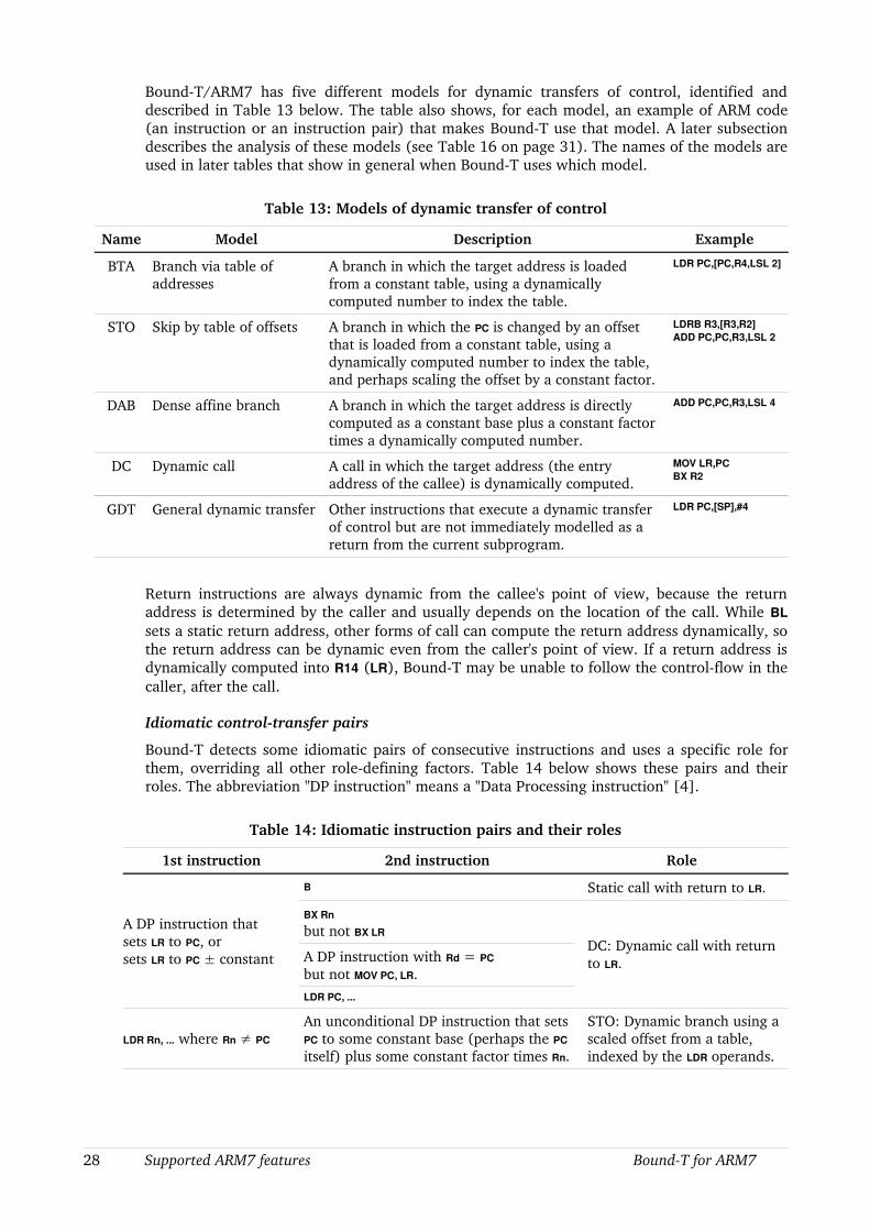
BoundT/ARM7 has five different models for dynamic transfers of control, identified and described in Table 13 below. The table also shows, for each model, an example of ARM code (an instruction or an instruction pair) that makes BoundT use that model. A later subsection describes the analysis of these models (see Table 16 on page 31). The names of the models are used in later tables that show in general when BoundT uses which model.
Table 13: Models of dynamic transfer of control
Name Model Description Example
BTA Branch via table of addresses
A branch in which the target address is loaded from a constant table, using a dynamically computed number to index the table.
LDR PC,[PC,R4,LSL 2]
STO Skip by table of offsets A branch in which the PC is changed by an offset that is loaded from a constant table, using a dynamically computed number to index the table, and perhaps scaling the offset by a constant factor.
LDRB R3,[R3,R2]ADD PC,PC,R3,LSL 2
DAB Dense affine branch A branch in which the target address is directly computed as a constant base plus a constant factor times a dynamically computed number.
ADD PC,PC,R3,LSL 4
DC Dynamic call A call in which the target address (the entry address of the callee) is dynamically computed.
MOV LR,PC BX R2
GDT General dynamic transfer Other instructions that execute a dynamic transfer of control but are not immediately modelled as a return from the current subprogram.
LDR PC,[SP],#4
Return instructions are always dynamic from the callee's point of view, because the return address is determined by the caller and usually depends on the location of the call. While BL sets a static return address, other forms of call can compute the return address dynamically, so the return address can be dynamic even from the caller's point of view. If a return address is dynamically computed into R14 (LR), BoundT may be unable to follow the controlflow in the caller, after the call.
Idiomatic controltransfer pairs
BoundT detects some idiomatic pairs of consecutive instructions and uses a specific role for them, overriding all other roledefining factors. Table 14 below shows these pairs and their roles. The abbreviation "DP instruction" means a "Data Processing instruction" [4].
Table 14: Idiomatic instruction pairs and their roles
1st instruction 2nd instruction Role
A DP instruction thatsets LR to PC, orsets LR to PC ± constant
B Static call with return to LR.
BX Rn but not BX LR
DC: Dynamic call with return to LR.A DP instruction with Rd = PC
but not MOV PC, LR.LDR PC, ...
LDR Rn, ... where Rn ≠ PC
An unconditional DP instruction that sets PC to some constant base (perhaps the PC
itself) plus some constant factor times Rn.
STO: Dynamic branch using a scaled offset from a table, indexed by the LDR operands.
28 Supported ARM7 features BoundT for ARM7

Tracking the Link Register LR = R14 with the option lr
In arithmetic instructions the Link Register LR = R14 is modelled as a normal register. This means that the LR can be used as a working register for any calculation, including loop counting.
The commandline option lr can be used to make BoundT track the definitional state of LR in a special way for the purpose of detecting calls and returns (see Table 15 below). For this purpose, four LR states are distinguished:
• Entry state: on entry to a subprogram, LR is assumed to contain the address to which the subprogram shall return.
• Set to static value: a static value has been stored in LR, to act as the return address for the next branch instruction. BoundT can continue controlflow analysis after the call.
• Set to dynamic value: a dynamic value has been stored in LR, to possibly act as the return address for the next branch instruction. BoundT must use arithmetic analysis to continue controlflow analysis after the call.
• Postcall: upon return from a call, LR is considered to have an opaque and irrelevant value.
Under the lr option, the LR state influences the classification of PCsetting instructions into branches, calls or returns, as shown in Table 15 below. Therefore BoundT makes the LR state a part of the “program control state” which identifies nodes in the controlflow graph. This means that any instruction that can be reached with different LR states (due, for example, to a conditional call before the instruction) will create as many different nodes and paths in the controlflow graph. This expansion can complicate the graph considerably; the graph can even become irreducible, whichs prevents its analysis. Therefore you should use the lr option only when necessary, and otherwise use the default (corresponding to the option no_lr). You may prefer to use instructionrole assertions (section 3.4) or the other commandline options bx_lr or ldm_pc, rather than the option lr.
Choosing the role of a standalone controltransfer instruction
Table 15 below shows how BoundT currently models ARM7 controltransfer instructions that are not part of an idiomatic instruction pair (as listed in Table 14) and for which a specific role has not been asserted (per section 3.4). The table also shows the options that have some influence on this classification. The table is written assuming ARM state, but as each Thumb controltransfer instruction has a directly analogous ARM instruction (when the POP {PC} instruction is considered analogous to LDM {PC}) the table can be applied to Thumb state also.
Table 15: Modelling ARM7 controltransfer instructions
Instruction Modelled as... When... Options
B Tail call, static callee, return to higherlevel subprogram (not to the current subprogram)
The target address is identified as the entry point of a subprogram (in the symbol table, or by an assertion), the B instruction is not in an exception vector, and the option tail_calls is enabled.
tail_calls [2]
elf_locals
Branch Otherwise, that is, if the B instruction is in an exception vector, or the target address is not identified as the entry point of a subprogram, or the option no_tail_calls is used.
tail_calls [2]
elf_locals
BL Call, static callee, return to next instruction in current subprogram
Always.
BoundT for ARM7 Supported ARM7 features 29
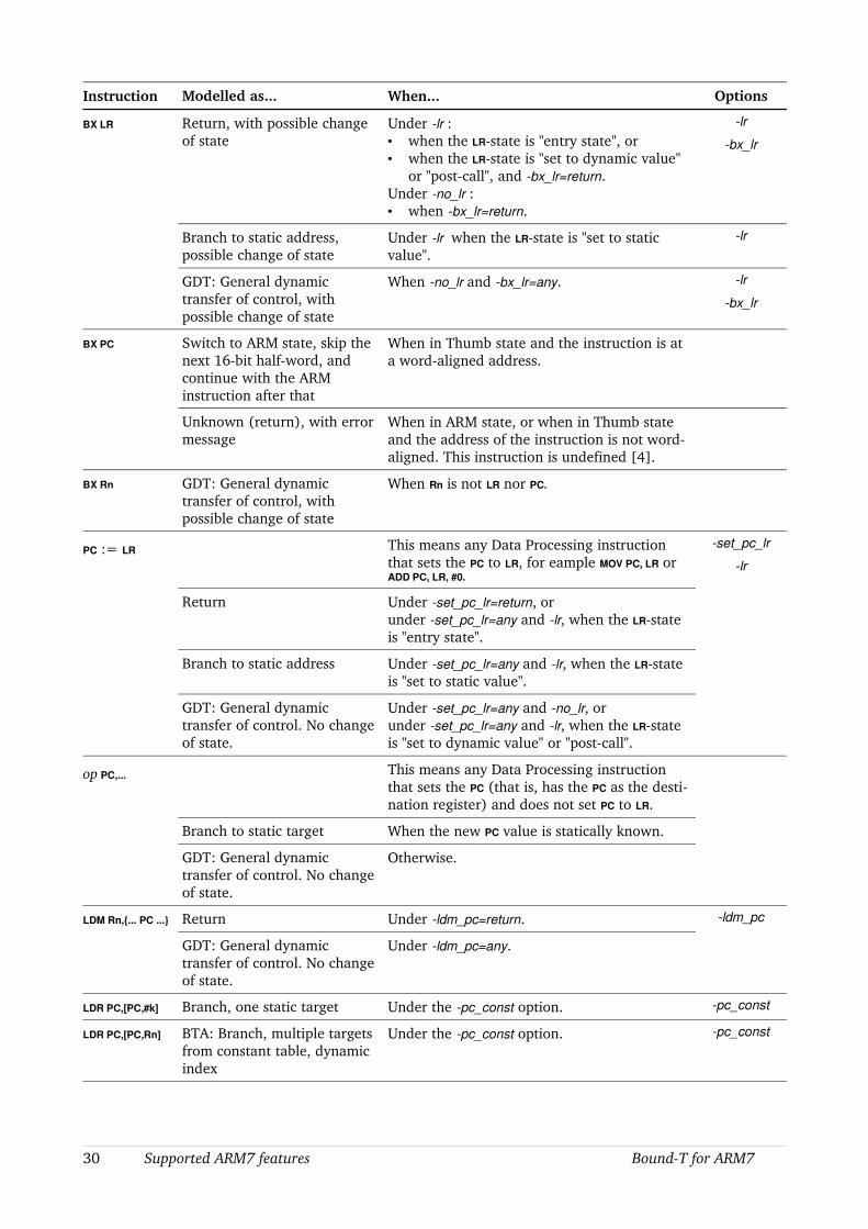
Instruction Modelled as... When... Options
BX LR Return, with possible change of state
Under lr :• when the LRstate is "entry state", or• when the LRstate is "set to dynamic value"
or "postcall", and bx_lr=return.Under no_lr :• when bx_lr=return.
lr
bx_lr
Branch to static address, possible change of state
Under lr when the LRstate is "set to static value".
lr
GDT: General dynamic transfer of control, with possible change of state
When no_lr and bx_lr=any. lr
bx_lr
BX PC Switch to ARM state, skip the next 16bit halfword, and continue with the ARM instruction after that
When in Thumb state and the instruction is at a wordaligned address.
Unknown (return), with error message
When in ARM state, or when in Thumb state and the address of the instruction is not wordaligned. This instruction is undefined [4].
BX Rn GDT: General dynamic transfer of control, with possible change of state
When Rn is not LR nor PC.
PC := LR This means any Data Processing instruction that sets the PC to LR, for eample MOV PC, LR or ADD PC, LR, #0.
set_pc_lr
lr
Return Under set_pc_lr=return, orunder set_pc_lr=any and lr, when the LRstate is "entry state".
Branch to static address Under set_pc_lr=any and lr, when the LRstate is "set to static value".
GDT: General dynamic transfer of control. No change of state.
Under set_pc_lr=any and no_lr, orunder set_pc_lr=any and lr, when the LRstate is "set to dynamic value" or "postcall".
op PC,... This means any Data Processing instruction that sets the PC (that is, has the PC as the destination register) and does not set PC to LR.
Branch to static target When the new PC value is statically known.
GDT: General dynamic transfer of control. No change of state.
Otherwise.
LDM Rn,{... PC ...} Return Under ldm_pc=return. ldm_pc
GDT: General dynamic transfer of control. No change of state.
Under ldm_pc=any.
LDR PC,[PC,#k] Branch, one static target Under the pc_const option. pc_const
LDR PC,[PC,Rn] BTA: Branch, multiple targets from constant table, dynamic index
Under the pc_const option. pc_const
30 Supported ARM7 features BoundT for ARM7
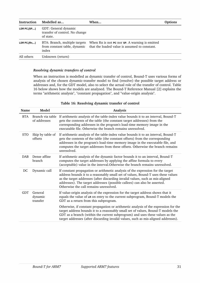
Instruction Modelled as... When... Options
LDR PC,[SP,...] GDT: General dynamic transfer of control. No change of state.
LDR PC,[Rn,...] BTA: Branch, multiple targets from constant table, dynamic index
When Rn is not PC nor SP. A warning is emitted that the loaded value is assumed to constant.
All others Unknown (return)
Resolving dynamic transfers of control
When an instruction is modelled as dynamic transfer of control, BoundT uses various forms of analysis of the chosen dynamictransfer model to find (resolve) the possible target address or addresses and, for the GDT model, also to select the actual role of the transfer of control. Table16 below shows how the models are analysed. The BoundT Reference Manual [2] explains the terms "arithmetic analysis", "constant propagation", and "valueorigin analysis".
Table 16: Resolving dynamic transfer of control
Name Model Analysis
BTA Branch via table of addresses
If arithmetic analysis of the tableindex value bounds it to an interval, BoundT gets the contents of the table (the constant target addresses) from the corresponding addresses in the program's loadtime memory image in the executable file. Otherwise the branch remains unresolved.
STO Skip by table of offsets
If arithmetic analysis of the tableindex value bounds it to an interval, BoundT gets the contents of the table (the constant offsets) from the corresponding addresses in the program's loadtime memory image in the executable file, and computes the target addresses from these offsets. Otherwise the branch remains unresolved.
DAB Dense affine branch
If arithmetic analysis of the dynamic factor bounds it to an interval, BoundT computes the target addresses by applying the affine formula to every (acceptable) value in the interval.Otherwise the branch remains unresolved.
DC Dynamic call If constant propagation or arithmetic analysis of the expression for the target address bounds it to a reasonably small set of values, BoundT uses these values as the target addresses (after discarding invalid values, such as misaligned addresses). The target addresses (possible callees) can also be asserted. Otherwise the call remains unresolved.
GDT General dynamic transfer
If valueorigin analysis of the expression for the target address shows that it equals the value of LR on entry to the current subprogram, BoundT models the GDT as a return from this subprogram.
Otherwise, if constant propagation or arithmetic analysis of the expression for the target address bounds it to a reasonably small set of values, BoundT models the GDT as a branch (within the current subprogram) and uses these values as the target addresses (after discarding invalid values, such as misaligned addresses).
BoundT for ARM7 Supported ARM7 features 31

5.5 Computational operations
Operations with opaque results
The following computational results are modelled as unknown (opaque):
• Carryout from all shift and rotate operations except LSL #0. Depending on the rest of the instruction, this unknown carryout may or may not define the new value of the C flag.
• All results of RRX, LSR #32, ASR #32.
• All results of MUL, UMULL, SMULL, MLA, UMLAL, SMLAL.
• All condition flags after an MSR (but BoundT assumes that the mode is not changed).
• The CPSR value stored by an MRS instruction.
• All results and flags from coprocessor instructions.
MVN operation
The MVN operation stores the bitwise logical negation ("not") of the second operand into the destination register. Logical negation is not usually important in the arithmetic analysis of loop counters. However, ARM7 compilers seem to use this instruction as a way to (almost) reverse the sign of the operand, using two's complement arithmetic. The result is therefore modelled as – operand2 – 1. The C flag becomes unknown.
LSL with zero shiftcount (LSL #0)
For this special case, the result is just the input operand and the carryout is the input value of the C flag.
5.6 Condition codes
The CPSR condition flags that are modelled are Z (result zero), N (result negative), C (carry or borrow from bit 31), and V (signed integer overflow). Note that the ARM7 carry flag C works unconventionally for subtractions: it is set if there is no borrow, which is the opposite of the conventional logic.
Each ARM instruction contains a 4bit conditioncode field that defines the condition for executing the instruction. There are 15 condition codes (the 4bit value 1111 is not used). Each condition code corresponds to a Boolean function of the condition flags Z, N, C, and V. For example, the condition code EQ (equal, zero) is defined as Z = 1, and the condition code GE (greater or equal, signed) as N = V.
Although BoundT does model the V flag in some analysis phases (mainly constant propagation), the most complex and powerful analysis phase, the "arithmetic" analysis, does not handle overflows. Therefore BoundT by default models the ARM7 condition codes as functions only of Z, N, and C, with the assumption that V = 0. For example, this models GE as N = 0.
The commandline option vsc makes BoundT include V and use the exact model for the condition codes. However, this does not enable analysis of overflow in loop bounds or other complex computations that require the arithmetic analysis phase.
Direct assignment to the CPSR register by the MSR instruction is modelled as storing opaque values in the condition flags.
32 Supported ARM7 features BoundT for ARM7
5.7 Memory data
Words, halfwords, octets
ARM7 instructions can access memory in units of 32bit words, 16bit halfwords, or 8bit octets. When a 16bit quantity is loaded from memory into a 32bit register the load instruction can specify sign extension (LDRSH) or not (LDRH). An 8bit quantity is always loaded with sign extension (LDRSB).
BoundT can model memory locations as 32bit words, 16bit halfwords, or 8bit octets, but currently considers all memory data as potentially signed. Moreover, BoundT does not currently constrain the value of a memory datum by its length; for example, there is no automatic constraint that the value of an 8bit memory datum must be in the range 128 .. 255.
Dynamically addressed data
An ARM7 instruction cannot specify the absolute address of a memory location directly, as an immediate, static value. Instead, all memory accesses use registerbased addressing. BoundT uses dataflow analysis to bound the possible register values. If the analysis results in a single possible address, BoundT can use the accessed memory location as a variable in the rest of the analysis. For example, if this variable is used as a loop counter, it is available to the loopbound analysis.
The analysis of the memory address of a load or store instruction can also show that the address has a constant offset within the stack frame of the current subprogram, in which case it represents either a parameter to the current subprogram or a local variable in the current subprogram, and is then available to the further analysis.
If the memory address of a load or store instruction cannot be bounded by analysis to a single value, or to a single stackframe offset, BoundT considers the instruction to access an unknown address. A value loaded from an unknown address is considered opaque. A store to an unknown address is currently modelled as having no effect, which introduces a risk of aliasing, to be corrected in a future version of BoundT.
Overlapping data
While BoundT separates between word, halfword, and octet memory locations, it does not currently check for aliasing or overlapping of memory variables. For example, an instruction that stores an octet in memory is not considered to modify the memory word that contains this octet. This defect will be corrected in future versions of BoundT.
5.8 Coprocessors
ARM7 systems can have one or several coprocessors. Each coprocessor has its own registers and its own condition flags and executes its own kind of operations or computations, for example floatingpoint arithmetic. BoundT does not currently model any specific coprocessor(s), and so:
• All coprocessor registers and flags are assumed to have unknown values.
• If a coprocessor register is loaded into an ordinary register by an MRC instruction, the loaded value is considered unknown.
• If coprocessor data are stored in memory by an STC instruction, the stored values are considered unknown.
• Any conditions depending on coprocessor flags are considered unknown (possibly true, possibly false).
• The execution time of coprocessor instructions is set by commandline options.
BoundT for ARM7 Supported ARM7 features 33

5.9 Time accuracy and approximations
BoundT reports WCET values that take into account most of the timing features of the ARM7. This section explains these features, how BoundT models them, and where BoundT must make assumptions or approximations.
Timing of conditional instructions
All ARM instructions can be conditional in the sense that the instruction is executed only if a condition code is true. The Data Sheet [4] is not entirely clear on the execution time of a conditional instruction when the condition is false. BoundT assumes that such an instruction takes one sequential cycle (S cycle). This agrees with measurements to date.
Multiplication instructions
The execution time of the ARM7 multiplication instructions (MUL, MLA, UMULL, UMLAL, SMULL, SMLAL) is variable. Depending on the value of one of the multiplicands (factors) the number of cycles in the 8bit multiplier array ranges from 1 to 4. BoundT assumes the worst case, 4 multiplier cycles, which can overestimate the real time by 3 cycles per instruction.
Coprocessor operations
Execution times for all coprocessorrelated instructions (MCR, MRC, LDC, STC) are set by the user with commandline options.
Memory wait states
BoundT for ARM7 currently assumes that memory is accessed with no wait states. In other words, the execution time is defined solely by the pipeline cycles that each instruction requires.
Summary of approximations
The following table lists the cases where BoundT uses an approximate model of the timing of ARM7 instructions.
Table 17: Approximations for instruction times
Case Description Maximum Error
Memory wait states At present BoundT assumes that all memory accesses execute with no wait states.
Depends on the actual number of wait states.
Multiply The execution time of a multiplication depends on the value of the multiplier. BoundT assumes the worst case.
Three internal (I) cycles per multiplication
Coprocessor operations
Userspecified. Depends on the userspecified times.
34 Supported ARM7 features BoundT for ARM7
6 PROCEDURE CALLING STANDARDS
6.1 Procedure calls in the ARM7
In this chapter, we explain how BoundT analyses the dataflow across subprogram calls and returns.
The ARM7 instruction set [4] contains only one instruction specifically intended for subprogram calls: the Branch and Link instruction, BL. This instruction defines only the role played by the Link Register (R14). All other aspects of subprogram calling, such as the passing of parameters, the saving and restoring of registers, and the use of the stack, are defined by software rules. Such rules are usually called a procedure calling standard or calling protocol.
The Procedure Calling Standard for ARM (AAPCS), as defined in [5], adds to the use of LR by defining the parameterpassing methods, the saving of registers across calls, and some aspects of the stack usage. However, compilers that generate ARM7 code are not forced to follow the AAPCS rules and can define their own rules. The ARMThumb Procedure Call Standard [6] defines the "interworking" of ARM and Thumb subprograms and the state changes (with BX) when a subprogram running in one state calls a subprogram running in another state, or returns to a caller running in another state.
6.2 Model of calling standard in Bound-T
BoundT normally analyses all the subprograms in a call tree. As part of the analysis of a callee subprogram, BoundT discovers (some of) the storage locations) that hold parameters or other input variables for this subprogram. Corresponding analysis of the caller subprograms discover how the callers supply values for these parameters or other input variables. Thus, BoundT generally does not need to know all about the calling protocol and the parameterpassing mechanisms, but can discover these datapaths on its own. However, the current design of BoundT implies that BoundT needs to know which registers, or other storage locations, can be altered by a subprogram call, and which cannot – the latter are called “invariant across a call”. In other words, BoundT needs to know which registers are “callersave” (the callee can change them) and which are “calleesave” (if the callee changes them, the callee has to restore their original values before returning).
For ARM7 programs BoundT currently assumes the rules shown in Table 18 below. This classification is of course not applicable to register R15 = PC; the rule that applies to the PC is that the callee returns with PC equal to the value of LR on entry to the caller, the return address.
Table 18: Invariance of registers and other storage cells in calls
Register Role
Registers R0 .. R3, R12, R14 Not invariant: callersave (scratch).
Registers R4 .. R11, R13 Invariant: calleesave.
Condition flags Z, C, N Not invariant.
Stack parameters for the caller Invariant.
Local stack variables of the caller Not invariant.
Statically allocated memory Not invariant.
BoundT for ARM7 Calling standards 35

7 WARNINGS AND ERRORS FOR ARM7
7.1 Warning messages
The following table lists the BoundT warning messages that are specific to the ARM7 or that have a specific interpretation for this processor. The messages are listed in alphabetical order, perhaps slightly altered by variable fields in the message; such fields are indicated by italic text. The BoundT Reference Manual [2] explains the generic warning messages, all of which may appear also when the ARM7 is the target. The BoundT Assertion Language manual [3] explains the generic warnings related to assertions. The IntelHex Technical Note [7] explains the warnings that can arise for IntelHex input files.
The specific warning messages for ARM7 refer mainly to unsupported or approximated features of the ARM7.
As BoundT evolves, the set and form of these messages may change, so this list may be out of date to some extent. However, we have tried to make the messages clear enough to be understood even without explanation. Feel free to ask us for an explanation of any BoundT output that seems obscure.
Table 19: Warning messages from BoundT/ARM7
Warning Message Meaning and Remedy
Asserted callee at T assumed to use same state (S) as the caller
Reasons This BX instruction performs a dynamic call, and an assertion resolves the call by listing the possible callees, including a callee at address T, but there is no information on the operating state (ARM or Thumb) used by this callee. BoundT assumes that the callee uses the same state (S) as the caller subprogram (in which the BX instruction lies).
This warning is issued only under the interwork option.
Action Check that callee assertion is correct, and that the subprogram at T indeed uses state S. Perhaps use an assertion on the "state" property to declare the correct state for this subprogram. See section 3.6.
Asserted role R ignored for dynamic flow
Reasons This Data Processing instruction has the PC as the destination register and will be modelled as a general dynamic transfer of control (model GDT). An instructionrole assertion says that the instruction performs role R, but BoundT does not yet support such assertions for this type of instruction.
Action Remove the assertion and try to use commandline options to make BoundT use the correct role model. If this is not possible, tell Tidorum about the problem.
Assumed to perform a return type Reasons BoundT assumes that this controltransfer instruction performs a return from the current subprogram, of a certain type, such as "return by BX", "return by pc := lr", "return by ldm {.. pc ..}", or "return by Thumb TBL2". The last type of return indicates misuse of the Thumb "long branch with link" instruction combination (Format 19, per [4]).
Action Check that the instruction is really meant to perform a return. If the instruction is meant to perform some other role, use commandline options or instructionrole assertions to make BoundT use the proper role.
36 Warning messages BoundT for ARM7

Warning Message Meaning and Remedy
Assuming that assertion indicates a dynamic call
Reasons An assertion says that this BX instruction should perform a "call" role. Since all BX instructions specify the target address dynamically (with a register), this warning informs you that BoundT will model the BX as a dynamic call.
Action If the instruction should be modelled as a dynamic call, change the assertion to specify the role "dynamic call".
Assuming that dynamic call returns to next instruction
Reasons An assertion says that this BX instruction should perform a "call" or "dynamic call" role. You are warned that BoundT assumes that the call will return to the instruction after the BX, as is usual. In principle, BoundT could try to analyse the current value of LR to find the return point; in practice, this analysis is not (yet) implemented.
Action If this assumption is wrong for your program, and you cannot change the program, inform Tidorum about the problem.
Assuming that the source of "ldr pc[base,..]" is constant
Reasons This LDR PC,.. instruction has a base register that is neither PC
nor SP. BoundT nevertheless assumes that the loaded value is a constant and tries to model the instruction as a branch via a table of addresses (model BTA).
Action Check that the assumption is correct.
BL instruction cannot perform a dynamic call. Assertion ignored.
Reasons An assertion claims that this BL instruction performs a "dynamic call" role. This is impossible because all BL
instructions specify the target address statically.
Action Remove or correct the assertion.
Branch from sourcestate at S to targetstate at T
Reasons The program contains a BX instruction that BoundT models as a dynamic branch (model GDT). Analysis shows that the branch can pass from address S to address T, while changing the processor state from the sourcestate (ARM or Thumb) to the targetstate (Thumb or ARM).
This message appears only under the option warn exchange.
Action Check that the program really should change state at this point.
Call from caller mode to callee mode Reasons In the call under analysis, the caller and callee subprogram run in different modes (USR, FIQ, IRQ, SVC, ABT, SYS, UND).
Action Probably no action is needed.
Call from caller state to callee state Reasons In the call under analysis, the caller and callee subprograms run in different states (ARM or Thumb).
Action Probably no action is needed.
Call from sourcestate at S to targetstate at T
Reasons The program contains a BX instruction that BoundT models as a dynamic call (model DC). Analysis shows that the call can pass from address S (call instruction) to address T (callee entry address) while changing the processor state from the sourcestate (ARM or Thumb) to the targetstate (Thumb or ARM).
This message appears only under the option warn exchange.
Action Check that the program really should change state at this point.
BoundT for ARM7 Warning messages 37
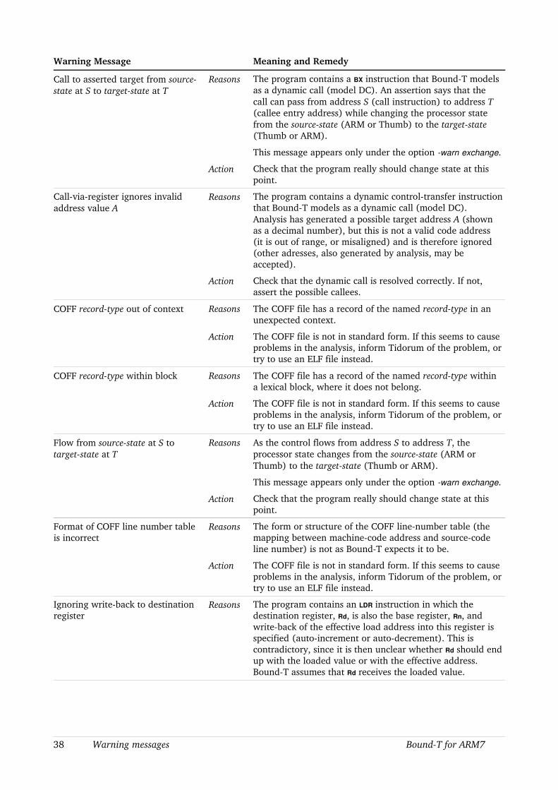
Warning Message Meaning and Remedy
Call to asserted target from sourcestate at S to targetstate at T
Reasons The program contains a BX instruction that BoundT models as a dynamic call (model DC). An assertion says that the call can pass from address S (call instruction) to address T (callee entry address) while changing the processor state from the sourcestate (ARM or Thumb) to the targetstate (Thumb or ARM).
This message appears only under the option warn exchange.
Action Check that the program really should change state at this point.
Callviaregister ignores invalid address value A
Reasons The program contains a dynamic controltransfer instruction that BoundT models as a dynamic call (model DC). Analysis has generated a possible target address A (shown as a decimal number), but this is not a valid code address (it is out of range, or misaligned) and is therefore ignored (other adresses, also generated by analysis, may be accepted).
Action Check that the dynamic call is resolved correctly. If not, assert the possible callees.
COFF recordtype out of context Reasons The COFF file has a record of the named recordtype in an unexpected context.
Action The COFF file is not in standard form. If this seems to cause problems in the analysis, inform Tidorum of the problem, or try to use an ELF file instead.
COFF recordtype within block Reasons The COFF file has a record of the named recordtype within a lexical block, where it does not belong.
Action The COFF file is not in standard form. If this seems to cause problems in the analysis, inform Tidorum of the problem, or try to use an ELF file instead.
Flow from sourcestate at S to targetstate at T
Reasons As the control flows from address S to address T, the processor state changes from the sourcestate (ARM or Thumb) to the targetstate (Thumb or ARM).
This message appears only under the option warn exchange.
Action Check that the program really should change state at this point.
Format of COFF line number table is incorrect
Reasons The form or structure of the COFF linenumber table (the mapping between machinecode address and sourcecode line number) is not as BoundT expects it to be.
Action The COFF file is not in standard form. If this seems to cause problems in the analysis, inform Tidorum of the problem, or try to use an ELF file instead.
Ignoring writeback to destination register
Reasons The program contains an LDR instruction in which the destination register, Rd, is also the base register, Rn, and writeback of the effective load address into this register is specified (autoincrement or autodecrement). This is contradictory, since it is then unclear whether Rd should end up with the loaded value or with the effective address. BoundT assumes that Rd receives the loaded value.
38 Warning messages BoundT for ARM7

Warning Message Meaning and Remedy
Action Check that this instruction really has this form, and is meant to be executed. If not, BoundT may be analysing an impossible path, perhaps because an overestimation in the analysis of an earlier dynamic branch.
Invalid register for COFF symbol S Reasons The COFF program file defines the variable symbol S, but claims that it is held in register Rn where n > 15. BoundT will not enter this symbol in its symbol tables so it will not be usable in assertions.
Action None, or report the problem to Tidorum if you need to use this variable in assertions.
Large literal D = hex H, used as signed = S
Reasons The instruction under analysis has a literal (immediate) operand. When the literal is interpreted as an unsigned number, it has the value D (decimal) or H (hex). However, at this point BoundT decides to interpret the literal as the signed value S (decimal).
This message appears only under the option warn sign [2].
Action Check that the signed interpretation is correct. If not, note that this may be a reason for problems in the arithmetic analysis and that you may have to use assertions instead.
Large literal D = hex H, used as unsigned
Reasons The instruction under analysis has a literal (immediate) operand. When the literal is interpreted as an unsigned number, it has the value D (decimal) or H (hex), and at this point BoundT decides to use this unsigned interpretation.
This message appears only under the option warn sign [2].
Action Check that the unsigned interpretation is correct. If not, note that this may be a reason for problems in the arithmetic analysis and that you may have to use assertions instead.
MUL has Rn /= 0 Reasons The program contains a MUL instruction in which the Rn
operand field (bits 12 .. 15 in the instruction) is not zero. This is surprising because the MUL instruction does not use this field (MLA does use it).
Action Check that this instruction really has this form, and is meant to be executed. If not, BoundT may be analysing an impossible path, perhaps because an overestimation in the analysis of an earlier dynamic branch.
No ELF, STABS, or DWARF symbols found
Reasons The executable file contains no symboltable in any of the forms that BoundT understands. Thus, BoundT cannot identify any subprogram or variable using its sourcelevel identifier.
Action Use only machinelevel names (addresses, registers) for subprograms and variables, or find an executable file with a symbol table (debugging information).
Parameter P mapped past caller stack height H
Reasons BoundT is analysing the parameterpassing in a call. The callee subprogram seems to use a parameter value from the stack, identified by the cellname P, but the offset of this stack cell, from the stack frame of the callee subprogram, is so large that the cell does not lie in the stack frame of the calling subprogram, as shown by the caller's stack height H at the call. The analysis of parameter passing in BoundT cannot handle this situation.
BoundT for ARM7 Warning messages 39

Warning Message Meaning and Remedy
Action Note that BoundT cannot use the (bounds on the) value of the actual parameter in its contextdependent analysis of the callee.
Patch branch target T is not wordaligned
Reasons The patch file (see Chapter 8) specifies a patch that is a branch to address T. However, T is not a multiple of 4 octets so it cannot be the address of an ARM instruction.
Action Correct the patch file.
PCbased constant at A is D = H Reasons The program contains an instruction that reads a value from a memory location using the PC as a base register, and BoundT assumes that this memory location (at address A, hex) contains a constant value, which (as read from the executable program file) is D (decimal) or, equivalently, H (hexadecimal).
This warning appears only under the options pc_const and warn pc_const.
Action Check that the assumption (address A contains a constant value) is correct.
PCbased location at A is blank, assumed to be variable
Reasons The program refers to memory data at address A using the PC as a base register. However, the memory image in the executable file does not define the contents of this memory location, so BoundT assumes that the location will contain variable data (not constant data).
This warning appears only under the options pc_const and warn pc_const.
Action If the memory location is meant to contain a constant, amend the executable file so that it statically loads this constant in this location.
PCbased store to constant memory Reasons The current instruction stores data in memory at an address that uses the PC as a base register. However, the option pc_const makes BoundT assume that such memory locations contain constants, so this store instruction means that this assumption is suspect.
Action Remove the option pc_const from the command line, or change the program to use some other form of address computation for variable data.
Reference to length parameter at offset H
Reasons The instruction under analysis refers to a datum in the stack, of a length less than a word (that is, a byte or a halfword), at the nonnegative offset H relative to the value of SP on entry to the current subprogram, where H is not a multiple of 32 bits (4 octets). This offset means that the datum is a parameter (not a local variable) which is surprising because all stacked parameters are expected to be full words in length.
SPbased references to wordaligned data of any length (word or subword) are accepted silently.
Action Check that this instruction really has this form, and is meant to be executed. If not, BoundT may be analysing an impossible path, perhaps because an overestimation in the analysis of an earlier dynamic branch.
40 Warning messages BoundT for ARM7

Warning Message Meaning and Remedy
Reference to misaligned parameter word at offset H
Reasons The instruction under analysis refers to a 32bit word in the stack at the nonnegative offset H relative to the value of SP
on entry to the current subprogram. However, the offset is not a multiple of 32 bits (4 octets), so the referenced word would not be wordaligned.
Action Check that this instruction really has this form, and is meant to be executed. If not, BoundT may be analysing an impossible path, perhaps because an overestimation in the analysis of an earlier dynamic branch.
Resolving N jumps by constant table of type offsets at A .. B.
Reasons The program contains a dynamic controltransfer instruction that BoundT models as a skip by a distance taken from a constant table of offsets (model STO) of a certain type, such as "unsigned octet", with a dynamic table index. Such an instruction typically results from a switchcase statement that has a dense sequence of case values. Analysis of the possible values of the table index has revealed that the table is located in the address range A .. B and has N entries (possible branch targets, cases).
Action Check that the subprogram under analysis contains a switch/case structure with N cases (excluding the default case, if any).
Resolving N jumps computed as C + F * (A .. B)
Reasons The program contains a controltransfer instruction that BoundT models as a branch to an address computed as a constant C plus a constant factor F times a dynamically computed number (model DAB). Analysis of the possible values of the dynamic factor has bounded it to the range A .. B, giving N possible branch targets.
Action Check that the subprogram under analysis contains a switch/case structure with N cases (excluding the default case, if any).
Resolving N jumps via constant address table at A .. B.
Reasons The program contains a dynamic controltransfer instruction that BoundT models as a branch to an address taken from a constant address table with a dynamic table index (model BTA). Such an instruction typically results from a switchcase statement that has a dense sequence of case values. Analysis of the possible values of the dynamic table index has revealed that the table is located in the address range A .. B and has N entries (possible branch targets, cases).
Action Check that the subprogram under analysis contains a switch/case structure with N cases (excluding the default case, if any).
Test operation with PC as nondestination
Reasons The program contains a test instruction (TST, TEQ, CMP, or CMN) in which the unused destination register (Rd) is the PC = R15. This is surprising.
Action Check that this instruction really has this form, and is meant to be executed. If not, BoundT may be analysing an impossible path, perhaps because an overestimation in the analysis of an earlier dynamic branch.
Test operation with S = 0 Reasons The program contains a test instruction (TST, TEQ, CMP, or CMN) in which the Sbit (instruction bit 20) is zero, which contradicts the purpose of the instruction (to set condition flags).
BoundT for ARM7 Warning messages 41
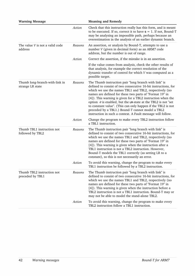
Warning Message Meaning and Remedy
Action Check that this instruction really has this form, and is meant to be executed. If so, correct it to have S = 1. If not, BoundT may be analysing an impossible path, perhaps because an overestimation in the analysis of an earlier dynamic branch.
The value V is not a valid code address
Reasons An assertion, or analysis by BoundT, attempts to use a number V (given in decimal form) as an ARM7 code address, but the number is out of range.
Action Correct the assertion, if the mistake is in an assertion.
If the value comes from analysis, check the other results of that analysis, for example the correct resolution of the dynamic transfer of control for which V was computed as a possible target.
Thumb longbranchwithlink in strange LR state
Reasons The Thumb instruction pair "long branch with link" is defined to consist of two consecutive 16bit instructions, for which we use the names TBL1 and TBL2, respectively (no names are defined for these two parts of "Format 19" in [4]). This warning is given for a TBL2 instruction when the option lr is enabled, but the LRstate at the TBL2 is not "set to constant value". (This can only happen if the TBL2 is not preceded by a TBL1.) BoundT cannot model a TBL2 instruction in such a context. A Fault message will follow.
Action Change the program to make every TBL2 instruction follow a TBL1 instruction.
Thumb TBL1 instruction not followed by TBL2
Reasons The Thumb instruction pair "long branch with link" is defined to consist of two consecutive 16bit instructions, for which we use the names TBL1 and TBL2, respectively (no names are defined for these two parts of "Format 19" in [4]). This warning is given when the instruction after a TBL1 instruction is not a TBL2 instruction. However, BoundT models the TBL1 correctly (as setting LR to a constant), so this is not necessarily an error.
Action To avoid this warning, change the program to make every TBL1 instruction be followed by a TBL2 instruction.
Thumb TBL2 instruction not preceded by TBL1
Reasons The Thumb instruction pair "long branch with link" is defined to consist of two consecutive 16bit instructions, for which we use the names TBL1 and TBL2, respectively (no names are defined for these two parts of "Format 19" in [4]). This warning is given when the instruction before a TBL2 instruction is not a TBL1 instruction. BoundT may or may not be able to model the standalone TBL2.
Action To avoid this warning, change the program to make every TBL2 instruction follow a TBL1 instruction.
42 Warning messages BoundT for ARM7

7.2 Error messages
The following table lists the BoundT error messages that are specific to the ARM7 or that have a specific interpretation for this processor. The messages are listed in alphabetical order, perhaps slightly altered by variable fields in the message; such fields are indicated by italic text. The BoundT Reference Manual [2] explains the generic error messages, all of which may appear also when the ARM7 is the target. The BoundT Assertion Language manual [3] explains the generic error messages related to assertions. The IntelHex Technical Note [7] explains the warnings that can arise for IntelHex input files.
As BoundT evolves, the set and form of these messages may change, so this list may be out of date to some extent. However, we have tried to make the messages clear enough to be understood even without explanation. Feel free to ask us for an explanation of any BoundT output that seems obscure.
To avoid redundancy and keep Table 20 compact, one common reason and solution has been omitted from the table: For any error message that reports an illegal, surprising, or nonanalysable instruction, one possible reason is that BoundT is analysing an impossible execution path, perhaps because of an overestimated analysis of an earlier dynamic branch. If so, the solution is either to use assertions to help BoundT analyse the dynamic branch correctly, or to change the target program to avoid such dynamic branches.
Table 20: Error messages from BoundT/ARM7
Error Message Meaning and Remedy
ARM code address A is misaligned Problem The address A of the current ARM instruction is not a multiple of 32 bits = 4 octets. This is an illegal address for an ARM instruction.
Reasons (1) The program is written in this way, or(2) the address of a root subprogram given on the BoundT command line has this error.
Solution (1) Correct the program to use only 32bit aligned ARM instructions, or(2) correct the command line.
ARM instruction “bx pc” is undefined; taken as return
Problem The current ARM instruction is BX PC. The behaviour of this instruction is not defined in [4].
Reasons The program is written in this way.
Solution Correct the program to use only allowed instructions.
Asserted call without exchange from caller state to callee state
Problem This instruction performs a dynamic call, but cannot change the operating state (it is not a BX). The call is resolved by an assertion that lists the possible callees, but one of the callees is known to use a different operating state, the callee state, than the caller, which uses the caller state. This is impossible.
Reasons A mistake in the assertion; or a mistake in the program (perhaps a BX should be used); or a mistake in whatever source defined the state of this callee.
Solution Correct the mistake.
BoundT for ARM7 Error messages 43

Error Message Meaning and Remedy
Asserted callee address A defines Thumb state, but callee C uses ARM state
Problem This BX instruction performs a dynamic call, and an assertion resolves the call by listing the possible callees, including a callee named C at an address A which has a 1 in the leastsignificant bit (making the address odd). Such an address makes the BX switch to Thumb state, but other information (perhaps a BL
call to C from the ARM state) suggests that C uses the ARM state, which is a contradiction.
Reasons The assertion may be in error, or the error may be in whatever reason suggests that C uses ARM state.
Solution Check all assertions that apply to C or that list C as a callee. If C does use Thumb state, check for BL calls to C from ARM state, and change them to use BX.
Asserted “mode” value M encodes no mode.
Problem An assertion tries to specify the “mode” property of a subprogram, but the given “mode” value M is not one of the mode codes defined in [4].
Reasons Error in the assertion file.
Solution Correct the value given in the assertion.See Table 11.
Asserted value of “mode” must be in 0 .. N, not M
Problem An assertion tries to specify the “mode” property of a subprogram, but the given “mode” value M is not in the valid range 0 .. N.
Reasons Error in the assertion file.
Solution Correct the value given in the assertion.See Table 11.
Asserted value of “state” must be in 0 .. 1, not M
Problem An assertion tries to specify the “state” property of a subprogram, but the given “state” value M is not in the valid range 0 .. 1.
Reasons Error in the assertion file.
Solution Correct the value given in the assertion.See Table 11.
Assertion on “mode” must set a single value, not A .. B
Problem An assertion tries to specify the “mode” property of a subprogram, but sets the “mode” to a range A .. B instead of a single value, as BoundT requires.
Reasons Error in the assertion file.
Solution Correct the assertion to set one value. See Table 11.
Assertion on “state” must set a single value, not A .. B
Problem An assertion tries to specify the “state” property of a subprogram, but sets the “state” to a range A .. B instead of a single value, as BoundT requires.
Reasons Error in the assertion file.
Solution Correct the assertion to set one value. See Table 11.
BL instruction cannot perform a role Problem An instructionrole assertion tells BoundT to model the present BL instruction with a role that BoundT cannot accept.
Reasons The assertion is written that way. Perhaps the assertion has the wrong address (or wrong offset) that makes BoundT apply the assertion to the wrong instruction.
44 Error messages BoundT for ARM7
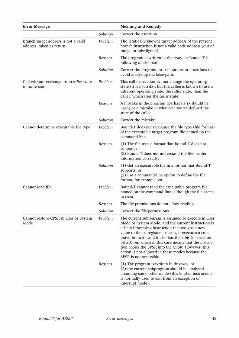
Error Message Meaning and Remedy
Solution Correct the assertion.
Branch target address is not a valid address, taken as return
Problem The (statically known) target address of the present branch instruction is not a valid code address (out of range, or misaligned).
Reasons The program is written in that way, or BoundT is following a false path.
Solution Correct the program, or use options or assertions to avoid analysing the false path.
Call without exchange from caller state to callee state
Problem This call instruction cannot change the operating state (it is not a BX), but the callee is known to use a different operating state, the callee state, than the caller, which uses the caller state.
Reasons A mistake in the program (perhaps a BX should be used) or a mistake in whatever source defined the state of the callee.
Solution Correct the mistake.
Cannot determine executable file type Problem BoundT does not recognise the file type (file format) of the executable target program file named on the command line.
Reasons (1) The file uses a format that BoundT does not support, or(2) BoundT does not understand the file header information correctly.
Solution (1) Get an executable file in a format that BoundT supports, or(2) use a commandline option to define the file format, for example elf.
Cannot read file Problem BoundT cannot read the executable program file named on the command line, although the file seems to exist.
Reasons The file permissions do not allow reading.
Solution Correct the file permissions.
Cannot restore CPSR in User or System Mode
Problem The current subrogram is assumed to execute in User Mode or System Mode, and the current instruction is a Data Processing instruction that assigns a new value to the PC register – that is, it executes a computed branch – and it also has the Sbit (instruction bit 20) on, which in this case means that the instruction copies the SPSR into the CPSR. However, this action is not allowed in these modes because the SPSR is not accessible.
Reasons (1) The program is written in this way, or(2) the current subprogram should be analysed assuming some other mode (this kind of instruction is normally used to exit from an exception or interrupt mode).
BoundT for ARM7 Error messages 45
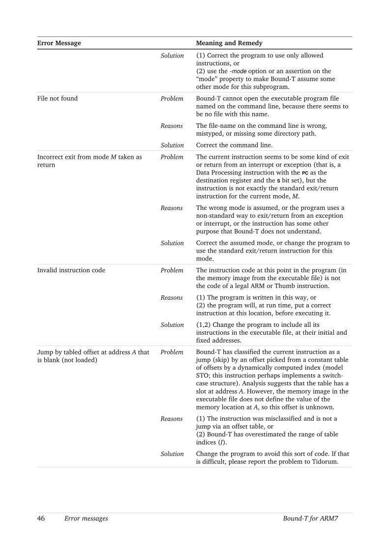
Error Message Meaning and Remedy
Solution (1) Correct the program to use only allowed instructions, or(2) use the mode option or an assertion on the “mode” property to make BoundT assume some other mode for this subprogram.
File not found Problem BoundT cannot open the executable program file named on the command line, because there seems to be no file with this name.
Reasons The filename on the command line is wrong, mistyped, or missing some directory path.
Solution Correct the command line.
Incorrect exit from mode M taken as return
Problem The current instruction seems to be some kind of exit or return from an interrupt or exception (that is, a Data Processing instruction with the PC as the destination register and the S bit set), but the instruction is not exactly the standard exit/return instruction for the current mode, M.
Reasons The wrong mode is assumed, or the program uses a nonstandard way to exit/return from an exception or interrupt, or the instruction has some other purpose that BoundT does not understand.
Solution Correct the assumed mode, or change the program to use the standard exit/return instruction for this mode.
Invalid instruction code Problem The instruction code at this point in the program (in the memory image from the executable file) is not the code of a legal ARM or Thumb instruction.
Reasons (1) The program is written in this way, or(2) the program will, at run time, put a correct instruction at this location, before executing it.
Solution (1,2) Change the program to include all its instructions in the executable file, at their initial and fixed addresses.
Jump by tabled offset at address A that is blank (not loaded)
Problem BoundT has classified the current instruction as a jump (skip) by an offset picked from a constant table of offsets by a dynamically computed index (model STO; this instruction perhaps implements a switchcase structure). Analysis suggests that the table has a slot at address A. However, the memory image in the executable file does not define the value of the memory location at A, so this offset is unknown.
Reasons (1) The instruction was misclassified and is not a jump via an offset table, or(2) BoundT has overestimated the range of table indices (I).
Solution Change the program to avoid this sort of code. If that is difficult, please report the problem to Tidorum.
46 Error messages BoundT for ARM7

Error Message Meaning and Remedy
Jump by tabled offset finds outofrange slot address A
Problem BoundT has classified the current instruction as a jump (skip) by an offset picked from a constant table of offsets by a dynamically computed index (model STO; this instruction perhaps implements a switchcase structure). Analysis suggests that the table has a slot at address A, but this is not in the range of valid addresses.
Reasons (1) The instruction was misclassified and is not a jump via an offset table, or(2) BoundT has overestimated the range of table indices.
Solution Change the program to avoid this sort of code. If that is difficult, please report the problem to Tidorum.
Jump by tabled offset F * X (at address A) from base B causes over or underflow
Problem BoundT has classified the current instruction as a jump (skip) by an offset picked from a constant table of offsets by a dynamically computed index (model STO; this instruction perhaps implements a switchcase structure). Analysis suggests that the table has a slot at address A, and the memory image in the executable file defines the offset value (before scaling) at this address as X, but the computation of the branch target address as F*X+B causes under or overflow, so the result is suspect and is not used. That is, this target is omitted from the flow graph.
The numbers F and X are shown in decimal form, A and B in hexadecimal form.
Reasons (1) The instruction was misclassified and is not a jump by an offset table, or(2) BoundT has overestimated the range of table indices, or(3) the offset values in the table are set at run time, so the table is not constant.
Solution Change the program to avoid this sort of code. If that is difficult, please report the problem to Tidorum.
Jump by tabled offset F * X (at address A) from base B ignored because computed target T is not a valid address
Problem BoundT has classified the current instruction as a jump (skip) by an offset picked from a constant table of offsets by a dynamically computed index (model STO; this instruction perhaps implements a switchcase structure). Analysis suggests that the table has a slot at address A, and the memory image in the executable file defines the offset value (before scaling) at this address as X, but the computation of the branch target address as F*X+B gives a value T that is not a valid code address. Therefore, the offset in this slot is not used and target T is not included in the flow graph.
The numbers F and X are shown in decimal form, while A, B, and T are in hexadecimal form.
BoundT for ARM7 Error messages 47
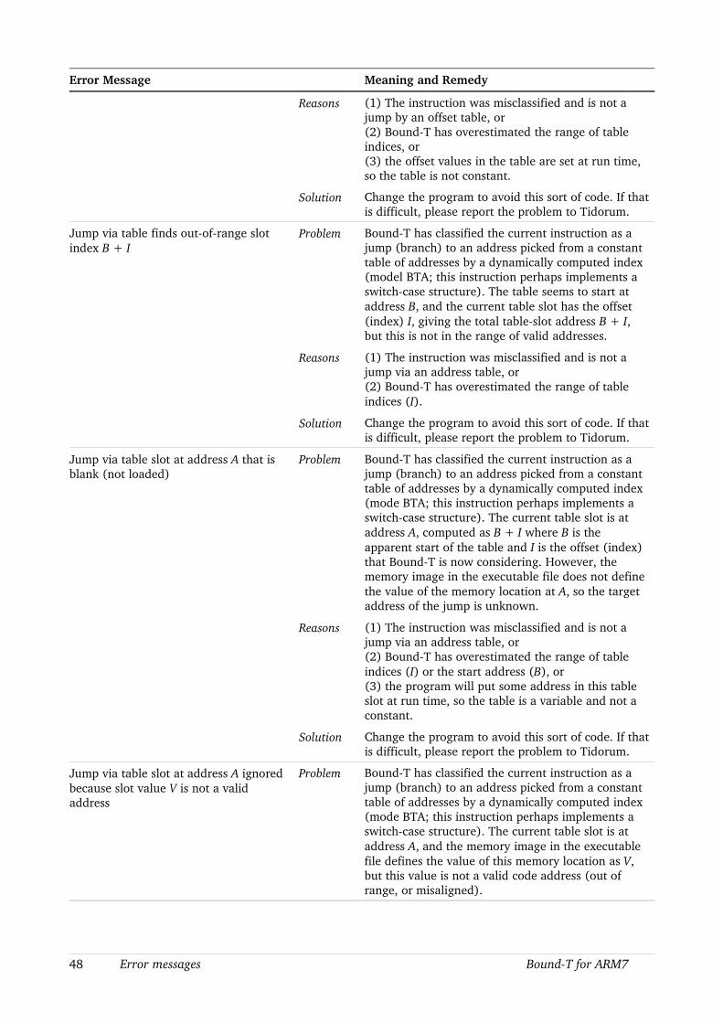
Error Message Meaning and Remedy
Reasons (1) The instruction was misclassified and is not a jump by an offset table, or(2) BoundT has overestimated the range of table indices, or(3) the offset values in the table are set at run time, so the table is not constant.
Solution Change the program to avoid this sort of code. If that is difficult, please report the problem to Tidorum.
Jump via table finds outofrange slot index B + I
Problem BoundT has classified the current instruction as a jump (branch) to an address picked from a constant table of addresses by a dynamically computed index (model BTA; this instruction perhaps implements a switchcase structure). The table seems to start at address B, and the current table slot has the offset (index) I, giving the total tableslot address B + I, but this is not in the range of valid addresses.
Reasons (1) The instruction was misclassified and is not a jump via an address table, or(2) BoundT has overestimated the range of table indices (I).
Solution Change the program to avoid this sort of code. If that is difficult, please report the problem to Tidorum.
Jump via table slot at address A that is blank (not loaded)
Problem BoundT has classified the current instruction as a jump (branch) to an address picked from a constant table of addresses by a dynamically computed index (mode BTA; this instruction perhaps implements a switchcase structure). The current table slot is at address A, computed as B + I where B is the apparent start of the table and I is the offset (index) that BoundT is now considering. However, the memory image in the executable file does not define the value of the memory location at A, so the target address of the jump is unknown.
Reasons (1) The instruction was misclassified and is not a jump via an address table, or(2) BoundT has overestimated the range of table indices (I) or the start address (B), or(3) the program will put some address in this table slot at run time, so the table is a variable and not a constant.
Solution Change the program to avoid this sort of code. If that is difficult, please report the problem to Tidorum.
Jump via table slot at address A ignored because slot value V is not a valid address
Problem BoundT has classified the current instruction as a jump (branch) to an address picked from a constant table of addresses by a dynamically computed index (mode BTA; this instruction perhaps implements a switchcase structure). The current table slot is at address A, and the memory image in the executable file defines the value of this memory location as V, but this value is not a valid code address (out of range, or misaligned).
48 Error messages BoundT for ARM7
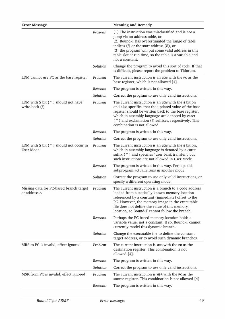
Error Message Meaning and Remedy
Reasons (1) The instruction was misclassified and is not a jump via an address table, or(2) BoundT has overestimated the range of table indices (I) or the start address (B), or(3) the program will put some valid address in this table slot at run time, so the table is a variable and not a constant.
Solution Change the program to avoid this sort of code. If that is difficult, please report the problem to Tidorum.
LDM cannot use PC as the base register Problem The current instruction is an LDM with the PC as the base register, which is not allowed [4].
Reasons The program is written in this way.
Solution Correct the program to use only valid instructions.
LDM with S bit (^) should not have writeback (!)
Problem The current instruction is an LDM with the S bit on and also specifies that the updated value of the base register should be written back to the base register, which in assembly language are denoted by caret (^) and exclamation (!) suffixes, respectively. This combination is not allowed.
Reasons The program is written in this way.
Solution Correct the program to use only valid instructions.
LDM with S bit (^) should not occur in User Mode
Problem The current instruction is an LDM with the S bit on, which in assembly language is denoted by a caret suffix (^) and specifies “user bank transfer”, but such instructions are not allowed in User Mode.
Reasons The program is written in this way. Perhaps this subprogram actually runs in another mode.
Solution Correct the program to use only valid instructions, or specify a different operating mode.
Missing data for PCbased branch target at address A
Problem The current instruction is a branch to a code address loaded from a statically known memory location referenced by a constant (immediate) offset to the PC. However, the memory image in the executable file does not define the value of this memory location, so BoundT cannot follow the branch.
Reasons Perhaps the PCbased memory location holds a variable value, not a constant. If so, BoundT cannot currently model this dynamic branch.
Solution Change the executable file to define the constant target address, or to avoid such dynamic branches.
MRS to PC is invalid, effect ignored Problem The current instruction is MRS with the PC as the destination register. This combination is not allowed [4].
Reasons The program is written in this way.
Solution Correct the program to use only valid instructions.
MSR from PC is invalid, effect ignored Problem The current instruction is MSR with the PC as the source register. This combination is not allowed [4].
Reasons The program is written in this way.
BoundT for ARM7 Error messages 49
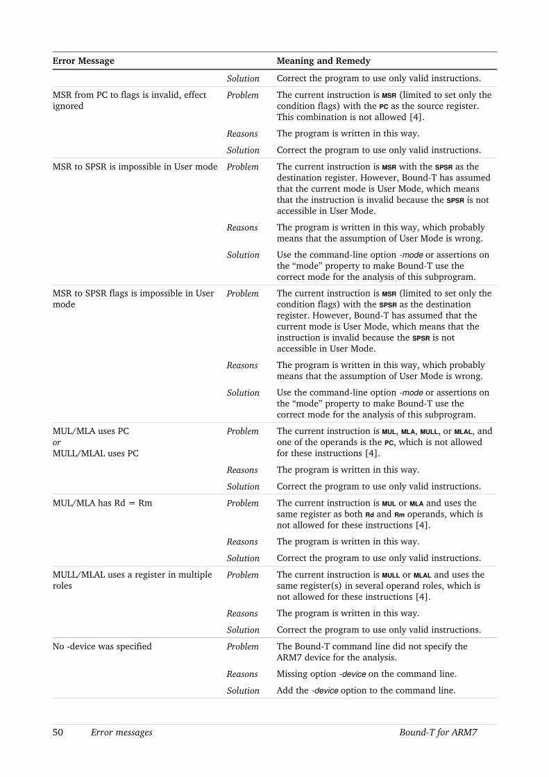
Error Message Meaning and Remedy
Solution Correct the program to use only valid instructions.
MSR from PC to flags is invalid, effect ignored
Problem The current instruction is MSR (limited to set only the condition flags) with the PC as the source register. This combination is not allowed [4].
Reasons The program is written in this way.
Solution Correct the program to use only valid instructions.
MSR to SPSR is impossible in User mode Problem The current instruction is MSR with the SPSR as the destination register. However, BoundT has assumed that the current mode is User Mode, which means that the instruction is invalid because the SPSR is not accessible in User Mode.
Reasons The program is written in this way, which probably means that the assumption of User Mode is wrong.
Solution Use the commandline option mode or assertions on the “mode” property to make BoundT use the correct mode for the analysis of this subprogram.
MSR to SPSR flags is impossible in User mode
Problem The current instruction is MSR (limited to set only the condition flags) with the SPSR as the destination register. However, BoundT has assumed that the current mode is User Mode, which means that the instruction is invalid because the SPSR is not accessible in User Mode.
Reasons The program is written in this way, which probably means that the assumption of User Mode is wrong.
Solution Use the commandline option mode or assertions on the “mode” property to make BoundT use the correct mode for the analysis of this subprogram.
MUL/MLA uses PCorMULL/MLAL uses PC
Problem The current instruction is MUL, MLA, MULL, or MLAL, and one of the operands is the PC, which is not allowed for these instructions [4].
Reasons The program is written in this way.
Solution Correct the program to use only valid instructions.
MUL/MLA has Rd = Rm Problem The current instruction is MUL or MLA and uses the same register as both Rd and Rm operands, which is not allowed for these instructions [4].
Reasons The program is written in this way.
Solution Correct the program to use only valid instructions.
MULL/MLAL uses a register in multiple roles
Problem The current instruction is MULL or MLAL and uses the same register(s) in several operand roles, which is not allowed for these instructions [4].
Reasons The program is written in this way.
Solution Correct the program to use only valid instructions.
No device was specified Problem The BoundT command line did not specify the ARM7 device for the analysis.
Reasons Missing option device on the command line.
Solution Add the device option to the command line.
50 Error messages BoundT for ARM7

Error Message Meaning and Remedy
No instruction loaded at this address Problem The program tries to execute an instruction from a memory location that is not defined in the executable program file (memory image). BoundT cannot continue its analysis because the contents of this memory location are unknown.
Reasons (1) The program is written in this way, or(2) some part of the program is missing from the executable file, or(3) the program will put instructions in this memory location at run time, before executing them.
Solution (1,2,3) Correct the program to include all its instructions in the executable, at their initial and fixed addresses.
Patch address A exceeds segment boundaries
Problem The patch file (see Chapter 8) specifies a patch at address A, but A is not located in any segment of the target program's memory image, nor is it in the exception vector area 0 .. 1C (hex).
Reasons Error in the patch file.
Solution Correct the patch file.
Patch address A is not wordaligned Problem The patch file (see Chapter 8) specifies a patch at address A, but A is not a multiple of 4 octets, as currently required for all patches (also for Thumb patches).
Reasons Error in the patch file.
Solution Correct the patch file.
Patching branch from A to T is too long Problem The patch file (see Chapter 8) specifies a patch at address A, to be a branch to address T, but the distance from A to T is too large to be encoded in a single B instruction.
Reasons Error in the patch file.
Solution Correct the patch file.
Patching data invalid: text Problem The patch file (see Chapter 8) specifies a patch consisting of the data text, but this text is not in the correct syntax for ARM7 patches.
Reasons Error in the patch file.
Solution Correct the patch file.
Patching data or params invalid Problem The patch file (see Chapter 8) contains a line that is not understood as an ARM7 patch.
Reasons Error in the patch file.
Solution Correct the patch file.
PCbased LDC/STC cannot have writeback
Problem The current instruction is an LDC or STC with the PC as the base register. The instruction also specifies “write back” of the automodified base register value, which is not allowed for the PC [4].
Reasons The program is written in this way.
Solution Correct the program to use only valid instructions.
BoundT for ARM7 Error messages 51
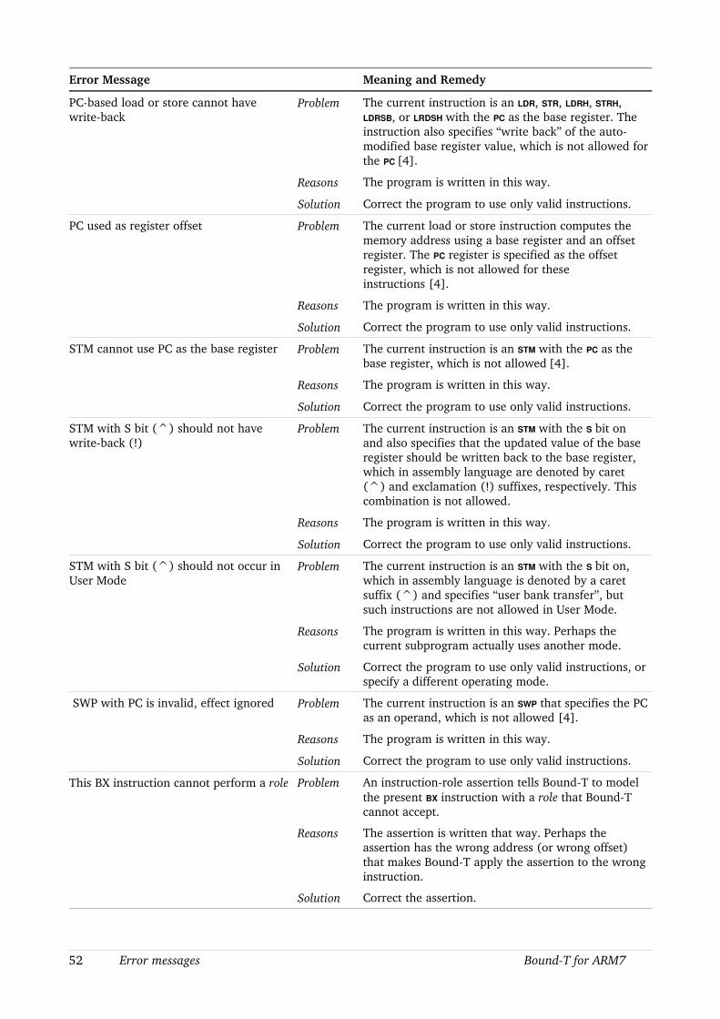
Error Message Meaning and Remedy
PCbased load or store cannot have writeback
Problem The current instruction is an LDR, STR, LDRH, STRH, LDRSB, or LRDSH with the PC as the base register. The instruction also specifies “write back” of the automodified base register value, which is not allowed for the PC [4].
Reasons The program is written in this way.
Solution Correct the program to use only valid instructions.
PC used as register offset Problem The current load or store instruction computes the memory address using a base register and an offset register. The PC register is specified as the offset register, which is not allowed for these instructions [4].
Reasons The program is written in this way.
Solution Correct the program to use only valid instructions.
STM cannot use PC as the base register Problem The current instruction is an STM with the PC as the base register, which is not allowed [4].
Reasons The program is written in this way.
Solution Correct the program to use only valid instructions.
STM with S bit (^) should not have writeback (!)
Problem The current instruction is an STM with the S bit on and also specifies that the updated value of the base register should be written back to the base register, which in assembly language are denoted by caret (^) and exclamation (!) suffixes, respectively. This combination is not allowed.
Reasons The program is written in this way.
Solution Correct the program to use only valid instructions.
STM with S bit (^) should not occur in User Mode
Problem The current instruction is an STM with the S bit on, which in assembly language is denoted by a caret suffix (^) and specifies “user bank transfer”, but such instructions are not allowed in User Mode.
Reasons The program is written in this way. Perhaps the current subprogram actually uses another mode.
Solution Correct the program to use only valid instructions, or specify a different operating mode.
SWP with PC is invalid, effect ignored Problem The current instruction is an SWP that specifies the PC as an operand, which is not allowed [4].
Reasons The program is written in this way.
Solution Correct the program to use only valid instructions.
This BX instruction cannot perform a role Problem An instructionrole assertion tells BoundT to model the present BX instruction with a role that BoundT cannot accept.
Reasons The assertion is written that way. Perhaps the assertion has the wrong address (or wrong offset) that makes BoundT apply the assertion to the wrong instruction.
Solution Correct the assertion.
52 Error messages BoundT for ARM7
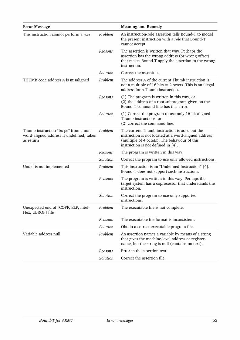
Error Message Meaning and Remedy
This instruction cannot perform a role Problem An instructionrole assertion tells BoundT to model the present instruction with a role that BoundT cannot accept.
Reasons The assertion is written that way. Perhaps the assertion has the wrong address (or wrong offset) that makes BoundT apply the assertion to the wrong instruction.
Solution Correct the assertion.
THUMB code address A is misaligned Problem The address A of the current Thumb instruction is not a multiple of 16 bits = 2 octets. This is an illegal address for a Thumb instruction.
Reasons (1) The program is written in this way, or(2) the address of a root subprogram given on the BoundT command line has this error.
Solution (1) Correct the program to use only 16bit aligned Thumb instructions, or(2) correct the command line.
Thumb instruction “bx pc” from a nonwordaligned address is undefined; taken as return
Problem The current Thumb instruction is BX PC but the instruction is not located at a wordaligned address (multiple of 4 octets). The behaviour of this instruction is not defined in [4].
Reasons The program is written in this way.
Solution Correct the program to use only allowed instructions.
Undef is not implemented Problem This instruction is an “Undefined Instruction” [4]. BoundT does not support such instructions.
Reasons The program is written in this way. Perhaps the target system has a coprocessor that understands this instruction.
Solution Correct the program to use only supported instructions.
Unexpected end of [COFF, ELF, IntelHex, UBROF] file
Problem The executable file is not complete.
Reasons The executable file format is inconsistent.
Solution Obtain a correct executable program file.
Variable address null Problem An assertion names a variable by means of a string that gives the machinelevel address or registername, but the string is null (contains no text).
Reasons Error in the assertion text.
Solution Correct the assertion file.
BoundT for ARM7 Error messages 53
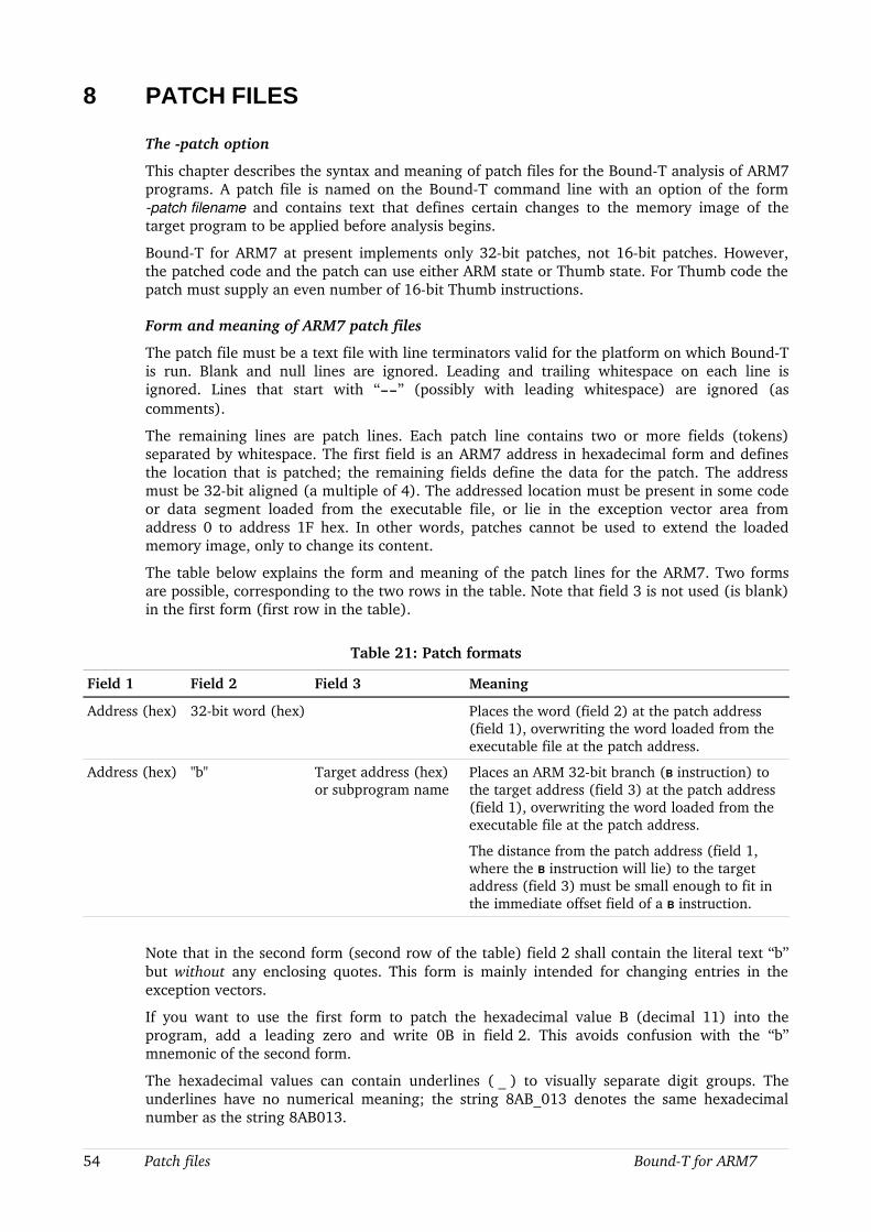
8 PATCH FILES
The patch option
This chapter describes the syntax and meaning of patch files for the BoundT analysis of ARM7 programs. A patch file is named on the BoundT command line with an option of the form patch filename and contains text that defines certain changes to the memory image of the target program to be applied before analysis begins.
BoundT for ARM7 at present implements only 32bit patches, not 16bit patches. However, the patched code and the patch can use either ARM state or Thumb state. For Thumb code the patch must supply an even number of 16bit Thumb instructions.
Form and meaning of ARM7 patch files
The patch file must be a text file with line terminators valid for the platform on which BoundT is run. Blank and null lines are ignored. Leading and trailing whitespace on each line is ignored. Lines that start with “” (possibly with leading whitespace) are ignored (as comments).
The remaining lines are patch lines. Each patch line contains two or more fields (tokens) separated by whitespace. The first field is an ARM7 address in hexadecimal form and defines the location that is patched; the remaining fields define the data for the patch. The address must be 32bit aligned (a multiple of 4). The addressed location must be present in some code or data segment loaded from the executable file, or lie in the exception vector area from address 0 to address 1F hex. In other words, patches cannot be used to extend the loaded memory image, only to change its content.
The table below explains the form and meaning of the patch lines for the ARM7. Two forms are possible, corresponding to the two rows in the table. Note that field 3 is not used (is blank) in the first form (first row in the table).
Table 21: Patch formats
Field 1 Field 2 Field 3 Meaning
Address (hex) 32bit word (hex) Places the word (field 2) at the patch address (field 1), overwriting the word loaded from the executable file at the patch address.
Address (hex) "b" Target address (hex) or subprogram name
Places an ARM 32bit branch (B instruction) to the target address (field 3) at the patch address (field 1), overwriting the word loaded from the executable file at the patch address.
The distance from the patch address (field 1, where the B instruction will lie) to the target address (field 3) must be small enough to fit in the immediate offset field of a B instruction.
Note that in the second form (second row of the table) field 2 shall contain the literal text “b” but without any enclosing quotes. This form is mainly intended for changing entries in the exception vectors.
If you want to use the first form to patch the hexadecimal value B (decimal 11) into the program, add a leading zero and write 0B in field 2. This avoids confusion with the “b” mnemonic of the second form.
The hexadecimal values can contain underlines ( _ ) to visually separate digit groups. The underlines have no numerical meaning; the string 8AB_013 denotes the same hexadecimal number as the string 8AB013.
54 Patch files BoundT for ARM7

Example
Here is an example of a patch file:
This is a comment. The following patch line places the instruction mov r4,124 which is "E3_A04_07C" in hexadecimal, at the address 2000810, also in hex:
2000810 E3_A04_07C
The following patch line places the instructions b Handler at address 8, where "Handler" is assumed to be a subprogram name, present in the symboltable:
8 b Handler
Note that a comment cannot be appended to a patch line, so the following patch line is wrong:
2000810 E3_A04_07C This kind of comment is not allowed.
BoundT for ARM7 Patch files 55

Tidorum Ltd
Tiirasaarentie 32FI00200 HelsinkiFinland
[email protected]. +358 (0) 40 563 9186Fax +358 (0) 42 563 9186VAT FI 18688130
56 Patch files BoundT for ARM7
Tidrum
Related Documents