Arlington Microgrid Glare Study Snohomish County Public Utility District No. 1 Arlington Microgrid Project Project No. 104583 Revision 0 1/31/2018

Welcome message from author
This document is posted to help you gain knowledge. Please leave a comment to let me know what you think about it! Share it to your friends and learn new things together.
Transcript
Arlington Microgrid Glare Study
Snohomish County Public Utility District No. 1
Arlington Microgrid Project Project No. 104583
Revision 0 1/31/2018

Arlington Microgrid Glare Study
prepared for
Snohomish County Public Utility District No. 1
Arlington Microgrid Project Everett, WA
Project No. 104583
Revision 0 1/31/2018
prepared by
Burns & McDonnell Engineering Company, Inc. Fort Worth, TX
COPYRIGHT © 2018 BURNS & McDONNELL ENGINEERING COMPANY, INC.

Solar Glare Report Revision 0 List of Abbreviations
SnoPUD i Burns & McDonnell
TABLE OF CONTENTS
EXECUTIVE SUMMARY Page No.
1.0 SUMMARY ........................................................................................................ 1-1 1.1 Methodology ........................................................................................................ 1-1 1.2 Assumptions and Limitations .............................................................................. 1-1
2.0 RESULTS .......................................................................................................... 2-3
APPENDIX A - RESULTS APPENDIX B DRAWINGS
Solar Glare Report Revision 0 List of Abbreviations
SnoPUD ii Burns & McDonnell
LIST OF ABBREVIATIONS
Abbreviation Term/Phrase/Name
ARC Antireflective coating
ATCT Air traffic control tower
Burns & McDonnell Burns & McDonnell Engineering Company, Inc.
FAA Federal Aviation Association
PV Photovoltaic
SGHAT Solar Glare and Hazard Analysis Tool
TCH Threshold clearing height
Solar Glare Report Revision 0 SUMMARY
SnoPUD 1-1 Burns & McDonnell
1.0 SUMMARY
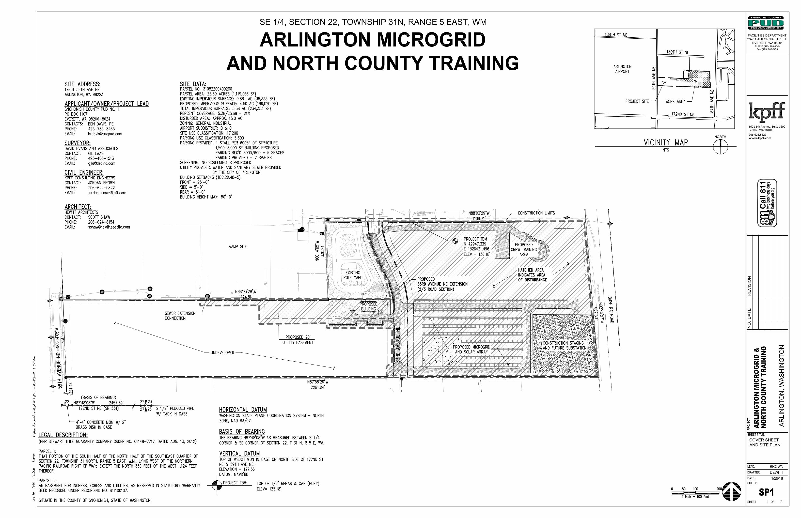
Solar glare hazard analysis was performed on the proposed solar array in Snohomish County. The result
indicates none of the flight paths are showing potential for after image glare.
1.1 Methodology Solar glare hazard analysis is performed utilizing the GlareGauge module form Forge Solar. The Glare
hazard analysis utilizes proposed general site locations and typical initial panel array orientation and tilt
for the latitude for the site. Determination of glare occurrence requires knowledge of the following: sun
position, observer location, and the tilt, orientation, location, extent, and optical properties of the modules
in the solar array. Vector algebra is then used to determine if glare is visible from the prescribed
observation points.
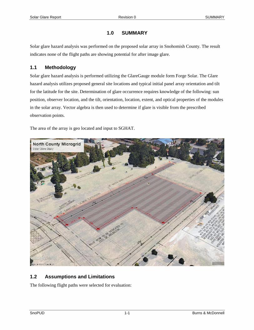
The area of the array is geo located and input to SGHAT.
1.2 Assumptions and Limitations The following flight paths were selected for evaluation:
Solar Glare Report Revision 0 SUMMARY
SnoPUD 1-2 Burns & McDonnell
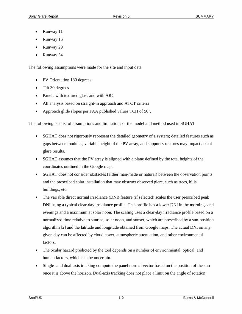
• Runway 11
• Runway 16
• Runway 29
• Runway 34
The following assumptions were made for the site and input data
• PV Orientation 180 degrees
• Tilt 30 degrees
• Panels with textured glass and with ARC
• All analysis based on straight-in approach and ATCT criteria
• Approach glide slopes per FAA published values TCH of 50’.
The following is a list of assumptions and limitations of the model and method used in SGHAT
• SGHAT does not rigorously represent the detailed geometry of a system; detailed features such as
gaps between modules, variable height of the PV array, and support structures may impact actual
glare results.
• SGHAT assumes that the PV array is aligned with a plane defined by the total heights of the
coordinates outlined in the Google map.
• SGHAT does not consider obstacles (either man-made or natural) between the observation points
and the prescribed solar installation that may obstruct observed glare, such as trees, hills,
buildings, etc.
• The variable direct normal irradiance (DNI) feature (if selected) scales the user prescribed peak
DNI using a typical clear-day irradiance profile. This profile has a lower DNI in the mornings and
evenings and a maximum at solar noon. The scaling uses a clear-day irradiance profile based on a
normalized time relative to sunrise, solar noon, and sunset, which are prescribed by a sun-position
algorithm [2] and the latitude and longitude obtained from Google maps. The actual DNI on any
given day can be affected by cloud cover, atmospheric attenuation, and other environmental
factors.
• The ocular hazard predicted by the tool depends on a number of environmental, optical, and
human factors, which can be uncertain.
• Single- and dual-axis tracking compute the panel normal vector based on the position of the sun
once it is above the horizon. Dual-axis tracking does not place a limit on the angle of rotation,

Solar Glare Report Revision 0 Results
SnoPUD 2-3 Burns & McDonnell
unless the sun is below the horizon. For single-axis tracking, a maximum angle of rotation can be
applied to both the clockwise and counterclockwise directions.
2.0 RESULTS
All flight paths analyzed show the glare produced either has zero or low potential for after-image. The
results for all paths analyzed fall within the FAA acceptance criteria. Refer to Appendix A for full report
results.
• Runway 11
o No measurable glare predicted along this flight path.
• Runway 16
o No measurable glare predicted along this flight path.
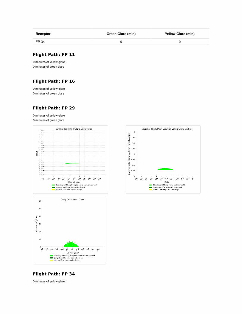
• Runway 29
o Glare produced within the flight path for Runway 29 occurs in the months of May-July
between 6:30 am and 7:00 am and has a duration of less than 10 minutes. This glare is
beyond 50 degrees from the pilot line-of-sight and is not considered to be a glare hazard.
There are 0 minutes of annual “green” glare – the minimum threshold considered to be a
glare hazard.
• Runway 34
o Glare produced within the flight path for Runway 34 occurs in the months of April-August
between 6:00 am and 7:00 am and has a duration of less than 5 minutes. This glare is beyond
50 degrees from the pilot line-of-sight and is not considered to be a glare hazard. There are 0
minutes of annual “green” glare – the minimum threshold considered to be a glare hazard.

APPENDIX A - RESULTS

FORGESOLAR GLARE ANALYSIS
Project: Snohomish Glare StudyArlington Airport
Site configuration: PV30 textured with ARCAnalysis conducted by Ryan Wubbens ([email protected]) at 19:23 on 26 Jan, 2018.
U.S. FAA 2013 Policy Adherence
The following table summarizes the policy adherence of the glare analysis based on the 2013 U.S. Federal Aviation AdministrationInterim Policy 78 FR 63276. This policy requires the following criteria be met for solar energy systems on airport property:
• No "yellow" glare (potential for after-image) for any flight path from threshold to 2 miles• No glare of any kind for Air Traffic Control Tower(s) ("ATCT") at cab height.• Default analysis and observer characteristics (see list below)
ForgeSolar does not represent or speak officially for the FAA and cannot approve or deny projects. Results are informational only.
COMPONENT STATUS DESCRIPTION
Analysis parameters PASS Analysis time interval and eye characteristics used are acceptableFlight path(s) PASS Flight path receptor(s) do not receive yellow glareATCT(s) N/A No ATCT receptors designated
Default glare analysis and observer eye characteristics are as follows:
• Analysis time interval: 1 minute• Ocular transmission coefficient: 0.5• Pupil diameter: 0.002 meters• Eye focal length: 0.017 meters• Sun subtended angle: 9.3 milliradians
FAA Policy 78 FR 63276 can be read at https://www.federalregister.gov/d/2013-24729

SITE CONFIGURATION
PV Array(s)
Analysis Parameters
DNI: peaks at 1,000.0 W/m^2 Time interval: 1 minOcular transmissioncoefficient: 0.5Pupil diameter: 0.002 mEye focal length: 0.017 mSun subtended angle: 9.3mrad Site Config ID: 14487.2216
Name: PV array 1 Axis tracking: Fixed (no rotation) Tilt: 30.0° Orientation: 180.0° Rated power: - Panel material: Light textured glass with AR coating Reflectivity: Vary with sun Slope error: correlate with material
Vertex Latitude (°) Longitude (°) Ground elevation (ft) Height above ground (ft) Total elevation (ft)
1 48.156573 -122.144808 130.78 0.00 130.782 48.156362 -122.144816 131.30 0.00 131.303 48.156359 -122.144577 130.95 0.00 130.954 48.156105 -122.144580 131.82 0.00 131.825 48.156102 -122.143884 131.69 0.00 131.696 48.155737 -122.143900 130.97 0.00 130.977 48.155731 -122.142770 131.67 0.00 131.678 48.156466 -122.142782 132.85 0.00 132.859 48.156464 -122.141993 132.99 0.00 132.9910 48.156558 -122.141989 134.00 0.00 134.00

Flight Path Receptor(s)
Name: FP 11 Description: Threshold height: 50 ft Direction: ° Glide slope: 3.5° Pilot view restricted? Yes Vertical view: 30.0° Azimuthal view: 120.0°
Point Latitude (°) Longitude (°) Ground elevation (ft) Height above ground (ft) Total elevation (ft)
Threshold 48.161674 -122.168811 125.49 50.00 175.49Two-mile 48.179716 -122.202721 36.53 784.88 821.40
Name: FP 16 Description: Threshold height: 50 ft Direction: ° Glide slope: 3.0° Pilot view restricted? Yes Vertical view: 30.0° Azimuthal view: 120.0°
Flight path map
Point Latitude (°) Longitude (°) Ground elevation (ft) Height above ground (ft) Total elevation (ft)
Threshold 48.169334 -122.156543 133.85 50.00 183.85Two-mile 48.198242 -122.157300 44.16 693.15 737.30
Name: FP 29 Description: Threshold height: 50 ft Direction: ° Glide slope: 4.0° Pilot view restricted? Yes Vertical view: 30.0° Azimuthal view: 120.0°
Point Latitude (°) Longitude (°) Ground elevation (ft) Height above ground (ft) Total elevation (ft)
Threshold 48.155894 -122.157401 117.59 50.00 167.59Two-mile 48.139581 -122.121577 407.75 498.31 906.06

GLARE ANALYSIS RESULTS
Summary of Glare
PV Array Name Tilt Orient "Green" Glare "Yellow" Glare Energy
(°) (°) min min kWhPV array 1 30.0 180.0 0 0 -
Total annual glare received by each receptor
Receptor Annual Green Glare (min) Annual Yellow Glare (min)
FP 11 0 0FP 16 0 0FP 29 0 0FP 34 0 0
Results for: PV array 1
Receptor Green Glare (min) Yellow Glare (min)
FP 11 0 0FP 16 0 0FP 29 0 0
Name: FP 34 Description: Threshold height: 50 ft Direction: ° Glide slope: 3.0° Pilot view restricted? Yes Vertical view: 30.0° Azimuthal view: 120.0°
Point Latitude (°) Longitude (°) Ground elevation (ft) Height above ground (ft) Total elevation (ft)
Threshold 48.154756 -122.156210 121.02 50.00 171.02Two-mile 48.125848 -122.155453 98.54 625.94 724.48
Receptor Green Glare (min) Yellow Glare (min)
FP 34 0 0
Flight Path: FP 11
0 minutes of yellow glare 0 minutes of green glare
Flight Path: FP 16
0 minutes of yellow glare 0 minutes of green glare
Flight Path: FP 29
0 minutes of yellow glare 0 minutes of green glare
Flight Path: FP 34
0 minutes of yellow glare
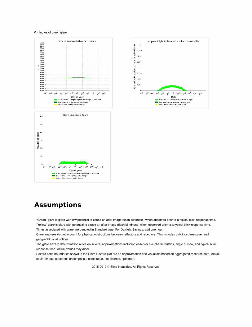
0 minutes of green glare
Assumptions
2015-2017 © Sims Industries, All Rights Reserved.
"Green" glare is glare with low potential to cause an after-image (flash blindness) when observed prior to a typical blink response time. "Yellow" glare is glare with potential to cause an after-image (flash blindness) when observed prior to a typical blink response time. Times associated with glare are denoted in Standard time. For Daylight Savings, add one hour. Glare analyses do not account for physical obstructions between reflectors and receptors. This includes buildings, tree cover andgeographic obstructions. The glare hazard determination relies on several approximations including observer eye characteristics, angle of view, and typical blinkresponse time. Actual values may differ. Hazard zone boundaries shown in the Glare Hazard plot are an approximation and visual aid based on aggregated research data. Actualocular impact outcomes encompass a continuous, not discrete, spectrum.

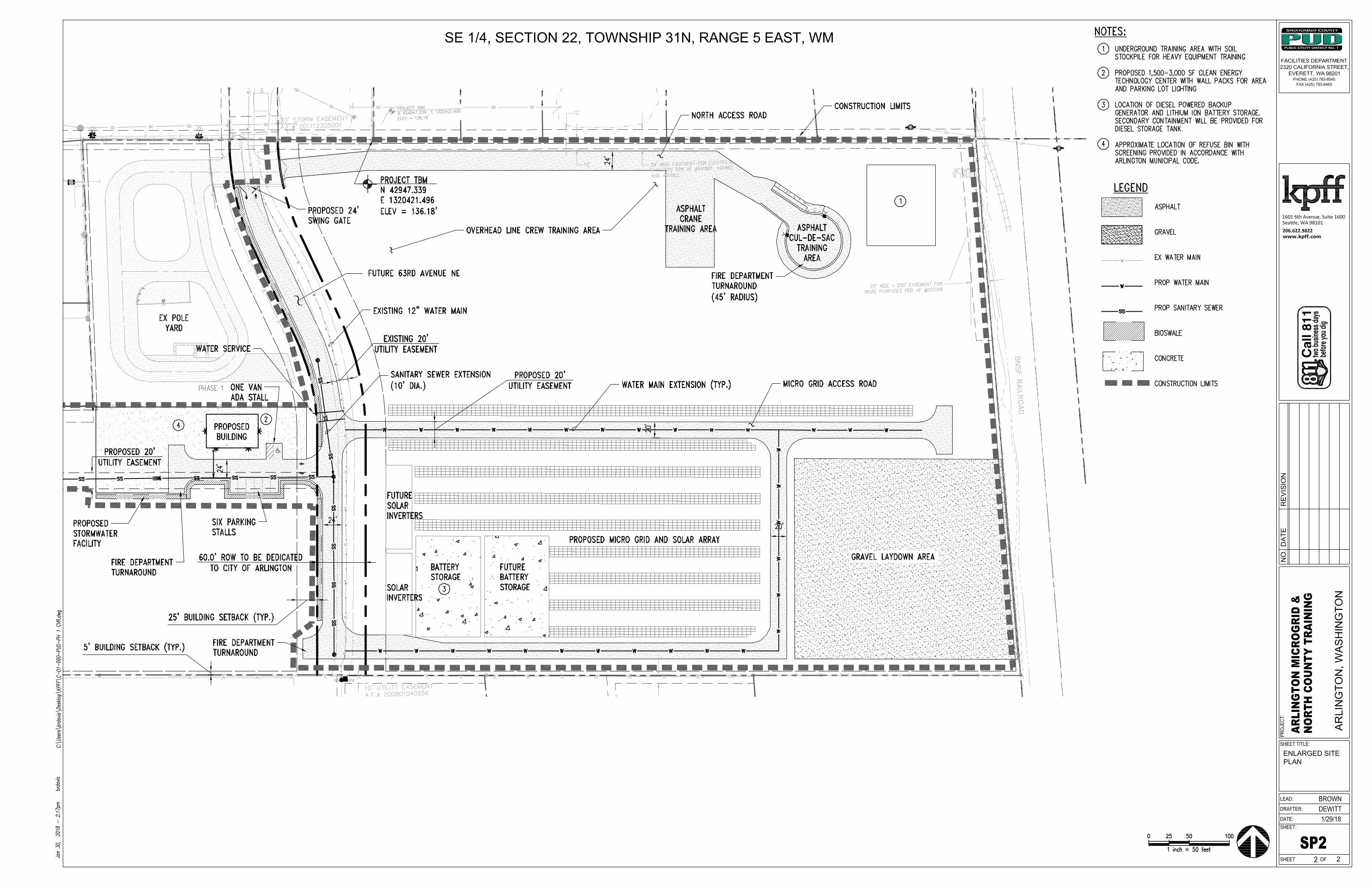
APPENDIX B DRAWINGS

Burns & McDonnell World Headquarters 9400 Ward Parkway
Kansas City, MO 64114 O 816-333-9400 F 816-333-3690
www.burnsmcd.com
Related Documents