Arkbird 1 Product Features ARKBIRD Flight Stabilization System is a high-accuracy stabilizer designed for fixed-wing, which has capability of auto-balancing to ease the manipulation while flying. 1. Attitude sensor through barometer, reliable design; on-board voltage regulation chip, “ESC+ voltage regulation” dual voltage design. 2. Inertial measurement unit, suitable for any kinds of weather environment. 3. Applicable for small-space model, support delta-wing. 4. Easy to adjust, which saves much time for adjustment and applicable for most models. Intelligent PID controller. 5. One button auto-leveling, one button return-to-home, go home once radio turn off. 6. Return-to-home even the signal from GPS satellite is poor. 7. Gyro normal balance and 3D balance. 8. One button hover mode. 9. Straight constant-height flight. 10. Switching to Return-to-Home Mode while flying over the rectangle area specified. One board integrated OSD, new features: 1. Adjusting OSD by radio stick. 2. Customized interface: can set HUD interface, and can choose the font size, the demands of latitude and longitude, and throttle protection. 3. Data link interface, support way point flight, intelligent formation flight. 2 pcs of Arkbird flight controller can implement auto-trace formation and the position of helicopter will be shown on OSD. 4. Customized display 3D Go-home arrow, radar mark, flight time, horizon, total distance, and power consumption.

ArkbirdManualV3.0710EN_120801
Dec 05, 2015
Manual for the Arkbird Flight Stabilization System.
Welcome message from author
This document is posted to help you gain knowledge. Please leave a comment to let me know what you think about it! Share it to your friends and learn new things together.
Transcript
Arkbird
1
Product Features::::
ARKBIRD Flight Stabilization System is a high-accuracy stabilizer designed for fixed-wing, which has
capability of auto-balancing to ease the manipulation while flying.
1. Attitude sensor through barometer, reliable design; on-board voltage regulation chip, “ESC+ voltage regulation”
dual voltage design.
2. Inertial measurement unit, suitable for any kinds of weather environment.
3. Applicable for small-space model, support delta-wing.
4. Easy to adjust, which saves much time for adjustment and applicable for most models. Intelligent PID controller.
5. One button auto-leveling, one button return-to-home, go home once radio turn off.
6. Return-to-home even the signal from GPS satellite is poor.
7. Gyro normal balance and 3D balance.
8. One button hover mode.
9. Straight constant-height flight.
10. Switching to Return-to-Home Mode while flying over the rectangle area
specified.
One board integrated OSD, new features:
1. Adjusting OSD by radio stick.
2. Customized interface: can set HUD interface, and can choose the font size, the demands of latitude and
longitude, and throttle protection.
3. Data link interface, support way point flight, intelligent formation flight. 2 pcs of Arkbird flight controller can
implement auto-trace formation and the position of helicopter will be shown on OSD.
4. Customized display 3D Go-home arrow, radar mark, flight time, horizon, total distance, and power
consumption.
Arkbird
2
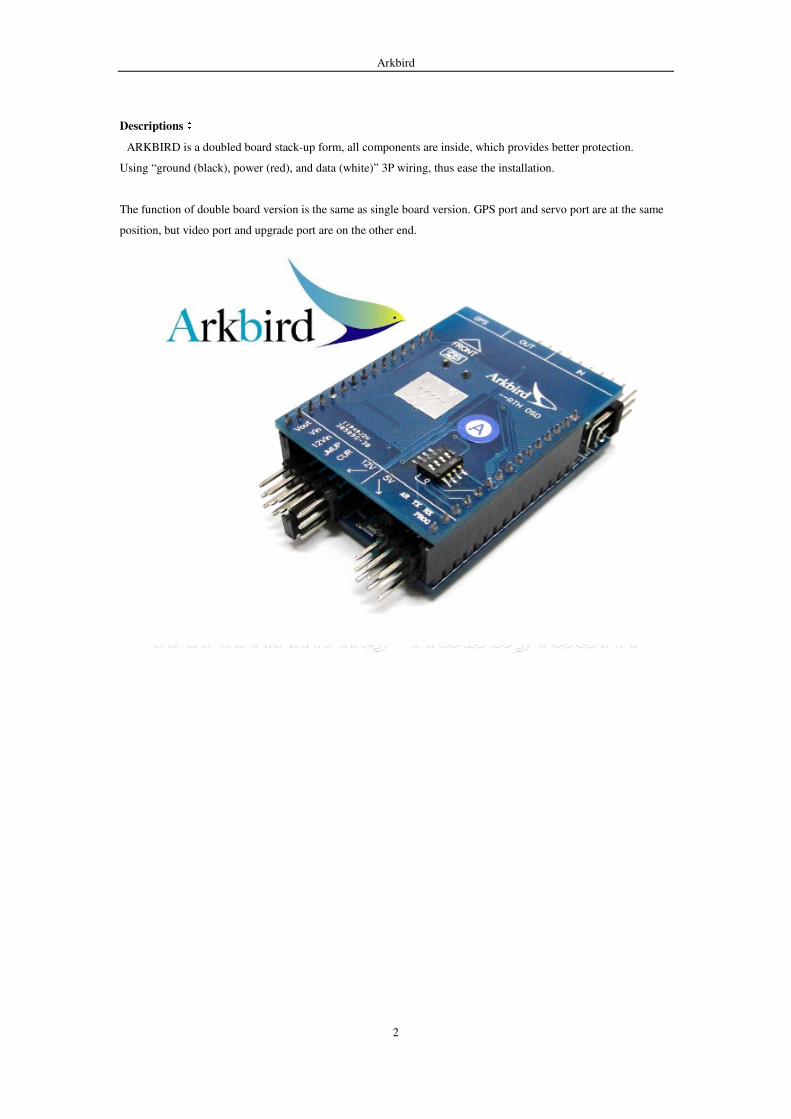
Descriptions::::
ARKBIRD is a doubled board stack-up form, all components are inside, which provides better protection.
Using “ground (black), power (red), and data (white)” 3P wiring, thus ease the installation.
The function of double board version is the same as single board version. GPS port and servo port are at the same
position, but video port and upgrade port are on the other end.
Arkbird
3
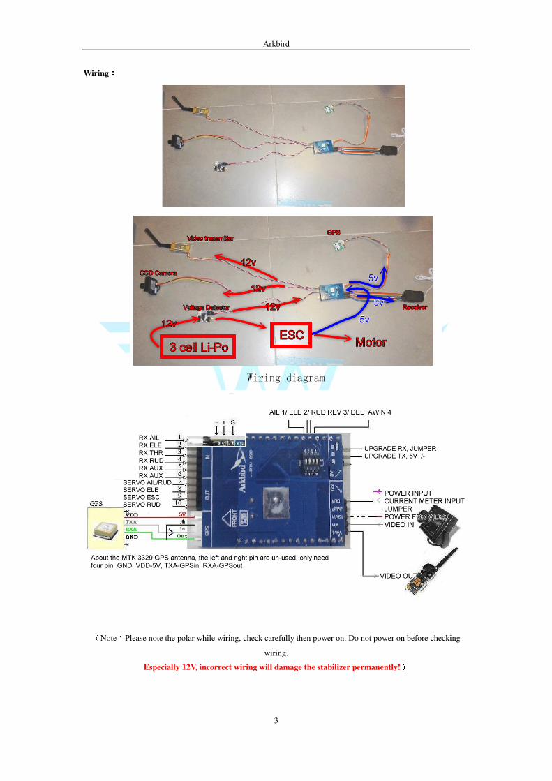
Wiring::::
Wiring diagram
(Note:Please note the polar while wiring, check carefully then power on. Do not power on before checking
wiring.
Especially 12V, incorrect wiring will damage the stabilizer permanently!)
Arkbird
4
All connections are now unified to “ground (black), power (red), and data (white)” 3P wiring.
1. When Arkbird sensor and 3S battery share the power, plug in the jumper, there will be power from sensor to
12V equipments (such as AV Tx and camera).
2. If using 3S battery alone to provide 12V power to AV Tx and OSD, remove the jumper, connect 3S battery to the
video power port on the third row.
The sequence to power on is OSD 12V first, and then ESC5V. Otherwise, the OSD cannot initialize and
display.
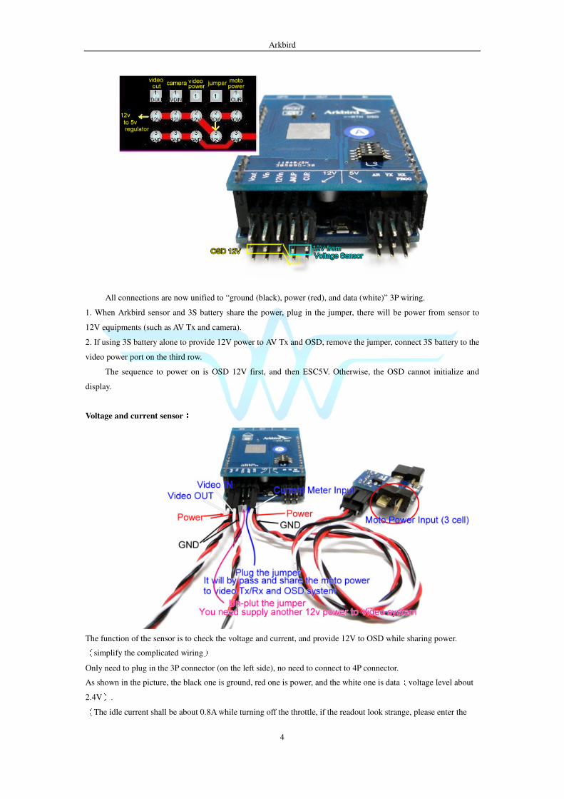
Voltage and current sensor::::
The function of the sensor is to check the voltage and current, and provide 12V to OSD while sharing power. (simplify the complicated wiring)
Only need to plug in the 3P connector (on the left side), no need to connect to 4P connector.
As shown in the picture, the black one is ground, red one is power, and the white one is data(voltage level about
2.4V). (The idle current shall be about 0.8A while turning off the throttle, if the readout look strange, please enter the
Arkbird
5
OSD menu again and exit to reset the current value.)
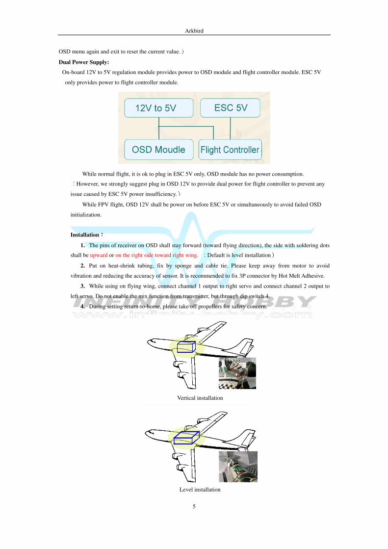
Dual Power Supply:
On-board 12V to 5V regulation module provides power to OSD module and flight controller module. ESC 5V
only provides power to flight controller module.
While normal flight, it is ok to plug in ESC 5V only, OSD module has no power consumption. (However, we strongly suggest plug in OSD 12V to provide dual power for flight controller to prevent any
issue caused by ESC 5V power insufficiency.)
While FPV flight, OSD 12V shall be power on before ESC 5V or simultaneously to avoid failed OSD
initialization.
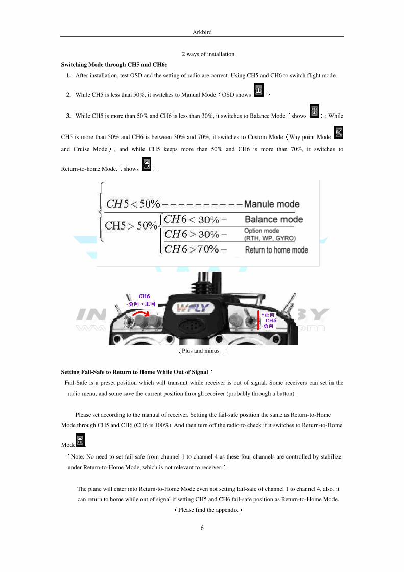
Installation::::
1. The pins of receiver on OSD shall stay forward (toward flying direction), the side with soldering dots
shall be upward or on the right side toward right wing. (Default is level installation)
2. Put on heat-shrink tubing, fix by sponge and cable tie. Please keep away from motor to avoid
vibration and reducing the accuracy of sensor. It is recommended to fix 3P connector by Hot Melt Adhesive.
3. While using on flying wing, connect channel 1 output to right servo and connect channel 2 output to
left servo. Do not enable the mix function from transmitter, but through dip switch 4.
4. During setting return-to-home, please take off propellers for safety concern.
Vertical installation
Level installation
Arkbird
6
2 ways of installation
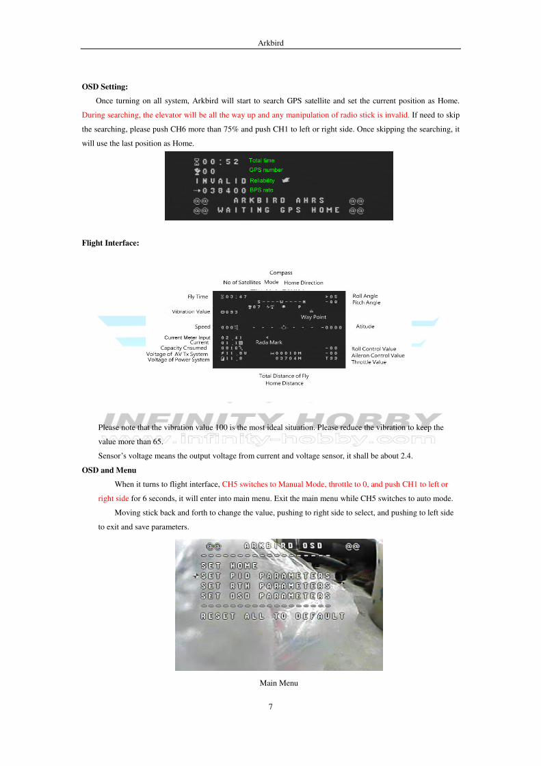
Switching Mode through CH5 and CH6:
1. After installation, test OSD and the setting of radio are correct. Using CH5 and CH6 to switch flight mode.
2. While CH5 is less than 50%, it switches to Manual Mode(OSD shows ),
3. While CH5 is more than 50% and CH6 is less than 30%, it switches to Balance Mode(shows ); While
CH5 is more than 50% and CH6 is between 30% and 70%, it switches to Custom Mode(Way point Mode
and Cruise Mode), and while CH5 keeps more than 50% and CH6 is more than 70%, it switches to
Return-to-home Mode.(shows ).
(Plus and minus )
Setting Fail-Safe to Return to Home While Out of Signal::::
Fail-Safe is a preset position which will transmit while receiver is out of signal. Some receivers can set in the
radio menu, and some save the current position through receiver (probably through a button).
Please set according to the manual of receiver. Setting the fail-safe position the same as Return-to-Home
Mode through CH5 and CH6 (CH6 is 100%). And then turn off the radio to check if it switches to Return-to-Home
Mode . (Note: No need to set fail-safe from channel 1 to channel 4 as these four channels are controlled by stabilizer
under Return-to-Home Mode, which is not relevant to receiver.)
The plane will enter into Return-to-Home Mode even not setting fail-safe of channel 1 to channel 4, also, it
can return to home while out of signal if setting CH5 and CH6 fail-safe position as Return-to-Home Mode. (Please find the appendix)
Arkbird
7
OSD Setting:
Once turning on all system, Arkbird will start to search GPS satellite and set the current position as Home.
During searching, the elevator will be all the way up and any manipulation of radio stick is invalid. If need to skip
the searching, please push CH6 more than 75% and push CH1 to left or right side. Once skipping the searching, it
will use the last position as Home.
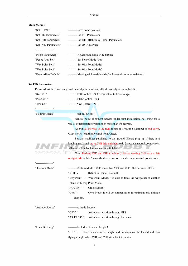
Flight Interface:
Please note that the vibration value 100 is the most ideal situation. Please reduce the vibration to keep the
value more than 65.
Sensor’s voltage means the output voltage from current and voltage sensor, it shall be about 2.4.
OSD and Menu
When it turns to flight interface, CH5 switches to Manual Mode, throttle to 0, and push CH1 to left or
right side for 6 seconds, it will enter into main menu. Exit the main menu while CH5 switches to auto mode.
Moving stick back and forth to change the value, pushing to right side to select, and pushing to left side
to exit and save parameters.
Main Menu
Arkbird
8
Main Menu::::
"Set HOME" --------- Save home position
"Set PID Parameters" --------- Set PID Parameters
"Set RTH Parameters" --------- Set RTH (Return to Home) Parameters
"Set OSD Parameters" --------- Set OSD Interface
"------------------"
"Flight Parameters" --------- Reverse and delta-wing mixing
"Fence Area Set" --------- Set Fence Mode Area
"Way Point Set1" --------- Set Way Point Mode1
"Way Point Set2" --------- Set Way Point Mode2
"Reset All to Default" --------- Moving stick to right side for 2 seconds to reset to default
Set PID Parameters
Please adjust the travel range and neutral point mechanically, do not adjust through radio.
"Roll Ctl " ---------Roll Control(%)(equivalent to travel range)
"Pitch Ctl " ---------Pitch Control(%)
"Yaw Ctl " ---------Yaw Control(%)
"------------------"
"Neutral Check" ---------Neutral Check:
Neutral point alignment needed under first installation, not using for a
while, or temperature variation is more than 10 degrees.
Aileron all the way to the right means it is waiting stabilizer be put down,
OSD shows “Waiting Neutral Point Check.”
Put the stabilizer paralleled to the ground (Please prop up if there is a
landing gear), and move CH1 left and right to do 3-seconds neutral point check.
Aileron will be back to center once finished.
Note: Pushing CH5 and CH6 to minus (0%) and moving CH1 stick to left
or right side within 3 seconds after power on can also enter neutral point check.
"------------------"
" Custom Mode" ---------Custom Mode(CH5 more than 50% and CH6 30% between 70%):
"RTH": Return to Home(Default)
"Way Point": Way Point Mode, it is able to trace the waypoints of another
plane with Way Point Mode.
"HOVER": Cruise Mode
"Gyro": Gyro Mode, it will do compensation for unintentional attitude
changes.
"Attitude Source" ---------Attitude Source:
"GPS": Attitude acquisition through GPS
"AR PRESS": Attitude acquisition through barometer
"Lock Dir/Heig" ---------Lock direction and height:
"ON": Under balance mode, height and direction will be locked and then
flying straight when CH1 and CH2 stick back to center.
Arkbird
9
When lock height and direction, OSD shows . Aileron and
elevator can also be controlled through CH1 and CH2.
"OFF": Turn off the mode.
Set RTH Parameters
"Max Roll" ---------Max roll angle while return to home, 20 to 40 degree recommended.
"Max UP" --------- Max pitch (up) angle while return to home, 20 to 40 degree
recommended
"Max Down" --------- Max pitch (down) angle while return to home, 20 to 35 degree
recommended
"Elevate Angle" ---------Elevate angle during level flight, 3 to 15 degree recommended. Under
Balance Mode, please adjust this value while pitch up or down to have level flight even the radio is out of signal.
"------------------"
"RTH Throttle" ---------Return to home throttle(%)
"AUTO Throttle" ---------The stabilizer will use the throttle value of level flight automatically as
return to home throttle. (Default)
"------------------"
"Safe Speed" ---------Minimum speed of return to home(when the speed GPS detected is less
than the certain value, it will accelerate throttle in proportion to avoid lost while being upwind.)
"Safe Height" ---------Safe Height(The minimum height of return to home, 80 to 150 m
recommended.)
"Throttle Safe" ---------Throttle Safe(When distance and height are less than 10m, for safety
concern, there is no throttle output under Return to Home Mode.)
Set OSD Parameters
"Big Letters" ---------Size of the characters selection
"Show Lat-lon" ---------Show longitude and altitude
"AD Calibrate" ---------Battery voltage calibration
"OSD Pattern" ---------OSD interface selection (Simple:Show home angle and voltage only) (Default:Normal interface) (Fighter:HUD interface) (ALL Info:Show all attitude information)
"P or N(Xin)" --------- PAL/ NTSC selection
Flight Parameters
Note: Adjusting these four parameters is equivalent to adjusting the dip switch.
"Roll (KEY1)" ---------Roll Reverse
"Pitch (KEY2)" ---------Pitch Reverse
"Yaw (KEY3)" ---------Yaw Reverse
"FlyWing (KEY4)" ---------Conventional/ Delta Wing
Arkbird
10
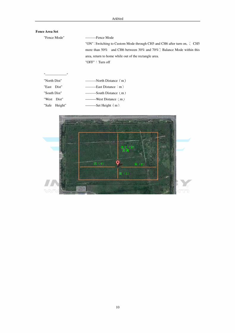
Fence Area Set
"Fence Mode" ---------Fence Mode
"ON":Switching to Custom Mode through CH5 and CH6 after turn on, ( CH5
more than 50% and CH6 between 30% and 70%)Balance Mode within this
area, return to home while out of the rectangle area.
"OFF":Turn off
"------------------"
"North Dist" ---------North Distance(m)
"East Dist" ---------East Distance(m)
"South Dist" ---------South Distance(m)
"West Dist" ---------West Distance(m)
"Safe Height" ---------Set Height(m)
Arkbird
11
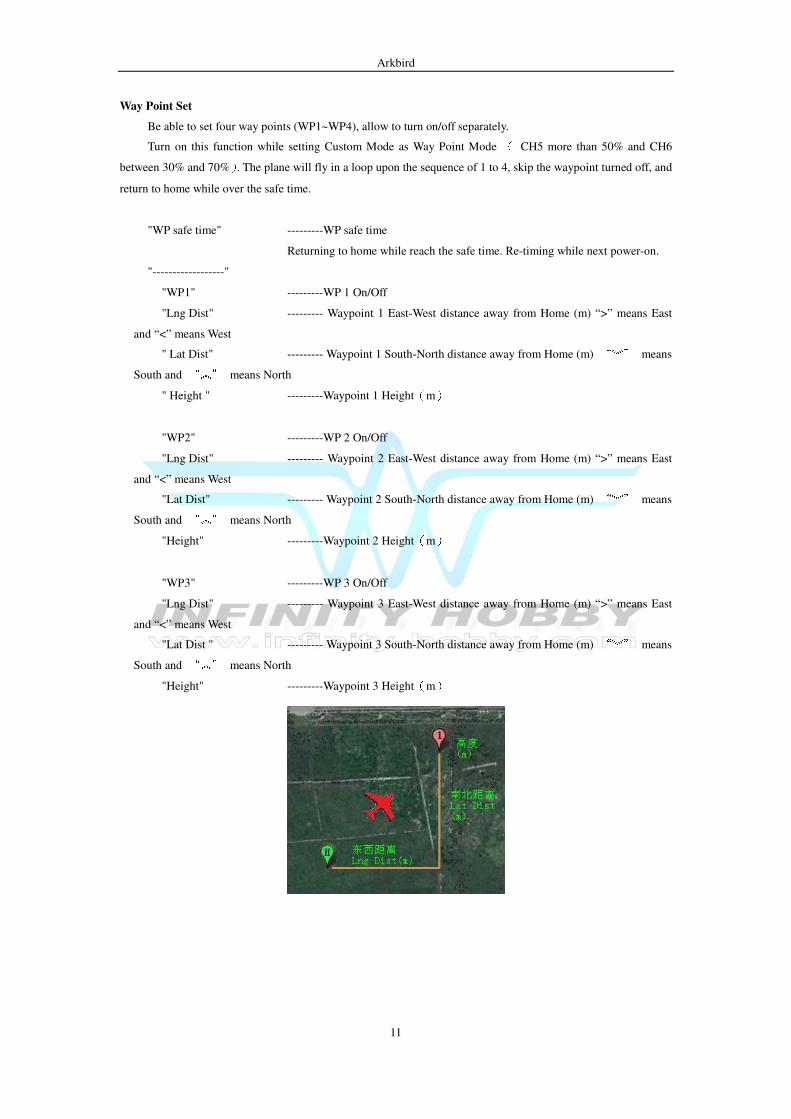
Way Point Set
Be able to set four way points (WP1~WP4), allow to turn on/off separately.
Turn on this function while setting Custom Mode as Way Point Mode ( CH5 more than 50% and CH6
between 30% and 70%). The plane will fly in a loop upon the sequence of 1 to 4, skip the waypoint turned off, and
return to home while over the safe time.
"WP safe time" ---------WP safe time
Returning to home while reach the safe time. Re-timing while next power-on.
"------------------"
"WP1" ---------WP 1 On/Off
"Lng Dist" --------- Waypoint 1 East-West distance away from Home (m) “>” means East
and “<” means West
" Lat Dist" --------- Waypoint 1 South-North distance away from Home (m) “︾” means
South and “︽” means North
" Height " ---------Waypoint 1 Height(m)
"WP2" ---------WP 2 On/Off
"Lng Dist" --------- Waypoint 2 East-West distance away from Home (m) “>” means East
and “<” means West
"Lat Dist" --------- Waypoint 2 South-North distance away from Home (m) “︾” means
South and “︽” means North
"Height" ---------Waypoint 2 Height(m)
"WP3" ---------WP 3 On/Off
"Lng Dist" --------- Waypoint 3 East-West distance away from Home (m) “>” means East
and “<” means West
"Lat Dist " --------- Waypoint 3 South-North distance away from Home (m) “︾” means
South and “︽” means North
"Height" ---------Waypoint 3 Height(m)
Arkbird
12
Reverse under Balance Mode::::
Switching to Manual Mode by pushing CH5 to 0%, and then setting reverse function through radio.
Switching to Balance Mode by pushing CH5 to 100% and CH6 to 0%, basically, if the neutral point is
correct, rudder, aileron and elevator shall be at the neutral position, otherwise, please check the neutral point again.
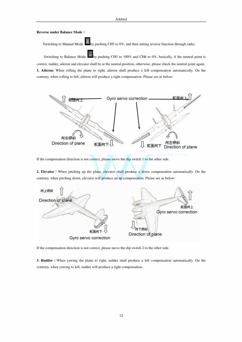
1. Aileron: When rolling the plane to right, aileron shall produce a left compensation automatically. On the
contrary, when rolling to left, aileron will produce a right compensation. Please see as below:
If the compensation direction is not correct, please move the dip switch 1 to the other side.
2. Elevator::::When pitching up the plane, elevator shall produce a down compensation automatically. On the
contrary, when pitching down, elevator will produce an up compensation. Please see as below:
If the compensation direction is not correct, please move the dip switch 2 to the other side.
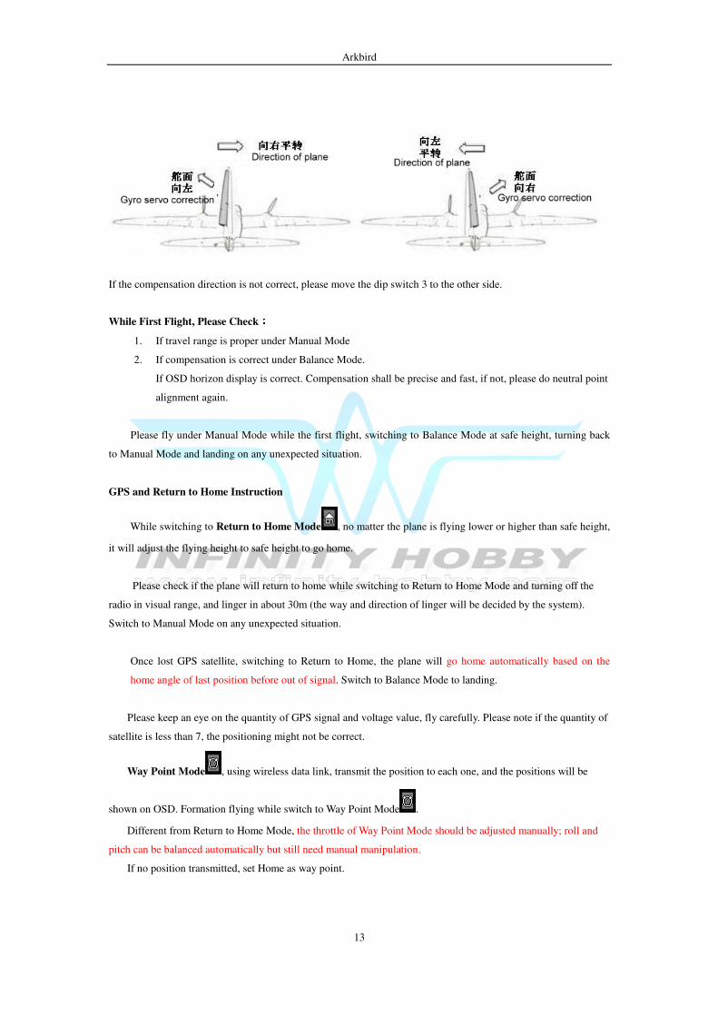
3. Rudder::::When yawing the plane to right, rudder shall produce a left compensation automatically. On the
contrary, when yawing to left, rudder will produce a right compensation.
Arkbird
13
If the compensation direction is not correct, please move the dip switch 3 to the other side.
While First Flight, Please Check::::
1. If travel range is proper under Manual Mode
2. If compensation is correct under Balance Mode.
If OSD horizon display is correct. Compensation shall be precise and fast, if not, please do neutral point
alignment again.
Please fly under Manual Mode while the first flight, switching to Balance Mode at safe height, turning back
to Manual Mode and landing on any unexpected situation.
GPS and Return to Home Instruction
While switching to Return to Home Mode , no matter the plane is flying lower or higher than safe height,
it will adjust the flying height to safe height to go home.
Please check if the plane will return to home while switching to Return to Home Mode and turning off the
radio in visual range, and linger in about 30m (the way and direction of linger will be decided by the system).
Switch to Manual Mode on any unexpected situation.
Once lost GPS satellite, switching to Return to Home, the plane will go home automatically based on the
home angle of last position before out of signal. Switch to Balance Mode to landing.
Please keep an eye on the quantity of GPS signal and voltage value, fly carefully. Please note if the quantity of
satellite is less than 7, the positioning might not be correct.
Way Point Mode , using wireless data link, transmit the position to each one, and the positions will be
shown on OSD. Formation flying while switch to Way Point Mode .
Different from Return to Home Mode, the throttle of Way Point Mode should be adjusted manually; roll and
pitch can be balanced automatically but still need manual manipulation.
If no position transmitted, set Home as way point.
Arkbird
14
Balance Mode and Return to Home Adjustment::::
Arkbird stabilizer has PID control, which can collect level flight throttle value automatically without any
parameter adjustment. If the most ideal situation expected, please refer to the following methods:
Once completing the first installation, do a neutral point alignment. Plane shall be put paralleled to the ground
before neutral point check, moving aileron stick left and right to get start. Roll the plane to right and left 45 degree
after neutral point check to see if OSD horizon tilts accordingly and quickly.
Please fly on default and record on the ground. Observe the attitude through OSD and adjust parameters.
Adjusting Balance Mode::::
Purpose:Stick and SUB-TRIM back to center, plane shall be able to have level flight.
1. Adjust PID parameters to the maximum under non-swing situation.
Please increase ctl value when the stability not good enough under Balance Mode (drift even stick back
to center), and decrease ctl value when the plane swings.
2. If plane pitches up or down when stick back to center, please adjust the elevate angle value (Do not
adjust through SUB-TRIM, or Return to Home Mode won’t be precise.)
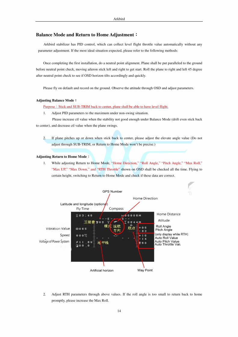
Adjusting Return to Home Mode::::
1. While adjusting Return to Home Mode, “Home Direction,” “Roll Angle,” “Pitch Angle,” “Max Roll,”
“Max UP,” “Max Down,” and “RTH Throttle” shown on OSD shall be checked all the time. Flying to
certain height, switching to Return to Home Mode and check if these data are correct.
2. Adjust RTH parameters through above values. If the roll angle is too small to return back to home
promptly, please increase the Max Roll.
Arkbird
15
3. Adjust Max Up and Max Down to make plane pitch up and down smoothly. (too prompt or slow are
improper)
4. Based on the height and distance expect to fly to adjust safe height as high as possible (If the flying
height is higher, please adjust this value more than 120m). Please set usual speed as minimum speed of
return to home.
Frequently Asked Questions::::
1. Incorrect PAL/NTSC selection:Take off camera, and select PAL/NTSC in “Set OSD Parameters” again.
2. If not be able to enter Menu, please check if the end point setting on radio is too small.
3. For 3-channel plane, please connect Airbird output 1 channel to rudder to steering. Please also note Dutch roll
and swings produced. The solution is to reduce “Yaw ctl.”
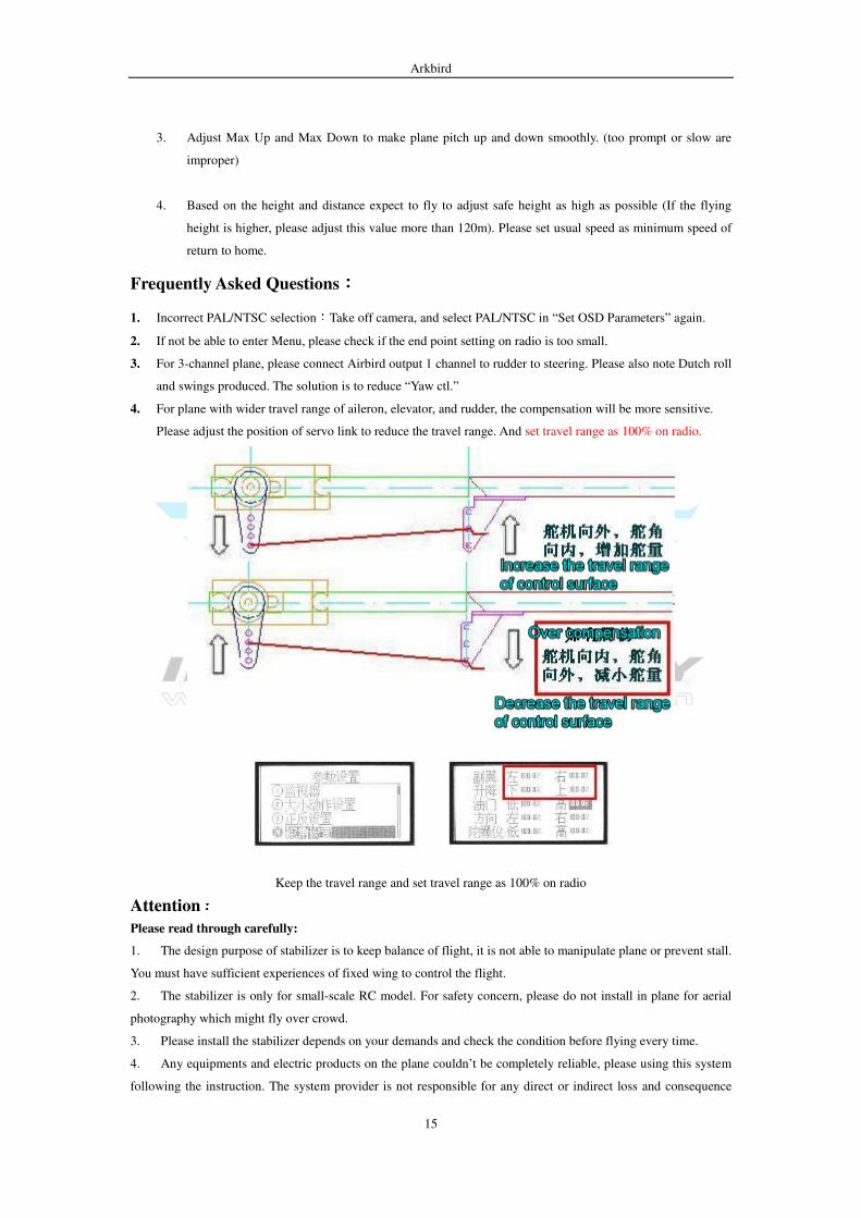
4. For plane with wider travel range of aileron, elevator, and rudder, the compensation will be more sensitive.
Please adjust the position of servo link to reduce the travel range. And set travel range as 100% on radio.
Keep the travel range and set travel range as 100% on radio
Attention::::
Please read through carefully:
1. The design purpose of stabilizer is to keep balance of flight, it is not able to manipulate plane or prevent stall.
You must have sufficient experiences of fixed wing to control the flight.
2. The stabilizer is only for small-scale RC model. For safety concern, please do not install in plane for aerial
photography which might fly over crowd.
3. Please install the stabilizer depends on your demands and check the condition before flying every time.
4. Any equipments and electric products on the plane couldn’t be completely reliable, please using this system
following the instruction. The system provider is not responsible for any direct or indirect loss and consequence
Arkbird
16
caused by using this product
Appendix::::
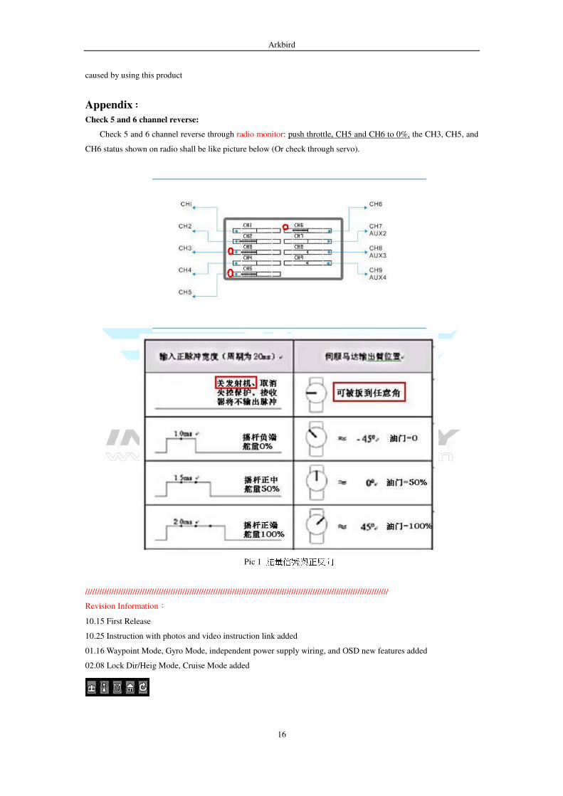
Check 5 and 6 channel reverse:
Check 5 and 6 channel reverse through radio monitor: push throttle, CH5 and CH6 to 0%, the CH3, CH5, and
CH6 status shown on radio shall be like picture below (Or check through servo).
Pic 1 舵量信號與正反向
////////////////////////////////////////////////////////////////////////////////////////////////////////////////////////////////
Revision Information:
10.15 First Release
10.25 Instruction with photos and video instruction link added
01.16 Waypoint Mode, Gyro Mode, independent power supply wiring, and OSD new features added
02.08 Lock Dir/Heig Mode, Cruise Mode added