ARDUINO 1 By Wilmer Arellano (Under Development)

ARDUINO 1 By Wilmer Arellano (Under Development).
Dec 24, 2015
Welcome message from author
This document is posted to help you gain knowledge. Please leave a comment to let me know what you think about it! Share it to your friends and learn new things together.
Transcript
ARDUINO 1By Wilmer Arellano (Under Development)
Arduino
Arduino is an open-source electronics prototyping platform based on flexible, easy-to-use hardware and software.
It's intended for artists, designers, hobbyists, and anyone interested in creating interactive
objects or environments. http://www.arduino.cc/
Arduino
Arduino can sense the environment by receiving input from a variety of sensors and
can affect its surroundings by controlling lights, motors, and other actuators.
The microcontroller on the board is programmed using the Arduino programming language (based on Wiring) and the Arduino development environment (based on Processing).
http://www.arduino.cc/
Arduino
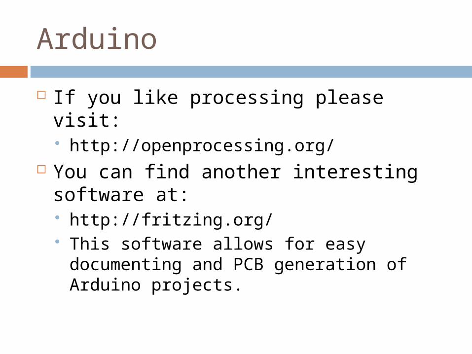
If you like processing please visit: http://openprocessing.org/
You can find another interesting software at: http://fritzing.org/ This software allows for easy documenting
and PCB generation of Arduino projects.
Arduino
Arduino projects can be stand-alone or they can communicate with software on running on a computer (e.g. Flash, Processing, MaxMSP).
http://www.arduino.cc/
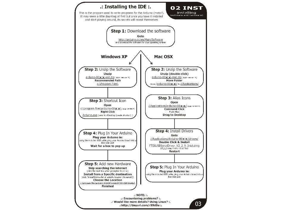
Download the latest version from the page: http://arduino.cc/en/Main/Software
Basics
In the Arduino environment programs are referred to as sketches
http://www.arduino.cc/ http://arduino.cc/en/Reference/
HomePage http://arduino.cc/en/Tutorial/Foundations
Basics
Comments /* * Blink * * The basic Arduino example.
Turns on an LED on for one second, * then off for one second, and so on... We use pin 13 because, * depending on your Arduino board, it has either a built-in LED * or a built-in resistor so that you need only an LED. * * http://www.arduino.cc/en/Tutorial/Blink */
// LED connected to digital pin 13
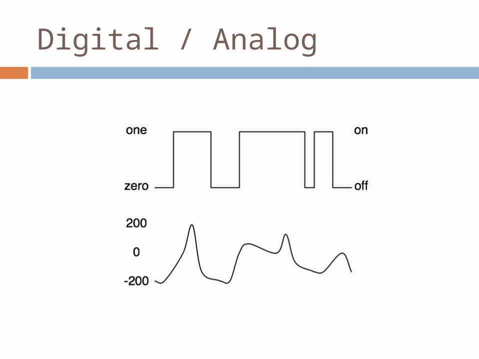
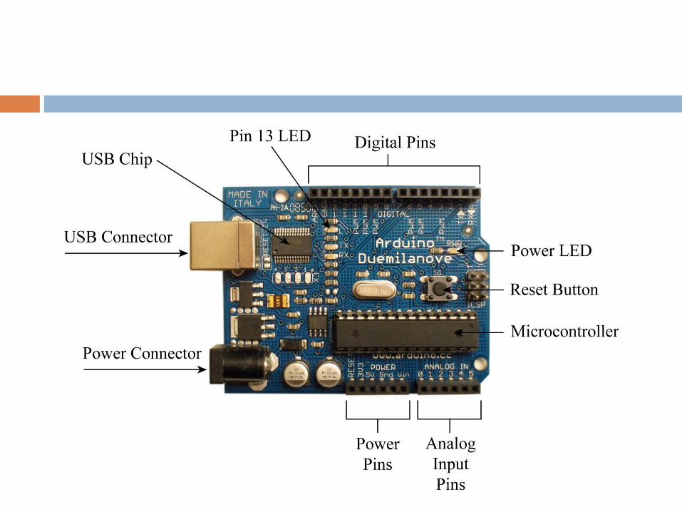
Digital / Analog
Power
The Arduino Duemilanove can be powered via the USB connection or with an external power supply. The power source is selected automatically. The Arduino Diecimila requires the user to select the power option with a jumper
External (non-USB) power can come either from an AC-to-DC adapter (wall-wart) or battery. The adapter can be connected by plugging a 2.1 mm center-positive plug into the board's power jack. Leads from a battery can be inserted in the Gnd and Vin pin headers of the POWER connector
Power
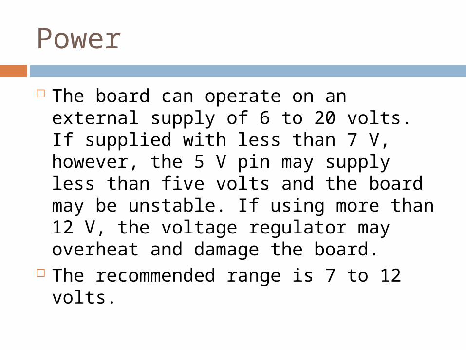
The board can operate on an external supply of 6 to 20 volts. If supplied with less than 7 V, however, the 5 V pin may supply less than five volts and the board may be unstable. If using more than 12 V, the voltage regulator may overheat and damage the board.
The recommended range is 7 to 12 volts.
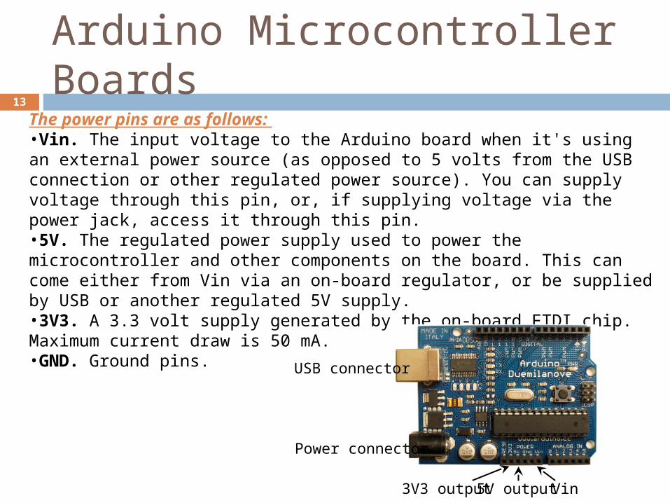
The power pins are as follows: •Vin. The input voltage to the Arduino board when it's using an external power source (as opposed to 5 volts from the USB connection or other regulated power source). You can supply voltage through this pin, or, if supplying voltage via the power jack, access it through this pin. •5V. The regulated power supply used to power the microcontroller and other components on the board. This can come either from Vin via an on-board regulator, or be supplied by USB or another regulated 5V supply. •3V3. A 3.3 volt supply generated by the on-board FTDI chip. Maximum current draw is 50 mA. •GND. Ground pins.
Power connector
USB connector
Vin5V output3V3 output
Arduino Microcontroller Boards13
Arduino Microcontroller Boards
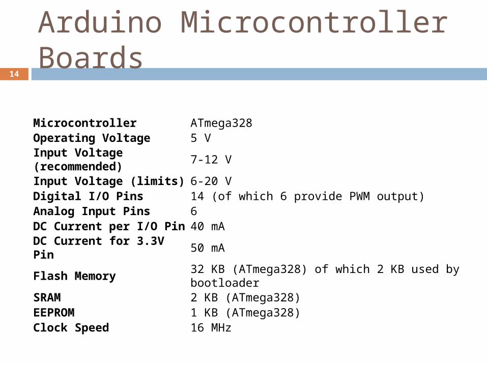
Microcontroller ATmega328 Operating Voltage 5 V Input Voltage (recommended) 7-12 V Input Voltage (limits) 6-20 V Digital I/O Pins 14 (of which 6 provide PWM output)Analog Input Pins 6DC Current per I/O Pin 40 mA DC Current for 3.3V Pin 50 mAFlash Memory 32 KB (ATmega328) of which 2 KB used by bootloader SRAM 2 KB (ATmega328)EEPROM 1 KB (ATmega328)Clock Speed 16 MHz
14
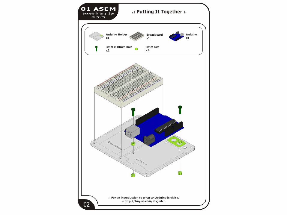
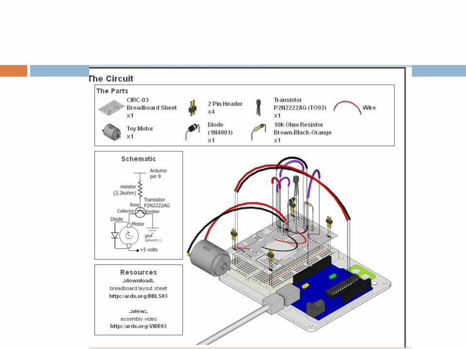
breadboards
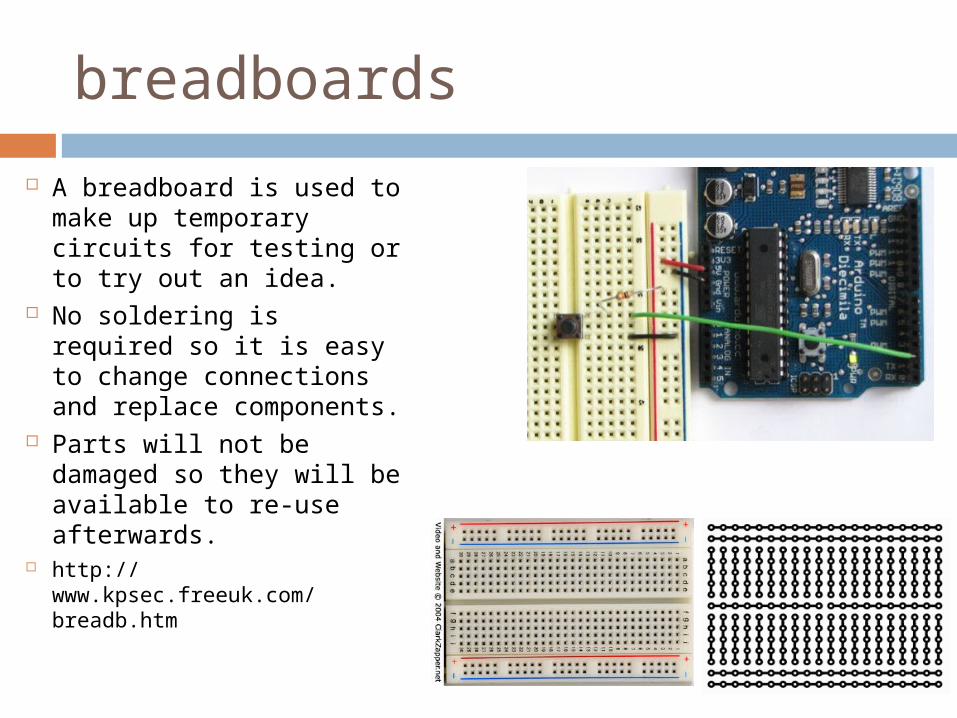
A breadboard is used to make up temporary circuits for testing or to try out an idea.
No soldering is required so it is easy to change connections and replace components.
Parts will not be damaged so they will be available to re-use afterwards.
http://www.kpsec.freeuk.com/breadb.htm
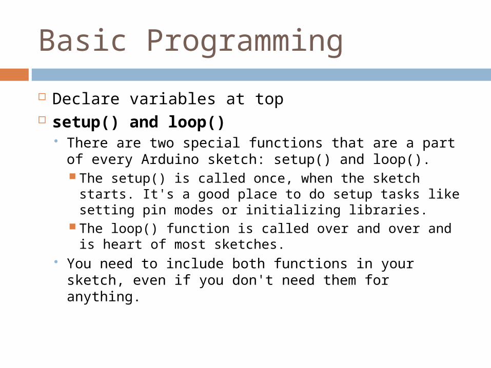
Basic Programming
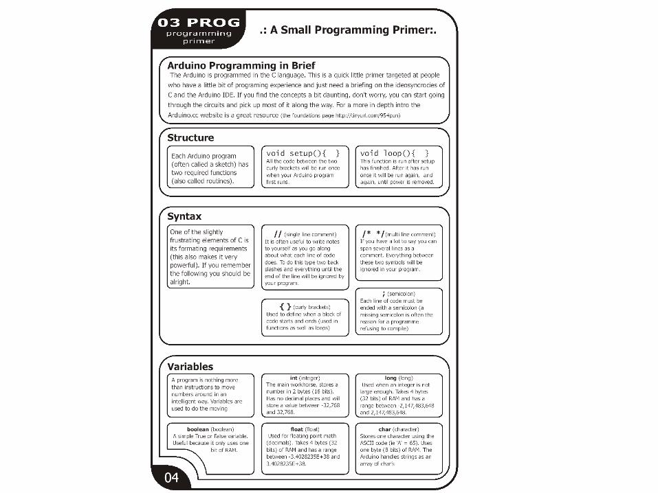
Declare variables at top setup() and loop()
There are two special functions that are a part of every Arduino sketch: setup() and loop(). The setup() is called once, when the sketch
starts. It's a good place to do setup tasks like setting pin modes or initializing libraries.
The loop() function is called over and over and is heart of most sketches.
You need to include both functions in your sketch, even if you don't need them for anything.
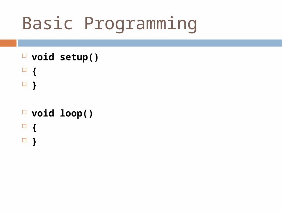
Basic Programming
void setup() { }
void loop() { }
/*
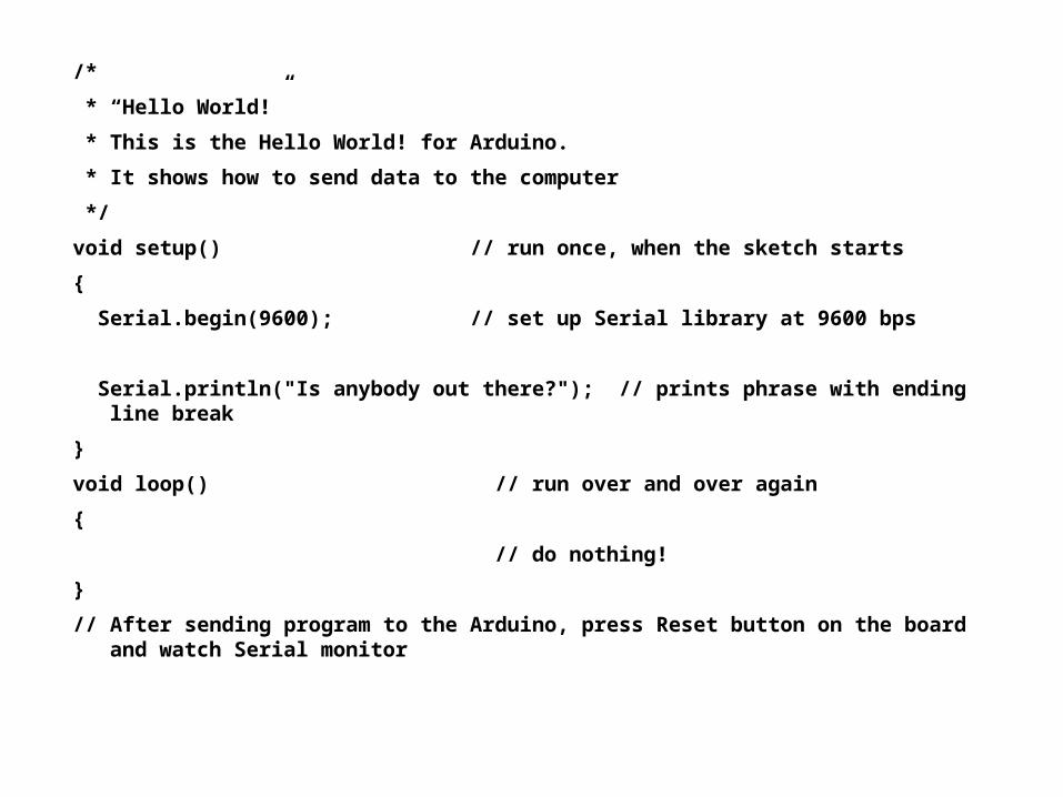
* “Hello World!”
* This is the Hello World! for Arduino.
* It shows how to send data to the computer
*/
void setup() // run once, when the sketch starts
{
Serial.begin(9600); // set up Serial library at 9600 bps
Serial.println("Is anybody out there?"); // prints phrase with ending line break
}
void loop() // run over and over again
{
// do nothing!
}
// After sending program to the Arduino, press Reset button on the board and watch Serial monitor
Basic Programming
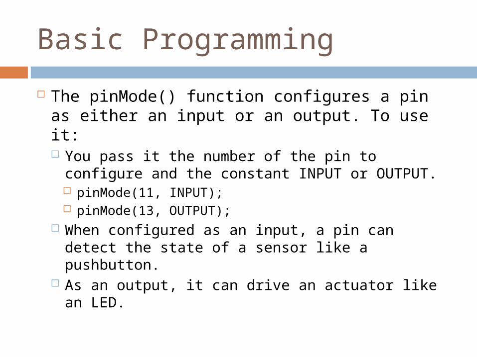
The pinMode() function configures a pin as either an input or an output. To use it: You pass it the number of the pin to
configure and the constant INPUT or OUTPUT. pinMode(11, INPUT); pinMode(13, OUTPUT);
When configured as an input, a pin can detect the state of a sensor like a pushbutton.
As an output, it can drive an actuator like an LED.
Basic Programming
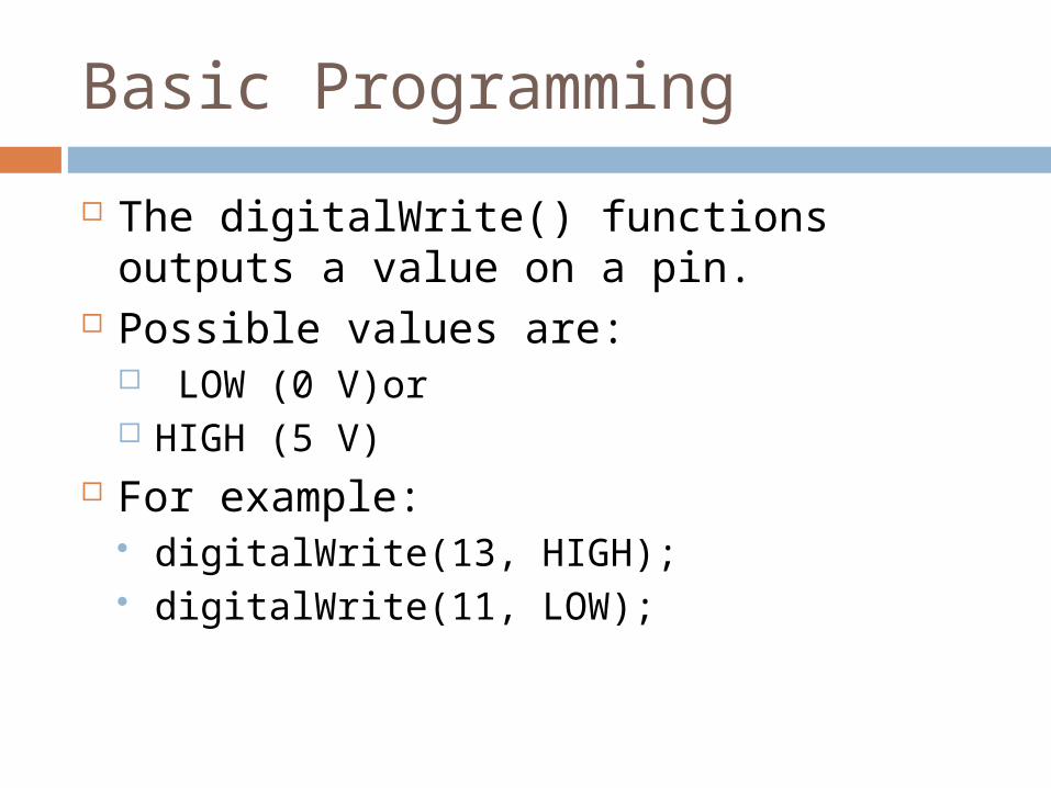
The digitalWrite() functions outputs a value on a pin.
Possible values are: LOW (0 V)or HIGH (5 V)
For example: digitalWrite(13, HIGH); digitalWrite(11, LOW);
Basic Programming
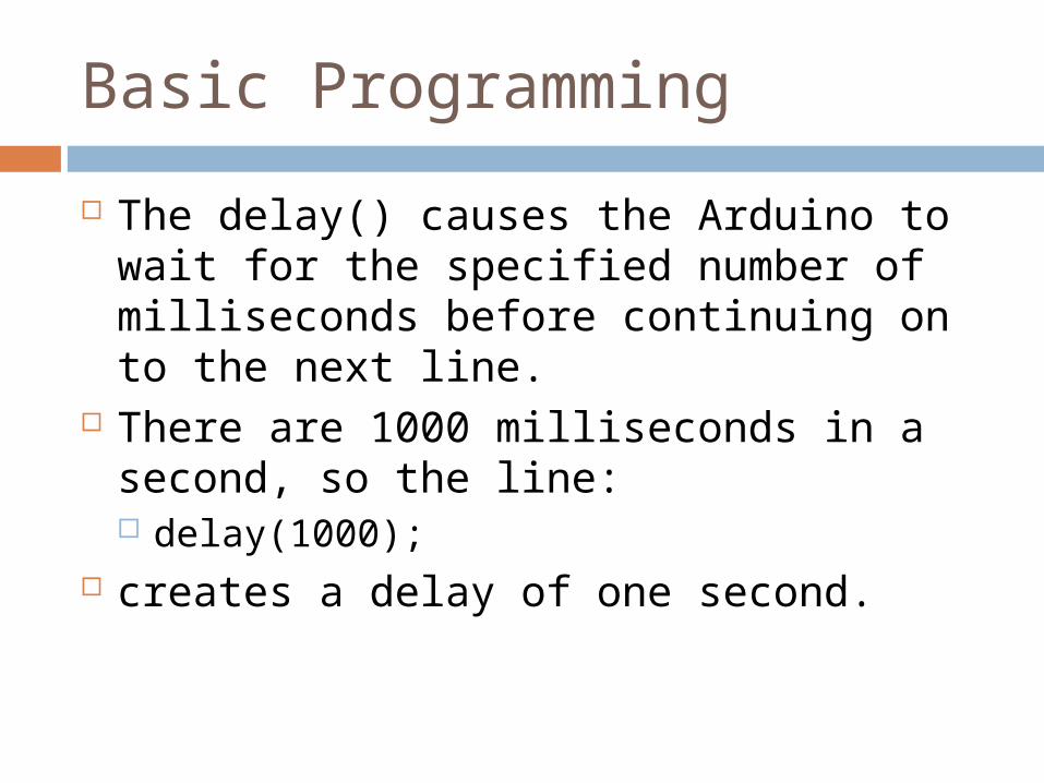
The delay() causes the Arduino to wait for the specified number of milliseconds before continuing on to the next line.
There are 1000 milliseconds in a second, so the line: delay(1000);
creates a delay of one second.
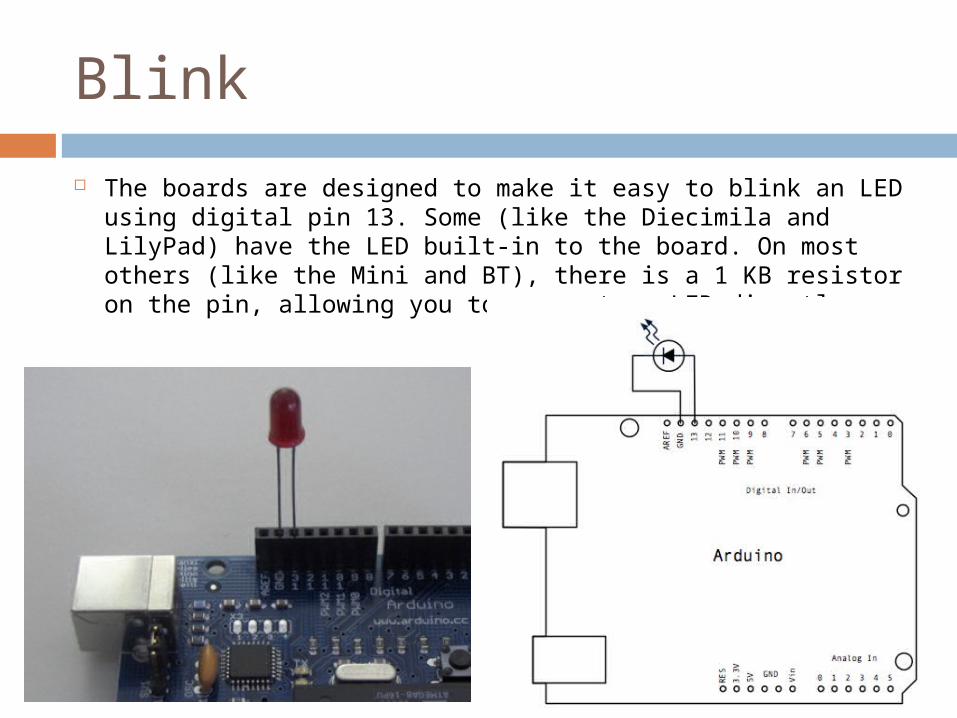
Blink
The boards are designed to make it easy to blink an LED using digital pin 13. Some (like the Diecimila and LilyPad) have the LED built-in to the board. On most others (like the Mini and BT), there is a 1 KB resistor on the pin, allowing you to connect an LED directly.
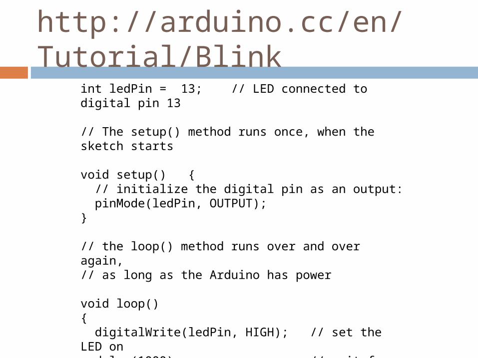
int ledPin = 13; // LED connected to digital pin 13
// The setup() method runs once, when the sketch starts
void setup() { // initialize the digital pin as an output: pinMode(ledPin, OUTPUT); }
// the loop() method runs over and over again,// as long as the Arduino has power
void loop() { digitalWrite(ledPin, HIGH); // set the LED on delay(1000); // wait for a second digitalWrite(ledPin, LOW); // set the LED off delay(1000); // wait for a second}
http://arduino.cc/en/Tutorial/Blink
Variables
You can use variables in a similar way as they are used in math or physics
All variables have to be declared before they are used , and optionally,
set an initial value (initializing the variable).

char
A data type that takes up 1 byte of memory that stores a character value. Character literals are written in single quotes, like this: 'A' (for multiple characters - strings - use double quotes: "ABC").
Characters are stored as numbers however. You can see the specific encoding in the ASCII chart.
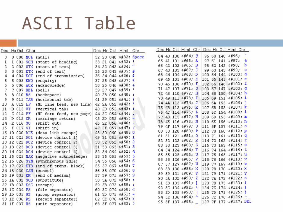
ASCII Table
char
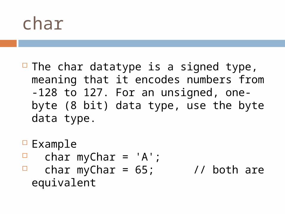
The char datatype is a signed type, meaning that it encodes numbers from -128 to 127. For an unsigned, one-byte (8 bit) data type, use the byte data type.
Example char myChar = 'A'; char myChar = 65; // both are
equivalent
char
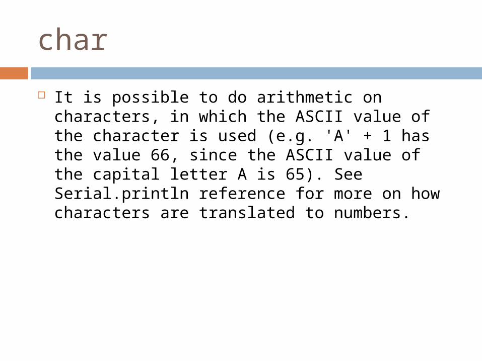
It is possible to do arithmetic on characters, in which the ASCII value of the character is used (e.g. 'A' + 1 has the value 66, since the ASCII value of the capital letter A is 65). See Serial.println reference for more on how characters are translated to numbers.
byte
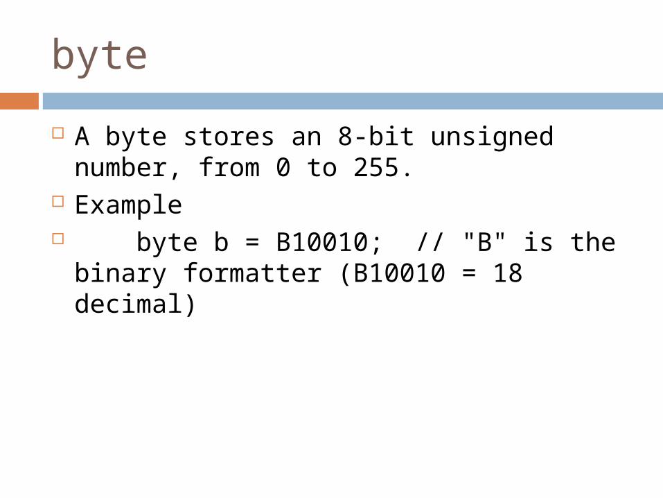
A byte stores an 8-bit unsigned number, from 0 to 255.
Example byte b = B10010; // "B" is the binary
formatter (B10010 = 18 decimal)
int
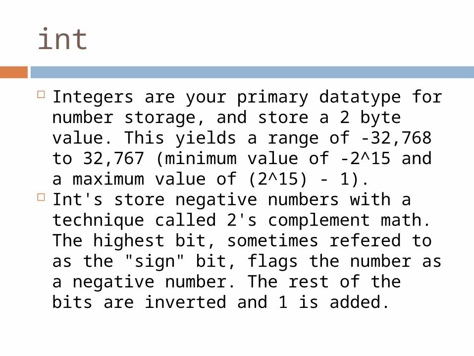
Integers are your primary datatype for number storage, and store a 2 byte value. This yields a range of -32,768 to 32,767 (minimum value of -2^15 and a maximum value of (2^15) - 1).
Int's store negative numbers with a technique called 2's complement math. The highest bit, sometimes refered to as the "sign" bit, flags the number as a negative number. The rest of the bits are inverted and 1 is added.
int
Example int ledPin = 13;
Syntax int var = val;
unsigned int
Unsigned ints (unsigned integers) are the same as ints in that they store a 2 byte value. Instead of storing negative numbers however they only store positive values, yielding a useful range of 0 to 65,535 (2^16) - 1).
unsigned int
Example unsigned int ledPin = 13;
Syntax unsigned int var = val;
var - your unsigned int variable name val - the value you assign to that variable
long
long – long variables are extended size variables for number storage, and store 32 bits (4 bytes), from −2,147,483,648 to 2,147,483,647.
unsigned long – unsigned long variables are extended size variables for number storage, and store 32 bits (4 bytes). Unlike standard longs unsigned longs won't store negative numbers, making their range from 0 to 4,294,967,295
float / double
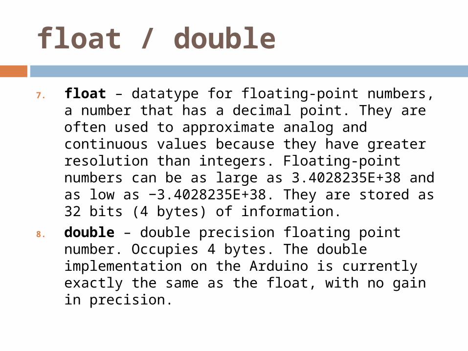
7. float – datatype for floating-point numbers, a number that has a decimal point. They are often used to approximate analog and continuous values because they have greater resolution than integers. Floating-point numbers can be as large as 3.4028235E+38 and as low as −3.4028235E+38. They are stored as 32 bits (4 bytes) of information.
8. double – double precision floating point number. Occupies 4 bytes. The double implementation on the Arduino is currently exactly the same as the float, with no gain in precision.
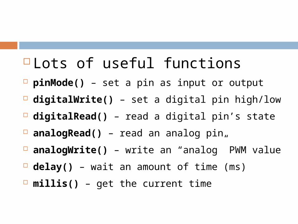
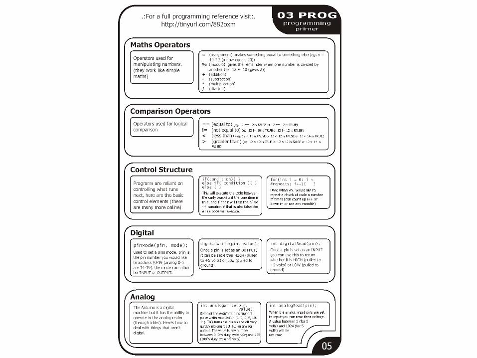
Lots of useful functions pinMode() – set a pin as input or output
digitalWrite() – set a digital pin high/low
digitalRead() – read a digital pin’s state
analogRead() – read an analog pin
analogWrite() – write an “analog” PWM value
delay() – wait an amount of time (ms)
millis() – get the current time
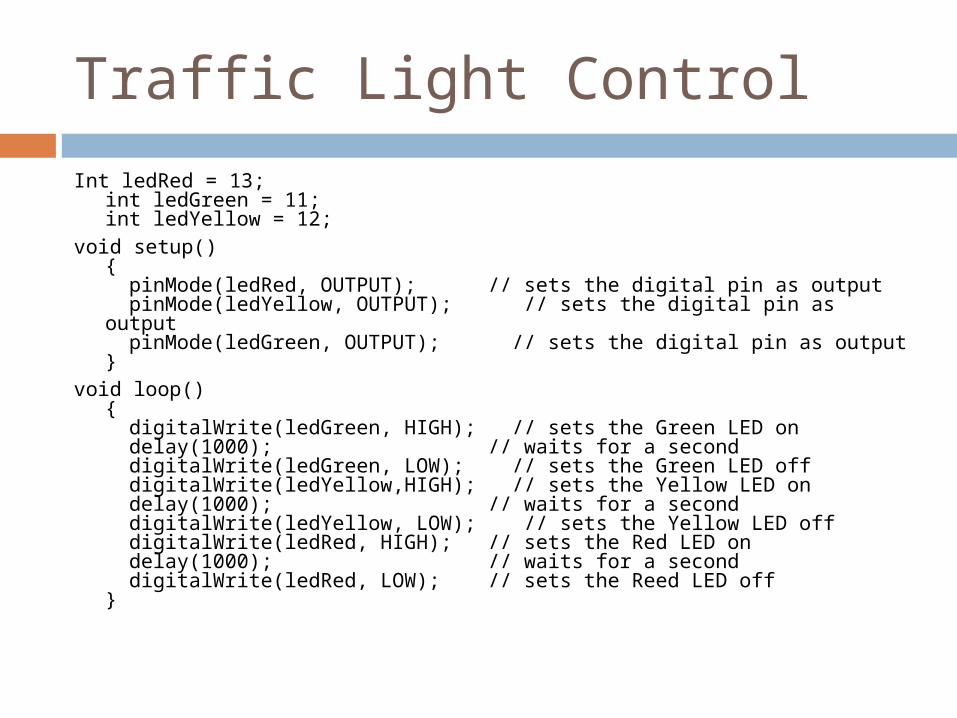
Traffic Light Control
Int ledRed = 13; int ledGreen = 11;int ledYellow = 12;
void setup(){ pinMode(ledRed, OUTPUT); // sets the digital pin as output pinMode(ledYellow, OUTPUT); // sets the digital pin as output pinMode(ledGreen, OUTPUT); // sets the digital pin as output}
void loop(){ digitalWrite(ledGreen, HIGH); // sets the Green LED on delay(1000); // waits for a second digitalWrite(ledGreen, LOW); // sets the Green LED off digitalWrite(ledYellow,HIGH); // sets the Yellow LED on delay(1000); // waits for a second digitalWrite(ledYellow, LOW); // sets the Yellow LED off digitalWrite(ledRed, HIGH); // sets the Red LED on delay(1000); // waits for a second digitalWrite(ledRed, LOW); // sets the Reed LED off}
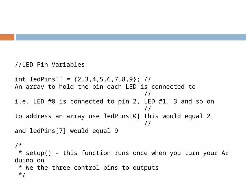
//LED Pin Variables
int ledPins[] = {2,3,4,5,6,7,8,9}; //An array to hold the pin each LED is connected to //i.e. LED #0 is connected to pin 2, LED #1, 3 and so on //to address an array use ledPins[0] this would equal 2 //and ledPins[7] would equal 9 /* * setup() - this function runs once when you turn your Arduino on * We the three control pins to outputs */
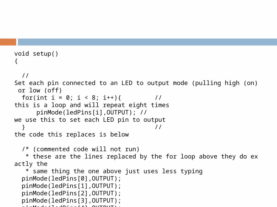
void setup(){ //Set each pin connected to an LED to output mode (pulling high (on) or low (off) for(int i = 0; i < 8; i++){ //this is a loop and will repeat eight times pinMode(ledPins[i],OUTPUT); //we use this to set each LED pin to output } //the code this replaces is below /* (commented code will not run) * these are the lines replaced by the for loop above they do exactly the * same thing the one above just uses less typing pinMode(ledPins[0],OUTPUT); pinMode(ledPins[1],OUTPUT); pinMode(ledPins[2],OUTPUT); pinMode(ledPins[3],OUTPUT); pinMode(ledPins[4],OUTPUT); pinMode(ledPins[5],OUTPUT); pinMode(ledPins[6],OUTPUT); pinMode(ledPins[7],OUTPUT); (end of commented code)*/}
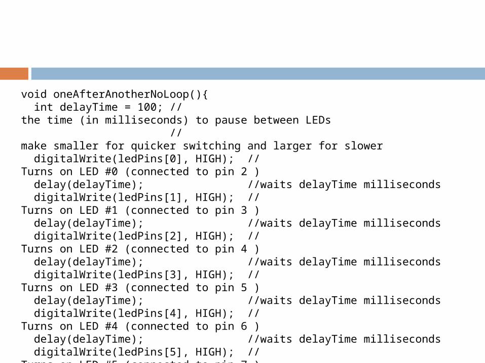
void oneAfterAnotherNoLoop(){ int delayTime = 100; //the time (in milliseconds) to pause between LEDs //make smaller for quicker switching and larger for slower digitalWrite(ledPins[0], HIGH); //Turns on LED #0 (connected to pin 2 ) delay(delayTime); //waits delayTime milliseconds digitalWrite(ledPins[1], HIGH); //Turns on LED #1 (connected to pin 3 ) delay(delayTime); //waits delayTime milliseconds digitalWrite(ledPins[2], HIGH); //Turns on LED #2 (connected to pin 4 ) delay(delayTime); //waits delayTime milliseconds digitalWrite(ledPins[3], HIGH); //Turns on LED #3 (connected to pin 5 ) delay(delayTime); //waits delayTime milliseconds digitalWrite(ledPins[4], HIGH); //Turns on LED #4 (connected to pin 6 ) delay(delayTime); //waits delayTime milliseconds digitalWrite(ledPins[5], HIGH); //Turns on LED #5 (connected to pin 7 ) delay(delayTime); //waits delayTime milliseconds digitalWrite(ledPins[6], HIGH); //Turns on LED #6 (connected to pin 8 ) delay(delayTime); //waits delayTime milliseconds digitalWrite(ledPins[7], HIGH); //Turns on LED #7 (connected to pin 9 ) delay(delayTime); //waits delayTime milliseconds
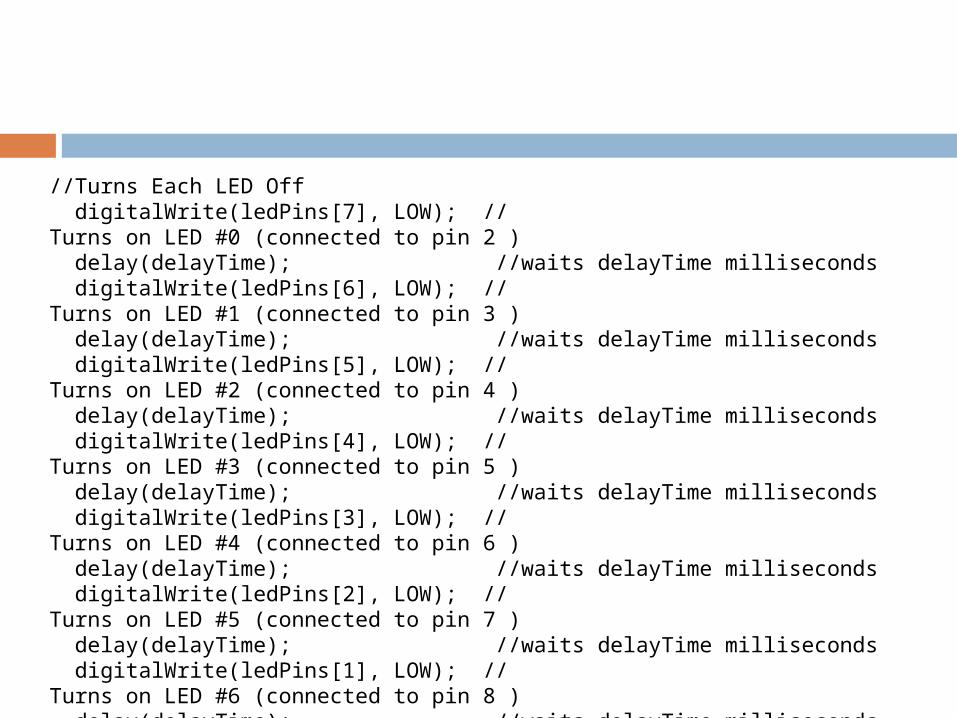
//Turns Each LED Off digitalWrite(ledPins[7], LOW); //Turns on LED #0 (connected to pin 2 ) delay(delayTime); //waits delayTime milliseconds digitalWrite(ledPins[6], LOW); //Turns on LED #1 (connected to pin 3 ) delay(delayTime); //waits delayTime milliseconds digitalWrite(ledPins[5], LOW); //Turns on LED #2 (connected to pin 4 ) delay(delayTime); //waits delayTime milliseconds digitalWrite(ledPins[4], LOW); //Turns on LED #3 (connected to pin 5 ) delay(delayTime); //waits delayTime milliseconds digitalWrite(ledPins[3], LOW); //Turns on LED #4 (connected to pin 6 ) delay(delayTime); //waits delayTime milliseconds digitalWrite(ledPins[2], LOW); //Turns on LED #5 (connected to pin 7 ) delay(delayTime); //waits delayTime milliseconds digitalWrite(ledPins[1], LOW); //Turns on LED #6 (connected to pin 8 ) delay(delayTime); //waits delayTime milliseconds digitalWrite(ledPins[0], LOW); //Turns on LED #7 (connected to pin 9 ) delay(delayTime); //waits delayTime milliseconds }
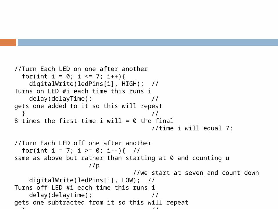
//Turn Each LED on one after another for(int i = 0; i <= 7; i++){ digitalWrite(ledPins[i], HIGH); //Turns on LED #i each time this runs i delay(delayTime); //gets one added to it so this will repeat } //8 times the first time i will = 0 the final //time i will equal 7; //Turn Each LED off one after another for(int i = 7; i >= 0; i--){ //same as above but rather than starting at 0 and counting u //p //we start at seven and count down digitalWrite(ledPins[i], LOW); //Turns off LED #i each time this runs i delay(delayTime); //gets one subtracted from it so this will repeat } //8 times the first time i will = 7 the final //time it will equal 0
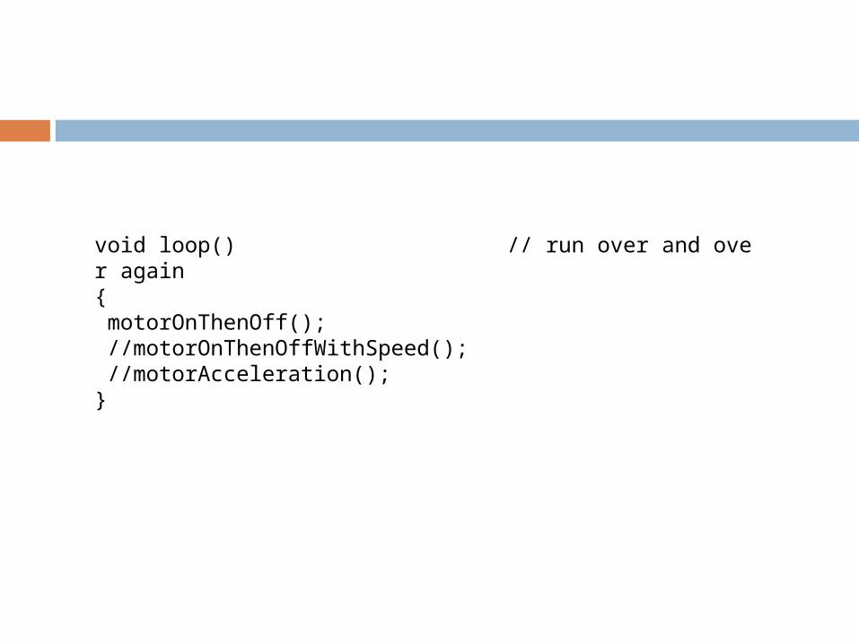
void loop() // run over and over again{ motorOnThenOff(); //motorOnThenOffWithSpeed(); //motorAcceleration();}
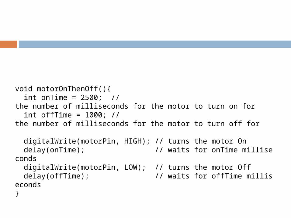
void motorOnThenOff(){ int onTime = 2500; //the number of milliseconds for the motor to turn on for int offTime = 1000; //the number of milliseconds for the motor to turn off for digitalWrite(motorPin, HIGH); // turns the motor On delay(onTime); // waits for onTime milliseconds digitalWrite(motorPin, LOW); // turns the motor Off delay(offTime); // waits for offTime milliseconds}
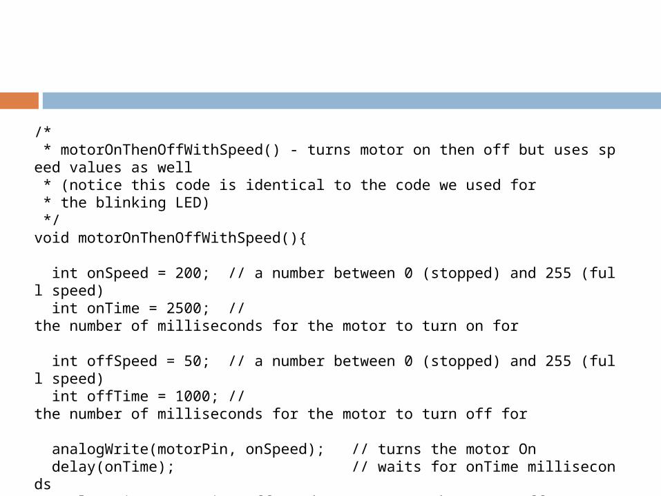
/* * motorOnThenOffWithSpeed() - turns motor on then off but uses speed values as well * (notice this code is identical to the code we used for * the blinking LED) */void motorOnThenOffWithSpeed(){ int onSpeed = 200; // a number between 0 (stopped) and 255 (full speed) int onTime = 2500; //the number of milliseconds for the motor to turn on for int offSpeed = 50; // a number between 0 (stopped) and 255 (full speed) int offTime = 1000; //the number of milliseconds for the motor to turn off for analogWrite(motorPin, onSpeed); // turns the motor On delay(onTime); // waits for onTime milliseconds analogWrite(motorPin, offSpeed); // turns the motor Off delay(offTime); // waits for offTime milliseconds}
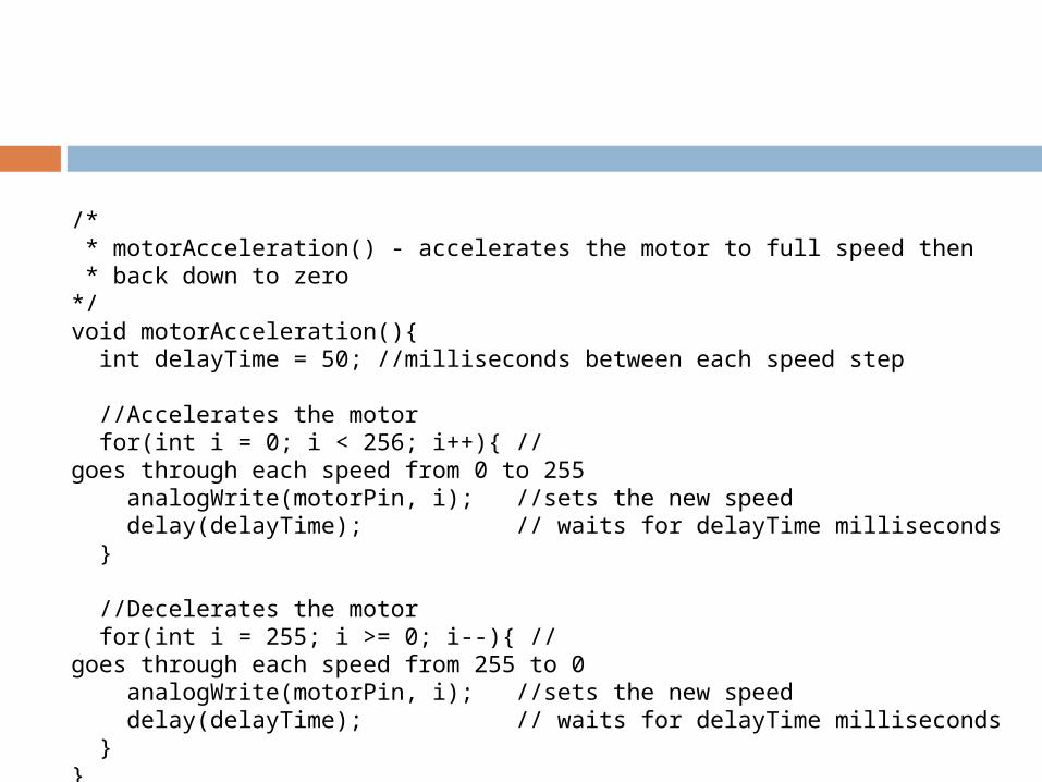
/* * motorAcceleration() - accelerates the motor to full speed then * back down to zero*/void motorAcceleration(){ int delayTime = 50; //milliseconds between each speed step //Accelerates the motor for(int i = 0; i < 256; i++){ //goes through each speed from 0 to 255 analogWrite(motorPin, i); //sets the new speed delay(delayTime); // waits for delayTime milliseconds } //Decelerates the motor for(int i = 255; i >= 0; i--){ //goes through each speed from 255 to 0 analogWrite(motorPin, i); //sets the new speed delay(delayTime); // waits for delayTime milliseconds }}
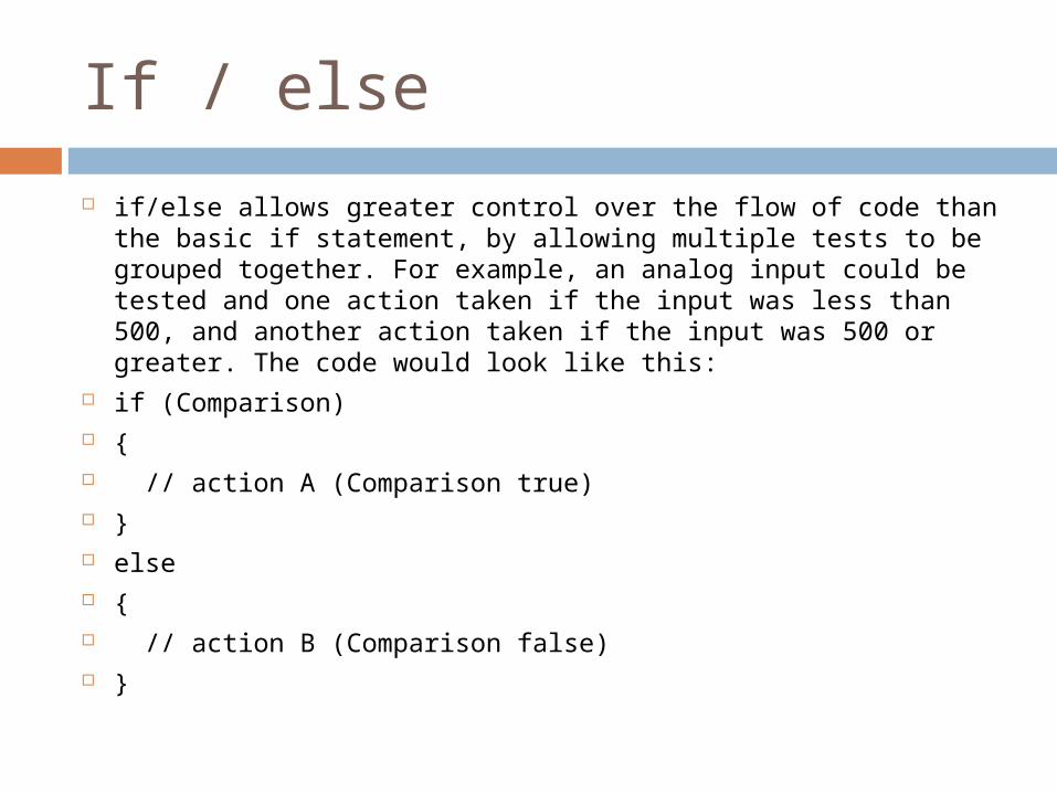
If / else
if/else allows greater control over the flow of code than the basic if statement, by allowing multiple tests to be grouped together. For example, an analog input could be tested and one action taken if the input was less than 500, and another action taken if the input was 500 or greater. The code would look like this:
if (Comparison) { // action A (Comparison true) } else { // action B (Comparison false) }
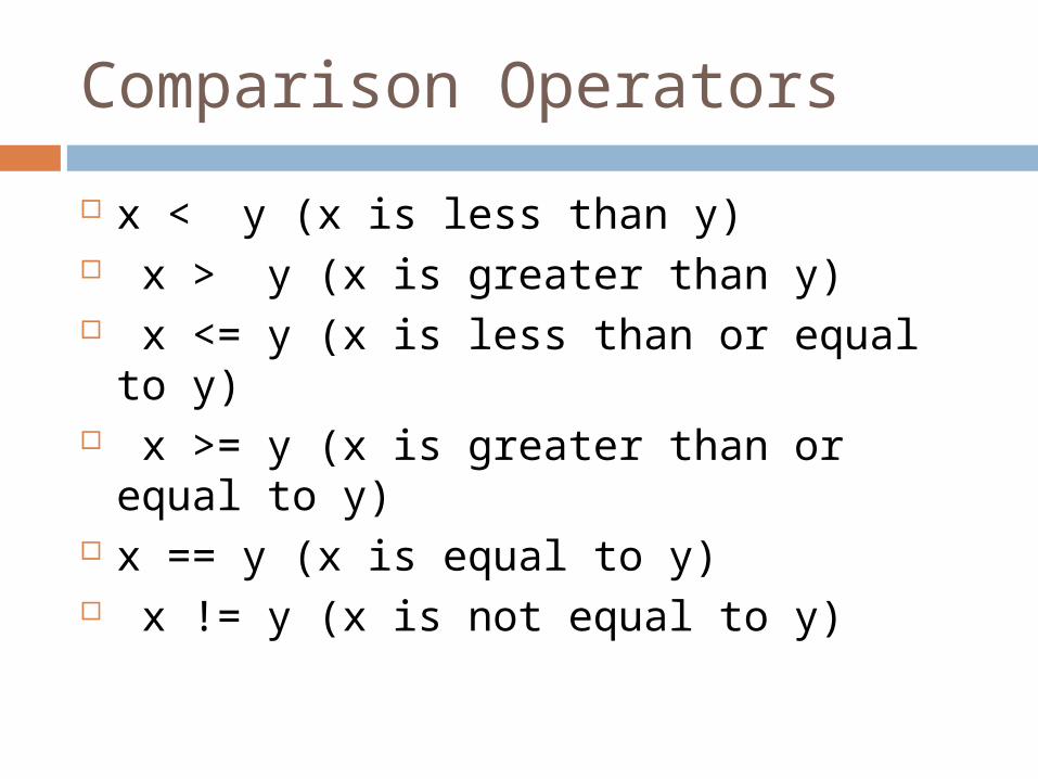
Comparison Operators
x < y (x is less than y) x > y (x is greater than y) x <= y (x is less than or equal to y) x >= y (x is greater than or equal to y) x == y (x is equal to y) x != y (x is not equal to y)
ARDX
Practice examples: 1, 2, 3, 6, 7, 8
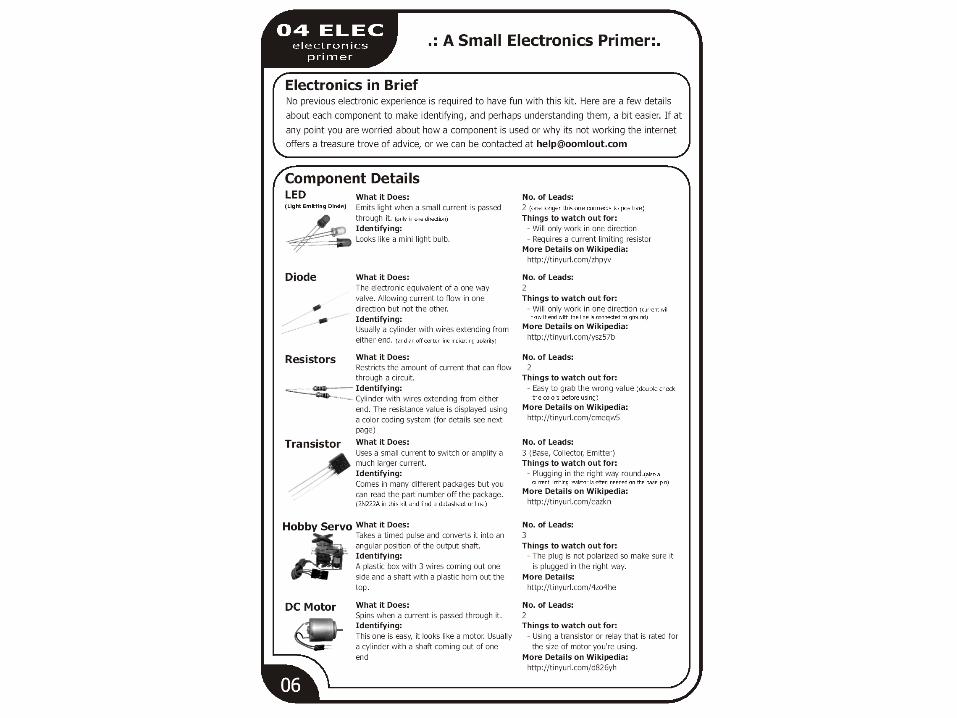
Button
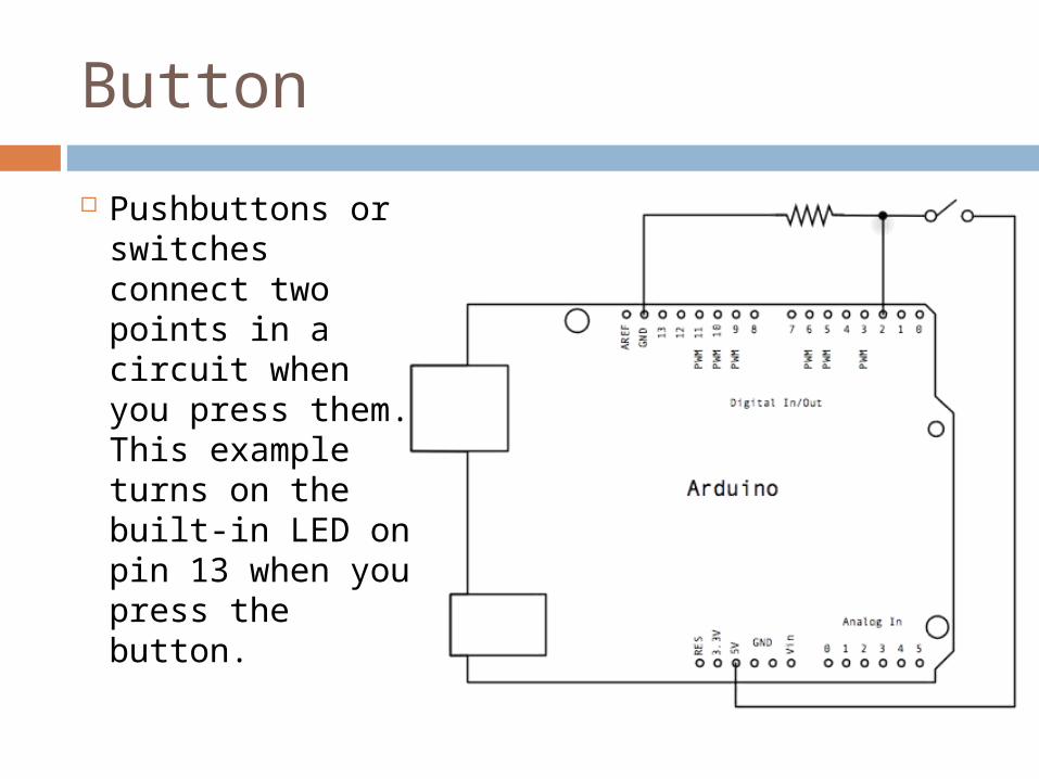
Pushbuttons or switches connect two points in a circuit when you press them. This example turns on the built-in LED on pin 13 when you press the button.
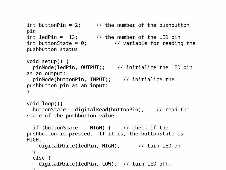
int buttonPin = 2; // the number of the pushbutton pinint ledPin = 13; // the number of the LED pinint buttonState = 0; // variable for reading the pushbutton status
void setup() { pinMode(ledPin, OUTPUT); // initialize the LED pin as an output: pinMode(buttonPin, INPUT); // initialize the pushbutton pin as an input: }
void loop(){ buttonState = digitalRead(buttonPin); // read the state of the pushbutton value:
if (buttonState == HIGH) { // check if the pushbutton is pressed. If it is, the buttonState is HIGH: digitalWrite(ledPin, HIGH); // turn LED on: } else { digitalWrite(ledPin, LOW); // turn LED off: }}
Button
The problem with the last program is that the switch has to remain pressed in order for the LED to turn on
We want the LED to change state when we press the button and to stay in the new state when the button is released
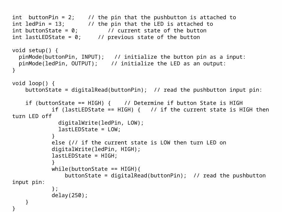
int buttonPin = 2; // the pin that the pushbutton is attached toint ledPin = 13; // the pin that the LED is attached toint buttonState = 0; // current state of the buttonint lastLEDState = 0; // previous state of the button
void setup() { pinMode(buttonPin, INPUT); // initialize the button pin as a input: pinMode(ledPin, OUTPUT); // initialize the LED as an output:}
void loop() { buttonState = digitalRead(buttonPin); // read the pushbutton input pin: if (buttonState == HIGH) { // Determine if button State is HIGH if (lastLEDState == HIGH) { // if the current state is HIGH then turn LED off digitalWrite(ledPin, LOW); lastLEDState = LOW; } else {// if the current state is LOW then turn LED on digitalWrite(ledPin, HIGH); lastLEDState = HIGH; } while(buttonState == HIGH){ buttonState = digitalRead(buttonPin); // read the pushbutton input pin: }; delay(250); } }
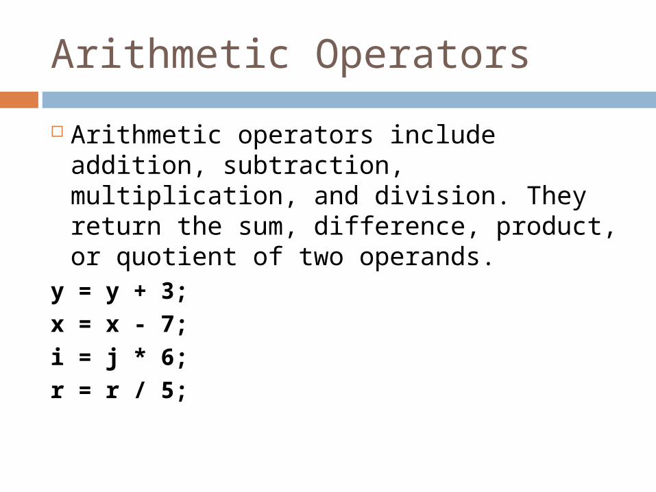
Arithmetic Operators
Arithmetic operators include addition, subtraction, multiplication, and division. They return the sum, difference, product, or quotient of two operands.
y = y + 3;
x = x - 7;
i = j * 6;
r = r / 5;
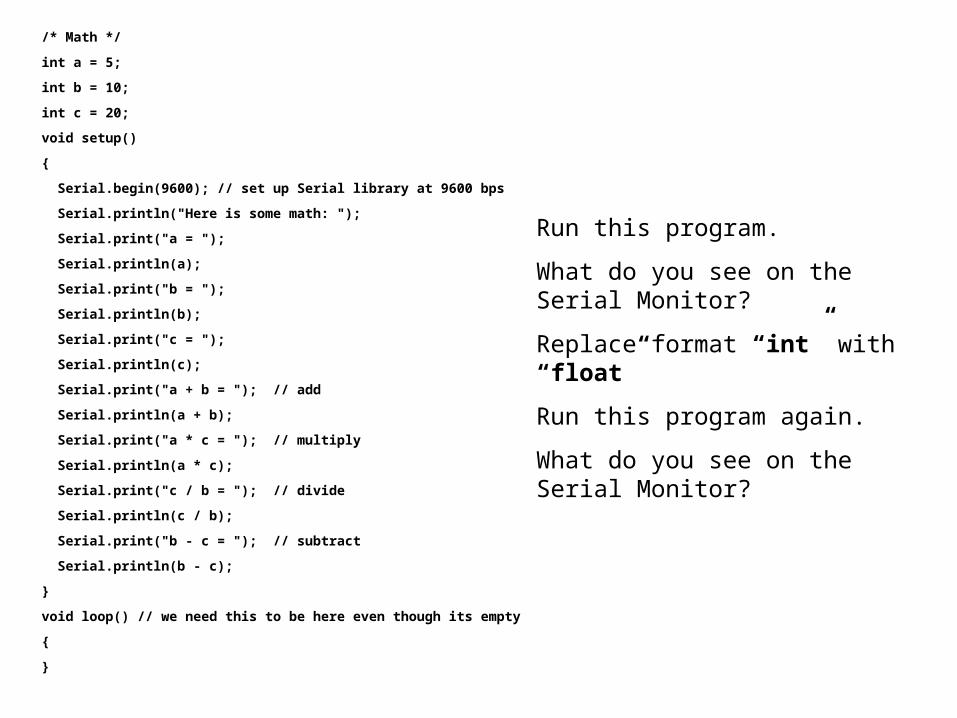
/* Math */
int a = 5;
int b = 10;
int c = 20;
void setup()
{
Serial.begin(9600); // set up Serial library at 9600 bps
Serial.println("Here is some math: ");
Serial.print("a = ");
Serial.println(a);
Serial.print("b = ");
Serial.println(b);
Serial.print("c = ");
Serial.println(c);
Serial.print("a + b = "); // add
Serial.println(a + b);
Serial.print("a * c = "); // multiply
Serial.println(a * c);
Serial.print("c / b = "); // divide
Serial.println(c / b);
Serial.print("b - c = "); // subtract
Serial.println(b - c);
}
void loop() // we need this to be here even though its empty
{
}
Run this program.
What do you see on the Serial Monitor?
Replace format “int” with “float”
Run this program again.
What do you see on the Serial Monitor?
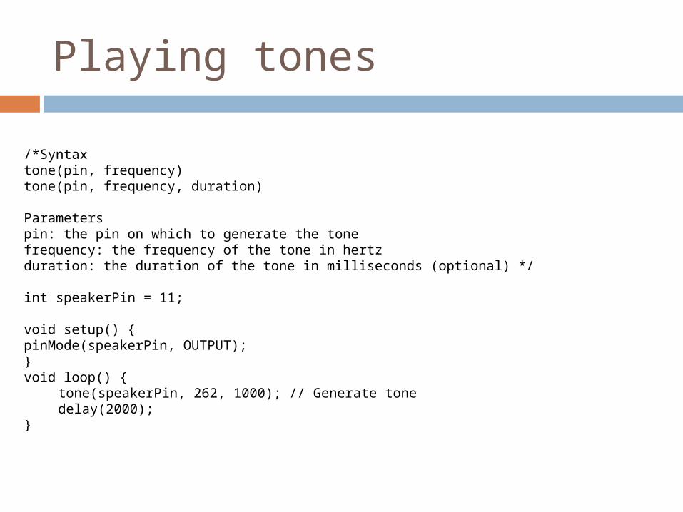
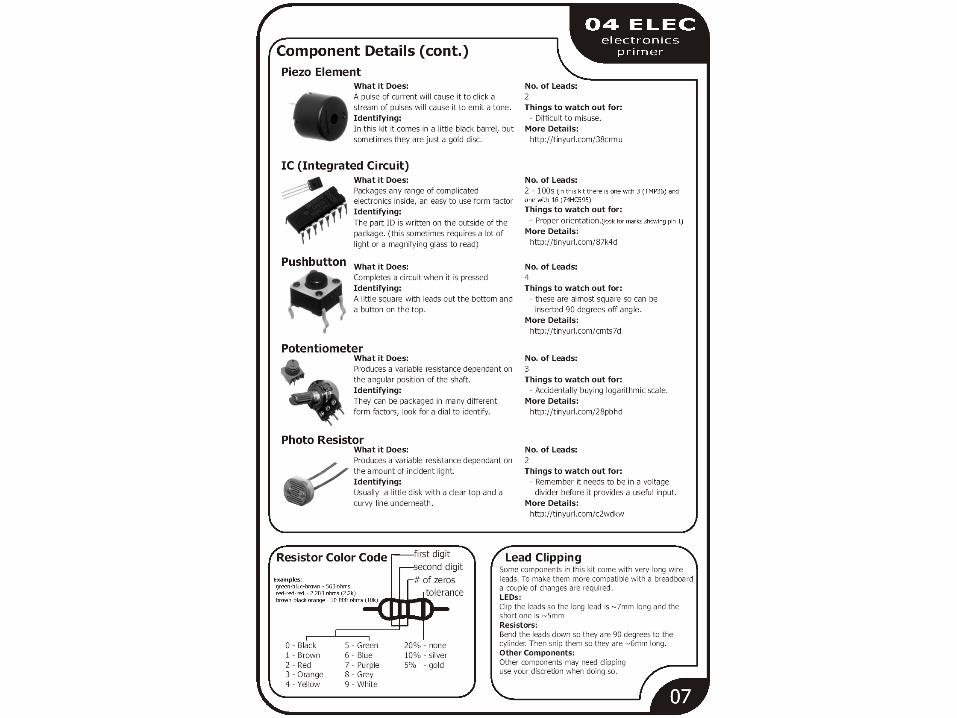
Playing tones
/*Syntaxtone(pin, frequency)tone(pin, frequency, duration)
Parameterspin: the pin on which to generate the tonefrequency: the frequency of the tone in hertzduration: the duration of the tone in milliseconds (optional) */
int speakerPin = 11;
void setup() {pinMode(speakerPin, OUTPUT);}void loop() {
tone(speakerPin, 262, 1000); // Generate tonedelay(2000);
}
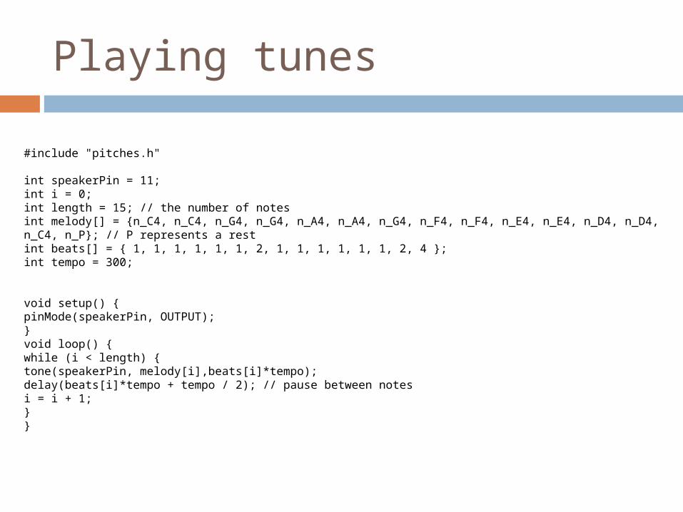
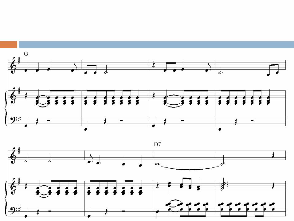
Playing tunes
#include "pitches.h"
int speakerPin = 11;int i = 0;int length = 15; // the number of notesint melody[] = {n_C4, n_C4, n_G4, n_G4, n_A4, n_A4, n_G4, n_F4, n_F4, n_E4, n_E4, n_D4, n_D4, n_C4, n_P}; // P represents a restint beats[] = { 1, 1, 1, 1, 1, 1, 2, 1, 1, 1, 1, 1, 1, 2, 4 };int tempo = 300;
void setup() {pinMode(speakerPin, OUTPUT);}void loop() {while (i < length) {tone(speakerPin, melody[i],beats[i]*tempo);delay(beats[i]*tempo + tempo / 2); // pause between notesi = i + 1;}}
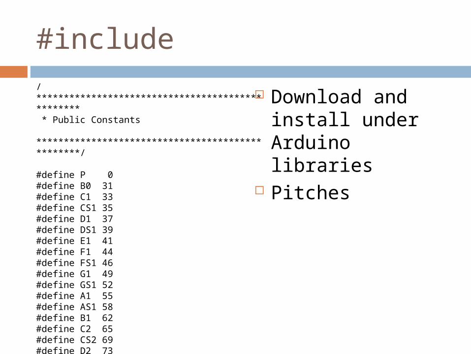
#include
Download and install under Arduino libraries
Pitches
/************************************************* * Public Constants *************************************************/
#define P 0#define B0 31#define C1 33#define CS1 35#define D1 37#define DS1 39#define E1 41#define F1 44#define FS1 46#define G1 49#define GS1 52#define A1 55#define AS1 58#define B1 62#define C2 65#define CS2 69#define D2 73
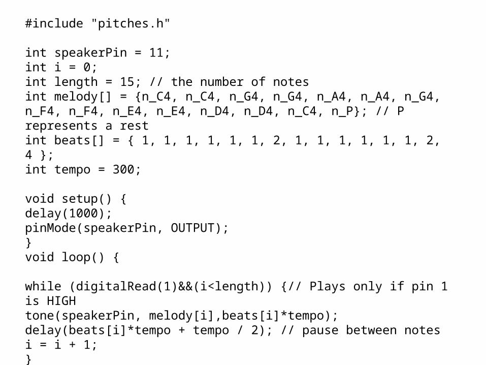
#include "pitches.h"
int speakerPin = 11;int i = 0;int length = 15; // the number of notesint melody[] = {n_C4, n_C4, n_G4, n_G4, n_A4, n_A4, n_G4, n_F4, n_F4, n_E4, n_E4, n_D4, n_D4, n_C4, n_P}; // P represents a restint beats[] = { 1, 1, 1, 1, 1, 1, 2, 1, 1, 1, 1, 1, 1, 2, 4 };int tempo = 300;
void setup() {delay(1000);pinMode(speakerPin, OUTPUT);}void loop() {
while (digitalRead(1)&&(i<length)) {// Plays only if pin 1 is HIGHtone(speakerPin, melody[i],beats[i]*tempo);delay(beats[i]*tempo + tempo / 2); // pause between notesi = i + 1;}i=0;}
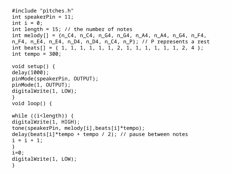
#include "pitches.h"int speakerPin = 11;int i = 0;int length = 15; // the number of notesint melody[] = {n_C4, n_C4, n_G4, n_G4, n_A4, n_A4, n_G4, n_F4, n_F4, n_E4, n_E4, n_D4, n_D4, n_C4, n_P}; // P represents a restint beats[] = { 1, 1, 1, 1, 1, 1, 2, 1, 1, 1, 1, 1, 1, 2, 4 };int tempo = 300;
void setup() {delay(1000);pinMode(speakerPin, OUTPUT);pinMode(1, OUTPUT);digitalWrite(1, LOW);}void loop() {
while ((i<length)) {digitalWrite(1, HIGH);tone(speakerPin, melody[i],beats[i]*tempo);delay(beats[i]*tempo + tempo / 2); // pause between notesi = i + 1;}i=0;digitalWrite(1, LOW);}
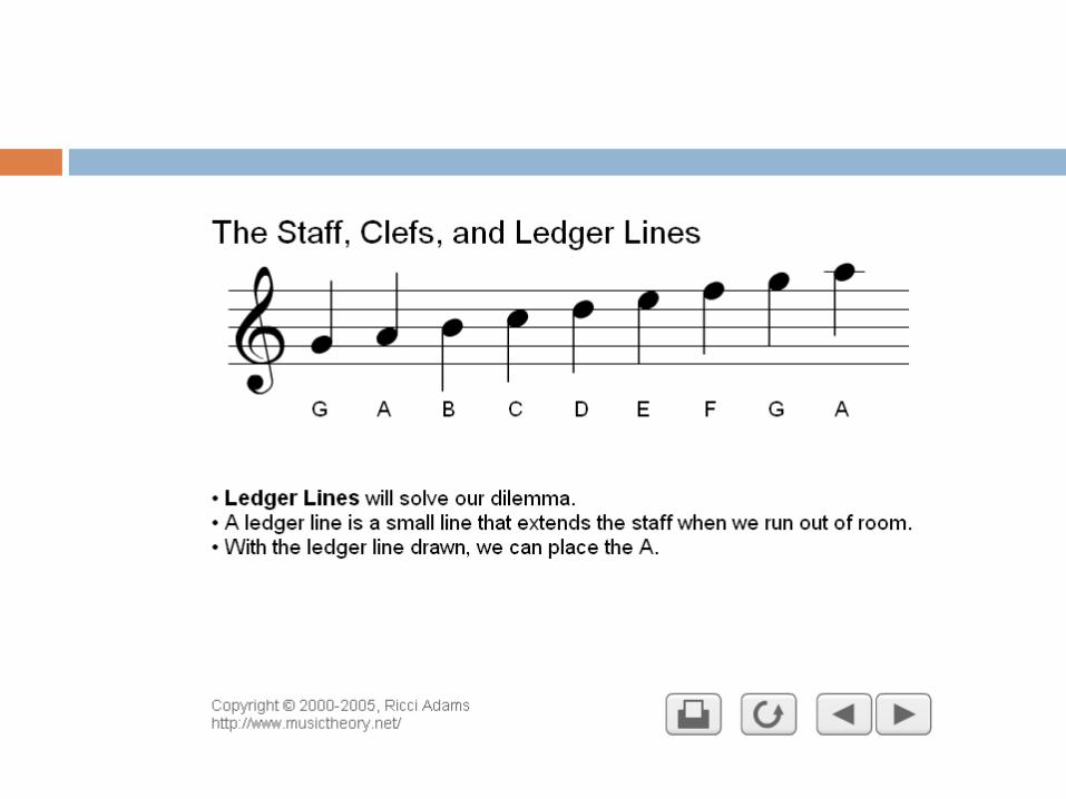
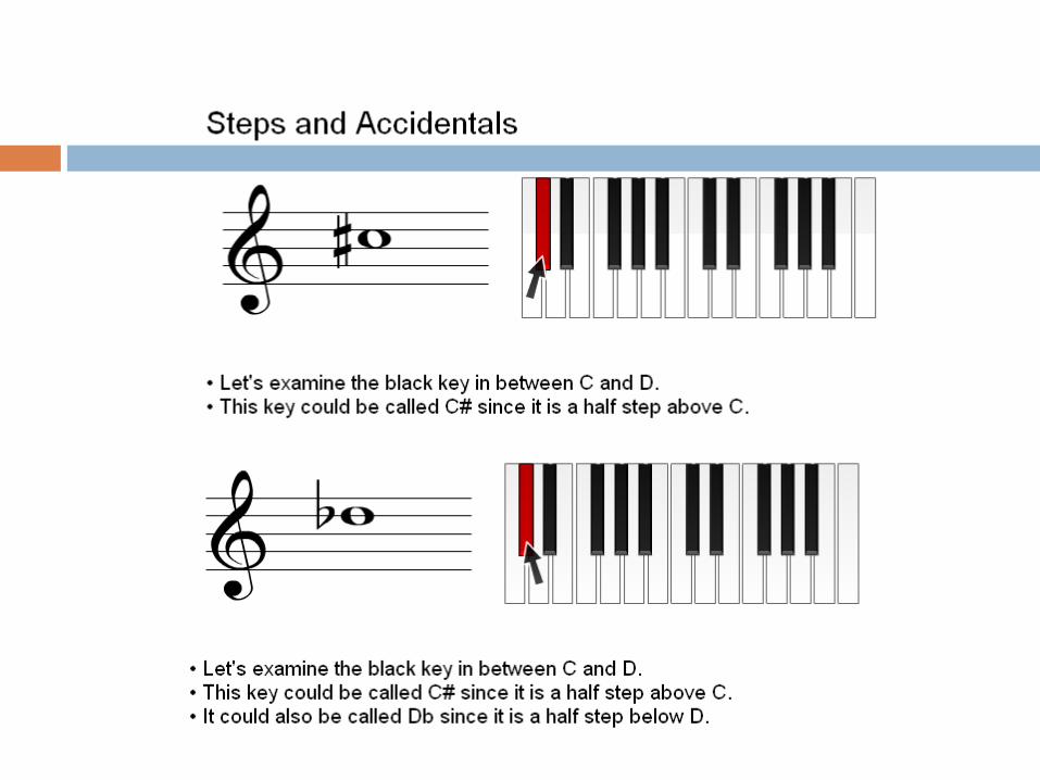
DE F
BA
G
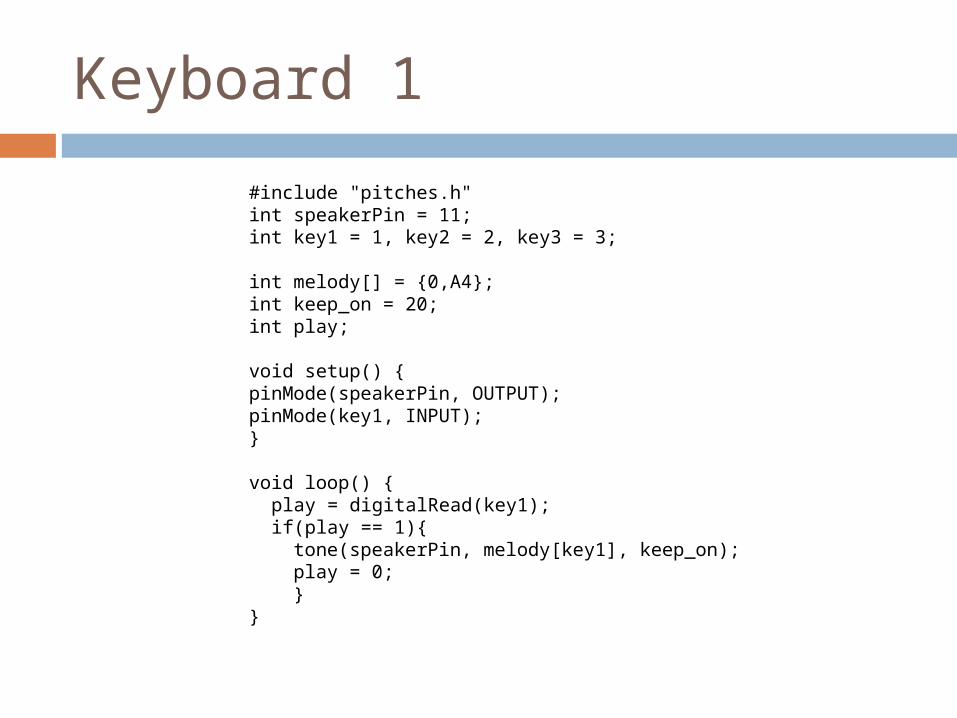
Keyboard 1
#include "pitches.h"int speakerPin = 11;int key1 = 1, key2 = 2, key3 = 3;
int melody[] = {0,A4}; int keep_on = 20;int play;
void setup() {pinMode(speakerPin, OUTPUT);pinMode(key1, INPUT);}
void loop() { play = digitalRead(key1); if(play == 1){ tone(speakerPin, melody[key1], keep_on); play = 0; }}
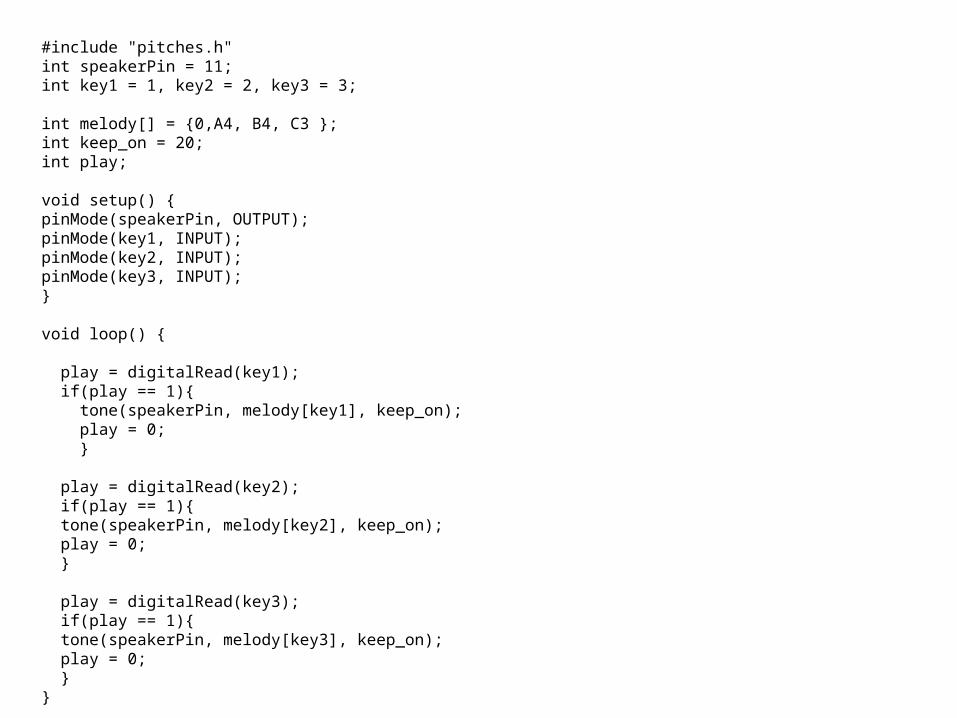
#include "pitches.h"int speakerPin = 11;int key1 = 1, key2 = 2, key3 = 3;
int melody[] = {0,A4, B4, C3 }; int keep_on = 20;int play;
void setup() {pinMode(speakerPin, OUTPUT);pinMode(key1, INPUT);pinMode(key2, INPUT);pinMode(key3, INPUT);}
void loop() {
play = digitalRead(key1); if(play == 1){ tone(speakerPin, melody[key1], keep_on); play = 0; } play = digitalRead(key2); if(play == 1){ tone(speakerPin, melody[key2], keep_on); play = 0; } play = digitalRead(key3); if(play == 1){ tone(speakerPin, melody[key3], keep_on); play = 0; }}
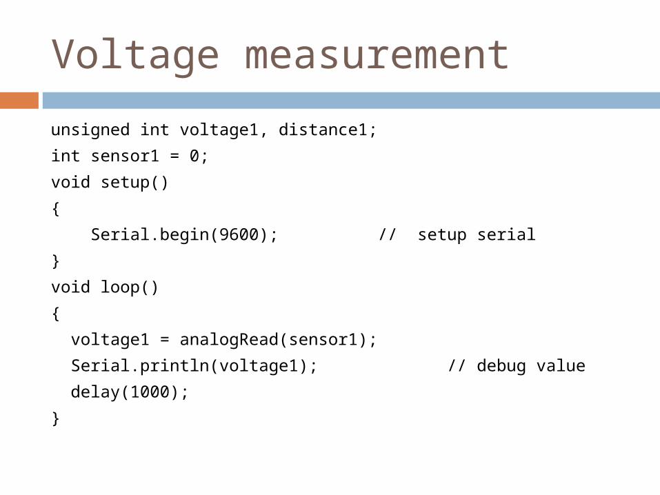
Voltage measurement
unsigned int voltage1, distance1;
int sensor1 = 0;
void setup()
{
Serial.begin(9600); // setup serial
}
void loop()
{
voltage1 = analogRead(sensor1);
Serial.println(voltage1); // debug value
delay(1000);
}
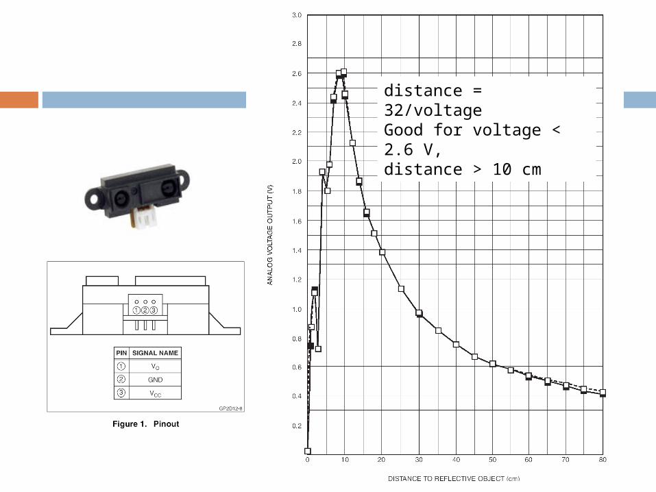
distance = 32/voltageGood for voltage < 2.6 V,distance > 10 cm
Voltage measurement
int analogRead(pin) Description
Reads the value from the specified analog pin. The Arduino board contains a 6 channel (8 channels on the Mini and Nano), 10-bit analog to digital converter. This means that it will map input voltages between 0 and 5 volts into integer values between 0 and 1023. This yields a resolution between readings of: 5 volts / 1024 units or, .0049 volts (4.9 mV) per unit. It takes about 100 us (0.0001 s) to read an analog input, so the maximum reading rate is about 10,000 times a second.
Related Documents