HSPS CT/ NOV. 2006 © 2006 Hamilton Sundstrand Corporation APS 3200 AUXILIARY POWER UNIT TRAINING COURSE (ECB SOFTWARE VERSION 6.0) LINE MAINTENANCE AND FAULT ISOLATION THIS HANDBOOK IS FOR REFERENCE PURPOSES ONLY. IF FAULT ISOLATION OR MAINTENANCE IS REQUIRED, REFER TO THE APPLICABLE MANUFACTURERS TECHNICAL MANUAL FOR SPECIFIC PROCEDURES Hamilton Sundstrand reserves the right to make changes in specifications and other information contained in this publication without prior notice NOTICE THIS TRAINING MANUAL IS TO BE USED FOR TRAINING PUPOSES ONLY This training manual was prepared by Hamilton Sundstrand for training purposes only. Some information contained herein is proprietary and/or copyrighted information of Hamilton Sundstrand. As a condit ion of, and as consideration for receiving this document, the recipient agrees that this document and the information contained therein shall not be disclosed outside the recipient or duplicated or used for any purpose without Hamilton Sundstrand’s prior written consent.

Welcome message from author
This document is posted to help you gain knowledge. Please leave a comment to let me know what you think about it! Share it to your friends and learn new things together.
Transcript

7/21/2019 Aps 3200 Training
http://slidepdf.com/reader/full/aps-3200-training 1/739
HSPS CT/ NOV. 2006 © 2006 Hamilton Sundstrand Corporation
APS 3200 AUXILIARY POWER UNIT
TRAINING COURSE
(ECB SOFTWARE VERSION 6.0)
LINE MAINTENANCE AND FAULT ISOLATION
THIS HANDBOOK IS FOR REFERENCE PURPOSES ONLY.IF FAULT ISOLATION OR MAINTENANCE IS REQUIRED, REFERTO THE APPLICABLE MANUFACTURERS TECHNICAL MANUAL
FOR SPECIFIC PROCEDURES
Hamilton Sundstrand reserves the right to make changes in specificationsand other information contained in this publication without prior notice
NOTICE
THIS TRAINING MANUAL IS TO BE USED FOR TRAINING PUPOSES ONLY
This training manual was prepared by Hamilton Sundstrand for training purposes only.
Some information contained herein is proprietary and/or copyrighted information of Hamilton Sundstrand. As a condition of, and as consideration for receiving thisdocument, the recipient agrees that this document and the information containedtherein shall not be disclosed outside the recipient or duplicated or used for anypurpose without Hamilton Sundstrand’s prior written consent.

7/21/2019 Aps 3200 Training
http://slidepdf.com/reader/full/aps-3200-training 2/739
HSPS CT/NOV. 2006
HAMILTON SUNDSTRAND PROPRIETARY
Use or disclosure of this data is subject to therestriction on the title page of this document
7/21/2019 Aps 3200 Training
http://slidepdf.com/reader/full/aps-3200-training 3/739
HSPS CT/NOV. 2006HAMILTON SUNDSTRAND PROPRIETARY
AIRBUS AIRCRAFT
Use or disclosure of this data is subject to theRestriction on the title page of this document

7/21/2019 Aps 3200 Training
http://slidepdf.com/reader/full/aps-3200-training 4/739
HSPS CT/NOV. 2006HAMILTON SUNDSTRAND PROPRIETARY
APS 3200 AUXILIARY POWER UNIT
Use or disclosure of this data is subject to theRestriction on the title page of this document

7/21/2019 Aps 3200 Training
http://slidepdf.com/reader/full/aps-3200-training 5/739
HSPS CT/NOV. 2006 Page i
HAMILTON SUNDSTRAND PROPRIETARY
APS 3200 Auxi liary Power Unit
Front Matter
Use or disclosure of this data is subject to therestriction on the title page of this document.
7/21/2019 Aps 3200 Training
http://slidepdf.com/reader/full/aps-3200-training 6/739
HSPS CT/NOV. 2006 Page ii
HAMILTON SUNDSTRAND PROPRIETARY
Use or disclosure of this data is subject to therestriction on the title page of this document.
TABLE OF CONTENTS
SUBJECT PAGE
Preface............................................................................................iii
Abbreviations ................................................................................. v
APU Leading Particulars ...............................................................viii
SUBJECT SECTION
Introduction...................................................................................... 1
Power Unit.......................................................................................2
Oil System....................................................................................... 3
Fuel System ....................................................................................4
Air System....................................................................................... 5
Control System................................................................................ 6
Indicating System............................................................................ 7
Starting System............................................................................... 8
Electrical System.............................................................................9
APU Installation.............................................................................10
Maintenance.................................................................................. 11
Fault Isolation................................................................................12
Troubleshooting............................................................................. 13

7/21/2019 Aps 3200 Training
http://slidepdf.com/reader/full/aps-3200-training 7/739
HSPS CT/ NOV. 2006 Page iii
HAMILTON SUNDSTRAND PROPRIETARY
Use or disclosure of this data is subject to therestriction on the title page of this document.
PREFACE
GENERAL DESCRIPTION
The APS 3200 Auxiliary Power Unit Maintenance Training Course,developed by the Customer Service Training Group of HamiltonSundstrand Power Systems, is designed to give the student anunderstanding of the various components of the Auxiliary Power Unit(APU) and their functions. This course also provides routinemaintenance and troubleshooting.
STUDENT WORKBOOK
This workbook is intended for the “limited” purpose of providingcomponent familiarization, general data, and support information for
this maintenance course.
This is an uncontrolled document and will not be updated or revisedon a regular basis. Specific values given in this document such asspeed, temperature, and pressure are provided for the purpose ofillustration and are not necessarily representative of the true valuesof the APS 3200 APU.
FAA AND AIRCRAFT MANUFACTURER APPROVEDPUBLICATIONS
The Airline is provided a variety of FAA and Aircraft Manufacturerapproved publications for the APS 3200 APU. These publicationsare:
Aircraft Flight Crew Manuals
Aircraft Maintenance Manuals
Engine and Component Maintenance Manuals
Service Bulletins
Chapter 49 of the aircraft maintenance manual presents detailed APU and LRU removal and installation procedures plus maintenanceand servicing techniques that can be accomplished at the flight-line.Careful study of Chapter 49 will add to the student's expertise introubleshooting and maintaining the Hamilton Sundstrand APS 3200
APU.

7/21/2019 Aps 3200 Training
http://slidepdf.com/reader/full/aps-3200-training 8/739
AIRCRAFT APPLICATIONS
The information presented in this course applies to the followingaircraft:
AIRBUS 318, 319, 320, 321
HSPS CT/NOV. 2006 Page iv
HAMILTON SUNDSTRAND PROPRIETARY
Use or disclosure of this data is subject to therestriction on the title page of this document.
7/21/2019 Aps 3200 Training
http://slidepdf.com/reader/full/aps-3200-training 9/739
HSPS CT/NOV. 2006 Page v
HAMILTON SUNDSTRAND PROPRIETARY
Use or disclosure of this data is subject to therestriction on the title page of this document.
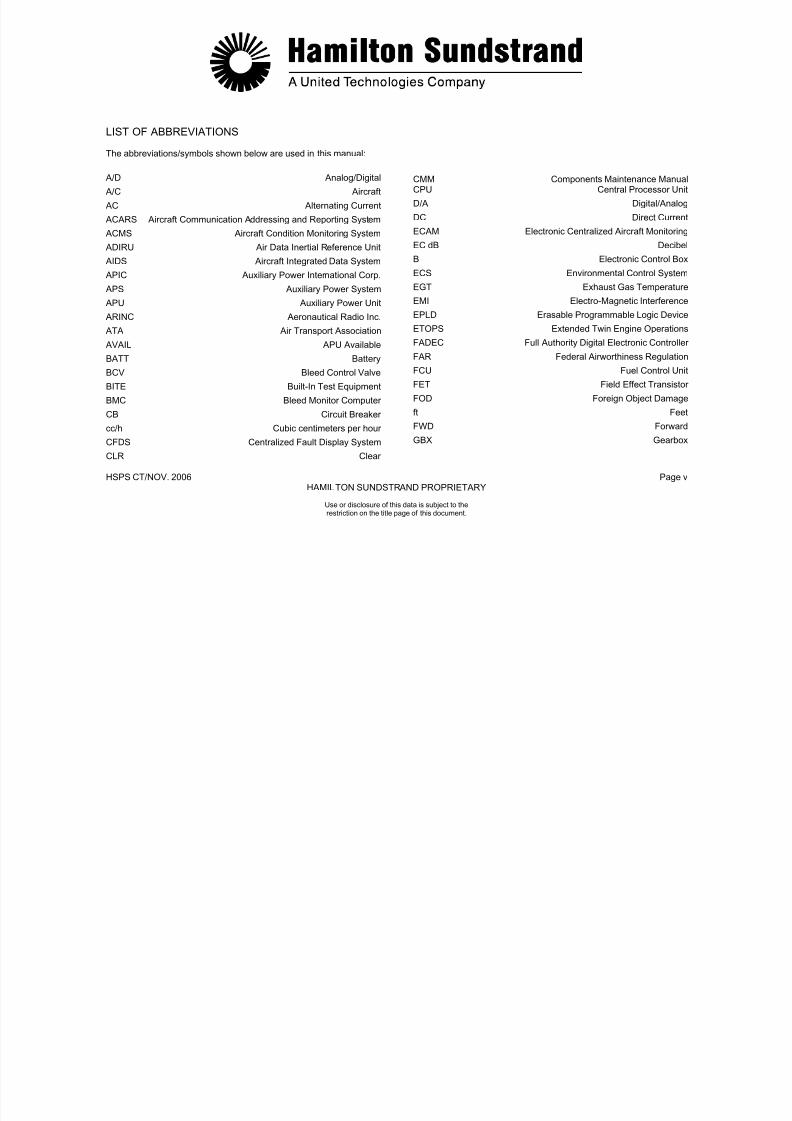
LIST OF ABBREVIATIONS
The abbreviations/symbols shown below are used in this manual:
A/D Analog/Digital
A/C Aircraft AC Alternating Current
ACARS Aircraft Communication Addressing and Reporting System
ACMS Aircraft Condition Monitoring System
ADIRU Air Data Inertial Reference Unit
AIDS Aircraft Integrated Data System
APIC Auxiliary Power International Corp.
APS Auxiliary Power System APU Auxiliary Power Unit
ARINC Aeronautical Radio Inc.
ATA Air Transport Association
AVAIL APU Available
BATT Battery
BCV Bleed Control Valve
BITE Built-In Test EquipmentBMC Bleed Monitor Computer
CB Circuit Breaker
cc/h Cubic centimeters per hour
CFDS Centralized Fault Display System
CLR Clear
CMM Components Maintenance ManualCPU Central Processor Unit
D/A Digital/Analog
DC Direct Current
ECAM Electronic Centralized Aircraft Monitoring
EC dB Decibel
B Electronic Control Box
ECS Environmental Control System
EGT Exhaust Gas TemperatureEMI Electro-Magnetic Interference
EPLD Erasable Programmable Logic Device
ETOPS Extended Twin Engine Operations
FADEC Full Authority Digital Electronic Controller
FAR Federal Airworthiness Regulation
FCU Fuel Control Unit
FET Field Effect TransistorFOD Foreign Object Damage
ft Feet
FWD Forward
GBX Gearbox

7/21/2019 Aps 3200 Training
http://slidepdf.com/reader/full/aps-3200-training 10/739
HSPS CT/NOV. 2006 Page vi
HAMILTON SUNDSTRAND PROPRIETARY
Use or disclosure of this data is subject to therestriction on the title page of this document.
LIST OF ABBREVIATIONS
GCU Generator Control Unit
GMT Greenwich Mean Time
GPH Gallons Per Hour
HOT High Oil TemperatureHP Horse PowerHSPS Hamilton Sundstrand Power System
Hz Hertz
ICAO International Civil Aviation Organization
ID Identification
IGV Inlet Guide Vane
IPC Illustrated Parts Catalogue
ISA International Standard Atmosphere
JAR Joint Airworthiness Requirement
kg Kilogram
kg/m Kilograms Per Minute
kg/s Kilograms Per Second
kHz Kilo Hertz
kPa Kilopascal
kPaa Kilopascals Absolute
kPad Kilopascals Differential
kPag Kilopascals Gauge
kW Kilo Watt
L Liter
l/h Liters Per Hour
lb Pound
lbs/hr Pounds Per Hour
lbs/m Pounds Per Minutelbs/sec. Pounds Per Second
LC Load Compressor
LOP Low Oil Pressure
LP Low Pressure
LRU Line Replaceable Unit
LVDT Linear Voltage Differential Transducer
m Meter
mA Milliampere
MAX Maximum
MCDU Multi-function Control and Display Unit
MES Main Engine Start
MHz Mega Hertz
P Qts Quarts
MIN Minimum
mm Millimeter
MMEL Master Minimum Equipment List
MTBF Mean Time Between Failure

7/21/2019 Aps 3200 Training
http://slidepdf.com/reader/full/aps-3200-training 11/739
HSPS CT/NOV. 2006 Page vii
HAMILTON SUNDSTRAND PROPRIETARY
Use or disclosure of this data is subject to therestriction on the title page of this document.
LIST OF ABBREVIATIONS
SIG Pounds Per Square Inch Gauge
MTBUR Mean Time Between Unscheduled Removals
mV Millivolt
N Rotation Speed
NGV Nozzle Guide Vane
NVM Non MemoryVolatile VAC Volts, Alternating Current
OAP Outside Air Pressure
OAT Outside Air Temperature
OBRM On Board Replaceable Memory
P/N Part Number
PCD Pressure Compressor Discharge
PMG Permanent Magnet Generator
PS Power Section
PSIA Pounds Per Square Inch Absolute
PSID Pounds Per Square Inch Differential
RAM Random Access Memory
ROM Read Only Memory
RPM Revolutions Per Minute
RTD Resistive Temperature Device
S Seconds
S/N Serial Number
SSLC Single Shaft Load Compressor
STS Status
THR Threshold
TRU Transformer Rectifier Unit
TSO Technical Standard Order
US G US Gallon
VDC Volts, Direct Current
°C Degrees Celsius
°F Degrees Fahrenheit
> Is Greater Than
< Is Less Than
± Plus or Minus
Ω Ohm
Δ Differential
% Percent
7/21/2019 Aps 3200 Training
http://slidepdf.com/reader/full/aps-3200-training 12/739
HSPS CT/ NOV. 2006 Page viii
HAMILTON SUNDSTRAND PROPRIETARY
Use or disclosure of this data is subject to therestriction on the title page of this document.
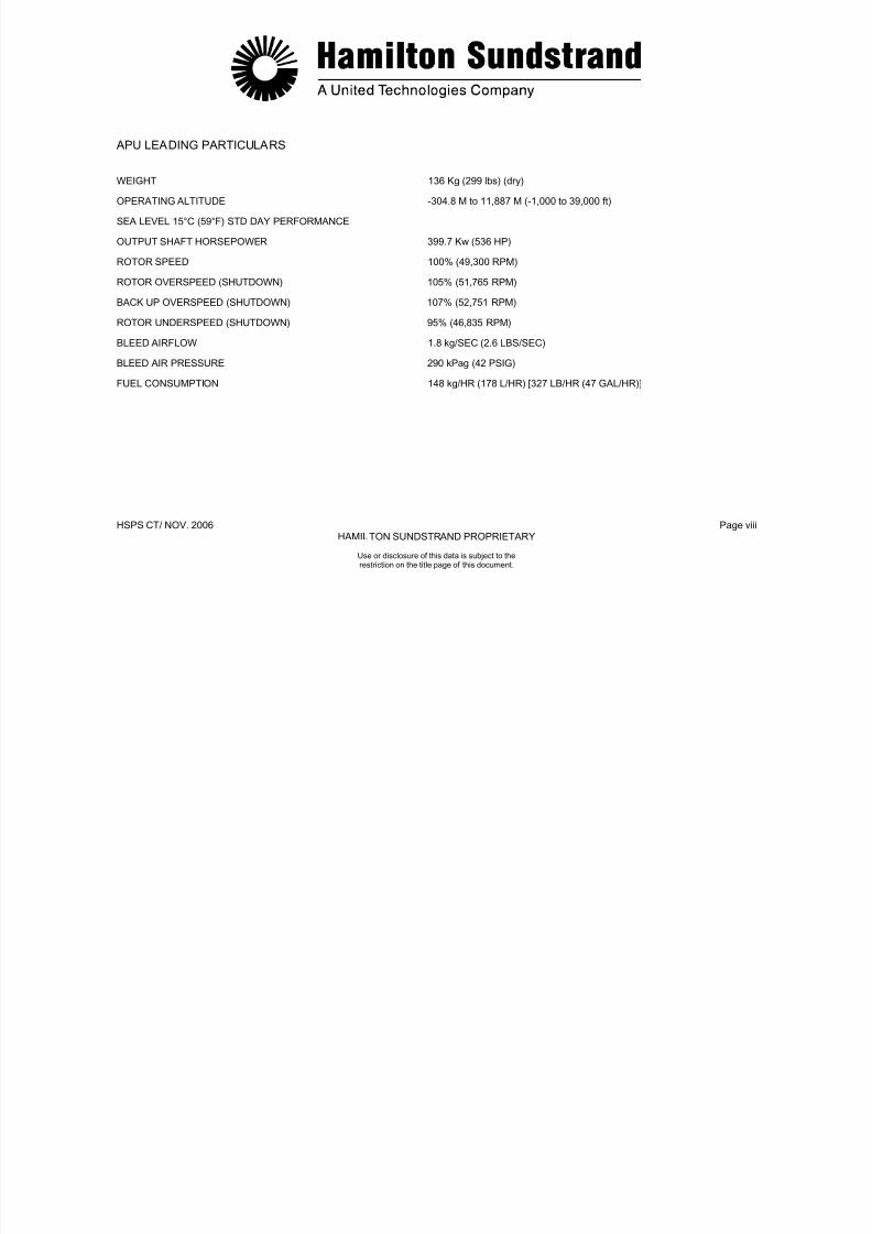
APU LEADING PARTICULARS
WEIGHT 136 Kg (299 lbs) (dry)
OPERATING ALTITUDE -304.8 M to 11,887 M (-1,000 to 39,000 ft)
SEA LEVEL 15°C (59°F) STD DAY PERFORMANCE
OUTPUT SHAFT HORSEPOWER 399.7 Kw (536 HP)
ROTOR SPEED 100% (49,300 RPM)
ROTOR OVERSPEED (SHUTDOWN) 105% (51,765 RPM)
BACK UP OVERSPEED (SHUTDOWN) 107% (52,751 RPM)
ROTOR UNDERSPEED (SHUTDOWN) 95% (46,835 RPM)
BLEED AIRFLOW 1.8 kg/SEC (2.6 LBS/SEC)
BLEED AIR PRESSURE 290 kPag (42 PSIG)
FUEL CONSUMPTION 148 kg/HR (178 L/HR) [327 LB/HR (47 GAL/HR)]

7/21/2019 Aps 3200 Training
http://slidepdf.com/reader/full/aps-3200-training 13/739
HSPS CT/NOV. 2006 Page ix
HAMILTON SUNDSTRAND PROPRIETARY
Use or disclosure of this data is subject to therestriction on the title page of this document.
APU LEADING PARTICULARS
EXHAUST GAS TEMPERATURE (SHUTDOWN)
START % SPEED EXHAUST GAS TEMPERATURE
0% 427°C (800°F)
10% 788°C (1450°F)
20% 899°C (1650°F)
30% 899°C (1650°F)
50% 853°C (1567°F)
80% 788°C (1450°F)
100% 670°C (1238°F)
RUN % SPEED EXHAUST GAS TEMPERATURE
100% 722°C (1332°F)

7/21/2019 Aps 3200 Training
http://slidepdf.com/reader/full/aps-3200-training 14/739
HSPS CT/NOV. 2006 Page x
HAMILTON SUNDSTRAND PROPRIETARY
Use or disclosure of this data is subject to therestriction on the title page of this document.
APU LEADING PARTICULARS
GEARBOX SPEEDS Input 49,300 RPMGenerator 24,034 RPM (output)Fuel Control 10,129 RPM (output)Starter 32,045 RPM (output)
Cooling Fan 51,965 RPM (output)Oil Pump 4,137 RPM (output)
OIL PRESSURE 241 kPag (35 PSIG) (minimum)345-414 kPag (50-60 PSIG) (normal)
OIL CAPACITY 3.9 L (4.16 Qts) (add)5.4 L (5.72 Qts) (full)
OIL TEMPERATURE (SHUT DOWN) 135°C (275°F) Lubrication system185°C (365°F) AC Generator
APPROVED OIL SPECIFICATION:
MIL-PRF-7808
MIL-PRF-23699
CAUTION:
DO NOT MIX OR SUBSTITUTE OIL SPECIFICATIONS. USE ONLY ONE OF THE APPROVED OILS. IF THE OIL SUPPLY IS LOW AND THE OIL BEING USED IS NOT AVAILABLE, DRAIN THE OIL SUMP AND CHANGE THE OIL FILTER. SERVICE THEOIL SYSTEM WITH AN APPROVED OIL.

7/21/2019 Aps 3200 Training
http://slidepdf.com/reader/full/aps-3200-training 15/739
HSPS CT/NOV. 2006 Page xi
HAMILTON SUNDSTRAND PROPRIETARY
Use or disclosure of this data is subject to therestriction on the title page of this document.
APU LEADING PARTICULARS
APPROVED FUELS
Fuel Type Specification Temperature Range
Jet A ATSM D1655 (NATO Code F-35)-35
°
C (-30°
F) to +57°
C (+135°
F)Jet A-1 ATSM D1655 (NATO Code F-35) -43°C (-45°F) to +57°C (+135°F)
Jet B ATSM D1655 (NATO Code F-45) -54°C (-65°F) to +57°C (+135°F)
JP-4 MIL-T-5624 (NATO Code F-40) -54°C (-65°F) to +57°C (+135°F)
JP-5 MIL-T-5624 (NATO Code F-44) -35°C (-30°F) to +93°C (+ 200°F)
JP-8 MIL-T-83133 (NATO Code F-34) -35°C (-30°F) to +93°C (+ 200°F)

7/21/2019 Aps 3200 Training
http://slidepdf.com/reader/full/aps-3200-training 16/739
HSPS CT/NOV. 2006 Page xii
HAMILTON SUNDSTRAND PROPRIETARY
APS 3200 AUXILIARY POWER UNIT
Use or disclosure of this data is subject to therestriction on the title page of this document

7/21/2019 Aps 3200 Training
http://slidepdf.com/reader/full/aps-3200-training 17/739
.
HSPS CT/NOV. 2006 Page 1.0
HAMILTON SUNDSTRAND PROPRIETARY
APS 3200 AUXILIARY POWER UNIT
SECTION 1
INTRODUCTION
Use or disclosure of this data is subject to therestriction on the title page of this document.
7/21/2019 Aps 3200 Training
http://slidepdf.com/reader/full/aps-3200-training 18/739
HSPS CT/NOV.. 2006 Page 1.1
HAMILTON SUNDSTRAND PROPRIETARY
Use or disclosure of this data is subject to therestriction on the title page of this document.
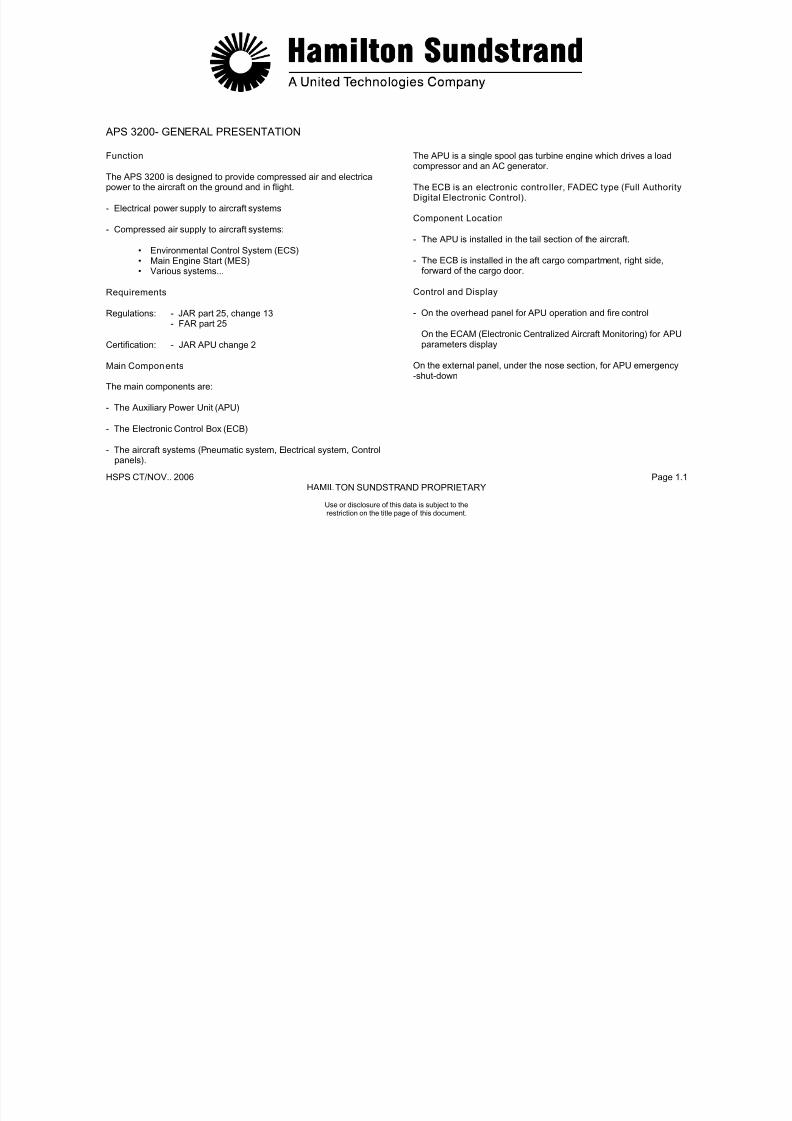
APS 3200- GENERAL PRESENTATION
Function
The APS 3200 is designed to provide compressed air and electricalpower to the aircraft on the ground and in flight.
- Electrical power supply to aircraft systems
- Compressed air supply to aircraft systems:
• Environmental Control System (ECS)• Main Engine Start (MES)• Various systems...
Requirements
Regulations: - JAR part 25, change 13- FAR part 25
Certification: - JAR APU change 2
Main Components
The main components are:
- The Auxiliary Power Unit (APU)
- The Electronic Control Box (ECB)
- The aircraft systems (Pneumatic system, Electrical system, Controlpanels).
The APU is a single spool gas turbine engine which drives a loadcompressor and an AC generator.
The ECB is an electronic contro ller, FADEC type (Full Authority
Digital Electronic Control).
Component Location
- The APU is installed in the tail section of the aircraft.
- The ECB is installed in the aft cargo compartment, right side,forward of the cargo door.
Control and Display
- On the overhead panel for APU operation and fire control
On the ECAM (Electronic Centralized Aircraft Monitoring) for APUparameters display
On the external panel, under the nose section, for APU emergency-shut-down
7/21/2019 Aps 3200 Training
http://slidepdf.com/reader/full/aps-3200-training 19/739
HSPS CT/NOV.. 2006 Page 1.2
HAMILTON SUNDSTRAND PROPRIETARY
.
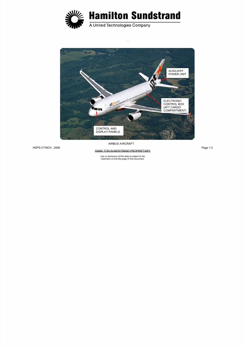
AUXILIARYPOWER UNIT
CONTROL ANDDISPLAY PANELS
ELECTRONICCONTROL BOX(AFT CARGOCOMPARTMENT)
AIRBUS AIRCRAFT
Use or disclosure of this data is subject to therestriction on the title page of this document.
7/21/2019 Aps 3200 Training
http://slidepdf.com/reader/full/aps-3200-training 20/739
.
HSPS CT/NOV. 2006 Page 1.3
HAMILTON SUNDSTRAND PROPRIETARY
Use or disclosure of this data is subject to therestriction on the title page of this document.
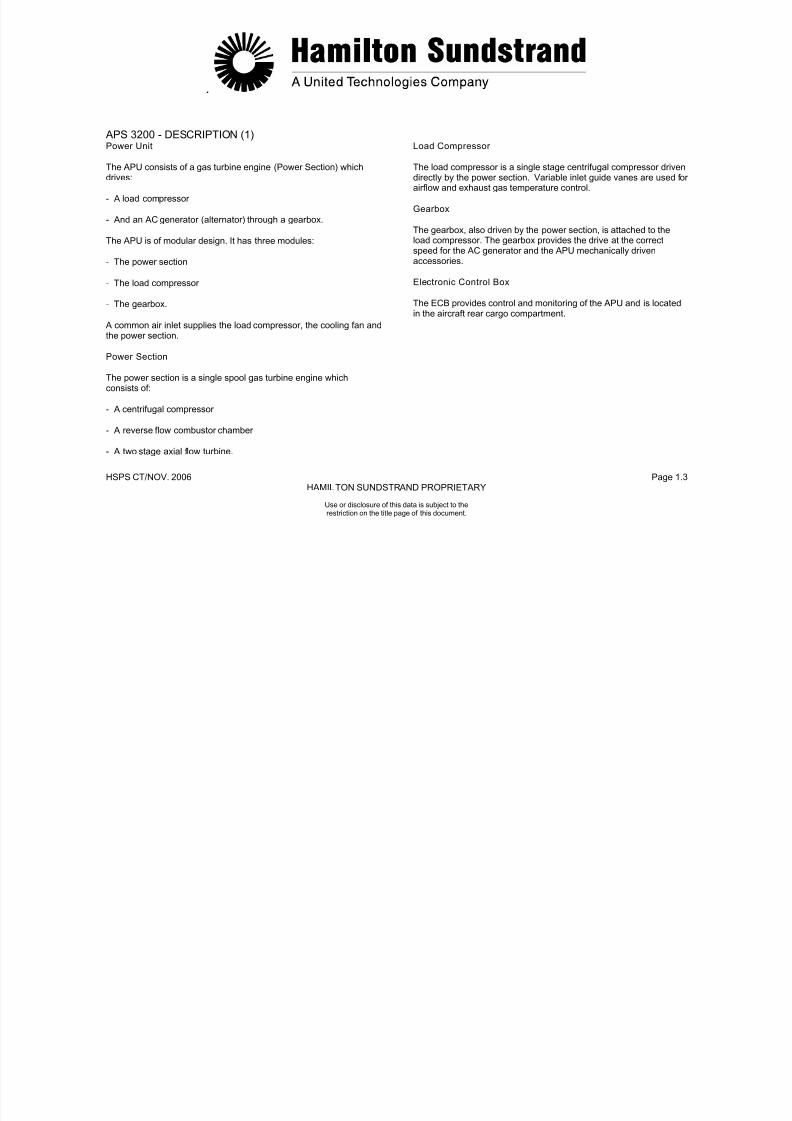
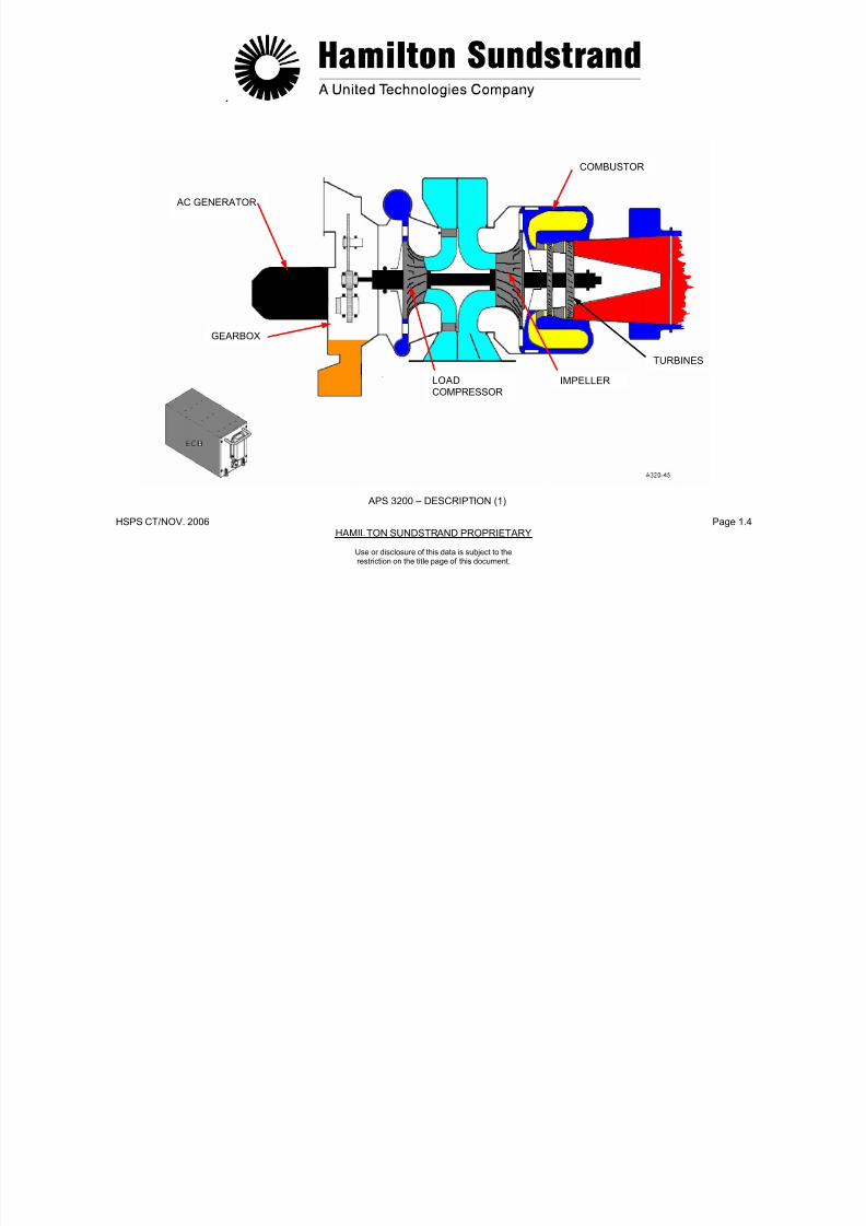
APS 3200 - DESCRIPTION (1)Power Unit
The APU consists of a gas turbine engine (Power Section) whichdrives:
- A load compressor
- And an AC generator (alternator) through a gearbox.
The APU is of modular design. It has three modules:
- The power section
- The load compressor
- The gearbox.
A common air inlet supplies the load compressor, the cooling fan andthe power section.
Power Section
The power section is a single spool gas turbine engine which
consists of:
- A centrifugal compressor
- A reverse flow combustor chamber
- A two stage axial flow turbine.
Load Compressor
The load compressor is a single stage centrifugal compressor drivendirectly by the power section. Variable inlet guide vanes are used forairflow and exhaust gas temperature control.
Gearbox
The gearbox, also driven by the power section, is attached to theload compressor. The gearbox provides the drive at the correctspeed for the AC generator and the APU mechanically drivenaccessories.
Electronic Control Box
The ECB provides control and monitoring of the APU and is locatedin the aircraft rear cargo compartment.
7/21/2019 Aps 3200 Training
http://slidepdf.com/reader/full/aps-3200-training 21/739
.
HSPS CT/NOV. 2006 Page 1.4
HAMILTON SUNDSTRAND PROPRIETARY
COMBUSTOR
Use or disclosure of this data is subject to therestriction on the title page of this document.
AC GENERATOR
GEARBOX
LOADCOMPRESSOR
IMPELLER
TURBINES
APS 3200 – DESCRIPTION (1)

7/21/2019 Aps 3200 Training
http://slidepdf.com/reader/full/aps-3200-training 22/739
.
HSPS CT/NOV. 2006 Page 1.5
HAMILTON SUNDSTRAND PROPRIETARY
Use or disclosure of this data is subject to therestriction on the title page of this document.
APS 3200 – DESCRIPTION (2)
- The APU air inlet plenum is connected to the aircraft air intakesystem.
The APU air inlet plenum has a screen to protect the APU internal
components from foreign object damage.
- The cooling fan assembly is located at the top of the gearboxfront face.
- The starter motor drives the APU rotor assembly during starting.
The starter motor is located on the front face of the gearbox.
- The fuel control unit supplies and meters fuel to the APU. It islocated on the gearbox front face.
- The load compressor scroll houses the load compressorimpeller.
- The air inlet plenum delivers air to the impellers.
The air inlet plenum is located between the load compressor andthe power section.
- The ignition exciter supplies high energy electrical power to the
ignitor plugs.
The ignition exciter is mounted on the left side of the air inletplenum.
- The oil cooler transfers the heat of the lubricating oil to the coolingair supplied by the cooling fan assembly.
- The APU exhaust system delivers the APU exhaust gases to the
aircraft exhaust pipe.

7/21/2019 Aps 3200 Training
http://slidepdf.com/reader/full/aps-3200-training 23/739
HSPS CT/NOV.. 2006 Page 1.6
HAMILTON SUNDSTRAND PROPRIETARY
COOLING FAN ASSEMBLY
Use or disclosure of this data is subject to therestriction on the title page of this document.
APS 3200 - DESCRIPTION (2)
AIR BYPASSPLENUM
OIL COOLER
AIR INLETPLENUM
EXCITER
LOAD COMPRESSORSCROLL
APU AIRINLET
FUEL CONTROLUNIT
STARTERMOTOR
7/21/2019 Aps 3200 Training
http://slidepdf.com/reader/full/aps-3200-training 24/739
HSPS CT/NOV.. 2006 Page 1.7
HAMILTON SUNDSTRAND PROPRIETARY
Use or disclosure of this data is subject to therestriction on the title page of this document.
APS 3200 - DESCRIPTION (3)Identification of Components
- The gearbox provides the drive for the AC generator and theaccessories for APU operation.
The gearbox also provides the sump for the oil system.
- The AC generator that provides electrical power for the aircraftsystems.
- The cooling fan assembly for airflow through the oil cooler andventilation of the APU compartment.
The cooling fan assembly is located on the gearbox front face.
- The APU drain collector . The collector is installed on the rightside of the gearbox by two struts.
- The air- bleed system that includes a servo valve, an actuator,and a bleed control valve.
- The inlet guide vane system that includes a servo valve, anactuator, the inlet guide vanes and their control mechanism.
- The combustor housing that houses the combustor chamber.
- Main and pilot fuel injection system installed on the combustorhousing.

7/21/2019 Aps 3200 Training
http://slidepdf.com/reader/full/aps-3200-training 25/739
.
HSPS CT/NOV. 2006 Page 1.8
HAMILTON SUNDSTRAND PROPRIETARY
MAIN AND PILOTFUEL INJECTIONSYSTEM
COOLING FAN ASSEMBLY
INLETGUIDE VANE
ACTUATOR
BLEED CONTROLVALVE
Use or disclosure of this data is subject to therestriction on the title page of this document.
APS 3200 – DESCRIPTION (3)
APU DRAINCOLLECTOR
GEARBOX
AC GENERATORMOUNTING PAD
7/21/2019 Aps 3200 Training
http://slidepdf.com/reader/full/aps-3200-training 26/739
.
HSPS CT/NOV. 2006 Page 1.9
HAMILTON SUNDSTRAND PROPRIETARY
APS 3200 - OPERATION
Power section provides the shaft power to drive the loadcompressor and the gearbox.
Power is produced by transforming the energy contained in theambient air and the fuel through thermodynamic cycle: compression,combustion, expansion.
- Compression of the air in the single stage centrifugal compressor
- Combustion of the air-fuel mixture in the reverse flow combustorchamber
- Expansion of the burned gases across the two stage axial flowturbine to drive:
• The power section impeller
• The load compressor impeller
• The gearbox.
The load compressor supplies compressed air to the aircraftpneumatic system. The air is compressed by a single stagecentrifugal impeller and uses variable inlet guide vanes to control the
air flow. The compressed air is delivered through a scroll to the bleedcontrol valve.
The gearbox provides the drive for the AC generator, andaccessories for APU operation.
The AC generator that provides electrical power for the aircraftsystems.
The Electronic Control Box receives various signals from theaircraft and the APU to operate and monitor the APU.
The electronic control box controls the following:
- Rotation speed (N) (fuel flow)
- Load compressor surge protection (bleed control valve)
- Exhaust Gas Temperature (EGT) (inlet guide vanes).
Use or disclosure of this data is subject to therestriction on the title page of this document.

7/21/2019 Aps 3200 Training
http://slidepdf.com/reader/full/aps-3200-training 27/739
HSPS CT/NOV.. 2006 Page 1.10
HAMILTON SUNDSTRAND PROPRIETARY
TO AIRCRAFT
TO APUEXHAUST
POWER SECTION
Use or disclosure of this data is subject to therestriction on the title page of this document.
APS 3200 - OPERATION
ECB
BLEED CONTROL
VALVE
COMPRESSION COMBUSTION EXPANSION
GENERATOR
AMBIENT AIRCOMPRESSED AIRCOMBUSTIONEXHAUSTFUEL FLOWELECTRICAL SIGNALS
IGV ACTUATORFUEL CONTROL
EXHAUST
GEARBOX
LOAD COMPRESSOR
7/21/2019 Aps 3200 Training
http://slidepdf.com/reader/full/aps-3200-training 28/739
HSPS CT/NOV. 2006 Page 1.11
HAMILTON SUNDSTRAND PROPRIETARY
APS 3200 AUXILIARY POWER UNIT
Use or disclosure of this data is subject to therestriction on the title page of this document

7/21/2019 Aps 3200 Training
http://slidepdf.com/reader/full/aps-3200-training 29/739
HSPS CT/NOV..2006 Page 2.0
HAMILTON SUNDSTRAND PROPRIETARY
APS 3200 AUXILIARY POWER UNIT
SECTION 2
POWER UNIT
Use or disclosure of this data is subject to therestriction on the title page of this document.

7/21/2019 Aps 3200 Training
http://slidepdf.com/reader/full/aps-3200-training 30/739
.
HSPS CT/NOV. 2006 Page 2.1
HAMILTON SUNDSTRAND PROPRIETARY
Use or disclosure of this data is subject to therestriction on the title page of this document.
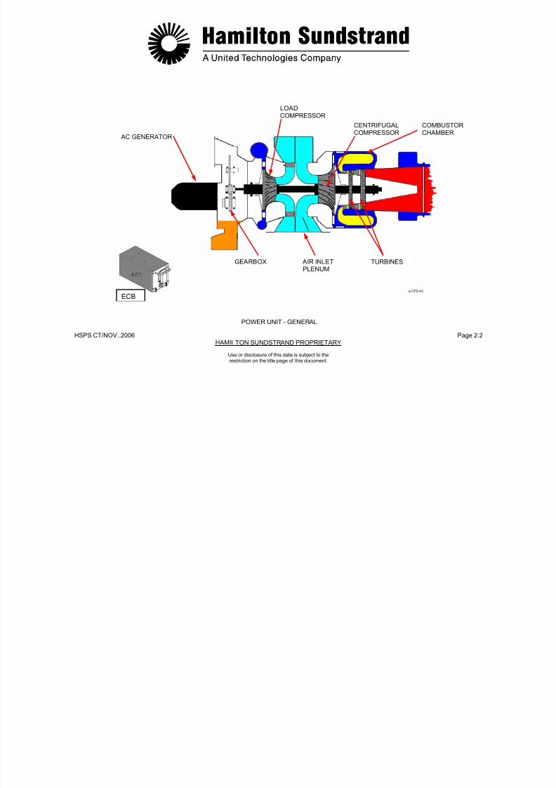
POWER UNIT - GENERAL
Function
The APU provides compressed air and electrical power to the aircraft.
Location
The APU is installed in the aircraft tail section.
Type
Single spool gas turbine engine driving a load compressor and an ACgenerator.
Main Characteristics
Characteristics at Aero Design Point, installed APU (ISA, sea level) aregiven for information only:
- Total power ............................400 kW (536 HP)
- Specific fuel consumption .......0.372 kg/kW.h (0.61 Ib/HP.H)
- Fuel consumption ...................148 kg/HR (178 L/HR)
................................................[327 LB/HR (47 GAL/HR)]- Electrical power ......................132 kW (177 HP)
- Pneumatic power ...................252 kW (338 HP)
- Bleed air flow .........................1.2 kg/sec. (2.6 lbs/sec.)
- Bleed air pressure ..................390 kPa (42 PSI)
- Rotation speed .......................49 300 RPM
- Direction of rotation ................clockwise (view from the rear)
- APU dry weight ......................136 kg (299 lbs).
Main Components
- Gearbox (with AC generator and APU accessory drive)
- Load compressor (centrifugal type provided with inlet guide vanes)
- Air inlet plenum (air intake and air dist ribution)
- Power section including:
• A centrifugal impeller
A reverse flow combustor chamber
• A two stage axial flow turbine.
7/21/2019 Aps 3200 Training
http://slidepdf.com/reader/full/aps-3200-training 31/739
HSPS CT/NOV..2006 Page 2.2
HAMILTON SUNDSTRAND PROPRIETARY
LOADCOMPRESSOR
CENTRIFUGALCOMPRESSOR
Use or disclosure of this data is subject to therestriction on the title page of this document.
POWER UNIT - GENERAL
GEARBOX AIR INLETPLENUM
TURBINES
AC GENERATOR
COMBUSTORCHAMBER
ECB
7/21/2019 Aps 3200 Training
http://slidepdf.com/reader/full/aps-3200-training 32/739
.
HSPS CT/NOV. 2006 Page 2.3
HAMILTON SUNDSTRAND PROPRIETARY
Use or disclosure of this data is subject to therestriction on the title page of this document.
POWER UNIT - DESCRIPTION (1)
The first part of the description deals with the APU rotating assemblyand the second part will consider the modular design of the APU.
The following main components are considered in this description:
gearbox, air intake plenum, load compressor and power section.
Gearbox
The gearbox located at the front of the APU provides the mechanicaldrive for the AC generator and the accessories required for the APUoperation. The oil sump is also part of the gearbox.
Load Compressor
The load compressor is driven by the power section and providescompressed air to the aircraft pneumatic system. It is a centrifugalimpeller that has variable inlet guide vanes to control the air flowoutput.
Air Inlet Plenum
The plenum is located between the load compressor and the power
section. The plenum directs the air supply to the power section, loadcompressor and the oil cooling system.
Power Section
The power section provides mechanical shaft power to drive the loadcompressor and the gearbox.
The power section comprises:
- A single stage centrifugal impeller
- A reverse flow combustion chamber
- A two stage axial flow turbine
- An exhaust system.
The main rotor assembly is supported by two bearings: A ballbearing at the front of the load compressor, a roller bearing at therear of the turbine.

7/21/2019 Aps 3200 Training
http://slidepdf.com/reader/full/aps-3200-training 33/739
.
HSPS CT/NOV. 2006 Page 2.4
HAMILTON SUNDSTRAND PROPRIETARY
DRIVE TRAINFOR AC GENERATOR
AND APU ACCESSORIESCENTRIFUGALIMPELLER COMBUSTION
CHAMBERFRONTBEARING
EXHAUST
Use or disclosure of this data is subject to therestriction on the title page of this document.
POWER UNIT - DESCRIPTION (1)
OILSUMP
CENTRIFUGALIMPELLER
AIR INLETPLENUM
TURBINES
REARBEARING
VARIABLEINLET GUIDEVANES

7/21/2019 Aps 3200 Training
http://slidepdf.com/reader/full/aps-3200-training 34/739

7/21/2019 Aps 3200 Training
http://slidepdf.com/reader/full/aps-3200-training 35/739
.
HSPS CT/NOV. 2006 Page 2.6
HAMILTON SUNDSTRAND PROPRIETARY
POWER SECTIONIMPELLERLOAD COMPRESSOR
IMPELLER
FRONT BALLBEARING
Use or disclosure of this data is subject to therestriction on the title page of this document.
POWER UNIT - DESCRIPTION (2)
QUILL
INTERSHAFTTIE
BOLT
SECURINGNUT
TURBINES
REAR ROLLERBEARING
SECURINGNUT
A320-457a
7/21/2019 Aps 3200 Training
http://slidepdf.com/reader/full/aps-3200-training 36/739
.
HSPS CT/NOV. 2006 Page 2.7
HAMILTON SUNDSTRAND PROPRIETARYUse or disclosure of this data is subject to therestriction on the title page of this document.
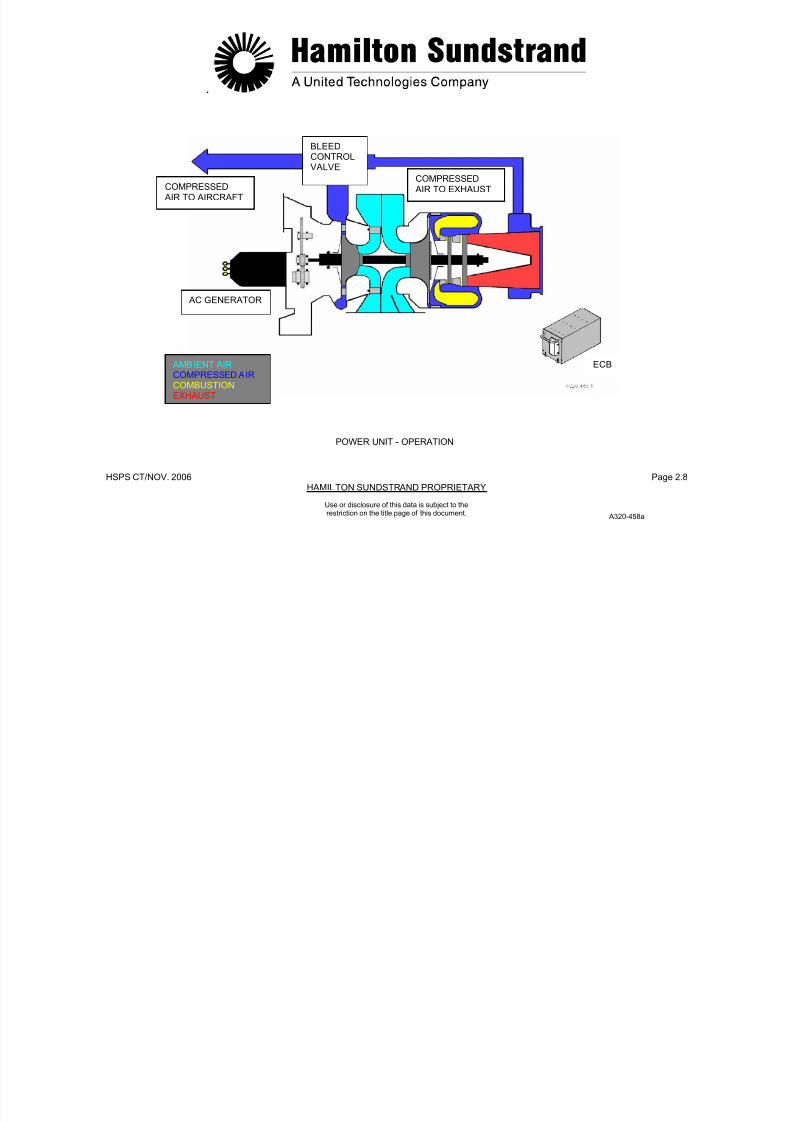
POWER UNIT - OPERATION
General
The power section produces mechanical shaft power for APUoperation.
This mechanical power is used to drive:
- The load compressor which supplies compressed air
- The AC generator which supplies electrical power
- Accessories required for the operation of the APU.
Power Section Operation
The air enters the power section through the aircraft air inlet and the APU plenum.
In the plenum, this air is divided into two flows; one for the loadcompressor and one for the power section.
The power section air is directed to the centrifugal impeller which
increases the air pressure.
The air is then admitted to the combustion chamber, mixed with thefuel and burned to provide a continuous combustion process. Thegases are expanded across the turbines that transforms the gasenergy into mechanical energy.
The gases are then expelled overboard through the aircraft exhaustsystem.
Load Compressor Operation
The load compressor is driven by the power section and produces airflow to the aircraft pneumatic systems.
Gearbox Operation
The gearbox is driven by the power section to operate the APUaccessories and the AC generator.
Electronic Control Box (ECB)
The ECB provides control and monitoring of the APU.
7/21/2019 Aps 3200 Training
http://slidepdf.com/reader/full/aps-3200-training 37/739
.
HSPS CT/NOV. 2006 Page 2.8
HAMILTON SUNDSTRAND PROPRIETARY
BLEEDCONTROLVALVE
COMPRESSED AIR TO EXHAUSTCOMPRESSED
AIR TO AIRCRAFT
AC GENERATOR
ECB AMBIENT AIRCOMPRESSED AIRCOMBUSTION
EXHAUST
POWER UNIT - OPERATION
Use or disclosure of this data is subject to therestriction on the title page of this document.
A320-458a

7/21/2019 Aps 3200 Training
http://slidepdf.com/reader/full/aps-3200-training 38/739
.
HSPS CT/NOV. 2006 Page 2.9
HAMILTON SUNDSTRAND PROPRIETARYUse or disclosure of this data is subject to therestriction on the title page of this document.
GEARBOX - GENERAL
Location
The gearbox is located at the front of the load compressor scroll.
Main Features
- Modular design
- Mechanical efficiency: 0.98
- Weight: 17 kg (37.4 lbs)
- Oil sump
- Gearbox drive power: 148 kW (198 HP)
- AC generator drive power: 132 kW (177 HP)
- Accessories drive power: 16 kW (21 HP)
- Material for housing: Aluminum alloy.
Gearbox Front Face View
- Oil cooling fan drive pad
- AC generator drive pad
- Starter motor drive pad
- Fuel control unit drive pad
- Accessories (oil filters, oil level sensor, de-oiling valve...).
Gearbox Left Side View
- Oil sight glass
- Oil fill tube
- High oil temperature sensor
- Speed sensor
- Gearbox mounting flange (attachment with the load compressorscroll)
- APU front left mount.

7/21/2019 Aps 3200 Training
http://slidepdf.com/reader/full/aps-3200-training 39/739
.
HSPS CT/NOV. 2006 Page 2.10
HAMILTON SUNDSTRAND PROPRIETARY
COOLING FAN
MOUNTINGFLANGE AC GENERATOR
Use or disclosure of this data is subject to therestriction on the title page of this document.
GEARBOX - GENERAL
APU FRONTMOUNT
FWD
OIL FILLTUBE
OIL SIGHTGLASS
HIGH OIL TEMPERATURE
SPEEDSENSOR
DE-OILINGVALVE
OIL LEVELSENSOR
OILFILTERS
STARTER MOTOR
FUEL CONTROL
DE-OILING
VALVE
A320-459a

7/21/2019 Aps 3200 Training
http://slidepdf.com/reader/full/aps-3200-training 40/739
.
HSPS CT/NOV. 2006 Page 2.11
HAMILTON SUNDSTRAND PROPRIETARYUse or disclosure of this data is subject to therestriction on the title page of this document.
GEARBOX DESCRIPTIO (1)
This description considers the gears, the bearings and the drivepads.
Gears
The gearbox comprises of 8 spur type gears made of steel alloy. Thegear train provides the correct speeds for the APU driven units.
BearingsThe gears are supported by bearings: 6 roller bearings and 6 ballbearings.
AC Generator Drive- Speed: 24034 RPM- Direction of rotation: Clockwise.
Intermediate Gear- Speed: 14349 RPM- Direction of rotation: Clockwise- Centrifugal air-oil separator.
Cooling Fan Drive- Speed: 51965 RPM
- Direction of rotation: Anti clockwise- PMG (Permanent Magnet Generator).
Starter Motor Drive- Speed: 32045 RPM- Direction of rotation: Anti clockwise- Starter clutch: Sprag type.
Fuel Pump Drive- Speed: 10129 RPM-Direction o f rotation: Clockwise.
Oil Pump Drives- Lubrication pump
• Speed: 4137 RPM• Direction of rotation: Clockwise.
Scavenge pumps• Speed: 4137 RPM
Direction of rotation: Anti clockwise.
Note: Direction of rotation by viewing the front of the gearbox.

7/21/2019 Aps 3200 Training
http://slidepdf.com/reader/full/aps-3200-training 41/739
.
HSPS CT/NOV. 2006 Page 2.12
HAMILTON SUNDSTRAND PROPRIETARY
-
FRONT VIEWCOOLING FANDRIVE(51965 RPM)
INTERMEDIATEGEAR(14349 RPM)
STARTER MOTORDRIVE(32045 RPM)
AC GENERATORDRIVE(24034 RPM)
Use or disclosure of this data is subject to therestriction on the title page of this document.
GEARBOX - DESCRIPTION (1)
DRIVEGEAR(49300 RPM)
FUEL PUMPDRIVE(10129 RPM)
OIL PUMPDRIVES(4137 RPM)
7/21/2019 Aps 3200 Training
http://slidepdf.com/reader/full/aps-3200-training 42/739
.
HSPS CT/NOV. 2006 Page 2.13
HAMILTON SUNDSTRAND PROPRIETARYUse or disclosure of this data is subject to therestriction on the title page of this document.
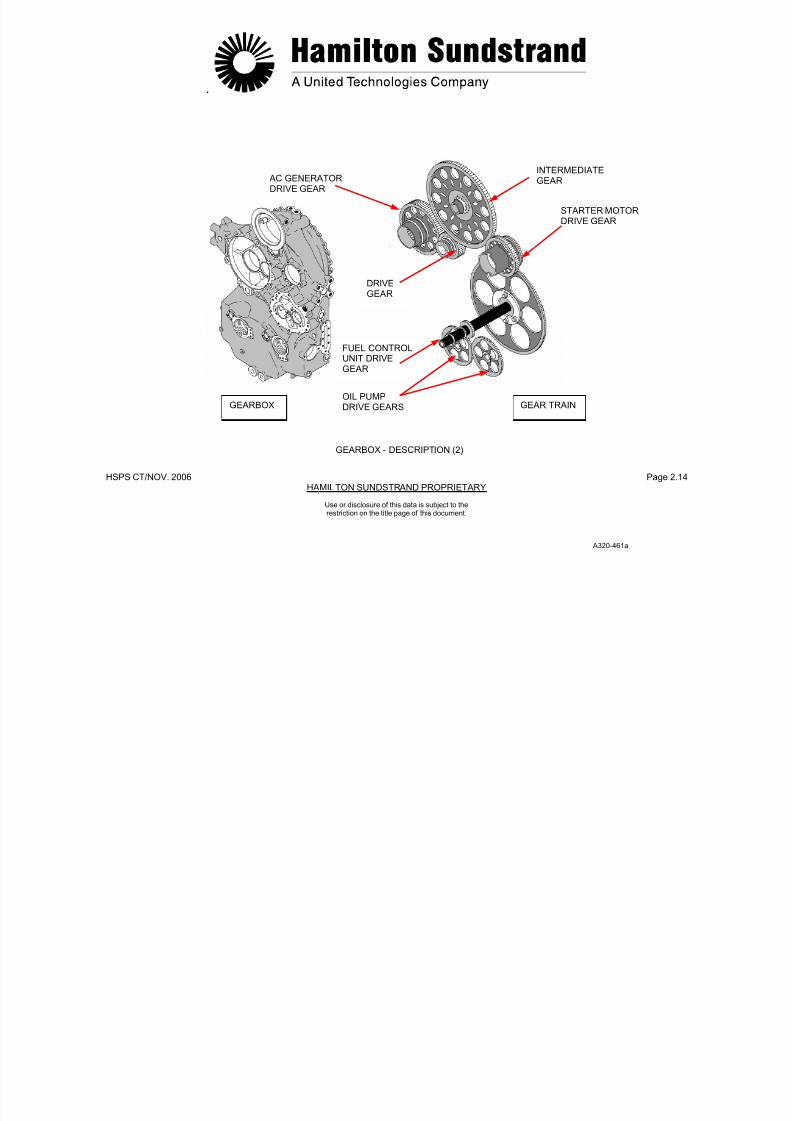
GEARBOX - DESCRIPTION (2)
Identification of Gearbox Components
- The gearbox housing which forms the oil sump and provides theaccessories for the oil system (oil filter, oil level sensor, magnetic
plug...).
The gearbox housing also provides the mounting pads for:
• The oil cooling fan
• The AC generator
• The starter motor
• The fuel control unit
The gearbox housing is attached to the load compressor scroll bya mounting flange.
- The APU front left and right mounts are located on the sides ofthe gearbox.
- The gearbox gear train which includes:
• The AC generator drive gear
• The intermediate gear, which also forms the air-oilseparator
• The starter motor drive gear
• The fuel control unit drive gear
• The oil pump drive gears.
7/21/2019 Aps 3200 Training
http://slidepdf.com/reader/full/aps-3200-training 43/739
.
HSPS CT/NOV. 2006 Page 2.14HAMILTON SUNDSTRAND PROPRIETARY
INTERMEDIATEGEAR AC GENERATOR
DRIVE GEAR
STARTER MOTORDRIVE GEAR
Use or disclosure of this data is subject to therestriction on the title page of this document.
GEARBOX - DESCRIPTION (2)
DRIVEGEAR
FUEL CONTROLUNIT DRIVEGEAR
OIL PUMPDRIVE GEARSGEARBOX GEAR TRAIN
A320-461a

7/21/2019 Aps 3200 Training
http://slidepdf.com/reader/full/aps-3200-training 44/739
.
HSPS CT/NOV. 2006 Page 2.15HAMILTON SUNDSTRAND PROPRIETARY
Use or disclosure of this data is subject to therestriction on the title page of this document.
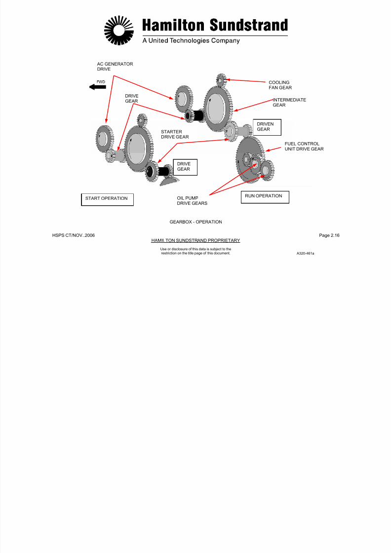
GEARBOX - OPERATION
During Starting
The starter motor is electrically energized and provides the torque tocrank the gear train and the APU rotor assembly.
At self-sustaining speed, the electrical supply to the starter is de-energized and the starter is disengaged by the sprag clutch.
Normal Running Condit ion
The power section provides the mechanical power to drive the loadcompressor and the gearbox drive gear.
The drive gear meshes directly with the AC generator gear.
It also drives an intermediate gear which in turn drives the oil coolerfan gear, the starter motor gear and the fuel control unit and oil pumpgears
7/21/2019 Aps 3200 Training
http://slidepdf.com/reader/full/aps-3200-training 45/739
HSPS CT/NOV..2006 Page 2.16HAMILTON SUNDSTRAND PROPRIETARY
AC GENERATORDRIVE
COOLINGFAN GEAR
DRIVE
GEAR INTERMEDIATEGEAR
DRIVENGEAR
STARTERDRIVE GEAR
FUEL CONTROL
UNIT DRIVE GEAR
DRIVEGEAR
Use or disclosure of this data is subject to therestriction on the title page of this document.
GEARBOX - OPERATION
RUN OPERATIONOIL PUMPDRIVE GEARS
START OPERATION
A320-461a
7/21/2019 Aps 3200 Training
http://slidepdf.com/reader/full/aps-3200-training 46/739
.
HSPS CT/NOV. 2006 Page 2.17HAMILTON SUNDSTRAND PROPRIETARY
Use or disclosure of this data is subject to therestriction on the title page of this document.
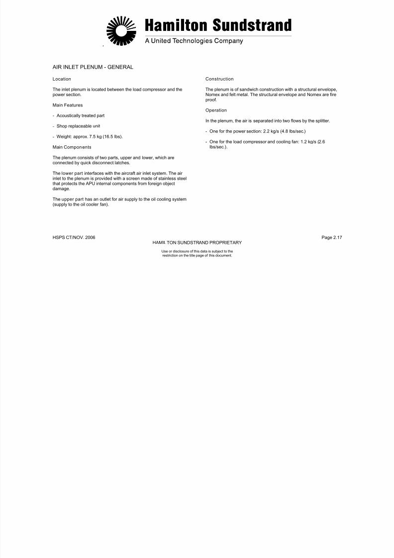
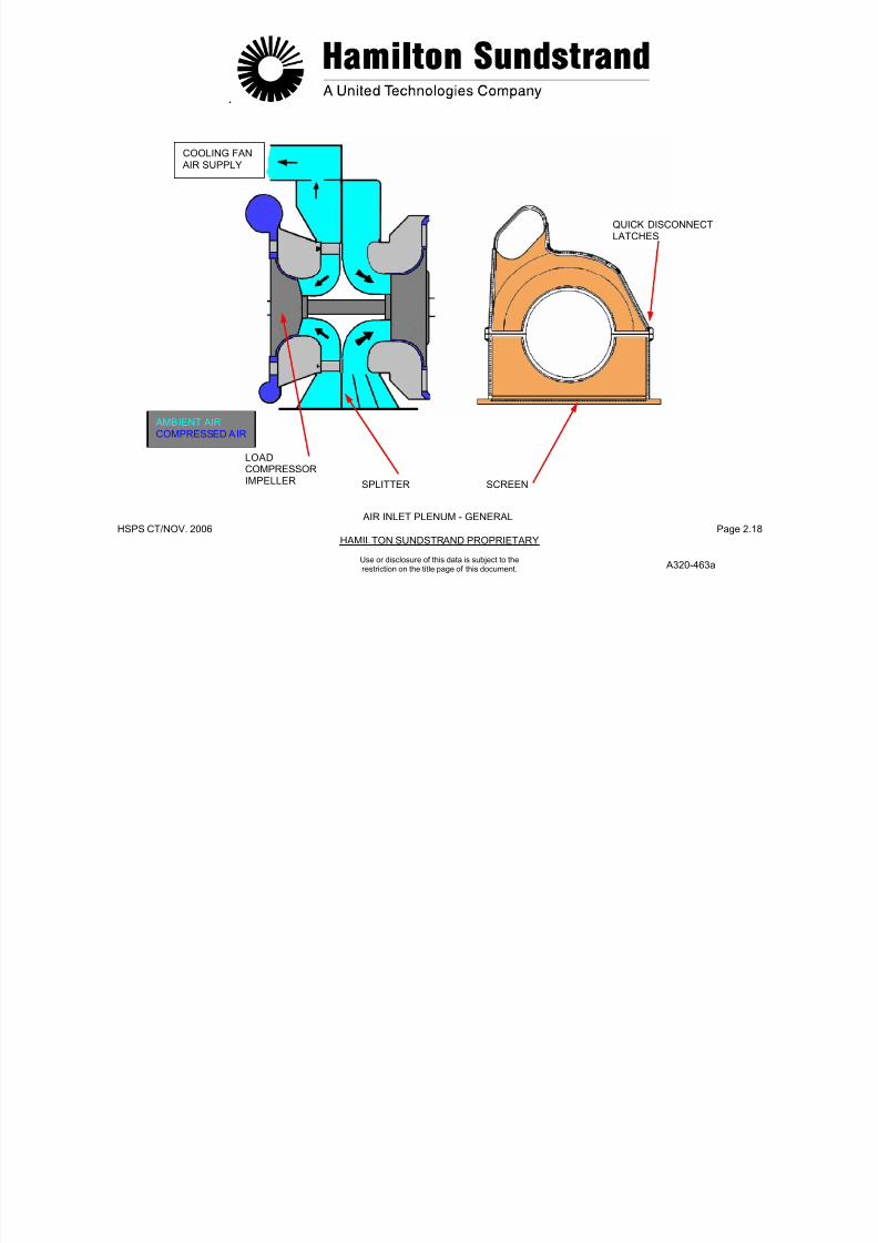
AIR INLET PLENUM - GENERAL
Location
The inlet plenum is located between the load compressor and thepower section.
Main Features
- Acoustically treated part
- Shop replaceable unit
- Weight: approx. 7.5 kg (16.5 lbs).
Main Components
The plenum consists of two parts, upper and lower, which areconnected by quick disconnect latches.
The lower part interfaces with the aircraft air inlet system. The airinlet to the plenum is provided with a screen made of stainless steelthat protects the APU internal components from foreign objectdamage.
The upper part has an outlet for air supply to the oil cooling system(supply to the oil cooler fan).
Construction
The plenum is of sandwich construction with a structural envelope,Nomex and felt metal. The structural envelope and Nomex are fire
proof.
Operation
In the plenum, the air is separated into two flows by the splitter.
- One for the power section: 2.2 kg/s (4.8 lbs/sec.)
- One for the load compressor and cooling fan: 1.2 kg/s (2.6lbs/sec.).
7/21/2019 Aps 3200 Training
http://slidepdf.com/reader/full/aps-3200-training 47/739
.
HSPS CT/NOV. 2006 Page 2.18HAMILTON SUNDSTRAND PROPRIETARY
COOLING FAN
AIR SUPPLY
QUICK DISCONNECTLATCHES
Use or disclosure of this data is subject to therestriction on the title page of this document.
AIR INLET PLENUM - GENERAL
LOADCOMPRESSORIMPELLER SPLITTER SCREEN
AMBIENT AIRCOMPRESSED AIR
A320-463a

7/21/2019 Aps 3200 Training
http://slidepdf.com/reader/full/aps-3200-training 48/739
.
HSPS CT/NOV. 2006 Page 2.19HAMILTON SUNDSTRAND PROPRIETARY
Use or disclosure of this data is subject to therestriction on the title page of this document.
AIR INLET PLENUM - DESCRIPTION
Identification of the Air Inlet Plenum Components
- The lower part of the air inlet plenum interfaces with the APU airinlet system. It has a screen to protect the APU internal
components from foreign object damage.
The lower part incorporates noise treatment and a splitter whichseparates the air into two flows. It also provides the support for thefollowing components:
• The ambient air pressure and temperature sensors
• The differential pressure sensor
• The low oil pressure switch
• The ignition exciter.
- The upper part of the air inlet plenum is also noise treated.
The upper part has an oval outlet to supply air to the oil coolingsystem
- The quick disconnect latches secure the upper part and lowerpart of the air inlet plenum.

7/21/2019 Aps 3200 Training
http://slidepdf.com/reader/full/aps-3200-training 49/739
.
HSPS CT/NOV. 2006 Page 2.20HAMILTON SUNDSTRAND PROPRIETARY
PLENUMUPPER PART
SPLITTER
Use or disclosure of this data is subject to therestriction on the title page of this document.
AIR INLET PLENUM - DESCRIPTION
A320-464a
AIR INLETHOUSING
PLENUMLOWER PART
QUICKDISCONNECTLATCH
COOLING FAN AIR SUPPLY
INLETSCREENLOCATING
TAB

7/21/2019 Aps 3200 Training
http://slidepdf.com/reader/full/aps-3200-training 50/739
.
HSPS CT/NOV. 2006 Page 2.21HAMILTON SUNDSTRAND PROPRIETARY
Use or disclosure of this data is subject to therestriction on the title page of this document.
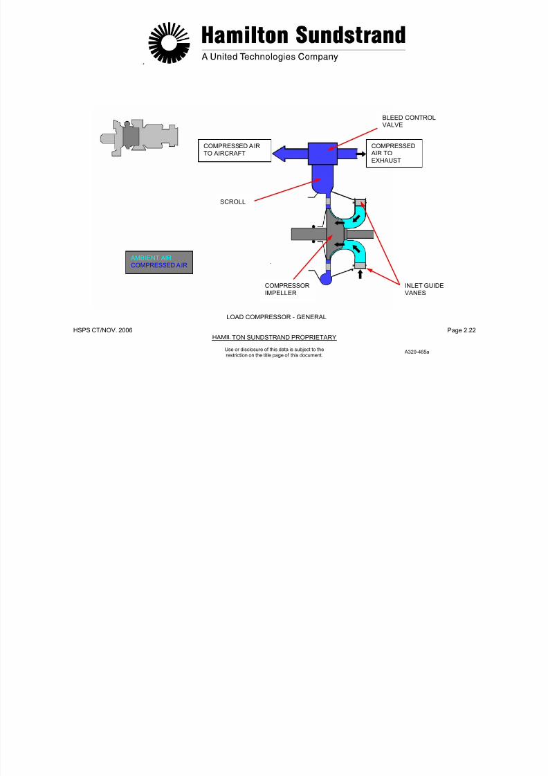
LOAD COMPRESSOR - GENERAL
Location
The load compressor is installed between the gearbox and the powersection.
Type
High pressure centrifugal impeller provided with inlet guide vanes.
Main Features
- Air flow: 1.2 kg/s (2.6 lbs/sec.)
- Pressure ratio: 4:1
- Max outlet temperature: 232°C (450°F)
- Rotation speed: 49 300 RPM
- Direction of rotation: clockwise (viewed from the rear of the APU).
Main Components
- Rotating components (compressor shaft, impeller, bearing,bearing seals)
- Stationary components (air inlet housing, variable inlet guidevanes, impeller shroud, diffuser, and scroll).
7/21/2019 Aps 3200 Training
http://slidepdf.com/reader/full/aps-3200-training 51/739
.
HSPS CT/NOV. 2006 Page 2.22HAMILTON SUNDSTRAND PROPRIETARY
BLEED CONTROLVALVE
COMPRESSED AIRTO AIRCRAFT
COMPRESSED AIR TOEXHAUST
Use or disclosure of this data is subject to therestriction on the title page of this document.
LOAD COMPRESSOR - GENERAL
INLET GUIDEVANES
COMPRESSORIMPELLER
SCROLL
AMBIENT AIRCOMPRESSED AIR
A320-465a

7/21/2019 Aps 3200 Training
http://slidepdf.com/reader/full/aps-3200-training 52/739
.
HSPS CT/NOV. 2006 Page 2.23HAMILTON SUNDSTRAND PROPRIETARY
Use or disclosure of this data is subject to therestriction on the title page of this document.
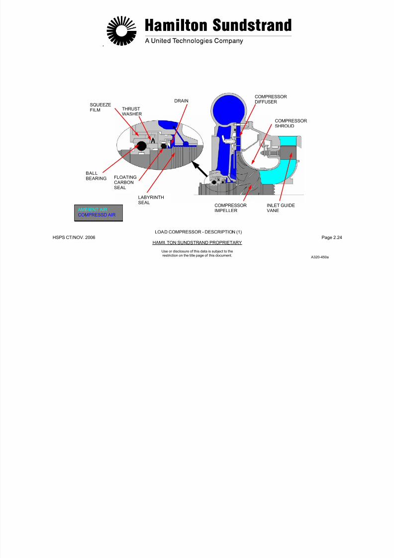
LOAD COMPRESSOR - DESCRIPTION (1)
The first part of this description deals with the load compressorcomponents, the second part will consider the inlet guide vanescontrol mechanism and the third part the identification of all thecomponents.
Air Inlet Housing
The housing allows the passage of air to the load compressor andsupports the inlet guide vanes. It is made of aluminum alloy.
Compressor Impeller
The impeller is constructed of titanium alloy. The rear shaft of theimpeller is connected to the rotor intershaft using a curvic coupling.The front is supported by a ball bearing.
Compressor Shroud
The shroud houses the impeller and is constructed of steel alloy.
Compressor Diffuser
It consists of 19 cambered vanes made of steel alloy.
Scroll
The annular scroll provides the air outlet of the load compressor. It iscast aluminum.
The scroll housing provides passages for static air pressure to theload compressor discharge pressure sensor.
Bearing
A ball thrust bearing supports the front shaft of the load compressor.It is mounted in the load compressor housing.
Bearing Seals
Oil that is used to lubricate the front bearing is prevented fromentering the impeller area by a floating carbon seal and a labyrinthseal.
7/21/2019 Aps 3200 Training
http://slidepdf.com/reader/full/aps-3200-training 53/739
.
HSPS CT/NOV. 2006 Page 2.24HAMILTON SUNDSTRAND PROPRIETARY
COMPRESSOR
DIFFUSERDRAINSQUEEZEFILM THRUST
WASHER
Use or disclosure of this data is subject to therestriction on the title page of this document.
LOAD COMPRESSOR - DESCRIPTION (1)
COMPRESSORSHROUD
INLET GUIDEVANE
A320-450a
COMPRESSORIMPELLER
BALLBEARING FLOATING
CARBONSEAL
LABYRINTHSEAL
AMBIENT AIRCOMPRESSD AIR

7/21/2019 Aps 3200 Training
http://slidepdf.com/reader/full/aps-3200-training 54/739
.
HSPS CT/NOV. 2006 Page 2.25HAMILTON SUNDSTRAND PROPRIETARY
Use or disclosure of this data is subject to therestriction on the title page of this document.
LOAD COMPRESSOR - DESCRIPTION (2)
Identification of Load Compressor Components
- The IGV assembly includes the variable inlet guide vanes, therack and pinion mechanism and the air inlet housing
- The compressor shroud houses the impeller.
- The load compressor impeller has main blades and splitterblades. The impeller is connected at the rear to the inter shaft bycurvic-coupling. The impeller front shaft is supported by the frontbearing.
- The scroll provides the air outlet of the load compressor. Thescroll also houses the load compressor diffuser.
- The front bearing is a ball bearing that supports the impeller frontshaft
- The labyrinth seal is pressurized with compressed air from thepower section impeller.
- The front bearing nut retains the front bearing and forms thephonic wheel of the speed sensing system
- The tie-bolt and the securing nut.

7/21/2019 Aps 3200 Training
http://slidepdf.com/reader/full/aps-3200-training 55/739
.
HSPS CT/NOV. 2006 Page 2.26HAMILTON SUNDSTRAND PROPRIETARY
SCROLL
LABYRINTHSEAL
Use or disclosure of this data is subject to therestriction on the title page of this document.
LOAD COMPRESSOR - DESCRIPTION (2)
FRONTBEARING
FRONT BEARINGJOURNAL
TIEBOLTSECURING
NUT
FRONT BEARING NUT(PHONIC WHEEL)
INLET GUIDEVANE ASSEMBLY
COMPRESSORSHROUD
LOAD COMPRESSORIMPELLER
7/21/2019 Aps 3200 Training
http://slidepdf.com/reader/full/aps-3200-training 56/739

7/21/2019 Aps 3200 Training
http://slidepdf.com/reader/full/aps-3200-training 57/739
HSPS CT/NOV..2006 Page 2.28HAMILTON SUNDSTRAND PROPRIETARY
ACTUATORROD HOUSING AIR INLET
HOUSING
Use or disclosure of this data is subject to therestriction on the title page of this document.
INLET GUIDEVANE CONTROLROD
INLET GUIDEVANE
ASSEMBLY
RINGGEAR
IGVPOSITIONINDICATOR
INLET GUIDE
VANE
SECTORGEAR
LOAD COMPRESSOR – DESCRIPTION (3)
A320-467A
7/21/2019 Aps 3200 Training
http://slidepdf.com/reader/full/aps-3200-training 58/739
.
HSPS CT/NOV. 2006 Page 2.29HAMILTON SUNDSTRAND PROPRIETARY
Use or disclosure of this data is subject to therestriction on the title page of this document.
LOAD COMPRESSOR - OPERATION
Air Inlet
The ambient air enters the APU through the aircraft air inlet and the APU plenum.
The plenum air is separated into three flows:
- Air for the power section
- Air for the oil cooling system
- Air for the load compressor.
The air for the load compressor passes through the inlet guidevanes; the flow of air depends upon the position (the angle) of thevanes. The air is then directed to the blades of the compressorimpeller.
Compression
As the air enters the blades of the rotating compressor impeller theair velocity increases.
The air leaves the tip of the blades at high velocity and flows throughthe diffuser vanes where velocity is transformed into pressure.
Delivery
The compressed air then flows into the scroll and delivered to the
pneumatic system through a bleed control valve.

7/21/2019 Aps 3200 Training
http://slidepdf.com/reader/full/aps-3200-training 59/739
.
HSPS CT/NOV. 2006 Page 2.30HAMILTON SUNDSTRAND PROPRIETARY
COMPRESSED AIR TOEXHAUST
COMPRESSED AIR TO AIRCRAFT
SCROLL
Use or disclosure of this data is subject to therestriction on the title page of this document.
LOAD COMPRESSOR - OPERATION
DIFFUSERVANE
COMPRESSORIMPELLER INLET GUIDE
VANES
A320-468a
AMBIENT AIRCOMPRESSED AIR
7/21/2019 Aps 3200 Training
http://slidepdf.com/reader/full/aps-3200-training 60/739
.
HSPS CT/NOV. 2006 Page 2.31HAMILTON SUNDSTRAND PROPRIETARY
Use or disclosure of this data is subject to therestriction on the title page of this document.
POWER SECTION - GENERAL
Function
The power section provides the power to drive the load compressorand the gearbox.
Location
The power section forms the rear part of the APU.
Type
Single spool gas turbine engine.
Main Components
The main functional components are:
- Single stage centrifugal impeller
- Reverse flow combustion chamber
- Two stage axial flow turbine
- Exhaust.

7/21/2019 Aps 3200 Training
http://slidepdf.com/reader/full/aps-3200-training 61/739
.
HSPS CT/NOV. 2006 Page 2.32HAMILTON SUNDSTRAND PROPRIETARY
Use or disclosure of this data is subject to therestriction on the title page of this document.
POWER SECTION - GENERAL
TWO STAGE AXIAL FLOWTURBINES
SINGLE STAGECENTRIFUGALCOMPRESSOR
MAIN CHARACTERISTICS
POWER400 Kw (536 HP)
SPECIFIC FUEL CONSUMPTION0.372 kg/kW.h (0.61 lb/HP.H)
FUEL CONSUMPTION327 LB/HR (47GAL/HR)
ROTATION SPEED49300 RPM
AIR MASS FLOW2.2 kg/s (4.8 lbs/sec)
COMPRESSION RATIO8:1
EXHAUST
REVERSE FLOWCOMBUSTIONCHAMBER
POWER SECTION - GENERAL
A320-469a
7/21/2019 Aps 3200 Training
http://slidepdf.com/reader/full/aps-3200-training 62/739
7/21/2019 Aps 3200 Training
http://slidepdf.com/reader/full/aps-3200-training 63/739
.
HSPS CT/NOV. 2006 Page 2.34HAMILTON SUNDSTRAND PROPRIETARY
IMPELLERCONTAINMENTSHIELD
COMPRESSORHOUSING
IMPELLERSHIELD
CURVICCOUPLINGCURVIC
COUPLING
Use or disclosure of this data is subject to therestriction on the title page of this document.
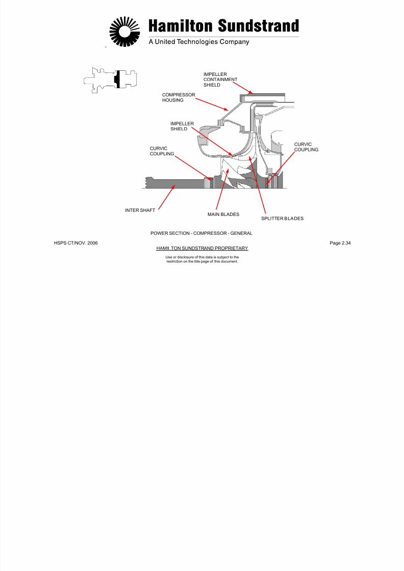
POWER SECTION - COMPRESSOR - GENERAL
INTER SHAFTMAIN BLADES
SPLITTER BLADES
7/21/2019 Aps 3200 Training
http://slidepdf.com/reader/full/aps-3200-training 64/739
.
HSPS CT/NOV. 2006 Page 2.35HAMILTON SUNDSTRAND PROPRIETARY
Use or disclosure of this data is subject to therestriction on the title page of this document.
POWER SECTION - COMPRESSOR - DESCRIPTION
Identification of Compressor Components
- The intermediate shaft is connected to the front of the loadcompressor impeller and to the rear of the power sectioncompressor impeller by curvic-couplings.
- The compressor housing houses the impeller and thecompressor shield.
The compressor housing is attached at the front to the air inlethousing and at the rear to the diffuser assembly and the combustorhousing.
- The impeller containment shield is mounted to the compressor
housing.
- The impeller has main blades and splitter blades. The impeller isconnected at the front to the intermediate shaft and at the rear tothe turbine by curvic-couplings.
- The diffuser is mounted to the impeller shield.

7/21/2019 Aps 3200 Training
http://slidepdf.com/reader/full/aps-3200-training 65/739
.
HSPS CT/NOV. 2006 Page 2.36HAMILTON SUNDSTRAND PROPRIETARY
Use or disclosure of this data is subject to therestriction on the title page of this document.
POWER SECTION - COMPRESSOR - DESCRIPTION
COMPRESSORHOUSING
IMPELLERCONTAINMENTSHIELD
INTERMEDIATESHAFT
DIFFUSER
IMPELLER IMPELLERSHIELD
POWER SECTION – COMPRESSOR - SECTION
a320-471a

7/21/2019 Aps 3200 Training
http://slidepdf.com/reader/full/aps-3200-training 66/739
7/21/2019 Aps 3200 Training
http://slidepdf.com/reader/full/aps-3200-training 67/739
.
HSPS CT/NOV. 2006 Page 2.38HAMILTON SUNDSTRAND PROPRIETARY
AIRCOMBUSTORTUBESHOUSING
FUEL
Use or disclosure of this data is subject to therestriction on the title page of this document.
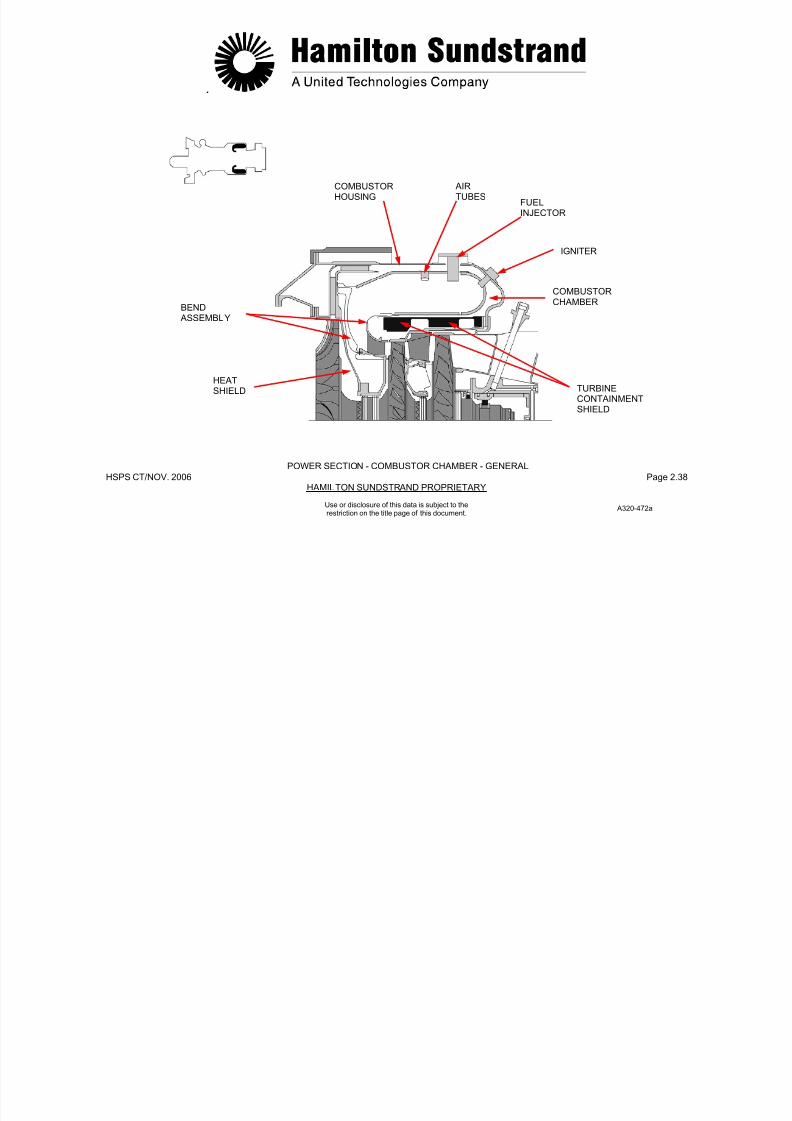
POWER SECTION - COMBUSTOR CHAMBER - GENERAL
INJECTOR
IGNITER
COMBUSTOR
CHAMBERBEND ASSEMBLY
HEATSHIELD TURBINE
CONTAINMENTSHIELD
A320-472a

7/21/2019 Aps 3200 Training
http://slidepdf.com/reader/full/aps-3200-training 68/739
.
HSPS CT/NOV. 2006 Page 2.39HAMILTON SUNDSTRAND PROPRIETARY
Use or disclosure of this data is subject to therestriction on the title page of this document.
POWER SECTION - COMBUSTOR CHAMBER -DESCRIPTION
Identification of Combustor Chamber Components
- The combustor housing houses the combustor chamber. It alsohas bosses for the mounting of the fuel injectors, the igniter plugsand the combustor chamber drain valve.
- The combustor chamber has holes and tubes that allows air usedfor combustion and cooling to enter the combustor chamber.
- The bend assembly guides the burned gases from the combustorchamber to the inlet of the first stage turbine nozzle guide vane.
- The heat shield protects the diffuser holder plate of the powersection impeller.
The heat shield is located between the bend assembly and thediffuser assembly.
- The combustor chamber drain valve is threaded into the bottomof the combustor housing, this allows unburned fuel to drainoverboard. The valve is closed by air pressure in the combustorhousing.
.

7/21/2019 Aps 3200 Training
http://slidepdf.com/reader/full/aps-3200-training 69/739
HSPS CT/NOV. 2006 Page 2.40HAMILTON SUNDSTRAND PROPRIETARY
Use or disclosure of this data is subject to therestriction on the title page of this document.
POWER SECTION - COMBUSTOR CHAMBER - DESCRIPTION
HEATSHIELD
BEND ASSEMBLY
FIRST STAGETURBINE NOZZLE
COMBUSTORCHAMBER
COMBUSTORCHAMBER DRAINVALVE
COMBUSTORHOUSING
COMBUSTOR AIR PRESSURE
7/21/2019 Aps 3200 Training
http://slidepdf.com/reader/full/aps-3200-training 70/739
.

7/21/2019 Aps 3200 Training
http://slidepdf.com/reader/full/aps-3200-training 71/739
HSPS CT/NOV. 2006 Page 2.42HAMILTON SUNDSTRAND PROPRIETARY
FIRST STAGE SECOND STAGENOZZLE GUIDETURBINE WHEEL
Use or disclosure of this data is subject to therestriction on the title page of this document.
POWER SECTION - TURBINE - GENERAL
FIRST STAGENOZZLE GUIDEVANE
VANE
CONTAINMENTSHIELD
SECOND STAGETURBINE WHEEL
CURVICCOUPLINGS
ROLLER TIEBEARING BOLT
A320-474a
.

7/21/2019 Aps 3200 Training
http://slidepdf.com/reader/full/aps-3200-training 72/739
HSPS CT/NOV. 2006 Page 2.43HAMILTON SUNDSTRAND PROPRIETARY
Use or disclosure of this data is subject to therestriction on the title page of this document.
POWER SECTION - TURBINE - DESCRIPTION
Identification of Turbine Components
- The first stage nozzle guide vane has 22 vanes installed in frontof the first stage turbine wheel
- The first stage turbine wheel has 37 fir tree blades inserted into adisc and secured by blade locks.
The turbine wheel is connected to the rear of the power sectionimpeller and to the second stage turbine wheel by curvic-couplings
- The second stage nozzle guide vane has 26 vanes installed infront of the second stage turbine wheel
- The second stage turbine wheel has 31 fir tree blades insertedinto a disc and secured by blade locks. Vibration dampers arefitted between the blades.
The turbine wheel is connected to the first stage turbine wheel by acurvic coupling.
The rear of the second stage turbine wheel is supported by a rollerbearing
- The containment shield is located around the turbine wheels.
- The turbine housing is located between the containment shieldand the turbine.
The turbine housing is connected to the exhaust housing.

7/21/2019 Aps 3200 Training
http://slidepdf.com/reader/full/aps-3200-training 73/739
HSPS CT/NOV..2006 Page 2.44HAMILTON SUNDSTRAND PROPRIETARY
FIR TREEBLADES
Use or disclosure of this data is subject to therestriction on the title page of this document.
POWER SECTION - TURBINE - DESCRIPTION
BLADELOCKS
VIBRATIONDAMPER
FIRST STAGENOZZLE GUIDEVANE
NOZZLE GUIDEVANE SUPPORT
FIRST STAGETURBINE WHEEL
CONTAINMENTSHIELD
TURBINEHOUSING
SECOND STAGENOZZLE GUIDEVANE
SECOND
STAGETURBINEWHEEL
A320-475a
.
7/21/2019 Aps 3200 Training
http://slidepdf.com/reader/full/aps-3200-training 74/739
HSPS CT/NOV. 2006 Page 2.45HAMILTON SUNDSTRAND PROPRIETARY
Use or disclosure of this data is subject to therestriction on the title page of this document.
POWER SECTION - EXHAUST - GENERAL
Function
The exhaust directs the exhaust gases to the aircraft exhaust pipe.
Location
The exhaust diffuser is located inside the APU exhaust housing.
Type
One piece, annular exhaust pipe.
Main Components
The exhaust housing is constructed of stainless steel and provides apassage for the exhaust gases. The housing also contains the rearbearing and struts that house oil pipes to the rear bearing.
.

7/21/2019 Aps 3200 Training
http://slidepdf.com/reader/full/aps-3200-training 75/739
HSPS CT/NOV. 2006 Page 2.46HAMILTON SUNDSTRAND PROPRIETARY
FLOATING CARBON SQUEEZESEAL FILM
Use or disclosure of this data is subject to therestriction on the title page of this document.
POWER SECTION - EXHAUST - GENERAL
STRUT
DISCHARGE AIR
REAR
BEARING
AIR BYPASSPLENUM
LABYRINTHSEAL
ROLLERBEARING
FLEXIBLECAGE
EXHAUSTHOUSING
A320-451a
.

7/21/2019 Aps 3200 Training
http://slidepdf.com/reader/full/aps-3200-training 76/739
HSPS CT/NOV. 2006 Page 2.47HAMILTON SUNDSTRAND PROPRIETARY
Use or disclosure of this data is subject to therestriction on the title page of this document.
POWER SECTION - EXHAUST - DESCRIPTION
Identification of Exhaust Components
- The exhaust housing consists of an outer housing and diffusercone supported by struts.
The inner cone houses the rear bearing assembly and the rearbearing oil pipes.
- The rear bearing housing:
• The rear bearing
• The rear end of the tie-bolt
• The securing nut.
The rear bearing housing has threaded bosses for the mounting ofthe rear bearing oil pipes.
- The rear bearing o il pipes:
• The rear bearing oil supply
• The rear bearing oil scavenge
• The rear bearing oil venting.
- The rear bearing is a roller bearing, it is located inside the rearbearing cage.
- The rear bearing labyrinth seal is installed on the rear shaft ofthe second stage turbine wheel.
The labyrinth seal is pressurized by compressed air from thepower section compressor.
- The air bypass plenum is installed on the exhaust housing and isprovided with a drain connected to the drain system.

7/21/2019 Aps 3200 Training
http://slidepdf.com/reader/full/aps-3200-training 77/739
HSPS CT/NOV..2006 Page 2.48HAMILTON SUNDSTRAND PROPRIETARY
AIR BYPASSPLENUM
REAR BEARINGHOUSING
REAR BEARINGVENT PIPE
SECURINGNUT
EXHAUSTHOUSING
LABYRINTH
Use or disclosure of this data is subject to therestriction on the title page of this document.
POWER SECTION - EXHAUST - DESCRIPTION
SEAL
REAR BEARING OILSUPPLY PIPE
REAR BEARINGSCAVENGE PIPE
REAR BEARING
TIEBOLT
CAGE
A320-476a
.

7/21/2019 Aps 3200 Training
http://slidepdf.com/reader/full/aps-3200-training 78/739
HSPS CT/NOV. 2006 Page 2.49HAMILTON SUNDSTRAND PROPRIETARY
Use or disclosure of this data is subject to therestriction on the title page of this document.
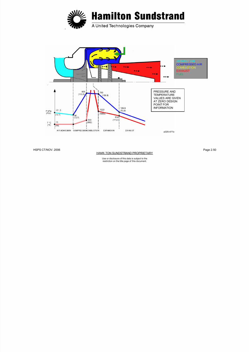
POWER SECTION - OPERATION (1)
The power section produces the shaft power through thethermodynamic cycle: compression, combustion, expansion andexhaust.
Compression
Ambient air is directed into the blades of the rotating impeller. The airthen flows through the divergent passages of the diffuser. (The airvelocity is transformed into pressure.)
Combustion
The compressed air is divided into two flows:
- A primary flow mixed with the fuel for combustion
- A secondary flow (dilution air) to cool the combustor and internalparts.
As a result of the continuous burning process, the pressuredecreases slightly whereas the velocity and the temperatureincrease.
Expansion
Expansion of the gases takes place across the two stages of theturbines, this transforms the gas energy into shaft power.
The gases flow through the nozzle guide vanes which increase thevelocity, then across the turbine blades. The aerodynamic forcescause the turbine wheels to rotate.
During expansion, the velocity of the gases increases and thepressure and temperature decrease.
Exhaust
The gases are then expelled overboard through the exhaust system.
.
7/21/2019 Aps 3200 Training
http://slidepdf.com/reader/full/aps-3200-training 79/739
HSPS CT/NOV. 2006 Page 2.50HAMILTON SUNDSTRAND PROPRIETARY
Use or disclosure of this data is subject to therestriction on the title page of this document.
POWER SECTION - OPERATION (1)
AMBIENT AIRCOMPRESSED AIRCOMBUSTIONEXHAUSTFUEL
a320-477a
PRESSURE ANDTEMPERATUREVALUES ARE GIVEN
AT ZERO DESIGNPOINT FORINFORMATION
.

7/21/2019 Aps 3200 Training
http://slidepdf.com/reader/full/aps-3200-training 80/739
HSPS CT/NOV. 2006 Page 2.51HAMILTON SUNDSTRAND PROPRIETARY
Use or disclosure of this data is subject to therestriction on the title page of this document.
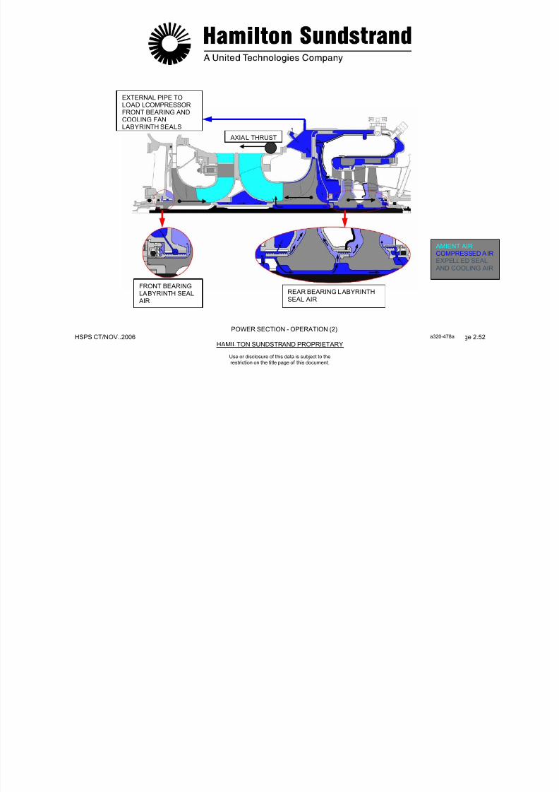
POWER SECTION - OPERATION (2)
The power section provides air flow to pressurize the APU labyrinthseals, to cool internal heated parts and balance rotor forces.
Pressurization
- Pressurization of Labyrinth Seals
Labyrinth seals are supplied with air pressure. A pressuredifference across the seals provide a non contact seal.
- Pressurization of Load Compressor Front Bearing
The pressurized air, bled from the outlet of the power sectionimpeller, flows through an external pipe to the labyrinth seal of the
load compressor front bearing and the cooling fan labyrinth seal.
- Pressurization of Power Section Rear Bearing
The pressurized air, bled at the outlet of the power sectionimpeller, flows through the power section rotor assembly to therear bearing labyrinth seal.
Cooling
To prevent excessive heating of the parts subjected to thecombustion gases, a circulation of cooling air (bled at the outlet ofthe power section impeller) is provided through the power section
rotor assembly, and is directed by internal passages to the turbinewheel faces.
Balance of Forces
The shaft, the turbine wheels, and the compressor impellers aresubjected to axial forces resulting from the operation of the rotorassembly.
To reduce the forces on the bearings, air pressure is used on thebackside of the power section impeller.
7/21/2019 Aps 3200 Training
http://slidepdf.com/reader/full/aps-3200-training 81/739
.
7/21/2019 Aps 3200 Training
http://slidepdf.com/reader/full/aps-3200-training 82/739
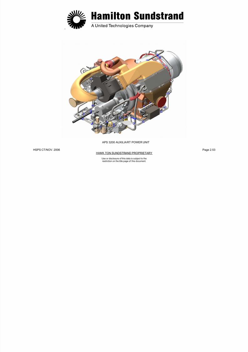
HSPS CT/NOV. 2006 Page 2.53HAMILTON SUNDSTRAND PROPRIETARY
APS 3200 AUXILIART POWER UNIT
Use or disclosure of this data is subject to therestriction on the title page of this document.

7/21/2019 Aps 3200 Training
http://slidepdf.com/reader/full/aps-3200-training 83/739
HSPS CT/NOV. 2006 Page 3.0HAMILTON SUNDSTRAND PROPRIETARY
APS 3200 AUXILIARY POWER UNIT
SECTION 3
OIL SYSTEM
Use or disclosure of this data is subject to therestriction on the title page of this document.
7/21/2019 Aps 3200 Training
http://slidepdf.com/reader/full/aps-3200-training 84/739
HSPS CT/NOV. 2006 Page 3.1HAMILTON SUNDSTRAND PROPRIETARY
Use or disclosure of this data is subject to therestriction on the title page of this document.
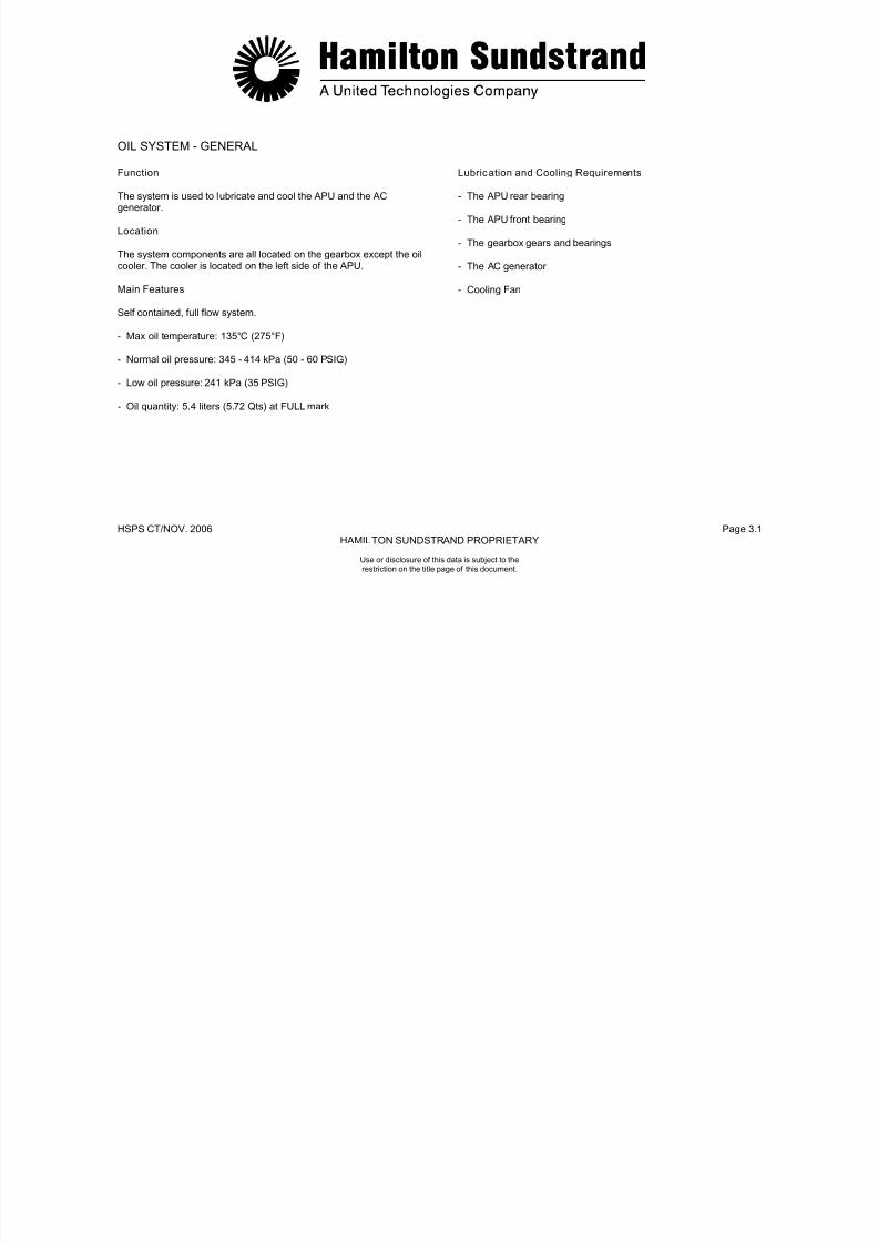
OIL SYSTEM - GENERAL
Function
The system is used to lubricate and cool the APU and the ACgenerator.
Location
The system components are all located on the gearbox except the oilcooler. The cooler is located on the left side of the APU.
Main Features
Self contained, full flow system.
- Max oil temperature: 135°C (275°F)
- Normal oil pressure: 345 - 414 kPa (50 - 60 PSIG)
- Low oil pressure: 241 kPa (35 PSIG)
- Oil quantity: 5.4 liters (5.72 Qts) at FULL mark
Lubrication and Cooling Requirements
- The APU rear bearing
- The APU front bearing
- The gearbox gears and bearings
- The AC generator
- Cooling Fan

7/21/2019 Aps 3200 Training
http://slidepdf.com/reader/full/aps-3200-training 85/739
HSPS CT/NOV.. 2006 Page 3.2HAMILTON SUNSTRAND PROPRIETARY
FRONTBEARING
Use or disclosure of this data is subject to therestriction on the title page of this document.
OIL SYSTEM - GENERAL
REARBEARING
GEARBOX
GEARS ANDBEARINGS
LUBRICATION AND
COOLING OF AC GENERATOR
OIL SYSTEMMAIN FEATURES
MAX OIL TEMPERATURE135 C (275 F)
NORMAL OIL PRESSURE345 – 414 Kpa (50-60 PSIG)
LOW OIL PRESSURE241 KPa (35 PSIG)
OIL QUANTITY5.4 liters (5.72 Qts)
OIL SYSTEM COMPONENTSON GEARBOX
(EXCPT OIL COOLER)
OIL SYSTEM - GENERAL
7/21/2019 Aps 3200 Training
http://slidepdf.com/reader/full/aps-3200-training 86/739
HSPS CT/NOV.. 2006 Page 3.3HAMILTON SUNSTRAND PROPRIETARY
Use or disclosure of this data is subject to therestriction on the title page of this document.
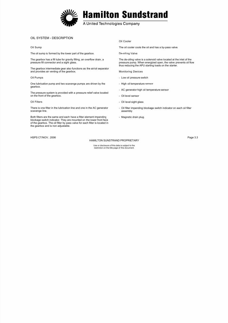
OIL SYSTEM - DESCRIPTION
Oil Sump
The oil sump is formed by the lower part of the gearbox.
The gearbox has a fill tube for gravity filling, an overflow drain, apressure fill connector and a sight glass.
The gearbox intermediate gear also functions as the air/oil separatorand provides air venting of the gearbox.
Oil Pumps
One lubrication pump and two scavenge pumps are driven by thegearbox.
The pressure system is provided with a pressure relief valve locatedon the front of the gearbox.
Oil Filters
There is one filter in the lubrication line and one in the AC generatorscavenge line.
Both filters are the same and each have a filter element impendingblockage switch indicator. They are mounted on the lower front faceof the gearbox. The oil filter by pass valve for each filter is located inthe gearbox and is non adjustable.
Oil Cooler
The oil cooler cools the oil and has a by-pass valve.
De-oili ng Valve
The de-oiling valve is a solenoid valve located at the inlet of thepressure pump. When energized open, the valve prevents oil flowthus reducing the APU starting loads on the starter.
Monitoring Devices
- Low oil pressure switch
- High oil temperature sensor
- AC generator high oil temperature sensor
- Oil level sensor
- Oil level sight glass
- Oil filter impending blockage switch indicator on each oil filterassembly
- Magnetic drain plug.

7/21/2019 Aps 3200 Training
http://slidepdf.com/reader/full/aps-3200-training 87/739
HSPS CT/NOV.. 2006 Page 3.4HAMILTON SUNSTRAND PROPRIETARY
Use or disclosure of this data is subject to therestriction on the title page of this document.
OIL SYSTEM - DESCRIPTION
OIL SUMP
OIL PRESSUREOIL RETURN
AIR-OIL MIST
SCAVENGEPUMPS
OIL FILTERBYPASS VALVES
OIL FILTERSOIL LEVELSIGHT GLASS
AC GENERATOR
HIGH OILTEMPERATURESENSOR
LOW OILPRESSURESWITCH
PRESSURERELIEF VALVE
CHECKVALVE
CHECK VALVE
OIL COOLER
AIR OILSEPERATOR
LUBRICATIONPUMP
DE-OILINGVALVE
OIL LEVELSENSOR
OILFILLERTUBE
MAGNETICDRAIN PLUG
HIGH OILTEMPERATURESENSOR
a 320-481a

7/21/2019 Aps 3200 Training
http://slidepdf.com/reader/full/aps-3200-training 88/739
HSPS CT/NOV.. 2006 Page 3.5HAMILTON SUNSTRAND PROPRIETARY
Use or disclosure of this data is subject to therestriction on the title page of this document.
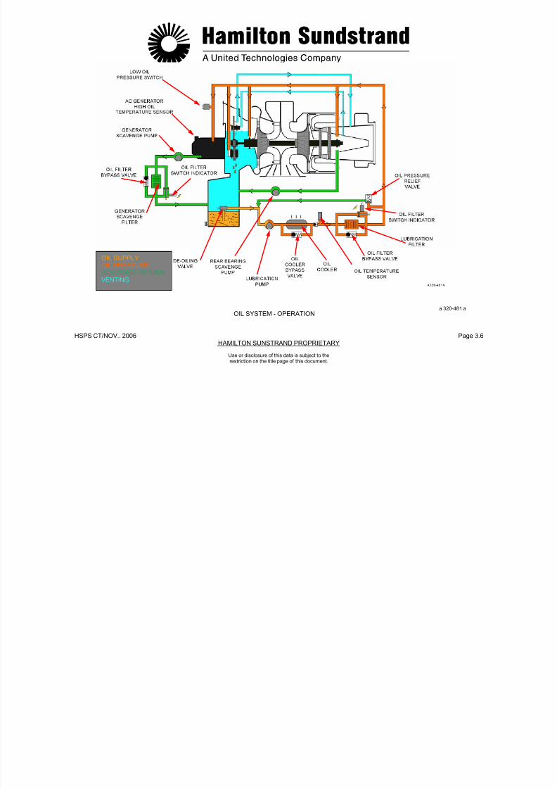
OIL SYSTEM – OPERATION
The main functions of the oil system are : oil supply, scavengereturn, venting and indicating.
Oil Supply
The lubrication pump draws the oil from the sump and delivers it to
the oil system. During starting, the de-oiling valve opens and air isdrawn into the pump to prevent oil flow. After de-oiling the oil flows tothe oil cooler, then to the filter.In the event oil flow through the filter becomes restricted, the switchindicator is activated. If the filter becomes blocked, the oil filterbypass valve will open and allow flow to the oil system.The oil pressure relief valve opens to regulate the oil systempressure. When the valve is open, some of the oil flow is bypassedback to the inlet side of the lubrication pump.
Scavenge Return
After lubrication, the oil returns to the gearbox sump by twoscavenge pumps:- One for the power section rear bearing that returns the oil directly
to the sump- One for the AC generator that returns the oil to the sump through a
filter.Note: The front bearing and the gearbox are scavenged by gravity.
Scavenge Return
After lubrication, the oil returns to the gearbox sump by twoscavenge pumps:
-One for the power section rear bearing that returns the oil directly tothe sump
One for the AC generator that returns the oil to the sump through afilter.
Note: The front bearing and the gearbox are scavenged by gravity.
Venting
Oil mist in the gearbox is separated by a centrifugal air-oil separator.
The gearbox is vented to the exhaust through an external pipe.
Monitoring-Low oil pressure switch-High oil temperature sensor- AC generator high oil temperature sensor- Oil filter impending blockage switch indicators- Oil level sensor- Oil level sight glass- Magnetic drain plug
7/21/2019 Aps 3200 Training
http://slidepdf.com/reader/full/aps-3200-training 89/739
V
HSPS CT/NOV.. 2006 Page 3.6HAMILTON SUNSTRAND PROPRIETARY
Use or disclosure of this data is subject to therestriction on the title page of this document.
OIL SYSTEM - OPERATION
OIL SUPPLYOIL PRESSURESCAVENGE RETURN VENTING
a 320-481 aOIL SYSTEM - OPERATION

7/21/2019 Aps 3200 Training
http://slidepdf.com/reader/full/aps-3200-training 90/739
HSPS CT/NOV.. 2006 Page 3.7HAMILTON SUNSTRAND PROPRIETARY
Use or disclosure of this data is subject to therestriction on the title page of this document.
ENGINE LUBRICATION (1)
Lubrication is required for the AC generator, the gearbox and the APU bearings.
AC Generator Lubricat ion and Cool ing
Oil Supply
From the lubrication pump and filter, the oil is supplied to the ACgenerator:
- One flow for cooling
- A second flow to lubricate the generator drive shaft splines.
Scavenge and Return
The oil from the AC generator is scavenged by a pump and returnedto the gearbox sump through a filter.
Gearbox Lubrication
Oil Supply
The oil flowing from the lubrication pump passes through the filterand then by means of internal lines and jets is sprayed onto thegears and bearings.
From the gearbox the oil is also supplied to the cooling fan bearingsand to the rotor assembly front bearing.
Scavenge and Return
After lubrication the oil returns to the gearbox sump by gravity.

7/21/2019 Aps 3200 Training
http://slidepdf.com/reader/full/aps-3200-training 91/739
HSPS CT/NOV.. 2006 Page 3.8HAMILTON SUNSTRAND PROPRIETARY
Use or disclosure of this data is subject to therestriction on the title page of this document.
ENGINE LUBRICATION (1) AC GENERATOR LUBRICATION
GEARBOX LUBRICATION
AC GENERATORLUBRICATION
AND COOLING
AC GENERATOROIL SCAVENGE
FROM LUBRICATIONPUMP
FROM LUBRICATIONPUMP
DE-OILED AIR TO
EXHAUST
DE-OILED AIR TO
EXHAUST
AC GENERATORDRIVE SHAFT SPLINELUBRICATION
SPRAYJETS
TO LUBRICATIONPUMP
TO LUBRICATIONPUMP
OIL RETURNTO SUMP
OIL SUPPLYOIL PRESSURESCAVENGE RETURNVENTING
AC GENERATOR LUBRICATION
a 320-482 a

7/21/2019 Aps 3200 Training
http://slidepdf.com/reader/full/aps-3200-training 92/739
HSPS CT/NOV.. 2006 Page 3.9HAMILTON SUNSTRAND PROPRIETARY
Use or disclosure of this data is subject to therestriction on the title page of this document.
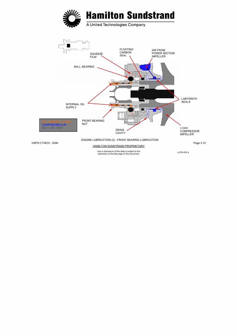
ENGINE LUBRICATION (2)
Front Bearing Lubrication
Oil Supply
The lubrication for the rotor front bearing is provided by pressurized
oil from the gearbox oil system.
A jet located in the gearbox housing sprays oil between the front endof the load compressor shaft and the front bearing nut. (PhonicWheel)
The oil runs along the shaft, lubricates the quill shaft splines andenters the gap through the split inner races to lubricate the bearing.
Oil flow to the bearing is also provided by oil passages between thegearbox and bearing outer race to provide a squeeze film to dampenbearing vibration.
Scavenge and Return
After lubrication the oil is returned to the sump by gravity.
Sealing
Oil sealing of this assembly is by a floating carbon seal and a
labyrinth seal using air from the power section impeller.
A drain cavity between the seals is vented overboard, into the APUdrainmast.
7/21/2019 Aps 3200 Training
http://slidepdf.com/reader/full/aps-3200-training 93/739
HSPS CT/NOV.. 2006 Page 3.10HAMILTON SUNSTRAND PROPRIETARY
FLOATING AIR FROMCARBONSEAL
POWER SECTIONIMPELLER
SQUEEZEFILM
BALL BEARING
Use or disclosure of this data is subject to therestriction on the title page of this document.
ENGINE LUBRICATION (2) - FRONT BEARING LUBRICATION
INTERNAL OILSUPPLY
FRONT BEARINGNUT
DRAINCAVITY
LOADCOMPRESSORIMPELLER
LABYRINTHSEALS
a 320-452 a
OIL PRESSURE SPRAYCOMPRESSED AIRSEA L AIR VENT
ENGINE LUBRICATION (3)
7/21/2019 Aps 3200 Training
http://slidepdf.com/reader/full/aps-3200-training 94/739
HSPS CT/NOV.. 2006 Page 3.11HAMILTON SUNSTRAND PROPRIETARY
Use or disclosure of this data is subject to therestriction on the title page of this document.
ENGINE LUBRICATION (3)
Rear Bearing Lubr ication
Oil Supply
The lubrication of the rotor rear bearing is provided by pressurized oilfrom the gearbox oil system.
The oil is supplied to the rear bearing through an external pipe.
In the bearing area, the oil is directed to the outer race to provide asqueeze film and an internal line that sprays oil into the rear tie-boltarea.
Drilled passages in the tie-bolt allow oil circulation for lubrication andcooling of the roller bearing.
Scavenge and Return
After lubrication, the oil is scavenged back to the sump through anexternal pipe by a scavenge pump.
Sealing
Oil sealing in the bearing area is accomplished by a floating carbonseal and a rotating labyrinth seal. The seals are pressurized with airflow from the power section impeller.

7/21/2019 Aps 3200 Training
http://slidepdf.com/reader/full/aps-3200-training 95/739
HSPS CT/NOV. 2006 Page 3.12HAMILTON SUNDSTRAND PROPRIETARY
OIL SUPPLY
TIEBOLT
SQUEEZEFILM
SECOND STAGETURBINE WHEEL
Use or disclosure of this data is subject to therestriction on the title page of this document.
ENGINE LUBRICATION (3) - REAR BEARING LUBRICATION
a 320-453 a
ROTATINGLABYRINTHSEAL
ROLLER
BEARING
AIR FROMPOWER SECTIONIMPELLER
FLOATINGCARBONSEAL
OIL PRESSUREOIL RETURNCOMPRESSOR AIR
7/21/2019 Aps 3200 Training
http://slidepdf.com/reader/full/aps-3200-training 96/739
HSPS CT/NOV. 2006 Page 3.13HAMILTON SUNDSTRAND PROPRIETARY
Use or disclosure of this data is subject to therestriction on the title page of this document.
OIL SUMP
Function
The sump provides a reservoir for the APU lubrication system.
Location
The sump is located in the bottom of the gearbox.
Main Features
- Capacity at the "FULL" mark: 5.4 litters (5.72 Qts)
- Capacity at the "ADD" mark: 3.95 litters (4.16 Qts)
Main Components
The main components of the oil sump are:
- Oil filler tube
- Oil overflow boss
- Oil pressure fill port
- Air-oil separator
- Magnetic drain plug
- Pressure relief valve
- Oil level sensor
- Oil level sight glass.
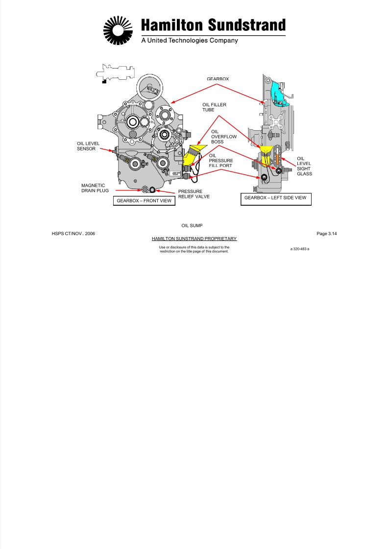
7/21/2019 Aps 3200 Training
http://slidepdf.com/reader/full/aps-3200-training 97/739
HSPS CT/NOV.. 2006 Page 3.14HAMILTON SUNSTRAND PROPRIETARY
GEARBOX
OIL FILLERTUBE
OILOVERFLOWBOSS
Use or disclosure of this data is subject to therestriction on the title page of this document.
OIL SUMP
OIL LEVELSENSOR
MAGNETICDRAIN PLUG PRESSURE
RELIEF VALVE
OILPRESSUREFILL PORT
OILLEVELSIGHTGLASS
GEARBOX – LEFT SIDE VIEWGEARBOX – FRONT VIEW
a 320-483 a

7/21/2019 Aps 3200 Training
http://slidepdf.com/reader/full/aps-3200-training 98/739
HSPS CT/NOV. 2006 Page 3.15HAMILTON SUNDSTRAND PROPRIETARY
Use or disclosure of this data is subject to therestriction on the title page of this document.
AIR-OIL SEPARATOR
Function
The air-oil separator separates the oil from the air.
Location
The air-oil separator is located in the upper part of the gearbox.
Description
The air-oil separator is part of the gearbox intermediate gear.
The gear has a hollow shaft with radial drillings. The rear of thehollow shaft vents into a passage in the gearbox housing.
Operation
An air-oil mist is created in the gearbox when the APU is operating.
The oil is separated from the air by the rotating action of the gearboxintermediate gear. The oil returns to the gearbox sump by gravityand the air is vented through a pipe to the APU exhaust.

7/21/2019 Aps 3200 Training
http://slidepdf.com/reader/full/aps-3200-training 99/739
HSPS CT/NOV.. 2006 Page 3.16HAMILTON SUNSTRAND PROPRIETARY
Use or disclosure of this data is subject to therestriction on the title page of this document.
AIR-OIL SEPARATOR
INTERMEDIATEGEAR
AIR-OILSEPERATOR
OIL RETURNTO SUMP
OIL MISTDE-OILED
AIR
TO APUEXHAUST
OIL RETURN
TO SUMP
AIR – OIL SEPERATOR
OIL PUMPS - GENERAL OIL PUMPS - DESCRIPTION

7/21/2019 Aps 3200 Training
http://slidepdf.com/reader/full/aps-3200-training 100/739
HSPS CT/NOV. 2006 Page 3.17HAMILTON SUNDSTRAND PROPRIETARY
Use or disclosure of this data is subject to therestriction on the title page of this document.
Function
One pump is used for the lubrication supply and two pumps forscavenge.LocationThe oil pumps are located inside the gearbox front face.
Main Features- Lubrication pump
• Type: Vane type• Flow: 2160 l/h (570 GPH)
- AC generator scavenge pump• Type: Vane type pump• Flow: 2160 l/h (570 GPH)
- Rear bearing scavenge pump• Type: Gerotor type pump
• Flow: 160 l/h (42 GPH)
Gerotor Type
The gerotor is a positive displacement pumping unit consisting of twoelements: an inner and outer rotor.The inner rotor has one less tooth than the outer, and has itscenterline positioned at a fixed eccentricity from the centerline of the
outer element.The inner element is driven by the gearbox.Vane TypeThe vane type pump consisting of a slotted inner rotor equipped withvanes operating in an eccentric housing.Operation of the Pressure Relief ValveThe oil pressure relief valve is a non adjustable, spring loaded reliefvalve.The valve will open when oil pressure reaches 345-414 kPag (50-60
PSIG). The oil that is bypassed, returns to the inlet of the lubricationpump.
AC GENERATOR
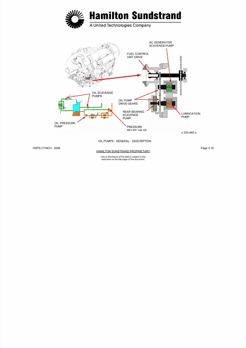
7/21/2019 Aps 3200 Training
http://slidepdf.com/reader/full/aps-3200-training 101/739
HSPS CT/NOV.. 2006 Page 3.18HAMILTON SUNSTRAND PROPRIETARY
AC GENERATORSCAVENGE PUMP
FUEL CONTROLUNIT DRIVE
Use or disclosure of this data is subject to therestriction on the title page of this document.
OIL PUMPS - GENERAL - DESCRIPTION
OIL SCAVENGE
PUMPS
OIL PRESSURE
PUMP PRESSURERELIEF VALVE
OIL PUMPDRIVE GEARS
REAR BEARINGSCAVENGEPUMP
LUBRICATIONPUMP
a 320-485 a

7/21/2019 Aps 3200 Training
http://slidepdf.com/reader/full/aps-3200-training 102/739
HSPS CT/NOV. 2006 Page 3.19HAMILTON SUNDSTRAND PROPRIETARY
Use or disclosure of this data is subject to therestriction on the title page of this document.
DE-OILING VALVEFunction
The de-oiling valve reduces the APU starting lead during startconditions.
Location
The valve is located on the left side of the gearbox.
Main Features
- Solenoid valve operated by the ECB
- Nominal rating: 28 VDC; 1.0 amps
- Solenoid valve energized open.
Description
The de-oiling valve is a solenoid operated valve directly controlled bythe ECB.
Operation
During the APU start up the de-oiling valve is energized open by theECB. When the valve is open the lubrication pump is prevented frompumping oil into the system. This reduces the starting load of the
APU and allows faster acceleration.
When the APU accelerates to 55% speed, the ECB de-energizes thede-oiling valve and allows the lubrication pump to produce oil flow.
During shutdown, the de-oiling valve is again energized by the ECBwhen the APU de-accelerates to 90% speed. This allows the oilremaining in the system to return to the oil sump with the exceptionof one quart remaining in the oil cooler.

7/21/2019 Aps 3200 Training
http://slidepdf.com/reader/full/aps-3200-training 103/739
HSPS CT/NOV.. 2006 Page 3.20HAMILTON SUNSTRAND PROPRIETARY
Use or disclosure of this data is subject to therestriction on the title page of this document.
DE-OILING SYSTEM
DE-OILING VALVE
AIR
GEARBOX LEFT SIDE
TOOIL
OIL SUMPCOOLER
OILFROM
TOLUBRICATION
PUMP
AIR
SUMPDE-OILING VALVE
a 320-486a
DE – OILING SYSTEM
OIL FILTERS - GENERAL OIL FILTERS - DESCRIPTION
7/21/2019 Aps 3200 Training
http://slidepdf.com/reader/full/aps-3200-training 104/739
HSPS CT/NOV. 2006 Page 3.21HAMILTON SUNDSTRAND PROPRIETARY
Use or disclosure of this data is subject to therestriction on the title page of this document.
Function
The function of the oil filters is to filter the oil.
There are two filters: one for lubrication and one for the AC generatorscavenge. They are the same type of filter.
Location
The lubrication filter is located in the pressure line after the oil cooler.The scavenge filter is located after the AC generator scavengepump.
Both filters are installed at the bottom front face of the gearbox.
Main Features
- Filter element: 20 microns
- By-pass valve setting: 345-414 kPad (50-60 PSID)
- Switch indicator setting: 207-241 kPad (30-35 PSID).
Each filter system consists of:
- A 20 micron disposable cartridge
- An oil filter impending blockage switch indicator
- A by-pass valv
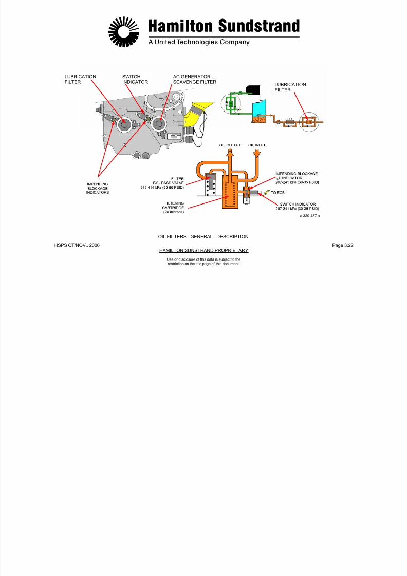
7/21/2019 Aps 3200 Training
http://slidepdf.com/reader/full/aps-3200-training 105/739
HSPS CT/NOV.. 2006 Page 3.22HAMILTON SUNSTRAND PROPRIETARY
LUBRICATIONFILTER
SWITCHINDICATOR
AC GENERATORSCAVENGE FILTER
Use or disclosure of this data is subject to therestriction on the title page of this document.
OIL FILTERS - GENERAL - DESCRIPTION
LUBRICATIONFILTER
a 320-487 a

7/21/2019 Aps 3200 Training
http://slidepdf.com/reader/full/aps-3200-training 106/739
HSPS CT/NOV. 2006 Page 3.23HAMILTON SUNDSTRAND PROPRIETARY
Use or disclosure of this data is subject to therestriction on the title page of this document.
OIL FILTER - OPERATION
Oil Flow
In normal operation the oil is filtered and then flows to the oil system.
Pre-blockage of the Oil Filters
Should the filter become contaminated, a difference in pressureacross the filter will occur.
Two switch indicators are mounted on the front of the gearbox neareach oil filter. The switch indicator provides a visual indication whenthe oil temperature is 74°C (165°F) and the oil pressure across thefilter reaches 241 kPad (30-35 PSID). The ECB also monitors eachswitch indicator and will store the fault message.
By-pass
When the differential pressure across the filter exceeds 345 to 414kPad (50 to 60 PSID), the by-pass valve will open and allowunfiltered oil to flow into the system.
The by-pass valve is located in the gearbox and is non-adjustable.
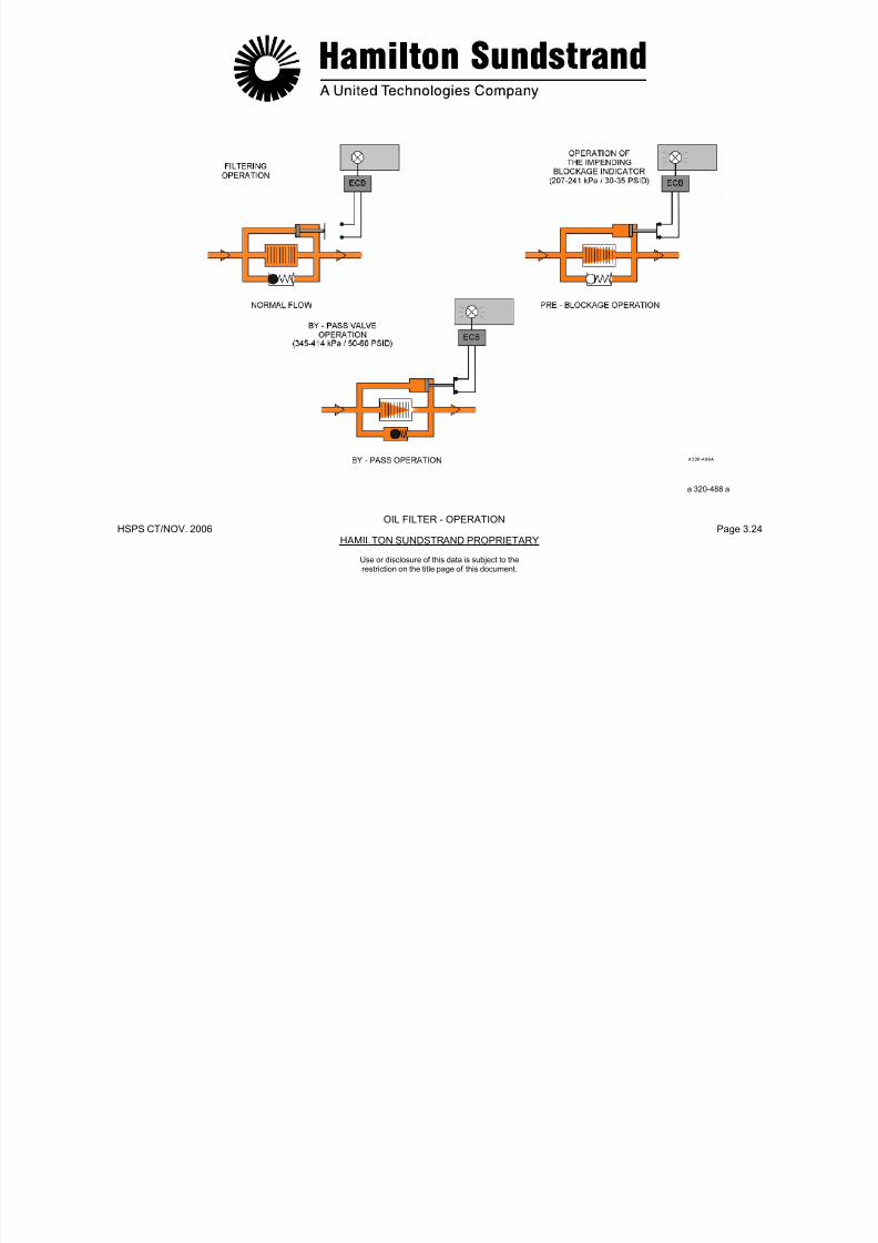
7/21/2019 Aps 3200 Training
http://slidepdf.com/reader/full/aps-3200-training 107/739
HSPS CT/NOV. 2006 Page 3.24HAMILTON SUNDSTRAND PROPRIETARY
Use or disclosure of this data is subject to therestriction on the title page of this document.
OIL FILTER - OPERATION
a 320-488 a
OIL FILTER - OPERATION
OIL COOLER - GENERAL OIL COOLER - DESCRIPTION
7/21/2019 Aps 3200 Training
http://slidepdf.com/reader/full/aps-3200-training 108/739
HSPS CT/NOV.. 2006 Page 3.25HAMILTON SUNSTRAND PROPRIETARY
Use or disclosure of this data is subject to therestriction on the title page of this document.
Function
The oil cooler transfers the heat of the lubr icating oil to the airflowing through the cooler.
Location
The oil cooler is installed on the left side of the APU.
In the oil system, the cooler is located between the lubrication pumpand the filter.
Main Features
- Oil cooling ability: 2160 l/h (540 GPH)
- Oil cooler by-pass valve setting:
• Opening threshold: 207 kPad (30 PSID)
• Fully open: 345 kPad (50 PSID).
The oil cooler is a rectangular unit which includes:
- An oil cooler housing which consists of an integrally brazedaluminum heat-exchanger with an aluminum core and a stainlesssteel housing.
- A check valve and a by-pass valve to regulate the oil flow and
internal pressure of the oil cooler.A drain plug to drain theoil cooler
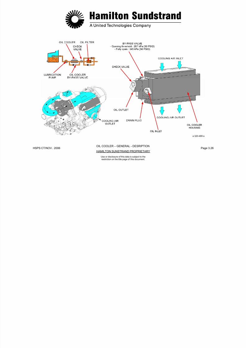
7/21/2019 Aps 3200 Training
http://slidepdf.com/reader/full/aps-3200-training 109/739
HSPS CT/NOV.. 2006 Page 3.26HAMILTON SUNSTRAND PROPRIETARY
OIL COOLER – GENERAL - DESRIPTION
a 320-489 a
Use or disclosure of this data is subject to therestriction on the title page of this document.
OIL COOLER - OPERATION

7/21/2019 Aps 3200 Training
http://slidepdf.com/reader/full/aps-3200-training 110/739
HSPS CT/NOV.. 2006 Page 3.27HAMILTON SUNSTRAND PROPRIETARY
Use or disclosure of this data is subject to therestriction on the title page of this document.
Normal Operation
The oil delivered by the lubrication pump flows through the aluminumcooling tubes that are cooled by the cooling fan air flow.
The cooled oil then flows to the various APU lubrication points.
By-pass Operation
When the pressure exceeds 207 kPad (30 PSID), the bypass valveopens.
The oil flow by-passes the cooler to the lubrication system.
Check Valve Operation
The check valve is an oil pressure operated valve.
When the pressure in the oil system is low (de-oiling during start andshutdown), the check valve closes and prevents draining of the oilcooler into the sump.
The check valve traps approximately one quart of oil in the oil cooler
when the APU is not running.
Air Flow
The oil cooler uses the airflow from the cooling fan to remove heatfrom the oil. The heated air is then discharged overboard through anair duct located in the left APU compartment service door.
COOLING AIRINLET
COOLING AIRINLET

7/21/2019 Aps 3200 Training
http://slidepdf.com/reader/full/aps-3200-training 111/739
HSPS CT/NOV.. 2006 Page 3.28HAMILTON SUNSTRAND PROPRIETARY
Use or disclosure of this data is subject to therestriction on the title page of this document.
OIL COOLER - OPERATION
OIL FLOW AIR FLOW
NORMAL
OPERATION
BY-PASSOPERATION
CHECKVALVE
OILOUTLET
OILOUTLET
CHECKVALVE
OIL FLOWRESTRICTION
OILINLET
OILINLET
BY-PASSVALVE CLOSED
BY-PASSVALVE OPEN
a 320-490 a
MONITORING DEVICES - LOW OIL PRESSURE SWITCHGeneral

7/21/2019 Aps 3200 Training
http://slidepdf.com/reader/full/aps-3200-training 112/739
HSPS CT/NOV.. 2006 Page 3.29HAMILTON SUNSTRAND PROPRIETARY
Use or disclosure of this data is subject to therestriction on the title page of this document.
Function
The Low Oil Pressure (LOP) switch senses the pressuredownstream of the filter.
The LOP switch initiates automatic APU shut down when the oilpressure is too low.
Location
The LOP switch is mounted on the right side of the air inlet plenumor on the lower right side of the gearbox
Main Features
- LOP switch setting: 241 kPag (35 PSIG)
- Output signal to ECB: ground signal.
Interfaces
- The ECB
- The APU oil system.
Functional Description
The LOP switch consists of a normally closed switch and is openwhen normal oil pressure is present.
The ECB does not check for oil pressure until the APU has reacheda speed of 100% (RTL) plus 10 seconds.
If oil pressure is below 241 kPag (35 PSIG), and the APU isoperating at 100% speed, the APU will shut down after running for10 seconds.
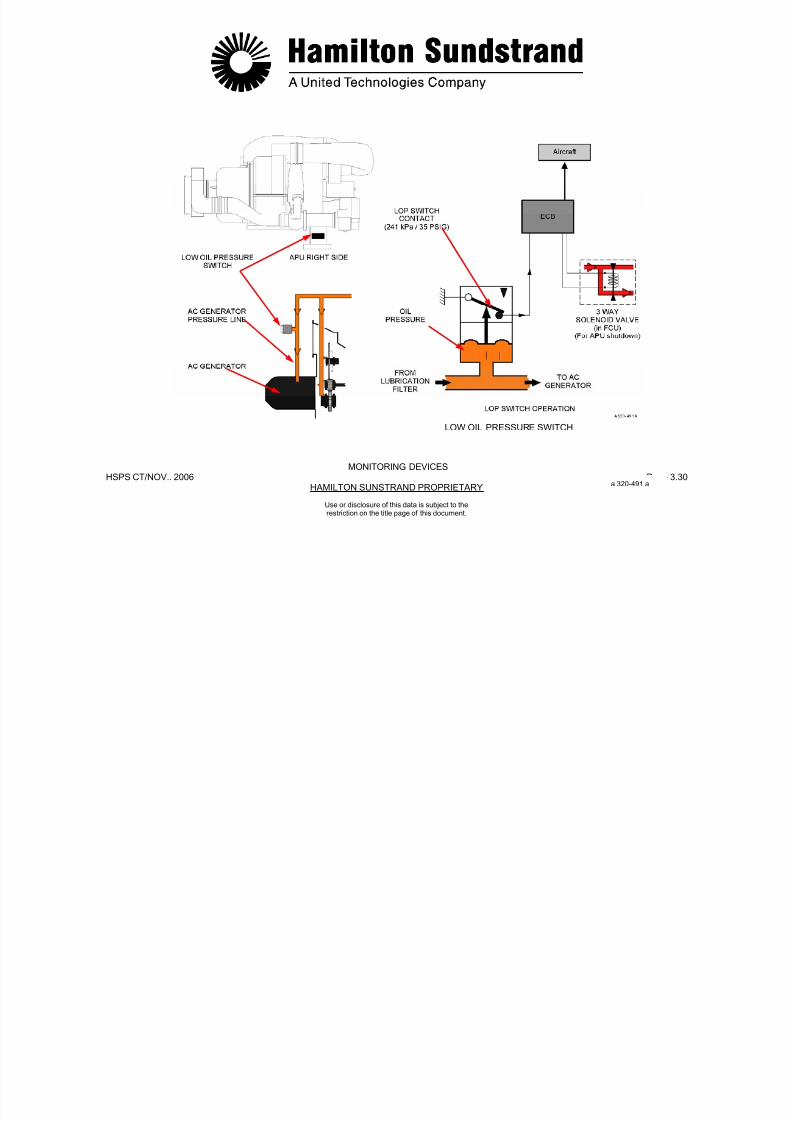
7/21/2019 Aps 3200 Training
http://slidepdf.com/reader/full/aps-3200-training 113/739
HSPS CT/NOV.. 2006 Page 3.30HAMILTON SUNSTRAND PROPRIETARY
LOW OIL PRESSURE SWITCH
MONITORING DEVICES
a 320-491 a
Use or disclosure of this data is subject to therestriction on the title page of this document.
MONITORING DEVICES - OIL TEMPERATURE SENSOR
General Functional Description
7/21/2019 Aps 3200 Training
http://slidepdf.com/reader/full/aps-3200-training 114/739
HSPS CT/NOV.. 2006 Page 3.31HAMILTON SUNSTRAND PROPRIETARY
Use or disclosure of this data is subject to therestriction on the title page of this document.
General
Function
The Oil Temperature (HOT) sensor senses the temperature of the oilat the outlet of the oil cooler. When the oil temperature is too high,
the HOT sensor initiates automatic APU shut down.
Location
The HOT sensor is installed on the lower rear face of the gearbox.
Main Features
- HOT sensor setting: 135° C (275° F)
- Sensor input signal (from ECB): 1 mA
- Sensor output signal (to ECB): variable output voltage
- 100 Ω RTD; 1 mA; 19°C to 149°C (67°F to 300°F.)
Interfaces
- The ECB
- The APU oil system.
Functional Description
The HOT sensor is a Resistive Temperature Device (RTD) suppliedwith a constant current of 1 mA (by the ECB). The resistance varieswith the oil temperature and modifies the sensor output voltage.
When the oil temperature reaches a limit value of approximately135°C (275°F), the ECB will initiate automatic APU shut down.
Note: The AC generator also has an integral oil temperaturesensor which causes the APU to shut down when anexcessive temperature is detected (180°C; 365°F). Thesensor is monitored by the ECB.
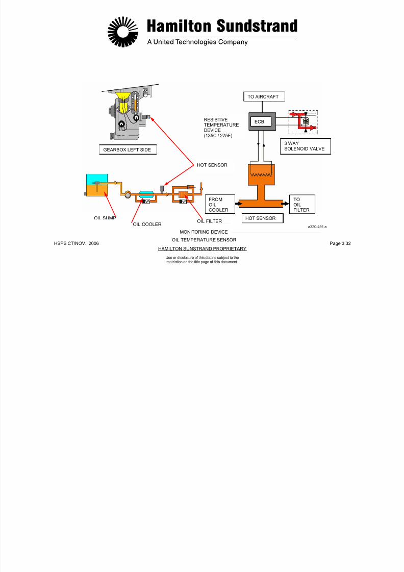
7/21/2019 Aps 3200 Training
http://slidepdf.com/reader/full/aps-3200-training 115/739
HSPS CT/NOV.. 2006 Page 3.32HAMILTON SUNSTRAND PROPRIETARY
ECB
TO AIRCRAFT
RESISTIVETEMPERATUREDEVICE(135C / 275F)
Use or disclosure of this data is subject to therestriction on the title page of this document.
MONITORING DEVICE
a320-491 a
3 WAYSOLENOID VALVEGEARBOX LEFT SIDE
HOT SENSOR
OIL SUMP
OIL COOLEROIL FILTER
FROMOIL
COOLER
TOOIL
FILTER
HOT SENSOR
OIL TEMPERATURE SENSOR
MONITORING DEVICES - OIL LEVEL SENSORGeneral Functional Description

7/21/2019 Aps 3200 Training
http://slidepdf.com/reader/full/aps-3200-training 116/739
HSPS CT/NOV.. 2006 Page 3.33HAMILTON SUNSTRAND PROPRIETARY
Use or disclosure of this data is subject to therestriction on the title page of this document.
Function
The oil level sensor measures the quantity of oil in the gearboxsump.
When the oil level is too low, the sensor provides a flight deckwarning of low oil quantity on the lower ECAM, APU systems page.
Location
The oil level sensor is located on the right side of the gearbox.
Main Features
- Sensor input signal (from ECB): 75 mA
- Sensor output signal (to ECB): variable output voltage.
Interfaces
- The ECB
- The APU oil system.
The oil level sensor is a Resistive Temperature Device (RTD) thatthe ECB supplies with a constant current of 75 mA.
The resistance varies with the oil level and changes the sensoroutput voltage sensed by the ECB.
At power up, the oil level is checked for a period of 8 seconds and isdetermined OK or LOW by the ECB.
If the oil level is low, the ECB will display "OIL QTY LOW" messageon the lower ECAM when the APU system page is selected.
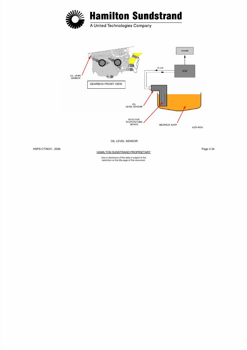
7/21/2019 Aps 3200 Training
http://slidepdf.com/reader/full/aps-3200-training 117/739
HSPS CT/NOV.. 2006 Page 3.34HAMILTON SUNSTRAND PROPRIETARY
MONITORING DEVICES
GEARBOX FRONT VIEW
a320-493a
OIL LEVEL SENSOR
Use or disclosure of this data is subject to the
restriction on the title page of this document.
MONITORING DEVICES
Oil Level Sight Glass
MAGNETIC DRAIN PLUG
A drain plug is located on the lower front side of the gearbox

7/21/2019 Aps 3200 Training
http://slidepdf.com/reader/full/aps-3200-training 118/739
HSPS CT/NOV. 2006 Page 3.35HAMILTON SUNDSTRAND PROPRIETARY
Use or disclosure of this data is subject to the
restriction on the title page of this document.
The oil level sight glass is located on the lower left side of thegearbox housing, close to the oil fill tube.
It provides a visual indication of the oil level in the sump.
Oil level ADD and FULL marks are written on the sight glass.
housing. Removing the plug allows oil drainage from the sump. Thedrain plug embodies a magnetic chip detector that attracts ferrousmetal particles in the oil. The detector can be removed, inspectedand installed without draining the oil sump.
A self sealing valve in the drain plug housing prevents oil drainagewhen the magnetic chip detector is removed.

7/21/2019 Aps 3200 Training
http://slidepdf.com/reader/full/aps-3200-training 119/739
HSPS CT/NOV.. 2006 Page 3.36HAMILTON SUNSTRAND PROPRIETARY
GEARBOXLEFT SIDE
GEARBOXFRONT VIEW
OIL LEVEL SIGHT GLASS MAGNETIC DRAIN PLUG
OIL LEVEL SIGHT GLASS - MAGNETIC CHIP DETECTOR
a320-494aMONITORING DEVICES
Use or disclosure of this data is subject to the
restriction on the title page of this document.
OIL PIPES
External Pipes

7/21/2019 Aps 3200 Training
http://slidepdf.com/reader/full/aps-3200-training 120/739
HSPS CT/NOV.. 2006 Page 3.37HAMILTON SUNSTRAND PROPRIETARY
Use or disclosure of this data is subject to the
restriction on the title page of this document.
Supply
- From lubrication pump, oil cooler and to the gearbox
- From gearbox to power section rear bearing.
Scavenge
- From power section rear bearing to scavenge pump.
Vent
- From power section rear bearing to air-oil separator
- From air-oil separator to APU exhaust system.

7/21/2019 Aps 3200 Training
http://slidepdf.com/reader/full/aps-3200-training 121/739
HSPS CT/NOV.. 2006 Page 3.38HAMILTON SUNSTRAND PROPRIETARY
Use or disclosure of this data is subject to the
restriction on the title page of this document.
OIL PIPES
OIL PRESSURE
OIL SCAVENGEVENT a320-495a
OIL PIPES
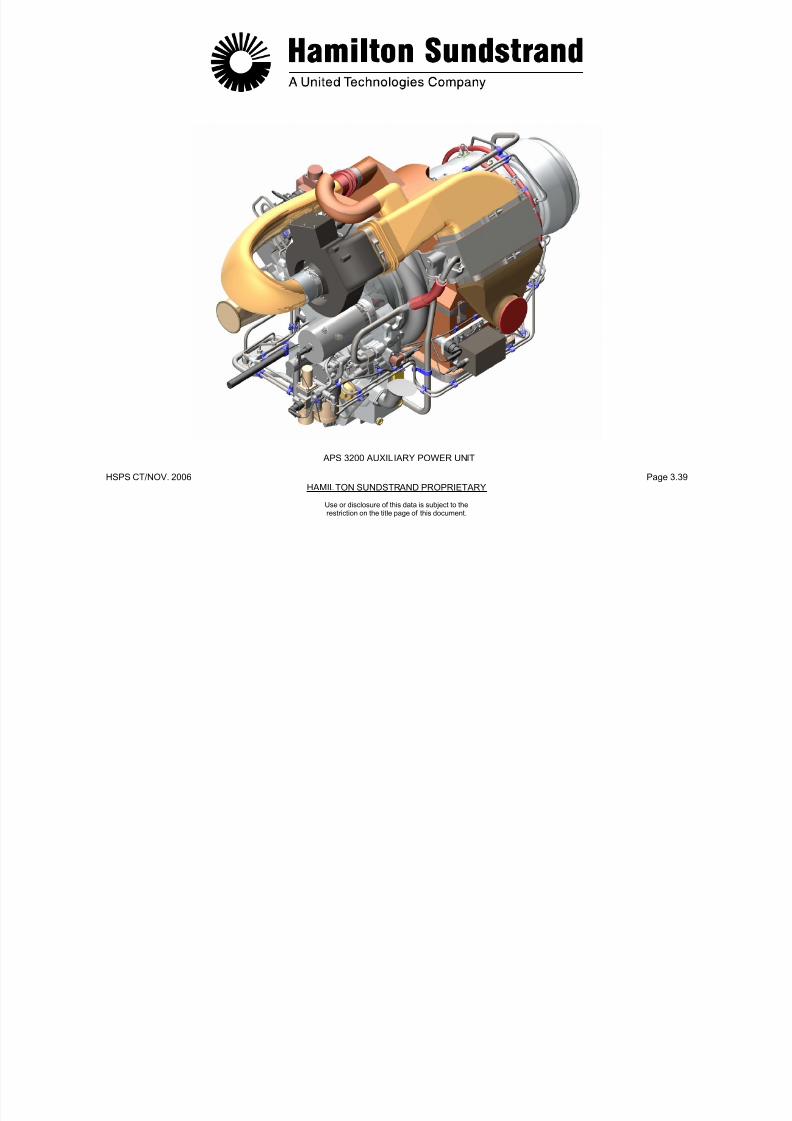
7/21/2019 Aps 3200 Training
http://slidepdf.com/reader/full/aps-3200-training 122/739
HSPS CT/NOV. 2006 Page 3.39HAMILTON SUNDSTRAND PROPRIETARY
APS 3200 AUXILIARY POWER UNIT
Use or disclosure of this data is subject to the
restriction on the title page of this document.

7/21/2019 Aps 3200 Training
http://slidepdf.com/reader/full/aps-3200-training 123/739
HSPS CT/NOV..2006 Page 4.0HAMILTON SUNDSTRAND PROPRIETARY
APS 3200 AUXILIARY POWER UNIT
SECTION 4
FUEL SYSTEM
Use or disclosure of this data is subject to the
restriction on the title page of this document.
FUEL SYSTEM - GENERAL
Function Components Location

7/21/2019 Aps 3200 Training
http://slidepdf.com/reader/full/aps-3200-training 124/739
HSPS CT/NOV..2006 Page 4.1HAMILTON SUNDSTRAND PROPRIETARY
Use or disclosure of this data is subject to the
restriction on the title page of this document.
The fuel system provides the supply and the control of fuel to the APU under all operating conditions.
Systems Involved
- The aircraft fuel system
- The pneumatic system
- The APU control system
- The APU fuel system.
APU Fuel System Main Components
- Fuel control unit
- Flow divider
- Pilot fuel manifold and injectors
- Main fuel manifold and injectors.
- The fuel control unit is located on the front face of the gearbox
- The flow divider is located on the combustor housing
- The fuel manifolds and injectors are located on the combustorhousing.

7/21/2019 Aps 3200 Training
http://slidepdf.com/reader/full/aps-3200-training 125/739
HSPS CT/NOV.. 2006 Page 4.2HAMILTON SUNDSTRAND PROPRIETARY
Use or disclosure of this data is subject to the
restriction on the title page of this document.
FUEL SYSTEM - GENERAL
FUEL SUPLYUN-METERED FUELMETERED FUELFUEL RETURN
FUEL SYSTEM - DESCRIPTION
The system consists of a fuel control unit, a flow divider and fuel
7/21/2019 Aps 3200 Training
http://slidepdf.com/reader/full/aps-3200-training 126/739
HSPS CT/NOV.. 2006 Page 4.3HAMILTON SUNDSTRAND PROPRIETARY
manifolds and injectors.
Fuel Control Unit
The fuel control unit contains the following injector components:
- Low fuel pressure switch (aircraft supplied)
- Low pressure pump (centrifugal type)
- Filter (filter element, by-pass valve and impending blockage ΔPindicator)
- High pressure pump (gear type pump);
- Servo valve (electrically operated valve that meters the fuel flow inresponse to signals from the electronic control box)
- Constant P valve (pressure differential valve that controls thedifferential pressure across the servo valve)
- 3 way solenoid valve (valve operated by the electronic controlbox to open and close the fuel supply to the fuel injectors).
- Pressure regulator (fuel pressure supply to the actuators of theair control system).
Flow Divider
The flow divider controls the flow to the main and pilot injectors. The
divider also provides pilot purge to the exhaust.
Main Fuel Manifold and Injectors
- Manifold to supply fuel to the main injectors
- Main in jectors (six injectors mounted on the combustor housing).
Pilot Fuel Manifold and Injectors
- Manifold to supply fuel to the pilot injectors
- Pilot injectors (three injectors mounted on the combustorhousing).
Use or disclosure of this data is subject to the
restriction on the title page of this document.
INLET GUIDEVANE
HIGHPRESSURE
PRESSUREREGULATOR

7/21/2019 Aps 3200 Training
http://slidepdf.com/reader/full/aps-3200-training 127/739
HSPS CT/NOV.. 2006 Page 4.4HAMILTON SUNDSTRAND PROPRIETARY
Use or disclosure of this data is subject to the
restriction on the title page of this document.
FUEL SYSTEM - DESCRIPTION
ACTUATORFILTERPRESSUREPUMP
SERVOVALVE
FLOWDIVIDER
PILOT FUELMANIFOLD
AND
INJECTORS
PURGE TOEXHAUST
LOW FUELPRESSURESWITCH
MAIN FUELMANIFOLD
ANDINJECTORS
3 WAYSOLENOIDVALVE
LOW PRESSUREPUMP
DRAIN
FUELINLET
FUEL SUPPLY
UN-MTERED FUELMETERED FUELFUEL RETURNFUEL DRAIN
CONSTANTDELTA-P VALVE a320-497a
FUEL SYSTEM - OPERATION (1)Starting
When APU start is selected: During starting, the fuel flow is controlled by the servo valve usingsignals from the ECB

7/21/2019 Aps 3200 Training
http://slidepdf.com/reader/full/aps-3200-training 128/739
HSPS CT/NOV.. 2006 Page 4.5HAMILTON SUNDSTRAND PROPRIETARY
Use or disclosure of this data is subject to the
restriction on the title page of this document.
- The starter motor is energized and cranks the APU rotor assembly
- The ignition exciter operates and supplies high voltage spark to thetwo igniter plugs
- The 3 way solenoid valve is energized open to provide fuel flow tothe injectors
- The servo valve is electrically operated to control the fuel flow.
Fuel from the aircraft fuel system is supplied by the low pressure andhigh pressure pumps through the servo valve and the 3 way solenoidvalve.
When the fuel pressure reaches approximately 138 kPad (20 PSID),the flow divider delivers fuel to the pilot injectors. The fuel injectedinto the combustor is ignited by the ignitor plugs.
When the fuel pressure reaches approximately 1380 kPad (200PSID), the flow divider delivers fuel to the main injectors.
signals from the ECB.
At self-sustaining speed, the starter and the ignition system aredeactivated and the APU accelerates to 100% speed.
The APU is maintained at 100% speed under all load conditions bythe servo valve controlling fuel flow.

7/21/2019 Aps 3200 Training
http://slidepdf.com/reader/full/aps-3200-training 129/739
HSPS CT/NOV.. 2006 Page 4.6HAMILTON SUNDSTRAND PROPRIETARY
Use or disclosure of this data is subject to the
restriction on the title page of this document.
FUEL SYSTEM - OPERATION (1)
STARTING
IGNITION EXCITER ANDIGNITERS OPERATION
TO PILOT INJECTORS
TO MAIN INJECTORS
BY SERVO VALVECONTROLLED BY ECB
FUEL SUPPLY
UN-METERED FUELMETERED FUELFUEL RETURNFUEL DRAIN
a320-498 a
STARTING
FUEL SYSTEM - OPERATION (2)Running Condition
- Stabilized condition
Shut-down
When APU shut-down is initiated (manual or automatic), the ECB de-energizes the 3 way solenoid valve. Fuel flow to the fuel injectors is
7/21/2019 Aps 3200 Training
http://slidepdf.com/reader/full/aps-3200-training 130/739
HSPS CT/NOV.. 2006 Page 4.7HAMILTON SUNDSTRAND PROPRIETARY
Use or disclosure of this data is subject to the
restriction on the title page of this document.
The fuel control unit provides a flow higher than APU fuel flowrequirements. The fuel is metered by the servo valve and iscontrolled by the ECB. The excess fuel is returned to the HP pumpinlet through the constant AP valve and the fuel filter.
- Transient condition
When the load applied to the power section changes, the rotationspeed changes. The ECB senses the change and implements asignal to the servo valve. The fuel flow is metered to keep the rotorspeed constant.
g y jshut off and bypassed back into the fuel system.
One second later the ECB de-energizes the fuel servo valve.
Any fuel remaining in the pilot manifold assembly and fuel injectors ispurged into the exhaust by combustor air pressure.

7/21/2019 Aps 3200 Training
http://slidepdf.com/reader/full/aps-3200-training 131/739
HSPS CT/NOV.. 2006 Page 4.8HAMILTON SUNDSTRAND PROPRIETARY
FUELSUPPLYUN-METERED FUELMETERED FUELFUEL RETURN
FUEL DRAIN
a320-499a
FUEL SYSTEM - OPERATION (2)
Use or disclosure of this data is subject to the
restriction on the title page of this document.
FUEL CONTROL UNIT - GENERAL
Function
The fuel control unit (FCU) supplies and meters fuel to the APU.
Main Components
- Fuel pumps
7/21/2019 Aps 3200 Training
http://slidepdf.com/reader/full/aps-3200-training 132/739
HSPS CT/NOV.. 2006 Page 4.9HAMILTON SUNDSTRAND PROPRIETARY
Use or disclosure of this data is subject to the
restriction on the title page of this document.
( ) pp
The fuel control unit also supplies regulated fuel pressure to the inletguide vane and bleed control valve actuators.
Location
The fuel control unit is mounted on the front face of the gearbox by av-band clamp.
Interfaces
- Aircraft fuel system
- Pneumatic system actuators
- Drain system
- Control system.
Main Features
- Fuel supply by a low pressure pump and a high pressure pump
- Fuel filtering for the high pressure pump.
- Fuel metering by an electronic system (servo valve and electroniccontrol box).
p p
- Filter
- Servo valve
- 3 way solenoid valve
- Pressure regulator.
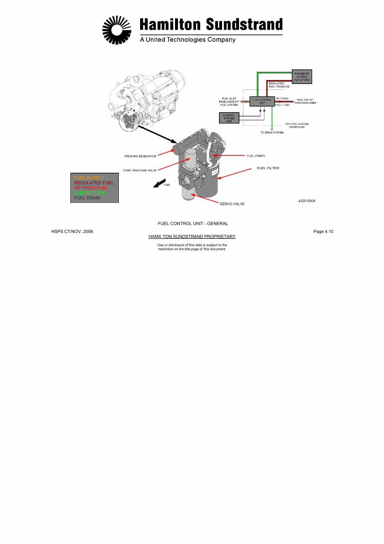
7/21/2019 Aps 3200 Training
http://slidepdf.com/reader/full/aps-3200-training 133/739
HSPS CT/NOV..2006 Page 4.10HAMILTON SUNDSTRAND PROPRIETARY
FUEL FILTER
Use or disclosure of this data is subject to the
restriction on the title page of this document.
FUEL CONTROL UNIT - GENERAL
SERVO VALVE
FUEL SUPPLYREGULATED FUELMETERED FUELFUEL RETURNFUEL DRAIN
a320-500A
FUEL CONTROL UNIT - DESCRIPTION (1)
Components of the Fuel Control Unit
- A low fuel pressure switch located at the FCU fuel inlet (not)
- A pressure regulator that provides a constant pressure to the air
7/21/2019 Aps 3200 Training
http://slidepdf.com/reader/full/aps-3200-training 134/739
HSPS CT/NOV.. 2006 Page 4.11HAMILTON SUNDSTRAND PROPRIETARY
Use or disclosure of this data is subject to the
restriction on the title page of this document.
shown)
- Fuel Pumps
• A low pressure pump (centrifugal type)
• A high pressure pump (gear type) provided with apressure relief valve
- A drain line for the pump shaft seal
- A filter which includes a filter element, a by-pass valve and animpending blockage AP indicator
- A servo valve (electrically operated valve that meters fuel flow inresponse to signals from the electronic control box)
- A constant P valve (a valve that controls the differential pressureacross the servo valve)
- A 3 way solenoid valve (valve operated by the electronic controlbox to open and close fuel flow to the fuel injectors)
system actuators:
• A fuel outlet port (fuel supply to the actuators)
• A fuel return port (fuel return from the actuators)
- A fuel inlet union (connected to the aircraft fuel system)
- An electrical connector (current signals from the electroniccontrol box to the 3 way solenoid valve and the servo valve).
O-rings
Two O-rings are located on the fuel control. One on the fuel controlmounting flange and one on the drive shaft. Both O-rings must beproperly installed or excessive loss of oil will occur when the APU isoperating.
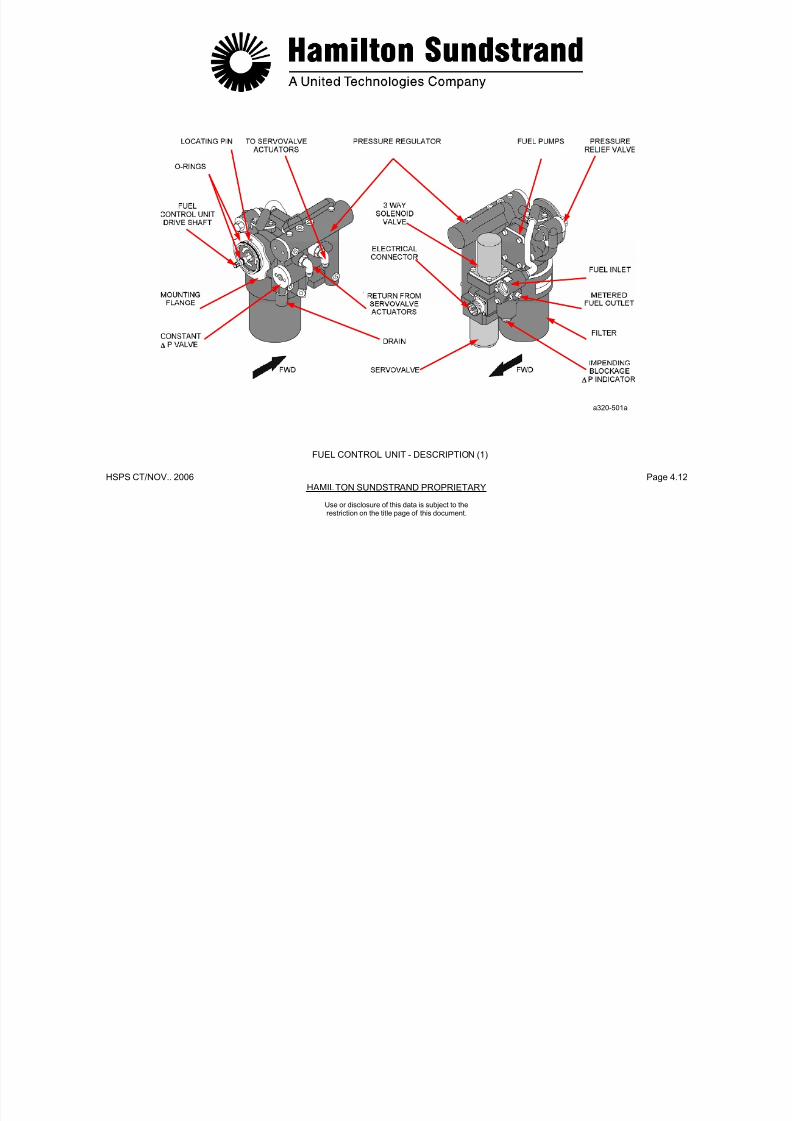
7/21/2019 Aps 3200 Training
http://slidepdf.com/reader/full/aps-3200-training 135/739
HSPS CT/NOV.. 2006 Page 4.12HAMILTON SUNDSTRAND PROPRIETARY
a320-501a
FUEL CONTROL UNIT - DESCRIPTION (1)
Use or disclosure of this data is subject to the
restriction on the title page of this document.
FUEL CONTROL UNIT - DESCRIPTION (2)
Low Pressure Fuel Pump
The low pressure fuel pump provides a positive supply to the inlet ofthe high pressure pump
High Pressure Fuel Pump
The high pressure fuel pump supplies a fuel flow higher than theAPU requirements The excess fuel is returned to the pump inlet
7/21/2019 Aps 3200 Training
http://slidepdf.com/reader/full/aps-3200-training 136/739
HSPS CT/NOV.. 2006 Page 4.13HAMILTON SUNDSTRAND PROPRIETARY
Use or disclosure of this data is subject to the
restriction on the title page of this document.
the high pressure pump.
The pump is mechanically driven at the same speed as the highpressure pump by a splined shaft (driven by the gearbox).
The splined shaft is provided with a seal and a drain line to the drainsystem.
Main Features
- Type: centrifugal
- Rotation speed: 10129 RPM
- Pressure: 550 - 690 kPad (80 - 100 PSID)
- Flow: 182 kg/h (400 lbs/hr) at 550 kPad (80 PSID).
APU requirements. The excess fuel is returned to the pump inlet
through the constant ΔP valve. The pump is also provided with apressure relief valve.
Main Features
- Type: gear type
- Rotation speed: 10129 RPM
- Pressure: 2068 - 4480 kPad (300 - 650 PSID)
- Flow: 727 kg/h (1600 lbs/hr)
- Relief valve setting: > 4480 kPad (> 650 PSID).
Note: - Fuel flow at 7 % N: 20 kg/h (45 lbs/hr)- Fuel pressure at 7 % N: 1379 kPad (200 PSID).
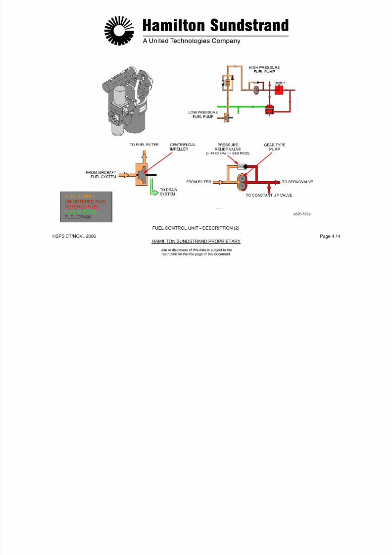
7/21/2019 Aps 3200 Training
http://slidepdf.com/reader/full/aps-3200-training 137/739
HSPS CT/NOV.. 2006 Page 4.14HAMILTON SUNDSTRAND PROPRIETARY
FUEL SUPPLYUN-METERED FUEL
METERED FUELFUEL RETURNFUEL DRAIN
a320-502a
FUEL CONTROL UNIT - DESCRIPTION (2)
Use or disclosure of this data is subject to the
restriction on the title page of this document.
FUEL CONTROL UNIT - DESCRIPTION (3)
Fuel Filter
The filter is located at the outlet of the low pressure pump.

7/21/2019 Aps 3200 Training
http://slidepdf.com/reader/full/aps-3200-training 138/739
HSPS CT/NOV.. 2006 Page 4.15HAMILTON SUNDSTRAND PROPRIETARY
Use or disclosure of this data is subject to the
restriction on the title page of this document.
The filter includes the following components:
- A filter element to filter the fuel
Filter specification: 10 microns
- An impending blockage P indicator to provide a visual warningof a restricted filter
Setting: 48 kPad (7 PSID)
- A by-pass valve to allow the fuel supply in the event of filter
blockage
Setting: 324 kPad (46 + - 4 PSID).
O-ring
An O-ring is located inside the fuel filter cavity of the fuel control unit.The O-ring functions as a seal and a securing device for the filterbowel. The bowel is not secured by any external locking device.

7/21/2019 Aps 3200 Training
http://slidepdf.com/reader/full/aps-3200-training 139/739
HSPS CT/NOV.. 2006 Page 4.16HAMILTON SUNDSTRAND PROPRIETARY
FUEL SUPPLY
UN-METERED FUELMETERED FUELFUEL RETURN
a320-503a
FUEL CONTROL UNIT - DESCRIPTION (3)
Use or disclosure of this data is subject to the
restriction on the title page of this document.
FUEL CONTROL UNIT - DESCRIPTION (4)
Servo Valve
The servo valve meters the fuel during starting and normal operatingconditions.
3 Way Soleno id Valve
The valve opens and closes the fuel supply for operation and shutdown of the APU.
7/21/2019 Aps 3200 Training
http://slidepdf.com/reader/full/aps-3200-training 140/739
HSPS CT/NOV.. 2006 Page 4.17HAMILTON SUNDSTRAND PROPRIETARY
Use or disclosure of this data is subject to the
restriction on the title page of this document.
The valve consists of a torque motor which operates a fuel meteringvalve (clevis type).
The motor is electrically controlled by the ECB. ECB currentoperates the valve to meter fuel flow.
During starting, the servo valve meters fuel flow to accelerate the APU.
In normal operating conditions, the fuel flow is metered to maintain aconstant 100% speed.
The main features of the servo valve are:
- Type: Torque motor
- Current: 0 - 100 mA
- Metered flow: 6 - 198 kg/h (13 - 435 lbs/hr).
The solenoid valve is energized open to supply fuel to the fuelinjectors (control from ECB).
When de-energized, a spring moves the valve to the close position.
When the valve closes, the fuel is shut off to the injectors andbypassed back into the fuel system.
During a normal or auto shutdown of the APU the ECB de-energizesthe 3 way solenoid valve, one second later the servo valve is de-energized.
In the event the 3 way solenoid valve does not close, the APU willshut down when the servo valve is de-energized. If this conditionoccurs, the ECB will store a fault message. (APU FUEL VALVEFAILED OPEN).
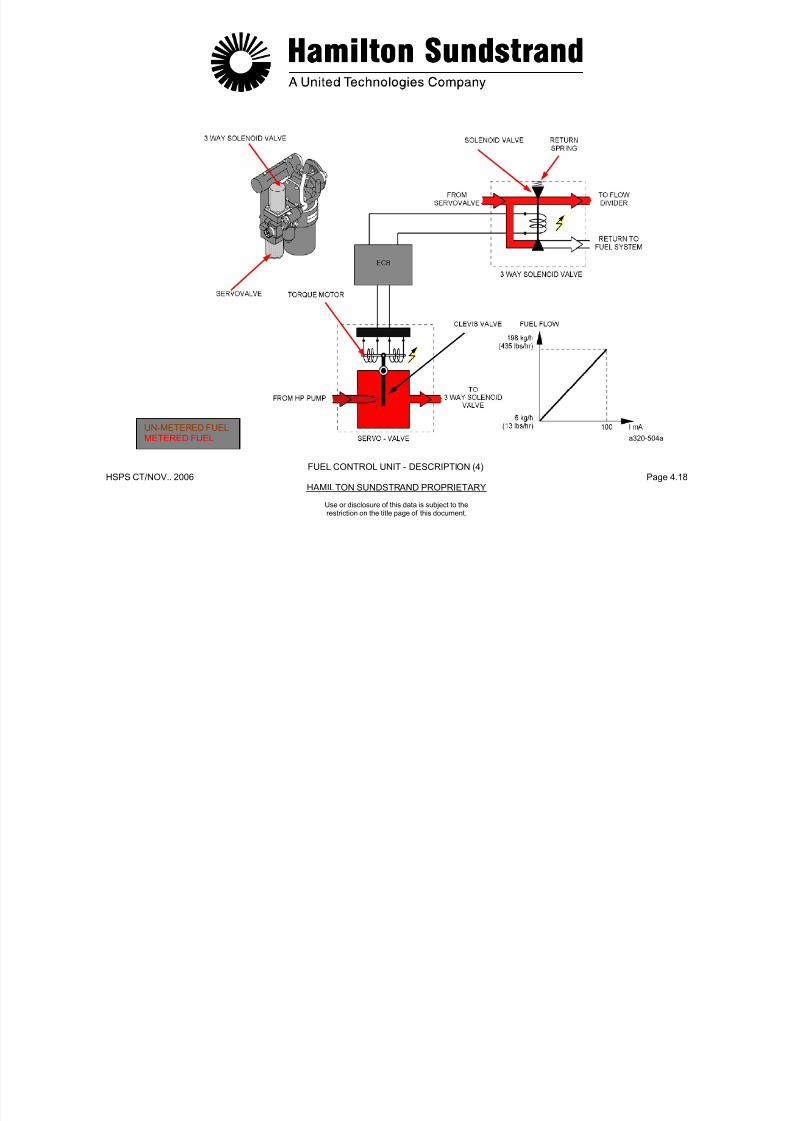
7/21/2019 Aps 3200 Training
http://slidepdf.com/reader/full/aps-3200-training 141/739
HSPS CT/NOV.. 2006 Page 4.18HAMILTON SUNDSTRAND PROPRIETARY
UN-METERED FUELMETERED FUEL a320-504a
FUEL CONTROL UNIT - DESCRIPTION (4)
Use or disclosure of this data is subject to the
restriction on the title page of this document.
FUEL CONTROL UNIT - DESCRIPTION (5)
Constant P Valve
The valve maintains a constant pressure differential across the servovalve.
Pressure Regulator
The pressure regulator provides the fuel pressure supply to the inletguide vane actuator and the bleed control valve actuator. The valvei dj t bl

7/21/2019 Aps 3200 Training
http://slidepdf.com/reader/full/aps-3200-training 142/739
HSPS CT/NOV.. 2006 Page 4.19HAMILTON SUNDSTRAND PROPRIETARY
Use or disclosure of this data is subject to the
restriction on the title page of this document.
The valve senses upstream pressure on one side and downstreampressure plus the force of a spring on the other side. The valve
position determines the amount of fuel to be returned to the fuelsystem.
The ΔP setting of the constant ΔP valve is of 689 kPad (100 PSID)across the servo valve. The valve is non-adjustable.
is non adjustable.
The pressure regulator is closed from 0 to 60% APU speed. When
the speed is above 60%, the regulator will open and deliver 1724KPad (250 PSID) of fuel pressure to the actuators.
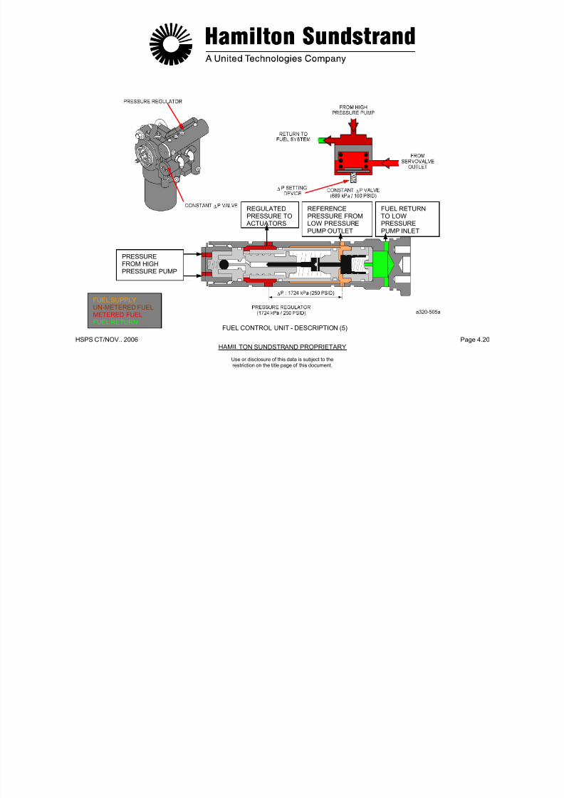
7/21/2019 Aps 3200 Training
http://slidepdf.com/reader/full/aps-3200-training 143/739
HSPS CT/NOV.. 2006 Page 4.20HAMILTON SUNDSTRAND PROPRIETARY
REGULATEDPRESSURE TO
ACTUATORS
REFERENCEPRESSURE FROMLOW PRESSURE
PUMP OUTLET
FUEL RETURNTO LOWPRESSURE
PUMP INLET
PRESSUREFROM HIGHPRESSURE PUMP
FUEL SUPPLYUN-METERED FUELMETERED FUELFUEL RETURN
a320-505a
FUEL CONTROL UNIT - DESCRIPTION (5)
Use or disclosure of this data is subject to the
restriction on the title page of this document.
FLOW DIVIDER - GENERAL
Function
The flow divider distributes fuel from the fuel control unit to the pilotand main injectors. It also provides purging of the pilot injectorsduring APU shut down
Interfaces
- Fuel control unit
Main injector manifold

7/21/2019 Aps 3200 Training
http://slidepdf.com/reader/full/aps-3200-training 144/739
HSPS CT/NOV.. 2006 Page 4.21HAMILTON SUNDSTRAND PROPRIETARY
Use or disclosure of this data is subject to therestriction on the title page of this document.
during APU shut-down.
Location
The flow divider is installed on the left side of the combustor housing.
The flow divider is located downstream of the 3 way solenoid valve.
Main Components
The flow divider consists of two valves:
- A pilot injector and purge valve set at approximately 138 kPad (20PSID) to open.
- A main injector valve set at approximately 1380 kPad (200 PSID)to open.
- Main injector manifold
- Pilot injector manifold
- Exhaust system (purge).
FUELCONTROLUNIT

7/21/2019 Aps 3200 Training
http://slidepdf.com/reader/full/aps-3200-training 145/739
HSPS CT/NOV.. 2006 Page 4.22HAMILTON SUNDSTRAND PROPRIETARY
Use or disclosure of this data is subject to therestriction on the title page of this document.
FLOW DIVIDER - GENERAL
UN-METERED FUELMETERED FUELFUEL RETURNFUEL PURGE
a320-506a
FLOW DIVIDER - DESCRIPTION AND OPERATION
Description
The flow divider consists of:
- Two valves:
Operating
- Starting
When the APU is started, the fuel pressure increases to 138 kPad

7/21/2019 Aps 3200 Training
http://slidepdf.com/reader/full/aps-3200-training 146/739
HSPS CT/NOV.. 2006 Page 4.23HAMILTON SUNDSTRAND PROPRIETARY
Use or disclosure of this data is subject to therestriction on the title page of this document.
Two valves:
• A pilot injector and purge valve set at approx. 138 kPad
(20 PSID)
• A main injector valve set at approx. 1380 kPad (200 PSID)
- A filter screen (located at the fuel inlet)
- Fuel inlet/outlet ports:
• Fuel inlet from the fuel control unit
• Fuel outlet to the pilot manifold
• Fuel outlet to the main manifold
• Fuel outlet to the exhaust system (purge).
When the APU is started, the fuel pressure increases to 138 kPad(20 PSID). The pilot injector valve opens and allows fuel flow to thepilot injectors.
When the pressure reaches 1380 kPad (200 PSID), the maininjector valve opens allowing fuel flow to the main injectors.
- Normal Running Condition
The two valves remain open to allow fuel flow to the pilot injectorsand the main injectors.
- Shut-down
As the fuel pressure decreases, the two valves close. The fuelremaining in the pilot injectors is purged into the exhaust bycombustor air pressure. At this time, a momentary puff of smokemay be viewed coming from the APU exhaust. This is a normaloccurrence.

7/21/2019 Aps 3200 Training
http://slidepdf.com/reader/full/aps-3200-training 147/739
HSPS CT/NOV.. 2006 Page 4.24HAMILTON SUNDSTRAND PROPRIETARY
Use or disclosure of this data is subject to therestriction on the title page of this document.
FLOW DIVIDER - DESCRIPTION AND OPERATION
METERED FUELFUEL PURGE
PILOT FUEL MANIFOLD AND INJECTORS
Function
The pilot manifold delivers fuel from the flow divider to the pilotinjectors during start and normal operation.

7/21/2019 Aps 3200 Training
http://slidepdf.com/reader/full/aps-3200-training 148/739
HSPS CT/NOV.. 2006 Page 4.25HAMILTON SUNDSTRAND PROPRIETARY
Use or disclosure of this data is subject to therestriction on the title page of this document.
It also supplies the pilot fuel injectors with fuel during normal running.
Location
The pilot manifold is mounted around the combustor housing.
Description
The pilot manifold consists of flexible pipes connecting the flowdivider to the three pilot injectors. It is comprised of teflon tubesencased in a single layer of steel braid that is covered with a rubber
sheath.
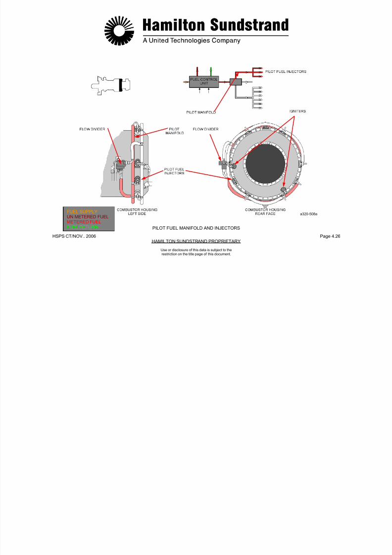
7/21/2019 Aps 3200 Training
http://slidepdf.com/reader/full/aps-3200-training 149/739
HSPS CT/NOV.. 2006 Page 4.26HAMILTON SUNDSTRAND PROPRIETARY
FUEL SUPPLYUN METERED FUELMETERED FUELFUEL RETURN
a320-508a
PILOT FUEL MANIFOLD AND INJECTORS
Use or disclosure of this data is subject to therestriction on the title page of this document.
PILOT FUEL INJECTORS
Type
Simple jet injectors.
Location
Description
A simple jet injector comprises:
- A pilot injector body and mounting flange

7/21/2019 Aps 3200 Training
http://slidepdf.com/reader/full/aps-3200-training 150/739
HSPS CT/NOV.. 2006 Page 4.27HAMILTON SUNDSTRAND PROPRIETARY
Use or disclosure of this data is subject to therestriction on the title page of this document.
The three pilot injectors are installed on the rear of the combustor
housing:
- One at the top (at 12 o'clock)
- Two at the bottom (one at 4 o'clock and one at 8 o'clock)
- A fuel nozzle
- A heat shield
The injector fits into a heat shield that is provided with two air inletholes for cooling.
A gasket between the injector and the combustor housing.
Operation
A continuous flow of fuel is delivered to the combustor by the pilotinjectors and atomized by the fuel nozzles, the fuel is then mixedwith combustor air to maintain the combustion process.
METERED FUELINLET

7/21/2019 Aps 3200 Training
http://slidepdf.com/reader/full/aps-3200-training 151/739
HSPS CT/NOV.. 2006 Page 4.28HAMILTON SUNDSTRAND PROPRIETARY
Use or disclosure of this data is subject to therestriction on the title page of this document.
PILOT FUEL INJECTORS
COMBUSTOR HOUSINGREAR FACE
GASKET
PILOT FUELINJECTOR
a320-509aMETERED FUELCOMBUSTOR AIRCOMBUSTION
MAIN FUEL MANIFOLD AND INJECTORS
Function
The main manifold delivers fuel from the flow divider to the maininjectors.
Location

7/21/2019 Aps 3200 Training
http://slidepdf.com/reader/full/aps-3200-training 152/739
HSPS CT/NOV.. 2006 Page 4.29HAMILTON SUNDSTRAND PROPRIETARY
Use or disclosure of this data is subject to therestriction on the title page of this document.
Location
The main manifold is mounted around the combustor housing.
Description
The main manifold consists of flexible pipes connecting the flowdivider to the six main injectors. It is comprised of teflon tubesencased in a single layer of steel braid that is covered with a rubbersheath.

7/21/2019 Aps 3200 Training
http://slidepdf.com/reader/full/aps-3200-training 153/739
HSPS CT/NOV.. 2006 Page 4.30HAMILTON SUNDSTRAND PROPRIETARY
FUEL SUPPLYREGULATED FUELMETERED FUELFUEL RETURN
a320-510a
MAIN FUEL MANIFOLD AND INJECTORS
Use or disclosure of this data is subject to therestriction on the title page of this document.
MAIN FUEL INJECTORS
Type
Air blast injectors.
Location
Operation
A continuous flow of fuel is delivered to the combustor by the maininjectors. The fuel is atomized by combustor air flowing through theshrouded air passage. The fuel is then mixed with combustor air tomaintain the combustion process.

7/21/2019 Aps 3200 Training
http://slidepdf.com/reader/full/aps-3200-training 154/739
HSPS CT/NOV.. 2006 Page 4.31HAMILTON SUNDSTRAND PROPRIETARY
Use or disclosure of this data is subject to therestriction on the title page of this document.
The six main injectors are located on the combustor housing.
Description
An air blast injector comprises:
- A main injector body and mounting flange
- A fuel injection tube and a shrouded air passage
- A gasket between the injector and the combustor housing.
p
MAIN INJJECTOR
BODY

7/21/2019 Aps 3200 Training
http://slidepdf.com/reader/full/aps-3200-training 155/739
HSPS CT/NOV.. 2006 Page 4.32HAMILTON SUNDSTRAND PROPRIETARY
Use or disclosure of this data is subject to therestriction on the title page of this document.
MAIN FUEL INJECTORS
FUEL INJECTOR
TUBE
GASKET
COMBUSTION SWIRL FLOW
METERED FUELCOMBUSTOR AIRCOMBUSTION
a320-511a
FUEL PIPES
Fuel supp ly
- From the aircraft fuel system to the fuel control unit.
Fuel distribution (pipes located on the APU left side)
Fuel drain (pipe located on the APU left side)
- From the flow divider to the exhaust system.
Fuel drain (pipes located on the APU right side)
7/21/2019 Aps 3200 Training
http://slidepdf.com/reader/full/aps-3200-training 156/739
HSPS CT/NOV.. 2006 Page 4.33HAMILTON SUNDSTRAND PROPRIETARY
Use or disclosure of this data is subject to therestriction on the title page of this document.
- From the fuel control unit to the flow divider
- From the fuel flow divider to:
• The pilot manifold and injectors
• The main manifold and injectors
Fuel distribution (pipes located on the APU right side)
- From the pressure regulator of the fuel control unit to:
• The BCV servo valve (fuel supply and return)
• The IGV servo valve (fuel supply and return).
- From the fuel control unit to the APU drain collector
- From the BCV actuator seals to the APU drain collector
- From the IGV actuator seals to the APU drain collector
- From the combustor housing, air bypass plenum and exhaust pipeto the APU drain collector.
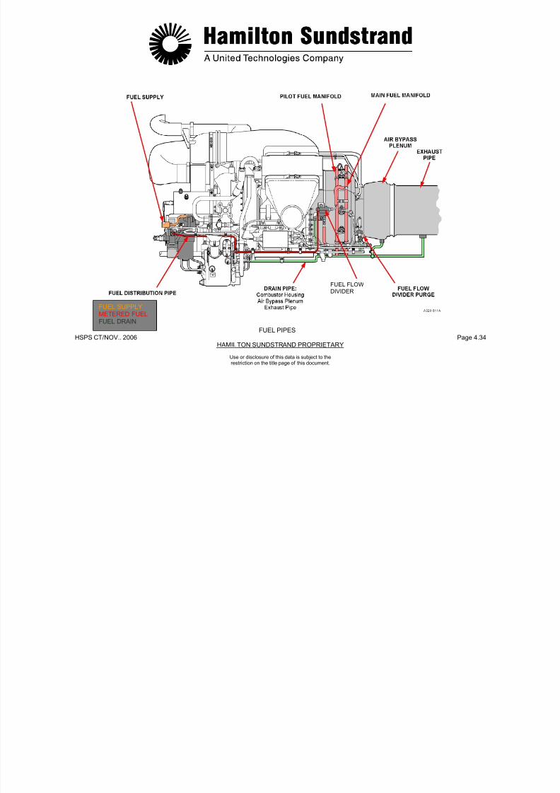
7/21/2019 Aps 3200 Training
http://slidepdf.com/reader/full/aps-3200-training 157/739
HSPS CT/NOV.. 2006 Page 4.34HAMILTON SUNDSTRAND PROPRIETARY
Use or disclosure of this data is subject to therestriction on the title page of this document.
FUEL PIPES
FUEL FLOW
DIVIDER
FUEL SUPPLYMETERED FUELFUEL DRAIN
FUEL SYSTEM INTERFACES
The APU fuel system has several interfaces: aircraft fuel system,pneumatic fuel system, APU control system, APU drain system.
Aircraf t Fuel Sys tem
The APU is supplied with fuel normally from the aircraft left wingtank The aircraft low pressure fuel pump provides fuel to the APU

7/21/2019 Aps 3200 Training
http://slidepdf.com/reader/full/aps-3200-training 158/739
HSPS CT/NOV.. 2006 Page 4.35HAMILTON SUNDSTRAND PROPRIETARY
Use or disclosure of this data is subject to therestriction on the title page of this document.
tank. The aircraft low pressure fuel pump provides fuel to the APU
when the aircraft tank pumps are not operating.
The low pressure valve is controlled by the ECB and is open whenthe APU is operating. The valve is closed when the APU is shutdown normally or by the APU fire switch.

7/21/2019 Aps 3200 Training
http://slidepdf.com/reader/full/aps-3200-training 159/739
HSPS CT/NOV.. 2006 Page 4.36HAMILTON SUNDSTRAND PROPRIETARY
FUEL SUPPLY
REGULATED FUELFUEL DRAIN
a320-513a
FUEL SYSTEM INTERFACES
Use or disclosure of this data is subject to therestriction on the title page of this document.
AIRCRAFT FUEL SYSTEM
The aircraft fuel system supplies fuel to the main engines and APU.
The aircraft fuel system has three main tanks:
- A left tank located inside the left wing
- A center tank located between the two wings
A low fuel pressure warning switch is located at the fuel inlet to thefuel inlet to the fuel control unit. The switch sends a signal to theECB if fuel pressure is too low.
The ECB will display "FUEL LO PR" message on the lower ECAMwhen the APU system page is selected. This requires the APU to beabove 7% speed and the fuel pressure below 109 KPag (15 8 PSIG)

7/21/2019 Aps 3200 Training
http://slidepdf.com/reader/full/aps-3200-training 160/739
HSPS CT/NOV.. 2006 Page 4.37HAMILTON SUNDSTRAND PROPRIETARY
Use or disclosure of this data is subject to therestriction on the title page of this document.
- A center tank located between the two wings
- A right tank located inside the right wing.
Each tank has electric pumps to supply the engines.
A cross feed valve, located between the tanks, connects the leftand right engine supply lines. In normal operation, the cross feedvalve is closed.
The low pressure valve isolates the APU from the fuel supply.
The valve is open when the APU is running. It closes when the APUis shutdown or when the FIRE switch is activated.
The APU low pressure fuel pump is controlled by a pressure switchlocated in the fuel line to the APU. The switch senses fuel tank pumppressure. If the pressure is too low or the fuel tank pumps are turnedoff, the switch will cause the APU low pressure fuel pump to turn on.
above 7% speed and the fuel pressure below 109 KPag (15.8 PSIG).
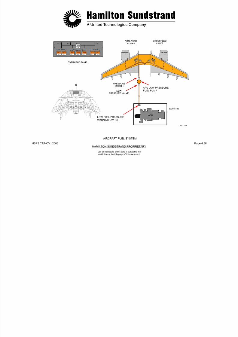
7/21/2019 Aps 3200 Training
http://slidepdf.com/reader/full/aps-3200-training 161/739
HSPS CT/NOV.. 2006 Page 4.38HAMILTON SUNDSTRAND PROPRIETARY
APU LOW PRESSURE
FUEL PUMP
a320-514a
LOW FUEL PRESSURE
WARNING SWITCH
AIRCRAFT FUEL SYSTEM
Use or disclosure of this data is subject to therestriction on the title page of this document.
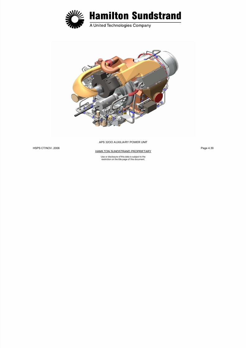
7/21/2019 Aps 3200 Training
http://slidepdf.com/reader/full/aps-3200-training 162/739
HSPS CT/NOV..2006 Page 4.39HAMILTON SUNDSTRAND PROPRIETARY
APS 32OO AUXILIARY POWER UNIT
Use or disclosure of this data is subject to therestriction on the title page of this document.
.
APS 3200AUXILIARY POWER UNIT

7/21/2019 Aps 3200 Training
http://slidepdf.com/reader/full/aps-3200-training 163/739
HSPS CT/NOV.. 2006 Page 5.0HAMILTON SUNDSTRAND PROPRIETARY
AUXILIARY POWER UNIT
SECTION 5
AIR SYSTEM
Use or disclosure of this data is subject to therestriction on the title page of this document.
AIR SYSTEM - GENERAL
Function
The air system provides compressed air to the aircraft on the groundand in flight.
Main Features
Component Location
The inlet guide vane system components are located on the rightupper side of the air inlet housing. The inlet guide vanes arelocated in the air inlet housing ahead of the load compressor air inlet.
The air bleed system components are located on the right lowerside of the load compressor scroll outlet

7/21/2019 Aps 3200 Training
http://slidepdf.com/reader/full/aps-3200-training 164/739
HSPS CT/NOV. 2006 Page 5.1HAMILTON SUNDSTRAND PROPRIETARY
Use or disclosure of this data is subject to therestriction on the title page of this document.
- Flow: 1.2 kg/s (2.6 lbs/sec.)
- Pressure: 289.6 kPag (42 PSIG)
- Temperature: 232°C (450°F).
Main Components
Two systems are considered:
- The inlet guide vane (IGV) system controls the load compressorairflow and prevents EGT overtemperature of the power sectionduring load compressor operation. The inlet guide vanes arecontrolled by the ECB, servo valve, and the IGV actuator.
- The air bleed system delivers airflow from the load compressor tothe aircraft pneumatic system through a bleed control valve (BCV).The valve also functions as an anti-surge valve for the loadcompressor. The BCV is controlled by the ECB, servo valve, and
the BCV actuator.
side of the load compressor scroll outlet.
All the sensors are located on the APU.
Interfaces
- The ECB
- The aircraft pneumatic system
- The APU fuel system.
.
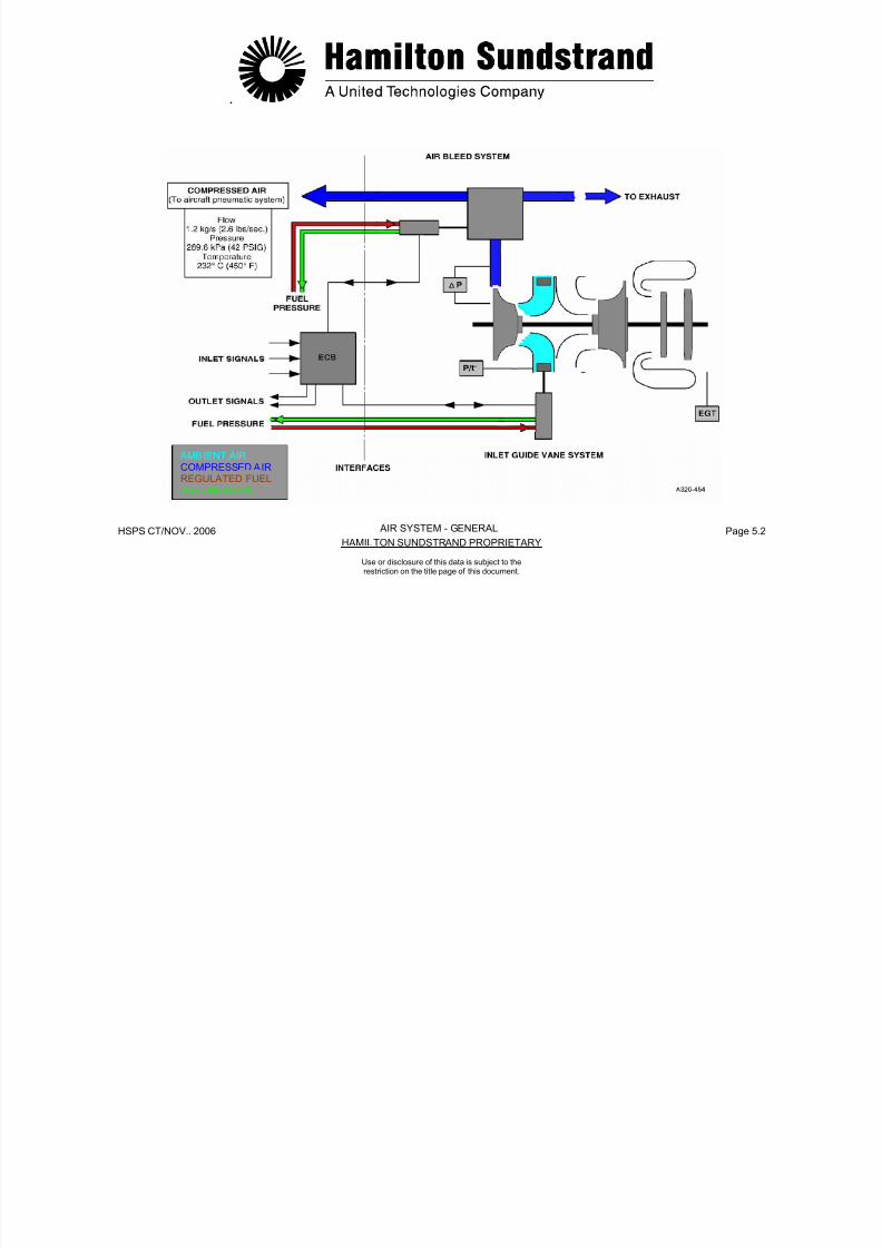
7/21/2019 Aps 3200 Training
http://slidepdf.com/reader/full/aps-3200-training 165/739
HSPS CT/NOV.. 2006 Page 5.2HAMILTON SUNDSTRAND PROPRIETARY
Use or disclosure of this data is subject to therestriction on the title page of this document.
AIR SYSTEM - GENERAL
AMBIENT AIRCOMPRESSED AIRREGULATED FUELFUEL RETURN
AIR SYSTEM - OPERATION
Control of the System
The ECB uses various control signals from the aircraft and the APUsensors to control the inlet guide vanes and the bleed control valve.
Indication

7/21/2019 Aps 3200 Training
http://slidepdf.com/reader/full/aps-3200-training 166/739
HSPS CT/NOV. 2006 Page 5.3HAMILTON SUNDSTRAND PROPRIETARY
Use or disclosure of this data is subject to therestriction on the title page of this document.
The pressure is indicated on the lower ECAM APU system pagedisplay. The pressure is indicated by the load compressor dischargepressure sensor and transmitted to the indicator through the ECB,the ADIRU, the BMC computers in PSIG.
Air Sys tem Operation
The air system operation chart shows IGV and positions duringvarious modes of operation
.
ENGINE BLEED PACK MODE AIRCRAFT IGV BCVSPEED SWITCH MODEL POSITION POSITION
%

7/21/2019 Aps 3200 Training
http://slidepdf.com/reader/full/aps-3200-training 167/739
HSPS CT/NOV.. 2006 Page 5.4HAMILTON SUNDSTRAND PROPRIETARY
0 - ALL CLOSED DISCHARGE72º ( 0)
100 OFF CLOSED - ALL CLOSED DISCHARGE82º ( 0)
100 ON OPEN - ALL OPEN DELIVERY 48º 45º TO 90º
100 ON OPEN ECS A318 OPEN DELIVERY A319 48º TO -30º 90º
A320
100 ON OPEN ECS A321 OPEN DELIVERY48º TO -10º 90º
100 ON CLOSED MES ALL OPEN DELIVERY
-5º 90º
OPERATION CHART
AIR SYSTEM - OPERATION
Use or disclosure of this data is subject to therestriction on the title page of this document.
INLET GUIDE VANE SYSTEM - GENERAL
Function
The inlet guide vane system controls the load compressor air flow toprovide the required flow to the aircraft pneumatic systems.
Main Features
Interfaces-Fuel inlet (fuel pressure)
Fuel outlet (fuel return)
- Fuel drain

7/21/2019 Aps 3200 Training
http://slidepdf.com/reader/full/aps-3200-training 168/739
HSPS CT/NOV. 2006 Page 5.5HAMILTON SUNDSTRAND PROPRIETARY
Use or disclosure of this data is subject to therestriction on the title page of this document.
- Hydraulically operated actuator, controlled by a servo-valve andthe electronic control box.
Components Involved
- The electronic control box (ECB)
- The inlet guide vane (IGV) system components: servo valve,actuator, control mechanism and inlet guide vanes
Components Location
- The servo-valve and actuator form an assembly located on theright upper part of the APU on the air inlet housing.
- The inlet guide vanes and their control mechanism are located inthe air inlet housing.
- Control signal from the ECB to the servo valve
- Position signal from the LVDT (Linear Voltage DifferentialTransducer) to the ECB
- EGT signal from APU exhaust thermocouples to the ECB.

7/21/2019 Aps 3200 Training
http://slidepdf.com/reader/full/aps-3200-training 169/739
HSPS CT/NOV. 2006 Page 5.6HAMILTON SUNDSTRAND PROPRIETARY
REGULATED FUELFUEL RETURNFUEL DRAIN
INLET GUIDE VANE SYSTEM - GENERAL
Use or disclosure of this data is subject to therestriction on the title page of this document.
INLET GUIDE VANE SYSTEM - DESCRIPTION (1)
The system includes the actuator, the control rod and the IGVmechanism.
IGV Actuator
Hydraulically operated actuator using fuel supplied by the FCU, itcomprises of a servo valve and an operating piston.

7/21/2019 Aps 3200 Training
http://slidepdf.com/reader/full/aps-3200-training 170/739
HSPS CT/NOV. 2006 Page 5.7HAMILTON SUNDSTRAND PROPRIETARY
Use or disclosure of this data is subject to therestriction on the title page of this document.
Control Rod
The rod connects the actuator piston to the IGV assembly. It isconnected to the actuator piston by a quick release pin.
IGV Position Indicator
The actuator rod housing has a position indicator cast on the top andbottom of the housing. The indicator markings range from CLOSEDto OPEN. An external metal tab is attached to the control rod andfunctions as a position indicator for the IGV’s and used to manuallymove the IGV’s when the APU is not running. The igv’s should be inthe CLOSED position before starting the APU.
IGV POSITION
INDICATOROPEN
ACTUATOR
CLOSED

7/21/2019 Aps 3200 Training
http://slidepdf.com/reader/full/aps-3200-training 171/739
HSPS CT/NOV. 2006 Page 5.8HAMILTON SUNDSTRAND PROPRIETARY
ACTUATOR
ROD HOUSING
METAL TAB
a 320-516.1
INLET GUIDE VANE SYSTEM - DESCRIPTION (1)
Use or disclosure of this data is subject to therestriction on the title page of this document.
INLET GUIDE VANE SYSTEM - DESCRIPTION (2)
Servo Valve
The servo valve controls the position of the actuator piston by usinga spill valve that meters the potentiometric jet. The servo valve has ametered fuel pressure inlet from the actuator and a return outlet tothe fuel control unit. The control current (0-100 MA) to the servovalve is provided by the ECB.
A t t
IGV Contro l Mechanism and Inlet Guide Vanes
The inlet guide vanes are part of the IGV assembly. A sector gear isattached to each inlet guide vane and is driven by a common ringgear.

7/21/2019 Aps 3200 Training
http://slidepdf.com/reader/full/aps-3200-training 172/739
HSPS CT/NOV. 2006 Page 5.9HAMILTON SUNDSTRAND PROPRIETARY
Use or disclosure of this data is subject to therestriction on the title page of this document.
Actuator
The actuator consists of a piston that is positioned by fuel pressuremetered by the servo valve. The actuator also uses double dynamicseals for piston shaft sealing.
The position of the actuator piston is provided by a Linear VoltageDifferential Transducer (LVDT). The position signal is sent to theECB for control of the servo valve.

7/21/2019 Aps 3200 Training
http://slidepdf.com/reader/full/aps-3200-training 173/739
HSPS CT/NOV. 2006 Page 5.10HAMILTON SUNDSTRAND PROPRIETARY
METRED
FUEL PRESSURE
FUEL PRESSUREMETERED FUEL PRESSUREFUEL RETURNFUEL DRAIN
INLET GUIDE VANE SYSTEM - DESCRIPTION (2)
Use or disclosure of this data is subject to therestriction on the title page of this document.
INLET GUIDE VANE SYSTEM - OPERATION
Principle of Operation
The ECB provides a control signal (0-100 MA) to the servo valve byusing the following input signals.
- APU bleed switch
- Speed (100%)
APU Star ting
During start, the inlet guide vanes are in the closed position toreduce the APU starting loads. The inlet guide vanes are also in theclosed position during APU shutdown.
Operation
During load compressor operation the position of the guide vanes

7/21/2019 Aps 3200 Training
http://slidepdf.com/reader/full/aps-3200-training 174/739
HSPS CT/NOV. 2006 Page 5.11HAMILTON SUNDSTRAND PROPRIETARY
Use or disclosure of this data is subject to therestriction on the title page of this document.
- EGT
- Air inlet pressure and temperature
- ECS mode
- MES mode.
The ECB control signal is sent to the servo valve. The servo valvemeters fuel pressure to control the actuator piston movement.
When the actuator moves, the linear voltage differential transducer(LVDT) sends the actuator position signal back to the ECB.
The actuator piston is maintained in a stabilized position by the ECBsignal (50 MA) to the servo valve.
The actuator piston positions the IGV assembly to control the airflowdelivery of the load compressor.
During load compressor operation, the position of the guide vanesare controlled by aircraft ECS computer signals sent to the ECB.
In the event APU exhaust gas temperature is too high during loadcompressor operation the ECB will signal the IGV actuator to reduceairflow delivery of the load compressor.
If inlet guide vane control is faulty, the IGV actuator will automaticallyposition the guide vanes to the closed position.
.
AIR INLETPRESSURE ANDTEMPERATURE

7/21/2019 Aps 3200 Training
http://slidepdf.com/reader/full/aps-3200-training 175/739
HSPS CT/NOV.. 2006 Page 5.12HAMILTON SUNDSTRAND PROPRIETARY
NOTE:
SEE OPERATIONCHART PAGE 5.4 FOR
AIRCRAFT MODEL
AND IGV POSITIONS
FUEL PRESSUREMETERED FUEL PRESSURE
FUEL RETURNFUEL DRAIN
INLET GUIDE VANE SYSTEM - OPERATION
Use or disclosure of this data is subject to therestriction on the title page of this document.
AIR BLEED SYSTEM - GENERALFunction
The air bleed system provides air delivery to the aircraft pneumaticsystem while preventing load compressor surge.
Main Features
- Hydraulically operated actuator, controlled by a servo-valve andthe electronic control box.
Component Location
- The servo-valve, the actuator and the bleed control valve form acomplete assembly located on the right lower part of the auxiliarypower unit at the scroll outlet
- Two load compressor discharge pressure pipes:
• One located in the scroll outlet (high pressure)
7/21/2019 Aps 3200 Training
http://slidepdf.com/reader/full/aps-3200-training 176/739
HSPS CT/NOV. 2006 Page 5.13HAMILTON SUNDSTRAND PROPRIETARY
Use or disclosure of this data is subject to therestriction on the title page of this document.
Components Involved
- The Electronic Control Box (ECB)
- The Bleed Control Valve (BCV): servo-valve, actuator and valve
- Pressure sensors
- Ducts.
• One located in the diffuser of the load compressor (lowpressure)
Both are connected to the load compressor dischargepressure sensor to prevent load compressor surge.
Interfaces
- Fuel inlet
- Fuel outlet
- Fuel drain
- Control signal from the ECB to the servo valve
- Position signal from the LVDT to the ECB
- Pressure signals to the load compressor discharge pressuresensor.
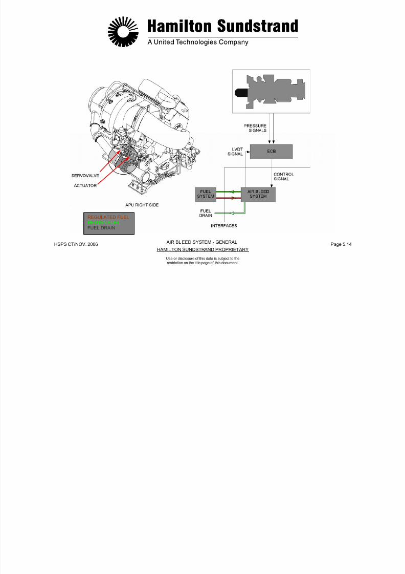
7/21/2019 Aps 3200 Training
http://slidepdf.com/reader/full/aps-3200-training 177/739
HSPS CT/NOV. 2006 Page 5.14HAMILTON SUNDSTRAND PROPRIETARY
REGULATED FUELRETURN FUELFUEL DRAIN
AIR BLEED SYSTEM - GENERAL
Use or disclosure of this data is subject to therestriction on the title page of this document.
AIR BLEED SYSTEM - DESCRIPTION (1)
The air bleed supply is controlled by a bleed control valve.
This valve comprises of a housing, a butterfly valve and an actuator.
APU Bleed Switch
When the APU master switch is selected to off during bleed airoperation, the APU will continue to run in a cool down mode for amaximum time of 2 minutes.
APU Bleed Switch
When the APU master switch is selected to off during bleed airoperation, the APU will continue to run in a cool down mode for amaximum time of 2 minutes.
The cooldown time limit can vary from 0 to 2 minutes. The time limitdepends on when the APU bleed switch is turned off prior toselecting the APU master switch to OFF.

7/21/2019 Aps 3200 Training
http://slidepdf.com/reader/full/aps-3200-training 178/739
HSPS CT/NOV. 2006 Page 5.15HAMILTON SUNDSTRAND PROPRIETARY
Use or disclosure of this data is subject to therestriction on the title page of this document.
Housing
The housing is mounted on the load compressor scroll outlet bymeans of a v-band clamp.
Butterfly Valve
The valve is located in the BCV housing and directs air flow from theload compressor to the aircraft pneumatic systems, APU exhaust orboth.
The butterfly shaft extends through the top of the BCV housing. Theshaft has a slot machined into it that provides manual positioning ofthe valve and also serves as a valve position indicator.
Low B leed Air Pressure
In the event low bleed air pressure occurs, cycle the APU bleedswitch OFF and then to ON. This may restore the system to normal.

7/21/2019 Aps 3200 Training
http://slidepdf.com/reader/full/aps-3200-training 179/739
HSPS CT/NOV. 2006 Page 5.16HAMILTON SUNDSTRAND PROPRIETARY
AIR BLEED SYSTEM - DESCRIPTION (1)
Use or disclosure of this data is subject to therestriction on the title page of this document.
AIR BLEED SYSTEM - DESCRIPTION (2)
Servo Valve
The servo valve controls the position of the actuator piston by usinga spill valve that meters the potentiometric jet. The servo valve has ametered fuel pressure inlet from the actuator and a return outlet tothe fuel control unit. The control current (0-100 MA) to the servovalve is provided by the ECB.
Actuator
Bleed Control Valve
The bleed control valve (BCV) delivers compressed air to the aircraft,also the valve functions as an anti-surge valve for the loadcompressor.

7/21/2019 Aps 3200 Training
http://slidepdf.com/reader/full/aps-3200-training 180/739
HSPS CT/NOV. 2006 Page 5.17HAMILTON SUNDSTRAND PROPRIETARY
Use or disclosure of this data is subject to therestriction on the title page of this document.
The actuator consists of a piston that is positioned by fuel pressuremetered by the servo valve. The actuator also uses double dynamicseals for piston shaft sealing.
The position of the actuator piston is provided by a linear voltagedifferential transducer (LVDT). The position signal is sent to the ECBfor control of the servo valve.

7/21/2019 Aps 3200 Training
http://slidepdf.com/reader/full/aps-3200-training 181/739
HSPS CT/NOV. 2006 Page 5.18HAMILTON SUNDSTRAND PROPRIETARY
COMPRESSED AIRREGULATED FUELMETERED FUELFUEL RETURNFUEL DRAIN
AIR BLEED SYSTEM - DESCRIPTION (2)
Use or disclosure of this data is subject to therestriction on the title page of this document.
AIR BLEED SYSTEM - OPERATION
Principle of Operation
The ECB provides a control signal (0-100 MA) to the servo valveusing the following inputs:
- APU bleed switch
- Speed (100%)
Air inlet temperature
APU Star ting
During start and shutdown the BCV is in the discharge position.
If the valve control is faulty, the BCV actuator will automaticallyposition the valve to discharge.
7/21/2019 Aps 3200 Training
http://slidepdf.com/reader/full/aps-3200-training 182/739
HSPS CT/NOV. 2006 Page 5.19HAMILTON SUNDSTRAND PROPRIETARY
Use or disclosure of this data is subject to therestriction on the title page of this document.
- Air inlet temperature
- Load compressor discharge pressure sensor (ΔP/P).
The ECB control signal is sent to the servo valve. The servo valvemeters fuel pressure to control the actuator piston movement.
When the actuator piston moves, the linear voltage differential
transducer (LVDT) sends the actuator position signal back to theECB.
The actuator piston is maintained in a stabilized position by the ECBsignal (50 MA) to the servo valve.
The actuator piston positions the BCV to deliver the maximum airflowto the aircraft pneumatic systems without causing load compressorsurge.

7/21/2019 Aps 3200 Training
http://slidepdf.com/reader/full/aps-3200-training 183/739
HSPS CT/NOV. 2006 Page 5.20HAMILTON SUNDSTRAND PROPRIETARY
COMPRESSED AIRREGULATED FUELMETERED FUELFUEL RETURNFUEL DRAIN
AIR BLEED SYSTEM - OPERATION
Use or disclosure of this data is subject to therestriction on the title page of this document.
AIR SYSTEM SENSORS - INLET AIR PRESSURE AND TEMPERATURE SENSOR
Function
The air inlet pressure and temperature signals are used by the ECBfor control purposes.
Location
The pressure and temperature sensors are in one unit which is
located on the right rear side of the air inlet plenum.
- Supply current: 1 mA
- Range: -55 to +150°C (-62 to 302°F)
- Resistance at 0°C (0°F): 1000 Ω.
Functional Description
- The pressure sensor is made of a bridge of 4 resistors printed ona flexible support One of them varies if the support is deformed by
7/21/2019 Aps 3200 Training
http://slidepdf.com/reader/full/aps-3200-training 184/739
HSPS CT/NOV. 2006 Page 5.21HAMILTON SUNDSTRAND PROPRIETARY
Main Features
Pressure Sensor
- Type: variable resistor device
- Excitation voltage: + 5 and - 5 VDC
- Output signal: 0 to 50 mV
- Range: 0 to 104 kPaa (0 to 15 PSIA)
- Minimum bridge impedance: 2000Ω.
Temperature Sensor
- Type: resistance temperature device
a flexible support. One of them varies if the support is deformed bythe air pressure. The whole bridge is supplied by a 5 VDC constantsource voltage coming from the ECB. The changes of the variableresistor cause the output to vary (from 0 to 50 mV).
- The temperature sensor is a resistor which is fed by a constant 1mA current supplied by the ECB. The output voltage changes fromapproximately 0.8 to 1.2 VDC according to the resistance changes
from -55 to +50°C (-67 to +122°F).
The ECB detects a sensor failure if:
- The measured ambient pressure is lower than 3.45 kPaa(0.5 PSIA) or higher than 110 kPaa (16 PSIA)
- The measured inlet temperature is lower than -62°C (-80°F) orhigher than 76°C (170°F)
Normal BCV control will be maintained if either air inlet pressure ortemperature sensor is failed.
Use or disclosure of this data is subject to therestriction on the title page of this document.
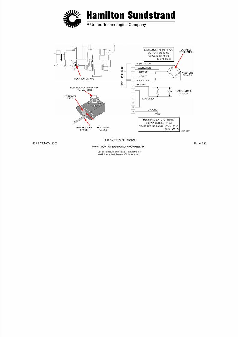
7/21/2019 Aps 3200 Training
http://slidepdf.com/reader/full/aps-3200-training 185/739
HSPS CT/NOV. 2006 Page 5.22HAMILTON SUNDSTRAND PROPRIETARY
AIR SYSTEM SENSORS
Use or disclosure of this data is subject to therestriction on the title page of this document.
AIR SYSTEM SENSORS - LOAD COMPRESSOR DISCHARGE PRESSURE SENSORS
General
Function
The load compressor discharge pressure sensors sense loadcompressor air pressure (high pressure) and (low pressure).
The ECB receives signals from the sensors and adjusts the bleed
control valve (BCV) to prevent load compressor surge.
Description
The two sensors are made of a bridge of 4 resistors.
The resistors are printed on a flexible support and one of them variesif the support is deformed by the pressure.
The bridges are supplied by a constant source voltage of 5 VDC
coming from the ECB.

7/21/2019 Aps 3200 Training
http://slidepdf.com/reader/full/aps-3200-training 186/739
HSPS CT/NOV. 2006 Page 5.23HAMILTON SUNDSTRAND PROPRIETARY
Use or disclosure of this data is subject to therestriction on the title page of this document.
Location
The pressure sensors (ΔP/P) are assembled as one unit. Thesensors are located on the right front side of the air inlet plenum.
Main Features
The pressure sensors are variable resistor devices.
Excitation voltage: + 5 and - 5 VDC
Output signal: 0 to 50 mV
Range 0 to 172 kPad (0 to 25 PSID) (ΔP)0 to 689 kPaa (0 to 100 PSIA) (P)
Minimum bridge impedance: 2000 Ω.
The changes of the variable resistor causes the output voltage tovary (from 0 to 50 millivolt).
The ECB detects a sensor failure if:
- The measured pressure is lower than 3.45 kPad (0.5 PSID) orhigher than 172 kPa (25 PSI) or than 690 kPa (100 PSI)
The load compressor bleed air pressure is displayed on the lowerECAM when the APU system page is selected.

7/21/2019 Aps 3200 Training
http://slidepdf.com/reader/full/aps-3200-training 187/739
HSPS CT/NOV. 2006 Page 5.24HAMILTON SUNDSTRAND PROPRIETARY
LOAD COMPRESSOR DISCHARGE PRESSURE SENSORS
AIR SYSTEM SENSORS
Use or disclosure of this data is subject to therestriction on the title page of this document.
ACCESSORY COOLING - GENERAL
Function
The accessory cooling system supplies air for the oil cooler and forthe APU compartment ventilation.
Location
The system components are located on the APU.
Main Features
Cooling Fan
The fan provides cooling air to the oil cooler and to the compartmentcooling duct. The fan assembly incorporates a permanent magnetgenerator that is used for APU backup overspeed and to preventmomentary power interruption of the ECB.
Fan Outlet Duct
This duct connects the outlet of the cooling fan to the inlet of the oilcooler

7/21/2019 Aps 3200 Training
http://slidepdf.com/reader/full/aps-3200-training 188/739
HSPS CT/NOV. 2006 Page 5.25HAMILTON SUNDSTRAND PROPRIETARY
Use or disclosure of this data is subject to therestriction on the title page of this document.
Cooling by circulation of air taken from the air inlet plenum andaccelerated by the cooling fan.
Main Components
The main components of the system are the fan inlet duct assembly,
the cooling fan, the fan outlet duct assembly, the oil cooler and theoil cooler exhaust duct.
Fan Inlet Duct
This duct connects the engine air inlet plenum to the inlet of thecooling fan.
cooler.
Oil Cooler Exhaust Duct
This duct connects the oil cooler outlet to the APU compartment doorvent.
Compartment Cooling
The APU compartment is ventilated by air ducted from the coolingfan outlet duct. The air is discharged into the compartment throughthe compartment cooling duct.

7/21/2019 Aps 3200 Training
http://slidepdf.com/reader/full/aps-3200-training 189/739
HSPS CT/NOV. 2006 Page 5.26HAMILTON SUNDSTRAND PROPRIETARY
ACCESSORY COOLING - GENERAL
Use or disclosure of this data is subject to therestriction on the title page of this document.
ACCESSORY COOLING - COOLING FAN
General
Function
The cooling fan (driven by the gearbox) provides air circulation forthe oil cooler and ventilation of the APU compartment.
The cooling fan incorporates a permanent magnet generator that
provides momentary direct current power, and a backup overspeedsignal to the electronic control box.
Main Components
- The cooling fan assembly includes:
• An axial flow fan
• The fan drive gear
• 2 roller bearings
- Fan inlet and outlet ducts
7/21/2019 Aps 3200 Training
http://slidepdf.com/reader/full/aps-3200-training 190/739
HSPS CT/NOV. 2006 Page 5.27HAMILTON SUNDSTRAND PROPRIETARY
Use or disclosure of this data is subject to therestriction on the title page of this document.
Location
The cooling fan is located at the top of the gearbox front face and issecured by a V-band clamp.
Main Features
- Cooling fan rotation speed: 51965 RPM
- Permanent Magnet Generator output: 40 VDC (100% of N)
- Speed signal for back-up of the overspeed protection system:107%.
- Fan inlet and outlet ducts
- A permanent magnet generator and control box.
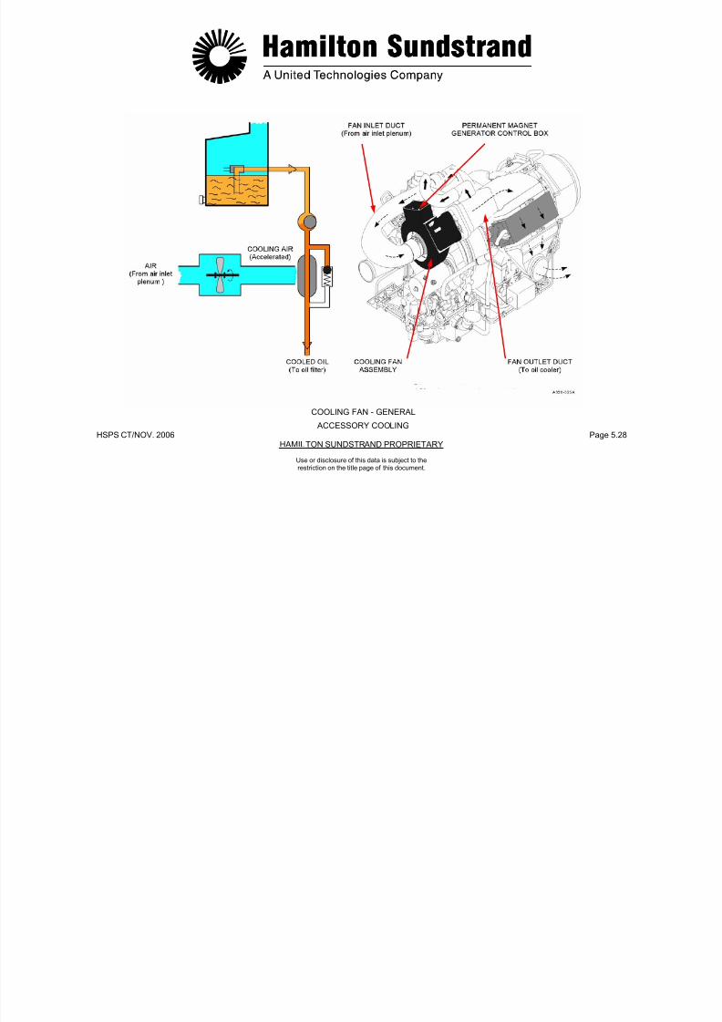
7/21/2019 Aps 3200 Training
http://slidepdf.com/reader/full/aps-3200-training 191/739
HSPS CT/NOV. 2006 Page 5.28HAMILTON SUNDSTRAND PROPRIETARY
COOLING FAN - GENERAL
ACCESSORY COOLING
Use or disclosure of this data is subject to therestriction on the title page of this document.
ACCESSORY COOLING - COOLING FAN
Description
The cooling fan is mounted on the gearbox and aligned by a locatingpin. The fan mounting flange is secured to the gearbox by a v-bandclamp.
The fan is driven by a shaft assembly that is supported by two ballbearings, the bearings are lubricated by the APU oil system. The
shaft assembly uses a carbon seal and two labyrinth sealspressurized by the power section impeller air. The oil used forlubrication of the cooling fan is returned to the oil sump by gravity.
Operation
Cooling Fan
The cooling fan accelerates the air flow through the oil cooler.Cooling air is also used for APU compartment cooling.
PMG
The permanent magnet generator (PMG) is driven by the cooling fanshaft. The PMG provides momentary (240 msec) of rectified
7/21/2019 Aps 3200 Training
http://slidepdf.com/reader/full/aps-3200-training 192/739
HSPS CT/NOV. 2006 Page 5.29HAMILTON SUNDSTRAND PROPRIETARY
Use or disclosure of this data is subject to therestriction on the title page of this document.
g p y g y
A permanent magnet generator (PMG) and a printed circuit boardare located in the fan housing. The printed circuit board contains therectifier components for the PMG electrical power output to the ECB.
The cooling fan can be used to turn the APU rotor assembly during
borescoping. This is accomplished by removing the fan inlet duct andmanually rotate the fan impeller.
p y ( )electrical power to the ECB when the aircraft electrical power isinterrupted during power transfer.
One unrectified PMG output provides a frequency signal to the ECBthat is used for the back up overspeed signal.
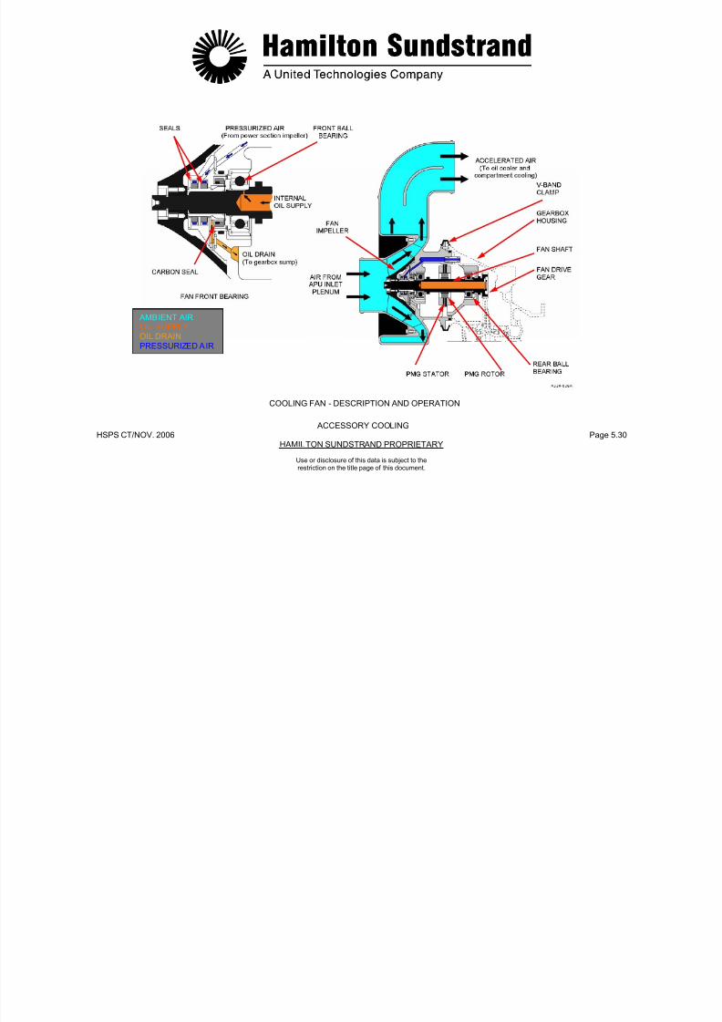
7/21/2019 Aps 3200 Training
http://slidepdf.com/reader/full/aps-3200-training 193/739
HSPS CT/NOV. 2006 Page 5.30HAMILTON SUNDSTRAND PROPRIETARY
AMBIENT AIROIL SUPPLYOIL DRAINPRESSURIZED AIR
COOLING FAN - DESCRIPTION AND OPERATION
ACCESSORY COOLING
Use or disclosure of this data is subject to therestriction on the title page of this document.
AIRCRAFT PNEUMATIC SYSTEM
The aircraft pneumatic system supplies compressed air to thefollowing:
- Aircraft air conditioning system
- Water tank pressurization
- Aft cargo heating
- Wing anti-icing system
7/21/2019 Aps 3200 Training
http://slidepdf.com/reader/full/aps-3200-training 194/739
HSPS CT/NOV. 2006 Page 5.31HAMILTON SUNDSTRAND PROPRIETARY
Use or disclosure of this data is subject to therestriction on the title page of this document.
- Main engine starting system
- Hydraulic reservoir pressurization.
The compressed air , used by the aircraft pneumatic system, can besupplied by:
- The APU
- Number 1 engine
- Number 2 engine
- Ground air source.
ENG. 1BLEED
HOT AIR
PACK 1ENG 2BLEED
PACK 2
X BLEED
GROUND AIR
APUBLEEDVALVE(BCV)

7/21/2019 Aps 3200 Training
http://slidepdf.com/reader/full/aps-3200-training 195/739
HSPS CT/NOV. 2006 Page 5.32HAMILTON SUNDSTRAND PROPRIETARY
Use or disclosure of this data is subject to therestriction on the title page of this document.
AIRCRAFT PNEUMATIC SYSTEM
APU COMPRESSED AIRENGINE FAN COOLING AIR
FAULT LIGHTOFF LIGHT
SUPPLY(BCV)
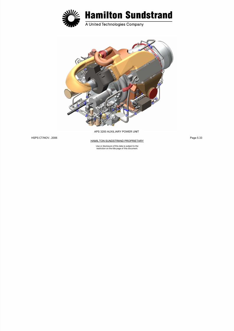
7/21/2019 Aps 3200 Training
http://slidepdf.com/reader/full/aps-3200-training 196/739
HSPS CT/NOV.. 2006 Page 5.33HAMILTON SUNDSTRAND PROPRIETARY
APS 3200 AUXILIARY POWER UNIT
Use or disclosure of this data is subject to therestriction on the title page of this document.
APS 3200 AUXILIARY POWER UNIT

7/21/2019 Aps 3200 Training
http://slidepdf.com/reader/full/aps-3200-training 197/739
HSPS CT/NOV.. 2006 Page 6.0HAMILTON STANDARD PROPRIETARY
SECTION 6
CONTROL SYSTEM
Use or disclosure of this data is subject to therestriction on the title page of this document.
APU CONTROL SYSTEM - GENERAL
Functions
The functions of the APU Control System are:
- To keep the power unit rotation speed constant to maintain ACgenerator frequency
- To protect the power unit from overtemperature
- To avoid load compressor surge
- To ensure a proper start of the power unit
Main Components
The main components of the APU control system are:
- The APU components (sensors, pressure switches, servo-valve,actuators ...)
- The electronic control box
- The aircraft control panels.

7/21/2019 Aps 3200 Training
http://slidepdf.com/reader/full/aps-3200-training 198/739
HSPS CT/NOV.. 2006 Page 6.1HAMILTON STANDARD PROPRIETARY
Use or disclosure of this data is subject to therestriction on the title page of this document.
- To ensure a proper start of the power unit
- To provide a proper start sequence.
- To monitor APU component operation.
- To supply fault information for trouble shooting, engine trendmonitoring and historical data retention.
Main Features
- FADEC (Full Authority Digital Electronic Controller)
- Single computer
- Electrical supply from the aircraft DC system and momentarypower backup from the cooling fan PMG.
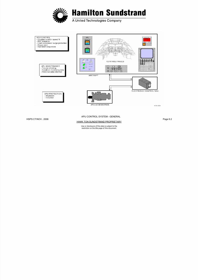
7/21/2019 Aps 3200 Training
http://slidepdf.com/reader/full/aps-3200-training 199/739
HSPS CT/NOV.. 2006 Page 6.2HAMILTON SUNDSTRAND PROPRIETARY
APU CONTROL SYSTEM - GENERAL
Use or disclosure of this data is subject to therestriction on the title page of this document.
APU CONTROL SYSTEM - DESCRIPTION (1)
General
This description considers:
- The Electronic Control Box (ECB)
- The ECB inputs
- The ECB outputs
- The ECB supply
ECB Outputs
They are the accessories (electro-valves, relays...) and indicatingdevices.
ECB Electrical Supply
- 28 VDC supply: from the aircraft electrical system
- Momentary supply: from the permanent magnet generator (part ofthe cooling fan assembly).

7/21/2019 Aps 3200 Training
http://slidepdf.com/reader/full/aps-3200-training 200/739
HSPS CT/NOV.. 2006 Page 6.3HAMILTON SUNDSTRAND PROPRIETARY
Use or disclosure of this data is subject to therestriction on the title page of this document.
- The electrical harness.
ECB
The ECB is located in the aft cargo compartment.
The unit is made of six printed wiring assemblies using digitaltechnology components.
ECB Inputs
They are the sensors (rotation speed, temperature, pressure...) anddiscrete signals (microswitches and switches).
Electrical Harness
The APU harness connects the APU to the aircraft electrical system.
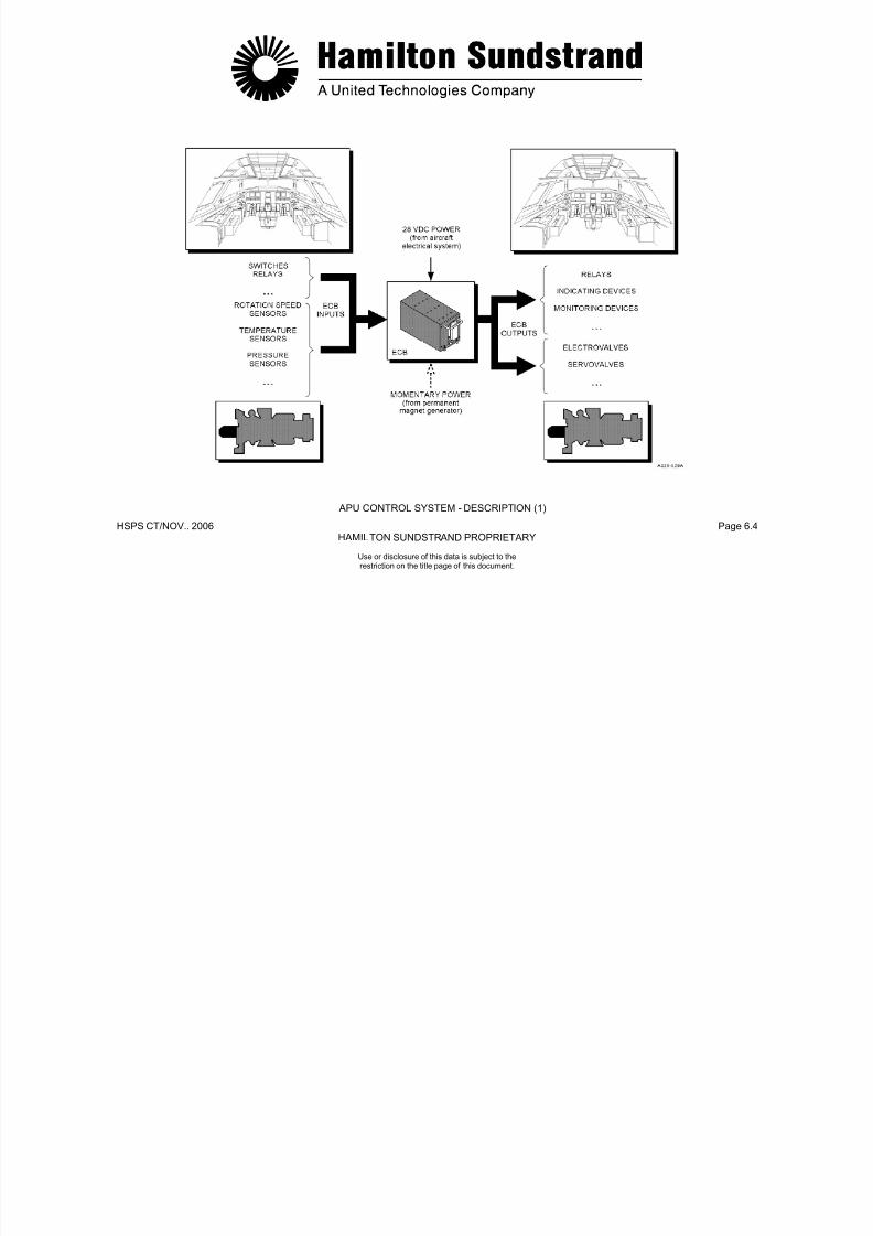
7/21/2019 Aps 3200 Training
http://slidepdf.com/reader/full/aps-3200-training 201/739
HSPS CT/NOV.. 2006 Page 6.4HAMILTON SUNDSTRAND PROPRIETARY
APU CONTROL SYSTEM - DESCRIPTION (1)
Use or disclosure of this data is subject to therestriction on the title page of this document.
APU CONTROL SYSTEM - DESCRIPTION (2)
Control System Components
Components of the control system:
- Low oil pressure switch
- Oil filter switch indicators
- High oil temperature sensor
- Oil level sensor
- Inlet guide vane servo valve
- Bleed control valve servo valve
- Fuel servo valve
- 3 way solenoid valve
- Low fuel pressure switch
- Permanent magnet generator

7/21/2019 Aps 3200 Training
http://slidepdf.com/reader/full/aps-3200-training 202/739
HSPS CT/NOV.. 2006 Page 6.5HAMILTON SUNDSTRAND PROPRIETARY
Use or disclosure of this data is subject to therestriction on the title page of this document.
- De-oiling valve
- Speed sensors
- EGT sensors
- Inlet air pressure sensor
- Inlet air temperature sensor
- Load compressor discharge pressure sensor
- Linear voltage differential transducers (LVDTs)
- Engine identification module
- Exciter
- Starter voltage sensing
- Centralized Fault Display System (CFDS)
- Aircraft discrete inputs and outputs.

7/21/2019 Aps 3200 Training
http://slidepdf.com/reader/full/aps-3200-training 203/739
HSPS CT/NOV.. 2006 Page 6.6HAMILTON SUNDSTRAND PROPRIETARY
APU CONTROL SYSTEM - DESCRIPTION (2)
CONTROL SYSTEM COMPONENTS
Use or disclosure of this data is subject to therestriction on the title page of this document.
APU CONTROL SYSTEM - OPERATION (1)
Rotation Speed Contro l
General
This function meters the fuel flow to maintain a constant rotor speed.
Components Involved
- Speed sensors
- Electronic Control Box (ECB)
Fuel servo valve
Exhaust Gas Temperature (EGT) Control
General
This function protects the power unit against over-temperature.
Components Involved
- EGT thermocouples, the speed sensors and the inlet pressure andtemperature signals
- ECB

7/21/2019 Aps 3200 Training
http://slidepdf.com/reader/full/aps-3200-training 204/739
HSPS CT/NOV.. 2006 Page 6.7HAMILTON SUNDSTRAND PROPRIETARY
Use or disclosure of this data is subject to therestriction on the title page of this document.
- Fuel servo-valve.
Principle of Operation
The ECB compares rotor speed with a nominal speed datum to
control the fuel servo-valve. The servo-valve then provides therequired fuel flow to maintain 100% rotor speed under all APU loadconditions.
- IGV actuator.
Principle of Operation
The ECB compares the actual EGT with an EGT datum.
The EGT datum is a function of the operating mode (ECS or MES)and of the ambient air conditions (P1 and T1).
The ECB controls the IGV servo-valve as a function of EGT.
The IGV's are modulated toward close as EGT exceeds the datum.
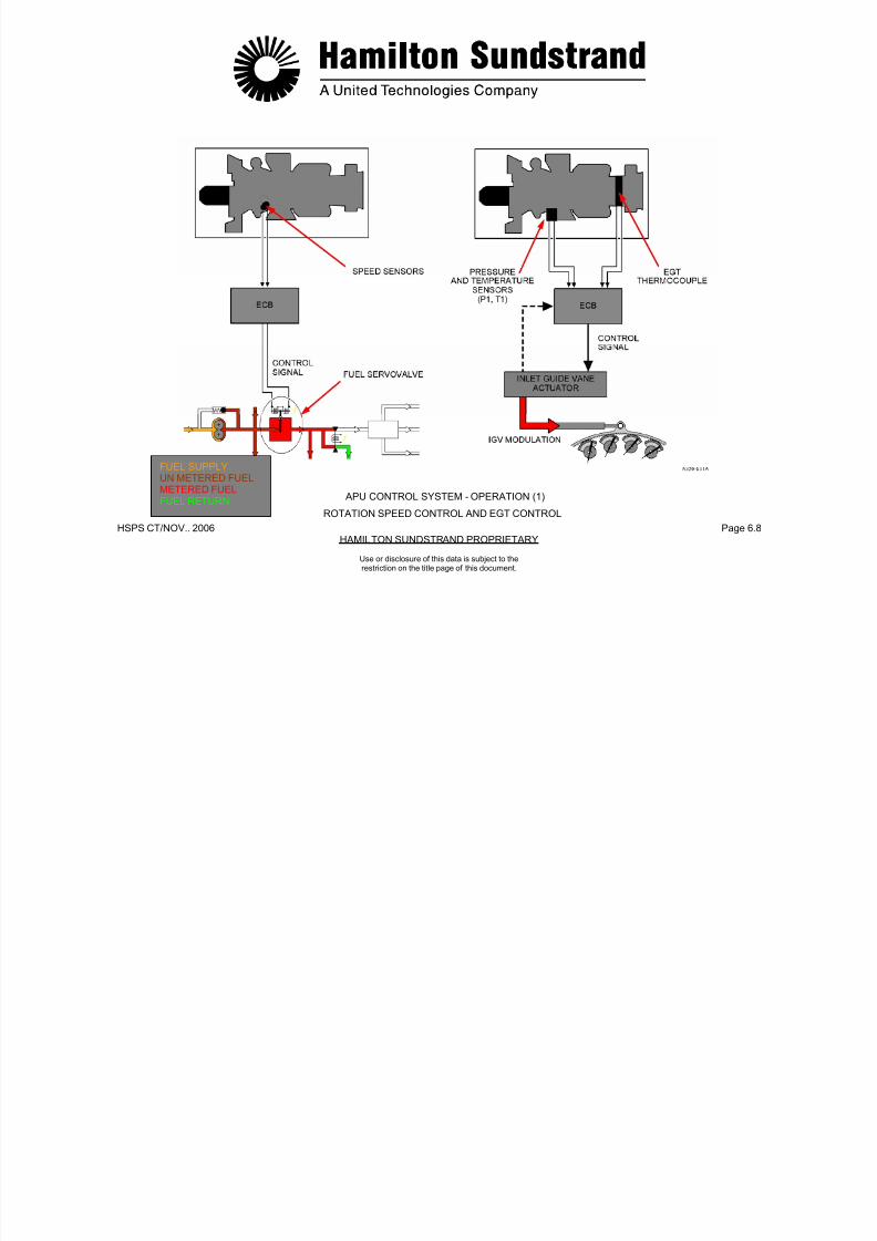
7/21/2019 Aps 3200 Training
http://slidepdf.com/reader/full/aps-3200-training 205/739
HSPS CT/NOV.. 2006 Page 6.8HAMILTON SUNDSTRAND PROPRIETARY
FUEL SUPPLY
UN METERED FUELMETERED FUEL APU CONTROL SYSTEM - OPERATION (1)FUEL RETURN
ROTATION SPEED CONTROL AND EGT CONTROL
Use or disclosure of this data is subject to therestriction on the title page of this document.
APU CONTROL SYSTEM - OPERATION (2)
Load Compressor Surge Control
General
This function protects the load compressor from surge.
Components Involved
- Load compressor output pressure sensors
- Electronic Control Box (ECB)
- Bleed control valve
Load Compressor Reverse Flow Protection
General
This function shuts down the APU in case of load compressor surge(eg. back pressure from the aircraft pneumatic system).
Components Involved
- Load compressor output pressure sensors
- ECB

7/21/2019 Aps 3200 Training
http://slidepdf.com/reader/full/aps-3200-training 206/739
HSPS CT/NOV.. 2006 Page 6.9HAMILTON SUNDSTRAND PROPRIETARY
Use or disclosure of this data is subject to therestriction on the title page of this document.
Bleed control valve.
Principle of Operation
The ECB compares the load compressor delivery pressure ratio
(Δ
P/P) with a datum pressure ratio. In case of a low airflow condition,the bleed control valve is modulated to discharge air into the APUexhaust.
- Fuel system and bleed control valve.
Principle of Operation
The ECB compares the load compressor delivery pressure ratio withtwo datums:
When the first datum is reached, the bleed control valve (BCV) willmove to the discharge position.
When the second datum is reached, the APU will automaticallyshutdown.

7/21/2019 Aps 3200 Training
http://slidepdf.com/reader/full/aps-3200-training 207/739
HSPS CT/NOV.. 2006 Page 6.10HAMILTON SUNDSTRAND PROPRIETARY
METERED FUEL
APU CONTROL SYSTEM - OPERATION (2)FUEL RETURN
LOAD COMPRESSOR SURGE CONTROL AND REVERSE FLOW PROTECTION
Use or disclosure of this data is subject to therestriction on the title page of this document.
APU CONTROL SYSTEM - OPERATION (3)
APU Star t Fuel Flow Control
General
This function meters the fuel flow during APU starting.
Components Involved
- Speed sensors, the EGT thermocouples, the air inlet pressure andtemperature probes
- Electronic Control Box (ECB)
Principle of Operation
The fuel flow program has two phases:
- The first phase: EGT rise
- The second phase: From EGT rise to 95% speed + 2 seconds.
During the first phase, the fuel supply is used to fill the manifold. Fuelflow is metered as a function of rotor speed only.
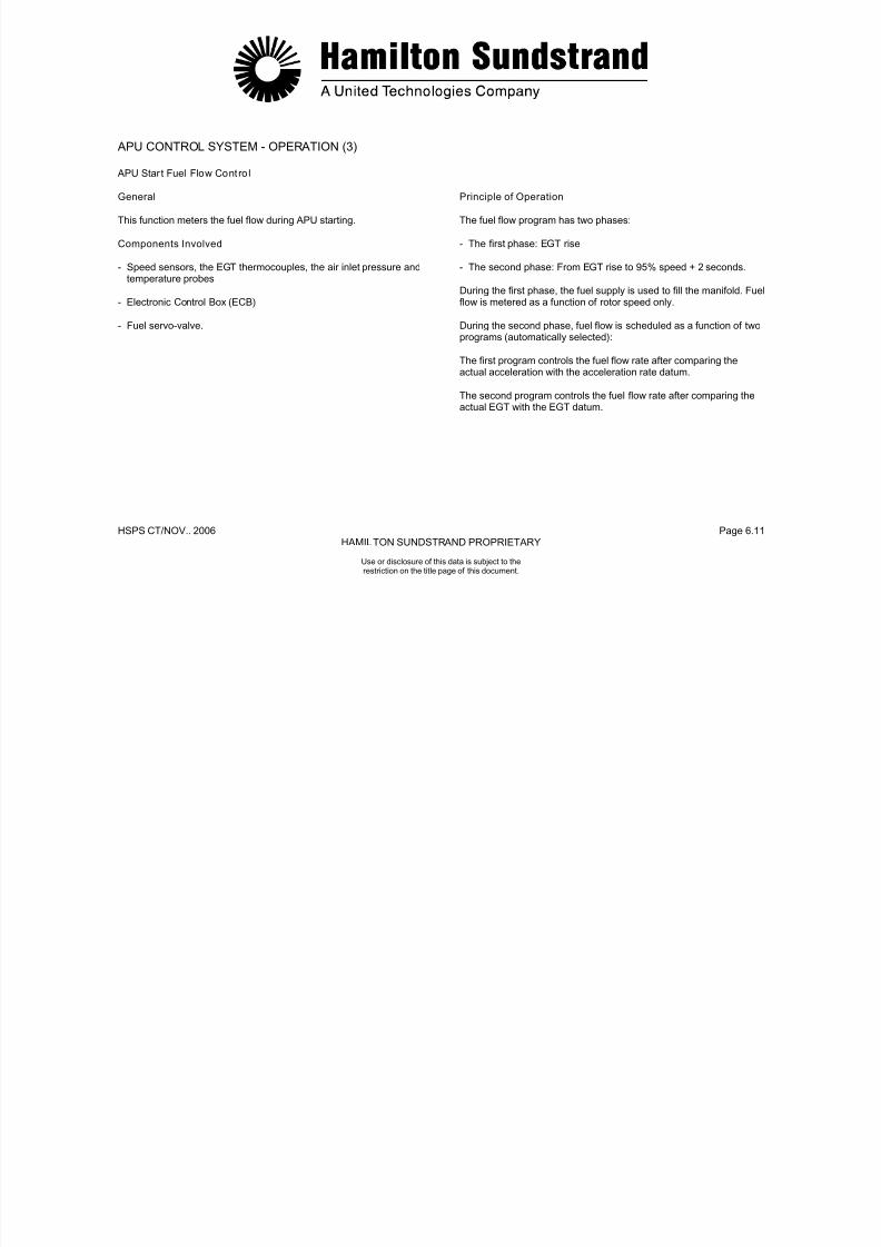
7/21/2019 Aps 3200 Training
http://slidepdf.com/reader/full/aps-3200-training 208/739
HSPS CT/NOV.. 2006 Page 6.11HAMILTON SUNDSTRAND PROPRIETARY
Use or disclosure of this data is subject to therestriction on the title page of this document.
- Fuel servo-valve. During the second phase, fuel flow is scheduled as a function of twoprograms (automatically selected):
The first program controls the fuel flow rate after comparing theactual acceleration with the acceleration rate datum.
The second program controls the fuel flow rate after comparing theactual EGT with the EGT datum.
CONTROLSYSTEM
ECB

7/21/2019 Aps 3200 Training
http://slidepdf.com/reader/full/aps-3200-training 209/739
HSPS CT/NOV.. 2006 Page 6.12HAMILTON SUNDSTRAND PROPRIETARY
ECB
FUEL SUPPLYMETERED FUELFUEL DRAIN
APU START FUEL FLOW CONTROL
APU CONTROL SYSTEM - OPERATION (3)
Use or disclosure of this data is subject to therestriction on the title page of this document.
APU CONTROL SYSTEM - OPERATION (4)
APU Faul t Sys tem
General
The APU is either shut down automatically or a warning is given incase of a fault.
Components
- The sensors
- The ECB
Th l i l i
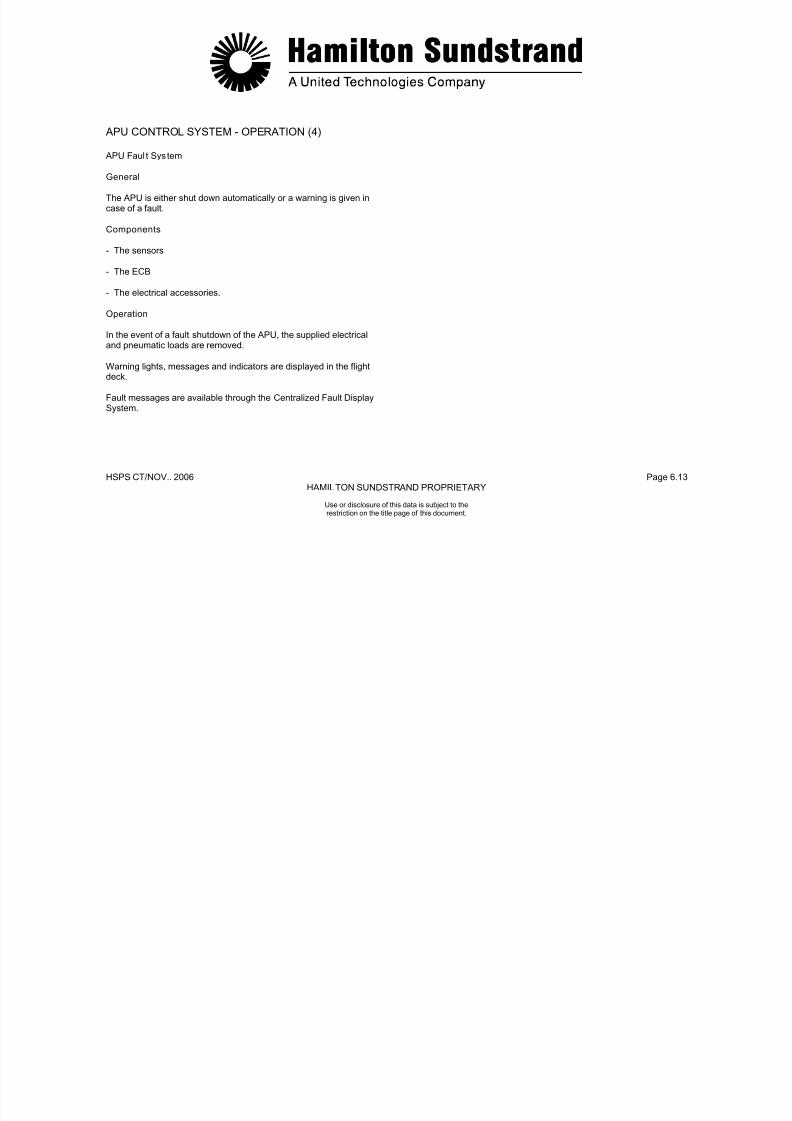
7/21/2019 Aps 3200 Training
http://slidepdf.com/reader/full/aps-3200-training 210/739
HSPS CT/NOV.. 2006 Page 6.13HAMILTON SUNDSTRAND PROPRIETARY
Use or disclosure of this data is subject to therestriction on the title page of this document.
- The electrical accessories.
Operation
In the event of a fault shutdown of the APU, the supplied electricaland pneumatic loads are removed.
Warning lights, messages and indicators are displayed in the flightdeck.
Fault messages are available through the Centralized Fault DisplaySystem.

7/21/2019 Aps 3200 Training
http://slidepdf.com/reader/full/aps-3200-training 211/739
APU CONTROL SYSTEM - OPERATION (5)
Monitoring
Function
The system provides information about the APU actual status,operation and maintenance.
The system displays:
- APU parameters
- Events and hours count
Condition and faults

7/21/2019 Aps 3200 Training
http://slidepdf.com/reader/full/aps-3200-training 212/739
HSPS CT/NOV.. 2006 Page 6.15HAMILTON SUNDSTRAND PROPRIETARY
Use or disclosure of this data is subject to therestriction on the title page of this document.
- Condition and faults.
Components Involved
- APU control system components
- The ECB
- The flight deck indicating system (CFDS, ECAM, MCDU).
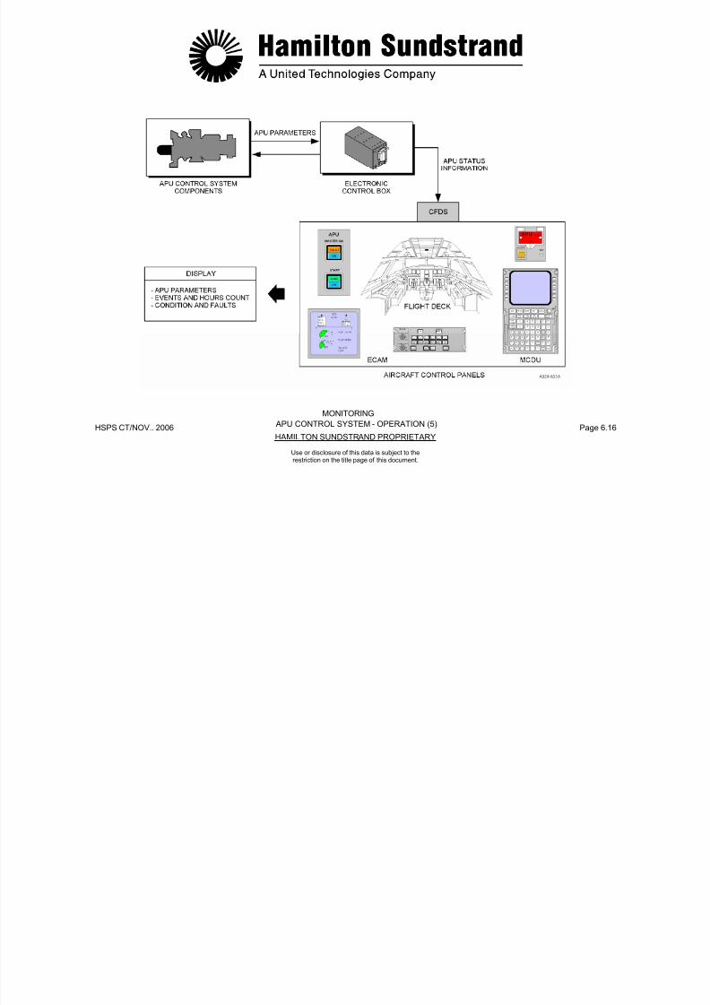
7/21/2019 Aps 3200 Training
http://slidepdf.com/reader/full/aps-3200-training 213/739
HSPS CT/NOV.. 2006 Page 6.16HAMILTON SUNDSTRAND PROPRIETARY
APU CONTROL SYSTEM - OPERATION (5)
MONITORING
Use or disclosure of this data is subject to therestriction on the title page of this document.
ELECTRONIC CONTROL BOX - GENERAL
Function
The Electronic Control Box (ECB) controls and monitors the AuxiliaryPower Unit systems.Location
The ECB is installed in the aft cargo compartment.
Main Features
-Full Authority Digital Electronic Controller (FADEC)- On Board Replaceable Memory Module (OBRM) for design
flexibility and reduced component count- Modular design for reliability, maintainability and testability
Weight and Dimensions
Weight: 7.3 kg (16.1 lbs)Dimensions:Weight and Dimensions
-• Width: 159 mm (6.2 inches)• Height: 195.4 mm (7.6 inches)• Depth: 375.4 mm (14.6 inches).
Main Components
The main components are:- The ECB enclosure which houses Printed Wiring Assemblies
(PWA)- The ECB front face which includes:
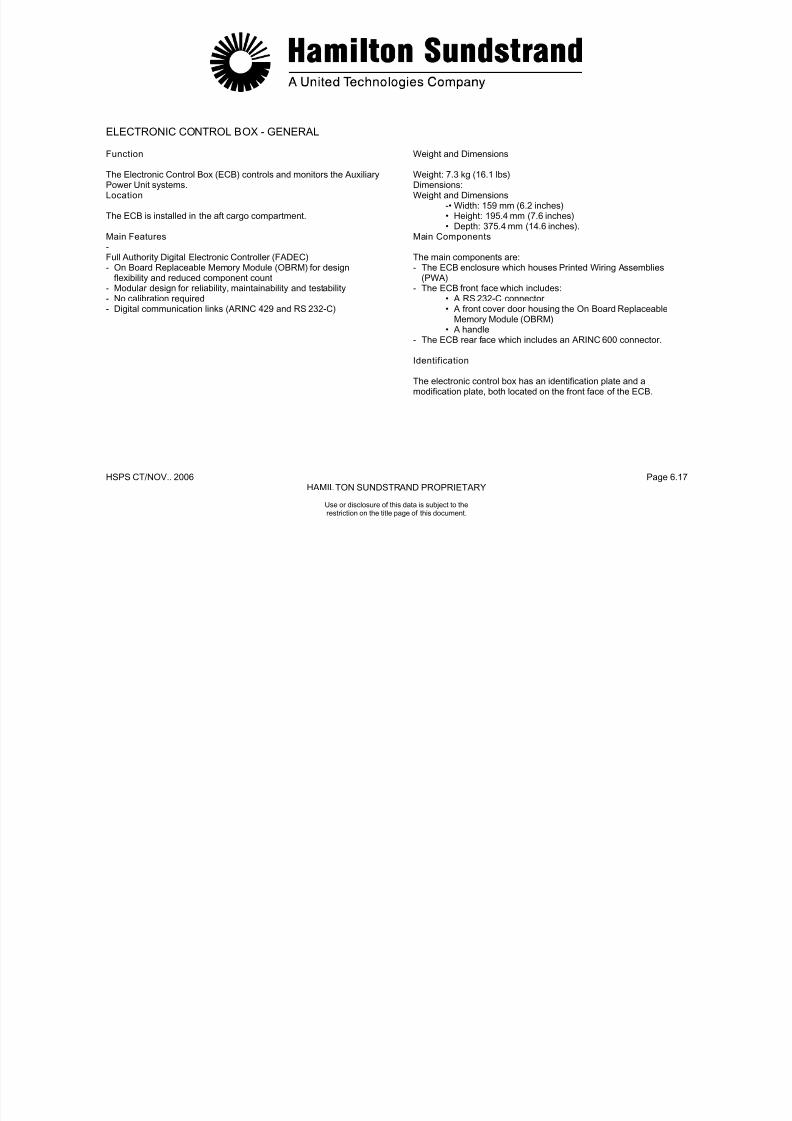
7/21/2019 Aps 3200 Training
http://slidepdf.com/reader/full/aps-3200-training 214/739
HSPS CT/NOV.. 2006 Page 6.17HAMILTON SUNDSTRAND PROPRIETARY
Use or disclosure of this data is subject to therestriction on the title page of this document.
- No calibration required- Digital communication links (ARINC 429 and RS 232-C)
• A RS 232-C connector• A front cover door housing the On Board Replaceable
Memory Module (OBRM)• A handle
- The ECB rear face which includes an ARINC 600 connector.
Identification
The electronic control box has an identification plate and amodification plate, both located on the front face of the ECB.

7/21/2019 Aps 3200 Training
http://slidepdf.com/reader/full/aps-3200-training 215/739
HSPS CT/NOV.. 2006 Page 6.18HAMILTON SUNDSTRAND PROPRIETARY
Use or disclosure of this data is subject to therestriction on the title page of this document.
ELECTRONIC CONTROL BOX - GENERAL
ELECTRONIC CONTROL BOX - DESCRIPTION (1)
ECB Inputs
General
This chapter considers the discrete and analog input signals to theECB.Sensors and Discrete Inputs from Ai rcraft to ECB
The corresponding signals form part of the ECB Inputs-Outputsdefinitions and PIN assignments.
The bleed control valve (BCV) command is transmitted to theECB by means of an aircraft discrete signal. Upon receipt of thiscommand, the ECB contro ls the opening o f the BCV to supplythe aircraft pneumatic sys tem.
Air/ground Conf iguration Switch (open/ground)
This signal to the ECB is to indicate whether or not the aircraft is in-flight operation. Special considerations (i.e. safety systems) apply forin-flight operation.

7/21/2019 Aps 3200 Training
http://slidepdf.com/reader/full/aps-3200-training 216/739
HSPS CT/NOV.. 2006 Page 6.19HAMILTON SUNDSTRAND PROPRIETARY
Use or disclosure of this data is subject to therestriction on the title page of this document.
definitions and PIN assignments.
APU Stop (ground)
The stop signal is transmitted to the ECB by the APU master switchin the flight deck. Actuating the switch causes a contact closure toground.
Bleed Control Valve Activation (ground)
Emergency Stop (ground for approx. 150 ms)
The emergency stop signal is transmitted to the ECB by means of adiscrete signal created by a contact closure to ground.
in flight operation.
MES Mode (28 V)
This signal indicates to the ECB whether or not the aircraft is in MainEngine Start mode (MES) of operation. The circuit is normally open.In the MES mode, the aircraft causes the circuit to close and tosupply a 28 V signal to the ECB.
Start Contactor Monitor (28 VDC/open/ground)
This discrete 28 VDC signal tells the ECB whether or not the back-upstart contactor is closed or whether or not it is open.The start contactor monitor is used exclusively for fault isolation
purposes.
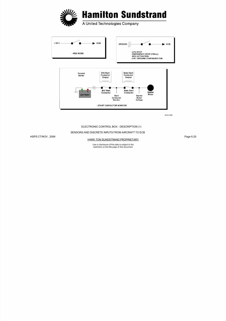
7/21/2019 Aps 3200 Training
http://slidepdf.com/reader/full/aps-3200-training 217/739
HSPS CT/NOV.. 2006 Page 6.20HAMILTON SUNDSTRAND PROPRIETARY
ELECTRONIC CONTROL BOX - DESCRIPTION (1)
SENSORS AND DISCRETE INPUTS FROM AIRCRAFT TO ECB
Use or disclosure of this data is subject to therestriction on the title page of this document.
ELECTRONIC CONTROL BOX - DESCRIPTION (2)
Sensors and Discrete Inputs from Aircraft to ECB (continued)
Air Intake Flap Open Posi tion (28 VDC)
When the air intake flap is in the fully open position, a switch isactivated to supply a 28 VDC signal to the ECB.
This signal is used to initiate the start sequence.
JAR Configuration
The ECB is programmed in the JAR mode. This means that allshutdown faults sensed by the ECB will cause the APU to shutdownon the ground or in flight.
Low Fuel Pressure Switch (open/ground)
The switch closes to ground when the fuel pressure falls below agiven pressure.
Air Intake Flap Closed Posit ion (ground)
When the air intake flap is in the fully closed position, a switch isactivated to the closed position and provides a ground signal to theECB. The aircraft relay operation is maintained until the flap closedsignal is received.
Air Intake Flap Movement (28 VDC)
D i l APU ti 28 VDC i l i t itt d t th
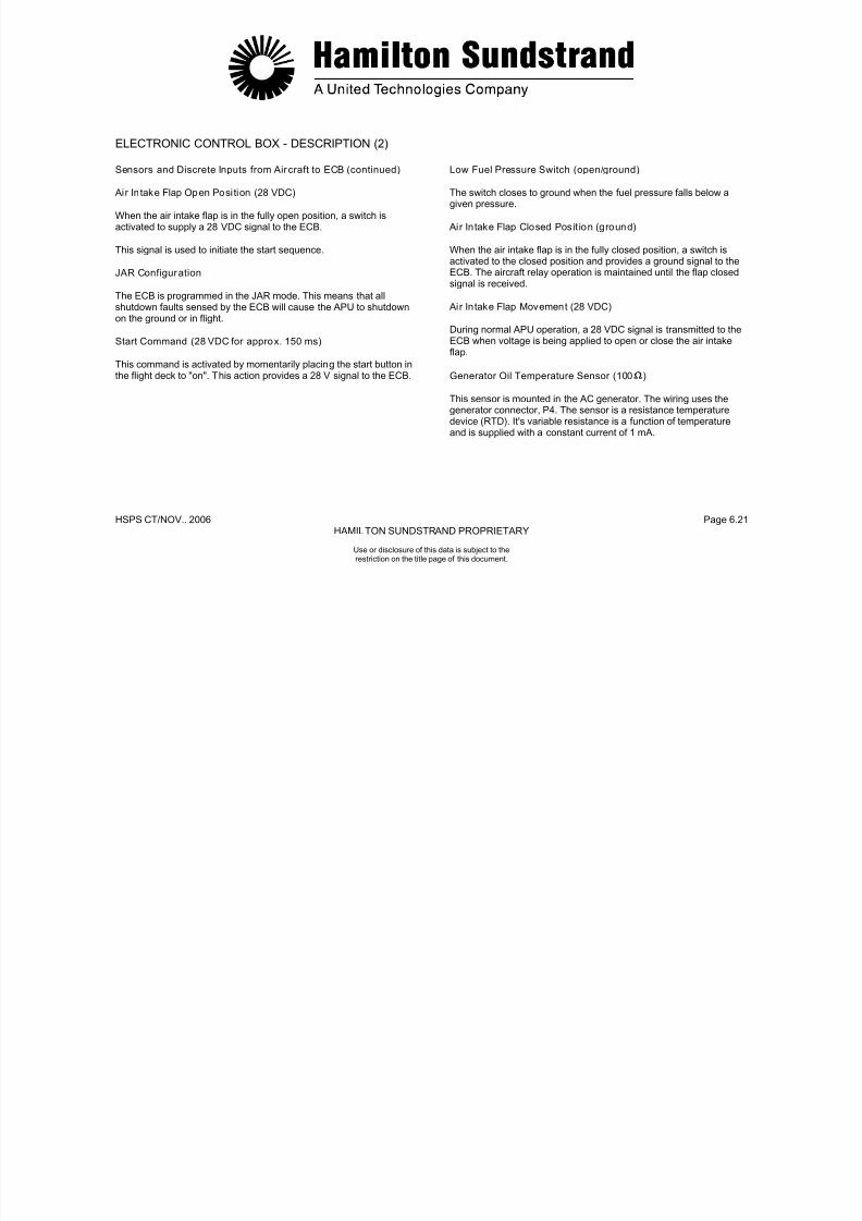
7/21/2019 Aps 3200 Training
http://slidepdf.com/reader/full/aps-3200-training 218/739
HSPS CT/NOV.. 2006 Page 6.21HAMILTON SUNDSTRAND PROPRIETARY
Use or disclosure of this data is subject to therestriction on the title page of this document.
Start Command (28 VDC for approx. 150 ms)
This command is activated by momentarily placing the start button in
the flight deck to "on". This action provides a 28 V signal to the ECB.
During normal APU operation, a 28 VDC signal is transmitted to theECB when voltage is being applied to open or close the air intakeflap.
Generator Oil Temperature Sensor (100 )
This sensor is mounted in the AC generator. The wiring uses thegenerator connector, P4. The sensor is a resistance temperaturedevice (RTD). It's variable resistance is a function of temperatureand is supplied with a constant current of 1 mA.
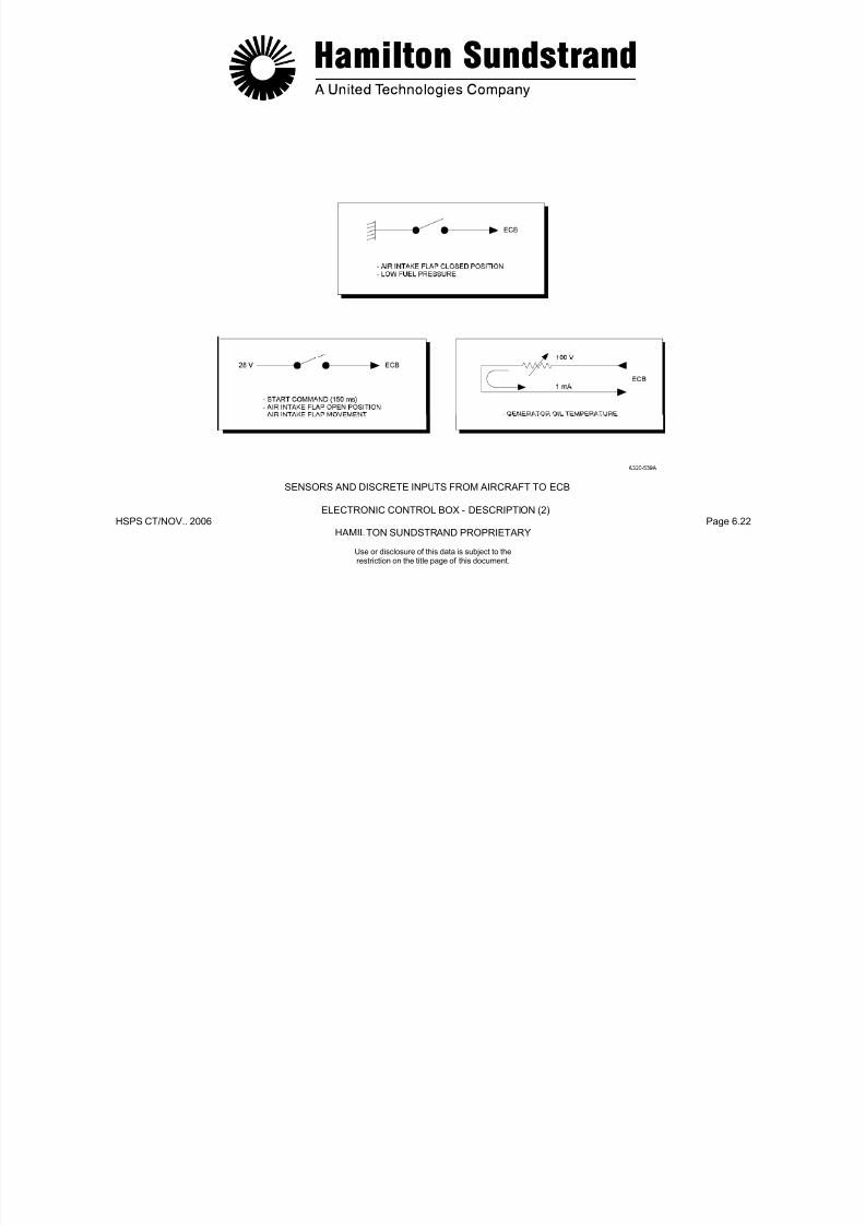
7/21/2019 Aps 3200 Training
http://slidepdf.com/reader/full/aps-3200-training 219/739
HSPS CT/NOV.. 2006 Page 6.22HAMILTON SUNDSTRAND PROPRIETARY
SENSORS AND DISCRETE INPUTS FROM AIRCRAFT TO ECB
ELECTRONIC CONTROL BOX - DESCRIPTION (2)
Use or disclosure of this data is subject to therestriction on the title page of this document.
ELECTRONIC CONTROL BOX - DESCRIPTION (3)
Sensors and Discrete Inputs from APU to ECB
Low Oil Pressure Switch (ground)
The low oil pressure switch is a normally closed contact. The switchopens and remains open when oil pressure is present.
Oil Filter Switch Indicators
This is a differential pressure switch that is normally open. Thecontact closes and provides a ground signal in case of filterrestriction.
EGT Sensors
This sensor is a variable resistance device supplied by a constantsource voltage of 5 VDC.
The output ranges from 0 to 50 mV for a 0 to 15 PSIA range of airpressure.
Load Compressor Discharge Air Pressure Sensors (P) and (
P)
There are two sensors: one to measure the pressure at the loadcompressor scroll (P), the other one to measure the differential airpressure between the diffuser and the scroll (AP). The ratio signal
AP/P is used to prevent load compressor surge.
The two sensors are of variable resistance type supplied by aconstant voltage of 5 VDC
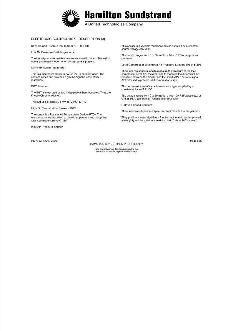
7/21/2019 Aps 3200 Training
http://slidepdf.com/reader/full/aps-3200-training 220/739
HSPS CT/NOV.. 2006 Page 6.23HAMILTON SUNDSTRAND PROPRIETARY
Use or disclosure of this data is subject to therestriction on the title page of this document.
The EGT is measured by two independent thermocouples. They areK type (Chromel-Alumel).
The output is of approx. 1 mV per 24°C (43°F).
High Oil Temperature Sensor (100 )
The sensor is a Resistance Temperature Device (RTD). Theresistance varies according to the oil temperature and is suppliedwith a constant current of 1 mA.
Inlet Air Pressure Sensor
constant voltage of 5 VDC.
The outputs range from 0 to 50 mV for a 0 to 100 PSIA (absolute) or0 to 25 PSID (differential) ranges of air pressure.
Rotation Speed Sensors
There are two independent speed sensors mounted in the gearbox.
They provide a wave signal as a function of the teeth on the phoneticwheel (24) and the rotation speed (i.e. 19720 Hz at 100% speed).

7/21/2019 Aps 3200 Training
http://slidepdf.com/reader/full/aps-3200-training 221/739
HSPS CT/NOV.. 2006 Page 6.24HAMILTON SUNDSTRAND PROPRIETARY
SENSORS AND DISCRETE INPUTS - FROM APU TO ECB
ELECTRONIC CONTROL BOX - DESCRIPTION (3)
Use or disclosure of this data is subject to therestriction on the title page of this document.
ELECTRONIC CONTROL BOX - DESCRIPTION (4)
Sensors and Discrete Inputs from APU to ECB (continued)
Inlet Air Temperature Sensor (1000 RTD)
The sensor is a variable resistance temperature device supplied by aconstant source current of 1 mA. Temperature range -55 to 150°C(-67 to 302°F).
Engine ID Module
The engine identification (ID) module is resistors that provide theECB with 3 voltage lines V 1, V2, V3 matched to the engine IDnumber. The engine serial number is the sum of the ID number andthe number 1000.
IGV and Bleed Control Valve LVDTs(Linear Voltage Differential Transducer)
LVDTs are used to detect the actual displacement of the IGV andBCV actuators. Their signal is fed back to the ECB for the purpose ofservo control.
Their primary coil is supplied with a constant voltage of 10 VAC.Their secondary coil provides a variable output voltage.
Upon loss of electrical signal, the IGV will close or the BCV opens todischarge.
Oil Level Sensor (100 A)

7/21/2019 Aps 3200 Training
http://slidepdf.com/reader/full/aps-3200-training 222/739
HSPS CT/NOV.. 2006 Page 6.25HAMILTON SUNDSTRAND PROPRIETARY
Use or disclosure of this data is subject to therestriction on the title page of this document.
The engine ID number is stored in the ECB NOVRAM memory aspart of the power up initialization. The ID module is considered failedwhen all inputs are shorted, one or all inputs are open, a number
greater than 2048 is used, or 3 consecutive readings at power upinitialization are not identical.
The gearbox mounted oil level sensor is a Resistance TemperatureDevice (RTD) type. The variable resistance value is provided with aconstant current of 75 mA. The oil level is checked at power up over
a period of 8 seconds and is determined OK or LOW.
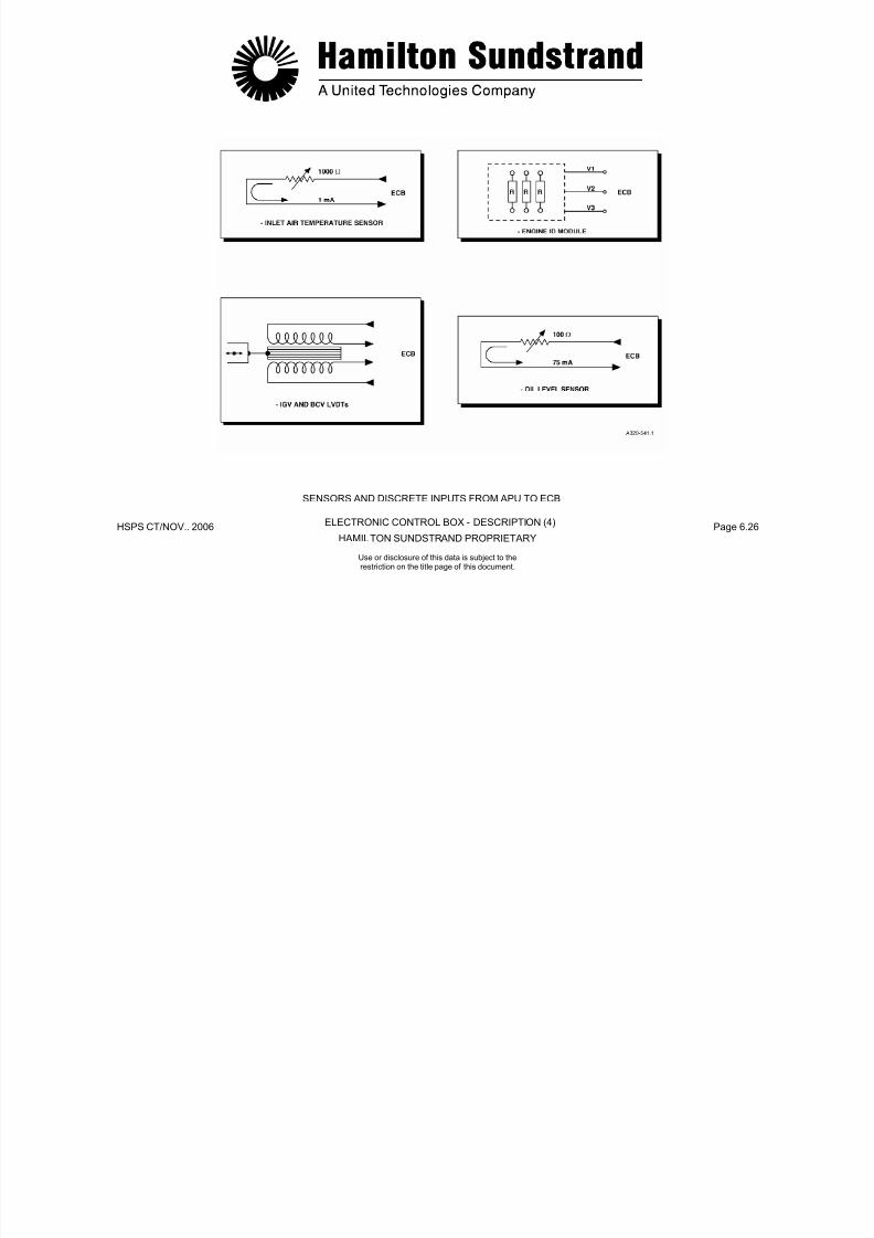
7/21/2019 Aps 3200 Training
http://slidepdf.com/reader/full/aps-3200-training 223/739
HSPS CT/NOV.. 2006 Page 6.26HAMILTON SUNDSTRAND PROPRIETARY
SENSORS AND DISCRETE INPUTS FROM APU TO ECB
ELECTRONIC CONTROL BOX - DESCRIPTION (4)
Use or disclosure of this data is subject to therestriction on the title page of this document.
ELECTRONIC CONTROL BOX - DESCRIPTION (5)
Sensors and Discrete Inputs from APU to ECB (continued)
Permanent Magnet Generator (PMG)
A Permanent Magnet Generator (PMG) is installed in the cooling fan.The assembly consists of the PMG rectifier circuit and a DC fusiblelink.
The PMG provides the ECB with rectified power and one unrectified
signal from one of the three phases (backup overspeed protection at107%).
The unrectified output is current limited (short circuit protection) bymeans of a resistor. The fusible link trip point is at 10 A.
Starter Motor Voltage
The starter motor is monitored by the ECB for low voltage during APU start. The low voltage sensing connector is located on the frontface of the starter motor housing.

7/21/2019 Aps 3200 Training
http://slidepdf.com/reader/full/aps-3200-training 224/739
HSPS CT/NOV.. 2006 Page 6.27HAMILTON SUNDSTRAND PROPRIETARY
Use or disclosure of this data is subject to therestriction on the title page of this document.
The rectified output provides 40 VDC at 100% speed for back-uppower supply to the ECB in the event of a momentary interruption inthe main power supply. This back-up supply lasts for 240 msec.
Note: The failure of the PMG/Speed circuit at startup will cause the APU to shutdown during acceleration.

7/21/2019 Aps 3200 Training
http://slidepdf.com/reader/full/aps-3200-training 225/739
HSPS CT/NOV.. 2006 Page 6.28HAMILTON SUNDSTRAND PROPRIETARY
SENSORS AND DISCRETE INPUTS FROM APU TO ECB
ELECTRONIC CONTROL BOX - DESCRIPTION (5)
Use or disclosure of this data is subject to therestriction on the title page of this document.
ELECTRONIC CONTROL BOX - DESCRIPTION (6)
ECB Outputs
General
This chapter considers the discrete and digital outputs of the ECB.
Discrete and Digital Outputs (to the aircraft)
Backup Start Contactor (28 VDC, 1 A nominal)
This contactor is energized by means of a discrete signal. The signalis supplied through a Field Effect Transistor (FET) in the ECB.
Main Start Contactor (28 VDC, 1 A nominal)
Thi t t i i d b f di t i l Th i l
Bleed Control Valve Open (28 VDC, 0.1 A)
The ECB transmits a discrete signal to the aircraft indicating systemwhen the bleed control valve is in the position that allows maximumflow to the aircraft pneumatic system.
APU Available (28 VDC, 0.4 A)
The ECB provides a discrete signal to the AVAIL light in the start
switch when the APU has completed the start sequence and is readyto load.
Start in Progress (28 VDC, 0.1 A)
The ECB transmits a discrete signal to the ON light in the start switchto indicate a start is in progress
7/21/2019 Aps 3200 Training
http://slidepdf.com/reader/full/aps-3200-training 226/739
HSPS CT/NOV.. 2006 Page 6.29HAMILTON SUNDSTRAND PROPRIETARY
Use or disclosure of this data is subject to therestriction on the title page of this document.
This contactor is energized by means of a discrete signal. The signalis supplied through a FET device in the ECB.
Aircraf t Relay (ground, 0.4 A)
The aircraft relay is activated by a closed contact to ground throughthe ECB. The aircraft relay is activated when the ECB is energizedand no stop command is present.
to indicate a start is in progress.
The light is "ON" from the beginning of the start until the "APU
available" light turns on.
Fault (28 VDC, 0.2 A)
The ECB transmits a fault discrete signal to the aircraft for allshutdowns.
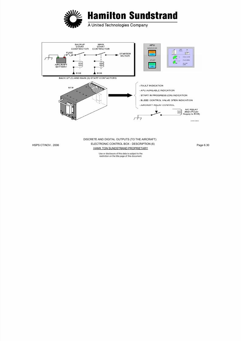
7/21/2019 Aps 3200 Training
http://slidepdf.com/reader/full/aps-3200-training 227/739
HSPS CT/NOV.. 2006 Page 6.30HAMILTON SUNDSTRAND PROPRIETARY
DISCRETE AND DIGITAL OUTPUTS (TO THE AIRCRAFT)
ELECTRONIC CONTROL BOX - DESCRIPTION (6)
Use or disclosure of this data is subject to therestriction on the title page of this document.
ELECTRONIC CONTROL BOX - DESCRIPTION (7)
Discrete and Digital Outputs (to the aircraft) (continued)
Flap Open Command (28 VDC, 3.5 A)
The ECB provides a power output for opening the air intake flap. Theflap open command is emitted through a FET device in the ECB.
This output is protected against overload and short circuits.
Flap Closed Command (28 VDC, 3.5 A)
The ECB provides a power output for closing the air intake flap. Theflap closed command is emitted through a FET device in the ECB.
This output is protected against overload and short circuits.
• ARINC 429 input from ECS: It is used by the ECB toreceive specific data from the Environmental ControlSystem (i.e. ECS demand signal, ECS valve status word,etc...)The ECS demand signal is used in the control of the IGV's.The ECS valve status word informs the ECB of the numberof air conditioning packs currently supplying air
• ARINC 429 CFDS output: The ARINC 429 output
transmits data to the CFDS, ECAM (Electronic Centralized Aircraft Monitoring) and ACMS (Aircraft ConditionMonitoring System)
- One RS 232 C interface: This interface is accessible on the rear ARINC connector and on the front face connector.

7/21/2019 Aps 3200 Training
http://slidepdf.com/reader/full/aps-3200-training 228/739
HSPS CT/NOV.. 2006 Page 6.31HAMILTON SUNDSTRAND PROPRIETARY
Use or disclosure of this data is subject to therestriction on the title page of this document.
Aircraf t Serial Communications
Data communication is achieved by means of four serialcommunication links:
- ARINC 429 CFDS output: Three ARINC 429 serial links (theyoperate at low speed - 12.5 K bits/sec)
• ARINC 429 input f rom CFDS: It is used by the ECB toreceive specific data from the Central Fault DisplaySystem with appropriate ARINC labels
It can be used:
• As a maintenance tool
• To access the test modes of the ECB
• To change the ECB software characteristics duringdevelopment.

7/21/2019 Aps 3200 Training
http://slidepdf.com/reader/full/aps-3200-training 229/739
HSPS CT/NOV.. 2006 Page 6.32HAMILTON SUNDSTRAND PROPRIETARY
DISCRETE AND DIGITAL OUTPUTS (TO THE AIRCRAFT)
ELECTRONIC CONTROL BOX - DESCRIPTION (7)
Use or disclosure of this data is subject to therestriction on the title page of this document.
ELECTRONIC CONTROL BOX - DESCRIPTION (8)
Discrete and Analog Outputs (to the APU)
Oil System De-oili ng valve (28 VDC, 1 A)
This output is activated to operate the valve during starting andshutdown.
Exci ter (28 VDC, 2 A)
This output is activated to supply the exciter during starting.
3 Way Solenoid Valve (28 VDC, 1 A)
This output is activated to operate the valve for start and shutdown.
Oil Level RTD, Oil Filter and LOP switches (Rtn, 1 A)
IGV and Bleed Control Valve LVDTs (3000 Hz, 10 VAC)
These two separate outputs supply a reference source signal to eachprimary coil.
IGV, Bleed Control Valve, Fuel Servo (0 - 100 mA)
These three separate outputs supply a variable low intensity signal tothe corresponding servo-valve.

7/21/2019 Aps 3200 Training
http://slidepdf.com/reader/full/aps-3200-training 230/739
HSPS CT/NOV.. 2006 Page 6.33HAMILTON SUNDSTRAND PROPRIETARY
Use or disclosure of this data is subject to therestriction on the title page of this document.
, ( , )
This output is common to all three items.
Pressure Transducers Excitation (5 VDC, 30 mA)
This output is activated to operate the air pressure transducers witha stabilized voltage.

7/21/2019 Aps 3200 Training
http://slidepdf.com/reader/full/aps-3200-training 231/739
HSPS CT/NOV.. 2006 Page 6.34HAMILTON SUNDSTRAND PROPRIETARY
DISCRETE AND DIGITAL OUTPUTS (TO THE APU)
ELECTRONIC CONTROL BOX - DESCRIPTION (8)
Use or disclosure of this data is subject to therestriction on the title page of this document.
ELECTRONIC CONTROL BOX - DESCRIPTION (9)
Hardware Description
The Electronic Control Box consists of an enclosure which includesthe following components:
- Six Printed Wiring Assemblies (PWA):
• A speed and temperature PWA
• A discrete input-output PWA
• A microprocessor PWA
• An analog input PWA
• An analog output PWA
- An On Board Replaceable Memory Module (OBRM) accessiblethrough a removable front cover door.
The board is equipped with an UVPROM type memory to be usedas the programme memory space for the ECB.
- Two electrical connectors:
• A RS 232 connector located on the ECB front face
• An ARINC 600 connector located on the ECB rear face.

7/21/2019 Aps 3200 Training
http://slidepdf.com/reader/full/aps-3200-training 232/739
HSPS CT/NOV.. 2006 Page 6.35HAMILTON SUNDSTRAND PROPRIETARY
Use or disclosure of this data is subject to therestriction on the title page of this document.
• A power supply PWA
- One printed wiring assembly for Electromagnetic Interference(EMI) and lightn ing protection
- PWA guides
- A backplate to interconnect the various PWA
- One High Power Switch FET Module (FET: Field Effect
Transistor)
- One Input Power Filter Module

7/21/2019 Aps 3200 Training
http://slidepdf.com/reader/full/aps-3200-training 233/739
HSPS CT/NOV.. 2006 Page 6.36HAMILTON STANDARD PROPRIETARY
HARDWARE DESCRIPTION
ELECTRONIC CONTROL BOX - DESCRIPTION (9)
Use or disclosure of this data is subject to therestriction on the title page of this document.
ELECTRONIC CONTROL BOX - OPERATION (1)
General
The operating phases are:
- Power up
- Watch state
- Start preparation state
- Starting state
- Run state
- Cool down state
Sh td t t
Power Up State
GeneralWhen the APU master switch is selected to ON, the ECB enters thePOWER UP state.The POWER UP state lasts approximately 3 sec.OperationThe ECB checks that outputs are not energized except those thatare required.
The ECB enters self test.The ECB is able to recognize and record the occurrence of start oremergency stop signals.Upon receipt and validation of the start signal, the "start in progress"output is energized.The requirement to activate the "start in progress" output alsoapplies to the WATCH state.In case of an emergency stop signal being received the ECB closes

7/21/2019 Aps 3200 Training
http://slidepdf.com/reader/full/aps-3200-training 234/739
HSPS CT/NOV.. 2006 Page 6.37HAMILTON SUNDSTRAND PROPRIETARY
Use or disclosure of this data is subject to therestriction on the title page of this document.
- Shutdown state In case of an emergency stop signal being received, the ECB closesthe air intake and deactivates the aircraft relay output once the air
intake is closed.
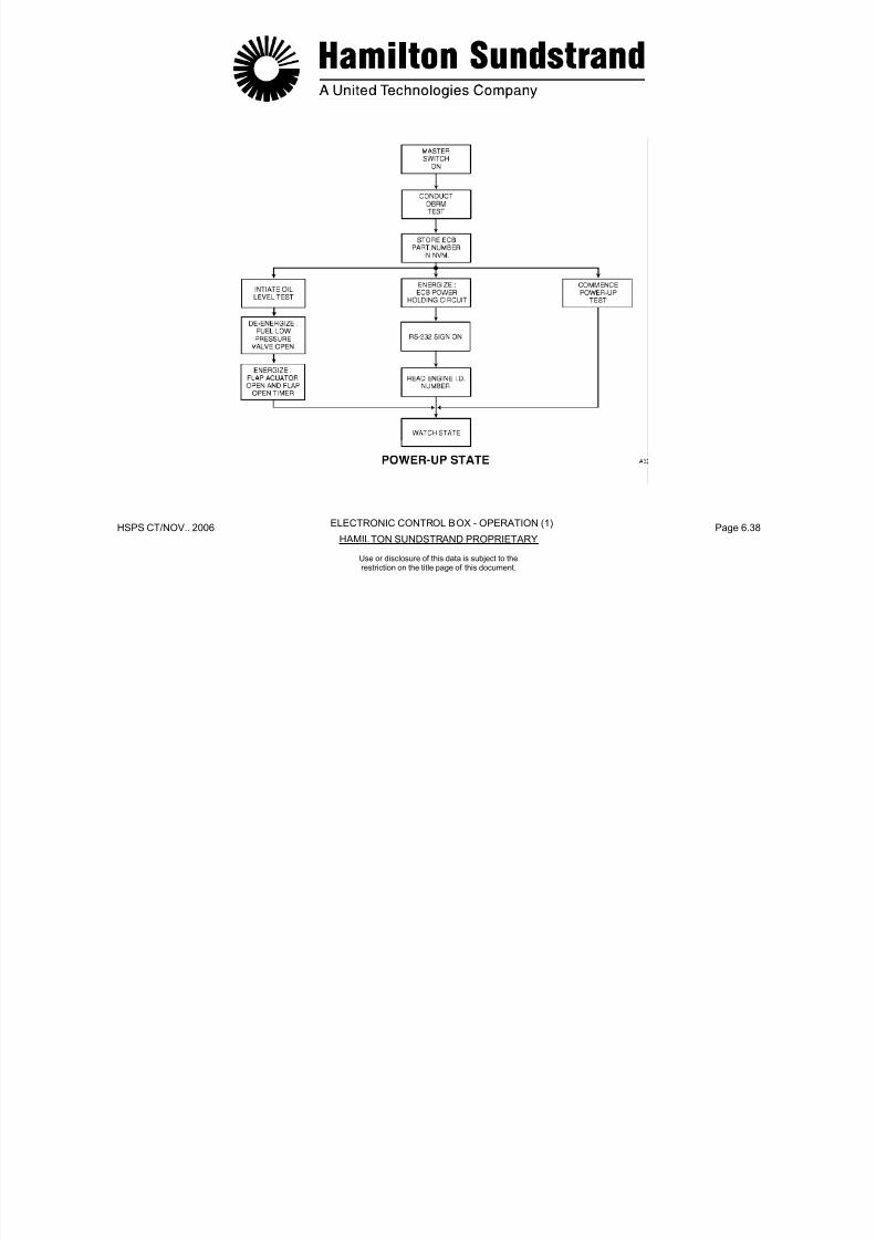
7/21/2019 Aps 3200 Training
http://slidepdf.com/reader/full/aps-3200-training 235/739
HSPS CT/NOV.. 2006 Page 6.38HAMILTON SUNDSTRAND PROPRIETARY
ELECTRONIC CONTROL BOX - OPERATION (1)
Use or disclosure of this data is subject to therestriction on the title page of this document.
ELECTRONIC CONTROL BOX - OPERATION (2)
Watch State
General
After completion of the POWER UP state the ECB automaticallyenters the WATCH state.
Operation
The ECB is able to recognize and record the occurrence of start oremergency signals.
Upon receipt of an emergency stop signal the ECB closes the airintake and deactivates the aircraft relay output once the air intake isclosed.
The ECB self tests as required
Start Preparation State
General
Upon receipt of the start command, the ECB enters the STARTPREPARATION state.
Operation
During this state the flap actuator position, the oil level and therotation speed is checked. If the speed is greater than 7%, the startcommand will be inhibited until the speed is less than or equal to 7%.
The ECB enters the START PREPARATION state automaticallywithout requiring a new start command.
7/21/2019 Aps 3200 Training
http://slidepdf.com/reader/full/aps-3200-training 236/739
HSPS CT/NOV.. 2006 Page 6.39HAMILTON SUNDSTRAND PROPRIETARY
Use or disclosure of this data is subject to therestriction on the title page of this document.
The ECB self tests as required.
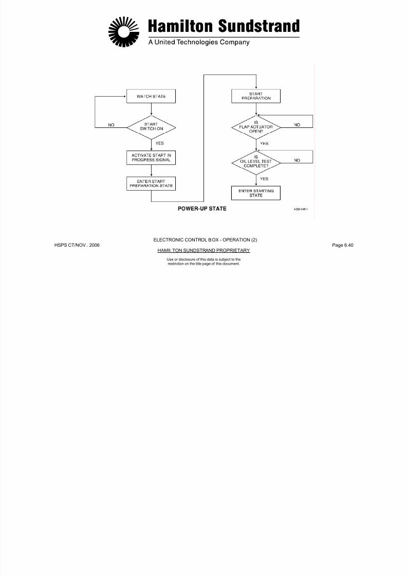
7/21/2019 Aps 3200 Training
http://slidepdf.com/reader/full/aps-3200-training 237/739
HSPS CT/NOV.. 2006 Page 6.40HAMILTON SUNDSTRAND PROPRIETARY
ELECTRONIC CONTROL BOX - OPERATION (2)
Use or disclosure of this data is subject to therestriction on the title page of this document.
ELECTRONIC CONTROL BOX - OPERATION (3)
Starting State - Sequences
General
The STARTING STATE is controlled by the ECB.
A stop signal at any time during the STARTING STATE willshutdown the APU.
Operation
The electrical sequences selected by the ECB are:
- Backup start contractor supply
- Gearbox de-oiling valve
- EGT rise
• Acceleration control to steady state speed control.
- At 55% speed
• Exciter de-energized
• Gearbox de-oiling valve and main start contactor de-energized.
- At 55% speed + 5 sec
• Backup start contactor de-energized.
- At 95% speed + 2 sec.
• Surge control activated
7/21/2019 Aps 3200 Training
http://slidepdf.com/reader/full/aps-3200-training 238/739
HSPS CT/NOV.. 2006 Page 6.41HAMILTON SUNDSTRAND PROPRIETARY
Use or disclosure of this data is subject to therestriction on the title page of this document.
- Exciter
- Main start contactor
- 3 way solenoid valve
- Pulse fuel servo valve
- Manifold fill algorithm
- Open loop fuel schedule activation.
• Surge control activated
• APU available signal activated• Start in progress output de-activated
• Steady state speed control loop activated
• Enter RUN STATE.
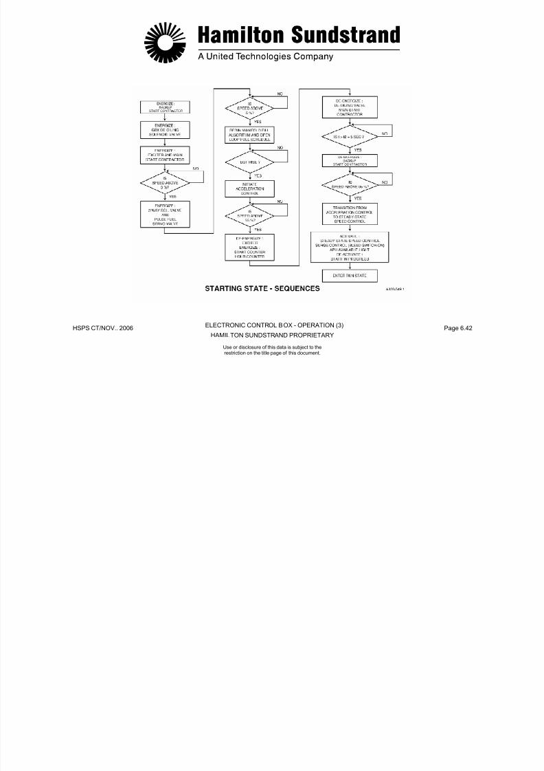
7/21/2019 Aps 3200 Training
http://slidepdf.com/reader/full/aps-3200-training 239/739
HSPS CT/NOV.. 2006 Page 6.42HAMILTON SUNDSTRAND PROPRIETARY
ELECTRONIC CONTROL BOX - OPERATION (3)
Use or disclosure of this data is subject to therestriction on the title page of this document.
ELECTRONIC CONTROL BOX - OPERATION (4)
Starting State- Fuel Control
General
There are three consecutive programs used to supply and meter thefuel during starting:
- Manifold Fill Algorithm
- Open Loop fuel schedule
- Acceleration control
Manifold Fill Algorithm - General
During engine start up the ECB controls the fuel servo valve toimplement the manifold fill algorithm.
Accelerat ion Control - General
This control occurs from EGT rise until steady state speed control isreached.
Fuel flow during acceleration is controlled by speed and EGT signalsto the ECB.

7/21/2019 Aps 3200 Training
http://slidepdf.com/reader/full/aps-3200-training 240/739
HSPS CT/NOV.. 2006 Page 6.43HAMILTON SUNDSTRAND PROPRIETARY
Use or disclosure of this data is subject to therestriction on the title page of this document.
The control is an open loop schedule based on the rotation speed,this ends when a given quantity of fuel is delivered to the manifold.
Open Loop Fuel Schedule - General
This fuel schedule replaces the manifold fill algorithm when the flowdelivered has reached 0.01 kg/m (0.032 lb/m).
The schedule determines a fuel flow rate depending on rotation
speed, ambient pressure and temperature. It is considered the"basic" fuel flow needed to obtain combustion in the combustorchamber.

7/21/2019 Aps 3200 Training
http://slidepdf.com/reader/full/aps-3200-training 241/739
HSPS CT/NOV.. 2006 Page 6.44HAMILTON STANDARD PROPRIETARY
STARTING STATE - FUEL CONTROL
ELECTRONIC CONTROL BOX - OPERATION (4)
Use or disclosure of this data is subject to therestriction on the title page of this document.
ELECTRONIC CONTROL BOX - OPERATION (5)
Run State- Fuel and Load Compressor Control
General
Upon completion of starting, three main functions are activated:
- Speed control
- Load compressor surge control
- EGT control.
Speed Control - General
The purpose of speed control is to maintain the APU at 100% speedunder all load conditions. This is accomplished by the fuel controlunit increasing or decreasing fuel flow automatically when APU loadchanges occur
Load Compressor Surge Control- General
This function prevents load compressor surge. This is accomplishedwhen the bleed switch is ON.
EGT Control - General
To prevent EGT over temperature during load compressor operation,the ECB will automatically move the IGV's to decrease airflow and
reduce the work load on the power section.
The AC generator output has priority overload compressor operation.
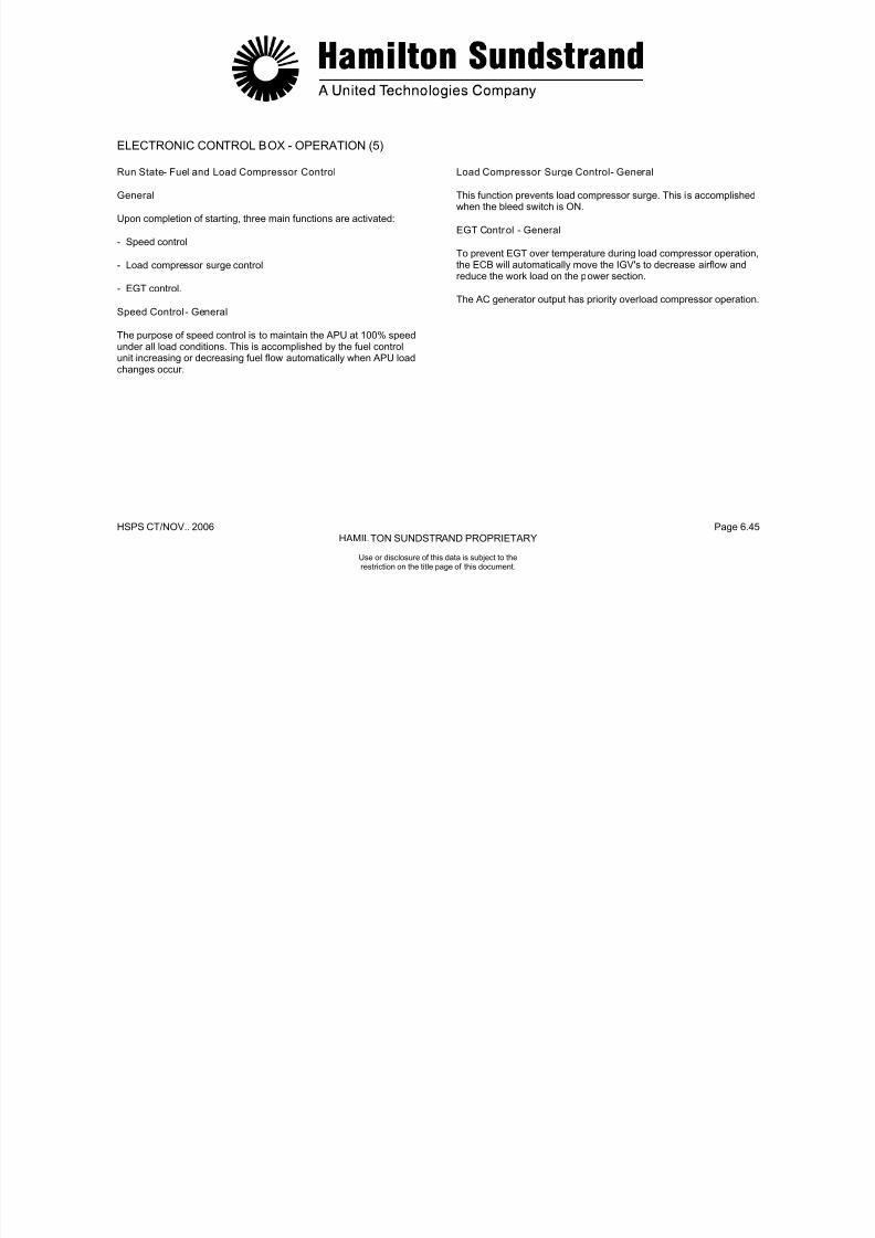
7/21/2019 Aps 3200 Training
http://slidepdf.com/reader/full/aps-3200-training 242/739
HSPS CT/NOV.. 2006 Page 6.45HAMILTON SUNDSTRAND PROPRIETARY
Use or disclosure of this data is subject to therestriction on the title page of this document.
changes occur.
GEARBOXGEARS

7/21/2019 Aps 3200 Training
http://slidepdf.com/reader/full/aps-3200-training 243/739
HSPS CT/NOV.. 2006 Page 6.46HAMILTON SUNDSTRAND PROPRIETARY
G S
AMBIENT AIRCOMPRESSED AIRMETERED FUELCOMBUSTIONEXHAUST
RUN STATE - FUEL AND LOAD COMPRESSOR CONTROL - GENERAL
ELECTRONIC CONTROL BOX - OPERATION (5)
Use or disclosure of this data is subject to therestriction on the title page of this document.
ELECTRONIC CONTROL BOX - OPERATION (6)
Cool Down State
General
This function allows the APU to operate in a no-load condition beforeentering the shutdown state.
When the APU master switch is selected to OFF, all loads areremoved (IGV's closed, Bleed Control valve to discharge).
If the APU was providing bleed air at this time, the APU will continueto run in a cool down mode for a maximum time of 2 minutes.
The cool down mode time limit can vary from 0 to 2 minutes. Thetime limit depends on when the APU bleed switch is turned off priorto selecting the APU master switch to OFF.
At the end of the cool down mode (if any) the operation enters the
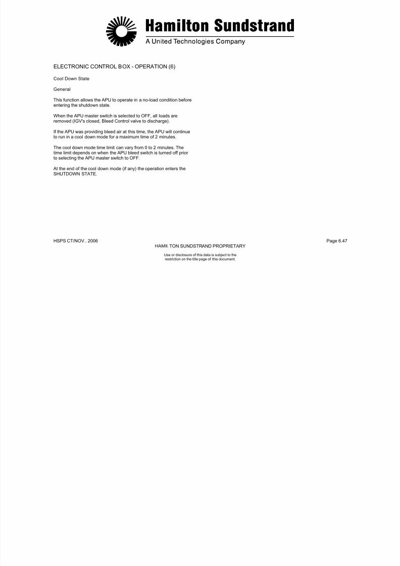
7/21/2019 Aps 3200 Training
http://slidepdf.com/reader/full/aps-3200-training 244/739
HSPS CT/NOV.. 2006 Page 6.47HAMILTON SUNDSTRAND PROPRIETARY
Use or disclosure of this data is subject to therestriction on the title page of this document.
At the end of the cool down mode (if any) the operation enters the
SHUTDOWN STATE.
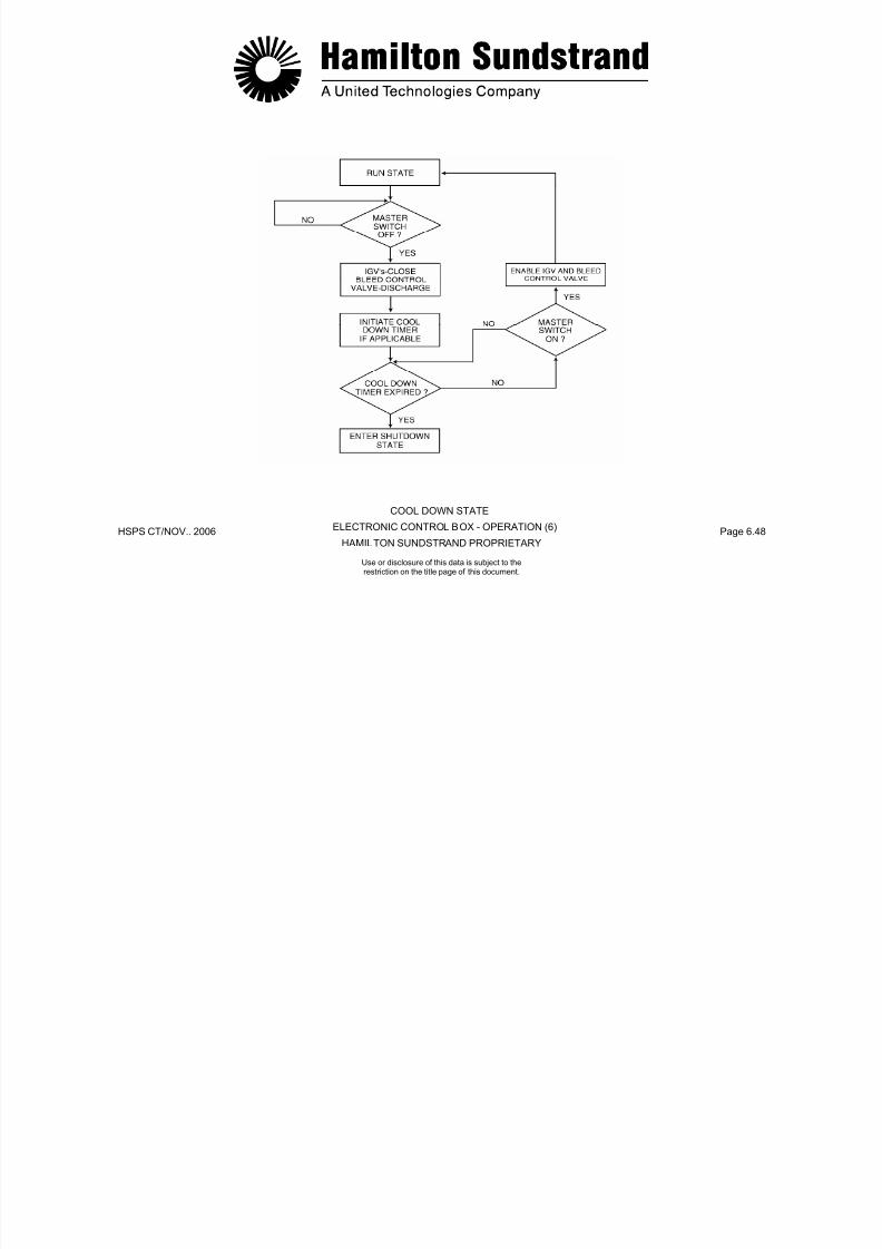
7/21/2019 Aps 3200 Training
http://slidepdf.com/reader/full/aps-3200-training 245/739
HSPS CT/NOV.. 2006 Page 6.48HAMILTON SUNDSTRAND PROPRIETARY
COOL DOWN STATE
ELECTRONIC CONTROL BOX - OPERATION (6)
Use or disclosure of this data is subject to therestriction on the title page of this document.
ELECTRONIC CONTROL BOX - OPERATION (7)
Shutdown State
General
The APU enters the shutdown state after a normal shutdown or afault shutdown occurs.
Note: The APU can be re-started during the shutdown state. Thisis accomplished by cycling the master switch OFF to ON andthen selecting the APU start switch to ON.
The ECB does not close the flap and the APU automaticallyre-starts when 7% speed is reached.

7/21/2019 Aps 3200 Training
http://slidepdf.com/reader/full/aps-3200-training 246/739
HSPS CT/NOV.. 2006 Page 6.49HAMILTON SUNDSTRAND PROPRIETARY
Use or disclosure of this data is subject to therestriction on the title page of this document.
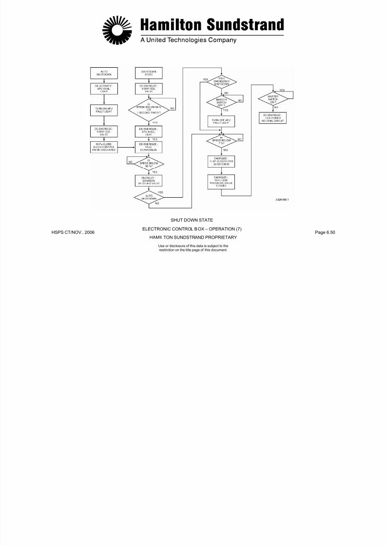
7/21/2019 Aps 3200 Training
http://slidepdf.com/reader/full/aps-3200-training 247/739
HSPS CT/NOV.. 2006 Page 6.50HAMILTON SUNDSTRAND PROPRIETARY
SHUT DOWN STATE
ELECTRONIC CONTROL BOX – OPERATION (7)
Use or disclosure of this data is subject to therestriction on the title page of this document.
ELECTRONIC CONTROL BOX - OPERATION (8)
Condition Monitor ing Data
General
For long term trend monitoring, the APU control system records theengine operating parameters.
Operation
APU conditioning monitoring parameters are taken during operationof the APU. The ECU does not store this information but it may beretrieved from the Aircraft Integrated Data System (AIDS) if thissystem is installed.
The following parameters are:
- Exhaust Gas Temperature °C
- Engine speed %
In addition, the ECB records:
- APU operating hours (in one minute increments from speed > 55%until the 3-way solenoid valve is de-energized.
- Number of starts (1 start = EGT rise detected + speed > 30%)
- ECB operating hours (in one minute increments, from ECB powerON to ECB power OFF).
The condition monitoring data is associated with the engineidentification (ID) number, ECB serial number.
Note 1: The condition monitoring parameters are not taken wheneither the inlet pressure or temperature sensors are faulty

7/21/2019 Aps 3200 Training
http://slidepdf.com/reader/full/aps-3200-training 248/739
HSPS CT/NOV.. 2006 Page 6.51HAMILTON SUNDSTRAND PROPRIETARY
Use or disclosure of this data is subject to therestriction on the title page of this document.
Engine speed %
- Engine inlet pressure PSIA
- Engine inlet temperature °C
- Fuel flow LB/HR
either the inlet pressure or temperature sensors are faulty.
Note 2: If the engine ID module has been determined failed, the APU system operating history data will be associated withthe last valid engine I D number.When a new engine ID number occurs, it is used withouterasing the previously recorded historical data.The oldest data is overwritten by the new data as it isrecorded.The ECB records the condition monitoring data associated
with the last APU cycle and the data is available via the ARINC 429 link.
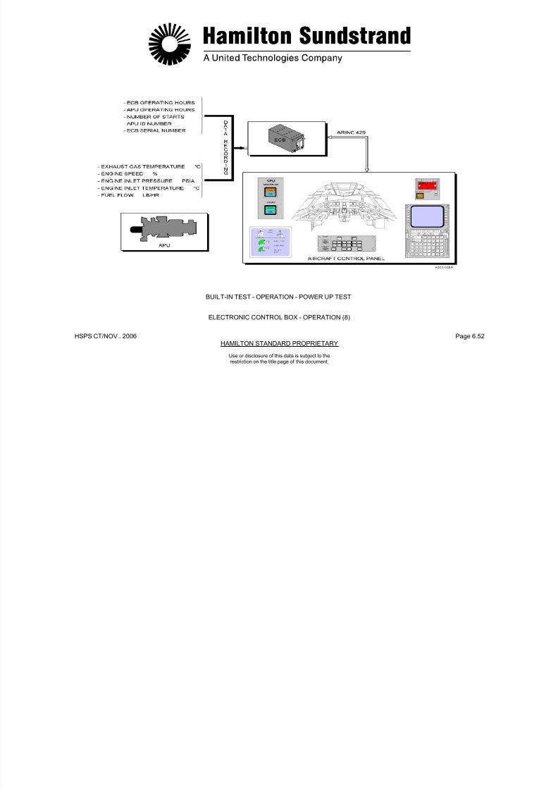
7/21/2019 Aps 3200 Training
http://slidepdf.com/reader/full/aps-3200-training 249/739
HSPS CT/NOV.. 2006 Page 6.52HAMILTON STANDARD PROPRIETARY
BUILT-IN TEST - OPERATION - POWER UP TEST
ELECTRONIC CONTROL BOX - OPERATION (8)
Use or disclosure of this data is subject to therestriction on the title page of this document.

7/21/2019 Aps 3200 Training
http://slidepdf.com/reader/full/aps-3200-training 250/739
HPS CT/NOV. 2006 Page 6. 53 HAMILTON SUNDSTRAND PROPRIETARY
APS 3200 AUXILIARY POWER UNIT
Use or disclosure of this data is subject to therestriction on the title page of this document.
APS 3200 AUXILIARY POWER UNIT
SECTION 7
INDICATING SYSTEM

7/21/2019 Aps 3200 Training
http://slidepdf.com/reader/full/aps-3200-training 251/739
HSPS CT/ NOV.. 2006 Page 7.0HAMILTON STANDARD PROPRIETARY
Use or disclosure of this data is subject to therestriction on the title page of this document.
INDICATING SYSTEM
Main Components
- APU components (speed sensors, thermocouples and engine IDmodule)
- The Electronic Control Box (ECB)
- The aircraft control panel which includes:
• APU master switch and APU start switch
• ECAM, MCDU
• FUEL, AIR CONDITIONING, ELECTRIC and FIRE controlpanels
• MASTER WARNING and MASTER CAUTION LIGHTS
- The EXTERNAL CONTROL PANEL.
Note: This chapter covers the APU indicating components andprovides general information on the aircraft system.
ECAM: Electronic Centralized Aircraft Monitoring.
MCDU: Multi-function Control and Display Unit.
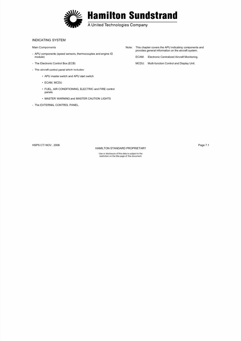
7/21/2019 Aps 3200 Training
http://slidepdf.com/reader/full/aps-3200-training 252/739
HSPS CT/ NOV.. 2006 Page 7.1HAMILTON STANDARD PROPRIETARY
Use or disclosure of this data is subject to therestriction on the title page of this document.
The EXTERNAL CONTROL PANEL.
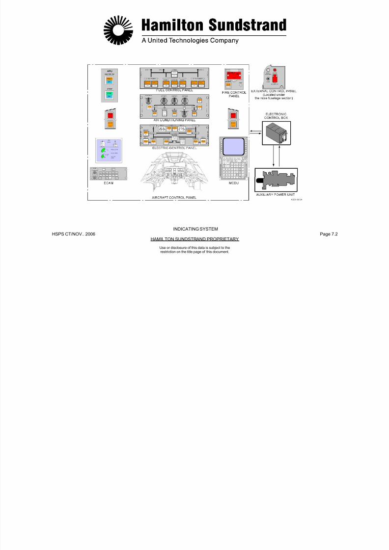
7/21/2019 Aps 3200 Training
http://slidepdf.com/reader/full/aps-3200-training 253/739
HSPS CT/NOV.. 2006 Page 7.2HAMILTON SUNDSTRAND PROPRIETARY
INDICATING SYSTEM
Use or disclosure of this data is subject to therestriction on the title page of this document.
ROTATION SPEED INDICATION SYSTEM - GENERAL
Function
The rotation speed signal is used by the ECB for:
- Indication
- Fuel metering
- ECB Sequencing
- ECB Control functions.
Main Features
Two sensors.
Interfaces
The ECB provides the speed information to the CFDS/ECAM display
Main Components
- One "phonic" wheel with 24 teeth
- Two electromagnetic sensors (single coil)
- Harness
- ECB.
Location of the Main Components
The phonic wheel is secured to the rotor front bearing journal.
The two speed sensors are located in the gearbox housing at 5o'clock and 7 o'clock. Each one is secured by a single bolt.
7/21/2019 Aps 3200 Training
http://slidepdf.com/reader/full/aps-3200-training 254/739
HSPS CT/NOV.. 2006 Page 7.3HAMILTON SUNDSTRAND PROPRIETARY
Use or disclosure of this data is subject to therestriction on the title page of this document.
ysystem.

7/21/2019 Aps 3200 Training
http://slidepdf.com/reader/full/aps-3200-training 255/739
HSPS CT/NOV.. 2006 Page 7.4HAMILTON SUNDSTRAND PROPRIETARY
UN METERED FUELMETERED FUEL
OIL LEVEL
ROTATION SPEED INDICATION SYSTEM - GENERAL
Use or disclosure of this data is subject to therestriction on the title page of this document.
ROTATION SPEED INDICATION SYSTEM -DESCRIPTION AND OPERATION
Description
- Phonic wheel has 24 teeth
- Two single coil speed sensors (the coil surrounds a magnetic core)
• Phonic wheel-speed sensor gap: 0.5 mm (0.018 inch); gapnot adjustable
- The two sensors are connected to the ECB
• Frequency signal at 100 %: 19720 Hz (49300 RPM)
• Frequency signal range: 0 to 24 KHz; 0 to 50 volts.
Operation
The phonic wheel rotates with the rotor assembly, as the teeth passby each speed sensor they generate a voltage. The voltage isproportional to the speed of the phonic wheel. The signal is sent tothe ECB for speed indication and system control.
The ECB will calculate the average signal of the two speed sensors.
In the event a signal difference of 5% or more occurs, the ECB willselect the sensor indicating the highest value.
APU speed indication is displayed on the lower ECAM when the APU system page is selected.

7/21/2019 Aps 3200 Training
http://slidepdf.com/reader/full/aps-3200-training 256/739
HSPS CT/NOV.. 2006 Page 7.5HAMILTON SUNDSTRAND PROPRIETARY
Use or disclosure of this data is subject to therestriction on the title page of this document.
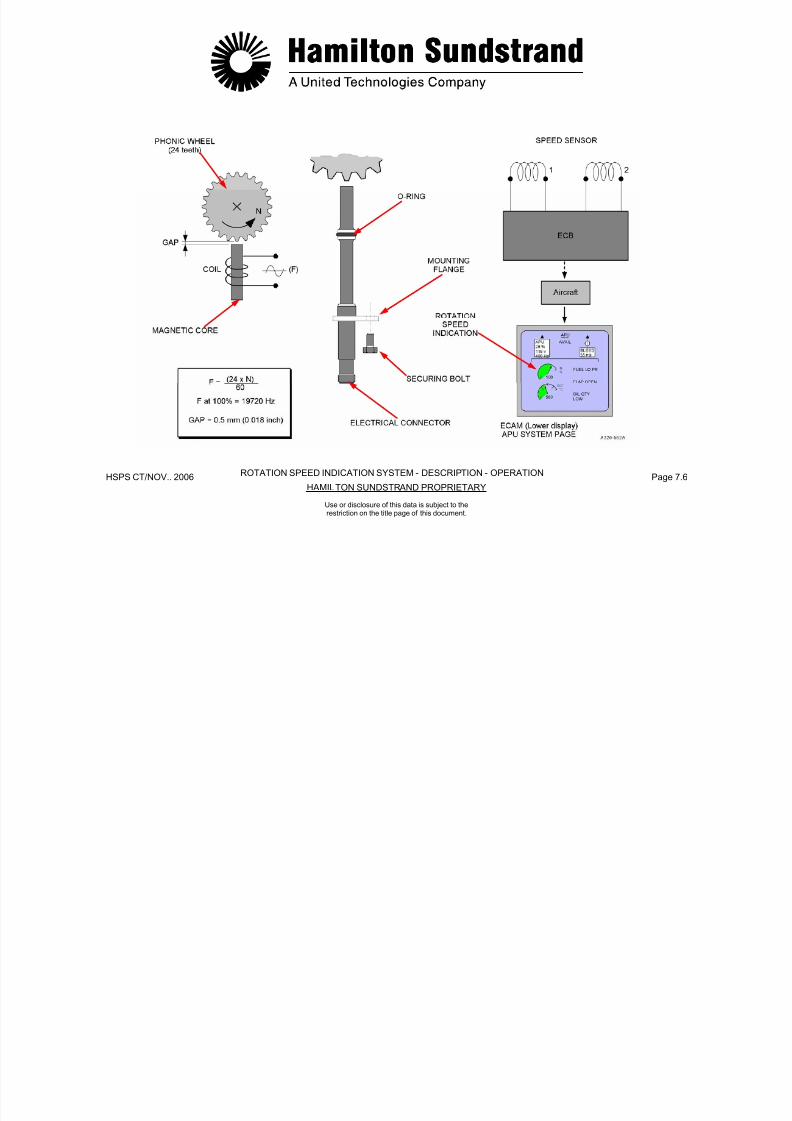
7/21/2019 Aps 3200 Training
http://slidepdf.com/reader/full/aps-3200-training 257/739
HSPS CT/NOV.. 2006 Page 7.6HAMILTON SUNDSTRAND PROPRIETARY
ROTATION SPEED INDICATION SYSTEM - DESCRIPTION - OPERATION
Use or disclosure of this data is subject to therestriction on the title page of this document.
EGT INDICATION SYSTEM - GENERAL
Function
The EGT signal is used for:
- Indication
- Load compressor control
- Sequences
- Control functions.
Main Features
The system uses K type chromel-alumel thermocouples and has acold junction compensation built into the ECB.
Interfaces
The ECB provides the EGT information to the ECAM display system
Main Components
- Two thermocouples
- Harness
- ECB.
Location of the Main Components
The two thermocouples are located in the power section exhausthousing.

7/21/2019 Aps 3200 Training
http://slidepdf.com/reader/full/aps-3200-training 258/739
HSPS CT/NOV.. 2006 Page 7.7HAMILTON SUNDSTRAND PROPRIETARY
Use or disclosure of this data is subject to therestriction on the title page of this document.
The ECB provides the EGT information to the ECAM display system.

7/21/2019 Aps 3200 Training
http://slidepdf.com/reader/full/aps-3200-training 259/739
HSPS CT/NOV.. 2006 Page 7.8HAMILTON SUNDSTRAND PROPRIETARY
EGT INDICATION SYSTEM - GENERAL
Use or disclosure of this data is subject to therestriction on the title page of this document.
EGT INDICATION SYSTEM - DESCRIPTION AND OPERATION
Functional Descripti on
Each thermocouple is secured into the exhaust housing by a bolt.
They are connected separately to the ECB.
Operation
The thermocouple generates a millivolt signal to the ECB that is usedfor engine control and indication (EGT)
The voltage value is of approximately 1 millivolt per 24°C (43°F).
The ECB compensates automatically the cold junction effect andcalculates the average EGT value.
An EGT system failure is declared if:
- EGT is lower than 120°C (250°F)
7/21/2019 Aps 3200 Training
http://slidepdf.com/reader/full/aps-3200-training 260/739
HSPS CT/NOV.. 2006 Page 7.9HAMILTON SUNDSTRAND PROPRIETARY
Use or disclosure of this data is subject to therestriction on the title page of this document.
EGT is lower than 120 C (250 F)
- EGT is higher than 1200°C (2200°F).
The ECU will calculate the average signal of the two thermocouples.In the event a signal difference of 121°C (250°F) or more occurs, theECB will select the thermocouple indicating the highest value.
APU exhaust gas temperature indication is displayed on the lower
ECAM when the APU system page is selected.

7/21/2019 Aps 3200 Training
http://slidepdf.com/reader/full/aps-3200-training 261/739
HSPS CT/NOV.. 2006 Page 7.10HAMILTON SUNDSTRAND PROPRIETARY
EGT INDICATION SYSTEM - DESCRIPTION - OPERATION
Use or disclosure of this data is subject to therestriction on the title page of this document.
ENGINE IDENTIFICATION MODULE
Function
To provide the engine serial number to the ECB.
Location
The module is installed on the ignition exciter support bracket (APUleft side).
Main Features
The ID module consists of a printed circuit board.
Functional Description
The ID module uses resistors located on a printed circuit board.
The board is housed in an electrical plug and is connected to theECB by means of 4 electrical wires.
There are 3 voltage lines V1, V2, V3 and a return line.
The engine ID number is read, validated and stored during the powerup phase of the ECB.
In case of ID module failure, the APU history data will be associatedwith the last valid ID number.
When a new engine ID number occurs, it is used without erasing thepreviously recorded historical data.
7/21/2019 Aps 3200 Training
http://slidepdf.com/reader/full/aps-3200-training 262/739
HSPS CT/NOV.. 2006 Page 7.11HAMILTON SUNDSTRAND PROPRIETARY
Use or disclosure of this data is subject to therestriction on the title page of this document.
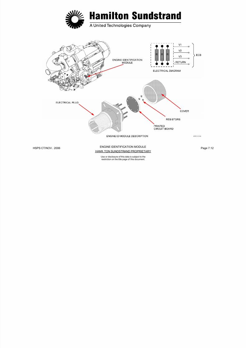
7/21/2019 Aps 3200 Training
http://slidepdf.com/reader/full/aps-3200-training 263/739
HSPS CT/NOV.. 2006 Page 7.12HAMILTON SUNDSTRAND PROPRIETARY
ENGINE IDENTIFICATION MODULE
Use or disclosure of this data is subject to therestriction on the title page of this document.
MONITORING SYSTEM - GENERAL
General
This system gives information about the APU actual status, foroperation and maintenance.
Description
Indication of operating parameters
The APU operating parameters are displayed on the lower ElectronicCentralized Aircraft Monitoring (ECAM) when the APU system pageis selected.
Maintenance and fault isolation
The ECB provides maintenance and fault information to the aircraftCentralized Fault Display System (CFDS). This information isdisplayed on the Multi-function Control and Display Unit (MCDU) inthe flight deck.
Warning messages
Warning, caution and indicating lights
MASTER WARNING, MASTER CAUTION and annunciator lightsprovide visual warning indications.
A FAULT light is incorporated in the APU master switch button, APUGEN button and APU BLEED button.
There are also the following lights:
- APU "ON" light in the APU master switch
- APU "START / ON" and APU "AVAILABLE" light in the APU startbutton
- APU GEN "OFF" light in the APU GEN button
- APU BLEED "ON" light in the APU BLEED button
- APU fire lights on the external control panel and in the flight deck.
7/21/2019 Aps 3200 Training
http://slidepdf.com/reader/full/aps-3200-training 264/739
HSPS CT/NOV.. 2006 Page 7.13HAMILTON SUNDSTRAND PROPRIETARY
Use or disclosure of this data is subject to therestriction on the title page of this document.
Warning messages
APU warning messages are displayed on the upper ECAM and the APU system page appears on the lower ECAM.

7/21/2019 Aps 3200 Training
http://slidepdf.com/reader/full/aps-3200-training 265/739
HSPS CT/NOV.. 2006 Page 7.14HAMILTON SUNDSTRAND PROPRIETARY
MONITORING SYSTEM - GENERAL
Use or disclosure of this data is subject to therestriction on the title page of this document.

7/21/2019 Aps 3200 Training
http://slidepdf.com/reader/full/aps-3200-training 266/739
HSPS CT/NOV.. 2006 Page 7.15HAMILTON SUNDSTRAND PROPRIETARY
APS 3200 AUXILIARY POWER UNIT
Use or disclosure of this data is subject to therestriction on the title page of this document.
APS 3200 AUXILIARY POWER UNIT
SECTION 8
STARTING SYSTEM

7/21/2019 Aps 3200 Training
http://slidepdf.com/reader/full/aps-3200-training 267/739
HSPS CT/NOV. 2006 Page 8.0HAMILTON SUNDSTRAND PROPRIETARY
Use or disclosure of this data is subject to therestriction on the title page of this document.
STARTING SYSTEM - GENERAL
Function
The starting system allows the APU to be started on the ground andin flight.
Starting requires:
- The cranking of the rotor assembly
- The fuel supply
- The ignition of the air-fuel mixture
- The automatic control of starting sequences.
Starting Requirements
- Starting envelope. Normal start throughout the operating envelope:minus 300 m to 11900 m (minus 1000 ft to 39000 ft)
- Starting time from zero speed to governed speed: less than 80
Starting System Components
- Starter motor for cranking
- Ignition exciter and igniters for ignition
- Fuel system
- Control components (Electronic Control Box, APU Master Switch,External Control Panel, Fire Extinguishing Panel).

7/21/2019 Aps 3200 Training
http://slidepdf.com/reader/full/aps-3200-training 268/739
HSPS CT/NOV. 2006 Page 8.1HAMILTON SUNDSTRAND PROPRIETARY
Use or disclosure of this data is subject to therestriction on the title page of this document.
g p g pseconds
- Starting attempts: 3 consecutive starts and cooling for 1 hour.
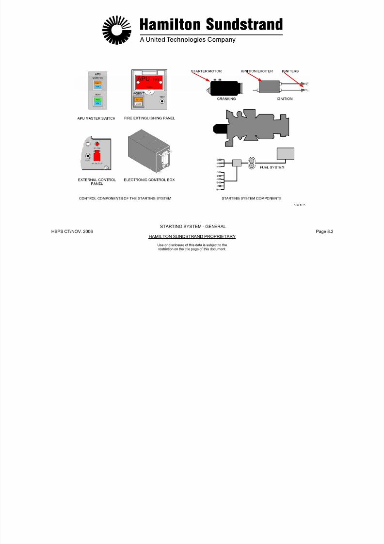
7/21/2019 Aps 3200 Training
http://slidepdf.com/reader/full/aps-3200-training 269/739
HSPS CT/NOV. 2006 Page 8.2HAMILTON SUNDSTRAND PROPRIETARY
Use or disclosure of this data is subject to therestriction on the title page of this document.
STARTING SYSTEM - GENERAL
STARTING SYSTEM - DESCRIPTION
The components involved are the starter-motor, the ignition exciter,the igniters and components of the fuel system and control system.
Starter-Motor
The electric starter motor drives the APU rotor assembly through asprag clutch.
The starter motor is mounted on the gearbox and aligned by alocating pin. A V-band clamp is used to secure the starter to the drive
pad.
A brush wear indicator pin and a starter low voltage sensingconnector are located on the front of the starter.
When brush wear reaches 75%, an indicator pin will appear in theplastic viewing window. (See Page 8.8)
Starter low voltage is sensed by the ECB through the low voltage
sensing connector.
I iti E it
Ignitor Cables
There are two igniter ignitor cables (one for each ignitor plug) thatdelivers high voltage from the exciter to the ignitors.
Ignitor Plugs
Two ignitor plugs are used to ignite the fuel in the combustorchamber. The ignitors are threaded into the combustor housing.
Control System
- Start switch and master switches
- Electronic Control Box.
7/21/2019 Aps 3200 Training
http://slidepdf.com/reader/full/aps-3200-training 270/739
HSPS CT/NOV. 2006 Page 8.3HAMILTON SUNDSTRAND PROPRIETARY
Use or disclosure of this data is subject to therestriction on the title page of this document.
Ignition Exciter
The ignition exciter is located on the left side of the APU. The exciteris a capacitor-discharge unit that uses 28V DC to provide anintermittent high voltage output to the two ignitor plugs.

7/21/2019 Aps 3200 Training
http://slidepdf.com/reader/full/aps-3200-training 271/739
HSPS CT/NOV. 2006 Page 8.4HAMILTON SUNDSTRAND PROPRIETARY
ECB
STARTING SYSTEM- DESCRIPTION
Use or disclosure of this data is subject to therestriction on the title page of this document.
STARTING SYSTEM - OPERATION
Start Selection
Starting is selected from the aircraft control panel:
- Master switch "on"
- APU system page on lower ECAM annunciates ...
- Start button.
Starting Operation
- Cranking
Energize the starter motor.
- Fuel supply
Fuel servo valve and 3 way solenoid valve energized open.
- Ignition
APU starting is controlled by the electronic control box.
The main phases are:
- Initial phase (cranking, fuel supply and ignition)
- Self-sustaining speed (de-energize the starter motor and ignitionexciter)
- 100% speed (speed governing and loading).
Shutdown Sequence
APU shut-down can be activated automatically or manually:
- Manually from the APU master switch, from the fire control panelor from the external control panel
- Automatically by the ECB fault shut-down system.
The ECB controls the fuel control unit 3 way solenoid valve. Whenthe APU is shut down manually or automatically the 3 way solenoid

7/21/2019 Aps 3200 Training
http://slidepdf.com/reader/full/aps-3200-training 272/739
HSPS CT/NOV. 2006 Page 8.5HAMILTON SUNDSTRAND PROPRIETARY
Use or disclosure of this data is subject to therestriction on the title page of this document.
Ignition exciter energized to provide ignition to the two ignitorplugs.
Starting Cycle
the APU is shut down manually or automatically the 3 way solenoidvalve is de-energized closed. The closed valve shuts off the fuel tothe fuel injectors.

7/21/2019 Aps 3200 Training
http://slidepdf.com/reader/full/aps-3200-training 273/739
HSPS CT/NOV. 2006 Page 8.6HAMILTON SUNDSTRAND PROPRIETARY
STARTING SYSTEM - OPERATION
Use or disclosure of this data is subject to therestriction on the title page of this document.
STARTER MOTOR - GENERAL
Function
The electric starter motor cranks the APU during the starting state.
Location
The starter-motor is mounted by a V-band clamp on the gearboxstarter drive pad.
Main Features
- Motor type:
- Weight: 4.22 kg (9.3 lbs)
- Voltage: 24 VDC (max. 28 VDC)
- Max current: 830 A.
Main Components
- The starter motor assembly
- The V-band clamp for attachment
- Positive and negative terminals
- Visual brushwear indicator
- Starter low voltage connector.
Interfaces
- Electrical power to the starter motor is provided by the aircraftbattery system through two start contactors (backup and main)
- Starter low voltage sensing
- Starter motor clutch.
7/21/2019 Aps 3200 Training
http://slidepdf.com/reader/full/aps-3200-training 274/739
HSPS CT/NOV. 2006 Page 8.7HAMILTON SUNDSTRAND PROPRIETARY
Use or disclosure of this data is subject to therestriction on the title page of this document.
(See Page 8.3)
(See Page 8.3)
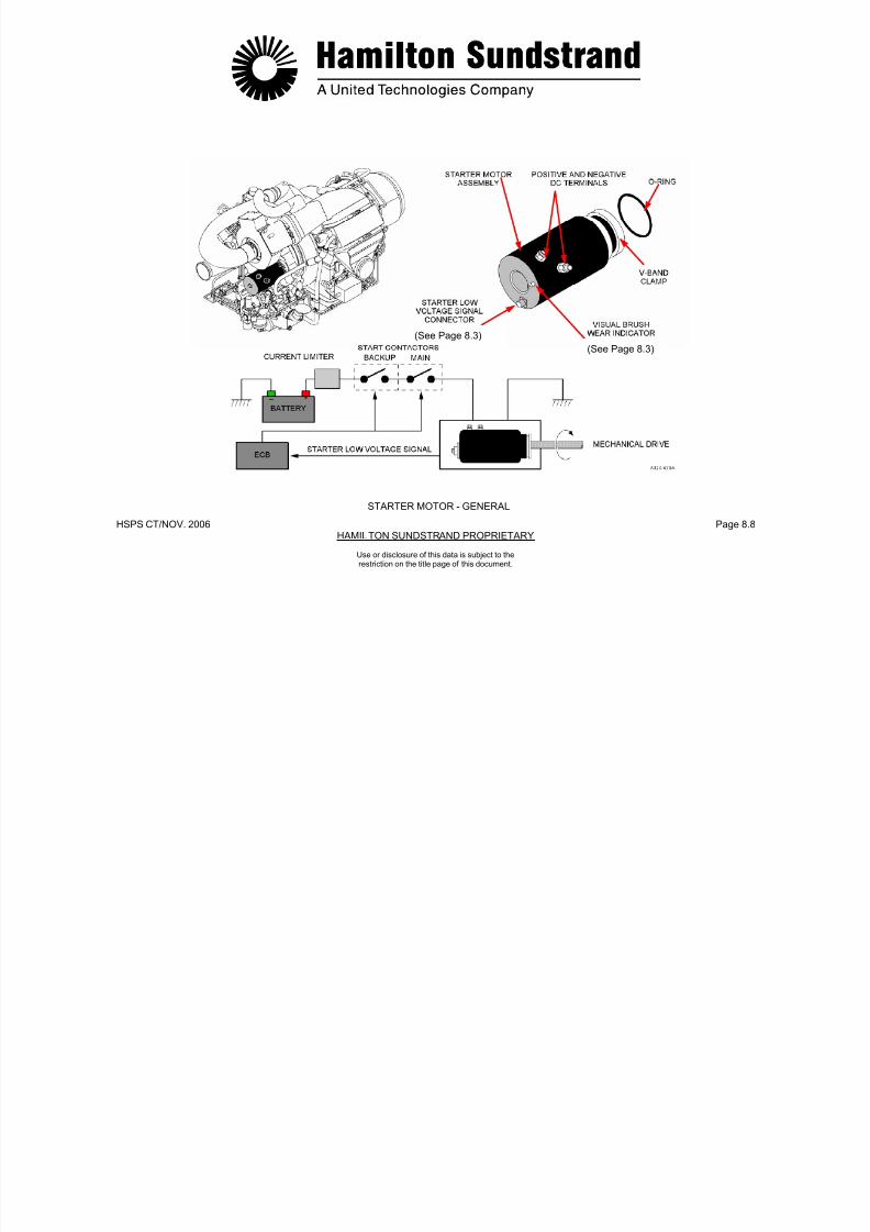
7/21/2019 Aps 3200 Training
http://slidepdf.com/reader/full/aps-3200-training 275/739
HSPS CT/NOV. 2006 Page 8.8HAMILTON SUNDSTRAND PROPRIETARY
STARTER MOTOR - GENERAL
Use or disclosure of this data is subject to therestriction on the title page of this document.
STARTER MOTOR CLUTCH
General
Function
The function of the clutch is to disengage the starter motor when the APU reaches self-sustaining speed.
Description
The clutch is a Line Replaceable Unit. It is necessary to remove the
starter motor and the bearing support assembly to extract the clutch.
The clutch assembly consists of two gears, a starter motor driveshaft, 4 bearings and a sprag clutch.
Operation
Two operating phases are considered : starter motor engaged andstarter motor disengaged.
Starter Motor Engaged
When the starter motor is operating, the sprag pawls make contactwith the starter motor shaft and the gear assembly.
Starter Motor Disengaged
At 55% speed the starter motor is de-energized by the ECB.
As the starter gear speed increases, centrifugal force moves thesprag pawls away from the starter motor shaft.
The starter motor shaft is disconnected from the sprag pawls, thisprevents the APU from driving the starter motor mechanically.

7/21/2019 Aps 3200 Training
http://slidepdf.com/reader/full/aps-3200-training 276/739
HSPS CT/NOV. 2006 Page 8.9HAMILTON SUNDSTRAND PROPRIETARY
Use or disclosure of this data is subject to therestriction on the title page of this document.
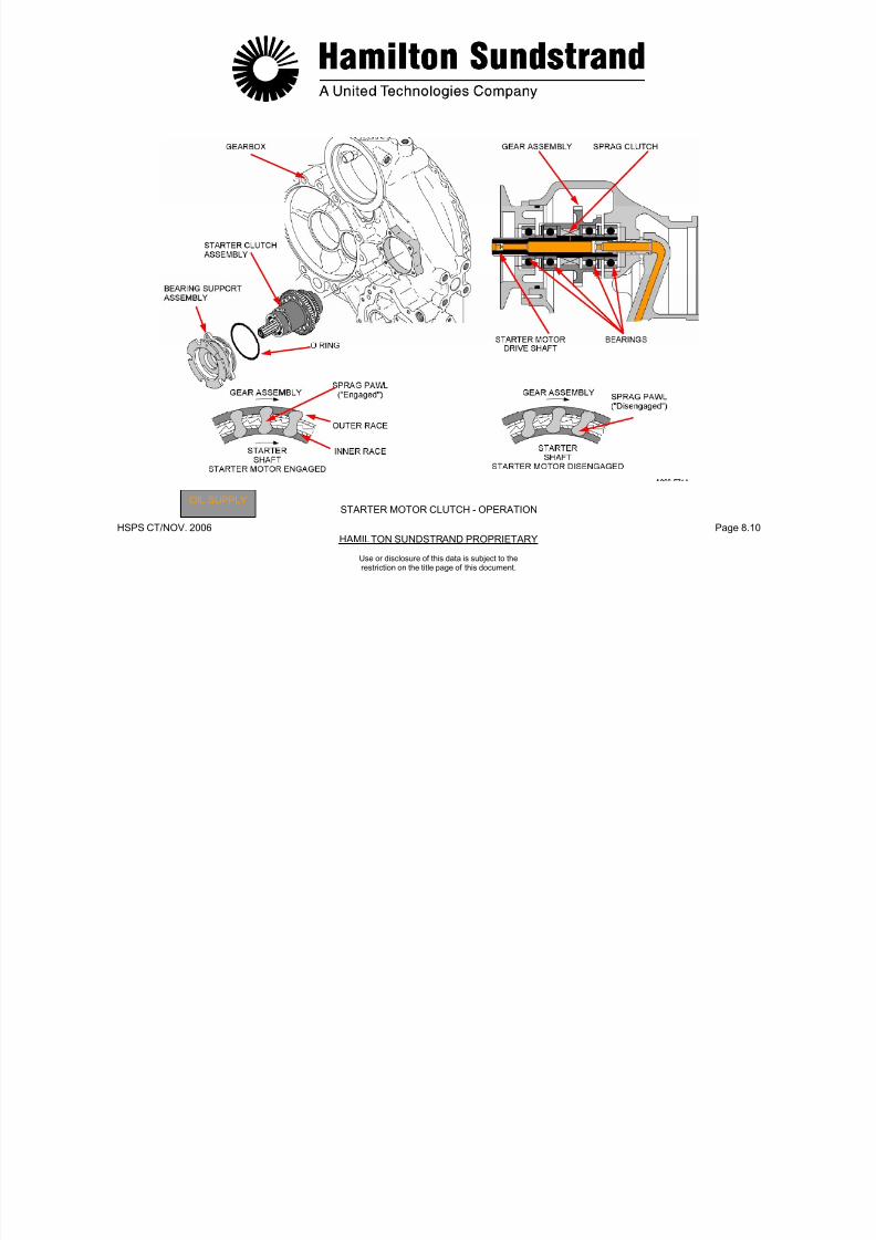
7/21/2019 Aps 3200 Training
http://slidepdf.com/reader/full/aps-3200-training 277/739
HSPS CT/NOV. 2006 Page 8.10HAMILTON SUNDSTRAND PROPRIETARY
OIL SUPPLY STARTER MOTOR CLUTCH - OPERATION
Use or disclosure of this data is subject to therestriction on the title page of this document.
IGNITION EXCITER - GENERAL
Function
The ignition exciter transforms low DC voltage into intermittent highvoltage supply to the ignitor plugs.
Location
The ignition exciter is mounted on the left side of the APU.
Main Features
- Voltage range: 10 VDC to 30 VDC
- Energy: 0.22 Joules per spark
- Spark duration: 15 microseconds
- Spark rate: 2 Hz at voltage above 10 VDC.
IGNITION EXCITER - DESCRIPTION
The ignition exciter is a sealed metal box assembly with a mounting
bracket.
The main components are:
- An input circuit with a connector and a DC/AC converter
- A high voltage transformer
- A high voltage output circuit with a rectifier, two capacitors and a
triggering device.
The ignition exciter DC input voltage is sensed by the ECB for faultdetection.

7/21/2019 Aps 3200 Training
http://slidepdf.com/reader/full/aps-3200-training 278/739
HSPS CT/NOV. 2006 Page 8.11HAMILTON SUNDSTRAND PROPRIETARY
Use or disclosure of this data is subject to therestriction on the title page of this document.

7/21/2019 Aps 3200 Training
http://slidepdf.com/reader/full/aps-3200-training 279/739
HSPS CT/NOV. 2006 Page 8.12HAMILTON SUNDSTRAND PROPRIETARY
IGNITION EXCITER - GENERAL - DESCRIPTION
Use or disclosure of this data is subject to therestriction on the title page of this document.
IGNITORS AND IGNITOR CABLES
Function
There are two ignitor plugs used to ignite the fuel in the combustorchamber during start up of the APU. They are connected to theignition exciter by two shielded ignitor cables.
Location
The two ignitor plugs are located on the combustor housing:
- One at 5 'o'clock
- One at 9 'o'clock.
Note: Location is looking at the combustor housing rear view.
7/21/2019 Aps 3200 Training
http://slidepdf.com/reader/full/aps-3200-training 280/739
HSPS CT/NOV. 2006 Page 8.13HAMILTON SUNDSTRAND PROPRIETARY
Use or disclosure of this data is subject to therestriction on the title page of this document.
IGNITORCABLES

7/21/2019 Aps 3200 Training
http://slidepdf.com/reader/full/aps-3200-training 281/739
HSPS CT/NOV. 2006 Page 8.14HAMILTON SUNDSTRAND PROPRIETARY
IGNITORS
Use or disclosure of this data is subject to therestriction on the title page of this document.
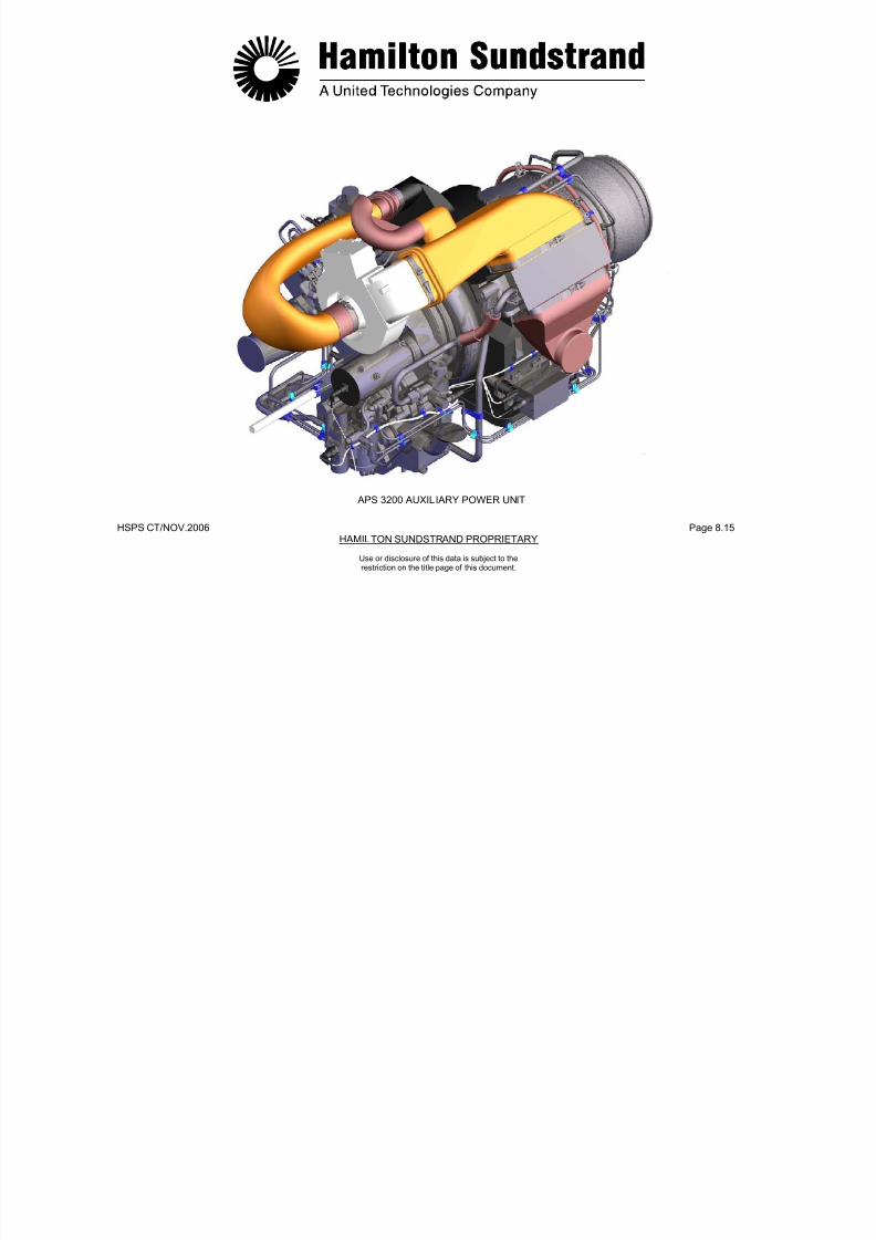
7/21/2019 Aps 3200 Training
http://slidepdf.com/reader/full/aps-3200-training 282/739
HSPS CT/NOV.2006 Page 8.15HAMILTON SUNDSTRAND PROPRIETARY
APS 3200 AUXILIARY POWER UNIT
Use or disclosure of this data is subject to therestriction on the title page of this document.
APS 3200 AUXILIARY POWER UNIT
SECTION 9
ELECTRICAL SYSTEM

7/21/2019 Aps 3200 Training
http://slidepdf.com/reader/full/aps-3200-training 283/739
HSPS CT/NOV.. 2006 Page 9.0HAMILTON SUNDSTRAND PROPRIETARY
Use or disclosure of this data is subject to therestriction on the title page of this document.
ELECTRICAL SYSTEM
Functions
To operate the electrical accessories by control signals from theECB.
To supply AC power from the APU generator to the aircraft electricalsystem.
Main Features
- DC power
- AC power.
Main Components
- The electrical accessories
- The ECB
- The electrical harness.
7/21/2019 Aps 3200 Training
http://slidepdf.com/reader/full/aps-3200-training 284/739
HSPS CT/NOV.. 2006 Page 9.1HAMILTON SUNDSTRAND PROPRIETARY
Use or disclosure of this data is subject to therestriction on the title page of this document.
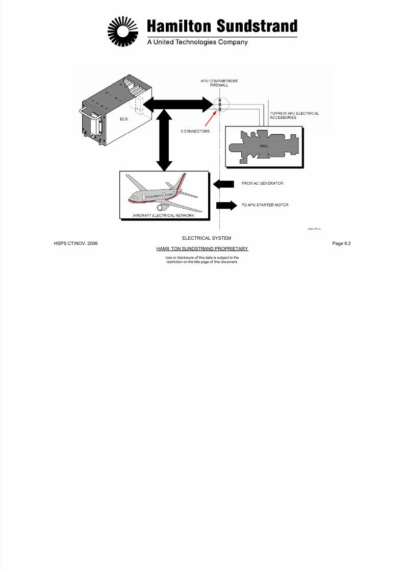
7/21/2019 Aps 3200 Training
http://slidepdf.com/reader/full/aps-3200-training 285/739
HSPS CT/NOV. 2006 Page 9.2HAMILTON SUNDSTRAND PROPRIETARY
ELECTRICAL SYSTEM
Use or disclosure of this data is subject to therestriction on the title page of this document.
AIRCRAFT/APU HARNESS (1)
Description
ECB connectors
The ECB has 2 connectors:
- An ARINC 600-2 connector with 3 inserts (A, B, C)
- A RS 232 C connector.
The ARINC 600 connector is installed at the rear of the ECB andplugs into a shelf mounted aircraft connector.
The ARINC 600 connector carries all inputs/outputs of the ECB plusthe ARINC 429 data link.
The RS 232 connector can be accessed through the front and therear connectors for maintenance purposes.
Aircraf t harness
- DC power to ECB and start contactors
- ARINC 429 data link
- AC generator control
- AC generator excitation control
- RS 232 C connector.
There are three firewall connectors that connect the ECB to theengine harness. They are identified as (J-1, J-2 and J-3).

7/21/2019 Aps 3200 Training
http://slidepdf.com/reader/full/aps-3200-training 286/739
HSPS CT/NOV. 2006 Page 9.3HAMILTON SUNDSTRAND PROPRIETARY
Use or disclosure of this data is subject to therestriction on the title page of this document.
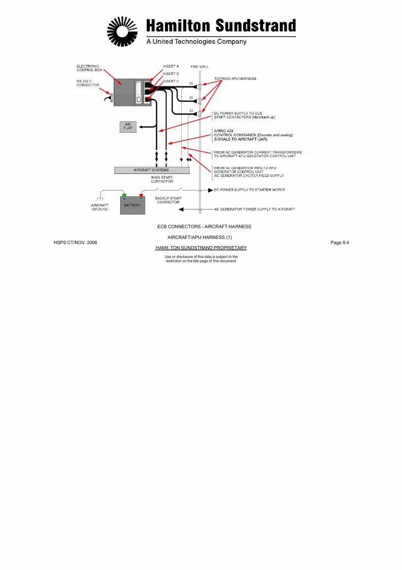
7/21/2019 Aps 3200 Training
http://slidepdf.com/reader/full/aps-3200-training 287/739
HSPS CT/NOV. 2006 Page 9.4HAMILTON SUNDSTRAND PROPRIETARY
ECB CONNECTORS - AIRCRAFT HARNESS
AIRCRAFT/APU HARNESS (1)
Use or disclosure of this data is subject to therestriction on the title page of this document.
AIRCRAFT/APU HARNESS (2)
Description (continued)
APU eng ine harnessThe engine harness is connected to three firewall connectors, theyare identified as (P-1, P-2 and P-3).P1 connector:- PMG- 3 way solenoid valve- Ignition exciter- Starter Motor (low voltage sense signal)
- Bleed Control Valve LVDT- Gearbox de-oiling valve- Oil filter switch indicators- Low oil pressure switch- Oil level sensor- Low fuel pressure switch- Generator high oil temperature sensor- AC generator current transformers.
P2 connector:- Load compressor discharge pressure sensors- IGV actuator (servo valve and LVDT)- BCV actuator (servo valve)- Fuel servo valve- Speeds sensor 1 and 2- Oil temperature sensor- EGT sensor 1 and 2
- Engine ID module- Air inlet pressure and temperature sensor.P3 connector:- AC generator PMG- AC generator excitation control.

7/21/2019 Aps 3200 Training
http://slidepdf.com/reader/full/aps-3200-training 288/739
HSPS CT/NOV. 2006 Page 9.5HAMILTON SUNDSTRAND PROPRIETARY
Use or disclosure of this data is subject to therestriction on the title page of this document.
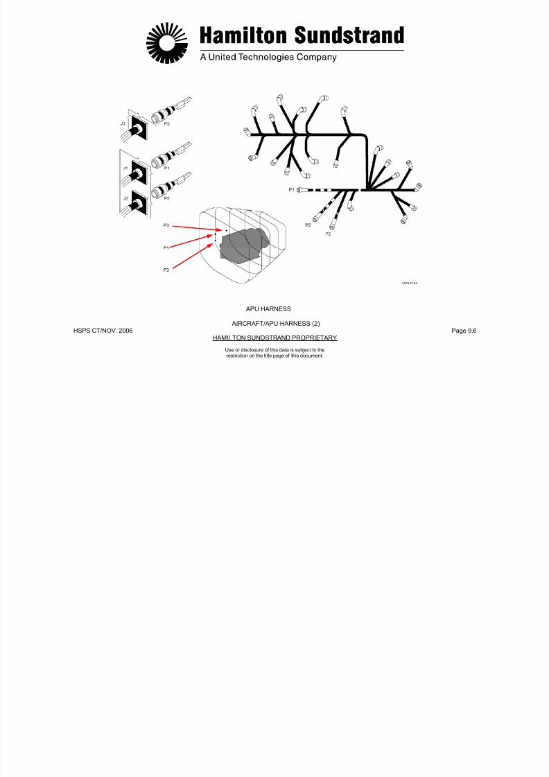
7/21/2019 Aps 3200 Training
http://slidepdf.com/reader/full/aps-3200-training 289/739
HSPS CT/NOV. 2006 Page 9.6HAMILTON SUNDSTRAND PROPRIETARY
APU HARNESS
AIRCRAFT/APU HARNESS (2)
Use or disclosure of this data is subject to therestriction on the title page of this document.
AIRCRAFT/APU HARNESS (3)
Description (continued)
Starter motor electrical power supply cables
The starter motor DC power supply is provided by the aircraftbatteries or the Transformer Rectifier Unit (TRU).
The supply is controlled by two contactors in series (backup andmain start contactors). The power cables link the start contactorsdirectly to the starter motor (+ and -cables).
AC generator harness
The AC generator connector P-4 is part of the engine harness. Theconnector provides the following signals:
- AC generator oil temperature and control signals through the P-1engine harness connector
- AC generator PMG signal and exciter field control through the P-3engine harness connector.
The four AC generator cables are connected to the aircraft electricalbuss system. Three of the cables provide AC power and the fourthcable is a neutral.

7/21/2019 Aps 3200 Training
http://slidepdf.com/reader/full/aps-3200-training 290/739
HSPS CT/NOV. 2006 Page 9.7HAMILTON SUNDSTRAND PROPRIETARY
Use or disclosure of this data is subject to therestriction on the title page of this document.

7/21/2019 Aps 3200 Training
http://slidepdf.com/reader/full/aps-3200-training 291/739
HSPS CT/NOV. 2006 Page 9.8HAMILTON SUNDSTRAND PROPRIETARY
STARTER MOTOR CABLES - AC GENERATOR HARNESS
AIRCRAFT/APU HARNESS (3)
Use or disclosure of this data is subject to therestriction on the title page of this document.
AC GENERATOR - GENERAL
Function
The AC generator (Alternating Current Generator) provides electricalpower to the aircraft systems.LocationThe AC generator is mounted on the front face of the gearbox.Type- Brushless- 3 phases- Oil cooled.Main Features
- Nominal power: 90 kVA- Output: 115 V, 400 Hz- Rotation speed: 24 034 RPM at 100 % APU speed- Direction of rotation: Clockwise viewing the pad- Weight: approx. 22.7 kg (50 lbs).
Interfaces
- Oil system (lubrication, cooling)- Generator Control Unit (GCU)- Electronic Control Box (ECB).Main Components- Permanent Magnet Generator- Current transformers- High oil temperature sensor (HOT).

7/21/2019 Aps 3200 Training
http://slidepdf.com/reader/full/aps-3200-training 292/739
HSPS CT/NOV. 2006 Page 9.9HAMILTON SUNDSTRAND PROPRIETARY
Use or disclosure of this data is subject to therestriction on the title page of this document.
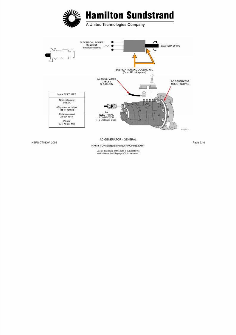
7/21/2019 Aps 3200 Training
http://slidepdf.com/reader/full/aps-3200-training 293/739
HSPS CT/NOV. 2006 Page 9.10HAMILTON SUNDSTRAND PROPRIETARY
AC GENERATOR - GENERAL
Use or disclosure of this data is subject to therestriction on the title page of this document.
ELECTRICAL SYSTEM INTERFACES
The APU AC generator is connected to the aircraft electrical systems
through the APU line contactor.
The lower ECAM, APU system page displays the AC generatorparameters:
- The percent of load
- The output voltage (115 V)
- The output frequency (400 Hz).

7/21/2019 Aps 3200 Training
http://slidepdf.com/reader/full/aps-3200-training 294/739
HSPS CT/NOV. 2006 Page 9.11HAMILTON SUNDSTRAND PROPRIETARY
Use or disclosure of this data is subject to therestriction on the title page of this document.

7/21/2019 Aps 3200 Training
http://slidepdf.com/reader/full/aps-3200-training 295/739
HSPS CT/NOV. 2006 Page 9.12HAMILTON SUNDSTRAND PROPRIETARY
ELECTRICAL SYSTEM INTERFACES
Use or disclosure of this data is subject to therestriction on the title page of this document.
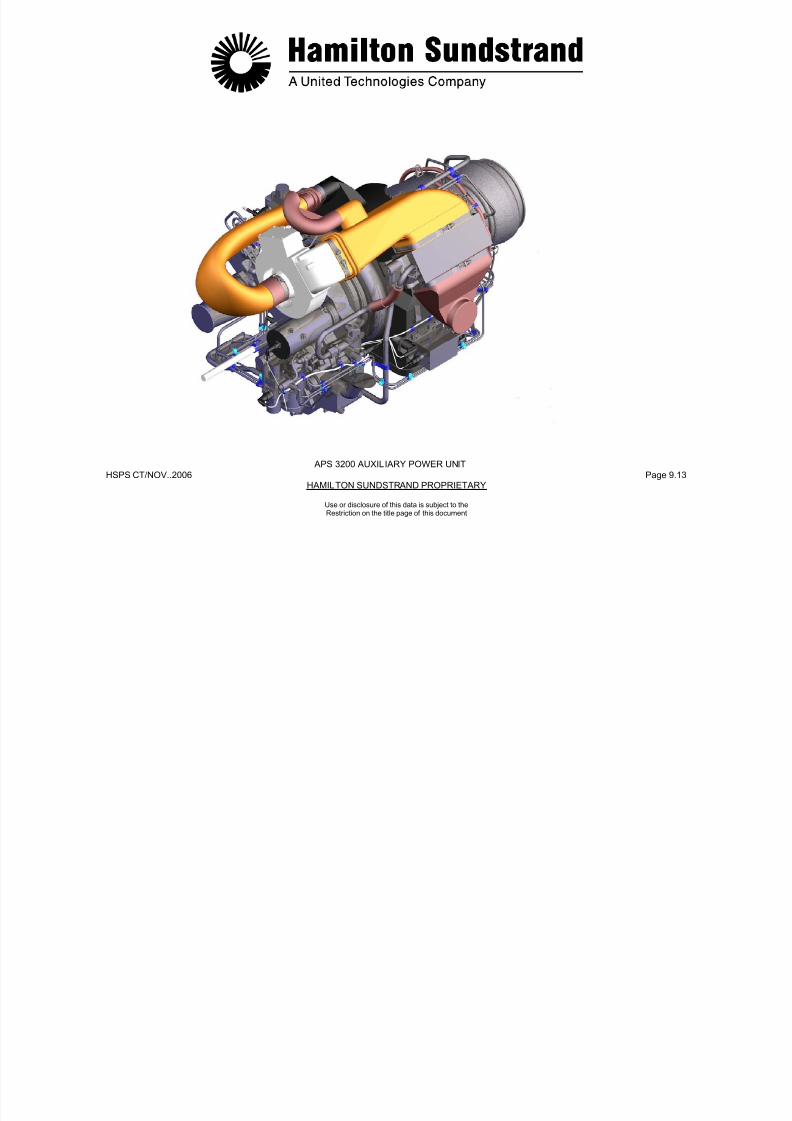
7/21/2019 Aps 3200 Training
http://slidepdf.com/reader/full/aps-3200-training 296/739
HSPS CT/NOV..2006 Page 9.13HAMILTON SUNDSTRAND PROPRIETARY
APS 3200 AUXILIARY POWER UNIT
Use or disclosure of this data is subject to theRestriction on the title page of this document
APS 3200 AUXILIARY POWER UNIT
SECTION 10
APU INSTALLATION

7/21/2019 Aps 3200 Training
http://slidepdf.com/reader/full/aps-3200-training 297/739
HSPS CT/NOV. 2006 Page 10.0HANMILTON SUNDSTRAND PROPRIETARY
Use or disclosure of this data is subject to therestriction on the title page of this document.
APU COMPARTMENT
The APU compartment is located inside the aircraft tail cone.
The compartment is fire proof using firewalls made of titanium alloy.
Two longitudinally-hinged access doors provide access to the APUcompartment.
The air inlet duct assembly is attached to the right access door andprovides a ducted airflow to the APU air inlet plenum.
The APU compartment has a fire extinguishing bottle located in aseparate compartment, forward of the firewall.
Cooling and ventilation of the compartment is provided by the APUcooling fan. The fan provides air flow to the oil cooler and the APUcompartment.

7/21/2019 Aps 3200 Training
http://slidepdf.com/reader/full/aps-3200-training 298/739
HSPS CT/NOV. 2006 Page 10.1HANMILTON SUNDSTRAND PROPRIETARY
Use or disclosure of this data is subject to therestriction on the title page of this document.
APU COMPARTMENT AMBIENT AIRCOMPRESSED AIREXHAUST GAS
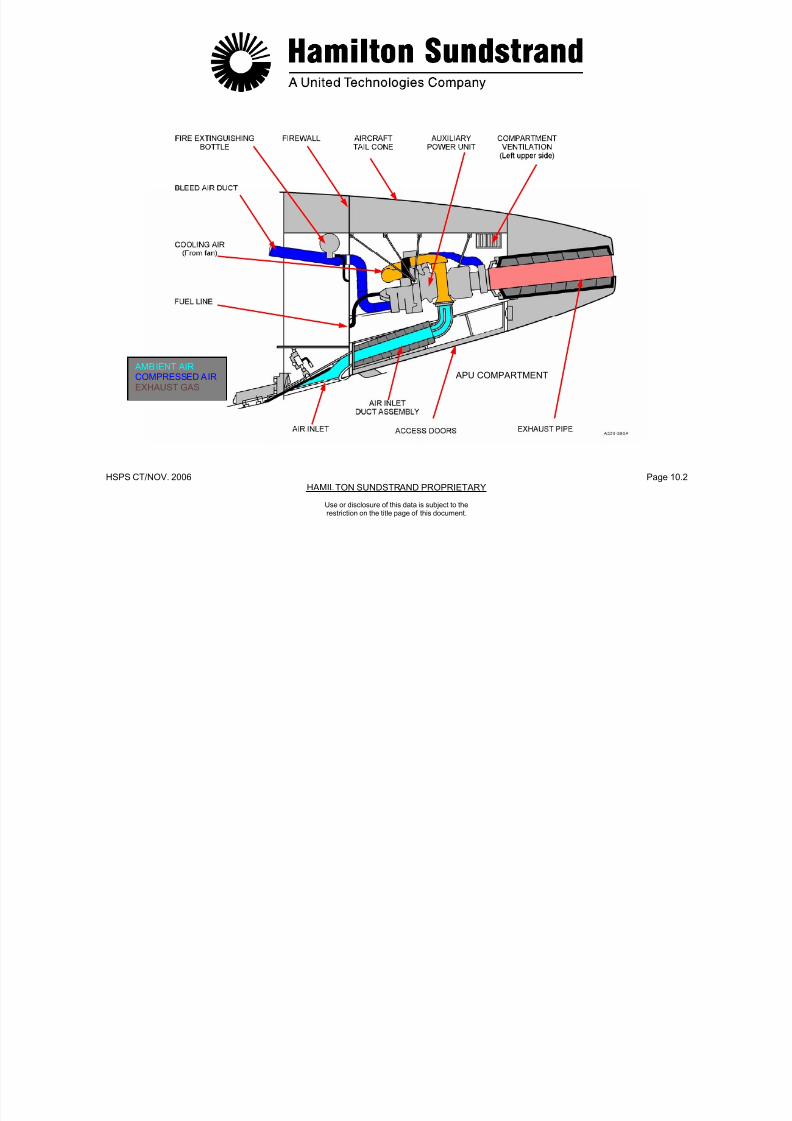
7/21/2019 Aps 3200 Training
http://slidepdf.com/reader/full/aps-3200-training 299/739
HSPS CT/NOV. 2006 Page 10.2HAMILTON SUNDSTRAND PROPRIETARY
Use or disclosure of this data is subject to therestriction on the title page of this document.
APU ATTACHMENT
The APU is attached to the aircraft tail cone structure by three struts.
The struts are connected to the APU through vibration isolators.
The two forward struts are attached to mounts on each side of thegearbox. The rear strut is attached to the power section impellercontainment shield.
A lifting eye is also provided for installation and removal of the APU.

7/21/2019 Aps 3200 Training
http://slidepdf.com/reader/full/aps-3200-training 300/739
HSPS CT/NOV. 2006 Page 10.3HAMILTON SUNDSTRAND PROPRIETARY
Use or disclosure of this data is subject to therestriction on the title page of this document.

7/21/2019 Aps 3200 Training
http://slidepdf.com/reader/full/aps-3200-training 301/739
HSPS CT/NOV. 2006 Page 10.4HAMILTON SUNDSTRAND PROPRIETARY
Use or disclosure of this data is subject to therestriction on the title page of this document.
APU ATTACHMENT
AIR INLET SYSTEM
Function
The air inlet system provides ambient air to the APU air inlet plenum.
Location
The air inlet is located on the underside of the tail section.
System Components
The air inlet system includes:
- The diverter
- The air inlet
- The diffuser
- The elbow
- The interface with the APU inlet plenum.
The Diverter directs ambient air flow into the air inlet when the
aircraft is operating at high airspeeds.
The Air Inlet has a flap that is opened and closed by an electricactuator. The actuator is controlled by the ECB.
The Diffuser slows the airflow delivery to the APU.
The Elbow is attached to the diffuser and directs the ambient airflowinto the APU air inlet plenum.
The air inlet duct assembly is secured to the right access door andcan be removed to provide better accessibility to the APU.

7/21/2019 Aps 3200 Training
http://slidepdf.com/reader/full/aps-3200-training 302/739
HSPS CT/NOV. 2006 Page 10.5HAMILTON SUNDSTRAND PROPRIETARY
Use or disclosure of this data is subject to therestriction on the title page of this document.
AMBIENT AIR

7/21/2019 Aps 3200 Training
http://slidepdf.com/reader/full/aps-3200-training 303/739
HSPS CT/NOV. 2006 Page 10.6HAMILTON SUNDSTRAND PROPRIETARY
AIR INLET SYSTEM
Use or disclosure of this data is subject to therestriction on the title page of this document.
EXHAUST SYSTEM
Function
The exhaust system directs the APU exhaust gasses overboard.
Location
The system is installed in the tail cone between the APU exhaustand the end of the tail cone.
System Components
- The exhaust pipe
- The exhaust muffler
- The insulation
- The sealing ring.
The exhaust pipe is mounted on rails that are attached to the insideof the tail cone.
This allows the exhaust pipe to be disconnected from the APU andmoved rearward to provide additional clearance during removal andinstallation of the APU.

7/21/2019 Aps 3200 Training
http://slidepdf.com/reader/full/aps-3200-training 304/739
HSPS CT/NOV. 2006 Page 10.7HAMILTON SUNDSTRAND PROPRIETARY
Use or disclosure of this data is subject to therestriction on the title page of this document.
EXHAUST GAS
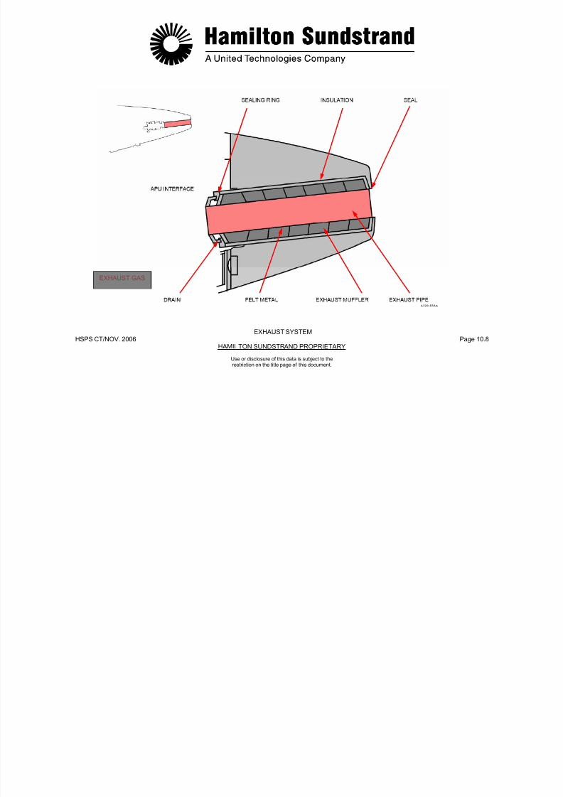
7/21/2019 Aps 3200 Training
http://slidepdf.com/reader/full/aps-3200-training 305/739
HSPS CT/NOV. 2006 Page 10.8HAMILTON SUNDSTRAND PROPRIETARY
Use or disclosure of this data is subject to therestriction on the title page of this document.
EXHAUST SYSTEM
DRAIN SYSTEM (1)
Function
The APU drain system provides drains from various components.The fluids are collected and drained overboard through the drainmast.
The fuel control unit, BCV actuator and IGV actuator use a commondrain to the aircraft drain tank. Fluids are siphoned from the draintank, into the drain mast and then discharged overboard when theaircraft is in flight.
The other common and single drains flow directly into the drain mastand then discharge overboard.
APU Drains and Vent
- Combustor Drain
- Air Bypass Plenum Drain
- Exhaust Pipe Drain
- Front Bearing Seal Drain
- Fuel Control Unit Drain
- Flow Divider Purge Drain (To exhaust)
- Gearbox Vent (To exhaust).
7/21/2019 Aps 3200 Training
http://slidepdf.com/reader/full/aps-3200-training 306/739
HSPS CT/NOV. 2006 Page 10.9HAMILTON SUNDSTRAND PROPRIETARY
Use or disclosure of this data is subject to therestriction on the title page of this document.
- BCV Actuator Seal Drain
- IGV Actuator Seal Drain
SIPHON TUBE
COLLECTORTANK
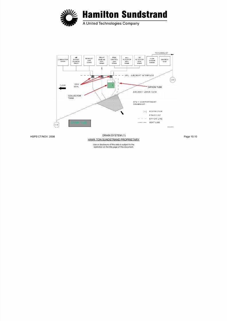
7/21/2019 Aps 3200 Training
http://slidepdf.com/reader/full/aps-3200-training 307/739
HSPS CT/NOV. 2006 Page 10.10HAMILTON SUNDSTRAND PROPRIETARY
Use or disclosure of this data is subject to therestriction on the title page of this document.
DRAIN SYSTEM (1)
DRAIN FLUID
FIRE PROTECTION
APU fire protection consists of a detection system and anextinguishing system. The systems are supplied by the aircraftmanufacturer.
Fire Detection and Extinguish ing
The detection system uses two continuous sensing elementsinstalled on the APU compartment walls.
One fire bottle is available for fire extinguishing. The bottle isinstalled on the forward side of the APU compartment firewall.
Operation
The APU fire control panel is located in the flight deck overheadpanel.
Pushing the fire switch will immediately shut down the APU and armthe fire extinguishing system.
In the event of an APU fire on the ground, the APU will automaticallyshutdown and discharge the extinguishing system.

7/21/2019 Aps 3200 Training
http://slidepdf.com/reader/full/aps-3200-training 308/739
HSPS CT/NOV. 2006 Page 10.11HAMILTON SUNDSTRAND PROPRIETARY
Use or disclosure of this data is subject to therestriction on the title page of this document.

7/21/2019 Aps 3200 Training
http://slidepdf.com/reader/full/aps-3200-training 309/739
HSPS CT/NOV. 2006 Page 10.12HAMILTON SUNDSTRAND PROPRIETARY
FIRE PROTECTION
Use or disclosure of this data is subject to therestriction on the title page of this document.

7/21/2019 Aps 3200 Training
http://slidepdf.com/reader/full/aps-3200-training 310/739
HSPS CT/NOV. 2006 Page 10.13HAMILTON SUNDSTRAND PROPRIETARY
Use or disclosure of this data is subject to therestriction on the title page of this document
APS 3200 AUXILIARY POWER UNIT
APS 3200 AUXILIARY POWER UNIT
SECTION 11
MAINTENANCE

7/21/2019 Aps 3200 Training
http://slidepdf.com/reader/full/aps-3200-training 311/739
HSPS CT/NOV.. 2006 Page 11.0HAMILTON SUNDSTRAND PROPRIETARY
Use or disclosure of this data is subject to therestriction on the title page of this document.
INSPECTION AND CHECKS
Visual Inspections
Opening the APU compartment for corrective maintenance orservicing provides the opportunity to visually inspect the APU forsecurity, leaks, and warning indicators. The following arerecommended inspection items:
- Engine mounts
- Engine Components and Fluid lines
- Oil Quantity and Magnetic Drain plug
- Oil and Fuel Filter impending blockage Indicators
- Electrical harness and Connectors
- Engine Air Inlet Plenum
- Engine Combustor Housing and Exhaust System.
Borescope Inspection
The APU internal components may be inspected by using a flexibleborescope. To rotate the APU internal components, the cooling faninlet duct may be removed to allow manual rotation of the fanimpeller.
The following components can be inspected with the APU installed inthe aircraft.
- Load compressor impeller and guide vanes
- Power section impeller
- Combustor, viewed through the ignitor and fuel injector bosses
- First stage turbine wheel
- Second stage turbine wheel.
Refer to the Aircraft Maintenance Manual for borescopeprocedures.

7/21/2019 Aps 3200 Training
http://slidepdf.com/reader/full/aps-3200-training 312/739
HSPS CT/NOV.. 2006 Page 11.1HAMILTON SUNDSTRAND PROPRIETARY
Use or disclosure of this data is subject to therestriction on the title page of this document.

7/21/2019 Aps 3200 Training
http://slidepdf.com/reader/full/aps-3200-training 313/739
HSPS CT/NOV. 2006 Page 11.2HAMILTON SUNDSTRAND PROPRIETARY
VISUAL INSPECTIONS - BORESCOPE INSPECTION
INSPECTION AND CHECKS
Use or disclosure of this data is subject to therestriction on the title page of this document.
LINE REPLACEABLE UNITS
The following Line Replaceable Units (LRU's) can be removed andreplaced without removing the APU from the aircraft:
Electronic Control BoxEngine HarnessIdentification ModuleStarter MotorClutch AssemblyIgnition Exciter
Ignitor CablesIgnitor PlugsSpeed SensorsThermocouples
Air Inlet Pressure And Temperature SensorOil Filter ElementsSwitch IndicatorsMagnetic Drain PlugDe-Oiling ValveLow Oil Pressure SwitchOil Temperature SensorOil Level SensorOil Pressure Relief ValveOil CoolerFuel Control UnitFuel Filter ElementFlow Divider Assembly
Pilot Fuel InjectorsMain Fuel InjectorsInlet Guide Vane ActuatorBleed Control ValveCompressor Discharge SensorCooling Fan Assembly
AC Generator PadFuel and Oil PipesCombustor Chamber Drain Valve
7/21/2019 Aps 3200 Training
http://slidepdf.com/reader/full/aps-3200-training 314/739
HSPS CT/NOV. 2006 Page 11.3HAMILTON SUNDSTRAND PROPRIETARY
Use or disclosure of this data is subject to therestriction on the title page of this document.
Flow Divider AssemblyPilot Manifold AssemblyMain Manifold Assembly
COOLING FAN ASSEMBLY
STARTER
ENGINEHARNESS
OIL COOLER
FUEL CONTROLUNIT
DE-OILING
IDENTIFICATIONMODULE
IGNITION
EXCITER
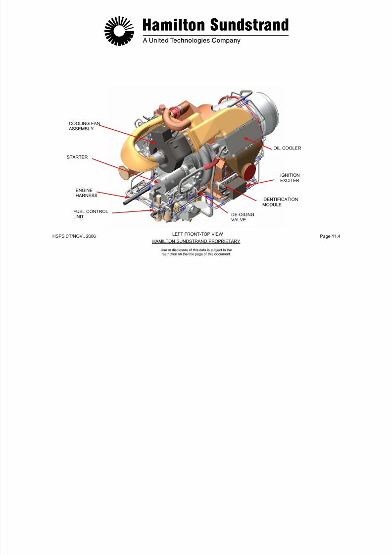
7/21/2019 Aps 3200 Training
http://slidepdf.com/reader/full/aps-3200-training 315/739
HSPS CT/NOV.. 2006 Page 11.4HAMILTON SUNDSTRAND PROPRIETARY
Use or disclosure of this data is subject to therestriction on the title page of this document.
LEFT FRONT-TOP VIEW
UNITDE OILINGVALVE
INLET GUIDEVANE
ACTUATOR
BLEEDCONTROLVALVE
COMPRESSORDISCHARGE
AC GENERATORMOUNTING PAD
SENSOROILLEVELSENSORSPEED
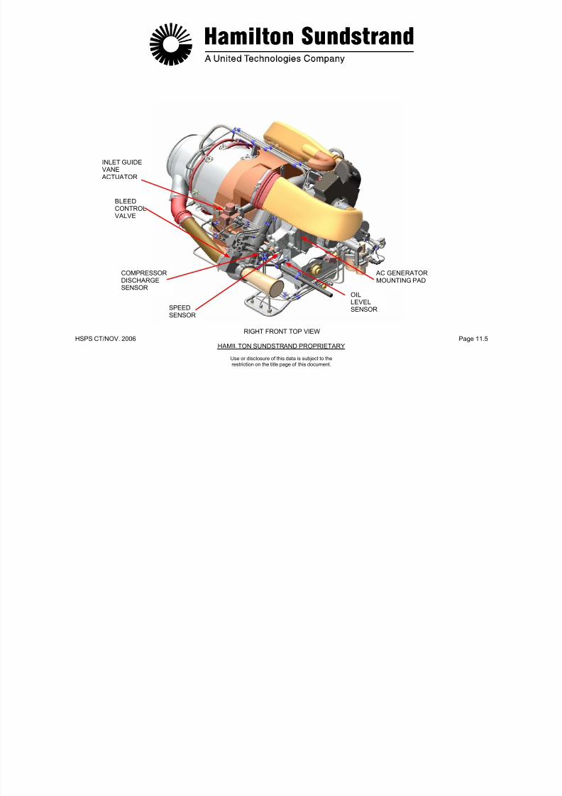
7/21/2019 Aps 3200 Training
http://slidepdf.com/reader/full/aps-3200-training 316/739
HSPS CT/NOV. 2006 Page 11.5HAMILTON SUNDSTRAND PROPRIETARY
Use or disclosure of this data is subject to therestriction on the title page of this document.
RIGHT FRONT TOP VIEW
SENSORSENSOR
SWITCHINDICATORS
MAGNETIC
GENERATORSCAVENGEFILTER
LUBRICATIONFILTER
OIL PRESSURE

7/21/2019 Aps 3200 Training
http://slidepdf.com/reader/full/aps-3200-training 317/739
HSPS CT/NOV. 2006 Page 11.6HAMILTON SUNDSTRAND PROPRIETARY
DRAIN PLUG REIEF VALVE
RIGHT FRONT BOTTOM VIEW
Use or disclosure of this data is subject to therestriction on the title page of this document.
THERMOCOUPLE
IGNITORCABLES
OIL TEMPERATURESENSOR
SPEEDSENSOR
FUELFILTER
PILOTMANIFOLD
ASSEMBLY
IGNITOR
FUEL FLOWDIVIDER
ASSEMBLY
MAINMANIFOLD
ASSEMBLY
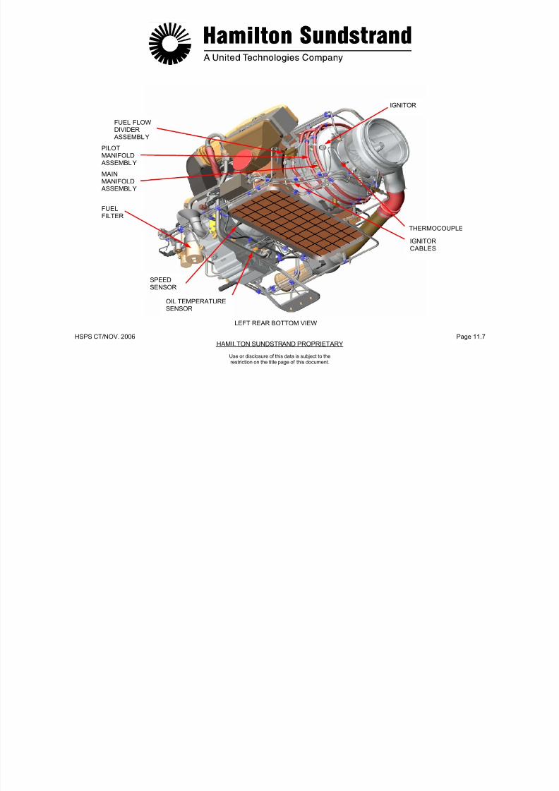
7/21/2019 Aps 3200 Training
http://slidepdf.com/reader/full/aps-3200-training 318/739
HSPS CT/NOV. 2006 Page 11.7HAMILTON SUNDSTRAND PROPRIETARY
SENSOR
LEFT REAR BOTTOM VIEW
Use or disclosure of this data is subject to therestriction on the title page of this document.
AIR INLET AND
TEMPERATURESENSOR
LOW OILPRESSURE SWITCH
NOTE:(The switch may alsobe Located on thelower right side of
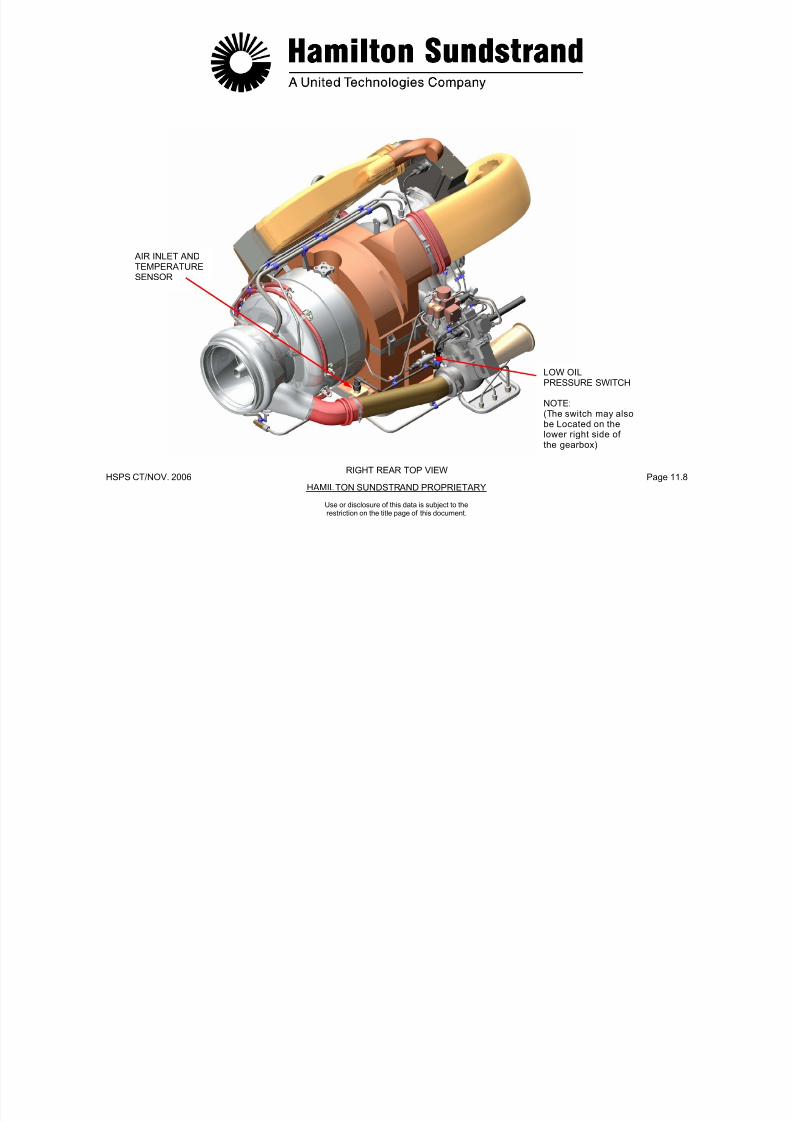
7/21/2019 Aps 3200 Training
http://slidepdf.com/reader/full/aps-3200-training 319/739
HSPS CT/NOV. 2006 Page 11.8HAMILTON SUNDSTRAND PROPRIETARY
the gearbox)
RIGHT REAR TOP VIEW
Use or disclosure of this data is subject to therestriction on the title page of this document.
THEMOCOUPLE
IGNITOR
COMBUSTORDRAIN CHECKCHECK VALVE
MAIN FUELINJECTOR
PILOT FUELINJECTOR
AIR INLET ANDTEMPERATURE

7/21/2019 Aps 3200 Training
http://slidepdf.com/reader/full/aps-3200-training 320/739
HSPS CT/NOV. 2006 Page 11.9HAMILTON SUNDSTRAND PROPRIETARY
SENSOR
RIGHT REAR BOTTOM VIEW
Use or disclosure of this data is subject to therestriction on the title page of this document.
APS 3200
AUXILIARY POWER UNIT
SECTION 12
FAULT ISOLATION
VERSION 6.0

7/21/2019 Aps 3200 Training
http://slidepdf.com/reader/full/aps-3200-training 321/739
HSPS CT/NOV. 2006 Page 12.0HAMILTON SUNDSTRAND PROPRIETARY
Use or disclosure of this data is subject to therestriction on the title page of this document.
GENERAL DESCRIPTION
The centralized fault display system (CFDS) provides electronicsystem fault detection, fault storage, fault displays, operationaltesting and troubleshooting from the flight deck multi-purpose controland display unit (MCDU).
CENTRALIZED FAULT DISPLAY AND INTERFACE UNIT
The CFDIU provides the interface between the APU electroniccontrol box (ECB) and the MCDU for screen display of APU faultinformation.
MULTIPURPOSE CONTROL AND DISPLAY UNITS
The Multipurpose Control and Display Unit (MCDU) is a display unitand a keyboard used by the CFDS to display and interrogate faultsand to initiate system tests. Both MCDU's (Multipurpose Control andDisplay Unit) are connected to the CFDS.
Only one MCDU can be used when interrogating the CFDS.
CFDIU/PRINTER INTERFACE
The CFDIU sends MCDU screen information and print commands tothe optional printer automatically or on request.
CFDIU/ACARS INTERFACE
The CFDIU sends fault information to the optional ACARS for down-linking when selected manually by the MCDU operator or when anuplink request is received from a ground station via the ACARSmanagement unit.

7/21/2019 Aps 3200 Training
http://slidepdf.com/reader/full/aps-3200-training 322/739
HSPS CT/NOV. 2006 Page 12.1HAMILTO SUNDSTRAND PROPRIETARY
Use or disclosure of this data is subject to therestriction on the title page of this document.
MCDU - 2
MCDU - 1

7/21/2019 Aps 3200 Training
http://slidepdf.com/reader/full/aps-3200-training 323/739
HSPS CT/NOV. 2006 Page 12.2HAMILTO SUNDSTRAND PROPRIETARY
CENTRALIZED FAULT DISPLAY SYSTEM
Use or disclosure of this data is subject to therestriction on the title page of this document.
APU FAULT WARNINGS
Flight Deck Fault Warnings are identified as Class 1, 2 and 3.Class 1 faults are further identified as Level 3, 2 and 1.
CLASS 1
- Level 3- This level corresponds to warnings needing immediate
action.- Level 3 warnings are associated with:
- Repetitive chime- Warning message on upper ECAM display- Master Warning Light flashing Red
- APU systems page on lower ECAM display
- Level 2- This level corresponds to abnormal situations needing
immediate awareness but not immediate action.- Level 2 warnings are associated with:
- Single chime- Master caution steady Amber light- Warning messages on upper ECAM display
- APU system page on lower ECAM displayLevel 1- This level corresponds to reduced bleed air performance- It is associated with low or zero duct pressure- Low or zero duct pressure is visible (lower ECAM display) on
the engine system page during MES or on the APUsystem page.
CLASS 2
- These failures are indicated on the STATUS page, under the title
of MAINTENANCE.- They are also accessible through the CFDS.
indicates that the STATUS page is not empty andflashes in flight phase 10 on the upper ECAM display.STS
CLASS 3
- These failures are only accessible through the CFDS. No APUfault warnings are displayed.

7/21/2019 Aps 3200 Training
http://slidepdf.com/reader/full/aps-3200-training 324/739
HSPS CT/NOV. 2006 Page 12.3HAMILTO SUNDSTRAND PROPRIETARY
Use or disclosure of this data is subject to therestriction on the title page of this document.

7/21/2019 Aps 3200 Training
http://slidepdf.com/reader/full/aps-3200-training 325/739
APU FAULT WARNINGS
STATUS
STATUS (STS) indication is an "attention getter" on the upper ECAMdisplay.
STATUS (STS) indicates that a status message (class 1 or class 2fault) is present and further maintenance action may be required. Aflashing STS indication occurs after the second engine shutdown inFlight Phase 10. It is necessary to press the STS key on the ECAMcontrol panel for the STATUS page to appear on the lower ECAMdisplay.

7/21/2019 Aps 3200 Training
http://slidepdf.com/reader/full/aps-3200-training 326/739
HSPS CT/NOV. 2006 Page 12.5HAMILTO SUNDSTRAND PROPRIETARY
Use or disclosure of this data is subject to therestriction on the title page of this document.

7/21/2019 Aps 3200 Training
http://slidepdf.com/reader/full/aps-3200-training 327/739
HSPS CT/NOV. 2006 Page 12.6HAMILTO SUNDSTRAND PROPRIETARY
UPPER ECAM ADVISORY AND STATUS DISPLAY
Use or disclosure of this data is subject to therestriction on the title page of this document.
APU FAULT WARNINGS
ECAM CONTROL PANEL
The control panel allows selection of the aircraft system pageincluding APU. Pressing the Status (STS) key presents the STATUSpage on the lower ECAM display. The STATUS page will indicate thefaulty aircraft systems under the INOP SYS (Class 1 Fault) andMAINTENANCE (Class 2 Fault) titles.

7/21/2019 Aps 3200 Training
http://slidepdf.com/reader/full/aps-3200-training 328/739
HSPS CT/NOV. 2006 Page 12.7HAMILTO SUNDSTRAND PROPRIETARY
Use or disclosure of this data is subject to therestriction on the title page of this document.
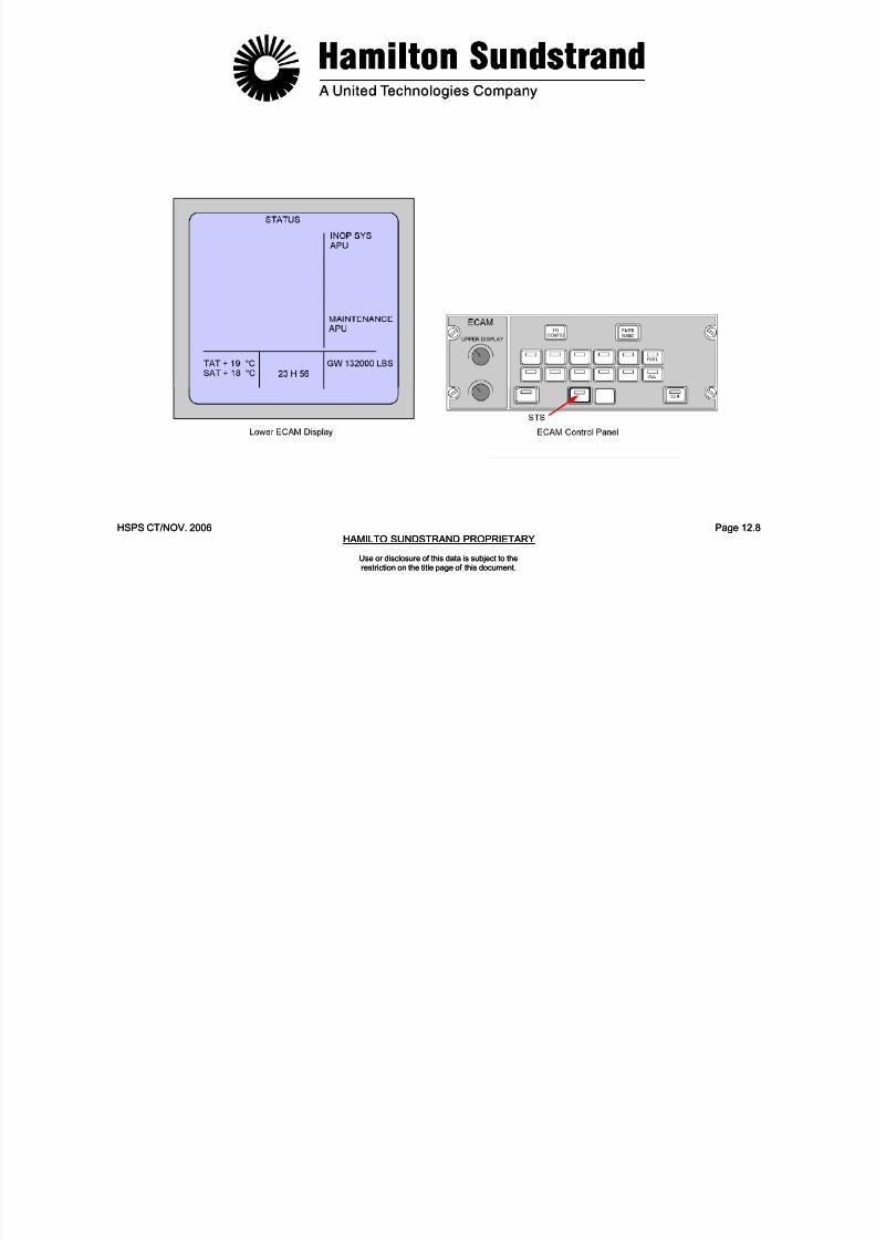
7/21/2019 Aps 3200 Training
http://slidepdf.com/reader/full/aps-3200-training 329/739
HSPS CT/NOV. 2006 Page 12.8HAMILTO SUNDSTRAND PROPRIETARY
Use or disclosure of this data is subject to therestriction on the title page of this document.
HSPS CT/NOV. 2006 Page 12.8HAMILTO SUNDSTRAND PROPRIETARY
Use or disclosure of this data is subject to therestriction on the title page of this document.
MULTIPURPOSE CONTROL AND DISPLAY UNITS
The Multipurpose Control and Display Unit (MCDU) is a display unitand a keyboard used by the CFDS to display and interrogate faults
and to initiate system tests. Both MCDU's (Multipurpose Control andDisplay Unit) are connected to the CFDS.
Only one MCDU can be used when interrogating the CFDS.
Pressing the MCDU MENU key, the MCDU menu page is displayed,and any one of the systems connected to the MCDU can beselected.
A multiple page display is indicated by an arrow (∇) in the right uppercorner of the screen. In this case the NEXT PAGE key must be usedto provide access to the various pages of the display. The NEXTPAGE key can be used as long as the arrow is displayed.
Twelve line select keys, six on the left and six on the right, provideaccess to a page or a function. The line select keys permit access toa page or a function when these prompt symbols appear (>, <). Theyare identified as 1L to 6L on the left, and 1R to 6R on the right.
If a flight deck printer is installed and operational, the current MCDUdisplay screen may be printed by pushing the PRINT line select key.
APU FAULT OPERATION
SYSTEM SELECTION
The MCDU MENU page is displayed when the MCDU MENU key ispushed.
Selecting the CFDS line select key will then display CFDS menu.
Pressing the SYSTEM REPORT/TEST line select key displays theSYSTEM REPORT TEST menu.

7/21/2019 Aps 3200 Training
http://slidepdf.com/reader/full/aps-3200-training 330/739
HSPS CT/NOV. 2006 Page 12.9HAMILTON SUNDSTRAND PROPRIETARY
Use or disclosure of this data is subject to therestriction on the title page of this document.
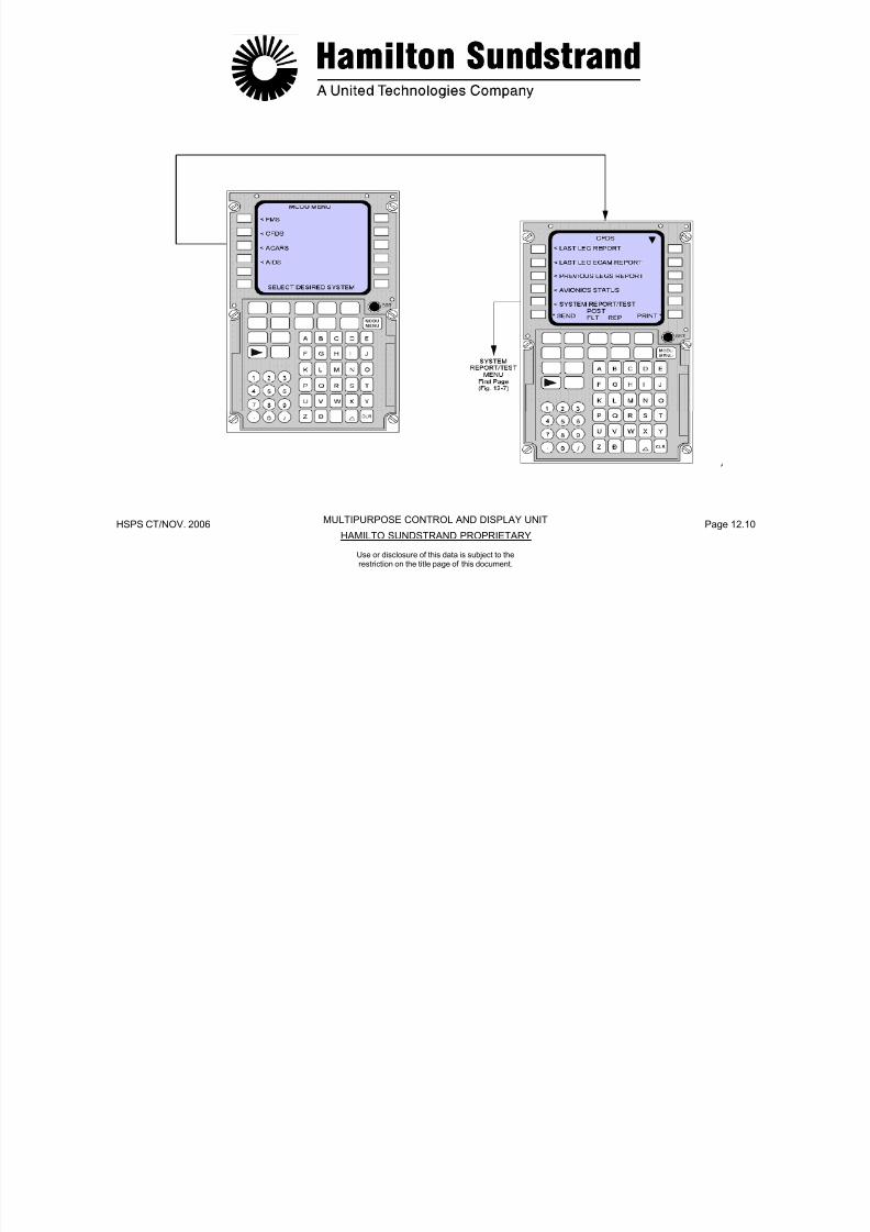
7/21/2019 Aps 3200 Training
http://slidepdf.com/reader/full/aps-3200-training 331/739
HSPS CT/NOV. 2006 Page 12.10HAMILTO SUNDSTRAND PROPRIETARY
MULTIPURPOSE CONTROL AND DISPLAY UNIT
Use or disclosure of this data is subject to therestriction on the title page of this document.
APU FAULT OPERATION
SYSTEM REPORT/TEST
When SYSTEM REPORT/TEST is selected while on the ground, asystems menu is displayed. The APU selection is located on thesecond page of the menu. Pushing the NEXT PAGE key will display
APU.
Selection of the RETURN line select key on the first page will displayMCDU MENU.
Selection of the RETURN line select key on the second page will
display the first page of SYSTEM REPORT/ TEST.
APU
There are two APU menu pages available. The first page displaysthe following information:
LASTLEGREPORT
PREVIOUSLEGREPORT
LRUIDENTIFICATION
SYSTEMSELF-TEST
SHUTDOWNS
The second page of the APU menu when selected by theNEXTPAGE key, displays the following information:
APUDATA/OIL
CLASS3FAULTS
Selection of the RETURN line select key on the First Page willdisplay the Second Page of SYSTEM REPORT/TEST.Selection of the RETURN line select key on the (Second Page) willdisplay the (First Page) of APU menu.
7/21/2019 Aps 3200 Training
http://slidepdf.com/reader/full/aps-3200-training 332/739
HSPS CT/NOV. 2006 Page 12.11HAMILTO SUNDSTRAND PROPRIETARY
Use or disclosure of this data is subject to therestriction on the title page of this document.

7/21/2019 Aps 3200 Training
http://slidepdf.com/reader/full/aps-3200-training 333/739
HSPS CT/NOV. 2006 Page 12.12O SUNDSTRAND PROPRIETARYHAMILT
Use or disclosure of this data is subject to therestriction on the title page of this document.
APU FAULT OPERATION
APU LAST LEG REPORT
The Last Leg Report displays fault information delivered by theCFDS system. It can store up to 40 failures during the Last Leg. TheLast LEG Report displays only class 1 and 2 faults and contains theidentity of each LRU, its corresponding Date, GMT, ATA chapter andFault Code Number (FCN) for each fault occurrence. The FunctionalIdentification Number (FIN) appears after each LRU. In the case ofmultiple failures, the failures will be displayed in chronological orderwith two failures per page. A maximum count of four intermittentfaults will only be displayed in the same flight leg. Prompts (>) at the
end of each LRU message indicate the line select key to display the APU FAULT CONDITIONS screen. All of the Last Leg Report isprinted when the PRINT line select key is pushed, even if it containsseveral pages.
Selection of the RETURN line select key will display APU menu,(First Page).
APU PREVIOUS LEGS REPORT
The Last Leg Report contents are transferred into the Previous LegReport with each new flight leg. The report can store up to 200failures over the last 63 flight legs. Each LRU is identified along withthe Aircraft identification, Leg number, Date, GMT, ATA chapter andFault Code Number (FCN) for each fault occurrence. The FunctionalIdentification Number (FIN) appears after each LRU. In the case ofmultiple failures, the failures will be displayed in reversechronological order with two failures per page. Prompts (>) at theend of each LRU message indicate the line select key to display the
APU FAULT CONDITIONS screen. Only the PREVIOUS LEGSREPORT displayed page will be printed when the PRINT line selectkey is pushed.
Selection of the RETURN line select key will display APU menu,(First Page).
7/21/2019 Aps 3200 Training
http://slidepdf.com/reader/full/aps-3200-training 334/739
HSPS CT/NOV. 2006 Page 12.13HAMILTO SUNDSTRAND PROPRIETARY
Use or disclosure of this data is subject to therestriction on the title page of this document.
APU LAST LEG REPORT APU PREVIOUS LEGS REPORT

7/21/2019 Aps 3200 Training
http://slidepdf.com/reader/full/aps-3200-training 335/739
HSPS CT/NOV. 2006 Page 12.14HAMILTO SUNDSTRAND PROPRIETARY
Use or disclosure of this data is subject to therestriction on the title page of this document.
APU FAULT OPERATION
APU LRU IDENTIFICATION
The LRU Identification page displays the ECB Part Number, ECBSerial Number and the ECB Software Version.
The ECB part number is adjustable and is stored in the NVM. Thebuilt letter (H) following the part number is adjustable from A to Z.
Selection of the RETURN line select key will display APU menu,(First Page).
APU SYSTEM SELF TEST
A self test of LRU's may be initiated through the CFDS. The test canonly be accomplished when the APU is not running and the MasterSwitch is ON. In case of no failures or when the test is in progress, orlack of availability of the test function, the message of TEST OK, INPROGRESS and NOT AVAILABLE will be displayed respectively.Detected failures will be displayed with their ATA Chapter and FaultCode Number (FCN). The Functional Identification Number (FIN)appears after each LRU. In the case of multiple failures, the failureswill be displayed in chronological order with two failures per page.
Only the SYSTEM SELF TEST displayed page will be printed whenthe PRINT line select key is pushed.
Selection of the RETURN line select key will display APU menu,(First Page).
7/21/2019 Aps 3200 Training
http://slidepdf.com/reader/full/aps-3200-training 336/739
HSPS CT/NOV. 2006 Page 12.15HAMILTO SUNDSTRAND PROPRIETARY
Use or disclosure of this data is subject to therestriction on the title page of this document.
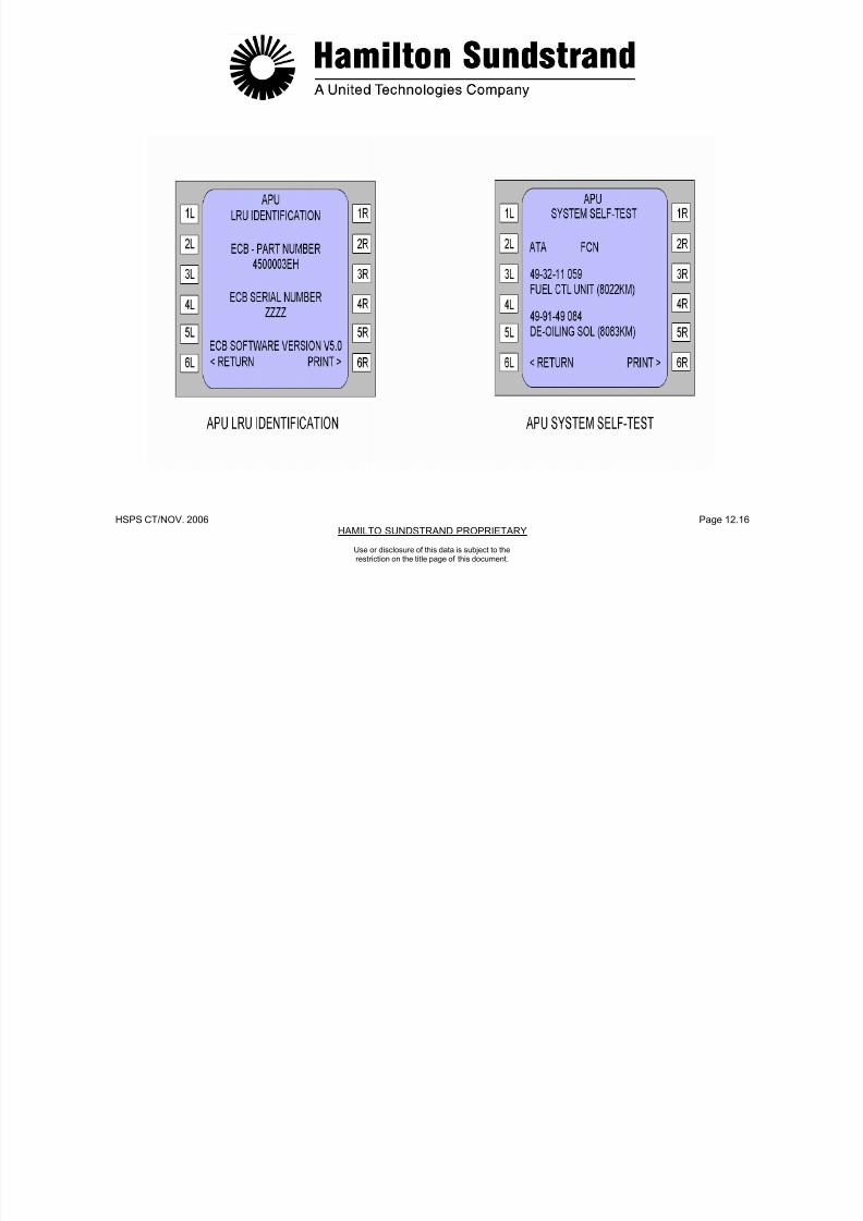
7/21/2019 Aps 3200 Training
http://slidepdf.com/reader/full/aps-3200-training 337/739
HSPS CT/NOV. 2006 Page 12.16HAMILTO SUNDSTRAND PROPRIETARY
Use or disclosure of this data is subject to therestriction on the title page of this document.
APU FAULT OPERATION
APU SHUTDOWNS
The Shutdowns page contains its corresponding Date, GMT, FaultCode Number (FCN), shutdown message and the identity of theLRU. The Shutdowns will be displayed in reverse chronological orderwith only one shutdown per page. Prompts (>) at the end of eachLRU message indicate the line select key to display the APU FAULTCONDITIONS screen.
In case there are no shutdowns, the message of NO SHUTDOWNSwill be displayed. Only the SHUTDOWNS displayed page will be
printed when the PRINT line select key is pushed.
Selection of the RETURN line select key will display APU menu,(First Page).
APU DATA/OIL
APU Data/Oil page contains the Date, APU Serial Number (S/N),Hours, Start Attempts, Start Cycles and Oil level status. Prompts (>)at the end of the message indicate the line select key to display the"Update APU Data" screen.
Selection of the RETURN line select key will display APU menu,(Second Page).

7/21/2019 Aps 3200 Training
http://slidepdf.com/reader/full/aps-3200-training 338/739
HSPS CT/NOV. 2006 Page 12.17HAMILTO SUNDSTRAND PROPRIETARY
Use or disclosure of this data is subject to therestriction on the title page of this document.

7/21/2019 Aps 3200 Training
http://slidepdf.com/reader/full/aps-3200-training 339/739
HSPS CT/NOV. 2006 Page 12.18HAMILTO SUNDSTRAND PROPRIETARY
Use or disclosure of this data is subject to therestriction on the title page of this document.
APU FAULT OPERATION
APU CLASS 3 FAULTS
Class 3 Faults can be stored up to 200 failures over the last 63 flightlegs. Each LRU is identified along with the Aircraft identification, Legnumber, GMT, ATA chapter and Fault Code Number (FCN) for eachfault occurrence. The Functional Identification Number (FIN) appearsafter each LRU. In the case of multiple failures, the failures will bedisplayed in reverse chronological order with two failures per page.Prompts (>) at the end of each LRU message indicate the line selectkey to display the APU FAULT CONDITIONS screen.
In case there are NO CLASS 3 FAULTS detected, the message NOFAULTS will be displayed. Only the CLASS 3 FAULTS displayedpage will be printed when the PRINT line select key is pushed.
Selection of the RETURN line select key will display APU menu,(Second Page).

7/21/2019 Aps 3200 Training
http://slidepdf.com/reader/full/aps-3200-training 340/739
HSPS CT/NOV. 2006 Page 12.19HAMILTO SUNDSTRAND PROPRIETARY
Use or disclosure of this data is subject to therestriction on the title page of this document.

7/21/2019 Aps 3200 Training
http://slidepdf.com/reader/full/aps-3200-training 341/739
HSPS CT/NOV. 2006 Page 12.20HAMILTO SUNDSTRAND PROPRIETARY
Use or disclosure of this data is subject to therestriction on the title page of this document.
APU FAULT OPERATION
UPDATE APU DATA
Selection of this screen allows the operator to update the APU hoursand cycles when the ECB or the APU is changed.The Update APU Data screen is only accessible by prompts (>) fromthe APU Data/Oil Screen. The Update APU Data screen displays the
APU Serial Number (S/N), and current values of Hours and Cycles.The new values of hours and cycles can be entered by use of MCDUkeyboard. After line key 3L is pressed (Prompt <) the screen willdisplay the new values for APU hours and cycles when the ECB or
APU is changed.
The HOURS and CYCLES will be printed when the PRINT line selectkey is pushed.
Selection of the RETURN line select key will display the APUDATA/OIL screen.

7/21/2019 Aps 3200 Training
http://slidepdf.com/reader/full/aps-3200-training 342/739
HSPS CT/NOV. 2006 Page 12.21HAMILTO SUNDSTRAND PROPRIETARY
Use or disclosure of this data is subject to therestriction on the title page of this document.
HSPS CT/NOV 2006 P 12 22

7/21/2019 Aps 3200 Training
http://slidepdf.com/reader/full/aps-3200-training 343/739
HSPS CT/NOV. 2006 Page 12.22HAMILTO SUNDSTRAND PROPRIETARY
Use or disclosure of this data is subject to therestriction on the title page of this document.
HSPS CT/NOV 2006 Page 12 23
APU FAULT OPERATION
FAULT CONDITIONS
The Fault Conditions screens are only available by the line selectkeys indicated by prompt (>) on the Last Leg Report, Previous LegsReport, Shutdown and Class 3 fault screens. Selection will displaythe Fault Conditions screen-1 or screen-2. Each screen will displaythe APU S/N, Date, GMT and the identity of the LRU. The FunctionalIdentification Number (FIN) appears after the LRU.Engine data from the fault data stored in the Electronic Control Boxnon-volatile memory will also appear on each screen. (See Screen-1and Screen-2 Parameters on page 12-24).
One screen at a time is displayed. To select screen-2 when screen-1is displayed or select screen-1 when screen-2 is displayed it isnecessary to press the NEXT PAGE key on the Multipurpose Controland Display Unit (MCDU).
Only the screen that is displayed (Screen-1 or Screen-2) will beprinted when the PRINT line select key is pushed.
Selection of the RETURN line select key will display the screen that
was shown preceding selection of the Fault Selection Screens.

7/21/2019 Aps 3200 Training
http://slidepdf.com/reader/full/aps-3200-training 344/739
HSPS CT/NOV. 2006 Page 12.23HAMILTO SUNDSTRAND PROPRIETARY
Use or disclosure of this data is subject to therestriction on the title page of this document.
HSPS CT/NOV 2006 Page 12 24
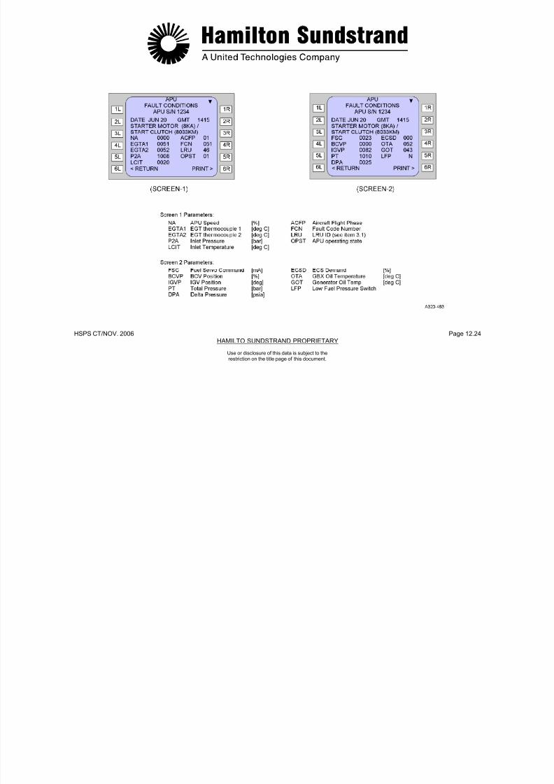
7/21/2019 Aps 3200 Training
http://slidepdf.com/reader/full/aps-3200-training 345/739
HSPS CT/NOV. 2006 Page 12.24HAMILTO SUNDSTRAND PROPRIETARY
Use or disclosure of this data is subject to therestriction on the title page of this document.
HSPS CT/NOV 2006 Page 12 25
FLIGHT DECK PRINTER
The Printer provides onboard printouts concerning various aircraftsystems, one at a time.
MANUAL PRINT
In manual mode, prints of the MCDU screen display are printedwhen the PRINT line select key is pushed.
AUTOMATIC PRINT
In flight phase 10, the Post Flight Report will be automaticallyprinted. The Post Flight Report is the sum of the LAST LEGREPORT and the LAST LEG ECAM REPORT.
A list of ECAM Warnings and Fault Messages with the associatedtime and ATA chapter references are provided on the printed tape.

7/21/2019 Aps 3200 Training
http://slidepdf.com/reader/full/aps-3200-training 346/739
HSPS CT/NOV. 2006 Page 12.25HAMILTO SUNDSTRAND PROPRIETARY
Use or disclosure of this data is subject to therestriction on the title page of this document.
HSPS CT/NOV. 2006 Page 12.26
FLIGHT DECK PRINTER

7/21/2019 Aps 3200 Training
http://slidepdf.com/reader/full/aps-3200-training 347/739
HSPS CT/NOV. 2006 Page 12.26HAMILTO SUNDSTRAND PROPRIETARY
Use or disclosure of this data is subject to therestriction on the title page of this document.
HSPS CT/NOV. 2006 Page 12.27
FAULT CHARTS
The following Fault Charts provide the information that will be sent tothe CFDS by the ECB in the event of a fault.
The information appears in the Fault Chart columns located underthe following headings:
Version 5.0
MCDU LRU MessageMCDU Shutdown MessageFault CodeFault ClassLRU ID
ATA ChapterSystem Severity level
SYSTEM SEVERITY LEVEL
System Severity Levels are not sent to the CFDS. It is presentedhere only as information.
Once a fault has been identified with a switch or a sensor thatcomponent will no longer be used for further fault detection, isolationor control until the fault is no longer present. Detected faults can becleared and a restart may be possible once the master switch iscycled.
SYSTEMSEVERITY LEVEL ECB ACTION ECB MESSAGE
1 SHUTDOWN TRANSMIT FAULTMESSAGE
2 SHUTDOWN TRANSMIT FAULTMESSAGE
3 SHUTDOWN IF REDUNDANTSOURCE NOT AVAILABLE
TRANSMIT FAULTMESSAGE
4 CONTINUE TO OPERATE TRANSMIT FAULTMESSAGE
X NOT APPLICABLE

7/21/2019 Aps 3200 Training
http://slidepdf.com/reader/full/aps-3200-training 348/739
gHAMILTO SUNDSTRAND PROPRIETARY
Use or disclosure of this data is subject to therestriction on the title page of this document.
HSPS CT/ NOV. 2006 Page 12.28
P OWE R UP
WA T C H
S T A RT P RE P
S T A RT I N G
R UN
C O OL D OWN
S H UT D OWN
S E L F T E S T
MCDULRU
MESSAGE
MCDUSHUTDOWNMESSAGE
FAULTCODE
FAULTCLASS
LRUID
ATACHAPTER
SYSTEM SEVERITY LEVEL
BLD FLOW XDCR (8039KM) 0 1 13 495112 4 4 4 4 4 4 4 4
BLD FLOW XDCR (8039KM) 1 1 13 495112 4 4 4 4 4 4 4 4
COOLING FAN PMG ASSY (8055KM) 2 1 53 495253 X X X 4 4 4 4 X
BLD FLOW XDCR (8039KM) 3 1 13 495112 4 4 4 4 4 4 4 4
INLET T-P SNSR (8013KM) 4 1 29 492317 4 4 4 4 4 4 4 4
INLET T-P SNSR (8013KM) 5 1 29 492317 4 4 4 4 4 4 4 4
INLET T-P SNSR (8013KM) 6 1 29 492317 4 4 4 4 4 4 4 4
(BLANK) 7
INLET T-P SNSR (8013KM) 8 1 29 492317 4 4 4 4 4 4 4 4
INLET T-P SNSR (8013KM) 9 1 29 492317 4 4 4 4 4 4 4 4
GENERATOR (8XS) 10 3 25 242351 3 3 3 3 3 3 3 3
GENERATOR (8XS) 11 3 25 242351 3 3 3 3 3 3 3 3
OIL TEMP SNSR (8084KM) 12 3 38 499151 3 3 3 3 3 3 3 3
OIL TEMP SNSR (8084KM) 13 3 38 499151 3 3 3 3 3 3 3 3
ECB (59KD) 14 3 14 496134 4 4 4 4 4 4 4 4
ECB (59KD) 15 3 14 496134 4 4 4 4 4 4 4 4
DE-OILING SOL (8083KM) 16 3 12 499149 4 X X 4 X X 4 4
CONTACTOR (5KA) 17 1 59 494255 X X X 4 X X X X
CONTACTOR (10KA) 18 1 10 494255 X X X 4 X X X X

7/21/2019 Aps 3200 Training
http://slidepdf.com/reader/full/aps-3200-training 349/739
HAMILTON SUNDSTRAND PROPRIETARY
Use or disclosure of this data is subject to therestriction on the title page of this document.
HSPS CT/NOV. 2006 Page 12.29HAMILTON SUNDSTRAND PROPRIETARY
P OWE R UP
WA T C H
S T A RT P RE P
S T A RT I N G
R UN
C O OL D OWN
S H UT D OWN
S E L F T E S T
MCDULRU
MESSAGE
MCDUSHUTDOWNMESSAGE
FAULTCODE
FAULTCLASS
LRUID
ATACHAPTER
SYSTEM SEVERITY LEVEL
WRG: ECB PIN AB-H9 19 3 45 496100 X X X 4 X X X X
WRG: ECB PIN AB-J6 20 3 3 496100 X X X X 4 4 X X
FUEL CTL UNIT (8022KM) 21 1 21 493211 4 X X 4 4 4 X 4
WRG: ECB PIN AB-H8 22 2 6 496100 X X X X 4 X X X
EXCITER SHORTED 23 1 26 494138 X X X 4 X X X X
ECB (59KD) 24 2 14 496134 4 4 4 4 4 4 X 4INLET FLAP ACTR (4015KM) 25 2 2 491651 4 4 X X X X 4 4
INLET FLAP ACTR (4015KM) 26 2 2 491651 4 4 X X X X 4 4
ECB (59KD) 27 3 14 496134 4 4 X X X X 4 4
ECB (59KD) 28 3 14 496134 3 3 3 3 3 3 3 3
SPEED SNSR1 (8060KM1) 29 3 40 497113 X X 3 3 3 3 3 X
ECB (59KD) 30 3 14 496134 X X X 3 3 3 X X
ECB (59KD) 31 3 14 496134 3 3 3 3 3 3 3 3
SPEED SNSR2 (8060KM2) 32 3 42 497113 X X 3 3 3 3 3 X
SPEED SNSR1 (8060KM1) ANDSPEED SNSR2 (8060KM2)
LOSS OF SPEED 33 1 44 497113 1 1 1 1 1 1 1 1
(SPEED SENSORS DO NOT MATCH - NO TEXT) 34 3 NO TEXT 4 4 4 4 4 4 4 4
EGT TC1 (8075KM1) 35 3 15 497215 X X X 3 3 3 X X
EGT TC1 (8057KM1) 36 3 15 497215 3 3 3 3 3 3 3 3
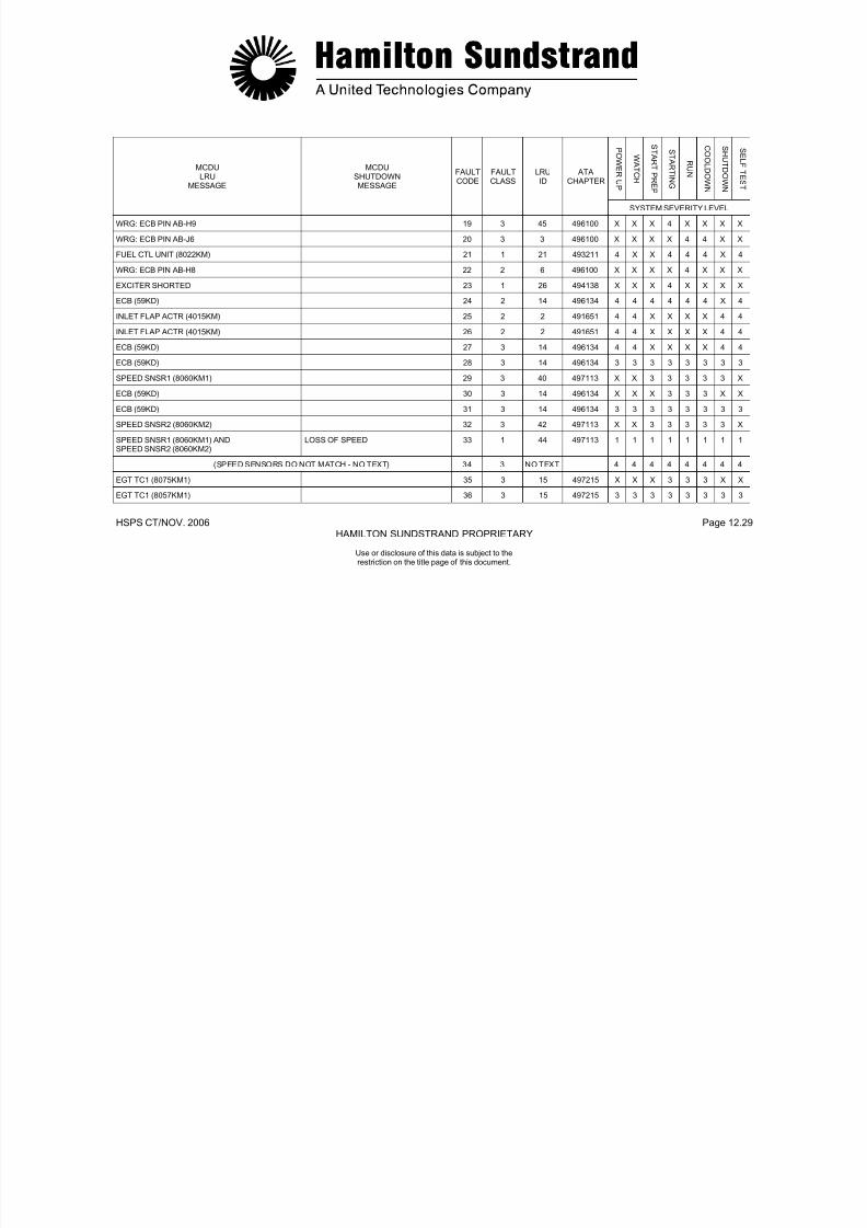
7/21/2019 Aps 3200 Training
http://slidepdf.com/reader/full/aps-3200-training 350/739
HAMILTON SUNDSTRAND PROPRIETARY
Use or disclosure of this data is subject to therestriction on the title page of this document.
HSPS CT/NOV. 2006 Page 12.30HAMILTON SUNDSTRAND PROPRIETARY
P OWE R UP
WA T C H
S T A RT P RE P
S T A RT I N G
R UN
C O OL D OWN
S H UT D OWN
S E L F T E S T
MCDULRU
MESSAGE
MCDUSHUTDOWNMESSAGE
FAULTCODE
FAULTCLASS
LRUID
ATACHAPTER
SYSTEM SEVERITY LEVEL
EGT TC2 (8057KM2) 37 3 18 497215 X X X 3 3 3 X X
EGT TC2 (8057KM2) 38 3 18 497215 3 3 3 3 3 3 3 3
GEN SCAN FILTER (8069KM) ANDLUB FILTER (8076KM)
39 2 7 499141 4 4 4 4 4 4 4 X
- LOSS OF DC POWER 40 1 - - X X X 1 1 1 X X
SERIAL NUMBER ENCODER (8061KM) 41 3 39 497331 4 X X X X X X 4
IGNITION UNIT (8030KM) NO FLAME 42 1 26 494138 X X X 1 X X X X
ECB (59KD) NO FLAME 42 1 14 496134 X X X 1 X X X X
FUEL CONTROL UNIT (8022KM) NO FLAME 42 1 21 493211 X X X 1 X X X X
CHECK APU FUEL SUPPLY NO FLAME 42 1 70 282200 X X X 1 X X X X
IGNITION UNIT (8030KM)FUEL CONTROL (8022KM)
NO FLAME 42 1 27 494138 X X X 1 X X X X
OIL PRESS SW (8091KM) 43 2 36 499414 4 4 X X X X X 4
CHECK OIL LEAKAGE/OIL PRESS SW (8091KM) LOW OIL PRESSURE 44 1 37 499100 X X X 2 2 2 X X
CHECK OIL LEAKAGE/OIL PRESS SW (8091KM) LOW OIL PRESSURE 45 1 37 499100 X X X 2 2 2 X X
CHECK OIL COOLER ASSY HIGH OIL TEMPERATURE 46 1 9 499144 X X X 2 2 2 X X
CHECK OIL SYSTEM/GENERATOR (8XS) GEN HIGH OIL TEMP 47 1 24 499100 X X X 2 2 2 X X
LOW OIL LEVEL 48 2 32 499300 4 4 X X X X X 4
OIL LEVEL SNSR (8089KM) 49 2 35 499317 4 4 X X X X X 4
OIL LEVEL SNSR (8089KM) 50 2 35 499317 4 4 X X X X X 4

7/21/2019 Aps 3200 Training
http://slidepdf.com/reader/full/aps-3200-training 351/739
HAMILTON SUNDSTRAND PROPRIETARY
Use or disclosure of this data is subject to therestriction on the title page of this document.
HSPS CT/NOV. 2006 Page 12.31HAMILTON SUNDSTRAND PROPRIETARY
P OWE R UP
WA T C H
S T A RT P RE P
S T A RT I N G
R UN
C O OL D OWN
S H UT D OWN
S E L F T E S T
MCDULRU
MESSAGE
MCDUSHUTDOWNMESSAGE
FAULTCODE
FAULTCLASS
LRUID
ATACHAPTER
SYSTEM SEVERITY LEVEL
ACFT BAT NOT SELECTED/CONTACTOR (5KA) NO ACCELERATION 51 1 11 243800 X X X 1 X X X X
CONTACTOR (5KA) NO ACCELERATION 51 1 59 494255 X X X 1 X X X X
CONTACTOR (10KA) NO ACCELERATION 51 1 10 494255 X X X 1 X X X X
CURRENT LIMITER (6KA)/CONTACTOR (10KA) NO ACCELERATION 51 1 51 494200 X X X 1 X X X X
STATOR MOTOR (8KA)/STARTERCLUTCH(8033KM)
NO ACCELERATION 51 1 46 494251 X X X 1 X X X X
ECB (59KD) NO ACCELERATION 52 1 14 496134 X X X 1 X X X X
FUEL CTL UNIT (8022KM) NO ACCELERATION 52 1 21 493211 X X X 1 X X X X
CHECK APU FUEL SUPPLY NO ACCELERATION 52 1 70 282200 X X X 1 X X X X
FUEL CTL UNIT (8022KM)/FLOW DIVIDER(8024KM)
NO ACCELERATION 52 1 23 493211 X X X 1 X X X X
FUEL CTL UNIT (8022KM) NO ACCELERATION 53 1 21 493211 X X X 2 X X X X
ECB (59KD) NO ACCELERATION 53 1 14 496134 X X X 2 X X X X
DE-OILING SOL (8083KM) NO ACCELERATION 53 1 12 499149 X X X 2 X X X X
IGV ACTR (8014KM) NO ACCELERATION 53 1 28 492351 X X X 2 X X X X
STARTER MOTOR (8KA)/BLD CTL VLV (8051KM) NO ACCELERATION 53 1 46 494251 X X X 2 X X X X
FLOW DIVIDER (8024KM) NO ACCELERATION 53 1 68 493213 X X X 2 X X X X
FLOW CTL UNIT (8022KM) NO ACCELERATION 53 1 21 493211 X X X 2 X X X X
ECB (59KD) 54 3 14 496134 4 X X X X X X 4
ECB (59KD) 55 3 14 496134 4 X X X X X X 4
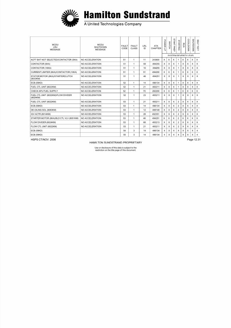
7/21/2019 Aps 3200 Training
http://slidepdf.com/reader/full/aps-3200-training 352/739
HAMILTON SUNDSTRAND PROPRIETARY
Use or disclosure of this data is subject to therestriction on the title page of this document.
HSPS CT/NOV. 2006 Page 12.32HAMILTON SUNDSTRAND PROPRIETARY
P OWE R UP
WA T C H
S T A RT P RE P
S T A RT I N G
R UN
C O OL D OWN
S H UT D OWN
S E L F T E S T
MCDULRU
MESSAGE
MCDUSHUTDOWNMESSAGE
FAULTCODE
FAULTCLASS
LRUID
ATACHAPTER
SYSTEM SEVERITY LEVEL
ECB (59KD) 56 3 14 496134 4 X X X X X X 4
INLET FLAP ACTR (4015KM) 57 2 2 491651 4 4 4 4 4 4 4 4
INLET FLAP ACTR (4015KM) 58 2 2 491651 X 4 4 4 X X 4 4
FUEL CTL UNIT (8022KM) 59 1 21 493211 4 X X X X X X 4
FUEL CTL UNIT (8022KM) 60 1 21 493211 4 X X X X X X 4
ECB (59KD) ECB FAILURE 61 1 14 496134 X X X 2 2 2 X XIGV ACTR (8014KM) 62 1 28 492351 X X X X 4 X X X
IGV ACTR (8014KM) 63 1 28 492351 X X X X 4 X X X
ECB (59KD) 64 2 14 496134 X X X X 4 X X X
(BLANK) 56
ECB (59KD) 66 2 14 496134 X X X X 4 X X X
ECB (59KD) UNDERSPEED 67 1 14 496134 X X X X 1 1 X X
CHECK APU FUEL SUPPLY UNDERSPEED 67 1 70 282200 X X X X 1 1 X X
FUEL CTL UNIT (8022KM) UNDERSPEED 67 1 21 493211 X X X X 1 1 X X
SPD SNSR1 (8060KM1) ANDSPD SNSR2 (8060KM2)
OVERSPEED 68 1 44 497113 X X X 1 1 1 X X
ECB (59KD) OVERSPEED 68 1 14 496134 X X X 1 1 1 X X
FUEL CTL UNIT (8022KM) OVERSPEED 68 1 21 493211 X X X 1 1 1 X X
BLEED CTL VLV (8051KM) 69 1 5 495153 X X X X 4 X X X

7/21/2019 Aps 3200 Training
http://slidepdf.com/reader/full/aps-3200-training 353/739
HAMILTON SUNDSTRAND PROPRIETARY
Use or disclosure of this data is subject to therestriction on the title page of this document.
HSPS CT/NOV. 2006 Page 12.33HAMILTON SUNDSTRAND PROPRIETARY
P OWE R UP
WA T C H
S T A RT P RE P
S T A RT I N G
R UN
C O OL D OWN
S H UT D OWN
S E L F T E S T
MCDULRU
MESSAGE
MCDUSHUTDOWNMESSAGE
FAULTCODE
FAULTCLASS
LRUID
ATACHAPTER
SYSTEM SEVERITY LEVEL
BLEED CTL VLV (8051KM) 70 1 5 495153 X X X X 4 X X X
ECB (59KD) 71 1 14 496134 X X X X 4 X X X
(BLANK) 27
ECB (59KD) 73 2 14 496134 X X X X 4 X X X
ECB (59KD) ECB FAILURE 74 1 14 496134 1 X X X X X X X
ECB (59KD) 75 3 14 496134 4 4 4 4 4 4 4 4
ECB (59KD) 76 3 14 496134 4 4 4 4 4 4 4 4
ECB (59KD) 77 3 14 496134 4 4 4 4 4 4 4 4
ECB (59KD) 78 3 14 496134 4 4 4 4 4 4 4 4
ECB (59KD) 79 3 14 496134 4 4 4 4 4 4 4 4
ECB (59KD) 80 3 14 496134 4 4 4 4 4 4 4 4
ECB (59KD) 81 3 14 496134 4 X 4 4 4 4 X 4
ECB (59KD) 82 2 14 496134 4 4 4 4 4 4 4 4
ECB (59KD) 83 3 14 496134 4 4 4 4 4 4 4 4
DE-OILING SOL (8083KM) 84 3 12 499149 4 X X 4 X X 4 4
ACFT BAT NOT SELECTED/CONTACTOR (5KA)
85 1 11 243800 X X X 4 X X X X
CONTACTOR (10KA) 86 1 10 494255 X X X 4 X X X X
WRG: ECB PIN AB-H9 87 3 45 496100 X X X 4 X X X X

7/21/2019 Aps 3200 Training
http://slidepdf.com/reader/full/aps-3200-training 354/739
HAMILTON SUNDSTRAND PROPRIETARY
Use or disclosure of this data is subject to therestriction on the title page of this document.
HSPS CT/NOV. 2006 Page 12.34HAMILTON SUNDSTRAND PROPRIETARY
P OWE R UP
WA T C H
S T A RT P RE P
S T A RT I N G
R UN
C O OL D OWN
S H UT D OWN
S E L F T E S T
MCDULRU
MESSAGE
MCDUSHUTDOWNMESSAGE
FAULTCODE
FAULTCLASS
LRUID
ATACHAPTER
SYSTEM SEVERITY LEVEL
WRG: ECB PIN AB-J6 88 3 3 496100 X X X X 4 4 X X
FUEL CTL UNIT (8022KM) 89 1 21 493211 4 X X 4 4 4 X 4
WRG: ECB PIN AB-H8 90 2 6 496100 X X X X 4 X X X
IGNITION UNIT (8030KM) 91 1 26 494138 X X X 4 X X X X
SPEED SNSR1 (8060M1) 92 3 40 497113 3 3 3 3 3 3 3 3
SPEED SNSR1 (8060M1) 93 3 40 497113 3 3 3 3 3 3 3 X
SPEED SNSR2 (8060KM2) 94 3 42 497113 3 3 3 3 3 3 3 3
SPEED SNSR2 (8060KM2) 95 3 42 497113 3 3 3 3 3 3 3 X
BLEED CTL VLV (8051KM) 96 1 5 495153 X X X X 4 4 X X
BLEED CTL VLV (8051KM) SURGE/REVERSE FLOW 97 1 5 495153 X X X X 2 2 X X
IGV ACTR (8014KM) OVERTEMPERATURE 98 1 28 492351 X X X 2 2 2 X X
EGT TC1 (8057KM1) OVERTEMPERATURE 98 1 15 497215 X X X 2 2 2 X X
EGT TC2 (8057KM2) OVERTEMPERATURE 98 1 18 497215 X X X 2 2 2 X X
FUEL CTL UNIT (8022KM) OVERTEMPERATURE 98 1 21 493211 X X X 2 2 2 X X
FUEL CTL UNIT (8022KM) 99 1 21 493211 X X X X X X 1 X
ECB (59KD) 100 2 14 496134 3 X X X X X X 3
ECB (59KD) 101 2 14 496134 3 X X X X X X 3
EGT TC1 (8057KM1) ANDEGT TC2 (8057KM2)
SENSOR FAILURE 102 1 16 497215 2 2 2 2 2 2 2 2
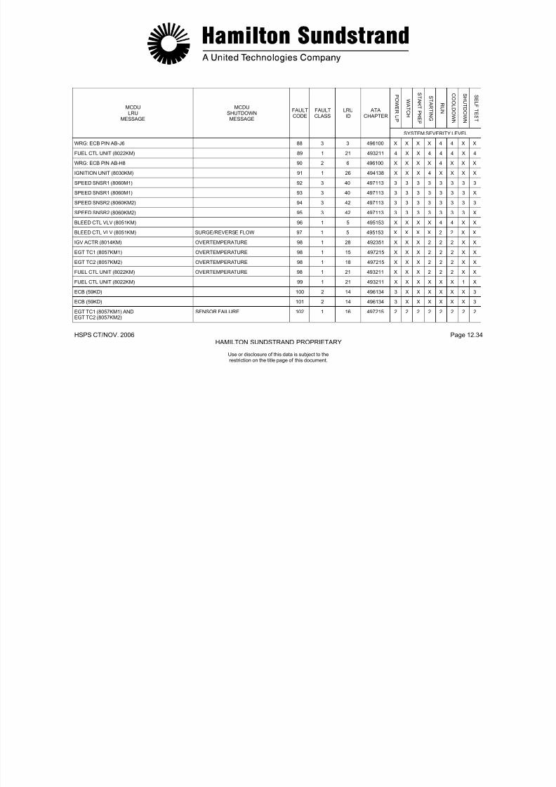
7/21/2019 Aps 3200 Training
http://slidepdf.com/reader/full/aps-3200-training 355/739
Use or disclosure of this data is subject to therestriction on the title page of this document.
HSPS CT/NOV. 2006 Page 12.35HAMILTON SUNDSTRAND PROPRIETARY
P OWE R UP
WA T C H
S T A RT P RE P
S T A RT I N G
R UN
C O OL D OWN
S H UT D OWN
S E L F T E S T
MCDULRU
MESSAGE
MCDUSHUTDOWNMESSAGE
FAULTCODE
FAULTCLASS
LRUID
ATACHAPTER
SYSTEM SEVERITY LEVEL
BLD FLOW XDCR (8039KM) 103 1 13 495112 4 4 4 4 4 4 4 4
ECB (59KD) ECB FAILURE 104 1 14 496134 1 1 1 1 1 1 1 1
ECB (59KD) ECB FAILURE 105 1 14 496134 1 1 1 1 1 1 1 1
NO DATA FROM ECS 106 3 34 216334 X X X X 4 X X X
ECB (59KD) 107 2 14 496134 X 4 4 4 4 4 4 4
ECB (59KD) ECB FAILURE 108 1 14 496134 X 1 1 1 1 1 1 1
ECB (59KD) ECB FAILURE 109 1 14 496134 X 1 1 1 1 1 1 1
ECB (59KD) ECB FAILURE 110 1 14 496134 X 1 1 1 1 1 1 1
ECB (59KD) ECB FAILURE 111 1 14 496134 X 1 1 1 1 1 1 1
FUEL LOW PRESS/LOW FUEL PRESS SW(5030QM)
112 2 31 282214 X X X 4 4 4 X X
- EMERGENCY STOP 113 1 NO TEXT - 1 1 1 1 1 1 1 1
COOLING FAN PMG ASSY (8055KM) SENSOR FAILURE 114 1 53 495253 X X X 1 X X X X
ECB (59KD) BACKUP OVERSPEED 115 1 14 496134 X 1 1 1 1 1 1 1
SPD SNSR1 (8060KM1) ANDSPD SNSR2 (8060KM2)
BACKUP OVERSPEED 115 1 44 497113 X 1 1 1 1 1 1 1
FUEL CTL UNIT (8022KM) BACKUP OVERSPEED 115 1 21 493211 X 1 1 1 1 1 1 1
COOLING FAN PMG ASSY (8055KM) BACKUP OVERSPEED 115 1 53 495253 X 1 1 1 1 1 1 1
ECB (59KD) BACKUP OVERSPEEDCIRCUIT FAILURE
116 1 14 496134 1 X X X X X X X

7/21/2019 Aps 3200 Training
http://slidepdf.com/reader/full/aps-3200-training 356/739
Use or disclosure of this data is subject to therestriction on the title page of this document.
HSPS CT/NOV. 2006 Page 12.36HAMILTON SUNDSTRAND PROPRIETARY
P OWE R UP
WA T C H
S T A RT P RE P
S T A RT I N G
R UN
C O OL D OWN
S H UT D OWN
S E L F T E S T
MCDULRU
MESSAGE
MCDUSHUTDOWNMESSAGE
FAULTCODE
FAULTCLASS
LRUID
ATACHAPTER
SYSTEM SEVERITY LEVEL
ECB (59KD) 117 1 14 496134 4 X X X X X X 4
CHECK APU FUEL SUPPLY 118 1 70 282200 X X X X 4 4 4 X
IGV ACTR (8014KM) 118 1 28 492351 X X X X 4 4 4 X
CHECK APU FUEL SUPPLY 119 1 70 282200 X X X X 4 4 4 X
BLEED CTL VLV (8051KM) 119 1 5 495153 X X X X 4 4 4 X
INLET FLAP ACTR (4015KM) 120 2 2 491651 X X X X X X 4 X
INLET FLAP ACTR (4015KM) AIR INTAKE NOT OPEN 121 1 2 491651 X 1 1 X X X X 1
OIL TEMP SNSR (8084KM) AND GENERATOR(8XS)`
SENSOR FAILURE 122 1 50 499151 2 2 2 2 2 2 2 2
ECB (59KD)/APU HARNESS (8001KM) 123 1 8 496134 4 4 4 4 4 4 4 4
WRG: ACFT TYPE PIN/FCB (59KD) 124 3 47 496100 4 X X X X X X X
WRG: ECB PIN AB-H5 125 3 4 496100 4 4 4 4 4 4 4 4
CURRENT LIMITER (6KA)/CONTACTOR (10KA) 126 1 51 494200 X X X 4 X X X X
CONTACTOR (10KA) 127 3 10 494255 X X X 4 X X X X
CONTACTOR (5KA) 128 1 59 494255 X X X 4 X X X X
CONTACTOR (5KA) 129 3 59 494255 X X X 4 X X X X
SERIAL NUMBER ENCODER (8061KM) 130 3 39 497331 4 X X X X X X 4
(BLANK) 131
ECB (59KD) ECB FAILURE 132 1 14 496134 1 X X X X X X 1

7/21/2019 Aps 3200 Training
http://slidepdf.com/reader/full/aps-3200-training 357/739
Use or disclosure of this data is subject to therestriction on the title page of this document.
HSPS CT/NOV. 2006 Page 12.37HAMILTON SUNDSTRAND PROPRIETARY
P OWE R UP
WA T C H
S T A RT P RE P
S T A RT I N G
R UN
C O OL D OWN
S H UT D OWN
S E L F T E S T
MCDULRU
MESSAGE
MCDUSHUTDOWNMESSAGE
FAULTCODE
FAULTCLASS
LRUID
ATACHAPTER
SYSTEM SEVERITY LEVEL
FIRE EMERG-STOP RELAY (6WF) 133 3 54 262200 X X X X X X 4 X
FIRE EMER STOP RELAY (6WF) 134 3 54 262200 X X X X X X 4 X
ECB (59KD) 135 3 14 496134 X 4 4 4 4 4 4 X
(EMERGENCY STOP TEST - NO TEXT) 136 3 NO TEXT - 4 4 X X X X X X
(BLANK) 137
BLEED CTL VLV (8051KM) 138 1 5 495153 X X X 4 X X X X
IGV ACTR (8014KM) 139 1 28 492351 X X X 4 X X X X
OIL PRESS SW (8091KM) AND OIL LVL SNSR(8089KM)
SENSOR FAILURE 140 1 55 499414 2 2 X X X X X 2
OIL PRESS SW (8091KM) AND LOW OIL LEVEL SENSOR FAILURE 141 1 56 499414 2 2 X X X X X 2
ECB (59KD) LOSS OF SPEED 142 1 14 496134 1 1 1 1 1 1 1 1
BLEED CTL VLV (8051KM) SURGE/REVERSE FLOW 143 1 5 495153 X X X X 2 2 X X
COOLING FAN PMG ASSY (8055KM) SENSOR FAILURE 144 1 53 495253 X X X 1 X X X X
SPD SNSR1 (8060KM1) AND ECB (59KD) LOSS OF SPEED 145 1 41 497133 1 1 1 1 1 1 1 1
SPD SNSR2 (8060KM2) AND ECB (59KD) LOSS OF SPEED 146 1 43 497113 1 1 1 1 1 1 1 1
(BLANK) 147
(BLANK) 148
BLD FLOW XDCR (8039KM) 149 1 13 499112 X X X 4 4 4 4 X
ECB (59KD) ECB FAILURE 150 1 14 496134 X 1 1 1 1 1 1 X
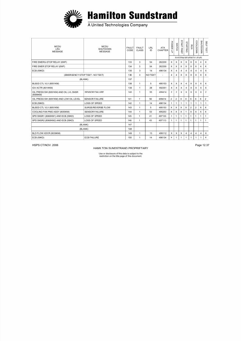
7/21/2019 Aps 3200 Training
http://slidepdf.com/reader/full/aps-3200-training 358/739
Use or disclosure of this data is subject to therestriction on the title page of this document.
HSPS CT/NOV. 2006 Page 12.38HAMILTON SUNDSTRAND PROPRIETARY
P OWE R UP
WA T C H
S T A RT P RE P
S T A RT I N G
R UN
C O OL D OWN
S H UT D OWN
S E L F T E S T
MCDULRU
MESSAGE
MCDUSHUTDOWNMESSAGE
FAULTCODE
FAULTCLASS
LRUID
ATACHAPTER
SYSTEM SEVERITY LEVEL
ECB (59KD) ECB FAILURE 151 1 14 496134 X 1 1 1 1 1 1 X
ECB (59KD) ECB FAILURE 152 1 14 496134 X 1 1 1 1 1 1 X
ECB (59KD) ECB FAILURE 153 1 14 496134 X 1 1 1 1 1 1 X
ECB (59KD) ECB FAILURE 154 1 14 496134 X 1 1 1 1 1 1 X
ECB (59KD) ECB FAILURE 155 1 14 496134 X 1 1 1 1 1 1 X
ECB (59KD) ECB FAILURE 156 1 14 496134 X 1 1 1 1 1 1 X
ECB (59KD) ECB FAILURE 157 1 14 496134 X 1 1 1 1 1 1 X
ECB (59KD) ECB FAILURE 158 1 14 496134 X 1 1 1 1 1 1 X
ECB (59KD) ECB FAILURE 159 1 14 496134 X 1 1 1 1 1 1 X
ECB (59KD) ECB FAILURE 160 1 14 496134 X 1 1 1 1 1 1 X
ECB (59KD) ECB FAILURE 161 1 14 496134 X 1 1 1 1 1 1 X
ECB (59KD) ECB FAILURE 162 1 14 496134 X 1 1 1 1 1 1 X
ECB (59KD) ECB FAILURE 163 1 14 496134 X 1 1 1 1 1 1 XECB (59KD) ECB FAILURE 164 1 14 496134 X 1 1 1 1 1 1 X
ECB (59KD) 165 3 14 496134 4 4 4 4 4 4 4 X
ECB (59KD) 166 3 14 496134 X 4 4 4 4 4 4 X
ECB (59KD) ECB FAILURE 167 1 14 496134 X 1 1 1 1 1 1 X
ECB (59KD) APU FUEL VALVE FAILED OPEN 168 1 14 496134 X 1 X X X X 1 X

7/21/2019 Aps 3200 Training
http://slidepdf.com/reader/full/aps-3200-training 359/739
Use or disclosure of this data is subject to therestriction on the title page of this document.
HSPS CT/NOV. 2006 Page 12.39HAMILTON SUNDSTRAND PROPRIETARY
P OWE R UP
WA T C H
S T A RT P RE P
S T A RT I N G
R UN
C O OL D OWN
S H UT D OWN
S E L F T E S T
MCDULRU
MESSAGE
MCDUSHUTDOWNMESSAGE
FAULTCODE
FAULTCLASS
LRUID
ATACHAPTER
SYSTEM SEVERITY LEVEL
BLD FLOW XDCR (8039KM)/BLD CTL VLV (8051KM)
169 1 48 495112 X X X X 4 4 X X
INLET T-P SNSR (8013KM) 170 1 29 492317 4 4 4 4 4 4 4 4
BLD FLOW XDCR (8039KM) 170 1 13 495112 4 4 4 4 4 4 4 4
BLD FLOW XDCR (8039KM) 171 1 13 495112 X X X X 4 X X X
BLEED CTL VLV (8051KM) 172 1 5 495153 X X X X 4 4 X X
ECB (59KD) ECB FAILURE 173 1 14 496134 X 1 1 1 1 1 1 1
BLEED CTL VLV (8051KM)/FUEL CTL UNIT (8022KM)
174 1 69 495153 X X X X 4 X X X
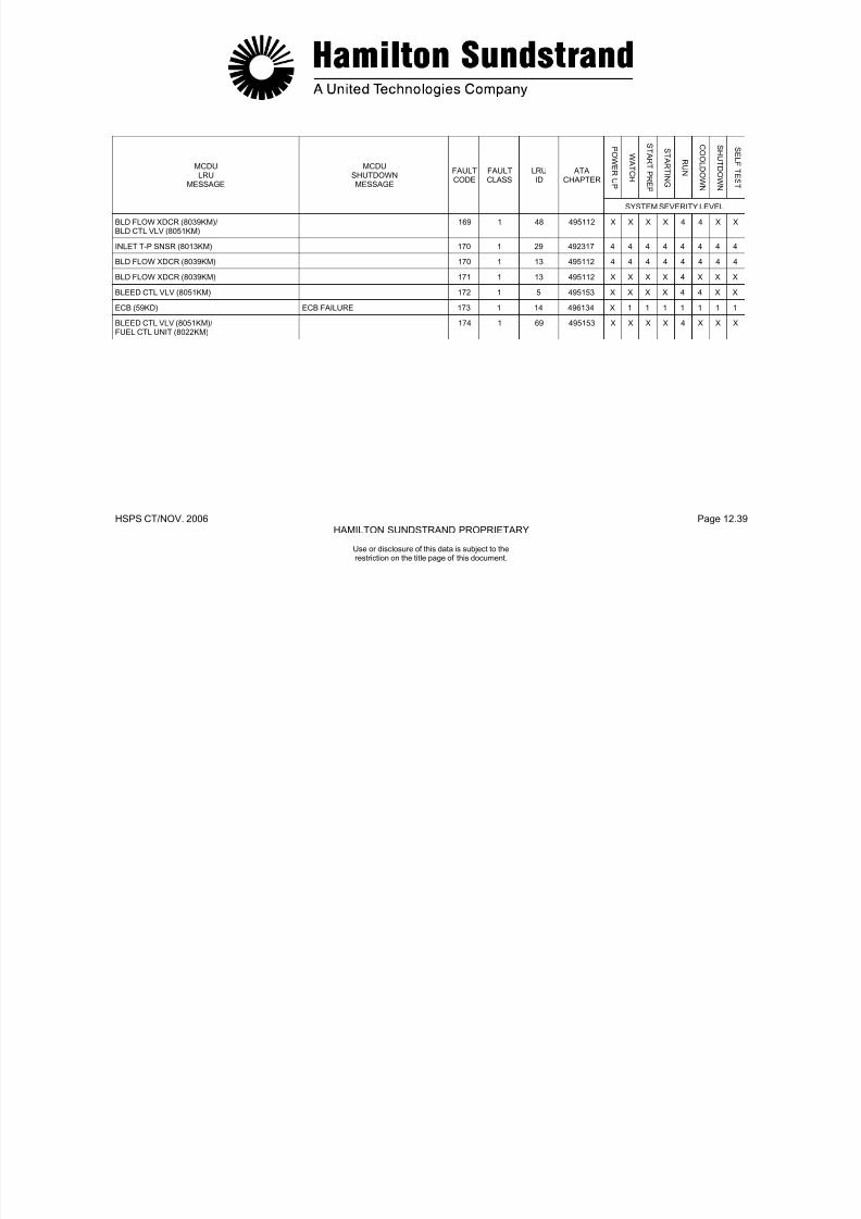
7/21/2019 Aps 3200 Training
http://slidepdf.com/reader/full/aps-3200-training 360/739
Use or disclosure of this data is subject to therestriction on the title page of this document.
HSPS CT/NOV. 2006 Page 13.0HAMILTON SUNDSTRAND PROPRIETARY
APS 3200 AUXILIARY POWER UNIT
SECTION 13
TROUBLESHOOTING

7/21/2019 Aps 3200 Training
http://slidepdf.com/reader/full/aps-3200-training 361/739
Use or disclosure of this data is subject to therestriction on the title page of this document.
HSPS CT/NOV. 2006 Page 13.1HAMILTON SUNDSTRAND PROPRIETARY
TROUBLESHOOTING
GENERAL
The troubleshooting system is designed to provide additional
information to aid in the maintenance and repair of the AuxiliaryPower Unit (APU) by downloading the Electronic Control Box (ECB)located in the aircraft aft cargo compartment.Maintenance information is stored in the nonvolatile memory of theECB and can be retrieved and analyzed by downloading into alaptop computer. The computer displays information andrecommended actions from the following stored data:
CONDITIONING MONITORING DATA
This data consists of engine parameters taken at each engine startand shutdown. Data is provided for the last twelve engine run cycles.
FAULT DATA
The data consists of maintenance and fault messages for class 1,class 2 faults and class 3 faults.
REQUIRED HARDWARE
Downloading of the ECB requires the following equipment:
Laptop computer or Personal Computer (PC) with at least3MB of free hard disc space, a modem and a Windows 95 orlater operating system.
A special interface cable is required to connect theComputer to the ECB. The interface cable (P/N AGE 70021)is available by contacting Hamilton Sundstrand.
7/21/2019 Aps 3200 Training
http://slidepdf.com/reader/full/aps-3200-training 362/739
Use or disclosure of this data is subject to therestriction on the title page of this document.
HSPS CT/NOV. 2006 Page 13.2HAMILTON SUNDSTRAND PROPRIETARY
U di l f thi d t i bj t t th

7/21/2019 Aps 3200 Training
http://slidepdf.com/reader/full/aps-3200-training 363/739
Use or disclosure of this data is subject to therestriction on the title page of this document.
HSPS CT/NOV. 2006 Page 13.3HAMILTON SUNDSTRAND PROPRIETARY
Use or disclosure of this data is subject to the
TROUBLESHOOTING
ECB TROUBLESHOOTING AID
To download and diagnose fault data, refer to APIC SIL APS32-
0049-47 for in-depth instructions.
Basic Steps:• Connect the interface cable from the computer to the ECB.• Power-up computer.• Select Diagnose on the tool bar.• Enter operators name on the Setup screen.• APU master switch ON (APU not running.)• Select Continue on the Setup screen.
7/21/2019 Aps 3200 Training
http://slidepdf.com/reader/full/aps-3200-training 364/739
Use or disclosure of this data is subject to therestriction on the title page of this document.
HSPS CT/NOV. 2006 Page 13.4HAMILTON SUNDSTRAND PROPRIETARY
Use or disclosure of this data is subject to the

7/21/2019 Aps 3200 Training
http://slidepdf.com/reader/full/aps-3200-training 365/739
Use or disclosure of this data is subject to therestriction on the title page of this document.
HSPS CT/NOV. 2006 Page 13.5HAMILTON SUNDSTRAND PROPRIETARY
Use or disclosure of this data is subject to the
TROUBLESHOOTING
ECB TROUBLESHOOTING AID
ECB TROUBLESHOOTING AID (Fault Information)
The computer screen displays Class 1, Class 2 faults and Class 3faults. The screen will download and provide a file automatically forreview. (See example on page 13.6.)
Select the Most Recent scroll bar on the screen to scroll through thevarious faults.Each fault or fault combination is provided with a fault descriptionand recommended action.

7/21/2019 Aps 3200 Training
http://slidepdf.com/reader/full/aps-3200-training 366/739
Use or disclosure of this data is subject to therestriction on the title page of this document.
HSPS CT/NOV. 2006 Page 13.6HAMILTON SUNDSTRAND PROPRIETARY
Use or disclosure of this data is subject to the
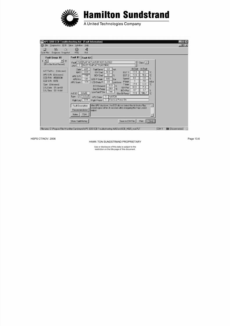
7/21/2019 Aps 3200 Training
http://slidepdf.com/reader/full/aps-3200-training 367/739
jrestriction on the title page of this document.
HSPS CT/NOV. 2006 Page 13.7HAMILTON SUNDSTRAND PROPRIETARY
Use or disclosure of this data is subject to the
TROUBLESHOOTING
ECB TROUBLESHOOTING AID
REAL-TIME DATA MONITORING
With the Real-Time Data monitoring screen displayed, select AnalogI/O, Speed/Temp, or Discreet Inputs. Each selection displays ascreen that provides real time data. The data is viewed at the bottomof the screen when a data box is selected.
Note: The more data boxes selected the longer it takes for theinformation to appear. Select data that is related to thespecific fault for a faster response time.
BASIC STEPS:• Connect the interface cable from the computer to the ECB.• Power-up computer.• Start and run APU.• Select data box.• Select Start Monitoring.• Select Stop Monitoring after data has been taken.
Selecting Save Data at the bottom of the screen and selecting a filename allows the data to be saved. (See page 13.9 and example onpage 13.10.)

7/21/2019 Aps 3200 Training
http://slidepdf.com/reader/full/aps-3200-training 368/739
restriction on the title page of this document.
HSPS CT/NOV. 2006 Page 13.8HAMILTON SUNDSTRAND PROPRIETARY
Use or disclosure of this data is subject to thet i ti th titl f thi d t
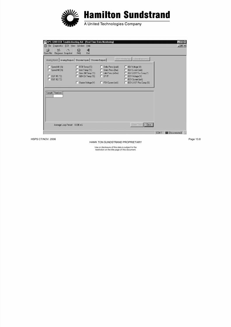
7/21/2019 Aps 3200 Training
http://slidepdf.com/reader/full/aps-3200-training 369/739
restriction on the title page of this document.
HSPS CT/NOV. 2006 Page 13.9HAMILTON SUNDSTRAND PROPRIETARY
Use or disclosure of this data is subject to therestriction on the title page of this document
TROUBLESHOOTING
ECB TROUBLESHOOTING AID
SNAPSHOT VIEW
BASIC STEPS:
• Select Snapshot with the APU operating• Select Analog Inputs.• Select Discrete Inputs.• Click on Take Snapshot. (This will provide one quick view
of data)

7/21/2019 Aps 3200 Training
http://slidepdf.com/reader/full/aps-3200-training 370/739
restriction on the title page of this document.
HSPS CT/NOV. 2006 Page 13.10HAMILTON SUNDSTRAND PROPRIETARY
Use or disclosure of this data is subject to therestriction on the title page of this document
HSPS CT/NOV. 2006 Page 13.10HAMILTON SUNDSTRAND PROPRIETARY
Use or disclosure of this data is subject to therestriction on the title page of this document
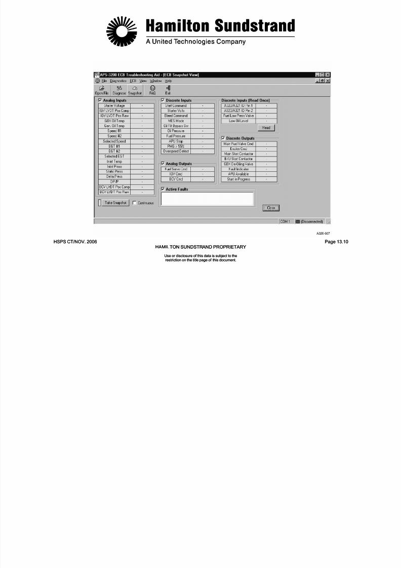
7/21/2019 Aps 3200 Training
http://slidepdf.com/reader/full/aps-3200-training 371/739
restriction on the title page of this document.restriction on the title page of this document.
HSPS CT/NOV. 2006 Page 13.11HAMILTON SUNDSTRAND PROPRIETARY
APS 3200 AUXILIARY POWER UNIT
Use or disclosure of this data is subject to therestriction on the title page of this document
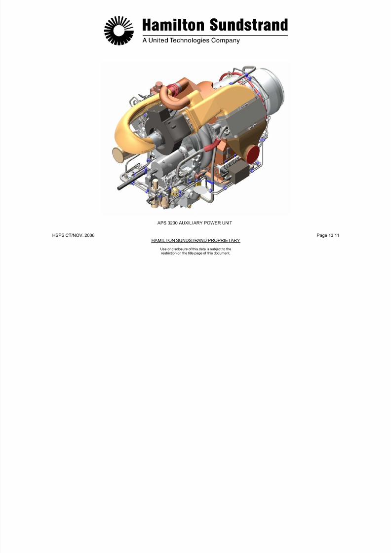
7/21/2019 Aps 3200 Training
http://slidepdf.com/reader/full/aps-3200-training 372/739
restriction on the title page of this document.
HSPS CT/NOV. 2006 Page iHAMILTON SUNDSTRAND PROPRIETARY
APS 3200 Auxi liary Power Unit
Front Matter
Use or disclosure of this data is subject to therestriction on the title page of this document.

7/21/2019 Aps 3200 Training
http://slidepdf.com/reader/full/aps-3200-training 373/739
p g
HSPS CT/NOV. 2006 Page iiHAMILTON SUNDSTRAND PROPRIETARY
Use or disclosure of this data is subject to therestriction on the title page of this document.
TABLE OF CONTENTS
SUBJECT PAGE
Preface............................................................................................iii
Abbreviations ................................................................................. v
APU Leading Particulars ...............................................................viii
SUBJECT SECTION
Introduction...................................................................................... 1
Power Unit.......................................................................................2
Oil System....................................................................................... 3
Fuel System ....................................................................................4
Air System....................................................................................... 5
Control System................................................................................ 6
Indicating System............................................................................ 7
Starting System............................................................................... 8
Electrical System.............................................................................9
APU Installation.............................................................................10
Maintenance.................................................................................. 11
Fault Isolation................................................................................12
Troubleshooting............................................................................. 13

7/21/2019 Aps 3200 Training
http://slidepdf.com/reader/full/aps-3200-training 374/739
HSPS CT/ NOV. 2006 Page iiiHAMILTON SUNDSTRAND PROPRIETARY
Use or disclosure of this data is subject to therestriction on the title page of this document.
PREFACE
GENERAL DESCRIPTION
The APS 3200 Auxiliary Power Unit Maintenance Training Course,
developed by the Customer Service Training Group of HamiltonSundstrand Power Systems, is designed to give the student anunderstanding of the various components of the Auxiliary Power Unit(APU) and their functions. This course also provides routinemaintenance and troubleshooting.
STUDENT WORKBOOK
This workbook is intended for the “limited” purpose of providing
component familiarization, general data, and support information forthis maintenance course.
This is an uncontrolled document and will not be updated or revisedon a regular basis. Specific values given in this document such asspeed, temperature, and pressure are provided for the purpose ofillustration and are not necessarily representative of the true valuesof the APS 3200 APU.
FAA AND AIRCRAFT MANUFACTURER APPROVEDPUBLICATIONS
The Airline is provided a variety of FAA and Aircraft Manufacturerapproved publications for the APS 3200 APU. These publicationsare:
Aircraft Flight Crew Manuals
Aircraft Maintenance Manuals
Engine and Component Maintenance Manuals
Service Bulletins
Chapter 49 of the aircraft maintenance manual presents detailed APU and LRU removal and installation procedures plus maintenanceand servicing techniques that can be accomplished at the flight-line.Careful study of Chapter 49 will add to the student's expertise introubleshooting and maintaining the Hamilton Sundstrand APS 3200
APU.
7/21/2019 Aps 3200 Training
http://slidepdf.com/reader/full/aps-3200-training 375/739
AIRCRAFT APPLICATIONS
The information presented in this course applies to the followingaircraft:
AIRBUS 318, 319, 320, 321
HSPS CT/NOV. 2006 Page ivHAMILTON SUNDSTRAND PROPRIETARY
Use or disclosure of this data is subject to therestriction on the title page of this document.

7/21/2019 Aps 3200 Training
http://slidepdf.com/reader/full/aps-3200-training 376/739
HSPS CT/NOV. 2006 Page vHAMILTON SUNDSTRAND PROPRIETARY
Use or disclosure of this data is subject to therestriction on the title page of this document.
LIST OF ABBREVIATIONS
The abbreviations/symbols shown below are used in this manual:
A/D Analog/Digital
A/C Aircraft
AC Alternating Current
ACARS Aircraft Communication Addressing and Reporting System
ACMS Aircraft Condition Monitoring System
ADIRU Air Data Inertial Reference Unit
AIDS Aircraft Integrated Data System
APIC Auxiliary Power International Corp.
APS Auxiliary Power System
APU Auxiliary Power Unit
ARINC Aeronautical Radio Inc.
ATA Air Transport Association
AVAIL APU Available
BATT Battery
BCV Bleed Control Valve
BITE Built-In Test Equipment
BMC Bleed Monitor Computer
CB Circuit Breaker
cc/h Cubic centimeters per hour
CFDS Centralized Fault Display System
CLR Clear
CMM Components Maintenance Manual
CPU Central Processor Unit
D/A Digital/Analog
DC Direct Current
ECAM Electronic Centralized Aircraft Monitoring
EC dB Decibel
B Electronic Control Box
ECS Environmental Control System
EGT Exhaust Gas Temperature
EMI Electro-Magnetic Interference
EPLD Erasable Programmable Logic Device
ETOPS Extended Twin Engine Operations
FADEC Full Authority Digital Electronic Controller
FAR Federal Airworthiness Regulation
FCU Fuel Control Unit
FET Field Effect Transistor
FOD Foreign Object Damage
ft Feet
FWD Forward
GBX Gearbox

7/21/2019 Aps 3200 Training
http://slidepdf.com/reader/full/aps-3200-training 377/739
HSPS CT/NOV. 2006 Page viHAMILTON SUNDSTRAND PROPRIETARY
Use or disclosure of this data is subject to therestriction on the title page of this document.
LIST OF ABBREVIATIONS
GCU Generator Control Unit
GMT Greenwich Mean Time
GPH Gallons Per Hour
HOT High Oil TemperatureHP Horse PowerHSPS Hamilton Sundstrand Power System
Hz Hertz
ICAO International Civil Aviation Organization
ID Identification
IGV Inlet Guide Vane
IPC Illustrated Parts Catalogue
ISA International Standard Atmosphere
JAR Joint Airworthiness Requirement
kg Kilogram
kg/m Kilograms Per Minute
kg/s Kilograms Per Second
kHz Kilo Hertz
kPa Kilopascal
kPaa Kilopascals Absolute
kPad Kilopascals Differential
kPag Kilopascals Gauge
kW Kilo Watt
L Liter
l/h Liters Per Hour
lb Poundlbs/hr Pounds Per Hour
lbs/m Pounds Per Minutelbs/sec. Pounds Per Second
LC Load Compressor
LOP Low Oil Pressure
LP Low Pressure
LRU Line Replaceable UnitLVDT Linear Voltage Differential Transducer
m Meter
mA Milliampere
MAX Maximum
MCDU Multi-function Control and Display Unit
MES Main Engine Start
MHz Mega HertzP Qts Quarts
MIN Minimum
mm Millimeter
MMEL Master Minimum Equipment List
MTBF Mean Time Between Failure
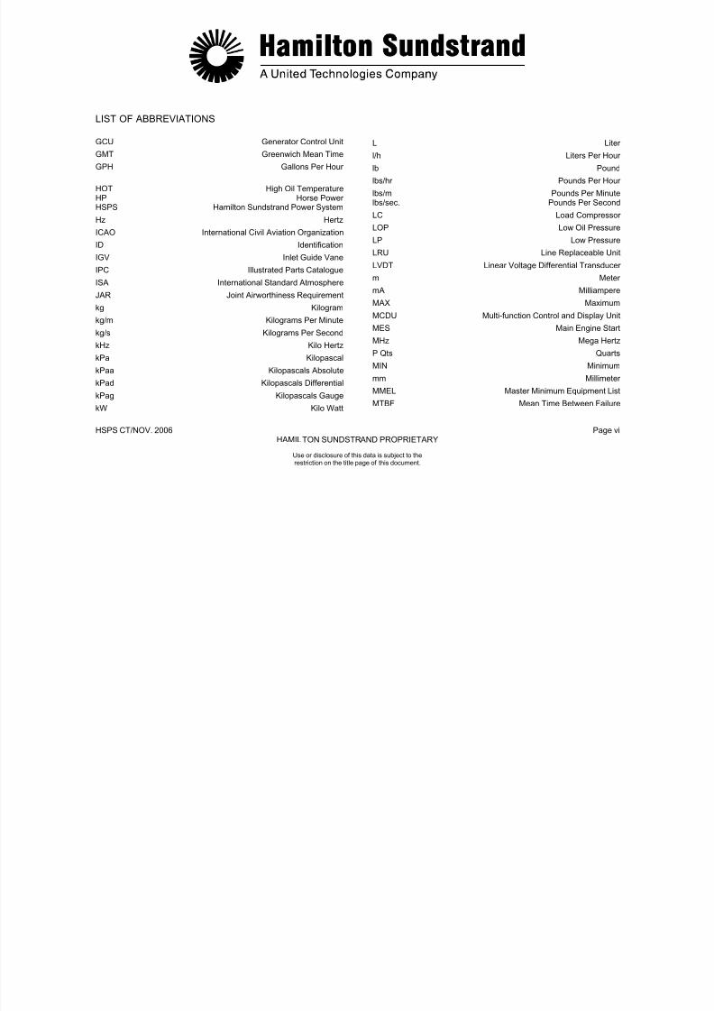
7/21/2019 Aps 3200 Training
http://slidepdf.com/reader/full/aps-3200-training 378/739
HSPS CT/NOV. 2006 Page viiHAMILTON SUNDSTRAND PROPRIETARY
Use or disclosure of this data is subject to therestriction on the title page of this document.
LIST OF ABBREVIATIONS
SIG Pounds Per Square Inch Gauge
MTBUR Mean Time Between Unscheduled Removals
mV MillivoltN Rotation Speed
NGV Nozzle Guide Vane
NVM Non MemoryVolatile VAC Volts, Alternating Current
OAP Outside Air Pressure
OAT Outside Air Temperature
OBRM On Board Replaceable Memory
P/N Part NumberPCD Pressure Compressor Discharge
PMG Permanent Magnet Generator
PS Power Section
PSIA Pounds Per Square Inch Absolute
PSID Pounds Per Square Inch Differential
RAM Random Access Memory
ROM Read Only MemoryRPM Revolutions Per Minute
RTD Resistive Temperature Device
S Seconds
S/N Serial Number
SSLC Single Shaft Load Compressor
STS Status
THR Threshold
TRU Transformer Rectifier Unit
TSO Technical Standard Order
US G US Gallon
VDC Volts, Direct Current
°C Degrees Celsius
°F Degrees Fahrenheit
> Is Greater Than< Is Less Than
± Plus or Minus
Ω Ohm
Δ Differential
% Percent
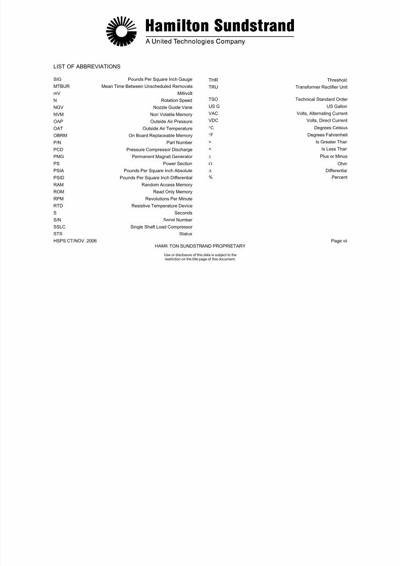
7/21/2019 Aps 3200 Training
http://slidepdf.com/reader/full/aps-3200-training 379/739
HSPS CT/ NOV. 2006 Page viiiHAMILTON SUNDSTRAND PROPRIETARY
Use or disclosure of this data is subject to therestriction on the title page of this document.
APU LEADING PARTICULARS
WEIGHT 136 Kg (299 lbs) (dry)
OPERATING ALTITUDE -304.8 M to 11,887 M (-1,000 to 39,000 ft)
SEA LEVEL 15°C (59°F) STD DAY PERFORMANCE
OUTPUT SHAFT HORSEPOWER 399.7 Kw (536 HP)
ROTOR SPEED 100% (49,300 RPM)
ROTOR OVERSPEED (SHUTDOWN) 105% (51,765 RPM)
BACK UP OVERSPEED (SHUTDOWN) 107% (52,751 RPM)
ROTOR UNDERSPEED (SHUTDOWN) 95% (46,835 RPM)
BLEED AIRFLOW 1.8 kg/SEC (2.6 LBS/SEC)
BLEED AIR PRESSURE 290 kPag (42 PSIG)
FUEL CONSUMPTION 148 kg/HR (178 L/HR) [327 LB/HR (47 GAL/HR)]

7/21/2019 Aps 3200 Training
http://slidepdf.com/reader/full/aps-3200-training 380/739
HSPS CT/NOV. 2006 Page ixHAMILTON SUNDSTRAND PROPRIETARY
Use or disclosure of this data is subject to therestriction on the title page of this document.
APU LEADING PARTICULARS
EXHAUST GAS TEMPERATURE (SHUTDOWN)
START % SPEED EXHAUST GAS TEMPERATURE
0% 427°C (800°F)
10% 788°C (1450°F)
20% 899°C (1650°F)
30% 899°C (1650°F)
50% 853°C (1567°F)
80% 788°C (1450°F)
100% 670°C (1238°F)
RUN % SPEED EXHAUST GAS TEMPERATURE
100% 722°C (1332°F)
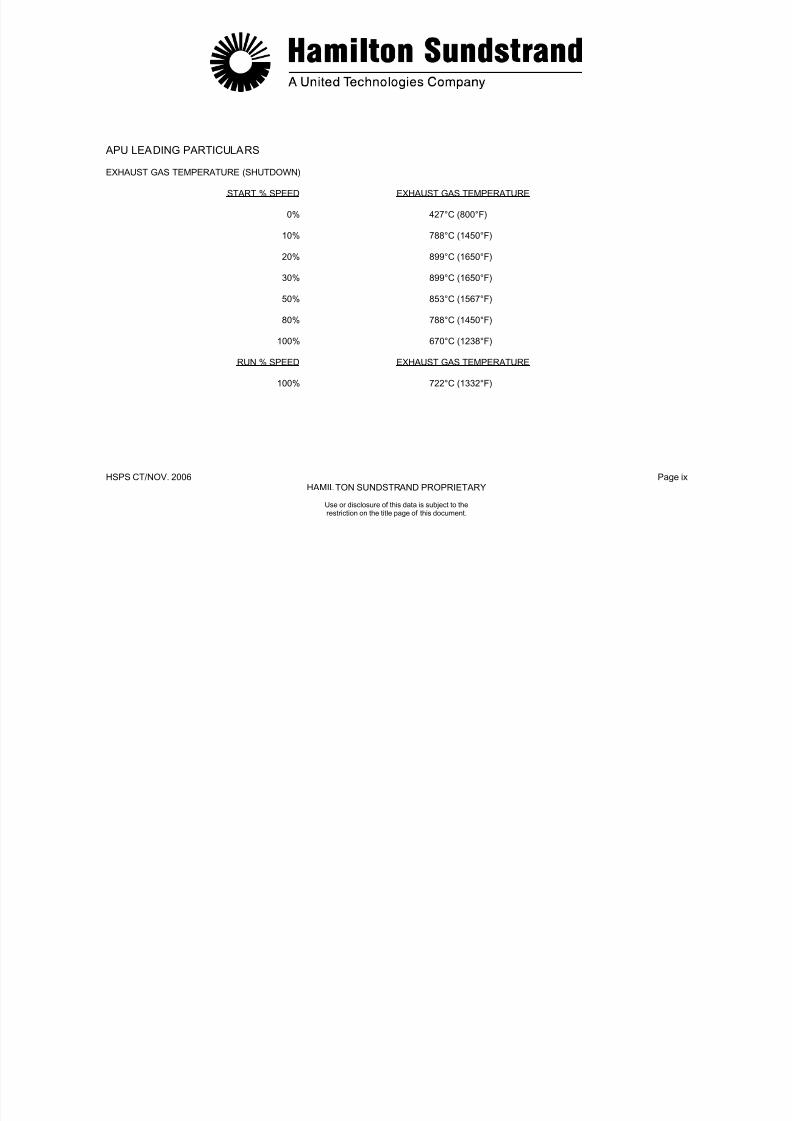
7/21/2019 Aps 3200 Training
http://slidepdf.com/reader/full/aps-3200-training 381/739
HSPS CT/NOV. 2006 Page xHAMILTON SUNDSTRAND PROPRIETARY
Use or disclosure of this data is subject to therestriction on the title page of this document.
APU LEADING PARTICULARS
GEARBOX SPEEDS Input 49,300 RPMGenerator 24,034 RPM (output)Fuel Control 10,129 RPM (output)
Starter 32,045 RPM (output)Cooling Fan 51,965 RPM (output)Oil Pump 4,137 RPM (output)
OIL PRESSURE 241 kPag (35 PSIG) (minimum)345-414 kPag (50-60 PSIG) (normal)
OIL CAPACITY 3.9 L (4.16 Qts) (add)5.4 L (5.72 Qts) (full)
OIL TEMPERATURE (SHUT DOWN) 135°C (275°F) Lubrication system185°C (365°F) AC Generator
APPROVED OIL SPECIFICATION:
MIL-PRF-7808
MIL-PRF-23699
CAUTION:
DO NOT MIX OR SUBSTITUTE OIL SPECIFICATIONS. USE ONLY ONE OF THE APPROVED OILS. IF THE OIL SUPPLY IS LOW AND THE OIL BEING USED IS NOT AVAILABLE, DRAIN THE OIL SUMP AND CHANGE THE OIL FILTER. SERVICE THEOIL SYSTEM WITH AN APPROVED OIL.
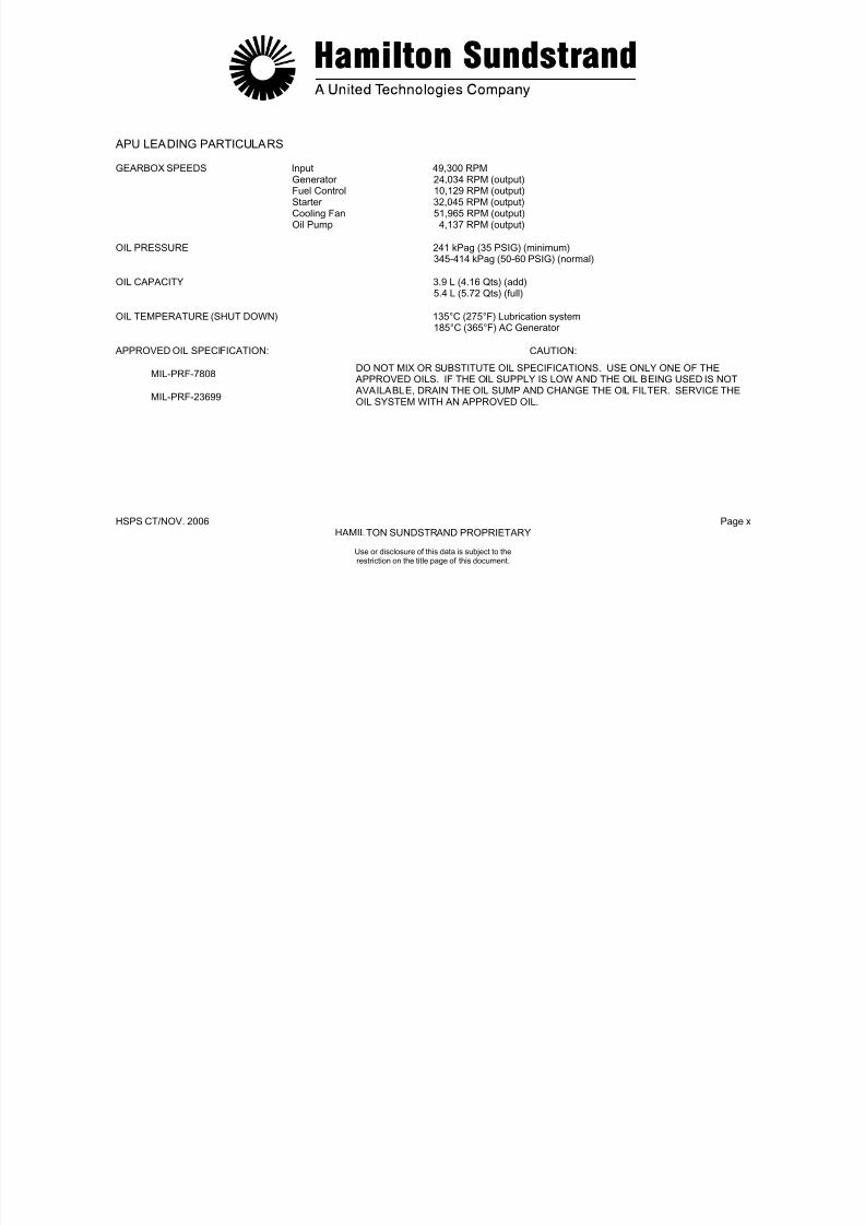
7/21/2019 Aps 3200 Training
http://slidepdf.com/reader/full/aps-3200-training 382/739
HSPS CT/NOV. 2006 Page xi
HAMILTON SUNDSTRAND PROPRIETARY
Use or disclosure of this data is subject to therestriction on the title page of this document.
APU LEADING PARTICULARS
APPROVED FUELS
Fuel Type Specification Temperature Range
Jet A ATSM D1655 (NATO Code F-35) -35°C (-30°F) to +57°C (+135°F)
Jet A-1 ATSM D1655 (NATO Code F-35) -43°C (-45°F) to +57°C (+135°F)
Jet B ATSM D1655 (NATO Code F-45) -54°C (-65°F) to +57°C (+135°F)
JP-4 MIL-T-5624 (NATO Code F-40) -54°C (-65°F) to +57°C (+135°F)
JP-5 MIL-T-5624 (NATO Code F-44) -35°C (-30°F) to +93°C (+ 200°F)
JP-8 MIL-T-83133 (NATO Code F-34) -35°C (-30°F) to +93°C (+ 200°F)

7/21/2019 Aps 3200 Training
http://slidepdf.com/reader/full/aps-3200-training 383/739
HSPS CT/NOV. 2006 Page xii
HAMILTON SUNDSTRAND PROPRIETARY
APS 3200 AUXILIARY POWER UNIT
Use or disclosure of this data is subject to therestriction on the title page of this document
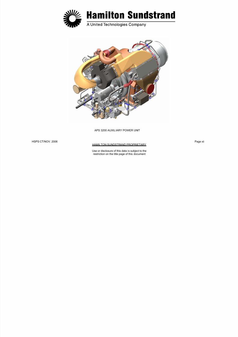
7/21/2019 Aps 3200 Training
http://slidepdf.com/reader/full/aps-3200-training 384/739
.
HSPS CT/NOV. 2006 Page 1.0HAMILTON SUNDSTRAND PROPRIETARY
APS 3200 AUXILIARY POWER UNIT
SECTION 1
INTRODUCTION
Use or disclosure of this data is subject to therestriction on the title page of this document.

7/21/2019 Aps 3200 Training
http://slidepdf.com/reader/full/aps-3200-training 385/739
HSPS CT/NOV.. 2006 Page 1.1HAMILTON SUNDSTRAND PROPRIETARY
Use or disclosure of this data is subject to therestriction on the title page of this document.
APS 3200- GENERAL PRESENTATION
Function
The APS 3200 is designed to provide compressed air and electrical
power to the aircraft on the ground and in flight.
- Electrical power supply to aircraft systems
- Compressed air supply to aircraft systems:
• Environmental Control System (ECS)• Main Engine Start (MES)• Various systems...
Requirements
Regulations: - JAR part 25, change 13- FAR part 25
Certification: - JAR APU change 2
Main Components
The main components are:
- The Auxiliary Power Unit (APU)
- The Electronic Control Box (ECB)
- The aircraft systems (Pneumatic system, Electrical system, Controlpanels).
The APU is a single spool gas turbine engine which drives a loadcompressor and an AC generator.
The ECB is an electronic contro ller, FADEC type (Full AuthorityDigital Electronic Control).
Component Location
- The APU is installed in the tail section of the aircraft.
- The ECB is installed in the aft cargo compartment, right side,forward of the cargo door.
Control and Display
- On the overhead panel for APU operation and fire control
On the ECAM (Electronic Centralized Aircraft Monitoring) for APUparameters display
On the external panel, under the nose section, for APU emergency-shut-down

7/21/2019 Aps 3200 Training
http://slidepdf.com/reader/full/aps-3200-training 386/739
HSPS CT/NOV.. 2006 Page 1.2HAMILTON SUNDSTRAND PROPRIETARY
.
AUXILIARYPOWER UNIT
CONTROL ANDDISPLAY PANELS
ELECTRONICCONTROL BOX(AFT CARGOCOMPARTMENT)
AIRBUS AIRCRAFT
Use or disclosure of this data is subject to therestriction on the title page of this document.

7/21/2019 Aps 3200 Training
http://slidepdf.com/reader/full/aps-3200-training 387/739
.
HSPS CT/NOV. 2006 Page 1.3HAMILTON SUNDSTRAND PROPRIETARY
Use or disclosure of this data is subject to therestriction on the title page of this document.
APS 3200 - DESCRIPTION (1)Power Unit
The APU consists of a gas turbine engine (Power Section) whichdrives:
- A load compressor
- And an AC generator (alternator) through a gearbox.
The APU is of modular design. It has three modules:
- The power section
-
The load compressor
- The gearbox.
A common air inlet supplies the load compressor, the cooling fan andthe power section.
Power Section
The power section is a single spool gas turbine engine whichconsists of:
- A centrifugal compressor
- A reverse flow combustor chamber
- A two stage axial flow turbine.
Load Compressor
The load compressor is a single stage centrifugal compressor drivendirectly by the power section. Variable inlet guide vanes are used for
airflow and exhaust gas temperature control.
Gearbox
The gearbox, also driven by the power section, is attached to theload compressor. The gearbox provides the drive at the correctspeed for the AC generator and the APU mechanically drivenaccessories.
Electronic Control Box
The ECB provides control and monitoring of the APU and is locatedin the aircraft rear cargo compartment.

7/21/2019 Aps 3200 Training
http://slidepdf.com/reader/full/aps-3200-training 388/739
.
HSPS CT/NOV. 2006 Page 1.4HAMILTON SUNDSTRAND PROPRIETARY
COMBUSTOR
Use or disclosure of this data is subject to therestriction on the title page of this document.
AC GENERATOR
GEARBOX
LOADCOMPRESSOR
IMPELLER
TURBINES
APS 3200 – DESCRIPTION (1)

7/21/2019 Aps 3200 Training
http://slidepdf.com/reader/full/aps-3200-training 389/739
.
HSPS CT/NOV. 2006 Page 1.5HAMILTON SUNDSTRAND PROPRIETARY
Use or disclosure of this data is subject to therestriction on the title page of this document.
APS 3200 – DESCRIPTION (2)
- The APU air inlet plenum is connected to the aircraft air intakesystem.
The APU air inlet plenum has a screen to protect the APU internalcomponents from foreign object damage.
- The cooling fan assembly is located at the top of the gearboxfront face.
- The starter motor drives the APU rotor assembly during starting.
The starter motor is located on the front face of the gearbox.
- The fuel control unit supplies and meters fuel to the APU. It islocated on the gearbox front face.
- The load compressor scroll houses the load compressorimpeller.
- The air inlet plenum delivers air to the impellers.
The air inlet plenum is located between the load compressor andthe power section.
- The ignition exciter supplies high energy electrical power to theignitor plugs.
The ignition exciter is mounted on the left side of the air inletplenum.
- The oil cooler transfers the heat of the lubricating oil to the coolingair supplied by the cooling fan assembly.
- The APU exhaust system delivers the APU exhaust gases to theaircraft exhaust pipe.
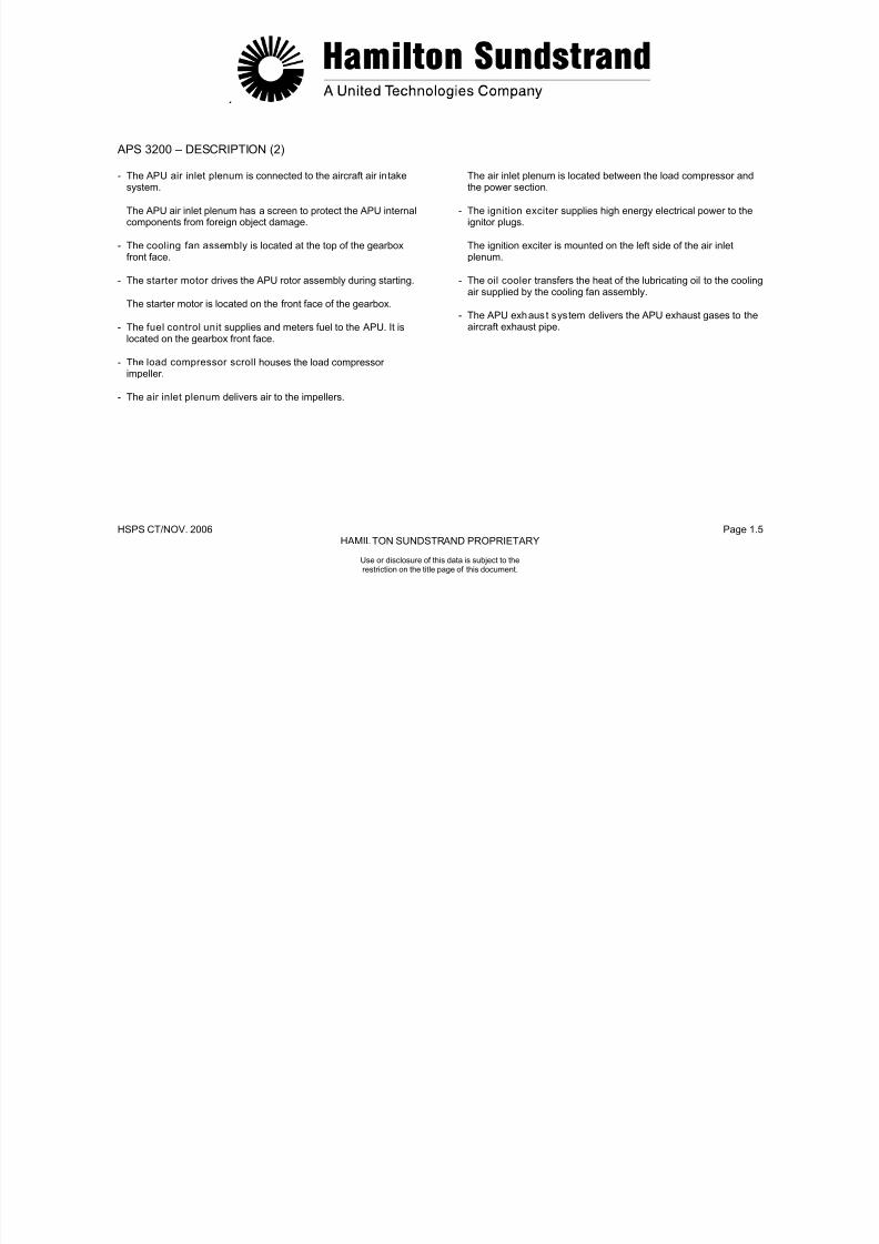
7/21/2019 Aps 3200 Training
http://slidepdf.com/reader/full/aps-3200-training 390/739
HSPS CT/NOV.. 2006 Page 1.6HAMILTON SUNDSTRAND PROPRIETARY
COOLING FAN ASSEMBLY
Use or disclosure of this data is subject to therestriction on the title page of this document.
APS 3200 - DESCRIPTION (2)
AIR BYPASS
PLENUM
OIL COOLER
AIR INLETPLENUM
EXCITER
LOAD COMPRESSORSCROLL
APU AIRINLET
FUEL CONTROLUNIT
STARTERMOTOR
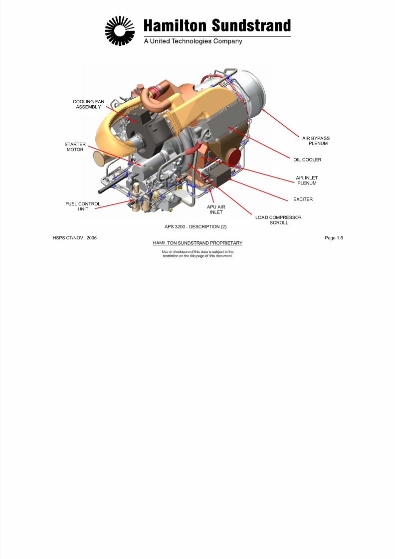
7/21/2019 Aps 3200 Training
http://slidepdf.com/reader/full/aps-3200-training 391/739
HSPS CT/NOV.. 2006 Page 1.7HAMILTON SUNDSTRAND PROPRIETARY
Use or disclosure of this data is subject to therestriction on the title page of this document.
APS 3200 - DESCRIPTION (3)Identification of Components
- The gearbox provides the drive for the AC generator and theaccessories for APU operation.
The gearbox also provides the sump for the oil system.
- The AC generator that provides electrical power for the aircraftsystems.
- The cooling fan assembly for airflow through the oil cooler andventilation of the APU compartment.
The cooling fan assembly is located on the gearbox front face.
- The APU drain collector . The collector is installed on the rightside of the gearbox by two struts.
- The air- bleed system that includes a servo valve, an actuator,and a bleed control valve.
- The inlet guide vane system that includes a servo valve, anactuator, the inlet guide vanes and their control mechanism.
- The combustor housing that houses the combustor chamber.
- Main and pilot fuel injection system installed on the combustorhousing.

7/21/2019 Aps 3200 Training
http://slidepdf.com/reader/full/aps-3200-training 392/739
.
HSPS CT/NOV. 2006 Page 1.8HAMILTON SUNDSTRAND PROPRIETARY
MAIN AND PILOTFUEL INJECTIONSYSTEM
COOLING FAN ASSEMBLY
INLETGUIDE VANE
ACTUATOR
BLEED CONTROLVALVE
Use or disclosure of this data is subject to therestriction on the title page of this document.
APS 3200 – DESCRIPTION (3)
APU DRAINCOLLECTOR
GEARBOX
AC GENERATORMOUNTING PAD
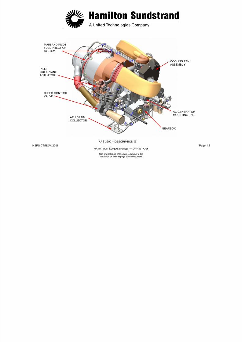
7/21/2019 Aps 3200 Training
http://slidepdf.com/reader/full/aps-3200-training 393/739
.
HSPS CT/NOV. 2006 Page 1.9HAMILTON SUNDSTRAND PROPRIETARY
APS 3200 - OPERATION
Power section provides the shaft power to drive the loadcompressor and the gearbox.
Power is produced by transforming the energy contained in theambient air and the fuel through thermodynamic cycle: compression,combustion, expansion.
- Compression of the air in the single stage centrifugal compressor
- Combustion of the air-fuel mixture in the reverse flow combustorchamber
- Expansion of the burned gases across the two stage axial flowturbine to drive:
• The power section impeller
• The load compressor impeller
• The gearbox.
The load compressor supplies compressed air to the aircraftpneumatic system. The air is compressed by a single stagecentrifugal impeller and uses variable inlet guide vanes to control theair flow. The compressed air is delivered through a scroll to the bleedcontrol valve.
The gearbox provides the drive for the AC generator, andaccessories for APU operation.
The AC generator that provides electrical power for the aircraftsystems.
The Electronic Control Box receives various signals from theaircraft and the APU to operate and monitor the APU.
The electronic control box controls the following:
- Rotation speed (N) (fuel flow)
- Load compressor surge protection (bleed control valve)
- Exhaust Gas Temperature (EGT) (inlet guide vanes).
Use or disclosure of this data is subject to therestriction on the title page of this document.

7/21/2019 Aps 3200 Training
http://slidepdf.com/reader/full/aps-3200-training 394/739
HSPS CT/NOV.. 2006 Page 1.10HAMILTON SUNDSTRAND PROPRIETARY
TO AIRCRAFT
TO APUEXHAUST
POWER SECTION
Use or disclosure of this data is subject to therestriction on the title page of this document.
APS 3200 - OPERATION
ECB
BLEED CONTROLVALVE
COMPRESSION COMBUSTION EXPANSION
GENERATOR
AMBIENT AIRCOMPRESSED AIRCOMBUSTIONEXHAUSTFUEL FLOWELECTRICAL SIGNALS
IGV ACTUATORFUEL CONTROL
EXHAUST
GEARBOX
LOAD COMPRESSOR
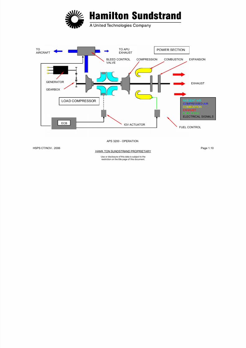
7/21/2019 Aps 3200 Training
http://slidepdf.com/reader/full/aps-3200-training 395/739
HSPS CT/NOV. 2006 Page 1.11HAMILTON SUNDSTRAND PROPRIETARY
APS 3200 AUXILIARY POWER UNIT
Use or disclosure of this data is subject to therestriction on the title page of this document

7/21/2019 Aps 3200 Training
http://slidepdf.com/reader/full/aps-3200-training 396/739
HSPS CT/NOV..2006 Page 2.0HAMILTON SUNDSTRAND PROPRIETARY
APS 3200 AUXILIARY POWER UNIT
SECTION 2
POWER UNIT
Use or disclosure of this data is subject to therestriction on the title page of this document.

7/21/2019 Aps 3200 Training
http://slidepdf.com/reader/full/aps-3200-training 397/739
.
HSPS CT/NOV. 2006 Page 2.1HAMILTON SUNDSTRAND PROPRIETARY
Use or disclosure of this data is subject to therestriction on the title page of this document.
POWER UNIT - GENERAL
Function
The APU provides compressed air and electrical power to the aircraft.
Location
The APU is installed in the aircraft tail section.
Type
Single spool gas turbine engine driving a load compressor and an ACgenerator.
Main Characteristics
Characteristics at Aero Design Point, installed APU (ISA, sea level) aregiven for information only:
- Total power ............................400 kW (536 HP)
- Specific fuel consumption .......0.372 kg/kW.h (0.61 Ib/HP.H)
- Fuel consumption ...................148 kg/HR (178 L/HR)................................................[327 LB/HR (47 GAL/HR)]
- Electrical power ......................132 kW (177 HP)
- Pneumatic power ...................252 kW (338 HP)
- Bleed air flow .........................1.2 kg/sec. (2.6 lbs/sec.)
- Bleed air pressure ..................390 kPa (42 PSI)
- Rotation speed .......................49 300 RPM
- Direction of rotation ................clockwise (view from the rear)
- APU dry weight ......................136 kg (299 lbs).Main Components
- Gearbox (with AC generator and APU accessory drive)
- Load compressor (centrifugal type provided with inlet guide vanes)
- Air inlet plenum (air intake and air dist ribution)
- Power section including:
• A centrifugal impeller
A reverse flow combustor chamber
• A two stage axial flow turbine.
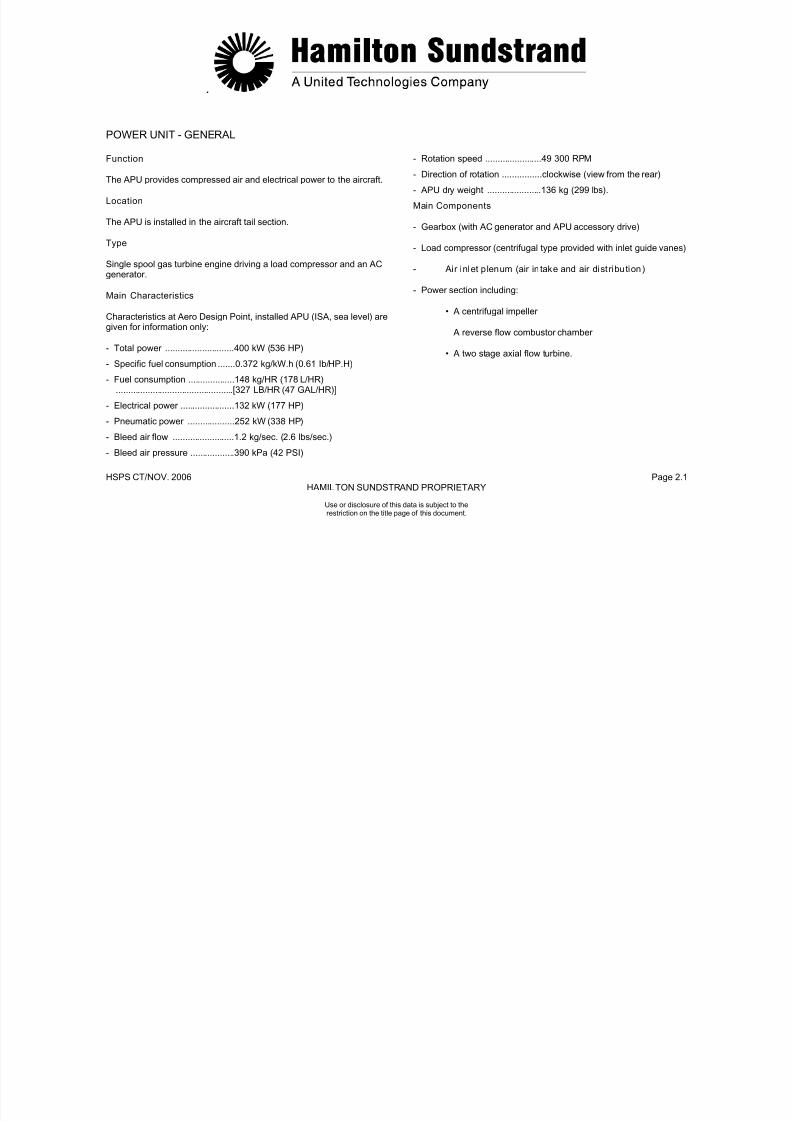
7/21/2019 Aps 3200 Training
http://slidepdf.com/reader/full/aps-3200-training 398/739
HSPS CT/NOV..2006 Page 2.2HAMILTON SUNDSTRAND PROPRIETARY
LOADCOMPRESSOR
CENTRIFUGAL
COMPRESSOR
Use or disclosure of this data is subject to therestriction on the title page of this document.
POWER UNIT - GENERAL
GEARBOX AIR INLET
PLENUM
TURBINES
AC GENERATOR
COMBUSTOR
CHAMBER
ECB

7/21/2019 Aps 3200 Training
http://slidepdf.com/reader/full/aps-3200-training 399/739
.
HSPS CT/NOV. 2006 Page 2.3HAMILTON SUNDSTRAND PROPRIETARY
Use or disclosure of this data is subject to therestriction on the title page of this document.
POWER UNIT - DESCRIPTION (1)
The first part of the description deals with the APU rotating assemblyand the second part will consider the modular design of the APU.
The following main components are considered in this description:gearbox, air intake plenum, load compressor and power section.
Gearbox
The gearbox located at the front of the APU provides the mechanicaldrive for the AC generator and the accessories required for the APUoperation. The oil sump is also part of the gearbox.
Load Compressor
The load compressor is driven by the power section and providescompressed air to the aircraft pneumatic system. It is a centrifugalimpeller that has variable inlet guide vanes to control the air flowoutput.
Air Inlet Plenum
The plenum is located between the load compressor and the power
section. The plenum directs the air supply to the power section, loadcompressor and the oil cooling system.
Power Section
The power section provides mechanical shaft power to drive the load
compressor and the gearbox.
The power section comprises:
- A single stage centrifugal impeller
- A reverse flow combustion chamber
- A two stage axial flow turbine
- An exhaust system.
The main rotor assembly is supported by two bearings: A ballbearing at the front of the load compressor, a roller bearing at therear of the turbine.

7/21/2019 Aps 3200 Training
http://slidepdf.com/reader/full/aps-3200-training 400/739
.
HSPS CT/NOV. 2006 Page 2.4HAMILTON SUNDSTRAND PROPRIETARY
DRIVE TRAINFOR AC GENERATOR
AND APU ACCESSORIESCENTRIFUGALIMPELLER COMBUSTION
CHAMBERFRONTBEARING
EXHAUST
Use or disclosure of this data is subject to therestriction on the title page of this document.
POWER UNIT - DESCRIPTION (1)
OILSUMP
CENTRIFUGALIMPELLER
AIR INLETPLENUM
TURBINES
REARBEARING
VARIABLEINLET GUIDEVANES
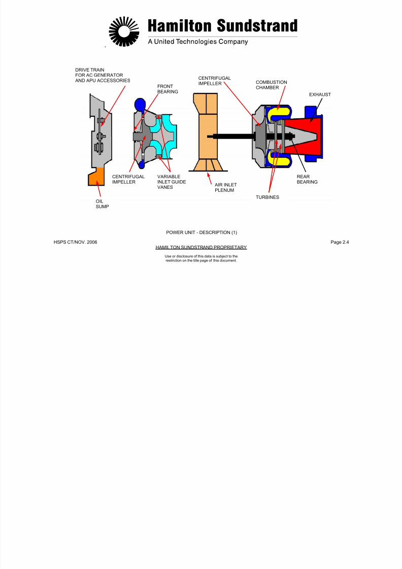
7/21/2019 Aps 3200 Training
http://slidepdf.com/reader/full/aps-3200-training 401/739
.
HSPS CT/NOV. 2006 Page 2.5HAMILTON SUNDSTRAND PROPRIETARY
Use or disclosure of this data is subject to therestriction on the title page of this document.
POWER UNIT – DESCRIPTION (2)
APU Rotating Assembly
The APU rotating assembly includes the following components:
- The load compressor impeller
- The inter shaft which connects the load compressor impeller to thepower section rotor assembly
- The compressor impeller of the power section
- The turbine wheels.
The tie-bolt secures the main components of the APU rotorassembly.
Bearings
The APU rotor assembly is supported by two bearings:
- Front ball bearing
- Rear roller bearing
Quill Shaft
The quill shaft is splined into the rotor shaft and provides themechanical connection between the APU rotor shaft and thegearbox.
7/21/2019 Aps 3200 Training
http://slidepdf.com/reader/full/aps-3200-training 402/739
.
HSPS CT/NOV. 2006 Page 2.6HAMILTON SUNDSTRAND PROPRIETARY
POWER SECTIONIMPELLERLOAD COMPRESSOR
IMPELLER
FRONT BALLBEARING
Use or disclosure of this data is subject to therestriction on the title page of this document.
POWER UNIT - DESCRIPTION (2)
QUILL
INTERSHAFTTIE
BOLT
SECURINGNUT
TURBINES
REAR ROLLERBEARING
SECURINGNUT
A320-457a
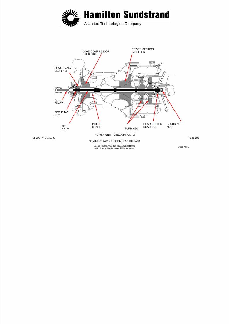
7/21/2019 Aps 3200 Training
http://slidepdf.com/reader/full/aps-3200-training 403/739
.
HSPS CT/NOV. 2006 Page 2.7HAMILTON SUNDSTRAND PROPRIETARY
Use or disclosure of this data is subject to therestriction on the title page of this document.
POWER UNIT - OPERATION
General
The power section produces mechanical shaft power for APU
operation.
This mechanical power is used to drive:
- The load compressor which supplies compressed air
- The AC generator which supplies electrical power
- Accessories required for the operation of the APU.
Power Section Operation
The air enters the power section through the aircraft air inlet and the APU plenum.
In the plenum, this air is divided into two flows; one for the loadcompressor and one for the power section.
The power section air is directed to the centrifugal impeller which
increases the air pressure.
The air is then admitted to the combustion chamber, mixed with thefuel and burned to provide a continuous combustion process. Thegases are expanded across the turbines that transforms the gasenergy into mechanical energy.
The gases are then expelled overboard through the aircraft exhaustsystem.
Load Compressor Operation
The load compressor is driven by the power section and produces airflow to the aircraft pneumatic systems.
Gearbox Operation
The gearbox is driven by the power section to operate the APUaccessories and the AC generator.
Electronic Control Box (ECB)
The ECB provides control and monitoring of the APU.

7/21/2019 Aps 3200 Training
http://slidepdf.com/reader/full/aps-3200-training 404/739
.
HSPS CT/NOV. 2006 Page 2.8
HAMILTON SUNDSTRAND PROPRIETARY
BLEEDCONTROLVALVE
COMPRESSED AIR TO EXHAUSTCOMPRESSED
AIR TO AIRCRAFT
AC GENERATOR
ECB AMBIENT AIRCOMPRESSED AIR
COMBUSTIONEXHAUST
POWER UNIT - OPERATION
Use or disclosure of this data is subject to therestriction on the title page of this document.
A320-458a

7/21/2019 Aps 3200 Training
http://slidepdf.com/reader/full/aps-3200-training 405/739
.
HSPS CT/NOV. 2006 Page 2.9
HAMILTON SUNDSTRAND PROPRIETARY
Use or disclosure of this data is subject to therestriction on the title page of this document.
GEARBOX - GENERAL
Location
The gearbox is located at the front of the load compressor scroll.
Main Features
- Modular design
- Mechanical efficiency: 0.98
- Weight: 17 kg (37.4 lbs)
- Oil sump
- Gearbox drive power: 148 kW (198 HP)
- AC generator drive power: 132 kW (177 HP)
- Accessories drive power: 16 kW (21 HP)
- Material for housing: Aluminum alloy.
Gearbox Front Face View
- Oil cooling fan drive pad
- AC generator drive pad
- Starter motor drive pad
- Fuel control unit drive pad
- Accessories (oil filters, oil level sensor, de-oiling valve...).
Gearbox Left Side View
- Oil sight glass
- Oil fill tube
- High oil temperature sensor
- Speed sensor
- Gearbox mounting flange (attachment with the load compressorscroll)
- APU front left mount.
7/21/2019 Aps 3200 Training
http://slidepdf.com/reader/full/aps-3200-training 406/739
.
HSPS CT/NOV. 2006 Page 2.10
HAMILTON SUNDSTRAND PROPRIETARY
COOLING FAN
MOUNTINGFLANGE AC GENERATOR
Use or disclosure of this data is subject to therestriction on the title page of this document.
GEARBOX - GENERAL
APU FRONTMOUNT
FWD
OIL FILLTUBE
OIL SIGHTGLASS
HIGH OIL TEMPERATURE
SPEEDSENSOR
DE-OILINGVALVE
OIL LEVELSENSOR
OILFILTERS
STARTER MOTOR
FUEL CONTROL
DE-OILING
VALVE
A320-459a
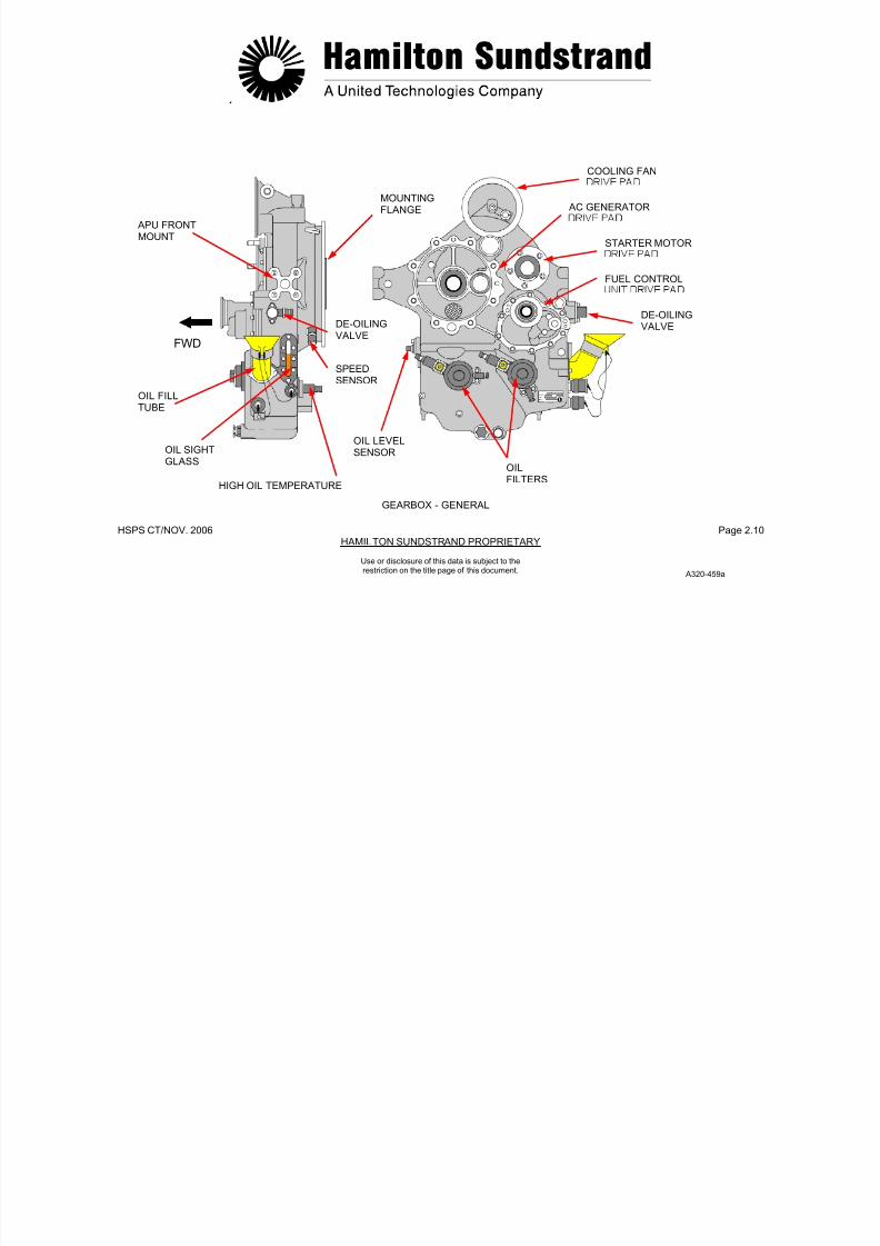
7/21/2019 Aps 3200 Training
http://slidepdf.com/reader/full/aps-3200-training 407/739
.
HSPS CT/NOV. 2006 Page 2.11
HAMILTON SUNDSTRAND PROPRIETARY
Use or disclosure of this data is subject to therestriction on the title page of this document.
GEARBOX DESCRIPTIO (1)
This description considers the gears, the bearings and the drivepads.
Gears
The gearbox comprises of 8 spur type gears made of steel alloy. Thegear train provides the correct speeds for the APU driven units.
BearingsThe gears are supported by bearings: 6 roller bearings and 6 ballbearings.
AC Generator Drive
- Speed: 24034 RPM- Direction of rotation: Clockwise.
Intermediate Gear- Speed: 14349 RPM- Direction of rotation: Clockwise- Centrifugal air-oil separator.
Cooling Fan Drive
- Speed: 51965 RPM- Direction of rotation: Anti clockwise- PMG (Permanent Magnet Generator).
Starter Motor Drive- Speed: 32045 RPM- Direction of rotation: Anti clockwise- Starter clutch: Sprag type.
Fuel Pump Drive- Speed: 10129 RPM-Direction o f rotation: Clockwise.
Oil Pump Drives- Lubrication pump
• Speed: 4137 RPM• Direction of rotation: Clockwise.
Scavenge pumps• Speed: 4137 RPM
Direction of rotation: Anti clockwise.
Note: Direction of rotation by viewing the front of the gearbox.
7/21/2019 Aps 3200 Training
http://slidepdf.com/reader/full/aps-3200-training 408/739
.
HSPS CT/NOV. 2006 Page 2.12
HAMILTON SUNDSTRAND PROPRIETARY
-
FRONT VIEWCOOLING FANDRIVE(51965 RPM)
INTERMEDIATEGEAR(14349 RPM)
STARTER MOTORDRIVE(32045 RPM)
AC GENERATORDRIVE
(24034 RPM)
Use or disclosure of this data is subject to therestriction on the title page of this document.
GEARBOX - DESCRIPTION (1)
DRIVEGEAR(49300 RPM)
FUEL PUMPDRIVE(10129 RPM)
OIL PUMPDRIVES(4137 RPM)
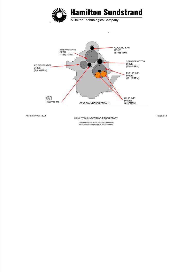
7/21/2019 Aps 3200 Training
http://slidepdf.com/reader/full/aps-3200-training 409/739
.
HSPS CT/NOV. 2006 Page 2.13
HAMILTON SUNDSTRAND PROPRIETARY
Use or disclosure of this data is subject to therestriction on the title page of this document.
GEARBOX - DESCRIPTION (2)
Identification of Gearbox Components
- The gearbox housing which forms the oil sump and provides theaccessories for the oil system (oil filter, oil level sensor, magneticplug...).
The gearbox housing also provides the mounting pads for:
• The oil cooling fan
• The AC generator
• The starter motor
• The fuel control unit
The gearbox housing is attached to the load compressor scroll bya mounting flange.
- The APU front left and right mounts are located on the sides ofthe gearbox.
- The gearbox gear train which includes:
• The AC generator drive gear
• The intermediate gear, which also forms the air-oilseparator
• The starter motor drive gear
• The fuel control unit drive gear
• The oil pump drive gears.

7/21/2019 Aps 3200 Training
http://slidepdf.com/reader/full/aps-3200-training 410/739
.
HSPS CT/NOV. 2006 Page 2.14
HAMILTON SUNDSTRAND PROPRIETARY
INTERMEDIATEGEAR AC GENERATOR
DRIVE GEAR
STARTER MOTORDRIVE GEAR
Use or disclosure of this data is subject to therestriction on the title page of this document.
GEARBOX - DESCRIPTION (2)
DRIVE
GEAR
FUEL CONTROLUNIT DRIVEGEAR
OIL PUMPDRIVE GEARSGEARBOX GEAR TRAIN
A320-461a

7/21/2019 Aps 3200 Training
http://slidepdf.com/reader/full/aps-3200-training 411/739
.
HSPS CT/NOV. 2006 Page 2.15
HAMILTON SUNDSTRAND PROPRIETARY
Use or disclosure of this data is subject to therestriction on the title page of this document.
GEARBOX - OPERATION
During Starting
The starter motor is electrically energized and provides the torque tocrank the gear train and the APU rotor assembly.
At self-sustaining speed, the electrical supply to the starter is de-energized and the starter is disengaged by the sprag clutch.
Normal Running Condit ion
The power section provides the mechanical power to drive the loadcompressor and the gearbox drive gear.
The drive gear meshes directly with the AC generator gear.
It also drives an intermediate gear which in turn drives the oil coolerfan gear, the starter motor gear and the fuel control unit and oil pumpgears

7/21/2019 Aps 3200 Training
http://slidepdf.com/reader/full/aps-3200-training 412/739
HSPS CT/NOV..2006 Page 2.16
HAMILTON SUNDSTRAND PROPRIETARY
AC GENERATORDRIVE
COOLINGFAN GEAR
DRIVEGEAR INTERMEDIATE
GEAR
DRIVENGEAR
STARTERDRIVE GEAR
FUEL CONTROLUNIT DRIVE GEAR
DRIVEGEAR
Use or disclosure of this data is subject to therestriction on the title page of this document.
GEARBOX - OPERATION
RUN OPERATIONOIL PUMPDRIVE GEARS
START OPERATION
A320-461a

7/21/2019 Aps 3200 Training
http://slidepdf.com/reader/full/aps-3200-training 413/739
.
HSPS CT/NOV. 2006 Page 2.17
HAMILTON SUNDSTRAND PROPRIETARY
Use or disclosure of this data is subject to therestriction on the title page of this document.
AIR INLET PLENUM - GENERAL
Location
The inlet plenum is located between the load compressor and thepower section.
Main Features
- Acoustically treated part
- Shop replaceable unit
- Weight: approx. 7.5 kg (16.5 lbs).
Main Components
The plenum consists of two parts, upper and lower, which areconnected by quick disconnect latches.
The lower part interfaces with the aircraft air inlet system. The airinlet to the plenum is provided with a screen made of stainless steelthat protects the APU internal components from foreign objectdamage.
The upper part has an outlet for air supply to the oil cooling system(supply to the oil cooler fan).
Construction
The plenum is of sandwich construction with a structural envelope,Nomex and felt metal. The structural envelope and Nomex are fireproof.
Operation
In the plenum, the air is separated into two flows by the splitter.
- One for the power section: 2.2 kg/s (4.8 lbs/sec.)
- One for the load compressor and cooling fan: 1.2 kg/s (2.6
lbs/sec.).

7/21/2019 Aps 3200 Training
http://slidepdf.com/reader/full/aps-3200-training 414/739
.
HSPS CT/NOV. 2006 Page 2.18
HAMILTON SUNDSTRAND PROPRIETARY
COOLING FAN
AIR SUPPLY
QUICK DISCONNECTLATCHES
Use or disclosure of this data is subject to therestriction on the title page of this document.
AIR INLET PLENUM - GENERAL
LOADCOMPRESSORIMPELLER SPLITTER SCREEN
AMBIENT AIR
COMPRESSED AIR
A320-463a

7/21/2019 Aps 3200 Training
http://slidepdf.com/reader/full/aps-3200-training 415/739
.
HSPS CT/NOV. 2006 Page 2.19
HAMILTON SUNDSTRAND PROPRIETARY
Use or disclosure of this data is subject to therestriction on the title page of this document.
AIR INLET PLENUM - DESCRIPTION
Identification of the Air Inlet Plenum Components
- The lower part of the air inlet plenum interfaces with the APU airinlet system. It has a screen to protect the APU internal
components from foreign object damage.
The lower part incorporates noise treatment and a splitter whichseparates the air into two flows. It also provides the support for thefollowing components:
• The ambient air pressure and temperature sensors
• The differential pressure sensor
• The low oil pressure switch
• The ignition exciter.
- The upper part of the air inlet plenum is also noise treated.
The upper part has an oval outlet to supply air to the oil coolingsystem
- The quick disconnect latches secure the upper part and lowerpart of the air inlet plenum.
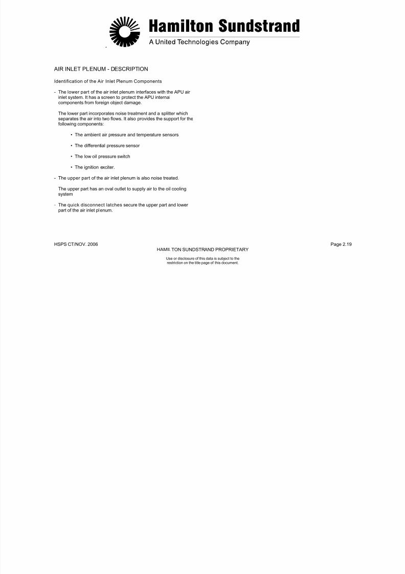
7/21/2019 Aps 3200 Training
http://slidepdf.com/reader/full/aps-3200-training 416/739
.
HSPS CT/NOV. 2006 Page 2.20
HAMILTON SUNDSTRAND PROPRIETARY
PLENUMUPPER PART
SPLITTER
Use or disclosure of this data is subject to therestriction on the title page of this document.
AIR INLET PLENUM - DESCRIPTION
A320-464a
AIR INLET
HOUSING
PLENUM
LOWER PART
QUICKDISCONNECTLATCH
COOLING FAN
AIR SUPPLY
INLET
SCREENLOCATINGTAB
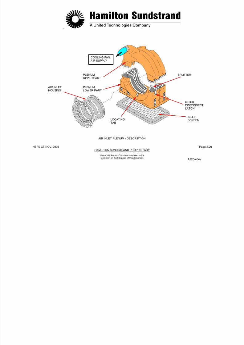
7/21/2019 Aps 3200 Training
http://slidepdf.com/reader/full/aps-3200-training 417/739
.
HSPS CT/NOV. 2006 Page 2.21
HAMILTON SUNDSTRAND PROPRIETARY
Use or disclosure of this data is subject to therestriction on the title page of this document.
LOAD COMPRESSOR - GENERAL
Location
The load compressor is installed between the gearbox and the powersection.
Type
High pressure centrifugal impeller provided with inlet guide vanes.
Main Features
- Air flow: 1.2 kg/s (2.6 lbs/sec.)
- Pressure ratio: 4:1
- Max outlet temperature: 232°C (450°F)
- Rotation speed: 49 300 RPM
- Direction of rotation: clockwise (viewed from the rear of the APU).
Main Components
- Rotating components (compressor shaft, impeller, bearing,bearing seals)
- Stationary components (air inlet housing, variable inlet guidevanes, impeller shroud, diffuser, and scroll).
7/21/2019 Aps 3200 Training
http://slidepdf.com/reader/full/aps-3200-training 418/739
.
HSPS CT/NOV. 2006 Page 2.22
HAMILTON SUNDSTRAND PROPRIETARY
BLEED CONTROLVALVE
COMPRESSED AIRTO AIRCRAFT
COMPRESSED AIR TOEXHAUST
Use or disclosure of this data is subject to therestriction on the title page of this document.
LOAD COMPRESSOR - GENERAL
INLET GUIDEVANES
COMPRESSORIMPELLER
SCROLL
AMBIENT AIRCOMPRESSED AIR
A320-465a

7/21/2019 Aps 3200 Training
http://slidepdf.com/reader/full/aps-3200-training 419/739
.
HSPS CT/NOV. 2006 Page 2.23
HAMILTON SUNDSTRAND PROPRIETARY
Use or disclosure of this data is subject to therestriction on the title page of this document.
LOAD COMPRESSOR - DESCRIPTION (1)
The first part of this description deals with the load compressorcomponents, the second part will consider the inlet guide vanescontrol mechanism and the third part the identification of all thecomponents.
Air Inlet Housing
The housing allows the passage of air to the load compressor andsupports the inlet guide vanes. It is made of aluminum alloy.
Compressor Impeller
The impeller is constructed of titanium alloy. The rear shaft of the
impeller is connected to the rotor intershaft using a curvic coupling.The front is supported by a ball bearing.
Compressor Shroud
The shroud houses the impeller and is constructed of steel alloy.
Compressor Diffuser
It consists of 19 cambered vanes made of steel alloy.
Scroll
The annular scroll provides the air outlet of the load compressor. It iscast aluminum.
The scroll housing provides passages for static air pressure to theload compressor discharge pressure sensor.
Bearing
A ball thrust bearing supports the front shaft of the load compressor.It is mounted in the load compressor housing.
Bearing Seals
Oil that is used to lubricate the front bearing is prevented fromentering the impeller area by a floating carbon seal and a labyrinthseal.
7/21/2019 Aps 3200 Training
http://slidepdf.com/reader/full/aps-3200-training 420/739
.
HSPS CT/NOV. 2006 Page 2.24
HAMILTON SUNDSTRAND PROPRIETARY
COMPRESSORDIFFUSERDRAINSQUEEZEFILM THRUST
WASHER
Use or disclosure of this data is subject to therestriction on the title page of this document.
LOAD COMPRESSOR - DESCRIPTION (1)
COMPRESSORSHROUD
INLET GUIDEVANE
A320-450a
COMPRESSORIMPELLER
BALLBEARING FLOATING
CARBONSEAL
LABYRINTHSEAL
AMBIENT AIRCOMPRESSD AIR

7/21/2019 Aps 3200 Training
http://slidepdf.com/reader/full/aps-3200-training 421/739
.
HSPS CT/NOV. 2006 Page 2.25
HAMILTON SUNDSTRAND PROPRIETARY
Use or disclosure of this data is subject to therestriction on the title page of this document.
LOAD COMPRESSOR - DESCRIPTION (2)
Identification of Load Compressor Components
- The IGV assembly includes the variable inlet guide vanes, therack and pinion mechanism and the air inlet housing
- The compressor shroud houses the impeller.
- The load compressor impeller has main blades and splitterblades. The impeller is connected at the rear to the inter shaft bycurvic-coupling. The impeller front shaft is supported by the frontbearing.
- The scroll provides the air outlet of the load compressor. The
scroll also houses the load compressor diffuser.
- The front bearing is a ball bearing that supports the impeller frontshaft
- The labyrinth seal is pressurized with compressed air from thepower section impeller.
- The front bearing nut retains the front bearing and forms the
phonic wheel of the speed sensing system
- The tie-bolt and the securing nut.
7/21/2019 Aps 3200 Training
http://slidepdf.com/reader/full/aps-3200-training 422/739
.
HSPS CT/NOV. 2006 Page 2.26
HAMILTON SUNDSTRAND PROPRIETARY
SCROLL
LABYRINTHSEAL
Use or disclosure of this data is subject to therestriction on the title page of this document.
LOAD COMPRESSOR - DESCRIPTION (2)
FRONTBEARING
FRONT BEARINGJOURNAL
TIEBOLTSECURING
NUT
FRONT BEARING NUT(PHONIC WHEEL)
INLET GUIDE
VANE ASSEMBLY
COMPRESSORSHROUD
LOAD COMPRESSORIMPELLER
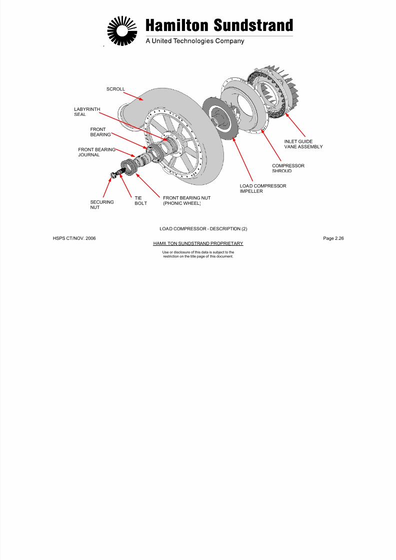
7/21/2019 Aps 3200 Training
http://slidepdf.com/reader/full/aps-3200-training 423/739
.
HSPS CT/NOV. 2006 Page 2.27
HAMILTON SUNDSTRAND PROPRIETARY
Use or disclosure of this data is subject to therestriction on the title page of this document.
LOAD COMPRESSOR - DESCRIPTION (3)
Inlet Guide Vanes
The Inlet Guide Vanes (IGV) consist of 24 vanes, made of titaniumalloy and mounted in the inlet housing.
Each inlet guide vane has a sector gear.
There are five guide vanes with holes in them. Three are located atthe 6:30 position, one at the ten o’clock and one at the two o’clockposition. The holes allow a minimum amount of air flow to the loadcompressor to prevent surging when the guide vanes are closed andthe APU is operating.
Control Mechanism
The mechanism controls the position of the vanes. The completemechanism consists of:
- The actuator
- The control rod
- The rack and pinion mechanism that moves the vanes.
The Actuator
The actuator is hydraulically operated. It uses fuel pressure meteredby an electrical signal from the electronic control box.
The Control Rod
The control rod is mechanically operated by the actuator.
The control rod is connected between the actuator and the inletguide vane assembly.
The Inlet Guide Vane Assembly
The inlet guide vane assembly consists of 24 sector gears engagedinto a common ring gear.
The ring gear is connected to the inlet guide vane control rod.

7/21/2019 Aps 3200 Training
http://slidepdf.com/reader/full/aps-3200-training 424/739
HSPS CT/NOV..2006 Page 2.28
HAMILTON SUNDSTRAND PROPRIETARY
ACTUATORROD HOUSING AIR INLET
HOUSING
Use or disclosure of this data is subject to therestriction on the title page of this document.
INLET GUIDEVANE CONTROLROD
INLET GUIDEVANE
ASSEMBLY
RINGGEAR
IGVPOSITIONINDICATOR
INLET GUIDEVANE
SECTORGEAR
LOAD COMPRESSOR – DESCRIPTION (3)
A320-467A
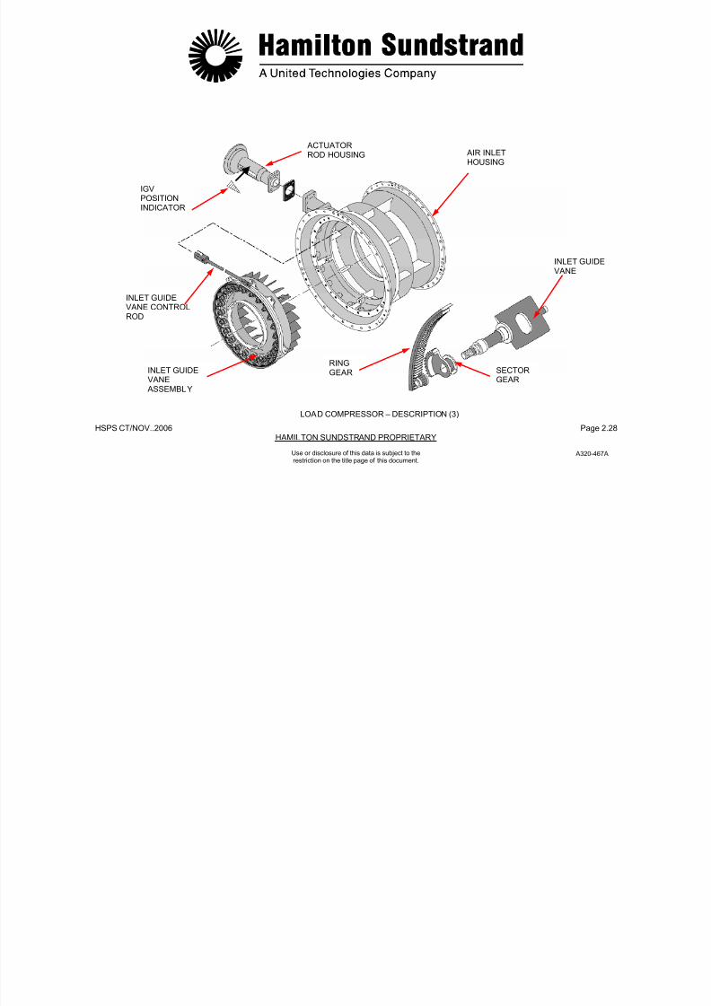
7/21/2019 Aps 3200 Training
http://slidepdf.com/reader/full/aps-3200-training 425/739
.
HSPS CT/NOV. 2006 Page 2.29
HAMILTON SUNDSTRAND PROPRIETARY
Use or disclosure of this data is subject to therestriction on the title page of this document.
LOAD COMPRESSOR - OPERATION
Air Inlet
The ambient air enters the APU through the aircraft air inlet and the APU plenum.
The plenum air is separated into three flows:
- Air for the power section
- Air for the oil cooling system
- Air for the load compressor.
The air for the load compressor passes through the inlet guidevanes; the flow of air depends upon the position (the angle) of thevanes. The air is then directed to the blades of the compressorimpeller.
Compression
As the air enters the blades of the rotating compressor impeller theair velocity increases.
The air leaves the tip of the blades at high velocity and flows throughthe diffuser vanes where velocity is transformed into pressure.
Delivery
The compressed air then flows into the scroll and delivered to thepneumatic system through a bleed control valve.

7/21/2019 Aps 3200 Training
http://slidepdf.com/reader/full/aps-3200-training 426/739
.
HSPS CT/NOV. 2006 Page 2.30
HAMILTON SUNDSTRAND PROPRIETARY
COMPRESSED AIR TOEXHAUST
COMPRESSED AIR TO AIRCRAFT
SCROLL
Use or disclosure of this data is subject to therestriction on the title page of this document.
LOAD COMPRESSOR - OPERATION
DIFFUSERVANE
COMPRESSORIMPELLER INLET GUIDE
VANES
A320-468a
AMBIENT AIRCOMPRESSED AIR
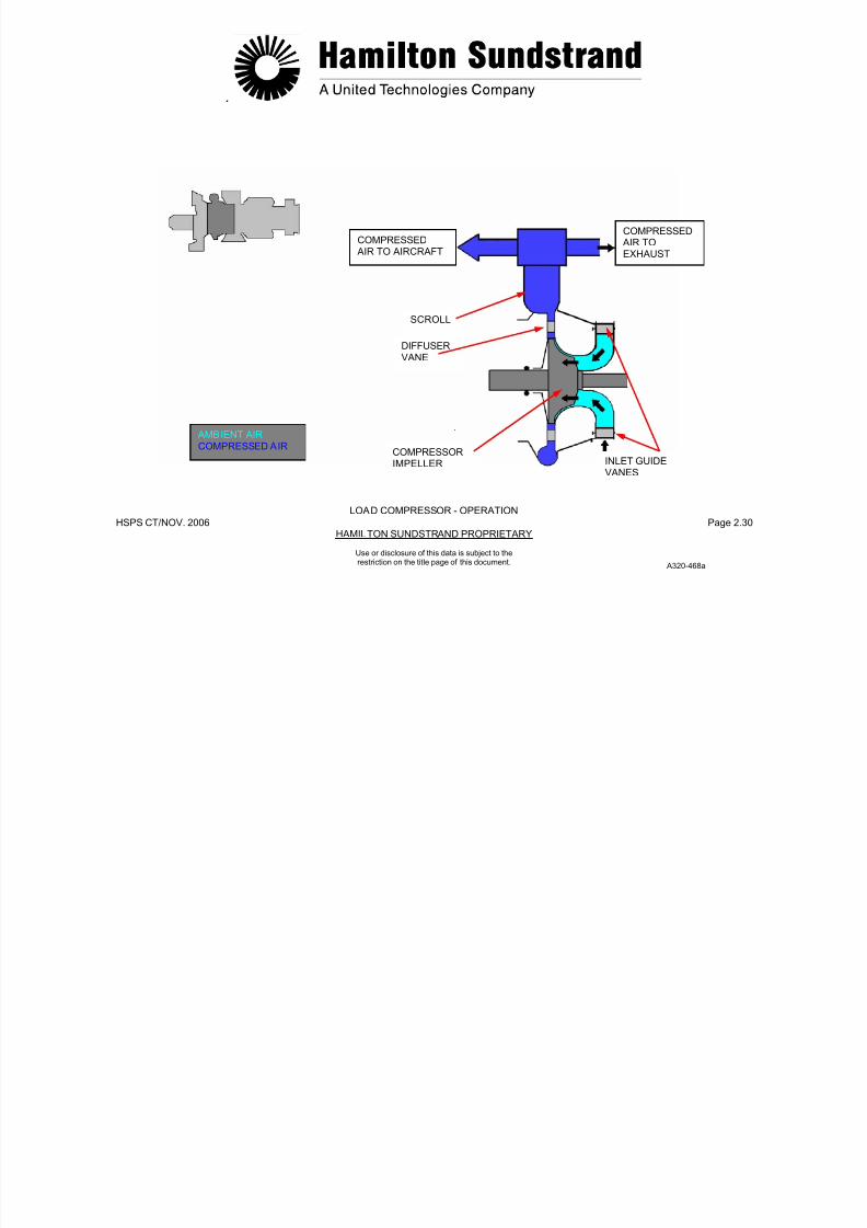
7/21/2019 Aps 3200 Training
http://slidepdf.com/reader/full/aps-3200-training 427/739
.
HSPS CT/NOV. 2006 Page 2.31
HAMILTON SUNDSTRAND PROPRIETARY
Use or disclosure of this data is subject to therestriction on the title page of this document.
POWER SECTION - GENERAL
Function
The power section provides the power to drive the load compressorand the gearbox.
Location
The power section forms the rear part of the APU.
Type
Single spool gas turbine engine.
Main Components
The main functional components are:
- Single stage centrifugal impeller
- Reverse flow combustion chamber
- Two stage axial flow turbine
- Exhaust.

7/21/2019 Aps 3200 Training
http://slidepdf.com/reader/full/aps-3200-training 428/739
.
HSPS CT/NOV. 2006 Page 2.32
HAMILTON SUNDSTRAND PROPRIETARY
Use or disclosure of this data is subject to therestriction on the title page of this document.
POWER SECTION - GENERAL
TWO STAGE AXIAL FLOW
TURBINESSINGLE STAGECENTRIFUGALCOMPRESSOR
MAIN CHARACTERISTICS
POWER400 Kw (536 HP)
SPECIFIC FUEL CONSUMPTION0.372 kg/kW.h (0.61 lb/HP.H)
FUEL CONSUMPTION327 LB/HR (47GAL/HR)
ROTATION SPEED49300 RPM
AIR MASS FLOW2.2 kg/s (4.8 lbs/sec)
COMPRESSION RATIO8:1
EXHAUST
REVERSE FLOWCOMBUSTIONCHAMBER
POWER SECTION - GENERAL
A320-469a
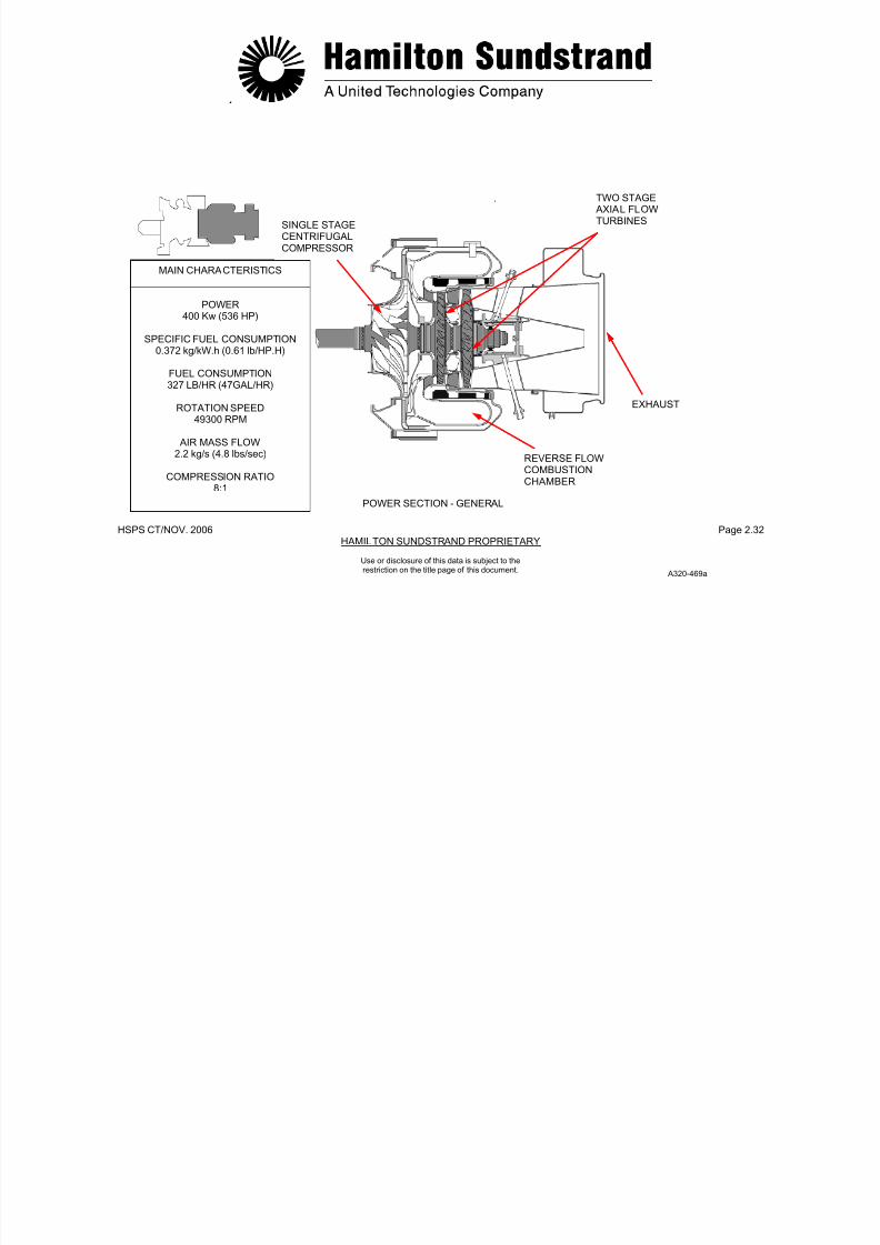
7/21/2019 Aps 3200 Training
http://slidepdf.com/reader/full/aps-3200-training 429/739
.
HSPS CT/NOV. 2006 Page 2.33
HAMILTON SUNDSTRAND PROPRIETARYUse or disclosure of this data is subject to therestriction on the title page of this document.
POWER SECTION - COMPRESSOR - GENERAL
Function
The impeller supplies the required amount of compressed air to thecombustor chamber.
Location
The impeller is located at the front of the power section.
Type
Single stage, high pressure, centrifugal flow impeller.
Main Features
• Compression ratio: 8:1
• Outlet air temperature: 350°C (662°F)
• Rotation speed: 49 300 RPM.
Main Components
- The impeller is made of titanium alloy. It has main blades andsplitter blades. The front and rear shaft are integral with the
impeller which is connected at the front to the inter shaft and at therear to the turbine shaft by curvic-couplings using a tie-bolt.
- The diffuser assembly is made of stainless steel. It has 19 radialvanes. The diffuser assembly is secured to the scroll with bolts.
The impeller shield is treated with an abradable material thatprovides a close tolerance clearance between the shield and theimpeller.
A containment shield for impeller containment is mounted on theoutside of the combustor housing.

7/21/2019 Aps 3200 Training
http://slidepdf.com/reader/full/aps-3200-training 430/739
.
HSPS CT/NOV. 2006 Page 2.34
HAMILTON SUNDSTRAND PROPRIETARY
IMPELLERCONTAINMENTSHIELD
COMPRESSOR
HOUSING
IMPELLERSHIELD
CURVIC
COUPLINGCURVICCOUPLING
Use or disclosure of this data is subject to therestriction on the title page of this document.
POWER SECTION - COMPRESSOR - GENERAL
INTER SHAFTMAIN BLADES
SPLITTER BLADES

7/21/2019 Aps 3200 Training
http://slidepdf.com/reader/full/aps-3200-training 431/739
.
HSPS CT/NOV. 2006 Page 2.35
HAMILTON SUNDSTRAND PROPRIETARYUse or disclosure of this data is subject to therestriction on the title page of this document.
POWER SECTION - COMPRESSOR - DESCRIPTION
Identification of Compressor Components
- The intermediate shaft is connected to the front of the loadcompressor impeller and to the rear of the power section
compressor impeller by curvic-couplings.
- The compressor housing houses the impeller and thecompressor shield.
The compressor housing is attached at the front to the air inlethousing and at the rear to the diffuser assembly and the combustorhousing.
- The impeller containment shield is mounted to the compressorhousing.
- The impeller has main blades and splitter blades. The impeller isconnected at the front to the intermediate shaft and at the rear tothe turbine by curvic-couplings.
- The diffuser is mounted to the impeller shield.

7/21/2019 Aps 3200 Training
http://slidepdf.com/reader/full/aps-3200-training 432/739
.
HSPS CT/NOV. 2006 Page 2.36
HAMILTON SUNDSTRAND PROPRIETARY
Use or disclosure of this data is subject to therestriction on the title page of this document.
POWER SECTION - COMPRESSOR - DESCRIPTION
COMPRESSORHOUSING
IMPELLERCONTAINMENT
SHIELD
INTERMEDIATESHAFT
DIFFUSER
IMPELLER IMPELLERSHIELD
POWER SECTION – COMPRESSOR - SECTION
a320-471a
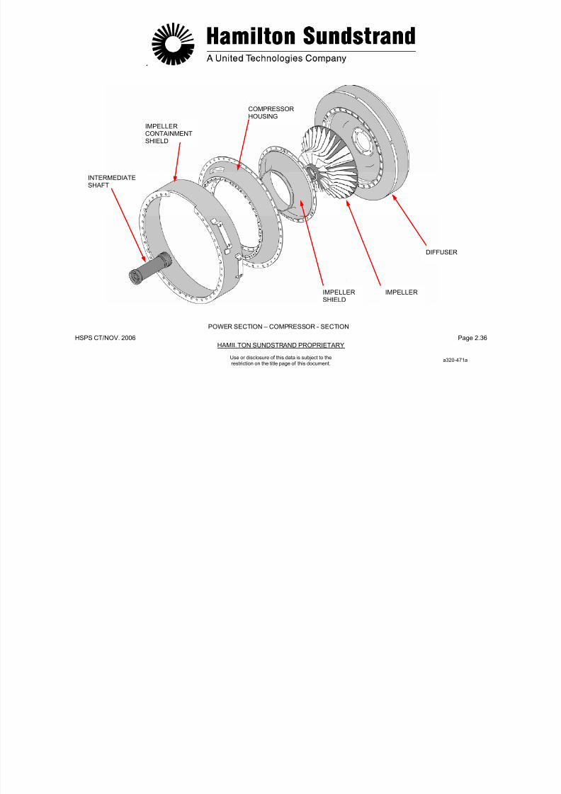
7/21/2019 Aps 3200 Training
http://slidepdf.com/reader/full/aps-3200-training 433/739
.
HSPS CT/NOV. 2006 Page 2.37
HAMILTON SUNDSTRAND PROPRIETARYUse or disclosure of this data is subject to therestriction on the title page of this document.
POWER SECTION - COMBUSTOR CHAMBER - GENERAL
Function
The combustor chamber burns the air-fuel mixture and delivers theresulting gas to the turbine.
Location
The combustor chamber is located in the middle of the powersection.
Type
Reverse flow, annular combustor chamber.
Main Features
- Fuel air ratio: 1/45
- Turbine inlet temperature: 1020°C (1868°F).
Main Components
- The combustor housing is made of steel alloy. It houses thecombustor chamber. It also has bosses for the mounting of fuel
injectors (3 pilot fuel injectors and 6 main fuel injectors) andigniters. The lower part of the external housing is provided with acombustor chamber drain valve.
- The combustor chamber is used for the fuel air mixturecombustion. The combustor chamber and the elbow are made ofheat resistant alloy and is provided with air holes and tubes.
- The heat shield acts as a shield between the bend assembly and
the impeller and directs the combustor gases to the turbines.
7/21/2019 Aps 3200 Training
http://slidepdf.com/reader/full/aps-3200-training 434/739
.
HSPS CT/NOV. 2006 Page 2.38
HAMILTON SUNDSTRAND PROPRIETARY
AIRCOMBUSTORTUBESHOUSING
FUEL
Use or disclosure of this data is subject to therestriction on the title page of this document.
POWER SECTION - COMBUSTOR CHAMBER - GENERAL
INJECTOR
IGNITER
COMBUSTORCHAMBER
BEND ASSEMBLY
HEAT
SHIELDTURBINECONTAINMENTSHIELD
A320-472a

7/21/2019 Aps 3200 Training
http://slidepdf.com/reader/full/aps-3200-training 435/739
.
HSPS CT/NOV. 2006 Page 2.39
HAMILTON SUNDSTRAND PROPRIETARYUse or disclosure of this data is subject to therestriction on the title page of this document.
POWER SECTION - COMBUSTOR CHAMBER -DESCRIPTION
Identification of Combustor Chamber Components
- The combustor housing houses the combustor chamber. It alsohas bosses for the mounting of the fuel injectors, the igniter plugs
and the combustor chamber drain valve.
- The combustor chamber has holes and tubes that allows air usedfor combustion and cooling to enter the combustor chamber.
- The bend assembly guides the burned gases from the combustorchamber to the inlet of the first stage turbine nozzle guide vane.
- The heat shield protects the diffuser holder plate of the power
section impeller.
The heat shield is located between the bend assembly and thediffuser assembly.
- The combustor chamber drain valve is threaded into the bottomof the combustor housing, this allows unburned fuel to drainoverboard. The valve is closed by air pressure in the combustorhousing.
7/21/2019 Aps 3200 Training
http://slidepdf.com/reader/full/aps-3200-training 436/739
.
HSPS CT/NOV. 2006 Page 2.40
HAMILTON SUNDSTRAND PROPRIETARY
Use or disclosure of this data is subject to therestriction on the title page of this document.
POWER SECTION - COMBUSTOR CHAMBER - DESCRIPTION
HEATSHIELD
BEND ASSEMBLY
FIRST STAGE
TURBINE NOZZLE
COMBUSTORCHAMBER
COMBUSTORCHAMBER DRAINVALVE
COMBUSTORHOUSING
COMBUSTOR AIR PRESSURE
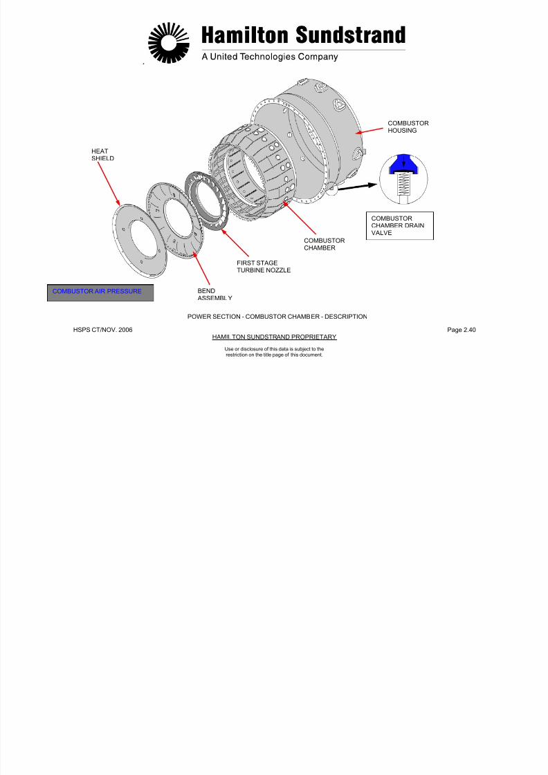
7/21/2019 Aps 3200 Training
http://slidepdf.com/reader/full/aps-3200-training 437/739
.
HSPS CT/NOV. 2006 Page 2.41
HAMILTON SUNDSTRAND PROPRIETARYUse or disclosure of this data is subject to therestriction on the title page of this document.
POWER SECTION - TURBINE - GENERAL
Function
The turbine extracts the energy from the combustor gases to drivethe impeller, the load compressor and the gearbox.
Location
The turbine is located at the rear of the power section.
Type
2 stage, axial flow turbine.
Main Features
• Turbine inlet temperature: 1020°C (1868°F)
• Turbine outlet temperature: 614°C (1137°F)
• Rotation speed: 49300 RPM
• Direction of rotation: clockwise (viewed from the rear of the APU).
Main Components
The two stage axial flow turbine comprises of:
- The first stage nozzle guide vane (22 cooled vanes)
- The first stage turbine wheel (37 fir tree blades inserted into a disc)
- The second stage nozzle guide vane (26 vanes)
- The second stage turbine wheel (31 fir tree blades inserted into adisc).
The turbine wheels are coupled together by curvic-couplings andsecured by a tie-bolt.
A turbine containment shield is located around the turbine wheel.
The turbine rear shaft is supported by a roller bearing and islocated in the rear bearing housing.

7/21/2019 Aps 3200 Training
http://slidepdf.com/reader/full/aps-3200-training 438/739
.
HSPS CT/NOV. 2006 Page 2.42HAMILTON SUNDSTRAND PROPRIETARY
FIRST STAGE SECOND STAGENOZZLE GUIDETURBINE WHEEL
Use or disclosure of this data is subject to therestriction on the title page of this document.
POWER SECTION - TURBINE - GENERAL
FIRST STAGENOZZLE GUIDEVANE
VANE
CONTAINMENTSHIELD
SECOND STAGE
TURBINE WHEEL
CURVICCOUPLINGS
ROLLER TIEBEARING BOLT
A320-474a
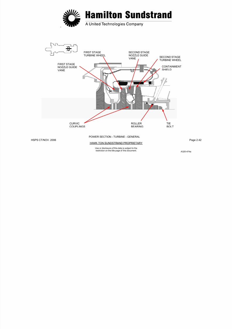
7/21/2019 Aps 3200 Training
http://slidepdf.com/reader/full/aps-3200-training 439/739
.
HSPS CT/NOV. 2006 Page 2.43HAMILTON SUNDSTRAND PROPRIETARY
Use or disclosure of this data is subject to therestriction on the title page of this document.
POWER SECTION - TURBINE - DESCRIPTION
Identification of Turbine Components
- The first stage nozzle guide vane has 22 vanes installed in frontof the first stage turbine wheel
- The first stage turbine wheel has 37 fir tree blades inserted into adisc and secured by blade locks.
The turbine wheel is connected to the rear of the power sectionimpeller and to the second stage turbine wheel by curvic-couplings
- The second stage nozzle guide vane has 26 vanes installed infront of the second stage turbine wheel
- The second stage turbine wheel has 31 fir tree blades insertedinto a disc and secured by blade locks. Vibration dampers arefitted between the blades.
The turbine wheel is connected to the first stage turbine wheel by acurvic coupling.
The rear of the second stage turbine wheel is supported by a rollerbearing
- The containment shield is located around the turbine wheels.
- The turbine housing is located between the containment shieldand the turbine.
The turbine housing is connected to the exhaust housing.
7/21/2019 Aps 3200 Training
http://slidepdf.com/reader/full/aps-3200-training 440/739
HSPS CT/NOV..2006 Page 2.44HAMILTON SUNDSTRAND PROPRIETARY
FIR TREEBLADES
Use or disclosure of this data is subject to therestriction on the title page of this document.
POWER SECTION - TURBINE - DESCRIPTION
BLADELOCKS
VIBRATIONDAMPER
FIRST STAGENOZZLE GUIDE
VANE
NOZZLE GUIDEVANE SUPPORT
FIRST STAGETURBINE WHEEL
CONTAINMENTSHIELD
TURBINEHOUSING
SECOND STAGENOZZLE GUIDEVANE
SECONDSTAGETURBINEWHEEL
A320-475a
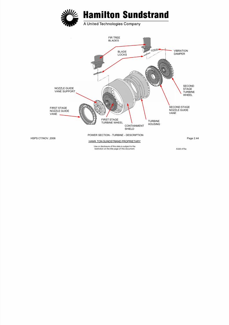
7/21/2019 Aps 3200 Training
http://slidepdf.com/reader/full/aps-3200-training 441/739
.
HSPS CT/NOV. 2006 Page 2.45HAMILTON SUNDSTRAND PROPRIETARY
Use or disclosure of this data is subject to therestriction on the title page of this document.
POWER SECTION - EXHAUST - GENERAL
Function
The exhaust directs the exhaust gases to the aircraft exhaust pipe.
Location
The exhaust diffuser is located inside the APU exhaust housing.
Type
One piece, annular exhaust pipe.
Main Components
The exhaust housing is constructed of stainless steel and provides apassage for the exhaust gases. The housing also contains the rearbearing and struts that house oil pipes to the rear bearing.

7/21/2019 Aps 3200 Training
http://slidepdf.com/reader/full/aps-3200-training 442/739
.
HSPS CT/NOV. 2006 Page 2.46HAMILTON SUNDSTRAND PROPRIETARY
FLOATING CARBON SQUEEZESEAL FILM
Use or disclosure of this data is subject to therestriction on the title page of this document.
POWER SECTION - EXHAUST - GENERAL
STRUT
DISCHARGE AIR
REAR
BEARING
AIR BYPASSPLENUM
LABYRINTHSEAL
ROLLERBEARING
FLEXIBLECAGE
EXHAUSTHOUSING
A320-451a
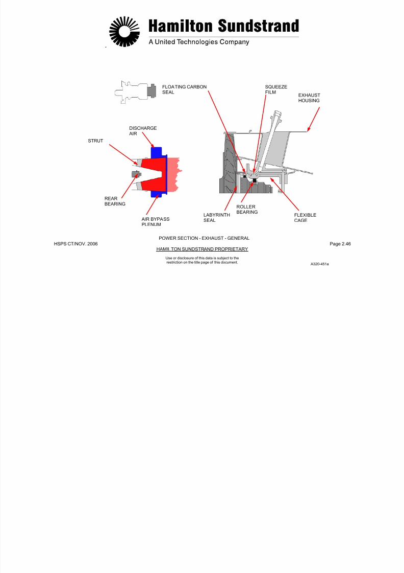
7/21/2019 Aps 3200 Training
http://slidepdf.com/reader/full/aps-3200-training 443/739
.
HSPS CT/NOV. 2006 Page 2.47HAMILTON SUNDSTRAND PROPRIETARY
Use or disclosure of this data is subject to therestriction on the title page of this document.
POWER SECTION - EXHAUST - DESCRIPTION
Identification of Exhaust Components
- The exhaust housing consists of an outer housing and diffusercone supported by struts.
The inner cone houses the rear bearing assembly and the rearbearing oil pipes.
- The rear bearing housing:
• The rear bearing
• The rear end of the tie-bolt
• The securing nut.
The rear bearing housing has threaded bosses for the mounting ofthe rear bearing oil pipes.
- The rear bearing o il pipes:
• The rear bearing oil supply
• The rear bearing oil scavenge
• The rear bearing oil venting.
- The rear bearing is a roller bearing, it is located inside the rearbearing cage.
- The rear bearing labyrinth seal is installed on the rear shaft ofthe second stage turbine wheel.
The labyrinth seal is pressurized by compressed air from thepower section compressor.
- The air bypass plenum is installed on the exhaust housing and isprovided with a drain connected to the drain system.
7/21/2019 Aps 3200 Training
http://slidepdf.com/reader/full/aps-3200-training 444/739
HSPS CT/NOV..2006 Page 2.48HAMILTON SUNDSTRAND PROPRIETARY
AIR BYPASSPLENUM
REAR BEARINGHOUSING
REAR BEARINGVENT PIPE
SECURINGNUT
EXHAUST
HOUSING
LABYRINTH
Use or disclosure of this data is subject to therestriction on the title page of this document.
POWER SECTION - EXHAUST - DESCRIPTION
SEAL
REAR BEARING OILSUPPLY PIPE
REAR BEARING
SCAVENGE PIPE
REAR BEARING
TIEBOLT
CAGE
A320-476a
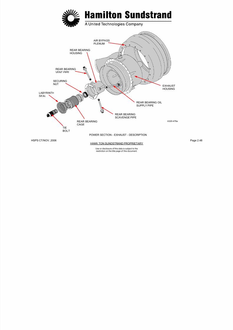
7/21/2019 Aps 3200 Training
http://slidepdf.com/reader/full/aps-3200-training 445/739
.
HSPS CT/NOV. 2006 Page 2.49HAMILTON SUNDSTRAND PROPRIETARY
Use or disclosure of this data is subject to therestriction on the title page of this document.
POWER SECTION - OPERATION (1)
The power section produces the shaft power through thethermodynamic cycle: compression, combustion, expansion andexhaust.
Compression
Ambient air is directed into the blades of the rotating impeller. The airthen flows through the divergent passages of the diffuser. (The airvelocity is transformed into pressure.)
Combustion
The compressed air is divided into two flows:
- A primary flow mixed with the fuel for combustion
- A secondary flow (dilution air) to cool the combustor and internalparts.
As a result of the continuous burning process, the pressuredecreases slightly whereas the velocity and the temperatureincrease.
Expansion
Expansion of the gases takes place across the two stages of theturbines, this transforms the gas energy into shaft power.
The gases flow through the nozzle guide vanes which increase thevelocity, then across the turbine blades. The aerodynamic forcescause the turbine wheels to rotate.
During expansion, the velocity of the gases increases and thepressure and temperature decrease.
Exhaust
The gases are then expelled overboard through the exhaust system.
7/21/2019 Aps 3200 Training
http://slidepdf.com/reader/full/aps-3200-training 446/739
.
HSPS CT/NOV. 2006 Page 2.50HAMILTON SUNDSTRAND PROPRIETARY
Use or disclosure of this data is subject to therestriction on the title page of this document.
POWER SECTION - OPERATION (1)
AMBIENT AIR
COMPRESSED AIRCOMBUSTIONEXHAUSTFUEL
a320-477a
PRESSURE AND
TEMPERATUREVALUES ARE GIVEN
AT ZERO DESIGNPOINT FORINFORMATION

7/21/2019 Aps 3200 Training
http://slidepdf.com/reader/full/aps-3200-training 447/739
.
HSPS CT/NOV. 2006 Page 2.51HAMILTON SUNDSTRAND PROPRIETARY
Use or disclosure of this data is subject to therestriction on the title page of this document.
POWER SECTION - OPERATION (2)
The power section provides air flow to pressurize the APU labyrinthseals, to cool internal heated parts and balance rotor forces.
Pressurization
- Pressurization of Labyrinth Seals
Labyrinth seals are supplied with air pressure. A pressuredifference across the seals provide a non contact seal.
- Pressurization of Load Compressor Front Bearing
The pressurized air, bled from the outlet of the power sectionimpeller, flows through an external pipe to the labyrinth seal of theload compressor front bearing and the cooling fan labyrinth seal.
- Pressurization of Power Section Rear Bearing
The pressurized air, bled at the outlet of the power sectionimpeller, flows through the power section rotor assembly to therear bearing labyrinth seal.
Cooling
To prevent excessive heating of the parts subjected to thecombustion gases, a circulation of cooling air (bled at the outlet of
the power section impeller) is provided through the power sectionrotor assembly, and is directed by internal passages to the turbinewheel faces.
Balance of Forces
The shaft, the turbine wheels, and the compressor impellers aresubjected to axial forces resulting from the operation of the rotorassembly.
To reduce the forces on the bearings, air pressure is used on thebackside of the power section impeller.
7/21/2019 Aps 3200 Training
http://slidepdf.com/reader/full/aps-3200-training 448/739
HSPS CT/NOV..2006 Page 2.52HAMILTON SUNDSTRAND PROPRIETARY
AXIAL THRUST
EXTERNAL PIPE TOLOAD LCOMPRESSORFRONT BEARING ANDCOOLING FANLABYRINTH SEALS
AMIENT AIRCOMPRESSED AIREXPELLED SEAL
AND COOLING AIR
Use or disclosure of this data is subject to therestriction on the title page of this document.
POWER SECTION - OPERATION (2)a320-478a
FRONT BEARINGLABYRINTH SEAL
AIR
REAR BEARING LABYRINTHSEAL AIR

7/21/2019 Aps 3200 Training
http://slidepdf.com/reader/full/aps-3200-training 449/739
.
HSPS CT/NOV. 2006 Page 2.53HAMILTON SUNDSTRAND PROPRIETARY
APS 3200 AUXILIART POWER UNIT
Use or disclosure of this data is subject to therestriction on the title page of this document.

7/21/2019 Aps 3200 Training
http://slidepdf.com/reader/full/aps-3200-training 450/739
HSPS CT/NOV. 2006 Page 3.0HAMILTON SUNDSTRAND PROPRIETARY
APS 3200 AUXILIARY POWER UNIT
SECTION 3
OIL SYSTEM
Use or disclosure of this data is subject to therestriction on the title page of this document.

7/21/2019 Aps 3200 Training
http://slidepdf.com/reader/full/aps-3200-training 451/739
HSPS CT/NOV. 2006 Page 3.1HAMILTON SUNDSTRAND PROPRIETARY
Use or disclosure of this data is subject to therestriction on the title page of this document.
OIL SYSTEM - GENERAL
Function
The system is used to lubricate and cool the APU and the ACgenerator.
Location
The system components are all located on the gearbox except the oilcooler. The cooler is located on the left side of the APU.
Main Features
Self contained, full flow system.
- Max oil temperature: 135°C (275°F)
- Normal oil pressure: 345 - 414 kPa (50 - 60 PSIG)
- Low oil pressure: 241 kPa (35 PSIG)
- Oil quantity: 5.4 liters (5.72 Qts) at FULL mark
Lubrication and Cooling Requirements
- The APU rear bearing
- The APU front bearing
- The gearbox gears and bearings
- The AC generator
- Cooling Fan

7/21/2019 Aps 3200 Training
http://slidepdf.com/reader/full/aps-3200-training 452/739
HSPS CT/NOV.. 2006 Page 3.2HAMILTON SUNSTRAND PROPRIETARY
FRONTBEARING
Use or disclosure of this data is subject to therestriction on the title page of this document.
OIL SYSTEM - GENERAL
REARBEARING
GEARBOXGEARS ANDBEARINGS
LUBRICATION AND
COOLING OF AC GENERATOR
OIL SYSTEMMAIN FEATURES
MAX OIL TEMPERATURE135 C (275 F)
NORMAL OIL PRESSURE
345 – 414 Kpa (50-60 PSIG)LOW OIL PRESSURE
241 KPa (35 PSIG)OIL QUANTITY
5.4 liters (5.72 Qts)
OIL SYSTEM COMPONENTS
ON GEARBOX(EXCPT OIL COOLER)
OIL SYSTEM - GENERAL
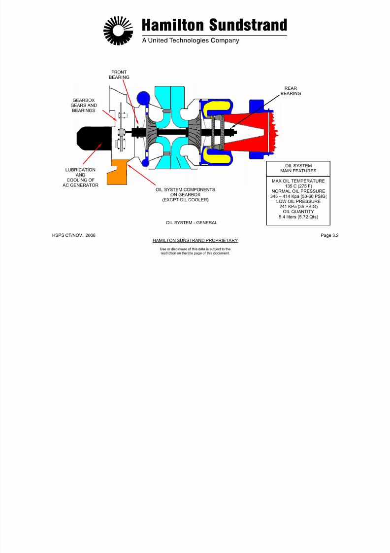
7/21/2019 Aps 3200 Training
http://slidepdf.com/reader/full/aps-3200-training 453/739
HSPS CT/NOV.. 2006 Page 3.3HAMILTON SUNSTRAND PROPRIETARY
Use or disclosure of this data is subject to therestriction on the title page of this document.
OIL SYSTEM - DESCRIPTION
Oil Sump
The oil sump is formed by the lower part of the gearbox.
The gearbox has a fill tube for gravity filling, an overflow drain, apressure fill connector and a sight glass.
The gearbox intermediate gear also functions as the air/oil separatorand provides air venting of the gearbox.
Oil Pumps
One lubrication pump and two scavenge pumps are driven by the
gearbox.
The pressure system is provided with a pressure relief valve locatedon the front of the gearbox.
Oil Filters
There is one filter in the lubrication line and one in the AC generatorscavenge line.
Both filters are the same and each have a filter element impendingblockage switch indicator. They are mounted on the lower front faceof the gearbox. The oil filter by pass valve for each filter is located inthe gearbox and is non adjustable.
Oil Cooler
The oil cooler cools the oil and has a by-pass valve.
De-oili ng Valve
The de-oiling valve is a solenoid valve located at the inlet of thepressure pump. When energized open, the valve prevents oil flowthus reducing the APU starting loads on the starter.
Monitoring Devices
- Low oil pressure switch
- High oil temperature sensor
- AC generator high oil temperature sensor
- Oil level sensor
- Oil level sight glass
- Oil filter impending blockage switch indicator on each oil filterassembly
- Magnetic drain plug.

7/21/2019 Aps 3200 Training
http://slidepdf.com/reader/full/aps-3200-training 454/739
HSPS CT/NOV.. 2006 Page 3.4HAMILTON SUNSTRAND PROPRIETARY
Use or disclosure of this data is subject to therestriction on the title page of this document.
OIL SYSTEM - DESCRIPTION
OIL SUMPOIL PRESSUREOIL RETURN
AIR-OIL MIST
SCAVENGEPUMPS
OIL FILTERBYPASS VALVES
OIL FILTERSOIL LEVELSIGHT GLASS
AC GENERATORHIGH OILTEMPERATURESENSOR
LOW OILPRESSURESWITCH
PRESSURERELIEF VALVE
CHECKVALVE
CHECK VALVE
OIL COOLER
AIR OIL
SEPERATOR
LUBRICATIONPUMP
DE-OILINGVALVE
OIL LEVELSENSOR
OILFILLERTUBE
MAGNETICDRAIN PLUG
HIGH OILTEMPERATURESENSOR
a 320-481a
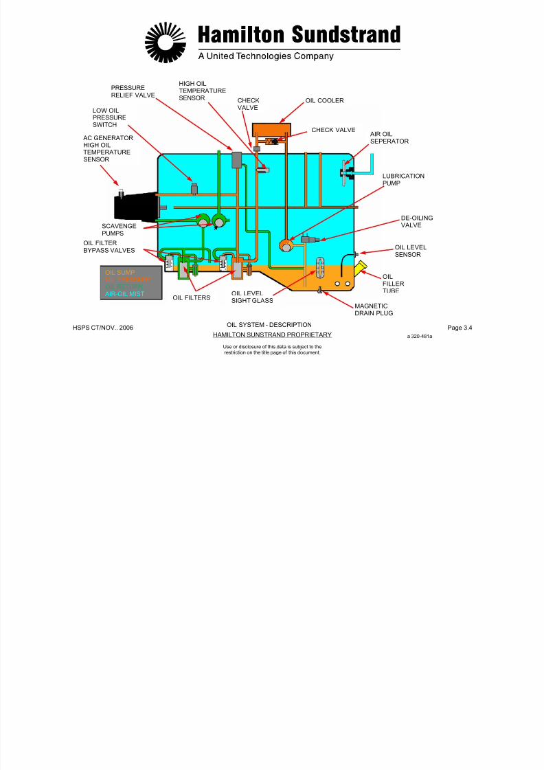
7/21/2019 Aps 3200 Training
http://slidepdf.com/reader/full/aps-3200-training 455/739
HSPS CT/NOV.. 2006 Page 3.5HAMILTON SUNSTRAND PROPRIETARY
Use or disclosure of this data is subject to therestriction on the title page of this document.
OIL SYSTEM – OPERATION
The main functions of the oil system are : oil supply, scavengereturn, venting and indicating.
Oil Supply
The lubrication pump draws the oil from the sump and delivers it tothe oil system. During starting, the de-oiling valve opens and air isdrawn into the pump to prevent oil flow. After de-oiling the oil flows tothe oil cooler, then to the filter.In the event oil flow through the filter becomes restricted, the switchindicator is activated. If the filter becomes blocked, the oil filterbypass valve will open and allow flow to the oil system.The oil pressure relief valve opens to regulate the oil systempressure. When the valve is open, some of the oil flow is bypassedback to the inlet side of the lubrication pump.
Scavenge Return
After lubrication, the oil returns to the gearbox sump by twoscavenge pumps:- One for the power section rear bearing that returns the oil directly
to the sump- One for the AC generator that returns the oil to the sump through a
filter.
Note: The front bearing and the gearbox are scavenged by gravity.
Scavenge Return
After lubrication, the oil returns to the gearbox sump by two
scavenge pumps:-One for the power section rear bearing that returns the oil directly to
the sumpOne for the AC generator that returns the oil to the sump through a
filter.Note: The front bearing and the gearbox are scavenged by gravity.
Venting
Oil mist in the gearbox is separated by a centrifugal air-oil separator.The gearbox is vented to the exhaust through an external pipe.
Monitoring-Low oil pressure switch-High oil temperature sensor- AC generator high oil temperature sensor- Oil filter impending blockage switch indicators- Oil level sensor
- Oil level sight glass- Magnetic drain plug
7/21/2019 Aps 3200 Training
http://slidepdf.com/reader/full/aps-3200-training 456/739
V
HSPS CT/NOV.. 2006 Page 3.6HAMILTON SUNSTRAND PROPRIETARY
Use or disclosure of this data is subject to therestriction on the title page of this document.
OIL SYSTEM - OPERATION
OIL SUPPLYOIL PRESSURESCAVENGE RETURN
VENTING
a 320-481 aOIL SYSTEM - OPERATION

7/21/2019 Aps 3200 Training
http://slidepdf.com/reader/full/aps-3200-training 457/739
HSPS CT/NOV.. 2006 Page 3.7HAMILTON SUNSTRAND PROPRIETARY
Use or disclosure of this data is subject to therestriction on the title page of this document.
ENGINE LUBRICATION (1)
Lubrication is required for the AC generator, the gearbox and the APU bearings.
AC Generator Lubricat ion and Cool ing
Oil Supply
From the lubrication pump and filter, the oil is supplied to the ACgenerator:
- One flow for cooling
- A second flow to lubricate the generator drive shaft splines.
Scavenge and Return
The oil from the AC generator is scavenged by a pump and returnedto the gearbox sump through a filter.
Gearbox Lubrication
Oil Supply
The oil flowing from the lubrication pump passes through the filterand then by means of internal lines and jets is sprayed onto thegears and bearings.
From the gearbox the oil is also supplied to the cooling fan bearingsand to the rotor assembly front bearing.
Scavenge and Return
After lubrication the oil returns to the gearbox sump by gravity.
7/21/2019 Aps 3200 Training
http://slidepdf.com/reader/full/aps-3200-training 458/739
HSPS CT/NOV.. 2006 Page 3.8HAMILTON SUNSTRAND PROPRIETARY
Use or disclosure of this data is subject to therestriction on the title page of this document.
ENGINE LUBRICATION (1) AC GENERATOR LUBRICATION
GEARBOX LUBRICATION
AC GENERATORLUBRICATION
AND COOLING
AC GENERATOROIL SCAVENGE
FROM LUBRICATIONPUMP
FROM LUBRICATIONPUMP
DE-OILED AIR TO
EXHAUST
DE-OILED
AIR TOEXHAUST
AC GENERATORDRIVE SHAFT SPLINELUBRICATION
SPRAYJETS
TO LUBRICATIONPUMP
TO LUBRICATIONPUMP
OIL RETURNTO SUMP
OIL SUPPLY
OIL PRESSURESCAVENGE RETURNVENTING
AC GENERATOR LUBRICATION
a 320-482 a
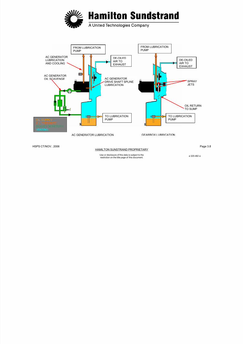
7/21/2019 Aps 3200 Training
http://slidepdf.com/reader/full/aps-3200-training 459/739
HSPS CT/NOV.. 2006 Page 3.9HAMILTON SUNSTRAND PROPRIETARY
Use or disclosure of this data is subject to therestriction on the title page of this document.
ENGINE LUBRICATION (2)
Front Bearing Lubrication
Oil Supply
The lubrication for the rotor front bearing is provided by pressurizedoil from the gearbox oil system.
A jet located in the gearbox housing sprays oil between the front endof the load compressor shaft and the front bearing nut. (PhonicWheel)
The oil runs along the shaft, lubricates the quill shaft splines andenters the gap through the split inner races to lubricate the bearing.
Oil flow to the bearing is also provided by oil passages between thegearbox and bearing outer race to provide a squeeze film to dampenbearing vibration.
Scavenge and Return
After lubrication the oil is returned to the sump by gravity.
Sealing
Oil sealing of this assembly is by a floating carbon seal and alabyrinth seal using air from the power section impeller.
A drain cavity between the seals is vented overboard, into the APUdrainmast.
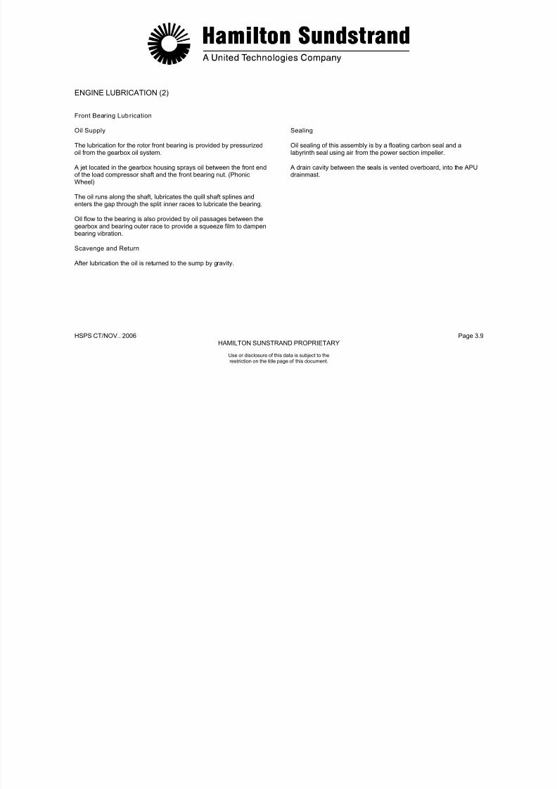
7/21/2019 Aps 3200 Training
http://slidepdf.com/reader/full/aps-3200-training 460/739
HSPS CT/NOV.. 2006 Page 3.10HAMILTON SUNSTRAND PROPRIETARY
FLOATING AIR FROMCARBONSEAL
POWER SECTIONIMPELLER
SQUEEZEFILM
BALL BEARING
Use or disclosure of this data is subject to therestriction on the title page of this document.
ENGINE LUBRICATION (2) - FRONT BEARING LUBRICATION
INTERNAL OILSUPPLY
FRONT BEARINGNUT
DRAINCAVITY
LOADCOMPRESSORIMPELLER
LABYRINTHSEALS
a 320-452 a
OIL PRESSURE SPRAYCOMPRESSED AIRSEA L AIR VENT

7/21/2019 Aps 3200 Training
http://slidepdf.com/reader/full/aps-3200-training 461/739
HSPS CT/NOV.. 2006 Page 3.11HAMILTON SUNSTRAND PROPRIETARY
Use or disclosure of this data is subject to therestriction on the title page of this document.
ENGINE LUBRICATION (3)
Rear Bearing Lubr ication
Oil Supply
The lubrication of the rotor rear bearing is provided by pressurized oil
from the gearbox oil system.
The oil is supplied to the rear bearing through an external pipe.
In the bearing area, the oil is directed to the outer race to provide asqueeze film and an internal line that sprays oil into the rear tie-boltarea.
Drilled passages in the tie-bolt allow oil circulation for lubrication and
cooling of the roller bearing.
Scavenge and Return
After lubrication, the oil is scavenged back to the sump through anexternal pipe by a scavenge pump.
Sealing
Oil sealing in the bearing area is accomplished by a floating carbon
seal and a rotating labyrinth seal. The seals are pressurized with airflow from the power section impeller.

7/21/2019 Aps 3200 Training
http://slidepdf.com/reader/full/aps-3200-training 462/739
HSPS CT/NOV. 2006 Page 3.12HAMILTON SUNDSTRAND PROPRIETARY
OIL SUPPLY
TIE
BOLT
SQUEEZEFILM
SECOND STAGETURBINE WHEEL
Use or disclosure of this data is subject to therestriction on the title page of this document.
ENGINE LUBRICATION (3) - REAR BEARING LUBRICATION
a 320-453 a
ROTATINGLABYRINTH
SEAL
ROLLERBEARING
AIR FROMPOWER SECTIONIMPELLER
FLOATINGCARBONSEAL
OIL PRESSUREOIL RETURNCOMPRESSOR AIR
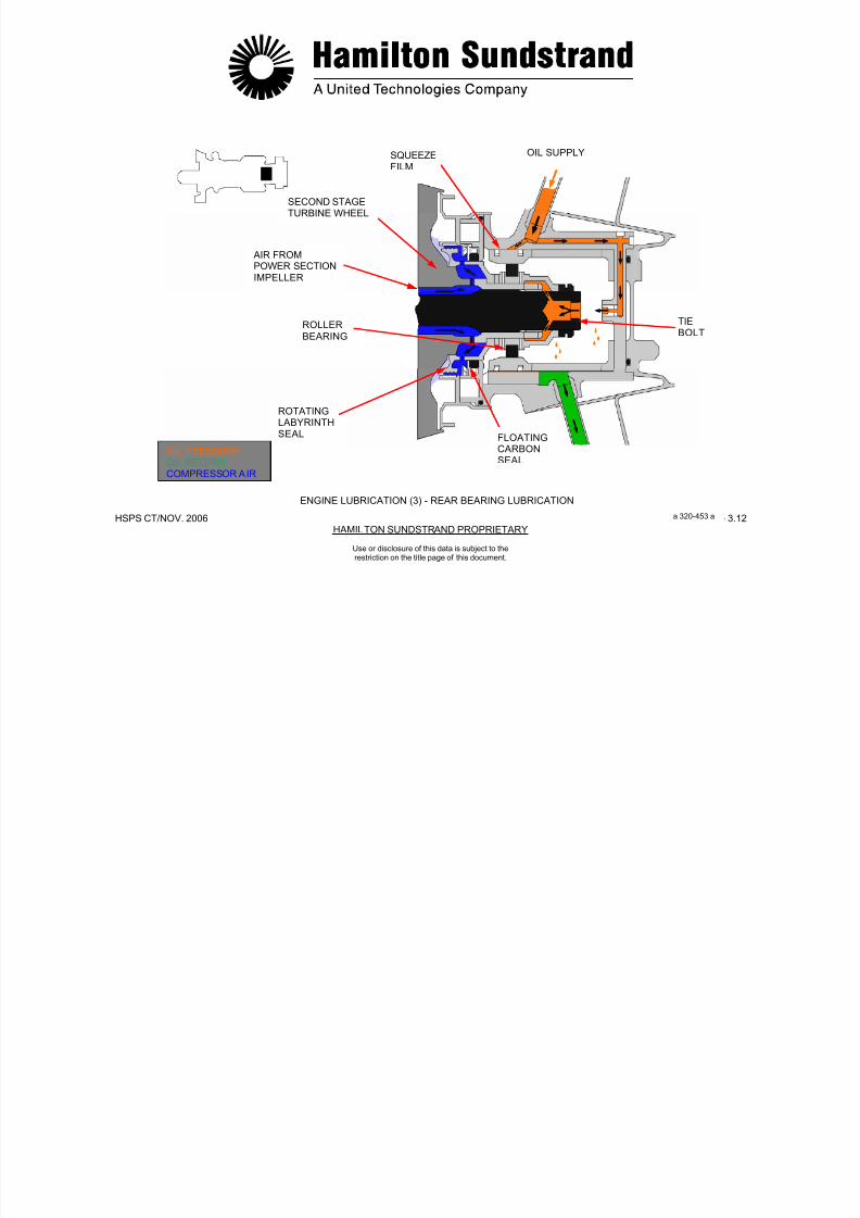
7/21/2019 Aps 3200 Training
http://slidepdf.com/reader/full/aps-3200-training 463/739
HSPS CT/NOV. 2006 Page 3.13HAMILTON SUNDSTRAND PROPRIETARY
Use or disclosure of this data is subject to therestriction on the title page of this document.
OIL SUMP
Function
The sump provides a reservoir for the APU lubrication system.
Location
The sump is located in the bottom of the gearbox.
Main Features
- Capacity at the "FULL" mark: 5.4 litters (5.72 Qts)
- Capacity at the "ADD" mark: 3.95 litters (4.16 Qts)
Main Components
The main components of the oil sump are:
- Oil filler tube
- Oil overflow boss
- Oil pressure fill port
- Air-oil separator
- Magnetic drain plug
- Pressure relief valve
- Oil level sensor
- Oil level sight glass.

7/21/2019 Aps 3200 Training
http://slidepdf.com/reader/full/aps-3200-training 464/739
HSPS CT/NOV.. 2006 Page 3.14HAMILTON SUNSTRAND PROPRIETARY
GEARBOX
OIL FILLERTUBE
OILOVERFLOWBOSS
Use or disclosure of this data is subject to therestriction on the title page of this document.
OIL SUMP
OIL LEVEL
SENSOR
MAGNETICDRAIN PLUG PRESSURE
RELIEF VALVE
OILPRESSUREFILL PORT
OILLEVELSIGHTGLASS
GEARBOX – LEFT SIDE VIEWGEARBOX – FRONT VIEW
a 320-483 a

7/21/2019 Aps 3200 Training
http://slidepdf.com/reader/full/aps-3200-training 465/739
HSPS CT/NOV. 2006 Page 3.15HAMILTON SUNDSTRAND PROPRIETARY
Use or disclosure of this data is subject to therestriction on the title page of this document.
AIR-OIL SEPARATOR
Function
The air-oil separator separates the oil from the air.
Location
The air-oil separator is located in the upper part of the gearbox.
Description
The air-oil separator is part of the gearbox intermediate gear.
The gear has a hollow shaft with radial drillings. The rear of thehollow shaft vents into a passage in the gearbox housing.
Operation
An air-oil mist is created in the gearbox when the APU is operating.
The oil is separated from the air by the rotating action of the gearboxintermediate gear. The oil returns to the gearbox sump by gravityand the air is vented through a pipe to the APU exhaust.

7/21/2019 Aps 3200 Training
http://slidepdf.com/reader/full/aps-3200-training 466/739
HSPS CT/NOV.. 2006 Page 3.16HAMILTON SUNSTRAND PROPRIETARY
Use or disclosure of this data is subject to therestriction on the title page of this document.
AIR-OIL SEPARATOR
INTERMEDIATEGEAR
AIR-OILSEPERATOR
OIL RETURNTO SUMP
OIL MISTDE-OILED
AIR
TO APUEXHAUST
OIL RETURNTO SUMP
AIR – OIL SEPERATOR
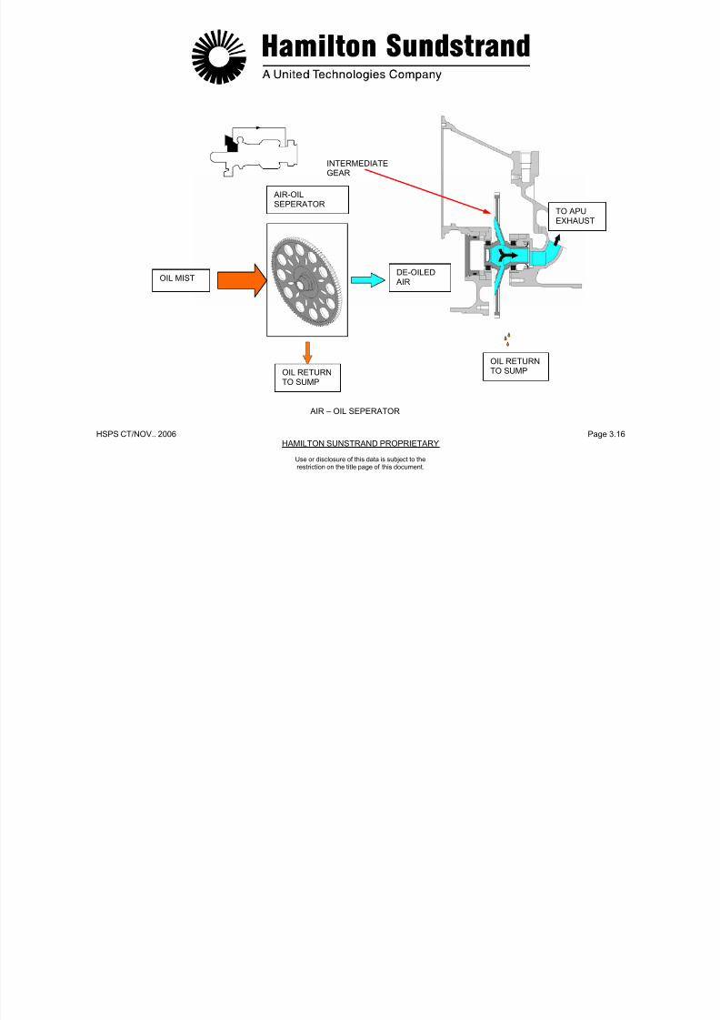
7/21/2019 Aps 3200 Training
http://slidepdf.com/reader/full/aps-3200-training 467/739
HSPS CT/NOV. 2006 Page 3.17HAMILTON SUNDSTRAND PROPRIETARY
Use or disclosure of this data is subject to therestriction on the title page of this document.
OIL PUMPS - GENERAL
Function
One pump is used for the lubrication supply and two pumps forscavenge.Location
The oil pumps are located inside the gearbox front face.Main Features- Lubrication pump
• Type: Vane type• Flow: 2160 l/h (570 GPH)
- AC generator scavenge pump• Type: Vane type pump• Flow: 2160 l/h (570 GPH)
- Rear bearing scavenge pump• Type: Gerotor type pump• Flow: 160 l/h (42 GPH)
OIL PUMPS - DESCRIPTION
Gerotor Type
The gerotor is a positive displacement pumping unit consisting of twoelements: an inner and outer rotor.The inner rotor has one less tooth than the outer, and has its
centerline positioned at a fixed eccentricity from the centerline of theouter element.The inner element is driven by the gearbox.Vane TypeThe vane type pump consisting of a slotted inner rotor equipped withvanes operating in an eccentric housing.Operation of the Pressure Relief ValveThe oil pressure relief valve is a non adjustable, spring loaded reliefvalve.The valve will open when oil pressure reaches 345-414 kPag (50-60PSIG). The oil that is bypassed, returns to the inlet of the lubricationpump.
7/21/2019 Aps 3200 Training
http://slidepdf.com/reader/full/aps-3200-training 468/739
HSPS CT/NOV.. 2006 Page 3.18HAMILTON SUNSTRAND PROPRIETARY
AC GENERATORSCAVENGE PUMP
FUEL CONTROLUNIT DRIVE
Use or disclosure of this data is subject to therestriction on the title page of this document.
OIL PUMPS - GENERAL - DESCRIPTION
OIL SCAVENGE
PUMPS
OIL PRESSUREPUMP PRESSURE
RELIEF VALVE
OIL PUMPDRIVE GEARS
REAR BEARINGSCAVENGEPUMP
LUBRICATIONPUMP
a 320-485 a

7/21/2019 Aps 3200 Training
http://slidepdf.com/reader/full/aps-3200-training 469/739
HSPS CT/NOV. 2006 Page 3.19HAMILTON SUNDSTRAND PROPRIETARY
Use or disclosure of this data is subject to therestriction on the title page of this document.
DE-OILING VALVEFunction
The de-oiling valve reduces the APU starting lead during startconditions.
Location
The valve is located on the left side of the gearbox.
Main Features
- Solenoid valve operated by the ECB
- Nominal rating: 28 VDC; 1.0 amps
- Solenoid valve energized open.
Description
The de-oiling valve is a solenoid operated valve directly controlled bythe ECB.
Operation
During the APU start up the de-oiling valve is energized open by theECB. When the valve is open the lubrication pump is prevented frompumping oil into the system. This reduces the starting load of the
APU and allows faster acceleration.
When the APU accelerates to 55% speed, the ECB de-energizes thede-oiling valve and allows the lubrication pump to produce oil flow.
During shutdown, the de-oiling valve is again energized by the ECBwhen the APU de-accelerates to 90% speed. This allows the oilremaining in the system to return to the oil sump with the exceptionof one quart remaining in the oil cooler.
7/21/2019 Aps 3200 Training
http://slidepdf.com/reader/full/aps-3200-training 470/739
HSPS CT/NOV.. 2006 Page 3.20HAMILTON SUNSTRAND PROPRIETARY
Use or disclosure of this data is subject to therestriction on the title page of this document.
DE-OILING SYSTEM
DE-OILING VALVE
AIR
GEARBOX LEFT SIDE
TOOIL
OIL SUMPCOOLER
OIL
FROM
TOLUBRICATION
PUMP
AIR
SUMPDE-OILING VALVE
a 320-486a
DE – OILING SYSTEM
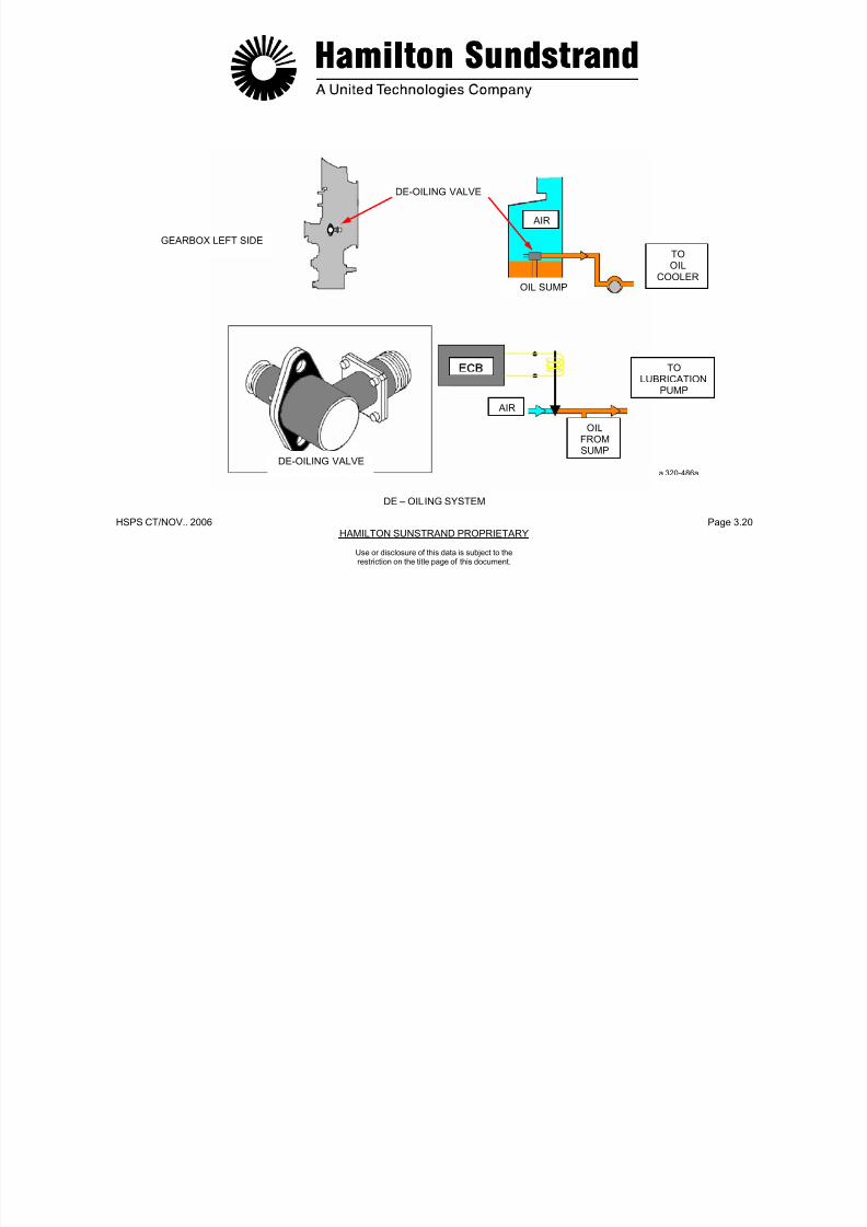
7/21/2019 Aps 3200 Training
http://slidepdf.com/reader/full/aps-3200-training 471/739
HSPS CT/NOV. 2006 Page 3.21HAMILTON SUNDSTRAND PROPRIETARY
Use or disclosure of this data is subject to therestriction on the title page of this document.
OIL FILTERS - GENERAL
Function
The function of the oil filters is to filter the oil.
There are two filters: one for lubrication and one for the AC generator
scavenge. They are the same type of filter.
Location
The lubrication filter is located in the pressure line after the oil cooler.The scavenge filter is located after the AC generator scavengepump.
Both filters are installed at the bottom front face of the gearbox.
Main Features
- Filter element: 20 microns
- By-pass valve setting: 345-414 kPad (50-60 PSID)
- Switch indicator setting: 207-241 kPad (30-35 PSID).
OIL FILTERS - DESCRIPTION
Each filter system consists of:
- A 20 micron disposable cartridge
- An oil filter impending blockage switch indicator
- A by-pass valv

7/21/2019 Aps 3200 Training
http://slidepdf.com/reader/full/aps-3200-training 472/739
HSPS CT/NOV.. 2006 Page 3.22HAMILTON SUNSTRAND PROPRIETARY
LUBRICATIONFILTER
SWITCHINDICATOR
AC GENERATORSCAVENGE FILTER
Use or disclosure of this data is subject to therestriction on the title page of this document.
OIL FILTERS - GENERAL - DESCRIPTION
LUBRICATIONFILTER
a 320-487 a

7/21/2019 Aps 3200 Training
http://slidepdf.com/reader/full/aps-3200-training 473/739
HSPS CT/NOV. 2006 Page 3.23HAMILTON SUNDSTRAND PROPRIETARY
Use or disclosure of this data is subject to therestriction on the title page of this document.
OIL FILTER - OPERATION
Oil Flow
In normal operation the oil is filtered and then flows to the oil system.
Pre-blockage of the Oil Filters
Should the filter become contaminated, a difference in pressureacross the filter will occur.
Two switch indicators are mounted on the front of the gearbox neareach oil filter. The switch indicator provides a visual indication when
the oil temperature is 74°C (165°F) and the oil pressure across thefilter reaches 241 kPad (30-35 PSID). The ECB also monitors eachswitch indicator and will store the fault message.
By-pass
When the differential pressure across the filter exceeds 345 to 414kPad (50 to 60 PSID), the by-pass valve will open and allowunfiltered oil to flow into the system.
The by-pass valve is located in the gearbox and is non-adjustable.
7/21/2019 Aps 3200 Training
http://slidepdf.com/reader/full/aps-3200-training 474/739
HSPS CT/NOV. 2006 Page 3.24HAMILTON SUNDSTRAND PROPRIETARY
Use or disclosure of this data is subject to therestriction on the title page of this document.
OIL FILTER - OPERATION
a 320-488 a
OIL FILTER - OPERATION

7/21/2019 Aps 3200 Training
http://slidepdf.com/reader/full/aps-3200-training 475/739
HSPS CT/NOV.. 2006 Page 3.25HAMILTON SUNSTRAND PROPRIETARY
Use or disclosure of this data is subject to therestriction on the title page of this document.
OIL COOLER - GENERAL
Function
The oil cooler transfers the heat of the lubr icating oil to the airflowing through the cooler.
Location
The oil cooler is installed on the left side of the APU.
In the oil system, the cooler is located between the lubrication pumpand the filter.
Main Features
- Oil cooling ability: 2160 l/h (540 GPH)
- Oil cooler by-pass valve setting:
• Opening threshold: 207 kPad (30 PSID)
• Fully open: 345 kPad (50 PSID).
OIL COOLER - DESCRIPTION
The oil cooler is a rectangular unit which includes:
- An oil cooler housing which consists of an integrally brazedaluminum heat-exchanger with an aluminum core and a stainlesssteel housing.
- A check valve and a by-pass valve to regulate the oil flow andinternal pressure of the oil cooler.A drain plug to drain theoil cooler

7/21/2019 Aps 3200 Training
http://slidepdf.com/reader/full/aps-3200-training 476/739
HSPS CT/NOV.. 2006 Page 3.26HAMILTON SUNSTRAND PROPRIETARY
OIL COOLER – GENERAL - DESRIPTION
a 320-489 a
Use or disclosure of this data is subject to therestriction on the title page of this document.

7/21/2019 Aps 3200 Training
http://slidepdf.com/reader/full/aps-3200-training 477/739
HSPS CT/NOV.. 2006 Page 3.27HAMILTON SUNSTRAND PROPRIETARY
Use or disclosure of this data is subject to therestriction on the title page of this document.
OIL COOLER - OPERATION
Normal Operation
The oil delivered by the lubrication pump flows through the aluminumcooling tubes that are cooled by the cooling fan air flow.
The cooled oil then flows to the various APU lubrication points.
By-pass Operation
When the pressure exceeds 207 kPad (30 PSID), the bypass valveopens.
The oil flow by-passes the cooler to the lubrication system.
Check Valve Operation
The check valve is an oil pressure operated valve.
When the pressure in the oil system is low (de-oiling during start andshutdown), the check valve closes and prevents draining of the oilcooler into the sump.
The check valve traps approximately one quart of oil in the oil cooler
when the APU is not running.
Air Flow
The oil cooler uses the airflow from the cooling fan to remove heatfrom the oil. The heated air is then discharged overboard through an
air duct located in the left APU compartment service door.
7/21/2019 Aps 3200 Training
http://slidepdf.com/reader/full/aps-3200-training 478/739
HSPS CT/NOV.. 2006 Page 3.28HAMILTON SUNSTRAND PROPRIETARY
COOLING AIRINLET
COOLING AIRINLET
Use or disclosure of this data is subject to therestriction on the title page of this document.
OIL COOLER - OPERATION
OIL FLOW AIR FLOW
NORMALOPERATION
BY-PASS
OPERATION
CHECKVALVE
OILOUTLET
OILOUTLET
CHECKVALVE
OIL FLOWRESTRICTION
OIL
INLET
OIL
INLET
BY-PASSVALVE CLOSED
BY-PASSVALVE OPEN
a 320-490 a
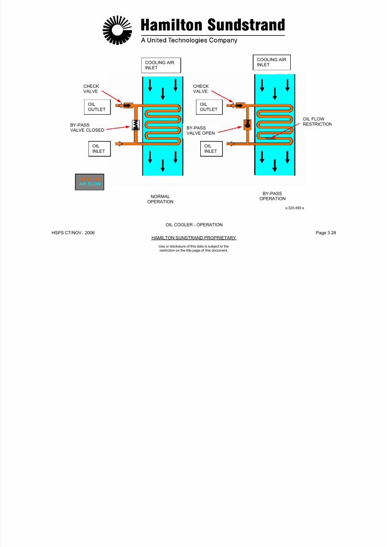
7/21/2019 Aps 3200 Training
http://slidepdf.com/reader/full/aps-3200-training 479/739
HSPS CT/NOV.. 2006 Page 3.29HAMILTON SUNSTRAND PROPRIETARY
Use or disclosure of this data is subject to therestriction on the title page of this document.
MONITORING DEVICES - LOW OIL PRESSURE SWITCHGeneral
Function
The Low Oil Pressure (LOP) switch senses the pressuredownstream of the filter.
The LOP switch initiates automatic APU shut down when the oilpressure is too low.
Location
The LOP switch is mounted on the right side of the air inlet plenumor on the lower right side of the gearbox
Main Features
- LOP switch setting: 241 kPag (35 PSIG)
- Output signal to ECB: ground signal.
Interfaces
- The ECB
- The APU oil system.
Functional Description
The LOP switch consists of a normally closed switch and is openwhen normal oil pressure is present.
The ECB does not check for oil pressure until the APU has reacheda speed of 100% (RTL) plus 10 seconds.
If oil pressure is below 241 kPag (35 PSIG), and the APU isoperating at 100% speed, the APU will shut down after running for10 seconds.
7/21/2019 Aps 3200 Training
http://slidepdf.com/reader/full/aps-3200-training 480/739
HSPS CT/NOV.. 2006 Page 3.30HAMILTON SUNSTRAND PROPRIETARY
LOW OIL PRESSURE SWITCH
MONITORING DEVICES
a 320-491 a
Use or disclosure of this data is subject to therestriction on the title page of this document.

7/21/2019 Aps 3200 Training
http://slidepdf.com/reader/full/aps-3200-training 481/739
HSPS CT/NOV.. 2006 Page 3.31HAMILTON SUNSTRAND PROPRIETARY
Use or disclosure of this data is subject to therestriction on the title page of this document.
MONITORING DEVICES - OIL TEMPERATURE SENSOR
General
Function
The Oil Temperature (HOT) sensor senses the temperature of the oilat the outlet of the oil cooler. When the oil temperature is too high,the HOT sensor initiates automatic APU shut down.
Location
The HOT sensor is installed on the lower rear face of the gearbox.
Main Features
- HOT sensor setting: 135° C (275° F)
- Sensor input signal (from ECB): 1 mA
- Sensor output signal (to ECB): variable output voltage
- 100 Ω RTD; 1 mA; 19°C to 149°C (67°F to 300°F.)
Interfaces
- The ECB
- The APU oil system.
Functional Description
The HOT sensor is a Resistive Temperature Device (RTD) suppliedwith a constant current of 1 mA (by the ECB). The resistance varieswith the oil temperature and modifies the sensor output voltage.
When the oil temperature reaches a limit value of approximately135°C (275°F), the ECB will initiate automatic APU shut down.
Note: The AC generator also has an integral oil temperaturesensor which causes the APU to shut down when anexcessive temperature is detected (180°C; 365°F). Thesensor is monitored by the ECB.

7/21/2019 Aps 3200 Training
http://slidepdf.com/reader/full/aps-3200-training 482/739
HSPS CT/NOV.. 2006 Page 3.32HAMILTON SUNSTRAND PROPRIETARY
ECB
TO AIRCRAFT
RESISTIVETEMPERATUREDEVICE(135C / 275F)
Use or disclosure of this data is subject to therestriction on the title page of this document.
MONITORING DEVICE
a320-491 a
3 WAYSOLENOID VALVEGEARBOX LEFT SIDE
HOT SENSOR
OIL SUMP
OIL COOLEROIL FILTER
FROMOILCOOLER
TOOILFILTER
HOT SENSOR
OIL TEMPERATURE SENSOR

7/21/2019 Aps 3200 Training
http://slidepdf.com/reader/full/aps-3200-training 483/739
HSPS CT/NOV.. 2006 Page 3.33HAMILTON SUNSTRAND PROPRIETARY
Use or disclosure of this data is subject to therestriction on the title page of this document.
MONITORING DEVICES - OIL LEVEL SENSORGeneral
Function
The oil level sensor measures the quantity of oil in the gearboxsump.
When the oil level is too low, the sensor provides a flight deckwarning of low oil quantity on the lower ECAM, APU systems page.
Location
The oil level sensor is located on the right side of the gearbox.
Main Features
- Sensor input signal (from ECB): 75 mA
- Sensor output signal (to ECB): variable output voltage.
Interfaces
- The ECB
- The APU oil system.
Functional Description
The oil level sensor is a Resistive Temperature Device (RTD) thatthe ECB supplies with a constant current of 75 mA.
The resistance varies with the oil level and changes the sensoroutput voltage sensed by the ECB.
At power up, the oil level is checked for a period of 8 seconds and isdetermined OK or LOW by the ECB.
If the oil level is low, the ECB will display "OIL QTY LOW" messageon the lower ECAM when the APU system page is selected.
7/21/2019 Aps 3200 Training
http://slidepdf.com/reader/full/aps-3200-training 484/739
HSPS CT/NOV.. 2006 Page 3.34HAMILTON SUNSTRAND PROPRIETARY
MONITORING DEVICES
GEARBOX FRONT VIEW
a320-493a
OIL LEVEL SENSOR
Use or disclosure of this data is subject to therestriction on the title page of this document.

7/21/2019 Aps 3200 Training
http://slidepdf.com/reader/full/aps-3200-training 485/739

7/21/2019 Aps 3200 Training
http://slidepdf.com/reader/full/aps-3200-training 486/739
HSPS CT/NOV.. 2006 Page 3.36HAMILTON SUNSTRAND PROPRIETARY
GEARBOXLEFT SIDE
GEARBOXFRONT VIEW
OIL LEVEL SIGHT GLASS MAGNETIC DRAIN PLUG
OIL LEVEL SIGHT GLASS - MAGNETIC CHIP DETECTOR
a320-494aMONITORING DEVICES
Use or disclosure of this data is subject to therestriction on the title page of this document.
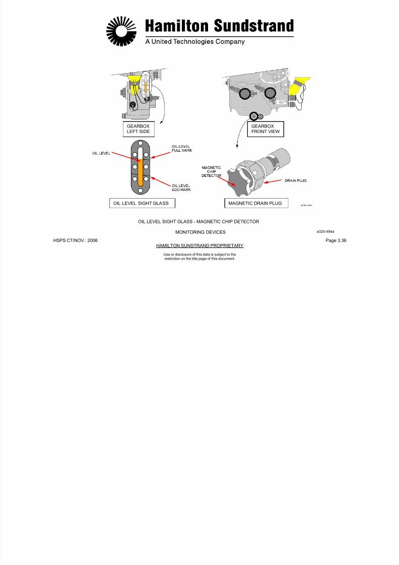
7/21/2019 Aps 3200 Training
http://slidepdf.com/reader/full/aps-3200-training 487/739
HSPS CT/NOV.. 2006 Page 3.37HAMILTON SUNSTRAND PROPRIETARY
Use or disclosure of this data is subject to therestriction on the title page of this document.
OIL PIPES
External Pipes
Supply
- From lubrication pump, oil cooler and to the gearbox
- From gearbox to power section rear bearing.
Scavenge
- From power section rear bearing to scavenge pump.
Vent
- From power section rear bearing to air-oil separator
- From air-oil separator to APU exhaust system.

7/21/2019 Aps 3200 Training
http://slidepdf.com/reader/full/aps-3200-training 488/739
HSPS CT/NOV.. 2006 Page 3.38HAMILTON SUNSTRAND PROPRIETARY
Use or disclosure of this data is subject to therestriction on the title page of this document.
OIL PIPES
OIL PRESSUREOIL SCAVENGEVENT a320-495a
OIL PIPES
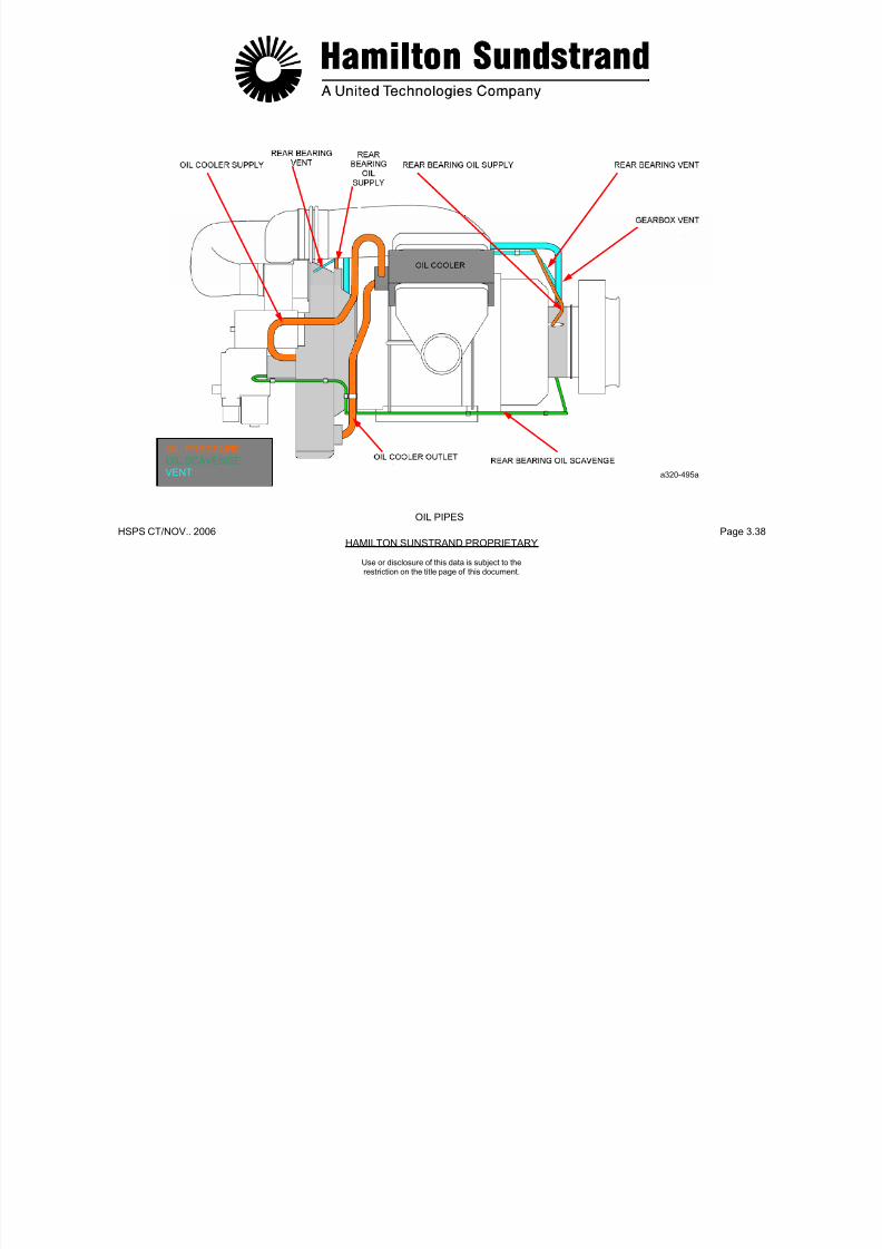
7/21/2019 Aps 3200 Training
http://slidepdf.com/reader/full/aps-3200-training 489/739
HSPS CT/NOV. 2006 Page 3.39HAMILTON SUNDSTRAND PROPRIETARY
APS 3200 AUXILIARY POWER UNIT
Use or disclosure of this data is subject to therestriction on the title page of this document.

7/21/2019 Aps 3200 Training
http://slidepdf.com/reader/full/aps-3200-training 490/739
HSPS CT/NOV..2006 Page 4.0HAMILTON SUNDSTRAND PROPRIETARY
APS 3200 AUXILIARY POWER UNIT
SECTION 4
FUEL SYSTEM
Use or disclosure of this data is subject to therestriction on the title page of this document.
FUEL SYSTEM GENERAL

7/21/2019 Aps 3200 Training
http://slidepdf.com/reader/full/aps-3200-training 491/739
HSPS CT/NOV..2006 Page 4.1HAMILTON SUNDSTRAND PROPRIETARY
Use or disclosure of this data is subject to therestriction on the title page of this document.
FUEL SYSTEM - GENERAL
Function
The fuel system provides the supply and the control of fuel to the APU under all operating conditions.
Systems Involved
- The aircraft fuel system
- The pneumatic system
- The APU control system
- The APU fuel system.
APU Fuel System Main Components
- Fuel control unit
- Flow divider
- Pilot fuel manifold and injectors
- Main fuel manifold and injectors.
Components Location
- The fuel control unit is located on the front face of the gearbox
- The flow divider is located on the combustor housing
- The fuel manifolds and injectors are located on the combustorhousing.
7/21/2019 Aps 3200 Training
http://slidepdf.com/reader/full/aps-3200-training 492/739
HSPS CT/NOV.. 2006 Page 4.2HAMILTON SUNDSTRAND PROPRIETARY
Use or disclosure of this data is subject to therestriction on the title page of this document.
FUEL SYSTEM - GENERAL
FUEL SUPLYUN-METERED FUELMETERED FUELFUEL RETURN
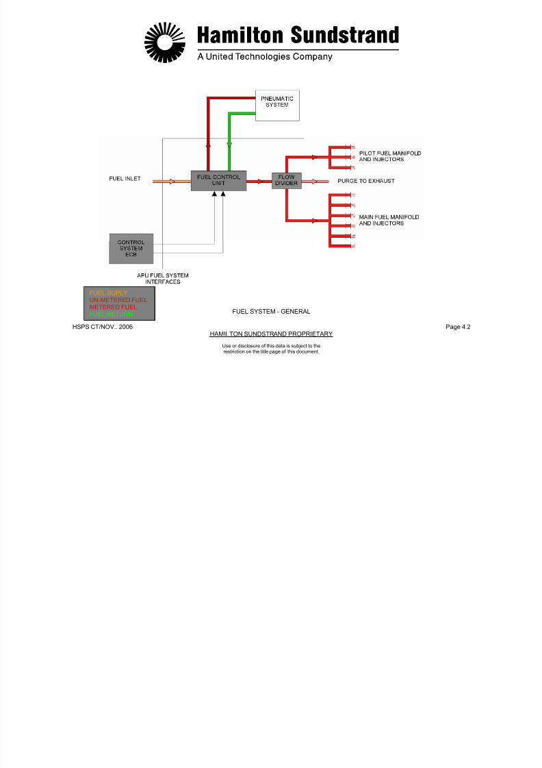
7/21/2019 Aps 3200 Training
http://slidepdf.com/reader/full/aps-3200-training 493/739
HSPS CT/NOV.. 2006 Page 4.3HAMILTON SUNDSTRAND PROPRIETARY
FUEL SYSTEM - DESCRIPTION
The system consists of a fuel control unit, a flow divider and fuelmanifolds and injectors.
Fuel Control Unit
The fuel control unit contains the following injector components:
- Low fuel pressure switch (aircraft supplied)
- Low pressure pump (centrifugal type)
- Filter (filter element, by-pass valve and impending blockage ΔPindicator)
- High pressure pump (gear type pump);
- Servo valve (electrically operated valve that meters the fuel flow inresponse to signals from the electronic control box)
- Constant P valve (pressure differential valve that controls thedifferential pressure across the servo valve)
- 3 way solenoid valve (valve operated by the electronic controlbox to open and close the fuel supply to the fuel injectors).
- Pressure regulator (fuel pressure supply to the actuators of theair control system).
Flow Divider
The flow divider controls the flow to the main and pilot injectors. Thedivider also provides pilot purge to the exhaust.
Main Fuel Manifold and Injectors
- Manifold to supply fuel to the main injectors
- Main in jectors (six injectors mounted on the combustor housing).
Pilot Fuel Manifold and Injectors
- Manifold to supply fuel to the pilot injectors
- Pilot injectors (three injectors mounted on the combustorhousing).
Use or disclosure of this data is subject to therestriction on the title page of this document.

7/21/2019 Aps 3200 Training
http://slidepdf.com/reader/full/aps-3200-training 494/739
HSPS CT/NOV.. 2006 Page 4.4HAMILTON SUNDSTRAND PROPRIETARY
Use or disclosure of this data is subject to therestriction on the title page of this document.
FUEL SYSTEM - DESCRIPTION
INLET GUIDEVANE
ACTUATORFILTER
HIGHPRESSUREPUMP
SERVOVALVE
FLOWDIVIDER
PILOT FUELMANIFOLD
ANDINJECTORS
PRESSUREREGULATOR
PURGE TOEXHAUST
LOW FUELPRESSURE
SWITCH
MAIN FUELMANIFOLD
ANDINJECTORS
3 WAYSOLENOIDVALVE
LOW PRESSUREPUMP
DRAIN
FUELINLET
FUEL SUPPLYUN-MTERED FUELMETERED FUELFUEL RETURNFUEL DRAIN
CONSTANTDELTA-P VALVE a320-497a
FUEL SYSTEM - OPERATION (1)
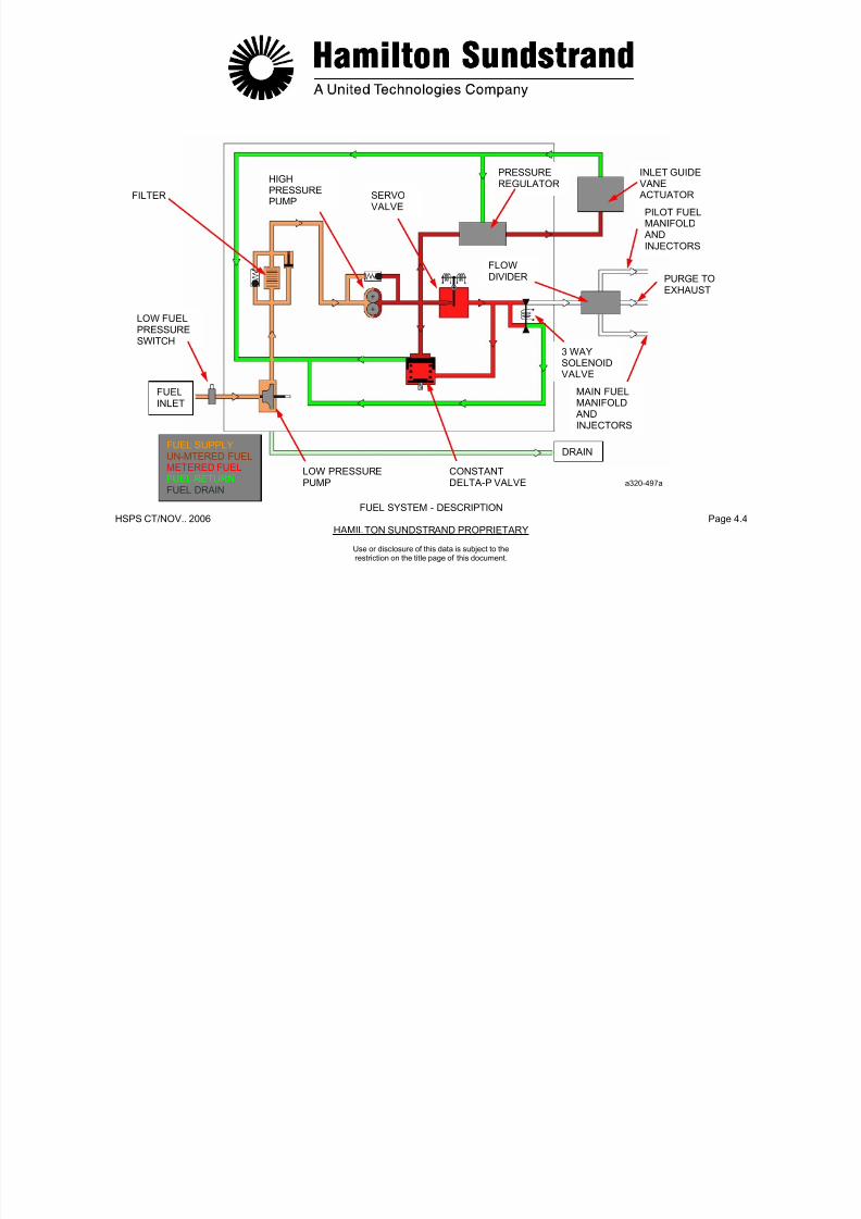
7/21/2019 Aps 3200 Training
http://slidepdf.com/reader/full/aps-3200-training 495/739
HSPS CT/NOV.. 2006 Page 4.5HAMILTON SUNDSTRAND PROPRIETARY
Use or disclosure of this data is subject to therestriction on the title page of this document.
( )Starting
When APU start is selected:
- The starter motor is energized and cranks the APU rotor assembly
- The ignition exciter operates and supplies high voltage spark to the
two igniter plugs
- The 3 way solenoid valve is energized open to provide fuel flow tothe injectors
- The servo valve is electrically operated to control the fuel flow.
Fuel from the aircraft fuel system is supplied by the low pressure andhigh pressure pumps through the servo valve and the 3 way solenoid
valve.
When the fuel pressure reaches approximately 138 kPad (20 PSID),the flow divider delivers fuel to the pilot injectors. The fuel injectedinto the combustor is ignited by the ignitor plugs.
When the fuel pressure reaches approximately 1380 kPad (200PSID), the flow divider delivers fuel to the main injectors.
During starting, the fuel flow is controlled by the servo valve usingsignals from the ECB.
At self-sustaining speed, the starter and the ignition system aredeactivated and the APU accelerates to 100% speed.
The APU is maintained at 100% speed under all load conditions bythe servo valve controlling fuel flow.
7/21/2019 Aps 3200 Training
http://slidepdf.com/reader/full/aps-3200-training 496/739
HSPS CT/NOV.. 2006 Page 4.6HAMILTON SUNDSTRAND PROPRIETARY
Use or disclosure of this data is subject to therestriction on the title page of this document.
FUEL SYSTEM - OPERATION (1)
STARTING
IGNITION EXCITER ANDIGNITERS OPERATION
TO PILOT INJECTORS
TO MAIN INJECTORS
BY SERVO VALVECONTROLLED BY ECB
FUEL SUPPLY UN-METERED FUELMETERED FUELFUEL RETURNFUEL DRAIN
a320-498 a
STARTING
FUEL SYSTEM - OPERATION (2)
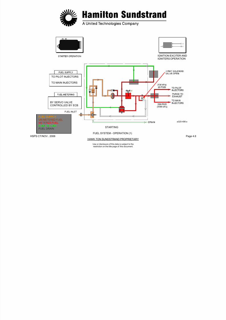
7/21/2019 Aps 3200 Training
http://slidepdf.com/reader/full/aps-3200-training 497/739
HSPS CT/NOV.. 2006 Page 4.7HAMILTON SUNDSTRAND PROPRIETARY
Use or disclosure of this data is subject to therestriction on the title page of this document.
Running Condition
- Stabilized condition
The fuel control unit provides a flow higher than APU fuel flowrequirements. The fuel is metered by the servo valve and iscontrolled by the ECB. The excess fuel is returned to the HP pump
inlet through the constant AP valve and the fuel filter.
- Transient condition
When the load applied to the power section changes, the rotationspeed changes. The ECB senses the change and implements asignal to the servo valve. The fuel flow is metered to keep the rotorspeed constant.
Shut-down
When APU shut-down is initiated (manual or automatic), the ECB de-energizes the 3 way solenoid valve. Fuel flow to the fuel injectors isshut off and bypassed back into the fuel system.
One second later the ECB de-energizes the fuel servo valve.
Any fuel remaining in the pilot manifold assembly and fuel injectors ispurged into the exhaust by combustor air pressure.

7/21/2019 Aps 3200 Training
http://slidepdf.com/reader/full/aps-3200-training 498/739
HSPS CT/NOV.. 2006 Page 4.8HAMILTON SUNDSTRAND PROPRIETARY
FUELSUPPLYUN-METERED FUELMETERED FUEL
FUEL RETURNFUEL DRAIN
a320-499a
FUEL SYSTEM - OPERATION (2)
Use or disclosure of this data is subject to therestriction on the title page of this document.
FUEL CONTROL UNIT - GENERAL
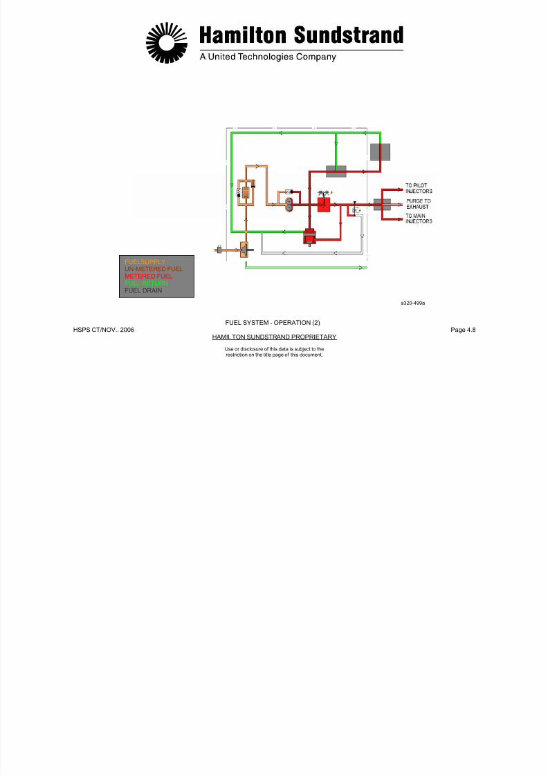
7/21/2019 Aps 3200 Training
http://slidepdf.com/reader/full/aps-3200-training 499/739
HSPS CT/NOV.. 2006 Page 4.9HAMILTON SUNDSTRAND PROPRIETARY
Use or disclosure of this data is subject to therestriction on the title page of this document.
Function
The fuel control unit (FCU) supplies and meters fuel to the APU.
The fuel control unit also supplies regulated fuel pressure to the inletguide vane and bleed control valve actuators.
Location
The fuel control unit is mounted on the front face of the gearbox by av-band clamp.
Interfaces
- Aircraft fuel system
- Pneumatic system actuators
- Drain system
- Control system.
Main Features
- Fuel supply by a low pressure pump and a high pressure pump
- Fuel filtering for the high pressure pump.
- Fuel metering by an electronic system (servo valve and electroniccontrol box).
Main Components
- Fuel pumps
- Filter
- Servo valve
- 3 way solenoid valve
- Pressure regulator.

7/21/2019 Aps 3200 Training
http://slidepdf.com/reader/full/aps-3200-training 500/739
HSPS CT/NOV..2006 Page 4.10HAMILTON SUNDSTRAND PROPRIETARY
FUEL FILTER
Use or disclosure of this data is subject to therestriction on the title page of this document.
FUEL CONTROL UNIT - GENERAL
SERVO VALVE
FUEL SUPPLYREGULATED FUELMETERED FUELFUEL RETURN
FUEL DRAIN a320-500A
FUEL CONTROL UNIT - DESCRIPTION (1)

7/21/2019 Aps 3200 Training
http://slidepdf.com/reader/full/aps-3200-training 501/739
HSPS CT/NOV.. 2006 Page 4.11HAMILTON SUNDSTRAND PROPRIETARY
Use or disclosure of this data is subject to therestriction on the title page of this document.
Components of the Fuel Control Unit
- A low fuel pressure switch located at the FCU fuel inlet (notshown)
- Fuel Pumps
• A low pressure pump (centrifugal type)
• A high pressure pump (gear type) provided with apressure relief valve
- A drain line for the pump shaft seal
- A filter which includes a filter element, a by-pass valve and an
impending blockage AP indicator
- A servo valve (electrically operated valve that meters fuel flow inresponse to signals from the electronic control box)
- A constant P valve (a valve that controls the differential pressureacross the servo valve)
- A 3 way solenoid valve (valve operated by the electronic control
box to open and close fuel flow to the fuel injectors)
- A pressure regulator that provides a constant pressure to the airsystem actuators:
• A fuel outlet port (fuel supply to the actuators)
• A fuel return port (fuel return from the actuators)
- A fuel inlet union (connected to the aircraft fuel system)
- An electrical connector (current signals from the electroniccontrol box to the 3 way solenoid valve and the servo valve).
O-rings
Two O-rings are located on the fuel control. One on the fuel controlmounting flange and one on the drive shaft. Both O-rings must beproperly installed or excessive loss of oil will occur when the APU isoperating.

7/21/2019 Aps 3200 Training
http://slidepdf.com/reader/full/aps-3200-training 502/739
HSPS CT/NOV.. 2006 Page 4.12HAMILTON SUNDSTRAND PROPRIETARY
a320-501a
FUEL CONTROL UNIT - DESCRIPTION (1)
Use or disclosure of this data is subject to therestriction on the title page of this document.
FUEL CONTROL UNIT - DESCRIPTION (2)

7/21/2019 Aps 3200 Training
http://slidepdf.com/reader/full/aps-3200-training 503/739
HSPS CT/NOV.. 2006 Page 4.13HAMILTON SUNDSTRAND PROPRIETARY
Use or disclosure of this data is subject to therestriction on the title page of this document.
Low Pressure Fuel Pump
The low pressure fuel pump provides a positive supply to the inlet ofthe high pressure pump.
The pump is mechanically driven at the same speed as the high
pressure pump by a splined shaft (driven by the gearbox).
The splined shaft is provided with a seal and a drain line to the drainsystem.
Main Features
- Type: centrifugal
- Rotation speed: 10129 RPM
- Pressure: 550 - 690 kPad (80 - 100 PSID)
- Flow: 182 kg/h (400 lbs/hr) at 550 kPad (80 PSID).
High Pressure Fuel Pump
The high pressure fuel pump supplies a fuel flow higher than the APU requirements. The excess fuel is returned to the pump inlet
through the constant ΔP valve. The pump is also provided with apressure relief valve.
Main Features
- Type: gear type
- Rotation speed: 10129 RPM
- Pressure: 2068 - 4480 kPad (300 - 650 PSID)
- Flow: 727 kg/h (1600 lbs/hr)
- Relief valve setting: > 4480 kPad (> 650 PSID).
Note: - Fuel flow at 7 % N: 20 kg/h (45 lbs/hr)- Fuel pressure at 7 % N: 1379 kPad (200 PSID).

7/21/2019 Aps 3200 Training
http://slidepdf.com/reader/full/aps-3200-training 504/739
HSPS CT/NOV.. 2006 Page 4.14HAMILTON SUNDSTRAND PROPRIETARY
FUEL SUPPLY
UN-METERED FUEL METERED FUELFUEL RETURNFUEL DRAIN
a320-502a
FUEL CONTROL UNIT - DESCRIPTION (2)
Use or disclosure of this data is subject to therestriction on the title page of this document.
FUEL CONTROL UNIT - DESCRIPTION (3)

7/21/2019 Aps 3200 Training
http://slidepdf.com/reader/full/aps-3200-training 505/739
HSPS CT/NOV.. 2006 Page 4.15HAMILTON SUNDSTRAND PROPRIETARY
Use or disclosure of this data is subject to therestriction on the title page of this document.
Fuel Filter
The filter is located at the outlet of the low pressure pump.
The filter includes the following components:
- A filter element to filter the fuel
Filter specification: 10 microns
- An impending blockage P indicator to provide a visual warningof a restricted filter
Setting: 48 kPad (7 PSID)
- A by-pass valve to allow the fuel supply in the event of filterblockage
Setting: 324 kPad (46 + - 4 PSID).
O-ring
An O-ring is located inside the fuel filter cavity of the fuel control unit.The O-ring functions as a seal and a securing device for the filter
bowel. The bowel is not secured by any external locking device.

7/21/2019 Aps 3200 Training
http://slidepdf.com/reader/full/aps-3200-training 506/739
HSPS CT/NOV.. 2006 Page 4.16HAMILTON SUNDSTRAND PROPRIETARY
FUEL SUPPLYUN-METERED FUELMETERED FUELFUEL RETURN
a320-503a
FUEL CONTROL UNIT - DESCRIPTION (3)
Use or disclosure of this data is subject to therestriction on the title page of this document.
FUEL CONTROL UNIT - DESCRIPTION (4)
S V l 3 W S l id V l
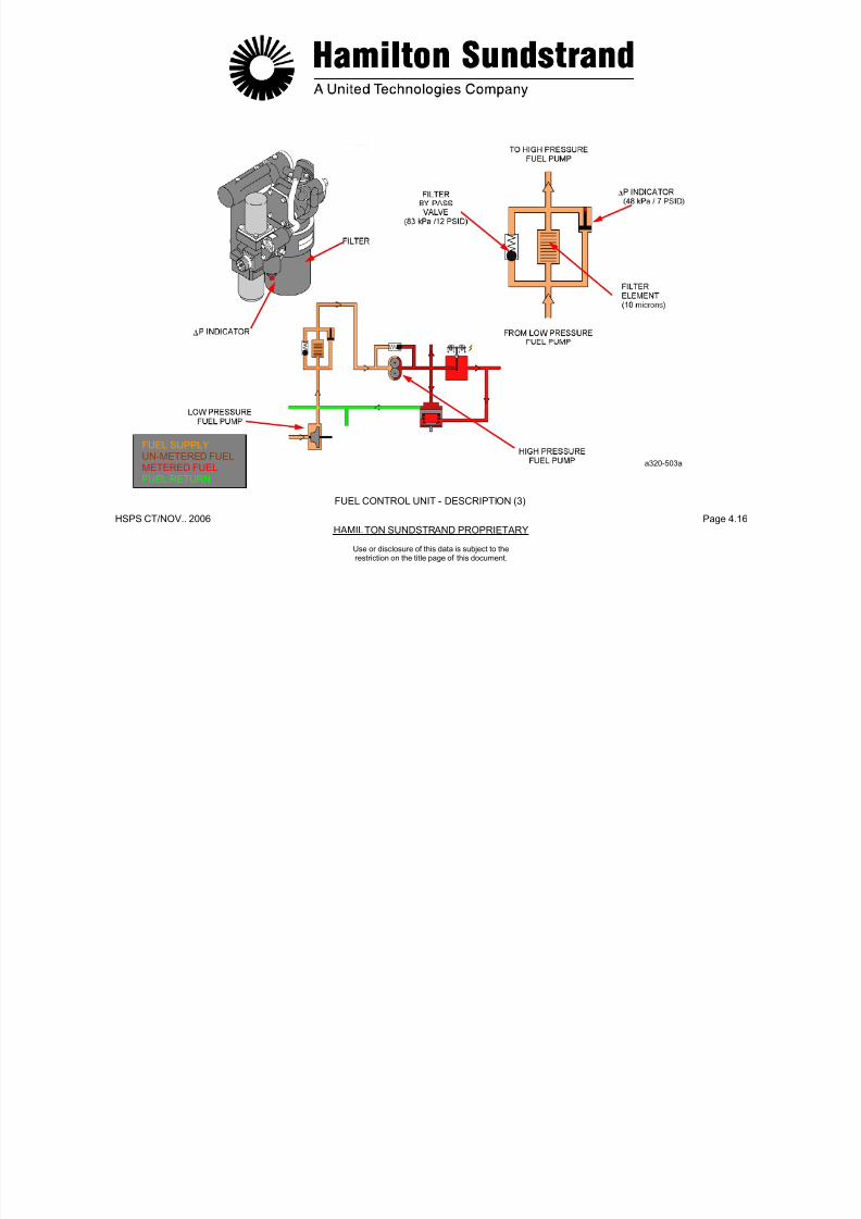
7/21/2019 Aps 3200 Training
http://slidepdf.com/reader/full/aps-3200-training 507/739
HSPS CT/NOV.. 2006 Page 4.17HAMILTON SUNDSTRAND PROPRIETARY
Use or disclosure of this data is subject to therestriction on the title page of this document.
Servo Valve
The servo valve meters the fuel during starting and normal operatingconditions.
The valve consists of a torque motor which operates a fuel metering
valve (clevis type).
The motor is electrically controlled by the ECB. ECB currentoperates the valve to meter fuel flow.
During starting, the servo valve meters fuel flow to accelerate the APU.
In normal operating conditions, the fuel flow is metered to maintain a
constant 100% speed.
The main features of the servo valve are:
- Type: Torque motor
- Current: 0 - 100 mA
- Metered flow: 6 - 198 kg/h (13 - 435 lbs/hr).
3 Way Soleno id Valve
The valve opens and closes the fuel supply for operation and shutdown of the APU.
The solenoid valve is energized open to supply fuel to the fuel
injectors (control from ECB).
When de-energized, a spring moves the valve to the close position.
When the valve closes, the fuel is shut off to the injectors andbypassed back into the fuel system.
During a normal or auto shutdown of the APU the ECB de-energizesthe 3 way solenoid valve, one second later the servo valve is de-
energized.
In the event the 3 way solenoid valve does not close, the APU willshut down when the servo valve is de-energized. If this conditionoccurs, the ECB will store a fault message. (APU FUEL VALVEFAILED OPEN).

7/21/2019 Aps 3200 Training
http://slidepdf.com/reader/full/aps-3200-training 508/739
HSPS CT/NOV.. 2006 Page 4.18HAMILTON SUNDSTRAND PROPRIETARY
UN-METERED FUELMETERED FUEL a320-504a
FUEL CONTROL UNIT - DESCRIPTION (4)
Use or disclosure of this data is subject to therestriction on the title page of this document.
FUEL CONTROL UNIT - DESCRIPTION (5)
Constant P Valve Pressure Regulator

7/21/2019 Aps 3200 Training
http://slidepdf.com/reader/full/aps-3200-training 509/739
HSPS CT/NOV.. 2006 Page 4.19HAMILTON SUNDSTRAND PROPRIETARY
Use or disclosure of this data is subject to therestriction on the title page of this document.
Constant P Valve
The valve maintains a constant pressure differential across the servovalve.
The valve senses upstream pressure on one side and downstream
pressure plus the force of a spring on the other side. The valveposition determines the amount of fuel to be returned to the fuelsystem.
The ΔP setting of the constant ΔP valve is of 689 kPad (100 PSID)across the servo valve. The valve is non-adjustable.
Pressure Regulator
The pressure regulator provides the fuel pressure supply to the inletguide vane actuator and the bleed control valve actuator. The valveis non adjustable.
The pressure regulator is closed from 0 to 60% APU speed. Whenthe speed is above 60%, the regulator will open and deliver 1724KPad (250 PSID) of fuel pressure to the actuators.
7/21/2019 Aps 3200 Training
http://slidepdf.com/reader/full/aps-3200-training 510/739
HSPS CT/NOV.. 2006 Page 4.20HAMILTON SUNDSTRAND PROPRIETARY
REGULATEDPRESSURE TO
ACTUATORS
REFERENCEPRESSURE FROM
LOW PRESSUREPUMP OUTLET
FUEL RETURNTO LOW
PRESSUREPUMP INLET
PRESSUREFROM HIGHPRESSURE PUMP
FUEL SUPPLYUN-METERED FUELMETERED FUELFUEL RETURN
a320-505a
FUEL CONTROL UNIT - DESCRIPTION (5)
Use or disclosure of this data is subject to therestriction on the title page of this document.
FLOW DIVIDER - GENERAL
Function Interfaces

7/21/2019 Aps 3200 Training
http://slidepdf.com/reader/full/aps-3200-training 511/739
HSPS CT/NOV.. 2006 Page 4.21HAMILTON SUNDSTRAND PROPRIETARY
Use or disclosure of this data is subject to therestriction on the title page of this document.
Function
The flow divider distributes fuel from the fuel control unit to the pilotand main injectors. It also provides purging of the pilot injectorsduring APU shut-down.
Location
The flow divider is installed on the left side of the combustor housing.
The flow divider is located downstream of the 3 way solenoid valve.
Main Components
The flow divider consists of two valves:
- A pilot injector and purge valve set at approximately 138 kPad (20PSID) to open.
- A main injector valve set at approximately 1380 kPad (200 PSID)to open.
Interfaces
- Fuel control unit
- Main injector manifold
- Pilot injector manifold
- Exhaust system (purge).
FUELCONTROL
7/21/2019 Aps 3200 Training
http://slidepdf.com/reader/full/aps-3200-training 512/739
HSPS CT/NOV.. 2006 Page 4.22HAMILTON SUNDSTRAND PROPRIETARY
Use or disclosure of this data is subject to the
restriction on the title page of this document.
FLOW DIVIDER - GENERAL
UNIT
UN-METERED FUELMETERED FUELFUEL RETURNFUEL PURGE
a320-506a
FLOW DIVIDER - DESCRIPTION AND OPERATION
Description Operating
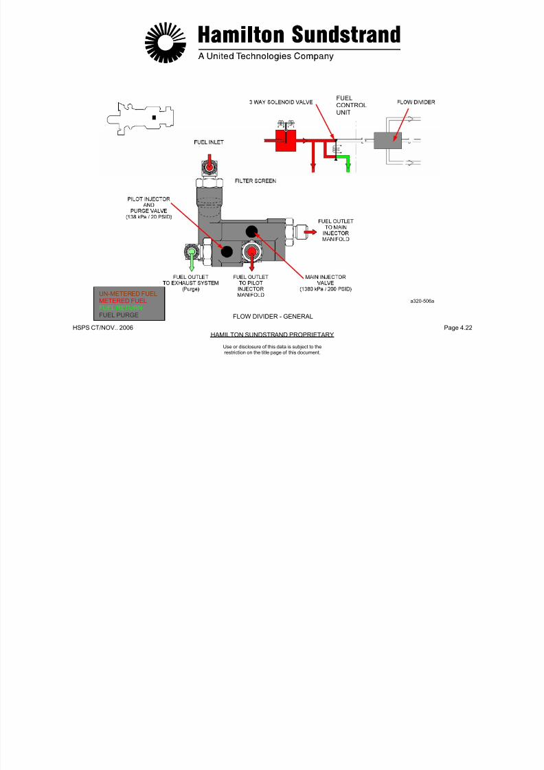
7/21/2019 Aps 3200 Training
http://slidepdf.com/reader/full/aps-3200-training 513/739
HSPS CT/NOV.. 2006 Page 4.23HAMILTON SUNDSTRAND PROPRIETARY
Use or disclosure of this data is subject to the
restriction on the title page of this document.
The flow divider consists of:
- Two valves:
• A pilot injector and purge valve set at approx. 138 kPad(20 PSID)
• A main injector valve set at approx. 1380 kPad (200 PSID)
- A filter screen (located at the fuel inlet)
- Fuel inlet/outlet ports:
• Fuel inlet from the fuel control unit
• Fuel outlet to the pilot manifold
• Fuel outlet to the main manifold
• Fuel outlet to the exhaust system (purge).
- Starting
When the APU is started, the fuel pressure increases to 138 kPad(20 PSID). The pilot injector valve opens and allows fuel flow to the
pilot injectors.
When the pressure reaches 1380 kPad (200 PSID), the maininjector valve opens allowing fuel flow to the main injectors.
- Normal Running Condition
The two valves remain open to allow fuel flow to the pilot injectorsand the main injectors.
- Shut-down
As the fuel pressure decreases, the two valves close. The fuelremaining in the pilot injectors is purged into the exhaust bycombustor air pressure. At this time, a momentary puff of smokemay be viewed coming from the APU exhaust. This is a normaloccurrence.
7/21/2019 Aps 3200 Training
http://slidepdf.com/reader/full/aps-3200-training 514/739
HSPS CT/NOV.. 2006 Page 4.24HAMILTON SUNDSTRAND PROPRIETARY
Use or disclosure of this data is subject to the
restriction on the title page of this document.
FLOW DIVIDER - DESCRIPTION AND OPERATION
METERED FUELFUEL PURGE
PILOT FUEL MANIFOLD AND INJECTORS
Function
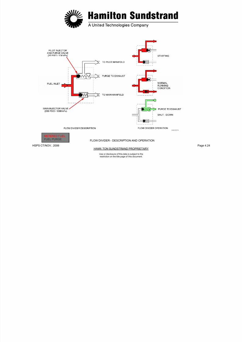
7/21/2019 Aps 3200 Training
http://slidepdf.com/reader/full/aps-3200-training 515/739
HSPS CT/NOV.. 2006 Page 4.25HAMILTON SUNDSTRAND PROPRIETARY
Use or disclosure of this data is subject to the
restriction on the title page of this document.
The pilot manifold delivers fuel from the flow divider to the pilotinjectors during start and normal operation.
It also supplies the pilot fuel injectors with fuel during normal running.
Location
The pilot manifold is mounted around the combustor housing.
Description
The pilot manifold consists of flexible pipes connecting the flowdivider to the three pilot injectors. It is comprised of teflon tubes
encased in a single layer of steel braid that is covered with a rubbersheath.

7/21/2019 Aps 3200 Training
http://slidepdf.com/reader/full/aps-3200-training 516/739
HSPS CT/NOV.. 2006 Page 4.26HAMILTON SUNDSTRAND PROPRIETARY
FUEL SUPPLYUN METERED FUELMETERED FUELFUEL RETURN
a320-508a
PILOT FUEL MANIFOLD AND INJECTORS
Use or disclosure of this data is subject to the
restriction on the title page of this document.
PILOT FUEL INJECTORS
Type Description

7/21/2019 Aps 3200 Training
http://slidepdf.com/reader/full/aps-3200-training 517/739
HSPS CT/NOV.. 2006 Page 4.27HAMILTON SUNDSTRAND PROPRIETARY
Use or disclosure of this data is subject to the
restriction on the title page of this document.
Simple jet injectors.
Location
The three pilot injectors are installed on the rear of the combustorhousing:
- One at the top (at 12 o'clock)
- Two at the bottom (one at 4 o'clock and one at 8 o'clock)
A simple jet injector comprises:
- A pilot injector body and mounting flange
- A fuel nozzle
- A heat shield
The injector fits into a heat shield that is provided with two air inletholes for cooling.
A gasket between the injector and the combustor housing.
Operation
A continuous flow of fuel is delivered to the combustor by the pilotinjectors and atomized by the fuel nozzles, the fuel is then mixedwith combustor air to maintain the combustion process.
METERED FUEL
INLET
7/21/2019 Aps 3200 Training
http://slidepdf.com/reader/full/aps-3200-training 518/739
HSPS CT/NOV.. 2006 Page 4.28HAMILTON SUNDSTRAND PROPRIETARY
Use or disclosure of this data is subject to the
restriction on the title page of this document.
PILOT FUEL INJECTORS
COMBUSTOR HOUSINGREAR FACE
GASKET
PILOT FUELINJECTOR
a320-509aMETERED FUELCOMBUSTOR AIRCOMBUSTION
MAIN FUEL MANIFOLD AND INJECTORS
Function
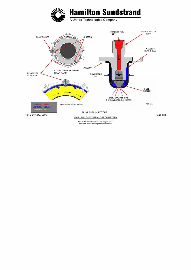
7/21/2019 Aps 3200 Training
http://slidepdf.com/reader/full/aps-3200-training 519/739
HSPS CT/NOV.. 2006 Page 4.29HAMILTON SUNDSTRAND PROPRIETARY
Use or disclosure of this data is subject to the
restriction on the title page of this document.
The main manifold delivers fuel from the flow divider to the maininjectors.
Location
The main manifold is mounted around the combustor housing.
Description
The main manifold consists of flexible pipes connecting the flowdivider to the six main injectors. It is comprised of teflon tubesencased in a single layer of steel braid that is covered with a rubbersheath.

7/21/2019 Aps 3200 Training
http://slidepdf.com/reader/full/aps-3200-training 520/739
HSPS CT/NOV.. 2006 Page 4.30HAMILTON SUNDSTRAND PROPRIETARY
FUEL SUPPLYREGULATED FUELMETERED FUELFUEL RETURN
a320-510a
MAIN FUEL MANIFOLD AND INJECTORS
Use or disclosure of this data is subject to the
restriction on the title page of this document.
MAIN FUEL INJECTORS
Type Operation
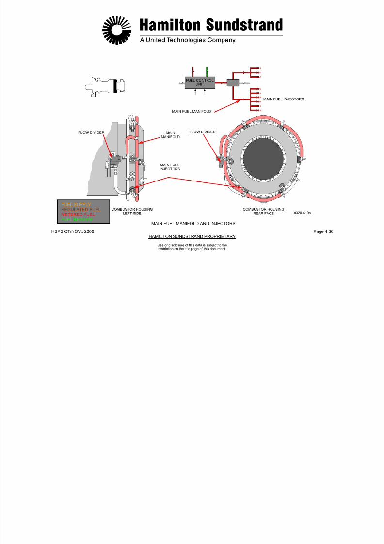
7/21/2019 Aps 3200 Training
http://slidepdf.com/reader/full/aps-3200-training 521/739
HSPS CT/NOV.. 2006 Page 4.31HAMILTON SUNDSTRAND PROPRIETARY
Use or disclosure of this data is subject to the
restriction on the title page of this document.
Air blast injectors.
Location
The six main injectors are located on the combustor housing.
Description
An air blast injector comprises:
- A main injector body and mounting flange
- A fuel injection tube and a shrouded air passage
- A gasket between the injector and the combustor housing.
A continuous flow of fuel is delivered to the combustor by the maininjectors. The fuel is atomized by combustor air flowing through theshrouded air passage. The fuel is then mixed with combustor air tomaintain the combustion process.

7/21/2019 Aps 3200 Training
http://slidepdf.com/reader/full/aps-3200-training 522/739
HSPS CT/NOV.. 2006 Page 4.32HAMILTON SUNDSTRAND PROPRIETARY
MAIN INJJECTOR
BODY
Use or disclosure of this data is subject to the
restriction on the title page of this document.
MAIN FUEL INJECTORS
FUEL INJECTOR
TUBE
GASKET
COMBUSTION SWIRL FLOWMETERED FUELCOMBUSTOR AIRCOMBUSTION
a320-511a
FUEL PIPES
Fuel supp ly
From the aircraft f el s stem to the f el control nit
Fuel drain (pipe located on the APU left side)
From the flo di ider to the e ha st s stem
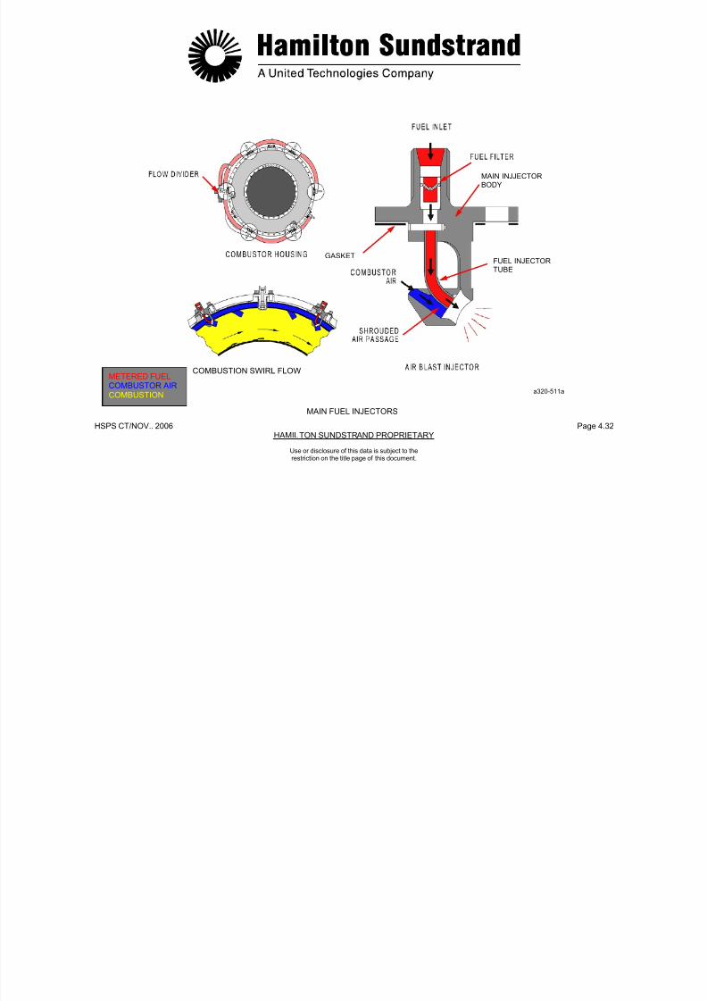
7/21/2019 Aps 3200 Training
http://slidepdf.com/reader/full/aps-3200-training 523/739
HSPS CT/NOV.. 2006 Page 4.33HAMILTON SUNDSTRAND PROPRIETARY
Use or disclosure of this data is subject to the
restriction on the title page of this document.
- From the aircraft fuel system to the fuel control unit.
Fuel distribution (pipes located on the APU left side)
- From the fuel control unit to the flow divider
- From the fuel flow divider to:
• The pilot manifold and injectors
• The main manifold and injectors
Fuel distribution (pipes located on the APU right side)
- From the pressure regulator of the fuel control unit to:
• The BCV servo valve (fuel supply and return)
• The IGV servo valve (fuel supply and return).
- From the flow divider to the exhaust system.
Fuel drain (pipes located on the APU right side)
- From the fuel control unit to the APU drain collector
- From the BCV actuator seals to the APU drain collector
- From the IGV actuator seals to the APU drain collector
- From the combustor housing, air bypass plenum and exhaust pipeto the APU drain collector.

7/21/2019 Aps 3200 Training
http://slidepdf.com/reader/full/aps-3200-training 524/739
HSPS CT/NOV.. 2006 Page 4.34HAMILTON SUNDSTRAND PROPRIETARY
Use or disclosure of this data is subject to the
restriction on the title page of this document.
FUEL PIPES
FUEL FLOW
DIVIDER
FUEL SUPPLYMETERED FUELFUEL DRAIN
FUEL SYSTEM INTERFACES
The APU fuel system has several interfaces: aircraft fuel system,pneumatic fuel system, APU control system, APU drain system.

7/21/2019 Aps 3200 Training
http://slidepdf.com/reader/full/aps-3200-training 525/739
HSPS CT/NOV.. 2006 Page 4.35HAMILTON SUNDSTRAND PROPRIETARY
Use or disclosure of this data is subject to the
restriction on the title page of this document.
Aircraf t Fuel Sys tem
The APU is supplied with fuel normally from the aircraft left wingtank. The aircraft low pressure fuel pump provides fuel to the APUwhen the aircraft tank pumps are not operating.
The low pressure valve is controlled by the ECB and is open whenthe APU is operating. The valve is closed when the APU is shutdown normally or by the APU fire switch.

7/21/2019 Aps 3200 Training
http://slidepdf.com/reader/full/aps-3200-training 526/739
HSPS CT/NOV.. 2006 Page 4.36HAMILTON SUNDSTRAND PROPRIETARY
FUEL SUPPLY
REGULATED FUELFUEL DRAIN
a320-513a
FUEL SYSTEM INTERFACES
Use or disclosure of this data is subject to the
restriction on the title page of this document.
AIRCRAFT FUEL SYSTEM
The aircraft fuel system supplies fuel to the main engines and APU.
The aircraft fuel system has three main tanks:
A low fuel pressure warning switch is located at the fuel inlet to thefuel inlet to the fuel control unit. The switch sends a signal to theECB if fuel pressure is too low.
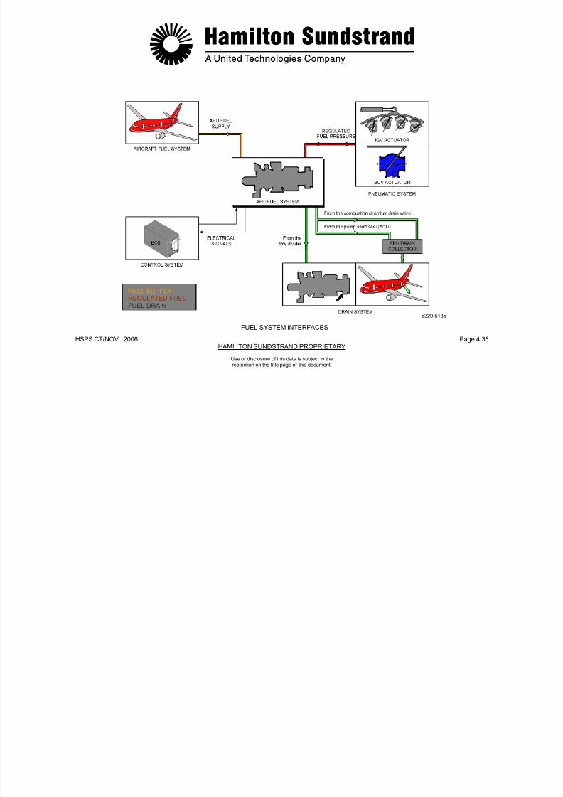
7/21/2019 Aps 3200 Training
http://slidepdf.com/reader/full/aps-3200-training 527/739
HSPS CT/NOV.. 2006 Page 4.37HAMILTON SUNDSTRAND PROPRIETARY
Use or disclosure of this data is subject to the
restriction on the title page of this document.
y
- A left tank located inside the left wing
- A center tank located between the two wings
- A right tank located inside the right wing.
Each tank has electric pumps to supply the engines.
A cross feed valve, located between the tanks, connects the leftand right engine supply lines. In normal operation, the cross feedvalve is closed.
The low pressure valve isolates the APU from the fuel supply.
The valve is open when the APU is running. It closes when the APUis shutdown or when the FIRE switch is activated.
The APU low pressure fuel pump is controlled by a pressure switchlocated in the fuel line to the APU. The switch senses fuel tank pumppressure. If the pressure is too low or the fuel tank pumps are turnedoff, the switch will cause the APU low pressure fuel pump to turn on.
p
The ECB will display "FUEL LO PR" message on the lower ECAMwhen the APU system page is selected. This requires the APU to beabove 7% speed and the fuel pressure below 109 KPag (15.8 PSIG).
7/21/2019 Aps 3200 Training
http://slidepdf.com/reader/full/aps-3200-training 528/739
HSPS CT/NOV.. 2006 Page 4.38HAMILTON SUNDSTRAND PROPRIETARY
APU LOW PRESSURE
FUEL PUMP
a320-514a
LOW FUEL PRESSURE
WARNING SWITCH
AIRCRAFT FUEL SYSTEM
Use or disclosure of this data is subject to the
restriction on the title page of this document.

7/21/2019 Aps 3200 Training
http://slidepdf.com/reader/full/aps-3200-training 529/739
HSPS CT/NOV..2006 Page 4.39HAMILTON SUNDSTRAND PROPRIETARY
APS 32OO AUXILIARY POWER UNIT
Use or disclosure of this data is subject to the
restriction on the title page of this document.
.

7/21/2019 Aps 3200 Training
http://slidepdf.com/reader/full/aps-3200-training 530/739
HSPS CT/NOV.. 2006 Page 5.0HAMILTON SUNDSTRAND PROPRIETARY
APS 3200
AUXILIARY POWER UNIT
SECTION 5
AIR SYSTEM
Use or disclosure of this data is subject to the
restriction on the title page of this document.
AIR SYSTEM - GENERAL
Function
The air system provides compressed air to the aircraft on the groundand in flight
Component Location
The inlet guide vane system components are located on the rightupper side of the air inlet housing. The inlet guide vanes are
7/21/2019 Aps 3200 Training
http://slidepdf.com/reader/full/aps-3200-training 531/739
HSPS CT/NOV. 2006 Page 5.1HAMILTON SUNDSTRAND PROPRIETARY
Use or disclosure of this data is subject to the
restriction on the title page of this document.
and in flight.
Main Features
- Flow: 1.2 kg/s (2.6 lbs/sec.)
- Pressure: 289.6 kPag (42 PSIG)
- Temperature: 232°C (450°F).
Main Components
Two systems are considered:
- The inlet guide vane (IGV) system controls the load compressorairflow and prevents EGT overtemperature of the power sectionduring load compressor operation. The inlet guide vanes arecontrolled by the ECB, servo valve, and the IGV actuator.
- The air bleed system delivers airflow from the load compressor tothe aircraft pneumatic system through a bleed control valve (BCV).The valve also functions as an anti-surge valve for the load
compressor. The BCV is controlled by the ECB, servo valve, andthe BCV actuator.
upper side of the air inlet housing. The inlet guide vanes arelocated in the air inlet housing ahead of the load compressor air inlet.
The air bleed system components are located on the right lower
side of the load compressor scroll outlet.
All the sensors are located on the APU.
Interfaces
- The ECB
- The aircraft pneumatic system
- The APU fuel system.
.
7/21/2019 Aps 3200 Training
http://slidepdf.com/reader/full/aps-3200-training 532/739
HSPS CT/NOV.. 2006 Page 5.2HAMILTON SUNDSTRAND PROPRIETARY
Use or disclosure of this data is subject to the
restriction on the title page of this document.
AIR SYSTEM - GENERAL
AMBIENT AIR
COMPRESSED AIRREGULATED FUELFUEL RETURN
AIR SYSTEM - OPERATION
Control of the System
The ECB uses various control signals from the aircraft and the APU

7/21/2019 Aps 3200 Training
http://slidepdf.com/reader/full/aps-3200-training 533/739
HSPS CT/NOV. 2006 Page 5.3HAMILTON SUNDSTRAND PROPRIETARY
Use or disclosure of this data is subject to the
restriction on the title page of this document.
gsensors to control the inlet guide vanes and the bleed control valve.
Indication
The pressure is indicated on the lower ECAM APU system pagedisplay. The pressure is indicated by the load compressor dischargepressure sensor and transmitted to the indicator through the ECB,the ADIRU, the BMC computers in PSIG.
Air Sys tem Operation
The air system operation chart shows IGV and positions during
various modes of operation
.

7/21/2019 Aps 3200 Training
http://slidepdf.com/reader/full/aps-3200-training 534/739
HSPS CT/NOV.. 2006 Page 5.4HAMILTON SUNDSTRAND PROPRIETARY
ENGINE BLEED PACK MODE AIRCRAFT IGV BCVSPEED SWITCH MODEL POSITION POSITION
%
0 - ALL CLOSED DISCHARGE72º ( 0)
100 OFF CLOSED - ALL CLOSED DISCHARGE82º ( 0)
100 ON OPEN - ALL OPEN DELIVERY 48º 45º TO 90º
100 ON OPEN ECS A318 OPEN DELIVERY A319 48º TO -30º 90º
A320
100 ON OPEN ECS A321 OPEN DELIVERY48º TO -10º 90º
100 ON CLOSED MES ALL OPEN DELIVERY-5º 90º
OPERATION CHART
AIR SYSTEM - OPERATION
Use or disclosure of this data is subject to the
restriction on the title page of this document.
INLET GUIDE VANE SYSTEM - GENERAL
Function
The inlet guide vane system controls the load compressor air flow to
Interfaces-Fuel inlet (fuel pressure)
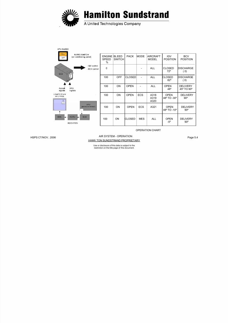
7/21/2019 Aps 3200 Training
http://slidepdf.com/reader/full/aps-3200-training 535/739
HSPS CT/NOV. 2006 Page 5.5HAMILTON SUNDSTRAND PROPRIETARY
Use or disclosure of this data is subject to the
restriction on the title page of this document.
provide the required flow to the aircraft pneumatic systems.
Main Features
- Hydraulically operated actuator, controlled by a servo-valve andthe electronic control box.
Components Involved
- The electronic control box (ECB)
- The inlet guide vane (IGV) system components: servo valve,
actuator, control mechanism and inlet guide vanes
Components Location
- The servo-valve and actuator form an assembly located on theright upper part of the APU on the air inlet housing.
- The inlet guide vanes and their control mechanism are located inthe air inlet housing.
Fuel outlet (fuel return)
- Fuel drain
- Control signal from the ECB to the servo valve
- Position signal from the LVDT (Linear Voltage DifferentialTransducer) to the ECB
- EGT signal from APU exhaust thermocouples to the ECB.
7/21/2019 Aps 3200 Training
http://slidepdf.com/reader/full/aps-3200-training 536/739
HSPS CT/NOV. 2006 Page 5.6HAMILTON SUNDSTRAND PROPRIETARY
REGULATED FUELFUEL RETURNFUEL DRAIN
INLET GUIDE VANE SYSTEM - GENERAL
Use or disclosure of this data is subject to the
restriction on the title page of this document.
INLET GUIDE VANE SYSTEM - DESCRIPTION (1)
The system includes the actuator, the control rod and the IGVmechanism.
IGV Actuator
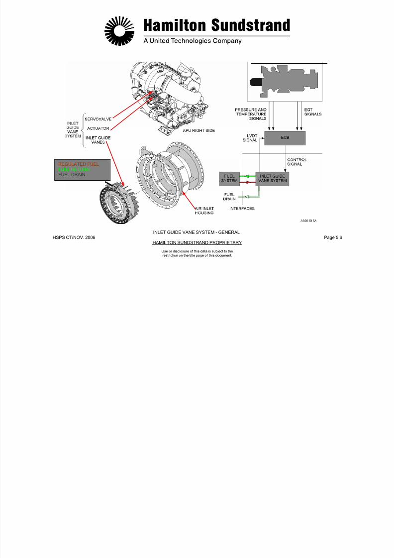
7/21/2019 Aps 3200 Training
http://slidepdf.com/reader/full/aps-3200-training 537/739
HSPS CT/NOV. 2006 Page 5.7HAMILTON SUNDSTRAND PROPRIETARY
Use or disclosure of this data is subject to the
restriction on the title page of this document.
Hydraulically operated actuator using fuel supplied by the FCU, itcomprises of a servo valve and an operating piston.
Control Rod
The rod connects the actuator piston to the IGV assembly. It isconnected to the actuator piston by a quick release pin.
IGV Position Indicator
The actuator rod housing has a position indicator cast on the top and
bottom of the housing. The indicator markings range from CLOSEDto OPEN. An external metal tab is attached to the control rod andfunctions as a position indicator for the IGV’s and used to manuallymove the IGV’s when the APU is not running. The igv’s should be inthe CLOSED position before starting the APU.
IGV POSITION
INDICATOROPEN
7/21/2019 Aps 3200 Training
http://slidepdf.com/reader/full/aps-3200-training 538/739
HSPS CT/NOV. 2006 Page 5.8HAMILTON SUNDSTRAND PROPRIETARY
OPEN
ACTUATOR
ROD HOUSING
METAL TAB
CLOSED
a 320-516.1
INLET GUIDE VANE SYSTEM - DESCRIPTION (1)
Use or disclosure of this data is subject to the
restriction on the title page of this document.
INLET GUIDE VANE SYSTEM - DESCRIPTION (2)
Servo Valve
The servo valve controls the position of the actuator piston by usinga spill valve that meters the potentiometric jet. The servo valve has ametered fuel pressure inlet from the actuator and a return outlet to
IGV Contro l Mechanism and Inlet Guide Vanes
The inlet guide vanes are part of the IGV assembly. A sector gear isattached to each inlet guide vane and is driven by a common ringgear
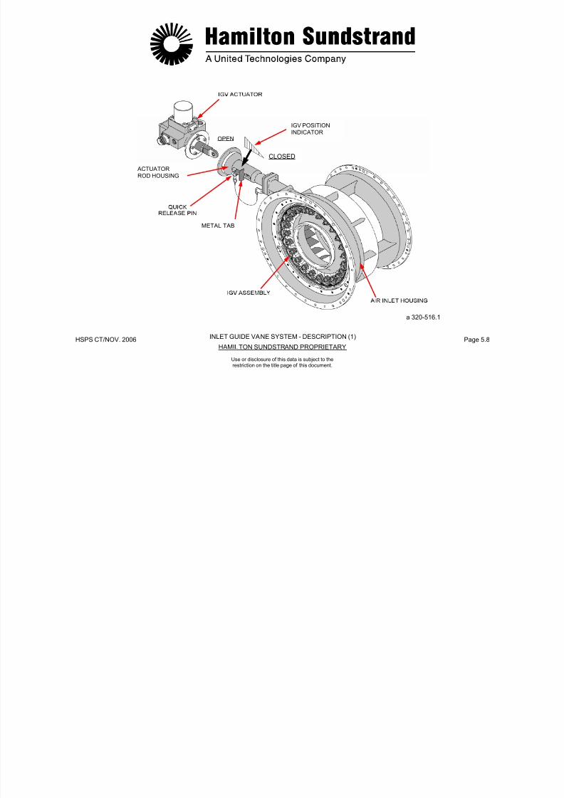
7/21/2019 Aps 3200 Training
http://slidepdf.com/reader/full/aps-3200-training 539/739
HSPS CT/NOV. 2006 Page 5.9HAMILTON SUNDSTRAND PROPRIETARY
Use or disclosure of this data is subject to therestriction on the title page of this document.
metered fuel pressure inlet from the actuator and a return outlet tothe fuel control unit. The control current (0-100 MA) to the servovalve is provided by the ECB.
Actuator
The actuator consists of a piston that is positioned by fuel pressuremetered by the servo valve. The actuator also uses double dynamicseals for piston shaft sealing.
The position of the actuator piston is provided by a Linear VoltageDifferential Transducer (LVDT). The position signal is sent to the
ECB for control of the servo valve.
gear.

7/21/2019 Aps 3200 Training
http://slidepdf.com/reader/full/aps-3200-training 540/739
HSPS CT/NOV. 2006 Page 5.10HAMILTON SUNDSTRAND PROPRIETARY
METRED
FUEL PRESSURE
FUEL PRESSUREMETERED FUEL PRESSUREFUEL RETURN
FUEL DRAIN
INLET GUIDE VANE SYSTEM - DESCRIPTION (2)
Use or disclosure of this data is subject to therestriction on the title page of this document.
INLET GUIDE VANE SYSTEM - OPERATION
Principle of Operation
The ECB provides a control signal (0-100 MA) to the servo valve byusing the following input signals.
APU Star ting
During start, the inlet guide vanes are in the closed position toreduce the APU starting loads. The inlet guide vanes are also in theclosed position during APU shutdown.
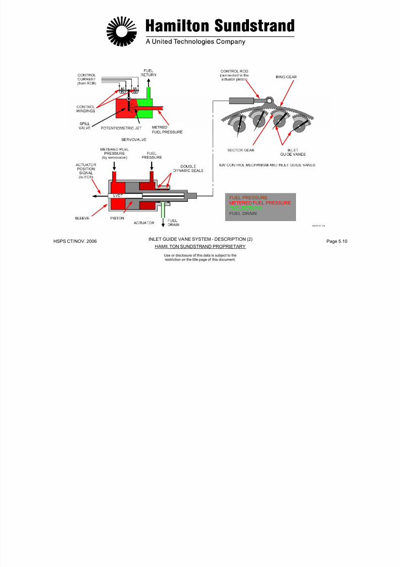
7/21/2019 Aps 3200 Training
http://slidepdf.com/reader/full/aps-3200-training 541/739
HSPS CT/NOV. 2006 Page 5.11HAMILTON SUNDSTRAND PROPRIETARY
Use or disclosure of this data is subject to therestriction on the title page of this document.
- APU bleed switch
- Speed (100%)
- EGT
- Air inlet pressure and temperature
- ECS mode
- MES mode.
The ECB control signal is sent to the servo valve. The servo valvemeters fuel pressure to control the actuator piston movement.
When the actuator moves, the linear voltage differential transducer(LVDT) sends the actuator position signal back to the ECB.
The actuator piston is maintained in a stabilized position by the ECBsignal (50 MA) to the servo valve.
The actuator piston positions the IGV assembly to control the airflowdelivery of the load compressor.
closed position during APU shutdown.
Operation
During load compressor operation, the position of the guide vanesare controlled by aircraft ECS computer signals sent to the ECB.
In the event APU exhaust gas temperature is too high during loadcompressor operation the ECB will signal the IGV actuator to reduceairflow delivery of the load compressor.
If inlet guide vane control is faulty, the IGV actuator will automatically
position the guide vanes to the closed position.
.
AIR INLETPRESSURE ANDTEMPERATURE
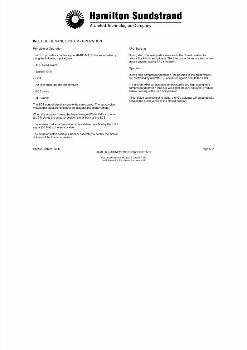
7/21/2019 Aps 3200 Training
http://slidepdf.com/reader/full/aps-3200-training 542/739
HSPS CT/NOV.. 2006 Page 5.12HAMILTON SUNDSTRAND PROPRIETARY
NOTE:
SEE OPERATIONCHART PAGE 5.4 FOR
AIRCRAFT MODEL AND IGV POSITIONS
FUEL PRESSUREMETERED FUEL PRESSURE
FUEL RETURNFUEL DRAIN
INLET GUIDE VANE SYSTEM - OPERATION
Use or disclosure of this data is subject to therestriction on the title page of this document.
AIR BLEED SYSTEM - GENERALFunction
The air bleed system provides air delivery to the aircraft pneumaticsystem while preventing load compressor surge.
Main Features
Component Location
- The servo-valve, the actuator and the bleed control valve form acomplete assembly located on the right lower part of the auxiliarypower unit at the scroll outlet
T l d di h i
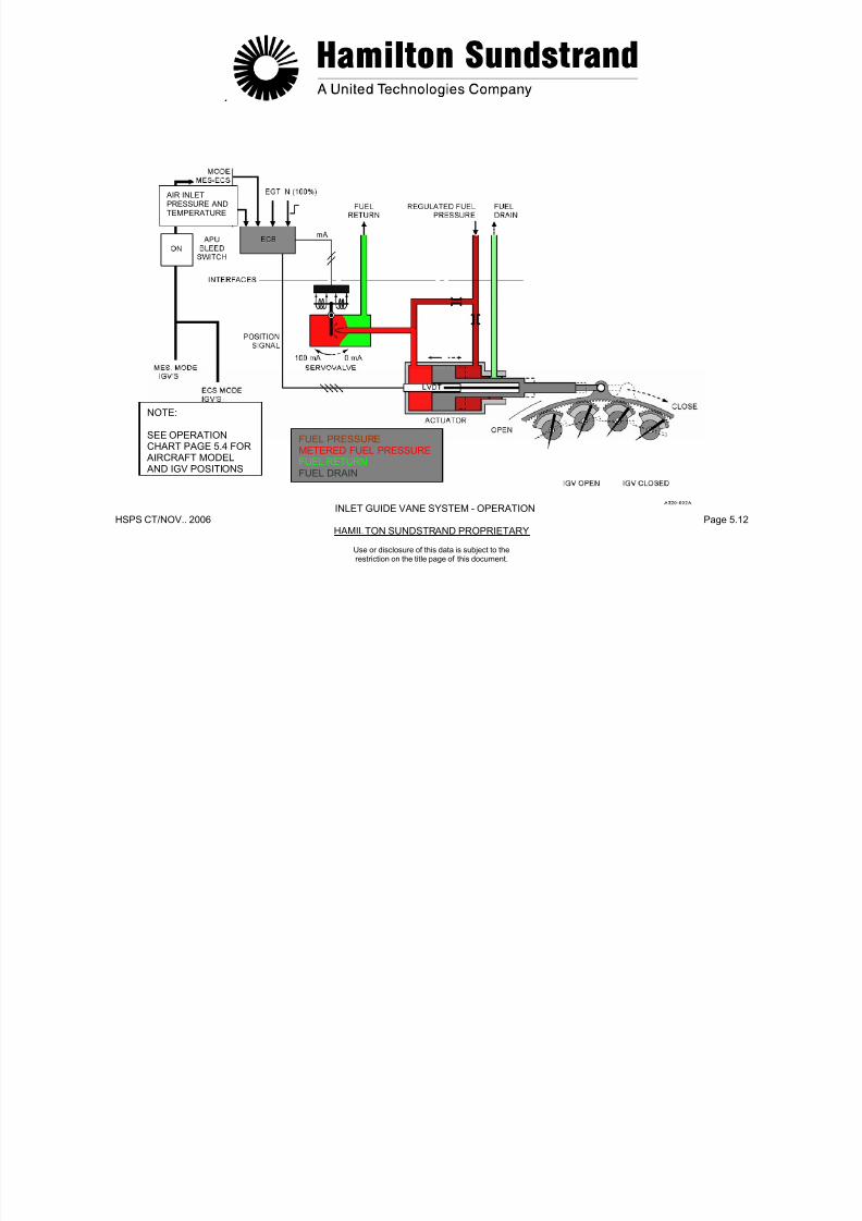
7/21/2019 Aps 3200 Training
http://slidepdf.com/reader/full/aps-3200-training 543/739
HSPS CT/NOV. 2006 Page 5.13HAMILTON SUNDSTRAND PROPRIETARY
Use or disclosure of this data is subject to therestriction on the title page of this document.
- Hydraulically operated actuator, controlled by a servo-valve and
the electronic control box.
Components Involved
- The Electronic Control Box (ECB)
- The Bleed Control Valve (BCV): servo-valve, actuator and valve
- Pressure sensors
- Ducts.
- Two load compressor discharge pressure pipes:
• One located in the scroll outlet (high pressure)
• One located in the diffuser of the load compressor (lowpressure)
Both are connected to the load compressor dischargepressure sensor to prevent load compressor surge.
Interfaces
- Fuel inlet
- Fuel outlet
- Fuel drain
- Control signal from the ECB to the servo valve
- Position signal from the LVDT to the ECB
- Pressure signals to the load compressor discharge pressuresensor.

7/21/2019 Aps 3200 Training
http://slidepdf.com/reader/full/aps-3200-training 544/739
HSPS CT/NOV. 2006 Page 5.14HAMILTON SUNDSTRAND PROPRIETARY
REGULATED FUELRETURN FUELFUEL DRAIN
AIR BLEED SYSTEM - GENERAL
Use or disclosure of this data is subject to therestriction on the title page of this document.
AIR BLEED SYSTEM - DESCRIPTION (1)
The air bleed supply is controlled by a bleed control valve.
This valve comprises of a housing, a butterfly valve and an actuator.
APU Bleed Switch
APU Bleed Switch
When the APU master switch is selected to off during bleed airoperation, the APU will continue to run in a cool down mode for amaximum time of 2 minutes.

7/21/2019 Aps 3200 Training
http://slidepdf.com/reader/full/aps-3200-training 545/739
HSPS CT/NOV. 2006 Page 5.15HAMILTON SUNDSTRAND PROPRIETARY
Use or disclosure of this data is subject to therestriction on the title page of this document.
When the APU master switch is selected to off during bleed air
operation, the APU will continue to run in a cool down mode for amaximum time of 2 minutes.
Housing
The housing is mounted on the load compressor scroll outlet bymeans of a v-band clamp.
Butterfly Valve
The valve is located in the BCV housing and directs air flow from theload compressor to the aircraft pneumatic systems, APU exhaust orboth.
The butterfly shaft extends through the top of the BCV housing. Theshaft has a slot machined into it that provides manual positioning ofthe valve and also serves as a valve position indicator.
The cooldown time limit can vary from 0 to 2 minutes. The time limit
depends on when the APU bleed switch is turned off prior toselecting the APU master switch to OFF.
Low B leed Air Pressure
In the event low bleed air pressure occurs, cycle the APU bleedswitch OFF and then to ON. This may restore the system to normal.
7/21/2019 Aps 3200 Training
http://slidepdf.com/reader/full/aps-3200-training 546/739
HSPS CT/NOV. 2006 Page 5.16HAMILTON SUNDSTRAND PROPRIETARY
AIR BLEED SYSTEM - DESCRIPTION (1)
Use or disclosure of this data is subject to therestriction on the title page of this document.
AIR BLEED SYSTEM - DESCRIPTION (2)
Servo Valve
The servo valve controls the position of the actuator piston by usinga spill valve that meters the potentiometric jet. The servo valve has ametered fuel pressure inlet from the actuator and a return outlet tothe fuel control unit The control current (0-100 MA) to the servo
Bleed Control Valve
The bleed control valve (BCV) delivers compressed air to the aircraft,also the valve functions as an anti-surge valve for the loadcompressor.
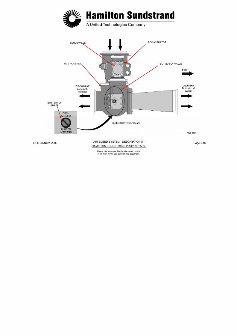
7/21/2019 Aps 3200 Training
http://slidepdf.com/reader/full/aps-3200-training 547/739
HSPS CT/NOV. 2006 Page 5.17HAMILTON SUNDSTRAND PROPRIETARY
Use or disclosure of this data is subject to therestriction on the title page of this document.
the fuel control unit. The control current (0-100 MA) to the servovalve is provided by the ECB.
Actuator
The actuator consists of a piston that is positioned by fuel pressuremetered by the servo valve. The actuator also uses double dynamicseals for piston shaft sealing.
The position of the actuator piston is provided by a linear voltagedifferential transducer (LVDT). The position signal is sent to the ECB
for control of the servo valve.

7/21/2019 Aps 3200 Training
http://slidepdf.com/reader/full/aps-3200-training 548/739
HSPS CT/NOV. 2006 Page 5.18HAMILTON SUNDSTRAND PROPRIETARY
COMPRESSED AIRREGULATED FUEL
METERED FUELFUEL RETURNFUEL DRAIN
AIR BLEED SYSTEM - DESCRIPTION (2)
Use or disclosure of this data is subject to therestriction on the title page of this document.
AIR BLEED SYSTEM - OPERATION
Principle of Operation
The ECB provides a control signal (0-100 MA) to the servo valveusing the following inputs:
- APU bleed switch
APU Star ting
During start and shutdown the BCV is in the discharge position.
If the valve control is faulty, the BCV actuator will automaticallyposition the valve to discharge.
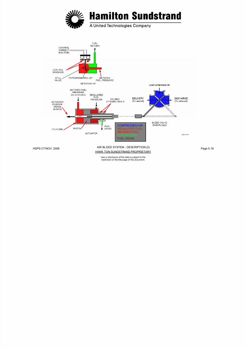
7/21/2019 Aps 3200 Training
http://slidepdf.com/reader/full/aps-3200-training 549/739
HSPS CT/NOV. 2006 Page 5.19HAMILTON SUNDSTRAND PROPRIETARY
Use or disclosure of this data is subject to therestriction on the title page of this document.
U b eed s tc
- Speed (100%)
- Air inlet temperature
- Load compressor discharge pressure sensor (ΔP/P).
The ECB control signal is sent to the servo valve. The servo valvemeters fuel pressure to control the actuator piston movement.
When the actuator piston moves, the linear voltage differentialtransducer (LVDT) sends the actuator position signal back to theECB.
The actuator piston is maintained in a stabilized position by the ECBsignal (50 MA) to the servo valve.
The actuator piston positions the BCV to deliver the maximum airflowto the aircraft pneumatic systems without causing load compressor
surge.
pos t o t e a e to d sc a ge

7/21/2019 Aps 3200 Training
http://slidepdf.com/reader/full/aps-3200-training 550/739
HSPS CT/NOV. 2006 Page 5.20HAMILTON SUNDSTRAND PROPRIETARY
COMPRESSED AIRREGULATED FUELMETERED FUELFUEL RETURNFUEL DRAIN
AIR BLEED SYSTEM - OPERATION
Use or disclosure of this data is subject to therestriction on the title page of this document.
AIR SYSTEM SENSORS - INLET AIR PRESSURE AND TEMPERATURE SENSOR
Function
The air inlet pressure and temperature signals are used by the ECBfor control purposes.
Location
- Supply current: 1 mA
- Range: -55 to +150°C (-62 to 302°F)
- Resistance at 0°C (0°F): 1000 Ω.
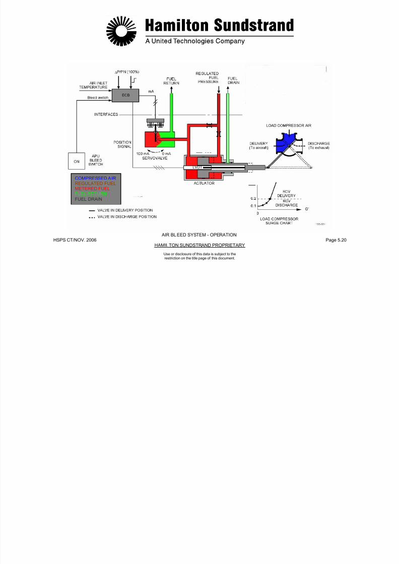
7/21/2019 Aps 3200 Training
http://slidepdf.com/reader/full/aps-3200-training 551/739
HSPS CT/NOV. 2006 Page 5.21HAMILTON SUNDSTRAND PROPRIETARY
The pressure and temperature sensors are in one unit which islocated on the right rear side of the air inlet plenum.
Main Features
Pressure Sensor
- Type: variable resistor device
- Excitation voltage: + 5 and - 5 VDC
- Output signal: 0 to 50 mV
- Range: 0 to 104 kPaa (0 to 15 PSIA)
- Minimum bridge impedance: 2000Ω.
Temperature Sensor
- Type: resistance temperature device
Functional Description
- The pressure sensor is made of a bridge of 4 resistors printed ona flexible support. One of them varies if the support is deformed bythe air pressure. The whole bridge is supplied by a 5 VDC constantsource voltage coming from the ECB. The changes of the variableresistor cause the output to vary (from 0 to 50 mV).
- The temperature sensor is a resistor which is fed by a constant 1mA current supplied by the ECB. The output voltage changes from
approximately 0.8 to 1.2 VDC according to the resistance changesfrom -55 to +50°C (-67 to +122°F).
The ECB detects a sensor failure if:
- The measured ambient pressure is lower than 3.45 kPaa(0.5 PSIA) or higher than 110 kPaa (16 PSIA)
- The measured inlet temperature is lower than -62°C (-80°F) orhigher than 76°C (170°F)
Normal BCV control will be maintained if either air inlet pressure ortemperature sensor is failed.
Use or disclosure of this data is subject to therestriction on the title page of this document.

7/21/2019 Aps 3200 Training
http://slidepdf.com/reader/full/aps-3200-training 552/739
HSPS CT/NOV. 2006 Page 5.22HAMILTON SUNDSTRAND PROPRIETARY
AIR SYSTEM SENSORS
Use or disclosure of this data is subject to therestriction on the title page of this document.
AIR SYSTEM SENSORS - LOAD COMPRESSOR DISCHARGE PRESSURE SENSORS
General
Function
The load compressor discharge pressure sensors sense loadcompressor air pressure (high pressure) and (low pressure).
Description
The two sensors are made of a bridge of 4 resistors.
The resistors are printed on a flexible support and one of them variesif the support is deformed by the pressure.

7/21/2019 Aps 3200 Training
http://slidepdf.com/reader/full/aps-3200-training 553/739
HSPS CT/NOV. 2006 Page 5.23HAMILTON SUNDSTRAND PROPRIETARY
Use or disclosure of this data is subject to therestriction on the title page of this document.
The ECB receives signals from the sensors and adjusts the bleedcontrol valve (BCV) to prevent load compressor surge.
Location
The pressure sensors (ΔP/P) are assembled as one unit. Thesensors are located on the right front side of the air inlet plenum.
Main Features
The pressure sensors are variable resistor devices.
Excitation voltage: + 5 and - 5 VDC
Output signal: 0 to 50 mV
Range 0 to 172 kPad (0 to 25 PSID) (ΔP)0 to 689 kPaa (0 to 100 PSIA) (P)
Minimum bridge impedance: 2000 Ω.
The bridges are supplied by a constant source voltage of 5 VDCcoming from the ECB.
The changes of the variable resistor causes the output voltage tovary (from 0 to 50 millivolt).
The ECB detects a sensor failure if:
- The measured pressure is lower than 3.45 kPad (0.5 PSID) or
higher than 172 kPa (25 PSI) or than 690 kPa (100 PSI)
The load compressor bleed air pressure is displayed on the lowerECAM when the APU system page is selected.
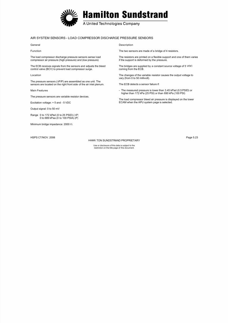
7/21/2019 Aps 3200 Training
http://slidepdf.com/reader/full/aps-3200-training 554/739
HSPS CT/NOV. 2006 Page 5.24HAMILTON SUNDSTRAND PROPRIETARY
LOAD COMPRESSOR DISCHARGE PRESSURE SENSORS
AIR SYSTEM SENSORS
Use or disclosure of this data is subject to therestriction on the title page of this document.
ACCESSORY COOLING - GENERAL
Function
The accessory cooling system supplies air for the oil cooler and forthe APU compartment ventilation.
Location
Cooling Fan
The fan provides cooling air to the oil cooler and to the compartmentcooling duct. The fan assembly incorporates a permanent magnetgenerator that is used for APU backup overspeed and to preventmomentary power interruption of the ECB.
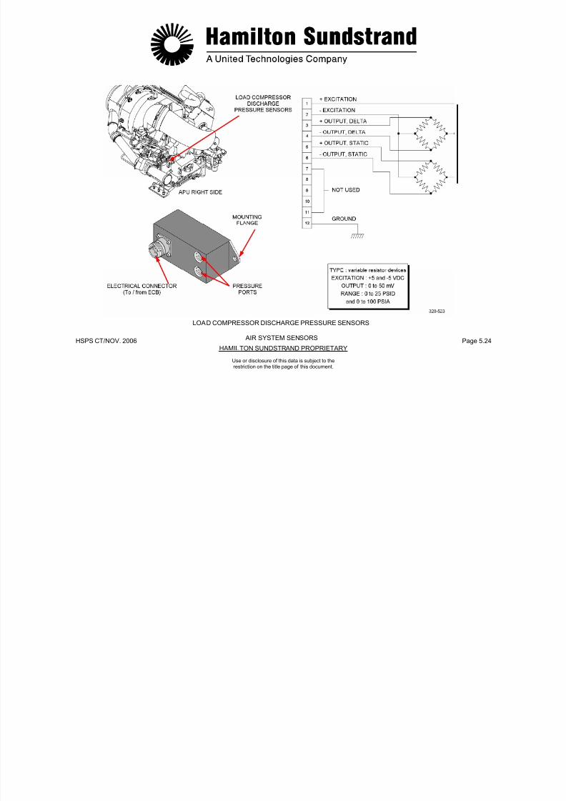
7/21/2019 Aps 3200 Training
http://slidepdf.com/reader/full/aps-3200-training 555/739
HSPS CT/NOV. 2006 Page 5.25HAMILTON SUNDSTRAND PROPRIETARY
Use or disclosure of this data is subject to therestriction on the title page of this document.
The system components are located on the APU.
Main Features
Cooling by circulation of air taken from the air inlet plenum andaccelerated by the cooling fan.
Main Components
The main components of the system are the fan inlet duct assembly,the cooling fan, the fan outlet duct assembly, the oil cooler and theoil cooler exhaust duct.
Fan Inlet Duct
This duct connects the engine air inlet plenum to the inlet of thecooling fan.
Fan Outlet Duct
This duct connects the outlet of the cooling fan to the inlet of the oilcooler.
Oil Cooler Exhaust Duct
This duct connects the oil cooler outlet to the APU compartment doorvent.
Compartment Cooling
The APU compartment is ventilated by air ducted from the coolingfan outlet duct. The air is discharged into the compartment throughthe compartment cooling duct.
7/21/2019 Aps 3200 Training
http://slidepdf.com/reader/full/aps-3200-training 556/739
HSPS CT/NOV. 2006 Page 5.26HAMILTON SUNDSTRAND PROPRIETARY
ACCESSORY COOLING - GENERAL
Use or disclosure of this data is subject to therestriction on the title page of this document.
ACCESSORY COOLING - COOLING FAN
General
Function
The cooling fan (driven by the gearbox) provides air circulation forthe oil cooler and ventilation of the APU compartment.
Main Components
- The cooling fan assembly includes:
• An axial flow fan
• The fan drive gear
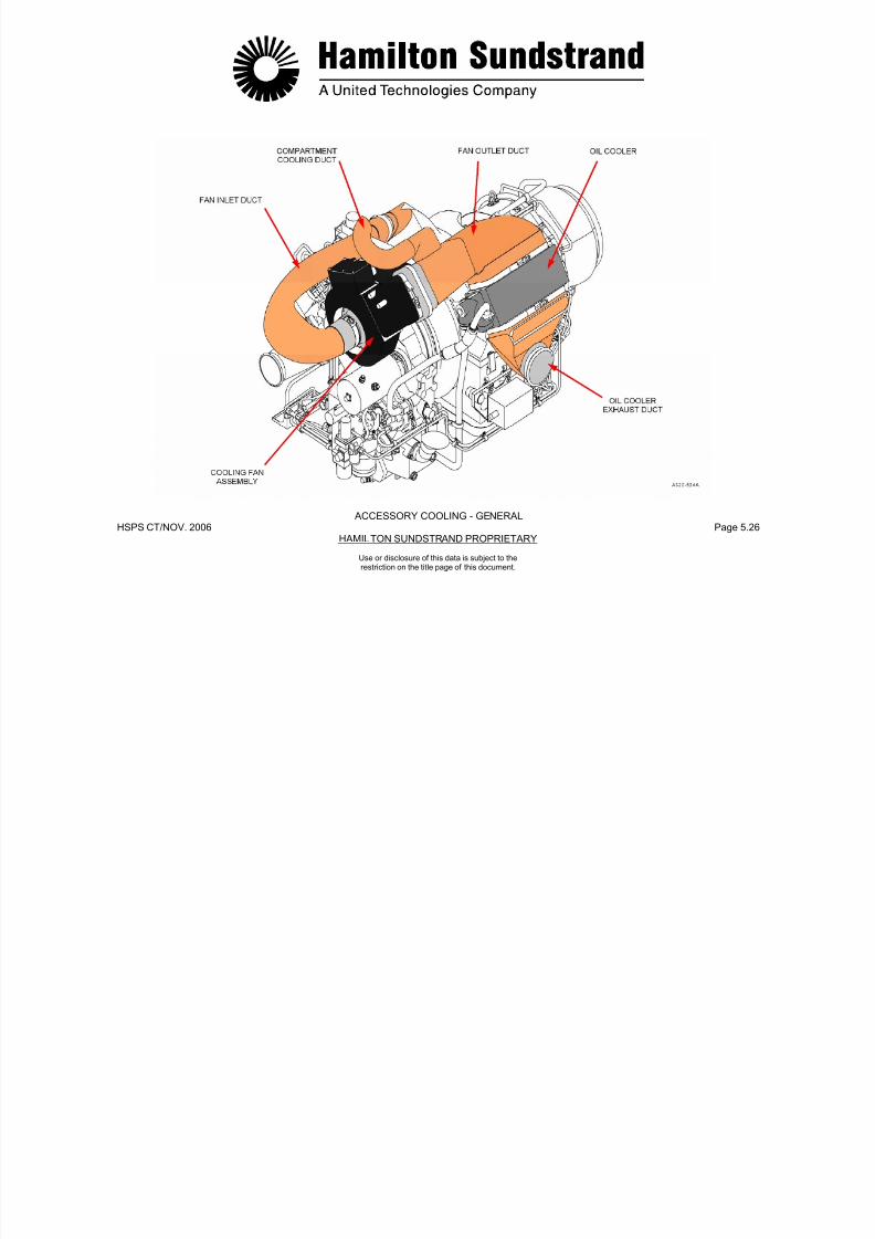
7/21/2019 Aps 3200 Training
http://slidepdf.com/reader/full/aps-3200-training 557/739
HSPS CT/NOV. 2006 Page 5.27HAMILTON SUNDSTRAND PROPRIETARY
Use or disclosure of this data is subject to therestriction on the title page of this document.
The cooling fan incorporates a permanent magnet generator thatprovides momentary direct current power, and a backup overspeedsignal to the electronic control box.
Location
The cooling fan is located at the top of the gearbox front face and issecured by a V-band clamp.
Main Features
- Cooling fan rotation speed: 51965 RPM
- Permanent Magnet Generator output: 40 VDC (100% of N)
- Speed signal for back-up of the overspeed protection system:107%.
g
• 2 roller bearings
- Fan inlet and outlet ducts
- A permanent magnet generator and control box.

7/21/2019 Aps 3200 Training
http://slidepdf.com/reader/full/aps-3200-training 558/739
HSPS CT/NOV. 2006 Page 5.28HAMILTON SUNDSTRAND PROPRIETARY
COOLING FAN - GENERAL
ACCESSORY COOLING
Use or disclosure of this data is subject to therestriction on the title page of this document.
ACCESSORY COOLING - COOLING FAN
Description
The cooling fan is mounted on the gearbox and aligned by a locatingpin. The fan mounting flange is secured to the gearbox by a v-bandclamp.
The fan is driven by a shaft assembly that is supported by two ball
Operation
Cooling Fan
The cooling fan accelerates the air flow through the oil cooler.Cooling air is also used for APU compartment cooling.

7/21/2019 Aps 3200 Training
http://slidepdf.com/reader/full/aps-3200-training 559/739
HSPS CT/NOV. 2006 Page 5.29HAMILTON SUNDSTRAND PROPRIETARY
Use or disclosure of this data is subject to therestriction on the title page of this document.
bearings, the bearings are lubricated by the APU oil system. Theshaft assembly uses a carbon seal and two labyrinth sealspressurized by the power section impeller air. The oil used forlubrication of the cooling fan is returned to the oil sump by gravity.
A permanent magnet generator (PMG) and a printed circuit boardare located in the fan housing. The printed circuit board contains therectifier components for the PMG electrical power output to the ECB.
The cooling fan can be used to turn the APU rotor assembly duringborescoping. This is accomplished by removing the fan inlet duct andmanually rotate the fan impeller.
PMG
The permanent magnet generator (PMG) is driven by the cooling fanshaft. The PMG provides momentary (240 msec) of rectifiedelectrical power to the ECB when the aircraft electrical power isinterrupted during power transfer.
One unrectified PMG output provides a frequency signal to the ECBthat is used for the back up overspeed signal.

7/21/2019 Aps 3200 Training
http://slidepdf.com/reader/full/aps-3200-training 560/739
HSPS CT/NOV. 2006 Page 5.30HAMILTON SUNDSTRAND PROPRIETARY
AMBIENT AIROIL SUPPLYOIL DRAINPRESSURIZED AIR
COOLING FAN - DESCRIPTION AND OPERATION
ACCESSORY COOLING
Use or disclosure of this data is subject to therestriction on the title page of this document.
AIRCRAFT PNEUMATIC SYSTEM
The aircraft pneumatic system supplies compressed air to thefollowing:
- Aircraft air conditioning system
- Water tank pressurization

7/21/2019 Aps 3200 Training
http://slidepdf.com/reader/full/aps-3200-training 561/739
HSPS CT/NOV. 2006 Page 5.31HAMILTON SUNDSTRAND PROPRIETARY
Use or disclosure of this data is subject to therestriction on the title page of this document.
- Aft cargo heating
- Wing anti-icing system
- Main engine starting system
- Hydraulic reservoir pressurization.
The compressed air , used by the aircraft pneumatic system, can besupplied by:
- The APU
- Number 1 engine
- Number 2 engine
- Ground air source.
ENG. 1
HOT AIR
PACK 1ENG 2BLEED
PACK 2
X BLEED

7/21/2019 Aps 3200 Training
http://slidepdf.com/reader/full/aps-3200-training 562/739
HSPS CT/NOV. 2006 Page 5.32HAMILTON SUNDSTRAND PROPRIETARY
Use or disclosure of this data is subject to therestriction on the title page of this document.
AIRCRAFT PNEUMATIC SYSTEM
APU COMPRESSED AIRENGINE FAN COOLING AIR
FAULT LIGHTOFF LIGHT
BLEED
GROUND AIR
SUPPLY
APUBLEEDVALVE(BCV)
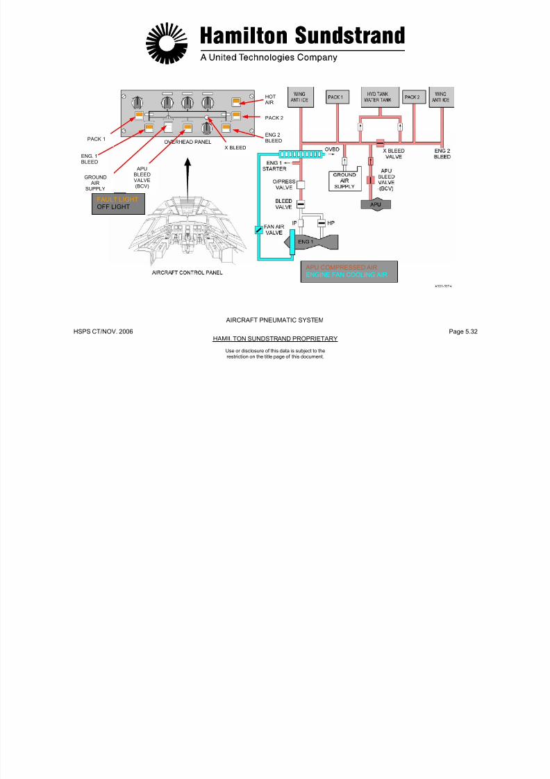
7/21/2019 Aps 3200 Training
http://slidepdf.com/reader/full/aps-3200-training 563/739
HSPS CT/NOV.. 2006 Page 5.33HAMILTON SUNDSTRAND PROPRIETARY
APS 3200 AUXILIARY POWER UNIT
Use or disclosure of this data is subject to therestriction on the title page of this document.
APS 3200

7/21/2019 Aps 3200 Training
http://slidepdf.com/reader/full/aps-3200-training 564/739
HSPS CT/NOV.. 2006 Page 6.0HAMILTON STANDARD PROPRIETARY
AUXILIARY POWER UNIT
SECTION 6
CONTROL SYSTEM
Use or disclosure of this data is subject to therestriction on the title page of this document.
APU CONTROL SYSTEM - GENERAL
Functions
The functions of the APU Control System are:
- To keep the power unit rotation speed constant to maintain ACgenerator frequency
Main Components
The main components of the APU control system are:
- The APU components (sensors, pressure switches, servo-valve,actuators ...)

7/21/2019 Aps 3200 Training
http://slidepdf.com/reader/full/aps-3200-training 565/739
HSPS CT/NOV.. 2006 Page 6.1HAMILTON STANDARD PROPRIETARY
Use or disclosure of this data is subject to therestriction on the title page of this document.
- To protect the power unit from overtemperature
- To avoid load compressor surge
- To ensure a proper start of the power unit
- To provide a proper start sequence.
- To monitor APU component operation.
- To supply fault information for trouble shooting, engine trendmonitoring and historical data retention.
Main Features
- FADEC (Full Authority Digital Electronic Controller)
- Single computer
- Electrical supply from the aircraft DC system and momentarypower backup from the cooling fan PMG.
- The electronic control box
- The aircraft control panels.

7/21/2019 Aps 3200 Training
http://slidepdf.com/reader/full/aps-3200-training 566/739
HSPS CT/NOV.. 2006 Page 6.2HAMILTON SUNDSTRAND PROPRIETARY
APU CONTROL SYSTEM - GENERAL
Use or disclosure of this data is subject to therestriction on the title page of this document.
APU CONTROL SYSTEM - DESCRIPTION (1)
General
This description considers:
- The Electronic Control Box (ECB)
- The ECB inputs
ECB Outputs
They are the accessories (electro-valves, relays...) and indicatingdevices.
ECB Electrical Supply
- 28 VDC supply: from the aircraft electrical system

7/21/2019 Aps 3200 Training
http://slidepdf.com/reader/full/aps-3200-training 567/739
HSPS CT/NOV.. 2006 Page 6.3HAMILTON SUNDSTRAND PROPRIETARY
Use or disclosure of this data is subject to therestriction on the title page of this document.
- The ECB outputs
- The ECB supply
- The electrical harness.
ECB
The ECB is located in the aft cargo compartment.
The unit is made of six printed wiring assemblies using digitaltechnology components.
ECB Inputs
They are the sensors (rotation speed, temperature, pressure...) anddiscrete signals (microswitches and switches).
- Momentary supply: from the permanent magnet generator (part ofthe cooling fan assembly).
Electrical Harness
The APU harness connects the APU to the aircraft electrical system.
7/21/2019 Aps 3200 Training
http://slidepdf.com/reader/full/aps-3200-training 568/739
HSPS CT/NOV.. 2006 Page 6.4HAMILTON SUNDSTRAND PROPRIETARY
APU CONTROL SYSTEM - DESCRIPTION (1)
Use or disclosure of this data is subject to therestriction on the title page of this document.
APU CONTROL SYSTEM - DESCRIPTION (2)
Control System Components
Components of the control system:
- Low oil pressure switch
- Oil filter switch indicators
High oil temperature sensor
- Inlet guide vane servo valve
- Bleed control valve servo valve
- Fuel servo valve
- 3 way solenoid valve
Low fuel pressure switch

7/21/2019 Aps 3200 Training
http://slidepdf.com/reader/full/aps-3200-training 569/739
HSPS CT/NOV.. 2006 Page 6.5HAMILTON SUNDSTRAND PROPRIETARY
Use or disclosure of this data is subject to therestriction on the title page of this document.
- High oil temperature sensor
- Oil level sensor
- De-oiling valve
- Speed sensors
- EGT sensors
- Inlet air pressure sensor
- Inlet air temperature sensor
- Load compressor discharge pressure sensor
- Linear voltage differential transducers (LVDTs)
- Low fuel pressure switch
- Permanent magnet generator
- Engine identification module
- Exciter
- Starter voltage sensing
- Centralized Fault Display System (CFDS)
- Aircraft discrete inputs and outputs.
7/21/2019 Aps 3200 Training
http://slidepdf.com/reader/full/aps-3200-training 570/739
HSPS CT/NOV.. 2006 Page 6.6HAMILTON SUNDSTRAND PROPRIETARY
APU CONTROL SYSTEM - DESCRIPTION (2)
CONTROL SYSTEM COMPONENTS
Use or disclosure of this data is subject to therestriction on the title page of this document.
APU CONTROL SYSTEM - OPERATION (1)
Rotation Speed Contro l
General
This function meters the fuel flow to maintain a constant rotor speed.
Components Involved
- Speed sensors
Exhaust Gas Temperature (EGT) Control
General
This function protects the power unit against over-temperature.
Components Involved
- EGT thermocouples the speed sensors and the inlet pressure and
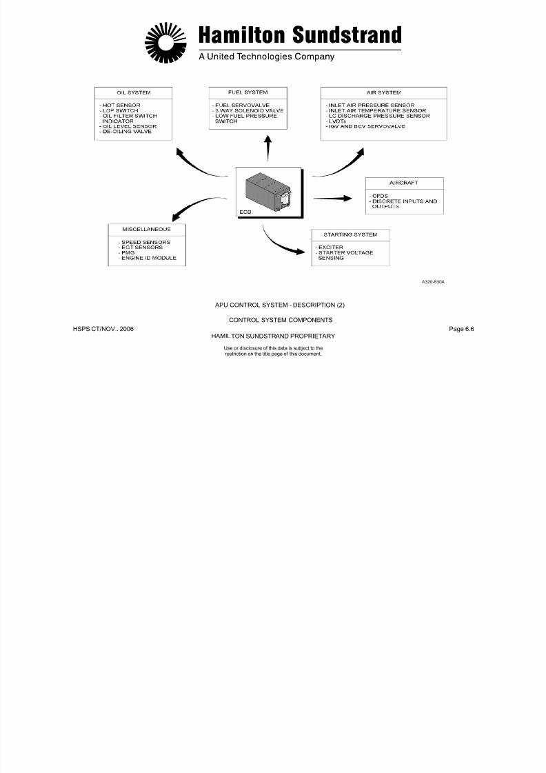
7/21/2019 Aps 3200 Training
http://slidepdf.com/reader/full/aps-3200-training 571/739
HSPS CT/NOV.. 2006 Page 6.7HAMILTON SUNDSTRAND PROPRIETARY
Use or disclosure of this data is subject to therestriction on the title page of this document.
Speed sensors
- Electronic Control Box (ECB)
- Fuel servo-valve.
Principle of Operation
The ECB compares rotor speed with a nominal speed datum to
control the fuel servo-valve. The servo-valve then provides therequired fuel flow to maintain 100% rotor speed under all APU loadconditions.
EGT thermocouples, the speed sensors and the inlet pressure andtemperature signals
- ECB
- IGV actuator.
Principle of Operation
The ECB compares the actual EGT with an EGT datum.
The EGT datum is a function of the operating mode (ECS or MES)and of the ambient air conditions (P1 and T1).
The ECB controls the IGV servo-valve as a function of EGT.
The IGV's are modulated toward close as EGT exceeds the datum.
7/21/2019 Aps 3200 Training
http://slidepdf.com/reader/full/aps-3200-training 572/739
HSPS CT/NOV.. 2006 Page 6.8HAMILTON SUNDSTRAND PROPRIETARY
FUEL SUPPLYUN METERED FUELMETERED FUEL
APU CONTROL SYSTEM - OPERATION (1)FUEL RETURN
ROTATION SPEED CONTROL AND EGT CONTROL
Use or disclosure of this data is subject to therestriction on the title page of this document.
APU CONTROL SYSTEM - OPERATION (2)
Load Compressor Surge Control
General
This function protects the load compressor from surge.
Components Involved
- Load compressor output pressure sensors
Load Compressor Reverse Flow Protection
General
This function shuts down the APU in case of load compressor surge(eg. back pressure from the aircraft pneumatic system).
Components Involved

7/21/2019 Aps 3200 Training
http://slidepdf.com/reader/full/aps-3200-training 573/739
HSPS CT/NOV.. 2006 Page 6.9HAMILTON SUNDSTRAND PROPRIETARY
Use or disclosure of this data is subject to therestriction on the title page of this document.
p p p
- Electronic Control Box (ECB)
- Bleed control valve.
Principle of Operation
The ECB compares the load compressor delivery pressure ratio
(ΔP/P) with a datum pressure ratio. In case of a low airflow condition,the bleed control valve is modulated to discharge air into the APUexhaust.
- Load compressor output pressure sensors
- ECB
- Fuel system and bleed control valve.
Principle of Operation
The ECB compares the load compressor delivery pressure ratio withtwo datums:
When the first datum is reached, the bleed control valve (BCV) willmove to the discharge position.
When the second datum is reached, the APU will automaticallyshutdown.
7/21/2019 Aps 3200 Training
http://slidepdf.com/reader/full/aps-3200-training 574/739
HSPS CT/NOV.. 2006 Page 6.10HAMILTON SUNDSTRAND PROPRIETARY
METERED FUEL APU CONTROL SYSTEM - OPERATION (2)FUEL RETURN
LOAD COMPRESSOR SURGE CONTROL AND REVERSE FLOW PROTECTION
Use or disclosure of this data is subject to therestriction on the title page of this document.
APU CONTROL SYSTEM - OPERATION (3)
APU Star t Fuel Flow Control
General
This function meters the fuel flow during APU starting.
Components Involved
- Speed sensors, the EGT thermocouples, the air inlet pressure andt t b
Principle of Operation
The fuel flow program has two phases:
- The first phase: EGT rise
- The second phase: From EGT rise to 95% speed + 2 seconds.
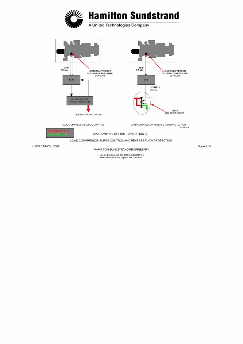
7/21/2019 Aps 3200 Training
http://slidepdf.com/reader/full/aps-3200-training 575/739
HSPS CT/NOV.. 2006 Page 6.11HAMILTON SUNDSTRAND PROPRIETARY
Use or disclosure of this data is subject to therestriction on the title page of this document.
temperature probes
- Electronic Control Box (ECB)
- Fuel servo-valve.
During the first phase, the fuel supply is used to fill the manifold. Fuelflow is metered as a function of rotor speed only.
During the second phase, fuel flow is scheduled as a function of twoprograms (automatically selected):
The first program controls the fuel flow rate after comparing the
actual acceleration with the acceleration rate datum.
The second program controls the fuel flow rate after comparing theactual EGT with the EGT datum.

7/21/2019 Aps 3200 Training
http://slidepdf.com/reader/full/aps-3200-training 576/739
HSPS CT/NOV.. 2006 Page 6.12HAMILTON SUNDSTRAND PROPRIETARY
CONTROLSYSTEM
ECB
FUEL SUPPLYMETERED FUELFUEL DRAIN
APU START FUEL FLOW CONTROL
APU CONTROL SYSTEM - OPERATION (3)
Use or disclosure of this data is subject to therestriction on the title page of this document.
APU CONTROL SYSTEM - OPERATION (4)
APU Faul t Sys tem
General
The APU is either shut down automatically or a warning is given incase of a fault.
Components
The sensors
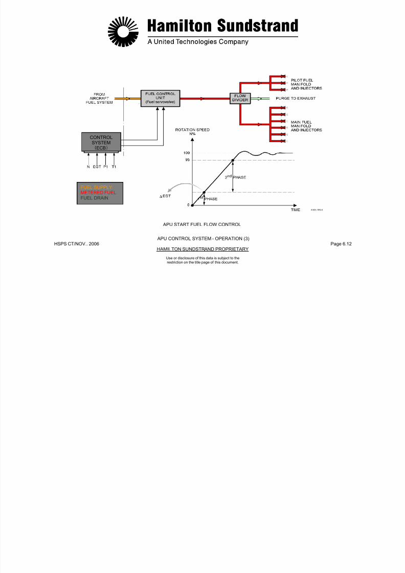
7/21/2019 Aps 3200 Training
http://slidepdf.com/reader/full/aps-3200-training 577/739
HSPS CT/NOV.. 2006 Page 6.13HAMILTON SUNDSTRAND PROPRIETARY
Use or disclosure of this data is subject to therestriction on the title page of this document.
- The sensors
- The ECB
- The electrical accessories.
Operation
In the event of a fault shutdown of the APU, the supplied electricaland pneumatic loads are removed.
Warning lights, messages and indicators are displayed in the flightdeck.
Fault messages are available through the Centralized Fault DisplaySystem.

7/21/2019 Aps 3200 Training
http://slidepdf.com/reader/full/aps-3200-training 578/739
HSPS CT/NOV.. 2006 Page 6.14HAMILTON SUNDSTRAND PROPRIETARY
APU SAFETY SYSTEM
APU CONTROL SYSTEM - OPERATION (4)
Use or disclosure of this data is subject to therestriction on the title page of this document.
APU CONTROL SYSTEM - OPERATION (5)
Monitoring
Function
The system provides information about the APU actual status,operation and maintenance.
The system displays:
- APU parameters
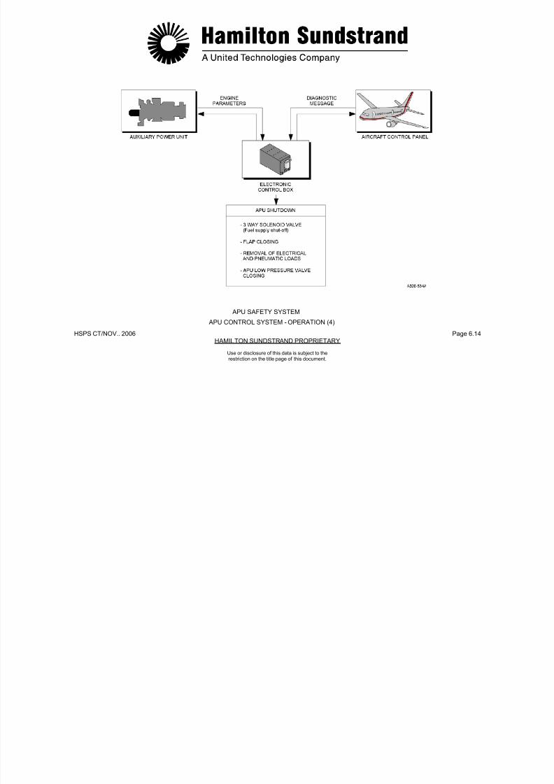
7/21/2019 Aps 3200 Training
http://slidepdf.com/reader/full/aps-3200-training 579/739
HSPS CT/NOV.. 2006 Page 6.15HAMILTON SUNDSTRAND PROPRIETARY
Use or disclosure of this data is subject to therestriction on the title page of this document.
APU parameters
- Events and hours count
- Condition and faults.
Components Involved
- APU control system components
- The ECB
- The flight deck indicating system (CFDS, ECAM, MCDU).
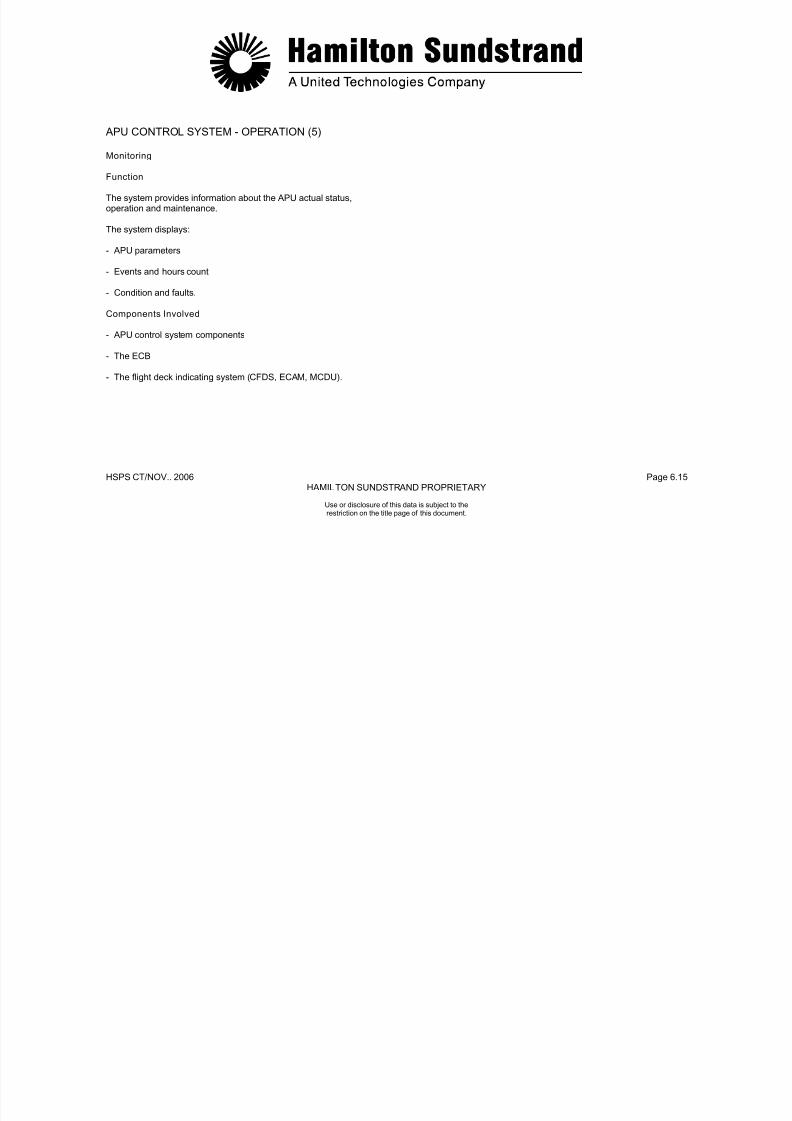
7/21/2019 Aps 3200 Training
http://slidepdf.com/reader/full/aps-3200-training 580/739
HSPS CT/NOV.. 2006 Page 6.16HAMILTON SUNDSTRAND PROPRIETARY
APU CONTROL SYSTEM - OPERATION (5)
MONITORING
Use or disclosure of this data is subject to therestriction on the title page of this document.
ELECTRONIC CONTROL BOX - GENERAL
Function
The Electronic Control Box (ECB) controls and monitors the AuxiliaryPower Unit systems.Location
The ECB is installed in the aft cargo compartment.
Main Features-Full Authority Digital Electronic Controller (FADEC)
Weight and Dimensions
Weight: 7.3 kg (16.1 lbs)Dimensions:Weight and Dimensions
-• Width: 159 mm (6.2 inches)• Height: 195.4 mm (7.6 inches)• Depth: 375.4 mm (14.6 inches).
Main Components
The main components are:

7/21/2019 Aps 3200 Training
http://slidepdf.com/reader/full/aps-3200-training 581/739
HSPS CT/NOV.. 2006 Page 6.17HAMILTON SUNDSTRAND PROPRIETARY
Use or disclosure of this data is subject to therestriction on the title page of this document.
Full Authority Digital Electronic Controller (FADEC)- On Board Replaceable Memory Module (OBRM) for design
flexibility and reduced component count- Modular design for reliability, maintainability and testability- No calibration required- Digital communication links (ARINC 429 and RS 232-C)
The main components are:- The ECB enclosure which houses Printed Wiring Assemblies
(PWA)- The ECB front face which includes:
• A RS 232-C connector• A front cover door housing the On Board Replaceable
Memory Module (OBRM)
• A handle- The ECB rear face which includes an ARINC 600 connector.
Identification
The electronic control box has an identification plate and amodification plate, both located on the front face of the ECB.

7/21/2019 Aps 3200 Training
http://slidepdf.com/reader/full/aps-3200-training 582/739
HSPS CT/NOV.. 2006 Page 6.18HAMILTON SUNDSTRAND PROPRIETARY
Use or disclosure of this data is subject to therestriction on the title page of this document.
ELECTRONIC CONTROL BOX - GENERAL
ELECTRONIC CONTROL BOX - DESCRIPTION (1)
ECB Inputs
General
This chapter considers the discrete and analog input signals to theECB.
The bleed control valve (BCV) command is transmitted to theECB by means of an aircraft discrete signal. Upon receipt of thiscommand, the ECB contro ls the opening o f the BCV to supplythe aircraft pneumatic sys tem.
Air/ground Conf iguration Switch (open/ground)
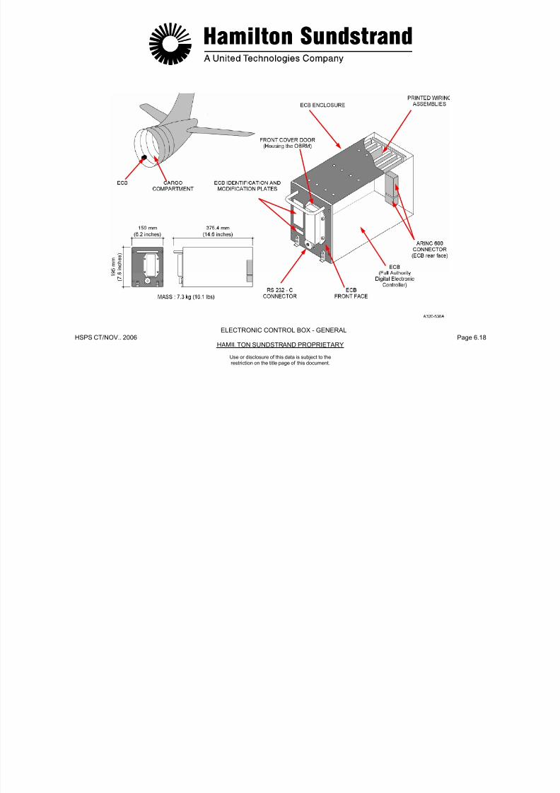
7/21/2019 Aps 3200 Training
http://slidepdf.com/reader/full/aps-3200-training 583/739
HSPS CT/NOV.. 2006 Page 6.19HAMILTON SUNDSTRAND PROPRIETARY
Use or disclosure of this data is subject to therestriction on the title page of this document.
Sensors and Discrete Inputs from Ai rcraft to ECB
The corresponding signals form part of the ECB Inputs-Outputsdefinitions and PIN assignments.
APU Stop (ground)
The stop signal is transmitted to the ECB by the APU master switchin the flight deck. Actuating the switch causes a contact closure toground.
Bleed Control Valve Activation (ground)
Emergency Stop (ground for approx. 150 ms)
The emergency stop signal is transmitted to the ECB by means of a
discrete signal created by a contact closure to ground.
This signal to the ECB is to indicate whether or not the aircraft is in-flight operation. Special considerations (i.e. safety systems) apply forin-flight operation.
MES Mode (28 V)
This signal indicates to the ECB whether or not the aircraft is in MainEngine Start mode (MES) of operation. The circuit is normally open.In the MES mode, the aircraft causes the circuit to close and tosupply a 28 V signal to the ECB.
Start Contactor Monitor (28 VDC/open/ground)
This discrete 28 VDC signal tells the ECB whether or not the back-upstart contactor is closed or whether or not it is open.
The start contactor monitor is used exclusively for fault isolationpurposes.
7/21/2019 Aps 3200 Training
http://slidepdf.com/reader/full/aps-3200-training 584/739
HSPS CT/NOV.. 2006 Page 6.20HAMILTON SUNDSTRAND PROPRIETARY
ELECTRONIC CONTROL BOX - DESCRIPTION (1)
SENSORS AND DISCRETE INPUTS FROM AIRCRAFT TO ECB
Use or disclosure of this data is subject to therestriction on the title page of this document.
ELECTRONIC CONTROL BOX - DESCRIPTION (2)
Sensors and Discrete Inputs from Aircraft to ECB (continued)
Air Intake Flap Open Posi tion (28 VDC)
When the air intake flap is in the fully open position, a switch isactivated to supply a 28 VDC signal to the ECB.
This signal is used to initiate the start sequence.
JAR Configuration
Low Fuel Pressure Switch (open/ground)
The switch closes to ground when the fuel pressure falls below agiven pressure.
Air Intake Flap Closed Posit ion (ground)
When the air intake flap is in the fully closed position, a switch is
activated to the closed position and provides a ground signal to theECB. The aircraft relay operation is maintained until the flap closedsignal is received

7/21/2019 Aps 3200 Training
http://slidepdf.com/reader/full/aps-3200-training 585/739
HSPS CT/NOV.. 2006 Page 6.21HAMILTON SUNDSTRAND PROPRIETARY
Use or disclosure of this data is subject to therestriction on the title page of this document.
The ECB is programmed in the JAR mode. This means that allshutdown faults sensed by the ECB will cause the APU to shutdownon the ground or in flight.
Start Command (28 VDC for approx. 150 ms)
This command is activated by momentarily placing the start button inthe flight deck to "on". This action provides a 28 V signal to the ECB.
signal is received.
Air Intake Flap Movement (28 VDC)
During normal APU operation, a 28 VDC signal is transmitted to theECB when voltage is being applied to open or close the air intakeflap.
Generator Oil Temperature Sensor (100 )
This sensor is mounted in the AC generator. The wiring uses thegenerator connector, P4. The sensor is a resistance temperaturedevice (RTD). It's variable resistance is a function of temperatureand is supplied with a constant current of 1 mA.

7/21/2019 Aps 3200 Training
http://slidepdf.com/reader/full/aps-3200-training 586/739
HSPS CT/NOV.. 2006 Page 6.22HAMILTON SUNDSTRAND PROPRIETARY
SENSORS AND DISCRETE INPUTS FROM AIRCRAFT TO ECB
ELECTRONIC CONTROL BOX - DESCRIPTION (2)
Use or disclosure of this data is subject to therestriction on the title page of this document.
ELECTRONIC CONTROL BOX - DESCRIPTION (3)
Sensors and Discrete Inputs from APU to ECB
Low Oil Pressure Switch (ground)
The low oil pressure switch is a normally closed contact. The switchopens and remains open when oil pressure is present.
Oil Filter Switch Indicators
This is a differential pressure switch that is normally open. Thecontact closes and provides a ground signal in case of filter
This sensor is a variable resistance device supplied by a constantsource voltage of 5 VDC.
The output ranges from 0 to 50 mV for a 0 to 15 PSIA range of airpressure.
Load Compressor Discharge Air Pressure Sensors (P) and (
P)
There are two sensors: one to measure the pressure at the loadcompressor scroll (P), the other one to measure the differential airpressure between the diffuser and the scroll (AP). The ratio signal

7/21/2019 Aps 3200 Training
http://slidepdf.com/reader/full/aps-3200-training 587/739
HSPS CT/NOV.. 2006 Page 6.23HAMILTON SUNDSTRAND PROPRIETARY
Use or disclosure of this data is subject to therestriction on the title page of this document.
p g grestriction.
EGT Sensors
The EGT is measured by two independent thermocouples. They areK type (Chromel-Alumel).
The output is of approx. 1 mV per 24°C (43°F).
High Oil Temperature Sensor (100 )
The sensor is a Resistance Temperature Device (RTD). Theresistance varies according to the oil temperature and is suppliedwith a constant current of 1 mA.
Inlet Air Pressure Sensor
p ( ) g AP/P is used to prevent load compressor surge.
The two sensors are of variable resistance type supplied by aconstant voltage of 5 VDC.
The outputs range from 0 to 50 mV for a 0 to 100 PSIA (absolute) or
0 to 25 PSID (differential) ranges of air pressure.
Rotation Speed Sensors
There are two independent speed sensors mounted in the gearbox.
They provide a wave signal as a function of the teeth on the phoneticwheel (24) and the rotation speed (i.e. 19720 Hz at 100% speed).

7/21/2019 Aps 3200 Training
http://slidepdf.com/reader/full/aps-3200-training 588/739
HSPS CT/NOV.. 2006 Page 6.24HAMILTON SUNDSTRAND PROPRIETARY
SENSORS AND DISCRETE INPUTS - FROM APU TO ECB
ELECTRONIC CONTROL BOX - DESCRIPTION (3)
Use or disclosure of this data is subject to therestriction on the title page of this document.
ELECTRONIC CONTROL BOX - DESCRIPTION (4)
Sensors and Discrete Inputs from APU to ECB (continued)
Inlet Air Temperature Sensor (1000 RTD)
The sensor is a variable resistance temperature device supplied by aconstant source current of 1 mA. Temperature range -55 to 150°C(-67 to 302°F).
Engine ID Module
The engine identification (ID) module is resistors that provide the
IGV and Bleed Control Valve LVDTs(Linear Voltage Differential Transducer)
LVDTs are used to detect the actual displacement of the IGV andBCV actuators. Their signal is fed back to the ECB for the purpose ofservo control.
Their primary coil is supplied with a constant voltage of 10 VAC.
Their secondary coil provides a variable output voltage.
Upon loss of electrical signal, the IGV will close or the BCV opens to
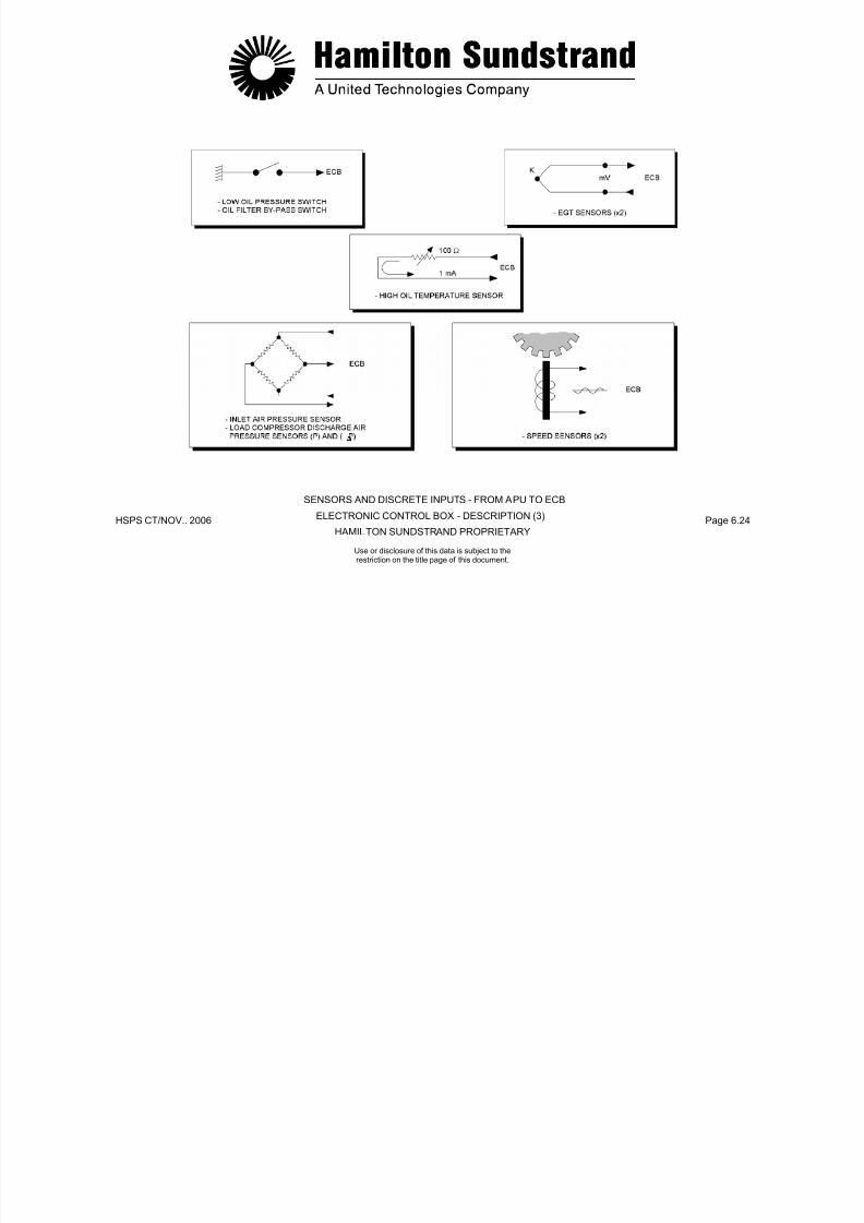
7/21/2019 Aps 3200 Training
http://slidepdf.com/reader/full/aps-3200-training 589/739
HSPS CT/NOV.. 2006 Page 6.25HAMILTON SUNDSTRAND PROPRIETARY
Use or disclosure of this data is subject to therestriction on the title page of this document.
ECB with 3 voltage lines V 1, V2, V3 matched to the engine IDnumber. The engine serial number is the sum of the ID number andthe number 1000.
The engine ID number is stored in the ECB NOVRAM memory aspart of the power up initialization. The ID module is considered failed
when all inputs are shorted, one or all inputs are open, a numbergreater than 2048 is used, or 3 consecutive readings at power upinitialization are not identical.
discharge.
Oil Level Sensor (100 A)
The gearbox mounted oil level sensor is a Resistance TemperatureDevice (RTD) type. The variable resistance value is provided with a
constant current of 75 mA. The oil level is checked at power up overa period of 8 seconds and is determined OK or LOW.
7/21/2019 Aps 3200 Training
http://slidepdf.com/reader/full/aps-3200-training 590/739
HSPS CT/NOV.. 2006 Page 6.26HAMILTON SUNDSTRAND PROPRIETARY
SENSORS AND DISCRETE INPUTS FROM APU TO ECB
ELECTRONIC CONTROL BOX - DESCRIPTION (4)
Use or disclosure of this data is subject to therestriction on the title page of this document.
ELECTRONIC CONTROL BOX - DESCRIPTION (5)
Sensors and Discrete Inputs from APU to ECB (continued)
Permanent Magnet Generator (PMG)
A Permanent Magnet Generator (PMG) is installed in the cooling fan.The assembly consists of the PMG rectifier circuit and a DC fusiblelink.
The PMG provides the ECB with rectified power and one unrectifiedsignal from one of the three phases (backup overspeed protection at107%).
Starter Motor Voltage
The starter motor is monitored by the ECB for low voltage during APU start. The low voltage sensing connector is located on the frontface of the starter motor housing.

7/21/2019 Aps 3200 Training
http://slidepdf.com/reader/full/aps-3200-training 591/739
HSPS CT/NOV.. 2006 Page 6.27HAMILTON SUNDSTRAND PROPRIETARY
Use or disclosure of this data is subject to therestriction on the title page of this document.
The unrectified output is current limited (short circuit protection) bymeans of a resistor. The fusible link trip point is at 10 A.
The rectified output provides 40 VDC at 100% speed for back-uppower supply to the ECB in the event of a momentary interruption in
the main power supply. This back-up supply lasts for 240 msec.
Note: The failure of the PMG/Speed circuit at startup will cause the APU to shutdown during acceleration.
7/21/2019 Aps 3200 Training
http://slidepdf.com/reader/full/aps-3200-training 592/739
HSPS CT/NOV.. 2006 Page 6.28HAMILTON SUNDSTRAND PROPRIETARY
SENSORS AND DISCRETE INPUTS FROM APU TO ECB
ELECTRONIC CONTROL BOX - DESCRIPTION (5)
Use or disclosure of this data is subject to therestriction on the title page of this document.
ELECTRONIC CONTROL BOX - DESCRIPTION (6)
ECB Outputs
General
This chapter considers the discrete and digital outputs of the ECB.
Discrete and Digital Outputs (to the aircraft)
Backup Start Contactor (28 VDC, 1 A nominal)
This contactor is energized by means of a discrete signal. The signalis supplied through a Field Effect Transistor (FET) in the ECB
Bleed Control Valve Open (28 VDC, 0.1 A)
The ECB transmits a discrete signal to the aircraft indicating systemwhen the bleed control valve is in the position that allows maximumflow to the aircraft pneumatic system.
APU Available (28 VDC, 0.4 A)
The ECB provides a discrete signal to the AVAIL light in the startswitch when the APU has completed the start sequence and is readyto load.
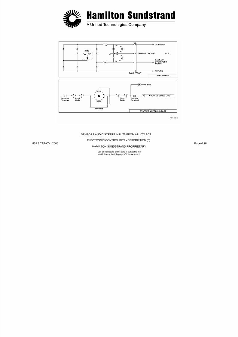
7/21/2019 Aps 3200 Training
http://slidepdf.com/reader/full/aps-3200-training 593/739
HSPS CT/NOV.. 2006 Page 6.29HAMILTON SUNDSTRAND PROPRIETARY
Use or disclosure of this data is subject to therestriction on the title page of this document.
is supplied through a Field Effect Transistor (FET) in the ECB.
Main Start Contactor (28 VDC, 1 A nominal)
This contactor is energized by means of a discrete signal. The signalis supplied through a FET device in the ECB.
Aircraf t Relay (ground, 0.4 A)
The aircraft relay is activated by a closed contact to ground throughthe ECB. The aircraft relay is activated when the ECB is energizedand no stop command is present.
Start in Progress (28 VDC, 0.1 A)
The ECB transmits a discrete signal to the ON light in the start switchto indicate a start is in progress.
The light is "ON" from the beginning of the start until the "APUavailable" light turns on.
Fault (28 VDC, 0.2 A)
The ECB transmits a fault discrete signal to the aircraft for allshutdowns.

7/21/2019 Aps 3200 Training
http://slidepdf.com/reader/full/aps-3200-training 594/739
HSPS CT/NOV.. 2006 Page 6.30HAMILTON SUNDSTRAND PROPRIETARY
DISCRETE AND DIGITAL OUTPUTS (TO THE AIRCRAFT)
ELECTRONIC CONTROL BOX - DESCRIPTION (6)
Use or disclosure of this data is subject to therestriction on the title page of this document.
ELECTRONIC CONTROL BOX - DESCRIPTION (7)
Discrete and Digital Outputs (to the aircraft) (continued)
Flap Open Command (28 VDC, 3.5 A)
The ECB provides a power output for opening the air intake flap. Theflap open command is emitted through a FET device in the ECB.
This output is protected against overload and short circuits.
Flap Closed Command (28 VDC, 3.5 A)
The ECB provides a power output for closing the air intake flap. The
• ARINC 429 input from ECS: It is used by the ECB toreceive specific data from the Environmental ControlSystem (i.e. ECS demand signal, ECS valve status word,etc...)The ECS demand signal is used in the control of the IGV's.The ECS valve status word informs the ECB of the numberof air conditioning packs currently supplying air
• ARINC 429 CFDS output: The ARINC 429 outputtransmits data to the CFDS, ECAM (Electronic Centralized
Aircraft Monitoring) and ACMS (Aircraft ConditionMonitoring System)

7/21/2019 Aps 3200 Training
http://slidepdf.com/reader/full/aps-3200-training 595/739
HSPS CT/NOV.. 2006 Page 6.31HAMILTON SUNDSTRAND PROPRIETARY
Use or disclosure of this data is subject to therestriction on the title page of this document.
p p p g pflap closed command is emitted through a FET device in the ECB.
This output is protected against overload and short circuits.
Aircraf t Serial Communications
Data communication is achieved by means of four serialcommunication links:
- ARINC 429 CFDS output: Three ARINC 429 serial links (theyoperate at low speed - 12.5 K bits/sec)
• ARINC 429 input f rom CFDS: It is used by the ECB toreceive specific data from the Central Fault DisplaySystem with appropriate ARINC labels
- One RS 232 C interface: This interface is accessible on the rear ARINC connector and on the front face connector.
It can be used:
• As a maintenance tool
• To access the test modes of the ECB
• To change the ECB software characteristics duringdevelopment.
7/21/2019 Aps 3200 Training
http://slidepdf.com/reader/full/aps-3200-training 596/739
HSPS CT/NOV.. 2006 Page 6.32HAMILTON SUNDSTRAND PROPRIETARY
DISCRETE AND DIGITAL OUTPUTS (TO THE AIRCRAFT)
ELECTRONIC CONTROL BOX - DESCRIPTION (7)
Use or disclosure of this data is subject to therestriction on the title page of this document.
ELECTRONIC CONTROL BOX - DESCRIPTION (8)
Discrete and Analog Outputs (to the APU)
Oil System De-oili ng valve (28 VDC, 1 A)
This output is activated to operate the valve during starting andshutdown.
Exci ter (28 VDC, 2 A)
This output is activated to supply the exciter during starting.
3 Way Solenoid Valve (28 VDC, 1 A)
IGV and Bleed Control Valve LVDTs (3000 Hz, 10 VAC)
These two separate outputs supply a reference source signal to eachprimary coil.
IGV, Bleed Control Valve, Fuel Servo (0 - 100 mA)
These three separate outputs supply a variable low intensity signal to
the corresponding servo-valve.
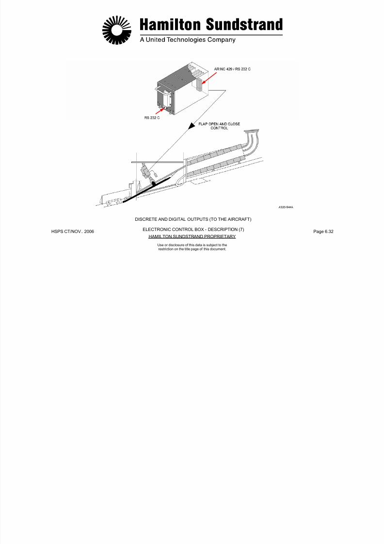
7/21/2019 Aps 3200 Training
http://slidepdf.com/reader/full/aps-3200-training 597/739
HSPS CT/NOV.. 2006 Page 6.33HAMILTON SUNDSTRAND PROPRIETARY
Use or disclosure of this data is subject to therestriction on the title page of this document.
This output is activated to operate the valve for start and shutdown.
Oil Level RTD, Oil Filter and LOP switches (Rtn, 1 A)
This output is common to all three items.
Pressure Transducers Excitation (5 VDC, 30 mA)
This output is activated to operate the air pressure transducers witha stabilized voltage.
7/21/2019 Aps 3200 Training
http://slidepdf.com/reader/full/aps-3200-training 598/739
HSPS CT/NOV.. 2006 Page 6.34HAMILTON SUNDSTRAND PROPRIETARY
DISCRETE AND DIGITAL OUTPUTS (TO THE APU)
ELECTRONIC CONTROL BOX - DESCRIPTION (8)
Use or disclosure of this data is subject to therestriction on the title page of this document.
ELECTRONIC CONTROL BOX - DESCRIPTION (9)
Hardware Description
The Electronic Control Box consists of an enclosure which includesthe following components:
- Six Printed Wiring Assemblies (PWA):
• A speed and temperature PWA
• A discrete input-output PWA
• A microprocessor PWA
- An On Board Replaceable Memory Module (OBRM) accessiblethrough a removable front cover door.
The board is equipped with an UVPROM type memory to be usedas the programme memory space for the ECB.
- Two electrical connectors:
• A RS 232 connector located on the ECB front face
• An ARINC 600 connector located on the ECB rear face.
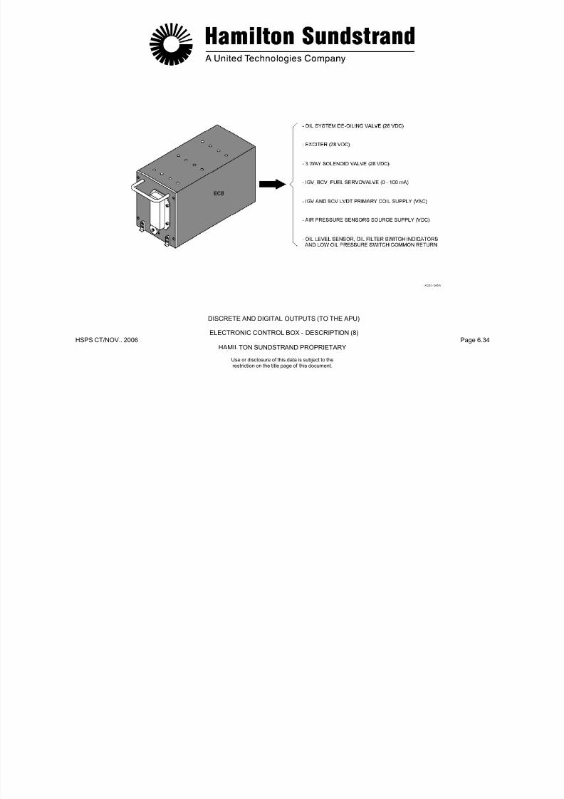
7/21/2019 Aps 3200 Training
http://slidepdf.com/reader/full/aps-3200-training 599/739
HSPS CT/NOV.. 2006 Page 6.35HAMILTON SUNDSTRAND PROPRIETARY
Use or disclosure of this data is subject to therestriction on the title page of this document.
• An analog input PWA
• An analog output PWA
• A power supply PWA
- One printed wiring assembly for Electromagnetic Interference(EMI) and lightn ing protection
- PWA guides
- A backplate to interconnect the various PWA
- One High Power Switch FET Module (FET: Field EffectTransistor)
- One Input Power Filter Module
7/21/2019 Aps 3200 Training
http://slidepdf.com/reader/full/aps-3200-training 600/739
HSPS CT/NOV.. 2006 Page 6.36HAMILTON STANDARD PROPRIETARY
HARDWARE DESCRIPTION
ELECTRONIC CONTROL BOX - DESCRIPTION (9)
Use or disclosure of this data is subject to therestriction on the title page of this document.
ELECTRONIC CONTROL BOX - OPERATION (1)
General
The operating phases are:
- Power up
- Watch state
- Start preparation state
- Starting state
- Run state
Power Up State
GeneralWhen the APU master switch is selected to ON, the ECB enters thePOWER UP state.The POWER UP state lasts approximately 3 sec.OperationThe ECB checks that outputs are not energized except those that
are required.The ECB enters self test.The ECB is able to recognize and record the occurrence of start oremergency stop signals.Upon receipt and validation of the start signal, the "start in progress"
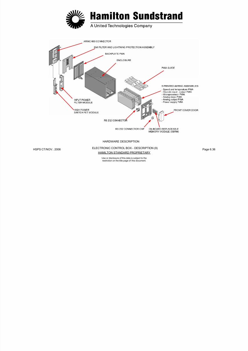
7/21/2019 Aps 3200 Training
http://slidepdf.com/reader/full/aps-3200-training 601/739
HSPS CT/NOV.. 2006 Page 6.37HAMILTON SUNDSTRAND PROPRIETARY
Use or disclosure of this data is subject to therestriction on the title page of this document.
Run state
- Cool down state
- Shutdown state
p p g , p goutput is energized.The requirement to activate the "start in progress" output alsoapplies to the WATCH state.In case of an emergency stop signal being received, the ECB closesthe air intake and deactivates the aircraft relay output once the air
intake is closed.
7/21/2019 Aps 3200 Training
http://slidepdf.com/reader/full/aps-3200-training 602/739
HSPS CT/NOV.. 2006 Page 6.38HAMILTON SUNDSTRAND PROPRIETARY
ELECTRONIC CONTROL BOX - OPERATION (1)
Use or disclosure of this data is subject to therestriction on the title page of this document.
ELECTRONIC CONTROL BOX - OPERATION (2)
Watch State
General
After completion of the POWER UP state the ECB automaticallyenters the WATCH state.
Operation
The ECB is able to recognize and record the occurrence of start oremergency signals.
Upon receipt of an emergency stop signal the ECB closes the air
Start Preparation State
General
Upon receipt of the start command, the ECB enters the STARTPREPARATION state.
Operation
During this state the flap actuator position, the oil level and therotation speed is checked. If the speed is greater than 7%, the startcommand will be inhibited until the speed is less than or equal to 7%.

7/21/2019 Aps 3200 Training
http://slidepdf.com/reader/full/aps-3200-training 603/739
HSPS CT/NOV.. 2006 Page 6.39HAMILTON SUNDSTRAND PROPRIETARY
Use or disclosure of this data is subject to therestriction on the title page of this document.
p p g y p gintake and deactivates the aircraft relay output once the air intake isclosed.
The ECB self tests as required.
The ECB enters the START PREPARATION state automaticallywithout requiring a new start command.

7/21/2019 Aps 3200 Training
http://slidepdf.com/reader/full/aps-3200-training 604/739
HSPS CT/NOV.. 2006 Page 6.40HAMILTON SUNDSTRAND PROPRIETARY
ELECTRONIC CONTROL BOX - OPERATION (2)
Use or disclosure of this data is subject to therestriction on the title page of this document.
ELECTRONIC CONTROL BOX - OPERATION (3)
Starting State - Sequences
General
The STARTING STATE is controlled by the ECB.
A stop signal at any time during the STARTING STATE willshutdown the APU.
Operation
The electrical sequences selected by the ECB are:
B k l
- EGT rise
• Acceleration control to steady state speed control.
- At 55% speed
• Exciter de-energized
• Gearbox de-oiling valve and main start contactor de-
energized.
- At 55% speed + 5 sec
• Backup start contactor de-energized

7/21/2019 Aps 3200 Training
http://slidepdf.com/reader/full/aps-3200-training 605/739
HSPS CT/NOV.. 2006 Page 6.41HAMILTON SUNDSTRAND PROPRIETARY
Use or disclosure of this data is subject to therestriction on the title page of this document.
- Backup start contractor supply
- Gearbox de-oiling valve
- Exciter
- Main start contactor
- 3 way solenoid valve
- Pulse fuel servo valve
- Manifold fill algorithm
- Open loop fuel schedule activation.
Backup start contactor de energized.
- At 95% speed + 2 sec.
• Surge control activated
• APU available signal activated
• Start in progress output de-activated
• Steady state speed control loop activated
• Enter RUN STATE.

7/21/2019 Aps 3200 Training
http://slidepdf.com/reader/full/aps-3200-training 606/739
HSPS CT/NOV.. 2006 Page 6.42HAMILTON SUNDSTRAND PROPRIETARY
ELECTRONIC CONTROL BOX - OPERATION (3)
Use or disclosure of this data is subject to therestriction on the title page of this document.
ELECTRONIC CONTROL BOX - OPERATION (4)
Starting State- Fuel Control
General
There are three consecutive programs used to supply and meter thefuel during starting:
- Manifold Fill Algorithm
- Open Loop fuel schedule
- Acceleration control
Manifold Fill Algorithm General
Accelerat ion Control - General
This control occurs from EGT rise until steady state speed control isreached.
Fuel flow during acceleration is controlled by speed and EGT signalsto the ECB.

7/21/2019 Aps 3200 Training
http://slidepdf.com/reader/full/aps-3200-training 607/739
HSPS CT/NOV.. 2006 Page 6.43HAMILTON SUNDSTRAND PROPRIETARY
Use or disclosure of this data is subject to therestriction on the title page of this document.
Manifold Fill Algorithm - General
During engine start up the ECB controls the fuel servo valve toimplement the manifold fill algorithm.
The control is an open loop schedule based on the rotation speed,this ends when a given quantity of fuel is delivered to the manifold.
Open Loop Fuel Schedule - General
This fuel schedule replaces the manifold fill algorithm when the flowdelivered has reached 0.01 kg/m (0.032 lb/m).
The schedule determines a fuel flow rate depending on rotation
speed, ambient pressure and temperature. It is considered the"basic" fuel flow needed to obtain combustion in the combustorchamber.
7/21/2019 Aps 3200 Training
http://slidepdf.com/reader/full/aps-3200-training 608/739
HSPS CT/NOV.. 2006 Page 6.44HAMILTON STANDARD PROPRIETARY
STARTING STATE - FUEL CONTROL
ELECTRONIC CONTROL BOX - OPERATION (4)
Use or disclosure of this data is subject to therestriction on the title page of this document.
ELECTRONIC CONTROL BOX - OPERATION (5)
Run State- Fuel and Load Compressor Control
General
Upon completion of starting, three main functions are activated:
- Speed control
- Load compressor surge control
- EGT control.
Speed Control - General
Load Compressor Surge Control- General
This function prevents load compressor surge. This is accomplishedwhen the bleed switch is ON.
EGT Control - General
To prevent EGT over temperature during load compressor operation,
the ECB will automatically move the IGV's to decrease airflow andreduce the work load on the power section.
The AC generator output has priority overload compressor operation.
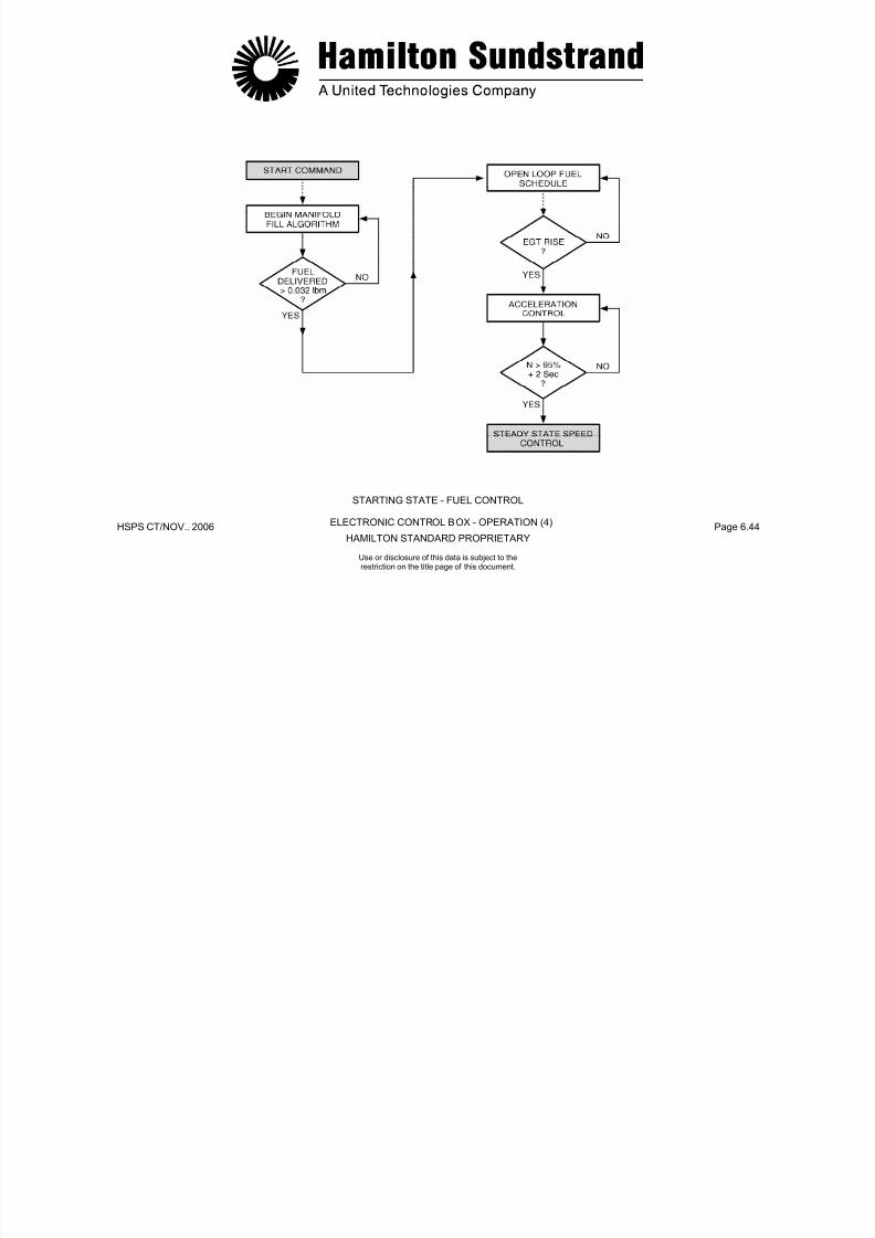
7/21/2019 Aps 3200 Training
http://slidepdf.com/reader/full/aps-3200-training 609/739
HSPS CT/NOV.. 2006 Page 6.45HAMILTON SUNDSTRAND PROPRIETARY
Use or disclosure of this data is subject to therestriction on the title page of this document.
The purpose of speed control is to maintain the APU at 100% speedunder all load conditions. This is accomplished by the fuel controlunit increasing or decreasing fuel flow automatically when APU loadchanges occur.

7/21/2019 Aps 3200 Training
http://slidepdf.com/reader/full/aps-3200-training 610/739
HSPS CT/NOV.. 2006 Page 6.46HAMILTON SUNDSTRAND PROPRIETARY
GEARBOXGEARS
AMBIENT AIRCOMPRESSED AIRMETERED FUELCOMBUSTIONEXHAUST
RUN STATE - FUEL AND LOAD COMPRESSOR CONTROL - GENERAL
ELECTRONIC CONTROL BOX - OPERATION (5)
Use or disclosure of this data is subject to therestriction on the title page of this document.
ELECTRONIC CONTROL BOX - OPERATION (6)
Cool Down State
General
This function allows the APU to operate in a no-load condition beforeentering the shutdown state.
When the APU master switch is selected to OFF, all loads areremoved (IGV's closed, Bleed Control valve to discharge).
If the APU was providing bleed air at this time, the APU will continueto run in a cool down mode for a maximum time of 2 minutes.
The cool down mode time limit can vary from 0 to 2 minutes. The
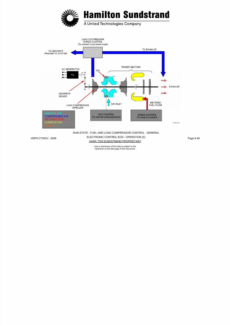
7/21/2019 Aps 3200 Training
http://slidepdf.com/reader/full/aps-3200-training 611/739
HSPS CT/NOV.. 2006 Page 6.47HAMILTON SUNDSTRAND PROPRIETARY
Use or disclosure of this data is subject to therestriction on the title page of this document.
time limit depends on when the APU bleed switch is turned off priorto selecting the APU master switch to OFF.
At the end of the cool down mode (if any) the operation enters the
SHUTDOWN STATE.

7/21/2019 Aps 3200 Training
http://slidepdf.com/reader/full/aps-3200-training 612/739
HSPS CT/NOV.. 2006 Page 6.48HAMILTON SUNDSTRAND PROPRIETARY
COOL DOWN STATE
ELECTRONIC CONTROL BOX - OPERATION (6)
Use or disclosure of this data is subject to therestriction on the title page of this document.
ELECTRONIC CONTROL BOX - OPERATION (7)
Shutdown State
General
The APU enters the shutdown state after a normal shutdown or afault shutdown occurs.
Note: The APU can be re-started during the shutdown state. Thisis accomplished by cycling the master switch OFF to ON andthen selecting the APU start switch to ON.
The ECB does not close the flap and the APU automaticallyre-starts when 7% speed is reached.

7/21/2019 Aps 3200 Training
http://slidepdf.com/reader/full/aps-3200-training 613/739
HSPS CT/NOV.. 2006 Page 6.49HAMILTON SUNDSTRAND PROPRIETARY
Use or disclosure of this data is subject to therestriction on the title page of this document.

7/21/2019 Aps 3200 Training
http://slidepdf.com/reader/full/aps-3200-training 614/739
HSPS CT/NOV.. 2006 Page 6.50HAMILTON SUNDSTRAND PROPRIETARY
SHUT DOWN STATE
ELECTRONIC CONTROL BOX – OPERATION (7)
Use or disclosure of this data is subject to therestriction on the title page of this document.
ELECTRONIC CONTROL BOX - OPERATION (8)
Condition Monitor ing Data
General
For long term trend monitoring, the APU control system records theengine operating parameters.
Operation
APU conditioning monitoring parameters are taken during operationof the APU. The ECU does not store this information but it may beretrieved from the Aircraft Integrated Data System (AIDS) if thissystem is installed.
The following parameters are:
In addition, the ECB records:
- APU operating hours (in one minute increments from speed > 55%until the 3-way solenoid valve is de-energized.
- Number of starts (1 start = EGT rise detected + speed > 30%)
- ECB operating hours (in one minute increments, from ECB powerON to ECB power OFF).
The condition monitoring data is associated with the engine

7/21/2019 Aps 3200 Training
http://slidepdf.com/reader/full/aps-3200-training 615/739
HSPS CT/NOV.. 2006 Page 6.51HAMILTON SUNDSTRAND PROPRIETARY
Use or disclosure of this data is subject to therestriction on the title page of this document.
g p
- Exhaust Gas Temperature °C
- Engine speed %
- Engine inlet pressure PSIA
- Engine inlet temperature °C
- Fuel flow LB/HR
g gidentification (ID) number, ECB serial number.
Note 1: The condition monitoring parameters are not taken when
either the inlet pressure or temperature sensors are faulty.
Note 2: If the engine ID module has been determined failed, the APU system operating history data will be associated withthe last valid engine I D number.When a new engine ID number occurs, it is used withouterasing the previously recorded historical data.The oldest data is overwritten by the new data as it isrecorded.
The ECB records the condition monitoring data associatedwith the last APU cycle and the data is available via the ARINC 429 link.
7/21/2019 Aps 3200 Training
http://slidepdf.com/reader/full/aps-3200-training 616/739
HSPS CT/NOV.. 2006 Page 6.52HAMILTON STANDARD PROPRIETARY
BUILT-IN TEST - OPERATION - POWER UP TEST
ELECTRONIC CONTROL BOX - OPERATION (8)
Use or disclosure of this data is subject to therestriction on the title page of this document.

7/21/2019 Aps 3200 Training
http://slidepdf.com/reader/full/aps-3200-training 617/739
HPS CT/NOV. 2006 Page 6. 53 HAMILTON SUNDSTRAND PROPRIETARY
APS 3200 AUXILIARY POWER UNIT
Use or disclosure of this data is subject to therestriction on the title page of this document.
APS 3200 AUXILIARY POWER UNIT
SECTION 7
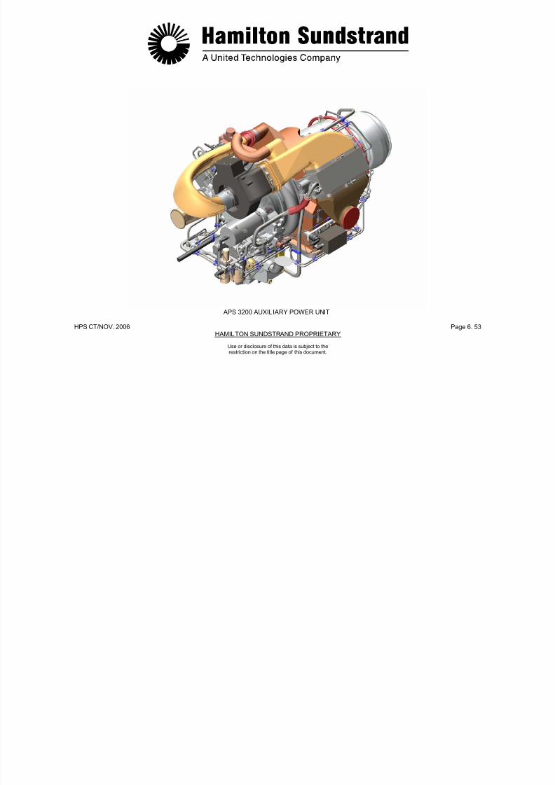
7/21/2019 Aps 3200 Training
http://slidepdf.com/reader/full/aps-3200-training 618/739
HSPS CT/ NOV.. 2006 Page 7.0HAMILTON STANDARD PROPRIETARY
INDICATING SYSTEM
Use or disclosure of this data is subject to therestriction on the title page of this document.
INDICATING SYSTEM
Main Components
- APU components (speed sensors, thermocouples and engine IDmodule)
- The Electronic Control Box (ECB)
- The aircraft control panel which includes:
• APU master switch and APU start switch
• ECAM, MCDU
• FUEL, AIR CONDITIONING, ELECTRIC and FIRE controlpanels
Note: This chapter covers the APU indicating components andprovides general information on the aircraft system.
ECAM: Electronic Centralized Aircraft Monitoring.
MCDU: Multi-function Control and Display Unit.
7/21/2019 Aps 3200 Training
http://slidepdf.com/reader/full/aps-3200-training 619/739
HSPS CT/ NOV.. 2006 Page 7.1HAMILTON STANDARD PROPRIETARY
Use or disclosure of this data is subject to therestriction on the title page of this document.
• MASTER WARNING and MASTER CAUTION LIGHTS
- The EXTERNAL CONTROL PANEL.

7/21/2019 Aps 3200 Training
http://slidepdf.com/reader/full/aps-3200-training 620/739
HSPS CT/NOV.. 2006 Page 7.2HAMILTON SUNDSTRAND PROPRIETARY
INDICATING SYSTEM
Use or disclosure of this data is subject to therestriction on the title page of this document.
ROTATION SPEED INDICATION SYSTEM - GENERAL
Function
The rotation speed signal is used by the ECB for:
- Indication
- Fuel metering
- ECB Sequencing
- ECB Control functions.
Main Features
Two sensors.
Main Components
- One "phonic" wheel with 24 teeth
- Two electromagnetic sensors (single coil)
- Harness
- ECB.
Location of the Main Components
The phonic wheel is secured to the rotor front bearing journal.
The two speed sensors are located in the gearbox housing at 5' l k d 7 ' l k E h i d b i l b lt

7/21/2019 Aps 3200 Training
http://slidepdf.com/reader/full/aps-3200-training 621/739
HSPS CT/NOV.. 2006 Page 7.3HAMILTON SUNDSTRAND PROPRIETARY
Use or disclosure of this data is subject to therestriction on the title page of this document.
Interfaces
The ECB provides the speed information to the CFDS/ECAM displaysystem.
o'clock and 7 o'clock. Each one is secured by a single bolt.

7/21/2019 Aps 3200 Training
http://slidepdf.com/reader/full/aps-3200-training 622/739
HSPS CT/NOV.. 2006 Page 7.4HAMILTON SUNDSTRAND PROPRIETARY
UN METERED FUEL
METERED FUELOIL LEVEL
ROTATION SPEED INDICATION SYSTEM - GENERAL
Use or disclosure of this data is subject to therestriction on the title page of this document.
ROTATION SPEED INDICATION SYSTEM -DESCRIPTION AND OPERATION
Description
- Phonic wheel has 24 teeth
- Two single coil speed sensors (the coil surrounds a magnetic core)
• Phonic wheel-speed sensor gap: 0.5 mm (0.018 inch); gapnot adjustable
- The two sensors are connected to the ECB
• Frequency signal at 100 %: 19720 Hz (49300 RPM)
• Frequency signal range: 0 to 24 KHz; 0 to 50 volts.
Operation
The phonic wheel rotates with the rotor assembly, as the teeth passby each speed sensor they generate a voltage. The voltage isproportional to the speed of the phonic wheel. The signal is sent tothe ECB for speed indication and system control.
The ECB will calculate the average signal of the two speed sensors.In the event a signal difference of 5% or more occurs, the ECB willselect the sensor indicating the highest value.
APU speed indication is displayed on the lower ECAM when the APU system page is selected.
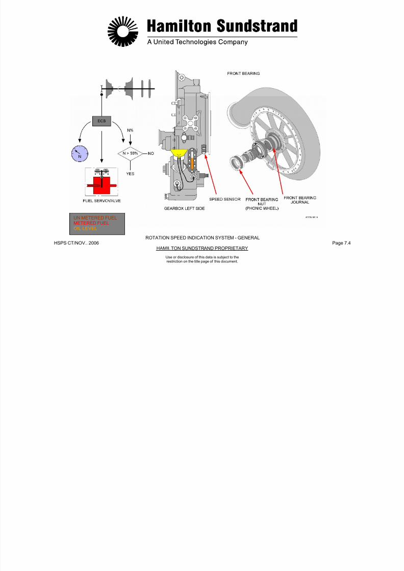
7/21/2019 Aps 3200 Training
http://slidepdf.com/reader/full/aps-3200-training 623/739
HSPS CT/NOV.. 2006 Page 7.5HAMILTON SUNDSTRAND PROPRIETARY
Use or disclosure of this data is subject to therestriction on the title page of this document.
7/21/2019 Aps 3200 Training
http://slidepdf.com/reader/full/aps-3200-training 624/739
HSPS CT/NOV.. 2006 Page 7.6HAMILTON SUNDSTRAND PROPRIETARY
ROTATION SPEED INDICATION SYSTEM - DESCRIPTION - OPERATION
Use or disclosure of this data is subject to therestriction on the title page of this document.
EGT INDICATION SYSTEM - GENERAL
Function
The EGT signal is used for:
- Indication
- Load compressor control
- Sequences
- Control functions.
Main Features
The system uses K type chromel-alumel thermocouples and has acold junction compensation built into the ECB.
Main Components
- Two thermocouples
- Harness
- ECB.
Location of the Main Components
The two thermocouples are located in the power section exhausthousing.

7/21/2019 Aps 3200 Training
http://slidepdf.com/reader/full/aps-3200-training 625/739
HSPS CT/NOV.. 2006 Page 7.7HAMILTON SUNDSTRAND PROPRIETARY
Use or disclosure of this data is subject to therestriction on the title page of this document.
j p
Interfaces
The ECB provides the EGT information to the ECAM display system.
7/21/2019 Aps 3200 Training
http://slidepdf.com/reader/full/aps-3200-training 626/739
HSPS CT/NOV.. 2006 Page 7.8HAMILTON SUNDSTRAND PROPRIETARY
EGT INDICATION SYSTEM - GENERAL
Use or disclosure of this data is subject to therestriction on the title page of this document.
EGT INDICATION SYSTEM - DESCRIPTION AND OPERATION
Functional Descripti on
Each thermocouple is secured into the exhaust housing by a bolt.
They are connected separately to the ECB.
Operation
The thermocouple generates a millivolt signal to the ECB that is usedfor engine control and indication (EGT)
The voltage value is of approximately 1 millivolt per 24°C (43°F).
The ECB compensates automatically the cold junction effect andcalculates the average EGT value.
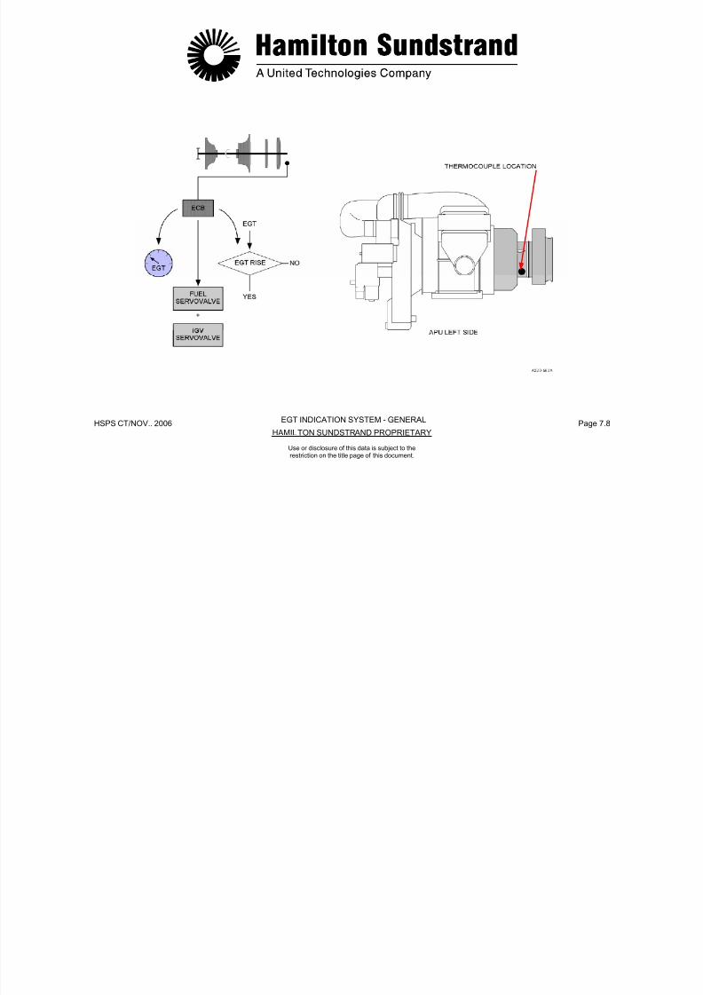
7/21/2019 Aps 3200 Training
http://slidepdf.com/reader/full/aps-3200-training 627/739
HSPS CT/NOV.. 2006 Page 7.9HAMILTON SUNDSTRAND PROPRIETARY
Use or disclosure of this data is subject to therestriction on the title page of this document.
g
An EGT system failure is declared if:
- EGT is lower than 120°C (250°F)
- EGT is higher than 1200°C (2200°F).
The ECU will calculate the average signal of the two thermocouples.In the event a signal difference of 121°C (250°F) or more occurs, theECB will select the thermocouple indicating the highest value.
APU exhaust gas temperature indication is displayed on the lowerECAM when the APU system page is selected.

7/21/2019 Aps 3200 Training
http://slidepdf.com/reader/full/aps-3200-training 628/739
HSPS CT/NOV.. 2006 Page 7.10HAMILTON SUNDSTRAND PROPRIETARY
EGT INDICATION SYSTEM - DESCRIPTION - OPERATION
Use or disclosure of this data is subject to therestriction on the title page of this document.
ENGINE IDENTIFICATION MODULE
Function
To provide the engine serial number to the ECB.
Location
The module is installed on the ignition exciter support bracket (APUleft side).
Main Features
The ID module consists of a printed circuit board.
Functional Description
The ID module uses resistors located on a printed circuit board.
The board is housed in an electrical plug and is connected to theECB by means of 4 electrical wires.
There are 3 voltage lines V1, V2, V3 and a return line.
The engine ID number is read, validated and stored during the powerup phase of the ECB.
In case of ID module failure, the APU history data will be associatedwith the last valid ID number.
When a new engine ID number occurs, it is used without erasing thepreviously recorded historical data
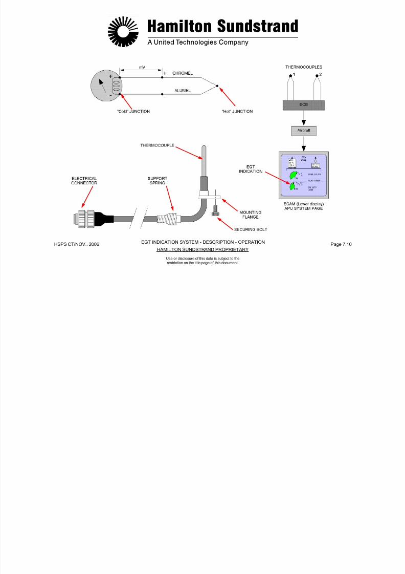
7/21/2019 Aps 3200 Training
http://slidepdf.com/reader/full/aps-3200-training 629/739
HSPS CT/NOV.. 2006 Page 7.11HAMILTON SUNDSTRAND PROPRIETARY
Use or disclosure of this data is subject to therestriction on the title page of this document.
previously recorded historical data.

7/21/2019 Aps 3200 Training
http://slidepdf.com/reader/full/aps-3200-training 630/739
HSPS CT/NOV.. 2006 Page 7.12HAMILTON SUNDSTRAND PROPRIETARY
ENGINE IDENTIFICATION MODULE
Use or disclosure of this data is subject to therestriction on the title page of this document.
MONITORING SYSTEM - GENERAL
General
This system gives information about the APU actual status, foroperation and maintenance.
Description
Indication of operating parameters
The APU operating parameters are displayed on the lower ElectronicCentralized Aircraft Monitoring (ECAM) when the APU system pageis selected.
Maintenance and fault isolation
The ECB provides maintenance and fault information to the aircraftCentralized Fault Display System (CFDS) This information is
Warning, caution and indicating lights
MASTER WARNING, MASTER CAUTION and annunciator lightsprovide visual warning indications.
A FAULT light is incorporated in the APU master switch button, APUGEN button and APU BLEED button.
There are also the following lights:
- APU "ON" light in the APU master switch
- APU "START / ON" and APU "AVAILABLE" light in the APU startbutton
- APU GEN "OFF" light in the APU GEN button

7/21/2019 Aps 3200 Training
http://slidepdf.com/reader/full/aps-3200-training 631/739
HSPS CT/NOV.. 2006 Page 7.13HAMILTON SUNDSTRAND PROPRIETARY
Use or disclosure of this data is subject to therestriction on the title page of this document.
Centralized Fault Display System (CFDS). This information isdisplayed on the Multi-function Control and Display Unit (MCDU) in
the flight deck.
Warning messages
APU warning messages are displayed on the upper ECAM and the APU system page appears on the lower ECAM.
- APU BLEED "ON" light in the APU BLEED button
- APU fire lights on the external control panel and in the flight deck.

7/21/2019 Aps 3200 Training
http://slidepdf.com/reader/full/aps-3200-training 632/739
HSPS CT/NOV.. 2006 Page 7.14HAMILTON SUNDSTRAND PROPRIETARY
MONITORING SYSTEM - GENERAL
Use or disclosure of this data is subject to therestriction on the title page of this document.
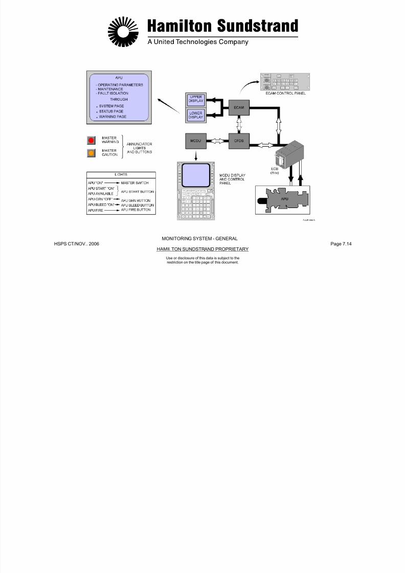
7/21/2019 Aps 3200 Training
http://slidepdf.com/reader/full/aps-3200-training 633/739
HSPS CT/NOV.. 2006 Page 7.15HAMILTON SUNDSTRAND PROPRIETARY
APS 3200 AUXILIARY POWER UNIT
Use or disclosure of this data is subject to therestriction on the title page of this document.
APS 3200 AUXILIARY POWER UNIT
SECTION 8
STARTING SYSTEM
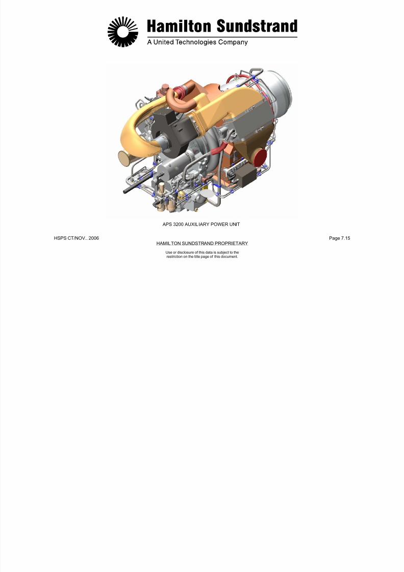
7/21/2019 Aps 3200 Training
http://slidepdf.com/reader/full/aps-3200-training 634/739
HSPS CT/NOV. 2006 Page 8.0HAMILTON SUNDSTRAND PROPRIETARY
STARTING SYSTEM
Use or disclosure of this data is subject to therestriction on the title page of this document.
STARTING SYSTEM - GENERAL
Function
The starting system allows the APU to be started on the ground andin flight.
Starting requires:
- The cranking of the rotor assembly
- The fuel supply
- The ignition of the air-fuel mixture
- The automatic control of starting sequences.
Starting Requirements
Starting System Components
- Starter motor for cranking
- Ignition exciter and igniters for ignition
- Fuel system
- Control components (Electronic Control Box, APU Master Switch,
External Control Panel, Fire Extinguishing Panel).

7/21/2019 Aps 3200 Training
http://slidepdf.com/reader/full/aps-3200-training 635/739
HSPS CT/NOV. 2006 Page 8.1HAMILTON SUNDSTRAND PROPRIETARY
Use or disclosure of this data is subject to therestriction on the title page of this document.
- Starting envelope. Normal start throughout the operating envelope:
minus 300 m to 11900 m (minus 1000 ft to 39000 ft)
- Starting time from zero speed to governed speed: less than 80seconds
- Starting attempts: 3 consecutive starts and cooling for 1 hour.
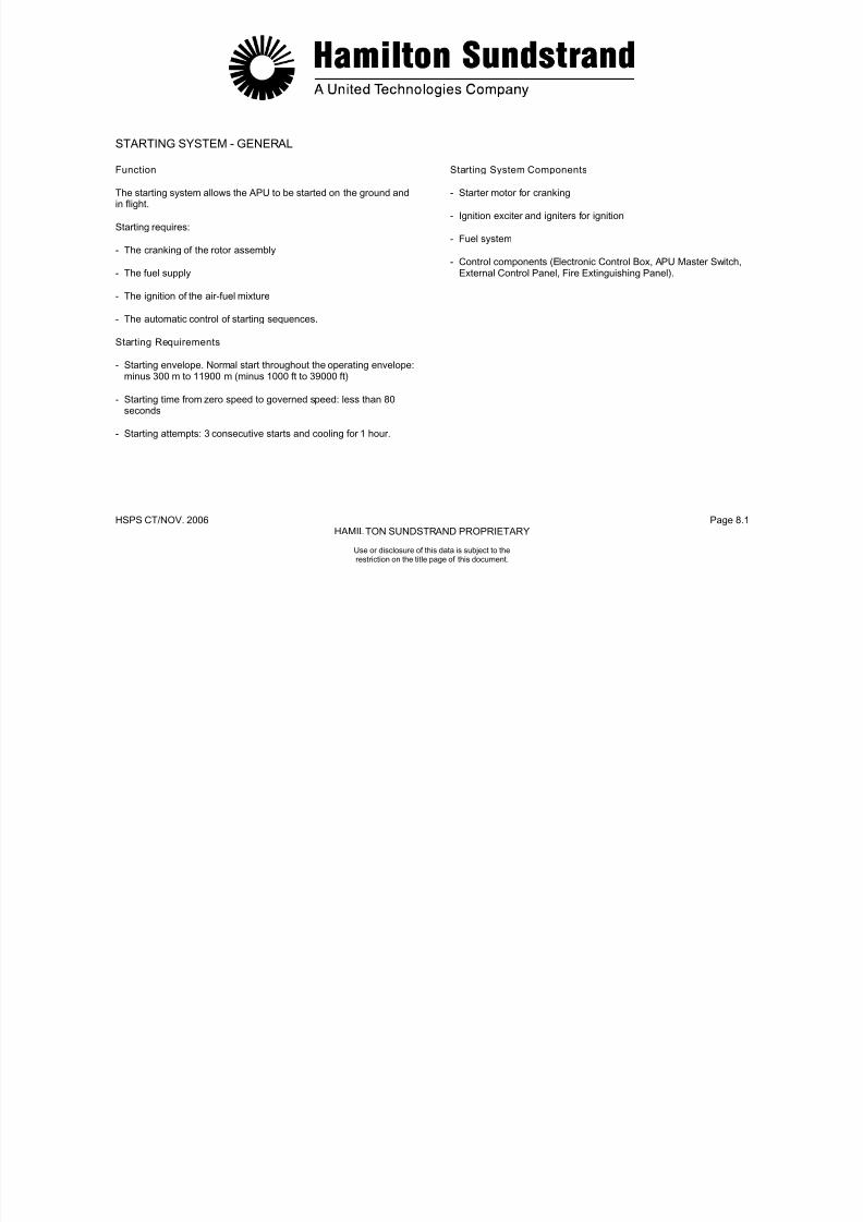
7/21/2019 Aps 3200 Training
http://slidepdf.com/reader/full/aps-3200-training 636/739
HSPS CT/NOV. 2006 Page 8.2HAMILTON SUNDSTRAND PROPRIETARY
Use or disclosure of this data is subject to therestriction on the title page of this document.
STARTING SYSTEM - GENERAL
STARTING SYSTEM - DESCRIPTION
The components involved are the starter-motor, the ignition exciter,the igniters and components of the fuel system and control system.
Starter-Motor
The electric starter motor drives the APU rotor assembly through asprag clutch.
The starter motor is mounted on the gearbox and aligned by a
locating pin. A V-band clamp is used to secure the starter to the drivepad.
A brush wear indicator pin and a starter low voltage sensingconnector are located on the front of the starter.
When brush wear reaches 75%, an indicator pin will appear in theplastic viewing window. (See Page 8.8)
Ignitor Cables
There are two igniter ignitor cables (one for each ignitor plug) thatdelivers high voltage from the exciter to the ignitors.
Ignitor Plugs
Two ignitor plugs are used to ignite the fuel in the combustorchamber. The ignitors are threaded into the combustor housing.
Control System
- Start switch and master switches
- Electronic Control Box.

7/21/2019 Aps 3200 Training
http://slidepdf.com/reader/full/aps-3200-training 637/739
HSPS CT/NOV. 2006 Page 8.3HAMILTON SUNDSTRAND PROPRIETARY
Use or disclosure of this data is subject to therestriction on the title page of this document.
Starter low voltage is sensed by the ECB through the low voltagesensing connector.
Ignition Exciter
The ignition exciter is located on the left side of the APU. The exciteris a capacitor-discharge unit that uses 28V DC to provide anintermittent high voltage output to the two ignitor plugs.

7/21/2019 Aps 3200 Training
http://slidepdf.com/reader/full/aps-3200-training 638/739
HSPS CT/NOV. 2006 Page 8.4HAMILTON SUNDSTRAND PROPRIETARY
ECB
STARTING SYSTEM- DESCRIPTION
Use or disclosure of this data is subject to therestriction on the title page of this document.
STARTING SYSTEM - OPERATION
Start Selection
Starting is selected from the aircraft control panel:
- Master switch "on"
- APU system page on lower ECAM annunciates ...
- Start button.
Starting Operation
- Cranking
Energize the starter motor.
- Fuel supply
APU starting is controlled by the electronic control box.
The main phases are:
- Initial phase (cranking, fuel supply and ignition)
- Self-sustaining speed (de-energize the starter motor and ignitionexciter)
- 100% speed (speed governing and loading).
Shutdown Sequence
APU shut-down can be activated automatically or manually:
- Manually from the APU master switch, from the fire control panelor from the external control panel
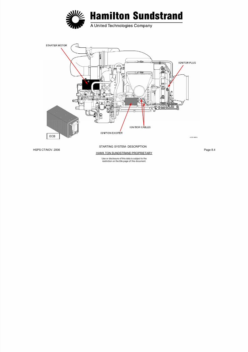
7/21/2019 Aps 3200 Training
http://slidepdf.com/reader/full/aps-3200-training 639/739
HSPS CT/NOV. 2006 Page 8.5HAMILTON SUNDSTRAND PROPRIETARY
Use or disclosure of this data is subject to therestriction on the title page of this document.
Fuel servo valve and 3 way solenoid valve energized open.
- Ignition
Ignition exciter energized to provide ignition to the two ignitorplugs.
Starting Cycle
- Automatically by the ECB fault shut-down system.
The ECB controls the fuel control unit 3 way solenoid valve. Whenthe APU is shut down manually or automatically the 3 way solenoidvalve is de-energized closed. The closed valve shuts off the fuel tothe fuel injectors.
7/21/2019 Aps 3200 Training
http://slidepdf.com/reader/full/aps-3200-training 640/739
HSPS CT/NOV. 2006 Page 8.6HAMILTON SUNDSTRAND PROPRIETARY
STARTING SYSTEM - OPERATION
Use or disclosure of this data is subject to therestriction on the title page of this document.
STARTER MOTOR - GENERAL
Function
The electric starter motor cranks the APU during the starting state.
Location
The starter-motor is mounted by a V-band clamp on the gearboxstarter drive pad.
Main Features
- Motor type:
- Weight: 4.22 kg (9.3 lbs)
- Voltage: 24 VDC (max. 28 VDC)
- Max current: 830 A.
Main Components
- The starter motor assembly
- The V-band clamp for attachment
- Positive and negative terminals
- Visual brushwear indicator
- Starter low voltage connector.
Interfaces
- Electrical power to the starter motor is provided by the aircraftbattery system through two start contactors (backup and main)
- Starter low voltage sensing
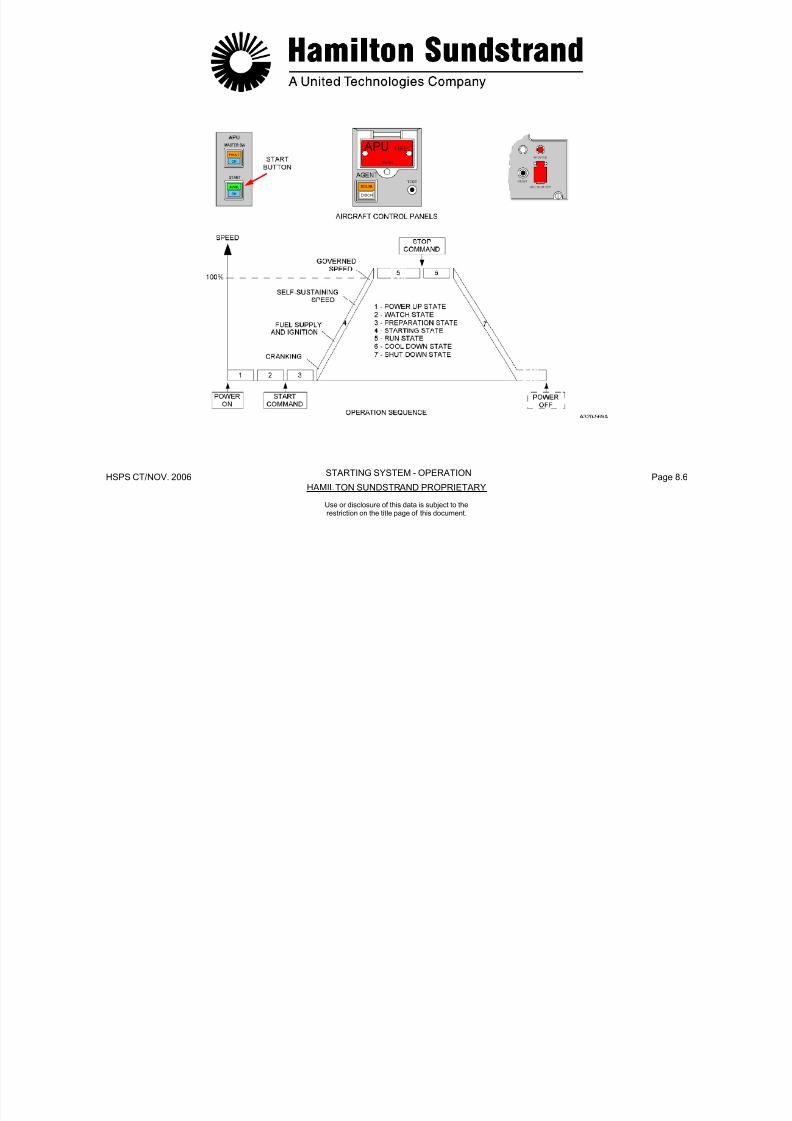
7/21/2019 Aps 3200 Training
http://slidepdf.com/reader/full/aps-3200-training 641/739
HSPS CT/NOV. 2006 Page 8.7HAMILTON SUNDSTRAND PROPRIETARY
Use or disclosure of this data is subject to therestriction on the title page of this document.
g g
- Starter motor clutch.
(See Page 8.3)
(See Page 8.3)

7/21/2019 Aps 3200 Training
http://slidepdf.com/reader/full/aps-3200-training 642/739
HSPS CT/NOV. 2006 Page 8.8HAMILTON SUNDSTRAND PROPRIETARY
STARTER MOTOR - GENERAL
Use or disclosure of this data is subject to therestriction on the title page of this document.
STARTER MOTOR CLUTCH
General
Function
The function of the clutch is to disengage the starter motor when the APU reaches self-sustaining speed.
Description
The clutch is a Line Replaceable Unit. It is necessary to remove thestarter motor and the bearing support assembly to extract the clutch.
The clutch assembly consists of two gears, a starter motor driveshaft, 4 bearings and a sprag clutch.
Operation
Two operating phases are considered : starter motor engaged andstarter motor disengaged.
Starter Motor Engaged
When the starter motor is operating, the sprag pawls make contactwith the starter motor shaft and the gear assembly.
Starter Motor Disengaged
At 55% speed the starter motor is de-energized by the ECB.
As the starter gear speed increases, centrifugal force moves thesprag pawls away from the starter motor shaft.
The starter motor shaft is disconnected from the sprag pawls, this

7/21/2019 Aps 3200 Training
http://slidepdf.com/reader/full/aps-3200-training 643/739
HSPS CT/NOV. 2006 Page 8.9HAMILTON SUNDSTRAND PROPRIETARY
Use or disclosure of this data is subject to therestriction on the title page of this document.
prevents the APU from driving the starter motor mechanically.
7/21/2019 Aps 3200 Training
http://slidepdf.com/reader/full/aps-3200-training 644/739
HSPS CT/NOV. 2006 Page 8.10HAMILTON SUNDSTRAND PROPRIETARY
OIL SUPPLYSTARTER MOTOR CLUTCH - OPERATION
Use or disclosure of this data is subject to therestriction on the title page of this document.
IGNITION EXCITER - GENERAL
Function
The ignition exciter transforms low DC voltage into intermittent highvoltage supply to the ignitor plugs.
Location
The ignition exciter is mounted on the left side of the APU.
Main Features
- Voltage range: 10 VDC to 30 VDC
- Energy: 0.22 Joules per spark
- Spark duration: 15 microseconds
- Spark rate: 2 Hz at voltage above 10 VDC.
IGNITION EXCITER - DESCRIPTION
The ignition exciter is a sealed metal box assembly with a mountingbracket.
The main components are:
- An input circuit with a connector and a DC/AC converter
- A high voltage transformer
- A high voltage output circuit with a rectifier, two capacitors and atriggering device.
The ignition exciter DC input voltage is sensed by the ECB for faultdetection.

7/21/2019 Aps 3200 Training
http://slidepdf.com/reader/full/aps-3200-training 645/739
HSPS CT/NOV. 2006 Page 8.11HAMILTON SUNDSTRAND PROPRIETARY
Use or disclosure of this data is subject to therestriction on the title page of this document.
7/21/2019 Aps 3200 Training
http://slidepdf.com/reader/full/aps-3200-training 646/739
HSPS CT/NOV. 2006 Page 8.12HAMILTON SUNDSTRAND PROPRIETARY
IGNITION EXCITER - GENERAL - DESCRIPTION
Use or disclosure of this data is subject to therestriction on the title page of this document.
IGNITORS AND IGNITOR CABLES
Function
There are two ignitor plugs used to ignite the fuel in the combustorchamber during start up of the APU. They are connected to theignition exciter by two shielded ignitor cables.
Location
The two ignitor plugs are located on the combustor housing:
- One at 5 'o'clock
- One at 9 'o'clock.
Note: Location is looking at the combustor housing rear view.
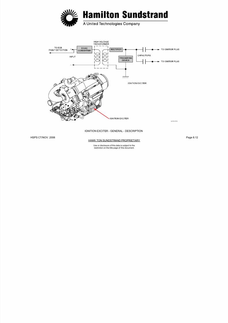
7/21/2019 Aps 3200 Training
http://slidepdf.com/reader/full/aps-3200-training 647/739
HSPS CT/NOV. 2006 Page 8.13HAMILTON SUNDSTRAND PROPRIETARY
Use or disclosure of this data is subject to therestriction on the title page of this document.
IGNITORCABLES

7/21/2019 Aps 3200 Training
http://slidepdf.com/reader/full/aps-3200-training 648/739
HSPS CT/NOV. 2006 Page 8.14HAMILTON SUNDSTRAND PROPRIETARY
IGNITORS
Use or disclosure of this data is subject to therestriction on the title page of this document.
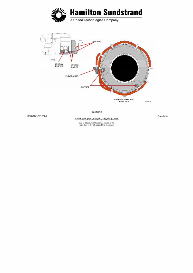
7/21/2019 Aps 3200 Training
http://slidepdf.com/reader/full/aps-3200-training 649/739
HSPS CT/NOV.2006 Page 8.15HAMILTON SUNDSTRAND PROPRIETARY
APS 3200 AUXILIARY POWER UNIT
Use or disclosure of this data is subject to therestriction on the title page of this document.
APS 3200 AUXILIARY POWER UNIT
SECTION 9
ELECTRICAL SYSTEM

7/21/2019 Aps 3200 Training
http://slidepdf.com/reader/full/aps-3200-training 650/739
HSPS CT/NOV.. 2006 Page 9.0HAMILTON SUNDSTRAND PROPRIETARY
Use or disclosure of this data is subject to therestriction on the title page of this document.
ELECTRICAL SYSTEM
Functions
To operate the electrical accessories by control signals from theECB.
To supply AC power from the APU generator to the aircraft electricalsystem.
Main Features
- DC power
- AC power.
Main Components
- The electrical accessories
- The ECB

7/21/2019 Aps 3200 Training
http://slidepdf.com/reader/full/aps-3200-training 651/739
HSPS CT/NOV.. 2006 Page 9.1HAMILTON SUNDSTRAND PROPRIETARY
Use or disclosure of this data is subject to therestriction on the title page of this document.
- The electrical harness.

7/21/2019 Aps 3200 Training
http://slidepdf.com/reader/full/aps-3200-training 652/739
HSPS CT/NOV. 2006 Page 9.2HAMILTON SUNDSTRAND PROPRIETARY
ELECTRICAL SYSTEM
Use or disclosure of this data is subject to therestriction on the title page of this document.
AIRCRAFT/APU HARNESS (1)
Description
ECB connectors
The ECB has 2 connectors:
- An ARINC 600-2 connector with 3 inserts (A, B, C)
- A RS 232 C connector.
The ARINC 600 connector is installed at the rear of the ECB andplugs into a shelf mounted aircraft connector.
The ARINC 600 connector carries all inputs/outputs of the ECB plusthe ARINC 429 data link.
The RS 232 connector can be accessed through the front and therear connectors for maintenance purposes.
Aircraf t harness
- DC power to ECB and start contactors
- ARINC 429 data link
- AC generator control
- AC generator excitation control
- RS 232 C connector.
There are three firewall connectors that connect the ECB to theengine harness. They are identified as (J-1, J-2 and J-3).

7/21/2019 Aps 3200 Training
http://slidepdf.com/reader/full/aps-3200-training 653/739
HSPS CT/NOV. 2006 Page 9.3HAMILTON SUNDSTRAND PROPRIETARY
Use or disclosure of this data is subject to therestriction on the title page of this document.
7/21/2019 Aps 3200 Training
http://slidepdf.com/reader/full/aps-3200-training 654/739
HSPS CT/NOV. 2006 Page 9.4HAMILTON SUNDSTRAND PROPRIETARY
ECB CONNECTORS - AIRCRAFT HARNESS
AIRCRAFT/APU HARNESS (1)
Use or disclosure of this data is subject to therestriction on the title page of this document.
AIRCRAFT/APU HARNESS (2)
Description (continued)
APU eng ine harnessThe engine harness is connected to three firewall connectors, theyare identified as (P-1, P-2 and P-3).P1 connector:- PMG- 3 way solenoid valve- Ignition exciter- Starter Motor (low voltage sense signal)- Bleed Control Valve LVDT- Gearbox de-oiling valve- Oil filter switch indicators- Low oil pressure switch- Oil level sensor- Low fuel pressure switch- Generator high oil temperature sensor- AC generator current transformers.
P2 connector:- Load compressor discharge pressure sensors- IGV actuator (servo valve and LVDT)- BCV actuator (servo valve)- Fuel servo valve- Speeds sensor 1 and 2- Oil temperature sensor- EGT sensor 1 and 2- Engine ID module- Air inlet pressure and temperature sensor.P3 connector:- AC generator PMG- AC generator excitation control.

7/21/2019 Aps 3200 Training
http://slidepdf.com/reader/full/aps-3200-training 655/739
HSPS CT/NOV. 2006 Page 9.5HAMILTON SUNDSTRAND PROPRIETARY
Use or disclosure of this data is subject to therestriction on the title page of this document.
7/21/2019 Aps 3200 Training
http://slidepdf.com/reader/full/aps-3200-training 656/739
HSPS CT/NOV. 2006 Page 9.6HAMILTON SUNDSTRAND PROPRIETARY
APU HARNESS
AIRCRAFT/APU HARNESS (2)
Use or disclosure of this data is subject to therestriction on the title page of this document.
AIRCRAFT/APU HARNESS (3)
Description (continued)
Starter motor electrical power supply cables
The starter motor DC power supply is provided by the aircraftbatteries or the Transformer Rectifier Unit (TRU).
The supply is controlled by two contactors in series (backup andmain start contactors). The power cables link the start contactorsdirectly to the starter motor (+ and -cables).
AC generator harness
The AC generator connector P-4 is part of the engine harness. Theconnector provides the following signals:
- AC generator oil temperature and control signals through the P-1engine harness connector
- AC generator PMG signal and exciter field control through the P-3engine harness connector.
The four AC generator cables are connected to the aircraft electricalbuss system. Three of the cables provide AC power and the fourthcable is a neutral.

7/21/2019 Aps 3200 Training
http://slidepdf.com/reader/full/aps-3200-training 657/739
HSPS CT/NOV. 2006 Page 9.7HAMILTON SUNDSTRAND PROPRIETARY
Use or disclosure of this data is subject to therestriction on the title page of this document.

7/21/2019 Aps 3200 Training
http://slidepdf.com/reader/full/aps-3200-training 658/739
HSPS CT/NOV. 2006 Page 9.8HAMILTON SUNDSTRAND PROPRIETARY
STARTER MOTOR CABLES - AC GENERATOR HARNESS
AIRCRAFT/APU HARNESS (3)
Use or disclosure of this data is subject to therestriction on the title page of this document.
AC GENERATOR - GENERAL
FunctionThe AC generator (Alternating Current Generator) provides electricalpower to the aircraft systems.LocationThe AC generator is mounted on the front face of the gearbox.Type- Brushless- 3 phases- Oil cooled.Main Features
- Nominal power: 90 kVA- Output: 115 V, 400 Hz- Rotation speed: 24 034 RPM at 100 % APU speed- Direction of rotation: Clockwise viewing the pad- Weight: approx. 22.7 kg (50 lbs).
Interfaces- Oil system (lubrication, cooling)- Generator Control Unit (GCU)- Electronic Control Box (ECB).Main Components- Permanent Magnet Generator- Current transformers- High oil temperature sensor (HOT).
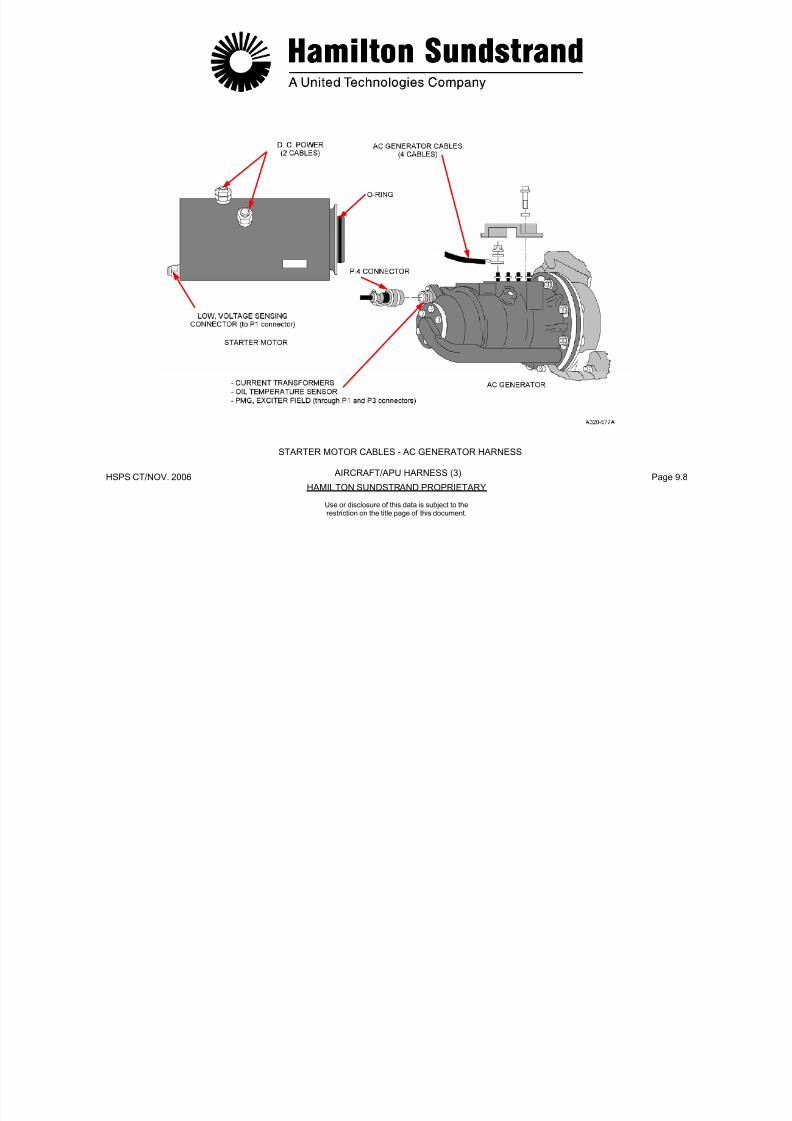
7/21/2019 Aps 3200 Training
http://slidepdf.com/reader/full/aps-3200-training 659/739
HSPS CT/NOV. 2006 Page 9.9HAMILTON SUNDSTRAND PROPRIETARY
Use or disclosure of this data is subject to therestriction on the title page of this document.
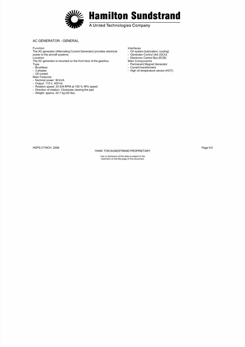
7/21/2019 Aps 3200 Training
http://slidepdf.com/reader/full/aps-3200-training 660/739
HSPS CT/NOV. 2006 Page 9.10HAMILTON SUNDSTRAND PROPRIETARY
AC GENERATOR - GENERAL
Use or disclosure of this data is subject to therestriction on the title page of this document.
ELECTRICAL SYSTEM INTERFACES
The APU AC generator is connected to the aircraft electrical systemsthrough the APU line contactor.
The lower ECAM, APU system page displays the AC generatorparameters:
- The percent of load
- The output voltage (115 V)
- The output frequency (400 Hz).

7/21/2019 Aps 3200 Training
http://slidepdf.com/reader/full/aps-3200-training 661/739
HSPS CT/NOV. 2006 Page 9.11HAMILTON SUNDSTRAND PROPRIETARY
Use or disclosure of this data is subject to therestriction on the title page of this document.

7/21/2019 Aps 3200 Training
http://slidepdf.com/reader/full/aps-3200-training 662/739
HSPS CT/NOV. 2006 Page 9.12HAMILTON SUNDSTRAND PROPRIETARY
ELECTRICAL SYSTEM INTERFACES
Use or disclosure of this data is subject to therestriction on the title page of this document.
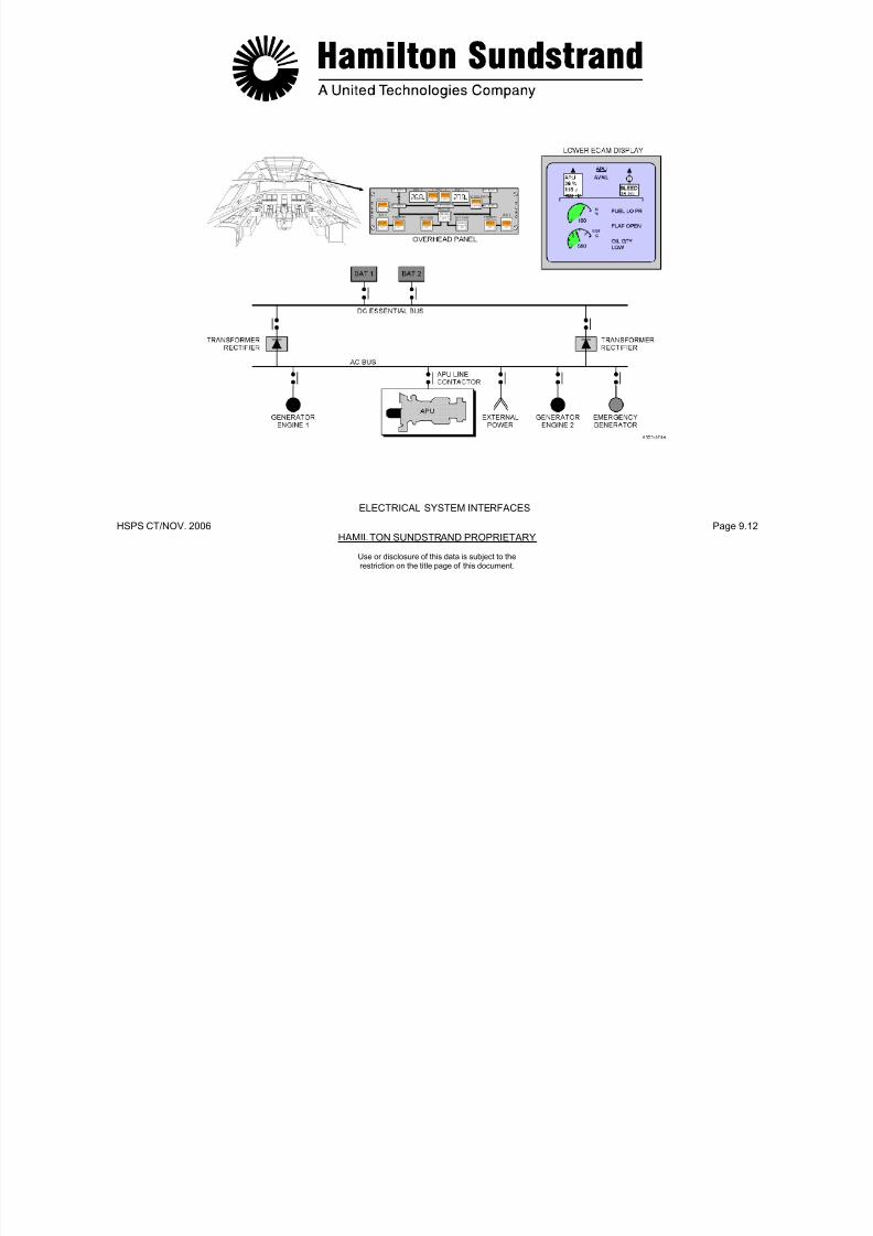
7/21/2019 Aps 3200 Training
http://slidepdf.com/reader/full/aps-3200-training 663/739
HSPS CT/NOV..2006 Page 9.13HAMILTON SUNDSTRAND PROPRIETARY
APS 3200 AUXILIARY POWER UNIT
Use or disclosure of this data is subject to theRestriction on the title page of this document
APS 3200 AUXILIARY POWER UNIT
SECTION 10
APU INSTALLATION

7/21/2019 Aps 3200 Training
http://slidepdf.com/reader/full/aps-3200-training 664/739
HSPS CT/NOV. 2006 Page 10.0HANMILTON SUNDSTRAND PROPRIETARY
Use or disclosure of this data is subject to therestriction on the title page of this document.
APU COMPARTMENT
The APU compartment is located inside the aircraft tail cone.
The compartment is fire proof using firewalls made of titanium alloy.
Two longitudinally-hinged access doors provide access to the APUcompartment.
The air inlet duct assembly is attached to the right access door andprovides a ducted airflow to the APU air inlet plenum.
The APU compartment has a fire extinguishing bottle located in aseparate compartment, forward of the firewall.
Cooling and ventilation of the compartment is provided by the APUcooling fan. The fan provides air flow to the oil cooler and the APUcompartment.

7/21/2019 Aps 3200 Training
http://slidepdf.com/reader/full/aps-3200-training 665/739
HSPS CT/NOV. 2006 Page 10.1HANMILTON SUNDSTRAND PROPRIETARY
Use or disclosure of this data is subject to therestriction on the title page of this document.
APU COMPARTMENT AMBIENT AIRCOMPRESSED AIR

7/21/2019 Aps 3200 Training
http://slidepdf.com/reader/full/aps-3200-training 666/739
HSPS CT/NOV. 2006 Page 10.2HAMILTON SUNDSTRAND PROPRIETARY
Use or disclosure of this data is subject to therestriction on the title page of this document.
APU COMPARTMENTCOMPRESSED AIREXHAUST GAS
APU ATTACHMENT
The APU is attached to the aircraft tail cone structure by three struts.The struts are connected to the APU through vibration isolators.
The two forward struts are attached to mounts on each side of thegearbox. The rear strut is attached to the power section impellercontainment shield.
A lifting eye is also provided for installation and removal of the APU.

7/21/2019 Aps 3200 Training
http://slidepdf.com/reader/full/aps-3200-training 667/739
HSPS CT/NOV. 2006 Page 10.3HAMILTON SUNDSTRAND PROPRIETARY
Use or disclosure of this data is subject to therestriction on the title page of this document.

7/21/2019 Aps 3200 Training
http://slidepdf.com/reader/full/aps-3200-training 668/739
HSPS CT/NOV. 2006 Page 10.4HAMILTON SUNDSTRAND PROPRIETARY
Use or disclosure of this data is subject to therestriction on the title page of this document.
APU ATTACHMENT
AIR INLET SYSTEM
Function
The air inlet system provides ambient air to the APU air inlet plenum.
Location
The air inlet is located on the underside of the tail section.
System Components
The air inlet system includes:
- The diverter
- The air inlet
- The diffuser
- The elbow
- The interface with the APU inlet plenum.
The Diverter directs ambient air flow into the air inlet when theaircraft is operating at high airspeeds.
The Air Inlet has a flap that is opened and closed by an electricactuator. The actuator is controlled by the ECB.
The Diffuser slows the airflow delivery to the APU.
The Elbow is attached to the diffuser and directs the ambient airflowinto the APU air inlet plenum.
The air inlet duct assembly is secured to the right access door andcan be removed to provide better accessibility to the APU.
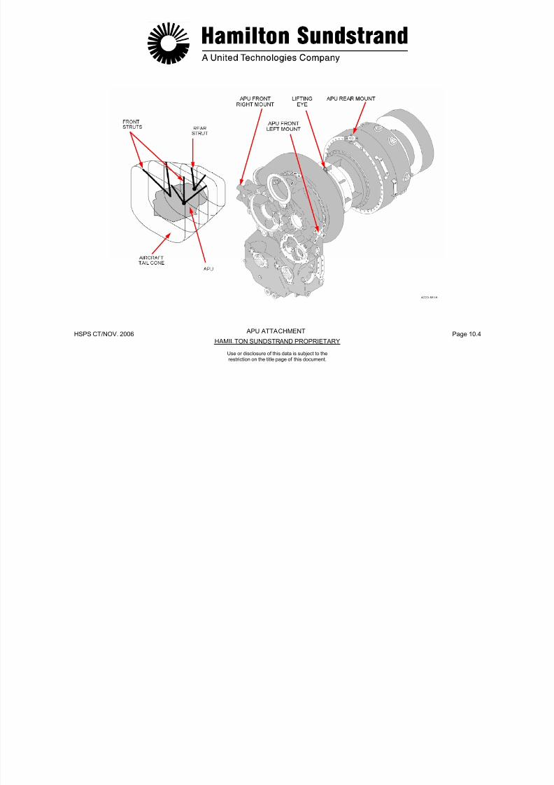
7/21/2019 Aps 3200 Training
http://slidepdf.com/reader/full/aps-3200-training 669/739
HSPS CT/NOV. 2006 Page 10.5HAMILTON SUNDSTRAND PROPRIETARY
Use or disclosure of this data is subject to therestriction on the title page of this document.
AMBIENT AIR
7/21/2019 Aps 3200 Training
http://slidepdf.com/reader/full/aps-3200-training 670/739
HSPS CT/NOV. 2006 Page 10.6HAMILTON SUNDSTRAND PROPRIETARY
AIR INLET SYSTEM
Use or disclosure of this data is subject to therestriction on the title page of this document.
EXHAUST SYSTEM
Function
The exhaust system directs the APU exhaust gasses overboard.
Location
The system is installed in the tail cone between the APU exhaustand the end of the tail cone.
System Components
- The exhaust pipe
- The exhaust muffler
- The insulation
- The sealing ring.
The exhaust pipe is mounted on rails that are attached to the insideof the tail cone.
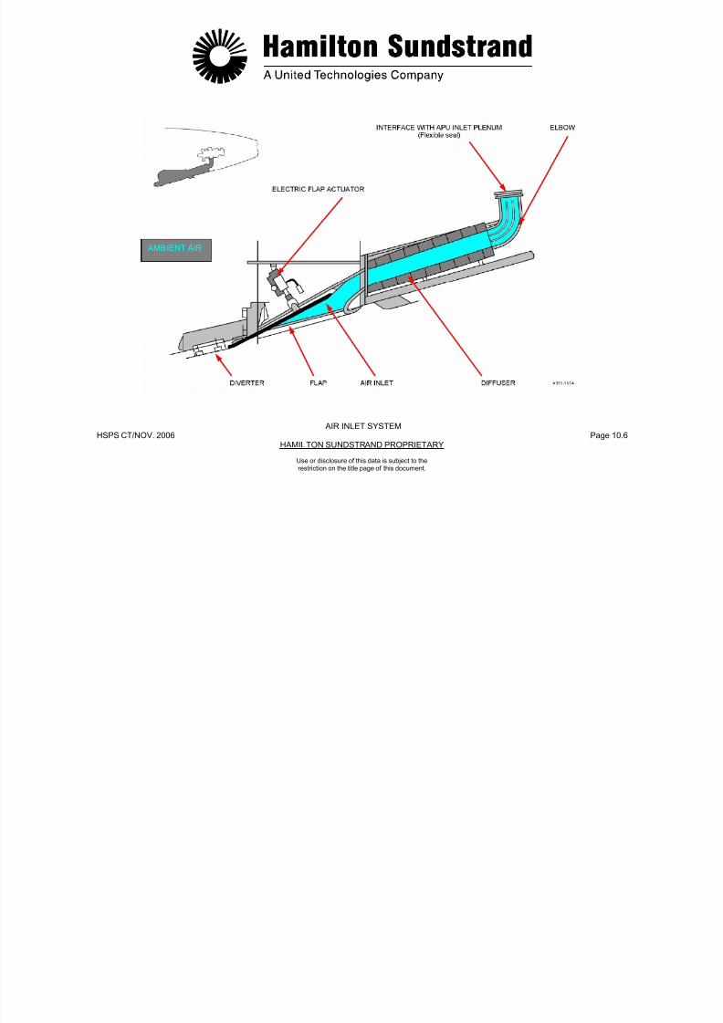
7/21/2019 Aps 3200 Training
http://slidepdf.com/reader/full/aps-3200-training 671/739
HSPS CT/NOV. 2006 Page 10.7HAMILTON SUNDSTRAND PROPRIETARY
Use or disclosure of this data is subject to therestriction on the title page of this document.
This allows the exhaust pipe to be disconnected from the APU andmoved rearward to provide additional clearance during removal andinstallation of the APU.
7/21/2019 Aps 3200 Training
http://slidepdf.com/reader/full/aps-3200-training 672/739
HSPS CT/NOV. 2006 Page 10.8HAMILTON SUNDSTRAND PROPRIETARY
Use or disclosure of this data is subject to therestriction on the title page of this document.
EXHAUST SYSTEM
EXHAUST GAS
DRAIN SYSTEM (1)
Function
The APU drain system provides drains from various components.The fluids are collected and drained overboard through the drainmast.
The fuel control unit, BCV actuator and IGV actuator use a commondrain to the aircraft drain tank. Fluids are siphoned from the draintank, into the drain mast and then discharged overboard when theaircraft is in flight.
The other common and single drains flow directly into the drain mastand then discharge overboard.
APU Drains and Vent
- Combustor Drain
- Air Bypass Plenum Drain
- Exhaust Pipe Drain
F t B i S l D i
- Flow Divider Purge Drain (To exhaust)
- Gearbox Vent (To exhaust).

7/21/2019 Aps 3200 Training
http://slidepdf.com/reader/full/aps-3200-training 673/739
HSPS CT/NOV. 2006 Page 10.9HAMILTON SUNDSTRAND PROPRIETARY
Use or disclosure of this data is subject to therestriction on the title page of this document.
- Front Bearing Seal Drain
- Fuel Control Unit Drain
- BCV Actuator Seal Drain
- IGV Actuator Seal Drain
SIPHON TUBE
COLLECTORTANK

7/21/2019 Aps 3200 Training
http://slidepdf.com/reader/full/aps-3200-training 674/739
HSPS CT/NOV. 2006 Page 10.10HAMILTON SUNDSTRAND PROPRIETARY
Use or disclosure of this data is subject to therestriction on the title page of this document.
DRAIN SYSTEM (1)
DRAIN FLUID
FIRE PROTECTION
APU fire protection consists of a detection system and an
extinguishing system. The systems are supplied by the aircraftmanufacturer.
Fire Detection and Extinguish ing
The detection system uses two continuous sensing elementsinstalled on the APU compartment walls.
One fire bottle is available for fire extinguishing. The bottle is
installed on the forward side of the APU compartment firewall.
Operation
The APU fire control panel is located in the flight deck overheadpanel.
Pushing the fire switch will immediately shut down the APU and armthe fire extinguishing system.
In the event of an APU fire on the ground, the APU will automaticallyshutdown and discharge the extinguishing system.

7/21/2019 Aps 3200 Training
http://slidepdf.com/reader/full/aps-3200-training 675/739
HSPS CT/NOV. 2006 Page 10.11HAMILTON SUNDSTRAND PROPRIETARY
Use or disclosure of this data is subject to therestriction on the title page of this document.
7/21/2019 Aps 3200 Training
http://slidepdf.com/reader/full/aps-3200-training 676/739
HSPS CT/NOV. 2006 Page 10.12HAMILTON SUNDSTRAND PROPRIETARY
FIRE PROTECTION
Use or disclosure of this data is subject to therestriction on the title page of this document.
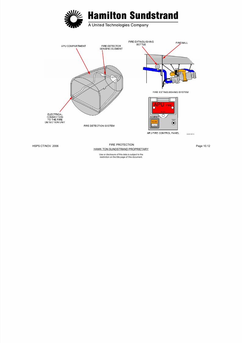
7/21/2019 Aps 3200 Training
http://slidepdf.com/reader/full/aps-3200-training 677/739
HSPS CT/NOV. 2006 Page 10.13HAMILTON SUNDSTRAND PROPRIETARY
Use or disclosure of this data is subject to therestriction on the title page of this document
APS 3200 AUXILIARY POWER UNIT
APS 3200 AUXILIARY POWER UNIT
SECTION 11
MAINTENANCE
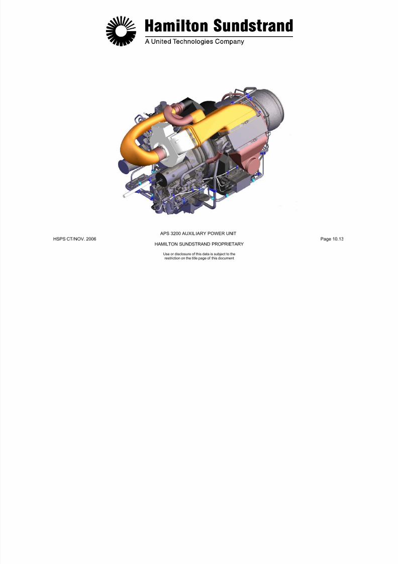
7/21/2019 Aps 3200 Training
http://slidepdf.com/reader/full/aps-3200-training 678/739
HSPS CT/NOV.. 2006 Page 11.0HAMILTON SUNDSTRAND PROPRIETARY
Use or disclosure of this data is subject to therestriction on the title page of this document.
INSPECTION AND CHECKS
Visual Inspections
Opening the APU compartment for corrective maintenance orservicing provides the opportunity to visually inspect the APU forsecurity, leaks, and warning indicators. The following arerecommended inspection items:
- Engine mounts
- Engine Components and Fluid lines
- Oil Quantity and Magnetic Drain plug
- Oil and Fuel Filter impending blockage Indicators
- Electrical harness and Connectors
- Engine Air Inlet Plenum
- Engine Combustor Housing and Exhaust System.
Borescope Inspection
The APU internal components may be inspected by using a flexibleborescope. To rotate the APU internal components, the cooling faninlet duct may be removed to allow manual rotation of the fanimpeller.
The following components can be inspected with the APU installed inthe aircraft.
- Load compressor impeller and guide vanes
- Power section impeller
- Combustor, viewed through the ignitor and fuel injector bosses
- First stage turbine wheel
- Second stage turbine wheel.
Refer to the Aircraft Maintenance Manual for borescopeprocedures.
7/21/2019 Aps 3200 Training
http://slidepdf.com/reader/full/aps-3200-training 679/739
HSPS CT/NOV.. 2006 Page 11.1HAMILTON SUNDSTRAND PROPRIETARY
Use or disclosure of this data is subject to therestriction on the title page of this document.
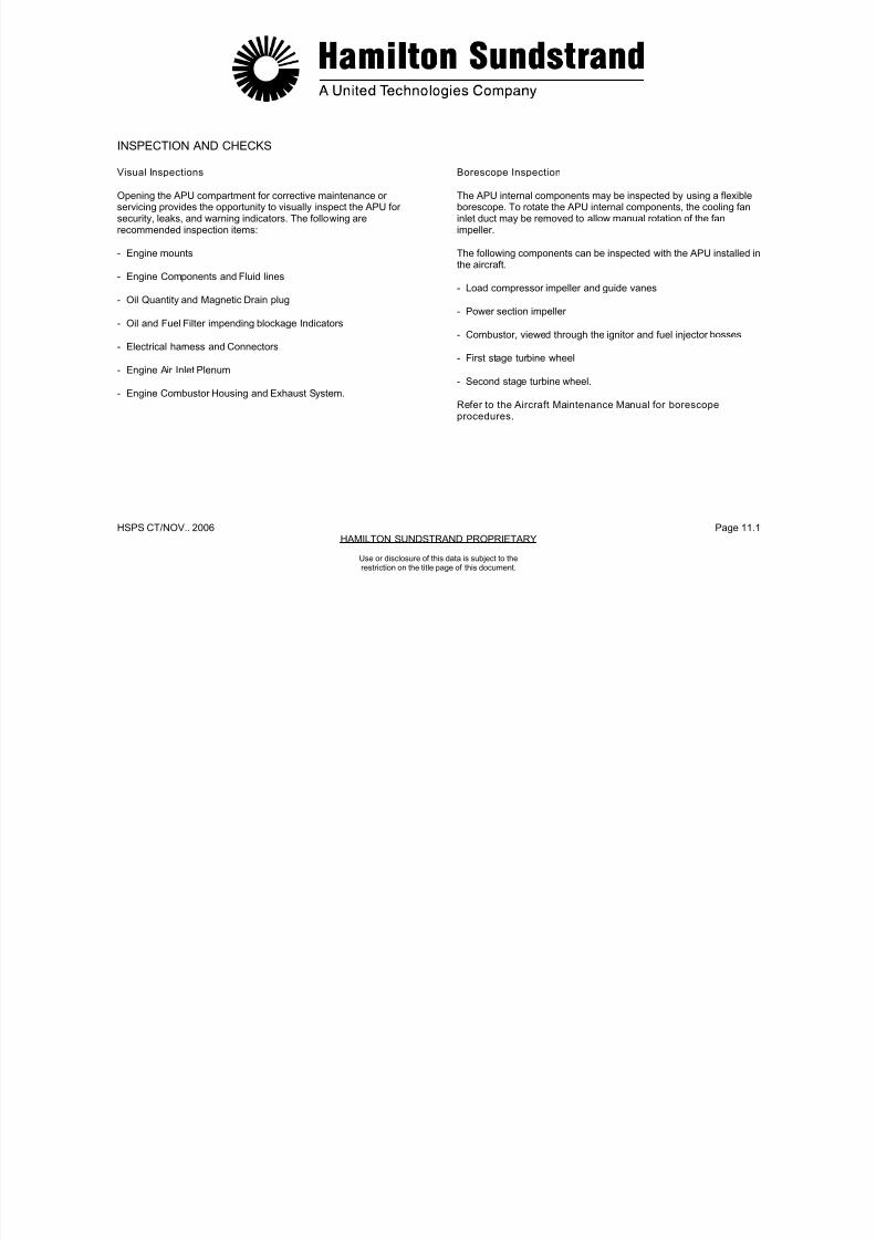
7/21/2019 Aps 3200 Training
http://slidepdf.com/reader/full/aps-3200-training 680/739
HSPS CT/NOV. 2006 Page 11.2HAMILTON SUNDSTRAND PROPRIETARY
VISUAL INSPECTIONS - BORESCOPE INSPECTION
INSPECTION AND CHECKS
Use or disclosure of this data is subject to therestriction on the title page of this document.
LINE REPLACEABLE UNITS
The following Line Replaceable Units (LRU's) can be removed andreplaced without removing the APU from the aircraft:
Electronic Control BoxEngine HarnessIdentification ModuleStarter MotorClutch AssemblyIgnition ExciterIgnitor CablesIgnitor PlugsSpeed SensorsThermocouples
Air Inlet Pressure And Temperature SensorOil Filter ElementsSwitch IndicatorsMagnetic Drain PlugDe-Oiling Valve
Low Oil Pressure SwitchOil Temperature SensorOil Level SensorOil Pressure Relief Valve
Pilot Fuel InjectorsMain Fuel InjectorsInlet Guide Vane ActuatorBleed Control ValveCompressor Discharge SensorCooling Fan Assembly
AC Generator PadFuel and Oil PipesCombustor Chamber Drain Valve
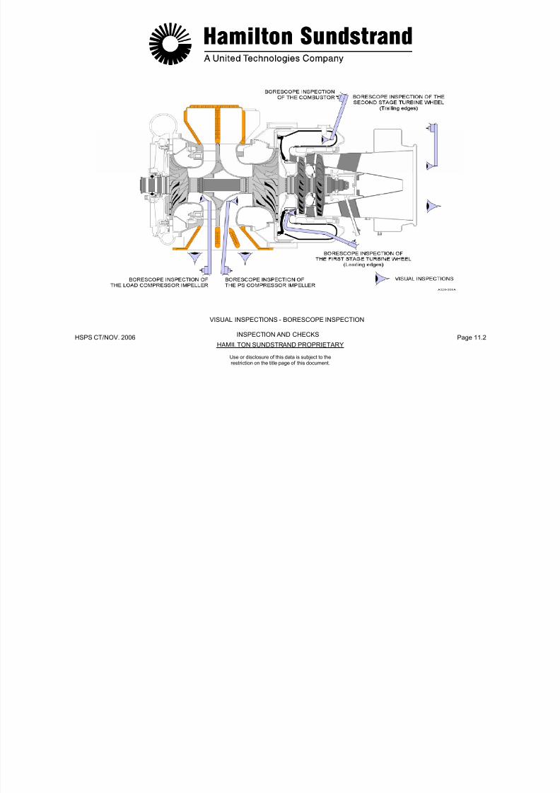
7/21/2019 Aps 3200 Training
http://slidepdf.com/reader/full/aps-3200-training 681/739
HSPS CT/NOV. 2006 Page 11.3HAMILTON SUNDSTRAND PROPRIETARY
Use or disclosure of this data is subject to therestriction on the title page of this document.
Oil CoolerFuel Control UnitFuel Filter ElementFlow Divider AssemblyPilot Manifold Assembly
Main Manifold Assembly
COOLING FAN
ASSEMBLY
STARTER
ENGINEHARNESS
OIL COOLER
IGNITIONEXCITER

7/21/2019 Aps 3200 Training
http://slidepdf.com/reader/full/aps-3200-training 682/739
HSPS CT/NOV.. 2006 Page 11.4HAMILTON SUNDSTRAND PROPRIETARY
Use or disclosure of this data is subject to therestriction on the title page of this document.
LEFT FRONT-TOP VIEW
HARNESS
FUEL CONTROLUNIT
DE-OILINGVALVE
IDENTIFICATIONMODULE
INLET GUIDEVANE
ACTUATOR
BLEEDCONTROLVALVE
COMPRESSORDISCHARGE
AC GENERATORMOUNTING PAD

7/21/2019 Aps 3200 Training
http://slidepdf.com/reader/full/aps-3200-training 683/739
HSPS CT/NOV. 2006 Page 11.5HAMILTON SUNDSTRAND PROPRIETARY
Use or disclosure of this data is subject to therestriction on the title page of this document.
RIGHT FRONT TOP VIEW
DISCHARGE MOUNTING PADSENSOR
OILLEVELSENSORSPEED
SENSOR
SWITCHINDICATORS
GENERATORSCAVENGEFILTER
O

7/21/2019 Aps 3200 Training
http://slidepdf.com/reader/full/aps-3200-training 684/739
HSPS CT/NOV. 2006 Page 11.6HAMILTON SUNDSTRAND PROPRIETARY
MAGNETICDRAIN PLUG
LUBRICATIONFILTER
OIL PRESSUREREIEF VALVE
RIGHT FRONT BOTTOM VIEW
Use or disclosure of this data is subject to therestriction on the title page of this document.
THERMOCOUPLE
IGNITORCABLES
SPEED
FUELFILTER
PILOTMANIFOLD
ASSEMBLY
IGNITOR
FUEL FLOWDIVIDER
ASSEMBLY
MAINMANIFOLD
ASSEMBLY
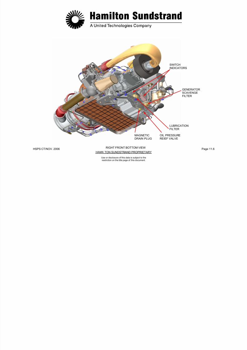
7/21/2019 Aps 3200 Training
http://slidepdf.com/reader/full/aps-3200-training 685/739
HSPS CT/NOV. 2006 Page 11.7HAMILTON SUNDSTRAND PROPRIETARY
OIL TEMPERATURESENSOR
SENSOR
LEFT REAR BOTTOM VIEW
Use or disclosure of this data is subject to therestriction on the title page of this document.
AIR INLET ANDTEMPERATURESENSOR
LOW OILPRESSURE SWITCH
NOTE:

7/21/2019 Aps 3200 Training
http://slidepdf.com/reader/full/aps-3200-training 686/739
HSPS CT/NOV. 2006 Page 11.8HAMILTON SUNDSTRAND PROPRIETARY
NOTE:(The switch may alsobe Located on thelower right side ofthe gearbox)
RIGHT REAR TOP VIEW
Use or disclosure of this data is subject to therestriction on the title page of this document.
THEMOCOUPLE
IGNITOR
COMBUSTORDRAIN CHECKCHECK VALVE
MAIN FUELINJECTOR

7/21/2019 Aps 3200 Training
http://slidepdf.com/reader/full/aps-3200-training 687/739
HSPS CT/NOV. 2006 Page 11.9HAMILTON SUNDSTRAND PROPRIETARY
PILOT FUELINJECTOR
AIR INLET ANDTEMPERATURESENSOR
RIGHT REAR BOTTOM VIEW
Use or disclosure of this data is subject to therestriction on the title page of this document.
APS 3200
AUXILIARY POWER UNIT
SECTION 12
FAULT ISOLATION
VERSION 6.0
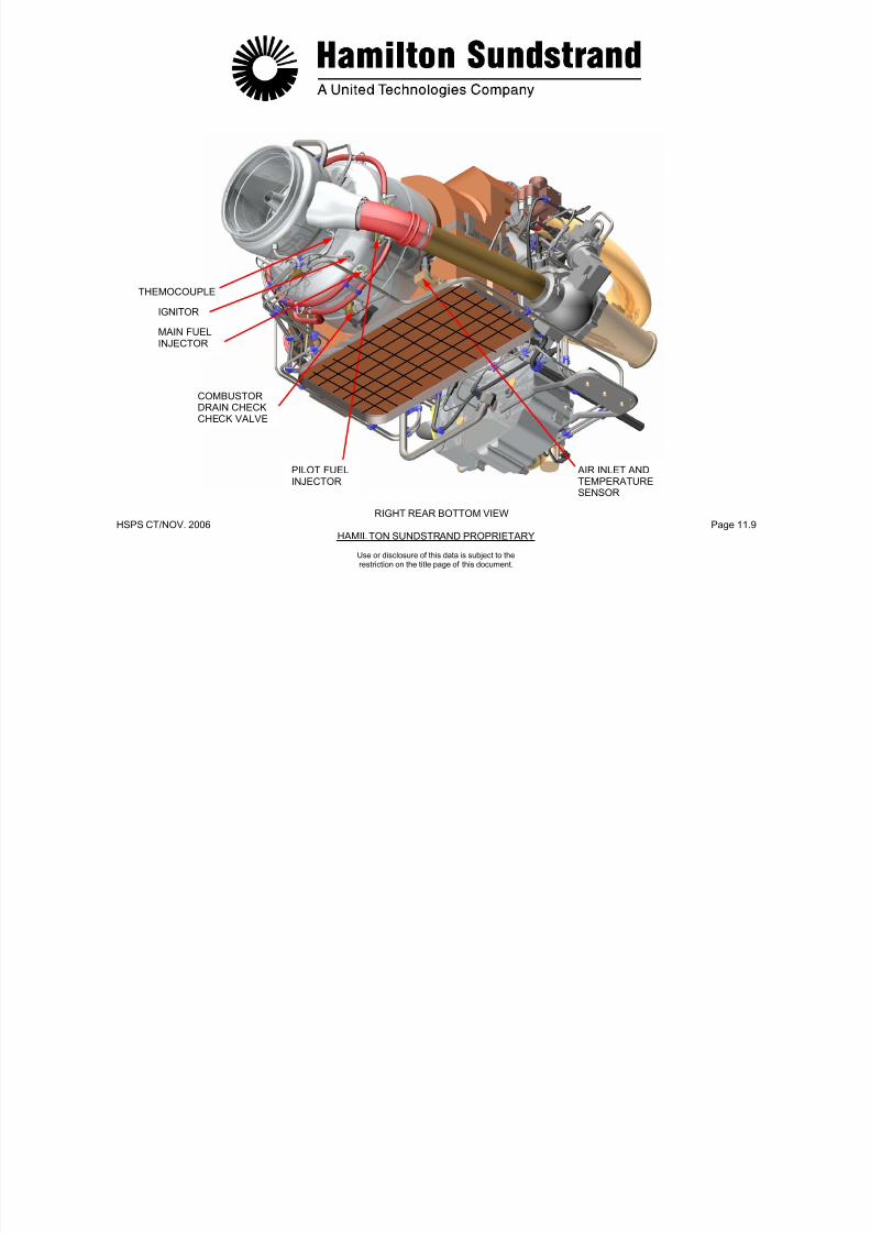
7/21/2019 Aps 3200 Training
http://slidepdf.com/reader/full/aps-3200-training 688/739
HSPS CT/NOV. 2006 Page 12.0HAMILTON SUNDSTRAND PROPRIETARY
Use or disclosure of this data is subject to therestriction on the title page of this document.
GENERAL DESCRIPTION
The centralized fault display system (CFDS) provides electronicsystem fault detection, fault storage, fault displays, operationaltesting and troubleshooting from the flight deck multi-purpose controland display unit (MCDU).
CENTRALIZED FAULT DISPLAY AND INTERFACE UNIT
The CFDIU provides the interface between the APU electronic
control box (ECB) and the MCDU for screen display of APU faultinformation.
MULTIPURPOSE CONTROL AND DISPLAY UNITS
The Multipurpose Control and Display Unit (MCDU) is a display unitand a keyboard used by the CFDS to display and interrogate faultsand to initiate system tests. Both MCDU's (Multipurpose Control andDisplay Unit) are connected to the CFDS.
Only one MCDU can be used when interrogating the CFDS.
CFDIU/PRINTER INTERFACE
The CFDIU sends MCDU screen information and print commands tothe optional printer automatically or on request.
CFDIU/ACARS INTERFACE
The CFDIU sends fault information to the optional ACARS for down-linking when selected manually by the MCDU operator or when anuplink request is received from a ground station via the ACARS
management unit.

7/21/2019 Aps 3200 Training
http://slidepdf.com/reader/full/aps-3200-training 689/739
HSPS CT/NOV. 2006 Page 12.1HAMILTO SUNDSTRAND PROPRIETARY
Use or disclosure of this data is subject to therestriction on the title page of this document.
MCDU - 2
MCDU - 1
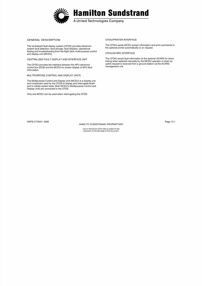
7/21/2019 Aps 3200 Training
http://slidepdf.com/reader/full/aps-3200-training 690/739
HSPS CT/NOV. 2006 Page 12.2HAMILTO SUNDSTRAND PROPRIETARY
CENTRALIZED FAULT DISPLAY SYSTEM
Use or disclosure of this data is subject to therestriction on the title page of this document.
APU FAULT WARNINGS
Flight Deck Fault Warnings are identified as Class 1, 2 and 3.
Class 1 faults are further identified as Level 3, 2 and 1.
CLASS 1
- Level 3- This level corresponds to warnings needing immediate
action.- Level 3 warnings are associated with:
- Repetitive chime- Warning message on upper ECAM display- Master Warning Light flashing Red - APU systems page on lower ECAM display
- Level 2- This level corresponds to abnormal situations needing
immediate awareness but not immediate action.- Level 2 warnings are associated with:
- Single chime- Master caution steady Amber light- Warning messages on upper ECAM display
- APU system page on lower ECAM displayLevel 1
- This level corresponds to reduced bleed air performance- It is associated with low or zero duct pressure- Low or zero duct pressure is visible (lower ECAM display) on
CLASS 2
- These failures are indicated on the STATUS page, under the titleof MAINTENANCE.
- They are also accessible through the CFDS.
indicates that the STATUS page is not empty andflashes in flight phase 10 on the upper ECAM display.STS
CLASS 3
- These failures are only accessible through the CFDS. No APUfault warnings are displayed.
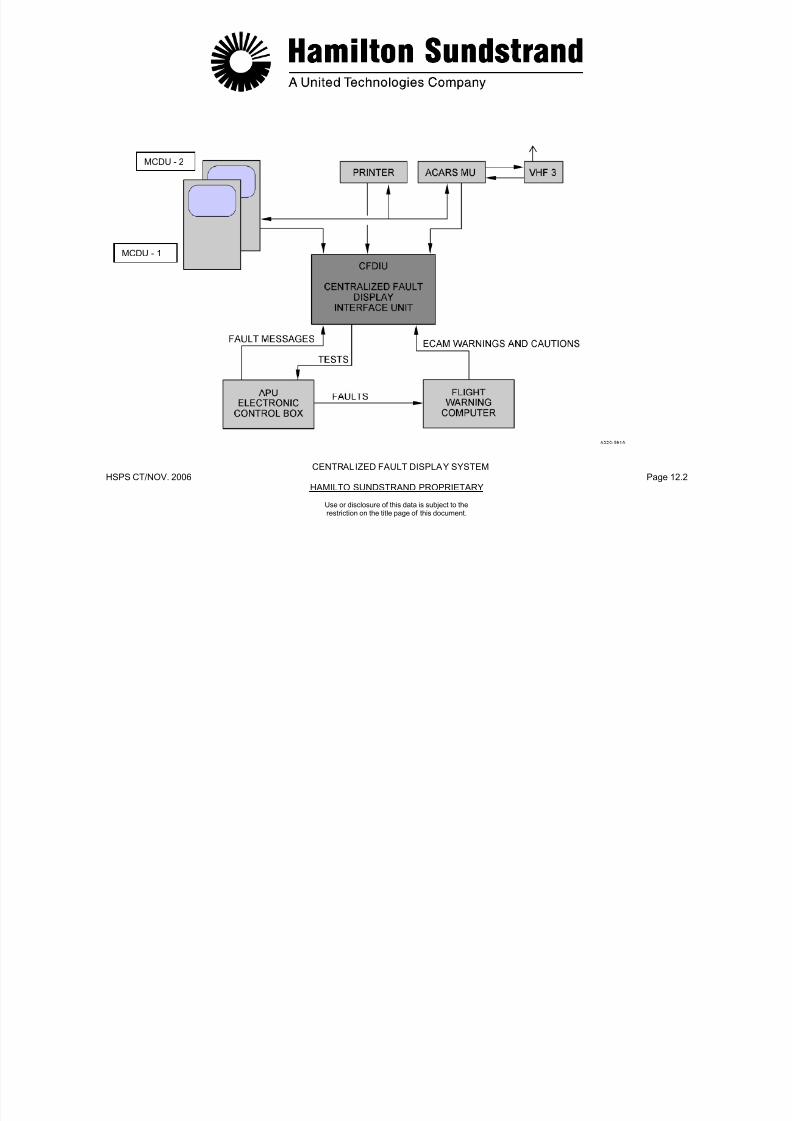
7/21/2019 Aps 3200 Training
http://slidepdf.com/reader/full/aps-3200-training 691/739
HSPS CT/NOV. 2006 Page 12.3HAMILTO SUNDSTRAND PROPRIETARY
Use or disclosure of this data is subject to therestriction on the title page of this document.
p ( p y)the engine system page during MES or on the APUsystem page.
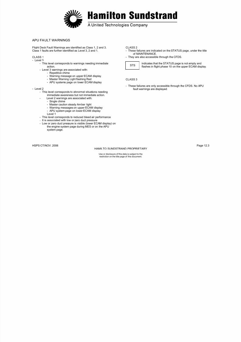
7/21/2019 Aps 3200 Training
http://slidepdf.com/reader/full/aps-3200-training 692/739
HSPS CT/NOV. 2006 Page 12.4HAMILTO SUNDSTRAND PROPRIETARY
APU FAULT WARNINGS
Use or disclosure of this data is subject to therestriction on the title page of this document.
APU FAULT WARNINGS
STATUS
STATUS (STS) indication is an "attention getter" on the upper ECAMdisplay.
STATUS (STS) indicates that a status message (class 1 or class 2fault) is present and further maintenance action may be required. Aflashing STS indication occurs after the second engine shutdown inFlight Phase 10. It is necessary to press the STS key on the ECAMcontrol panel for the STATUS page to appear on the lower ECAMdisplay.
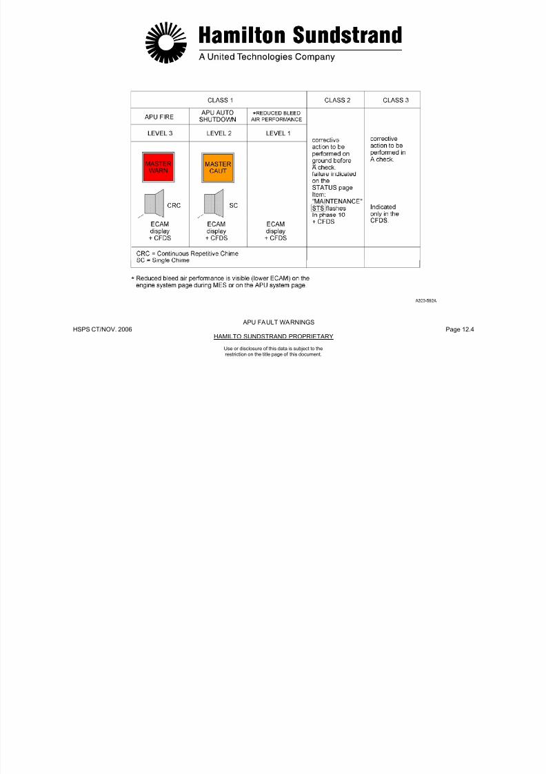
7/21/2019 Aps 3200 Training
http://slidepdf.com/reader/full/aps-3200-training 693/739
HSPS CT/NOV. 2006 Page 12.5HAMILTO SUNDSTRAND PROPRIETARY
Use or disclosure of this data is subject to therestriction on the title page of this document.

7/21/2019 Aps 3200 Training
http://slidepdf.com/reader/full/aps-3200-training 694/739
HSPS CT/NOV. 2006 Page 12.6HAMILTO SUNDSTRAND PROPRIETARY
UPPER ECAM ADVISORY AND STATUS DISPLAY
Use or disclosure of this data is subject to therestriction on the title page of this document.
APU FAULT WARNINGS
ECAM CONTROL PANEL
The control panel allows selection of the aircraft system pageincluding APU. Pressing the Status (STS) key presents the STATUSpage on the lower ECAM display. The STATUS page will indicate thefaulty aircraft systems under the INOP SYS (Class 1 Fault) andMAINTENANCE (Class 2 Fault) titles.
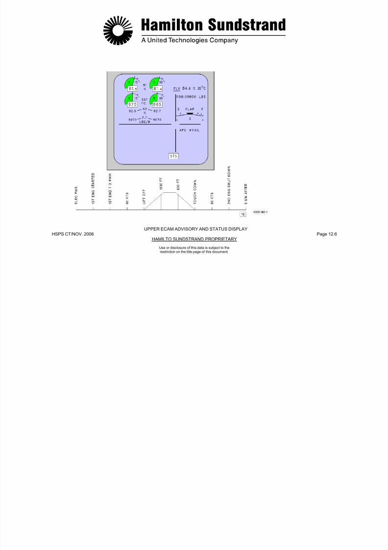
7/21/2019 Aps 3200 Training
http://slidepdf.com/reader/full/aps-3200-training 695/739
HSPS CT/NOV. 2006 Page 12.7HAMILTO SUNDSTRAND PROPRIETARY
Use or disclosure of this data is subject to therestriction on the title page of this document.

7/21/2019 Aps 3200 Training
http://slidepdf.com/reader/full/aps-3200-training 696/739
HSPS CT/NOV. 2006 Page 12.8HAMILTO SUNDSTRAND PROPRIETARY
Use or disclosure of this data is subject to therestriction on the title page of this document.
HSPS CT/NOV. 2006 Page 12.8HAMILTO SUNDSTRAND PROPRIETARY
Use or disclosure of this data is subject to therestriction on the title page of this document.
MULTIPURPOSE CONTROL AND DISPLAY UNITS
The Multipurpose Control and Display Unit (MCDU) is a display unit
and a keyboard used by the CFDS to display and interrogate faultsand to initiate system tests. Both MCDU's (Multipurpose Control andDisplay Unit) are connected to the CFDS.
Only one MCDU can be used when interrogating the CFDS.
Pressing the MCDU MENU key, the MCDU menu page is displayed,and any one of the systems connected to the MCDU can beselected.
A multiple page display is indicated by an arrow (∇) in the right uppercorner of the screen. In this case the NEXT PAGE key must be usedto provide access to the various pages of the display. The NEXTPAGE key can be used as long as the arrow is displayed.
Twelve line select keys, six on the left and six on the right, provideaccess to a page or a function. The line select keys permit access toa page or a function when these prompt symbols appear (>, <). Theyare identified as 1L to 6L on the left, and 1R to 6R on the right.
If a flight deck printer is installed and operational, the current MCDUdisplay screen may be printed by pushing the PRINT line select key.
APU FAULT OPERATION
SYSTEM SELECTION
The MCDU MENU page is displayed when the MCDU MENU key ispushed.
Selecting the CFDS line select key will then display CFDS menu.
Pressing the SYSTEM REPORT/TEST line select key displays theSYSTEM REPORT TEST menu.

7/21/2019 Aps 3200 Training
http://slidepdf.com/reader/full/aps-3200-training 697/739
HSPS CT/NOV. 2006 Page 12.9HAMILTON SUNDSTRAND PROPRIETARY
Use or disclosure of this data is subject to therestriction on the title page of this document.
7/21/2019 Aps 3200 Training
http://slidepdf.com/reader/full/aps-3200-training 698/739
HSPS CT/NOV. 2006 Page 12.10HAMILTO SUNDSTRAND PROPRIETARY
MULTIPURPOSE CONTROL AND DISPLAY UNIT
Use or disclosure of this data is subject to therestriction on the title page of this document.
APU FAULT OPERATION
SYSTEM REPORT/TEST
When SYSTEM REPORT/TEST is selected while on the ground, asystems menu is displayed. The APU selection is located on thesecond page of the menu. Pushing the NEXT PAGE key will display
APU.
Selection of the RETURN line select key on the first page will displayMCDU MENU.
Selection of the RETURN line select key on the second page willdisplay the first page of SYSTEM REPORT/ TEST.
APU
There are two APU menu pages available. The first page displaysthe following information:
LASTLEGREPORT
PREVIOUSLEGREPORT
LRUIDENTIFICATION
SYSTEMSELF-TEST
SHUTDOWNS
The second page of the APU menu when selected by theNEXTPAGE key, displays the following information:
APUDATA/OIL
CLASS3FAULTS
Selection of the RETURN line select key on the First Page willdisplay the Second Page of SYSTEM REPORT/TEST.Selection of the RETURN line select key on the (Second Page) willdisplay the (First Page) of APU menu.

7/21/2019 Aps 3200 Training
http://slidepdf.com/reader/full/aps-3200-training 699/739
HSPS CT/NOV. 2006 Page 12.11HAMILTO SUNDSTRAND PROPRIETARY
Use or disclosure of this data is subject to therestriction on the title page of this document.
d sp ay t e ( st age) o U e u

7/21/2019 Aps 3200 Training
http://slidepdf.com/reader/full/aps-3200-training 700/739
HSPS CT/NOV. 2006 Page 12.12O SUNDSTRAND PROPRIETARYHAMILT
Use or disclosure of this data is subject to therestriction on the title page of this document.
APU FAULT OPERATION
APU LAST LEG REPORT
The Last Leg Report displays fault information delivered by theCFDS system. It can store up to 40 failures during the Last Leg. TheLast LEG Report displays only class 1 and 2 faults and contains theidentity of each LRU, its corresponding Date, GMT, ATA chapter andFault Code Number (FCN) for each fault occurrence. The FunctionalIdentification Number (FIN) appears after each LRU. In the case ofmultiple failures, the failures will be displayed in chronological orderwith two failures per page. A maximum count of four intermittentfaults will only be displayed in the same flight leg. Prompts (>) at the
end of each LRU message indicate the line select key to display the APU FAULT CONDITIONS screen. All of the Last Leg Report isprinted when the PRINT line select key is pushed, even if it containsseveral pages.
Selection of the RETURN line select key will display APU menu,(First Page).
APU PREVIOUS LEGS REPORT
The Last Leg Report contents are transferred into the Previous LegReport with each new flight leg. The report can store up to 200failures over the last 63 flight legs. Each LRU is identified along withthe Aircraft identification, Leg number, Date, GMT, ATA chapter andFault Code Number (FCN) for each fault occurrence. The FunctionalIdentification Number (FIN) appears after each LRU. In the case ofmultiple failures, the failures will be displayed in reversechronological order with two failures per page. Prompts (>) at theend of each LRU message indicate the line select key to display the
APU FAULT CONDITIONS screen. Only the PREVIOUS LEGSREPORT displayed page will be printed when the PRINT line selectkey is pushed.
Selection of the RETURN line select key will display APU menu,(First Page).
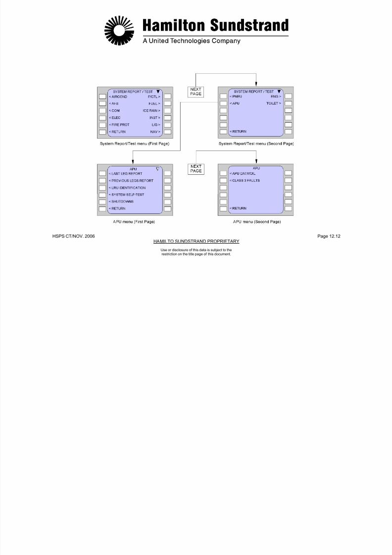
7/21/2019 Aps 3200 Training
http://slidepdf.com/reader/full/aps-3200-training 701/739
HSPS CT/NOV. 2006 Page 12.13HAMILTO SUNDSTRAND PROPRIETARY
Use or disclosure of this data is subject to therestriction on the title page of this document.
APU LAST LEG REPORT APU PREVIOUS LEGS REPORT

7/21/2019 Aps 3200 Training
http://slidepdf.com/reader/full/aps-3200-training 702/739
HSPS CT/NOV. 2006 Page 12.14HAMILTO SUNDSTRAND PROPRIETARY
Use or disclosure of this data is subject to therestriction on the title page of this document.
APU FAULT OPERATION
APU LRU IDENTIFICATION
The LRU Identification page displays the ECB Part Number, ECBSerial Number and the ECB Software Version.
The ECB part number is adjustable and is stored in the NVM. Thebuilt letter (H) following the part number is adjustable from A to Z.
Selection of the RETURN line select key will display APU menu,(First Page).
APU SYSTEM SELF TEST
A self test of LRU's may be initiated through the CFDS. The test canonly be accomplished when the APU is not running and the MasterSwitch is ON. In case of no failures or when the test is in progress, orlack of availability of the test function, the message of TEST OK, INPROGRESS and NOT AVAILABLE will be displayed respectively.Detected failures will be displayed with their ATA Chapter and FaultCode Number (FCN). The Functional Identification Number (FIN)appears after each LRU. In the case of multiple failures, the failureswill be displayed in chronological order with two failures per page.
Only the SYSTEM SELF TEST displayed page will be printed whenthe PRINT line select key is pushed.
Selection of the RETURN line select key will display APU menu,(First Page).
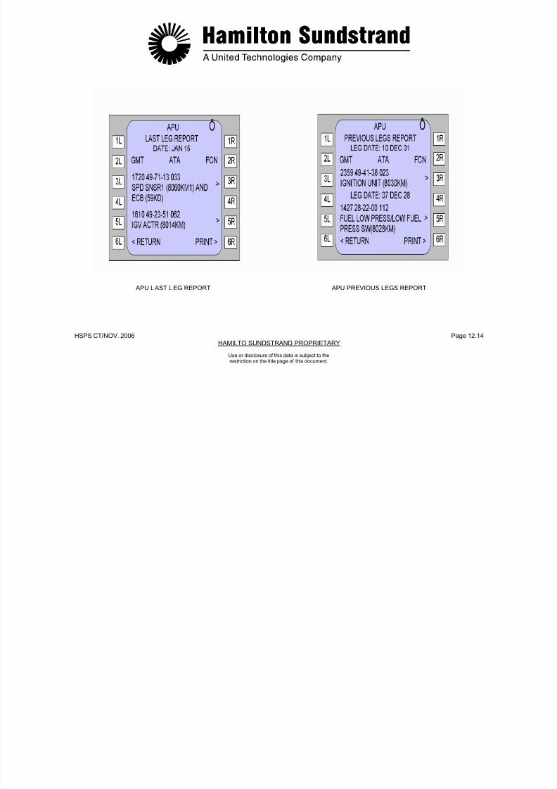
7/21/2019 Aps 3200 Training
http://slidepdf.com/reader/full/aps-3200-training 703/739
HSPS CT/NOV. 2006 Page 12.15HAMILTO SUNDSTRAND PROPRIETARY
Use or disclosure of this data is subject to therestriction on the title page of this document.

7/21/2019 Aps 3200 Training
http://slidepdf.com/reader/full/aps-3200-training 704/739
HSPS CT/NOV. 2006 Page 12.16HAMILTO SUNDSTRAND PROPRIETARY
Use or disclosure of this data is subject to therestriction on the title page of this document.
APU FAULT OPERATION
APU SHUTDOWNS
The Shutdowns page contains its corresponding Date, GMT, FaultCode Number (FCN), shutdown message and the identity of theLRU. The Shutdowns will be displayed in reverse chronological orderwith only one shutdown per page. Prompts (>) at the end of eachLRU message indicate the line select key to display the APU FAULTCONDITIONS screen.
In case there are no shutdowns, the message of NO SHUTDOWNSwill be displayed. Only the SHUTDOWNS displayed page will be
printed when the PRINT line select key is pushed.
Selection of the RETURN line select key will display APU menu,(First Page).
APU DATA/OIL
APU Data/Oil page contains the Date, APU Serial Number (S/N),Hours, Start Attempts, Start Cycles and Oil level status. Prompts (>)at the end of the message indicate the line select key to display the"Update APU Data" screen.
Selection of the RETURN line select key will display APU menu,(Second Page).

7/21/2019 Aps 3200 Training
http://slidepdf.com/reader/full/aps-3200-training 705/739
HSPS CT/NOV. 2006 Page 12.17HAMILTO SUNDSTRAND PROPRIETARY
Use or disclosure of this data is subject to therestriction on the title page of this document.

7/21/2019 Aps 3200 Training
http://slidepdf.com/reader/full/aps-3200-training 706/739
HSPS CT/NOV. 2006 Page 12.18HAMILTO SUNDSTRAND PROPRIETARY
Use or disclosure of this data is subject to therestriction on the title page of this document.
APU FAULT OPERATION
APU CLASS 3 FAULTS
Class 3 Faults can be stored up to 200 failures over the last 63 flightlegs. Each LRU is identified along with the Aircraft identification, Legnumber, GMT, ATA chapter and Fault Code Number (FCN) for eachfault occurrence. The Functional Identification Number (FIN) appearsafter each LRU. In the case of multiple failures, the failures will bedisplayed in reverse chronological order with two failures per page.Prompts (>) at the end of each LRU message indicate the line selectkey to display the APU FAULT CONDITIONS screen.
In case there are NO CLASS 3 FAULTS detected, the message NOFAULTS will be displayed. Only the CLASS 3 FAULTS displayedpage will be printed when the PRINT line select key is pushed.
Selection of the RETURN line select key will display APU menu,(Second Page).
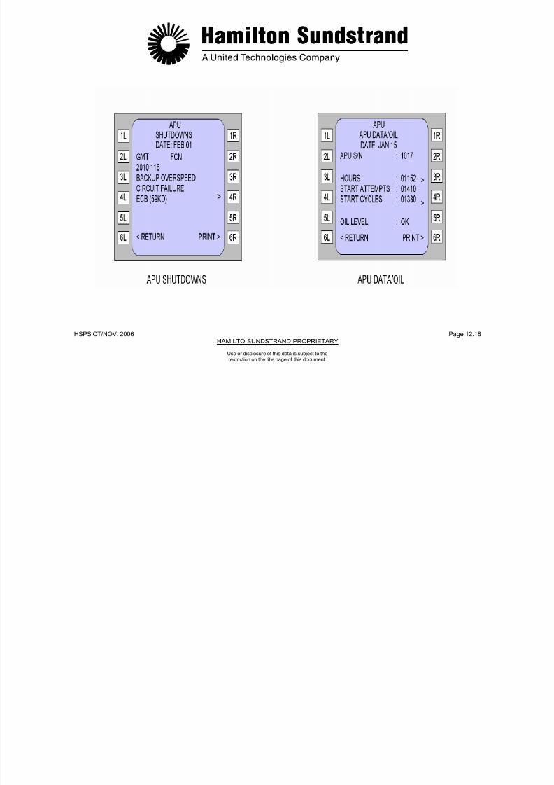
7/21/2019 Aps 3200 Training
http://slidepdf.com/reader/full/aps-3200-training 707/739
HSPS CT/NOV. 2006 Page 12.19HAMILTO SUNDSTRAND PROPRIETARY
Use or disclosure of this data is subject to therestriction on the title page of this document.

7/21/2019 Aps 3200 Training
http://slidepdf.com/reader/full/aps-3200-training 708/739
HSPS CT/NOV. 2006 Page 12.20HAMILTO SUNDSTRAND PROPRIETARY
Use or disclosure of this data is subject to therestriction on the title page of this document.
APU FAULT OPERATION
UPDATE APU DATA
Selection of this screen allows the operator to update the APU hoursand cycles when the ECB or the APU is changed.The Update APU Data screen is only accessible by prompts (>) fromthe APU Data/Oil Screen. The Update APU Data screen displays the
APU Serial Number (S/N), and current values of Hours and Cycles.The new values of hours and cycles can be entered by use of MCDUkeyboard. After line key 3L is pressed (Prompt <) the screen willdisplay the new values for APU hours and cycles when the ECB or
APU is changed.
The HOURS and CYCLES will be printed when the PRINT line selectkey is pushed.
Selection of the RETURN line select key will display the APUDATA/OIL screen.
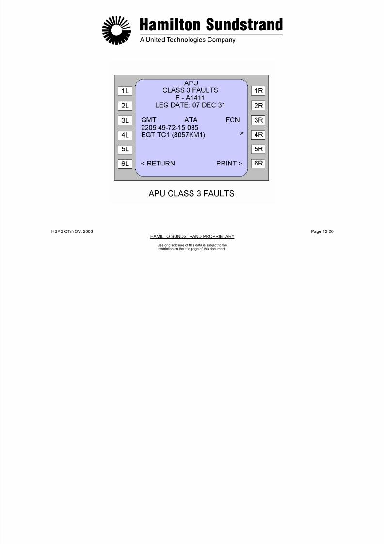
7/21/2019 Aps 3200 Training
http://slidepdf.com/reader/full/aps-3200-training 709/739
HSPS CT/NOV. 2006 Page 12.21HAMILTO SUNDSTRAND PROPRIETARY
Use or disclosure of this data is subject to therestriction on the title page of this document.

7/21/2019 Aps 3200 Training
http://slidepdf.com/reader/full/aps-3200-training 710/739
HSPS CT/NOV. 2006 Page 12.22HAMILTO SUNDSTRAND PROPRIETARY
Use or disclosure of this data is subject to therestriction on the title page of this document.
APU FAULT OPERATION
FAULT CONDITIONS
The Fault Conditions screens are only available by the line selectkeys indicated by prompt (>) on the Last Leg Report, Previous LegsReport, Shutdown and Class 3 fault screens. Selection will displaythe Fault Conditions screen-1 or screen-2. Each screen will displaythe APU S/N, Date, GMT and the identity of the LRU. The FunctionalIdentification Number (FIN) appears after the LRU.Engine data from the fault data stored in the Electronic Control Boxnon-volatile memory will also appear on each screen. (See Screen-1and Screen-2 Parameters on page 12-24).
One screen at a time is displayed. To select screen-2 when screen-1is displayed or select screen-1 when screen-2 is displayed it isnecessary to press the NEXT PAGE key on the Multipurpose Controland Display Unit (MCDU).
Only the screen that is displayed (Screen-1 or Screen-2) will beprinted when the PRINT line select key is pushed.
Selection of the RETURN line select key will display the screen thatwas shown preceding selection of the Fault Selection Screens.
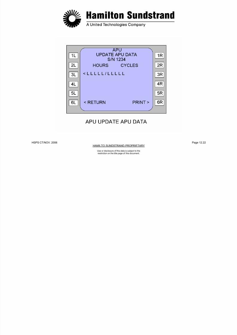
7/21/2019 Aps 3200 Training
http://slidepdf.com/reader/full/aps-3200-training 711/739
HSPS CT/NOV. 2006 Page 12.23HAMILTO SUNDSTRAND PROPRIETARY
Use or disclosure of this data is subject to therestriction on the title page of this document.
7/21/2019 Aps 3200 Training
http://slidepdf.com/reader/full/aps-3200-training 712/739
HSPS CT/NOV. 2006 Page 12.24HAMILTO SUNDSTRAND PROPRIETARY
Use or disclosure of this data is subject to therestriction on the title page of this document.
FLIGHT DECK PRINTER
The Printer provides onboard printouts concerning various aircraftsystems, one at a time.
MANUAL PRINT
In manual mode, prints of the MCDU screen display are printedwhen the PRINT line select key is pushed.
AUTOMATIC PRINT
In flight phase 10, the Post Flight Report will be automatically
printed. The Post Flight Report is the sum of the LAST LEGREPORT and the LAST LEG ECAM REPORT.
A list of ECAM Warnings and Fault Messages with the associatedtime and ATA chapter references are provided on the printed tape.

7/21/2019 Aps 3200 Training
http://slidepdf.com/reader/full/aps-3200-training 713/739
HSPS CT/NOV. 2006 Page 12.25HAMILTO SUNDSTRAND PROPRIETARY
Use or disclosure of this data is subject to therestriction on the title page of this document.

7/21/2019 Aps 3200 Training
http://slidepdf.com/reader/full/aps-3200-training 714/739
HSPS CT/NOV. 2006 Page 12.26HAMILTO SUNDSTRAND PROPRIETARY
FLIGHT DECK PRINTER
Use or disclosure of this data is subject to therestriction on the title page of this document.
FAULT CHARTS
The following Fault Charts provide the information that will be sent tothe CFDS by the ECB in the event of a fault.
The information appears in the Fault Chart columns located underthe following headings:
Version 5.0
MCDU LRU MessageMCDU Shutdown MessageFault CodeFault Class
LRU ID ATA ChapterSystem Severity level
SYSTEM SEVERITY LEVEL
System Severity Levels are not sent to the CFDS. It is presentedhere only as information.
Once a fault has been identified with a switch or a sensor thatcomponent will no longer be used for further fault detection, isolationor control until the fault is no longer present. Detected faults can becleared and a restart may be possible once the master switch iscycled.
SYSTEMSEVERITY LEVEL ECB ACTION ECB MESSAGE
1 SHUTDOWN TRANSMIT FAULTMESSAGE
2 SHUTDOWN TRANSMIT FAULTMESSAGE
3 SHUTDOWN IF REDUNDANTSOURCE NOT AVAILABLE
TRANSMIT FAULTMESSAGE
4 CONTINUE TO OPERATE TRANSMIT FAULTMESSAGE
X NOT APPLICABLE
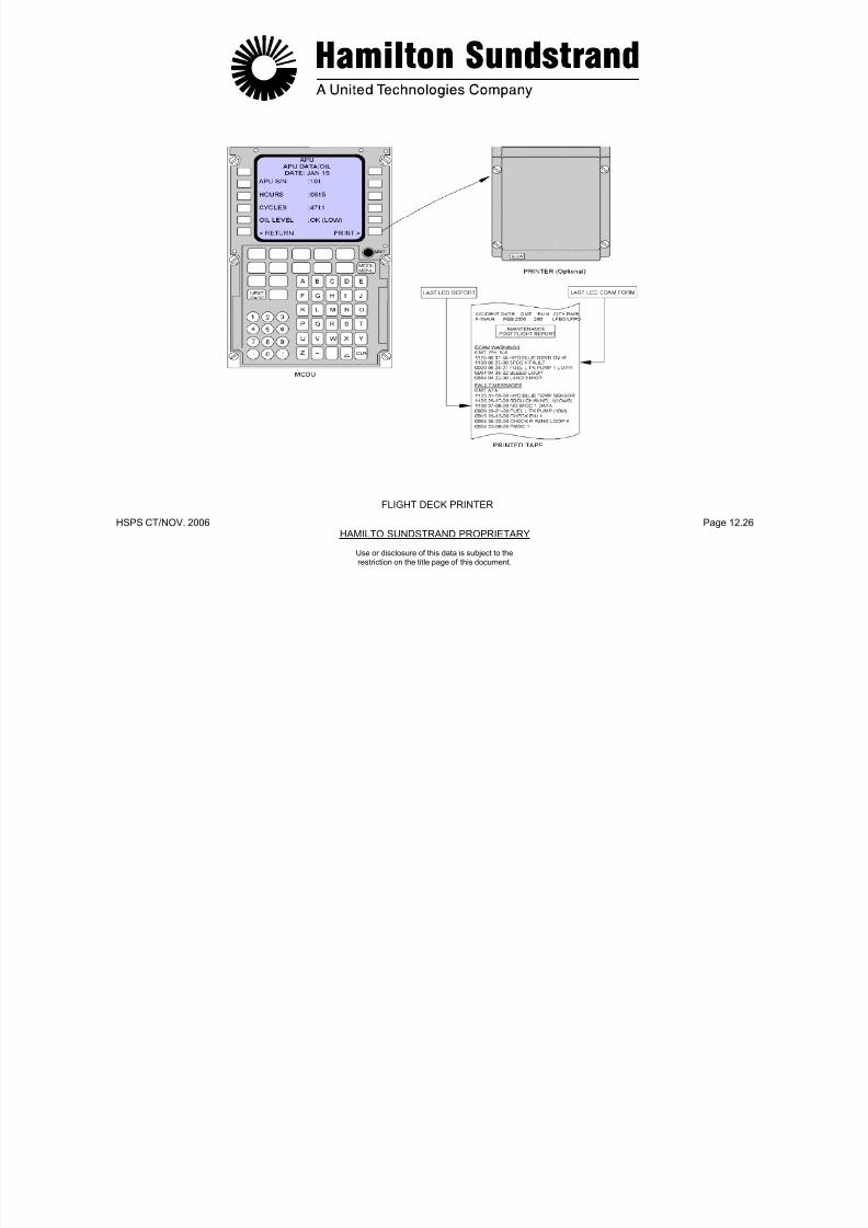
7/21/2019 Aps 3200 Training
http://slidepdf.com/reader/full/aps-3200-training 715/739
HSPS CT/NOV. 2006 Page 12.27HAMILTO SUNDSTRAND PROPRIETARY
Use or disclosure of this data is subject to therestriction on the title page of this document.
P OWE R U
P
WA T C H
S T A RT P RE P
S T A RT I N G
R UN
C O OL D OW
N
S H UT D OW
N
S E L F T E S
T
MCDULRU
MESSAGE
MCDUSHUTDOWNMESSAGE
FAULTCODE
FAULTCLASS
LRUID
ATACHAPTER
SYSTEM SEVERITY LEVEL
BLD FLOW XDCR (8039KM) 0 1 13 495112 4 4 4 4 4 4 4 4
BLD FLOW XDCR (8039KM) 1 1 13 495112 4 4 4 4 4 4 4 4
COOLING FAN PMG ASSY (8055KM) 2 1 53 495253 X X X 4 4 4 4 X
BLD FLOW XDCR (8039KM) 3 1 13 495112 4 4 4 4 4 4 4 4
INLET T-P SNSR (8013KM) 4 1 29 492317 4 4 4 4 4 4 4 4
INLET T-P SNSR (8013KM) 5 1 29 492317 4 4 4 4 4 4 4 4
INLET T-P SNSR (8013KM) 6 1 29 492317 4 4 4 4 4 4 4 4
(BLANK) 7
INLET T-P SNSR (8013KM) 8 1 29 492317 4 4 4 4 4 4 4 4
INLET T-P SNSR (8013KM) 9 1 29 492317 4 4 4 4 4 4 4 4
GENERATOR (8XS) 10 3 25 242351 3 3 3 3 3 3 3 3
GENERATOR (8XS) 11 3 25 242351 3 3 3 3 3 3 3 3
OIL TEMP SNSR (8084KM) 12 3 38 499151 3 3 3 3 3 3 3 3
OIL TEMP SNSR (8084KM) 13 3 38 499151 3 3 3 3 3 3 3 3
ECB (59KD) 14 3 14 496134 4 4 4 4 4 4 4 4
ECB (59KD) 15 3 14 496134 4 4 4 4 4 4 4 4
DE-OILING SOL (8083KM) 16 3 12 499149 4 X X 4 X X 4 4
CONTACTOR (5KA) 17 1 59 494255 X X X 4 X X X X
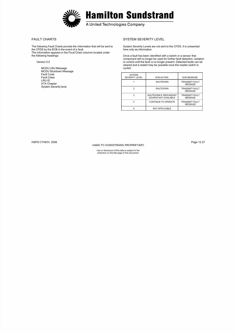
7/21/2019 Aps 3200 Training
http://slidepdf.com/reader/full/aps-3200-training 716/739
HSPS CT/ NOV. 2006 Page 12.28HAMILTON SUNDSTRAND PROPRIETARY
Use or disclosure of this data is subject to therestriction on the title page of this document.
CONTACTOR (5KA) 17 1 59 494255 X X X 4 X X X X
CONTACTOR (10KA) 18 1 10 494255 X X X 4 X X X X
P OWE R U
P
WA T C H
S T A RT P RE P
S T A RT I N G
R UN
C O OL D OW
N
S H UT D OW
N
S E L F T E S
T
MCDULRU
MESSAGE
MCDUSHUTDOWNMESSAGE
FAULTCODE
FAULTCLASS
LRUID
ATACHAPTER
SYSTEM SEVERITY LEVEL
WRG: ECB PIN AB-H9 19 3 45 496100 X X X 4 X X X X
WRG: ECB PIN AB-J6 20 3 3 496100 X X X X 4 4 X X
FUEL CTL UNIT (8022KM) 21 1 21 493211 4 X X 4 4 4 X 4
WRG: ECB PIN AB-H8 22 2 6 496100 X X X X 4 X X X
EXCITER SHORTED 23 1 26 494138 X X X 4 X X X X
ECB (59KD) 24 2 14 496134 4 4 4 4 4 4 X 4
INLET FLAP ACTR (4015KM) 25 2 2 491651 4 4 X X X X 4 4
INLET FLAP ACTR (4015KM) 26 2 2 491651 4 4 X X X X 4 4
ECB (59KD) 27 3 14 496134 4 4 X X X X 4 4
ECB (59KD) 28 3 14 496134 3 3 3 3 3 3 3 3
SPEED SNSR1 (8060KM1) 29 3 40 497113 X X 3 3 3 3 3 X
ECB (59KD) 30 3 14 496134 X X X 3 3 3 X X
ECB (59KD) 31 3 14 496134 3 3 3 3 3 3 3 3
SPEED SNSR2 (8060KM2) 32 3 42 497113 X X 3 3 3 3 3 X
SPEED SNSR1 (8060KM1) ANDSPEED SNSR2 (8060KM2)
LOSS OF SPEED 33 1 44 497113 1 1 1 1 1 1 1 1
(SPEED SENSORS DO NOT MATCH - NO TEXT) 34 3 NO TEXT 4 4 4 4 4 4 4 4
EGT TC1 (8075KM1) 35 3 15 497215 X X X 3 3 3 X X
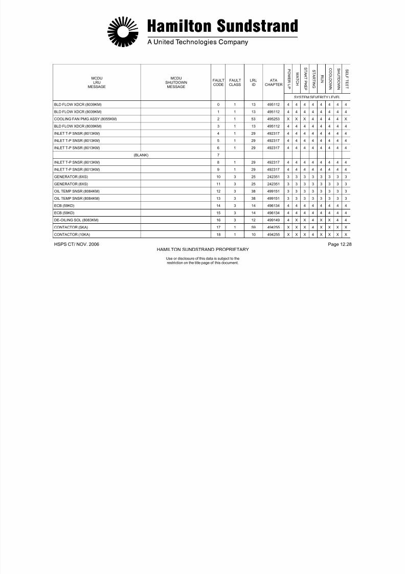
7/21/2019 Aps 3200 Training
http://slidepdf.com/reader/full/aps-3200-training 717/739
HSPS CT/NOV. 2006 Page 12.29HAMILTON SUNDSTRAND PROPRIETARY
Use or disclosure of this data is subject to therestriction on the title page of this document.
EGT TC1 (8057KM1) 36 3 15 497215 3 3 3 3 3 3 3 3
P OWE R U
P
WA T C H
S T A RT P RE P
S T A RT I N G
R UN
C O OL D OW
N
S H UT D OW
N
S E L F T E S
T
MCDULRU
MESSAGE
MCDUSHUTDOWNMESSAGE
FAULTCODE
FAULTCLASS
LRUID
ATACHAPTER
SYSTEM SEVERITY LEVEL
EGT TC2 (8057KM2) 37 3 18 497215 X X X 3 3 3 X X
EGT TC2 (8057KM2) 38 3 18 497215 3 3 3 3 3 3 3 3
GEN SCAN FILTER (8069KM) ANDLUB FILTER (8076KM)
39 2 7 499141 4 4 4 4 4 4 4 X
- LOSS OF DC POWER 40 1 - - X X X 1 1 1 X X
SERIAL NUMBER ENCODER (8061KM) 41 3 39 497331 4 X X X X X X 4
IGNITION UNIT (8030KM) NO FLAME 42 1 26 494138 X X X 1 X X X X
ECB (59KD) NO FLAME 42 1 14 496134 X X X 1 X X X X
FUEL CONTROL UNIT (8022KM) NO FLAME 42 1 21 493211 X X X 1 X X X X
CHECK APU FUEL SUPPLY NO FLAME 42 1 70 282200 X X X 1 X X X X
IGNITION UNIT (8030KM)FUEL CONTROL (8022KM)
NO FLAME 42 1 27 494138 X X X 1 X X X X
OIL PRESS SW (8091KM) 43 2 36 499414 4 4 X X X X X 4
CHECK OIL LEAKAGE/OIL PRESS SW (8091KM) LOW OIL PRESSURE 44 1 37 499100 X X X 2 2 2 X X
CHECK OIL LEAKAGE/OIL PRESS SW (8091KM) LOW OIL PRESSURE 45 1 37 499100 X X X 2 2 2 X X
CHECK OIL COOLER ASSY HIGH OIL TEMPERATURE 46 1 9 499144 X X X 2 2 2 X X
CHECK OIL SYSTEM/GENERATOR (8XS) GEN HIGH OIL TEMP 47 1 24 499100 X X X 2 2 2 X X
LOW OIL LEVEL 48 2 32 499300 4 4 X X X X X 4
OIL LEVEL SNSR (8089KM) 49 2 35 499317 4 4 X X X X X 4

7/21/2019 Aps 3200 Training
http://slidepdf.com/reader/full/aps-3200-training 718/739
HSPS CT/NOV. 2006 Page 12.30HAMILTON SUNDSTRAND PROPRIETARY
Use or disclosure of this data is subject to therestriction on the title page of this document.
OIL LEVEL SNSR (8089KM) 49 2 35 499317 4 4 X X X X X 4
OIL LEVEL SNSR (8089KM) 50 2 35 499317 4 4 X X X X X 4
P OWE R U
P
WA T C H
S T A RT P RE P
S T A RT I N G
R UN
C O OL D OW
N
S H UT D OW
N
S E L F T E S
T
MCDULRU
MESSAGE
MCDUSHUTDOWNMESSAGE
FAULTCODE
FAULTCLASS
LRUID
ATACHAPTER
SYSTEM SEVERITY LEVEL
ACFT BAT NOT SELECTED/CONTACTOR (5KA) NO ACCELERATION 51 1 11 243800 X X X 1 X X X X
CONTACTOR (5KA) NO ACCELERATION 51 1 59 494255 X X X 1 X X X X
CONTACTOR (10KA) NO ACCELERATION 51 1 10 494255 X X X 1 X X X X
CURRENT LIMITER (6KA)/CONTACTOR (10KA) NO ACCELERATION 51 1 51 494200 X X X 1 X X X X
STATOR MOTOR (8KA)/STARTERCLUTCH
(8033KM)
NO ACCELERATION 51 1 46 494251 X X X 1 X X X X
ECB (59KD) NO ACCELERATION 52 1 14 496134 X X X 1 X X X X
FUEL CTL UNIT (8022KM) NO ACCELERATION 52 1 21 493211 X X X 1 X X X X
CHECK APU FUEL SUPPLY NO ACCELERATION 52 1 70 282200 X X X 1 X X X X
FUEL CTL UNIT (8022KM)/FLOW DIVIDER(8024KM)
NO ACCELERATION 52 1 23 493211 X X X 1 X X X X
FUEL CTL UNIT (8022KM) NO ACCELERATION 53 1 21 493211 X X X 2 X X X X
ECB (59KD) NO ACCELERATION 53 1 14 496134 X X X 2 X X X X
DE-OILING SOL (8083KM) NO ACCELERATION 53 1 12 499149 X X X 2 X X X X
IGV ACTR (8014KM) NO ACCELERATION 53 1 28 492351 X X X 2 X X X X
STARTER MOTOR (8KA)/BLD CTL VLV (8051KM) NO ACCELERATION 53 1 46 494251 X X X 2 X X X X
FLOW DIVIDER (8024KM) NO ACCELERATION 53 1 68 493213 X X X 2 X X X X
FLOW CTL UNIT (8022KM) NO ACCELERATION 53 1 21 493211 X X X 2 X X X X
ECB (59KD) 54 3 14 496134 4 X X X X X X 4
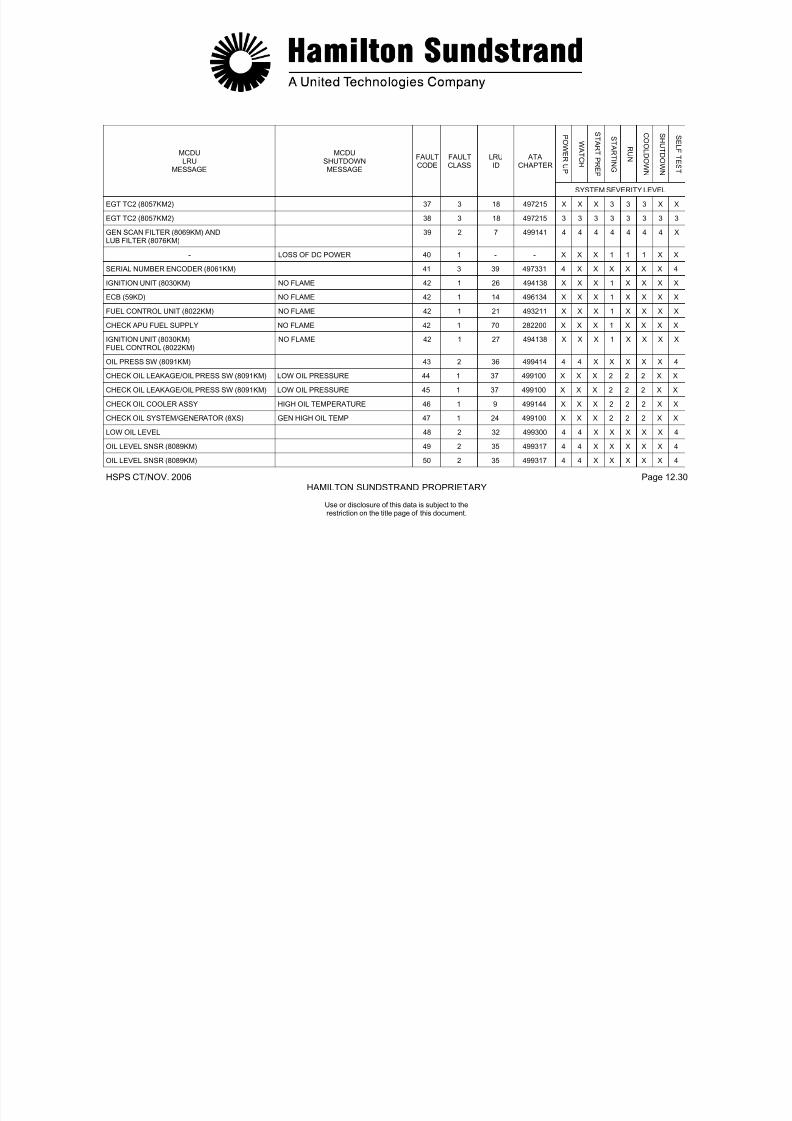
7/21/2019 Aps 3200 Training
http://slidepdf.com/reader/full/aps-3200-training 719/739
HSPS CT/NOV. 2006 Page 12.31HAMILTON SUNDSTRAND PROPRIETARY
Use or disclosure of this data is subject to therestriction on the title page of this document.
ECB (59KD) 54 3 14 496134 4 X X X X X X 4
ECB (59KD) 55 3 14 496134 4 X X X X X X 4
P OWE R U
P
WA T C H
S T A RT P RE P
S T A RT I N G
R UN
C O OL D OW
N
S H UT D OW
N
S E L F T E S
T
MCDULRU
MESSAGE
MCDUSHUTDOWNMESSAGE
FAULTCODE
FAULTCLASS
LRUID
ATACHAPTER
SYSTEM SEVERITY LEVEL
ECB (59KD) 56 3 14 496134 4 X X X X X X 4
INLET FLAP ACTR (4015KM) 57 2 2 491651 4 4 4 4 4 4 4 4
INLET FLAP ACTR (4015KM) 58 2 2 491651 X 4 4 4 X X 4 4
FUEL CTL UNIT (8022KM) 59 1 21 493211 4 X X X X X X 4
FUEL CTL UNIT (8022KM) 60 1 21 493211 4 X X X X X X 4
ECB (59KD) ECB FAILURE 61 1 14 496134 X X X 2 2 2 X X
IGV ACTR (8014KM) 62 1 28 492351 X X X X 4 X X X
IGV ACTR (8014KM) 63 1 28 492351 X X X X 4 X X X
ECB (59KD) 64 2 14 496134 X X X X 4 X X X
(BLANK) 56
ECB (59KD) 66 2 14 496134 X X X X 4 X X X
ECB (59KD) UNDERSPEED 67 1 14 496134 X X X X 1 1 X X
CHECK APU FUEL SUPPLY UNDERSPEED 67 1 70 282200 X X X X 1 1 X X
FUEL CTL UNIT (8022KM) UNDERSPEED 67 1 21 493211 X X X X 1 1 X X
SPD SNSR1 (8060KM1) ANDSPD SNSR2 (8060KM2)
OVERSPEED 68 1 44 497113 X X X 1 1 1 X X
ECB (59KD) OVERSPEED 68 1 14 496134 X X X 1 1 1 X X
FUEL CTL UNIT (8022KM) OVERSPEED 68 1 21 493211 X X X 1 1 1 X X
C ( )

7/21/2019 Aps 3200 Training
http://slidepdf.com/reader/full/aps-3200-training 720/739
HSPS CT/NOV. 2006 Page 12.32HAMILTON SUNDSTRAND PROPRIETARY
Use or disclosure of this data is subject to therestriction on the title page of this document.
BLEED CTL VLV (8051KM) 69 1 5 495153 X X X X 4 X X X
P OWE R U
P
WA T C H
S T A RT P RE P
S T A RT I N G
R UN
C O OL D OW
N
S H UT D OW
N
S E L F T E S
T
MCDULRU
MESSAGE
MCDUSHUTDOWNMESSAGE
FAULTCODE
FAULTCLASS
LRUID
ATACHAPTER
SYSTEM SEVERITY LEVEL
BLEED CTL VLV (8051KM) 70 1 5 495153 X X X X 4 X X X
ECB (59KD) 71 1 14 496134 X X X X 4 X X X
(BLANK) 27
ECB (59KD) 73 2 14 496134 X X X X 4 X X X
ECB (59KD) ECB FAILURE 74 1 14 496134 1 X X X X X X X
ECB (59KD) 75 3 14 496134 4 4 4 4 4 4 4 4
ECB (59KD) 76 3 14 496134 4 4 4 4 4 4 4 4
ECB (59KD) 77 3 14 496134 4 4 4 4 4 4 4 4
ECB (59KD) 78 3 14 496134 4 4 4 4 4 4 4 4
ECB (59KD) 79 3 14 496134 4 4 4 4 4 4 4 4
ECB (59KD) 80 3 14 496134 4 4 4 4 4 4 4 4
ECB (59KD) 81 3 14 496134 4 X 4 4 4 4 X 4
ECB (59KD) 82 2 14 496134 4 4 4 4 4 4 4 4
ECB (59KD) 83 3 14 496134 4 4 4 4 4 4 4 4
DE-OILING SOL (8083KM) 84 3 12 499149 4 X X 4 X X 4 4
ACFT BAT NOT SELECTED/CONTACTOR (5KA)
85 1 11 243800 X X X 4 X X X X
CONTACTOR (10KA) 86 1 10 494255 X X X 4 X X X X
WRG ECB PIN AB H9 87 3 45 496100 X X X 4 X X X X
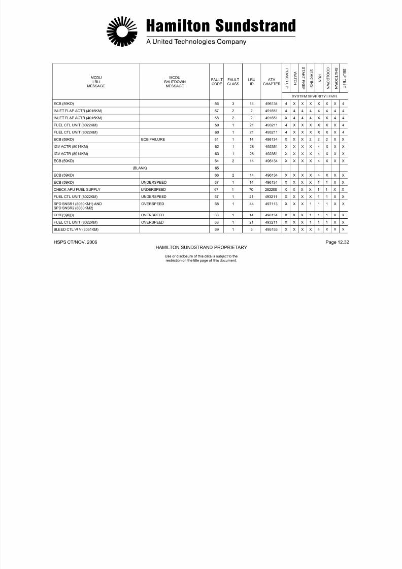
7/21/2019 Aps 3200 Training
http://slidepdf.com/reader/full/aps-3200-training 721/739
HSPS CT/NOV. 2006 Page 12.33HAMILTON SUNDSTRAND PROPRIETARY
Use or disclosure of this data is subject to therestriction on the title page of this document.
WRG: ECB PIN AB-H9 87 3 45 496100 X X X 4 X X X X
P OWE R U
P
WA T C H
S T A RT P RE
P
S T A RT I N G
R UN
C O OL D OW
N
S H UT D OW
N
S E L F T E S
T
MCDULRU
MESSAGE
MCDUSHUTDOWNMESSAGE
FAULTCODE
FAULTCLASS
LRUID
ATACHAPTER
SYSTEM SEVERITY LEVEL
WRG: ECB PIN AB-J6 88 3 3 496100 X X X X 4 4 X X
FUEL CTL UNIT (8022KM) 89 1 21 493211 4 X X 4 4 4 X 4
WRG: ECB PIN AB-H8 90 2 6 496100 X X X X 4 X X X
IGNITION UNIT (8030KM) 91 1 26 494138 X X X 4 X X X X
SPEED SNSR1 (8060M1) 92 3 40 497113 3 3 3 3 3 3 3 3
SPEED SNSR1 (8060M1) 93 3 40 497113 3 3 3 3 3 3 3 X
SPEED SNSR2 (8060KM2) 94 3 42 497113 3 3 3 3 3 3 3 3
SPEED SNSR2 (8060KM2) 95 3 42 497113 3 3 3 3 3 3 3 X
BLEED CTL VLV (8051KM) 96 1 5 495153 X X X X 4 4 X X
BLEED CTL VLV (8051KM) SURGE/REVERSE FLOW 97 1 5 495153 X X X X 2 2 X X
IGV ACTR (8014KM) OVERTEMPERATURE 98 1 28 492351 X X X 2 2 2 X X
EGT TC1 (8057KM1) OVERTEMPERATURE 98 1 15 497215 X X X 2 2 2 X X
EGT TC2 (8057KM2) OVERTEMPERATURE 98 1 18 497215 X X X 2 2 2 X X
FUEL CTL UNIT (8022KM) OVERTEMPERATURE 98 1 21 493211 X X X 2 2 2 X X
FUEL CTL UNIT (8022KM) 99 1 21 493211 X X X X X X 1 X
ECB (59KD) 100 2 14 496134 3 X X X X X X 3
ECB (59KD) 101 2 14 496134 3 X X X X X X 3
EGT TC1 (8057KM1) ANDEGT TC2 (8057KM2)
SENSOR FAILURE 102 1 16 497215 2 2 2 2 2 2 2 2
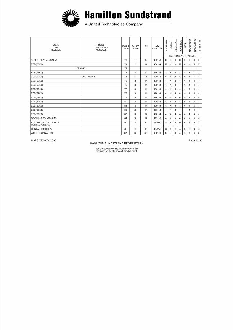
7/21/2019 Aps 3200 Training
http://slidepdf.com/reader/full/aps-3200-training 722/739
HSPS CT/NOV. 2006 Page 12.34HAMILTON SUNDSTRAND PROPRIETARY
Use or disclosure of this data is subject to therestriction on the title page of this document.
EGT TC2 (8057KM2)
P OWE R UP
WA T C H
S T A RT P RE
P
S T A RT I N G
R UN
C O OL D OW
N
S H UT D OW
N
S E L F T E S T
MCDULRU
MESSAGE
MCDUSHUTDOWNMESSAGE
FAULTCODE
FAULTCLASS
LRUID
ATACHAPTER
SYSTEM SEVERITY LEVEL
BLD FLOW XDCR (8039KM) 103 1 13 495112 4 4 4 4 4 4 4 4
ECB (59KD) ECB FAILURE 104 1 14 496134 1 1 1 1 1 1 1 1
ECB (59KD) ECB FAILURE 105 1 14 496134 1 1 1 1 1 1 1 1
NO DATA FROM ECS 106 3 34 216334 X X X X 4 X X X
ECB (59KD) 107 2 14 496134 X 4 4 4 4 4 4 4
ECB (59KD) ECB FAILURE 108 1 14 496134 X 1 1 1 1 1 1 1
ECB (59KD) ECB FAILURE 109 1 14 496134 X 1 1 1 1 1 1 1
ECB (59KD) ECB FAILURE 110 1 14 496134 X 1 1 1 1 1 1 1
ECB (59KD) ECB FAILURE 111 1 14 496134 X 1 1 1 1 1 1 1
FUEL LOW PRESS/LOW FUEL PRESS SW(5030QM)
112 2 31 282214 X X X 4 4 4 X X
- EMERGENCY STOP 113 1 NO TEXT - 1 1 1 1 1 1 1 1
COOLING FAN PMG ASSY (8055KM) SENSOR FAILURE 114 1 53 495253 X X X 1 X X X X
ECB (59KD) BACKUP OVERSPEED 115 1 14 496134 X 1 1 1 1 1 1 1
SPD SNSR1 (8060KM1) ANDSPD SNSR2 (8060KM2)
BACKUP OVERSPEED 115 1 44 497113 X 1 1 1 1 1 1 1
FUEL CTL UNIT (8022KM) BACKUP OVERSPEED 115 1 21 493211 X 1 1 1 1 1 1 1
COOLING FAN PMG ASSY (8055KM) BACKUP OVERSPEED 115 1 53 495253 X 1 1 1 1 1 1 1
ECB (59KD) BACKUP OVERSPEEDCIRCUIT FAILURE
116 1 14 496134 1 X X X X X X X

7/21/2019 Aps 3200 Training
http://slidepdf.com/reader/full/aps-3200-training 723/739
HSPS CT/NOV. 2006 Page 12.35HAMILTON SUNDSTRAND PROPRIETARY
Use or disclosure of this data is subject to therestriction on the title page of this document.
CIRCUIT FAILURE
P OWE R UP
WA T C H
S T A RT P RE
P
S T A RT I N G
R UN
C O OL D OW
N
S H UT D OW
N
S E L F T E S T
MCDULRU
MESSAGE
MCDUSHUTDOWNMESSAGE
FAULTCODE
FAULTCLASS
LRUID
ATACHAPTER
SYSTEM SEVERITY LEVEL
ECB (59KD) 117 1 14 496134 4 X X X X X X 4
CHECK APU FUEL SUPPLY 118 1 70 282200 X X X X 4 4 4 X
IGV ACTR (8014KM) 118 1 28 492351 X X X X 4 4 4 X
CHECK APU FUEL SUPPLY 119 1 70 282200 X X X X 4 4 4 X
BLEED CTL VLV (8051KM) 119 1 5 495153 X X X X 4 4 4 X
INLET FLAP ACTR (4015KM) 120 2 2 491651 X X X X X X 4 X
INLET FLAP ACTR (4015KM) AIR INTAKE NOT OPEN 121 1 2 491651 X 1 1 X X X X 1
OIL TEMP SNSR (8084KM) AND GENERATOR(8XS)`
SENSOR FAILURE 122 1 50 499151 2 2 2 2 2 2 2 2
ECB (59KD)/APU HARNESS (8001KM) 123 1 8 496134 4 4 4 4 4 4 4 4
WRG: ACFT TYPE PIN/FCB (59KD) 124 3 47 496100 4 X X X X X X X
WRG: ECB PIN AB-H5 125 3 4 496100 4 4 4 4 4 4 4 4
CURRENT LIMITER (6KA)/CONTACTOR (10KA) 126 1 51 494200 X X X 4 X X X X
CONTACTOR (10KA) 127 3 10 494255 X X X 4 X X X X
CONTACTOR (5KA) 128 1 59 494255 X X X 4 X X X X
CONTACTOR (5KA) 129 3 59 494255 X X X 4 X X X X
SERIAL NUMBER ENCODER (8061KM) 130 3 39 497331 4 X X X X X X 4
(BLANK) 131
ECB (59KD) ECB FAILURE 132 1 14 496134 1 X X X X X X 1
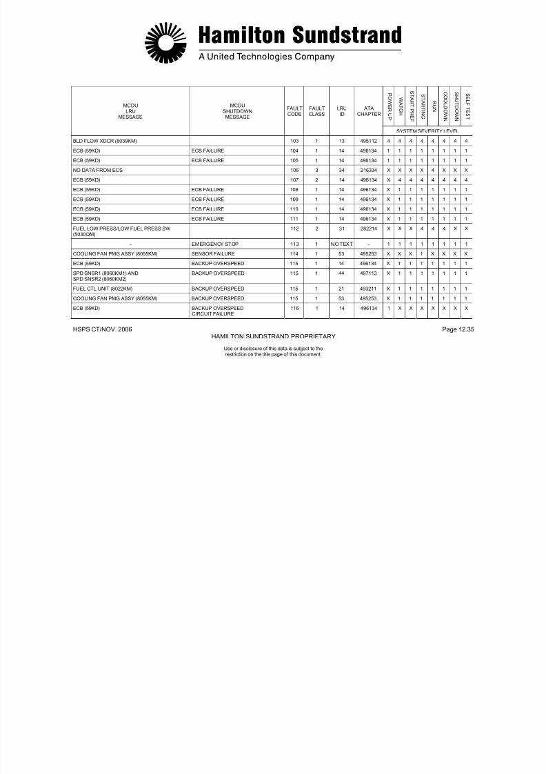
7/21/2019 Aps 3200 Training
http://slidepdf.com/reader/full/aps-3200-training 724/739
HSPS CT/NOV. 2006 Page 12.36HAMILTON SUNDSTRAND PROPRIETARY
Use or disclosure of this data is subject to therestriction on the title page of this document.
( )
P OWE R UP
WA T C H
S T A RT P RE
P
S T A RT I N G
R UN
C O OL D OW
N
S H UT D OW
N
S E L F T E S T
MCDULRU
MESSAGE
MCDUSHUTDOWNMESSAGE
FAULTCODE
FAULTCLASS
LRUID
ATACHAPTER
SYSTEM SEVERITY LEVEL
FIRE EMERG-STOP RELAY (6WF) 133 3 54 262200 X X X X X X 4 X
FIRE EMER STOP RELAY (6WF) 134 3 54 262200 X X X X X X 4 X
ECB (59KD) 135 3 14 496134 X 4 4 4 4 4 4 X
(EMERGENCY STOP TEST - NO TEXT) 136 3 NO TEXT - 4 4 X X X X X X
(BLANK) 137
BLEED CTL VLV (8051KM) 138 1 5 495153 X X X 4 X X X X
IGV ACTR (8014KM) 139 1 28 492351 X X X 4 X X X X
OIL PRESS SW (8091KM) AND OIL LVL SNSR(8089KM)
SENSOR FAILURE 140 1 55 499414 2 2 X X X X X 2
OIL PRESS SW (8091KM) AND LOW OIL LEVEL SENSOR FAILURE 141 1 56 499414 2 2 X X X X X 2
ECB (59KD) LOSS OF SPEED 142 1 14 496134 1 1 1 1 1 1 1 1
BLEED CTL VLV (8051KM) SURGE/REVERSE FLOW 143 1 5 495153 X X X X 2 2 X X
COOLING FAN PMG ASSY (8055KM) SENSOR FAILURE 144 1 53 495253 X X X 1 X X X X
SPD SNSR1 (8060KM1) AND ECB (59KD) LOSS OF SPEED 145 1 41 497133 1 1 1 1 1 1 1 1
SPD SNSR2 (8060KM2) AND ECB (59KD) LOSS OF SPEED 146 1 43 497113 1 1 1 1 1 1 1 1
(BLANK) 147
(BLANK) 148
BLD FLOW XDCR (8039KM) 149 1 13 499112 X X X 4 4 4 4 X
ECB (59KD) ECB FAILURE 150 1 14 496134 X 1 1 1 1 1 1 X
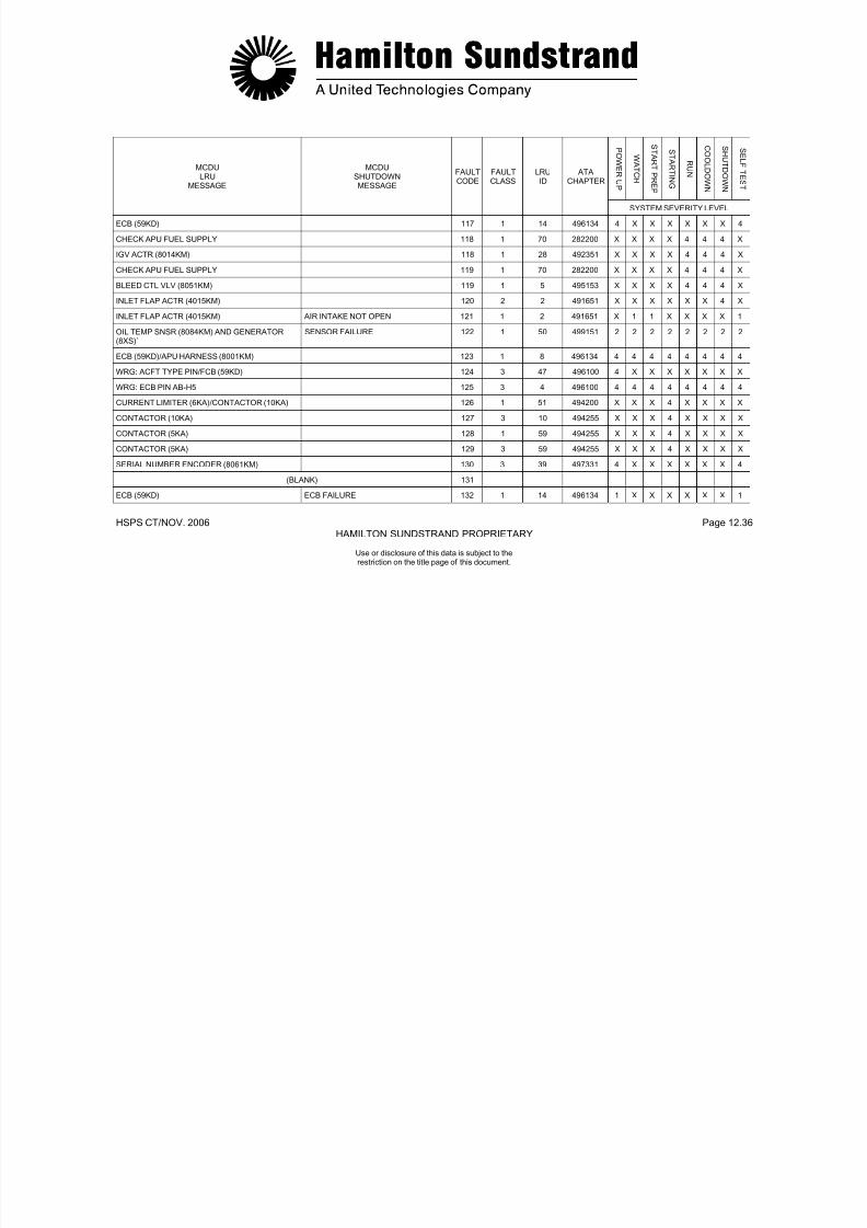
7/21/2019 Aps 3200 Training
http://slidepdf.com/reader/full/aps-3200-training 725/739
HSPS CT/NOV. 2006 Page 12.37HAMILTON SUNDSTRAND PROPRIETARY
Use or disclosure of this data is subject to therestriction on the title page of this document.
P OWE R UP
WA T C H
S T A RT P RE
P
S T A RT I N G
R UN
C O OL D OW
N
S H UT D OW
N
S E L F T E S T
MCDULRU
MESSAGE
MCDUSHUTDOWNMESSAGE
FAULTCODE
FAULTCLASS
LRUID
ATACHAPTER
SYSTEM SEVERITY LEVEL
ECB (59KD) ECB FAILURE 151 1 14 496134 X 1 1 1 1 1 1 X
ECB (59KD) ECB FAILURE 152 1 14 496134 X 1 1 1 1 1 1 X
ECB (59KD) ECB FAILURE 153 1 14 496134 X 1 1 1 1 1 1 X
ECB (59KD) ECB FAILURE 154 1 14 496134 X 1 1 1 1 1 1 X
ECB (59KD) ECB FAILURE 155 1 14 496134 X 1 1 1 1 1 1 X
ECB (59KD) ECB FAILURE 156 1 14 496134 X 1 1 1 1 1 1 X
ECB (59KD) ECB FAILURE 157 1 14 496134 X 1 1 1 1 1 1 X
ECB (59KD) ECB FAILURE 158 1 14 496134 X 1 1 1 1 1 1 X
ECB (59KD) ECB FAILURE 159 1 14 496134 X 1 1 1 1 1 1 X
ECB (59KD) ECB FAILURE 160 1 14 496134 X 1 1 1 1 1 1 X
ECB (59KD) ECB FAILURE 161 1 14 496134 X 1 1 1 1 1 1 X
ECB (59KD) ECB FAILURE 162 1 14 496134 X 1 1 1 1 1 1 X
ECB (59KD) ECB FAILURE 163 1 14 496134 X 1 1 1 1 1 1 X
ECB (59KD) ECB FAILURE 164 1 14 496134 X 1 1 1 1 1 1 X
ECB (59KD) 165 3 14 496134 4 4 4 4 4 4 4 X
ECB (59KD) 166 3 14 496134 X 4 4 4 4 4 4 X
ECB (59KD) ECB FAILURE 167 1 14 496134 X 1 1 1 1 1 1 X
ECB (59KD) APU FUEL VALVE FAILED OPEN 168 1 14 496134 X 1 X X X X 1 X

7/21/2019 Aps 3200 Training
http://slidepdf.com/reader/full/aps-3200-training 726/739
HSPS CT/NOV. 2006 Page 12.38HAMILTON SUNDSTRAND PROPRIETARY
Use or disclosure of this data is subject to therestriction on the title page of this document.
P OWE R UP
WA T C H
S T A RT P RE
P
S T A RT I N G
R UN
C O OL D OW
N
S H UT D OW
N
S E L F T E S T
MCDULRU
MESSAGE
MCDUSHUTDOWNMESSAGE
FAULTCODE
FAULTCLASS
LRUID
ATACHAPTER
SYSTEM SEVERITY LEVEL
BLD FLOW XDCR (8039KM)/BLD CTL VLV (8051KM)
169 1 48 495112 X X X X 4 4 X X
INLET T-P SNSR (8013KM) 170 1 29 492317 4 4 4 4 4 4 4 4
BLD FLOW XDCR (8039KM) 170 1 13 495112 4 4 4 4 4 4 4 4
BLD FLOW XDCR (8039KM) 171 1 13 495112 X X X X 4 X X X
BLEED CTL VLV (8051KM) 172 1 5 495153 X X X X 4 4 X X
ECB (59KD) ECB FAILURE 173 1 14 496134 X 1 1 1 1 1 1 1
BLEED CTL VLV (8051KM)/FUEL CTL UNIT (8022KM)
174 1 69 495153 X X X X 4 X X X
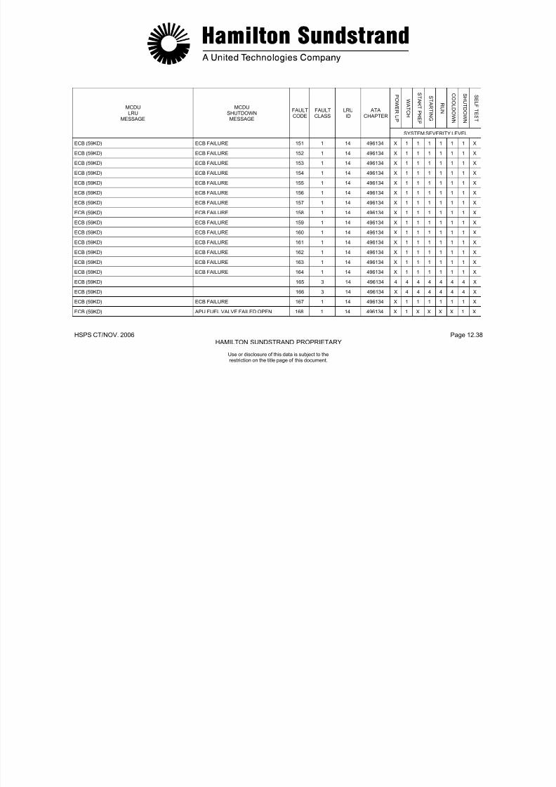
7/21/2019 Aps 3200 Training
http://slidepdf.com/reader/full/aps-3200-training 727/739
HSPS CT/NOV. 2006 Page 12.39HAMILTON SUNDSTRAND PROPRIETARY
Use or disclosure of this data is subject to therestriction on the title page of this document.
APS 3200 AUXILIARY POWER UNIT
SECTION 13
TROUBLESHOOTING

7/21/2019 Aps 3200 Training
http://slidepdf.com/reader/full/aps-3200-training 728/739
HSPS CT/NOV. 2006 Page 13.0HAMILTON SUNDSTRAND PROPRIETARY
Use or disclosure of this data is subject to therestriction on the title page of this document.
TROUBLESHOOTING
GENERAL
The troubleshooting system is designed to provide additionalinformation to aid in the maintenance and repair of the AuxiliaryPower Unit (APU) by downloading the Electronic Control Box (ECB)located in the aircraft aft cargo compartment.Maintenance information is stored in the nonvolatile memory of theECB and can be retrieved and analyzed by downloading into alaptop computer. The computer displays information andrecommended actions from the following stored data:
CONDITIONING MONITORING DATA
This data consists of engine parameters taken at each engine startand shutdown. Data is provided for the last twelve engine run cycles.
FAULT DATA
The data consists of maintenance and fault messages for class 1,class 2 faults and class 3 faults.
REQUIRED HARDWARE
Downloading of the ECB requires the following equipment:
Laptop computer or Personal Computer (PC) with at least3MB of free hard disc space, a modem and a Windows 95 orlater operating system.
A special interface cable is required to connect theComputer to the ECB. The interface cable (P/N AGE 70021)is available by contacting Hamilton Sundstrand.

7/21/2019 Aps 3200 Training
http://slidepdf.com/reader/full/aps-3200-training 729/739
HSPS CT/NOV. 2006 Page 13.1HAMILTON SUNDSTRAND PROPRIETARY
Use or disclosure of this data is subject to therestriction on the title page of this document.

7/21/2019 Aps 3200 Training
http://slidepdf.com/reader/full/aps-3200-training 730/739
HSPS CT/NOV. 2006 Page 13.2HAMILTON SUNDSTRAND PROPRIETARY
Use or disclosure of this data is subject to therestriction on the title page of this document.
TROUBLESHOOTING
ECB TROUBLESHOOTING AID
To download and diagnose fault data, refer to APIC SIL APS32-0049-47 for in-depth instructions.
Basic Steps:• Connect the interface cable from the computer to the ECB.• Power-up computer.• Select Diagnose on the tool bar.• Enter operators name on the Setup screen.• APU master switch ON (APU not running.)
• Select Continue on the Setup screen.
7/21/2019 Aps 3200 Training
http://slidepdf.com/reader/full/aps-3200-training 731/739
HSPS CT/NOV. 2006 Page 13.3HAMILTON SUNDSTRAND PROPRIETARY
Use or disclosure of this data is subject to therestriction on the title page of this document.

7/21/2019 Aps 3200 Training
http://slidepdf.com/reader/full/aps-3200-training 732/739
HSPS CT/NOV. 2006 Page 13.4HAMILTON SUNDSTRAND PROPRIETARY
Use or disclosure of this data is subject to therestriction on the title page of this document.
TROUBLESHOOTING
ECB TROUBLESHOOTING AID
ECB TROUBLESHOOTING AID (Fault Information)
The computer screen displays Class 1, Class 2 faults and Class 3faults. The screen will download and provide a file automatically forreview. (See example on page 13.6.)
Select the Most Recent scroll bar on the screen to scroll through thevarious faults.Each fault or fault combination is provided with a fault description
and recommended action.
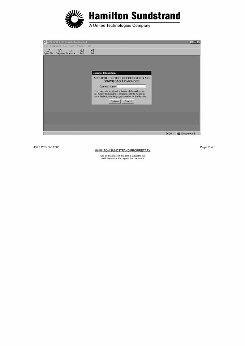
7/21/2019 Aps 3200 Training
http://slidepdf.com/reader/full/aps-3200-training 733/739
HSPS CT/NOV. 2006 Page 13.5HAMILTON SUNDSTRAND PROPRIETARY
Use or disclosure of this data is subject to therestriction on the title page of this document.

7/21/2019 Aps 3200 Training
http://slidepdf.com/reader/full/aps-3200-training 734/739
HSPS CT/NOV. 2006 Page 13.6HAMILTON SUNDSTRAND PROPRIETARY
Use or disclosure of this data is subject to therestriction on the title page of this document.
TROUBLESHOOTING
ECB TROUBLESHOOTING AID
REAL-TIME DATA MONITORING
With the Real-Time Data monitoring screen displayed, select AnalogI/O, Speed/Temp, or Discreet Inputs. Each selection displays ascreen that provides real time data. The data is viewed at the bottomof the screen when a data box is selected.
Note: The more data boxes selected the longer it takes for theinformation to appear. Select data that is related to the
specific fault for a faster response time.
BASIC STEPS:• Connect the interface cable from the computer to the ECB.• Power-up computer.• Start and run APU.• Select data box.• Select Start Monitoring.• Select Stop Monitoring after data has been taken.
Selecting Save Data at the bottom of the screen and selecting a filename allows the data to be saved. (See page 13.9 and example onpage 13.10.)

7/21/2019 Aps 3200 Training
http://slidepdf.com/reader/full/aps-3200-training 735/739
HSPS CT/NOV. 2006 Page 13.7HAMILTON SUNDSTRAND PROPRIETARY
Use or disclosure of this data is subject to therestriction on the title page of this document.
7/21/2019 Aps 3200 Training
http://slidepdf.com/reader/full/aps-3200-training 736/739
HSPS CT/NOV. 2006 Page 13.8HAMILTON SUNDSTRAND PROPRIETARY
Use or disclosure of this data is subject to therestriction on the title page of this document.
TROUBLESHOOTING
ECB TROUBLESHOOTING AID
SNAPSHOT VIEW
BASIC STEPS:
• Select Snapshot with the APU operating• Select Analog Inputs.• Select Discrete Inputs.• Click on Take Snapshot. (This will provide one quick view
of data)

7/21/2019 Aps 3200 Training
http://slidepdf.com/reader/full/aps-3200-training 737/739
HSPS CT/NOV. 2006 Page 13.9HAMILTON SUNDSTRAND PROPRIETARY
Use or disclosure of this data is subject to therestriction on the title page of this document.
HSPS CT/NOV 2006 P 13 10HSPS CT/NOV 2006 P 13 10

7/21/2019 Aps 3200 Training
http://slidepdf.com/reader/full/aps-3200-training 738/739
HSPS CT/NOV. 2006 Page 13.10HAMILTON SUNDSTRAND PROPRIETARY
Use or disclosure of this data is subject to therestriction on the title page of this document.
HSPS CT/NOV. 2006 Page 13.10HAMILTON SUNDSTRAND PROPRIETARY
Use or disclosure of this data is subject to therestriction on the title page of this document.
HSPS CT/NOV 2006 Page 13 11
APS 3200 AUXILIARY POWER UNIT

7/21/2019 Aps 3200 Training
http://slidepdf.com/reader/full/aps-3200-training 739/739
HSPS CT/NOV. 2006 Page 13.11HAMILTON SUNDSTRAND PROPRIETARY
Use or disclosure of this data is subject to therestriction on the title page of this document.
Related Documents