Appendix J 95% Geotechnical Engineering Design Study

Welcome message from author
This document is posted to help you gain knowledge. Please leave a comment to let me know what you think about it! Share it to your friends and learn new things together.
Transcript
Appendix J 95% Geotechnical Engineering Design Study

95% Geotechnical Engineering Design Study
Terminal 5 Deepening and Crane Rail Upgrade Seattle, Washington Prepared for
Port of Seattle June 14, 2016 19094‐01
19094‐01 June 14, 2016
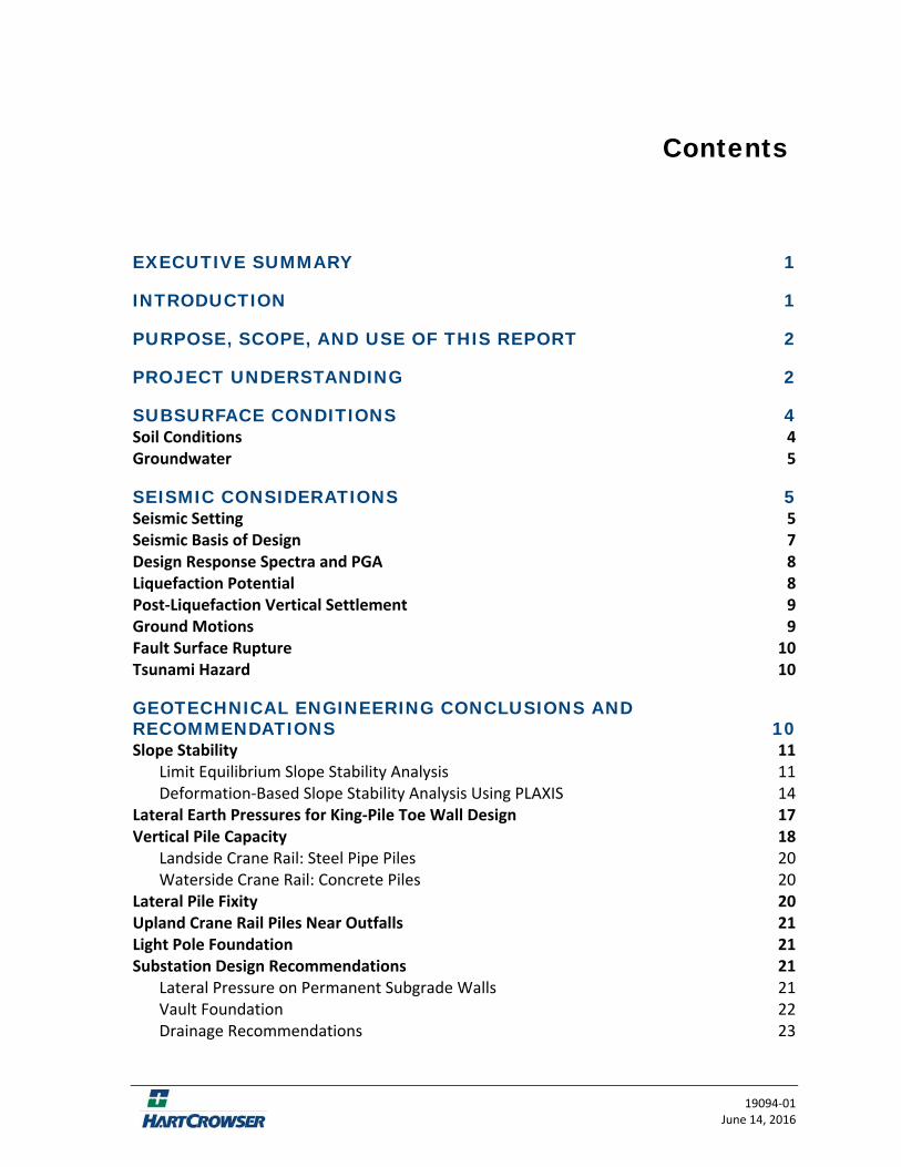
Contents
EXECUTIVE SUMMARY 1
INTRODUCTION 1
PURPOSE, SCOPE, AND USE OF THIS REPORT 2
PROJECT UNDERSTANDING 2
SUBSURFACE CONDITIONS 4 Soil Conditions 4 Groundwater 5
SEISMIC CONSIDERATIONS 5 Seismic Setting 5 Seismic Basis of Design 7 Design Response Spectra and PGA 8 Liquefaction Potential 8 Post‐Liquefaction Vertical Settlement 9 Ground Motions 9 Fault Surface Rupture 10 Tsunami Hazard 10
GEOTECHNICAL ENGINEERING CONCLUSIONS AND RECOMMENDATIONS 10 Slope Stability 11
Limit Equilibrium Slope Stability Analysis 11 Deformation‐Based Slope Stability Analysis Using PLAXIS 14
Lateral Earth Pressures for King‐Pile Toe Wall Design 17 Vertical Pile Capacity 18
Landside Crane Rail: Steel Pipe Piles 20 Waterside Crane Rail: Concrete Piles 20
Lateral Pile Fixity 20 Upland Crane Rail Piles Near Outfalls 21 Light Pole Foundation 21 Substation Design Recommendations 21
Lateral Pressure on Permanent Subgrade Walls 21 Vault Foundation 22 Drainage Recommendations 23
ii | Contents
19094‐01 June 14, 2016
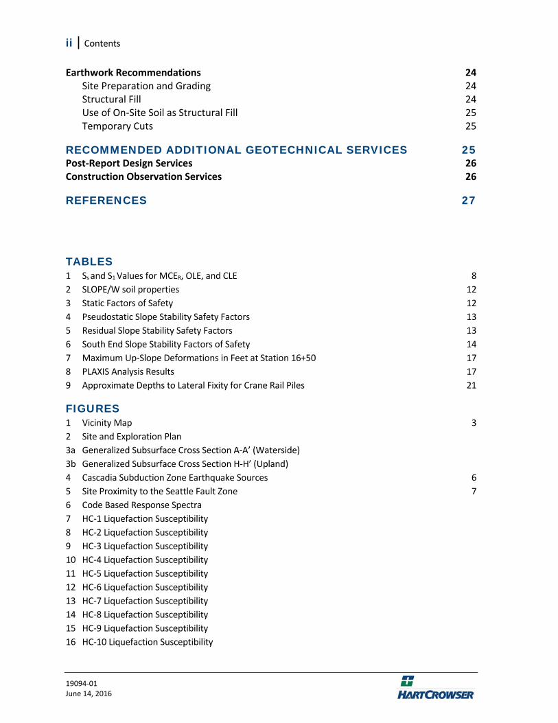
Earthwork Recommendations 24 Site Preparation and Grading 24 Structural Fill 24 Use of On‐Site Soil as Structural Fill 25 Temporary Cuts 25
RECOMMENDED ADDITIONAL GEOTECHNICAL SERVICES 25 Post‐Report Design Services 26 Construction Observation Services 26
REFERENCES 27
TABLES 1 Ss and S1 Values for MCER, OLE, and CLE 8 2 SLOPE/W soil properties 12 3 Static Factors of Safety 12 4 Pseudostatic Slope Stability Safety Factors 13 5 Residual Slope Stability Safety Factors 13 6 South End Slope Stability Factors of Safety 14 7 Maximum Up‐Slope Deformations in Feet at Station 16+50 17 8 PLAXIS Analysis Results 17 9 Approximate Depths to Lateral Fixity for Crane Rail Piles 21
FIGURES 1 Vicinity Map 3 2 Site and Exploration Plan 3a Generalized Subsurface Cross Section A‐A’ (Waterside) 3b Generalized Subsurface Cross Section H‐H’ (Upland) 4 Cascadia Subduction Zone Earthquake Sources 6 5 Site Proximity to the Seattle Fault Zone 7 6 Code Based Response Spectra 7 HC‐1 Liquefaction Susceptibility 8 HC‐2 Liquefaction Susceptibility 9 HC‐3 Liquefaction Susceptibility 10 HC‐4 Liquefaction Susceptibility 11 HC‐5 Liquefaction Susceptibility 12 HC‐6 Liquefaction Susceptibility 13 HC‐7 Liquefaction Susceptibility 14 HC‐8 Liquefaction Susceptibility 15 HC‐9 Liquefaction Susceptibility 16 HC‐10 Liquefaction Susceptibility
Contents | iii
19094‐01 June 14, 2016
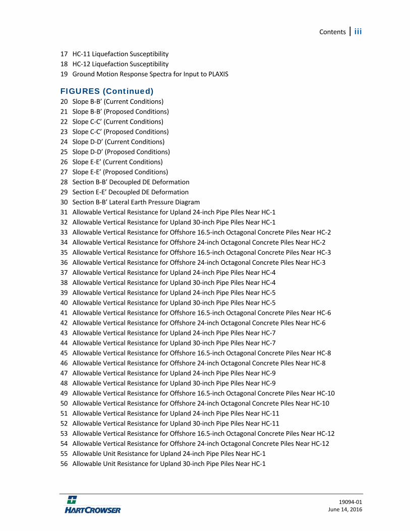
17 HC‐11 Liquefaction Susceptibility 18 HC‐12 Liquefaction Susceptibility 19 Ground Motion Response Spectra for Input to PLAXIS
FIGURES (Continued) 20 Slope B‐B’ (Current Conditions) 21 Slope B‐B’ (Proposed Conditions) 22 Slope C‐C’ (Current Conditions) 23 Slope C‐C’ (Proposed Conditions) 24 Slope D‐D’ (Current Conditions) 25 Slope D‐D’ (Proposed Conditions) 26 Slope E‐E’ (Current Conditions) 27 Slope E‐E’ (Proposed Conditions) 28 Section B‐B’ Decoupled DE Deformation 29 Section E‐E’ Decoupled DE Deformation 30 Section B‐B’ Lateral Earth Pressure Diagram 31 Allowable Vertical Resistance for Upland 24‐inch Pipe Piles Near HC‐1 32 Allowable Vertical Resistance for Upland 30‐inch Pipe Piles Near HC‐1 33 Allowable Vertical Resistance for Offshore 16.5‐inch Octagonal Concrete Piles Near HC‐2 34 Allowable Vertical Resistance for Offshore 24‐inch Octagonal Concrete Piles Near HC‐2 35 Allowable Vertical Resistance for Offshore 16.5‐inch Octagonal Concrete Piles Near HC‐3 36 Allowable Vertical Resistance for Offshore 24‐inch Octagonal Concrete Piles Near HC‐3 37 Allowable Vertical Resistance for Upland 24‐inch Pipe Piles Near HC‐4 38 Allowable Vertical Resistance for Upland 30‐inch Pipe Piles Near HC‐4 39 Allowable Vertical Resistance for Upland 24‐inch Pipe Piles Near HC‐5 40 Allowable Vertical Resistance for Upland 30‐inch Pipe Piles Near HC‐5 41 Allowable Vertical Resistance for Offshore 16.5‐inch Octagonal Concrete Piles Near HC‐6 42 Allowable Vertical Resistance for Offshore 24‐inch Octagonal Concrete Piles Near HC‐6 43 Allowable Vertical Resistance for Upland 24‐inch Pipe Piles Near HC‐7 44 Allowable Vertical Resistance for Upland 30‐inch Pipe Piles Near HC‐7 45 Allowable Vertical Resistance for Offshore 16.5‐inch Octagonal Concrete Piles Near HC‐8 46 Allowable Vertical Resistance for Offshore 24‐inch Octagonal Concrete Piles Near HC‐8 47 Allowable Vertical Resistance for Upland 24‐inch Pipe Piles Near HC‐9 48 Allowable Vertical Resistance for Upland 30‐inch Pipe Piles Near HC‐9 49 Allowable Vertical Resistance for Offshore 16.5‐inch Octagonal Concrete Piles Near HC‐10 50 Allowable Vertical Resistance for Offshore 24‐inch Octagonal Concrete Piles Near HC‐10 51 Allowable Vertical Resistance for Upland 24‐inch Pipe Piles Near HC‐11 52 Allowable Vertical Resistance for Upland 30‐inch Pipe Piles Near HC‐11 53 Allowable Vertical Resistance for Offshore 16.5‐inch Octagonal Concrete Piles Near HC‐12 54 Allowable Vertical Resistance for Offshore 24‐inch Octagonal Concrete Piles Near HC‐12 55 Allowable Unit Resistance for Upland 24‐inch Pipe Piles Near HC‐1 56 Allowable Unit Resistance for Upland 30‐inch Pipe Piles Near HC‐1
iv | Contents
19094‐01 June 14, 2016
FIGURES (Continued) 57 Allowable Unit Resistance for Offshore 16.5‐inch Octagonal Concrete Piles Near HC‐2 58 Allowable Unit Resistance for Offshore 24‐inch Octagonal Concrete Piles Near HC‐2 59 Allowable Unit Resistance for Offshore 16.5‐inch Octagonal Concrete Piles Near HC‐3 60 Allowable Unit Resistance for Offshore 24‐inch Octagonal Concrete Piles Near HC‐3 61 Allowable Unit Resistance for Upland 24‐inch Pipe Piles Near HC‐4 62 Allowable Unit Resistance for Upland 30‐inch Pipe Piles Near HC‐4 63 Allowable Unit Resistance for Upland 24‐inch Pipe Piles Near HC‐5 64 Allowable Unit Resistance for Upland 30‐inch Pipe Piles Near HC‐5 65 Allowable Unit Resistance for Offshore 16.5‐inch Octagonal Concrete Piles Near HC‐6 66 Allowable Unit Resistance for Offshore 24‐inch Octagonal Concrete Piles Near HC‐6 67 Allowable Unit Resistance for Upland 24‐inch Pipe Piles Near HC‐7 68 Allowable Unit Resistance for Upland 30‐inch Pipe Piles Near HC‐7 69 Allowable Unit Resistance for Offshore 16.5‐inch Octagonal Concrete Piles Near HC‐8 70 Allowable Unit Resistance for Offshore 24‐inch Octagonal Concrete Piles Near HC‐8 71 Allowable Unit Resistance for Upland 24‐inch Pipe Piles Near HC‐9 72 Allowable Unit Resistance for Upland 30‐inch Pipe Piles Near HC‐9 73 Allowable Unit Resistance for Offshore 16.5‐inch Octagonal Concrete Piles Near HC‐10 74 Allowable Unit Resistance for Offshore 24‐inch Octagonal Concrete Piles Near HC‐10 75 Allowable Unit Resistance for Upland 24‐inch Pipe Piles Near HC‐11 76 Allowable Unit Resistance for Upland 30‐inch Pipe Piles Near HC‐11 77 Allowable Unit Resistance for Offshore 16.5‐inch Octagonal Concrete Piles Near HC‐12 78 Allowable Unit Resistance for Offshore 24‐inch Octagonal Concrete Piles Near HC‐12 79 Surcharge Pressures Determination of Lateral Pressure Acting on Adjacent Shoring
ATTACHMENT 1 Tsunami Hazard Map
ATTACHMENT 2 Shear Wave Velocity Testing Report
ATTACHMENT 3 PLAXIS Output Report
ATTACHMENT 4 Test Pile Program Draft Report
APPENDIX A Field Exploration Methods and Analysis
APPENDIX B Laboratory Testing Program
Contents | v
19094‐01 June 14, 2016
APPENDIX C Previous Explorations and Laboratory Results by Hart Crowser and Others
APPENDIX D Slope Stability Inputs and Results
19094‐01 June 14, 2016
95% Geotechnical Engineering Design Study
Terminal 5 Deepening and Crane Rail Upgrade Seattle, Washington
EXECUTIVE SUMMARY We completed 12 new soil borings to support the geotechnical engineering design of the Terminal 5 Deepening and Crane Rail Upgrade project. Using the results of these borings and soil laboratory tests on selected samples, we developed representative soil profiles for geotechnical engineering analysis and design for this project. We provide recommendations for seismic, substation building, and pile design in this study. Our limit equilibrium slope stability analyses show that the proposed dredged slope configurations factors of safety can meet or exceed the current factors of safety with the addition of a king‐pile toe wall supplemented with pinch piles on the lower portion of the under‐pier slope. This design satisfies the Port’s memorandum of understanding with the city that the seismic slope stability will not be diminished following the terminal improvements. In addition, we performed dynamic deformation‐based analyses using PLAXIS that show reduced slope movement following the improvements. We believe the project is feasible from a geotechnical perspective.
INTRODUCTION This 95% geotechnical engineering study report presents the results of our geotechnical investigation and our recommendations for the Terminal 5 Deepening and Crane Rail Upgrade Project at the Port of Seattle.
The project’s significant geotechnical design elements include new crane rail piles, dredging at the toe of the slope, a new submerged king‐pile toe wall near the waterside edge of the terminal, slope‐stabilizing pinch piles, and a substation building. The king‐pile toe wall will increase the design berth depths by 8 to 13 feet over existing conditions, to elevation −58 feet (ft) Mean Lower Low Water (MLLW). The −58‐ft MLLW depth is based on a design dredge depth of −55 feet and up to 3 feet of maintenance dredging and overdredging (cumulative). Terminal 5 has already been deepened in most of the project area from the design elevation of −40 feet MLLW. We found that maintaining seismic stability of the slope and toe wall is possible, but will require a new, larger‐capacity king‐pile toe wall and structural reinforcement (pinch piles) over a portion of the slope area where berth deepening is planned.
We have organized this report into several sections. The first two pages describe the purpose and scope of our work and our understanding of the project. The main body of the report presents the subsurface conditions, seismic considerations, and our geotechnical engineering conclusions and recommendations.
Tables and figures are included within the text if space permits; larger tables and figures follow the text. Attachment 1, a Tsunami Hazard Map for Seattle, follows the tables and figures. Field data are presented in Appendix A and geotechnical laboratory test program results are presented in Appendix
2 | Terminal 5 Deepening and Crane Rail Upgrade
19094‐01 June 14, 2016
B. Appendix C presents relevant exploration logs from earlier geotechnical studies at the site. Appendix D includes results of our slope stability analyses.
PURPOSE, SCOPE, AND USE OF THIS REPORT The purpose of our work is to provide the Port of Seattle with subsurface information and interpretation and geotechnical engineering design recommendations. Our work supports the Port’s design and cost estimate for deepening the berth and upgrading the crane rail at Terminal 5.
Our scope of work for this project included:
Assessing subsurface conditions using explorations, laboratory tests, and historical geotechnical reports and explorations;
Performing geotechnical design and analysis; Providing geotechnical engineering recommendations; and Producing a geotechnical engineering design report.
This report addresses each of our scope items. We prepared this report for the exclusive use of the Port of Seattle, Moffatt & Nichol Engineers, and their design and construction consultants for specific application to the Terminal 5 Dock Upgrade Project and site location. Within the limitations of scope, schedule, and budget, we completed the work according to generally accepted geotechnical practices in the same or similar localities, related to the nature of the work accomplished, at the time the services were accomplished. We make no warranty, expressed or implied.
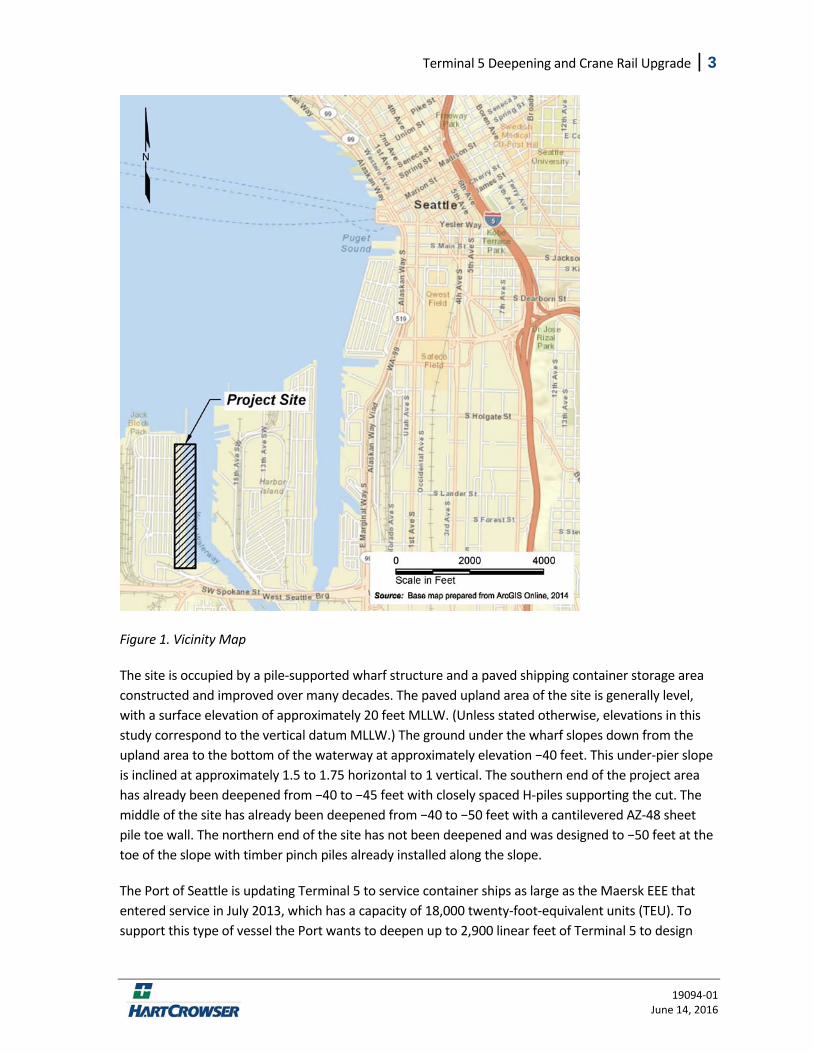
PROJECT UNDERSTANDING The project site is located along the west shore of the West Waterway at the mouth of the Duwamish River at the Port of Seattle (Figure 1).
Terminal 5 Deepening and Crane Rail Upgrade | 3
19094‐01 June 14, 2016
Figure 1. Vicinity Map
The site is occupied by a pile‐supported wharf structure and a paved shipping container storage area constructed and improved over many decades. The paved upland area of the site is generally level, with a surface elevation of approximately 20 feet MLLW. (Unless stated otherwise, elevations in this study correspond to the vertical datum MLLW.) The ground under the wharf slopes down from the upland area to the bottom of the waterway at approximately elevation −40 feet. This under‐pier slope is inclined at approximately 1.5 to 1.75 horizontal to 1 vertical. The southern end of the project area has already been deepened from −40 to −45 feet with closely spaced H‐piles supporting the cut. The middle of the site has already been deepened from −40 to −50 feet with a cantilevered AZ‐48 sheet pile toe wall. The northern end of the site has not been deepened and was designed to −50 feet at the toe of the slope with timber pinch piles already installed along the slope.
The Port of Seattle is updating Terminal 5 to service container ships as large as the Maersk EEE that entered service in July 2013, which has a capacity of 18,000 twenty‐foot‐equivalent units (TEU). To support this type of vessel the Port wants to deepen up to 2,900 linear feet of Terminal 5 to design
4 | Terminal 5 Deepening and Crane Rail Upgrade
19094‐01 June 14, 2016
elevation −55 feet (including 1 foot of maintenance dredge and 2 feet of overdredge results in a new toe of slope up to −58 feet). In addition, larger and heavier cranes are required, which will produce crane loads of approximately 85 kips per foot on each rail. Our study limits extend from Station 2+00 to 29+00 (Bent 25s to 114). To facilitate additional berth deepening, a new, stronger, king‐pile toe wall will be required with supplemental structural reinforcement (pinch piles) required along some or all of the stations.
SUBSURFACE CONDITIONS Our understanding of the subsurface conditions at Terminal 5 is based on numerous existing soil explorations, the materials encountered in 12 new mud rotary borings, laboratory testing of soil samples, shear wave testing (Attachment 2), and our experience in the area. Figure 2 shows the location of the existing and new soil explorations. Figures 3a and 3b illustrate the interpreted subsurface conditions along the wharf. Details of the conditions observed at the new boring locations are shown on the logs included in Appendix A and should be referred to for specific information.
Subsurface soil conditions are based on explorations accomplished at discrete locations at the site. Soil properties inferred from the field and laboratory tests formed the basis for developing our geotechnical recommendations contained in this report. The nature and extent of variations between the explorations may not become evident until construction. If variations appear, it may be necessary to reevaluate the recommendations in this report.
Soil Conditions The soil conditions can be generalized as follows:
A surficial veneer of riprap of varying size and depth was on the under‐pier slopes. A layer of asphalt over gravel and sand fill was encountered in the upland areas.
Very loose to dense Sand to very silty Sand with layers of Silt and Clay was observed throughout the site. For our analyses this is referred to as engineering soil unit (ESU) 1.
Very soft Silt and Clay layers were observed, typically located just above the bearing layer. This layer is referred to as ESU 2.
Very dense glacially overridden soils were observed at depth in the new and the historical explorations. This bearing layer is at elevation −120 to −90 feet at the south end of Terminal 5 and gradually deepens to elevation −135 feet in the borings at the north end of the terminal. Our most southern upland boring (HC‐5) encountered this layer at approximately elevation –90 feet. Very dense till and till‐like materials are referred to as ESU 3, while glacially overridden silts and clays are labeled ESU 4.
Terminal 5 Deepening and Crane Rail Upgrade | 5
19094‐01 June 14, 2016
Groundwater Groundwater at the site is influenced by tidal fluctuations in Elliott Bay. We did not observe the groundwater table in the upland soil borings because of the drilling method that was used. Tidal influence is typically limited to a short distance behind the top of the slope. Typical groundwater levels in the backland throughout Terminal 5 are at around elevation 9 to 10 feet.
SEISMIC CONSIDERATIONS The site is in a seismically active area. In this section, we describe the seismic setting at the project site, identify the seismic basis of design, provide our recommended preliminary design response spectra, and discuss the seismic hazards at the site.
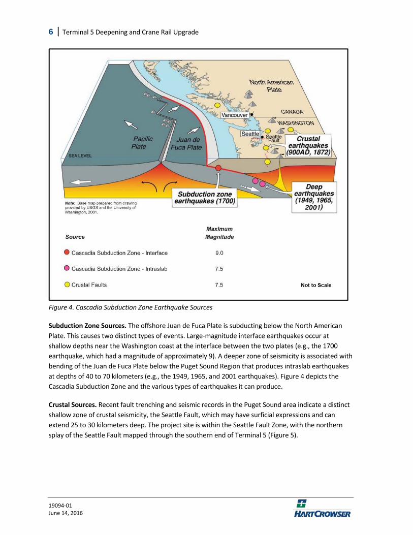
Seismic Setting The seismicity of Western Washington is dominated by the Cascadia Subduction Zone, in which the offshore Juan de Fuca Plate is subducting beneath the continental North American Plate (Figure 4). Three types of earthquakes are associated with subduction zones: intraslab subduction, interface subduction, and crustal earthquakes.
6 | Terminal 5 Deepening and Crane Rail Upgrade
19094‐01 June 14, 2016
Figure 4. Cascadia Subduction Zone Earthquake Sources
Subduction Zone Sources. The offshore Juan de Fuca Plate is subducting below the North American Plate. This causes two distinct types of events. Large‐magnitude interface earthquakes occur at shallow depths near the Washington coast at the interface between the two plates (e.g., the 1700 earthquake, which had a magnitude of approximately 9). A deeper zone of seismicity is associated with bending of the Juan de Fuca Plate below the Puget Sound Region that produces intraslab earthquakes at depths of 40 to 70 kilometers (e.g., the 1949, 1965, and 2001 earthquakes). Figure 4 depicts the Cascadia Subduction Zone and the various types of earthquakes it can produce.
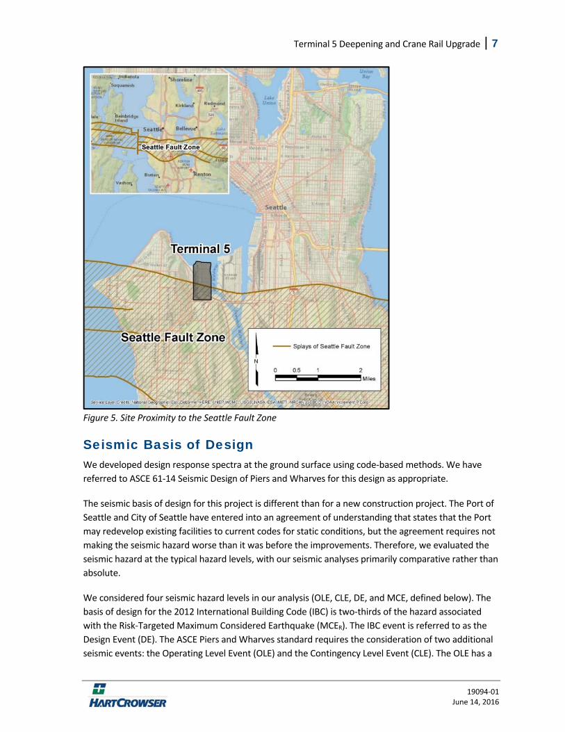
Crustal Sources. Recent fault trenching and seismic records in the Puget Sound area indicate a distinct shallow zone of crustal seismicity, the Seattle Fault, which may have surficial expressions and can extend 25 to 30 kilometers deep. The project site is within the Seattle Fault Zone, with the northern splay of the Seattle Fault mapped through the southern end of Terminal 5 (Figure 5).
Terminal 5 Deepening and Crane Rail Upgrade | 7
19094‐01 June 14, 2016
Figure 5. Site Proximity to the Seattle Fault Zone
Seismic Basis of Design We developed design response spectra at the ground surface using code‐based methods. We have referred to ASCE 61‐14 Seismic Design of Piers and Wharves for this design as appropriate.
The seismic basis of design for this project is different than for a new construction project. The Port of Seattle and City of Seattle have entered into an agreement of understanding that states that the Port may redevelop existing facilities to current codes for static conditions, but the agreement requires not making the seismic hazard worse than it was before the improvements. Therefore, we evaluated the seismic hazard at the typical hazard levels, with our seismic analyses primarily comparative rather than absolute.
We considered four seismic hazard levels in our analysis (OLE, CLE, DE, and MCE, defined below). The basis of design for the 2012 International Building Code (IBC) is two‐thirds of the hazard associated with the Risk‐Targeted Maximum Considered Earthquake (MCER). The IBC event is referred to as the Design Event (DE). The ASCE Piers and Wharves standard requires the consideration of two additional seismic events: the Operating Level Event (OLE) and the Contingency Level Event (CLE). The OLE has a
8 | Terminal 5 Deepening and Crane Rail Upgrade
19094‐01 June 14, 2016
50 percent probability of exceedance in 50 years, which corresponds with a return period of 72 years. The CLE has a 10 percent probability of exceedance in 50 years, which corresponds with a return period of 475 years. Slope performance was evaluated for the OLE, CLE, and DE. Liquefaction hazard was evaluated for the OLE, CLE, DE, and Maximum Considered Earthquake (MCE). The MCE has a 2 percent probability of exceedance in 50 years, which corresponds with a return period of 2,475 years.
Design Response Spectra and PGA We determined the site class in accordance with 2012 IBC based on Standard Penetration Test (SPT) data collected from our explorations at the project site. The site contains liquefiable soil corresponding to a classification of Site Class F. The code requires a site‐specific analysis for Site Class F, if the period of the structure is greater than 0.5 seconds. Because this structure will have a period greater than 0.5 seconds, we typically recommend that a site‐specific analysis be performed as part of final design. As the seismic structural design for this project is comparison‐based, and we understand a site‐response analysis is not needed, the project team decided a site‐specific response analysis was unnecessary. For miscellaneous design, and for buildings with a period less than 0.5 seconds, we used the site class definition without considering liquefaction‐susceptibility, which corresponds to Site Class E.
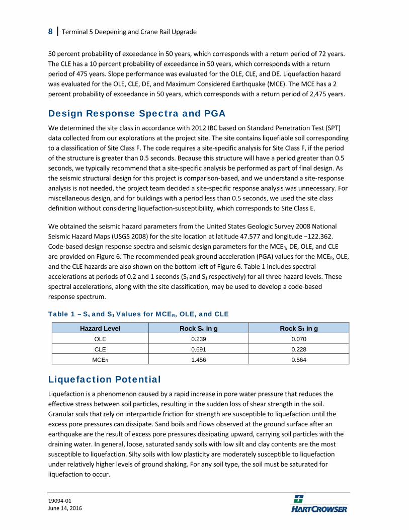
We obtained the seismic hazard parameters from the United States Geologic Survey 2008 National Seismic Hazard Maps (USGS 2008) for the site location at latitude 47.577 and longitude −122.362. Code‐based design response spectra and seismic design parameters for the MCER, DE, OLE, and CLE are provided on Figure 6. The recommended peak ground acceleration (PGA) values for the MCER, OLE, and the CLE hazards are also shown on the bottom left of Figure 6. Table 1 includes spectral accelerations at periods of 0.2 and 1 seconds (Ss and S1 respectively) for all three hazard levels. These spectral accelerations, along with the site classification, may be used to develop a code‐based response spectrum.
Table 1 – Ss and S1 Values for MCER, OLE, and CLE
Hazard Level Rock Ss in g Rock S1 in g OLE 0.239 0.070
CLE 0.691 0.228
MCER 1.456 0.564
Liquefaction Potential Liquefaction is a phenomenon caused by a rapid increase in pore water pressure that reduces the effective stress between soil particles, resulting in the sudden loss of shear strength in the soil. Granular soils that rely on interparticle friction for strength are susceptible to liquefaction until the excess pore pressures can dissipate. Sand boils and flows observed at the ground surface after an earthquake are the result of excess pore pressures dissipating upward, carrying soil particles with the draining water. In general, loose, saturated sandy soils with low silt and clay contents are the most susceptible to liquefaction. Silty soils with low plasticity are moderately susceptible to liquefaction under relatively higher levels of ground shaking. For any soil type, the soil must be saturated for liquefaction to occur.
Terminal 5 Deepening and Crane Rail Upgrade | 9
19094‐01 June 14, 2016
We used empirical methods to estimate liquefaction potential based on the standard penetration test (SPT) data obtained at the site. Procedures after Idriss and Boulanger (2008) were used for the SPT data. For the OLE and MCE hazard levels we used earthquake magnitudes of 6.53 and 6.8 and peak ground surface horizontal acceleration (PGA) of 0.26 and 0.545 g in our analysis, respectively. According to our analysis, the site is very susceptible to liquefaction in soil units below the water table down to glacial soils. The potential for liquefaction in the alluvial soils is relatively consistent across the site. The results of our analyses are presented on Figures 7 through 18 for each of our new borings. Occasional interbedded layers of non‐liquefiable soil may be present throughout the profile; however, the vast majority of submerged soils within 80 feet of the ground surface are susceptible to liquefaction in the MCE event.
Site‐specific dynamic laboratory testing resistance to liquefaction have been completed. Results of these tests are included in Appendix B. Sandy soils tests likely had the liquefaction resistance reduced during the process of sampling. When completed on sandy soils, the tests were generally completed to verify that they did not have a higher liquefaction resistance than empirical methods estimated.
Post-Liquefaction Vertical Settlement Post‐liquefaction settlement results from densification and redistribution of liquefiable soils following an earthquake. The ground surface settlement is not typically uniform across the area, and can result in significant differential settlement.
We estimated liquefaction‐induced ground surface settlement using the Idriss and Boulanger (2008) method based on SPT data. The results of our analysis indicate that liquefaction‐induced settlement will be slightly greater at the south end of the terminal in upland crane rail areas. MCE settlement is predicted to range up to 38 inches and 49 inches at the north and south ends of the terminal, respectively. Assuming a stable slope, the pile‐supported crane rail structure is not expected to settle more than a couple of inches. Although, many of the wharf piles could see more settlement because they do not all extend to the bearing layer. This could lead to significant differential settlement within the wharf structure and between the structure and surrounding ground surface.
Ground Motions We selected and scaled a single ground motion for two hazard levels for input to our finite element analysis using PLAXIS. We used response spectra based on the deaggregated hazard from the USGS (2008) probabilistic seismic hazard analysis for the 72‐year and 2,475‐year return periods with a corresponding shear wave velocity of 2,500 feet per second. These response spectra correspond to the OLE and the MCE hazards, respectively. The MCE hazard was then scaled by two‐thirds to obtain the design‐level event. We selected and scaled multiple ground motions to obtain a single motion that was a close match to the target response spectra.
For the OLE and MCE hazards, we selected intraslab subduction record and a crustal record, respectively. These earthquake mechanisms were chosen based on the deaggregated data from USGS. The data show that approximately 50 percent of OLE hazard corresponds with an intraplate subduction event and that nearly 50 percent of the MCE hazard corresponds with a Seattle Fault type
10 | Terminal 5 Deepening and Crane Rail Upgrade
19094‐01 June 14, 2016
of event (crustal fault). The OLE was chosen out of a suite of 30 intraslab ground motions and the MCE from a suite of over 100 crustal motions. These suites of motions are part of a Hart Crowser database. The selection was based on the smallest least squares error in combination with a modest scaling factor.
For the OLE hazard, we chose a ground motion from the 1965 Puget Sound earthquake, and for the design level earthquake (2/3 MCE) we selected one from the 1999 Chi‐Chi earthquake. The target and ground motion response spectra for the selected ground motions are presented on Figure 19. The spectral accelerations in this figure are lower than the code‐based spectra on Figure 6 for equivalent hazard levels. This is because the Figure 6 spectra are developed to represent soil conditions at the base of the PLAXIS model, which is equivalent to the Site Class B/C boundary.
Fault Surface Rupture As mentioned previously, the southern end of Terminal 5 is within the northern portion of the Seattle Fault Zone (Figure 5). Therefore, there is potential for surface rupture at the site in the case of a Seattle Fault event. Even if there is not surface rupture due to the deep, loose‐to‐soft soil, it is possible for significant differential movement of piles embedded in the dense bearing layer. Design for this type of rupture is cost‐prohibitive and difficult due to uncertainty about where fault rupture could occur. Fortunately, because of the relatively long return periods of the Seattle Fault, the uncertainty about where fault rupture could occur within the Seattle Fault Zone, and the low potential for fault surface rupture during the design life of the structure, the overall hazard associated with fault surface rupture is low.
Tsunami Hazard The tsunami hazard within Puget Sound is controlled by crustal faults. According to the Elliott Bay Area Tsunami Hazard Map prepared by the Washington State Department of Natural Resources (2003), a tsunami originating from a Seattle Fault earthquake is predicted to cause widespread inundation ranging from 0.5 to 2 meters deep across the project site. In addition, inundation could be 2 to 5 meters in localized areas. The Tsunami Hazard Map is included as Attachment 1. Because of the relatively long return period of the Seattle Fault, the tsunami hazard during the design life of the structure is also low, but is larger than the potential for fault surface rupture.
GEOTECHNICAL ENGINEERING CONCLUSIONS AND RECOMMENDATIONS This section of the report presents our conclusions and recommendations for the geotechnical aspects of design and construction on the project site. We have developed our recommendations based on our current understanding of the project and the subsurface conditions encountered by our explorations. If the nature or location of the development is different than we have assumed, we should be notified so we can change or confirm our recommendations.
Terminal 5 Deepening and Crane Rail Upgrade | 11
19094‐01 June 14, 2016
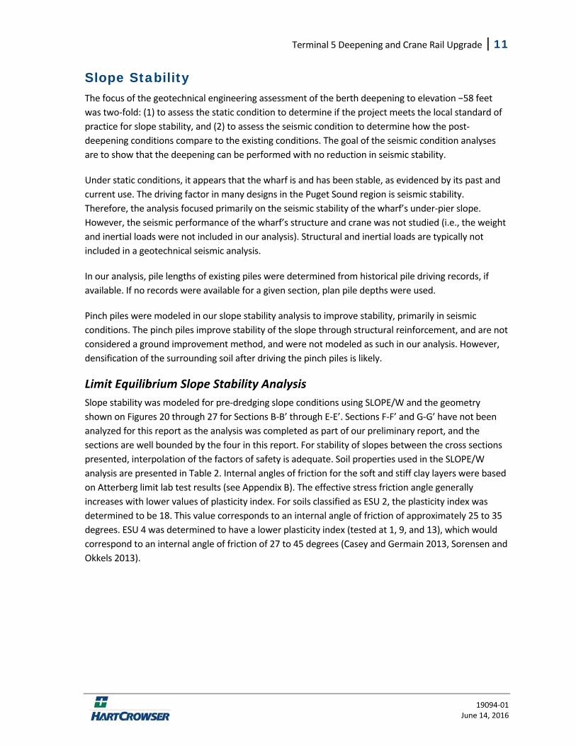
Slope Stability The focus of the geotechnical engineering assessment of the berth deepening to elevation −58 feet was two‐fold: (1) to assess the static condition to determine if the project meets the local standard of practice for slope stability, and (2) to assess the seismic condition to determine how the post‐deepening conditions compare to the existing conditions. The goal of the seismic condition analyses are to show that the deepening can be performed with no reduction in seismic stability.
Under static conditions, it appears that the wharf is and has been stable, as evidenced by its past and current use. The driving factor in many designs in the Puget Sound region is seismic stability. Therefore, the analysis focused primarily on the seismic stability of the wharf’s under‐pier slope. However, the seismic performance of the wharf’s structure and crane was not studied (i.e., the weight and inertial loads were not included in our analysis). Structural and inertial loads are typically not included in a geotechnical seismic analysis.
In our analysis, pile lengths of existing piles were determined from historical pile driving records, if available. If no records were available for a given section, plan pile depths were used.
Pinch piles were modeled in our slope stability analysis to improve stability, primarily in seismic conditions. The pinch piles improve stability of the slope through structural reinforcement, and are not considered a ground improvement method, and were not modeled as such in our analysis. However, densification of the surrounding soil after driving the pinch piles is likely.
Limit Equilibrium Slope Stability Analysis
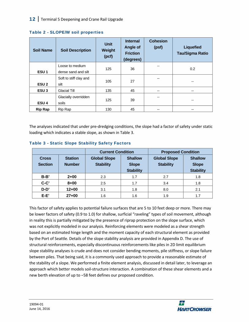
Slope stability was modeled for pre‐dredging slope conditions using SLOPE/W and the geometry shown on Figures 20 through 27 for Sections B‐B’ through E‐E’. Sections F‐F’ and G‐G’ have not been analyzed for this report as the analysis was completed as part of our preliminary report, and the sections are well bounded by the four in this report. For stability of slopes between the cross sections presented, interpolation of the factors of safety is adequate. Soil properties used in the SLOPE/W analysis are presented in Table 2. Internal angles of friction for the soft and stiff clay layers were based on Atterberg limit lab test results (see Appendix B). The effective stress friction angle generally increases with lower values of plasticity index. For soils classified as ESU 2, the plasticity index was determined to be 18. This value corresponds to an internal angle of friction of approximately 25 to 35 degrees. ESU 4 was determined to have a lower plasticity index (tested at 1, 9, and 13), which would correspond to an internal angle of friction of 27 to 45 degrees (Casey and Germain 2013, Sorensen and Okkels 2013).
12 | Terminal 5 Deepening and Crane Rail Upgrade
19094‐01 June 14, 2016
Table 2 - SLOPE/W soil properties
Soil Name Soil Description Unit
Weight (pcf)
Internal Angle of Friction
(degrees)
Cohesion (psf) Liquefied
Tau/Sigma Ratio
ESU 1 Loose to medium
dense sand and silt 125 36
-- 0.2
ESU 2 Soft to stiff clay and
silt 105 27
-- --
ESU 3 Glacial Till 135 45 -- --
ESU 4 Glacially overridden
soils 125 39
-- --
Rip Rap Rip Rap 130 45 -- --
The analyses indicated that under pre‐dredging conditions, the slope had a factor of safety under static loading which indicates a stable slope, as shown in Table 3.
Table 3 - Static Slope Stability Safety Factors
Current Condition Proposed Condition Cross
Section Station Number
Global Slope Stability
Shallow Slope
Stability
Global Slope Stability
Shallow Slope
Stability B-B’ 2+00 2.3 1.7 2.7 1.8
C-C’ 8+00 2.5 1.7 3.4 1.8
D-D’ 12+00 3.1 1.8 8.0 2.1
E-E’ 27+00 1.6 1.6 1.9 1.7
This factor of safety applies to potential failure surfaces that are 5 to 10 feet deep or more. There may be lower factors of safety (0.9 to 1.0) for shallow, surficial “raveling” types of soil movement, although in reality this is partially mitigated by the presence of riprap protection on the slope surface, which was not explicitly modeled in our analysis. Reinforcing elements were modeled as a shear strength based on an estimated hinge length and the moment capacity of each structural element as provided by the Port of Seattle. Details of the slope stability analysis are provided in Appendix D. The use of structural reinforcements, especially discontinuous reinforcements like piles in 2D limit equilibrium slope stability analyses is crude and does not consider bending moments, pile stiffness, or slope failure between piles. That being said, it is a commonly used approach to provide a reasonable estimate of the stability of a slope. We performed a finite element analysis, discussed in detail later, to leverage an approach which better models soil‐structure interaction. A combination of these shear elements and a new berth elevation of up to −58 feet defines our proposed condition.
Terminal 5 Deepening and Crane Rail Upgrade | 13
19094‐01 June 14, 2016
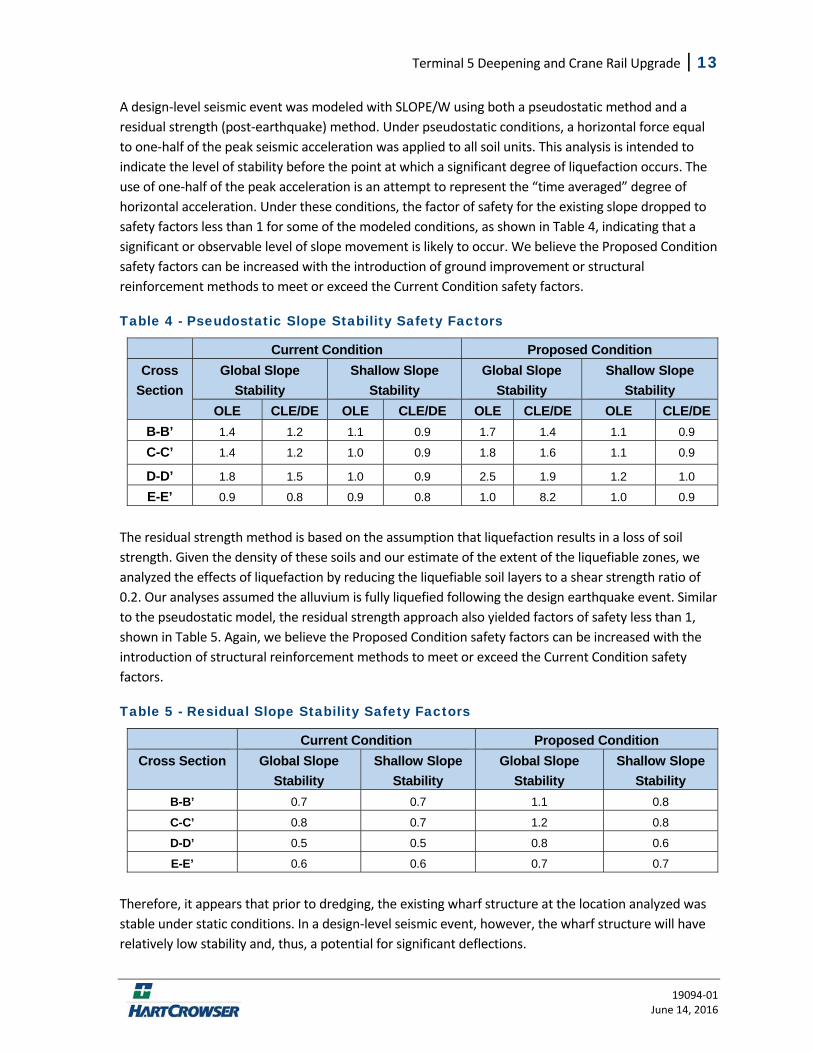
A design‐level seismic event was modeled with SLOPE/W using both a pseudostatic method and a residual strength (post‐earthquake) method. Under pseudostatic conditions, a horizontal force equal to one‐half of the peak seismic acceleration was applied to all soil units. This analysis is intended to indicate the level of stability before the point at which a significant degree of liquefaction occurs. The use of one‐half of the peak acceleration is an attempt to represent the “time averaged” degree of horizontal acceleration. Under these conditions, the factor of safety for the existing slope dropped to safety factors less than 1 for some of the modeled conditions, as shown in Table 4, indicating that a significant or observable level of slope movement is likely to occur. We believe the Proposed Condition safety factors can be increased with the introduction of ground improvement or structural reinforcement methods to meet or exceed the Current Condition safety factors.
Table 4 - Pseudostatic Slope Stability Safety Factors
Current Condition Proposed Condition Cross
Section Global Slope
Stability Shallow Slope
Stability Global Slope
Stability Shallow Slope
Stability OLE CLE/DE OLE CLE/DE OLE CLE/DE OLE CLE/DE
B-B’ 1.4 1.2 1.1 0.9 1.7 1.4 1.1 0.9
C-C’ 1.4 1.2 1.0 0.9 1.8 1.6 1.1 0.9
D-D’ 1.8 1.5 1.0 0.9 2.5 1.9 1.2 1.0
E-E’ 0.9 0.8 0.9 0.8 1.0 8.2 1.0 0.9
The residual strength method is based on the assumption that liquefaction results in a loss of soil strength. Given the density of these soils and our estimate of the extent of the liquefiable zones, we analyzed the effects of liquefaction by reducing the liquefiable soil layers to a shear strength ratio of 0.2. Our analyses assumed the alluvium is fully liquefied following the design earthquake event. Similar to the pseudostatic model, the residual strength approach also yielded factors of safety less than 1, shown in Table 5. Again, we believe the Proposed Condition safety factors can be increased with the introduction of structural reinforcement methods to meet or exceed the Current Condition safety factors.
Table 5 - Residual Slope Stability Safety Factors
Current Condition Proposed Condition Cross Section Global Slope
Stability Shallow Slope
Stability Global Slope
Stability Shallow Slope
Stability B-B’ 0.7 0.7 1.1 0.8
C-C’ 0.8 0.7 1.2 0.8
D-D’ 0.5 0.5 0.8 0.6
E-E’ 0.6 0.6 0.7 0.7
Therefore, it appears that prior to dredging, the existing wharf structure at the location analyzed was stable under static conditions. In a design‐level seismic event, however, the wharf structure will have relatively low stability and, thus, a potential for significant deflections.
14 | Terminal 5 Deepening and Crane Rail Upgrade
19094‐01 June 14, 2016
Stability of South End Section
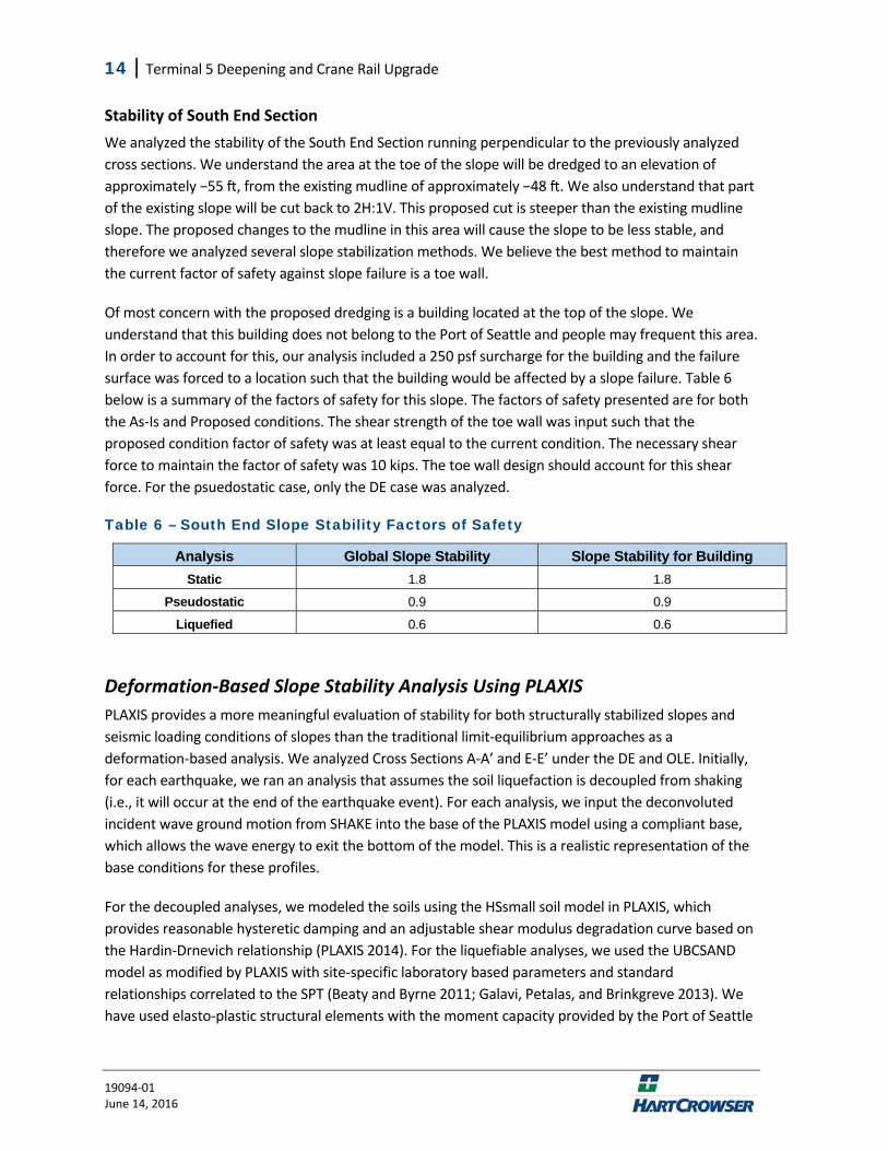
We analyzed the stability of the South End Section running perpendicular to the previously analyzed cross sections. We understand the area at the toe of the slope will be dredged to an elevation of approximately −55 , from the exis ng mudline of approximately −48 . We also understand that part of the existing slope will be cut back to 2H:1V. This proposed cut is steeper than the existing mudline slope. The proposed changes to the mudline in this area will cause the slope to be less stable, and therefore we analyzed several slope stabilization methods. We believe the best method to maintain the current factor of safety against slope failure is a toe wall.
Of most concern with the proposed dredging is a building located at the top of the slope. We understand that this building does not belong to the Port of Seattle and people may frequent this area. In order to account for this, our analysis included a 250 psf surcharge for the building and the failure surface was forced to a location such that the building would be affected by a slope failure. Table 6 below is a summary of the factors of safety for this slope. The factors of safety presented are for both the As‐Is and Proposed conditions. The shear strength of the toe wall was input such that the proposed condition factor of safety was at least equal to the current condition. The necessary shear force to maintain the factor of safety was 10 kips. The toe wall design should account for this shear force. For the psuedostatic case, only the DE case was analyzed.
Table 6 – South End Slope Stability Factors of Safety
Analysis Global Slope Stability Slope Stability for Building Static 1.8 1.8
Pseudostatic 0.9 0.9
Liquefied 0.6 0.6
Deformation‐Based Slope Stability Analysis Using PLAXIS
PLAXIS provides a more meaningful evaluation of stability for both structurally stabilized slopes and seismic loading conditions of slopes than the traditional limit‐equilibrium approaches as a deformation‐based analysis. We analyzed Cross Sections A‐A’ and E‐E’ under the DE and OLE. Initially, for each earthquake, we ran an analysis that assumes the soil liquefaction is decoupled from shaking (i.e., it will occur at the end of the earthquake event). For each analysis, we input the deconvoluted incident wave ground motion from SHAKE into the base of the PLAXIS model using a compliant base, which allows the wave energy to exit the bottom of the model. This is a realistic representation of the base conditions for these profiles.
For the decoupled analyses, we modeled the soils using the HSsmall soil model in PLAXIS, which provides reasonable hysteretic damping and an adjustable shear modulus degradation curve based on the Hardin‐Drnevich relationship (PLAXIS 2014). For the liquefiable analyses, we used the UBCSAND model as modified by PLAXIS with site‐specific laboratory based parameters and standard relationships correlated to the SPT (Beaty and Byrne 2011; Galavi, Petalas, and Brinkgreve 2013). We have used elasto‐plastic structural elements with the moment capacity provided by the Port of Seattle
Terminal 5 Deepening and Crane Rail Upgrade | 15
19094‐01 June 14, 2016
to provide a consistent comparison between the proposed conditions. Piles were modeled using the embedded pile row element in PLAXIS, which attempts to model the three‐dimensional nature of piles in two dimensions, with the peak lateral spring forces defined by LPILE. Existing structural elements which are intersected by the battered pinch piles in the cross section view are not modeled. These elements do not change from the current condition to proposed design, and thus should not significantly alter the comparative results. For each analysis condition, we provide a solution that maintains or improves the approximate level of slope stiffness that is currently in place. The expected trends of increasing deformation with level of shaking and with the onset of liquefaction were observed. Each of these was relative and consistent for each condition, meaning that if the proposed condition was stiffer under the DE than the current condition, it was also stiffer for the OLE as well.
PLAXIS Analyses and Results
Section B‐B’ currently has H‐piles supporting a 5‐foot cut spaced at approximately 4 or 5 feet on center. Current berthing elevation at this location is −45 MLLW. As previously discussed, the proposed dredging increases the design depth of the berth to elevation −55 with an allowance of 3 feet for dredging and overdredging.
Section E‐E’ is currently sloped down to elevation −50 MLLW. The proposed berthing elevation is −55 with allowances for dredging and overdredging at this location, as well.
In order to provide comparable stiffness to the current condition, we have analyzed a HZ1180M D‐26 with AZ 26‐700 king‐pile toe wall with structural properties provided by the Port of Seattle, which we converted to the units used in PLAXIS. The structural properties for this system were an EA of 87E6 pounds per lineal foot, an EI of 1.68E9 square foot pound per lineal foot, and a plastic moment of 1.904E6 foot pound per lineal foot. The HP14x73 was modeled with a modulus of elasticity of 4.18E9 psf, an area of 0.148 square feet, and a moment of inertia of 0.035 ft4 at a spacing of 5.5 feet. We have conservatively modeled the king‐pile toe wall at an elevation of −90 feet, with the wall HZ piles extending to bearing. Existing pile properties for concrete piles are provided in Attachment 3. All structural systems were modeled with a target 5% Rayleigh damping between 1 and 4 hertz.
The pinch piles specified are 60 foot long, 14 inch diameter timber piles with a 1 inch taper every 10 feet. The lateral springs for the piles were modeled with the taper taken into consideration in LPILE. The structural properties in the PLAXIS model are based on a 1 foot diameter pile, as the majority of the deformation within the model is shallow, and the piles are not controlled by bending. The piles were modeled with a moment capacity of 10.58E3 foot pounds. Spacing was based on the current design drawings of 6.7 and 10 feet on average.
The king‐pile toe wall configuration provides a similar response as the current condition while also providing a continuous wall to retain the soils, rather than the discrete H‐pile system.
As explored in our preliminary report, the proposed king‐pile system alone results in greater up‐slope deformation than the current condition. We previously considered two improved ground situations to reduce the king‐pile system displacement.
16 | Terminal 5 Deepening and Crane Rail Upgrade
19094‐01 June 14, 2016
The first of these alternatives is a generic, 10‐foot‐wide jetted grouted system placed immediately behind the king‐pile toe wall. The wall could also be constructed using a compaction grouted system spaced 4 to 6 feet on center with equivalent composite material strength. Compaction grouting would likely result in less grout spoils while also densifying/strengthening the soil around it.
The grouted section was modeled with a bottom elevation of −100 feet MLLW and up to our estimated bottom of rip‐rap. The grouted section dimensions should be refined as part of final design. The grouted improvement zone was modeled with a Mohr Coulomb soil model with a stiffness of 62E6 psf, shear strength of 55E3 psf (382 psi), and an allowable tension of 500 psf. The grouted section condition shows more deformation under the OLE than the current condition but less deformation under the DE. This can largely be attributed to the simplicity of the Mohr Coulomb model and its inability to model shear modulus degradation. We anticipate stone columns to perform similarly, with little mitigation of upslope movements.
A “pinch‐pile” alternative was considered, which consists of driving timber piles into the lower third of the slope at approximately 5 feet on‐center. The pinch piles were modeled with the embedded pile row element with a modulus of elasticity of 216E6 psf and a diameter of 0.75 feet. Pinch piles were modelled vertically along approximately the lower third of the slope, installation would likely be in a radial manner along the same portion of the slope. We do not expect this to significantly alter the performance of the piles. The decreases in the up‐slope from deformation associated with the alternatives are shown in Table 5.
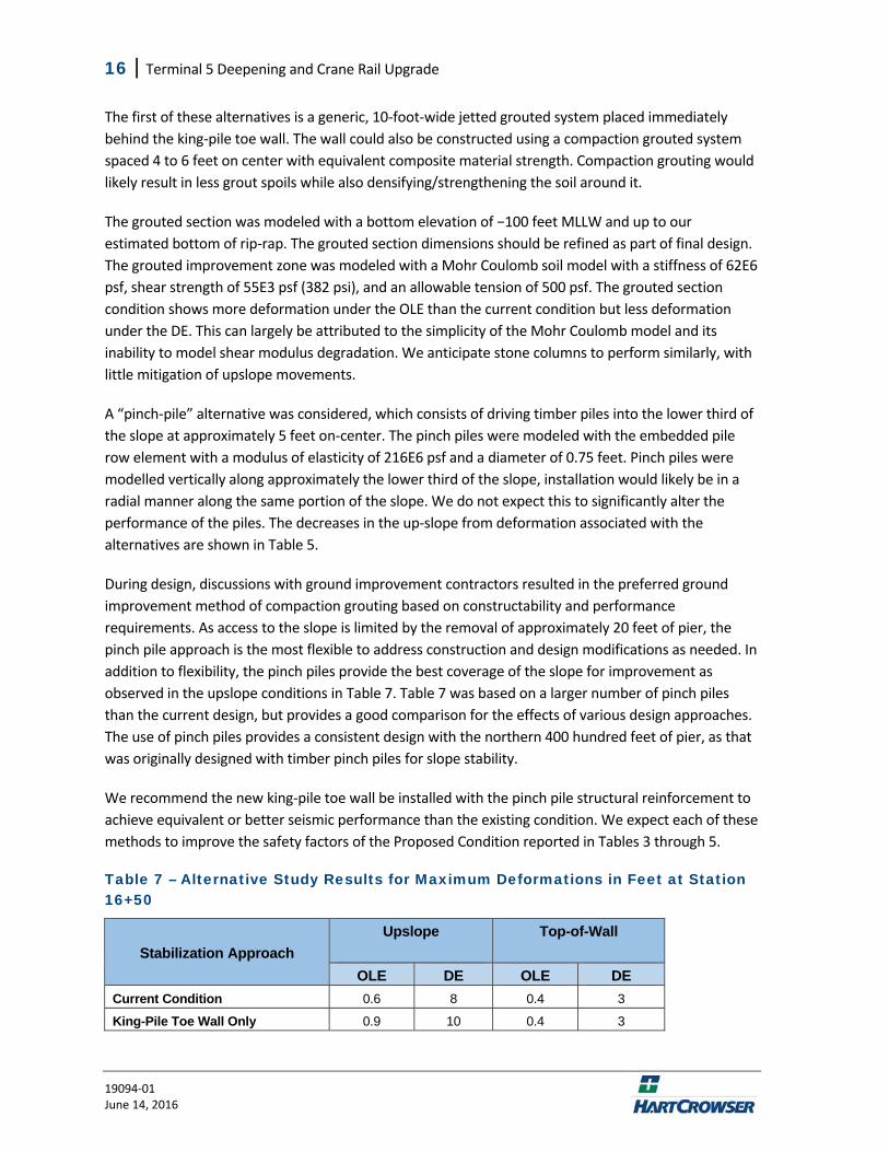
During design, discussions with ground improvement contractors resulted in the preferred ground improvement method of compaction grouting based on constructability and performance requirements. As access to the slope is limited by the removal of approximately 20 feet of pier, the pinch pile approach is the most flexible to address construction and design modifications as needed. In addition to flexibility, the pinch piles provide the best coverage of the slope for improvement as observed in the upslope conditions in Table 7. Table 7 was based on a larger number of pinch piles than the current design, but provides a good comparison for the effects of various design approaches. The use of pinch piles provides a consistent design with the northern 400 hundred feet of pier, as that was originally designed with timber pinch piles for slope stability.
We recommend the new king‐pile toe wall be installed with the pinch pile structural reinforcement to achieve equivalent or better seismic performance than the existing condition. We expect each of these methods to improve the safety factors of the Proposed Condition reported in Tables 3 through 5.
Table 7 – Alternative Study Results for Maximum Deformations in Feet at Station 16+50
Stabilization Approach
Upslope
Top-of-Wall
OLE DE OLE DE Current Condition 0.6 8 0.4 3
King-Pile Toe Wall Only 0.9 10 0.4 3
Terminal 5 Deepening and Crane Rail Upgrade | 17
19094‐01 June 14, 2016
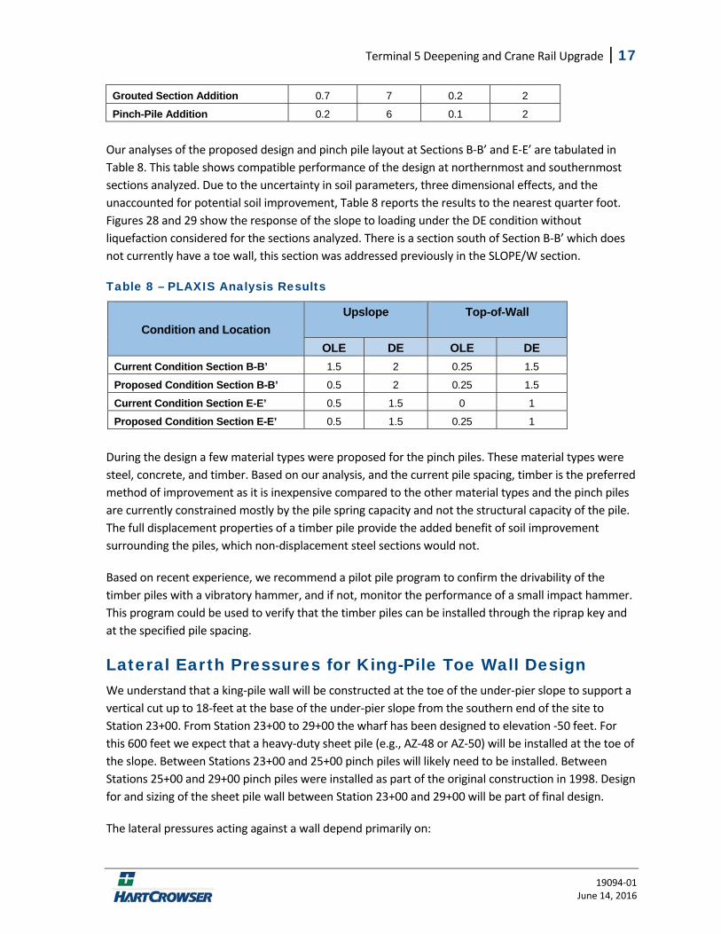
Grouted Section Addition 0.7 7 0.2 2
Pinch-Pile Addition 0.2 6 0.1 2
Our analyses of the proposed design and pinch pile layout at Sections B‐B’ and E‐E’ are tabulated in Table 8. This table shows compatible performance of the design at northernmost and southernmost sections analyzed. Due to the uncertainty in soil parameters, three dimensional effects, and the unaccounted for potential soil improvement, Table 8 reports the results to the nearest quarter foot. Figures 28 and 29 show the response of the slope to loading under the DE condition without liquefaction considered for the sections analyzed. There is a section south of Section B‐B’ which does not currently have a toe wall, this section was addressed previously in the SLOPE/W section.
Table 8 – PLAXIS Analysis Results
Condition and Location
Upslope
Top-of-Wall
OLE DE OLE DE Current Condition Section B-B’ 1.5 2 0.25 1.5
Proposed Condition Section B-B’ 0.5 2 0.25 1.5
Current Condition Section E-E’ 0.5 1.5 0 1
Proposed Condition Section E-E’ 0.5 1.5 0.25 1
During the design a few material types were proposed for the pinch piles. These material types were steel, concrete, and timber. Based on our analysis, and the current pile spacing, timber is the preferred method of improvement as it is inexpensive compared to the other material types and the pinch piles are currently constrained mostly by the pile spring capacity and not the structural capacity of the pile. The full displacement properties of a timber pile provide the added benefit of soil improvement surrounding the piles, which non‐displacement steel sections would not.
Based on recent experience, we recommend a pilot pile program to confirm the drivability of the timber piles with a vibratory hammer, and if not, monitor the performance of a small impact hammer. This program could be used to verify that the timber piles can be installed through the riprap key and at the specified pile spacing.
Lateral Earth Pressures for King-Pile Toe Wall Design We understand that a king‐pile wall will be constructed at the toe of the under‐pier slope to support a vertical cut up to 18‐feet at the base of the under‐pier slope from the southern end of the site to Station 23+00. From Station 23+00 to 29+00 the wharf has been designed to elevation ‐50 feet. For this 600 feet we expect that a heavy‐duty sheet pile (e.g., AZ‐48 or AZ‐50) will be installed at the toe of the slope. Between Stations 23+00 and 25+00 pinch piles will likely need to be installed. Between Stations 25+00 and 29+00 pinch piles were installed as part of the original construction in 1998. Design for and sizing of the sheet pile wall between Station 23+00 and 29+00 will be part of final design.
The lateral pressures acting against a wall depend primarily on:
18 | Terminal 5 Deepening and Crane Rail Upgrade
19094‐01 June 14, 2016
Fill material type and degree of compaction immediately adjacent to the wall; Surcharges and sloping ground conditions at or behind the wall; Flexibility of the wall and the degree of lateral movement the wall undergoes; Drainage and presence of water; and Seismic loading considerations.
Lateral loading on the bulkhead can be expected from the soil for both static and seismic loads.
Static Loading. We expect that active (yielding wall) conditions will develop behind the king‐pile wall. When loaded laterally, the top of a yielding wall will move at least 0.1 percent of its exposed height. Allowable lateral pressures on the bulkhead can be estimated using Figure 30.
The equivalent fluid weight does not include any surface or surcharge load conditions. Any vertical loads that are behind and adjacent to the bulkhead will impose additional lateral loads on the bulkhead. Lateral loads should be incorporated into the bulkhead design on a case‐by‐case basis. Furthermore, we recommend that the passive resistance in the upper 2 feet be neglected to account for soil disturbance or erosion.
Seismic Loading. Lateral loads due to seismic pressure can be computed by applying a rectangular pressure distribution over the height of the bulkhead. We used the force required to stabilize the slope above the dredge elevation in a slope‐stability model to develop the seismic lateral earth pressures that should be added to the active pressures provided on Figures 30. This method involved placing a point load in our SLOPE/W model at a point 2/3 of the toe wall height from the top of the toe wall (where an equivalent load would act on a wall), instead of placing a toe wall reinforcement. The point load was then increased or decreased on a trial and error basis until a factor of safety of 1 was obtained. This load is the force required to stabilize the slope above the dredge elevation. This approach addresses concerns of Monobe‐Okabe performing poorly for backslopes near the friction angle of the soils. The post‐seismic condition can be addressed by increasing the active pressure equivalent unit weight of ESU 1 to 46 pounds per cubic foot (pcf), and reducing the passive pressure equivalent fluid unit weight to 50 pcf. This increase is based on a full liquefied alluvial section, which is consistent with our slope‐stability results.
Vertical Pile Capacity Vertical compressive loads can be resisted by friction along the pile sides and by end bearing at the tip. Because of the high pile load requirements, it is important that piles be embedded sufficiently in the bearing layer. Because the bearing layer is variable, required pile lengths can only be approximated based on field boring logs at discrete locations. Actual pile lengths will depend upon driving resistance and other factors, and may need to be adjusted in the field. Piles should have an excess length, such that they can be driven to additional depths for adequate embedment into the bearing layer if necessary. The capacity recommendations provided with this report consider the results of the test pile program, the results of which are summarize in Attachment 5.
Terminal 5 Deepening and Crane Rail Upgrade | 19
19094‐01 June 14, 2016
Based on the soil conditions at the project site, our review of the test pile program results, we determined pile capacities based on effective stress analysis methods. We used Unipile to model the vertical capacity at each of our borings (HC‐1 through 12). For each soil profile, multiple pile sizes were considered; steel pipe piles were used for the landside profiles and concrete piles were used for the offshore profiles. We used a compressive factor of safety of 2.0 for static and 1.0 for post‐liquefied conditions. Under uplift condition we used a factor of safety of 3.0 for static and 1.0 for post‐liquefied uplift conditions. A factor of safety of one considering structural and downdrag loading is consistent with ASCE 61‐14. These factors of safety must be verified in the field by a load test as defined by the IBC, which allows PDA/CAPWAP to be the load test method.
Downdrag results from settlement within the liquefiable layer and all the soil layers above it. Soils above and within the liquefiable layer settle relative to the pile and cause downward forces on the pile. The post‐liquefaction plots neglect compressive soil resistance above the base of the liquefied layer. Downdrag loads are accounted for in the allowable compressive resistance plots on Figures 31 to 54. The compressive capacity under downdrag loading due to liquefaction generally appears to control the design.
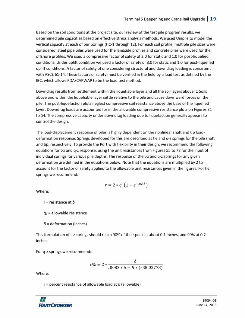
The load‐displacement response of piles is highly dependent on the nonlinear shaft and tip load‐deformation response. Springs developed for this are described as t‐z and q‐z springs for the pile shaft and tip, respectively. To provide the Port with flexibility in their design, we recommend the following equations for t‐z and q‐z response, using the unit resistances from Figures 55 to 78 for the input of individual springs for various pile depths. The response of the t‐z and q‐z springs for any given deformation are defined in the equations below. Note that the equations are multiplied by 2 to account for the factor of safety applied to the allowable unit resistances given in the figures. For t‐z springs we recommend:
2 ∗ 1 ∗ Where:
r = resistance at δ
qa = allowable resistance
δ = deformation (inches).
This formulation of t‐z springs should reach 90% of their peak at about 0.1 inches, and 99% at 0.2 inches.
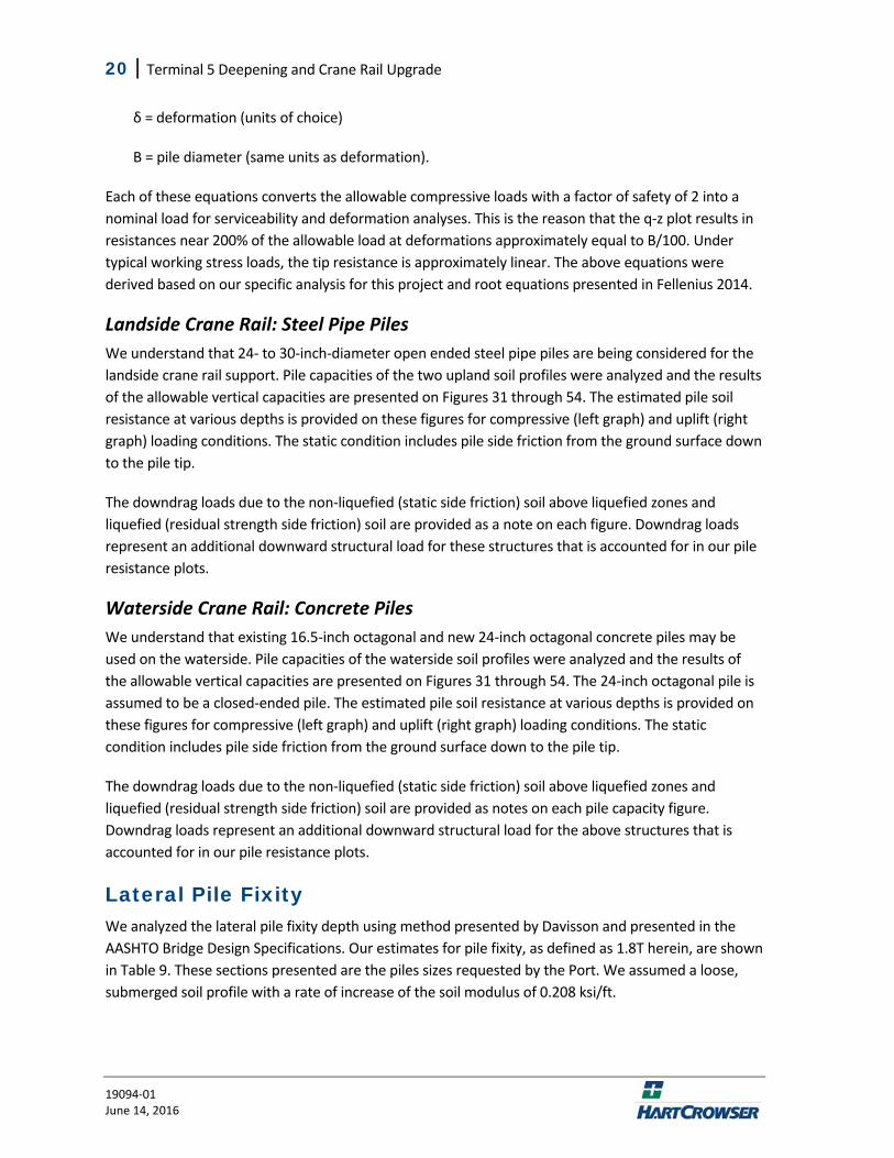
For q‐z springs we recommend:
% 2 ∗. 0083 ∗ ∗ .00002778
Where:
r = percent resistance of allowable load at δ (allowable)
20 | Terminal 5 Deepening and Crane Rail Upgrade
19094‐01 June 14, 2016
δ = deformation (units of choice)
B = pile diameter (same units as deformation).
Each of these equations converts the allowable compressive loads with a factor of safety of 2 into a nominal load for serviceability and deformation analyses. This is the reason that the q‐z plot results in resistances near 200% of the allowable load at deformations approximately equal to B/100. Under typical working stress loads, the tip resistance is approximately linear. The above equations were derived based on our specific analysis for this project and root equations presented in Fellenius 2014.
Landside Crane Rail: Steel Pipe Piles
We understand that 24‐ to 30‐inch‐diameter open ended steel pipe piles are being considered for the landside crane rail support. Pile capacities of the two upland soil profiles were analyzed and the results of the allowable vertical capacities are presented on Figures 31 through 54. The estimated pile soil resistance at various depths is provided on these figures for compressive (left graph) and uplift (right graph) loading conditions. The static condition includes pile side friction from the ground surface down to the pile tip.
The downdrag loads due to the non‐liquefied (static side friction) soil above liquefied zones and liquefied (residual strength side friction) soil are provided as a note on each figure. Downdrag loads represent an additional downward structural load for these structures that is accounted for in our pile resistance plots.
Waterside Crane Rail: Concrete Piles
We understand that existing 16.5‐inch octagonal and new 24‐inch octagonal concrete piles may be used on the waterside. Pile capacities of the waterside soil profiles were analyzed and the results of the allowable vertical capacities are presented on Figures 31 through 54. The 24‐inch octagonal pile is assumed to be a closed‐ended pile. The estimated pile soil resistance at various depths is provided on these figures for compressive (left graph) and uplift (right graph) loading conditions. The static condition includes pile side friction from the ground surface down to the pile tip.
The downdrag loads due to the non‐liquefied (static side friction) soil above liquefied zones and liquefied (residual strength side friction) soil are provided as notes on each pile capacity figure. Downdrag loads represent an additional downward structural load for the above structures that is accounted for in our pile resistance plots.
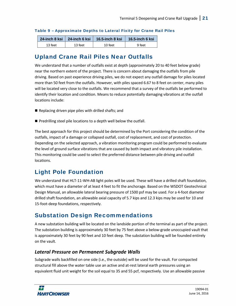
Lateral Pile Fixity We analyzed the lateral pile fixity depth using method presented by Davisson and presented in the AASHTO Bridge Design Specifications. Our estimates for pile fixity, as defined as 1.8T herein, are shown in Table 9. These sections presented are the piles sizes requested by the Port. We assumed a loose, submerged soil profile with a rate of increase of the soil modulus of 0.208 ksi/ft.
Terminal 5 Deepening and Crane Rail Upgrade | 21
19094‐01 June 14, 2016
Table 9 – Approximate Depths to Lateral Fixity for Crane Rail Piles
24-inch 8 ksi 24-inch 6 ksi 16.5-inch 8 ksi 16.5-inch 6 ksi 13 feet 13 feet 10 feet 9 feet
Upland Crane Rail Piles Near Outfalls We understand that a number of outfalls exist at depth (approximately 20 to 40 feet below grade) near the northern extent of the project. There is concern about damaging the outfalls from pile driving. Based on past experience driving piles, we do not expect any outfall damage for piles located more than 50 feet from the outfalls. However, with piles spaced 6.67 to 8 feet on center, many piles will be located very close to the outfalls. We recommend that a survey of the outfalls be performed to identify their location and condition. Means to reduce potentially damaging vibrations at the outfall locations include:
Replacing driven pipe piles with drilled shafts; and
Predrilling steel pile locations to a depth well below the outfall.
The best approach for this project should be determined by the Port considering the condition of the outfalls, impact of a damage or collapsed outfall, cost of replacement, and cost of protection. Depending on the selected approach, a vibration monitoring program could be performed to evaluate the level of ground surface vibrations that are caused by both impact and vibratory pile installation. This monitoring could be used to select the preferred distance between pile driving and outfall locations.
Light Pole Foundation We understand that HLT‐11‐WH‐AB light poles will be used. These will have a drilled shaft foundation, which must have a diameter of at least 4 feet to fit the anchorage. Based on the WSDOT Geotechnical Design Manual, an allowable lateral bearing pressure of 1500 psf may be used. For a 4‐foot diameter drilled shaft foundation, an allowable axial capacity of 5.7 kips and 12.3 kips may be used for 10 and 15‐foot‐deep foundations, respectively.
Substation Design Recommendations A new substation building will be located on the landside portion of the terminal as part of the project. The substation building is approximately 30 feet by 75 feet above a below‐grade unoccupied vault that is approximately 30 feet by 90 feet and 10 feet deep. The substation building will be founded entirely on the vault.
Lateral Pressure on Permanent Subgrade Walls
Subgrade walls backfilled on one side (i.e., the outside) will be used for the vault. For compacted structural fill above the water table use an active and at‐rest lateral earth pressures using an equivalent fluid unit weight for the soil equal to 35 and 55 pcf, respectively. Use an allowable passive
22 | Terminal 5 Deepening and Crane Rail Upgrade
19094‐01 June 14, 2016
equivalent fluid unit weight for this material of 270 pcf, which includes a factor of safety of 1.5. These values are based on a drained condition behind the walls so there is no buildup of hydrostatic pressure.
In addition to the active soil pressures we recommend applying a horizontal traffic and material surcharge be applied. This surcharge may be calculated as 0.3 times the vertical surcharge load (e.g., for a vertical surcharge of 250 psf the horizontal surcharge pressure on the wall is 75 psf).
Below the water table, the active and at‐rest pressure equivalent fluid weights are 18 and 29 pcf, respectively. Similarly, the equivalent fluid unit weight for passive resistance reduces to 135 pcf. Hydrostatic pressure should be applied to the wall when submerged.
The use of active pressure is appropriate if the subgrade wall is allowed to yield a minimum of 0.001 times the height of the wall. For a non‐yielding wall, at‐rest conditions should be used. We expect that the vault walls will be non‐yielding. Lateral loads applied to the wall caused by external vertical loads applied to the surrounding soils can be determined using Figure 79.
Vault Foundation
Where finish floor elevations are above or only slightly below the design high groundwater elevation, slab‐on‐grade floor slabs may be used. We provide recommendations for both slab‐on‐grade floor slabs, and structural slabs, and the base of the vault.
The floor slab of vault base could be constructed as a slab‐on‐grade above a drainage layer and the specified improved ground. Do not found near‐grade floor slabs on existing fill or loose soil, unless they are free of organic material and can be compacted to a dense, non‐yielding condition as determined by probing or proof rolling the subgrade. Overexcavate at least 12 inches of unsuitable fill (if encountered) and replace it with structural fill compacted to a firm non‐yielding condition below the vault slab.
In addition to the structural fill, all slabs should be underlain directly by a drainage layer at least 6 inches thick. This layer should consist of clean, well graded coarse sand and gravel with a fines content (soil finer than the No. 200 sieve based on the minus 3/4‐inch fraction of the material) of less than 3 percent by weight. ‐This layer serves as a capillary break and drainage layer and is intended to reduce the potential buildup of hydrostatic pressure beneath the slab and to provide permanent control of groundwater beneath the floor slab and behind the perimeter walls, (see Section 6.7). For slab‐on‐grade floors, we recommend:
Compact the drainage layer to the criteria of structural fill described in our Earthwork Recommendations.
Use an allowable bearing pressure of 1,000 pounds per square foot (psf) with an estimated settlement of up to an inch;
Terminal 5 Deepening and Crane Rail Upgrade | 23
19094‐01 June 14, 2016
Use a modulus of subgrade reaction of 25 pounds per cubic inch (pci) for design of the vault floor slabs on compacted structural fill.
Determine sliding friction between the slab and subgrade using an allowable coefficient of friction of 0.30.
Submit any soil that is to be considered as capillary break or drainage material to Hart Crowser for gradational analysis.
Note that if the bottom of the excavation is soft, wet, and disturbed, the contractor should be prepared to place a temporary working surface. This surface cannot count as part of the 6‐inch drainage layer.
Drainage Recommendations
Groundwater is typically near elevation 10 feet MLLW at Terminal 5. Based on these groundwater levels, our recommendations for drainage are as follows. If the base of the vault is below the groundwater table, waterproofing should be applied up to at least one foot above the water table.
Foundation Drainage
For permanent drainage around the structure foundations, we recommend that a capillary break layer of at least 6 inches of free‐draining material be placed below slabs‐on‐grade, vault foundations, and shallow footings. This 6‐inch‐thick layer should be composed of import material.
Backfilled Walls
Walls with soil backfilled on one side will require drainage, or must be designed to withstand full hydrostatic pressure. We recommend the following:
Backfill with a minimum thickness of 18 inches of well‐graded, free‐draining sand (less than 3 percent fines based on the minus 3/4‐inch fraction) or sand and gravel.
Install drains behind any backfilled subgrade walls. Drains with cleanouts should incorporate a minimum 4‐inch‐diameter perforated pipe surrounded by at least 6 inches of well‐graded, free‐draining sand (less than 3 percent fines based on minus 3/4 inch fraction), or sand and gravel. The drains should be sloped to carry the water to a sump or other suitable discharge.
The backfill should be continuous and envelop the drainage behind the wall.
Site Drainage
Final grades should be sloped to carry surface water runoff away from structures to prevent water from infiltrating near the foundation walls. Roof drainage and new surface water drainage should not be tied into the subdrain system and should not discharge onto the site.
24 | Terminal 5 Deepening and Crane Rail Upgrade
19094‐01 June 14, 2016
Earthwork Recommendations
Site Preparation and Grading
We recommend all site grading, paving, and any utility trenching be conducted during relatively dry weather conditions.
It may be necessary to relocate or abandon some utilities. Excavation of these utility lines will probably occur through fill. Abandoned underground utilities should be removed or completely grouted. Ends of remaining abandoned utility lines should be sealed to prevent piping of soil or water into the pipe. Soft or loose backfill should be removed, and excavations should be backfilled with structural fill. Coordination with the utility agency is generally required.
Structural Fill
Backfill placed within the building area or below paved areas should be considered structural fill. We make the following recommendations for structural fill:
For imported soil to be used as structural fill, use a clean, well‐graded sand or sand and gravel with less than 5 percent by weight passing the No. 200 mesh sieve (based on the minus 3/4‐inch fraction). Compaction of soil containing more than about 5 percent fines may be difficult if the material is wet or becomes wet during rainy weather.
Place and compact all structural fill in lifts with a loose thickness no greater than 10 inches. For hand‐operated “jumping jack” compactors, loose lifts should not exceed 6 inches. For small vibrating plate/sled compactors, loose lifts should not exceed 3 inches.
Compact all structural fill to at least 95 percent of the modified Proctor maximum dry density (as determined by ASTM D 1557 test procedure).
Control the moisture content of the fill to within 2 percent of the optimum moisture. Optimum moisture is the moisture content corresponding to the maximum Proctor dry density.
In wet subgrade areas, clean material with a gravel content of at least 30 to 35 percent may be necessary. Gravel is material coarser than a US No. 4 sieve.
Before filling begins, provide samples of the structural and drainage fill for laboratory testing. Laboratory testing will include a Proctor test and gradation for structural fill and a gradation for drainage fill. Field testing with a nuclear density gauge uses the maximum dry density determined from a Proctor test so it is important to complete the laboratory testing as soon as possible in order to not delay backfilling.
Terminal 5 Deepening and Crane Rail Upgrade | 25
19094‐01 June 14, 2016
Use of On‐Site Soil as Structural Fill
Our explorations indicated that the near‐surface site soil includes silty sand, silt, and clay; we do not recommend using these soils for structural fill. The sands may be used but are likely to contain more than 5 percent fines and will be moisture‐sensitive and could be difficult to compact in wet weather.
Temporary Cuts
Because of the variables involved, actual slope grades required for stability in temporary cut areas can only be estimated before construction. We recommend that stability of the temporary slopes used for construction be the sole responsibility of the contractor, since the contractor is in control of the construction operation and is continuously at the site to observe the nature and condition of the subsurface. Excavations should be made in accordance with all local, state, and federal safety requirements.
For planning purposes, the soils across the site are likely OSHA Soil Classification Type C; however, the soil classification must be reevaluated at the time of construction.
The stability and safety of open trenches and cut slopes depend on a number of factors, including:
Type and density of the soil;
Presence and amount of any seepage;
Depth of cut;
Proximity of the cut to any surcharge loads near the top of the cut, such as stockpiled material, traffic loads, structures, etc.;
Duration of the open excavation; and
Care and methods used by the contractor.
Based on these factors, we recommend:
Using plastic sheeting to protect slopes from erosion; and
Limiting the duration of open excavations as much as possible.
RECOMMENDED ADDITIONAL GEOTECHNICAL SERVICES This report will be superseded with a 100% report at a later date which will include the final numerical modelling results.
Recommendations discussed in this report should be reviewed and modified as needed during the final design stages of the project. We also recommend that geotechnical construction observation be
26 | Terminal 5 Deepening and Crane Rail Upgrade
19094‐01 June 14, 2016
incorporated into the construction plans. The following sections present our recommended post‐report geotechnical engineering services specific to this project.
Post-Report Design Services We recommend that Hart Crowser be afforded the opportunity to review geotechnical aspects of the final design plans and specifications to confirm that our recommendations were properly understood and implemented in the design. We will be available to discuss these issues with the design team as the design develops and as needed. Specifically, we recommend the following additional design services:
Provide geotechnical engineering support to the civil/structural engineer during preparation of project plans and specifications; and
Prepare geotechnical review letters and response to geotechnical plan review comments from the City of Seattle Department of Planning and Development (DPD).
Construction Observation Services Because the future performance and integrity of the structural elements of the project will depend largely on proper pile installation, site preparation, drainage, fill placement, and construction procedures, monitoring and testing by experienced geotechnical personnel should be considered an integral part of the construction process.
The purpose of our observations is to verify compliance with design concepts and recommendations, and to allow design changes or evaluation of appropriate construction methods in the event that subsurface conditions differ from those anticipated prior to the start of construction. Consequently, we recommend that Hart Crowser be retained to provide the following construction support services:
Review geotechnically related construction submittals from the contractor to verify compliance with the construction plans and the recommendations of this report.
Attend a pre‐construction conference with the contractor and DPD to discuss important geotechnically related construction issues.
Observe the installation of new piles to confirm conformance with the geotechnical design recommendations and the construction plans.
Observe installation of ground improvement elements (i.e., pinch piles).
Observe all exposed footing, slab‐on‐grade, and pavement subgrades after completion of stripping and overexcavation to confirm that suitable soil conditions have been reached and to determine appropriate subgrade compaction methods.
Observe the installation of all perimeter drains, wall drains, and capillary break layers to verify their conformance with the construction plans.
Terminal 5 Deepening and Crane Rail Upgrade | 27
19094‐01 June 14, 2016
Monitor the placement and test the compaction of all structural fill soil to verify confirm conformance with the construction specifications.
Monitor and test utility trench backfill.
Provide assistance with any other geotechnical considerations that may arise during the course of construction.
REFERENCES Beaty, M.H. and Byrne, P.M. 2011. UBCSAND Constitutive Model Version 904aR. Itasca Consulting.
Casey, B. and Germain, J.T. 2013. Stress Dependence of Shear Strength in Fine‐Grained Soils and Correlations with Liquid Limit, Journal of Geotechnical and Geoenvironmental Engineering, Vol 139 No. 10.
Consortium of Organizations for Strong‐Motion Observation Systems (COSMOS) 1997‐2007. COSMOS Virtual Data Center. Web site: http://db.cosmos‐eq.org/scripts/earthquakes.plx
Fellenius, H.B. 2014. Basics of Foundation Design. Electronic Edition (The Red Book).
Galavi, V., Petalas, A., and Brinkgreve, R.B.J. 2013. Finite Element Modelling of Seismic Liquefaction in Soils. Geotechnical Engineering Journals of the SEAGS and AGSSEA, Vol. 44 No. 3.
Idriss, I.M. and R.W. Boulanger 2008. Soil Liquefaction During Earthquakes. EERI Publication.
Mejia, L.H. and Dawson, E.M. 2006. Earthquake Deconvolution for FLAC. Paper presented at Fourth International FLAC Symposium on Numerical Modeling in Geomechanics, Madrid, Spain, May 2006.
Pacific Earthquake Engineering Research (PEER) Center 2010. PEER Strong Ground Motion Database. Web site: http://peer.berkeley.edu/products/strong_ground_motion_db.html
Sorensen, K.K. and Okkels, N. 2013. Correlation between drained shear strength and plasticity index of undisturbed overconsolidated clays, Proceedings of the 18th International Conference on Soil Mechanics and Geotechnical Engineering, Paris 2013.
Tomlinson, M.J. 1994. Pile Design and Construction Practice. Fourth Edition, E & FN Spon, London.
US Geological Survey 2008a. USGS 2008 National Seismic Hazard Mapping Project PSHA Interactive Deaggregation Web Site: http://eqint.cr.usgs.gov/deaggint/2008/
US Geological Survey 2008b. USGS National Seismic Hazard Maps, from USGS Web site: http://earthquake.usgs.gov/hazards/designmaps/usdesign.php
28 | Terminal 5 Deepening and Crane Rail Upgrade
19094‐01 June 14, 2016
Washington State Department of Natural Resources 2003. Tsunami Hazard Map of Elliot Bay Area, Seattle, Washington: Modeled Tsunami Inundation from Seattle Fault Earthquake, Open File Report 2003‐14
Washington State Department of Transportation 2015. Geotechnical Design Manual.
L:\Notebooks\1909401_T5 Sediment Berth Deepening Project\Deliverables\Reports\95% Geotechnical Report\95% Geotechnical Report.docx

Terminal 5 Cargo Wharf Rehabilitation, Berth Deepening, and Improvements October 2016
Final Environmental Impact Statement
There are 1052 pages of Figures, Attachments, and Appendices
removed from this document for brevity.
If you need this information, please contact the following:
Paul Meyer, Port of Seattle
Manager, Environmental Permitting and Compliance
Email: [email protected]
Phone: (206) 787-3127
Related Documents