RP45 APPARATUS AND METHODS FOR THE SEPARATION, IDENTIFICATION, AND DETERMINATION OF THE CHEMICAL CONSTITUENTS OF PETROLEUM By Edward W. Washburn, Johannes H. Bruun, and Mildred M. Hicks ABSTRACT This paper contains a description of the following apparatus and methods: 1. A rectifying still with a 20-plate column and with means for independently controlling and measuring the temperatures of the plates. . The still is designed for distillation in a stream of an inert gas (C02) with or without boiling. 2. All-glass rectifying stills for vacuum distillation. They are heated by immersion in an electrically heated bath of nickel shot. 3. Various types of molecular stills by means of which distillation can be carried out at any temperature at which the vapor pressure at the distilling surface is not lower than the degree of vacuum attainable. 4. Methods and apparatus for fractionation by crystallization or melting. 5. An apparatus for combustion analysis, with special provisions for purifying the oxygen employed and with all rubber connections eliminated. With the aid of this apparatus the" formula for any hydrocarbon up to Cioo can be determined. The change in the iodine number of a petroleum oil produced by heating it for different periods and at different temperatures up to 370° C. in (a) air and (6) H 2 , N 2, and C0 2 , respectively, has been determined, and it is shown that in the absence of air this change is greatly reduced. Evidence is presented showing that the hazards from exposed mercury surfaces in a laboratory are eliminated as soon as the mercury surface becomes contami- nated with a continuous layer of a heavy oil or grease. CONTENTS PART 1 Page I. Introduction 468 PART 2 II. A rectifying still for distillation in a current of inert gas 470 1. The distillation train___ 470 2. Distillation of the gas oil 472 PART 3 III. The effect of high temperatures upon petroleum in the presence of hydrogen, nitrogen, or carbon dioxide 473 PART 4 IV. Glass rectifying stills for vacuum distillation 476 .21230°—20 1 467

Welcome message from author
This document is posted to help you gain knowledge. Please leave a comment to let me know what you think about it! Share it to your friends and learn new things together.
Transcript

RP45
APPARATUS AND METHODS FOR THE SEPARATION,IDENTIFICATION, AND DETERMINATION OF THECHEMICAL CONSTITUENTS OF PETROLEUM
By Edward W. Washburn, Johannes H. Bruun, and Mildred M. Hicks
ABSTRACT
This paper contains a description of the following apparatus and methods:
1. A rectifying still with a 20-plate column and with means for independently
controlling and measuring the temperatures of the plates. . The still is designed
for distillation in a stream of an inert gas (C02) with or without boiling.
2. All-glass rectifying stills for vacuum distillation. They are heated byimmersion in an electrically heated bath of nickel shot.
3. Various types of molecular stills by means of which distillation can be
carried out at any temperature at which the vapor pressure at the distilling
surface is not lower than the degree of vacuum attainable.
4. Methods and apparatus for fractionation by crystallization or melting.
5. An apparatus for combustion analysis, with special provisions for purifying
the oxygen employed and with all rubber connections eliminated. With the
aid of this apparatus the" formula for any hydrocarbon up to Cioo can be determined.
The change in the iodine number of a petroleum oil produced by heating it for
different periods and at different temperatures up to 370° C. in (a) air and (6) H2 ,
N2 , and C02 , respectively, has been determined, and it is shown that in the
absence of air this change is greatly reduced.
Evidence is presented showing that the hazards from exposed mercury surfaces
in a laboratory are eliminated as soon as the mercury surface becomes contami-
nated with a continuous layer of a heavy oil or grease.
CONTENTS
PART 1Page
I. Introduction 468
PART 2
II. A rectifying still for distillation in a current of inert gas 470
1. The distillation train___ 470
2. Distillation of the gas oil 472
PART 3
III. The effect of high temperatures upon petroleum in the presence of
hydrogen, nitrogen, or carbon dioxide 473
PART 4
IV. Glass rectifying stills for vacuum distillation 476
.21230°—20 1 467
468 Bureau of Standards Journal of Research [voi.s
PART 5
Page
V. Molecular stills 476
1. The essential features of the molecular still 477
2. Types of construction 477
3. History of the molecular still 478
4. Rate of distillation 478
5. Selection of the cooling agent 480
6. Azeotropic mixtures 481
7. Illustrative experiments 482
PART 6
VI. Methods of fractionation by crystallization or melting and of deter-
mining freezing-point curves 483
PART 7
VII. Apparatus for combustion analysis 487
PART 8
VIII. Summary 487
PART I
I. INTRODUCTION
By Edward W. Washburn
In cooperation with the American Petroleum Institute, the Bureau
of Standards is conducting an investigation, the object of which is
the development of methods for fractionating petroleum into its
chemical constituents and for identifying these constituents. Anexamination of the literature on the composition of petroleum dis-
closes the reported existence of a large number of different hydro-
carbons to which formulas and values of physical properties have
been assigned. A study of the evidence presented in identification
of these " compounds, " however, impresses one chiefly because of
its inadequacy. In fact, with the exception of some of the lower
boiling constituents, most of the compounds whose existence has
been reported must be classed as purely fictitious in the light of the
evidence at present available. 1
Most of the previous work on the problem of the constitution of
petroleum has rested almost entirely upon the results of fractional
distillation, a process which is in many instances inadequate for
effecting complete separation of the mixture into its constituents.
In attacking the problem anew it was decided to fractionate by both
distillation and crystallization, so that constant boiling mixtures
might be broken up by crystallization and constant freezing mixtures
by distillation. In this way complete separation can ultimately be
i See, for example, Burrell, Ind, Eng. Chem., 20, p. 602; 1923.

Washburn, Bruan,Hicks Fractionation of Petroleum 469
attained. The purpose of the present paper is to describe the
apparatus and methods employed.
In undertaking the present investigation it was decided to take
advantage of the initial fractionation resulting from a commercial
straight-run distillation of a petroleum sample from a single pool.
Since the lower boiling fractions of such a distillation have been in-
vestigated to some extent by other investigators, it was decided to
start the present work with what is known commercially as the gas-
oil fraction. Through the courtesy of Dr. W. Van Der Gracht, of
the Marland Oil Co., of Oklahoma, a petroleum sample from the
Oklahoma field was subjected to a straight-run distillation, and ail
of the fractions resulting therefrom were sent to the bureau. Thegeneral characteristics of these fractions are presented in Table 1 ?
Table 1.
—
Distillation of petroleum from No. 6 well of the South Ponca Field, KayCounty, Okla.
WILCOX SAND
Property Naphtha Kerosene Gas oil *Wax
distillate
Bottoms(color,
brown)
YieldGravityBoiling point:
Initial..
per cent.-°API__
1————do.—do— -
do .__.
16.464.8
126
358
22.952.0
214436
15.441.5
16.034.6
18.129.1
10.218.1
EndFlash point 158
180225275
325390106 at
100° F.80
545620207 at
°F210° F.
92
1 Contained 0.28 per cent S.
The first step in the further fractionation of the gas-oil fraction
required a still of such capacity as to necessitate construction from
metal. It was impossible to carry out the distillation by boiling under
atmospheric pressure, since decomposition occurs at the temperatures
required. The usual recourse under such circumstances is to employvacuum distillation. A vacuum distillation, however, possesses
certain disadvantages. In the first place the lowest boiling fraction
contains hydrocarbons which are gases at ordinary temperatures andpressures, and this fraction would be lost in a vacuum distillation
unless a collecting pump were employed. In the second place it is
difficult to construct a still with gasket connections, for operation at
relatively high temperatures, which will remain absolutely vacuumtight throughout the considerable period of time covered by the dis-
tillation. The presence of very slight leaks would, it is true, not
interfere with the maintenance of the necessary vacuum, since the
vacuum pump could easily take care of them. Such slight leaks,
2 Since the receipt of this material a second lot of 1,000 gallons from the same well has been obtained and500 gallons are to be subjected to a commercial straight-run low-temperature distillation with 2 per cent
cuts. Work upon the further fractionation of the lowest boiling of these fractions is now under way.

470 Bureau of Standards Journal of Research [V01.2
however, whose presence would be difficult to detect during the
distillation, would result in the introduction of traces of oxygen into
the still, and oxygen has a pronounced effect in promoting the cracking
of hydrocarbon vapors at high temperatures.
In order, therefore, to avoid the use of vacuum distillation, it was
decided to carry out the process in a series of isothermal steps in
each of which the temperature of the liquid in the still pot is kept
constant (and low enough to avoid cracking) while distillation is
compelled to proceed by passing through the liquid a fine stream of
bubbles of previously heated oxygen-free carbon dioxide. Then,
after passing through condensers, this carbon dioxide is absorbed by
a solution of KOH, above which remains the fraction composed of
the uncondensed hydrocarbon gases. Previous studies, described
below, demonstrated that under these conditions cracking is reduced
to a minimum. Obviously, in this process the pressure both inside
and outside the still is approximately atmospheric, being slightly
higher on the inside so that no leakage into the still can occur.
In constructing the still it was decided to provide the plates in the
rectifying column with separate heaters and thermocouples so that
the temperatures of these plates could be independently controlled
and measured.
PAKT 2
II. A RECTIFYING STILL FOR DISTILLATION IN A CURRENTOF INERT GAS
By Johannes H. Bruun and Mildred M. Hicks
1. THE DISTILLATION TRAIN
The elements of the train will be described in the order of passage
of the inert gas from its storage cylinder to its final absorption.
(See fig. 1.) v i
(a) The Purification Train.—The C02 from its storage cylinder,
1, passes first through two drying tubes, 2, filled with "dehydrite"
(MgC104.3H20), then through a flow meter, 3, into a pyrex glass
tube, 4, filled with copper shavings aud heated electrically to 650° C.
Glass or copper-to-glass seals are used for all connections in this part
of the train.
(&) The Manometer and Safety Valves.—-The C02 from the
furnace tube passes first through a cooling coil and then past a mercury
manometer, 5, provided with a safety valve, 6. (For details, see
fig. 2.) This manometer registers the total pressure of the gas,
which in turn is determined by the depth of liquid in the still pot
plus that on the plates of the rectifying column.


Washburn, Bruun,]Hicks J
Fractionation of Petroleum 471
The safety valve acts with either increase or decrease of pressure
to prevent any access of air to the gas stream. An automatic shut-
off valve prevents any possible back flow of liquid from the still in
the event of accidental interruption of gas pressure.
The C02 enters the still pot at 7, first passing through a copper
tube provided with an electrical heating coil. At the bottom of the
-till pot this tube is bent to form a large ring which is perforated so
as to break up the gas flow into numerous streams of fine bubbles.
(c) The Still Pot (8 in fig. I. For detail, see fig. 3).—The pot
holds about 20 liters. It is made of welded steel and is joined to the
column by a reinforced bolted flange sealed with a copper-ring gasket.
The pot is heated by three independent electric heaters, one at the
/^\
Fig. 2.
—
Manometer and safety valve
bottom and two coiled around the cylinder. A thermocouple is
located about 2 inches above the bottom of the pot.
(d) The Fractionating Column.—The column, 9, contains 20
plates. Each plate is provided with an independent heating coil and
alternate plates with thermocouples. These heating coils, together
with the insulating covering of the column, serve to maintain the
desired temperature conditions in the column and make it possible
to clear the column at the end of the distillation. The top of the
column contains a reflux condenser, 10, the temperature of which (as
indicated by a thermocouple) is controlled by circulating oil from a
special heating and pumping system, 14, 20, 19, and 21.
(e) The Condensers.—The gas and vapor stream, after leaving
the column, passes around a well containing a thermocouple andenters the first condenser, 12, through a copper tube, 11, provided
with a heating coil to prevent the formation of a solid condensate.

472 Bureau of Standards Journal of Research [Vol.. 2
This tube is connected by a copper-i
^-COPPER COiLS FORCOOLIHO^ WATtfV
MASS TUBE ran THERMOeoum.es.
asbestos
COLUMN
i^SBtSTOS PAPE*
-HEATING- COILS
IE.ATIN&COiUS
Fig. 3.
—
Rectifying-still detail
,o-giass seal to the inner tube of
a vertical Liebig condenser,
cooled by air or water of con-
trolled temperature. (For de-
tail, see fig. 3.) The condensate
from this condenser is received
in the graduated tube, 13, from
the top of which the gas stream
passes first through a water-
cooled condenser, 15, and then
through a series of conden-
sers of decreasing tempera-
tures as follows: 0°, — 15°, and
-80°C.
(J) The C02 Absorbers.—From the last condenser of the
train the gas passes through a
series of saturated solutions of
KOH which absorb the C02 ,
and the residual gases are
collected in bottles over KOHsolution.
2. DISTILLATION OF THE GASOIL
Before charging the still itwasfirst assembled and tested for
leaks by filling it with C02 at
25 pounds pressure and allowing
it to stand for 15 days. At the
end of this time the gauge
showed a pressure of 25 pounds.
The still pot was then charged
with gas oil to about three-
fourths of its capacity. Astream of dry oxygen-free C02
at the rate of 150 cm3 per minute
was first bubbled through the
oil for five hours at room tem-
perature in order to remove
dissolved air and water. The
temperature of the still pot was
then gradually raised until all
of the plates of the column were
filled as shown by the reading

Washburn, Bruun,']Hicks J
Fractionation of Petroleum 73
of the manometer. (Fig. 2.) The heating coils of the plates were
then adjusted so as to give a controlled gradient of about 70° C. between
the bottom and top plates of the column. The temperature of the
reflux condenser was set about 2° lower than the temperature of the
upper plate. As distillation proceeded, the temperature of the still
pot was raised from time to time, with corresponding adjustments of
the column, until the temperature of the liquid in the pot reached
350° C. The column was then cleared by gradually raising the tem-
perature of the plates in succession, beginning with the lowest one.
Table 2 gives the results of the distillation.
Table 2.
—
Distillation data
Serial number of fraction Time Temperature, top of
columnTemperature, bottom
of columnVolume
of fraction
3
H. M.6 __
10 2013 4016 4019 ..
20 ._
23 ..
31 ._
32 20
°C.107 to 221....
°C.About 306
COT3
9104A 222 to 232 307 to 312 9104B 233 to 237 .- 313 to 316 . 5655 233 to 252 . 317 to 321 8456 253 to 267 322 to 327 875
7 268 to 274 328 to 330 8608 275 to 279 330 to 335...
.
8609 280 to 285 336 to 344 89010 286 to 301 345 to 351 . 910Bottoms 7,800
PAET 3
III. THE EFFECT OF HIGH TEMPERATURES UPON PETRO-LEUM IN THE PRESENCE OF HYDROGEN, NITROGEN,OR CARBON DIOXIDE
By Johannes H. Bruun
Before the selection of carbon dioxide as the inert gas for use in
the distillation procedure just described, experiments were made with
different inert gases to determine the effects of these gases upon the
tendency of the oil to crack at the temperatures employed in the
distillation.
These experiments were carried out in the apparatus shown in
Figure 4. The entire assembly is made of pyrex glass. The gas
employed is first purified, preheated, and then passed continuously
into the oil, which is heated to definite temperatures for different
intervals of time. The amount of cracking is estimated by compar-
ing the iodine numbers of the oil before and after subjecting it to
this treatment. The inert gas passes from its storage cylinder
through a drying tower, 1, filled with magnesium perchlorate tri-
hydrate and then into an electrically heated furnace, 2, containing
copper shavings for the removal of oxygen (temperature 650° C).

474 Bureau of Standards Journal of Research [Vol.2
A cooling coil, 5, is placed next in the train, and this is followed bya second drying tube, 6. The gas is then preheated, 7, and bubbledinto the flask containing the oil in contact with copper and brass
turnings. A mercury-seal safety valve, 8, is placed between the
heater and the flask, thus taking care of any excess pressure.
The inert gas is first allowed to bubble through the oil at roomtemperature for two hours in order to free it from dissolved or
occluded gases or water vapor. The temperature is read from a
thermometer suspended in the flask. The flask is provided with a
reflux column kept at room temperature, using an air blast whennecessary. A cotton-filled bulb in the gas outlet at the top of the
column frees the gas from any oil spray, and the gas is then forced
jyD
tt^uus
Sell.
Fig. 4.
—
Apparatus for studying cracking behavior
1, Drying jar with Mg perchlorate trihydrate; 2, copper tube filled with copper shavings; S, electrical
heating coils; 4, potential meter and thermocouple; 5, cooling coils; 6, drying tube; 7, preheater; 8, mer-
cury seal
through a mercury seal. The hydrogen and nitrogen are allowed to
escape, but the carbon dioxide is absorbed in a tower filled with a
saturated solution of potassium hydroxide. Using the "wax dis-
tillate" from the original distillation (see Table 1), the following
results were obtained (Table 3)
:
Table 3.
—
Cracking behavior of raw-wax fraction in the presence of various gases
[EFFECT OF NATURE OF GAS—THREE HOURS' HEATING AT 370° C.
Gas
Iodine number
Before After Increase
N2 16.016.016.0
17.517.417.2
1.5H 2- 1.4
C02 1.2

Washburn, Bruun,Hicks Fractionation of Petroleum 475
Table 3.
—
Cracking behavior of raw-wax fraction in the presence of various gases
—Continued
EFFECT OF CO2—VARIATION WITH TIME OF HEATING AT 370 3 C.
Iodine number
Time (hours)
iBefore After Increase
5 I16.0 16.4
17.221.5
0.4
3 : i 16.0 1.2
20 16.5 5.0
EFFECT OF CO2—VARIATION WITH TEMPERATURE FOR A 20-HOCR HEATINGPERIOD
Iodine number
i (° C)
100.
200.
250.
315.
350.
370.
EFFECT OF BOILING IN CONTACT WITH AIR FOR 20 HOURS WITH A RETURNCONDENSER
B.p. (°C.) Iodine number
InitialAfter 20hours ™« A
iXL20 "**
370 330 16. 3 59. 1 42. 8
Table 4.
—
Cracking behavior of refined wax * {containing 0.09 per. cent sulphur)
in the presence of CO2 during 20 hours' heating at various temperatures
t (° C)
Iodine number
Before Af.er Increase
200 11.411.411.411 4
11.511.411.516 7
1250320 i360 5 3
1 The raw-wax fraction contained 0.28 per cent S. After washing with concentrated H2SO4 this wasreduced to 0.09 per cent. At the same time the iodine number fell from 16 to 11.4.
From these results it is clear that in the presence of these inert
gases little change in iodine number occurs during prolonged heating
up to 320° C, and even at 370° the iodine number increases only oneunit at the end of three hours' heating.
21230°—29 2
476 Bureau of Standards Journal of Research [voi.g
PART 4
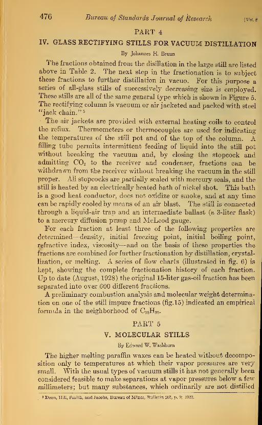
IV. GLASS RECTIFYING STILLS FOR VACUUM DISTILLATIONBy Johannes H. Bruun
The fractions obtained from the disillation in the large still are listed
above in Table 2. The next step in the fractionation is to subjectthese fractions to further distillation in vacuo. For this purpose aseries of all-glass stills of successively decreasing size is employed.These stills are all of the same general type which is shown in Figure 5.
The rectifying column is vacuum or air jacketed and packed with steel
"jack chain." 3
The air jackets are provided with external heating coils to control
the reflux. Thermometers or thermocouples are used for indicating
the temperatures of the still pot and of the top of the column. Afilling tube permits intermittent feeding of liquid into the still potwithout breaking the vacuum and, by- closing the stopcock andadmitting C02 to the receiver and condenser, fractions can be•withdrawn from the receiver without breaking the vacuum in the still
proper. All stopcocks are partially sealed with mercury seals, and the
still is heated by an electrically heated bath of nickel shot. This bath
is a good heat conductor, does not oxidize or smoke, and at any time
can be rapidly cooled by means of an air blast. The still is connected
through a liquid-air trap and an intermediate ballast (a 3-liter flask)
to a mercury diffusion pump and MeLeod gauge.
For each fraction at least three of the following properties are
determined—density, initial freezing point, initial boiling point,
refractive index, viscosity—and on the basis of these properties the
fractions are combined for further fractionation by distillation, crystal-
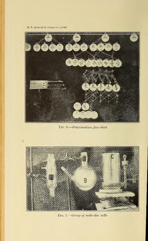
lization, or melting. A series of flow charts (illustrated in ^g. 6) is
kept, showing the complete fractionation history of each fraction.
Up to date (August. 1928) the original 15-liter gas-oil fraction has been
separated into over 600 different fractions.
A preh'minary combustion analysis and molecular weight determina-
tion on one of the still impure fractions (fig. 15) indicated an empirical
formula in the neighborhood of Ci 8H36 .
PART 5
V. MOLECULAR STILLS
By Echvard W. Washburn
The higher melting paraffin waxes can be heated without decompo-
sition only to temperatures at which their vapor pressures are very
small. With the usual types of vacuum stills it has not generally been
considered feasible to make separations at vapor pressures below a few
millimeters; but many substances, which ordinarily are not distilled
» Dean, Hill, Smith, and Jacobs, Bureau of Mines, Bulletin 207, p. 9; 1922.

B. S. Journal of Research, RP45
Fig. 5.
—
Rectifying still for vacuum distillation
B. S. Journal of Research, RP45
m •
Fig. 6.
—
Fractionation flow chart
i
?'-*. . : is ;
1 : VI
** WW11: tlS'illlfe HJfr
B
,.,;.;:i||Si|Spi:y':iP':
;
;.
Fig. 7.—Group of molecular stills

Washburn, Bruun,Hicks Fractionation of Petroleum 47*
because they can not be heated without decomposition, can be
rather easily distilled even at room temperatures by what may be
called a " molecular still/' a type first used by Brousted and Hevesy 4
for separating the isotopes of mercury.
1. THE ESSENTIAL FEATURES OF THE MOLECULAR STILL
The essential features of this type of still are the following
:
1. A high vacuum. For securing this vacuum, means should be
available for producing a vacuum equal to, or preferably better than,
the vapor pressure of the substance at the temperature at which it is
to be distilled.
2. A large and clean area of evap-
orating surface.
3. A short distance between the
evaporating surface and the con-
denser.
4. A sufficient temperature differ-
ence between the distilling surface
and the condensing surface.
With a still constructed according
to these principles such materials as
mercury, paraffin wax, and calomel,
for example, can be distilled at roomtemperature. It is not necessary
that the substance to be distilled be
in the liquid state at the distilling
temperature, although fractionation
without the necessity of provision
for artificial stirring is, of course,
more rapid with liquids.
B
2. TYPES OF CONSTRUCTION UFig. 8.
—
Molecular still
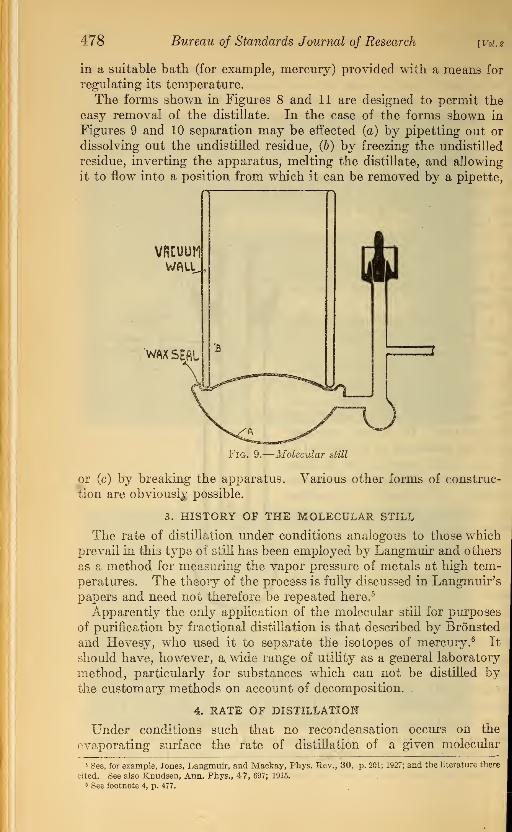
Various forms of molecular stills are
shown in accompanying Figures 7, 8,
9, 10, and 11. In all cases the sub-
stance to be distilled is placed in
the receptacle A and the cooling agent (for example, liquid hydro-gen, liquid air, carbon dioxide snow mixed with a suitable liquid, ice
and salt, etc., according to the temperature gradient required) is
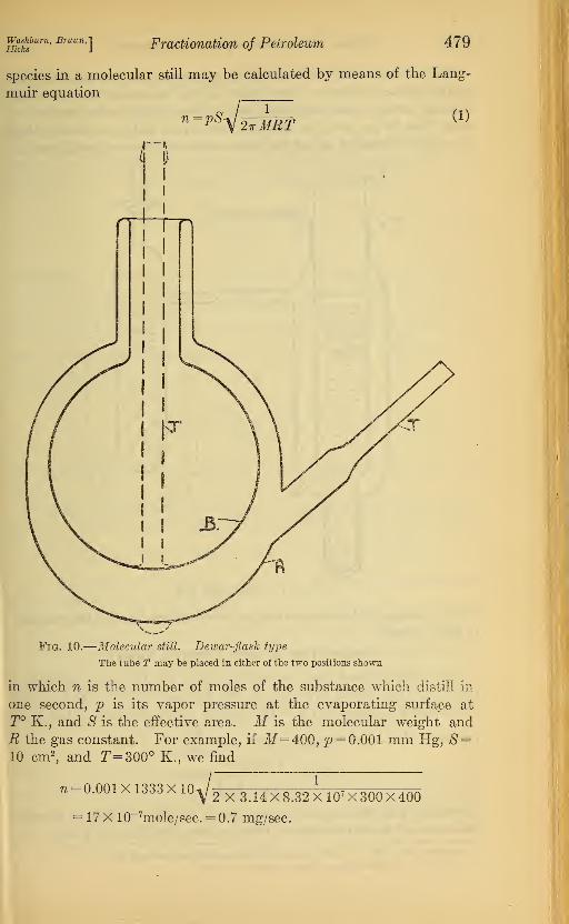
placed in the receptacle B. The forms shown in Figures 10 and 11
make it possible to distribute the substance to be distilled in a layerover the interior surface of the vessel A, with consequent increase in
the rate of distillation. The temperature of the substance in A duringthe distillation is controlled by immersing this part of the apparatus
1 Bronsted and Hevesy, Phil. Mag., 43, p. 31; 1922.
478 Bureau of Standards Journal of Research [Vol.
in a suitable bath (for example, mercury) provided with a means for
regulating its temperature.
The forms shown in Figures 8 and 11 are designed to permit the
easy removal of the distillate. In the ease of the forms shown in
Figures 9 and 10 separation may be effected (a) by pipetting out or
dissolving out the undistilled residue, (b) by freezing the undistilled
residue, inverting the apparatus, melting the distillate, and allowing
it to flow into a position from which it can be removed by a pipette,
vacuunWALL
WAX SEAL
Fig. 9.
—
Molecular still
or (c) by breaking the apparatus,
tion are obviously possible.
Various other forms of construc-
3. HISTORY OF THE MOLECULAR STILL
The rate of distillation under conditions analogous to those whichprevail in this type of still has been employed by Langmuir and others
as a method for measuring the vapor pressure of metals at high tem-
peratures. The theory of the process is fully discussed in Langmuir's
papers and need not therefore be repeated here. 5
Apparently the only application of the molecular still for purposes
of purification by fractional distillation is that described by Bronsted
and Hevesy, who used it to separate the isotopes of mercury. 6 It
should have, however, a. wide range of utility as a general laboratory
method, particularly for substances which can not be distilled bythe customary methods on account of decomposition.
4. RATE OF DISTILLATION
Under conditions such that no recondensation occurs on the
evaporating surface the rate of distillation of a given molecular
1 See, for example, Jones, Langmuir, and Mackay, Phys. Sev., 30, p. 201; 1927; and the literature there
cited. See also Knudsen, Ann. Phys., 47, 697; 1915.
6 See footnote 4, p. 477.
Washburn, Bruun,!Hicks J
Fractionation of Petroleum 479
species in a molecular still may be calculated by means of the Lang-
muir equation
?l=W^iz^ (1)MET
Fig. 10.
—
Molecular still. Dewar-flask type
The tube T may be placed in either of the two positions shown
in which n is the number of moles of the substance which distill in
one second, p is its vapor pressure at the evaporating surface at
T° K., and S is the effective area. M is the molecular weight andR the gas constant. For example, if M=400, p = 0.001 mm Hg, S=10 cm2
, and T=300° K., we find
71 = 0.001X1333X10V:2 X 3.14 X 8.32 X107 X 300X400
17 X 10_7mole/sec. = 0.7 mg/sec.

480 Bureau of Standards Journal of Research [Vol.?
The actual rate of distillation will, in general, be less than the cal-
culated value, owing to some reflection of molecules from the con-
densing surface, but such reflection will at worst never amount to
more than 90 per cent,7 so that the actual rate will never be less than
0.1 of the calculated rate if the temperature of the condensing surface
*ound joint
Liquid
I i
/ /
/y
Fig. 11.
—
Molecular still
is low enough, if the evaporating surface is clean,8 and if the vacuumis high enough.
5. SELECTION OF THE COOLING AGENT
The cooling agent may be selected from the following considera-
tions: pe = the vapor pressure at the temperature T (°K.) of the
evaporating surface, and p c= the desired vapor pressure at the tem-
perature (T—At) of the condenser. Let — =x. Then
... riogio 33
At< &rp approx.
logio x + 4>~y
(2)
in which TB is the normal boiling point in °K. If this is known,the constant 4> can be obtained from International Critical Tables, vol-
7 Langmuir, Phys. Rev., 7, p. 176; 1916; and International Critical Tables, 5, p. 53.
8 Clean; that is, free from a layer of lower volatility, v. infra.

Washburn, Branny Fractionation of Petroleum 481
ume 3, page 246. This relation assumes that the condensate is in
the form of a supercooled liquid. In many cases it will be crystalline,
in which case the required At will be smaller than that given by the
above relation.
The following example illustrates the use of relation (2): If wetake x =100, which is large enough for any practical case, and if weput JF=300° K. (room temperature), relation (2) becomes
AJ ^300X2 600At<
2 + 0_Tb 2-J-0TB (2a)
T T
Suppose the substance to be distilled is anthraquinone, for which
2^ = 653° K. This substance falls in Group of Table 3 (I. C. T.,
vol. 3, p. 247) and from Figure 1 (p. 246) we find = 5.0 at 2 B = 380°C.
From figure 2 (p. 247), using benzene as the type substance, we find
T T 300that <t>
increases about 0.5 unit between jr= l and m-=^o« Hence,
substituting in equation (2a) we have
^2 + 5.5X653^12.9^300
The temperature of the condenser should therefore be — 19° C. or
lower.
In many cases the normal boiling point of the substance will not be
known. For such cases a safe upper limit for At may be computed
2Tby taking TB<1.5T, which gives (for a? =100) Atm&x .
=,
.. '
For the distillation of organic compounds at room temperatures it
will usually suffice to take At <60°.
In this connection it should be pointed out that the ordinary type
of still, in which the temperature difference between distilling surface
and condensing surface is small and in which the rate of distillation
is proportional to the difference between the two vapor pressures, is
also capable of practical operation for distillations with vapor pres-
sures as low as 0.05 mm., if the condenser is placed within the dis-
tillation chamber as in the apparatus described by Volmer. 9
6. AZEOTROPIC MIXTURES
If the mixture which is being distilled is an azeotropic mixture, noseparation is secured in the ordinary types of stills. In the molecular
still, however, fractionation of such a mixture will, in general, result,
as Bronsted and Hevesy have pointed out, because from equation
•Volmer, Z. angew. Chem., 34, p. 150; 1921.
482 Bureau of Standards Journal of Research [Vol. £
(1) it is evident that the rate of evaporation of a given molecular
species is determined not alone by its partial vapor pressure, but also
by its molecular weight. There is, however, also a condition under
which no fractionation will occur in a molecular still, namely, when
the ratio — ( -^r ) is equal to the molecular ratio — in the liquid
phase, for each of any two molecular species present. Under these
conditions the condensate would have the same composition as the
original liquid. For mixtures which are ideal solutions this is equiva-
lent to the condition that the ratio -& shall be the same for all molec-
ular species present, p being the vapor pressure in the pure state-
Since, however, for members of the same homologous series pdecreases as M increases, fractionation of such mixtures in a molecular
still is advantageously affected by the variations in both p and M.
The condition that ———( ~jr ) might, however, conceivably occur
quite as frequently as the condition of azeotropism in ordinary dis-
tillation. The case that any mixture will satisfy the conditions for
distilling in unchanged proportions b}^ both methods is limited to
mixtures of substances of equal molecular weights and equal vapor
pressures at all temperatures and will never be encountered except
with mixtures of two optical isomers. Hence, practically every mix-
ture should be subject to fractionation in either the usual still or the
molecular still. It might, of course, be possible that a series of alter-
nate fractionations by the two methods would be necessary to accom-
plish the most complete separation, if distillation alone is employed.
7. ILLUSTRATIVE EXPERIMENTS
A sample of paraffin wax having an initial freezing range of 54.1 to
51.7° was separated into two fractions by a single distillation at 55° C.
in the still shown in Figure 9, using carbon dioxide snow as the cooling
agent. The distillate had a freezing range of 48.6 to 48° and the
residue a freezing range of 57.1 to 56.5°.
A sample of cane sugar was distilled at 120° C. The distillate wasa white solid, sweet in taste and dextro rotatory in aqueous solution.
Another example of the use of stills of the general type shown in
Figures 8 and 10 is described in connection with Bronsted and
Hevesy's experiments on the isotopic separation of mercury. 10
Since mercury is a convenient substance for testing the efficiency
of a given type of molecular still with reference to the rate of dis-
io See footnote 4, p. 477.
Washburn, BruunqFractionation of Petroleum 483
tillation obtainable in practice as compared with the rate calculated
from equation (1), an experiment was carried out with mercury in
the still, shown in Figure 10. The lower part of the still containing
the liquid mercury was immersed in a bath of mercury kept at 0°
by means of an ice pack. A thermometer inserted through the side
arm indicated the average temperature of the distilling surface dur-
ing the distillation. Liquid air was placed in the inner chamber B.
The following results were obtained :
n
Time of distillation hours. _ 4.
Area of distillation surface cm 2.. 48.
Temperature of distilling surface °C__ —0. 2
Vapor pressure at distilling surface mm__ 0. 00018
Weight of distillate obtained g_ _ 5. 2
Weight of distillate calculated do 6.2
Efficiency per cent. _ 84
The test experiments with the molecular still on mercury, paraffin
wax, and calomel were carried out by Mildred M. Hicks; those with
cane sugar, by Dr. R. T. Leslie and S. T. Schicktanz.
PART 6
VI. METHODS OF FRACTIONATION BY CRYSTALLIZATIONOR MELTING AND OF DETERMINING FREEZING-POINTCURVES
By Mildred M. Hicks
In addition to its value as a primary method, fractionation by crys-
tallization or fusion is convenient for breaking up azeotropic mixtures.
The fractionation may be carried out either with or without the use
of a solvent. For the higher petroleum fractions, such as lubricating
oil, petrolatum, or wax, the use of a solvent is usually desirable.
The following solvents have been studied in this connection:
Methyl alcohol, glycerol, ethyl ether, acetone, chloroform, carbon
11 Note on poison hazards from spilled mercury.—In recent literature attention has been directed to the
dangers of mercury poisoning in rooms containing exposed mercury surfaces resulting from spilled mercurylodged in floor cracks and other crevices from which its removal is difficult. The vapor pressure of pure
mercury at room temperatures is of the order 0.001 to 0.003 mm Hg, and if the air of the room were only
partially saturated with this mercury vapor, continued exposure thereto might constitute a hazard. Oneexperiment on the rate of distillation of mercury carried out as described above apparently throws somelight upon the question.
In this experiment the distillation was carried out for seven hours. Instead, however, of obtaining ap-
proximately the theoretical yield of 9 g of distillate, no distillate whatever was obtained. Examination of
the mercury surface showed that it was contaminated with a barely visible layer of stopcock grease which
was apparently sufficient to completely stop appreciable vaporization in this period of time. It seems prob-
able, therefore, that the hazard from spilled mercury in a laboratory soon disappears by the natural con-
tamination of the mercury surface in a short period of time. In any case a spray of heavy oil on the sur-
face of spilled mercury would appear to be an adequate means of eliminating all hazard in ventilated rooms.
This is also the conclusion reached by Gaede (Ber. Naturforsch. Ges. Freiberg i. Br., 18, p. 174; 1911),
who found that the vapor pressure of Hg at room temperature, as registered in his manometer, fell from
0.0013 mm to zero after admitting air from the room (apparently through a stopcock) and again reevacuat-
ing, and then slowly rose to only 0.00007 mm after several hours.

484 Bureau of Standards Journal of Research [Vol.2
k
IIm
tetrachloride, carbon disulphide, acetic acid, benzene, toluene,
petroleum ether, and kerosene. Of these, ethyl ether was found to be
one of the best, and it has been the principal one
employed thus far. The fractionation may be
carried out by any one or more of the following
procedures
:
1. By cooling the solution.
2. By evaporating the solvent at any controlled
temperature.
3. By precipitation with a second solvent.
4. By complete solidification of the solution,
followed by equilibrium melting.
All of these procedures have been used, but
the fourth one 12 has proved most convenient for
most of the work up to the present. In this pro-
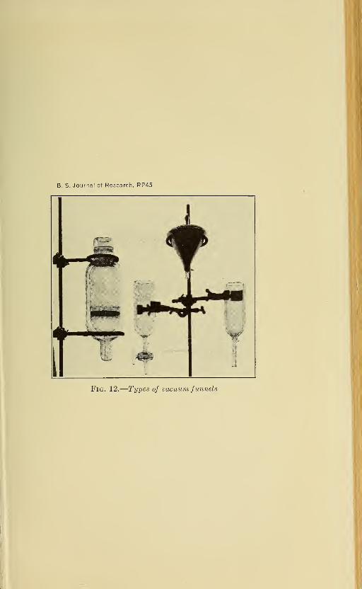
cedure the solidified solution is placed on a porous
support in a vacuum-jacketed funnel fitted with a
thermometer and stirrer. The melting mass is
stirred so as to maintain equilibrium, and the
liquid fractions which drain through are removed
from time to time in accordance with the ther-
mometer readings. Some forms of vacuumfunnels employed for this purpose are shown in
Figure 12.
The time-temperature cooling curve is a con-
venient index of the progress of the fractionation.
For obtaining this curve the apparatus shown in
Figure 13 is employed. Some typical curves
obtained in this way are shown in Figures 14,
15, and 16. The values in the F. P. column are
the initial freezing points.
It may be stated at this point that in the
present investigation there has been found no
petroleum fraction which can not be completely
and readily obtained in crystalline form. Frac-
tionation by crystallization is therefore possible
at any stage of the work except possibly in the
case of tarry or asphaltic materials. These have not been studied.
Fig. 13.
—
Appara-
tus for determin-
ing time-temper-
ature cooling
curves
12 See also Timmermans and Martin, J. chim. phys., 23, p. 6; 1926.
B. S. Journal of Research, RP45
Fig. 12.
—
Types of vacuum funnels

Washburn, Bruun,Hicks Fractionation of Petroleum 485
1C0[
95}
85
80
75o
70^ o
T ri r i i i r i 1 r
65-
60_
55-
50
19 CRYSTALLIZATIONS
o 3 CRYSTALLIZATIONSDoooooooo oo oo oooo
CO,'CO
J___l L
i) 55 00 65 70 755 10 15 20 25 30 3S 40 45
TIME IM MINUTES
Fig. 14.
—
Typical cooling curves
1 2 3 4 5 6
TIME IN MINUTES
12 3 4 5 6
ILLUSTRATION OF BEHAV0IR BEFORE FRACTIONATION
Fig. 15.
—
Cooling curves of gas-oil fractions after extensive fractionation byboth distillation and crystallization

486 Bureau of Standards Journal of Research [Vol.S
t—i—i1—i—r—
r
"AppTOXi CMb-
VOL
CM3
354 6,6
R.I.
!.4es
1.468
1.478
23456789 10
TIME IN MINUTES
* ILLUSTRATION OF BEHAVOIR BEFORE FRACTIONATION
Fig. 16.
—
Some cooling curves of fractions subjected to
distillation only
DRGRNIC COMBUSTION ANRL3515
<JDWMETEWt k\\\\\\\\fL\\\\\\V\T
lSEAL
FURNACE..
ABSORPTION APPARATUS.\ I ^^1R^ BSSkROUND JOINT
LKHQTiNSKJ'
Fig. 18.
—
Apparatus for combustion analysis. Detail

B. S. Journal of Research, RP45
Fig. 17.
—
Apparatus for combustion analyses
A, oxygen tankB, flow meterC, furnace for the destruction of organic impurities. Contains a glass tube filled with palladized
asbestosD, mercury seal joint (one on each side of the furnace)E, purification train filled with CaCl2, ascarite, magnesium perchlorate trihydrate, and P2O5.This train, by means of flexible copper tubing is connected to: F, ground-glass nonlubricatedjoint; G, the combustion furnace; H and /, water and CO2 absorption bulbs (all connectionsare ground glass-to-glass joints)

Washburn, Bruun,Hicks Fractionation of Petroleum
PART 7
487
VII. APPARATUS FOR COMBUSTION ANALYSIS
By Johannes H. Bruun
The combustion apparatus is illustrated in Figures 17 and 18. Theonly features not usually found in such apparatus are (1) the provi-
sions for insuring the required purity of the oxygen and (2) the use
of wax-sealed metal-to-glass or of glass-to-glass joints only, through-
out the combustion train. 13 The following results obtained with the
apparatus indicate the accuracy with which combustion analyses can
be duplicated. With this degree of accuracy in the combustion
analysis it is possible, with the aid, when necessary, of a molecular
weight determination, to determine with certainty the empirical
formula of any hydrocarbon up to Ci00 .
Table 5
COMBUSTION OF RESUBLIMED NAPHTHALENE (NOT PURE)
Run H Devia-tion
C Devia-tion
Sum
1
Per cent
6.276.216.26
0.02.04.01
Per cent
93.6193. 6693.61
0.02.03.02
Per cent
99.882 99.873 99.87
Average _ 6.25 .023 93.63 .023 99.87
Theoretical ._ . .._ 6.29 93.71 100.00
COMBUSTION OF A GAS-OIL FRACTION (LIQUID)
1 13.6613.6413.61
0.02.00.03
86.1086.0586.08
0.03.02.01
99.762 99.693 -- _ _ -__ 99.69
13.64 .017 86.07 .02 99.71
PART 8
VIII. SUMMARY
This paper contains a description of apparatus and methods de-
vised and employed for the fractionation of petroleum into its con-
stituent hydrocarbons. They include the following:
1. A rectifying still with a 20-plate column and with means for inde-
pendently controlling and measuring the temperatures of the plates.
The still is designed for distillation in a stream of an inert gas (C02 )
with or without boiling. It is provided with a purifying train for the
C02 , with a series of condensers with stepped temperatures down to
— 80° C, and with a final absorber for the C02 .
13 For quantitative data relative to the magnitudes of the errors arising from the presence of (a) rubber
connections, (6) stopcock lubricants, and (c) impurities in the oxygen, see Lindner (Ber. 60 B: p. 124; 1927)
and the literature there cited.

488 Bureau of Standards Journal of Research [V01.2
2. A set of all-glass rectifying stills for vacuum distillation. Thesestills have vacuum or air jacketed columns, mercury-sealed stopcocks,
and provision for intermittent feeding of liquid and withdrawal of
fractions during the distillation. They are heated by immersion in anelectrically heated bath of nickel shot.
3. Various types of molecular stills by means of which distillation
can be carried out at any temperature at which the vapor pressure
at the distilling surface is not lower than, say, 10"~6 mm Hg.
4. Methods and apparatus for fractionation by crystallization or
melting.
5. An apparatus for combustion analysis, with special provisions
for purifying the oxygen employed, and with all rubber connections
eliminated. With this apparatus the combustion analysis of a hydro-
carbon can be duplicated with the following average precision:
Per cent C and H each to about ±0.05. This makes it possible to
determine with certainty the values of n and x in the formula
CnH2n+x , for any hydrocarbon up to Cioo.
The change in the iodine number of the "wax-distillate" fraction
of a petroleum oil produced by heating it for different periods and at
different temperatures up to 370° C. in (a) air and (b) H2 , N2 , and
C02 , respectively, has ,been determined, and it is shown that in the
absence of air the rate of this change is greatly reduced, thus makingit possible to distil petroleum at high temperatures without cracking,
provided all air is excluded.
Evidence is presented showing that the hazards from exposed
mercury surfaces in a laboratory are eliminated as soon as the mer-
cury surface becomes contaminated with a continuous layer of a
heavy oil or grease.ACKNOWLEDGMENT
This paper describes the apparatus and methods which have been
developed and are being employed in an investigation on "Theseparation, identification, and determination of the chemical con-
stituents of commercial petroleum fractions" listed as Project No.
6 of American Petroleum Institute Kesearch. Financial assistance
in this work has been received from a research fund of the American
Petroleum Institute donated by John D. Kockefeller. This fund is
being administered by the institute with the cooperation of the
Central Petroleum Committee of the National Kesearch Council.
Washington, August 4, 1928.
Related Documents