Installation, Operation and Maintenance Manual API 6D/API 594 Dual Plate Wafer Check Valve Document #: DHV-IOM-WC-20 Published: November 2020 Revision: 1 Page 1 of 16 INSTALLATION, OPERATION AND MAINTENANCE MANUAL API 6D/API 594 CAST STEEL DUAL PLATE WAFER CHECK VALVE

Welcome message from author
This document is posted to help you gain knowledge. Please leave a comment to let me know what you think about it! Share it to your friends and learn new things together.
Transcript
Installation, Operation and Maintenance Manual API 6D/API 594 Dual Plate Wafer Check Valve Document #: DHV-IOM-WC-20 Published: November 2020 Revision: 1
Page 1 of 16
INSTALLATION, OPERATION AND MAINTENANCE MANUAL
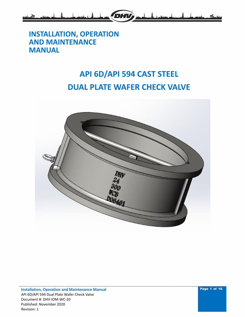
API 6D/API 594 CAST STEEL
DUAL PLATE WAFER CHECK VALVE

Installation, Operation and Maintenance Manual API 6D/API 594 Dual Plate Wafer Check Valve Document #: DHV-IOM-WC-20 Published: November 2020 Revision: 1
Page 2 of 16
TABLE OF CONTENTS
FOREWORD ......................................................................................................................................... 4
1. ENDUSER INSTRUCTION .................................................................................................................. 4
2. VALVE TRANSPORTATION AND STORAGE ........................................................................................ 5
2.1 TRANSPORTATION ................................................................................................................. 5
2.2 STORAGE ............................................................................................................................... 5
3. VALVE INSTALLATION ....................................................................................................................... 6
3.1 INSPECTION BEFORE INSTALLATION ..................................................................................... 6
3.2 INSTALLATION ........................................................................................................................ 6
4. VALVE OPERATION ........................................................................................................................... 11
5. VALVE MAINTENANCE ..................................................................................................................... 12
6. DETAILED DISASSEMBLY AND ASSEMBLY ........................................................................................ 13
6.1 WAFER CHECK VALVE DISASSEMBLY ..................................................................................... 13
6.2 WAFER CHECK VALVE ASSEMBLY ........................................................................................... 13
7. TROUBLESHOOTING ........................................................................................................................ 14
8. WARRANTY AND SERVICE ............................................................................................................... 15
8.1 VALVE WARRANTY PERIOD .................................................................................................... 15
8.2 SERVICE ................................................................................................................................. 15
Installation, Operation and Maintenance Manual API 6D/API 594 Dual Plate Wafer Check Valve Document #: DHV-IOM-WC-20 Published: November 2020 Revision: 1
Page 3 of 16
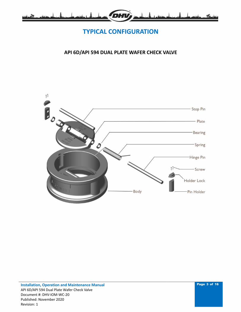
TYPICAL CONFIGURATION
API 6D/API 594 DUAL PLATE WAFER CHECK VALVE
Installation, Operation and Maintenance Manual API 6D/API 594 Dual Plate Wafer Check Valve Document #: DHV-IOM-WC-20 Published: November 2020 Revision: 1
Page 4 of 16
FOREWORD
Personal Safety and Long Term Ownership of your DHV API 6D/API 594 Dual Plate Wafer Check Valve is
the most important matter in reviewing our Installation, Operation & Maintenance Manual. This manual
will provide all the necessary safety guidelines for our valve including information for the valve
transportation, storage, installation, operation and maintenance. Please read carefully before installing
or servicing the valve.
DHV provides general guidelines in this manual, and cannot provide specific data and warnings for all
possible applications. The purchaser/end user must therefore assume responsibility for proper valve
selection, sizing, installation, operation, and maintenance of DHV valve products. The purchaser/end
user should read and understand this document and any instructions provided with the product, and
conduct training with its employees and contractors to ensure they are aware of the proper and safe
use of DHV valve products in connection with the specific application.
1. ENDUSER INSTRUCTION
Personnel safety is always the most important factor in the transportation, storage, installation,
operation and maintenance of any valve. DHV valves are designed to meet the customer’s order
requirements and specifications. DHV disclaims all responsibility for problems that may be caused by
applications other than the specified use. Valve service pressure/temperature information is detailed
on the valve name plate. When selecting a valve, always consider the application, service and
temperature for the intended service. Select the applicable valve material for anti-corrosion and anti-
abrasive service. For safety of personnel and plant/environment: Prior to conducting any service on the
valve, ensure the valve is not under pressure, properly vented, and drained. When performing any
operation, maintenance or service, personal protective equipment should be used, such as protective
clothing, oxygen masks, safety glasses, work gloves, etc. DHV will not be responsible for any loss or
expense resulting from the failure of equipment, damage to any property, or death or injury to any
person resulting in whole or in part from repairs or modification performed by other than authorized
DHV personnel. Such unauthorized repairs shall also serve to terminate any contractual or other
warranty, if any, on the equipment and may result in the equipment no longer meeting applicable
requirements.
Installation, Operation and Maintenance Manual API 6D/API 594 Dual Plate Wafer Check Valve Document #: DHV-IOM-WC-20 Published: November 2020 Revision: 1
Page 5 of 16
2. VALVE TRANSPORTATION AND STORAGE
2.1 TRANSPORTATION
1. Use the proper hoisting equipment to transport the valve, especially when lifting or lowering the
valve. Special attention to personnel safety and the care of the valve should be made when
transporting the valve. Avoid impacting or striking the valve during transportation. Lay the valve on
a clean flat surface; avoid laying the valve on the flange face. Ensure there is adequate clearance
around the valve for proper operation and maintenance.
When lifting the valve, use the lifting eye.
2. During transportation, ensure the valve’s paint, name plate and flange sealing surfaces are fully
protected. Do not drag the valve across the floor, or place the valve flange sealing face on the floor.
3. The disc should remain stationary during handling to avoid damage of sealing surfaces of both the
disc and body seat due to impact.
4. For those valves not required to be immediately installed, do not open the end flange protective
covers. Ensure the valves are stored in a safe, clean environment and are protected from rain and
dust.
2.2 STORAGE
1. Valves should be stored in the closed position. Valve ports and flange serration surfaces should be
kept sealed with protective flange covers.
2. Valves should be stored in a dust free, low humidity and well-ventilated room, not in direct contact
to the floor. If possible, the valves shall be kept in the original packing box. If the valves must be
stored outdoors, keep the valve in the original crate or shipping container. Ensure the valve’s
packaging is stored on raised blocking to avoid moisture damage. Protective covering should be
used for protection against dust and rain.
3. Valves should never be stacked on top of each other, to avoid any valve distortion which may affect
valve performance and cause personnel injury.
4. Valves that have been stored for an extended time should be cleaned and inspected prior to
installation. Inspect the sealing surface to ensure it is clean and free of any debris or damage.
5. Do not expose the valve to any corrosive environment.
Installation, Operation and Maintenance Manual API 6D/API 594 Dual Plate Wafer Check Valve Document #: DHV-IOM-WC-20 Published: November 2020 Revision: 1
Page 6 of 16
3. VALVE INSTALLATION
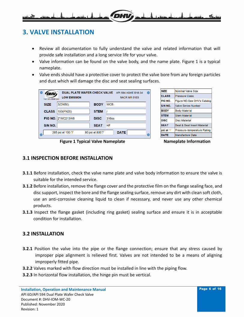
• Review all documentation to fully understand the valve and related information that will
provide safe installation and a long service life for your valve.
• Valve information can be found on the valve body, and the name plate. Figure 1 is a typical
nameplate.
• Valve ends should have a protective cover to protect the valve bore from any foreign particles
and dust which will damage the disc and seat sealing surfaces.
Figure 1 Typical Valve Nameplate Nameplate Information
3.1 INSPECTION BEFORE INSTALLATION
3.1.1 Before installation, check the valve name plate and valve body information to ensure the valve is
suitable for the intended service.
3.1.2 Before installation, remove the flange cover and the protective film on the flange sealing face, and
disc support, inspect the bore and the flange sealing surface, remove any dirt with clean soft cloth,
use an anti-corrosive cleaning liquid to clean if necessary, and never use any other chemical
products.
3.1.3 Inspect the flange gasket (including ring gasket) sealing surface and ensure it is in acceptable
condition for installation.
3.2 INSTALLATION
3.2.1 Position the valve into the pipe or the flange connection; ensure that any stress caused by
improper pipe alignment is relieved first. Valves are not intended to be a means of aligning
improperly fitted pipe.
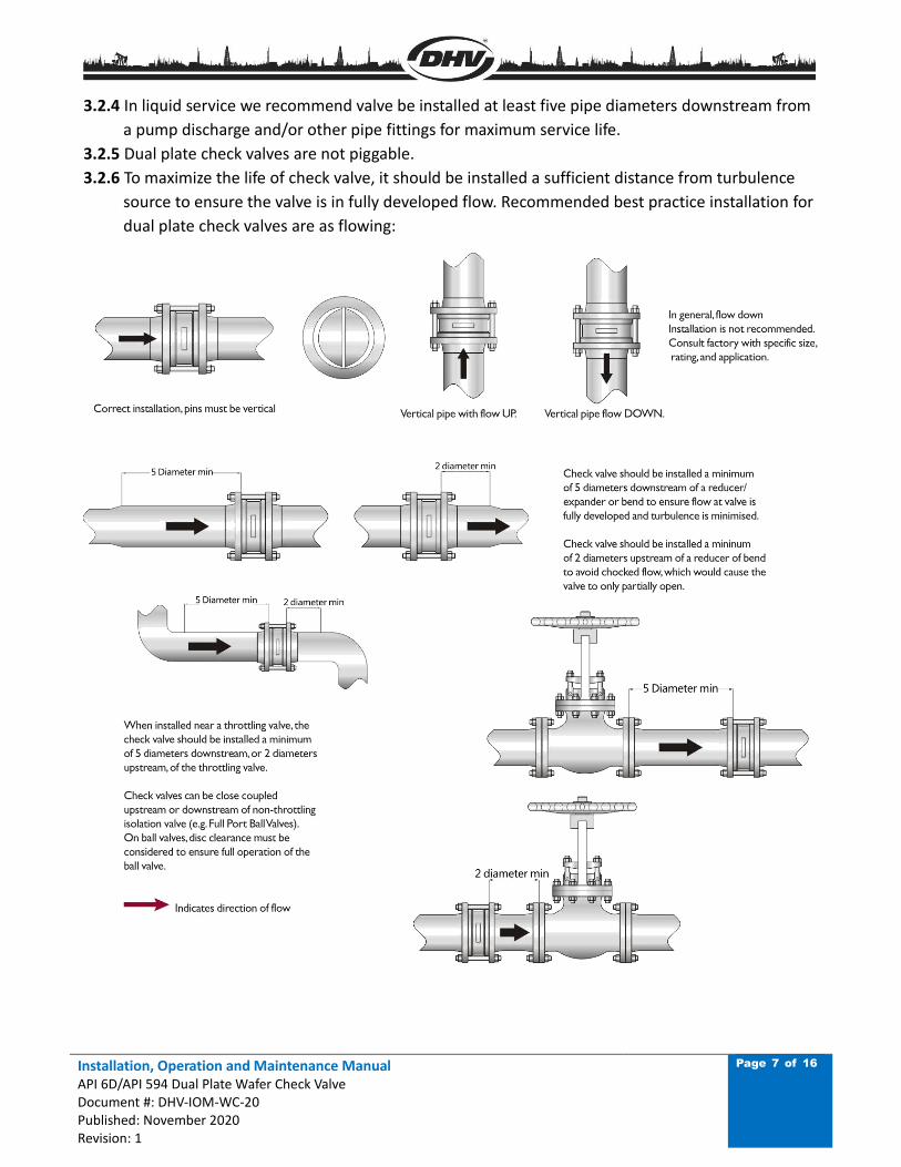
3.2.2 Valves marked with flow direction must be installed in line with the piping flow.
3.2.3 In horizontal flow installation, the hinge pin must be vertical.
Installation, Operation and Maintenance Manual API 6D/API 594 Dual Plate Wafer Check Valve Document #: DHV-IOM-WC-20 Published: November 2020 Revision: 1
Page 7 of 16
3.2.4 In liquid service we recommend valve be installed at least five pipe diameters downstream from
a pump discharge and/or other pipe fittings for maximum service life.
3.2.5 Dual plate check valves are not piggable.
3.2.6 To maximize the life of check valve, it should be installed a sufficient distance from turbulence
source to ensure the valve is in fully developed flow. Recommended best practice installation for
dual plate check valves are as flowing:
Installation, Operation and Maintenance Manual API 6D/API 594 Dual Plate Wafer Check Valve Document #: DHV-IOM-WC-20 Published: November 2020 Revision: 1
Page 8 of 16
FLANGE ENDS:
• Select the proper gasket (including ring gasket) to install, line up the bolt holes between the
valve flange and pipeline flange, then install the bolts and nuts and tighten to the accepted
piping and bolting standards. The bolt threads should be lubricated first for ease of bolting.
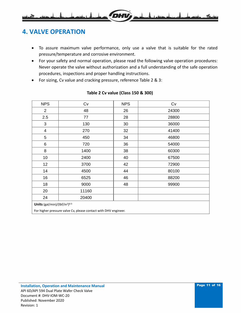
• Use an appropriate sized torque wrench when tightening the bolt/nut, to avoid flange
deformation. Please follow Fig 2 and Table 1 for bolting sequence and bolting torque. If the
bolting quantity is different from the chart shown, please follow the same principle to get
a new sequence to follow.
• For large diameter valves, the valve must be properly and safely supported during
installation. After installation is completed, valve supports should be moved to the bottom
of the valve flanges.
• After valve installation is complete, recheck and tighten the bolts as necessary to the values
provided in Table 1 & Figure 2.
• It is recommended that the tightness of the joint bolt tension be inspected at least yearly.
Refer to Table 1 & Figure 2.
DURING INSTALLATION, IF VALVE IS NOT IN LINE WITH THE PIPELINE, FLANGE FACES ARE
NOT PARALLEL TO EACH OTHER, OR BOLTING TORQUE IS NOT UNIFORM, VALVE LEAKAGE
MAY BE EXPERIENCED.
Installation, Operation and Maintenance Manual API 6D/API 594 Dual Plate Wafer Check Valve Document #: DHV-IOM-WC-20 Published: November 2020 Revision: 1
Page 9 of 16
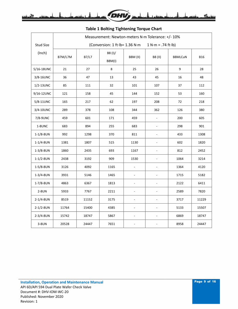
Table 1 Bolting Tightening Torque Chart
Stud Size
(Inch)
Measurement: Newton-meters N·m Tolerance: +/- 10%
(Conversion: 1 ft⋅lb= 1.36 N·m 1 N·m = .74 ft⋅lb)
B7M/L7M B7/L7 B8 (I)/
B8M(I) B8M (II) B8 (II) B8MLCuN B16
5/16-18UNC 21 27 8 25 26 9 28
3/8-16UNC 36 47 13 43 45 16 48
1/2-13UNC 85 111 32 101 107 37 112
9/16-12UNC 121 158 45 144 152 53 160
5/8-11UNC 165 217 62 197 208 72 218
3/4-10UNC 289 378 108 344 362 126 380
7/8-9UNC 459 601 171 459 - 200 605
1-8UNC 683 894 255 683 - 298 901
1-1/8-8UN 992 1298 370 811 - 433 1308
1-1/4-8UN 1381 1807 515 1130 - 602 1820
1-3/8-8UN 1860 2435 693 1167 - 812 2452
1-1/2-8UN 2438 3192 909 1530 - 1064 3214
1-5/8-8UN 3126 4092 1165 - - 1364 4120
1-3/4-8UN 3931 5146 1465 - - 1715 5182
1-7/8-8UN 4863 6367 1813 - - 2122 6411
2-8UN 5933 7767 2211 - - 2589 7820
2-1/4-8UN 8519 11152 3175 - - 3717 11229
2-1/2-8UN 11764 15400 4385 - - 5133 15507
2-3/4-8UN 15742 18747 5867 - - 6869 18747
3-8UN 20528 24447 7651 - - 8958 24447
Installation, Operation and Maintenance Manual API 6D/API 594 Dual Plate Wafer Check Valve Document #: DHV-IOM-WC-20 Published: November 2020 Revision: 1
Page 10 of 16
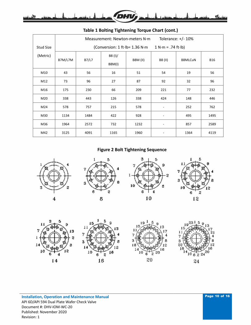
Table 1 Bolting Tightening Torque Chart (cont.)
Stud Size
(Metric)
Measurement: Newton-meters N·m Tolerance: +/- 10%
(Conversion: 1 ft⋅lb= 1.36 N·m 1 N·m = .74 ft⋅lb)
B7M/L7M B7/L7 B8 (I)/
B8M(I) B8M (II) B8 (II) B8MLCuN B16
M10 43 56 16 51 54 19 56
M12 73 96 27 87 92 32 96
M16 175 230 66 209 221 77 232
M20 338 443 126 338 424 148 446
M24 578 757 215 578 - 252 762
M30 1134 1484 422 928 - 495 1495
M36 1964 2572 732 1232 - 857 2589
M42 3125 4091 1165 1960 - 1364 4119
Figure 2 Bolt Tightening Sequence
Installation, Operation and Maintenance Manual API 6D/API 594 Dual Plate Wafer Check Valve Document #: DHV-IOM-WC-20 Published: November 2020 Revision: 1
Page 11 of 16
4. VALVE OPERATION
• To assure maximum valve performance, only use a valve that is suitable for the rated
pressure/temperature and corrosive environment.
• For your safety and normal operation, please read the following valve operation procedures:
Never operate the valve without authorization and a full understanding of the safe operation
procedures, inspections and proper handling instructions.
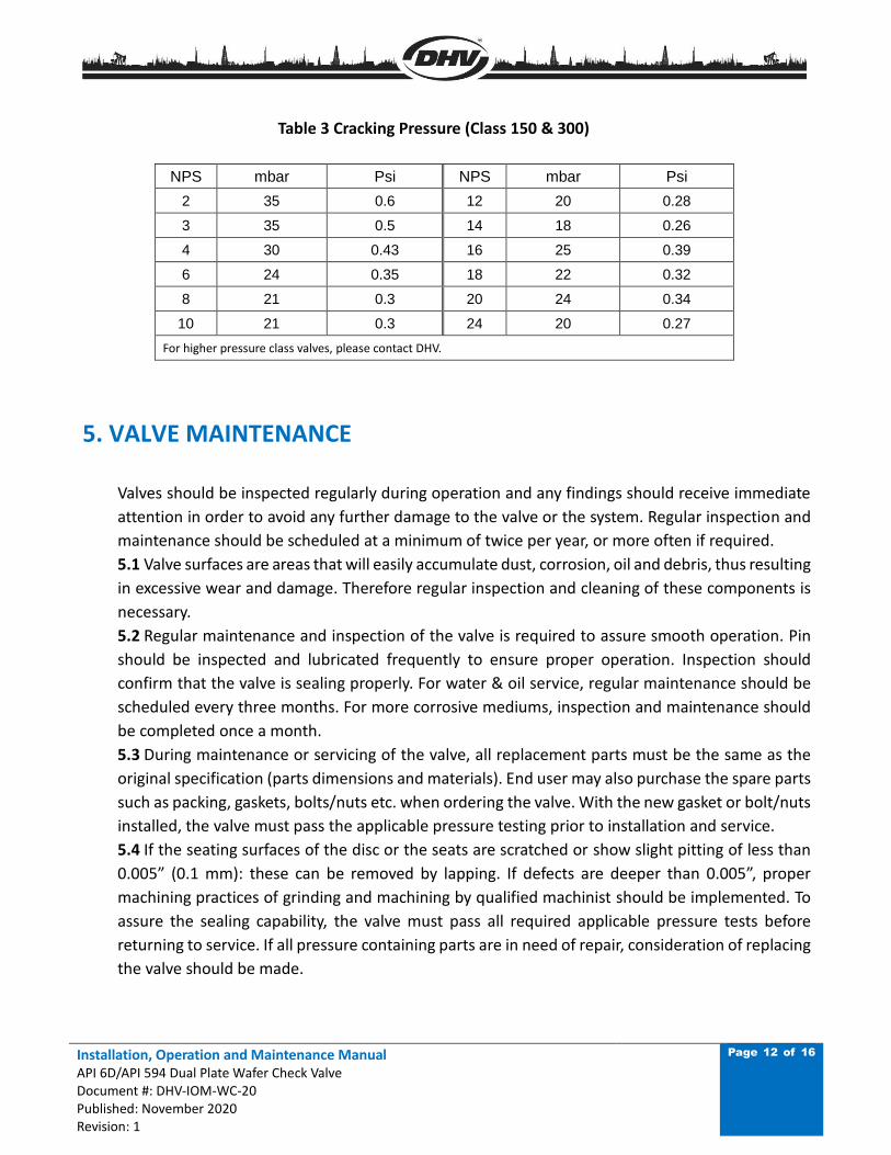
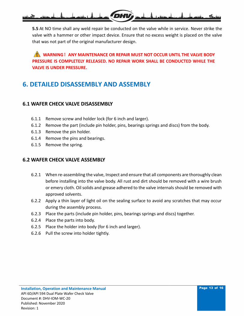
• For sizing, Cv value and cracking pressure, reference Table 2 & 3:
Table 2 Cv value (Class 150 & 300)
NPS Cv NPS Cv
2 48 26 24300
2.5 77 28 28800
3 130 30 36000
4 270 32 41400
5 450 34 46800
6 720 36 54000
8 1400 38 60300
10 2400 40 67500
12 3700 42 72900
14 4500 44 80100
16 6525 46 88200
18 9000 48 99900
20 11160
24 20400
Units (gal/min)/(lbf/in2)0.5
For higher pressure valve Cv, please contact with DHV engineer.
Installation, Operation and Maintenance Manual API 6D/API 594 Dual Plate Wafer Check Valve Document #: DHV-IOM-WC-20 Published: November 2020 Revision: 1
Page 12 of 16
Table 3 Cracking Pressure (Class 150 & 300)
NPS mbar Psi NPS mbar Psi
2 35 0.6 12 20 0.28
3 35 0.5 14 18 0.26
4 30 0.43 16 25 0.39
6 24 0.35 18 22 0.32
8 21 0.3 20 24 0.34
10 21 0.3 24 20 0.27
For higher pressure class valves, please contact DHV.
5. VALVE MAINTENANCE
Valves should be inspected regularly during operation and any findings should receive immediate
attention in order to avoid any further damage to the valve or the system. Regular inspection and
maintenance should be scheduled at a minimum of twice per year, or more often if required.
5.1 Valve surfaces are areas that will easily accumulate dust, corrosion, oil and debris, thus resulting
in excessive wear and damage. Therefore regular inspection and cleaning of these components is
necessary.
5.2 Regular maintenance and inspection of the valve is required to assure smooth operation. Pin
should be inspected and lubricated frequently to ensure proper operation. Inspection should
confirm that the valve is sealing properly. For water & oil service, regular maintenance should be
scheduled every three months. For more corrosive mediums, inspection and maintenance should
be completed once a month.
5.3 During maintenance or servicing of the valve, all replacement parts must be the same as the
original specification (parts dimensions and materials). End user may also purchase the spare parts
such as packing, gaskets, bolts/nuts etc. when ordering the valve. With the new gasket or bolt/nuts
installed, the valve must pass the applicable pressure testing prior to installation and service.
5.4 If the seating surfaces of the disc or the seats are scratched or show slight pitting of less than
0.005” (0.1 mm): these can be removed by lapping. If defects are deeper than 0.005”, proper
machining practices of grinding and machining by qualified machinist should be implemented. To
assure the sealing capability, the valve must pass all required applicable pressure tests before
returning to service. If all pressure containing parts are in need of repair, consideration of replacing
the valve should be made.
Installation, Operation and Maintenance Manual API 6D/API 594 Dual Plate Wafer Check Valve Document #: DHV-IOM-WC-20 Published: November 2020 Revision: 1
Page 13 of 16
5.5 At NO time shall any weld repair be conducted on the valve while in service. Never strike the
valve with a hammer or other impact device. Ensure that no excess weight is placed on the valve
that was not part of the original manufacturer design.
WARNING!ANY MAINTENANCE OR REPAIR MUST NOT OCCUR UNTIL THE VALVE BODY
PRESSURE IS COMPLETELY RELEASED. NO REPAIR WORK SHALL BE CONDUCTED WHILE THE
VALVE IS UNDER PRESSURE.
6. DETAILED DISASSEMBLY AND ASSEMBLY
6.1 WAFER CHECK VALVE DISASSEMBLY
6.1.1 Remove screw and holder lock (for 6 inch and larger).
6.1.2 Remove the part (include pin holder, pins, bearings springs and discs) from the body.
6.1.3 Remove the pin holder.
6.1.4 Remove the pins and bearings.
6.1.5 Remove the spring.
6.2 WAFER CHECK VALVE ASSEMBLY
6.2.1 When re-assembling the valve, Inspect and ensure that all components are thoroughly clean
before installing into the valve body. All rust and dirt should be removed with a wire brush
or emery cloth. Oil solids and grease adhered to the valve internals should be removed with
approved solvents.
6.2.2 Apply a thin layer of light oil on the sealing surface to avoid any scratches that may occur
during the assembly process.
6.2.3 Place the parts (include pin holder, pins, bearings springs and discs) together.
6.2.4 Place the parts into body.
6.2.5 Place the holder into body (for 6 inch and larger).
6.2.6 Pull the screw into holder tightly.
Installation, Operation and Maintenance Manual API 6D/API 594 Dual Plate Wafer Check Valve Document #: DHV-IOM-WC-20 Published: November 2020 Revision: 1
Page 14 of 16
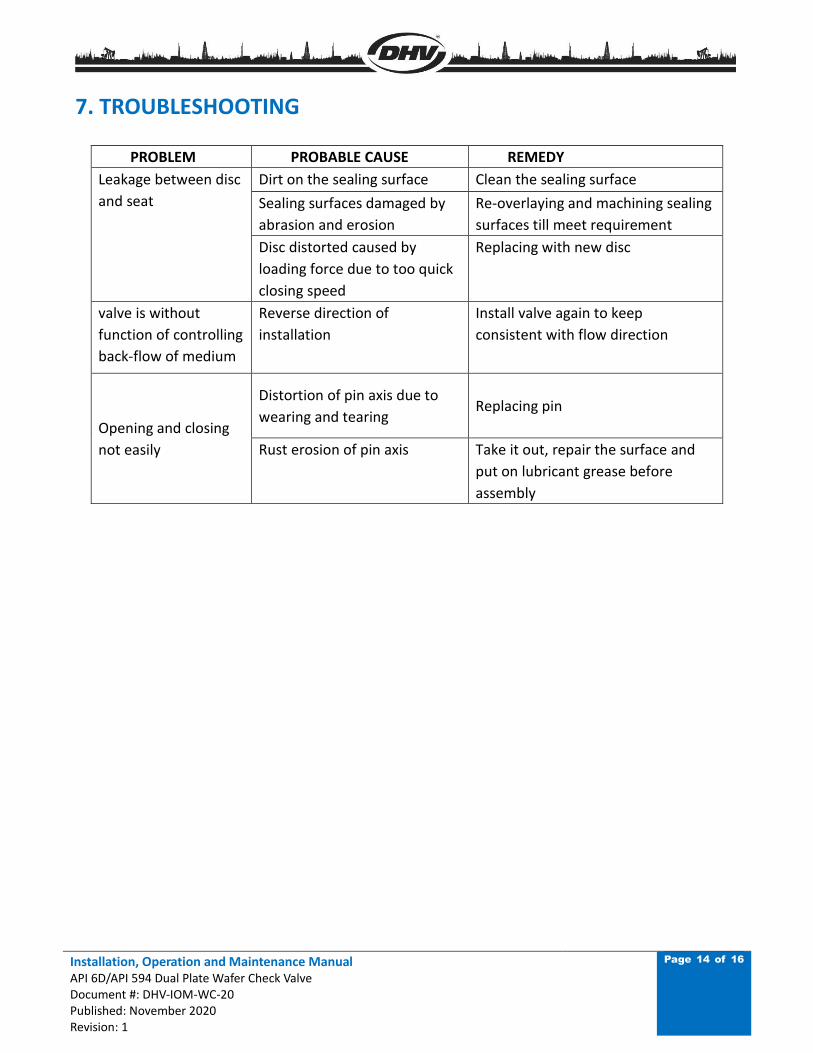
7. TROUBLESHOOTING
PROBLEM PROBABLE CAUSE REMEDY
Leakage between disc
and seat
Dirt on the sealing surface Clean the sealing surface
Sealing surfaces damaged by
abrasion and erosion
Re-overlaying and machining sealing
surfaces till meet requirement
Disc distorted caused by
loading force due to too quick
closing speed
Replacing with new disc
valve is without
function of controlling
back-flow of medium
Reverse direction of
installation
Install valve again to keep
consistent with flow direction
Opening and closing
not easily
Distortion of pin axis due to
wearing and tearing Replacing pin
Rust erosion of pin axis Take it out, repair the surface and
put on lubricant grease before
assembly
Installation, Operation and Maintenance Manual API 6D/API 594 Dual Plate Wafer Check Valve Document #: DHV-IOM-WC-20 Published: November 2020 Revision: 1
Page 15 of 16
8. WARRANTY AND SERVICE
8.1 VALVE WARRANTY PERIOD
8.1.1 Valve warranty period is 12 months from the date shipped from the factory.
8.1.2 In the event the end user encounters an issue of quality, please notify DHV immediately.
DHV reserve the right to investigate and settle all issues of quality concerns directly with the end
user. Refer to DHV’s standard warranty policies for questions or concerns regarding warranty
concerns.
8.1.3 Addressing a valve quality issue within the warranty period:
DHV reserves the right to review and respond to all requests for warranty repair or replacement,
prior to making any replacement or repairs by the end user.
8.1.4 DHV will not be held responsible for any damage due to natural disaster, such as earthquake,
hurricane etc. during valve shipment.
8.1.5 DHV must to be consulted for any warranty issue before being held responsible for any
repairs or valve replacement.
8.2 SERVICE
8.2.1 If required by the contract, DHV may provide and perform field installation and start up
testing.
8.2.2 Upon end user request, DHV can provide services in monitoring the valve quality and history
for Long Term Ownership. Additionally, DHV can provide all the necessary training of repair
services to the valve, as well as training on safe valve operations.
Installation, Operation and Maintenance Manual API 6D/API 594 Dual Plate Wafer Check Valve Document #: DHV-IOM-WC-20 Published: November 2020 Revision: 1
Page 16 of 16
DHV is committed to providing you with the necessary information to support our products.
Our global network of authorized service centers, technical support personnel and warranty
support personnel are ready to serve your needs for support on applications, products,
service and warranty. Contact our USA Bakersfield headquarters for immediate assistance to
your support needs.
DHV Industries, Inc.
3451 Pegasus Drive
Bakersfield, CA 93308 USA
Call Toll Free: (833) DHV-USA1
Phone: (661) 392-8948
Fax: (661) 392-8947
E-mail: [email protected]
Website: www.dhvindustries.com
DHV Valve Company, Inc.
10401 South Sam Houston Pkwy West,
Houston, TX 77071 USA
Call Toll Free: (844) 828-2169
TEL: (346)304-2968
Fax: (346)304-2971
E-mail: [email protected]
Website: www.dhvvalve.com
Related Documents