Chapter 12 Structural Dynamics 1 Chapter 12 Structural Dynamics 12.1 Basics of Structural Dynamics 12.2 Step-by-Step: Lifting Fork 12.3 Step-by-Step: Two-Story Building 12.4 More Exercise: Ball and Rod 12.5 More Exercise: Guitar String 12.6 Review

Welcome message from author
This document is posted to help you gain knowledge. Please leave a comment to let me know what you think about it! Share it to your friends and learn new things together.
Transcript
Chapter 12 Structural Dynamics 1
Chapter 12Structural Dynamics12.1 Basics of Structural Dynamics
12.2 Step-by-Step: Lifting Fork
12.3 Step-by-Step: Two-Story Building
12.4 More Exercise: Ball and Rod
12.5 More Exercise: Guitar String
12.6 Review
Chapter 12 Structural Dynamics Section 12.1 Basics of Structural Dynamics 2
Section 12.1Basics of Structural Dynamics
Key Concepts
• Lumped Mass Model
• Single Degree of Freedom Model
• Undamped Free Vibration
• Damped Free Vibration
• Damping Coefficient
• Damping Mechanisms
• Viscous Damping
• Material Damping
• Coulomb Friction
• Modal Analysis
• Harmonic Response Analysis
• Transient Structural Analysis
• Explicit Dynamics
• Response Spectrum Analysis
• Random Vibration Analysis

Chapter 12 Structural Dynamics Section 12.1 Basics of Structural Dynamics 3
Lumped Mass Model: The Two-Story Building
k
1
c1
k
2
c
2
m
1 m
2[1] A two-degrees-of-
freedom model for finding the lateral displacements of the two-story building.
[2] Total mass lumped at the first floor.
[3] Total mass lumped at the roof
floor.
[4] Total bending stiffness of the first-floor's beams
and columns.
[5] Total bending stiffness of the second-floor's beams and columns.
[6] Energy dissipating mechanism of the first
floor.
[7] Energy dissipating mechanism of the
second floor.
Chapter 12 Structural Dynamics Section 12.1 Basics of Structural Dynamics 4
Single Degree of Freedom Model
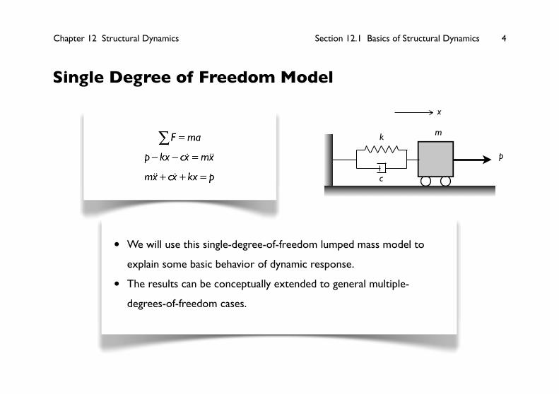
F∑ = ma
p− kx − cx = mx
mx + cx + kx = p
k
c
m
p
x
• We will use this single-degree-of-freedom lumped mass model to
explain some basic behavior of dynamic response.
• The results can be conceptually extended to general multiple-
degrees-of-freedom cases.

Chapter 12 Structural Dynamics Section 12.1 Basics of Structural Dynamics 5
If no external forces exist, the equation for the
one-degree-of-freedom system becomes
mx + cx + kx = 0
If the damping is negligible, then the equation
becomes
mx + kx = 0The
x = Asin ω t + B( )
Natural frequency: ω = k
m(rad/s) or
f = ω
2π (Hz)
Natural period: T = 1
f
Undamped Free Vibration
Dis
plac
emen
t (x
)
time (t)
T = 2π
ω
Chapter 12 Structural Dynamics Section 12.1 Basics of Structural Dynamics 6
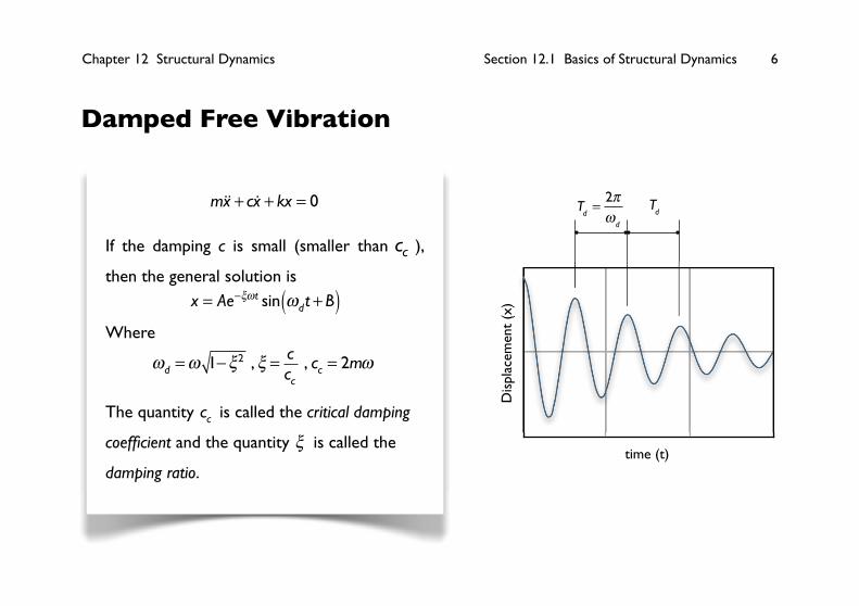
Damped Free Vibration
Dis
plac
emen
t (x
)
time (t)
T
d= 2πω
d T
d mx + cx + kx = 0
If the damping c is small (smaller than cc ),
then the general solution is
x = Ae−ξωt sin ωdt + B( )
Where
ωd =ω 1−ξ2 ,
ξ = c
cc, cc = 2mω
The quantity cc is called the critical damping
coefficient and the quantity ξ is called the
damping ratio.

Chapter 12 Structural Dynamics Section 12.1 Basics of Structural Dynamics 7
Damping Mechanisms
• Damping is the collection of all energy dissipating mechanisms.
• In a structural system, all energy dissipating mechanisms come down
to one word: friction. Three categories of frictions can be identified:
• friction between the structure and its surrounding fluid, called
viscous damping;
• internal friction in the material, called material damping, solid
damping, or elastic hysteresis;
• friction in the connection between structural members, called dry
friction or Coulomb friction.
Chapter 12 Structural Dynamics Section 12.1 Basics of Structural Dynamics 8
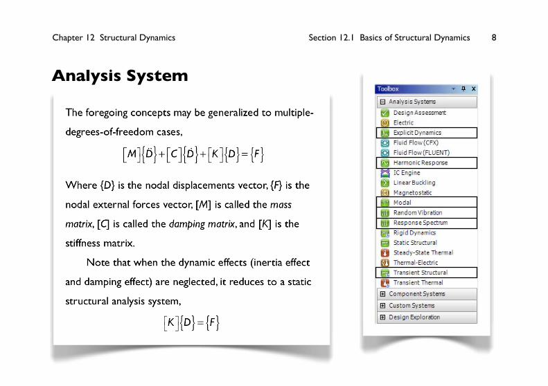
Analysis System
The foregoing concepts may be generalized to multiple-
degrees-of-freedom cases,
M⎡⎣ ⎤⎦ D{ }+ C⎡⎣ ⎤⎦ D{ }+ K⎡⎣ ⎤⎦ D{ } = F{ }
Where {D} is the nodal displacements vector, {F} is the
nodal external forces vector, [M] is called the mass
matrix, [C] is called the damping matrix, and [K] is the
stiffness matrix.
Note that when the dynamic effects (inertia effect
and damping effect) are neglected, it reduces to a static
structural analysis system,
K⎡⎣ ⎤⎦ D{ } = F{ }

Chapter 12 Structural Dynamics Section 12.1 Basics of Structural Dynamics 9
Modal Analysis
M⎡⎣ ⎤⎦ D{ }+ C⎡⎣ ⎤⎦ D{ }+ K⎡⎣ ⎤⎦ D{ } = 0
For a problem of n degrees of freedom, it has at most n solutions, denoted by
{Di }, i =1,2,...,n . These solutions are called mode shapes of the structure. Each mode
shape {Di } can be excited by an external excitation of frequency
ω i , called the natural
frequency of the mode.
In a modal analysis, since we are usually interested only in the natural frequencies
and the shapes of the vibration modes, the damping effect is usually neglected to
simplify the calculation,
M⎡⎣ ⎤⎦ D{ }+ K⎡⎣ ⎤⎦ D{ } = 0

Chapter 12 Structural Dynamics Section 12.1 Basics of Structural Dynamics 10
Harmonic Response Analysis
M⎡⎣ ⎤⎦ D{ }+ C⎡⎣ ⎤⎦ D{ }+ K⎡⎣ ⎤⎦ D{ } = F{ }
<Harmonic Response> analysis solves a special form of the equation, in which the
external force on ith degree of freedom is of the form
Fi = Ai sin(Ωt +φi )
where Ai is the amplitude of the force,
φi is the phase angle of the force, and Ω is
the angular frequency of the external force. The steady-state solution of the
equation will be of the form
Di = Bi sin(Ωt +ϕ i )
The goal of the harmonic response analysis to find the magnitude Bi and the
phase angle ϕ i , under a range of frequencies of the external force.
Chapter 12 Structural Dynamics Section 12.1 Basics of Structural Dynamics 11
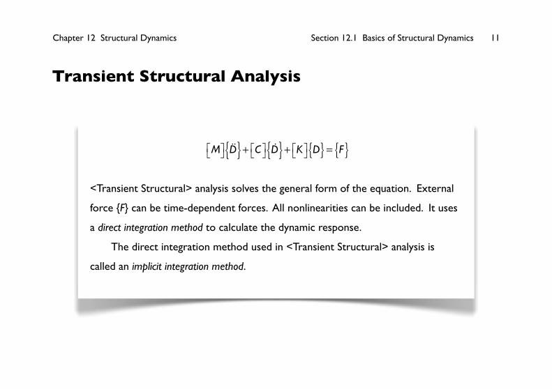
Transient Structural Analysis
M⎡⎣ ⎤⎦ D{ }+ C⎡⎣ ⎤⎦ D{ }+ K⎡⎣ ⎤⎦ D{ } = F{ }
<Transient Structural> analysis solves the general form of the equation. External
force {F} can be time-dependent forces. All nonlinearities can be included. It uses
a direct integration method to calculate the dynamic response.
The direct integration method used in <Transient Structural> analysis is
called an implicit integration method.
Chapter 12 Structural Dynamics Section 12.1 Basics of Structural Dynamics 12
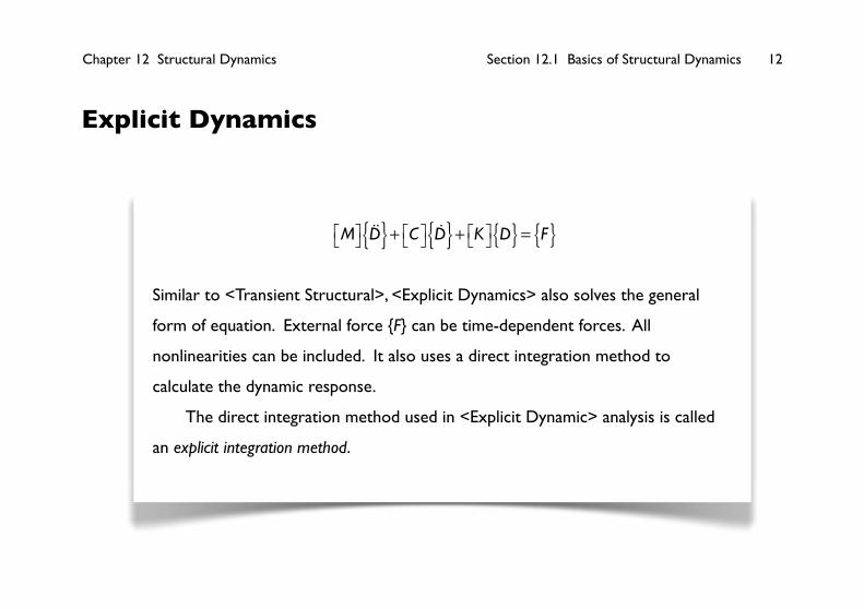
Explicit Dynamics
M⎡⎣ ⎤⎦ D{ }+ C⎡⎣ ⎤⎦ D{ }+ K⎡⎣ ⎤⎦ D{ } = F{ }
Similar to <Transient Structural>, <Explicit Dynamics> also solves the general
form of equation. External force {F} can be time-dependent forces. All
nonlinearities can be included. It also uses a direct integration method to
calculate the dynamic response.
The direct integration method used in <Explicit Dynamic> analysis is called
an explicit integration method.
Chapter 12 Structural Dynamics Section 12.2 Lifting Fork 13
Section 12.2Lifting Fork
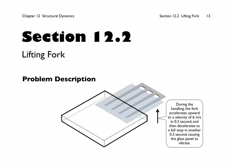
Problem Description
During the handling, the fork
accelerates upward to a velocity of 6 m/s
in 0.3 second, and then decelerates to a full stop in another 0.3 second, causing the glass panel to
vibrate.

Chapter 12 Structural Dynamics Section 12.2 Lifting Fork 14
Static Structural Simulation
The maximum static deflection
is 15 mm.

Chapter 12 Structural Dynamics Section 12.2 Lifting Fork 15
Transient Structural Simulation
Chapter 12 Structural Dynamics Section 12.3 Two-Story Building 16
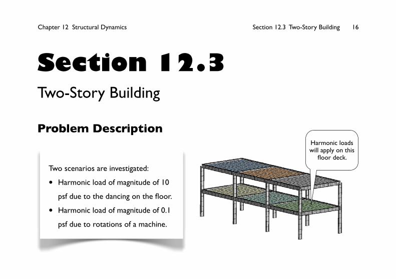
Section 12.3Two-Story Building
Problem DescriptionHarmonic loads will apply on this floor deck.
Two scenarios are investigated:
• Harmonic load of magnitude of 10
psf due to the dancing on the floor.
• Harmonic load of magnitude of 0.1
psf due to rotations of a machine.
Chapter 12 Structural Dynamics Section 12.3 Two-Story Building 17
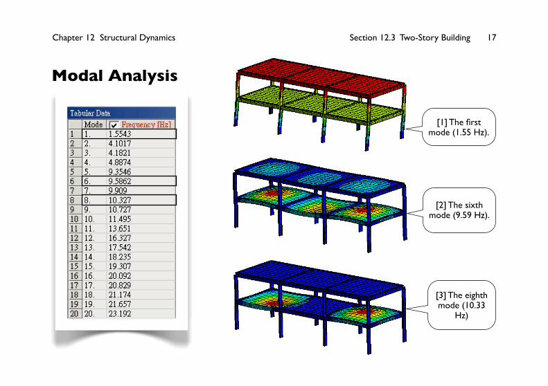
Modal Analysis
[1] The first mode (1.55 Hz).
[2] The sixth mode (9.59 Hz).
[3] The eighth mode (10.33
Hz)

Chapter 12 Structural Dynamics Section 12.3 Two-Story Building 18
• The dancing frequency is close to the fundamental mode
(1.55 Hz), that's why we pay attention to this mode,
which is a side sway mode (in X-direction).
• For the rotatory machine, we are concerned about the
floor vibrations in vertical direction. That's why we pay
attention on the sixth and eighth modes.
Chapter 12 Structural Dynamics Section 12.3 Two-Story Building 19
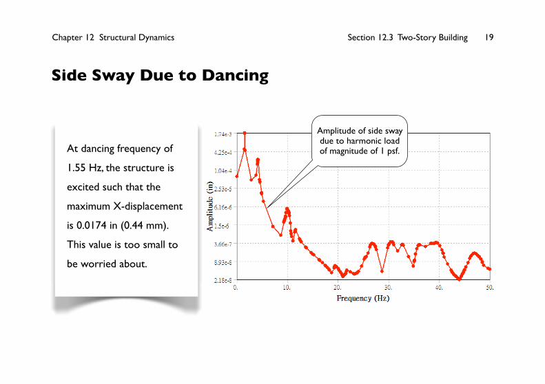
Side Sway Due to Dancing
At dancing frequency of
1.55 Hz, the structure is
excited such that the
maximum X-displacement
is 0.0174 in (0.44 mm).
This value is too small to
be worried about.
Amplitude of side sway due to harmonic load of magnitude of 1 psf.

Chapter 12 Structural Dynamics Section 12.3 Two-Story Building 20
Vertical Deflection of the Floor Due to Rotatory Machine
Amplitude of vertical deflection of the floor due to harmonic load of magnitude of 1 psf.
Although high frequencies do excite the floor, but the values are
very small. At frequency of 10.3 Hz, the excitation reaches a
maximum of 0.0033 in (0.1 times of 0.033 in), or 0.084 mm. The
value is too small to cause an issue.
Chapter 12 Structural Dynamics Section 12.4 Disk and Block 21
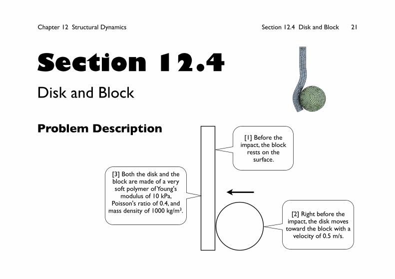
Section 12.4Disk and Block
Problem Description
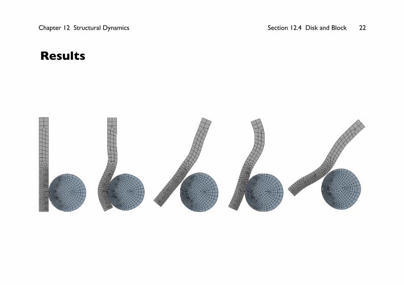
[2] Right before the impact, the disk moves toward the block with a
velocity of 0.5 m/s.
[1] Before the impact, the block
rests on the surface.
[3] Both the disk and the block are made of a very soft polymer of Young's
modulus of 10 kPa, Poisson's ratio of 0.4, and
mass density of 1000 kg/m3.
Chapter 12 Structural Dynamics Section 12.4 Disk and Block 22
Results
Chapter 12 Structural Dynamics Section 12.4 Disk and Block 23
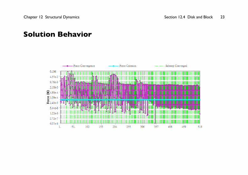
Solution Behavior
Chapter 12 Structural Dynamics Section 12.5 Guitar String 24
Section 12.5Guitar String
The main purpose of this exercise is to demonstrate how to use the
results of a static simulation as the initial condition of a transient
dynamic simulation
Related Documents