Network Architectures and Services NET 2010-08-1 Organisation Proceedings of IPTComm 2010 Principles, Systems and Applications of IP Telecommunications IPTComm 2010 Leibniz-Rechenzentrum der Bayerischen Akademie der Wissenschaften, Munich Chair for Network Architectures and Services, Department of Computer Science, Technische Universität München Location Leibniz Supercomputing Center, Munich, Germany Georg Carle, Helmut Reiser Gonzalo Camarillo, Vijay K. Gurbani Technically co-sponsored by ACM SIGCOMM and IFIP TC6 WG6.2 Chairs TPC Chairs Sponsorship

Welcome message from author
This document is posted to help you gain knowledge. Please leave a comment to let me know what you think about it! Share it to your friends and learn new things together.
Transcript
Network Architectures and ServicesNET 2010-08-1
Organisation
Proceedings of IPTComm 2010
Principles, Systems and Applications of IP
Telecommunications
IPTComm 2010
Leibniz-Rechenzentrum der Bayerischen Akademie der Wissenschaften, Munich
Chair for Network Architectures and Services, Department of Computer Science, Technische Universität München
Location Leibniz Supercomputing Center, Munich, Germany
Georg Carle, Helmut Reiser
Gonzalo Camarillo, Vijay K. Gurbani
Technically co-sponsored by ACM SIGCOMM and IFIP TC6 WG6.2
Chairs
TPC Chairs
Sponsorship

Proceedings of IPTComm 2010
Principles, Systems and Applications of IP Telecommunications
August 2nd and 3rd, 2010
Leibniz Supercomputing Center, Munich, Germany
Editors: Georg Carle, Helmut Reiser,
Gonzalo Camarillo, Vijay K. Gurbani
Leibniz-Rechenzentrum der Bayerischen Akademie der
Wissenschaften, Munich
Chair for Network Architectures and services, Department of
Computer Science, Technische Universität München
Network Architectures and Services NET 2010-08-1
IPTComm
2010
II
IPTComm 2010 Proceedings of IPTComm 2010 Principles, Systems and Applications of IP Telecommunications Editors: Georg Carle Chair for Network Architectures and Services Department of Computer Science Technische Universität München D-85748 Garching b. München, Germany Email: [email protected] Web: http://www.net.in.tum.de/~carle/
Helmut Reiser Leibniz Supercomputing Center Boltzmannstr. 1 D-85748 Garching b. München, Germany Email: [email protected] Web: http://www.lrz.de/~reiser/
Gonzalo Camarillo Ericsson Advanced Signalling Research Lab. FIN-02420 Jorvas, Finland Email: [email protected] Web: http://users.piuha.net/gonzalo/
Vijay K. Gurbani Bell Laboratories, Alcatel-Lucent 1960 Lucent Lane, Rm. 9C-533 Naperville, Illinois 60566, USA Email: [email protected] Web: http://ect.bell-labs.com/who/vkg/ Cataloging-in-Publication Data IPTComm 2010 Proceedings of IPTComm 2010 Principles, Systems and Applications of IP Telecommunications Munich, Germany August 2 and 3, 2010 Georg Carle, Helmut Reiser, Gonzalo Camarillo, Vijay K. Gurbani ISBN: 3-937201-15-7 ISSN: 1868-2634 (print) ISSN: 1868-2642 (electronic) Network Architectures and Services NET 2010-08-1 Series Editor: Georg Carle, Technische Universität München, Germany © 2010, Technische Universität München, Germany

III
Preface These are the proceedings of IPTComm 2010, the fourth of a successful series of conferences on Principles, Systems and Applications of IP Telecommunications. This year’s edition of the conference is held in Garching b. München, Germany, on August 2 and 3, 2010. The scope of the conference covers new services and service models, management and resilience, mobility, and a special focus on security. The call for papers asked for submission of full papers, short papers. It attracted 50 paper submissions. The technical program committee chairs ensured a rigid review process. For each paper, at least three reviews were received. The technical programm committee decided to accept 12 papers as regular papers for the conference, resulting in an acceptance ratio of 24 %. Additionally, 4 papers were selected to be presented as “Work-in-Progress” papers for presentation at the conference. We are very grateful to the all members of the technical program committee and to all external reviewers for their hard work, in particular to the TPC co-chairs Gonzalo Camarillo and Vijay K. Gurbani, who made a tremendous effort, and who ensured that the conference selected highly attractive papers. A separate call for industrial talks and demonstrations attracted a number of highly interesting submissions, of which the industrial talks and demonstrations committee selected 5 industry talks and 8 demonstrations. The conference is hosted by the Leibniz Supercomputing Centre (LRZ) of the Bavarian Academy of Sciences and Humanities, which is the scientific computer centre for all Munich Universities and other research organizations within the greater area of Munich. It supplies more than 100.000 users with IT services and acts as an IT competence centre for all its customers. We would like to thank all authors, conference organizers sponsors for their support of IPTComm 2010! Munich, August 2010
Georg Carle Helmut Reiser

IV
Executive Commitee
Steering Committee Members
Gregory Bond (AT&T Research)
Dorgham Sisalem (Tekelec) Saverio Niccolini (NEC Laboratories Europe)
Radu State (University of Luxembourg) Henning Schulzrinne (Columbia University)
General Chairs
Georg Carle, Technische Universität München Helmut Reiser, Leibniz Supercomputing Center, Munich
Technical Programm Committee Chairs
Gonzalo Camarillo, Ericsson Research
Vijay K. Gurbani, Bell Laboratories/Alcatel-Lucent
Technical Programm Committee
John Buford, Avaya Labs Research Eric Chen, NTT Corporation Eric Cheung, AT&T Labs Research Tasos Dagiuklas, Technological Educational Institute of Mesolonghi Carol Davids, Illinois Institute of Technology Ali Fessi, Technical University of Munich Rosario Garroppo, University of Pisa Aniruddha Gokhale, Vanderbilt University Swapna Gokhale, University of Connecticut Carmen Guerrero, University Carlos III of Madrid Christian Hoene, University of Tübingen Alan Jeffrey, Bell Laboratories, Alcatel-Lucent Cullen Jennings, Cisco Systems Salvatore Loreto, Ericsson Jouni Mäenpää, Ericsson
Enrico Marocco, Telecom Italia Joerg Ott, Helsinki University of Technology Victor P. Avila, Acme Packets Joachim Posegga, University of Passau Anand Prasad, NEC Corporation Ivica Rimac, Bell Laboratories, Alcatel-Lucent Ronaldo Salles, Military Institute of Engineering (Brazil) Stefano Salsano, University of Rome "Tor Vergata" Jan Seedorf, NEC Laboratories Europe Jose Solar, Technical University of Denmark Ivan Vidal, University Carlos III of Madrid Xiaotao Wu, Avaya Labs Research Pamela Zave, AT&T Labs Research
V
Conference Web Site
http://www.iptcomm.org
Table of Contents
Session 1: Security
• Technical Paper: Introducing a Cross Federation Identity Solution for Converged Network Environments.............................................................................. 1 Konstantinos Lampropoulos (University of Patras, GR); Daniel Diaz-Sanchez (Universidad Carlos III de Madrid, ES); Florina Almenares (Universidad Carlos III de Madrid, ES); Peter Weik (Fraunhofer FOKUS, DE); Spyros Denazis (University of Patras, GR)
• Technical Paper: Hidden VoIP Calling Records from Networking Intermediaries .............................................................................................................. 15 Ge Zhang (Karlstads Universitet, SE); Stefan Berthold (Karlstad University, SE)
• Technical Paper: Work in Progress: Inter-Domain and DoS-Resistant Call Establishment Protocol (IDDR-CEP) ........................................................................ 25 Patrick Battistello (Orange Labs, FR)
• Technical Paper: Work in Progress: A secure and lightweight scheme for media keying in the Session Initiation Protocol (SIP) .............................................. 35 Vijay K. Gurbani (Bell Laboratories, Alcatel-Lucent, US); Vladimir Kolesnikov (Bell Labs, US)
VI
Session 2: Deployment considerations and services architecture track (I)
• Technical Paper: Reusable features for VoIP service realization............................ 45 Thomas M. Smith (AT&T Labs Research, US)
• Technical Paper: Specification and Evaluation of Transparent Behavior for SIP Back-to-Back User Agents ................................................................................... 51 Gregory Bond (AT&T Research, US); Eric Cheung (AT&T Labs - Research, US); Thomas M Smith (AT&T Labs - Research, US); Pamela Zave (AT&T Laboratories, US)
Session 3: Performance of VoIP systems and networks
• Technical Paper: The Impact of TLS on SIP Server Performance ......................... 63 Charles Shen (Columbia University, US); Erich Nahum (IBM T.J. Watson Research Center, US); Henning Schulzrinne (Columbia University, US); Charles P. Wright (IBM Research, US)
• Technical Paper: On TCP-based SIP Server Overload Control.............................. 75 Charles Shen (Columbia University, US); Henning Schulzrinne (Columbia University, US)
Session 4: Deployment considerations and services architecture track (II)
• Technical Paper: A Novel Implementation of Very Large Teleconferences........... 89 Eric Cheung (AT&T Labs - Research, US); Gerald M Karam (AT&T, US)
• Technical Paper: CCMP: a novel standard protocol for Conference Management in the XCON Framework .................................................................... 97 Simon Pietro Romano (University of Napoli Federico II, IT); Henning Schulzrinne (Columbia University, US); Roberta Presta (University of Napoli Federico II, IT); Lorenzo Miniero (University of Napoli Federico II, IT); Mary Barnes (Nortel, US)
• Technical Paper: Work in Progress: Black-Box Approach for Testing Quality of Service in Case of Security Incidents by Combining Multiple Test Techniques on the Example of a SIP- based VoIP Service .................................... 107 Peter Steinbacher (Vienna University of Technology, AT); Florian Fankhauser (Vienna University of Technology, AT); Schanes (Vienna University of Technology, AT)
VII
Session 5: Peer-to-Peer in IP Telephony
• Technical Paper: Reliability and Relay Selection in Peer-to-Peer Communication Systems ........................................................................................... 117 Salman Abdul Baset (Columbia University, US); Henning Schulzrinne (Columbia University, US)
• Technical Paper: A Virtual and Distributed Control Layer with Proximity Awareness for Group Conferencing in P2PSIP ...................................................... 129 Alexander Knauf (HAW Hamburg, DE); Gabriel Hege (HAW Hamburg University of Applied Sciences, DE); Thomas C. Schmidt (HAW Hamburg (DE), DE); Matthias Wählisch (Freie Universität Berlin, DE)
• Technical Paper: Pr2-P2PSIP: Privacy Preserving P2P Signaling for VoIP and IM......................................................................................................................... 141 Ali Fessi (Technische Universität München, DE); Nathan Evans (Technische Universität München, DE); Heiko Niedermayer (TU Munich, DE); Ralph G Holz (Technische Universität München, DE)
Session 6: Deployment considerations and services architecture track (III)
• Technical Paper: Online Non-Intrusive Diagnosis of One-Way RTP Faults in VoIP Networks Using Cooperation .......................................................................... 153 Alessandro Amirante (University of Napoli Federico II, IT); Simon Pietro Romano (University of Napoli Federico II, IT); Henning Schulzrinne (Columbia University, US); Kyung Hwa Kim (Columbia University, US)
• Technical Paper: Work in Progress: A Communications-Enabled Collaboration Platform: Framework, Features, and Feature Interactions.......... 161 John Buford (Avaya Labs Research, US); K. Kishore Dhara (Avaya Labs Research, US); Venkatesh Krishnaswamy (Avaya Labs Research, US); Xiaotao Wu (Avaya Labs Research, US); Mario Kolberg (University of Stirling, UK)

Introducing a Cross Federation Identity Solution for Converged Network Environments
Konstantinos Lampropoulos University of Patras
Patras, Greece +302610969863
Daniel Diaz- Sanchez University Carlos III of Madrid
Madrid, Spain +34916246233
Florina Almenares University Carlos III of Madrid
Madrid, Spain +34916248799
Peter Weik Fraunhofer FOKUS
Berlin, Germany +493034637196
Spyros Denazis University of Patras
Patras, Greece +302610969863
ABSTRACT The Future Internet architecture, based on the integration of existing networks and services, and the addition of many new devices like sensors, face a series of important technical challenges, one of them being the management of diverse user identities. The diversity and plethora of the services and procedures affected by the unassociated existing user identities stress the necessity for a holistic solution to deal with the different aspects of the identity management problem. Existing efforts propose limited identity solutions that can only be applied within well defined boundaries and cannot extend their functionality to support converged network environments and service operations across different administrative domains. This paper presents a Dynamic Identity MApping N’ Discovery System (DIMANDS) as a holistic identity solution for large scale heterogeneous network environments. This solution offers cross federation identity services and is based on a universal discovery mechanism which spans across different networks, layers and federations. It is also empowered with a unified trust framework which can collect and process diverse trust information to provide trust decisions on a widely accepted format.
Categories and Subject Descriptors C.2.m [Computer Systems Organization]: Computer-Communication Networks – Miscellaneous
General Terms Management, Design, Security.
Keywords Identity Management, Trust Management, Privacy, Discovery.
1. INTRODUCTION Future Internet promises to offer a unified network environment able to provide innovative services agnostic to
the underlying infrastructure. To achieve this, current network concepts, must be redesigned, translated or mapped in such a way that diverse data may travel and be processed among different networks, contexts and administrative domains. Presently, users are owners of diverse identities and of unrelated identity information, valid and used in different contexts and for different purposes. We see this fragmentation as one of the major obstacles for developing cross-domain user-centric services in the Future Internet.
Despite the fact that Future Internet advocates network convergence, existing research efforts examine the identity problem partially, placing it in very specific and narrow contexts. Proposed solutions often implement identity frameworks which are usually applicable only within well defined administrative boundaries resulting in the creation of “Identity Management islands with interoperability issues” [1]. Cross-domain IdM systems have also been proposed to support environments with multiple co-operative providers and technologies (e.g. converged networks, clouds, federated testbeds etc), but the vast majority of them also suffer from the same symptom: they introduce customized identity formats; preconfigured trust/business relations; custom procedures. These peculiarities make them applicable only within the federation of domains (e.g. federation identities) thus any attempt for interoperating across federations becomes impossible. These practices have just shifted the problem from the isolation of domains to the isolation of federations and certainly away from network convergence.
The IdM problem in the Future Internet must be approached from a different perspective. Numerous domains, federations, cloud-hosted applications etc, which apply different identity schemes, adjusted to their internal procedures, will always exist e.g. for the Internet of Things which will connect not only users but additionally also huge amounts of sensors and slave-labour devices.
1
Enforcing new identity management systems or new identity formats which must be adopted by everyone is therefore not a feasible solution. Towards the Future Internet, the only way to address the IdM problem is to permit today’s administrative domains to create customized identities, based on their needs and technologies, and support network convergence by creating the appropriate dynamic identity associations between these domains. Trust/business relations should dynamically flourish in an ad-hoc and autonomously way free of closed and centralized mechanisms. The proposed solution must act as the glue between the existing diverse identity concepts and support interoperability allowing diverse identity data to travel across different domains and federations. Such a solution can be realized only through an autonomous and independent system that exclusively provides identity services across different domains, federations, technologies and layers without affecting internal network procedures.
Motivated by the aforementioned arguments, this work proposes a Dynamic Identity MApping N’ Discovery System (DIMANDS). DIMANDS is an autonomous and independent system designed to organize all kinds of identities that a single user may own as a member of various providers (e.g. government organizations, applications, service or network providers). With DIMANDS, the end user can form a dynamic online profile and allow third parties to automatically discover identity information about him irrespectively of the identity he is currently using or his network availability. The system is also able to setup and negotiate new trust relations breaking the trust staticity of current identity systems. Accordingly, the system does not collect or store any private identity data but points to authorized places that hold and manage this information.
The rest of the paper is organized as follows. In section 2 we present the current state of the art and in section 3 we describe our identity management and discovery framework. In section 4 we introduce our trust dynamic framework which deals with trust establishment inside and outside DIMANDS borders while in section 5 we present how the overall system supports critical cross domain identity issues. In section 6 we discuss security privacy and trust issues about DIMANDS. Section 7 presents the evaluation of our system and finally in section 8 we conclude this paper discussing open issues and future work.
2. PREVIOUS WORK Identity management is an intensively researched topic in many academic, enterprise and standardization bodies.
Liberty Alliance [2] group has proposed Liberty Federation, a framework for federated identity management. Based on its specifications, OASIS formed the Security Assertion Markup Language (SAML) 2.0, an XML based standard for data exchange between Identity Provider and Service Providers. With federated identities,
providers that reside in a Federation Group bind together various login identities assumed by one user. In this framework providers form static bindings between some of these identities, while there is no identity blinding since the closed Federation Group ensures the desired trust.
According to the OpenID [3] proposed solution, when a user contacts an OpenID-enabled web site instead of his username, he inserts a URL. The OpenID site redirects the user to a site that corresponds to the submitted URL, which in turn, performs the user login operation. OpenID is fast becoming the de-facto solution for secure login in the internet as it is user-friendly, user centric and supports features like Single Sign On (SSO). Nevertheless, this approach (due to the required URL login), is restricted only to application layer identity solutions excluding integration with lower layer identities. Its functionalities are limited to user authentication while its framework does not support management of multiple identities.
Information Cards [4], a Microsoft-initiated solution, is a user-centric mechanism to store and manage online identities. Using a client software, users can create, delete, and modify the identity profiles (Information Cards) they use in the network thus controlling the kind and amount of information revealed in the network. With this approach however, features like cross-layer SSO are not supported while its architecture does not link the different names assumed by one user. Privacy is granted through identity isolation and there is no formation of a single network entity to provide cross-layer identity solutions in the NGN.
Project Higgins [5] is another identity framework which unifies all identity interactions across multiple heterogeneous systems through a common user interface metaphor also called Information Cards (i-cards). The represented identities (Digital Subjects) and their Identity Attributes are exposed in a Context through a data model, described by OWL. It is a user centric system with the end users having a single point of control over multiple heterogeneous identities preferences and relationships. Even though the project presents a unified representation for every type of identity, the identity framework is again limited in the application layer identities and attributes without making clear how lower level protocols may be able to comprehend and adopt it.
The DAIDALOS Project [6] proposes a cross layer identity management system based on the management of all different profiles a user may have in the network. These profiles are linked together into multiple groups, creating the so called Virtual Identities (VIDs). Two or more VIDs cannot be associated with each other, providing strong privacy and security. Project SWIFT [7], a European Union funded project started in 2008, is also based on VIDs. Formation and submission of VIDs though, is a static procedure. Every new service has its unique restrictions and requirements and users must always create, organize
2
and remember numerous VIDs. A complete unified network entity cannot be constructed and existing identities are replaced with VIDs forcing all systems to adopt handle and transport this new type of identity.
Project PRIME [8] defines a system which consists of two parts: a service-side module which mainly provides access control functionalities, and handles trust and policy negotiations and a user-side module (PRIME middleware) which runs on the user's computer. The PRIME management console enables the user to control the disclosure of his personal data. PRIMElife [9] is the follow up project launched in 2008. These projects offer many solutions in identity management, especially in privacy. But again their proposal rejects identity convergence for security reasons, not making clear how it can be integrated in the NGN environment.
Other identity systems designed to face the identity challenges are Shibboleth [10] and Athens [11]. Both these systems propose solutions through a secure login procedure but like the majority of the research are limited to application layer identities.
In [12] authors acknowledge the need for a widely deployed IdM system that must encompass identities of different layers, formats and business areas. This work describes a valid discovery mechanism but all network interactions assume end-users’ intervention and require from them to take all the final decisions about who they should trust and the amount of identity information they are willing to reveal.
Within standardization bodies, ETSI is developing the Universal Communication Identifier (UCI) [13]. This identifier is bound to a Personal User Agent (PUA) that negotiates with other PUAs to deliver communication services between two end parties. UCIs are globally unique identifiers that can be solely resolved to a unique resource where a complete user profile resides. UCI is a cross layer proposal for the identity management system that is mapped to the NGN requirements. It requires though the use of a unique identifier, imposing the need for modification to existing systems and procedures, something that is not easily acceptable especially in protocols levels lower than the application. Furthermore the solution is restricted within a single domain, and it is not clear if and how external identities can be authenticated and then adopted by the system. Also the recently founded industry specification group Identity Management for Networks and Services (INS) of ETSI does not address the aspect of cross-layer identity resolution.
The Focus Group on Identity Management (FG IdM) of ITU-T NGN GSI (SG13) is designing the NGN User Identity (NUI) [1], a new type of identity that will meet a series of NGN requirements and also provide means for identification, authentication, ubiquitous access to network
and services, profile organization etc. NUI may include a public user identity for communication with other NGN users, and a private user identity for networking purposes like authentication with providers. Until now current specifications from FG IdM outline the current state of the identity management system presenting existing identity management solutions, also indicating scenarios to target areas and gaps that still remain unsolved.
Finally the Kantara Initiative [14], an evolution of Liberty Alliance, is an effort to address the identity problem in a much wider landscape. But as stated in [15] “the reality is that it is one more layer of bureaucracy on top of already top-heavy structures”. Kantara proposes that smaller Identity solutions and also the persons creating these projects should become members of its large identity framework. Thus the identity management solution is again based on the formation of large scale trust group something that has already proved to be insufficient.
The main problem behind current initiatives is their inability to transport and manage identity data across predefined trust areas (e.g. federations) thus they are incapable to expand their functionality to unconditionally support converged network environments.
3. DIMANDS ARCHITECTURE The DIMANDS architecture is based on an innovative Distribute Hash Table (DHT) overlay infrastructure which combines the routing capabilities of DHT networks and the security benefits of individual Identity Providers (IdPs). The basic characteristics of DIMANDS overlay are:
• Only nodes (individual IdPs) exist in DIMANDS overlay and not objects (identity data).
• The overlay is used only for routing purposes (and not for storage of any kind of data)
• Participating nodes cannot change their position in the overlay.
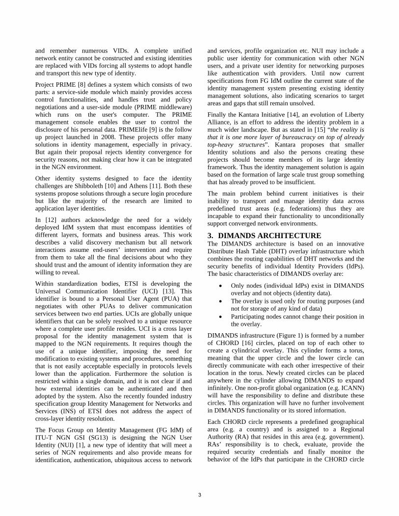
DIMANDS infrastructure (Figure 1) is formed by a number of CHORD [16] circles, placed on top of each other to create a cylindrical overlay. This cylinder forms a torus, meaning that the upper circle and the lower circle can directly communicate with each other irrespective of their location in the torus. Newly created circles can be placed anywhere in the cylinder allowing DIMANDS to expand infinitely. One non-profit global organization (e.g. ICANN) will have the responsibility to define and distribute these circles. This organization will have no further involvement in DIMANDS functionality or its stored information.
Each CHORD circle represents a predefined geographical area (e.g. a country) and is assigned to a Regional Authority (RA) that resides in this area (e.g. government). RAs’ responsibility is to check, evaluate, provide the required security credentials and finally monitor the behavior of the IdPs that participate in the CHORD circle
3
of their geographic area. The RAs will have no further involvement in DIMANDS functionality or DIMANDS stored information.
.FR
.UK
CHORD circles representing geographical areas
Identity Providers in a geographical zone participate as nodes of the
CHORD circle (IdPID)
Routing in the circle is held exactly like
CHORD
Regional Authorities monitor CHORD circle
Each node has neighbors in other CHORD
circles
Figure 1. DIMANDS overlay.
DIMANDS’ functionality is deployed through independent Identity Providers. Any kind of provider, organization, authority etc that wishes to join DIMANDS as an IdP, must first be evaluated by RA of its geographical zone. Upon successful validation, this IdP joins, as a new node, the corresponding CHORD circle and reserves a specific and permanent point. This point is called Identity Provider ID (IdPID) and it is a numeric value which indicates its position in the overlay. CHORD overlay structure ensures uniform distribution on the circle for practically an infinite number of nodes.
Each overlay node (IdP) sustains a number of neighbors and constantly maintains secure connections with each one of them. These neighbors exist in its own circle and in other circles and their number may vary based on system’s size and traffic. Selecting neighbors in the same circle is carried out exactly like CHORD. To be able to select neighbors in different circles a node requests from the corresponding RA a list, containing the IdPIDs of the nodes that exist in the same point like itself in the rest of the CHORD circles (or close to that point). Since DIMANDS overlay is a torus, the nodes in this list form a virtual vertical circle thus the selection of neighbors in other circles is held again exactly like CHORD. To deliver a message destined to a specific point on the overlay, a node must simply forward it vertically to a node in another circle or horizontally to a node in its own circle using CHORD routing.
The proposed architecture is designed to satisfy a number of key requirements in terms of performance, privacy, trust and security. DIMANDS is based on a hierarchical 3-level architecture where multiple organizations and providers contribute and assume well defined and separate roles, without being able to access data or functions that are not
supposed to. In the two top levels of DIMANDS architecture reside distinguished organizations (ICANN, Regional Authorities) which only purpose is to provide the necessary orchestration to the IdPs that host DIMANDS actual functionality and compose the lower third level of the DIMANDS architecture. End-users’ private data are safely stored in the IdP of their choice without being accessible to any of the organizations of the two upper levels.
The DHT architecture offers minimal management overhead and robustness to the system and was selected over other centralized or hierarchical architectures to support the hard trust and security requirements of an IdM system. Nodes (IdPs) in the overlay will rarely join or leave DIMANDS. Thus each node will sustain stationary neighbors and build long term trust relations with them. Any message, destined to a node in DIMANDS, will safely travel through a path of trusted neighbors. In any other centralized of hierarchical architecture the destination node would have to process incoming messages from unknown sources without always being able to validate them. Furthermore, in DIMANDS overlay neighboring nodes exchange data through secure connections, thus providing high levels of security to the system. In any other centralized of hierarchical architecture it is impossible to store credentials and establish secure connections between all of the participating IdPs to securely exchange identity information. New circles and nodes can constantly join the overlay without affecting the functionality or the architecture of the system. Failure of a node has only temporary and local effects and does not affect the overall system. Its neighbors may temporarily route messages from alternative paths, and there is no data loss since each node is responsible for maintaining the data of its own users.
Assigning CHORD circles to specific geographical areas provides locality to DIMANDS overlay and advances system’s performance. End-users’ identities will mainly exist in providers located in their geographical area (e-government, e-health, telco services) thus message exchanging between entities that reside in large distances in the actual network is minimized. Better locality can be achieved, if the nodes in each geographical circle are organized in a locality aware CHORD. It must be clarified that CHORD was selected among other existing DHTs due to its ability to improve locality by only modifying the neighbors on each node on the circle and not the position of the node, thus satisfying DIMANDS requirement for stationary nodes.
3.1 User Account In DIMANDS a user may select the IdP he prefers and trust the most, and create an account. Each DIMANDS account is defined by an identifier called User account ID (UsID) which is a numeric value assigned and known only by the IdP. Linked to this UsID exists a unique database where the
4
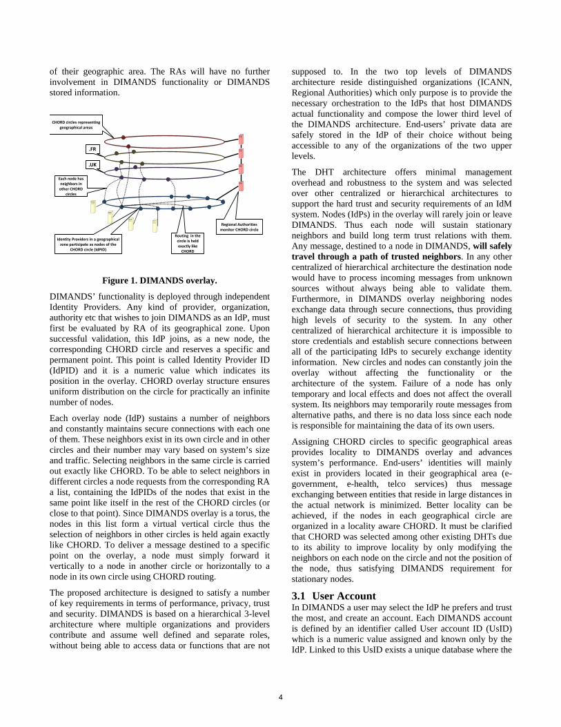
user can store the identity information he wishes (Figure 2). This database has four fields. The “RID” and “TRID” fields which hold representations of all user’s identities, the “Domain Name” field where all the domains that host the profiles for the corresponding user’s identities are stored and a variable set of fields called “Attributes”.
DIMANDS obfuscates the real identities and replaces them with Random Identity Numbers (RIDs). An RID is a unique representation of a single identity and is stored in both DIMANDS’ IdP and the organization’s (the one that holds the profile for this specific identity) databases. Any communication between the organization and DIMANDS regarding an identity is carried out by using the corresponding RID, providing robust identity obfuscation.
UsID: 1311652232 TRID RID Domain
Name Attributes
35124 1234.6334124463 umts.com Service: Tel, video Network Authorization: Yes
61234 1234.1254576222 telco.com Service: Tel, video, IM Network Authorization: Yes
78123 1234.6982145781 gov.uk User Validation: Yes Age Validation: Yes
Location Validation: Yes Figure 2. The database stored in DIMANDS’ User
Account.
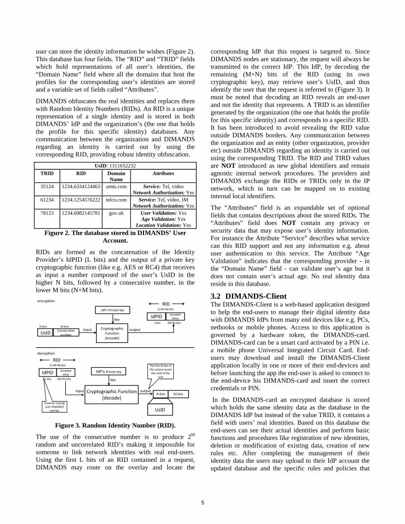
RIDs are formed as the concatenation of the Identity Provider’s IdPID (L bits) and the output of a private key cryptographic function (like e.g. AES or RC4) that receives as input a number composed of the user’s UsID in the higher N bits, followed by a consecutive number, in the lower M bits (N+M bits).
Cryptographic Function(encode)
UsID Consecutive number
RID
inputN-bits M-bits
IdP’s Private key
key
output
Cryptographic Function(decode)
N-bits M-bits
Encoded value
input
IdP’s Private key
key
output
UsID
The first N-bits of the output reveal
the UsID of the user
encryption
decryption
(M+N) bits
(M+N)-bits
IdPID Encoded Value
L bits
(L+M+N) bits
IdPIDL bits
(L+M+N) bits
RID
Used for routing over DIMANDS
overlay
Figure 3. Random Identity Number (RID).
The use of the consecutive number is to produce 2M random and uncorrelated RID’s making it impossible for someone to link network identities with real end-users. Using the first L bits of an RID contained in a request, DIMANDS may route on the overlay and locate the
corresponding IdP that this request is targeted to. Since DIMANDS nodes are stationary, the request will always be transmitted to the correct IdP. This IdP, by decoding the remaining (M+N) bits of the RID (using its own cryptographic key), may retrieve user’s UsID, and thus identify the user that the request is referred to (Figure 3). It must be noted that decoding an RID reveals an end-user and not the identity that represents. A TRID is an identifier generated by the organization (the one that holds the profile for this specific identity) and corresponds to a specific RID. It has been introduced to avoid revealing the RID value outside DIMANDS borders. Any communication between the organization and an entity (other organization, provider etc) outside DIMANDS regarding an identity is carried out using the corresponding TRID. The RID and TIRD values are NOT introduced as new global identifiers and remain agnostic internal network procedures. The providers and DIMANDS exchange the RIDs or TRIDs only in the IP network, which in turn can be mapped on to existing internal local identifiers.
The “Attributes” field is an expandable set of optional fields that contains descriptions about the stored RIDs. The “Attributes” field does NOT contain any privacy or security data that may expose user’s identity information. For instance the Attribute “Service” describes what service can this RID support and not any information e.g. about user authentication to this service. The Attribute “Age Validation” indicates that the corresponding provider - in the “Domain Name” field - can validate user’s age but it does not contain user’s actual age. No real identity data reside in this database.
3.2 DIMANDS-Client The DIMANDS-Client is a web-based application designed to help the end-users to manage their digital identity data with DIMANDS IdPs from many end devices like e.g. PCs, netbooks or mobile phones. Access to this application is governed by a hardware token, the DIMANDS-card. DIMANDS-card can be a smart card activated by a PIN i.e. a mobile phone Universal Integrated Circuit Card. End-users may download and install the DIMANDS-Client application locally in one or more of their end-devices and before launching the app the end-user is asked to connect to the end-device his DIMANDS-card and insert the correct credentials or PIN.
In the DIMANDS-card an encrypted database is stored which holds the same identity data as the database in the DIMANDS IdP but instead of the value TRID, it contains a field with users’ real identities. Based on this database the end-users can see their actual identities and perform basic functions and procedures like registration of new identities, deletion or modification of existing data, creation of new rules etc. After completing the management of their identity data the users may upload to their IdP account the updated database and the specific rules and policies that
5
organize the data stored in it. This upload is held over a secure connection between DIMANDS-Client and the IdP.
The responsibility for developing and distributing the DIMANDS-clients and associated DIMANDS-cards is assigned to the IdPs that participate in the DIMANDS infrastructure. Both of these components must meet a predefined and very specific set of obligatory security and privacy requirements. Each IdP may modify them only by adding improvements in security. The exact interface of the application and its full capabilities are not described since they are outside of the scope of this paper.
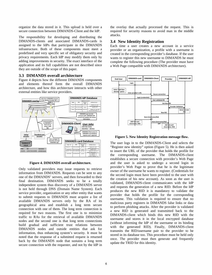
3.3 DIMANDS overall architecture Figure 4 depicts how the different DIMANDS components and elements thereof form the overall DIMANDS architecture, and how this architecture interacts with other external entities like service providers.
DIMANDS IdP DatabaseDIMANDS overlay
ProviderA.com(provider)
User JohnJohn has many identities – devices
UoP.gr(provider) …
Database of uop.gr
TRID RID Username
61234 1234.7321214585 [email protected]
John has a DIMANDS account in the Identity Provider IDP_1
DIMANDS-Client
DIMANDS-card Database
DIMANDS-app securely connects with DIMANDS IdP
account and updates the stored information
DIMANDS-Client access to DIMANDS-card database requires user’s approval
John manages his identities through
DIMANDS-app UsID:0261311652231
Name – id RID Domain Name
Attribute Service
(imsi)123….12 1234.6334124463 umts.com Service: Tel, videoNetwork Authorization: Yes
[email protected] 1234.7321214585 uop.gr Service: email(tel)+31…1121 1234.1254576222 telco.com Service: Tel, video, IM
Network Authorization: YesJohn Smith 1234.6982145781 gov.uk User Validation: Yes
Age Validation: YesLocation Validation: Yes
IDP_1(IdPID: 1234)
Communication to DIMANDS is
held only by using a valid
RID
UsID:0261311652231TRID RID Domain
NameAttribute Service
35124 1234.6334124463 umts.com Service: Tel, videoNetwork Authorization: Yes
61234 1234.7321214585 uop.gr Service: email
78123 1234.1254576222 telco.com Service: Tel, video, IMNetwork Authorization: Yes
Figure 4. DIMANDS overall architecture.
Only validated providers may issue requests to retrieve information from DIMANDS. Requests can be sent to any one of the DIMANDS’ servers, and then forwarded to their final destination. DIMANDS seeks to be a totally independent system thus discovery of a DIMANDS server is not held through DNS (Domain Name System). Each service provider, organization or any other entity that wants to submit requests to DIMANDS must acquire a list of available DIMANDS servers only by the RA of its geographical area and establish a long term secure connection with one of them. The long term connection is required for two reasons. The first one is to minimize traffic to RAs for the retrieval of available DIMANDS nodes and the second one is that long term connections build gradual and sufficient trust relations between DIMANDS nodes and outside entities that ask for information, thus enhancing system’s security. It must be noted that the response of a submitted request is returned back by the DIMANDS node that sustains a long term secure connection with the requester, and not by the IdP in
the overlay that actually processed the request. This is required for security reasons to avoid man in the middle attacks.
3.4 New Identity Registration Each time a user creates a new account in a service provider or an organization, a profile with a username is created in the corresponding provider’s database. If the user wants to register this new username to DIMANDS he must complete the following procedure (The provider must have a Web Page compatible with DIMANDS architecture).
ProviderEnd User
Store (Username/Rid) pair
Add new pair (Username, RID)
DIMANDS IdP
Login
DIMANDS-Client
Select “Add New Identity” option
Enter provider’s URLSecure connection
Login (credentials)
New RID
Add new pair (Username, RID)
DIMANDS-card
Store (Username/Rid) pair
Generate new RID
Get New RID
User validated OK
Provider Validation
Figure 5. New Identity Registration message flow.
The user logs in to the DIMANDS-Client and selects the “Register new identity” option (Figure 5). He is then asked to insert the URL of the provider that holds the profile for the corresponding username. The DIMANDS-client establishes a secure connection with provider’s Web Page and the user is asked to undergo a second login in provider’s Web Page to prove that he is the legitimate owner of the username he wants to register. (Credentials for the second login must have been provided to the user with the creation of his new account). As soon as the user is validated, DIMANDS-client communicates with the IdP and requests the generation of a new RID. Before the IdP produces the new RID it is mandatory to validate the provider that holds the profile for the corresponding username. This validation is required to ensure that no malicious party registers in DIMANDS false links or data to perform phishing attacks. After the provider is validated a new RID is generated and transmitted back to the DIMANDS-client which binds this new RID with the username and stores it in the local encrypted database (without informing the IdP of the username or its binding with the generated RID). Finally, DIMANDS-client transmits the RID/username pair to the provider to be stored in its database too. This procedure must be held only once. The provider must then generate and frequently update the TRID for this identity.
6
4. TRUST FRAMEWORK Identity discovery is the first step in every single interaction but afterwards there is another issue to solve, the lack of dynamic trust support.
IdM systems manage trust in different ways as stated in [17] or [18], but it is always handled in a very static fashion. For instance, SAML employs pre-existing trust relationship, by means of PKI, between the Relying Party and the Attribute Provider [19]. Shibboleth inherits from SAML this model. Thus, Shibboleth federations imply the aggregation of large lists of providers that agree to use common rules and contracts. The process might require human intervention being even more rigid. The drawbacks of this kind of trust model are well known: hard to deploy and maintain, and high dependence on central authorities [20]. OpenID did not consider trust in the beginning (trust-all-comers model). However, a new OpenID extension called PAPE (Provider Authentication Policy Extension) [21] has been approved in order to enforce trust mechanisms. PAPE provides means for RPs and OpenID Providers to request and advertise previously agreed policies. Others, as WS-Federation and Liberty Alliance, resemble PKI trust models between Certification Authorities (CAs). These models are typically implemented by means of trust lists containing trustworthy authorities that are manually configured by an administrator. To overcome the aforementioned trust staticity, two different paradigms are applied in the trust framework: trust management and trust negotiation. So, flexibility in trust is provided while security and privacy are guaranteed. In a high dynamic ecosystem, as Future Internet would be, trust might be handled mimicking humans’ behavior, considering though the history of interactions, the environment, and the scope to derive trust levels for every request.
The trust framework does not store data in DIMANDS user’s accounts and is not combined with the identity organization and discovery mechanism. In fact, our aim is to minimize the dependence on central authorities or previous configuration to allow entities to be more autonomous and capable of making P2P trust decisions.
DIMANDS exploits this framework’s functionality to address the trust issues that arise inside and outside its borders. In this way, interactions between providers, IdPs, and users are seamlessly achieved. Such interactions could imply bridging trust models across disparate domains, as well as negotiating several options such as protocols, multiple identifiers, flexible attributes, a common set of policies, obligations, and procedures regarding access control, information disclosure or treatment, etc. No trust data must exist in user’s DIMANDS accounts, in order for
the system to meet its hard privacy and security requirements.
The system provides trust services to allow new comers as, IdP, service providers or external entities, to negotiate trust by exchanging requirements and credentials. The trust framework can be instantiated in every single entity willing to participate, can be shared by several entities, or used as a trust broker for an administrative domain.
The following sections describe our trust framework. The Pervasive Trust Manager is in charge of handling trust in stationary state, in other words, maintains a trust relation after it has been set up. Existing trust relations are monitored using evidences, context and preferences dealing with cooperative attacks, botnets and virus. The Pervasive Trust Negotiation module is the bootstrapping module. It handles interactions with estrangers deriving a trust relation for the first time, enables dynamic trust establishment to increase privileges or handles important context (or preferences) changes that require a new relation to be established. Both modules manage the risk associated to establish and manage relationships with a certain uncertainty degree.
4.1 Pervasive Trust Negotiation This module assists entities to select policies (requirements), credentials, and resources to disclose, according to strategies, preferences, and context. The objective is to achieve a fair P2P trust negotiation. The module uses a human-mimicking decision engine able to simplify problems. Moreover, if a human is involved in the process, the module can graphically present those problems in comprehensive way allowing he/she to understand what is happening despite his/her technical training.
In order to authenticate and authorize estrangers, trust negotiation rely on the fact that any resource is protected by a policy that express which credential(s) should be disclosed to obtain access to it. [22] describes the requirements that trust negotiation systems should cope with. Requirements should be disclosed gradually, according to the level of trust reached until the moment, since they might contain sensible information [23]. However, to protect entities against rogue or greedy peers, that harvest unnecessary credentials from others, the process should be driven by a decision engine.
The trust framework is agnostic in terms of policy or credential language and encoding. The negotiation is governed by policies from different editors that protect resources. A resource can be protected by several policies and a policy can protect several resources. For that reason, policies are split into parts that are called “policy items”. A policy item is a formal definition, therefore expressed with adequate semantics, for a requirement. The formal definition of a resource, guarantees that other peers would be able to find out which credential(s) should be disclosed
7
in order to satisfy it. Finally, a resource is any information, service, mechanism or credential, in general any object, which its disclosure implies a risk. Policy items are considered also resources since it disclosure might be dangerous.
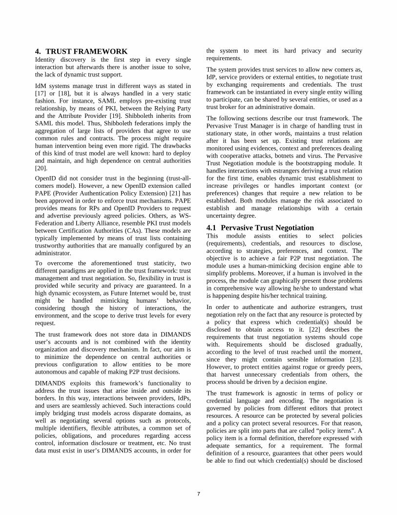
To drive the credential exchange towards a fair negotiation, for either bringing up a new trust relation or to increase privileges, we place every object (resources or policy items), subject to be part of the decision, into a decision set, as shown in Figure 6. The decision set is composed by object descriptions that are collections of attributes. In a highly dynamic scenario, is unfeasible to find a common model to describe every object, especially if objects can be different in nature. Thus, the amount of attributes used to describe objects depends on the nature and the available information. The Pervasive Trust Negotiation module fetches then context and preferences the environment. It derives an agnostic decision set from the input by transforming attributes using generic attribute taxonomy. The taxonomy is able to cope with quantitative, ordinal and membership data.
Once the engine derives the generic attribute taxonomy, it includes a virtual object called “status” into the decision space. The status object contains attributes, according the derived taxonomy, which reflect the information known up to the moment, as disclosed credentials, environment information, and preferences. Then the engine computes dissimilarities among entities and produces a dissimilarity matrix, similar to a covariance matrix.
Figure 6. Pervasive Trust Negotiation Engine
The Pervasive Trust Negotiation module uses multivariate statistics to simplify the problem by reducing the dimensionality of the input space to a common set of
attributes. To achieve that, the engine process the matrix with ALSCAL Multidimensional Scaling (MDS) [24], which uses alternate least squares, together with weighted dissimilarities, to combine both metric and non-metric analysis. The algorithm deals with spare matrixes (with different number of attributes) so it is suitable for the problem we face with highly dynamic environments (absence of some data).
In order to find out the next credential to exchange or the next requirement to commit, the Pervasive Trust Negotiation engine takes the simplified decision space and measure the distance between any object and the status object. This distance is directly interpreted as a measure of risk. After a successful requirement fulfillment, a change on the preferences or environment data, the engine computes again the dissimilarity matrix, simplifies the problem, and computes the risk again obtaining the next step.
MDS has been successfully used to solve similar complex problems as classifying music [25], or selecting the most appropriate network from a heterogeneous set [26]. When applied to trust negotiation, it provides robustness (works in the absence of data) and agnosticism (works with any object) if compared to Petry Network driven trust negotiation [27]. Compared to solutions that make policies publicly available but obfuscate them including fake policies [28], our system make policies private and release them according to a risk model, thus it does not suffer from cooperative attacks that end up finding the fake policies. Other solutions define their own language as [29] and make peers to exchange complex graphs but they lack of agnosticism or the context is not well addressed.
4.2 Pervasive Trust Manager This module is responsible for managing internal and external trust information, and maintaining dynamically the trust and distrust lists updated. The internal trust information is obtained from a local repository, which contains data related to the entities’ behavior. On the other hand, external trust information is obtained from trusted third parties (TTPs), making use of the common knowledge by means of requesting and collecting reputation information, so maintaining a history of the interactions and collecting recommendations from other entities.
From such trust information, the Trust Manager models trust evolution over time, as it has a clear impact in risk management and trust decisions. Trust evolution represents that trust learning is gradual, subjective and dynamic. This takes into account the environment as well as historical evidences or reputation information. So, this module is enriched with more complex functionality such as risk and policies management, and uses of techniques applied to cooperation and collaboration models. These advanced functionalities allow considering timing, analysis of cached
8
trust material, update to policies, agreements fulfillment, etc., in order to achieve a better trust management.
The trust metrics used are specified in order to make easier the mapping from different trust models applied to every domain similar to the problem of identity formats.
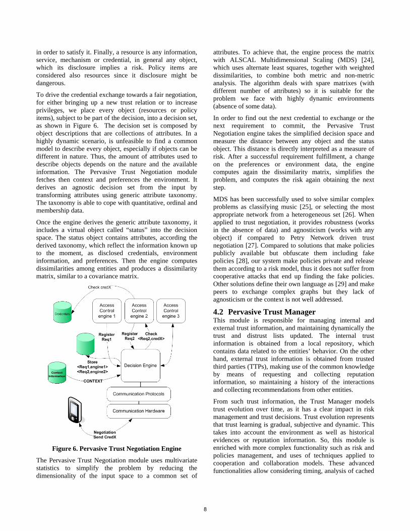
5. DISCOVERY – IDENTITY CONVERGENCE Being an independent and autonomous entity, DIMANDS has the ability to provide cross domain/federation identity services. Figure 7 presents a cross domain service delivery scenario that requires the co-operation of providers which reside in multiple and unassociated federations. User “[email protected]” logs on his account in provider “webstore.com” and requests a specific service (e.g. an online purchase). In order to complete the transaction, provider “webstore.com” must contact other providers (e.g. paypal.com, supplier.com etc) which all participate in the federation F1.
The “supplier.com” provider though needs to validate user’s age information against an entity that might not be part of the federation F1 but that should be trusted.
Existing literature fails to support the above operation because the “supplier.com” cannot autonomously discover where the desired information resides (is restricted to use only information that exists in the federation or the cloud) and even if it somehow knew that the information existed in the gov.com” organization, the username “[email protected]” means nothing to “gov.com”.
webstore.com
DIMANDSoverlayUser supplier.com
Service Request: [email protected]
Federation: Fd1
gov.com
Federation: Fd2
Service Request: [email protected]
DIMANDS Req: [email protected]
Age validationDIMANDS Req: RID
([email protected])Supplier.com wants: Age validation
DIMANDS Resp: List (domains/TRIDs)
Age Validationuser: TRID
Service Response: OK [email protected]
Service Response: OK [email protected]
Figure 7. Cross federation service delivery using
DIMANDS.
Using DIMANDS functionality, the provider “supplier.com” constructs a DIMANDS request asking for age validation. Since it has no knowledge of a valid RID (the user does not have an active account in supplier.com) to directly contact DIMANDS, the request is transmitted to the provider “webstore.com”, which in turn retrieves from
its database the corresponding RID and forwards the request to DIMANDS on behalf of the “supplier.com”. DIMANDS validates that the “supplier.com” is a legitimate provider and responds a message containing a list with domains, which can validate user’s age and a number of TRIDs. The “supplier.com” provider receives the list and among the containing providers chooses the “gov.com” organization that trusts the most (participate in a different federation). Using the corresponding TRID, can now directly contact the organization and acquire the desired information However, it cannot be assumed that the above list will always contain trusted providers. Accordingly, if the “supplier.com” and the organization and “gov.com” had no previous trust relation and interacted for the very first time, they should set up a trust relation dynamically. To accomplish that task based on our proposed trust framework, both entities would engage in a trust negotiation. For instance, “supplier.com” derives its dissimilarity matrix and looks for the next step in the negotiation. It sends a basic authentication requirement to “gov.com”. “gov.com” authenticates with a PKI certificate and requests authentication to “supplier.com”. After the basic authentication phase, both entities know they are talking to the appropriate machine. According to “supplier.com” policy, “gov.com” must demonstrate that is a valid source for verifying the age. Nevertheless, before going further, “gov.com” calculates its decision space and requests “supplier.com” to send a credential asserting it is a valid supplier and requests it to agree on the privacy policy. In this way, “gov.com” protects itself from rogue peers. Once “supplier.com” fulfills those requirements, “gov.com” sends a set of attributes within a SAML sheet that demonstrates it is a valid source and validates the age. Both entities will convey their brand new trust relations to the trust management module so next interactions, under the same scope, would be faster.
6. SECURITY, PRIVACY & TRUST ANALYSIS Security: Even though DIMANDS is formed by multiple individual IdPs its architecture provides maximum security to the system since all communication, is held over secure connections. Encryption for all messages provides data integrity and monitor of the participants’ behavior by the RAs protects the system from internal malicious parties. Monitoring the IdPs of a geographical area may be held through our proposed Pervasive Trust Manager, part of the trust framework. Thus, each IdP might be evaluated by its neighbors and inappropriate actions would be reported to the RAs to generate evidences for future trust decisions. Any kind of unaccepted behavior from an IdP may result in its permanent removal from the system. Only validated providers can register or acquire information from DIMANDS system. This validation can be achieved
9
through certificates and ensures that no malicious entity will have the ability to insert false links or data to perform e.g. phishing attacks, or illegally collect identity information. Misbehaving outside entities may be denied of DIMANDS services. DIMANDS-Client is one of the most essential parts in DIMANDS architecture thus any security flaw may cause serious data exposure. Firstly it must be ensured that the application cannot be modified and distributed from any unauthorized party. Its distribution should be performed only by the IdPs through a secure site which supports SSL client side authentication. As mentioned above, DIMANDS-Client is a web-interfaced application. The web interface advances the usability of the system making it more user-friendly. However this imposes many critical security threats e.g. cross-script attacks. DIMANDS-Client cannot be developed on top of existing browsers because the system will constantly be subjected to the plethora of different security flaws that these browsers may have. Thus we propose that DIMANDS-Client should be an independent application designed in such a way that meets specific security requirements, capable of supporting generic web browsing, used only for DIMANDS purposes. Furthermore for DIMANDS-card, it must be ensured that its connection with DIMANDS-Client is absolutely secure. Many secure frameworks exist in literature that provide security and data integrity for the use of smart cards. Mutual PKI (Private Key Infrastructure) authentication is mandatory and frequent re-authentication is advised, to ensure that DIMANDS-card is connected with a valid and secure DIMANDS-Client. Finally, for the protection of DIMANDS from threads that apply in all large scale networks e.g. DDoS attacks, many security solutions exist in literature that can be exploited based on the nature of the attack. This kind of security analysis is outside of scope of this paper. Privacy: Considering privacy, the 3-level architecture of DIMANDS ensures that each user’s data will only remain under the control of the Identity Provider of his choice, and will not be accessible by any other entity in the system (e.g. ICANN or RAs). The obfuscation of the real identities (with the use of RIDs and TRIDs) ensures maximum security from monitoring and data collection even within DIMANDS. However the strongest part of DIMANDS is the nature of the stored information. DIMANDS holds irresolvable identity mappings and descriptions of their capabilities. No actual identities or identity data exist in DIMANDS. The actual information are distributed and well protected in the providers and the organizations that issued user’s real identities. Trust: DIMANDS assigns CHORD circles in geographical areas to advance trust with its users. End-users most likely will trust IdPs that reside in the same geographic region, share the same culture, and obey the same security policies and rules enforced by a locally distinguished Authority. Of course the strongest evidence on why should the end-users
trust DIMANDS, is the fact that stored information in DIMANDS do not carry any actual identities or identity data and cannot lead to personal information exposure. DIMANDS proves its trustworthiness to the IdPs that participate in its infrastructure and the outside providers - organizations that exchange information with, through the careful design of its architecture that ensures maximum privacy and security. The long-term connections between DIMANDS nodes and external providers combined with the trust relations between DIMANDS overlay neighbors provide high levels of trust and security for the overall system. Furthermore with the adoption of our proposed trust framework that provides trust services to allow new comers (e.g. IdPs, service providers or external entities) to negotiate trust by exchanging requirements and credentials DIMANDS succeeds in supporting the essential issue of trust not only inside, but also outside its borders
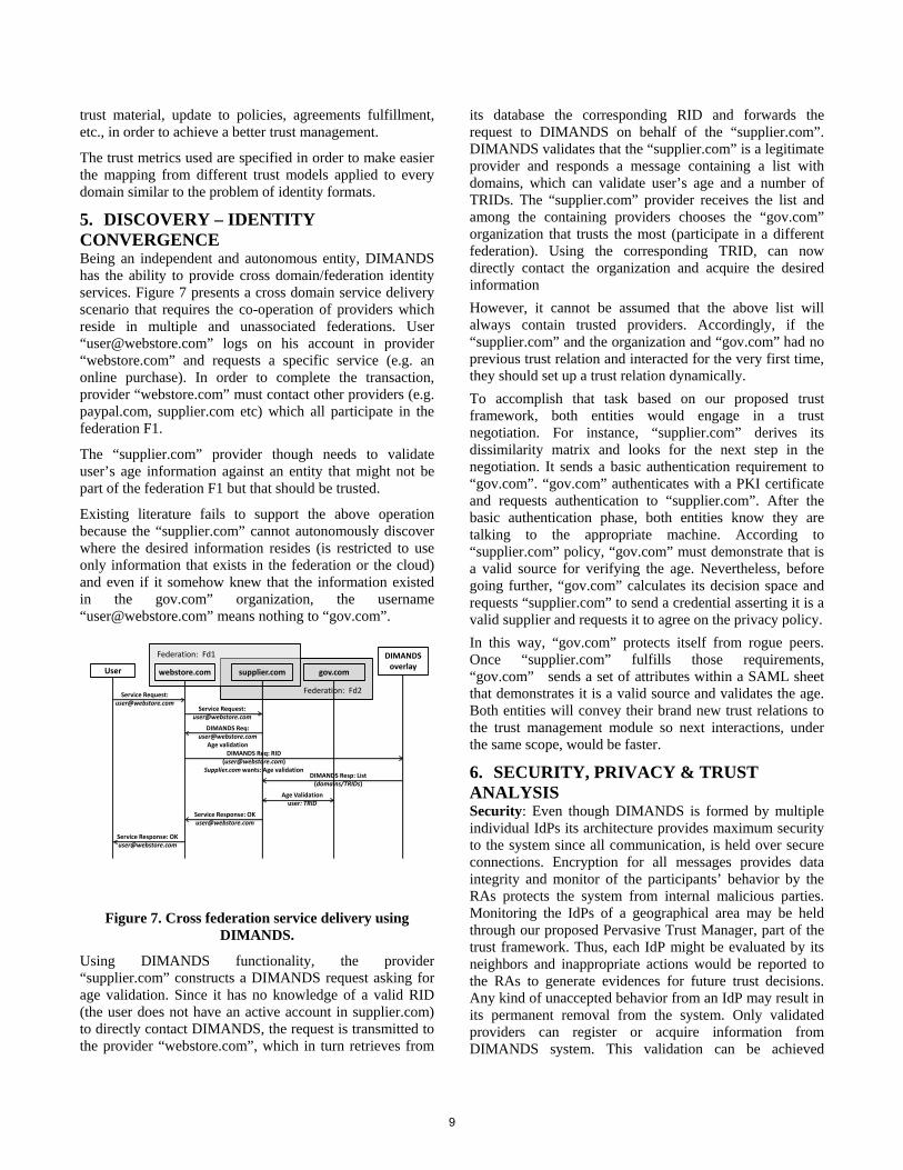
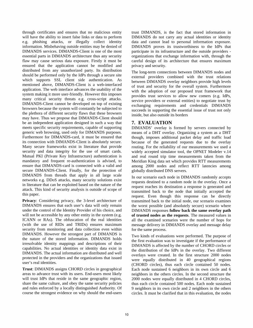
7. EVALUATION DIMANDS’ overlay is formed by servers connected by means of a DHT overlay. Organizing a system as a DHT though, imposes additional packet delay and traffic load because of the generated requests due to the overlay routing. For the reliability of our measurements we used a widely accepted simulator tool, the OPNET Modeler v.14 and real round trip time measurements taken from the Meridian King data set which provides RTT measurements among 2000 nodes and reflect RTT latencies among globally distributed DNS servers. In our scenario each node in DIMANDS randomly accepts requests destined to a random node in the overlay. Once a request reaches its destination a response is generated and transmitted back to the node that initially accepted the request. Even though this response can be directly transmitted back to the initial node, our scenario examines the worst possible (and absolutely secure) scenario where DIMANDS responses follow back the same overlay path of trusted nodes as the requests. The measured values in all the examined scenarios were the number of hops for message delivery in DIMANDS overlay and message delay for the same process. Two kinds of evaluations were performed. The purpose of the first evaluation was to investigate if the performance of DIMANDS is affected by the number of CHORD circles or the distribution of the IdPs in the overlay. Two different overlays were created. In the first structure 2000 nodes were equally distributed in 40 geographical regions (CHORD circles), thus each circle contained 50 nodes. Each node sustained 6 neighbors in its own circle and 6 neighbors in the others circles. In the second structure the 2000 nodes were equally distributed in 4 CHORD circles, thus each circle contained 500 nodes. Each node sustained 9 neighbors in its own circle and 2 neighbors in the others circles. It must be clarified that in this evaluation, the nodes
10
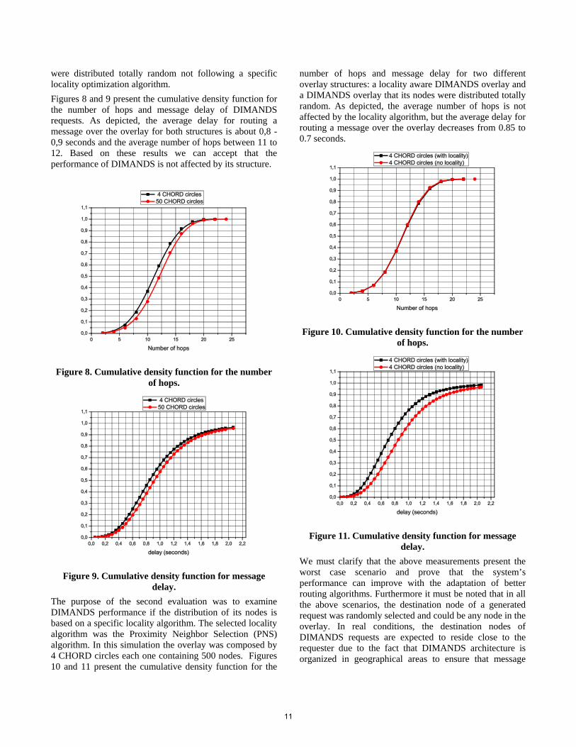
were distributed totally random not following a specific locality optimization algorithm. Figures 8 and 9 present the cumulative density function for the number of hops and message delay of DIMANDS requests. As depicted, the average delay for routing a message over the overlay for both structures is about 0,8 - 0,9 seconds and the average number of hops between 11 to 12. Based on these results we can accept that the performance of DIMANDS is not affected by its structure.
Figure 8. Cumulative density function for the number
of hops.
Figure 9. Cumulative density function for message
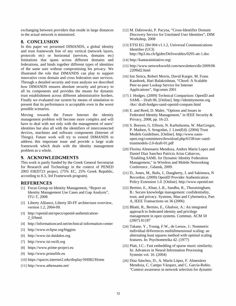
delay. The purpose of the second evaluation was to examine DIMANDS performance if the distribution of its nodes is based on a specific locality algorithm. The selected locality algorithm was the Proximity Neighbor Selection (PNS) algorithm. In this simulation the overlay was composed by 4 CHORD circles each one containing 500 nodes. Figures 10 and 11 present the cumulative density function for the
number of hops and message delay for two different overlay structures: a locality aware DIMANDS overlay and a DIMANDS overlay that its nodes were distributed totally random. As depicted, the average number of hops is not affected by the locality algorithm, but the average delay for routing a message over the overlay decreases from 0.85 to 0.7 seconds.
Figure 10. Cumulative density function for the number
of hops.
Figure 11. Cumulative density function for message
delay. We must clarify that the above measurements present the worst case scenario and prove that the system’s performance can improve with the adaptation of better routing algorithms. Furthermore it must be noted that in all the above scenarios, the destination node of a generated request was randomly selected and could be any node in the overlay. In real conditions, the destination nodes of DIMANDS requests are expected to reside close to the requester due to the fact that DIMANDS architecture is organized in geographical areas to ensure that message
11
exchanging between providers that reside in large distances in the actual network is minimized.
8. CONCLUSION In this paper we presented DIMANDS, a global identity and trust framework free of any vertical (network layers, protocols etc) or horizontal (services, domains etc) limitations that spans across different domains and federations, and binds together different types of identities of the same user without compromising his privacy. We illustrated the role that DIMANDS can play to support innovative cross domain and cross federation user services. Through a detailed security and trust analysis we described how DIMANDS ensures absolute security and privacy to all its components and provides the means for dynamic trust establishment across different administrative borders. Finally we evaluated our system by means of simulation to present that its performance is acceptable even in the worst possible scenarios. Moving towards the Future Internet the identity management problem will become more complex and will have to deal with not only with the management of users’ identities but also all with the identifiers of interconnected devices, machines and software components (Internet of Things). Future work will try to extend DIMANDS to address this important issue and provide a large scale framework which deals with the identity management problem as a whole.
9. ACKNOWLEDGMENTS This work is partly funded by the Greek General Secretariat for Research and Technology in the context of PENED 2003 03ED723 project, (75% EC, 25% Greek Republic, according to 8.3, 3rd Framework program).
REFERENCES [1] Focus Group on Identity Management, “Report on
Identity Management Use Cases and Gap Analysis”, ITU-T, 2008
[2] Liberty Alliance, Liberty ID-FF architecture overview, version 1.2, 2004-09.
[3] http://openid.net/specs/openid-authentication-2_0/html.
[4] http://informationcard.net/technical-information-center [5] http://www.eclipse.org/higgins [6] http://www.ist-daidalos.org [7] http://www.ist-swift.org [8] https://www.prime-project.eu [9] http://www.primelife.eu [10] https://spaces.internet2.edu/display/SHIB2/Home [11] http://www.athensams.net/
[12] M. Dabrowski, P. Pacyna, “Cross-Identifier Domain Discovery Service for Unrelated User Identities”, DIM Workshop, 2008
[13] ETSI EG 284 004 v1.1.2, Universal Communications Identifier (UCI) http://ftp3.itu.ch/fgidm/Deliverables/0295-att-1.doc
[14] http://kantarainitiative.org/ [15] http://www.networkworld.com/newsletters/dir/2009/06
2209id2.html [16] Ion Stoica, Robert Morris, David Karger, M. Frans
Kaashoek, Hari Balakrishnan, “Chord: A Scalable Peer-to-peer Lookup Service for Internet Applications”, Sigcomm 2001
[17] J. Hodges. (2009) Technical Comparison: OpenID and SAML - Draft 06. [Online]. http://identitymeme.org /doc/ draft-hodges-saml-openid-compare.html
[18] E. and Reed, D. Maler, "Options and Issues in Federated Identity Management," in IEEE Security & Privacy, 2008, pp. 16-23.
[19] S. Boeyen, G. Ellison, N. Karhuluoma, W. MacGregor, P. Madsen, S. Sengodan, J. Linn(Ed). (2004) Trust Models Guidelines. [Online]. http://www.oasis-open.org/committees/download.php/6158/sstc-saml-trustmodels-2.0-draft-01.pdf
[20] Florina Almenarez Mendoza, Andres Marin Lopez and Daniel Diaz Sanchez Patricia Arias Cabarcos, "Enabling SAML for Dynamic Identity Federation Management," in Wireless and Mobile Networking Conference , Gdansk, 2009.
[21] D., Jones, M., Bufu, J., Daugherty, J. and Sakimura, N Recordon. (2009) OpenID Provider Authentication Policy Extension 1.0. [Online]. http://www.openid.net
[22] Bertino, E., Khan, L.R., Sandhu, R., Thuraisingham, B.: Secure knowledge management: confidentiality, trust, and privacy. Systems, Man and Cybernetics, Part A, IEEE Transactions on 36 (2006)
[23] Bhatti, R., Bertino, E., Ghafoor, A.: An integrated approach to federated identity and privilege management in open systems. Commun. ACM 50 (2007) 81{87
[24] Takane, Y., Young, F.W., de Leeuw, J.: Nonmetric individual di®erences multidimensional scaling: an alternating least squares method with optimal scaling features. In: Psychometrika 42. (1977)
[25] Platt, J.C.: Fast embedding of sparse music similarity. In: Advances in Neural Information Processing Systems vol. 16. (2004)
[26] Díaz Sánchez, D., A. Marín López, F. Almenárez Mendoza, C. Campo Vázquez, and C. García-Rubio. "Context awareness in network selection for dynamic
12

environments." Journal/Magazine: Telecommunication Systems. Vol:36. Issue: 1 (2007): Pages:49–60
[27] Yan He and Miaoling Zhu. “A complete and efficient strategy based on petri net in automated trust negotiation”. Infoscale, June 2007.
[28] Keith Irwin and Ting Yu. “Preventing attribute information leakage in automated trust negotiation”. CCS'05, 12th ACM conference on Computer and communications security , November 2005.
[29] Jiangtao Li, Ninghui Li, and William H. Winsborough. “Automated trust negotiation using cryptographic credentials”. CCS'05, 12th ACM conference on Computer and communications security, November 2005.
13

14
Hidden VoIP Calling Records from NetworkingIntermediaries
Ge ZhangKarlstad University, Karlstad, Sweden
Stefan BertholdKarlstad University, Karlstad, Sweden
ABSTRACTWhile confidentiality of telephone conversation contents hasrecently received considerable attention in Internet telephony(VoIP), the protection of the caller–callee relation is largelyunexplored. From the privacy research community we learnthat this relation can be protected by Chaum’s mixes. Inearly proposals of mix networks, however, it was reasonableto assume that high latency is acceptable. While the generalidea has been deployed for low latency networks as well, im-portant security measures had to be dropped for achievingperformance. The result is protection against a consider-ably weaker adversary model in exchange for usability. Inthis paper, we show that it is unjustified to conclude thatlow latency network applications imply weak protection. Onthe contrary, we argue that current Internet telephony proto-cols provide a range of promising preconditions for adoptinganonymity services with security properties similar to thoseof high latency anonymity networks. We expect that imple-menting anonymity services becomes a major challenge ascustomer privacy becomes one of the most important sec-ondary goals in any (commercial) Internet application.
Categories and Subject DescriptorsC.2.0 [Computer-Communication Networks]: General—Security and Protection; K.6.5 [Management of Comput-ing and Information Systems]: Security and Protection
General TermsSecurity
KeywordsVoIP, Mixes, Anonymity, Traffic analysis attacks
1. INTRODUCTIONAddressing on the network layer in the Internet is by no
means secure: neither is it a simple task to validate a given
Permission to make digital or hard copies of all or part of this work forpersonal or classroom use is granted without fee provided that copies arenot made or distributed for profit or commercial advantage and that copiesbear this notice and the full citation on the first page. To copy otherwise, torepublish, to post on servers or to redistribute to lists, requires prior specificpermission and/or a fee.IPTComm 2010, 2-3 August, 2010 Munich, GermanyCopyright 2010 ACM ...$10.00.
address, since forking is easy, nor is it simple to hide ad-dresses reliably from network intermediaries, and thus es-tablish anonymity, since explicit addresses are an inherentpart of most Internet protocols. Chaum’s mixes [1] are de-signed to build an anonymity layer upon such protocols. Amix is a forwarding proxy which obfuscates addresses, send-ing and receiving time, and contents of network messages.A typical way of obfuscating the sending or receiving timein high latency applications, such as e-mail (Mixminion [2]),is to wait for several messages arriving at the mix beforeforwarding them all together in random order. However,in low latency protection services (e.g., AN.ON [3], Tor [4],and ISDN-Mixes [5]), delaying messages is no option. Evenfor web mixes, practical experience shows that the packetdelay needs to be close to zero. The smaller the delay ofa packet may be, however, the smaller is the set of pack-ets that can be sent out in random order or lexicographicalorder for practical reason, and thus the higher becomes theprobability of successful traffic analysis attacks. A commonproposal to avoid this kind of attacks is to generate artificialcover traffic in the network, if otherwise the mix does notreceive enough packets.
Voice over IP (VoIP) applications are natural competi-tors of classic public switched telephone network (PSTN),but fall short when it comes to preserving the anonymityof users on the network level, since explicit addresses areused. At first sight, it seems hard to establish an anonymitylayer between network layer and existing VoIP protocols dueto their bandwidth demands and the low latency which isallowed. A few assumptions about the mode of operation,however, allow to create a view on VoIP protocols which isquite appealing for establishing the anonymity layer. Theseassumptions are (1) VoIP media flow is sent in constant rate,(2) it is sent continuously, i. e., silence suppression is not ap-plied, and (3) each media packet is with the equal size, i. e.,a fixed bit rate codec is employed.
In this paper, we perform an analysis of the passive trafficanalysis attacks on VoIP systems, considering both, signal-ing flow and media flow, and moreover demonstrate how toeliminate or equalize the flow patterns to make the attacksmore difficult.
We deem privacy concerns as one of the major hurdles inthe large-scale adoption of VoIP technology. Not only thetelecommunication legislation in many countries declares thetelecommunication contents and the caller-callee relation assensitive data in general, but also companies may specifi-cally worry about business secrets such as confidential nego-tiations, they may allow anonymous whistle-blowing within
15
schmitt
Stempel
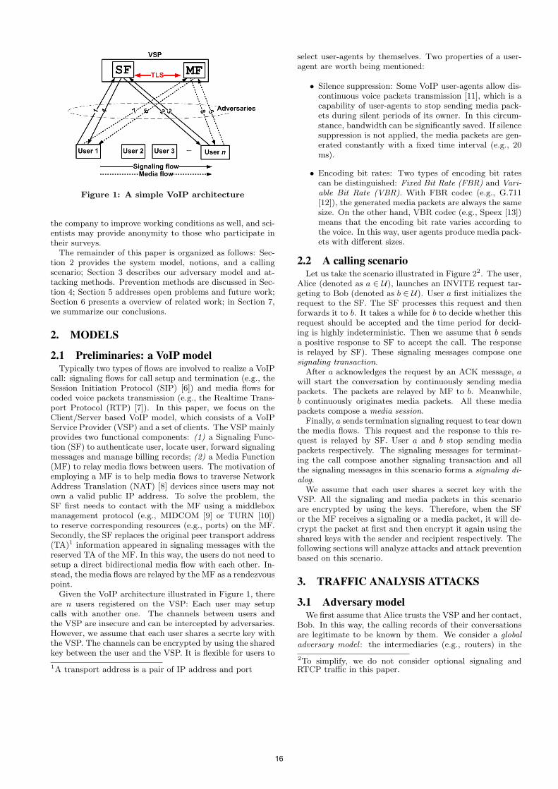
Figure 1: A simple VoIP architecture
the company to improve working conditions as well, and sci-entists may provide anonymity to those who participate intheir surveys.The remainder of this paper is organized as follows: Sec-
tion 2 provides the system model, notions, and a callingscenario; Section 3 describes our adversary model and at-tacking methods. Prevention methods are discussed in Sec-tion 4; Section 5 addresses open problems and future work;Section 6 presents a overview of related work; in Section 7,we summarize our conclusions.
2. MODELS
2.1 Preliminaries: a VoIP modelTypically two types of flows are involved to realize a VoIP
call: signaling flows for call setup and termination (e.g., theSession Initiation Protocol (SIP) [6]) and media flows forcoded voice packets transmission (e.g., the Realtime Trans-port Protocol (RTP) [7]). In this paper, we focus on theClient/Server based VoIP model, which consists of a VoIPService Provider (VSP) and a set of clients. The VSP mainlyprovides two functional components: (1) a Signaling Func-tion (SF) to authenticate user, locate user, forward signalingmessages and manage billing records; (2) a Media Function(MF) to relay media flows between users. The motivation ofemploying a MF is to help media flows to traverse NetworkAddress Translation (NAT) [8] devices since users may notown a valid public IP address. To solve the problem, theSF first needs to contact with the MF using a middleboxmanagement protocol (e.g., MIDCOM [9] or TURN [10])to reserve corresponding resources (e.g., ports) on the MF.Secondly, the SF replaces the original peer transport address(TA)1 information appeared in signaling messages with thereserved TA of the MF. In this way, the users do not need tosetup a direct bidirectional media flow with each other. In-stead, the media flows are relayed by the MF as a rendezvouspoint.Given the VoIP architecture illustrated in Figure 1, there
are n users registered on the VSP: Each user may setupcalls with another one. The channels between users andthe VSP are insecure and can be intercepted by adversaries.However, we assume that each user shares a secrte key withthe VSP. The channels can be encrypted by using the sharedkey between the user and the VSP. It is flexible for users to
1A transport address is a pair of IP address and port
select user-agents by themselves. Two properties of a user-agent are worth being mentioned:
• Silence suppression: Some VoIP user-agents allow dis-continuous voice packets transmission [11], which is acapability of user-agents to stop sending media pack-ets during silent periods of its owner. In this circum-stance, bandwidth can be significantly saved. If silencesuppression is not applied, the media packets are gen-erated constantly with a fixed time interval (e.g., 20ms).
• Encoding bit rates: Two types of encoding bit ratescan be distinguished: Fixed Bit Rate (FBR) and Vari-able Bit Rate (VBR). With FBR codec (e.g., G.711[12]), the generated media packets are always the samesize. On the other hand, VBR codec (e.g., Speex [13])means that the encoding bit rate varies according tothe voice. In this way, user agents produce media pack-ets with different sizes.
2.2 A calling scenarioLet us take the scenario illustrated in Figure 22. The user,
Alice (denoted as a ∈ U), launches an INVITE request tar-geting to Bob (denoted as b ∈ U). User a first initializes therequest to the SF. The SF processes this request and thenforwards it to b. It takes a while for b to decide whether thisrequest should be accepted and the time period for decid-ing is highly indeterministic. Then we assume that b sendsa positive response to SF to accept the call. The responseis relayed by SF). These signaling messages compose onesignaling transaction.
After a acknowledges the request by an ACK message, awill start the conversation by continuously sending mediapackets. The packets are relayed by MF to b. Meanwhile,b continuously originates media packets. All these mediapackets compose a media session.
Finally, a sends termination signaling request to tear downthe media flows. This request and the response to this re-quest is relayed by SF. User a and b stop sending mediapackets respectively. The signaling messages for terminat-ing the call compose another signaling transaction and allthe signaling messages in this scenario forms a signaling di-alog.
We assume that each user shares a secret key with theVSP. All the signaling and media packets in this scenarioare encrypted by using the keys. Therefore, when the SFor the MF receives a signaling or a media packet, it will de-crypt the packet at first and then encrypt it again using theshared keys with the sender and recipient respectively. Thefollowing sections will analyze attacks and attack preventionbased on this scenario.
3. TRAFFIC ANALYSIS ATTACKS
3.1 Adversary modelWe first assume that Alice trusts the VSP and her contact,
Bob. In this way, the calling records of their conversationsare legitimate to be known by them. We consider a globaladversary model : the intermediaries (e.g., routers) in the
2To simplify, we do not consider optional signaling andRTCP traffic in this paper.
16
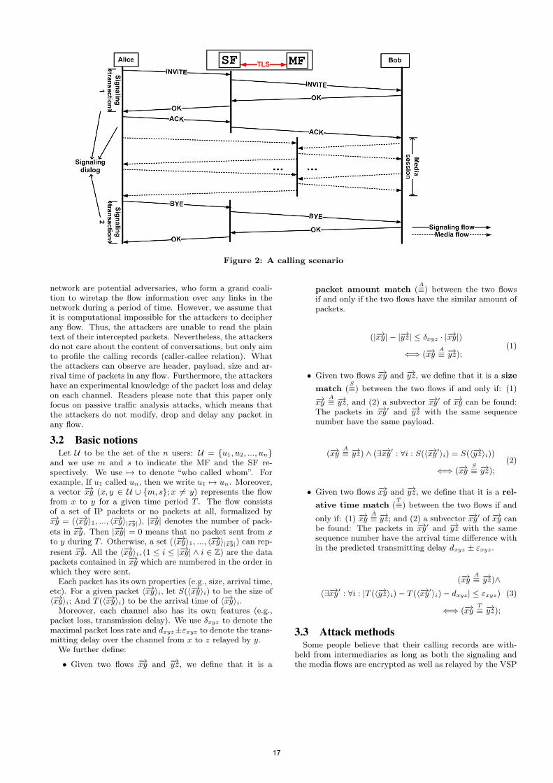
Figure 2: A calling scenario
network are potential adversaries, who form a grand coali-tion to wiretap the flow information over any links in thenetwork during a period of time. However, we assume thatit is computational impossible for the attackers to decipherany flow. Thus, the attackers are unable to read the plaintext of their intercepted packets. Nevertheless, the attackersdo not care about the content of conversations, but only aimto profile the calling records (caller-callee relation). Whatthe attackers can observe are header, payload, size and ar-rival time of packets in any flow. Furthermore, the attackershave an experimental knowledge of the packet loss and delayon each channel. Readers please note that this paper onlyfocus on passive traffic analysis attacks, which means thatthe attackers do not modify, drop and delay any packet inany flow.
3.2 Basic notionsLet U to be the set of the n users: U = {u1, u2, ..., un}
and we use m and s to indicate the MF and the SF re-spectively. We use 7→ to denote “who called whom”. Forexample, If u1 called un, then we write u1 7→ un. Moreover,a vector −→xy (x, y ∈ U ∪ {m, s};x = y) represents the flowfrom x to y for a given time period T . The flow consistsof a set of IP packets or no packets at all, formalized by−→xy = (⟨−→xy⟩1, ..., ⟨−→xy⟩|−→xy|), |−→xy| denotes the number of pack-
ets in −→xy. Then |−→xy| = 0 means that no packet sent from xto y during T . Otherwise, a set (⟨−→xy⟩1, ..., ⟨−→xy⟩|−→xy|) can rep-
resent −→xy. All the ⟨−→xy⟩i, (1 ≤ i ≤ |−→xy| ∧ i ∈ Z) are the datapackets contained in −→xy which are numbered in the order inwhich they were sent.Each packet has its own properties (e.g., size, arrival time,
etc). For a given packet ⟨−→xy⟩i, let S(⟨−→xy⟩i) to be the size of⟨−→xy⟩i; And T (⟨−→xy⟩i) to be the arrival time of ⟨−→xy⟩i.Moreover, each channel also has its own features (e.g.,
packet loss, transmission delay). We use δxyz to denote themaximal packet loss rate and dxyz±εxyz to denote the trans-mitting delay over the channel from x to z relayed by y.We further define:
• Given two flows −→xy and −→yz, we define that it is a
packet amount match (A≡) between the two flows
if and only if the two flows have the similar amount ofpackets.
(|−→xy| − |−→yz| ≤ δxyz · |−→xy|)
⇐⇒ (−→xyA≡ −→yz);
(1)
• Given two flows −→xy and −→yz, we define that it is a size
match (S≡) between the two flows if and only if: (1)
−→xyA≡ −→yz, and (2) a subvector −→xy′ of −→xy can be found:
The packets in −→xy′ and −→yz with the same sequencenumber have the same payload.
(−→xyA≡ −→yz) ∧ (∃−→xy′ : ∀i : S(⟨−→xy′⟩i) = S(⟨−→yz⟩i))
⇐⇒ (−→xyS≡ −→yz);
(2)
• Given two flows −→xy and −→yz, we define that it is a rel-
ative time match (T≡) between the two flows if and
only if: (1) −→xyA≡ −→yz; and (2) a subvector −→xy′ of −→xy can
be found: The packets in −→xy′ and −→yz with the samesequence number have the arrival time difference within the predicted transmitting delay dxyz ± εxyz.
(−→xyA≡ −→yz)∧
(∃−→xy′ : ∀i : |T (⟨−→yz⟩i)− T (⟨−→xy′⟩i)− dxyz| ≤ εxyz)
⇐⇒ (−→xyT≡ −→yz);
(3)
3.3 Attack methodsSome people believe that their calling records are with-
held from intermediaries as long as both the signaling andthe media flows are encrypted as well as relayed by the VSP
17
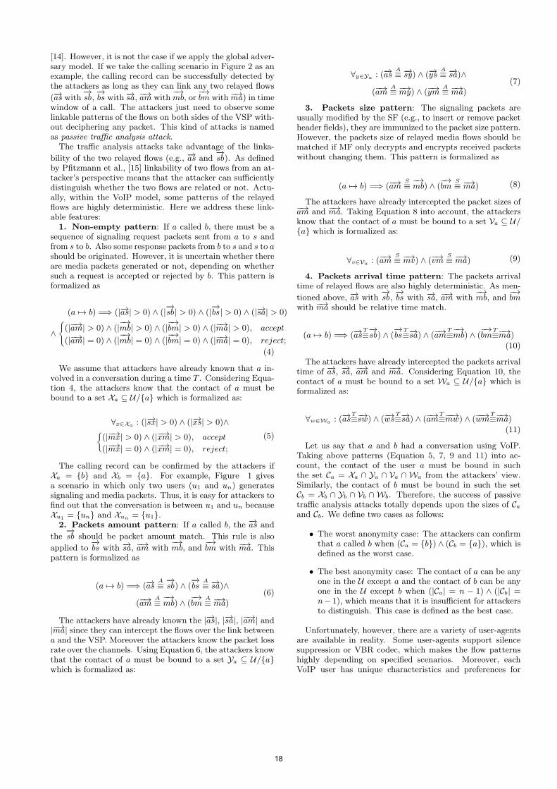
[14]. However, it is not the case if we apply the global adver-sary model. If we take the calling scenario in Figure 2 as anexample, the calling record can be successfully detected bythe attackers as long as they can link any two relayed flows
(−→as with−→sb,
−→bs with −→sa, −→am with
−→mb, or
−→bm with −→ma) in time
window of a call. The attackers just need to observe somelinkable patterns of the flows on both sides of the VSP with-out deciphering any packet. This kind of attacks is namedas passive traffic analysis attack.The traffic analysis attacks take advantage of the linka-
bility of the two relayed flows (e.g., −→as and−→sb). As defined
by Pfitzmann et al., [15] linkability of two flows from an at-tacker’s perspective means that the attacker can sufficientlydistinguish whether the two flows are related or not. Actu-ally, within the VoIP model, some patterns of the relayedflows are highly deterministic. Here we address these link-able features:1. Non-empty pattern: If a called b, there must be a
sequence of signaling request packets sent from a to s andfrom s to b. Also some response packets from b to s and s to ashould be originated. However, it is uncertain whether thereare media packets generated or not, depending on whethersuch a request is accepted or rejected by b. This pattern isformalized as
(a 7→ b) =⇒ (|−→as| > 0) ∧ (|−→sb| > 0) ∧ (|
−→bs| > 0) ∧ (|−→sa| > 0)
∧®(|−→am| > 0) ∧ (|
−→mb| > 0) ∧ (|
−→bm| > 0) ∧ (|−→ma| > 0), accept
(|−→am| = 0) ∧ (|−→mb| = 0) ∧ (|
−→bm| = 0) ∧ (|−→ma| = 0), reject;
(4)
We assume that attackers have already known that a in-volved in a conversation during a time T . Considering Equa-tion 4, the attackers know that the contact of a must bebound to a set Xa ⊆ U/{a} which is formalized as:
∀x∈Xa : (|−→sx| > 0) ∧ (|−→xs| > 0)∧ß(|−→mx| > 0) ∧ (|−→xm| > 0), accept
(|−→mx| = 0) ∧ (|−→xm| = 0), reject;
(5)
The calling record can be confirmed by the attackers ifXa = {b} and Xb = {a}. For example, Figure 1 givesa scenario in which only two users (u1 and un) generatessignaling and media packets. Thus, it is easy for attackers tofind out that the conversation is between u1 and un becauseXu1 = {un} and Xun = {u1}.2. Packets amount pattern: If a called b, the −→as and
the−→sb should be packet amount match. This rule is also
applied to−→bs with −→sa, −→am with
−→mb, and
−→bm with −→ma. This
pattern is formalized as
(a 7→ b) =⇒ (−→asA≡
−→sb) ∧ (
−→bs
A≡ −→sa)∧
(−→amA≡
−→mb) ∧ (
−→bm
A≡ −→ma)
(6)
The attackers have already known the |−→as|, |−→sa|, |−→am| and|−→ma| since they can intercept the flows over the link betweena and the VSP. Moreover the attackers know the packet lossrate over the channels. Using Equation 6, the attackers knowthat the contact of a must be bound to a set Ya ⊆ U/{a}which is formalized as:
∀y∈Ya : (−→asA≡ −→sy) ∧ (−→ys
A≡ −→sa)∧
(−→amA≡ −→my) ∧ (−→ym
A≡ −→ma)
(7)
3. Packets size pattern: The signaling packets areusually modified by the SF (e.g., to insert or remove packetheader fields), they are immunized to the packet size pattern.However, the packets size of relayed media flows should bematched if MF only decrypts and encrypts received packetswithout changing them. This pattern is formalized as
(a 7→ b) =⇒ (−→amS≡
−→mb) ∧ (
−→bm
S≡ −→ma) (8)
The attackers have already intercepted the packet sizes of−→am and −→ma. Taking Equation 8 into account, the attackersknow that the contact of a must be bound to a set Va ⊆ U/{a} which is formalized as:
∀v∈Va : (−→amS≡ −→mv) ∧ (−→vm
S≡ −→ma) (9)
4. Packets arrival time pattern: The packets arrivaltime of relayed flows are also highly deterministic. As men-
tioned above, −→as with−→sb,
−→bs with −→sa, −→am with
−→mb, and
−→bm
with −→ma should be relative time match.
(a 7→ b) =⇒ (−→asT≡−→sb) ∧ (
−→bs
T≡−→sa) ∧ (−→am
T≡−→mb) ∧ (
−→bm
T≡−→ma)
(10)
The attackers have already intercepted the packets arrivaltime of −→as, −→sa, −→am and −→ma. Considering Equation 10, thecontact of a must be bound to a set Wa ⊆ U/{a} which isformalized as:
∀w∈Wa : (−→asT≡−→sw) ∧ (−→ws
T≡−→sa) ∧ (−→am
T≡−−→mw) ∧ (−−→wm
T≡−→ma)
(11)
Let us say that a and b had a conversation using VoIP.Taking above patterns (Equation 5, 7, 9 and 11) into ac-count, the contact of the user a must be bound in suchthe set Ca = Xa ∩ Ya ∩ Va ∩ Wa from the attackers’ view.Similarly, the contact of b must be bound in such the setCb = Xb ∩ Yb ∩ Vb ∩ Wb. Therefore, the success of passivetraffic analysis attacks totally depends upon the sizes of Ca
and Cb. We define two cases as follows:
• The worst anonymity case: The attackers can confirmthat a called b when (Ca = {b}) ∧ (Cb = {a}), which isdefined as the worst case.
• The best anonymity case: The contact of a can be anyone in the U except a and the contact of b can be anyone in the U except b when (|Ca| = n − 1) ∧ (|Cb| =n− 1), which means that it is insufficient for attackersto distinguish. This case is defined as the best case.
Unfortunately, however, there are a variety of user-agentsare available in reality. Some user-agents support silencesuppression or VBR codec, which makes the flow patternshighly depending on specified scenarios. Moreover, eachVoIP user has unique characteristics and preferences for
18
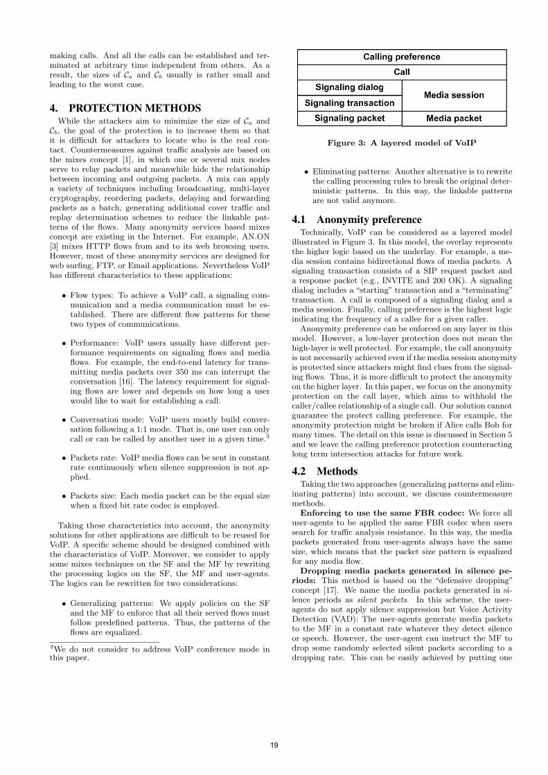
making calls. And all the calls can be established and ter-minated at arbitrary time independent from others. As aresult, the sizes of Ca and Cb usually is rather small andleading to the worst case.
4. PROTECTION METHODSWhile the attackers aim to minimize the size of Ca and
Cb, the goal of the protection is to increase them so thatit is difficult for attackers to locate who is the real con-tact. Countermeasures against traffic analysis are based onthe mixes concept [1], in which one or several mix nodesserve to relay packets and meanwhile hide the relationshipbetween incoming and outgoing packets. A mix can applya variety of techniques including broadcasting, multi-layercryptography, reordering packets, delaying and forwardingpackets as a batch, generating additional cover traffic andreplay determination schemes to reduce the linkable pat-terns of the flows. Many anonymity services based mixesconcept are existing in the Internet. For example, AN.ON[3] mixes HTTP flows from and to its web browsing users.However, most of these anonymity services are designed forweb surfing, FTP, or Email applications. Nevertheless VoIPhas different characteristics to these applications:
• Flow types: To achieve a VoIP call, a signaling com-munication and a media communication must be es-tablished. There are different flow patterns for thesetwo types of communications.
• Performance: VoIP users usually have different per-formance requirements on signaling flows and mediaflows. For example, the end-to-end latency for trans-mitting media packets over 350 ms can interrupt theconversation [16]. The latency requirement for signal-ing flows are lower and depends on how long a userwould like to wait for establishing a call.
• Conversation mode: VoIP users mostly build conver-sation following a 1:1 mode. That is, one user can onlycall or can be called by another user in a given time.3
• Packets rate: VoIP media flows can be sent in constantrate continuously when silence suppression is not ap-plied.
• Packets size: Each media packet can be the equal sizewhen a fixed bit rate codec is employed.
Taking these characteristics into account, the anonymitysolutions for other applications are difficult to be reused forVoIP. A specific scheme should be designed combined withthe characteristics of VoIP. Moreover, we consider to applysome mixes techniques on the SF and the MF by rewritingthe processing logics on the SF, the MF and user-agents.The logics can be rewritten for two considerations:
• Generalizing patterns: We apply policies on the SFand the MF to enforce that all their served flows mustfollow predefined patterns. Thus, the patterns of theflows are equalized.
3We do not consider to address VoIP conference mode inthis paper.
Figure 3: A layered model of VoIP
• Eliminating patterns: Another alternative is to rewritethe calling processing rules to break the original deter-ministic patterns. In this way, the linkable patternsare not valid anymore.
4.1 Anonymity preferenceTechnically, VoIP can be considered as a layered model
illustrated in Figure 3. In this model, the overlay representsthe higher logic based on the underlay. For example, a me-dia session contains bidirectional flows of media packets. Asignaling transaction consists of a SIP request packet anda response packet (e.g., INVITE and 200 OK). A signalingdialog includes a “starting” transaction and a “terminating”transaction. A call is composed of a signaling dialog and amedia session. Finally, calling preference is the highest logicindicating the frequency of a callee for a given caller.
Anonymity preference can be enforced on any layer in thismodel. However, a low-layer protection does not mean thehigh-layer is well protected. For example, the call anonymityis not necessarily achieved even if the media session anonymityis protected since attackers might find clues from the signal-ing flows. Thus, it is more difficult to protect the anonymityon the higher layer. In this paper, we focus on the anonymityprotection on the call layer, which aims to withhold thecaller/callee relationship of a single call. Our solution cannotguarantee the protect calling preference. For example, theanonymity protection might be broken if Alice calls Bob formany times. The detail on this issue is discussed in Section 5and we leave the calling preference protection counteractinglong term intersection attacks for future work.
4.2 MethodsTaking the two approaches (generalizing patterns and elim-
inating patterns) into account, we discuss countermeasuremethods.
Enforcing to use the same FBR codec: We force alluser-agents to be applied the same FBR codec when userssearch for traffic analysis resistance. In this way, the mediapackets generated from user-agents always have the samesize, which means that the packet size pattern is equalizedfor any media flow.
Dropping media packets generated in silence pe-riods: This method is based on the “defensive dropping”concept [17]. We name the media packets generated in si-lence periods as silent packets. In this scheme, the user-agents do not apply silence suppression but Voice ActivityDetection (VAD): The user-agents generate media packetsto the MF in a constant rate whatever they detect silenceor speech. However, the user-agent can instruct the MF todrop some randomly selected silent packets according to adropping rate. This can be easily achieved by putting one
19
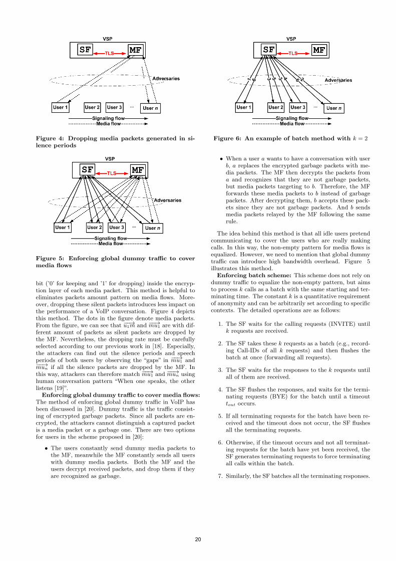
Figure 4: Dropping media packets generated in si-lence periods
Figure 5: Enforcing global dummy traffic to covermedia flows
bit (’0’ for keeping and ’1’ for dropping) inside the encryp-tion layer of each media packet. This method is helpful toeliminates packets amount pattern on media flows. More-over, dropping these silent packets introduces less impact onthe performance of a VoIP conversation. Figure 4 depictsthis method. The dots in the figure denote media packets.From the figure, we can see that −−→u1m and −−→mu1 are with dif-ferent amount of packets as silent packets are dropped bythe MF. Nevertheless, the dropping rate must be carefullyselected according to our previous work in [18]. Especially,the attackers can find out the silence periods and speechperiods of both users by observing the “gaps” in −−→mu1 and−−→mun if all the silence packets are dropped by the MF. Inthis way, attackers can therefore match −−→mu1 and −−→mun usinghuman conversation pattern “When one speaks, the otherlistens [19]”.Enforcing global dummy traffic to cover media flows:
The method of enforcing global dummy traffic in VoIP hasbeen discussed in [20]. Dummy traffic is the traffic consist-ing of encrypted garbage packets. Since all packets are en-crypted, the attackers cannot distinguish a captured packetis a media packet or a garbage one. There are two optionsfor users in the scheme proposed in [20]:
• The users constantly send dummy media packets tothe MF, meanwhile the MF constantly sends all userswith dummy media packets. Both the MF and theusers decrypt received packets, and drop them if theyare recognized as garbage.
Figure 6: An example of batch method with k = 2
• When a user a wants to have a conversation with userb, a replaces the encrypted garbage packets with me-dia packets. The MF then decrypts the packets froma and recognizes that they are not garbage packets,but media packets targeting to b. Therefore, the MFforwards these media packets to b instead of garbagepackets. After decrypting them, b accepts these pack-ets since they are not garbage packets. And b sendsmedia packets relayed by the MF following the samerule.
The idea behind this method is that all idle users pretendcommunicating to cover the users who are really makingcalls. In this way, the non-empty pattern for media flows isequalized. However, we need to mention that global dummytraffic can introduce high bandwidth overhead. Figure 5illustrates this method.
Enforcing batch scheme: This scheme does not rely ondummy traffic to equalize the non-empty pattern, but aimsto process k calls as a batch with the same starting and ter-minating time. The constant k is a quantitative requirementof anonymity and can be arbitrarily set according to specificcontexts. The detailed operations are as follows:
1. The SF waits for the calling requests (INVITE) untilk requests are received.
2. The SF takes these k requests as a batch (e.g., record-ing Call-IDs of all k requests) and then flushes thebatch at once (forwarding all requests).
3. The SF waits for the responses to the k requests untilall of them are received.
4. The SF flushes the responses, and waits for the termi-nating requests (BYE) for the batch until a timeouttout occurs.
5. If all terminating requests for the batch have been re-ceived and the timeout does not occur, the SF flushesall the terminating requests.
6. Otherwise, if the timeout occurs and not all terminat-ing requests for the batch have yet been received, theSF generates terminating requests to force terminatingall calls within the batch.
7. Similarly, the SF batches all the terminating responses.
20
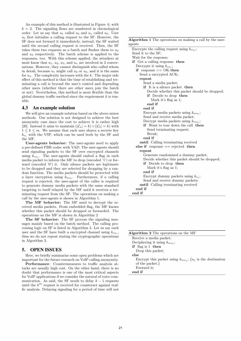
An example of this method is illustrated in Figure 6, withk = 2. The signaling flows are numbered in chronologicalorder. Let us say that u1 called u2 and un called u3. Useru1 first initialize a calling request to the SF. However, theSF does not forward it immediately, instead, the SF waiteduntil the second calling request is received. Then, the SFtakes these two requests as a batch and flushes them to u2
and u3 respectively. The batch scheme is applied to theresponses, too. With this scheme applied, the attackers atmost know that u1, u2, u3, and un are involved in 2 conver-sations. However, they cannot distinguish who called whomin detail, because u1 might call u2 or u3, and it is the samefor un. The complexity increases with the k. The major sideeffect of this method is that the time of establishing and ter-minating a call is beyond the user’s control and dependingother users (whether there are other users join the batchor not). Nevertheless, this method is more flexible than theglobal dummy traffic method since the requirement k is tun-able.
4.3 An example solutionWe will give an example solution based on the above mixes
methods. Our solution is not designed to achieve the bestanonymity case since the cost to achieve it is rather high[20]. Instead it aims to maintain (|Ca| = k)∨ (|Cb| = k) with1 ≤ k ≤ m. We assume that each user shares a secrete keykui with the VSP, which can be used both by the SF andthe MF.User-agents behavior: The user-agents need to apply
a pre-defined FBR codec with VAD. The user-agents shouldsend signaling packets to the SF over encrypted channelsusing ksui . The user-agents should embed a flag in eachmedia packet to inform the MF to drop (encoded ’1’) or for-ward (encoded ’0’) it. Only silence packets are legitimateto be dropped and they are selected for dropping by a ran-dom function. The media packets should be protected witha layer encryption using kmui . Furthermore, if a callingrequest is rejected, the user-agent of the caller is requiredto generate dummy media packets with the same standardtargeting to itself relayed by the MF until it receives a ter-minating request from the SF. The operations on making acall by the user-agents is shown in Algorithm 1.The MF behavior: The MF need to decrypt the re-
ceived media packets. From embedded flag, the MF knowswhether this packet should be dropped or forwarded. Theoperations on the MF is shown in Algorithm 2The SF behavior: The SF process the signaling mes-
sages mainly based on the batch method. The calling pro-cessing logic on SF is listed in Algorithm 3. Let us say eachuser and the SF have built a encrypted channel using ksui ,thus we do not repeat stating the cryptographic operationsin Algorithm 3.
5. OPEN ISSUESHere, we briefly summarize some open problems which are
important for the future research on VoIP calling anonymity.Performance: Countermeasures to traffic analysis at-
tacks are usually high cost. On the other hand, there is nodoubt that performance is one of the most critical aspectsfor VoIP applications if we consider the natural of voice com-munication. As said, the SF needs to delay k − 1 requestsuntil the kth request is received for counteract against traf-fic analysis. Delaying signaling for a period of time will not
Algorithm 1 The operations on making a call by the user-agents
Encrypts the calling request using ksui ;Send it to the SF;Wait for the response;if Get a calling response then
Decrypts it using ksui ;if response == OK then
Send a encrypted ACK;repeat
Send a media packet;if It is a silence packet then
Decide whether this packet should be dropped;if Decide to drop then
Mark it’s flag as 1;end if
end ifEncrypt media packets using kmui ;Send and receive media packet;Decrypt media packets using kmui ;if Want to tear down the call then
Send terminating request;Break;
end ifuntil Calling terminating received
else if response == rejected thenrepeat
Generate randomized a dummy packet;Decide whether this packet should be dropped;if Decide to drop then
Mark it’s flag as 1;end ifEncrypt dummy packets using kui ;Send and receive dummy packets;
until Calling terminating receivedend if
end if
Algorithm 2 The operations on the MF
Receive a media packet;Deciphering it using kmui ;if flag is 1 then
Drop this packet;else
Encrypt this packet using kmuj ; {uj is the destinationof the packet.}Forward it;
end if
21
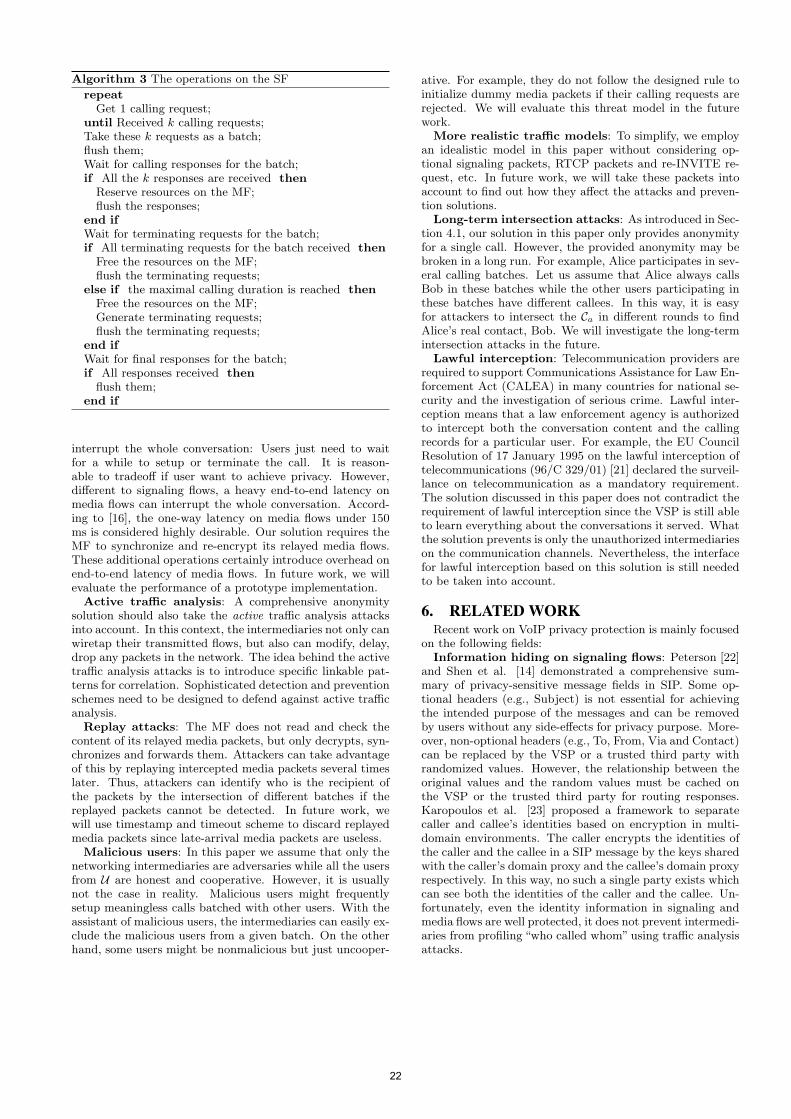
Algorithm 3 The operations on the SF
repeatGet 1 calling request;
until Received k calling requests;Take these k requests as a batch;flush them;Wait for calling responses for the batch;if All the k responses are received then
Reserve resources on the MF;flush the responses;
end ifWait for terminating requests for the batch;if All terminating requests for the batch received then
Free the resources on the MF;flush the terminating requests;
else if the maximal calling duration is reached thenFree the resources on the MF;Generate terminating requests;flush the terminating requests;
end ifWait for final responses for the batch;if All responses received then
flush them;end if
interrupt the whole conversation: Users just need to waitfor a while to setup or terminate the call. It is reason-able to tradeoff if user want to achieve privacy. However,different to signaling flows, a heavy end-to-end latency onmedia flows can interrupt the whole conversation. Accord-ing to [16], the one-way latency on media flows under 150ms is considered highly desirable. Our solution requires theMF to synchronize and re-encrypt its relayed media flows.These additional operations certainly introduce overhead onend-to-end latency of media flows. In future work, we willevaluate the performance of a prototype implementation.Active traffic analysis: A comprehensive anonymity
solution should also take the active traffic analysis attacksinto account. In this context, the intermediaries not only canwiretap their transmitted flows, but also can modify, delay,drop any packets in the network. The idea behind the activetraffic analysis attacks is to introduce specific linkable pat-terns for correlation. Sophisticated detection and preventionschemes need to be designed to defend against active trafficanalysis.Replay attacks: The MF does not read and check the
content of its relayed media packets, but only decrypts, syn-chronizes and forwards them. Attackers can take advantageof this by replaying intercepted media packets several timeslater. Thus, attackers can identify who is the recipient ofthe packets by the intersection of different batches if thereplayed packets cannot be detected. In future work, wewill use timestamp and timeout scheme to discard replayedmedia packets since late-arrival media packets are useless.Malicious users: In this paper we assume that only the
networking intermediaries are adversaries while all the usersfrom U are honest and cooperative. However, it is usuallynot the case in reality. Malicious users might frequentlysetup meaningless calls batched with other users. With theassistant of malicious users, the intermediaries can easily ex-clude the malicious users from a given batch. On the otherhand, some users might be nonmalicious but just uncooper-
ative. For example, they do not follow the designed rule toinitialize dummy media packets if their calling requests arerejected. We will evaluate this threat model in the futurework.
More realistic traffic models: To simplify, we employan idealistic model in this paper without considering op-tional signaling packets, RTCP packets and re-INVITE re-quest, etc. In future work, we will take these packets intoaccount to find out how they affect the attacks and preven-tion solutions.
Long-term intersection attacks: As introduced in Sec-tion 4.1, our solution in this paper only provides anonymityfor a single call. However, the provided anonymity may bebroken in a long run. For example, Alice participates in sev-eral calling batches. Let us assume that Alice always callsBob in these batches while the other users participating inthese batches have different callees. In this way, it is easyfor attackers to intersect the Ca in different rounds to findAlice’s real contact, Bob. We will investigate the long-termintersection attacks in the future.
Lawful interception: Telecommunication providers arerequired to support Communications Assistance for Law En-forcement Act (CALEA) in many countries for national se-curity and the investigation of serious crime. Lawful inter-ception means that a law enforcement agency is authorizedto intercept both the conversation content and the callingrecords for a particular user. For example, the EU CouncilResolution of 17 January 1995 on the lawful interception oftelecommunications (96/C 329/01) [21] declared the surveil-lance on telecommunication as a mandatory requirement.The solution discussed in this paper does not contradict therequirement of lawful interception since the VSP is still ableto learn everything about the conversations it served. Whatthe solution prevents is only the unauthorized intermediarieson the communication channels. Nevertheless, the interfacefor lawful interception based on this solution is still neededto be taken into account.
6. RELATED WORKRecent work on VoIP privacy protection is mainly focused
on the following fields:Information hiding on signaling flows: Peterson [22]
and Shen et al. [14] demonstrated a comprehensive sum-mary of privacy-sensitive message fields in SIP. Some op-tional headers (e.g., Subject) is not essential for achievingthe intended purpose of the messages and can be removedby users without any side-effects for privacy purpose. More-over, non-optional headers (e.g., To, From, Via and Contact)can be replaced by the VSP or a trusted third party withrandomized values. However, the relationship between theoriginal values and the random values must be cached onthe VSP or the trusted third party for routing responses.Karopoulos et al. [23] proposed a framework to separatecaller and callee’s identities based on encryption in multi-domain environments. The caller encrypts the identities ofthe caller and the callee in a SIP message by the keys sharedwith the caller’s domain proxy and the callee’s domain proxyrespectively. In this way, no such a single party exists whichcan see both the identities of the caller and the callee. Un-fortunately, even the identity information in signaling andmedia flows are well protected, it does not prevent intermedi-aries from profiling “who called whom” using traffic analysisattacks.
22
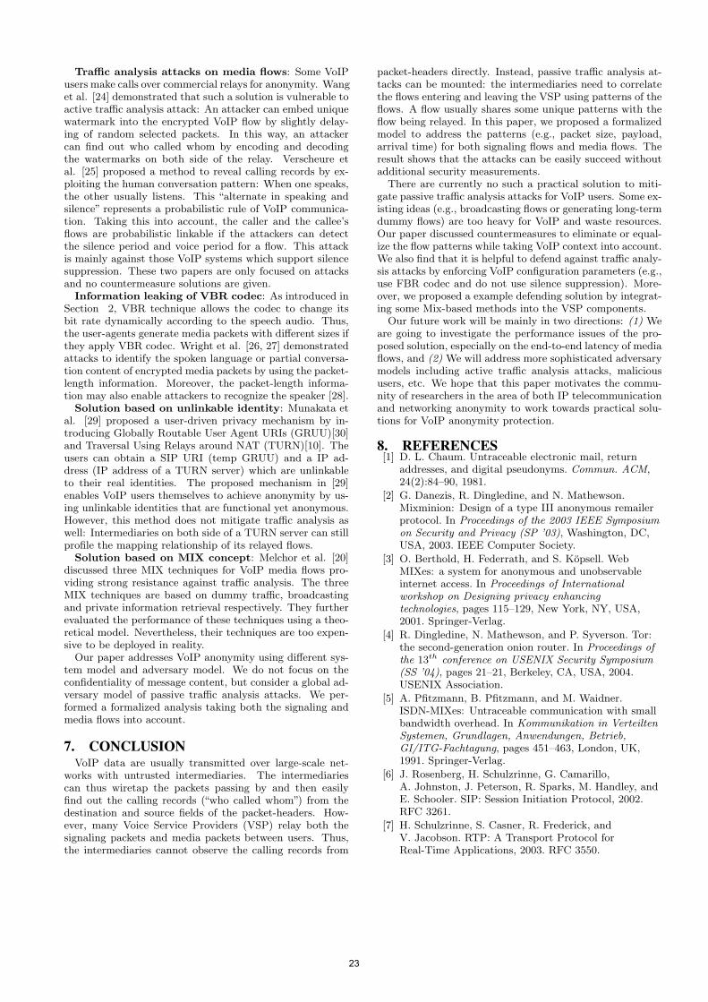
Traffic analysis attacks on media flows: Some VoIPusers make calls over commercial relays for anonymity. Wanget al. [24] demonstrated that such a solution is vulnerable toactive traffic analysis attack: An attacker can embed uniquewatermark into the encrypted VoIP flow by slightly delay-ing of random selected packets. In this way, an attackercan find out who called whom by encoding and decodingthe watermarks on both side of the relay. Verscheure etal. [25] proposed a method to reveal calling records by ex-ploiting the human conversation pattern: When one speaks,the other usually listens. This “alternate in speaking andsilence” represents a probabilistic rule of VoIP communica-tion. Taking this into account, the caller and the callee’sflows are probabilistic linkable if the attackers can detectthe silence period and voice period for a flow. This attackis mainly against those VoIP systems which support silencesuppression. These two papers are only focused on attacksand no countermeasure solutions are given.Information leaking of VBR codec: As introduced in
Section 2, VBR technique allows the codec to change itsbit rate dynamically according to the speech audio. Thus,the user-agents generate media packets with different sizes ifthey apply VBR codec. Wright et al. [26, 27] demonstratedattacks to identify the spoken language or partial conversa-tion content of encrypted media packets by using the packet-length information. Moreover, the packet-length informa-tion may also enable attackers to recognize the speaker [28].Solution based on unlinkable identity: Munakata et
al. [29] proposed a user-driven privacy mechanism by in-troducing Globally Routable User Agent URIs (GRUU)[30]and Traversal Using Relays around NAT (TURN)[10]. Theusers can obtain a SIP URI (temp GRUU) and a IP ad-dress (IP address of a TURN server) which are unlinkableto their real identities. The proposed mechanism in [29]enables VoIP users themselves to achieve anonymity by us-ing unlinkable identities that are functional yet anonymous.However, this method does not mitigate traffic analysis aswell: Intermediaries on both side of a TURN server can stillprofile the mapping relationship of its relayed flows.Solution based on MIX concept: Melchor et al. [20]
discussed three MIX techniques for VoIP media flows pro-viding strong resistance against traffic analysis. The threeMIX techniques are based on dummy traffic, broadcastingand private information retrieval respectively. They furtherevaluated the performance of these techniques using a theo-retical model. Nevertheless, their techniques are too expen-sive to be deployed in reality.Our paper addresses VoIP anonymity using different sys-
tem model and adversary model. We do not focus on theconfidentiality of message content, but consider a global ad-versary model of passive traffic analysis attacks. We per-formed a formalized analysis taking both the signaling andmedia flows into account.
7. CONCLUSIONVoIP data are usually transmitted over large-scale net-
works with untrusted intermediaries. The intermediariescan thus wiretap the packets passing by and then easilyfind out the calling records (“who called whom”) from thedestination and source fields of the packet-headers. How-ever, many Voice Service Providers (VSP) relay both thesignaling packets and media packets between users. Thus,the intermediaries cannot observe the calling records from
packet-headers directly. Instead, passive traffic analysis at-tacks can be mounted: the intermediaries need to correlatethe flows entering and leaving the VSP using patterns of theflows. A flow usually shares some unique patterns with theflow being relayed. In this paper, we proposed a formalizedmodel to address the patterns (e.g., packet size, payload,arrival time) for both signaling flows and media flows. Theresult shows that the attacks can be easily succeed withoutadditional security measurements.
There are currently no such a practical solution to miti-gate passive traffic analysis attacks for VoIP users. Some ex-isting ideas (e.g., broadcasting flows or generating long-termdummy flows) are too heavy for VoIP and waste resources.Our paper discussed countermeasures to eliminate or equal-ize the flow patterns while taking VoIP context into account.We also find that it is helpful to defend against traffic analy-sis attacks by enforcing VoIP configuration parameters (e.g.,use FBR codec and do not use silence suppression). More-over, we proposed a example defending solution by integrat-ing some Mix-based methods into the VSP components.
Our future work will be mainly in two directions: (1) Weare going to investigate the performance issues of the pro-posed solution, especially on the end-to-end latency of mediaflows, and (2) We will address more sophisticated adversarymodels including active traffic analysis attacks, malicioususers, etc. We hope that this paper motivates the commu-nity of researchers in the area of both IP telecommunicationand networking anonymity to work towards practical solu-tions for VoIP anonymity protection.
8. REFERENCES[1] D. L. Chaum. Untraceable electronic mail, return
addresses, and digital pseudonyms. Commun. ACM,24(2):84–90, 1981.
[2] G. Danezis, R. Dingledine, and N. Mathewson.Mixminion: Design of a type III anonymous remailerprotocol. In Proceedings of the 2003 IEEE Symposiumon Security and Privacy (SP ’03), Washington, DC,USA, 2003. IEEE Computer Society.
[3] O. Berthold, H. Federrath, and S. Kopsell. WebMIXes: a system for anonymous and unobservableinternet access. In Proceedings of Internationalworkshop on Designing privacy enhancingtechnologies, pages 115–129, New York, NY, USA,2001. Springer-Verlag.
[4] R. Dingledine, N. Mathewson, and P. Syverson. Tor:the second-generation onion router. In Proceedings ofthe 13th conference on USENIX Security Symposium(SS ’04), pages 21–21, Berkeley, CA, USA, 2004.USENIX Association.
[5] A. Pfitzmann, B. Pfitzmann, and M. Waidner.ISDN-MIXes: Untraceable communication with smallbandwidth overhead. In Kommunikation in VerteiltenSystemen, Grundlagen, Anwendungen, Betrieb,GI/ITG-Fachtagung, pages 451–463, London, UK,1991. Springer-Verlag.
[6] J. Rosenberg, H. Schulzrinne, G. Camarillo,A. Johnston, J. Peterson, R. Sparks, M. Handley, andE. Schooler. SIP: Session Initiation Protocol, 2002.RFC 3261.
[7] H. Schulzrinne, S. Casner, R. Frederick, andV. Jacobson. RTP: A Transport Protocol forReal-Time Applications, 2003. RFC 3550.
23
[8] K. Egevang and P. Francis. The IP Network AddressTranslator (NAT), 1994. RFC 1631.
[9] P. Srisuresh, J. Kuthan, J. Rosenberg, A. Molitor, andA. Rayhan. Middlebox communication architectureand framework, 2002. RFC 3303.
[10] J. Rosenberg, R. Mahy, and P. Matthews. Traversalusing relays around nat (TURN): Relay extensions tosession traversal utilities for NAT (STUN), 2010. RFC5766.
[11] R. Zopf. Real-time Transport Protocol (RTP) Payloadfor Comfort Noise (CN), 2002. RFC 3389.
[12] G.711. http://www.itu.int/rec/T-REC-G.711/e,visited at 21th-Oct-2009.
[13] Speex. http://www.speex.org/, visited at21th-Oct-2009.
[14] S. Chen, X. Wang, and S. Jajodia. On the anonymityand traceability of peer-to-peer VoIP calls. Network,IEEE, 20(5):32–37, 2006.
[15] A. Pfitzmann and M. Hansen. Anonymity,unlinkability, undetectability, unobservability,pseudonymity, and identity management - aconsolidated proposal for terminology. Technicalreport, February 2008.
[16] ITU-T. Recommendation G.114 - One-wayTransmission Time, 2003.
[17] B. N. Levine, M. K. Reiter, C. Wang, and M. Wright.Timing attacks in low-latency mix systems (extendedabstract). In FC ’04: Proceedings of the 8th
international conference on Financial Cryptography,pages 251–265, Berlin, Heidelberg, 2004.Springer-Verlag.
[18] G. Zhang and S. Fischer-Hubner. Peer-to-peer VoIPcommunications using anonymisation overlaynetworks. In Proceedings of the 11th Conference onCommunications and Multimedia Security (CMS ’10),Linz, Austria, 2010. Springer-Verlag.
[19] M. Vlachos, A. Anagnostopoulos, O. Verscheure, andP. S. Yu. Online pairing of VoIP conversations. TheVLDB Journal, 18(1):77–98, 2009.
[20] C. A. Melchor, Y. Deswarte, and J. Iguchi-Cartigny.Closed-circuit unobservable Voice over IP. InProceedings of the 23rd Annual Computer SecurityApplications Conference (ACSAC ’07), pages 119–128,Los Alamitos, CA, USA, 2007. IEEE ComputerSociety.
[21] Council Resolution of 17 January 1995 on the lawfulinterception of telecommunications. http://eur-lex.europa.eu/LexUriServ/LexUriServ.do?uri=CELEX:31996G1104:EN:HTML, visited at 21th-Jun-2010.
[22] J. Peterson. A Privacy Mechanism for the SessionInitiation Protocol (SIP), 2002. RFC 3323.
[23] G. Karopoulos, G. Kambourakis, S. Gritzalis, andE. Konstantinou. A framework for identity privacy inSIP. J. Netw. Comput. Appl., 33(1):16–28, 2010.
[24] X. Wang, S. Chen, and S. Jajodia. Trackinganonymous peer-to-peer VoIP calls on the Internet. InProceedings of the 12th ACM conference on Computerand communications security (CCS ’05), pages 81–91,New York, NY, USA, 2005. ACM.
[25] O. Verscheure, M. Vlachos, A. Anagnostopoulos,P. Frossard, E. Bouillet, and P. S. Yu. Finding ”who is
talking to whom” in VoIP networks via progressivestream clustering. In Proceedings of the SixthInternational Conference on Data Mining (ICDM’06), pages 667–677, Washington, DC, USA, 2006.IEEE Computer Society.
[26] C. V. Wright, L. Ballard, F. Monrose, and G. M.Masson. Language identification of encrypted VoIPtraffic: Alejandra y Roberto or Alice and Bob? InProceedings of 16th USENIX Security Symposium onUSENIX Security Symposium (SS ’07), pages 1–12,Berkeley, CA, USA, 2007. USENIX Association.
[27] C. V. Wright, L. Ballard, S. E. Coull, F. Monrose, andG. M. Masson. Spot me if you can: Uncovering spokenphrases in encrypted VoIP conversations. InProceedings of the 2008 IEEE Symposium on Securityand Privacy (SP ’08), pages 35–49, Washington, DC,USA, 2008. IEEE Computer Society.
[28] L.A. Khan, M.S. Baig, and A. M. Youssef. Speakerrecognition from encrypted VoIP communications.Digital Investigation, In Press, Elsvier, 2009.
[29] M. Munakata, S. Schubert, and T. Ohba.User-agent-driven privacy mechanism for SIP, 2010.RFC 5767.
[30] J. Rosenberg. Obtaining and using globally routableuser agent uris (GRUUs) in the session initiationprotocol (SIP), 2009. RFC 5627.
24
Work in Progress: Inter-Domain and DoS-Resistant CallEstablishment Protocol (IDDR-CEP)
Patrick Battistello∗
Orange Labs2 av. Pierre Marzin, 22307 Lannion, France
ABSTRACTVoIP security is a tricky issue in inter-domain open contextwhere interconnection proxies are reachable from anywhereon the public Internet and may be the subject of DoS andSPIT attacks. This paper proposes a secure call establish-ment protocol designed for this context with a particularfocus on DoS protection. The mechanism performs sessionkey agreement in the signalling plane and can be integratedto SIP call establishment. It is based on symmetric cryp-tography algorithms and implicit transaction identifiers toprotect against DoS attacks. We provide heuristic analy-sis of various security properties among which privacy andresistance to off-line passive attacks. The IDDR-CEP pro-tocol is presented in a three party architecture but can beadapted to a two party architecture; it may also be adaptedto non-VoIP applications.
Categories and Subject DescriptorsC.2.0 [Computer Systems Organization]: Computer-Communication Networks—General, Security and Protec-tion
General TermsSecurity
KeywordsVoIP, security, inter-domain, DoS-resistant, call establish-ment, key agreement, authentication, privacy, SPIT, token,ticket, Kerberos
1. INTRODUCTIONVoIP has become a major technology, both for residentialand professional customers. It enables voice and data inte-gration along with new services (notification, presence, Web-Phone, ClickToPhone,...). On the other hand, VoIP raisesnew issues amongst which the security of communications[6], which is the subject of this paper.
∗Also temporally affiliated to Telcom Bretagne, France.
IPTComm 2010, 2-3 August, 2010 Munich, Germany
1.1 BackgroundThree main architectures can be found in VoIP networks.First the initial architecture1 which comes from the incum-bent telco operators and is a flat centralized architecturebased on registrar and proxy servers. Secondly, the P2Parchitecture which distributes the registrar and proxy func-tions over a set of nodes and combines the DHT (DistributedHash Table) concepts with usual VoIP protocols as describedin [12]. Finally, theWEB architecture which brings the VoIPendpoint directly in the client’s WEB browser thus leadingto the WebPhone and ClickToPhone concepts. Among thevarious protocols for VoIP, SIP [24] has become the funda-mental signalling brick in association with SDP for sessiondescription and RTP for conveying the media flows. Fur-ther in this article, we will use the SIP-INVITE request toindicate the beginning of the call establishment process.
1.2 Current stakes in VoIP securitySeveral threats have been pointed out in many studies like[6], [2], [10], [13] but their impact strongly depends on thecontext, especially intra-domain or inter-domain contexts.
In the intra-domain context, VoIP communications remainconfined in the same administrative domain, whatever theunderlying network architecture2. Each user endpoint is au-thenticated by a unique identifier (ID) and the operatorproxies usually stand in the call signalling path. Becauseof these characteristics, specific VoIP risks are limited toDoS and SPIT (SPam over Ip Telephony). DoS risks comefrom the protocols complexity and the need to maintain callcontext. SPIT originates from (possibly compromised) soft-phones thus primarily in VoIP P2P and WEB architecturesbut now also in incumbent operator architectures with newmobile endpoints.
The threats become higher in the inter-domain context whereseveral of the previous architectures are interconnected; anexhaustive taxonomy is provided in [17]. However, the risklevel depends on the chosen interconnection approach.
A first approach, noted open model hereafter, assumes thatIP connectivity between endpoints, proxies or domains andDNS lookup are sufficient to establish multimedia commu-nications, just like the e-mail model. The first major issuehere is that VoIP identifiers are designed to convey a domain
1In reference to the first ITU-T and IETF VoIP standards.2However interconnection with PSTN is not precluded.
25
schmitt
Stempel
part but, as explained in [23], because of the huge hard-phone installed base and of the PSTN predominance, mostVoIP calls originate from, or terminate in, a PSTN cloud.Consequently, caller (or callee) identifiers lack the domainpart, so inter-domain calls are tricky to route and vice versato verify. Where a public-ENUM-like system3 would solvethis problem, it is foreseen in [23] that such a solution isunlikely to appear in the public domain. The second majorissue is the accumulation of DoS and SPIT risks over theinterconnection points which is called the ”pinhole problem”in [23] and is very similar to the e-mail vulnerabilities.
An alternative approach, noted closed model or private fed-erations hereafter, is based on a contractual agreement be-tween a set of operators to share a secure interconnection ar-chitecture. The IMS (IP Multimedia Subsystem) standards[1] define such an architecture with secure links (IPSec)between domains and network topology hiding to protectagainst DoS attacks towards the interconnection proxies.The phone number problem is solved by sharing securelyE.164 information between the operators.
Finally, a very recent approach VIPR [23] proposes an hy-brid model combining VoIP, P2P and PSTN components.In brief, it relies on PSTN call information to build securerouting and authentication information which are then usedto place direct VoIP calls.
1.3 Problem statementIt is unlikely that VoIP calls remain confined in intra-domaincontext, although it offers the highest security. For inter-domain calls, the closed model reproduces the PSTN prin-ciples and is expected to reach comparable security. How-ever, its architecture is not designed for ”any-to-any” spo-radic communications between domains (like the e-mail ar-chitecture). Therefore, we anticipate that this model willcoexist with open model or hybrid model where the securityrisks are much higher because VoIP proxys are reachablefrom anywhere on the public Internet and also because ofthe difficulty to route and verify the E.164 call identifiers.
As explained in section 2, the current solutions available foropen or hybrid model show some limitations. Consequently,we identify the need for a secure call establishment protocolfor inter-domain context which addresses these issues andtakes into account the VoIP specificities, especially: its real-time nature and the regulatory constraints4 which may havea strong impact on deployment [11]. It should also meet the”usual”security requirements of key establishment protocols:mutual authentication, session key freshness, access control,privacy, DoS protection, Perfect Forward Secrecy (PFS) andanti-replay5. The key freshness requirement is taken in itsbroader scope meaning a new session key shall be establishedat each new call. The PFS requirement shall apply to bothpassive off-line attacks (like password guessing) and compro-mission attacks where the adversary has obtained the longterm secrets of one or several parties; under these hypoth-esis the adversary shall still not be able to recover any of
3ENUM stands for E.164 to Uniform Resource Identifiers.4Especially the capability to disclose session keys when re-quired by legal procedure.5The reader is referred to [7] for a more detailed definitionand illustration of theses requirements.
the past session keys. It is assumed that the adversary hasall the required capabilities for protocol interaction (messageinterception, tampering, replay, forging or deletion) and maybe also an insider as described in [7].
The remaining of this article is organized as follows: sec-tion 2 analyses the related work in VoIP secure call estab-lishment. In section 3, we provide the specifications of theIDDR-CEP protocol. Section 4 shows some possible imple-mentation of this protocol in a VoIP context. Finally, section5 provides the discussion and the conclusions.
2. RELATED WORK2.1 Authentication and key establishmentAs often done in the litterature [7], we associate in this sec-tion the authentication and key establishment aspects. TheE.164 call identifiers problematic is also implicitely associ-ated to the authentication phase. We consider mainly au-thentication between VoIP domains, assuming each domainis responsible for authenticating its own endpoints.
The first possible solution is the use of TLS (or DTLS orIPSec) on a hop-by-hop basis with inter-domain authenti-cation. Once the secure link is established, the session keycan be transported in the SIP-INVITE request by using SDPspecific security parameters [4]. In addition to the analysisprovided in [9], this approach does not solve the E.164 iden-tifiers problematic and it does not meet the PFS (PerfectForward Secrecy) requirement since compromission of a pri-vate key will expose all the previous session keys. Also, itis unclear how an inbound proxy facing the public Internetwould behave in case of a DoS attack at the TLS level.
The SIP Identity protocol [22] supports end-to-end authen-tication of the calling domain by adding a digital signaturein the SIP-INVITE request. Called domain authenticationcan be supported in return with the extension defined in[8]. The overall solution supports neither privacy nor keyestablishment (because the SIP-INVITE request is not en-crypted). Also, as explained in [9], this mechanism seemsvulnerable to DoS attacks if the called domain is floodedwith spoofed requests containing invalid signatures. TheSIP Identity protocol was also proposed in conjunction withthe E.164-RRC (Return Routability Check) mechanism [26]to perform E.164 caller ID verification. The main idea wasto return a verification request towards the E.164 callingnumber with a random token (nonce) to be signed. Un-fortunately, this verification phase assumes that the E.164
routing problematic has been solved previously.
More recently, the VIPR proposal [23] claims to solve thephone number routing problem by combining VoIP, P2P andPSTN technologies. It requires that each domain joins aglobal open P2P network and publishes in the DHT the listof its phone identifiers and at least one of its VoIP proxy.Once an inter-domain PSTN call is completed, if the callednumber can be found in the DHT, the calling domain con-tacts the called domain and obtains a ”cryptographic calltoken” bounded to the specific called number and specificcalling domain, along with SIP routing information to placedirect VoIP calls in the future. While this mechanism offersan incremental approach, we envision some limitations: thecalled endpoint has no guarantee that the calling number
26
has not been spoofed, each domain has to store potentiallya large number of tokens and besides all it requires PSTNendlessly. Actually, each time a token validity has expiredor a new destination is being called, a PSTN verification isrequired. Even worse, if a signature key gets compromised,the process involving PSTN shall be repeated for all the pre-viously issued tokens. It should be noted that some VIPRideas were previously proposed in [20] where authenticationtokens are also inserted by the caller in the SIP-INVITE re-quests. The constraints (token storage and security) arealmost the same since the tokens have a long-term validity.
Another approach, still in the signalling plane, is MIKEY[5] which can be integrated into the VoIP SIP call establish-ment6 and supports three authentication modes: pre-sharedkey (PSK), public key (PKI) or Diffie-Hellman (DH) ex-change. Recently, a new MIKEY mode denoted KMS wasproposed in [14]. It is a ticket-based approach with a trustedthird party, inspired from Kerberos [16], which can also beintegrated into the VoIP call establishment and addressesthe call forking specificity. According to [9], the MIKEYprotocol is subject to DoS attack and we anticipate the sameissue with KMS extension7. Also, except for MIKEY-DH,the PFS security property is not met since the other modesuse session key transportation.
Specific inter-domain protocols were also proposed for au-thentication and key exchange. Among them, [27] is a four-party protocol organized in three tiers, using identity-basedcryptography and secret public keys. While this protocolprovides PFS and resistance against off-line and active at-tacks, it may not be resistant to DoS attacks since a singlefake message from sender A will generate a total of 6 mes-sages from both the responder B, the domain server SB andthe domain server SA. Another inter-domain protocol isproposed in [21]; it is based on an improved proxy ElGamalencryption scheme which enables two users in two distinctdomains to exchange a cipher text through a proxy serverin each domain. This scheme assumes that a shared inter-domain key KDM1,DM2 is set up; consequently PFS is notachieved because if this key is compromised all the previousexchanges are revealed.
Session key establishment may also be performed in the me-dia plane with the ZRTP [29] or DTLS-SRTP [15] protocols.Operating the key exchange in the media plane may conflictwith regulatory requirement of key disclosure and, as ex-plained in [9], this does not save the need for a securityinfrastructure at the signalling plane in most of the cases.
2.2 DoS protectionSeveral DoS-resistant protocols have been proposed with thecommon attempt to limit resources consumption by the re-sponder at the very first step. For this purpose, a cookie isoften returned by the responder and has to be acknowledgedby the originator. This is done for example in [3] where thecookie includes the initiator information and the responder’scurrent exponential. Although the responder does not com-mit memory resources at the very first step, it still has to
6It does not require prior establishment of a secure link.7This is because the receiver has no means to check theticket validity prior to contacting the KMS.
return a message to the initiator and compute one exponen-tiation each time a spoofed initiation message is received.Even worse, if the adversary acknowledges the cookie, theresponder has to verify a fake public-key signature on thethird message. The same analysis and conclusions hold for[25] where the responder can still not authenticate the firstinitiator message thus exposing him to DoS attack in sub-sequent messages.
An alternative approach is described in IPACF [28] whereeach message conveys an access filter value which is ”trivial”to check. This filter value is updated at each new frame andit depends on a shared secret key established between theserver and each client. When the server receives a framewith a valid filter value, it responds to the client with a newresponder filter value and updates the client filter value forthe next frame; the same process holds for the client. Thismechanism also provides user privacy by sending a pseudo-ID which is user specific and changes at each frame. How-ever, it is unclear how the protocol behaves if one (or several)frames are lost or disordered and whether strictly bidirec-tional exchange has to be maintained between the server andeach client.
3. PROTOCOL SPECIFICATIONS3.1 General overview and technical noveltyStarting from the architectural view, and the simplified case,the protocol runs between entities A and B. Entity A is theinitiator, that is the caller or calling entity in a VoIP con-text. It may be the user endpoint itself or a proxy actingon its behalf which is able to authenticate the caller iden-tity IDA. Entity B is the responder, that is the callee orthe called entity. It may be the user endpoint itself or aproxy acting on its behalf which is able to authenticate thecallee identity IDB . Entities A and B share a secret fromwhich they can perform secure transactions. Since installingshared secrets between each couple of entities is not scalable,an intermediary server S is involved in the general case. En-tity S is responsible for authenticating A and B and takespart in each transaction from A to B, provided it receivesa valid transaction request from A. This means that S isonline and has shared-secrets KAS and KSB with respec-tively entities A and B. A protocol transaction is definedas the set of IDDR-CEP messages leading to the receipt byB of the Authenticated Message (AM) related to the origi-nal message (MES) held by A. Finally, S is responsible forperforming phone number routing and verification betweendomains when necessary. This design choice comes fromthe previous statements that phone number authenticationalways requires a trusted third party; in VIPR [23] this is ex-plicitly the PSTN network whereas with e164-RRC [26] thisis SIP routing and thus implicitly some kind of underlyingPSTN routing.
This architectural setting is similar to Kerberos, but the pro-tocol is different and it brings several properties that Ker-beros is lacking: PFS is achieved even if KAS and KSB arecompromised, the protocol is DoS resistant and the size ofthe final message from A to B is not expanded significantly.This last property is achieved because no key transporta-tion is used and consequently the UDP transport can bepreserved. As detailed in section 4, this three party archi-tecture is quite flexible because entities A and B can be
27
from different domains or from the same domain; the roam-ing situation where entity A or B is in a visited domain isalso supported. Finally, entity S may be located in a thirddomain or in the calling domain or in the called domain. Therest of the description keeps the general three entities casebut it can be easily adapted to the simplified two entitiescase by assuming A = S.
There are two ways to integrate this protocol with VoIP.The first one is when the (final) IDDR-CEP AuthenticatedMessage (AM) is a SIP-INVITE request conveying the secu-rity information. This ”on-top” approach is illustrated in allthe implementation examples given in section 4. The sec-ond way is to consider IDDR-CEP as a key establishmentprotocol in itself. In that case, the Authenticated Message(AM) is the first (and only) message required from A to Bfor authentication and key agreement. This alternative ap-proach may be used to set-up a secure link for exchangingVoIP trafic; it is not further described in this paper.
The DoS resistant property is achieved mainly by using sym-metric cryptographic algorithms (for both entities authenti-cation and key agreement) and by inserting an identificationvalue TRIDN in each AMmessage. This identification value(also called token) serves for filtering purposes on the respon-der side (B entity). It can be checked straightaway by Bentity by comparing the received value to the pre-computed(expected) value. Consequently, any AM message with in-valid TRIDN value is immediately discarded and also, sincethe filter value changes at each transaction, the responderis protected from replay attacks. The B entity is also pro-tected from blind attacks because it is not engaged in anyprocessing (cryptographic computation, context handling ormessage generation) before a valid TRIDN value is detected.This contrasts with protocols like SIP Identity [22], Kerberos[16] or MIKEY [5] where the responder has to perform atleast one cryptographic operation before further processingof the message.
From this perspective, IDDR-CEP follows the same filter-ing principle as the IPACF protocol [28] and extends itsusability from the access to the inter-domain area. How-ever, the TRIDN value also serves as a transaction identi-fier among a possible set of transactions (called a transac-tion window) thus achieving two properties which seem tobe lacking in IPACF: the handling of transactions loss or dis-ordering. More precisely, the TRIDN value is the result of aone-way cryptographic function which depends on the cur-rent transaction index N maintained by the responder. Thevalue of N is kept secret and only its public image TRIDN
is sent as a reference to the current transaction index.
Finally, the DoS protection is increased by the structure ofthe protocol exchange. Unlike KMS [14] where B has tocontact the trusted third-party (S) for checking each mes-sage it received from A and for obtaining the session key,in IDDR-CEP the responder B can retreive all the crypto-graphic material from the single message sent by A. Moreprecisely, the session key KAB,N between A and B is es-tablished with a key agreement scheme: it is pre-computedby B as a function of the current transaction index N andtherefore it is uniquely identified from the received TRIDN
value. This approach contrasts with several protocols like
TLS, Kerberos, MIKEY or KMS where the (encrypted) ses-sion key is provided to the responder by the initiator or bya trusted third party. The first benefit is that the final AMmessage sent to B is much shorter. Moreover, this removesthe risk of off-line passive attacks since no encrypted key istransported to B.
As a summary, the IDDR-CEP approach improves the prop-erties of both Kerberos and IPACF protocols by adding re-spectively the DoS protection, the PFS property and thesupport for transaction loss or disordering. Other securityproperties are achieved as explained at the end of this sec-tion.
3.2 Definitions and notationsTRIDN : public image (or identifier) of transaction index N .This identifier shall depend (at least) on the value N andbe the result of a cryptographic function such that knowingany number of TRIDN−i(i ≥ 0) identifiers it is impossible todetermine either N or any of the following TRIDN+j(j > 0)identifier 8.
KAB,N : the session key shared between A and B after com-pleting transaction of index N . This key shall depend (atleast) on N and KSB and be the result of a cryptographicfunction such that knowing KAB,N and N it is impossibleto infer KSB .
H(V ): hash of value V whereH is a cryptographically secureone-way hash function.
MACK(V ): Message Authentication Code applied to mes-sage V and based on key K.
{V }K : encryption of value V using symmetric key K.
V1 ⊕ V2: the result of V1 XOR V2.
|| or , : concatenation operator.
len(V ): binary length of value V .
[V ]: optional value V .
trunc(V, n): the n leftmost bits of value V .
3.3 Operations on the responder sideThis section describes the operations between entities S andB assuming the shared secret KSB has been previously es-tablished. Along with the shared secret, entities S and Bagree on the initial transaction index N0 which shall also bekept secret. From the shared secret KSB and the currenttransaction index N , entities S and B simultaneously derivethe TRIDN and KAB,N values associated to this transac-tion (cf. section 3.2). An additionnal key KSB,N,MAC isalso derived from N and KSB through a cryptographic func-tion such that knowing KSB,N,MAC and N it is impossibleto infer KSB . The KSB,N,MAC symmetric key is used forauthentication and integrity protection of information sentfrom S to B.
8In this context, and further on, impossible means ”compu-tationaly non-feasible with non-negligible probability”.
28
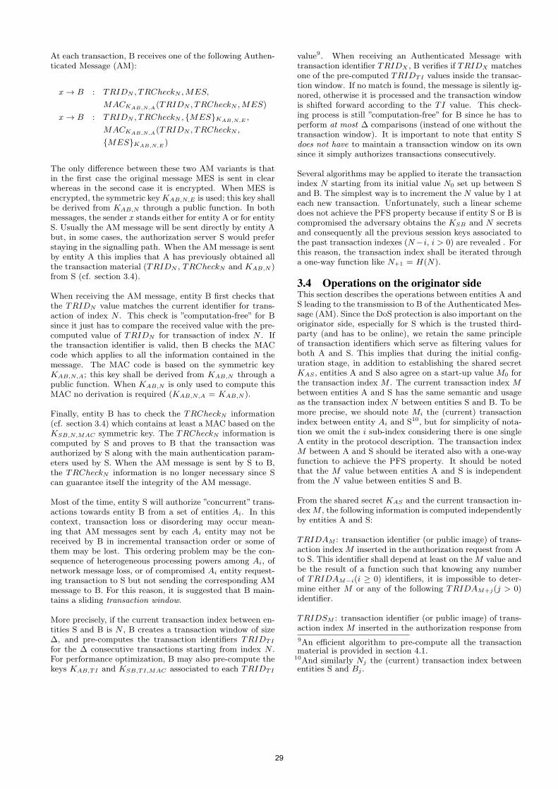
At each transaction, B receives one of the following Authen-ticated Message (AM):
x → B : TRIDN , TRCheckN ,MES,
MACKAB,N,A(TRIDN , TRCheckN ,MES)
x → B : TRIDN , TRCheckN , {MES}KAB,N,E ,
MACKAB,N,A(TRIDN , TRCheckN ,
{MES}KAB,N,E )
The only difference between these two AM variants is thatin the first case the original message MES is sent in clearwhereas in the second case it is encrypted. When MES isencrypted, the symmetric keyKAB,N,E is used; this key shallbe derived from KAB,N through a public function. In bothmessages, the sender x stands either for entity A or for entityS. Usually the AM message will be sent directly by entity Abut, in some cases, the authorization server S would preferstaying in the signalling path. When the AM message is sentby entity A this implies that A has previously obtained allthe transaction material (TRIDN , TRCheckN and KAB,N )from S (cf. section 3.4).
When receiving the AM message, entity B first checks thatthe TRIDN value matches the current identifier for trans-action of index N . This check is ”computation-free” for Bsince it just has to compare the received value with the pre-computed value of TRIDN for transaction of index N . Ifthe transaction identifier is valid, then B checks the MACcode which applies to all the information contained in themessage. The MAC code is based on the symmetric keyKAB,N,A; this key shall be derived from KAB,N through apublic function. When KAB,N is only used to compute thisMAC no derivation is required (KAB,N,A = KAB,N ).
Finally, entity B has to check the TRCheckN information(cf. section 3.4) which contains at least a MAC based on theKSB,N,MAC symmetric key. The TRCheckN information iscomputed by S and proves to B that the transaction wasauthorized by S along with the main authentication param-eters used by S. When the AM message is sent by S to B,the TRCheckN information is no longer necessary since Scan guarantee itself the integrity of the AM message.
Most of the time, entity S will authorize ”concurrent” trans-actions towards entity B from a set of entities Ai. In thiscontext, transaction loss or disordering may occur mean-ing that AM messages sent by each Ai entity may not bereceived by B in incremental transaction order or some ofthem may be lost. This ordering problem may be the con-sequence of heterogeneous processing powers among Ai, ofnetwork message loss, or of compromised Ai entity request-ing transaction to S but not sending the corresponding AMmessage to B. For this reason, it is suggested that B main-tains a sliding transaction window.
More precisely, if the current transaction index between en-tities S and B is N , B creates a transaction window of size∆, and pre-computes the transaction identifiers TRIDTI
for the ∆ consecutive transactions starting from index N .For performance optimization, B may also pre-compute thekeys KAB,TI and KSB,TI,MAC associated to each TRIDTI
value9. When receiving an Authenticated Message withtransaction identifier TRIDX , B verifies if TRIDX matchesone of the pre-computed TRIDTI values inside the transac-tion window. If no match is found, the message is silently ig-nored, otherwise it is processed and the transaction windowis shifted forward according to the TI value. This check-ing process is still ”computation-free” for B since he has toperform at most ∆ comparisons (instead of one without thetransaction window). It is important to note that entity Sdoes not have to maintain a transaction window on its ownsince it simply authorizes transactions consecutively.
Several algorithms may be applied to iterate the transactionindex N starting from its initial value N0 set up between Sand B. The simplest way is to increment the N value by 1 ateach new transaction. Unfortunately, such a linear schemedoes not achieve the PFS property because if entity S or B iscompromised the adversary obtains the KSB and N secretsand consequently all the previous session keys associated tothe past transaction indexes (N−i, i > 0) are revealed . Forthis reason, the transaction index shall be iterated througha one-way function like N+1 = H(N).
3.4 Operations on the originator sideThis section describes the operations between entities A andS leading to the transmission to B of the Authenticated Mes-sage (AM). Since the DoS protection is also important on theoriginator side, especially for S which is the trusted third-party (and has to be online), we retain the same principleof transaction identifiers which serve as filtering values forboth A and S. This implies that during the initial config-uration stage, in addition to establishing the shared secretKAS , entities A and S also agree on a start-up value M0 forthe transaction index M . The current transaction index Mbetween entities A and S has the same semantic and usageas the transaction index N between entities S and B. To bemore precise, we should note Mi the (current) transactionindex between entity Ai and S10, but for simplicity of nota-tion we omit the i sub-index considering there is one singleA entity in the protocol description. The transaction indexM between A and S should be iterated also with a one-wayfunction to achieve the PFS property. It should be notedthat the M value between entities A and S is independentfrom the N value between entities S and B.
From the shared secret KAS and the current transaction in-dexM , the following information is computed independentlyby entities A and S:
TRIDAM : transaction identifier (or public image) of trans-action index M inserted in the authorization request from Ato S. This identifier shall depend at least on the M value andbe the result of a function such that knowing any numberof TRIDAM−i(i ≥ 0) identifiers, it is impossible to deter-mine either M or any of the following TRIDAM+j(j > 0)identifier.
TRIDSM : transaction identifier (or public image) of trans-action index M inserted in the authorization response from
9An efficient algorithm to pre-compute all the transactionmaterial is provided in section 4.1.
10And similarly Nj the (current) transaction index betweenentities S and Bj .
29
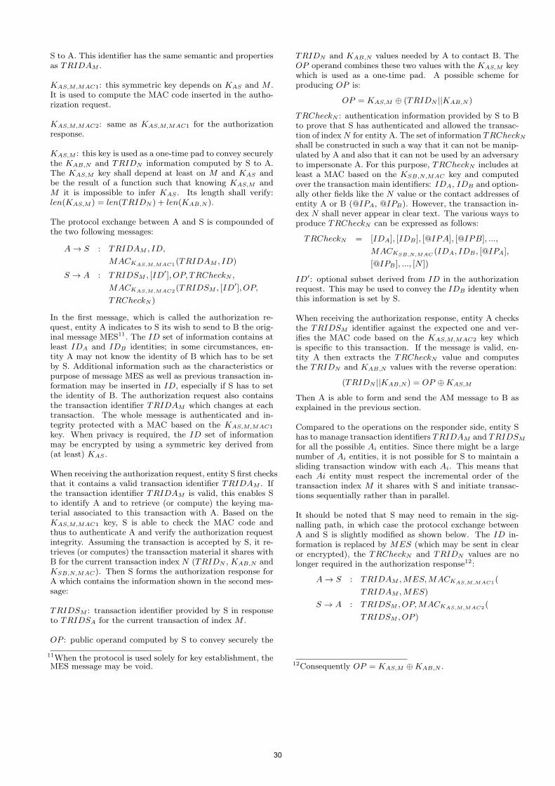
S to A. This identifier has the same semantic and propertiesas TRIDAM .
KAS,M,MAC1: this symmetric key depends on KAS and M .It is used to compute the MAC code inserted in the autho-rization request.
KAS,M,MAC2: same as KAS,M,MAC1 for the authorizationresponse.
KAS,M : this key is used as a one-time pad to convey securelythe KAB,N and TRIDN information computed by S to A.The KAS,M key shall depend at least on M and KAS andbe the result of a function such that knowing KAS,M andM it is impossible to infer KAS . Its length shall verify:len(KAS,M ) = len(TRIDN ) + len(KAB,N ).
The protocol exchange between A and S is compounded ofthe two following messages:
A → S : TRIDAM , ID,
MACKAS,M,MAC1(TRIDAM , ID)
S → A : TRIDSM , [ID′], OP, TRCheckN ,
MACKAS,M,MAC2(TRIDSM , [ID′], OP,
TRCheckN )
In the first message, which is called the authorization re-quest, entity A indicates to S its wish to send to B the orig-inal message MES11. The ID set of information contains atleast IDA and IDB identities; in some circumstances, en-tity A may not know the identity of B which has to be setby S. Additional information such as the characteristics orpurpose of message MES as well as previous transaction in-formation may be inserted in ID, especially if S has to setthe identity of B. The authorization request also containsthe transaction identifier TRIDAM which changes at eachtransaction. The whole message is authenticated and in-tegrity protected with a MAC based on the KAS,M,MAC1
key. When privacy is required, the ID set of informationmay be encrypted by using a symmetric key derived from(at least) KAS .
When receiving the authorization request, entity S first checksthat it contains a valid transaction identifier TRIDAM . Ifthe transaction identifier TRIDAM is valid, this enables Sto identify A and to retrieve (or compute) the keying ma-terial associated to this transaction with A. Based on theKAS,M,MAC1 key, S is able to check the MAC code andthus to authenticate A and verify the authorization requestintegrity. Assuming the transaction is accepted by S, it re-trieves (or computes) the transaction material it shares withB for the current transaction index N (TRIDN , KAB,N andKSB,N,MAC). Then S forms the authorization response forA which contains the information shown in the second mes-sage:
TRIDSM : transaction identifier provided by S in responseto TRIDSA for the current transaction of index M .
OP : public operand computed by S to convey securely the
11When the protocol is used solely for key establishment, theMES message may be void.
TRIDN and KAB,N values needed by A to contact B. TheOP operand combines these two values with the KAS,M keywhich is used as a one-time pad. A possible scheme forproducing OP is:
OP = KAS,M ⊕ (TRIDN ||KAB,N )
TRCheckN : authentication information provided by S to Bto prove that S has authenticated and allowed the transac-tion of indexN for entity A. The set of information TRCheckNshall be constructed in such a way that it can not be manip-ulated by A and also that it can not be used by an adversaryto impersonate A. For this purpose, TRCheckN includes atleast a MAC based on the KSB,N,MAC key and computedover the transaction main identifiers: IDA, IDB and option-ally other fields like the N value or the contact addresses ofentity A or B (@IPA, @IPB). However, the transaction in-dex N shall never appear in clear text. The various ways toproduce TRCheckN can be expressed as follows:
TRCheckN = [IDA], [IDB ], [@IPA], [@IPB], ...,
MACKSB,N,MAC (IDA, IDB , [@IPA],
[@IPB ], ..., [N ])
ID′: optional subset derived from ID in the authorizationrequest. This may be used to convey the IDB identity whenthis information is set by S.
When receiving the authorization response, entity A checksthe TRIDSM identifier against the expected one and ver-ifies the MAC code based on the KAS,M,MAC2 key whichis specific to this transaction. If the message is valid, en-tity A then extracts the TRCheckN value and computesthe TRIDN and KAB,N values with the reverse operation:
(TRIDN ||KAB,N ) = OP ⊕KAS,M
Then A is able to form and send the AM message to B asexplained in the previous section.
Compared to the operations on the responder side, entity Shas to manage transaction identifiers TRIDAM and TRIDSM
for all the possible Ai entities. Since there might be a largenumber of Ai entities, it is not possible for S to maintain asliding transaction window with each Ai. This means thateach Ai entity must respect the incremental order of thetransaction index M it shares with S and initiate transac-tions sequentially rather than in parallel.
It should be noted that S may need to remain in the sig-nalling path, in which case the protocol exchange betweenA and S is slightly modified as shown below. The ID in-formation is replaced by MES (which may be sent in clearor encrypted), the TRCheckN and TRIDN values are nolonger required in the authorization response12:
A → S : TRIDAM ,MES,MACKAS,M,MAC1(
TRIDAM ,MES)
S → A : TRIDSM , OP,MACKAS,M,MAC2(
TRIDSM , OP )
12Consequently OP = KAS,M ⊕KAB,N .
30
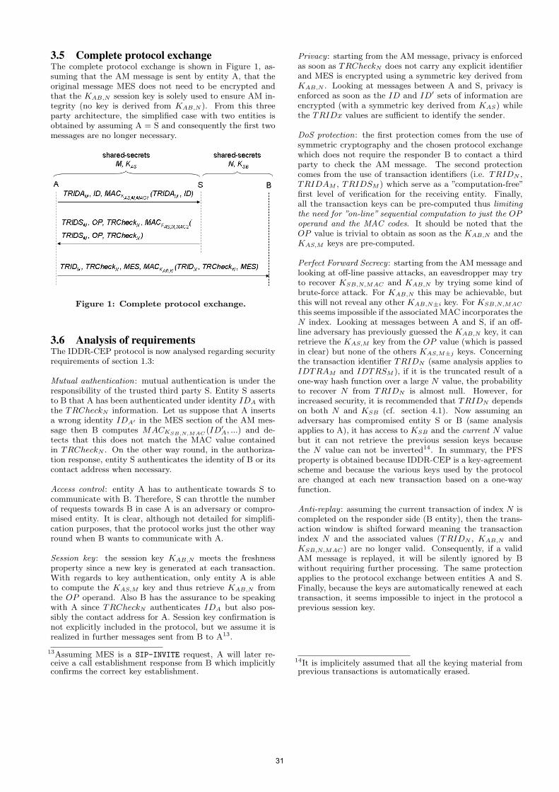
3.5 Complete protocol exchangeThe complete protocol exchange is shown in Figure 1, as-suming that the AM message is sent by entity A, that theoriginal message MES does not need to be encrypted andthat the KAB,N session key is solely used to ensure AM in-tegrity (no key is derived from KAB,N ). From this threeparty architecture, the simplified case with two entities isobtained by assuming A = S and consequently the first twomessages are no longer necessary.
Figure 1: Complete protocol exchange.
3.6 Analysis of requirementsThe IDDR-CEP protocol is now analysed regarding securityrequirements of section 1.3:
Mutual authentication: mutual authentication is under theresponsibility of the trusted third party S. Entity S assertsto B that A has been authenticated under identity IDA withthe TRCheckN information. Let us suppose that A insertsa wrong identity IDA′ in the MES section of the AM mes-sage then B computes MACKSB,N,MAC (ID′
A, ...) and de-tects that this does not match the MAC value containedin TRCheckN . On the other way round, in the authoriza-tion response, entity S authenticates the identity of B or itscontact address when necessary.
Access control : entity A has to authenticate towards S tocommunicate with B. Therefore, S can throttle the numberof requests towards B in case A is an adversary or compro-mised entity. It is clear, although not detailed for simplifi-cation purposes, that the protocol works just the other wayround when B wants to communicate with A.
Session key : the session key KAB,N meets the freshnessproperty since a new key is generated at each transaction.With regards to key authentication, only entity A is ableto compute the KAS,M key and thus retrieve KAB,N fromthe OP operand. Also B has the assurance to be speakingwith A since TRCheckN authenticates IDA but also pos-sibly the contact address for A. Session key confirmation isnot explicitly included in the protocol, but we assume it isrealized in further messages sent from B to A13.
13Assuming MES is a SIP-INVITE request, A will later re-ceive a call establishment response from B which implicitlyconfirms the correct key establishment.
Privacy : starting from the AM message, privacy is enforcedas soon as TRCheckN does not carry any explicit identifierand MES is encrypted using a symmetric key derived fromKAB,N . Looking at messages between A and S, privacy isenforced as soon as the ID and ID′ sets of information areencrypted (with a symmetric key derived from KAS) whilethe TRIDx values are sufficient to identify the sender.
DoS protection: the first protection comes from the use ofsymmetric cryptography and the chosen protocol exchangewhich does not require the responder B to contact a thirdparty to check the AM message. The second protectioncomes from the use of transaction identifiers (i.e. TRIDN ,TRIDAM , TRIDSM ) which serve as a ”computation-free”first level of verification for the receiving entity. Finally,all the transaction keys can be pre-computed thus limitingthe need for ”on-line” sequential computation to just the OPoperand and the MAC codes. It should be noted that theOP value is trivial to obtain as soon as the KAB,N and theKAS,M keys are pre-computed.
Perfect Forward Secrecy : starting from the AM message andlooking at off-line passive attacks, an eavesdropper may tryto recover KSB,N,MAC and KAB,N by trying some kind ofbrute-force attack. For KAB,N this may be achievable, butthis will not reveal any other KAB,N±i key. For KSB,N,MAC
this seems impossible if the associated MAC incorporates theN index. Looking at messages between A and S, if an off-line adversary has previously guessed the KAB,N key, it canretrieve the KAS,M key from the OP value (which is passedin clear) but none of the others KAS,M±j keys. Concerningthe transaction identifier TRIDN (same analysis applies toIDTRAM and IDTRSM ), if it is the truncated result of aone-way hash function over a large N value, the probabilityto recover N from TRIDN is almost null. However, forincreased security, it is recommended that TRIDN dependson both N and KSB (cf. section 4.1). Now assuming anadversary has compromised entity S or B (same analysisapplies to A), it has access to KSB and the current N valuebut it can not retrieve the previous session keys becausethe N value can not be inverted14. In summary, the PFSproperty is obtained because IDDR-CEP is a key-agreementscheme and because the various keys used by the protocolare changed at each new transaction based on a one-wayfunction.
Anti-replay : assuming the current transaction of index N iscompleted on the responder side (B entity), then the trans-action window is shifted forward meaning the transactionindex N and the associated values (TRIDN , KAB,N andKSB,N,MAC) are no longer valid. Consequently, if a validAM message is replayed, it will be silently ignored by Bwithout requiring further processing. The same protectionapplies to the protocol exchange between entities A and S.Finally, because the keys are automatically renewed at eachtransaction, it seems impossible to inject in the protocol aprevious session key.
14It is implicitely assumed that all the keying material fromprevious transactions is automatically erased.
31
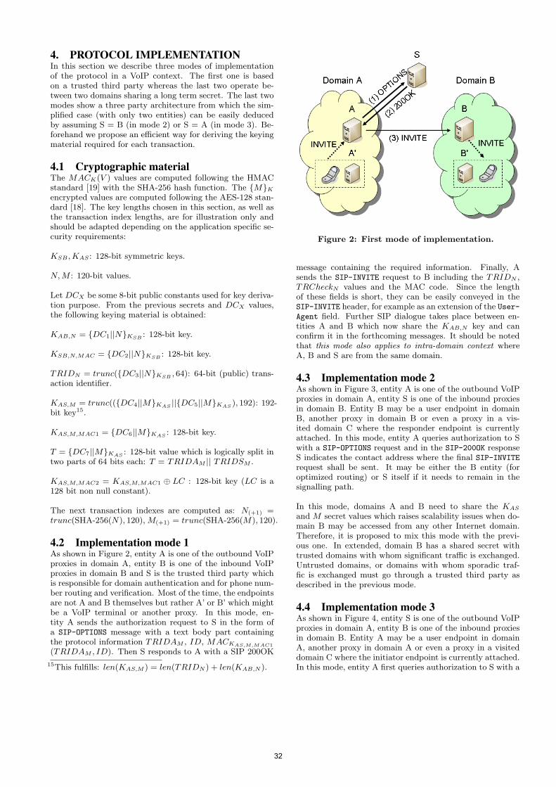
4. PROTOCOL IMPLEMENTATIONIn this section we describe three modes of implementationof the protocol in a VoIP context. The first one is basedon a trusted third party whereas the last two operate be-tween two domains sharing a long term secret. The last twomodes show a three party architecture from which the sim-plified case (with only two entities) can be easily deducedby assuming S = B (in mode 2) or S = A (in mode 3). Be-forehand we propose an efficient way for deriving the keyingmaterial required for each transaction.
4.1 Cryptographic materialThe MACK(V ) values are computed following the HMACstandard [19] with the SHA-256 hash function. The {M}Kencrypted values are computed following the AES-128 stan-dard [18]. The key lengths chosen in this section, as well asthe transaction index lengths, are for illustration only andshould be adapted depending on the application specific se-curity requirements:
KSB ,KAS : 128-bit symmetric keys.
N,M : 120-bit values.
Let DCX be some 8-bit public constants used for key deriva-tion purpose. From the previous secrets and DCX values,the following keying material is obtained:
KAB,N = {DC1||N}KSB : 128-bit key.
KSB,N,MAC = {DC2||N}KSB : 128-bit key.
TRIDN = trunc({DC3||N}KSB , 64): 64-bit (public) trans-action identifier.
KAS,M = trunc(({DC4||M}KAS ||{DC5||M}KAS ), 192): 192-bit key15.
KAS,M,MAC1 = {DC6||M}KAS : 128-bit key.
T = {DC7||M}KAS : 128-bit value which is logically split intwo parts of 64 bits each: T = TRIDAM || TRIDSM .
KAS,M,MAC2 = KAS,M,MAC1 ⊕ LC : 128-bit key (LC is a128 bit non null constant).
The next transaction indexes are computed as: N(+1) =trunc(SHA-256(N), 120), M(+1) = trunc(SHA-256(M), 120).
4.2 Implementation mode 1As shown in Figure 2, entity A is one of the outbound VoIPproxies in domain A, entity B is one of the inbound VoIPproxies in domain B and S is the trusted third party whichis responsible for domain authentication and for phone num-ber routing and verification. Most of the time, the endpointsare not A and B themselves but rather A’ or B’ which mightbe a VoIP terminal or another proxy. In this mode, en-tity A sends the authorization request to S in the form ofa SIP-OPTIONS message with a text body part containingthe protocol information TRIDAM , ID, MACKAS,M,MAC1
(TRIDAM , ID). Then S responds to A with a SIP 200OK
15This fulfills: len(KAS,M ) = len(TRIDN ) + len(KAB,N ).
Figure 2: First mode of implementation.
message containing the required information. Finally, Asends the SIP-INVITE request to B including the TRIDN ,TRCheckN values and the MAC code. Since the lengthof these fields is short, they can be easily conveyed in theSIP-INVITE header, for example as an extension of the User-Agent field. Further SIP dialogue takes place between en-tities A and B which now share the KAB,N key and canconfirm it in the forthcoming messages. It should be notedthat this mode also applies to intra-domain context whereA, B and S are from the same domain.
4.3 Implementation mode 2As shown in Figure 3, entity A is one of the outbound VoIPproxies in domain A, entity S is one of the inbound proxiesin domain B. Entity B may be a user endpoint in domainB, another proxy in domain B or even a proxy in a vis-ited domain C where the responder endpoint is currentlyattached. In this mode, entity A queries authorization to Swith a SIP-OPTIONS request and in the SIP-200OK responseS indicates the contact address where the final SIP-INVITErequest shall be sent. It may be either the B entity (foroptimized routing) or S itself if it needs to remain in thesignalling path.
In this mode, domains A and B need to share the KAS
and M secret values which raises scalability issues when do-main B may be accessed from any other Internet domain.Therefore, it is proposed to mix this mode with the previ-ous one. In extended, domain B has a shared secret withtrusted domains with whom significant traffic is exchanged.Untrusted domains, or domains with whom sporadic traf-fic is exchanged must go through a trusted third party asdescribed in the previous mode.
4.4 Implementation mode 3As shown in Figure 4, entity S is one of the outbound VoIPproxies in domain A, entity B is one of the inbound proxiesin domain B. Entity A may be a user endpoint in domainA, another proxy in domain A or even a proxy in a visiteddomain C where the initiator endpoint is currently attached.In this mode, entity A first queries authorization to S with a
32
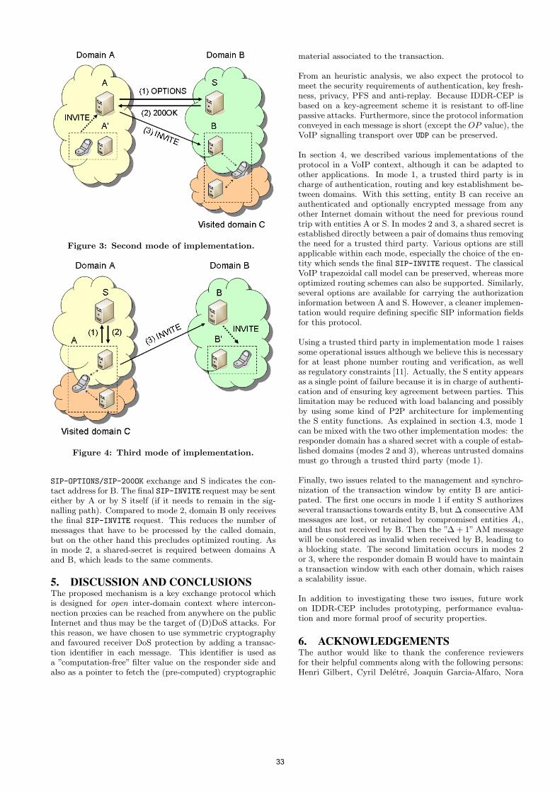
Figure 3: Second mode of implementation.
Figure 4: Third mode of implementation.
SIP-OPTIONS/SIP-200OK exchange and S indicates the con-tact address for B. The final SIP-INVITE request may be senteither by A or by S itself (if it needs to remain in the sig-nalling path). Compared to mode 2, domain B only receivesthe final SIP-INVITE request. This reduces the number ofmessages that have to be processed by the called domain,but on the other hand this precludes optimized routing. Asin mode 2, a shared-secret is required between domains Aand B, which leads to the same comments.
5. DISCUSSION AND CONCLUSIONSThe proposed mechanism is a key exchange protocol whichis designed for open inter-domain context where intercon-nection proxies can be reached from anywhere on the publicInternet and thus may be the target of (D)DoS attacks. Forthis reason, we have chosen to use symmetric cryptographyand favoured receiver DoS protection by adding a transac-tion identifier in each message. This identifier is used asa ”computation-free” filter value on the responder side andalso as a pointer to fetch the (pre-computed) cryptographic
material associated to the transaction.
From an heuristic analysis, we also expect the protocol tomeet the security requirements of authentication, key fresh-ness, privacy, PFS and anti-replay. Because IDDR-CEP isbased on a key-agreement scheme it is resistant to off-linepassive attacks. Furthermore, since the protocol informationconveyed in each message is short (except the OP value), theVoIP signalling transport over UDP can be preserved.
In section 4, we described various implementations of theprotocol in a VoIP context, although it can be adapted toother applications. In mode 1, a trusted third party is incharge of authentication, routing and key establishment be-tween domains. With this setting, entity B can receive anauthenticated and optionally encrypted message from anyother Internet domain without the need for previous roundtrip with entities A or S. In modes 2 and 3, a shared secret isestablished directly between a pair of domains thus removingthe need for a trusted third party. Various options are stillapplicable within each mode, especially the choice of the en-tity which sends the final SIP-INVITE request. The classicalVoIP trapezoidal call model can be preserved, whereas moreoptimized routing schemes can also be supported. Similarly,several options are available for carrying the authorizationinformation between A and S. However, a cleaner implemen-tation would require defining specific SIP information fieldsfor this protocol.
Using a trusted third party in implementation mode 1 raisessome operational issues although we believe this is necessaryfor at least phone number routing and verification, as wellas regulatory constraints [11]. Actually, the S entity appearsas a single point of failure because it is in charge of authenti-cation and of ensuring key agreement between parties. Thislimitation may be reduced with load balancing and possiblyby using some kind of P2P architecture for implementingthe S entity functions. As explained in section 4.3, mode 1can be mixed with the two other implementation modes: theresponder domain has a shared secret with a couple of estab-lished domains (modes 2 and 3), whereas untrusted domainsmust go through a trusted third party (mode 1).
Finally, two issues related to the management and synchro-nization of the transaction window by entity B are antici-pated. The first one occurs in mode 1 if entity S authorizesseveral transactions towards entity B, but ∆ consecutive AMmessages are lost, or retained by compromised entities Ai,and thus not received by B. Then the ”∆ + 1” AM messagewill be considered as invalid when received by B, leading toa blocking state. The second limitation occurs in modes 2or 3, where the responder domain B would have to maintaina transaction window with each other domain, which raisesa scalability issue.
In addition to investigating these two issues, future workon IDDR-CEP includes prototyping, performance evalua-tion and more formal proof of security properties.
6. ACKNOWLEDGEMENTSThe author would like to thank the conference reviewersfor their helpful comments along with the following persons:Henri Gilbert, Cyril Deletre, Joaquin Garcia-Alfaro, Nora
33
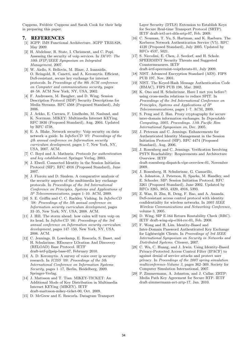
Cuppens, Frederic Cuppens and Sarah Cook for their helpin preparing this paper.
7. REFERENCES[1] 3GPP. IMS Functional Architecture. 3GPP TR33.828,
May 2009.
[2] H. Abdelnur, R. State, I. Chrisment, and C. Popi.Assessing the security of voip services. In IM’07: The10th IFIP/IEEE Symposium on IntegratedManagement, 2007.
[3] W. Aiello, S. Bellovin, M. Blaze, J. Ioannidis,O. Reingold, R. Canetti, and A. Keromytis. Efficient,DoS-resistant, secure key exchange for internetprotocols. In Proceedings of the 9th ACM conferenceon Computer and communications security, pages48–58. ACM New York, NY, USA, 2002.
[4] F. Andreasen, M. Baugher, and D. Wing. SessionDescription Protocol (SDP) Security Descriptions forMedia Streams. RFC 4568 (Proposed Standard), July2006.
[5] J. Arkko, E. Carrara, F. Lindholm, M. Naslund, andK. Norrman. MIKEY: Multimedia Internet KEYing.RFC 3830 (Proposed Standard), Aug. 2004. Updatedby RFC 4738.
[6] E. A. Blake. Network security: Voip security on datanetwork–a guide. In InfoSecCD ’07: Proceedings of the4th annual conference on Information securitycurriculum development, pages 1–7, New York, NY,USA, 2007. ACM.
[7] C. Boyd and A. Mathuria. Protocols for authenticationand key establishment. Springer Verlag, 2003.
[8] J. Elwell. Connected Identity in the Session InitiationProtocol (SIP). RFC 4916 (Proposed Standard), June2007.
[9] J. Floroiu and D. Sisalem. A comparative analysis ofthe security aspects of the multimedia key exchangeprotocols. In Proceedings of the 3rd InternationalConference on Principles, Systems and Applications ofIP Telecommunications, pages 1–10. ACM, 2009.
[10] S. E. Griffin and C. C. Rackley. Vishing. In InfoSecCD’08: Proceedings of the 5th annual conference onInformation security curriculum development, pages33–35, New York, NY, USA, 2008. ACM.
[11] J. Hill. The storm ahead: how calea will turn voip onits head. In InfoSecCD ’06: Proceedings of the 3rdannual conference on Information security curriculumdevelopment, pages 147–150, New York, NY, USA,2006. ACM.
[12] C. Jennings, B. Lowekamp, E. Rescorla, S. Baset, andH. Schulzrinne. REsource LOcation And Discovery(RELOAD) Base Protocol. IETFdraft-ietf-p2psip-base-07, February 2010.
[13] A. D. Keromytis. A survey of voice over ip securityresearch. In ICISS ’09: Proceedings of the 5thInternational Conference on Information SystemsSecurity, pages 1–17, Berlin, Heidelberg, 2009.Springer-Verlag.
[14] J. Mattsson and T. Tian. MIKEY-TICKET: AnAdditional Mode of Key Distribution in MultimediaInternet KEYing (MIKEY). IETFdraft-mattsson-mikey-ticket-00, Oct. 2009.
[15] D. McGrew and E. Rescorla. Datagram Transport
Layer Security (DTLS) Extension to Establish Keysfor Secure Real-time Transport Protocol (SRTP).IETF draft-ietf-avt-dtls-srtp-07, Feb. 2009.
[16] C. Neuman, T. Yu, S. Hartman, and K. Raeburn. TheKerberos Network Authentication Service (V5). RFC4120 (Proposed Standard), July 2005. Updated byRFCs 4537, 5021.
[17] S. Niccolini, E. Chen, J. Seedorf, and H. Scholz.SPEERMINT Security Threats and SuggestedCountermeasures. IETFdraft-ietf-speermint-voipthreats-01, July 2009.
[18] NIST. Advanced Encryption Standard (AES). FIPSPUB 197, Nov. 2001.
[19] NIST. The Keyed-Hash Message Authentication Code(HMAC). FIPS PUB 198, Mar. 2002.
[20] K. Ono and H. Schulzrinne. Have I met you before?:using cross-media relations to reduce SPIT. InProceedings of the 3rd International Conference onPrinciples, Systems and Applications of IPTelecommunications, pages 1–7. ACM, 2009.
[21] S. Peng and Z. Han. Proxy cryptography for secureinter-domain information exchanges. In DependableComputing, 2005. Proceedings. 11th Pacific RimInternational Symposium on, Dec. 2005.
[22] J. Peterson and C. Jennings. Enhancements forAuthenticated Identity Management in the SessionInitiation Protocol (SIP). RFC 4474 (ProposedStandard), Aug. 2006.
[23] J. Rosenberg and C. Jennings. Verification InvolvingPSTN Reachability: Requirements and ArchitectureOverview. IETFdraft-rosenberg-dispatch-vipr-overview-01, November2009.
[24] J. Rosenberg, H. Schulzrinne, G. Camarillo,A. Johnston, J. Peterson, R. Sparks, M. Handley, andE. Schooler. SIP: Session Initiation Protocol. RFC3261 (Proposed Standard), June 2002. Updated byRFCs 3265, 3853, 4320, 4916, 5393.
[25] Z. Wan, B. Zhu, R. Deng, F. Bao, and A. Ananda.DoS-resistant access control protocol with identityconfidentiality for wireless networks. In 2005 IEEEWireless Communications and Networking Conference,volume 3, 2005.
[26] D. Wing. SIP E.164 Return Routability Check (RRC).IETF draft-wing-sip-e164-rrc-01, Feb. 2008.
[27] F. Wong and H. Lim. Identity-Based andInter-Domain Password Authenticated Key Exchangefor Lightweight Clients. In Proceedings of 3rd IEEEInternational Symposium on Security in Networks andDistributed Systems. Citeseer, 2007.
[28] C. Wu, C. Huang, and J. Irwin. Using Identity-BasedPrivacy-Protected Access Control Filter (IPACF) toagainst denial of service attacks and protect userprivacy. In Proceedings of the 2007 spring simulationmulticonference-Volume 3, pages 362–369. Society forComputer Simulation International, 2007.
[29] P. Zimmermann, A. Johnston, and J. Callas. ZRTP:Media Path Key Agreement for Secure RTP. IETFdraft-zimmermann-avt-zrtp-17, Jan. 2010.
34
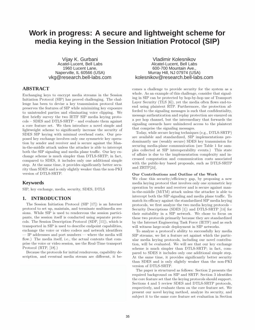
Work in progress: A secure and lightweight scheme formedia keying in the Session Initiation Protocol (SIP)
Vijay K. GurbaniAcatel-Lucent, Bell Labs
1960 Lucent Lane,Naperville, IL 60566 (USA)
Vladimir KolesnikovAlcatel-Lucent, Bell Labs600-700 Mountain Ave.,
Murray Hill, NJ 07974 (USA)[email protected]
ABSTRACTExchanging keys to encrypt media streams in the SessionInitiation Protocol (SIP) has proved challenging. The chal-lenge has been to devise a key transmission protocol thatpreserves the features of SIP while minimizing key exposureto unintended parties and eliminating voice clipping. Wefirst briefly survey the two IETF SIP media keying proto-cols – SDES and DTLS-SRTP – and evaluate them againsta core feature set. We then introduce a novel simple andlightweight scheme to significantly increase the security ofSDES SIP keying with minimal overhead costs. Our pro-posed key exchange involves only one symmetric key opera-tion by sender and receiver and is secure against the Man-in-the-middle attack unless the attacker is able to interceptboth the SIP signaling and media plane traffic. Our key ex-change scheme is much simpler than DTLS-SRTP; in fact,compared to SDES, it includes only one additional simplestep. At the same time, it provides significantly better secu-rity than SDES and is only slightly weaker than the non-PKIversion of DTLS-SRTP.
KeywordsSIP, key exchange, media, security, SDES, DTLS
1. INTRODUCTIONThe Session Initiation Protocol (SIP [17]) is an Internet
protocol to set up, maintain, and terminate multimedia ses-sions. While SIP is used to rendezvous the session partici-pants, the session itself is conducted using separate proto-cols. The Session Description Protocol (SDP, [11]), which istransported in SIP is used to describe endpoint capabilities,exchange the voice or video codecs and network identifiers— IP addressses and port numbers — where the media willflow.) The media itself, i.e., the actual contents that com-prise the voice or video session, use the Real-Time transportProtocol (RTP, [18].)
Because the protocols for initial rendezvous, capability de-scription, and eventual media stream are different, it be-
Permission to make digital or hard copies of all or part of this work forpersonal or classroom use is granted without fee provided that copies arenot made or distributed for profit or commercial advantage and that copiesbear this notice and the full citation on the first page. To copy otherwise, torepublish, to post on servers or to redistribute to lists, requires prior specificpermission and/or a fee.IPTComm 2010, 2-3 August, 2010 Munich, GermanyCopyright 2010 ACM ...$5.00.
comes a challenge to provide security for the system as awhole. As an example of this challenge, consider that signal-ing in SIP can be protected by hop-by-hop use of TransportLayer Security (TLS [6]), yet the media often flows end-to-end using plaintext RTP. Furthermore, the protection af-forded to the signaling messages is such that confidentiality,message authentication and replay protection are ensured ona per hop channel, but the intermediary that forwards thesignaling onwards have unhindered access to the plaintextthat comprise the signaling messages.
Today, while secure keying techniques (e.g., DTLS-SRTP)are available and standardized, SIP implementations pre-dominantly use (weakly secure) SDES key transmission forsecuring media-plane communication (see Table 1 for sam-ples collected at SIP interoperability events.) This stateof affairs is due to the implementation complexity and in-creased computation and communication costs associatedwith the public-key based proposals, such as DTLS-SRTPand ZRTP[24].
Our Contributions and Outline of the Work
We close this security/efficiency gap, by proposing a newmedia keying protocol that involves only one symmetric keyoperation by sender and receiver and is secure against man-in-the-middle (MiTM) attack unless the attacker is able tointercept both the SIP signaling and media plane traffic. Tomatch its efficacy against the standardized SIP media keyingprotocols, we first analyze the two media keying protocols –Security Descriptions (SDES [1]) and DTLS-SRTP [14] fortheir suitability in a SIP network. We chose to focus onthese two protocols primarily because they are standardizedby the Internet Engineering Task Force (IETF) and as suchwill witness large-scale deployment in SIP networks.
To analyze a protocol’s ability to successfully key mediaSIP streams, we list a feature set against which the partic-ular media keying protocols, including our novel contribu-tion, will be evaluated. We will see that our key exchangescheme is much simpler than DTLS-SRTP; in fact, com-pared to SDES it includes only one additional simple step.At the same time, it provides significantly better securitythan SDES and is only slightly weaker than the non-PKIversion of DTLS-SRTP.
The paper is structured as follows: Section 2 presents therequired background on SIP and SRTP. Section 3 identifiesthe core feature set that the keying protocols should support.Sections 4 and 5 review SDES and DTLS-SRTP protocols,respectively, and evaluate them on the core feature set. Wepresent our novel keying method, analyze its security, andsubject it to the same core feature set evaluation in Section
35
schmitt
Stempel
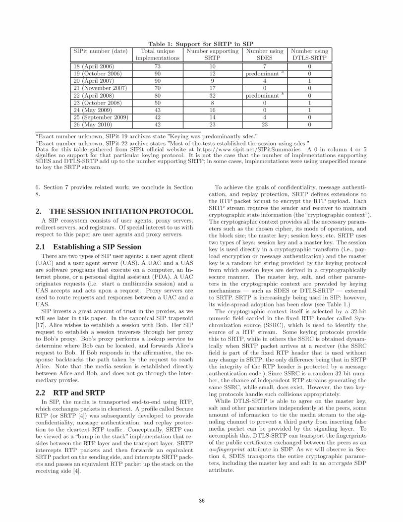
Table 1: Support for SRTP in SIP
SIPit number (date) Total unique Number supporting Number using Number usingimplementations SRTP SDES DTLS-SRTP
18 (April 2006) 73 10 7 019 (October 2006) 90 12 predominant a 020 (April 2007) 90 9 4 121 (November 2007) 70 17 0 0
22 (April 2008) 80 32 predominant b 023 (October 2008) 50 8 0 124 (May 2009) 43 16 0 125 (September 2009) 42 14 4 026 (May 2010) 42 23 23 0
aExact number unknown, SIPit 19 archives state ”Keying was predominantly sdes.”bExact number unknown, SIPit 22 archive states ”Most of the tests established the session using sdes.”Data for this table gathered from SIPit official website at https://www.sipit.net/SIPitSummaries. A 0 in column 4 or 5signifies no support for that particular keying protocol. It is not the case that the number of implementations supportingSDES and DTLS-SRTP add up to the number supporting SRTP; in some cases, implementations were using unspecified meansto key the SRTP stream.
6. Section 7 provides related work; we conclude in Section8.
2. THE SESSION INITIATION PROTOCOLA SIP ecosystem consists of user agents, proxy servers,
redirect servers, and registrars. Of special interest to us withrespect to this paper are user agents and proxy servers.
2.1 Establishing a SIP SessionThere are two types of SIP user agents: a user agent client
(UAC) and a user agent server (UAS). A UAC and a UASare software programs that execute on a computer, an In-ternet phone, or a personal digital assistant (PDA). A UACoriginates requests (i.e. start a multimedia session) and aUAS accepts and acts upon a request. Proxy servers areused to route requests and responses between a UAC and aUAS.
SIP invests a great amount of trust in the proxies, as wewill see later in this paper. In the canonical SIP trapezoid[17], Alice wishes to establish a session with Bob. Her SIPrequest to establish a session traverses through her proxyto Bob’s proxy. Bob’s proxy performs a lookup service todetermine where Bob can be located, and forwards Alice’srequest to Bob. If Bob responds in the affirmative, the re-sponse backtracks the path taken by the request to reachAlice. Note that the media session is established directlybetween Alice and Bob, and does not go through the inter-mediary proxies.
2.2 RTP and SRTPIn SIP, the media is transported end-to-end using RTP,
which exchanges packets in cleartext. A profile called SecureRTP (or SRTP [4]) was subsequently developed to provideconfidentiality, message authentication, and replay protec-tion to the cleartext RTP traffic. Conceptually, SRTP canbe viewed as a “bump in the stack” implementation that re-sides between the RTP layer and the transport layer. SRTPintercepts RTP packets and then forwards an equivalentSRTP packet on the sending side, and intercepts SRTP pack-ets and passes an equivalent RTP packet up the stack on thereceiving side [4].
To achieve the goals of confidentiality, message authenti-cation, and replay protection, SRTP defines extensions tothe RTP packet format to encrypt the RTP payload. EachSRTP stream requires the sender and receiver to maintaincryptographic state information (the“cryptographic context”).The cryptographic context provides all the necessary param-eters such as the chosen cipher, its mode of operation, andthe block size; the master key; session keys; etc. SRTP usestwo types of keys: session key and a master key. The sessionkey is used directly in a cryptographic transform (i.e., pay-load encryption or message authentication) and the masterkey is a random bit string provided by the keying protocolfrom which session keys are derived in a cryptographicallysecure manner. The master key, salt, and other parame-ters in the cryptographic context are provided by keyingmechanisms — such as SDES or DTLS-SRTP — externalto SRTP. SRTP is increasingly being used in SIP; however,its wide-spread adoption has been slow (see Table 1.)
The cryptographic context itself is selected by a 32-bitnumeric field carried in the fixed RTP header called Syn-chronization source (SSRC), which is used to identify thesource of a RTP stream. Some keying protocols providethis to SRTP, while in others the SSRC is obtained dynam-ically when SRTP packet arrives at a receiver (the SSRCfield is part of the fixed RTP header that is used withoutany change in SRTP; the only difference being that in SRTPthe integrity of the RTP header is protected by a messageauthentication code.) Since SSRC is a random 32-bit num-ber, the chance of independent RTP streams generating thesame SSRC, while small, does exist. However, the two key-ing protocols handle such collisions appropriately.
While DTLS-SRTP is able to agree on the master key,salt and other parameters independently at the peers, someamount of information to tie the media stream to the sig-naling channel to prevent a third party from inserting falsemedia packet can be provided by the signaling layer. Toaccomplish this, DTLS-SRTP can transport the fingerprintsof the public certificates exchanged between the peers as ana=fingerprint attribute in SDP. As we will observe in Sec-tion 4, SDES transports the entire cryptographic parame-ters, including the master key and salt in an a=crypto SDPattribute.
36
3. IDENTIFYING A FEATURE SETWe now establish a core feature set that we consider im-
mutable. That is, when we analyze the key exchange pro-tocols, we will analyze them with a view towards how theysupport (or do not) this core feature set in a transparentmanner (i.e., the feature behavior should not be modifiedto conform to the machination of the specific media keyingprotocol.) This core feature set includes features that areintrinsic to how SIP works as a protocol as well as featuresthat use SIP as a service enabler. Some of the features in ourset overlap with those outlined in Wing et al. [23], however,we go further by including in our set those features that aredeemed out of scope (e.g., shared-key conferencing) or notdiscussed at all (e.g., legal interception) in Wing et al. [23].
We consider eight features important enough to be sup-ported by a key exchange protocol. Of these eight, six are de-scribed in Wing et al. [23]. These are: forking, the Heteroge-neous Error Response Forking (HERFP) problem, minimiz-ing media clipping, re-targeting, placing calls from the Inter-net to the public-switched telephone network (PSTN), andshared-key conferencing. Shared-key conferencing, while de-scribed in Wing et al. [23] is deemed out of scope in theiranalysis; we include it in our analysis. There are an addi-tional two features that are not mentioned in Wing et al.[23]; these are legal intercept and session recording. We de-fine them below.
3.1 Security ModelBefore proceeding with the feature set, it is important
to understand the guarantees and limitations of the secu-rity services provided by the keying techniques. First, westress that we analyze security against very strong adver-sary, so-called Man-in-the-Middle (MiTM) who fully con-trols the communication channel between the parties. Suchadversaries are standard in cryptographic design and anal-ysis of key exchange protocols [5, 20, 12, 13]. In particular,most adversarial capabilities considered by IETF and otherstandards communities are special cases of MiTM.
Second, flooding attacks are far easier to mount againstthe SIP protocol itself than they are against some of the key-ing techniques [9]. DTLS-SRTP in particular only performsa pair-wise key exchange with the peer that is interestedin establishing a session (i.e., responds with a 200 OK re-sponse message.) Thus, the only way an attacker can mounta flooding attack at the keying layer is by causing the initialrequest to fork to many endpoints, each of which returns a200 OK response to the sender. This will cause the senderto enter a pair-wise key exchange session with multiple end-points simultaneously. Note that an attacker that simplycauses a swarm of manufactured 200 OK responses to besent to an arbitrary victim does limited harm to the victimbecause such a response will not match any pending SIPtransaction in the victim’s transaction state table, causingthe victim to simply throw away the response at the cost ofa search across the transaction table. Thus we limit our dis-cussion on flooding attacks as well, unless a certain featurerequires specific discussion for such an attack.
3.2 Feature: Legal InterceptionIn order to comply with the legal procedures and regula-
tory environments pertinent to business practices and coun-try codes, traditional switched networks evolved to supportlegal interception of the media traffic by law enforcement or
by business or enterprise for other reasons (e.g., recordingcalls at a call center for training or at a financial brokeragefirm for non-repudiation.) In an end-to-end key exchangemodel, this operational requirement becomes harder to en-force because the service provider will not have access to themaster key.
3.3 Feature: Session RecordingSession recording is a critical operational requirement in
many businesses, especially where voice is used as a mediumfor commerce and customer support [22]. SIP does not — atthe protocol level — provide any explicit support for sessionrecording. In fact, if Alice is talking to Bob, either can decideto record the session on their local endpoints, assuming thatthe local endpoint is capable of recording and storing media(in the most general case, recording is simply duplicatingarriving and departing media packets and storing them ina persistent store while maintaining the temporal orderingbetween the packets.)
The problem arises when the local endpoint cannot dorecording and a specialized entity — a recording server —has to be invited to a session in order to perform recording.Under this model, Alice and Bob have to send their mediastreams to the recording server. When Alice and Bob useSRTP, the recording server will not have the required keyto decrypt the media for a subsequent playback. There areseveral ways to mitigate this problem.
One way is for Alice or Bob to send the mixed but unen-crypted RTP media stream to the recording server. How-ever, this compromises the privacy of the communicationsbetween Alice and Bob if the plaintext media is being sentto the recording server over an insecure channel. A sec-ond approach is to share the master key with the recordingserver — the mixed SRTP media stream is directed towardsthe recording server and when the session ends, the SRTPmaster key is shared with the recording server. Wing et al.[22] discuss mechanisms by which the key sharing can beperformed. One subtlety to be addressed here is that therecording server may be able to interfere with the commu-nication, since it is given the key used to secure it.
A more secure approach at addressing the problem is forAlice or Bob to execute a key exchange with the record-ing server. Then, the mixed media is sent to the recordingserver encrypted using the exchanged key. The disadvantagehere is the added complexity of this approach and increasedprocessing on the client responsible for the re-encryption ofmedia to the recording server.
4. SECURITY DESCRIPTIONS
4.1 Security Descriptions OverviewConceptually, SDES is the simpler of the two key man-
agement protocols. Simply put, it arranges for the SRTPmaster key, salt, and other parameters to be transported inthe SIP signaling messages (thus pedantically, it is not a keyexchange protocol as much as a key transport protocol.)
SDES defines a new SDP attribute called “crypto” that isused to signal and negotiate cryptographic parameters forSRTP media streams. This attribute transports the encryp-tion and authentication algorithms, master key and salt ofthe sender (i.e., the receiver should use the said master keyand salt to derive session keys for decryption), and the life-time of the master key (i.e., maximum number of SRTP and
37
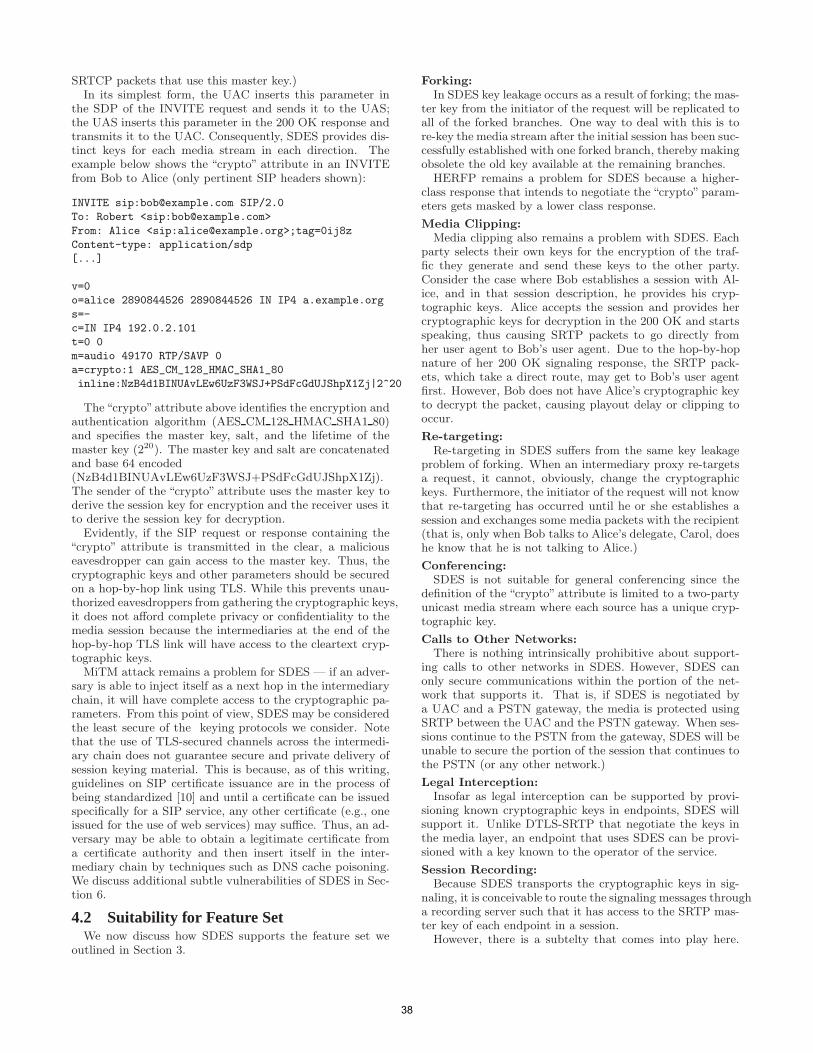
SRTCP packets that use this master key.)In its simplest form, the UAC inserts this parameter in
the SDP of the INVITE request and sends it to the UAS;the UAS inserts this parameter in the 200 OK response andtransmits it to the UAC. Consequently, SDES provides dis-tinct keys for each media stream in each direction. Theexample below shows the “crypto” attribute in an INVITEfrom Bob to Alice (only pertinent SIP headers shown):
INVITE sip:[email protected] SIP/2.0
To: Robert <sip:[email protected]>
From: Alice <sip:[email protected]>;tag=0ij8z
Content-type: application/sdp
[...]
v=0
o=alice 2890844526 2890844526 IN IP4 a.example.org
s=-
c=IN IP4 192.0.2.101
t=0 0
m=audio 49170 RTP/SAVP 0
a=crypto:1 AES_CM_128_HMAC_SHA1_80
inline:NzB4d1BINUAvLEw6UzF3WSJ+PSdFcGdUJShpX1Zj|2^20
The“crypto”attribute above identifies the encryption andauthentication algorithm (AES CM 128 HMAC SHA1 80)and specifies the master key, salt, and the lifetime of themaster key (220). The master key and salt are concatenatedand base 64 encoded(NzB4d1BINUAvLEw6UzF3WSJ+PSdFcGdUJShpX1Zj).The sender of the “crypto” attribute uses the master key toderive the session key for encryption and the receiver uses itto derive the session key for decryption.
Evidently, if the SIP request or response containing the“crypto” attribute is transmitted in the clear, a maliciouseavesdropper can gain access to the master key. Thus, thecryptographic keys and other parameters should be securedon a hop-by-hop link using TLS. While this prevents unau-thorized eavesdroppers from gathering the cryptographic keys,it does not afford complete privacy or confidentiality to themedia session because the intermediaries at the end of thehop-by-hop TLS link will have access to the cleartext cryp-tographic keys.
MiTM attack remains a problem for SDES — if an adver-sary is able to inject itself as a next hop in the intermediarychain, it will have complete access to the cryptographic pa-rameters. From this point of view, SDES may be consideredthe least secure of the keying protocols we consider. Notethat the use of TLS-secured channels across the intermedi-ary chain does not guarantee secure and private delivery ofsession keying material. This is because, as of this writing,guidelines on SIP certificate issuance are in the process ofbeing standardized [10] and until a certificate can be issuedspecifically for a SIP service, any other certificate (e.g., oneissued for the use of web services) may suffice. Thus, an ad-versary may be able to obtain a legitimate certificate froma certificate authority and then insert itself in the inter-mediary chain by techniques such as DNS cache poisoning.We discuss additional subtle vulnerabilities of SDES in Sec-tion 6.
4.2 Suitability for Feature SetWe now discuss how SDES supports the feature set we
outlined in Section 3.
Forking:
In SDES key leakage occurs as a result of forking; the mas-ter key from the initiator of the request will be replicated toall of the forked branches. One way to deal with this is tore-key the media stream after the initial session has been suc-cessfully established with one forked branch, thereby makingobsolete the old key available at the remaining branches.
HERFP remains a problem for SDES because a higher-class response that intends to negotiate the “crypto” param-eters gets masked by a lower class response.
Media Clipping:
Media clipping also remains a problem with SDES. Eachparty selects their own keys for the encryption of the traf-fic they generate and send these keys to the other party.Consider the case where Bob establishes a session with Al-ice, and in that session description, he provides his cryp-tographic keys. Alice accepts the session and provides hercryptographic keys for decryption in the 200 OK and startsspeaking, thus causing SRTP packets to go directly fromher user agent to Bob’s user agent. Due to the hop-by-hopnature of her 200 OK signaling response, the SRTP pack-ets, which take a direct route, may get to Bob’s user agentfirst. However, Bob does not have Alice’s cryptographic keyto decrypt the packet, causing playout delay or clipping tooccur.
Re-targeting:
Re-targeting in SDES suffers from the same key leakageproblem of forking. When an intermediary proxy re-targetsa request, it cannot, obviously, change the cryptographickeys. Furthermore, the initiator of the request will not knowthat re-targeting has occurred until he or she establishes asession and exchanges some media packets with the recipient(that is, only when Bob talks to Alice’s delegate, Carol, doeshe know that he is not talking to Alice.)
Conferencing:
SDES is not suitable for general conferencing since thedefinition of the “crypto” attribute is limited to a two-partyunicast media stream where each source has a unique cryp-tographic key.
Calls to Other Networks:
There is nothing intrinsically prohibitive about support-ing calls to other networks in SDES. However, SDES canonly secure communications within the portion of the net-work that supports it. That is, if SDES is negotiated bya UAC and a PSTN gateway, the media is protected usingSRTP between the UAC and the PSTN gateway. When ses-sions continue to the PSTN from the gateway, SDES will beunable to secure the portion of the session that continues tothe PSTN (or any other network.)
Legal Interception:
Insofar as legal interception can be supported by provi-sioning known cryptographic keys in endpoints, SDES willsupport it. Unlike DTLS-SRTP that negotiate the keys inthe media layer, an endpoint that uses SDES can be provi-sioned with a key known to the operator of the service.
Session Recording:
Because SDES transports the cryptographic keys in sig-naling, it is conceivable to route the signaling messages througha recording server such that it has access to the SRTP mas-ter key of each endpoint in a session.
However, there is a subtelty that comes into play here.
38
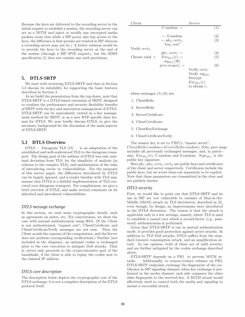
Because the keys are delivered to the recording server in theinitial request to establish a session, the recording server canact as a MiTM and inject or modify any encrypted mediapackets (note that while a SIP proxy also has access to thekeys, the difference is that proxies are trusted in SIP whereasa recording server may not be.) A better solution would beto provide the keys to the recording server at the end ofthe session (through a SIP BYE request), but the SDESspecification [1] does not contain any such provisions.
5. DTLS-SRTPWe start with reviewing DTLS-SRTP and then in Section
5.3 discuss its suitability for supporting the basic featuresdescribed in Section 3.
As we build the presentation from the top down, note thatDTLS-SRTP is a DTLS-based extension of SRTP, designedto combine the performance and security flexibility benefitsof SRTP with the key and association management of DTLS.DTLS-SRTP can be equivalently viewed as a key manage-ment method for SRTP, or as a new RTP-specific data for-mat for DTLS. We now briefly discuss DTLS, to give thenecessary background for the discussion of the main aspectsof DTLS-SRTP.
5.1 DTLS OverviewDTLS — Datagram TLS [15] — is an adaptation of the
established and well-understood TLS to the datagram trans-port. The design goal of the authors of DTLS was only min-imal deviation from TLS, for the simplicity of analysis (inrelation to the complex TLS), and minimization of the risksof introducing errors or vulnerabilities. For the purposesof this survey paper, the differences introduced by DTLScan be largely ignored, and a reader familiar with TLS mayassume that DTLS is a faithful implementation of TLS exe-cuted over datagram transport. For completeness, we give abrief overview of DTLS, and make several comments on itsinherited and introduced vulnerabilities.
DTLS message exchangeIn this section, we omit some cryptographic details, suchas agreement on suites, etc. For concreteness, we show thecase with mutual authentication using RSA. (If the Clientis not authenticated, “request cert”, ClientCertificate andClientCertificateVerify messages are not sent. Then theClient avoids the expense of the computation, and the Serverdoes not perform corresponding verifications.) Further (notincluded in the diagram), an optional cookie is exchangedprior to the core execution to mitigate DoS attacks. Thatis, server only proceeds to the crypto-intensive part of thehandshake, if the client is able to replay the cookie sent tothe claimed IP address.
DTLS core descriptionThe description below depicts the cryptographic core of theDTLS exchange; it is not a complete description of the DTLSprotocol itself.
Client Server
C.random → (1)
← S.random (2)← pkS, certS, (3)“req. cert”
Verify certS
pkC , certC → (4)Choose rand. r EncpkS
(r)→ (5)sigpkC
(H(prev.msgs))→ (6)
Verify certC
Verify sigpkC
DecryptEncpkS
(r)to obtain r,
where messages (1)-(6) are:
1. ClientHello
2. ServerHello
3. ServerCertificate
4. ClientCertificate
5. ClientKeyExchange
6. ClientCertificateVerify
The session key is set to PRF (r, “master secret”,
ClientHello.random+ServerHello.random). Note, prev.msgsincludes all previously exchanged messages, and, in partic-ular, EncpkS
(r), C.random and S.random. SignpkCis the
public key signature.Here pkC , pkS, certC , certS are public keys and certificates
of the client and server respectively. Certificates include thepublic keys, but we wrote them out separately to be explicit.Note that these parameters are transmitted in the clear andare publicly known.
DTLS securityFirst, we would like to point out that DTLS-SRTP and itsuse in SIP are not vulnerable to variants of Man-in-the-Middle (MitM) attack on TLS derivatives, described in [3],even though, by design, no improvements were introducedin the DTLS derivation. The reason is that the attack isapplicable only in a few settings, namely, where TLS is usedto establish a tunnel over which a second-factor (e.g. pass-word) authentication is performed.
Given that DTLS-SRTP is run in mutual authenticationmode, it provides good protection against active attacks. Inaddition to TLS DoS attacks, DTLS suffers from the stan-dard resource consumption attack, and an amplification at-tack. In our opinion, both of these are of mild severity,and are further mitigated by the cookie exchange describedabove.
DTLS-SRTP depends on a PKI to prevent MiTM at-tacks. Additionally, to remove/reduce reliance on PKI,DTLS-SRTP endpoints exchange the fingerprint of the cer-tificates in SIP signaling channel; when key exchange is per-formed in the media channel, each side compares the othersides fingerprint to the received key. A MiTM attack wouldeffectively need to control both the media and signaling tomount a successful attack.
39
5.2 DTLS-SRTP OverviewWhile DTLS provides the key to the communicating par-
ties, DTLS-SRTP specifies its usage in the following dataexchanges.
DTLS-SRTP is defined for point-to-point media sessions,in which there are exactly two participants. Each DTLS-SRTP session contains a single DTLS association, and eithertwo SRTP contexts (if media traffic is flowing in both direc-tions on the same host/port quartet) or one SRTP context(if media traffic is only flowing in one direction). All SRTPtraffic flowing over that pair in a given direction uses a singleSRTP context. A single DTLS-SRTP session only protectsdata carried over a single UDP source and destination portpair in a single direction.
The general pattern of DTLS-SRTP is as follows. For eachRTP or RTCP flow, the peers do a DTLS handshake on thesame source and destination port pair to establish a DTLSassociation. Which side is the DTLS client and which side isthe DTLS server is established via an out of band mechanism(SIP). The keying material from that handshake is fed intothe SRTP stack. Once that association is established, RTPpackets are protected (becoming SRTP) using that keyingmaterial.
Between a single pair of participants, there may be multi-ple media sessions. There must be a separate DTLS-SRTPsession for each distinct pair of source and destination portsused by a media session. However, for efficiency, it is rec-ommended that such sessions share a single DTLS sessionand hence amortize the initial public key handshake. Thisis done by deriving separate DTLS-SRTP master keys foreach DTLS-SRTP session from the same DTLS output.
Credentials and AuthenticationThe security of entire data exchange run by DTLS-SRTPis dependent on the integrity of the public key certificatespossessed by the communicating parties. Ideally, they willbe maintained by a PKI; however this solution has potentialhigh costs associated with it.
An alternative natural approach is to delegate some of theresponsibility to the SIP layer. For example, as describedin [14], parties may exchange hashes of their public keysin the SIP layer. Then, if the SIP layer is secured, thisprovides sufficient guarantees; if it is not, this serves merelyas an additional hurdle for the attacker, and the combinedprotocol is still vulnerable to attacks.
More specifically, when Alice wishes to set up a securemedia session with Bob, she sends an offer in a SIP mes-sage to Bob. This offer includes, as part of the SDP pay-load, the fingerprint (i.e. secure collision-resistant hash) ofAlice’s certificate. Alice should utilize existing SIP secu-rity mechanism, and send this message to her proxy over anintegrity-protected channel. If all the channels on the wayto Bob are integrity-protected, a polynomial time adversarywill not be able to compromise the security of DTLS-SRTP.
5.3 Suitability for Feature SetIn this section, we go over features discussed in Section 3
and analyze their support by DTLS-SRTP.
Forking:
Key exchange and session establishment occurs in DTLS-SRTP in the media plane. Therefore, each responder wouldestablish independent key with the initiator, and key leakagewill not occur. Further, as also noted in [7] (Appendix A.24),
since key exchange is executed in the media path, error mes-sages are also communicated along this path, and proxieswill not need to take action based on error messages. Thus,Heterogeneous Error Response Forking Problem (HERFP)is not applicable here either. In summary, threats associatedwith forking, as described in Section 3 are not applicable inDTLS-SRTP.
Media Clipping:
Again, since keying occurs in the media plane, user agentapplications are in full control over how to send the data (en-crypted or not), depending on whether DTLS has completedand keys were derived. Therefore, the problem of early me-dia clipping, as described in Section 3 is easily avoidable byclient applications.
DTLS-SRTP signals its intent such that both peers mustsupport the extension before SRTP media flows betweenthem. In this respect, it does not result in any leak of privacyby first sending plaintext RTP.
Re-targeting:
First, we observe that the keys will not be leaked to unin-tended recipients since key exchange is executed end-to-endin the media plane. Further, authenticated DTLS-SRTPwill always detect an exception in case of re-targeting, sincethe credentials won’t match. Because DTLS-SRTP relieson certificates, the initiator will have received the certificateof the responder and will be able to identify the person towhom the call has been re-targeted.
As an aside, to our knowledge no proposed protocol sup-ports cryptographic delegation of authorization from Bob toCarol. Such an authorization, for example, may be a sim-ple specially formatted message signed by Bob, associatingCarol’s public key, delegation period, and possibly other rel-evant information. When Carol answers the call, this mes-sage can be attached to her PKI chain to convince Alice thatCarol is an authorized representative.
Conferencing:
DTLS-SRTP does not support establishment of a singlekey shared between more than two endpoints. However, par-ticipants can still establish DTLS-SRTP sessions individu-ally with a conference bridge.
When Alice participates in a conference, DTLS-SRTP al-lows her to establish secure media to the conference bridgeor entity acting as the bridge in the case of three-way callingwhen a participant bridges someone into the call. Alice hasno control over whether or not media from her is encryptedas it is sent from the bridge to other participants. Alicealso has no control over who the other participants are andtherefore to whom the media is sent (aside from being ableto choose not to participate herself).
Calls to Other Networks:
As mentioned in the discussions on forking and re-targeting,one endpoint may not be within a VoIP network and theSRTP terminates at a gateway to another network, such as aswitched cellular network or PSTN. The same gateway maynot be used for every call between the same two endpoints.For such calls, DTLS-SRTP only provides establishment ofSRTP keying material between the participant on the VoIPnetwork and an undetermined endpoint.
Legal Interception:
DTLS-SRTP exchanges keys end-to-end in the media stream.Unlike SDES, it does not transport the keys in signaling thusmaking legal interception (or informed recording of conver-
40
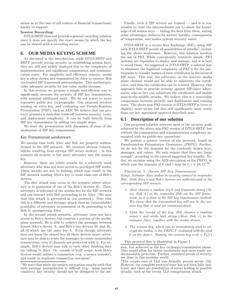
sation as in the case of call centers or financial transactions)harder to support.
Session Recording:
DTLS-SRTP does not provide a general recording solutionsince it does not specify the exact means by which the keycan be shared with a recording server.
6. OUR MEDIA KEYING SCHEMEAs discussed in the introduction, while DTLS-SRTP and
ZRTP provide strong security in establishing session keys,they are still not widely deployed due to the complexity ofimplementation and significant computation and communi-cation costs. For simplicity and efficiency reasons, mediakey is often chosen and transmitted by Alice to receiver Bobvia trusted SIP framework intermediaries. This method pro-vides adequate security for low-value media streams.
In this section, we propose a simple and efficient way tosignificantly increase the security of SIP key transmission,with minimal additional costs. We do not resort to moreexpensive public key cryptography. Our proposal involvessending an extra key, and evaluating one Pseudo-RandomPermutation (PRP), such as AES. We believe that our pro-tocol presents a desirable trade-off between security, costs,and deployment complexity. It can be built directly fromSIP key transmission by adding two simple steps.
We start the presentation with discussion of some of theweaknesses of SIP key transmission.
Key Transmission weaknesses.We assume that both Alice and Bob are properly authen-ticated to the SIP network. We mention obvious vulnera-bilities resulting from corrupt SIP server node(s) – in thisscenario all security is lost since adversary sees the sessionkey.
However, there are subtle attacks by a relatively weakadversary who does not have access to privileged SIP nodes.These attacks are due to forking, which may result in theSIP network sending Alice’s key to more than one of Bob’sdevices.
The first attack may occur in the scenario where adver-sary is in possession of one of the Bob’s devices B1. Then,adversary is informed of the session key by the SIP networkand can interact with Bob pretending to be Alice. (We notethat this attack is prevented in our protocol.) Note thatthis is a different and stronger attack than an (unavoidable)possibility of adversary in possession of B1 pretending to beBob to unsuspecting Alice.
In the second attack scenario, adversary does not haveaccess to Bob’s devices, but controls a portion of the media-plane network. He is able to redirect the messages betweenhonest Alice’s device A1 and Bob’s two devices B1 and B2,all of which use the same key k. Even though adversarydoes not know the shared key all three devices share, adver-sary may be able to route the messages to create unintendedtransactions, even if channels are protected with k. For ex-ample, Bob’s devices may talk to each other thinking theyare talking to Alice. Or, outside of VoIP scope, both Bob’sdevices would initiate a transaction (e.g. a money transfer),and result in duplicate transaction execution1.
1We note that while the session encryption may be such thatsuch message manipulation is difficult (e.g. using specialcounters), key security should not be delegated to the ses-
Finally, even if SIP servers are trusted — and it is rea-sonable to trust the intermediaries not to abuse the knowl-edge of all session keys — hiding the keys from them, amongother advantages, reduces the servers’ liability, consequencesof compromise, and makes system recovery easier.
DTLS-SRTP is a secure Key Exchange (KE); using SIPwith DTLS-SRTP avoids all possibilities of attacks2, includ-ing the above weaknesses. However, this solution involvesthe use of PKI. While conceptually relatively simple, PKIsystems are expensive to deploy and manage, and it is bestto avoid them. As suggested in DTLS-SRTP, a natural wayto eliminate the logistical complexity of PKI is for the par-ticipants to transfer hashes of their certificates in the securedSIP layer. This way, the adversary on the insecure mediaplane channel would not be able to substitute the certifi-cates, and thus the certificates can be trusted. However, thisapproach fails to provide security against SIP-layer adver-saries, who in fact can substitute the certificates and enableman-in-the-middle attacks. We believe this is a reasonablecompromise between security and deployment and runningcosts. The above non-PKI version of DTLS-SRTP is (ever soslightly) more secure but also still significantly more costlythan our key agreement protocol described next.
6.1 Description of our solutionOur proposed solution achieves most of the security goals
achieved by the above non-PKI version of DTLS-SRTP, butwithout the computation and communication complexity as-sociated with its public-key operations.
We present a generic version of the protocol, based onPseudorandom Permutation Generators (PRPG). Further,we do not fix the domains for the randomly drawn keys,messages, and values. We only require that they are “largeenough”, according to the current suggested key lengths. To-day, we envision using the AES encryption as the PRPG, inwhich case the domains of k and r may be k, r ∈ {0, 1}128.
Protocol 1. (Secure SIP Key Transmission)Setup: Initiator Alice wishes to securely connect to responderBob. Both Alice’s and Bob’s devices are authenticated to thecorresponding SIP servers.
1. Alice chooses a random key k and transmits string (Al-ice, Bob, k) to the responder Bob via the SIP frame-work, as it is done in the SIP key transmission method.We stress that the transmitted key will not be the ses-sion key that is used for communication.
2. Upon the receipt of the key, Bob chooses a randomnonce r and sends back string (Alice, Bob, r) to theinitiator Alice, together with the media stream.
3. The session key, which can be immediately used to en-crypt the media, is the PRPG F evaluated with the seedk on the data r. Namely, the session key is sk = Fk(r)
This protocol flow is illustrated in Figure 1.
sion, but achieved in the key exchange/transmission phase.This would allow for better modularity and more easily un-derstandable protocols. Further, standard proofs of securityare done in this modular world.2The crypto core of TLS was formally proven secure [16].However, the complete protocol suite has not been fully ana-lyzed, and there are possibilities of errors leading to possibleattacks, such as the recent TLS renegotiation attack.
41
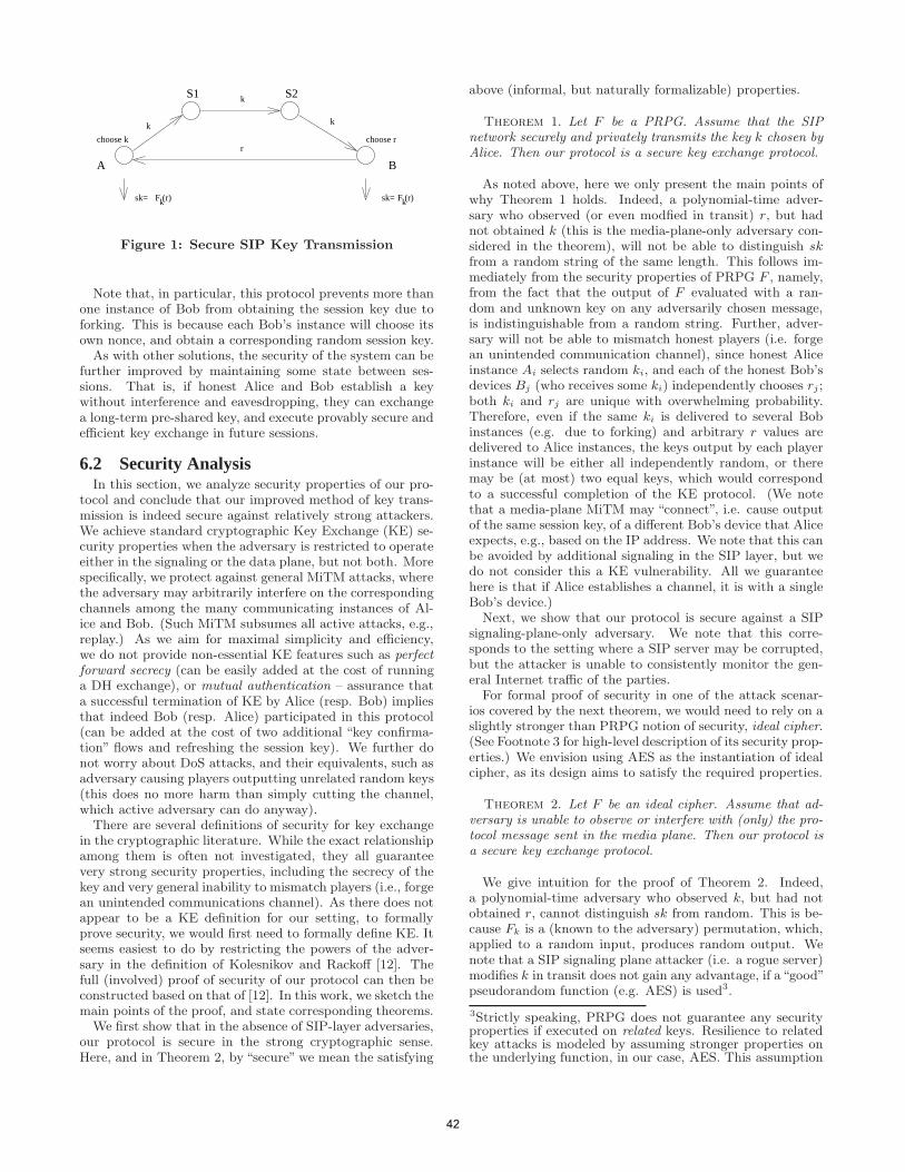
B
F (r) F (r)ksk=sk=
k
k
k
rchoose rchoose k
A
S1 S2
k
Figure 1: Secure SIP Key Transmission
Note that, in particular, this protocol prevents more thanone instance of Bob from obtaining the session key due toforking. This is because each Bob’s instance will choose itsown nonce, and obtain a corresponding random session key.
As with other solutions, the security of the system can befurther improved by maintaining some state between ses-sions. That is, if honest Alice and Bob establish a keywithout interference and eavesdropping, they can exchangea long-term pre-shared key, and execute provably secure andefficient key exchange in future sessions.
6.2 Security AnalysisIn this section, we analyze security properties of our pro-
tocol and conclude that our improved method of key trans-mission is indeed secure against relatively strong attackers.We achieve standard cryptographic Key Exchange (KE) se-curity properties when the adversary is restricted to operateeither in the signaling or the data plane, but not both. Morespecifically, we protect against general MiTM attacks, wherethe adversary may arbitrarily interfere on the correspondingchannels among the many communicating instances of Al-ice and Bob. (Such MiTM subsumes all active attacks, e.g.,replay.) As we aim for maximal simplicity and efficiency,we do not provide non-essential KE features such as perfectforward secrecy (can be easily added at the cost of runninga DH exchange), or mutual authentication – assurance thata successful termination of KE by Alice (resp. Bob) impliesthat indeed Bob (resp. Alice) participated in this protocol(can be added at the cost of two additional “key confirma-tion” flows and refreshing the session key). We further donot worry about DoS attacks, and their equivalents, such asadversary causing players outputting unrelated random keys(this does no more harm than simply cutting the channel,which active adversary can do anyway).
There are several definitions of security for key exchangein the cryptographic literature. While the exact relationshipamong them is often not investigated, they all guaranteevery strong security properties, including the secrecy of thekey and very general inability to mismatch players (i.e., forgean unintended communications channel). As there does notappear to be a KE definition for our setting, to formallyprove security, we would first need to formally define KE. Itseems easiest to do by restricting the powers of the adver-sary in the definition of Kolesnikov and Rackoff [12]. Thefull (involved) proof of security of our protocol can then beconstructed based on that of [12]. In this work, we sketch themain points of the proof, and state corresponding theorems.
We first show that in the absence of SIP-layer adversaries,our protocol is secure in the strong cryptographic sense.Here, and in Theorem 2, by “secure” we mean the satisfying
above (informal, but naturally formalizable) properties.
Theorem 1. Let F be a PRPG. Assume that the SIPnetwork securely and privately transmits the key k chosen byAlice. Then our protocol is a secure key exchange protocol.
As noted above, here we only present the main points ofwhy Theorem 1 holds. Indeed, a polynomial-time adver-sary who observed (or even modfied in transit) r, but hadnot obtained k (this is the media-plane-only adversary con-sidered in the theorem), will not be able to distinguish sk
from a random string of the same length. This follows im-mediately from the security properties of PRPG F , namely,from the fact that the output of F evaluated with a ran-dom and unknown key on any adversarily chosen message,is indistinguishable from a random string. Further, adver-sary will not be able to mismatch honest players (i.e. forgean unintended communication channel), since honest Aliceinstance Ai selects random ki, and each of the honest Bob’sdevices Bj (who receives some ki) independently chooses rj ;both ki and rj are unique with overwhelming probability.Therefore, even if the same ki is delivered to several Bobinstances (e.g. due to forking) and arbitrary r values aredelivered to Alice instances, the keys output by each playerinstance will be either all independently random, or theremay be (at most) two equal keys, which would correspondto a successful completion of the KE protocol. (We notethat a media-plane MiTM may “connect”, i.e. cause outputof the same session key, of a different Bob’s device that Aliceexpects, e.g., based on the IP address. We note that this canbe avoided by additional signaling in the SIP layer, but wedo not consider this a KE vulnerability. All we guaranteehere is that if Alice establishes a channel, it is with a singleBob’s device.)
Next, we show that our protocol is secure against a SIPsignaling-plane-only adversary. We note that this corre-sponds to the setting where a SIP server may be corrupted,but the attacker is unable to consistently monitor the gen-eral Internet traffic of the parties.
For formal proof of security in one of the attack scenar-ios covered by the next theorem, we would need to rely on aslightly stronger than PRPG notion of security, ideal cipher.(See Footnote 3 for high-level description of its security prop-erties.) We envision using AES as the instantiation of idealcipher, as its design aims to satisfy the required properties.
Theorem 2. Let F be an ideal cipher. Assume that ad-versary is unable to observe or interfere with (only) the pro-tocol message sent in the media plane. Then our protocol isa secure key exchange protocol.
We give intuition for the proof of Theorem 2. Indeed,a polynomial-time adversary who observed k, but had notobtained r, cannot distinguish sk from random. This is be-cause Fk is a (known to the adversary) permutation, which,applied to a random input, produces random output. Wenote that a SIP signaling plane attacker (i.e. a rogue server)modifies k in transit does not gain any advantage, if a“good”pseudorandom function (e.g. AES) is used3.
3Strictly speaking, PRPG does not guarantee any securityproperties if executed on related keys. Resilience to relatedkey attacks is modeled by assuming stronger properties onthe underlying function, in our case, AES. This assumption
42
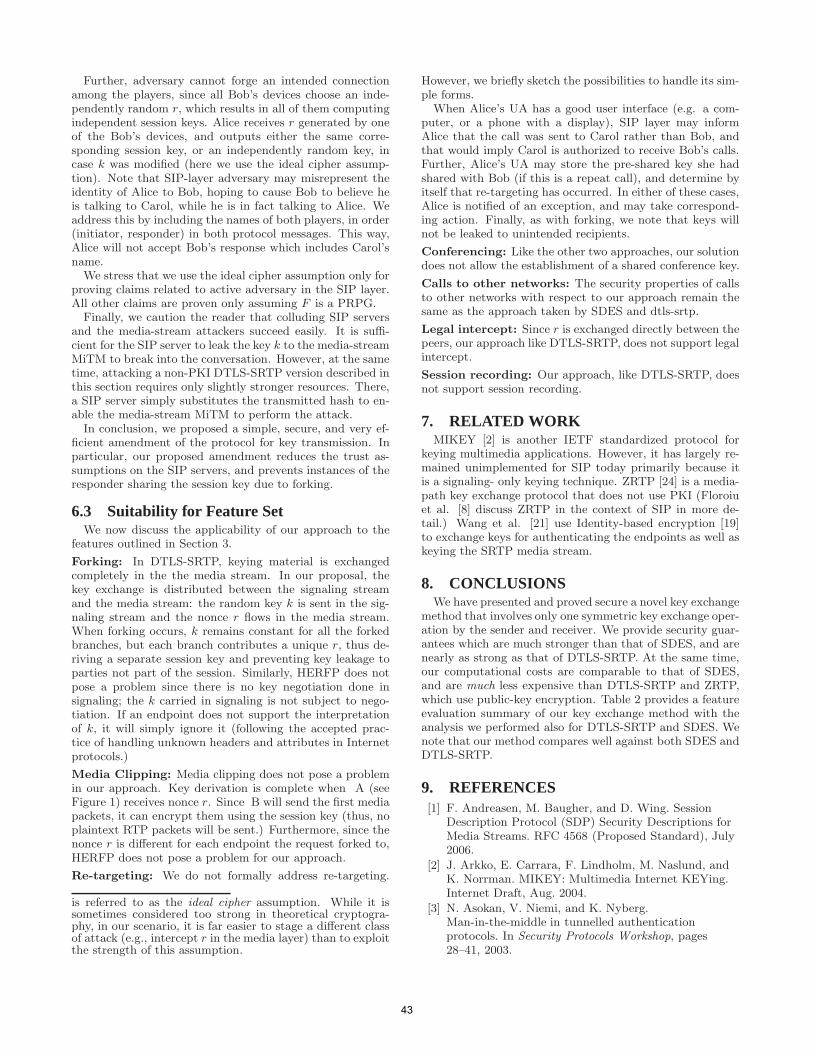
Further, adversary cannot forge an intended connectionamong the players, since all Bob’s devices choose an inde-pendently random r, which results in all of them computingindependent session keys. Alice receives r generated by oneof the Bob’s devices, and outputs either the same corre-sponding session key, or an independently random key, incase k was modified (here we use the ideal cipher assump-tion). Note that SIP-layer adversary may misrepresent theidentity of Alice to Bob, hoping to cause Bob to believe heis talking to Carol, while he is in fact talking to Alice. Weaddress this by including the names of both players, in order(initiator, responder) in both protocol messages. This way,Alice will not accept Bob’s response which includes Carol’sname.
We stress that we use the ideal cipher assumption only forproving claims related to active adversary in the SIP layer.All other claims are proven only assuming F is a PRPG.
Finally, we caution the reader that colluding SIP serversand the media-stream attackers succeed easily. It is suffi-cient for the SIP server to leak the key k to the media-streamMiTM to break into the conversation. However, at the sametime, attacking a non-PKI DTLS-SRTP version described inthis section requires only slightly stronger resources. There,a SIP server simply substitutes the transmitted hash to en-able the media-stream MiTM to perform the attack.
In conclusion, we proposed a simple, secure, and very ef-ficient amendment of the protocol for key transmission. Inparticular, our proposed amendment reduces the trust as-sumptions on the SIP servers, and prevents instances of theresponder sharing the session key due to forking.
6.3 Suitability for Feature SetWe now discuss the applicability of our approach to the
features outlined in Section 3.
Forking: In DTLS-SRTP, keying material is exchangedcompletely in the the media stream. In our proposal, thekey exchange is distributed between the signaling streamand the media stream: the random key k is sent in the sig-naling stream and the nonce r flows in the media stream.When forking occurs, k remains constant for all the forkedbranches, but each branch contributes a unique r, thus de-riving a separate session key and preventing key leakage toparties not part of the session. Similarly, HERFP does notpose a problem since there is no key negotiation done insignaling; the k carried in signaling is not subject to nego-tiation. If an endpoint does not support the interpretationof k, it will simply ignore it (following the accepted prac-tice of handling unknown headers and attributes in Internetprotocols.)
Media Clipping: Media clipping does not pose a problemin our approach. Key derivation is complete when A (seeFigure 1) receives nonce r. Since B will send the first mediapackets, it can encrypt them using the session key (thus, noplaintext RTP packets will be sent.) Furthermore, since thenonce r is different for each endpoint the request forked to,HERFP does not pose a problem for our approach.
Re-targeting: We do not formally address re-targeting.
is referred to as the ideal cipher assumption. While it issometimes considered too strong in theoretical cryptogra-phy, in our scenario, it is far easier to stage a different classof attack (e.g., intercept r in the media layer) than to exploitthe strength of this assumption.
However, we briefly sketch the possibilities to handle its sim-ple forms.
When Alice’s UA has a good user interface (e.g. a com-puter, or a phone with a display), SIP layer may informAlice that the call was sent to Carol rather than Bob, andthat would imply Carol is authorized to receive Bob’s calls.Further, Alice’s UA may store the pre-shared key she hadshared with Bob (if this is a repeat call), and determine byitself that re-targeting has occurred. In either of these cases,Alice is notified of an exception, and may take correspond-ing action. Finally, as with forking, we note that keys willnot be leaked to unintended recipients.
Conferencing: Like the other two approaches, our solutiondoes not allow the establishment of a shared conference key.
Calls to other networks: The security properties of callsto other networks with respect to our approach remain thesame as the approach taken by SDES and dtls-srtp.
Legal intercept: Since r is exchanged directly between thepeers, our approach like DTLS-SRTP, does not support legalintercept.
Session recording: Our approach, like DTLS-SRTP, doesnot support session recording.
7. RELATED WORKMIKEY [2] is another IETF standardized protocol for
keying multimedia applications. However, it has largely re-mained unimplemented for SIP today primarily because itis a signaling- only keying technique. ZRTP [24] is a media-path key exchange protocol that does not use PKI (Floroiuet al. [8] discuss ZRTP in the context of SIP in more de-tail.) Wang et al. [21] use Identity-based encryption [19]to exchange keys for authenticating the endpoints as well askeying the SRTP media stream.
8. CONCLUSIONSWe have presented and proved secure a novel key exchange
method that involves only one symmetric key exchange oper-ation by the sender and receiver. We provide security guar-antees which are much stronger than that of SDES, and arenearly as strong as that of DTLS-SRTP. At the same time,our computational costs are comparable to that of SDES,and are much less expensive than DTLS-SRTP and ZRTP,which use public-key encryption. Table 2 provides a featureevaluation summary of our key exchange method with theanalysis we performed also for DTLS-SRTP and SDES. Wenote that our method compares well against both SDES andDTLS-SRTP.
9. REFERENCES[1] F. Andreasen, M. Baugher, and D. Wing. Session
Description Protocol (SDP) Security Descriptions forMedia Streams. RFC 4568 (Proposed Standard), July2006.
[2] J. Arkko, E. Carrara, F. Lindholm, M. Naslund, andK. Norrman. MIKEY: Multimedia Internet KEYing.Internet Draft, Aug. 2004.
[3] N. Asokan, V. Niemi, and K. Nyberg.Man-in-the-middle in tunnelled authenticationprotocols. In Security Protocols Workshop, pages28–41, 2003.
43
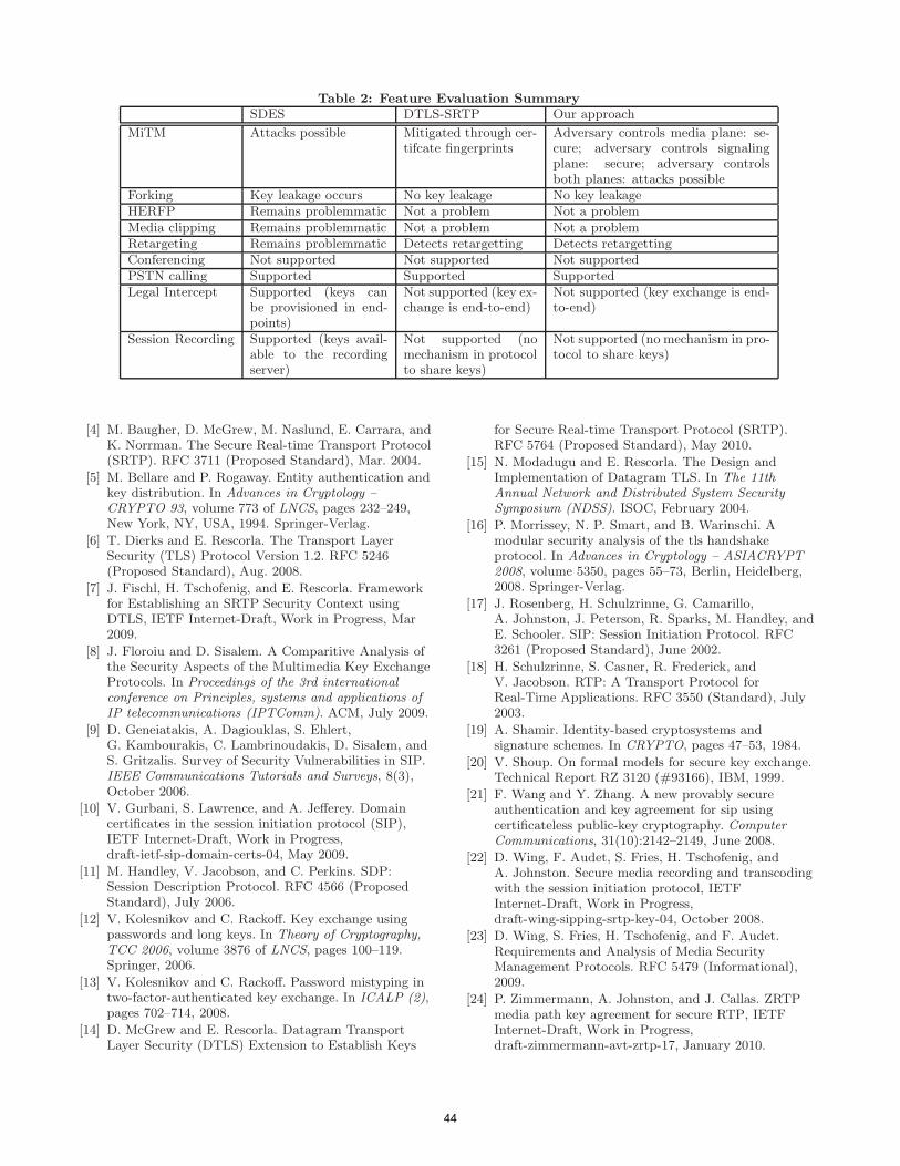
Table 2: Feature Evaluation Summary
SDES DTLS-SRTP Our approach
MiTM Attacks possible Mitigated through cer-tifcate fingerprints
Adversary controls media plane: se-cure; adversary controls signalingplane: secure; adversary controlsboth planes: attacks possible
Forking Key leakage occurs No key leakage No key leakageHERFP Remains problemmatic Not a problem Not a problemMedia clipping Remains problemmatic Not a problem Not a problemRetargeting Remains problemmatic Detects retargetting Detects retargettingConferencing Not supported Not supported Not supportedPSTN calling Supported Supported SupportedLegal Intercept Supported (keys can
be provisioned in end-points)
Not supported (key ex-change is end-to-end)
Not supported (key exchange is end-to-end)
Session Recording Supported (keys avail-able to the recordingserver)
Not supported (nomechanism in protocolto share keys)
Not supported (no mechanism in pro-tocol to share keys)
[4] M. Baugher, D. McGrew, M. Naslund, E. Carrara, andK. Norrman. The Secure Real-time Transport Protocol(SRTP). RFC 3711 (Proposed Standard), Mar. 2004.
[5] M. Bellare and P. Rogaway. Entity authentication andkey distribution. In Advances in Cryptology –CRYPTO 93, volume 773 of LNCS, pages 232–249,New York, NY, USA, 1994. Springer-Verlag.
[6] T. Dierks and E. Rescorla. The Transport LayerSecurity (TLS) Protocol Version 1.2. RFC 5246(Proposed Standard), Aug. 2008.
[7] J. Fischl, H. Tschofenig, and E. Rescorla. Frameworkfor Establishing an SRTP Security Context usingDTLS, IETF Internet-Draft, Work in Progress, Mar2009.
[8] J. Floroiu and D. Sisalem. A Comparitive Analysis ofthe Security Aspects of the Multimedia Key ExchangeProtocols. In Proceedings of the 3rd internationalconference on Principles, systems and applications ofIP telecommunications (IPTComm). ACM, July 2009.
[9] D. Geneiatakis, A. Dagiouklas, S. Ehlert,G. Kambourakis, C. Lambrinoudakis, D. Sisalem, andS. Gritzalis. Survey of Security Vulnerabilities in SIP.IEEE Communications Tutorials and Surveys, 8(3),October 2006.
[10] V. Gurbani, S. Lawrence, and A. Jefferey. Domaincertificates in the session initiation protocol (SIP),IETF Internet-Draft, Work in Progress,draft-ietf-sip-domain-certs-04, May 2009.
[11] M. Handley, V. Jacobson, and C. Perkins. SDP:Session Description Protocol. RFC 4566 (ProposedStandard), July 2006.
[12] V. Kolesnikov and C. Rackoff. Key exchange usingpasswords and long keys. In Theory of Cryptography,TCC 2006, volume 3876 of LNCS, pages 100–119.Springer, 2006.
[13] V. Kolesnikov and C. Rackoff. Password mistyping intwo-factor-authenticated key exchange. In ICALP (2),pages 702–714, 2008.
[14] D. McGrew and E. Rescorla. Datagram TransportLayer Security (DTLS) Extension to Establish Keys
for Secure Real-time Transport Protocol (SRTP).RFC 5764 (Proposed Standard), May 2010.
[15] N. Modadugu and E. Rescorla. The Design andImplementation of Datagram TLS. In The 11thAnnual Network and Distributed System SecuritySymposium (NDSS). ISOC, February 2004.
[16] P. Morrissey, N. P. Smart, and B. Warinschi. Amodular security analysis of the tls handshakeprotocol. In Advances in Cryptology – ASIACRYPT2008, volume 5350, pages 55–73, Berlin, Heidelberg,2008. Springer-Verlag.
[17] J. Rosenberg, H. Schulzrinne, G. Camarillo,A. Johnston, J. Peterson, R. Sparks, M. Handley, andE. Schooler. SIP: Session Initiation Protocol. RFC3261 (Proposed Standard), June 2002.
[18] H. Schulzrinne, S. Casner, R. Frederick, andV. Jacobson. RTP: A Transport Protocol forReal-Time Applications. RFC 3550 (Standard), July2003.
[19] A. Shamir. Identity-based cryptosystems andsignature schemes. In CRYPTO, pages 47–53, 1984.
[20] V. Shoup. On formal models for secure key exchange.Technical Report RZ 3120 (#93166), IBM, 1999.
[21] F. Wang and Y. Zhang. A new provably secureauthentication and key agreement for sip usingcertificateless public-key cryptography. ComputerCommunications, 31(10):2142–2149, June 2008.
[22] D. Wing, F. Audet, S. Fries, H. Tschofenig, andA. Johnston. Secure media recording and transcodingwith the session initiation protocol, IETFInternet-Draft, Work in Progress,draft-wing-sipping-srtp-key-04, October 2008.
[23] D. Wing, S. Fries, H. Tschofenig, and F. Audet.Requirements and Analysis of Media SecurityManagement Protocols. RFC 5479 (Informational),2009.
[24] P. Zimmermann, A. Johnston, and J. Callas. ZRTPmedia path key agreement for secure RTP, IETFInternet-Draft, Work in Progress,draft-zimmermann-avt-zrtp-17, January 2010.
44

Reusable Features for VoIP Service Realization
Thomas M. SmithAT&T Labs Research
180 Park AvenueFlorham Park, NJ 07932
ABSTRACTTelecommunication services vary greatly in their behavior.However they often can be decomposed into tightly-focusedcomponents, each designed to accomplish a certain limitedfunction. In some cases, these functions are repeated acrossmany services that seem quite disparate at first glance. Weexamine some components that have proven to be highlyreusable, and demonstrate how they can be composed intoa variety of interesting services.
KeywordsTelecommunications, VoIP, features, application composi-tion, patterns
1. INTRODUCTIONA wide variety of telecommunication services provide fa-
miliar behavior to users everywhere. Common examplesinclude voicemail systems, conference calling services, IVR“phone-tree”applications commonly employed by businesses,and end-user features such as call waiting and three-way call-ing. Some services of limited scope may be provided by astandalone software implementation of modest complexity.However, when the number of supported features increases,they may be implemented in highly complex, even byzan-tine, software systems. Such systems complicate the task ofmaintaining and extending the service logic.
It has long been considered useful to consider models inwhich system behavior can be decomposed into standalonemodules that can be independently specified, developed, andtested. Such modules can then be combined to provide morefunctionality without undue complexity [8, 9, 14, 17, 10,21]. Such a design ethic is evident in currently-emergingstandards such as the IP Multimedia Subsystem (IMS) [19]and the SIP Servlet 1.1 specification [11].
This paper draws on experience developing Voice over IP(VoIP) software modules to distill a number of highly usefulsoftware components, each performing a limited function. InSection 2, the function of each component is described and
Permission to make digital or hard copies of all or part of this work forpersonal or classroom use is granted without fee provided that copies arenot made or distributed for profit or commercial advantage and that copiesbear this notice and the full citation on the first page. To copy otherwise, torepublish, to post on servers or to redistribute to lists, requires prior specificpermission and/or a fee.IPTComm 2010, 2-3 August, 2010 Munich, GermanyCopyright 2010 ACM ...$10.00.
illustrated by example. In Section 3, the components areemployed to compose some familiar services. Section 4 con-tains some preliminary thoughts on different software mech-anisms that can be used as compositional patterns, and theappropriateness of each in different settings. We concludein Section 5 with a description of future work.
2. FEATURESIn this section, we will describe a number of telecommu-
nication modules that represent common functionality thatcan be found in a number of different contexts. In tradi-tional telecommunication parlance, these are designated asfeatures. More generally, these features embody commondesign patterns of telecommunication logic. Software designpatterns have been studied extensively [7, 16, 12], and thereis a body of work concerning the use of design patterns intelecommunications [18, 20]. The features described here ex-hibit patterns of call-control logic. Note that although thesefeatures can be characterized as patterns, they have alsobeen reified as functional, standalone software components.
Note that the increment of functionality embodied in thesefeatures is small; the scope of an individual feature is onthe order of “call waiting,” not “IP-PBX.” A system witha scope of the latter could be built out of a large numberof features with the scope of the former, however. This setof features is certainly not meant to be comprehensive, butrather illustrative of how small components can be composedto realize a variety of outcomes.
The features described here can be viewed through thelens of scope, commonality, and variability [6], though thesedecompositions are the result of informal iteration ratherthan systematic procedure. Encounters with repeated call-control patterns have suggested the scope of each feature.The commonality between instances of the features is gen-erally dictated by the call processing message classes beingacted upon (either sent or received); and the variability usu-ally applies to parameters used to form the details of themessage contents, rather than the message classes. Gener-ally these parameters take the form of addresses, timeoutvalues, etc.
Each of the features is described in isolation below. Thenwe will consider how to compose these features into usefulservices using pipe-and-filter composition [2, 10, 13]. Thisstyle of composition allows all components (features) to re-main independent of the others; in fact the components maynot even be aware of the existence of other components. Thegraph that results from the runtime composition of multi-ple features may be achieved by direct addressing, in which
45
schmitt
Stempel

Prompt and Switch
IVR system
caller callee
feature
external server
call partycall path
non-call path
Legend
1
2 3
4
Figure 1: Prompt-and-Switch feature
features translate addresses in order to route calls to otherfeatures, or through a more sophisticated subscription mech-anism, as in Distributed Feature Composition (DFC) [10].In either case, the mechanics of composition are achievedthrough telecommunication protocol means, with no changesrequired to feature logic. Call-time composition is also usedin IMS [19] and the SIP Servlet 1.1 specification [11]. Notethan anywhere that a call party appears in the representa-tion of a feature call flow, that party may be another fea-ture, not necessarily an end user. From the vantage point ofa feature, it does not know or care what entity is placing orreceiving a call.
2.1 Prompt and SwitchThe Prompt-and-Switch (PS) feature, shown in Figure 1,
provides the ability to answer an incoming call with an auto-mated audio dialog as commonly found in Interactive VoiceResponse (IVR) systems. After a period of time duringwhich the calling party interacts with the automated dia-log, the logic of the IVR system can specify an address towhich the calling party should be switched. This functionshould be very familiar to anyone who has called the mainnumber of a business, only to encounter an automated menulisting the parties (or departments) that can be reached viaan interaction with the menu. This feature takes care of therequired signaling to redirect the call to the IVR system,as well as any further signaling required to tear down theIVR call and switch the (connected) caller to a new (uncon-nected) address.
As presented, this feature could perform a number of fa-miliar standalone functions:
• It can provide an“automated attendant”function, prompt-ing the caller with a menu of departments that can bereached.
• It can be the basis of a prepaid calling service, wherecalls are placed to an IVR system to collect a prepaidaccount number and desired number to call. When thecalled party hangs up, the caller is reconnected to theIVR system and allowed to make more calls.
Connect Two Partiescallee1 callee2
initiator
1
2 3
Figure 2: Connect-Two-Parties feature
• It can support “remote authentication,” where sub-scribers call in and authenticate themselves before be-ing allowed access to some protected functions (in-cluding placing an outbound call). Such a functionis present in AT&T’s Callvantage Service [4].
Figure 1 shows a graphical representation of this feature.The incoming call, labeled (1), is directed to the IVR system(2). The IVR system returns a command (3), causing thefeature to switch the caller to an address specified by theIVR logic (4).
In terms of [6], the commonality is as described above.One element of variability in the call-processing logic is thatthe feature may be optionally configured to detect call ter-mination from the callee and to reconnect the caller to theIVR system for further instructions. This behavior couldbe used to allow a caller to make multiple sequential callsafter entering a prepaid calling card number or performingremote authentication.
2.2 Connect Two PartiesWhile a great many features are activated by an incoming
call, there are occasions where the initial event is somethingother than a call-related event. An example of this would bea corporate web page with a button that reads, “Click hereto be connected to one of our representatives.” In this case,the initiating event would be a web click, not a call event.This function can be implemented in a Connect-Two-Parties(CTP) feature that is activated by the non-call event, asshown in Figure 2.
The initiating event must specify the addresses of the twoparties that should be connected. To reduce confusion, it isdesirable that the parties be connected one-at-a-time; thatis, the second party will not be called until the first partyanswers. Accordingly, execution should terminate if the firstleg of the call fails.
Figure 2 shows a graphical representation of this feature.A non-call event (1) prompts the CTP feature to place out-going calls to first one party (2), then the other party (3).These parties are located at addresses that are specified inthe initiating event.
Note that the endpoints of this call need not both be livepeople; rather they can be any callable entity, including me-dia servers and other features.
2.3 Redirect on FailureThe Redirect-on-Failure (RF) feature provides a simple
but crucial capability: it continues an incoming call towardits destination, but in the event that the call cannot reach itsdestination for any of a variety of reasons (busy, no answer,
46
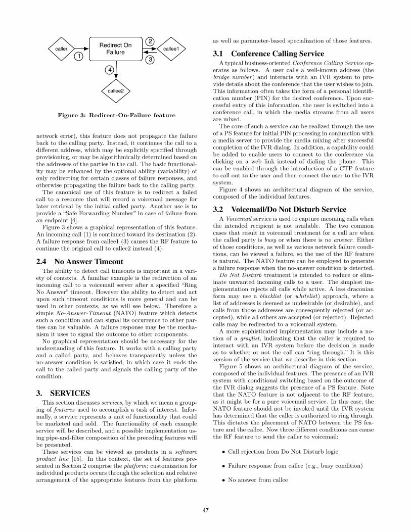
Redirect On Failure
callee2
caller callee11
43
2
Figure 3: Redirect-On-Failure feature
network error), this feature does not propagate the failureback to the calling party. Instead, it continues the call to adifferent address, which may be explicitly specified throughprovisioning, or may be algorithmically determined based onthe addresses of the parties in the call. The basic functional-ity may be enhanced by the optional ability (variability) ofonly redirecting for certain classes of failure responses, andotherwise propagating the failure back to the calling party.
The canonical use of this feature is to redirect a failedcall to a resource that will record a voicemail message forlater retrieval by the initial called party. Another use is toprovide a “Safe Forwarding Number” in case of failure froman endpoint [4].
Figure 3 shows a graphical representation of this feature.An incoming call (1) is continued toward its destination (2).A failure response from callee1 (3) causes the RF feature tocontinue the original call to callee2 instead (4).
2.4 No Answer TimeoutThe ability to detect call timeouts is important in a vari-
ety of contexts. A familiar example is the redirection of anincoming call to a voicemail server after a specified “RingNo Answer” timeout. However the ability to detect and actupon such timeout conditions is more general and can beused in other contexts, as we will see below. Therefore asimple No-Answer-Timeout (NATO) feature which detectssuch a condition and can signal its occurrence to other par-ties can be valuable. A failure response may be the mecha-nism it uses to signal the outcome to other components.
No graphical representation should be necessary for theunderstanding of this feature. It works with a calling partyand a called party, and behaves transparently unless theno-answer condition is satisfied, in which case it ends thecall to the called party and signals the calling party of thecondition.
3. SERVICESThis section discusses services, by which we mean a group-
ing of features used to accomplish a task of interest. Infor-mally, a service represents a unit of functionality that couldbe marketed and sold. The functionality of each exampleservice will be described, and a possible implementation us-ing pipe-and-filter composition of the preceding features willbe presented.
These services can be viewed as products in a softwareproduct line [15]. In this context, the set of features pre-sented in Section 2 comprise the platform; customization forindividual products occurs through the selection and relativearrangement of the appropriate features from the platform
as well as parameter-based specialization of those features.
3.1 Conference Calling ServiceA typical business-oriented Conference Calling Service op-
erates as follows. A user calls a well-known address (thebridge number) and interacts with an IVR system to pro-vide details about the conference that the user wishes to join.This information often takes the form of a personal identifi-cation number (PIN) for the desired conference. Upon suc-cessful entry of this information, the user is switched into aconference call, in which the media streams from all usersare mixed.
The core of such a service can be realized through the useof a PS feature for initial PIN processing in conjunction witha media server to provide the media mixing after successfulcompletion of the IVR dialog. In addition, a capability couldbe added to enable users to connect to the conference viaclicking on a web link instead of dialing the phone. Thiscan be enabled through the introduction of a CTP featureto call out to the user and then connect the user to the IVRsystem.
Figure 4 shows an architectural diagram of the service,composed of the individual features.
3.2 Voicemail/Do Not Disturb ServiceA Voicemail service is used to capture incoming calls when
the intended recipient is not available. The two commoncases that result in voicemail treatment for a call are whenthe called party is busy or when there is no answer. Eitherof those conditions, as well as various network failure condi-tions, can be viewed a failure, so the use of the RF featureis natural. The NATO feature can be employed to generatea failure response when the no-answer condition is detected.
Do Not Disturb treatment is intended to reduce or elim-inate unwanted incoming calls to a user. The simplest im-plementation rejects all calls while active. A less draconianform may use a blacklist (or whitelist) approach, where alist of addresses is deemed as undesirable (or desirable), andcalls from those addresses are consequently rejected (or ac-cepted), while all others are accepted (or rejected). Rejectedcalls may be redirected to a voicemail system.
A more sophisticated implementation may include a no-tion of a graylist, indicating that the caller is required tointeract with an IVR system before the decision is madeas to whether or not the call can “ring through.” It is thisversion of the service that we describe in this section.
Figure 5 shows an architectural diagram of the service,composed of the individual features. The presence of an IVRsystem with conditional switching based on the outcome ofthe IVR dialog suggests the presence of a PS feature. Notethat the NATO feature is not adjacent to the RF feature,as it might be for a pure voicemail service. In this case, theNATO feature should not be invoked until the IVR systemhas determined that the caller is authorized to ring through.This dictates the placement of NATO between the PS fea-ture and the callee. Now three different conditions can causethe RF feature to send the caller to voicemail:
• Call rejection from Do Not Disturb logic
• Failure response from callee (e.g., busy condition)
• No answer from callee
47
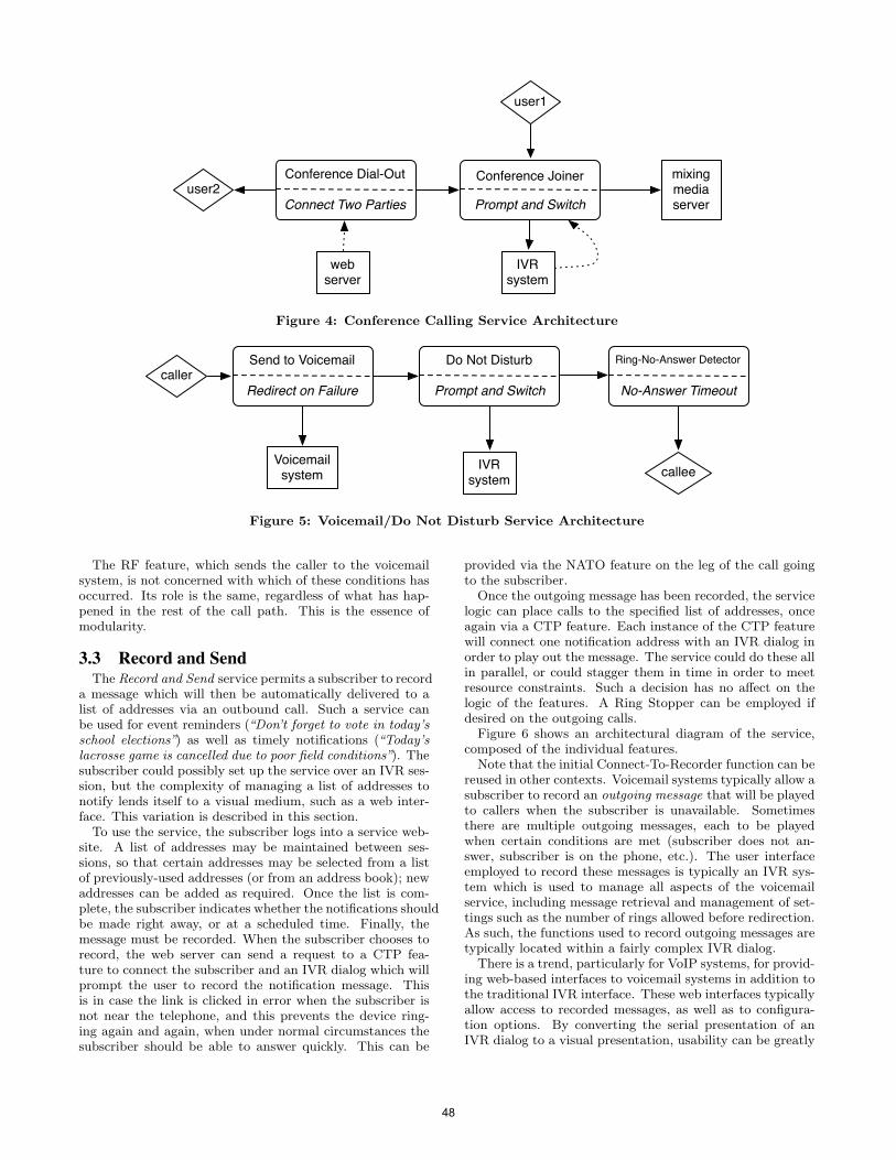
IVR system
user2mixing media server
Conference Joiner
Prompt and Switch
Conference Dial-Out
Connect Two Parties
user1
web server
Figure 4: Conference Calling Service Architecture
Do Not DisturbSend to Voicemail
Redirect on Failure Prompt and Switch
Ring-No-Answer Detector
No-Answer Timeout
callee
caller
Voicemail system
IVR system
Figure 5: Voicemail/Do Not Disturb Service Architecture
The RF feature, which sends the caller to the voicemailsystem, is not concerned with which of these conditions hasoccurred. Its role is the same, regardless of what has hap-pened in the rest of the call path. This is the essence ofmodularity.
3.3 Record and SendThe Record and Send service permits a subscriber to record
a message which will then be automatically delivered to alist of addresses via an outbound call. Such a service canbe used for event reminders (“Don’t forget to vote in today’sschool elections”) as well as timely notifications (“Today’slacrosse game is cancelled due to poor field conditions”). Thesubscriber could possibly set up the service over an IVR ses-sion, but the complexity of managing a list of addresses tonotify lends itself to a visual medium, such as a web inter-face. This variation is described in this section.
To use the service, the subscriber logs into a service web-site. A list of addresses may be maintained between ses-sions, so that certain addresses may be selected from a listof previously-used addresses (or from an address book); newaddresses can be added as required. Once the list is com-plete, the subscriber indicates whether the notifications shouldbe made right away, or at a scheduled time. Finally, themessage must be recorded. When the subscriber chooses torecord, the web server can send a request to a CTP fea-ture to connect the subscriber and an IVR dialog which willprompt the user to record the notification message. Thisis in case the link is clicked in error when the subscriber isnot near the telephone, and this prevents the device ring-ing again and again, when under normal circumstances thesubscriber should be able to answer quickly. This can be
provided via the NATO feature on the leg of the call goingto the subscriber.
Once the outgoing message has been recorded, the servicelogic can place calls to the specified list of addresses, onceagain via a CTP feature. Each instance of the CTP featurewill connect one notification address with an IVR dialog inorder to play out the message. The service could do these allin parallel, or could stagger them in time in order to meetresource constraints. Such a decision has no affect on thelogic of the features. A Ring Stopper can be employed ifdesired on the outgoing calls.
Figure 6 shows an architectural diagram of the service,composed of the individual features.
Note that the initial Connect-To-Recorder function can bereused in other contexts. Voicemail systems typically allow asubscriber to record an outgoing message that will be playedto callers when the subscriber is unavailable. Sometimesthere are multiple outgoing messages, each to be playedwhen certain conditions are met (subscriber does not an-swer, subscriber is on the phone, etc.). The user interfaceemployed to record these messages is typically an IVR sys-tem which is used to manage all aspects of the voicemailservice, including message retrieval and management of set-tings such as the number of rings allowed before redirection.As such, the functions used to record outgoing messages aretypically located within a fairly complex IVR dialog.
There is a trend, particularly for VoIP systems, for provid-ing web-based interfaces to voicemail systems in addition tothe traditional IVR interface. These web interfaces typicallyallow access to recorded messages, as well as to configura-tion options. By converting the serial presentation of anIVR dialog to a visual presentation, usability can be greatly
48
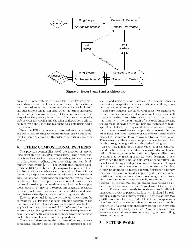
Connect To Player
Connect Two Parties
Ring Stopper
No-Answer Timeoutreceiver
Connect To Player
Connect Two Parties
Ring Stopper
No-Answer Timeoutreceiver
Connect To Recorder
Connect Two Parties
Ring Stopper
No-Answer Timeout
IVR system
sender
web server
Connect To Player
Connect Two Parties
Ring Stopper
No-Answer Timeoutreceiver
Figure 6: Record and Send Architecture
enhanced. Some systems, such as AT&T’s CallVantage Ser-vice, allow the user to click a link on this web interface in or-der to record an outgoing message. When the link is clicked,the subscriber’s phone will ring; when the call is answered,the subscriber is placed precisely at the point in the IVR di-alog where the greeting is recorded. This allows the use of aweb browser for viewing and choosing configuration options,coupled with the use of the telephone as a ubiquitous audioinput device.
Since the IVR component is presumed to exist already,the web-based greeting recording function can be added us-ing the same Connect-To-Recorder composition shown inFigure 6.
4. OTHER COMPOSITIONAL PATTERNSThe previous section illustrated the creation of service
logic through pipe-and-filter composition. This design pat-tern is well known in software engineering, and can be seenin Unix process pipelines, data processing, and web devel-opment frameworks [2, 1]. The Distributed Feature Com-position (DFC) architecture [10] employs the pipe-and-filterarchitecture to great advantage in controlling feature inter-action. By proper use of address translation [22], a variety ofDFC usages, each containing an appropriate feature chain,can be assembled. DFC provides a theoretical basis that canbe used for realizing composed services, like those in the pre-vious section. By having a toolbox full of general features,services can be easily composed by manipulating addressesand feature subscription, instead of writing new code.
However, pipes and filters are not the only mechanism forsoftware re-use. Perhaps the most common software re-usemechanism is that of a software library made available toapplications via a documented API. Software libraries areroutinely used during almost any software development pro-cess. Some of the functions defined in the preceding sectionscould also be implemented as library modules.
There are differences in the patterns of re-use betweencomposing complete feature modules, as discussed in Sec-
tion 3, and using software libraries. One key difference isthat feature composition occurs at runtime, and library com-position occurs at compile time.
There are tradeoffs associated with these two patterns ofre-use. For example, use of a software library may wellhave less overhead associated with a call to a library rou-tine than with the instantiation of a feature instance andthe overhead of having more call protocol instances to man-age. Compile-time checking could also ensure that the func-tion is being invoked from an appropriate context. On theother hand, run-time assembly of the software componentsmeans that no recompilation is required to change behavior.This means that the software composition can be controlledpurely through configuration of the desired call graph.
In practice, it may not be clear which of these composi-tional patterns is more suitable for a particular implemen-tation. Some experiences indicate that pipe-and-filter com-position may be most appropriate when designing a newservice for the first time, as this level of composition canbe achieved through configuration rather than code changes[5]. When an implementation is more mature and stable,it may be desirable to migrate certain functions to libraryroutines. This can potentially improve performance charac-teristics of the system as a whole, presuming that calling alibrary routine is less computationally expensive than per-forming the incremental call processing that would be re-quired for a standalone feature. A good rule of thumb maybe that if a component needs to create or absorb call-pathmessages in order to perform its function, it should be real-ized in a feature, not a library routine. There are at least twojustifications for this design rule. First, if one component islinked to another at compile time, it prevents run-time in-terpolation of a third component between the other two andthus constrains flexibility for re-use. Also, inter-feature mes-sages are a critical mechanism for analyzing and controllingfeature interaction.
5. FUTURE WORK
49
Extensive experience building VoIP services has resultedin the extraction of common call-control patterns into thefeatures described in this paper. There is every reason to ex-pect that further experience will result in continuing insightsinto interesting decompositions. Investigation of systematictechniques such as [6] could yield new insights. The appli-cability of software product line engineering techniques [15,3] to this domain should be explored.
Additionally, the thoughts on alternate compositional pat-terns are in the early stages. Other compositional patternsfrom the software engineering literature [2] should be ex-plored for possible applicability to this domain. Furtherreflection and experience should lead to more concrete andrigorous design guidelines.
Finally, the topic of converged services has not been di-rectly addressed in this paper. When non-telecommunicationprotocols (such as HTTP) are included as part of the servicelogic, the boundary lines of features, and thus compositionalpatterns, may shift.
6. CONCLUSIONBy carefully designing telecommunication features to per-
form certain common functions, it is possible to realize com-plex service logic through call-time composition of the con-stituent features. There is growing industry momentum forsuch mechanisms as seen in the IMS architecture and theSIP Servlet 1.1 standard.
7. ACKNOWLEDGMENTSThe author gratefully acknowledges his close extended col-
laboration with Greg Bond, Eric Cheung, Karrie Hanson,Don Henderson, Gerald Karam, Hal Purdy, Venkita Subra-monian and Pamela Zave, out of which this work was pro-duced. Alicia Abella consistently provides excellent advice.Laura Dillon also provided valuable suggestions which im-proved this paper. Finally, the anonymous reviewers pro-vided excellent suggestions about related work.
8. REFERENCES[1] Apache cocoon site. http://cocoon.apache.org/.
[2] V. Ambriola and G. Tortora. Advances in SoftwareEngineering and Knowledge Engineering. WorldScientific, 1993.
[3] F. Bachmann and L. Bass. Managing variability insoftware architectures. SIGSOFT Softw. Eng. Notes,26(3):126–132, 2001.
[4] G. W. Bond, E. Cheung, H. H. Goguen, K. J. Hanson,D. Henderson, G. M. Karam, K. H. Purdy, T. M.Smith, and P. Zave. Experience with component-baseddevelopment of a telecommunication service. InProceedings of the Eighth International Symposium onComponent-Based Software Engineering, pages298–305. Springer-Verlag LNCS 3489, May 2005.
[5] E. Cheung and T. M. Smith. Experience withmodularity in an advanced teleconferencing servicedeployment. In ICSE Companion, pages 39–49. IEEE,2009.
[6] J. Coplien, D. Hoffman, and D. Weiss. Commonalityand variability in software engineering. IEEE Softw.,15(6):37–45, 1998.
[7] E. Gamma, R. Helm, R. Johnson, and J. Vlissides.Design patterns: elements of reusable object-orientedsoftware. Addison-Wesley Longman Publishing Co.,Inc., Boston, MA, USA, 1995.
[8] J. J. Garrahan, P. A. Russo, K. Kitami, and R. Kung.Intelligent Network overview. IEEE Communications,31(3):30–36, March 1993.
[9] N. D. Griffeth and H. Velthuijsen. The NegotiatingAgents approach to runtime feature interactionresolution. In L. G. Bouma and H. Velthuijsen,editors, Feature Interactions in TelecommunicationsSystems, pages 217–235. IOS Press, Amsterdam, 1994.
[10] M. Jackson and P. Zave. Distributed featurecomposition: A virtual architecture fortelecommunications services. IEEE Transactions onSoftware Engineering, XXIV(10):831–847, October1998.
[11] JSR 289: SIP Servlet Version 1.1. Java CommunityProcess, 2008. Available from:http://jcp.org/en/jsr/detail?id=289.
[12] C. Larman. Applying UML and Patterns: AnIntroduction to Object-Oriented Analysis and Designand the Unified Process. Prentice Hall PTR, UpperSaddle River, NJ, USA, 2001.
[13] D. Mennie and B. Pagurek. An architecture to supportdynamic composition of service components, 2000.
[14] M. Plath and M. Ryan. Plug-and-play features. InK. Kimbler and L. G. Bouma, editors, FeatureInteractions in Telecommunications and SoftwareSystems V, pages 150–164. IOS Press, Amsterdam,1998.
[15] K. Pohl, G. Bockle, and F. J. v. d. Linden. SoftwareProduct Line Engineering: Foundations, Principlesand Techniques. Springer-Verlag New York, Inc.,Secaucus, NJ, USA, 2005.
[16] W. Pree. Design patterns for object-oriented softwaredevelopment. ACM Press/Addison-Wesley PublishingCo., New York, NY, USA, 1995.
[17] C. Prehofer. Plug-and-play composition of featuresand feature interactions with Statechart diagrams. InD. Amyot and L. Logrippo, editors, FeatureInteractions in Telecommunications and SoftwareSystems VII, pages 43–58. IOS Press, Amsterdam,2003.
[18] L. Rising, editor. Design patterns in communicationssoftware. Cambridge University Press, New York, NY,USA, 2001.
[19] F. Salm. Application servers and sip signaling in imsenvironments.
[20] D. C. Schmidt. Using design patterns to developreusable object-oriented communication software.Commun. ACM, 38(10):65–74, 1995.
[21] R. Steenfeldt and H. Smith. Sip service execution rulelanguage framework and requirements, November2001.
[22] P. Zave. Address translation in telecommunicationfeatures. ACM Transactions on Software Engineeringand Methodology (TOSEM), 13(1):1–36, January 2004.
50
Specification and Evaluation of Transparent Behaviorfor SIP Back-to-Back User Agents
Gregory W. BondAT&T Labs—ResearchFlorham Park, NJ, USA
Eric CheungAT&T Labs—ResearchFlorham Park, NJ, [email protected]
Thomas M. SmithAT&T Labs—ResearchFlorham Park, NJ, [email protected]
Pamela ZaveAT&T Labs—ResearchFlorham Park, NJ, [email protected]
ABSTRACTA back-to-back user agent (B2BUA) is a powerful mecha-nism for realizing complex SIP applications. The ability tocreate, terminate, and modify SIP dialogs allows the cre-ation of arbitrarily complex services. However, B2BUAsmust be designed with care so as not to disrupt service in-teroperability. A commonly-stated goal is for B2BUAs to beas transparent as possible while achieving its design goals.Though the notion of transparency is intuitively appealing,it is difficult to define. To address this issue, this paperproposes a definition of transparency and presents a formalmodel of a transparent B2BUA to serve as the specificationof transparency. From this specification, we identify issueswith both the realizability and desirability of this behavior,and suggest modifications to the original model. We evalu-ate the behavior of a number of public B2BUA implementa-tions via testing, using some novel techniques to create testcases based on the formal models.
1. INTRODUCTIONA back-to-back user agent (B2BUA) is a powerful mecha-
nism for realizing complex SIP applications. The ability tocreate, terminate, and modify SIP dialogs allows the cre-ation of arbitrarily complex services. However, B2BUAsmust be designed with care so as not to disrupt service in-teroperability.
A commonly-stated goal is for B2BUAs to be as transpar-ent as possible while achieving its design goals. However,the notion of transparency is not defined by the SIP speci-fication [13]. This specification defines a back-to-back useragent as “a logical entity that receives a request and pro-cesses it as a user agent server (UAS). In order to determinehow the request should be answered, it acts as a user agentclient (UAC) and generates requests.” The specification fur-ther states that “Since it is a concatenation of a UAC and
Permission to make digital or hard copies of all or part of this work forpersonal or classroom use is granted without fee provided that copies arenot made or distributed for profit or commercial advantage and that copiesbear this notice and the full citation on the first page. To copy otherwise, torepublish, to post on servers or to redistribute to lists, requires prior specificpermission and/or a fee.IPTComm 2010, 2-3 August, 2010 Munich, GermanyCopyright 2010 ACM ...$10.00.
UAS, no explicit definitions are needed for its behavior.”To date, the behavior of B2BUAs has not been specified,
other than that it must comply with the behavior of a UAon each side. This leads to the perception that B2BUAsbreak transparency of the network, and therefore hindersinnovation at the endpoints. On the other hand, a largenumber of use cases have arisen in real-world deploymentsof SIP services that require B2BUAs. For example:
• Hide network topology information. This is often per-formed by Session Border Controllers (SBCs) that in-terface the networks of two service providers.
• Terminate an existing session, for example by a pre-paid application when calling credit has run out, or byan IMS P-CSCF when it detects that the radio linkagewith the mobile device has been disconnected.
• Modify the Session Description Protocol (SDP) infor-mation in the message body, for example to work throughfirewalls.
• Perform third party call control by advanced applica-tions, for example to change a direct two-party call toa three-party call by bringing in a mixing media server.
The conflict between common usage and lack of specifi-cation is untenable. It is important that the behavior ofB2BUAs is specified such that developers can implementthem correctly and service providers can test them for com-pliance. At the same time, any innovations and extensionsto the SIP protocol can be designed to work with transpar-ent B2BUAs as intermediaries. While a transparent B2BUAdoes not provide any useful service, it can serve as the base-line and various B2BUAs that provide services can be de-fined as deviations from the transparent B2BUA. For ex-ample, a prepaid application B2BUA is transparent exceptwhen it terminates the session by sending BYE requests onboth SIP dialogs.
In 2007, the IETF SIPPING working group started towork on a Best Current Practices document for a transpar-ent B2BUA. Unfortunately, this work has not been contin-ued to completion. The last draft [11] specifies how theAllow, Required and Supported headers should be handledwhen a request is received. It also specifies that when the
51
schmitt
Stempel
B2BUA relays a message certain headers should be gener-ated, and the other headers and message body should becopied.
The SIP Servlet API standard [1] provides limited supportfor B2BUAs by providing methods for creating an outgoingrequest to be sent out on the UAC side based on an incomingrequest received on the UAS side. It specifies that the imple-mentation must copy the headers from the incoming requestto the outgoing request (with a few exceptions). However,the SIP Servlet API standard does not further specify anytransparent B2BUA behavior.
The purpose of this paper is to provide a firmer foundationfor B2BUAs in SIP by providing a rigorous and pragmaticspecification of transparent behavior. This entails a numberof contributions.
First, we show that it is difficult to define what ”trans-parency” means, even on an informal and intuitive basis.After examining the alternatives, we settle on a pragmaticworking definition (Section 2).
Second, we formalize our informal definition (Section 3).Message sequencing is formalized in terms of an executablemodel in Promela, the language of the Spin model checker.Message contents are described in terms of header values.To provide an environment in which the B2BUA model canbe analyzed and verified automatically, we also developednew formal models of SIP user agents. Because of the use ofmodel checking, all of the Promela models are guaranteedto be complete, consistent, unambiguous, and correct withrespect to well-defined criteria.
Third, we demonstrate the pragmatic use of our specifi-cation by evaluating existing B2BUA implementations (Sec-tion 4). Because manually generated tests are not sufficient,we generated a suite of 2,408 tests automatically from theformal UA models. We then ran both manually and auto-matically generated tests, using automated testing tools, onthe available implementations. None of the implementationscomply fully with the B2BUA specification. This shows thatimplementing a correct B2BUA is difficult, and that com-prehensive testing is necessary to ensure the correctness ofimplementations.
Overall, this research shows that judicious use of specifi-cation, analysis, and testing tools can greatly improve thequality of SIP components and SIP-based applications. Al-though our research needs to be extended in various ways,further work is amply justified by the initial results.
2. DEFINITION OF TRANSPARENTBEHAVIOR
What does it mean for a B2BUA to behave transparently?Transparency is an appealingly intuitive concept, but it isnot easy to give it a rigorous definition.
In general, there are two approaches to definition. Anoperational definition of transparency would focus on thebehavior of the B2BUA itself. An observational definitionwould define transparent behavior of a B2BUA as observedby its environment, which consists of the UAs at the farends of its two dialogs. The advantage of an operationaldefinition is that it is easy to tell whether a specific B2BUAsatisfies the definition. One advantage of an observationaldefinition is that it corresponds most closely to the intuitivenotion of transparency. Another advantage is that it allowsthe most freedom in implementing B2BUAs.
In this paper, pure propagation refers to the following be-havior of a B2BUA: receive a message in one dialog, and sendit unchanged in the other dialog. A possible operational def-inition is, “A transparent B2BUA applies pure propagationto each received message, and does not send any messagesthat are not propagated.”
Pure propagation cannot be correct transparent behav-ior because a B2BUA must change propagated messages instraightforward ways, such as modifying the Call-ID headerand tag parameters to match the unique identifiers of eachdialog. These changes to message content are specified inSection 3.2.
In this paper, propagation as a B2BUA behavior is thesame as pure propagation, except with necessary headerchanges. A revised operational definition is, “A transpar-ent B2BUA applies propagation to each received message,and does not send any messages that are not propagated.”This definition does not work either, because it sometimesviolates the SIP standard in the individual dialogs. Sec-tion 3.1.3 describes these situations.
Unfortunately, a rigorous observational definition is evenharder to find than an operational definition. It could re-quire that the presence of the B2BUA be undetectable bythe far endpoints, but that is not achievable, even whenreal-time delays and header changes are excepted (see Sec-tion 3.1.3).
An observational definition should require that the me-dia sessions between the far endpoints be the same whetherthere is a B2BUA present or not, because controlling mediasessions is the primary purpose of SIP. To formalize this suc-cessfully, it would be necessary to define “the same” so thatit generalizes over the nondeterministic behavior of the net-work between the far endpoints, which can affect endpointbehavior and media sessions even when there is no B2BUA.Also, a definition of transparency based on media sessionswould be necessary but not sufficient—SIP signaling accom-plishes more than just controlling media sessions.
In this paper we use a pragmatic definition of transparencythat lies somewhere between the two extremes. A B2BUAis transparent if and only if:
• It acts as a standards-compliant UA in both dialogs.
• Its behavior within the two SIP dialogs is to propa-gate each message, and to not send any messages thatare not propagated, except when this behavior wouldviolate the protocol in either dialog.
• When its behavior is an exception to the basic rule, itsbehavior minimizes the effect of its presence betweenthe far endpoint UAs.
The first two points are operational and precise. The thirdpoint is observational and rather vague.
We feel that this definition, despite its flaws, has enabledus to make progress toward understanding transparency. Weregard it as an interim result, to be replaced in the futureby a more precise observational definition.
3. SPECIFICATION OF TRANSPARENTBEHAVIOR
Our study covers the basic version of SIP defined in RFC3261 [13], plus info [3] requests. Info requests allow application-level mid-call signaling without affecting dialog state, and
52
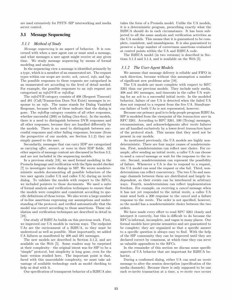
are used extensively for PSTN–SIP interworking and mediaserver control.
3.1 Message Sequencing
3.1.1 Method of StudyMessage sequencing is an aspect of behavior. It is con-
cerned with when a user agent can or must send a message,and what messages a user agent might receive at any giventime. We study message sequencing by means of formalmodeling and analysis.
In the sequencing view a message is identified primarily bya type, which is a member of an enumerated set. The requesttypes within our scope are invite, ack, cancel, info, and bye.The possible responses to these requests are categorized inan enumerated set according to the level of detail needed.For example, the possible responses to an info request arecategorized as infoDVR or infoRsp.
The infoDVR category consists of 408 (Request Timeout)and 481 (Call/Transaction Does Not Exist) messages in re-sponse to an info. The name stands for Dialog VanishedResponse, because both of these indicate that the dialog isgone. The infoRsp category consists of all other responses,whether successful (200) or failing (3xx-6xx). In the models,there is a need to distinguish between DVR responses andall other responses, because they are handled differently bythe models. There is no need to distinguish between suc-cessful responses and other failing responses, because (fromthe perspective of our models, see Section 3.1.2) they aresimply passed to the user.
Secondarily, messages that can carry SDP are categorizedas carrying offer, answer, or none in their SDP fields. Allother aspects of message content are discussed in Section 3.2,and are not included in the sequencing models.
In a previous study [18], we used formal modeling in thePromela language and verification with the Spin model checker[7] to investigate invite dialogs in SIP. We wrote nondeter-ministic models documenting all possible behaviors of thetwo user agents (caller UA and callee UA) during an invitedialog. To validate the models with respect to the RFCs,we included pointers to those documents. We used a suiteof formal analysis and verification techniques to ensure thatthe models were complete and consistent according to spe-cific definitions of those terms. We also wrote a large numberof in-line assertions expressing our assumptions and under-standing of the protocol, and verified automatically that themodel was correct according to those assertions. These val-idation and verification techniques are described in detail in[18].
Our study of B2BUAs builds on this previous work. First,we improved our UA models in various ways. The endpointUAs are the environment of a B2BUA, so they must beunderstood as well as possible. Most importantly, we addedUA failures as manifested by 408 and 481 messages.
The new models are described in Section 3.1.2, and areavailable on the Web [5]. Some readers may be surprisedat their complexity—the original intent was for SIP to be a“simple” protocol, but simplicity is long gone, even for thebasic version studied here. The important point is that,faced with this unavoidable complexity, we must take ad-vantage of available technology such as model checking tohelp us deal with it.
Our specification of transparent behavior of a B2BUA also
takes the form of a Promela model. Unlike the UA models,it is a deterministic program, prescribing exactly what theB2BUA should do in each circumstance. It has been sub-jected to all the same analysis and verification activities asthe UA models. This means that it is guaranteed to be com-plete, consistent, and unambiguous. It is also guaranteed topreserve a large number of correctness assertions evaluatedat control points within the UA and B2BUA code.
The B2BUA model (in two versions) is described in Sec-tions 3.1.3 and 3.1.4, and is available on the Web [5].
3.1.2 The User-Agent ModelsWe assume that message delivery is reliable and FIFO in
each direction, because without this assumption a numberof significant new problems arise [18].
The UA models are more complete with respect to RFC3261 than our previous models. They include early media,408 and 481 messages, and timeouts in the callee UA wait-ing for an ack to a successful initial invite. In the modeledbehavior, failure of one UA is detected when the failed UAdoes not respond to a request from the live UA. Simultane-ous failure of both UAs is not represented, however.
Because our primary goal is to help people program B2BUAs,SIP is modeled from the viewpoint of the transaction user inRFC 3261. According to RFC 3261, 100 (Trying) messages,retransmissions, and acknowledgments after invite failuresare all handled exclusively by a lower-level transaction layerof the protocol stack. This means that they need not bepresent in our models.
As mentioned previously, the UA models are highly non-deterministic. There are four major causes of nondetermin-ism. First, nondeterminism can reflect user choice. For ex-ample, after sending an initial invite, a caller UA can chooseto send a cancel message or wait for the response to the in-vite. Second, nondeterminism can represent the possibilityof failure. Whenever a UA is due to respond to a request,the UA model can send the request or else fail. Third, non-determinism can reflect concurrency. The two UAs and mes-sage channels between them are distributed and largely in-dependent, so their events can be interleaved in arbitraryways. Fourth, nondeterminism can reflect implementationfreedom. For example, on receiving a cancel message whenit has not yet responded to the initial invite, a callee UAmust send both a 200 response to the cancel and a failureresponse to the invite. The order is not specified, however,so the model has a nondeterministic choice between the twoorders.
We have made every effort to read RFC 3261 closely andinterpret it correctly, but this is difficult to do because theRFC is informal, incomplete, and vague in many places. Ourformal models have precise semantics and are guaranteed tobe complete; they are organized so that a specific answerto a specific question is always easy to find. With the helpof the SIP community they can be improved until they aredeclared correct by consensus, at which time they can serveas valuable appendices to the RFCs.
In the remainder of this section we discuss some specificaspects of UA behavior that are important for B2BUA be-havior.
During a confirmed dialog, either UA can send an invitemessage to alter the session description (specification of themedia channels). Because there is only supposed to be onesuch re-invite transaction at a time, a re-invite race occurs
53
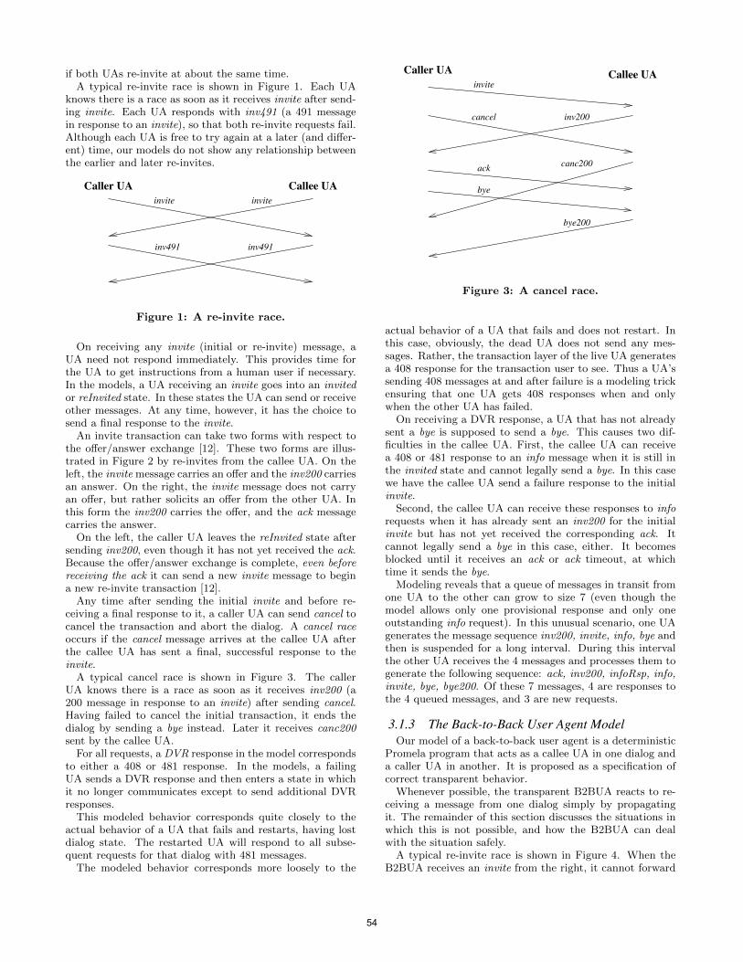
if both UAs re-invite at about the same time.A typical re-invite race is shown in Figure 1. Each UA
knows there is a race as soon as it receives invite after send-ing invite. Each UA responds with inv491 (a 491 messagein response to an invite), so that both re-invite requests fail.Although each UA is free to try again at a later (and differ-ent) time, our models do not show any relationship betweenthe earlier and later re-invites.
invite invite
inv491 inv491
Caller UA Callee UA
Figure 1: A re-invite race.
On receiving any invite (initial or re-invite) message, aUA need not respond immediately. This provides time forthe UA to get instructions from a human user if necessary.In the models, a UA receiving an invite goes into an invitedor reInvited state. In these states the UA can send or receiveother messages. At any time, however, it has the choice tosend a final response to the invite.
An invite transaction can take two forms with respect tothe offer/answer exchange [12]. These two forms are illus-trated in Figure 2 by re-invites from the callee UA. On theleft, the invite message carries an offer and the inv200 carriesan answer. On the right, the invite message does not carryan offer, but rather solicits an offer from the other UA. Inthis form the inv200 carries the offer, and the ack messagecarries the answer.
On the left, the caller UA leaves the reInvited state aftersending inv200, even though it has not yet received the ack.Because the offer/answer exchange is complete, even beforereceiving the ack it can send a new invite message to begina new re-invite transaction [12].
Any time after sending the initial invite and before re-ceiving a final response to it, a caller UA can send cancel tocancel the transaction and abort the dialog. A cancel raceoccurs if the cancel message arrives at the callee UA afterthe callee UA has sent a final, successful response to theinvite.
A typical cancel race is shown in Figure 3. The callerUA knows there is a race as soon as it receives inv200 (a200 message in response to an invite) after sending cancel.Having failed to cancel the initial transaction, it ends thedialog by sending a bye instead. Later it receives canc200sent by the callee UA.
For all requests, a DVR response in the model correspondsto either a 408 or 481 response. In the models, a failingUA sends a DVR response and then enters a state in whichit no longer communicates except to send additional DVRresponses.
This modeled behavior corresponds quite closely to theactual behavior of a UA that fails and restarts, having lostdialog state. The restarted UA will respond to all subse-quent requests for that dialog with 481 messages.
The modeled behavior corresponds more loosely to the
cancel
invite
inv200
ack
bye
bye200
Caller UA Callee UA
canc200
Figure 3: A cancel race.
actual behavior of a UA that fails and does not restart. Inthis case, obviously, the dead UA does not send any mes-sages. Rather, the transaction layer of the live UA generatesa 408 response for the transaction user to see. Thus a UA’ssending 408 messages at and after failure is a modeling trickensuring that one UA gets 408 responses when and onlywhen the other UA has failed.
On receiving a DVR response, a UA that has not alreadysent a bye is supposed to send a bye. This causes two dif-ficulties in the callee UA. First, the callee UA can receivea 408 or 481 response to an info message when it is still inthe invited state and cannot legally send a bye. In this casewe have the callee UA send a failure response to the initialinvite.
Second, the callee UA can receive these responses to inforequests when it has already sent an inv200 for the initialinvite but has not yet received the corresponding ack. Itcannot legally send a bye in this case, either. It becomesblocked until it receives an ack or ack timeout, at whichtime it sends the bye.
Modeling reveals that a queue of messages in transit fromone UA to the other can grow to size 7 (even though themodel allows only one provisional response and only oneoutstanding info request). In this unusual scenario, one UAgenerates the message sequence inv200, invite, info, bye andthen is suspended for a long interval. During this intervalthe other UA receives the 4 messages and processes them togenerate the following sequence: ack, inv200, infoRsp, info,invite, bye, bye200. Of these 7 messages, 4 are responses tothe 4 queued messages, and 3 are new requests.
3.1.3 The Back-to-Back User Agent ModelOur model of a back-to-back user agent is a deterministic
Promela program that acts as a callee UA in one dialog anda caller UA in another. It is proposed as a specification ofcorrect transparent behavior.
Whenever possible, the transparent B2BUA reacts to re-ceiving a message from one dialog simply by propagatingit. The remainder of this section discusses the situations inwhich this is not possible, and how the B2BUA can dealwith the situation safely.
A typical re-invite race is shown in Figure 4. When theB2BUA receives an invite from the right, it cannot forward
54
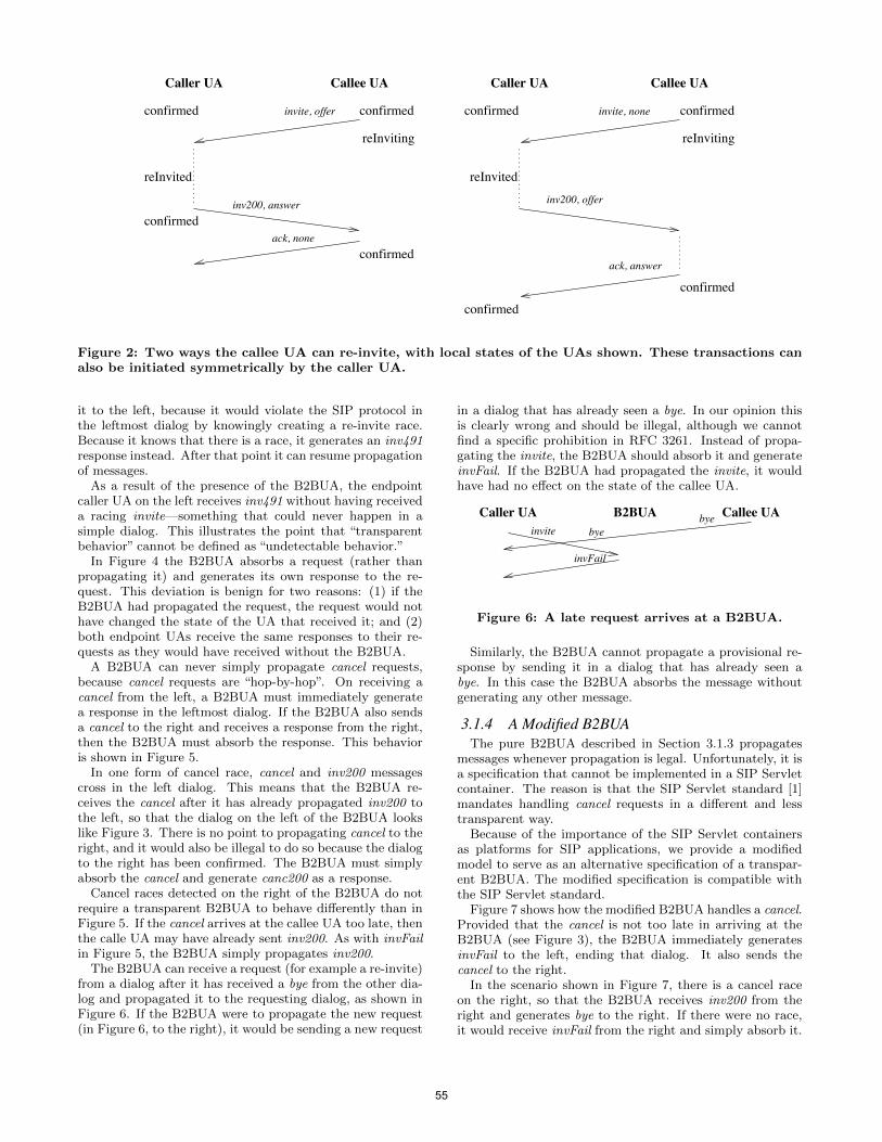
reInvited
confirmedconfirmed confirmed confirmed
reInviting
confirmed
confirmed
reInviting
confirmedconfirmed
ack, answer
inv200, offer
invite, noneinvite, offer
ack, none
reInvited
inv200, answer
Caller UA Callee UA Caller UA Callee UA
Figure 2: Two ways the callee UA can re-invite, with local states of the UAs shown. These transactions canalso be initiated symmetrically by the caller UA.
it to the left, because it would violate the SIP protocol inthe leftmost dialog by knowingly creating a re-invite race.Because it knows that there is a race, it generates an inv491response instead. After that point it can resume propagationof messages.
As a result of the presence of the B2BUA, the endpointcaller UA on the left receives inv491 without having receiveda racing invite—something that could never happen in asimple dialog. This illustrates the point that “transparentbehavior” cannot be defined as “undetectable behavior.”
In Figure 4 the B2BUA absorbs a request (rather thanpropagating it) and generates its own response to the re-quest. This deviation is benign for two reasons: (1) if theB2BUA had propagated the request, the request would nothave changed the state of the UA that received it; and (2)both endpoint UAs receive the same responses to their re-quests as they would have received without the B2BUA.
A B2BUA can never simply propagate cancel requests,because cancel requests are “hop-by-hop”. On receiving acancel from the left, a B2BUA must immediately generatea response in the leftmost dialog. If the B2BUA also sendsa cancel to the right and receives a response from the right,then the B2BUA must absorb the response. This behavioris shown in Figure 5.
In one form of cancel race, cancel and inv200 messagescross in the left dialog. This means that the B2BUA re-ceives the cancel after it has already propagated inv200 tothe left, so that the dialog on the left of the B2BUA lookslike Figure 3. There is no point to propagating cancel to theright, and it would also be illegal to do so because the dialogto the right has been confirmed. The B2BUA must simplyabsorb the cancel and generate canc200 as a response.
Cancel races detected on the right of the B2BUA do notrequire a transparent B2BUA to behave differently than inFigure 5. If the cancel arrives at the callee UA too late, thenthe calle UA may have already sent inv200. As with invFailin Figure 5, the B2BUA simply propagates inv200.
The B2BUA can receive a request (for example a re-invite)from a dialog after it has received a bye from the other dia-log and propagated it to the requesting dialog, as shown inFigure 6. If the B2BUA were to propagate the new request(in Figure 6, to the right), it would be sending a new request
in a dialog that has already seen a bye. In our opinion thisis clearly wrong and should be illegal, although we cannotfind a specific prohibition in RFC 3261. Instead of propa-gating the invite, the B2BUA should absorb it and generateinvFail. If the B2BUA had propagated the invite, it wouldhave had no effect on the state of the callee UA.
B2BUA byebyeinvite
invFail
Caller UA Callee UA
Figure 6: A late request arrives at a B2BUA.
Similarly, the B2BUA cannot propagate a provisional re-sponse by sending it in a dialog that has already seen abye. In this case the B2BUA absorbs the message withoutgenerating any other message.
3.1.4 A Modified B2BUAThe pure B2BUA described in Section 3.1.3 propagates
messages whenever propagation is legal. Unfortunately, it isa specification that cannot be implemented in a SIP Servletcontainer. The reason is that the SIP Servlet standard [1]mandates handling cancel requests in a different and lesstransparent way.
Because of the importance of the SIP Servlet containersas platforms for SIP applications, we provide a modifiedmodel to serve as an alternative specification of a transpar-ent B2BUA. The modified specification is compatible withthe SIP Servlet standard.
Figure 7 shows how the modified B2BUA handles a cancel.Provided that the cancel is not too late in arriving at theB2BUA (see Figure 3), the B2BUA immediately generatesinvFail to the left, ending that dialog. It also sends thecancel to the right.
In the scenario shown in Figure 7, there is a cancel raceon the right, so that the B2BUA receives inv200 from theright and generates bye to the right. If there were no race,it would receive invFail from the right and simply absorb it.
55
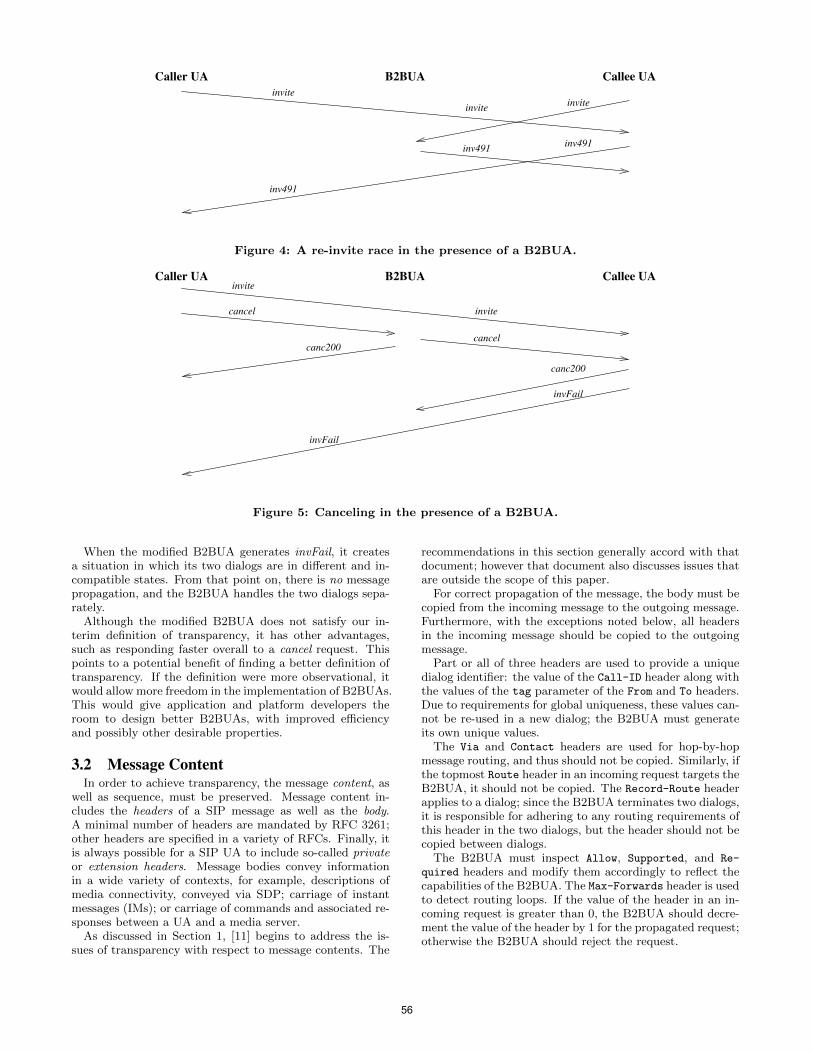
B2BUAinvite
inv491
invite
inv491
invite
inv491
Caller UA Callee UA
Figure 4: A re-invite race in the presence of a B2BUA.
B2BUA
canc200
cancel
invite
invite
cancel
canc200
invFail
invFail
Caller UA Callee UA
Figure 5: Canceling in the presence of a B2BUA.
When the modified B2BUA generates invFail, it createsa situation in which its two dialogs are in different and in-compatible states. From that point on, there is no messagepropagation, and the B2BUA handles the two dialogs sepa-rately.
Although the modified B2BUA does not satisfy our in-terim definition of transparency, it has other advantages,such as responding faster overall to a cancel request. Thispoints to a potential benefit of finding a better definition oftransparency. If the definition were more observational, itwould allow more freedom in the implementation of B2BUAs.This would give application and platform developers theroom to design better B2BUAs, with improved efficiencyand possibly other desirable properties.
3.2 Message ContentIn order to achieve transparency, the message content, as
well as sequence, must be preserved. Message content in-cludes the headers of a SIP message as well as the body.A minimal number of headers are mandated by RFC 3261;other headers are specified in a variety of RFCs. Finally, itis always possible for a SIP UA to include so-called privateor extension headers. Message bodies convey informationin a wide variety of contexts, for example, descriptions ofmedia connectivity, conveyed via SDP; carriage of instantmessages (IMs); or carriage of commands and associated re-sponses between a UA and a media server.
As discussed in Section 1, [11] begins to address the is-sues of transparency with respect to message contents. The
recommendations in this section generally accord with thatdocument; however that document also discusses issues thatare outside the scope of this paper.
For correct propagation of the message, the body must becopied from the incoming message to the outgoing message.Furthermore, with the exceptions noted below, all headersin the incoming message should be copied to the outgoingmessage.
Part or all of three headers are used to provide a uniquedialog identifier: the value of the Call-ID header along withthe values of the tag parameter of the From and To headers.Due to requirements for global uniqueness, these values can-not be re-used in a new dialog; the B2BUA must generateits own unique values.
The Via and Contact headers are used for hop-by-hopmessage routing, and thus should not be copied. Similarly, ifthe topmost Route header in an incoming request targets theB2BUA, it should not be copied. The Record-Route headerapplies to a dialog; since the B2BUA terminates two dialogs,it is responsible for adhering to any routing requirements ofthis header in the two dialogs, but the header should not becopied between dialogs.
The B2BUA must inspect Allow, Supported, and Re-
quired headers and modify them accordingly to reflect thecapabilities of the B2BUA. The Max-Forwards header is usedto detect routing loops. If the value of the header in an in-coming request is greater than 0, the B2BUA should decre-ment the value of the header by 1 for the propagated request;otherwise the B2BUA should reject the request.
56
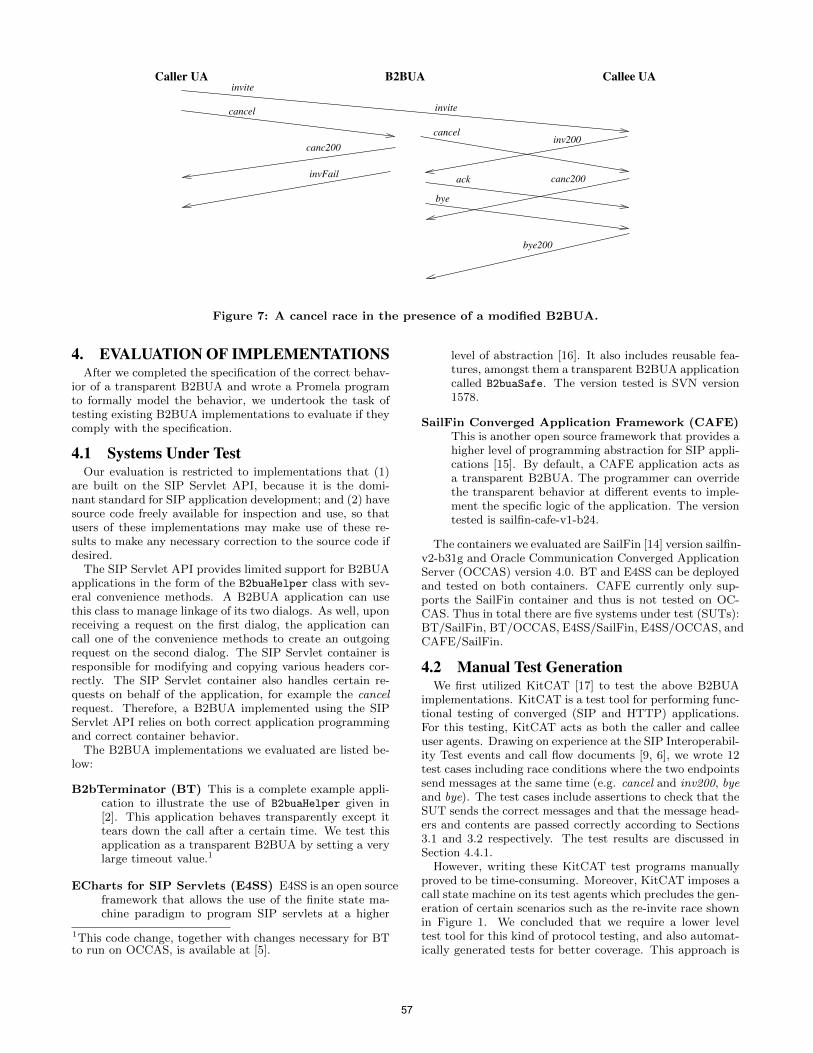
B2BUA
canc200
cancel
invite
invite
invFail
cancelinv200
ack
bye
bye200
Caller UA Callee UA
canc200
Figure 7: A cancel race in the presence of a modified B2BUA.
4. EVALUATION OF IMPLEMENTATIONSAfter we completed the specification of the correct behav-
ior of a transparent B2BUA and wrote a Promela programto formally model the behavior, we undertook the task oftesting existing B2BUA implementations to evaluate if theycomply with the specification.
4.1 Systems Under TestOur evaluation is restricted to implementations that (1)
are built on the SIP Servlet API, because it is the domi-nant standard for SIP application development; and (2) havesource code freely available for inspection and use, so thatusers of these implementations may make use of these re-sults to make any necessary correction to the source code ifdesired.
The SIP Servlet API provides limited support for B2BUAapplications in the form of the B2buaHelper class with sev-eral convenience methods. A B2BUA application can usethis class to manage linkage of its two dialogs. As well, uponreceiving a request on the first dialog, the application cancall one of the convenience methods to create an outgoingrequest on the second dialog. The SIP Servlet container isresponsible for modifying and copying various headers cor-rectly. The SIP Servlet container also handles certain re-quests on behalf of the application, for example the cancelrequest. Therefore, a B2BUA implemented using the SIPServlet API relies on both correct application programmingand correct container behavior.
The B2BUA implementations we evaluated are listed be-low:
B2bTerminator (BT) This is a complete example appli-cation to illustrate the use of B2buaHelper given in[2]. This application behaves transparently except ittears down the call after a certain time. We test thisapplication as a transparent B2BUA by setting a verylarge timeout value.1
ECharts for SIP Servlets (E4SS) E4SS is an open sourceframework that allows the use of the finite state ma-chine paradigm to program SIP servlets at a higher
1This code change, together with changes necessary for BTto run on OCCAS, is available at [5].
level of abstraction [16]. It also includes reusable fea-tures, amongst them a transparent B2BUA applicationcalled B2buaSafe. The version tested is SVN version1578.
SailFin Converged Application Framework (CAFE)This is another open source framework that provides ahigher level of programming abstraction for SIP appli-cations [15]. By default, a CAFE application acts asa transparent B2BUA. The programmer can overridethe transparent behavior at different events to imple-ment the specific logic of the application. The versiontested is sailfin-cafe-v1-b24.
The containers we evaluated are SailFin [14] version sailfin-v2-b31g and Oracle Communication Converged ApplicationServer (OCCAS) version 4.0. BT and E4SS can be deployedand tested on both containers. CAFE currently only sup-ports the SailFin container and thus is not tested on OC-CAS. Thus in total there are five systems under test (SUTs):BT/SailFin, BT/OCCAS, E4SS/SailFin, E4SS/OCCAS, andCAFE/SailFin.
4.2 Manual Test GenerationWe first utilized KitCAT [17] to test the above B2BUA
implementations. KitCAT is a test tool for performing func-tional testing of converged (SIP and HTTP) applications.For this testing, KitCAT acts as both the caller and calleeuser agents. Drawing on experience at the SIP Interoperabil-ity Test events and call flow documents [9, 6], we wrote 12test cases including race conditions where the two endpointssend messages at the same time (e.g. cancel and inv200, byeand bye). The test cases include assertions to check that theSUT sends the correct messages and that the message head-ers and contents are passed correctly according to Sections3.1 and 3.2 respectively. The test results are discussed inSection 4.4.1.
However, writing these KitCAT test programs manuallyproved to be time-consuming. Moreover, KitCAT imposes acall state machine on its test agents which precludes the gen-eration of certain scenarios such as the re-invite race shownin Figure 1. We concluded that we require a lower leveltest tool for this kind of protocol testing, and also automat-ically generated tests for better coverage. This approach is
57
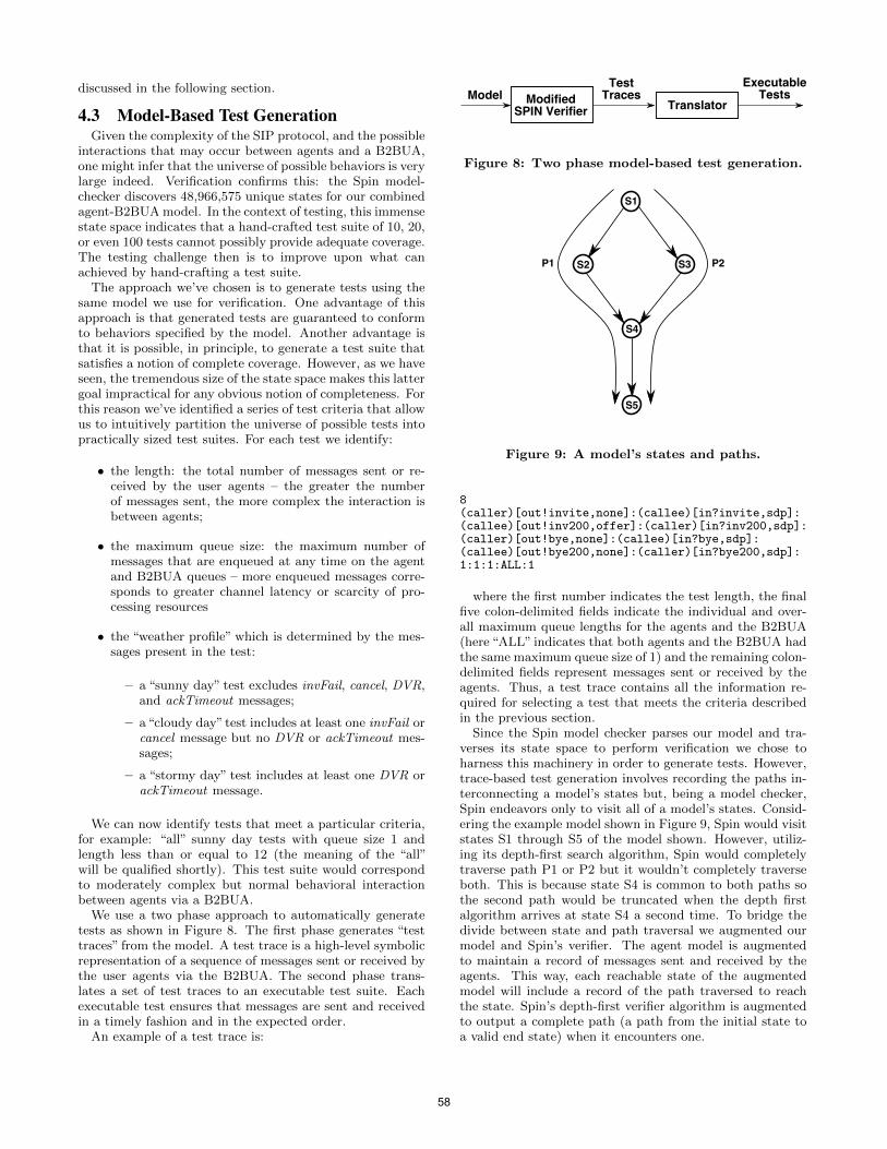
discussed in the following section.
4.3 Model-Based Test GenerationGiven the complexity of the SIP protocol, and the possible
interactions that may occur between agents and a B2BUA,one might infer that the universe of possible behaviors is verylarge indeed. Verification confirms this: the Spin model-checker discovers 48,966,575 unique states for our combinedagent-B2BUA model. In the context of testing, this immensestate space indicates that a hand-crafted test suite of 10, 20,or even 100 tests cannot possibly provide adequate coverage.The testing challenge then is to improve upon what canachieved by hand-crafting a test suite.
The approach we’ve chosen is to generate tests using thesame model we use for verification. One advantage of thisapproach is that generated tests are guaranteed to conformto behaviors specified by the model. Another advantage isthat it is possible, in principle, to generate a test suite thatsatisfies a notion of complete coverage. However, as we haveseen, the tremendous size of the state space makes this lattergoal impractical for any obvious notion of completeness. Forthis reason we’ve identified a series of test criteria that allowus to intuitively partition the universe of possible tests intopractically sized test suites. For each test we identify:
• the length: the total number of messages sent or re-ceived by the user agents – the greater the numberof messages sent, the more complex the interaction isbetween agents;
• the maximum queue size: the maximum number ofmessages that are enqueued at any time on the agentand B2BUA queues – more enqueued messages corre-sponds to greater channel latency or scarcity of pro-cessing resources
• the “weather profile” which is determined by the mes-sages present in the test:
– a “sunny day” test excludes invFail, cancel, DVR,and ackTimeout messages;
– a“cloudy day”test includes at least one invFail orcancel message but no DVR or ackTimeout mes-sages;
– a “stormy day” test includes at least one DVR orackTimeout message.
We can now identify tests that meet a particular criteria,for example: “all” sunny day tests with queue size 1 andlength less than or equal to 12 (the meaning of the “all”will be qualified shortly). This test suite would correspondto moderately complex but normal behavioral interactionbetween agents via a B2BUA.
We use a two phase approach to automatically generatetests as shown in Figure 8. The first phase generates “testtraces” from the model. A test trace is a high-level symbolicrepresentation of a sequence of messages sent or received bythe user agents via the B2BUA. The second phase trans-lates a set of test traces to an executable test suite. Eachexecutable test ensures that messages are sent and receivedin a timely fashion and in the expected order.
An example of a test trace is:
Figure 8: Two phase model-based test generation.
Figure 9: A model’s states and paths.
8(caller)[out!invite,none]:(callee)[in?invite,sdp]:(callee)[out!inv200,offer]:(caller)[in?inv200,sdp]:(caller)[out!bye,none]:(callee)[in?bye,sdp]:(callee)[out!bye200,none]:(caller)[in?bye200,sdp]:1:1:1:ALL:1
where the first number indicates the test length, the finalfive colon-delimited fields indicate the individual and over-all maximum queue lengths for the agents and the B2BUA(here “ALL” indicates that both agents and the B2BUA hadthe same maximum queue size of 1) and the remaining colon-delimited fields represent messages sent or received by theagents. Thus, a test trace contains all the information re-quired for selecting a test that meets the criteria describedin the previous section.
Since the Spin model checker parses our model and tra-verses its state space to perform verification we chose toharness this machinery in order to generate tests. However,trace-based test generation involves recording the paths in-terconnecting a model’s states but, being a model checker,Spin endeavors only to visit all of a model’s states. Consid-ering the example model shown in Figure 9, Spin would visitstates S1 through S5 of the model shown. However, utiliz-ing its depth-first search algorithm, Spin would completelytraverse path P1 or P2 but it wouldn’t completely traverseboth. This is because state S4 is common to both paths sothe second path would be truncated when the depth firstalgorithm arrives at state S4 a second time. To bridge thedivide between state and path traversal we augmented ourmodel and Spin’s verifier. The agent model is augmentedto maintain a record of messages sent and received by theagents. This way, each reachable state of the augmentedmodel will include a record of the path traversed to reachthe state. Spin’s depth-first verifier algorithm is augmentedto output a complete path (a path from the initial state toa valid end state) when it encounters one.
58
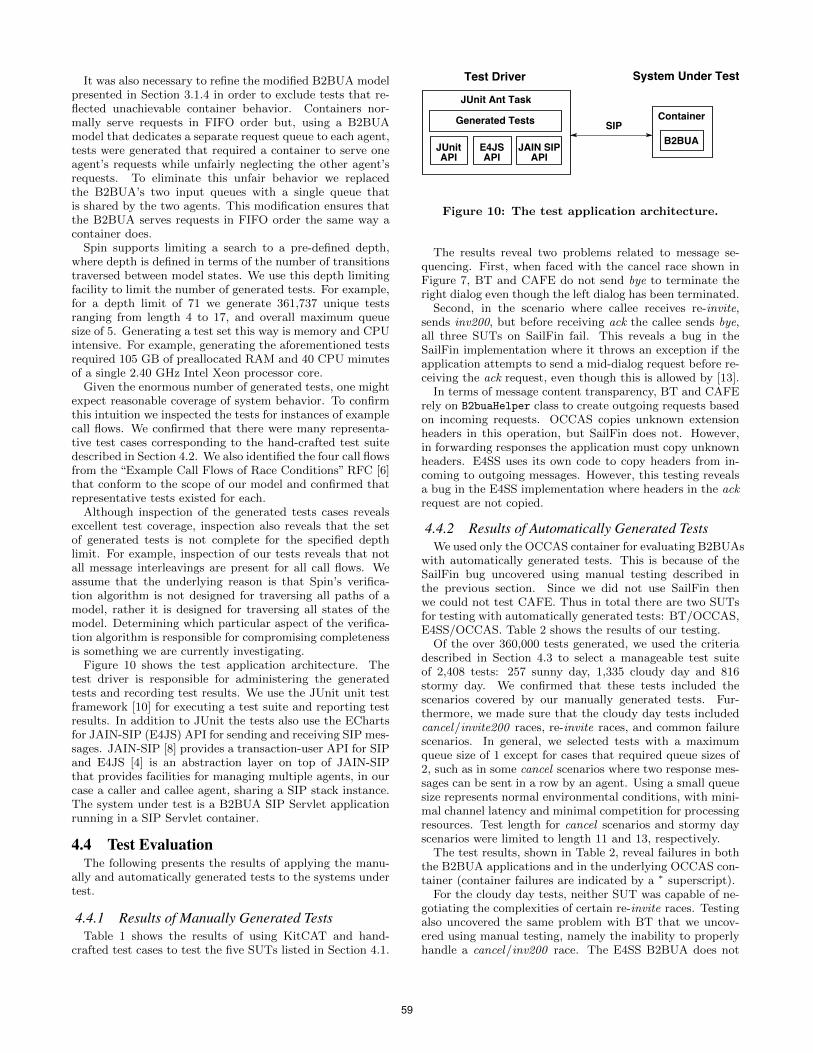
It was also necessary to refine the modified B2BUA modelpresented in Section 3.1.4 in order to exclude tests that re-flected unachievable container behavior. Containers nor-mally serve requests in FIFO order but, using a B2BUAmodel that dedicates a separate request queue to each agent,tests were generated that required a container to serve oneagent’s requests while unfairly neglecting the other agent’srequests. To eliminate this unfair behavior we replacedthe B2BUA’s two input queues with a single queue thatis shared by the two agents. This modification ensures thatthe B2BUA serves requests in FIFO order the same way acontainer does.
Spin supports limiting a search to a pre-defined depth,where depth is defined in terms of the number of transitionstraversed between model states. We use this depth limitingfacility to limit the number of generated tests. For example,for a depth limit of 71 we generate 361,737 unique testsranging from length 4 to 17, and overall maximum queuesize of 5. Generating a test set this way is memory and CPUintensive. For example, generating the aforementioned testsrequired 105 GB of preallocated RAM and 40 CPU minutesof a single 2.40 GHz Intel Xeon processor core.
Given the enormous number of generated tests, one mightexpect reasonable coverage of system behavior. To confirmthis intuition we inspected the tests for instances of examplecall flows. We confirmed that there were many representa-tive test cases corresponding to the hand-crafted test suitedescribed in Section 4.2. We also identified the four call flowsfrom the “Example Call Flows of Race Conditions” RFC [6]that conform to the scope of our model and confirmed thatrepresentative tests existed for each.
Although inspection of the generated tests cases revealsexcellent test coverage, inspection also reveals that the setof generated tests is not complete for the specified depthlimit. For example, inspection of our tests reveals that notall message interleavings are present for all call flows. Weassume that the underlying reason is that Spin’s verifica-tion algorithm is not designed for traversing all paths of amodel, rather it is designed for traversing all states of themodel. Determining which particular aspect of the verifica-tion algorithm is responsible for compromising completenessis something we are currently investigating.
Figure 10 shows the test application architecture. Thetest driver is responsible for administering the generatedtests and recording test results. We use the JUnit unit testframework [10] for executing a test suite and reporting testresults. In addition to JUnit the tests also use the EChartsfor JAIN-SIP (E4JS) API for sending and receiving SIP mes-sages. JAIN-SIP [8] provides a transaction-user API for SIPand E4JS [4] is an abstraction layer on top of JAIN-SIPthat provides facilities for managing multiple agents, in ourcase a caller and callee agent, sharing a SIP stack instance.The system under test is a B2BUA SIP Servlet applicationrunning in a SIP Servlet container.
4.4 Test EvaluationThe following presents the results of applying the manu-
ally and automatically generated tests to the systems undertest.
4.4.1 Results of Manually Generated TestsTable 1 shows the results of using KitCAT and hand-
crafted test cases to test the five SUTs listed in Section 4.1.
Figure 10: The test application architecture.
The results reveal two problems related to message se-quencing. First, when faced with the cancel race shown inFigure 7, BT and CAFE do not send bye to terminate theright dialog even though the left dialog has been terminated.
Second, in the scenario where callee receives re-invite,sends inv200, but before receiving ack the callee sends bye,all three SUTs on SailFin fail. This reveals a bug in theSailFin implementation where it throws an exception if theapplication attempts to send a mid-dialog request before re-ceiving the ack request, even though this is allowed by [13].
In terms of message content transparency, BT and CAFErely on B2buaHelper class to create outgoing requests basedon incoming requests. OCCAS copies unknown extensionheaders in this operation, but SailFin does not. However,in forwarding responses the application must copy unknownheaders. E4SS uses its own code to copy headers from in-coming to outgoing messages. However, this testing revealsa bug in the E4SS implementation where headers in the ackrequest are not copied.
4.4.2 Results of Automatically Generated TestsWe used only the OCCAS container for evaluating B2BUAs
with automatically generated tests. This is because of theSailFin bug uncovered using manual testing described inthe previous section. Since we did not use SailFin thenwe could not test CAFE. Thus in total there are two SUTsfor testing with automatically generated tests: BT/OCCAS,E4SS/OCCAS. Table 2 shows the results of our testing.
Of the over 360,000 tests generated, we used the criteriadescribed in Section 4.3 to select a manageable test suiteof 2,408 tests: 257 sunny day, 1,335 cloudy day and 816stormy day. We confirmed that these tests included thescenarios covered by our manually generated tests. Fur-thermore, we made sure that the cloudy day tests includedcancel/invite200 races, re-invite races, and common failurescenarios. In general, we selected tests with a maximumqueue size of 1 except for cases that required queue sizes of2, such as in some cancel scenarios where two response mes-sages can be sent in a row by an agent. Using a small queuesize represents normal environmental conditions, with mini-mal channel latency and minimal competition for processingresources. Test length for cancel scenarios and stormy dayscenarios were limited to length 11 and 13, respectively.
The test results, shown in Table 2, reveal failures in boththe B2BUA applications and in the underlying OCCAS con-tainer (container failures are indicated by a ∗ superscript).
For the cloudy day tests, neither SUT was capable of ne-gotiating the complexities of certain re-invite races. Testingalso uncovered the same problem with BT that we uncov-ered using manual testing, namely the inability to properlyhandle a cancel/inv200 race. The E4SS B2BUA does not
59
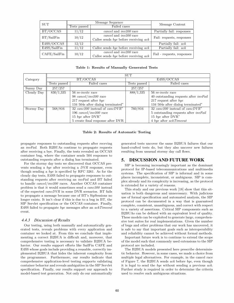
SUTMessage Sequence
Message ContentTests passed Failed cases
BT/OCCAS 11/12 cancel and inv200 race Partially fail: responses
BT/SailFin 10/12cancel and inv200 race
Fail: requests, responsesCallee sends bye before receiving ack
E4SS/OCCAS 12/12 Partially fail: ackE4SS/SailFin 11/12 Callee sends bye before receiving ack Partially fail: ack
CAFE/SailFin 10/12cancel and inv200 race
Fail - requests, responsesCallee sends bye before receiving ack
Table 1: Results of Manually Generated Tests
CategorySUT
BT/OCCAS E4SS/OCCASTests passed Failed cases Tests passed Failed cases
Sunny Day 257/257 257/257Cloudy Day 830/1,335 56 re-invite race 888/1,335 56 re-invite race
98 cancel/inv200 race 40 outstanding requests after invFail217 request after bye 217 request after bye134 504s after dialog terminated∗ 134 504s after dialog terminated∗
Stormy Day 568/816 32 canc200 instead of cancDVR∗ 760/816 32 canc200 instead of cancDVR∗
196 cancel/inv200 race 5 outstanding requests after invFail15 bye after DVR∗ 15 bye after DVR∗
5 create final response after DVR 4 bye after ackTimeout
Table 2: Results of Automatic Testing
propagate responses to outstanding requests after recevingan invFail. Both B2BUAs continue to propagate requestsafter receiving a bye. Finally, the tests revealed an OCCAScontainer bug, where the container sends 504 responses tooutstanding requests after a dialog has terminated.
For the stormy day tests we discovered that OCCAS pre-vents sending a bye after receiving a DVR response, eventhough sending a bye is specified by RFC 3261. As for thecloudy day tests, E4SS failed to propagate responses to out-standing requests after receiving an invFail and BT failedto handle cancel/inv200 races. Another OCCAS containerproblem is that it would sometimes send a canc200 insteadof the expected cancDVR in some DVR scenarios. BT failsto propagate a message because one of BT’s SipSessions nolonger exists. It isn’t clear if this is due to a bug in BT, theSIP Servlet specification or the OCCAS container. Finally,E4SS failed to propagate bye messages after an ackTimeoutevent.
4.4.3 Discussion of ResultsOur testing, using both manually and automatically gen-
erated tests, reveals problems with every application andcontainer we looked at. From this we conclude that imple-menting a correct B2BUA is difficult and, moreover, thatcomprehensive testing is necessary to validate B2BUA be-havior. Our results support efforts like SailFin CAFE andE4SS whose goals include providing a reusable, correctly im-plemented B2BUA that hides the inherent complexity fromthe programmer. Furthermore, our results indicate thatcomprehensive application-level testing supports validatingcontainer behavior and reveals ambiguities in the SIP Servletspecification. Finally, our results support our approach tomodel-based test generation. Not only do our automatically
generated tests uncover the same B2BUA failures that ourhand-crafted tests do, but they also uncover new failuresresulting from unusual stormy day call flows.
5. DISCUSSION AND FUTURE WORKSIP is becoming increasingly important as the dominant
protocol for IP-based telecommunications and multimediasystems. The specification of SIP is informal and in someplaces incomplete, inconsistent, or ambiguous. SIP is com-plex already and its complexity is increasing, as the protocolis extended for a variety of reasons.
This study and our previous work [18] show that this sit-uation is both dangerous and unnecessary. With judicioususe of formal specification and automated analysis, the SIPprotocol can be documented in a way that is guaranteedcomplete, consistent, unambiguous, and correct with respectto a variety of assertions. Critical SIP components such asB2BUAs can be defined with an equivalent level of quality.These models can be exploited to generate large, comprehen-sive test suites for real implementations. Given the numberof bugs and other problems that our work has uncovered, itis safe to say that important goals such as interoperabilityand reliability cannot be achieved without formal methods.
Important future work is to continue to extend the scopeof the model such that commonly used extensions to the SIPprotocol are included.
The B2BUA models presented here prescribe determinis-tic behavior. However, in some cases, we made a choice frommultiple legal alternatives. For example, in the cancel raceof Figure 7, the B2BUA sends ack before bye, even thoughit is legal to send the bye without sending a previous ack.Further study is required in order to determine the criteriaused to resolve such ambiguous situations.
60
It is our intention to expand the scope of our testing to in-clude tests with greater lengths and maximum queue sizes.The machine we use for generating traces has 128 GB ofRAM which limits us to a Spin verification depth limit of71. Using the current model this results in a maximum testlength of 17. By simplifying the model, for example, by con-straining certain transition sequences to execute atomically,we should be able to greatly reduce the state space with-out compromising completeness, thereby permitting deepersearches and generation of longer test traces.
Another challenge we faced was analyzing test results.While our test platform unambigiously indicates how manytests pass and how many fail, it does not provide any insightinto why tests fail. To do this we resorted to manually in-specting failure signatures extracted from log files, their as-sociated test cases and the associated application code. Nat-urally, this becomes tedious and error-prone as the numberof failure cases increases. This process would benefit fromautomated post-processing where similar failure signaturescould be grouped thereby reducing the number of failuresrequiring investigation.
A goal of the SIP Servlet specification is to simplify lifefor the application developer. To this end, a SIP Servletcontainer presents an abstraction of the SIP stack to theprogrammer. This abstraction intersects with that of a SIPtransaction-user but, in some cases, also presents a higher-level abstraction. The problem, as revealed by our testing,is that this abstraction is incompletely specified and has ledcontainer vendors to make their own, independent imple-mentation decisions without fully understanding their impli-cations. The result is that the SIP Servlet standard, whosegoal is to support interoperability of applications across con-tainers, does not achieve that goal. To address this situation,a topic for future research is to formally specify SIP Servletcontainer behavior and integrate the resulting model withour B2BUA models.
6. ACKNOWLEDGMENTSWe gratefully acknowledge Kristoffer Gronowski for sup-
plying the BT example code, as well as the SailFin CAFEteam for their publicly-available B2BUA implementation.Finally, we acknowledge, with gratitude and fondness, thegreat contributions and lasting memories of our late col-league Venkita Subramonian.
7. REFERENCES[1] BEA. SIP Servlet API version 1.1, 2008. Java
Community Process JSR 289.http://jcp.org/en/jsr/detail?id=289.
[2] C. Boulton and K. Gronowski. Understanding SIPServlets 1.1. Artech House, April 2009.
[3] S. Donovan. The SIP INFO method, October 2000.IETF RFC 2976.
[4] ECharts for JAIN SIP (E4JS). http://echarts.org/.
[5] Formal models of SIP, 2010.http://www.research.att.com/˜pamela/sip.html.
[6] M. Hasebe, J. Koshiko, Y. Suzuki, T. Yoshikawa, andP. Kyzivat. Example call flows of race conditions inthe session initiation protocol (SIP). IETF RFC 5407,December 2008.
[7] G. J. Holzmann. The Spin Model Checker: Primer andReference Manual. Addison-Wesley, 2004.
[8] JAIN(tm) SIP Specification. Java Community Process,2003. Available from: http://jcp.org/aboutJava/
communityprocess/final/jsr032/.
[9] A. Johnston, S. Donovan, R. Sparks, C. Cunningham,and K. Summers. Session Initiation Protocol (SIP)basic call flow examples. IETF RFC 3665, December2003.
[10] JUnit. http://www.junit.org/.
[11] X. Marjou, I. Elz, and P. Musgrave. Best currentpractices for a session initiation protocol (SIP)transparent back-to-back user-agent (B2BUA). IETFInternet-Draft draft-marjou-sipping-b2bua-01, July2007.
[12] J. Rosenberg and H. Schulzrinne. An offer/answermodel with the session description protocol (SDP),June 2002. IETF RFC 3264.
[13] J. Rosenberg, H. Schulzrinne, G. Camarillo,A. Johnston, J. Peterson, R. Sparks, M. Handley, andE. Schooler. SIP: Session initiation protocol, June2002. IETF RFC 3261.
[14] Project SailFin. https://sailfin.dev.java.net/.
[15] SailFin CAFE project.https://sailfin-cafe.dev.java.net/.
[16] T. M. Smith and G. W. Bond. ECharts for SIPServlets: a state-machine programming environmentfor VoIP applications. In IPTComm ’07: Proceedingsof the 1st International Conference on Principles,Systems and Applications of IP telecommunications,pages 89–98. ACM, 2007.
[17] V. Subramonian. Towards automated functionaltesting of converged applications. In IPTComm ’09:Proceedings of the 3rd International Conference onPrinciples, Systems and Applications of IPTelecommunications, pages 1–12, New York, NY,USA, 2009. ACM.
[18] P. Zave. Understanding SIP through model-checking.In Proceedings of the Second International Conferenceon Principles, Systems and Applications of IPTelecommunications, pages 256–279. Springer-VerlagLNCS 5310, 2008.
61

62
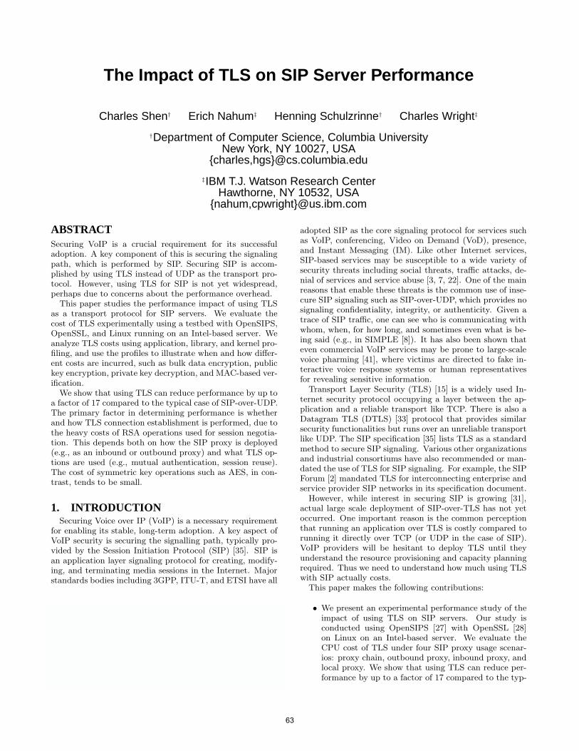
The Impact of TLS on SIP Server Performance
Charles Shen† Erich Nahum‡ Henning Schulzrinne† Charles Wright‡
†Department of Computer Science, Columbia UniversityNew York, NY 10027, USA
{charles,hgs}@cs.columbia.edu
‡IBM T.J. Watson Research CenterHawthorne, NY 10532, USA
{nahum,cpwright}@us.ibm.com
ABSTRACTSecuring VoIP is a crucial requirement for its successfuladoption. A key component of this is securing the signalingpath, which is performed by SIP. Securing SIP is accom-plished by using TLS instead of UDP as the transport pro-tocol. However, using TLS for SIP is not yet widespread,perhaps due to concerns about the performance overhead.
This paper studies the performance impact of using TLSas a transport protocol for SIP servers. We evaluate thecost of TLS experimentally using a testbed with OpenSIPS,OpenSSL, and Linux running on an Intel-based server. Weanalyze TLS costs using application, library, and kernel pro-filing, and use the profiles to illustrate when and how differ-ent costs are incurred, such as bulk data encryption, publickey encryption, private key decryption, and MAC-based ver-ification.
We show that using TLS can reduce performance by up toa factor of 17 compared to the typical case of SIP-over-UDP.The primary factor in determining performance is whetherand how TLS connection establishment is performed, due tothe heavy costs of RSA operations used for session negotia-tion. This depends both on how the SIP proxy is deployed(e.g., as an inbound or outbound proxy) and what TLS op-tions are used (e.g., mutual authentication, session reuse).The cost of symmetric key operations such as AES, in con-trast, tends to be small.
1. INTRODUCTIONSecuring Voice over IP (VoIP) is a necessary requirement
for enabling its stable, long-term adoption. A key aspect ofVoIP security is securing the signalling path, typically pro-vided by the Session Initiation Protocol (SIP) [35]. SIP isan application layer signaling protocol for creating, modify-ing, and terminating media sessions in the Internet. Majorstandards bodies including 3GPP, ITU-T, and ETSI have all
Permission to make digital or hard copies of all or part of this work forpersonal or classroom use is granted without fee provided that copies arenot made or distributed for profit or commercial advantage and that copiesbear this notice and the full citation on the first page. To copy otherwise, torepublish, to post on servers or to redistribute to lists, requires prior specificpermission and/or a fee.IPTComm 2010, 2-3 August, 2010 Munich, GermanyCopyright 2010 ACM ...$10.00.
adopted SIP as the core signaling protocol for services suchas VoIP, conferencing, Video on Demand (VoD), presence,and Instant Messaging (IM). Like other Internet services,SIP-based services may be susceptible to a wide variety ofsecurity threats including social threats, traffic attacks, de-nial of services and service abuse [3, 7, 22]. One of the mainreasons that enable these threats is the common use of inse-cure SIP signaling such as SIP-over-UDP, which provides nosignaling confidentiality, integrity, or authenticity. Given atrace of SIP traffic, one can see who is communicating withwhom, when, for how long, and sometimes even what is be-ing said (e.g., in SIMPLE [8]). It has also been shown thateven commercial VoIP services may be prone to large-scalevoice pharming [41], where victims are directed to fake in-teractive voice response systems or human representativesfor revealing sensitive information.
Transport Layer Security (TLS) [15] is a widely used In-ternet security protocol occupying a layer between the ap-plication and a reliable transport like TCP. There is also aDatagram TLS (DTLS) [33] protocol that provides similarsecurity functionalities but runs over an unreliable transportlike UDP. The SIP specification [35] lists TLS as a standardmethod to secure SIP signaling. Various other organizationsand industrial consortiums have also recommended or man-dated the use of TLS for SIP signaling. For example, the SIPForum [2] mandated TLS for interconnecting enterprise andservice provider SIP networks in its specification document.
However, while interest in securing SIP is growing [31],actual large scale deployment of SIP-over-TLS has not yetoccurred. One important reason is the common perceptionthat running an application over TLS is costly compared torunning it directly over TCP (or UDP in the case of SIP).VoIP providers will be hesitant to deploy TLS until theyunderstand the resource provisioning and capacity planningrequired. Thus we need to understand how much using TLSwith SIP actually costs.
This paper makes the following contributions:
• We present an experimental performance study of theimpact of using TLS on SIP servers. Our study isconducted using OpenSIPS [27] with OpenSSL [28]on Linux on an Intel-based server. We evaluate theCPU cost of TLS under four SIP proxy usage scenar-ios: proxy chain, outbound proxy, inbound proxy, andlocal proxy. We show that using TLS can reduce per-formance by up to a factor of 17 compared to the typ-
63
schmitt
Stempel
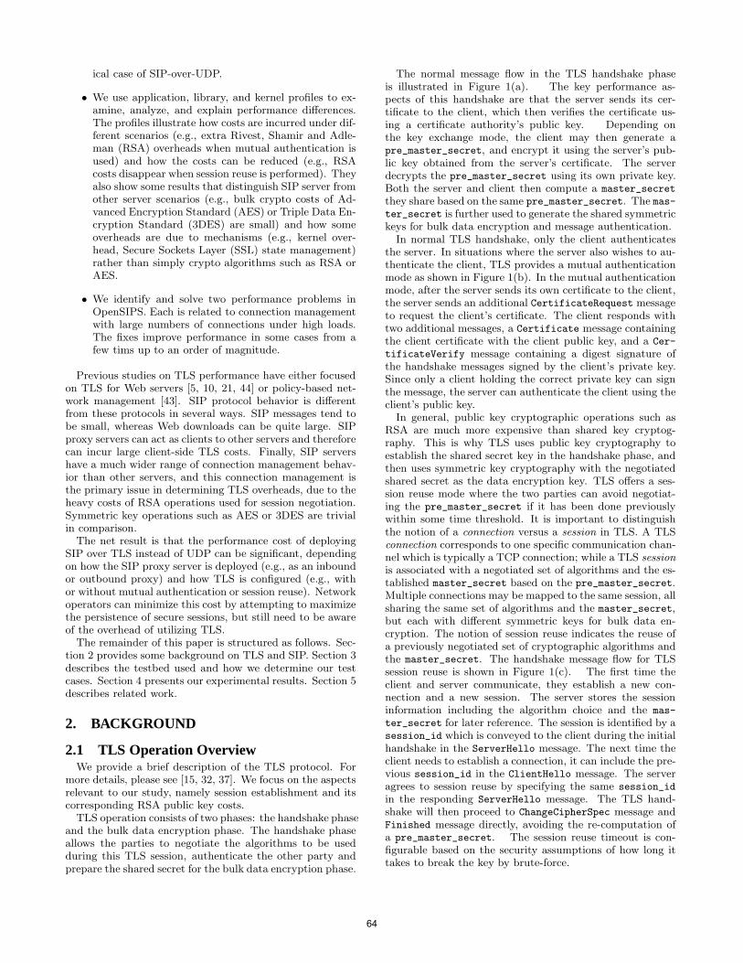
ical case of SIP-over-UDP.
• We use application, library, and kernel profiles to ex-amine, analyze, and explain performance differences.The profiles illustrate how costs are incurred under dif-ferent scenarios (e.g., extra Rivest, Shamir and Adle-man (RSA) overheads when mutual authentication isused) and how the costs can be reduced (e.g., RSAcosts disappear when session reuse is performed). Theyalso show some results that distinguish SIP server fromother server scenarios (e.g., bulk crypto costs of Ad-vanced Encryption Standard (AES) or Triple Data En-cryption Standard (3DES) are small) and how someoverheads are due to mechanisms (e.g., kernel over-head, Secure Sockets Layer (SSL) state management)rather than simply crypto algorithms such as RSA orAES.
• We identify and solve two performance problems inOpenSIPS. Each is related to connection managementwith large numbers of connections under high loads.The fixes improve performance in some cases from afew tims up to an order of magnitude.
Previous studies on TLS performance have either focusedon TLS for Web servers [5, 10, 21, 44] or policy-based net-work management [43]. SIP protocol behavior is differentfrom these protocols in several ways. SIP messages tend tobe small, whereas Web downloads can be quite large. SIPproxy servers can act as clients to other servers and thereforecan incur large client-side TLS costs. Finally, SIP servershave a much wider range of connection management behav-ior than other servers, and this connection management isthe primary issue in determining TLS overheads, due to theheavy costs of RSA operations used for session negotiation.Symmetric key operations such as AES or 3DES are trivialin comparison.
The net result is that the performance cost of deployingSIP over TLS instead of UDP can be significant, dependingon how the SIP proxy server is deployed (e.g., as an inboundor outbound proxy) and how TLS is configured (e.g., withor without mutual authentication or session reuse). Networkoperators can minimize this cost by attempting to maximizethe persistence of secure sessions, but still need to be awareof the overhead of utilizing TLS.
The remainder of this paper is structured as follows. Sec-tion 2 provides some background on TLS and SIP. Section 3describes the testbed used and how we determine our testcases. Section 4 presents our experimental results. Section 5describes related work.
2. BACKGROUND
2.1 TLS Operation OverviewWe provide a brief description of the TLS protocol. For
more details, please see [15, 32, 37]. We focus on the aspectsrelevant to our study, namely session establishment and itscorresponding RSA public key costs.
TLS operation consists of two phases: the handshake phaseand the bulk data encryption phase. The handshake phaseallows the parties to negotiate the algorithms to be usedduring this TLS session, authenticate the other party andprepare the shared secret for the bulk data encryption phase.
The normal message flow in the TLS handshake phaseis illustrated in Figure 1(a). The key performance as-pects of this handshake are that the server sends its cer-tificate to the client, which then verifies the certificate us-ing a certificate authority’s public key. Depending onthe key exchange mode, the client may then generate apre_master_secret, and encrypt it using the server’s pub-lic key obtained from the server’s certificate. The serverdecrypts the pre_master_secret using its own private key.Both the server and client then compute a master_secret
they share based on the same pre_master_secret. The mas-ter_secret is further used to generate the shared symmetrickeys for bulk data encryption and message authentication.
In normal TLS handshake, only the client authenticatesthe server. In situations where the server also wishes to au-thenticate the client, TLS provides a mutual authenticationmode as shown in Figure 1(b). In the mutual authenticationmode, after the server sends its own certificate to the client,the server sends an additional CertificateRequest messageto request the client’s certificate. The client responds withtwo additional messages, a Certificate message containingthe client certificate with the client public key, and a Cer-
tificateVerify message containing a digest signature ofthe handshake messages signed by the client’s private key.Since only a client holding the correct private key can signthe message, the server can authenticate the client using theclient’s public key.
In general, public key cryptographic operations such asRSA are much more expensive than shared key cryptog-raphy. This is why TLS uses public key cryptography toestablish the shared secret key in the handshake phase, andthen uses symmetric key cryptography with the negotiatedshared secret as the data encryption key. TLS offers a ses-sion reuse mode where the two parties can avoid negotiat-ing the pre_master_secret if it has been done previouslywithin some time threshold. It is important to distinguishthe notion of a connection versus a session in TLS. A TLSconnection corresponds to one specific communication chan-nel which is typically a TCP connection; while a TLS session
is associated with a negotiated set of algorithms and the es-tablished master_secret based on the pre_master_secret.Multiple connections may be mapped to the same session, allsharing the same set of algorithms and the master_secret,but each with different symmetric keys for bulk data en-cryption. The notion of session reuse indicates the reuse ofa previously negotiated set of cryptographic algorithms andthe master_secret. The handshake message flow for TLSsession reuse is shown in Figure 1(c). The first time theclient and server communicate, they establish a new con-nection and a new session. The server stores the sessioninformation including the algorithm choice and the mas-
ter_secret for later reference. The session is identified by asession_id which is conveyed to the client during the initialhandshake in the ServerHello message. The next time theclient needs to establish a connection, it can include the pre-vious session_id in the ClientHello message. The serveragrees to session reuse by specifying the same session_id
in the responding ServerHello message. The TLS hand-shake will then proceed to ChangeCipherSpec message andFinished message directly, avoiding the re-computation ofa pre_master_secret. The session reuse timeout is con-figurable based on the security assumptions of how long ittakes to break the key by brute-force.
64
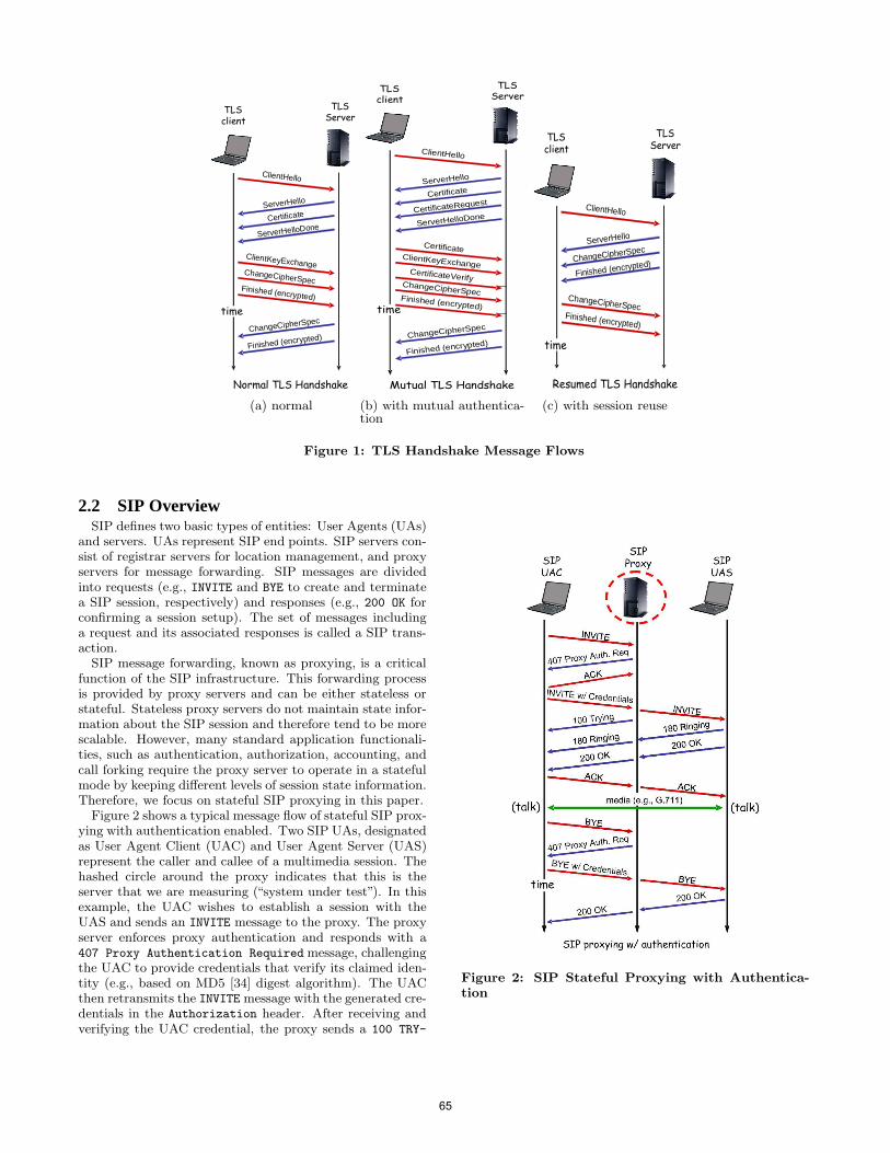
TLS
client
TLS
Server
ClientHello
Normal TLS Handshake
time
ServerHello
Certificate
ServerHelloDone
ClientKeyExchange
Finished (encrypted)
ChangeCipherSpec
ChangeCipherSpec
Finished (encrypted)
(a) normal
TLS
client
TLS
Server
ClientHello
Mutual TLS Handshake
time
ServerHello
Certificate
CertificateRequest
Certificate
CertificateVerify
ChangeCipherSpec
ClientKeyExchange
Finished (encrypted)
ServerHelloDone
Finished (encrypted)
ChangeCipherSpec
(b) with mutual authentica-tion
TLS
client
TLS
Server
ClientHello
Resumed TLS Handshake
time
ServerHello
ChangeCipherSpec
Finished (encrypted)
Finished (encrypted)
ChangeCipherSpec
(c) with session reuse
Figure 1: TLS Handshake Message Flows
2.2 SIP OverviewSIP defines two basic types of entities: User Agents (UAs)
and servers. UAs represent SIP end points. SIP servers con-sist of registrar servers for location management, and proxyservers for message forwarding. SIP messages are dividedinto requests (e.g., INVITE and BYE to create and terminatea SIP session, respectively) and responses (e.g., 200 OK forconfirming a session setup). The set of messages includinga request and its associated responses is called a SIP trans-action.
SIP message forwarding, known as proxying, is a criticalfunction of the SIP infrastructure. This forwarding processis provided by proxy servers and can be either stateless orstateful. Stateless proxy servers do not maintain state infor-mation about the SIP session and therefore tend to be morescalable. However, many standard application functionali-ties, such as authentication, authorization, accounting, andcall forking require the proxy server to operate in a statefulmode by keeping different levels of session state information.Therefore, we focus on stateful SIP proxying in this paper.
Figure 2 shows a typical message flow of stateful SIP prox-ying with authentication enabled. Two SIP UAs, designatedas User Agent Client (UAC) and User Agent Server (UAS)represent the caller and callee of a multimedia session. Thehashed circle around the proxy indicates that this is theserver that we are measuring (“system under test”). In thisexample, the UAC wishes to establish a session with theUAS and sends an INVITE message to the proxy. The proxyserver enforces proxy authentication and responds with a407 Proxy Authentication Required message, challengingthe UAC to provide credentials that verify its claimed iden-tity (e.g., based on MD5 [34] digest algorithm). The UACthen retransmits the INVITE message with the generated cre-dentials in the Authorization header. After receiving andverifying the UAC credential, the proxy sends a 100 TRY-
Figure 2: SIP Stateful Proxying with Authentica-tion
65

ING message to inform the UAC that the message has beenreceived and that it needs not worry about hop-by-hop re-transmissions. The proxy then looks up the contact addressfor the SIP URI of the UAS and, assuming it is available,forwards the message. The UAS, in turn, acknowledges re-ceipt of the INVITE message with a 180 RINGING messageand rings the callee’s phone. When the callee actually picksup the phone, the UAS sends out a 200 OK. Both the 180
RINGING and 200 OK messages make their way back to theUAC through the proxy. The UAC then generates an ACK
message for the 200 OK message. Having established the ses-sion, the two endpoints communicate directly, peer-to-peer,using a media protocol such as RTP [39]. However, this me-dia session does not traverse the proxy, by design. Whenthe conversation is finished, the UAC “hangs up” and gen-erates a BYE message that the proxy forwards to the UAS.The UAS then responds with a 200 OK which is forwardedback to the UAC.
SIP proxy authentication is an optional operation, typi-cally done between a UA and its first hop SIP proxy server.While the example above shows a single SIP proxy along thepath, in practice it is common to have multiple proxy serversin the signaling path. The message flow with multiple proxyservers is similar, except that the proxy authentication isusually only applicable to the first hop.
2.3 SIP Connection Management over TLSSIP can operate over different transport protocols, both
reliable and unreliable. Since TLS requires a reliable trans-port, all our evaluations for TLS use TCP transport. Ingeneral, a TCP connection is first established between end-points, and then a TLS handshake occurs to negotiate theTLS session. Once the TLS session is established, the SIPsignaling messages will be passed to the TLS layer and en-crypted.
When a connection oriented transport such as TCP isused, the connection management policy needs to be de-fined. In a multi-hop SIP server network scenario, it is usu-ally preferable to maintain a single long-lasting connectionbetween two interconnected proxy servers. All SIP messagesbetween the two proxy servers that go through the same ex-isting connection can avoid the per-session connection hand-shake overhead. In contrast, if the proxy server is connectedwith a SIP UAC or UAS directly, the proxy typically has toestablish separate connections with each of them since theyare located on separate hosts.
3. TESTBED AND METHODOLOGY
3.1 OpenSIPS SIP ServerThe SIP server we evaluated is Open SIP Server (Open-
SIPS) version 1.4.2 [27], a freely-available, open source SIPproxy server. OpenSIPS is a fork of OpenSER, which in turnwas a fork of SIP Express Router (SER) [20]. All these proxyservers are written in the C language, use standard process-based concurrency with shared memory segments for sharingstate, and are considered to be highly efficient. These sets ofserver implementations represent the de facto open sourceversion of SIP server, occupying a role similar to that ofApache for web server [4, 6, 13, 14, 16, 17, 24, 30, 42].
We made several modifications to OpenSIPS in order tosupport all of our test cases. In particular, we added a con-nection mode where OpenSIPS will establish a new connec-
tion to a UAS upon a new call, even if the UAS has the sameIP address. This is needed to test the multiple connectionmode between the proxy server and UAS using a limitednumber of UAS machines. We also added OpenSIPS op-tions to to request TLS session reuse when it is acting asthe TLS client, and OpenSIPS options to request for TLSmutual authentication when it is acting as the TLS server.
One unexpected parameter that initially prevented us fromrunning high load tests with SIP proxy authentication is the“nonce index” value in OpenSIPS. It turns out that the de-fault MAX_NONCE_INDEX value used to create nonce for proxyauthentication is too small and could exhaust easily at highload. When the nonce could no longer be generated, au-thentication cannot proceed and the server will simply re-ject calls. We increased the default MAX_NONCE_INDEX valuefrom 100, 000 to 10, 000, 000. This change alone increasedthe throughput results dramatically, e.g., in the proxy chainmode the peak throughput with SIP proxy authentication isincreased by close to an order of magnitude.
In configurations involving proxy authentication where auser database is required, we use MySQL-5.0.67 [26], whichwe populated with 10, 000 unique user names and passwords.The MySQL server runs on the same machine as the Open-SIPS server.
3.2 SIPp Client Load GeneratorWe use another freely available open-source tool, SIPp [19]
to generate SIP traffic. SIPp allows a wide range of SIPscenarios to be tested, such as UAC, UAS and Third-PartyCall Control (3PCC). We use the SIPp release from August26th, 2008. We also added additional functionality to SIPpto accommodate all our test cases. Specifically, we addedSIPp options to request TLS session reuse when it is actingas the TLS client and SIPp options to request TLS mutualauthentication when it is acting as the TLS server. TheTLS support library for SIPp is a statically-compiled versionbased on OpenSSL [28] release 0.9.8i (which is the latestrelease at the time of the compilation).
3.3 Hardware and ConnectivityThe server hardware we use has 2 Intel Xeon 3.06 GHz pro-
cessors with 4 GB RAM and 34 GB disk drives. However, forour experiments, we only use one processor because SIP per-formance under multiple processors or a multi-core proces-sor is itself a topic that requires separate attention [42]. Weuse 10 client machines, six of which have 2 Intel Pentium 43.00 GHz processors with 1GB RAM and 80GB hard drives.The other four have 2 Intel Xeon 3.06 GHz processors with4GB RAM and 36GB hard drives. The server and clientmachines communicate over copper Gigabit or 100Mbit Eth-ernet. The round trip time measured by the ping commandfrom the client to the server is around 0.15 ms.
3.4 Software PlatformThe server uses Ubuntu 8.04 with Linux kernel 2.6.24-19,
OpenSSL 0.9.8.g, and oprofile 0.9.3. The clients use Ubuntuwith either a 2.6.22 kernel or a 2.6.24 kernel. We encoun-tered an SSL library failure at the SIPp load generator sidewhen generating high loads. After examining the OpenSSLerror queue in more detail, the ERR_error_string is foundto be error:1409F07F:SSL routines:SSL3_WRITE_PENDING:
bad write retry. A bug fix is found at [18]. This fix wassubmitted in 2003 but had not yet been incorporated into
66
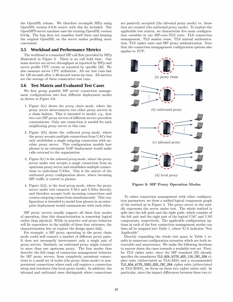
the OpenSSL release. We therefore recompile SIPp usingOpenSSL version 0.9.8i source with this fix included. TheOpenSIPS server machine uses the existing OpenSSL version0.9.8g. The bug does not manifest itself there and keepingthe original OpenSSL on the server makes profiling moreconvenient.
3.5 Workload and Performance MetricsThe workload is a standard SIP call flow provided by SIPp
illustrated in Figure 2. There is no call hold time. Ourmain metrics are server throughput as reported by SIPp andserver profile CPU events as reported by oprofile [29]. Wealso measure server CPU utilization. All our test runs lastfor 120 seconds after a 30-second warm-up time. All metricsare the average of three consecutive test runs.
3.6 Test Matrix and Evaluated Test CasesWe first group possible SIP server connection manage-
ment configurations into four different deployment modesas shown in Figure 3.6.
1. Figure 3(a) shows the proxy chain mode, where theproxy server interconnects two other proxy servers ina chain fashion. This is intended to model, e.g., howtwo core SIP proxy servers of different service providerscommunicate. Only one connection is needed for eachneighboring proxy server in this case.
2. Figure 3(b) shows the outbound proxy mode, wherethe proxy accepts multiple connections from UACs butonly establishes a single outgoing connection with an-other proxy server. This configuration models howphones in an enterprise VoIP deployment would makecalls external to the organization.
3. Figure 3(c) is the inbound proxy mode, where the proxyserver under test accepts a single connection from anupstream proxy server and establishes multiple connec-tions to individual UASes. This is the mirror of theoutbound proxy configuration above, where incomingSIP traffic is routed to phones.
4. Figure 3(d), is the local proxy mode, where the proxyserver under test connects UACs and UASes directly,and therefore accepts both incoming connections andcreates outgoing connections simultaneously. This con-figuration is intended to model how phones in an enter-prise deployment would communicate with each other.
SIP proxy servers usually support all these four modesof operation, thus this characterization is somewhat logicalrather than physical. While in practice real proxy behaviorwill lie somewhere in the middle of these four extremes, thecharacterization lets us explore the design space fully.
For example, a SIP proxy operating in the proxy chainmode could well connect a number of different proxy pairs.It does not necessarily interconnect only a single pair ofproxy servers. Similarly, an outbound proxy might connectto more than one upstream proxy. The four modes thusdescribe the full range of connection management behaviorfor SIP proxy servers, from completely persistent connec-tions to a small set of nodes (the proxy chain mode) to non-persistent connections where each call requires a connectionsetup and teardown (the local proxy mode). In addition, theinbound and outbound cases distinguish where connections
are passively accepted (the inbound proxy mode) vs. thosethat are created (the outbound proxy mode). To explore theapplicable test matrix, we characterize five main configura-tion variables in our SIP-over-TLS tests: TLS connectionmanagement, TLS session reuse, TLS mutual authentica-tion, TLS cipher suite and SIP proxy authentication. Notethat the connection mangagement configuration options alsoapplies to TCP.
(a) proxy chain
(b) outbound proxy
(c) inbound proxy
(d) local proxy
Figure 3: SIP Proxy Operation Modes
To relate connection management with other configura-tion parameters, we draw a unified logical component graphof the testbed as in Figure 4. The proxy server in the mid-dle represents the server under test. The whole testbed issplit into the left path and the right path, which consists ofthe left pair and the right pair of the logical UAC and UAScomponents, respectively. The applicable configuration op-tions in each of the four connection management modes canthen all be mapped into Table 1, where N/A indicates “NotApplicable”.
Directly expanding the whole test space in Table 1 re-sults in numerous configuration scenarios which are both in-tractable and unnecessary. We make the following decisionsto narrow down the cases towards a workable test set. First,for TLS cipher suite, since the SIP standard [35] alreadyspecifies the mandatory TLS_RSA_WITH_AES_128_CBC_SHA ci-pher suite (abbreviated as TLS-AES) and a recommendedTLS_RSA_WITH_3DES_EDE_CBC_SHA cipher suite (abbreviatedas TLS-3DES), we focus on these two cipher suites only. Inparticular, since the impact differences between these two ci-
67
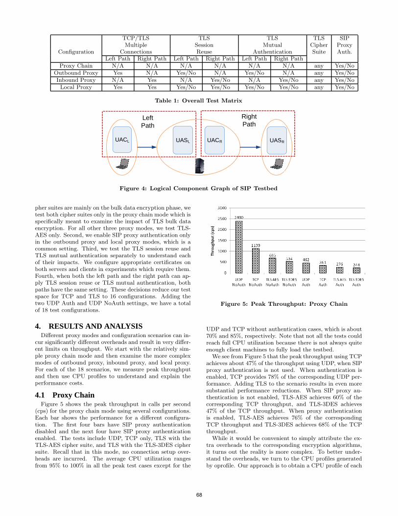
TCP/TLS TLS TLS TLS SIPMultiple Session Mutual Cipher Proxy
Configuration Connections Reuse Authentication Suite Auth.Left Path Right Path Left Path Right Path Left Path Right Path
Proxy Chain N/A N/A N/A N/A N/A N/A any Yes/NoOutbound Proxy Yes N/A Yes/No N/A Yes/No N/A any Yes/NoInbound Proxy N/A Yes N/A Yes/No N/A Yes/No any Yes/NoLocal Proxy Yes Yes Yes/No Yes/No Yes/No Yes/No any Yes/No
Table 1: Overall Test Matrix
UACL UASRUASL UACR
Left Path
Right Path
Figure 4: Logical Component Graph of SIP Testbed
pher suites are mainly on the bulk data encryption phase, wetest both cipher suites only in the proxy chain mode which isspecifically meant to examine the impact of TLS bulk dataencryption. For all other three proxy modes, we test TLS-AES only. Second, we enable SIP proxy authentication onlyin the outbound proxy and local proxy modes, which is acommon setting. Third, we test the TLS session reuse andTLS mutual authentication separately to understand eachof their impacts. We configure appropriate certificates onboth servers and clients in experiments which require them.Fourth, when both the left path and the right path can ap-ply TLS session reuse or TLS mutual authentication, bothpaths have the same setting. These decisions reduce our testspace for TCP and TLS to 16 configurations. Adding thetwo UDP Auth and UDP NoAuth settings, we have a totalof 18 test configurations.
4. RESULTS AND ANALYSISDifferent proxy modes and configuration scenarios can in-
cur significantly different overheads and result in very differ-ent limits on throughput. We start with the relatively sim-ple proxy chain mode and then examine the more complexmodes of outbound proxy, inbound proxy, and local proxy.For each of the 18 scenarios, we measure peak throughputand then use CPU profiles to understand and explain theperformance costs.
4.1 Proxy ChainFigure 5 shows the peak throughput in calls per second
(cps) for the proxy chain mode using several configurations.Each bar shows the performance for a different configura-tion. The first four bars have SIP proxy authenticationdisabled and the next four have SIP proxy authenticationenabled. The tests include UDP, TCP only, TLS with theTLS-AES cipher suite, and TLS with the TLS-3DES ciphersuite. Recall that in this mode, no connection setup over-heads are incurred. The average CPU utilization rangesfrom 95% to 100% in all the peak test cases except for the
Figure 5: Peak Throughput: Proxy Chain
UDP and TCP without authentication cases, which is about70% and 85%, respectively. Note that not all the tests couldreach full CPU utilization because there is not always quiteenough client machines to fully load the testbed.
We see from Figure 5 that the peak throughput using TCPachieves about 47% of the throughput using UDP, when SIPproxy authentication is not used. When authentication isenabled, TCP provides 78% of the corresponding UDP per-formance. Adding TLS to the scenario results in even moresubstantial performance reductions. When SIP proxy au-thentication is not enabled, TLS-AES achieves 60% of thecorresponding TCP throughput, and TLS-3DES achieves47% of the TCP throughput. When proxy authenticationis enabled, TLS-AES achieves 76% of the correspondingTCP throughput and TLS-3DES achieves 68% of the TCPthroughput.
While it would be convenient to simply attribute the ex-tra overheads to the corresponding encryption algorithms,it turns out the reality is more complex. To better under-stand the overheads, we turn to the CPU profiles generatedby oprofile. Our approach is to obtain a CPU profile of each
68
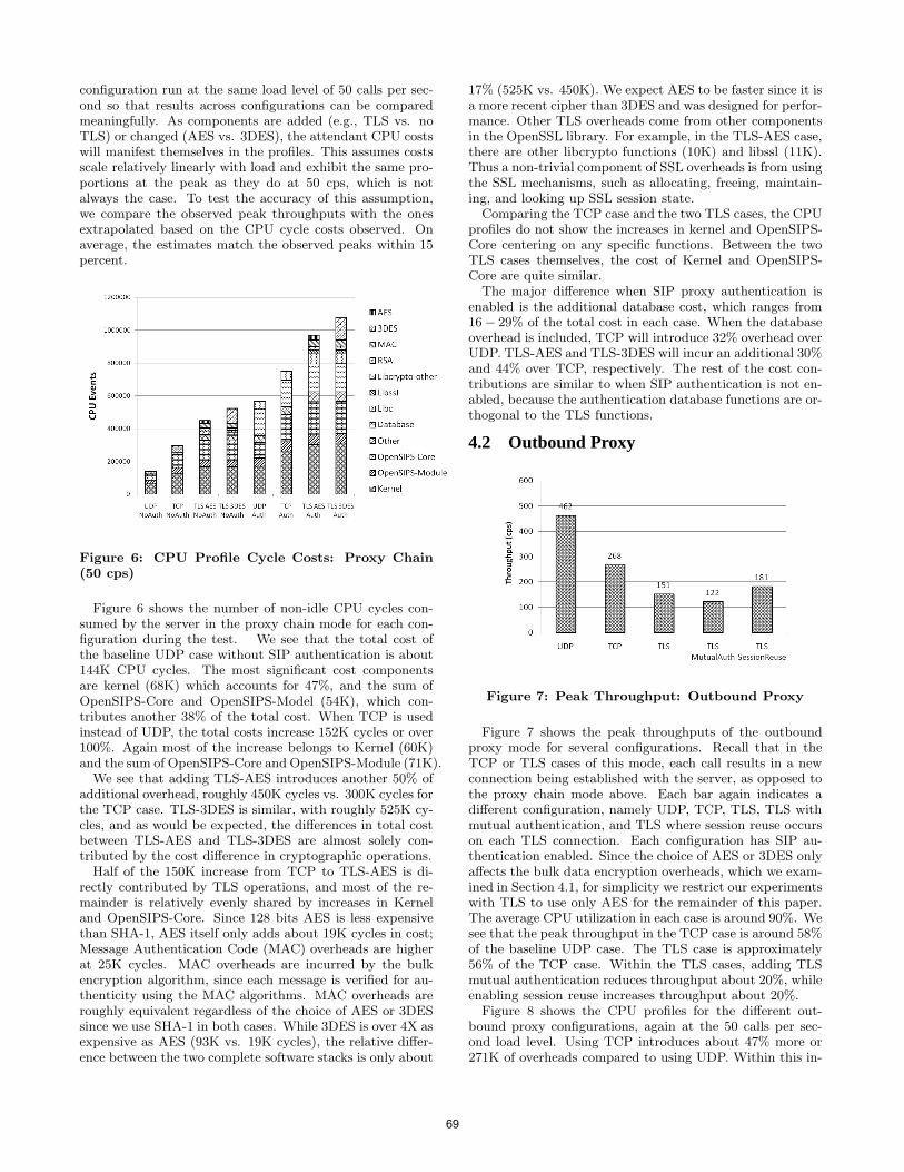
configuration run at the same load level of 50 calls per sec-ond so that results across configurations can be comparedmeaningfully. As components are added (e.g., TLS vs. noTLS) or changed (AES vs. 3DES), the attendant CPU costswill manifest themselves in the profiles. This assumes costsscale relatively linearly with load and exhibit the same pro-portions at the peak as they do at 50 cps, which is notalways the case. To test the accuracy of this assumption,we compare the observed peak throughputs with the onesextrapolated based on the CPU cycle costs observed. Onaverage, the estimates match the observed peaks within 15percent.
Figure 6: CPU Profile Cycle Costs: Proxy Chain(50 cps)
Figure 6 shows the number of non-idle CPU cycles con-sumed by the server in the proxy chain mode for each con-figuration during the test. We see that the total cost ofthe baseline UDP case without SIP authentication is about144K CPU cycles. The most significant cost componentsare kernel (68K) which accounts for 47%, and the sum ofOpenSIPS-Core and OpenSIPS-Model (54K), which con-tributes another 38% of the total cost. When TCP is usedinstead of UDP, the total costs increase 152K cycles or over100%. Again most of the increase belongs to Kernel (60K)and the sum of OpenSIPS-Core and OpenSIPS-Module (71K).
We see that adding TLS-AES introduces another 50% ofadditional overhead, roughly 450K cycles vs. 300K cycles forthe TCP case. TLS-3DES is similar, with roughly 525K cy-cles, and as would be expected, the differences in total costbetween TLS-AES and TLS-3DES are almost solely con-tributed by the cost difference in cryptographic operations.
Half of the 150K increase from TCP to TLS-AES is di-rectly contributed by TLS operations, and most of the re-mainder is relatively evenly shared by increases in Kerneland OpenSIPS-Core. Since 128 bits AES is less expensivethan SHA-1, AES itself only adds about 19K cycles in cost;Message Authentication Code (MAC) overheads are higherat 25K cycles. MAC overheads are incurred by the bulkencryption algorithm, since each message is verified for au-thenticity using the MAC algorithms. MAC overheads areroughly equivalent regardless of the choice of AES or 3DESsince we use SHA-1 in both cases. While 3DES is over 4X asexpensive as AES (93K vs. 19K cycles), the relative differ-ence between the two complete software stacks is only about
17% (525K vs. 450K). We expect AES to be faster since it isa more recent cipher than 3DES and was designed for perfor-mance. Other TLS overheads come from other componentsin the OpenSSL library. For example, in the TLS-AES case,there are other libcrypto functions (10K) and libssl (11K).Thus a non-trivial component of SSL overheads is from usingthe SSL mechanisms, such as allocating, freeing, maintain-ing, and looking up SSL session state.
Comparing the TCP case and the two TLS cases, the CPUprofiles do not show the increases in kernel and OpenSIPS-Core centering on any specific functions. Between the twoTLS cases themselves, the cost of Kernel and OpenSIPS-Core are quite similar.
The major difference when SIP proxy authentication isenabled is the additional database cost, which ranges from16 − 29% of the total cost in each case. When the databaseoverhead is included, TCP will introduce 32% overhead overUDP. TLS-AES and TLS-3DES will incur an additional 30%and 44% over TCP, respectively. The rest of the cost con-tributions are similar to when SIP authentication is not en-abled, because the authentication database functions are or-thogonal to the TLS functions.
4.2 Outbound Proxy
Figure 7: Peak Throughput: Outbound Proxy
Figure 7 shows the peak throughputs of the outboundproxy mode for several configurations. Recall that in theTCP or TLS cases of this mode, each call results in a newconnection being established with the server, as opposed tothe proxy chain mode above. Each bar again indicates adifferent configuration, namely UDP, TCP, TLS, TLS withmutual authentication, and TLS where session reuse occurson each TLS connection. Each configuration has SIP au-thentication enabled. Since the choice of AES or 3DES onlyaffects the bulk data encryption overheads, which we exam-ined in Section 4.1, for simplicity we restrict our experimentswith TLS to use only AES for the remainder of this paper.The average CPU utilization in each case is around 90%. Wesee that the peak throughput in the TCP case is around 58%of the baseline UDP case. The TLS case is approximately56% of the TCP case. Within the TLS cases, adding TLSmutual authentication reduces throughput about 20%, whileenabling session reuse increases throughput about 20%.
Figure 8 shows the CPU profiles for the different out-bound proxy configurations, again at the 50 calls per sec-ond load level. Using TCP introduces about 47% more or271K of overheads compared to using UDP. Within this in-
69
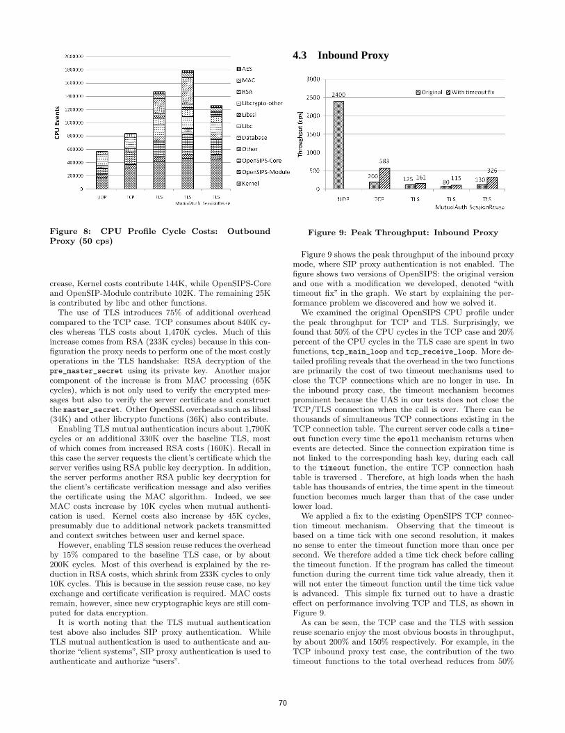
Figure 8: CPU Profile Cycle Costs: OutboundProxy (50 cps)
crease, Kernel costs contribute 144K, while OpenSIPS-Coreand OpenSIP-Module contribute 102K. The remaining 25Kis contributed by libc and other functions.
The use of TLS introduces 75% of additional overheadcompared to the TCP case. TCP consumes about 840K cy-cles whereas TLS costs about 1,470K cycles. Much of thisincrease comes from RSA (233K cycles) because in this con-figuration the proxy needs to perform one of the most costlyoperations in the TLS handshake: RSA decryption of thepre_master_secret using its private key. Another majorcomponent of the increase is from MAC processing (65Kcycles), which is not only used to verify the encrypted mes-sages but also to verify the server certificate and constructthe master_secret. Other OpenSSL overheads such as libssl(34K) and other libcrypto functions (36K) also contribute.
Enabling TLS mutual authentication incurs about 1,790Kcycles or an additional 330K over the baseline TLS, mostof which comes from increased RSA costs (160K). Recall inthis case the server requests the client’s certificate which theserver verifies using RSA public key decryption. In addition,the server performs another RSA public key decryption forthe client’s certificate verification message and also verifiesthe certificate using the MAC algorithm. Indeed, we seeMAC costs increase by 10K cycles when mutual authenti-cation is used. Kernel costs also increase by 45K cycles,presumably due to additional network packets transmittedand context switches between user and kernel space.
However, enabling TLS session reuse reduces the overheadby 15% compared to the baseline TLS case, or by about200K cycles. Most of this overhead is explained by the re-duction in RSA costs, which shrink from 233K cycles to only10K cycles. This is because in the session reuse case, no keyexchange and certificate verification is required. MAC costsremain, however, since new cryptographic keys are still com-puted for data encryption.
It is worth noting that the TLS mutual authenticationtest above also includes SIP proxy authentication. WhileTLS mutual authentication is used to authenticate and au-thorize “client systems”, SIP proxy authentication is used toauthenticate and authorize “users”.
4.3 Inbound Proxy
Figure 9: Peak Throughput: Inbound Proxy
Figure 9 shows the peak throughput of the inbound proxymode, where SIP proxy authentication is not enabled. Thefigure shows two versions of OpenSIPS: the original versionand one with a modification we developed, denoted “withtimeout fix” in the graph. We start by explaining the per-formance problem we discovered and how we solved it.
We examined the original OpenSIPS CPU profile underthe peak throughput for TCP and TLS. Surprisingly, wefound that 50% of the CPU cycles in the TCP case and 20%percent of the CPU cycles in the TLS case are spent in twofunctions, tcp_main_loop and tcp_receive_loop. More de-tailed profiling reveals that the overhead in the two functionsare primarily the cost of two timeout mechanisms used toclose the TCP connections which are no longer in use. Inthe inbound proxy case, the timeout mechanism becomesprominent because the UAS in our tests does not close theTCP/TLS connection when the call is over. There can bethousands of simultaneous TCP connections existing in theTCP connection table. The current server code calls a time-
out function every time the epoll mechanism returns whenevents are detected. Since the connection expiration time isnot linked to the corresponding hash key, during each callto the timeout function, the entire TCP connection hashtable is traversed . Therefore, at high loads when the hashtable has thousands of entries, the time spent in the timeoutfunction becomes much larger than that of the case underlower load.
We applied a fix to the existing OpenSIPS TCP connec-tion timeout mechanism. Observing that the timeout isbased on a time tick with one second resolution, it makesno sense to enter the timeout function more than once persecond. We therefore added a time tick check before callingthe timeout function. If the program has called the timeoutfunction during the current time tick value already, then itwill not enter the timeout function until the time tick valueis advanced. This simple fix turned out to have a drasticeffect on performance involving TCP and TLS, as shown inFigure 9.
As can be seen, the TCP case and the TLS with sessionreuse scenario enjoy the most obvious boosts in throughput,by about 200% and 150% respectively. For example, in theTCP inbound proxy test case, the contribution of the twotimeout functions to the total overhead reduces from 50%
70
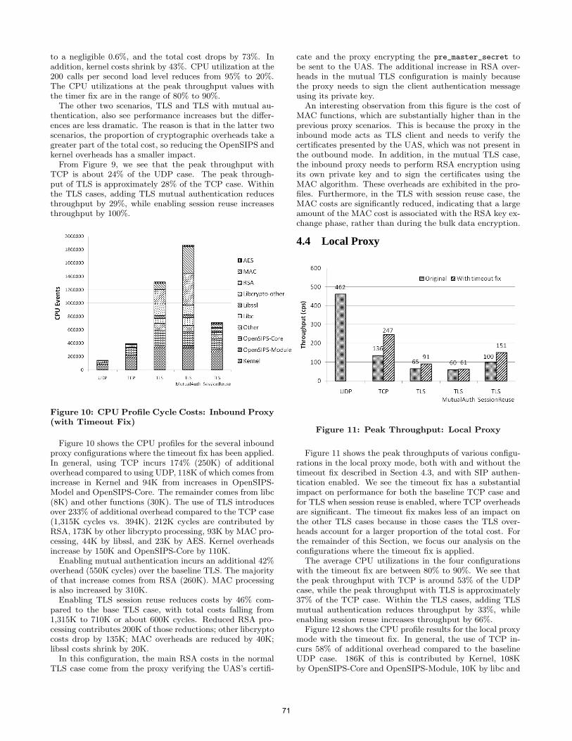
to a negligible 0.6%, and the total cost drops by 73%. Inaddition, kernel costs shrink by 43%. CPU utilization at the200 calls per second load level reduces from 95% to 20%.The CPU utilizations at the peak throughput values withthe timer fix are in the range of 80% to 90%.
The other two scenarios, TLS and TLS with mutual au-thentication, also see performance increases but the differ-ences are less dramatic. The reason is that in the latter twoscenarios, the proportion of cryptographic overheads take agreater part of the total cost, so reducing the OpenSIPS andkernel overheads has a smaller impact.
From Figure 9, we see that the peak throughput withTCP is about 24% of the UDP case. The peak through-put of TLS is approximately 28% of the TCP case. Withinthe TLS cases, adding TLS mutual authentication reducesthroughput by 29%, while enabling session reuse increasesthroughput by 100%.
Figure 10: CPU Profile Cycle Costs: Inbound Proxy(with Timeout Fix)
Figure 10 shows the CPU profiles for the several inboundproxy configurations where the timeout fix has been applied.In general, using TCP incurs 174% (250K) of additionaloverhead compared to using UDP, 118K of which comes fromincrease in Kernel and 94K from increases in OpenSIPS-Model and OpenSIPS-Core. The remainder comes from libc(8K) and other functions (30K). The use of TLS introducesover 233% of additional overhead compared to the TCP case(1,315K cycles vs. 394K). 212K cycles are contributed byRSA, 173K by other libcrypto processing, 93K by MAC pro-cessing, 44K by libssl, and 23K by AES. Kernel overheadsincrease by 150K and OpenSIPS-Core by 110K.
Enabling mutual authentication incurs an additional 42%overhead (550K cycles) over the baseline TLS. The majorityof that increase comes from RSA (260K). MAC processingis also increased by 310K.
Enabling TLS session reuse reduces costs by 46% com-pared to the base TLS case, with total costs falling from1,315K to 710K or about 600K cycles. Reduced RSA pro-cessing contributes 200K of those reductions; other libcryptocosts drop by 135K; MAC overheads are reduced by 40K;libssl costs shrink by 20K.
In this configuration, the main RSA costs in the normalTLS case come from the proxy verifying the UAS’s certifi-
cate and the proxy encrypting the pre_master_secret tobe sent to the UAS. The additional increase in RSA over-heads in the mutual TLS configuration is mainly becausethe proxy needs to sign the client authentication messageusing its private key.
An interesting observation from this figure is the cost ofMAC functions, which are substantially higher than in theprevious proxy scenarios. This is because the proxy in theinbound mode acts as TLS client and needs to verify thecertificates presented by the UAS, which was not present inthe outbound mode. In addition, in the mutual TLS case,the inbound proxy needs to perform RSA encryption usingits own private key and to sign the certificates using theMAC algorithm. These overheads are exhibited in the pro-files. Furthermore, in the TLS with session reuse case, theMAC costs are significantly reduced, indicating that a largeamount of the MAC cost is associated with the RSA key ex-change phase, rather than during the bulk data encryption.
4.4 Local Proxy
Figure 11: Peak Throughput: Local Proxy
Figure 11 shows the peak throughputs of various configu-rations in the local proxy mode, both with and without thetimeout fix described in Section 4.3, and with SIP authen-tication enabled. We see the timeout fix has a substantialimpact on performance for both the baseline TCP case andfor TLS when session reuse is enabled, where TCP overheadsare significant. The timeout fix makes less of an impact onthe other TLS cases because in those cases the TLS over-heads account for a larger proportion of the total cost. Forthe remainder of this Section, we focus our analysis on theconfigurations where the timeout fix is applied.
The average CPU utilizations in the four configurationswith the timeout fix are between 80% to 90%. We see thatthe peak throughput with TCP is around 53% of the UDPcase, while the peak throughput with TLS is approximately37% of the TCP case. Within the TLS cases, adding TLSmutual authentication reduces throughput by 33%, whileenabling session reuse increases throughput by 66%.
Figure 12 shows the CPU profile results for the local proxymode with the timeout fix. In general, the use of TCP in-curs 58% of additional overhead compared to the baselineUDP case. 186K of this is contributed by Kernel, 108Kby OpenSIPS-Core and OpenSIPS-Module, 10K by libc and
71
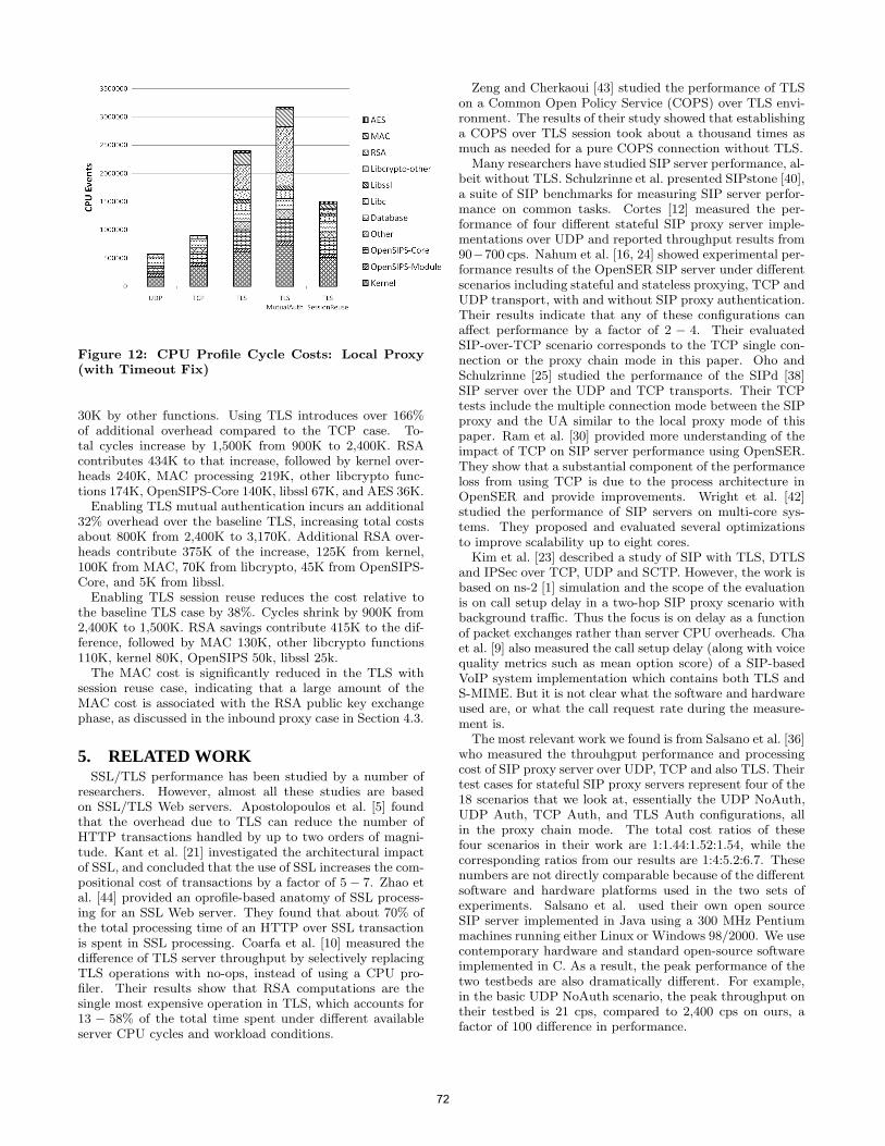
Figure 12: CPU Profile Cycle Costs: Local Proxy(with Timeout Fix)
30K by other functions. Using TLS introduces over 166%of additional overhead compared to the TCP case. To-tal cycles increase by 1,500K from 900K to 2,400K. RSAcontributes 434K to that increase, followed by kernel over-heads 240K, MAC processing 219K, other libcrypto func-tions 174K, OpenSIPS-Core 140K, libssl 67K, and AES 36K.
Enabling TLS mutual authentication incurs an additional32% overhead over the baseline TLS, increasing total costsabout 800K from 2,400K to 3,170K. Additional RSA over-heads contribute 375K of the increase, 125K from kernel,100K from MAC, 70K from libcrypto, 45K from OpenSIPS-Core, and 5K from libssl.
Enabling TLS session reuse reduces the cost relative tothe baseline TLS case by 38%. Cycles shrink by 900K from2,400K to 1,500K. RSA savings contribute 415K to the dif-ference, followed by MAC 130K, other libcrypto functions110K, kernel 80K, OpenSIPS 50k, libssl 25k.
The MAC cost is significantly reduced in the TLS withsession reuse case, indicating that a large amount of theMAC cost is associated with the RSA public key exchangephase, as discussed in the inbound proxy case in Section 4.3.
5. RELATED WORKSSL/TLS performance has been studied by a number of
researchers. However, almost all these studies are basedon SSL/TLS Web servers. Apostolopoulos et al. [5] foundthat the overhead due to TLS can reduce the number ofHTTP transactions handled by up to two orders of magni-tude. Kant et al. [21] investigated the architectural impactof SSL, and concluded that the use of SSL increases the com-positional cost of transactions by a factor of 5 − 7. Zhao etal. [44] provided an oprofile-based anatomy of SSL process-ing for an SSL Web server. They found that about 70% ofthe total processing time of an HTTP over SSL transactionis spent in SSL processing. Coarfa et al. [10] measured thedifference of TLS server throughput by selectively replacingTLS operations with no-ops, instead of using a CPU pro-filer. Their results show that RSA computations are thesingle most expensive operation in TLS, which accounts for13 − 58% of the total time spent under different availableserver CPU cycles and workload conditions.
Zeng and Cherkaoui [43] studied the performance of TLSon a Common Open Policy Service (COPS) over TLS envi-ronment. The results of their study showed that establishinga COPS over TLS session took about a thousand times asmuch as needed for a pure COPS connection without TLS.
Many researchers have studied SIP server performance, al-beit without TLS. Schulzrinne et al. presented SIPstone [40],a suite of SIP benchmarks for measuring SIP server perfor-mance on common tasks. Cortes [12] measured the per-formance of four different stateful SIP proxy server imple-mentations over UDP and reported throughput results from90−700 cps. Nahum et al. [16, 24] showed experimental per-formance results of the OpenSER SIP server under differentscenarios including stateful and stateless proxying, TCP andUDP transport, with and without SIP proxy authentication.Their results indicate that any of these configurations canaffect performance by a factor of 2 − 4. Their evaluatedSIP-over-TCP scenario corresponds to the TCP single con-nection or the proxy chain mode in this paper. Oho andSchulzrinne [25] studied the performance of the SIPd [38]SIP server over the UDP and TCP transports. Their TCPtests include the multiple connection mode between the SIPproxy and the UA similar to the local proxy mode of thispaper. Ram et al. [30] provided more understanding of theimpact of TCP on SIP server performance using OpenSER.They show that a substantial component of the performanceloss from using TCP is due to the process architecture inOpenSER and provide improvements. Wright et al. [42]studied the performance of SIP servers on multi-core sys-tems. They proposed and evaluated several optimizationsto improve scalability up to eight cores.
Kim et al. [23] described a study of SIP with TLS, DTLSand IPSec over TCP, UDP and SCTP. However, the work isbased on ns-2 [1] simulation and the scope of the evaluationis on call setup delay in a two-hop SIP proxy scenario withbackground traffic. Thus the focus is on delay as a functionof packet exchanges rather than server CPU overheads. Chaet al. [9] also measured the call setup delay (along with voicequality metrics such as mean option score) of a SIP-basedVoIP system implementation which contains both TLS andS-MIME. But it is not clear what the software and hardwareused are, or what the call request rate during the measure-ment is.
The most relevant work we found is from Salsano et al. [36]who measured the throuhgput performance and processingcost of SIP proxy server over UDP, TCP and also TLS. Theirtest cases for stateful SIP proxy servers represent four of the18 scenarios that we look at, essentially the UDP NoAuth,UDP Auth, TCP Auth, and TLS Auth configurations, allin the proxy chain mode. The total cost ratios of thesefour scenarios in their work are 1:1.44:1.52:1.54, while thecorresponding ratios from our results are 1:4:5.2:6.7. Thesenumbers are not directly comparable because of the differentsoftware and hardware platforms used in the two sets ofexperiments. Salsano et al. used their own open sourceSIP server implemented in Java using a 300 MHz Pentiummachines running either Linux or Windows 98/2000. We usecontemporary hardware and standard open-source softwareimplemented in C. As a result, the peak performance of thetwo testbeds are also dramatically different. For example,in the basic UDP NoAuth scenario, the peak throughput ontheir testbed is 21 cps, compared to 2,400 cps on ours, afactor of 100 difference in performance.
72
One approach to reducing security overheads is to use ahardware crypto accelerator, e.g., Sun’s Crypto 6000 card[11]. While this can improve performance (e.g., the cardclaims 13,000 1024-bit RSA operations per second), the cardstend to be expensive (e.g., the list price for the board was$1350 at the time of this writing). More importantly, inmany cases, much of the overhead we observed was in theOpenSSL software libaries themselves (e.g., libssl, libssl-other), rather than the crypto algorithms (libcrypto). Cryptoacceleration hardware will not help with these overheads.
6. CONCLUSIONSInsecure UDP-based signaling is one major reason that ex-
poses SIP-based services to many common security threats.We have evaluated and analyzed the impact of using TLS asa transport on SIP server performance versus the standardapproach of SIP-over-UDP. Using an experimental testbedwith the OpenSIPS server, OpenSSL, Linux, and an Intel-based server, we show that the performance with TLS can bereduced significantly. We use application, library, and kernelprofiling to illustrate where different costs are incurred (e.g.,extra RSA overheads when mutual authentication is used)and how they can be avoided (i.e., RSA costs are nearlyeliminated when session reuse is effective).
In the best case, the baseline UDP performance is aboutthree times that with TLS (the proxy chain mode); in theworst case, UDP is 17 times the performance than with TLS(the local proxy with TLS and mutual authentication). Theperformance results depend primarily on whether and howfrequent TLS connection establishment is performed, sinceTLS session negotiation incurs expensive RSA public keyoperations. In turn, session negotiation depends on how theSIP proxy is deployed (as an inbound, outbound, or localproxy) and how TLS is configured (with mutual authentica-tion or session reuse). Bulk encryption costs such as 3DESor AES, in contrast, are minimal, typically no more thanseven percent.
Implementation plays a role as well. We found severalperformance bugs in OpenSIPS and OpenSSL, despite thefact that they have mature code bases and large numbersof users. When fixed, performance improved in some casesfrom a few times up to an order of magnitude.
Network operators considering deploying SIP over TLSwill need to consider the extra resources required to providethe same service quality as would be the case with UDP.Costs can be reduced by maximizing the potential for persis-tent TLS sessions, which avoid heavy connection setup costs.These lessons may be appropriate for other protocols thatuse TLS, especially if they tend to have short messages.
AcknowledgmentsThe authors would like to thank the anonymous reviewersfor insightful and detailed comments which helped improvethis paper. Charles Shen would like to acknowledge Dr.Arata Koike of NTT for useful discussions.
7. REFERENCES[1] ns-2 simulator. http://www.isi.edu/nsnam/ns/.[2] SIP forum. http://www.sipforum.org.[3] VoIP security alliance. http://www.voipsa.org.[4] Arup Acharya, Xiping Wang, and Charles Wright. A
programmable message classification engine for sessioninitiation protocol (sip). In ANCS ’07: Proceedings of the
3rd ACM/IEEE Symposium on Architecture fornetworking and communications systems, pages 185–194,Orlando, FL, December 2007.
[5] G. Apostolopoulos, V. Peris, and D. Saha. Transport layersecurity: How much does it really cost? In IEEE InfoCom’99: Proceedings of the 18th Annual Joint Conference ofthe IEEE Computer and Communications Societies, NewYork, NY, March 1999.
[6] Vijay A. Balasubramaniyan, Arup Acharya, MustaqueAhamad, Mudhakar Srivatsa, Italo Dacosta, and Charles P.Wright. Servartuka: Dynamic distribution of state toimprove SIP server scalability. In ICDCS ’08: Proceedingsof the 2008 The 28th International Conference onDistributed Computing Systems, pages 562–572, Beijing,China, June 2008.
[7] D. Butcher, X. Li, and J. Guo. Security challenge anddefense in VoIP infrastructures. IEEE Transactions onSystems, Man, and Cybernetics, Part C: Applications andReviews, 37(6):1152–1162, November 2007.
[8] B. Campbell, J. Rosenberg, H. Schulzrinne, C. Huitima,and D. Gurle. Session Initiation Protocol (SIP) extensionfor Instant Messaging. RFC 3428 (Standard), December2002.
[9] E. Cha, H. Choi, and S. Cho. Evaluation of securityprotocols for the Session Initiation Protocol. In Proceedingsof the 16th International Conference on ComputerCommunications and Networks (ICCCN), Honolulu, HI,August 2007.
[10] C. Coarfa, P. Druschel, and D. Wallach. Performanceanalysis of TLS Web servers. In Proceedings of the InternetSociety Symposium on Network and Distributed SystemSecurity (NDSS), San Diego, CA, February 2002.
[11] Oracle Corporation. Sun crypto accelerator 6000 PCIe card.
[12] M. Cortes, J. Ensor, and J. Esteban. On SIP performance.IEEE Network, 9(3):155–172, Nov 2004.
[13] Italo Dacosta, Vijay Balasubramaniyan, MustaqueAhamad, and Patrick Traynor. Improving authenticationperformance of distributed SIP proxies. In IPTComm ’09:Proceedings of the 3rd International Conference onPrinciples, Systems and Applications of IPTelecommunications, pages 1–11, Atlanta, GA, July 2009.
[14] Italo Dacosta and Patrick Traynor. Proxychain: Developinga robust and efficient authentication infrastructure forcarrier-scale VoIP networks. In USENIX ’10: Proceedingsof the USENIX Annual Technical Conference, Boston, MA,June 2010.
[15] T. Dierks and E. Rescorla. The Transport Layer Security(TLS) Protocol Version 1.2. RFC 5246 (ProposedStandard), 2008.
[16] E. Nahum and J. Tracey and C. Wright. Evaluating SIPserver performance. ACM SIGMETRICS PerformanceEvaluation Review, 35(1):349–350, June 2007.
[17] Joachim Fabini, Norbert Jordan, Peter Reichl, AlexanderPoropatich, and Rainer Huber. “IMS in a bottle”: Initialexperiences from an OpenSER-based prototypeimplementation of the 3GPP IP multimedia subsystem. InICMB ’06: Proceedings of the International Conference onMobile Business, page 13, Copenhagen, Denmark, June2006.
[18] RT for openssl.org. Ticket no. 598.http://rt.openssl.org/Ticket/Display.html?id=598\&user=guest\&pass=guest.
[19] R. Gayraud and O. Jacques. SIPp.http://sipp.sourceforge.net.
[20] IPTel.org. SIP express router (SER).http://www.iptel.org/ser.
[21] K. Kent, R. Iyer, and P. Mohapatra. Architectural impactof secure socket layer on Internet servers. In InternationalConference on Computer Design (ICCD), pages 7–14,Austin, TX, October 2000.
[22] A. Keromytis. Voice over IP: Risks, threats and
73

vulnerabilities. In Proceedings of the Cyber InfrastructureProtection (CIP) Conference, New York, NY, June 2009.
[23] J. Kim, S. Yoon, H. Jeong, and Y. Won. Implementationand evaluation of SIP-based secure VoIP communicationsystem. In Proceedings of the 2008 IEEE/IFIPInternational Conference on Embedded and UbiquitousComputing, Shanghai, China, December 2008.
[24] E. Nahum, J. Tracey, and C. Wright. Evaluating SIP proxyserver performance. In 17th International Workshop onNetworking and Operating Systems Support for DigitalAudio and Video (NOSSDAV), Urbana-Champaign, IL,June 2007.
[25] K. Ono and H. Schulzrinne. One server per city: UsingTCP for very large SIP servers. In IPTComm ’08:Proceedings of the 2nd International Conference onPrinciples, Systems and Applications of IPTelecommunications, volume 5310/2008, pages 133–148,Heidelberg, Germany, October 2008.
[26] The MySQL Project. MySQL database server.http://www.mysql.org.
[27] The OpenSIPS Project. The open SIP server (OpenSIPS).http://www.opensips.org.
[28] The OpenSSL Project. The OpenSSL library.http://www.openssl.org.
[29] The OProfile Project. OProfile.http://oprofile.sourceforge.net.
[30] K. Kumar Ram, I. Fedeli, A. Cox, and S. Rixner.Explaining the impact of network transport protocols onSIP proxy performance. In IEEE International Symposiumon Performance Analysis of Systems and Software(ISPASS), pages 75–84, Austin, TX, April 2008.
[31] Light Reading. VoIP security: Vendors prepare for theinevitable. VoIP Services Insider, 5(1), January 2009.
[32] E. Rescorla. SSL and TLS: Designing and Building SecureSystems. Addison Wesley, 2000.
[33] E. Rescorla and N. Modadugu. Datagram Transport LayerSecurity. RFC 4347 (Proposed Standard), April 2006.
[34] R. Rivest. The MD5 Message-Digest Algorithm . RFC 1321(Informational), April 1992.
[35] J. Rosenberg, H. Schulzrinne, G. Camarillo, A. Johnston,J. Peterson, R. Sparks, M. Handley, and E. Schooler. SIP:Session Initiation Protocol. RFC 3261 (ProposedStandard), June 2002. Updated by RFCs 3265, 3853, 4320.
[36] S. Salsano, L. Veltri, and D. Papalilo. SIP security issues:the SIP authentication procedure and its processing load.IEEE Network, 16(6):38–44, Nov/Dec 2002.
[37] B. Schneier. Applied Cryptography (2nd Edition). JohnWiley and Sons, Inc., New York, NY, 1996.
[38] H. Schulzrinne. SIPd.http://www.cs.columbia.edu/IRT/cinema.
[39] H. Schulzrinne, S. Casner, R. Frederick, and V. Jacobson.RTP: A Transport Protocol for Real-Time Applications.RFC 3550 (Standard), July 2003.
[40] H. Schulzrinne, S. Narayanan, J. Lennox, and M. Doyle.SIPstone-benchmarking SIP server performance. April2002. http://www.sipstone.com.
[41] X. Wang, R. Zhang, X. Yang, X. Jiang, and D. Wijesekera.Voice pharming attack and the trust of VoIP. InSecureComm ’08: Proceedings of the 4th internationalconference on Security and privacy in communicationnetowrks, pages 1–11, Istanbul, Turkey, September 2008.
[42] C.P. Wright, E Nahum, D. Wood, J. Tracey, and E. Hu.SIP server performance on multicore systems. IBM Journalof Research and Developement, 54(1), February 2010.
[43] Y. Zeng and O. Cherkaoui. Performance study of COPSover TLS and IPsec secure session. In Proceedings of the13th IFIP/IEEE International Workshop on DistributedSystems: Operations and Management (DSOM), pages133–144, Montreal, Canada, October 2002.
[44] L. Zhao, R. Iyer, S. Makineni, and L. Bhuyan. Anatomyand performance of SSL processing. In International
Symposium on Performance Analysis of Systems andSoftware (ISPASS), pages 197–206, Austin, TX, March2005.
74
On TCP-based SIP Server Overload Control
Charles Shen and Henning SchulzrinneDepartment of Computer Science, Columbia University
New York, NY 10027{charles,hgs}@cs.columbia.edu
ABSTRACTThe Session Initiation Protocol (SIP) server overload man-agement has attracted interest since SIP is being widely de-ployed in the Next Generation Networks (NGN) as a coresignaling protocol. Yet all existing SIP overload control workis focused on SIP-over-UDP, despite the fact that TCP is in-creasingly seen as the more viable choice of SIP transport.This paper answers the following questions: is the existingTCP flow control capable of handling the SIP overload prob-lem? If not, why and how can we make it work? We providea comprehensive explanation of the default SIP-over-TCPoverload behavior through server instrumentation. We alsopropose and implement novel but simple overload controlalgorithms without any kernel or protocol level modifica-tion. Experimental evaluation shows that with our mech-anism the overload performance improves from its originalzero throughput to nearly full capacity. Our work leads tothe important general insight that the traditional notion ofTCP flow control alone is incapable of managing overloadfor time-critical session-based applications, which would beapplicable not only to SIP, but also to a wide range of othercommon applications such as database servers.
1. INTRODUCTIONThe Session Initiation Protocol (SIP) [34] is an application
layer signaling protocol for creating, modifying, and termi-nating media sessions in the Internet. SIP has been adoptedby major standardization bodies including 3GPP, ITU-T,and ETSI as the core signaling protocol of Next GenerationNetworks (NGN) for services such as Voice over IP (VoIP),conferencing, Video on Demand (VoD), presence, and In-stant Messaging (IM). The increasingly wide deployment ofSIP has raised a requirement for SIP server overload man-agement solutions [33]. SIP server can be overloaded formany reasons such as emergency-induced call volume, flashcrowds generated by TV programs (e.g., American Idol),special events such as “free tickets to the third caller”, ordenial of service attacks.
Permission to make digital or hard copies of all or part of this work forpersonal or classroom use is granted without fee provided that copies arenot made or distributed for profit or commercial advantage and that copiesbear this notice and the full citation on the first page. To copy otherwise, torepublish, to post on servers or to redistribute to lists, requires prior specificpermission and/or a fee.IPTComm 2010, 2-3 August, 2010 Munich, GermanyCopyright 2010 ACM ...$10.00.
Although a SIP server is an application server, the SIPserver overload problem is distinct from other well-knownapplication server such as HTTP overload because in theSIP architecture, multiple server hops are common. Thereare also many SIP application level retransmission timers,and there is a time-critical session completion requirement.SIP’s built-in session rejection mechanism is known to beunable to manage overload [33] because it could cause theserver to spend all cycles rejecting messages and result incongestion collapse. If, as often recommended, the rejectedsessions are sent to a load-sharing SIP server, the alterna-tive server will soon also be generating nothing but rejectionmessages, leading to a cascading failure. Hilt et al. [40, 41]articulate a SIP overload control framework based on aug-menting the current SIP specification with application levelfeedback between SIP proxy servers. The feedback, whichmay be rate-based or window-based, pushes the burden ofrejecting excessive sessions from the target server to its up-stream servers and thus prevents the overload. Detailed SIPapplication level feedback algorithms and their effectivenesshave been demonstrated by a number of researchers, e.g.,Noel [27], Shen [37] and Hilt [19].
As far as we know, all existing SIP overload control de-sign and evaluation focus on SIP-over-UDP, presumably be-cause UDP is still the common choice for today’s SIP op-erational environment. However, SIP-over-TCP is gettingincreasingly popular and seen as a more viable SIP trans-port choice for a number of reasons, such as the need forsecuring SIP signaling over TLS/TCP [1, 32, 34, 36] (Thereis also a newer TLS version - Datagram TLS, which runs overUDP, but its deployment popularity is not clear), supportfor message sizes exceeding the maximum UDP datagramsize [34], facilitation of firewall and NATs traversal [28], andpotentially overload control.
The SIP-over-TCP overload control problem differs in twomain aspects from the SIP-over-UDP overload control prob-lem. One is TCP’s built-in flow control mechanism whichprovides an inherent, existing channel for feedback-basedoverload control. The other is the removal of many applica-tion layer retransmission timers that exacerbates the over-load condition in SIP-over-UDP. Nahum et al. [9] have ex-perimentally studied SIP performance and found that over-load leads to congestion collapse for both SIP-over-TCP andSIP-over-UDP. Their focus, however, is not on overload con-trol so they do not discuss why SIP-over-TCP congestioncollapse happens or how to prevent it. Hilt et al. [19] haveshown simulation results by applying application level feed-back control to SIP servers with TCP-specific SIP timers but
75
schmitt
Stempel
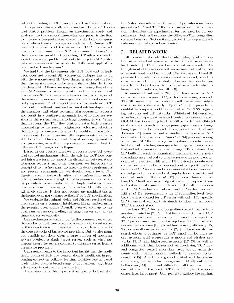
without including a TCP transport stack in the simulation.This paper systematically addresses the SIP-over-TCP over-
load control problem through an experimental study andanalysis. To the authors’ knowledge, our paper is the firstto provide a comprehensive answer to the following ques-tions: why is there still congestion collapse in SIP-over-TCPdespite the presence of the well-known TCP flow controlmechanism and much fewer SIP retransmission timers? Isthere a way we can utilize the existing TCP infrastructure tosolve the overload problem without changing the SIP proto-col specification as is needed for the UDP-based applicationlevel feedback mechanisms?
We find that the key reasons why TCP flow control feed-back does not prevent SIP congestion collapse has to dowith the session-based SIP load characteristics and the factthat the session needs to be established within the time-out threshold. Different messages in the message flow of thesame SIP session arrive at different times from upstream anddownstream SIP entities; start-of-session requests trigger allthe remaining in-session messages and are therefore espe-cially expensive. The transport level connection-based TCPflow control, without knowing the causal relationship amongthe messages, will admit too many start-of-session requestsand result in a continued accumulation of in-progress ses-sions in the system, leading to large queuing delays. Whenthat happens, the TCP flow control creates back pressurepropagating to the session originators, adversely affectingtheir ability to generate messages that could complete exist-ing sessions. In the meantime, SIP response retransmissionstill kicks in. The combined delayed message generationand processing as well as response retransmission lead toSIP-over-TCP congestion collapse.
Based on our observations, we propose a novel SIP over-load control mechanisms within the existing TCP flow con-trol infrastructure. To respect the distinction between start-of-session requests and other messages, we introduce theconcept of connection split. To meet the delay requirementsand prevent retransmission, we develop smart forwarding
algorithms combined with buffer minimization. Our mech-anisms contain only a single tunable parameter for whichwe provide a recommended value. Implementation of ourmechanisms exploits existing Linux socket API calls and isextremely simple. It does not require any modifications atthe kernel level, nor changes to the SIP or TCP specification.
We evaluate throughput, delay and fairness results of ourmechanisms on a common Intel-based Linux testbed usingthe popular open source OpenSIPS server with up to tenupstream servers overloading the target server at over tentimes the server capacity.
Our mechanism is best suited for the common case wherethe number of upstream servers overloading the target serverat the same time is not excessively large, such as servers inthe core networks of big service providers. But we also pointout possible solutions when a large number of upstreamservers overload a single target server, such as when nu-merous enterprise servers connect to the same server from abig service provider.
Our research leads to the important insight that the tradi-tional notion of TCP flow control alone is insufficient in pre-venting congestion collapse for time-sensitive session-basedloads, which cover a broad range of applications, e.g., fromSIP servers to data center systems [42].
The remainder of this paper is structured as follows. Sec-
tion 2 describes related work. Section 3 provides some back-ground on SIP and TCP flow and congestion control. Sec-tion 4 describes the experimental testbed used for our ex-periments. Section 5 explains the SIP-over-TCP congestioncollapse behavior. Section 6 and Section 7 develop and eval-uate our overload control mechanism.
2. RELATED WORKSIP overload falls into the broader category of applica-
tion server overload where, in particular, web server over-load control [7, 12, 48] has been studied extensively. Al-though most of the work on web server overload control usesa request-based workload model, Cherkasova and Phaal [6]presented a study using session-based workload, which iscloser to our SIP overload study. However their mechanismuses the overloaded server to reject excessive loads, which isknown to be insufficient for SIP [33].
A number of authors [9, 28, 31, 36] have measured SIPserver performance over TCP, without discussing overload.The SIP server overload problem itself has received inten-sive attention only recently. Ejzak et al. [10] provided aqualitative comparison of the overload in PSTN SS7 signal-ing networks and SIP networks. Whitehead [45] describeda protocol-independent overload control framework calledGOCAP but its mapping to SIP is still being defined. Ohta [24]explored the approach of using a priority queueing and bang-bang type of overload control through simulation. Noel andJohnson [27] presented initial results of a rate-based SIPoverload control mechanism. Sun et al. [39] proposed addinga front end SIP flow management system to conduct over-load control including message scheduling, admission con-trol and retransmission removal. Sengar [35] combined theSIP built-in backoff retransmission mechanism with a selec-tive admittance method to provide server-side pushback foroverload prevention. Hilt et al. [19] provided a side-by-sidecomparison of a number of overload control algorithms for anetwork of SIP servers, and also examined different overloadcontrol paradigms such as local, hop-by-hop and end-to-endoverload control. Shen et al. [37] proposed three window-based SIP feedback control algorithms and compared themwith rate-control algorithms. Except for [19], all of the abovework on SIP overload control assumes UDP as the transport.Hilt et al. [19] present simulation of application level feed-back overload control for SIP server with only TCP-specificSIP timers enabled, but their simulation does not include aTCP transport stack.
The basic TCP flow and congestion control mechanismsare documented in [22,29]. Modifications to the basic TCPalgorithm have been proposed to improve various aspects ofTCP performance, such as start-up behavior [20], retrans-mission fast recovery [13], packet loss recovery efficiency [15,25], or overall congestion control [2, 5]. There are also re-search efforts to optimize the TCP algorithm for more re-cent network architecture such as mobile and wireless net-works [11, 47] and high-speed networks [17, 23], as well asadditional work that focuses not on modifying TCP flowand congestion control algorithm itself, but on using dy-namic socket buffer tunning methods to improve perfor-mance [8, 18]. Another category of related work focuses onrouters, e.g., active buffer management [14, 26] and routerbuffer sizing [43]. Our work differs from all the above in thatour metric is not the direct TCP throughput, but the appli-cation level throughput. Our goal is to explore the existing
76
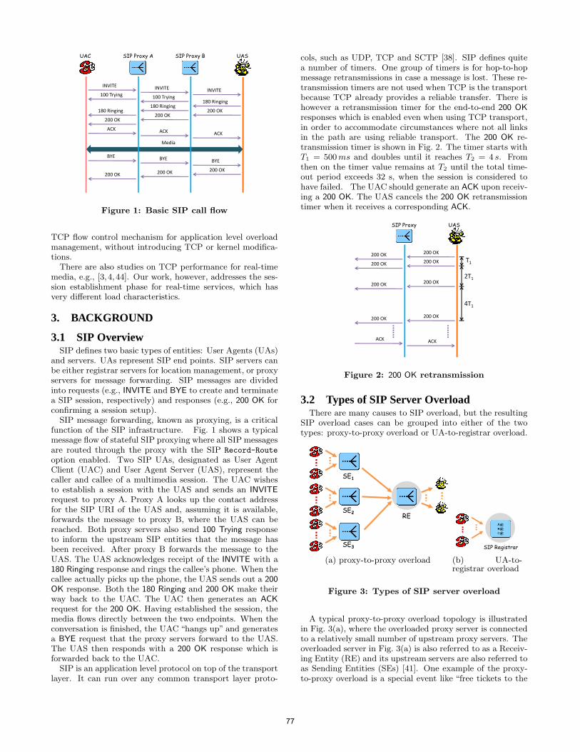
INVITE INVITE INVITE100 Trying 100 Trying
180 Ringing
200 OK180 Ringing
200 OK
ACK ACK ACK
BYE BYE BYE
200 OK200 OK200 OK
Media
UAC UASSIP Proxy B
180 Ringing
200 OK
SIP Proxy A
Figure 1: Basic SIP call flow
TCP flow control mechanism for application level overloadmanagement, without introducing TCP or kernel modifica-tions.
There are also studies on TCP performance for real-timemedia, e.g., [3,4,44]. Our work, however, addresses the ses-sion establishment phase for real-time services, which hasvery different load characteristics.
3. BACKGROUND
3.1 SIP OverviewSIP defines two basic types of entities: User Agents (UAs)
and servers. UAs represent SIP end points. SIP servers canbe either registrar servers for location management, or proxyservers for message forwarding. SIP messages are dividedinto requests (e.g., INVITE and BYE to create and terminatea SIP session, respectively) and responses (e.g., 200 OK forconfirming a session setup).
SIP message forwarding, known as proxying, is a criticalfunction of the SIP infrastructure. Fig. 1 shows a typicalmessage flow of stateful SIP proxying where all SIP messagesare routed through the proxy with the SIP Record-Route
option enabled. Two SIP UAs, designated as User AgentClient (UAC) and User Agent Server (UAS), represent thecaller and callee of a multimedia session. The UAC wishesto establish a session with the UAS and sends an INVITE
request to proxy A. Proxy A looks up the contact addressfor the SIP URI of the UAS and, assuming it is available,forwards the message to proxy B, where the UAS can bereached. Both proxy servers also send 100 Trying responseto inform the upstream SIP entities that the message hasbeen received. After proxy B forwards the message to theUAS. The UAS acknowledges receipt of the INVITE with a180 Ringing response and rings the callee’s phone. When thecallee actually picks up the phone, the UAS sends out a 200
OK response. Both the 180 Ringing and 200 OK make theirway back to the UAC. The UAC then generates an ACK
request for the 200 OK. Having established the session, themedia flows directly between the two endpoints. When theconversation is finished, the UAC “hangs up” and generatesa BYE request that the proxy servers forward to the UAS.The UAS then responds with a 200 OK response which isforwarded back to the UAC.
SIP is an application level protocol on top of the transportlayer. It can run over any common transport layer proto-
cols, such as UDP, TCP and SCTP [38]. SIP defines quitea number of timers. One group of timers is for hop-to-hopmessage retransmissions in case a message is lost. These re-transmission timers are not used when TCP is the transportbecause TCP already provides a reliable transfer. There ishowever a retransmission timer for the end-to-end 200 OK
responses which is enabled even when using TCP transport,in order to accommodate circumstances where not all linksin the path are using reliable transport. The 200 OK re-transmission timer is shown in Fig. 2. The timer starts withT1 = 500 ms and doubles until it reaches T2 = 4 s. Fromthen on the timer value remains at T2 until the total time-out period exceeds 32 s, when the session is considered tohave failed. The UAC should generate an ACK upon receiv-ing a 200 OK. The UAS cancels the 200 OK retransmissiontimer when it receives a corresponding ACK.
ACK
200 OK
UASSIP Proxy
200 OK
200 OK
200 OK
T1
2T1
4T1
200 OK
200 OK
200 OK
200 OK
ACK
Figure 2: 200 OK retransmission
3.2 Types of SIP Server OverloadThere are many causes to SIP overload, but the resulting
SIP overload cases can be grouped into either of the twotypes: proxy-to-proxy overload or UA-to-registrar overload.
RE
SE3
SE2
SE1
(a) proxy-to-proxy overload
SIP Registrar
(b) UA-to-registrar overload
Figure 3: Types of SIP server overload
A typical proxy-to-proxy overload topology is illustratedin Fig. 3(a), where the overloaded proxy server is connectedto a relatively small number of upstream proxy servers. Theoverloaded server in Fig. 3(a) is also referred to as a Receiv-ing Entity (RE) and its upstream servers are also referred toas Sending Entities (SEs) [41]. One example of the proxy-to-proxy overload is a special event like “free tickets to the
77
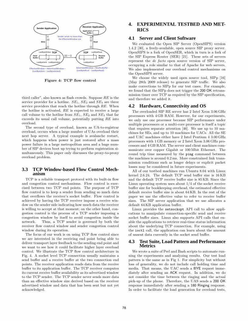
Sender Application
Write
TCP
Read
■ ■ ■ Receive Buffer
LastByteSent LastByteAcked LastByteRcvd
LastByteWritten LastByteRead
Send Buffer
TCP
EffectiveWindow = AdvertisedWindow –
(LastByteSent – LastByteAcked)
AdvertisedWindow = MaxRcvBuffer -
(LastByteRcvd - LastByteRead)
Sender sends no more than
the EffectiveWindow size
ApplicationBuffer
Receiver Application
Figure 4: TCP flow control
third caller”, also known as flash crowds. Suppose RE is theservice provider for a hotline. SE1, SE2 and SE3 are threeservice providers that reach the hotline through RE. Whenthe hotline is activated, RE is expected to receive a largecall volume to the hotline from SE1, SE2 and SE3 that farexceeds its usual call volume, potentially putting RE intooverload.
The second type of overload, known as UA-to-registraroverload, occurs when a large number of UAs overload theirnext hop server. A typical example is avalanche restart,which happens when power is just restored after a masspower failure in a large metropolitan area and a huge num-ber of SIP devices boot up trying to perform registration si-multaneously. This paper only discusses the proxy-to-proxyoverload problem.
3.3 TCP Window-based Flow Control Mech-anism
TCP is a reliable transport protocol with its built-in flowand congestion control mechanisms. Flow control is exer-cised between two TCP end points. The purpose of TCPflow control is to keep a sender from sending so much datathat overflows the receiver’s socket buffer. Flow control isachieved by having the TCP receiver impose a receive win-dow on the sender side indicating how much data the receiveris willing to accept at that moment; on the other hand, con-gestion control is the process of a TCP sender imposing acongestion window by itself to avoid congestion inside thenetwork. Thus, a TCP sender is governed by both thereceiver flow control window and sender congestion controlwindow during its operation.
The focus of our work is on using TCP flow control sincewe are interested in the receiving end point being able todeliver transport layer feedback to the sending end point andwe want to see how it could facilitate higher layer overloadcontrol. We illustrate the TCP flow control architecture inFig. 4. A socket level TCP connection usually maintains asend buffer and a receive buffer at the two connection endpoints. The receiver application reads data from the receivebuffer to its application buffer. The TCP receiver computesits current receive buffer availability as its advertised windowto the TCP sender. The TCP sender never sends more datathan an effective window size derived based on the receiveradvertised window and data that has been sent but not yetacknowledged.
4. EXPERIMENTAL TESTBED AND MET-RICS
4.1 Server and Client SoftwareWe evaluated the Open SIP Server (OpenSIPS) version
1.4.2 [30], a freely-available, open source SIP proxy server.OpenSIPS is a fork of OpenSER, which in turn is a fork ofthe SIP Express Router (SER) [21]. These sets of serversrepresent the de facto open source version of SIP server,occupying a role similar to that of Apache for web servers.We also implemented our overload control mechanisms onthe OpenSIPS server.
We choose the widely used open source tool, SIPp [16](May 28th 2009 release) to generate SIP traffic. We alsomake corrections to SIPp for our test cases. For example,we found that the SIPp does not trigger the 200 OK retrans-mission timer over TCP as required by the SIP specification,and therefore we added it.
4.2 Hardware, Connectivity and OSThe overloaded SIP RE server has 2 Intel Xeon 3.06 GHz
processors with 4GB RAM. However, for our experiments,we only use one processor because SIP performance undermultiple processors or a multi-core processor is itself a topicthat requires separate attention [46]. We use up to 10 ma-chines for SEs, and up to 10 machines for UACs. All the SEand UAC machines either have 2 Intel Pentium 4 3.00 GHzprocessors with 1GB memory or 2 Intel Xeon 3.06 GHz pro-cessors and 4GB RAM. The server and client machines com-municate over copper Gigabit or 100 Mbit Ethernet. Theround trip time measured by the ping command betweenthe machines is around 0.2 ms. More constrained link trans-mission conditions such as longer delays or explicit packetlosses may be considered in future experiments.
All of our testbed machines run Ubuntu 8.04 with Linuxkernel 2.6.24. The default TCP send buffer size is 16 KBand the default TCP receive buffer size is 85KB. Since theLinux operating system uses about 1/4 of the socket receivebuffer size for bookkeeping overhead, the estimated effectivedefault receive buffer size is about 64KB. In the rest of thepaper we use the effective value to refer to receive buffersizes. The SIP server application that we use allocates adefault 64KB application buffer.
Linux provides the setsockopt API call to allow appli-cations to manipulate connection-specific send and receivesocket buffer sizes. Linux also supports API calls that en-able the applications to retrieve real-time status informationabout the underlying TCP connection. For example, usingthe ioctl call, the application can learn about the amountof unsent data currently in the socket send buffer.
4.3 Test Suite, Load Pattern and PerformanceMetrics
We wrote a suite of Perl and Bash scripts to automate run-ning the experiments and analyzing results. Our test loadpattern is the same as in Fig 1. For simplicity but withoutloss of generality, we do not include call holding time andmedia. That means, the UAC sends a BYE request imme-diately after sending an ACK request. In addition, we donot consider the time between the ringing and the actualpick-up of the phone. Therefore, the UAS sends a 200 OK
response immediately after sending a 180 Ringing response.In order to facilitate the load generation for overload tests,
78
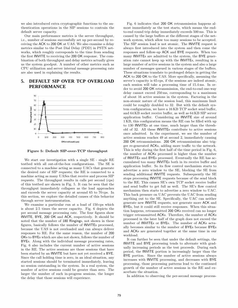
we also introduced extra cryptographic functions to the au-thentication operations in the SIP sessions to contrain thedefault server capacity.
Our main performance metrics is the server throughput,i.e., number of sessions successfully set up per-second by re-ceiving the ACK to 200 OK at UAS. We also examine a delaymetrics similar to the Post Dial Delay (PDD) in PSTN net-works, which roughly corresponds to the time from sendingthe first INVITE to receiving the 200 OK response. The com-bination of both throughput and delay metrics actually givesus the system goodput. A number of other metrics such asCPU utilization and server internal message processing rateare also used in explaining the results.
5. DEFAULT SIP OVER TCP OVERLOADPERFORMANCE
Figure 5: Default SIP-over-TCP throughput
We start our investigation with a single SE - single REtestbed with all out-of-the-box configurations. The SE isconnected to a machine acting as many UACs that generatethe desired rate of SIP requests; the RE is connected to amachine acting as many UASes that receive and process SIPrequests. The throughput results in calls per second (cps)of this testbed are shown in Fig. 5. It can be seen that thethroughput immediately collapses as the load approachesand exceeds the server capacity at around 65 to 70 cps. Inthis section, we explore the detailed causes of this behaviorthrough server instrumentation.
We examine a particular run at a load of 150 cps whichis about 2.5 times the server capacity. Fig. 6 depicts theper second message processing rate. The four figures showINVITE, BYE, 200 OK and ACK, respectively. It should benoted that the number of 180 Ringings, not shown in thesefigures, basically follows the number of INVITEs processed,because the UAS is not overloaded and can always deliverresponses to RE. For the same reason, the number of 200
OKs to BYEs which are also not shown, follows the number ofBYEs. Along with the individual message processing rates,Fig. 6 also includes the current number of active sessionsin the RE. The active sessions are those sessions that havebeen started by an INVITE but have not yet received a BYE.Since the call holding time is zero, in an ideal situation, anystarted sessions should be terminated immediately, leavingno session outstanding in the system. In a real system, thenumber of active sessions could be greater than zero. Thelarger the number of such in-progress sessions, the longerthe delay that those sessions will experience.
Fig. 6 indicates that 200 OK retransmission happens al-most immediately as the test starts, which means the end-to-end round trip delay immediately exceeds 500ms. This iscaused by the large buffers at the different stages of the net-work system, which allow too many sessions to be accepted.The SIP session load is not atomic. The INVITE request isalways first introduced into the system and then come theresponses and follow-up ACK and BYE requests. When toomany INVITEs are admitted to the system, the BYE gener-ation rate cannot keep up with the INVITEs, resulting in alarge number of active sessions in the system and also a largenumber of messages queued in various stages of the buffers.These situations translate to prolonged delays in getting theACK to 200 OK to the UAS. More specifically, assuming theserver’s capacity is 65 cps, if the sessions are indeed atomic,each session will take a processing time of 15.4 ms. In or-der to avoid 200 OK retransmission, the end-to-end one-waydelay cannot exceed 250 ms, corresponding to a maximumof about 16 active sessions in the system. Factoring in thenon-atomic nature of the session load, this maximum limitcould be roughly doubled to 32. But with the default sys-tem configuration, we have a 16KB TCP socket send buffer,and 64 KB socket receive buffer, as well as 64 KB SIP serverapplication buffer. Considering an INVITE size of around1KB, this configuration means the RE can be filled with upto 130 INVITEs at one time, much larger than the thresh-old of 32. All these INVITEs contribute to active sessionsonce admitted. In the experiment, we see the number ofactive sessions reaches 49 at second 2, immediately causing200 OK retransmissions. 200 OK retransmissions also trig-ger re-generated ACKs, adding more traffic to the network.This is why during the first half of the time period in Fig. 6,the number of ACKs processed is higher than the numberof INVITEs and BYEs processed. Eventually the RE has ac-cumulated too many INVITEs both in its receive buffer andapplication buffer. So its flow control mechanism starts toadvertise a zero window to the SE, blocking the SE fromsending additional INVITE requests. Subsequently the SEstops processing INVITE requests because of the send blockto the RE. This causes SE’s own TCP socket receive bufferand send buffer to get full as well. The SE’s flow controlmechanism then starts to advertise a zero window to UAC.This back pressure on UAC prevents the UAC from sendinganything out to the SE. Specifically, the UAC can neithergenerate new INVITE requests, nor generate more ACK andBYEs, but it could still receive responses. When this situa-tion happens, retransmitted 200 OKs received can no longertrigger retransmitted ACKs. Therefore, the number of ACKsprocessed in the later half of the graph does not exceed thenumber of INVITEs or BYEs. The number of ACKs actu-ally becomes similar to the number of BYEs because BYEsand ACKs are generated together at the same time in ourworkload.
It can further be seen that under the default settings, theINVITE and BYE processing tends to alternate with grad-ually increasing periods as the test proceeds. During eachperiod, the INVITE portion is increasingly larger than theBYE portion. Since the number of active sessions alwaysincreases with INVITE processing, and decreases with BYE
processing, those processing patterns lead to the continuedgrowth of the number of active sessions in the RE and ex-acerbate the situation.
In addition to observing the per-second message process-
79
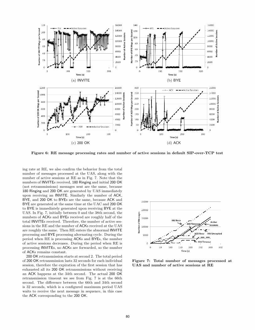
(a) INVITE (b) BYE
(c) 200 OK (d) ACK
Figure 6: RE message processing rates and number of active sessions in default SIP-over-TCP test
ing rate at RE, we also confirm the behavior from the totalnumber of messages processed at the UAS, along with thenumber of active sessions at RE as in Fig. 7. Note that thenumbers of INVITEs received, 180 Ringing and initial 200 OK
(not retransmissions) messages sent are the same, because180 Ringing and 200 OK are generated by UAS immediatelyupon receiving an INVITE. Similarly the number of ACK,BYE, and 200 OK to BYEs are the same, because ACK andBYE are generated at the same time at the UAC and 200 OK
to BYE is immediately generated upon receiving BYE at theUAS. In Fig. 7, initially between 0 and the 38th second, thenumbers of ACKs and BYEs received are roughly half of thetotal INVITEs received. Therefore, the number of active ses-sions in the RE and the number of ACKs received at the UASare roughly the same. Then RE enters the abnormal INVITE
processing and BYE processing alternating cycle. During theperiod when RE is processing ACKs and BYEs, the numberof active sessions decreases. During the period when RE isprocessing INVITEs, no ACKs are forwarded, so the numberof ACKs remains constant.
200 OK retransmission starts at second 2. The total periodof 200 OK retransmission lasts 32 seconds for each individualsession, therefore the expiration of the first session that hasexhausted all its 200 OK retransmissions without receivingan ACK happens at the 34th second. The actual 200 OK
retransmission timeout we see from Fig. 7 is at the 66thsecond. The difference between the 66th and 34th secondis 32 seconds, which is a configured maximum period UASwaits to receive the next message in sequence, in this casethe ACK corresponding to the 200 OK.
Figure 7: Total number of messages processed atUAS and number of active sessions at RE
80
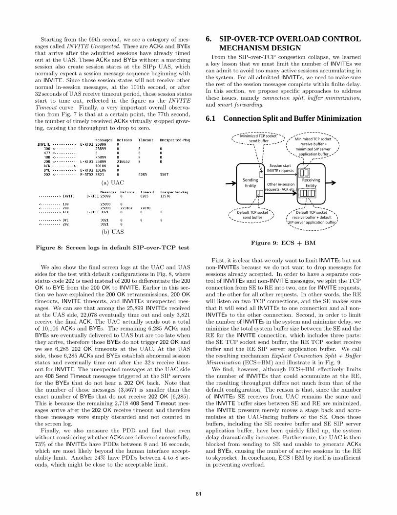
Starting from the 69th second, we see a category of mes-sages called INVITE Unexpected. These are ACKs and BYEsthat arrive after the admitted sessions have already timedout at the UAS. These ACKs and BYEs without a matchingsession also create session states at the SIPp UAS, whichnormally expect a session message sequence beginning withan INVITE. Since those session states will not receive othernormal in-session messages, at the 101th second, or after32 seconds of UAS receive timeout period, those session statesstart to time out, reflected in the figure as the INVITE
Timeout curve. Finally, a very important overall observa-tion from Fig. 7 is that at a certain point, the 77th second,the number of timely received ACKs virtually stopped grow-ing, causing the throughput to drop to zero.
(a) UAC
(b) UAS
Figure 8: Screen logs in default SIP-over-TCP test
We also show the final screen logs at the UAC and UASsides for the test with default configurations in Fig. 8, wherestatus code 202 is used instead of 200 to differentiate the 200
OK to BYE from the 200 OK to INVITE. Earlier in this sec-tion we have explained the 200 OK retransmissions, 200 OK
timeouts, INVITE timeouts, and INVITEs unexpected mes-sages. We can see that among the 25,899 INVITEs receivedat the UAS side, 22,078 eventually time out and only 3,821receive the final ACK. The UAC actually sends out a totalof 10,106 ACKs and BYEs. The remaining 6,285 ACKs andBYEs are eventually delivered to UAS but are too late whenthey arrive, therefore those BYEs do not trigger 202 OK andwe see 6,285 202 OK timeouts at the UAC. At the UASside, those 6,285 ACKs and BYEs establish abnormal sessionstates and eventually time out after the 32 s receive time-out for INVITE. The unexpected messages at the UAC sideare 408 Send Timeout messages triggered at the SIP serversfor the BYEs that do not hear a 202 OK back. Note thatthe number of those messages (3,567) is smaller than theexact number of BYEs that do not receive 202 OK (6,285).This is because the remaining 2,718 408 Send Timeout mes-sages arrive after the 202 OK receive timeout and thereforethose messages were simply discarded and not counted inthe screen log.
Finally, we also measure the PDD and find that evenwithout considering whether ACKs are delivered successfully,73% of the INVITEs have PDDs between 8 and 16 seconds,which are most likely beyond the human interface accept-ability limit. Another 24% have PDDs between 4 to 8 sec-onds, which might be close to the acceptable limit.
6. SIP-OVER-TCP OVERLOAD CONTROLMECHANISM DESIGN
From the SIP-over-TCP congestion collapse, we learneda key lesson that we must limit the number of INVITEs wecan admit to avoid too many active sessions accumulating inthe system. For all admitted INVITEs, we need to make surethe rest of the session messages complete within finite delay.In this section, we propose specific approaches to addressthese issues, namely connection split, buffer minimization,and smart forwarding.
6.1 Connection Split and Buffer Minimization
Session start
INVITE requests
Receiving
Entity
Sending
Entity Other in-session
requests (ACK etc.)
Minimized TCP socket
receive buffer +
minimized SIP server
application buffer
Minimized TCP socket
send buffer
Default TCP socket
send buffer
Default TCP socket
receive buffer + default
SIP server application buffer
Figure 9: ECS + BM
First, it is clear that we only want to limit INVITEs but notnon-INVITEs because we do not want to drop messages forsessions already accepted. In order to have a separate con-trol of INVITEs and non-INVITE messages, we split the TCPconnection from SE to RE into two, one for INVITE requests,and the other for all other requests. In other words, the REwill listen on two TCP connections, and the SE makes surethat it will send all INVITEs to one connection and all non-INVITEs to the other connection. Second, in order to limitthe number of INVITEs in the system and minimize delay, weminimize the total system buffer size between the SE and theRE for the INVITE connection, which includes three parts:the SE TCP socket send buffer, the RE TCP socket receivebuffer and the RE SIP server application buffer. We callthe resulting mechanism Explicit Connection Split + Buffer
Minimization (ECS+BM) and illustrate it in Fig. 9.We find, however, although ECS+BM effectively limits
the number of INVITEs that could accumulate at the RE,the resulting throughput differs not much from that of thedefault configuration. The reason is that, since the numberof INVITEs SE receives from UAC remains the same andthe INVITE buffer sizes between SE and RE are minimized,the INVITE pressure merely moves a stage back and accu-mulates at the UAC-facing buffers of the SE. Once thosebuffers, including the SE receive buffer and SE SIP serverapplication buffer, have been quickly filled up, the systemdelay dramatically increases. Furthermore, the UAC is thenblocked from sending to SE and unable to generate ACKsand BYEs, causing the number of active sessions in the REto skyrocket. In conclusion, ECS+BM by itself is insufficientin preventing overload.
81
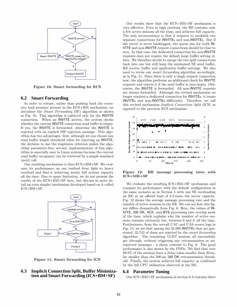
INVITE connectionsend buffer empty?
INVITE arrival?
Forward INVITE
Reject INVITE
Start
Y
N
Y
N
Figure 10: Smart forwarding for ECS
6.2 Smart ForwardingIn order to release, rather than pushing back the exces-
sive load pressure present in the ECS+BM mechanism, weintroduce the Smart Forwarding (SF) algorithm as shownin Fig. 10. This algorithm is enforced only for the INVITE
connection. When an INVITE arrives, the system checkswhether the current INVITE connection send buffer is empty.If yes, the INVITE is forwarded; otherwise the INVITE isrejected with an explicit SIP rejection message. This algo-rithm has two advantages: first, although we can choose anysend buffer length threshold value for rejecting an INVITE,the decision to use the emptiness criterion makes the algo-rithm parameter-free; second, implementation of this algo-rithm is especially easy in Linux systems because the currentsend buffer occupancy can be retrieved by a simple standardioctl call.
Our resulting mechanism is then ECS+BM+SF. We eval-uate its performance on our testbed from light to heavyoverload and find it achieving nearly full system capacityall the time. Due to space limitation, we do not present theresults of the ECS+BM+SF here, but discuss in more de-tail an even simpler mechanism developed based on it calledICS+BM+SF.
send buffer empty?
message arrival?
Forward
Reject
Start
Y
N
Y
N
Is an INVITE?
Y
N
Figure 11: Smart forwarding for ICS
6.3 Implicit Connection Split, Buffer Minimiza-tion and Smart Forwarding (ICS+BM+SF)
Our results show that the ECS+BM+SF mechanism isvery effective. Even in high overload, the RE contains onlya few active sessions all the time, and achieves full capacity.The only inconvenience is that it requires to establish twoseparate connections for INVITEs and non-INVITEs. But ifthe server is never backlogged, the queue size for both IN-
VITE and non-INVITE request connections should be close tozero. In that case, the dedicated connection for non-INVITE
requests does not require the default large buffer setting ei-ther. We therefore decide to merge the two split connectionsback into one but still keep the minimized SE send buffer,RE receive buffer and application buffer settings. We alsoneed to revise our smart forwarding algorithm accordingly,as in Fig. 11. Since there is only a single request connectionnow, the algorithm performs an additional check for INVITE
requests and rejects it if the send buffer is non-empty. Oth-erwise, the INVITE is forwarded. All non-INVITE requestsare always forwarded. Although the revised mechanism nolonger requires a dedicated connection for INVITEs, it treatsINVITEs and non-INVITEs differently. Therefore, we callthis revised mechanism Implicit Connection Split (ICS) asopposed to the previous ECS mechanism.
Figure 12: RE message processing rates withICS+MB+SF
We evaluate the resulting ICS+BM+SF mechanism andcompare its performance with the default configuration inthe same scenario as in Section 5 with one SE overloadingan RE at an offered load of 2.5 times the server capacity.Fig. 12 shows the average message processing rate and thenumber of active sessions in the RE. We can see how this fig-ure differs dramatically from Fig. 6. Here, the values of IN-
VITE, 200 OK, ACK, and BYE processing rate overlap mostof the time, which explains why the number of active ses-sions remains extremely low, between 0 and 3, all the time.Furthermore, from the overall UAC and UAS screen logs inFig. 13, we see that among the 35,999 INVITEs that are gen-erated, 22,742 of them are rejected by the smart forwarding
algorithm. The remaining 13,257 sessions all successfullyget through, without triggering any retransmission or un-expected messages - a sharp contrast to Fig. 8. The goodperformance is also shown by the PDDs. We find that over99.8% of the sessions have a delay value smaller than 30ms,far smaller than the 500 ms 200 OK retransmission thresh-old. Finally, the system achieves full capacity as confirmedby the full CPU utilization observed at the RE.
6.4 Parameter TuningOur ICS+BM+SF mechanism in section 6.3 contains three
82
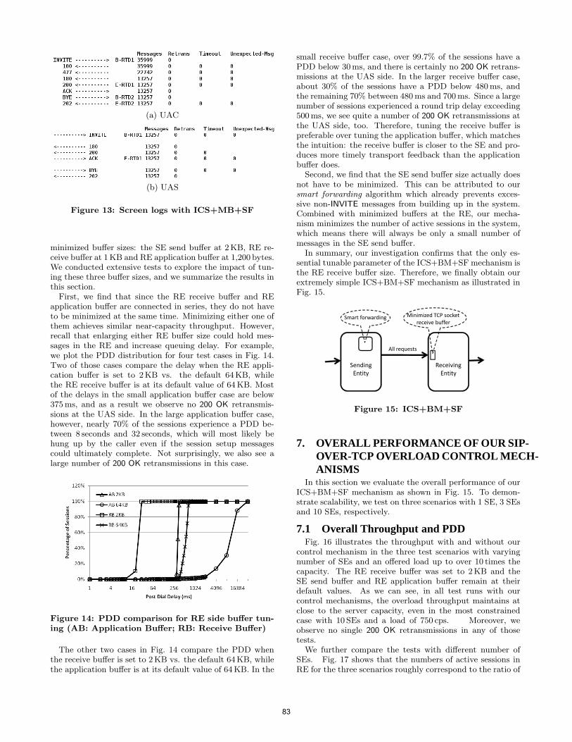
(a) UAC
(b) UAS
Figure 13: Screen logs with ICS+MB+SF
minimized buffer sizes: the SE send buffer at 2KB, RE re-ceive buffer at 1KB and RE application buffer at 1,200 bytes.We conducted extensive tests to explore the impact of tun-ing these three buffer sizes, and we summarize the results inthis section.
First, we find that since the RE receive buffer and REapplication buffer are connected in series, they do not haveto be minimized at the same time. Minimizing either one ofthem achieves similar near-capacity throughput. However,recall that enlarging either RE buffer size could hold mes-sages in the RE and increase queuing delay. For example,we plot the PDD distribution for four test cases in Fig. 14.Two of those cases compare the delay when the RE appli-cation buffer is set to 2KB vs. the default 64KB, whilethe RE receive buffer is at its default value of 64 KB. Mostof the delays in the small application buffer case are below375 ms, and as a result we observe no 200 OK retransmis-sions at the UAS side. In the large application buffer case,however, nearly 70% of the sessions experience a PDD be-tween 8 seconds and 32 seconds, which will most likely behung up by the caller even if the session setup messagescould ultimately complete. Not surprisingly, we also see alarge number of 200 OK retransmissions in this case.
Figure 14: PDD comparison for RE side buffer tun-ing (AB: Application Buffer; RB: Receive Buffer)
The other two cases in Fig. 14 compare the PDD whenthe receive buffer is set to 2KB vs. the default 64KB, whilethe application buffer is at its default value of 64 KB. In the
small receive buffer case, over 99.7% of the sessions have aPDD below 30ms, and there is certainly no 200 OK retrans-missions at the UAS side. In the larger receive buffer case,about 30% of the sessions have a PDD below 480 ms, andthe remaining 70% between 480 ms and 700 ms. Since a largenumber of sessions experienced a round trip delay exceeding500 ms, we see quite a number of 200 OK retransmissions atthe UAS side, too. Therefore, tuning the receive buffer ispreferable over tuning the application buffer, which matchesthe intuition: the receive buffer is closer to the SE and pro-duces more timely transport feedback than the applicationbuffer does.
Second, we find that the SE send buffer size actually doesnot have to be minimized. This can be attributed to oursmart forwarding algorithm which already prevents exces-sive non-INVITE messages from building up in the system.Combined with minimized buffers at the RE, our mecha-nism minimizes the number of active sessions in the system,which means there will always be only a small number ofmessages in the SE send buffer.
In summary, our investigation confirms that the only es-sential tunable parameter of the ICS+BM+SF mechanism isthe RE receive buffer size. Therefore, we finally obtain ourextremely simple ICS+BM+SF mechanism as illustrated inFig. 15.
Receiving
Entity
Sending
Entity
All requests
Minimized TCP socket
receive bufferSmart forwarding
Figure 15: ICS+BM+SF
7. OVERALL PERFORMANCE OF OUR SIP-OVER-TCP OVERLOAD CONTROL MECH-ANISMS
In this section we evaluate the overall performance of ourICS+BM+SF mechanism as shown in Fig. 15. To demon-strate scalability, we test on three scenarios with 1 SE, 3 SEsand 10 SEs, respectively.
7.1 Overall Throughput and PDDFig. 16 illustrates the throughput with and without our
control mechanism in the three test scenarios with varyingnumber of SEs and an offered load up to over 10 times thecapacity. The RE receive buffer was set to 2KB and theSE send buffer and RE application buffer remain at theirdefault values. As we can see, in all test runs with ourcontrol mechanisms, the overload throughput maintains atclose to the server capacity, even in the most constrainedcase with 10 SEs and a load of 750 cps. Moreover, weobserve no single 200 OK retransmissions in any of thosetests.
We further compare the tests with different number ofSEs. Fig. 17 shows that the numbers of active sessions inRE for the three scenarios roughly correspond to the ratio of
83
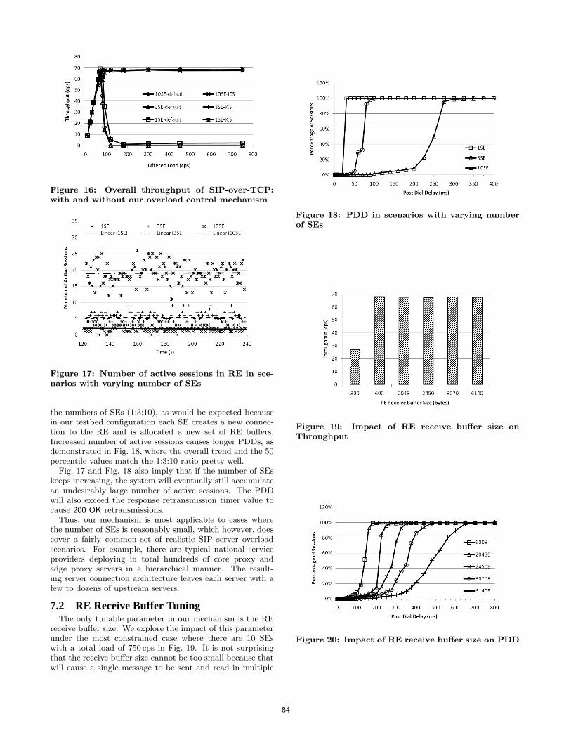
Figure 16: Overall throughput of SIP-over-TCP:with and without our overload control mechanism
Figure 17: Number of active sessions in RE in sce-narios with varying number of SEs
the numbers of SEs (1:3:10), as would be expected becausein our testbed configuration each SE creates a new connec-tion to the RE and is allocated a new set of RE buffers.Increased number of active sessions causes longer PDDs, asdemonstrated in Fig. 18, where the overall trend and the 50percentile values match the 1:3:10 ratio pretty well.
Fig. 17 and Fig. 18 also imply that if the number of SEskeeps increasing, the system will eventually still accumulatean undesirably large number of active sessions. The PDDwill also exceed the response retransmission timer value tocause 200 OK retransmissions.
Thus, our mechanism is most applicable to cases wherethe number of SEs is reasonably small, which however, doescover a fairly common set of realistic SIP server overloadscenarios. For example, there are typical national serviceproviders deploying in total hundreds of core proxy andedge proxy servers in a hierarchical manner. The result-ing server connection architecture leaves each server with afew to dozens of upstream servers.
7.2 RE Receive Buffer TuningThe only tunable parameter in our mechanism is the RE
receive buffer size. We explore the impact of this parameterunder the most constrained case where there are 10 SEswith a total load of 750 cps in Fig. 19. It is not surprisingthat the receive buffer size cannot be too small because thatwill cause a single message to be sent and read in multiple
Figure 18: PDD in scenarios with varying numberof SEs
Figure 19: Impact of RE receive buffer size onThroughput
Figure 20: Impact of RE receive buffer size on PDD
84
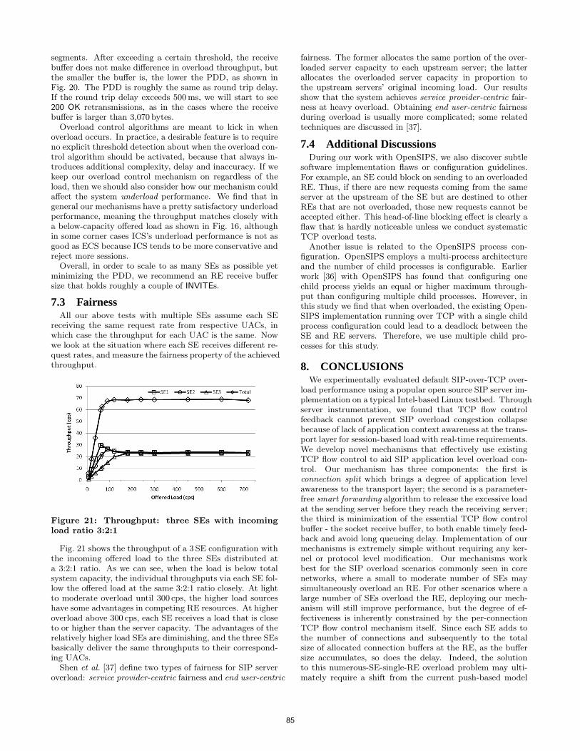
segments. After exceeding a certain threshold, the receivebuffer does not make difference in overload throughput, butthe smaller the buffer is, the lower the PDD, as shown inFig. 20. The PDD is roughly the same as round trip delay.If the round trip delay exceeds 500 ms, we will start to see200 OK retransmissions, as in the cases where the receivebuffer is larger than 3,070 bytes.
Overload control algorithms are meant to kick in whenoverload occurs. In practice, a desirable feature is to requireno explicit threshold detection about when the overload con-trol algorithm should be activated, because that always in-troduces additional complexity, delay and inaccuracy. If wekeep our overload control mechanism on regardless of theload, then we should also consider how our mechanism couldaffect the system underload performance. We find that ingeneral our mechanisms have a pretty satisfactory underloadperformance, meaning the throughput matches closely witha below-capacity offered load as shown in Fig. 16, althoughin some corner cases ICS’s underload performance is not asgood as ECS because ICS tends to be more conservative andreject more sessions.
Overall, in order to scale to as many SEs as possible yetminimizing the PDD, we recommend an RE receive buffersize that holds roughly a couple of INVITEs.
7.3 FairnessAll our above tests with multiple SEs assume each SE
receiving the same request rate from respective UACs, inwhich case the throughput for each UAC is the same. Nowwe look at the situation where each SE receives different re-quest rates, and measure the fairness property of the achievedthroughput.
Figure 21: Throughput: three SEs with incomingload ratio 3:2:1
Fig. 21 shows the throughput of a 3 SE configuration withthe incoming offered load to the three SEs distributed ata 3:2:1 ratio. As we can see, when the load is below totalsystem capacity, the individual throughputs via each SE fol-low the offered load at the same 3:2:1 ratio closely. At lightto moderate overload until 300 cps, the higher load sourceshave some advantages in competing RE resources. At higheroverload above 300 cps, each SE receives a load that is closeto or higher than the server capacity. The advantages of therelatively higher load SEs are diminishing, and the three SEsbasically deliver the same throughputs to their correspond-ing UACs.
Shen et al. [37] define two types of fairness for SIP serveroverload: service provider-centric fairness and end user-centric
fairness. The former allocates the same portion of the over-loaded server capacity to each upstream server; the latterallocates the overloaded server capacity in proportion tothe upstream servers’ original incoming load. Our resultsshow that the system achieves service provider-centric fair-ness at heavy overload. Obtaining end user-centric fairnessduring overload is usually more complicated; some relatedtechniques are discussed in [37].
7.4 Additional DiscussionsDuring our work with OpenSIPS, we also discover subtle
software implementation flaws or configuration guidelines.For example, an SE could block on sending to an overloadedRE. Thus, if there are new requests coming from the sameserver at the upstream of the SE but are destined to otherREs that are not overloaded, those new requests cannot beaccepted either. This head-of-line blocking effect is clearly aflaw that is hardly noticeable unless we conduct systematicTCP overload tests.
Another issue is related to the OpenSIPS process con-figuration. OpenSIPS employs a multi-process architectureand the number of child processes is configurable. Earlierwork [36] with OpenSIPS has found that configuring onechild process yields an equal or higher maximum through-put than configuring multiple child processes. However, inthis study we find that when overloaded, the existing Open-SIPS implementation running over TCP with a single childprocess configuration could lead to a deadlock between theSE and RE servers. Therefore, we use multiple child pro-cesses for this study.
8. CONCLUSIONSWe experimentally evaluated default SIP-over-TCP over-
load performance using a popular open source SIP server im-plementation on a typical Intel-based Linux testbed. Throughserver instrumentation, we found that TCP flow controlfeedback cannot prevent SIP overload congestion collapsebecause of lack of application context awareness at the trans-port layer for session-based load with real-time requirements.We develop novel mechanisms that effectively use existingTCP flow control to aid SIP application level overload con-trol. Our mechanism has three components: the first isconnection split which brings a degree of application levelawareness to the transport layer; the second is a parameter-free smart forwarding algorithm to release the excessive loadat the sending server before they reach the receiving server;the third is minimization of the essential TCP flow controlbuffer - the socket receive buffer, to both enable timely feed-back and avoid long queueing delay. Implementation of ourmechanisms is extremely simple without requiring any ker-nel or protocol level modification. Our mechanisms workbest for the SIP overload scenarios commonly seen in corenetworks, where a small to moderate number of SEs maysimultaneously overload an RE. For other scenarios where alarge number of SEs overload the RE, deploying our mech-anism will still improve performance, but the degree of ef-fectiveness is inherently constrained by the per-connectionTCP flow control mechanism itself. Since each SE adds tothe number of connections and subsequently to the totalsize of allocated connection buffers at the RE, as the buffersize accumulates, so does the delay. Indeed, the solutionto this numerous-SE-single-RE overload problem may ulti-mately require a shift from the current push-based model
85
to a poll-based model. Specifically, instead of allowing allthe SEs to send, the RE may advertise a zero TCP windowto most of the SEs and open the windows only for thoseSEs that the RE is currently polling to accept loads. Futurework is needed in this area.
Our study sheds light both at software level and concep-tual level. At the software level, we discover implementa-tion flaws for overload management that would not be no-ticed without conducting a systematic overload study, eventhough our evaluated SIP server is a mature open sourceserver. At the conceptual level, our results suggest an aug-mentation to the long-held notion of TCP flow control: thetraditional TCP flow-control alone is incapable of handlingSIP-like time-sensitive session-based application overload.The conclusion may be generalized to a much broader ap-plication space that share similar load characteristics, suchas database systems. Our proposed combined techniques in-cluding connection split, smart forwarding and buffer mini-
mization are key elements to make TCP flow control actuallywork for managing overload of such applications.
9. ACKNOWLEDGEMENTThe authors would like to acknowledge NTT for funding
this project and Dr. Arata Koike for useful discussions. Wewould also like to thank the anonymous reviewers for thehelpful comments.
10. REFERENCES[1] SIP forum. http://www.sipforum.org.[2] M. Allman, V. Paxson, and W. Stevens. TCP Congestion
Control. RFC 2581, Apr. 1999. Updated by RFC 3390.[3] A. Argyriou. Real-time and rate-distortion optimized video
streaming with TCP. Image Commun., 22(4):374–388,2007.
[4] S. Baset, E. Brosh, V. Misra, D. Rubenstein, andH. Schulzrinne. Understanding the behavior of TCP forreal-time CBR workloads. In Proc. ACM CoNEXT ’06,pages 1–2, Lisboa, Portugal, Dec. 2006.
[5] L.S. Brakmo and L.L. Peterson. TCP vegas: end to endcongestion avoidance on a global internet. IEEE Journal onSelected Areas in Communications, 13(8):1465–1480, Oct.1995.
[6] L. Cherkasova and P. Phaal. Session-based admissioncontrol: A mechanism for peak load management ofcommercial web sites. IEEE Trans. Comput.,51(6):669–685, 2002.
[7] M. Colajanni, V. Cardellini, and P. Yu. Dynamic loadbalancing in geographically distributed heterogeneous webservers. In ICDCS ’98: Proceedings of the 18thInternational Conference on Distributed ComputingSystems, page 295, Amsterdam, The Netherlands, May1998.
[8] T. Dunigan, M. Mathis, and B. Tierney. A TCP tuningdaemon. In Supercomputing ’02: Proceedings of the 2002ACM/IEEE conference on Supercomputing, pages 1–16,Baltimore, Maryland, Nov. 2002.
[9] E. Nahum and J. Tracey and C. Wright. Evaluating SIPserver performance. In ACM SIGMETRICS PerformanceEvaluation Review, volume 35, pages 349–350, San Diego,California, Jun. 2007.
[10] R. Ejzak, C. Florkey, and R. Hemmeter. Network overloadand congestion: A comparison of ISUP and SIP. Bell LabsTechnical Journal, 9(3):173–182, Nov. 2004.
[11] H. Elaarag. Improving TCP performance over mobilenetworks. ACM Comput. Surv., 34(3):357–374, 2002.
[12] S. Elnikety, E. Nahum, J. Tracey, and W. Zwaenepoel. Amethod for transparent admission control and request
scheduling in e-commerce web sites. In Proceedings of the13th international conference on World Wide Web, pages276–286, New York, New York, May 2004.
[13] S. Floyd, T. Henderson, and A. Gurtov. The NewRenoModification to TCP’s Fast Recovery Algorithm. RFC3782, Apr. 2004.
[14] S. Floyd and V. Jacobson. Random early detectiongateways for congestion avoidance. IEEE/ACMTransactions on Networking, 1(4):397–413, Aug. 1993.
[15] S. Floyd, J. Mahdavi, M. Mathis, and M. Podolsky. AnExtension to the Selective Acknowledgement (SACK)Option for TCP. RFC 2883, Jul. 2000.
[16] R. Gayraud and O. Jacques. SIPp.http://sipp.sourceforge.net.
[17] S. Ha, I. Rhee, and L. Xu. Cubic: a new TCP-friendlyhigh-speed TCP variant. SIGOPS Oper. Syst. Rev.,42(5):64–74, 2008.
[18] G. Hasegawa, T. Terai, T. Okamoto, and M. Murata.Scalable socket buffer tuning for high-performance webservers. In Ninth International Conference on NetworkProtocols, pages 281–289, Riverside, California, Nov. 2001.
[19] V. Hilt and I. Widjaja. Controlling overload in networks ofSIP servers. In IEEE International Conference on NetworkProtocols (ICNP), pages 83–93, Orlando, Florida, Oct.2008.
[20] J. Hoe. Improving the start-up behavior of a congestioncontrol scheme for TCP. In SIGCOMM’ 96, pages 270–280,Palo Alto, California, 1996.
[21] IPTel.org. SIP express router (SER).http://www.iptel.org/ser.
[22] V. Jacobson. Congestion avoidance and control. InSIGCOMM ’88: Symposium proceedings onCommunications architectures and protocols, pages314–329, Stanford, California, Aug. 1988.
[23] D. Kliazovich, F. Granelli, and D. Miorandi. Logarithmicwindow increase for TCP westwood+ for improvement inhigh speed, long distance networks. Computer Networks,52(12):2395–2410, 2008.
[24] M. Ohta. Overload Protection in a SIP Signaling Network.In International Conference on Internet Surveillance andProtection, Cote d’Azur, France, Aug. 2006.
[25] M. Mathis, J. Mahdavi, S. Floyd, and A. Romanow. TCPSelective Acknowledgement Options. RFC 2018, Oct. 1996.
[26] R. Morris. Scalable TCP congestion control. In Proc. IEEEINFOCOM 2000, pages 1176–1183, Tel-Aviv, Israel, Mar.2000.
[27] E. Noel and C. Johnson. Initial simulation results thatanalyze SIP based VoIP networks under overload. In ITC,pages 54–64, Ottawa, Canada, Jun. 2007.
[28] K. Ono and H. Schulzrinne. One server per city: Using TCPfor very large SIP servers. In IPTComm ’08: Principles,Systems and Applications of IP Telecommunications.Services and Security for Next Generation Networks,volume 5310/2008, pages 133–148, Oct. 2008.
[29] J. Postel. Transmission Control Protocol. RFC 793, Sep.1981. Updated by RFC 3168.
[30] The OpenSIPS Project. http://www.opensips.org.[31] K. Kumar Ram, I. Fedeli, A. Cox, and S. Rixner.
Explaining the impact of network transport protocols onSIP proxy performance. In IEEE International Symposiumon Performance Analysis of Systems and Software(ISPASS), pages 75–84, Austin, Texas, Apr. 2008.
[32] Light Reading. VoIP security: Vendors prepare for theinevitable. VoIP Services Insider, 5(1), Jan. 2009.
[33] J. Rosenberg. Requirements for Management of Overload inthe Session Initiation Protocol. RFC 5390, Dec. 2008.
[34] J. Rosenberg, H. Schulzrinne, G. Camarillo, A. Johnston,J. Peterson, R. Sparks, M. Handley, and E. Schooler. SIP:Session Initiation Protocol. RFC 3261, Jun. 2002.
[35] H. Sengar. Overloading vulnerability of VoIP networks. InIEEE/IFIP International Conference on Dependable
86
Systems & Networks, pages 419–428, Lisbon, Portugal, Jul.2009.
[36] C. Shen, E. Nahum, H. Schulzrinne, and C.P. Wright. Theimpact of TLS on SIP server performance. TechnicalReport CUCS-022-09, Columbia University Department ofComputer Science, May 2009.
[37] C. Shen, H. Schulzrinne, and E. Nahum. Session InitiationProtocol (SIP) server overload control: Design andevaluation. In IPTComm ’08: Principles, Systems andApplications of IP Telecommunications. Services andSecurity for Next Generation Networks, volume 5310/2008,pages 149–173, Heidelberg, Germany, Oct. 2008.
[38] R. Stewart. Stream Control Transmission Protocol. RFC4960, Sep. 2007.
[39] J. Sun, J. Hu, R. Tian, and B. Yang. Flow management forSIP application servers. In Proc. IEEE ICC ’07, pages646–652, Glasgow, Scotland, Jun. 2007.
[40] V. Gurbani, V. Hilt, and H. Schulzrinne. Session InitiationProtocol (SIP) Overload Control. Internet draft, Jun. 2010.Work in progress.
[41] V. Hilt, E. Noel, C. Shen, and A. Abdelal. DesignConsiderations for Session Initiation Protocol (SIP)Overload Control. Internet draft, Jun. 2010. Work inprogress.
[42] V. Vasudevan, A. Phanishayee, H. Shah, E. Krevat,D. Andersen, G. Ganger, G. Gibson, and B. Mueller. Safeand effective fine-grained TCP retransmissions fordatacenter communication. In Proc. of SIGCOMM ’09,pages 303–314, Barcelona, Spain, Aug. 2009.
[43] A. Vishwanath, V. Sivaraman, and M. Thottan.Perspectives on router buffer sizing: recent results and openproblems. SIGCOMM Comput. Commun. Rev.,39(2):34–39, 2009.
[44] B. Wang, J. Kurose, P. Shenoy, and D. Towsley.Multimedia streaming via TCP: an analytic performancestudy. In Proc. ACM MULTIMEDIA ’04, pages 908–915,New York, New York, Oct. 2004.
[45] M. Whitehead. GOCAP - one standardised overload controlfor next generation networks. BT Technology Journal,23(1):144–153, 2005.
[46] C.P. Wright, E Nahum, D. Wood, J. Tracey, and E. Hu.SIP server performance on multicore systems. IBM Journalof Research and Developement, 54(1), Feb. 2010.
[47] X. Wu, M. Chan, and A. Ananda. Improving TCPperformance in heterogeneous mobile environments byexploiting the explicit cooperation between server andmobile host. Computer Networks, 52(16):3062–3074, 2008.
[48] W. Zhao and H. Schulzrinne. Enabling on-demand queryresult caching in dotslash for handling web hotspotseffectively. In 1st IEEE Workshop on HOTWEB, pages1–12, Boston, Massachusetts, Nov. 2006.
87

88
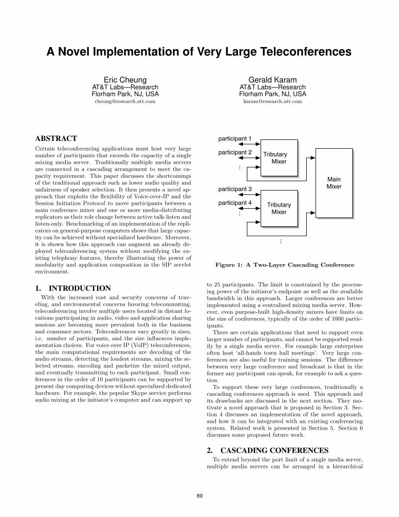
A Novel Implementation of Very Large Teleconferences
Eric CheungAT&T Labs—ResearchFlorham Park, NJ, [email protected]
Gerald KaramAT&T Labs—ResearchFlorham Park, NJ, USA
ABSTRACTCertain teleconferencing applications must host very largenumber of participants that exceeds the capacity of a singlemixing media server. Traditionally multiple media serversare connected in a cascading arrangement to meet the ca-pacity requirement. This paper discusses the shortcomingsof the traditional approach such as lower audio quality andunfairness of speaker selection. It then presents a novel ap-proach that exploits the flexibility of Voice-over-IP and theSession Initiation Protocol to move participants between amain conference mixer and one or more media-distributingreplicators as their role change between active talk-listen andlisten-only. Benchmarking of an implementation of the repli-cators on general-purpose computers shows that large capac-ity can be achieved without specialized hardware. Moreover,it is shown how this approach can augment an already de-ployed teleconferencing system without modifying the ex-isting telephony features, thereby illustrating the power ofmodularity and application composition in the SIP servletenvironment.
1. INTRODUCTIONWith the increased cost and security concerns of trav-
eling, and environmental concerns favoring telecommuting,teleconferencing involve multiple users located in distant lo-cations participating in audio, video and application sharingsessions are becoming more prevalent both in the businessand consumer sectors. Teleconferences vary greatly in sizes,i.e. number of participants, and the size influences imple-mentation choices. For voice over IP (VoIP) teleconferences,the main computational requirements are decoding of theaudio streams, detecting the loudest streams, mixing the se-lected streams, encoding and packetize the mixed output,and eventually transmitting to each participant. Small con-ferences in the order of 10 participants can be supported bypresent day computing devices without specialized dedicatedhardware. For example, the popular Skype service performsaudio mixing at the initiator’s computer and can support up
Permission to make digital or hard copies of all or part of this work forpersonal or classroom use is granted without fee provided that copies arenot made or distributed for profit or commercial advantage and that copiesbear this notice and the full citation on the first page. To copy otherwise, torepublish, to post on servers or to redistribute to lists, requires prior specificpermission and/or a fee.IPTComm 2010, 2-3 August, 2010 Munich, GermanyCopyright 2010 ACM ...$10.00.
Main Mixer
TributaryMixer
participant 4
participant 3
TributaryMixer
participant 2
participant 1
...
...
...
Figure 1: A Two-Layer Cascading Conference
to 25 participants. The limit is constrained by the process-ing power of the initiator’s endpoint as well as the availablebandwidth in this approach. Larger conferences are betterimplemented using a centralized mixing media server. How-ever, even purpose-built high-density mixers have limits onthe size of conferences, typically of the order of 1000 partic-ipants.
There are certain applications that need to support evenlarger number of participants, and cannot be supported read-ily by a single media server. For example large enterprisesoften host ‘all-hands town hall meetings’. Very large con-ferences are also useful for training sessions. The differencebetween very large conference and broadcast is that in theformer any participant can speak, for example to ask a ques-tion.
To support these very large conferences, traditionally acascading conferences approach is used. This approach andits drawbacks are discussed in the next section. They mo-tivate a novel approach that is proposed in Section 3. Sec-tion 4 discusses an implementation of the novel approach,and how it can be integrated with an existing conferencingsystem. Related work is presented in Section 5. Section 6discusses some proposed future work.
2. CASCADING CONFERENCESTo extend beyond the port limit of a single media server,
multiple media servers can be arranged in a hierarchical
89
schmitt
Stempel
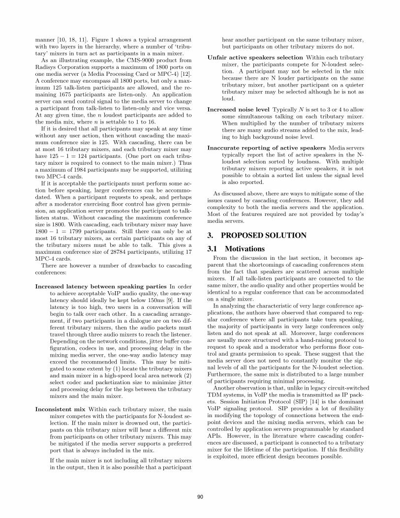
manner [10, 18, 11]. Figure 1 shows a typical arrangementwith two layers in the hierarchy, where a number of ‘tribu-tary’ mixers in turn act as participants in a main mixer.
As an illustrating example, the CMS-9000 product fromRadisys Corporation supports a maximum of 1800 ports onone media server (a Media Processing Card or MPC-4) [12].A conference may encompass all 1800 ports, but only a max-imum 125 talk-listen participants are allowed, and the re-maining 1675 participants are listen-only. An applicationserver can send control signal to the media server to changea participant from talk-listen to listen-only and vice versa.At any given time, the n loudest participants are added tothe media mix, where n is settable to 1 to 16.
If it is desired that all participants may speak at any timewithout any user action, then without cascading the maxi-mum conference size is 125. With cascading, there can beat most 16 tributary mixers, and each tributary mixer mayhave 125 − 1 = 124 participants. (One port on each tribu-tary mixer is required to connect to the main mixer.) Thusa maximum of 1984 participants may be supported, utilizingtwo MPC-4 cards.
If it is acceptable the participants must perform some ac-tion before speaking, larger conferences can be accommo-dated. When a participant requests to speak, and perhapsafter a moderator exercising floor control has given permis-sion, an application server promotes the participant to talk-listen status. Without cascading the maximum conferencesize is 1800. With cascading, each tributary mixer may have1800 − 1 = 1799 participants. Still there can only be atmost 16 tributary mixers, as certain participants on any ofthe tributary mixers must be able to talk. This gives amaximum conference size of 28784 participants, utilizing 17MPC-4 cards.
There are however a number of drawbacks to cascadingconferences:
Increased latency between speaking parties In orderto achieve acceptable VoIP audio quality, the one-waylatency should ideally be kept below 150ms [9]. If thelatency is too high, two users in a conversation willbegin to talk over each other. In a cascading arrange-ment, if two participants in a dialogue are on two dif-ferent tributary mixers, then the audio packets musttravel through three audio mixers to reach the listener.Depending on the network conditions, jitter buffer con-figuration, codecs in use, and processing delay in themixing media server, the one-way audio latency mayexceed the recommended limits. This may be miti-gated to some extent by (1) locate the tributary mixersand main mixer in a high-speed local area network (2)select codec and packetization size to minimize jitterand processing delay for the legs between the tributarymixers and the main mixer.
Inconsistent mix Within each tributary mixer, the mainmixer competes with the participants for N-loudest se-lection. If the main mixer is drowned out, the partici-pants on this tributary mixer will hear a different mixfrom participants on other tributary mixers. This maybe mitigated if the media server supports a preferredport that is always included in the mix.
If the main mixer is not including all tributary mixersin the output, then it is also possible that a participant
hear another participant on the same tributary mixer,but participants on other tributary mixers do not.
Unfair active speakers selection Within each tributarymixer, the participants compete for N-loudest selec-tion. A participant may not be selected in the mixbecause there are N louder participants on the sametributary mixer, but another participant on a quietertributary mixer may be selected although he is not asloud.
Increased noise level Typically N is set to 3 or 4 to allowsome simultaneous talking on each tributary mixer.When multiplied by the number of tributary mixersthere are many audio streams added to the mix, lead-ing to high background noise level.
Inaccurate reporting of active speakers Media serverstypically report the list of active speakers in the N-loudest selection sorted by loudness. With multipletributary mixers reporting active speakers, it is notpossible to obtain a sorted list unless the signal levelis also reported.
As discussed above, there are ways to mitigate some of theissues caused by cascading conferences. However, they addcomplexity to both the media servers and the application.Most of the features required are not provided by today’smedia servers.
3. PROPOSED SOLUTION
3.1 MotivationsFrom the discussion in the last section, it becomes ap-
parent that the shortcomings of cascading conferences stemfrom the fact that speakers are scattered across multiplemixers. If all talk-listen participants are connected to thesame mixer, the audio quality and other properties would beidentical to a regular conference that can be accommodatedon a single mixer.
In analyzing the characteristic of very large conference ap-plications, the authors have observed that compared to reg-ular conference where all participants take turn speaking,the majority of participants in very large conferences onlylisten and do not speak at all. Moreover, large conferencesare usually more structured with a hand-raising protocol torequest to speak and a moderator who performs floor con-trol and grants permission to speak. These suggest that themedia server does not need to constantly monitor the sig-nal levels of all the participants for the N-loudest selection.Furthermore, the same mix is distributed to a large numberof participants requiring minimal processing.
Another observation is that, unlike in legacy circuit-switchedTDM systems, in VoIP the media is transmitted as IP pack-ets. Session Initiation Protocol (SIP) [14] is the dominantVoIP signaling protocol. SIP provides a lot of flexibilityin modifying the topology of connections between the end-point devices and the mixing media servers, which can becontrolled by application servers programmable by standardAPIs. However, in the literature where cascading confer-ences are discussed, a participant is connected to a tributarymixer for the lifetime of the participation. If this flexibilityis exploited, more efficient design becomes possible.
90
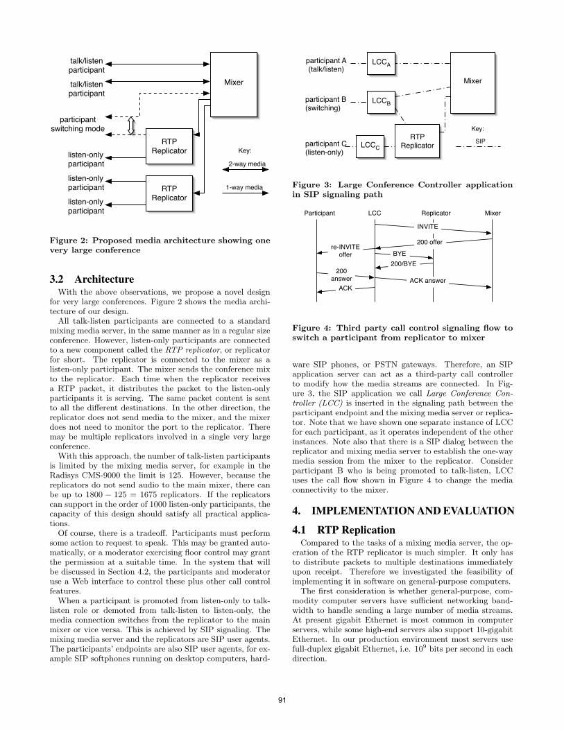
Mixer
RTP Replicator
RTP Replicator
talk/listenparticipant
talk/listenparticipant
listen-onlyparticipant
listen-onlyparticipant
listen-onlyparticipant
participantswitching mode
2-way media
Key:
1-way media
Figure 2: Proposed media architecture showing onevery large conference
3.2 ArchitectureWith the above observations, we propose a novel design
for very large conferences. Figure 2 shows the media archi-tecture of our design.
All talk-listen participants are connected to a standardmixing media server, in the same manner as in a regular sizeconference. However, listen-only participants are connectedto a new component called the RTP replicator, or replicatorfor short. The replicator is connected to the mixer as alisten-only participant. The mixer sends the conference mixto the replicator. Each time when the replicator receivesa RTP packet, it distributes the packet to the listen-onlyparticipants it is serving. The same packet content is sentto all the different destinations. In the other direction, thereplicator does not send media to the mixer, and the mixerdoes not need to monitor the port to the replicator. Theremay be multiple replicators involved in a single very largeconference.
With this approach, the number of talk-listen participantsis limited by the mixing media server, for example in theRadisys CMS-9000 the limit is 125. However, because thereplicators do not send audio to the main mixer, there canbe up to 1800 − 125 = 1675 replicators. If the replicatorscan support in the order of 1000 listen-only participants, thecapacity of this design should satisfy all practical applica-tions.
Of course, there is a tradeoff. Participants must performsome action to request to speak. This may be granted auto-matically, or a moderator exercising floor control may grantthe permission at a suitable time. In the system that willbe discussed in Section 4.2, the participants and moderatoruse a Web interface to control these plus other call controlfeatures.
When a participant is promoted from listen-only to talk-listen role or demoted from talk-listen to listen-only, themedia connection switches from the replicator to the mainmixer or vice versa. This is achieved by SIP signaling. Themixing media server and the replicators are SIP user agents.The participants’ endpoints are also SIP user agents, for ex-ample SIP softphones running on desktop computers, hard-
Mixer
RTP Replicator
participant A(talk/listen)
participant C(listen-only)
participant B(switching)
SIP
Key:
LCCA
LCCB
LCCC
Figure 3: Large Conference Controller applicationin SIP signaling path
LCC Replicator Mixer
BYEre-INVITE
offer
Participant
200answer
INVITE
200 offer
ACKACK answer
200/BYE
Figure 4: Third party call control signaling flow toswitch a participant from replicator to mixer
ware SIP phones, or PSTN gateways. Therefore, an SIPapplication server can act as a third-party call controllerto modify how the media streams are connected. In Fig-ure 3, the SIP application we call Large Conference Con-troller (LCC) is inserted in the signaling path between theparticipant endpoint and the mixing media server or replica-tor. Note that we have shown one separate instance of LCCfor each participant, as it operates independent of the otherinstances. Note also that there is a SIP dialog between thereplicator and mixing media server to establish the one-waymedia session from the mixer to the replicator. Considerparticipant B who is being promoted to talk-listen, LCCuses the call flow shown in Figure 4 to change the mediaconnectivity to the mixer.
4. IMPLEMENTATION AND EVALUATION
4.1 RTP ReplicationCompared to the tasks of a mixing media server, the op-
eration of the RTP replicator is much simpler. It only hasto distribute packets to multiple destinations immediatelyupon receipt. Therefore we investigated the feasibility ofimplementing it in software on general-purpose computers.
The first consideration is whether general-purpose, com-modity computer servers have sufficient networking band-width to handle sending a large number of media streams.At present gigabit Ethernet is most common in computerservers, while some high-end servers also support 10-gigabitEthernet. In our production environment most servers usefull-duplex gigabit Ethernet, i.e. 109 bits per second in eachdirection.
91
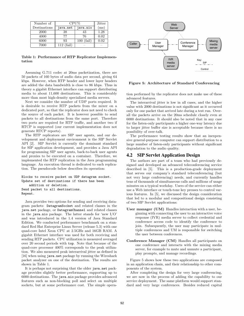
Number of CPU% JitterDestinations java.net java.nio (ms)
2000 38 43 1.284000 77 76 0.026000 93 100 (fail) 0.027000 112 (fail) – –
Table 1: Performance of RTP Replicator Implemen-tation
Assuming G.711 codec at 20ms packetization, there are50 packets of 160 bytes of audio data per second, giving 64kbps. However, when RTP header and lower layer headersare added the data bandwidth is close to 86 kbps. Thus intheory a gigabit Ethernet interface can support distributingmedia to about 11,600 destinations. This is considerablymore than most high-density specialized media servers.
Next we consider the number of UDP ports required. Itis desirable to receive RTP packets from the mixer on adedicated port, so that the replicator does not need to checkthe source of each packet. It is however possible to sendpackets to all destinations from the same port. Thereforetwo ports are required for RTP traffic, and another two ifRTCP is supported (our current implementation does notgenerate RTCP reports).
The RTP replicators are SIP user agents, and our de-velopment and deployment environment is the SIP ServletAPI [2]. SIP Servlet is currently the dominant standardfor SIP application development, and provides a Java APIfor programming SIP user agents, back-to-back user agentsand proxies to be executed on a container. Therefore, weimplemented the RTP replication in the Java programminglanguage. An execution thread is dedicated to each replica-tion. The pseudocode below describes its operation:
Blocks to receive packet on UDP datagram socket.
Update set of destinations if there has been
addition or deletion.
Send packet to all destinations.
Repeat.
Java provides two options for sending and receiving data-gram packets: DatagramSocket and related classes in thejava.net package, or DatagramChannel and related classesin the java.nio package. The latter stands for ‘new I/O’and was introduced in the 1.4 version of Java StandardEdition. We conducted performance benchmark on a stan-dard Red Hat Enterprise Linux Server (release 5.3) with onequad-core Intel Xeon CPU at 2.5GHz and 16GB RAM. Agigabit Ethernet interface was used for both receiving andsending RTP packets. CPU utilization is measured averagedover 20 second periods with top. Note that because of thequad-core processor 400% corresponds to the peak utiliza-tion. We also measured peak interarrival jitter as defined in[16] when using java.net package by running the Wiresharkpacket analyzer on one of the destination. The results areshown in Table 1.
It is perhaps not surprising that the older java.net pack-age provides slightly better performance, supporting up to6000 destinations. The java.nio package provides advancedfeatures such as non-blocking poll and select on multiplesockets, but at some performance cost. The simple opera-
User Manager
IVRmediaserver
Web Server
Mixingmediaserver
Caller Conference Manager
SIPKey:
Control
Figure 5: Architecture of Standard Conferencing
tion performed by the replicator does not make use of theseadvanced features.
The interarrival jitter is low in all cases, and the highervalue with 2000 destinations is not significant as it occurredonly for one packet that arrived late during a test run. Over-all the packets arrive on the 20ms schedule closely even at6000 destinations. It should also be noted that in any casefor the listen-only participants a higher one-way latency dueto larger jitter buffer size is acceptable because there is nopossibility of over-talk.
The performance testing results show that an inexpen-sive general-purpose computer can support distribution to alarge number of listen-only participants without significantdegradation to the audio quality.
4.2 SIP Servlet Application DesignThe authors are part of a team who had previously de-
signed and developed an advanced teleconferencing servicedescribed in [5]. This is a production-grade deploymentthat serves our company’s standard teleconferencing (butnot very large conferencing) needs, and currently handlestens of thousands of simultaneous calls and millions of usageminutes on a typical workday. Users of the service can eitheruse a Web interface or touch-tone key presses to control var-ious features. In [5], we discussed the design considerationthat led to a modular and compositional design consistingof two SIP Servlet applications:
User manager (UM) Handles interaction with a user, be-ginning with connecting the user to an interactive voiceresponse (IVR) media server to collect credential andconference access code to identify the conference tojoin. Subsequently, the user may participate in mul-tiple conferences and UM is responsible for switchingthe user between conferences.
Conference Manager (CM) Handles all participants onone conference and interacts with the mixing mediaserver, for example to mute and unmute a participant,play prompts, and manage recordings.
Figure 5 shows how these two applications are composedin an application chain, and their relationship to other com-ponents of the system.
After completing the design for very large conferencing,we are now in the process of adding the capability to ourservice deployment. The same platform would support stan-dard and very large conferences. Besides reduced capital
92
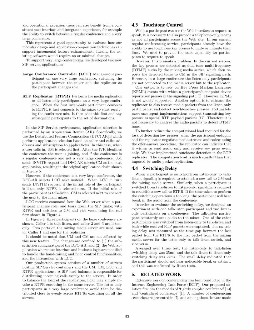
and operational expenses, users can also benefit from a con-sistent user interface and integrated experience, for examplethe ability to switch between a regular conference and a verylarge conference.
This represents a good opportunity to evaluate how ourmodular design and application composition techniques cansupport incremental feature enhancement. Ideally, the ex-isting software would require no or minimal changes.
To support very large conferencing, we developed two newSIP servlet applications:
Large Conference Controller (LCC) Manages one par-ticipant on one very large conference, switching theparticipant between the mixer and the replicator asthe participant changes role.
RTP Replicator (RTPR) Performs the media replicationto all listen-only participants on a very large confer-ence. When the first listen-only participant connectsto RTPR, it first connects to the mixer to start receiv-ing the conference mix. It then adds this first and anysubsequent participants to the set of destinations.
In the SIP Servlet environment, application selection isperformed by an Application Router (AR). Specifically, weuse the Distributed Feature Composition (DFC) AR[4] whichperforms application selection based on caller and callee ad-dresses and subscription to applications. In this case, whena user calls in, UM is selected first. After the IVR identifiesthe conference the user is joining, and if the conference isa regular conference and not a very large conference, UMsends INVITE request and DFC-AR selects CM as the nextapplication, resulting in the original application chain shownin Figure 5.
However, if the conference is a very large conference, theDFC-AR selects LCC next instead. When LCC in turnsends INVITE request, if the initial role of the participantis listen-only, RTPR is selected next. If the initial role ofthe participant is talk-listen, CM is selected next to connectthe user to the main mixer.
LCC receives command from the Web server when a par-ticipant changes role, and tears down the SIP dialog withRTPR and switches to CM and vice versa using the callflow shown in Figure 4.
In Figure 6, three participants on the large conference areshown. Caller 1 is talk-listen, and caller 2 and 3 are listen-only. Two ports on the mixing media server are used, onefor Caller 1 and one for the replicator.
It should be noted that UM and CM are not affected bythis new feature. The changes are confined to (1) the sub-scription configuration of the DFC-AR, and (2) the Web ap-plication where user interface and business logic are modifiedto handle the hand-raising and floor control functionalities,and the interaction with LCC.
Our production system consists of a number of servershosting SIP Servlet containers and the UM, CM, LCC andRTPR applications. A SIP load balancer is responsible fordistributing incoming calls evenly to the servers. In orderto balance the load of the replicators, LCC may simply in-voke a RTPR executing in the same server. The listen-onlyparticipants in a very large conference would then be dis-tributed close to evenly across RTPRs executing on all theservers.
4.3 Touchtone ControlWhile a participant can use the Web interface to request to
speak, it is necessary to also provide a telephone-only meansas not all participants access the Web site. In our currentregular conferencing service, participants already have theability to use touchtone key presses to mute or unmute theirlines. We need to provide the same capability for partici-pants to request to speak.
However, this presents a problem. In the current system,the key presses are detected as dual-tone multi-frequency(DTMF) audio by the mixing media server, which then re-ports the detected tones to CM in the SIP signaling path.However, in a large conference the listen-only participantsare not connected to the media server but to the replicator.
One option is to rely on Key Press Markup Language(KPML) events with which a participant’s endpoint devicereports key presses in the signaling path [3]. However, KPMLis not widely supported. Another option is to enhance thereplicator to also receive media packets from the listen-onlyparticipants, and detect touchtone key presses. Fortunatelymost user agent implementations support transmitting keypresses as special RTP payload packets [17]. Therefore it isnot necessary to analyze the audio packets to detect DTMFtones.
To further reduce the computational load required for thetask of detecting key presses, when the participant endpointand the replicator negotiate media streams and codecs usingthe offer-answer procedure, the replicator can indicate thatit wishes to send audio only and receive key press eventonly. We have implemented touchtone detection in the RTPreplicator. The computation load is much smaller than thatimposed by audio packet replication.
4.4 Switching DelayWhen a participant is switched from listen-only to talk-
listen, signaling is required to establish a new call to CM andthe mixing media server. Similarly, when a participant isswitched from talk-listen to listen-only, signaling is requiredto establish a new call to RTPR. If the time taken to performthe switching operations is too long, the participant will hearbreak in the audio from the conference.
In order to evaluate the switching delay, we designed anexperiment with one talk-listen participant and two listen-only participants on a conference. The talk-listen partici-pant constantly sent audio to the mixer. One of the otherparticipants was switched from listen-only to talk-listen andback while received RTP packets were captured. The switch-ing delay was measured as the time gap between the lastpacket from the RTPR to the first packet from the mixingmedia server for the listen-only to talk-listen switch, andvice versa.
Averaged over three test, the listen-only to talk-listenswitching delay was 35ms, and the talk-listen to listen-onlyswitching delay was 24ms. The small delay indicated thatthe participant should not hear noticeable break or artifact,and this was confirmed by listen tests.
5. RELATED WORKExtensive work on conferencing has been conducted in the
Internet Engineering Task Force (IETF). Our proposed so-lution fits into the models of ‘tightly coupled conference’ [13]and ‘centralized conference’ [1]. A number of conferencingscenarios are presented in [7], and among them ‘lecture mode
93
User Manager
User Manager
Web Server
Mixingmediaserver
Caller 1
Conference Manager
RTPReplicator
Large Conf Controller
Caller 2
Large Conf Controller
Caller 3
User Manager
Large Conf Controller
SIPKey:
Control
Media
Figure 6: Architecture of Very Large Conferencing
conferences’ and ‘presentation and Q & A sessions’ can besupported readily by the proposal in this paper. However,the IETF has not proposed a solution that switches partic-ipants between a mixer and a replicator or multicast.
As noted in Section 2, cascading conferences have beenproposed to support conferences with very large number ofparticipants in [10, 18, 11]. In these work, the assignmentof participants to mixers are static, and does not take intoaccount the status of the participants.
A scalable group communication system is proposed in[19]. A tree-based control topology is used to improve scala-bility and responsiveness, with reconfiguration mechanismsaimed to optimize performance. However, this work is pri-marily concerned with control and signaling. The transmis-sion and mixing of audio and video data rely on existingtransport facilities, and no new mechanisms are proposed.
IP multicast can also be used to support large scale audioand video conferencing [6, 8]. Each participant broadcastshis media packets that are then received by all other partici-pants. Alternatively application-layer multicast can be usedto remove the requirement of network-layer multicast [15].However, in these loosely coupled conferences it is difficultto exert floor control. Nonetheless, we intend to investigatea hybrid system that uses multicast to distribute media tothe listen-only participants.
6. SUMMARY AND FUTURE WORKIn this paper, we have described a novel design for very
large teleconferencing systems. We have completed an im-plementation using the SIP Servlet Java API, and showedthat high capacity can be achieved on general-purpose com-puters. We have also showed how this new capability canbe integrated into our existing teleconference system becauseof modularity and application composition techniques. Atthe present time, this very large teleconferencing system isready to begin user trial and will go into production soon
afterwards.There are several areas of future work that we intend to
pursue. First, our current service only uses the G.711 codec.In order to support multiple codecs, a RTP replicator can beassigned to each codec. The replicator would then connectto the mixing media server using the relevant codec. Thetask of selecting the correct replicator can reside with theLarge Conference Controller, which can inspect the SDP inthe media offer received from the participant endpoint tomake the determination.
For scenarios where participants are divided into severalgeographically distant sites, the cascading conferences ar-rangement can offer a way to reduce the traffic on the dis-tant links by having participants connect to their local trib-utary conference. Similarly, in this proposal a number ofRTP replicators may be distributed geographically to closeto groups of participants. The talk-listen participants wouldstill need to connect directly to the mixing media server ina single location. However, one possible optimization is toagain exploit the flexibility of VoIP signaling and media con-trol to dynamically move to a media server that is close tothe majority of the current talk-listen participants.
Currently we use a form of multi-unicast for the distri-bution of RTP packets to the listen-only participants. Weintend to investigate using multicast techniques for the verylarge teleconference application, taking into considerationSIP endpoint support, multicast through wide area networks,latency, and security issues.
7. ACKNOWLEDGMENTSWe are grateful for our colleagues on the advanced tele-
conferencing service team: Mike Bamert, Jessie Chen, AdamCombs, Tom Everling, Vince Hadap, and Tom Smith, whoconstantly provide inspirations, insights and assistance forour work. The anonymous reviewers also provided valuablecomments and suggestions.
94
8. REFERENCES[1] M. Barnes, C. Boulton, and O. Levin. A framework for
centralized conferencing, June 2008. IETF RFC 5239.
[2] BEA. SIP servlet API version 1.1, 2008. JavaCommunity Process JSR 289.http://jcp.org/en/jsr/detail?id=289.
[3] E. Burger and M. Dolly. A Session Initiation Protocol(SIP) event package for key press stimulus (KPML),November 2006. IETF RFC 4730.
[4] E. Cheung and K. Purdy. An application router forSIP servlet application composition. InCommunications, 2008. ICC ’08. IEEE InternationalConference on, pages 1802 –1806, May 2008.
[5] E. Cheung and T. M. Smith. Experience withmodularity in an advanced teleconferencing servicedeployment. In Proceedings of the 31st InternationalConference on Software Engineering (ICSE), pages39–49, 2009.
[6] J. Eriksson. MBONE: The multicast backbone,August 1994.
[7] R. Even and N. Ismail. Conferencing scenarios, July2006. IETF RFC 4597.
[8] V. Hardman, M. A. Sasse, and I. Kouvelas. Successfulmultiparty audio communication over the internet.Commun. ACM, 41(5):74–80, 1998.
[9] ITU-T. One-way transmission time, May 2003. ITU-TRecommendation G.114.
[10] D. Ozone. Proposal for MC+MP cascading in H.323,1997. ITU-T SG 16 Document AVC-1108.
[11] M. Radenkovic, C. Greenhalgh, and S. Benford. Ascaleable and adaptive audio service to support largescale collaborative work and entertainment. InProceedings of International Conference on Advancesin Infrastructures for Electronic Business, Education,Science and Medicine on the Internet (SSGRR 2002),2002.
[12] Radisys corporation. http://radisys.com/.
[13] J. Rosenberg. A framework for conferencing with theSession Initiation Protocol (SIP), February 2006.IETF RFC 4353.
[14] J. Rosenberg, H. Schulzrinne, G. Camarillo,A. Johnston, J. Peterson, R. Sparks, M. Handley, andE. Schooler. SIP: Session initiation protocol, June2002. IETF RFC 3261.
[15] T. C. Schmidt and M. Wahlisch. Group ConferenceManagement with SIP, chapter 6, pages 123–158. CRCPress, 2008. In SIP Handbook: Services, Technologies,and Security of Session Initiation Protocol.
[16] H. Schulzrinne, S. Casner, R. Frederick, andV. Jacobson. RTP: A transport protocol for real-timeapplications, July 2003. IETF RFC 3550.
[17] H. Schulzrinne and T. Taylor. RTP payload forDTMF digits, telephony tones, and telephony signals,December 2006. IETF RFC 4733.
[18] K. Singh, G. Nair, and H. Schulzrinne. Centralizedconferencing using SIP. In Proceedings of the 2ndIP-Telephony Workshop (IPTel’2001), April 2001.
[19] D. Trossen. Scalable Group Communication in TightlyCoupled Environments. PhD thesis, University ofTechnology North-Rhine Westfalia Aachen, Germany,2000.
95

96
CCMP: a novel standard protocol for ConferenceManagement in the XCON Framework
Mary BarnesNortel
Lorenzo MinieroMeetecho srl
Roberta PrestaUniversity of Napoli Federico [email protected]
Simon Pietro RomanoUniveristy of Napoli Federico II
Henning ShulzrinneColumbia University
ABSTRACTThis paper presents the design and implementation of CCMP,a conference management protocol currently under stan-dardization within the IETF, conceived at the outset as alightweight protocol allowing conferencing clients to accessand manipulate objects describing a centralized conference.The CCMP is a state-less, XML-based, client-server pro-tocol carrying in its request and response messages con-ference information in the form of XML documents andfragments conforming to the centralized conferencing datamodel schema. It represents a powerful means to controlbasic and advanced conference features such as conferencestate and capabilities, participants and relative roles and de-tails. We first focus on the design of the protocol and thendiscuss how it has been integrated in the Meetecho collab-orative framework developed at the University of Napoli asan active playground for IETF standardization activities inthe field of real-time applications and infrastructure.
KeywordsConferencing, Conference Control and Manipulation, Pro-tocol Design, Protocol Integration
1. INTRODUCTIONIn the latest years, the IETF (Internet Engineering Task
Force) has devoted many efforts to the definition of standardconferencing solutions. Among such solutions, the Frame-work for Centralized Conferencing [2] (XCON Framework)defines a signaling-agnostic architecture, naming conventionsand logical entities required for building advanced conferenc-ing systems. The XCON Framework introduces the confer-ence object as a logical representation of a conference in-stance, representing the current state and capabilities ofa conference. The Centralized Conferencing ManipulationProtocol (CCMP) illustrated in this paper is the latest out-put to be produced by the XCON working group. It is
Permission to make digital or hard copies of all or part of this work forpersonal or classroom use is granted without fee provided that copies arenot made or distributed for profit or commercial advantage and that copiesbear this notice and the full citation on the first page. To copy otherwise, torepublish, to post on servers or to redistribute to lists, requires prior specificpermission and/or a fee.IPTComm 2010, 2-3 August, 2010 Munich, GermanyCopyright 2010 ACM ...$10.00.
currently undergoing review from the international researchcommunity and it is heading towards completion and pub-lication as an RFC (Request For Comments) standard doc-ument.
CCMP allows authenticated and authorized users to cre-ate, manipulate and delete conference objects. Operationson conferences include adding and removing participants,changing their roles, as well as adding and removing mediastreams and associated end points. CCMP is based on aclient-server paradigm and is specifically suited to serve as aconference manipulation protocol within the XCON frame-work, with the Conference Control Client and ConferenceControl Server acting as client and server, respectively. TheCCMP uses HTTP as the protocol to transfer requests andresponses, which contain the domain-specific XML-encodeddata objects defined in [7].
This paper is structured in 8 sections. We first brieflyintroduce, in section 2, the general architecture for central-ized conferencing defined by the XCON working group inthe IETF. We then present, in section 3, a bird’s eye view ofthe Centralized Conferencing Manipulation Protocol. Thesame section also provides some insights on the history ofthe overall specification process. Section 4 drills down onthe specific messages that can be carried inside the body ofthe CCMP protocol, while section 5 concludes the part asso-ciated with our standardization work by depicting a typicalcall flow related to a CCMP-based interaction between aconferencing client and an XCON Conferencing server. Thesecond part of the paper is entirely devoted to the imple-mentation of the CCMP specification. Such part is based onthe work ongoing at the University of Napoli “Federico II”,which is since long involved in the IETF activities falling inthe area of real-time applications and infrastructures. TheUniversity of Napoli has contributed to the activities in theXCON working group, by also providing timely prototypeimplementations of most of the protocols therein involvedand/or specified. As far as the CCMP protocol is concerned,we have worked both on the specification of the protocoland on its implementation, during the various phases of itslong-lived design history. Information about this activityis hence provided in section 6. Section 7 reports informa-tion about the history of the CCMP specification within theIETF community. Finally, section 8 provides some conclud-ing remarks, as well as information about our future workrelated to the protocol.
97
schmitt
Stempel
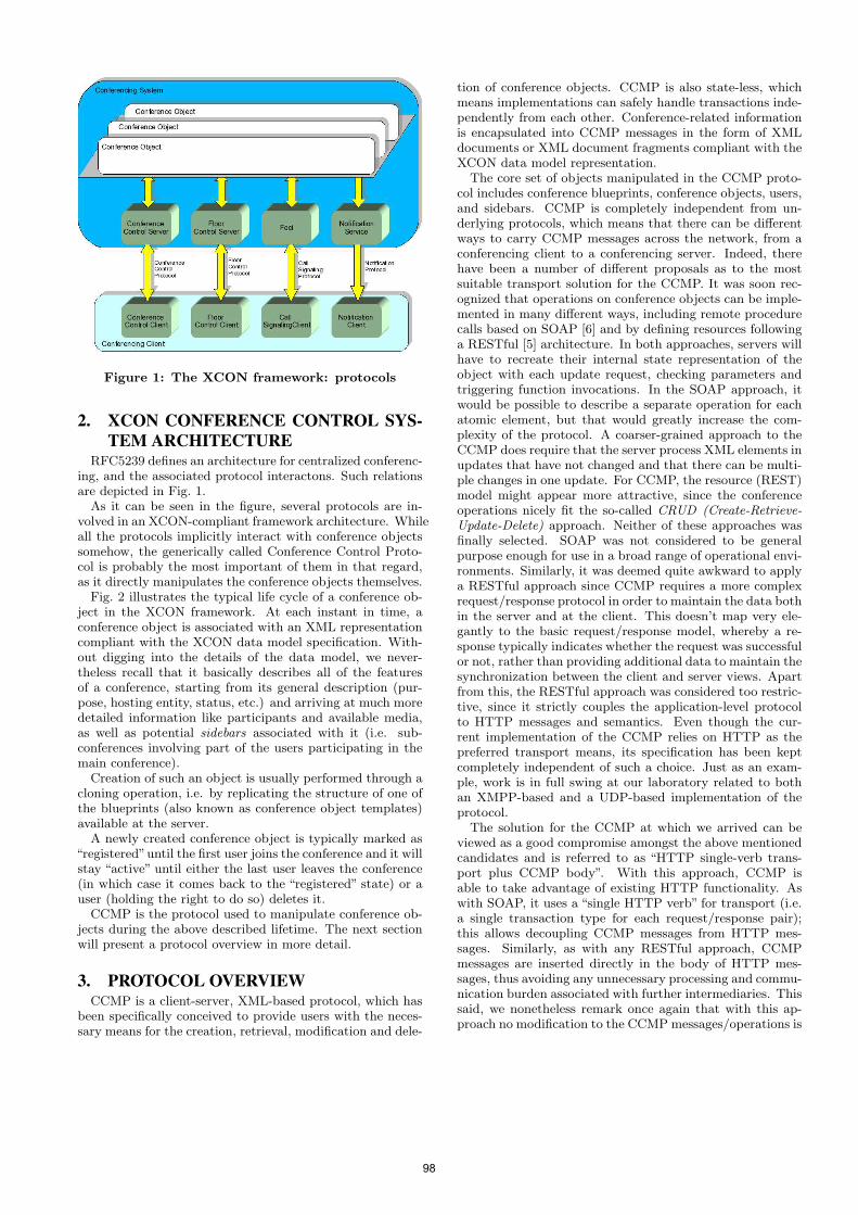
Figure 1: The XCON framework: protocols
2. XCON CONFERENCE CONTROL SYS-TEM ARCHITECTURE
RFC5239 defines an architecture for centralized conferenc-ing, and the associated protocol interactons. Such relationsare depicted in Fig. 1.
As it can be seen in the figure, several protocols are in-volved in an XCON-compliant framework architecture. Whileall the protocols implicitly interact with conference objectssomehow, the generically called Conference Control Proto-col is probably the most important of them in that regard,as it directly manipulates the conference objects themselves.
Fig. 2 illustrates the typical life cycle of a conference ob-ject in the XCON framework. At each instant in time, aconference object is associated with an XML representationcompliant with the XCON data model specification. With-out digging into the details of the data model, we never-theless recall that it basically describes all of the featuresof a conference, starting from its general description (pur-pose, hosting entity, status, etc.) and arriving at much moredetailed information like participants and available media,as well as potential sidebars associated with it (i.e. sub-conferences involving part of the users participating in themain conference).
Creation of such an object is usually performed through acloning operation, i.e. by replicating the structure of one ofthe blueprints (also known as conference object templates)available at the server.
A newly created conference object is typically marked as“registered”until the first user joins the conference and it willstay “active” until either the last user leaves the conference(in which case it comes back to the “registered” state) or auser (holding the right to do so) deletes it.
CCMP is the protocol used to manipulate conference ob-jects during the above described lifetime. The next sectionwill present a protocol overview in more detail.
3. PROTOCOL OVERVIEWCCMP is a client-server, XML-based protocol, which has
been specifically conceived to provide users with the neces-sary means for the creation, retrieval, modification and dele-
tion of conference objects. CCMP is also state-less, whichmeans implementations can safely handle transactions inde-pendently from each other. Conference-related informationis encapsulated into CCMP messages in the form of XMLdocuments or XML document fragments compliant with theXCON data model representation.
The core set of objects manipulated in the CCMP proto-col includes conference blueprints, conference objects, users,and sidebars. CCMP is completely independent from un-derlying protocols, which means that there can be differentways to carry CCMP messages across the network, from aconferencing client to a conferencing server. Indeed, therehave been a number of different proposals as to the mostsuitable transport solution for the CCMP. It was soon rec-ognized that operations on conference objects can be imple-mented in many different ways, including remote procedurecalls based on SOAP [6] and by defining resources followinga RESTful [5] architecture. In both approaches, servers willhave to recreate their internal state representation of theobject with each update request, checking parameters andtriggering function invocations. In the SOAP approach, itwould be possible to describe a separate operation for eachatomic element, but that would greatly increase the com-plexity of the protocol. A coarser-grained approach to theCCMP does require that the server process XML elements inupdates that have not changed and that there can be multi-ple changes in one update. For CCMP, the resource (REST)model might appear more attractive, since the conferenceoperations nicely fit the so-called CRUD (Create-Retrieve-Update-Delete) approach. Neither of these approaches wasfinally selected. SOAP was not considered to be generalpurpose enough for use in a broad range of operational envi-ronments. Similarly, it was deemed quite awkward to applya RESTful approach since CCMP requires a more complexrequest/response protocol in order to maintain the data bothin the server and at the client. This doesn’t map very ele-gantly to the basic request/response model, whereby a re-sponse typically indicates whether the request was successfulor not, rather than providing additional data to maintain thesynchronization between the client and server views. Apartfrom this, the RESTful approach was considered too restric-tive, since it strictly couples the application-level protocolto HTTP messages and semantics. Even though the cur-rent implementation of the CCMP relies on HTTP as thepreferred transport means, its specification has been keptcompletely independent of such a choice. Just as an exam-ple, work is in full swing at our laboratory related to bothan XMPP-based and a UDP-based implementation of theprotocol.
The solution for the CCMP at which we arrived can beviewed as a good compromise amongst the above mentionedcandidates and is referred to as “HTTP single-verb trans-port plus CCMP body”. With this approach, CCMP isable to take advantage of existing HTTP functionality. Aswith SOAP, it uses a “single HTTP verb” for transport (i.e.a single transaction type for each request/response pair);this allows decoupling CCMP messages from HTTP mes-sages. Similarly, as with any RESTful approach, CCMPmessages are inserted directly in the body of HTTP mes-sages, thus avoiding any unnecessary processing and commu-nication burden associated with further intermediaries. Thissaid, we nonetheless remark once again that with this ap-proach no modification to the CCMP messages/operations is
98
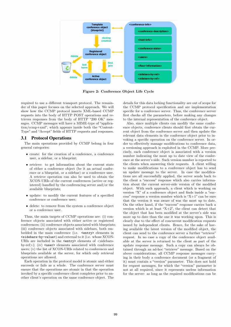
firstjoin
Templateconference object
(blueprint)
Registered conference object
Activeconference object
cloningcreation
lastleave
<conference-info>
<sidebars-by-val><sidebars-by-ref>
<conference-description>
<host-info>
<floor-information>
<conference-state>
<users>delete
delete
Figure 2: Conference Object Life Cycle
required to use a different transport protocol. The remain-der of this paper focuses on the selected approach. We willshow how the CCMP protocol inserts XML-based CCMPrequests into the body of HTTP POST operations and re-trieves responses from the body of HTTP “200 OK” mes-sages. CCMP messages will have a MIME-type of “applica-tion/ccmp+xml”, which appears inside both the “Content-Type” and “Accept” fields of HTTP requests and responses.
3.1 Protocol OperationsThe main operations provided by CCMP belong in four
general categories:
• create: for the creation of a conference, a conferenceuser, a sidebar, or a blueprint;
• retrieve: to get information about the current stateof either a conference object (be it an actual confer-ence or a blueprint, or a sidebar) or a conference user.A retrieve operation can also be used to obtain theXCON-URIs of the current conferences (active or reg-istered) handled by the conferencing server and/or theavailable blueprints;
• update: to modify the current features of a specifiedconference or conference user;
• delete: to remove from the system a conference objector a conference user.
Thus, the main targets of CCMP operations are: (i) con-ference objects associated with either active or registeredconferences; (ii) conference objects associated with blueprints;(iii) conference objects associated with sidebars, both em-bedded in the main conference (i.e. <entry> elements in<sidebars-by-value>) and external to it (i.e. whose XCON-URIs are included in the <entry> elements of <sidebars-by-ref>); (iv) <user> elements associated with conferenceusers; (v) the list of XCON-URIs related to conferences andblueprints available at the server, for which only retrievaloperations are allowed.
Each operation in the protocol model is atomic and eithersucceeds or fails as a whole. The conference server mustensure that the operations are atomic in that the operationinvoked by a specific conference client completes prior to an-other client’s operation on the same conference object. The
details for this data locking functionality are out of scope forthe CCMP protocol specification and are implementationspecific for a conference server. Thus, the conference serverfirst checks all the parameters, before making any changesto the internal representation of the conference object.
Also, since multiple clients can modify the same confer-ence objects, conference clients should first obtain the cur-rent object from the conference server and then update therelevant data elements in the conference object prior to in-voking a specific operation on the conference server. In or-der to effectively manage modifications to conference data,a versioning approach is exploited in the CCMP. More pre-cisely, each conference object is associated with a versionnumber indicating the most up to date view of the confer-ence at the server’s side. Such version number is reported tothe clients when answering their requests. A client willingto make modifications to a conference object has to sendan update message to the server. In case the modifica-tions are all successfully applied, the server sends back tothe client a “success” response which also carries informa-tion about the current server-side version of the modifiedobject. With such approach, a client which is working onversion “X” of a conference object and finds inside a “suc-cess” response a version number which is “X+1” can be surethat the version it was aware of was the most up to date.On the other hand, if the “success” response carries back aversion which is at least “X+2”, the client can detect thatthe object that has been modified at the server’s side wasmore up to date than the one it was working upon. This isclearly due to the effect of concurrent modification requestsissued by independent clients. Hence, for the sake of hav-ing available the latest version of the modified object, theclient can send to the conference server a further “retrieve”request. In no case a copy of the conference object avail-able at the server is returned to the client as part of theupdate response message. Such a copy can always be ob-tained through an ad-hoc “retrieve” message. Based on theabove considerations, all CCMP response messages carry-ing in their body a conference document (or a fragment ofit) must contain a “version” parameter. This does not holdfor request messages, for which the “version” parameter isnot at all required, since it represents useless informationfor the server: as long as the required modifications can be
99
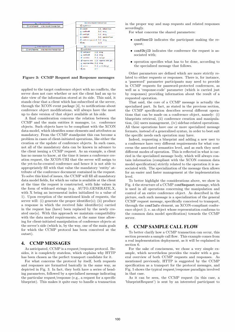
Figure 3: CCMP Request and Response messages
applied to the target conference object with no conflicts, theserver does not care whether or not the client had an up todate view of the information stored at its side. This said, itstands clear that a client which has subscribed at the server,through the XCON event package [4], to notifications aboutconference object modifications, will always have the mostup to date version of that object available at his side.
A final consideration concerns the relation between theCCMP and the main entities it manages, i.e. conferenceobjects. Such objects have to be compliant with the XCONdata-model, which identifies some elements and attributes asmandatory. From the CCMP standpoint this can become aproblem in cases of client-initiated operations, like either thecreation or the update of conference objects. In such cases,not all of the mandatory data can be known in advance tothe client issuing a CCMP request. As an example, a clienthas no means to know, at the time it issues a conference cre-ation request, the XCON-URI that the server will assign tothe yet-to-be-created conference and hence it is not able toappropriately fill with that value the mandatory ‘entity’ at-tribute of the conference document contained in the request.To solve this kind of issues, the CCMP will fill all mandatorydata model fields, for which no value is available at the clientat the time the request is constructed, with fake values inthe form of wildcard strings (e.g. AUTO GENERATE X,with X being an incremental index initialized to a value of1). Upon reception of the mentioned kinds of requests, theserver will: (i) generate the proper identifier(s); (ii) producea response in which the received fake identifier(s) carriedin the request has (have) been replaced by the newly cre-ated one(s). With this approach we maintain compatibilitywith the data model requirements, at the same time allow-ing for client-initiated manipulation of conference objects atthe server’s side (which is, by the way, one of the main goalsfor which the CCMP protocol has been conceived at theoutset).
4. CCMP MESSAGESAs anticipated, CCMP is a request/response protocol. Be-
sides, it is completely stateless, which explains why HTTPhas been chosen as the perfect transport candidate for it.
For what concerns the protocol by itself, both requestsand responses are formatted basically in the same way, asdepicted in Fig. 3. In fact, they both have a series of head-ing parameters, followed by a specialized message indicatingthe particular request/response (e.g., a request for a specificblueprint). This makes it quite easy to handle a transaction
in the proper way and map requests and related responsesaccordingly.
For what concerns the shared parameters:
• confUserID indicates the participant making the re-quest;
• confObjID indicates the conference the request is as-sociated with;
• operation specifies what has to be done, according tothe specialized message that follows.
Other parameters are defined which are more strictly re-lated to either requests or responses. There is, for instance,a ‘password’ parameter participants may need to providein CCMP requests for password-protected conferences, aswell as a ‘response-code’ parameter (which is carried justby responses) providing information about the result of arequested operation.
That said, the core of a CCMP message is actually thespecialized part. In fact, as stated in the previous section,the CCMP specification describes several different opera-tions that can be made on a conference object, namely: (i)blueprints retrieval, (ii) conference creation and manipula-tion, (iii) users management, (iv) sidebar-related operations.All these operations have one or more specialized messageformats, instead of a generalized syntax, in order to best suitthe specific needs each operation may have.
Indeed, requesting a blueprint and adding a new user toa conference have very different requirements for what con-cerns the associated semantics level, and as such they needdifferent modes of operation. This is reflected in what is car-ried in the specialized message body, which will always con-tain information (compliant with the XCON common datamodel specification) strictly related to the operation it is as-sociated with. The specialization of the message then allowsfor an easier and faster management at the implementationlevel.
To better highlight the considerations above, we show inFig. 4 the structure of a CCMP confRequest message, whichis used in all operations concerning the manipulation andcontrol of an entire conference object. As described in thepicture, each such message is a specialization of the generalCCMP request message, specifically conceived to transport,through the confInfo element, an XCON-compliant confer-ence object (i. e. an object whose representation conforms tothe common data model specification) towards the CCMPserver.
5. CCMP SAMPLE CALL FLOWTo better clarify how a CCMP transaction can occur, this
section presents a sample call flow. This example comes froma real implementation deployment, as it will be explained insection 6.
For the sake of conciseness, we chose a very simple ex-ample, which nevertheless provides the reader with a gen-eral overview of both CCMP requests and responses. Asmentioned previously, HTTP is suggested by the CCMPspecification as a transport for the protocol messages, andFig. 5 shows the typical request/response paradigm involvedin that case.
As it can be seen, the CCMP request (in this case, a’blueprintRequest’) is sent by an interested participant to
100
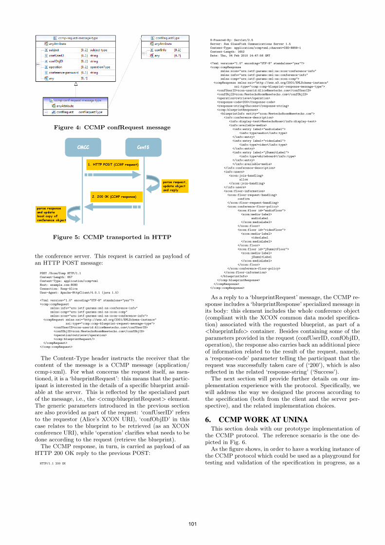
Figure 4: CCMP confRequest message
Figure 5: CCMP transported in HTTP
the conference server. This request is carried as payload ofan HTTP POST message:
POST /Xcon/Ccmp HTTP/1.1
Content-Length: 657
Content-Type: application/ccmp+xml
Host: example.com:8080
Connection: Keep-Alive
User-Agent: Apache-HttpClient/4.0.1 (java 1.5)
<?xml version="1.0" encoding="UTF-8" standalone="yes"?>
<ccmp:ccmpRequest
xmlns:info="urn:ietf:params:xml:ns:conference-info"
xmlns:ccmp="urn:ietf:params:xml:ns:xcon:ccmp"
xmlns:xcon="urn:ietf:params:xml:ns:xcon-conference-info">
<ccmpRequest xmlns:xsi="http://www.w3.org/2001/XMLSchema-instance"
xsi:type="ccmp:ccmp-blueprint-request-message-type">
<confUserID>xcon-userid:[email protected]</confUserID>
<confObjID>xcon:[email protected]</confObjID>
<operation>retrieve</operation>
<ccmp:blueprintRequest/>
</ccmpRequest>
</ccmp:ccmpRequest>
The Content-Type header instructs the receiver that thecontent of the message is a CCMP message (application/ccmp+xml). For what concerns the request itself, as men-tioned, it is a ‘blueprintRequest’: this means that the partic-ipant is interested in the details of a specific blueprint avail-able at the server. This is reflected by the specialized partof the message, i.e., the <ccmp:blueprintRequest> element.The generic parameters introduced in the previous sectionare also provided as part of the request: ‘confUserID’ refersto the requestor (Alice’s XCON URI), ‘confObjID’ in thiscase relates to the blueprint to be retrieved (as an XCONconference URI), while ‘operation’ clarifies what needs to bedone according to the request (retrieve the blueprint).
The CCMP response, in turn, is carried as payload of anHTTP 200 OK reply to the previous POST:
HTTP/1.1 200 OK
X-Powered-By: Servlet/2.5
Server: Sun GlassFish Communications Server 1.5
Content-Type: application/ccmp+xml;charset=ISO-8859-1
Content-Length: 1652
Date: Thu, 04 Feb 2010 14:47:56 GMT
<?xml version="1.0" encoding="UTF-8" standalone="yes"?>
<ccmp:ccmpResponse
xmlns:xcon="urn:ietf:params:xml:ns:xcon-conference-info"
xmlns:info="urn:ietf:params:xml:ns:conference-info"
xmlns:ccmp="urn:ietf:params:xml:ns:xcon:ccmp">
<ccmpResponse xmlns:xsi="http://www.w3.org/2001/XMLSchema-instance"
xsi:type="ccmp:ccmp-blueprint-response-message-type">
<confUserID>xcon-userid:[email protected]</confUserID>
<confObjID>xcon:[email protected]</confObjID>
<operation>retrieve</operation>
<response-code>200</response-code>
<response-string>Success</response-string>
<ccmp:blueprintResponse>
<blueprintInfo entity="xcon:[email protected]">
<info:conference-description>
<info:display-text>MeetechoRoom</info:display-text>
<info:available-media>
<info:entry label="audioLabel">
<info:type>audio</info:type>
</info:entry>
<info:entry label="videoLabel">
<info:type>video</info:type>
</info:entry>
<info:entry label="jSummitLabel">
<info:type>whiteboard</info:type>
</info:entry>
</info:available-media>
</info:conference-description>
<info:users>
<xcon:join-handling>
allow
</xcon:join-handling>
</info:users>
<xcon:floor-information>
<xcon:floor-request-handling>
confirm
</xcon:floor-request-handling>
<xcon:conference-floor-policy>
<xcon:floor id="audioFloor">
<xcon:media-label>
audioLabel
</xcon:mediaLabel>
</xcon:floor>
<xcon:floor id="videoFloor">
<xcon:media-label>
videoLabel
</xcon:mediaLabel>
</xcon:floor>
<xcon:floor id="jSummitFloor">
<xcon:media-label>
jSummitLabel
</xcon:mediaLabel>
</xcon:floor>
</xcon:conference-floor-policy>
</xcon:floor-information>
</blueprintInfo>
</ccmp:blueprintResponse>
</ccmpResponse>
</ccmp:ccmpResponse>
As a reply to a ‘blueprintRequest’ message, the CCMP re-sponse includes a ‘blueprintResponse’ specialized message inits body: this element includes the whole conference object(compliant with the XCON common data model specifica-tion) associated with the requested blueprint, as part of a<blueprintInfo> container. Besides containing some of theparameters provided in the request (confUserID, confObjID,operation), the response also carries back an additional pieceof information related to the result of the request, namely,a ‘response-code’ parameter telling the participant that therequest was successfully taken care of (‘200’), which is alsoreflected in the related ‘response-string’ (‘Success’).
The next section will provide further details on our im-plementation experience with the protocol. Specifically, wewill address the way we designed the process according tothe specification (both from the client and the server per-spective), and the related implementation choices.
6. CCMP WORK AT UNINAThis section deals with our prototype implementation of
the CCMP protocol. The reference scenario is the one de-picted in Fig. 6.
As the figure shows, in order to have a working instance ofthe CCMP protocol which could be used as a playground fortesting and validation of the specification in progress, as a
101
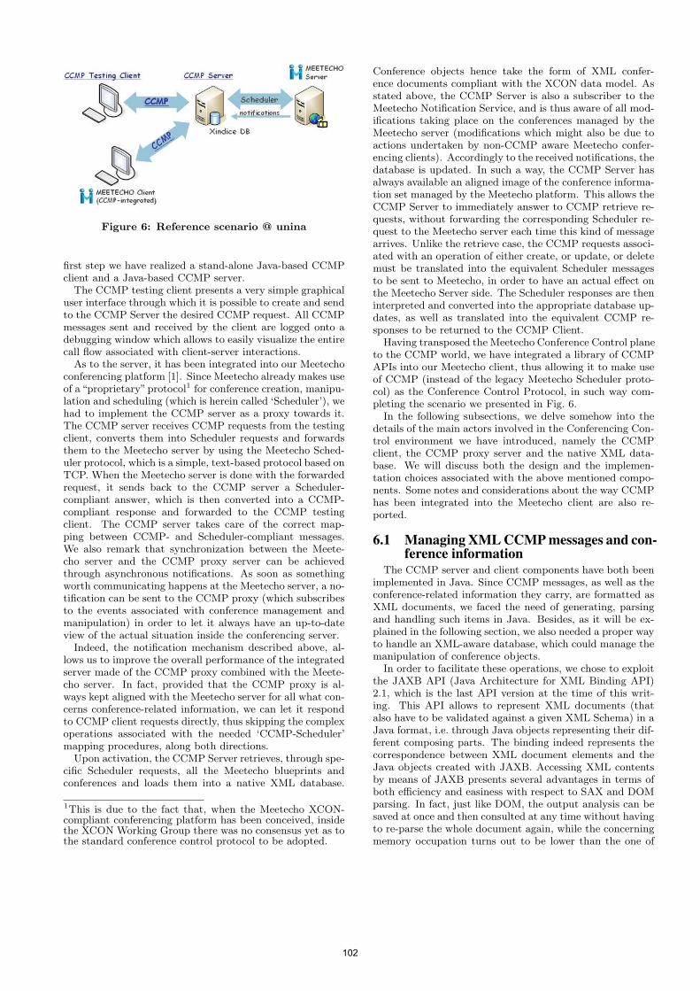
Figure 6: Reference scenario @ unina
first step we have realized a stand-alone Java-based CCMPclient and a Java-based CCMP server.
The CCMP testing client presents a very simple graphicaluser interface through which it is possible to create and sendto the CCMP Server the desired CCMP request. All CCMPmessages sent and received by the client are logged onto adebugging window which allows to easily visualize the entirecall flow associated with client-server interactions.
As to the server, it has been integrated into our Meetechoconferencing platform [1]. Since Meetecho already makes useof a“proprietary”protocol1 for conference creation, manipu-lation and scheduling (which is herein called ‘Scheduler’), wehad to implement the CCMP server as a proxy towards it.The CCMP server receives CCMP requests from the testingclient, converts them into Scheduler requests and forwardsthem to the Meetecho server by using the Meetecho Sched-uler protocol, which is a simple, text-based protocol based onTCP. When the Meetecho server is done with the forwardedrequest, it sends back to the CCMP server a Scheduler-compliant answer, which is then converted into a CCMP-compliant response and forwarded to the CCMP testingclient. The CCMP server takes care of the correct map-ping between CCMP- and Scheduler-compliant messages.We also remark that synchronization between the Meete-cho server and the CCMP proxy server can be achievedthrough asynchronous notifications. As soon as somethingworth communicating happens at the Meetecho server, a no-tification can be sent to the CCMP proxy (which subscribesto the events associated with conference management andmanipulation) in order to let it always have an up-to-dateview of the actual situation inside the conferencing server.
Indeed, the notification mechanism described above, al-lows us to improve the overall performance of the integratedserver made of the CCMP proxy combined with the Meete-cho server. In fact, provided that the CCMP proxy is al-ways kept aligned with the Meetecho server for all what con-cerns conference-related information, we can let it respondto CCMP client requests directly, thus skipping the complexoperations associated with the needed ‘CCMP-Scheduler’mapping procedures, along both directions.
Upon activation, the CCMP Server retrieves, through spe-cific Scheduler requests, all the Meetecho blueprints andconferences and loads them into a native XML database.
1This is due to the fact that, when the Meetecho XCON-compliant conferencing platform has been conceived, insidethe XCON Working Group there was no consensus yet as tothe standard conference control protocol to be adopted.
Conference objects hence take the form of XML confer-ence documents compliant with the XCON data model. Asstated above, the CCMP Server is also a subscriber to theMeetecho Notification Service, and is thus aware of all mod-ifications taking place on the conferences managed by theMeetecho server (modifications which might also be due toactions undertaken by non-CCMP aware Meetecho confer-encing clients). Accordingly to the received notifications, thedatabase is updated. In such a way, the CCMP Server hasalways available an aligned image of the conference informa-tion set managed by the Meetecho platform. This allows theCCMP Server to immediately answer to CCMP retrieve re-quests, without forwarding the corresponding Scheduler re-quest to the Meetecho server each time this kind of messagearrives. Unlike the retrieve case, the CCMP requests associ-ated with an operation of either create, or update, or deletemust be translated into the equivalent Scheduler messagesto be sent to Meetecho, in order to have an actual effect onthe Meetecho Server side. The Scheduler responses are theninterpreted and converted into the appropriate database up-dates, as well as translated into the equivalent CCMP re-sponses to be returned to the CCMP Client.
Having transposed the Meetecho Conference Control planeto the CCMP world, we have integrated a library of CCMPAPIs into our Meetecho client, thus allowing it to make useof CCMP (instead of the legacy Meetecho Scheduler proto-col) as the Conference Control Protocol, in such way com-pleting the scenario we presented in Fig. 6.
In the following subsections, we delve somehow into thedetails of the main actors involved in the Conferencing Con-trol environment we have introduced, namely the CCMPclient, the CCMP proxy server and the native XML data-base. We will discuss both the design and the implemen-tation choices associated with the above mentioned compo-nents. Some notes and considerations about the way CCMPhas been integrated into the Meetecho client are also re-ported.
6.1 Managing XML CCMP messages and con-ference information
The CCMP server and client components have both beenimplemented in Java. Since CCMP messages, as well as theconference-related information they carry, are formatted asXML documents, we faced the need of generating, parsingand handling such items in Java. Besides, as it will be ex-plained in the following section, we also needed a proper wayto handle an XML-aware database, which could manage themanipulation of conference objects.
In order to facilitate these operations, we chose to exploitthe JAXB API (Java Architecture for XML Binding API)2.1, which is the last API version at the time of this writ-ing. This API allows to represent XML documents (thatalso have to be validated against a given XML Schema) in aJava format, i.e. through Java objects representing their dif-ferent composing parts. The binding indeed represents thecorrespondence between XML document elements and theJava objects created with JAXB. Accessing XML contentsby means of JAXB presents several advantages in terms ofboth efficiency and easiness with respect to SAX and DOMparsing. In fact, just like DOM, the output analysis can besaved at once and then consulted at any time without havingto re-parse the whole document again, while the concerningmemory occupation turns out to be lower than the one of
102
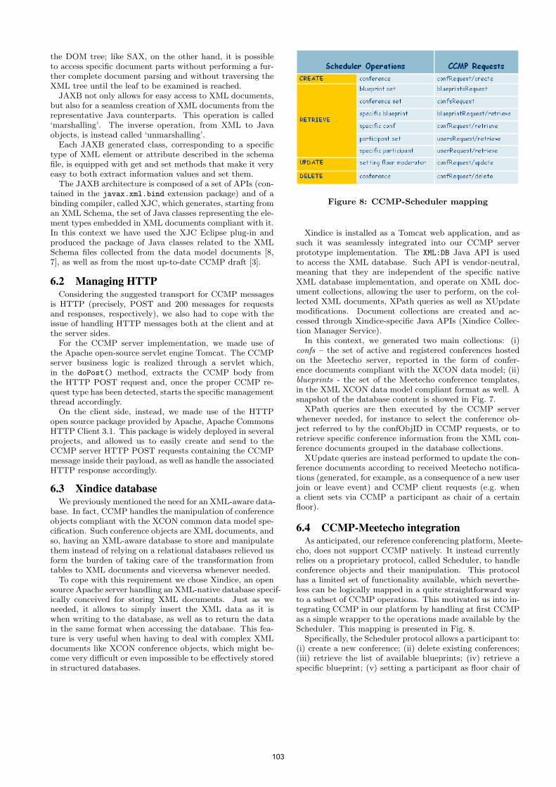
the DOM tree; like SAX, on the other hand, it is possibleto access specific document parts without performing a fur-ther complete document parsing and without traversing theXML tree until the leaf to be examined is reached.
JAXB not only allows for easy access to XML documents,but also for a seamless creation of XML documents from therepresentative Java counterparts. This operation is called‘marshalling’. The inverse operation, from XML to Javaobjects, is instead called ‘unmarshalling’.
Each JAXB generated class, corresponding to a specifictype of XML element or attribute described in the schemafile, is equipped with get and set methods that make it veryeasy to both extract information values and set them.
The JAXB architecture is composed of a set of APIs (con-tained in the javax.xml.bind extension package) and of abinding compiler, called XJC, which generates, starting froman XML Schema, the set of Java classes representing the ele-ment types embedded in XML documents compliant with it.In this context we have used the XJC Eclipse plug-in andproduced the package of Java classes related to the XMLSchema files collected from the data model documents [8,7], as well as from the most up-to-date CCMP draft [3].
6.2 Managing HTTPConsidering the suggested transport for CCMP messages
is HTTP (precisely, POST and 200 messages for requestsand responses, respectively), we also had to cope with theissue of handling HTTP messages both at the client and atthe server sides.
For the CCMP server implementation, we made use ofthe Apache open-source servlet engine Tomcat. The CCMPserver business logic is realized through a servlet which,in the doPost() method, extracts the CCMP body fromthe HTTP POST request and, once the proper CCMP re-quest type has been detected, starts the specific managementthread accordingly.
On the client side, instead, we made use of the HTTPopen source package provided by Apache, Apache CommonsHTTP Client 3.1. This package is widely deployed in severalprojects, and allowed us to easily create and send to theCCMP server HTTP POST requests containing the CCMPmessage inside their payload, as well as handle the associatedHTTP response accordingly.
6.3 Xindice databaseWe previously mentioned the need for an XML-aware data-
base. In fact, CCMP handles the manipulation of conferenceobjects compliant with the XCON common data model spe-cification. Such conference objects are XML documents, andso, having an XML-aware database to store and manipulatethem instead of relying on a relational databases relieved usform the burden of taking care of the transformation fromtables to XML documents and viceversa whenever needed.
To cope with this requirement we chose Xindice, an opensource Apache server handling an XML-native database specif-ically conceived for storing XML documents. Just as weneeded, it allows to simply insert the XML data as it iswhen writing to the database, as well as to return the datain the same format when accessing the database. This fea-ture is very useful when having to deal with complex XMLdocuments like XCON conference objects, which might be-come very difficult or even impossible to be effectively storedin structured databases.
Figure 8: CCMP-Scheduler mapping
Xindice is installed as a Tomcat web application, and assuch it was seamlessly integrated into our CCMP serverprototype implementation. The XML:DB Java API is usedto access the XML database. Such API is vendor-neutral,meaning that they are independent of the specific nativeXML database implementation, and operate on XML doc-ument collections, allowing the user to perform, on the col-lected XML documents, XPath queries as well as XUpdatemodifications. Document collections are created and ac-cessed through Xindice-specific Java APIs (Xindice Collec-tion Manager Service).
In this context, we generated two main collections: (i)confs – the set of active and registered conferences hostedon the Meetecho server, reported in the form of confer-ence documents compliant with the XCON data model; (ii)blueprints - the set of the Meetecho conference templates,in the XML XCON data model compliant format as well. Asnapshot of the database content is showed in Fig. 7.
XPath queries are then executed by the CCMP serverwhenever needed, for instance to select the conference ob-ject referred to by the confObjID in CCMP requests, or toretrieve specific conference information from the XML con-ference documents grouped in the database collections.
XUpdate queries are instead performed to update the con-ference documents according to received Meetecho notifica-tions (generated, for example, as a consequence of a new userjoin or leave event) and CCMP client requests (e.g. whena client sets via CCMP a participant as chair of a certainfloor).
6.4 CCMP-Meetecho integrationAs anticipated, our reference conferencing platform, Meete-
cho, does not support CCMP natively. It instead currentlyrelies on a proprietary protocol, called Scheduler, to handleconference objects and their manipulation. This protocolhas a limited set of functionality available, which neverthe-less can be logically mapped in a quite straightforward wayto a subset of CCMP operations. This motivated us into in-tegrating CCMP in our platform by handling at first CCMPas a simple wrapper to the operations made available by theScheduler. This mapping is presented in Fig. 8.
Specifically, the Scheduler protocol allows a participant to:(i) create a new conference; (ii) delete existing conferences;(iii) retrieve the list of available blueprints; (iv) retrieve aspecific blueprint; (v) setting a participant as floor chair of
103
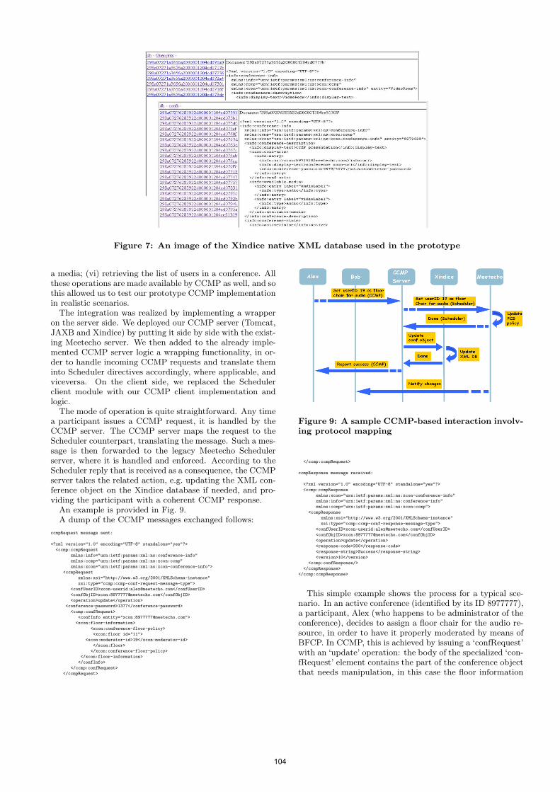
Figure 7: An image of the Xindice native XML database used in the prototype
a media; (vi) retrieving the list of users in a conference. Allthese operations are made available by CCMP as well, and sothis allowed us to test our prototype CCMP implementationin realistic scenarios.
The integration was realized by implementing a wrapperon the server side. We deployed our CCMP server (Tomcat,JAXB and Xindice) by putting it side by side with the exist-ing Meetecho server. We then added to the already imple-mented CCMP server logic a wrapping functionality, in or-der to handle incoming CCMP requests and translate theminto Scheduler directives accordingly, where applicable, andviceversa. On the client side, we replaced the Schedulerclient module with our CCMP client implementation andlogic.
The mode of operation is quite straightforward. Any timea participant issues a CCMP request, it is handled by theCCMP server. The CCMP server maps the request to theScheduler counterpart, translating the message. Such a mes-sage is then forwarded to the legacy Meetecho Schedulerserver, where it is handled and enforced. According to theScheduler reply that is received as a consequence, the CCMPserver takes the related action, e.g. updating the XML con-ference object on the Xindice database if needed, and pro-viding the participant with a coherent CCMP response.
An example is provided in Fig. 9.A dump of the CCMP messages exchanged follows:
ccmpRequest message sent:
<?xml version="1.0" encoding="UTF-8" standalone="yes"?>
<ccmp:ccmpRequest
xmlns:info="urn:ietf:params:xml:ns:conference-info"
xmlns:ccmp="urn:ietf:params:xml:ns:xcon:ccmp"
xmlns:xcon="urn:ietf:params:xml:ns:xcon-conference-info">
<ccmpRequest
xmlns:xsi="http://www.w3.org/2001/XMLSchema-instance"
xsi:type="ccmp:ccmp-conf-request-message-type">
<confUserID>xcon-userid:[email protected]</confUserID>
<confObjID>xcon:[email protected]</confObjID>
<operation>update</operation>
<conference-password>1377</conference-password>
<ccmp:confRequest>
<confInfo entity="xcon:[email protected]">
<xcon:floor-information>
<xcon:conference-floor-policy>
<xcon:floor id="11">
<xcon:moderator-id>19</xcon:moderator-id>
</xcon:floor>
</xcon:conference-floor-policy>
</xcon:floor-information>
</confInfo>
</ccmp:confRequest>
</ccmpRequest>
Figure 9: A sample CCMP-based interaction involv-ing protocol mapping
</ccmp:ccmpRequest>
ccmpResponse message received:
<?xml version="1.0" encoding="UTF-8" standalone="yes"?>
<ccmp:ccmpResponse
xmlns:xcon="urn:ietf:params:xml:ns:xcon-conference-info"
xmlns:info="urn:ietf:params:xml:ns:conference-info"
xmlns:ccmp="urn:ietf:params:xml:ns:xcon:ccmp">
<ccmpResponse
xmlns:xsi="http://www.w3.org/2001/XMLSchema-instance"
xsi:type="ccmp:ccmp-conf-response-message-type">
<confUserID>xcon-userid:[email protected]</confUserID>
<confObjID>xcon:[email protected]</confObjID>
<operation>update</operation>
<response-code>200</response-code>
<response-string>Success</response-string>
<version>10</version>
<ccmp:confResponse/>
</ccmpResponse>
</ccmp:ccmpResponse>
This simple example shows the process for a typical sce-nario. In an active conference (identified by its ID 8977777),a participant, Alex (who happens to be administrator of theconference), decides to assign a floor chair for the audio re-source, in order to have it properly moderated by means ofBFCP. In CCMP, this is achieved by issuing a ‘confRequest’with an ‘update’ operation: the body of the specialized ‘con-fRequest’ element contains the part of the conference objectthat needs manipulation, in this case the floor information
104
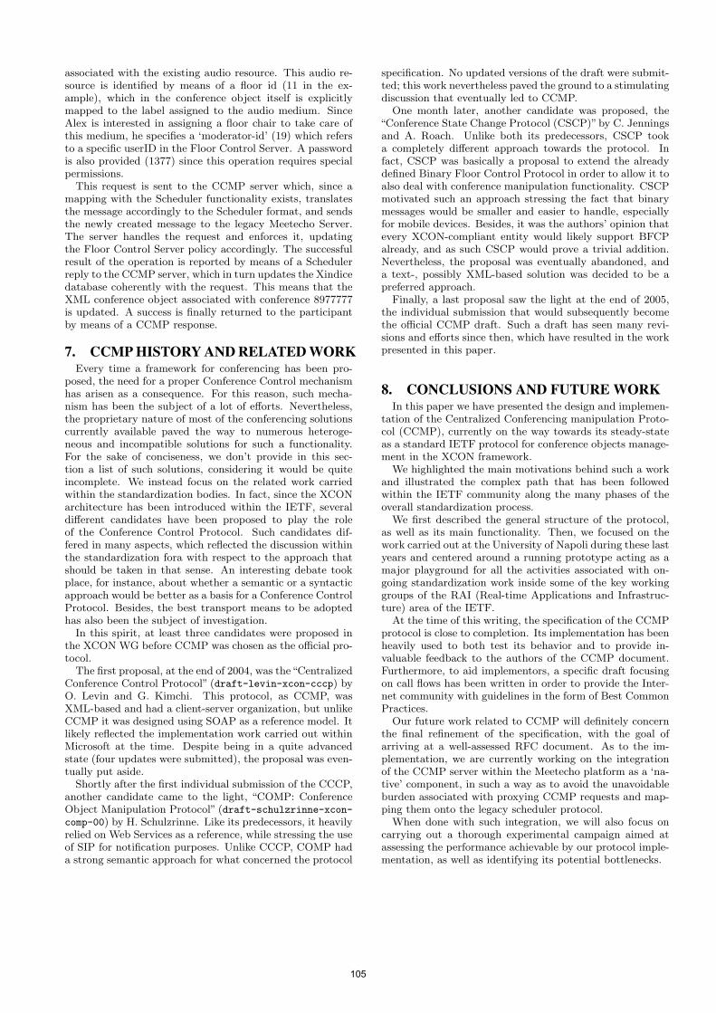
associated with the existing audio resource. This audio re-source is identified by means of a floor id (11 in the ex-ample), which in the conference object itself is explicitlymapped to the label assigned to the audio medium. SinceAlex is interested in assigning a floor chair to take care ofthis medium, he specifies a ‘moderator-id’ (19) which refersto a specific userID in the Floor Control Server. A passwordis also provided (1377) since this operation requires specialpermissions.
This request is sent to the CCMP server which, since amapping with the Scheduler functionality exists, translatesthe message accordingly to the Scheduler format, and sendsthe newly created message to the legacy Meetecho Server.The server handles the request and enforces it, updatingthe Floor Control Server policy accordingly. The successfulresult of the operation is reported by means of a Schedulerreply to the CCMP server, which in turn updates the Xindicedatabase coherently with the request. This means that theXML conference object associated with conference 8977777is updated. A success is finally returned to the participantby means of a CCMP response.
7. CCMP HISTORY AND RELATED WORKEvery time a framework for conferencing has been pro-
posed, the need for a proper Conference Control mechanismhas arisen as a consequence. For this reason, such mecha-nism has been the subject of a lot of efforts. Nevertheless,the proprietary nature of most of the conferencing solutionscurrently available paved the way to numerous heteroge-neous and incompatible solutions for such a functionality.For the sake of conciseness, we don’t provide in this sec-tion a list of such solutions, considering it would be quiteincomplete. We instead focus on the related work carriedwithin the standardization bodies. In fact, since the XCONarchitecture has been introduced within the IETF, severaldifferent candidates have been proposed to play the roleof the Conference Control Protocol. Such candidates dif-fered in many aspects, which reflected the discussion withinthe standardization fora with respect to the approach thatshould be taken in that sense. An interesting debate tookplace, for instance, about whether a semantic or a syntacticapproach would be better as a basis for a Conference ControlProtocol. Besides, the best transport means to be adoptedhas also been the subject of investigation.
In this spirit, at least three candidates were proposed inthe XCON WG before CCMP was chosen as the official pro-tocol.
The first proposal, at the end of 2004, was the“CentralizedConference Control Protocol” (draft-levin-xcon-cccp) byO. Levin and G. Kimchi. This protocol, as CCMP, wasXML-based and had a client-server organization, but unlikeCCMP it was designed using SOAP as a reference model. Itlikely reflected the implementation work carried out withinMicrosoft at the time. Despite being in a quite advancedstate (four updates were submitted), the proposal was even-tually put aside.
Shortly after the first individual submission of the CCCP,another candidate came to the light, “COMP: ConferenceObject Manipulation Protocol” (draft-schulzrinne-xcon-comp-00) by H. Schulzrinne. Like its predecessors, it heavilyrelied on Web Services as a reference, while stressing the useof SIP for notification purposes. Unlike CCCP, COMP hada strong semantic approach for what concerned the protocol
specification. No updated versions of the draft were submit-ted; this work nevertheless paved the ground to a stimulatingdiscussion that eventually led to CCMP.
One month later, another candidate was proposed, the“Conference State Change Protocol (CSCP)”by C. Jenningsand A. Roach. Unlike both its predecessors, CSCP tooka completely different approach towards the protocol. Infact, CSCP was basically a proposal to extend the alreadydefined Binary Floor Control Protocol in order to allow it toalso deal with conference manipulation functionality. CSCPmotivated such an approach stressing the fact that binarymessages would be smaller and easier to handle, especiallyfor mobile devices. Besides, it was the authors’ opinion thatevery XCON-compliant entity would likely support BFCPalready, and as such CSCP would prove a trivial addition.Nevertheless, the proposal was eventually abandoned, anda text-, possibly XML-based solution was decided to be apreferred approach.
Finally, a last proposal saw the light at the end of 2005,the individual submission that would subsequently becomethe official CCMP draft. Such a draft has seen many revi-sions and efforts since then, which have resulted in the workpresented in this paper.
8. CONCLUSIONS AND FUTURE WORKIn this paper we have presented the design and implemen-
tation of the Centralized Conferencing manipulation Proto-col (CCMP), currently on the way towards its steady-stateas a standard IETF protocol for conference objects manage-ment in the XCON framework.
We highlighted the main motivations behind such a workand illustrated the complex path that has been followedwithin the IETF community along the many phases of theoverall standardization process.
We first described the general structure of the protocol,as well as its main functionality. Then, we focused on thework carried out at the University of Napoli during these lastyears and centered around a running prototype acting as amajor playground for all the activities associated with on-going standardization work inside some of the key workinggroups of the RAI (Real-time Applications and Infrastruc-ture) area of the IETF.
At the time of this writing, the specification of the CCMPprotocol is close to completion. Its implementation has beenheavily used to both test its behavior and to provide in-valuable feedback to the authors of the CCMP document.Furthermore, to aid implementors, a specific draft focusingon call flows has been written in order to provide the Inter-net community with guidelines in the form of Best CommonPractices.
Our future work related to CCMP will definitely concernthe final refinement of the specification, with the goal ofarriving at a well-assessed RFC document. As to the im-plementation, we are currently working on the integrationof the CCMP server within the Meetecho platform as a ‘na-tive’ component, in such a way as to avoid the unavoidableburden associated with proxying CCMP requests and map-ping them onto the legacy scheduler protocol.
When done with such integration, we will also focus oncarrying out a thorough experimental campaign aimed atassessing the performance achievable by our protocol imple-mentation, as well as identifying its potential bottlenecks.
105
9. REFERENCES[1] A. Amirante, T. Castaldi, L. Miniero, and S. P.
Romano. Meetecho: A standard multimediaconferencing architecture. In FMN ’09: Proceedings ofthe 2nd International Workshop on Future MultimediaNetworking, pages 218–223, Berlin, Heidelberg, 2009.Springer-Verlag.
[2] M. Barnes, C. Boulton, and O. Levin. RFC 5239 - AFramework for Centralized Conferencing. Request forcomments, IETF, June 2008.
[3] M. Barnes, C. Boulton, S. Romano, and H. Schulzrinne.Centralized Conferencing Manipulation Protocol (workin progress). Internet draft, IETF, June 2010.
[4] G. Camarillo, S. Srinivasan, R. Even, andJ. Urpalainen. Conference event package data formatextension for centralized conferencing (xcon) (work inprogress). Internet draft, IETF, September 2008.
[5] Fielding. Architectural styles and the design ofnetwork-based software architectures. Technical report,2000.
[6] M. Gudgin, N. Mendelsohn, M. Hadley, J. Moreau, andH. Nielsen. Soap version 1.2 part 1: Messagingframework. World wide web consortium first editionrec-soap12-part1-20030624, W3C, June 2003.
[7] O. Novo, G. Camarillo, D. Morgan, and J. Urpalainen.Conference information data model for centralizedconferencing (xcon) (work in progress). Internet draft,IETF, February 2010.
[8] J. Rosenberg, H. Shulzrinne, and O. Levin. RFC 4575 -A Session Initiation Protocol (SIP) Event Package forConference State. Request for comments, IETF, August2006.
106
Work in Progress: Black-Box Approach for Testing Qualityof Service in Case of Security Incidents on the Example of
a SIP-based VoIP Service
Peter Steinbacher, Florian Fankhauser, Christian Schanes, Thomas Grechenig
Vienna University of TechnologyIndustrial Software (INSO)
1040 Vienna, Austria{peter.steinbacher, florian.fankhauser, christian.schanes, thomas.grechenig}@inso.tuwien.ac.at
ABSTRACTOne of the main security objectives for systems connectedto the Internet which provide services like Voice over Inter-net Protocol (VoIP) is to ensure robustness against securityattacks to fulfill Quality of Service (QoS). To avoid systemfailures during attacks service providers have to integratecountermeasures which have to be tested. This work evalu-ates a test approach to determine the efficiency of counter-measures to fulfill QoS for Session Initiation Protocol (SIP)based VoIP systems even under attack. The main objectiveof the approach is the evaluation of service availability of aSystem Under Test (SUT) during security attacks, e.g., De-nial of Service (DoS) attacks. Therefore, a simulated systemload based on QoS requirements is combined with differentsecurity attacks. The observation of the system is basedon black-box testing. By monitoring quality metrics of SIPtransactions the behavior of the system is measurable. Theconcept was realized as a prototype and was evaluated usingdifferent VoIP systems. For this, multiple security attacksare integrated to the testing scenarios. The outcome showedthat the concept provides sound test results, which reflectthe behavior of SIP systems availability under various at-tacks. Thus, security problems can be found and QoS forSIP-based VoIP communication under attack can be pre-dicted.
Categories and Subject DescriptorsC.2.0 [Computer Communications Networks]: Gen-eral—Security and protection, Data communications; D.2.4[Software Engineering]: Software/Program Verification—Reliability ; D.2.5 [Software Engineering]: Testing andDebugging—Testing tools
General TermsSecurity, Verification, Reliability, Performance
IPTComm 2010, 2-3 August, 2010 Munich, Germany
1. INTRODUCTIONVoice over Internet Protocol (VoIP) is steadily gaining alarger user base. Since VoIP communication is based on theInternet Protocol (IP), new challenges concerning the secu-rity of telephony arise. Information security objectives likeconfidentiality, integrity, robustness and availability must beachieved [4]. The most prevalent threats to VoIP systemstoday are known from data networks [9]. For example, manythreats are known for IP based protocols like SIP and RealTime Protocol (RTP) for media transport in VoIP systems.VoIP specific protocols like Session Initiation Protocol (SIP)for call signaling increase the attack surface of such systemswhich requires new countermeasures for additional vulnera-bilities in VoIP-telephony. The four largest threats faced byservice providers today are Denial of Service (DoS), ServiceAbuse and Fraud, Spam over Internet Telephony (SPIT),and Eavesdropping (see Abdelnur et al. [1]). Keromytismentioned that Service Abuse and DoS need more research[15].
The common similarity of different VoIP solutions is thatall data is fully transmitted over IP. This includes mediadata (e.g., speech) and signaling data. This is not the casein traditional telecommunication systems which use Signal-ing System 7 (SS7)1 for signaling. Data transfer is circuitswitched and not packet oriented. These may transport IPtraffic, but are not based on it. Today, VoIP and tradi-tional telephony have an architectural split of signaling andtransmission of media in common. For VoIP signaling, twoprotocol standards are commonly used: H.3232 and SIP [22].
In this paper, the focus is on SIP which is defined by theInternet Engineering Task Force3 and is designed to setupbidirectional communication sessions, not limited to onlyVoIP calls. If used for VoIP, it is recommended to use itwith Session Description Protocol4 (SDP) and Real TimeProtocol5 (RTP).
The focus of availability [4] is to assure information and
1http://www.itu.int/rec/T-REC-Q2http://www.itu.int/rec/T-REC-H.3233http://www.ietf.org4RFC 45665RFC 3550
107
schmitt
Stempel

communication services will be ready for use when expected.Attempts to block or reduce availability are called Denial ofService attacks or Intentional Interruption of Service. DoSattacks on SIP systems cause loss of service to the users ofthat system [6]. When talking about DoS attacks in thispaper we refer to network based attacks which are executedremotely over the network against services. This may be viathe public Internet or on a local network, but without directaccess to the operating system or the hardware of the targetsystem.
Depending on the software used and the architecture of thesystem, different countermeasures are possible for protect-ing the VoIP system against availability failures. Regardlessof the methods used, they should be evaluated on their ef-fectiveness by testing. When evaluating the security of agiven SIP based solution a software/system tester should beable to answer the question under which attack scenarios acertain Quality of Service (QoS) requirement or a ServiceLevel Agreement (SLA) can not be met anymore.
We will present a security test concept which provides basicmechanisms to realize and execute such a test of availabilityagainst a SIP system. Thus, the evaluation of availability ofSIP based VoIP systems will be examined by executing loadand performance tests together with different types of DoSattacks, i.e., multiple test techniques are combined. Thecentral idea for the security test concept is to simulate userload on a server as for example defined by QoS requirementswhile at the same time also performing DoS attacks. Fromthe measured change of real time behavior effects of DoSattacks can be measured. Therefore, the results of a normalload without attacks can be compared with the results madeduring attacks. The concept is implemented as a black-boxapproach. This way, the internals of the system are notrelevant for testing. Our traffic simulation only verifies andrecords output and response time of the interactions with theSUT. The test criteria for the defined concept for each imag-inary user is service availability, basic functional correctness,and performance. We suggest a concept and describe a proofof concept test environment that makes it possible to define,execute, and evaluate such tests. However, a final set of testcases for SIP based VoIP systems will not be defined. Theconcept can be integrated into an existing comprehensivetest process consisting of, for example, functional tests, per-formance tests, penetration tests etc. Such test processesalready exist in most large IT infrastructures.
The remainder of this paper is structured as follows: Sec-tion 2 lists related work. Section 3 introduces the used se-curity verification concept and points out the specific re-quirements for testing availability aspects during securityattacks. Section 4 gives details about implementation of thetest concept. The test approach and the implemented proto-type were evaluated by doing several security tests which arepresented in Section 5. The paper finishes with a conclusionand ideas for future work in Section 6.
2. RELATED WORKAn overview of current VoIP Security research is given byKeromytis in [15]. He identified two specific areas (DoSand service abuse) as being underrepresented in terms of re-search efforts. Peng et al. publish basic classification and de-
scription of DoS and Distributed Denial of Services (DDoS)prevention methods in [19], where countermeasures are dis-tinguished in Attack Prevention, Attack Detection, AttackSource Identification and Attack Reaction. To ensure avail-ability for SIP based services, a time critical method distin-guishing between valid and malicious requests is required.In [3], Akbar et al. present an approach focusing on evo-lutionary algorithms to detect flooding attacks against SIPbased VoIP systems. Countermeasures can also simply en-tail ensuring that enough resources like bandwidth, CPUtime, memory, etc. are available and good implementa-tions and configurations are chosen. Keromytis calls foradditional effort at securing implementations and configu-rations [15] and also states in [16] that complex systemswith default configurations remain a problem. Sisalem et al.show that the first line of protection starts by deploying ahigh-performance infrastructure [24]. This work points outthat different approaches to protect systems against secu-rity attacks are available and after implementation a test ofeffectiveness is required.
Testing VoIP systems is an important method for revealingDoS vulnerabilities independent from their origins. Securitytesting approaches for SIP implementations focus testing inorder to discover implementation vulnerabilities. For exam-ple, PROTOS test suite6 finds DoS vulnerabilities by ma-licious INVITE packets, but does not mention flooding at-tacks. Although focusing on automated penetration tests, in[2] by Abdelnur et al. DoS vulnerabilities are mentioned, butflood attacks are not considered. These approaches couldnot verify how the behavior of SIP systems may change un-der system load during flooding attacks. Some SIP flood-ing attack examples are briefly described and evaluated byEndler and Collier in [8]. A systematic concept is missingin this work, though. A comprehensive testing platform ispresented by Srinivasan in [25] which provides security tests.It additionally briefly considers simulated flooding attacks.Ming et al. demonstrate SIP vulnerabilities by CPU basedDoS attacks in [17]. In [20] Rafique et al. evaluated DoS at-tacks against SIP proxy implementations and showed thatthose are vulnerable against different DoS attacks. Theybased the analysis on black- and white-box tests. The ap-proach is similar to ours but we focus on integrating simu-lated security attacks into the test process and combine itwith other test techniques of the test process, e.g., perfor-mance or penetration tests.
Performance testing of SIP is described from Montagna etal. in [18] and Schulzrinne et al. in [23]. Performance testingis one part of our approach to generate required load.
We suggest a more comprehensive security verification ap-proach towards an iterative test process. Foundations, prin-ciples and terminology of general software testing are takenfrom [6, 12, 13, 14].
General requirements for testing QoS in case of security at-tacks are gained. Attack types should not be limited. In-stead various attack types are used and using threat model-ing is suggested. Black-box testing detaches from the testedsystems, generalizes the test environment and includes con-
6http://www.ee.oulu.fi/research/ouspg/protos/testing/c07/sip
108
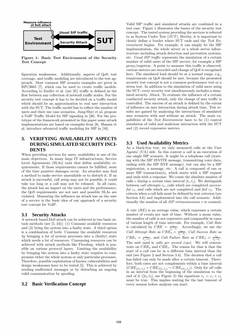
SUTTest
Environment Security Attack
Usual SIP traffic
Measure influence of DoS attack
Figure 1: Basic Test Environment of the SecurityTest Concept
figuration weaknesses. Additionally, aspects of QoS, testcoverage, and traffic modeling are introduced to the test ap-proach. Most common SIP scenario examples are given inRFC3665 [7], which can be used to create traffic models.According to Endler et al. (see [6]) traffic is defined as theflow between any collection of network traffic nodes. For thesecurity test concept it has to be decided on a traffic modelwhich should be an approximation to real user interactionwith the SUT. The traffic model has to reflect the number ofusers and their use case scenarios. Jung-Shyr et al. proposea VoIP Traffic Model for SIP signaling in [26]. For the pro-totype of the framework presented in this paper some attackimplementations are based on examples from [8]. Hassan etal. introduce advanced traffic modeling for SIP in [10].
3. VERIFYING AVAILABILITY ASPECTSDURING SIMULATED SECURITY INCI-DENTS
When providing services for users, availability is one of themain objectives. In many large IT infrastructures, ServiceLevel Agreements (SLAs) exist that define availability re-quirements. If those requirements cannot be fulfilled, mostof the time punitive damages occur. An attacker may finda method to make service unavailable or to disturb it. If anattack is successful, call setup may not be possible, it couldtake too long or a call may not be released. In all cases,the attack has an impact on the users and the performance,the QoS requirements are not met and possible SLAs areviolated. Measuring the influence an attack has on the userof a service is the basic idea of our approach of a securitytest concept for VoIP.
3.1 Security AttacksA network based DoS attack can be achieved in two basic at-tack methods (see [5, 24]): (1) Consume available resourcesand (2) bring the system into a faulty state. A third optionis a combination of both: Consume the available resourcesby bringing a lot of system processes into a (faulty) statewhich needs a lot of resources. Consuming resources can beachieved with attack methods like Flooding, which is pos-sible on various protocol layers. Limiting the availabilityby bringing the system into a faulty state requires to com-promise either the whole system or only particular processes.Therefore, possible exploitation of known vulnerabilities anddesign weaknesses have to be tested [5]. This is achieved bysending malformed messages or by disturbing an ongoingvalid communication by spoofing.
3.2 Basic Verification Concept
Valid SIP traffic and simulated attacks are combined in atest case. Figure 1 illustrates the basics of the security testconcept. The tested system providing the services is referredto as System Under Test (SUT ). Hereby, it is important toclearly define a border where SUT ends and the Test En-vironment begins. For example, it can simply be the SIPimplementation, the whole server or a whole server infras-tructure including attack detection and prevention systems,etc. Usual SIP traffic represents the simulation of a certainnumber of valid users of the SIP service, for example a SIPproxy/registrar. A point to measure this traffic is observed,various metrics are recorded and change of QoS is recognizedhere. The simulated load should be at a normal range, e.g.,requirements on QoS should be met, because the presentedsecurity test concept is not a common performance test or astress test. In addition to the simulation of valid users usingthe SUT, every security test simultaneously includes a simu-lated security Attack. To evaluate the influence of a certainconducted security attack, only the change of user traffic iscontrolled. The success of an attack is defined by the extentof influence on user interaction during attack time. Test re-sults are gained by analyzing the interactions of simulateduser scenarios with and without an attack. The main ca-pabilities of the Test Environment have to be (1) controlsimulation of valid and malicious interaction with the SUTand (2) record expressive metrics.
3.3 Used Availability MetricsAs a black-box test, we only measured calls at the UserAgents’ (UA) side. In this context a call is an execution ofone single SIP scenario. It might be a telephone call (start-ing with the SIP INVITE message, transmitting voice data,ending with the SIP BYE message), but can also be a SIPregistration, a message, etc. A call is composed of one ormore SIP transaction(s), which starts with a SIP requestand ends with a response. We count the absolute number ofcalls c during a certain time interval [ti, tj ]. We distinguishbetween call attempts ca, calls which are completed success-ful cs, and calls which are not completed and fail cf . Thecriteria when a call fails must be defined by test criterion (seeSection 3.6) and implemented into the call scenario. Addi-tionally the number of all SIP retransmissions r is counted.
A rate (RE) is an average value, which expresses a certainnumber of events per unit of time. Without a mean value,the number of calls is not expressive and comparable in casesof various length of time intervals. For example, Call Rateis calculated by CRE = c
tj−ti. Accordingly, we use the
Call Attempt Rate as CREa = ca
tj−ti, Call Success Rate as
CREs = cs
tj−ti, and Call Failure Rate as CREf =
cf
tj−ti.
The unit used is calls per second (cps). We will concen-trate on CREa and CREs. The reason for that is that thestart of a call can be in a different time interval than theend (see Figure 2 and Section 3.4). The decision that a callhas failed can only be made after a certain timeout. There-fore, both rates are not complements within a time interval(CREs[ti,tj ] + CREf [ti,tj ] ∼ CREa[ti,tj ]). Only for all callsin an interval from the beginning of the simulation to theend of it ([t0, t5], see Figure 2) the equations ca = cs + cf
must be true. This implies waiting for the last timeout ofevery session before analysis can start.
109
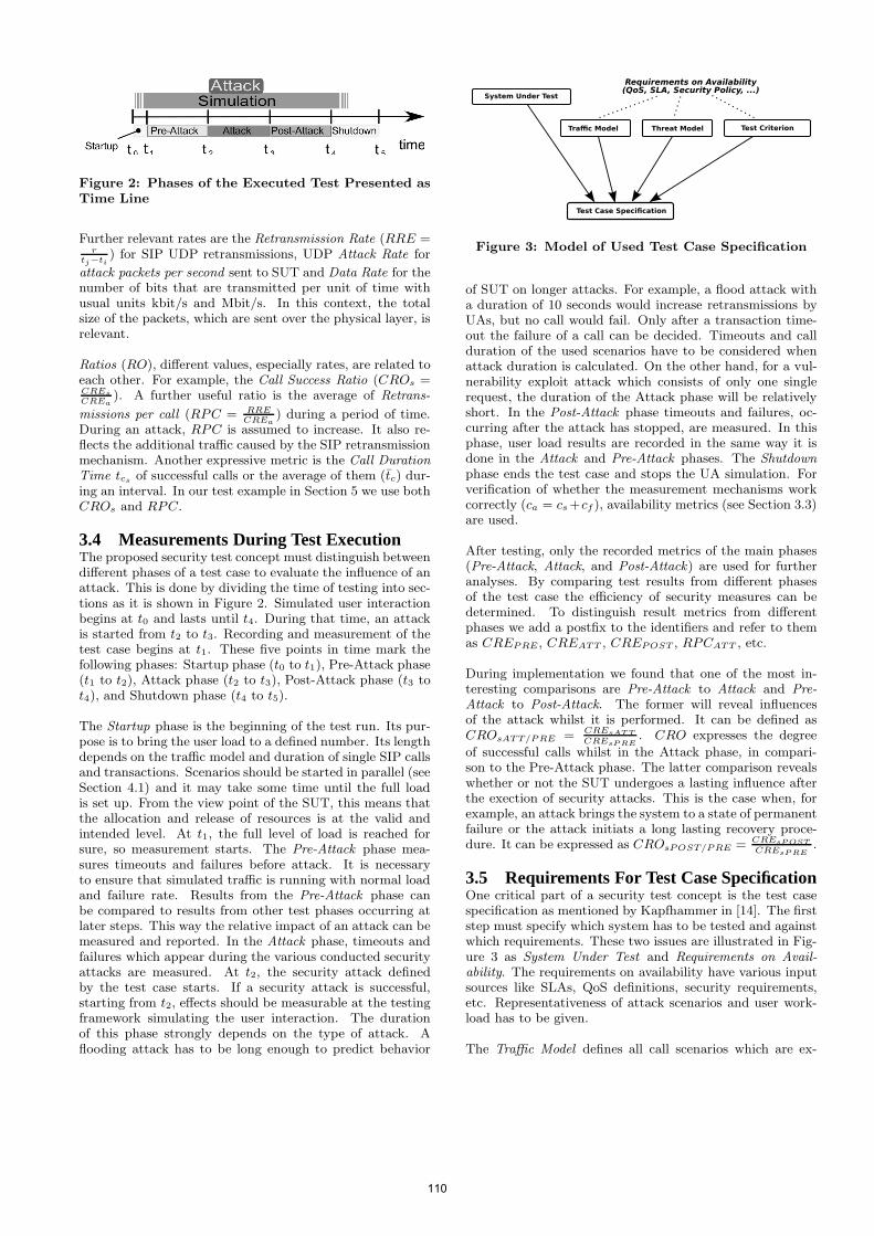
Figure 2: Phases of the Executed Test Presented asTime Line
Further relevant rates are the Retransmission Rate (RRE =r
tj−ti) for SIP UDP retransmissions, UDP Attack Rate for
attack packets per second sent to SUT and Data Rate for thenumber of bits that are transmitted per unit of time withusual units kbit/s and Mbit/s. In this context, the totalsize of the packets, which are sent over the physical layer, isrelevant.
Ratios (RO), different values, especially rates, are related toeach other. For example, the Call Success Ratio (CROs =CREs
CREa). A further useful ratio is the average of Retrans-
missions per call (RPC = RRECREa
) during a period of time.During an attack, RPC is assumed to increase. It also re-flects the additional traffic caused by the SIP retransmissionmechanism. Another expressive metric is the Call DurationTime tcs of successful calls or the average of them (tc) dur-ing an interval. In our test example in Section 5 we use bothCROs and RPC.
3.4 Measurements During Test ExecutionThe proposed security test concept must distinguish betweendifferent phases of a test case to evaluate the influence of anattack. This is done by dividing the time of testing into sec-tions as it is shown in Figure 2. Simulated user interactionbegins at t0 and lasts until t4. During that time, an attackis started from t2 to t3. Recording and measurement of thetest case begins at t1. These five points in time mark thefollowing phases: Startup phase (t0 to t1), Pre-Attack phase(t1 to t2), Attack phase (t2 to t3), Post-Attack phase (t3 tot4), and Shutdown phase (t4 to t5).
The Startup phase is the beginning of the test run. Its pur-pose is to bring the user load to a defined number. Its lengthdepends on the traffic model and duration of single SIP callsand transactions. Scenarios should be started in parallel (seeSection 4.1) and it may take some time until the full loadis set up. From the view point of the SUT, this means thatthe allocation and release of resources is at the valid andintended level. At t1, the full level of load is reached forsure, so measurement starts. The Pre-Attack phase mea-sures timeouts and failures before attack. It is necessaryto ensure that simulated traffic is running with normal loadand failure rate. Results from the Pre-Attack phase canbe compared to results from other test phases occurring atlater steps. This way the relative impact of an attack can bemeasured and reported. In the Attack phase, timeouts andfailures which appear during the various conducted securityattacks are measured. At t2, the security attack definedby the test case starts. If a security attack is successful,starting from t2, effects should be measurable at the testingframework simulating the user interaction. The durationof this phase strongly depends on the type of attack. Aflooding attack has to be long enough to predict behavior
Threat Model
Test Case Specification
Traffic Model Test Criterion
Requirements on Availability(QoS, SLA, Security Policy, ...)
System Under Test
Figure 3: Model of Used Test Case Specification
of SUT on longer attacks. For example, a flood attack witha duration of 10 seconds would increase retransmissions byUAs, but no call would fail. Only after a transaction time-out the failure of a call can be decided. Timeouts and callduration of the used scenarios have to be considered whenattack duration is calculated. On the other hand, for a vul-nerability exploit attack which consists of only one singlerequest, the duration of the Attack phase will be relativelyshort. In the Post-Attack phase timeouts and failures, oc-curring after the attack has stopped, are measured. In thisphase, user load results are recorded in the same way it isdone in the Attack and Pre-Attack phases. The Shutdownphase ends the test case and stops the UA simulation. Forverification of whether the measurement mechanisms workcorrectly (ca = cs +cf ), availability metrics (see Section 3.3)are used.
After testing, only the recorded metrics of the main phases(Pre-Attack, Attack, and Post-Attack) are used for furtheranalyses. By comparing test results from different phasesof the test case the efficiency of security measures can bedetermined. To distinguish result metrics from differentphases we add a postfix to the identifiers and refer to themas CREPRE, CREATT , CREPOST , RPCATT , etc.
During implementation we found that one of the most in-teresting comparisons are Pre-Attack to Attack and Pre-Attack to Post-Attack. The former will reveal influencesof the attack whilst it is performed. It can be defined asCROsATT/PRE = CREsAT T
CREsP RE. CRO expresses the degree
of successful calls whilst in the Attack phase, in compari-son to the Pre-Attack phase. The latter comparison revealswhether or not the SUT undergoes a lasting influence afterthe exection of security attacks. This is the case when, forexample, an attack brings the system to a state of permanentfailure or the attack initiats a long lasting recovery proce-dure. It can be expressed as CROsPOST/PRE = CREsP OST
CREsP RE.
3.5 Requirements For Test Case SpecificationOne critical part of a security test concept is the test casespecification as mentioned by Kapfhammer in [14]. The firststep must specify which system has to be tested and againstwhich requirements. These two issues are illustrated in Fig-ure 3 as System Under Test and Requirements on Avail-ability. The requirements on availability have various inputsources like SLAs, QoS definitions, security requirements,etc. Representativeness of attack scenarios and user work-load has to be given.
The Traffic Model defines all call scenarios which are ex-
110
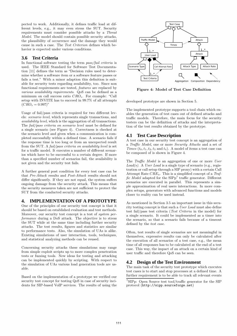
pected to work. Additionally, it defines traffic load at dif-ferent levels, e.g., it may even stress the SUT. Securityrequirements must consider possible attacks by a ThreatModel. The model should contain possible security attacks,the plausibility of occurrence and the damage they wouldcause in such a case. The Test Criterion defines which be-havior is expected under various conditions.
3.6 Test CriteriaIn functional software testing the term pass/fail criteria isused. The IEEE Standard for Software Test Documenta-tion [11] defines the term as “Decision rules used to deter-mine whether a software item or a software feature passes orfails a test.” With a minor adaption this definition is suit-able for security tests regarding availability, too. Since nonfunctional requirements are tested, features are replaced byvarious availability requirements. QoS can be defined as aminimum on call success ratio CROs. For example: “Callsetup with INVITE has to succeed in 99.7% of all attempts(CROs = 0.997)”
Usage of fail/pass criteria is required for two different lev-els: scenario level, which represents single transactions, andavailability level, which is the aggregation of all transactions.The fail/pass criteria on scenario level must be defined fora single scenario (see Figure 4). Correctness is checked atthe scenario level and given when a communication is com-pleted successfully within a defined time. A scenario fails ifthe response time is too long or from an unexpected resultfrom the SUT. A fail/pass criteria on availability level is setfor a traffic model. It executes a number of different scenar-ios which have to be successful to a certain degree. If morethan a specified number of scenarios fail, the availability isnot given and the security test fails.
A further general post condition for every test case can bethat Pre-Attack results and Post-Attack results should notdiffer significantly. If they are not equal, the system suffersongoing damage from the security attack. This means thatthe security measures taken are not sufficient to protect theSUT from the conducted security attacks.
4. IMPLEMENTATION OF A PROTOTYPEOne of the principles of our security test concept is that itshould be based on established evaluation and test methods.Moreover, our security test concept is a test of system per-formance during a DoS attack. The objective is to stressthe SUT while at the same time including further securityattacks. The test results, figures and statistics are similarto performance tests. Also, the simulation of UAs is alike.Existing simulations of user interaction, tools, techniques,and statistical analyzing methods can be reused.
Concerning security attacks these simulations may rangefrom simple exploit scripts up to more complex penetrationtests or fuzzing tools. New ideas for testing and attackingcan be implemented quickly by scripting. With respect tothe simulation of UAs various load generation tools are us-able.
Based on the implementation of a prototype we verified oursecurity test concept for testing QoS in case of security inci-dents for SIP-based VoIP services. The results of using the
Test Case
Attack
User Load
DependencyCompositionAggregation
1..*1..*
Attack
Traffic Model
Times
Attack RateAttack TypeCall Attempt RateScenario Type
Test Criteria
1..*
Figure 4: Model of Test Case Definition
developed prototype are shown in Section 5.
The implemented prototype supports a tool chain which en-ables the generation of test cases out of defined attacks andtraffic models. Therefore, the main focus for the securitytesters can be the definition of attacks and the interpreta-tion of the test results obtained by the prototype.
4.1 Test Case DescriptionA test case in our security test concept is an aggregation ofa Traffic Model, one or more Security Attacks and a set ofTimes (t0, t1, t2, t3 and t4). A model of items a test case canbe composed of is shown in Figure 4.
The Traffic Model is an aggregation of one or more UserLoad(s). A User Load is a single type of scenario (e.g., regis-tration or call setup through a SIP proxy) with a certain CallAttempt Rate CREa. This is a simplified concept of a Traf-fic Model adapted for the SIPp7 traffic generator. Differentscenarios are executed in parallel. This represents a sim-ple approximation of real users interactions. In more com-plex setups, generators with advanced functions and modelscloser to reality can be used instead.
As mentioned in Section 3.5 an important issue in this secu-rity testing concept is that such a User Load must also definetest fail/pass test criteria (Test Criteria in the model) fora single scenario. It could be implemented as a timer intothe scenario, so that a scenario fails because of a timeoutdefined by the test case.
Often, test results of single scenarios are not meaningful inthemselves, expressive results can only be calculated afterthe execution of all scenarios of a test case, e.g., the meantime of all responses has to be calculated at the end of a testcase. This way, the impact of an attack on a certain kind ofuser traffic and therefore QoS can be seen.
4.2 Design of the Test EnvironmentThe main task of the security test prototype which executestest cases is to start and stop processes at a defined time. Afurther requirement is to be able to track all relevant events
7SIPp: Open Source test tool/traffic generator for the SIPprotocol (http://sipp.sourceforge.net)
111
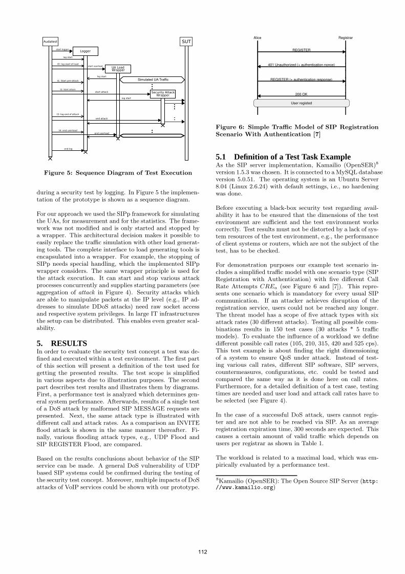
Audatest
log start
UA LoadWrapper
start userload
start logger
log start
t0: log start of load
Security Attackstart attack
log start
t3: log end of attack
SUT
t1: Start pre-attack
t2: Start attack
end attack
t4: end userload
end userload
end log
Simulated UA Traffic
Wrapper
Logger
Figure 5: Sequence Diagram of Test Execution
during a security test by logging. In Figure 5 the implemen-tation of the prototype is shown as a sequence diagram.
For our approach we used the SIPp framework for simulatingthe UAs, for measurement and for the statistics. The frame-work was not modified and is only started and stopped bya wrapper. This architectural decision makes it possible toeasily replace the traffic simulation with other load generat-ing tools. The complete interface to load generating tools isencapsulated into a wrapper. For example, the stopping ofSIPp needs special handling, which the implemented SIPpwrapper considers. The same wrapper principle is used forthe attack execution. It can start and stop various attackprocesses concurrently and supplies starting parameters (seeaggregation of attack in Figure 4). Security attacks whichare able to manipulate packets at the IP level (e.g., IP ad-dresses to simulate DDoS attacks) need raw socket accessand respective system privileges. In large IT infrastructuresthe setup can be distributed. This enables even greater scal-ability.
5. RESULTSIn order to evaluate the security test concept a test was de-fined and executed within a test environment. The first partof this section will present a definition of the test used forgetting the presented results. The test scope is simplifiedin various aspects due to illustration purposes. The secondpart describes test results and illustrates them by diagrams.First, a performance test is analyzed which determines gen-eral system performance. Afterwards, results of a single testof a DoS attack by malformed SIP MESSAGE requests arepresented. Next, the same attack type is illustrated withdifferent call and attack rates. As a comparison an INVITEflood attack is shown in the same manner thereafter. Fi-nally, various flooding attack types, e.g., UDP Flood andSIP REGISTER Flood, are compared.
Based on the results conclusions about behavior of the SIPservice can be made. A general DoS vulnerability of UDPbased SIP systems could be confirmed during the testing ofthe security test concept. Moreover, multiple impacts of DoSattacks of VoIP services could be shown with our prototype.
Alice Registrar
REGISTER
401 Unauthorized (+ authentication nonce)
REGISTER (+ authentication response)
200 OK
User registed
Figure 6: Simple Traffic Model of SIP RegistrationScenario With Authentication [7]
5.1 Definition of a Test Task ExampleAs the SIP server implementation, Kamailio (OpenSER)8
version 1.5.3 was chosen. It is connected to a MySQL databaseversion 5.0.51. The operating system is an Ubuntu Server8.04 (Linux 2.6.24) with default settings, i.e., no hardeningwas done.
Before executing a black-box security test regarding avail-ability it has to be ensured that the dimensions of the testenvironment are sufficient and the test environment workscorrectly. Test results must not be distorted by a lack of sys-tem resources of the test environment, e.g., the performanceof client systems or routers, which are not the subject of thetest, has to be checked.
For demonstration purposes our example test scenario in-cludes a simplified traffic model with one scenario type (SIPRegistration with Authentication) with five different CallRate Attempts CREa (see Figure 6 and [7]). This repre-sents one scenario which is mandatory for every usual SIPcommunication. If an attacker achieves disruption of theregistration service, users could not be reached any longer.The threat model has a scope of five attack types with sixattack rates (30 different attacks). Testing all possible com-binations results in 150 test cases (30 attacks * 5 trafficmodels). To evaluate the influence of a workload we definedifferent possible call rates (105, 210, 315, 420 and 525 cps).This test example is about finding the right dimensioningof a system to ensure QoS under attack. Instead of test-ing various call rates, different SIP software, SIP servers,countermeasures, configurations, etc. could be tested andcompared the same way as it is done here on call rates.Furthermore, for a detailed definition of a test case, testingtimes are needed and user load and attack call rates have tobe selected (see Figure 4).
In the case of a successful DoS attack, users cannot regis-ter and are not able to be reached via SIP. As an averageregistration expiration time, 300 seconds are expected. Thiscauses a certain amount of valid traffic which depends onusers per registrar as shown in Table 1.
The workload is related to a maximal load, which was em-pirically evaluated by a performance test.
8Kamailio (OpenSER): The Open Source SIP Server (http://www.kamailio.org)
112
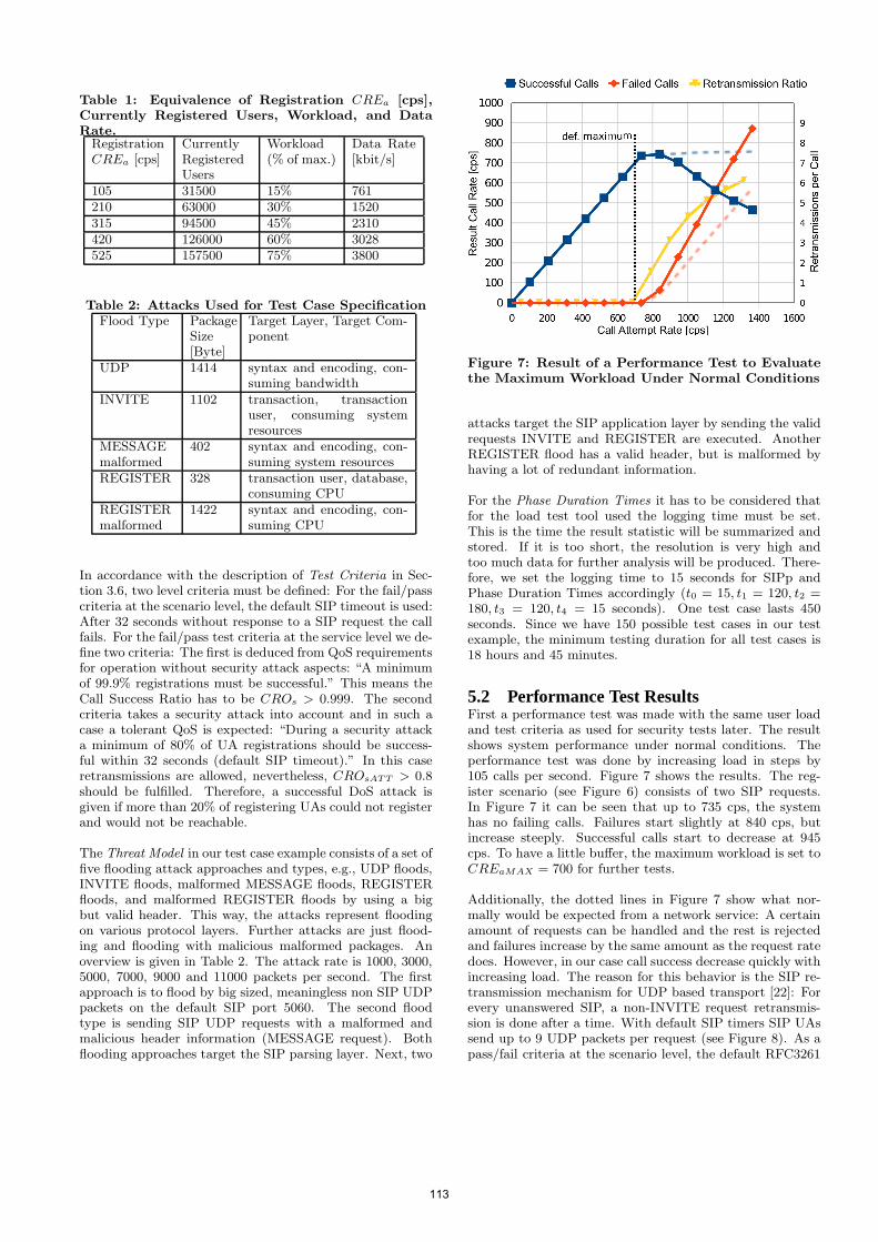
Table 1: Equivalence of Registration CREa [cps],Currently Registered Users, Workload, and DataRate.
RegistrationCREa [cps]
CurrentlyRegisteredUsers
Workload(% of max.)
Data Rate[kbit/s]
105 31500 15% 761210 63000 30% 1520315 94500 45% 2310420 126000 60% 3028525 157500 75% 3800
Table 2: Attacks Used for Test Case SpecificationFlood Type Package
Size[Byte]
Target Layer, Target Com-ponent
UDP 1414 syntax and encoding, con-suming bandwidth
INVITE 1102 transaction, transactionuser, consuming systemresources
MESSAGEmalformed
402 syntax and encoding, con-suming system resources
REGISTER 328 transaction user, database,consuming CPU
REGISTERmalformed
1422 syntax and encoding, con-suming CPU
In accordance with the description of Test Criteria in Sec-tion 3.6, two level criteria must be defined: For the fail/passcriteria at the scenario level, the default SIP timeout is used:After 32 seconds without response to a SIP request the callfails. For the fail/pass test criteria at the service level we de-fine two criteria: The first is deduced from QoS requirementsfor operation without security attack aspects: “A minimumof 99.9% registrations must be successful.” This means theCall Success Ratio has to be CROs > 0.999. The secondcriteria takes a security attack into account and in such acase a tolerant QoS is expected: “During a security attacka minimum of 80% of UA registrations should be success-ful within 32 seconds (default SIP timeout).” In this caseretransmissions are allowed, nevertheless, CROsATT > 0.8should be fulfilled. Therefore, a successful DoS attack isgiven if more than 20% of registering UAs could not registerand would not be reachable.
The Threat Model in our test case example consists of a set offive flooding attack approaches and types, e.g., UDP floods,INVITE floods, malformed MESSAGE floods, REGISTERfloods, and malformed REGISTER floods by using a bigbut valid header. This way, the attacks represent floodingon various protocol layers. Further attacks are just flood-ing and flooding with malicious malformed packages. Anoverview is given in Table 2. The attack rate is 1000, 3000,5000, 7000, 9000 and 11000 packets per second. The firstapproach is to flood by big sized, meaningless non SIP UDPpackets on the default SIP port 5060. The second floodtype is sending SIP UDP requests with a malformed andmalicious header information (MESSAGE request). Bothflooding approaches target the SIP parsing layer. Next, two
0
1
2
3
4
5
6
7
8
0 200 400 600 800 1000 1200 1400 1600
0
100
200
300
400
500
600
700
800
900
1000
Figure 7: Result of a Performance Test to Evaluatethe Maximum Workload Under Normal Conditions
attacks target the SIP application layer by sending the validrequests INVITE and REGISTER are executed. AnotherREGISTER flood has a valid header, but is malformed byhaving a lot of redundant information.
For the Phase Duration Times it has to be considered thatfor the load test tool used the logging time must be set.This is the time the result statistic will be summarized andstored. If it is too short, the resolution is very high andtoo much data for further analysis will be produced. There-fore, we set the logging time to 15 seconds for SIPp andPhase Duration Times accordingly (t0 = 15, t1 = 120, t2 =180, t3 = 120, t4 = 15 seconds). One test case lasts 450seconds. Since we have 150 possible test cases in our testexample, the minimum testing duration for all test cases is18 hours and 45 minutes.
5.2 Performance Test ResultsFirst a performance test was made with the same user loadand test criteria as used for security tests later. The resultshows system performance under normal conditions. Theperformance test was done by increasing load in steps by105 calls per second. Figure 7 shows the results. The reg-ister scenario (see Figure 6) consists of two SIP requests.In Figure 7 it can be seen that up to 735 cps, the systemhas no failing calls. Failures start slightly at 840 cps, butincrease steeply. Successful calls start to decrease at 945cps. To have a little buffer, the maximum workload is set toCREaMAX = 700 for further tests.
Additionally, the dotted lines in Figure 7 show what nor-mally would be expected from a network service: A certainamount of requests can be handled and the rest is rejectedand failures increase by the same amount as the request ratedoes. However, in our case call success decrease quickly withincreasing load. The reason for this behavior is the SIP re-transmission mechanism for UDP based transport [22]: Forevery unanswered SIP, a non-INVITE request retransmis-sion is done after a time. With default SIP timers SIP UAssend up to 9 UDP packets per request (see Figure 8). As apass/fail criteria at the scenario level, the default RFC3261
113
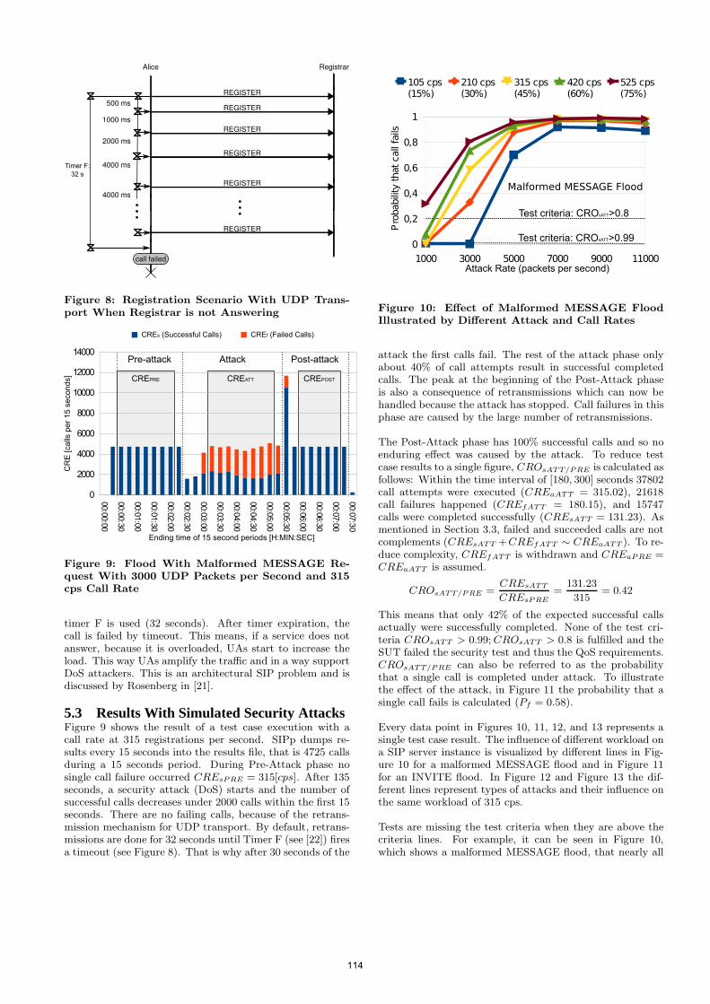
500 ms
1000 ms
2000 ms
4000 ms
4000 ms
Alice Registrar
REGISTER
REGISTER
REGISTER
REGISTER
REGISTER
REGISTER
call failed
Timer F:
32 s
Figure 8: Registration Scenario With UDP Trans-port When Registrar is not Answering
00:0
0:0
0
00:0
0:3
0
00:0
1:0
0
00:0
1:3
0
00:0
2:0
0
00:0
2:3
0
00:0
3:0
0
00:0
3:3
0
00:0
4:0
0
00:0
4:3
0
00:0
5:0
0
00:0
5:3
0
00:0
6:0
0
00:0
6:3
0
00:0
7:0
0
00:0
7:3
0
0
2000
4000
6000
8000
10000
12000
14000
CREs (Successful Calls) CREf (Failed Calls)
Ending time of 15 second periods [H:MIN:SEC]
Pre-attack Attack Post-attack
CREATTCREPRE
CR
E [calls
pe
r 1
5 s
eco
nds] CREPOST
Figure 9: Flood With Malformed MESSAGE Re-quest With 3000 UDP Packets per Second and 315cps Call Rate
timer F is used (32 seconds). After timer expiration, thecall is failed by timeout. This means, if a service does notanswer, because it is overloaded, UAs start to increase theload. This way UAs amplify the traffic and in a way supportDoS attackers. This is an architectural SIP problem and isdiscussed by Rosenberg in [21].
5.3 Results With Simulated Security AttacksFigure 9 shows the result of a test case execution with acall rate at 315 registrations per second. SIPp dumps re-sults every 15 seconds into the results file, that is 4725 callsduring a 15 seconds period. During Pre-Attack phase nosingle call failure occurred CREsPRE = 315[cps]. After 135seconds, a security attack (DoS) starts and the number ofsuccessful calls decreases under 2000 calls within the first 15seconds. There are no failing calls, because of the retrans-mission mechanism for UDP transport. By default, retrans-missions are done for 32 seconds until Timer F (see [22]) firesa timeout (see Figure 8). That is why after 30 seconds of the
1000 3000 5000 7000 9000 11000
0
0,2
0,4
0,6
0,8
1
Malformed MESSAGE Flood
Attack Rate (packets per second)
105 cps (15%)
210 cps (30%)
315 cps (45%)
420 cps (60%)
525 cps (75%)
Pro
babili
ty that call
fails
Test criteria: CROsATT>0.8
Test criteria: CROsATT>0.99
Figure 10: Effect of Malformed MESSAGE FloodIllustrated by Different Attack and Call Rates
attack the first calls fail. The rest of the attack phase onlyabout 40% of call attempts result in successful completedcalls. The peak at the beginning of the Post-Attack phaseis also a consequence of retransmissions which can now behandled because the attack has stopped. Call failures in thisphase are caused by the large number of retransmissions.
The Post-Attack phase has 100% successful calls and so noenduring effect was caused by the attack. To reduce testcase results to a single figure, CROsATT/PRE is calculated asfollows: Within the time interval of [180, 300] seconds 37802call attempts were executed (CREaATT = 315.02), 21618call failures happened (CREfATT = 180.15), and 15747calls were completed successfully (CREsATT = 131.23). Asmentioned in Section 3.3, failed and succeeded calls are notcomplements (CREsATT +CREfATT ∼ CREaATT ). To re-duce complexity, CREfATT is withdrawn and CREaPRE =CREaATT is assumed.
CROsATT/PRE =CREsATT
CREsPRE
=131.23
315= 0.42
This means that only 42% of the expected successful callsactually were successfully completed. None of the test cri-teria CROsATT > 0.99; CROsATT > 0.8 is fulfilled and theSUT failed the security test and thus the QoS requirements.CROsATT/PRE can also be referred to as the probabilitythat a single call is completed under attack. To illustratethe effect of the attack, in Figure 11 the probability that asingle call fails is calculated (Pf = 0.58).
Every data point in Figures 10, 11, 12, and 13 represents asingle test case result. The influence of different workload ona SIP server instance is visualized by different lines in Fig-ure 10 for a malformed MESSAGE flood and in Figure 11for an INVITE flood. In Figure 12 and Figure 13 the dif-ferent lines represent types of attacks and their influence onthe same workload of 315 cps.
Tests are missing the test criteria when they are above thecriteria lines. For example, it can be seen in Figure 10,which shows a malformed MESSAGE flood, that nearly all
114
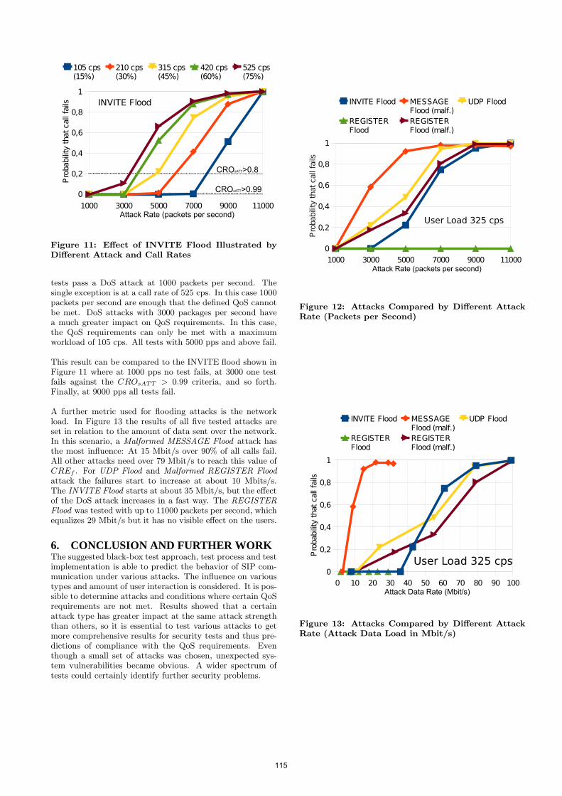
1000 3000 5000 7000 9000 11000
0
0,2
0,4
0,6
0,8
1
INVITE Flood
105 cps (15%)
210 cps (30%)
315 cps (45%)
420 cps (60%)
525 cps (75%)
Attack Rate (packets per second)
Pro
babili
ty that call
fails
CROsATT>0.8
CROsATT>0.99
Figure 11: Effect of INVITE Flood Illustrated byDifferent Attack and Call Rates
tests pass a DoS attack at 1000 packets per second. Thesingle exception is at a call rate of 525 cps. In this case 1000packets per second are enough that the defined QoS cannotbe met. DoS attacks with 3000 packages per second havea much greater impact on QoS requirements. In this case,the QoS requirements can only be met with a maximumworkload of 105 cps. All tests with 5000 pps and above fail.
This result can be compared to the INVITE flood shown inFigure 11 where at 1000 pps no test fails, at 3000 one testfails against the CROsATT > 0.99 criteria, and so forth.Finally, at 9000 pps all tests fail.
A further metric used for flooding attacks is the networkload. In Figure 13 the results of all five tested attacks areset in relation to the amount of data sent over the network.In this scenario, a Malformed MESSAGE Flood attack hasthe most influence: At 15 Mbit/s over 90% of all calls fail.All other attacks need over 79 Mbit/s to reach this value ofCREf . For UDP Flood and Malformed REGISTER Floodattack the failures start to increase at about 10 Mbits/s.The INVITE Flood starts at about 35 Mbit/s, but the effectof the DoS attack increases in a fast way. The REGISTERFlood was tested with up to 11000 packets per second, whichequalizes 29 Mbit/s but it has no visible effect on the users.
6. CONCLUSION AND FURTHER WORKThe suggested black-box test approach, test process and testimplementation is able to predict the behavior of SIP com-munication under various attacks. The influence on varioustypes and amount of user interaction is considered. It is pos-sible to determine attacks and conditions where certain QoSrequirements are not met. Results showed that a certainattack type has greater impact at the same attack strengththan others, so it is essential to test various attacks to getmore comprehensive results for security tests and thus pre-dictions of compliance with the QoS requirements. Eventhough a small set of attacks was chosen, unexpected sys-tem vulnerabilities became obvious. A wider spectrum oftests could certainly identify further security problems.
1000 3000 5000 7000 9000 11000
0
0,2
0,4
0,6
0,8
1
User Load 325 cps
INVITE Flood MESSAGE Flood (malf.)
UDP Flood
REGISTER Flood
REGISTER Flood (malf.)
Attack Rate (packets per second)
Pro
babili
ty that call
fails
Figure 12: Attacks Compared by Different AttackRate (Packets per Second)
0 10 20 30 40 50 60 70 80 90 100
0
0,2
0,4
0,6
0,8
1
INVITE Flood MESSAGE Flood (malf.)
UDP Flood
REGISTER Flood
REGISTER Flood (malf.)
Attack Data Rate (Mbit/s)
Pro
babili
ty that call
fails
User Load 325 cps
Figure 13: Attacks Compared by Different AttackRate (Attack Data Load in Mbit/s)
115
A potential improvement is to shorten execution time of testcases. A further area of investigation is to establish modelsfor both the attack scenarios and the user workload. Forchoosing representative attacks, existing threat models ofSIP service could be consulted. Additionally, possible DoSattacks against RTP payload could be taken into account.The traffic model should be based on statistics of real VoIPsystems, for more realistic simulation of user interaction.Another kind of research may be done on iterative cyclictest processes hardening VoIP systems using this concept.
Functional tests, performance tests and penetration testsare often executed in large IT infrastructures. In this pa-per we showed that this is not enough for building systemswith high availability requirements like SIP-based VoIP ser-vices. Our results indicate that by combining multiple testtechniques like performance and penetration tests it is pos-sible to evaluate quality of service requirements and greatlyenhance the security level of critical services.
7. REFERENCES[1] H. Abdelnur, V. Cridlig, R. State, and O. Festor. Voip
security assessment: methods and tools. VoIPManagement and Security, 2006. 1st IEEE Workshopon, 0(0):29–34, April 2006.
[2] H. Abdelnur, R. State, I. Chrisment, and C. Popi.Assessing the security of voip services. -, 2007.
[3] M. A. Akbar and M. Farooq. Application ofevolutionary algorithms in detection of sip basedflooding attacks. In GECCO ’09: Proceedings of the11th Annual conference on Genetic and evolutionarycomputation, pages 1419–1426, New York, NY, USA,2009. ACM.
[4] M. Bishop. Introduction to Computer Security.Addison-Wesley Professional, 2004.
[5] R. Chang. Defending against flooding-baseddistributed denial-of-service attacks: a tutorial.Communications Magazine, IEEE, 40(10):42 – 51, oct2002.
[6] E. David, D. Ghosal, R. Jafari, A. Karlcut,M. Kolenko, N. Nguyen, W. Walkoe, and J. Zar. Voipsecurity and privacy threat taxonomy. Technicalreport, VOIPSA, 2005.
[7] S. Donovan, R. Sparks, C. C., and K. Summers.Rfc3665: Session initiation protocol (sip) basic callflow examples. http://www.ietf.org/rfc/rfc3665.txt.
[8] D. Endler and M. Collier. Hacking Exposed VoIP:Voice Over IP Security Secrets & Solutions (HackingExposed). McGraw-Hill Osborne Media, 2006.
[9] D. Endler and M. Collier. Hacking voip exposed, 2006.BlackHat Conference 2006 USA.
[10] H. Hassan, J. Garcia, and C. Bockstal. Aggregatetraffic models for voip applications. In DigitalTelecommunications, , 2006. ICDT ’06. InternationalConference on, volume 0, pages 70–70, Aug. 2006.
[11] IEEE. Ieee standard for software test documentation.IEEE Std 829-1998, Dec 1998.
[12] IEEE. Ieee std 1012 - 2004 ieee standard for softwareverification and validation. IEEE Std 1012-2004.Revision of IEEE Std 1012-1998., 0(0):1 to 110, 12005.
[13] C. Kaner, J. Falk, and H. Q. Hguyen. Testing
Computer Software. International ThompsonComputer Press, London, UK, 1993.
[14] G. M. Kapfhammer. Software testing. In TheComputer ScienceHandbook. CRC Press, 2004.
[15] A. D. Keromytis. A survey of voice over ip securityresearch. In A. Prakash and I. Gupta, editors, ICISS,volume 5905 of Lecture Notes in Computer Science,pages 1–17. Springer, 2009.
[16] A. D. Keromytis. Voice over ip: Risks, threats, andvulnerabilities. In Proceedings of the IEEE Symposiumon Computers and Communications (ISCC), pages557–563. IEEE, 2009.
[17] M. Luo, T. Peng, and C. Leckie. Cpu-based dosattacks against sip servers. In Network Operations andManagement Symposium, 2008. NOMS 2008. IEEE,volume 0, pages 41 –48, april 2008.
[18] S. Montagna and M. Pignolo. Performance evaluationof load control techniques in sip signaling servers. InSystems, 2008. ICONS 08. Third InternationalConference on, pages 51 –56, april 2008.
[19] T. Peng, C. Leckie, and K. Ramamohanarao. Surveyof network-based defense mechanisms countering thedos and ddos problems. ACM Comput. Surv., 39(1):3,2007.
[20] M. Z. Rafique, M. A. Akbar, and M. Farooq.Evaluating dos attacks against sip-based voip systems.In GLOBECOM, pages 1–6. IEEE, 2009.
[21] J. Rosenberg. Rfc5390: Requirements for managementof overload in the session initiation protocol.http://www.ietf.org/rfc/rfc5390.txt.
[22] J. Rosenberg, H. Schulzrinne, G. Camarillo,A. Johnston, J. Peterson, R. Sparks, H. M., andE. Schooler. Rfc 3261: Sip - session initiation protocol.http://www.ietf.org/rfc/rfc3261.txt.
[23] H. Schulzrinne, S. Narayanan, J. Lennox, andM. Doyle. Sipstone - benchmarking sip serverperformance. http://www.sipstone.com, april 2002.
[24] D. Sisalem, J. Kuthan, and S. Ehlert. Denial of serviceattacks targeting a sip voip infrastructure: attackscenarios and prevention mechanisms. Network, IEEE,20(5):26–31, Sept.-Oct. 2006.
[25] H. Srinivasan and K. Sarac. A sip security testingframework. In CCNC’09: Proceedings of the 6th IEEEConference on Consumer Communications andNetworking Conference, pages 1056–1060, Piscataway,NJ, USA, 2009. IEEE Press.
[26] J.-S. Wu and P.-Y. Wang. The performance analysisof sip-t signaling system in carrier class voip network.In Advanced Information Networking andApplications, 2003. AINA 2003. 17th InternationalConference on, pages 39 – 44, march 2003.
116
Reliability and Relay Selection in Peer-to-PeerCommunication Systems
Salman Abdul Baset and Henning SchulzrinneDepartment of Computer Science
Columbia University, New York, NY, USA{salman,hgs}@cs.columbia.edu
ABSTRACTThe presence of restrictive network address translators (NATs)and firewalls prevent nodes from directly exchanging packetsand thereby pose a problem for peer-to-peer (p2p) commu-nication systems. Skype, a popular p2p VoIP application,addresses this problem by using another Skype client (relay)with unrestricted connectivity to relay the signaling and me-dia traffic between session endpoints. This distributed tech-nique for addressing connectivity issues raises challengingquestions about the reliability and latency of relayed calls,relay selection techniques, and the interference of relayedcalls with the applications running on relays – a phenomenawe refer to as user annoyance.We devise a framework to analyze reliability in peer-to-
peer communication systems and present a simple model toestimate the number of relays needed for maintaining the de-sired reliability for the media sessions. We then analyze twotechniques for improving the reliability of relayed calls. Wepresent a distributed relay selection technique that leveragesa two level hierarchical p2p network to find a relay in O(1)hop. We augment our distributed relay selection techniqueto find a relay that minimizes call latency and user annoy-ance. Our results indicate that for Skype node lifetimes, atleast three relays are needed to achieve a 99.9% success ratefor call duration of 60mins (95th percentile of Skype calldurations).
Categories and Subject DescriptorsC.4 [Performance of Systems]: [Reliability, availability,and serviceability]
General TermsDesign, Reliability, Measurement
KeywordsReliability, P2P, VoIP, Relay
Permission to make digital or hard copies of all or part of this work forpersonal or classroom use is granted without fee provided that copies arenot made or distributed for profit or commercial advantage and that copiesbear this notice and the full citation on the first page. To copy otherwise, torepublish, to post on servers or to redistribute to lists, requires prior specificpermission and/or a fee.IPTComm 2010, 2-3 August, 2010 Munich, GermanyCopyright 2010 ACM ...$10.00.
1. INTRODUCTIONRestrictive network address translators (NATs) and fire-
walls prevent hosts from directly exchanging packets. A re-cent survey of 1,787 NAT devices indicates that hosts be-hind approximately 30% of these devices cannot traversethe NATs using UDP or TCP [3] implying that hosts behindtwo different such devices are not likely to directly exchangepackets without an intermediary. Moreover, corporationsare increasingly deploying firewalls to protect their networksfrom malicious traffic that originates both outside and insidetheir networks. The restrictive NATs and firewalls pose aproblem for IP communication systems because they pre-vent the user agents from directly exchanging signaling andmedia traffic.
In a client-server (c/s) communication system, the calleruser agent discovers the current network address of a calleeuser agent through a managed server and exchanges sig-naling information with the callee user agent to establisha media session. The media traffic flows directly betweenthe user agents. To address the connectivity constraints dueto restrictive NATs and firewalls, c/s systems such as Von-age [8] use managed servers for relaying the media trafficbetween user agents with restrictive connectivity. In con-trast, in a peer-to-peer (p2p) communication system, thereare minimal or no servers. The user agents collaborate todiscover the network address of the callee user agent andthen directly exchange signaling and media traffic to estab-lish a media session. When the user agents behind restrictiveNATs and firewalls cannot directly exchange packets, theyrely on user agents (or peers) with unrestricted connectiv-ity for exchanging signaling and media traffic. Skype is anexample of a peer-to-peer communication system that usesthis technique [9]. Suh et al. [29] report hundreds of callsbeing relayed by a Skype relay.
The above characteristics of a p2p communication sys-tem pose unique challenges for a system designer. First, thelookup performance in p2p systems must at least be as effec-tive as the lookup performance of client-server systems. Ad-ditionally, a media session may be prematurely terminatedbecause a relay peer goes offline. This issue necessitates aformal analysis of the reliability of p2p communication sys-tems and techniques to prevent dropped sessions. Moreover,since media sessions such as voice and video have a tightplayout requirement, the network latency of a media ses-sion involving a relay peer should satisfy these tight require-ments. Further, the relaying of a media session may interferewith other user applications and impair their performance.A system designer must either provide incentives for users
117
schmitt
Stempel
to run relay peers or design techniques that minimize theinterference of relayed session with other user applications.In this paper, we present a framework to analyze the re-
liability of peer-to-peer communication systems (Section 3).We then devise a simple analytical model that predicts thesmallest number of relays needed to achieve the desired reli-ability for relayed media sessions (Section 4.1) and evaluateit on exponential, pareto, and Skype node lifetimes. For agiven node lifetime and call duration distribution, the modelallows determining the minimum number of relays so thatthe percentage of successful relayed calls does not fall belowa desired threshold (e.g., 99.9%). Such an analysis can helpcharacterize the resources (relays) needed for improving thereliability of relayed calls. We then devise two techniques toprevent dropped sessions, selecting k relay peers at the be-ginning of a call with no-replacement and with-replacementand predict their reliability improvement using reliabilitytheory in Section 4.2 and 4.3. In Section 4.4, we analyze thereliability improvement scheme used by Skype. Section 4.5presents the experimental evaluation of the model and dis-cussion.In Section 5, we present a distributed technique to find
a relay peer in O(1) hop and compare the performance ofthis technique to a relay selection scheme that has globalknowledge of all the relays in the p2p network. Insteadof designing incentives for users to allow relaying of mediasessions through their user agents, we aim to minimize theinterference of relayed session with the user applications.To capture the impact of the relayed media sessions on theuser applications, we introduce the notion of user annoyance(Section 5.2). We augment our distributed search techniqueto select a relay that minimizes delay, user annoyance, orboth within a threshold. To the best of our knowledge, weare the first to address the reliability issues in p2p communi-cation systems, and to devise techniques for finding a relaythat optimizes the latency of a relayed call and user annoy-ance. Our analysis and results are also applicable to mediatranslation and conferencing in p2p communication systems.
2. PROBLEM SETTINGWe consider a peer-to-peer communication system that
has N participating nodes. A node is a machine with CPU,memory and disk and is connected to the Internet througha dialup, DSL, cable, fiber, or a wireless connection. Typ-ically, a human user is associated with each node or a ma-chine and runs a peer-to-peer communication application(s)(also referred to as user agents) and other applications. Thep2p applications use any peer-to-peer protocol to form ap2p network. There are two types of nodes in a peer-to-peercommunication network, peers and free-riders. In the liter-ature, they are also referred to as super nodes and ordinarynodes [9, 21] or peers and clients [12]. A peer fully par-ticipates in the p2p network, collaborates with other peersto discover the reachable network address of the callee useragent, and can relay one or more media sessions. A free-riderdoes not collaborate in the discovery of the callee user agentand does not relay any media sessions. However, this col-laboration is not always purposefully avoided. The presenceof restrictive NATs and firewalls may hinder the participa-tion of a node in the overlay, thereby forcing it to act asa free-rider. The need for relaying media sessions betweencaller and callee user agents arises precisely due to this rea-son. For ease of exposition, we refer to the caller and callee
user agent as caller and callee, relay peer as relay, and voicesession as a call. Unless stated otherwise, we refer to thep2p communication application as a p2p application.
3. RELIABILITY OF A P2P COMMUNICA-TION SYSTEM
Availability is the classical metric for modeling the relia-bility of a communication system and is typically measuredby the number of nines after a decimal point. For exam-ple, a “3 nines” (99.9%) reliability means that the system isdown only 0.1% of the time. In a p2p communication sys-tem, availability implies the ability of the system to find thenetwork address of the callee, and also to find a relay forestablishing the relayed call. However, this notion does notfully capture the reliability of relayed calls because in addi-tion to relay search failure, calls can also fail due to relaychurn since there is no guarantee about the uptime of re-lays. Thus, a more accurate metric to capture the reliabilityof calls in a p2p communication is the number of successfullycompleted calls.
Psucc = PssFnorelay + PssFnorelayPrsP (R > D) (1)
Equation (1) formalizes the notion of reliability or per-centage of successful calls in a p2p communication system.The term to the immediate left of plus sign is the probabilityof successfully finding the network address of the callee useragent, Pss, times the proportion of calls that do not need arelay, Fnorelay. The term to the immediate right of plus signis the probability of successfully finding the relay, Prs, timesthe proportion of calls that need a relay, Fnorelay, times theprobability that the residual lifetime of a relay, R, is greaterthan the call duration distribution D. This equation indi-cates that the proportion of successful calls can be increasedby enhancing the performance of lookup schemes using tech-niques similar to [24,27], by designing schemes that establisha media session between user agents in the presence of NATsand firewalls without requiring a relay [15], and by improv-ing the success rate of distributed relay search and relaycalls. We focus our attention on analyzing the reliabilityof relayed calls and relay search since other areas have seenrelated work [25].
4. MODELING RELIABILITY OF RELAYEDCALLS
We present a simple model to calculate the minimum num-ber of relays per call, k so that the success rate of relayedcalls is above a desired reliability criteria such as 99.9%(Section 4.1), analyze two reliability improvement schemes,namely, no-replacement (Section 4.2) and with-replacement(Section 4.3), and present an evaluation of the model andreliability improvement schemes (Section 4.5). Our analysisassume that the nodes that need a relay to establish a call(ordinary nodes) can randomly select it from the set of allrelays, that relays are plenty, and the system has reachedstationarity. In Section 5.1, we discuss a distributed schemeto find a relay.
4.1 Number of RelaysLet Xi be a random variable (r.v) that denotes the life-
time of relay i, FXi be its CDF, and Xi be independent and
118
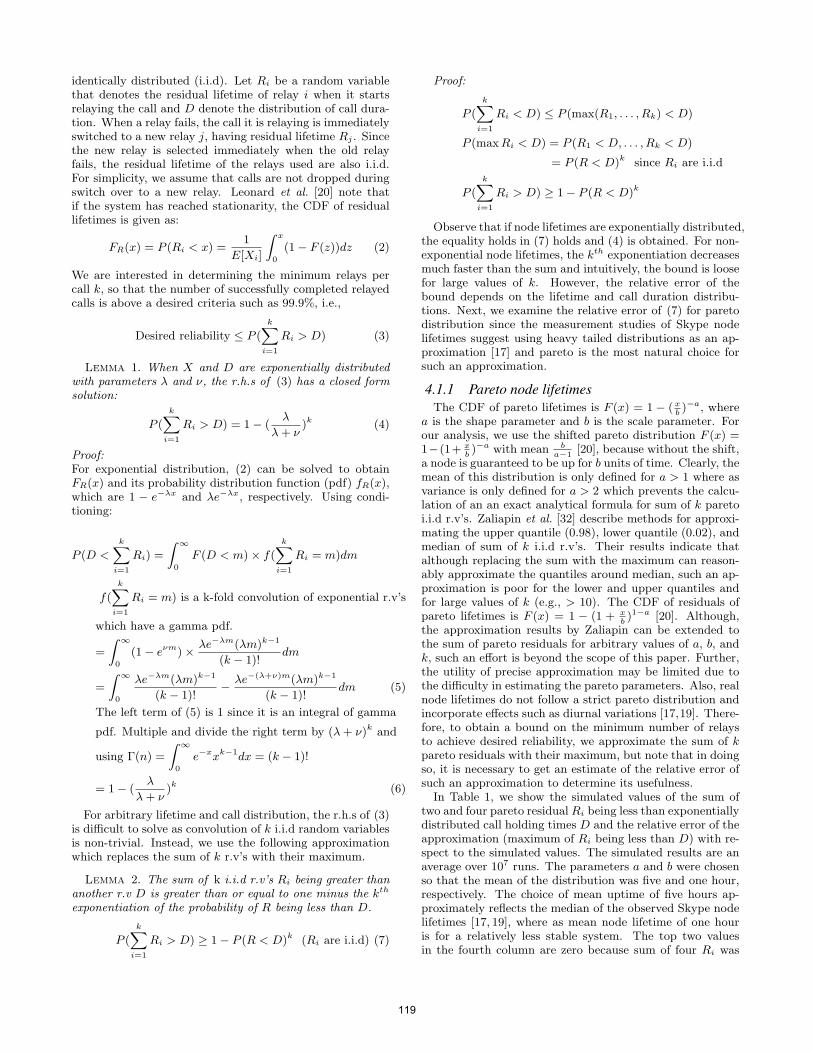
identically distributed (i.i.d). Let Ri be a random variablethat denotes the residual lifetime of relay i when it startsrelaying the call and D denote the distribution of call dura-tion. When a relay fails, the call it is relaying is immediatelyswitched to a new relay j, having residual lifetime Rj . Sincethe new relay is selected immediately when the old relayfails, the residual lifetime of the relays used are also i.i.d.For simplicity, we assume that calls are not dropped duringswitch over to a new relay. Leonard et al. [20] note thatif the system has reached stationarity, the CDF of residuallifetimes is given as:
FR(x) = P (Ri < x) =1
E[Xi]
∫ x
0
(1− F (z))dz (2)
We are interested in determining the minimum relays percall k, so that the number of successfully completed relayedcalls is above a desired criteria such as 99.9%, i.e.,
Desired reliability ≤ P (
k∑i=1
Ri > D) (3)
Lemma 1. When X and D are exponentially distributedwith parameters λ and ν, the r.h.s of (3) has a closed formsolution:
P (
k∑i=1
Ri > D) = 1− (λ
λ+ ν)k (4)
Proof:For exponential distribution, (2) can be solved to obtainFR(x) and its probability distribution function (pdf) fR(x),which are 1 − e−λx and λe−λx, respectively. Using condi-tioning:
P (D <
k∑i=1
Ri) =
∫ ∞
0
F (D < m)× f(
k∑i=1
Ri = m)dm
f(
k∑i=1
Ri = m) is a k-fold convolution of exponential r.v’s
which have a gamma pdf.
=
∫ ∞
0
(1− eνm)× λe−λm(λm)k−1
(k − 1)!dm
=
∫ ∞
0
λe−λm(λm)k−1
(k − 1)!− λe−(λ+ν)m(λm)k−1
(k − 1)!dm (5)
The left term of (5) is 1 since it is an integral of gamma
pdf. Multiple and divide the right term by (λ+ ν)k and
using Γ(n) =
∫ ∞
0
e−xxk−1dx = (k − 1)!
= 1− (λ
λ+ ν)k (6)
For arbitrary lifetime and call distribution, the r.h.s of (3)is difficult to solve as convolution of k i.i.d random variablesis non-trivial. Instead, we use the following approximationwhich replaces the sum of k r.v’s with their maximum.
Lemma 2. The sum of k i.i.d r.v’s Ri being greater thananother r.v D is greater than or equal to one minus the kth
exponentiation of the probability of R being less than D.
P (
k∑i=1
Ri > D) ≥ 1− P (R < D)k (Ri are i.i.d) (7)
Proof:
P (
k∑i=1
Ri < D) ≤ P (max(R1, . . . , Rk) < D)
P (maxRi < D) = P (R1 < D, . . . , Rk < D)
= P (R < D)k since Ri are i.i.d
P (
k∑i=1
Ri > D) ≥ 1− P (R < D)k
Observe that if node lifetimes are exponentially distributed,the equality holds in (7) holds and (4) is obtained. For non-exponential node lifetimes, the kth exponentiation decreasesmuch faster than the sum and intuitively, the bound is loosefor large values of k. However, the relative error of thebound depends on the lifetime and call duration distribu-tions. Next, we examine the relative error of (7) for paretodistribution since the measurement studies of Skype nodelifetimes suggest using heavy tailed distributions as an ap-proximation [17] and pareto is the most natural choice forsuch an approximation.
4.1.1 Pareto node lifetimesThe CDF of pareto lifetimes is F (x) = 1 − (x
b)−a, where
a is the shape parameter and b is the scale parameter. Forour analysis, we use the shifted pareto distribution F (x) =1−(1+ x
b)−a with mean b
a−1[20], because without the shift,
a node is guaranteed to be up for b units of time. Clearly, themean of this distribution is only defined for a > 1 where asvariance is only defined for a > 2 which prevents the calcu-lation of an an exact analytical formula for sum of k paretoi.i.d r.v’s. Zaliapin et al. [32] describe methods for approxi-mating the upper quantile (0.98), lower quantile (0.02), andmedian of sum of k i.i.d r.v’s. Their results indicate thatalthough replacing the sum with the maximum can reason-ably approximate the quantiles around median, such an ap-proximation is poor for the lower and upper quantiles andfor large values of k (e.g., > 10). The CDF of residuals ofpareto lifetimes is F (x) = 1 − (1 + x
b)1−a [20]. Although,
the approximation results by Zaliapin can be extended tothe sum of pareto residuals for arbitrary values of a, b, andk, such an effort is beyond the scope of this paper. Further,the utility of precise approximation may be limited due tothe difficulty in estimating the pareto parameters. Also, realnode lifetimes do not follow a strict pareto distribution andincorporate effects such as diurnal variations [17,19]. There-fore, to obtain a bound on the minimum number of relaysto achieve desired reliability, we approximate the sum of kpareto residuals with their maximum, but note that in doingso, it is necessary to get an estimate of the relative error ofsuch an approximation to determine its usefulness.
In Table 1, we show the simulated values of the sum oftwo and four pareto residual Ri being less than exponentiallydistributed call holding times D and the relative error of theapproximation (maximum of Ri being less than D) with re-spect to the simulated values. The simulated results are anaverage over 107 runs. The parameters a and b were chosenso that the mean of the distribution was five and one hour,respectively. The choice of mean uptime of five hours ap-proximately reflects the median of the observed Skype nodelifetimes [17, 19], where as mean node lifetime of one houris for a relatively less stable system. The top two valuesin the fourth column are zero because sum of four Ri was
119
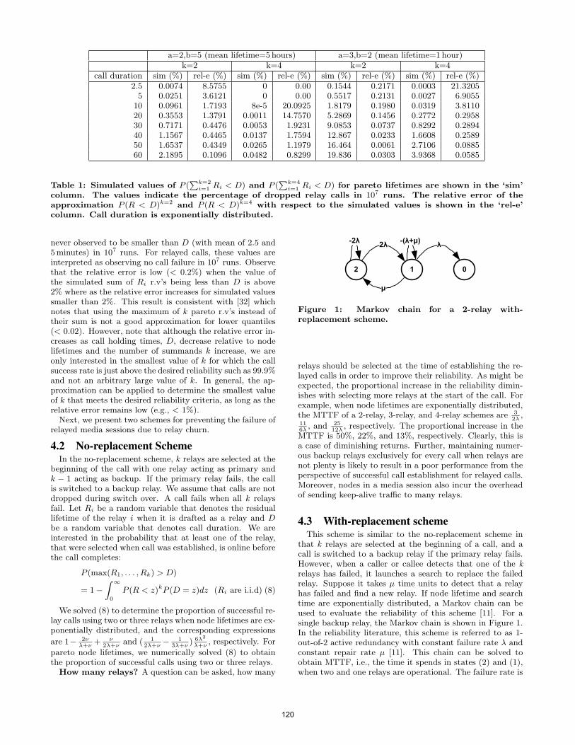
a=2,b=5 (mean lifetime=5hours) a=3,b=2 (mean lifetime=1hour)k=2 k=4 k=2 k=4
call duration sim (%) rel-e (%) sim (%) rel-e (%) sim (%) rel-e (%) sim (%) rel-e (%)2.5 0.0074 8.5755 0 0.00 0.1544 0.2171 0.0003 21.32055 0.0251 3.6121 0 0.00 0.5517 0.2131 0.0027 6.9055
10 0.0961 1.7193 8e-5 20.0925 1.8179 0.1980 0.0319 3.811020 0.3553 1.3791 0.0011 14.7570 5.2869 0.1456 0.2772 0.295830 0.7171 0.4476 0.0053 1.9231 9.0853 0.0737 0.8292 0.289440 1.1567 0.4465 0.0137 1.7594 12.867 0.0233 1.6608 0.258950 1.6537 0.4349 0.0265 1.1979 16.464 0.0061 2.7106 0.088560 2.1895 0.1096 0.0482 0.8299 19.836 0.0303 3.9368 0.0585
Table 1: Simulated values of P (∑k=2
i=1 Ri < D) and P (∑k=4
i=1 Ri < D) for pareto lifetimes are shown in the ‘sim’column. The values indicate the percentage of dropped relay calls in 107 runs. The relative error of theapproximation P (R < D)k=2 and P (R < D)k=4 with respect to the simulated values is shown in the ‘rel-e’column. Call duration is exponentially distributed.
never observed to be smaller than D (with mean of 2.5 and5minutes) in 107 runs. For relayed calls, these values areinterpreted as observing no call failure in 107 runs. Observethat the relative error is low (< 0.2%) when the value ofthe simulated sum of Ri r.v’s being less than D is above2% where as the relative error increases for simulated valuessmaller than 2%. This result is consistent with [32] whichnotes that using the maximum of k pareto r.v’s instead oftheir sum is not a good approximation for lower quantiles(< 0.02). However, note that although the relative error in-creases as call holding times, D, decrease relative to nodelifetimes and the number of summands k increase, we areonly interested in the smallest value of k for which the callsuccess rate is just above the desired reliability such as 99.9%and not an arbitrary large value of k. In general, the ap-proximation can be applied to determine the smallest valueof k that meets the desired reliability criteria, as long as therelative error remains low (e.g., < 1%).Next, we present two schemes for preventing the failure of
relayed media sessions due to relay churn.
4.2 No-replacement SchemeIn the no-replacement scheme, k relays are selected at the
beginning of the call with one relay acting as primary andk − 1 acting as backup. If the primary relay fails, the callis switched to a backup relay. We assume that calls are notdropped during switch over. A call fails when all k relaysfail. Let Ri be a random variable that denotes the residuallifetime of the relay i when it is drafted as a relay and Dbe a random variable that denotes call duration. We areinterested in the probability that at least one of the relay,that were selected when call was established, is online beforethe call completes:
P (max(R1, . . . , Rk) > D)
= 1−∫ ∞
0
P (R < z)kP (D = z)dz (Ri are i.i.d) (8)
We solved (8) to determine the proportion of successful re-lay calls using two or three relays when node lifetimes are ex-ponentially distributed, and the corresponding expressions
are 1− 2νλ+ν
+ ν2λ+ν
and ( 12λ+ν
− 13λ+ν
) 6λ2
λ+ν, respectively. For
pareto node lifetimes, we numerically solved (8) to obtainthe proportion of successful calls using two or three relays.How many relays? A question can be asked, how many
2 1 0
µ
2λ λ-(λ+µ)-2λ
Figure 1: Markov chain for a 2-relay with-replacement scheme.
relays should be selected at the time of establishing the re-layed calls in order to improve their reliability. As might beexpected, the proportional increase in the reliability dimin-ishes with selecting more relays at the start of the call. Forexample, when node lifetimes are exponentially distributed,the MTTF of a 2-relay, 3-relay, and 4-relay schemes are 3
2λ,
116λ
, and 2512λ
, respectively. The proportional increase in theMTTF is 50%, 22%, and 13%, respectively. Clearly, this isa case of diminishing returns. Further, maintaining numer-ous backup relays exclusively for every call when relays arenot plenty is likely to result in a poor performance from theperspective of successful call establishment for relayed calls.Moreover, nodes in a media session also incur the overheadof sending keep-alive traffic to many relays.
4.3 With-replacement schemeThis scheme is similar to the no-replacement scheme in
that k relays are selected at the beginning of a call, and acall is switched to a backup relay if the primary relay fails.However, when a caller or callee detects that one of the krelays has failed, it launches a search to replace the failedrelay. Suppose it takes µ time units to detect that a relayhas failed and find a new relay. If node lifetime and searchtime are exponentially distributed, a Markov chain can beused to evaluate the reliability of this scheme [11]. For asingle backup relay, the Markov chain is shown in Figure 1.In the reliability literature, this scheme is referred to as 1-out-of-2 active redundancy with constant failure rate λ andconstant repair rate µ [11]. This chain can be solved toobtain MTTF, i.e., the time it spends in states (2) and (1),when two and one relays are operational. The failure rate is
120
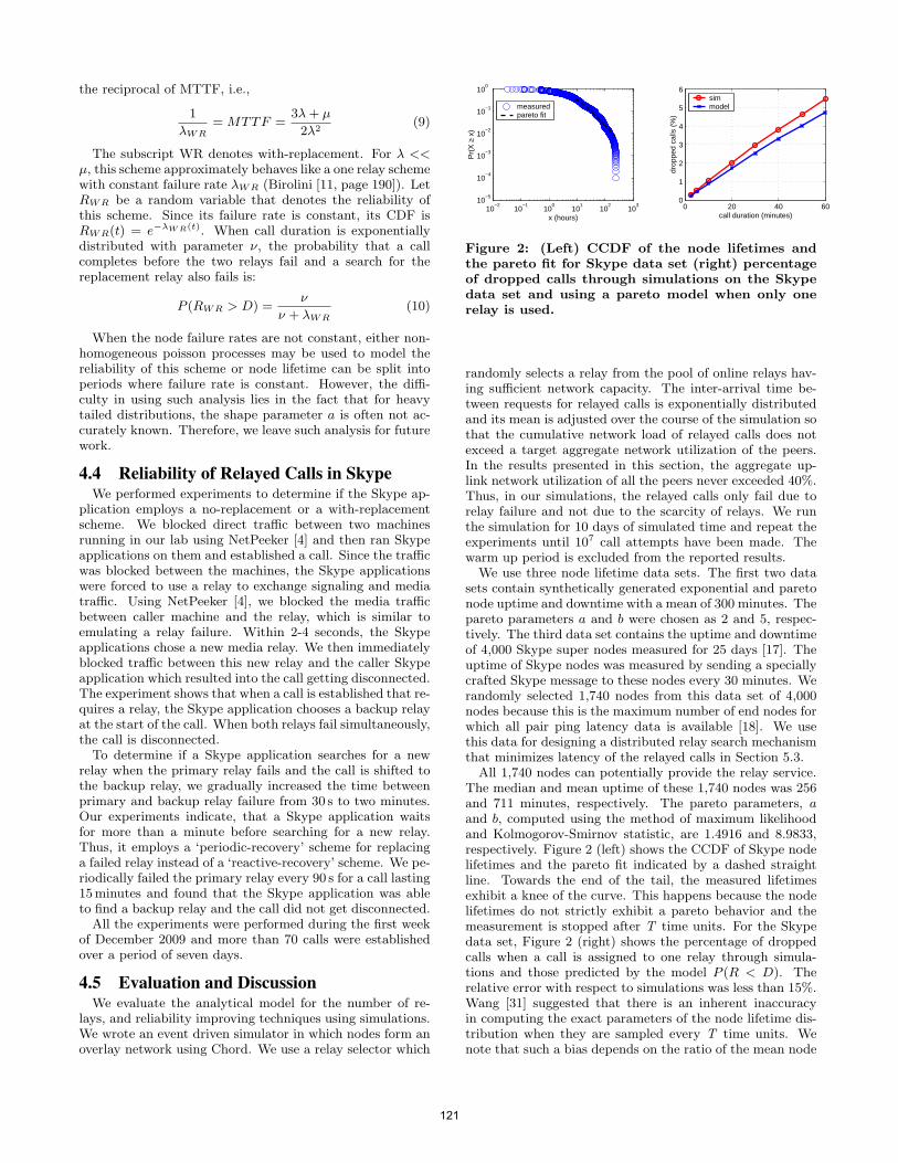
the reciprocal of MTTF, i.e.,
1
λWR= MTTF =
3λ+ µ
2λ2(9)
The subscript WR denotes with-replacement. For λ <<µ, this scheme approximately behaves like a one relay schemewith constant failure rate λWR (Birolini [11, page 190]). LetRWR be a random variable that denotes the reliability ofthis scheme. Since its failure rate is constant, its CDF isRWR(t) = e−λWR(t). When call duration is exponentiallydistributed with parameter ν, the probability that a callcompletes before the two relays fail and a search for thereplacement relay also fails is:
P (RWR > D) =ν
ν + λWR(10)
When the node failure rates are not constant, either non-homogeneous poisson processes may be used to model thereliability of this scheme or node lifetime can be split intoperiods where failure rate is constant. However, the diffi-culty in using such analysis lies in the fact that for heavytailed distributions, the shape parameter a is often not ac-curately known. Therefore, we leave such analysis for futurework.
4.4 Reliability of Relayed Calls in SkypeWe performed experiments to determine if the Skype ap-
plication employs a no-replacement or a with-replacementscheme. We blocked direct traffic between two machinesrunning in our lab using NetPeeker [4] and then ran Skypeapplications on them and established a call. Since the trafficwas blocked between the machines, the Skype applicationswere forced to use a relay to exchange signaling and mediatraffic. Using NetPeeker [4], we blocked the media trafficbetween caller machine and the relay, which is similar toemulating a relay failure. Within 2-4 seconds, the Skypeapplications chose a new media relay. We then immediatelyblocked traffic between this new relay and the caller Skypeapplication which resulted into the call getting disconnected.The experiment shows that when a call is established that re-quires a relay, the Skype application chooses a backup relayat the start of the call. When both relays fail simultaneously,the call is disconnected.To determine if a Skype application searches for a new
relay when the primary relay fails and the call is shifted tothe backup relay, we gradually increased the time betweenprimary and backup relay failure from 30 s to two minutes.Our experiments indicate, that a Skype application waitsfor more than a minute before searching for a new relay.Thus, it employs a ‘periodic-recovery’ scheme for replacinga failed relay instead of a ‘reactive-recovery’ scheme. We pe-riodically failed the primary relay every 90 s for a call lasting15minutes and found that the Skype application was ableto find a backup relay and the call did not get disconnected.All the experiments were performed during the first week
of December 2009 and more than 70 calls were establishedover a period of seven days.
4.5 Evaluation and DiscussionWe evaluate the analytical model for the number of re-
lays, and reliability improving techniques using simulations.We wrote an event driven simulator in which nodes form anoverlay network using Chord. We use a relay selector which
10−2
10−1
100
101
102
103
10−5
10−4
10−3
10−2
10−1
100
Pr(
X ≥
x)
x (hours)
measuredpareto fit
0 20 40 600
1
2
3
4
5
6
drop
ped
calls
(%
)
call duration (minutes)
simmodel
Figure 2: (Left) CCDF of the node lifetimes andthe pareto fit for Skype data set (right) percentageof dropped calls through simulations on the Skypedata set and using a pareto model when only onerelay is used.
randomly selects a relay from the pool of online relays hav-ing sufficient network capacity. The inter-arrival time be-tween requests for relayed calls is exponentially distributedand its mean is adjusted over the course of the simulation sothat the cumulative network load of relayed calls does notexceed a target aggregate network utilization of the peers.In the results presented in this section, the aggregate up-link network utilization of all the peers never exceeded 40%.Thus, in our simulations, the relayed calls only fail due torelay failure and not due to the scarcity of relays. We runthe simulation for 10 days of simulated time and repeat theexperiments until 107 call attempts have been made. Thewarm up period is excluded from the reported results.
We use three node lifetime data sets. The first two datasets contain synthetically generated exponential and paretonode uptime and downtime with a mean of 300 minutes. Thepareto parameters a and b were chosen as 2 and 5, respec-tively. The third data set contains the uptime and downtimeof 4,000 Skype super nodes measured for 25 days [17]. Theuptime of Skype nodes was measured by sending a speciallycrafted Skype message to these nodes every 30 minutes. Werandomly selected 1,740 nodes from this data set of 4,000nodes because this is the maximum number of end nodes forwhich all pair ping latency data is available [18]. We usethis data for designing a distributed relay search mechanismthat minimizes latency of the relayed calls in Section 5.3.
All 1,740 nodes can potentially provide the relay service.The median and mean uptime of these 1,740 nodes was 256and 711 minutes, respectively. The pareto parameters, aand b, computed using the method of maximum likelihoodand Kolmogorov-Smirnov statistic, are 1.4916 and 8.9833,respectively. Figure 2 (left) shows the CCDF of Skype nodelifetimes and the pareto fit indicated by a dashed straightline. Towards the end of the tail, the measured lifetimesexhibit a knee of the curve. This happens because the nodelifetimes do not strictly exhibit a pareto behavior and themeasurement is stopped after T time units. For the Skypedata set, Figure 2 (right) shows the percentage of droppedcalls when a call is assigned to one relay through simula-tions and those predicted by the model P (R < D). Therelative error with respect to simulations was less than 15%.Wang [31] suggested that there is an inherent inaccuracyin computing the exact parameters of the node lifetime dis-tribution when they are sampled every T time units. Wenote that such a bias depends on the ratio of the mean node
121
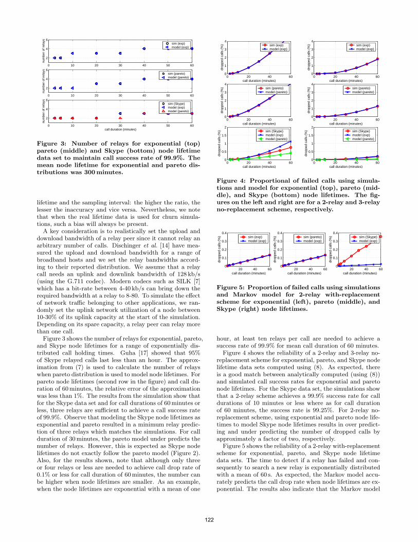
0 10 20 30 40 50 60
2
4
6nu
mbe
r of
rel
ays
sim (exp)model (exp)
0 10 20 30 40 50 60
2
4
6
num
ber
of r
elay
s
sim (pareto)model (pareto)
0 10 20 30 40 50 60
2
4
6
num
ber
of r
elay
s
call duration (minutes)
sim (Skype)model (exp)model (pareto)
Figure 3: Number of relays for exponential (top)pareto (middle) and Skype (bottom) node lifetimedata set to maintain call success rate of 99.9%. Themean node lifetime for exponential and pareto dis-tributions was 300minutes.
lifetime and the sampling interval: the higher the ratio, thelesser the inaccuracy and vice versa. Nevertheless, we notethat when the real lifetime data is used for churn simula-tions, such a bias will always be present.A key consideration is to realistically set the upload and
download bandwidth of a relay peer since it cannot relay anarbitrary number of calls. Dischinger et al. [14] have mea-sured the upload and download bandwidth for a range ofbroadband hosts and we set the relay bandwidths accord-ing to their reported distribution. We assume that a relaycall needs an uplink and downlink bandwidth of 128 kb/s(using the G.711 codec). Modern codecs such as SILK [7]which has a bit-rate between 4-40 kb/s can bring down therequired bandwidth at a relay to 8-80. To simulate the effectof network traffic belonging to other applications, we ran-domly set the uplink network utilization of a node between10-30% of its uplink capacity at the start of the simulation.Depending on its spare capacity, a relay peer can relay morethan one call.Figure 3 shows the number of relays for exponential, pareto,
and Skype node lifetimes for a range of exponentially dis-tributed call holding times. Guha [17] showed that 95%of Skype relayed calls last less than an hour. The approx-imation from (7) is used to calculate the number of relayswhen pareto distribution is used to model node lifetimes. Forpareto node lifetimes (second row in the figure) and call du-ration of 60minutes, the relative error of the approximationwas less than 1%. The results from the simulation show thatfor the Skype data set and for call durations of 60minutes orless, three relays are sufficient to achieve a call success rateof 99.9%. Observe that modeling the Skype node lifetimes asexponential and pareto resulted in a minimum relay predic-tion of three relays which matches the simulations. For callduration of 30minutes, the pareto model under predicts thenumber of relays. However, this is expected as Skype nodelifetimes do not exactly follow the pareto model (Figure 2).Also, for the results shown, note that although only threeor four relays or less are needed to achieve call drop rate of0.1% or less for call duration of 60minutes, the number canbe higher when node lifetimes are smaller. As an example,when the node lifetimes are exponential with a mean of one
0 20 40 600
1
2
3
4
drop
ped
calls
(%
)
call duration (minutes)
sim (exp)model (exp)
0 20 40 600
1
2
3
4
drop
ped
calls
(%
)
call duration (minutes)
sim (exp)model (exp)
0 20 40 600
1
2
3
4
drop
ped
calls
(%
)
call duration (minutes)
sim (pareto)model (pareto)
0 20 40 600
1
2
3
4
drop
ped
calls
(%
)
call duration (minutes)
sim (pareto)model (pareto)
0 20 40 600
0.5
1
1.5
2
drop
ped
calls
(%
)
call duration (minutes)
sim (Skype)model (exp)model (pareto)
0 20 40 600
0.5
1
1.5
2
drop
ped
calls
(%
)
call duration (minutes)
sim (Skype)model (exp)model (pareto)
Figure 4: Proportional of failed calls using simula-tions and model for exponential (top), pareto (mid-dle), and Skype (bottom) node lifetimes. The fig-ures on the left and right are for a 2-relay and 3-relayno-replacement scheme, respectively.
20 40 600
0.1
0.2
0.3
0.4
drop
ped
calls
(%
)
call duration (minutes)
sim (exp)model (exp)
20 40 600
0.1
0.2
0.3
0.4
drop
ped
calls
(%
)call duration (minutes)
sim (pareto)model (exp)
20 40 600
0.1
0.2
0.3
0.4
drop
ped
calls
(%
)
call duration (minutes)
sim (Skype)model (exp)
Figure 5: Proportion of failed calls using simulationsand Markov model for 2-relay with-replacementscheme for exponential (left), pareto (middle), andSkype (right) node lifetimes.
hour, at least ten relays per call are needed to achieve asuccess rate of 99.9% for mean call duration of 60 minutes.
Figure 4 shows the reliability of a 2-relay and 3-relay no-replacement scheme for exponential, pareto, and Skype nodelifetime data sets computed using (8). As expected, thereis a good match between analytically computed (using (8))and simulated call success rates for exponential and paretonode lifetimes. For the Skype data set, the simulations showthat a 2-relay scheme achieves a 99.9% success rate for calldurations of 10 minutes or less where as for call durationof 60 minutes, the success rate is 99.25%. For 2-relay no-replacement scheme, using exponential and pareto node life-times to model Skype node lifetimes results in over predict-ing and under predicting the number of dropped calls byapproximately a factor of two, respectively.
Figure 5 shows the reliability of a 2-relay with-replacementscheme for exponential, pareto, and Skype node lifetimedata sets. The time to detect if a relay has failed and con-sequently to search a new relay is exponentially distributedwith a mean of 60 s. As expected, the Markov model accu-rately predicts the call drop rate when node lifetimes are ex-ponential. The results also indicate that the Markov model
122
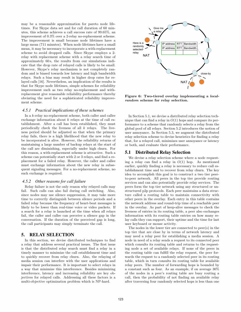
may be a reasonable approximation for pareto node life-times. For Skype data set and for call duration of 60 min-utes, this scheme achieves a call success rate of 99.65%, animprovement of 0.3% over a 2-relay no-replacement scheme.The improvement is small because node lifetimes have alarge mean (711 minutes). When node lifetimes have a smallmean, it may be necessary to incorporate a with-replacementscheme to avoid dropped calls. Since Skype employs a 2-relay with replacement scheme with a relay search time ofapproximately 60 s, the results from our simulations indi-cate that the drop rate of relayed calls is likely to be small.However, Skype’s relay mechanism is not completely ran-dom and is biased towards low latency and high bandwidthrelays. Such a bias may result in higher drop rates for re-layed calls [16]. Nevertheless, an implication of the results isthat for Skype node lifetimes, simple schemes for reliabilityimprovement such as two relay no-replacement and with-replacement give reasonable reliability performance therebyobviating the need for a sophisticated reliability improve-ment scheme.
4.5.1 Practical implications of these schemesIn a k-relay no-replacement scheme, both caller and callee
exchange information about k relays at the time of call es-tablishment. After a call has been established, they mustperiodically check the liveness of all k relays. The live-ness period should be adjusted so that when the primaryrelay fails, there is a high likelihood that the new relay tobe incorporated is alive. However, the reliability returns ofmaintaining a large number of backup relays at the start ofthe call are diminishing, especially under high churn. Forthis reason, a with-replacement scheme is attractive. Such ascheme can potentially start with 2 or 3 relays, and find a re-placement for a failed relay. However, the caller and calleemust exchange information about the new relay in subse-quent signaling messages. For a no-replacement scheme, nosuch exchange is required.
4.5.2 Other reasons for call failureRelay failure is not the only reason why relayed calls may
fail. Such calls can also fail during call switching. Also,since nodes may use silence suppression, it may take moretime to correctly distinguish between silence periods and afailed relay because the frequency of heart-beat messages islikely to be lower than real-time voice or video packets. Ifa search for a relay is launched at the time when all relaysfail, the caller and callee can perceive a silence gap in theconversation. If the duration of the perceived gap is long,the call participants may simply terminate the call.
5. RELAY SELECTIONIn this section, we devise distributed techniques to find
a relay that address several practical issues. The first issueis that the distributed relay search must find a relay in atimely manner to minimize the call establishment time andto quickly recover from relay churn. Also, the relaying ofmedia session can interfere with the user applications andimpair their performance. It is important to select relays ina way that minimize this interference. Besides minimizinginterference, latency and increasing reliability are key ob-jectives for relayed calls. Addressing all these factors is amulti-objective optimization problem which is NP-hard.
IP address
IP address
RTT Bandwidth
RTT Bandwidth
Give me
a relay
Here is a
randomly
selected
relayNAT
NAT
close-by
Figure 6: Two-tiered overlay implementing a local-random scheme for relay selection.
In Section 5.1, we devise a distributed relay selection tech-nique that can find a relay in O(1) hops and compare its per-formance to a scheme that randomly selects a relay from theglobal pool of all relays. Section 5.2 introduces the notion ofuser annoyance. In Section 5.3, we augment the distributedrelay selection scheme to devise heuristics for finding a relaythat, for a relayed call, minimizes user annoyance or latencyor both, and evaluate their performance.
5.1 Distributed Relay SelectionWe devise a relay selection scheme where a node request-
ing a relay can find a relay in O(1) hop. As mentionedearlier, quickly finding a relay is necessary to reduce call es-tablishment time and to recover from relay churn. The keyidea to accomplish this goal is to construct a two tier peer-to-peer network. All peers in the top tier provide routingservices and can also potentially provide relay services. Thepeers form the top tier network using any structured or un-structured p2p protocols. Each peer maintains a data struc-ture called a routing table to maintain connectivity withother peers in the overlay. Each entry in this table containsthe network address and round-trip time of a reachable peerin the overlay. As part of keep-alive messages to check theliveness of entries in its routing table, a peer also exchangesinformation with its routing table entries on how many re-lay calls they can support, their uptime and the time for lastuser keyboard or mouse activity.
The nodes in the lower tier are connected to peer(s) in thetop tier that are close by in terms of network latency andmay need a relay peer for establishing a media session. Anode in need of a relay sends a request to its connected peerwhich consults its routing table and returns to the request-ing node a set of available relays. If none of the peers inthe routing table can fulfill the relay request, the peer for-wards the request to a randomly selected peer in its routingtable, which in turn consults its routing table for availablerelay peers. The number of forwarding hops is bounded bya constant such as four. As an example, if on average 30%of the nodes in a peer’s routing table are busy routing acall, then the probability of not finding an available relayafter traversing four randomly selected hops is less than one
123
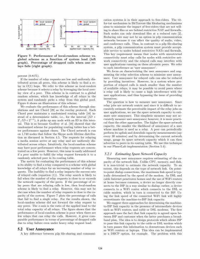
40 50 60 70 80 900
1
2
3
4
5%
sea
rch
faile
d
applied load / capacity (%)
local−randomglobal
40 50 60 70 80 900
0.5
1
1.5
2
% d
ropp
ed c
alls
applied load / capacity (%)
local−randomglobal
Figure 7: Performance of local-random scheme vs.global scheme as a function of system load (leftgraph). Percentage of dropped calls when one re-lays fails (right graph).
percent (0.81%).If the number of relay requests are low and uniformly dis-
tributed across all peers, this scheme is likely to find a re-lay in O(1) hops. We refer to this scheme as local-randomscheme because it selects a relay by leveraging the local over-lay view of a peer. This scheme is in contrast to a globalrandom scheme, which has knowledge of all relays in thesystem and randomly picks a relay from this global pool.Figure 6 shows an illustration of this scheme.We evaluate the performance of this scheme through sim-
ulations and use Chord [28] as the overlay protocol. EachChord peer maintains a randomized routing table [16] in-stead of a deterministic table, i.e., for the interval [ID +2i, ID+2i+1), it picks up any node with an ID in this inter-val. This is so because Godfrey et al. [16] showed that therandomized scheme for populating routing tables has a bet-ter performance against churn. The Chord network is runon 1,740 nodes that follow the Skype node lifetime distribu-tion as discussed in Section 4.5. The requests for relayinga media session arrive at any relay and are uniformly dis-tributed across relays. Intuitively, the local-random schememay have poor performance when relay requests are concen-trated on a few peers. However, this issue is easily addressedif a peer unable to fulfill the relay request forwards it to arandomly selected peer in its routing table.The metric for evaluating the performance of this scheme
is its ability to find a relay compared to a scheme with globalknowledge of all relays for an increasing number of relay re-quests. The inability to find a relay impacts the success rateof relayed calls (equation (1)). The relay search is likely tofail when the number of relay requests is close to or exceedsthe network capacity of the peers. If the percentage of re-lay peers that are relaying calls is low, then local-randomscheme is likely to find a relay. However, this may not bethe case when the number of relay requests is close to the ca-pacity of the system. Figure 7 plots the percentage of callsthat fail to find a single relay. For the results shown, thelocal-random scheme did not forward the relay request toany peers. The x-axis is the ratio of the applied load to thetotal relay capacity of all relays. The figure shows that theperformance of local-random scheme is poor when there arefew relays that can relay the calls. However, it gives com-parable performance in terms of percentage of dropped callsdue to relay failure even under heavy relay request load.
5.2 User AnnoyanceA key difference between p2p file-sharing and communi-
cation systems is in their approach to free-riders. The tit-for-tat mechanism in BitTorrent-like filesharing mechanismsaims to minimize the impact of free-riders that are not will-ing to share files or are behind restrictive NAT and firewalls.Such nodes can only download files at a reduced rate [2].Reducing rate may not be an option in p2p communicationnetworks because it can affect the quality of audio, video,and conference calls. Thus, in contrast to a p2p file-sharingsystem, a p2p communication system must provide accept-able service to nodes behind restrictive NATs and firewalls.This key requirement means that nodes with unrestrictedconnectivity must relay calls for nodes with restrictive net-work connectivity and the relayed calls may interfere withuser applications running on these altruistic peers. We referto such interference as ‘user annoyance’.
We focus on characterizing the user annoyance and aug-menting the relay selection scheme to minimize user annoy-ance. User annoyance for relayed calls can also be reducedby providing incentives. However, in a system where pro-portion of relayed calls is much smaller than the numberof available relays, it may be possible to avoid peers wherea relay call is likely to cause a high interference with theuser applications, and thus bypassing the issue of providingincentives.
The question is how to measure user annoyance. Sincerelay jobs are network centric and since it is difficult to ac-curately estimate the perceivable impact of the relay jobs onuser applications, we use the spare network capacity to esti-mate user annoyance. This simplistic measure may not ac-curately measure user annoyance; however, it is more practi-cal than the other approaches. The higher the spare networkcapacity, the smaller the likelihood of annoyance of a userwhose machine is used as a relay. A peer can periodicallyperform its uplink and downlink capacity measurements (sayevery 30 minutes) and by determining the current networkusage, gauge its spare network capacity which it can thenadvertise to peers in its routing table. We use this techniquein our PlanetLab implementation (Section 5.4).
5.2.1 Estimating Spare Network CapacityMeasuring user annoyance requires estimating of the ca-
pacity of the network link. Unlike CPU, memory, and disk,it is non-trivial to estimate the network capacity. To anextent, this depends on the type of network link. On point-to-point dialup connections, the maximum link speed is typ-ically determined by the speed of the modem. As DSL andcable Internet penetrates homes and the use of WiFi routersat home becomes common, a device no longer directly con-nects to the ISP in a way similar to dialup; rather, a deviceconnects to a WiFi router which connects to the DSL orcable modem, which in turn is connected to the ISP. Us-ing the link speed of the connected WiFi link will highlyoverestimate the machine-to-ISP link capacity.
We suggest three approaches for determining the machine-to-ISP link capacity in the presence of intermediate devicessuch as WiFi routers, and cable or DSL modems. The firstapproach uses the fact that link capacity is agreed upon be-tween ISP and customer when the latter purchases a broad-band plan. The idea is to design protocols which allows ISPto pass this link capacity to the cable or DSL modem whichin turn passes this information to downstream devices suchas WiFi routers or laptops. This idea can be implementedas a DHCP option, for example. The problem with this
124
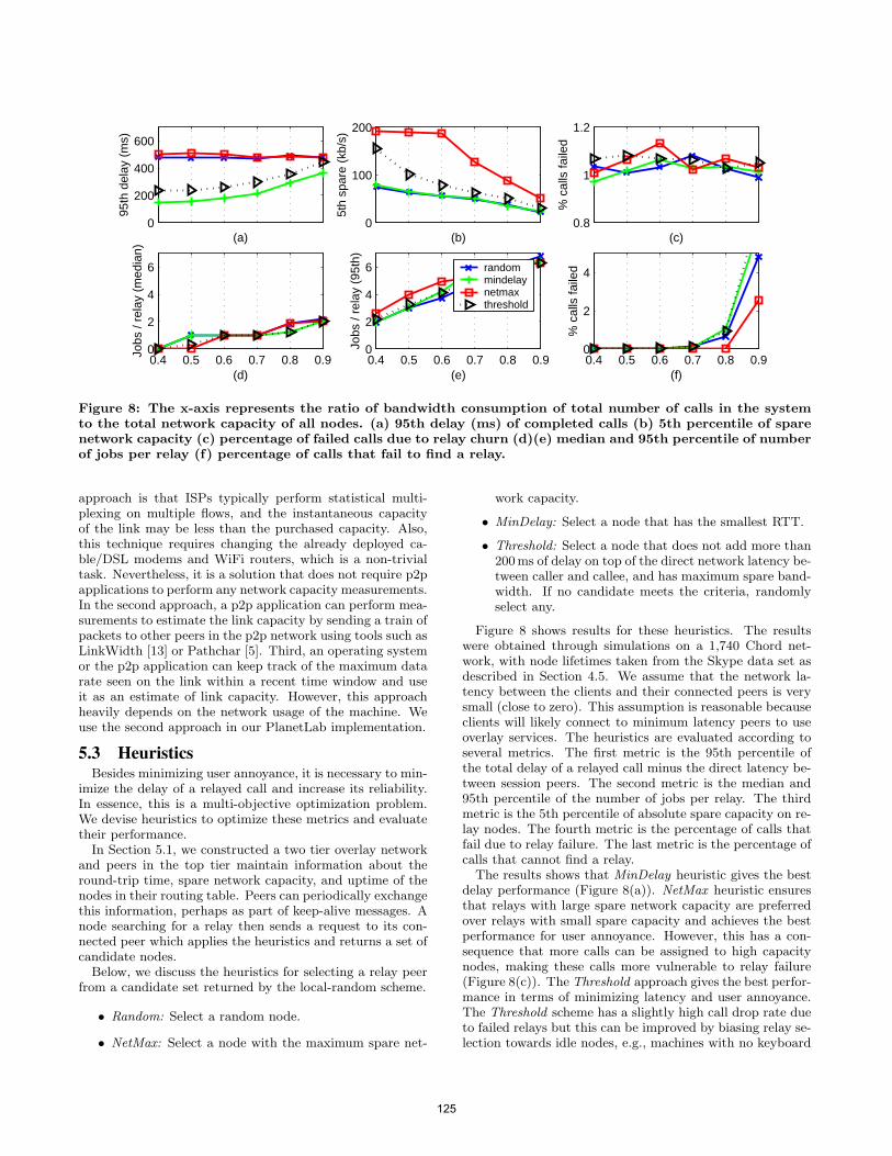
0
200
400
600
95th
del
ay (
ms)
(a)0
100
200
5th
spar
e (k
b/s)
(b)
0.4 0.5 0.6 0.7 0.8 0.90
2
4
6
Jobs
/ re
lay
(med
ian)
(d)0.4 0.5 0.6 0.7 0.8 0.90
2
4
6
Jobs
/ re
lay
(95t
h)
(e)
randommindelaynetmaxthreshold
0.8
1
1.2
% c
alls
faile
d
(c)
0.4 0.5 0.6 0.7 0.8 0.90
2
4
% c
alls
faile
d
(f)
Figure 8: The x-axis represents the ratio of bandwidth consumption of total number of calls in the systemto the total network capacity of all nodes. (a) 95th delay (ms) of completed calls (b) 5th percentile of sparenetwork capacity (c) percentage of failed calls due to relay churn (d)(e) median and 95th percentile of numberof jobs per relay (f) percentage of calls that fail to find a relay.
approach is that ISPs typically perform statistical multi-plexing on multiple flows, and the instantaneous capacityof the link may be less than the purchased capacity. Also,this technique requires changing the already deployed ca-ble/DSL modems and WiFi routers, which is a non-trivialtask. Nevertheless, it is a solution that does not require p2papplications to perform any network capacity measurements.In the second approach, a p2p application can perform mea-surements to estimate the link capacity by sending a train ofpackets to other peers in the p2p network using tools such asLinkWidth [13] or Pathchar [5]. Third, an operating systemor the p2p application can keep track of the maximum datarate seen on the link within a recent time window and useit as an estimate of link capacity. However, this approachheavily depends on the network usage of the machine. Weuse the second approach in our PlanetLab implementation.
5.3 HeuristicsBesides minimizing user annoyance, it is necessary to min-
imize the delay of a relayed call and increase its reliability.In essence, this is a multi-objective optimization problem.We devise heuristics to optimize these metrics and evaluatetheir performance.In Section 5.1, we constructed a two tier overlay network
and peers in the top tier maintain information about theround-trip time, spare network capacity, and uptime of thenodes in their routing table. Peers can periodically exchangethis information, perhaps as part of keep-alive messages. Anode searching for a relay then sends a request to its con-nected peer which applies the heuristics and returns a set ofcandidate nodes.Below, we discuss the heuristics for selecting a relay peer
from a candidate set returned by the local-random scheme.
• Random: Select a random node.
• NetMax: Select a node with the maximum spare net-
work capacity.
• MinDelay: Select a node that has the smallest RTT.
• Threshold: Select a node that does not add more than200ms of delay on top of the direct network latency be-tween caller and callee, and has maximum spare band-width. If no candidate meets the criteria, randomlyselect any.
Figure 8 shows results for these heuristics. The resultswere obtained through simulations on a 1,740 Chord net-work, with node lifetimes taken from the Skype data set asdescribed in Section 4.5. We assume that the network la-tency between the clients and their connected peers is verysmall (close to zero). This assumption is reasonable becauseclients will likely connect to minimum latency peers to useoverlay services. The heuristics are evaluated according toseveral metrics. The first metric is the 95th percentile ofthe total delay of a relayed call minus the direct latency be-tween session peers. The second metric is the median and95th percentile of the number of jobs per relay. The thirdmetric is the 5th percentile of absolute spare capacity on re-lay nodes. The fourth metric is the percentage of calls thatfail due to relay failure. The last metric is the percentage ofcalls that cannot find a relay.
The results shows that MinDelay heuristic gives the bestdelay performance (Figure 8(a)). NetMax heuristic ensuresthat relays with large spare network capacity are preferredover relays with small spare capacity and achieves the bestperformance for user annoyance. However, this has a con-sequence that more calls can be assigned to high capacitynodes, making these calls more vulnerable to relay failure(Figure 8(c)). The Threshold approach gives the best perfor-mance in terms of minimizing latency and user annoyance.The Threshold scheme has a slightly high call drop rate dueto failed relays but this can be improved by biasing relay se-lection towards idle nodes, e.g., machines with no keyboard
125

or mouse activity within a time period. All heuristics havesimilar performance in terms of their ability to find a relayunder increasing load.As mentioned in Section 5.2, spare network capacity is
a simplistic measure to estimate user annoyance. In addi-tion to spare network capacity, machine idle time is a usefulmeasure for relay selection. The idea is to select a relaywith spare capacity that has been idle for sometime. Theuse of idle time as a relay selection metric is motivated bySETI@home project [6]. SETI@home runs compute jobs asa screen saver on idle machines that are distributed aroundthe world. Using this approach in a p2p communication net-work, peers participating in the top-level hierarchy informpeers in their routing table how long they have been idle andwhether they are in the screen saver mode. A node in needof a relay then selects a peer that meets the delay constraint,has been idle, and has the maximum spare capacity.Figure 7 showed that search for relays start to fail when
the requests for relay calls are close to or exceed the totalnetwork capacity of the system. This is unacceptable foran overlay provider like Skype. The only solution for theoverlay provider is to provision the p2p applications withcentralized media relay servers. When nodes establishing amedia session fail to find a relay peer, they send a requestto the media relay server to relay the media session. Sucha hybrid solution is necessary for a commercial p2p VoIPprovider, if it needs to guarantee call establishment whenthere are not enough relays in the system.
5.4 PlanetLab DeploymentTo examine the feasibility of relay selection schemes, we
have implemented the Random and Threshold scheme in ourOpenVoIP [10] system. OpenVoIP is a two-level hierarchi-cal overlay network deployed on PlanetLab that uses theKademlia DHT [26]. We have successfully scaled the top-level network to 1,000 peers that run on 500 PlanetLab ma-chines. Each peer in the top-level network fully participatesin the overlay and can act as a relay peer using TURN pro-tocol [22]. Further, each peer periodically performs uplinkand downlink TCP throughput measurements and sharesthis information with its routing table nodes. Using TCPthroughput provides a conservative estimate of the link ca-pacity than tools such as LinkWidth [13] or Pathchar [5]. Inaddition to sharing its uplink and downlink capacity mea-surements, a peer also shares its uptime with its routingtable nodes. We have integrated p2p functionality with anopen source SIP phone. This P2PSIP phone fully partici-pates in the overlay if it is not behind a NAT or a firewall.Otherwise, it participates as a client. When two P2PSIPphones behind a restrictive NAT cannot establish a mediasession directly, they use a peer in the top-level hierarchy torelay the media session.We have implemented the Random and Threshold scheme
for relay selection. Our implementation of the Thresholdscheme uses delay and spare network capacity metric. Wedo not use a SETI@home like technique for determiningwhether a machine is idle as the PlanetLab machines arenot user desktop machines. The results for the Thresholdscheme indicate that relay selection is biased towards nodeswith maximum spare network capacity and low latency. Wenote that these relayed calls are real voice calls between twoSIP user agents and are not emulated.
6. RELATED WORKThere has been extensive research on constructing prox-
imity aware DHTs [25] and to minimize the impact of churnon DHT routing [16]. Ren et al. [23] showed through mea-surements that many relay peer selections in Skype are suboptimal, waiting time to select a peer can be quite long, andthere are a large number of unnecessary probes. They de-signed an autonomous system aware p2p protocol (ASAP),which considers autonomous systems into peer relay selec-tion. Their approach suffers from three limitations. First,when using DHTs, the network address of all relay peerswithin the same AS can get stored on a single node, cre-ating a single point of failure. Second, their techniques donot incorporate interference of a relay session with the userapplications. This is critical because users will not altru-istically run a p2p application if it actively interferes withtheir applications. Finally, they provide no guidance on howmany relay peers are needed to achieve desired reliability.Leonard et al. [20] analyze node connectivity in DHTs for ex-ponential and pareto residual lifetimes. However, our focusis on charaterizing the reliability of relayed calls. Godfreyet al. [16] analyzed the impact of churn on the DHT routingperformance and suggested techniques to minimize such im-pact. Our relay selection techniques uses their random selec-tion approach. However, it is imperative to explicitly deviseschemes to prevent dropped calls. Tan et al. [30] presentanalysis to improve the reliability of DHT-based multicastby improving its delivery ratio. Delivery ratio is not an ap-propriate metric to for analyzing reliability in peer-to-peercommunication systems.
Connectivity issues due to NAT and firewalls also arisein p2p file sharing networks such as Kazaa [21] and BitTor-rent [1]. BitTorrent allows nodes behind restrictive NATand firewalls to download file chunks, albeit at a lower rate.To improve the download rate, BitTorrent FAQ recommendsusers to configure the ‘port forwarding’ feature of NATs [2].Lowering rate is not an option in p2p communication net-works because it can impact the quality of a call. Further, auser of the p2p communication may find it difficult to con-figure the NAT device and may abandon the p2p applicationin favor of a configuration-less communication application.
7. CONCLUSIONWe have formalized the notion of reliability in peer-to-
peer communication systems and designed a simple analyt-ical model that predicts the reliability of relayed calls asa function of node lifetime and call duration distributions.Our analysis shows that for Skype node lifetimes and for calldurations of 60 minutes or less, at least 2-3 relays are neededto achieve a 99.9% call success rate. We have presentedtwo techniques for relay selection, namely, no-replacementand with-replacement, and used reliability theory to ana-lyze them. We have observed that Skype follows a 2-relaywith-replacement scheme, and it uses periodic recovery toreplace a failed relay, and the search period is more than aminute. Our results indicate that exponential distribution,despite its limitations, is useful in analyzing the reliabilityof relayed calls.
We also introduced the notion of user annoyance whichmeasures the interference of a p2p communication applica-tion relaying a call with other applications running on amachine. We have devised a distributed technique to find
126
a relay in O(1) hop. We augment this technique to find arelay that minimizes the latency of a relayed call and userannoyance. Finally, we have explored the feasibility of ourrelay selection schemes on a 1,000 node peer-to-peer commu-nication system deployed on PlanetLab. In the future, wewill extend our reliability analysis to p2p audio and videoconferencing.
8. REFERENCES[1] BitTorrent [accessed June 2010].
http://www.bittorrent.com/.
[2] BitTorrent FAQ [accessed June 2010].http://dessent.net/btfaq/\#ports.
[3] NAT tester [accessed June, 2010].http://nattest.net.in.tum.de/.
[4] NetPeeker [accessed June 2010].http://www.net-peeker.com/.
[5] Pathchar [accessed June 2010]. http://www.caida.org/tools/utilities/others/pathchar/.
[6] SETI@home [accessed June 2010].http://setiathome.ssl.berkeley.edu/.
[7] Skype Silk codec [accessed June 2010].https://developer.skype.com/silk/.
[8] Vonage [accessed June 2010].http://www.vonage.com/.
[9] S. A. Baset and H. Schulzrinne. An Analysis of theSkype Peer-to-Peer Internet Telephony Protocol. InProc. of IEEE INFOCOM, Barcelona, Spain, April2006.
[10] S. A. Baset and H. Schulzrinne. OpenVoIP: An OpenPeer-to-Peer VoIP and IM System. In Proc. ofSIGCOMM (demo), Seattle, WA, USA, September2008.
[11] A. Birolini. Reliability Engineering: Theory andPractice. Springer-Verlag, 2004.
[12] D. Bryan, P. Matthews, E. Shim, D. Willis, andS. Dawkings. Concepts and Terminology forPeer-to-Peer SIP. Internet draft (work-in-progress),July 2008.
[13] S. Chakravarty, A. Stavrou, and A. Keromytis.LinkWidth: A Method to Measure Link Capacity andAvailable Bandwidth using Single-End Probes.Technical Report (cucs-002-08), Department ofComputer Science, Columbia University, January2008.
[14] M. Dischinger, A. Haeberlen, K. P. Gummadi, andS. Saroiu. Characterizing Residential BroadbandNetworks. In Proc. of IMC, San Diego, California,USA, 2007.
[15] B. Ford, P. Srisuresh, and D. Kegel. Peer-to-PeerCommunication Across Network Address Translators.In Proc. of USENIX Tech. Conf., Anaheim, CA, USA,2005.
[16] P. B. Godfrey, S. Shenker, and I. Stoica. MinimizingChurn in Distributed Systems. In Proc. of SIGCOMM,Pisa, Italy, 2006.
[17] S. Guha, N. Daswani, and R. Jain. An ExperimentalStudy of the Skype Peer-to-Peer VoIP System. InProc. of IPTPS, February 2006.
[18] K. P. Gummadi, S. Saroiu, and S. D. Gribble. King:Estimating Latency Between Arbitrary Internet End
Hosts. SIGCOMM Comput. Commun. Rev.,32(3):11–11, 2002.
[19] W. Kho, S. A. Baset, and H. Schulzrinne. Skype RelayCalls: Measurements and Experiments. In Proc. ofIEEE Global Internet Symposium, Phoenix, AZ, USA,April 2008.
[20] D. Leonard, V. Rai, and D. Loguinov. OnLifetime-based Node Failure and Stochastic Resilienceof Decentralized Peer-to-Peer Networks. In Proc. ofSIGMETRICS, Banf, Alberta, Canada, June 2005.
[21] J. Liang, R. Kumar, and K. Ross. UnderstandingKazaa, 2004.
[22] R. Mahy, P. Matthews, and J. Rosenberg. TraversalUsing Relays around NAT (TURN). Internet draft(work-in-progress), April 2010.
[23] S. Ren, L. Guo, and X. Zhang. ASAP: an AS-AwarePeer-Relay Protocol for High Quality VoIP. In Proc.of ICDCS, Lisbon, Portugal, 2006.
[24] S. Rhea, D. Geels, T. Roscoe, and J. Kubiatowicz.Handling Churn in a DHT. In Proc. of USENIX Tech.Conf., Anaheim, CA, USA, 2004.
[25] S. C. Rhea. OpenDHT: A Public DHT Service. PhDthesis, University of California at Berkeley, Berkeley,CA, USA, 2005.
[26] J. Risson and T. Moors. Survey of Research towardsRobust Peer-to-Peer Networks: Search Methods. RFC4981, September 2007.
[27] J. Rosenberg. Interactive Connectivity Establishment(ICE). RFC 5245, April 2010.
[28] I. Stoica, R. Morris, D. Liben-Nowell, D. Karger,M. F. Kaashoek, F. Dabek, and H. Balakrishnan.Chord: A Scalable Peer-to-peer Lookup Service forInternet Applications. IEEE/ACM Transactions onNetworking, 11(1):17–32, February 2003.
[29] K. Suh, D. R. Figuieredo, J. Kurose, and D. Towsley.Characterizing and Detecting Relayed Traffic: A CaseStudy using Skype. In Proc. of IEEE INFOCOM,Barcelona, Spain, April 2006.
[30] G. Tan and S. A. Jarvis. Stochastic Analysis andImprovement of the Reliability of DHT-BasedMulticast. In Proc. of IEEE INFOCOM, Anchorage,Alaska, May 2007.
[31] X. Wang, Z. Yao, and D. Loguinov. Residual-BasedEstimation of Peer and Link Lifetimes in P2PNetworks. IEEE/ACM Transactions on Networking,17(3):726–739, 2009.
[32] I. V. Zaliapin, Y. Y. Kagan, and F. P. Schoenberg.Approximating the Distribution of Pareto Sums. Pureand Applied Geophysics, May 2005.
127

128
A Virtual and Distributed Control Layer with ProximityAwareness for Group Conferencing in P2PSIP ∗
Alexander Knauf1 Gabriel Hege1 Thomas C. Schmidt1 Matthias Wählisch2
1HAW Hamburg, Dept. Informatik, Berliner Tor 7, D–20099 Hamburg, Germany2Freie Universität Berlin, Inst. für Informatik, Takustr. 9, D–14195 Berlin, Germany
[email protected] [email protected] {t.schmidt,waehlisch}@ieee.org
ABSTRACTThere is an increasing demand to access voice or video groupconferences without the burden of a dedicated infrastruc-ture, but at any place and in an ad hoc fashion. Corre-sponding solutions require a lightweight, fully distributedcooperation among parties that share and manage the con-ference in an efficient, self-adaptive way. The technologyframework of P2PSIP can be seen as a promising startingpoint to meet these objectives. In this paper, we make sev-eral contributions towards such a distributed, virtualizedcontrol layer based on P2PSIP that seamlessly scales andadapts to the user needs. We propose a P2P-signaling pro-tocol scheme for a distributed conference control with SIP,that splits the semantic of Identifier and Locator of a SIPconference URI in a standard-compliant manner. This pro-tocol scheme serves as further basis for a virtualization inRELOAD. We further design and evaluate a self-organizingcommunication layer that provides load sharing and churnresilience with proximity-awareness. Finally, we address keyaspects of security and trust, as well as compatibility forconference unaware clients.
Categories and Subject DescriptorsC.2.2 [Network Protocols]: Applications—SIP ; C.2.4 [Dis-tributed Systems]: Distributed applications—Conferenc-ing
General TermsScalability, Reliability, Security
KeywordsOverlay virtualization, ID locator split, tightly coupled SIPconferencing, distributed conference control
∗This work is supported by the German Min-istry for Research and Education within theprojects Mindstone (http://mindstone.hylos.org) andH∀Mcast (http://hamcast.realmv6.org).
Permission to make digital or hard copies of all or part of this work forpersonal or classroom use is granted without fee provided that copies arenot made or distributed for profit or commercial advantage and that copiesbear this notice and the full citation on the first page. To copy otherwise, torepublish, to post on servers or to redistribute to lists, requires prior specificpermission and/or a fee.IPTComm 2010, 2-3 August, 2010 Munich, GermanyCopyright 2010 ACM ...$5.00.
1. INTRODUCTIONVoice and Video over IP (VVoIP) conference applications
follow a trend to become independent tools driven by endusers, since the capabilities at end systems (CPU, Memory)and the connectivity to broadband Internet are increasingcontinuously. They not only offer an alternative to tradi-tional telephony, but liberate users from provider-bound in-frastructure at common service charges. These changes areeven more visible in the mobile domain with its spread of in-telligent smartphones, and a foreseeable decline of operatorcontrol of end systems. In addition to traditional telecom-munication services, VVoIP deployments open the realm toricher and more flexible use cases such as ad-hoc multi-partyconversations of variable sizes.
Popular lightweight group communicators such as Skype[1] are built from proprietary models and protocols, whilemultiuser multimedia conferencing systems based on the Ses-sion Initiation Protocol (SIP) standard [2] are mainly de-ployed on dedicated server systems. Recent IETF activities,though, emerge to a new, infrastructureless session man-agement using P2PSIP overlays and a control layer thatconverges to the form of REsource LOcation And Discov-ery (RELOAD) [3]. Conferencing solutions built by SIPand non-SIP means are still almost exclusively constructedwith the help of one central conference controller per session,which — in a P2P setup — severely limits scalability andreliability of the application. Distributed conference sessionmanagement has not yet been taken up by the P2PSIP com-munity.
In this paper, we propose a virtual and distributed con-ference management architecture and a protocol that oper-ate in a P2P ad-hoc mode independent of infrastructure.By separating the locator from the identifier of the confer-ence controller, the focus [4] or conference Unified ResourceIdentifier (URI), we show how the multi-party session man-agement can be distributed among multiple peers. We in-troduce a simple routing scheme that transparently guidesconference signaling through the focus cloud, but still re-quires a globally routable physical focus instance for an ini-tial conference contact. To overcome the dependence onindividual peers, we virtualize the focus addressing withinRELOAD. The conference URI, which commonly providesglobal routability to a dedicated focus, is published on theP2PSIP overlay network as a key to several end system de-vices. Further on, the transparent routing is transfered tooperate on a proximity-aware overlay identifier space andgives rise to a self-adaptive tuning of the mutual communi-cation flows.
129
schmitt
Stempel
The overall result of this work is a decentralized server-less system for distributed conference management with SIPcoined DisCo. It solves the open problem of organizing con-ferences in a spontaneous, scalable and robust way basedon the emerging standards of P2PSIP technologies. Eval-uations reveal that the use of proximity-aware identifiersin an adaptive routing lead to a seamless self-organizationwith efficient neighborhood selection in our solution. Thesemechanisms are also designed as base implementations for adistributed media mixing which scales up to a large numberof participants, and remains reliable against node departureor failures.
The remainder of this paper is organized as follows. Sec-tion 2 presents an overview of background technologies andrelated work on the subject, followed by a discussion of thedistributed conferencing problem and its requirements. Ourcore distribution mechanisms for a SIP conference focus areoutlined and evaluated in Section 3. Section 4 is dedicatedto the conference virtualization in P2PSIP and its adoptionof the core distribution scheme; RELOAD usages and kindsare defined here along with the self-organizing procedures,authentication and trust aspects and a protocol evaluation.Finally, Section 5 is dedicated to conclusions and an outlook.
2. DISTRIBUTED CONFERENCING: PROB-LEM STATEMENT & RELATED WORK
2.1 Traditional ConferencingThree models of multi-party communication have been
defined in the discussion process at the IETF. The looselycoupled model does not provide a signaling relationship be-tween conference participants. Membership is achieved byjoining multicast groups and control information are learnedout of band or from the application transport protocol (e.g.,RTCP [5]). In a fully distributed model, each participantsomehow manages a signaling dialog to all other remoteparticipants. Finally, in the tightly coupled model signalingrelationships are established between participants and onecentral point of control, that negotiates media parameters toestablish media sessions. In SIP, this central point of controlis called the focus of a conference [6]. It is identified and lo-cated by a conference-specific SIP URI that must be globallyunique and routable. The first two models are not furtherdefined, leaving details and complexity to further specifica-tions. In the tightly coupled approach, a conference-specificURI will be obtained by querying a dedicated conferencingserver. This allocates and publishes a conference URI (e.g.,sip:[email protected]) and instantiates its correspond-ing focus . The focus then serves as interface towards SIPuser agents that are interested in joining the multimedia ses-sion. In addition to media negotiations, a conference focusmay comprise presence and conference state [7] notificationservices. The focus also enforces a predefined conferencepolicy (e.g., permitted participants) and controls the mediamixing components.
2.2 Peer-to-Peer SIP OverviewThe P2PSIP working group is dedicated to provide a vir-
tualized communication infrastructure for IP-based sessionservices. It decided to rely on a structured peer-to-peer ap-proach. Structured P2P systems are based on DistributedHash Table (DHT) algorithms that can provide resource lo-cation and storage in an application layer overlay network.
The overlay routing and data storage efforts are equally dis-tributed among the participating peers and scales up to avery high number of joining nodes. The benefits of DHTsoriginate form its performance properties of typically O(log(N))routing hops on average, and for a requirement of O(log(N))routing table entries per node, where N is the number ofoverlay members. DHTs such as Chord, Pastry, CAN, andKademlia [8, 9, 10, 11] have proved for their distributed, ro-bust and scalable characteristics and now experience a widerdeployment in various file sharing applications (e.g., BitTor-rent [12]).
Proximity Aware Overlays.Overlay network identifier are typically generated from
hash-functions (e.g., SHA1 in Chord) for maintaining a uni-form flat address space. These IDs normally do not haveany relation to relative network positions of a nodes in theunderlay. Numerical neighbors in the overlay can be phys-ically far apart. Improved structuring of P2P overlays [13,14] therefore may account for proximity information. Oneclass of approaches is built from landmarks. To determinethe relative network position p of a node, the round-triptimes (RTT) are measured against a fixed set of well knownlandmarks l0, l1, .., ln. These measurement results will beordered according to the landmark index with the result ofa landmark vector < l1, l2, .., l3 >. Thereafter, the entireaddress space will be divide into equally sized regions. Thedefinition of a region depends on the DHT and its addressstructure in use. The ring-type address space like in Chordcan be cut into equal slices; subtrees in Pastry can define aregion or an n-dimensional space in CAN. Each landmarkvector permutation produces exactly one related region. Anode then joins the overlay at a ’random’ point in the re-gion, that belongs to its landmark vector permutation. Anode may then be assigned to a relative position according toits overlay ID, since every node has constructed its ID usingthe same calculations. A disadvantage of this ID construc-tion is caused by an uneven population of the address space.This may cause peers to become responsible for much largeraddress ranges than others. Load-balancing algorithms canhandle this problem by relocating responsibilities for overlayspaces to less loaded peers.
Other approaches construct mappings between overlay IDsand position information that are stored in the overlay. As-suming the relative position p for node-ID IDn, then p′ =hash(IDn) is an overlay identifier, for position p of node n.Node n will then be mapped with p′ into the overlay region,stored on the node that is responsible for this address range.The nodes n1 and n2 are close to each other if the differenceof |p1 − p2| is low, with p1 and p2 were retrieved by a lookupoperation on p1
′ and p2′.
P2PSIP approaches.Traditional SIP-oriented service architectures depend on
proxy servers that assist in call routing, user location, NATand Firewall traversal, as well as additional functionalities.This orientation on static infrastructure limits deploymentand motivates approaches to relocate the proxy roles intoa P2P overlay for SIP sessions. Peers query the overlay byusing a P2P signaling protocol, and may contact an addressof the desired user agent without further hindrance. Coreprocedures for call establishment should still be achieved byusing standard SIP mechanisms. K. Singh et al. [15] and D.
130
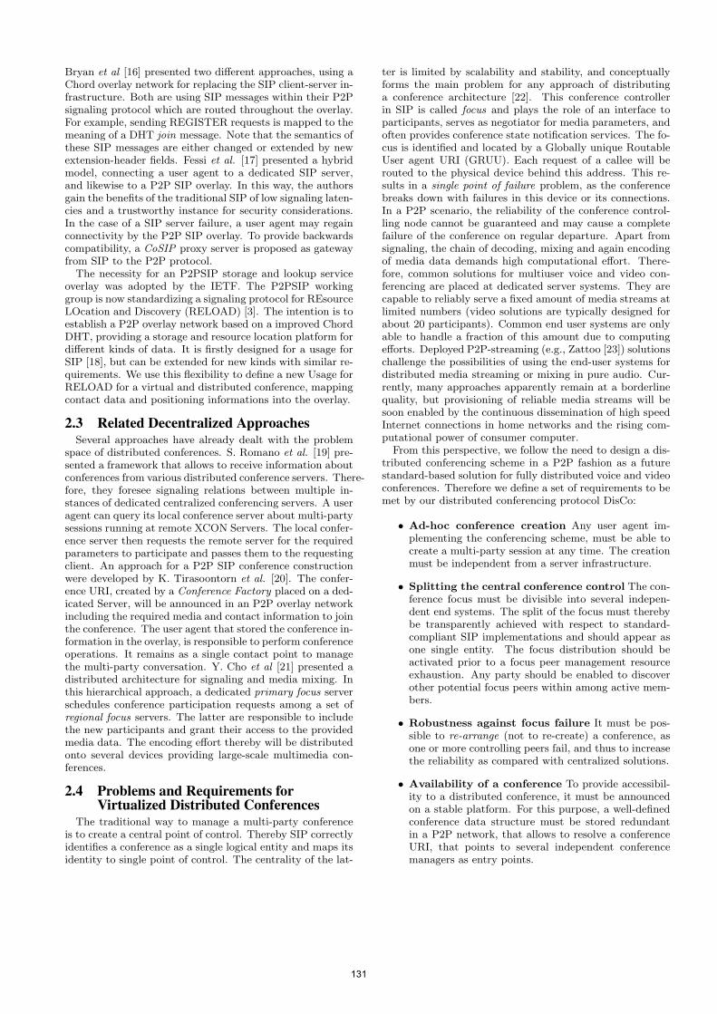
Bryan et al [16] presented two different approaches, using aChord overlay network for replacing the SIP client-server in-frastructure. Both are using SIP messages within their P2Psignaling protocol which are routed throughout the overlay.For example, sending REGISTER requests is mapped to themeaning of a DHT join message. Note that the semantics ofthese SIP messages are either changed or extended by newextension-header fields. Fessi et al. [17] presented a hybridmodel, connecting a user agent to a dedicated SIP server,and likewise to a P2P SIP overlay. In this way, the authorsgain the benefits of the traditional SIP of low signaling laten-cies and a trustworthy instance for security considerations.In the case of a SIP server failure, a user agent may regainconnectivity by the P2P SIP overlay. To provide backwardscompatibility, a CoSIP proxy server is proposed as gatewayfrom SIP to the P2P protocol.
The necessity for an P2PSIP storage and lookup serviceoverlay was adopted by the IETF. The P2PSIP workinggroup is now standardizing a signaling protocol for REsourceLOcation and Discovery (RELOAD) [3]. The intention is toestablish a P2P overlay network based on a improved ChordDHT, providing a storage and resource location platform fordifferent kinds of data. It is firstly designed for a usage forSIP [18], but can be extended for new kinds with similar re-quirements. We use this flexibility to define a new Usage forRELOAD for a virtual and distributed conference, mappingcontact data and positioning informations into the overlay.
2.3 Related Decentralized ApproachesSeveral approaches have already dealt with the problem
space of distributed conferences. S. Romano et al. [19] pre-sented a framework that allows to receive information aboutconferences from various distributed conference servers. There-fore, they foresee signaling relations between multiple in-stances of dedicated centralized conferencing servers. A useragent can query its local conference server about multi-partysessions running at remote XCON Servers. The local confer-ence server then requests the remote server for the requiredparameters to participate and passes them to the requestingclient. An approach for a P2P SIP conference constructionwere developed by K. Tirasoontorn et al. [20]. The confer-ence URI, created by a Conference Factory placed on a ded-icated Server, will be announced in an P2P overlay networkincluding the required media and contact information to jointhe conference. The user agent that stored the conference in-formation in the overlay, is responsible to perform conferenceoperations. It remains as a single contact point to managethe multi-party conversation. Y. Cho et al [21] presented adistributed architecture for signaling and media mixing. Inthis hierarchical approach, a dedicated primary focus serverschedules conference participation requests among a set ofregional focus servers. The latter are responsible to includethe new participants and grant their access to the providedmedia data. The encoding effort thereby will be distributedonto several devices providing large-scale multimedia con-ferences.
2.4 Problems and Requirements forVirtualized Distributed Conferences
The traditional way to manage a multi-party conferenceis to create a central point of control. Thereby SIP correctlyidentifies a conference as a single logical entity and maps itsidentity to single point of control. The centrality of the lat-
ter is limited by scalability and stability, and conceptuallyforms the main problem for any approach of distributinga conference architecture [22]. This conference controllerin SIP is called focus and plays the role of an interface toparticipants, serves as negotiator for media parameters, andoften provides conference state notification services. The fo-cus is identified and located by a Globally unique RoutableUser agent URI (GRUU). Each request of a callee will berouted to the physical device behind this address. This re-sults in a single point of failure problem, as the conferencebreaks down with failures in this device or its connections.In a P2P scenario, the reliability of the conference control-ling node cannot be guaranteed and may cause a completefailure of the conference on regular departure. Apart fromsignaling, the chain of decoding, mixing and again encodingof media data demands high computational effort. There-fore, common solutions for multiuser voice and video con-ferencing are placed at dedicated server systems. They arecapable to reliably serve a fixed amount of media streams atlimited numbers (video solutions are typically designed forabout 20 participants). Common end user systems are onlyable to handle a fraction of this amount due to computingefforts. Deployed P2P-streaming (e.g., Zattoo [23]) solutionschallenge the possibilities of using the end-user systems fordistributed media streaming or mixing in pure audio. Cur-rently, many approaches apparently remain at a borderlinequality, but provisioning of reliable media streams will besoon enabled by the continuous dissemination of high speedInternet connections in home networks and the rising com-putational power of consumer computer.
From this perspective, we follow the need to design a dis-tributed conferencing scheme in a P2P fashion as a futurestandard-based solution for fully distributed voice and videoconferences. Therefore we define a set of requirements to bemet by our distributed conferencing protocol DisCo:
• Ad-hoc conference creation Any user agent im-plementing the conferencing scheme, must be able tocreate a multi-party session at any time. The creationmust be independent from a server infrastructure.
• Splitting the central conference control The con-ference focus must be divisible into several indepen-dent end systems. The split of the focus must therebybe transparently achieved with respect to standard-compliant SIP implementations and should appear asone single entity. The focus distribution should beactivated prior to a focus peer management resourceexhaustion. Any party should be enabled to discoverother potential focus peers within among active mem-bers.
• Robustness against focus failure It must be pos-sible to re-arrange (not to re-create) a conference, asone or more controlling peers fail, and thus to increasethe reliability as compared with centralized solutions.
• Availability of a conference To provide accessibil-ity to a distributed conference, it must be announcedon a stable platform. For this purpose, a well-definedconference data structure must be stored redundantin a P2P network, that allows to resolve a conferenceURI, that points to several independent conferencemanagers as entry points.
131
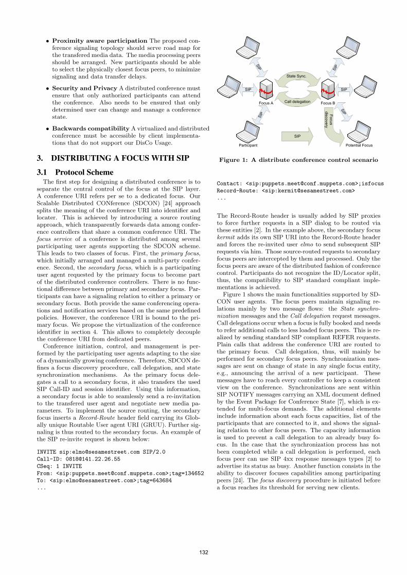
• Proximity aware participation The proposed con-ference signaling topology should serve road map forthe transfered media data. The media processing peersshould be arranged. New participants should be ableto select the physically closest focus peers, to minimizesignaling and data transfer delays.
• Security and Privacy A distributed conference mustensure that only authorized participants can attendthe conference. Also needs to be ensured that onlydetermined user can change and manage a conferencestate.
• Backwards compatibility A virtualized and distributedconference must be accessible by client implementa-tions that do not support our DisCo Usage.
3. DISTRIBUTING A FOCUS WITH SIP
3.1 Protocol SchemeThe first step for designing a distributed conference is to
separate the central control of the focus at the SIP layer.A conference URI refers per se to a dedicated focus. OurScalable Distributed CONference (SDCON) [24] approachsplits the meaning of the conference URI into identifier andlocater. This is achieved by introducing a source routingapproach, which transparently forwards data among confer-ence controllers that share a common conference URI. Thefocus service of a conference is distributed among severalparticipating user agents supporting the SDCON scheme.This leads to two classes of focus. First, the primary focus,which initially arranged and managed a multi-party confer-ence. Second, the secondary focus, which is a participatinguser agent requested by the primary focus to become partof the distributed conference controllers. There is no func-tional difference between primary and secondary focus. Par-ticipants can have a signaling relation to either a primary orsecondary focus. Both provide the same conferencing opera-tions and notification services based on the same predefinedpolicies. However, the conference URI is bound to the pri-mary focus. We propose the virtualization of the conferenceidentifier in section 4. This allows to completely decouplethe conference URI from dedicated peers.
Conference initiation, control, and management is per-formed by the participating user agents adapting to the sizeof a dynamically growing conference. Therefore, SDCON de-fines a focus discovery procedure, call delegation, and statesynchronization mechanisms. As the primary focus dele-gates a call to a secondary focus, it also transfers the usedSIP Call-ID and session identifier. Using this information,a secondary focus is able to seamlessly send a re-invitationto the transfered user agent and negotiate new media pa-rameters. To implement the source routing, the secondaryfocus inserts a Record-Route header field carrying its Glob-ally unique Routable User agent URI (GRUU). Further sig-naling is thus routed to the secondary focus. An example ofthe SIP re-invite request is shown below:
INVITE sip:[email protected] SIP/2.0
Call-ID: [email protected]
CSeq: 1 INVITE
From: <sip:[email protected]>;tag=134652
To: <sip:[email protected]>;tag=643684
...
Participant Potential Focus
SIPSIP
SIP
SIP
SIP
SIP
State Sync.
Call delegation
Focus discovery
Focus A Focus B
SIP
Figure 1: A distribute conference control scenario
Contact: <sip:[email protected]>;isfocus
Record-Route: <sip:[email protected]>
...
The Record-Route header is usually added by SIP proxiesto force further requests in a SIP dialog to be routed viathese entities [2]. In the example above, the secondary focuskermit adds its own SIP URI into the Record-Route headerand forces the re-invited user elmo to send subsequent SIPrequests via him. Those source-routed requests to secondaryfocus peers are intercepted by them and processed. Only thefocus peers are aware of the distributed fashion of conferencecontrol. Participants do not recognize the ID/Locator split,thus, the compatibility to SIP standard compliant imple-mentations is achieved.
Figure 1 shows the main functionalities supported by SD-CON user agents. The focus peers maintain signaling re-lations mainly by two message flows: the State synchro-nization messages and the Call delegation request messages.Call delegations occur when a focus is fully booked and needsto refer additional calls to less loaded focus peers. This is re-alized by sending standard SIP compliant REFER requests.Plain calls that address the conference URI are routed tothe primary focus. Call delegation, thus, will mainly beperformed for secondary focus peers. Synchronization mes-sages are sent on change of state in any single focus entity,e.g., announcing the arrival of a new participant. Thesemessages have to reach every controller to keep a consistentview on the conference. Synchronizations are sent withinSIP NOTIFY messages carrying an XML document definedby the Event Package for Conference State [7], which is ex-tended for multi-focus demands. The additional elementsinclude information about each focus capacities, list of theparticipants that are connected to it, and shows the signal-ing relation to other focus peers. The capacity informationis used to prevent a call delegation to an already busy fo-cus. In the case that the synchronization process has notbeen completed while a call delegation is performed, eachfocus peer can use SIP 4xx response messages types [2] toadvertise its status as busy. Another function consists in theability to discover focuses capabilities among participatingpeers [24]. The focus discovery procedure is initiated beforea focus reaches its threshold for serving new clients.
132
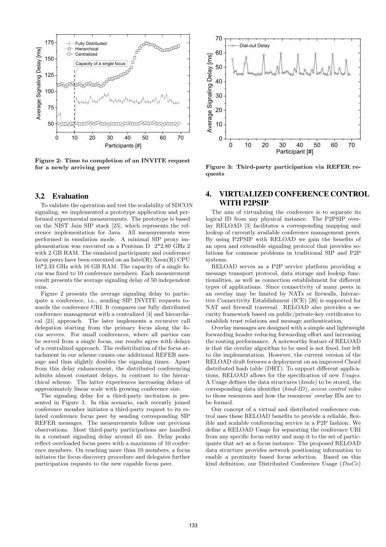
0 1 0 2 0 3 0 4 0 5 0 6 0 7 05 0
7 5
1 0 0
1 2 5
1 5 0
1 7 5Av
erage
Sign
aling D
elay [
ms]
P a r t i c i p a n t s [ # ]
F u l l y D i s t r i b u t e d H i e r a r c h i c a l C e n t r a l i z e dC a p a c i t y o f a s i n g l e f o c u s
Figure 2: Time to completion of an INVITE requestfor a newly arriving peer
3.2 EvaluationTo validate the operation and test the scalability of SDCON
signaling, we implemented a prototype application and per-formed experimental measurements. The prototype is basedon the NIST Jain SIP stack [25], which represents the ref-erence implementation for Java. All measurements wereperformed in emulation mode. A minimal SIP proxy im-plementation was executed on a Pentium D 2*2.80 GHz 2with 2 GB RAM. The emulated participants and conferencefocus peers have been executed on an Intel(R) Xeon(R) CPU16*2.33 GHz with 16 GB RAM. The capacity of a single fo-cus was fixed to 10 conference members. Each measurementresult presents the average signaling delay of 50 independentruns.
Figure 2 presents the average signaling delay to partic-ipate a conference, i.e., sending SIP INVITE requests to-wards the conference URI. It compares our fully distributedconference management with a centralized [4] and hierarchi-cal [21] approach. The later implements a recursive calldelegation starting from the primary focus along the fo-cus servers. For small conferences, where all parties canbe served from a single focus, our results agree with delaysof a centralized approach. The redistribution of the focus at-tachment in our scheme causes one additional REFER mes-sage and thus slightly doubles the signaling times. Apartfrom this delay enhancement, the distributed conferencingadmits almost constant delays, in contrast to the hierar-chical scheme. The latter experiences increasing delays ofapproximately linear scale with growing conference size.
The signaling delay for a third-party invitation is pre-sented in Figure 3. In this scenario, each recently joinedconference member initiates a third-party request to its re-lated conference focus peer by sending corresponding SIPREFER messages. The measurements follow our previousobservations. Most third-party participations are handledin a constant signaling delay around 45 ms. Delay peaksreflect overloaded focus peers with a maximum of 10 confer-ence members. On reaching more than 10 members, a focusinitiates the focus discovery procedure and delegates furtherparticipation requests to the new capable focus peer.
0 1 0 2 0 3 0 4 0 5 0 6 0 7 00
1 02 03 04 05 06 07 0
Avera
ge Si
gnalin
g Dela
y [ms
]
P a r t i c i p a n t [ # ]
D i a l - o u t D e l a y
Figure 3: Third-party participation via REFER re-quests
4. VIRTUALIZED CONFERENCE CONTROLWITH P2PSIP
The aim of virtualizing the conference is to separate itslogical ID from any physical instance. The P2PSIP over-lay RELOAD [3] facilitates a corresponding mapping andlookup of currently available conference management peers.By using P2PSIP with RELOAD we gain the benefits ofan open and extensible signaling protocol that provides so-lutions for common problems in traditional SIP and P2Psystems.
RELOAD serves as a P2P service platform providing amessage transport protocol, data storage and lookup func-tionalities, as well as connection establishment for differenttypes of applications. Since connectivity of many peers inan overlay may be limited by NATs or firewalls, Interac-tive Connectivity Establishment (ICE) [26] is supported forNAT and firewall traversal. RELOAD also provides a se-curity framework based on public/private-key certificates toestablish trust relations and message authentication.
Overlay messages are designed with a simple and lightweightforwarding header reducing forwarding effort and increasingthe routing performance. A noteworthy feature of RELOADis that the overlay algorithm to be used is not fixed, but leftto the implementation. However, the current version of theRELOAD draft foresees a deployment on an improved Chorddistributed hash table (DHT). To support different applica-tions, RELOAD allows for the specification of new Usages.A Usage defines the data structures (kinds) to be stored, thecorresponding data identifier (kind-ID), access control rulesto those resources and how the resources’ overlay IDs are tobe formed.
Our concept of a virtual and distributed conference con-trol uses these RELOAD benefits to provide a reliable, flex-ible and scalable conferencing service in a P2P fashion. Wedefine a RELOAD Usage for separating the conference URIfrom any specific focus entity and map it to the set of partic-ipants that act as a focus instance. The proposed RELOADdata structure provides network positioning information toenable a proximity based focus selection. Based on thiskind definition, our Distributed Conference Usage (DisCo)
133
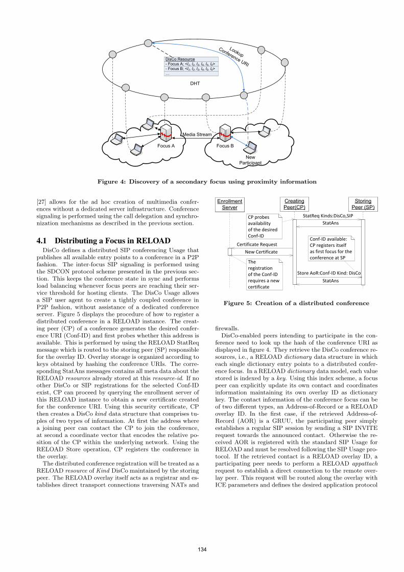
DisCo Resource- Focus A; <l1, l2, l3, l4, l5, l6>- Focus B; <l1, l2, l3, l4, l5, l6>…
New Participant
DHT
Focus B
Lookup Conference URI
Media Stream
Focus A
Figure 4: Discovery of a secondary focus using proximity information
[27] allows for the ad hoc creation of multimedia confer-ences without a dedicated server infrastructure. Conferencesignaling is performed using the call delegation and synchro-nization mechanisms as described in the previous section.
4.1 Distributing a Focus in RELOADDisCo defines a distributed SIP conferencing Usage that
publishes all available entry points to a conference in a P2Pfashion. The inter-focus SIP signaling is performed usingthe SDCON protocol scheme presented in the previous sec-tion. This keeps the conference state in sync and performsload balancing whenever focus peers are reaching their ser-vice threshold for hosting clients. The DisCo Usage allowsa SIP user agent to create a tightly coupled conference inP2P fashion, without assistance of a dedicated conferenceserver. Figure 5 displays the procedure of how to register adistributed conference in a RELOAD instance. The creat-ing peer (CP) of a conference generates the desired confer-ence URI (Conf-ID) and first probes whether this address isavailable. This is performed by using the RELOAD StatReqmessage which is routed to the storing peer (SP) responsiblefor the overlay ID. Overlay storage is organized according tokeys obtained by hashing the conference URIs. The corre-sponding StatAns messages contains all meta data about theRELOAD resources already stored at this resource-id. If noother DisCo or SIP registrations for the selected Conf-IDexist, CP can proceed by querying the enrollment server ofthis RELOAD instance to obtain a new certificate createdfor the conference URI. Using this security certificate, CPthen creates a DisCo kind data structure that comprises tu-ples of two types of information. At first the address wherea joining peer can contact the CP to join the conference,at second a coordinate vector that encodes the relative po-sition of the CP within the underlying network. Using theRELOAD Store operation, CP registers the conference inthe overlay.
The distributed conference registration will be treated as aRELOAD resource of Kind DisCo maintained by the storingpeer. The RELOAD overlay itself acts as a registrar and es-tablishes direct transport connections traversing NATs and
CP probes availabilityof the desired Conf‐ID
Conf‐ID available:CP registers itselfas first focus for theconference at SP
The registrationof the Conf‐IDrequires a newcertificate
StatReq Kinds:DisCo,SIPStatAns
Certificate Request
New Certificate
Store AoR:Conf‐ID Kind: DisCo
StatAns
Figure 5: Creation of a distributed conference
firewalls.DisCo-enabled peers intending to participate in the con-
ference need to look up the hash of the conference URI asdisplayed in figure 4. They retrieve the DisCo conference re-sources, i.e., a RELOAD dictionary data structure in whicheach single dictionary entry points to a distributed confer-ence focus. In a RELOAD dictionary data model, each valuestored is indexed by a key. Using this index scheme, a focuspeer can explicitly update its own contact and coordinatesinformation maintaining its own overlay ID as dictionarykey. The contact information of the conference focus can beof two different types, an Address-of-Record or a RELOADoverlay ID. In the first case, if the retrieved Address-of-Record (AOR) is a GRUU, the participating peer simplyestablishes a regular SIP session by sending a SIP INVITErequest towards the announced contact. Otherwise the re-ceived AOR is registered with the standard SIP Usage forRELOAD and must be resolved following the SIP Usage pro-tocol. If the retrieved contact is a RELOAD overlay ID, aparticipating peer needs to perform a RELOAD appattachrequest to establish a direct connection to the remote over-lay peer. This request will be routed along the overlay withICE parameters and defines the desired application protocol
134
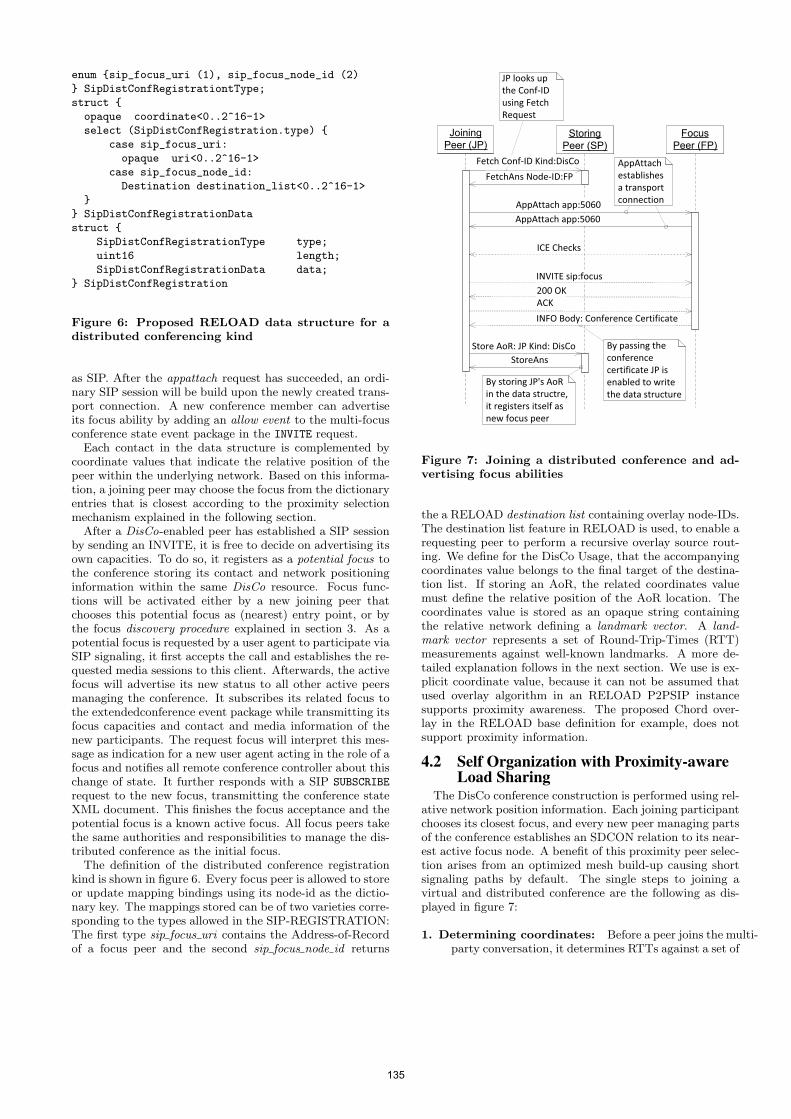
enum {sip_focus_uri (1), sip_focus_node_id (2)
} SipDistConfRegistrationtType;
struct {
opaque coordinate<0..2^16-1>
select (SipDistConfRegistration.type) {
case sip_focus_uri:
opaque uri<0..2^16-1>
case sip_focus_node_id:
Destination destination_list<0..2^16-1>
}
} SipDistConfRegistrationData
struct {
SipDistConfRegistrationType type;
uint16 length;
SipDistConfRegistrationData data;
} SipDistConfRegistration
Figure 6: Proposed RELOAD data structure for adistributed conferencing kind
as SIP. After the appattach request has succeeded, an ordi-nary SIP session will be build upon the newly created trans-port connection. A new conference member can advertiseits focus ability by adding an allow event to the multi-focusconference state event package in the INVITE request.
Each contact in the data structure is complemented bycoordinate values that indicate the relative position of thepeer within the underlying network. Based on this informa-tion, a joining peer may choose the focus from the dictionaryentries that is closest according to the proximity selectionmechanism explained in the following section.
After a DisCo-enabled peer has established a SIP sessionby sending an INVITE, it is free to decide on advertising itsown capacities. To do so, it registers as a potential focus tothe conference storing its contact and network positioninginformation within the same DisCo resource. Focus func-tions will be activated either by a new joining peer thatchooses this potential focus as (nearest) entry point, or bythe focus discovery procedure explained in section 3. As apotential focus is requested by a user agent to participate viaSIP signaling, it first accepts the call and establishes the re-quested media sessions to this client. Afterwards, the activefocus will advertise its new status to all other active peersmanaging the conference. It subscribes its related focus tothe extendedconference event package while transmitting itsfocus capacities and contact and media information of thenew participants. The request focus will interpret this mes-sage as indication for a new user agent acting in the role of afocus and notifies all remote conference controller about thischange of state. It further responds with a SIP SUBSCRIBE
request to the new focus, transmitting the conference stateXML document. This finishes the focus acceptance and thepotential focus is a known active focus. All focus peers takethe same authorities and responsibilities to manage the dis-tributed conference as the initial focus.
The definition of the distributed conference registrationkind is shown in figure 6. Every focus peer is allowed to storeor update mapping bindings using its node-id as the dictio-nary key. The mappings stored can be of two varieties corre-sponding to the types allowed in the SIP-REGISTRATION:The first type sip focus uri contains the Address-of-Recordof a focus peer and the second sip focus node id returns
By passing theconference certificate JP isenabled to write the data structure
AppAttach establishes a transport connection
JP looks upthe Conf�IDusing FetchRequest
By storing JP's AoR in the data structre, it registers itself as new focus peer
Fetch Conf�ID Kind:DisCo
FetchAns Node�ID:FP
AppAttach app:5060AppAttach app:5060
ICE Checks
INVITE sip:focus
INFO Body: Conference Certificate
ACK200 OK
Store AoR: JP Kind: DisCoStoreAns
Figure 7: Joining a distributed conference and ad-vertising focus abilities
the a RELOAD destination list containing overlay node-IDs.The destination list feature in RELOAD is used, to enable arequesting peer to perform a recursive overlay source rout-ing. We define for the DisCo Usage, that the accompanyingcoordinates value belongs to the final target of the destina-tion list. If storing an AoR, the related coordinates valuemust define the relative position of the AoR location. Thecoordinates value is stored as an opaque string containingthe relative network defining a landmark vector. A land-mark vector represents a set of Round-Trip-Times (RTT)measurements against well-known landmarks. A more de-tailed explanation follows in the next section. We use is ex-plicit coordinate value, because it can not be assumed thatused overlay algorithm in an RELOAD P2PSIP instancesupports proximity awareness. The proposed Chord over-lay in the RELOAD base definition for example, does notsupport proximity information.
4.2 Self Organization with Proximity-awareLoad Sharing
The DisCo conference construction is performed using rel-ative network position information. Each joining participantchooses its closest focus, and every new peer managing partsof the conference establishes an SDCON relation to its near-est active focus node. A benefit of this proximity peer selec-tion arises from an optimized mesh build-up causing shortsignaling paths by default. The single steps to joining avirtual and distributed conference are the following as dis-played in figure 7:
1. Determining coordinates: Before a peer joins the multi-party conversation, it determines RTTs against a set of
135
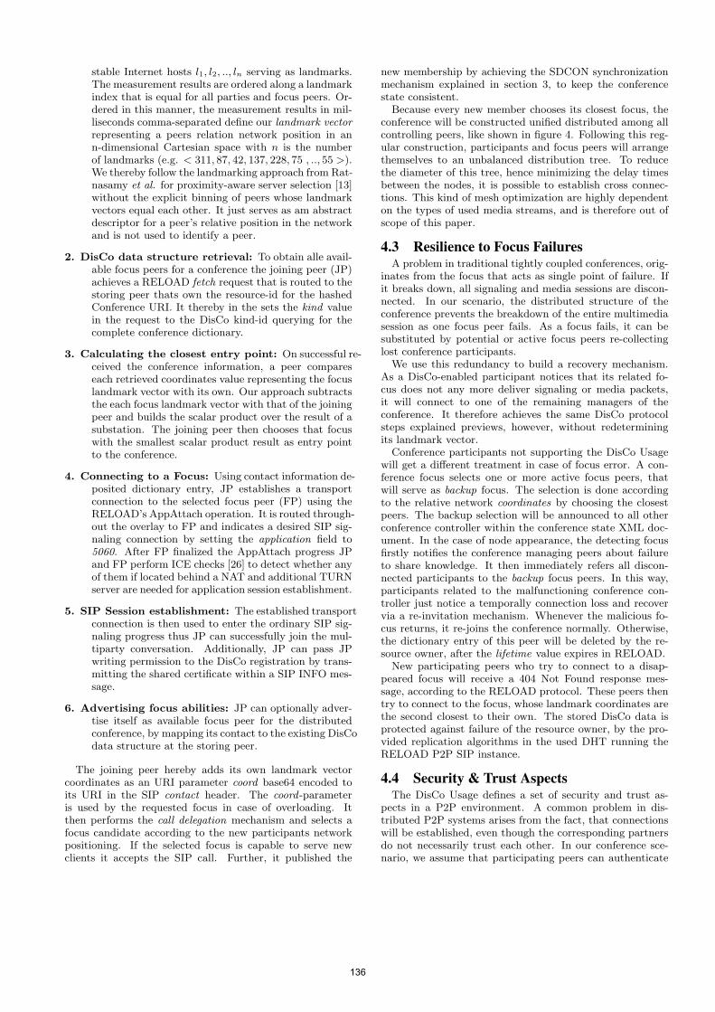
stable Internet hosts l1, l2, .., ln serving as landmarks.The measurement results are ordered along a landmarkindex that is equal for all parties and focus peers. Or-dered in this manner, the measurement results in mil-liseconds comma-separated define our landmark vectorrepresenting a peers relation network position in ann-dimensional Cartesian space with n is the numberof landmarks (e.g. < 311, 87, 42, 137, 228, 75 , .., 55 >).We thereby follow the landmarking approach from Rat-nasamy et al. for proximity-aware server selection [13]without the explicit binning of peers whose landmarkvectors equal each other. It just serves as am abstractdescriptor for a peer’s relative position in the networkand is not used to identify a peer.
2. DisCo data structure retrieval: To obtain alle avail-able focus peers for a conference the joining peer (JP)achieves a RELOAD fetch request that is routed to thestoring peer thats own the resource-id for the hashedConference URI. It thereby in the sets the kind valuein the request to the DisCo kind-id querying for thecomplete conference dictionary.
3. Calculating the closest entry point: On successful re-ceived the conference information, a peer compareseach retrieved coordinates value representing the focuslandmark vector with its own. Our approach subtractsthe each focus landmark vector with that of the joiningpeer and builds the scalar product over the result of asubstation. The joining peer then chooses that focuswith the smallest scalar product result as entry pointto the conference.
4. Connecting to a Focus: Using contact information de-posited dictionary entry, JP establishes a transportconnection to the selected focus peer (FP) using theRELOAD’s AppAttach operation. It is routed through-out the overlay to FP and indicates a desired SIP sig-naling connection by setting the application field to5060. After FP finalized the AppAttach progress JPand FP perform ICE checks [26] to detect whether anyof them if located behind a NAT and additional TURNserver are needed for application session establishment.
5. SIP Session establishment: The established transportconnection is then used to enter the ordinary SIP sig-naling progress thus JP can successfully join the mul-tiparty conversation. Additionally, JP can pass JPwriting permission to the DisCo registration by trans-mitting the shared certificate within a SIP INFO mes-sage.
6. Advertising focus abilities: JP can optionally adver-tise itself as available focus peer for the distributedconference, by mapping its contact to the existing DisCodata structure at the storing peer.
The joining peer hereby adds its own landmark vectorcoordinates as an URI parameter coord base64 encoded toits URI in the SIP contact header. The coord-parameteris used by the requested focus in case of overloading. Itthen performs the call delegation mechanism and selects afocus candidate according to the new participants networkpositioning. If the selected focus is capable to serve newclients it accepts the SIP call. Further, it published the
new membership by achieving the SDCON synchronizationmechanism explained in section 3, to keep the conferencestate consistent.
Because every new member chooses its closest focus, theconference will be constructed unified distributed among allcontrolling peers, like shown in figure 4. Following this reg-ular construction, participants and focus peers will arrangethemselves to an unbalanced distribution tree. To reducethe diameter of this tree, hence minimizing the delay timesbetween the nodes, it is possible to establish cross connec-tions. This kind of mesh optimization are highly dependenton the types of used media streams, and is therefore out ofscope of this paper.
4.3 Resilience to Focus FailuresA problem in traditional tightly coupled conferences, orig-
inates from the focus that acts as single point of failure. Ifit breaks down, all signaling and media sessions are discon-nected. In our scenario, the distributed structure of theconference prevents the breakdown of the entire multimediasession as one focus peer fails. As a focus fails, it can besubstituted by potential or active focus peers re-collectinglost conference participants.
We use this redundancy to build a recovery mechanism.As a DisCo-enabled participant notices that its related fo-cus does not any more deliver signaling or media packets,it will connect to one of the remaining managers of theconference. It therefore achieves the same DisCo protocolsteps explained previews, however, without redeterminingits landmark vector.
Conference participants not supporting the DisCo Usagewill get a different treatment in case of focus error. A con-ference focus selects one or more active focus peers, thatwill serve as backup focus. The selection is done accordingto the relative network coordinates by choosing the closestpeers. The backup selection will be announced to all otherconference controller within the conference state XML doc-ument. In the case of node appearance, the detecting focusfirstly notifies the conference managing peers about failureto share knowledge. It then immediately refers all discon-nected participants to the backup focus peers. In this way,participants related to the malfunctioning conference con-troller just notice a temporally connection loss and recovervia a re-invitation mechanism. Whenever the malicious fo-cus returns, it re-joins the conference normally. Otherwise,the dictionary entry of this peer will be deleted by the re-source owner, after the lifetime value expires in RELOAD.
New participating peers who try to connect to a disap-peared focus will receive a 404 Not Found response mes-sage, according to the RELOAD protocol. These peers thentry to connect to the focus, whose landmark coordinates arethe second closest to their own. The stored DisCo data isprotected against failure of the resource owner, by the pro-vided replication algorithms in the used DHT running theRELOAD P2P SIP instance.
4.4 Security & Trust AspectsThe DisCo Usage defines a set of security and trust as-
pects in a P2P environment. A common problem in dis-tributed P2P systems arises from the fact, that connectionswill be established, even though the corresponding partnersdo not necessarily trust each other. In our conference sce-nario, we assume that participating peers can authenticate
136
each other in person based on the received voice and videotransmissions. Built on this, we introduce a graduated trustdelegation system for distributed conferences.
RELOAD provides a set of access control policies, definingwhether a peer is allowed to perform a certain store requestor not. For our distributed conferencing resource, we usethe defined user-match access policy. Each stored data canbe written if the request is signed with a key associated witha certificate whose hashed user name equals the resource’soverlay ID. Since our DisCo resource needs to be updatedby multiple peers, using the user-node-match policy used bythe SIP Usage for RELOAD is not an option. We use ourtrust delegation mechanism, allowing peers to obtain writeaccess to the shared resource. To receive write permissionsfor the distributed conference overlay resource, the privatekey for the certificate of the stored resource will be trans-mitted within a SIP INFO message to allowed focus peers.Using this key, a user is able to authenticate itself againstthe owner of the conference data structure, and can registeras potential focus.
On conference creation, the initiating peer can setup thedistributed conference policy for a layered authentication.In an open access model, every peer interested to join theconference can do so by just inviting one of the multi-partyfocus peers. No authentication is required for participat-ing. An open access model may be suitable for a groupconversation of public interest, for example a political de-bate. Because in this open model, an attacker could easilybecome a focus peer and send malicious packages, we definean open access focus authenticate model. The conferenceinitiator can specify that peers wanting to become a focusneed to authenticate themselves using any of the standardauthentication mechanisms allowed in SIP. The correspond-ing credentials need to be transmitted to those peers bya non-SIP, non-overlay mechanism. As a new participantinvites the conference, it uses ordinary SIP authorization.After validation of the presented credentials the called focusis then allowed to pass the conference’s certificate key to therecently joined conference member. To create a closed multi-media conference, it is also possible to set an authenticationscheme required for participation in a closed access model.Thus, only users who present valid authorization credentialsare allowed to join. By combining the closed access and thefocus authenticate model, our layered access model definesdifferent permissions for clients joining the conference onlyand peers that are allowed to become focus, dependent ontheir credentials. Focus peers obtain the information neededto validate participants’ credentials within the conferenceXML document (e.g. a conference password or certificate),to be able to authorize new members. The used access modelwill be stored in the conference state XML extension, thusevery controlling peer is aware of the used access model.
Providing these access layers, a user initiating a conferenceis able to setup its desired privacy policies for the multi-partyconversation. It can be suggested, that in closed conferencesan unknown conference member will be detected by the par-ticipating users, for example by not recognizing its voice oroutwards appearance in video. Those unsuspected users canbe excluded by a conference focus peer by disconnecting sig-naling and media sessions.
4.5 Supporting Conference-unaware PartiesParticipation a virtual and distributed conference is not
be exclusive for those peers that implemented our RELOADUsage definition. Standard compliant participation is trans-parently provided to peers unaware of the distributed con-ference construction. This section describes the backwardcompatibility to user applications implementing the SIP Us-age [18] for RELOAD, and describes how connectivity toSIP-only user agents is achieved.
The SIP Usage for RELOAD defines a kind data structurefor storing an AoR for a SIP user agent. It likewise uses thedestination list feature in RELOAD and provides the stor-age of GRUUs as contact addresses for SIP session establish-ment. To provide backward compatibility to RELOAD peersonly implementing the SIP Usage, a conference initiator candecide to register the conference URI as SIP-Registrationkind parallel to the DisCo kind. The SIP Usage registrationis then performed using the destination list feature, register-ing the amount of active and potential focus peers as entriesin the destination list. Peers attending to join requesting re-solving conference URI using SIP-Registration kind-ID, re-trieve the destination list containing the conference entrypoints. The connection to a conference focus then will beachieved in accordance with the SIP Usage. Those peers willnot be aware of the distributed structure of the multi-partyconversation.
Because the SIP usage for RELOAD access model is user-node-match, other focus peers will not be able to updatethe stored data. The conference initiator must update theSIP-Registration kind continuously, on appearance or disap-pearance of focus peers. Hence, it depends to the conferenceinitiator to keep the destination list up to date and valid.To achieve maximal accessibility in the case that the lat-ter permanently leaves the multi-party conversation, it hasto set the lifetime value on a high level. By just using theSIP-registration kind, conference joins can not be performedunder proximity selection. However, a conference createdwith DisCo can provide access to the multi-party, althougha client does not implement our usage.
The participation for ordinary SIP user agents is per-formed by another mechanism. Since a virtualized confer-ence URI is stored in a RELOAD overlay, a standard SIPuser agent can not resolve it with traditional mechanismsand a direct participation is not possible. Instead, partic-ipation will be achieved through third-party initiated fromwithin the conference. An established multi-party memberrequests its related focus to invite the new attendees sendingSIP REFER requests. By using the protocol mechanisms fortransparent focus distribution explained in section 3, the re-quested conference manager invites the new attendee send-ing a SIP INVITE request.
4.6 EvaluationTo verify our concept of the proximity-aware focus se-
lection, we conducted experimental measurements based onthe PlanetLab platform [28]. PlanetLab nodes are globallydistributed and thus allows for geographically placement ofconference peers. Although this real-world experimental fa-cility is biased in the sense that significant nodes are lo-cated at well-connected university networks, it gives a goodapproximation of delay characteristics for this part of theInternet.
137
CAIDA Monitor Location
mnl-ph.ark.caida.orgnrt-jp.ark.caida.org ASIAshe-cn.ark.caida.orgdub-ie.ark.caida.orglej-de.ark.caida.org Europeher-gr.ark.caida.orgpna-es.ark.caida.orgsea-us.ark.caida.orgmty-mx.ark.caida.orgamw-us.ark.caida.org North Americayto-ca.ark.caida.orgwbu-us.ark.caida.orghlz-nz.ark.caida.org Oceaniagig-br.ark.caida.org South Americascl-cl.ark.caida.org
Table 1: Selected landmark nodes chosen fromCAIDA measurement monitors
Experimental SetupThe experiment considers small and medium size confer-ences. The principle setup is the following: We deployedDisCo on a varying number of peers chosen from a prede-fined subset of all PlanetLab nodes. These peers create focusinstances and corresponding relationships based on the land-marking approach described in section 4.2. Relative networkpositions are determined using 15 landmark nodes outsideof the PlanetLab system. The experiment is conducted untilmeasurements are converged.
100 nodes are selected from the overall PlanetLab nodesto create the list of potential DisCo peers. To mitigate localsystem disturbances, we included only hosts that exhibit anappropriate system load. The selected nodes are locatedin Asia, Europe, South and North America to emulate aglobally distributed conference and observe long range delayeffects.
In general, the quality of landmark approaches depends onan appropriate number of landmark nodes and their place-ment. However, there is no common sense on the num-ber of dimensions to create a coordinate system [29]. Theymay range typically of 7 to 9 [30], but also depend on thedataset. In order to evaluate proximity-awareness for an al-most generic scenario with respect to the selected DisCopeer, i.e., without any dedicated landmark optimization,15 landmarks are chosen from the set of CAIDA [31] mon-itor points (cf. Table 1). This has two advantages: First,CAIDA monitors are globally reachable and not located be-hind NATs or firewalls, which is important and a realistic de-ployment assumption for landmark nodes. Second, they areglobally distributed covering different geographic locations.The landmark selection process omits suspicious nodes thatreply unusually on ICMP echos.
Performance MetricsWe analyze the quality of our proximity-aware self organi-zation of (focus) peers based on the following metrics:
Degree corresponds to the number of neighbors. Nodesthat have a degree of 1 only participate in the con-ference without replicate data. Nodes with a largerdegree operate as focus. This metric, thus, reflects
1 2 3 4 5 6 7 8 9 1 0 1 1 1 20 , 0
0 , 1
0 , 2
0 , 3
0 , 4
0 , 5
0 , 6
<Rela
tive Fr
eque
ncy>
D e g r e e [ # N e i g h b o r s ]
L a n d m a r k R a n d o m O p t i m a l
1 2 3 4 5 6 7 8 91 E - 3
0 , 0 1
0 , 1
1
Figure 8: Degree distribution
implicitly the load on a peer.
Delay Stretch measures the ratio of the average delay causedby the overlay and the average delay using native dis-tribution. It follows the idea of the relative averagedelay (RAD) defined by Castro et al. [32]. This met-ric represents the relative delay penalty.
Foci Ratio describes the ratio of overlay peers that attainthe role of a focus. This metric quantifies the distri-bution of conference management load among peers.
The results are compared with a complete random selec-tion of focus nodes, and an optimal solution of the focus andpeer topology.
ResultsThe degree distribution of inter-peer relations was measuredand displayed in Figure 8. For all schemes, the majority ofnodes are single-attached and thus pure leafe nodes. Fo-cus nodes that exhibit a degree ≥ 2 dominantly admit lowdegrees and thus suffer little load of packet replication andforwarding. More significantly and clearly visible from theinsert, the probability of higher degrees exponentially de-creases leaving negligible weight to the occurrence of over-loaded peers or unsuitable conferencing demands.
A more sensitive measure on detailed conference perfor-mance is given by the delays imposed mutually related peerneighborhoods on the overlay. Figure 9 compares the aver-age delay stretch of our landmarking scheme with a randomneighbor selection and the optimal set-up. While a routingvia arbitrary conference neighbors in our global conferenceevaluation may lead to alienating delay enhancements of 15to 30 times, our landmarking scheme remains within favor-able bounds around 2 to 3, which is very close to the opti-mal solution. Most importantly, the delay stretch remainsconstant with respect to the numbers of conferencing par-ties and thus promotes arbitrary scalability of our proposedadaptive self-organization scheme. It should be noted thatrandomized neighbor selection leads to a linearly increasingstretch.
Finally, we examine the relative portion of peers that at-tain the role of a conference controller assuming the absence
138
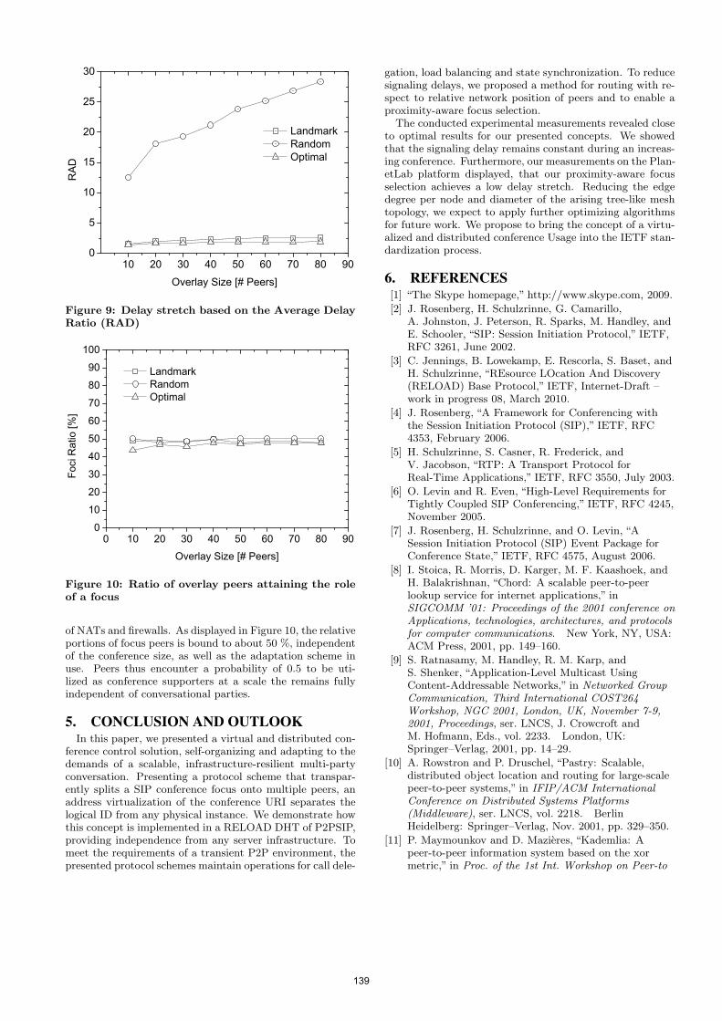
1 0 2 0 3 0 4 0 5 0 6 0 7 0 8 0 9 00
5
1 0
1 5
2 0
2 5
3 0RA
D
O v e r l a y S i z e [ # P e e r s ]
L a n d m a r k R a n d o m O p t i m a l
Figure 9: Delay stretch based on the Average DelayRatio (RAD)
0 1 0 2 0 3 0 4 0 5 0 6 0 7 0 8 0 9 00
1 02 03 04 05 06 07 08 09 0
1 0 0
Foci R
atio [
%]
O v e r l a y S i z e [ # P e e r s ]
L a n d m a r k R a n d o m O p t i m a l
Figure 10: Ratio of overlay peers attaining the roleof a focus
of NATs and firewalls. As displayed in Figure 10, the relativeportions of focus peers is bound to about 50 %, independentof the conference size, as well as the adaptation scheme inuse. Peers thus encounter a probability of 0.5 to be uti-lized as conference supporters at a scale the remains fullyindependent of conversational parties.
5. CONCLUSION AND OUTLOOKIn this paper, we presented a virtual and distributed con-
ference control solution, self-organizing and adapting to thedemands of a scalable, infrastructure-resilient multi-partyconversation. Presenting a protocol scheme that transpar-ently splits a SIP conference focus onto multiple peers, anaddress virtualization of the conference URI separates thelogical ID from any physical instance. We demonstrate howthis concept is implemented in a RELOAD DHT of P2PSIP,providing independence from any server infrastructure. Tomeet the requirements of a transient P2P environment, thepresented protocol schemes maintain operations for call dele-
gation, load balancing and state synchronization. To reducesignaling delays, we proposed a method for routing with re-spect to relative network position of peers and to enable aproximity-aware focus selection.
The conducted experimental measurements revealed closeto optimal results for our presented concepts. We showedthat the signaling delay remains constant during an increas-ing conference. Furthermore, our measurements on the Plan-etLab platform displayed, that our proximity-aware focusselection achieves a low delay stretch. Reducing the edgedegree per node and diameter of the arising tree-like meshtopology, we expect to apply further optimizing algorithmsfor future work. We propose to bring the concept of a virtu-alized and distributed conference Usage into the IETF stan-dardization process.
6. REFERENCES[1] “The Skype homepage,” http://www.skype.com, 2009.
[2] J. Rosenberg, H. Schulzrinne, G. Camarillo,A. Johnston, J. Peterson, R. Sparks, M. Handley, andE. Schooler, “SIP: Session Initiation Protocol,” IETF,RFC 3261, June 2002.
[3] C. Jennings, B. Lowekamp, E. Rescorla, S. Baset, andH. Schulzrinne, “REsource LOcation And Discovery(RELOAD) Base Protocol,” IETF, Internet-Draft –work in progress 08, March 2010.
[4] J. Rosenberg, “A Framework for Conferencing withthe Session Initiation Protocol (SIP),” IETF, RFC4353, February 2006.
[5] H. Schulzrinne, S. Casner, R. Frederick, andV. Jacobson, “RTP: A Transport Protocol forReal-Time Applications,” IETF, RFC 3550, July 2003.
[6] O. Levin and R. Even, “High-Level Requirements forTightly Coupled SIP Conferencing,” IETF, RFC 4245,November 2005.
[7] J. Rosenberg, H. Schulzrinne, and O. Levin, “ASession Initiation Protocol (SIP) Event Package forConference State,” IETF, RFC 4575, August 2006.
[8] I. Stoica, R. Morris, D. Karger, M. F. Kaashoek, andH. Balakrishnan, “Chord: A scalable peer-to-peerlookup service for internet applications,” inSIGCOMM ’01: Proceedings of the 2001 conference onApplications, technologies, architectures, and protocolsfor computer communications. New York, NY, USA:ACM Press, 2001, pp. 149–160.
[9] S. Ratnasamy, M. Handley, R. M. Karp, andS. Shenker, “Application-Level Multicast UsingContent-Addressable Networks,” in Networked GroupCommunication, Third International COST264Workshop, NGC 2001, London, UK, November 7-9,2001, Proceedings, ser. LNCS, J. Crowcroft andM. Hofmann, Eds., vol. 2233. London, UK:Springer–Verlag, 2001, pp. 14–29.
[10] A. Rowstron and P. Druschel, “Pastry: Scalable,distributed object location and routing for large-scalepeer-to-peer systems,” in IFIP/ACM InternationalConference on Distributed Systems Platforms(Middleware), ser. LNCS, vol. 2218. BerlinHeidelberg: Springer–Verlag, Nov. 2001, pp. 329–350.
[11] P. Maymounkov and D. Mazieres, “Kademlia: Apeer-to-peer information system based on the xormetric,” in Proc. of the 1st Int. Workshop on Peer-to
139
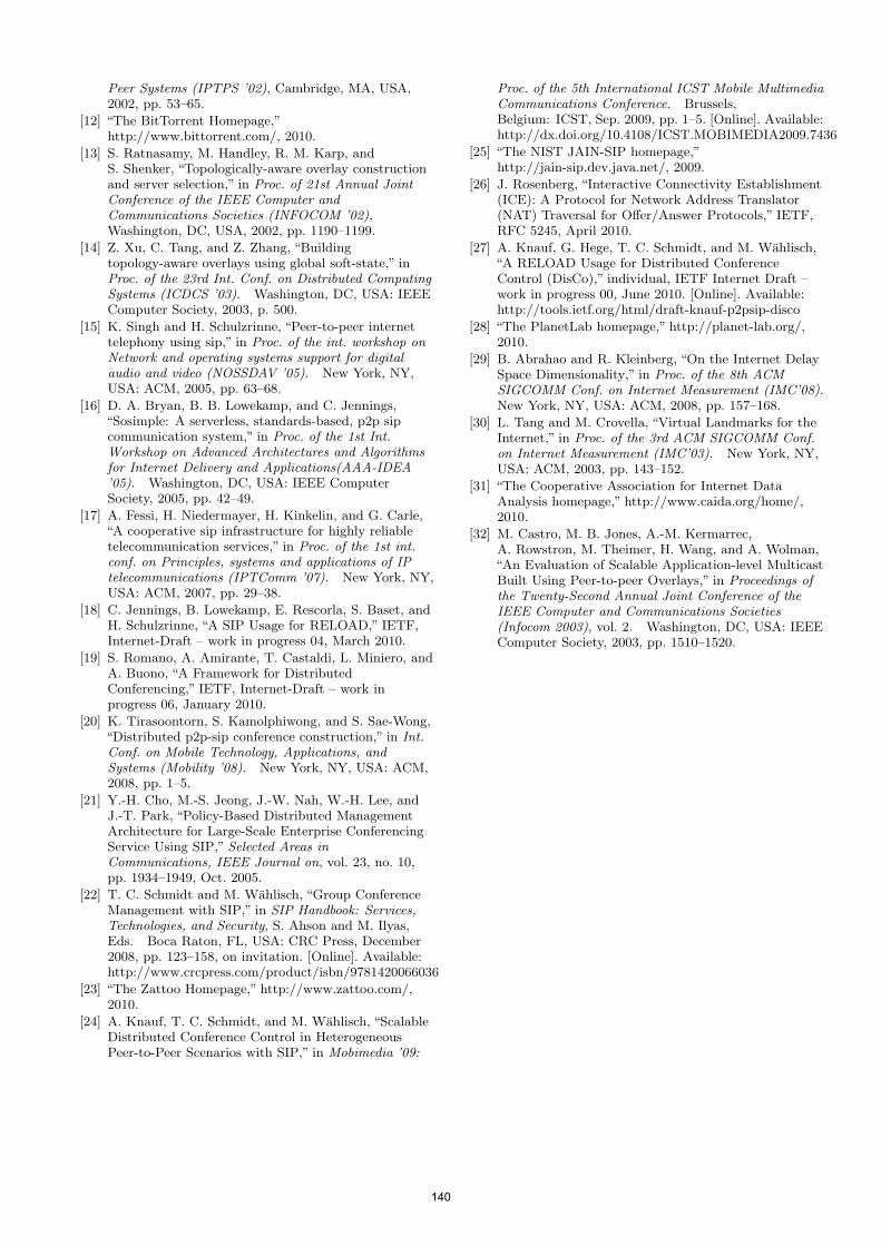
Peer Systems (IPTPS ’02), Cambridge, MA, USA,2002, pp. 53–65.
[12] “The BitTorrent Homepage,”http://www.bittorrent.com/, 2010.
[13] S. Ratnasamy, M. Handley, R. M. Karp, andS. Shenker, “Topologically-aware overlay constructionand server selection,” in Proc. of 21st Annual JointConference of the IEEE Computer andCommunications Societies (INFOCOM ’02),Washington, DC, USA, 2002, pp. 1190–1199.
[14] Z. Xu, C. Tang, and Z. Zhang, “Buildingtopology-aware overlays using global soft-state,” inProc. of the 23rd Int. Conf. on Distributed ComputingSystems (ICDCS ’03). Washington, DC, USA: IEEEComputer Society, 2003, p. 500.
[15] K. Singh and H. Schulzrinne, “Peer-to-peer internettelephony using sip,” in Proc. of the int. workshop onNetwork and operating systems support for digitalaudio and video (NOSSDAV ’05). New York, NY,USA: ACM, 2005, pp. 63–68.
[16] D. A. Bryan, B. B. Lowekamp, and C. Jennings,“Sosimple: A serverless, standards-based, p2p sipcommunication system,” in Proc. of the 1st Int.Workshop on Advanced Architectures and Algorithmsfor Internet Delivery and Applications(AAA-IDEA’05). Washington, DC, USA: IEEE ComputerSociety, 2005, pp. 42–49.
[17] A. Fessi, H. Niedermayer, H. Kinkelin, and G. Carle,“A cooperative sip infrastructure for highly reliabletelecommunication services,” in Proc. of the 1st int.conf. on Principles, systems and applications of IPtelecommunications (IPTComm ’07). New York, NY,USA: ACM, 2007, pp. 29–38.
[18] C. Jennings, B. Lowekamp, E. Rescorla, S. Baset, andH. Schulzrinne, “A SIP Usage for RELOAD,” IETF,Internet-Draft – work in progress 04, March 2010.
[19] S. Romano, A. Amirante, T. Castaldi, L. Miniero, andA. Buono, “A Framework for DistributedConferencing,” IETF, Internet-Draft – work inprogress 06, January 2010.
[20] K. Tirasoontorn, S. Kamolphiwong, and S. Sae-Wong,“Distributed p2p-sip conference construction,” in Int.Conf. on Mobile Technology, Applications, andSystems (Mobility ’08). New York, NY, USA: ACM,2008, pp. 1–5.
[21] Y.-H. Cho, M.-S. Jeong, J.-W. Nah, W.-H. Lee, andJ.-T. Park, “Policy-Based Distributed ManagementArchitecture for Large-Scale Enterprise ConferencingService Using SIP,” Selected Areas inCommunications, IEEE Journal on, vol. 23, no. 10,pp. 1934–1949, Oct. 2005.
[22] T. C. Schmidt and M. Wahlisch, “Group ConferenceManagement with SIP,” in SIP Handbook: Services,Technologies, and Security, S. Ahson and M. Ilyas,Eds. Boca Raton, FL, USA: CRC Press, December2008, pp. 123–158, on invitation. [Online]. Available:http://www.crcpress.com/product/isbn/9781420066036
[23] “The Zattoo Homepage,” http://www.zattoo.com/,2010.
[24] A. Knauf, T. C. Schmidt, and M. Wahlisch, “ScalableDistributed Conference Control in HeterogeneousPeer-to-Peer Scenarios with SIP,” in Mobimedia ’09:
Proc. of the 5th International ICST Mobile MultimediaCommunications Conference. Brussels,Belgium: ICST, Sep. 2009, pp. 1–5. [Online]. Available:http://dx.doi.org/10.4108/ICST.MOBIMEDIA2009.7436
[25] “The NIST JAIN-SIP homepage,”http://jain-sip.dev.java.net/, 2009.
[26] J. Rosenberg, “Interactive Connectivity Establishment(ICE): A Protocol for Network Address Translator(NAT) Traversal for Offer/Answer Protocols,” IETF,RFC 5245, April 2010.
[27] A. Knauf, G. Hege, T. C. Schmidt, and M. Wahlisch,“A RELOAD Usage for Distributed ConferenceControl (DisCo),” individual, IETF Internet Draft –work in progress 00, June 2010. [Online]. Available:http://tools.ietf.org/html/draft-knauf-p2psip-disco
[28] “The PlanetLab homepage,” http://planet-lab.org/,2010.
[29] B. Abrahao and R. Kleinberg, “On the Internet DelaySpace Dimensionality,” in Proc. of the 8th ACMSIGCOMM Conf. on Internet Measurement (IMC’08).New York, NY, USA: ACM, 2008, pp. 157–168.
[30] L. Tang and M. Crovella, “Virtual Landmarks for theInternet,” in Proc. of the 3rd ACM SIGCOMM Conf.on Internet Measurement (IMC’03). New York, NY,USA: ACM, 2003, pp. 143–152.
[31] “The Cooperative Association for Internet DataAnalysis homepage,” http://www.caida.org/home/,2010.
[32] M. Castro, M. B. Jones, A.-M. Kermarrec,A. Rowstron, M. Theimer, H. Wang, and A. Wolman,“An Evaluation of Scalable Application-level MulticastBuilt Using Peer-to-peer Overlays,” in Proceedings ofthe Twenty-Second Annual Joint Conference of theIEEE Computer and Communications Societies(Infocom 2003), vol. 2. Washington, DC, USA: IEEEComputer Society, 2003, pp. 1510–1520.
140
Pr2-P2PSIP: Privacy PreservingP2P Signaling for VoIP and IM
Ali Fessi, Nathan Evans, Heiko Niedermayer, Ralph HolzTechnische Universität München
Boltzmannstrasse 3Munich, Germany
{fessi|evans|niedermayer|holz}@net.in.tum.de
ABSTRACTIn the last few years, there has been a good deal of ef-fort put into the research and standardization of P2P-basedVoIP signaling, commonly called P2PSIP. However, therehas been one important issue which has not been dealt withadequately, privacy. Specifically i) location privacy, and ii)privacy of social interaction in terms of who is communicat-ing with whom. In this paper, we present Pr2-P2PSIP , aPrivacy-Preserving P2PSIP signaling protocol for VoIP andIM. Our contribution is primarily a feasibility study tacklingthe privacy issues inherent in P2PSIP. We leverage stan-dard security protocols as well as concepts and experienceslearned from other anonymization networks such as Tor andI2P where applicable. We present the design and on-goingimplementation of Pr2-P2PSIP and provide a threat analy-sis as well as an analysis of the overhead of adding privacyto P2PSIP networks. Particularly we analyze cryptographicoverhead, signaling latency and reliability costs.
Categories and Subject DescriptorsC.2 [Network Architecture and Design]: Miscellaneous;K.4.1 [ Public Policy Issues]: Privacy
General TermsPrivacy, anonymization, Peer-to-Peer(P2P), Session Initia-tion Protocol (SIP)
KeywordsP2P signaling, P2PSIP, location privacy, social interactionprivacy, onion routing, reliability costs
1. INTRODUCTIONThe Session Initiation Protocol (SIP) [30] is a protocol
standardized by the IETF for setting up multimedia ses-sions, in particular Voice over IP (VoIP) sessions. It canalso be used for Instant Messaging (IM) [29]. There has
Permission to make digital or hard copies of all or part of this work forpersonal or classroom use is granted without fee provided that copies arenot made or distributed for profit or commercial advantage and that copiesbear this notice and the full citation on the first page. To copy otherwise, torepublish, to post on servers or to redistribute to lists, requires prior specificpermission and/or a fee.IPTComm 2010, 2-3 August, 2010 Munich, GermanyCopyright 2010 ACM ...$10.00.
been a lot of effort in research and standardization in thelast few years related to P2PSIP [6]. The concept behindP2PSIP is that the location of a SIP User Agent (UA) (IPaddress and port number) is published not to a SIP Regis-trar, but in a Distributed Hash Table (DHT). This data isstored at other peers with peer identifiers (IDs) uncorrelatedto the SIP UA. These peers, called replica nodes, reply toqueries from any other peer looking for the UA. This makesthe UA available for incoming VoIP phone calls and chatmessages. However, the SIP UA has no control over know-ing which peers have asked for its current location. Curiousand malicious peers can perform a lookup for the SIP URI ofthe UA regularly. The IP addresses of the UA could then bemapped to geographic locations [1]. Using this information,attackers could build location profiles of a user. Even worse,attackers could “crawl” the P2PSIP network and harvest lo-cation profiles of all participants. This issue has been leftout-of-scope in the IETF P2PSIP working group (WG) [2].On the other hand, location privacy had been thought ofearly in the GSM standardization process. Thus, it seemsto be necessary to consider this privacy issue in P2PSIPnetworks as well.
Another privacy threat in P2PSIP is that replica peerscan observe that communication is established between twoSIP UAs and deduce knowledge about the social interactionof the two users.
In this paper, we tackle the two privacy issues illustratedabove; the former, location privacy and the latter, socialinteraction privacy, by developing a new protocol which wecall Privacy-Preserving P2PSIP (Pr2-P2PSIP). The rest ofthis paper is organized as follows. In Section 2, we presentour on-going work on the design and implementation of Pr2-P2PSIP. Section 3 provides an evaluation of Pr2-P2PSIPin terms of threat analyses as well as an analysis of theoverhead of adding privacy to P2PSIP networks in termsof cryptographic overhead, signaling latency and reliabilitycosts. Section 4 provides an overview of related work andSection 5 concludes our findings in this paper.
2. DESIGN OF PR2-P2PSIPIn this section, we introduce Pr2-P2PSIP.
2.1 Model and NotationFirst, we introduce the model and notation used in the
rest of the paper.
2.1.1 SIP UAs and Public IdentitiesThe SIP UAs provide the means for users to perform their
141
schmitt
Stempel
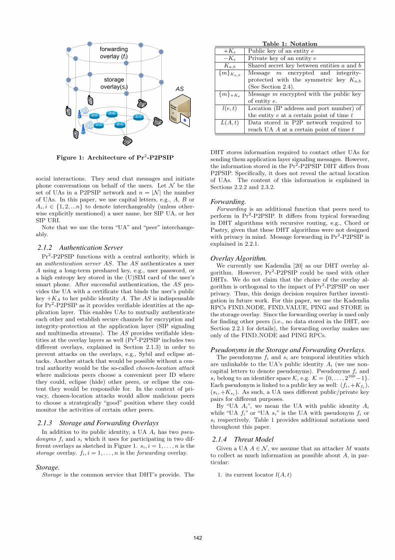
storage overlay(si)
forwardingoverlay (fi)
AS
Figure 1: Architecture of Pr2-P2PSIP
social interactions. They send chat messages and initiatephone conversations on behalf of the users. Let N be theset of UAs in a P2PSIP network and n = |N | the numberof UAs. In this paper, we use capital letters, e.g., A, B orAi, i ∈ {1, 2, ...n} to denote interchangeably (unless other-wise explicitly mentioned) a user name, her SIP UA, or herSIP URI.
Note that we use the term “UA” and “peer” interchange-ably.
2.1.2 Authentication ServerPr2-P2PSIP functions with a central authority, which is
an authentication server AS. The AS authenticates a userA using a long-term preshared key, e.g., user password, ora high entropy key stored in the (U)SIM card of the user’ssmart phone. After successful authentication, the AS pro-vides the UA with a certificate that binds the user’s publickey +KA to her public identity A. The AS is indispensablefor Pr2-P2PSIP as it provides verifiable identities at the ap-plication layer. This enables UAs to mutually authenticateeach other and establish secure channels for encryption andintegrity-protection at the application layer (SIP signalingand multimedia streams). The AS provides verifiable iden-tities at the overlay layers as well (Pr2-P2PSIP includes twodifferent overlays, explained in Section 2.1.3) in order toprevent attacks on the overlays, e.g., Sybil and eclipse at-tacks. Another attack that would be possible without a cen-tral authority would be the so-called chosen-location attackwhere malicious peers choose a convenient peer ID wherethey could, eclipse (hide) other peers, or eclipse the con-tent they would be responsible for. In the context of pri-vacy, chosen-location attacks would allow malicious peersto choose a strategically “good” position where they couldmonitor the activities of certain other peers.
2.1.3 Storage and Forwarding OverlaysIn addition to its public identity, a UA Ai has two pseu-
donyms fi and si which it uses for participating in two dif-ferent overlays as sketched in Figure 1. si, i = 1, . . . , n is thestorage overlay. fi, i = 1, . . . , n is the forwarding overlay.
Storage.Storage is the common service that DHT’s provide. The
Table 1: Notation+Ke Public key of an entity e−Ke Private key of an entity eKa,b Shared secret key between entities a and b{m}Ka,b Message m encrypted and integrity-
protected with the symmetric key Ka,b
(See Section 2.4).{m}+Ke Message m encrypted with the public key
of entity e.l(e, t) Location (IP address and port number) of
the entity e at a certain point of time tL(A, t) Data stored in P2P network required to
reach UA A at a certain point of time t
DHT stores information required to contact other UAs forsending them application layer signaling messages. However,the information stored in the Pr2-P2PSIP DHT differs fromP2PSIP. Specifically, it does not reveal the actual locationof UAs. The content of this information is explained inSections 2.2.2 and 2.3.2.
Forwarding.Forwarding is an additional function that peers need to
perform in Pr2-P2PSIP. It differs from typical forwardingin DHT algorithms with recursive routing, e.g., Chord orPastry, given that these DHT algorithms were not designedwith privacy in mind. Message forwarding in Pr2-P2PSIP isexplained in 2.2.1.
Overlay Algorithm.We currently use Kademlia [20] as our DHT overlay al-
gorithm. However, Pr2-P2PSIP could be used with otherDHTs. We do not claim that the choice of the overlay al-gorithm is orthogonal to the impact of Pr2-P2PSIP on userprivacy. Thus, this design decision requires further investi-gation in future work. For this paper, we use the KademliaRPCs FIND NODE, FIND VALUE, PING and STORE inthe storage overlay. Since the forwarding overlay is used onlyfor finding other peers (i.e., no data stored in the DHT, seeSection 2.2.1 for details), the forwarding overlay makes useonly of the FIND NODE and PING RPCs.
Pseudonyms in the Storage and Forwarding Overlays.The pseudonyms fi and si are temporal identities which
are unlinkable to the UA’s public identity Ai (we use non-capital letters to denote pseudonyms). Pseudonyms fi andsi belong to an identifier space K, e.g. K = {0, . . . , 2160−1}.Each pseudonym is linked to a public key as well: (fi,+Kfi),(si,+Ksi). As such, a UA uses different public/private keypairs for different purposes.
By “UA Ai”, we mean the UA with public identity Aiwhile “UA fi” or “UA si” is the UA with pseudonym fi orsi respectively. Table 1 provides additional notations usedthroughout this paper.
2.1.4 Threat ModelGiven a UA A ∈ N , we assume that an attacker M wants
to collect as much information as possible about A, in par-ticular:
1. its current locator l(A, t)
142
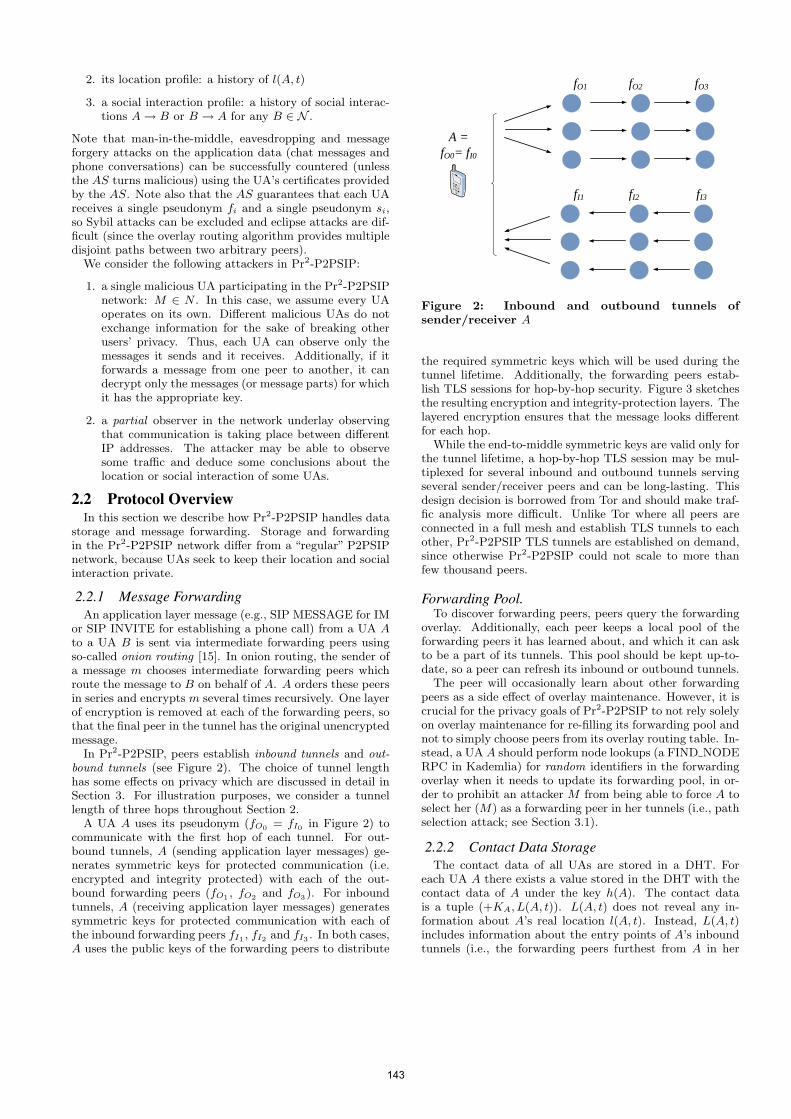
2. its location profile: a history of l(A, t)
3. a social interaction profile: a history of social interac-tions A→ B or B → A for any B ∈ N .
Note that man-in-the-middle, eavesdropping and messageforgery attacks on the application data (chat messages andphone conversations) can be successfully countered (unlessthe AS turns malicious) using the UA’s certificates providedby the AS. Note also that the AS guarantees that each UAreceives a single pseudonym fi and a single pseudonym si,so Sybil attacks can be excluded and eclipse attacks are dif-ficult (since the overlay routing algorithm provides multipledisjoint paths between two arbitrary peers).
We consider the following attackers in Pr2-P2PSIP:
1. a single malicious UA participating in the Pr2-P2PSIPnetwork: M ∈ N . In this case, we assume every UAoperates on its own. Different malicious UAs do notexchange information for the sake of breaking otherusers’ privacy. Thus, each UA can observe only themessages it sends and it receives. Additionally, if itforwards a message from one peer to another, it candecrypt only the messages (or message parts) for whichit has the appropriate key.
2. a partial observer in the network underlay observingthat communication is taking place between differentIP addresses. The attacker may be able to observesome traffic and deduce some conclusions about thelocation or social interaction of some UAs.
2.2 Protocol OverviewIn this section we describe how Pr2-P2PSIP handles data
storage and message forwarding. Storage and forwardingin the Pr2-P2PSIP network differ from a “regular” P2PSIPnetwork, because UAs seek to keep their location and socialinteraction private.
2.2.1 Message ForwardingAn application layer message (e.g., SIP MESSAGE for IM
or SIP INVITE for establishing a phone call) from a UA Ato a UA B is sent via intermediate forwarding peers usingso-called onion routing [15]. In onion routing, the sender ofa message m chooses intermediate forwarding peers whichroute the message to B on behalf of A. A orders these peersin series and encrypts m several times recursively. One layerof encryption is removed at each of the forwarding peers, sothat the final peer in the tunnel has the original unencryptedmessage.
In Pr2-P2PSIP, peers establish inbound tunnels and out-bound tunnels (see Figure 2). The choice of tunnel lengthhas some effects on privacy which are discussed in detail inSection 3. For illustration purposes, we consider a tunnellength of three hops throughout Section 2.
A UA A uses its pseudonym (fO0 = fI0 in Figure 2) tocommunicate with the first hop of each tunnel. For out-bound tunnels, A (sending application layer messages) ge-nerates symmetric keys for protected communication (i.e.encrypted and integrity protected) with each of the out-bound forwarding peers (fO1 , fO2 and fO3). For inboundtunnels, A (receiving application layer messages) generatessymmetric keys for protected communication with each ofthe inbound forwarding peers fI1 , fI2 and fI3 . In both cases,A uses the public keys of the forwarding peers to distribute
fO1 fO2 fO3
A =
fO0= fI0
fI1 fI2 fI3
Figure 2: Inbound and outbound tunnels ofsender/receiver A
the required symmetric keys which will be used during thetunnel lifetime. Additionally, the forwarding peers estab-lish TLS sessions for hop-by-hop security. Figure 3 sketchesthe resulting encryption and integrity-protection layers. Thelayered encryption ensures that the message looks differentfor each hop.
While the end-to-middle symmetric keys are valid only forthe tunnel lifetime, a hop-by-hop TLS session may be mul-tiplexed for several inbound and outbound tunnels servingseveral sender/receiver peers and can be long-lasting. Thisdesign decision is borrowed from Tor and should make traf-fic analysis more difficult. Unlike Tor where all peers areconnected in a full mesh and establish TLS tunnels to eachother, Pr2-P2PSIP TLS tunnels are established on demand,since otherwise Pr2-P2PSIP could not scale to more thanfew thousand peers.
Forwarding Pool.To discover forwarding peers, peers query the forwarding
overlay. Additionally, each peer keeps a local pool of theforwarding peers it has learned about, and which it can askto be a part of its tunnels. This pool should be kept up-to-date, so a peer can refresh its inbound or outbound tunnels.
The peer will occasionally learn about other forwardingpeers as a side effect of overlay maintenance. However, it iscrucial for the privacy goals of Pr2-P2PSIP to not rely solelyon overlay maintenance for re-filling its forwarding pool andnot to simply choose peers from its overlay routing table. In-stead, a UA A should perform node lookups (a FIND NODERPC in Kademlia) for random identifiers in the forwardingoverlay when it needs to update its forwarding pool, in or-der to prohibit an attacker M from being able to force A toselect her (M) as a forwarding peer in her tunnels (i.e., pathselection attack; see Section 3.1).
2.2.2 Contact Data StorageThe contact data of all UAs are stored in a DHT. For
each UA A there exists a value stored in the DHT with thecontact data of A under the key h(A). The contact datais a tuple (+KA, L(A, t)). L(A, t) does not reveal any in-formation about A’s real location l(A, t). Instead, L(A, t)includes information about the entry points of A’s inboundtunnels (i.e., the forwarding peers furthest from A in her
143
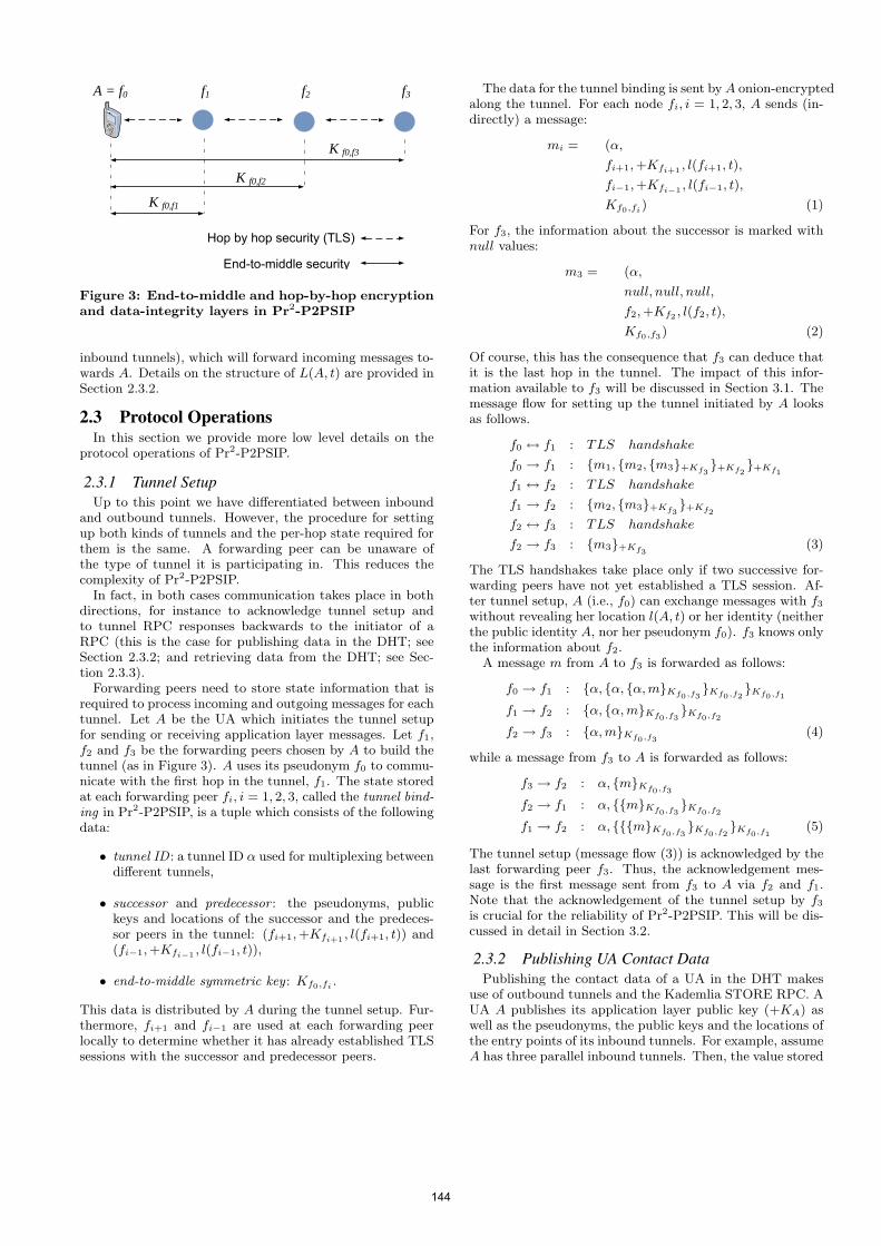
A = f0 f1 f2 f3
Hop by hop security (TLS)
End-to-middle security
K f0,f3
K f0,f2
K f0,f1
Figure 3: End-to-middle and hop-by-hop encryptionand data-integrity layers in Pr2-P2PSIP
inbound tunnels), which will forward incoming messages to-wards A. Details on the structure of L(A, t) are provided inSection 2.3.2.
2.3 Protocol OperationsIn this section we provide more low level details on the
protocol operations of Pr2-P2PSIP.
2.3.1 Tunnel SetupUp to this point we have differentiated between inbound
and outbound tunnels. However, the procedure for settingup both kinds of tunnels and the per-hop state required forthem is the same. A forwarding peer can be unaware ofthe type of tunnel it is participating in. This reduces thecomplexity of Pr2-P2PSIP.
In fact, in both cases communication takes place in bothdirections, for instance to acknowledge tunnel setup andto tunnel RPC responses backwards to the initiator of aRPC (this is the case for publishing data in the DHT; seeSection 2.3.2; and retrieving data from the DHT; see Sec-tion 2.3.3).
Forwarding peers need to store state information that isrequired to process incoming and outgoing messages for eachtunnel. Let A be the UA which initiates the tunnel setupfor sending or receiving application layer messages. Let f1,f2 and f3 be the forwarding peers chosen by A to build thetunnel (as in Figure 3). A uses its pseudonym f0 to commu-nicate with the first hop in the tunnel, f1. The state storedat each forwarding peer fi, i = 1, 2, 3, called the tunnel bind-ing in Pr2-P2PSIP, is a tuple which consists of the followingdata:
• tunnel ID : a tunnel ID α used for multiplexing betweendifferent tunnels,
• successor and predecessor : the pseudonyms, publickeys and locations of the successor and the predeces-sor peers in the tunnel: (fi+1,+Kfi+1 , l(fi+1, t)) and(fi−1,+Kfi−1 , l(fi−1, t)),
• end-to-middle symmetric key : Kf0,fi .
This data is distributed by A during the tunnel setup. Fur-thermore, fi+1 and fi−1 are used at each forwarding peerlocally to determine whether it has already established TLSsessions with the successor and predecessor peers.
The data for the tunnel binding is sent byA onion-encryptedalong the tunnel. For each node fi, i = 1, 2, 3, A sends (in-directly) a message:
mi = (α,
fi+1,+Kfi+1 , l(fi+1, t),
fi−1,+Kfi−1 , l(fi−1, t),
Kf0,fi) (1)
For f3, the information about the successor is marked withnull values:
m3 = (α,
null, null, null,
f2,+Kf2 , l(f2, t),
Kf0,f3) (2)
Of course, this has the consequence that f3 can deduce thatit is the last hop in the tunnel. The impact of this infor-mation available to f3 will be discussed in Section 3.1. Themessage flow for setting up the tunnel initiated by A looksas follows.
f0 ↔ f1 : TLS handshake
f0 → f1 : {m1, {m2, {m3}+Kf3}+Kf2
}+Kf1
f1 ↔ f2 : TLS handshake
f1 → f2 : {m2, {m3}+Kf3}+Kf2
f2 ↔ f3 : TLS handshake
f2 → f3 : {m3}+Kf3(3)
The TLS handshakes take place only if two successive for-warding peers have not yet established a TLS session. Af-ter tunnel setup, A (i.e., f0) can exchange messages with f3
without revealing her location l(A, t) or her identity (neitherthe public identity A, nor her pseudonym f0). f3 knows onlythe information about f2.
A message m from A to f3 is forwarded as follows:
f0 → f1 : {α, {α, {α,m}Kf0,f3}Kf0,f2
}Kf0,f1
f1 → f2 : {α, {α,m}Kf0,f3}Kf0,f2
f2 → f3 : {α,m}Kf0,f3(4)
while a message from f3 to A is forwarded as follows:
f3 → f2 : α, {m}Kf0,f3
f2 → f1 : α, {{m}Kf0,f3}Kf0,f2
f1 → f2 : α, {{{m}Kf0,f3}Kf0,f2
}Kf0,f1(5)
The tunnel setup (message flow (3)) is acknowledged by thelast forwarding peer f3. Thus, the acknowledgement mes-sage is the first message sent from f3 to A via f2 and f1.Note that the acknowledgement of the tunnel setup by f3
is crucial for the reliability of Pr2-P2PSIP. This will be dis-cussed in detail in Section 3.2.
2.3.2 Publishing UA Contact DataPublishing the contact data of a UA in the DHT makes
use of outbound tunnels and the Kademlia STORE RPC. AUA A publishes its application layer public key (+KA) aswell as the pseudonyms, the public keys and the locations ofthe entry points of its inbound tunnels. For example, assumeA has three parallel inbound tunnels. Then, the value stored
144
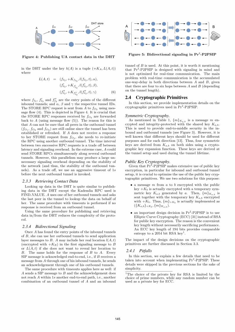
A
DHT storefO1 fO2 fO3
Figure 4: Publishing UA contact data in the DHT
in the DHT under the key h(A) is a tuple (+KA, L(A, t))where
L(A, t) = (fI3 ,+KfI3, l(fI3 , t), α),
(f ′I3 ,+Kf ′I3, l(f ′I3 , t), β),
(f ′′I3 ,+Kf ′′I3, l(f ′′I3 , t), γ) (6)
where fI3 , f ′I3 and f ′′I3 are the entry points of the differentinbound tunnels; and α, β and γ the respective tunnel IDs.The STORE RPC request is sent from A to fO3 using mes-sage flow (4). This is depicted in Figure 4. It is crucial thatthe STORE RPC responses received by fO3 are forwardedback to A (using message flow (5)). The reason for this isthat A can not be sure that all peers in the outbound tunnel(fO1 , fO2 and fO3) are still online since the tunnel has beenestablished or refreshed. If A does not receive a responseto her STORE request from fO3 , she needs to re-initiatethe RPC using another outbound tunnel. The time intervalbetween two successive RPC requests is a trade off betweenlatency and signaling overhead. In the extreme case, A couldsend STORE RPCs simultaneously along several outboundtunnels. However, this parallelism may produce a large un-necessary signaling overhead depending on the stability ofthe network (and thus, the stability of the outbound tun-nels). As a trade off, we use an aggressive timeout of 1sbefore the next outbound tunnel is invoked.
2.3.3 Retrieving Contact DataLooking up data in the DHT is quite similar to publish-
ing data in the DHT except the Kademlia RPC used isFIND VALUE. A uses one of her outbound tunnels and asksthe last peer in the tunnel to lookup the data on behalf ofher. The same procedure with timeouts is performed if noresponse is received from an outbound tunnel.
Using the same procedure for publishing and retrievingdata in/from the DHT reduces the complexity of the proto-col.
2.3.4 Bidirectional SignalingOnce A has found the entry points of the inbound tunnels
of B, she can use her outbound tunnels to send applicationlayer messages to B. A may include her real location l(A, t)(encrypted with +KB) in the first signaling message to Bor L(A, t) if she does not want to reveal her location toB. The same holds for the response of B to A. EverySIP message is acknowledged end-to-end, i.e., if B receives amessage from A through one of his inbound tunnels, he sendsan acknowledgement through one of his outbound tunnels.
The same procedure with timeouts applies here as well: ifA sends a SIP message to B and the acknowledgement doesnot reach A within 1s another end-to-end path, i.e., anothercombination of an outbound tunnel of A and an inbound
BA
Figure 5: Bidirectional signaling in Pr2-P2PSIP
tunnel of B is used. At this point, it is worth it mentioningthat Pr2-P2PSIP is designed with signaling in mind andis not optimized for real-time communication. The mainproblem with real-time communication is the accumulatedone-way-delay in both directions between A and B, giventhat there are four to six hops between A and B (dependingon the tunnel length).
2.4 Cryptographic PrimitivesIn this section, we provide implementation details on the
cryptographic primitives used in Pr2-P2PSIP.
Symmetric Cryptography.As mentioned in Table 1, {m}Ka,b is a message m en-
crypted and integrity-protected with the shared key Ka,b.This is used to provide end-to-middle security in the in-bound and outbound tunnels (see Figure 3). However, it iswell known that different keys should be used for differentpurposes and for each direction [13]. Thus, four symmetrickeys are derived from Ka,b on both sides using a crypto-graphic key expansion function. These keys are derived atthe tunnel setup and used during the tunnel lifetime.
Public Key Cryptography.Given that Pr2-P2PSIP makes extensive use of public key
encryption, in particular for inbound and outbound tunnelsetup, it is crucial to optimize the use of the public key cryp-tographic primitives. We use two solutions for this purpose:
• a message m from a to b encrypted with the publickey +Kb is actually encrypted with a temporary sym-metric key Ka,b generated by a. Then, {m}Ka,b issent together with the temporary key Ka,b encryptedwith +Kb. Thus, {m}+Kb is actually implemented as({Ka,b}+Kb , {m}Ka,b).
• an important design decision in Pr2-P2PSIP is to useElliptic Curve Cryptography (ECC) [31] instead of RSAfor public key encryption. The reason is the convenientkey length without necessarily sacrificing performance.An ECC key length of 194 bits provides comparableentropy to a 2054 bit RSA key1.
The impact of the design decisions on the cryptographicprimitives are further discussed in Section 3.3.
2.4.1 PitfallsIn this section, we explain a few details that need to be
taken into account when implementing Pr2-P2PSIP. Thesedetails were skipped in the previous sections for the sake ofsimplicity.1The choice of the private key for RSA is limited by thechoice of prime numbers, while any random number can beused as a private key for ECC.
145
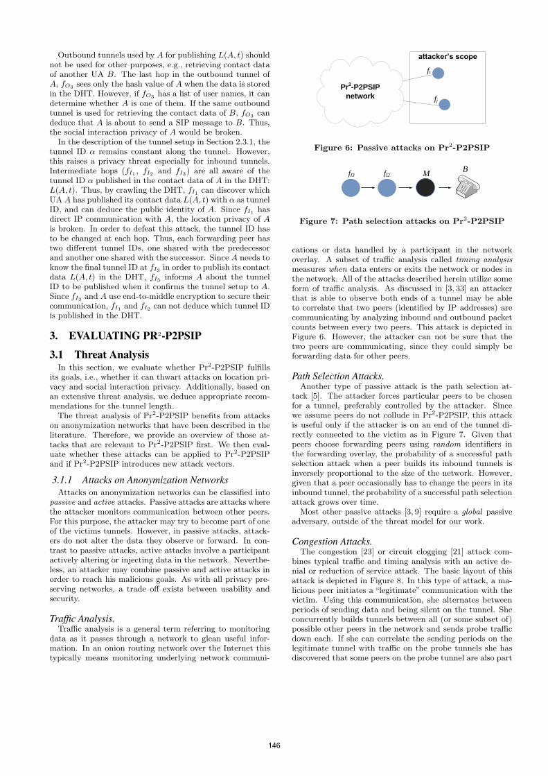
Outbound tunnels used by A for publishing L(A, t) shouldnot be used for other purposes, e.g., retrieving contact dataof another UA B. The last hop in the outbound tunnel ofA, fO3 sees only the hash value of A when the data is storedin the DHT. However, if fO3 has a list of user names, it candetermine whether A is one of them. If the same outboundtunnel is used for retrieving the contact data of B, fO3 candeduce that A is about to send a SIP message to B. Thus,the social interaction privacy of A would be broken.
In the description of the tunnel setup in Section 2.3.1, thetunnel ID α remains constant along the tunnel. However,this raises a privacy threat especially for inbound tunnels.Intermediate hops (fI1 , fI2 and fI3) are all aware of thetunnel ID α published in the contact data of A in the DHT:L(A, t). Thus, by crawling the DHT, fI1 can discover whichUA A has published its contact data L(A, t) with α as tunnelID, and can deduce the public identity of A. Since fI1 hasdirect IP communication with A, the location privacy of Ais broken. In order to defeat this attack, the tunnel ID hasto be changed at each hop. Thus, each forwarding peer hastwo different tunnel IDs, one shared with the predecessorand another one shared with the successor. Since A needs toknow the final tunnel ID at fI3 in order to publish its contactdata L(A, t) in the DHT, fI3 informs A about the tunnelID to be published when it confirms the tunnel setup to A.Since fI3 and A use end-to-middle encryption to secure theircommunication, fI1 and fI2 can not deduce which tunnel IDis published in the DHT.
3. EVALUATING PR2-P2PSIP
3.1 Threat AnalysisIn this section, we evaluate whether Pr2-P2PSIP fulfills
its goals, i.e., whether it can thwart attacks on location pri-vacy and social interaction privacy. Additionally, based onan extensive threat analysis, we deduce appropriate recom-mendations for the tunnel length.
The threat analysis of Pr2-P2PSIP benefits from attackson anonymization networks that have been described in theliterature. Therefore, we provide an overview of those at-tacks that are relevant to Pr2-P2PSIP first. We then eval-uate whether these attacks can be applied to Pr2-P2PSIPand if Pr2-P2PSIP introduces new attack vectors.
3.1.1 Attacks on Anonymization NetworksAttacks on anonymization networks can be classified into
passive and active attacks. Passive attacks are attacks wherethe attacker monitors communication between other peers.For this purpose, the attacker may try to become part of oneof the victims tunnels. However, in passive attacks, attack-ers do not alter the data they observe or forward. In con-trast to passive attacks, active attacks involve a participantactively altering or injecting data in the network. Neverthe-less, an attacker may combine passive and active attacks inorder to reach his malicious goals. As with all privacy pre-serving networks, a trade off exists between usability andsecurity.
Traffic Analysis.Traffic analysis is a general term referring to monitoring
data as it passes through a network to glean useful infor-mation. In an onion routing network over the Internet thistypically means monitoring underlying network communi-
attacker’s scope
Pr2-P2PSIPnetwork
fi
fj
Figure 6: Passive attacks on Pr2-P2PSIP
BMfI2fI3
Figure 7: Path selection attacks on Pr2-P2PSIP
cations or data handled by a participant in the networkoverlay. A subset of traffic analysis called timing analysismeasures when data enters or exits the network or nodes inthe network. All of the attacks described herein utilize someform of traffic analysis. As discussed in [3, 33] an attackerthat is able to observe both ends of a tunnel may be ableto correlate that two peers (identified by IP addresses) arecommunicating by analyzing inbound and outbound packetcounts between every two peers. This attack is depicted inFigure 6. However, the attacker can not be sure that thetwo peers are communicating, since they could simply beforwarding data for other peers.
Path Selection Attacks.Another type of passive attack is the path selection at-
tack [5]. The attacker forces particular peers to be chosenfor a tunnel, preferably controlled by the attacker. Sincewe assume peers do not collude in Pr2-P2PSIP, this attackis useful only if the attacker is on an end of the tunnel di-rectly connected to the victim as in Figure 7. Given thatpeers choose forwarding peers using random identifiers inthe forwarding overlay, the probability of a successful pathselection attack when a peer builds its inbound tunnels isinversely proportional to the size of the network. However,given that a peer occasionally has to change the peers in itsinbound tunnel, the probability of a successful path selectionattack grows over time.
Most other passive attacks [3, 9] require a global passiveadversary, outside of the threat model for our work.
Congestion Attacks.The congestion [23] or circuit clogging [21] attack com-
bines typical traffic and timing analysis with an active de-nial or reduction of service attack. The basic layout of thisattack is depicted in Figure 8. In this type of attack, a ma-licious peer initiates a “legitimate” communication with thevictim. Using this communication, she alternates betweenperiods of sending data and being silent on the tunnel. Sheconcurrently builds tunnels between all (or some subset of)possible other peers in the network and sends probe trafficdown each. If she can correlate the sending periods on thelegitimate tunnel with traffic on the probe tunnels she hasdiscovered that some peers on the probe tunnel are also part
146
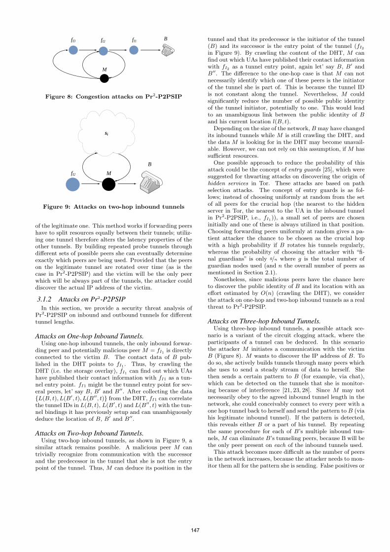
fI1fI2fI3 B
M
Figure 8: Congestion attacks on Pr2-P2PSIP
si
B
MfI2
Figure 9: Attacks on two-hop inbound tunnels
of the legitimate one. This method works if forwarding peershave to split resources equally between their tunnels; utiliz-ing one tunnel therefore alters the latency properties of theother tunnels. By building repeated probe tunnels throughdifferent sets of possible peers she can eventually determineexactly which peers are being used. Provided that the peerson the legitimate tunnel are rotated over time (as is thecase in Pr2-P2PSIP) and the victim will be the only peerwhich will be always part of the tunnels, the attacker coulddiscover the actual IP address of the victim.
3.1.2 Attacks on Pr2-P2PSIPIn this section, we provide a security threat analysis of
Pr2-P2PSIP on inbound and outbound tunnels for differenttunnel lengths.
Attacks on One-hop Inbound Tunnels.Using one-hop inbound tunnels, the only inbound forwar-
ding peer and potentially malicious peer M = fI1 is directlyconnected to the victim B. The contact data of B pub-lished in the DHT points to fI1 . Thus, by crawling theDHT (i.e. the storage overlay), fI1 can find out which UAshave published their contact information with fI1 as a tun-nel entry point. fI1 might be the tunnel entry point for sev-eral peers, let’ say B, B′ and B′′. After collecting the data{L(B, t), L(B′, t), L(B′′, t)} from the DHT, fI1 can correlatethe tunnel IDs in L(B, t), L(B′, t) and L(B′′, t) with the tun-nel bindings it has previously setup and can unambiguouslydeduce the location of B, B′ and B′′.
Attacks on Two-hop Inbound Tunnels.Using two-hop inbound tunnels, as shown in Figure 9, a
similar attack remains possible. A malicious peer M cantrivially recognize from communication with the successorand the predecessor in the tunnel that she is not the entrypoint of the tunnel. Thus, M can deduce its position in the
tunnel and that its predecessor is the initiator of the tunnel(B) and its successor is the entry point of the tunnel (fI2in Figure 9). By crawling the content of the DHT, M canfind out which UAs have published their contact informationwith fI2 as a tunnel entry point, again let’ say B, B′ andB′′. The difference to the one-hop case is that M can notnecessarily identify which one of these peers is the initiatorof the tunnel she is part of. This is because the tunnel IDis not constant along the tunnel. Nevertheless, M couldsignificantly reduce the number of possible public identityof the tunnel initiator, potentially to one. This would leadto an unambiguous link between the public identity of Band his current location l(B, t).
Depending on the size of the network, B may have changedits inbound tunnels while M is still crawling the DHT, andthe data M is looking for in the DHT may become unavail-able. However, we can not rely on this assumption, if M hassufficient resources.
One possible approach to reduce the probability of thisattack could be the concept of entry guards [25], which weresuggested for thwarting attacks on discovering the origin ofhidden services in Tor. These attacks are based on pathselection attacks. The concept of entry guards is as fol-lows; instead of choosing uniformly at random from the setof all peers for the crucial hop (the nearest to the hiddenserver in Tor, the nearest to the UA in the inbound tunnelin Pr2-P2PSIP, i.e., fI1)), a small set of peers are choseninitially and one of these is always utilized in that position.Choosing forwarding peers uniformly at random gives a pa-tient attacker the chance to be chosen as the crucial hopwith a high probability if B rotates his tunnels regularly,whereas the probability of choosing the attacker with “fi-nal guardians” is only g/n where g is the total number ofguardian nodes used (and n the overall number of peers asmentioned in Section 2.1).
Nonetheless, since malicious peers have the chance hereto discover the public identity of B and its location with aneffort estimated by O(n) (crawling the DHT), we considerthe attack on one-hop and two-hop inbound tunnels as a realthreat to Pr2-P2PSIP.
Attacks on Three-hop Inbound Tunnels.Using three-hop inbound tunnels, a possible attack sce-
nario is a variant of the circuit clogging attack, where theparticipants of a tunnel can be deduced. In this scenariothe attacker M initiates a communication with the victimB (Figure 8). M wants to discover the IP address of B. Todo so, she actively builds tunnels through many peers whichshe uses to send a steady stream of data to herself. Shethen sends a certain pattern to B (for example, via chat),which can be detected on the tunnels that she is monitor-ing because of interference [21, 23, 28]. Since M may notnecessarily obey to the agreed inbound tunnel length in thenetwork, she could conceivably connect to every peer with aone hop tunnel back to herself and send the pattern to B (viahis legitimate inbound tunnel). If the pattern is detected,this reveals either B or a part of his tunnel. By repeatingthe same procedure for each of B’s multiple inbound tun-nels, M can eliminate B’s tunneling peers, because B will bethe only peer present on each of the inbound tunnels used.
This attack becomes more difficult as the number of peersin the network increases, because the attacker needs to mon-itor them all for the pattern she is sending. False positives or
147
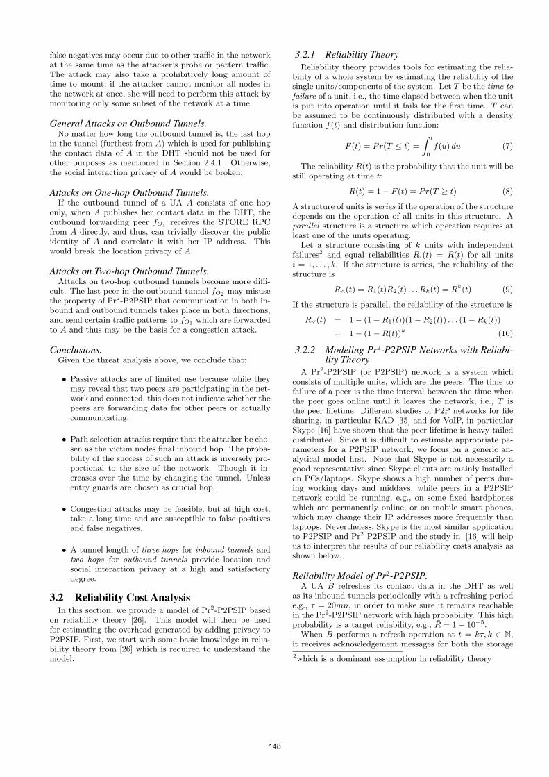
false negatives may occur due to other traffic in the networkat the same time as the attacker’s probe or pattern traffic.The attack may also take a prohibitively long amount oftime to mount; if the attacker cannot monitor all nodes inthe network at once, she will need to perform this attack bymonitoring only some subset of the network at a time.
General Attacks on Outbound Tunnels.No matter how long the outbound tunnel is, the last hop
in the tunnel (furthest from A) which is used for publishingthe contact data of A in the DHT should not be used forother purposes as mentioned in Section 2.4.1. Otherwise,the social interaction privacy of A would be broken.
Attacks on One-hop Outbound Tunnels.If the outbound tunnel of a UA A consists of one hop
only, when A publishes her contact data in the DHT, theoutbound forwarding peer fO1 receives the STORE RPCfrom A directly, and thus, can trivially discover the publicidentity of A and correlate it with her IP address. Thiswould break the location privacy of A.
Attacks on Two-hop Outbound Tunnels.Attacks on two-hop outbound tunnels become more diffi-
cult. The last peer in the outbound tunnel fO2 may misusethe property of Pr2-P2PSIP that communication in both in-bound and outbound tunnels takes place in both directions,and send certain traffic patterns to fO1 which are forwardedto A and thus may be the basis for a congestion attack.
Conclusions.Given the threat analysis above, we conclude that:
• Passive attacks are of limited use because while theymay reveal that two peers are participating in the net-work and connected, this does not indicate whether thepeers are forwarding data for other peers or actuallycommunicating.
• Path selection attacks require that the attacker be cho-sen as the victim nodes final inbound hop. The proba-bility of the success of such an attack is inversely pro-portional to the size of the network. Though it in-creases over the time by changing the tunnel. Unlessentry guards are chosen as crucial hop.
• Congestion attacks may be feasible, but at high cost,take a long time and are susceptible to false positivesand false negatives.
• A tunnel length of three hops for inbound tunnels andtwo hops for outbound tunnels provide location andsocial interaction privacy at a high and satisfactorydegree.
3.2 Reliability Cost AnalysisIn this section, we provide a model of Pr2-P2PSIP based
on reliability theory [26]. This model will then be usedfor estimating the overhead generated by adding privacy toP2PSIP. First, we start with some basic knowledge in relia-bility theory from [26] which is required to understand themodel.
3.2.1 Reliability TheoryReliability theory provides tools for estimating the relia-
bility of a whole system by estimating the reliability of thesingle units/components of the system. Let T be the time tofailure of a unit, i.e., the time elapsed between when the unitis put into operation until it fails for the first time. T canbe assumed to be continuously distributed with a densityfunction f(t) and distribution function:
F (t) = Pr(T ≤ t) =
∫ t
0
f(u) du (7)
The reliability R(t) is the probability that the unit will bestill operating at time t:
R(t) = 1− F (t) = Pr(T ≥ t) (8)
A structure of units is series if the operation of the structuredepends on the operation of all units in this structure. Aparallel structure is a structure which operation requires atleast one of the units operating.
Let a structure consisting of k units with independentfailures2 and equal reliabilities Ri(t) = R(t) for all unitsi = 1, . . . , k. If the structure is series, the reliability of thestructure is
R∧(t) = R1(t)R2(t) . . . Rk(t) = Rk(t) (9)
If the structure is parallel, the reliability of the structure is
R∨(t) = 1− (1−R1(t))(1−R2(t)) . . . (1−Rk(t))
= 1− (1−R(t))k (10)
3.2.2 Modeling Pr2-P2PSIP Networks with Reliabi-lity Theory
A Pr2-P2PSIP (or P2PSIP) network is a system whichconsists of multiple units, which are the peers. The time tofailure of a peer is the time interval between the time whenthe peer goes online until it leaves the network, i.e., T isthe peer lifetime. Different studies of P2P networks for filesharing, in particular KAD [35] and for VoIP, in particularSkype [16] have shown that the peer lifetime is heavy-taileddistributed. Since it is difficult to estimate appropriate pa-rameters for a P2PSIP network, we focus on a generic an-alytical model first. Note that Skype is not necessarily agood representative since Skype clients are mainly installedon PCs/laptops. Skype shows a high number of peers dur-ing working days and middays, while peers in a P2PSIPnetwork could be running, e.g., on some fixed hardphoneswhich are permanently online, or on mobile smart phones,which may change their IP addresses more frequently thanlaptops. Nevertheless, Skype is the most similar applicationto P2PSIP and Pr2-P2PSIP and the study in [16] will helpus to interpret the results of our reliability costs analysis asshown below.
Reliability Model of Pr2-P2PSIP.A UA B refreshes its contact data in the DHT as well
as its inbound tunnels periodically with a refreshing periode.g., τ = 20mn, in order to make sure it remains reachablein the Pr2-P2PSIP network with high probability. This highprobability is a target reliability, e.g., R = 1− 10−5.
When B performs a refresh operation at t = kτ, k ∈ N,it receives acknowledgement messages for both the storage
2which is a dominant assumption in reliability theory
148
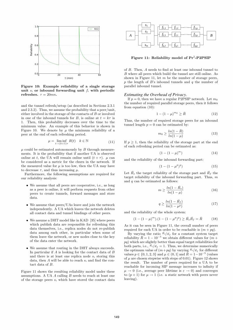
0 20 40 60
t (min)
0.0
0.2
0.4
0.6
0.8
1.0
Relia
bili
tyR(t)
Figure 10: Example reliability of a single storageunit si or inbound forwarding unit fi with periodicrefreshes. τ = 20mn.
and the tunnel refresh/setup (as described in Sections 2.3.1and 2.3.2). Thus, we assume the probability that a peer/unit,either involved in the storage of the contacts of B or involvedin one of the inbound tunnels for B, is online at t = kτ is1. Then, this probability decreases over the time to theminimum value. An example of this behavior is shown inFigure 10. We denote by µ the minimum reliability of apeer at the end of each refreshing period.
µ = lim inft→(k+1)τ
R(t) k ∈ N (11)
µ could be estimated autonomously by B through measure-ments. It is the probability that if another UA is observedonline at t, the UA will remain online until (t + τ). µ canbe considered as a metric for the churn in the network. Ifthe measured value for µ is too low, then the UA may haveto decrease τ , and thus increasing µ.
Furthermore, the following assumptions are required forour reliability analysis:
• We assume that all peers are cooperative, i.e., as longas a peer is online, it will perform requests from otherpeers to create tunnels, forward messages and storedata.
• We assume that peers/UAs leave and join the networkindependently. A UA which leaves the network deletesall contact data and tunnel bindings of other peers.
• We assume a DHT model like in KAD [35] where peerswhich publish data are responsible for refreshing thisdata themselves, i.e., replica nodes do not re-publishdata among each other, in particular when some ofthem leave the network, or new nodes close to the keyof the data enter the network.
• We assume that routing in the DHT always succeeds.In particular if A is looking for the contact data of Band there is at least one replica node si storing thisdata, then A will be able to reach si and find the con-tact data of B.
Figure 11 shows the resulting reliability model under theseassumptions. A UA A calling B needs to reach at least oneof the storage peers si which have stored the contact data
A
s1
s2
sm
….
f1,1 f1,2 f1,p….
f2,1 f2,1 f2,p….
fq,1 fq,1 fq,p
B
….
….
Figure 11: Reliability model of Pr2-P2PSIP
of B. Then, A needs to find at least one inbound tunnel toB where all peers which build the tunnel are still online. Asshown in Figure 11, let m be the number of storage peers,p the length of B’s inbound tunnels and q the number ofparallel inbound tunnel.
Estimating the Overhead of Privacy.If p = 0, then we have a regular P2PSIP network. Let m0
the number of required parallel storage peers, then it followsfrom equation (10):
1− (1− µ)m0 ≥ R (12)
Thus, the number of required storage peers for an inboundtunnel length p = 0 can be estimated by:
m0 ≥ln(1− R)
ln(1− µ)(13)
If p ≥ 1, then the reliability of the storage part at the endof each refreshing period can be estimated as:
(1− (1− µ)m) (14)
and the reliability of the inbound forwarding part:
(1− (1− µp)q) (15)
Let Rs the target reliablity of the storage part and Rf thetarget reliability of the inbound forwarding part. Thus, mand q can be estimated as follows:
m ≥ ln(1− Rs)ln(1− µ)
(16)
q ≥ ln(1− Rf )
ln(1− µp) (17)
and the reliability of the whole system:
(1− (1− µ)m).(1− (1− µp)q) ≥ RsRf = R (18)
As it can be seen in Figure 11, the overall number of peersrequired for each UA in order to be reachable is (m+ pq).
By varying the ratio Rs/Rf for a constant system targetreliability R = 1− 10−5 we obtain different values for (m+pq) which are slightly better than equal target reliabilities forboth parts, i.e., Rs/Rf = 1. Thus, we determine numericallythe optimum value of (m+pq) by varying Rs/Rf for differentvalues p ∈ {0, 1, 2, 3} and µ ∈ (0, 1] and R = 1−10−5 (valuesof µ are chosen stepwise with steps of 0.01). Figure 12 showsthe result. The number of peers required for a UA to bereachable for incoming SIP message increases to infinity ifµ → 0 (i.e., average peer lifetime is ε → 0) and convergesto (p+ 1) for µ→ 1 (i.e. a static network with peers neverleaving).
149
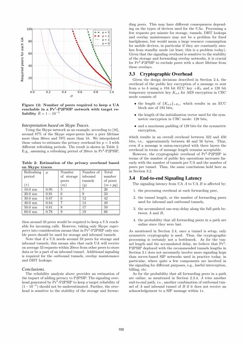
0.0 0.2 0.4 0.6 0.8 1.0µ
20
40
60
80
100
Requir
ed p
eers
for
each
UA
p = 3 p = 2 p = 1 p = 0
Figure 12: Number of peers required to keep a UAreachable in a Pr2-P2PSIP network with target re-liability R = 1− 10−5
Interpretation based on Skype Traces.Using the Skype network as an example, according to [16],
around 87% of the Skype super-peers have a peer lifetimemore than 30mn and 78% more than 1h. We interpolatedthese values to estimate the privacy overhead for p = 3 withdifferent refreshing periods. The result is shown in Table 2.E.g., assuming a refreshing period of 20mn in Pr2-P2PSIP,
Table 2: Estimation of the privacy overhead basedon Skype traces
Refreshingperiod
µ Numberof storagepeers
Number ofinboundtunnels
Totalnumberof peers
(τ) (m) (q) (m+pq)10.0 mn 0.95 5 7 2620.0 mn 0.91 6 9 3330.0 mn 0.87 6 12 4240.0 mn 0.84 7 14 4950.0 mn 0.81 8 17 5960.0 mn 0.78 9 19 66
then around 33 peers would be required to keep a UA reach-able for incoming calls. However, taking only Skype super-peers into consideration means that in Pr2-P2PSIP only sta-ble peers should be used for storage and inbound tunnels.
Note that if a UA needs around 33 peers for storage andinbound tunnels, this means also that each UA will receiveon average 33 requests within 20mn from other peers to storedata or be a part of an inbound tunnel. Additional signalingis required for the outbound tunnels, overlay maintenanceand DHT lookups.
Conclusions.The reliability analysis above provides an estimation of
the impact of adding privacy to P2PSIP. The signaling over-head generated by Pr2-P2PSIP to keep a target reliability of(1−10−5) should not be underestimated. Further, the over-head is sensitive to the stability of the storage and forwar-
ding peers. This may have different consequences depend-ing on the types of devices used for the UAs. Processing afew requests per minute for storage, tunnels, DHT lookupsand overlay maintenance may not be a problem for fixedhardphones, but would mean a large resource consumptionfor mobile devices, in particular if they are constantly awo-ken from standby mode (at least, this is a problem today).Given that the signaling overhead is sensitive to the stabilityof the storage and forwarding overlay networks, it is crucialfor Pr2-P2PSIP to exclude peers with a short lifetime fromthese overlays.
3.3 Cryptographic OverheadGiven the design decisions described in Section 2.4, the
overhead of the public key encryption of a message m sentfrom a to b using a 194 bit ECC key +Kb and a 128 bittemporary symmetric key Ka,b for AES encryption in CBCmode consists of:
• the length of {Ka,b}+Kb , which results in an ECCblock size of 194 bits,
• the length of the initialization vector used for the sym-metric encryption in CBC mode: 128 bits,
• and a maximum padding of 128 bits for the symmetricencryption,
which results in an overall overhead between 322 and 450bits, i.e,. approximately between 40 and 56 bytes. Thus,even if a message is onion-encrypted with three layers theoverhead in terms of message length remains acceptable.
However, the cryptographic overhead of Pr2-P2PSIP interms of the number of public key operations increases lin-early with the number of tunnels per UA and the number ofpeers per tunnel. Thus, the same conclusions hold here asin Section 3.2.
3.4 End-to-end Signaling LatencyThe signaling latency from UA A to UA B is affected by:
1. the processing overhead at each forwarding peer,
2. the tunnel length, or the number of forwarding peersused for inbound and outbound tunnels,
3. the accumulated one-way-delay along the full path be-tween A and B,
4. the probability that all forwarding peers in a path areonline since they were last.
As mentioned in Section 2.4, once a tunnel is setup, onlysymmetric cryptography is used. Thus, the cryptographicprocessing is certainly not a bottleneck. As for the tun-nel length and the accumulated delay, we believe that Pr2-P2PSIP deployed with the recommended tunnels lengths inSection 3.1 does not necessarily involve more signaling hopsthan server-based SIP networks used in practice today, inparticular, where quite a few components are involved inthe signaling for different purposes, e.g., lawful interception,billing, etc.
As for the probability that all forwarding peers in a pathare online, as mentioned in Section 2.3.4, A tries anotherend-to-end path, i.e., another combination of outbound tun-nel of A and inbound tunnel of B if it does not receive anacknowledgement to a SIP message within 1s.
150
Thus, the maximum overall signaling latency is expectedto be within a few seconds. If peers in the forwarding over-lay are stable, it becomes more likely that the tunnels areavailable and the signaling succeeds at the first attempt,thus reducing the latency by an order of magnitude. If Pr2-P2PSIP is used for chat, the same tunnels should be usedfor subsequent chat messages, since once tunnels have beensuccessfully used, they are likely to remain available for thenext chat messages, assuming a heavy-tailed distribution ofthe peer lifetime.
4. RELATED WORKLocation privacy was not a main concern when the Inter-
net was conceived, because hosts were fixed. However, it wasconsidered early on in GSM standardization. In GSM andUMTS networks, each mobile devices has a unique identifiercalled the International Mobile Subscriber Identity (IMSI).However, temporary pseudonyms called Temporary MobileSubscriber Identities (TMSI) are usually used for commu-nication with base stations. Nevertheless, both GMS andUMTS authentication protocols allow an attacker to imper-sonate a base station and request the User Equipment (UE)to send its IMSI for authentication.
P2PSIP was suggested initially by [7] and [34] and raisedmuch interest and follow up work. Seedorf [32] discussesthe security issues inherent in P2PSIP and mentions privacybriefly. In [4], the authors investigate a game theoreticalapproach for the security threats of P2PSIP such as SPITand attacks on overlay routing. However, privacy is notaddressed.
RELOAD [18], the base protocol for P2PSIP allows fordifferent overlay algorithms to be plugged in. The IETFP2PSIP WG charter [2] does not preclude the deploymentof anonymization networks. However, it can not be assumedthat any general purpose anonymization network could beused. The Internet draft [17] describes SIP usage for RE-LOAD and mentions explicitly that “all RELOAD SIP reg-istration data is public. Methods of providing location andidentity privacy are still being studied”. Thus, Pr2-P2PSIPis right on target to address this issue.
Reliability theory has been used in [35] for modeling P2Pnetworks in the context of the KAD file sharing network.In [19], the authors investigate self-tuning behavior of DHTsin order to optimize the reliability costs in the context ofPastry. However, they consider only the reliability of overlayrouting. In [38], the authors investigate the costs of main-tenance and lookup in DHTs with different ratios of superpeers. Their work considers regular DHT functionality with-out privacy. Nonetheless, our work can be enhanced in thefuture with a similar analysis in order to provide better in-sight on the signaling overhead of Pr2-P2PSIP with differentratios of fixed and mobile devices with different resources.In [8,36] the authors demonstrate how the end points of P2PVoIP streams, e.g. Skype streams, can be identified. Thus,they demonstrate how one could break location and socialinteraction privacy. However, Skype peers do not considereach other as potentially malicious.
There are many anonymization networks which utilize onionrouting [15] or a derivative, notably Tor [10], JAP [12],MorphMix [28] and I2P [11]. They all share character-istics and sometimes differ only in subtle ways. Our in-tention is not to invent a new anonymization network ornew anonymization techniques, but to leverage existing tech-
niques, particularly onion routing and inbound and out-bound tunnels to address the privacy issues of P2PSIP. Nev-ertheless, Pr2-P2PSIP can still be clearly differentiated fromexisting anonymization networks in several aspects. Ap-proaches for anonymization networks can be classified intocentralized and P2P approaches. Pr2-P2PSIP is a P2P ap-proach. Centralized approaches, e.g., Tor [10], Crowds [27]and MorphMix [28] rely on centralized databases (althougheventually redundant as in the Tor case) to get a list of relaynodes. Pr2-P2PSIP relies on a forwarding overlay. Likewise,Tor hidden services, which can be compared to Pr2-P2PSIPinbound tunnels, are accessed via service descriptors storedin a central database. In Pr2-P2PSIP, peers get the contactdata from the DHT before they contact the inbound tunnelentry points.
In P2P anonymization networks, such as I2P [11], Salsa [24],Cashmere [37], Tarzan [14] and AP3 [22], there is no centralauthority as in Pr2-P2PSIP, which makes them vulnerableto Sybil attacks. Further, peers select forwarding peers fromtheir P2P routing tables. This makes them vulnerable to at-tacks where malicious peers attempt to dominate the routingtables of other peers. Pr2-P2PSIP uses a separate overlayfor forwarding and chooses forwarding peers randomly.
Pr2-P2PSIP allows anonymous routing only within thenetwork. Other anonymity networks such as JAP [12], Cash-mere [37], Tarzan [14], MorphMix [28] and Crowds [27] aredesigned to allow communication with normal servers in theInternet. Thus, they need to support outbound connections.On the other hand, the clients do not have to be reachablefor incoming communication as in Pr2-P2PSIP.
In summary, Pr2-P2PSIP benefits from the design of Torand other anonymization networks and experience learnedfrom them, while it has been designed exclusively to providethe P2P-based SIP user registration and session establish-ment, while preserving the privacy of the network partici-pants. To the best of our knowledge, there has been no workwhich provides a dedicated solution to the privacy needs ofP2PSIP with such an extensive analysis of the implications.
5. CONCLUSIONSOur conclusions are as follows: Pr2-P2PSIP provides lo-
cation and social interaction privacy with a tunnel lengthof three for inbound tunnels and two for outbound tunnels.Cryptographic overhead is not a hindrance for Pr2-P2PSIP,in particular if ECC is deployed. Signaling latency improvesas the forwarding overlay becomes more stable. The signal-ing overhead to keep a target reliability of (1−10−5) shouldnot be underestimated. Further, the signaling overhead issensitive to the stability of the forwarding overlay. Thus,it is crucial for a successful deployment of Pr2-P2PSIP thatstable peers, i.e., those with a long lifetime, are preferentiallychosen for building tunnels.
6. ACKNOWLEDGEMENTThe authors would like to thank Christian Grothoff, Georg
Carle and the anonymous reviewers for their valuable feed-back and support for this paper. This work is partiallyfunded by the EU project ResumeNet (FP7-224619) and byDeutsche Forschungs Gemeinschaft (DFG) under ENP GR3688/1-1.
151
7. REFERENCES[1] Geo ip tool - view my ip information.
http://www.geoiptool.com/. Last checked on Feb. 10th2010.
[2] IETF P2PSIP working group charter. http://www.ietf.org/dyn/wg/charter/p2psip-charter.html.Last checked on Feb. 10th 2010.
[3] A. Back, U. Moller, and A. Stiglic. Traffic analysis attacksand trade-offs in anonymity providing systems. In I. S.Moskowitz, editor, Proceedings of Information HidingWorkshop (IH 2001), pages 245–257. Springer-Verlag,LNCS 2137, April 2001.
[4] S. Becker, R. State, and T. Engel. Using game theory toconfigure P2P SIP. In Proceedings of IPTComm ’09,Atlanta, Georgia, pages 1–9. ACM, 2009.
[5] N. Borisov, G. Danezis, P. Mittal, and P. Tabriz. Denial ofservice or denial of security? How attacks on reliability cancompromise anonymity. In CCS ’07: Proceedings of the14th ACM conference on Computer and communicationssecurity, pages 92–102, New York, NY, USA, October 2007.ACM.
[6] D. A. Bryan and T. Broadband. P2P SIP.http://www.p2psip.org. Last checked on Feb. 10th 2010;last updated Jul. 2009.
[7] D. A. Bryan, B. B. Lowekamp, and C. Jennings. Sosimple:A serverless, standards-based, p2p sip communicationsystem. In AAA-IDEA ’05: Proceedings of the FirstInternational Workshop on Advanced Architectures andAlgorithms for Internet Delivery and Applications, pages42–49, Washington, DC, USA, 2005. IEEE ComputerSociety.
[8] S. Chen, X. Wang, and S. Jajodia. On the anonymity andtraceability of peer-to-peer voip calls. IEEE Network,20(5):32–37, 2006.
[9] G. Danezis. Statistical disclosure attacks: Trafficconfirmation in open environments. In Gritzalis, Vimercati,Samarati, and Katsikas, editors, Proceedings of Securityand Privacy in the Age of Uncertainty, (SEC2003), pages421–426, Athens, May 2003. IFIP TC11, Kluwer.
[10] R. Dingledine, N. Mathewson, and P. Syverson. Tor: Thesecond-generation onion router. In Proceedings of the 13thUSENIX Security Symposium, August 2004.
[11] I. P. M. et. al. I2p tech intro.
[12] H. Federrath. Jap: Anonymity and privacy.http://anon.inf.tu-dresden.de, 2000-2006.
[13] N. Ferguson and B. Schneier. Practical Cryptography. JohnWiley and Sons (1st edition), 2003.
[14] M. J. Freedman, E. Sit, J. Cates, and R. Morris.Introducing tarzan, a peer-to-peer anonymizing networklayer. In IPTPS ’01: Revised Papers from the FirstInternational Workshop on Peer-to-Peer Systems, pages121–129, London, UK, 2002. Springer-Verlag.
[15] D. M. Goldschlag, M. G. Reed, and P. F. Syverson. HidingRouting Information. In R. Anderson, editor, Proceedingsof Information Hiding: First International Workshop,pages 137–150. Springer-Verlag, LNCS 1174, May 1996.
[16] S. Guha, N. Daswani, and R. Jain. An experimental studyof the skype peer-to-peer voip system. In IPTPS’06: The5th International Workshop on Peer-to-Peer Systems, 2006.
[17] C. Jennings, B. Lowekamp, E. Rescorla, S. Baset, andH. Schulzrinne. A SIP Usage for RELOAD.draft-ietf-p2psip-sip-04, Internet Draft, Work in Progress,2010.
[18] C. Jennings, B. Lowekamp, E. Rescorla, S. Baset, andH. Schulzrinne. REsource LOcation And Discovery(RELOAD). draft-ietf-p2psip-base-08, Internet Draft, Workin Progress, 2010.
[19] R. Mahajan, M. Castro, and A. Rowstron. Controlling thecost of reliability in peer-to-peer overlays. In In IPTPS’03,2003.
[20] P. Maymounkov and D. Mazieres. Kademlia: A
peer-to-peer information system based on the xor metric. InPeer-To-Peer Systems: First International Workshop,IPTPS 2002, Cambridge, MA, USA, March 7-8, 2002,pages 53–65, 2002.
[21] J. McLachlan and N. Hopper. Don’t clog the queue! circuitclogging and mitigation in p2p anonymity schemes. InFinancial Cryptography, pages 31–46, 2008.
[22] A. Mislove, G. Oberoi, A. Post, C. Reis, P. Druschel, andD. S. Wallach. Ap3: cooperative, decentralized anonymouscommunication. In EW 11: Proceedings of the 11thworkshop on ACM SIGOPS European workshop, page 30,New York, NY, USA, 2004. ACM.
[23] S. J. Murdoch and G. Danezis. Low-cost traffic analysis ofTor. In SP ’05: Proceedings of the 2005 IEEE Symposiumon Security and Privacy, pages 183–195, Washington, DC,USA, May 2005. IEEE Computer Society.
[24] A. Nambiar and M. Wright. Salsa: A structured approachto large-scale anonymity. In Proceedings of CCS 2006,October 2006.
[25] L. Øverlier and P. Syverson. Locating hidden servers. In SP’06: Proceedings of the 2006 IEEE Symposium on Securityand Privacy, pages 100–114, Washington, DC, USA, May2006. IEEE Computer Society.
[26] M. Rausand and A. Hoyland. System Reliability Theory;Models, Statistical Methods, and Applications.Addison-Wesley Publishing Company (2nd Edition),Reading, Massachusetts, 2004.
[27] M. Reiter and A. Rubin. Crowds: Anonymity for webtransactions. ACM Transactions on Information andSystem Security, 1(1), June 1998.
[28] M. Rennhard and B. Plattner. Introducing MorphMix:Peer-to-Peer based Anonymous Internet Usage withCollusion Detection. In WPES ’02: Proceedings of the 2002ACM workshop on Privacy in the Electronic Society, pages91–102, New York, NY, USA, November 2002. ACM.
[29] J. Rosenberg. A Presence Event Package for the SessionInitiation Protocol (SIP). RFC 3856 (Proposed Standard),Aug. 2004.
[30] J. Rosenberg, H. Schulzrinne, G. Camarillo, A. Johnston,J. Peterson, R. Sparks, M. Handley, and E. Schooler. SIP:Session Initiation Protocol. RFC 3261, June 2002. Updatedby RFCs 3265, 3853, 4320, 4916, 5393, 5621, 5626, 5630.
[31] M. Rosing. Implementing elliptic curve cryptography.Manning Publications Co., Greenwich, CT, USA, 1999.
[32] J. Seedorf. Security challenges for peer-to-peer sip. IEEENetwork, 20(5):38–45, 2006.
[33] A. Serjantov and P. Sewell. Passive attack analysis forconnection-based anonymity systems. In Proceedings ofESORICS 2003, October 2003.
[34] K. Singh and H. Schulzrinne. Peer-to-peer internettelephony using sip. Technical report, Columbia UniversityCUCS-044-04, 2004.
[35] M. Steiner, T. En Najjary, and E. W. Biersack. A globalview of KAD. In IMC 2007, ACM SIGCOMM InternetMeasurement Conference, October 23-26, 2007, San Diego,USA, 10 2007.
[36] X. Wang, S. Chen, and S. Jajodia. Tracking anonymouspeer-to-peer voip calls on the internet. In CCS ’05:Proceedings of the 12th ACM conference on Computer andcommunications security, pages 81–91, New York, NY,USA, 2005. ACM.
[37] L. Zhuang, F. Zhou, U. C. Berkeley, B. Y. Zhao, andA. Rowstron. Cashmere: Resilient anonymous routing. InIn Proc. of NSDI. ACM/USENIX, 2005.
[38] S. Zoels, Z. Despotovic, and W. Kellerer. Cost-basedanalysis of hierarchical dht design. In P2P ’06: Proceedingsof the Sixth IEEE International Conference onPeer-to-Peer Computing, pages 233–239, Washington, DC,USA, 2006. IEEE Computer Society.
152
Online Non-Intrusive Diagnosis of One-Way RTP Faults inVoIP Networks Using Cooperation
A. Amirante, S. P. RomanoComputer Science Department
University of Napoli Federico II, Napoli, Italy{alessandro.amirante, spromano}@unina.it
K. H. Kim, H. SchulzrinneDepartment of Computer Science
Columbia University, New York (NY), USA{khkim, hgs}@cs.columbia.edu
ABSTRACTWe address the well-known issue of one-way RTP flows inVoIP communications. We investigate the main causes thatusually lead to this type of fault, and we propose a method-ology allowing for their automated online detection and di-agnosis. The envisaged approach exploits node cooperationand is based on a more general framework for network faultsdiagnosis called DYSWIS (Do You See What I See). Asmost of the problems associated with one-way RTP can beascribed to the presence of NAT elements along the com-munication path, one of the key features of the proposedmethodology resides in the capability to detect such type ofdevices. Besides, another important aspect of this work isthat the diagnosis is non-intrusive, meaning that the wholeprocess is based on the passive observation of flowing pack-ets, and on silent active probing that is transparent to theusers. In this way, we also avoid the possibility of being clas-sified as SPIT (SPam over Internet Telephony). We providea thorough description of the various steps the diagnosingprocess goes through, together with some implementationdetails as well as the results of the validation process.
1. INTRODUCTIONWe tackle the challenge of automatically detecting faults
occurring in SIP-based Voice over IP (VoIP) networks. Wefirst illustrate the most common fault scenarios that charac-terize a complex communication infrastructure comprisingentities which handle end-to-end data, both in the controlplane (proxies, back-to-back user agents, etc.) and in thedata plane (NATs, Application Level Gateways, relays, etc.).We then focus on one of the most critical faults that can hap-pen when trying to setup a multimedia communication in aSIP [1] network, namely the impossibility of creating a real-time bi-directional communication channel between a callerand a callee. Such fault, which is known in the literatureas the “one-way RTP issue”, can be due to a number of dif-ferent yet often interdependent causes and represents one ofthe most cumbersome problems VoIP architects have to face
Permission to make digital or hard copies of all or part of this work forpersonal or classroom use is granted without fee provided that copies arenot made or distributed for profit or commercial advantage and that copiesbear this notice and the full citation on the first page. To copy otherwise, torepublish, to post on servers or to redistribute to lists, requires prior specificpermission and/or a fee.IPTComm 2010, 2-3 August, 2010 Munich, GermanyCopyright 2010 ACM ...$10.00.
when deploying and maintaining their networks. We dealwith the above mentioned issue by leveraging a novel peer-to-peer architecture for network diagnosis, called DYSWIS(Do You See What I See) [2], which has been conceived atthe outset as an extensible infrastructure for non-intrusive,cooperation-based detection of network faults. We will de-scribe how we extended DYSWIS in order to let it supportboth the SIP and the RTP [3] protocol state machines. Thepaper embraces an engineering approach. It delves into someof the details of the most notable implementation choicescharacterizing our contribution. It also illustrates how themost common real-world scenarios which suffer from theone-way RTP issue can be addressed with the approach wepropose. At the best of our knowledge, no other approachesaddressing the one-way RTP problem have been proposedas yet. The paper is structured as follows. In Section 2we report the main causes of the problem. In Section 3,we first introduce the DYSWIS architecture as a frameworkfor automated network faults diagnosis; then we show howwe added to it support for the SIP, SDP [4] and RTP pro-tocols. The section explains how we devised an approachbased on passive tests and silent active probing. Section 4contains some implementation details, while in Section 5 weshow the results of our validation process. Finally, Section 6concludes the paper by summarizing the main achievementswhile also presenting the main directions of future work.
2. ONE-WAY MEDIA FLOWS: A WELLKNOWN ISSUE
The problem of one-way RTP flows is very common inVoIP communications. In this section, we provide a clas-sification of the causes that lead to such kind of fault, bysplitting them into four main categories.
2.1 Configuration problemsInto this category fall all the problems that can be as-
cribed to some error in the configuration of the machinehosting a User Agent (UA). First of all, there are possibleoversights in the configuration of the UA itself (e.g., wrongaudio capture device selected). Then, we have network inter-face configuration errors, that are quite common especiallyin multi-homed systems. In fact, it can happen to see RTPpackets being received and sent on two different network in-terfaces, for example on machines having both a wired andwireless connection up (this is not unlikely on Unix-basedsystems, and is usually due to the configuration stored inthe /etc/hosts file). The presence of software firewalls notproperly configured can also cause one-way media flows: for
153
schmitt
Stempel
example, if we want both audio and video to be involvedin the call, it would not be sufficient to open a couple ofports, since each call leg consumes two ports (one for RTPand the other for RTCP). Finally, we also classify IP addressconflicts in the network as a local configuration problem.
As we will see in Section 3.3, it is easy to diagnose prob-lems falling into this category.
2.2 NAT-related problemsMost of the factors that can cause one-way media flows
fall into this category and are related to the presence ofNAT elements along the communication path. Several NATtraversal solutions have been proposed by the Internet En-gineering Task Force (IETF), namely the STUN (SessionTraversal Utilities for NAT) [5], TURN (Traversal UsingRelay NAT) [6] and ICE (Interactive Connectivity Estab-lishment) [7] protocols and the Application Level Gateway(ALG) and RTP proxy elements. If no such solution is em-ployed, the User Agent is unable to receive RTP packets.Even worse, even if a NAT traversal technique is employed, itcan happen that the “natted” party is anyhow unable to seeincoming packets. This is the case of the most widespreadNAT traversal solution: the STUN protocol. STUN is actu-ally helpful in a number of cases; though, it is useless whena User Agent is behind a symmetric NAT 1, in which caseit experiences one-way media flows. Furthermore, one morescenario where the STUN usage does not avoid one-way RTPflows is when both the caller and the callee happen to be inthe same subnet, since a lot of NAT elements discard packetsreceived from the private network and destined to their ownpublic IP address. The last situation can happen also if theSTUN protocol is not employed, but the NAT box has built-in SIP Application Level Gateway (ALG) functionality. Thisis becoming very common, as many of today’s commercialrouters implement such feature. Unfortunately, poorly im-plemented ALGs are quite common, too, and in some casesthey can be the cause of the problem rather than the so-lution2. Finally, very often the same device handles bothNAT and firewall functions; in these cases, port blockingissues have to be taken into account.
2.3 Node crash problemsThe sudden crash of a network node also causes the in-
ability to receive RTP packets. We remark that the crashednode could be neither the caller nor the called party, but apossible RTP proxy that belongs to the media path.
2.4 Codec mismatchA lot of SIP clients offer the possibility to select only a
subset of media codecs, among the ones supported. Unfor-tunately, sometimes this choice is not reflected in the capa-bilities offered in the SDP, so it can happen that the result ofthe media negotiation is a codec that has been disabled. Asa consequence of this, one of the parties involved in the callwould not hear the voice or see the video of the other, even ifit is actually receiving the corresponding RTP packets. Wereport this kind of problem just for the sake of completeness,as in this case we are not experiencing one-way media flowssince RTP packets flow in both directions. Consequently,our work does not address this issue.
1For a thorough description of the different types of NAT,the reader can refer to [5].2See www.voip-info.org/wiki/view/Routers+SIP+ALG.
3. DIAGNOSIS: THE DYSWIS APPROACHAs previously introduced, this work is based upon a net-
work diagnosis architecture that is currently under develop-ment at Columbia University, called DYSWIS3, which lever-ages distributed resources in the network, called DYSWISnodes, as multiple vantage points from which to obtain aglobal view of the state of the network itself. Each DYSWISnode is capable to detect fault occurrences and perform orrequest diagnostic tests, and has analytical capabilities tomake inferences about the corresponding causes.
3.1 Architecture overviewFrom a very high-level perspective, a DYSWIS node tries
to isolate the cause of a failure by asking questions to peernodes and performing active tests. The architecture is de-picted in Fig. 1; in the following, we do not dwell on ar-chitectural details, since these are beyond the scope of thiswork. We just remark that a modular approach is adopted,in order to allow support for new protocols in an easy fash-ion. Specifically, each time a new protocol has to be added,protocol-specific Detect and Session modules have to be im-plemented, together with a representation of the fault. Fur-thermore, new tests and probes have to be implemented,too, when required. Finally, the rules that drive the diagno-sis process have to be written. In fact, each DYSWIS noderelies on a rule engine that triggers the invocation of theprobes on the basis of the type of fault and of the result ofprevious tests.
As probing functions need to be executed on remote nodesthat have specific characteristics, a criterion to identify suchnodes is needed, as well as a communication protocol. Forexample, we could be interested in selecting a peer that hasa public IP address, rather than a node that belongs toa given subnet. At the time of writing, remote peers arediscovered by means of a centralized repository where eachnode registers all its useful information as soon as it becomesavailable. However, an alternative approach, exploiting aDistributed Hash Table (DHT), has been implemented inorder to better fulfill scalability requirements.
In order to communicate among each other, as well asto convey information about detected failures and requesta probe to be run, the DYSWIS nodes exploit a request-response protocol. For further details about how this func-tionality is provided, refer to Section 4, which discusses im-plementation aspects.
Finally, when the probing phase is completed, the Analysismodule produces the final response and presents it to theuser.
3.2 Adding SIP/RTP diagnosing features to theframework
For the purpose of this work, we added support for bothSIP and RTP to the DYSWIS architecture. The detectionpart is simply performed by “sniffing” packets on the SIPstandard ports 5060 and 5061, as well as on the media portsindicated by the SDP’s m-lines. In Fig. 2, instead, we showthe SIP Finite State Machine (FSM) we devised for the ses-sion module. We note that the detection process is based onthe observation of packets flowing through a host’s networkinterface, so it is a bit different from the classical SIP statemachine.
3See http://www.cs.columbia.edu/irt/project/dyswis/
154
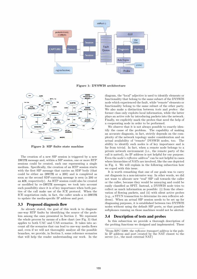
Figure 1: DYSWIS architecture
Figure 2: SIP finite state machine
The creation of a new SIP session is triggered by a newINVITE message and, within a SIP session, one or more RTPsessions could be created, each one representing a singlemedium. Specifically, the creation of an RTP session startswith the first SIP message that carries an SDP body (thatcould be either an INVITE or a 200) and is completed assoon as the second SDP-carrying message is seen (a 200 oran ACK, respectively). An RTP session could also be createdor modified by re-INVITE messages; we took into accountsuch possibility since it is of key importance when both par-ties of the call make use of the ICE protocol. When theICE negotiation ends, in fact, the caller sends a re-INVITEto update the media-specific IP address and port.
3.3 Proposed diagnosis flowAs already stated, the goal of this work is to diagnose
one-way RTP faults by identifying the source of the prob-lem among the ones presented in Section 2. We representthe whole process by means of a flow chart (see Fig. 3) thatapplies to both UAC and UAS scenarios. It takes into ac-count all the scenarios that can lead to one-way media flowsand, even if we will not thoroughly analyze all the possiblebranches, we provide, in Section 5, some reference scenariosthat will help the reader understanding our work. In the
diagram, the “local” adjective is used to identify elements orfunctionality that belong to the same subnet of the DYSWISnode which experienced the fault, while“remote”elements orfunctionality belong to the same subnet of the other party.We also make a distinction between tests and probes: theformer class only exploits local information, while the latterplays an active role by introducing packets into the network.Finally, we explicitly mark the probes that need the help ofa cooperating node in order to be performed.
We observe that it is not always possible to exactly iden-tify the cause of the problem. The capability of makingan accurate diagnosis, in fact, strictly depends on the com-plexity of the network topology under consideration and onactual availability of “remote” DYSWIS nodes, too. Theability to identify such nodes is of key importance and isfar from trivial. In fact, when a remote node belongs to aprivate network environment (i.e., the remote party of thecall is natted), its IP address is not helpful for our purpose.Even the node’s reflexive address4 can be not helpful in caseswhere hierarchies of NATs are involved, like the one depictedin Fig. 4. We will explain in the following subsection howwe coped with this issue.
It is worth remarking that one of our goals was to carryout diagnosis in a non-intrusive way. In other words, we didnot want to allocate new “real” SIP call towards the calleror the callee, because they would be annoying and could beeasily classified as SPIT. Instead, a DYSWIS node tries tocollect as much information as possible: (i) from the obser-vation of flowing packets, and (ii) with silent active probes(e.g., a STUN transaction to determine its own reflexive ad-dress). When an actual SIP session needs to be set up fordiagnosing purposes, it is established between two DYSWISnodes without using the default SIP ports, so that possiblesoftphones running on those machines would not be alerted.
3.4 Description of tests and probesIn this subsection we provide a thorough description of
the probing functions we designed and implemented. These
4From RFC 5389: the reflexive transport address is the pub-lic IP address and port created by the NAT closest to theserver (i.e., the most external NAT)
155
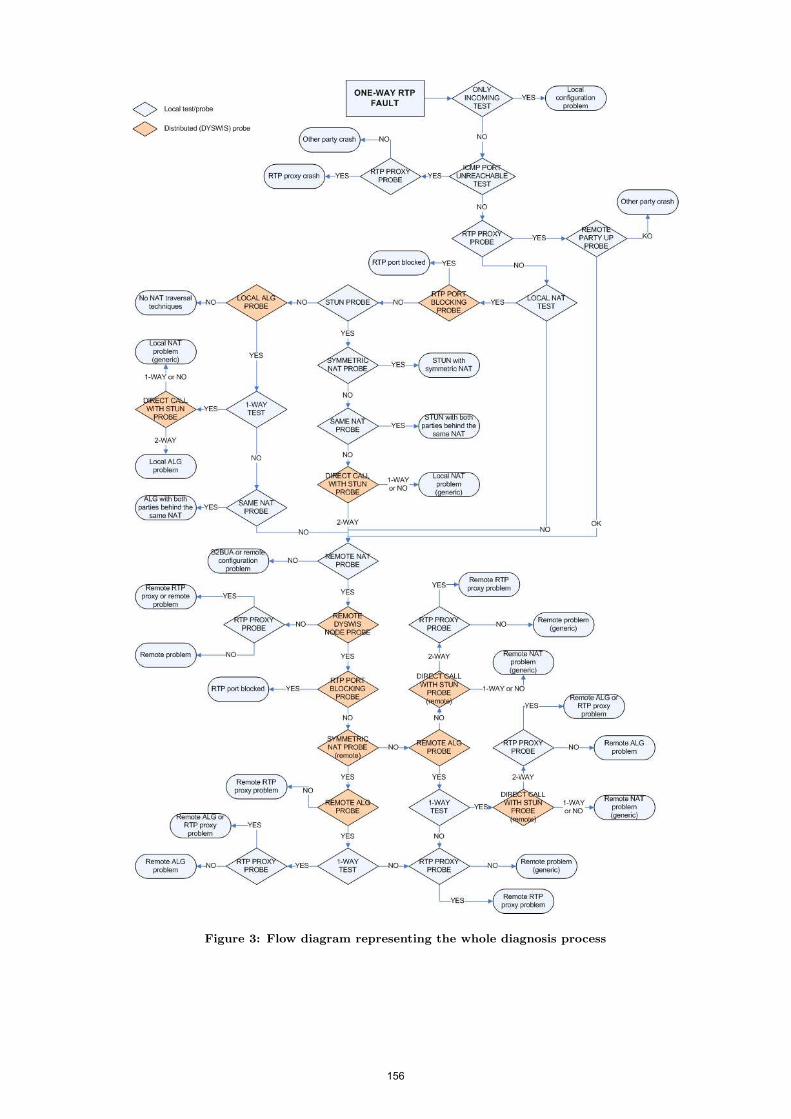
Figure 3: Flow diagram representing the whole diagnosis process
156
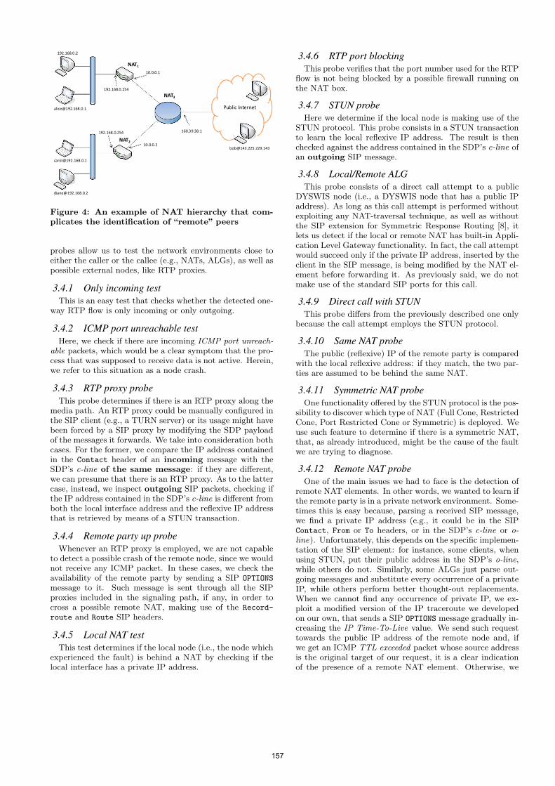
Public Internet
NAT3
NAT2
NAT1
192.168.0.254
10.0.0.2
10.0.0.1
192.168.0.254
160.39.38.1
192.168.0.2
Figure 4: An example of NAT hierarchy that com-plicates the identification of “remote” peers
probes allow us to test the network environments close toeither the caller or the callee (e.g., NATs, ALGs), as well aspossible external nodes, like RTP proxies.
3.4.1 Only incoming testThis is an easy test that checks whether the detected one-
way RTP flow is only incoming or only outgoing.
3.4.2 ICMP port unreachable testHere, we check if there are incoming ICMP port unreach-
able packets, which would be a clear symptom that the pro-cess that was supposed to receive data is not active. Herein,we refer to this situation as a node crash.
3.4.3 RTP proxy probeThis probe determines if there is an RTP proxy along the
media path. An RTP proxy could be manually configured inthe SIP client (e.g., a TURN server) or its usage might havebeen forced by a SIP proxy by modifying the SDP payloadof the messages it forwards. We take into consideration bothcases. For the former, we compare the IP address containedin the Contact header of an incoming message with theSDP’s c-line of the same message: if they are different,we can presume that there is an RTP proxy. As to the lattercase, instead, we inspect outgoing SIP packets, checking ifthe IP address contained in the SDP’s c-line is different fromboth the local interface address and the reflexive IP addressthat is retrieved by means of a STUN transaction.
3.4.4 Remote party up probeWhenever an RTP proxy is employed, we are not capable
to detect a possible crash of the remote node, since we wouldnot receive any ICMP packet. In these cases, we check theavailability of the remote party by sending a SIP OPTIONS
message to it. Such message is sent through all the SIPproxies included in the signaling path, if any, in order tocross a possible remote NAT, making use of the Record-
route and Route SIP headers.
3.4.5 Local NAT testThis test determines if the local node (i.e., the node which
experienced the fault) is behind a NAT by checking if thelocal interface has a private IP address.
3.4.6 RTP port blockingThis probe verifies that the port number used for the RTP
flow is not being blocked by a possible firewall running onthe NAT box.
3.4.7 STUN probeHere we determine if the local node is making use of the
STUN protocol. This probe consists in a STUN transactionto learn the local reflexive IP address. The result is thenchecked against the address contained in the SDP’s c-line ofan outgoing SIP message.
3.4.8 Local/Remote ALGThis probe consists of a direct call attempt to a public
DYSWIS node (i.e., a DYSWIS node that has a public IPaddress). As long as this call attempt is performed withoutexploiting any NAT-traversal technique, as well as withoutthe SIP extension for Symmetric Response Routing [8], itlets us detect if the local or remote NAT has built-in Appli-cation Level Gateway functionality. In fact, the call attemptwould succeed only if the private IP address, inserted by theclient in the SIP message, is being modified by the NAT el-ement before forwarding it. As previously said, we do notmake use of the standard SIP ports for this call.
3.4.9 Direct call with STUNThis probe differs from the previously described one only
because the call attempt employs the STUN protocol.
3.4.10 Same NAT probeThe public (reflexive) IP of the remote party is compared
with the local reflexive address: if they match, the two par-ties are assumed to be behind the same NAT.
3.4.11 Symmetric NAT probeOne functionality offered by the STUN protocol is the pos-
sibility to discover which type of NAT (Full Cone, RestrictedCone, Port Restricted Cone or Symmetric) is deployed. Weuse such feature to determine if there is a symmetric NAT,that, as already introduced, might be the cause of the faultwe are trying to diagnose.
3.4.12 Remote NAT probeOne of the main issues we had to face is the detection of
remote NAT elements. In other words, we wanted to learn ifthe remote party is in a private network environment. Some-times this is easy because, parsing a received SIP message,we find a private IP address (e.g., it could be in the SIPContact, From or To headers, or in the SDP’s c-line or o-line). Unfortunately, this depends on the specific implemen-tation of the SIP element: for instance, some clients, whenusing STUN, put their public address in the SDP’s o-line,while others do not. Similarly, some ALGs just parse out-going messages and substitute every occurrence of a privateIP, while others perform better thought-out replacements.When we cannot find any occurrence of private IP, we ex-ploit a modified version of the IP traceroute we developedon our own, that sends a SIP OPTIONS message gradually in-creasing the IP Time-To-Live value. We send such requesttowards the public IP address of the remote node and, ifwe get an ICMP TTL exceeded packet whose source addressis the original target of our request, it is a clear indicationof the presence of a remote NAT element. Otherwise, we
157
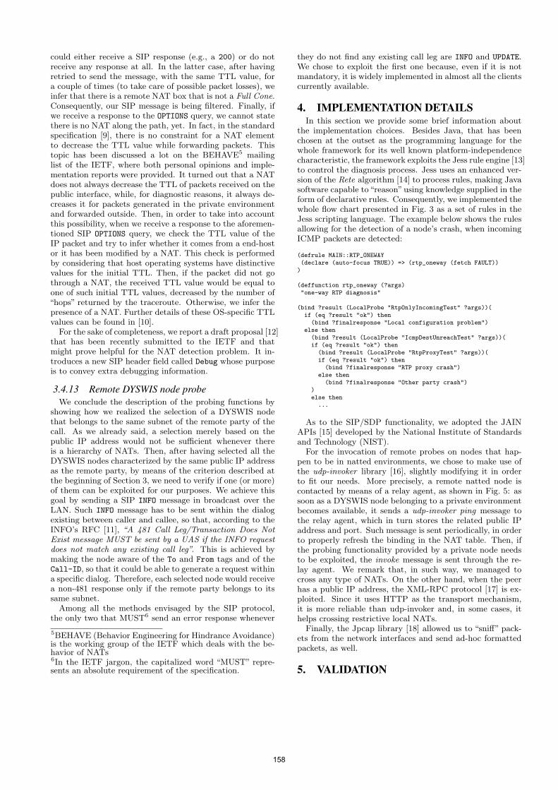
could either receive a SIP response (e.g., a 200) or do notreceive any response at all. In the latter case, after havingretried to send the message, with the same TTL value, fora couple of times (to take care of possible packet losses), weinfer that there is a remote NAT box that is not a Full Cone.Consequently, our SIP message is being filtered. Finally, ifwe receive a response to the OPTIONS query, we cannot statethere is no NAT along the path, yet. In fact, in the standardspecification [9], there is no constraint for a NAT elementto decrease the TTL value while forwarding packets. Thistopic has been discussed a lot on the BEHAVE5 mailinglist of the IETF, where both personal opinions and imple-mentation reports were provided. It turned out that a NATdoes not always decrease the TTL of packets received on thepublic interface, while, for diagnostic reasons, it always de-creases it for packets generated in the private environmentand forwarded outside. Then, in order to take into accountthis possibility, when we receive a response to the aforemen-tioned SIP OPTIONS query, we check the TTL value of theIP packet and try to infer whether it comes from a end-hostor it has been modified by a NAT. This check is performedby considering that host operating systems have distinctivevalues for the initial TTL. Then, if the packet did not gothrough a NAT, the received TTL value would be equal toone of such initial TTL values, decreased by the number of“hops” returned by the traceroute. Otherwise, we infer thepresence of a NAT. Further details of these OS-specific TTLvalues can be found in [10].
For the sake of completeness, we report a draft proposal [12]that has been recently submitted to the IETF and thatmight prove helpful for the NAT detection problem. It in-troduces a new SIP header field called Debug whose purposeis to convey extra debugging information.
3.4.13 Remote DYSWIS node probeWe conclude the description of the probing functions by
showing how we realized the selection of a DYSWIS nodethat belongs to the same subnet of the remote party of thecall. As we already said, a selection merely based on thepublic IP address would not be sufficient whenever thereis a hierarchy of NATs. Then, after having selected all theDYSWIS nodes characterized by the same public IP addressas the remote party, by means of the criterion described atthe beginning of Section 3, we need to verify if one (or more)of them can be exploited for our purposes. We achieve thisgoal by sending a SIP INFO message in broadcast over theLAN. Such INFO message has to be sent within the dialogexisting between caller and callee, so that, according to theINFO’s RFC [11], “A 481 Call Leg/Transaction Does NotExist message MUST be sent by a UAS if the INFO requestdoes not match any existing call leg”. This is achieved bymaking the node aware of the To and From tags and of theCall-ID, so that it could be able to generate a request withina specific dialog. Therefore, each selected node would receivea non-481 response only if the remote party belongs to itssame subnet.
Among all the methods envisaged by the SIP protocol,the only two that MUST6 send an error response whenever
5BEHAVE (Behavior Engineering for Hindrance Avoidance)is the working group of the IETF which deals with the be-havior of NATs6In the IETF jargon, the capitalized word “MUST” repre-sents an absolute requirement of the specification.
they do not find any existing call leg are INFO and UPDATE.We chose to exploit the first one because, even if it is notmandatory, it is widely implemented in almost all the clientscurrently available.
4. IMPLEMENTATION DETAILSIn this section we provide some brief information about
the implementation choices. Besides Java, that has beenchosen at the outset as the programming language for thewhole framework for its well known platform-independencecharacteristic, the framework exploits the Jess rule engine [13]to control the diagnosis process. Jess uses an enhanced ver-sion of the Rete algorithm [14] to process rules, making Javasoftware capable to“reason”using knowledge supplied in theform of declarative rules. Consequently, we implemented thewhole flow chart presented in Fig. 3 as a set of rules in theJess scripting language. The example below shows the rulesallowing for the detection of a node’s crash, when incomingICMP packets are detected:
(defrule MAIN::RTP_ONEWAY(declare (auto-focus TRUE)) => (rtp_oneway (fetch FAULT))
)
(deffunction rtp_oneway (?args)"one-way RTP diagnosis"
(bind ?result (LocalProbe "RtpOnlyIncomingTest" ?args))(if (eq ?result "ok") then(bind ?finalresponse "Local configuration problem")
else then(bind ?result (LocalProbe "IcmpDestUnreachTest" ?args))(if (eq ?result "ok") then
(bind ?result (LocalProbe "RtpProxyTest" ?args))(if (eq ?result "ok") then(bind ?finalresponse "RTP proxy crash")
else then(bind ?finalresponse "Other party crash")
)else then
...
As to the SIP/SDP functionality, we adopted the JAINAPIs [15] developed by the National Institute of Standardsand Technology (NIST).
For the invocation of remote probes on nodes that hap-pen to be in natted environments, we chose to make use ofthe udp-invoker library [16], slightly modifying it in orderto fit our needs. More precisely, a remote natted node iscontacted by means of a relay agent, as shown in Fig. 5: assoon as a DYSWIS node belonging to a private environmentbecomes available, it sends a udp-invoker ping message tothe relay agent, which in turn stores the related public IPaddress and port. Such message is sent periodically, in orderto properly refresh the binding in the NAT table. Then, ifthe probing functionality provided by a private node needsto be exploited, the invoke message is sent through the re-lay agent. We remark that, in such way, we managed tocross any type of NATs. On the other hand, when the peerhas a public IP address, the XML-RPC protocol [17] is ex-ploited. Since it uses HTTP as the transport mechanism,it is more reliable than udp-invoker and, in some cases, ithelps crossing restrictive local NATs.
Finally, the Jpcap library [18] allowed us to “sniff” pack-ets from the network interfaces and send ad-hoc formattedpackets, as well.
5. VALIDATION
158
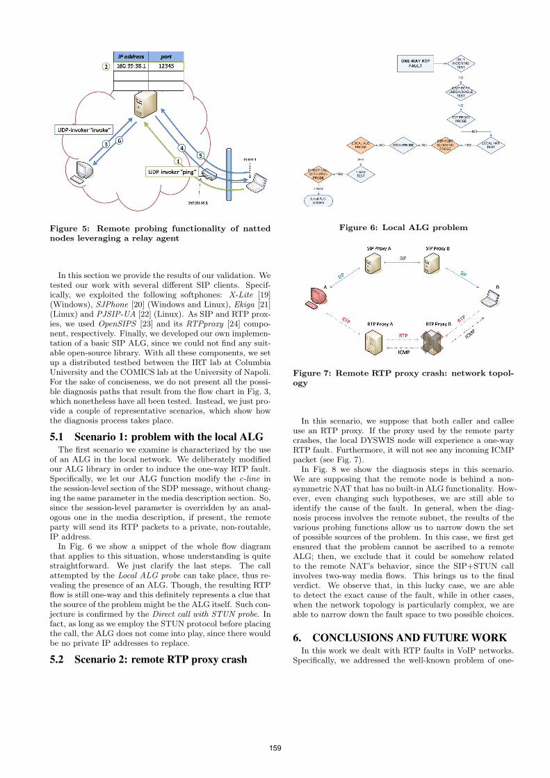
Figure 5: Remote probing functionality of nattednodes leveraging a relay agent
In this section we provide the results of our validation. Wetested our work with several different SIP clients. Specif-ically, we exploited the following softphones: X-Lite [19](Windows), SJPhone [20] (Windows and Linux), Ekiga [21](Linux) and PJSIP-UA [22] (Linux). As SIP and RTP prox-ies, we used OpenSIPS [23] and its RTPproxy [24] compo-nent, respectively. Finally, we developed our own implemen-tation of a basic SIP ALG, since we could not find any suit-able open-source library. With all these components, we setup a distributed testbed between the IRT lab at ColumbiaUniversity and the COMICS lab at the University of Napoli.For the sake of conciseness, we do not present all the possi-ble diagnosis paths that result from the flow chart in Fig. 3,which nonetheless have all been tested. Instead, we just pro-vide a couple of representative scenarios, which show howthe diagnosis process takes place.
5.1 Scenario 1: problem with the local ALGThe first scenario we examine is characterized by the use
of an ALG in the local network. We deliberately modifiedour ALG library in order to induce the one-way RTP fault.Specifically, we let our ALG function modify the c-line inthe session-level section of the SDP message, without chang-ing the same parameter in the media description section. So,since the session-level parameter is overridden by an anal-ogous one in the media description, if present, the remoteparty will send its RTP packets to a private, non-routable,IP address.
In Fig. 6 we show a snippet of the whole flow diagramthat applies to this situation, whose understanding is quitestraightforward. We just clarify the last steps. The callattempted by the Local ALG probe can take place, thus re-vealing the presence of an ALG. Though, the resulting RTPflow is still one-way and this definitely represents a clue thatthe source of the problem might be the ALG itself. Such con-jecture is confirmed by the Direct call with STUN probe. Infact, as long as we employ the STUN protocol before placingthe call, the ALG does not come into play, since there wouldbe no private IP addresses to replace.
5.2 Scenario 2: remote RTP proxy crash
Figure 6: Local ALG problem
Figure 7: Remote RTP proxy crash: network topol-ogy
In this scenario, we suppose that both caller and calleeuse an RTP proxy. If the proxy used by the remote partycrashes, the local DYSWIS node will experience a one-wayRTP fault. Furthermore, it will not see any incoming ICMPpacket (see Fig. 7).
In Fig. 8 we show the diagnosis steps in this scenario.We are supposing that the remote node is behind a non-symmetric NAT that has no built-in ALG functionality. How-ever, even changing such hypotheses, we are still able toidentify the cause of the fault. In general, when the diag-nosis process involves the remote subnet, the results of thevarious probing functions allow us to narrow down the setof possible sources of the problem. In this case, we first getensured that the problem cannot be ascribed to a remoteALG; then, we exclude that it could be somehow relatedto the remote NAT’s behavior, since the SIP+STUN callinvolves two-way media flows. This brings us to the finalverdict. We observe that, in this lucky case, we are ableto detect the exact cause of the fault, while in other cases,when the network topology is particularly complex, we areable to narrow down the fault space to two possible choices.
6. CONCLUSIONS AND FUTURE WORKIn this work we dealt with RTP faults in VoIP networks.
Specifically, we addressed the well-known problem of one-
159
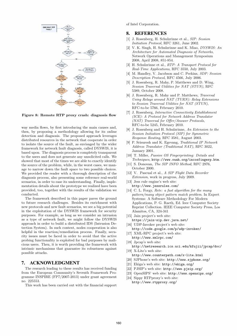
Figure 8: Remote RTP proxy crash: diagnosis flow
way media flows, by first introducing the main causes and,then, by proposing a methodology allowing for its onlinedetection and diagnosis. The proposed approach leveragesdistributed resources in the network that cooperate in orderto isolate the source of the fault, as envisaged by the widerframework for network fault diagnosis, called DYSWIS, it isbased upon. The diagnosis process is completely transparentto the users and does not generate any unsolicited calls. Weshowed that most of the times we are able to exactly identifythe source of the problem, while, in the worst cases, we man-age to narrow down the fault space to two possible choices.We provided the reader with a thorough description of thediagnosis process, also presenting some reference real-worldscenarios, in order to ease its understanding. Finally, imple-mentation details about the prototype we realized have beenprovided, too, together with the results of the validation weconducted.
The framework described in this paper paves the groundto future research challenges. Besides its enrichment withnew protocols and new fault scenarios, we see a big potentialin the exploitation of the DYSWIS framework for securitypurposes. For example, as long as we consider an intrusionas a type of network fault, we might follow the DYSWISapproach in order to build a distributed IDS (Intrusion De-tection System). In such context, nodes cooperation is alsohelpful in the reaction/remediation process. Finally, secu-rity issues must be faced in order to avoid that the activeprobing functionality is exploited for bad purposes by mali-cious users. Then, it is worth providing the framework withintrinsic mechanisms that guarantee its robustness againstpossible attacks.
7. ACKNOWLEDGMENTThe research leading to these results has received funding
from the European Community’s Seventh Framework Pro-gramme INSPIRE (FP7/2007-2013) under grant agreementno. 225553.
This work has been carried out with the financial support
of Intel Corporation.
8. REFERENCES[1] J. Rosenberg, H. Schulzrinne et al., SIP: Session
Initiation Protocol, RFC 3261, June 2002.
[2] V. K. Singh, H. Schulzrinne and K. Miao, DYSWIS: AnArchitecture for Automated Diagnosis of Networks,Network Operations and Management Symposium2008, April 2008, 851-854.
[3] H. Schulzrinne et al., RTP: A Transport Protocol forReal-Time Applications, RFC 3550, July 2003.
[4] M. Handley, V. Jacobson and C. Perkins, SDP: SessionDescription Protocol, RFC 4566, July 2006.
[5] J. Rosenberg, R. Mahy, P. Matthews and D. Wing,Session Traversal Utilities for NAT (STUN), RFC5389, October 2008.
[6] J. Rosenberg, R. Mahy and P. Matthews, TraversalUsing Relays around NAT (TURN): Relay Extensionsto Session Traversal Utilities for NAT (STUN),RFC-to-be 5766, February 2010.
[7] J. Rosenberg, Interactive Connectivity Establishment(ICE): A Protocol for Network Address Translator(NAT) Traversal for Offer/Answer Protocols,RFC-to-be 5245, February 2010.
[8] J. Rosenberg and H. Schulzrinne, An Extension to theSession Initiation Protocol (SIP) for SymmetricResponse Routing, RFC 3581, August 2003.
[9] P. Srisuresh and K. Egevang, Traditional IP NetworkAddress Translator (Traditional NAT), RFC 3022,January 2001.
[10] T. Miller, Passive OS Fingerprinting: Details andTechniques, http://www.ouah.org/incosfingerp.htm.
[11] S. Donovan, The SIP INFO Method, RFC 2976,October 2000.
[12] V. Pascual et al., A SIP Flight Data RecorderExtension, work in progress, July 2009.
[13] Jess rule engine’s web site:http://www.jessrules.com/
[14] C. L. Forgy, Rete: a fast algorithm for the manypattern/many object pattern match problem. In ExpertSystems: A Software Methodology For ModernApplications, P. G. Raeth, Ed. Ieee Computer SocietyReprint Collection. IEEE Computer Society Press, LosAlamitos, CA, 324-341
[15] Jain project’s web site:https://jain-sip.dev.java.net/
[16] UDP-Invoker project’s web site:http://code.google.com/p/udp-invoker/
[17] XML-RPC project’s web site:http://www.xmlrpc.com/
[18] Jpcap’s web site:http://netresearch.ics.uci.edu/kfujii/jpcap/doc/
[19] X-Lite’s web site:http://www.counterpath.com/x-lite.html
[20] SJPhone’s web site: http://www.sjphone.org/
[21] Ekiga’s web site: http://ekiga.org/
[22] PJSIP’s web site: http://www.pjsip.org/
[23] OpenSIPS’ web site: http://www.opensips.org/
[24] Sippy RTPproxy’s web site:http://www.rtpproxy.org/
160
Work in Progress: A Communications-Enabled Collaboration Platform
John Buford, Kishore Dhara, Venky Krishnaswamy, Xiaotao Wu IP Communications Department
Avaya Labs Research buford, dhara, venky, [email protected]
Mario Kolberg Dept. of Computing Science and
Mathematics, Univ. of Stirling [email protected]
ABSTRACT
Existing online collaboration tools and platforms provide basic communications integration and the ability to include some real-time information sources. For enterprise use there are requirements for extending these tools with better integration with existing intelligent communication systems, simplifying the collaboration life cycle, enabling the collaboration process, and being able to support long-term collaborations in a variety of ways. We present a new model for such a collaboration environment called ConnectedSpaces. Like a number of existing systems, ConnectedSpaces uses a collaboration space as the basic construct. We present important feature sets of ConnectedSpaces, including views, spaces as communication endpoints, space persistence and structuring, and a variety of types of embedded objects. We then describe novel features of the ConnectedSpaces framework, including space history, embedded gadgets and robots, semantic processing, and integration with other collaboration frameworks. Finally we illustrate specific ConnectedSpaces functionality with examples from experimental work.
Categories and Subject Descriptors H.4.3 [Communications Applications]: Computer communication and information browsers
General Terms Management, Design
Keywords Collaboration Tools, Enterprise Communication, Feature sets
1. INTRODUCTION Today’s enterprise collaboration platforms include well known web conferencing systems, online document editing, shared document repositories, and voice and video conferencing. Rudimentary communications integration is starting to appear, with softphone and instant message components being integrated into web browsers and collaboration tools through Web 2.0 programming.
More than twenty years of research in groupware, computer-supported cooperative work, and mixed reality systems has demonstrated a rich set of potential features for collaboration environments. However the convergence of internet-scale telephony, messaging, RIA, web, online media, social networking, and real-time information feeds has rapidly enlarged the design choices. It has also made it possible to launch mass market collaboration applications which are distinguished not by major feature differences but by stylistic associations such as tweeting, yammering, skyping, IM-ing, and blogging.
We envision the following areas of evolution to these tools and platforms for increasing their utility for information workers in enterprises, and are particularly interested in seamless integration of intelligent communication capability:
- Highly composable collaboration spaces including space addressing and nesting
- Collaboration spaces as communication endpoints - Space history and temporal control which includes
semantic time markers and layered time relationships - Group management and information security In this paper we present the following results:
1. We describe features for ConnectedSpaces, an enterprise-oriented collaboration platform, and compare these features with existing collaboration platforms.
2. We present the ConnectedSpaces framework for building scalable collaboration platform.
3. We present implemented components of ConnectedSpaces-like functionality as illustration of key ideas.
Section 2 summarizes related work in contemporary collaboration systems. Section 3 describes the ConnectedSpaces collaboration framework. Section 4 presents the categories of ConnectedSpaces features, and describes example use cases. Section 4 describes the ConnectedSpaces collaboration framework. Section 5 describes implementation work on ConnectedSpaces components, and Section 6 concludes this paper.
161
2. RELATED WORK Collaboration platforms vary from wikis, blogs, and shared documents to web-based collaboration systems to 3D collaboration spaces offered by virtual worlds. The focus in this paper is on the features of collaboration systems and is independent of the underlying collaboration tools used. A brief discussion of the existing classes of collaboration tools helps in understanding the new features of collaboration for enterprises that are discussed in the rest of this paper. For a survey of collaboration platforms, see for example [1].
Web based collaborations such as wikis, blogs, conferencing systems such as WebEx or Meeting Exchange are used for collaboration in enterprises. While wikis and blogs are used as collaborative authoring tools for a large number of users, other web-based conferencing systems are used to create a space that combines users’ communication links with desk-top application sharing. Typically, these include audio and video conferencing and features such as side-bar, remote-party mute, etc. These systems are based on the notion that there is a common space that is accessed through a browser and users can collaborate in that space.
Microsoft Groove [3] and Sharepoint offer an alternate approach for collaboration on a set of files or documents. The collaboration client is a thick application and not a generic browser based client. Besides the client, the major variation of this approach is the individual view of data until it is synchronized. That is, each user in the collaboration session can have their view of the data that they work on remotely and synchronize through various means to a common repository. This synchronization is enabled in the client by providing tools for communication between users and by displaying the presence status of various users that belong to the collaboration session.
Other new collaboration platforms such as Google’s Wave [1] and Thinkature [4] offer real-time collaboration tools that allows users to create and manage their own collaboration spaces. The ability to create a collaboration space allows users to tailor collaboration space to the needs of a project or for a particular collaborative effort. Persisting these spaces allows users to continue a collaboration in a given space, and continue to use all the contacts, content, and other tools previously added to the space. Further, Google Wave allows threading of a collaborative effort as a Wave and allows user-defined applications (gadgets) and automated participants (robots) to act on such waves. In this paper, we argue that while these are important steps in enhancing collaboration spaces, for enterprise collaboration additional features are needed in those collaboration spaces.
There is another set of collaboration platforms that are based on virtual worlds, such as Second Life [5], Kaneva [6], and There.com [7]. These virtual words offer features
such as immediacy (real-time interaction), interaction (ability to view, create, modify, and act) on a shared space that is closer to replicating reality. While these platforms offer rich user-experiences, often the creation of collaboration spaces and the navigation in those spaces is not easy. The taxonomy of networked virtual environments [8] discusses the need for designing a network architecture within virtual environments.
Broll et al. [9] defined an approach for inter-world communication. Bouras et al. [10] defined an approach for inter-world communication. Bouras et al. [11] proposed a distributed virtual reality networking platform for multi-user interaction. Sallnas [12] provides a comparative study of different modes of communications. All of these efforts improve communication and interaction among users of virtual worlds, but are limited to instant messaging or in-world voice. In this paper we propose novel concepts for integrating enterprise communications in collaboration platforms that is mixing in-world (virtual) communication with real world enterprise communication systems. Voice over IP (VoIP) based services provided by companies like Vivox [13] offer communication within virtual worlds, but are not enterprise grade with respect to their scope and their features.
3. CONNECTEDSPACES 3.1 Motivation and Goals Today's collaboration tools are powerful and widely used. Nevertheless we observe:
- the need for better integration of intelligent communication capability with collaboration environments.
- the value of simplifying the creation and initialization of new collaborations.
- the importance of being able to structure collaborations and treat them as persistent and externally reference-able, since enterprise collaborations are often long-term, deal with complex information, and are important to document.
To achieve these goals, our ConnectedSpaces framework uses increased automation, meta (view) mechanisms, integration with external information and communication resources, and semantic processing where feasible.
The following table summarizes key concepts in our collaboration model.
Table 1 Concepts in ConnectedSpaces Concept Definition space (collaboration space)
A collaboration space provides a shared persistent container in which users perform collaboration activities. It requires resources, such as computation, communication, and storage devices, to support those activities. For
162
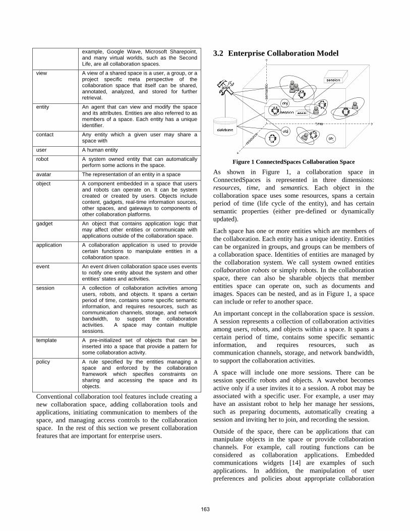
example, Google Wave, Microsoft Sharepoint, and many virtual worlds, such as the Second Life, are all collaboration spaces.
view A view of a shared space is a user, a group, or a project specific meta perspective of the collaboration space that itself can be shared, annotated, analyzed, and stored for further retrieval.
entity An agent that can view and modify the space and its attributes. Entities are also referred to as members of a space. Each entity has a unique identifier.
contact Any entity which a given user may share a space with
user A human entity
robot A system owned entity that can automatically perform some actions in the space.
avatar The representation of an entity in a space
object A component embedded in a space that users and robots can operate on. It can be system created or created by users. Objects include content, gadgets, real-time information sources, other spaces, and gateways to components of other collaboration platforms.
gadget An object that contains application logic that may affect other entities or communicate with applications outside of the collaboration space.
application A collaboration application is used to provide certain functions to manipulate entities in a collaboration space.
event An event driven collaboration space uses events to notify one entity about the system and other entities’ states and activities.
session A collection of collaboration activities among users, robots, and objects. It spans a certain period of time, contains some specific semantic information, and requires resources, such as communication channels, storage, and network bandwidth, to support the collaboration activities. A space may contain multiple sessions.
template A pre-initialized set of objects that can be inserted into a space that provide a pattern for some collaboration activity.
policy A rule specified by the entities managing a space and enforced by the collaboration framework which specifies constraints on sharing and accessing the space and its objects.
Conventional collaboration tool features include creating a new collaboration space, adding collaboration tools and applications, initiating communication to members of the space, and managing access controls to the collaboration space. In the rest of this section we present collaboration features that are important for enterprise users.
3.2 Enterprise Collaboration Model
sem
antic
resou
rce
Figure 1 ConnectedSpaces Collaboration Space
As shown in Figure 1, a collaboration space in ConnectedSpaces is represented in three dimensions: resources, time, and semantics. Each object in the collaboration space uses some resources, spans a certain period of time (life cycle of the entity), and has certain semantic properties (either pre-defined or dynamically updated).
Each space has one or more entities which are members of the collaboration. Each entity has a unique identity. Entities can be organized in groups, and groups can be members of a collaboration space. Identities of entities are managed by the collaboration system. We call system owned entities collaboration robots or simply robots. In the collaboration space, there can also be sharable objects that member entities space can operate on, such as documents and images. Spaces can be nested, and as in Figure 1, a space can include or refer to another space.
An important concept in the collaboration space is session. A session represents a collection of collaboration activities among users, robots, and objects within a space. It spans a certain period of time, contains some specific semantic information, and requires resources, such as communication channels, storage, and network bandwidth, to support the collaboration activities.
A space will include one more sessions. There can be session specific robots and objects. A wavebot becomes active only if a user invites it to a session. A robot may be associated with a specific user. For example, a user may have an assistant robot to help her manage her sessions, such as preparing documents, automatically creating a session and inviting her to join, and recording the session.
Outside of the space, there can be applications that can manipulate objects in the space or provide collaboration channels. For example, call routing functions can be considered as collaboration applications. Embedded communications widgets [14] are examples of such applications. In addition, the manipulation of user preferences and policies about appropriate collaboration
163
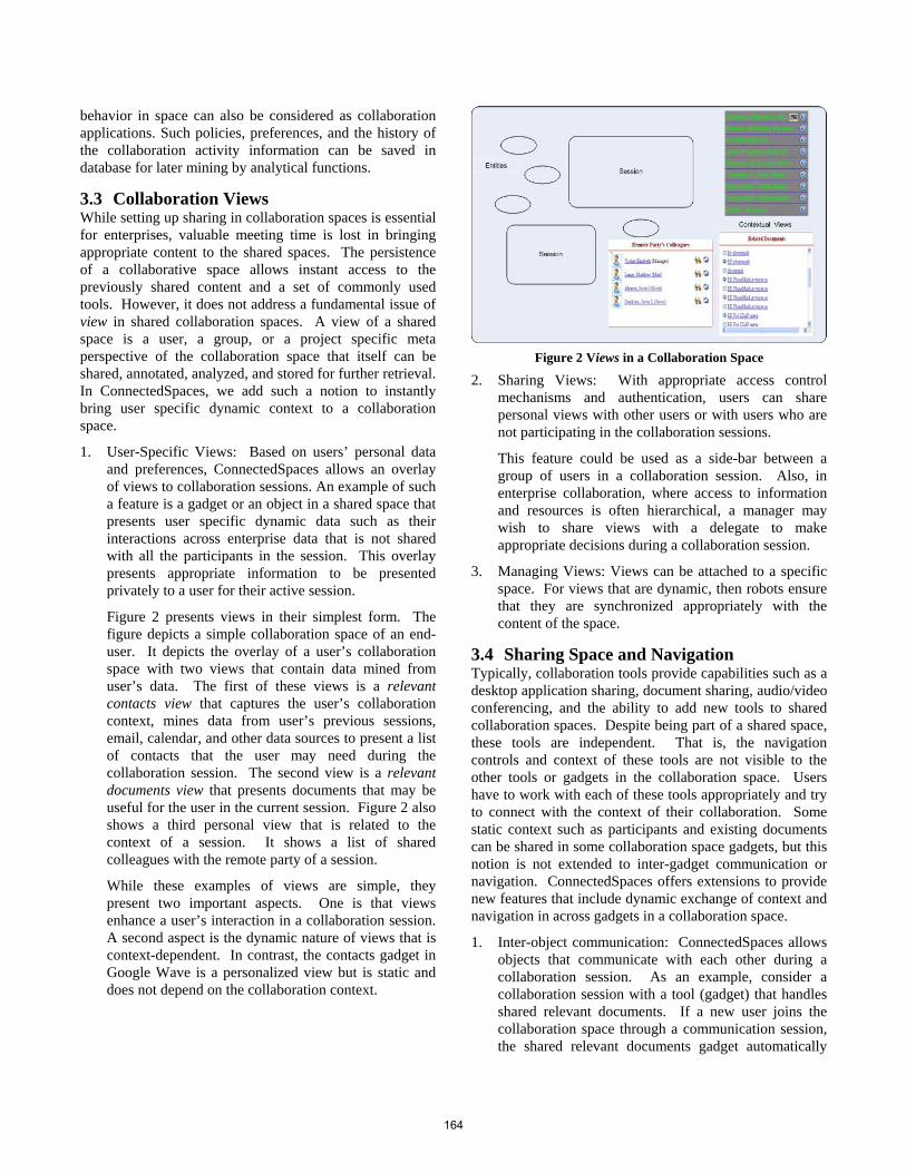
behavior in space can also be considered as collaboration applications. Such policies, preferences, and the history of the collaboration activity information can be saved in database for later mining by analytical functions.
3.3 Collaboration Views While setting up sharing in collaboration spaces is essential for enterprises, valuable meeting time is lost in bringing appropriate content to the shared spaces. The persistence of a collaborative space allows instant access to the previously shared content and a set of commonly used tools. However, it does not address a fundamental issue of view in shared collaboration spaces. A view of a shared space is a user, a group, or a project specific meta perspective of the collaboration space that itself can be shared, annotated, analyzed, and stored for further retrieval. In ConnectedSpaces, we add such a notion to instantly bring user specific dynamic context to a collaboration space.
1. User-Specific Views: Based on users’ personal data and preferences, ConnectedSpaces allows an overlay of views to collaboration sessions. An example of such a feature is a gadget or an object in a shared space that presents user specific dynamic data such as their interactions across enterprise data that is not shared with all the participants in the session. This overlay presents appropriate information to be presented privately to a user for their active session.
Figure 2 presents views in their simplest form. The figure depicts a simple collaboration space of an end-user. It depicts the overlay of a user’s collaboration space with two views that contain data mined from user’s data. The first of these views is a relevant contacts view that captures the user’s collaboration context, mines data from user’s previous sessions, email, calendar, and other data sources to present a list of contacts that the user may need during the collaboration session. The second view is a relevant documents view that presents documents that may be useful for the user in the current session. Figure 2 also shows a third personal view that is related to the context of a session. It shows a list of shared colleagues with the remote party of a session.
While these examples of views are simple, they present two important aspects. One is that views enhance a user’s interaction in a collaboration session. A second aspect is the dynamic nature of views that is context-dependent. In contrast, the contacts gadget in Google Wave is a personalized view but is static and does not depend on the collaboration context.
Figure 2 Views in a Collaboration Space
2. Sharing Views: With appropriate access control mechanisms and authentication, users can share personal views with other users or with users who are not participating in the collaboration sessions.
This feature could be used as a side-bar between a group of users in a collaboration session. Also, in enterprise collaboration, where access to information and resources is often hierarchical, a manager may wish to share views with a delegate to make appropriate decisions during a collaboration session.
3. Managing Views: Views can be attached to a specific space. For views that are dynamic, then robots ensure that they are synchronized appropriately with the content of the space.
3.4 Sharing Space and Navigation Typically, collaboration tools provide capabilities such as a desktop application sharing, document sharing, audio/video conferencing, and the ability to add new tools to shared collaboration spaces. Despite being part of a shared space, these tools are independent. That is, the navigation controls and context of these tools are not visible to the other tools or gadgets in the collaboration space. Users have to work with each of these tools appropriately and try to connect with the context of their collaboration. Some static context such as participants and existing documents can be shared in some collaboration space gadgets, but this notion is not extended to inter-gadget communication or navigation. ConnectedSpaces offers extensions to provide new features that include dynamic exchange of context and navigation in across gadgets in a collaboration space.
1. Inter-object communication: ConnectedSpaces allows objects that communicate with each other during a collaboration session. As an example, consider a collaboration session with a tool (gadget) that handles shared relevant documents. If a new user joins the collaboration space through a communication session, the shared relevant documents gadget automatically
164
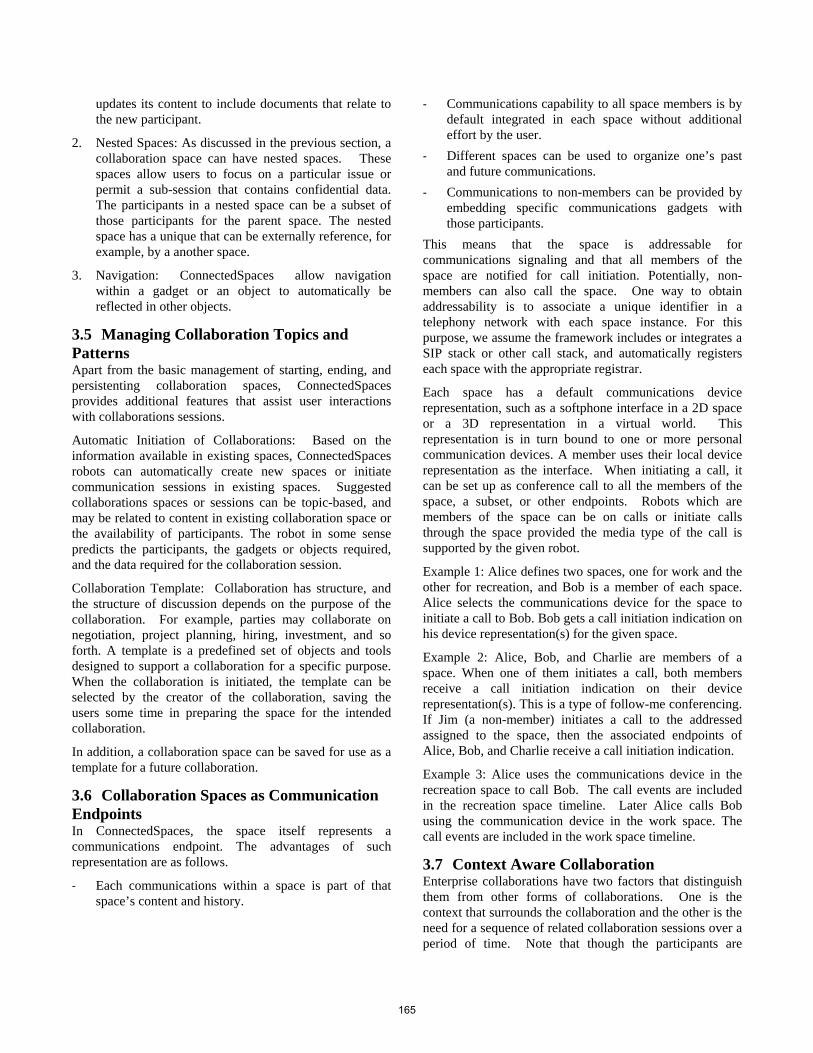
updates its content to include documents that relate to the new participant.
2. Nested Spaces: As discussed in the previous section, a collaboration space can have nested spaces. These spaces allow users to focus on a particular issue or permit a sub-session that contains confidential data. The participants in a nested space can be a subset of those participants for the parent space. The nested space has a unique that can be externally reference, for example, by a another space.
3. Navigation: ConnectedSpaces allow navigation within a gadget or an object to automatically be reflected in other objects.
3.5 Managing Collaboration Topics and Patterns Apart from the basic management of starting, ending, and persistenting collaboration spaces, ConnectedSpaces provides additional features that assist user interactions with collaborations sessions.
Automatic Initiation of Collaborations: Based on the information available in existing spaces, ConnectedSpaces robots can automatically create new spaces or initiate communication sessions in existing spaces. Suggested collaborations spaces or sessions can be topic-based, and may be related to content in existing collaboration space or the availability of participants. The robot in some sense predicts the participants, the gadgets or objects required, and the data required for the collaboration session.
Collaboration Template: Collaboration has structure, and the structure of discussion depends on the purpose of the collaboration. For example, parties may collaborate on negotiation, project planning, hiring, investment, and so forth. A template is a predefined set of objects and tools designed to support a collaboration for a specific purpose. When the collaboration is initiated, the template can be selected by the creator of the collaboration, saving the users some time in preparing the space for the intended collaboration.
In addition, a collaboration space can be saved for use as a template for a future collaboration.
3.6 Collaboration Spaces as Communication Endpoints In ConnectedSpaces, the space itself represents a communications endpoint. The advantages of such representation are as follows.
- Each communications within a space is part of that space’s content and history.
- Communications capability to all space members is by default integrated in each space without additional effort by the user.
- Different spaces can be used to organize one’s past and future communications.
- Communications to non-members can be provided by embedding specific communications gadgets with those participants.
This means that the space is addressable for communications signaling and that all members of the space are notified for call initiation. Potentially, non-members can also call the space. One way to obtain addressability is to associate a unique identifier in a telephony network with each space instance. For this purpose, we assume the framework includes or integrates a SIP stack or other call stack, and automatically registers each space with the appropriate registrar.
Each space has a default communications device representation, such as a softphone interface in a 2D space or a 3D representation in a virtual world. This representation is in turn bound to one or more personal communication devices. A member uses their local device representation as the interface. When initiating a call, it can be set up as conference call to all the members of the space, a subset, or other endpoints. Robots which are members of the space can be on calls or initiate calls through the space provided the media type of the call is supported by the given robot.
Example 1: Alice defines two spaces, one for work and the other for recreation, and Bob is a member of each space. Alice selects the communications device for the space to initiate a call to Bob. Bob gets a call initiation indication on his device representation(s) for the given space.
Example 2: Alice, Bob, and Charlie are members of a space. When one of them initiates a call, both members receive a call initiation indication on their device representation(s). This is a type of follow-me conferencing. If Jim (a non-member) initiates a call to the addressed assigned to the space, then the associated endpoints of Alice, Bob, and Charlie receive a call initiation indication.
Example 3: Alice uses the communications device in the recreation space to call Bob. The call events are included in the recreation space timeline. Later Alice calls Bob using the communication device in the work space. The call events are included in the work space timeline.
3.7 Context Aware Collaboration Enterprise collaborations have two factors that distinguish them from other forms of collaborations. One is the context that surrounds the collaboration and the other is the need for a sequence of related collaboration sessions over a period of time. Note that though the participants are
165
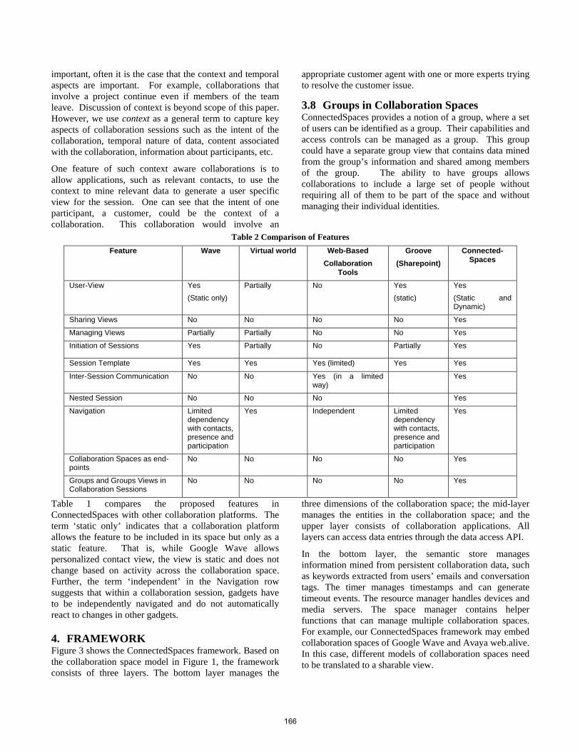
important, often it is the case that the context and temporal aspects are important. For example, collaborations that involve a project continue even if members of the team leave. Discussion of context is beyond scope of this paper. However, we use context as a general term to capture key aspects of collaboration sessions such as the intent of the collaboration, temporal nature of data, content associated with the collaboration, information about participants, etc.
One feature of such context aware collaborations is to allow applications, such as relevant contacts, to use the context to mine relevant data to generate a user specific view for the session. One can see that the intent of one participant, a customer, could be the context of a collaboration. This collaboration would involve an
appropriate customer agent with one or more experts trying to resolve the customer issue.
3.8 Groups in Collaboration Spaces ConnectedSpaces provides a notion of a group, where a set of users can be identified as a group. Their capabilities and access controls can be managed as a group. This group could have a separate group view that contains data mined from the group’s information and shared among members of the group. The ability to have groups allows collaborations to include a large set of people without requiring all of them to be part of the space and without managing their individual identities.
Table 2 Comparison of Features
Feature Wave Virtual world Web-Based Collaboration
Tools
Groove (Sharepoint)
Connected-Spaces
User-View Yes (Static only)
Partially No Yes (static)
Yes (Static and Dynamic)
Sharing Views No No No No Yes
Managing Views Partially Partially No No Yes
Initiation of Sessions Yes Partially No Partially Yes
Session Template Yes Yes Yes (limited) Yes Yes
Inter-Session Communication No No Yes (in a limited way)
Yes
Nested Session No No No Yes
Navigation Limited dependency with contacts, presence and participation
Yes Independent Limited dependency with contacts, presence and participation
Yes
Collaboration Spaces as end-points
No No No No Yes
Groups and Groups Views in Collaboration Sessions
No No No No Yes
Table 1 compares the proposed features in ConnectedSpaces with other collaboration platforms. The term ‘static only’ indicates that a collaboration platform allows the feature to be included in its space but only as a static feature. That is, while Google Wave allows personalized contact view, the view is static and does not change based on activity across the collaboration space. Further, the term ‘independent’ in the Navigation row suggests that within a collaboration session, gadgets have to be independently navigated and do not automatically react to changes in other gadgets.
4. FRAMEWORK Figure 3 shows the ConnectedSpaces framework. Based on the collaboration space model in Figure 1, the framework consists of three layers. The bottom layer manages the
three dimensions of the collaboration space; the mid-layer manages the entities in the collaboration space; and the upper layer consists of collaboration applications. All layers can access data entries through the data access API.
In the bottom layer, the semantic store manages information mined from persistent collaboration data, such as keywords extracted from users’ emails and conversation tags. The timer manages timestamps and can generate timeout events. The resource manager handles devices and media servers. The space manager contains helper functions that can manage multiple collaboration spaces. For example, our ConnectedSpaces framework may embed collaboration spaces of Google Wave and Avaya web.alive. In this case, different models of collaboration spaces need to be translated to a sharable view.
166
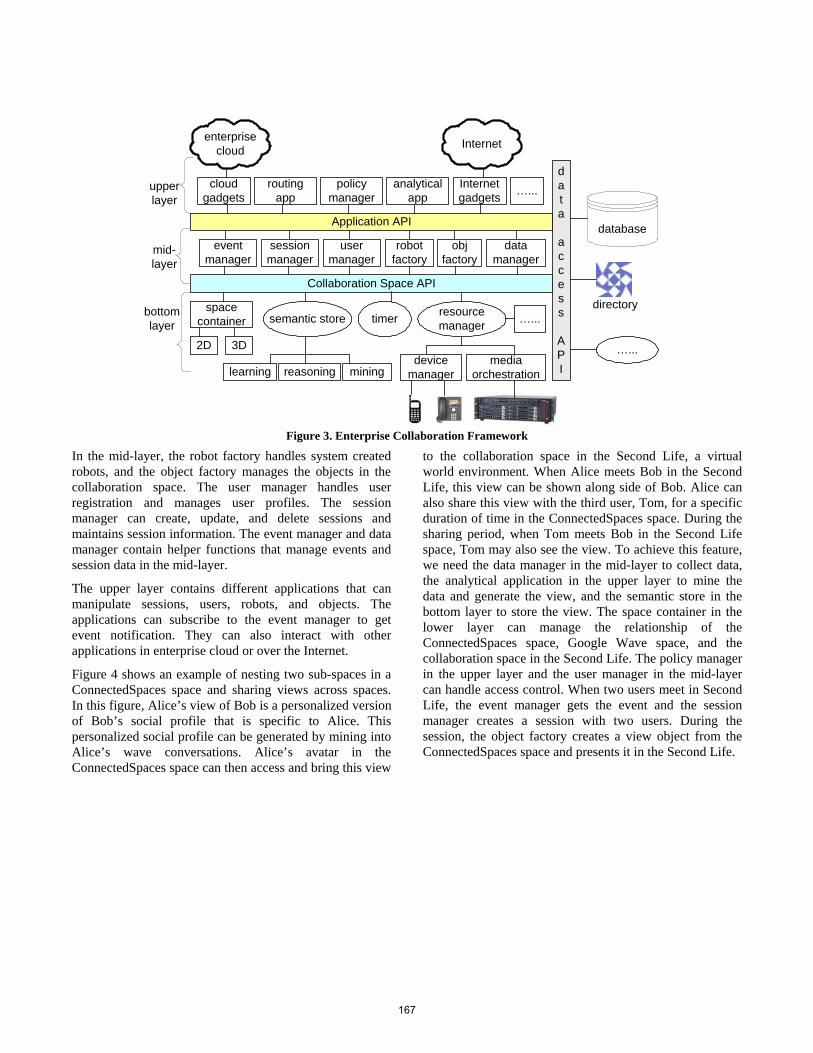
Figure 3. Enterprise Collaboration Framework
In the mid-layer, the robot factory handles system created robots, and the object factory manages the objects in the collaboration space. The user manager handles user registration and manages user profiles. The session manager can create, update, and delete sessions and maintains session information. The event manager and data manager contain helper functions that manage events and session data in the mid-layer.
The upper layer contains different applications that can manipulate sessions, users, robots, and objects. The applications can subscribe to the event manager to get event notification. They can also interact with other applications in enterprise cloud or over the Internet.
Figure 4 shows an example of nesting two sub-spaces in a ConnectedSpaces space and sharing views across spaces. In this figure, Alice’s view of Bob is a personalized version of Bob’s social profile that is specific to Alice. This personalized social profile can be generated by mining into Alice’s wave conversations. Alice’s avatar in the ConnectedSpaces space can then access and bring this view
to the collaboration space in the Second Life, a virtual world environment. When Alice meets Bob in the Second Life, this view can be shown along side of Bob. Alice can also share this view with the third user, Tom, for a specific duration of time in the ConnectedSpaces space. During the sharing period, when Tom meets Bob in the Second Life space, Tom may also see the view. To achieve this feature, we need the data manager in the mid-layer to collect data, the analytical application in the upper layer to mine the data and generate the view, and the semantic store in the bottom layer to store the view. The space container in the lower layer can manage the relationship of the ConnectedSpaces space, Google Wave space, and the collaboration space in the Second Life. The policy manager in the upper layer and the user manager in the mid-layer can handle access control. When two users meet in Second Life, the event manager gets the event and the session manager creates a session with two users. During the session, the object factory creates a view object from the ConnectedSpaces space and presents it in the Second Life.
semantic store timer resource manager
session manager
user manager
routing app
obj factory
device manager
mediaorchestration
database
Collaboration Space API
learning reasoning mining
data
access
API
directory
robot factory
policy manager
Application API
analytical app
data manager
Internetgadgets
Internet
cloudgadgets …...
…...
enterprise cloud
event manager
bottomlayer
mid-layer
upperlayer
…...space
container
2D 3D
167
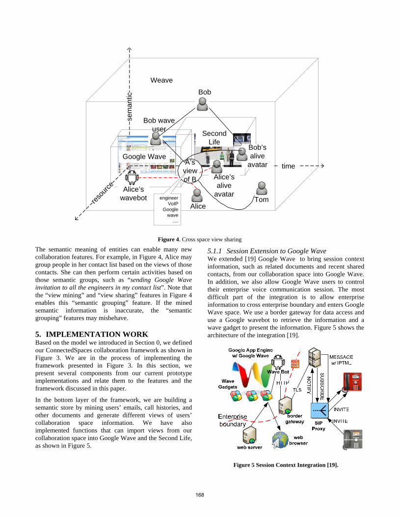
Figure 4. Cross space view sharing
The semantic meaning of entities can enable many new collaboration features. For example, in Figure 4, Alice may group people in her contact list based on the views of those contacts. She can then perform certain activities based on those semantic groups, such as “sending Google Wave invitation to all the engineers in my contact list”. Note that the “view mining” and “view sharing” features in Figure 4 enables this “semantic grouping” feature. If the mined semantic information is inaccurate, the “semantic grouping” features may misbehave.
5. IMPLEMENTATION WORK Based on the model we introduced in Section 0, we defined our ConnectedSpaces collaboration framework as shown in Figure 3. We are in the process of implementing the framework presented in Figure 3. In this section, we present several components from our current prototype implementations and relate them to the features and the framework discussed in this paper.
In the bottom layer of the framework, we are building a semantic store by mining users’ emails, call histories, and other documents and generate different views of users’ collaboration space information. We have also implemented functions that can import views from our collaboration space into Google Wave and the Second Life, as shown in Figure 5.
5.1.1 Session Extension to Google Wave We extended [19] Google Wave to bring session context information, such as related documents and recent shared contacts, from our collaboration space into Google Wave. In addition, we also allow Google Wave users to control their enterprise voice communication session. The most difficult part of the integration is to allow enterprise information to cross enterprise boundary and enters Google Wave space. We use a border gateway for data access and use a Google wavebot to retrieve the information and a wave gadget to present the information. Figure 5 shows the architecture of the integration [19].
Figure 5 Session Context Integration [19].
sem
antic
Second Life
Google Wave
Weave
resou
rce
timeA’s view of B
Alice
Alice’s wavebot
Alice’s alive
avatar
Bob wave user
Bob’s alive
avatar
Bob
engineerVoIP
Google wave
….
Tom
168
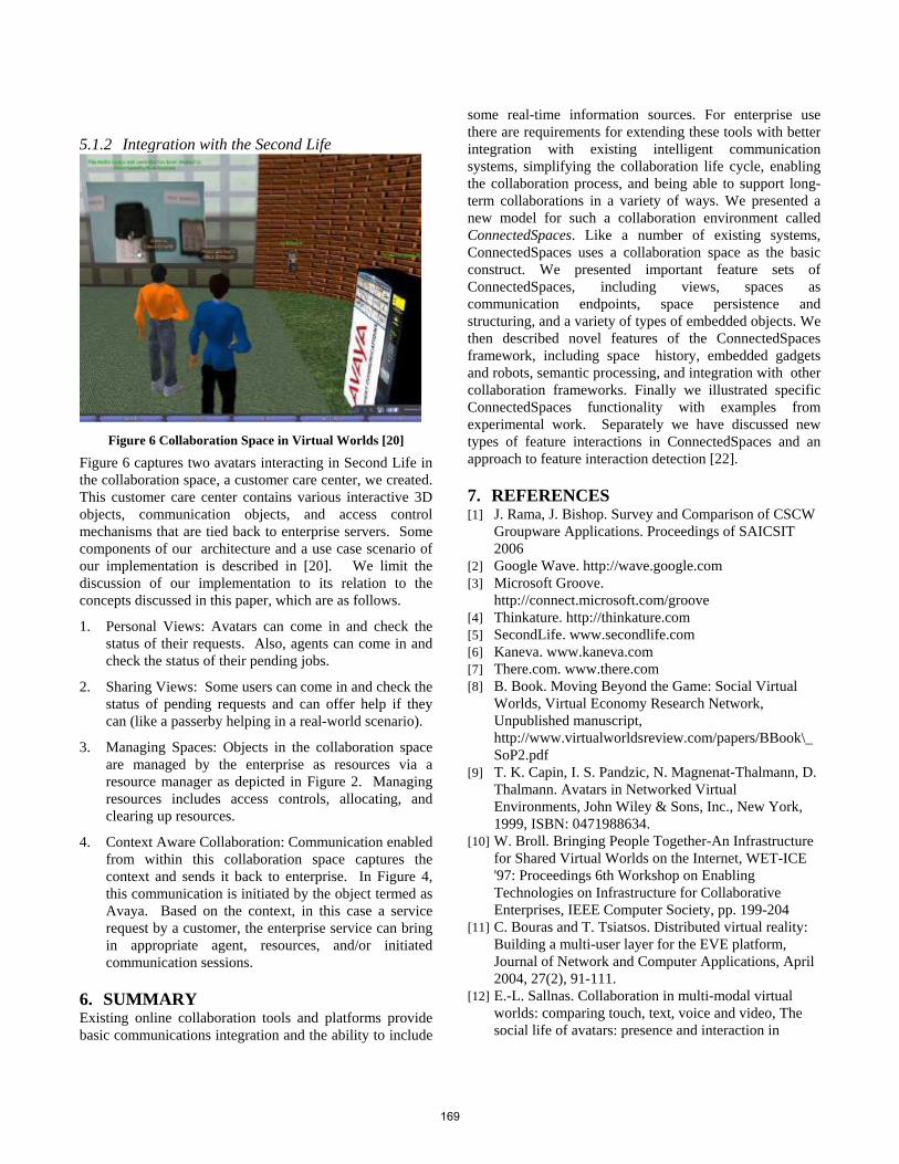
5.1.2 Integration with the Second Life
Figure 6 Collaboration Space in Virtual Worlds [20]
Figure 6 captures two avatars interacting in Second Life in the collaboration space, a customer care center, we created. This customer care center contains various interactive 3D objects, communication objects, and access control mechanisms that are tied back to enterprise servers. Some components of our architecture and a use case scenario of our implementation is described in [20]. We limit the discussion of our implementation to its relation to the concepts discussed in this paper, which are as follows.
1. Personal Views: Avatars can come in and check the status of their requests. Also, agents can come in and check the status of their pending jobs.
2. Sharing Views: Some users can come in and check the status of pending requests and can offer help if they can (like a passerby helping in a real-world scenario).
3. Managing Spaces: Objects in the collaboration space are managed by the enterprise as resources via a resource manager as depicted in Figure 2. Managing resources includes access controls, allocating, and clearing up resources.
4. Context Aware Collaboration: Communication enabled from within this collaboration space captures the context and sends it back to enterprise. In Figure 4, this communication is initiated by the object termed as Avaya. Based on the context, in this case a service request by a customer, the enterprise service can bring in appropriate agent, resources, and/or initiated communication sessions.
6. SUMMARY Existing online collaboration tools and platforms provide basic communications integration and the ability to include
some real-time information sources. For enterprise use there are requirements for extending these tools with better integration with existing intelligent communication systems, simplifying the collaboration life cycle, enabling the collaboration process, and being able to support long-term collaborations in a variety of ways. We presented a new model for such a collaboration environment called ConnectedSpaces. Like a number of existing systems, ConnectedSpaces uses a collaboration space as the basic construct. We presented important feature sets of ConnectedSpaces, including views, spaces as communication endpoints, space persistence and structuring, and a variety of types of embedded objects. We then described novel features of the ConnectedSpaces framework, including space history, embedded gadgets and robots, semantic processing, and integration with other collaboration frameworks. Finally we illustrated specific ConnectedSpaces functionality with examples from experimental work. Separately we have discussed new types of feature interactions in ConnectedSpaces and an approach to feature interaction detection [22].
7. REFERENCES [1] J. Rama, J. Bishop. Survey and Comparison of CSCW
Groupware Applications. Proceedings of SAICSIT 2006
[2] Google Wave. http://wave.google.com [3] Microsoft Groove.
http://connect.microsoft.com/groove [4] Thinkature. http://thinkature.com [5] SecondLife. www.secondlife.com [6] Kaneva. www.kaneva.com [7] There.com. www.there.com [8] B. Book. Moving Beyond the Game: Social Virtual
Worlds, Virtual Economy Research Network, Unpublished manuscript, http://www.virtualworldsreview.com/papers/BBook\_SoP2.pdf
[9] T. K. Capin, I. S. Pandzic, N. Magnenat-Thalmann, D. Thalmann. Avatars in Networked Virtual Environments, John Wiley & Sons, Inc., New York, 1999, ISBN: 0471988634.
[10] W. Broll. Bringing People Together-An Infrastructure for Shared Virtual Worlds on the Internet, WET-ICE '97: Proceedings 6th Workshop on Enabling Technologies on Infrastructure for Collaborative Enterprises, IEEE Computer Society, pp. 199-204
[11] C. Bouras and T. Tsiatsos. Distributed virtual reality: Building a multi-user layer for the EVE platform, Journal of Network and Computer Applications, April 2004, 27(2), 91-111.
[12] E.-L. Sallnas. Collaboration in multi-modal virtual worlds: comparing touch, text, voice and video, The social life of avatars: presence and interaction in
169
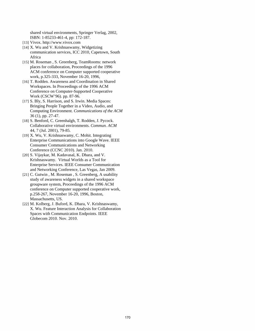
shared virtual environments, Springer Verlag, 2002, ISBN: 1-85233-461-4, pp: 172-187.
[13] Vivox. http://www.vivox.com [14] X. Wu and V. Krishnaswamy, Widgetizing
communication services, ICC 2010, Capetown, South Africa
[15] M. Roseman , S. Greenberg, TeamRooms: network places for collaboration, Proceedings of the 1996 ACM conference on Computer supported cooperative work, p.325-333, November 16-20, 1996,
[16] T. Rodden. Awareness and Coordination in Shared Workspaces. In Proceedings of the 1996 ACM Conference on Computer-Supported Cooperative Work (CSCW’96). pp. 87-96.
[17] S. Bly, S. Harrison, and S. Irwin. Media Spaces: Bringing People Together in a Video, Audio, and Computing Environment. Communications of the ACM 36 (1), pp. 27-47.
[18] S. Benford, C. Greenhalgh, T. Rodden, J. Pycock. Collaborative virtual environments. Commun. ACM 44, 7 (Jul. 2001), 79-85.
[19] X. Wu, V. Krishnaswamy, C. Mohit. Integrating Enterprise Communications into Google Wave. IEEE Consumer Communications and Networking Conference (CCNC 2010). Jan. 2010.
[20] S. Vijaykar, M. Kadavasal, K. Dhara, and V. Krishnaswamy. Virtual Worlds as a Tool for Enterprise Services. IEEE Consumer Communication and Networking Conference, Las Vegas, Jan 2009.
[21] C. Gutwin , M. Roseman , S. Greenberg, A usability study of awareness widgets in a shared workspace groupware system, Proceedings of the 1996 ACM conference on Computer supported cooperative work, p.258-267, November 16-20, 1996, Boston, Massachusetts, US.
[22] M. Kolberg, J. Buford, K. Dhara, V. Krishnaswamy, X. Wu. Feature Interaction Analysis for Collaboration Spaces with Communication Endpoints. IEEE Globecom 2010. Nov. 2010.
170


ISBN 3-937201-15 - 7
ISSN 1868-2634 (print)ISSN 1868-2642 (electronic)
Related Documents