Analysis of the MIFARE Classic used in the OV-Chipkaart project Gerhard de Koning Gans Radboud University Nijmegen Supervisors Thesis 584 Jaap-Henk Hoepman Gerhard de Koning Gans Flavio D. Garcia Version 1.00 June 2008

Welcome message from author
This document is posted to help you gain knowledge. Please leave a comment to let me know what you think about it! Share it to your friends and learn new things together.
Transcript
Analysis of the MIFARE Classic
used in the OV-Chipkaart project
Gerhard de Koning GansRadboud University Nijmegen
Supervisors Thesis 584Jaap-Henk Hoepman Gerhard de Koning GansFlavio D. Garcia Version 1.00
June 2008
Abstract
The mifare Classic is the most widely used contactless smart cardin the market. Its design and implementation details are kept secret byits manufacturer. We investigate the mifare Classic because this cardshould become the new ticket, called the OV-Chipkaart, in the Dutchpublic transport system.
This thesis studies the architecture of the card and the communicationprotocol between card and reader. At the start of this research, there wasno information available on the mifare Classic protocol nor the imple-mentation of the OV-Chipkaart. To perform this research we used theProxmark, a device that allows us to eavesdrop on the communicationbetween the reader and the card.
Our contributions are as follows. First, an ISO14443-A firmware imple-mentation for the Proxmark that enables eavesdropping on the mifareClassic, among other card types. Secondly, we present an overview ofthe commands and responses of the protocol. Furthermore, we develop amethod to read data from the mifare Classic card without knowledge ofthe secret key. Due to a weakness in the pseudo-random generator, weare able to recover the keystream generated by the CRYPTO1 stream ci-pher. We exploit the malleability of the stream cipher to read all memoryblocks of the first sector of the card. Moreover, we are able to read anysector of the memory of the card, provided that we know one memoryblock within this sector. Finally, and perhaps more damaging, the sameholds for modifying memory blocks.
1
Preface
In the past year I have had the privilege to perform research on an interestingtopic. A topic where I could combine theory and practice. It was my supervisorJaap-Henk Hoepman who suggested the OV-Chipkaart as subject of investiga-tion. How does this card actually work? How does it communicate and, mostimportant of all, is it secure enough?
One important prerequisite at the start of this research was the possibility tolook into the communication of the OV-Chipkaart. At that point I ran into thework of Roel Verdult who was already working on a device which should be ableto do this. Apparently, it was not that easy. Appropriate hardware became oneof the main problems. For months we worked in relative silence on this matter.November 14th, Roel and I had some little success in Rotterdam. Finally wegot our hardware working.
It remained quiet until December 2007 when I received an e-mail from Jaap-Henk. He pointed me to a presentation of two German researchers who hadfound some major weaknesses in the mifare Classic chip. Well, this mightsound totally different from our research and it would not have gained muchattention if the OV-Chipkaart did not actually use the mifare Classic chip.Dutch media took this very seriously, and soon many questions rose about thesecurity of the OV-Chipkaart. Then on January 14th, Roel Verdult showed thatit was possible to clone a disposable card. Meanwhile, I had already developedan attack that allowed to read and modify memory contents without knowingthe secret key.
From that time on it remained busy. One reason was the press attentiongenerated on this topic. Another reason, we had already an interesting attackand decided to write a paper on these findings. When this paper, the contentsof which is featured in this thesis, was finished, we got some interesting newdevelopments. More people got interested in the topic. At that point, it seemedthat with some effort we could get complete insight in the mifare Classic se-curity. This thesis stops at that point and is not about that joint research. Ienjoyed the fact that I could participate in a group of enthuastic people whojoined Roel and me in some feverish investigations of the detailed workings ofthe chip. This resulted in the dismantling of the mifare Classic. Which is, assaid before, described elsewhere.
2
Acknowledgements
Hereby I would like to thank a lot of people. First, I would like to thank Jaap-Henk Hoepman, he made me enthusiastic for the subject and took good careof the research direction. Although circumstances prevented him from joiningthe latest research I would like to stress that it was his idea to look into theOV-Chipkaart. Flavio Garcia, who was already working in this field and anexcellent second supervisor. Roel Verdult, who almost thought of terminatinghis work on the hardware and thought of starting another research. Happily herefrained from this idea. We spent both many hours on the hardware of thisresearch and succeeded. Then, I would like to thank the Kali brothers, as I callVinesh and Ravindra sometimes, for their enduring support from the beginning.
Furthermore, I would like to thank people who joined us later on in furtherresearch on this topic. Ruben Muijrers, a student who just bumped into this,has given an outstanding contribution to the research. The same counts forRonny Wichers Schreur. He was hard to stop in his attempts to improve theattack. Peter van Rossum, his mathematical skill combined with the area ofcomputer security was very effective and I am convinced this saved us manyhours. Wouter Teepe, yes the guy who handled the media, and yes that alsomeans he had to handle the difficult questions. He did very well on that job.Last but not least, I would like to thank Bart Jacobs for steering this sometimeschaotic group and keeping us motivated.
There were many others involved. I hope you understand it is difficult toname every person involved in this project. And also remember that importantpeople are not always listed.
Gerhard de Koning Gans, June 2008
3
Contents
1 Introduction 51.1 RFID . . . . . . . . . . . . . . . . . . . . . . . . . . . . . . . . . 51.2 Technology in Action . . . . . . . . . . . . . . . . . . . . . . . . . 61.3 Today’s Use . . . . . . . . . . . . . . . . . . . . . . . . . . . . . . 61.4 Outline of this Thesis . . . . . . . . . . . . . . . . . . . . . . . . 9
2 Research 102.1 Problem Definition . . . . . . . . . . . . . . . . . . . . . . . . . . 102.2 Related work . . . . . . . . . . . . . . . . . . . . . . . . . . . . . 102.3 Our contribution . . . . . . . . . . . . . . . . . . . . . . . . . . . 112.4 Background information . . . . . . . . . . . . . . . . . . . . . . . 12
3 The Mifare Classic 143.1 Communication Layer . . . . . . . . . . . . . . . . . . . . . . . . 143.2 Logical Structure . . . . . . . . . . . . . . . . . . . . . . . . . . . 153.3 Commands . . . . . . . . . . . . . . . . . . . . . . . . . . . . . . 163.4 Security Features . . . . . . . . . . . . . . . . . . . . . . . . . . . 16
3.4.1 Authentication Protocol . . . . . . . . . . . . . . . . . . . 173.5 Mifare Higher Level Protocol . . . . . . . . . . . . . . . . . . . . 17
4 Hardware 194.1 Ghost . . . . . . . . . . . . . . . . . . . . . . . . . . . . . . . . . 204.2 OpenPCD and OpenPICC . . . . . . . . . . . . . . . . . . . . . . 204.3 Proxmark III . . . . . . . . . . . . . . . . . . . . . . . . . . . . . 21
5 Software 245.1 Client . . . . . . . . . . . . . . . . . . . . . . . . . . . . . . . . . 245.2 Microcontroller . . . . . . . . . . . . . . . . . . . . . . . . . . . . 265.3 FPGA . . . . . . . . . . . . . . . . . . . . . . . . . . . . . . . . . 28
5.3.1 Verilog . . . . . . . . . . . . . . . . . . . . . . . . . . . . . 295.3.2 FPGA Modes . . . . . . . . . . . . . . . . . . . . . . . . . 29
6 Case studies 356.1 Attacks on MIFARE . . . . . . . . . . . . . . . . . . . . . . . . . 35
6.1.1 Keystream Recovery Attack . . . . . . . . . . . . . . . . . 366.1.2 Bruteforce Attack . . . . . . . . . . . . . . . . . . . . . . 416.1.3 Key Recovery using Cryptanalysis . . . . . . . . . . . . . 42
6.2 Proprietary Commands . . . . . . . . . . . . . . . . . . . . . . . 42
7 Conclusions & Recommendations 447.1 Observations . . . . . . . . . . . . . . . . . . . . . . . . . . . . . 447.2 Recommendations . . . . . . . . . . . . . . . . . . . . . . . . . . 45
8 Further research 47
4
1 Introduction
In this thesis the focus is on Radio Frequency Identification (RFID) technology.RFID is a technology that is used in many different applications and purposes.Even though many people see RFID as a ‘new technology’, it has been in usesince World War II for military purposes. It was used to distinguish an alliedplane from an enemy plane [Fin03]. Nowadays, the technology has developedto tiny digital labels that can be read out from varying distances1.
1.1 RFID
In short, RFID is a wireless technique to identify objects. The concept of wirelesscommunication has been adopted in many applications. Some examples areradio, cell phones and the Global Positioning System (GPS). In case of RFID,there is communication between a reader (also known as Proximity CouplingDevice (PCD)) and a transponder2 (also known as tag). Transponders areavailable in different types, there are active and passive transponders. Wherethe former have their own power source, like a battery, the latter use the powerthey receive from the magnetic field of the reader. The advantage of a self-powered transponder is that it is able to communicate over bigger distances.The advantage of a passive transponder is that it has no battery, which canunload, and its production can be really cheap.
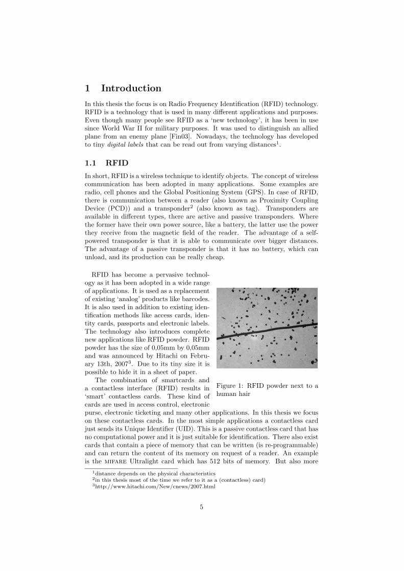
Figure 1: RFID powder next to ahuman hair
RFID has become a pervasive technol-ogy as it has been adopted in a wide rangeof applications. It is used as a replacementof existing ‘analog’ products like barcodes.It is also used in addition to existing iden-tification methods like access cards, iden-tity cards, passports and electronic labels.The technology also introduces completenew applications like RFID powder. RFIDpowder has the size of 0,05mm by 0,05mmand was announced by Hitachi on Febru-ary 13th, 20073. Due to its tiny size it ispossible to hide it in a sheet of paper.
The combination of smartcards anda contactless interface (RFID) results in‘smart’ contactless cards. These kind ofcards are used in access control, electronicpurse, electronic ticketing and many other applications. In this thesis we focuson these contactless cards. In the most simple applications a contactless cardjust sends its Unique Identifier (UID). This is a passive contactless card that hasno computational power and it is just suitable for identification. There also existcards that contain a piece of memory that can be written (is re-programmable)and can return the content of its memory on request of a reader. An exampleis the mifare Ultralight card which has 512 bits of memory. But also more
1distance depends on the physical characteristics2in this thesis most of the time we refer to it as a (contactless) card)3http://www.hitachi.com/New/cnews/2007.html
5
advanced cards which have some computational power are available in the mar-ket. These allow encryption like DES and AES, but also proprietary ciphers areused. Think of the Sony FeliCa and the mifare Classic from NXP. Being thismifare Classic that is our subject of investigation. mifare Classic is part of themifare product family of NXP Semiconductors. The mifare family consists ofthe following cards: Ultralight, Classic, DESFire and SmartMX. The mifareClassic card is available with 1 KB and 4 KB of memory. Currently it is themost used contactless card worldwide4.
1.2 Technology in Action
Contactless smartcards like the mifare Classic are used for example in accesscontrol and public transport ticketing. In London, the Oyster card, which is amifare Classic card, is used in public transport ticketing. Besides the ticketingsystem of London there are many other systems that use the mifare Classicchip. In the Netherlands, the OV-Chipkaart should become the new ticketingstandard for public transport. It is the first project where such a system is setup nationwide.
1.3 Today’s Use
Although almost everyone uses RFID in everyday life, most people are not awareof it. In most cases the technology is out of sight and hidden in applications.Most of the time it is not even recognized and brings the ease of use it wasexpected to bring. In this section we give some examples of applications thatuse RFID technology.
Animal Identification In Animal Identification a tiny chip is implanted justbelow the skin of an animal. This way it can easily be identified. Addition-ally, medical information like vaccinations can be linked to this animal. TheISO 11784/85 standard is used in Animal Identification. The information likevaccination data needs to be looked up in a database. ISO 14223 defines howto store this data on the implanted chip. This means that there is no need toaccess a database, because all information is contained on the chip itself.
Car Keys Almost every new car comes with a remote control to open the carremotely. In the early days the transmitted signal was just an identification num-ber. The car checked for the correct number and opened the door if its numberand the one of the transponder (car key) matched. Nowadays, a popular systemfor car keys is KeeLoq. KeeLoq is a technology from Microchip that uses RFIDtechnology. It uses a cryptographic algorithm to prevent eavesdroppers fromcopying the car key and getting unauthorized access to the car. The operatingdistance of the KeeLoq system is about 100 meters. The security of KeeLoqhas been broken. After cryptanalysis of the algorithm by Bogdanov [Bog07]many attacks followed. The latest ones are very serious and use side-channelinformation to recover the key of the controller. Even the master key can berecovered.
4the mifare family represents 85% of the contactless smartcard market, http://www.nxp.com
6
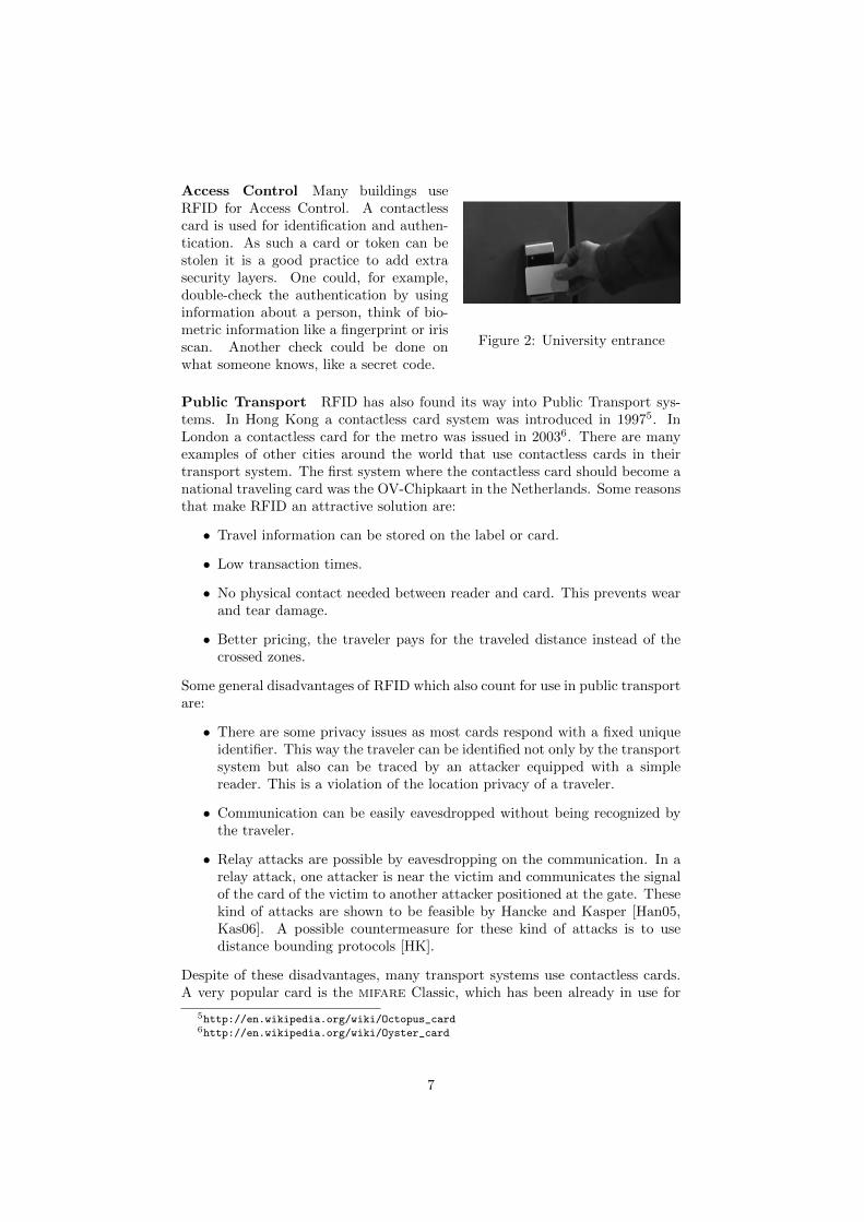
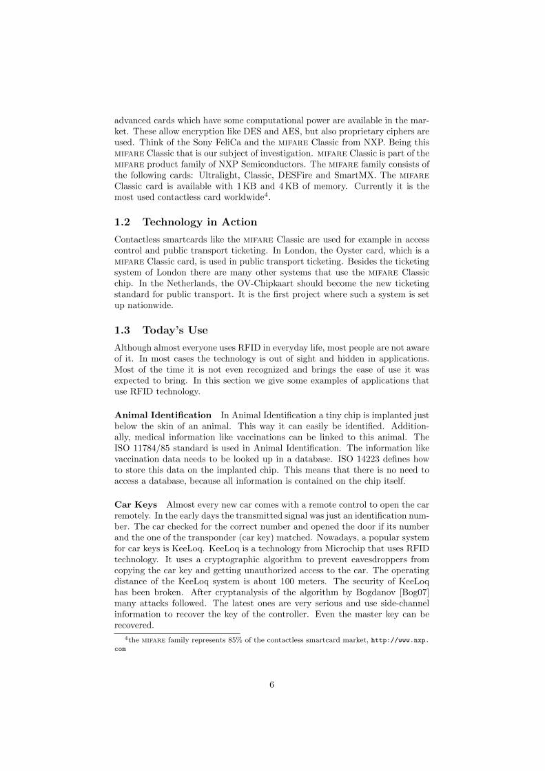
Figure 2: University entrance
Access Control Many buildings useRFID for Access Control. A contactlesscard is used for identification and authen-tication. As such a card or token can bestolen it is a good practice to add extrasecurity layers. One could, for example,double-check the authentication by usinginformation about a person, think of bio-metric information like a fingerprint or irisscan. Another check could be done onwhat someone knows, like a secret code.
Public Transport RFID has also found its way into Public Transport sys-tems. In Hong Kong a contactless card system was introduced in 19975. InLondon a contactless card for the metro was issued in 20036. There are manyexamples of other cities around the world that use contactless cards in theirtransport system. The first system where the contactless card should become anational traveling card was the OV-Chipkaart in the Netherlands. Some reasonsthat make RFID an attractive solution are:
• Travel information can be stored on the label or card.
• Low transaction times.
• No physical contact needed between reader and card. This prevents wearand tear damage.
• Better pricing, the traveler pays for the traveled distance instead of thecrossed zones.
Some general disadvantages of RFID which also count for use in public transportare:
• There are some privacy issues as most cards respond with a fixed uniqueidentifier. This way the traveler can be identified not only by the transportsystem but also can be traced by an attacker equipped with a simplereader. This is a violation of the location privacy of a traveler.
• Communication can be easily eavesdropped without being recognized bythe traveler.
• Relay attacks are possible by eavesdropping on the communication. In arelay attack, one attacker is near the victim and communicates the signalof the card of the victim to another attacker positioned at the gate. Thesekind of attacks are shown to be feasible by Hancke and Kasper [Han05,Kas06]. A possible countermeasure for these kind of attacks is to usedistance bounding protocols [HK].
Despite of these disadvantages, many transport systems use contactless cards.A very popular card is the mifare Classic, which has been already in use for
5http://en.wikipedia.org/wiki/Octopus_card6http://en.wikipedia.org/wiki/Oyster_card
7
years. Just as in the system of London the Dutch public transport, representedby TransLink Systems (TLS), decided to use the mifare Classic in their im-plementation. The card has been used in many systems around the world andhas never shown any failures on its security. Unfortunately, after some seriousanalysis of the card it turned out that the mifare Classic is broken and can beeasily compromised. This means that many systems around the world need tomigrate to better protected cards within a little time frame.
Ticketing The FIFA World Cup tickets of 2006 in Germany are an exampleof RFID use in ticketing. Timo Kasper showed [Kas06] that he could performa successful replay attack on these tickets. Of course the tickets were securedtwofold. First, the tickets physical appearance needed to be correct and secondthe data stored on the Mifare Ultralight chip also needed to be correct.
Figure 3: Barcode and RFID label
Labels RFID is also used as replacementfor or in addition to barcodes. Barcodesmake it possible to quickly scan a serialnumber of a product and obtain or storeinformation about it. This is especiallyuseful in logistics. For the barcodes to besuccessfully scanned it is important thatthe barcode, and therefore the product,is correctly positioned with respect to thereader. The use of RFID removes this con-straint. It does only require the label to bewithin a certain range. Depending on thestrength of the signal of the reader, thisrange might be from several centimetersto several meters. This allows applicationswhere a truck drives through a gate and allproducts that leave the factory are scanned7.The barcode label in Figure 3 is extended with an RFID chip which is visiblewhen we keep it against the sunlight. The RFID chip is visible in the middleand the antenna windings at the border of the label.
Electronic Passport Electronic passports are basically just passports, butwith an embedded RFID chip. Again an application where RFID is used inaddition to an existing product. The electronic passport is developed to storebiometric data. This application uses a heavier, and therefore more expensive,RFID chip. For sake of privacy the RFID chip uses a random UID every timeit gets selected. To prevent e-passports from being read by just anyone, an e-passport uses a Basic Access Control (BAC) mechanism. This requires access toprinted information inside the passport. Weaknesses of this method are shownin [HHJ+06, AKQ]. But even before authentication e-passports already leakinformation about the nationality of a person [RMP07].
7http://www.qualitydigest.com/may07/articles/04_article.shtml
8
1.4 Outline of this Thesis
This thesis is based on and contains parts of the paper ‘A Practical Attack onthe mifare Classic’ (forthcoming [dKGHG08]). Section 2 discusses the researchgoals that we wanted to achieve. Then, Section 3 discusses the communicationtechnique that is used in the specific RFID system (mifare Classic) we wantto analyze. In Section 4 the currently available open-source tools are describedwhich can be used to analyze RFID communication. In the end, we choosethe Proxmark III of Jonathan Westhues, which needed some software extensionto meet our needs. This software extension is discussed in Section 5 and isa general solution that can be used in any further research on ISO 14443-Aprotocols. Then Section 6 discusses the protocol and the found weaknesses. Apractical attack is deployed on these weaknesses. Also, results of concurrentresearch is addressed. Although, it turned out to be a lost race for the mifareClassic, it is our responsibility to give recommendations on safer usage of thecard. We conclude with the conclusions and recommendations in Section 7.Finally, further research is discussed in Section 8.
9
2 Research
2.1 Problem Definition
RFID does not solely bring ease, it also introduces new security risks. It isa wireless application, which means the data is transferred over the air. Thisintroduces possibilities for eavesdroppers to eavesdrop on the communicationwhile the chance of being detected is low. In this thesis the protocol of theOV-Chipkaart project and therefore mifare Classic is subject of investigation.The mifare Ultralight and the mifare Classic 4k cards are used in the OV-Chipkaart project. The goal of this research project is to perform an analysisof the OV-Chipkaart protocol and get insight in the communication.
The communication in mifare Classic applications is encrypted and hides theprotocol messages. NXP does not give any information on the protocol usedby mifare 4k and mifare Ultralight applications. NXP has developed severalASICs8 that are able to handle the protocol. Specifications on those ASICs talkabout the interface of the chip. The actual processing of the RF communicationis done by this ASIC.
In the Netherlands the company TransLink Systems (TLS) is implement-ing the first travel card system that will operate nationwide called the OV-Chipkaart. The project runs since 2002 and is, to some extend, comparable tothe Octopus card of Hong Kong. The Octopus card was introduced in HongKong in 1997 to collect fares in the public transport system. Nowadays it is usedfor many more applications in micro payments9. Participants in the project arethe Dutch government together with the carriers NS, Connexxion, RET, HTMand GVB which serve 80 % of the public transport in the Netherlands.
Problem Definition
1. How do tag and reader communicate?
2. Are there privacy problems?
3. How secure is it?
Research Goal
1. Reverse engineering the mifare protocol.
2. Reverse engineering an application specific protocol like the OV-Chipkaart.
2.2 Related work
There have been several studies on RFID that focus on the contactless interfaceof RFID cards and the limitations on the complexity of their design.
8Application Specific Integrated Circuit (ASIC)9http://en.wikipedia.org/wiki/Octopus_card
10
Relay attack A contactless interface means that relay attacks are possiblewhich is shown by Gerhard Hancke in [Han05] and Timo Kasper in [Kas06]. Apossible solution to prevent relay attacks is to make good restrictions on therelay time using distance bounding protocols [HK].
Replay attack Another possible attack is the replay attack. This means thatthe attacker replays an earlier recorded message. This is obvious a problem forRFID tags that just send out an unique identification number like the VeriChip.Jonathan Westhues describes on his website10 how to clone a VeriChip. He alsodemonstrated that some Government buildings use access cards that just sendout a number. Replaying this signal was enough to open the door11.Timo Kasper also carried out a replay attack in [Kas06].
Disposable RFID cards Sometimes RFID is used in a bad way. Siekermanand van der Schee found a flaw in the disposable card of the Dutch PublicTransport system [SvdS07]. There was a wrong use of the locking functionalityof the card. The card has lock bits which prevent writing to the card memorywhen set. It was possible to lock the lock bits which means that the systemcould not lock portions of to the card memory anymore. The system did notcheck for this situation. This is an example of a bad implementation.
Clone attacks The disposable card (mifare Ultralight) does not use anyencryption. The command set is known and the functionality and memory islimited. Roel Verdult managed to program a cloning device (Ghost) in sucha way that it was recognized as a disposable card [Ver08]. The ‘advantage’ ofsuch a device is that a memory dump can be placed back when needed. Sincethe back-end system did not check for any duplicates in the transport systemthis attack was not recognized.
Reverse engineering Karsten Nohl and Henryk Plotz have partially reverseengineered the mifare Classic cryptographic algorithm [NP07]. The mifareClassic card is in use since 1994 which is quit a long time. Nohl and Plotzmanaged to recover the cipher by removing layers from the chip and takingpictures of the result with a 500x optical microscope. After determination of 70different logical gates the rest was detected using image processing techniques.
2.3 Our contribution
We used a Proxmark III12 to analyze mifare cards and mount an attack. Todo so, we have implemented the ISO 14443-A functionality on the Proxmark,since only ISO 14443-B was implemented at that time. We programmed bothprocessing and generation of reader-to-tag and tag-to-reader communication atphysical and higher levels of the protocol. The source code of the firmware isavailable in the public domain13. Concurrently, and independently from Nohland Plotz results, we also noticed a weakness in the pseudo-random generator.
10http://www.cq.cx/verichip.pl11http://www.youtube.com/watch?v=4jpRFgDPWVA12http://cq.cx/proxmark3.pl13http://www.proxmark.org
11
Our contribution is threefold: First and foremost, using the weakness ofthe pseudo-random generator, and given access to a particular mifare card,we are able to recover the keystream generated by the CRYPTO1 stream ci-pher, without knowing the encryption key. Secondly, we describe in detail thecommunication between tag and reader. Finally, we exploit the malleability ofthe stream cipher to read all memory blocks of the first sector (sector zero) ofthe card (without having access to the secret key). In general, we are able toread any sector of the memory of the card, provided that we know one memoryblock within this sector. After eavesdropping a transaction, we are always ableto read the first 6 bytes of every block in that sector, and in most cases also thelast 6 bytes. This leaves only 4 non revealed bytes in those blocks.
We would like to stress that we notified NXP of our findings before publishingour results. Moreover, we gave them the opportunity to discuss with us howto publish our results without damaging their (and their customers) immediateinterests. They did not take advantage of this offer.
2.4 Background information
This section gives a short overview on developments in mifare Classic securityto give some information on the context of this research.For many years the mifare Classic card has been a cheap solution for appli-cations where security was needed at low cost. With the announcement thatCRYPTO1 was revealed in December 2007 by Nohl and Plotz [NP07] a lot ofnew developments on the security of the chip followed. At that time the attackdeployed in this thesis was already in an advanced state [dKGHG08]. Beforethis announcement, in November 2007, the mifare Ultralight clone attack ofVerdult [Ver08] was already a fact. The attack on the Dutch public transportsystem, with a cloned disposable card, hit the news on January 14th. The in-formation that was disclosed by Nohl and Plotz was a very useful input for theRFID research team of the Digital Security Group in Nijmegen. The Usenixsubmission [NESP08] gives no information about the f -function (filter function).The filter function hides the internal state of the Linear Feedback Shift Register(LFSR). The Digital Security Group in Nijmegen recovered the missing crucialinformation and revealed the complete CRYPTO1 stream cipher together withthe authentication and initialization protocols. At the same time an attack wasdeveloped that did not need a full brute-force to recover the card keys. Then, onMarch 10th, things went fast. Nohl developed a theoretical attack [Noh08] thatuses output bits of the reader which leaks information. This attack relies on thefact that the sequence of the reader random is known and the current position ofthe generator in this sequence is known. To reveal this it is required to know atleast one key. March 12th, the DS Group of Nijmegen demonstrates [Dig08] animplementation of a developed attack that uses a precomputed table of abouthalf a gigabyte in size and 216 recorded authentication trials of a reader. Theannounced dismantling of the algorithm has become true. After the practicaldemonstration the attack of Nijmegen improved due to cryptanalysis on theCRYPTO1 algorithm. Several weaknesses in the design make an attack possi-ble that does not require any precomputation or brute-force. The current attackspeed14 is 12 keys per second. Another method is to use more general algebraic
14May 2008
12

attacks that are known for streamciphers. This algebraic method is announcedby Nicolas T. Courtois et al [CNO08].To conclude this developments so far, the algorithm is recovered and it turnedout to contain serious weaknesses. The attack speed of 12 keys per second allowsa realtime attack scenario.
13
3 The Mifare Classic
Contactless smartcards are used in many applications nowadays. Contactlesscards are based on radio frequency identification technology (RFID) [Fin03]. In1995 NXP, Philips at that time, introduced mifare15. Some target applicationsof mifare are public transportation, access control and event ticketing. Themifare Classic [NXP07b] card is a member of the mifare product family andis compliant with ISO 14443 type A up to part 3. Part 4 defines the high-levelprotocol and the implementation of NXP differs from the standard. Section 3.1discusses the different parts.
3.1 Communication Layer
The communication layer of the mifare Classic card is based on the ISO 14443standard [ISO01]. This ISO standard defines the communication for identifi-cation cards, contactless integrated circuit(s) cards and proximity cards. Thestandard consists of four parts.
Part 1 Physical characteristics
Part 2 Radio frequency interface power and signal interface
Part 3 Initialization and anticollision
Part 4 Transmission protocol
Part 1 describes the physical characteristics and circumstances under which thecard should be able to operate.Part 2 defines the communication between the reader and card and vice versa.The data can be encoded and modulated in two ways, type A and type B.mifare Classic uses type A which defines Amplitude Shift Keying (ASK) forreader to card communication. To encode data bits the reader stops to generatea carrier for about 2µs with certain intervals. This corresponds with 100%ASK because there is no amplitude at all in this period. The card to readercommunication for type A is done by load modulation. The card will adda subcarrier or not, On-off Keying (OOK), to encode data bits. For moredetailed information about the communication on RFID we refer to the “RFIDHandbook” by Klaus Finkenzeller [Fin03].Part 3 describes the initialization and anticollision protocol. The anticollisionis needed to select a particular card when more cards are present within thereading range of the reader. After a successful initialization and anticollisionthe card is in an active state and ready to receive a command. This state isthe starting point for part 4 of the standard and also the point where mifareClassic differs from the ISO standard.The mifare Classic data sheets [NXP07b] do not mention any commands thatcould be send on this level nor does it specify answers from the card or the lengthof the messages. The data sheets does define though the structure of the memoryof the card and how to organize it, which is explained in Section 3.2. Themodulation of commands is done by the mifare Classic reader chip. Knowledgeabout the actual modulation is therefore not needed. Note that the PC to readerinterface is defined and provides commands and codes.
15http://www.nxp.com
14
3.2 Logical Structure
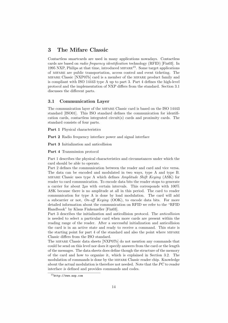
A mifare Classic card is in principle a memory card with few extra function-alities. The memory is divided in data blocks of 16 bytes. Those data blocksare grouped into sectors. The mifare Classic 1k card has 16 sectors of 4 datablocks each. The first 32 sectors of a mifare Classic 4k card consists of 4 datablocks and the remaining 8 sectors consist of 16 data blocks. Every last datablock of a sector is called sector trailer. A schematic of the memory of a mifareClassic 4k card is shown in Figure 4.
Note that block 0 of sector 0 contains special data. The first 4 data bytescontain the unique identifier of the card (UID) followed by its 1-byte bit countcheck (BCC). The bit count check is calculated by successively XOR-ing theseparate UID bytes. The remaining bytes are used to store manufacturer data.This data block is set and immediately locked by the manufacturer so its con-tents cannot longer be modified. The reader needs to authenticate for a sector
Figure 4: mifare Classic 4k Memory
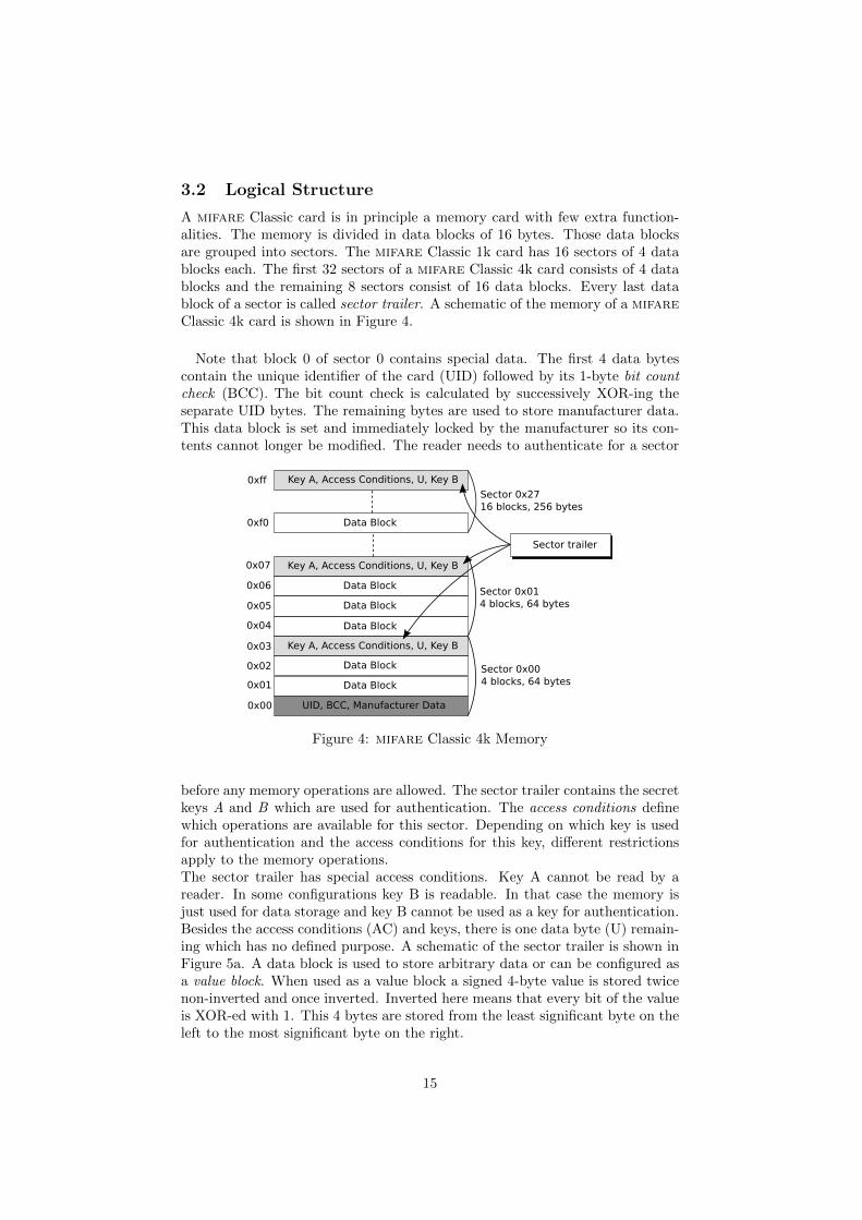
before any memory operations are allowed. The sector trailer contains the secretkeys A and B which are used for authentication. The access conditions definewhich operations are available for this sector. Depending on which key is usedfor authentication and the access conditions for this key, different restrictionsapply to the memory operations.The sector trailer has special access conditions. Key A cannot be read by areader. In some configurations key B is readable. In that case the memory isjust used for data storage and key B cannot be used as a key for authentication.Besides the access conditions (AC) and keys, there is one data byte (U) remain-ing which has no defined purpose. A schematic of the sector trailer is shown inFigure 5a. A data block is used to store arbitrary data or can be configured asa value block. When used as a value block a signed 4-byte value is stored twicenon-inverted and once inverted. Inverted here means that every bit of the valueis XOR-ed with 1. This 4 bytes are stored from the least significant byte on theleft to the most significant byte on the right.
15
The four remaining bytes are used to store a 1-byte block address that can beused as a pointer. The address is stored twice non-inverted and twice inverted.Besides this specific format the access conditions should be configured such thatthe specific value block commands are allowed for this block.
3.3 Commands
The command set of mifare Classic is small. Most commands are relatedto a data block and require the reader to be authenticated for its containingsector. The access conditions are checked every time a command is executed todetermine whether it is allowed or not. A block of data might be configured tobe read only. Another example of a restriction might be a value block whichcan only be decremented.
Read and Write The read and write commands read or write one data block.This is either a data block or a value block. The write command can be usedto format a data block as value block or just store arbitrary data.
Decrement, Increment, Restore and Transfer These commands are onlyallowed on data blocks that are formatted as value blocks. The increment anddecrement commands will increment or decrement a value block with a givenvalue and place the result in a memory register. The restore command loads avalue into the memory register without any change. Finally the memory registeris transferred in the same block or transferred to another block by the transfercommand.
3.4 Security Features
The mifare Classic card has some built-in security features. The communica-tion is encrypted by the proprietary stream cipher CRYPTO1.
Keys The 48-bit keys used for authentication are stored in the sector trailerof each sector (see section 3.2). mifare Classic uses symmetric keys. Everysector can have to keys. At least a key A is defined and Sector key A can neverbe read. If key B is configured to be used for authentication, this key cannotbe read either.
(a) Sector Trailer (b) Value Block
Figure 5: Block contents
16
3.4.1 Authentication Protocol
According to the mifare documentation [NXP07b], mifare Classic makes useof a mutual three pass authentication protocol that is based on ISO 9798-2.However, it turned out that this is not completely true [?]. In this paper weonly use the first initial nonce that is send by the card. So the exact authen-tication protocol used does not matter. The reader sends a request for sectorauthentication and the card will respond with a 32-bit nonce NC . Then, thereader sends back an 8-byte answer to that nonce which also contains a readerrandom NR. This answer is the first encrypted message after the start of theauthentication procedure. Finally, the card sends a 4-byte response. As far asour attack is concerned this description captures all the necessary information.
3.5 Mifare Higher Level Protocol
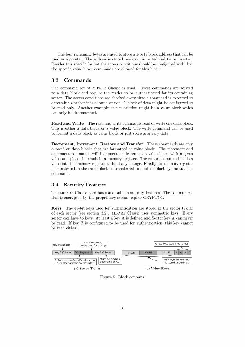
To find out what the mifare Classic communication looks like we made tracesof transactions between mifare readers and cards. In this way, we gatheredmany traces which gave us some insights on the high-level protocol of mifareClassic. In this section we explain a trace we recorded as an example, which isshown in Figure 6. This trace contains every part of a transaction. We will refer
ETU SEQ sender0 : 01 : PCD 26
64 : 02 : TAG 04 00
12097 : 03 : PCD 93 20
64 : 04 : TAG 2a 69 8d 43 8d
16305 : 05 : PCD 93 70 2a 69 8d 43 8d 52 55
64 : 06 : TAG 08 b6 dd
Anticollision
16504 : 07 : PCD 60 04 d1 3d
112 : 08 : TAG 3b ae 03 2d
6952 : 09 : PCD c4! 94 a1 d2 6e! 96 86! 4264 : 10 : TAG 84 66! 05! 9e!
Authentication
396196 : 11 : PCD a0 61! d3! e3208 : 12 : TAG 0d
8442 : 13 : PCD 26 42 ea 1d f1! 68!5120 : 14 : PCD 8d! ca cd ea
2816 : 15 : TAG 06!
Increment & Transfer
1349238 : 16 : PCD 2a 2b 17 97
72 : 17 : TAG 49! 09! 3b! 4e! 9e! 5e b0 06 d0!07! 1a! 4a! b4! 5c b0! 4f c8! a4!
Read
Figure 6: Trace of a card with default keys, recorded by the Proxmark III
to the sequence number (SEQ) of the messages we discuss. The messages fromthe reader are shown as PCD (Proximity Coupling Device) messages and fromthe card as TAG messages. The time between messages is shown in ElementaryTime Units (ETU). One ETU is a quarter of the bit period, which equals 1.18µs.The messages are represented in hexadecimal notation. If the parity bit (whichis not explicitly shown in the trace) of a byte is incorrect, this is shown by anexclamation mark. We will discuss only the most significant messages.
Anticollision The reader starts the SELECT procedure. The reader sends93 20 (#3), on which the card will respond with its unique identifier (#4). The
17
reader sends 93 70 followed by the UID and two CRC bytes (#5) to select thecard.
Authentication The card is in the active state and ready to handle any higherlayer commands. In Section 3.4.1 we discussed the authentication protocol. InFigure 6, messages #7 to #10 correspond to authentication.The authentication request of the reader is 60 04 d1 3d (#07). The first byte60 stands for an authentication request with key A. For authentication with keyB, the first byte must be 61. The second byte indicates that the reader wants toauthenticate for block 4. Note that block 4 is part of sector 1 and therefore thisis an authentication request for sector 1. The last two bytes are CRC bytes.
Encrypted Communication After this successful authentication the cardis ready to handle commands for sector 1. The structure of the commandscan be recognized clearly. Since we control the mifare Classic reader we knewwhich commands were send. Message #11 to #15 show how an increment isperformed. The increment is immediately followed by a read command (#16and #17).
The mifare Classic commands of the higher level protocol consist of 4 bytesof the form XX YY ZZ ZZ. The first byte XX indicates the command type. Thesecond byte YY indicates the memory address on which the command shouldbe executed. A command is not always related to a specific memory address.The halt command (50 00 57 cd) illustrates this. The last two bytes ZZ ZZ
are CRC bytes.
18
4 Hardware
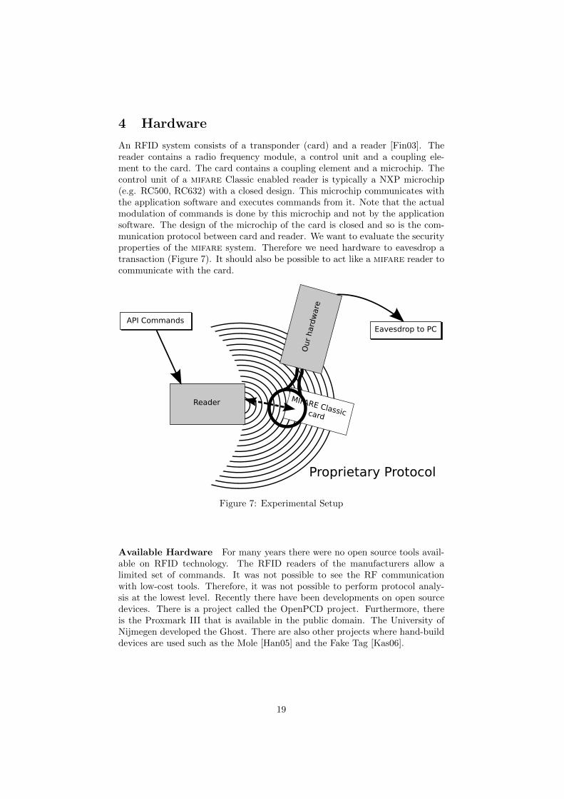
An RFID system consists of a transponder (card) and a reader [Fin03]. Thereader contains a radio frequency module, a control unit and a coupling ele-ment to the card. The card contains a coupling element and a microchip. Thecontrol unit of a mifare Classic enabled reader is typically a NXP microchip(e.g. RC500, RC632) with a closed design. This microchip communicates withthe application software and executes commands from it. Note that the actualmodulation of commands is done by this microchip and not by the applicationsoftware. The design of the microchip of the card is closed and so is the com-munication protocol between card and reader. We want to evaluate the securityproperties of the mifare system. Therefore we need hardware to eavesdrop atransaction (Figure 7). It should also be possible to act like a mifare reader tocommunicate with the card.
Figure 7: Experimental Setup
Available Hardware For many years there were no open source tools avail-able on RFID technology. The RFID readers of the manufacturers allow alimited set of commands. It was not possible to see the RF communicationwith low-cost tools. Therefore, it was not possible to perform protocol analy-sis at the lowest level. Recently there have been developments on open sourcedevices. There is a project called the OpenPCD project. Furthermore, thereis the Proxmark III that is available in the public domain. The University ofNijmegen developed the Ghost. There are also other projects where hand-builddevices are used such as the Mole [Han05] and the Fake Tag [Kas06].
19
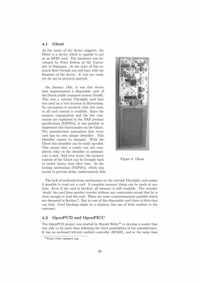
4.1 Ghost
Figure 8: Ghost
As the name of the device suggests, theGhost is a device which is capable to actas an RFID card. The hardware was de-veloped by Peter Dolron of the Univer-sity of Nijmegen. At the start of this re-search Roel Verdult was still busy with thefirmware of the device. It was not readyyet for use in protocol analysis.
On January 14th, it was this devicethat impersonated a disposable card ofthe Dutch public transport system [Ver08].This was a mifare Ultralight card thatwas used on a test location in Rotterdam.No encryption is involved with this card,so all card content is readable. Since thememory organization and the few com-mands are explained in the NXP productspecification [NXP07a], it was possible toimplement this functionality on the Ghost.The manufacturer guarantees that everycard has its own unique identifier. Thisidentifier cannot be changed. With theGhost this identifier can be easily spoofed.This means that a reader can not com-pletely relay on the identifier to authenti-cate a card. And even worse, the memorycontent of the Ghost can be brought backto earlier states, time after time. So thelocking mechanism [NXP07a], which wasmeant to prevent abuse, unfortunately fails.
The lack of authentication mechanisms on the mifare Ultralight card makesit possible to read out a card. A complete memory dump can be made at anytime. Even if the card is blocked, all memory is still readable. The attacker‘steals’ the card from another traveler without any constraints except that he isclose enough to read the card. There are some countermeasures possible whichare discussed in Section 7. But in case of this disposable card there is little thatcan help. Card blocking might be a solution, but one of little comfort to thecustomer.
4.2 OpenPCD and OpenPICC
The OpenPCD project was started by Harald Welte16 to develop a reader thatwas able to do more than following the fixed possibilities of the manufacturer.It has an on-board mifare enabled controller (RC632), and at the same time
16http://www.openpcd.org
20
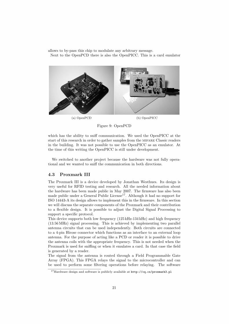
allows to by-pass this chip to modulate any arbitrary message.Next to the OpenPCD there is also the OpenPICC. This is a card emulator
(a) OpenPCD (b) OpenPICC
Figure 9: OpenPCD
which has the ability to sniff communication. We used the OpenPICC at thestart of this research in order to gather samples from the mifare Classic readersin the building. It was not possible to use the OpenPICC as an emulator. Atthe time of this writing the OpenPICC is still under development.
We switched to another project because the hardware was not fully opera-tional and we wanted to sniff the communication in both directions.
4.3 Proxmark III
The Proxmark III is a device developed by Jonathan Westhues. Its design isvery useful for RFID testing and research. All the needed information aboutthe hardware has been made public in May 2007. The firmware has also beenmade public under a General Public License17. Although it had no support forISO 14443-A its design allows to implement this in the firmware. In this sectionwe will discuss the separate components of the Proxmark and their contributionto a flexible design. It is possible to adjust the Digital Signal Processing tosupport a specific protocol.This device supports both low frequency (125 kHz-134 kHz) and high frequency(13.56 MHz) signal processing. This is achieved by implementing two parallelantenna circuits that can be used independently. Both circuits are connectedto a 4-pin Hirose connector which functions as an interface to an external loopantenna. For the purpose of acting like a PCD or reader it is possible to drivethe antenna coils with the appropriate frequency. This is not needed when theProxmark is used for sniffing or when it emulates a card. In that case the fieldis generated by a reader.The signal from the antenna is routed through a Field Programmable GateArray (FPGA). This FPGA relays the signal to the microcontroller and canbe used to perform some filtering operations before relaying. The software
17Hardware design and software is publicly available at http://cq.cx/proxmark3.pl
21
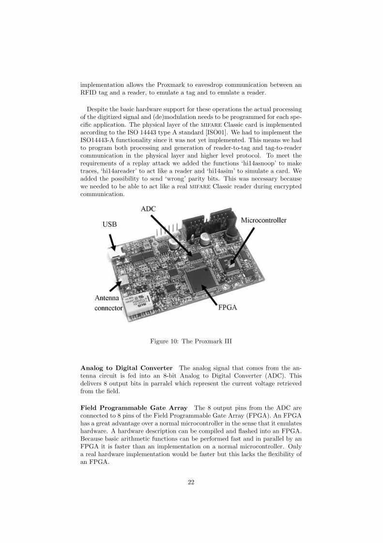
implementation allows the Proxmark to eavesdrop communication between anRFID tag and a reader, to emulate a tag and to emulate a reader.
Despite the basic hardware support for these operations the actual processingof the digitized signal and (de)modulation needs to be programmed for each spe-cific application. The physical layer of the mifare Classic card is implementedaccording to the ISO 14443 type A standard [ISO01]. We had to implement theISO14443-A functionality since it was not yet implemented. This means we hadto program both processing and generation of reader-to-tag and tag-to-readercommunication in the physical layer and higher level protocol. To meet therequirements of a replay attack we added the functions ‘hi14asnoop’ to maketraces, ‘hi14areader’ to act like a reader and ‘hi14asim’ to simulate a card. Weadded the possibility to send ‘wrong’ parity bits. This was necessary becausewe needed to be able to act like a real mifare Classic reader during encryptedcommunication.
Figure 10: The Proxmark III
Analog to Digital Converter The analog signal that comes from the an-tenna circuit is fed into an 8-bit Analog to Digital Converter (ADC). Thisdelivers 8 output bits in parralel which represent the current voltage retrievedfrom the field.
Field Programmable Gate Array The 8 output pins from the ADC areconnected to 8 pins of the Field Programmable Gate Array (FPGA). An FPGAhas a great advantage over a normal microcontroller in the sense that it emulateshardware. A hardware description can be compiled and flashed into an FPGA.Because basic arithmetic functions can be performed fast and in parallel by anFPGA it is faster than an implementation on a normal microcontroller. Onlya real hardware implementation would be faster but this lacks the flexibility ofan FPGA.
22
Microcontroller The microcontroller is responsible for the protocol part. Itreceives the digital encoded signals from the FPGA and decodes them. Thedecoded signals can just be copied to a buffer in the EEPROM memory. Ad-ditionally, an answer to the received message can be send by encoding a replyand communicating this to the FPGA.
23
5 Software
In this section we discuss the developed software to support ISO 14443A onthe Proxmark. The Proxmark is able to operate in three modes. These modesare the sniffing mode, the card emulation mode and the reader mode. A fewrequirements need to be fulfilled to implement these functions. First, we needan underlying physical layer which takes care of the Digital Signal Processing(DSP), this is implemented in the FPGA. Next, the modes of operation shouldbe implemented as functions on the microcontroller. Finally, a client should beable to call the functions and display the results. This leads to a rough divisionof the software into three parts:
• Client software, calls the functions implemented on the Proxmark, re-sponsible for representation of the results. The client can be seen as theapplication layer in the communication. It makes use of the underlyingprotocol to receive information about an RFID card.
• Microcontroller software, implements the different modes of operation.This is done by defining which protocol messages should be sent in whichformat and in what order. This can be seen as the transport layer of thecommunication.
• FPGA software, is responsible for the DSP and therefore responsible forthe physical layer of the communication.
Figure 11 shows the different components of the Proxmark application andtheir different responsibilities. The processing and generation of the protocolmessages is partly done by the FPGA and partly by the Microcontroller (ARM).The FPGA mainly does the edge detection and communicates to the ARMwhether the signal was high or low. The ARM then tries to decode the retrievedbit stream using Manchester or Modified Miller. For generation of messages theARM will send a bit stream to the FPGA that represents the Manchester orModified Miller encoded message. The FPGA will modulate according to thisbit stream. The design choice to split this DSP in two parts was mainly becauseof the limited capacity of the FPGA. It has not enough space to do flash adesign that does the signal processing and message decoding/encoding at thesame time. The next subsections are about the way different communicationmodes are implemented in each different component.
5.1 Client
The client application is written by Jonathan Westhues [Wes] and connects tothe Proxmark via the standard HID protocol. The operating system on theARM does not represent a proper real-time operating system in the sense thatit still polls for things like USB packets. This way it is not possible to streamthe retrieved samples on real-time to the PC. So when the ARM retrieves acommand from the client it runs this command and stores any useful messagesin its memory buffer. After the command finishes the client should send a new
24
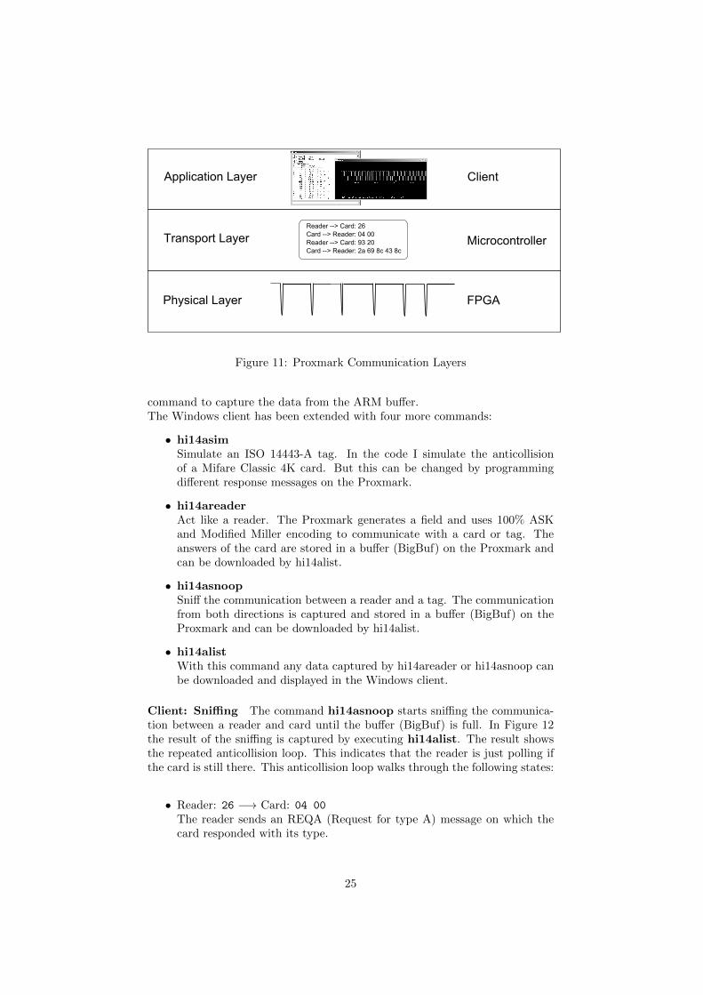
Figure 11: Proxmark Communication Layers
command to capture the data from the ARM buffer.The Windows client has been extended with four more commands:
• hi14asimSimulate an ISO 14443-A tag. In the code I simulate the anticollisionof a Mifare Classic 4K card. But this can be changed by programmingdifferent response messages on the Proxmark.
• hi14areaderAct like a reader. The Proxmark generates a field and uses 100% ASKand Modified Miller encoding to communicate with a card or tag. Theanswers of the card are stored in a buffer (BigBuf) on the Proxmark andcan be downloaded by hi14alist.
• hi14asnoopSniff the communication between a reader and a tag. The communicationfrom both directions is captured and stored in a buffer (BigBuf) on theProxmark and can be downloaded by hi14alist.
• hi14alistWith this command any data captured by hi14areader or hi14asnoop canbe downloaded and displayed in the Windows client.
Client: Sniffing The command hi14asnoop starts sniffing the communica-tion between a reader and card until the buffer (BigBuf) is full. In Figure 12the result of the sniffing is captured by executing hi14alist. The result showsthe repeated anticollision loop. This indicates that the reader is just polling ifthe card is still there. This anticollision loop walks through the following states:
• Reader: 26 −→ Card: 04 00
The reader sends an REQA (Request for type A) message on which thecard responded with its type.
25
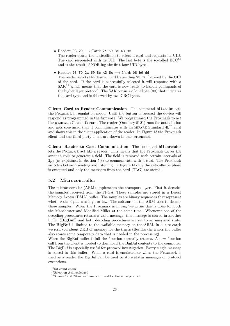
• Reader: 93 20 −→ Card: 2a 69 8c 43 8c
The reader starts the anticollision to select a card and requests its UID.The card responded with its UID. The last byte is the so-called BCC18
and is the result of XOR-ing the first four UID-bytes.
• Reader: 93 70 2a 69 8c 43 8c −→ Card: 08 b6 dd
The reader selects the desired card by sending 93 70 followed by the UIDof the card. If the card is successfully selected it will response with aSAK19 which means that the card is now ready to handle commands ofthe higher layer protocol. The SAK consists of one byte (08) that indicatesthe card type and is followed by two CRC bytes.
Client: Card to Reader Communication The command hi14asim setsthe Proxmark in emulation mode. Until the button is pressed the device willrespond as programmed in the firmware. We programmed the Proxmark to actlike a mifare Classic 4k card. The reader (Omnikey 5121) runs the anticollisionand gets convinced that it communicates with an mifare Standard 4k20 cardand shows this in the client application of the reader. In Figure 13 the Proxmarkclient and the third-party client are shown in one screenshot.
Client: Reader to Card Communication The command hi14areaderlets the Proxmark act like a reader. This means that the Proxmark drives theantenna coils to generate a field. The field is removed with certain intervals of2µs (as explained in Section 5.3) to communicate with a card. The Proxmarkswitches between sending and listening. In Figure 14 only the anticollision phaseis executed and only the messages from the card (TAG) are stored.
5.2 Microcontroller
The microcontroller (ARM) implements the transport layer. First it decodesthe samples received from the FPGA. These samples are stored in a DirectMemory Access (DMA) buffer. The samples are binary sequences that representwhether the signal was high or low. The software on the ARM tries to decodethese samples. When the Proxmark is in sniffing mode this is done for boththe Manchester and Modified Miller at the same time. Whenever one of thedecoding procedures returns a valid message, this message is stored in anotherbuffer (BigBuf) and both decoding procedures are set to an unsynced state.The BigBuf is limited to the available memory on the ARM. In our researchwe reserved about 2 KB of memory for the traces (Besides the traces the bufferalso stores some temporary data that is needed in the processing).When the BigBuf buffer is full the function normally returns. A new functioncall from the client is needed to download the BigBuf contents to the computer.The BigBuf is especially useful for protocol investigation. Every single messageis stored in this buffer. When a card is emulated or when the Proxmark isused as a reader the BigBuf can be used to store status messages or protocolexceptions.
18bit count check19Selection Acknowledged20‘Classic’ and ‘Standard’ are both used for the same product
26
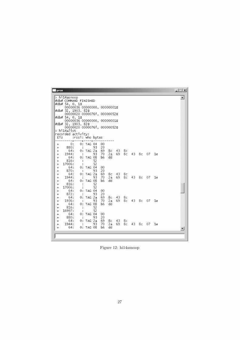
Figure 12: hi14asnoop
27
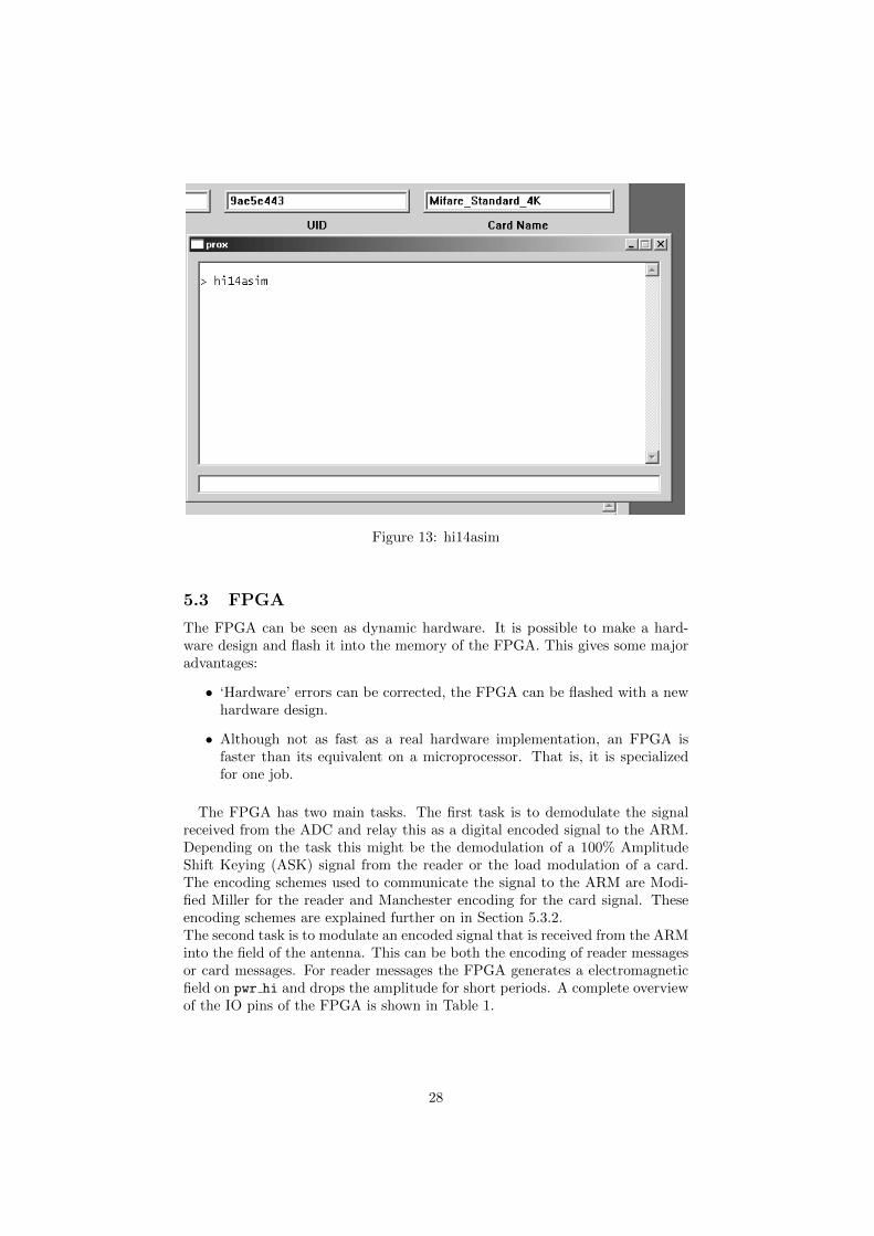
Figure 13: hi14asim
5.3 FPGA
The FPGA can be seen as dynamic hardware. It is possible to make a hard-ware design and flash it into the memory of the FPGA. This gives some majoradvantages:
• ‘Hardware’ errors can be corrected, the FPGA can be flashed with a newhardware design.
• Although not as fast as a real hardware implementation, an FPGA isfaster than its equivalent on a microprocessor. That is, it is specializedfor one job.
The FPGA has two main tasks. The first task is to demodulate the signalreceived from the ADC and relay this as a digital encoded signal to the ARM.Depending on the task this might be the demodulation of a 100% AmplitudeShift Keying (ASK) signal from the reader or the load modulation of a card.The encoding schemes used to communicate the signal to the ARM are Modi-fied Miller for the reader and Manchester encoding for the card signal. Theseencoding schemes are explained further on in Section 5.3.2.The second task is to modulate an encoded signal that is received from the ARMinto the field of the antenna. This can be both the encoding of reader messagesor card messages. For reader messages the FPGA generates a electromagneticfield on pwr hi and drops the amplitude for short periods. A complete overviewof the IO pins of the FPGA is shown in Table 1.
28
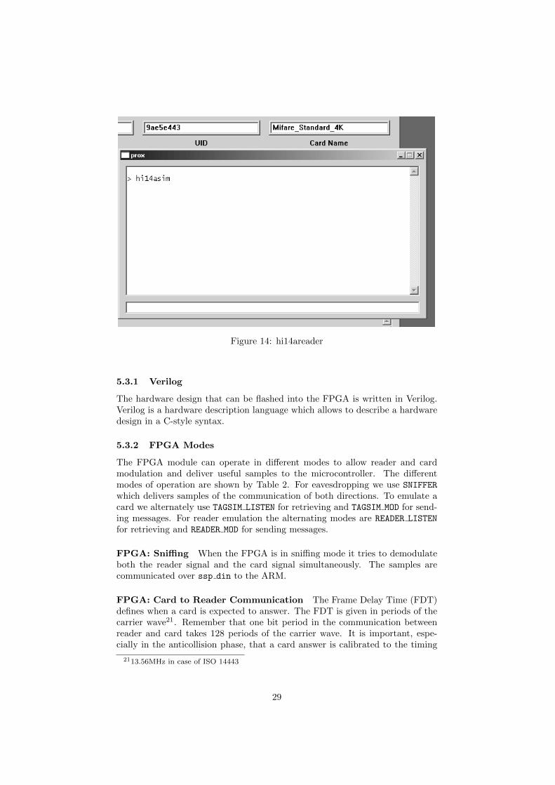
Figure 14: hi14areader
5.3.1 Verilog
The hardware design that can be flashed into the FPGA is written in Verilog.Verilog is a hardware description language which allows to describe a hardwaredesign in a C-style syntax.
5.3.2 FPGA Modes
The FPGA module can operate in different modes to allow reader and cardmodulation and deliver useful samples to the microcontroller. The differentmodes of operation are shown by Table 2. For eavesdropping we use SNIFFER
which delivers samples of the communication of both directions. To emulate acard we alternately use TAGSIM LISTEN for retrieving and TAGSIM MOD for send-ing messages. For reader emulation the alternating modes are READER LISTEN
for retrieving and READER MOD for sending messages.
FPGA: Sniffing When the FPGA is in sniffing mode it tries to demodulateboth the reader signal and the card signal simultaneously. The samples arecommunicated over ssp din to the ARM.
FPGA: Card to Reader Communication The Frame Delay Time (FDT)defines when a card is expected to answer. The FDT is given in periods of thecarrier wave21. Remember that one bit period in the communication betweenreader and card takes 128 periods of the carrier wave. It is important, espe-cially in the anticollision phase, that a card answer is calibrated to the timing
2113.56MHz in case of ISO 14443
29
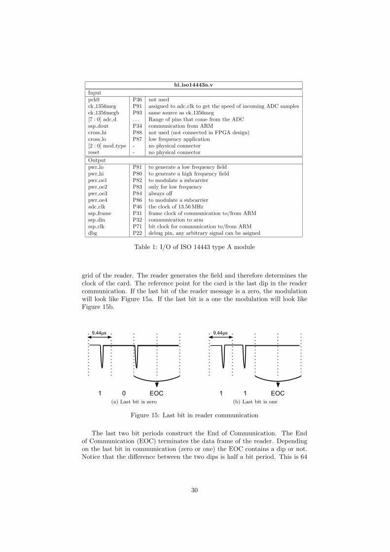
hi iso14443a.v
Inputpck0 P36 not usedck 1356meg P91 assigned to adc clk to get the speed of incoming ADC samplesck 1356megb P93 same source as ck 1356meg[7 : 0] adc d . . . Range of pins that come from the ADCssp dout P34 communication from ARMcross hi P88 not used (not connected in FPGA design)cross lo P87 low frequency application[2 : 0] mod type - no physical connectorreset - no physical connector
Outputpwr lo P81 to generate a low frequency fieldpwr hi P80 to generate a high frequency fieldpwr oe1 P82 to modulate a subcarrierpwr oe2 P83 only for low frequencypwr oe3 P84 always offpwr oe4 P86 to modulate a subcarrieradc clk P46 the clock of 13.56 MHzssp frame P31 frame clock of communication to/from ARMssp din P32 communication to armssp clk P71 bit clock for communication to/from ARMdbg P22 debug pin, any arbitrary signal can be asigned
Table 1: I/O of ISO 14443 type A module
grid of the reader. The reader generates the field and therefore determines theclock of the card. The reference point for the card is the last dip in the readercommunication. If the last bit of the reader message is a zero, the modulationwill look like Figure 15a. If the last bit is a one the modulation will look likeFigure 15b.
(a) Last bit is zero (b) Last bit is one
Figure 15: Last bit in reader communication
The last two bit periods construct the End of Communication. The Endof Communication (EOC) terminates the data frame of the reader. Dependingon the last bit in communication (zero or one) the EOC contains a dip or not.Notice that the difference between the two dips is half a bit period. This is 64
30
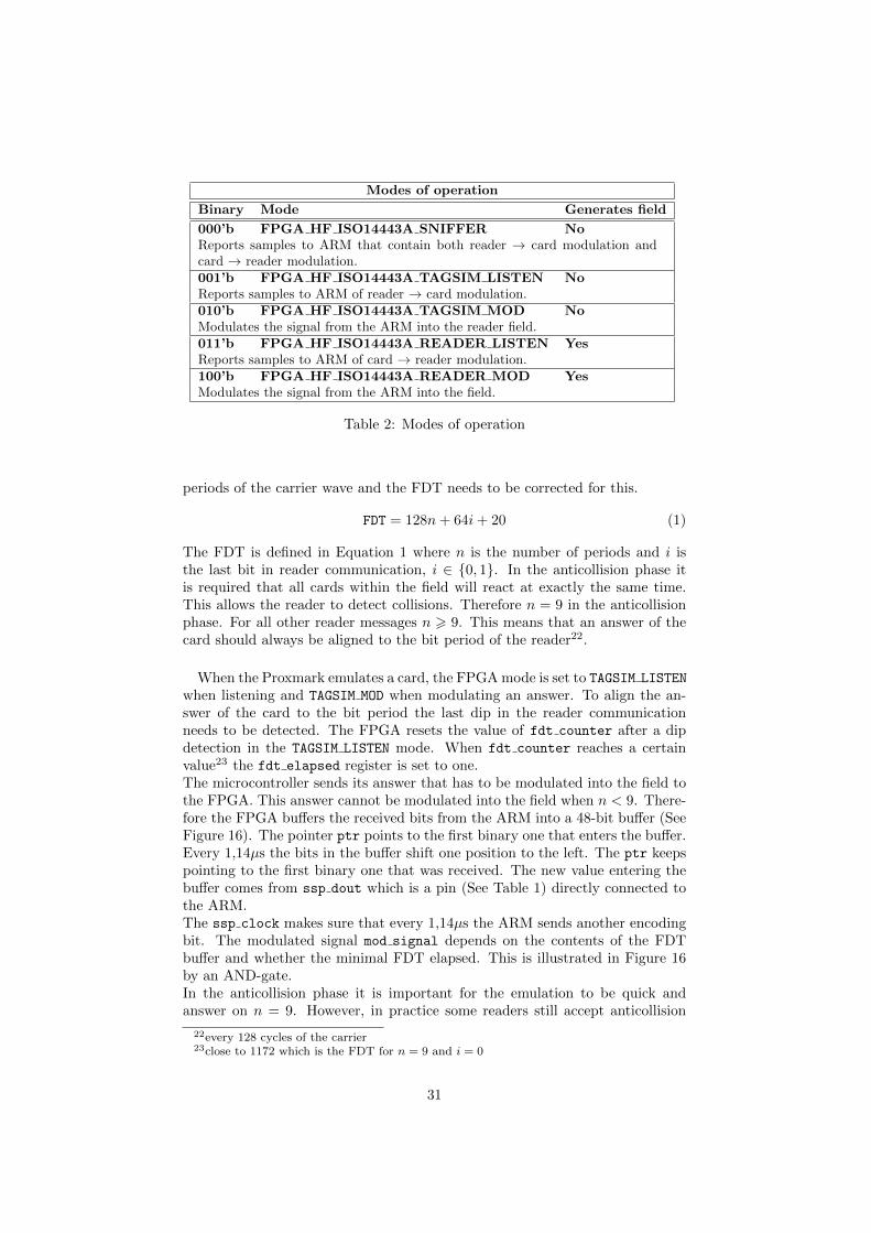
Modes of operation
Binary Mode Generates field
000’b FPGA HF ISO14443A SNIFFER NoReports samples to ARM that contain both reader → card modulation andcard → reader modulation.001’b FPGA HF ISO14443A TAGSIM LISTEN NoReports samples to ARM of reader → card modulation.010’b FPGA HF ISO14443A TAGSIM MOD NoModulates the signal from the ARM into the reader field.011’b FPGA HF ISO14443A READER LISTEN YesReports samples to ARM of card → reader modulation.100’b FPGA HF ISO14443A READER MOD YesModulates the signal from the ARM into the field.
Table 2: Modes of operation
periods of the carrier wave and the FDT needs to be corrected for this.
FDT = 128n+ 64i+ 20 (1)
The FDT is defined in Equation 1 where n is the number of periods and i isthe last bit in reader communication, i ∈ {0, 1}. In the anticollision phase itis required that all cards within the field will react at exactly the same time.This allows the reader to detect collisions. Therefore n = 9 in the anticollisionphase. For all other reader messages n > 9. This means that an answer of thecard should always be aligned to the bit period of the reader22.
When the Proxmark emulates a card, the FPGA mode is set to TAGSIM LISTEN
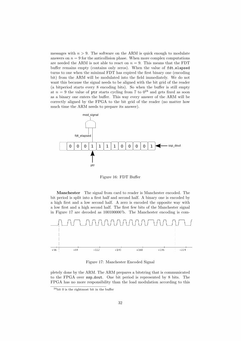
when listening and TAGSIM MOD when modulating an answer. To align the an-swer of the card to the bit period the last dip in the reader communicationneeds to be detected. The FPGA resets the value of fdt counter after a dipdetection in the TAGSIM LISTEN mode. When fdt counter reaches a certainvalue23 the fdt elapsed register is set to one.The microcontroller sends its answer that has to be modulated into the field tothe FPGA. This answer cannot be modulated into the field when n < 9. There-fore the FPGA buffers the received bits from the ARM into a 48-bit buffer (SeeFigure 16). The pointer ptr points to the first binary one that enters the buffer.Every 1,14µs the bits in the buffer shift one position to the left. The ptr keepspointing to the first binary one that was received. The new value entering thebuffer comes from ssp dout which is a pin (See Table 1) directly connected tothe ARM.The ssp clock makes sure that every 1,14µs the ARM sends another encodingbit. The modulated signal mod signal depends on the contents of the FDTbuffer and whether the minimal FDT elapsed. This is illustrated in Figure 16by an AND-gate.In the anticollision phase it is important for the emulation to be quick andanswer on n = 9. However, in practice some readers still accept anticollision
22every 128 cycles of the carrier23close to 1172 which is the FDT for n = 9 and i = 0
31
messages with n > 9. The software on the ARM is quick enough to modulateanswers on n = 9 for the anticollision phase. When more complex computationsare needed the ARM is not able to react on n = 9. This means that the FDTbuffer remains empty (contains only zeros). When the value of fdt elapsed
turns to one when the minimal FDT has expired the first binary one (encodingbit) from the ARM will be modulated into the field immediately. We do notwant this because the signal needs to be aligned with the bit grid of the reader(a bitperiod starts every 8 encoding bits). So when the buffer is still emptyat n = 9 the value of ptr starts cycling from 7 to 024 and gets fixed as soonas a binary one enters the buffer. This way every answer of the ARM will becorrectly aligned by the FPGA to the bit grid of the reader (no matter howmuch time the ARM needs to prepare its answer).
Figure 16: FDT Buffer
Manchester The signal from card to reader is Manchester encoded. Thebit period is split into a first half and second half. A binary one is encoded bya high first and a low second half. A zero is encoded the opposite way witha low first and a high second half. The first few bits of the Manchester signalin Figure 17 are decoded as 100100000’b. The Manchester encoding is com-
Figure 17: Manchester Encoded Signal
pletely done by the ARM. The ARM prepares a bitstring that is communicatedto the FPGA over ssp dout. One bit period is represented by 8 bits. TheFPGA has no more responsibility than the load modulation according to this
24bit 0 is the rightmost bit in the buffer
32
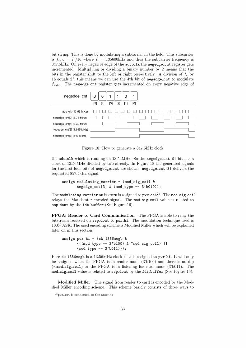
bit string. This is done by modulating a subcarrier in the field. This subcarrieris fsubc = fc/16 where fc = 135600kHz and thus the subcarrier frequency is847.5kHz. On every negative edge of the adc clk the negedge cnt register getsincremented. Multiplying or dividing a binary number by 2 means that thebits in the register shift to the left or right respectively. A division of fc by16 equals 24, this means we can use the 4th bit of negedge cnt to modulatefsubc. The negedge cnt register gets incremented on every negative edge of
Figure 18: How to generate a 847.5kHz clock
the adc clk which is running on 13.56MHz. So the negedge cnt[0] bit has aclock of 13.56MHz divided by two already. In Figure 18 the generated signalsfor the first four bits of negedge cnt are shown. negedge cnt[3] delivers therequested 857.5kHz signal.
assign modulating_carrier = (mod_sig_coil &
negedge_cnt[3] & (mod_type == 3’b010));
The modulating carrier on its turn is assigned to pwr oe425. The mod sig coil
relays the Manchester encoded signal. The mod sig coil value is related tossp dout by the fdt buffer (See Figure 16).
FPGA: Reader to Card Communication The FPGA is able to relay thebitstream received on ssp dout to pwr hi. The modulation technique used is100% ASK. The used encoding scheme is Modified Miller which will be explainedlater on in this section.
assign pwr_hi = (ck_1356megb &
(((mod_type == 3’b100) & ~mod_sig_coil) ||
(mod_type == 3’b011)));
Here ck 1356megb is a 13.56MHz clock that is assigned to pwr hi. It will onlybe assigned when the FPGA is in reader mode (3’b100) and there is no dip(∼mod sig coil) or the FPGA is in listening for card mode (3’b011). Themod sig coil value is related to ssp dout by the fdt buffer (See Figure 16).
Modified Miller The signal from reader to card is encoded by the Mod-ified Miller encoding scheme. This scheme basicly consists of three ways to
25pwr oe4 is connected to the antenna
33
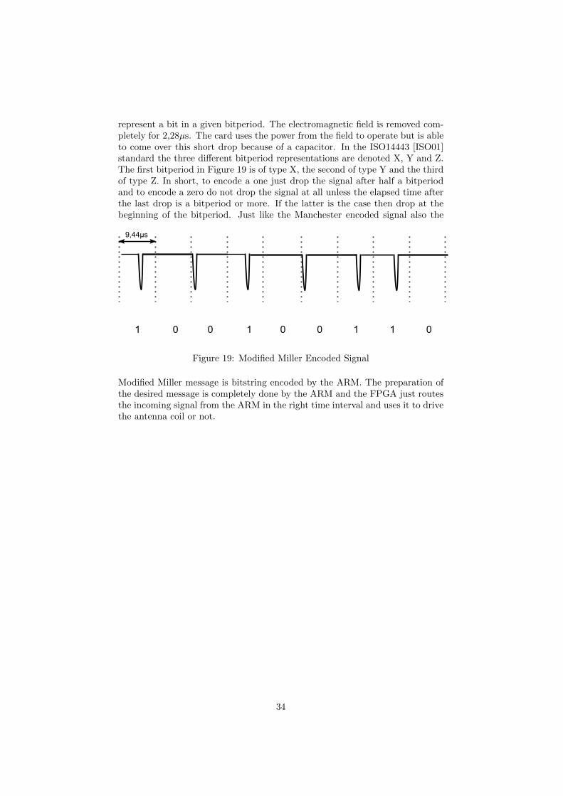
represent a bit in a given bitperiod. The electromagnetic field is removed com-pletely for 2,28µs. The card uses the power from the field to operate but is ableto come over this short drop because of a capacitor. In the ISO14443 [ISO01]standard the three different bitperiod representations are denoted X, Y and Z.The first bitperiod in Figure 19 is of type X, the second of type Y and the thirdof type Z. In short, to encode a one just drop the signal after half a bitperiodand to encode a zero do not drop the signal at all unless the elapsed time afterthe last drop is a bitperiod or more. If the latter is the case then drop at thebeginning of the bitperiod. Just like the Manchester encoded signal also the
Figure 19: Modified Miller Encoded Signal
Modified Miller message is bitstring encoded by the ARM. The preparation ofthe desired message is completely done by the ARM and the FPGA just routesthe incoming signal from the ARM in the right time interval and uses it to drivethe antenna coil or not.
34
6 Case studies
Nohl and Plotz [NP07] discovered that the pseudo-random generator, used togenerate the nonces in the authentication, is weak. During our experiments, in-dependently, we also discovered this weakness of the pseudo-random generatorby requesting many nonces from the card, at arbitrary times. This experimentshowed that a ‘random’ nonce repeats a few times per hour. This is just bychance because Nohl and Plotz discovered that the nonce is generated by anLinear Feedback Shift Register (LFSR) which shifts every 9.44µs. This is ex-actly one bit period in the communication. Therefore a random nonce couldtheoretically reappear after 0.618s, if the card is queried at exactly the righttime.
Without knowing the cryptographic algorithm, only an online brute forceattack can be mounted, trying all possible keys in an actual authentication runbetween a reader and a card. Because of the communication delay, this wouldtake 5ms for each attempt. An exhaustive key search would then take 16,289,061days, which equals about 44,627 years.When the cryptographic algorithm is known, an off-line brute force attack canbe mounted using a few eavesdropped traces of an authentication run. Nohland Plotz state that with dedicated hardware of around $17.000 this wouldtake about 1 hour. For this attack to work, some known plaintext is required.Our analysis provides this plaintext.
It is however possible to attack the mifare Classic in another way, that doesnot require recovering the key. This attack, that we describe here, uses theweakness of the pseudo-random generator to recover the keystream.
6.1 Attacks on MIFARE
There are several attacks possible on mifare Classic. The first practical attackwas carried out by us in [dKGHG08] and was the topic of this master studies,so will be explained in detail further on. This attack recovers used keystreamin a transaction between a reader and a card. Due to a weak pseudo-randomgenerator the same keystream can be used twice. For this attack the secret keyremains unknown and is not needed. Also the algorithm used can be unknown.Other attacks have the secret key as target and try to recover the key. One wayto do this is a brute-force attack. Until now a brute-force attack could only beperformed on-line against a card because the CRYPTO1 algorithm was secret.The algorithm is recovered partially by reverse engineering of the hardwarechip [NP07] and the rest could be revealed by protocol analysis [Dig08, NESP08].An off-line attack is now one of the possibilities but still takes a lot of time (oneweek per key) or is expensive ($17.000) [NP07]. Cryptanalysis showed that thereare weaknesses in the design of the algorithm which make it possible to recover12 keys per second [GdKGM+08]. Also algebraic attacks are possible. In thissection we visit the different attacks known so far.
35
6.1.1 Keystream Recovery Attack
In this section we develop a method to recover the keystream that is used inan earlier recorded transaction between a reader and a card. As a result thekeystream of the communication will be recovered. For this attack we need tobe in possession of the card. The following reasons make this attack interesting:
1. Our attack provides the known plaintext necessary to mount a brute forceattack on the key.
2. Using our attack we recovered details about the byte commands.
3. Using the recovered key stream we can read card contents without knowingthe key.
4. Using the recovered key stream we can also modify the contents of thecard without knowing the key.
Keystream Recovery To recover the keystream we exploit the weakness onthe pseudo-random generator (Figure 20). We also use the fact that this randomnonce in combination with only one valid response of the reader determines thecontinuation of the keystream. This allows us to replace for example the addressbyte of a read command as shown on the bottom of the diagram in Figure 20.For this attack we need complete control over the reader (Proxmark) and accessto a (genuine) card. The attack consists of the following steps:
1. Eavesdrop the communication between a reader and a card. This can befor example be in an access control system or public transport system.
2. Start a new communication with the same card, but now using the Prox-mark. Make sure that the card will use the same keystream as in therecorded communication. This is possible because the card repeats thesame nonce in reasonable time, and we completely control the reader.
3. Modify the plaintext, such that the card receives a command for whichwe know plaintext in the response (e.g., by changing the block number ina read command).
4. For each segment of known plaintext, compute the corresponding keystreamsegment.
5. Use this keystream to partially decrypt the trace obtained in 1.
6. Try recovering more keystream bits by shifting commands.
The plaintext P1 in the communication is XOR-ed bitwise with a keystreamK which gives the encrypted data C1.
It should not be possible to control the initialization of the stream cipherin a way that it generates the same key stream again. Because of the weakpseudo-random generator it is possible to retrieve the same card challenge overand over again. When it is possible to use the same keystream on a differentplaintext P2 and either P1 or P2 is known, then both P1 and P2 are revealed.
P1 ⊕K = C1
P2 ⊕K = C2
}C1 ⊕ C2 ⇒ P1 ⊕ P2 ⊕K ⊕K ⇒ P1 ⊕ P2 (2)
36
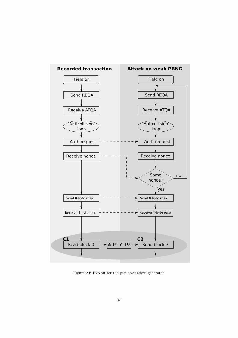
Figure 20: Exploit for the pseudo-random generator
37
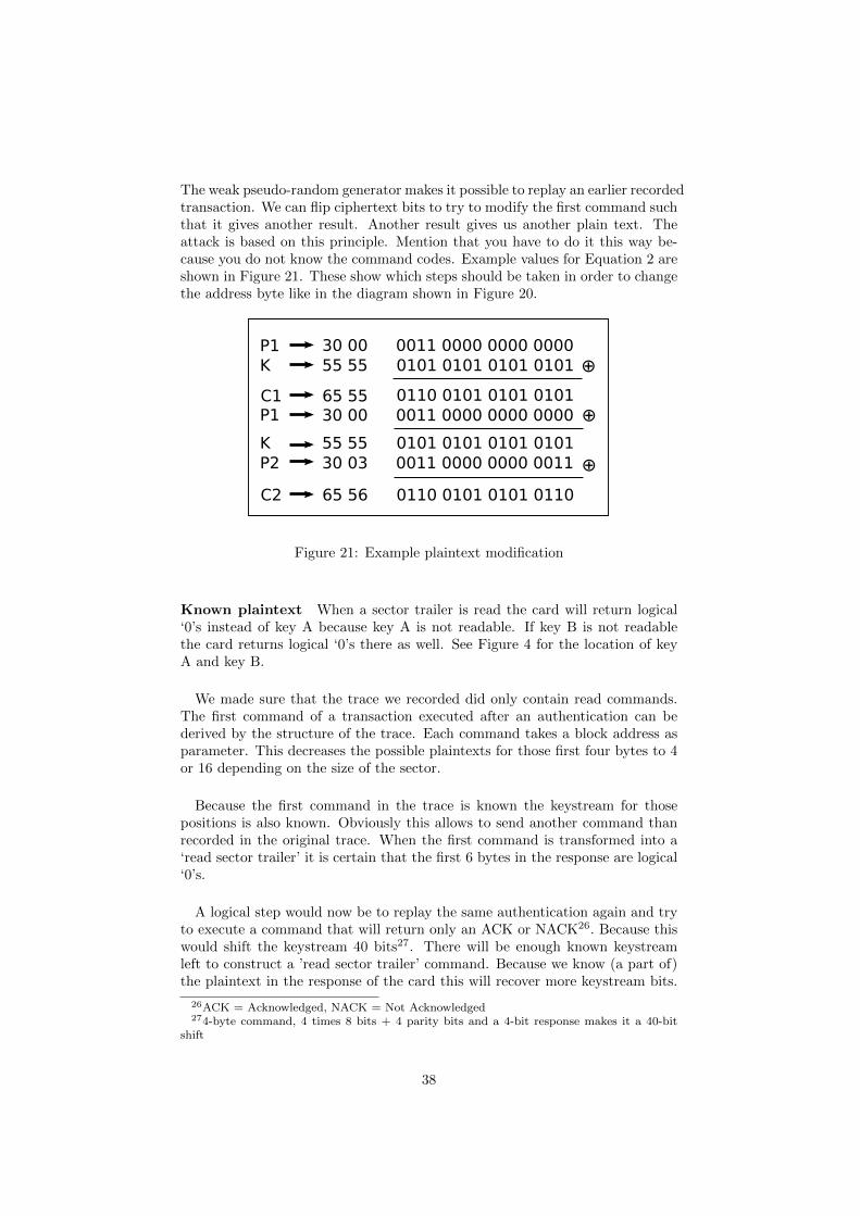
The weak pseudo-random generator makes it possible to replay an earlier recordedtransaction. We can flip ciphertext bits to try to modify the first command suchthat it gives another result. Another result gives us another plain text. Theattack is based on this principle. Mention that you have to do it this way be-cause you do not know the command codes. Example values for Equation 2 areshown in Figure 21. These show which steps should be taken in order to changethe address byte like in the diagram shown in Figure 20.
Figure 21: Example plaintext modification
Known plaintext When a sector trailer is read the card will return logical‘0’s instead of key A because key A is not readable. If key B is not readablethe card returns logical ‘0’s there as well. See Figure 4 for the location of keyA and key B.
We made sure that the trace we recorded did only contain read commands.The first command of a transaction executed after an authentication can bederived by the structure of the trace. Each command takes a block address asparameter. This decreases the possible plaintexts for those first four bytes to 4or 16 depending on the size of the sector.
Because the first command in the trace is known the keystream for thosepositions is also known. Obviously this allows to send another command thanrecorded in the original trace. When the first command is transformed into a‘read sector trailer’ it is certain that the first 6 bytes in the response are logical‘0’s.
A logical step would now be to replay the same authentication again and tryto execute a command that will return only an ACK or NACK26. Because thiswould shift the keystream 40 bits27. There will be enough known keystreamleft to construct a ’read sector trailer’ command. Because we know (a part of)the plaintext in the response of the card this will recover more keystream bits.
26ACK = Acknowledged, NACK = Not Acknowledged274-byte command, 4 times 8 bits + 4 parity bits and a 4-bit response makes it a 40-bit
shift
38
This attempt does not work when we send commands that result in a NACK.The protocol aborts when any incorrectness is detected. This might be in caseof access violation or errors in the communication. Messages that are too short,too long or have wrong parity bits are not accepted. Also unknown commandsare rejected. Because the card halts after such messages we can not send a readcommand and recover more keystream bits.
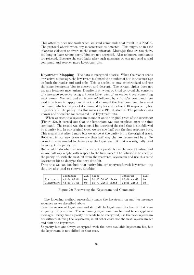
Keystream Mapping The data is encrypted bitwise. When the reader sendsor receives a message, the keystream is shifted the number of bits in this messageon both the reader and card side. This is needed to stay synchronized and usethe same keystream bits to encrypt and decrypt. The stream cipher does notuse any feedback mechanism. Despite that, when we tried to reveal the contentsof a message sequence using a known keystream of an earlier trace, somethingwent wrong. We recorded an increment followed by a transfer command. Weused this trace to apply our attack and changed the first command to a readcommand which consists of 4 command bytes and delivers 18 response bytes.Together with the parity bits this makes it a 198 bit stream. The plaintext wasknown and therefore we recovered 198 keystream bits.
When we used this keystream to map it on the original trace of the increment(Figure 22), it turned out that the keystream was not in phase after the firstcommand. The reason was the short 4-bit answer of the card that is not followedby a parity bit. In our original trace we are now half way the first response byte.This means that after 4 more bits we arrive at the parity bit in the original trace.However, in our new trace we are then half way the next command byte. Tocorrect this we needed to throw away the keystream bit that was originally usedto encrypt the parity bit.But what to do when we need to decrypt a parity bit in the new situation andwe are half way a byte with respect to the first trace? The solution is to encryptthe parity bit with the next bit from the recovered keystream and use this samekeystream bit to decrypt the next data bit.From this we can conclude that parity bits are encrypted with keystream bitsthat are also used to encrypt databits.
INCREMENT ACK VALUE TRANSFER ACK
Plaintext c1 04 f6 8b 0a 01 00 00 00 bb 4a b0 04 ea 62 0a
Ciphertext 4c 88 31 bc! 0a! e2 79!2a!14 35!6f! 04!81 2d!1e! 0c!
Figure 22: Recovering the Keystream and Commands
The following method successfully maps the keystream on another messagesequence as we described above.Take the recovered keystream and strip all the keystream bits from it that wereat parity bit positions. The remaining keystream can be used to encrypt newmessages. Every time a parity bit needs to be encrypted, use the next keystreambit without shifting the keystream, in all other cases use the next keystream bitand shift the keystream.So parity bits are always encrypted with the next available keystream bit, butthe keystream is not shifted in that case.
39
Authentication Replay As shown in Section 3.1 the high-level protocolstarts always with an authentication. This can be an authentication with keyA or B (see table 24). So after a successful anticollision phase (part 3 of ISO14443 [ISO01]) the only option will be to send an authentication request 60 (forkey A) or 61 (for key B)28. In response to this authentication request the cardwill send a challenge nonce NC . In Section ?? it is shown that the card repeatsNC within reasonable time. Because no other varying information is used in theauthentication like timestamps this enables a replay of an authentication.To replay an authentication we first need a trace of a successful authenticationbetween a genuine mifare reader and card. An example of an authenticationfollowed by one read command is shown below.
1 PCD 60 03 6e 49
2 TAG e0 92 93 98
3 PCD ad e7 96! 48! 20! 22 df 93
4 TAG bf 06 91! 82
5 PCD b5! 05! 47 3f
6 TAG 3f 14! 4f e9! 86 38! 96! 85 3e!
f3 e3! 3d! eb! 2b! a2 d4 dd 76!
After this recorded authentication between card and reader, we make sure thatthe memory of the card is not modified. This ensures that when the memory ofthe card is read it will return the same plaintext. Now we will act like a mifarereader and try to initiate the same authentication. In short:
1. We recorded a trace of a successful authentication between a genuine cardand reader.
2. We send authentication requests (#1) until we get a nonce that is equalto the one (#2) in the original trace.
3. We send the recorded response (#3) to this nonce. It consists of a validresponse to the challenge nonce and challenge from the reader.
4. We retrieve the response (#4) to the challenge from the card.
5. Now we are at the point we where we could resend the same command(#5) or attempt to modify it.
After step 4 the card is in a state where we have successfully authenticated for(in this case) sector 0 (block 3). Now it expects a command for this sector.If we send the same command we recorded earlier, we get the same encryptedresponse as in the original trace. Therefore the keystream is the same.
Reading a Sector We will show that it is possible to read sector 0 froma card without knowing the key. We only need one transaction between agenuine mifare reader and card. Every mifare Classic card has some knownmemory contents. The product information published by NXP [NXP07b] givesthis information.When a sector trailer is read the card will return logical ‘0’s instead of key Abecause key A is not readable. If key B is not readable the card also returnslogical ‘0’s. It depends on the access conditions if key B is readable or not. The
28Except from sending a HALT command
40
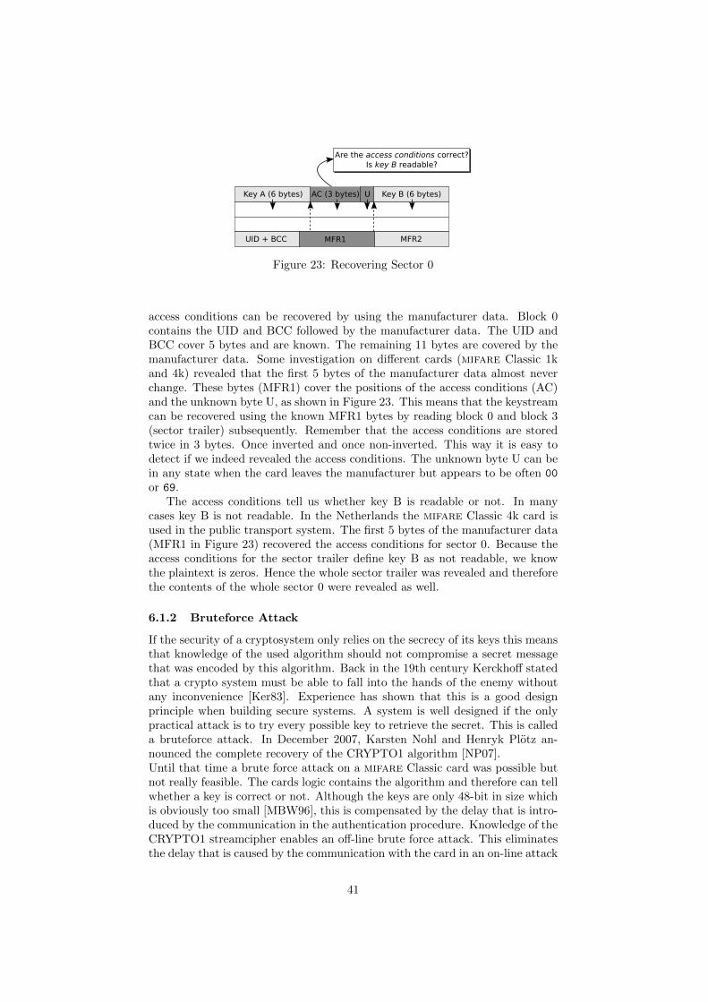
Figure 23: Recovering Sector 0
access conditions can be recovered by using the manufacturer data. Block 0contains the UID and BCC followed by the manufacturer data. The UID andBCC cover 5 bytes and are known. The remaining 11 bytes are covered by themanufacturer data. Some investigation on different cards (mifare Classic 1kand 4k) revealed that the first 5 bytes of the manufacturer data almost neverchange. These bytes (MFR1) cover the positions of the access conditions (AC)and the unknown byte U, as shown in Figure 23. This means that the keystreamcan be recovered using the known MFR1 bytes by reading block 0 and block 3(sector trailer) subsequently. Remember that the access conditions are storedtwice in 3 bytes. Once inverted and once non-inverted. This way it is easy todetect if we indeed revealed the access conditions. The unknown byte U can bein any state when the card leaves the manufacturer but appears to be often 00
or 69.The access conditions tell us whether key B is readable or not. In many
cases key B is not readable. In the Netherlands the mifare Classic 4k card isused in the public transport system. The first 5 bytes of the manufacturer data(MFR1 in Figure 23) recovered the access conditions for sector 0. Because theaccess conditions for the sector trailer define key B as not readable, we knowthe plaintext is zeros. Hence the whole sector trailer was revealed and thereforethe contents of the whole sector 0 were revealed as well.
6.1.2 Bruteforce Attack
If the security of a cryptosystem only relies on the secrecy of its keys this meansthat knowledge of the used algorithm should not compromise a secret messagethat was encoded by this algorithm. Back in the 19th century Kerckhoff statedthat a crypto system must be able to fall into the hands of the enemy withoutany inconvenience [Ker83]. Experience has shown that this is a good designprinciple when building secure systems. A system is well designed if the onlypractical attack is to try every possible key to retrieve the secret. This is calleda bruteforce attack. In December 2007, Karsten Nohl and Henryk Plotz an-nounced the complete recovery of the CRYPTO1 algorithm [NP07].Until that time a brute force attack on a mifare Classic card was possible butnot really feasible. The cards logic contains the algorithm and therefore can tellwhether a key is correct or not. Although the keys are only 48-bit in size whichis obviously too small [MBW96], this is compensated by the delay that is intro-duced by the communication in the authentication procedure. Knowledge of theCRYPTO1 streamcipher enables an off-line brute force attack. This eliminatesthe delay that is caused by the communication with the card in an on-line attack
41
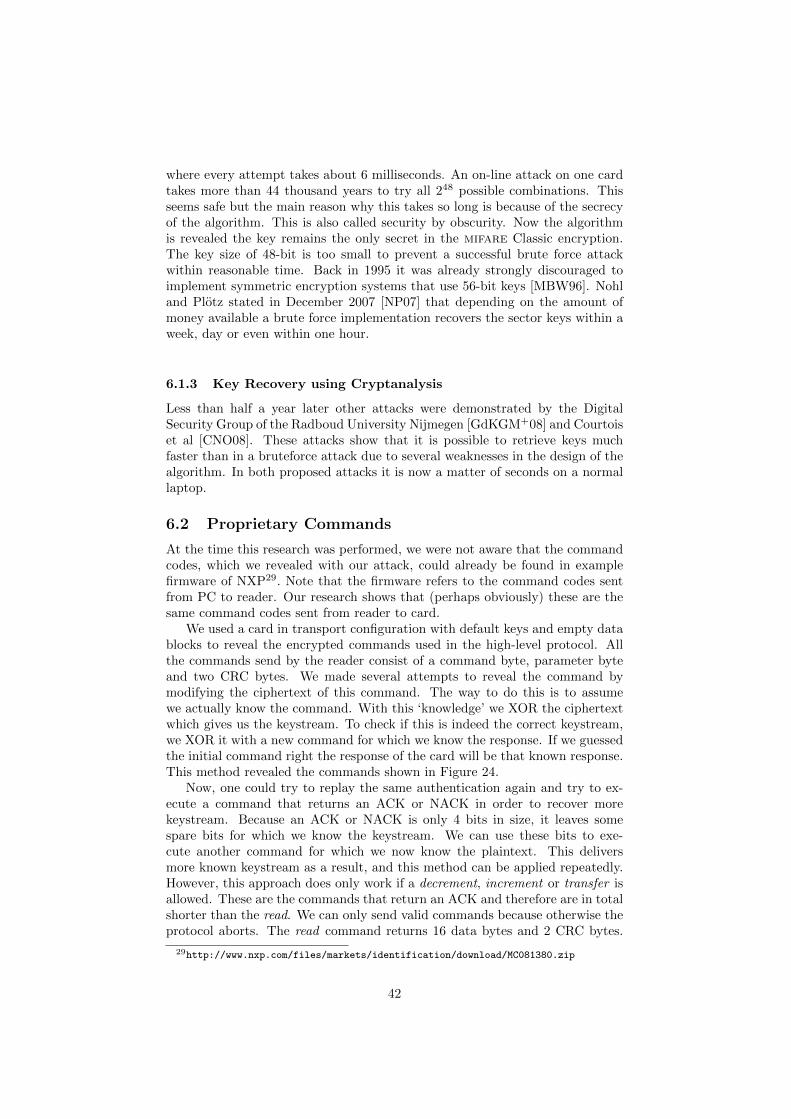
where every attempt takes about 6 milliseconds. An on-line attack on one cardtakes more than 44 thousand years to try all 248 possible combinations. Thisseems safe but the main reason why this takes so long is because of the secrecyof the algorithm. This is also called security by obscurity. Now the algorithmis revealed the key remains the only secret in the mifare Classic encryption.The key size of 48-bit is too small to prevent a successful brute force attackwithin reasonable time. Back in 1995 it was already strongly discouraged toimplement symmetric encryption systems that use 56-bit keys [MBW96]. Nohland Plotz stated in December 2007 [NP07] that depending on the amount ofmoney available a brute force implementation recovers the sector keys within aweek, day or even within one hour.
6.1.3 Key Recovery using Cryptanalysis
Less than half a year later other attacks were demonstrated by the DigitalSecurity Group of the Radboud University Nijmegen [GdKGM+08] and Courtoiset al [CNO08]. These attacks show that it is possible to retrieve keys muchfaster than in a bruteforce attack due to several weaknesses in the design of thealgorithm. In both proposed attacks it is now a matter of seconds on a normallaptop.
6.2 Proprietary Commands
At the time this research was performed, we were not aware that the commandcodes, which we revealed with our attack, could already be found in examplefirmware of NXP29. Note that the firmware refers to the command codes sentfrom PC to reader. Our research shows that (perhaps obviously) these are thesame command codes sent from reader to card.
We used a card in transport configuration with default keys and empty datablocks to reveal the encrypted commands used in the high-level protocol. Allthe commands send by the reader consist of a command byte, parameter byteand two CRC bytes. We made several attempts to reveal the command bymodifying the ciphertext of this command. The way to do this is to assumewe actually know the command. With this ‘knowledge’ we XOR the ciphertextwhich gives us the keystream. To check if this is indeed the correct keystream,we XOR it with a new command for which we know the response. If we guessedthe initial command right the response of the card will be that known response.This method revealed the commands shown in Figure 24.
Now, one could try to replay the same authentication again and try to ex-ecute a command that returns an ACK or NACK in order to recover morekeystream. Because an ACK or NACK is only 4 bits in size, it leaves somespare bits for which we know the keystream. We can use these bits to exe-cute another command for which we now know the plaintext. This deliversmore known keystream as a result, and this method can be applied repeatedly.However, this approach does only work if a decrement, increment or transfer isallowed. These are the commands that return an ACK and therefore are in totalshorter than the read. We can only send valid commands because otherwise theprotocol aborts. The read command returns 16 data bytes and 2 CRC bytes.
29http://www.nxp.com/files/markets/identification/download/MC081380.zip
42
Figure 24: Command set of mifare Classic
On a write command the card returns a 4-bit ACK, this indicates that the cardis ready to receive 16 data bytes followed by 2 CRC bytes.The decrement, increment and restore commands all follow the same procedure.The card indicates that it is expecting a value from the reader by sending a 4-bitACK response. This value is 4 bytes and is followed by 2 CRC bytes. For therestore this value is send but not used. The value is send as YY YY YY YY ZZ
ZZ, where YY are the value bytes and ZZ the CRC bytes.Finally, a transfer command is send to transfer the result of one of the previouscommands to a memory block. The card response is an ACK if it went well.Otherwise it responds with a NACK.
The 4-bit ACK is 0xa. When a command is not allowed the card sends 0x4.When a transmission error is detected the card sends 0x5. The card does noteven give a response at all if the command is of the wrong length. The protocolaborts on every mistake or disallowed command.
43
7 Conclusions & Recommendations
We have implemented a successful attack to recover the keystream of an earlierrecorded transaction between a genuine mifare Classic reader and card.
We used a mifare Classic reader in combination with a ‘blank’ card withdefault keys to recover the byte commands that are used in the proprietaryprotocol. Knowing the byte commands and a sufficiently long keystream allowedus to perform any operation as if we were in possession of the secret key.
We managed to read all memory blocks of the sector zero of the card, withouthaving access to the secret key. In general, we were able to read any sector ofthe memory of the card, provided that we know one memory block within thissector. Moreover, after recording a valid transaction on any sector, we were ableto read the first 6 bytes of any block in that sector and also the last 6 bytes ifkey B is read only. Similarly, we are able to modify the information stored in aparticular sector.
7.1 Observations
Weak pseudo-random generator It is known that good pseudo-randomgenerators are needed for cryptographic protocols to provide secure communi-cation. By empirical research we found that the nonces generated by the mifareClassic card reappeared very often. This was the main reason why our attackdeveloped in [dKGHG08] was successful.
Keystream recovery is possible The keystream recovery compromises mi-fare Classic in three ways. First and foremost, using the weakness of thepseudo-random generator, and given access to a particular mifare Classic card,the keystream generated by the CRYPTO1 streamcipher can be recovered, with-out knowing the key used. Secondly, the exact details of the communication be-tween reader and card can be revealed. The command codes and structure thatso far were unknown are revealed. Although the command codes can be foundin firmware code that controls the mifare PCD chip, this research confirmsthat they are actually sent by the mifare PCD chip. And last, the malleabilityof the streamcipher is used to read all memory blocks of the first sector (sector0) of the card (without having access to the secret key). This gives us the samepossibilities as if we were in possession of the secret key. So, modification is alsopossible with this recovered keystream.
Consequences First of all, all data stored on the card (except the keys them-selves) should no longer be considered secret. In particular, if the mifare Classiccard is used to store personal information (like name, date of birth, or travel in-formation), this constitutes a direct privacy risk. The security risk is relativelylow because in general the security is guaranteed by the secrecy of the keys.Note that in particular we are not able to clone cards, because the secret keysremain secret.
Secondly, the integrity and authenticity of the data stored on the card canno longer be relied on. This is quite a severe security risk. This is particularlyworrying in applications where the card is used to store a certain value, likeloyalty points or, even worse, some form of digital currency. The loyalty level or
44
the value stored in the electronic purse could easily be increased (or decreased,in a denial-of-service type of attack).
Thirdly, knowledge of the plaintext (or the keystream) is a necessary condi-tion to perform brute force (or other more sophisticated) attacks to recover thesecret key. This allowed us to develop a very efficient attack to recover arbitrarysector keys of a mifare Classic card [dKGHG08].
7.2 Recommendations
Migrate to a more advanced card The main recommendation to solve theproblems with the mifare Classic is unfortunately to migrate to another cardtype. The contactless smartcard market has developed more advanced cardswith cryptographic schemes like DES, AES and even public-key cryptographyover the years. For the implementation of new systems the mifare Classicis often chosen for its low price on one hand, and because it is thought toprovide a reasonable level of security on the other. With respect to the latestdevelopments, mifare Classic is not a serious candidate anymore. It is not saidthat, because it is possible, every system using mifare Classic is immediatelyunder attack. The question is what the award will be if an attacker breaks intothe system. Now the mifare Classic does not deliver the protection for whichit was once sold it is needed to migrate to another product. Which product thisshould be depends again on the balance between level of security and price.
Make sure abuse is detectable Because migration takes a lot of time andshould be prepared carefully it is useful to reduce the chance of abuse by somecountermeasures.While it has become relative easy to copy a mifare Classic card, it is not said tobe impossible to detect this kind of attack. We have made an implementation ofthe CRYPTO1 algorithm on the Proxmark III which emulates a card completely.This means that there are two ‘cards’ in the system that are completely equalto the system. The back office should log all transactions. In most systems thisis already the case. Detection is then done by finding contradictions in theselogs. It is not possible for person A to enter building B1 and building B2 atthe same time. On the other hand it is possible for person A to enter buildingB1 and after some time enter building B2. Then it is hard to detect if a clonedcard was used.
A mechanism that detects the use of duplicate cards in any case is easy toachieve. The encryption provided by the card is broken, so store data encryptedwith an encryption scheme like AES. When an attacker reads the data, he stillcan not tamper with it as long as he is not in possession of the right AES key.This way it is possible to store a counter on the card that gets incremented inevery transaction by the reader. The card holder nor a possible attacker is ableto increment this counter by one and store the new encrypted value becausethey do not posses the AES key. The latest value of this counter is stored inthe back office. Every new transaction the counter is compared to the one inthe back office and if they match nothing is wrong. If the value in the backoffice appears to be a successor of the value on the card this means that anothercard (duplicate or original) caused a transaction and increased the counter.
45
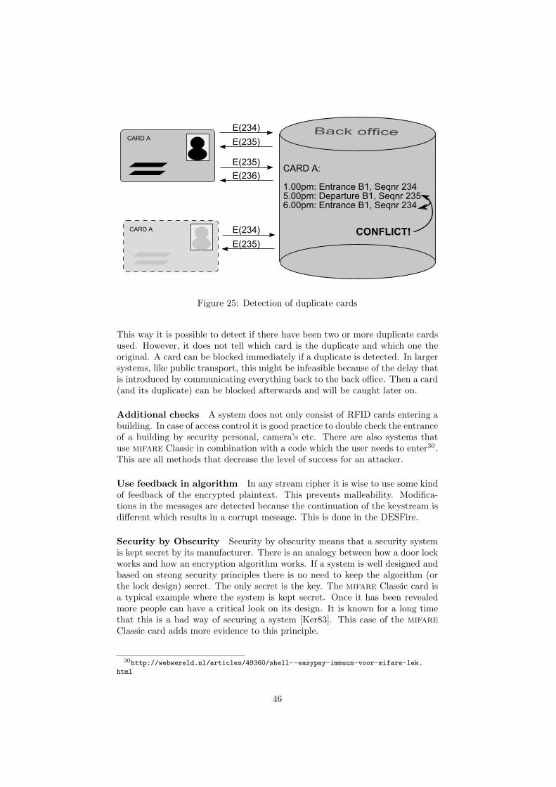
Figure 25: Detection of duplicate cards
This way it is possible to detect if there have been two or more duplicate cardsused. However, it does not tell which card is the duplicate and which one theoriginal. A card can be blocked immediately if a duplicate is detected. In largersystems, like public transport, this might be infeasible because of the delay thatis introduced by communicating everything back to the back office. Then a card(and its duplicate) can be blocked afterwards and will be caught later on.
Additional checks A system does not only consist of RFID cards entering abuilding. In case of access control it is good practice to double check the entranceof a building by security personal, camera’s etc. There are also systems thatuse mifare Classic in combination with a code which the user needs to enter30.This are all methods that decrease the level of success for an attacker.
Use feedback in algorithm In any stream cipher it is wise to use some kindof feedback of the encrypted plaintext. This prevents malleability. Modifica-tions in the messages are detected because the continuation of the keystream isdifferent which results in a corrupt message. This is done in the DESFire.
Security by Obscurity Security by obscurity means that a security systemis kept secret by its manufacturer. There is an analogy between how a door lockworks and how an encryption algorithm works. If a system is well designed andbased on strong security principles there is no need to keep the algorithm (orthe lock design) secret. The only secret is the key. The mifare Classic card isa typical example where the system is kept secret. Once it has been revealedmore people can have a critical look on its design. It is known for a long timethat this is a bad way of securing a system [Ker83]. This case of the mifareClassic card adds more evidence to this principle.
30http://webwereld.nl/articles/49360/shell--easypay-immuun-voor-mifare-lek.
html
46
8 Further research
The problems concerning the mifare Classic are not only due to a weak design ofthe cryptographic algorithm. It is an old chip in comparison to similar productsin the market. Back in 1994, when mifare Classic was introduced, the chipcomplexity was significant lower than any developed chips nowadays. It is achallenge to find methods and design protocols that provide sufficient security,privacy and anonymity given the constraints of an RFID system.
The results on the mifare Classic card might indicate that similar productscould bear the same problems. One could think of the Sony FeliCa card whichhas comparable functionality. Sony claims on its website that it uses ‘industrystandard’ security algorithms. The communication speed is 212 kbps, twiceas fast as the 106 kbps of mifare Classic, and is based on other modulationschemes. More advanced cards of the mifare family like the DESFire andthe SmartMX seem to have better protection against the attack we developed.Basically, the initialization of the protocols uses a random with a higher entropythan the mifare Classic. Additionally, they use some sort of feedback thatinvolves the plaintext. This makes it harder to recover the keystream. Ofcourse, also these cards have to deal with limiting constraints, but at least theused encryption scheme is public. Which of course should not be confused withthe way it is implemented. Furthermore, there are much more RFID systemswhich are relatively cheap and provide proprietary security like the mifareClassic. Research on randomness of the used pseudo-random generators andthe protocol should point out whether the products actually deliver the claimedsecurity or not. The development of new research tools like the OpenPCD,OpenPICC, Proxmark, Ghost, Mole and many others show that the technologybecomes cheaper over the years. Inherently, the number of people that look intothe used protocols and security mechanisms will grow. Therefore, it is neededto detect design flaws in early stages to prevent abuse.
The mifare product family is also capable of communication speeds fasterthan the 106 kbps we have implemented in the Proxmark. It would be veryhelpful for additional research to make the Proxmark compatible with thesehigher speeds.
Nowadays it is possible to buy contactless cards that implement encryptionschemes like AES. So the question is not any more if this is possible at all.However, for authentication and initialization one needs good pseudo-randomgenerators. It is challenging to design a pseudo-random number generator thatis heavily restricted by its environment (timing and power from reader).
The focus in the field of RFID is more on security instead of privacy. Whileone of the main results of the many RFID tags used today is that goods becometraceable. First, because logistic companies want so, but also in cases whenproducts leave the logistic chain and the customer is not aware of the RFID tag.This is only one example and many others are available. To provide privacy itis of course possible to use a random identifier, perform an authentication tothe tag and then retrieve the real product ID under encryption. But these
47
implementations are too expensive in systems that trace goods by millions oftags. Easier concepts are presented that introduce tags which send a randomnumber concatenated with the hash of that random and their identifier (orsecret). This gives strong privacy, but lacks performance. For a worst-caselook-up the system has to compute the hashes for all tags in the system. Thisincreases linearly. There are solutions to this by using trees, but these sacrificesome privacy [NE]. Then the question is if it possible to maintain strong privacyon low-cost RFID tags.
48
References
[AKQ] Gildas Avoine, Kassem Kalach, and Jean-Jacques Quisquater.ePassport: Securing International Contacts with ContactlessChips. to appear.
[Bog07] A. Bogdanov. Cryptanalysis of the KeeLoq block cipher. Techni-cal report, Cryptology ePrint Archive, Report 2007/055, Febru-ary 16, 2007.
[CNO08] Nicolas T. Courtois, Karsten Nohl, and Sean O’Neil. AlgebraicAttacks on the Crypto-1 Stream Cipher in MiFare Classic andOyster Cards. Cryptology ePrint Archive, Report 2008/166,2008. http://eprint.iacr.org/.
[Dig08] Digital Security Group, Radboud University Nijmegen. Disman-tling contactless smartcards. Press release, March 2008.
[dKGHG08] G. de Koning Gans, J.H. Hoepman, and F.D. Garcia. A PracticalAttack on the MIFARE Classic. Arxiv preprint arXiv:0803.2285,2008.
[Fin03] Klaus Finkenzeller. RFID Handbook. John Wiley and Sons, 2ndedition, 2003.
[GdKGM+08] Flavio D. Garcia, Gerhard de Koning Gans, Ruben Muijrers,Peter van Rossum, Roel Verdult, and Ronny Wichers Schreur.Dismantling Mifare Classic. Forthcoming, 2008.
[Han05] G.P. Hancke. A practical relay attack on ISO 14443 proxim-ity cards. Technical report, University of Cambridge ComputerLaboratory, 2005.
[HHJ+06] J.-H. Hoepman, E. Hubbers, B. Jacobs, M. Oostdijk, andR. Wichers Schreur. Crossing Borders: Security and PrivacyIssues of the European e-Passport. In Hiroshi Yoshiura, KouichiSakurai, Kai Rannenberg, Yuko Murayama, and Shinichi Kawa-mura, editors, Advances in Information and Computer Security.International Workshop on Security (IWSEC 2006), volume 4266of Lecture Notes in Computer Science, pages 152–167. SpringerVerlag, 2006.
[HK] G.P. Hancke and M.G. Kuhn. An RFID distance bounding pro-tocol. Conference on Security and Privacy for Emerging Areasin Communication Networks–SecureComm 2005.
[ISO01] ISO/IEC 14443. Identification cards - Contactless integrated cir-cuit(s) cards - Proximity cards, 2001.
[Kas06] Timo Kasper. Embedded Security Analysis of RFID Devices.Master’s thesis, Ruhr-University Bochum, 2006.
[Ker83] Auguste Kerckhoffs. La cryptographie militaire. Journal dessciences militaires, IX, 1983. pp. 5–38, Jan. 1883, and pp. 161–191, Feb. 1883.
49
[MBW96] R. Rivest B. Schneier T. Shimomura E. Thompson M. Blaze,W. Diffie and M. Wiener. Minimal Key Lengths for SymmetricCiphers to Provide Adequate Commercial Security. 1996.
[NE] K. Nohl and D. Evans. Quantifying Information Leakage in Tree-Based Hash Protocols. Proceedings of the Conference on Infor-mation and Communications Security, pages 228–237.
[NESP08] Karsten Nohl, David Evans, Starbug, and Henryk Plotz. Reverse-Engineering a Cryptographic RFID Tag. 2008. USENIX SecuritySymposium. San Jose, CA. 31 July 2008.
[Noh08] Karsten Nohl. Cryptanalysis of Crypto-1. 2008. Published onMarch 10th.
[NP07] Karsten Nohl and Henryk Plotz. Mifare, Little Security, De-spite Obscurity. Presentation on the 24th Congress of the ChaosComputer Club in Berlin, December 2007.
[NXP07a] NXP Semiconductors. Functional specification contactless single-trip ticket IC, April 2007.
[NXP07b] NXP Semiconductors. MIFARE Standard 4kByte Card IC func-tional specification, February 2007.
[RMP07] H. Richter, W. Mostowski, and E. Poll. Fingerprinting Passports.2007.
[SvdS07] P. Siekerman and M. van der Schee. Security Evaluation of thedisposable OV-chipkaart v1.6. Master’s thesis, University of Am-sterdam, 2007.
[Ver08] Roel Verdult. Proof of concept, cloning the OV-Chip card. Tech-nical report, Radboud University Nijmegen, 2008.
[Wes] J. Westhues. Hacking the prox card. RFID: Applications, Secu-rity, and Privacy, pages 291–300.
50
Related Documents