Understanding “VFD ” nfi Allen Bradley Power Flex 4M Variable Frequency Drive

Allen Bradley VFD- Powerflex 4M
Dec 20, 2014
Allen Bradley VFD- Powerflex 4M
This presentation explains various parameters associated with Allen Bradley VFD- Powerflex 4M. If you want to learn more, Unlock our Online VFD Course "Learn VFD in a Day" with 57+ High Quality Video tutorials for $49 only!
Course link: https://www.udemy.com/learn-vfd-in-a-day/?couponCode=slideshare
Welcome message from author
This document is posted to help you gain knowledge. Please leave a comment to let me know what you think about it! Share it to your friends and learn new things together.
Transcript

Understanding
“VFD”
nfi
Allen Bradley Power Flex 4M
Variable Frequency Drive
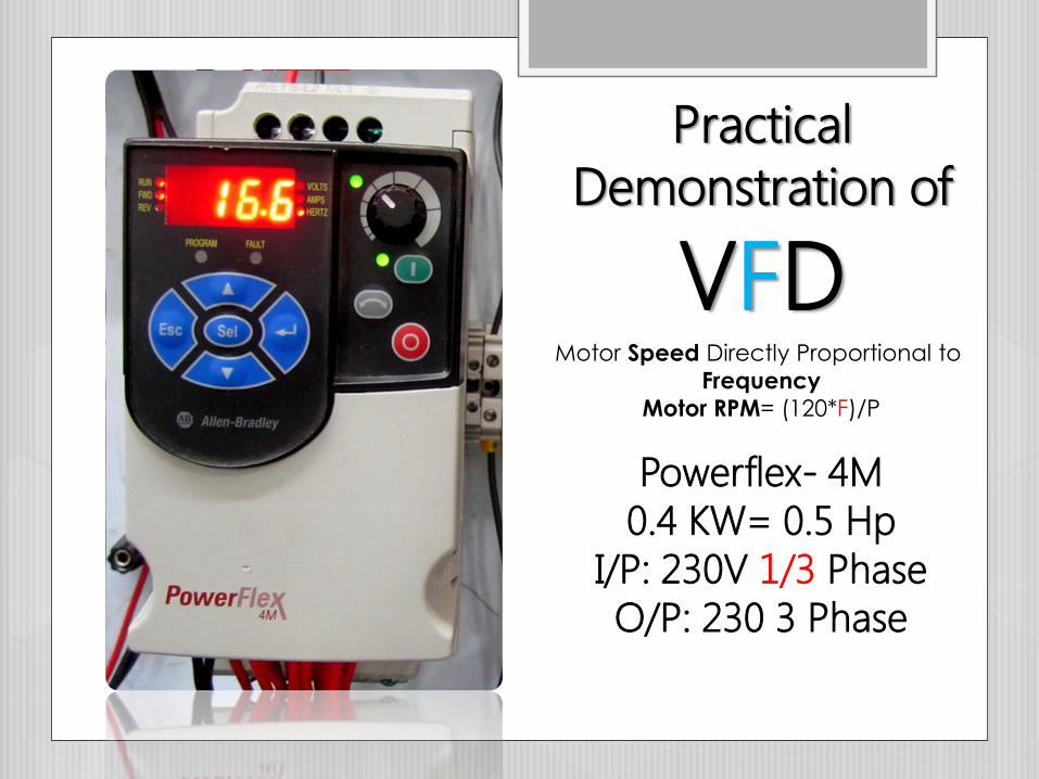
Practical
Demonstration of
VFD
Powerflex- 4M
0.4 KW= 0.5 Hp
I/P: 230V 1/3 Phase
O/P: 230 3 Phase
Motor Speed Directly Proportional to
Frequency
Motor RPM= (120*F)/P

Maximum Output Frequency Range
0 ~ 400 Hz
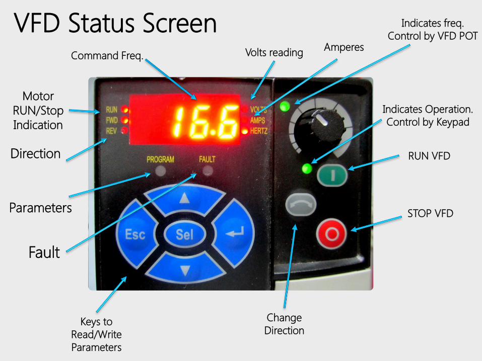
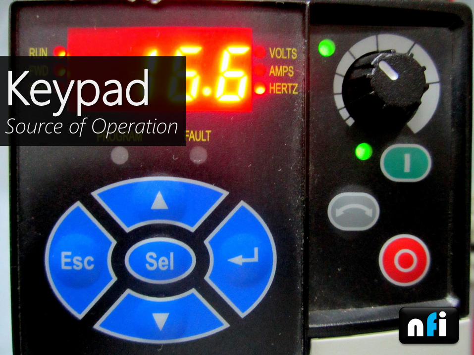
Motor
RUN/Stop
Indication
Command Freq.
Parameters
Direction
Volts reading
Fault
VFD Status ScreenAmperes
Indicates freq.
Control by VFD POT
Indicates Operation.
Control by Keypad
RUN VFD
STOP VFD
Change
DirectionKeys to
Read/Write
Parameters
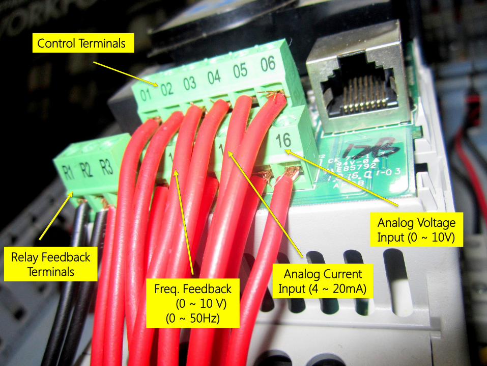
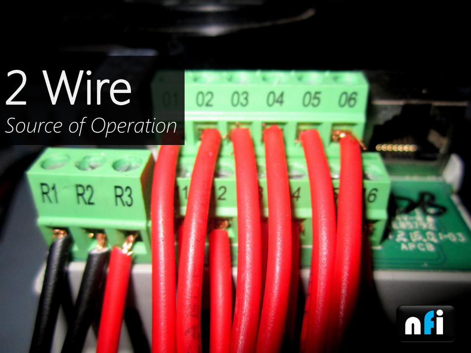
Control Terminals
Relay Feedback
Terminals
Freq. Feedback
(0 ~ 10 V)
(0 ~ 50Hz)
Analog Voltage
Input (0 ~ 10V)
Analog Current
Input (4 ~ 20mA)

Motor Output
Terminals

3 Phase/ 1 Phase
220 VAC

VFD Wiring Diagram
Power Flex 4M
Parameters to be used in
this Course
nfi
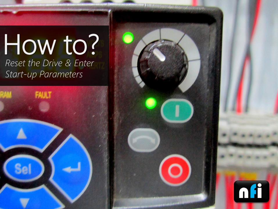
Reset the Drive & Enter
Start-up Parameters
How to?

Programming the VFD
AB Powerflex 4M
Step 1:
Reset the Drive to Factory Setting
Parameter:
P112 – Reset to DefaultResets all parameter values to factory defaults.
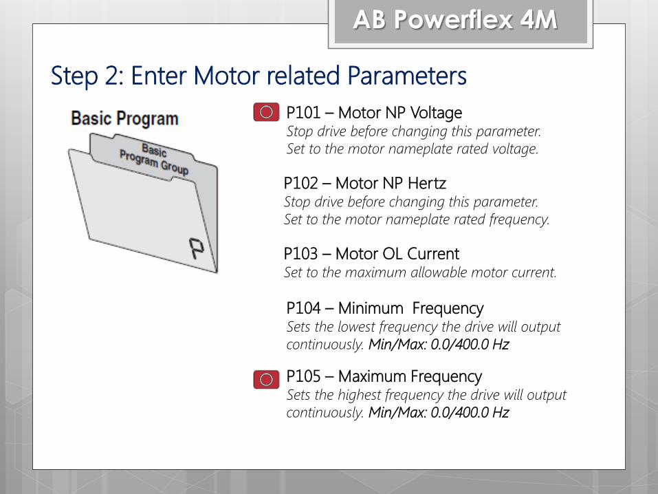
Step 2: Enter Motor related Parameters
AB Powerflex 4M
P101 – Motor NP VoltageStop drive before changing this parameter.
Set to the motor nameplate rated voltage.
P102 – Motor NP HertzStop drive before changing this parameter.
Set to the motor nameplate rated frequency.
P103 – Motor OL CurrentSet to the maximum allowable motor current.
P104 – Minimum FrequencySets the lowest frequency the drive will output
continuously. Min/Max: 0.0/400.0 Hz
P105 – Maximum FrequencySets the highest frequency the drive will output
continuously. Min/Max: 0.0/400.0 Hz
nfi
Source of Operation
Keypad

AB Powerflex 4M
P106 – Start SourceStop drive before changing this parameter.
Sets the control scheme used to start the
drive.
Source of Operation

nfi
Source of Operation
3 Wire

AB Powerflex 4M
P106 – Start SourceStop drive before changing this parameter.
Sets the control scheme used to start the
drive.
Source of Operation
nfi
Source of Operation
2 Wire
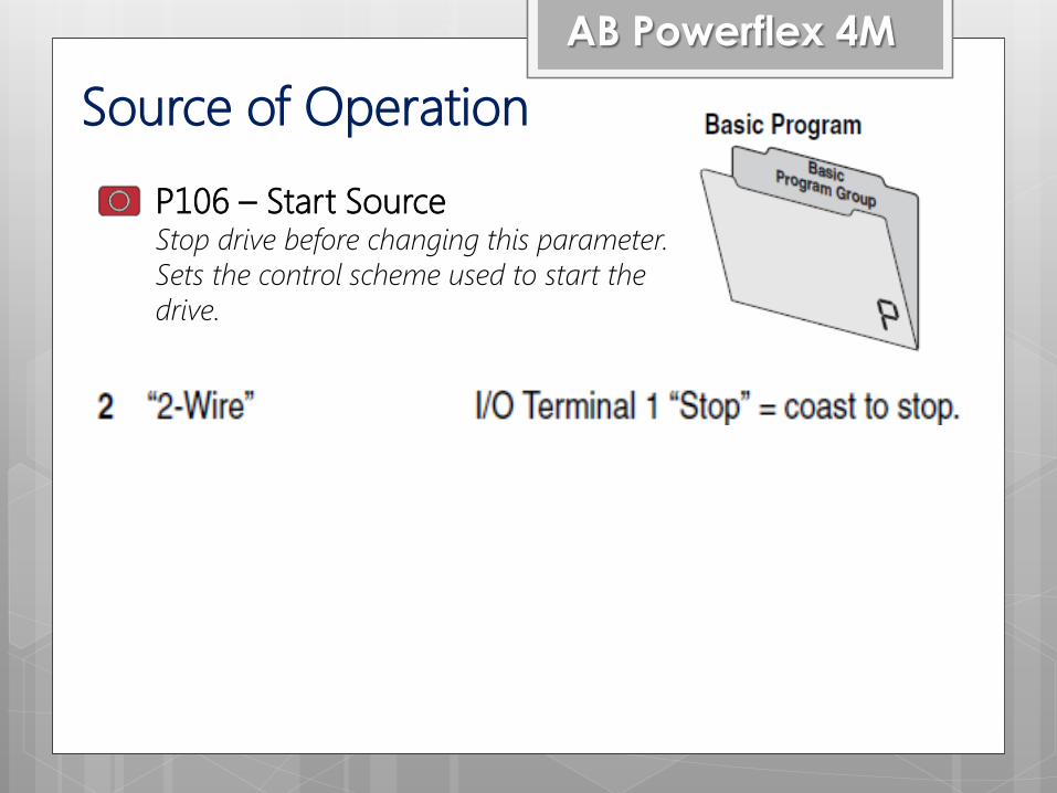
AB Powerflex 4M
P106 – Start SourceStop drive before changing this parameter.
Sets the control scheme used to start the
drive.
Source of Operation

AB Powerflex 4M
P107 – Stop ModeActive stop mode for all stop sources
0“Ramp, CF”(1) (Default)
Ramp to Stop. “Stop” command clears
active fault.
1“Coast, CF”(1)
Coast to Stop. “Stop” command clears
active fault.
Stop Method
P110 – Dec. Time
nfi
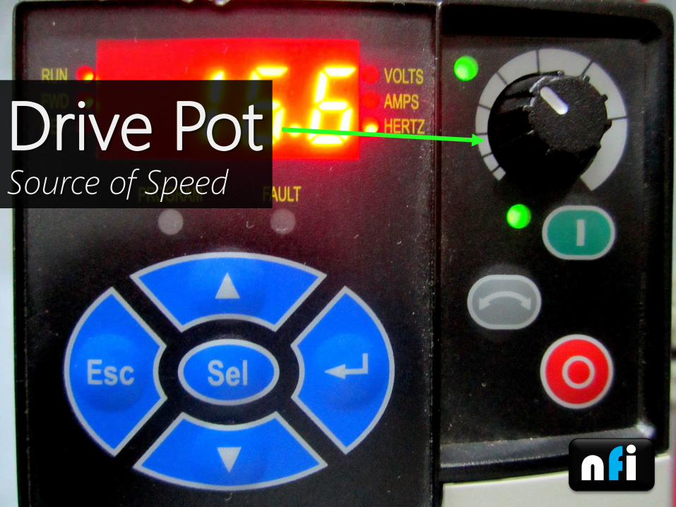
Source of Speed
Drive Pot

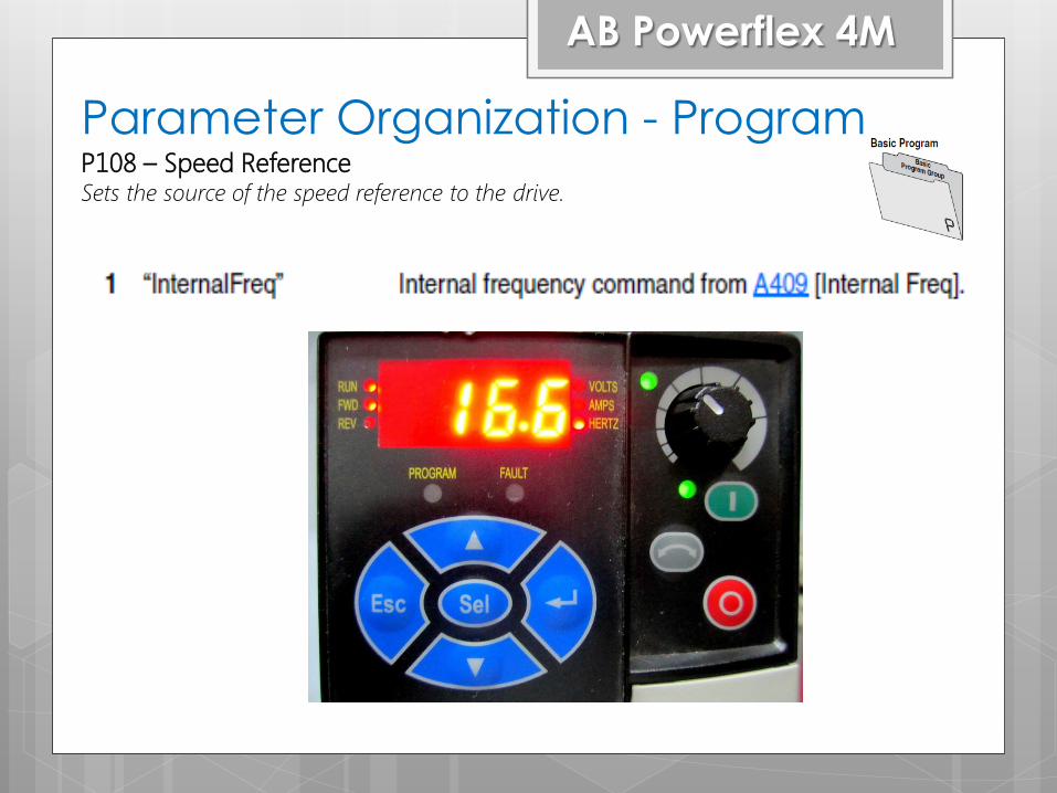
Parameter Organization - Program
AB Powerflex 4M
P108 – Speed ReferenceSets the source of the speed reference to the drive.
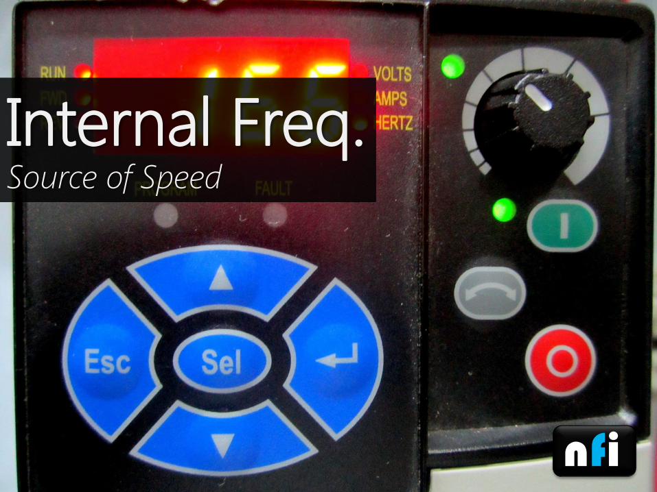
nfi
Source of Speed
Internal Freq.
Parameter Organization - Program
AB Powerflex 4M
P108 – Speed ReferenceSets the source of the speed reference to the drive.
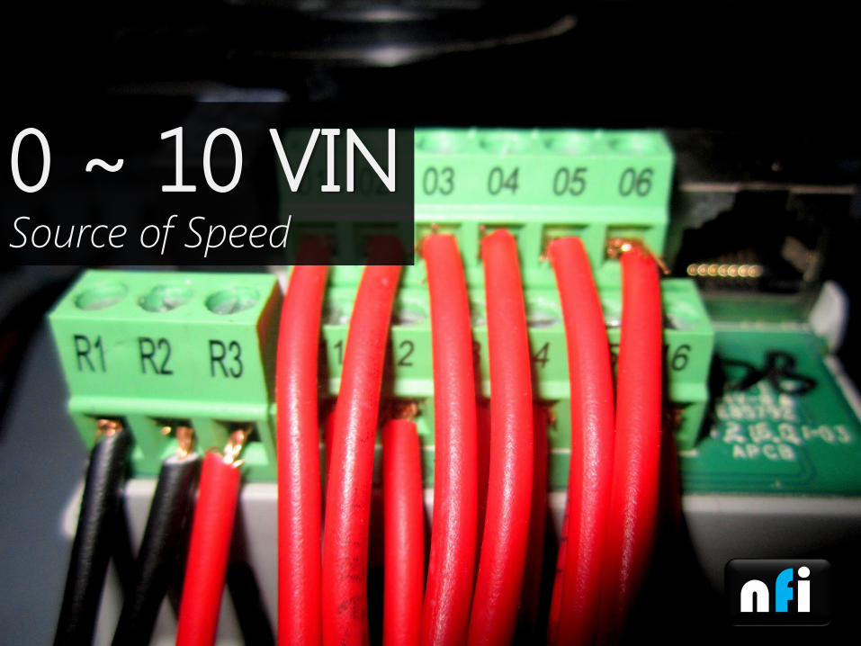
nfi
Source of Speed
0 ~ 10 VIN
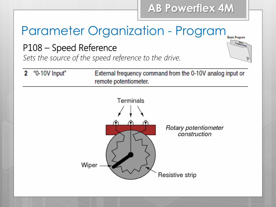
Parameter Organization - Program
AB Powerflex 4M
P108 – Speed ReferenceSets the source of the speed reference to the drive.

nfi
Source of Speed
Preset Freq.
Parameter Organization - Program
AB Powerflex 4M
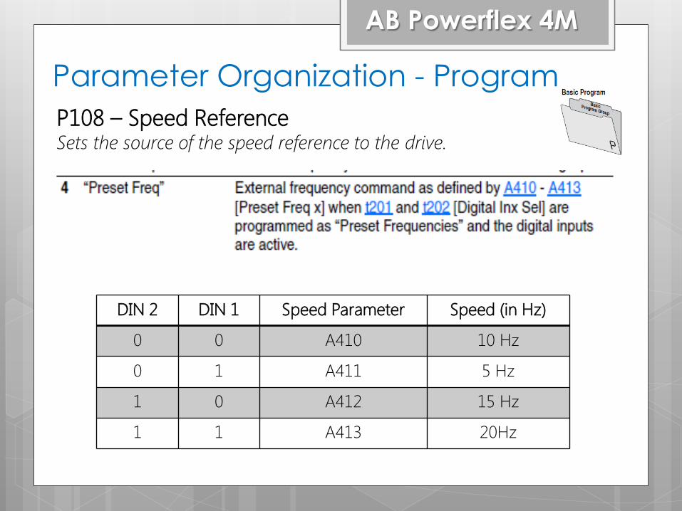
P108 – Speed ReferenceSets the source of the speed reference to the drive.
DIN 2 DIN 1 Speed Parameter Speed (in Hz)
0 0 A410 10 Hz
0 1 A411 5 Hz
1 0 A412 15 Hz
1 1 A413 20Hz
nfi
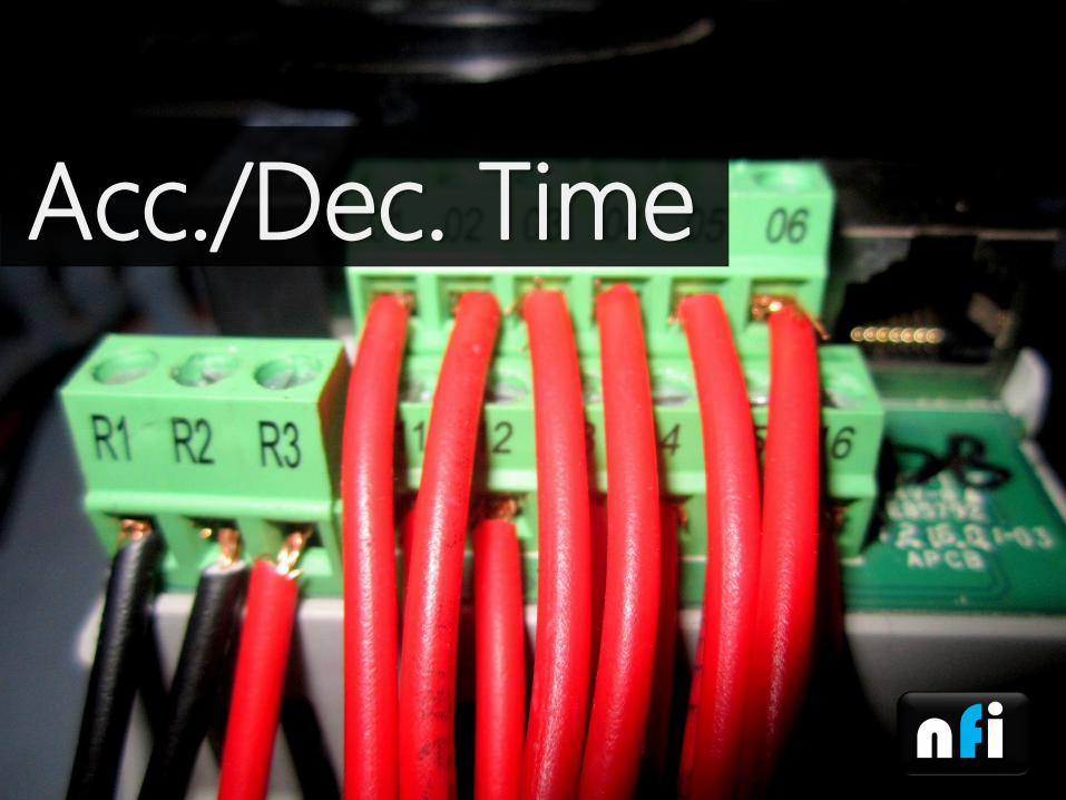
Acc./Dec. Time

AB Powerflex 4M
P110 – Dec. TimeSets the rate of deceleration for all speed decreases.
P109– Acc. TimeSets the rate of deceleration for all speed decreases.
Acc./ Dec.
nfi
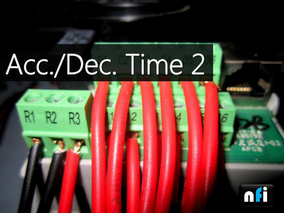
Acc./Dec. Time 2
AB Powerflex 4M
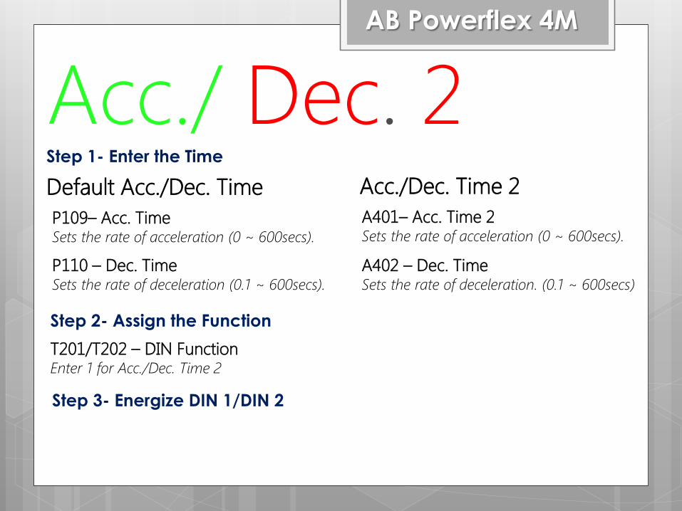
P110 – Dec. TimeSets the rate of deceleration (0.1 ~ 600secs).
P109– Acc. TimeSets the rate of acceleration (0 ~ 600secs).
Acc./ Dec. 2Default Acc./Dec. Time Acc./Dec. Time 2
A401– Acc. Time 2Sets the rate of acceleration (0 ~ 600secs).
A402 – Dec. TimeSets the rate of deceleration. (0.1 ~ 600secs)
T201/T202 – DIN FunctionEnter 1 for Acc./Dec. Time 2
Step 1- Enter the Time
Step 2- Assign the Function
Step 3- Energize DIN 1/DIN 2

nfi
JOG Mode
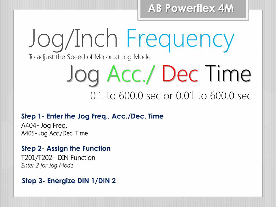
Jog/Inch FrequencyTo adjust the Speed of Motor at Jog Mode
Jog Acc./ Dec Time0.1 to 600.0 sec or 0.01 to 600.0 sec
AB Powerflex 4M
T201/T202– DIN FunctionEnter 2 for Jog Mode
Step 2- Assign the Function
Step 3- Energize DIN 1/DIN 2
A404- Jog Freq.A405- Jog Acc./Dec. Time
Step 1- Enter the Jog Freq., Acc./Dec. Time

nfi
LocalControl
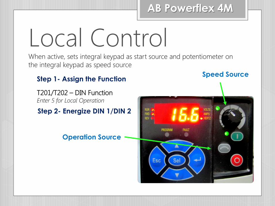
Local ControlWhen active, sets integral keypad as start source and potentiometer on
the integral keypad as speed source
AB Powerflex 4M
T201/T202 – DIN FunctionEnter 5 for Local Operation
Step 1- Assign the Function
Step 2- Energize DIN 1/DIN 2
Operation Source
Speed Source
nfi
AuxFault
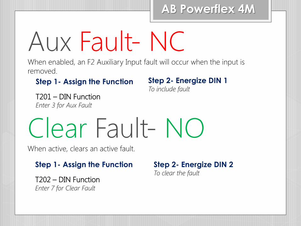
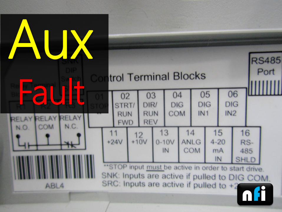
Aux Fault- NCWhen enabled, an F2 Auxiliary Input fault will occur when the input is
removed.
AB Powerflex 4M
T201 – DIN FunctionEnter 3 for Aux Fault
Step 1- Assign the Function Step 2- Energize DIN 1To include fault
Clear Fault- NOWhen active, clears an active fault.
T202 – DIN FunctionEnter 7 for Clear Fault
Step 1- Assign the Function Step 2- Energize DIN 2To clear the fault

nfi
Source of Speed
Override
0 ~ 10 VIN
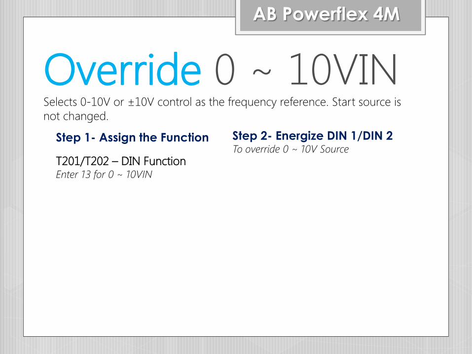
Override 0 ~ 10VINSelects 0-10V or ±10V control as the frequency reference. Start source is
not changed.
AB Powerflex 4M
T201/T202 – DIN FunctionEnter 13 for 0 ~ 10VIN
Step 1- Assign the Function Step 2- Energize DIN 1/DIN 2To override 0 ~ 10V Source
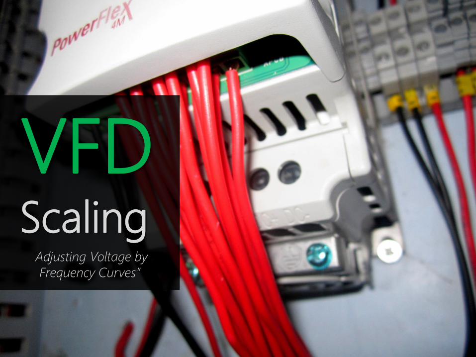
VFDScaling
“Adjusting Voltage by
Frequency Curves”
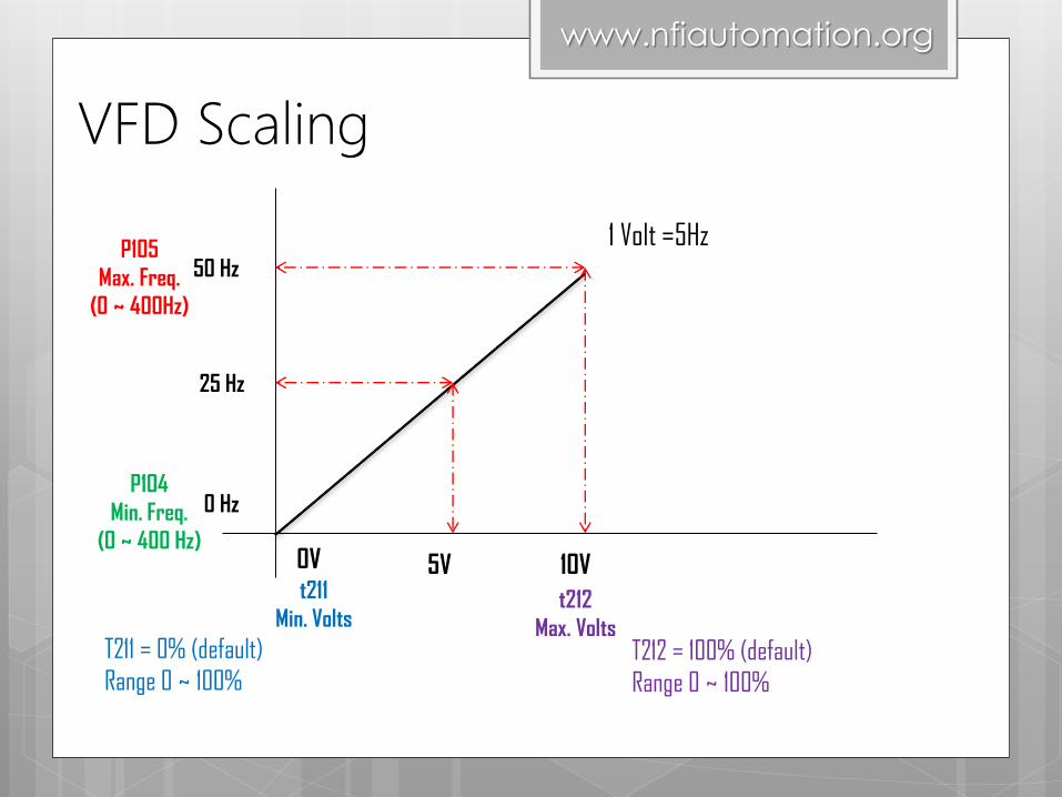
VFD Scaling
0V 5V 10V
1 Volt =5Hz
0 Hz
25 Hz
50 Hz
T211 = 0% (default)
Range 0 ~ 100%
www.nfiautomation.org
P104
Min. Freq.
(0 ~ 400 Hz)
P105
Max. Freq.
(0 ~ 400Hz)
t211
Min. Voltst212
Max. VoltsT212 = 100% (default)
Range 0 ~ 100%
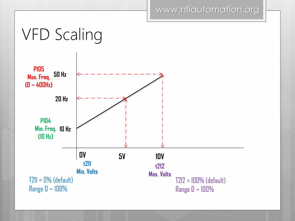
VFD Scaling
0V 5V 10V
10 Hz
20 Hz
50 Hz
T211 = 0% (default)
Range 0 ~ 100%
www.nfiautomation.org
P104
Min. Freq.
(10 Hz)
P105
Max. Freq.
(0 ~ 400Hz)
t211
Min. Voltst212
Max. VoltsT212 = 100% (default)
Range 0 ~ 100%

VFD Scaling
1V 4.5V 10V
0 Hz
25 Hz
50 Hz
T211 = 10%
Range 0 ~ 100%
www.nfiautomation.org
P104
Min. Freq.
(0 ~ 400 Hz)
P105
Max. Freq.
(0 ~ 400Hz)
t211
Min. Voltst212
Max. VoltsT212 = 100% (default)
Range 0 ~ 100%
Scaling Value = Bias Voltage/Full Voltage x 100
= 1/10 x 100
= 10%
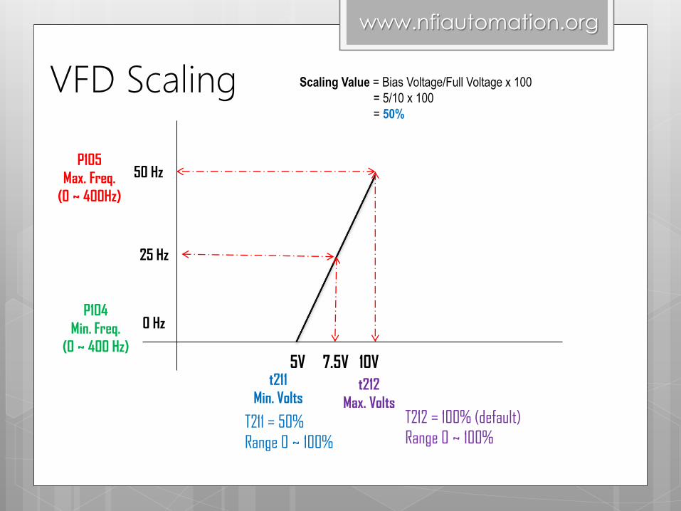
VFD Scaling
7.5V5V 10V
0 Hz
25 Hz
50 Hz
T211 = 50%
Range 0 ~ 100%
www.nfiautomation.org
P104
Min. Freq.
(0 ~ 400 Hz)
P105
Max. Freq.
(0 ~ 400Hz)
t211
Min. Voltst212
Max. VoltsT212 = 100% (default)
Range 0 ~ 100%
Scaling Value = Bias Voltage/Full Voltage x 100
= 5/10 x 100
= 50%
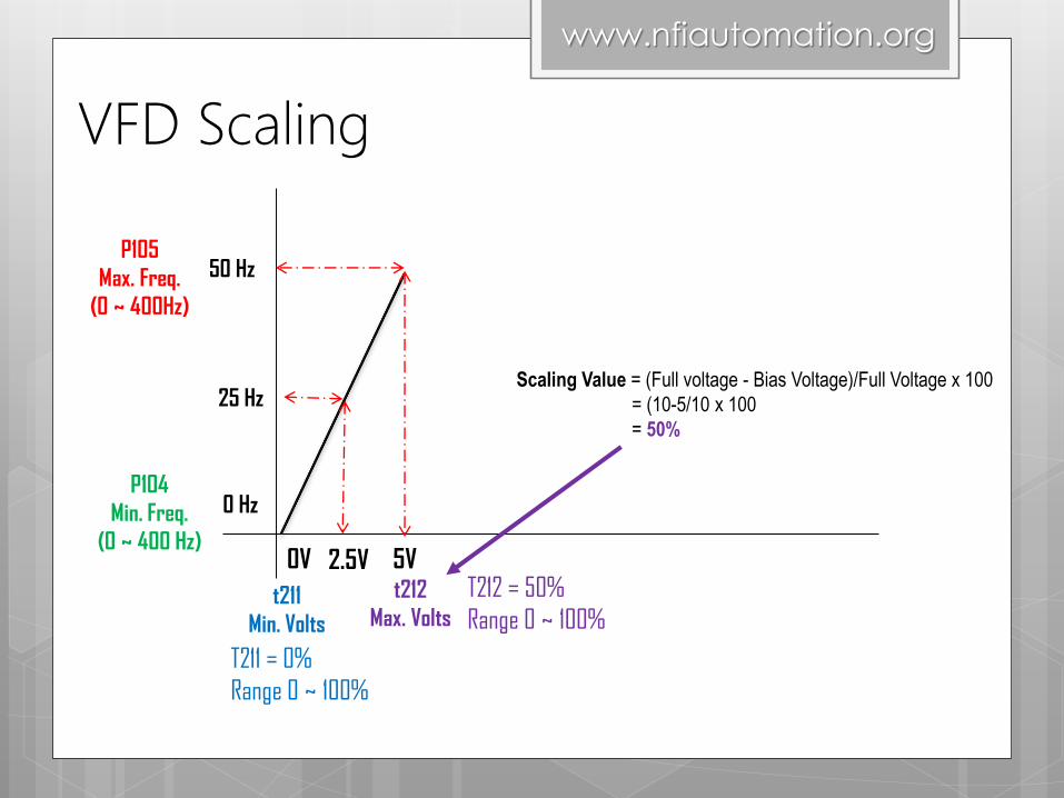
VFD Scaling
2.5V0V 5V
0 Hz
25 Hz
50 Hz
T211 = 0%
Range 0 ~ 100%
www.nfiautomation.org
P104
Min. Freq.
(0 ~ 400 Hz)
P105
Max. Freq.
(0 ~ 400Hz)
t211
Min. Volts
t212
Max. Volts
T212 = 50%
Range 0 ~ 100%
Scaling Value = (Full voltage - Bias Voltage)/Full Voltage x 100
= (10-5/10 x 100
= 50%
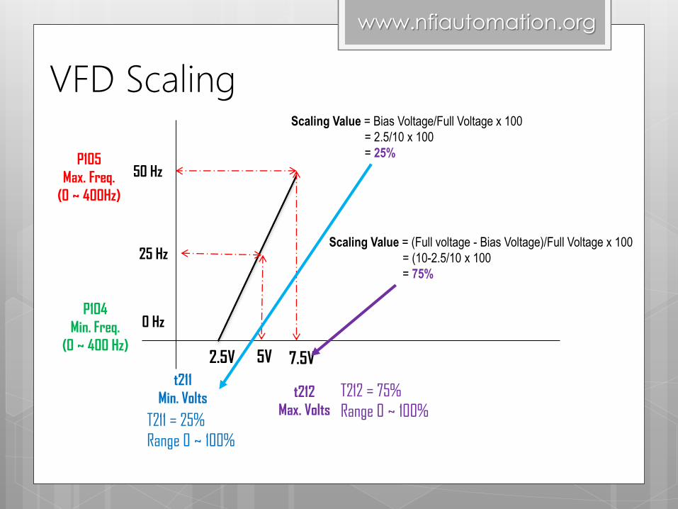
VFD Scaling
2.5V 5V 7.5V
0 Hz
25 Hz
50 Hz
T211 = 25%
Range 0 ~ 100%
www.nfiautomation.org
P104
Min. Freq.
(0 ~ 400 Hz)
P105
Max. Freq.
(0 ~ 400Hz)
t211
Min. Volts t212
Max. Volts
T212 = 75%
Range 0 ~ 100%
Scaling Value = (Full voltage - Bias Voltage)/Full Voltage x 100
= (10-2.5/10 x 100
= 75%
Scaling Value = Bias Voltage/Full Voltage x 100
= 2.5/10 x 100
= 25%
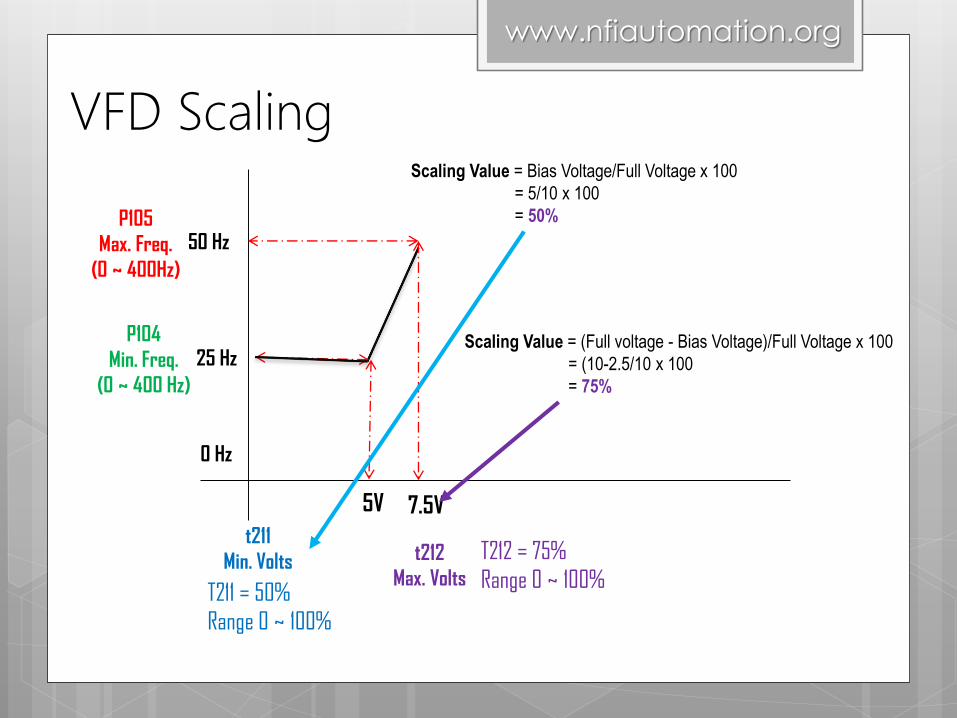
VFD Scaling
5V 7.5V
0 Hz
25 Hz
50 Hz
T211 = 50%
Range 0 ~ 100%
www.nfiautomation.org
P104
Min. Freq.
(0 ~ 400 Hz)
P105
Max. Freq.
(0 ~ 400Hz)
t211
Min. Volts t212
Max. Volts
T212 = 75%
Range 0 ~ 100%
Scaling Value = (Full voltage - Bias Voltage)/Full Voltage x 100
= (10-2.5/10 x 100
= 75%
Scaling Value = Bias Voltage/Full Voltage x 100
= 5/10 x 100
= 50%
nfi
SignalsFeedback

Feedback – Relay Type
1. VFD Operation – Run & Stop
t221 =2
2. VFD Running Reverse
t221 = 3
3. VFD Desired Frequency Attained
t221= 6
t222 = Frequency
Related Parameter: t221 & t222
Sets the condition that changes the state of the output
relay contacts.
Sets the trip point for the digital
output relay if the value of t221
[Relay Out Sel] is 6, 7, 8, 10 or 11.

Thank You
nfiwww.nfiautomation.org
Related Documents