FRE ENG ESP GER ITL HARDWARE MANUAL α SIMPLE APPLICATION CONTROLLER

Welcome message from author
This document is posted to help you gain knowledge. Please leave a comment to let me know what you think about it! Share it to your friends and learn new things together.
Transcript

FRE
ENG
ESP
GER
ITL
HARDWARE MANUALα SIMPLE APPLICATION CONTROLLER
α Simple Application Controller
ENG
Foreword• This manual contains text, diagrams and explanations which will guide the reader in the correct installation,
safe use and operation of the α Series and should be read and understood before attempting to install or use the unit.
• If in doubt at any stage during the installation of the α Series always consult a professional electrical engi-neer who is qualified and trained to the local and national standards. If in doubt about the operation or use of the α Series please consult the nearest Mitsubishi Electric distributor.
• This manual is subject to change without notice.
α Simple Application Controller
ENG
i
αααα Simple Application Controller
Hardware ManualManual number : JY992D74201Manual revision : JDate : April 2002

α Simple Application Controller
ENG
ii
Guidelines for the safety of the user and protection of equipmentThis manual is written to be used by trained and competent personnel for installation of this equipment as defined bythe European directives for machinery, low voltage and EMC. A technician or engineer trained in the local andnational electrical standards should perform all tasks associated with the electrical wiring of the α Series controllers.Throughout this manual symbols are used to highlight information relating to the user’s personal safety and protec-tion of the equipment. When any of these symbols are encountered, the associated note must be read and under-stood.
Symbols are:
1) The identified danger will cause physical and property damage.
2) The identified danger could cause physical and property damage.
• Under no circumstances will MITSUBISHI ELECTRIC be liable or responsible for any consequential damage that may arise as aresult of installation or use of this equipment.
• All example and diagrams shown in this manual are intended to aid understanding and do not guarantee operation. MITSUBISHIELECTRIC will accept no responsibility for actual use of this product based on these examples.
• Due to the great variety of possible applications for this equipment, the user must assess the suitability of this product for specificapplications.
• If the controller breaks for any reason, please have safety procedures in place to stop any connected equipment in a safe manner.
• Do not replace electrical parts or try to repair an α Series product in any way.
• Please dispose of the α Series product in accordance with local and national standards.
α Simple Application Controller
iii
Table of Contents
Guideline................................................................................................................................... ii
1. Introduction............................................................................................................ 1
2. Hardware Specification......................................................................................... 32.1 Available Models.......................................................................................................... 32.2 Power Supply Specification ......................................................................................... 42.3 Input Specification........................................................................................................ 62.4 Output Specification..................................................................................................... 82.5 General Specification................................................................................................... 9
3. Installation............................................................................................................ 113.1 DIN RAIL Mounting .................................................................................................... 113.2 Termination at Screw Terminals ................................................................................ 113.3 Installation Mounting Notes........................................................................................ 12
ENG
α Simple Application Controller
iv
4. Wiring ................................................................................................................... 154.1 Installation Wiring Notes ............................................................................................ 154.2 Wire Size and Specifications ..................................................................................... 154.3 Power Supply............................................................................................................. 164.4 Recommended Power Input Wiring Diagram............................................................. 164.5 AC Input Wiring.......................................................................................................... 17
4.5.1 AC Input Wiring Diagram..................................................................................... 174.6 Wiring Diagrams for the Sink/Source Terminals ........................................................ 18
4.6.1 Source (“+” Common) Input Wiring Diagram....................................................... 184.6.2 Sink ("-" Common) Input Wiring Diagram ............................................................ 18
4.7 Output Relay and Transistor Wiring........................................................................... 194.7.1 Relay Output Wiring Diagram (AC and/or DC) .................................................... 194.7.2 Transistor Output (Source or “+” Common Only) Wiring Diagram ...................... 20
5. αααα Series Terminal Layout.................................................................................... 21
6. How to Use αααα Series Controllers - Getting Started .......................................... 236.1 Connecting Two Blocks ............................................................................................. 236.2 Accessing Blocks ...................................................................................................... 246.3 Setting Function Block Parameters............................................................................ 256.4 Exiting, Running, and Stopping the Program............................................................. 25
ENG
α Simple Application Controller Introduction 1
1
ENG
1. Introduction
The simple, friendly α Series has been designed for use around your home, office, factory.... anywhere thatrequires a flexible supervisory control function. Every module allows you to read signals and set outputsaccording to particular conditions or time settings defined by you, the user. Plus the built-in programmabledisplay allows you to check the status of your system anytime.
Special features of the α Series system are:
• Direct (on-device) programming capability
• High current output capability
• Small size
• Easy access programming port
• EEPROM cassette program storage capability
• Built-in Real Time Clock as standard
• Windows based programming package, AL-PCS/WIN-E
• Plus a full range of support documentation and Training packages
The α Series is designed to be used in the following automatic applications: lighting, air conditioning,irrigation, doors, gates, simple security systems, greenhouses, air fans, etc. The Real Time Clock can beused as a power saving device to automatically turn the equipment On/Off at scheduled times.
Debug programs carefully before installing in automated equipment. The α Series is not designed to be usedin life critical or fail safe applications.
Contact your dealer for more information.
α Simple Application Controller Introduction 1
2
ENG
α Simple Application Controller Hardware Specification 2
3
ENG
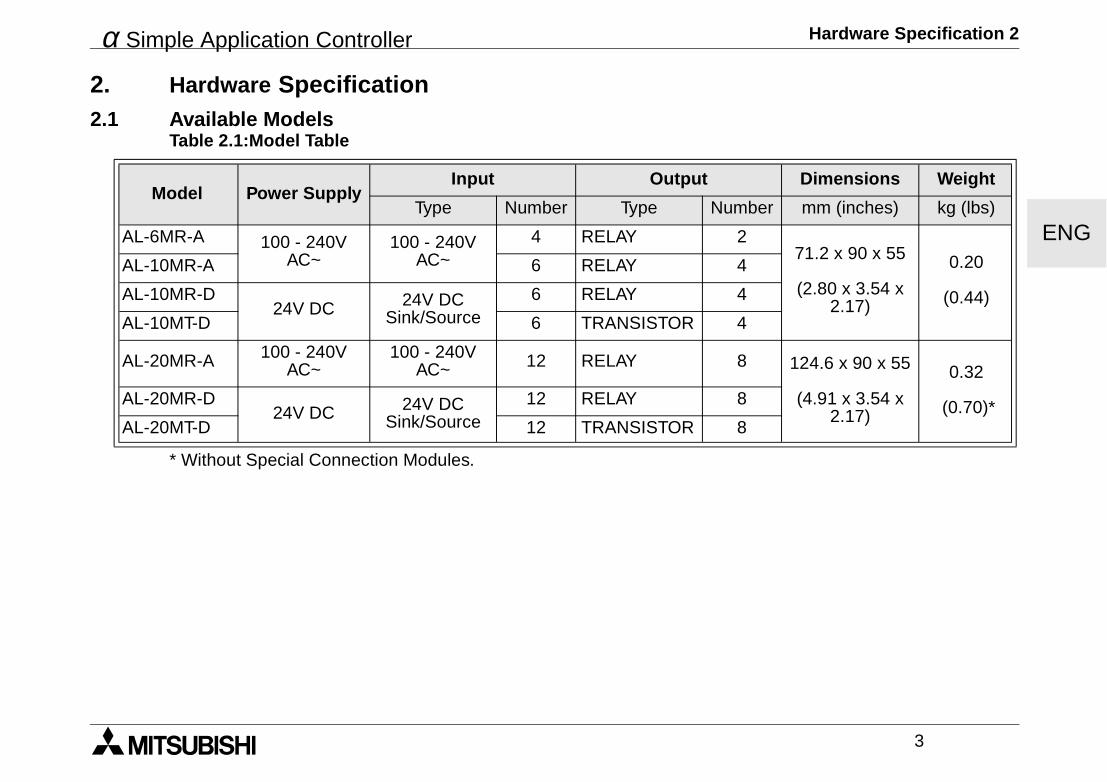
2. Hardware Specification2.1 Available Models
* Without Special Connection Modules.
Table 2.1:Model Table
Model Power SupplyInput Output Dimensions Weight
Type Number Type Number mm (inches) kg (lbs)
AL-6MR-A 100 - 240V AC~
100 - 240V AC~
4 RELAY 271.2 x 90 x 55
(2.80 x 3.54 x 2.17)
0.20
(0.44)
AL-10MR-A 6 RELAY 4
AL-10MR-D24V DC 24V DC
Sink/Source6 RELAY 4
AL-10MT-D 6 TRANSISTOR 4
AL-20MR-A 100 - 240V AC~
100 - 240V AC~ 12 RELAY 8 124.6 x 90 x 55
(4.91 x 3.54 x 2.17)
0.32
(0.70)*AL-20MR-D24V DC 24V DC
Sink/Source12 RELAY 8
AL-20MT-D 12 TRANSISTOR 8
α Simple Application Controller Hardware Specification 2
4
ENG
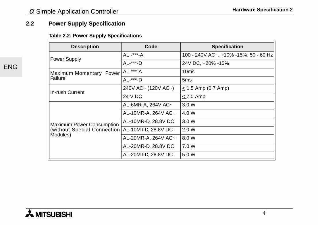
2.2 Power Supply Specification
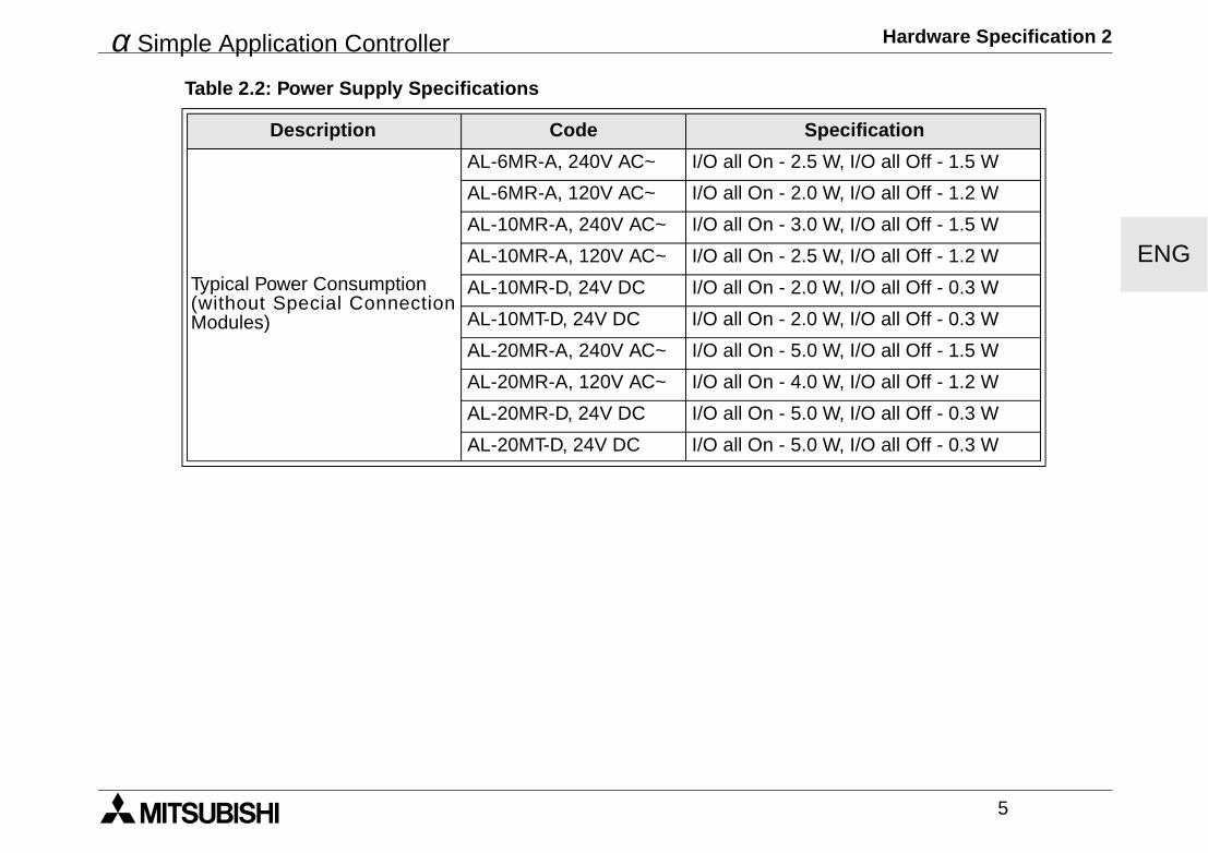
Table 2.2: Power Supply Specifications
Description Code Specification
Power SupplyAL -***-A 100 - 240V AC~, +10% -15%, 50 - 60 Hz
AL-***-D 24V DC, +20% -15%
Maximum Momentary PowerFailure
AL-***-A 10ms
AL-***-D 5ms
In-rush Current240V AC~ (120V AC~) < 1.5 Amp (0.7 Amp)
24 V DC < 7.0 Amp
Maximum Power Consumption(without Special ConnectionModules)
AL-6MR-A, 264V AC~ 3.0 W
AL-10MR-A, 264V AC~ 4.0 W
AL-10MR-D, 28.8V DC 3.0 W
AL-10MT-D, 28.8V DC 2.0 W
AL-20MR-A, 264V AC~ 8.0 W
AL-20MR-D, 28.8V DC 7.0 W
AL-20MT-D, 28.8V DC 5.0 W
α Simple Application Controller Hardware Specification 2
5
ENGTypical Power Consumption(without Special ConnectionModules)
AL-6MR-A, 240V AC~ I/O all On - 2.5 W, I/O all Off - 1.5 W
AL-6MR-A, 120V AC~ I/O all On - 2.0 W, I/O all Off - 1.2 W
AL-10MR-A, 240V AC~ I/O all On - 3.0 W, I/O all Off - 1.5 W
AL-10MR-A, 120V AC~ I/O all On - 2.5 W, I/O all Off - 1.2 W
AL-10MR-D, 24V DC I/O all On - 2.0 W, I/O all Off - 0.3 W
AL-10MT-D, 24V DC I/O all On - 2.0 W, I/O all Off - 0.3 W
AL-20MR-A, 240V AC~ I/O all On - 5.0 W, I/O all Off - 1.5 W
AL-20MR-A, 120V AC~ I/O all On - 4.0 W, I/O all Off - 1.2 W
AL-20MR-D, 24V DC I/O all On - 5.0 W, I/O all Off - 0.3 W
AL-20MT-D, 24V DC I/O all On - 5.0 W, I/O all Off - 0.3 W
Table 2.2: Power Supply Specifications
Description Code Specification
α Simple Application Controller Hardware Specification 2
6
ENG
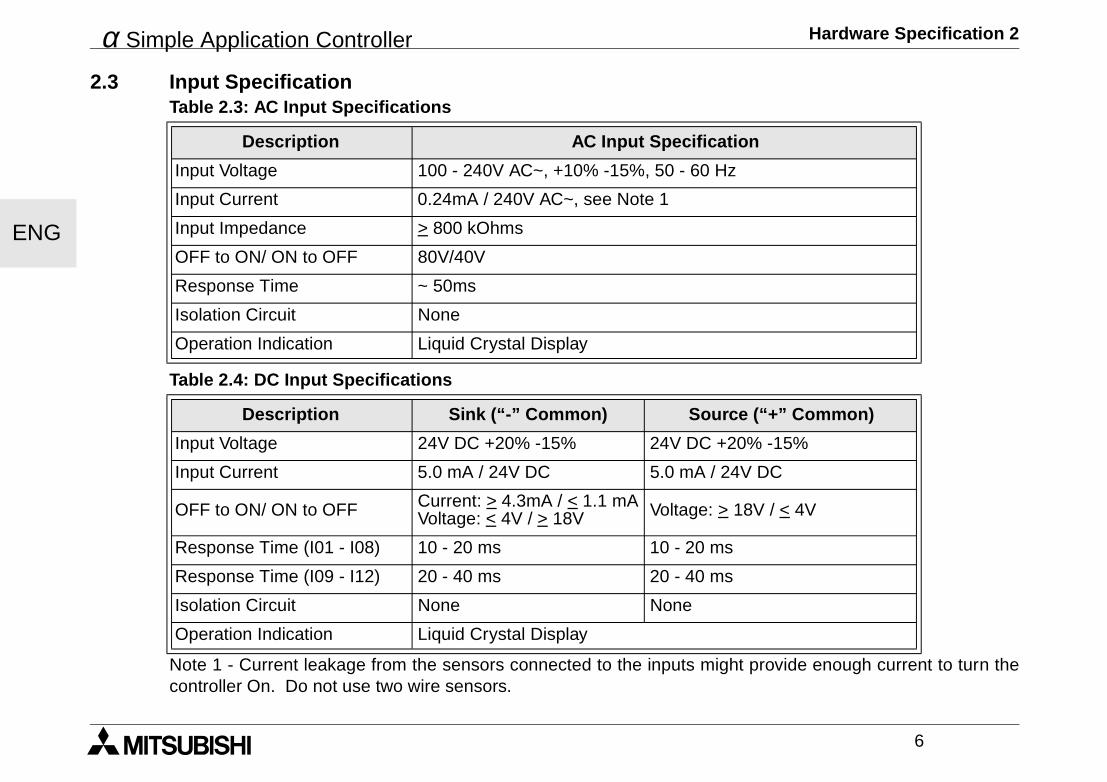
2.3 Input Specification
Note 1 - Current leakage from the sensors connected to the inputs might provide enough current to turn thecontroller On. Do not use two wire sensors.
Table 2.3: AC Input Specifications
Description AC Input Specification
Input Voltage 100 - 240V AC~, +10% -15%, 50 - 60 Hz
Input Current 0.24mA / 240V AC~, see Note 1
Input Impedance > 800 kOhms
OFF to ON/ ON to OFF 80V/40V
Response Time ~ 50ms
Isolation Circuit None
Operation Indication Liquid Crystal Display
Table 2.4: DC Input Specifications
Description Sink (“-” Common) Source (“+” Common)
Input Voltage 24V DC +20% -15% 24V DC +20% -15%
Input Current 5.0 mA / 24V DC 5.0 mA / 24V DC
OFF to ON/ ON to OFF Current: > 4.3mA / < 1.1 mAVoltage: < 4V / > 18V Voltage: > 18V / < 4V
Response Time (I01 - I08) 10 - 20 ms 10 - 20 ms
Response Time (I09 - I12) 20 - 40 ms 20 - 40 ms
Isolation Circuit None None
Operation Indication Liquid Crystal Display
α Simple Application Controller Hardware Specification 2
7
ENG
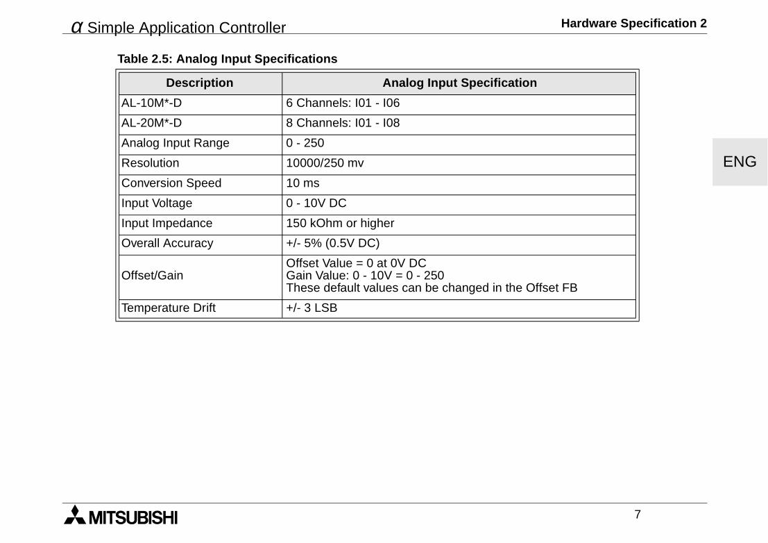
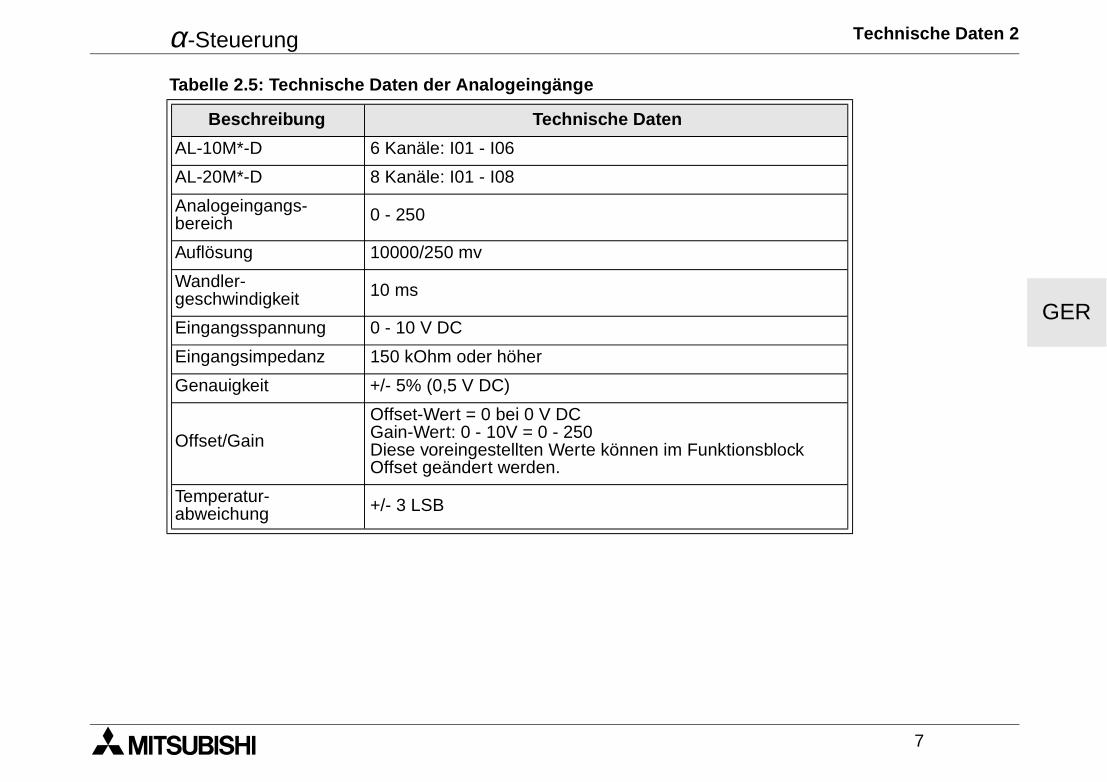
Table 2.5: Analog Input Specifications
Description Analog Input Specification
AL-10M*-D 6 Channels: I01 - I06
AL-20M*-D 8 Channels: I01 - I08
Analog Input Range 0 - 250
Resolution 10000/250 mv
Conversion Speed 10 ms
Input Voltage 0 - 10V DC
Input Impedance 150 kOhm or higher
Overall Accuracy +/- 5% (0.5V DC)
Offset/GainOffset Value = 0 at 0V DCGain Value: 0 - 10V = 0 - 250These default values can be changed in the Offset FB
Temperature Drift +/- 3 LSB
α Simple Application Controller Hardware Specification 2
8
ENG
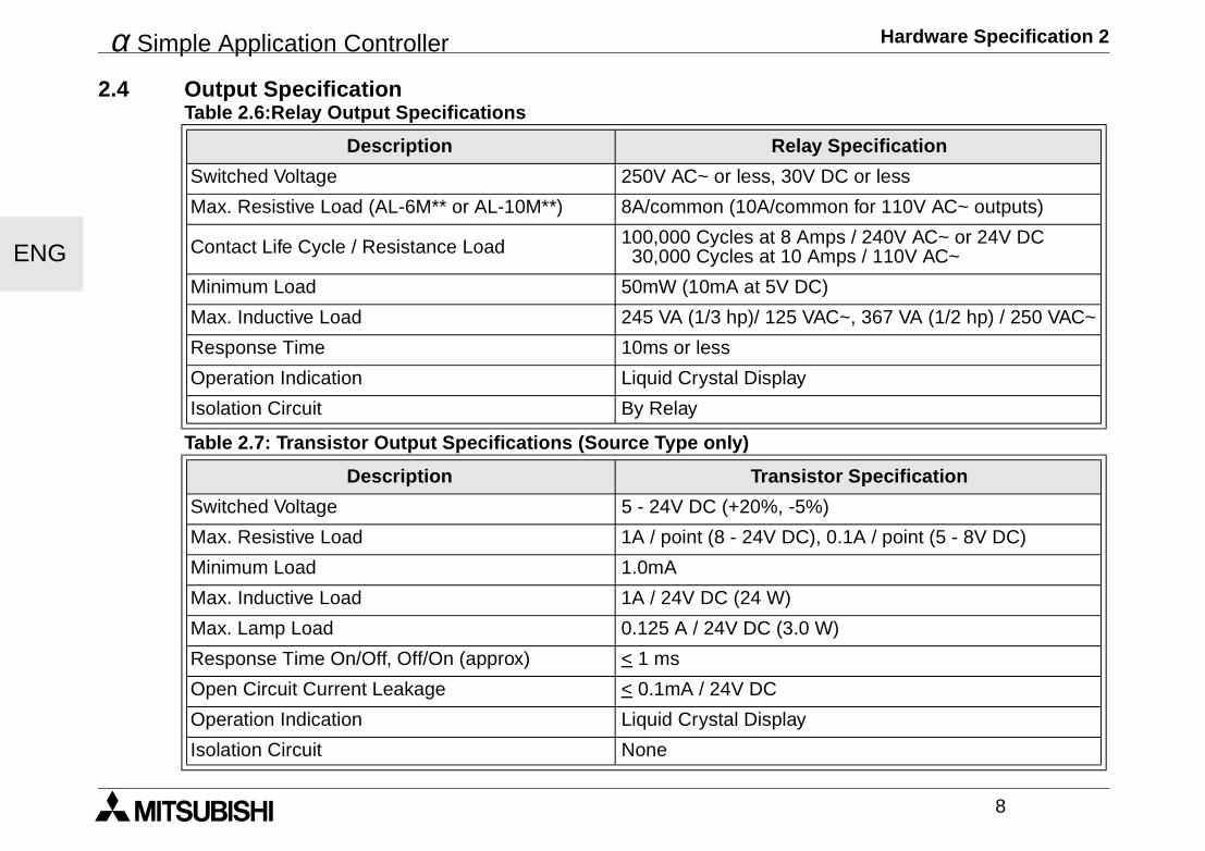
2.4 Output Specification
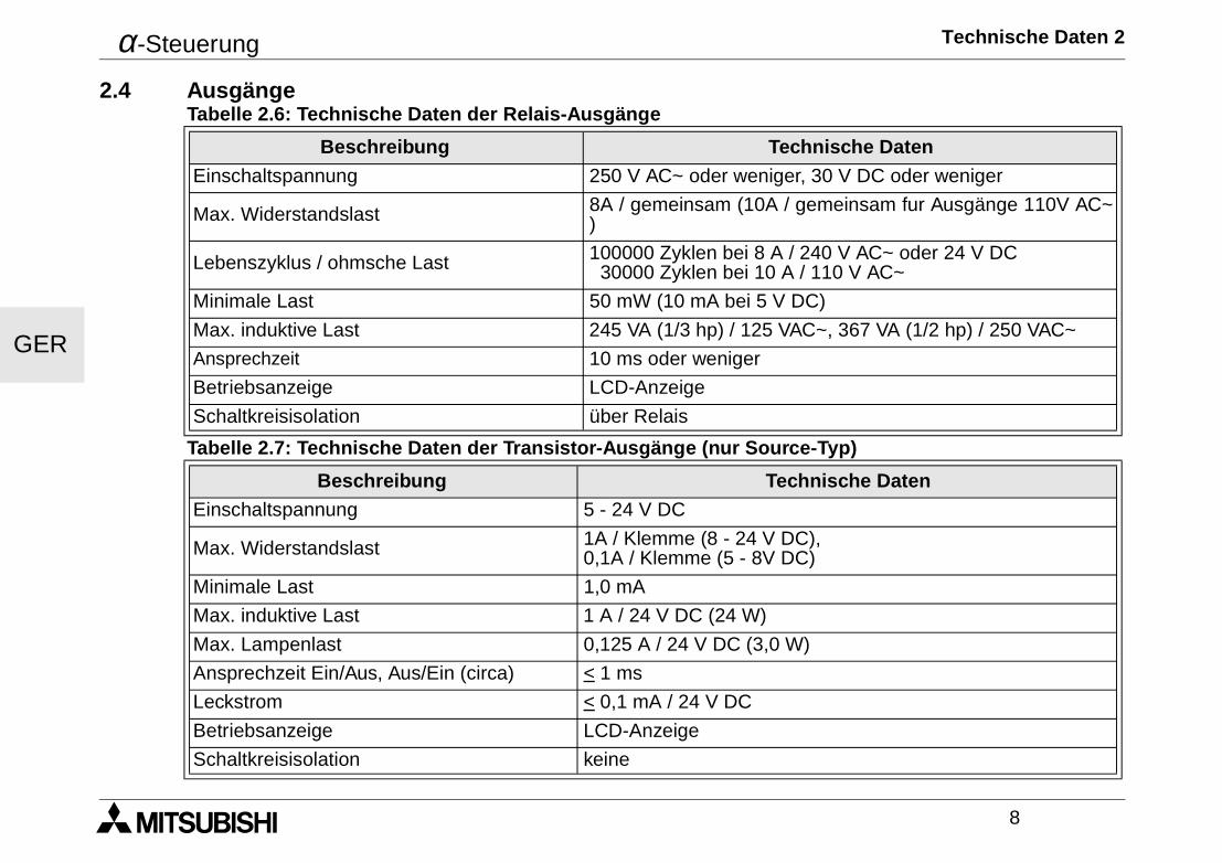
Table 2.6:Relay Output Specifications
Description Relay Specification
Switched Voltage 250V AC~ or less, 30V DC or less
Max. Resistive Load (AL-6M** or AL-10M**) 8A/common (10A/common for 110V AC~ outputs)
Contact Life Cycle / Resistance Load 100,000 Cycles at 8 Amps / 240V AC~ or 24V DC 30,000 Cycles at 10 Amps / 110V AC~
Minimum Load 50mW (10mA at 5V DC)
Max. Inductive Load 245 VA (1/3 hp)/ 125 VAC~, 367 VA (1/2 hp) / 250 VAC~
Response Time 10ms or less
Operation Indication Liquid Crystal Display
Isolation Circuit By Relay
Table 2.7: Transistor Output Specifications (Source Type only)
Description Transistor Specification
Switched Voltage 5 - 24V DC (+20%, -5%)
Max. Resistive Load 1A / point (8 - 24V DC), 0.1A / point (5 - 8V DC)
Minimum Load 1.0mA
Max. Inductive Load 1A / 24V DC (24 W)
Max. Lamp Load 0.125 A / 24V DC (3.0 W)
Response Time On/Off, Off/On (approx) < 1 ms
Open Circuit Current Leakage < 0.1mA / 24V DC
Operation Indication Liquid Crystal Display
Isolation Circuit None
α Simple Application Controller Hardware Specification 2
9
ENG
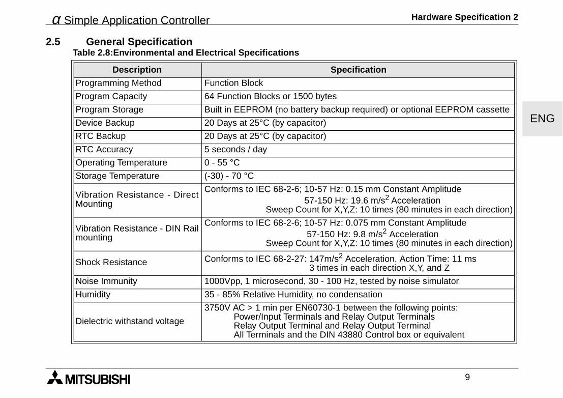
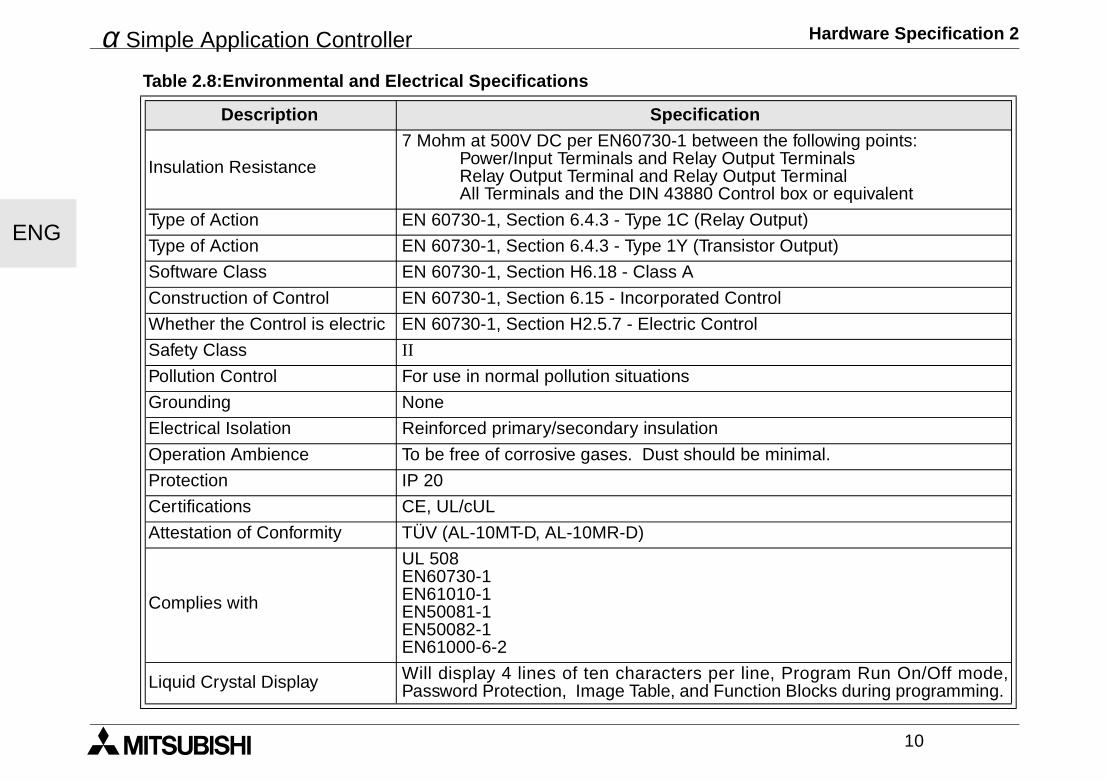
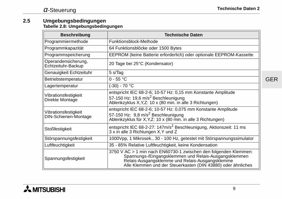
2.5 General SpecificationTable 2.8:Environmental and Electrical Specifications
Description SpecificationProgramming Method Function Block
Program Capacity 64 Function Blocks or 1500 bytes
Program Storage Built in EEPROM (no battery backup required) or optional EEPROM cassette
Device Backup 20 Days at 25°C (by capacitor)
RTC Backup 20 Days at 25°C (by capacitor)
RTC Accuracy 5 seconds / day
Operating Temperature 0 - 55 °C
Storage Temperature (-30) - 70 °C
Vibration Resistance - DirectMounting
Conforms to IEC 68-2-6; 10-57 Hz: 0.15 mm Constant Amplitude 57-150 Hz: 19.6 m/s2 Acceleration Sweep Count for X,Y,Z: 10 times (80 minutes in each direction)
Vibration Resistance - DIN Railmounting
Conforms to IEC 68-2-6; 10-57 Hz: 0.075 mm Constant Amplitude 57-150 Hz: 9.8 m/s2 Acceleration Sweep Count for X,Y,Z: 10 times (80 minutes in each direction)
Shock Resistance Conforms to IEC 68-2-27: 147m/s2 Acceleration, Action Time: 11 ms 3 times in each direction X,Y, and Z
Noise Immunity 1000Vpp, 1 microsecond, 30 - 100 Hz, tested by noise simulator
Humidity 35 - 85% Relative Humidity, no condensation
Dielectric withstand voltage
3750V AC > 1 min per EN60730-1 between the following points:Power/Input Terminals and Relay Output TerminalsRelay Output Terminal and Relay Output TerminalAll Terminals and the DIN 43880 Control box or equivalent
α Simple Application Controller Hardware Specification 2
10
ENG
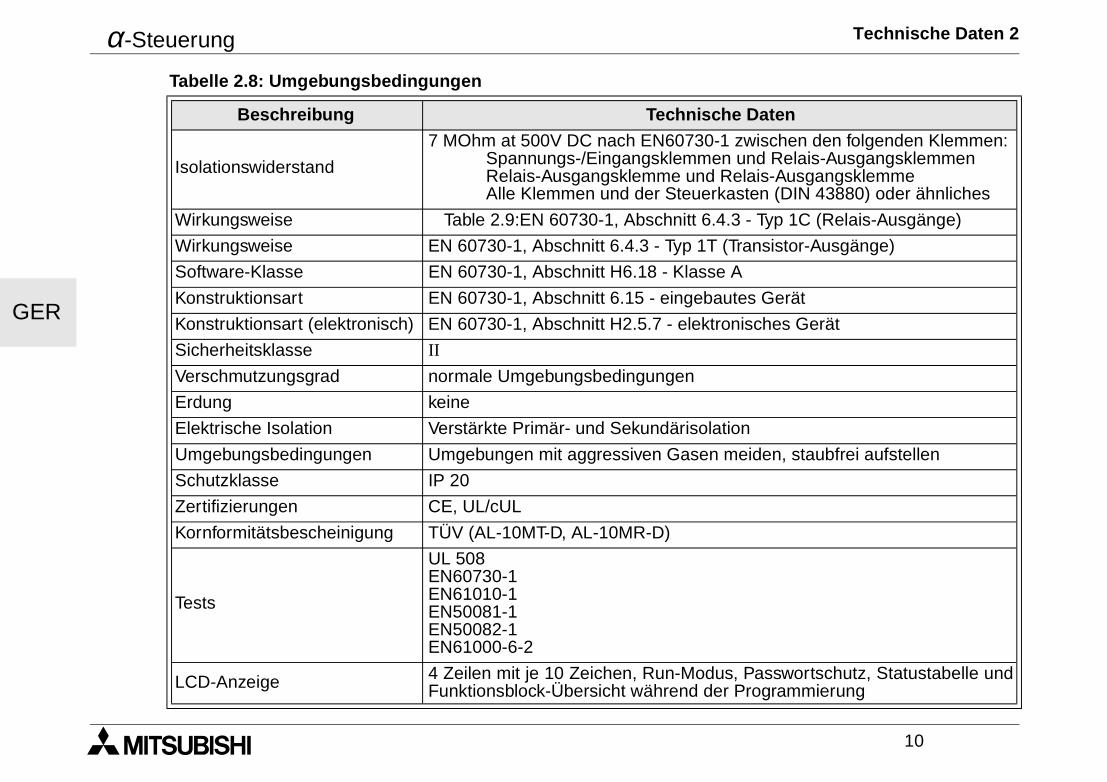
Insulation Resistance
7 Mohm at 500V DC per EN60730-1 between the following points:Power/Input Terminals and Relay Output TerminalsRelay Output Terminal and Relay Output TerminalAll Terminals and the DIN 43880 Control box or equivalent
Type of Action EN 60730-1, Section 6.4.3 - Type 1C (Relay Output)
Type of Action EN 60730-1, Section 6.4.3 - Type 1Y (Transistor Output)
Software Class EN 60730-1, Section H6.18 - Class A
Construction of Control EN 60730-1, Section 6.15 - Incorporated Control
Whether the Control is electric EN 60730-1, Section H2.5.7 - Electric Control
Safety Class II
Pollution Control For use in normal pollution situations
Grounding None
Electrical Isolation Reinforced primary/secondary insulation
Operation Ambience To be free of corrosive gases. Dust should be minimal.
Protection IP 20
Certifications CE, UL/cUL
Attestation of Conformity TÜV (AL-10MT-D, AL-10MR-D)
Complies with
UL 508EN60730-1EN61010-1EN50081-1EN50082-1EN61000-6-2
Liquid Crystal Display Will display 4 lines of ten characters per line, Program Run On/Off mode,Password Protection, Image Table, and Function Blocks during programming.
Table 2.8:Environmental and Electrical Specifications
Description Specification
α Simple Application Controller Installation 3
11
ENG
3. Installation
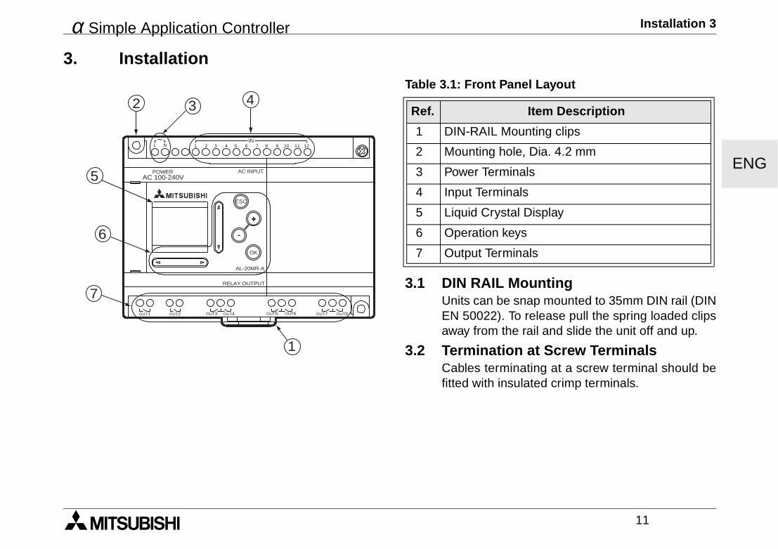
3.1 DIN RAIL MountingUnits can be snap mounted to 35mm DIN rail (DINEN 50022). To release pull the spring loaded clipsaway from the rail and slide the unit off and up.
3.2 Termination at Screw TerminalsCables terminating at a screw terminal should befitted with insulated crimp terminals.
Table 3.1: Front Panel Layout
Ref. Item Description
1 DIN-RAIL Mounting clips
2 Mounting hole, Dia. 4.2 mm
3 Power Terminals
4 Input Terminals
5 Liquid Crystal Display
6 Operation keys
7 Output Terminals
AC 100-240VPOWER AC INPUT
AL-20MR-A
OK
ESC
RELAY OUTPUT
OUT1 OUT2 OUT5OUT3 OUT4 OUT6 OUT8OUT7
1 2 3 4 5 6 7 8 9 10 11 12IN
L N~
432
5
6
7
1

α Simple Application Controller Installation 3
12
ENG
3.3 Installation Mounting Notes
The α Series’ safe design means theuser can install it almost anywhere butthe following points should be taken intoconsideration.
Do not install in areas with: excessive orconductive dust, corrosive or flammablegas, moisture or rain, excessive heat,regular impact shocks or excessivevibration. Do not place in water or letwater leak onto the controller.
Do not allow debris to fall inside the unitduring installation.
Keep as fa r as poss ib le f romhigh-voltage cables and power equip-ment.
The α Ser ies Contro l ler must beinstalled in cabinets which are designedfor the assembly of devices complyingto DIN 43880 or in a control box.
Use size M4 screws when mounting by screw holes.
The connectors must be covered to prevent injury from contact with “live” wires.
* Leave a minimum of 10mm of space for ventilation between the top and bottom edges of the α Series Con-troller and the enclosure walls.
POWER
IN
OK
+
RELAY OUTPUT
ESC
-
3 421 5L 6N
OUT3 OUT4OUT2OUT1
AC INPUTAC 100/240V
10(0.39")*
10(0.39")*
71.2(2.80")
6.0(0.24")
90.0
(3.5
4")
4.0(
0.16
")
55.0(2.17")
4.0(
0.16
")
6.0(0.24")
α Simple Application Controller Installation 3
13
ENG
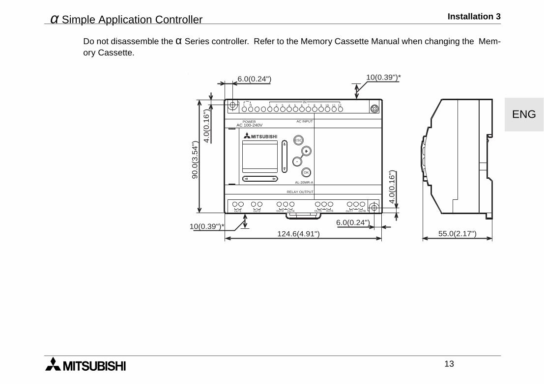
Do not disassemble the α Series controller. Refer to the Memory Cassette Manual when changing the Mem-ory Cassette.
AC 100-240VPOWER AC INPUT
AL-20MR-A
OK
ESC
RELAY OUTPUT
6.0(0.24") 10(0.39")*
55.0(2.17")
6.0(0.24")
124.6(4.91")10(0.39")*
4.0
(0.1
6")90.0
(3.5
4") 4
.0(0
.16")
OUT1 OUT2 OUT5OUT3 OUT4 OUT6 OUT8OUT7
1 2 3 4 5 6 7 8 9 10 11 12IN
L N~
α Simple Application Controller Installation 3
14
ENG
α Simple Application Controller Wiring 4
15
ENG
4. Wiring4.1 Installation Wiring Notes
The wiring of α Series has been designed to be safe and easy. A technician or engineer trained in the local
and national electrical standards should perform all tasks associated with the electrical wiring of the α Seriescontrollers. Turn off the Power before performing any wiring operations.
• Input and output cables should not be run through the same multicore cable or share the same wire.
• Do not lay input/output cables near high voltage power cables.
Allow for voltage drop and noise interference with input/output lines used over an extended distance. Pleaseuse wire that is properly sized for the current load.
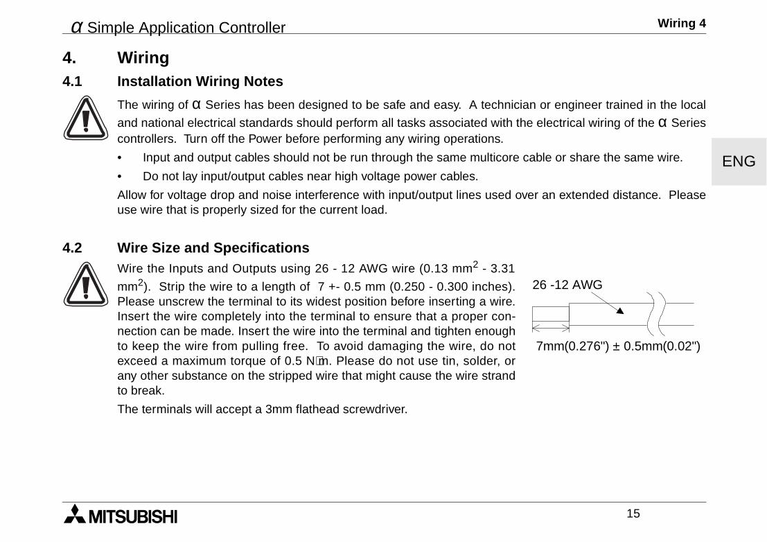
4.2 Wire Size and SpecificationsWire the Inputs and Outputs using 26 - 12 AWG wire (0.13 mm2 - 3.31
mm2). Strip the wire to a length of 7 +- 0.5 mm (0.250 - 0.300 inches).Please unscrew the terminal to its widest position before inserting a wire.Insert the wire completely into the terminal to ensure that a proper con-nection can be made. Insert the wire into the terminal and tighten enoughto keep the wire from pulling free. To avoid damaging the wire, do notexceed a maximum torque of 0.5 N⋅m. Please do not use tin, solder, orany other substance on the stripped wire that might cause the wire strandto break.
The terminals will accept a 3mm flathead screwdriver.
7mm(0.276") ± 0.5mm(0.02")
26 -12 AWG
α Simple Application Controller Wiring 4
16
ENG
4.3 Power SupplyWhen wiring AC supplies the “Live” cable should be connected to the “L” terminal and the “Neutral” cableshould be connected to the “N” terminal. Do NOT connect the “Live” wire to the “N” terminal, the user mightreceive a dangerous shock on powerup.
When wiring DC supplies the “positive” cable should be connected to the "+" terminal and the negative cableshould be connected to the “-” terminal. On no account should the power supply terminals be connected toany other terminal on the unit. DC Power Supply units should be capable of providing 4 Amperes of currentto the controller.
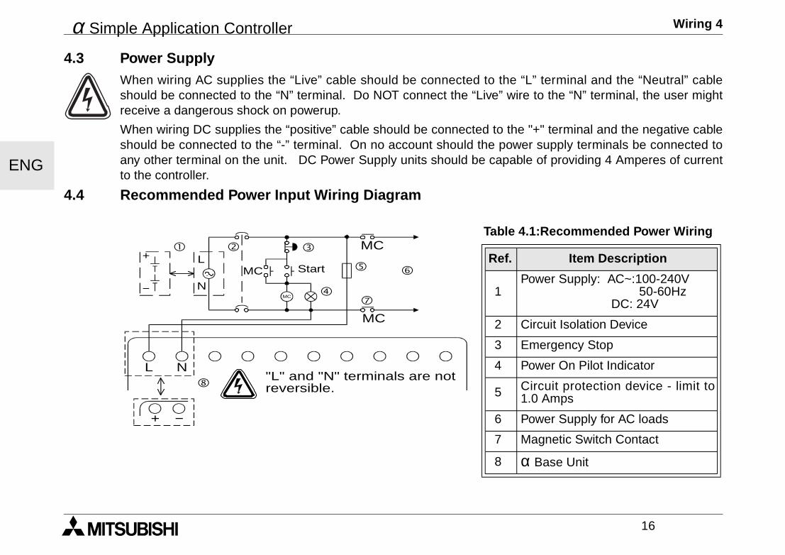
4.4 Recommended Power Input Wiring Diagram
Table 4.1:Recommended Power Wiring
Ref. Item Description
1Power Supply: AC~:100-240V 50-60Hz DC: 24V
2 Circuit Isolation Device
3 Emergency Stop
4 Power On Pilot Indicator
5 Circuit protection device - limit to1.0 Amps
6 Power Supply for AC loads
7 Magnetic Switch Contact
8 α Base Unit
MC
MC
MC
MC
L N
! " #
$
% &
'
(
+
−
L
N
+ −
Start
"L" and "N" terminals are notreversible.
α Simple Application Controller Wiring 4
17
ENG
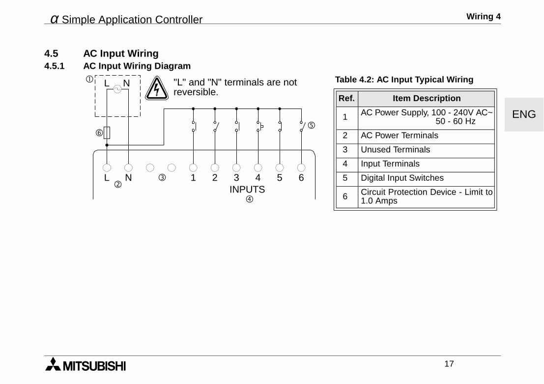
4.5 AC Input Wiring4.5.1 AC Input Wiring Diagram
Table 4.2: AC Input Typical Wiring
Ref. Item Description
1 AC Power Supply, 100 - 240V AC~ 50 - 60 Hz
2 AC Power Terminals
3 Unused Terminals
4 Input Terminals
5 Digital Input Switches
6 Circuit Protection Device - Limit to1.0 Amps$
! L N
"#
%
L N 1 2 3INPUTS
4 5 6
&
"L" and "N" terminals are notreversible.
α Simple Application Controller Wiring 4
18
ENG
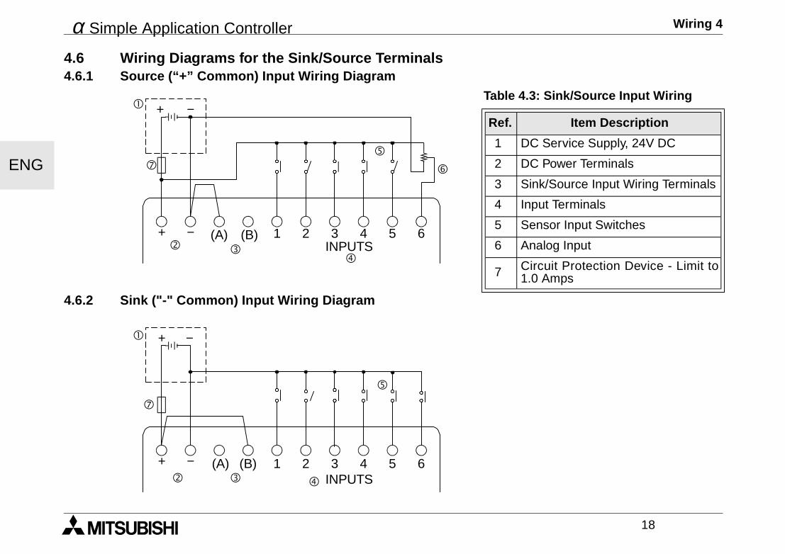
4.6 Wiring Diagrams for the Sink/Source Terminals4.6.1 Source (“+” Common) Input Wiring Diagram
4.6.2 Sink ("-" Common) Input Wiring Diagram
Table 4.3: Sink/Source Input Wiring
Ref. Item Description
1 DC Service Supply, 24V DC
2 DC Power Terminals
3 Sink/Source Input Wiring Terminals
4 Input Terminals
5 Sensor Input Switches
6 Analog Input
7 Circuit Protection Device - Limit to1.0 Amps
! + −
"$
%
&
+ − (A) (B) 1 2 3INPUTS
4 5 6
(
#
! + −
" # $
%
+ − (A) (B) 1 2 3INPUTS
4 5 6
(
α Simple Application Controller Wiring 4
19
ENG
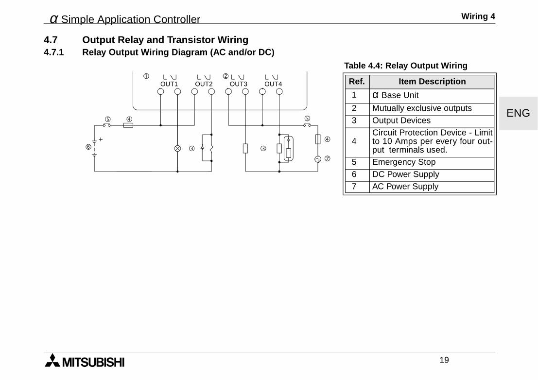
4.7 Output Relay and Transistor Wiring4.7.1 Relay Output Wiring Diagram (AC and/or DC)
Table 4.4: Relay Output Wiring
Ref. Item Description
1 α Base Unit
2 Mutually exclusive outputs 3 Output Devices
4Circuit Protection Device - Limitto 10 Amps per every four out-put terminals used.
5 Emergency Stop 6 DC Power Supply 7 AC Power Supply
"!
$
OUT1
##
%
&
OUT2 OUT3 OUT4
(
$
%
+

α Simple Application Controller Wiring 4
20
ENG
4.7.2 Transistor Output (Source or “+” Common Only) Wiring DiagramTable 4.5: Transistor Output Wiring
Ref. Item Description
1 α Base Unit
2 Output Terminals3 Output Devices
4 Circuit Protection Device - SeeTable 4.6 for Specifications
5 Emergency Stop6 DC Power Supply for output7 Power Terminal8 DC Power Supply, 24V DC
9 Circuit Protection Device - Limit to 1.0 Amps
Table 4.6: Transistor Output Circuit Protection Table
Circuit Voltage Circuit Protection (Fuse)
5 Volt < 0.3 Amps per Circuit12 Volt < 2.0 Amps per Circuit24 Volt < 2.0 Amps per Circuit
Volt Output Terminal Notes
5 Each circuit can contain from one output terminal up to every output terminal.12-24 Each circuit can contain from one output terminal up to every output terminal.
5,12,24Using any combination of 5 Volt, 12 Volt, and 24 Volt outputs can be accomplished on the sameα Series Controller if separate circuits are used for each voltage level.
"
!
OUT1
##
OUT2 OUT3 OUT4
$
%
&
+ −
+ −(
$
%
&+
+
#
)
'
α Simple Application Controller αααα Series Terminal Layout 5
21
ENG
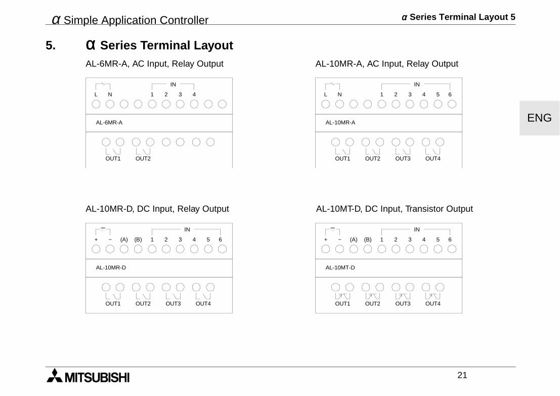
5. αααα Series Terminal LayoutAL-6MR-A, AC Input, Relay Output AL-10MR-A, AC Input, Relay Output
AL-10MR-D, DC Input, Relay Output AL-10MT-D, DC Input, Transistor Output
L N 1 2 3 4
OUT1
AL-6MR-A
OUT2
IN
L N 1 2 3 4
OUT1
AL-10MR-A
OUT2
IN
5 6
OUT3 OUT4
+ − (A) (B) 1 2 3 4
OUT1
AL-10MR-D
OUT2
IN
5 6
OUT3 OUT4
+ − (B) 1 2 3 4
OUT1
AL-10MT-D
OUT2
IN
5 6
OUT3 OUT4
(A)
α Simple Application Controller αααα Series Terminal Layout 5
22
ENG
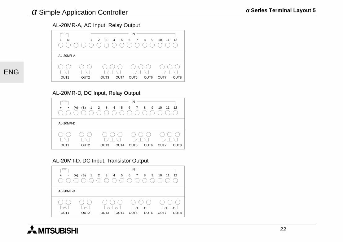
AL-20MR-A, AC Input, Relay Output
AL-20MR-D, DC Input, Relay Output
AL-20MT-D, DC Input, Transistor Output
L N
IN
12111 2 3 4 5 6 7 8 9 10
OUT1 OUT2 OUT3 OUT5 OUT7OUT4 OUT6 OUT8
AL-20MR-A
+ -
IN
12111 2 3 4 5 6 7 8 9 10
OUT1 OUT2 OUT3 OUT5 OUT7OUT4 OUT6 OUT8
AL-20MR-D
(A) (B)
+ -
IN
12111 2 3 4 5 6 7 8 9 10
OUT1 OUT2 OUT3 OUT5 OUT7OUT4 OUT6 OUT8
AL-20MT-D
(A) (B)
α Simple Application Controller How to Use αααα Series Controllers - Getting Started 6
23
ENG
6. How to Use αααα Series Controllers - Getting Started
α Series controllers use Function Block Programming. In this style of programming, Function Blocks are con-nected together to build a program. There are five types of blocks that can be placed in your program: SystemInputs, front panel Keys, System M bits, Function Blocks, and System Outputs.
A screen showing the date, time, and image table (input and output status) will show when the controller isturned On. Hit any key to proceed to the Top Menu. Enter the ProgEdit mode with the OK key to begin pro-gramming.
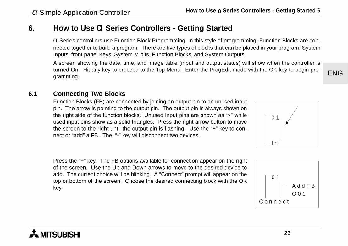
6.1 Connecting Two BlocksFunction Blocks (FB) are connected by joining an output pin to an unused inputpin. The arrow is pointing to the output pin. The output pin is always shown onthe right side of the function blocks. Unused Input pins are shown as “>” whileused input pins show as a solid triangles. Press the right arrow button to movethe screen to the right until the output pin is flashing. Use the “+” key to con-nect or “add” a FB. The “-” key will disconnect two devices.
Press the “+” key. The FB options available for connection appear on the rightof the screen. Use the Up and Down arrows to move to the desired device toadd. The current choice will be blinking. A “Connect” prompt will appear on thetop or bottom of the screen. Choose the desired connecting block with the OKkey
0 1
I n
0 1
A d d F BO 0 1
C o n n e c t
α Simple Application Controller How to Use αααα Series Controllers - Getting Started 6
24
ENG
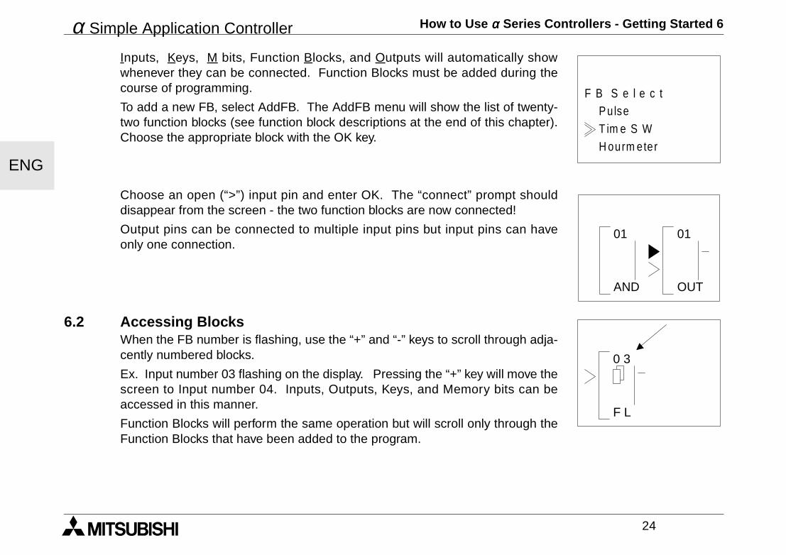
Inputs, Keys, M bits, Function Blocks, and Outputs will automatically showwhenever they can be connected. Function Blocks must be added during thecourse of programming.
To add a new FB, select AddFB. The AddFB menu will show the list of twenty-two function blocks (see function block descriptions at the end of this chapter).Choose the appropriate block with the OK key.
Choose an open (“>”) input pin and enter OK. The “connect” prompt shoulddisappear from the screen - the two function blocks are now connected!
Output pins can be connected to multiple input pins but input pins can haveonly one connection.
6.2 Accessing Blocks When the FB number is flashing, use the “+” and “-” keys to scroll through adja-cently numbered blocks.
Ex. Input number 03 flashing on the display. Pressing the “+” key will move thescreen to Input number 04. Inputs, Outputs, Keys, and Memory bits can beaccessed in this manner.
Function Blocks will perform the same operation but will scroll only through theFunction Blocks that have been added to the program.
H ourm eter
PulseF B S e l e c t
T im e S W
AND
01 01
OUT
0 3
F L
α Simple Application Controller How to Use αααα Series Controllers - Getting Started 6
25
ENG
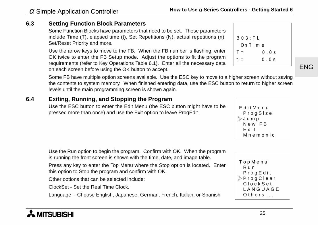
6.3 Setting Function Block ParametersSome Function Blocks have parameters that need to be set. These parametersinclude Time (T), elapsed time (t), Set Repetitions (N), actual repetitions (n),Set/Reset Priority and more.
Use the arrow keys to move to the FB. When the FB number is flashing, enterOK twice to enter the FB Setup mode. Adjust the options to fit the programrequirements (refer to Key Operations Table 6.1). Enter all the necessary dataon each screen before using the OK button to accept.
Some FB have multiple option screens available. Use the ESC key to move to a higher screen without savingthe contents to system memory. When finished entering data, use the ESC button to return to higher screenlevels until the main programming screen is shown again.
6.4 Exiting, Running, and Stopping the ProgramUse the ESC button to enter the Edit Menu (the ESC button might have to bepressed more than once) and use the Exit option to leave ProgEdit.
Use the Run option to begin the program. Confirm with OK. When the programis running the front screen is shown with the time, date, and image table.
Press any key to enter the Top Menu where the Stop option is located. Enterthis option to Stop the program and confirm with OK.
Other options that can be selected include:
ClockSet - Set the Real Time Clock.
Language - Choose English, Japanese, German, French, Italian, or Spanish
t = 0 . 0 s
O n T i m eB 0 3 : F L
T = 0 . 0 s
E d i t M e n u
E x i t
P r o g S i z eJ u m pN e w F B
M n e m o n i c
T o p M e n u
C l o c k S e t
R u nP r o g E d i tP r o g C l e a r
O t h e r s . . .L A N G U A G E
α Simple Application Controller How to Use αααα Series Controllers - Getting Started 6
26
ENG
ProgClear - Deletes everything in program memory, programs and data!
Others - Gives more Options for a Version Check, Password Protection, Summer Time Change Schedule,Modem Initialization, and Menu Key operation.
Table 6.1:Key Number and Basic Operation
Key number Main Key Function
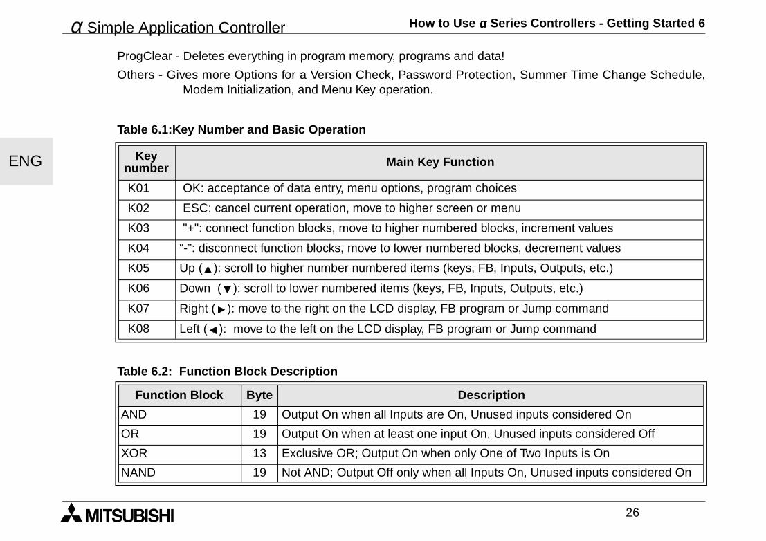
K01 OK: acceptance of data entry, menu options, program choices
K02 ESC: cancel current operation, move to higher screen or menu
K03 "+": connect function blocks, move to higher numbered blocks, increment values
K04 “-”: disconnect function blocks, move to lower numbered blocks, decrement values
K05 Up ( ): scroll to higher number numbered items (keys, FB, Inputs, Outputs, etc.)
K06 Down ( ): scroll to lower numbered items (keys, FB, Inputs, Outputs, etc.)
K07 Right ( ): move to the right on the LCD display, FB program or Jump command
K08 Left ( ): move to the left on the LCD display, FB program or Jump command
Table 6.2: Function Block Description
Function Block Byte Description
AND 19 Output On when all Inputs are On, Unused inputs considered On
OR 19 Output On when at least one input On, Unused inputs considered Off
XOR 13 Exclusive OR; Output On when only One of Two Inputs is On
NAND 19 Not AND; Output Off only when all Inputs On, Unused inputs considered On
α Simple Application Controller How to Use αααα Series Controllers - Getting Started 6
27
ENG
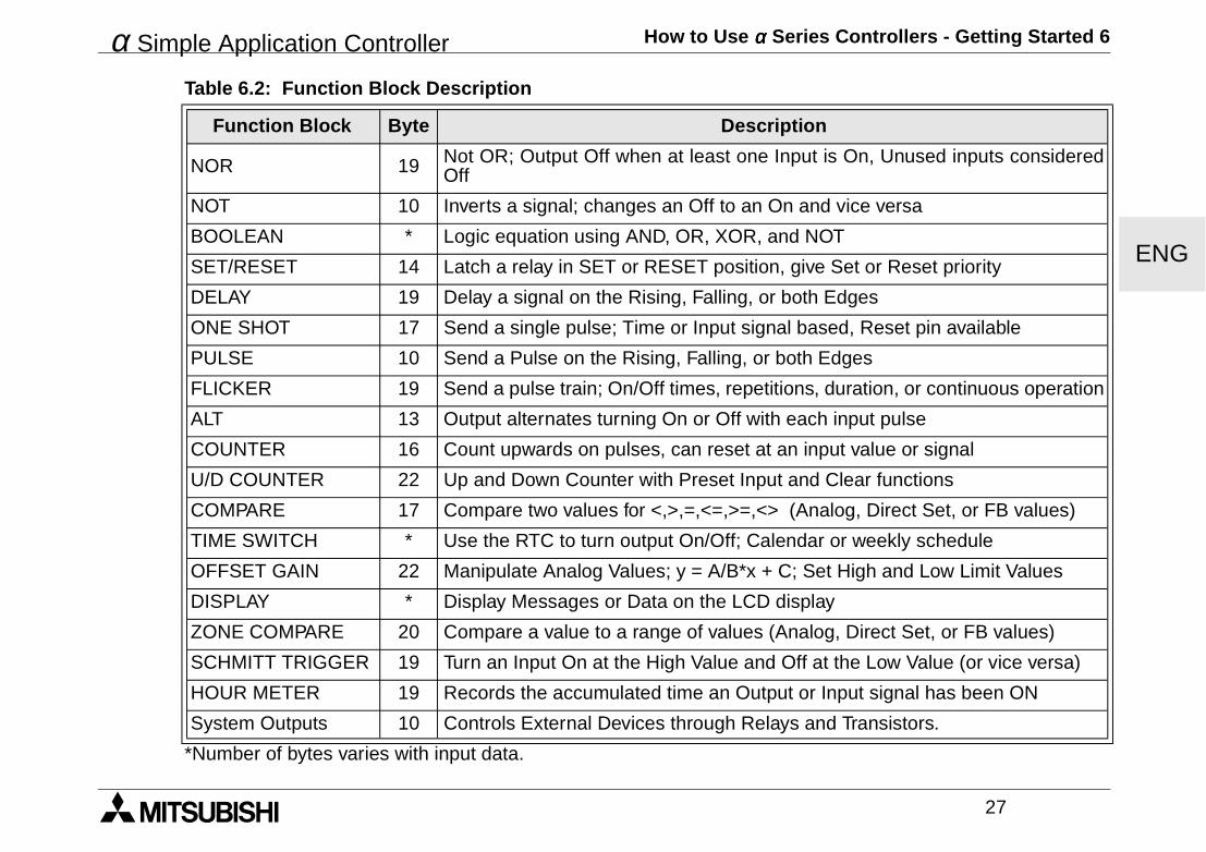
*Number of bytes varies with input data.
NOR 19 Not OR; Output Off when at least one Input is On, Unused inputs consideredOff
NOT 10 Inverts a signal; changes an Off to an On and vice versa
BOOLEAN * Logic equation using AND, OR, XOR, and NOT
SET/RESET 14 Latch a relay in SET or RESET position, give Set or Reset priority
DELAY 19 Delay a signal on the Rising, Falling, or both Edges
ONE SHOT 17 Send a single pulse; Time or Input signal based, Reset pin available
PULSE 10 Send a Pulse on the Rising, Falling, or both Edges
FLICKER 19 Send a pulse train; On/Off times, repetitions, duration, or continuous operation
ALT 13 Output alternates turning On or Off with each input pulse
COUNTER 16 Count upwards on pulses, can reset at an input value or signal
U/D COUNTER 22 Up and Down Counter with Preset Input and Clear functions
COMPARE 17 Compare two values for <,>,=,<=,>=,<> (Analog, Direct Set, or FB values)
TIME SWITCH * Use the RTC to turn output On/Off; Calendar or weekly schedule
OFFSET GAIN 22 Manipulate Analog Values; y = A/B*x + C; Set High and Low Limit Values
DISPLAY * Display Messages or Data on the LCD display
ZONE COMPARE 20 Compare a value to a range of values (Analog, Direct Set, or FB values)
SCHMITT TRIGGER 19 Turn an Input On at the High Value and Off at the Low Value (or vice versa)
HOUR METER 19 Records the accumulated time an Output or Input signal has been ON
System Outputs 10 Controls External Devices through Relays and Transistors.
Table 6.2: Function Block Description
Function Block Byte Description
α Simple Application Controller How to Use αααα Series Controllers - Getting Started 6
28
ENG

GER
HARDWARE-HANDBUCHα-Steuerung
α-Steuerung
GER
Vorwort• Dieses Handbuch enhält Texte, Abbildungen und Erläuterungen zur korrekten Installation und Bedienung
der α-Steuerung. Vor der Installation und dem Einsatz des Gerätes muß dieses Handbuch gelesen werden. Die Inhalte müssen verstanden sein.
• Wenn während der Installation Fragen auftreten, ziehen Sie auf jeden Fall eine Elektrofachkraft zu Rate, die mit den lokalen und nationalen elektrotechnischen Bestimmungen vertraut ist. Setzen Sie sich mit demnächstliegenden Händler von MITSUBISHI ELECTRIC in Verbindung, wenn Sie Unterstützung bei der Bedienung oder Anwendung der α-Steuerung benötigen.
• Dieses Handbuch wird vorbehaltlich etwaiger Änderungen herausgegeben. Änderungen können ohne Hinweis vorgenommen werden.
α-Steuerung
GER
i
αααα -Steuerung
Hardware-HandbuchNummer : JY992D74201Revision : JDatum : 04/2002
α-Steuerung
GER
ii
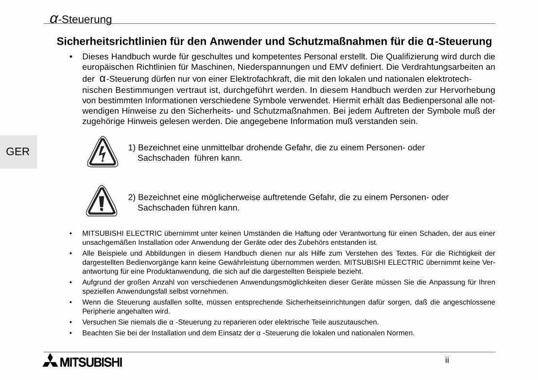
Sicherheitsrichtlinien für den Anwender und Schutzmaßnahmen für die αααα-Steuerung• Dieses Handbuch wurde für geschultes und kompetentes Personal erstellt. Die Qualifizierung wird durch die
europäischen Richtlinien für Maschinen, Niederspannungen und EMV definiert. Die Verdrahtungsarbeiten ander α-Steuerung dürfen nur von einer Elektrofachkraft, die mit den lokalen und nationalen elektrotech-nischen Bestimmungen vertraut ist, durchgeführt werden. In diesem Handbuch werden zur Hervorhebungvon bestimmten Informationen verschiedene Symbole verwendet. Hiermit erhält das Bedienpersonal alle not-wendigen Hinweise zu den Sicherheits- und Schutzmaßnahmen. Bei jedem Auftreten der Symbole muß derzugehörige Hinweis gelesen werden. Die angegebene Information muß verstanden sein.
1) Bezeichnet eine unmittelbar drohende Gefahr, die zu einem Personen- oder Sachschaden führen kann.
2) Bezeichnet eine möglicherweise auftretende Gefahr, die zu einem Personen- oder Sachschaden führen kann.
• MITSUBISHI ELECTRIC übernimmt unter keinen Umständen die Haftung oder Verantwortung für einen Schaden, der aus einerunsachgemäßen Installation oder Anwendung der Geräte oder des Zubehörs entstanden ist.
• Alle Beispiele und Abbildungen in diesem Handbuch dienen nur als Hilfe zum Verstehen des Textes. Für die Richtigkeit derdargestellten Bedienvorgänge kann keine Gewährleistung übernommen werden. MITSUBISHI ELECTRIC übernimmt keine Ver-antwortung für eine Produktanwendung, die sich auf die dargestellten Beispiele bezieht.
• Aufgrund der großen Anzahl von verschiedenen Anwendungsmöglichkeiten dieser Geräte müssen Sie die Anpassung für Ihrenspeziellen Anwendungsfall selbst vornehmen.
• Wenn die Steuerung ausfallen sollte, müssen entsprechende Sicherheitseinrichtungen dafür sorgen, daß die angeschlossenePeripherie angehalten wird.
• Versuchen Sie niemals die α -Steuerung zu reparieren oder elektrische Teile auszutauschen.
• Beachten Sie bei der Installation und dem Einsatz der α -Steuerung die lokalen und nationalen Normen.
α-Steuerung
iii
Inhaltsverzeichnis
Sicherheitsrichtlinien ................................................................................................................. ii
1. Einleitung ............................................................................................................... 1
2. Technische Daten.................................................................................................. 32.1 Verfügbare Modelle...................................................................................................... 32.2 Spannungsversorgung................................................................................................. 42.3 Eingänge...................................................................................................................... 62.4 Ausgänge .................................................................................................................... 82.5 Umgebungsbedingungen............................................................................................. 9
3. Installation............................................................................................................ 113.1 DIN-Schienen-Montage ............................................................................................. 113.2 Schraubklemmenanschluß ........................................................................................ 113.3 Installationshinweise .................................................................................................. 12
GER
α-Steuerung
iv
4. Verdrahtung ......................................................................................................... 154.1 Hinweise zur Installationsverdrahtung ....................................................................... 154.2 Kabelgröße und Spezifikationen ................................................................................ 154.3 Spannungsversorgung............................................................................................... 164.4 Empfohlene Verdrahtung der Spannungsversorgung................................................ 164.5 Verdrahtung der AC-Eingänge................................................................................... 17
4.5.1 Verdrahtung der AC-Eingänge ............................................................................ 174.6 Verdrahtung der Sink-/Source-Eingänge ................................................................... 18
4.6.1 Source-Eingangsverdrahtung (plusschaltend) .................................................... 184.6.2 Sink-Eingangsverdrahtung (minusschaltend)...................................................... 18
4.7 Relais-/Transistor-Ausgangsverdrahtung .................................................................. 194.7.1 Relais-Ausgangsverdrahtung (AC und/oder DC) ................................................ 194.7.2 Transistor-Ausgangsverdrahtung (nur Source - plusschaltend) .......................... 20
5. Klemmenbelegungen .......................................................................................... 21
6. Einstieg in die Programmierung ........................................................................ 236.1 Verbinden von zwei Blöcken...................................................................................... 236.2 Bearbeitung von Blöcken .......................................................................................... 246.3 Einstellung der Funktionsblockparameter.................................................................. 256.4 Verlassen, Starten und Stoppen des Programms...................................................... 26
GER
α-Steuerung Einleitung 1
1
GER
1. EinleitungDie α-Steuerung ist ausgesprochen einfach zu bedienen und prädestiniert für alle möglichen Schalt-,Steuerungs- und Überwachungsaufgaben rund um Ihr Haus, Ihr Büro, Ihre Fabrik, ... eigentlich überall.
Mit jedem Modul können Sie Signale lesen und Ausgänge setzen, und zwar genau nach den Bedingungenund Zeitvorgaben, die Sie festgelegt haben. Natürlich können Sie den aktuellen Zustand des Systems auf derAnzeige jederzeit ablesen.
Besonderheiten der α-Steuerung:
• Programmierung direkt am Gerät
• Hohe Ausgangsstromschaltleistung
• Kleine Abmessungen
• Programmierschnittstelle direkt auf dem Gerät
• EEPROM-Kassetten für die Programmspeicherung
• Integrierte Echtzeituhr als Standard
• Windows-Programmiersoftware AL-PCS/WIN-E
• Ausführliche Dokumentation und Lernpakete
Die α-Steuerung ist für die folgenden automatischen Anwendungen konstruiert: Beleuchtung, Klimaanlagen,Bewässerung, Türen, Tore, einfache Alarmanlagen, Gewächshäuser, Belüftungsanlagen usw. Die integrierteEchtzeituhr kann als stromsparende Komponente verwendet werden, da sie die Anlage zu vorher fest-gelegten Zeiten ein- und ausschalten kann.
Testen Sie die Programme sorgfältig, bevor Sie sie in automatisierten Einrichtungen installieren. Die
α-Steuerung wurde nicht für lebenserhaltende oder selbstüberwachende Anwendungen entwickelt.
Bitte wenden Sie sich an Ihren Händler, dort erhalten Sie detaillierte Informationen zu diesem Produkt.
α-Steuerung Einleitung 1
2
GER
α-Steuerung Technische Daten 2
3
GER
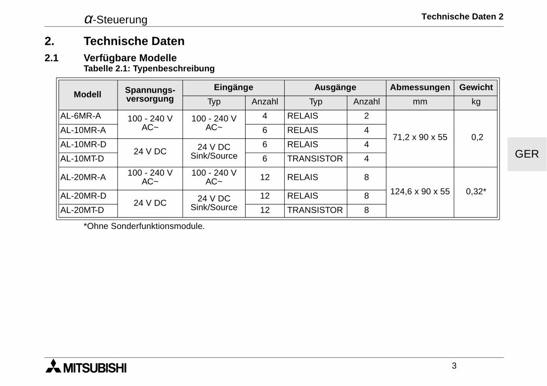
2. Technische Daten2.1 Verfügbare Modelle
*Ohne Sonderfunktionsmodule.
Tabelle 2.1: Typenbeschreibung
Modell Spannungs-versorgung
Eingänge Ausgänge Abmessungen Gewicht
Typ Anzahl Typ Anzahl mm kg
AL-6MR-A 100 - 240 V AC~
100 - 240 V AC~
4 RELAIS 2
71,2 x 90 x 55 0,2AL-10MR-A 6 RELAIS 4
AL-10MR-D24 V DC 24 V DC
Sink/Source6 RELAIS 4
AL-10MT-D 6 TRANSISTOR 4
AL-20MR-A 100 - 240 V AC~
100 - 240 V AC~ 12 RELAIS 8
124,6 x 90 x 55 0,32*AL-20MR-D24 V DC 24 V DC
Sink/Source12 RELAIS 8
AL-20MT-D 12 TRANSISTOR 8
α-Steuerung Technische Daten 2
4
GER
2.2 Spannungsversorgung
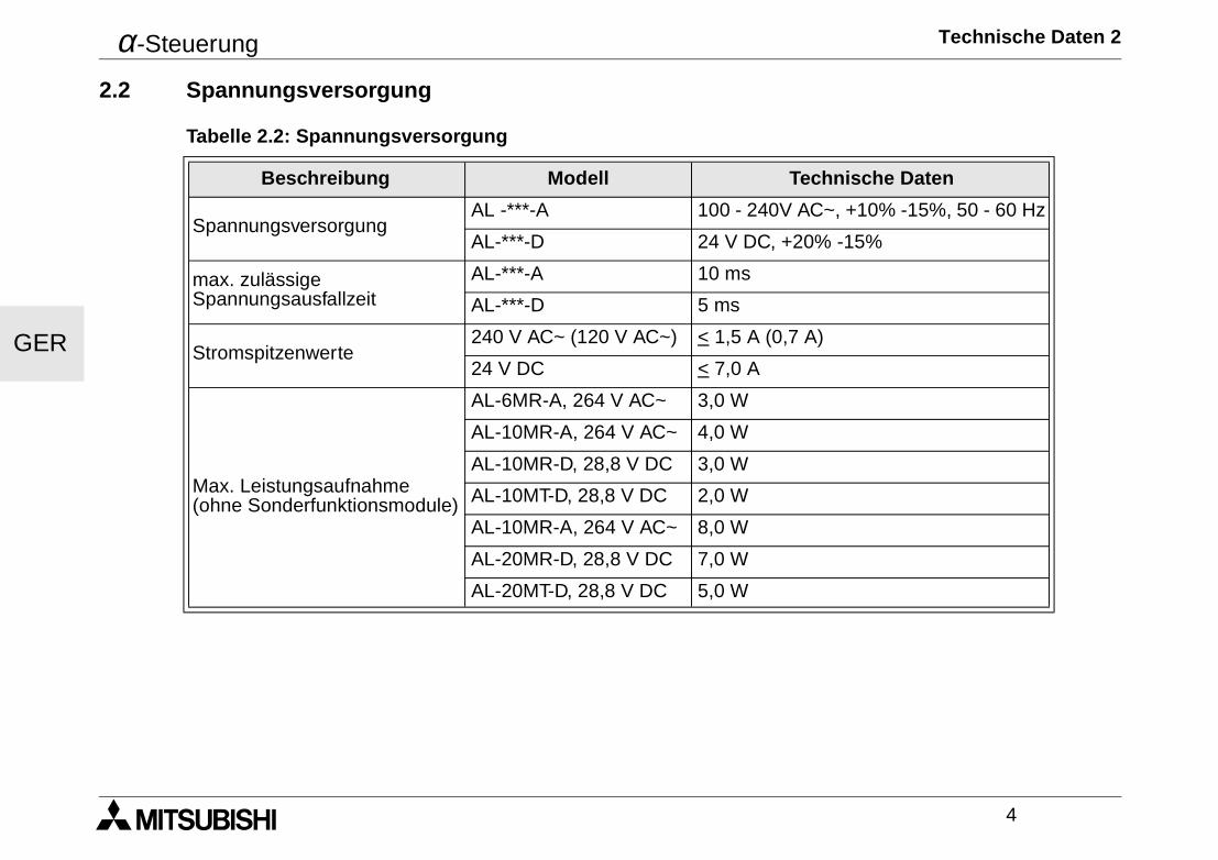
Tabelle 2.2: Spannungsversorgung
Beschreibung Modell Technische Daten
SpannungsversorgungAL -***-A 100 - 240V AC~, +10% -15%, 50 - 60 Hz
AL-***-D 24 V DC, +20% -15%
max. zulässige Spannungsausfallzeit
AL-***-A 10 ms
AL-***-D 5 ms
Stromspitzenwerte240 V AC~ (120 V AC~) < 1,5 A (0,7 A)
24 V DC < 7,0 A
Max. Leistungsaufnahme(ohne Sonderfunktionsmodule)
AL-6MR-A, 264 V AC~ 3,0 W
AL-10MR-A, 264 V AC~ 4,0 W
AL-10MR-D, 28,8 V DC 3,0 W
AL-10MT-D, 28,8 V DC 2,0 W
AL-10MR-A, 264 V AC~ 8,0 W
AL-20MR-D, 28,8 V DC 7,0 W
AL-20MT-D, 28,8 V DC 5,0 W
α-Steuerung Technische Daten 2
5
GER
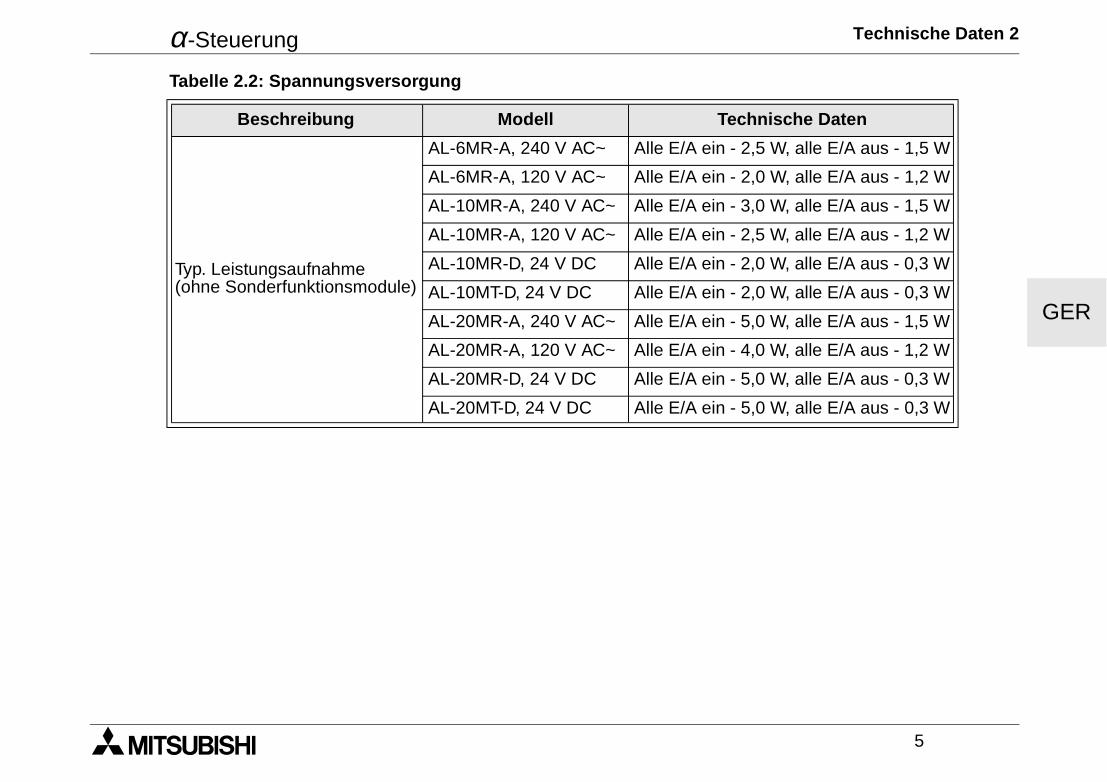
Typ. Leistungsaufnahme(ohne Sonderfunktionsmodule)
AL-6MR-A, 240 V AC~ Alle E/A ein - 2,5 W, alle E/A aus - 1,5 W
AL-6MR-A, 120 V AC~ Alle E/A ein - 2,0 W, alle E/A aus - 1,2 W
AL-10MR-A, 240 V AC~ Alle E/A ein - 3,0 W, alle E/A aus - 1,5 W
AL-10MR-A, 120 V AC~ Alle E/A ein - 2,5 W, alle E/A aus - 1,2 W
AL-10MR-D, 24 V DC Alle E/A ein - 2,0 W, alle E/A aus - 0,3 W
AL-10MT-D, 24 V DC Alle E/A ein - 2,0 W, alle E/A aus - 0,3 W
AL-20MR-A, 240 V AC~ Alle E/A ein - 5,0 W, alle E/A aus - 1,5 W
AL-20MR-A, 120 V AC~ Alle E/A ein - 4,0 W, alle E/A aus - 1,2 W
AL-20MR-D, 24 V DC Alle E/A ein - 5,0 W, alle E/A aus - 0,3 W
AL-20MT-D, 24 V DC Alle E/A ein - 5,0 W, alle E/A aus - 0,3 W
Tabelle 2.2: Spannungsversorgung
Beschreibung Modell Technische Daten
α-Steuerung Technische Daten 2
6
GER
2.3 Eingänge
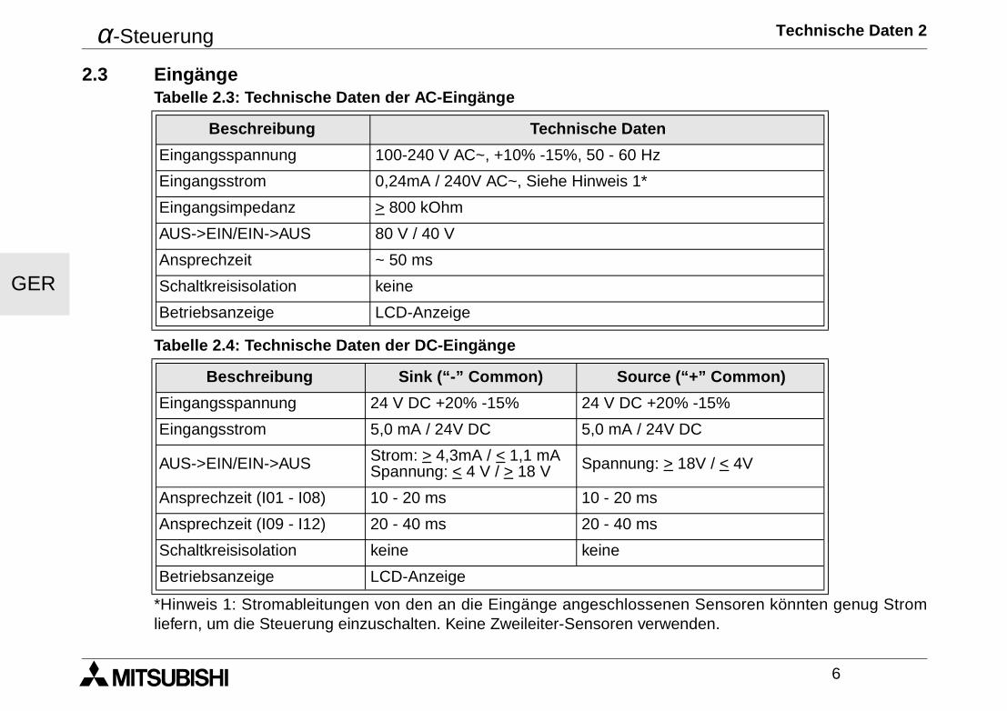
*Hinweis 1: Stromableitungen von den an die Eingänge angeschlossenen Sensoren könnten genug Stromliefern, um die Steuerung einzuschalten. Keine Zweileiter-Sensoren verwenden.
Tabelle 2.3: Technische Daten der AC-Eingänge
Beschreibung Technische Daten
Eingangsspannung 100-240 V AC~, +10% -15%, 50 - 60 Hz
Eingangsstrom 0,24mA / 240V AC~, Siehe Hinweis 1*
Eingangsimpedanz > 800 kOhm
AUS->EIN/EIN->AUS 80 V / 40 V
Ansprechzeit ~ 50 ms
Schaltkreisisolation keine
Betriebsanzeige LCD-Anzeige
Tabelle 2.4: Technische Daten der DC-Eingänge
Beschreibung Sink (“-” Common) Source (“+” Common)
Eingangsspannung 24 V DC +20% -15% 24 V DC +20% -15%
Eingangsstrom 5,0 mA / 24V DC 5,0 mA / 24V DC
AUS->EIN/EIN->AUS Strom: > 4,3mA / < 1,1 mASpannung: < 4 V / > 18 V Spannung: > 18V / < 4V
Ansprechzeit (I01 - I08) 10 - 20 ms 10 - 20 ms
Ansprechzeit (I09 - I12) 20 - 40 ms 20 - 40 ms
Schaltkreisisolation keine keine
Betriebsanzeige LCD-Anzeige
α-Steuerung Technische Daten 2
7
GER
Tabelle 2.5: Technische Daten der Analogeingänge
Beschreibung Technische Daten
AL-10M*-D 6 Kanäle: I01 - I06
AL-20M*-D 8 Kanäle: I01 - I08
Analogeingangs-bereich 0 - 250
Auflösung 10000/250 mv
Wandler-geschwindigkeit 10 ms
Eingangsspannung 0 - 10 V DC
Eingangsimpedanz 150 kOhm oder höher
Genauigkeit +/- 5% (0,5 V DC)
Offset/Gain
Offset-Wert = 0 bei 0 V DCGain-Wert: 0 - 10V = 0 - 250Diese voreingestellten Werte können im Funktionsblock Offset geändert werden.
Temperatur-abweichung +/- 3 LSB
α-Steuerung Technische Daten 2
8
GER
2.4 Ausgänge Tabelle 2.6: Technische Daten der Relais-Ausgänge
Beschreibung Technische Daten
Einschaltspannung 250 V AC~ oder weniger, 30 V DC oder weniger
Max. Widerstandslast 8A / gemeinsam (10A / gemeinsam fur Ausgänge 110V AC~)
Lebenszyklus / ohmsche Last 100000 Zyklen bei 8 A / 240 V AC~ oder 24 V DC 30000 Zyklen bei 10 A / 110 V AC~
Minimale Last 50 mW (10 mA bei 5 V DC)
Max. induktive Last 245 VA (1/3 hp) / 125 VAC~, 367 VA (1/2 hp) / 250 VAC~
Ansprechzeit 10 ms oder weniger
Betriebsanzeige LCD-Anzeige
Schaltkreisisolation über Relais
Tabelle 2.7: Technische Daten der Transistor-Ausgänge (nur Source-Typ)
Beschreibung Technische DatenEinschaltspannung 5 - 24 V DC
Max. Widerstandslast 1A / Klemme (8 - 24 V DC), 0,1A / Klemme (5 - 8V DC)
Minimale Last 1,0 mA
Max. induktive Last 1 A / 24 V DC (24 W)
Max. Lampenlast 0,125 A / 24 V DC (3,0 W)
Ansprechzeit Ein/Aus, Aus/Ein (circa) < 1 ms
Leckstrom < 0,1 mA / 24 V DC
Betriebsanzeige LCD-Anzeige
Schaltkreisisolation keine
α-Steuerung Technische Daten 2
9
GER
2.5 UmgebungsbedingungenTabelle 2.8: Umgebungsbedingungen
Beschreibung Technische DatenProgrammiermethode Funktionsblock-Methode
Programmkapazität 64 Funktionsblöcke oder 1500 Bytes
Programmspeicherung EEPROM (keine Batterie erforderlich) oder optionale EEPROM-Kassette
Operandensicherung,Echtzeituhr-Backup 20 Tage bei 25°C (Kondensator)
Genauigkeit Echtzeituhr 5 s/Tag
Betriebstemperatur 0 - 55 °C
Lagertemperatur (-30) - 70 °C
VibrationsfestigkeitDirekte Montage
entspricht IEC 68-2-6; 10-57 Hz: 0,15 mm Konstante Amplitude57-150 Hz: 19,6 m/s2 BeschleunigungAblenkzyklus X,Y,Z: 10 x (80 min. in alle 3 Richtungen)
VibrationsfestigkeitDIN-Schienen-Montage
entspricht IEC 68-2-6; 10-57 Hz: 0,075 mm Konstante Amplitude57-150 Hz: 9,8 m/s2 BeschleunigungAblenkzyklus für X,Y,Z: 10 x (80 min. in alle 3 Richtungen)
Stoßfestigkeit entspricht IEC 68-2-27: 147m/s2 Beschleunigung, Aktionszeit: 11 ms3 x in alle 3 Richtungen X,Y und Z
Störspannungsfestigkeit 1000Vpp, 1 Mikrosek., 30 - 100 Hz, getestet mit Störspannungssimulator
Luftfeuchtigkeit 35 - 85% Relative Luftfeuchtigkeit, keine Kondensation
Spannungsfestigkeit
3750 V AC > 1 min nach EN60730-1 zwischen den folgenden Klemmen:Spannungs-/Eingangsklemmen und Relais-AusgangsklemmenRelais-Ausgangsklemme und Relais-AusgangsklemmeAlle Klemmen und der Steuerkasten (DIN 43880) oder ähnliches
α-Steuerung Technische Daten 2
10
GER
Isolationswiderstand
7 MOhm at 500V DC nach EN60730-1 zwischen den folgenden Klemmen:Spannungs-/Eingangsklemmen und Relais-AusgangsklemmenRelais-Ausgangsklemme und Relais-AusgangsklemmeAlle Klemmen und der Steuerkasten (DIN 43880) oder ähnliches
Wirkungsweise Table 2.9:EN 60730-1, Abschnitt 6.4.3 - Typ 1C (Relais-Ausgänge)
Wirkungsweise EN 60730-1, Abschnitt 6.4.3 - Typ 1T (Transistor-Ausgänge)
Software-Klasse EN 60730-1, Abschnitt H6.18 - Klasse A
Konstruktionsart EN 60730-1, Abschnitt 6.15 - eingebautes Gerät
Konstruktionsart (elektronisch) EN 60730-1, Abschnitt H2.5.7 - elektronisches Gerät
Sicherheitsklasse II
Verschmutzungsgrad normale Umgebungsbedingungen
Erdung keine
Elektrische Isolation Verstärkte Primär- und Sekundärisolation
Umgebungsbedingungen Umgebungen mit aggressiven Gasen meiden, staubfrei aufstellen
Schutzklasse IP 20
Zertifizierungen CE, UL/cUL
Kornformitätsbescheinigung TÜV (AL-10MT-D, AL-10MR-D)
Tests
UL 508EN60730-1EN61010-1EN50081-1EN50082-1EN61000-6-2
LCD-Anzeige 4 Zeilen mit je 10 Zeichen, Run-Modus, Passwortschutz, Statustabelle undFunktionsblock-Übersicht während der Programmierung
Tabelle 2.8: Umgebungsbedingungen
Beschreibung Technische Daten
α-Steuerung Installation 3
11
GER
3. Installation
3.1 DIN-Schienen-MontageDie Geräte können auf einer DIN-Schiene 35 mm(DIN EN 50022) montiert werden. Zur Demontagedes Gerätes heben Sie die Schnellbefestigung miteinem Schraubendreher ab, und nehmen Sie dasGerät von der Schiene.
3.2 SchraubklemmenanschlußFür den Kabelanschluß sind an der α-SteuerungSchraubklemmen vorgesehen.
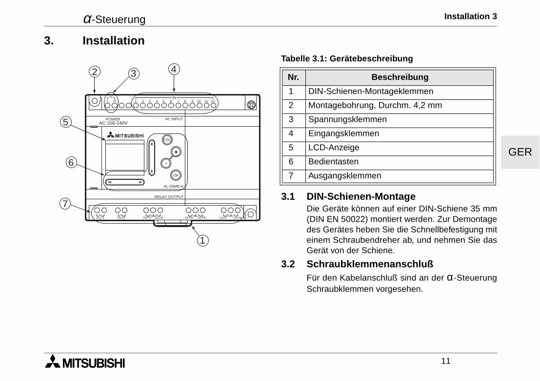
Tabelle 3.1: Gerätebeschreibung
Nr. Beschreibung
1 DIN-Schienen-Montageklemmen
2 Montagebohrung, Durchm. 4,2 mm
3 Spannungsklemmen
4 Eingangsklemmen
5 LCD-Anzeige
6 Bedientasten
7 Ausgangsklemmen
AC 100-240VPOWER AC INPUT
AL-20MR-A
OK
ESC
RELAY OUTPUT
OUT1 OUT2 OUT5OUT3 OUT4 OUT6 OUT8OUT7
1 2 3 4 5 6 7 8 9 10 11 12IN
L N~
432
5
6
7
1
α-Steuerung Installation 3
12
GER
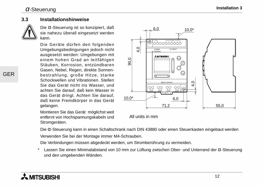
3.3 Installationshinweise
Die α-Steuerung ist so konzipiert, daßsie nahezu überall eingesetzt werdenkann.
Die Gerä te dü r fen den fo lgendenUmgebungsbedingungen jedoch nichtausgesetzt werden: Umgebungen mite inem hohen Grad an le i t fähigenStäuben, Korrosion, entzündbarenGasen, Nebel, Regen, direkte Sonnen-best rah lung, große Hi tze, s tarkeSchockwellen und Vibrationen. StellenSie das Gerät nicht ins Wasser, undachten Sie darauf, daß kein Wasser indas Gerät dringt. Achten Sie darauf,daß keine Fremdkörper in das Gerätgelangen.
Montieren Sie das Gerät möglichst weitentfernt von Hochspannungskabeln undStromgeräten.
Die α-Steuerung kann in einen Schaltschrank nach DIN 43880 oder einen Steuerkasten eingebaut werden
Verwenden Sie bei der Montage immer M4-Schrauben.
Die Verbindungen müssen abgedeckt werden, um Stromberührung zu vermeiden.
* Lassen Sie einen Minimalabstand von 10 mm zur Lüftung zwischen Ober- und Unterrand der α-Steuerungund den umgebenden Wänden.
POWER
IN
OK
+
RELAY OUTPUT
ESC
-
3 421 5L 6N
OUT3 OUT4OUT2OUT1
AC INPUTAC 100/240V
10,0*
10,0*
71,2
6,0
90,0
4,0
55,0
4,0
6,0
All units in mm
α-Steuerung Installation 3
13
GER
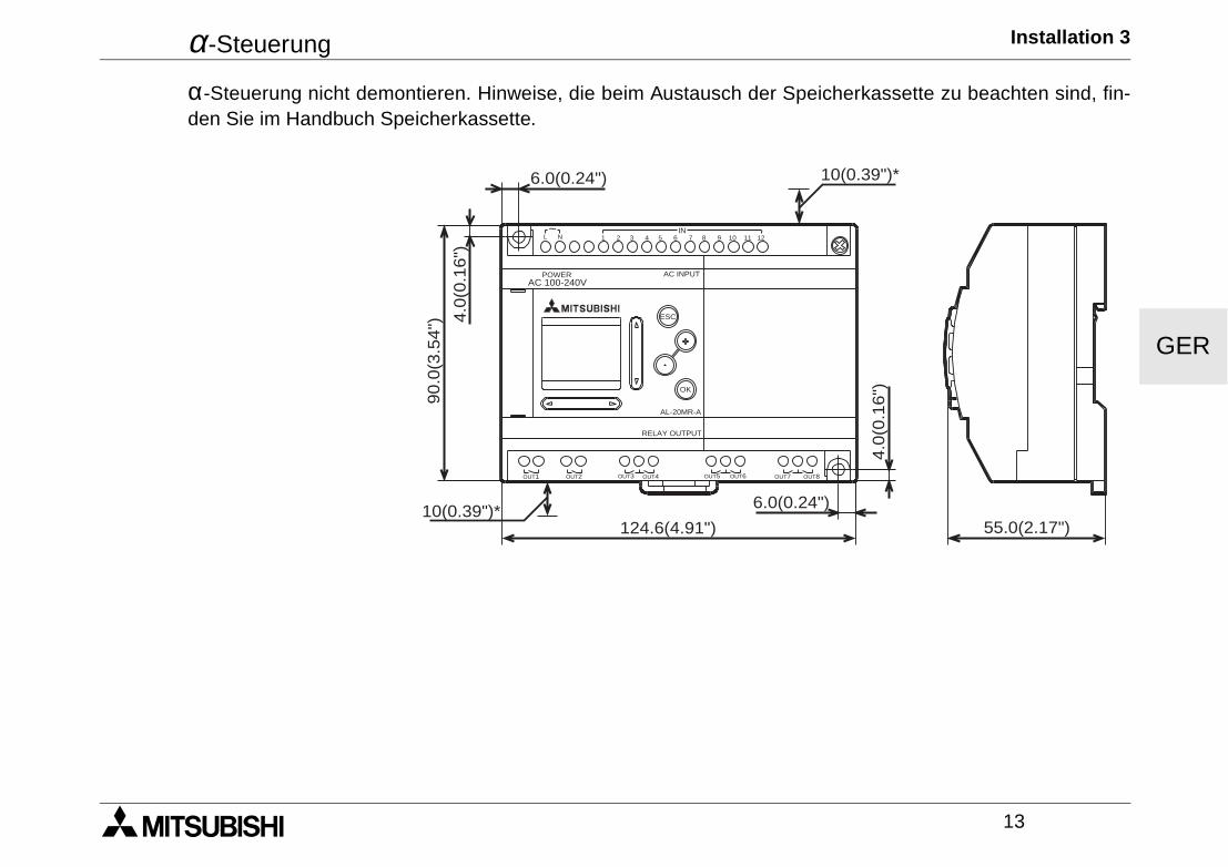
α-Steuerung nicht demontieren. Hinweise, die beim Austausch der Speicherkassette zu beachten sind, fin-den Sie im Handbuch Speicherkassette.
AC 100-240VPOWER AC INPUT
AL-20MR-A
OK
ESC
RELAY OUTPUT
6.0(0.24") 10(0.39")*
55.0(2.17")
6.0(0.24")
124.6(4.91")10(0.39")*
4.0
(0.1
6")90.0
(3.5
4") 4
.0(0
.16")
OUT1 OUT2 OUT5OUT3 OUT4 OUT6 OUT8OUT7
1 2 3 4 5 6 7 8 9 10 11 12IN
L N~

α-Steuerung Installation 3
14
GER
α-Steuerung Verdrahtung 4
15
GER
4. Verdrahtung4.1 Hinweise zur Installationsverdrahtung
Tie Verdrahtung der α-Steuerung ist denkbar einfach. Nur speziell ausgebildetes Personal darf die elek-trische Verdrahtung der Geräte vornehmen. Sollten Sie spezialisierte Unterstützung brauchen, wenden Siesich an eine anerkannt ausgebildete Elektrofachkraft, die mit den lokalen und nationalen Sicherheitsstan-dards der Automatisierungstechnik vertraut ist. Stromversorgung abschalten, bevor Sie mit der Verdrahtungbeginnen.
• Die Ein- und Ausgangskabel dürfen nicht durch das gleiche Multikernkabel oder den gleichen Kabel-baum verlegt werden.
• Die Ein- und Ausgangskabel dürfen nicht in der Nähe von Hochspannungsleitungen verlegt werden.
Berücksichtigen Sie Spannungsabfälle und Störungen, wenn die Eingangs- und Ausgangssignalkabel übergroße Entfernungen geführt werden. Stellen Sie sicher, daß für die Kabel die richtigen Kabelgrößen verwen-det werden.
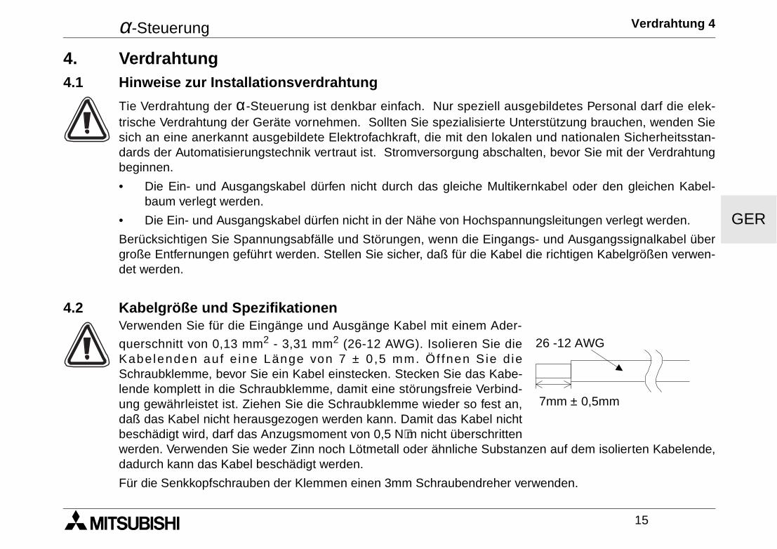
4.2 Kabelgröße und SpezifikationenVerwenden Sie für die Eingänge und Ausgänge Kabel mit einem Ader-
querschnitt von 0,13 mm2 - 3,31 mm2 (26-12 AWG). Isolieren Sie dieKabelenden auf e ine Länge von 7 ± 0 ,5 mm. Ö f fnen S ie d ieSchraubklemme, bevor Sie ein Kabel einstecken. Stecken Sie das Kabe-lende komplett in die Schraubklemme, damit eine störungsfreie Verbind-ung gewährleistet ist. Ziehen Sie die Schraubklemme wieder so fest an,daß das Kabel nicht herausgezogen werden kann. Damit das Kabel nichtbeschädigt wird, darf das Anzugsmoment von 0,5 N⋅m nicht überschrittenwerden. Verwenden Sie weder Zinn noch Lötmetall oder ähnliche Substanzen auf dem isolierten Kabelende,dadurch kann das Kabel beschädigt werden.
Für die Senkkopfschrauben der Klemmen einen 3mm Schraubendreher verwenden.
7mm ± 0,5mm
26 -12 AWG
α-Steuerung Verdrahtung 4
16
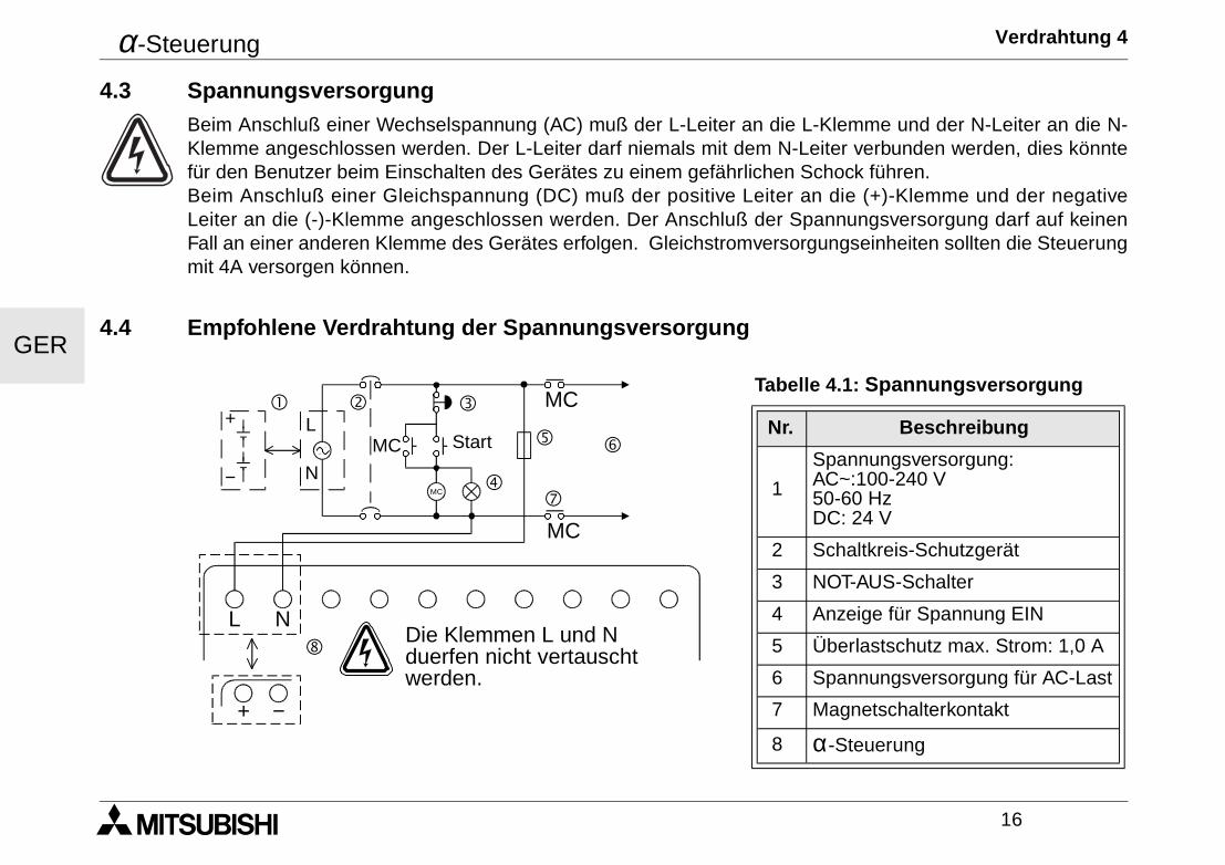
GER
4.3 SpannungsversorgungBeim Anschluß einer Wechselspannung (AC) muß der L-Leiter an die L-Klemme und der N-Leiter an die N-Klemme angeschlossen werden. Der L-Leiter darf niemals mit dem N-Leiter verbunden werden, dies könntefür den Benutzer beim Einschalten des Gerätes zu einem gefährlichen Schock führen.Beim Anschluß einer Gleichspannung (DC) muß der positive Leiter an die (+)-Klemme und der negativeLeiter an die (-)-Klemme angeschlossen werden. Der Anschluß der Spannungsversorgung darf auf keinenFall an einer anderen Klemme des Gerätes erfolgen. Gleichstromversorgungseinheiten sollten die Steuerungmit 4A versorgen können.
4.4 Empfohlene Verdrahtung der Spannungsversorgung
Tabelle 4.1: Spannungsversorgung
Nr. Beschreibung
1
Spannungsversorgung: AC~:100-240 V50-60 HzDC: 24 V
2 Schaltkreis-Schutzgerät
3 NOT-AUS-Schalter
4 Anzeige für Spannung EIN
5 Überlastschutz max. Strom: 1,0 A
6 Spannungsversorgung für AC-Last
7 Magnetschalterkontakt
8 α-Steuerung
MC
MC
MC
MC
L N
! " #
$
% &
'
(
+
−
L
N
+ −
Start
Die Klemmen L und Nduerfen nicht vertauschtwerden.
α-Steuerung Verdrahtung 4
17
GER
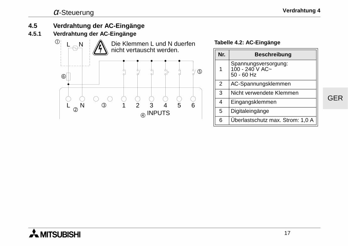
4.5 Verdrahtung der AC-Eingänge4.5.1 Verdrahtung der AC-Eingänge
Tabelle 4.2: AC-Eingänge
Nr. Beschreibung
1Spannungsversorgung:100 - 240 V AC~50 - 60 Hz
2 AC-Spannungsklemmen
3 Nicht verwendete Klemmen
4 Eingangsklemmen
5 Digitaleingänge
6 Überlastschutz max. Strom: 1,0 A
! L N
"#
$
%
L N 1 2 3INPUTS
4 5 6
&
Die Klemmen L und N duerfennicht vertauscht werden.
α-Steuerung Verdrahtung 4
18
GER
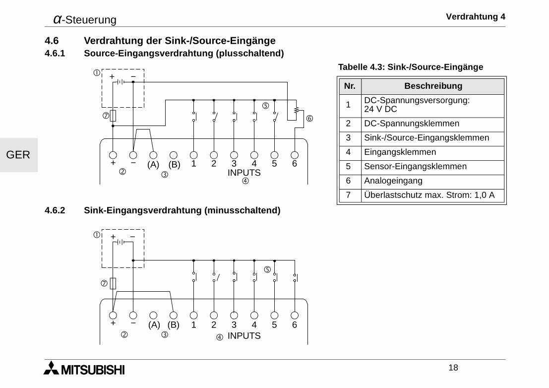
4.6 Verdrahtung der Sink-/Source-Eingänge4.6.1 Source-Eingangsverdrahtung (plusschaltend)
4.6.2 Sink-Eingangsverdrahtung (minusschaltend)
Tabelle 4.3: Sink-/Source-Eingänge
Nr. Beschreibung
1 DC-Spannungsversorgung: 24 V DC
2 DC-Spannungsklemmen
3 Sink-/Source-Eingangsklemmen
4 Eingangsklemmen
5 Sensor-Eingangsklemmen
6 Analogeingang
7 Überlastschutz max. Strom: 1,0 A
! + −
"$
%
&
+ − (A) (B) 1 2 3INPUTS
4 5 6
(
#
! + −
" # $
%
+ − (A) (B) 1 2 3INPUTS
4 5 6
(
α-Steuerung Verdrahtung 4
19
GER
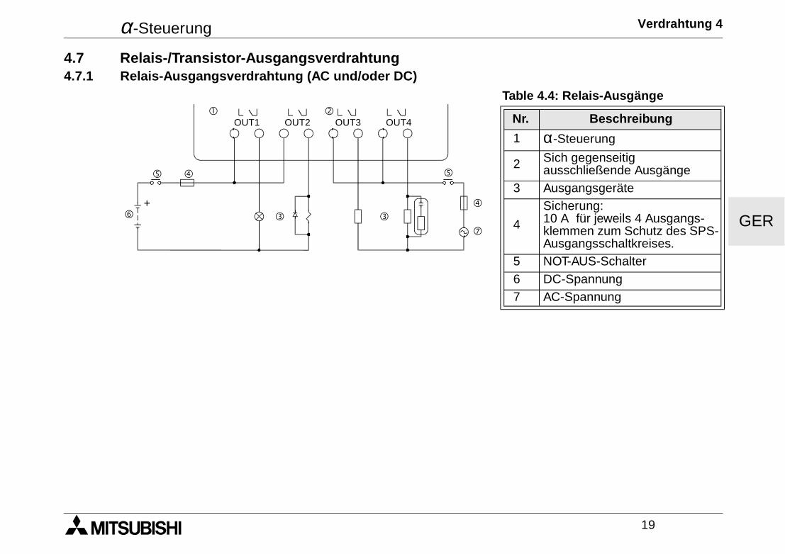
4.7 Relais-/Transistor-Ausgangsverdrahtung4.7.1 Relais-Ausgangsverdrahtung (AC und/oder DC)
Table 4.4: Relais-Ausgänge
Nr. Beschreibung
1 α-Steuerung
2 Sich gegenseitig ausschließende Ausgänge
3 Ausgangsgeräte
4
Sicherung: 10 A für jeweils 4 Ausgangs-klemmen zum Schutz des SPS-Ausgangsschaltkreises.
5 NOT-AUS-Schalter 6 DC-Spannung 7 AC-Spannung
"!
$
OUT1
##
%
&
OUT2 OUT3 OUT4
(
$
%
+
α-Steuerung Verdrahtung 4
20
GER
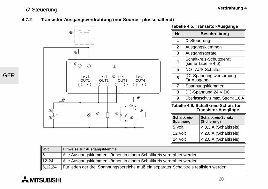
4.7.2 Transistor-Ausgangsverdrahtung (nur Source - plusschaltend)Tabelle 4.5: Transistor-Ausgänge
Nr. Beschreibung
1 α-Steuerung
2 Ausgangsklemmen3 Ausgangsgeräte
4 Schaltkreis-Schutzgerät(siehe Tabelle 4.6)
5 NOT-AUS-Schalter
6 DC-Spannungsversorgungfür Ausgänge
7 Spannungsklemmen8 DC-Spannung 24 V DC9 Überlastschutz max. Strom: 1,0 A
Tabelle 4.6: Schaltkreis-Schutz für Transistor-Ausgänge
Schaltkreis-Spannung
Schaltkreis-Schutz(Sicherung)
5 Volt < 0,3 A (Schaltkreis)12 Volt < 2,0 A (Schaltkreis)24 Volt < 2,0 A (Schaltkreis)
Volt Hinweise zur Ausgangsklemme
5 Alle Ausgangsklemmen können in einem Schaltkreis verdrahtet werden.12-24 Alle Ausgangsklemmen können in einem Schaltkreis verdrahtet werden.5,12,24 Für jeden der drei Spannungsbereiche muß ein separater Schaltkreis realisiert werden.
"
!
OUT1
##
OUT2 OUT3 OUT4
$
%
&
+ −
+ −(
$
%
&+
+
#
)
'
α-Steuerung Klemmenbelegungen 5
21
GER
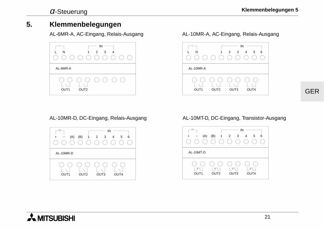
5. KlemmenbelegungenAL-6MR-A, AC-Eingang, Relais-Ausgang AL-10MR-A, AC-Eingang, Relais-Ausgang
AL-10MR-D, DC-Eingang, Relais-Ausgang AL-10MT-D, DC-Eingang, Transistor-Ausgang
L N 1 2 3 4
OUT1
AL-6MR-A
OUT2
IN
L N 1 2 3 4
OUT1
AL-10MR-A
OUT2
IN
5 6
OUT3 OUT4
+ − (A) (B) 1 2 3 4
OUT1
AL-10MR-D
OUT2
IN
5 6
OUT3 OUT4
+ − (B) 1 2 3 4
OUT1
AL-10MT-D
OUT2
IN
5 6
OUT3 OUT4
(A)
α-Steuerung Klemmenbelegungen 5
22
GER
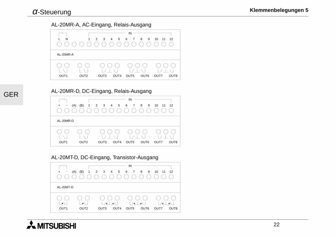
AL-20MR-A, AC-Eingang, Relais-Ausgang
AL-20MR-D, DC-Eingang, Relais-Ausgang
AL-20MT-D, DC-Eingang, Transistor-Ausgang
L N
IN
12111 2 3 4 5 6 7 8 9 10
OUT1 OUT2 OUT3 OUT5 OUT7OUT4 OUT6 OUT8
AL-20MR-A
+ -
IN
12111 2 3 4 5 6 7 8 9 10
OUT1 OUT2 OUT3 OUT5 OUT7OUT4 OUT6 OUT8
AL-20MR-D
(A) (B)
+ -
IN
12111 2 3 4 5 6 7 8 9 10
OUT1 OUT2 OUT3 OUT5 OUT7OUT4 OUT6 OUT8
AL-20MT-D
(A) (B)
α-Steuerung Einstieg in die Programmierung 6
23
GER
6. Einstieg in die ProgrammierungDie α-Steuerung arbeitet mit der Funktionsblock-Programmierung. In dieser Art der Programmierung werdenFunktionsblöcke miteinander verbunden und bilden dadurch ein Programm. Sie haben die Auswahl zwischenfünf Funktionsblöcken: Systemeingänge, Funktionstasten der Modulvorderseite, Systemspeicher-Bits, Funk-tionsblöcke und Systemausgänge.
Beim Einschalten der CPU erscheint ein Eröffnungsbildschirm, in dem Datum, Uhrzeit und Statustabelle (Ein-gangs- und Ausgangsstatus) angezeigt werden. Betätigen Sie eine beliebige Taste, um in das Hauptmenü zugelangen. Starten Sie den Programmeditier-Modus durch Betätigung der OK-Taste, um mit der Program-mierung zu beginnen.
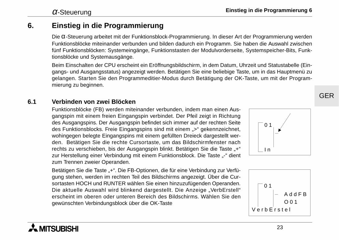
6.1 Verbinden von zwei BlöckenFunktionsblöcke (FB) werden miteinander verbunden, indem man einen Aus-gangspin mit einem freien Eingangspin verbindet. Der Pfeil zeigt in Richtungdes Ausgangspins. Der Ausgangspin befindet sich immer auf der rechten Seitedes Funktionsblocks. Freie Eingangspins sind mit einem „>“ gekennzeichnet,wohingegen belegte Eingangspins mit einem gefüllten Dreieck dargestellt wer-den. Betätigen Sie die rechte Cursortaste, um das Bildschirmfenster nachrechts zu verschieben, bis der Ausgangspin blinkt. Betätigen Sie die Taste „+“zur Herstellung einer Verbindung mit einem Funktionsblock. Die Taste „-“ dientzum Trennen zweier Operanden.
Betätigen Sie die Taste „+“. Die FB-Optionen, die für eine Verbindung zur Verfü-gung stehen, werden im rechten Teil des Bildschirms angezeigt. Über die Cur-sortasten HOCH und RUNTER wählen Sie einen hinzuzufügenden Operanden.Die aktuelle Auswahl wird blinkend dargestellt. Die Anzeige „VerbErstell“erscheint im oberen oder unteren Bereich des Bildschirms. Wählen Sie dengewünschten Verbindungsblock über die OK-Taste
0 1
I n
0 1
A d d F BO 0 1
V e r b E r s t e l
α-Steuerung Einstieg in die Programmierung 6
24
GER
Eingänge, Tasten, Speicher-Bits, Funktionsblöcke und Ausgänge zeigenautomatisch an, ob Sie verbunden werden können. Funktionsblöcke müssenwährend der Programmierung hinzugefügt werden.
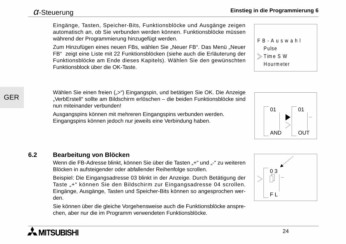
Zum Hinzufügen eines neuen FBs, wählen Sie „Neuer FB“. Das Menü „NeuerFB“ zeigt eine Liste mit 22 Funktionsblöcken (siehe auch die Erläuterung derFunktionsblöcke am Ende dieses Kapitels). Wählen Sie den gewünschtenFunktionsblock über die OK-Taste.
Wählen Sie einen freien („>“) Eingangspin, und betätigen Sie OK. Die Anzeige„VerbErstell“ sollte am Bildschirm erlöschen – die beiden Funktionsblöcke sindnun miteinander verbunden!
Ausgangspins können mit mehreren Eingangspins verbunden werden. Eingangspins können jedoch nur jeweils eine Verbindung haben.
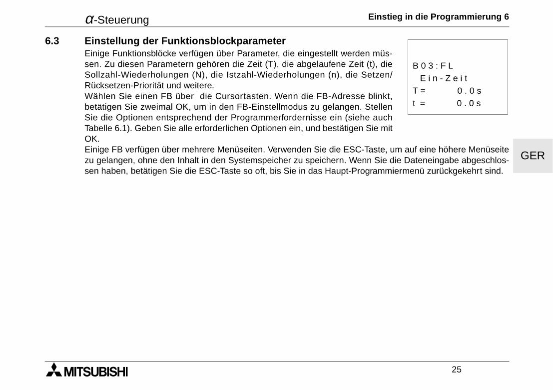
6.2 Bearbeitung von Blöcken Wenn die FB-Adresse blinkt, können Sie über die Tasten „+“ und „-“ zu weiterenBlöcken in aufsteigender oder abfallender Reihenfolge scrollen.
Beispiel: Die Eingangsadresse 03 blinkt in der Anzeige. Durch Betätigung derTaste „+“ können Sie den Bildschirm zur Eingangsadresse 04 scrollen.Eingänge, Ausgänge, Tasten und Speicher-Bits können so angesprochen wer-den.
Sie können über die gleiche Vorgehensweise auch die Funktionsblöcke anspre-chen, aber nur die im Programm verwendeten Funktionsblöcke.
H ourm eter
PulseF B - A u s w a h l
T im e S W
AND
01 01
OUT
0 3
F L
α-Steuerung Einstieg in die Programmierung 6
25
GER
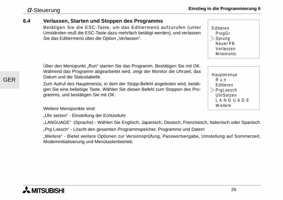
6.3 Einstellung der FunktionsblockparameterEinige Funktionsblöcke verfügen über Parameter, die eingestellt werden müs-sen. Zu diesen Parametern gehören die Zeit (T), die abgelaufene Zeit (t), dieSollzahl-Wiederholungen (N), die Istzahl-Wiederholungen (n), die Setzen/Rücksetzen-Priorität und weitere. Wählen Sie einen FB über die Cursortasten. Wenn die FB-Adresse blinkt,betätigen Sie zweimal OK, um in den FB-Einstellmodus zu gelangen. StellenSie die Optionen entsprechend der Programmerfordernisse ein (siehe auchTabelle 6.1). Geben Sie alle erforderlichen Optionen ein, und bestätigen Sie mitOK. Einige FB verfügen über mehrere Menüseiten. Verwenden Sie die ESC-Taste, um auf eine höhere Menüseitezu gelangen, ohne den Inhalt in den Systemspeicher zu speichern. Wenn Sie die Dateneingabe abgeschlos-sen haben, betätigen Sie die ESC-Taste so oft, bis Sie in das Haupt-Programmiermenü zurückgekehrt sind.
t = 0 . 0 s
E i n - Z e i tB 0 3 : F L
T = 0 . 0 s
α-Steuerung Einstieg in die Programmierung 6
26
GER
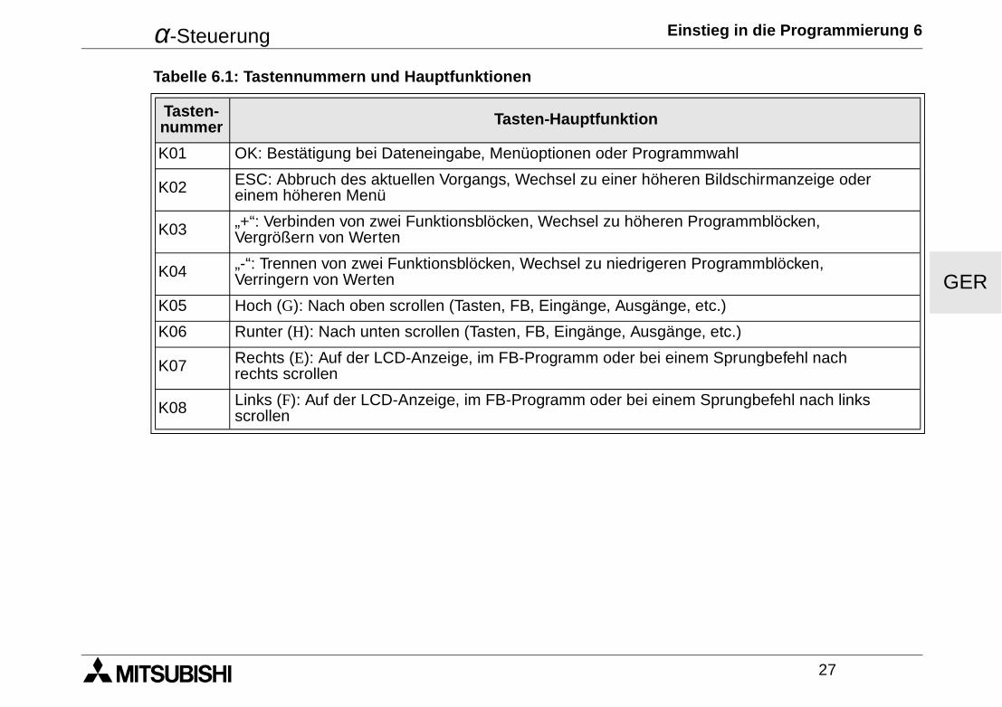
6.4 Verlassen, Starten und Stoppen des ProgrammsBetät igen Sie die ESC-Taste, um das Editiermenü aufzurufen (unterUmständen muß die ESC-Taste dazu mehrfach betätigt werden), und verlassenSie das Editiermenü über die Option „Verlassen“.
Über den Menüpunkt „Run“ starten Sie das Programm. Bestätigen Sie mit OK.Während das Programm abgearbeitet wird, zeigt der Monitor die Uhrzeit, dasDatum und die Statustabelle.
Zum Aufruf des Hauptmenüs, in dem der Stopp-Befehl angeboten wird, betäti-gen Sie eine beliebige Taste. Wählen Sie diesen Befehl zum Stoppen des Pro-gramms, und bestätigen Sie mit OK.
Weitere Menüpunkte sind:
„Uhr setzen“ - Einstellung der Echtzeituhr
„LANGUAGE“ (Sprache) - Wählen Sie Englisch, Japanisch, Deutsch, Französisch, Italienisch oder Spanisch
„Prg Loesch“ - Löscht den gesamten Programmspeicher, Programme und Daten!
„Weitere“ - Bietet weitere Optionen zur Versionsprüfung, Passwortvergabe, Umstellung auf Sommerzeit,Modeminitialisierung und Menütastenbetrieb.
Editie ren
Verlassen
ProgG r.SprungN euer FB
M nem onic
H auptm enue
U hrS etzen
R u nEditie renPrgLoesch
W eite reL A N G U A G E
α-Steuerung Einstieg in die Programmierung 6
27
GER
Tabelle 6.1: Tastennummern und Hauptfunktionen
Tasten-nummer Tasten-Hauptfunktion
K01 OK: Bestätigung bei Dateneingabe, Menüoptionen oder Programmwahl
K02 ESC: Abbruch des aktuellen Vorgangs, Wechsel zu einer höheren Bildschirmanzeige oder einem höheren Menü
K03 „+“: Verbinden von zwei Funktionsblöcken, Wechsel zu höheren Programmblöcken, Vergrößern von Werten
K04 „-“: Trennen von zwei Funktionsblöcken, Wechsel zu niedrigeren Programmblöcken, Verringern von Werten
K05 Hoch (G): Nach oben scrollen (Tasten, FB, Eingänge, Ausgänge, etc.)
K06 Runter (H): Nach unten scrollen (Tasten, FB, Eingänge, Ausgänge, etc.)
K07 Rechts (E): Auf der LCD-Anzeige, im FB-Programm oder bei einem Sprungbefehl nach rechts scrollen
K08 Links (F): Auf der LCD-Anzeige, im FB-Programm oder bei einem Sprungbefehl nach links scrollen
α-Steuerung Einstieg in die Programmierung 6
28
GER
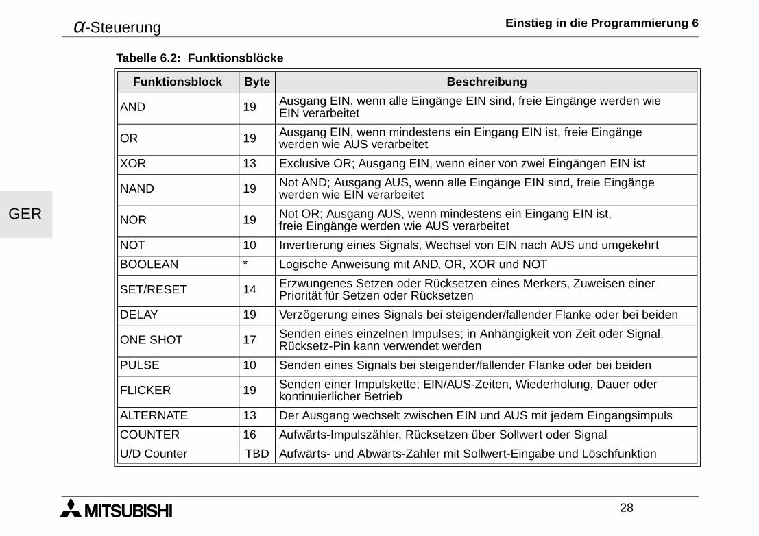
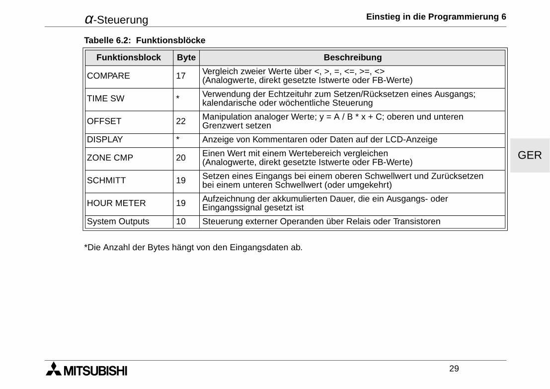
Tabelle 6.2: Funktionsblöcke
Funktionsblock Byte Beschreibung
AND 19 Ausgang EIN, wenn alle Eingänge EIN sind, freie Eingänge werden wie EIN verarbeitet
OR 19 Ausgang EIN, wenn mindestens ein Eingang EIN ist, freie Eingänge werden wie AUS verarbeitet
XOR 13 Exclusive OR; Ausgang EIN, wenn einer von zwei Eingängen EIN ist
NAND 19 Not AND; Ausgang AUS, wenn alle Eingänge EIN sind, freie Eingänge werden wie EIN verarbeitet
NOR 19 Not OR; Ausgang AUS, wenn mindestens ein Eingang EIN ist, freie Eingänge werden wie AUS verarbeitet
NOT 10 Invertierung eines Signals, Wechsel von EIN nach AUS und umgekehrt
BOOLEAN * Logische Anweisung mit AND, OR, XOR und NOT
SET/RESET 14 Erzwungenes Setzen oder Rücksetzen eines Merkers, Zuweisen einer Priorität für Setzen oder Rücksetzen
DELAY 19 Verzögerung eines Signals bei steigender/fallender Flanke oder bei beiden
ONE SHOT 17 Senden eines einzelnen Impulses; in Anhängigkeit von Zeit oder Signal, Rücksetz-Pin kann verwendet werden
PULSE 10 Senden eines Signals bei steigender/fallender Flanke oder bei beiden
FLICKER 19 Senden einer Impulskette; EIN/AUS-Zeiten, Wiederholung, Dauer oder kontinuierlicher Betrieb
ALTERNATE 13 Der Ausgang wechselt zwischen EIN und AUS mit jedem Eingangsimpuls
COUNTER 16 Aufwärts-Impulszähler, Rücksetzen über Sollwert oder Signal
U/D Counter TBD Aufwärts- und Abwärts-Zähler mit Sollwert-Eingabe und Löschfunktion
α-Steuerung Einstieg in die Programmierung 6
29
GER
*Die Anzahl der Bytes hängt von den Eingangsdaten ab.
COMPARE 17 Vergleich zweier Werte über <, >, =, <=, >=, <> (Analogwerte, direkt gesetzte Istwerte oder FB-Werte)
TIME SW * Verwendung der Echtzeituhr zum Setzen/Rücksetzen eines Ausgangs; kalendarische oder wöchentliche Steuerung
OFFSET 22 Manipulation analoger Werte; y = A / B * x + C; oberen und unteren Grenzwert setzen
DISPLAY * Anzeige von Kommentaren oder Daten auf der LCD-Anzeige
ZONE CMP 20 Einen Wert mit einem Wertebereich vergleichen (Analogwerte, direkt gesetzte Istwerte oder FB-Werte)
SCHMITT 19 Setzen eines Eingangs bei einem oberen Schwellwert und Zurücksetzen bei einem unteren Schwellwert (oder umgekehrt)
HOUR METER 19 Aufzeichnung der akkumulierten Dauer, die ein Ausgangs- oder Eingangssignal gesetzt ist
System Outputs 10 Steuerung externer Operanden über Relais oder Transistoren
Tabelle 6.2: Funktionsblöcke
Funktionsblock Byte Beschreibung
α-Steuerung Einstieg in die Programmierung 6
30
GER
FRE
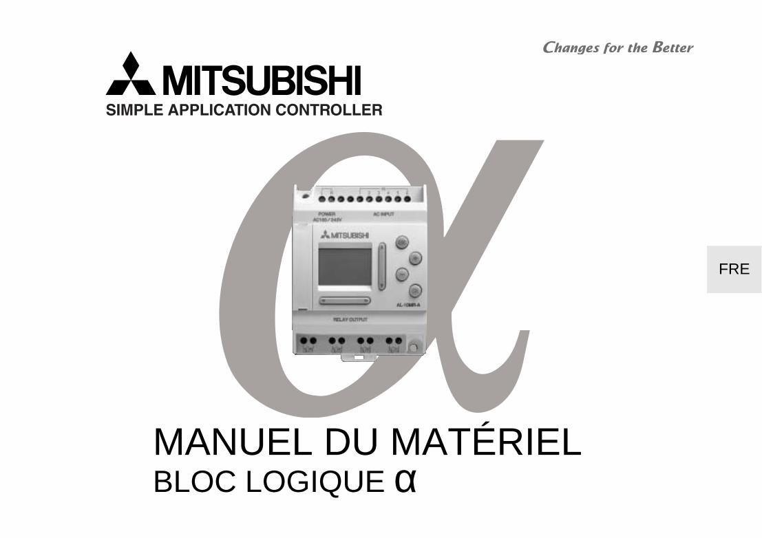
MANUEL DU MATÉRIELBLOC LOGIQUE α
Bloc logique α
FRE
Préface• Le présent manual contient des textes, des illustrations et des applications pour une installation et une
utilisation correctes du bloc logique α. L’utilisateur doit le lire et avoir compris son contenu avant d’installer ou d’utliliser l’appareil.
• Si lors de l’installation des incertitudes persistent, n’hesitez pas à consulter un électricien compétent, qualifié et formé à l’utilisation des normes électriques locales et nationales. Contactez le représentant leplus proche de MITSUBISHI ELECTRIC si la manipulation ou l’utilisation des blocs logiques α vous pose des problèmes.
• Le présent manual est publié sous réserve de modifications. Ces modifications peuvent être apportées sans avis préalable.
Bloc logique α
FRE
i
Bloc logique αααα
Manuel du matérielNo. du manuel : JY992D74201Indice : JDate : 04/2002
Bloc logique α
FRE
ii
Directives de sécurité pour l’utilisateur et mesures de protection pour le bloc logique ααααCe manuel a été conçu pour un personnel formé et qualifié. La qualification est définie par les directiveseuropéennes pour machines, basses tensions et CEM. Seul un électricien compétent, qualifié et formé à l’utilisationdes normes électriques locales et nationales doit effectuer les travaux de câblage du bloc logique α. Ce manuel uti-lise différents symboles pour la mise en évidence de certaines informations. Ceci permet de transmettre aux opéra-teurs toutes les remarques nécessaires aux mesures de sécurité et de protection. En présence de l’un de cessymboles, la remarque correspondante doit être lue et l’information transmise doit être comprise.
1) Désigne un danger imminent susceptible d’entraîner un dommage corporel ou matériel.
2) Désigne un danger éventuel susceptible d’entraîner un dommage corporel ou matériel.
• MITSUBISHI ELECTRIC décline toute responsabilité pour les dommages imputables à une installation ou à une utilisation incor-recte des appareils ou des accessoires.
• Tous les exemples et illustrations du présent manuel constituent une simple aide à la compréhension du texte. Nous déclinonstoute responsabilité pour l’exactitude des opérations de commande représentées. MITSUBISHI ELECTRIC décline toute respon-sabilité pour une utilisation du produit se réclamant des exemples présentés.
• En raison du nombre important de possibilités d’utilisation diverses de cet appareil, il incombe au client d’adapter celui-ci à soncas d’application particulier.
• Prévoir des dispositifs de sécurité pour déconnecter les périphériques si le bloc logique α ne fonctionne plus.
• En aucun cas n’essayez de réparer le bloc logique α ou d’en remplacer des pièces détachées.
• Installez le bloc logique α conformément aux normes locales et nationales.
Bloc logique α
iii
Sommaire
Directives de sécurité................................................................................................................ ii
1. Introduction............................................................................................................ 1
2. Caractéristiques .................................................................................................... 32.1 Modèles Disponibles.................................................................................................... 32.2 Alimentation ................................................................................................................. 42.3 Entrées......................................................................................................................... 62.4 Sorties.......................................................................................................................... 82.5 Caractéristiques Générales ......................................................................................... 9
3. Installation............................................................................................................ 113.1 Montage sur rail DIN .................................................................................................. 113.2 Bornes à vis ............................................................................................................... 113.3 Conseils pour l'installation.......................................................................................... 12
FRE
Bloc logique α
iv
4. Câblage................................................................................................................. 154.1 Remarques sur le câblage de l’installation ................................................................ 154.2 Format et caractéristiques techniques des fils........................................................... 154.3 Alimentation ............................................................................................................... 164.4 Câblage de l’alimentation recommandé..................................................................... 164.5 Câblage des entrées CA............................................................................................ 17
4.5.1 Entrées CA .......................................................................................................... 174.6 Câblage des entrées Sink/Source ............................................................................. 18
4.6.1 Entrées Source (+) .............................................................................................. 184.6.2 Entrées Sink (-).................................................................................................... 18
4.7 Câblage des sorties relais et transistors .................................................................... 194.7.1 Sorties relais (CA et/ou CC) ................................................................................ 194.7.2 Sorties transistor (source ou “+” Common seulement)........................................ 20
5. Occupation des bornes....................................................................................... 21
6. Mise en route ....................................................................................................... 236.1 Connexion de deux blocs........................................................................................... 236.2 Accès aux blocs ........................................................................................................ 246.3 Définition des paramètres des blocs fonctions .......................................................... 256.4 Quitter, exécuter et interrompre le programme.......................................................... 26
FRE
Bloc logique α Introduction 1
1
FRE
1. IntroductionSimple et convivial, le bloc logique α a été conçu pour être utilisé dans le domaine domestique, les bâtiments,les locaux industriels, partout en quelque sorte. Il offre une fonction de contrôle et de supervision très flexible.Chaque module permet de lire des signaux et de définir des sorties selon les conditions particulières ou deslurées définies par l'utilisateur. L'affichage intégré programmable permet de consulter à tout moment l'état dusystème.
Les particularités du bloc logique α :
• Programmation directe (sur l'appareil)
• Pouvoir de coupure des sorties élevé
• Faible encombrement
• Port de programmation facile d'accès
• Cassette EEPROM pour stocker un programme
• Horloge temps réel intégrée
• Logiciel de programmation sous Windows, AL-PCS/Win-E
• Documentation de mise en oeuvre et de formation complète
Le bloc logique α est conçu pour contrôler les automatismes suivants: éclairage, climatisation, irrigation,portes, portails, systèmes de sécurité simples, serres, ventilateurs, etc. L'horloge temps réel peut être utiliséecomme dispositif d'économie d'énergie, permettant d'allumer et d'éteindre automatiquement les appareilsselon un horaire prédéfini.
Déboguer minutieusement les programmes avant l’installation dans l’équipement automatisé. La série α n’est pasconçue pour être utilisée dans des applications opérationnelles critiques ou à sécurité relative.
Contactez votre fournisseur pour obtenir de plus amples informations.
Bloc logique α Introduction 1
2
FRE
Bloc logique α Caractéristiques 2
3
FRE
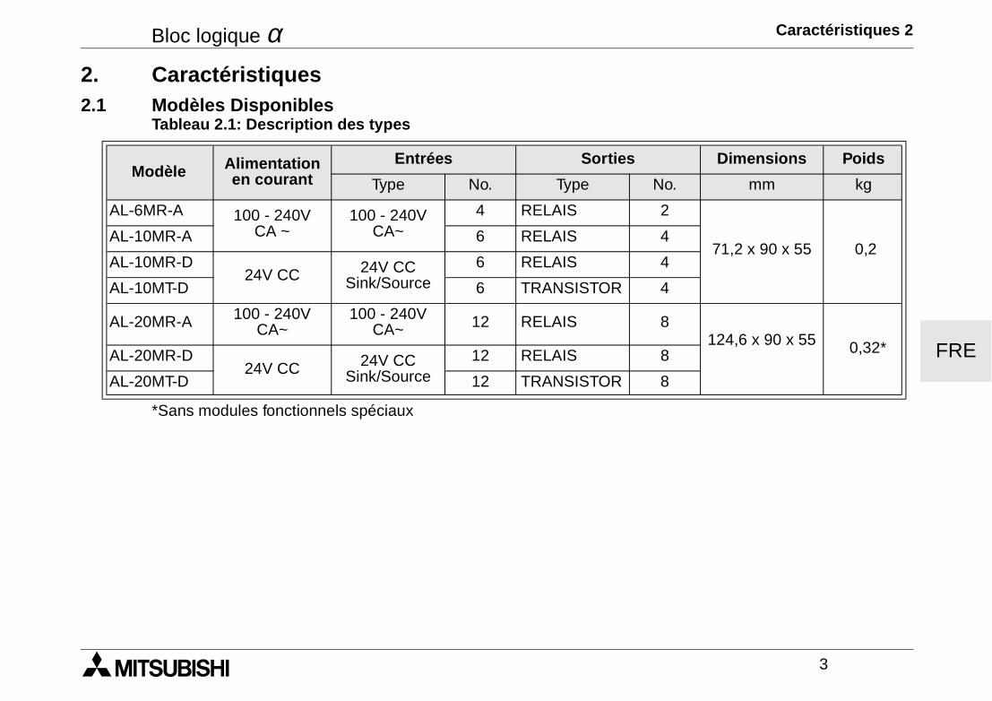
2. Caractéristiques2.1 Modèles Disponibles
*Sans modules fonctionnels spéciaux
Tableau 2.1: Description des types
Modèle Alimentation en courant
Entrées Sorties Dimensions Poids
Type No. Type No. mm kg
AL-6MR-A 100 - 240V CA ~
100 - 240V CA~
4 RELAIS 2
71,2 x 90 x 55 0,2AL-10MR-A 6 RELAIS 4
AL-10MR-D24V CC 24V CC
Sink/Source6 RELAIS 4
AL-10MT-D 6 TRANSISTOR 4
AL-20MR-A 100 - 240V CA~
100 - 240V CA~ 12 RELAIS 8
124,6 x 90 x 55 0,32*AL-20MR-D24V CC 24V CC
Sink/Source12 RELAIS 8
AL-20MT-D 12 TRANSISTOR 8
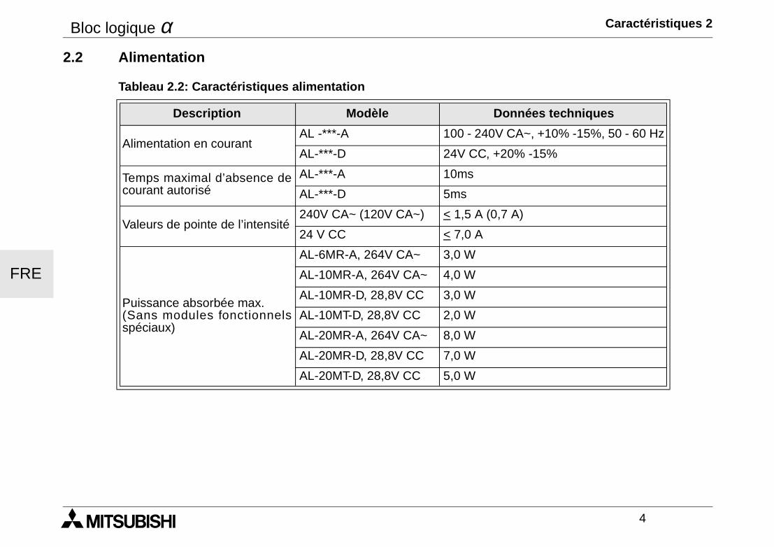
Bloc logique α Caractéristiques 2
4
FRE
2.2 Alimentation
Tableau 2.2: Caractéristiques alimentation
Description Modèle Données techniques
Alimentation en courantAL -***-A 100 - 240V CA~, +10% -15%, 50 - 60 Hz
AL-***-D 24V CC, +20% -15%
Temps maximal d’absence decourant autorisé
AL-***-A 10ms
AL-***-D 5ms
Valeurs de pointe de l’intensité240V CA~ (120V CA~) < 1,5 A (0,7 A)
24 V CC < 7,0 A
Puissance absorbée max.(Sans modules fonctionnelsspéciaux)
AL-6MR-A, 264V CA~ 3,0 W
AL-10MR-A, 264V CA~ 4,0 W
AL-10MR-D, 28,8V CC 3,0 W
AL-10MT-D, 28,8V CC 2,0 W
AL-20MR-A, 264V CA~ 8,0 W
AL-20MR-D, 28,8V CC 7,0 W
AL-20MT-D, 28,8V CC 5,0 W
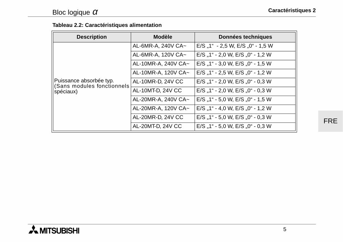
Bloc logique α Caractéristiques 2
5
FRE
Puissance absorbée typ.(Sans modules fonctionnelsspéciaux)
AL-6MR-A, 240V CA~ E/S „1“ - 2,5 W, E/S „0“ - 1,5 W
AL-6MR-A, 120V CA~ E/S „1“ - 2,0 W, E/S „0“ - 1,2 W
AL-10MR-A, 240V CA~ E/S „1“ - 3,0 W, E/S „0“ - 1,5 W
AL-10MR-A, 120V CA~ E/S „1“ - 2,5 W, E/S „0“ - 1,2 W
AL-10MR-D, 24V CC E/S „1“ - 2,0 W, E/S „0“ - 0,3 W
AL-10MT-D, 24V CC E/S „1“ - 2,0 W, E/S „0“ - 0,3 W
AL-20MR-A, 240V CA~ E/S „1“ - 5,0 W, E/S „0“ - 1,5 W
AL-20MR-A, 120V CA~ E/S „1“ - 4,0 W, E/S „0“ - 1,2 W
AL-20MR-D, 24V CC E/S „1“ - 5,0 W, E/S „0“ - 0,3 W
AL-20MT-D, 24V CC E/S „1“ - 5,0 W, E/S „0“ - 0,3 W
Tableau 2.2: Caractéristiques alimentation
Description Modèle Données techniques
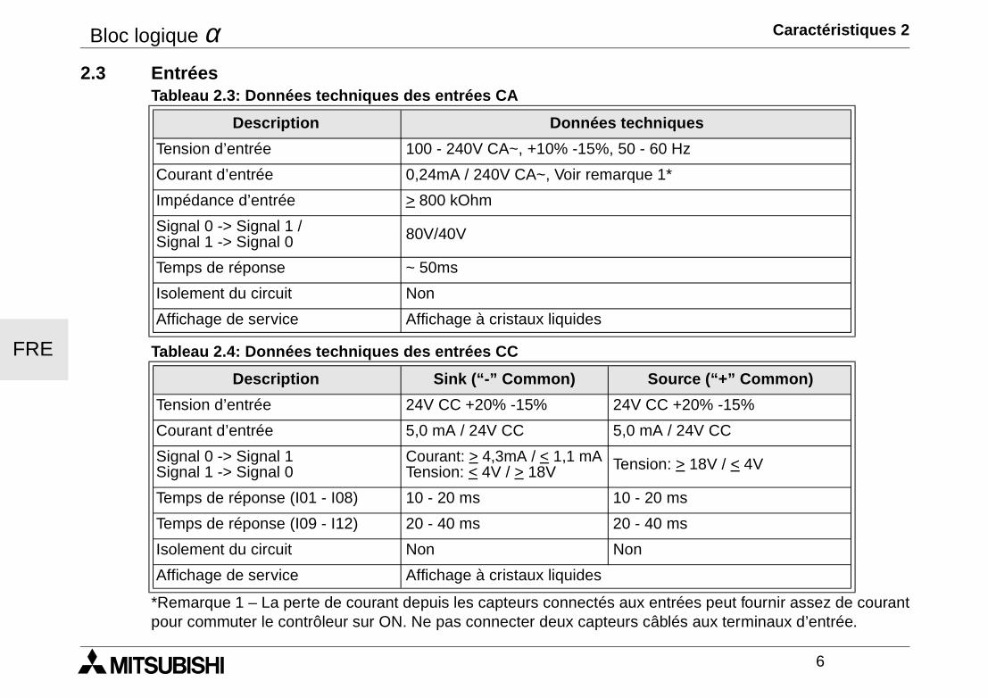
Bloc logique α Caractéristiques 2
6
FRE
2.3 Entrées
*Remarque 1 – La perte de courant depuis les capteurs connectés aux entrées peut fournir assez de courantpour commuter le contrôleur sur ON. Ne pas connecter deux capteurs câblés aux terminaux d’entrée.
Tableau 2.3: Données techniques des entrées CA
Description Données techniques
Tension d’entrée 100 - 240V CA~, +10% -15%, 50 - 60 Hz
Courant d’entrée 0,24mA / 240V CA~, Voir remarque 1*
Impédance d’entrée > 800 kOhm
Signal 0 -> Signal 1 / Signal 1 -> Signal 0 80V/40V
Temps de réponse ~ 50ms
Isolement du circuit Non
Affichage de service Affichage à cristaux liquides
Tableau 2.4: Données techniques des entrées CC
Description Sink (“-” Common) Source (“+” Common)
Tension d’entrée 24V CC +20% -15% 24V CC +20% -15%
Courant d’entrée 5,0 mA / 24V CC 5,0 mA / 24V CC
Signal 0 -> Signal 1Signal 1 -> Signal 0
Courant: > 4,3mA / < 1,1 mATension: < 4V / > 18V Tension: > 18V / < 4V
Temps de réponse (I01 - I08) 10 - 20 ms 10 - 20 ms
Temps de réponse (I09 - I12) 20 - 40 ms 20 - 40 ms
Isolement du circuit Non Non
Affichage de service Affichage à cristaux liquides
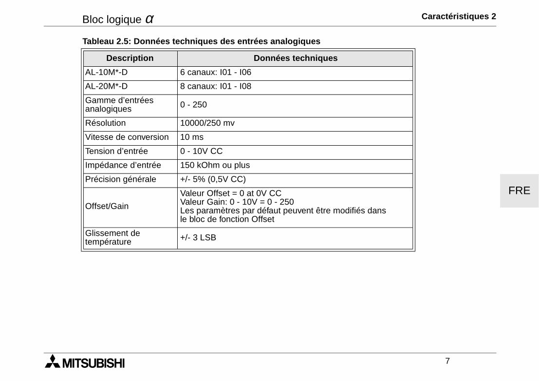
Bloc logique α Caractéristiques 2
7
FRE
Tableau 2.5: Données techniques des entrées analogiques
Description Données techniques
AL-10M*-D 6 canaux: I01 - I06
AL-20M*-D 8 canaux: I01 - I08
Gamme d’entréesanalogiques 0 - 250
Résolution 10000/250 mv
Vitesse de conversion 10 ms
Tension d’entrée 0 - 10V CC
Impédance d’entrée 150 kOhm ou plus
Précision générale +/- 5% (0,5V CC)
Offset/Gain
Valeur Offset = 0 at 0V CCValeur Gain: 0 - 10V = 0 - 250Les paramètres par défaut peuvent être modifiés dans le bloc de fonction Offset
Glissement detempérature +/- 3 LSB
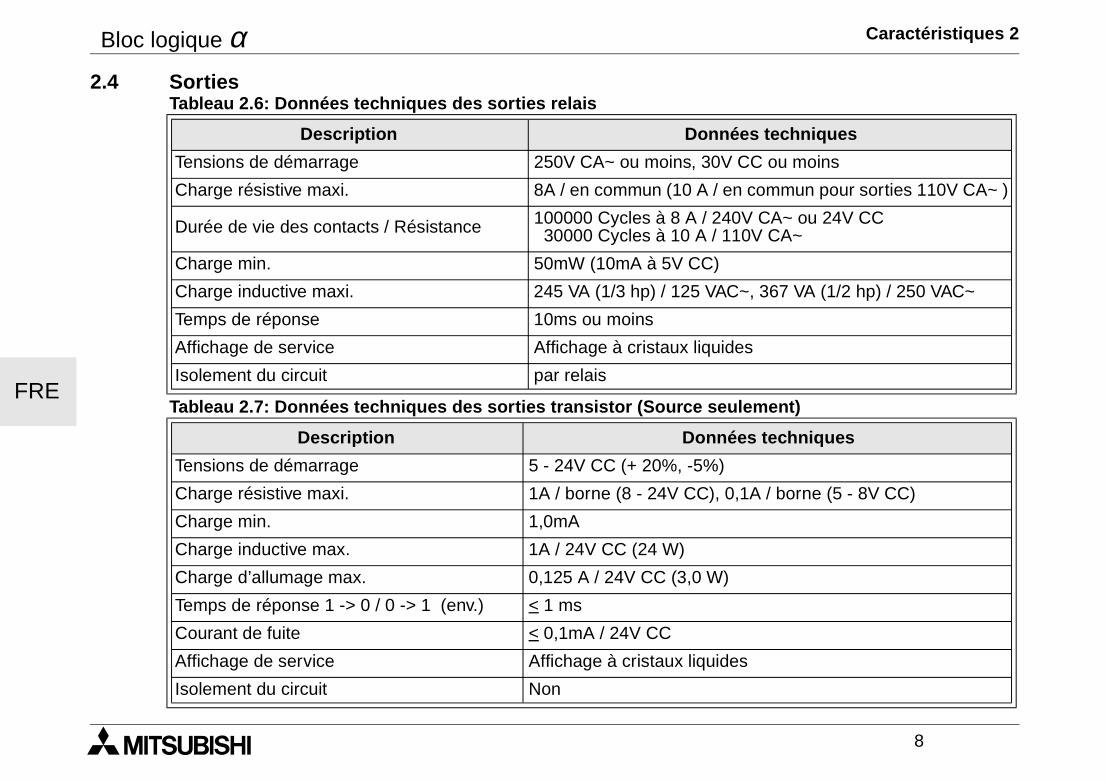
Bloc logique α Caractéristiques 2
8
FRE
2.4 Sorties
Tableau 2.6: Données techniques des sorties relais
Description Données techniques
Tensions de démarrage 250V CA~ ou moins, 30V CC ou moins
Charge résistive maxi. 8A / en commun (10 A / en commun pour sorties 110V CA~ )
Durée de vie des contacts / Résistance 100000 Cycles à 8 A / 240V CA~ ou 24V CC 30000 Cycles à 10 A / 110V CA~
Charge min. 50mW (10mA à 5V CC)
Charge inductive maxi. 245 VA (1/3 hp) / 125 VAC~, 367 VA (1/2 hp) / 250 VAC~
Temps de réponse 10ms ou moins
Affichage de service Affichage à cristaux liquides
Isolement du circuit par relais
Tableau 2.7: Données techniques des sorties transistor (Source seulement)
Description Données techniques
Tensions de démarrage 5 - 24V CC (+ 20%, -5%)
Charge résistive maxi. 1A / borne (8 - 24V CC), 0,1A / borne (5 - 8V CC)
Charge min. 1,0mA
Charge inductive max. 1A / 24V CC (24 W)
Charge d’allumage max. 0,125 A / 24V CC (3,0 W)
Temps de réponse 1 -> 0 / 0 -> 1 (env.) < 1 ms
Courant de fuite < 0,1mA / 24V CC
Affichage de service Affichage à cristaux liquides
Isolement du circuit Non
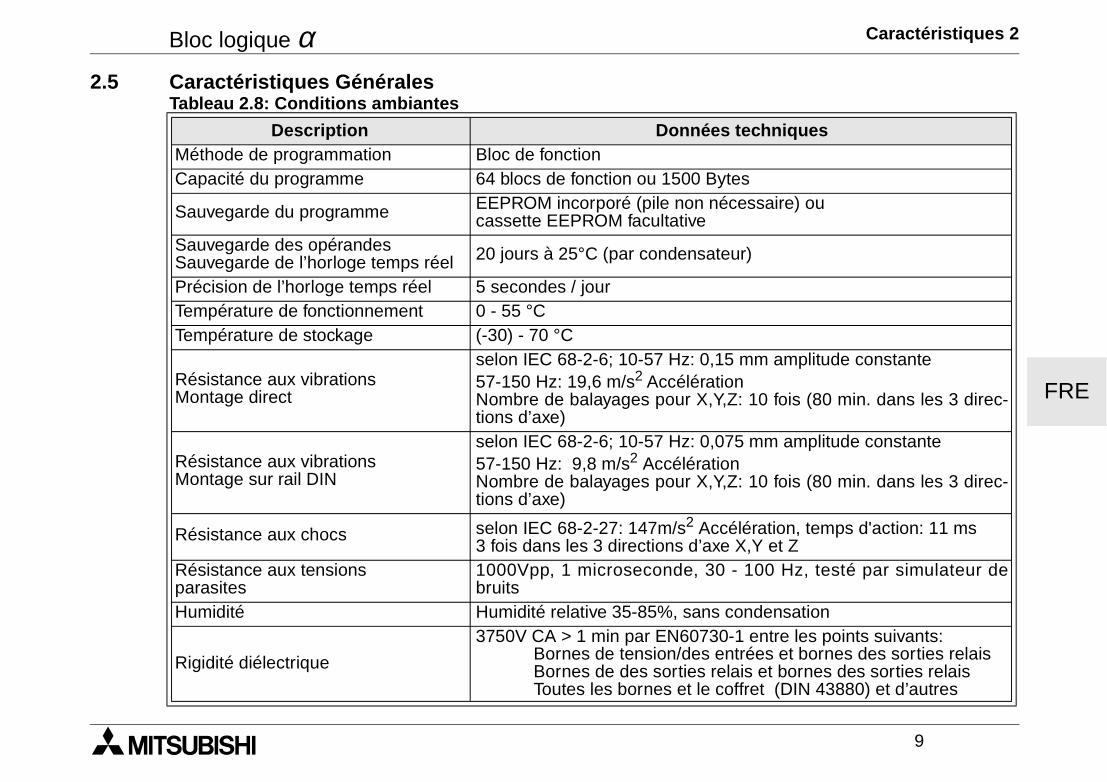
Bloc logique α Caractéristiques 2
9
FRE
2.5 Caractéristiques GénéralesTableau 2.8: Conditions ambiantes
Description Données techniquesMéthode de programmation Bloc de fonctionCapacité du programme 64 blocs de fonction ou 1500 Bytes
Sauvegarde du programme EEPROM incorporé (pile non nécessaire) ou cassette EEPROM facultative
Sauvegarde des opérandesSauvegarde de l’horloge temps réel 20 jours à 25°C (par condensateur)
Précision de l’horloge temps réel 5 secondes / jourTempérature de fonctionnement 0 - 55 °CTempérature de stockage (-30) - 70 °C
Résistance aux vibrationsMontage direct
selon IEC 68-2-6; 10-57 Hz: 0,15 mm amplitude constante57-150 Hz: 19,6 m/s2 AccélérationNombre de balayages pour X,Y,Z: 10 fois (80 min. dans les 3 direc-tions d’axe)
Résistance aux vibrationsMontage sur rail DIN
selon IEC 68-2-6; 10-57 Hz: 0,075 mm amplitude constante57-150 Hz: 9,8 m/s2 AccélérationNombre de balayages pour X,Y,Z: 10 fois (80 min. dans les 3 direc-tions d’axe)
Résistance aux chocs selon IEC 68-2-27: 147m/s2 Accélération, temps d'action: 11 ms3 fois dans les 3 directions d’axe X,Y et Z
Résistance aux tensions parasites
1000Vpp, 1 microseconde, 30 - 100 Hz, testé par simulateur debruits
Humidité Humidité relative 35-85%, sans condensation
Rigidité diélectrique
3750V CA > 1 min par EN60730-1 entre les points suivants:Bornes de tension/des entrées et bornes des sorties relaisBornes de des sorties relais et bornes des sorties relaisToutes les bornes et le coffret (DIN 43880) et d’autres
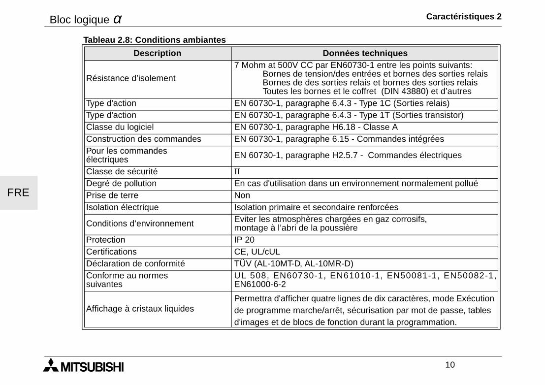
Bloc logique α Caractéristiques 2
10
FRE
Résistance d’isolement
7 Mohm at 500V CC par EN60730-1 entre les points suivants:Bornes de tension/des entrées et bornes des sorties relaisBornes de des sorties relais et bornes des sorties relaisToutes les bornes et le coffret (DIN 43880) et d’autres
Type d'action EN 60730-1, paragraphe 6.4.3 - Type 1C (Sorties relais)Type d'action EN 60730-1, paragraphe 6.4.3 - Type 1T (Sorties transistor)Classe du logiciel EN 60730-1, paragraphe H6.18 - Classe AConstruction des commandes EN 60730-1, paragraphe 6.15 - Commandes intégréesPour les commandes électriques EN 60730-1, paragraphe H2.5.7 - Commandes électriques
Classe de sécurité IIDegré de pollution En cas d'utilisation dans un environnement normalement polluéPrise de terre NonIsolation électrique Isolation primaire et secondaire renforcées
Conditions d’environnement Eviter les atmosphères chargées en gaz corrosifs, montage à l’abri de la poussière
Protection IP 20Certifications CE, UL/cULDéclaration de conformité TÜV (AL-10MT-D, AL-10MR-D)Conforme au normes suivantes
UL 508, EN60730-1, EN61010-1, EN50081-1, EN50082-1,EN61000-6-2
Affichage à cristaux liquidesPermettra d'afficher quatre lignes de dix caractères, mode Exécution de programme marche/arrêt, sécurisation par mot de passe, tables d'images et de blocs de fonction durant la programmation.
Tableau 2.8: Conditions ambiantes
Description Données techniques
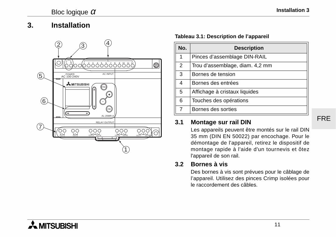
Bloc logique α Installation 3
11
FRE
3. Installation
3.1 Montage sur rail DINLes appareils peuvent être montés sur le rail DIN35 mm (DIN EN 50022) par encochage. Pour ledémontage de l'appareil, retirez le dispositif demontage rapide à l'aide d'un tournevis et ôtezl'appareil de son rail.
3.2 Bornes à visDes bornes à vis sont prévues pour le câblage del’appareil. Utilisez des pinces Crimp isolées pourle raccordement des câbles.
Tableau 3.1: Description de l’appareil
No. Description
1 Pinces d’assemblage DIN-RAIL
2 Trou d’assemblage, diam. 4,2 mm
3 Bornes de tension
4 Bornes des entrées
5 Affichage à cristaux liquides
6 Touches des opérations
7 Bornes des sorties
AC 100-240VPOWER AC INPUT
AL-20MR-A
OK
ESC
RELAY OUTPUT
OUT1 OUT2 OUT5OUT3 OUT4 OUT6 OUT8OUT7
1 2 3 4 5 6 7 8 9 10 11 12IN
L N~
432
5
6
7
1
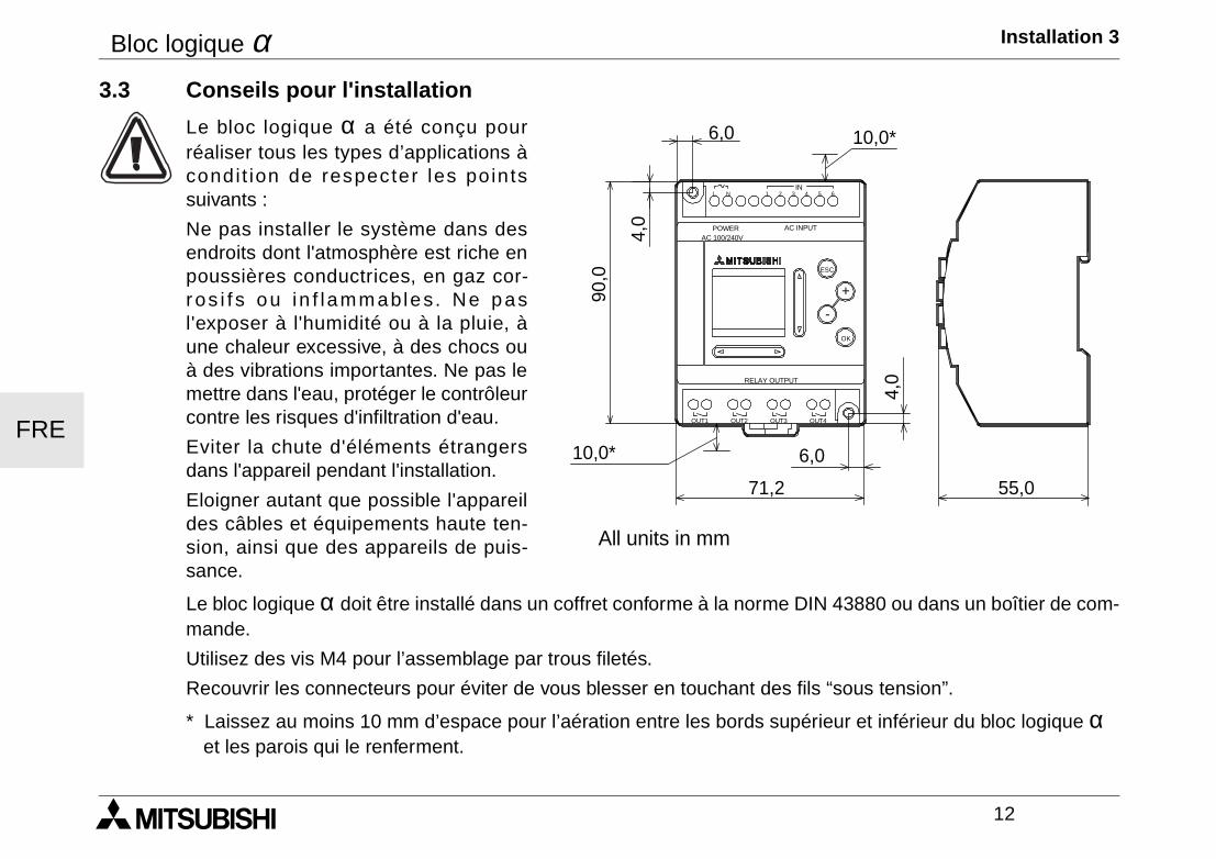
Bloc logique α Installation 3
12
FRE
3.3 Conseils pour l'installation
Le bloc logique α a été conçu pourréaliser tous les types d’applications àcondit ion de respecter les pointssuivants :
Ne pas installer le système dans desendroits dont l'atmosphère est riche enpoussières conductrices, en gaz cor-ros i f s ou in f lamm ables. Ne pasl'exposer à l'humidité ou à la pluie, àune chaleur excessive, à des chocs ouà des vibrations importantes. Ne pas lemettre dans l'eau, protéger le contrôleurcontre les risques d'infiltration d'eau.
Eviter la chute d'éléments étrangersdans l'appareil pendant l'installation.
Eloigner autant que possible l'appareildes câbles et équipements haute ten-sion, ainsi que des appareils de puis-sance.
Le bloc logique α doit être installé dans un coffret conforme à la norme DIN 43880 ou dans un boîtier de com-mande.
Utilisez des vis M4 pour l’assemblage par trous filetés.
Recouvrir les connecteurs pour éviter de vous blesser en touchant des fils “sous tension”.
* Laissez au moins 10 mm d’espace pour l’aération entre les bords supérieur et inférieur du bloc logique α et les parois qui le renferment.
POWER
IN
OK
+
RELAY OUTPUT
ESC
-
3 421 5L 6N
OUT3 OUT4OUT2OUT1
AC INPUTAC 100/240V
10,0*
10,0*
71,2
6,0
90,0
4,0
55,0
4,0
6,0
All units in mm
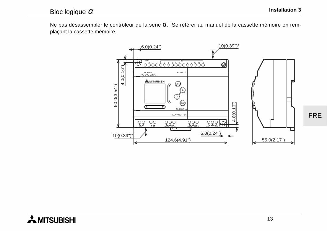
Bloc logique α Installation 3
13
FRE
Ne pas désassembler le contrôleur de la série α. Se référer au manuel de la cassette mémoire en rem-plaçant la cassette mémoire.
AC 100-240VPOWER AC INPUT
AL-20MR-A
OK
ESC
RELAY OUTPUT
6.0(0.24") 10(0.39")*
55.0(2.17")
6.0(0.24")
124.6(4.91")10(0.39")*
4.0
(0.1
6")90.0
(3.5
4") 4
.0(0
.16")
OUT1 OUT2 OUT5OUT3 OUT4 OUT6 OUT8OUT7
1 2 3 4 5 6 7 8 9 10 11 12IN
L N~

Bloc logique α Installation 3
14
FRE
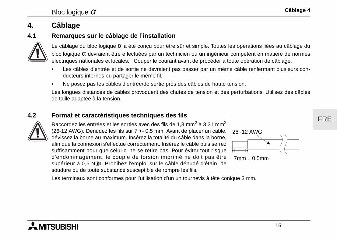
Bloc logique α Câblage 4
15
FRE
4. Câblage4.1 Remarques sur le câblage de l’installation
Le câblage du bloc logique α a été conçu pour être sûr et simple. Toutes les opérations liées au câblage du
bloc logique α devraient être effectuées par un technicien ou un ingénieur compétent en matière de normesélectriques nationales et locales. Couper le courant avant de procéder à toute opération de câblage.
• Les câbles d’entrée et de sortie ne devraient pas passer par un même câble renfermant plusieurs con-ducteurs internes ou partager le même fil.
• Ne posez pas les câbles d’entrée/de sortie près des câbles de haute tension.
Les longues distances de câbles provoquent des chutes de tension et des perturbations. Utilisez des câblesde taille adaptée à la tension.
4.2 Format et caractéristiques techniques des filsRaccordez les entrées et les sorties avec des fils de 1,3 mm2 à 3,31 mm2
(26-12 AWG). Dénudez les fils sur 7 +- 0,5 mm. Avant de placer un câble,dévissez la borne au maximum. Insérez la totalité du câble dans la borne,afin que la connexion s'effectue correctement. Insérez le câble puis serrezsuffisamment pour que celui-ci ne se retire pas. Pour éviter tout risqued'endommagement, le couple de torsion imprimé ne doit pas êtresupérieur à 0,5 N⋅⋅⋅⋅m. Prohibez l'emploi sur le câble dénudé d'étain, desoudure ou de toute substance susceptible de rompre les fils.
Les terminaux sont conformes pour l’utilisation d’un un tournevis à tête conique 3 mm.
7mm ± 0,5mm
26 -12 AWG
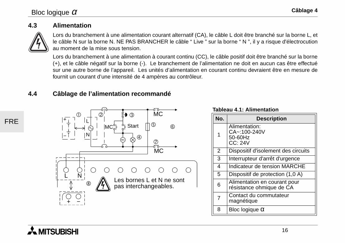
Bloc logique α Câblage 4
16
FRE
4.3 AlimentationLors du branchement à une alimentation courant alternatif (CA), le câble L doit être branché sur la borne L, etle câble N sur la borne N. NE PAS BRANCHER le câble “ Live ” sur la borne “ N ”, il y a risque d'électrocutionau moment de la mise sous tension.
Lors du branchement à une alimentation à courant continu (CC), le câble positif doit être branché sur la borne(+), et le câble négatif sur la borne (-). Le branchement de l’alimentation ne doit en aucun cas être effectuésur une autre borne de l’appareil. Les unités d’alimentation en courant continu devraient être en mesure defournit un courant d’une intensité de 4 ampères au contrôleur.
4.4 Câblage de l’alimentation recommandé
Tableau 4.1: Alimentation
No. Description
1
Alimentation: CA~:100-240V50-60HzCC: 24V
2 Dispositif d'isolement des circuits 3 Interrupteur d'arrêt d'urgence 4 Indicateur de tension MARCHE 5 Dispositif de protection (1,0 A)
6 Alimentation en courant pourrésistance ohmique de CA
7 Contact du commutateur magnétique
8 Bloc logique α
MC
MC
MC
MC
L N
! " #
$
% &
'
(
+
−
L
N
+ −
Start
Les bornes L et N ne sontpas interchangeables.
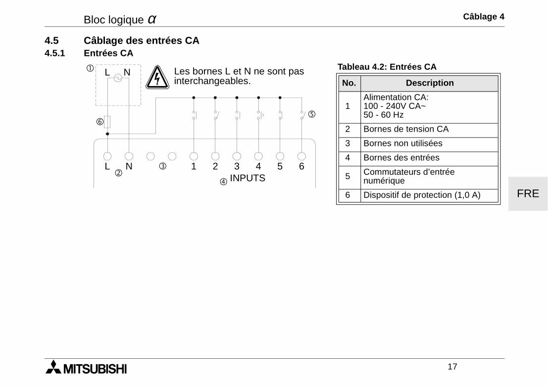
Bloc logique α Câblage 4
17
FRE
4.5 Câblage des entrées CA4.5.1 Entrées CA
Tableau 4.2: Entrées CA
No. Description
1Alimentation CA:100 - 240V CA~50 - 60 Hz
2 Bornes de tension CA
3 Bornes non utilisées
4 Bornes des entrées
5 Commutateurs d’entréenumérique
6 Dispositif de protection (1,0 A)
! L N
"#
$
%
L N 1 2 3INPUTS
4 5 6
&
Les bornes L et N ne sont pasinterchangeables.
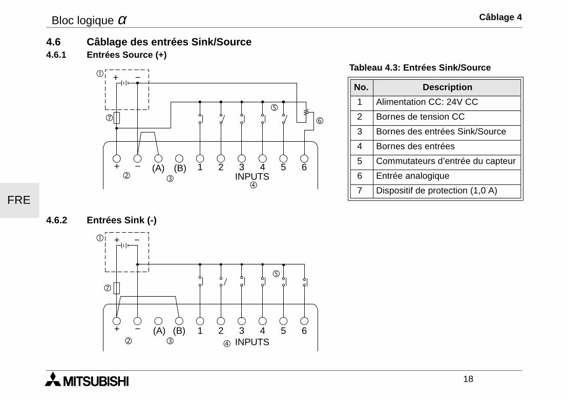
Bloc logique α Câblage 4
18
FRE
4.6 Câblage des entrées Sink/Source4.6.1 Entrées Source (+)
4.6.2 Entrées Sink (-)
Tableau 4.3: Entrées Sink/Source
No. Description
1 Alimentation CC: 24V CC
2 Bornes de tension CC
3 Bornes des entrées Sink/Source
4 Bornes des entrées
5 Commutateurs d’entrée du capteur
6 Entrée analogique
7 Dispositif de protection (1,0 A)
! + −
"$
%
&
+ − (A) (B) 1 2 3INPUTS
4 5 6
(
#
! + −
" # $
%
+ − (A) (B) 1 2 3INPUTS
4 5 6
(
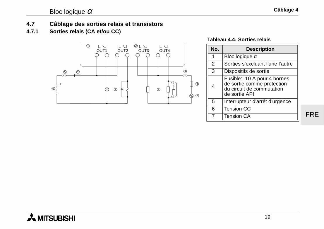
Bloc logique α Câblage 4
19
FRE
4.7 Câblage des sorties relais et transistors4.7.1 Sorties relais (CA et/ou CC)
Tableau 4.4: Sorties relais
No. Description 1 Bloc logique α 2 Sorties s’excluant l’une l’autre 3 Dispositifs de sortie
4
Fusible: 10 A pour 4 bornes de sortie comme protection du circuit de commutation de sortie API
5 Interrupteur d'arrêt d'urgence 6 Tension CC 7 Tension CA
"!
$
OUT1
##
%
&
OUT2 OUT3 OUT4
(
$
%
+

Bloc logique α Câblage 4
20
FRE
4.7.2 Sorties transistor (source ou “+” Common seulement)Tableau 4.5: Sorties transistor
No. Description1 Bloc logique α2 Bornes de sorties3 Dispositifs de sortie
4 Dispositif de protection cf. le tableau 4.6
5 Interrupteur d'arrêt d'urgence6 Alimentation CC pour sorties7 Bornes de tension8 Alimentation CC, 24V CC9 Dispositif de protection (1,0 A)
Tableau 4.6: Protection pour sorties transistors
Circuit Protection du circuit (fusible))
5 Volt < 0,3 A par circuit12 Volt < 2,0 A par circuit24 Volt < 2,0 A par circuit
Volt Bornes de sorties
5 Chaque circuit contient de une à toutes les bornes de sortie.12-24 Chaque circuit contient de une à toutes les bornes de sortie.
5 ,12 ,or 24
Il est possible d'utiliser toutes les combinaisons possibles de sorties 5 volt, 12 volt et 24 volt sur unmême contrôleur de la gamme α à condition d'utiliser des circuits séparés pour chaque niveau detension.
"
!
OUT1
##
OUT2 OUT3 OUT4
$
%
&
+ −
+ −(
$
%
&+
+
#
)
'
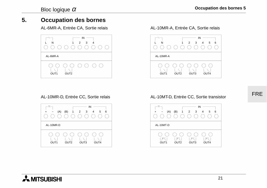
Bloc logique α Occupation des bornes 5
21
FRE
5. Occupation des bornesAL-6MR-A, Entrée CA, Sortie relais AL-10MR-A, Entrée CA, Sortie relais
AL-10MR-D, Entrée CC, Sortie relais AL-10MT-D, Entrée CC, Sortie transistor
L N 1 2 3 4
OUT1
AL-6MR-A
OUT2
IN
L N 1 2 3 4
OUT1
AL-10MR-A
OUT2
IN
5 6
OUT3 OUT4
+ − (A) (B) 1 2 3 4
OUT1
AL-10MR-D
OUT2
IN
5 6
OUT3 OUT4
+ − (B) 1 2 3 4
OUT1
AL-10MT-D
OUT2
IN
5 6
OUT3 OUT4
(A)
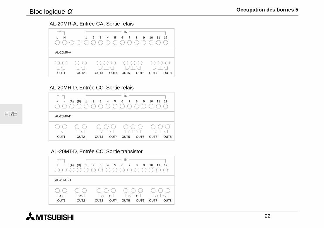
Bloc logique α Occupation des bornes 5
22
FRE
AL-20MR-A, Entrée CA, Sortie relais
AL-20MR-D, Entrée CC, Sortie relais
AL-20MT-D, Entrée CC, Sortie transistor
L N
IN
12111 2 3 4 5 6 7 8 9 10
OUT1 OUT2 OUT3 OUT5 OUT7OUT4 OUT6 OUT8
AL-20MR-A
+ -
IN
12111 2 3 4 5 6 7 8 9 10
OUT1 OUT2 OUT3 OUT5 OUT7OUT4 OUT6 OUT8
AL-20MR-D
(A) (B)
+ -
IN
12111 2 3 4 5 6 7 8 9 10
OUT1 OUT2 OUT3 OUT5 OUT7OUT4 OUT6 OUT8
AL-20MT-D
(A) (B)
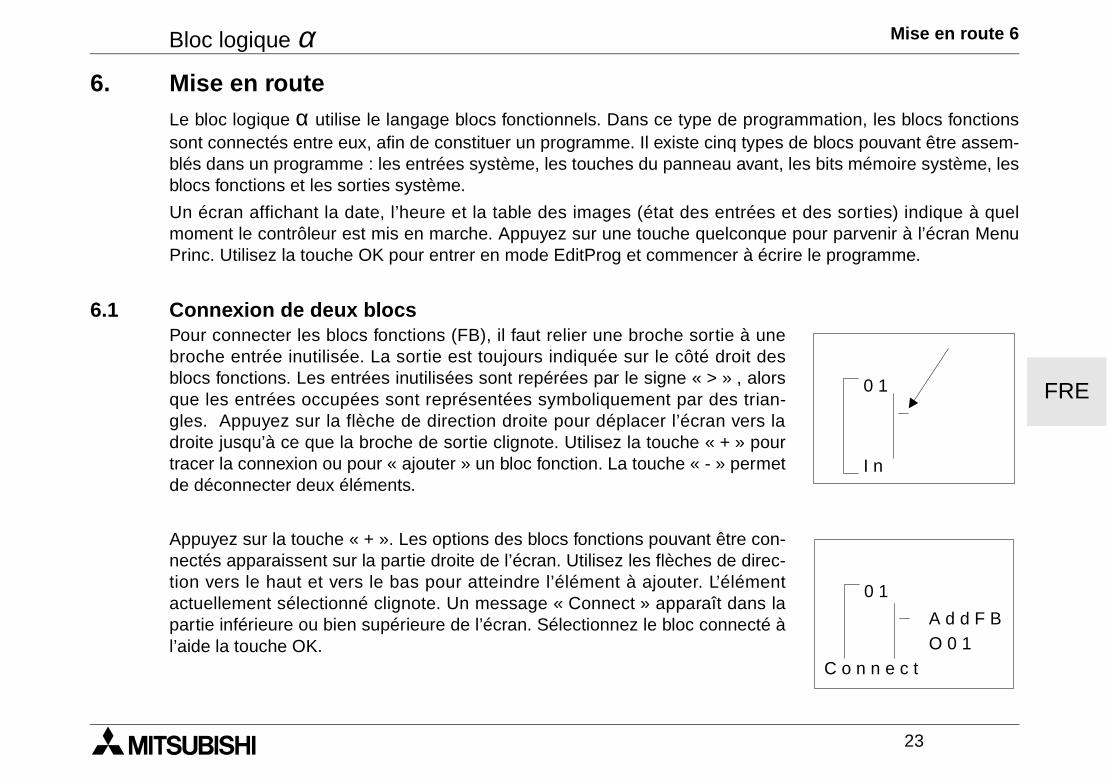
Bloc logique α Mise en route 6
23
FRE
6. Mise en routeLe bloc logique α utilise le langage blocs fonctionnels. Dans ce type de programmation, les blocs fonctionssont connectés entre eux, afin de constituer un programme. Il existe cinq types de blocs pouvant être assem-blés dans un programme : les entrées système, les touches du panneau avant, les bits mémoire système, lesblocs fonctions et les sorties système.
Un écran affichant la date, l’heure et la table des images (état des entrées et des sorties) indique à quelmoment le contrôleur est mis en marche. Appuyez sur une touche quelconque pour parvenir à l’écran MenuPrinc. Utilisez la touche OK pour entrer en mode EditProg et commencer à écrire le programme.
6.1 Connexion de deux blocsPour connecter les blocs fonctions (FB), il faut relier une broche sortie à unebroche entrée inutilisée. La sortie est toujours indiquée sur le côté droit desblocs fonctions. Les entrées inutilisées sont repérées par le signe « > » , alorsque les entrées occupées sont représentées symboliquement par des trian-gles. Appuyez sur la flèche de direction droite pour déplacer l’écran vers ladroite jusqu’à ce que la broche de sortie clignote. Utilisez la touche « + » pourtracer la connexion ou pour « ajouter » un bloc fonction. La touche « - » permetde déconnecter deux éléments.
Appuyez sur la touche « + ». Les options des blocs fonctions pouvant être con-nectés apparaissent sur la partie droite de l’écran. Utilisez les flèches de direc-tion vers le haut et vers le bas pour atteindre l’élément à ajouter. L’élémentactuellement sélectionné clignote. Un message « Connect » apparaît dans lapartie inférieure ou bien supérieure de l’écran. Sélectionnez le bloc connecté àl’aide la touche OK.
0 1
I n
0 1
A d d F BO 0 1
C o n n e c t
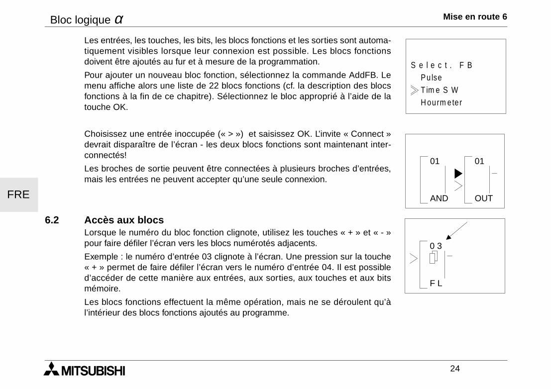
Bloc logique α Mise en route 6
24
FRE
Les entrées, les touches, les bits, les blocs fonctions et les sorties sont automa-tiquement visibles lorsque leur connexion est possible. Les blocs fonctionsdoivent être ajoutés au fur et à mesure de la programmation.
Pour ajouter un nouveau bloc fonction, sélectionnez la commande AddFB. Lemenu affiche alors une liste de 22 blocs fonctions (cf. la description des blocsfonctions à la fin de ce chapitre). Sélectionnez le bloc approprié à l’aide de latouche OK.
Choisissez une entrée inoccupée (« > ») et saisissez OK. L’invite « Connect »devrait disparaître de l’écran - les deux blocs fonctions sont maintenant inter-connectés!
Les broches de sortie peuvent être connectées à plusieurs broches d’entrées,mais les entrées ne peuvent accepter qu’une seule connexion.
6.2 Accès aux blocs Lorsque le numéro du bloc fonction clignote, utilisez les touches « + » et « - »pour faire défiler l’écran vers les blocs numérotés adjacents.
Exemple : le numéro d’entrée 03 clignote à l’écran. Une pression sur la touche« + » permet de faire défiler l’écran vers le numéro d’entrée 04. Il est possibled’accéder de cette manière aux entrées, aux sorties, aux touches et aux bitsmémoire.
Les blocs fonctions effectuent la même opération, mais ne se déroulent qu’àl’intérieur des blocs fonctions ajoutés au programme.
H ourm ete r
Pu lseS e l e c t . F B
T im e S W
AND
01 01
OUT
0 3
F L
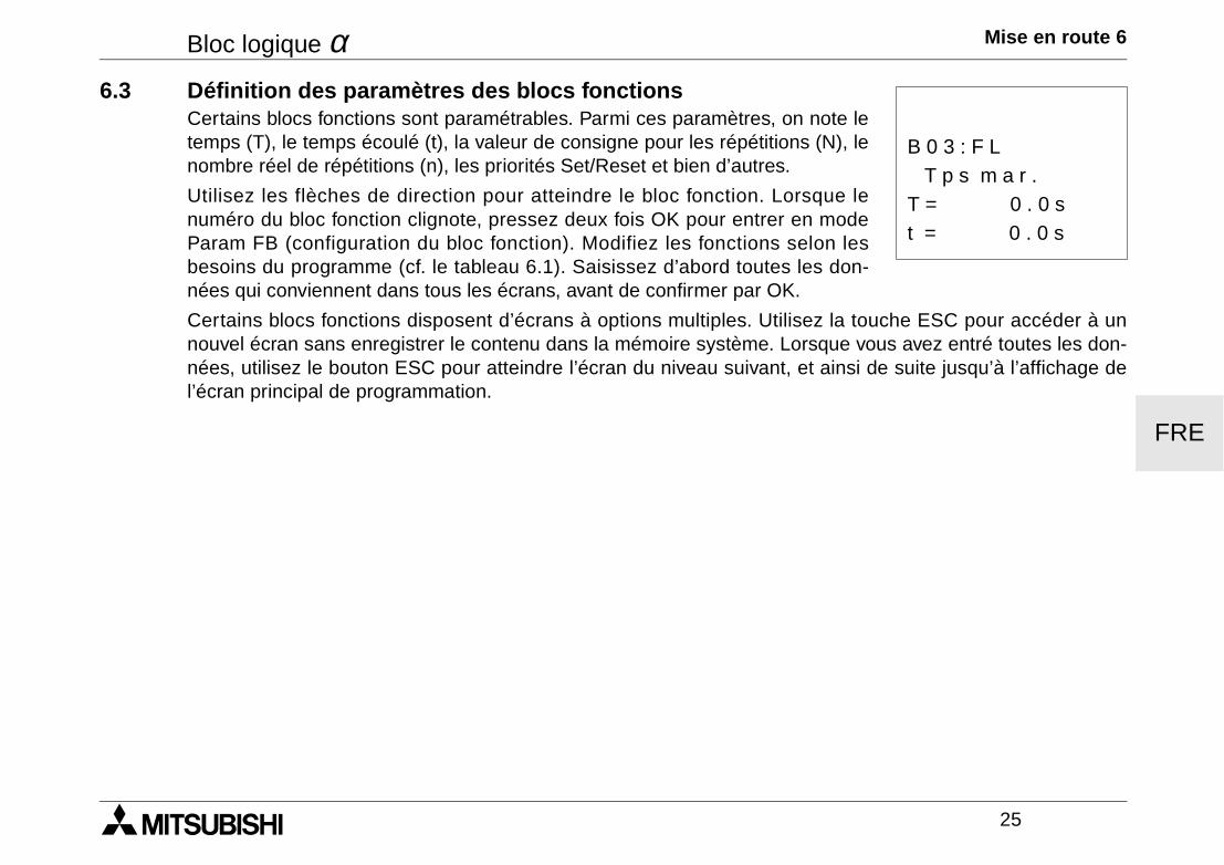
Bloc logique α Mise en route 6
25
FRE
6.3 Définition des paramètres des blocs fonctionsCertains blocs fonctions sont paramétrables. Parmi ces paramètres, on note letemps (T), le temps écoulé (t), la valeur de consigne pour les répétitions (N), lenombre réel de répétitions (n), les priorités Set/Reset et bien d’autres.
Utilisez les flèches de direction pour atteindre le bloc fonction. Lorsque lenuméro du bloc fonction clignote, pressez deux fois OK pour entrer en modeParam FB (configuration du bloc fonction). Modifiez les fonctions selon lesbesoins du programme (cf. le tableau 6.1). Saisissez d’abord toutes les don-nées qui conviennent dans tous les écrans, avant de confirmer par OK.
Certains blocs fonctions disposent d’écrans à options multiples. Utilisez la touche ESC pour accéder à unnouvel écran sans enregistrer le contenu dans la mémoire système. Lorsque vous avez entré toutes les don-nées, utilisez le bouton ESC pour atteindre l’écran du niveau suivant, et ainsi de suite jusqu’à l’affichage del’écran principal de programmation.
t = 0 . 0 s
T p s m a r .B 0 3 : F L
T = 0 . 0 s
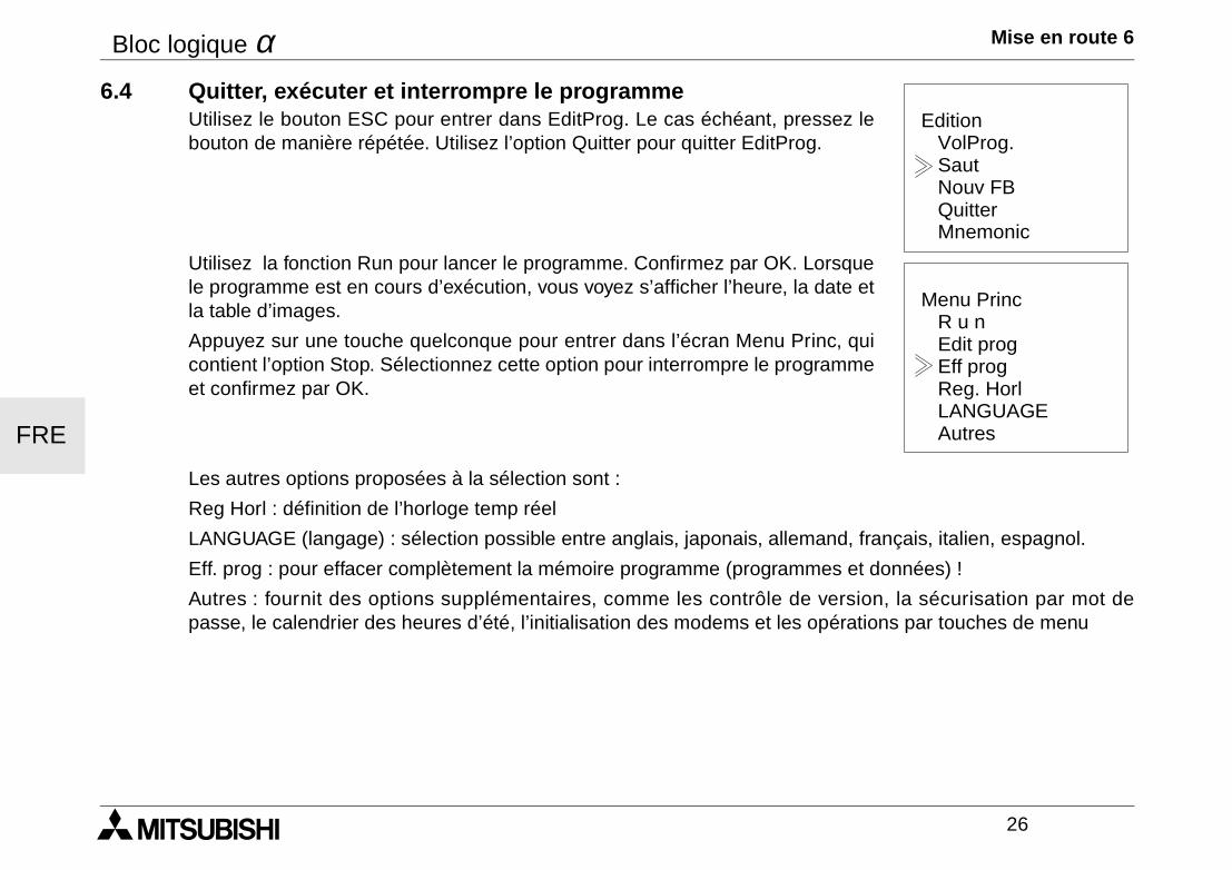
Bloc logique α Mise en route 6
26
FRE
6.4 Quitter, exécuter et interrompre le programmeUtilisez le bouton ESC pour entrer dans EditProg. Le cas échéant, pressez lebouton de manière répétée. Utilisez l’option Quitter pour quitter EditProg.
Utilisez la fonction Run pour lancer le programme. Confirmez par OK. Lorsquele programme est en cours d’exécution, vous voyez s’afficher l’heure, la date etla table d’images.
Appuyez sur une touche quelconque pour entrer dans l’écran Menu Princ, quicontient l’option Stop. Sélectionnez cette option pour interrompre le programmeet confirmez par OK.
Les autres options proposées à la sélection sont :
Reg Horl : définition de l’horloge temp réel
LANGUAGE (langage) : sélection possible entre anglais, japonais, allemand, français, italien, espagnol.
Eff. prog : pour effacer complètement la mémoire programme (programmes et données) !
Autres : fournit des options supplémentaires, comme les contrôle de version, la sécurisation par mot depasse, le calendrier des heures d’été, l’initialisation des modems et les opérations par touches de menu
Edition
Quitter
VolProg.SautNouv FB
Mnemonic
Menu Princ
Reg. Horl
R u nEdit progEff prog
AutresLANGUAGE
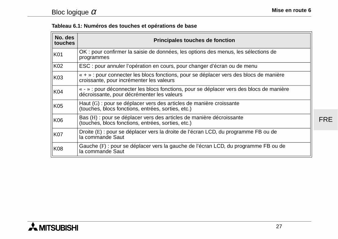
Bloc logique α Mise en route 6
27
FRE
Tableau 6.1: Numéros des touches et opérations de base
No. des touches Principales touches de fonction
K01 OK : pour confirmer la saisie de données, les options des menus, les sélections de programmes
K02 ESC : pour annuler l’opération en cours, pour changer d’écran ou de menu
K03 « + » : pour connecter les blocs fonctions, pour se déplacer vers des blocs de manière croissante, pour incrémenter les valeurs
K04 « - » : pour déconnecter les blocs fonctions, pour se déplacer vers des blocs de manière décroissante, pour décrémenter les valeurs
K05 Haut (G) : pour se déplacer vers des articles de manière croissante (touches, blocs fonctions, entrées, sorties, etc.)
K06 Bas (H) : pour se déplacer vers des articles de manière décroissante (touches, blocs fonctions, entrées, sorties, etc.)
K07 Droite (E) : pour se déplacer vers la droite de l’écran LCD, du programme FB ou de la commande Saut
K08 Gauche (F) : pour se déplacer vers la gauche de l’écran LCD, du programme FB ou de la commande Saut
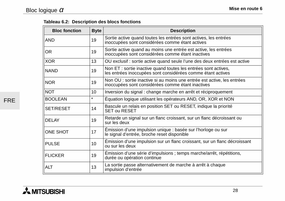
Bloc logique α Mise en route 6
28
FRE
Tableau 6.2: Description des blocs fonctions
Bloc fonction Byte Description
AND 19 Sortie active quand toutes les entrées sont actives, les entrées inoccupées sont considérées comme étant actives
OR 19 Sortie active quand au moins une entrée est active, les entrées inoccupées sont considérées comme étant inactives
XOR 13 OU exclusif : sortie active quand seule l’une des deux entrées est active
NAND 19 Non ET : sortie inactive quand toutes les entrées sont actives, les entrées inoccupées sont considérées comme étant actives
NOR 19 Non OU : sortie inactive si au moins une entrée est active, les entrées inoccupées sont considérées comme étant inactives
NOT 10 Inversion du signal : change marche en arrêt et réciproquement
BOOLEAN * Équation logique utilisant les opérateurs AND, OR, XOR et NON
SET/RESET 14 Bascule un relais en position SET ou RESET, indique la priorité SET ou RESET
DELAY 19 Retarde un signal sur un flanc croissant, sur un flanc décroissant ou sur les deux
ONE SHOT 17 Émission d’une impulsion unique : basée sur l’horloge ou sur le signal d’entrée, broche reset disponible
PULSE 10 Émission d’une impulsion sur un flanc croissant, sur un flanc décroissant ou sur les deux
FLICKER 19 Émission d’une série d’impulsions ; temps marche/arrêt, répétitions, durée ou opération continue
ALT 13 La sortie passe alternativement de marche à arrêt à chaque impulsion d’entrée
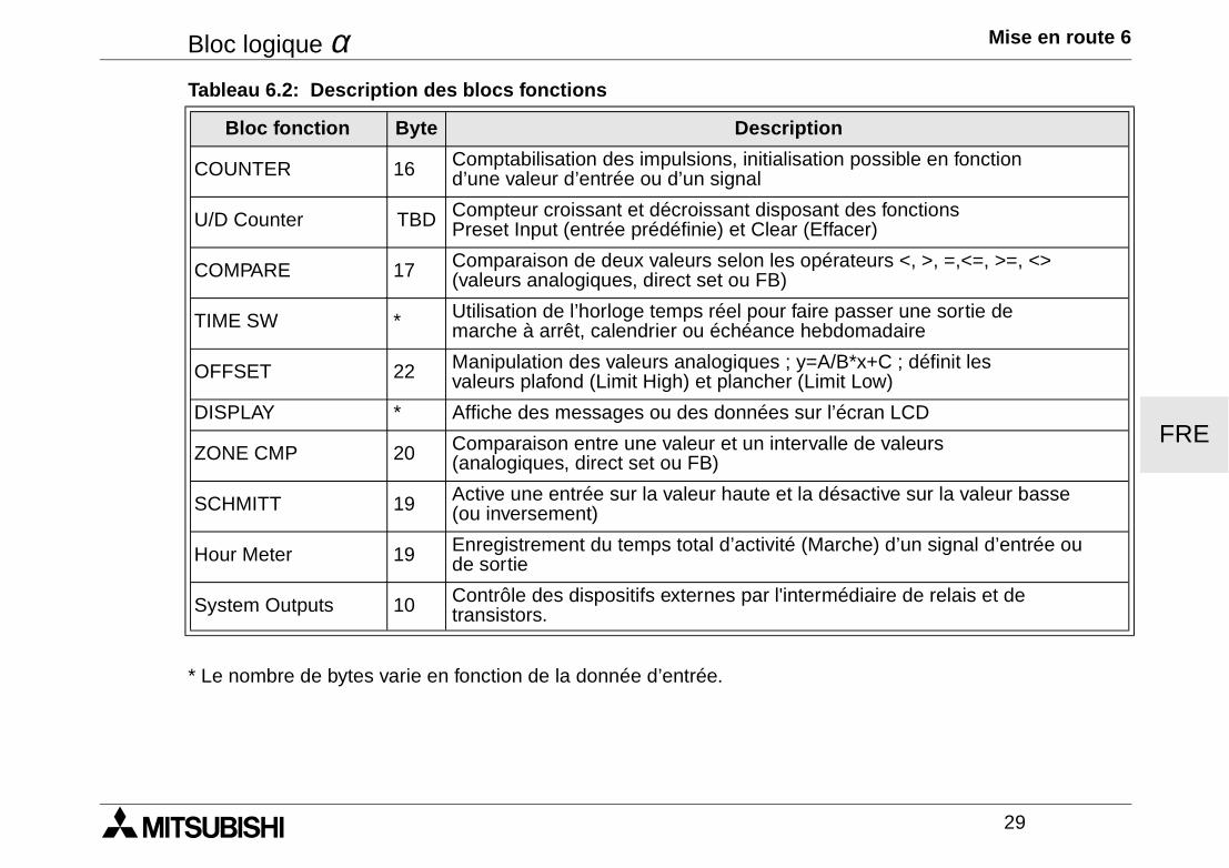
Bloc logique α Mise en route 6
29
FRE
* Le nombre de bytes varie en fonction de la donnée d’entrée.
COUNTER 16 Comptabilisation des impulsions, initialisation possible en fonction d’une valeur d’entrée ou d’un signal
U/D Counter TBD Compteur croissant et décroissant disposant des fonctions Preset Input (entrée prédéfinie) et Clear (Effacer)
COMPARE 17 Comparaison de deux valeurs selon les opérateurs <, >, =,<=, >=, <> (valeurs analogiques, direct set ou FB)
TIME SW * Utilisation de l’horloge temps réel pour faire passer une sortie de marche à arrêt, calendrier ou échéance hebdomadaire
OFFSET 22 Manipulation des valeurs analogiques ; y=A/B*x+C ; définit les valeurs plafond (Limit High) et plancher (Limit Low)
DISPLAY * Affiche des messages ou des données sur l’écran LCD
ZONE CMP 20 Comparaison entre une valeur et un intervalle de valeurs (analogiques, direct set ou FB)
SCHMITT 19 Active une entrée sur la valeur haute et la désactive sur la valeur basse (ou inversement)
Hour Meter 19 Enregistrement du temps total d’activité (Marche) d’un signal d’entrée ou de sortie
System Outputs 10 Contrôle des dispositifs externes par l'intermédiaire de relais et de transistors.
Tableau 6.2: Description des blocs fonctions
Bloc fonction Byte Description
Bloc logique α Mise en route 6
30
FRE

ITL
MANUALE HARDWARESISTEMA α
Sistema α
ITL
Premessa• Il presente manuale contiene testi, figure e spiegazioni per la corretta installazione e un corretto impiego del
sistema α e dovrebbe essere letto e compreso prima di installare o impiegare l’apparecchio.• Se durante l’installazione qualcosa non fosse chiaro, dovreste consultare in ogni caso uno specialista
elettrico, qualificato e istruito sull’applicazione delle norme elttriche locali e nazionali. Contattate il conces-sionario più vicino della MITSUBISHI ELECTRIC se durante le operazioni o l’impiego del sistema α doves-sero insorgere dei dubbi.
• Il presente manual viene pubblicato con riserva di modifiche. Ci riserviamo il diritto di apportare modifiche al presente manuale senza alcun preavviso.
Sistema α
ITL
i
Sistema αααα
Manuale HardwareNumero: JY992D74201Revisione: JData: 04/2002
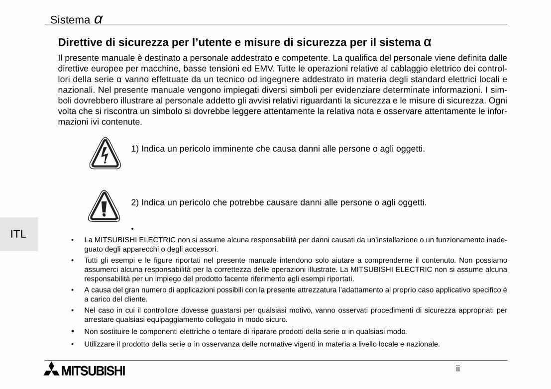
Sistema α
ITL
ii
Direttive di sicurezza per l’utente e misure di sicurezza per il sistema ααααIl presente manuale è destinato a personale addestrato e competente. La qualifica del personale viene definita dalledirettive europee per macchine, basse tensioni ed EMV. Tutte le operazioni relative al cablaggio elettrico dei control-lori della serie α vanno effettuate da un tecnico od ingegnere addestrato in materia degli standard elettrici locali enazionali. Nel presente manuale vengono impiegati diversi simboli per evidenziare determinate informazioni. I sim-boli dovrebbero illustrare al personale addetto gli avvisi relativi riguardanti la sicurezza e le misure di sicurezza. Ognivolta che si riscontra un simbolo si dovrebbe leggere attentamente la relativa nota e osservare attentamente le infor-mazioni ivi contenute.
1) Indica un pericolo imminente che causa danni alle persone o agli oggetti.
2) Indica un pericolo che potrebbe causare danni alle persone o agli oggetti.
•
• La MITSUBISHI ELECTRIC non si assume alcuna responsabilità per danni causati da un’installazione o un funzionamento inade-guato degli apparecchi o degli accessori.
• Tutti gli esempi e le figure riportati nel presente manuale intendono solo aiutare a comprenderne il contenuto. Non possiamoassumerci alcuna responsabilità per la correttezza delle operazioni illustrate. La MITSUBISHI ELECTRIC non si assume alcunaresponsabilità per un impiego del prodotto facente riferimento agli esempi riportati.
• A causa del gran numero di applicazioni possibili con la presente attrezzatura l’adattamento al proprio caso applicativo specifico èa carico del cliente.
• Nel caso in cui il controllore dovesse guastarsi per qualsiasi motivo, vanno osservati procedimenti di sicurezza appropriati perarrestare qualsiasi equipaggiamento collegato in modo sicuro.
• Non sostituire le componenti elettriche o tentare di riparare prodotti della serie α in qualsiasi modo.
• Utilizzare il prodotto della serie α in osservanza delle normative vigenti in materia a livello locale e nazionale.
Sistema α
iii
Indice
Direttive di sicurezza .............................................................................................................. ii
1. Introduzione ........................................................................................................... 1
2. Dati tecnici ............................................................................................................. 32.1 Modelli disponibili ......................................................................................................... 32.2 Alimentazione di potenza............................................................................................. 42.3 Ingressi ........................................................................................................................ 62.4 Uscite ........................................................................................................................... 82.5 Descrizione Generale .................................................................................................. 9
3. Installazione ......................................................................................................... 133.1 Montaggio su barra DIN............................................................................................. 133.2 Allacciamento mediante morsetti a vite ..................................................................... 133.3 Osservazioni sull'installazione ................................................................................... 14 ITL
Sistema α
iv
4. Allacciamento elettrico ....................................................................................... 174.1 Note sul cablaggio di installazione............................................................................. 174.2 Formato dei fili e dati caratteristici ............................................................................. 174.3 Tensione di alimentazione ......................................................................................... 184.4 Circuito di alimentazione raccomandato .................................................................... 184.5 Circuito di ingressi...................................................................................................... 19
4.5.1 Ingressi CA.......................................................................................................... 194.6 Circuito di ingressi Sink/Source ................................................................................. 20
4.6.1 Ingressi Source (+) .............................................................................................. 204.6.2 Ingressi Sink (-) ................................................................................................... 20
4.7 Circuito di uscita transistore e relè ............................................................................. 214.7.1 Uscita relè (CA e/o CC) ....................................................................................... 214.7.2 Uscita transistore (source o “+” Common solo) ................................................... 22
5. Assegnazione dei morsetti ................................................................................. 23
6. Primi passi ........................................................................................................... 256.1 Collegamento di due blocchi...................................................................................... 256.2 Blocchi di accesso .................................................................................................... 266.3 Impostazione dei parametri dei blocchi funzionali ..................................................... 276.4 Uscita, funzionamento e fermata del programma ...................................................... 28
ITL
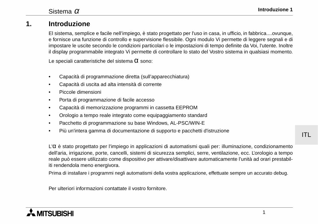
Sistema α Introduzione 1
1
ITL
1. IntroduzioneEl sistema, semplice e facile nell’impiego, è stato progettato per l'uso in casa, in ufficio, in fabbrica....ovunque,e fornisce una funzione di controllo e supervisione flessibile. Ogni modulo Vi permette di leggere segnali e diimpostare le uscite secondo le condizioni particolari o le impostazioni di tempo definite da Voi, l'utente. Inoltreil display programmabile integrato Vi permette di controllare lo stato del Vostro sistema in qualsiasi momento.
Le speciali caratteristiche del sistema α sono:
• Capacità di programmazione diretta (sull’apparecchiatura)
• Capacità di uscita ad alta intensità di corrente
• Piccole dimensioni
• Porta di programmazione di facile accesso
• Capacità di memorizzazione programmi in cassetta EEPROM
• Orologio a tempo reale integrato come equipaggiamento standard
• Pacchetto di programmazione su base Windows, AL-PSC/WIN-E
• Più un'intera gamma di documentazione di supporto e pacchetti d'istruzione
L'α è stato progettato per l'impiego in applicazioni di automatismi quali per: illuminazione, condizionamentodell'aria, irrigazione, porte, cancelli, sistemi di sicurezza semplici, serre, ventilazione, ecc. L’orologio a temporeale può essere utilizzato come dispositivo per attivare/disattivare automaticamente l’unità ad orari prestabil-iti rendendola meno energivora.
Prima di installare i programmi negli automatismi della vostra applicazione, effettuate sempre un accurato debug.
Per ulteriori informazioni contattate il vostro fornitore.

Sistema α Introduzione 1
2
ITL
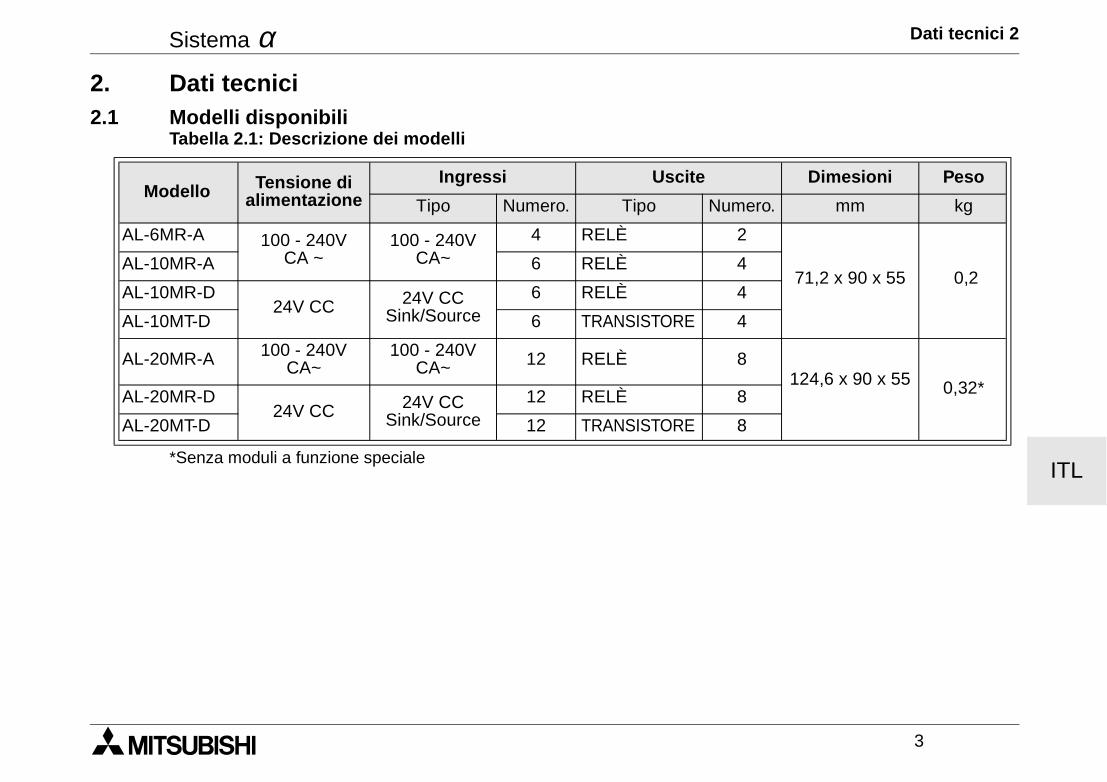
Sistema α Dati tecnici 2
3
ITL
2. Dati tecnici2.1 Modelli disponibili
*Senza moduli a funzione speciale
Tabella 2.1: Descrizione dei modelli
Modello Tensione di alimentazione
Ingressi Uscite Dimesioni Peso
Tipo Numero. Tipo Numero. mm kg
AL-6MR-A 100 - 240V CA ~
100 - 240V CA~
4 RELÈ 2
71,2 x 90 x 55 0,2AL-10MR-A 6 RELÈ 4
AL-10MR-D24V CC 24V CC
Sink/Source6 RELÈ 4
AL-10MT-D 6 TRANSISTORE 4
AL-20MR-A 100 - 240V CA~
100 - 240V CA~ 12 RELÈ 8
124,6 x 90 x 55 0,32*AL-20MR-D24V CC 24V CC
Sink/Source12 RELÈ 8
AL-20MT-D 12 TRANSISTORE 8
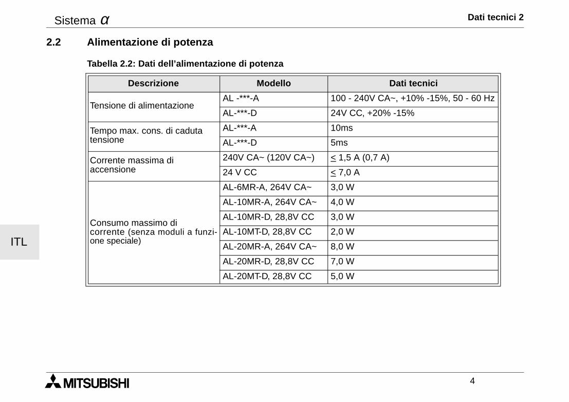
Sistema α Dati tecnici 2
4
ITL
2.2 Alimentazione di potenza
Tabella 2.2: Dati dell’alimentazione di potenza
Descrizione Modello Dati tecnici
Tensione di alimentazioneAL -***-A 100 - 240V CA~, +10% -15%, 50 - 60 Hz
AL-***-D 24V CC, +20% -15%
Tempo max. cons. di caduta tensione
AL-***-A 10ms
AL-***-D 5ms
Corrente massima di accensione
240V CA~ (120V CA~) < 1,5 A (0,7 A)
24 V CC < 7,0 A
Consumo massimo di corrente (senza moduli a funzi-one speciale)
AL-6MR-A, 264V CA~ 3,0 W
AL-10MR-A, 264V CA~ 4,0 W
AL-10MR-D, 28,8V CC 3,0 W
AL-10MT-D, 28,8V CC 2,0 W
AL-20MR-A, 264V CA~ 8,0 W
AL-20MR-D, 28,8V CC 7,0 W
AL-20MT-D, 28,8V CC 5,0 W
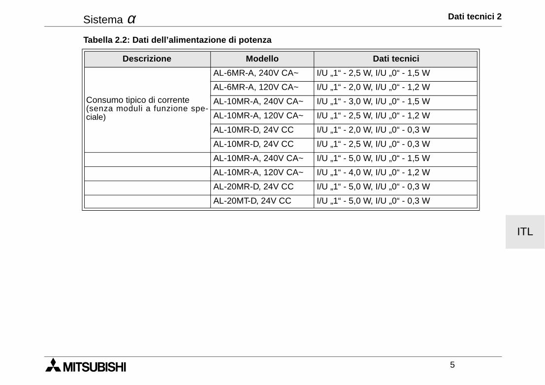
Sistema α Dati tecnici 2
5
ITL
Consumo tipico di corrente(senza moduli a funzione spe-ciale)
AL-6MR-A, 240V CA~ I/U „1“ - 2,5 W, I/U „0“ - 1,5 W
AL-6MR-A, 120V CA~ I/U „1“ - 2,0 W, I/U „0“ - 1,2 W
AL-10MR-A, 240V CA~ I/U „1“ - 3,0 W, I/U „0“ - 1,5 W
AL-10MR-A, 120V CA~ I/U „1“ - 2,5 W, I/U „0“ - 1,2 W
AL-10MR-D, 24V CC I/U „1“ - 2,0 W, I/U „0“ - 0,3 W
AL-10MR-D, 24V CC I/U „1“ - 2,5 W, I/U „0“ - 0,3 W
AL-10MR-A, 240V CA~ I/U „1“ - 5,0 W, I/U „0“ - 1,5 W
AL-10MR-A, 120V CA~ I/U „1“ - 4,0 W, I/U „0“ - 1,2 W
AL-20MR-D, 24V CC I/U „1“ - 5,0 W, I/U „0“ - 0,3 W
AL-20MT-D, 24V CC I/U „1“ - 5,0 W, I/U „0“ - 0,3 W
Tabella 2.2: Dati dell’alimentazione di potenza
Descrizione Modello Dati tecnici
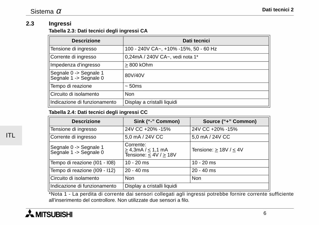
Sistema α Dati tecnici 2
6
ITL
2.3 Ingressi
*Nota 1 - La perdita di corrente dai sensori collegati agli ingressi potrebbe fornire corrente sufficienteall’inserimento del controllore. Non utilizzate due sensori a filo.
Tabella 2.3: Dati tecnici degli ingressi CA
Descrizione Dati tecnici
Tensione di ingresso 100 - 240V CA~, +10% -15%, 50 - 60 Hz
Corrente di ingresso 0,24mA / 240V CA~, vedi nota 1*
Impedenza d’ingresso > 800 kOhm
Segnale 0 -> Segnale 1Segnale 1 -> Segnale 0 80V/40V
Tempo di reazione ~ 50ms
Circuito di isolamento Non
Indicazione di funzionamento Display a cristalli liquidi
Tabella 2.4: Dati tecnici degli ingressi CC
Descrizione Sink (“-” Common) Source (“+” Common)
Tensione di ingresso 24V CC +20% -15% 24V CC +20% -15%
Corrente di ingresso 5,0 mA / 24V CC 5,0 mA / 24V CC
Segnale 0 -> Segnale 1Segnale 1 -> Segnale 0
Corrente: > 4,3mA / < 1,1 mATensione: < 4V / > 18V
Tensione: > 18V / < 4V
Tempo di reazione (I01 - I08) 10 - 20 ms 10 - 20 ms
Tempo di reazione (I09 - I12) 20 - 40 ms 20 - 40 ms
Circuito di isolamento Non Non
Indicazione di funzionamento Display a cristalli liquidi
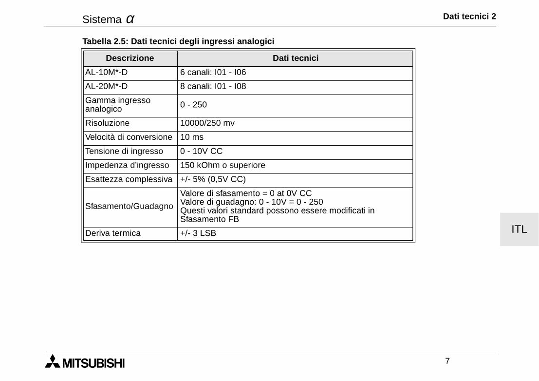
Sistema α Dati tecnici 2
7
ITL
Tabella 2.5: Dati tecnici degli ingressi analogici
Descrizione Dati tecnici
AL-10M*-D 6 canali: I01 - I06
AL-20M*-D 8 canali: I01 - I08
Gamma ingresso analogico 0 - 250
Risoluzione 10000/250 mv
Velocità di conversione 10 ms
Tensione di ingresso 0 - 10V CC
Impedenza d’ingresso 150 kOhm o superiore
Esattezza complessiva +/- 5% (0,5V CC)
Sfasamento/Guadagno
Valore di sfasamento = 0 at 0V CCValore di guadagno: 0 - 10V = 0 - 250Questi valori standard possono essere modificati in Sfasamento FB
Deriva termica +/- 3 LSB
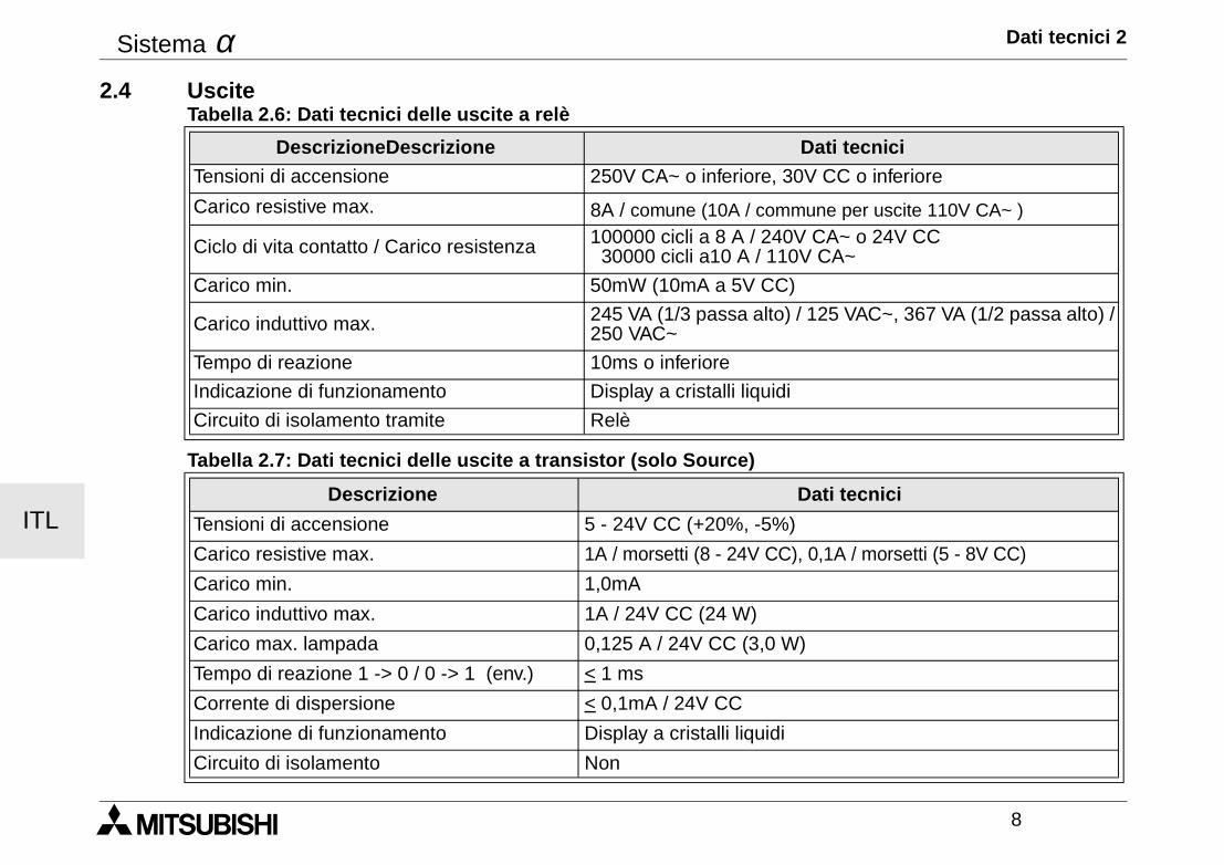
Sistema α Dati tecnici 2
8
ITL
2.4 Uscite
Tabella 2.6: Dati tecnici delle uscite a relè
DescrizioneDescrizione Dati tecnici
Tensioni di accensione 250V CA~ o inferiore, 30V CC o inferiore
Carico resistive max. 8A / comune (10A / commune per uscite 110V CA~ )
Ciclo di vita contatto / Carico resistenza 100000 cicli a 8 A / 240V CA~ o 24V CC 30000 cicli a10 A / 110V CA~
Carico min. 50mW (10mA a 5V CC)
Carico induttivo max. 245 VA (1/3 passa alto) / 125 VAC~, 367 VA (1/2 passa alto) /250 VAC~
Tempo di reazione 10ms o inferiore
Indicazione di funzionamento Display a cristalli liquidi
Circuito di isolamento tramite Relè
Tabella 2.7: Dati tecnici delle uscite a transistor (solo Source)
Descrizione Dati tecnici
Tensioni di accensione 5 - 24V CC (+20%, -5%)
Carico resistive max. 1A / morsetti (8 - 24V CC), 0,1A / morsetti (5 - 8V CC)
Carico min. 1,0mA
Carico induttivo max. 1A / 24V CC (24 W)
Carico max. lampada 0,125 A / 24V CC (3,0 W)
Tempo di reazione 1 -> 0 / 0 -> 1 (env.) < 1 ms
Corrente di dispersione < 0,1mA / 24V CC
Indicazione di funzionamento Display a cristalli liquidi
Circuito di isolamento Non
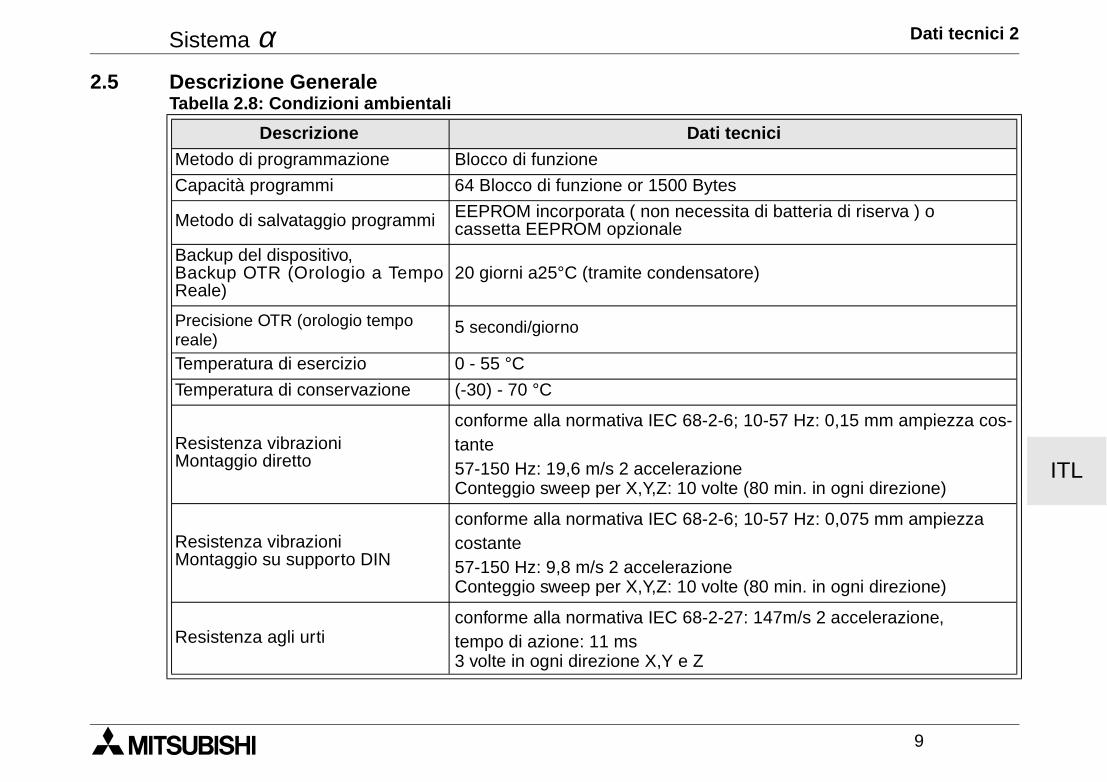
Sistema α Dati tecnici 2
9
ITL
2.5 Descrizione GeneraleTabella 2.8: Condizioni ambientali
Descrizione Dati tecnici
Metodo di programmazione Blocco di funzione
Capacità programmi 64 Blocco di funzione or 1500 Bytes
Metodo di salvataggio programmi EEPROM incorporata ( non necessita di batteria di riserva ) o cassetta EEPROM opzionale
Backup del dispositivo,Backup OTR (Orologio a TempoReale)
20 giorni a25°C (tramite condensatore)
Precisione OTR (orologio tempo reale)
5 secondi/giorno
Temperatura di esercizio 0 - 55 °C
Temperatura di conservazione (-30) - 70 °C
Resistenza vibrazioniMontaggio diretto
conforme alla normativa IEC 68-2-6; 10-57 Hz: 0,15 mm ampiezza cos-tante 57-150 Hz: 19,6 m/s 2 accelerazione Conteggio sweep per X,Y,Z: 10 volte (80 min. in ogni direzione)
Resistenza vibrazioniMontaggio su supporto DIN
conforme alla normativa IEC 68-2-6; 10-57 Hz: 0,075 mm ampiezza costante 57-150 Hz: 9,8 m/s 2 accelerazione Conteggio sweep per X,Y,Z: 10 volte (80 min. in ogni direzione)
Resistenza agli urticonforme alla normativa IEC 68-2-27: 147m/s 2 accelerazione, tempo di azione: 11 ms3 volte in ogni direzione X,Y e Z
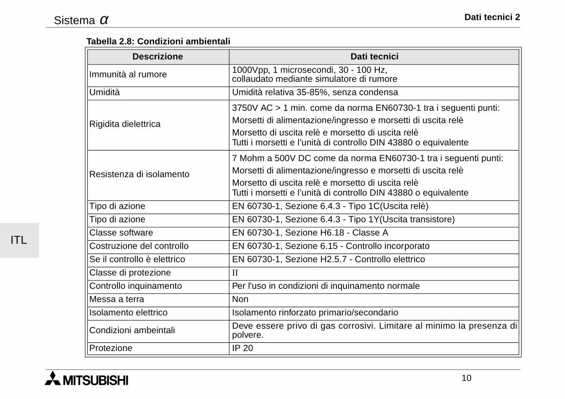
Sistema α Dati tecnici 2
10
ITL
Immunità al rumore 1000Vpp, 1 microsecondi, 30 - 100 Hz, collaudato mediante simulatore di rumore
Umidità Umidità relativa 35-85%, senza condensa
Rigidita dielettrica
3750V AC > 1 min. come da norma EN60730-1 tra i seguenti punti:Morsetti di alimentazione/ingresso e morsetti di uscita relè Morsetto di uscita relè e morsetto di uscita relè Tutti i morsetti e l’unità di controllo DIN 43880 o equivalente
Resistenza di isolamento
7 Mohm a 500V DC come da norma EN60730-1 tra i seguenti punti: Morsetti di alimentazione/ingresso e morsetti di uscita relè Morsetto di uscita relè e morsetto di uscita relè Tutti i morsetti e l’unità di controllo DIN 43880 o equivalente
Tipo di azione EN 60730-1, Sezione 6.4.3 - Tipo 1C(Uscita relè)
Tipo di azione EN 60730-1, Sezione 6.4.3 - Tipo 1Y(Uscita transistore)
Classe software EN 60730-1, Sezione H6.18 - Classe A
Costruzione del controllo EN 60730-1, Sezione 6.15 - Controllo incorporato
Se il controllo è elettrico EN 60730-1, Sezione H2.5.7 - Controllo elettrico
Classe di protezione II
Controllo inquinamento Per l'uso in condizioni di inquinamento normale
Messa a terra Non
Isolamento elettrico Isolamento rinforzato primario/secondario
Condizioni ambeintali Deve essere privo di gas corrosivi. Limitare al minimo la presenza dipolvere.
Protezione IP 20
Tabella 2.8: Condizioni ambientali
Descrizione Dati tecnici
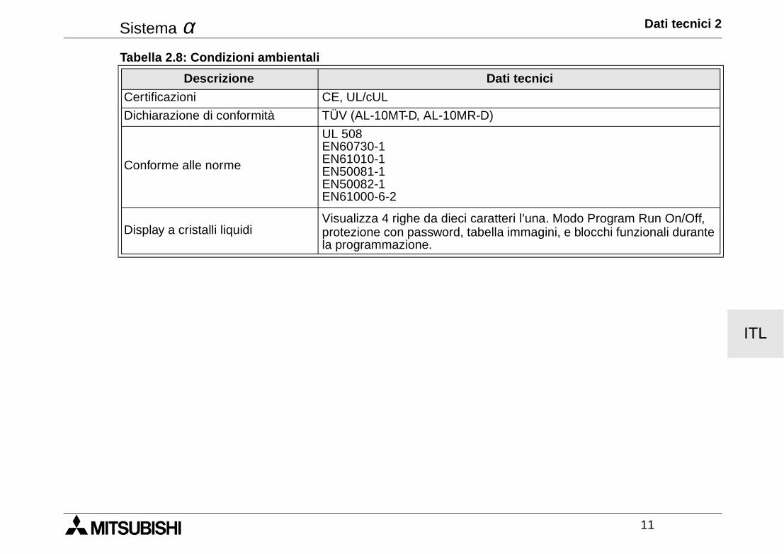
Sistema α Dati tecnici 2
11
ITL
Certificazioni CE, UL/cUL
Dichiarazione di conformità TÜV (AL-10MT-D, AL-10MR-D)
Conforme alle norme
UL 508EN60730-1EN61010-1EN50081-1EN50082-1EN61000-6-2
Display a cristalli liquidiVisualizza 4 righe da dieci caratteri l’una. Modo Program Run On/Off, protezione con password, tabella immagini, e blocchi funzionali durante la programmazione.
Tabella 2.8: Condizioni ambientali
Descrizione Dati tecnici

Sistema α Dati tecnici 2
12
ITL
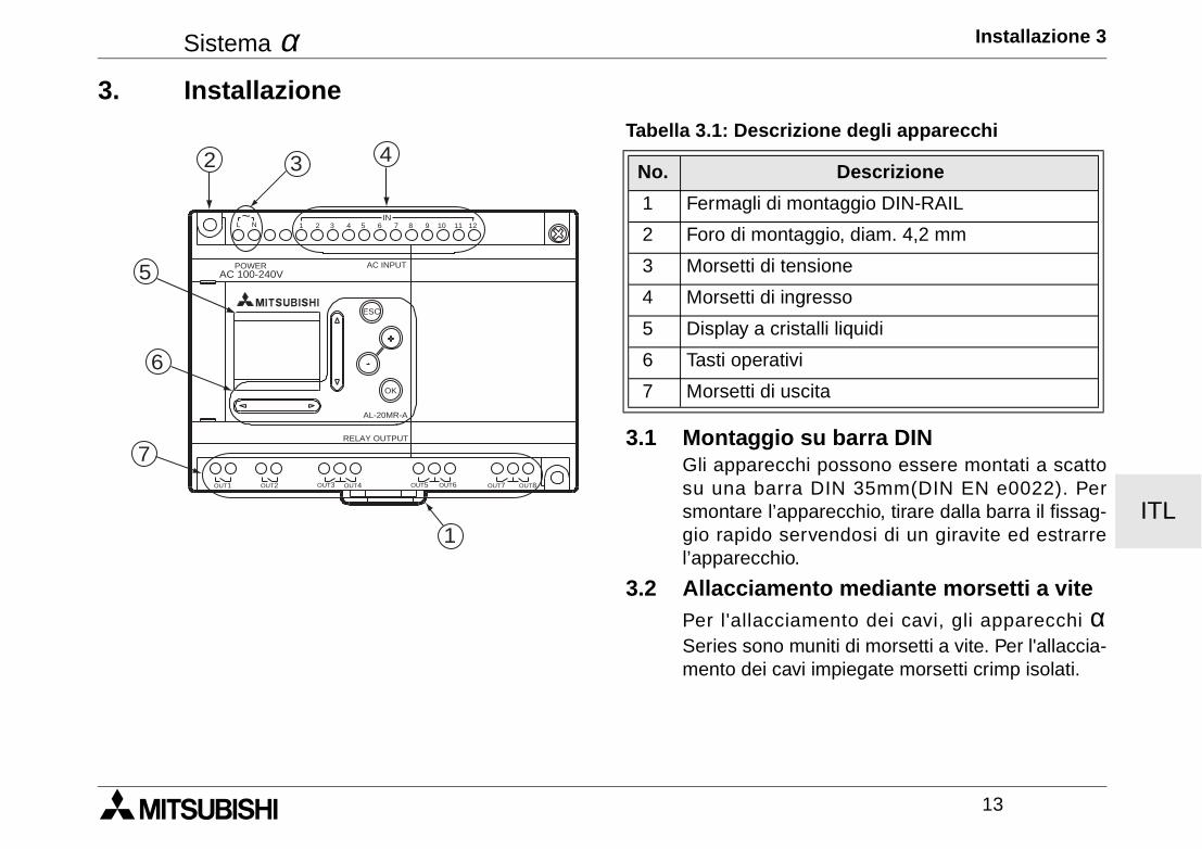
Sistema α Installazione 3
13
ITL
3. Installazione
3.1 Montaggio su barra DINGli apparecchi possono essere montati a scattosu una barra DIN 35mm(DIN EN e0022). Persmontare l’apparecchio, tirare dalla barra il fissag-gio rapido servendosi di un giravite ed estrarrel’apparecchio.
3.2 Allacciamento mediante morsetti a vitePer l'allacciamento dei cavi, gli apparecchi αSeries sono muniti di morsetti a vite. Per l'allaccia-mento dei cavi impiegate morsetti crimp isolati.
Tabella 3.1: Descrizione degli apparecchi
No. Descrizione
1 Fermagli di montaggio DIN-RAIL
2 Foro di montaggio, diam. 4,2 mm
3 Morsetti di tensione
4 Morsetti di ingresso
5 Display a cristalli liquidi
6 Tasti operativi
7 Morsetti di uscita
AC 100-240VPOWER AC INPUT
AL-20MR-A
OK
ESC
RELAY OUTPUT
OUT1 OUT2 OUT5OUT3 OUT4 OUT6 OUT8OUT7
1 2 3 4 5 6 7 8 9 10 11 12IN
L N~
432
5
6
7
1
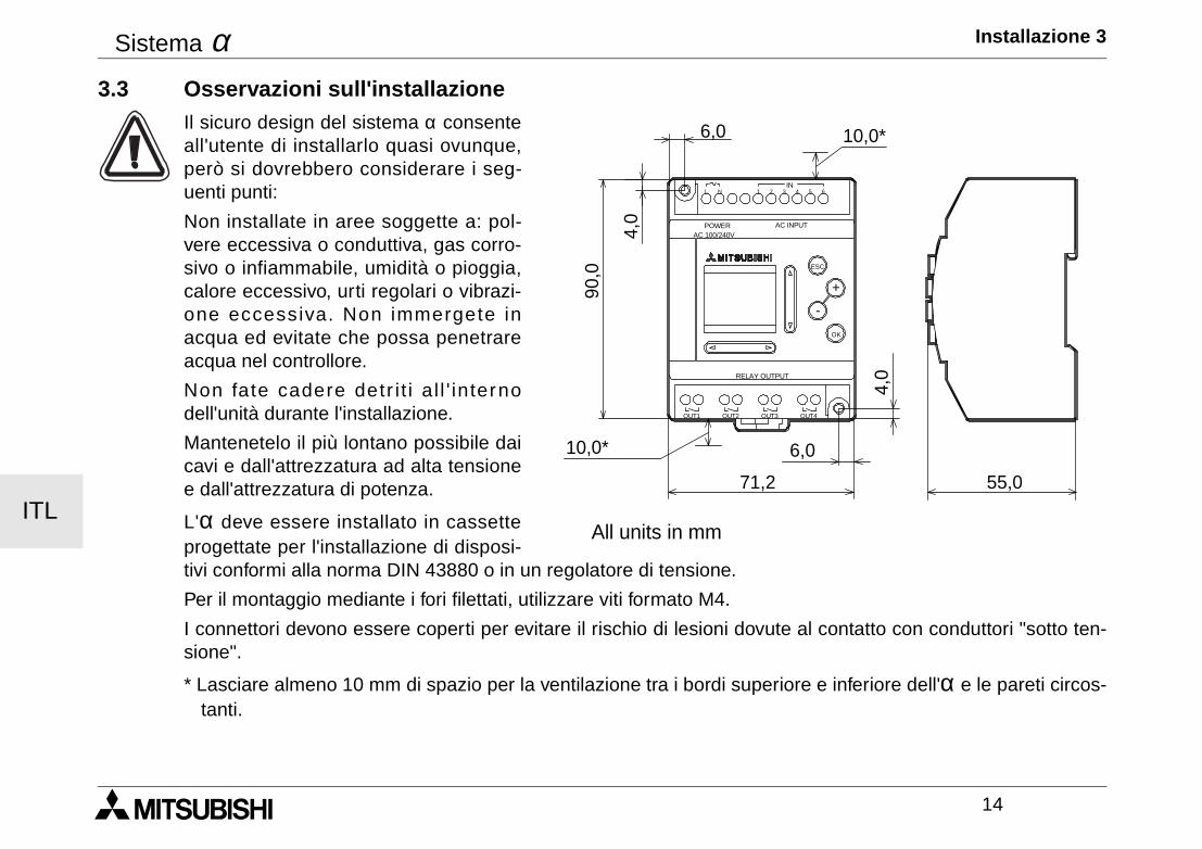
Sistema α Installazione 3
14
ITL
3.3 Osservazioni sull'installazioneIl sicuro design del sistema α consenteall'utente di installarlo quasi ovunque,però si dovrebbero considerare i seg-uenti punti:
Non installate in aree soggette a: pol-vere eccessiva o conduttiva, gas corro-sivo o infiammabile, umidità o pioggia,calore eccessivo, urti regolari o vibrazi-one eccessiva. Non immergete inacqua ed evitate che possa penetrareacqua nel controllore.
Non fate cadere detr i t i a l l ' internodell'unità durante l'installazione.
Mantenetelo il più lontano possibile daicavi e dall'attrezzatura ad alta tensionee dall'attrezzatura di potenza.
L'α deve essere installato in cassetteprogettate per l'installazione di disposi-tivi conformi alla norma DIN 43880 o in un regolatore di tensione.
Per il montaggio mediante i fori filettati, utilizzare viti formato M4.
I connettori devono essere coperti per evitare il rischio di lesioni dovute al contatto con conduttori "sotto ten-sione".
* Lasciare almeno 10 mm di spazio per la ventilazione tra i bordi superiore e inferiore dell'α e le pareti circos-tanti.
POWER
IN
OK
+
RELAY OUTPUT
ESC
-
3 421 5L 6N
OUT3 OUT4OUT2OUT1
AC INPUTAC 100/240V
10,0*
10,0*
71,2
6,0
90,0
4,0
55,0
4,0
6,0
All units in mm
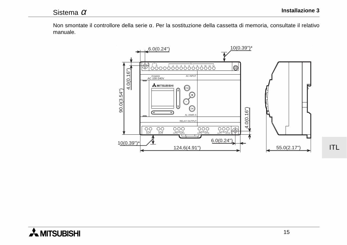
Sistema α Installazione 3
15
ITL
Non smontate il controllore della serie α. Per la sostituzione della cassetta di memoria, consultate il relativomanuale.
AC 100-240VPOWER AC INPUT
AL-20MR-A
OK
ESC
RELAY OUTPUT
6.0(0.24") 10(0.39")*
55.0(2.17")
6.0(0.24")
124.6(4.91")10(0.39")*
4.0
(0.1
6")90.0
(3.5
4") 4
.0(0
.16")
OUT1 OUT2 OUT5OUT3 OUT4 OUT6 OUT8OUT7
1 2 3 4 5 6 7 8 9 10 11 12IN
L N~
Sistema α Installazione 3
16
ITL
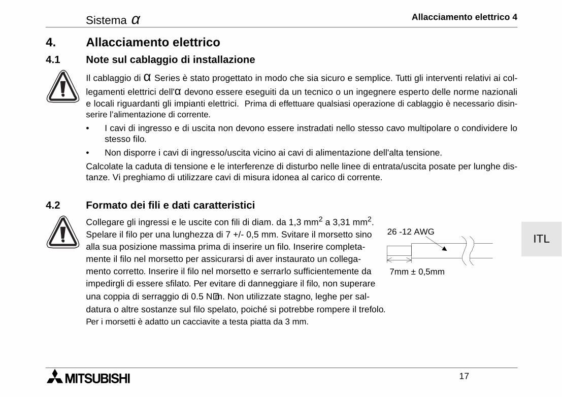
Sistema α Allacciamento elettrico 4
17
ITL
4. Allacciamento elettrico4.1 Note sul cablaggio di installazione
Il cablaggio di α Series è stato progettato in modo che sia sicuro e semplice. Tutti gli interventi relativi ai col-
legamenti elettrici dell'α devono essere eseguiti da un tecnico o un ingegnere esperto delle norme nazionalie locali riguardanti gli impianti elettrici. Prima di effettuare qualsiasi operazione di cablaggio è necessario disin-serire l’alimentazione di corrente.
• I cavi di ingresso e di uscita non devono essere instradati nello stesso cavo multipolare o condividere lostesso filo.
• Non disporre i cavi di ingresso/uscita vicino ai cavi di alimentazione dell'alta tensione.
Calcolate la caduta di tensione e le interferenze di disturbo nelle linee di entrata/uscita posate per lunghe dis-tanze. Vi preghiamo di utilizzare cavi di misura idonea al carico di corrente.
4.2 Formato dei fili e dati caratteristici
Collegare gli ingressi e le uscite con fili di diam. da 1,3 mm2 a 3,31 mm2. Spelare il filo per una lunghezza di 7 +/- 0,5 mm. Svitare il morsetto sino alla sua posizione massima prima di inserire un filo. Inserire completa-mente il filo nel morsetto per assicurarsi di aver instaurato un collega-mento corretto. Inserire il filo nel morsetto e serrarlo sufficientemente da impedirgli di essere sfilato. Per evitare di danneggiare il filo, non superare
una coppia di serraggio di 0.5 N⋅⋅⋅⋅m. Non utilizzate stagno, leghe per sal-
datura o altre sostanze sul filo spelato, poiché si potrebbe rompere il trefolo.Per i morsetti è adatto un cacciavite a testa piatta da 3 mm.
7mm ± 0,5mm
26 -12 AWG
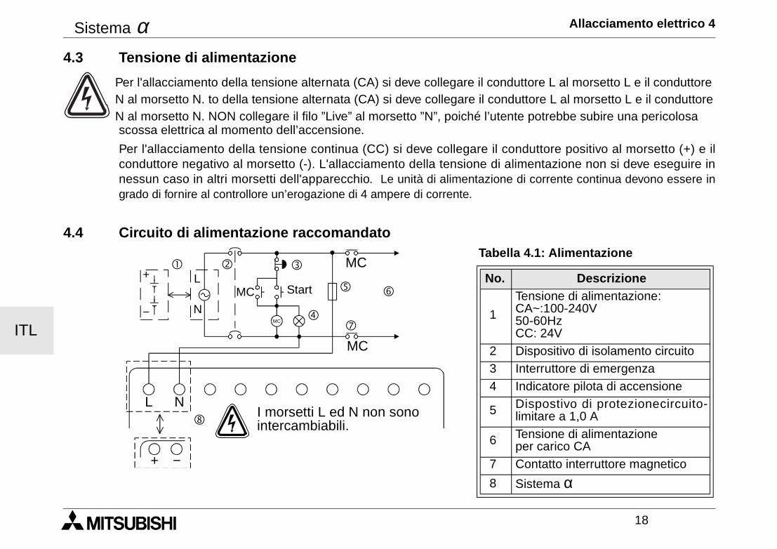
Sistema α Allacciamento elettrico 4
18
ITL
4.3 Tensione di alimentazione
Per l'allacciamento della tensione alternata (CA) si deve collegare il conduttore L al morsetto L e il conduttore N al morsetto N. to della tensione alternata (CA) si deve collegare il conduttore L al morsetto L e il conduttoreN al morsetto N. NON collegare il filo ”Live” al morsetto ”N”, poiché l’utente potrebbe subire una pericolosa scossa elettrica al momento dell’accensione.
Per l'allacciamento della tensione continua (CC) si deve collegare il conduttore positivo al morsetto (+) e ilconduttore negativo al morsetto (-). L'allacciamento della tensione di alimentazione non si deve eseguire innessun caso in altri morsetti dell'apparecchio. Le unità di alimentazione di corrente continua devono essere ingrado di fornire al controllore un’erogazione di 4 ampere di corrente.
4.4 Circuito di alimentazione raccomandatoTabella 4.1: Alimentazione
No. Descrizione
1
Tensione di alimentazione: CA~:100-240V50-60HzCC: 24V
2 Dispositivo di isolamento circuito 3 Interruttore di emergenza 4 Indicatore pilota di accensione
5 Dispostivo di protezionecircuito-limitare a 1,0 A
6 Tensione di alimentazione per carico CA
7 Contatto interruttore magnetico
8 Sistema α
MC
MC
MC
MC
L N
! " #
$
% &
'
(
+
−
L
N
+ −
Start
I morsetti L ed N non sonointercambiabili.
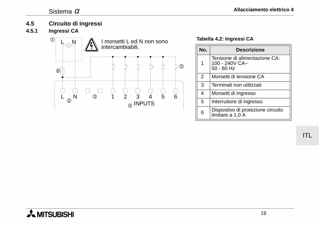
Sistema α Allacciamento elettrico 4
19
ITL
4.5 Circuito di ingressi4.5.1 Ingressi CA
Tabella 4.2: Ingressi CA
No. Descrizione
1Tensione di alimentazione CA:100 - 240V CA~50 - 60 Hz
2 Morsetti di tensione CA
3 Terminali non utilizzati
4 Morsetti di ingresso
5 Interruttore di ingresso
6 Dispostivo di protezione circuitolimitare a 1,0 A
! L N
"#
$
%
L N 1 2 3INPUTS
4 5 6
&
I morsetti L ed N non sonointercambiabili.
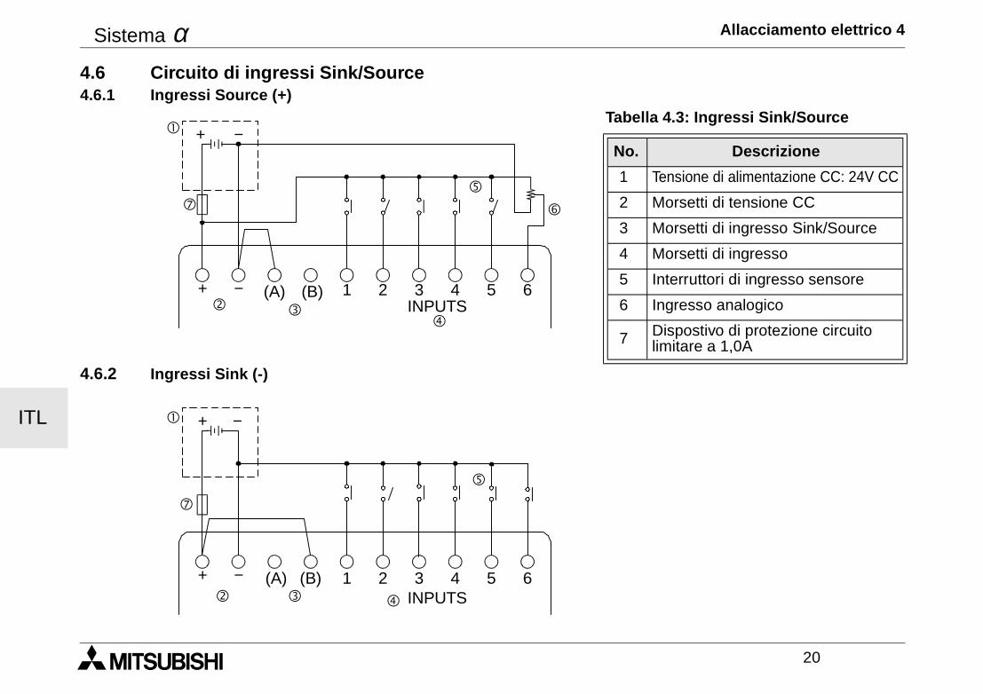
Sistema α Allacciamento elettrico 4
20
ITL
4.6 Circuito di ingressi Sink/Source4.6.1 Ingressi Source (+)
4.6.2 Ingressi Sink (-)
Tabella 4.3: Ingressi Sink/Source
No. Descrizione
1 Tensione di alimentazione CC: 24V CC
2 Morsetti di tensione CC
3 Morsetti di ingresso Sink/Source
4 Morsetti di ingresso
5 Interruttori di ingresso sensore
6 Ingresso analogico
7 Dispostivo di protezione circuitolimitare a 1,0A
! + −
"$
%
&
+ − (A) (B) 1 2 3INPUTS
4 5 6
(
#
! + −
" # $
%
+ − (A) (B) 1 2 3INPUTS
4 5 6
(
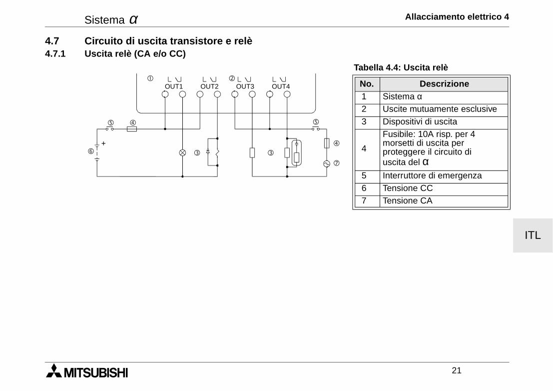
Sistema α Allacciamento elettrico 4
21
ITL
4.7 Circuito di uscita transistore e relè4.7.1 Uscita relè (CA e/o CC)
Tabella 4.4: Uscita relè
No. Descrizione 1 Sistema α 2 Uscite mutuamente esclusive 3 Dispositivi di uscita
4
Fusibile: 10A risp. per 4 morsetti di uscita per proteggere il circuito di uscita del α
5 Interruttore di emergenza 6 Tensione CC 7 Tensione CA
"!
$
OUT1
##
%
&
OUT2 OUT3 OUT4
(
$
%
+
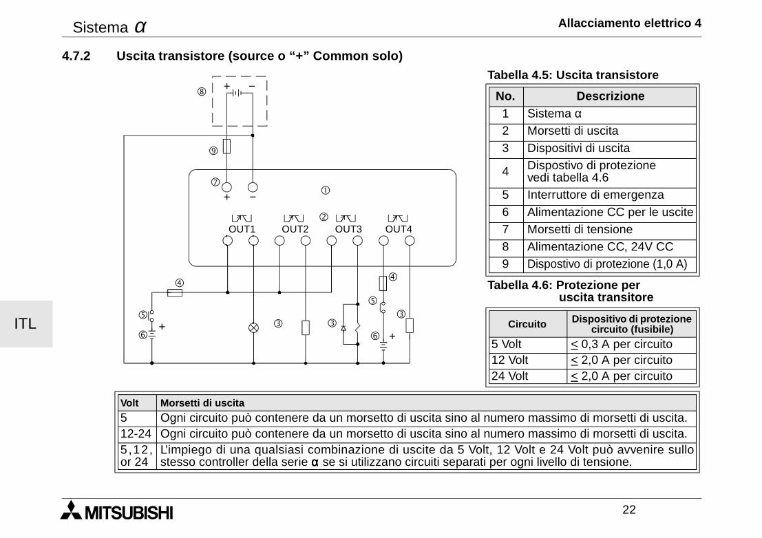
Sistema α Allacciamento elettrico 4
22
ITL
4.7.2 Uscita transistore (source o “+” Common solo)Tabella 4.5: Uscita transistore
No. Descrizione1 Sistema α2 Morsetti di uscita3 Dispositivi di uscita
4 Dispostivo di protezione vedi tabella 4.6
5 Interruttore di emergenza6 Alimentazione CC per le uscite7 Morsetti di tensione8 Alimentazione CC, 24V CC9 Dispostivo di protezione (1,0 A)
Tabella 4.6: Protezione per uscita transitore
Circuito Dispositivo di protezione circuito (fusibile)
5 Volt < 0,3 A per circuito12 Volt < 2,0 A per circuito24 Volt < 2,0 A per circuito
Volt Morsetti di uscita
5 Ogni circuito può contenere da un morsetto di uscita sino al numero massimo di morsetti di uscita.12-24 Ogni circuito può contenere da un morsetto di uscita sino al numero massimo di morsetti di uscita.5 ,12,or 24
L’impiego di una qualsiasi combinazione di uscite da 5 Volt, 12 Volt e 24 Volt può avvenire sullostesso controller della serie α α α α se si utilizzano circuiti separati per ogni livello di tensione.
"
!
OUT1
##
OUT2 OUT3 OUT4
$
%
&
+ −
+ −(
$
%
&+
+
#
)
'
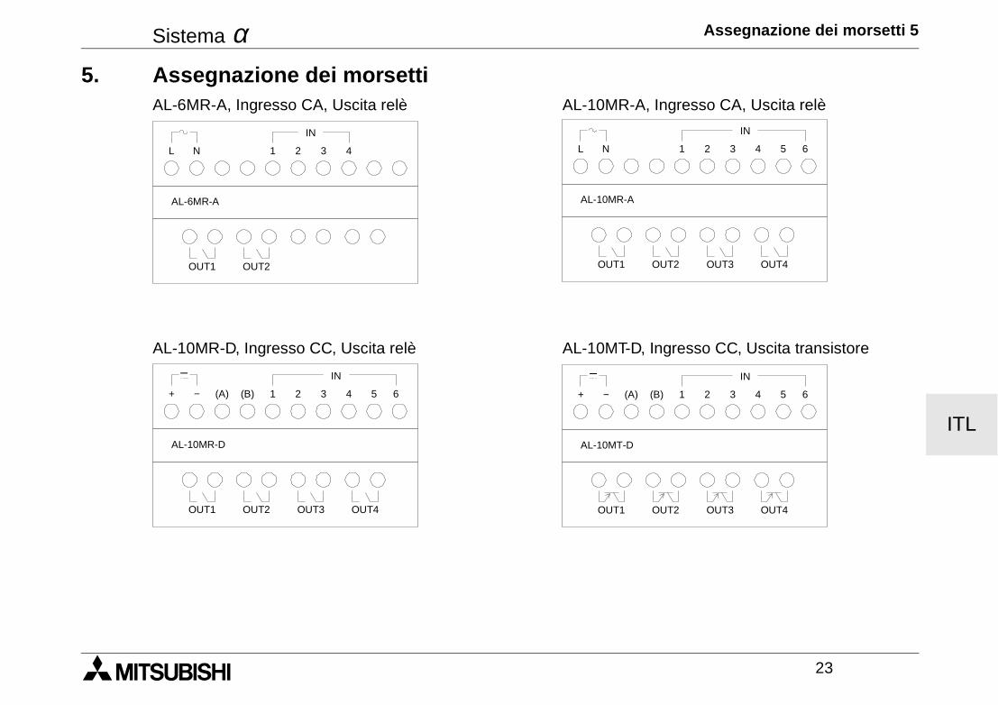
Sistema α Assegnazione dei morsetti 5
23
ITL
5. Assegnazione dei morsettiAL-6MR-A, Ingresso CA, Uscita relè AL-10MR-A, Ingresso CA, Uscita relè
AL-10MR-D, Ingresso CC, Uscita relè AL-10MT-D, Ingresso CC, Uscita transistore
L N 1 2 3 4
OUT1
AL-6MR-A
OUT2
IN
L N 1 2 3 4
OUT1
AL-10MR-A
OUT2
IN
5 6
OUT3 OUT4
+ − (A) (B) 1 2 3 4
OUT1
AL-10MR-D
OUT2
IN
5 6
OUT3 OUT4
+ − (B) 1 2 3 4
OUT1
AL-10MT-D
OUT2
IN
5 6
OUT3 OUT4
(A)
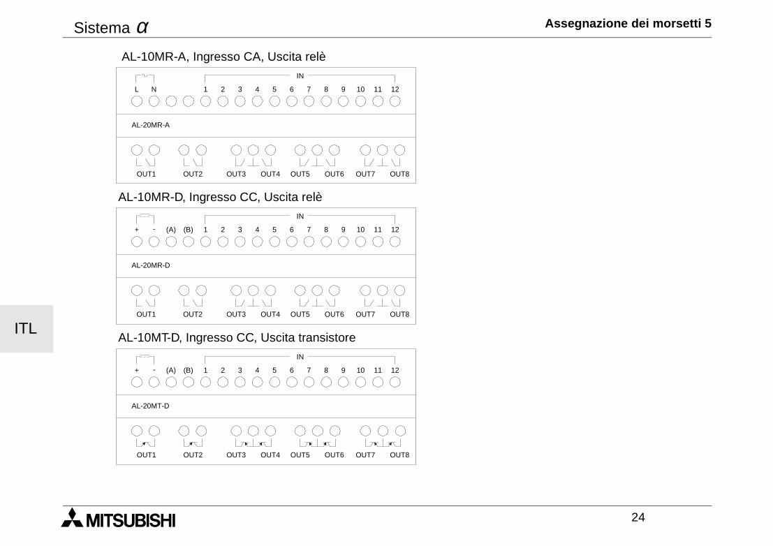
Sistema α Assegnazione dei morsetti 5
24
ITL
AL-10MR-A, Ingresso CA, Uscita relè
AL-10MR-D, Ingresso CC, Uscita relè
AL-10MT-D, Ingresso CC, Uscita transistore
L N
IN
12111 2 3 4 5 6 7 8 9 10
OUT1 OUT2 OUT3 OUT5 OUT7OUT4 OUT6 OUT8
AL-20MR-A
+ -
IN
12111 2 3 4 5 6 7 8 9 10
OUT1 OUT2 OUT3 OUT5 OUT7OUT4 OUT6 OUT8
AL-20MR-D
(A) (B)
+ -
IN
12111 2 3 4 5 6 7 8 9 10
OUT1 OUT2 OUT3 OUT5 OUT7OUT4 OUT6 OUT8
AL-20MT-D
(A) (B)
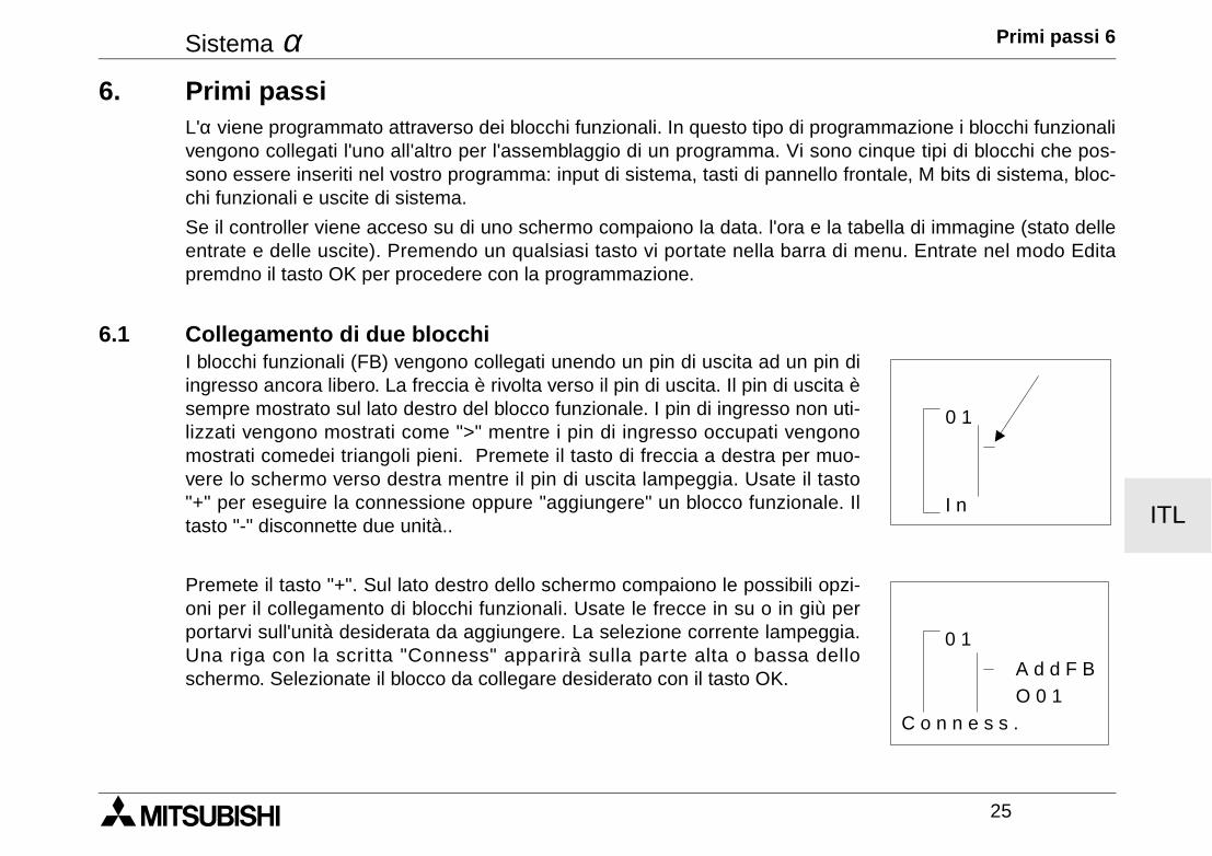
Sistema α Primi passi 6
25
ITL
6. Primi passiL'α viene programmato attraverso dei blocchi funzionali. In questo tipo di programmazione i blocchi funzionalivengono collegati l'uno all'altro per l'assemblaggio di un programma. Vi sono cinque tipi di blocchi che pos-sono essere inseriti nel vostro programma: input di sistema, tasti di pannello frontale, M bits di sistema, bloc-chi funzionali e uscite di sistema.
Se il controller viene acceso su di uno schermo compaiono la data. l'ora e la tabella di immagine (stato delleentrate e delle uscite). Premendo un qualsiasi tasto vi portate nella barra di menu. Entrate nel modo Editapremdno il tasto OK per procedere con la programmazione.
6.1 Collegamento di due blocchiI blocchi funzionali (FB) vengono collegati unendo un pin di uscita ad un pin diingresso ancora libero. La freccia è rivolta verso il pin di uscita. Il pin di uscita èsempre mostrato sul lato destro del blocco funzionale. I pin di ingresso non uti-lizzati vengono mostrati come ">" mentre i pin di ingresso occupati vengonomostrati comedei triangoli pieni. Premete il tasto di freccia a destra per muo-vere lo schermo verso destra mentre il pin di uscita lampeggia. Usate il tasto"+" per eseguire la connessione oppure "aggiungere" un blocco funzionale. Iltasto "-" disconnette due unità..
Premete il tasto "+". Sul lato destro dello schermo compaiono le possibili opzi-oni per il collegamento di blocchi funzionali. Usate le frecce in su o in giù perportarvi sull'unità desiderata da aggiungere. La selezione corrente lampeggia.Una riga con la scritta "Conness" apparirà sulla parte alta o bassa delloschermo. Selezionate il blocco da collegare desiderato con il tasto OK.
0 1
I n
0 1
A d d F BO 0 1
C o n n e s s .
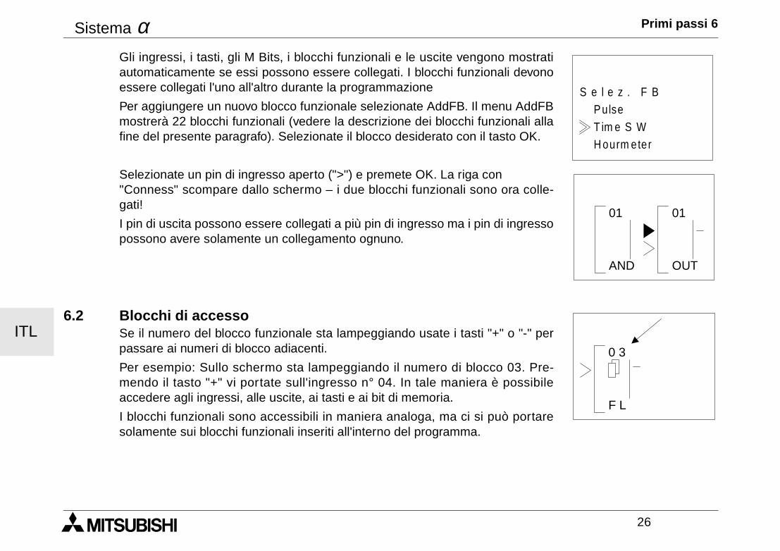
Sistema α Primi passi 6
26
ITL
Gli ingressi, i tasti, gli M Bits, i blocchi funzionali e le uscite vengono mostratiautomaticamente se essi possono essere collegati. I blocchi funzionali devonoessere collegati l'uno all'altro durante la programmazione
Per aggiungere un nuovo blocco funzionale selezionate AddFB. Il menu AddFBmostrerà 22 blocchi funzionali (vedere la descrizione dei blocchi funzionali allafine del presente paragrafo). Selezionate il blocco desiderato con il tasto OK.
Selezionate un pin di ingresso aperto (">") e premete OK. La riga con "Conness" scompare dallo schermo – i due blocchi funzionali sono ora colle-gati!
I pin di uscita possono essere collegati a più pin di ingresso ma i pin di ingressopossono avere solamente un collegamento ognuno.
6.2 Blocchi di accesso Se il numero del blocco funzionale sta lampeggiando usate i tasti "+" o "-" perpassare ai numeri di blocco adiacenti.
Per esempio: Sullo schermo sta lampeggiando il numero di blocco 03. Pre-mendo il tasto "+" vi portate sull'ingresso n° 04. In tale maniera è possibileaccedere agli ingressi, alle uscite, ai tasti e ai bit di memoria.
I blocchi funzionali sono accessibili in maniera analoga, ma ci si può portaresolamente sui blocchi funzionali inseriti all'interno del programma.
H ourm eter
PulseS e l e z . F B
T im e S W
AND
01 01
OUT
0 3
F L
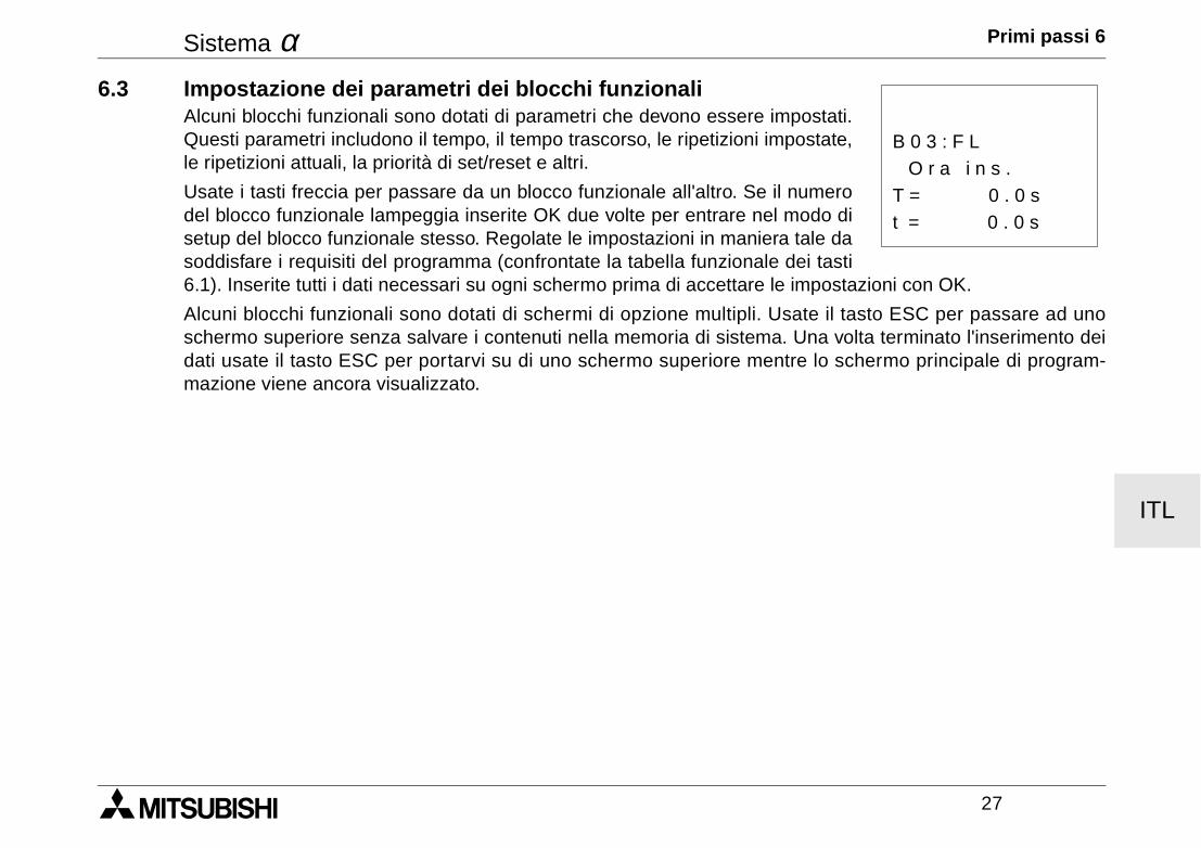
Sistema α Primi passi 6
27
ITL
6.3 Impostazione dei parametri dei blocchi funzionaliAlcuni blocchi funzionali sono dotati di parametri che devono essere impostati.Questi parametri includono il tempo, il tempo trascorso, le ripetizioni impostate,le ripetizioni attuali, la priorità di set/reset e altri.
Usate i tasti freccia per passare da un blocco funzionale all'altro. Se il numerodel blocco funzionale lampeggia inserite OK due volte per entrare nel modo disetup del blocco funzionale stesso. Regolate le impostazioni in maniera tale dasoddisfare i requisiti del programma (confrontate la tabella funzionale dei tasti6.1). Inserite tutti i dati necessari su ogni schermo prima di accettare le impostazioni con OK.
Alcuni blocchi funzionali sono dotati di schermi di opzione multipli. Usate il tasto ESC per passare ad unoschermo superiore senza salvare i contenuti nella memoria di sistema. Una volta terminato l'inserimento deidati usate il tasto ESC per portarvi su di uno schermo superiore mentre lo schermo principale di program-mazione viene ancora visualizzato.
t = 0 . 0 s
O r a i n s .B 0 3 : F L
T = 0 . 0 s
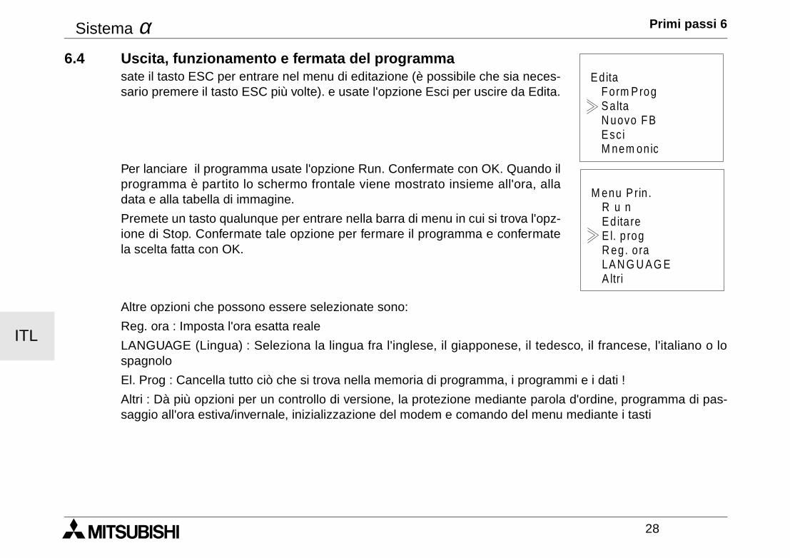
Sistema α Primi passi 6
28
ITL
6.4 Uscita, funzionamento e fermata del programmasate il tasto ESC per entrare nel menu di editazione (è possibile che sia neces-sario premere il tasto ESC più volte). e usate l'opzione Esci per uscire da Edita.
Per lanciare il programma usate l'opzione Run. Confermate con OK. Quando ilprogramma è partito lo schermo frontale viene mostrato insieme all'ora, alladata e alla tabella di immagine.
Premete un tasto qualunque per entrare nella barra di menu in cui si trova l'opz-ione di Stop. Confermate tale opzione per fermare il programma e confermatela scelta fatta con OK.
Altre opzioni che possono essere selezionate sono:
Reg. ora : Imposta l'ora esatta reale
LANGUAGE (Lingua) : Seleziona la lingua fra l'inglese, il giapponese, il tedesco, il francese, l'italiano o lospagnolo
El. Prog : Cancella tutto ciò che si trova nella memoria di programma, i programmi e i dati !
Altri : Dà più opzioni per un controllo di versione, la protezione mediante parola d'ordine, programma di pas-saggio all'ora estiva/invernale, inizializzazione del modem e comando del menu mediante i tasti
Ed ita
Esc i
Form ProgSaltaN uovo FB
M nem onic
M enu P rin .
R eg. ora
R u nEditareE l. p rog
A ltriLAN G U AG E
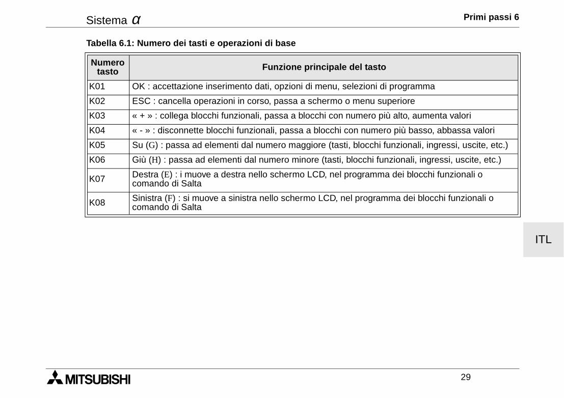
Sistema α Primi passi 6
29
ITL
Tabella 6.1: Numero dei tasti e operazioni di base
Numero tasto Funzione principale del tasto
K01 OK : accettazione inserimento dati, opzioni di menu, selezioni di programma
K02 ESC : cancella operazioni in corso, passa a schermo o menu superiore
K03 « + » : collega blocchi funzionali, passa a blocchi con numero più alto, aumenta valori
K04 « - » : disconnette blocchi funzionali, passa a blocchi con numero più basso, abbassa valori
K05 Su (G) : passa ad elementi dal numero maggiore (tasti, blocchi funzionali, ingressi, uscite, etc.)
K06 Giù (H) : passa ad elementi dal numero minore (tasti, blocchi funzionali, ingressi, uscite, etc.)
K07 Destra (E) : i muove a destra nello schermo LCD, nel programma dei blocchi funzionali ocomando di Salta
K08 Sinistra (F) : si muove a sinistra nello schermo LCD, nel programma dei blocchi funzionali ocomando di Salta
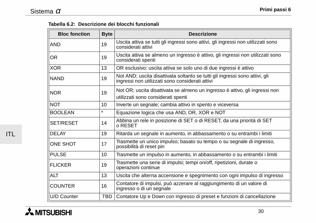
Sistema α Primi passi 6
30
ITL
Tabella 6.2: Descrizione dei blocchi funzionali
Bloc fonction Byte Descrizione
AND 19 Uscita attiva se tutti gli ingressi sono attivi, gli ingressi non utilizzati sono considerati attivi
OR 19 Uscita attiva se almeno un ingresso è attivo, gli ingressi non utilizzati sonoconsiderati spenti
XOR 13 OR esclusivo: uscita attiva se solo uno di due ingressi è attivo
NAND 19 Not AND; uscita disattivata soltanto se tutti gli ingressi sono attivi, gli ingressi non utilizzati sono considerati attivi
NOR 19 Not OR; uscita disattivata se almeno un ingresso è attivo, gli ingressi non utilizzati sono considerati spenti
NOT 10 Inverte un segnale; cambia attivo in spento e viceversa
BOOLEAN * Equazione logica che usa AND, OR, XOR e NOT
SET/RESET 14 Abbina un rele in posizione di SET o di RESET, da una priorità di SET o RESET
DELAY 19 Ritarda un segnale in aumento, in abbassamento o su entrambi i limiti
ONE SHOT 17 Trasmette un unico impulso; basato su tempo o su segnale di ingresso, possibilità di reset pin
PULSE 10 Trasmette un impulso in aumento, in abbassamento o su entrambi i limiti
FLICKER 19 Trasmette una serie di impulsi; tempi on/off, ripetizioni, durate o operazioni continue
ALT 13 Uscita che alterna accensione e spegnimento con ogni impulso di ingresso
COUNTER 16 Contatore di impulsi, può azzerare al raggiungimento di un valore di ingresso o di un segnale
U/D Counter TBD Contatore Up e Down con ingresso di preset e funzioni di cancellazione
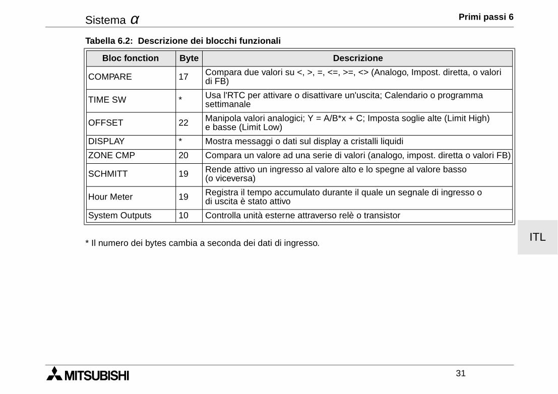
Sistema α Primi passi 6
31
ITL* Il numero dei bytes cambia a seconda dei dati di ingresso.
COMPARE 17 Compara due valori su <, >, =, <=, >=, <> (Analogo, Impost. diretta, o valori di FB)
TIME SW * Usa l'RTC per attivare o disattivare un'uscita; Calendario o programma settimanale
OFFSET 22 Manipola valori analogici; Y = A/B*x + C; Imposta soglie alte (Limit High) e basse (Limit Low)
DISPLAY * Mostra messaggi o dati sul display a cristalli liquidi
ZONE CMP 20 Compara un valore ad una serie di valori (analogo, impost. diretta o valori FB)
SCHMITT 19 Rende attivo un ingresso al valore alto e lo spegne al valore basso (o viceversa)
Hour Meter 19 Registra il tempo accumulato durante il quale un segnale di ingresso o di uscita è stato attivo
System Outputs 10 Controlla unità esterne attraverso relè o transistor
Tabella 6.2: Descrizione dei blocchi funzionali
Bloc fonction Byte Descrizione

Sistema α Primi passi 6
32
ITL

ESP
MANUAL DE HARDWARESISTEMA α
Sistema α
ESP
Prólogo• Este manual contiene textos, ilustraciones y aclaraciones para asegurar una correcta instalación y manejo
de los sistemas α y deberá leerse antes de proceder a su instalación o manejo. Es imprescindible entenderel contenido de este manual.
• En caso de duda durante la instalación, deberá consultar a un electricista cualificado que conozca las normas electrotécnicas locales y nacionales. Si se presenta algún problema durante el manejo o uso delsistema α, póngase en contacto con el concesionario de MITSUBISHI ELECTRIC más cercano.
• Nos reservamos el derecho de efectuar cualquier modificación o cambio en este manual, en cualquiermomento y sin previo aviso.
Sistema α
ESP
i
Sistema αααα
Manual de hardwareNúmero: JY992D74201Revisión: JFecha: 04/2002
Sistema α
ESP
ii
Instrucciones de seguridad para el usuario y medidas de protección para las unidadesEl manual ha sido elaborado para uso del personal competente y cualificado. La certificación cumple las direc-tivas europeas sobre máquinas, bajas tensiones y EMC. El cableado eléctrico de los controladores delsistema α debe ser manipulado por un técnico o ingeniero especializado en las normas eléctricas locales ynacionales. En este manual se emplean símbolos que permiten resaltar determinadas características. Conello, se ofrece a los operarios las indicaciones sobre medidas de seguridad y de protección necesarias.Cuando aparezca uno de los símbolos debe leerse la indicación pertinente para así entender la informaciónproporcionada.
1) Indica un peligro inminente, que puede conducir a daños personales o materiales.
2) Indica la posibilidad de un peligro, que puede conducir a daños personales o materiales.
• MITSUBISHI ELECTRIC no asumirá responsabilidad alguna de los daños que se hayan podido producir por causa de una insta-lación inadecuada o por un uso inapropiado tanto de las unidades como de los accesorios.
• Todos los ejemplos e ilustraciones que aparecen en el manual tienen la finalidad de facilitar la comprensión del texto. MITSUBISHI ELECTRIC no asumirá responsabilidad alguna en cuanto a la exactitud e implementación de los ejemplos expues-tos en este manual se refiere ni a los daños que pudieran ocasionarse tras ponerlos en práctica.
• Debido a las amplias posibilidades de aplicación de este equipo, el propio usuario deberá adaptar dicho equipo a su caso especí-fico.
• Si se rompe el controlador por alguna razón, rogamos tomen medidas de seguridad para parar de forma segura cualquier equipoconectado.
• No cambie ninguna pieza eléctrica ni trate de reparar un producto del sistema α .
• Por favor, utilice el producto del sistema α según las normas locales y nacionales.
Sistema α
iii
Contenido
Instrucciones de seguridad ....................................................................................................... ii
1. Introducción........................................................................................................... 1
2. Especificaciónes ................................................................................................... 32.1 Modelos disponibles .................................................................................................... 32.2 Especificación de suministro eléctrico ......................................................................... 42.3 Entradas....................................................................................................................... 62.4 Salidas ......................................................................................................................... 82.5 Especificación de carácter general .............................................................................. 9
3. Instalación............................................................................................................ 113.1 Carriles de montaje DIN............................................................................................. 113.2 Conexiones de bornas roscadas ............................................................................... 113.3 Observaciones sobre el emplazamiento.................................................................... 12
ESP
Sistema α
iv
4. Alambrado............................................................................................................ 154.1 Notas sobre los alambres de instalación ................................................................... 154.2 Tamaño del alambre y sus especificaciones ............................................................. 154.3 Alimentación de tensión............................................................................................. 164.4 Cableando la alimentación......................................................................................... 164.5 Cableando las entradas CA ....................................................................................... 17
4.5.1 Entradas CA ........................................................................................................ 174.6 Cableando las entradas Sink/Source......................................................................... 18
4.6.1 Entradas Source (+) ............................................................................................ 184.6.2 Entradas Sink (-).................................................................................................. 18
4.7 Cableando las salidas de relé y de transistor ............................................................ 194.7.1 Sortidas de relé (CA y/o CC) ............................................................................... 194.7.2 Sortidas de transistor (source o “+” Common solamente)................................... 20
5. Ocupaciones de bornas...................................................................................... 21
6. Inicio ..................................................................................................................... 236.1 Manera de conectar dos bloques............................................................................... 236.2 Manera de acceder a los bloques ............................................................................. 246.3 Manera de configurar los parámetros de un bloque de función................................. 256.4 Manera de salir, ejecutar o detener el programa ....................................................... 26ESP
Sistema α Introducción 1
1
ESP
1. IntroducciónEl sistema tan simple y de fácil uso ha sido diseñado para ser usado en el hogar, la oficina, fábrica... en todaspartes y además consta de una función flexible de control. Cada módulo le permite leer señales y ajustar laspotencias de salida de acuerdo a las condiciones particulares a los ajustes de tiempo definidos por usted, elusuario. Junto a esto, el visualizador integrado programable le permite controlar el estado de su sistema entodo momento.
Las características especiales del sistema α son:
• Capacidad de programación directa (en el equipo)
• Capacidad de salida de corriente elevada
• Tamaño pequeño
• Puerto de programación de fácil acceso
• Capacidad de almacenamiento de programa en casete EEPROM
• Reloj integrado de tiempo real de serie
• Paquete de programación basado en Windows, AL-PCS/WIN-E
• Más una amplia gama de documentación de ayuda y paquetes de entrenamiento
El α está diseñado para ser usado en las siguientes aplicaciones automáticas: iluminación, aire acondicio-nado, irrigación, puertas, portones, sistemas simples de seguridad, invernaderos, ventiladores, etc. El relojde tiempo real se puede utilizar como un potente dispositivo capaz de ahorrar energía al encender o apagarel equipo a las horas programadas.
Depure los programas cuidadosamente antes de instalarlos en el equipo automatizado. El α no está diseñado parautilizar en situaciones críticas que ponen la vida en peligro ni en aplicaciones de seguridad contra averías.
Para más información, póngase en contacto con su comerciante habitual.
Sistema α Introducción 1
2
ESP
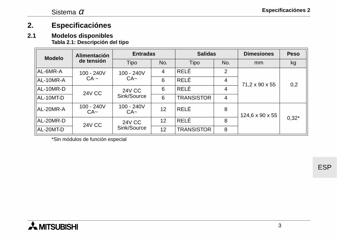
Sistema α Especificaciónes 2
3
ESP
2. Especificaciónes2.1 Modelos disponibles
*Sin módulos de función especial
Tabla 2.1: Descripción del tipo
Modelo Alimentación de tensión
Entradas Salidas Dimesiones Peso
Tipo No. Tipo No. mm kg
AL-6MR-A 100 - 240V CA ~
100 - 240V CA~
4 RELÉ 2
71,2 x 90 x 55 0,2AL-10MR-A 6 RELÉ 4
AL-10MR-D24V CC 24V CC
Sink/Source6 RELÉ 4
AL-10MT-D 6 TRANSISTOR 4
AL-20MR-A 100 - 240V CA~
100 - 240V CA~ 12 RELÉ 8
124,6 x 90 x 55 0,32*AL-20MR-D24V CC 24V CC
Sink/Source12 RELÉ 8
AL-20MT-D 12 TRANSISTOR 8
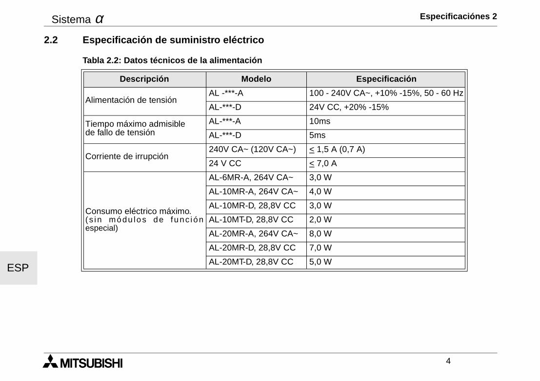
Sistema α Especificaciónes 2
4
ESP
2.2 Especificación de suministro eléctrico
Tabla 2.2: Datos técnicos de la alimentación
Descripción Modelo Especificación
Alimentación de tensiónAL -***-A 100 - 240V CA~, +10% -15%, 50 - 60 Hz
AL-***-D 24V CC, +20% -15%
Tiempo máximo admisible de fallo de tensión
AL-***-A 10ms
AL-***-D 5ms
Corriente de irrupción240V CA~ (120V CA~) < 1,5 A (0,7 A)
24 V CC < 7,0 A
Consumo eléctrico máximo.(s in módu lo s de fu nc iónespecial)
AL-6MR-A, 264V CA~ 3,0 W
AL-10MR-A, 264V CA~ 4,0 W
AL-10MR-D, 28,8V CC 3,0 W
AL-10MT-D, 28,8V CC 2,0 W
AL-20MR-A, 264V CA~ 8,0 W
AL-20MR-D, 28,8V CC 7,0 W
AL-20MT-D, 28,8V CC 5,0 W
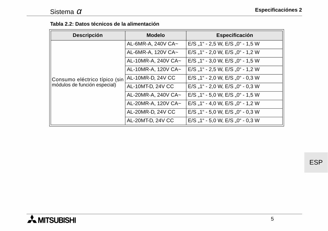
Sistema α Especificaciónes 2
5
ESP
Consumo eléctrico típico (sinmódulos de función especial)
AL-6MR-A, 240V CA~ E/S „1“ - 2,5 W, E/S „0“ - 1,5 W
AL-6MR-A, 120V CA~ E/S „1“ - 2,0 W, E/S „0“ - 1,2 W
AL-10MR-A, 240V CA~ E/S „1“ - 3,0 W, E/S „0“ - 1,5 W
AL-10MR-A, 120V CA~ E/S „1“ - 2,5 W, E/S „0“ - 1,2 W
AL-10MR-D, 24V CC E/S „1“ - 2,0 W, E/S „0“ - 0,3 W
AL-10MT-D, 24V CC E/S „1“ - 2,0 W, E/S „0“ - 0,3 W
AL-20MR-A, 240V CA~ E/S „1“ - 5,0 W, E/S „0“ - 1,5 W
AL-20MR-A, 120V CA~ E/S „1“ - 4,0 W, E/S „0“ - 1,2 W
AL-20MR-D, 24V CC E/S „1“ - 5,0 W, E/S „0“ - 0,3 W
AL-20MT-D, 24V CC E/S „1“ - 5,0 W, E/S „0“ - 0,3 W
Tabla 2.2: Datos técnicos de la alimentación
Descripción Modelo Especificación
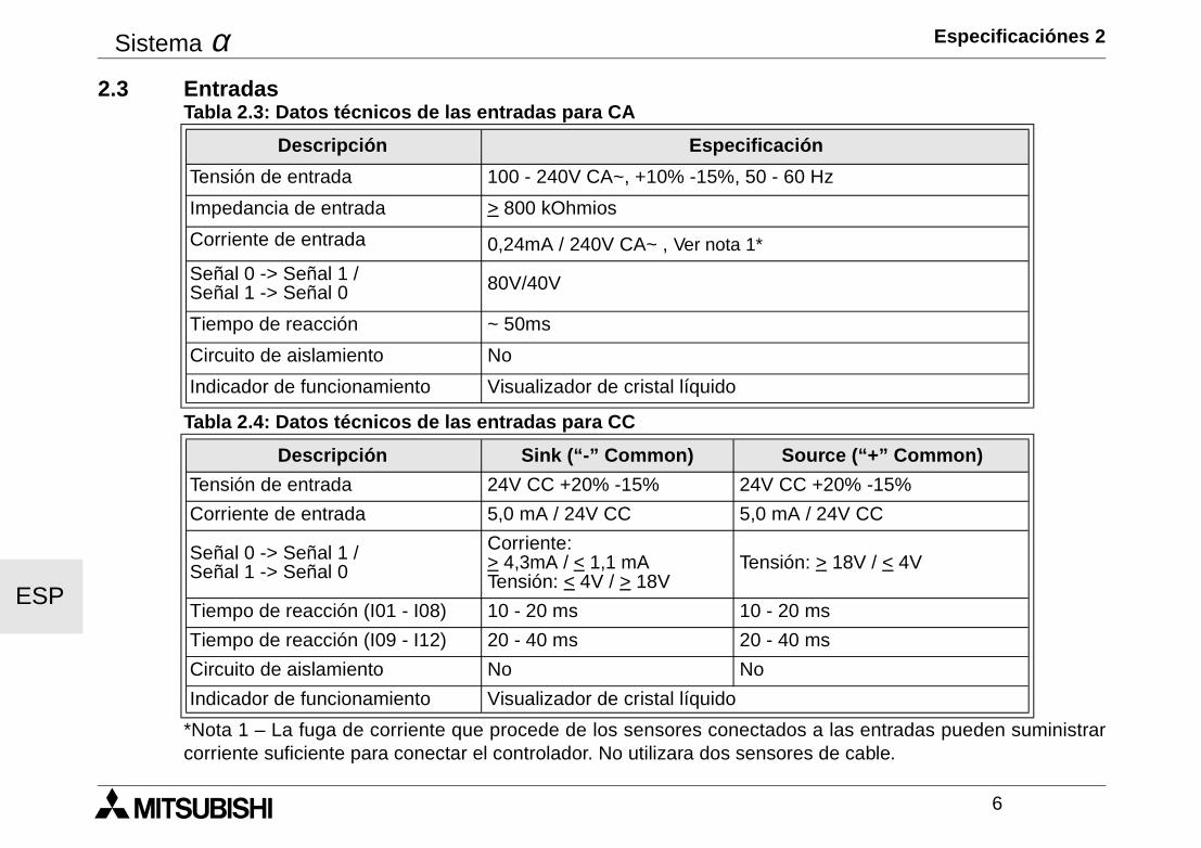
Sistema α Especificaciónes 2
6
ESP
2.3 Entradas
*Nota 1 – La fuga de corriente que procede de los sensores conectados a las entradas pueden suministrarcorriente suficiente para conectar el controlador. No utilizara dos sensores de cable.
Tabla 2.3: Datos técnicos de las entradas para CA
Descripción Especificación
Tensión de entrada 100 - 240V CA~, +10% -15%, 50 - 60 Hz
Impedancia de entrada > 800 kOhmios
Corriente de entrada 0,24mA / 240V CA~ , Ver nota 1*
Señal 0 -> Señal 1 / Señal 1 -> Señal 0 80V/40V
Tiempo de reacción ~ 50ms
Circuito de aislamiento No
Indicador de funcionamiento Visualizador de cristal líquido
Tabla 2.4: Datos técnicos de las entradas para CC
Descripción Sink (“-” Common) Source (“+” Common)
Tensión de entrada 24V CC +20% -15% 24V CC +20% -15%
Corriente de entrada 5,0 mA / 24V CC 5,0 mA / 24V CC
Señal 0 -> Señal 1 / Señal 1 -> Señal 0
Corriente: > 4,3mA / < 1,1 mATensión: < 4V / > 18V
Tensión: > 18V / < 4V
Tiempo de reacción (I01 - I08) 10 - 20 ms 10 - 20 ms
Tiempo de reacción (I09 - I12) 20 - 40 ms 20 - 40 ms
Circuito de aislamiento No No
Indicador de funcionamiento Visualizador de cristal líquido
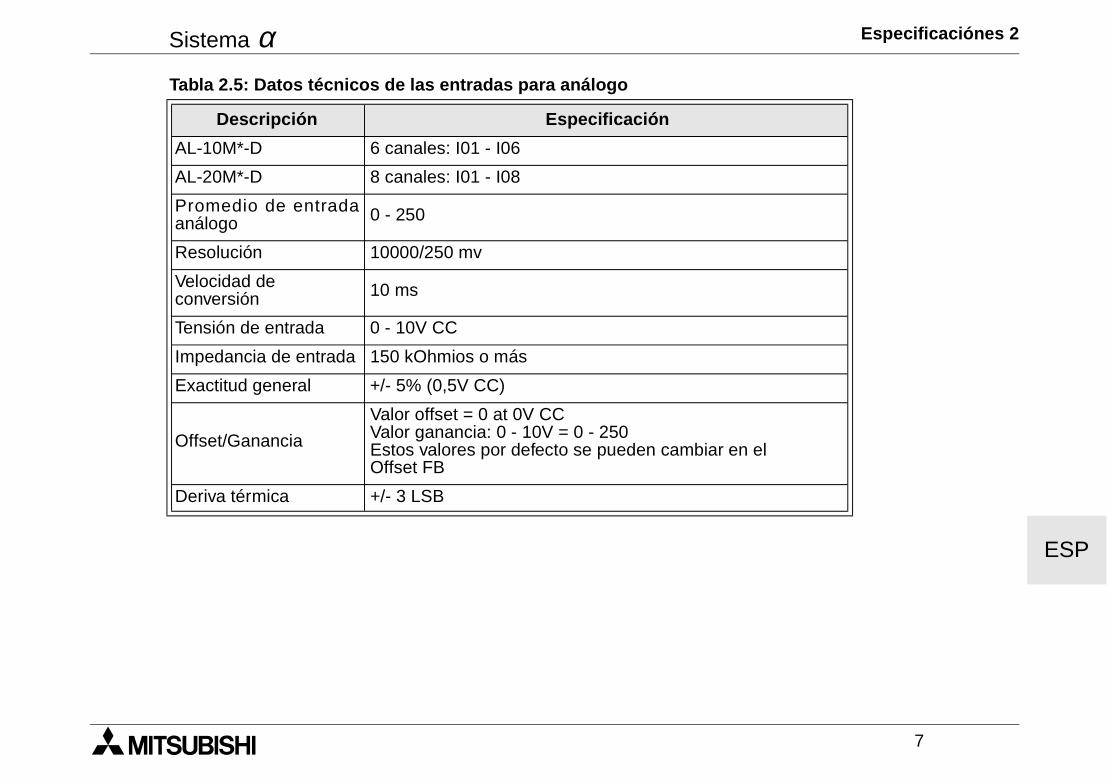
Sistema α Especificaciónes 2
7
ESP
Tabla 2.5: Datos técnicos de las entradas para análogo
Descripción Especificación
AL-10M*-D 6 canales: I01 - I06
AL-20M*-D 8 canales: I01 - I08
Promedio de entradaanálogo 0 - 250
Resolución 10000/250 mv
Velocidad de conversión 10 ms
Tensión de entrada 0 - 10V CC
Impedancia de entrada 150 kOhmios o más
Exactitud general +/- 5% (0,5V CC)
Offset/Ganancia
Valor offset = 0 at 0V CCValor ganancia: 0 - 10V = 0 - 250Estos valores por defecto se pueden cambiar en el Offset FB
Deriva térmica +/- 3 LSB
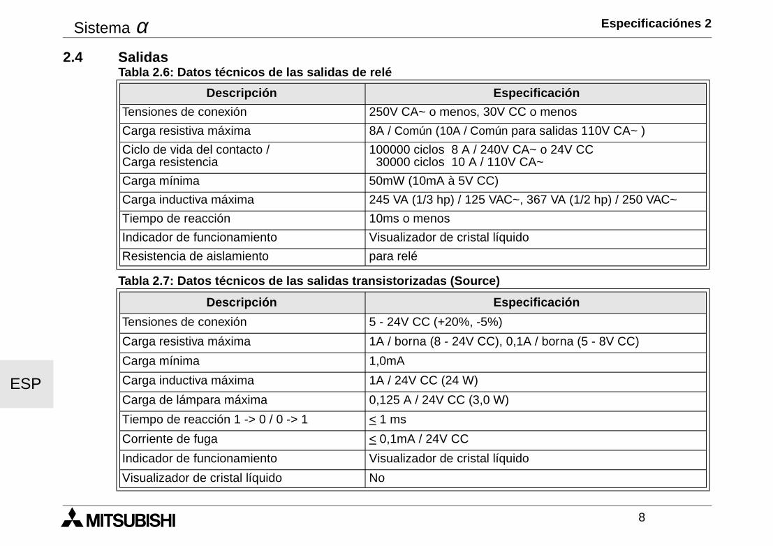
Sistema α Especificaciónes 2
8
ESP
2.4 Salidas
Tabla 2.6: Datos técnicos de las salidas de relé
Descripción Especificación
Tensiones de conexión 250V CA~ o menos, 30V CC o menos
Carga resistiva máxima 8A / Común (10A / Común para salidas 110V CA~ )
Ciclo de vida del contacto / Carga resistencia
100000 ciclos 8 A / 240V CA~ o 24V CC 30000 ciclos 10 A / 110V CA~
Carga mínima 50mW (10mA à 5V CC)
Carga inductiva máxima 245 VA (1/3 hp) / 125 VAC~, 367 VA (1/2 hp) / 250 VAC~
Tiempo de reacción 10ms o menos
Indicador de funcionamiento Visualizador de cristal líquido
Resistencia de aislamiento para relé
Tabla 2.7: Datos técnicos de las salidas transistorizadas (Source)
Descripción Especificación
Tensiones de conexión 5 - 24V CC (+20%, -5%)
Carga resistiva máxima 1A / borna (8 - 24V CC), 0,1A / borna (5 - 8V CC)
Carga mínima 1,0mA
Carga inductiva máxima 1A / 24V CC (24 W)
Carga de lámpara máxima 0,125 A / 24V CC (3,0 W)
Tiempo de reacción 1 -> 0 / 0 -> 1 < 1 ms
Corriente de fuga < 0,1mA / 24V CC
Indicador de funcionamiento Visualizador de cristal líquido
Visualizador de cristal líquido No
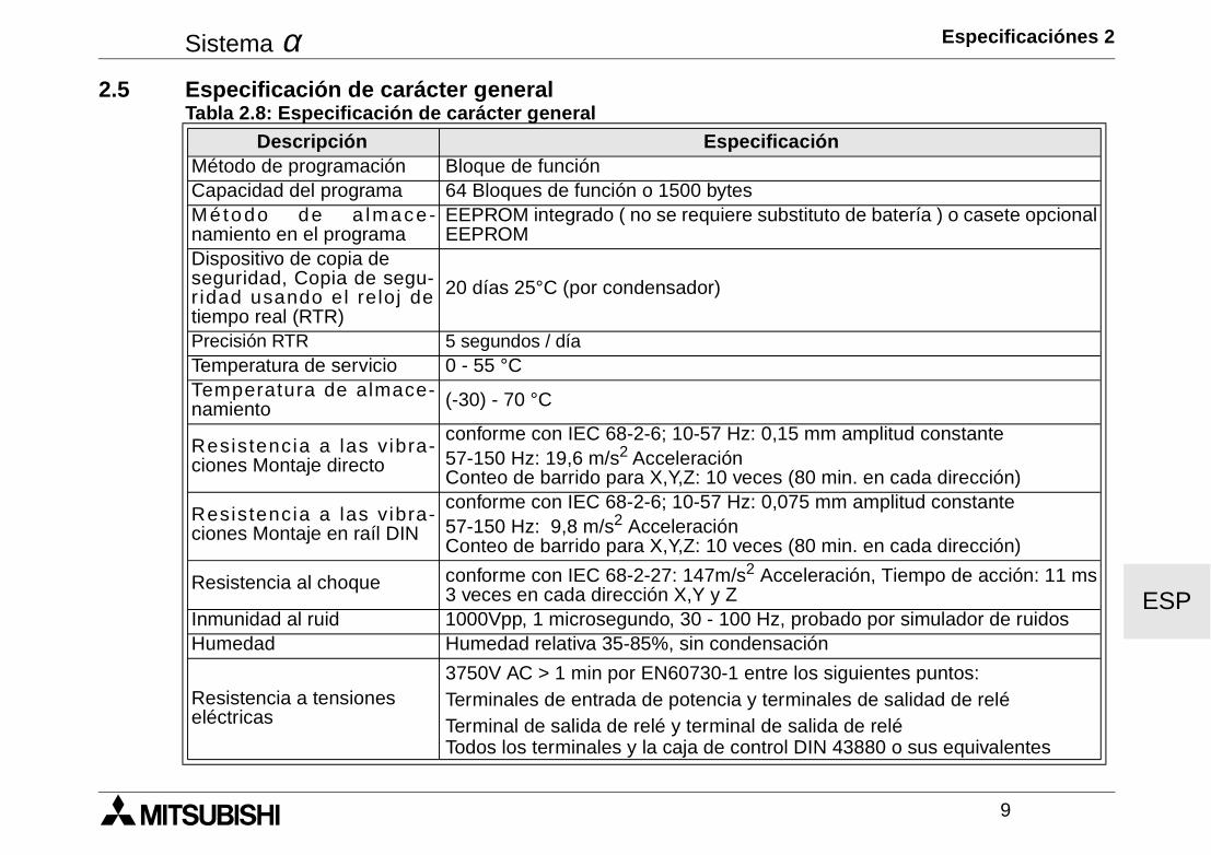
Sistema α Especificaciónes 2
9
ESP
2.5 Especificación de carácter generalTabla 2.8: Especificación de carácter general
Descripción EspecificaciónMétodo de programación Bloque de funciónCapacidad del programa 64 Bloques de función o 1500 bytesMé t odo de a lmace-namiento en el programa
EEPROM integrado ( no se requiere substituto de batería ) o casete opcionalEEPROM
Dispositivo de copia de seguridad, Copia de segu-r idad usando el reloj detiempo real (RTR)
20 días 25°C (por condensador)
Precisión RTR 5 segundos / día Temperatura de servicio 0 - 55 °CTemperatura de almace-namiento (-30) - 70 °C
Resistencia a las v ibra-ciones Montaje directo
conforme con IEC 68-2-6; 10-57 Hz: 0,15 mm amplitud constante57-150 Hz: 19,6 m/s2 AcceleraciónConteo de barrido para X,Y,Z: 10 veces (80 min. en cada dirección)
Resistencia a las v ibra-ciones Montaje en raíl DIN
conforme con IEC 68-2-6; 10-57 Hz: 0,075 mm amplitud constante57-150 Hz: 9,8 m/s2 AcceleraciónConteo de barrido para X,Y,Z: 10 veces (80 min. en cada dirección)
Resistencia al choque conforme con IEC 68-2-27: 147m/s2 Acceleración, Tiempo de acción: 11 ms3 veces en cada dirección X,Y y Z
Inmunidad al ruid 1000Vpp, 1 microsegundo, 30 - 100 Hz, probado por simulador de ruidosHumedad Humedad relativa 35-85%, sin condensación
Resistencia a tensiones eléctricas
3750V AC > 1 min por EN60730-1 entre los siguientes puntos:Terminales de entrada de potencia y terminales de salidad de reléTerminal de salida de relé y terminal de salida de reléTodos los terminales y la caja de control DIN 43880 o sus equivalentes
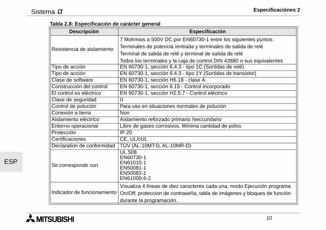
Sistema α Especificaciónes 2
10
ESP
Resistencia de aislamiento
7 Mohmios a 500V DC por EN60730-1 entre los siguientes puntos:Terminales de potencia /entrada y terminales de salida de reléTerminal de salida de relé y terminal de salida de reléTodos los terminales y la caja de control DIN 43880 o sus equivalentes
Tipo de acción EN 60730-1, sección 6.4.3 - tipo 1C (Sortidas de relé)Tipo de acción EN 60730-1, sección 6.4.3 - tipo 1Y (Sortidas de transistor)Clase de software EN 60730-1, sección H6.18 - clase AConstrucción del control EN 60730-1, sección 6.15 - Control incorporadoEl control es eléctrico EN 60730-1, sección H2.5.7 - Control eléctricoClase de seguridad IIControl de polución Para uso en situaciones normales de poluciónConexión a tierra NonAislamiento eléctrico Aislamiento reforzado primario /seccundarioEntorno operacional Libre de gases corrosivos. Mínima cantidad de polvo.Protección IP 20Certificaciones CE, UL/cULDeclaration de conformidad TÜV (AL-10MT-D, AL-10MR-D)
Se corresponde con
UL 508EN60730-1EN61010-1EN50081-1EN50082-1EN61000-6-2
Indicador de funcionamientoVisualiza 4 líneas de diez caracteres cada una, modo Ejecución programa On/Off, proteccion de contraseña, tabla de imágenes y bloques de función durante la programación.
Tabla 2.8: Especificación de carácter generalDescripción Especificación
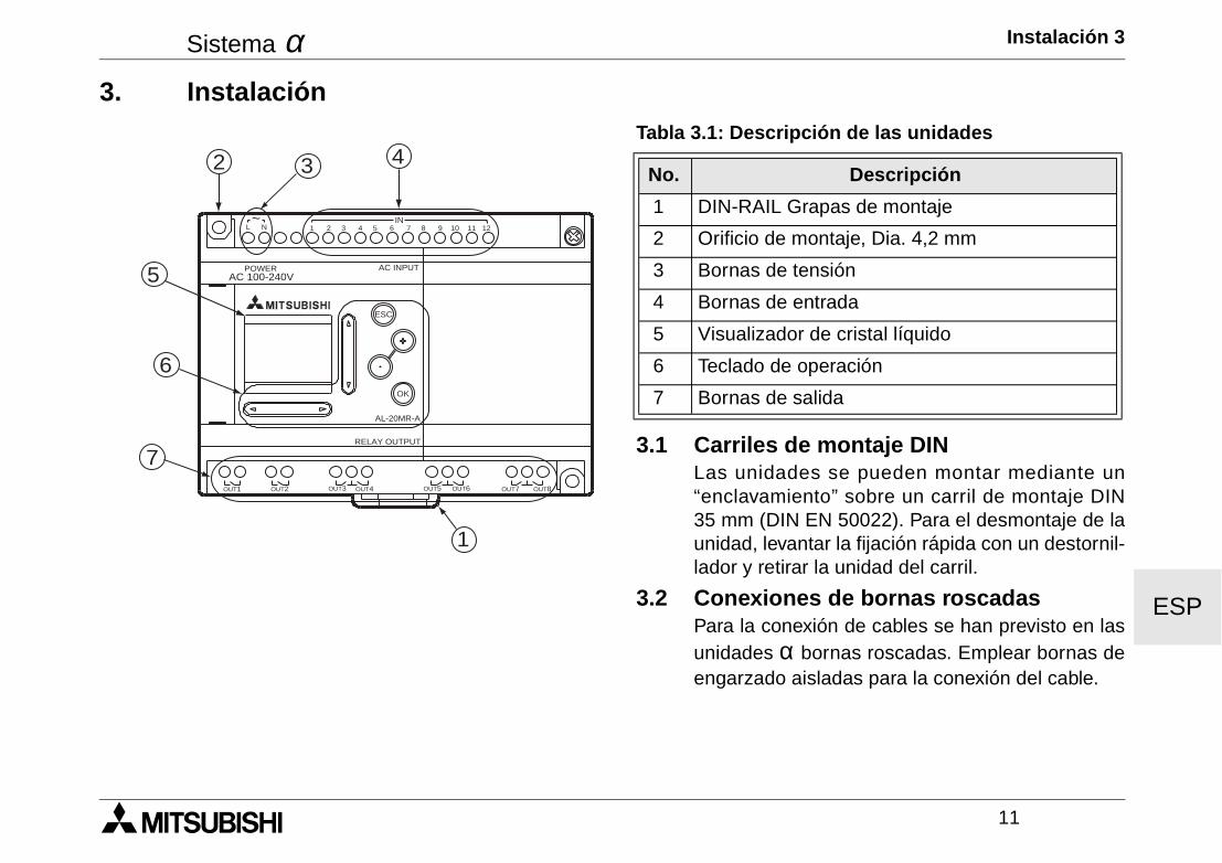
Sistema α Instalación 3
11
ESP
3. Instalación
3.1 Carriles de montaje DINLas unidades se pueden montar mediante un“enclavamiento” sobre un carril de montaje DIN35 mm (DIN EN 50022). Para el desmontaje de launidad, levantar la fijación rápida con un destornil-lador y retirar la unidad del carril.
3.2 Conexiones de bornas roscadasPara la conexión de cables se han previsto en lasunidades α bornas roscadas. Emplear bornas deengarzado aisladas para la conexión del cable.
Tabla 3.1: Descripción de las unidades
No. Descripción
1 DIN-RAIL Grapas de montaje
2 Orificio de montaje, Dia. 4,2 mm
3 Bornas de tensión
4 Bornas de entrada
5 Visualizador de cristal líquido
6 Teclado de operación
7 Bornas de salida
AC 100-240VPOWER AC INPUT
AL-20MR-A
OK
ESC
RELAY OUTPUT
OUT1 OUT2 OUT5OUT3 OUT4 OUT6 OUT8OUT7
1 2 3 4 5 6 7 8 9 10 11 12IN
L N~
432
5
6
7
1
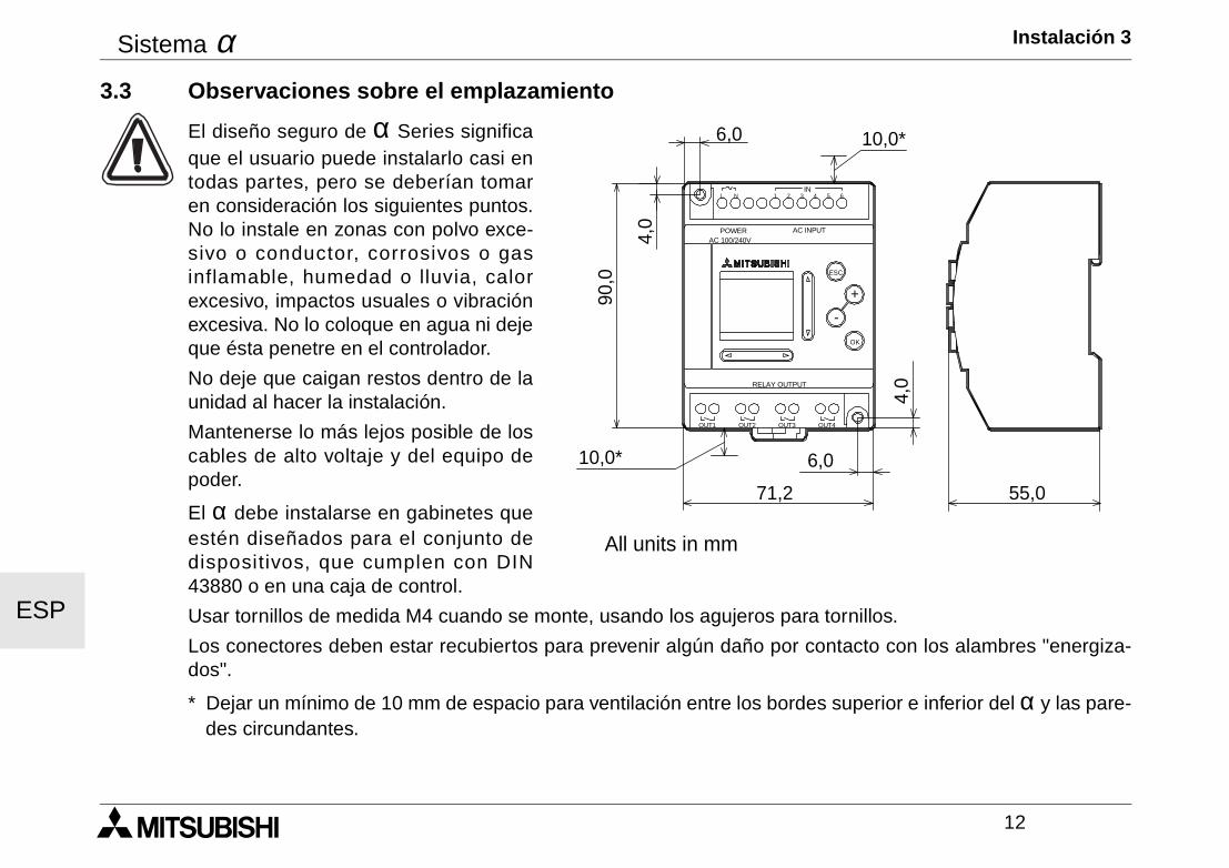
Sistema α Instalación 3
12
ESP
3.3 Observaciones sobre el emplazamiento
El diseño seguro de α Series significaque el usuario puede instalarlo casi entodas partes, pero se deberían tomaren consideración los siguientes puntos.No lo instale en zonas con polvo exce-sivo o conductor, corrosivos o gasinflamable, humedad o lluvia, calorexcesivo, impactos usuales o vibraciónexcesiva. No lo coloque en agua ni dejeque ésta penetre en el controlador.
No deje que caigan restos dentro de launidad al hacer la instalación.
Mantenerse lo más lejos posible de loscables de alto voltaje y del equipo depoder.
El α debe instalarse en gabinetes queestén diseñados para el conjunto dedispositivos, que cumplen con DIN43880 o en una caja de control.
Usar tornillos de medida M4 cuando se monte, usando los agujeros para tornillos.
Los conectores deben estar recubiertos para prevenir algún daño por contacto con los alambres "energiza-dos".
* Dejar un mínimo de 10 mm de espacio para ventilación entre los bordes superior e inferior del α y las pare-des circundantes.
POWER
IN
OK
+
RELAY OUTPUT
ESC
-
3 421 5L 6N
OUT3 OUT4OUT2OUT1
AC INPUTAC 100/240V
10,0*
10,0*
71,2
6,0
90,0
4,0
55,0
4,0
6,0
All units in mm
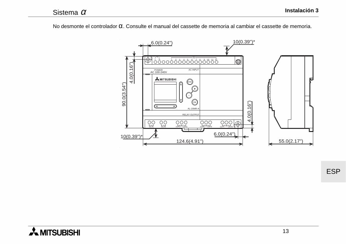
Sistema α Instalación 3
13
ESP
No desmonte el controlador α. Consulte el manual del cassette de memoria al cambiar el cassette de memoria.
AC 100-240VPOWER AC INPUT
AL-20MR-A
OK
ESC
RELAY OUTPUT
6.0(0.24") 10(0.39")*
55.0(2.17")
6.0(0.24")
124.6(4.91")10(0.39")*
4.0
(0.1
6")90.0
(3.5
4") 4
.0(0
.16")
OUT1 OUT2 OUT5OUT3 OUT4 OUT6 OUT8OUT7
1 2 3 4 5 6 7 8 9 10 11 12IN
L N~

Sistema α Instalación 3
14
ESP
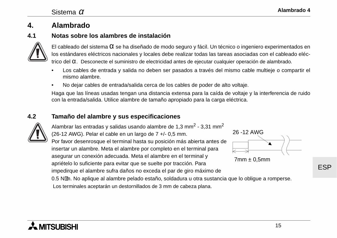
Sistema α Alambrado 4
15
ESP
4. Alambrado4.1 Notas sobre los alambres de instalación
El cableado del sistema α se ha diseñado de modo seguro y fácil. Un técnico o ingeniero experimentados enlos estándares eléctricos nacionales y locales debe realizar todas las tareas asociadas con el cableado eléc-trico del α. Desconecte el suministro de electricidad antes de ejecutar cualquier operación de alambrado.
• Los cables de entrada y salida no deben ser pasados a través del mismo cable multieje o compartir elmismo alambre.
• No dejar cables de entrada/salida cerca de los cables de poder de alto voltaje.
Haga que las líneas usadas tengan una distancia extensa para la caída de voltaje y la interferencia de ruidocon la entrada/salida. Utilice alambre de tamaño apropiado para la carga eléctrica.
4.2 Tamaño del alambre y sus especificaciones
Alambrar las entradas y salidas usando alambre de 1,3 mm2 - 3,31 mm2 (26-12 AWG). Pelar el cable en un largo de 7 +/- 0,5 mm.Por favor desenrosque el terminal hasta su posición más abierta antes de insertar un alambre. Meta el alambre por completo en el terminal para asegurar un conexión adecuada. Meta el alambre en el terminal y apriételo lo suficiente para evitar que se suelte por tracción. Para impedirque el alambre sufra daños no exceda el par de giro máximo de
0.5 N⋅⋅⋅⋅m. No aplique al alambre pelado estaño, soldadura u otra sustancia que lo obligue a romperse. Los terminales aceptarán un destornillados de 3 mm de cabeza plana.
7mm ± 0,5mm
26 -12 AWG
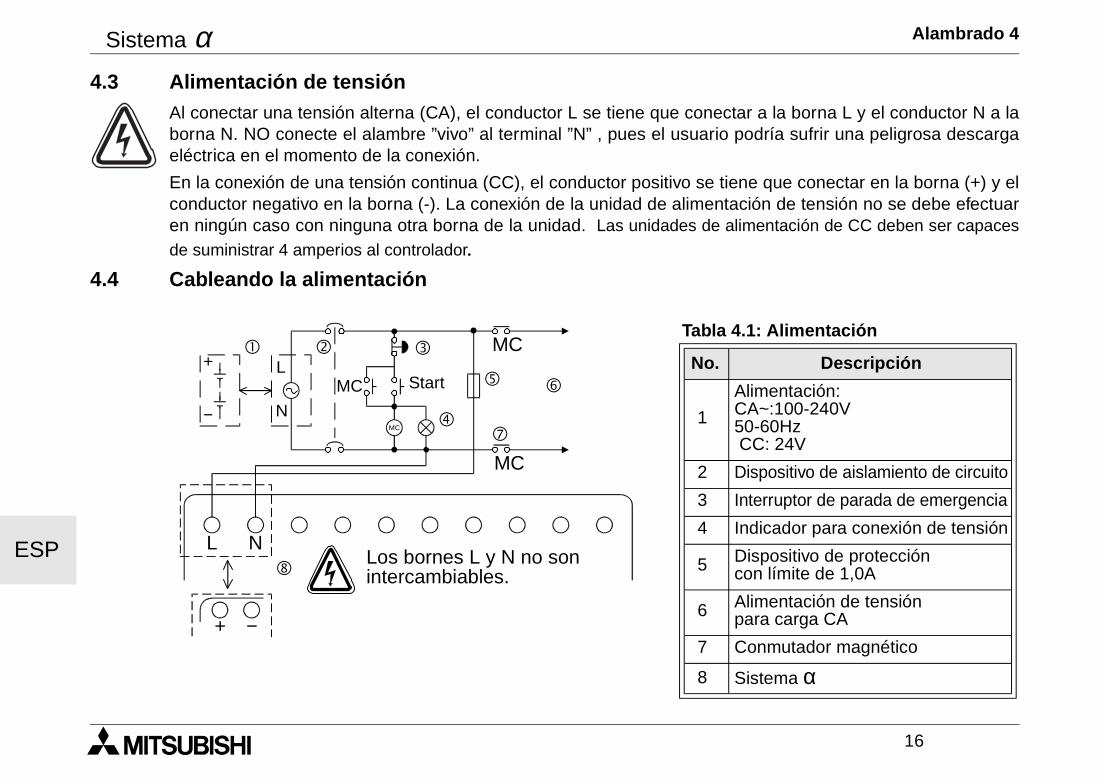
Sistema α Alambrado 4
16
ESP
4.3 Alimentación de tensiónAl conectar una tensión alterna (CA), el conductor L se tiene que conectar a la borna L y el conductor N a laborna N. NO conecte el alambre ”vivo” al terminal ”N” , pues el usuario podría sufrir una peligrosa descargaeléctrica en el momento de la conexión.
En la conexión de una tensión continua (CC), el conductor positivo se tiene que conectar en la borna (+) y elconductor negativo en la borna (-). La conexión de la unidad de alimentación de tensión no se debe efectuaren ningún caso con ninguna otra borna de la unidad. Las unidades de alimentación de CC deben ser capaces
de suministrar 4 amperios al controlador.4.4 Cableando la alimentación
Tabla 4.1: Alimentación
No. Descripción
1
Alimentación: CA~:100-240V50-60Hz CC: 24V
2 Dispositivo de aislamiento de circuito
3 Interruptor de parada de emergencia
4 Indicador para conexión de tensión
5 Dispositivo de protección con límite de 1,0A
6 Alimentación de tensión para carga CA
7 Conmutador magnético
8 Sistema α
MC
MC
MC
MC
L N
! " #
$
% &
'
(
+
−
L
N
+ −
Start
Los bornes L y N no sonintercambiables.
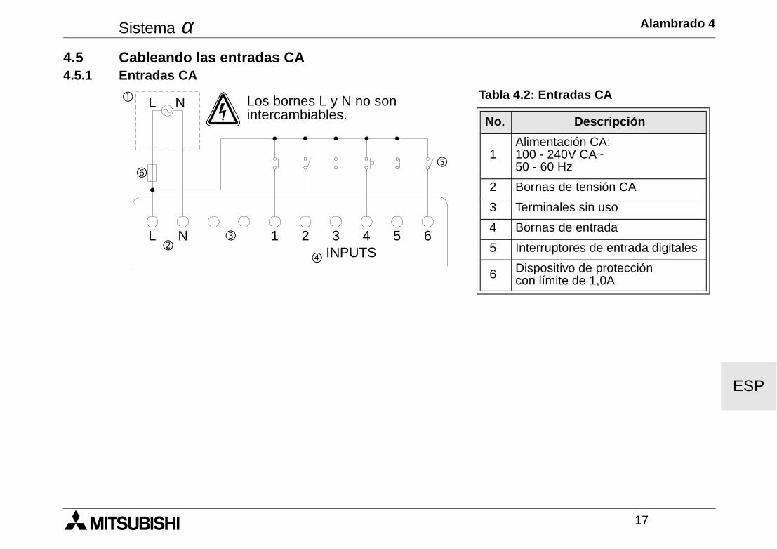
Sistema α Alambrado 4
17
ESP
4.5 Cableando las entradas CA4.5.1 Entradas CA
Tabla 4.2: Entradas CA
No. Descripción
1Alimentación CA:100 - 240V CA~50 - 60 Hz
2 Bornas de tensión CA
3 Terminales sin uso
4 Bornas de entrada
5 Interruptores de entrada digitales
6 Dispositivo de protección con límite de 1,0A
! L N
"#
$
%
L N 1 2 3INPUTS
4 5 6
&
Los bornes L y N no sonintercambiables.
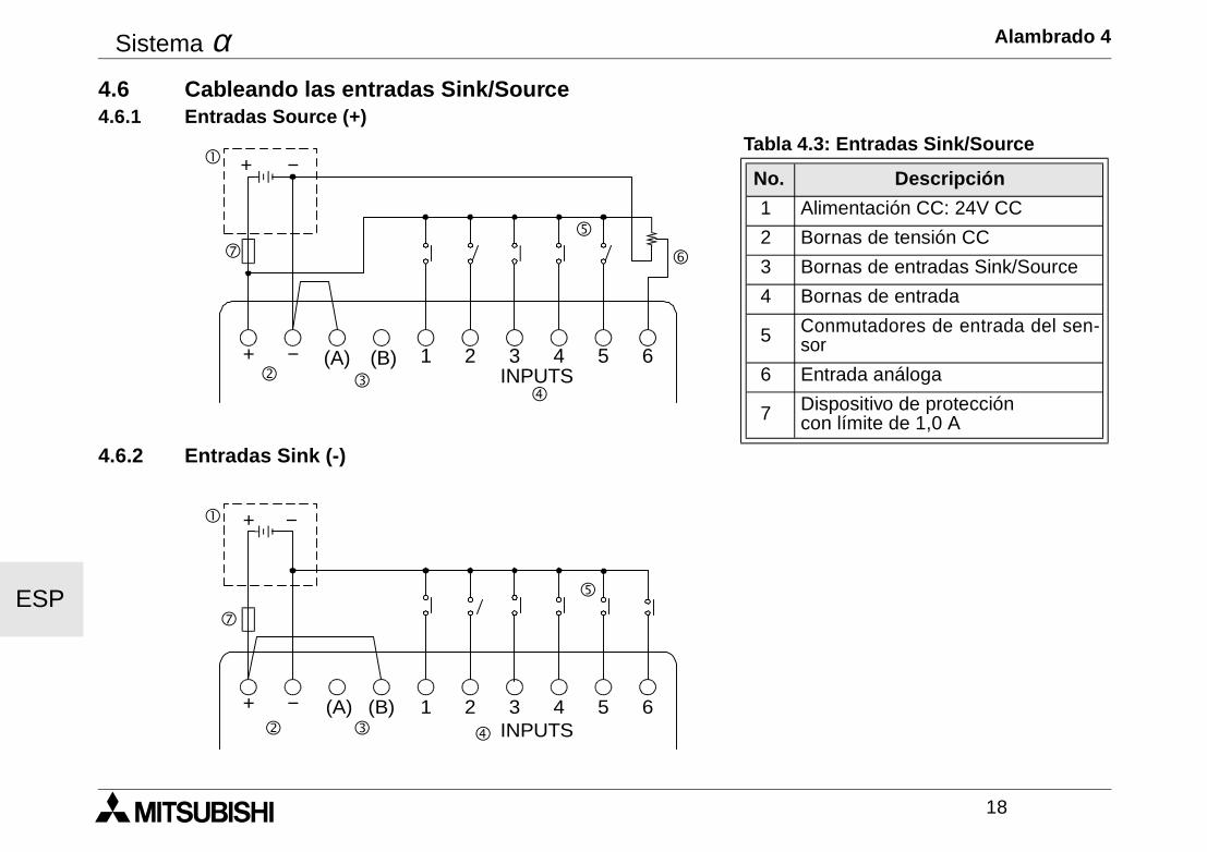
Sistema α Alambrado 4
18
ESP
4.6 Cableando las entradas Sink/Source4.6.1 Entradas Source (+)
4.6.2 Entradas Sink (-)
Tabla 4.3: Entradas Sink/Source
No. Descripción
1 Alimentación CC: 24V CC
2 Bornas de tensión CC
3 Bornas de entradas Sink/Source
4 Bornas de entrada
5 Conmutadores de entrada del sen-sor
6 Entrada análoga
7 Dispositivo de protección con límite de 1,0 A
! + −
"$
%
&
+ − (A) (B) 1 2 3INPUTS
4 5 6
(
#
! + −
" # $
%
+ − (A) (B) 1 2 3INPUTS
4 5 6
(
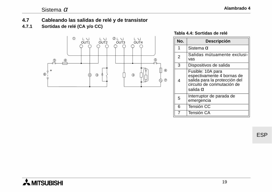
Sistema α Alambrado 4
19
ESP
4.7 Cableando las salidas de relé y de transistor4.7.1 Sortidas de relé (CA y/o CC)
Tabla 4.4: Sortidas de relé
No. Descripción
1 Sistema α 2 Salidas mútuamente exclusi-
vas 3 Dispositivos de salida
4
Fusible: 10A para espectivamente 4 bornas desalida para la protección del circuito de conmutación de salida α
5 Interruptor de parada de emergencia
6 Tensión CC 7 Tensión CA
"!
$
OUT1
##
%
&
OUT2 OUT3 OUT4
(
$
%
+
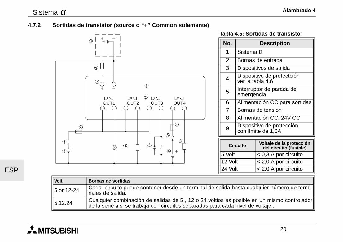
Sistema α Alambrado 4
20
ESP
4.7.2 Sortidas de transistor (source o “+” Common solamente)Tabla 4.5: Sortidas de transistor
No. Description
1 Sistema α2 Bornas de entrada3 Dispositivos de salida
4 Dispositivo de protectciónver la tabla 4.6
5 Interruptor de parada de emergencia
6 Alimentación CC para sortidas7 Bornas de tensión8 Alimentación CC, 24V CC
9 Dispositivo de protección con límite de 1,0A
Circuito Voltaje de la protección del circuito (fusible)
5 Volt < 0,3 A por circuito12 Volt < 2,0 A por circuito24 Volt < 2,0 A por circuito
Volt Bornas de sortidas
5 or 12-24 Cada circuito puede contener desde un terminal de salida hasta cualquier número de termi-nales de salida.
5,12,24 Cualquier combinación de salidas de 5 , 12 o 24 voltios es posible en un mismo controladorde la serie a si se trabaja con circuitos separados para cada nivel de voltaje..
"
!
OUT1
##
OUT2 OUT3 OUT4
$
%
&
+ −
+ −(
$
%
&+
+
#
)
'
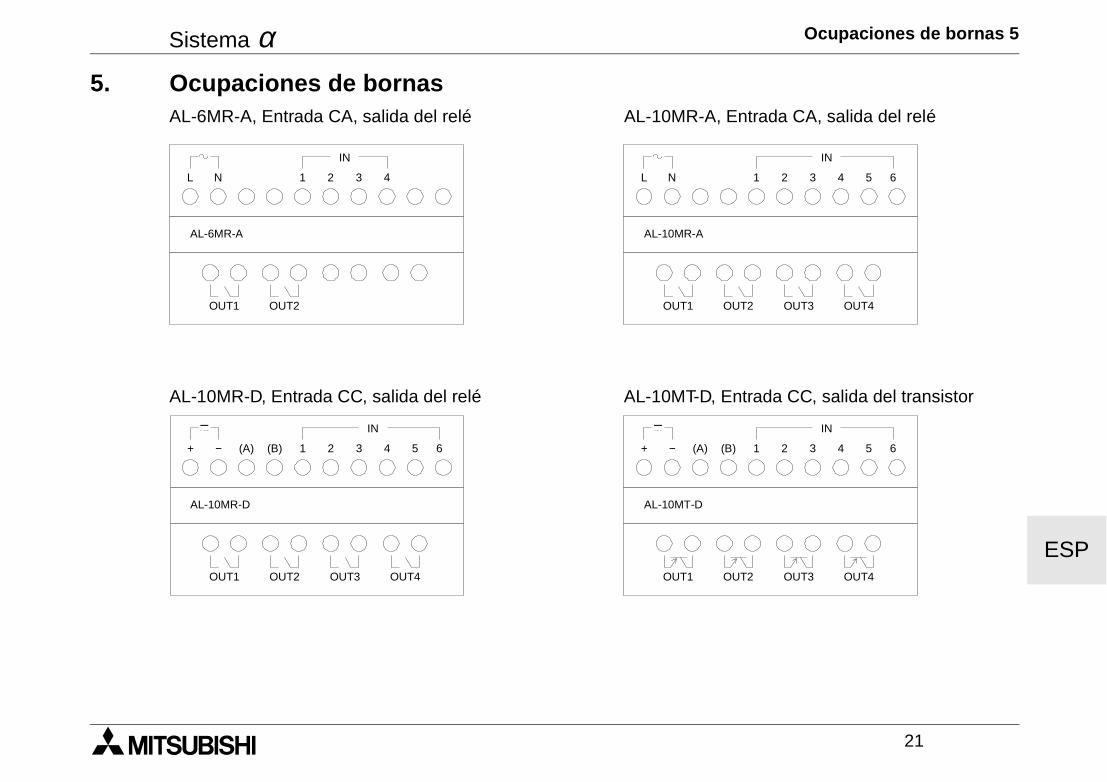
Sistema α Ocupaciones de bornas 5
21
ESP
5. Ocupaciones de bornasAL-6MR-A, Entrada CA, salida del relé AL-10MR-A, Entrada CA, salida del relé
AL-10MR-D, Entrada CC, salida del relé AL-10MT-D, Entrada CC, salida del transistor
L N 1 2 3 4
OUT1
AL-6MR-A
OUT2
IN
L N 1 2 3 4
OUT1
AL-10MR-A
OUT2
IN
5 6
OUT3 OUT4
+ − (A) (B) 1 2 3 4
OUT1
AL-10MR-D
OUT2
IN
5 6
OUT3 OUT4
+ − (B) 1 2 3 4
OUT1
AL-10MT-D
OUT2
IN
5 6
OUT3 OUT4
(A)
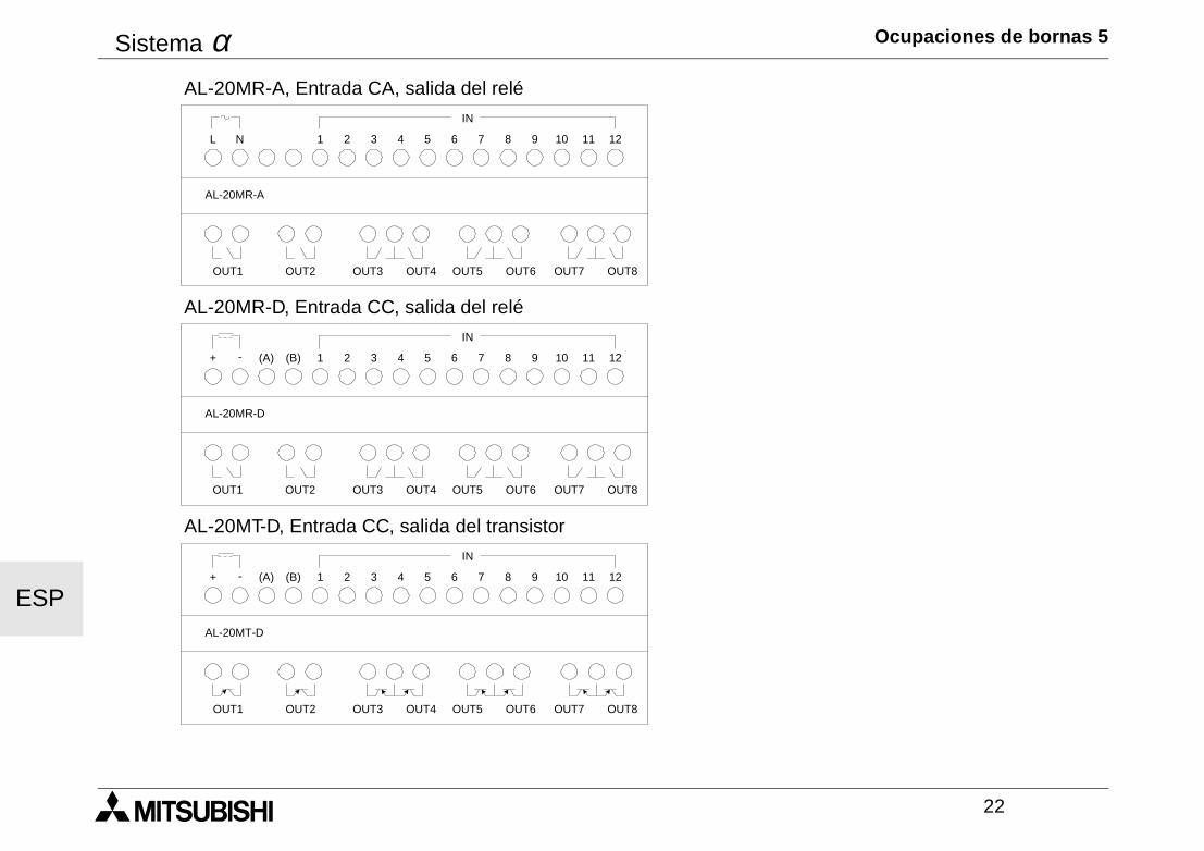
Sistema α Ocupaciones de bornas 5
22
ESP
AL-20MR-A, Entrada CA, salida del relé
AL-20MR-D, Entrada CC, salida del relé
AL-20MT-D, Entrada CC, salida del transistor
L N
IN
12111 2 3 4 5 6 7 8 9 10
OUT1 OUT2 OUT3 OUT5 OUT7OUT4 OUT6 OUT8
AL-20MR-A
+ -
IN
12111 2 3 4 5 6 7 8 9 10
OUT1 OUT2 OUT3 OUT5 OUT7OUT4 OUT6 OUT8
AL-20MR-D
(A) (B)
+ -
IN
12111 2 3 4 5 6 7 8 9 10
OUT1 OUT2 OUT3 OUT5 OUT7OUT4 OUT6 OUT8
AL-20MT-D
(A) (B)
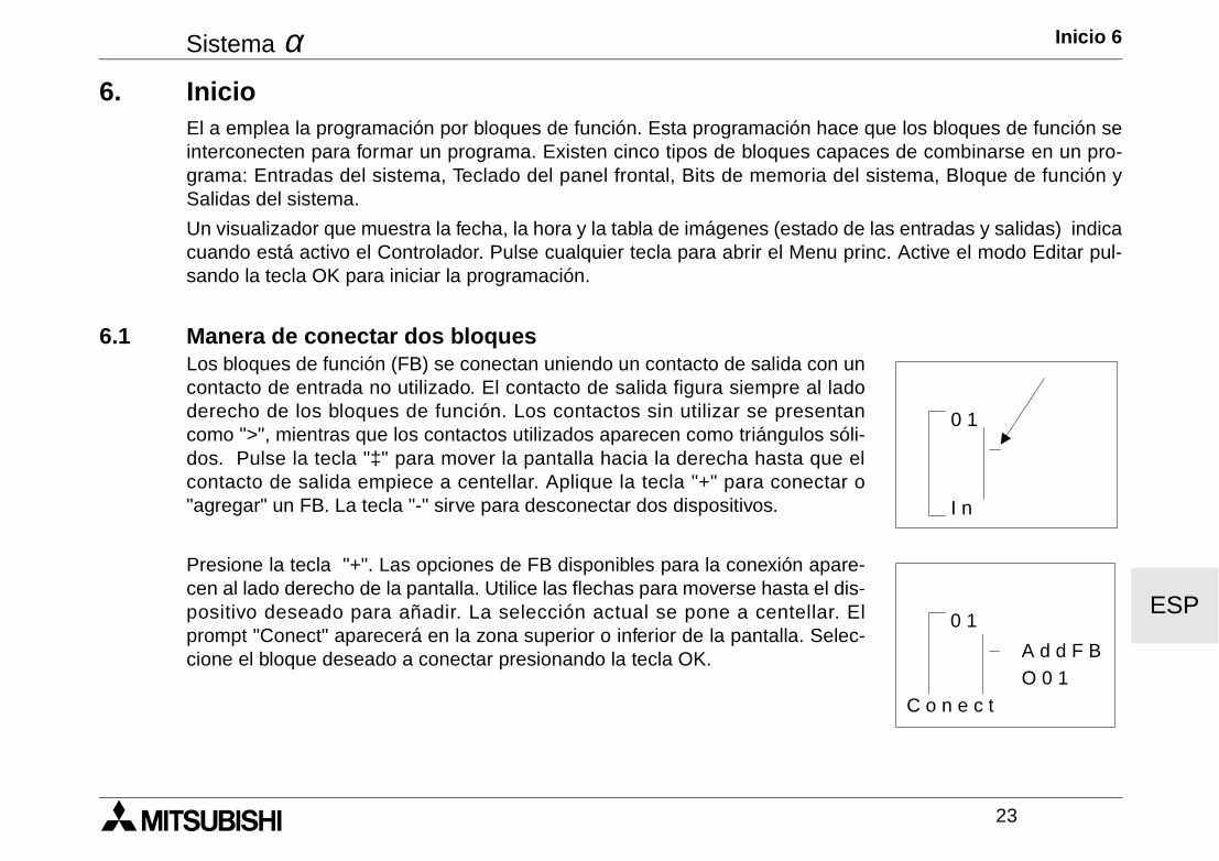
Sistema α Inicio 6
23
ESP
6. InicioEl a emplea la programación por bloques de función. Esta programación hace que los bloques de función seinterconecten para formar un programa. Existen cinco tipos de bloques capaces de combinarse en un pro-grama: Entradas del sistema, Teclado del panel frontal, Bits de memoria del sistema, Bloque de función ySalidas del sistema.
Un visualizador que muestra la fecha, la hora y la tabla de imágenes (estado de las entradas y salidas) indicacuando está activo el Controlador. Pulse cualquier tecla para abrir el Menu princ. Active el modo Editar pul-sando la tecla OK para iniciar la programación.
6.1 Manera de conectar dos bloquesLos bloques de función (FB) se conectan uniendo un contacto de salida con uncontacto de entrada no utilizado. El contacto de salida figura siempre al ladoderecho de los bloques de función. Los contactos sin utilizar se presentancomo ">", mientras que los contactos utilizados aparecen como triángulos sóli-dos. Pulse la tecla "‡" para mover la pantalla hacia la derecha hasta que elcontacto de salida empiece a centellar. Aplique la tecla "+" para conectar o"agregar" un FB. La tecla "-" sirve para desconectar dos dispositivos.
Presione la tecla "+". Las opciones de FB disponibles para la conexión apare-cen al lado derecho de la pantalla. Utilice las flechas para moverse hasta el dis-positivo deseado para añadir. La selección actual se pone a centellar. Elprompt "Conect" aparecerá en la zona superior o inferior de la pantalla. Selec-cione el bloque deseado a conectar presionando la tecla OK.
0 1
I n
0 1
A d d F BO 0 1
C o n e c t
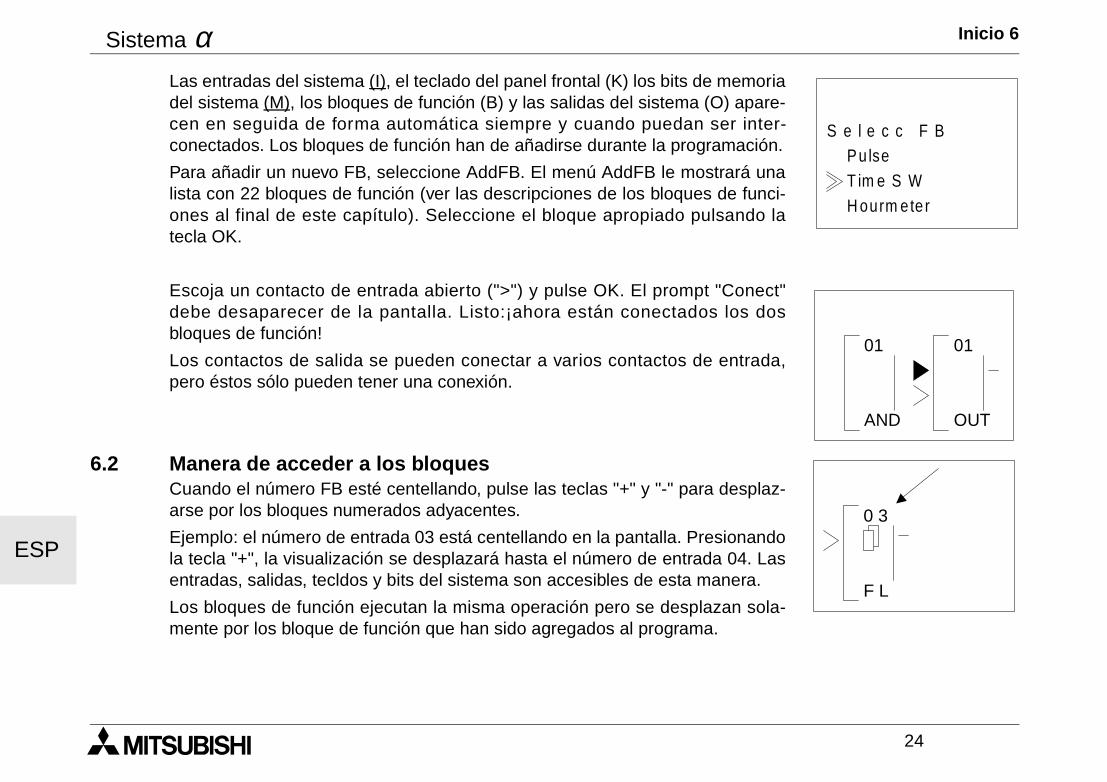
Sistema α Inicio 6
24
ESP
Las entradas del sistema (I), el teclado del panel frontal (K) los bits de memoriadel sistema (M), los bloques de función (B) y las salidas del sistema (O) apare-cen en seguida de forma automática siempre y cuando puedan ser inter-conectados. Los bloques de función han de añadirse durante la programación.
Para añadir un nuevo FB, seleccione AddFB. El menú AddFB le mostrará unalista con 22 bloques de función (ver las descripciones de los bloques de funci-ones al final de este capítulo). Seleccione el bloque apropiado pulsando latecla OK.
Escoja un contacto de entrada abierto (">") y pulse OK. El prompt "Conect"debe desaparecer de la pantalla. Listo:¡ahora están conectados los dosbloques de función!
Los contactos de salida se pueden conectar a varios contactos de entrada,pero éstos sólo pueden tener una conexión.
6.2 Manera de acceder a los bloques Cuando el número FB esté centellando, pulse las teclas "+" y "-" para desplaz-arse por los bloques numerados adyacentes.
Ejemplo: el número de entrada 03 está centellando en la pantalla. Presionandola tecla "+", la visualización se desplazará hasta el número de entrada 04. Lasentradas, salidas, tecldos y bits del sistema son accesibles de esta manera.
Los bloques de función ejecutan la misma operación pero se desplazan sola-mente por los bloque de función que han sido agregados al programa.
H ourm ete r
Pu lseS e l e c c F B
T im e S W
AND
01 01
OUT
0 3
F L
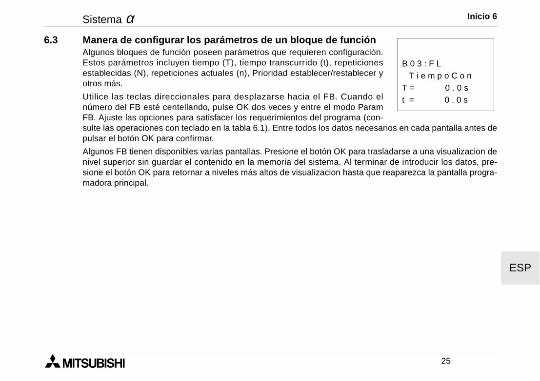
Sistema α Inicio 6
25
ESP
6.3 Manera de configurar los parámetros de un bloque de funciónAlgunos bloques de función poseen parámetros que requieren configuración.Estos parámetros incluyen tiempo (T), tiempo transcurrido (t), repeticionesestablecidas (N), repeticiones actuales (n), Prioridad establecer/restablecer yotros más.
Utilice las teclas direccionales para desplazarse hacia el FB. Cuando elnúmero del FB esté centellando, pulse OK dos veces y entre el modo ParamFB. Ajuste las opciones para satisfacer los requerimientos del programa (con-sulte las operaciones con teclado en la tabla 6.1). Entre todos los datos necesarios en cada pantalla antes depulsar el botón OK para confirmar.
Algunos FB tienen disponibles varias pantallas. Presione el botón OK para trasladarse a una visualizacion denivel superior sin guardar el contenido en la memoria del sistema. Al terminar de introducir los datos, pre-sione el botón OK para retornar a niveles más altos de visualizacion hasta que reaparezca la pantalla progra-madora principal.
t = 0 . 0 s
T i e m p o C o nB 0 3 : F L
T = 0 . 0 s

Sistema α Inicio 6
26
ESP
6.4 Manera de salir, ejecutar o detener el programaPresione el botón ESC para entrar Editar (posiblemente sea necesario presio-nar el botón ESC más de una vez) y aplique elija la opción Salida para salir deEditar.
Aplique a opción Run para iniciar la ejecución del programa. Confirme con OK.Cuando el programa está en ejecución aparece una pantalla frontal con lehora, la fecha y la tabla de imágenes.
Presione cualquier tecla para entrar el Menu princ donde figura la opción Stop.Entre esta opción para detener el programa y confirme con OK.
Otras opciones elegibles incluyen :
PonerHora : Ajuste el Reloj de Tiempo Real
LANGUAGE (lengaje) : Inglés, japonés, alemán, francés, italiano o español.
BorraProg : Borra todo en la memoria del programa: ¡programas y datos!
Mas : Ofrece otras opciones más para las operaciones de chequeo de versiones (Version Check), protecciónde contraseña (Password Protection), programa de cambio a hora de verano (Summer Time Change Sched-ule), inicialización del módem (Modem Initialization) y menú de teclado (Menu Key)
Editar
Salida
T am . P rog.SaltoFB nuevo
M nem onic
M enu princ
PonerH ora
R u nEditarBorraProg
M asLAN G U AG E
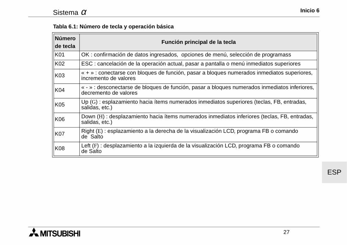
Sistema α Inicio 6
27
ESP
Tabla 6.1: Número de tecla y operación básica
Número de tecla
Función principal de la tecla
K01 OK : confirmación de datos ingresados, opciones de menú, selección de programass
K02 ESC : cancelación de la operación actual, pasar a pantalla o menú inmediatos superiores
K03 « + » : conectarse con bloques de función, pasar a bloques numerados inmediatos superiores, incremento de valores
K04 « - » : desconectarse de bloques de función, pasar a bloques numerados inmediatos inferiores, decremento de valores
K05 Up (G) : esplazamiento hacia ítems numerados inmediatos superiores (teclas, FB, entradas, salidas, etc.)
K06 Down (H) : desplazamiento hacia ítems numerados inmediatos inferiores (teclas, FB, entradas, salidas, etc.)
K07 Right (E) : esplazamiento a la derecha de la visualización LCD, programa FB o comando de Salto
K08 Left (F) : desplazamiento a la izquierda de la visualización LCD, programa FB o comando de Salto
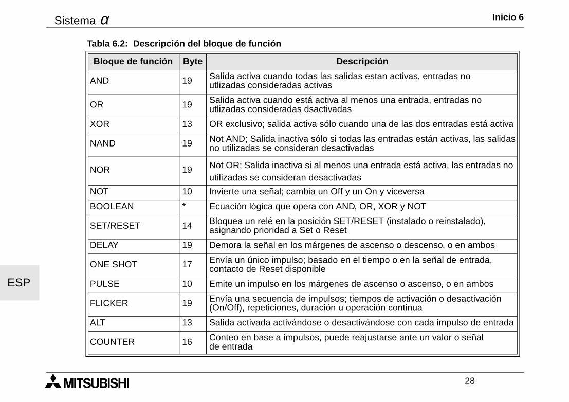
Sistema α Inicio 6
28
ESP
Tabla 6.2: Descripción del bloque de función
Bloque de función Byte Descripción
AND 19 Salida activa cuando todas las salidas estan activas, entradas no utlizadas consideradas activas
OR 19 Salida activa cuando está activa al menos una entrada, entradas no utlizadas consideradas dsactivadas
XOR 13 OR exclusivo; salida activa sólo cuando una de las dos entradas está activa
NAND 19 Not AND; Salida inactiva sólo si todas las entradas están activas, las salidasno utilizadas se consideran desactivadas
NOR 19 Not OR; Salida inactiva si al menos una entrada está activa, las entradas no utilizadas se consideran desactivadas
NOT 10 Invierte una señal; cambia un Off y un On y viceversa
BOOLEAN * Ecuación lógica que opera con AND, OR, XOR y NOT
SET/RESET 14 Bloquea un relé en la posición SET/RESET (instalado o reinstalado), asignando prioridad a Set o Reset
DELAY 19 Demora la señal en los márgenes de ascenso o descenso, o en ambos
ONE SHOT 17 Envía un único impulso; basado en el tiempo o en la señal de entrada, contacto de Reset disponible
PULSE 10 Emite un impulso en los márgenes de ascenso o ascenso, o en ambos
FLICKER 19 Envía una secuencia de impulsos; tiempos de activación o desactivación (On/Off), repeticiones, duración u operación continua
ALT 13 Salida activada activándose o desactivándose con cada impulso de entrada
COUNTER 16 Conteo en base a impulsos, puede reajustarse ante un valor o señal de entrada
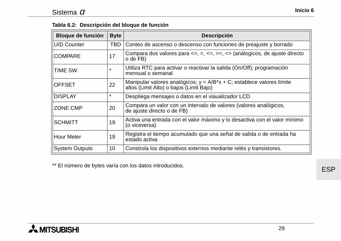
Sistema α Inicio 6
29
ESP** El número de bytes varía con los datos introducidos.
U/D Counter TBD Conteo de ascenso o descenso con funciones de preajuste y borrado
COMPARE 17 Compara dos valores para <>, =, <=, >=, <> (análogicos, de ajuste directo o de FB)
TIME SW * Utiliza RTC para activar o reactivar la salida (On/Off); programación mensual o semanal
OFFSET 22 Manipular valores analógicos; y = A/B*x + C; establece valores límite altos (Limit Alto) o bajos (Limit Bajo)
DISPLAY * Despliega mensajes o datos en el viaualizador LCD
ZONE CMP 20 Compara un valor con un intervalo de valores (valores analógicos, de ajuste directo o de FB)
SCHMITT 19 Activa una entrada con el valor máximo y lo desactiva con el valor mínimo (o viceversa)
Hour Meter 19 Registra el tiempo acumulado que una señal de salida o de entrada ha estado activa
System Outputs 10 Constrola los dispositivos externos mediante relés y transistores.
Tabla 6.2: Descripción del bloque de función
Bloque de función Byte Descripción
Sistema α Inicio 6
30
ESP
α Simple Application Controller

HEAD OFFICE: MITSUBISHI DENKI BLDG MARUNOUCHI TOKYO 100-8310 TELEX:J24532 CABLE MELCO TOKYOHIMEJI WORKS:840, CHIYODA CHO, HIMEJI, JAPAN
JY992D74201J(MEE)
Effective Apr. 2002Specifications are subjectto change without notice.
Related Documents