Antenna Interface Standards Group Standard No. AISG v2.0 13th June 2006 Protocol Specification AISG v2.0 Draft 4 Page 1 of 41 Control interface for antenna line devices Revision History DATE ISSUE NOTES 29 th Oct., 2003 1.0 First issue 30 th July, 2004 1.1 Amended as agreed at GM June 2004 13'th of June 2006 AISG v2.0 Consistent with 3GPP TS 25.460 - TS 25.463 Release 6 © Copyright AISG Ltd., 2002-2006

Welcome message from author
This document is posted to help you gain knowledge. Please leave a comment to let me know what you think about it! Share it to your friends and learn new things together.
Transcript

Antenna Interface Standards Group Standard No. AISG v2.0
13th June 2006
Protocol Specification AISG v2.0 Draft 4 Page 1 of 41
Control interface for antenna line devices
Revision History
DATE ISSUE NOTES
29th Oct., 2003 1.0 First issue
30th July, 2004 1.1 Amended as agreed at GM June 2004
13'th of June 2006 AISG v2.0
Consistent with 3GPP TS 25.460 - TS 25.463
Release 6
© Copyright AISG Ltd., 2002-2006
Antenna Interface Standards Group Standard No. AISG v2.0
13th June 2006
Protocol Specification AISG v2.0 Draft 4 Page 2 of 41
CONTENTS 1. FOREWORD......................................................................................................................4 2. SCOPE...............................................................................................................................5 3. REFERENCES...................................................................................................................6 4. ABBREVIATIONS ..............................................................................................................7 5. TERMINOLOGY AND DEFINITIONS.................................................................................8 6. LAYER 1...........................................................................................................................10 6.1. Extended Specifications...................................................................................................10 6.1.1. Device terminating impedance.........................................................................................10 6.1.2. Bus terminating impedance (Informative).........................................................................10 6.2. Antenna line network (Informative)...................................................................................10 6.2.1. Network current consumption...........................................................................................10 6.2.2. Maximum ALD network current demand ..........................................................................10 6.2.3. Overcurrent protection......................................................................................................11 6.3. Interface Connector types ................................................................................................11 6.3.1. Multi-pole connector .........................................................................................................11 6.3.2. Polarity of multi-pole connectors ......................................................................................12 6.4. DC supply.........................................................................................................................13 6.4.1. Noise and ripple ...............................................................................................................13 6.4.2. TMA DC power consumption ...........................................................................................13 6.4.3. TMA power-up characteristics..........................................................................................13 6.4.4. TMA inrush current...........................................................................................................14 6.5. Resumption of operation ..................................................................................................14 6.5.1. RETs ................................................................................................................................14 6.5.2. TMAs................................................................................................................................14 7. LAYER 2...........................................................................................................................15 7.1. Device Types....................................................................................................................15 7.2. Protocol Version...............................................................................................................15 7.3 Device Type Substance Version Parameter ....................................................................16 8. LAYER 7...........................................................................................................................17 8.1. Return and alarm codes...................................................................................................17 8.2. Procedure message interpretation ...................................................................................17 8.3. Overview of Elementary Procedures for TMAs ................................................................17 8.4. Specification of Elementary Procedures ..........................................................................18 8.4.1. TMA Set Mode .................................................................................................................18 8.4.2. TMA Get Mode .................................................................................................................19 8.4.3. TMA Get Supported Functions.........................................................................................20 8.4.4. TMA Set Gain...................................................................................................................22 8.4.5. TMA Get Gain ..................................................................................................................24 8.4.6. TMA Set Device Data.......................................................................................................25 8.4.7. TMA Get Device Data ......................................................................................................26 8.4.8. TMA Alarm Indication .......................................................................................................27 8.4.9. TMA Clear Active Alarms .................................................................................................28 8.4.10. TMA Get Alarm Status .....................................................................................................29 8.4.11. TMA Get Number of Subunits ..........................................................................................29 8.5. 3GPP Clear Active Alarms and Get Alarm Status............................................................30
Antenna Interface Standards Group Standard No. AISG v2.0
13th June 2006
Protocol Specification AISG v2.0 Draft 4 Page 3 of 41
9. VERSION MANAGEMENT ..............................................................................................31 9.1. Extensions........................................................................................................................31 9.2. Example ...........................................................................................................................32 10. ADDITIONAL RECOMMENDATIONS..............................................................................33 10.1. Electromagnetic compatibility...........................................................................................33 10.2. Lightning protection..........................................................................................................33 11. PRODUCT IDENTIFICATION ..........................................................................................34 11.1. Marking of conforming products .......................................................................................34 11.2. Use of the AISG name and logo.......................................................................................34 11.3. Vendor ID and Serial Number ..........................................................................................34 Annex A: Assigned Vendor Codes (Informative) .............................................................................35 Annex B: Return Codes for AISG ALDs (Normative) .......................................................................36 Annex C: Assigned Fields for Additional Data (Normative) .............................................................37 Annex D: I-frame and INFO-field format (Informative) .....................................................................39 Annex E: AISG protocol version negotiation (Informative)...............................................................40 Annex F: Version Management Example (informative)....................................................................41
Antenna Interface Standards Group Standard No. AISG v2.0
13th June 2006
Protocol Specification AISG v2.0 Draft 4 Page 4 of 41
1. FOREWORD This standard has been produced by the Antenna Interface Standards Group to facilitate the introduction of antenna line products with remote control and monitoring facilities. The purpose of this standard is to ensure basic interoperability of antennas and control infrastructure. AISG supports compatibility with the relevant parts of 3GPP specification in all points which are specified in the relevant standards [15..18]. These documents are included as references in the present AISG standard. To ensure compatibility, all relevant parts of the 3GPP specifications [15..18] shall take precedence if any contradiction is detected. Backward compatibility is not provided between the present version of this standard and AISG 1.1. A number of aspects of this specification are subject to extension and development to accommodate new requirements. Members are recommended to consult the AISG Website (www.aisg.org.uk) for information on current or forthcoming updates.
Antenna Interface Standards Group Standard No. AISG v2.0
13th June 2006
Protocol Specification AISG v2.0 Draft 4 Page 5 of 41
2. SCOPE This document specifies the necessary additions to the 3GPP specifications [15], [16], [17] and [18] for antennas implementing remote electrical tilt (RETs) and tower-mounted amplifiers (TMAs). In order to add new antenna line devices (for example VSWR measuring units) new releases of this specification will be released from time to time. NOTE: Reference [15] contains an introduction to the UTRAN Iuant interface. Reference [16] contains descriptions of the different layer 1 options: RS485 or modem. This document defines a standard data interface at an antenna line device by means of which functional parameters of the device can be remotely controlled; specifically it defines the requirements of a three-layer protocol model. The three-layer model is a compact form of the OSI seven-layer reference model and includes only layers 1, 2 and 7. The advantage of this compact model is that it provides an efficient protocol stack suitable for implementation on a single embedded microcontroller. Layer 1, the physical layer, defines the signalling levels, basic data characteristics including bit rate and the preferred input connector. Layer 2, the data link layer, is based on a custom subset of the HDLC standard as defined in [13]. Layer 7, the application layer, defines the data payload format and the required command set.
In addition, this document defines recommended environmental parameters, together with recommended standards for safety, electromagnetic compatibility (EMC) and electromagnetic pulse (EMP).
Antenna line devices may include RET antennas, TMAs, boosters, VSWR measuring units and other tower-top equipment. All these (and others) can be implemented using the system described in this standard, but each device type (kind of equipment) needs separate definition according to its control and monitoring requirements.
This standard is applicable to equipment designed for operation in any type of mobile radio fixed infrastructure.
Antenna Interface Standards Group Standard No. AISG v2.0
13th June 2006
Protocol Specification AISG v2.0 Draft 4 Page 6 of 41
3. REFERENCES
This AISG standard incorporates provisions from other publications. These are cited in the text and the referenced publications are listed below. Where references are dated, subsequent amendments or revisions of these publications apply only when specifically incorporated by amendment or revision of this AISG standard. For undated references the latest edition of the publication referred to applies. 1 EMC Directive, 83/336/EEC 2 ETS 300 342 2 Radio equipment and systems (RES): Electromagnetic compatibility (EMC)
for European digital cellular communications system (GSM 900MHz and DCS 1800MHz); Part 2: Base station radio and ancillary equipment
3 ETS 301 489 8 Electromagnetic compatibility and radio spectrum matters (ERM); Electromagnetic compatibility (EMC) standard for radio equipment and services; Part 8: Specific conditions for GSM base stations
4 ETS 301 489 23 Electromagnetic compatibility and radio spectrum matters (ERM); Electromagnetic compatibility (EMC) standard for radio equipment and services; Part 23: Specific conditions for IMT-2000 CDMA Direct Spread (UTRA) base station (BS) radio, repeater and ancillary equipment
5 IEC 60130-9 (Ed. 3.0, May 2000): Connectors for frequencies below 3 MHz – Part 9: Circular connectors for radio and associated sound equipment
6 IEC 60529 (Feb 2001): Degrees of protection provided by enclosures (IP Code) 7 IEC 61000-4-5 01-Feb-1995 Electromagnetic compatibility (EMC) - Part 4: Testing and
measurement techniques - Section 5: Surge immunity test 8 IEC 62305-4 Protection against lightning – Part 4: Electrical and electronic systems within
structures 9 (Reference not required) 10 ISO/IEC 646:1991 Information technology – 7-bit coded character set for information
exchange 11 ISO/IEC 7498-1:1994: Information technology – Open Systems Interconnection Basic
Reference Model: The Basic Model 12 ISO/IEC 8482:1993: Information technology – Telecommunications and information
exchange between systems - Twisted pair multipoint interconnections 13 ISO/IEC 13239 (2nd Edition, March 2000): Information Technology – Telecommunications
and information exchange between systems – High-level data link control (HDLC) procedures
14 RTTE Directive 99/5/EEC 15 3GPP TS25.460 UTRAN Iuant Interface General Aspects and Principles Release 6 16 3GPP TS25.461 UTRAN Iuant Interface Layer 1 Release 6 17 3GPP TS25.462 UTRAN Iuant Interface Signalling Transport Release 6 18 3GPP TS25.463 UTRAN Iuant Interface Remote Electrical Tilting (RET) Release 6
Antenna Interface Standards Group Standard No. AISG v2.0
13th June 2006
Protocol Specification AISG v2.0 Draft 4 Page 7 of 41
4. ABBREVIATIONS
Where abbreviations or acronyms are used in this document they have the following meanings:
ADR Address ALD Antenna line device ASCII American Standard Code for Information Interchange CRC Cyclic redundancy check EMC Electromagnetic compatibility EMP Electromagnetic pulse ETS European Telecommunications Standard I Information (frame type) IEC International Electrotechnical Commission (www.iec.ch) INFO Information (field name) ISO International Standard Organization (www.iso.org) OSI Open systems interconnection, as described in ISO/IEC 7498-1 RET Remote electrical tilt unit (antenna drive unit) RS485 A physical interface conforming to ISO/IEC 8482 (ANSI-EIA RS485) RTTE Radio and Telecommunications Terminal Equipment TMA Tower-mounted amplifier XID Exchange ID (Frame type) 3GPP 3rd Generation Partnership Project
Antenna Interface Standards Group Standard No. AISG v2.0
13th June 2006
Protocol Specification AISG v2.0 Draft 4 Page 8 of 41
5. TERMINOLOGY AND DEFINITIONS Where the following terms are used in this document, they have the meanings listed below.
ALD modem A modem and current injector used between the antenna feeder cable and one or more antenna line devices.
Antenna line A group of logical devices associated with one or more antenna systems, which may include antenna drives, amplifiers and other equipment.
Antenna line device A generic term for an addressable physical device, such as an antenna drive or amplifier.
ASCII character A character forming part of the International Reference Version of the 7-bit character set defined in ISO/IEC 646:1991.
Device type One octet identifying the type of a device. Daisy chain A connection method in which a number of devices are
sequentially connected to a single cable, corresponding electrical connections being made in parallel at each device.
Modem A device providing a layer 1 conversion between On-Off keying and RS485 (typically integrated into TMAs).
Octet 8 bits as used in [13]. On-Off keying A simple modulation system in which a carrier is switched
between two states, ON and OFF. Return code A code which defines information about the outcome of an
elementary procedure execution. Reset A process by which the device is put in the state it reaches
after a completed power-up.
Serial number An identifying alphanumeric designation for each product complying with this specification, assigned by the product manufacturer and having a maximum length of 17 octets. The serial number is stored as ASCII characters (see above). NOTE that the combination of serial number and vendor code may be used to address antenna line devices on one or more complete mobile radio networks, so each vendor must manage the allocation of serial numbers to ensure they are never duplicated. The provision of the vendor code allows each vendor to manage serial numbers independently in accordance with their own established practice within the assigned field, the only constraint being that they are not repeated.
TMA A TMA comprises a low noise amplifier together with its control and monitoring electronics and optional modem.
TMA subunit A TMA may comprise more than one TMA subunit combined

Antenna Interface Standards Group Standard No. AISG v2.0
13th June 2006
Protocol Specification AISG v2.0 Draft 4 Page 9 of 41
in a single physical entity. All TMA subunits within one TMA have the same layer 2 HDLC address and are addressable by an index via layer 7 procedures.
Vendor code A unique ASCII 2-character code assigned by AISG to each vendor manufacturing products conforming to this specification (See Appendix A for a list of assigned vendor codes).

Antenna Interface Standards Group Standard No. AISG v2.0
13th June 2006
Protocol Specification AISG v2.0 Draft 4 Page 10 of 41
6. LAYER 1 All definitions and specifications for RET devices in the reference [15] and [16] regarding Iuant Layer 1 apply to ALDs in the present standard.
6.1. Extended Specifications
6.1.1. Device terminating impedance It is not required for the RS485 to be terminated at the ALD. Devices without termination connected to the bus should conform to the following parameters:
Resistance between RS485 A and RS485 B > 1k ohm Resistance between RS485 A or RS485 B and DC return / RS485 GND >1k ohm Capacitance between RS485 A and RS485 B < 1nF Capacitance between RS485 A or RS485 B and DC/RS485 GND < 1nF
6.1.2. Bus terminating impedance (Informative) An RS485 bus is preferably terminated in an impedance equal to the characteristic impedance of the cable used to connect bus devices together. Termination may be found to be unnecessary for short connections operating at low data rates and is therefore not mandatory.
6.2. Antenna line network (Informative) The RS485 implementation of Layer 1 supports the connection of multiple ALDs forming an ALD network. Connections to multiple devices can be made using star or daisy-chain configurations.
When the connection topology requires one ALD to pass current to other downstream ALDs, it is important to ensure that each ALD can support the downstream current requirement.
6.2.1. Network current consumption The total current consumption of an antenna line network is not specified as it will depend on the size of the network, the ALDs used and the primary station software design.
6.2.2. Maximum ALD network current demand A RET will exhibit high current consumption only for controlled and limited periods. An ALD network may therefore be designed to support a total current consumption that is lower
Antenna Interface Standards Group Standard No. AISG v2.0
13th June 2006
Protocol Specification AISG v2.0 Draft 4 Page 11 of 41
than the sum of the maximum consumption in the operating mode as specified in [16] of each ALD. It is the responsibility of the ALD controller (ie the primary station) to avoid overload and secure a stable operating voltage for the ALDs. Specifically the primary station must ensure that high current devices such as RETs are not operated simultaneously.
6.2.3. Overcurrent protection No short circuit protection capability is specified in this standard for separate ALDs. Attention is drawn to the need to avoid by design the possibility of damage to ALDs or interconnecting cables by short circuit faults, and to reduce the possibility of multiple devices being disabled by a single fault.
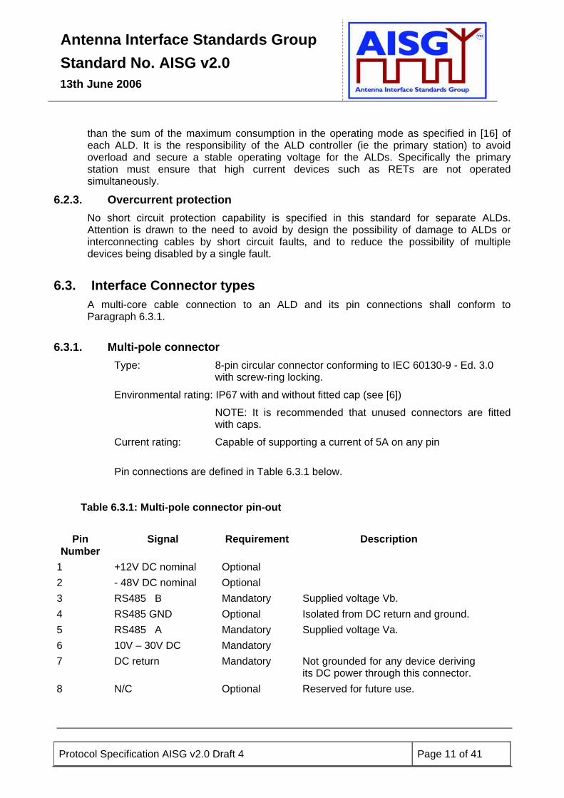
6.3. Interface Connector types A multi-core cable connection to an ALD and its pin connections shall conform to Paragraph 6.3.1.
6.3.1. Multi-pole connector Type: 8-pin circular connector conforming to IEC 60130-9 - Ed. 3.0
with screw-ring locking.
Environmental rating: IP67 with and without fitted cap (see [6])
NOTE: It is recommended that unused connectors are fitted with caps.
Current rating: Capable of supporting a current of 5A on any pin
Pin connections are defined in Table 6.3.1 below.
Table 6.3.1: Multi-pole connector pin-out
Pin Number
Signal Requirement Description
1 +12V DC nominal Optional 2 - 48V DC nominal Optional 3 RS485 B Mandatory Supplied voltage Vb. 4 RS485 GND Optional Isolated from DC return and ground. 5 RS485 A Mandatory Supplied voltage Va. 6 10V – 30V DC Mandatory 7 DC return Mandatory Not grounded for any device deriving
its DC power through this connector. 8 N/C Optional Reserved for future use.
Antenna Interface Standards Group Standard No. AISG v2.0
13th June 2006
Protocol Specification AISG v2.0 Draft 4 Page 12 of 41
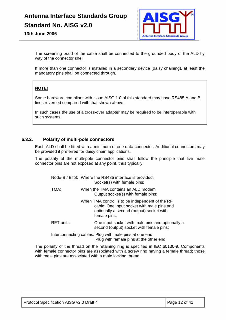
The screening braid of the cable shall be connected to the grounded body of the ALD by way of the connector shell. If more than one connector is installed in a secondary device (daisy chaining), at least the mandatory pins shall be connected through. NOTE! Some hardware compliant with Issue AISG 1.0 of this standard may have RS485 A and B lines reversed compared with that shown above. In such cases the use of a cross-over adapter may be required to be interoperable with such systems.
6.3.2. Polarity of multi-pole connectors Each ALD shall be fitted with a minimum of one data connector. Additional connectors may be provided if preferred for daisy chain applications.
The polarity of the multi-pole connector pins shall follow the principle that live male connector pins are not exposed at any point, thus typically:
Node-B / BTS: Where the RS485 interface is provided: Socket(s) with female pins;
TMA: When the TMA contains an ALD modem Output socket(s) with female pins;
When TMA control is to be independent of the RF cable: One input socket with male pins and optionally a second (output) socket with female pins;
RET units: One input socket with male pins and optionally a second (output) socket with female pins;
Interconnecting cables: Plug with male pins at one end Plug with female pins at the other end.
The polarity of the thread on the retaining ring is specified in IEC 60130-9. Components with female connector pins are associated with a screw ring having a female thread; those with male pins are associated with a male locking thread.
Antenna Interface Standards Group Standard No. AISG v2.0
13th June 2006
Protocol Specification AISG v2.0 Draft 4 Page 13 of 41
6.4. DC supply
Optionally to the specified voltage range in [16] one of the following voltage ranges or a combination hereof may be supported:
12V: 10.0V to 15.0V – 48V: -39.0V to -57.0V
NOTE: In the case where only RET Antennas and TMAs are used, the same power option is recommended for both devices in order to avoid the usage of DC/DC converters in the TMAs, ALD modems or in other tower top equipment.
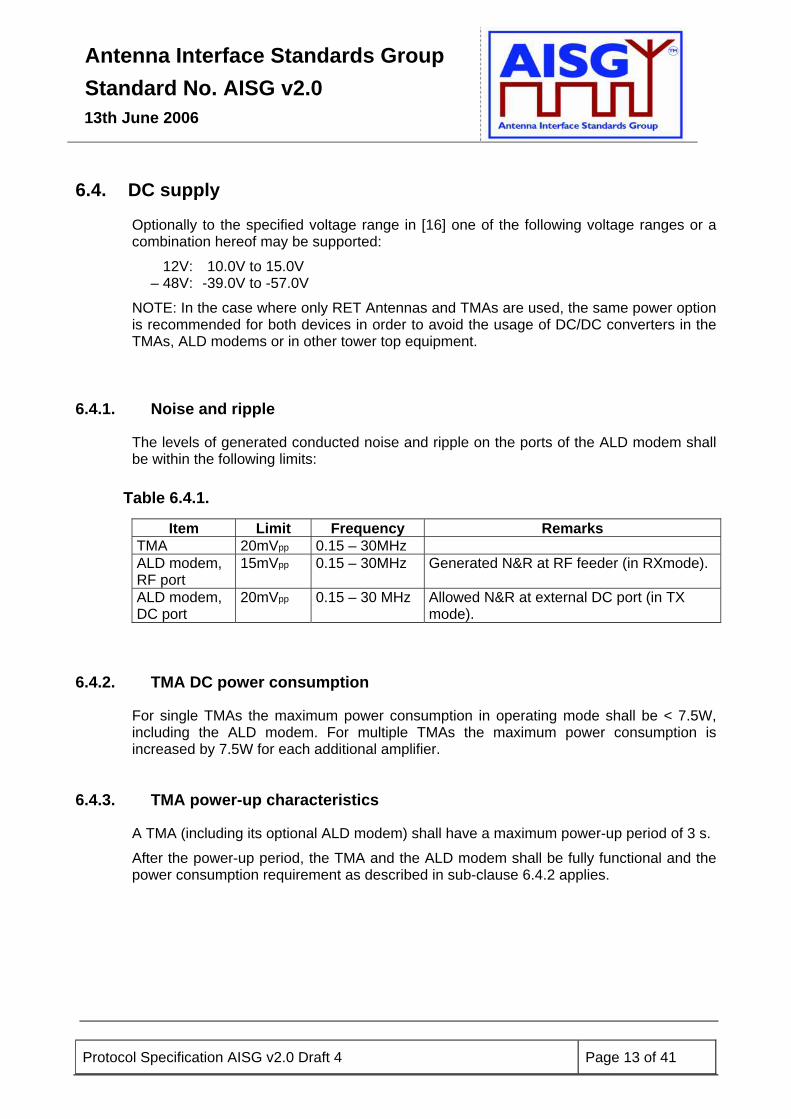
6.4.1. Noise and ripple
The levels of generated conducted noise and ripple on the ports of the ALD modem shall be within the following limits:
Table 6.4.1.
Item Limit Frequency Remarks TMA 20mVpp 0.15 – 30MHz ALD modem, RF port
15mVpp 0.15 – 30MHz Generated N&R at RF feeder (in RXmode).
ALD modem, DC port
20mVpp 0.15 – 30 MHz Allowed N&R at external DC port (in TX mode).
6.4.2. TMA DC power consumption
For single TMAs the maximum power consumption in operating mode shall be < 7.5W, including the ALD modem. For multiple TMAs the maximum power consumption is increased by 7.5W for each additional amplifier.
6.4.3. TMA power-up characteristics
A TMA (including its optional ALD modem) shall have a maximum power-up period of 3 s.
After the power-up period, the TMA and the ALD modem shall be fully functional and the power consumption requirement as described in sub-clause 6.4.2 applies.
Antenna Interface Standards Group Standard No. AISG v2.0
13th June 2006
Protocol Specification AISG v2.0 Draft 4 Page 14 of 41
6.4.4. TMA inrush current
A TMA (including its optional ALD modem) shall exhibit the circuit equivalent of a DC power consumer with a current consumption of maximum 1 A in parallel with a capacitor of maximum 0.5 µF.
6.5. Resumption of operation After reset (see [17]) or power-up, the ALD shall not resume or restart any elementary procedures (e.g. self-test, calibration or tilt setting). Data shall be retained as specified below.
6.5.1. RETs
During loss of DC power, antennas with RETs continue in normal RF operation but will lose control functionality.
The following data shall be retained:
• Tilt setting
• Configuration data
• Calibration status
• Additional data (see [18, Annex B])
• User data
If power is interrupted during a tilt change operation and as a result the position is lost or uncertain, then a NotCalibrated alarm must be generated on re-connection of power.
NOTE: These systems may be left unpowered for extended periods.
6.5.2. TMAs The following data shall be retained:
• Mode setting
• Gain setting
• Additional data (see Annex C)
• User data

Antenna Interface Standards Group Standard No. AISG v2.0
13th June 2006
Protocol Specification AISG v2.0 Draft 4 Page 15 of 41
7. LAYER 2 All definitions and specifications for RET devices in reference [17] regarding Iuant Layer 2 are valid for all antenna line devices included in the present standard.
In the following chapter extended specifications to layer 2 are defined.
7.1. Device Types In extension to [17] additional device types are allowed. In the following table the additional device types are shown: Table 7.1.1: Device type
Device Type 1-octet hexadecimal code Tower mounted low-noise amplifier (TMA) 0x02
7.2. Protocol Version In addition to the XID negotiation in [17] the parameter “AISG Protocol Version” is defined as follows: Table 7.2.1: Protocol version
FI GI PI PL Desciption of PV 0x81 0xF0 20
(decimal) 1 AISG Protocol Version number (the number
called A in paragraph 9).
The AISG protocol version number shall be a one octet unsigned integer in the range 2 to 255 (inclusive). All primaries shall negotiate AISG version immediately after address assignment (and possibly the 3GPP version negotiation), so both parties know that the AISG protocol is used. An example of AISG protocol version negotiation is shown in Annex E.
Antenna Interface Standards Group Standard No. AISG v2.0
13th June 2006
Protocol Specification AISG v2.0 Draft 4 Page 16 of 41
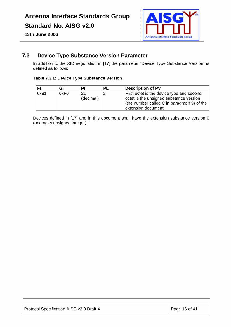
7.3 Device Type Substance Version Parameter In addition to the XID negotiation in [17] the parameter “Device Type Substance Version” is defined as follows: Table 7.3.1: Device Type Substance Version
FI GI PI PL Description of PV 0x81 0xF0 21
(decimal) 2 First octet is the device type and second
octet is the unsigned substance version (the number called C in paragraph 9) of the extension document
Devices defined in [17] and in this document shall have the extension substance version 0 (one octet unsigned integer).
Antenna Interface Standards Group Standard No. AISG v2.0
13th June 2006
Protocol Specification AISG v2.0 Draft 4 Page 17 of 41
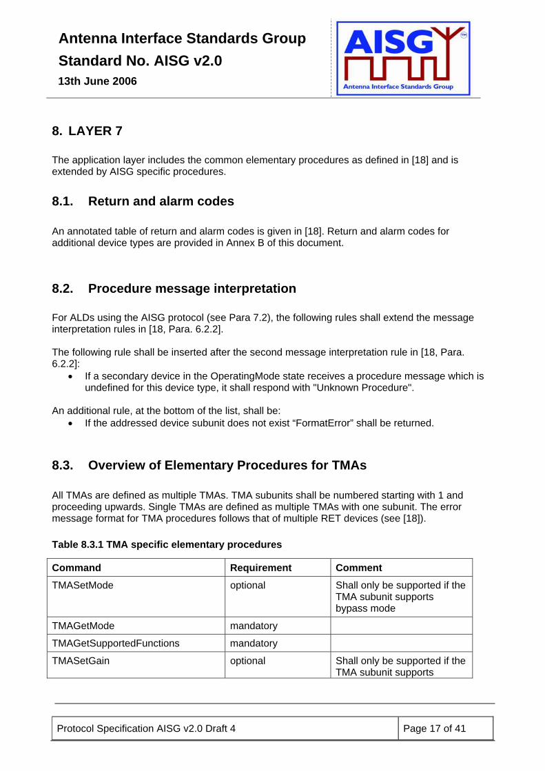
8. LAYER 7 The application layer includes the common elementary procedures as defined in [18] and is extended by AISG specific procedures.
8.1. Return and alarm codes An annotated table of return and alarm codes is given in [18]. Return and alarm codes for additional device types are provided in Annex B of this document.
8.2. Procedure message interpretation For ALDs using the AISG protocol (see Para 7.2), the following rules shall extend the message interpretation rules in [18, Para. 6.2.2]. The following rule shall be inserted after the second message interpretation rule in [18, Para. 6.2.2]:
• If a secondary device in the OperatingMode state receives a procedure message which is undefined for this device type, it shall respond with "Unknown Procedure".
An additional rule, at the bottom of the list, shall be:
• If the addressed device subunit does not exist “FormatError” shall be returned.
8.3. Overview of Elementary Procedures for TMAs All TMAs are defined as multiple TMAs. TMA subunits shall be numbered starting with 1 and proceeding upwards. Single TMAs are defined as multiple TMAs with one subunit. The error message format for TMA procedures follows that of multiple RET devices (see [18]). Table 8.3.1 TMA specific elementary procedures
Command Requirement Comment TMASetMode optional Shall only be supported if the
TMA subunit supports bypass mode
TMAGetMode mandatory
TMAGetSupportedFunctions mandatory
TMASetGain optional Shall only be supported if the TMA subunit supports

Antenna Interface Standards Group Standard No. AISG v2.0
13th June 2006
Protocol Specification AISG v2.0 Draft 4 Page 18 of 41
variable gain
TMAGetGain mandatory
TMASetDeviceData mandatory
TMAGetDeviceData mandatory
TMAAlarmIndication mandatory
TMAClearActiveAlarms mandatory
TMAGetAlarmStatus mandatory
TMAGetNumberOfSubunits mandatory
8.4. Specification of Elementary Procedures
8.4.1. TMA Set Mode The TMA Set Mode procedure shall only be supported if the TMA subunit can be set in bypass mode. On receipt of the initiating message, the secondary device shall first set the TMA subunit in the appropriate mode as indicated by the state flag, and then return a response message. If a TMA subunit in bypass mode receives the elementary procedure TMASetMode to Bypass, the elementary procedure shall not be performed but the response OK shall be returned. State flag = 0 represents Normal mode. State flag = 1 represents Bypass mode. Table 8.4.1.1: Elementary procedure TMA Set Mode
Name: TMA Set Mode Code: Issued by: Procedure class: DownloadMode
state: Power mode:
0x70 Primary device 1 No n/a Table 8.4.1.2: Initiating message parameters and format TMA Set Mode
Number Length Type Description
1 1 octet Unsigned integer Subunit number
2 1 octet Unsigned integer State flag Table 8.4.1.3: Response message parameters and format for TMA Set Mode
Number Length Type Description

Antenna Interface Standards Group Standard No. AISG v2.0
13th June 2006
Protocol Specification AISG v2.0 Draft 4 Page 19 of 41
1 1 octet Unsigned integer Subunit number
2 1 octet ReturnCode Return code OK
Table 8.4.1.4: Return codes for TMA Set Mode
OK FAIL Comment FormatError
Busy HardwareError WorkingSoftwareMissing UnsupportedProcedure OutOfRange MajorTMAFault MinorTMAFault
HardwareError shall refer to a detected inability to switch mode. UnsupportedProcedure shall be returned if set mode is not supported by the TMA subunit. OutOfRange shall be returned if the state flag has another value than those listed in the procedure description. MajorTMAFault shall be returned if the TMA subunit is in bypass mode due to a major TMA fault and TMASetMode to Normal is received. MinorTMAFault shall be returned if the TMA subunit is in bypass mode due to a minor TMA fault and TMASetMode to Normal is received.
8.4.2. TMA Get Mode
Antenna Interface Standards Group Standard No. AISG v2.0
13th June 2006
Protocol Specification AISG v2.0 Draft 4 Page 20 of 41
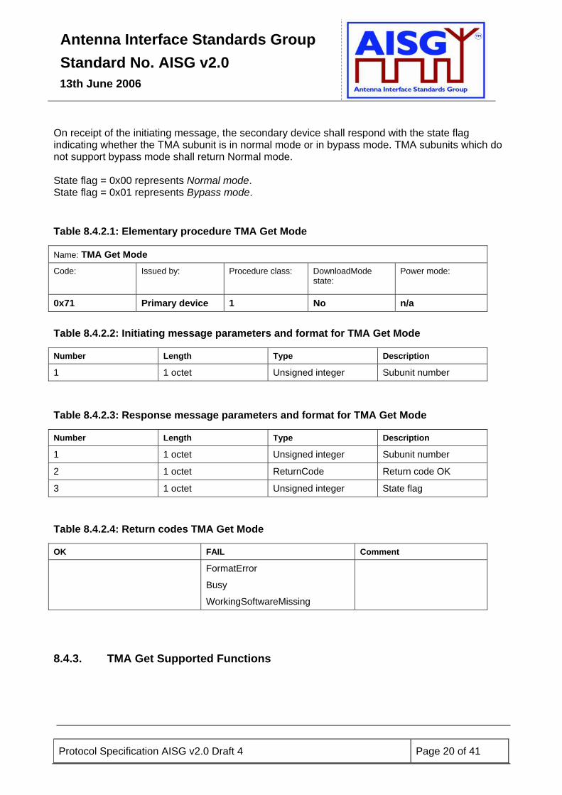
On receipt of the initiating message, the secondary device shall respond with the state flag indicating whether the TMA subunit is in normal mode or in bypass mode. TMA subunits which do not support bypass mode shall return Normal mode. State flag = 0x00 represents Normal mode. State flag = 0x01 represents Bypass mode. Table 8.4.2.1: Elementary procedure TMA Get Mode
Name: TMA Get Mode Code:
Issued by:
Procedure class: DownloadMode state:
Power mode:
0x71 Primary device 1 No n/a Table 8.4.2.2: Initiating message parameters and format for TMA Get Mode
Number Length Type Description
1 1 octet Unsigned integer Subunit number
Table 8.4.2.3: Response message parameters and format for TMA Get Mode
Number Length Type Description
1 1 octet Unsigned integer Subunit number
2 1 octet ReturnCode Return code OK
3 1 octet Unsigned integer State flag Table 8.4.2.4: Return codes TMA Get Mode
OK FAIL Comment
FormatError
Busy
WorkingSoftwareMissing
8.4.3. TMA Get Supported Functions
Antenna Interface Standards Group Standard No. AISG v2.0
13th June 2006
Protocol Specification AISG v2.0 Draft 4 Page 21 of 41
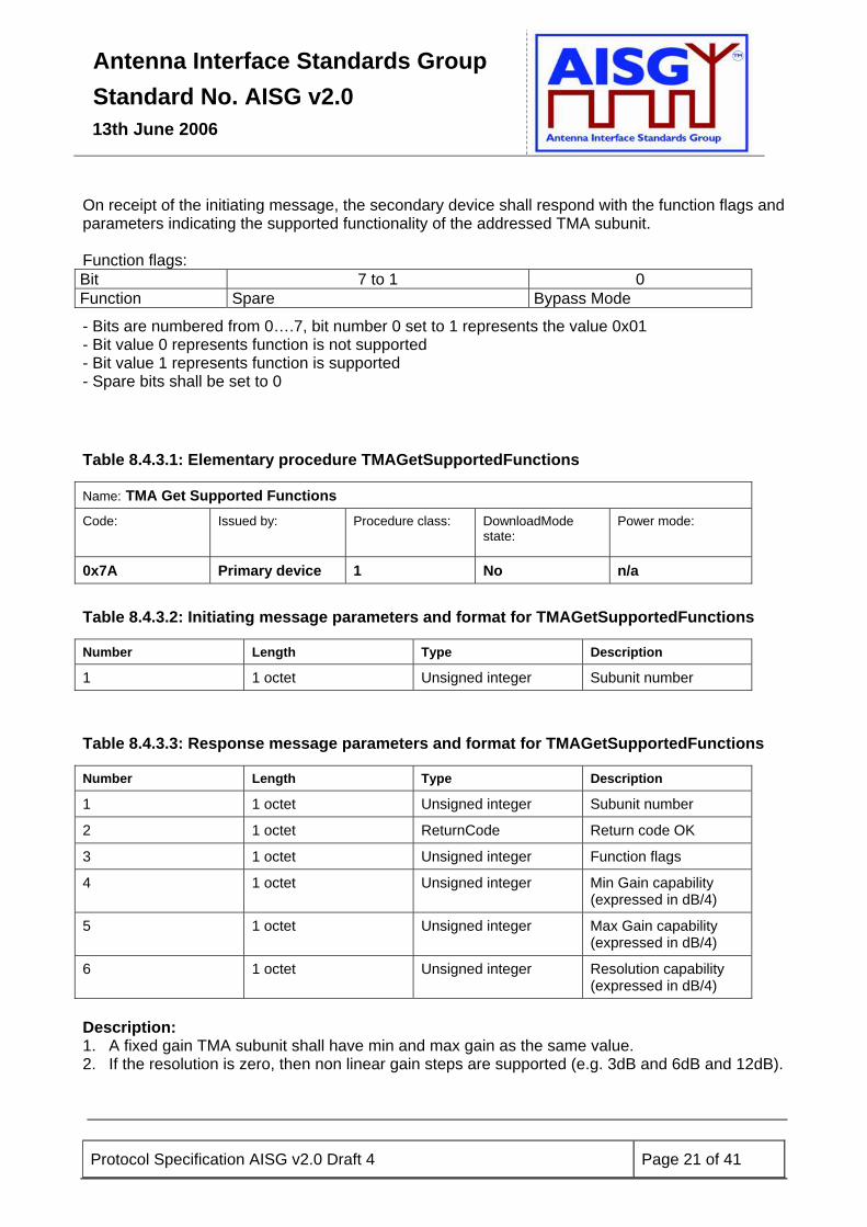
On receipt of the initiating message, the secondary device shall respond with the function flags and parameters indicating the supported functionality of the addressed TMA subunit. Function flags: Bit 7 to 1 0 Function Spare Bypass Mode
- Bits are numbered from 0….7, bit number 0 set to 1 represents the value 0x01 - Bit value 0 represents function is not supported - Bit value 1 represents function is supported - Spare bits shall be set to 0 Table 8.4.3.1: Elementary procedure TMAGetSupportedFunctions
Name: TMA Get Supported Functions Code:
Issued by:
Procedure class: DownloadMode state:
Power mode:
0x7A Primary device 1 No n/a Table 8.4.3.2: Initiating message parameters and format for TMAGetSupportedFunctions
Number Length Type Description
1 1 octet Unsigned integer Subunit number
Table 8.4.3.3: Response message parameters and format for TMAGetSupportedFunctions
Number Length Type Description
1 1 octet Unsigned integer Subunit number
2 1 octet ReturnCode Return code OK
3 1 octet Unsigned integer Function flags
4 1 octet Unsigned integer Min Gain capability (expressed in dB/4)
5 1 octet Unsigned integer Max Gain capability (expressed in dB/4)
6 1 octet Unsigned integer Resolution capability (expressed in dB/4)
Description: 1. A fixed gain TMA subunit shall have min and max gain as the same value. 2. If the resolution is zero, then non linear gain steps are supported (e.g. 3dB and 6dB and 12dB).

Antenna Interface Standards Group Standard No. AISG v2.0
13th June 2006
Protocol Specification AISG v2.0 Draft 4 Page 22 of 41
NOTE: These parameters represent absolute fixed physical data. Any change of the corresponding parameter in the additional data will not have any operational impact on the TMA. Table 8.4.3.4: Return codes TMAGetSupportedFunctions
OK FAIL Comment
FormatError
Busy
WorkingSoftwareMissing
8.4.4. TMA Set Gain The procedure TMASetGain shall only be supported if the TMA subunit gain can be adjusted. On receipt of the initiating message, the secondary device shall first set the addressed TMA subunit to the gain determined by the TMA gain figure parameter, and then return the response message. The TMA gain figure parameter is calculated as 4 times the required gain expressed in dB. (This method of specification allows the gain to be set with a resolution of 0.25 dB while using an integer parameter.) If the TMA subunit is set in bypass mode by TMASetMode, and TMASetGain is received, then the procedure shall be performed and bypass mode shall be retained. Gain shall be accepted if Gmin <=Gdemanded <=Gmax For linear steps: Gdemanded = (Gmin +n*Gresolution) where n is a non-negative
integer For non-linear steps: Gdemanded must be equal to a supported value. Gmin, Gmax and Gresolution are reported by TMAGetSupportedFunctions. For all other values of Gdemanded, the TMA subunit shall respond UnsupportedValue. Table 8.4.4.1: Elementary procedure TMA Set Gain
Name: TMA Set Gain Code: Issued by: Procedure class: DownloadMode
state: Power mode:
0x72 Primary device 1 No n/a
Antenna Interface Standards Group Standard No. AISG v2.0
13th June 2006
Protocol Specification AISG v2.0 Draft 4 Page 23 of 41
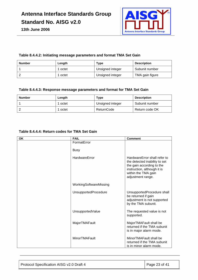
Table 8.4.4.2: Initiating message parameters and format TMA Set Gain
Number Length Type Description
1 1 octet Unsigned integer Subunit number
2 1 octet Unsigned integer TMA gain figure
Table 8.4.4.3: Response message parameters and format for TMA Set Gain
Number Length Type Description
1 1 octet Unsigned integer Subunit number
2 1 octet ReturnCode Return code OK Table 8.4.4.4: Return codes for TMA Set Gain
OK FAIL Comment FormatError
Busy HardwareError WorkingSoftwareMissing UnsupportedProcedure UnsupportedValue MajorTMAFault MinorTMAFault
HardwareError shall refer to the detected inability to set the gain according to the instruction, although it is within the TMA gain adjustment range. UnsupportedProcedure shall be returned if gain adjustment is not supported by the TMA subunit. The requested value is not supported. MajorTMAFault shall be returned if the TMA subunit is in major alarm mode. MinorTMAFault shall be returned if the TMA subunit is in minor alarm mode.
Antenna Interface Standards Group Standard No. AISG v2.0
13th June 2006
Protocol Specification AISG v2.0 Draft 4 Page 24 of 41
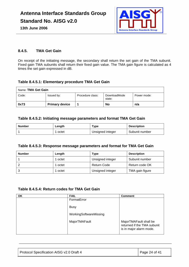
8.4.5. TMA Get Gain On receipt of the initiating message, the secondary shall return the set gain of the TMA subunit. Fixed gain TMA subunits shall return their fixed gain value. The TMA gain figure is calculated as 4 times the set gain expressed in dB. Table 8.4.5.1: Elementary procedure TMA Get Gain
Name: TMA Get Gain Code: Issued by: Procedure class: DownloadMode
state: Power mode:
0x73 Primary device 1 No n/a
Table 8.4.5.2: Initiating message parameters and format TMA Get Gain
Number Length Type Description
1 1 octet Unsigned integer Subunit number
Table 8.4.5.3: Response message parameters and format for TMA Get Gain
Number Length Type Description
1 1 octet Unsigned integer Subunit number
2 1 octet Return Code Return code OK
3 1 octet Unsigned integer TMA gain figure
Table 8.4.5.4: Return codes for TMA Get Gain
OK FAIL Comment FormatError
Busy WorkingSoftwareMissing MajorTMAFault
MajorTMAFault shall be returned if the TMA subunit is in major alarm mode.
Antenna Interface Standards Group Standard No. AISG v2.0
13th June 2006
Protocol Specification AISG v2.0 Draft 4 Page 25 of 41
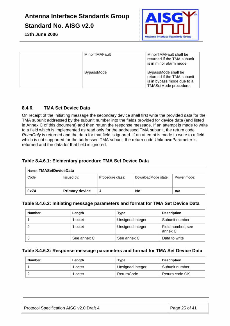
MinorTMAFault BypassMode
MinorTMAFault shall be returned if the TMA subunit is in minor alarm mode. BypassMode shall be returned if the TMA subunit is in bypass mode due to a TMASetMode procedure.
8.4.6. TMA Set Device Data On receipt of the initiating message the secondary device shall first write the provided data for the TMA subunit addressed by the subunit number into the fields provided for device data (and listed in Annex C of this document) and then return the response message. If an attempt is made to write to a field which is implemented as read only for the addressed TMA subunit, the return code ReadOnly is returned and the data for that field is ignored. If an attempt is made to write to a field which is not supported for the addressed TMA subunit the return code UnknownParameter is returned and the data for that field is ignored. Table 8.4.6.1: Elementary procedure TMA Set Device Data
Name: TMASetDeviceData Code:
Issued by:
Procedure class:
DownloadMode state: Power mode:
0x74 Primary device 1 No n/a
Table 8.4.6.2: Initiating message parameters and format for TMA Set Device Data
Number Length Type Description
1 1 octet Unsigned integer Subunit number
2 1 octet Unsigned integer Field number; see annex C
3 See annex C See annex C Data to write Table 8.4.6.3: Response message parameters and format for TMA Set Device Data
Number Length Type Description
1 1 octet Unsigned integer Subunit number
2 1 octet ReturnCode Return code OK

Antenna Interface Standards Group Standard No. AISG v2.0
13th June 2006
Protocol Specification AISG v2.0 Draft 4 Page 26 of 41
Table 8.4.6.4: Return codes for TMA Set Device Data
OK FAIL Comment
FormatError
Busy
HardwareError
WorkingSoftwareMissing
ReadOnly
UnknownParameter
8.4.7. TMA Get Device Data On receipt of the initiating message the secondary device shall return the data stored for the addressed TMA subunit in the field for additional device data specified by the field number in the initiating message and listed in Annex C of this document. Table 8.4.7.1: Elementary procedure TMA Get Device Data
Name: TMAGetDeviceData Code: Issued by: Procedure class: DownloadMode state: Power mode:
0x75 Primary device 1 No n/a Table 8.4.7.2: Initiating message parameters and format for TMA Get Device Data
Number Length Type Description
1 1 octet Unsigned integer Subunit number
2 1 octet Unsigned integer Field number to be read; see Annex C
Table 8.4.7.3: Response message parameters and format for TMA Get Device Data
Number Length Type Description
1 1 octet Unsigned integer Subunit number
2 1 octet Return Code Return code OK
3 See Annex C See Annex C Field value
Antenna Interface Standards Group Standard No. AISG v2.0
13th June 2006
Protocol Specification AISG v2.0 Draft 4 Page 27 of 41
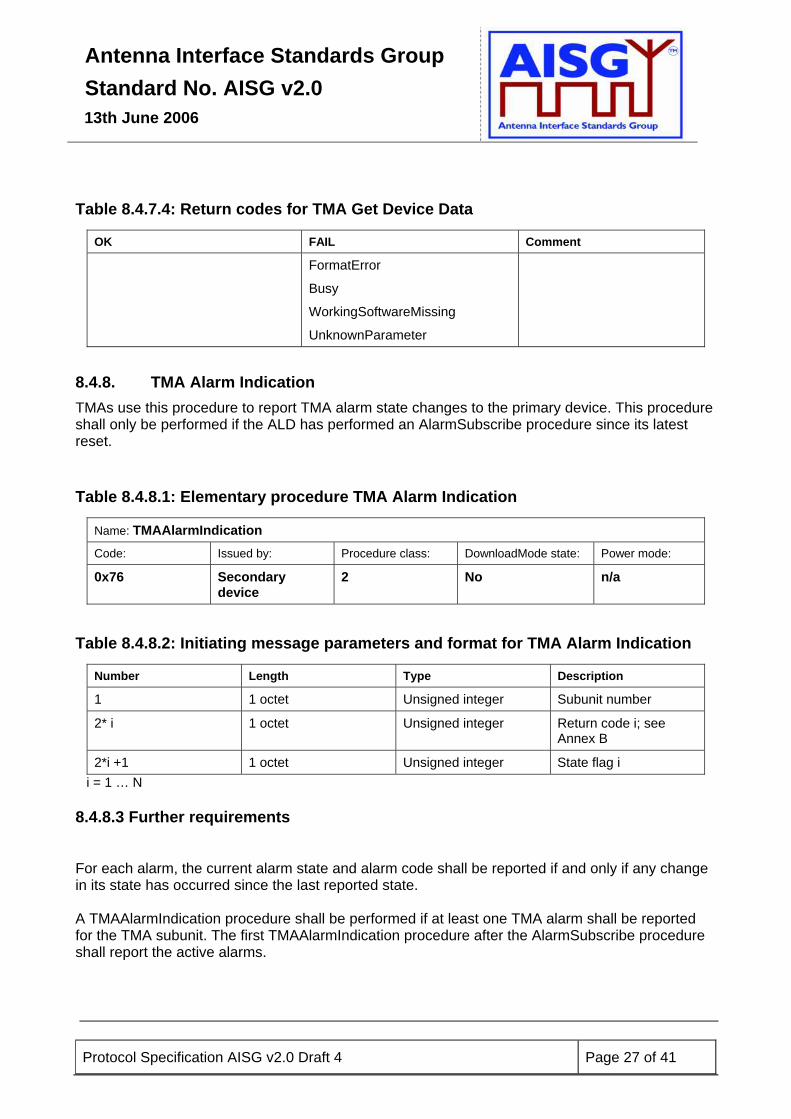
Table 8.4.7.4: Return codes for TMA Get Device Data
OK FAIL Comment
FormatError
Busy
WorkingSoftwareMissing
UnknownParameter
8.4.8. TMA Alarm Indication TMAs use this procedure to report TMA alarm state changes to the primary device. This procedure shall only be performed if the ALD has performed an AlarmSubscribe procedure since its latest reset. Table 8.4.8.1: Elementary procedure TMA Alarm Indication
Name: TMAAlarmIndication Code: Issued by: Procedure class: DownloadMode state: Power mode: 0x76 Secondary
device 2 No n/a
Table 8.4.8.2: Initiating message parameters and format for TMA Alarm Indication
Number Length Type Description
1 1 octet Unsigned integer Subunit number
2* i 1 octet Unsigned integer Return code i; see Annex B
2*i +1 1 octet Unsigned integer State flag i i = 1 … N 8.4.8.3 Further requirements For each alarm, the current alarm state and alarm code shall be reported if and only if any change in its state has occurred since the last reported state. A TMAAlarmIndication procedure shall be performed if at least one TMA alarm shall be reported for the TMA subunit. The first TMAAlarmIndication procedure after the AlarmSubscribe procedure shall report the active alarms.

Antenna Interface Standards Group Standard No. AISG v2.0
13th June 2006
Protocol Specification AISG v2.0 Draft 4 Page 28 of 41
Alarm state changes are considered as reported at the time the message is passed to the transport layer. State flag = 0x00 represents alarm state cleared. State flag = 0x01 represents alarm state raised.
8.4.9. TMA Clear Active Alarms On receipt of the initiating message the secondary device shall first clear all stored alarm information for the addressed TMA subunit and then return a procedure response message. In the event that the cause of the alarm persists the alarm shall be re-raised and a new TMA Alarm Indication procedure shall be performed. Table 8.4.9.1: Elementary procedure TMA Clear Active Alarms
Name: TMAClearActiveAlarms Code: Issued by Procedure class: DownloadMode state: Power mode: 0x77 Primary device 1 No n/a
Table 8.4.9.2: Initiating message parameters and format for TMA Clear Active Alarms
Number Length Type Description
1 1 octet Unsigned integer Subunit number Table 8.4.9.3: Response message parameters and format for TMA Clear Active Alarms
Number Length Type Description
1 1 octet Unsigned integer Subunit number
2 1 octet ReturnCode Return code OK Table 8.4.9.4: Return codes for TMA Clear Active Alarms
OK FAIL Comment
FormatError
Busy
WorkingSoftwareMissing
Antenna Interface Standards Group Standard No. AISG v2.0
13th June 2006
Protocol Specification AISG v2.0 Draft 4 Page 29 of 41
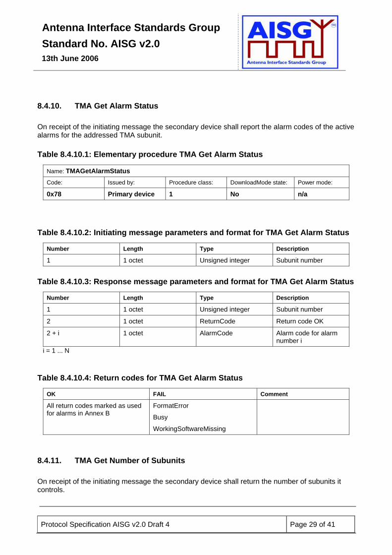
8.4.10. TMA Get Alarm Status On receipt of the initiating message the secondary device shall report the alarm codes of the active alarms for the addressed TMA subunit. Table 8.4.10.1: Elementary procedure TMA Get Alarm Status
Name: TMAGetAlarmStatus Code: Issued by: Procedure class: DownloadMode state: Power mode: 0x78 Primary device 1 No n/a
Table 8.4.10.2: Initiating message parameters and format for TMA Get Alarm Status
Number Length Type Description
1 1 octet Unsigned integer Subunit number Table 8.4.10.3: Response message parameters and format for TMA Get Alarm Status
Number Length Type Description
1 1 octet Unsigned integer Subunit number
2 1 octet ReturnCode Return code OK
2 + i 1 octet AlarmCode Alarm code for alarm number i
i = 1 ... N Table 8.4.10.4: Return codes for TMA Get Alarm Status
OK FAIL Comment
All return codes marked as used for alarms in Annex B
FormatError
Busy
WorkingSoftwareMissing
8.4.11. TMA Get Number of Subunits On receipt of the initiating message the secondary device shall return the number of subunits it controls.
Antenna Interface Standards Group Standard No. AISG v2.0
13th June 2006
Protocol Specification AISG v2.0 Draft 4 Page 30 of 41
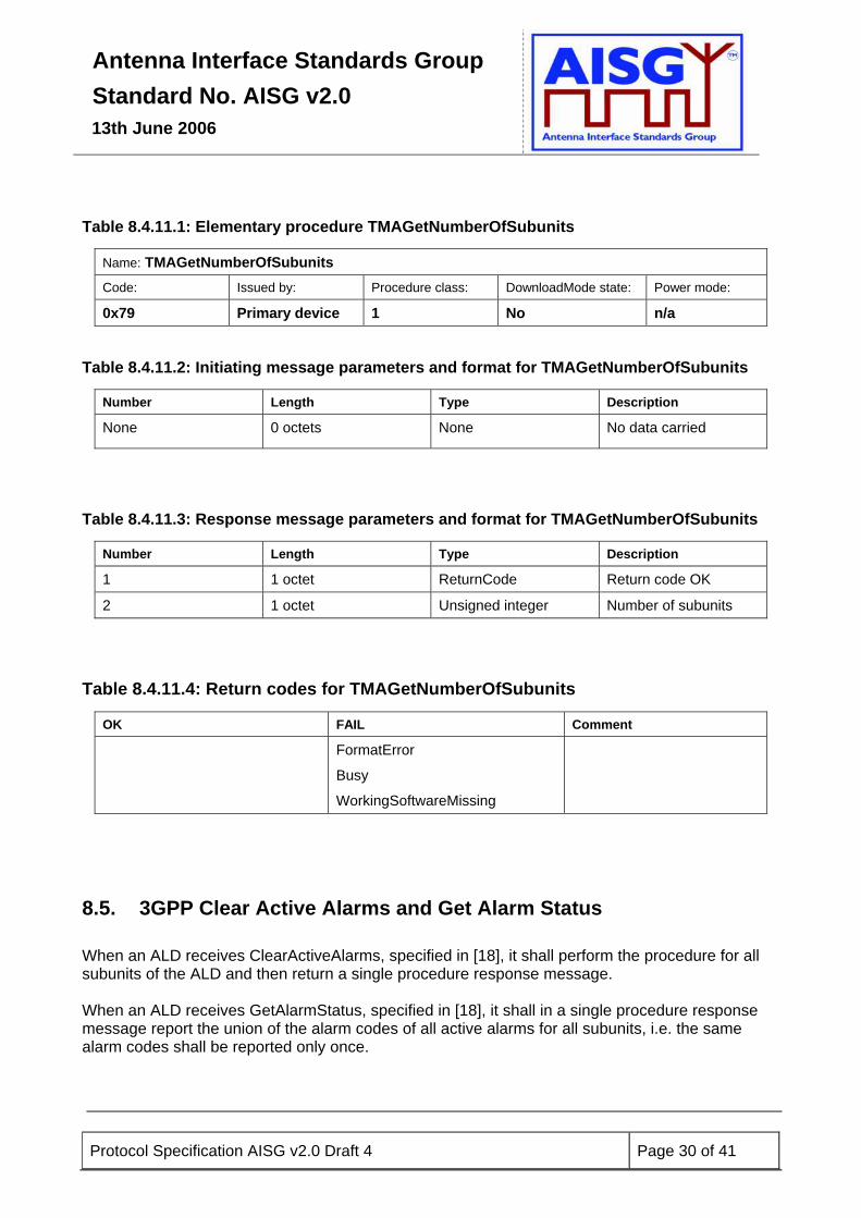
Table 8.4.11.1: Elementary procedure TMAGetNumberOfSubunits
Name: TMAGetNumberOfSubunits Code: Issued by: Procedure class: DownloadMode state: Power mode: 0x79 Primary device 1 No n/a
Table 8.4.11.2: Initiating message parameters and format for TMAGetNumberOfSubunits
Number Length Type Description
None 0 octets None No data carried
Table 8.4.11.3: Response message parameters and format for TMAGetNumberOfSubunits
Number Length Type Description
1 1 octet ReturnCode Return code OK
2 1 octet Unsigned integer Number of subunits Table 8.4.11.4: Return codes for TMAGetNumberOfSubunits
OK FAIL Comment
FormatError
Busy
WorkingSoftwareMissing
8.5. 3GPP Clear Active Alarms and Get Alarm Status When an ALD receives ClearActiveAlarms, specified in [18], it shall perform the procedure for all subunits of the ALD and then return a single procedure response message. When an ALD receives GetAlarmStatus, specified in [18], it shall in a single procedure response message report the union of the alarm codes of all active alarms for all subunits, i.e. the same alarm codes shall be reported only once.

Antenna Interface Standards Group Standard No. AISG v2.0
13th June 2006
Protocol Specification AISG v2.0 Draft 4 Page 31 of 41
9. VERSION MANAGEMENT
The version of the base document (this document) and the version of an extension document (See Para 9.1) are connected. In the following definitions A,B,C and D are used to represent parts of the version number. The connection between base and extension documents is represented by A.
Base document version A.B • A shall be used in version negotiation (PI=20). • B is for editorial updates and shall not be used in version negotiation. • Incompatible changes require an update of A. • Base document version A.B defines base protocol version A. • After version A has been released, clarifications of missing or ambiguous definitions shall be
considered as editorial updates. • B starts at 0 when A is incremented. Extension document version A.C.D • A is used to show which base protocol version the extension is based on. • C shall be used in version negotiation (PI=21) for the extension. • D is only for editorial updates and shall not be used in version negotiation. • Incompatible changes require an update of C. • The extension document version A.C.D defines extension protocol version A.C. • After version A.C has been released, clarifications of missing or ambiguous definitions shall
be considered as editorial updates. • C starts at 1 when A is incremented, D starts at 0 when C is changed.
9.1. Extensions New device types shall be managed as separate documents, AISG extensions. The process for introducing new extensions to AISG shall be:
1) A member who wants to propose a new extension shall send in a New Extension Request, proposing the new device type, the extension name, additional procedures and device data for that device type.
2) One or more AISG work group meetings shall be held to review and finalise the proposal.
3) The proposal shall be approved by an AISG General meeting.
New extensions shall be called “AISG extension <Foobar>”. The AISG Secretary maintains a list of the agreed extension names, version numbers and elementary procedure numbers.

Antenna Interface Standards Group Standard No. AISG v2.0
13th June 2006
Protocol Specification AISG v2.0 Draft 4 Page 32 of 41
The intention is that a new substance version of the base document shall incorporate all preceding extensions.
9.2. Example 1) Changes of substance in the base document, i.e technical enhancements, corrections,
updates etc. Update A 2) Editorial changes in the base document Update B 3) Addition of new extensions New document A.1.0 4) Changes of substance in an extension, i.e technical enhancements, corrections, updates
etc Update C 5) Editorial changes in an extension Update D
NOTE: A further example is shown in Annex F.
Antenna Interface Standards Group Standard No. AISG v2.0
13th June 2006
Protocol Specification AISG v2.0 Draft 4 Page 33 of 41
10. ADDITIONAL RECOMMENDATIONS
10.1. Electromagnetic compatibility It is recommended that all devices connected to the RS485 bus comply with the relevant parts of the following specifications: • ETS 301 489-8 • ETS 301 489-23 • ETS 300 342-2 • EMC Directive 83/336/EEC • RTTE Directive 99/5/EEC
10.2. Lightning protection A tower-top environment presents a severe lightning threat to the reliable operation of sensitive low-voltage equipment. In order to ensure a satisfactory level of in-service reliability it is recommended that all tower-mounted equipment must be tested in accordance to one of the following specifications: • IEC 62305-4 • IEC 61000-4-5
Antenna Interface Standards Group Standard No. AISG v2.0
13th June 2006
Protocol Specification AISG v2.0 Draft 4 Page 34 of 41
11. PRODUCT IDENTIFICATION
11.1. Marking of conforming products In order to allow users to identify products which conform to the requirements of this standard, member companies are encouraged to use the AISG logo on conforming products and on any brochures, advertisements or product literature associated with them. In addition, the legends 'AISG v2.0' or 'Conforms to interface standard AISG v2.0' may be used on such products and associated literature.
11.2. Use of the AISG name and logo The name Antenna Interface Standards Group in full or in abbreviated form (AISG) and the AISG logo are the property of AISG Limited and may not be used in connection with any current product which does not, nor any future product which will not conform to a published AISG standard.
11.3. Vendor ID and Serial Number The combination of Vendor ID and product Serial Number form a unique identity for every antenna line device. Each vendor shall ensure that under no circumstances are serial numbers duplicated in their products. The use of the unique assigned Vendor ID allows each vendor to manage serial numbers independently of all other vendors.

Antenna Interface Standards Group Standard No. AISG v2.0
13th June 2006
Protocol Specification AISG v2.0 Draft 4 Page 35 of 41
Annex A: Assigned Vendor Codes (Informative)
The following two-letter codes are assigned to vendors for use in identifying products Vendor Code Company name Vendor
Code Company name
AA Alcatel HS Huber + Suhner AC ADC, Inc JB Jaybeam Wireless AD Alan Dick & Co Ltd JQ Jacquelot Technologies AE Ace Technology Corporation KA Kathrein KG AL Powerwave KL K & L Microwave Inc AI Amphenol Antel Inc KM KMW Ltd AM Arialcom SA LA Powerwave AN Andrew Corporation LG Powerwave AT Antenova Ltd LU Lucent Technologies AR
Argus Technologies (Australia) Pty Ltd
MA Jaybeam Wireless
AV Avitec AB MI Mitec Inc BW Böke & Walterfang Ltd MO Motorola CB Comba Telecom MT Mobile Antenna Technologies
(Shenzhen) Ltd CC CSS Antenna Inc MY Sistemas Radiantes F Moyano SA CM Combilent A/S NK Nokia CT Celletra, Inc NN Nortel Networks CS Jaybeam Wireless PO Polyphaser Corp CX Cellmax Technologies PW Powerwave DA DAPA Systèmes SA QU Quintel Ltd DB Andrew Corporation RA Racal Antennas Ltd EB Elektrobit Ltd RC Radio Components Sweden AB EM EMS Technologies, Inc RE Powerwave ET ETSA RF RFS Inc ER Ericsson RY RYMSA SA EY Eyecom Technologies SE Selecom SA FI Filtronic Ltd SH University of Sheffield FO Andrew Corporation SI Sigma Wireless Technology Ltd FR Fractus SA SM Siemens AG GN Gamma Nu Inc SP Spinner GmbH GR Grintek Antennas SU Sunwave HI Hitachi Cable Co Ltd TH Thales Antennas Ltd HW Huawei Technologies Ltd UW Unity Wireless Corporation VX Voxaura Technologies Inc XH Xi’an Haitian Antenna
Technologies Co Ltd Other vendors wishing to manufacture equipment conforming to this standard may request the assignment of a Vendor Code by contacting: [email protected] In some instances the vendors listed above may have changed name or for other reasons ceased to manufacture antenna line devices. The original assigned Vendor IDs are retained in this list. The complete, normative and current list of Vendor IDs may be found at www.aisg.org.uk.
Antenna Interface Standards Group Standard No. AISG v2.0
13th June 2006
Protocol Specification AISG v2.0 Draft 4 Page 36 of 41
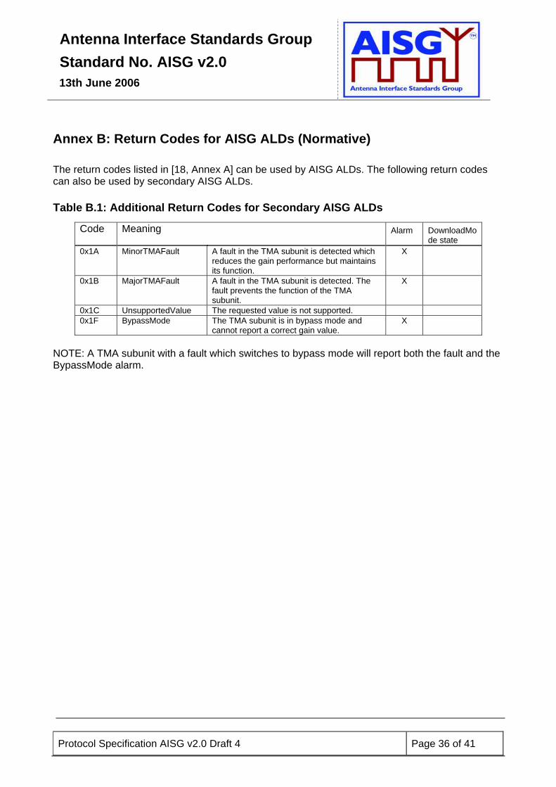
Annex B: Return Codes for AISG ALDs (Normative) The return codes listed in [18, Annex A] can be used by AISG ALDs. The following return codes can also be used by secondary AISG ALDs.
Table B.1: Additional Return Codes for Secondary AISG ALDs
Code Meaning Alarm DownloadMode state
0x1A MinorTMAFault A fault in the TMA subunit is detected which reduces the gain performance but maintains its function.
X
0x1B MajorTMAFault A fault in the TMA subunit is detected. The fault prevents the function of the TMA subunit.
X
0x1C UnsupportedValue The requested value is not supported. 0x1F BypassMode The TMA subunit is in bypass mode and
cannot report a correct gain value. X
NOTE: A TMA subunit with a fault which switches to bypass mode will report both the fault and the BypassMode alarm.
Antenna Interface Standards Group Standard No. AISG v2.0
13th June 2006
Protocol Specification AISG v2.0 Draft 4 Page 37 of 41
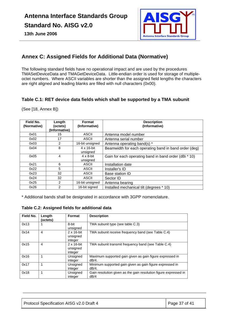
Annex C: Assigned Fields for Additional Data (Normative) The following standard fields have no operational impact and are used by the procedures TMASetDeviceData and TMAGetDeviceData. Little-endian order is used for storage of multiple-octet numbers. Where ASCII variables are shorter than the assigned field lengths the characters are right aligned and leading blanks are filled with null characters (0x00). Table C.1: RET device data fields which shall be supported by a TMA subunit
(See [18, Annex B])
Field No.
(Normative) Length (octets)
(Informative)
Format (Informative)
Description (Informative)
0x01 15 ASCII Antenna model number 0x02 17 ASCII Antenna serial number 0x03 2 16-bit unsigned Antenna operating band(s) * 0x04 8 4 x 16-bit
unsigned Beamwidth for each operating band in band order (deg)
0x05 4 4 x 8-bit unsigned
Gain for each operating band in band order (dBi * 10)
0x21 6 ASCII Installation date 0x22 5 ASCII Installer's ID 0x23 32 ASCII Base station ID 0x24 32 ASCII Sector ID 0x25 2 16-bit unsigned Antenna bearing 0x26 2 16-bit signed Installed mechanical tilt (degrees * 10)
* Additional bands shall be designated in accordance with 3GPP nomenclature. Table C.2: Assigned fields for additional data
Field No. Length (octets)
Format Description
0x13 1 8-bit unsigned
TMA subunit type (see table C.3)
0x14 4 2 x 16-bit unsigned integer
TMA subunit receive frequency band (see Table C.4)
0x15 4 2 x 16-bit unsigned integer
TMA subunit transmit frequency band (see Table C.4)
0x16 1 Unsigned integer
Maximum supported gain given as gain figure expressed in dB/4.
0x17 1 Unsigned integer
Minimum supported gain given as gain figure expressed in dB/4.
0x18 1 Unsigned integer
Gain resolution given as the gain resolution figure expressed in dB/4
Antenna Interface Standards Group Standard No. AISG v2.0
13th June 2006
Protocol Specification AISG v2.0 Draft 4 Page 38 of 41
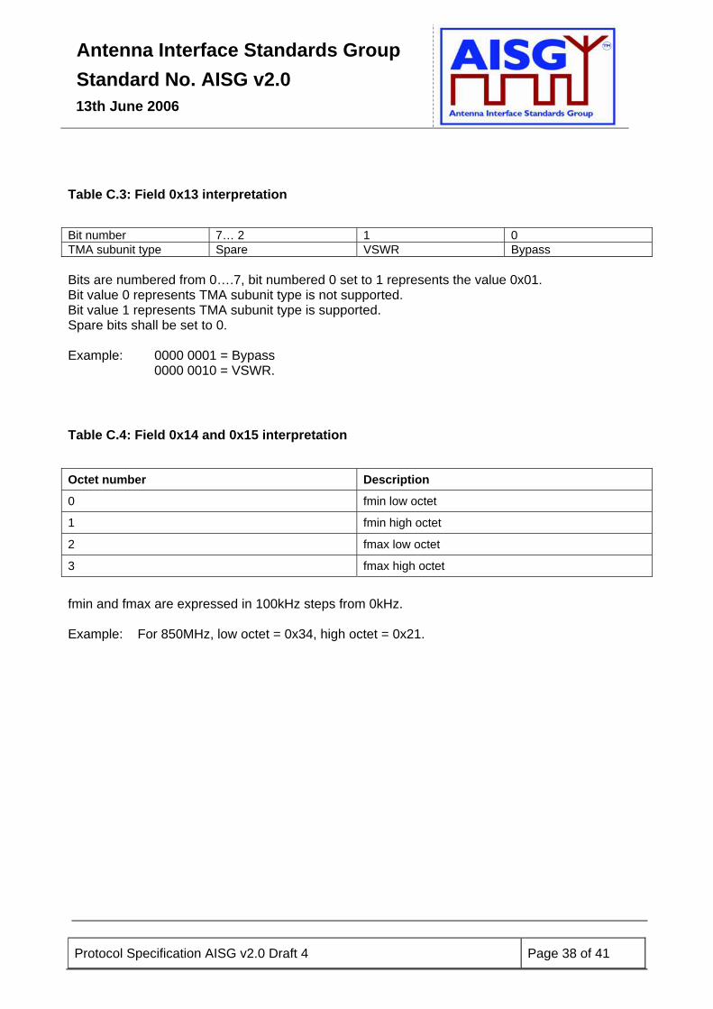
Table C.3: Field 0x13 interpretation
Bit number 7… 2 1 0 TMA subunit type Spare VSWR Bypass Bits are numbered from 0….7, bit numbered 0 set to 1 represents the value 0x01. Bit value 0 represents TMA subunit type is not supported. Bit value 1 represents TMA subunit type is supported. Spare bits shall be set to 0. Example: 0000 0001 = Bypass 0000 0010 = VSWR. Table C.4: Field 0x14 and 0x15 interpretation
Octet number Description
0 fmin low octet
1 fmin high octet
2 fmax low octet
3 fmax high octet
fmin and fmax are expressed in 100kHz steps from 0kHz. Example: For 850MHz, low octet = 0x34, high octet = 0x21.
Antenna Interface Standards Group Standard No. AISG v2.0
13th June 2006
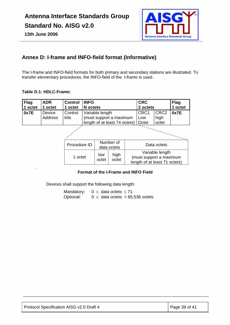
Annex D: I-frame and INFO-field format (Informative)
The I-frame and INFO-field formats for both primary and secondary stations are illustrated. To transfer elementary procedures, the INFO-field of the I-frame is used.
Table D.1: HDLC-Frame: Flag 1 octet
ADR 1 octet
Control 1 octet
INFO N octets
CRC 2 octets
Flag 1 octet
0x7E Device Address
Control bits
Variable length (must support a maximum length of at least 74 octets)
CRC1 Low Octet
CRC2 high octet
0x7E
Procedure ID Number of data octets Data octets
1 octet low octet
high octet
Variable length (must support a maximum length of at least 71 octets)
. Format of the I-Frame and INFO Field
Devices shall support the following data length:
Mandatory: 0 ≤ data octets ≤ 71 Optional: 0 ≤ data octets < 65,536 octets
Protocol Specification AISG v2.0 Draft 4 Page 39 of 41
Antenna Interface Standards Group Standard No. AISG v2.0
13th June 2006
Protocol Specification AISG v2.0 Draft 4 Page 40 of 41
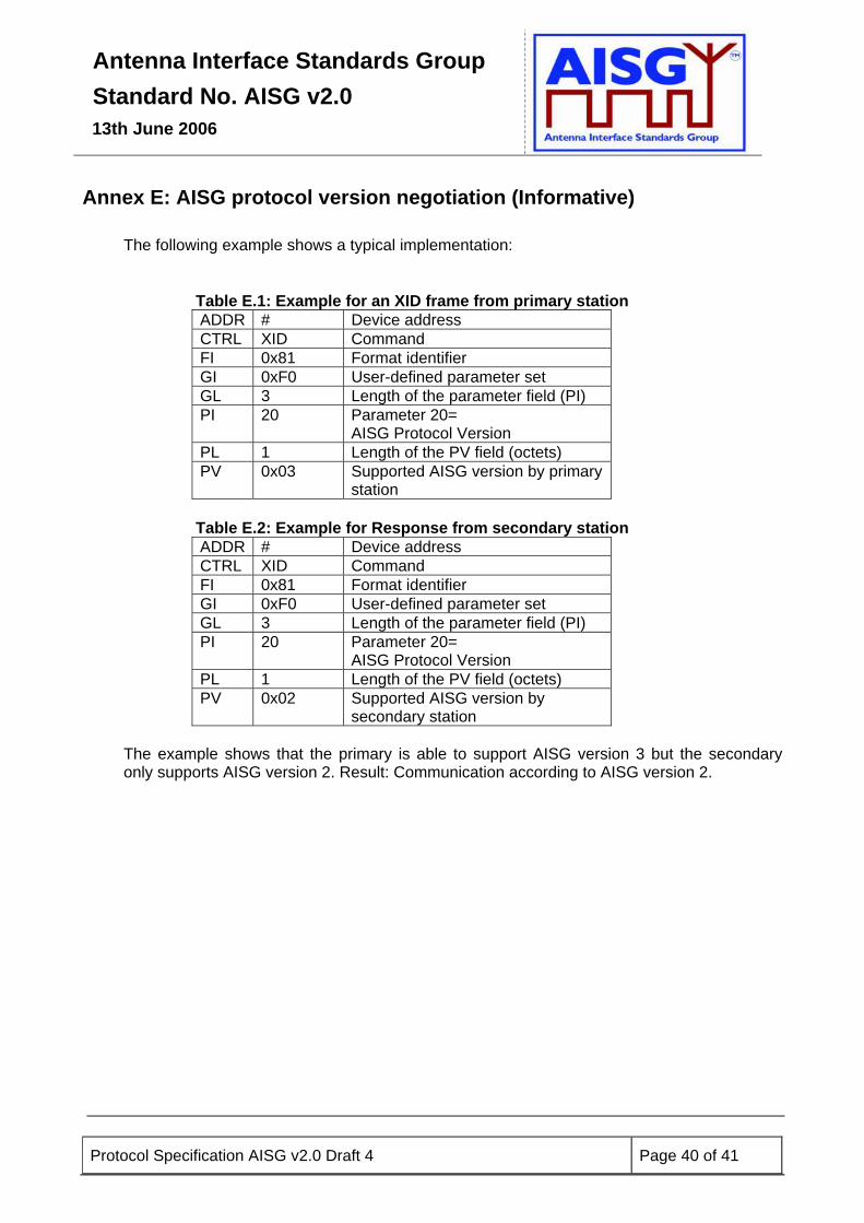
Annex E: AISG protocol version negotiation (Informative) The following example shows a typical implementation:
Table E.1: Example for an XID frame from primary station ADDR # Device address CTRL XID Command FI 0x81 Format identifier GI 0xF0 User-defined parameter set GL 3 Length of the parameter field (PI) PI 20 Parameter 20=
AISG Protocol Version PL 1 Length of the PV field (octets) PV 0x03 Supported AISG version by primary
station
Table E.2: Example for Response from secondary station ADDR # Device address CTRL XID Command FI 0x81 Format identifier GI 0xF0 User-defined parameter set GL 3 Length of the parameter field (PI) PI 20 Parameter 20=
AISG Protocol Version PL 1 Length of the PV field (octets) PV 0x02 Supported AISG version by
secondary station The example shows that the primary is able to support AISG version 3 but the secondary only supports AISG version 2. Result: Communication according to AISG version 2.
Antenna Interface Standards Group Standard No. AISG v2.0
13th June 2006
Protocol Specification AISG v2.0 Draft 4 Page 41 of 41
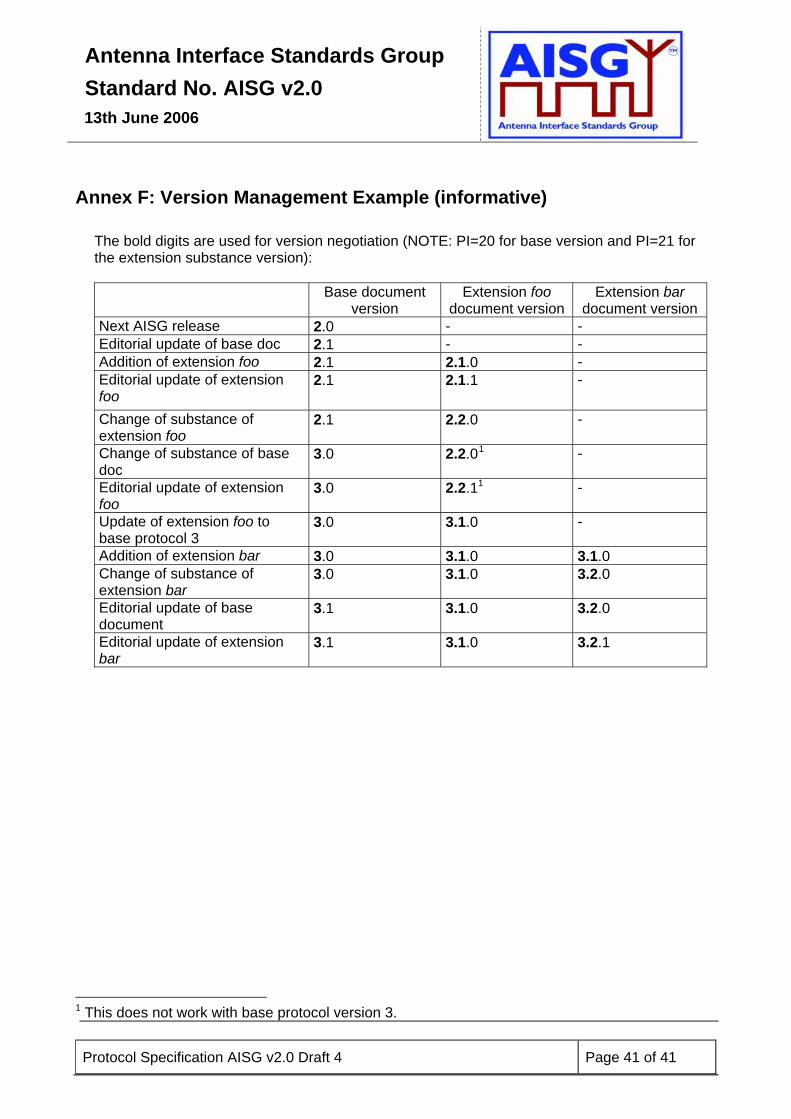
Annex F: Version Management Example (informative)
The bold digits are used for version negotiation (NOTE: PI=20 for base version and PI=21 for the extension substance version): Base document
version Extension foo
document version Extension bar
document version Next AISG release 2.0 - - Editorial update of base doc 2.1 - - Addition of extension foo 2.1 2.1.0 - Editorial update of extension foo
2.1 2.1.1 -
Change of substance of extension foo
2.1 2.2.0 -
Change of substance of base doc
3.0 2.2.01 -
Editorial update of extension foo
3.0 2.2.11 -
Update of extension foo to base protocol 3
3.0 3.1.0 -
Addition of extension bar 3.0 3.1.0 3.1.0 Change of substance of extension bar
3.0 3.1.0 3.2.0
Editorial update of base document
3.1 3.1.0 3.2.0
Editorial update of extension bar
3.1 3.1.0 3.2.1
1 This does not work with base protocol version 3.
Related Documents