• For any further information please contact your local dealer or call: For spare parts drawings refer to the section “ LIST OF COMPONENTS” enclosed to this manual. INSTRUCTION MANUAL GB TRANSLATION FROM THE ORIGINAL INSTRUCTIONS - Rev. n. 2 (11/2018) AIKIDO.4 AIKIDO.4FI 7104-M009-2_B BUTLER ENGINEERING and MARKETING S.p.A. a s. u. Via dell’Ecologia, 6 - 42047 Rolo - (RE) Italy Phone (+39) 0522 647911 - Fax (+39) 0522 649760 - e-mail: [email protected] 7104-M009-2_B

Welcome message from author
This document is posted to help you gain knowledge. Please leave a comment to let me know what you think about it! Share it to your friends and learn new things together.
Transcript
• For any further information please contact your local dealer or call:
For spare parts drawings refer to the section “ LIST OF COMPONENTS” enclosed to this manual.
INSTRUCTION MANUAL
GB TRANSLATION FROM THE ORIGINAL INSTRUCTIONS
- Rev. n. 2 (11/2018)
AIKIDO.4AIKIDO.4FI
7104-M009-2_B
BUTLER ENGINEERING and MARKETING S.p.A. a s. u.Via dell’Ecologia, 6 - 42047 Rolo - (RE) Italy
Phone (+39) 0522 647911 - Fax (+39) 0522 649760 - e-mail: [email protected]
7104-M009-2_B
INSTRUCTION, USE AND MAINTENANCE MANUAL
GBPage 2 of 43
SUMMARY
1.0 GENERAL INTRODUCTION __________ 71.1 Introduction ____________________________7
2.0 INTENDED USE _____________________ 72.1 Training of personnel __________________7
3.0 SAFETY DEVICES ___________________ 83.1 Residual risks __________________________8
4.0 GENERAL SAFETY RULES __________ 8
5.0 PACKING AND MOBILIZATION FOR TRANSPORT ________________________ 9
6.0 UNPACKING ________________________ 10
7.0 MOBILIZATION _____________________ 10
8.0 WORKING ENVIRONMENT CONDI-TIONS ______________________________ 11
8.1 Working position ______________________118.2 Working area __________________________118.3 Lighting _______________________________11
9.0 MACHINE ASSEMBLY ______________ 129.1 Anchoring system _____________________129.2 Fixtures contained in the packing _____129.3 Assembly procedures _________________12
10.0 ELECTRICAL CONNECTIONS _______ 1310.1 Working area modification ____________1410.2 Electrical checks ______________________15
11.0 CONTROLS _________________________ 1511.1 Control device (see Fig. 13) ____________1511.2 Storing of tool vertical position _______16
11.2.1 Return of tool vertical position _____1711.2.2 Erasure of tool stored position _____1711.2.3 Reset of tool stored position _______17
11.3 Pedalboard (see Fig. 16) _______________17
12.0 USING THE MACHINE ______________ 1812.1 Precaution measures during tyre re-
moval and fitting ______________________1812.2 Preliminary operations - Preparing
the wheel ______________________________1812.3 Wheel clamping _______________________18
13.2.1 Mandrel height adjustment ________2012.3.2 Reverse wheel pan protection ______21
12.4 Bead breaking through vertical rolls __2112.5 Demounting the tyre __________________2312.6 Mounting the tyre _____________________2512.7 Special use of the bead-breaker _______2712.8 Tyre inflation with machine without
tubeless inflation ______________________2712.9 Tyre inflation with machine with tube-
less inflation __________________________27
13.0 ROUTINE MAINTENANCE __________ 2813.1 Replacement of the feeler pin __________3013.2 Lubricants ____________________________3013.3 Neck adjustment ______________________30
14.0 TROUBLESHOOTING TABLE _______ 33
15.0 TECHNICAL DATA __________________ 3415.1 Weight _________________________________3415.2 Dimensions ____________________________35
16.0 STORING ___________________________ 37
17.0 SCRAPPING ________________________ 37
18.0 REGISTRATION PLATE DATA ______ 37
19.0 FUNCTIONAL DIAGRAMS __________ 37Table A - Electric diagram __________________38Table B - Pneumatic diagram _______________41
20.0 LIST OF COMPONENTS
7104-M009-2_B
AIKIDO.4 - AIKIDO.4FI
INSTRUCTION, USE AND MAINTENANCE MANUAL
GB Page 3 of 43
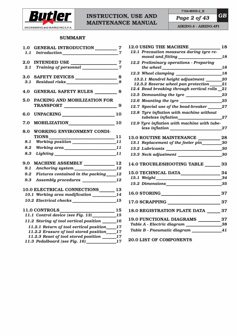
KEY 1 – Wheel support 2 – Upper tool 3 – Upper roll 4 – Lower roll 5 – Lower tool 6 – Control panel 7 – Pedalboard 8 – Complete column 9 – Pressure reducer filter unit 10 – Locking ring nut 11 – Lifting device 12 – Activator support 13 – Entrainer 14 – Ring for assembly grease support
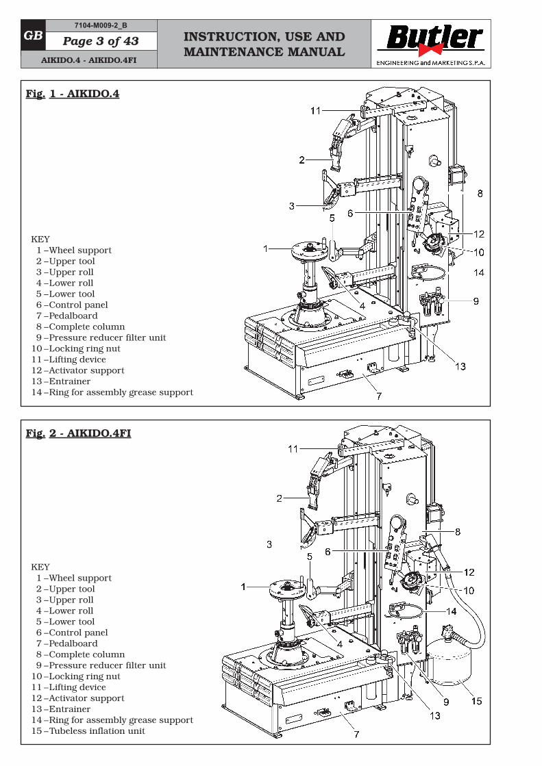
KEY 1 – Wheel support 2 – Upper tool 3 – Upper roll 4 – Lower roll 5 – Lower tool 6 – Control panel 7 – Pedalboard 8 – Complete column 9 – Pressure reducer filter unit 10 – Locking ring nut 11 – Lifting device 12 – Activator support 13 – Entrainer 14 – Ring for assembly grease support 15 – Tubeless inflation unit
7104-M009-2_B
AIKIDO.4 - AIKIDO.4FI
Fig. 1 - AIKIDO.4
Fig. 2 - AIKIDO.4FI
INSTRUCTION, USE AND MAINTENANCE MANUAL
GBPage 4 of 43
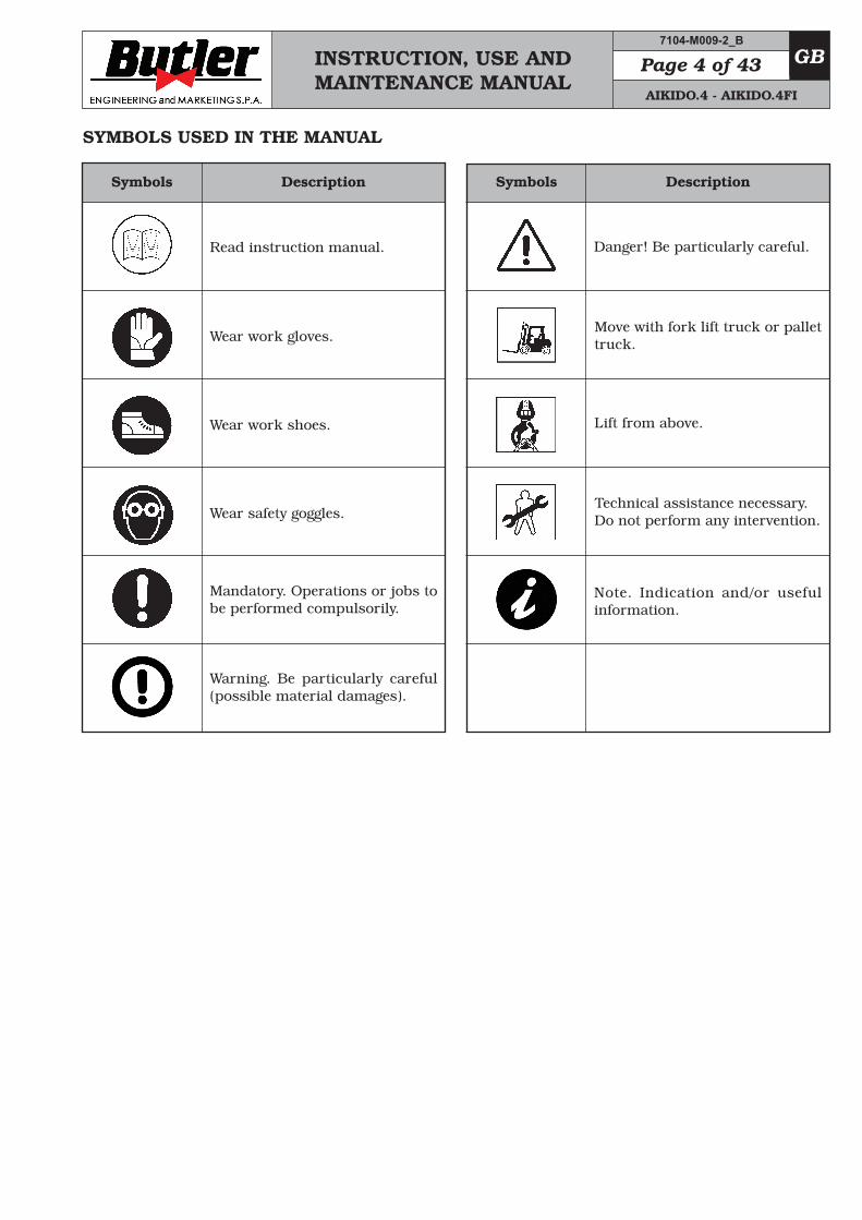
SYMBOLS USED IN THE MANUAL
Symbols Description
Read instruction manual.
Wear work gloves.
Wear work shoes.
Mandatory. Operations or jobs to be performed compulsorily.
Danger! Be particularly careful.
Symbols Description
Move with fork lift truck or pallet truck.
Lift from above.
Wear safety goggles.Technical assistance necessary. Do not perform any intervention.
Warning. Be particularly careful (possible material damages).
Note. Indication and/or useful information.
7104-M009-2_B
AIKIDO.4 - AIKIDO.4FI
INSTRUCTION, USE AND MAINTENANCE MANUAL
GB Page 5 of 43
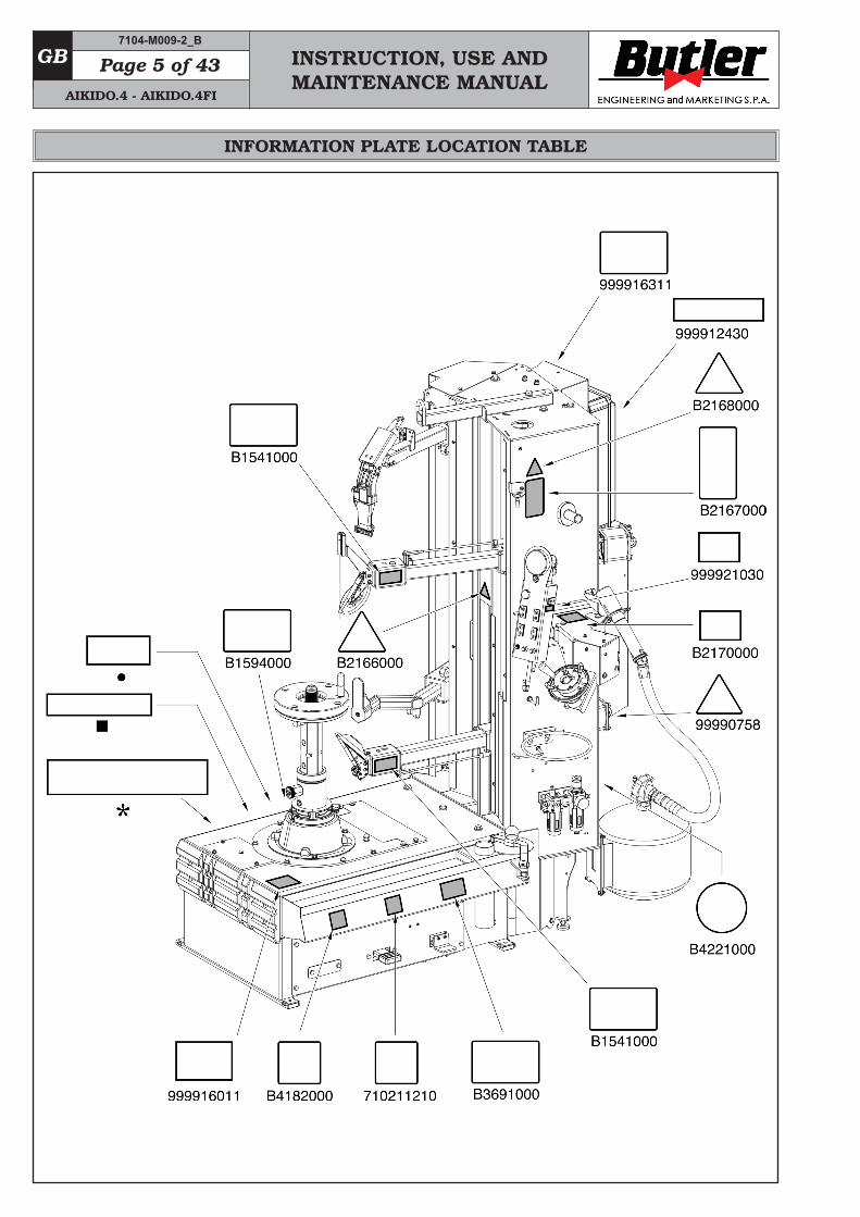
INFORMATION PLATE LOCATION TABLE
7104-M009-2_B
AIKIDO.4 - AIKIDO.4FI

INSTRUCTION, USE AND MAINTENANCE MANUAL
GBPage 6 of 43
Code numbers of plates
B1541000 Danger plate
B1594000 Date indicating plate
B2166000 Hand crushing danger plate
B2167000 Obligation to wear protective clothing plate
B2168000 Tyre burst plate
B2170000 Max inflation pressure rating plate
B3691000 Inflation pedal plate
B4182000 Electric motor specifications plate
B4221000 Grounding plate
B4244000 Rotating parts danger plate
99990758 Electricity danger plate
710211210 Rotation direction plate
999921030 Lateral key plate
999912430 230V 50 Hz plate
999916011 Motoinverter plate
999916311 Rubbish skip label
• Serial number plate
* Machine nameplate
♦ Manufacturer name plate
IF ONE OR MORE PLATES DISAPPEAR FROM THE MACHINE OR BECOMES DIFFICULT TO READ. REPLACE IT AND QUOTE ITS/THEIR CODE NUMBER/S WHEN REORDERING.
7104-M009-2_B
AIKIDO.4 - AIKIDO.4FI
INSTRUCTION, USE AND MAINTENANCE MANUAL
GB Page 7 of 43
SOME OF THE PICTURES PRE-SENT IN THIS MANUAL HAVE BEEN OBTAINED FROM PICTURES OF PROTOTYPES, THEREFORE THE STANDARD PRODUCTION MACHINES AND ACCESSORIES CAN BE DIFFERENT IN SOME COMPONENTS.
1.0 GENERAL INTRODUCTIONThis manual is an integral part of the product and must be retained for the whole operating life of the machine.Carefully study the warnings and instructions con-tained in this manual. It contains important instruc-tions regarding FUNCTIONING, SAFE USE and MAINTENANCE.
KEEP THE MANUAL IN A KNOWN, EASILY ACCESSIBLE PLACE FOR ALL ACCESSORY OPERATORS TO CONSULT IT WHENEVER IN DOUBT.
THE MANUFACTURER DISCLAIMS ALL RESPONSIBILITY FOR ANY DAMAGE OCCURRED WHEN THE INDICATIONS GIVEN IN THIS MANUAL ARE NOT RESPECTED: AS A MATTER OF FACT, THE NON-COMPLIANCE WITH SUCH INDI-CATIONS MIGHT LEAD TO EVEN SERIOUS DANGERS.
1.1 Introduction
Thank you for preferring this electro-hydraulic tyre changer. We feel sure you will not regret your decision.This machine has been designed for use in profes-sional workshops and in particular it stands out for its reliability and easy, safe and rapid operation: with just a small degree of maintenance and care, this tyre changer will give you many years of trouble-free service and lots of satisfaction.
2.0 INTENDED USEThe machines described in this manual and their different versions, are tyre-changers for car tires projected to be used exclusively for the mounting, demounting, and inflation of wheels with dimen-sions of max. diameter of 54" and max. width of 15".
THIS ACCESSORY MUST ONLY BE USED FOR THE PURPOSE FOR WHICH IT IS SPECIFICALLY DE-SIGNED.ANY OTHER USE IS CONSIDERED IMPROPER AND THEREFORE UN-ACCEPTABLE.
THE MANUFACTURER CANNOT BE HELD RESPONSIBLE FOR ANY DAMAGE CAUSED BY IMPROPER, ERRONEOUS, OR UNACCEPTABLE USE.
AN INTENSIVE USE OF THE EQUIP-MENT IN INDUSTRIAL ENVIRON-MENT IS NOT RECOMMENDED.
2.1 Training of personnel
The machine may be operated only by suitably trained and authorized personnel.
Given the complexity of the operations necessary to manage the machine and to carry out the operations safely and efficiently, the personnel must be trained in such a way that they learn all the information necessary to operate the machine as intended by the manufacturer.
A CAREFUL READING OF THIS INSTRUCTION MANUAL FOR USE AND MAINTENANCE AND A SHORT PERIOD OF TRAINING WITH SKILLED PERSONNEL CAN BE AN ENOUGH PREVENTIVE PREPARATION.
7104-M009-2_B
AIKIDO.4 - AIKIDO.4FI
INSTRUCTION, USE AND MAINTENANCE MANUAL
GBPage 8 of 43
3.0 SAFETY DEVICES
PERIODICALLY, AT LEAST MONTH-LY, CHECK THE INTEGRITY AND THE FUNCTIONALITY OF THE SAFETY AND PROTECTION DE-VICES ON THE MACHINE.
All the machines are equipped with:• man-operated controls (immediate stop of operation
when the control is released) for all operating devices;• mandrel rotation;• tool translation;• bead breaking roller translation. • Non-adjustable pressure limiter.
This allows inflation of tyres in reasonable safety. Inflation of tyres to over 4,2 ± 0,2 bar (60 PSI) is not allowed.
• Controls logic dispositionIts function is to prevent the operator from danger-ous mistakes.
• Motor protection devicesThe new “Invemotor” motor is equipped with elec-tronic protection devices. They stop the motor if working defected conditions appear to avoid that the motor itself can be damaged and that the operator safety can be compromised (overvoltage, overload, overtemperature). For other details, see the chapt. 14 “Fault-Finding”.
3.1 Residual risks
The machine was subjected to a complete analysis of risks according to reference standard EN ISO 12100.Risks are as reduced as possible in relation with tech-nology and product functionality.This manual stresses possible residual risks, also highlighted in pictograms on the present manual and adhesive warning signals placed on the machine: their location is represented in “PLATE LOCATION ON MA-CHINE INFORMATION TABLE” on page 5.
4.0 GENERAL SAFETY RULES
• Any tampering with or modification to the machine not previously authorized by the manufacturer ex-empts the latter from all responsibility for damage caused by or derived from said actions.
• Removing of or tampering with the safety devices or with the warning signals placed on the machine leads to serious dangers and represents a transgression of European safety rules.
• Use of the machine is only permitted in places free from explosion or fire hazard and in dry places under cover.
• Original spare parts and accessories should be used.
THE MANUFACTURER DENIES ANY RESPONSIBILITY IN CASE OF DAMAGES CAUSED BY UNAU-THORIZED MODIFICATIONS OR BY THE USE OF NON ORIGINAL COMPONENTS OR EQUIPMENT.
• Installation must be conducted only by qualified personnel exactly according to the instructions that are given below.
• Ensure that there are no dangerous situations dur-ing the machine operating manoeuvres. Immediately stop the machine if it miss-functions and contact the assistance service of an authorized dealer.
• In emergency situations and before carrying out any maintenance or repairs, disconnect all supplies to the machine by using the main switch.
• The machine electrical supply system must be equipped with an appropriate earthing, to which the yellow-green machine protection wire must be connected.
• Ensure that the work area around the machine is free of potentially dangerous objects and that there is no oil since this could damage the tyre. Oil on the floor is also a potential danger for the operator.
7104-M009-2_B
AIKIDO.4 - AIKIDO.4FI
INSTRUCTION, USE AND MAINTENANCE MANUAL
GB Page 9 of 43
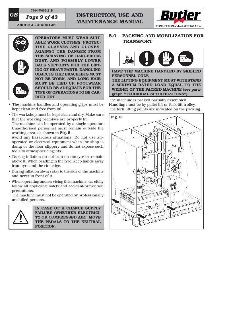
5.0 PACKING AND MOBILIZATION FOR TRANSPORT
HAVE THE MACHINE HANDLED BY SKILLED PERSONNEL ONLY. THE LIFTING EQUIPMENT MUST WITHSTAND A MINIMUM RATED LOAD EQUAL TO THE WEIGHT OF THE PACKED MACHINE (see para-graph “TECHNICAL SPECIFICATIONS”).
The machine is packed partially assembled. Handling must be by pallet-lift or fork-lift trolley. The fork lifting points are indicated on the packing.
Fig. 3
OPERATORS MUST WEAR SUIT-ABLE WORK CLOTHES, PROTEC-TIVE GLASSES AND GLOVES, AGAINST THE DANGER FROM THE SPRAYING OF DANGEROUS DUST, AND POSSIBLY LOWER BACK SUPPORTS FOR THE LIFT-ING OF HEAVY PARTS. DANGLING OBJECTS LIKE BRACELETS MUST NOT BE WORN, AND LONG HAIR MUST BE TIED UP. FOOTWEAR SHOULD BE ADEQUATE FOR THE TYPE OF OPERATIONS TO BE CAR-RIED OUT.
• The machine handles and operating grips must be kept clean and free from oil.
• The workshop must be kept clean and dry. Make sure that the working premises are properly lit.The machine can be operated by a single operator. Unauthorised personnel must remain outside the working area, as shown in Fig. 5.Avoid any hazardous situations. Do not use air-operated or electrical equipment when the shop is damp or the floor slippery and do not expose such tools to atmospheric agents.
• During inflation do not lean on the tyre or remain above it. When beading in the tyre, keep hands away from tyre and the rim edge.
• During inflation always stay to the side of the machine and never in front of it.
• When operating and servicing this machine, carefully follow all applicable safety and accident-prevention precautions.The machine must not be operated by professionally unskilled persons.
IN CASE OF A CHANCE SUPPLY FAILURE (WHETHER ELECTRICI-TY OR COMPRESSED AIR), MOVE THE PEDALS TO THE NEUTRAL POSITION.
7104-M009-2_B
AIKIDO.4 - AIKIDO.4FI
INSTRUCTION, USE AND MAINTENANCE MANUAL
GBPage 10 of 43
6.0 UNPACKING
DURING UNPACKING, ALWAYS WEAR GLOVES TO PREVENT ANY INJURY CAUSED BY CONTACT WITH PACKAGING MATERIAL (NAILS, ETC.).
The cardboard box is supported with plastic strap-ping. Cut the strapping with suitable scissors. Use a small knife to cut along the lateral axis of the box and open it like a fan.It is also possible to unnail the cardboard box from the pallet it is fixed to. After removing the packing, and in the case of the machine packed fully assembled, check that the machine is complete and that there is no visible damage. If in doubt do not use the machine and refer to pro-fessionally qualified personnel (to the seller).The packing (plastic bags, expanded polystyrene, nails, screws, timber, etc.) should not be left within reach of children since it is potentially dangerous. These materials should be deposited in the relevant collec-tion points if they are pollutants or non biodegradable.
THE BOX CONTAINING THE FIX-TURES IS CONTAINED IN THE WRAPPING. DO NOT THROW IT AWAY WITH THE PACKING.
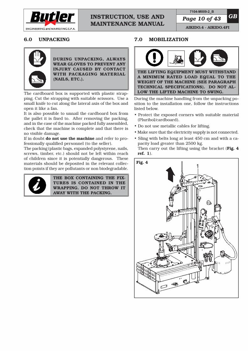
7.0 MOBILIZATION
THE LIFTING EQUIPMENT MUST WITHSTAND A MINIMUM RATED LOAD EQUAL TO THE WEIGHT OF THE MACHINE (SEE PARAGRAPH TECHNICAL SPECIFICATIONS). DO NOT AL-LOW THE LIFTED MACHINE TO SWING.
During the machine handling from the unpacking po-sition to the installation one, follow the instructions listed below.• Protect the exposed corners with suitable material
(Pluribol/cardboard).• Do not use metallic cables for lifting.• Make sure that the electricity supply is not connected.• Sling with belts long at least 450 cm and with a ca-
pacity load greater than 2500 kg. Then carry out the lifting using the bracket (Fig. 4 ref. 1).
Fig. 4
7104-M009-2_B
AIKIDO.4 - AIKIDO.4FI
INSTRUCTION, USE AND MAINTENANCE MANUAL
GB Page 11 of 43
8.0 WORKING ENVIRONMENT CONDI-TIONS
The machine must be operated under proper condi-tions as follows:• temperature: 0° + 55° C • relative humidity: 30 - 95% (dew-free) • atmospheric pressure: 860 - 1060 hPa (mbar). The use of the machine in ambient conditions other than those specified above is only allowed after prior agreement with and approval of the manufacturer.
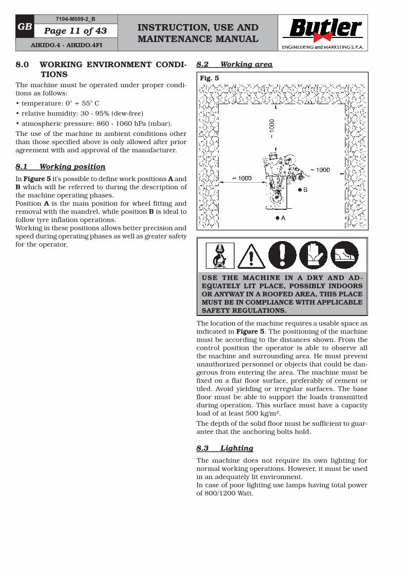
8.1 Working position
In Figure 5 it's possible to define work positions A and B which will be referred to during the description of the machine operating phases. Position A is the main position for wheel fitting and removal with the mandrel, while position B is ideal to follow tyre inflation operations. Working in these positions allows better precision and speed during operating phases as well as greater safety for the operator.
8.2 Working area
Fig. 5
USE THE MACHINE IN A DRY AND AD-EQUATELY LIT PLACE, POSSIBLY INDOORS OR ANYWAY IN A ROOFED AREA, THIS PLACE MUST BE IN COMPLIANCE WITH APPLICABLE SAFETY REGULATIONS.
The location of the machine requires a usable space as indicated in Figure 5. The positioning of the machine must be according to the distances shown. From the control position the operator is able to observe all the machine and surrounding area. He must prevent unauthorized personnel or objects that could be dan-gerous from entering the area. The machine must be fixed on a flat floor surface, preferably of cement or tiled. Avoid yielding or irregular surfaces. The base floor must be able to support the loads transmitted during operation. This surface must have a capacity load of at least 500 kg/m².The depth of the solid floor must be sufficient to guar-antee that the anchoring bolts hold.
8.3 Lighting
The machine does not require its own lighting for normal working operations. However, it must be used in an adequately lit environment. In case of poor lighting use lamps having total power of 800/1200 Watt.
7104-M009-2_B
AIKIDO.4 - AIKIDO.4FI
INSTRUCTION, USE AND MAINTENANCE MANUAL
GBPage 12 of 43
9.0 MACHINE ASSEMBLYAfter having freed the various components from the packing check that they are complete, and that there are no anomalies, then comply with the following in-structions for the assembly of the components making use of the attached series of illustrations.
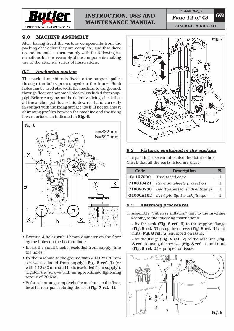
9.1 Anchoring system
The packed machine is fixed to the support pallet through the holes prearranged on the frame. Such holes can be used also to fix the machine to the ground, through floor anchor small blocks (excluded from sup-ply). Before carrying out the definitive fixing, check that all the anchor points are laid down flat and correctly in contact with the fixing surface itself. If not so, insert shimming profiles between the machine and the fixing lower surface, as indicated in Fig. 6.
Fig. 6
a=832 mmb=590 mm
• Execute 4 holes with 12 mm diameter on the floor by the holes on the bottom floor;
• insert the small blocks (excluded from supply) into the holes;
• fix the machine to the ground with 4 M12x120 mm screws (excluded from supply) (Fig. 6 ref. 1) (or with 4 12x80 mm stud bolts (excluded from supply)). Tighten the screws with an approximate tightening torque of 70 Nm.
• Before clamping completely the machine to the floor, level its rear part rotating the feet (Fig. 7 ref. 1).
Fig. 7
9.2 Fixtures contained in the packing
The packing case contains also the fixtures box.Check that all the parts listed are there.
Code Description N.
B1157000 Two-faced cone 1
710013421 Reverse wheels protection 1
710090730 Bead depressor with entrainer 1
G1000A152 D.14 pin light truck flange 1
9.3 Assembly procedures
1. Assemble “Tubeless inflation” unit to the machine keeping to the following instructions:
- fix the tank (Fig. 8 ref. 6) to the support flange (Fig. 8 ref. 7) using the screws (Fig. 8 ref. 4) and nuts (Fig. 8 ref. 5) equipped on issue;
- fix the flange (Fig. 8 ref. 7) to the machine (Fig. 8 ref. 3) using the screws (Fig. 8 ref. 1) and nuts (Fig. 8 ref. 2) equipped on issue;
7
6
4
14
325
5
Fig. 8
7104-M009-2_B
AIKIDO.4 - AIKIDO.4FI
INSTRUCTION, USE AND MAINTENANCE MANUAL
GB Page 13 of 43
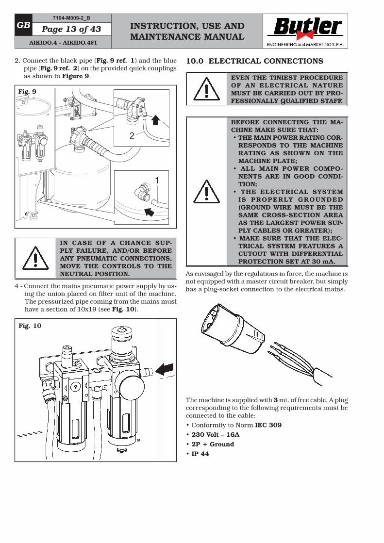
2. Connect the black pipe (Fig. 9 ref. 1) and the blue pipe (Fig. 9 ref. 2) on the provided quick couplings as shown in Figure 9.
1
2
Fig. 9
IN CASE OF A CHANCE SUP-PLY FAILURE, AND/OR BEFORE ANY PNEUMATIC CONNECTIONS, MOVE THE CONTROLS TO THE NEUTRAL POSITION.
4 - Connect the mains pneumatic power supply by us-ing the union placed on filter unit of the machine. The pressurized pipe coming from the mains must have a section of 10x19 (see Fig. 10).
Fig. 10
10.0 ELECTRICAL CONNECTIONS
EVEN THE TINIEST PROCEDURE OF AN ELECTRICAL NATURE MUST BE CARRIED OUT BY PRO-FESSIONALLY QUALIFIED STAFF.
BEFORE CONNECTING THE MA-CHINE MAKE SURE THAT: • THE MAIN POWER RATING COR-
RESPONDS TO THE MACHINE RATING AS SHOWN ON THE MACHINE PLATE;
• ALL MAIN POWER COMPO -NENTS ARE IN GOOD CONDI-TION;
• THE ELECTRICAL SYSTEM IS PROPERLY GROUNDED (GROUND WIRE MUST BE THE SAME CROSS-SECTION AREA AS THE LARGEST POWER SUP-PLY CABLES OR GREATER);
• MAKE SURE THAT THE ELEC-TRICAL SYSTEM FEATURES A CUTOUT WITH DIFFERENTIAL PROTECTION SET AT 30 mA.
As envisaged by the regulations in force, the machine is not equipped with a master circuit breaker, but simply has a plug-socket connection to the electrical mains.
The machine is supplied with 3 mt. of free cable. A plug corresponding to the following requirements must be connected to the cable:• Conformity to Norm IEC 309• 230 Volt – 16A• 2P + Ground• IP 44
7104-M009-2_B
AIKIDO.4 - AIKIDO.4FI
INSTRUCTION, USE AND MAINTENANCE MANUAL
GBPage 14 of 43
FIT A TYPE-APPROVED PLUG TO THE MACHINE CABLE (THE GROUND WIRE IS YELLOW/GREEN AND MUST NEVER BE CONNECTED TO ONE OF THE PHASE LEADS).
MAKE SURE THAT THE ELECTRI-CAL SYSTEM IS COMPATIBLE WITH THE RATED POWER AB-SORPTION SPECIFIED IN THIS MANUAL AND APT TO ENSURE THAT VOLTAGE DROP UNDER FULL LOAD WILL NOT EXCEED 4% OF RATED VOLTAGE (10% UPON START-UP).
VERSION WITH SINGLE-PHASE MOTOR
On delivery, the machine is pre-set to operate at a single-phase voltage of 200 ÷ 265 V - 50/60 Hz.
FAILURE TO OBSERVE THE ABOVE INSTRUCTIONS WILL IMMEDIATE-LY INVALIDATE THE WARRANTY.
10.1 Working area modification
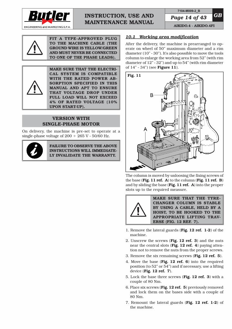
After the delivery, the machine is prearranged to op-erate on wheel of 50” maximum diameter and a rim diameter (10” - 30”). It’s also possible to move the tools column to enlarge the working area from 52” (with rim diameter of 12” - 32”) and up to 54” (with rim diameter of 14” - 34”) (see Figure 11).
Fig. 11
The column is moved by unloosing the fixing screws of the base (Fig. 11 ref. A) to the column (Fig. 11 ref. B) and by sliding the base (Fig. 11 ref. A) into the proper slots up to the required measure.
MAKE SURE THAT THE TYRE-CHANGER COLUMN IS STABLE BY USING A CABLE, HELD BY A HOIST, TO BE HOOKED TO THE APPROPRIATE LIFTING TRAV-ERSE (FIG. 12 REF. 7).
1. Remove the lateral guards (Fig. 12 ref. 1-2) of the machine.
2. Unscrew the screws (Fig. 12 ref. 3) and the nuts near the central slots (Fig. 12 ref. 4) paying atten-tion not to remove the nuts from the proper screws.
3. Remove the six remaining screws (Fig. 12 ref. 5).4. Move the base (Fig. 12 ref. 6) into the required
position (to 52” or 54”) and if necessary, use a lifting device (Fig. 12 ref. 7).
5. Lock the base three screws (Fig. 12 ref. 3) with a couple of 80 Nm.
6. Place six screws (Fig. 12 ref. 5) previously removed and lock them on the bases side with a couple of 80 Nm.
7. Remount the lateral guards (Fig. 12 ref. 1-2) of the machine.
7104-M009-2_B
AIKIDO.4 - AIKIDO.4FI
INSTRUCTION, USE AND MAINTENANCE MANUAL
GB Page 15 of 43
AFTER THE ASSEMBLY, CHECK THE CORRECT POSITION OF THE TOOLS. LOCK THE RIM ON THE MANDREL CENTRE. WITH THE LOWER BEAD BREAKER ARM, CHECK THAT THE DISTANCE BE-TWEEN THE ROLL AND THE RIM EDGES (UPPER AND LOWER) IS ALMOST THE SAME. REPEAT ALL THE PROCEDURES STARTING FROM POINT 1 IF THE DISTANCE IS NOT THE SAME.
Fig. 12
10.2 Electrical checks
BEFORE STARTING UP THE TYRE-CHANGER, BE SURE TO BECOME FAMILIAR WITH THE LOCATION AND OPERATION OF ALL CON-TROLS AND CHECK THEIR PROP-ER OPERATION (SEE PAR. “CON-TROLS”).
CARRY OUT A DAILY CHECK OF MAINTAINED-TYPE CONTROLS CORRECT FUNCTIONING, BEFORE STARTING MACHINE OPERATION.
11.0 CONTROLS
E
F
C
D
GB
I
M
H
L
A
Fig. 13
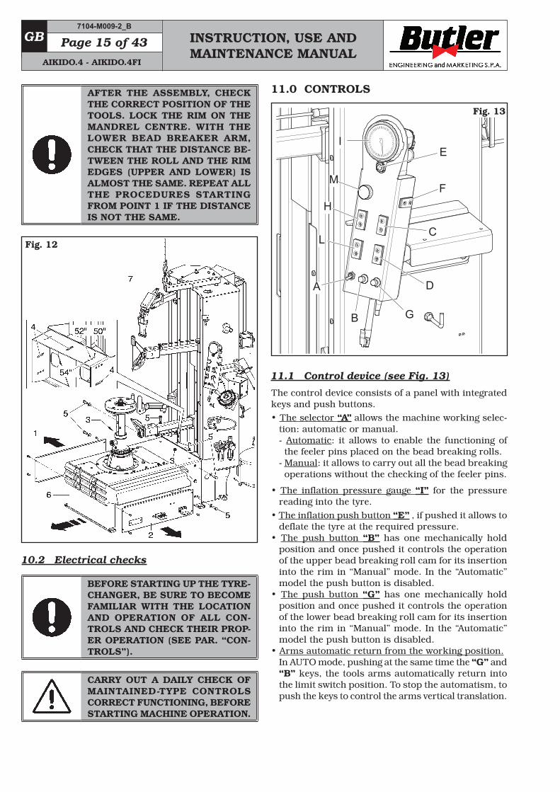
11.1 Control device (see Fig. 13)
The control device consists of a panel with integrated keys and push buttons.• The selector “A” allows the machine working selec-
tion: automatic or manual.- Automatic: it allows to enable the functioning of the feeler pins placed on the bead breaking rolls.
- Manual: it allows to carry out all the bead breaking operations without the checking of the feeler pins.
• The inflation pressure gauge “I” for the pressure reading into the tyre.
• The inflation push button “E” , if pushed it allows to deflate the tyre at the required pressure.
• The push button “B” has one mechanically hold position and once pushed it controls the operation of the upper bead breaking roll cam for its insertion into the rim in “Manual” mode. In the “Automatic” model the push button is disabled.
• The push button “G” has one mechanically hold position and once pushed it controls the operation of the lower bead breaking roll cam for its insertion into the rim in “Manual” mode. In the “Automatic” model the push button is disabled.
• Arms automatic return from the working position.In AUTO mode, pushing at the same time the “G” and “B” keys, the tools arms automatically return into the limit switch position. To stop the automatism, to push the keys to control the arms vertical translation.
7104-M009-2_B
AIKIDO.4 - AIKIDO.4FI
INSTRUCTION, USE AND MAINTENANCE MANUAL
GBPage 16 of 43
• The push button “F” has one hold position and once pushed () it controls the ahead translation of the tools. If pushed () it controls the backwards translation of the tools.
• The push button “C” has one hold position and it controls the vertical shifting of the upper bead breaking roll. If pushed on its lower part (), it will control the downwards translation. If pushed on its upper part (), it controls upward translation. Keep-ing it pushed for more than one second, translation carries on automatically until the arm reaches the stroke limit. To stop automatism, push again push button “C”.
• The push button “D” has one mechanically hold posi-tion and once pushed it controls the vertical shifting of the lower bead breaking roll. If pushed on its lower part (), it will control the downwards translation. If pushed on its upper part (), it controls upward translation. Keeping it pushed for more than one second, translation carries on automatically until the arm reaches the stroke limit. To stop automatism, push again push button “D”.
• The push button “H” has one mechanically hold position and it controls the upper tool vertical shift. If pushed on its lower part (), it will control the downwards translation. If pushed on its upper part (), it controls upward translation.
• The push button “L” has one mechanically hold po-sition and it controls the upper tool vertical shift. If pushed on its lower part (), it will control the down-wards translation. If pushed on its upper part (), it controls upward translation. Keeping it pushed for more than one second, translation carries on automatically until the arm reaches the stroke limit. To stop automatism, push again push button “L”.
• The backlighted push button “M” allows the stor-ing of the height position of the tool arm, so that by merely pressing the same, the tool comes back to the previously stored position (see paragraph 11.2).
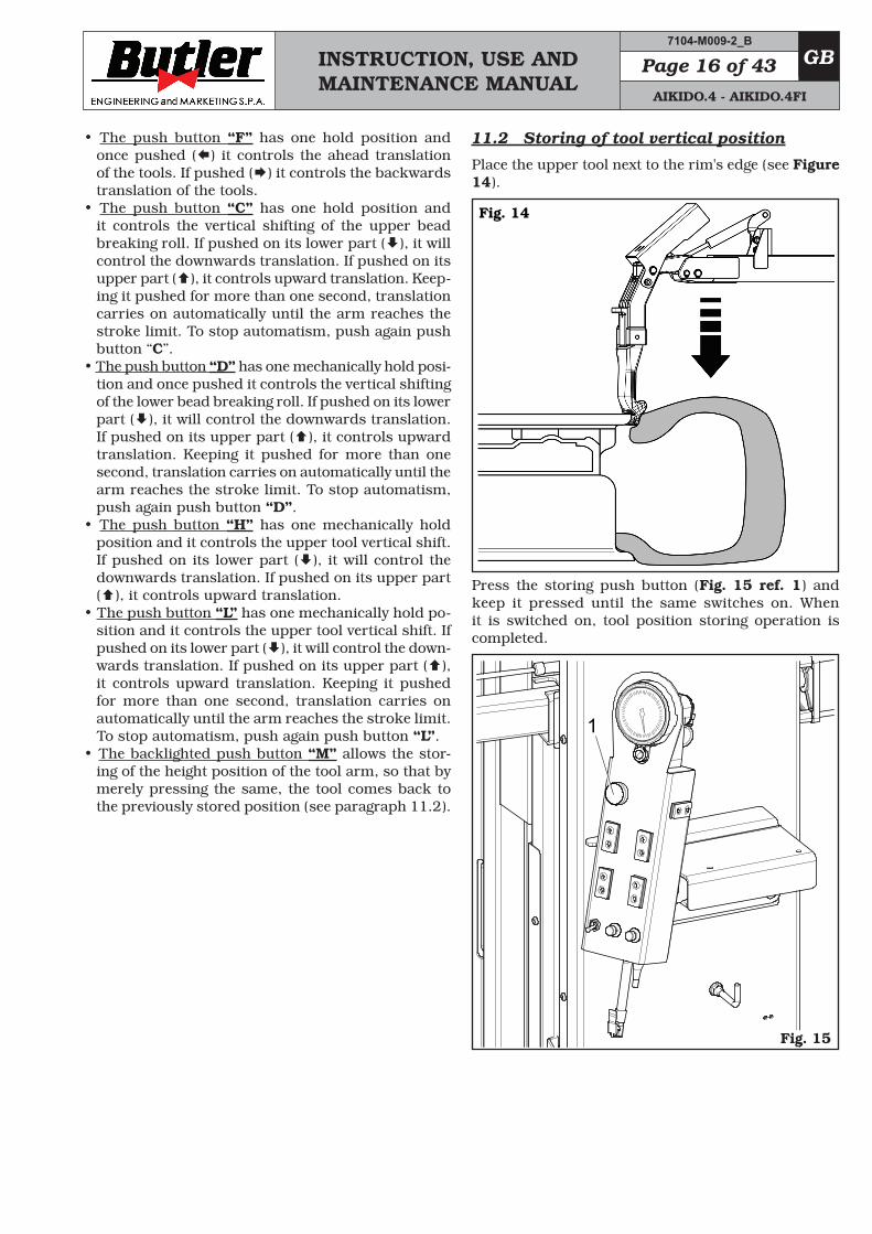
11.2 Storing of tool vertical position
Place the upper tool next to the rim's edge (see Figure 14).
Fig. 14
Press the storing push button (Fig. 15 ref. 1) and keep it pressed until the same switches on. When it is switched on, tool position storing operation is completed.
1
A
Fig. 15
7104-M009-2_B
AIKIDO.4 - AIKIDO.4FI
INSTRUCTION, USE AND MAINTENANCE MANUAL
GB Page 17 of 43
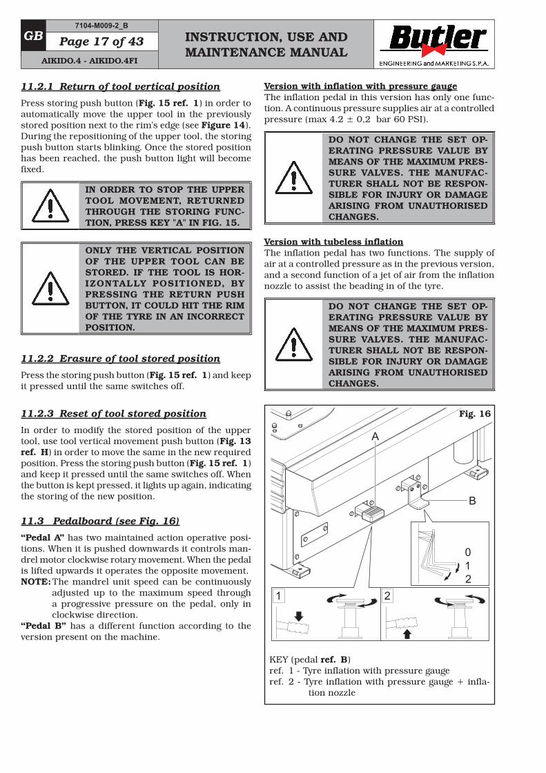
Version with inflation with pressure gaugeThe inflation pedal in this version has only one func-tion. A continuous pressure supplies air at a controlled pressure (max 4.2 ± 0,2 bar 60 PSI).
DO NOT CHANGE THE SET OP-ERATING PRESSURE VALUE BY MEANS OF THE MAXIMUM PRES-SURE VALVES. THE MANUFAC-TURER SHALL NOT BE RESPON-SIBLE FOR INJURY OR DAMAGE ARISING FROM UNAUTHORISED CHANGES.
Version with tubeless inflationThe inflation pedal has two functions. The supply of air at a controlled pressure as in the previous version, and a second function of a jet of air from the inflation nozzle to assist the beading in of the tyre.
DO NOT CHANGE THE SET OP-ERATING PRESSURE VALUE BY MEANS OF THE MAXIMUM PRES-SURE VALVES. THE MANUFAC-TURER SHALL NOT BE RESPON-SIBLE FOR INJURY OR DAMAGE ARISING FROM UNAUTHORISED CHANGES.
KEY (pedal ref. B)ref. 1 - Tyre inflation with pressure gaugeref. 2 - Tyre inflation with pressure gauge + infla-
tion nozzle
21210
A
B
Fig. 16
11.2.1 Return of tool vertical position
Press storing push button (Fig. 15 ref. 1) in order to automatically move the upper tool in the previously stored position next to the rim's edge (see Figure 14). During the repositioning of the upper tool, the storing push button starts blinking. Once the stored position has been reached, the push button light will become fixed.
IN ORDER TO STOP THE UPPER TOOL MOVEMENT, RETURNED THROUGH THE STORING FUNC-TION, PRESS KEY "A" IN FIG. 15.
ONLY THE VERTICAL POSITION OF THE UPPER TOOL CAN BE STORED. IF THE TOOL IS HOR-IZONTALLY POSITIONED, BY PRESSING THE RETURN PUSH BUTTON, IT COULD HIT THE RIM OF THE TYRE IN AN INCORRECT POSITION.
11.2.2 Erasure of tool stored position
Press the storing push button (Fig. 15 ref. 1) and keep it pressed until the same switches off.
11.2.3 Reset of tool stored position
In order to modify the stored position of the upper tool, use tool vertical movement push button (Fig. 13 ref. H) in order to move the same in the new required position. Press the storing push button (Fig. 15 ref. 1) and keep it pressed until the same switches off. When the button is kept pressed, it lights up again, indicating the storing of the new position.
11.3 Pedalboard (see Fig. 16)
“Pedal A” has two maintained action operative posi-tions. When it is pushed downwards it controls man-drel motor clockwise rotary movement. When the pedal is lifted upwards it operates the opposite movement.NOTE: The mandrel unit speed can be continuously
adjusted up to the maximum speed through a progressive pressure on the pedal, only in clockwise direction.
“Pedal B” has a different function according to the version present on the machine.
7104-M009-2_B
AIKIDO.4 - AIKIDO.4FI
INSTRUCTION, USE AND MAINTENANCE MANUAL
GBPage 18 of 43
12.0 USING THE MACHINE
12.1 Precaution measures during tyre re-moval and fitting
Before fitting a tyre, observe the following safety rules:• rim and tyre must be clean, dry and in good condi-
tion; if necessary, remove the balancing weights and clean the rim. Check that:- neither the bead nor the tread of the tyre are dam-
aged;- the rim does not produce dents and/or deformation
(especially for alloy rims, dents can cause internal micro-fractures, that pass unobserved at visual inspection, and can compromise the solidity of the rim and constitute danger even during inflation);
• adequately lubricate the contact surface of rim and tyre bead, using specific tyre lubricants only;
• replace the inner tube valve with a new valve, if the tyre tube has a metal valve, replace the grommet;
• make sure that the tyre is the right size for the rim; on the contrary, never fit a tyre unless you are sure it is of the right size (the rated size of the rim and tyre is usually printed directly on each of them);
• do not use compressed air or water jets to clean the wheels on the machine.
12.2 Preliminary operations - Preparing the wheel
• Remove the wheel balancing weights from both sides of the wheel.
• Remove the valve stem and allow the tyre to com-pletely deflate.
• Establish from which side the tyre should be de-mounted, checking the position of the groove.
• Find the rim locking type.• Try to establish the special types of wheels, such as
“EH2” and “EH2+”, in order to improve locking, bead breaking, assembly and disassembly performances.
WHEN HANDLING WHEELS WEIGHING MORE THAN 10 KG AND/OR WITH A FREQUENCY OF MORE THAN 20/30 WHEELS PER HOUR, A LIFTING DEVICE SHOULD BE USED.
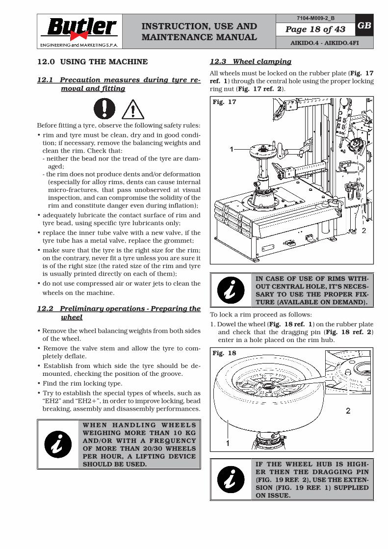
12.3 Wheel clamping
All wheels must be locked on the rubber plate (Fig. 17 ref. 1) through the central hole using the proper locking ring nut (Fig. 17 ref. 2).
Fig. 17
IN CASE OF USE OF RIMS WITH-OUT CENTRAL HOLE, IT’S NECES-SARY TO USE THE PROPER FIX-TURE (AVAILABLE ON DEMAND).
To lock a rim proceed as follows: 1. Dowel the wheel (Fig. 18 ref. 1) on the rubber plate
and check that the dragging pin (Fig. 18 ref. 2) enter in a hole placed on the rim hub.
Fig. 18
IF THE WHEEL HUB IS HIGH-ER THEN THE DRAGGING PIN (FIG. 19 REF. 2), USE THE EXTEN-SION (FIG. 19 REF. 1) SUPPLIED ON ISSUE.
7104-M009-2_B
AIKIDO.4 - AIKIDO.4FI
INSTRUCTION, USE AND MAINTENANCE MANUAL
GB Page 19 of 43
Fig. 19
FOR WHEELS WITH ALLOY RIMS, USE THE PROPER PLASTIC GUARD (FIG. 20 REF. 1).
Fig. 20
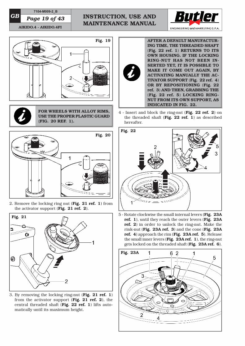
2. Remove the locking ring nut (Fig. 21 ref. 1) from the activator support (Fig. 21 ref. 2).
Fig. 21
3. By removing the locking ring-nut (Fig. 21 ref. 1) from the activator support (Fig. 21 ref. 2), the central threaded shaft (Fig. 22 ref. 1) lifts auto-matically until its maximum height.
AFTER A DEFAULT MANUFACTUR-ING TIME, THE THREADED SHAFT (Fig. 22 ref. 1) RETURNS TO ITS OWN HOUSING. IF THE LOCKING RING-NUT HAS NOT BEEN IN-SERTED YET, IT IS POSSIBLE TO MAKE IT COME OUT AGAIN, BY ACTIVATING MANUALLY THE AC-TIVATOR SUPPORT (Fig. 22 ref. 4) OR BY REPOSITIONING (Fig. 22 ref. 3) AND THEN, GRABBING THE (Fig. 22 ref. 5) LOCKING RING-NUT FROM ITS OWN SUPPORT, AS INDICATED IN FIG. 22.
4 - Insert and block the ring-nut (Fig. 22 ref. 2) on the threaded shaft (Fig. 22 ref. 1) as described hereafter.
Fig. 22
5 - Rotate clockwise the small internal levers (Fig. 23A ref. 1), until they reach the outer levers (Fig. 23A ref. 2) in order to unlock the ring-nut. Make the rink-nut (Fig. 23A ref. 3) and the cone (Fig. 23A ref. 4) approach the rim (Fig. 23A ref. 5). Release the small inner levers (Fig. 23A ref. 1), the ring-nut gets locked on the threaded shaft (Fig. 23A ref. 6).
Fig. 23A
7104-M009-2_B
AIKIDO.4 - AIKIDO.4FI
INSTRUCTION, USE AND MAINTENANCE MANUAL
GBPage 20 of 43
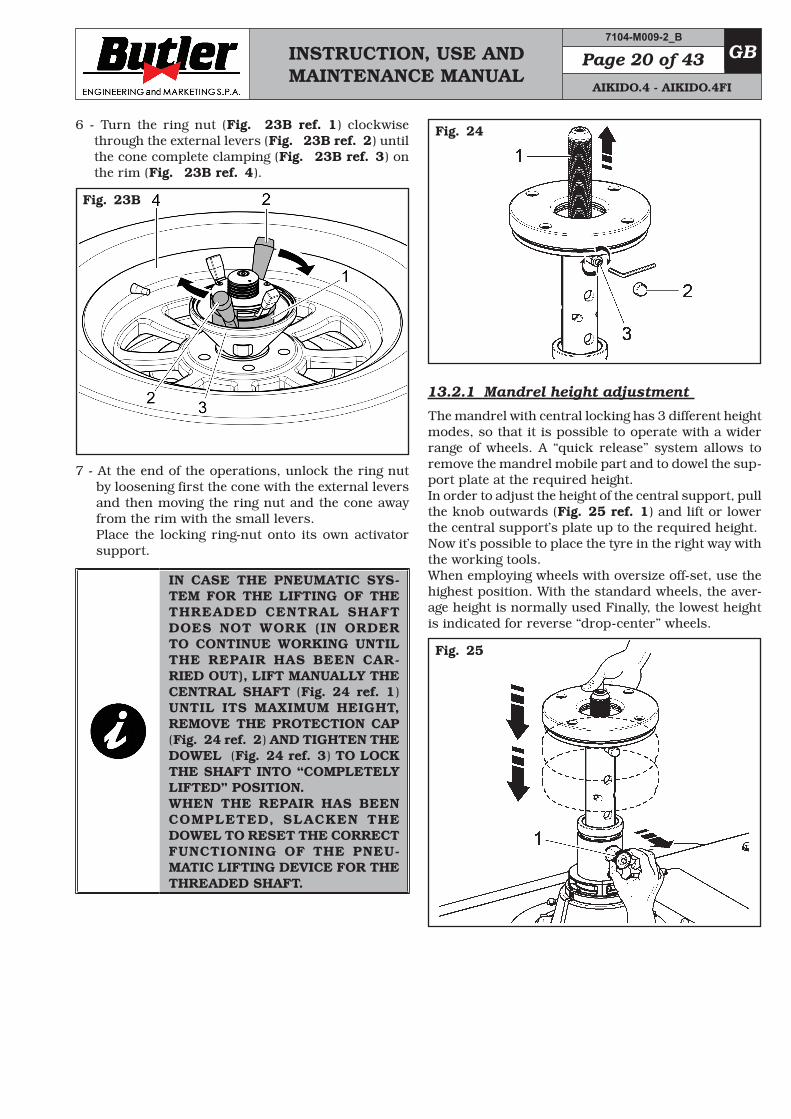
6 - Turn the ring nut (Fig. 23B ref. 1) clockwise through the external levers (Fig. 23B ref. 2) until the cone complete clamping (Fig. 23B ref. 3) on the rim (Fig. 23B ref. 4).
Fig. 23B
7 - At the end of the operations, unlock the ring nut by loosening first the cone with the external levers and then moving the ring nut and the cone away from the rim with the small levers.Place the locking ring-nut onto its own activator support.
IN CASE THE PNEUMATIC SYS-TEM FOR THE LIFTING OF THE THREADED CENTRAL SHAFT DOES NOT WORK (IN ORDER TO CONTINUE WORKING UNTIL THE REPAIR HAS BEEN CAR-RIED OUT), LIFT MANUALLY THE CENTRAL SHAFT (Fig. 24 ref. 1) UNTIL ITS MAXIMUM HEIGHT, REMOVE THE PROTECTION CAP (Fig. 24 ref. 2) AND TIGHTEN THE DOWEL (Fig. 24 ref. 3) TO LOCK THE SHAFT INTO “COMPLETELY LIFTED” POSITION.WHEN THE REPAIR HAS BEEN COMPLETED, SLACKEN THE DOWEL TO RESET THE CORRECT FUNCTIONING OF THE PNEU-MATIC LIFTING DEVICE FOR THE THREADED SHAFT.
Fig. 24
13.2.1 Mandrel height adjustment
The mandrel with central locking has 3 different height modes, so that it is possible to operate with a wider range of wheels. A “quick release” system allows to remove the mandrel mobile part and to dowel the sup-port plate at the required height.In order to adjust the height of the central support, pull the knob outwards (Fig. 25 ref. 1) and lift or lower the central support’s plate up to the required height.Now it’s possible to place the tyre in the right way with the working tools.When employing wheels with oversize off-set, use the highest position. With the standard wheels, the aver-age height is normally used Finally, the lowest height is indicated for reverse “drop-center” wheels.
Fig. 25
7104-M009-2_B
AIKIDO.4 - AIKIDO.4FI
INSTRUCTION, USE AND MAINTENANCE MANUAL
GB Page 21 of 43
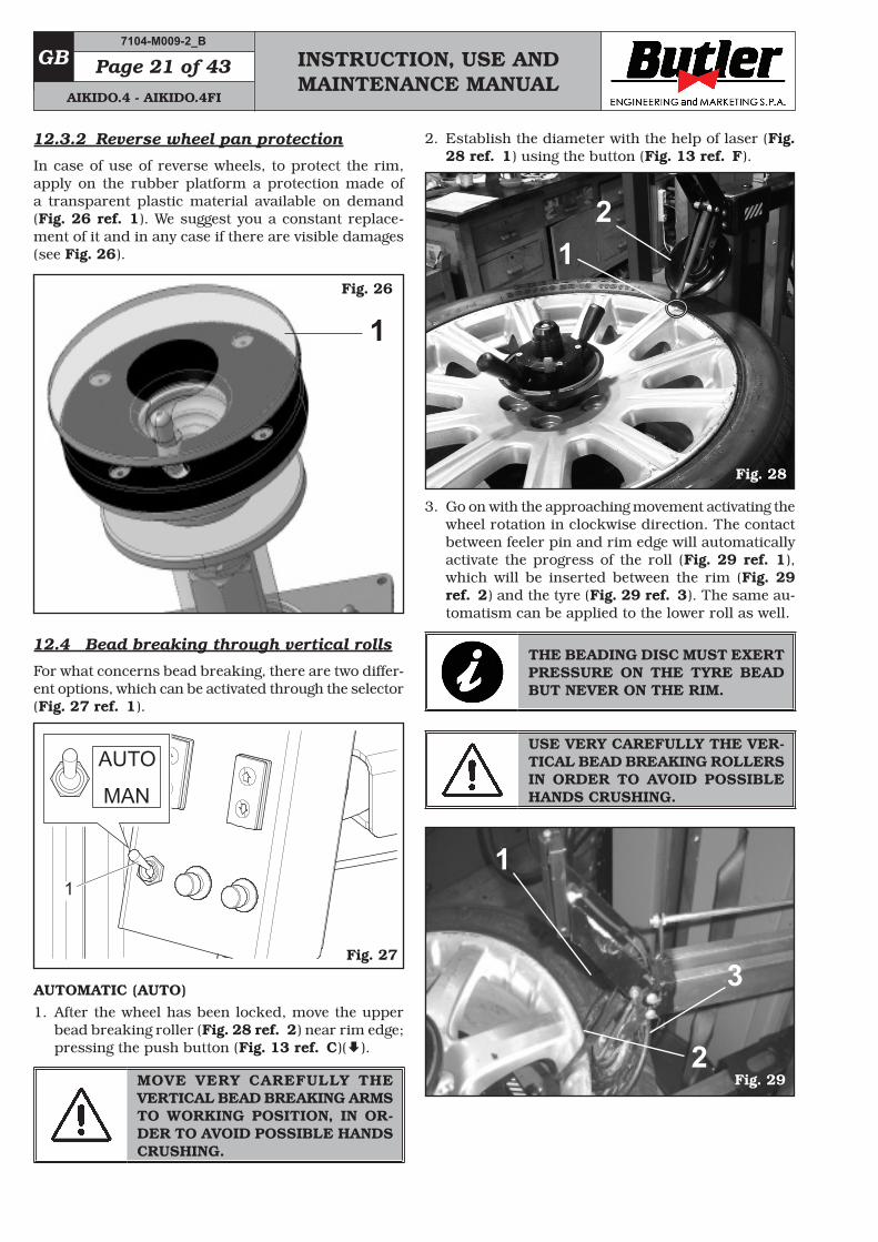
12.3.2 Reverse wheel pan protection
In case of use of reverse wheels, to protect the rim, apply on the rubber platform a protection made of a transparent plastic material available on demand (Fig. 26 ref. 1). We suggest you a constant replace-ment of it and in any case if there are visible damages (see Fig. 26).
Fig. 26
1
12.4 Bead breaking through vertical rolls
For what concerns bead breaking, there are two differ-ent options, which can be activated through the selector (Fig. 27 ref. 1).
AUTO
MAN
1
Fig. 27
AUTOMATIC (AUTO)1. After the wheel has been locked, move the upper
bead breaking roller (Fig. 28 ref. 2) near rim edge; pressing the push button (Fig. 13 ref. C)().
MOVE VERY CAREFULLY THE VERTICAL BEAD BREAKING ARMS TO WORKING POSITION, IN OR-DER TO AVOID POSSIBLE HANDS CRUSHING.
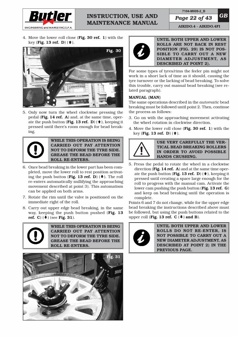
2. Establish the diameter with the help of laser (Fig. 28 ref. 1) using the button (Fig. 13 ref. F).
Fig. 28
12
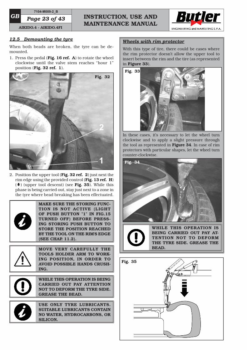
3. Go on with the approaching movement activating the wheel rotation in clockwise direction. The contact between feeler pin and rim edge will automatically activate the progress of the roll (Fig. 29 ref. 1), which will be inserted between the rim (Fig. 29 ref. 2) and the tyre (Fig. 29 ref. 3). The same au-tomatism can be applied to the lower roll as well.
THE BEADING DISC MUST EXERT PRESSURE ON THE TYRE BEAD BUT NEVER ON THE RIM.
USE VERY CAREFULLY THE VER-TICAL BEAD BREAKING ROLLERS IN ORDER TO AVOID POSSIBLE HANDS CRUSHING.
Fig. 29
1
2
3
7104-M009-2_B
AIKIDO.4 - AIKIDO.4FI
INSTRUCTION, USE AND MAINTENANCE MANUAL
GBPage 22 of 43
4. Move the lower roll close (Fig. 30 ref. 1) with the key (Fig. 13 ref. D) ().
1
Fig. 30
5. Only now turn the wheel clockwise pressing the pedal (Fig. 14 ref. A) and, at the same time, oper-ate the push button (Fig. 13 ref. D) (), keeping it pressed until there's room enough for bead break-ing.
WHILE THIS OPERATION IS BEING CARRIED OUT PAY ATTENTION NOT TO DEFORM THE TYRE SIDE. GREASE THE BEAD BEFORE THE ROLL RE-ENTERS.
6. Once bead breaking in the lower part has been com-pleted, move the lower roll to rest position activat-ing the push button (Fig. 13 ref. D) (). The roll re-enters automatically nullifying the approaching movement described at point 3). This automatism can be applied on both arms.
7. Rotate the rim until the valve is positioned on the immediate right of the roll.
8. Carry out upper edge bead breaking, in the same way, keeping the push button pushed (Fig. 13 ref. C) () (see Fig. 31).
WHILE THIS OPERATION IS BEING CARRIED OUT PAY ATTENTION NOT TO DEFORM THE TYRE SIDE. GREASE THE BEAD BEFORE THE ROLL RE-ENTERS.
Fig. 31
UNTIL BOTH UPPER AND LOWER ROLLS ARE NOT BACK IN REST POSITION (FIG. 29) IS NOT POS-SIBLE TO CARRY OUT A NEW DIAMETER ADJUSTMENT, AS DESCRIBED AT POINT 2).
For some types of tyres/rims the feeler pin might not work in a short lack of time as it should, causing the tyre turnover or the lacking of bead breaking. To solve this trouble, carry out manual bead breaking (see re-lated paragraph).
MANUAL (MAN)The same operations described in the automatic bead breaking must be followed until point 2. Then, continue the process as follows:3. Go on with the approaching movement activating
the wheel rotation in clockwise direction.4. Move the lower roll close (Fig. 30 ref. 1) with the
key (Fig. 13 ref. D) ().
USE VERY CAREFULLY THE VER-TICAL BEAD BREAKING ROLLERS IN ORDER TO AVOID POSSIBLE HANDS CRUSHING.
5. Press the pedal to rotate the wheel in a clockwise direction (Fig. 14 ref. A) and at the same time oper-ate the push button (Fig. 13 ref. D) (), keeping it pressed until creating a space large enough for the roll to progress with the manual cam. Activate the lower cam pushing the push button (Fig. 13 ref. G) and keep on bead breaking until the operation is complete.
Points 6 and 7 do not change, while for the upper edge bead breaking the instructions described above must be followed, but using the push buttons related to the upper roll (Fig. 13 ref. C () and B).
UNTIL BOTH UPPER AND LOWER ROLLS DO NOT RE-ENTER, IS NOT POSSIBLE TO CARRY OUT A NEW DIAMETER ADJUSTMENT, AS DESCRIBED AT POINT 2) IN THE PREVIOUS PAGE.
7104-M009-2_B
AIKIDO.4 - AIKIDO.4FI
INSTRUCTION, USE AND MAINTENANCE MANUAL
GB Page 23 of 43
12.5 Demounting the tyre
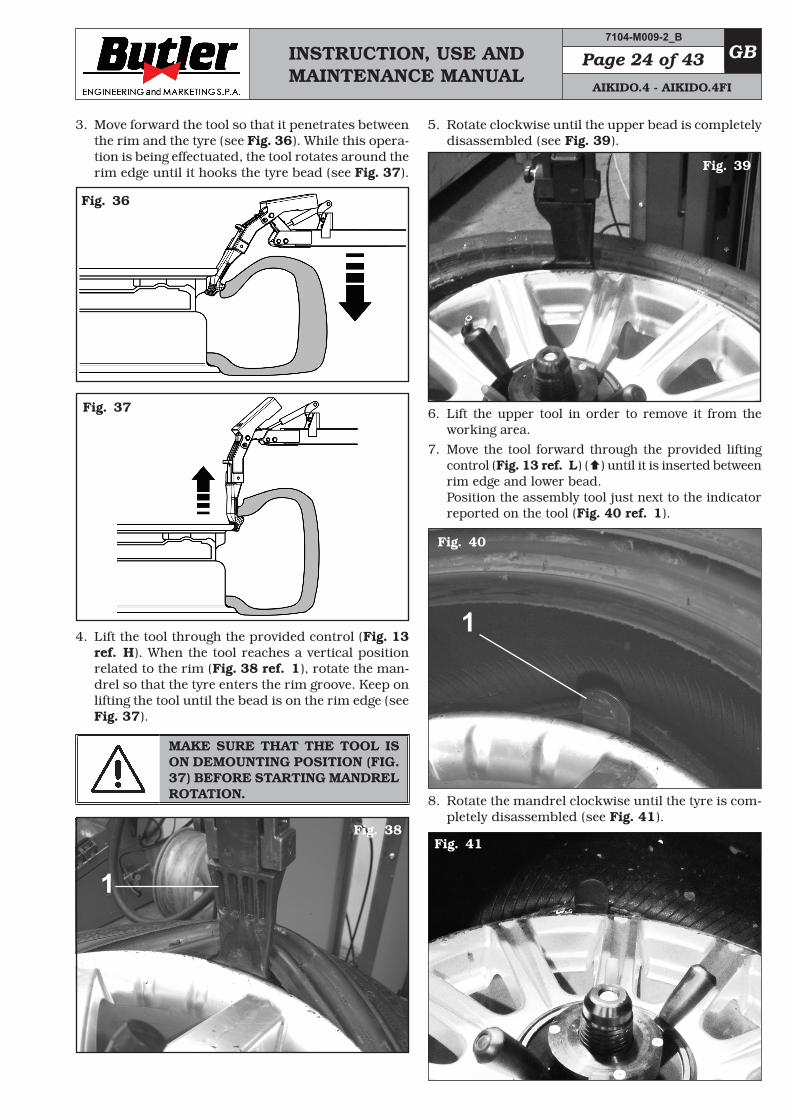
When both beads are broken, the tyre can be de-mounted.1. Press the pedal (Fig. 16 ref. A) to rotate the wheel
clockwise until the valve stem reaches “hour 1” position (Fig. 32 ref. 1).
Fig. 32
1
2
2. Position the upper tool (Fig. 32 ref. 2) just next the rim edge using the provided control (Fig. 13 ref. H) () (upper tool descent) (see Fig. 35). While this phase is being carried out, stay just next to a zone in the tyre where bead breaking has been effectuated.
MAKE SURE THE STORING FUNC-TION IS NOT ACTIVE (LIGHT OF PUSH BUTTON "1" IN FIG.15 TURNED OFF) BEFORE PRESS-ING STORING PUSH BUTTON TO STORE THE POSITION REACHED BY THE TOOL ON THE RIM'S EDGE (SEE CHAP. 11.2).
MOVE VERY CAREFULLY THE TOOLS HOLDER ARM TO WORK-ING POSITION, IN ORDER TO AVOID POSSIBLE HANDS CRUSH-ING.
WHILE THIS OPERATION IS BEING CARRIED OUT PAY ATTENTION NOT TO DEFORM THE TYRE SIDE. GREASE THE BEAD.
USE ONLY TYRE LUBRICANTS. SUITABLE LUBRICANTS CONTAIN NO WATER, HYDROCARBONS, OR SILICON.
Wheels with rim protector
With this type of tire, there could be cases where the rim protector doesn’t allow the upper tool to insert between the rim and the tire (as represented in Figure 33).
Fig. 33
In these cases, it’s necessary to let the wheel turn clockwise and to apply a slight pressure through the tool as represented in Figure 34. In case of rim protectors with particular shapes, let the wheel turn counter-clockwise.
Fig. 34
WHILE THIS OPERATION IS BEING CARRIED OUT PAY AT-TENTION NOT TO DEFORM THE TYRE SIDE. GREASE THE BEAD.
Fig. 35
7104-M009-2_B
AIKIDO.4 - AIKIDO.4FI
INSTRUCTION, USE AND MAINTENANCE MANUAL
GBPage 24 of 43
3. Move forward the tool so that it penetrates between the rim and the tyre (see Fig. 36). While this opera-tion is being effectuated, the tool rotates around the rim edge until it hooks the tyre bead (see Fig. 37).
Fig. 36
Fig. 37
4. Lift the tool through the provided control (Fig. 13 ref. H). When the tool reaches a vertical position related to the rim (Fig. 38 ref. 1), rotate the man-drel so that the tyre enters the rim groove. Keep on lifting the tool until the bead is on the rim edge (see Fig. 37).
MAKE SURE THAT THE TOOL IS ON DEMOUNTING POSITION (FIG. 37) BEFORE STARTING MANDREL ROTATION.
Fig. 38
1
5. Rotate clockwise until the upper bead is completely disassembled (see Fig. 39).
Fig. 39
6. Lift the upper tool in order to remove it from the working area.
7. Move the tool forward through the provided lifting control (Fig. 13 ref. L) () until it is inserted between rim edge and lower bead.Position the assembly tool just next to the indicator reported on the tool (Fig. 40 ref. 1).
1
Fig. 40
8. Rotate the mandrel clockwise until the tyre is com-pletely disassembled (see Fig. 41).
Fig. 41
7104-M009-2_B
AIKIDO.4 - AIKIDO.4FI
INSTRUCTION, USE AND MAINTENANCE MANUAL
GB Page 25 of 43
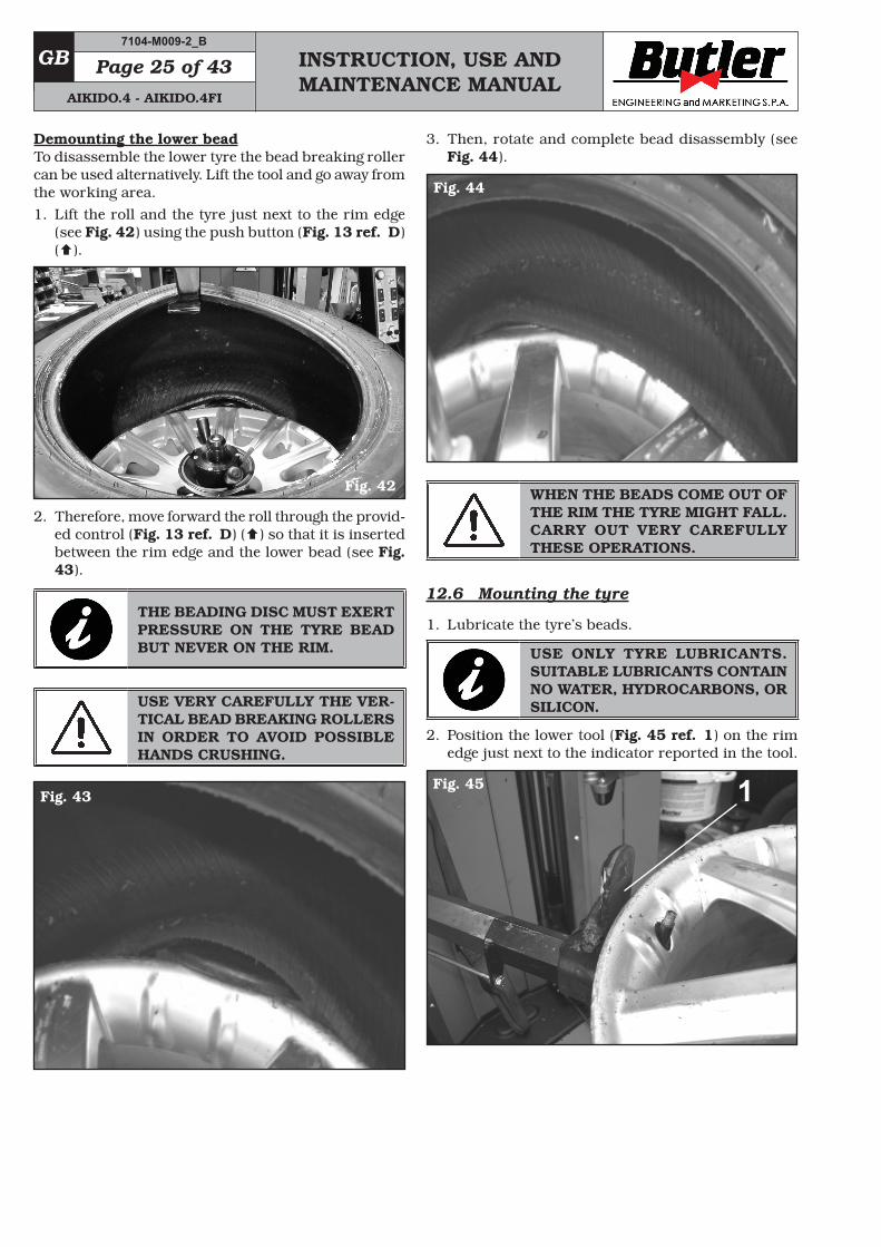
Demounting the lower beadTo disassemble the lower tyre the bead breaking roller can be used alternatively. Lift the tool and go away from the working area.1. Lift the roll and the tyre just next to the rim edge
(see Fig. 42) using the push button (Fig. 13 ref. D) ().
Fig. 42
2. Therefore, move forward the roll through the provid-ed control (Fig. 13 ref. D) () so that it is inserted between the rim edge and the lower bead (see Fig. 43).
THE BEADING DISC MUST EXERT PRESSURE ON THE TYRE BEAD BUT NEVER ON THE RIM.
USE VERY CAREFULLY THE VER-TICAL BEAD BREAKING ROLLERS IN ORDER TO AVOID POSSIBLE HANDS CRUSHING.
Fig. 43
3. Then, rotate and complete bead disassembly (see Fig. 44).
Fig. 44
WHEN THE BEADS COME OUT OF THE RIM THE TYRE MIGHT FALL. CARRY OUT VERY CAREFULLY THESE OPERATIONS.
12.6 Mounting the tyre
1. Lubricate the tyre’s beads.
USE ONLY TYRE LUBRICANTS. SUITABLE LUBRICANTS CONTAIN NO WATER, HYDROCARBONS, OR SILICON.
2. Position the lower tool (Fig. 45 ref. 1) on the rim edge just next to the indicator reported in the tool.
Fig. 45 1
7104-M009-2_B
AIKIDO.4 - AIKIDO.4FI
INSTRUCTION, USE AND MAINTENANCE MANUAL
GBPage 26 of 43
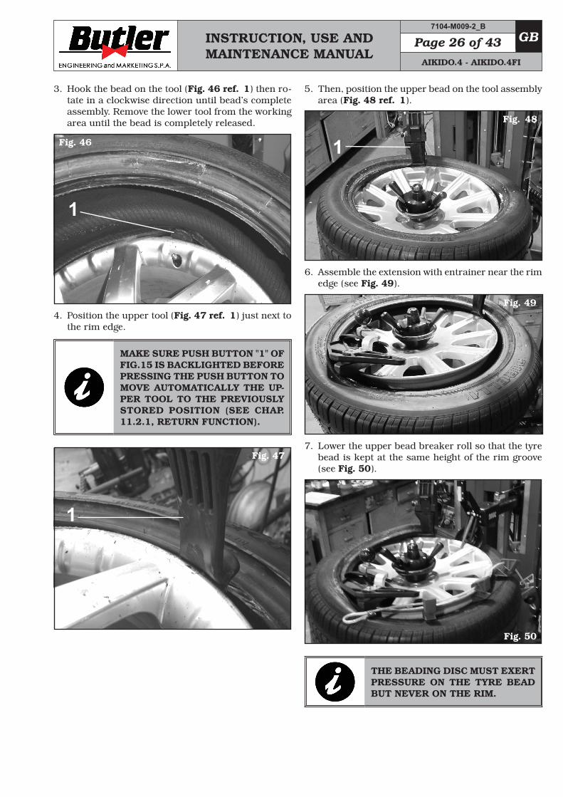
3. Hook the bead on the tool (Fig. 46 ref. 1) then ro-tate in a clockwise direction until bead’s complete assembly. Remove the lower tool from the working area until the bead is completely released.
Fig. 46
1
4. Position the upper tool (Fig. 47 ref. 1) just next to the rim edge.
MAKE SURE PUSH BUTTON "1" OF FIG.15 IS BACKLIGHTED BEFORE PRESSING THE PUSH BUTTON TO MOVE AUTOMATICALLY THE UP-PER TOOL TO THE PREVIOUSLY STORED POSITION (SEE CHAP. 11.2.1, RETURN FUNCTION).
Fig. 47
1
5. Then, position the upper bead on the tool assembly area (Fig. 48 ref. 1).
Fig. 48
1
6. Assemble the extension with entrainer near the rim edge (see Fig. 49).
Fig. 49
7. Lower the upper bead breaker roll so that the tyre bead is kept at the same height of the rim groove (see Fig. 50).
Fig. 50
THE BEADING DISC MUST EXERT PRESSURE ON THE TYRE BEAD BUT NEVER ON THE RIM.
7104-M009-2_B
AIKIDO.4 - AIKIDO.4FI
INSTRUCTION, USE AND MAINTENANCE MANUAL
GB Page 27 of 43
USE VERY CAREFULLY THE VER-TICAL BEAD BREAKING ROLLERS IN ORDER TO AVOID POSSIBLE HANDS CRUSHING.
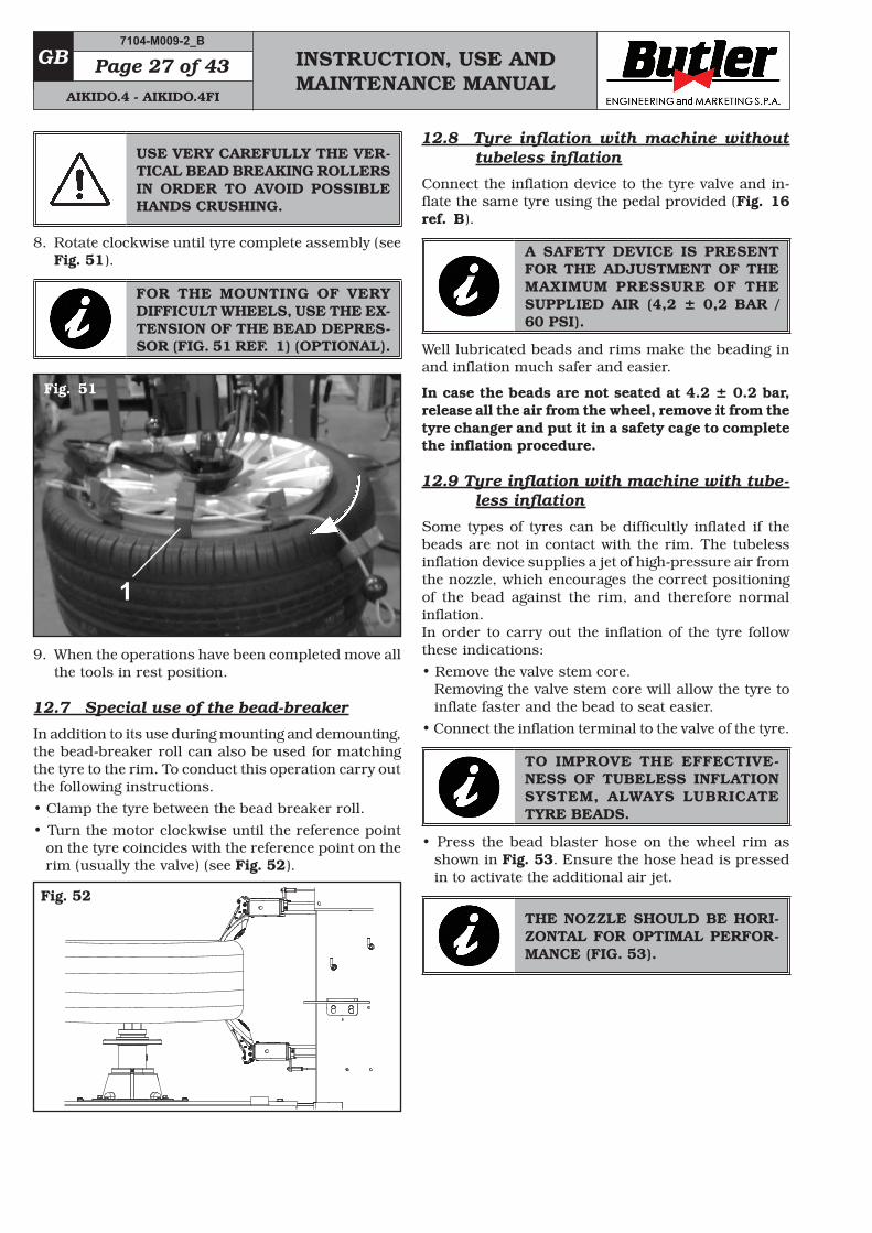
8. Rotate clockwise until tyre complete assembly (see Fig. 51).
FOR THE MOUNTING OF VERY DIFFICULT WHEELS, USE THE EX-TENSION OF THE BEAD DEPRES-SOR (FIG. 51 REF. 1) (OPTIONAL).
Fig. 51
1
9. When the operations have been completed move all the tools in rest position.
12.7 Special use of the bead-breaker
In addition to its use during mounting and demounting, the bead-breaker roll can also be used for matching the tyre to the rim. To conduct this operation carry out the following instructions.• Clamp the tyre between the bead breaker roll.• Turn the motor clockwise until the reference point
on the tyre coincides with the reference point on the rim (usually the valve) (see Fig. 52).
Fig. 52
12.8 Tyre inflation with machine without tubeless inflation
Connect the inflation device to the tyre valve and in-flate the same tyre using the pedal provided (Fig. 16 ref. B).
A SAFETY DEVICE IS PRESENT FOR THE ADJUSTMENT OF THE MAXIMUM PRESSURE OF THE SUPPLIED AIR (4,2 ± 0,2 BAR / 60 PSI).
Well lubricated beads and rims make the beading in and inflation much safer and easier.
In case the beads are not seated at 4.2 ± 0.2 bar, release all the air from the wheel, remove it from the tyre changer and put it in a safety cage to complete the inflation procedure.
12.9 Tyre inflation with machine with tube-less inflation
Some types of tyres can be difficultly inflated if the beads are not in contact with the rim. The tubeless inflation device supplies a jet of high-pressure air from the nozzle, which encourages the correct positioning of the bead against the rim, and therefore normal inflation.In order to carry out the inflation of the tyre follow these indications:• Remove the valve stem core.
Removing the valve stem core will allow the tyre to inflate faster and the bead to seat easier.
• Connect the inflation terminal to the valve of the tyre.
TO IMPROVE THE EFFECTIVE-NESS OF TUBELESS INFLATION SYSTEM, ALWAYS LUBRICATE TYRE BEADS.
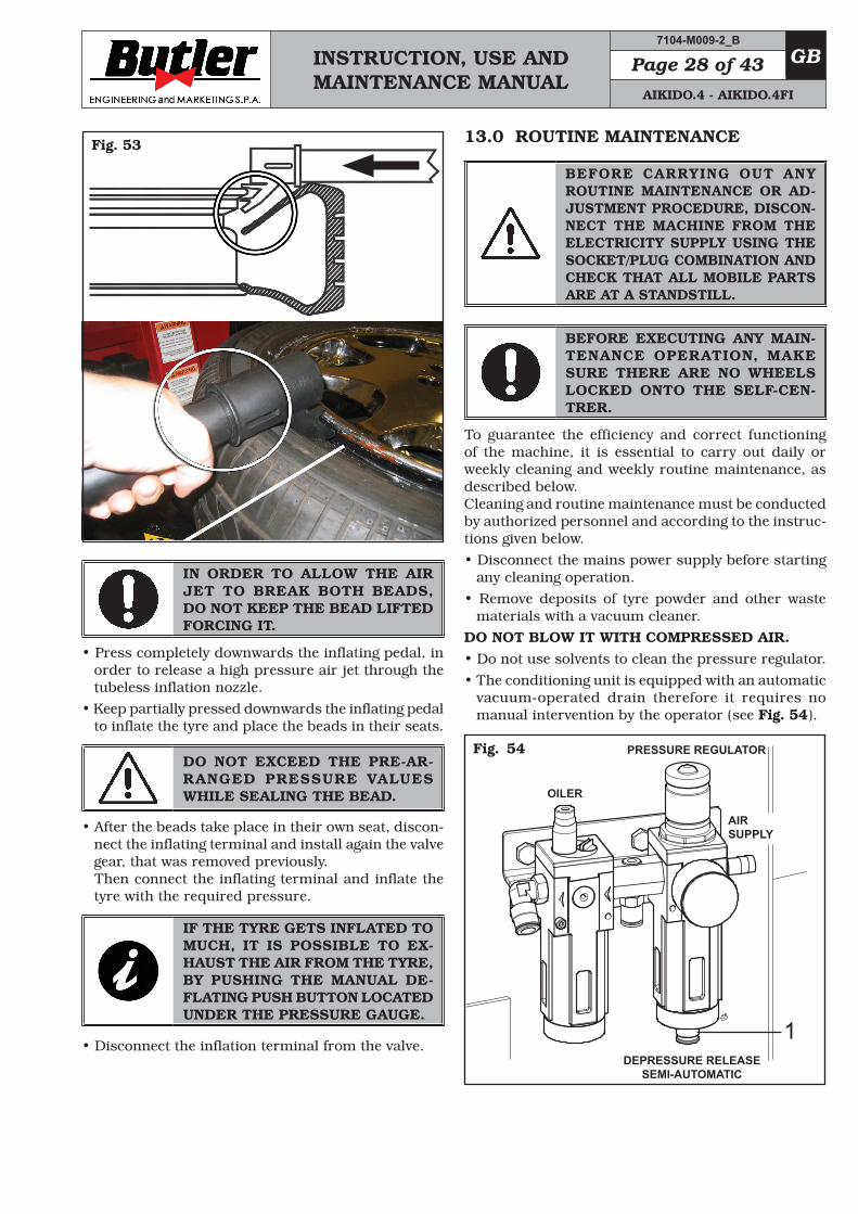
• Press the bead blaster hose on the wheel rim as shown in Fig. 53. Ensure the hose head is pressed in to activate the additional air jet.
THE NOZZLE SHOULD BE HORI-ZONTAL FOR OPTIMAL PERFOR-MANCE (FIG. 53).
7104-M009-2_B
AIKIDO.4 - AIKIDO.4FI
INSTRUCTION, USE AND MAINTENANCE MANUAL
GBPage 28 of 43
Fig. 53
IN ORDER TO ALLOW THE AIR JET TO BREAK BOTH BEADS, DO NOT KEEP THE BEAD LIFTED FORCING IT.
• Press completely downwards the inflating pedal, in order to release a high pressure air jet through the tubeless inflation nozzle.
• Keep partially pressed downwards the inflating pedal to inflate the tyre and place the beads in their seats.
DO NOT EXCEED THE PRE-AR-RANGED PRESSURE VALUES WHILE SEALING THE BEAD.
• After the beads take place in their own seat, discon-nect the inflating terminal and install again the valve gear, that was removed previously. Then connect the inflating terminal and inflate the tyre with the required pressure.
IF THE TYRE GETS INFLATED TO MUCH, IT IS POSSIBLE TO EX-HAUST THE AIR FROM THE TYRE, BY PUSHING THE MANUAL DE-FLATING PUSH BUTTON LOCATED UNDER THE PRESSURE GAUGE.
• Disconnect the inflation terminal from the valve.
13.0 ROUTINE MAINTENANCE
BEFORE CARRYING OUT ANY ROUTINE MAINTENANCE OR AD-JUSTMENT PROCEDURE, DISCON-NECT THE MACHINE FROM THE ELECTRICITY SUPPLY USING THE SOCKET/PLUG COMBINATION AND CHECK THAT ALL MOBILE PARTS ARE AT A STANDSTILL.
BEFORE EXECUTING ANY MAIN-TENANCE OPERATION, MAKE SURE THERE ARE NO WHEELS LOCKED ONTO THE SELF-CEN-TRER.
To guarantee the efficiency and correct functioning of the machine, it is essential to carry out daily or weekly cleaning and weekly routine maintenance, as described below.Cleaning and routine maintenance must be conducted by authorized personnel and according to the instruc-tions given below.• Disconnect the mains power supply before starting
any cleaning operation.• Remove deposits of tyre powder and other waste
materials with a vacuum cleaner.DO NOT BLOW IT WITH COMPRESSED AIR.• Do not use solvents to clean the pressure regulator.• The conditioning unit is equipped with an automatic
vacuum-operated drain therefore it requires no manual intervention by the operator (see Fig. 54).
Fig._54 PRESSURE REGULATOR
DEPRESSURE RELEASE SEMI-AUTOMATIC
OILER
AIR SUPPLY
1
7104-M009-2_B
AIKIDO.4 - AIKIDO.4FI
INSTRUCTION, USE AND MAINTENANCE MANUAL
GB Page 29 of 43
IN ORDER TO ENSURE A GOOD FUNCTIONING AND TO AVOID THE PRESENCE OF CONDENSATION IN THE AIR TREATMENT UNITS WITH SEMI-AUTOMATIC DRAIN, IT'S NECESSARY TO MAKE SURE ABOUT THE CORRECT POSITION OF THE VALVE (FIG. 54 REF. 1), PLACED UNDER THE CAP. TO ACTIVATE A CORRECT DRAIN FUNCTION, THE CAP MUST BE ROTATED IN THE RIGHT WAY.
IN ORDER TO ALLOW A LONGER LIFE OF THE FILTER AND OF ALL MOVING PNEUMATIC DEVICES, YOU HAVE TO MAKE SURE THAT THE SUPPLIED AIR IS:• EXEMPT FROM THE LUBRICAT-
ING OIL OF THE COMPRESSOR; • EXEMPT FROM HUMIDITY; • EXEMPT FROM IMPURITY.
• Periodically, with a frequency of at least once a month, lubricate the arms of the bead breaking roller and of the tools.
• Immediately replace worn parts, bead breaking rolls, assembly tools, feeler pins.
• At regular intervals, at least every two months, verify the rubber guard conditions, in relation to point 3.0 Safety devices. If necessary replace damaged parts requesting for them to the supplier.
• Every week and/or when necessary, top up the oil tank using the filler hole provided, closed by a cap or screw, on the lubricator filter.
NOTE: This operation should not be carried out by unscrewing the cup of the lubricator filter.
• The use of synthetic oil might damage the pressure regulator filter.
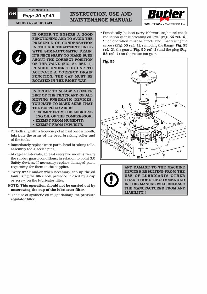
• Periodically (at least every 100 working hours) check reduction gear lubricating oil level (Fig. 55 ref. 5). Such operation must be effectuated unscrewing the screws (Fig. 55 ref. 1), removing the flange (Fig. 55 ref. 2), the guard (Fig. 55 ref. 3) and the plug (Fig. 55 ref. 4) on the reduction gear.
Fig. 55
ANY DAMAGE TO THE MACHINE DEVICES RESULTING FROM THE USE OF LUBRICANTS OTHER THAN THOSE RECOMMENDED IN THIS MANUAL WILL RELEASE THE MANUFACTURER FROM ANY LIABILITY!!
7104-M009-2_B
AIKIDO.4 - AIKIDO.4FI
INSTRUCTION, USE AND MAINTENANCE MANUAL
GBPage 30 of 43
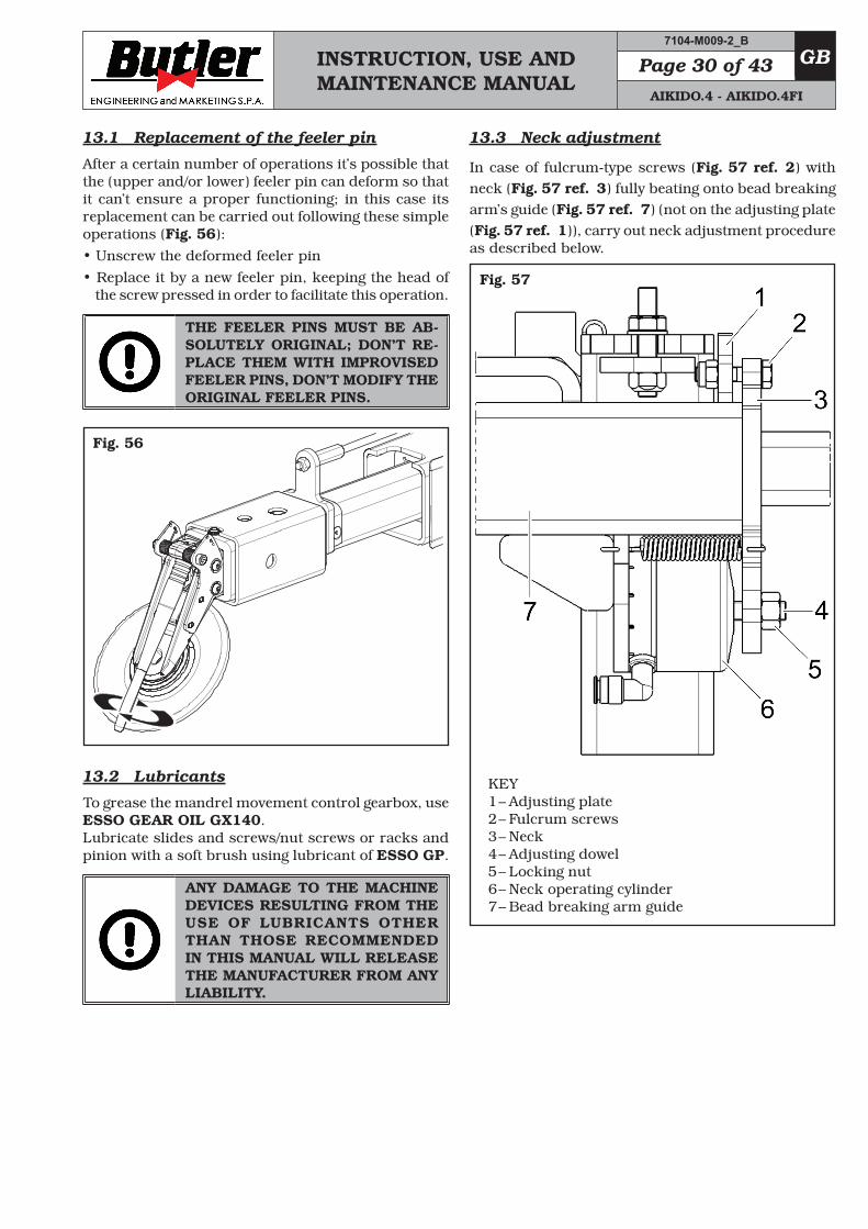
13.1 Replacement of the feeler pin
After a certain number of operations it’s possible that the (upper and/or lower) feeler pin can deform so that it can’t ensure a proper functioning; in this case its replacement can be carried out following these simple operations (Fig. 56):• Unscrew the deformed feeler pin• Replace it by a new feeler pin, keeping the head of
the screw pressed in order to facilitate this operation.
THE FEELER PINS MUST BE AB-SOLUTELY ORIGINAL; DON’T RE-PLACE THEM WITH IMPROVISED FEELER PINS, DON’T MODIFY THE ORIGINAL FEELER PINS.
Fig. 56
13.2 Lubricants
To grease the mandrel movement control gearbox, use ESSO GEAR OIL GX140. Lubricate slides and screws/nut screws or racks and pinion with a soft brush using lubricant of ESSO GP.
ANY DAMAGE TO THE MACHINE DEVICES RESULTING FROM THE USE OF LUBRICANTS OTHER THAN THOSE RECOMMENDED IN THIS MANUAL WILL RELEASE THE MANUFACTURER FROM ANY LIABILITY.
13.3 Neck adjustment
In case of fulcrum-type screws (Fig. 57 ref. 2) with neck (Fig. 57 ref. 3) fully beating onto bead breaking arm’s guide (Fig. 57 ref. 7) (not on the adjusting plate (Fig. 57 ref. 1)), carry out neck adjustment procedure as described below.
Fig. 57
KEY 1 – Adjusting plate 2 – Fulcrum screws 3 – Neck 4 – Adjusting dowel 5 – Locking nut 6 – Neck operating cylinder 7 – Bead breaking arm guide
7104-M009-2_B
AIKIDO.4 - AIKIDO.4FI
INSTRUCTION, USE AND MAINTENANCE MANUAL
GB Page 31 of 43
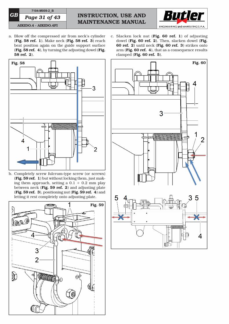
a. Blow off the compressed air from neck’s cylinder (Fig. 58 ref. 1). Make neck (Fig. 58 ref. 3) reach beat position again on the guide support surface (Fig. 58 ref. 4), by turning the adjusting dowel (Fig. 58 ref. 2).
Fig. 58
b. Completely screw fulcrum-type screw (or screws) (Fig. 59 ref. 1) but without locking them, just mak-ing them approach, setting a 0.1 ÷ 0.2 mm play between neck (Fig. 59 ref. 2) and adjusting plate (Fig. 59 ref. 3), positioning nut (Fig. 59 ref. 4) and letting it rest completely onto adjusting plate.
Fig. 59
c. Slacken lock nut (Fig. 60 ref. 1) of adjusting dowel (Fig. 60 ref. 2). Then, slacken dowel (Fig. 60 ref. 2) until neck (Fig. 60 ref. 3) strikes onto arm (Fig. 60 ref. 4), that as a consequence results clamped (Fig. 60 ref. 5).
Fig. 60
7104-M009-2_B
AIKIDO.4 - AIKIDO.4FI
INSTRUCTION, USE AND MAINTENANCE MANUAL
GBPage 32 of 43
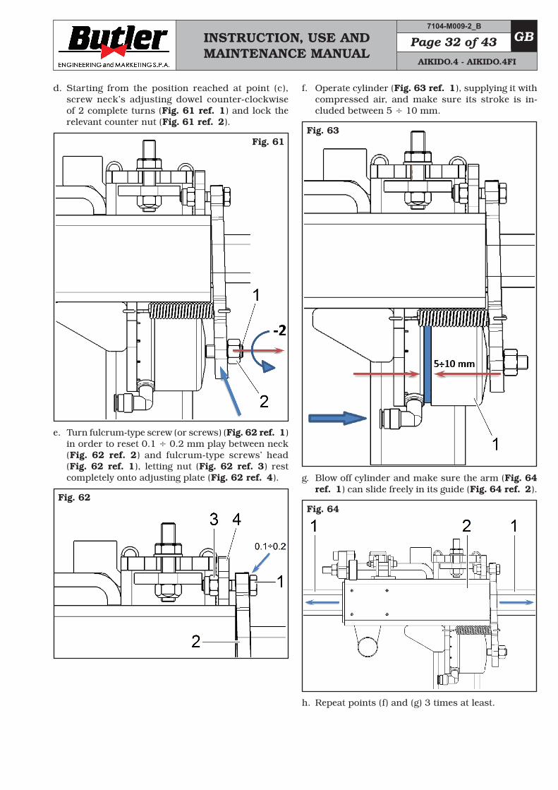
d. Starting from the position reached at point (c), screw neck’s adjusting dowel counter-clockwise of 2 complete turns (Fig. 61 ref. 1) and lock the relevant counter nut (Fig. 61 ref. 2).
Fig. 61
e. Turn fulcrum-type screw (or screws) (Fig. 62 ref. 1) in order to reset 0.1 ÷ 0.2 mm play between neck (Fig. 62 ref. 2) and fulcrum-type screws’ head (Fig. 62 ref. 1), letting nut (Fig. 62 ref. 3) rest completely onto adjusting plate (Fig. 62 ref. 4).
Fig. 62
f. Operate cylinder (Fig. 63 ref. 1), supplying it with compressed air, and make sure its stroke is in-cluded between 5 ÷ 10 mm.
Fig. 63
g. Blow off cylinder and make sure the arm (Fig. 64 ref. 1) can slide freely in its guide (Fig. 64 ref. 2).
Fig. 64
h. Repeat points (f) and (g) 3 times at least.
7104-M009-2_B
AIKIDO.4 - AIKIDO.4FI
INSTRUCTION, USE AND MAINTENANCE MANUAL
GB Page 33 of 43
14.0 TROUBLESHOOTING TABLE
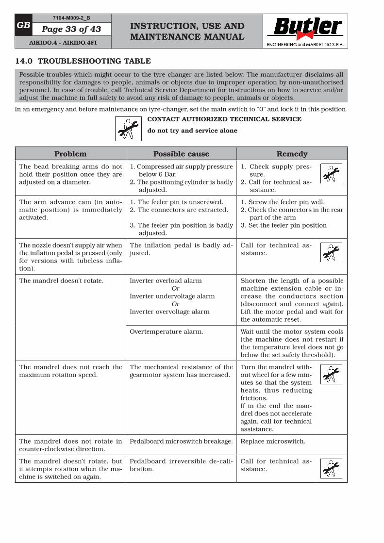
Possible troubles which might occur to the tyre-changer are listed below. The manufacturer disclaims all responsibility for damages to people, animals or objects due to improper operation by non-unauthorised personnel. In case of trouble, call Technical Service Department for instructions on how to service and/or adjust the machine in full safety to avoid any risk of damage to people, animals or objects.
In an emergency and before maintenance on tyre-changer, set the main switch to “0” and lock it in this position.
CONTACT AUTHORIZED TECHNICAL SERVICE
do not try and service alone
Problem Possible cause Remedy
The bead breaking arms do not hold their position once they are adjusted on a diameter.
1. Compressed air supply pressure below 6 Bar.
2. The positioning cylinder is badly adjusted.
1. Check supply pres-sure.
2. Call for technical as-sistance.
The arm advance cam (in auto-matic position) is immediately activated.
1. The feeler pin is unscrewed.2. The connectors are extracted.
3. The feeler pin position is badly adjusted.
1. Screw the feeler pin well.2. Check the connectors in the rear
part of the arm3. Set the feeler pin position
The nozzle doesn’t supply air when the inflation pedal is pressed (only for versions with tubeless infla-tion).
The inflation pedal is badly ad-justed.
Call for technical as-sistance.
The mandrel doesn’t rotate. Inverter overload alarm OrInverter undervoltage alarm OrInverter overvoltage alarm
Shorten the length of a possible machine extension cable or in-crease the conductors section (disconnect and connect again). Lift the motor pedal and wait for the automatic reset.
Overtemperature alarm. Wait until the motor system cools (the machine does not restart if the temperature level does not go below the set safety threshold).
The mandrel does not reach the maximum rotation speed.
The mechanical resistance of the gearmotor system has increased.
Turn the mandrel with-out wheel for a few min-utes so that the system heats, thus reducing frictions. If in the end the man-drel does not accelerate again, call for technical assistance.
The mandrel does not rotate in counter-clockwise direction.
Pedalboard microswitch breakage. Replace microswitch.
The mandrel doesn’t rotate, but it attempts rotation when the ma-chine is switched on again.
Pedalboard irreversible de-cali-bration.
Call for technical as-sistance.
7104-M009-2_B
AIKIDO.4 - AIKIDO.4FI
INSTRUCTION, USE AND MAINTENANCE MANUAL
GBPage 34 of 43
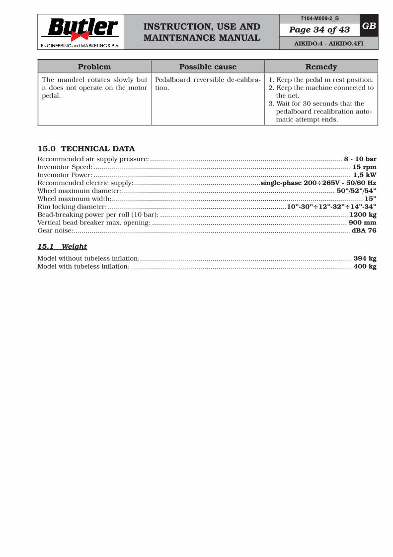
Problem Possible cause Remedy
The mandrel rotates slowly but it does not operate on the motor pedal.
Pedalboard reversible de-calibra-tion.
1. Keep the pedal in rest position.2. Keep the machine connected to
the net.3. Wait for 30 seconds that the
pedalboard recalibration auto-matic attempt ends.
15.0 TECHNICAL DATARecommended air supply pressure: ................................................................................................ 8 - 10 barInvemotor Speed: ................................................................................................................................ 15 rpmInvemotor Power: ................................................................................................................................ 1,5 kW Recommended electric supply: ...............................................................single-phase 200÷265V - 50/60 HzWheel maximum diameter: .......................................................................................................... 50”/52”/54”Wheel maximum width: ............................................................................................................................. 15”Rim locking diameter: .........................................................................................10”-30”÷12”-32”÷14”-34”Bead-breaking power per roll (10 bar): ..............................................................................................1200 kgVertical bead breaker max. opening: ................................................................................................. 900 mmGear noise: ..........................................................................................................................................dBA 76
15.1 Weight
Model without tubeless inflation: ..........................................................................................................394 kgModel with tubeless inflation: ...............................................................................................................400 kg
7104-M009-2_B
AIKIDO.4 - AIKIDO.4FI
INSTRUCTION, USE AND MAINTENANCE MANUAL
GB Page 35 of 43
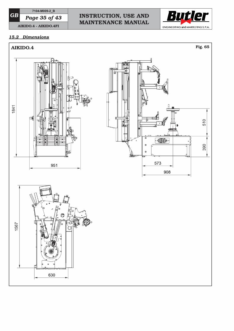
15.2 Dimensions
Fig. 65
7104-M009-2_B
AIKIDO.4 - AIKIDO.4FI
AIKIDO.4
INSTRUCTION, USE AND MAINTENANCE MANUAL
GBPage 36 of 43
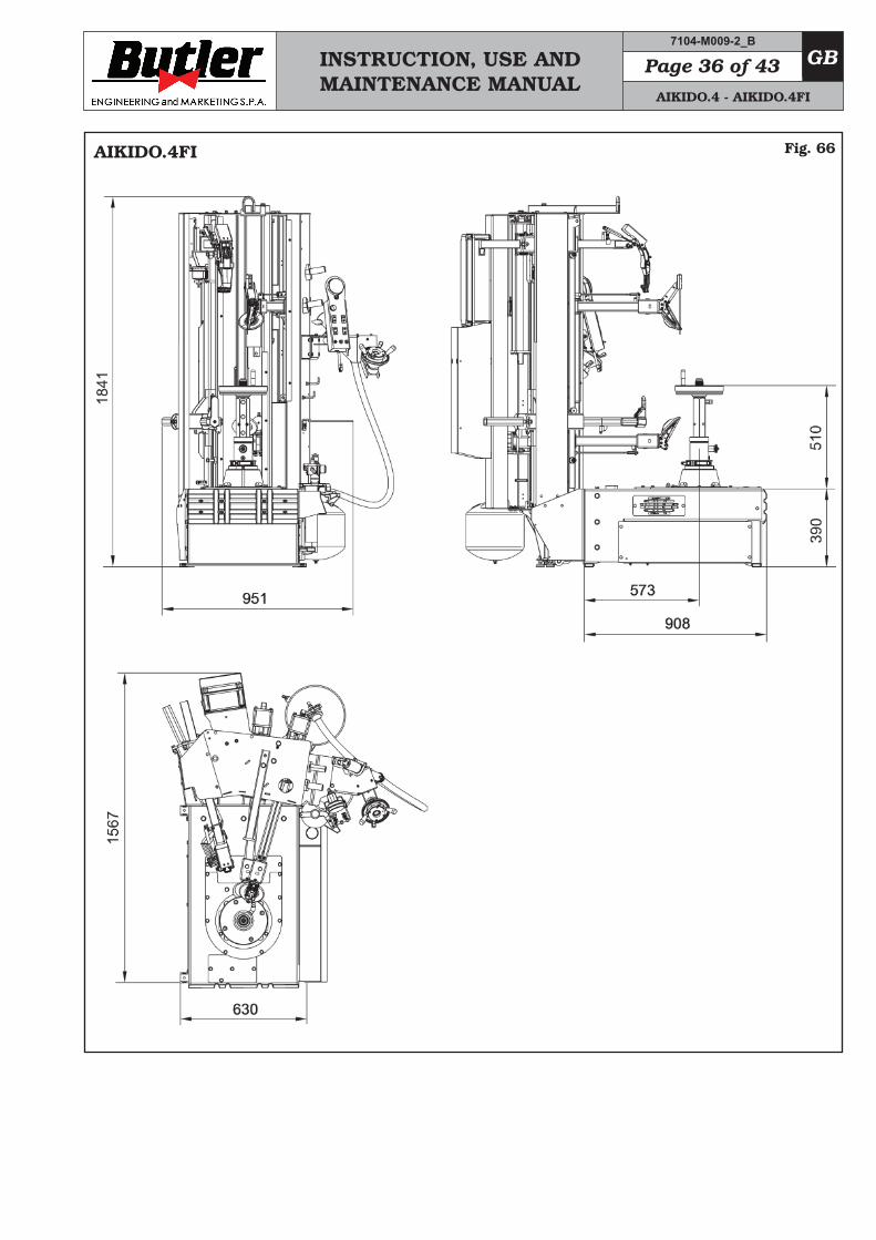
Fig. 66
7104-M009-2_B
AIKIDO.4 - AIKIDO.4FI
AIKIDO.4FI
INSTRUCTION, USE AND MAINTENANCE MANUAL
GB Page 37 of 43
18.0 REGISTRATION PLATE DATA
The validity of the Conformity Declaration enclosed to this manual is also extended to products and/or devices the machine model object of the Conformity Declaration can be equipped with. Said plate must always be kept clean from grease residues or filth generally.
ATTENTION: TAMPERING WITH, CARVING, CHANGING ANYHOW OR EVEN REMOVING MACHINE IDENTIFICATION PLATE IS AB-SOLUTELY FORBIDDEN; DO NOT COVER IT WITH TEMPORARY PANELS, ETC., SINCE IT MUST ALWAYS BE VISIBLE.
WARNING: Should the plate be accidentally damaged (removed from the machine, damaged or even par-tially illegible) inform immediately the manufacturer.
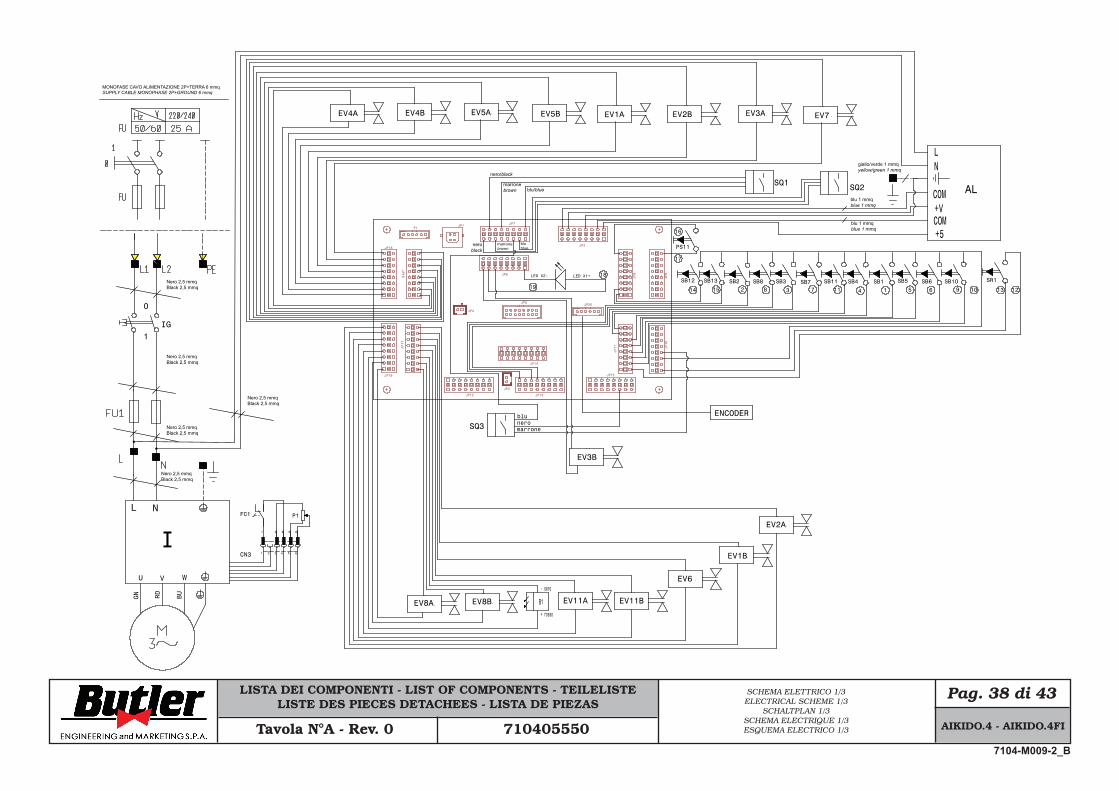
19.0 FUNCTIONAL DIAGRAMSHere follows a list of the machine functional diagrams.
16.0 STORINGIf storing for long periods disconnect the main power supply and take measures to protect the machine from dust build-up. Lubricate parts that could be damaged from drying out. When putting the machine back into operation replace the rubber pads and the mounting tool.
17.0 SCRAPPINGWhen the decision is taken not to make further use of the machine, it is advisable to make it inoperative by removing the connection pressure hoses. The machine is to be considered as special waste and should be dismantled into homogeneous parts. Dispose of it in accordance with current legislation.
Instructions for the correct management of waste from electric and electronic equip-ment (WEEE) according to the Italian legis-lative decree 49/14 and subsequent amend-ments.
In order to inform the users on the correct way to dispose the product (as required by the article 26, paragraph 1 of the Italian legislative decree 49/14 and subsequent amendments), we communicate what follows: the meaning of the crossed dustbin symbol reported on the equipment indicates that the product must not be thrown among the undifferentiated rub-bish (that is to say together with the “mixed urban waste”), but it has to be managed separately, to let the WEEE go through special operations for their reuse or treatment, in order to remove and dispose safely the waste that could be dangerous for the environment and to extract and recycle the raw materials to be reused.
Fig. 67
7104-M009-2_B
AIKIDO.4 - AIKIDO.4FI
LISTA DEI COMPONENTI - LIST OF COMPONENTS - TEILELISTELISTE DES PIECES DETACHEES - LISTA DE PIEZAS
Pag. 38 di 43SCHEMA ELETTRICO 1/3ELECTRICAL SCHEME 1/3
SCHALTPLAN 1/3SCHEMA ELECTRIQUE 1/3ESQUEMA ELECTRICO 1/3Tavola N°A - Rev. 0 710405550
IG
JP8JP6
JP17
JP14
JP13JP12
JP18
JP16
JP10
JP11
JP19
JP1
JP5
JP9
JP7
JP2
JP15
JP4
JP3
P1
JP20
SB2 SB8 SB3 SB7 SB4 SB1 SB5 SB6
EV7EV2BEV1AEV5BEV5AEV4BEV4A
EV1B
EV3B
EV2A
SR1
SQ1 SQ2
blublue
12 3 4 5 678 10
SQ3bluneromarrone
EV3A
0
1
1213SB11
11 9SB10
EV8BEV8A
15
SB13SB12
14
EV11A EV11B
EV6
LED X1+LED X2- 18
19
ENCODER
PS11
16
17
AL
+5COM+VCOM
NL
B1
- nero
+ rosso
U V W
NL
I1 2 3 4 5 6
631 4 5
CN3
FC1 P1
GN BURD
MONOFASE CAVO ALIMENTAZIONE 2P+TERRA 6 mmqSUPPLY CABLE MONOPHASE 2P+GROUND 6 mmq
Nero 2,5 mmqBlack 2,5 mmq
Nero 2,5 mmqBlack 2,5 mmq
Nero 2,5 mmqBlack 2,5 mmq
Nero 2,5 mmqBlack 2,5 mmq
Nero 2,5 mmqBlack 2,5 mmq
blu/blue
nero/black
marronebrown
neroblack
marronebrown
giallo/verde 1 mmqyellow/green 1 mmq
blu 1 mmqblue 1 mmq
blu 1 mmqblue 1 mmq
AIKIDO.4 - AIKIDO.4FI
7104-M009-2_B
LISTA DEI COMPONENTI - LIST OF COMPONENTS - TEILELISTELISTE DES PIECES DETACHEES - LISTA DE PIEZAS
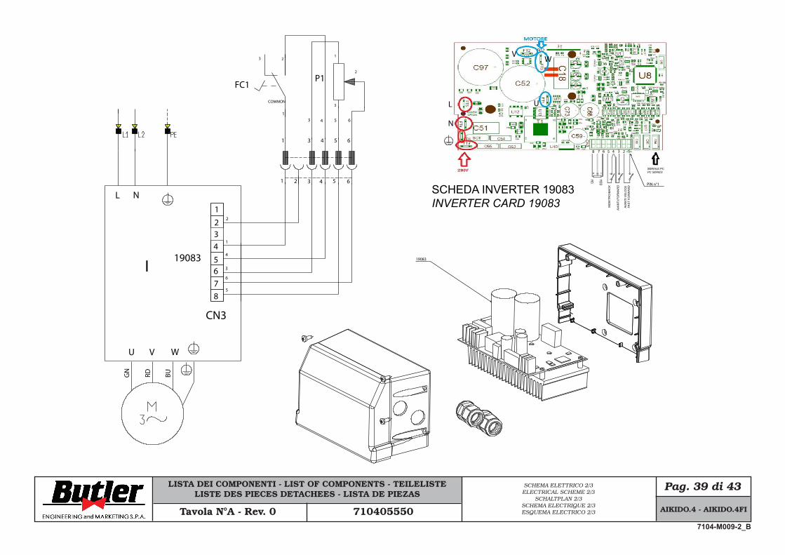
Pag. 39 di 43SCHEMA ELETTRICO 2/3ELECTRICAL SCHEME 2/3
SCHALTPLAN 2/3SCHEMA ELECTRIQUE 2/3ESQUEMA ELECTRICO 2/3Tavola N°A - Rev. 0 710405550
5 631
4
2
L
N
VW
U
8 7 6 5 4 3 2 1
PIN n°1
U V W
NL
I
1
3
4
5
6
3 2
COMMON
FC1
GN
RD BU
3
2
1
P1
1
19083
8765432
1 2 3 4 5 6
631 4 5
CN3
19083
SCHEDA INVERTER 19083INVERTER CARD 19083 IN
DIE
TRO
/BA
CK
AVA
NTI
/FO
RW
AR
D
AVA
NTI
VE
LOC
EFA
ST
FOR
WA
RD
SERIALE PCPC SERIES
AIKIDO.4 - AIKIDO.4FI
7104-M009-2_B

LISTA DEI COMPONENTI - LIST OF COMPONENTS - TEILELISTELISTE DES PIECES DETACHEES - LISTA DE PIEZAS
Pag. 40 di 43
Cod.N° Descrizione Description Beschreibung DescripciónDescription
SCHEMA ELETTRICO 3/3ELECTRICAL SCHEME 3/3
SCHALTPLAN 3/3SCHEMA ELECTRIQUE 3/3ESQUEMA ELECTRICO 3/3Tavola N°A - Rev. 0 710405550
AL Alimentatore Power supply Speiseleitung Alimentateur AlimentadorCN3 Conn. connessione micro+potenz. Micro connector+potentiometer Verbinder Mikro+Potenziometer Conn. micro+potentiomètre Conec. conex. micro+potenciómetro
EV1A Elett. mov. braccio stall. sup. salita Rising upper bead breaking sv Elekt. oberer Abdrückarm Anstieg Elect. décolle-talons sup. montée Elec. mov. brazo dest. sup. subidaEV1B Elett. mov. braccio stall. sup. discesa Descent upper bead breaking sv Elekt. oberer Abdrückarm Abstieg Elect. décolle-talons sup. descente Elec. mov. brazo dest. sup. bajadaEV2A Elett. mov. braccio stall. inf. salita Rising lower bead breaking sv Elekt. unterer Abdrückarm Anstieg Elect. décolle-talons inf. montée Elec. mov. brazo destal. inf. subidaEV2B Elett. mov. braccio stall. inf. discesa Descent lower bead breaking sv Elekt. unterer Abdrückarm Abstieg Elect. décolle-talons inf. descente Elec. mov. brazo destal. inf. bajadaEV3A Elett. mov. braccio uten. salita Rising tool solenoid valve Elekt. Werkzeugarm Anstieg Elect. mov. bras outil montée Elec. mov. brazo utens. subidaEV3B Elett. mov. braccio uten. discesa Descent tool solenoid valve Elekt. Werkzeugarm Abstieg Elect. mov. bras outil descente Elec. mov. brazo utens. bajadaEV4A Elett. movim. camma sup. avanti Forward upper cam solenoid valve Voraus Elekt. oberer Nocke Elect. mov. came sup. en avant Elec. movim. leva sup. adelanteEV4B Elett. movim. camma sup. indietro Backward upper cam solenoid valve Züruck Elekt. oberer Nocke Elect. mov. came sup. en arrière Elec. movim. leva sup. atrás EV5A Elett. movim. camma inf. avanti Forward lower cam solenoid valve Voraus Elekt. unterer Nocke Elect. mov. came inf. en avant Elec. movim. leva inf. adelanteEV5B Elett. movim. camma inf. indietro Backward lower cam solenoid valve Züruck Elekt. unterer Nocke Elect. mov. came inf. en arrière Elec. movim. leva inf. atrás EV6 Elettrovalvola sblocco bracci Arm unlocking solenoid valve Elektroventil Lösung Armen Electrovanne déblocage bras Electroválvula desbloqueo brazosEV7 Elettrovalvola blocca stelo Rod locking solenoid valve Elektoventil Sperrung Schaft Electrovanne blocage tige Electroválvula bloqueo asta
EV8A Elett. mov. braccio uten. inf.salita Rising lower tool arm movement sv Elekt. unterer Werkzeugarm Anstieg Elect. mov. bras outil inf. montée Elec. mov. brazo utensilio inf. subidaEV8B Elett. mov. braccio uten. inf. discesa Descent lower tool arm movement sv Elekt. unterer Werkzeugarm Abstieg Elect. mov. bras outil inf. descente Elec. mov. brazo utensilio inf. bajadaEV11A Elett. movimento bracci avanti Ahead arms movement sv Voraus Elektroventil Armen Electrovanne mov. bras en avant Elec. movim. brazos atrás EV11B Elett. movimento bracci indietro Back arms movement sv Züruck Elektroventil Armen Electrovanne mov. bras en arrière Elec. movim. brazos adelante
FC1 Micro interruttore comando motore Motor control microswitch Mikroregulador Motorbefehl Micro-inter. commande moteur Micro regulador mando motorFU1 Fusibile protezione linea Line guard fuse Linieschmelzsicherung Fusible protection ligne Fusible protección linea
I Inverter comando motore Motor control inverter Frequenumformerantriebmotor Variateur commande moteur Inversor mando motorM Motore asincrono trifase Threephase asynchronous motor Dreiphasen Asynchronmotor Moteur asynchrone triphasé Motor asincrónico trifásicoP1 Potenziometro reg. velocità motore Moteur speed adj. potentiometer Motorgeschw. Potenziometerreg. Potentiomètre reg. vitesse moteur Potenciómetro reg. velocidad motor
SR1 Selettore auto-man Auto-man selector Schalter Auto/Man Sélecteur auto-man Selector Auto/ManSB1 Puls. com. braccio stallon. sup. salita Rising upper bead breaking button Abdrückerknopf oberer Anstieg Pous. décolle-talons sup. montée Puls. mando brazo dest. sup. subidaSB2 Puls.com. braccio stallon.sup.discesa Descent upper bead breaking button Abdrückerknopf oberer Abstieg Pous. décolle-talons sup. descente Puls. mando brazo dest. sup. bajadaSB3 Puls. com. braccio stallon. inf. salita Rising lower bead breaking button Abdrückerknopf unterer Anstieg Pous. décolle-talons inf. montée Puls. mando brazo dest. inf. subidaSB4 Puls. com. braccio stall. inf. discesa Descent lower bead breaking button Abdrückerknopf unterer Abstieg Pous. décolle-talons inf. descente Puls. mando brazo dest. inf. bajadaSB5 Puls. inserimento camma superiore Upper cam insertion push button Oberer Nocke Einsteckenknopf Pous. insertion came supérieur Puls. inserción leva superiorSB6 Puls. inserimento camma inferiore Lower cam insertion push button Unterer Nocke Einsteckenknopf Pous. insertion came inférieur Pulsador inserción leva inferiorSB7 Puls. com. braccio uten. salita Rising tool push button Knopf Werkzeug Anstieg Pous. com. bras outil montée Puls. mando brazo uten. subidaSB8 Puls. com. braccio uten. discesa Descent tool push button Knopf Werkzeug Abstieg Pous. com. bras outil descente Puls. mando brazo uten. bajada
SB10 Puls. com. braccio utens. inf. salita Rising lower tool arm push button Werkzeugearmknopf unterer Anstieg Pous. com. bras outil inf. montée Puls. mando brazo uten. inf. subidaSB11 Puls. com. braccio utens. inf. discesa Descent lower tool arm push button Werkzeugearmknopf unterer Abstieg Pous. com. bras outil inf. descente Puls. mando brazo uten. inf. bajadaSB12 Pulsante comando braccio avanti Ahead arms push button Voraus Armenknopf Poussoir commande bras en avant Puls. mando brazo uten. inf. atrásSB13 Pulsante comando braccio indietro Back arms push button Züruck Armenknopf Poussoir commande bras en arrière Puls. mando brazo uten. inf. adelanteSCS Scheda controllo smontagomme Tyre changing machine control card Karte Kontrolle Kraftfahrzeugreifen Carte contrôle démonte-pneus Ficha control desmontasgomasSQ1 Sensore di hall superiore Upper hall sensor Oberer sensor Hall Capteur hall supérieur Sensor hall superiorSQ2 Sensore di hall inferiore Lower hall sensor Unterer sensor Hall Capteur hall inférieur Sensor hall inferiorSQ3 Sensore di hall sollevamento Lifting hall sensor Heben Hallsensor Capteur hall soulèvement Sensor hall de levantaciónIG Interruttore generale Main switch Schalter general Interrupteur general Interruptor generalB1 Puntatore laser Laser pointer Richtpfeil Laser Point laser Apuntador laser■ Morsetto Clamp Klemme Borne Abrazadera
AIKIDO.4 - AIKIDO.4FI
7104-M009-2_B
LISTA DEI COMPONENTI - LIST OF COMPONENTS - TEILELISTELISTE DES PIECES DETACHEES - LISTA DE PIEZAS
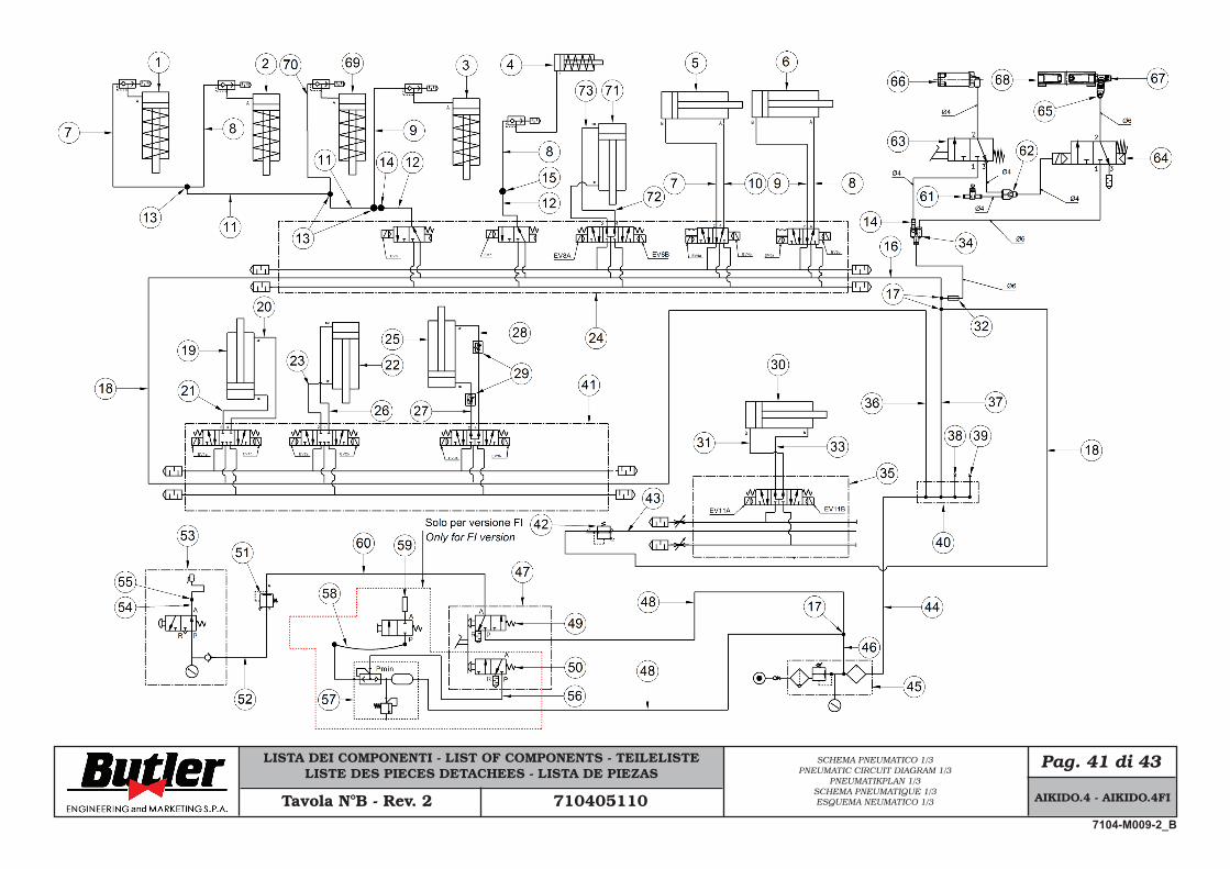
Pag. 41 di 43SCHEMA PNEUMATICO 1/3PNEUMATIC CIRCUIT DIAGRAM 1/3
PNEUMATIKPLAN 1/3SCHEMA PNEUMATIQUE 1/3ESQUEMA NEUMATICO 1/3Tavola N°B - Rev. 2 710405110 AIKIDO.4 - AIKIDO.4FI
7104-M009-2_B
LISTA DEI COMPONENTI - LIST OF COMPONENTS - TEILELISTELISTE DES PIECES DETACHEES - LISTA DE PIEZAS
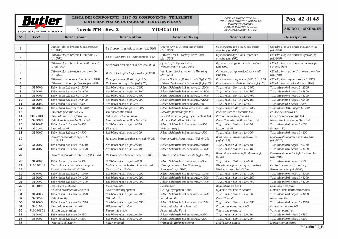
Pag. 42 di 43
Cod.N° Descrizione Description Beschreibung DescripciónDescription
SCHEMA PNEUMATICO 2/3PNEUMATIC CIRCUIT DIAGRAM 2/3
PNEUMATIKPLAN 2/3SCHEMA PNEUMATIQUE 2/3ESQUEMA NEUMATICO 2/3Tavola N°B - Rev. 2 710405110
1 Cilindro blocco braccio C superiore sx (cil. Ø60)
Lh C upper arm lock cylinder (cyl. Ø60)Oberer Arm C Blockzylinder links (Zyl. Ø60)
Cylindre blocage bras C supérieur gauche (cyl. Ø60)
Cilindro bloqueo brazo C superior izq (cil. Ø60)
2 Cilindro blocco braccio C inferiore sx (cil. Ø60)
Lh C lower arm lock cylinder (cyl. Ø60)Unterer Arm C Blockzylinder links (Zyl. Ø60)
Cylindre blocage bras C inférieur gauche (cyl. Ø60)
Cilindro bloqueo brazo C inferior izq (cil. Ø60)
3 Cilindro blocco braccio utensile superio-re (cil. Ø60)
Upper tool arm lock cylinder (cyl. Ø60)Zylinder für Sperren des Werkzeugsarms (Zyl. Ø60)
Cylindre blocage bras outil supérior (cyl. Ø60)
Cilindro bloqueo brazo utensilio supe-rior (cil. Ø60)
4 Cilindro blocco verticale per utensile (cil. Ø60)
Vertical lock cylinder for tool (cyl. Ø60)Vertikaler Blockzylinder für Werzeug (Zyl. Ø60)
Cylindre blocage vertical pour outil (cyl. Ø60)
Cilindro bloqueo vertical para utensilio (cil. Ø60)
5 Cilindro camma superiore dx (cil. Ø70) Rh upper cam cylinder (cyl. Ø70) Oberer Nockenzylinder rechts (Zyl. Ø70) Cylindre came supérieur droite (cyl. Ø70 Cilindro leva superior dra (cil. Ø70)6 Cilindro camma inferiore dx (cil. Ø70) Rh lower cam cylinder (cyl. Ø70) Unterer Nockenzylinder rechts (Zyl. Ø70) Cylindre came inférieur droite (cyl. Ø70) Cilindro leva inferior dra (cil. Ø70)7 317006 Tubo rilsan 6x4 nero L=2300 6x4 black rilsan pipe L=2300 Rilsan Schlauch 6x4 schwarz L=2300 Tuyau rilsan 6x4 noir L=2300 Tubo rilsan 6x4 negro L=23008 317006 Tubo rilsan 6x4 nero L=1800 6x4 black rilsan pipe L=1800 Rilsan Schlauch 6x4 schwarz L=1800 Tuyau rilsan 6x4 noir L=1800 Tubo rilsan 6x4 negro L=18009 317006 Tubo rilsan 6x4 nero L=1700 6x4 black rilsan pipe L=1700 Rilsan Schlauch 6x4 schwarz L=1700 Tuyau rilsan 6x4 noir L=1700 Tubo rilsan 6x4 negro L=1700
10 317006 Tubo rilsan 6x4 nero L=2400 6x4 black rilsan pipe L=2400 Rilsan Schlauch 6x4 schwarz L=2400 Tuyau rilsan 6x4 noir L=2400 Tubo rilsan 6x4 negro L=240011 317006 Tubo rilsan 6x4 nero L=50 6x4 black rilsan pipe L=50 Rilsan Schlauch 6x4 schwarz L=50 Tuyau rilsan 6x4 noir L=50 Tubo rilsan 6x4 negro L=5012 317026 Tubo rilsan 4x2,7 nero L=200 4x2,7 black rilsan pipe L=200 Rilsan Schlauch 4x2,7 schwarz L=200 Tuyau rilsan 4x2,7 noir L=200 Tubo rilsan 4x2,7 negro L=20013 Raccordo pneumatico V 6 V 6 pneumatic union Raccord pneumatique V 6 Pneumatischer Anschluss Y-6 Enlace neumático Y-614 B0171000 Raccordo riduzione fissa 6-4 6-4 Fixed reduction union Feststehender Verjüngungsanschluss 6-4 Raccord reduction fixe 6-4 Conector reducción fijo 6-415 325086 Riduzione intermedia D.6 - D.4 Intermediate reduction D.6 - D.4 Mittlere Reduktion D.6 - D.4 Reduction intermédiaire D.6 - D.4 Reducción intermedia D.6 - D.416 317007 Tubo rilsan 8x6 nero L=350 8x6 black rilsan pipe L=350 Rilsan Schlauch 8x6 schwarz L=350 Tuyau rilsan 8x6 noir L=350 Tubo rilsan 8x6 negro L=35017 325181 Raccordo a V8 V8 union V-Verbindung 8 Raccord à V8 Enlace a V818 317007 Tubo rilsan 8x6 nero L=300 8x6 black rilsan pipe L=300 Rilsan Schlauch 8x6 schwarz L=300 Tuyau rilsan 8x6 noir L=300 Tubo rilsan 8x6 negro L=300
19 Braccio stallonatore super. dx (cil. Ø125)
Rh upper bead breaker arm (cil. Ø125) Oberer Abdrückarm rechts (Zyl. Ø125)Bras décolle-talons supér. droite (cyl. Ø125)
Brazo destalonador super. derecho (cil. Ø125)
20 317007 Tubo rilsan 8x6 nero L=2150 8x6 black rilsan pipe L=2150 Rilsan Schlauch 8x6 schwarz L=2150 Tuyau rilsan 8x6 noir L=2150 Tubo rilsan 8x6 negro L=215021 317007 Tubo rilsan 8x6 nero L=1400 8x6 black rilsan pipe L=1400 Rilsan Schlauch 8x6 schwarz L=1400 Tuyau rilsan 8x6 noir L=1400 Tubo rilsan 8x6 negro L=1400
22 Braccio stallonatore infer. dx (cil. Ø125) Rh lower bead breaker arm (cyl. Ø125) Unterer Abdrückarm rechts (Zyl. Ø125)Bras décolle-talons infér. droite (cyl. Ø125)
Brazo destalonador inferior derecho (cil. Ø125)
23 317007 Tubo rilsan 8x6 nero L=900 8x6 black rilsan pipe L=900 Rilsan Schlauch 8x6 schwarz L=900 Tuyau rilsan 8x6 noir L=900 Tubo rilsan 8x6 negro L=90024 710490241 Centralina pneumatica principale Main pneumatic hydraulic power unit Hauptpneumatischer Steuerung Distributeur pneumatique principal Centralita neumática principal25 Braccio utensile (cil. Ø100) Tool arm (cyl. Ø100) Bras outil (cyl. Ø100) Werkzeugarm (Zyl. Ø100) Brazo utensilio (cil. Ø100)26 317007 Tubo rilsan 8x6 nero L=1550 8x6 black rilsan pipe L=1550 Rilsan Schlauch 8x6 schwarz L=1550 Tuyau rilsan 8x6 noir L=1550 Tubo rilsan 8x6 negro L=155027 317007 Tubo rilsan 8x6 nero L=1200 8x6 black rilsan pipe L=1200 Rilsan Schlauch 8x6 schwarz L=1200 Tuyau rilsan 8x6 noir L=1200 Tubo rilsan 8x6 negro L=120028 317007 Tubo rilsan 8x6 nero L=1700 8x6 black rilsan pipe L=1700 Rilsan Schlauch 8x6 schwarz L=1700 Tuyau rilsan 8x6 noir L=1700 Tubo rilsan 8x6 negro L=170029 399284 Regolatore di flusso Flow regulator Flussregler Regulateur de débit Regulación de flujo30 Sistema movimentazione cavi Cable handling system Bewegungssystem Kabel Système mouvement câbles Sistema movimentación cables31 317006 Tubo rilsan 6x4 nero L=1200 6x4 black rilsan pipe L=1200 Rilsan Schlauch 6x4 schwarz L=1200 Tuyau rilsan 6x4 noir L=1200 Tubo rilsan 6x4 negro L=120032 325054 Riduzione 6-8 6-8 reduction Reduktion 6-8 Reduction 6-8 Reducción 6-833 317006 Tubo rilsan 6x4 nero L=1550 6x4 black rilsan pipe L=1550 Rilsan Schlauch 6x4 schwarz L=1550 Tuyau rilsan 6x4 noir L=1550 Tubo rilsan 6x4 negro L=155034 325191 Raccordo pneumatico Y-6 Y-6 pneumatic union Pneumatischer Anschluss Y-6 Raccord pneumatique Y-6 Enlace neumático Y-635 710090851 Valvola pneumatica Pneumatic valve Pneumatische Ventil Vanne pneumatique Válvula neumática36 317007 Tubo rilsan 8x6 nero L=350 8x6 black rilsan pipe L=350 Rilsan Schlauch 8x6 schwarz L=350 Tuyau rilsan 8x6 noir L=350 Tubo rilsan 8x6 negro L=35037 317007 Tubo rilsan 8x6 nero L=250 8x6 black rilsan pipe L=250 Rilsan Schlauch 8x6 schwarz L=250 Tuyau rilsan 8x6 noir L=250 Tubo rilsan 8x6 negro L=25038 Optional sollevatore Lifter optional Optionelle Hubvorrichtung Soulèvateur option Levantador opcional
AIKIDO.4 - AIKIDO.4FI
7104-M009-2_B
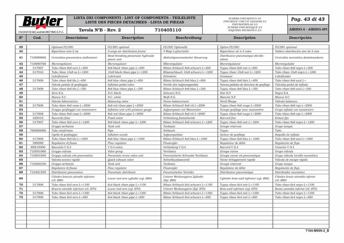
LISTA DEI COMPONENTI - LIST OF COMPONENTS - TEILELISTELISTE DES PIECES DETACHEES - LISTA DE PIEZAS
Pag. 43 di 43
Cod.N° Descrizione Description Beschreibung DescripciónDescription
SCHEMA PNEUMATICO 3/3PNEUMATIC CIRCUIT DIAGRAM 3/3
PNEUMATIKPLAN 3/3SCHEMA PNEUMATIQUE 3/3ESQUEMA NEUMATICO 3/3Tavola N°B - Rev. 2 710405110
39 Optional PLUS91 PLUS91 optional PLUS91 Optionelle Option PLUS91 PLUS91 opcional40 Ripartitore aria 5 vie 5-ways air distribution frame 5 Wege Luftverteiler Répartiteur air à 5 voies Tablero distribución aire de 5 vías
41 710090662 Centralina pneumatica stallonatoriBead breaking pneumatic hydraulic power unit
Abdrückpneumatischer SteuerungDistributeur pneumatique décolle-talons
Centralita neumática destalonadores
42 710090760 Microregolatore Microregulator Mikroregulator Microrégulateur Microregulador43 317007 Tubo rilsan 8x6 nero L=200 8x6 black rilsan pipe L=200 Rilsan Schlauch 8x6 schwarz L=200 Tuyau rilsan 8x6 noir L=200 Tubo rilsan 8x6 negro L=20044 317010 Tubo rilsan 10x8 ne L=1200 10x8 black rilsan pipe L=1200 Rilsanschlauch 10x8 schwarz L=1200 Tuyau rilsan 10x8 noir L=1200 Tubo rilsan 10x8 negro L=120045 Lubrificatore Lubricator Schmierer Graisseur Lubrificador46 317009 Tubo rilsan 8x6 blu L=650 8x6 blue rilsan pipe L=650 Rilsan Schlauch 8x6 blau L=650 Tuyau rilsan 8x6 bleu L=650 Tubo rilsan 8x6 azul L= 47 Valvole pedale di gonfiaggio Inflation pedal valve Ventile des Aufpumppedals Vannes pédales de direction de gonflage Válvulas pedal de inflado48 317009 Tubo rilsan 8x6 blu L=350 8x6 blue rilsan pipe L=350 Rilsan Schlauch 8x6 blau L=350 Tuyau rilsan 8x6 bleu L=350 Tubo rilsan 8x6 azul L=35049 Nera N.A. N.O. black Schwarz N.O. Noir N.O Negra N.A.50 Bianca N.C. N.C. white Weiß N.G. Blanche N.F. Blanca N.C.51 Valvola bilanciatrice Balancing valve Vanne balancement Ventil Waage Válvula balanceo52 317008 Tubo rilsan 8x6 rosso L=2500 8x6 red rilsan pipe L=2500 Rilsan Schlauch 8x6 röt L=2500 Tuyau rilsan 8x6 rouge L=2500 Tubo rilsan 8x6 rojo L=250053 Gruppo gonfiaggio con manometro Inflation unit with pressure gauge Aufpumpsatz mit Manometer Groupe gonflage avec manomètre Grupo inflado con manómetro54 317008 Tubo rilsan 8x6 rosso L=2000 8x6 red rilsan pipe L=2000 Rilsan Schlauch 8x6 röt L=2000 Tuyau rilsan 8x6 rouge L=2000 Tubo rilsan 8x6 rojo L=200055 325016 Raccordo fisso Fixed union Verbindung feststehende Raccord fixe Enlace fijo56 317007 Tubo rilsan 8x6 nero L=1200 8x6 black rilsan pipe L=1200 Rilsan Schlauch 8x6 schwarz L=1200 Tuyau rilsan 8x6 noir L=1200 Tubo rilsan 8x6 negro L=120057 Gruppo serbatoio Tank unit Tanksatz Groupe réservoir Grupo tanque58 790090060 Tubo cianfrinato Pipe Schlauch Tuyau Tubo59 Ugello di gonfiaggio Inflation nozzle Aufpumpedüse Gicleur de gonflage Boquilla de inflado60 317009 Tubo rilsan 8x6 blu L=1000 8x6 blue rilsan pipe L=1000 Rilsan Schlauch 8x6 blau L=1000 Tuyau rilsan 8x6 bleu L=1000 Tubo rilsan 8x6 azul L=100061 399286 Regolatore di flusso Flow regulator Flussregler Regulateur de débit Regulación de flujo62 B5815000 Raccordo V D.4 V D.4 union Verbindung V D.4 Raccord V D.4 Conector V D.463 710591960 Gruppo valvola Valve group Ventilsatz Groupe vanne Grupo válvula64 710591950 Gruppo valvola vite pneumatica Pneumatic screw valve unit Pneumatische Schraube Ventilsatz Groupe vanne vis pneumatique Grupo válvula tornillo neumática65 Valvola scarico rapido Quick exhaust valve Schnellauslassventil Vanne échappement rapide Válvula de escape rápido66 710292330 Gruppo serbatoio Tank unit Tanksatz Groupe réservoir Grupo tanque67 Regolatore di flusso Flow regulator Flussregler Regulateur de débit Regulación de flujo68 710491550 Distributore pneumatico Pneumatic distributor Pneumatischer Verteiler Distributeur pneumatique Distribuidor neumático
69 Cilindro braccio utensile inferiore (cil. Ø60)
Lower tool arm cylinder (cyl. Ø60)Unterer Werkzeugarm Zylinder (Zyl. Ø60)
Cylindre bras outil inférieur (cyl. Ø60)Cilindro brazo utensilio inferior (cil. Ø60)
70 317006 Tubo rilsan 6x4 nero L=1100 6x4 black rilsan pipe L=1100 Rilsan Schlauch 6x4 schwarz L=1100 Tuyau rilsan 6x4 noir L=1100 Tubo rilsan 6x4 negro L=110071 Braccio utensile inferiore (cil. Ø70) Lower tool arm (cyl. Ø70) Unterer Werkzeugarm (Zyl. Ø70) Bras outil inférieur (cyl. Ø70) Brazo utensilio inferior (cil. Ø70)72 317006 Tubo rilsan 6x4 nero L=1350 6x4 black rilsan pipe L=1350 Rilsan Schlauch 6x4 schwarz L=1350 Tuyau rilsan 6x4 noir L=1350 Tubo rilsan 6x4 negro L=135073 317006 Tubo rilsan 6x4 nero L=650 6x4 black rilsan pipe L=650 Rilsan Schlauch 6x4 schwarz L=650 Tuyau rilsan 6x4 noir L=650 Tubo rilsan 6x4 negro L=650
AIKIDO.4 - AIKIDO.4FI
7104-M009-2_B

• Per eventuali chiarimenti interpellare il più vicino rivenditore oppure rivolgersi direttamente a:• For any further information please contact your local dealer or call:• Im Zweifelsfall ober bei Rückfragen wenden Sie sich bitte an den nächsten Wiederverkäufer oder direkt an:• Pour tout renseignement complémentaire s’adresser au revendeur le Plus proche ou directement à:• En caso de dudas, para eventuales aclaraciones, póngase en contacto con el distribudor más próximo ó
diríjasie directamente a:
GLI ESPLOSI SERVONO SOLO PER L’IDENTIFICAZIONE DELLE PARTI DA SOSTITUIRE.LA SOSTITUZIONE DEVE ESSERE EFFETTUATA DA PERSONALE PROFESSIONAL-MENTE QUALIFICATO.
THE DIAGRAMS SERVE ONLY FOR THE IDENTIFICATION OF PARTS TO BE REPLACED. THE REPLACEMENT MUST BE CARRIED OUT PROFESSIONALLY QUALIFIED PER-SONNEL.
DIE ZEICHNUNGEN DIENEN NUR ZUR IDENTIFIZIERUNG DER ERSATZTEILE. DIE ERSETZUNG MUSS DURCH QUALIFIZIERTES PERSONAL ERFOLGEN.
LES DESSINS NE SERVENT QU’À L’IDENTIFICATION DES PIÈCES À REMPLACER.LE REMPLACEMENT DOIT ÊTRE EFFECTUÉ PAR UN PERSONNE PROFESSIONNEL-LEMENT QUALIFIÉ.
LOS DIBUJOS EN DESPIECE SIRVEN ÚNICAMENTE PARA IDENTIFICAR LAS PIEZAS QUE DEBEN SUSTITUIRSE. LA SUSTITUCIÓN DE PIEZAS DEBE EFECTUARLA EXCLU-SIVAMENTE PERSONAL PROFESIONALMENTE CUALIFICADO.
20.0 LISTA DEI COMPONENTI
20.0 LIST OF COMPONENTS
20.0 TEILELISTE
20.0 LISTE DES PIECES DETACHEES
20.0 LISTA DE PIEZAS
I
GB
D
F
E
- Rev. n. 2 (10/2018)
BUTLER ENGINEERING and MARKETING S.p.A. a s. u.Via dell’Ecologia, 6 - 42047 Rolo - (RE) Italy
Phone (+39) 0522 647911 - Fax (+39) 0522 649760 - e-mail: [email protected]
7104-R009-2_B
7104-R009-2_B
AIKIDO.4AIKIDO.4FI
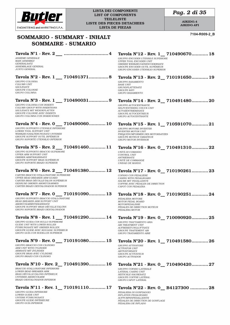
LISTA DEI COMPONENTILIST OF COMPONENTS
TEILELISTELISTE DES PIECES DETACHEES
LISTA DE PIEZAS
Pag. 2 di 35
SOMMARIO - SUMMARY - INHALTSOMMAIRE - SUMARIO
Tavola N°1 - Rev. 2 ___ ................................4ASSIEME GENERALEMAIN ASSEMBLYGENERALSATZASSEMBLAGE GENERALJUNTO GENERAL
Tavola N°2 - Rev. 1 ___ 710491371 ..............8GRUPPO COLONNACOLUMN UNITSÄULESATZGROUPE COLONNEGRUPO COLUMNA
Tavola N°3 - Rev. 1 ___ 710490031 ..............9GRUPPO COLONNA CON INSERTICOLUMN GROUP WITH INSERTIONSSÄULESATZ MIT WENDEPLATTENGROUPE COLONNE AVEC INSERTSGRUPO COLUMNA CON INSERCIÓNES
Tavola N°4 - Rev. 0 ___ 710490060 ............10GRUPPO SUPPORTO UTENSILE INFERIORELOWER TOOL SUPPORT UNITWERKZEUGHALTERUNGSATZ UNTERERGROUPE SUPPORT OUTIL INFÉRIEURGRUPO SOPORTE UTENSILIO INFERIOR
Tavola N°5 - Rev. 2 ___ 710491460 ............11GRUPPO SUPPORTO BRACCIO SUPERIOREUPPER ARM SUPPORT UNITOBERER ARMTRÄGERSATZGROUPE SUPPORT BRAS SUPÉRIEURGRUPO SOPORTE BRAZO SUPERIOR
Tavola N°6 - Rev. 2 ___ 710491380 ............12CARTER BRACCIO STALLONATORE SUPERIOREUPPER BEAD BREAKER ARM GUARDCARTER BRAS DÉCOLLE-TALON SUPÉRIEURGEHÄUSE OBEREN ABDRÜCKARMESCÁRTER BRAZO DESTALONADOR SUPERIOR
Tavola N°7 - Rev. 0 ___ 710191090 ............13GRUPPO SUPPORTO BRACCIO STALLONATOREBEAD BREAKER ARM SUPPORT UNITABDRÜCKARMSTRÄGERSATZGROUPE SUPPORT BRAS DÉCOLLE-TALONSGRUPO SOPORTE BRAZO DESTALONADOR
Tavola N°8 - Rev. 1 ___ 710491290 ............14GRUPPO GUIDA CON RULLO SUPERIOREGUIDE UNIT WITH LOWER ROLLERFÜHRUNGSATZ MIT OBERER ROLLENGROUPE GUIDE AVEC ROULEAU SUPÉRIEURGRUPO GUÍA CON RODILLOS SUPERIOR
Tavola N°9 - Rev. 0 ___ 710191080 ............15GRUPPO BRACCIO CON CILINDROARM UNIT WITH CYLINDERARMSATZ MIT ZYLINDERGROUPE BRAS AVEC CYLINDREGRUPO BRAZO CON CILINDRO
Tavola N°10 - Rev. 2 __ 710491390 ............16BRACCIO STALLONATORE INFERIORELOWER BEAD BREAKER ARMBRAS DÉCOLLE-TALONS INFÉRIEURUNTERER ABDRÜCKARMBRAZO DESTALONADOR INFERIOR
Tavola N°11 - Rev. 1 __ 710191110 ............17GRUPPO GUIDA INFERIORELOWER GUIDE UNITUNTERE FÜHRUNGSATZGROUPE GUIDE INFÉRIEUREGRUPO GUÍA INFERIOR
Tavola N°12 - Rev. 1 __ 710490670 ............18GRUPPO ENCODER UTENSILE SUPERIOREUPPER TOOL ENCODER UNITOBERER WERKZEUGENENCODERSATZGROUPE ENCODER OUTIL SUPÉRIEURGRUPO ENCODER UTENSILIO SUPERIOR
Tavola N°13 - Rev. 2 __ 710191650 ............19GRUPPO BASAMENTOBASE UNITGRUNDPLATTESATZGROUPE BATIGRUPO BASAMIENTO
Tavola N°14 - Rev. 2 __ 710491480 ............20GRUPPO AUTOCENTRANTESELFCENTERING CHUCK UNITAUTOZENTRIERESATZGROUPE AUTOCENTREURGRUPO AUTOCENTRANTE
Tavola N°15 - Rev. 1 __ 710591070 ............21GRUPPO MOTORE INVERTER INVERTER MOTOR UNITFREQUENUMFORMER DES MOTORSATZESGROUPE MOTEUR VARIATEURGRUPO MOTOR INVERSOR
Tavola N°16 - Rev. 0 __ 710491310 ............22UNITÁ DI COMANDOCONTROL UNITANTRIEBSATZUNITÉ DE COMMANDEUNIDAD DE MANDO
Tavola N°17 - Rev. 0 __ 710190261 ............23COFANO CON PEDALIERECASING WITH PEDALBOARDHAUBE MIT PEDALLEISTECOFFRE AVEC PÉDALES DE DIRECTIONCAPOT CON PEDALERA
Tavola N°18 - Rev. 0 __ 710190251 ............24PEDALIERA MOTOREMOTOR PEDAL BOARDMOTORPEDALERIEPÉDALES DE DIRECTION MOTEURPEDALERA MOTOR
Tavola N°19 - Rev. 0 __ 710090920 ............25GRUPPO TRATTAMENTO ARIAAIR TREATMENT UNITAUFBEREITUNGLUFTSATZGROUPE TRAITEMENT AIRGRUPO TRATAMIENTO AIRE
Tavola N°20 - Rev. 1 __ 710491580 ............26GRUPPO ATTIVATOREACTIVATOR UNITAKTIVATORSATZGROUPE ACTIVATEURGRUPO ACTIVADOR
Tavola N°21 - Rev. 0 __ 710490420 ............27GRUPPO COFANO LATERALELATERAL CASING UNITSEITICHLE HAUBESATZGROUPE COFFRE LATÉRALGRUPO CAPOT LATERAL
Tavola N°22 - Rev. 0 __ B4127300 .............28PEDALIERA DI GONFIAGGIOINFLATION PEDALBOARDAUFPUMPENPEDALLEISTEPÉDALES DE DIRECTION DE GONFLAGEPEDALERA DE INFLADO
7104-R009-2_B
AIKIDO.4AIKIDO.4FI
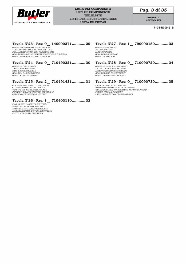
LISTA DEI COMPONENTILIST OF COMPONENTS
TEILELISTELISTE DES PIECES DETACHEES
LISTA DE PIEZAS
Pag. 3 di 35
Tavola N°23 - Rev. 0 __ 140990371 ............29GRUPPO PEDALIERA GONFIATUBELESSTUBELESS INFLATION PEDALBOARD UNITPEDALLEISTE AUFPUMPEN TUBELESS SATZGROUPE PÉDALES DE DIRECTION GONFLAGE TUBELESSGRUPO PEDALERA INFLADO TUBELESS
Tavola N°24 - Rev. 0 __ 710490321 ............30GRUPPO 4 CAVI BOWDEN4 BOWDEN CABLE UNITSATZ 4 BOWDENKABELNGROUPE 4 CABLES BOWDENGRUPO 4 CABLES BOWDEN
Tavola N°25 - Rev. 2 __ 710491431 ............31CHIUSURA CON IMPIANTO ELETTRICOCLOSING WITH ELECTRIC SYSTEMVERSCHLUSS MIT ELEKTROANLAGEFERMERTURE AVEC SYSTÈME ÉLECTRIQUECERRADO CON SISTEMA ÉLECTRICO
Tavola N°26 - Rev. 1 __ 710403110 ............32INSIEME MTG CASSETTA ELETTRICAMTG ELECTRICAL BOX ASSEMBLYENSEMBLE MTG ELEKTRISCHEKISTEASSEMBLAGE MTG BOITIER ÉLECTRIQUEJUNTO MTG CAJITA ELECTRICA
Tavola N°27 - Rev. 1 __ 790090180 ............33GRUPPO GONFIAGGIOINFLATION GROUPAUFPUMPENSATZGROUPE DE GONFLAGEGRUPO DE INFLADO
Tavola N°28 - Rev. 0 __ 710090720 ............34GRUPPO STAFFA SOLLEVAMENTOLIFTING DEVICE BRACKET UNITABZIGVORRICHTUNGBÜGELSATZGROUPE BRIDE SOULÈVEMENTGRUPO BRIDA LEVANTAMIENTO
Tavola N°29 - Rev. 0 __ 710090730 ............35PREMITALLONE 28” C/TRAZIONEBEAD DEPRESSING 28” WITH ENTRAINERWULSTABDRÜCKERVORRICHTUNG MIT FÜHRUNGSPINPOUSSE-TALON AVEC GALETPRESIONATALÓN CON TRANSPORTADOR
7104-R009-2_B
AIKIDO.4AIKIDO.4FI
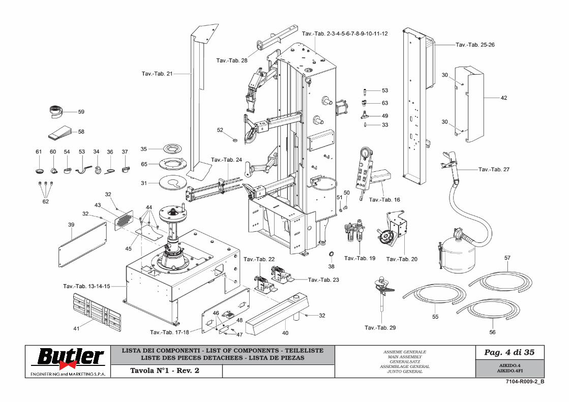
LISTA DEI COMPONENTI - LIST OF COMPONENTS - TEILELISTELISTE DES PIECES DETACHEES - LISTA DE PIEZAS
Pag. 4 di 35ASSIEME GENERALEMAIN ASSEMBLYGENERALSATZ
ASSEMBLAGE GENERALJUNTO GENERALTavola N°1 - Rev. 2
AIKIDO.4AIKIDO.4FI
7104-R009-2_B
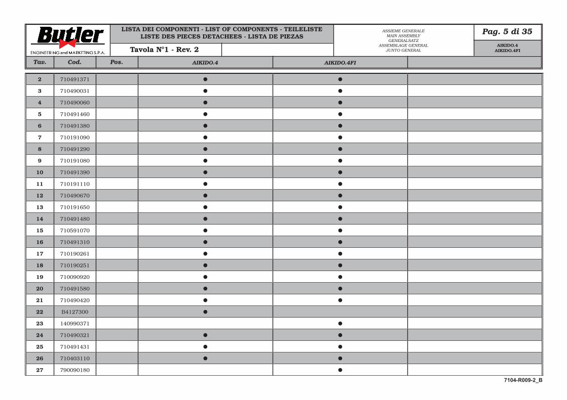
LISTA DEI COMPONENTI - LIST OF COMPONENTS - TEILELISTELISTE DES PIECES DETACHEES - LISTA DE PIEZAS
Pag. 5 di 35
Cod. Pos.Tav.
ASSIEME GENERALEMAIN ASSEMBLYGENERALSATZ
ASSEMBLAGE GENERALJUNTO GENERALTavola N°1 - Rev. 2
2 710491371
3 710490031
4 710490060
5 710491460
6 710491380
7 710191090
8 710491290
9 710191080
10 710491390
11 710191110
12 710490670
13 710191650
14 710491480
15 710591070
16 710491310
17 710190261
18 710190251
19 710090920
20 710491580
21 710490420
22 B4127300
23 140990371
24 710490321
25 710491431
26 710403110
27 790090180
7104-R009-2_B
AIKIDO.4 AIKIDO.4FI
AIKIDO.4AIKIDO.4FI
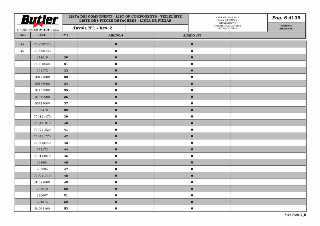
LISTA DEI COMPONENTI - LIST OF COMPONENTS - TEILELISTELISTE DES PIECES DETACHEES - LISTA DE PIEZAS
Pag. 6 di 35
Cod. Pos.Tav.
28 710090720
29 710090730
272019 30
710013421 31
203172 32
B0171000 33
B0178000 34
B1157000 35
B1949000 36
B5717000 37
599418 38
710111470 39
710411810 40
710411820 41
710411770 42
710413440 43
272172 44
710114870 45
228501 46
203035 47
710011710 48
B1371800 49
203019 50
226007 51
224015 52
B4063100 53
ASSIEME GENERALEMAIN ASSEMBLYGENERALSATZ
ASSEMBLAGE GENERALJUNTO GENERALTavola N°1 - Rev. 2
7104-R009-2_B
AIKIDO.4 AIKIDO.4FI
AIKIDO.4AIKIDO.4FI
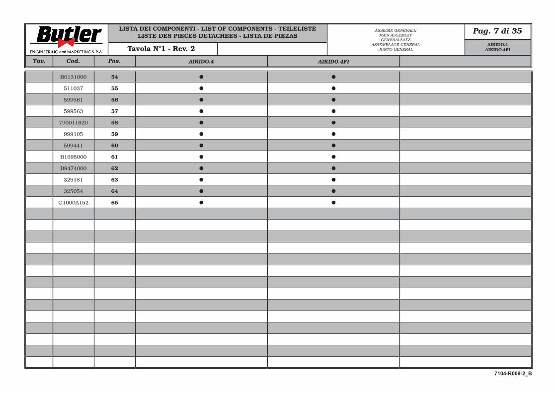
LISTA DEI COMPONENTI - LIST OF COMPONENTS - TEILELISTELISTE DES PIECES DETACHEES - LISTA DE PIEZAS
Pag. 7 di 35
Cod. Pos.Tav.
ASSIEME GENERALEMAIN ASSEMBLYGENERALSATZ
ASSEMBLAGE GENERALJUNTO GENERALTavola N°1 - Rev. 2
B6131000 54
511037 55
599561 56
599563 57
790011620 58
999105 59
599441 60
B1695000 61
B9474000 62
325181 63
325054 64
G1000A152 65
7104-R009-2_B
AIKIDO.4 AIKIDO.4FI
AIKIDO.4AIKIDO.4FI
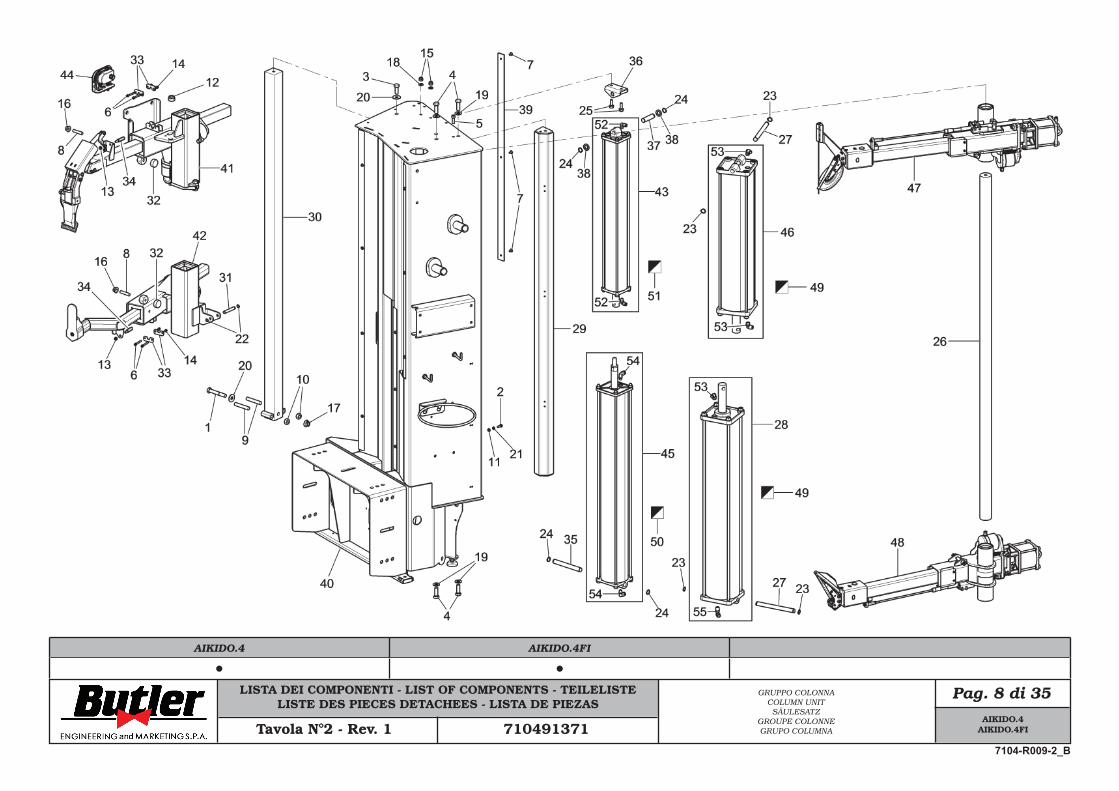
LISTA DEI COMPONENTI - LIST OF COMPONENTS - TEILELISTELISTE DES PIECES DETACHEES - LISTA DE PIEZAS
Pag. 8 di 35GRUPPO COLONNACOLUMN UNIT
SÄULESATZGROUPE COLONNEGRUPO COLUMNATavola N°2 - Rev. 1 710491371
AIKIDO.4AIKIDO.4FI
7104-R009-2_B
AIKIDO.4 AIKIDO.4FI
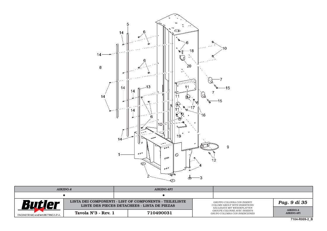
LISTA DEI COMPONENTI - LIST OF COMPONENTS - TEILELISTELISTE DES PIECES DETACHEES - LISTA DE PIEZAS
Pag. 9 di 35GRUPPO COLONNA CON INSERTICOLUMN GROUP WITH INSERTIONSSÄULESATZ MIT WENDEPLATTENGROUPE COLONNE AVEC INSERTS
GRUPO COLUMNA CON INSERCIÓNESTavola N°3 - Rev. 1 710490031
AIKIDO.4AIKIDO.4FI
7104-R009-2_B
AIKIDO.4 AIKIDO.4FI
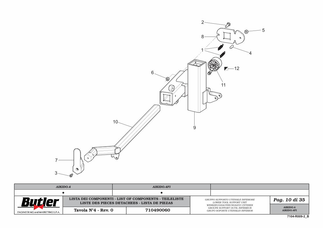
LISTA DEI COMPONENTI - LIST OF COMPONENTS - TEILELISTELISTE DES PIECES DETACHEES - LISTA DE PIEZAS
Pag. 10 di 35GRUPPO SUPPORTO UTENSILE INFERIORELOWER TOOL SUPPORT UNIT
WERKZEUGHALTERUNGSATZ UNTERERGROUPE SUPPORT OUTIL INFÉRIEUR
GRUPO SOPORTE UTENSILIO INFERIORTavola N°4 - Rev. 0 710490060
3
12
7
10
6
5
2
1
8
4
11
9
AIKIDO.4AIKIDO.4FI
7104-R009-2_B
AIKIDO.4 AIKIDO.4FI
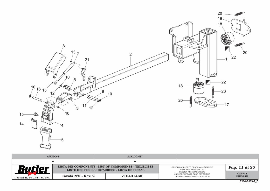
LISTA DEI COMPONENTI - LIST OF COMPONENTS - TEILELISTELISTE DES PIECES DETACHEES - LISTA DE PIEZAS
Pag. 11 di 35GRUPPO SUPPORTO BRACCIO SUPERIOREUPPER ARM SUPPORT UNITOBERER ARMTRÄGERSATZ
GROUPE SUPPORT BRAS SUPÉRIEURGRUPO SOPORTE BRAZO SUPERIORTavola N°5 - Rev. 2 710491460
AIKIDO.4AIKIDO.4FI
7104-R009-2_B
AIKIDO.4 AIKIDO.4FI
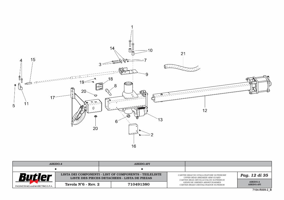
LISTA DEI COMPONENTI - LIST OF COMPONENTS - TEILELISTELISTE DES PIECES DETACHEES - LISTA DE PIEZAS
Pag. 12 di 35CARTER BRACCIO STALLONATORE SUPERIOREUPPER BEAD BREAKER ARM GUARD
CARTER BRAS DÉCOLLE-TALON SUPÉRIEURGEHÄUSE OBEREN ABDRÜCKARMES
CÁRTER BRAZO DESTALONADOR SUPERIORTavola N°6 - Rev. 2 710491380
AIKIDO.4AIKIDO.4FI
7104-R009-2_B
AIKIDO.4 AIKIDO.4FI
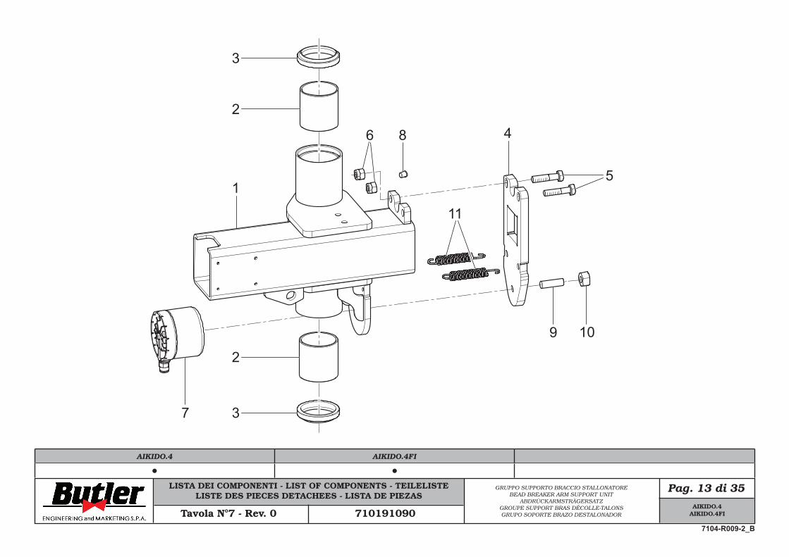
LISTA DEI COMPONENTI - LIST OF COMPONENTS - TEILELISTELISTE DES PIECES DETACHEES - LISTA DE PIEZAS
Pag. 13 di 35GRUPPO SUPPORTO BRACCIO STALLONATOREBEAD BREAKER ARM SUPPORT UNIT
ABDRÜCKARMSTRÄGERSATZGROUPE SUPPORT BRAS DÉCOLLE-TALONSGRUPO SOPORTE BRAZO DESTALONADORTavola N°7 - Rev. 0 710191090
51
2
2
3
3
46
7
8
9 10
11
AIKIDO.4AIKIDO.4FI
7104-R009-2_B
AIKIDO.4 AIKIDO.4FI
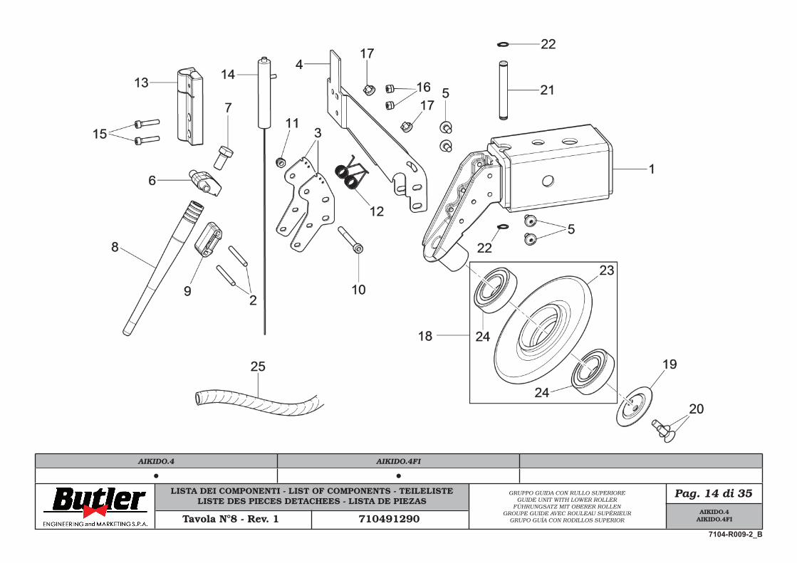
LISTA DEI COMPONENTI - LIST OF COMPONENTS - TEILELISTELISTE DES PIECES DETACHEES - LISTA DE PIEZAS
Pag. 14 di 35GRUPPO GUIDA CON RULLO SUPERIOREGUIDE UNIT WITH LOWER ROLLER
FÜHRUNGSATZ MIT OBERER ROLLENGROUPE GUIDE AVEC ROULEAU SUPÉRIEUR
GRUPO GUÍA CON RODILLOS SUPERIORTavola N°8 - Rev. 1 710491290
AIKIDO.4AIKIDO.4FI
7104-R009-2_B
AIKIDO.4 AIKIDO.4FI
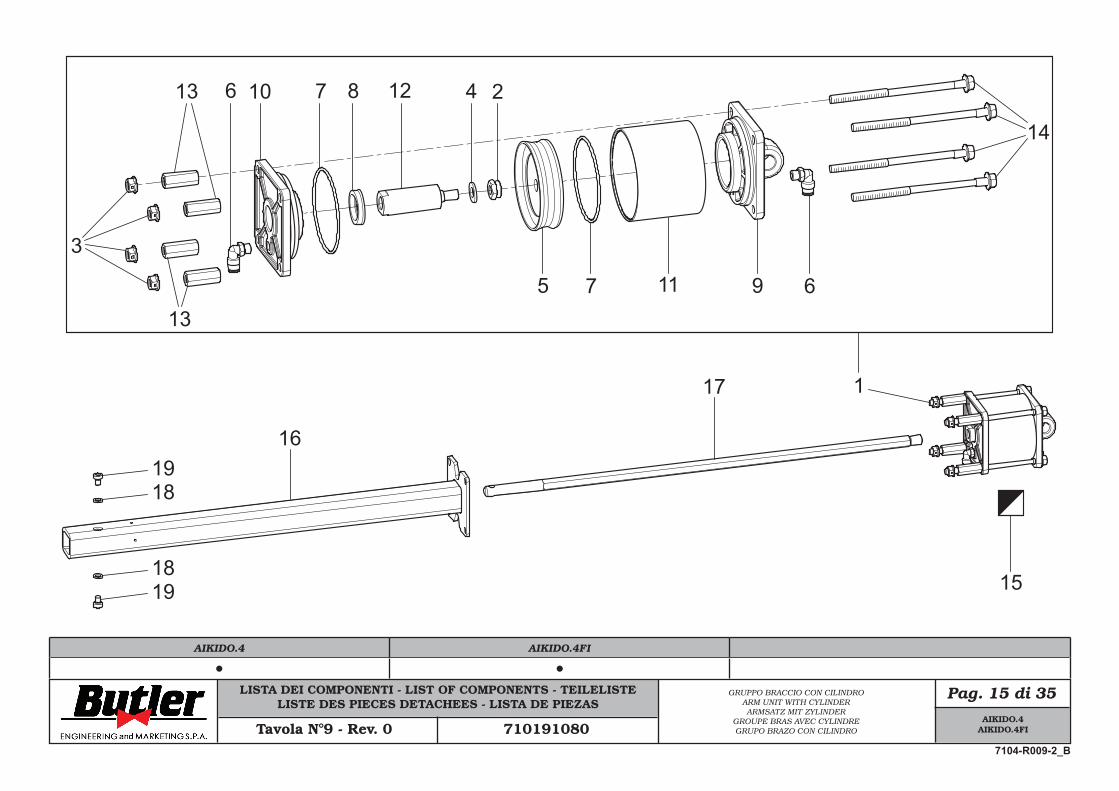
LISTA DEI COMPONENTI - LIST OF COMPONENTS - TEILELISTELISTE DES PIECES DETACHEES - LISTA DE PIEZAS
Pag. 15 di 35
Tavola N°9 - Rev. 0 710191080
GRUPPO BRACCIO CON CILINDROARM UNIT WITH CYLINDERARMSATZ MIT ZYLINDER
GROUPE BRAS AVEC CYLINDREGRUPO BRAZO CON CILINDRO
16
117
18
1819
19
91175
10 7 8 12
6
6
14
4 2
3
13
13
15
AIKIDO.4AIKIDO.4FI
7104-R009-2_B
AIKIDO.4 AIKIDO.4FI
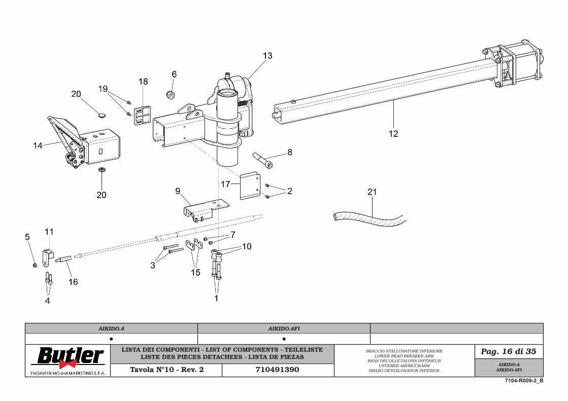
LISTA DEI COMPONENTI - LIST OF COMPONENTS - TEILELISTELISTE DES PIECES DETACHEES - LISTA DE PIEZAS
Pag. 16 di 35
Tavola N°10 - Rev. 2 710491390
BRACCIO STALLONATORE INFERIORELOWER BEAD BREAKER ARM
BRAS DÉCOLLE-TALONS INFÉRIEURUNTERER ABDRÜCKARM
BRAZO DESTALONADOR INFERIOR
AIKIDO.4AIKIDO.4FI
7104-R009-2_B
AIKIDO.4 AIKIDO.4FI
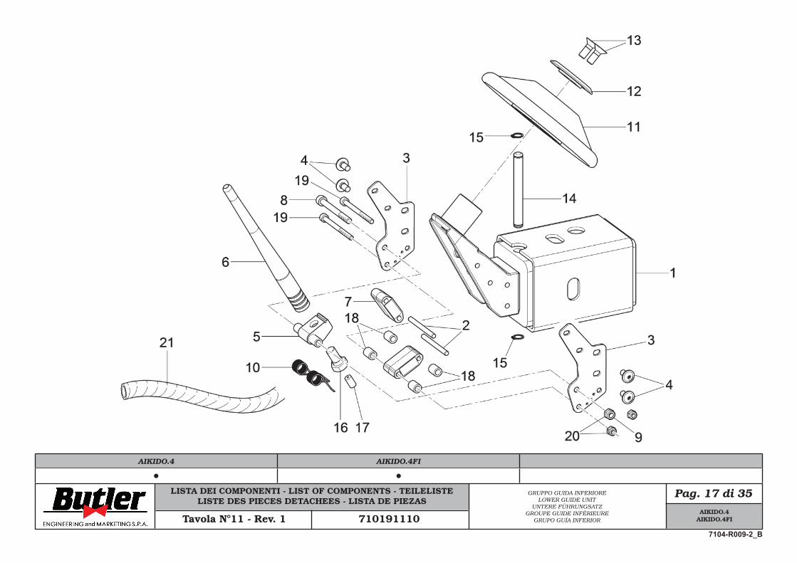
LISTA DEI COMPONENTI - LIST OF COMPONENTS - TEILELISTELISTE DES PIECES DETACHEES - LISTA DE PIEZAS
Pag. 17 di 35
Tavola N°11 - Rev. 1 710191110
GRUPPO GUIDA INFERIORELOWER GUIDE UNIT
UNTERE FÜHRUNGSATZGROUPE GUIDE INFÉRIEURE
GRUPO GUÍA INFERIOR
AIKIDO.4AIKIDO.4FI
7104-R009-2_B
AIKIDO.4 AIKIDO.4FI
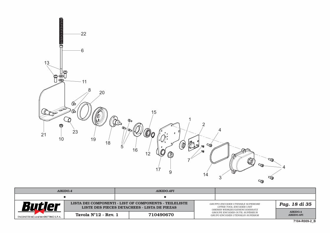
LISTA DEI COMPONENTI - LIST OF COMPONENTS - TEILELISTELISTE DES PIECES DETACHEES - LISTA DE PIEZAS
Pag. 18 di 35GRUPPO ENCODER UTENSILE SUPERIOREUPPER TOOL ENCODER UNIT
OBERER WERKZEUGENENCODERSATZGROUPE ENCODER OUTIL SUPÉRIEUR
GRUPO ENCODER UTENSILIO SUPERIORTavola N°12 - Rev. 1 710490670
22
6
13
11
8
2110
23
20
1918
516
12
15
17 9
12
4
7
14 3
4
AIKIDO.4AIKIDO.4FI
7104-R009-2_B
AIKIDO.4 AIKIDO.4FI
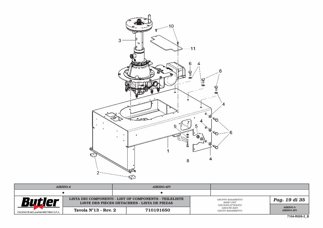
LISTA DEI COMPONENTI - LIST OF COMPONENTS - TEILELISTELISTE DES PIECES DETACHEES - LISTA DE PIEZAS
Pag. 19 di 35GRUPPO BASAMENTOBASE UNIT
GRUNDPLATTESATZGROUPE BATI
GRUPO BASAMIENTOTavola N°13 - Rev. 2 710191650
AIKIDO.4AIKIDO.4FI
7104-R009-2_B
AIKIDO.4 AIKIDO.4FI
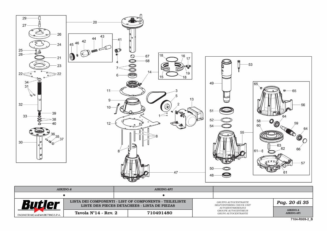
LISTA DEI COMPONENTI - LIST OF COMPONENTS - TEILELISTELISTE DES PIECES DETACHEES - LISTA DE PIEZAS
Pag. 20 di 35GRUPPO AUTOCENTRANTESELFCENTERING CHUCK UNIT
AUTOZENTRIERESATZGROUPE AUTOCENTREURGRUPO AUTOCENTRANTETavola N°14 - Rev. 2 710491480
AIKIDO.4AIKIDO.4FI
7104-R009-2_B
AIKIDO.4 AIKIDO.4FI
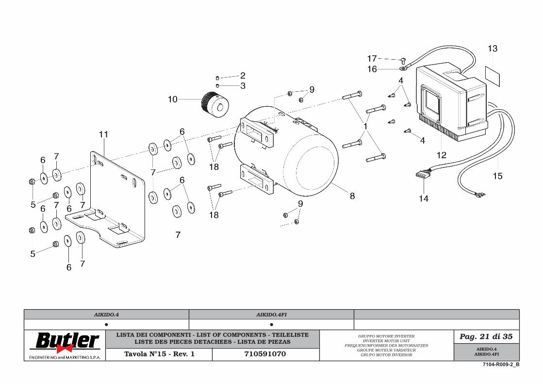
LISTA DEI COMPONENTI - LIST OF COMPONENTS - TEILELISTELISTE DES PIECES DETACHEES - LISTA DE PIEZAS
Pag. 21 di 35GRUPPO MOTORE INVERTER INVERTER MOTOR UNIT
FREQUENUMFORMER DES MOTORSATZESGROUPE MOTEUR VARIATEUR
GRUPO MOTOR INVERSORTavola N°15 - Rev. 1 710591070
AIKIDO.4AIKIDO.4FI
7104-R009-2_B
AIKIDO.4 AIKIDO.4FI
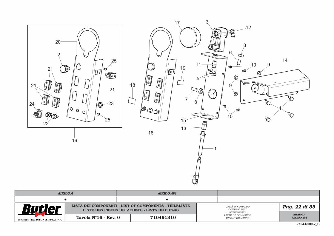
LISTA DEI COMPONENTI - LIST OF COMPONENTS - TEILELISTELISTE DES PIECES DETACHEES - LISTA DE PIEZAS
Pag. 22 di 35UNITÁ DI COMANDOCONTROL UNITANTRIEBSATZ
UNITÉ DE COMMANDEUNIDAD DE MANDOTavola N°16 - Rev. 0 710491310
21
2
20
24
21
22
21
23
25
25
16
18
16
1
19
17
7 8
10
5
11
4
312
68
10 914
9
15
13
AIKIDO.4AIKIDO.4FI
7104-R009-2_B
AIKIDO.4 AIKIDO.4FI
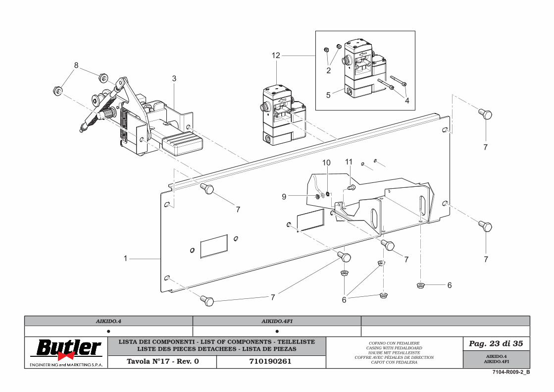
LISTA DEI COMPONENTI - LIST OF COMPONENTS - TEILELISTELISTE DES PIECES DETACHEES - LISTA DE PIEZAS
Pag. 23 di 35COFANO CON PEDALIERECASING WITH PEDALBOARDHAUBE MIT PEDALLEISTE
COFFRE AVEC PÉDALES DE DIRECTIONCAPOT CON PEDALERATavola N°17 - Rev. 0 710190261
1
3
6
7
7 7
7
8
67
9
10 11
2
45
12
AIKIDO.4AIKIDO.4FI
7104-R009-2_B
AIKIDO.4 AIKIDO.4FI
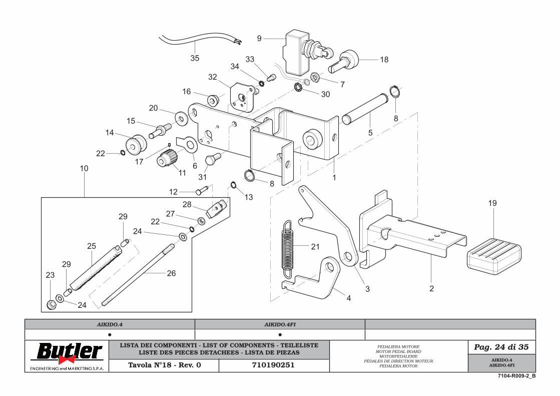
LISTA DEI COMPONENTI - LIST OF COMPONENTS - TEILELISTELISTE DES PIECES DETACHEES - LISTA DE PIEZAS
Pag. 24 di 35PEDALIERA MOTOREMOTOR PEDAL BOARD
MOTORPEDALERIEPÉDALES DE DIRECTION MOTEUR
PEDALERA MOTORTavola N°18 - Rev. 0 710190251
1
234
5
8
8
9
10 11
1213
1415
16
17
18
19
20
21
2827
22
24
26
25
24
2329
29
6
307
22
31
3334
32
35
AIKIDO.4AIKIDO.4FI
7104-R009-2_B
AIKIDO.4 AIKIDO.4FI
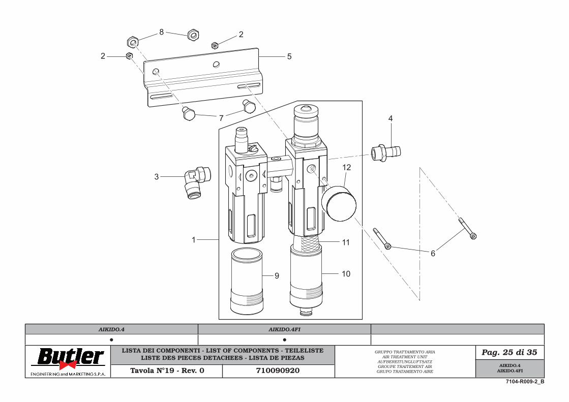
LISTA DEI COMPONENTI - LIST OF COMPONENTS - TEILELISTELISTE DES PIECES DETACHEES - LISTA DE PIEZAS
Pag. 25 di 35GRUPPO TRATTAMENTO ARIAAIR TREATMENT UNIT
AUFBEREITUNGLUFTSATZGROUPE TRAITEMENT AIRGRUPO TRATAMIENTO AIRETavola N°19 - Rev. 0 710090920
1
2
3
4
5
6
7
8 2
9 10
11
12
AIKIDO.4AIKIDO.4FI
7104-R009-2_B
AIKIDO.4 AIKIDO.4FI
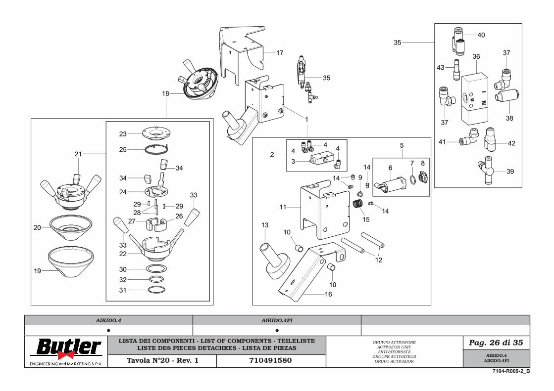
LISTA DEI COMPONENTI - LIST OF COMPONENTS - TEILELISTELISTE DES PIECES DETACHEES - LISTA DE PIEZAS
Pag. 26 di 35
Tavola N°20 - Rev. 1 710491580
GRUPPO ATTIVATOREACTIVATOR UNITAKTIVATORSATZ
GROUPE ACTIVATEURGRUPO ACTIVADOR
AIKIDO.4AIKIDO.4FI
7104-R009-2_B
AIKIDO.4 AIKIDO.4FI
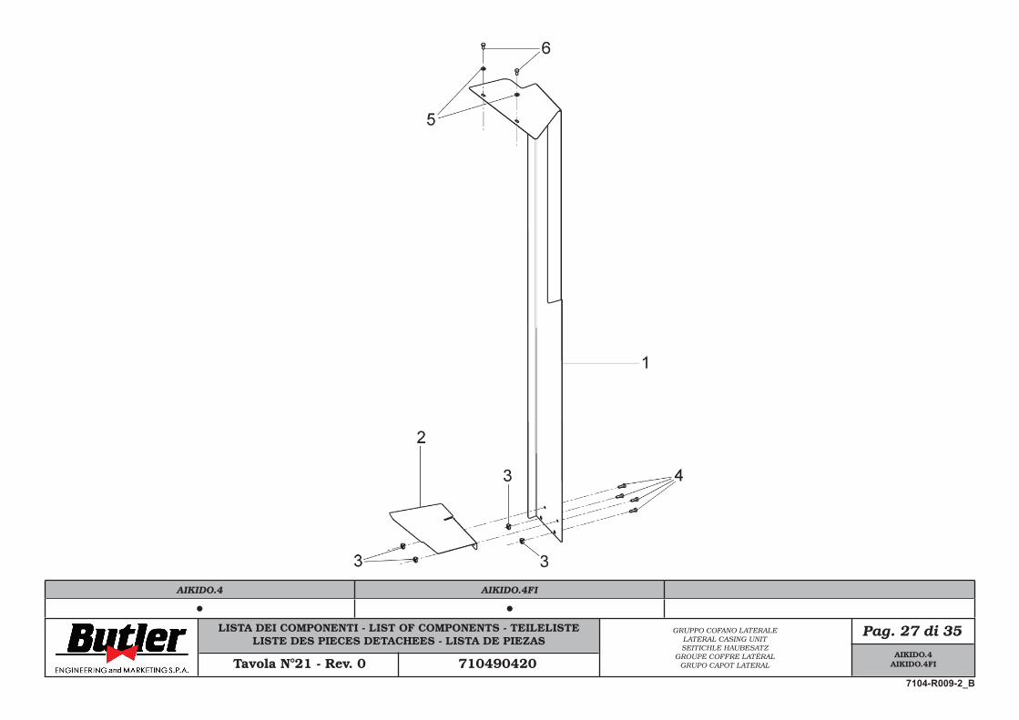
LISTA DEI COMPONENTI - LIST OF COMPONENTS - TEILELISTELISTE DES PIECES DETACHEES - LISTA DE PIEZAS
Pag. 27 di 35GRUPPO COFANO LATERALELATERAL CASING UNITSEITICHLE HAUBESATZ
GROUPE COFFRE LATÉRALGRUPO CAPOT LATERALTavola N°21 - Rev. 0 710490420
AIKIDO.4AIKIDO.4FI
7104-R009-2_B
AIKIDO.4 AIKIDO.4FI
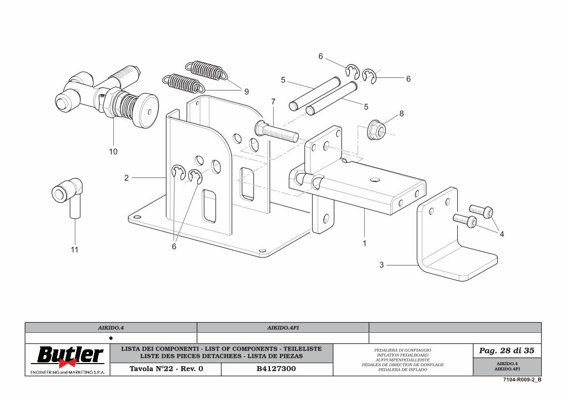
LISTA DEI COMPONENTI - LIST OF COMPONENTS - TEILELISTELISTE DES PIECES DETACHEES - LISTA DE PIEZAS
Pag. 28 di 35PEDALIERA DI GONFIAGGIOINFLATION PEDALBOARD
AUFPUMPENPEDALLEISTEPÉDALES DE DIRECTION DE GONFLAGE
PEDALERA DE INFLADOTavola N°22 - Rev. 0 B4127300
1
2
3
4
6
5
5
6
6
78
9
10
11
AIKIDO.4AIKIDO.4FI
7104-R009-2_B
AIKIDO.4 AIKIDO.4FI
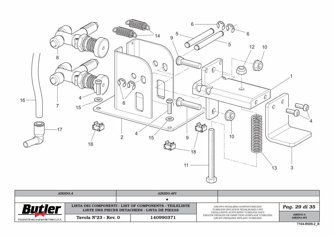
LISTA DEI COMPONENTI - LIST OF COMPONENTS - TEILELISTELISTE DES PIECES DETACHEES - LISTA DE PIEZAS
Pag. 29 di 35GRUPPO PEDALIERA GONFIATUBELESSTUBELESS INFLATION PEDALBOARD UNIT
PEDALLEISTE AUFPUMPEN TUBELESS SATZGROUPE PÉDALES DE DIRECTION GONFLAGE TUBELESS
GRUPO PEDALERA INFLADO TUBELESSTavola N°23 - Rev. 0 140990371
1
2
3
4
5
5 6
6
67
8
9 10
10
11
12
13
14
4
15
154
9
1818
17
16
AIKIDO.4AIKIDO.4FI
7104-R009-2_B
AIKIDO.4 AIKIDO.4FI
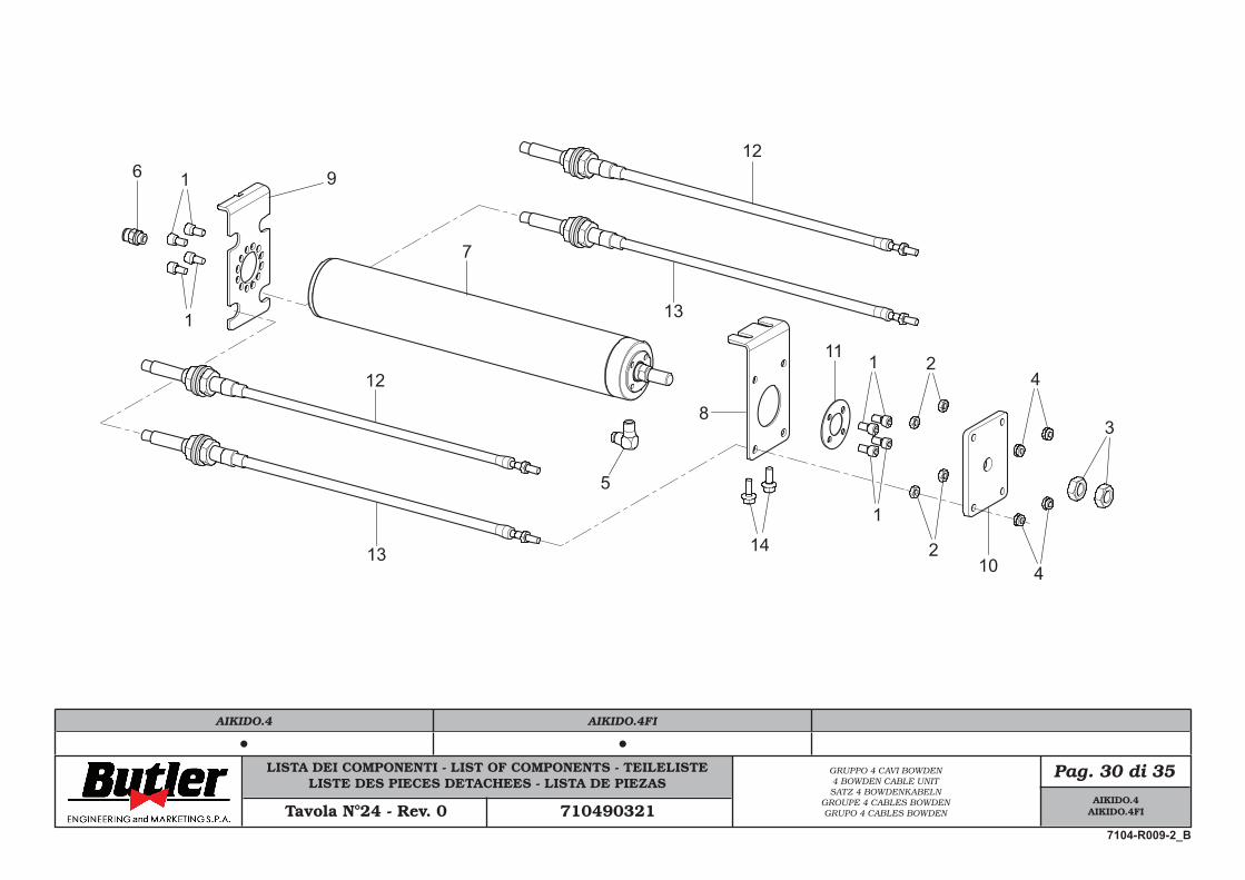
LISTA DEI COMPONENTI - LIST OF COMPONENTS - TEILELISTELISTE DES PIECES DETACHEES - LISTA DE PIEZAS
Pag. 30 di 35GRUPPO 4 CAVI BOWDEN4 BOWDEN CABLE UNITSATZ 4 BOWDENKABELN
GROUPE 4 CABLES BOWDENGRUPO 4 CABLES BOWDENTavola N°24 - Rev. 0 710490321
6 9
1
1
7
14
8
5
12
13
13
12
3
4
4
102
211 1
1
AIKIDO.4AIKIDO.4FI
7104-R009-2_B
AIKIDO.4 AIKIDO.4FI
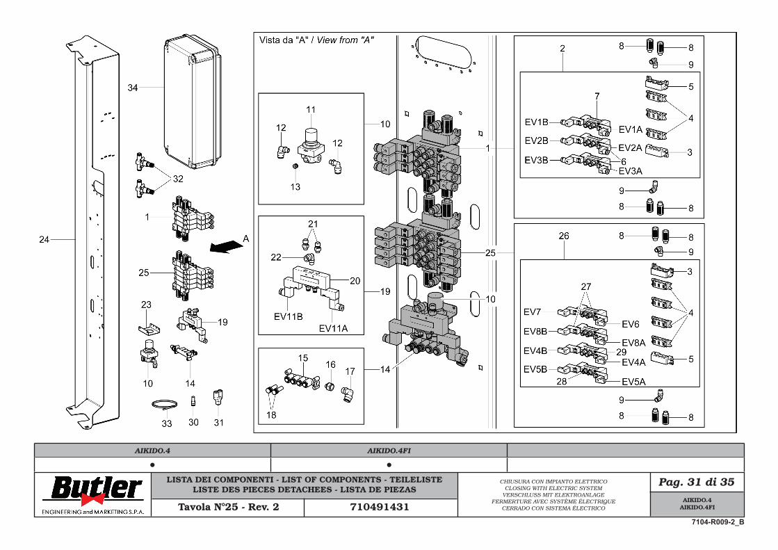
LISTA DEI COMPONENTI - LIST OF COMPONENTS - TEILELISTELISTE DES PIECES DETACHEES - LISTA DE PIEZAS
Pag. 31 di 35CHIUSURA CON IMPIANTO ELETTRICOCLOSING WITH ELECTRIC SYSTEM
VERSCHLUSS MIT ELEKTROANLAGEFERMERTURE AVEC SYSTÈME ÉLECTRIQUE
CERRADO CON SISTEMA ÉLECTRICOTavola N°25 - Rev. 2 710491431
AIKIDO.4AIKIDO.4FI
7104-R009-2_B
AIKIDO.4 AIKIDO.4FI
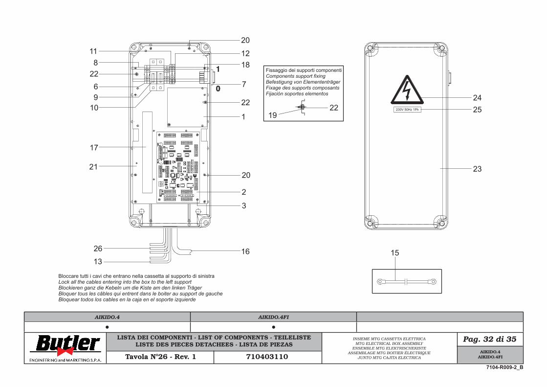
LISTA DEI COMPONENTI - LIST OF COMPONENTS - TEILELISTELISTE DES PIECES DETACHEES - LISTA DE PIEZAS
Pag. 32 di 35INSIEME MTG CASSETTA ELETTRICAMTG ELECTRICAL BOX ASSEMBLY
ENSEMBLE MTG ELEKTRISCHEKISTEASSEMBLAGE MTG BOITIER ÉLECTRIQUE
JUNTO MTG CAJITA ELECTRICATavola N°26 - Rev. 1 710403110
22 Fissaggio dei supporti componentiComponents support fixingBefestigung von ElemententrägerFixage des supports composantsFijación soportes elementos
Bloccare tutti i cavi che entrano nella cassetta al supporto di sinistra Lock all the cables entering into the box to the left supportBlockieren ganz die Kebeln um die Kiste am den linken TrägerBloquer tous les câbles qui entrent dans le boiter au support de gaucheBloquear todos los cables en la caja en el soporte izquierde
22
8
19
69
10
17
21
2613
7
1812
2011
22
1
20
2
3
16
2425
23
15
230V 50Hz 1Ph
AIKIDO.4AIKIDO.4FI
7104-R009-2_B
AIKIDO.4 AIKIDO.4FI
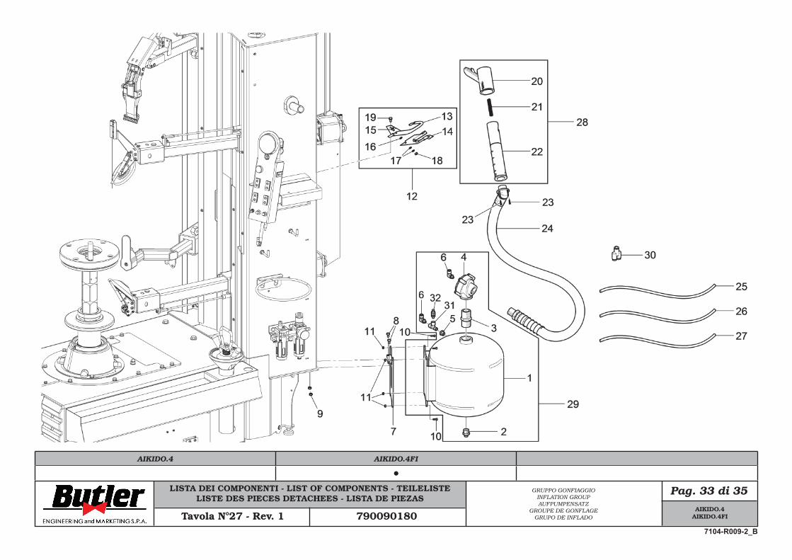
LISTA DEI COMPONENTI - LIST OF COMPONENTS - TEILELISTELISTE DES PIECES DETACHEES - LISTA DE PIEZAS
Pag. 33 di 35GRUPPO GONFIAGGIOINFLATION GROUPAUFPUMPENSATZ
GROUPE DE GONFLAGEGRUPO DE INFLADOTavola N°27 - Rev. 1 790090180
AIKIDO.4AIKIDO.4FI
7104-R009-2_B
AIKIDO.4 AIKIDO.4FI
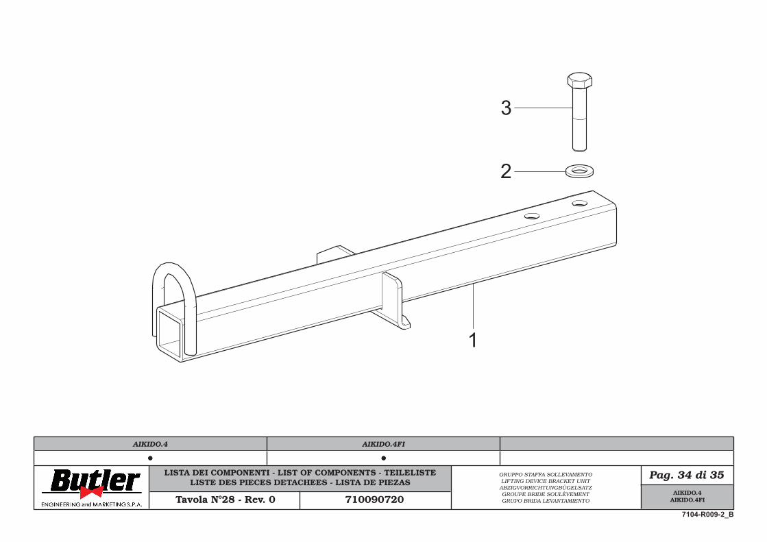
LISTA DEI COMPONENTI - LIST OF COMPONENTS - TEILELISTELISTE DES PIECES DETACHEES - LISTA DE PIEZAS
Pag. 34 di 35GRUPPO STAFFA SOLLEVAMENTOLIFTING DEVICE BRACKET UNIT
ABZIGVORRICHTUNGBÜGELSATZGROUPE BRIDE SOULÈVEMENTGRUPO BRIDA LEVANTAMIENTOTavola N°28 - Rev. 0 710090720
1
2
3
AIKIDO.4AIKIDO.4FI
7104-R009-2_B
AIKIDO.4 AIKIDO.4FI
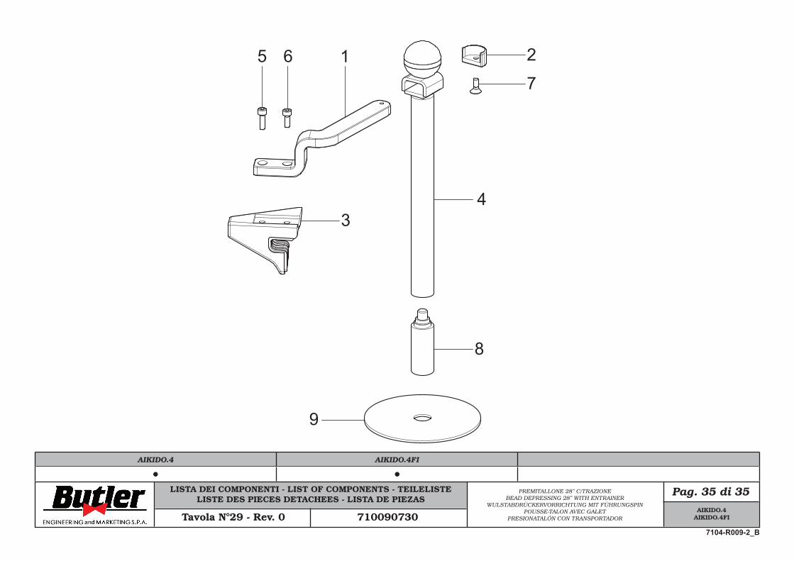
LISTA DEI COMPONENTI - LIST OF COMPONENTS - TEILELISTELISTE DES PIECES DETACHEES - LISTA DE PIEZAS
Pag. 35 di 35PREMITALLONE 28” C/TRAZIONEBEAD DEPRESSING 28” WITH ENTRAINER
WULSTABDRÜCKERVORRICHTUNG MIT FÜHRUNGSPINPOUSSE-TALON AVEC GALET
PRESIONATALÓN CON TRANSPORTADORTavola N°29 - Rev. 0 710090730
1 2
34
5 67
8
9
AIKIDO.4AIKIDO.4FI
7104-R009-2_B
AIKIDO.4 AIKIDO.4FI
Related Documents