Advanced Mud Hammer Systems D. Pixton ( [email protected]; 801-374-2755) D. Hall ( [email protected]; 801-374-6222) Novatek, Inc. 2185 South Larsen Parkway Provo, UT 84606 Abstract Novatek and the U.S. Department of Energy’ s Federal Energy Technology Center have engaged in a cooperative effort to develop an integrated, steerable drilling system, which includes a mud-actuated hammer as a key element. The overall goal of this system is to provide significant cost reduction and technical advantage over current drilling practice, particularly in deep, medium-to-hard rock formations. Following preliminary evaluation of several advanced drilling concepts, a system concept has been developed which offers potential improvements in drilling rate, directional control, formation evaluation, and wellbore stability. This paper describes several key subsystems of the integrated drilling system concept in some detail, including an advanced telemetry system, a steerable drilling head that offers advanced sensing capabilities, and a means of lining the wellbore while drilling. Progress on prototype development is reported, and key technological developments and hurdles are described. Introduction In a study completed in 1994, a committee appointed to review the future needs of drilling technology concluded that “the principal thrust of an R&D program should be on the development of the smart drilling system.” A “smart”drilling system is defined as a system that is able to sense conditions at and ahead of the drill bit and adapt to these varying conditions while drilling. This drilling system was identified to include, among other things: a) sensors to measure conditions at and ahead of the drill bit; b) improved methods to steer the drill bit; c) improved telemetry methods to transmit real time data to the surface; and d) continuous and instantaneous support of the borehole. 1 Identifying that several of these functions could be supplied by a down-hole mud actuated hammer, Novatek began a joint development effort in 1997 with the US Department of Energy’ s Federal Energy Technology Center to develop key elements of this “smart drilling system.” This effort was first to evaluate several competing methods of accomplishing the above-mentioned functions, and then proceed with development of the most promising technologies. The competitive evaluation just mentioned was accomplished during the first phase of work ending in fall of 1998. A discussion of the concepts evaluated and the conclusions of the initial evaluation have been submitted previously in reports to the U.S. Department of Energy. 2,3 Since that time, Novatek has refined the designs of the key components of the smart system and has begun prototype manufacture to enable verification and further refinement of the

Welcome message from author
This document is posted to help you gain knowledge. Please leave a comment to let me know what you think about it! Share it to your friends and learn new things together.
Transcript
Advanced Mud Hammer Systems
D. Pixton ([email protected]; 801-374-2755)D. Hall ([email protected]; 801-374-6222)
Novatek, Inc.2185 South Larsen Parkway
Provo, UT 84606
Abstract
Novatek and the U.S. Department of Energy’s Federal Energy Technology Center haveengaged in a cooperative effort to develop an integrated, steerable drilling system, whichincludes a mud-actuated hammer as a key element. The overall goal of this system is to providesignificant cost reduction and technical advantage over current drilling practice, particularly indeep, medium-to-hard rock formations. Following preliminary evaluation of several advanceddrilling concepts, a system concept has been developed which offers potential improvements indrilling rate, directional control, formation evaluation, and wellbore stability. This paperdescribes several key subsystems of the integrated drilling system concept in some detail,including an advanced telemetry system, a steerable drilling head that offers advanced sensingcapabilities, and a means of lining the wellbore while drilling. Progress on prototypedevelopment is reported, and key technological developments and hurdles are described.
Introduction
In a study completed in 1994, a committee appointed to review the future needs of drillingtechnology concluded that “the principal thrust of an R&D program should be on thedevelopment of the smart drilling system.” A “smart” drilling system is defined as a systemthat is able to sense conditions at and ahead of the drill bit and adapt to these varyingconditions while drilling. This drilling system was identified to include, among other things:a) sensors to measure conditions at and ahead of the drill bit; b) improved methods to steerthe drill bit; c) improved telemetry methods to transmit real time data to the surface; and d)continuous and instantaneous support of the borehole.1
Identifying that several of these functions could be supplied by a down-hole mud actuatedhammer, Novatek began a joint development effort in 1997 with the US Department ofEnergy’s Federal Energy Technology Center to develop key elements of this “smart drillingsystem.” This effort was first to evaluate several competing methods of accomplishing theabove-mentioned functions, and then proceed with development of the most promisingtechnologies. The competitive evaluation just mentioned was accomplished during the firstphase of work ending in fall of 1998. A discussion of the concepts evaluated and theconclusions of the initial evaluation have been submitted previously in reports to the U.S.Department of Energy.2,3
Since that time, Novatek has refined the designs of the key components of the smart systemand has begun prototype manufacture to enable verification and further refinement of the
various subsystems. The purpose of this writing is to report on these activities which havetaken place since the phase I reports.
Objectives
The overall objectives of the present research effort are to decrease the cost of drilling wellsand extend the capabilities of current drilling technology to more effectively tap energyreserves. More specifically, the program objectives are to:
1) Develop key elements of a smart drilling system including an improved steerabledrilling head, advanced formation sensing means, high data rate communicationbetween top and bottom of well, and an in-situ wellbore lining means, and
2) Provide means for integrating these individual elements into a complete system
The first objective mentioned above focuses on improvements to present drilling technologyand is expected to yield tools and subsystems capable of stand-alone use*; the second focuseson compatibility of the subsystems and thereby assures that a complete system may bedeveloped.
Approach
To accomplish the above objectives, the study has sought first to develop and exploitvarious features of Novatek’s mud hammer drilling head. The features most readilyexploited are the hammer’s ability to improve penetration rate, its interaction with theformation, and the linear oscillation of the hammer piston. The first of these features offersthe ability of the system to drill more rapidly, thereby helping to decrease well costs. Thesecond feature offers novel means of diagnosing the formation characteristics at and aheadof the drill bit, thereby allowing adjustment of drilling parameters to meet changing drillingconditions, and facilitating direction of the drill into the desired formations. The thirdfeature enables down-hole generation of high-pressure hydraulic power, which is importantin further penetration rate increase and improved steering.
Although it is technically possible to use the oscillation of the hammer piston to also driverotation of the drill bit, generate electrical power, and even send mud pulse or acousticsignals for communication with the surface, the present study has chosen not to pursuethese functions because better approaches are possible. Since the hammer alone cannotaccomplish the objectives outlined above, novel downhole mechanisms have been designedto complete the remaining objectives. These mechanisms include a very high data ratecommunications system and a means of lining the borehole while drilling.
As mentioned previously, the first phase of activity in this project has been a conceptualdistillation process, wherein several competing concepts were evaluated, and the mostpromising were selected for further study. The current phase of work includes:
1. Generating detailed designs of the selected subsystems * Varying development times and market pull for various of the concepts discussed herein will necessitateintroduction of some of the technologies as stand-alone tools, or as enhancements which build upon existingsystems. The first of these stand-alone tools will most probably be a down-hole hammer drill.
2. Building prototype models of these designs3. Testing prototype models under laboratory conditions (and field sites where
possible), and4. Evaluating test results to determine the technical fitness and probable economic
impact of the tested mechanisms.
A third phase of work will take promising technologies to field sites for testing anddemonstration, and will lead to commercialization of these technologies.
Description of Technology
Overall System
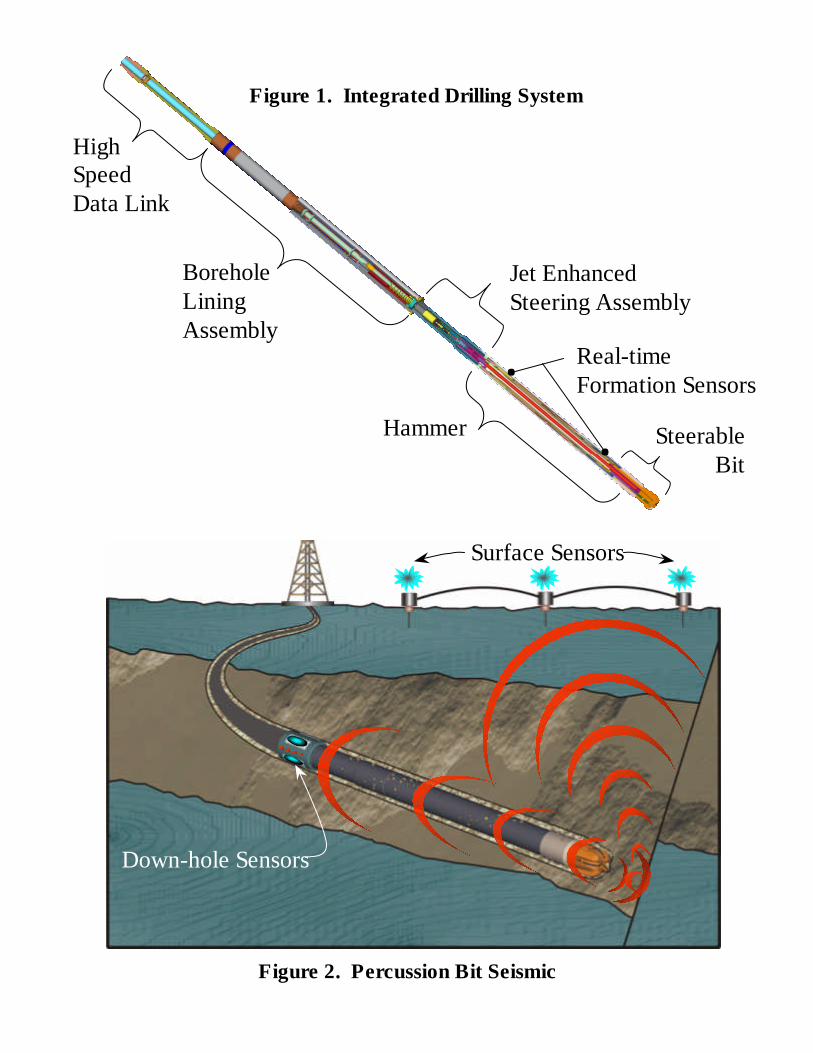
Figure 1 illustrates the basic components of the overall system, which have been selected forconsideration in this study. As shown, the system includes a mud-actuated hammer drillinghead, real time formation sensors, a high-pressure jet enhanced steering assembly, a boreholelining assembly, and a high-speed data link. It is anticipated that, along with the formationsensors described herein, other current art and novel sensors will be added as needed toprovide more complete downhole diagnostic information. Also not specifically shown is acentral processing unit and associated hardware that enables adaptation of the hammer andsteering assembly to the diagnostic information provided by the sensors and the operator.This unit will likely reside in the steering assembly shown in the figure. A discussion of eachof the main subsystems follows.
Mud Hammer Drilling Head/Formation Sensors
As mentioned, a key component of the overall drilling system is a down-hole mud hammer.The primary motivation for employing the hammer in the system is of course its potential tobring improved rate of penetration (ROP). The hammer does this by creating aninstantaneously high axial force, which in brittle formations causes high fracturing, and inmore ductile formations causes greater indentation of the cutters in the bit. In previous fieldtrials, hammers have also been noted to help remove unwanted deviation, and improve bitfootage.4,5
Aside from these benefits, the motion and vibrational output of the hammer may alsopotentially be used as a type of formation sensor, and also provide a seismic signal whiledrilling. The ability of the hammer to act as a formation sensor derives from the fact that itis influenced somewhat by the formation it is drilling: formations of differing mechanicalproperties will cause different rebound in the hammer as it strikes the formation. If thelinear motion of the hammer can be evaluated near impact, this information can be used todetermine at least a composite index that identifies overall rock characteristics. Thisinformation may be used alone or to supplement formation data obtained from othercurrent art sensors and give a more detailed picture of the formation. By so combining datafrom multiple sources, fewer assumptions than presently required may need to be made,resulting in more accurate data interpretation. Furthermore, the motion of the hammer canbe used as an important feedback quantity to verify and quantify the output of the hammerdrill as the hole progresses in time and depth.
SteerableBit
Hammer
Jet EnhancedSteering Assembly
BoreholeLiningAssembly
HighSpeedData Link
Real-timeFormation Sensors
Figure 1. Integrated Drilling System
Figure 2. Percussion Bit Seismic
Down-hole Sensors
Surface Sensors
The impact of the hammer upon the formation being drilled also provides a steady seismicsignal at the hole bottom, which may be used for reverse vertical seismic profiling and lookahead measurements. This concept is similar to the concept of drill bit seismic, which isalready in practice.6 This system would ideally require seismic sensors near bit and at thesurface, as shown in Figure 2.
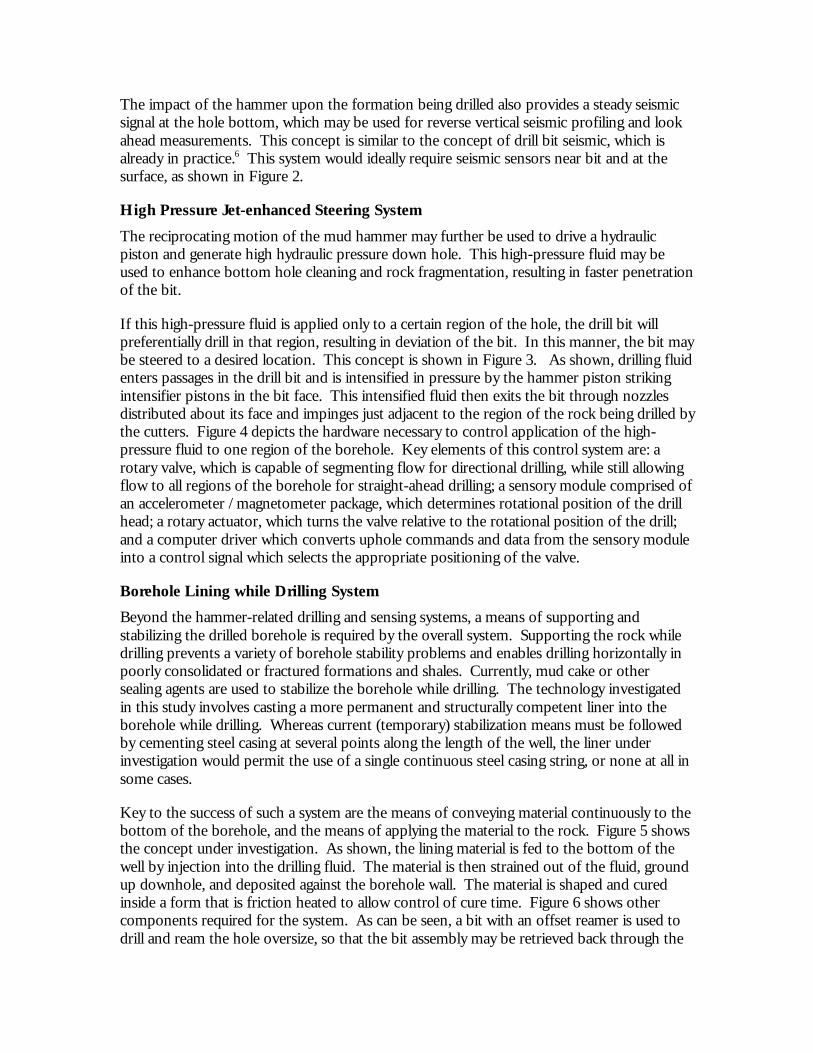
High Pressure Jet-enhanced Steering System
The reciprocating motion of the mud hammer may further be used to drive a hydraulicpiston and generate high hydraulic pressure down hole. This high-pressure fluid may beused to enhance bottom hole cleaning and rock fragmentation, resulting in faster penetrationof the bit.
If this high-pressure fluid is applied only to a certain region of the hole, the drill bit willpreferentially drill in that region, resulting in deviation of the bit. In this manner, the bit maybe steered to a desired location. This concept is shown in Figure 3. As shown, drilling fluidenters passages in the drill bit and is intensified in pressure by the hammer piston strikingintensifier pistons in the bit face. This intensified fluid then exits the bit through nozzlesdistributed about its face and impinges just adjacent to the region of the rock being drilled bythe cutters. Figure 4 depicts the hardware necessary to control application of the high-pressure fluid to one region of the borehole. Key elements of this control system are: arotary valve, which is capable of segmenting flow for directional drilling, while still allowingflow to all regions of the borehole for straight-ahead drilling; a sensory module comprised ofan accelerometer /magnetometer package, which determines rotational position of the drillhead; a rotary actuator, which turns the valve relative to the rotational position of the drill;and a computer driver which converts uphole commands and data from the sensory moduleinto a control signal which selects the appropriate positioning of the valve.
Borehole Lining while Drilling System
Beyond the hammer-related drilling and sensing systems, a means of supporting andstabilizing the drilled borehole is required by the overall system. Supporting the rock whiledrilling prevents a variety of borehole stability problems and enables drilling horizontally inpoorly consolidated or fractured formations and shales. Currently, mud cake or othersealing agents are used to stabilize the borehole while drilling. The technology investigatedin this study involves casting a more permanent and structurally competent liner into theborehole while drilling. Whereas current (temporary) stabilization means must be followedby cementing steel casing at several points along the length of the well, the liner underinvestigation would permit the use of a single continuous steel casing string, or none at all insome cases.
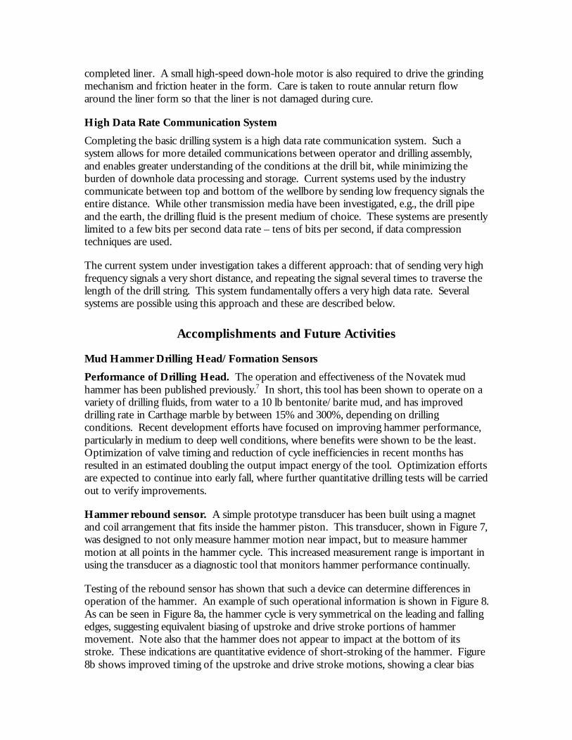
Key to the success of such a system are the means of conveying material continuously to thebottom of the borehole, and the means of applying the material to the rock. Figure 5 showsthe concept under investigation. As shown, the lining material is fed to the bottom of thewell by injection into the drilling fluid. The material is then strained out of the fluid, groundup downhole, and deposited against the borehole wall. The material is shaped and curedinside a form that is friction heated to allow control of cure time. Figure 6 shows othercomponents required for the system. As can be seen, a bit with an offset reamer is used todrill and ream the hole oversize, so that the bit assembly may be retrieved back through the
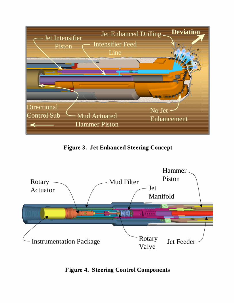
Figure 3. Jet Enhanced Steering Concept
Mud ActuatedHammer Piston
Jet IntensifierPiston Intensifier Feed
Line
Jet Enhanced Drilling
Directional Control Sub
No JetEnhancement
Deviation
RotaryActuator
Mud FilterJetManifold
RotaryValve
Jet Feeder
HammerPiston
Instrumentation Package
Figure 4. Steering Control Components
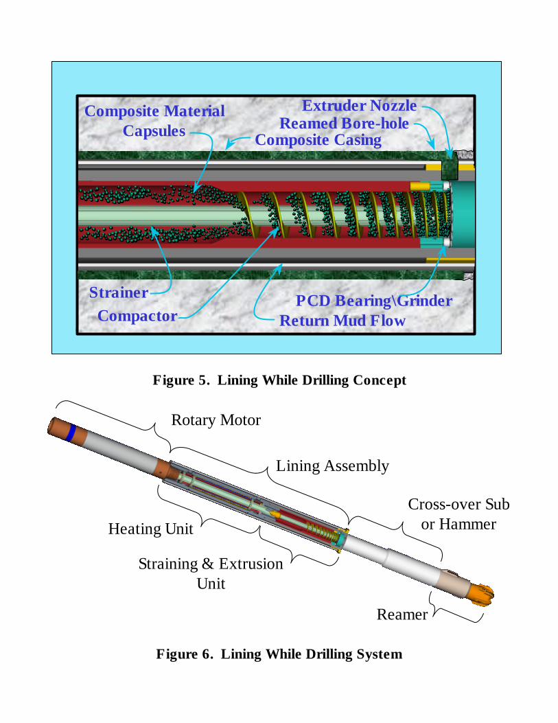
Figure 5. Lining While Drilling Concept
Rotary Motor
Lining Assembly
Cross-over Subor HammerHeating Unit
Straining & ExtrusionUnit
Reamer
Figure 6. Lining While Drilling System
Composite MaterialCapsules
Strainer
Composite Casing
Extruder NozzleReamed Bore-hole
PCD Bearing\GrinderReturn Mud FlowCompactor
completed liner. A small high-speed down-hole motor is also required to drive the grindingmechanism and friction heater in the form. Care is taken to route annular return flowaround the liner form so that the liner is not damaged during cure.
High Data Rate Communication System
Completing the basic drilling system is a high data rate communication system. Such asystem allows for more detailed communications between operator and drilling assembly,and enables greater understanding of the conditions at the drill bit, while minimizing theburden of downhole data processing and storage. Current systems used by the industrycommunicate between top and bottom of the wellbore by sending low frequency signals theentire distance. While other transmission media have been investigated, e.g., the drill pipeand the earth, the drilling fluid is the present medium of choice. These systems are presentlylimited to a few bits per second data rate – tens of bits per second, if data compressiontechniques are used.
The current system under investigation takes a different approach: that of sending very highfrequency signals a very short distance, and repeating the signal several times to traverse thelength of the drill string. This system fundamentally offers a very high data rate. Severalsystems are possible using this approach and these are described below.
Accomplishments and Future Activities
Mud Hammer Drilling Head/Formation Sensors
Performance of Drilling Head. The operation and effectiveness of the Novatek mudhammer has been published previously.7 In short, this tool has been shown to operate on avariety of drilling fluids, from water to a 10 lb bentonite/barite mud, and has improveddrilling rate in Carthage marble by between 15% and 300%, depending on drillingconditions. Recent development efforts have focused on improving hammer performance,particularly in medium to deep well conditions, where benefits were shown to be the least.Optimization of valve timing and reduction of cycle inefficiencies in recent months hasresulted in an estimated doubling the output impact energy of the tool. Optimization effortsare expected to continue into early fall, where further quantitative drilling tests will be carriedout to verify improvements.
Hammer rebound sensor. A simple prototype transducer has been built using a magnetand coil arrangement that fits inside the hammer piston. This transducer, shown in Figure 7,was designed to not only measure hammer motion near impact, but to measure hammermotion at all points in the hammer cycle. This increased measurement range is important inusing the transducer as a diagnostic tool that monitors hammer performance continually.
Testing of the rebound sensor has shown that such a device can determine differences inoperation of the hammer. An example of such operational information is shown in Figure 8.As can be seen in Figure 8a, the hammer cycle is very symmetrical on the leading and fallingedges, suggesting equivalent biasing of upstroke and drive stroke portions of hammermovement. Note also that the hammer does not appear to impact at the bottom of itsstroke. These indications are quantitative evidence of short-stroking of the hammer. Figure8b shows improved timing of the upstroke and drive stroke motions, showing a clear bias
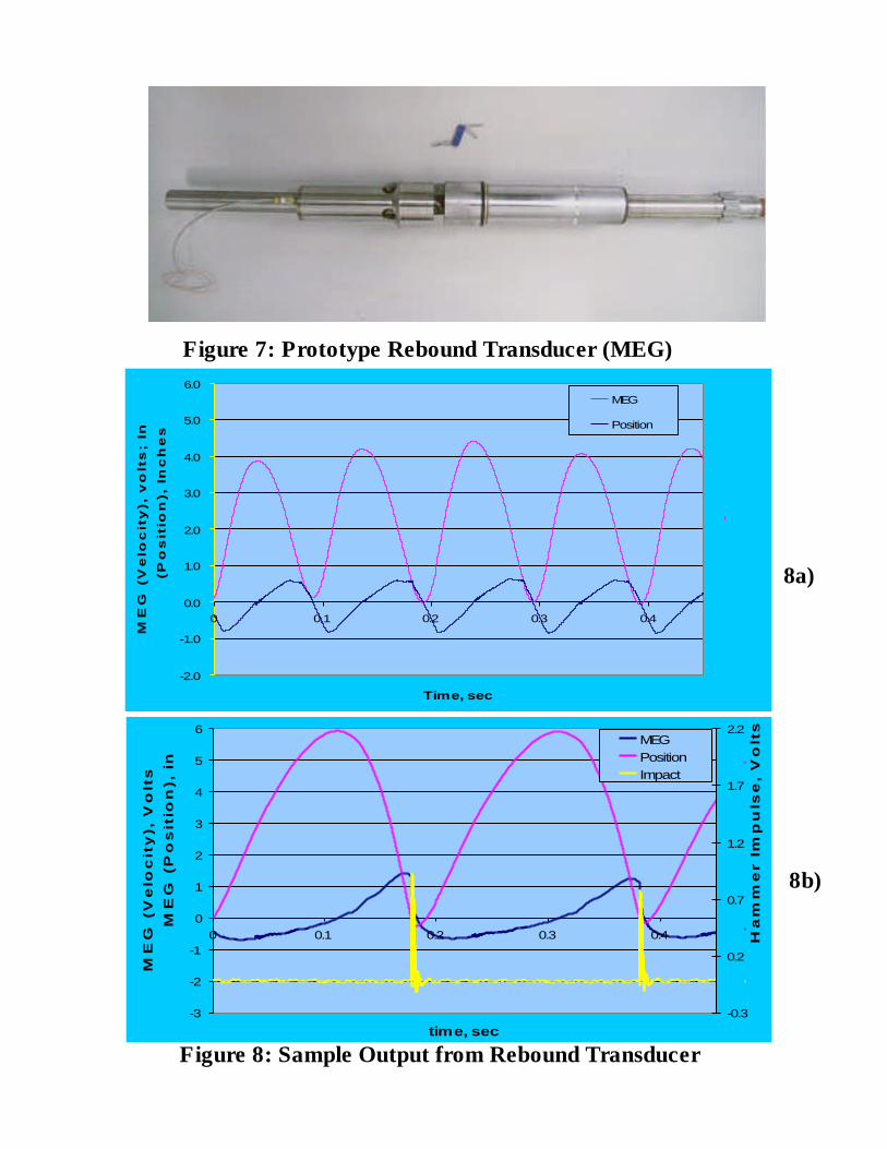
Figure 7: Prototype Rebound Transducer (MEG)
Figure 8: Sample Output from Rebound Transducer
8a)
8b)
-3
-2
-1
0
1
2
3
4
5
6
0 0.1 0.2 0.3 0.4
time, sec
ME
G (
Ve
loc
ity
), V
olt
s;
Inte
gra
ted
M
EG
(P
os
itio
n),
in
-0.3
0.2
0.7
1.2
1.7
2.2
Ha
mm
er
Imp
uls
e,
Vo
lts
MEGPositionImpact
-2.0
-1.0
0.0
1.0
2.0
3.0
4.0
5.0
6.0
0 0.1 0.2 0.3 0.4
Time, sec
ME
G (
Velo
cit
y),
vo
lts;
Inte
grate
d M
EG
(Po
sit
ion
), In
ch
es
MEG
Position
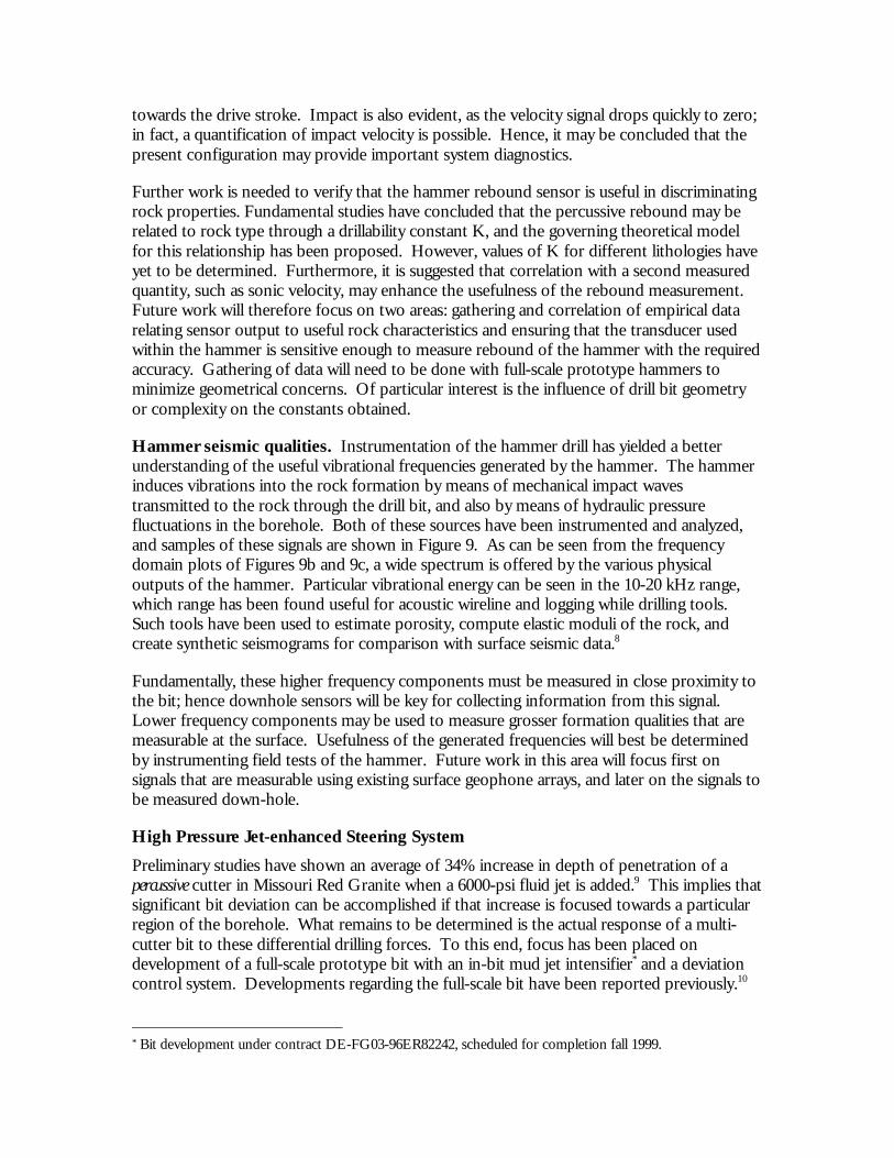
towards the drive stroke. Impact is also evident, as the velocity signal drops quickly to zero;in fact, a quantification of impact velocity is possible. Hence, it may be concluded that thepresent configuration may provide important system diagnostics.
Further work is needed to verify that the hammer rebound sensor is useful in discriminatingrock properties. Fundamental studies have concluded that the percussive rebound may berelated to rock type through a drillability constant K, and the governing theoretical modelfor this relationship has been proposed. However, values of K for different lithologies haveyet to be determined. Furthermore, it is suggested that correlation with a second measuredquantity, such as sonic velocity, may enhance the usefulness of the rebound measurement.Future work will therefore focus on two areas: gathering and correlation of empirical datarelating sensor output to useful rock characteristics and ensuring that the transducer usedwithin the hammer is sensitive enough to measure rebound of the hammer with the requiredaccuracy. Gathering of data will need to be done with full-scale prototype hammers tominimize geometrical concerns. Of particular interest is the influence of drill bit geometryor complexity on the constants obtained.
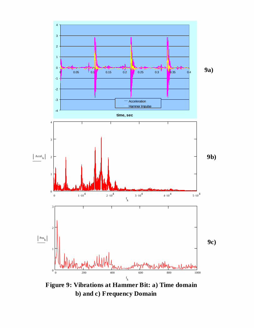
Hammer seismic qualities. Instrumentation of the hammer drill has yielded a betterunderstanding of the useful vibrational frequencies generated by the hammer. The hammerinduces vibrations into the rock formation by means of mechanical impact wavestransmitted to the rock through the drill bit, and also by means of hydraulic pressurefluctuations in the borehole. Both of these sources have been instrumented and analyzed,and samples of these signals are shown in Figure 9. As can be seen from the frequencydomain plots of Figures 9b and 9c, a wide spectrum is offered by the various physicaloutputs of the hammer. Particular vibrational energy can be seen in the 10-20 kHz range,which range has been found useful for acoustic wireline and logging while drilling tools.Such tools have been used to estimate porosity, compute elastic moduli of the rock, andcreate synthetic seismograms for comparison with surface seismic data.8
Fundamentally, these higher frequency components must be measured in close proximity tothe bit; hence downhole sensors will be key for collecting information from this signal.Lower frequency components may be used to measure grosser formation qualities that aremeasurable at the surface. Usefulness of the generated frequencies will best be determinedby instrumenting field tests of the hammer. Future work in this area will focus first onsignals that are measurable using existing surface geophone arrays, and later on the signals tobe measured down-hole.
High Pressure Jet-enhanced Steering System
Preliminary studies have shown an average of 34% increase in depth of penetration of apercussive cutter in Missouri Red Granite when a 6000-psi fluid jet is added.9 This implies thatsignificant bit deviation can be accomplished if that increase is focused towards a particularregion of the borehole. What remains to be determined is the actual response of a multi-cutter bit to these differential drilling forces. To this end, focus has been placed ondevelopment of a full-scale prototype bit with an in-bit mud jet intensifier* and a deviationcontrol system. Developments regarding the full-scale bit have been reported previously.10
* Bit development under contract DE-FG03-96ER82242, scheduled for completion fall 1999.
0 1 .104 2 .104 3 .104 4 .104 5 .1040
1
2
3
4
Accelk
fk
0 200 400 600 800 10000
1
2
3
Pexk
fk
Figure 9: Vibrations at Hammer Bit: a) Time domain b) and c) Frequency Domain
9a)
9b)
9c)
-4
-3
-2
-1
0
1
2
3
4
0 0.05 0.1 0.15 0.2 0.25 0.3 0.35 0.4
time, sec
AccelerationHammer Impulse
Efforts to direct a bit by biasing conventional bit hydraulics (as opposed to the high-pressurejets of the present system) have been exerted previously.11 The resultant system, whichseems to have most likely application in softer formations where conventional bit hydraulicsare more effective, suffered from valve wear problems. To minimize this concern in thepresent system, the control system design includes a fully pressure-balanced valve, therebyminimizing torque and thrust on the valve. The valve has also been designed to minimizethe potential for erosion and clogging from drilling mud, resulting in high life and reliability,as well as minimal power requirements. Figure 10 shows the prototype valve assembly to beused in fundamental and full-scale operational verification tests. Bench testing of thesemechanisms is expected to begin in fall of 1999. Once proper operation is demonstrated,further work will focus on implementing downhole-compatible rotary actuators and, finally,position measurement sensors.
Borehole Lining while Drilling System
Initial studies of the borehole lining system have focused on the type of material to beemployed in the lining and the means of applying it to a submerged borehole. Severaldifferent materials have been investigated for the lining material, including metals and metalreinforced polymers, aggregate reinforced materials, and fiber reinforced polymers.Difficulties encountered with several of these materials included problems with underwateradhesion, density (which manifests itself in slumping or sloughing of the material), and poorstrength. This investigation found fiber-reinforced polymer systems to provide the bestcombination of cost, strength, and workability.
A key issue when dealing with polymer systems is curing method. Cure time is particularlyan issue with a down-hole system, since too slow a cure time impedes drilling progress andtoo fast a cure time compromises material strength and poses potential problems withclogging mixing and application mechanisms. Furthermore, variable down-holetemperatures may adversely influence cure time. To obtain better control over cure time,polymerization processes other than simple chemical initiation have been considered,including UV, gamma ray, and thermal initiators. While the former two were unacceptablefor depth of cure and cost considerations respectively, the study has concluded that athermal initiation process, where polymerization is initiated at a temperature above down-hole ambient, may give the most repeatable casing quality. Accordingly, a system utilizing afluid-driven friction heater has been designed (see Figure 6). Further work with thematerials system will include verification of cure time and strength and final composition.Some work has previously been done to characterize the improvement to borehole stabilityoffered by another polymer lining system12; further such work will be necessary in order todetermine suitable applications for the current system.
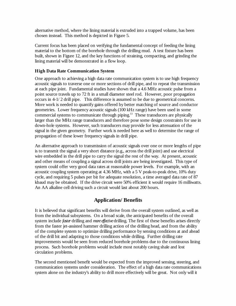
Studies into the means of application of the material to the borehole have included simplemockup tests, where a bead of material was applied to the bore of a concrete pipe in a coiledrope fashion, then smoothed and trowelled in place. A sample result from these mockuptests is shown in Figure 11. From these tests, it was determined that good adhesion could beachieved with a submerged surface, but that mechanical working of the materials into therock was important to exclude wellbore fluids and promote this adhesion. Due todifficulties working the material into the rock in an unconfined space, as required by thecoiled rope approach, it has been determined that this method is less desirable. An
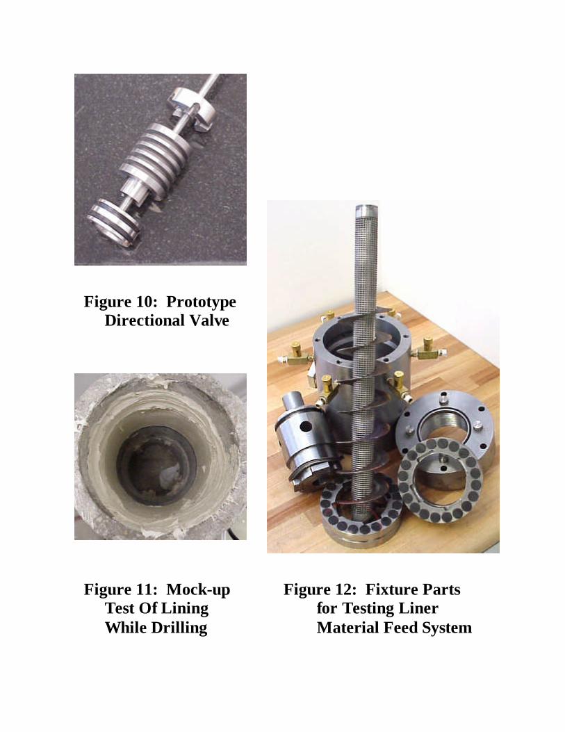
Figure 10: Prototype Directional Valve
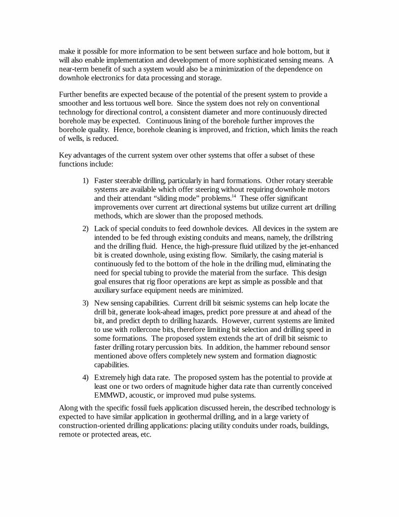
Figure 11: Mock-up Figure 12: Fixture PartsTest Of Lining for Testing LinerWhile Drilling Material Feed System
alternative method, where the lining material is extruded into a trapped volume, has beenchosen instead. This method is depicted in Figure 5.
Current focus has been placed on verifying the fundamental concept of feeding the liningmaterial to the bottom of the borehole through the drilling mud. A test fixture has beenbuilt, shown in Figure 12, and the key functions of straining, compacting, and grinding thelining material will be demonstrated in a flow loop.
High Data Rate Communication System
One approach to achieving a high data rate communication system is to use high frequencyacoustic signals to traverse one or more sections of drill pipe, and to repeat the transmissionat each pipe joint. Fundamental studies have shown that a 4.6 MHz acoustic pulse from apoint source travels up to 72 ft in a small diameter steel rod. However, poor propagationoccurs in 4-1/2 drill pipe. This difference is assumed to be due to geometrical concerns.More work is needed to quantify gains offered by better matching of source and conductorgeometries. Lower frequency acoustic signals (100 kHz range) have been used in somecommercial systems to communicate through piping.13 These transducers are physicallylarger than the MHz range transducers and therefore pose some design constraints for use indown-hole systems. However, such transducers may provide for less attenuation of thesignal in the given geometry. Further work is needed here as well to determine the range ofpropagation of these lower frequency signals in drill pipe.
An alternative approach to transmission of acoustic signals over one or more lengths of pipeis to transmit the signal a very short distance (e.g., across the drill joint) and use electricalwire embedded in the drill pipe to carry the signal the rest of the way. At present, acousticand other means of coupling a signal across drill joints are being investigated. This type ofsystem could offer very good data rates at reasonable power levels. For example, with anacoustic coupling system operating at 4.36 MHz, with a 5 V peak-to-peak drive, 10% dutycycle, and requiring 5 pulses per bit for adequate resolution, a time averaged data rate of 87kbaud may be obtained. If the drive circuit were 50% efficient it would require 16 milliwatts.An AA alkaline cell driving such a circuit would last about 200 hours.
Application/Benefits
It is believed that significant benefits will derive from the overall system outlined, as well asfrom the individual subsystems. On a broad scale, the anticipated benefits of the overallsystem include faster drilling and more effective drilling. The first of these benefits arises directlyfrom the faster jet-assisted hammer drilling action of the drilling head, and from the abilityof the complete system to optimize drilling performance by sensing conditions at and aheadof the drill bit and adapting to those conditions while drilling. Further drilling rateimprovements would be seen from reduced borehole problems due to the continuous liningprocess. Such borehole problems would include most notably caving shale and lostcirculation problems.
The second mentioned benefit would be expected from the improved sensing, steering, andcommunication systems under consideration. The effect of a high data rate communicationssystem alone on the industry’s ability to drill more effectively will be great. Not only will it
make it possible for more information to be sent between surface and hole bottom, but itwill also enable implementation and development of more sophisticated sensing means. Anear-term benefit of such a system would also be a minimization of the dependence ondownhole electronics for data processing and storage.
Further benefits are expected because of the potential of the present system to provide asmoother and less tortuous well bore. Since the system does not rely on conventionaltechnology for directional control, a consistent diameter and more continuously directedborehole may be expected. Continuous lining of the borehole further improves theborehole quality. Hence, borehole cleaning is improved, and friction, which limits the reachof wells, is reduced.
Key advantages of the current system over other systems that offer a subset of thesefunctions include:
1) Faster steerable drilling, particularly in hard formations. Other rotary steerablesystems are available which offer steering without requiring downhole motorsand their attendant “sliding mode” problems.14 These offer significantimprovements over current art directional systems but utilize current art drillingmethods, which are slower than the proposed methods.
2) Lack of special conduits to feed downhole devices. All devices in the system areintended to be fed through existing conduits and means, namely, the drillstringand the drilling fluid. Hence, the high-pressure fluid utilized by the jet-enhancedbit is created downhole, using existing flow. Similarly, the casing material iscontinuously fed to the bottom of the hole in the drilling mud, eliminating theneed for special tubing to provide the material from the surface. This designgoal ensures that rig floor operations are kept as simple as possible and thatauxiliary surface equipment needs are minimized.
3) New sensing capabilities. Current drill bit seismic systems can help locate thedrill bit, generate look-ahead images, predict pore pressure at and ahead of thebit, and predict depth to drilling hazards. However, current systems are limitedto use with rollercone bits, therefore limiting bit selection and drilling speed insome formations. The proposed system extends the art of drill bit seismic tofaster drilling rotary percussion bits. In addition, the hammer rebound sensormentioned above offers completely new system and formation diagnosticcapabilities.
4) Extremely high data rate. The proposed system has the potential to provide atleast one or two orders of magnitude higher data rate than currently conceivedEMMWD, acoustic, or improved mud pulse systems.
Along with the specific fossil fuels application discussed herein, the described technology isexpected to have similar application in geothermal drilling, and in a large variety ofconstruction-oriented drilling applications: placing utility conduits under roads, buildings,remote or protected areas, etc.
Acknowledgement
Novatek expresses its appreciation to the U.S. Department of Energy’s Federal EnergyTechnology Center, which is sponsoring this research. Special thanks are given to Mr. RoyLong, the FETC Contracting Officer’s Representative, for his support and enthusiasm for thisproject. This research is carried out under Contract #DE-FC26-97FT34365 (performanceperiod 9/30/1997-9/30/2002). Contract with Novatek, Inc., 2185 South Larsen Parkway,Provo, UT 84606.
References 1 National Research Council, Drilling and Excavation Technologies for the Future, National Academy Press,Washington, D.C. (1994), pp. 2-6.2 David S. Pixton, David R. Hall, Integrated Drilling System: Phase I Status Report, Novatek Report (30 June 1998).3 Integrated Drilling System, Novatek Report (14 September 1998).4 Harpst, W.E., and E.E. Davis. "Rotary Percussion Drilling." Oil and Gas Journal (Mar. 17, 1949), pp. 182-187.5 Wanamaker, J.A. "Rotary Percussion Drilling in West Texas." World Oil (Sept. 1951), pp. 182-187.6 Richard Meehan, Les Nutt, Neder Dutta, James Menzies, “Case Histories Show Real-time InformationReduces Uncertainty,” Oil and Gas Journal (May 18, 1998), pp 55-59.7 David S. Pixton, and David R. Hall, A Rotary Percussive Drilling Engine, in Proceedings of the 1998 ASME EnergySources Technology Conference, Houston (February 2-4, 1998).8 John W. Minear, Dale R. Heysse, Paul M. Boonen, “Initial Results from an Acoustic Logging-While-DrillingTool,” SPE Paper 36543 (1996).9 Santi, P., S. Bell, D.A. Summers, D. Pixton “Waterjet assisted polycrystalline diamond indentation drilling ofrock,” in Proceedings, 14th International Conference of Jetting Technology, Brugge, Belgium (Sept 21-23, 1998).10 David S. Pixton, David R. Hall, and David Summers, “Development and Testing of a Jet AssistedPolycrystalline Diamond Drilling Bit, Federal Geothermal Research Program Update, Fiscal Year 1998 (May 1999), pp.4-9 – 4-20.11 Lawrence J. Leising, Methods and Apparatus for Controlled Directional Drilling of Boreholes, U.S. Patent 4,637,479(Jan. 20, 1987).12 T. Moen and F. Remvik, “Continuous Cast Lining – A Solution to Downhole Problems,” in Rock MechanicsContributions and Challenges, Hustrulid & Johnson (eds), Balkema, Rotterdam (1990), pp 679-686.13 Ekhart Kinderling, “Machines Communicate Wirelessly” (in German), Electronik (December 1992).14 Tommy M. Warren, “Trends Toward Rotary Steerable Directional Systems,” World Oil (May 1997), pp. 43-47.
Related Documents