Americas Headquarters Cisco Systems, Inc. 170 West Tasman Drive San Jose, CA 95134-1706 USA http://www.cisco.com Tel: 408 526-4000 800 553-NETS (6387) Fax: 408 527-0883 Administering Cisco Physical Security Operations Manager, Release 6.1 January 31, 2013 Text Part Number: OL-28432-01

Administering Cisco Physical Security Operations Manager, Release 6.1
Nov 28, 2015
Administering Cisco Physical Security Operations Manager, Release 6.1
Welcome message from author
This document is posted to help you gain knowledge. Please leave a comment to let me know what you think about it! Share it to your friends and learn new things together.
Transcript

Americas HeadquartersCisco Systems, Inc.170 West Tasman DriveSan Jose, CA 95134-1706 USAhttp://www.cisco.comTel: 408 526-4000
800 553-NETS (6387)Fax: 408 527-0883
Administering Cisco Physical Security Operations Manager, Release 6.1January 31, 2013
Text Part Number: OL-28432-01

THE SPECIFICATIONS AND INFORMATION REGARDING THE PRODUCTS IN THIS MANUAL ARE SUBJECT TO CHANGE WITHOUT NOTICE. ALL STATEMENTS, INFORMATION, AND RECOMMENDATIONS IN THIS MANUAL ARE BELIEVED TO BE ACCURATE BUT ARE PRESENTED WITHOUT WARRANTY OF ANY KIND, EXPRESS OR IMPLIED. USERS MUST TAKE FULL RESPONSIBILITY FOR THEIR APPLICATION OF ANY PRODUCTS.
THE SOFTWARE LICENSE AND LIMITED WARRANTY FOR THE ACCOMPANYING PRODUCT ARE SET FORTH IN THE INFORMATION PACKET THAT SHIPPED WITH THE PRODUCT AND ARE INCORPORATED HEREIN BY THIS REFERENCE. IF YOU ARE UNABLE TO LOCATE THE SOFTWARE LICENSE OR LIMITED WARRANTY, CONTACT YOUR CISCO REPRESENTATIVE FOR A COPY.
The following information is for FCC compliance of Class A devices: This equipment has been tested and found to comply with the limits for a Class A digital device, pursuant to part 15 of the FCC rules. These limits are designed to provide reasonable protection against harmful interference when the equipment is operated in a commercial environment. This equipment generates, uses, and can radiate radio-frequency energy and, if not installed and used in accordance with the instruction manual, may cause harmful interference to radio communications. Operation of this equipment in a residential area is likely to cause harmful interference, in which case users will be required to correct the interference at their own expense.
The following information is for FCC compliance of Class B devices: The equipment described in this manual generates and may radiate radio-frequency energy. If it is not installed in accordance with Cisco’s installation instructions, it may cause interference with radio and television reception. This equipment has been tested and found to comply with the limits for a Class B digital device in accordance with the specifications in part 15 of the FCC rules. These specifications are designed to provide reasonable protection against such interference in a residential installation. However, there is no guarantee that interference will not occur in a particular installation.
Modifying the equipment without Cisco’s written authorization may result in the equipment no longer complying with FCC requirements for Class A or Class B digital devices. In that event, your right to use the equipment may be limited by FCC regulations, and you may be required to correct any interference to radio or television communications at your own expense.
You can determine whether your equipment is causing interference by turning it off. If the interference stops, it was probably caused by the Cisco equipment or one of its peripheral devices. If the equipment causes interference to radio or television reception, try to correct the interference by using one or more of the following measures:
• Turn the television or radio antenna until the interference stops.
• Move the equipment to one side or the other of the television or radio.
• Move the equipment farther away from the television or radio.
• Plug the equipment into an outlet that is on a different circuit from the television or radio. (That is, make certain the equipment and the television or radio are on circuits controlled by different circuit breakers or fuses.)
Modifications to this product not authorized by Cisco Systems, Inc. could void the FCC approval and negate your authority to operate the product.
The Cisco implementation of TCP header compression is an adaptation of a program developed by the University of California, Berkeley (UCB) as part of UCB’s public domain version of the UNIX operating system. All rights reserved. Copyright © 1981, Regents of the University of California.
NOTWITHSTANDING ANY OTHER WARRANTY HEREIN, ALL DOCUMENT FILES AND SOFTWARE OF THESE SUPPLIERS ARE PROVIDED “AS IS” WITH ALL FAULTS. CISCO AND THE ABOVE-NAMED SUPPLIERS DISCLAIM ALL WARRANTIES, EXPRESSED OR IMPLIED, INCLUDING, WITHOUT LIMITATION, THOSE OF MERCHANTABILITY, FITNESS FOR A PARTICULAR PURPOSE AND NONINFRINGEMENT OR ARISING FROM A COURSE OF DEALING, USAGE, OR TRADE PRACTICE.
IN NO EVENT SHALL CISCO OR ITS SUPPLIERS BE LIABLE FOR ANY INDIRECT, SPECIAL, CONSEQUENTIAL, OR INCIDENTAL DAMAGES, INCLUDING, WITHOUT LIMITATION, LOST PROFITS OR LOSS OR DAMAGE TO DATA ARISING OUT OF THE USE OR INABILITY TO USE THIS MANUAL, EVEN IF CISCO OR ITS SUPPLIERS HAVE BEEN ADVISED OF THE POSSIBILITY OF SUCH DAMAGES.
Cisco and the Cisco logo are trademarks or registered trademarks of Cisco and/or its affiliates in the U.S. and other countries. To view a list of Cisco trademarks, go to this URL: www.cisco.com/go/trademarks. Third-party trademarks mentioned are the property of their respective owners. The use of the word partner does not imply a partnership relationship between Cisco and any other company. (1110R)
Administering Cisco Physical Security Operations Manager, Release 6.1
© 2013 Cisco Systems, Inc. All rights reserved.
1Administering Cisco Physical Security Operations Manager, Release 6.1
OL-28432-01
C O N T E N T S
About PSOM 1-1
Understanding the Deployment Architecture 1-1
Learning about PSOM Services 1-2
Overview of the Operation Console 1-4
Configuring PSOM 1-6
Getting Familiar with the Administration Console 1-9
Docking and Undocking the Navigation Pane 1-11
Logging On or Off 1-11
Viewing and Updating Your License Key 1-12
Setting Preferences 1-13
Setting Homeland Security or MARSEC Levels for the Operation Console 1-14
Setting Alert Preferences for the Operation Console 1-15
Setting Alert Preferences for the Alert Management Console 1-15
Setting Alert Preferences for the Alert Details Window 1-16
Setting the Order of the Monitoring Hierarchy 1-16
Stopping Video Alert Messages for Consoles without Video Support 1-16
Enabling Instant Messaging 1-17
Enabling Playback Looping of Alert Video in the Alert Details Window 1-17
Viewing Alert Video in the Video Management Console 1-18
Starting and Stopping PSOM Services 1-20
Managing Users 2-1
Types of User Roles 2-1
Planning a PSOM User Deployment 2-2
Setting Up User Accounts 2-2
Changing a User Password or Security role 2-3
Changing the Name Assigned to a User 2-4
Viewing the Groups to which a User Belongs 2-4
Removing a User from PSOM 2-5
Viewing Users by Role 2-5
Managing User Groups 2-6
Creating a User Group 2-6
Contents
2Administering Cisco Physical Security Operations Manager, Release 6.1
OL-28432-01
Editing a User Group 2-7
Managing the Members of a User Group 2-7
Deleting a User Group 2-8
Permissions within PSOM 2-9
Enforcing Strong Passwords in PSOM 2-11
Single Sign On and User Management 2-13
Configuring Active Directory for PSOM 2-13
Logging in to PSOM with SSO 2-16
Adding Users from Active Directory 2-16
Identity Management in PSOM 2-17
Enabling Video Integration with PSOM 3-1
Configuring Access to Video Servers for Monitoring 3-1
Adding new Sensors for Video Cameras 3-2
Controlling User Access to Video 3-2
Granting Access to PSOM from Video Services 3-3
Performing Batch Imports for Video Camera Sensors 3-3
Managing Video Matrix Views and Guard Tours 3-4
Planning Locations for Your Environment 4-1
Adding Locations to PSOM 4-2
Editing Locations 4-2
Deleting Locations 4-3
Importing or Exporting Location Names 4-3
Understanding the Monitoring Hierarchy 5-1
Planning Monitoring Areas and Monitoring Zones 5-3
Adding Monitoring Areas to PSOM 5-3
Adding Monitoring Zones to PSOM 5-4
Setting up the Monitoring Hierarchy 5-4
Adding Monitoring Zones to the Monitoring Hierarchy 5-5
Adding Multiple Levels of Monitoring Zones to the Monitoring Hierarchy 5-6
Adding Monitoring Areas to the Monitoring Hierarchy 5-6
Removing nodes from the Monitoring Hierarchy 5-7
Viewing Properties for Monitoring Nodes 5-7
Adding Maps to Monitoring Areas and Monitoring Zones 5-9
Editing or Deleting Monitoring Areas 5-9
Contents
3Administering Cisco Physical Security Operations Manager, Release 6.1
OL-28432-01
Editing or Deleting Monitoring Zones 5-10
Importing or Exporting Monitoring Areas 5-10
Reordering the Monitoring Hierarchy 5-11
Types of Sensors and Connectors 6-1
Planning Sensor Integration 6-3
Adding new Sensors for Access Control Devices 6-3
Adding new Sensors for Video Cameras 6-5
Setting up PTZ Preset Positions 6-6
Adding new Sensors for Other Types of Devices 6-8
Using the Extended URL Property 6-13
Editing Sensors 6-14
Grouping Sensors 6-16
Types of Sensor Groups 6-16
Adding a Sensor Group 6-16
Editing a Sensor Group 6-17
Deleting a Sensor Group 6-18
Managing Intercom Groups 6-18
Adding an Intercom Group 6-18
Editing an Intercom Group 6-19
Deleting an Intercom Group 6-20
Importing and Exporting Sensors, Sensor Groups, and Intercom Groups with PSOM 6-20
Updating Sensors with a Web Service Call 6-22
Create Custom Sensor Icons 6-24
Entering Map Design Mode 7-1
Adding Background Map Images 7-4
Configuring Origin and Scale for a Map 7-5
Configuring Coordinates using GPS 7-6
Configuring Microsoft Bing Maps 7-12
Setting Display Options for a Map 7-13
Drawing a Monitoring Zone Boundary or Monitoring Area Boundary on a Map 7-14
Adding Sensors to a Map 7-19
Adding Navigation to Maps 7-25
Adding URL Links to Maps 7-28
Adding Notes to Maps 7-30
Contents
4Administering Cisco Physical Security Operations Manager, Release 6.1
OL-28432-01
Editing and Deleting Items from the Map 7-31
Setting the Sort order of the Monitoring Hierarchy 7-32
Integrating GIS maps with PSOM 7-32
Integrating Microsoft Bing Maps 7-33
Collapsing Similar Alerts Under a Single Listing 8-1
Adding an Alert Collapsing Rule 8-1
Applying an Alert Collapsing Rule 8-3
Types of Default Reports 9-1
Customizing a Report 9-2
Modifying a Custom Report 9-6
Deleting a Custom Report 9-7
Setting a Default Directory for Incident Packages 9-8
Viewing Security Resources 10-1
Activating or Deactivating a Resource 10-2
Understanding Tracking Devices 10-2
Viewing Tracking Devices in PSOM 10-3
Activating or Deactivating a Tracking Device 10-4
Customize Colors for Tracking Objects 10-4
Setting How Many Tracking Points to Display 10-6
Overview of Sensor Mappings 11-1
Mapping a Sensor 11-2
Editing or Deleting a Sensor Mapping 11-3
Registering Third-Party Alarms 11-3
Editing or Deleting a Registered Alert Type 11-5
Creating a Custom Alert Type 11-5
Creating a System Alert Type 11-7
Configuring Integration Modules for External Systems Integration 11-8
How Operators use EZ-Track 12-1
Configuring PSOM for EZ-Track 12-3
Taking ‘Field of View’ Snapshot Images for Camera Sensors 12-3
Configuring the View Settings for Camera Sensors 12-5
Displaying the Sensor Name and Range in the Map View 12-6
Configuring the EZ-Track Camera Topology 12-7
Making an Adjacent Camera the new “Base” camera 12-12
Viewing Other Region Links to an Adjacent Camera 12-12
Contents
5Administering Cisco Physical Security Operations Manager, Release 6.1
OL-28432-01
Testing the EZ-Track Configuration 12-13
Enabling EZ-Track (Backward) 12-14
Configuring EZ-Track in Batch with XML Configuration File 12-15
Defining the EZ-Track Configuration in XML 12-15
Uploading the XML Configuration file for EZ-Track 12-16
Exporting Your EZ-Track Configuration 12-17
Setting the Location of Track Link Video Packages 12-17
Response Workflows within the Operation Console 13-1
Enforcing Task Completion in the Operation Console 13-2
Designing Response Workflows 13-3
Modifying the Default Response Workflow 13-7
Setting Up Notification for Response Workflows 13-11
Providing Email Addresses for Users 13-11
Configuring the SMTP Server 13-12
Set Notification Properties for Tasks 13-12
How Response Workflows are Triggered 13-13
Diagnosing Response Workflows 13-14
Managing User Permissions to Response Workflows 13-15
Designing Business Logic in the Business Logic Designer 14-1
Managing Business Logic using Templates 14-7
Creating an Event Business Logic Template Based on the Default Template 14-7
Creating an Alert Business Logic Template Based on the Default Template 14-19
Creating a Schedule Business Logic Template Based on the Default Template 14-22
Creating an On-Demand Business Logic Template Based on the Default Template 14-25
Creating an Alert Status Business Logic Template Based on the Default Template 14-30
Creating a Response Workflow Business Logic Template Based on the Default Template 14-33
Testing Business Logic Templates in the Business Logic Designer 14-38
Debugging Business Logic Templates that Include CorrelateCondition Components 14-39
Debugging Business Logic Templates that Include Delay Loops 14-41
Applying Business Logic Policies 14-41
Importing and Exporting Business Logic Templates 14-45
Using Global System Variables in Business Logic 14-46
Storing PowerShell Scripts for Business Logic 14-47
Setting Up PowerShell Scripts 14-50
PowerShell Script Format 14-51
Passing Objects in PowerShell Scripts Using Script Variables 14-52
Contents
6Administering Cisco Physical Security Operations Manager, Release 6.1
OL-28432-01
Understanding Activity Contexts 14-54
Performing Health Checks using PowerShell Scripts 14-56
Understanding Business Logic Components 15-2
Configuring Add Alert Note Properties 15-10
Configuring Call Everbridge Properties 15-10
Configuring Call External Method Properties 15-12
Configuring Call Web Service Properties 15-15
Configuring Camera Control Properties 15-16
Configuring Create Admin Alert Properties 15-17
Configuring Create Alert Properties 15-18
Configuring Create Report Properties 15-21
Configuring Delay Properties 15-22
Configuring DOS Command Properties 15-23
Configuring HTTP Send Properties 15-24
Configuring IPICS Dispatch Alert Properties 15-26
Configuring IPICS Notify Alert Properties 15-27
Configuring ODBC Action Properties 15-27
Configuring PowerShell Action Properties 15-28
PowerShell Action Examples 15-29
Configuring Send Email Properties 15-30
Configuring Sensor Synchronization Properties 15-31
Configuring Set Alert Context Properties 15-32
Configuring Set Alert Instruction Properties 15-32
Configuring Set Alert Severity Properties 15-33
Configuring Set Alert Status Properties 15-33
Configuring SNMP Request Properties 15-34
Sample Results 15-35
Sample Request 15-35
Configuring Alert Condition Properties 15-36
Configuring Geo-Location Properties 15-38
Configuring Geo-Location Switch Properties 15-39
Configuring Monitor Hierarchy Properties 15-41
Configuring Monitor Hierarchy Switch Properties 15-42
Contents
7Administering Cisco Physical Security Operations Manager, Release 6.1
OL-28432-01
Configuring Schedule Condition Properties 15-43
Configuring Sensor Event Count Correlation Properties 15-44
Configuring Threat Level Properties 15-45
Using Decision Components 15-46
Using Flow Components 15-46
Using Switch Components 15-47
Configuring Manual Decision Properties 15-47
Configuring Manual Switch Properties 15-49
Using Parallel Flow Components 15-51
Configuring Simulate Alert Properties 15-52
Configuring Simulate Contexts Properties 15-52
Configuring Simulate Event Properties 15-53
Configuring Correlate Condition Properties 15-54
Configuring Event Map Filter Properties 15-59
Using Event Map Filter in Event Business Logic 15-61
Configuring Escalate Condition Properties 15-63
Configuring ODBC Condition Properties 15-64
Configuring PowerShell Decision Properties 15-65
PowerShell Decision Examples 15-66
Configuring RSS Alerts Properties 15-71
Configuring Acknowledge Task Properties 15-72
Configuring Manual Task Execution Properties 15-74
Configuring Text Box Task Properties 15-76
Configuring View Document Task Properties 15-77
Configuring View Video Task Properties 15-78
Configuring Lock Door Properties 15-80
Configuring Open Door Properties 15-81
Configuring Open Door Momentarily Properties 15-82
Diagnosing Administrative Alerts 16-1
Diagnosing Monitoring Alerts 16-2
Producing an Audit Trail of All Activity in PSOM 16-4
Setting How Long Audit Records are Stored by PSOM 16-6
Diagnosing Response Workflows 16-7
Logging Into the System Health Diagnostic Tools 17-1
Contents
8Administering Cisco Physical Security Operations Manager, Release 6.1
OL-28432-01
Navigating Resources 17-2
Viewing Alarms 17-6
Viewing Statistics When Offline 17-7
A P P E N D I X A Planning Worksheets A-1
Access Control System Integration Planning A-2
User Deployment Planning A-3
Locations Planning A-4
Video Camera Planning A-5
Monitoring Zone Planning A-6
Monitoring Areas Planning A-7
Task Items Planning A-8
Response Workflow Planning A-9
EZ-Track Planning A-10
A P P E N D I X B Backup and Restore PSOM Database B-1
Scheduled Backup of the PSOM Database B-1
Manually Backing up the PSOM Database B-3
Restoring the PSOM Database B-6
Cleaning up after Database Migration B-8
Grooming the PSOM Database B-12
A P P E N D I X C Reconfiguring PSOM Services C-1
Reconfiguring Settings for PSOM Services C-1
Specifying Custom Parsing C-23
Changing the Configuration of the PSOM Web Service C-26
Configuring Failover for PSOM Web Service C-29
Reconfiguring the Connector Web Service C-31
Reconfiguring Settings for PSOM User Services C-38
I N D E X
C H A P T E R
1-1Administering Cisco Physical Security Operations Manager, Release 6.1
OL-28432-01
1Getting Started with PSOM
As the administrator, you are responsible for setting up and managing all components of that are used by operators in the Operation Console. In this chapter, you’ll learn hat operators do with the Operation Console, what must be configured so that the Operation Console can be used, and how you must proceed to set up the of Cisco Physical Security Operations Manager (PSOM) system
This chapter includes these topics:
• About PSOM, page 1-1
• Understanding the Deployment Architecture, page 1-1
• Learning about PSOM Services, page 1-2
• Overview of the Operation Console, page 1-4
• Configuring PSOM, page 1-6
• Getting Familiar with the Administration Console, page 1-9
• Logging On or Off, page 1-11
• Viewing and Updating Your License Key, page 1-12
• Setting Preferences, page 1-13
• Starting and Stopping PSOM Services, page 1-20
About PSOMPSOM is a Physical Security Information Management (PSIM) solution that provides situational awareness across the organization and delivers the insight required to protect people, assets and infrastructure. PSOM is a unified management platform that connects physical security systems (access control, analytics, sensors, video surveillance, etc.) with logical ones to enable security teams to better manage security events.
Understanding the Deployment ArchitecturePSOM has these major components:
1-2Administering Cisco Physical Security Operations Manager, Release 6.1
OL-28432-01
Chapter 1 Getting Started with PSOM Learning about PSOM Services
• PSOM services—Collect information from various sensors within a security environment, and process this data for analysis of alert conditions. Specifically, the PSOM services integrate with video, access control, and intrusion detection systems to collect sensor alerts and live and recorded video. Multiple NICs (network interface cards) enable PSOM services to access the IP networks for the subsystems which may be on different networks.
• PSOM Consoles—Includes the Administration Console, Operation Console, Alert Management Console, Video Management Console, and Business Logic Designer. The Operation Console enables operators to detect and respond to alerts, view live and recorded video, and report on alert conditions. The Administration Console enables administrators to configure and manage the elements of PSOM used by the Operation Console. This document provides details about all of the Consoles.
• PSOM Repository—Stores all environment configurations and data collected by PSOM in a standard Microsoft SQL Server 2008 database.
Learning about PSOM ServicesEach of the PSOM services must be running for PSOM to function correctly.
• Bus Services (BUS)—Dispatches and routes policies, alerts, schedules, and commands to various services. Dynamically discovers Integration Modules and monitors services for abnormalities (e.g., a service becomes unreachable).
• Caching Services (CS)—Speeds up business logic execution by caching Monitoring Hierarchy and sensor map information.
• Business Logic Core Services (BL CORE)—Runs business logic policies such as Alert Business Logic, Scheduled Business Logic, and so forth; the BL CORE does not handle event monitoring logic.
• Monitoring Logic Services (MS)—Detects new and updated events from sensors via Integration Modules and creates alerts in PSOM.
• Sensor Management Services (SM)—Automatically discovers sensors via Integration Modules and synchronizes them with PSOM. Supports customized parsing of device semantics, and can automatically create the Monitoring Hierarchy with correct Monitoring Areas, Monitoring Zones and Sensor locations.
• Web Services (WS)—Handles communication between PSOM services and PSOM consoles, and enables integration with external alarm systems.
• User Services (US)—Runs reports on data collected by PSOM and controls video management systems and cameras. This service is optional.
• Connector Web Services (CWS)—Handles communication with third-party vendor systems via Integration Modules. This service is optional if only video is being used.
• Collaboration Services—Serves as the central service hub for end users to collaborate and communicate via instant messaging, as well as enables push notifications/subscriptions, and Response Workflow notifications.
• Health Monitoring Services—Monitors the PSOM system runtime behavior and health using agents that are polled to collect data and raise any alarms if necessary.
• Video Alert Services—Allows video adaptors to expose video alerts to Monitoring Services and Business Logic processing.
1-3Administering Cisco Physical Security Operations Manager, Release 6.1
OL-28432-01
Chapter 1 Getting Started with PSOM Learning about PSOM Services
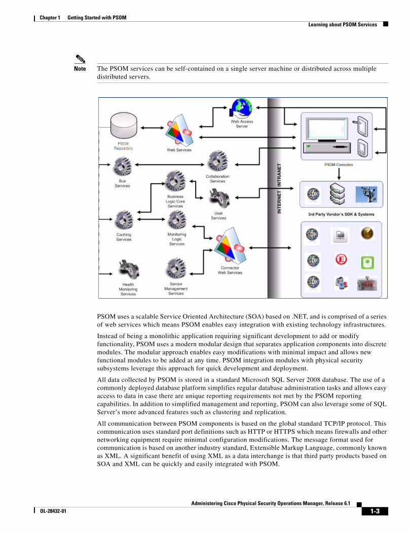
Note The PSOM services can be self-contained on a single server machine or distributed across multiple distributed servers.
PSOM uses a scalable Service Oriented Architecture (SOA) based on .NET, and is comprised of a series of web services which means PSOM enables easy integration with existing technology infrastructures.
Instead of being a monolithic application requiring significant development to add or modify functionality, PSOM uses a modern modular design that separates application components into discrete modules. The modular approach enables easy modifications with minimal impact and allows new functional modules to be added at any time. PSOM integration modules with physical security subsystems leverage this approach for quick development and deployment.
All data collected by PSOM is stored in a standard Microsoft SQL Server 2008 database. The use of a commonly deployed database platform simplifies regular database administration tasks and allows easy access to data in case there are unique reporting requirements not met by the PSOM reporting capabilities. In addition to simplified management and reporting, PSOM can also leverage some of SQL Server’s more advanced features such as clustering and replication.
All communication between PSOM components is based on the global standard TCP/IP protocol. This communication uses standard port definitions such as HTTP or HTTPS which means firewalls and other networking equipment require minimal configuration modifications. The message format used for communication is based on another industry standard, Extensible Markup Language, commonly known as XML. A significant benefit of using XML as a data interchange is that third party products based on SOA and XML can be quickly and easily integrated with PSOM.
1-4Administering Cisco Physical Security Operations Manager, Release 6.1
OL-28432-01
Chapter 1 Getting Started with PSOM Overview of the Operation Console
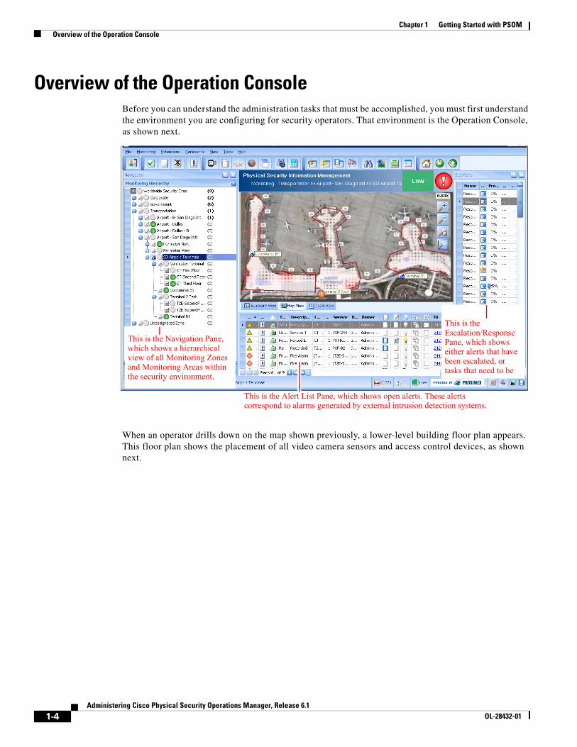
Overview of the Operation ConsoleBefore you can understand the administration tasks that must be accomplished, you must first understand the environment you are configuring for security operators. That environment is the Operation Console, as shown next.
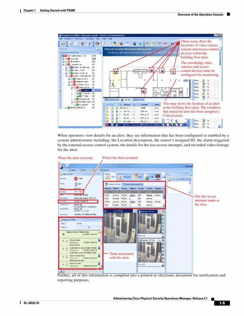
When an operator drills down on the map shown previously, a lower-level building floor plan appears. This floor plan shows the placement of all video camera sensors and access control devices, as shown next.
This is the Navigation Pane, which shows a hierarchical view of all Monitoring Zones and Monitoring Areas within the security environment.
This is the Escalation/Response Pane, which shows either alerts that have been escalated, or tasks that need to be
This is the Alert List Pane, which shows open alerts. These alerts correspond to alarms generated by external intrusion detection systems.
1-5Administering Cisco Physical Security Operations Manager, Release 6.1
OL-28432-01
Chapter 1 Getting Started with PSOM Overview of the Operation Console
When operators view details for an alert, they see information that has been configured or enabled by a system administrator including: the Location description, the sensor’s assigned ID, the alarm triggered by the external access control system, the details for the last access attempts, and recorded video footage for the alert.
Further, all of this information is compiled into a printed or electronic document for notification and reporting purposes.
This map shows the location of an alert in the building floor plan. The condition that raised the alert has been assigned a Critical status.
These icons show the locations of video camera sensors and access control devices within the building floor plan.
The correlating video cameras and access control devices must be configured for monitoring.
The last access attempts made at the door.
Where the alert occurred.When the alert occurred.
Tasks associated with the alert.
1-6Administering Cisco Physical Security Operations Manager, Release 6.1
OL-28432-01
Chapter 1 Getting Started with PSOM Configuring PSOM
See Using Cisco Physical Security Operations Manager for information about using the Operation Console.
Configuring PSOMAs the administrator, you play a critical role in designing and configuring PSOM so the right information is readily available to security operators and first responders.
To get PSOM running, you must perform a series of tasks to setup the environment. The Configuration Wizard guides you through this process.
To configure PSOM using the Configuration Start Wizard, follow these steps:
Procedure
Step 1 Choose Tools > Configuration Wizard.
The Configuration Wizard appears.
Step 2 Select each task in order and its section will expand with a list of tasks to be completed.
Step 3 Click the Configure button to launch the appropriate configuration window for the task to be completed.
Step 4 Click Next to move on to the next administration task.
Configuration tasks you must perform as administrator include:
• Set up users and assign them to security groups.
• Establish the Monitoring Hierarchy of Monitoring Zones and Monitoring Areas within your security environment. This involves dividing the overall security boundary into logical top-level groups (Monitoring Zones), and then splitting those groups into areas that can be managed from a single view of a building floor plan (Monitoring Areas).
• Create maps for the Monitoring Hierarchy. This involves uploading graphics for the different Monitoring Areas and Monitoring Zones in your environment, and optionally configuring maps as Geographic Information System (GIS) maps.
• Draw boundaries on maps for the Monitoring Zones and Monitoring Areas. This involves visually defining the Monitoring Zones and Monitoring Areas on graphical maps to show the boundaries.
• Add Sensors for each video camera and access control, and define Sensor Groups. A Sensor must be defined in PSOM for each physical sensor in the environment. And you can group Sensors together that collaborate to report events; for example, group an access control device and the video camera that monitors it.
• Place Sensors into the correct Monitoring Zone or Monitoring Area, and add them to maps. Then these Sensors must be placed appropriately on building floor plans for your Monitoring Areas.
• Apply Event Business Logic to ensure that policies are followed and security policies are consistently repeatable.
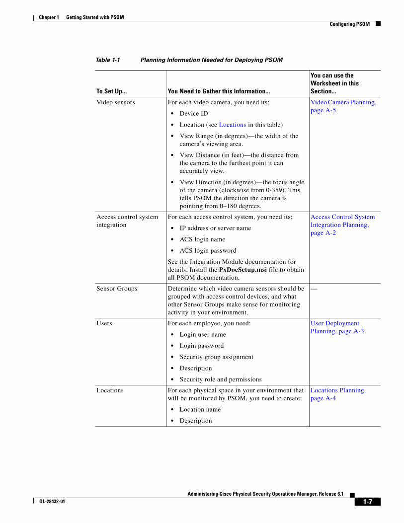
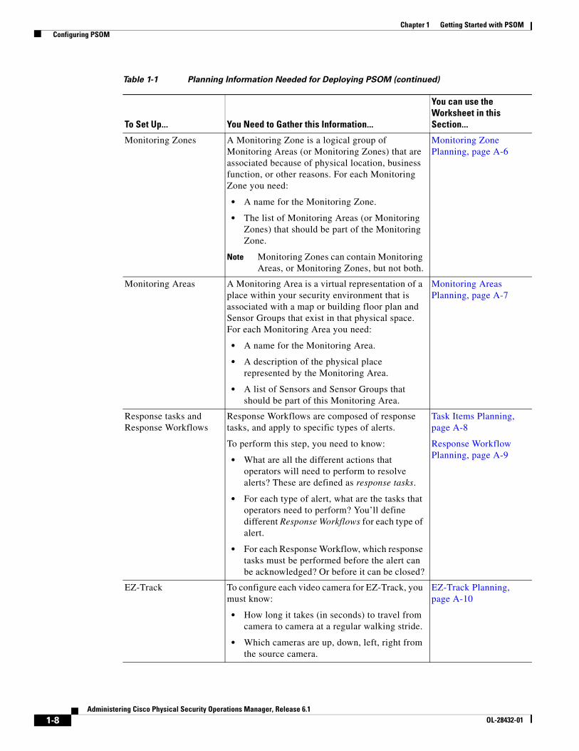
There is a set of information you need to gather before beginning to set up PSOM for your security environment. Table 1-1 lists the details you’ll need and tells you which planning worksheet you can use in Appendix A, “Planning Worksheets,” to gather the information.
1-7Administering Cisco Physical Security Operations Manager, Release 6.1
OL-28432-01
Chapter 1 Getting Started with PSOM Configuring PSOM
Table 1-1 Planning Information Needed for Deploying PSOM
To Set Up... You Need to Gather this Information...
You can use the Worksheet in this Section...
Video sensors For each video camera, you need its:
• Device ID
• Location (see Locations in this table)
• View Range (in degrees)—the width of the camera’s viewing area.
• View Distance (in feet)—the distance from the camera to the furthest point it can accurately view.
• View Direction (in degrees)—the focus angle of the camera (clockwise from 0-359). This tells PSOM the direction the camera is pointing from 0–180 degrees.
Video Camera Planning, page A-5
Access control system integration
For each access control system, you need its:
• IP address or server name
• ACS login name
• ACS login password
See the Integration Module documentation for details. Install the PxDocSetup.msi file to obtain all PSOM documentation.
Access Control System Integration Planning, page A-2
Sensor Groups Determine which video camera sensors should be grouped with access control devices, and what other Sensor Groups make sense for monitoring activity in your environment.
—
Users For each employee, you need:
• Login user name
• Login password
• Security group assignment
• Description
• Security role and permissions
User Deployment Planning, page A-3
Locations For each physical space in your environment that will be monitored by PSOM, you need to create:
• Location name
• Description
Locations Planning, page A-4
1-8Administering Cisco Physical Security Operations Manager, Release 6.1
OL-28432-01
Chapter 1 Getting Started with PSOM Configuring PSOM
Monitoring Zones A Monitoring Zone is a logical group of Monitoring Areas (or Monitoring Zones) that are associated because of physical location, business function, or other reasons. For each Monitoring Zone you need:
• A name for the Monitoring Zone.
• The list of Monitoring Areas (or Monitoring Zones) that should be part of the Monitoring Zone.
Note Monitoring Zones can contain Monitoring Areas, or Monitoring Zones, but not both.
Monitoring Zone Planning, page A-6
Monitoring Areas A Monitoring Area is a virtual representation of a place within your security environment that is associated with a map or building floor plan and Sensor Groups that exist in that physical space. For each Monitoring Area you need:
• A name for the Monitoring Area.
• A description of the physical place represented by the Monitoring Area.
• A list of Sensors and Sensor Groups that should be part of this Monitoring Area.
Monitoring Areas Planning, page A-7
Response tasks and Response Workflows
Response Workflows are composed of response tasks, and apply to specific types of alerts.
To perform this step, you need to know:
• What are all the different actions that operators will need to perform to resolve alerts? These are defined as response tasks.
• For each type of alert, what are the tasks that operators need to perform? You’ll define different Response Workflows for each type of alert.
• For each Response Workflow, which response tasks must be performed before the alert can be acknowledged? Or before it can be closed?
Task Items Planning, page A-8
Response Workflow Planning, page A-9
EZ-Track To configure each video camera for EZ-Track, you must know:
• How long it takes (in seconds) to travel from camera to camera at a regular walking stride.
• Which cameras are up, down, left, right from the source camera.
EZ-Track Planning, page A-10
Table 1-1 Planning Information Needed for Deploying PSOM (continued)
To Set Up... You Need to Gather this Information...
You can use the Worksheet in this Section...
1-9Administering Cisco Physical Security Operations Manager, Release 6.1
OL-28432-01
Chapter 1 Getting Started with PSOM Getting Familiar with the Administration Console
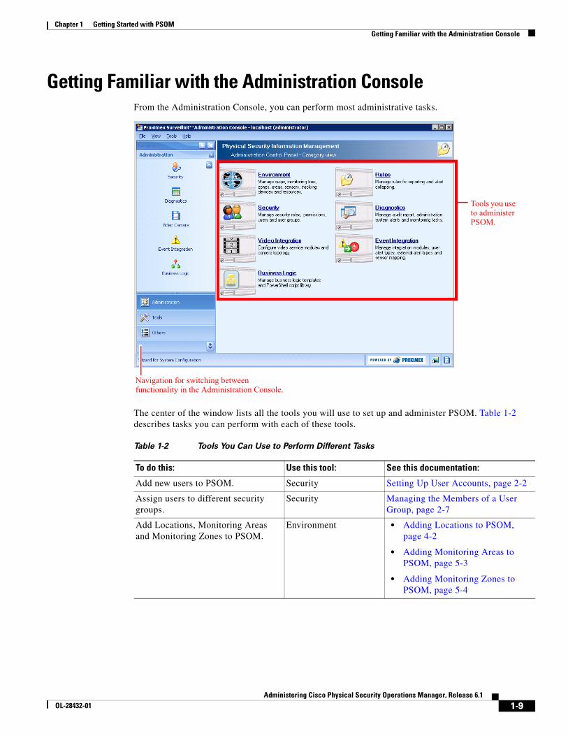
Getting Familiar with the Administration ConsoleFrom the Administration Console, you can perform most administrative tasks.
The center of the window lists all the tools you will use to set up and administer PSOM. Table 1-2 describes tasks you can perform with each of these tools.
Navigation for switching between functionality in the Administration Console.
Tools you use to administer PSOM.
Table 1-2 Tools You Can Use to Perform Different Tasks
To do this: Use this tool: See this documentation:
Add new users to PSOM. Security Setting Up User Accounts, page 2-2
Assign users to different security groups.
Security Managing the Members of a User Group, page 2-7
Add Locations, Monitoring Areas and Monitoring Zones to PSOM.
Environment • Adding Locations to PSOM, page 4-2
• Adding Monitoring Areas to PSOM, page 5-3
• Adding Monitoring Zones to PSOM, page 5-4
1-10Administering Cisco Physical Security Operations Manager, Release 6.1
OL-28432-01
Chapter 1 Getting Started with PSOM Getting Familiar with the Administration Console
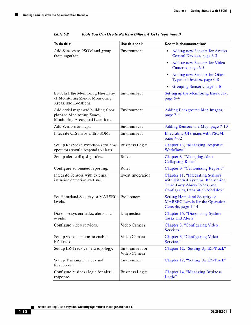
Add Sensors to PSOM and group them together.
Environment • Adding new Sensors for Access Control Devices, page 6-3
• Adding new Sensors for Video Cameras, page 6-5
• Adding new Sensors for Other Types of Devices, page 6-8
• Grouping Sensors, page 6-16
Establish the Monitoring Hierarchy of Monitoring Zones, Monitoring Areas, and Locations.
Environment Setting up the Monitoring Hierarchy, page 5-4
Add aerial maps and building floor plans to Monitoring Zones, Monitoring Areas, and Locations.
Environment Adding Background Map Images, page 7-4
Add Sensors to maps. Environment Adding Sensors to a Map, page 7-19
Integrate GIS maps with PSOM. Environment Integrating GIS maps with PSOM, page 7-32
Set up Response Workflows for how operators should respond to alerts.
Business Logic Chapter 13, “Managing Response Workflows”
Set up alert collapsing rules. Rules Chapter 8, “Managing Alert Collapsing Rules”
Configure automated reporting. Rules Chapter 9, “Customizing Reports”
Integrate Sensors with external intrusion detection systems.
Event Integration Chapter 11, “Integrating Sensors with External Systems, Registering Third-Party Alarm Types, and Configuring Integration Modules”
Set Homeland Security or MARSEC levels.
Preferences Setting Homeland Security or MARSEC Levels for the Operation Console, page 1-14
Diagnose system tasks, alerts and events.
Diagnostics Chapter 16, “Diagnosing System Tasks and Alerts”
Configure video services. Video Camera Chapter 3, “Configuring Video Services”
Set up video cameras to enable EZ-Track.
Video Camera Chapter 3, “Configuring Video Services”
Set up EZ-Track camera topology. Environment or Video Camera
Chapter 12, “Setting Up EZ-Track”
Set up Tracking Devices and Resources.
Environment Chapter 12, “Setting Up EZ-Track”
Configure business logic for alert response.
Business Logic Chapter 14, “Managing Business Logic”
Table 1-2 Tools You Can Use to Perform Different Tasks (continued)
To do this: Use this tool: See this documentation:
1-11Administering Cisco Physical Security Operations Manager, Release 6.1
OL-28432-01
Chapter 1 Getting Started with PSOM Logging On or Off
Aside from the tools you can use, you can launch the Operation Console by clicking its name under Operations on the left side of the window.
Under Others on the left side of the window, you can perform these functions:
• To change preferences for the Administration Console and Operation Consoles in your organization, click Preferences.
• If you want to change the permissions or password of the current login account, click Security Profile.
• To view licensing information, or update your license key, click License Manager.
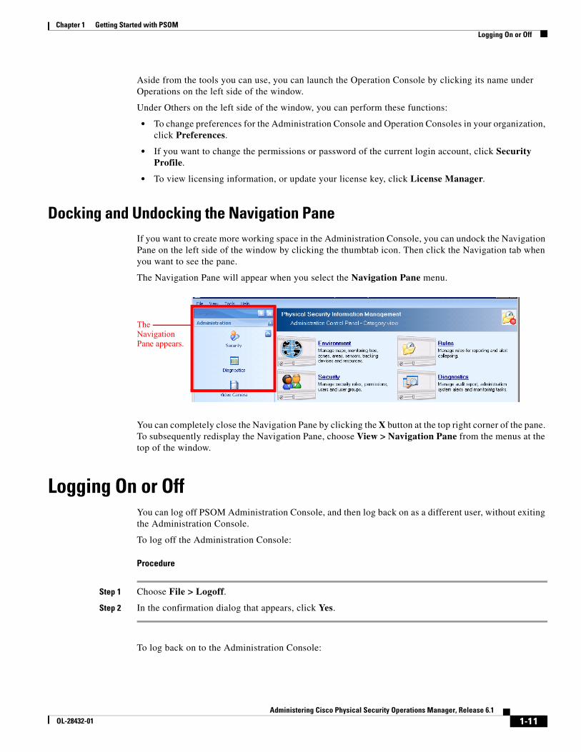
Docking and Undocking the Navigation PaneIf you want to create more working space in the Administration Console, you can undock the Navigation Pane on the left side of the window by clicking the thumbtab icon. Then click the Navigation tab when you want to see the pane.
The Navigation Pane will appear when you select the Navigation Pane menu.
You can completely close the Navigation Pane by clicking the X button at the top right corner of the pane. To subsequently redisplay the Navigation Pane, choose View > Navigation Pane from the menus at the top of the window.
Logging On or OffYou can log off PSOM Administration Console, and then log back on as a different user, without exiting the Administration Console.
To log off the Administration Console:
Procedure
Step 1 Choose File > Logoff.
Step 2 In the confirmation dialog that appears, click Yes.
To log back on to the Administration Console:
The Navigation Pane appears.
1-12Administering Cisco Physical Security Operations Manager, Release 6.1
OL-28432-01
Chapter 1 Getting Started with PSOM Viewing and Updating Your License Key
Note If you are using Single Sign On to login to PSOM (for example, Windows Authentication), see the “Single Sign On and User Management” section on page 2-13.
Procedure
Step 1 Choose File > Logon.
The Logon window appears.
Step 2 Select the server where PSOM is running from the Server Name field.
Step 3 Select the user name for logging in to PSOM from the User Name field.
Step 4 Enter the corresponding password in the Password field.
Step 5 If SSL is configured, the only way to connect to PSOM components is via HTTPS. Therefore, you must check the Use HTTPS connection check box.
Step 6 Click Logon.
Viewing and Updating Your License KeyYour PSOM license key controls access to the Administration Console, Operation Console, EZ-Track functionality, and other key features. Your license key may, or may not, have an expiration date depending upon the product purchased.
The license key is a 25-character string.
To view your license key, follow these steps:
Procedure
Step 1 Click Others in the Navigation pane.
Step 2 Click License Manager in the Navigation pane.
The PSOM License Manager appears.
If you have exceeded your license requirement for an item, it appears highlighted in the list.
To update your license key, follow these steps:
Procedure
Step 1 Click Others and then License Manager in the Navigation pane.
Step 2 Click the Update Key button.
The PSOM License Key window appears.
Step 3 Enter your license key in the fields provided and click OK.
1-13Administering Cisco Physical Security Operations Manager, Release 6.1
OL-28432-01
Chapter 1 Getting Started with PSOM Setting Preferences
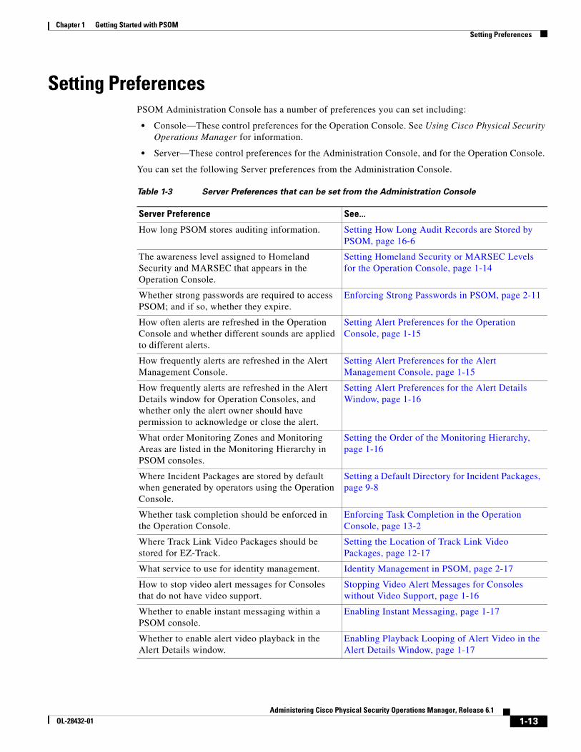
Setting PreferencesPSOM Administration Console has a number of preferences you can set including:
• Console—These control preferences for the Operation Console. See Using Cisco Physical Security Operations Manager for information.
• Server—These control preferences for the Administration Console, and for the Operation Console.
You can set the following Server preferences from the Administration Console.
Table 1-3 Server Preferences that can be set from the Administration Console
Server Preference See...
How long PSOM stores auditing information. Setting How Long Audit Records are Stored by PSOM, page 16-6
The awareness level assigned to Homeland Security and MARSEC that appears in the Operation Console.
Setting Homeland Security or MARSEC Levels for the Operation Console, page 1-14
Whether strong passwords are required to access PSOM; and if so, whether they expire.
Enforcing Strong Passwords in PSOM, page 2-11
How often alerts are refreshed in the Operation Console and whether different sounds are applied to different alerts.
Setting Alert Preferences for the Operation Console, page 1-15
How frequently alerts are refreshed in the Alert Management Console.
Setting Alert Preferences for the Alert Management Console, page 1-15
How frequently alerts are refreshed in the Alert Details window for Operation Consoles, and whether only the alert owner should have permission to acknowledge or close the alert.
Setting Alert Preferences for the Alert Details Window, page 1-16
What order Monitoring Zones and Monitoring Areas are listed in the Monitoring Hierarchy in PSOM consoles.
Setting the Order of the Monitoring Hierarchy, page 1-16
Where Incident Packages are stored by default when generated by operators using the Operation Console.
Setting a Default Directory for Incident Packages, page 9-8
Whether task completion should be enforced in the Operation Console.
Enforcing Task Completion in the Operation Console, page 13-2
Where Track Link Video Packages should be stored for EZ-Track.
Setting the Location of Track Link Video Packages, page 12-17
What service to use for identity management. Identity Management in PSOM, page 2-17
How to stop video alert messages for Consoles that do not have video support.
Stopping Video Alert Messages for Consoles without Video Support, page 1-16
Whether to enable instant messaging within a PSOM console.
Enabling Instant Messaging, page 1-17
Whether to enable alert video playback in the Alert Details window.
Enabling Playback Looping of Alert Video in the Alert Details Window, page 1-17
1-14Administering Cisco Physical Security Operations Manager, Release 6.1
OL-28432-01
Chapter 1 Getting Started with PSOM Setting Preferences
Setting Homeland Security or MARSEC Levels for the Operation ConsoleThe Operation Console displays the current Homeland Security or MARSEC level at the bottom right corner of the window.
You can manually set these levels for the Operation Console from the Administration Console.
To set the Homeland Security or MARSEC levels, follow these steps:
Procedure
Step 1 From the Administration Console, choose File > Preferences.
The Console Preferences window appears.
Step 2 Click Server.
The Server preferences appear.
Step 3 In the Security Threat Level Indicator section, select the type of security threat you want to display in the Operation Console from the pull-down menu: Homeland Security or MARSEC.
Step 4 From the Set security threat level at field, choose a level.
Step 5 For Homeland Security, the choices are: Low, Guarded, Elevated, High, or Severe.
For MARSEC, the choices are: MARSEC 1, MARSEC 2, or MARSEC 3.
Note For MARSEC, the levels roughly correlate to Homeland Security in this way:
– MARSEC 1—Routine maritime operations; this level aligns with Green, Blue and Yellow Homeland Security levels.
– MARSEC 2—Heightened security awareness; this level aligns with the Orange Homeland Security level.
– MARSEC 3—Imminent threats to security; this level aligns with the Red Homeland Security level.
Step 6 Click OK to apply your settings.
Whether to enable alert video to be viewed from the Video Management Console.
Viewing Alert Video in the Video Management Console, page 1-18
Whether to configure failover for PSOM Web Service and PSOM consoles
Configuring Failover for PSOM Web Service, page C-29
Table 1-3 Server Preferences that can be set from the Administration Console (continued)
Server Preference See...
1-15Administering Cisco Physical Security Operations Manager, Release 6.1
OL-28432-01
Chapter 1 Getting Started with PSOM Setting Preferences
Setting Alert Preferences for the Operation ConsoleYou can set alert preferences that apply to all Operation Consoles in the network from the Administration Console.
To set alert preferences for Operation Consoles, follow these steps:
Procedure
Step 7 Select File > Preferences from the Administration Console.
Step 8 Click All Consoles under Server in the left navigation pane.
Step 9 Enter the interval at which alert information should be refreshed in the Operation Console in the Minimum console update interval field.
Step 10 If you want to limit the number of alerts that are displayed in the Alert Pane in the Operation Console, check the Maximum number of alerts displayed in the list checkbox and enter a number in the field provided.
Step 11 If you want to associate a sound with a specific alert type, click the Sound button.
The Configure Sound by Alert Type window appears.
Step 12 To play a default sound for all alerts, check the Default sound for alerts checkbox and click Select. Navigate and select the audio file you want played for all alerts.
Step 13 To associate a sound with a specific type of alert, select the alert in the window and click Add. Navigate and select the audio file you want played for the specific alert. The sound file is now listed next to the selected alert.
Note Sound files need to be installed in the same folder across the machines where PSOM Operation Console will be running, or in a shared folder that all of these machines can access.
Step 14 If you want to have Microsoft Windows’ speech functionality read alert descriptions—for example, “Alert! 'Suspect did not pass check point and disappear' at 'T2E-SecondFloorMain' Sensor 'P-108'”—then check the Voice speak for new alert description checkbox.
You can configure the voice used to read the descriptions by clicking the Speech icon in the Control Panel in Windows. Click the Text To Speech tab and choose the voice you want to use from the Voice selection field.
Step 15 Click OK. Then click Apply or OK in the Console Preferences window.
Setting Alert Preferences for the Alert Management ConsoleYou can set preferences for the Alert Management Console.
To set alert preferences for the Alert Management Console, follow these steps:
Procedure
Step 1 Choose File > Preferences from the Administration Console.
Step 2 Click All Consoles under Server in the left navigation pane.
1-16Administering Cisco Physical Security Operations Manager, Release 6.1
OL-28432-01
Chapter 1 Getting Started with PSOM Setting Preferences
Step 3 Enter the interval at which alert information should be refreshed in the Alert Management Console in the Minimum console update interval field.
Step 4 Click OK.
Setting Alert Preferences for the Alert Details WindowYou can set preferences for the Alert Details window in all Operation Consoles.
To set alert preferences for the Alert Details, follow these steps:
Procedure
Step 1 Choose File > Preferences from the Administration Console.
Step 2 Click All Consoles under Server in the left navigation pane.
Step 3 Enter the interval at which alert information should be refreshed in the Alert Details window in the Minimum window update interval field.
Step 4 If you only want the owner of an alert to be able to acknowledge or close the alert, choose Yes from the Lock Alert: Only allow alert to be acknowledged and closed by alert owner field.
Step 5 Click OK.
Setting the Order of the Monitoring HierarchyYou can set the order in which Monitoring Node names appear in the Monitoring Hierarchy across all Consoles.
To set the order of the Monitoring Hierarchy, follow these steps:
Procedure
Step 1 Choose File > Preferences from the Administration Console.
Step 2 Click All Consoles under Server in the left navigation pane.
Step 3 Select the order in which you want Monitoring Node names to appear in the Monitoring Hierarchy from the Sort order of hierarchy node name field.
Step 4 Click OK.
Stopping Video Alert Messages for Consoles without Video SupportIf the Operation Console does not need to use video-related features, you can set an option to turn off video alert messages at startup.
To set video alert preferences for the Operation Console, follow these steps:
1-17Administering Cisco Physical Security Operations Manager, Release 6.1
OL-28432-01
Chapter 1 Getting Started with PSOM Setting Preferences
Procedure
Step 1 Choose File > Preferences from the Alert Management Console.
Step 2 Click General under Console (Per Computer) in the left navigation pane.
Step 3 To turn off video alert messages, deselect the Show video integration warning message at console startup option.
Step 4 Click OK.
Enabling Instant MessagingThe PSOM Instant Messenger allows different operators to communicate instantly over the network using text messaging. Instant Messenger can be launched as standalone application from the Start Menu, or from within PSOM consoles (such as the Operation Console or Alert Console).
These preferences are used to enable the Instant Messenger Console to automatically launch instant messenger when a user logs into the Operation Console.
To enable instant messaging within PSOM consoles, follow these steps:
Procedure
Step 1 Choose File > Preferences from the PSOM Console.
Step 2 Choose Console (Per User) > General.
Step 3 Check the Start Instant Messenger Console Automatically after logon option.
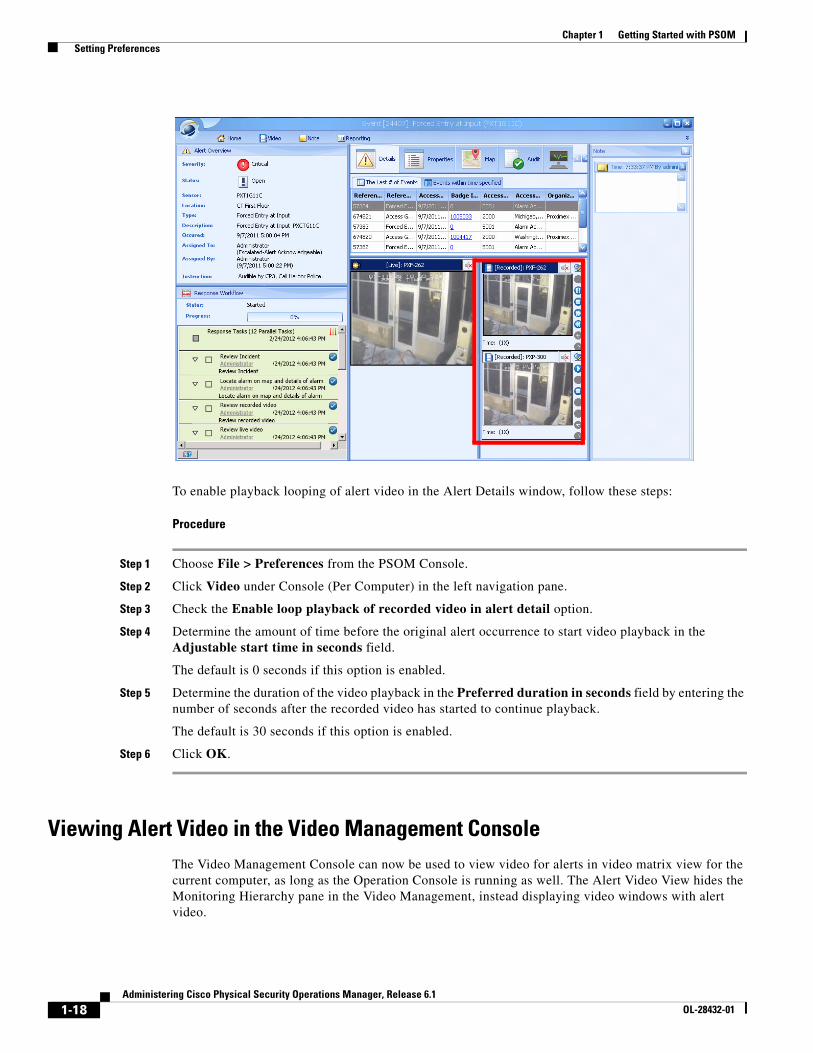
Enabling Playback Looping of Alert Video in the Alert Details WindowYou can now enable looping playback for alert-related recorded video in the Alert Details window. When configured, alert-related recorded videos in the Alert Details window will have looped playback for both the Operation Console and Alert Console.
1-18Administering Cisco Physical Security Operations Manager, Release 6.1
OL-28432-01
Chapter 1 Getting Started with PSOM Setting Preferences
To enable playback looping of alert video in the Alert Details window, follow these steps:
Procedure
Step 1 Choose File > Preferences from the PSOM Console.
Step 2 Click Video under Console (Per Computer) in the left navigation pane.
Step 3 Check the Enable loop playback of recorded video in alert detail option.
Step 4 Determine the amount of time before the original alert occurrence to start video playback in the Adjustable start time in seconds field.
The default is 0 seconds if this option is enabled.
Step 5 Determine the duration of the video playback in the Preferred duration in seconds field by entering the number of seconds after the recorded video has started to continue playback.
The default is 30 seconds if this option is enabled.
Step 6 Click OK.
Viewing Alert Video in the Video Management ConsoleThe Video Management Console can now be used to view video for alerts in video matrix view for the current computer, as long as the Operation Console is running as well. The Alert Video View hides the Monitoring Hierarchy pane in the Video Management, instead displaying video windows with alert video.
1-19Administering Cisco Physical Security Operations Manager, Release 6.1
OL-28432-01
Chapter 1 Getting Started with PSOM Setting Preferences
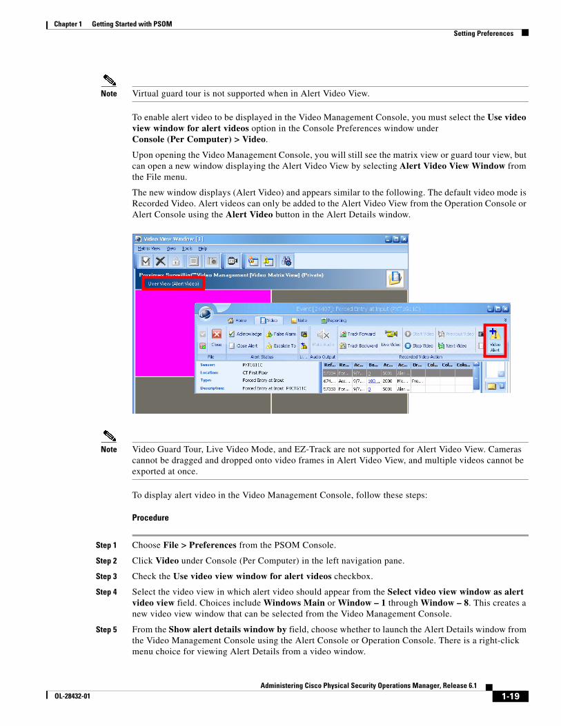
Note Virtual guard tour is not supported when in Alert Video View.
To enable alert video to be displayed in the Video Management Console, you must select the Use video view window for alert videos option in the Console Preferences window underConsole (Per Computer) > Video.
Upon opening the Video Management Console, you will still see the matrix view or guard tour view, but can open a new window displaying the Alert Video View by selecting Alert Video View Window from the File menu.
The new window displays (Alert Video) and appears similar to the following. The default video mode is Recorded Video. Alert videos can only be added to the Alert Video View from the Operation Console or Alert Console using the Alert Video button in the Alert Details window.
Note Video Guard Tour, Live Video Mode, and EZ-Track are not supported for Alert Video View. Cameras cannot be dragged and dropped onto video frames in Alert Video View, and multiple videos cannot be exported at once.
To display alert video in the Video Management Console, follow these steps:
Procedure
Step 1 Choose File > Preferences from the PSOM Console.
Step 2 Click Video under Console (Per Computer) in the left navigation pane.
Step 3 Check the Use video view window for alert videos checkbox.
Step 4 Select the video view in which alert video should appear from the Select video view window as alert video view field. Choices include Windows Main or Window – 1 through Window – 8. This creates a new video view window that can be selected from the Video Management Console.
Step 5 From the Show alert details window by field, choose whether to launch the Alert Details window from the Video Management Console using the Alert Console or Operation Console. There is a right-click menu choice for viewing Alert Details from a video window.
1-20Administering Cisco Physical Security Operations Manager, Release 6.1
OL-28432-01
Chapter 1 Getting Started with PSOM Starting and Stopping PSOM Services
Step 6 If you want alert video to automatically appear in the first available tile of the Video Management Console matrix when the Alert Details window is opened, check the Automatically add alert video into the first available tile checkbox.
If all 16 tiles are taken (4x4 style matrix), any new alarm with video will take over the first tile. If this option is not selected, the user will have to click the Post Alert Video button in the Alert Details window to add the video to a frame in the Video Management Console matrix.
Note For this functionality to work, the Video Management Console and Operation Console need to be on the same machine.
If an alert has more than one video camera associated to it, when an alarm is generated, all the associated recorded video (not just one) will be displayed in the Alert Video matrix.
Step 7 To automatically remove alert video from the Video Management Console matrix when an alert status changes to Acknowledged or Closed from the Alert Details window, check the Automatically remove video from alert view window checkbox and select the alert status that triggers removal. If the alert status changes in any other way, this functionality will not be performed.
Step 8 To automatically add alert video for new alerts to the first available tile in the video view, select the Automatically add alert video into the first available tile of the alert view window when new open alert raised from the Operation or Alert Console option.
Step 9 Click OK.
Starting and Stopping PSOM ServicesWhen a system is restarted, PSOM services are configured to restart automatically. However, in cases where the services need to be manually restarted follow the instructions in this section.
Note Contact Cisco before reinitializing PSOM services.
The following services exist for PSOM:
• PSOM Bus Services
• PSOM Business Logic Core Services
• PSOM Caching Services
• PSOM Collaboration Services
• PSOM Health Monitoring Services
• PSOM Monitoring Logic Services
• PSOM Sensor Management Services
To restart PSOM services, follow these steps:
1-21Administering Cisco Physical Security Operations Manager, Release 6.1
OL-28432-01
Chapter 1 Getting Started with PSOM Starting and Stopping PSOM Services
Procedure
Step 1 From the Start menu, choose All Programs > Cisco Physical Security Operations Manager Services > Services Configuration.
The Services Configuration window appears.
Step 2 Choose 11 - Logs in the left side of the window.
Step 3 Click Finish.
Step 4 Click Apply changes and restart services. The PSOM services restart and a confirmation window appears.
Step 5 Click Finish.

1-22Administering Cisco Physical Security Operations Manager, Release 6.1
OL-28432-01
Chapter 1 Getting Started with PSOM Starting and Stopping PSOM Services

C H A P T E R
2-1Administering Cisco Physical Security Operations Manager, Release 6.1
OL-28432-01
2Defining Users and Managing User Groups
This chapter describes how to set up user accounts and assign them to user groups so that operators can access the Operation Console, Administration Console, Alert Management Console, Video Management Console, Business Logic Designer, or Web Console.
This chapter includes these topics:
• Managing Users, page 2-1
• Viewing Users by Role, page 2-5
• Managing User Groups, page 2-6
• Managing the Members of a User Group, page 2-7
• Permissions within PSOM, page 2-9
• Enforcing Strong Passwords in PSOM, page 2-11
• Single Sign On and User Management, page 2-13
• Identity Management in PSOM, page 2-17
Managing UsersBefore users can log in to PSOM, they must have a user account. Administrators are responsible for:
• Creating new user accounts
• Granting users certain privileges by assigning them a user role
• Assigning users to different user groups that can be used for escalation of tasks or enforce access scope (for examples, limit the Monitoring Zones that certain users can access)
• Changing user passwords. (Users can also change their own passwords from the Security Profile window of any console except the Web Console)
• Removing users from PSOM
Types of User RolesPSOM includes the following user roles:
• Operators—These users can access the Operation Console, and Video Management Console, Alert Management Console, or Web Console. These users cannot access the Administration Console or Business Logic Designer.
2-2Administering Cisco Physical Security Operations Manager, Release 6.1
OL-28432-01
Chapter 2 Defining Users and Managing User Groups Managing Users
• Power Users—These users can access a limited scope within any console. Power users cannot add, edit or delete administrator users.
• Administrators—These users can access everything within all consoles. This allows them to perform the same actions as operators, as well as create, configure, modify and view the entire PSOM system.
• Video Viewers—These users can access the Video Management Console only. This allows them to navigate the Monitoring Zones and Monitoring Areas within the environment and view surveillance videos from video sensors.
• Mobile Operators—These users can access Web Console from hand-held mobile devices.
Note You cannot edit or delete these user roles.
You can add new user roles to PSOM. See the “Permissions within PSOM” section on page 2-9.
Planning a PSOM User DeploymentWhen you are initially deploying PSOM within your organization, it is helpful to make a list of all users that need to be added to PSOM. For each of these users, assign them user names, passwords, roles and user groups. Table 2-1 shows a sample user deployment.
Note For a planning table you can use for your planning efforts, see the “User Deployment Planning” section on page A-3.
Setting Up User AccountsTo add a user account, follow these steps:
Procedure
Step 1 Click the Security icon in the Administration Console.
The Security window appears.
Step 2 Click the Users icon.
The Security User Manager window appears with the Users tab selected.
Step 3 Click the Add button to create a new user account.
The Add User window appears.
Table 2-1 Sample User Deployment Planning
Employee User Name Password User Role User Group
Operator Operator ****** Operator Management
Supervisor1 Supervisor1 ****** Power User Dayshift
Supervisor2 Supervisor2 ****** Power User Nightshift
2-3Administering Cisco Physical Security Operations Manager, Release 6.1
OL-28432-01
Chapter 2 Defining Users and Managing User Groups Managing Users
Step 4 In the User Name field, enter the name you want to assign to the user account. If you’re using single sign on, you click the button and select the user from Active Directory. See the “Single Sign On and User Management” section on page 2-13.
Step 5 In the Password and Confirm Password fields, enter the password for the account. If you are using single sign on, these fields are dimmed. See the “Single Sign On and User Management” section on page 2-13.
Step 6 From the Security Role field, select the security role you want to assign to this account: Administrator, Power User, Video Viewer, Operator, Paramedics, Law Enforcement Personnels, or Mobile Operator.
See the “Types of User Roles” section on page 2-1 for details.
Step 7 In the Description field, enter any notes about this user that are needed.
Step 8 In the Email field, enter the user’s email address to be used for notifications.
Step 9 Click OK to save the user account to the database.
After it is saved, the entry is displayed in the Security User Manager window.
Changing a User Password or Security roleYou can edit a user’s password or security role from the Security User Manager.
Note Users can also change their own passwords from the Security Profile window of any console except the Web Console.
To change a user password or security role, follow these steps:
Procedure
Step 1 Click the Security icon in the Administration Console.
Step 2 Click the Users icon.
The Security User Manager window appears with the Users tab selected.
2-4Administering Cisco Physical Security Operations Manager, Release 6.1
OL-28432-01
Chapter 2 Defining Users and Managing User Groups Managing Users
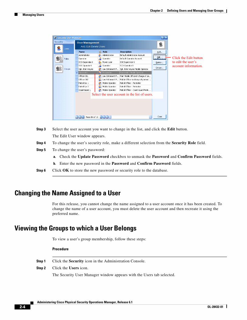
Step 3 Select the user account you want to change in the list, and click the Edit button.
The Edit User window appears.
Step 4 To change the user’s security role, make a different selection from the Security Role field.
Step 5 To change the user’s password:
a. Check the Update Password checkbox to unmask the Password and Confirm Password fields.
b. Enter the new password in the Password and Confirm Password fields.
Step 6 Click OK to store the new password or security role to the database.
Changing the Name Assigned to a UserFor this release, you cannot change the name assigned to a user account once it has been created. To change the name of a user account, you must delete the user account and then recreate it using the preferred name.
Viewing the Groups to which a User BelongsTo view a user’s group membership, follow these steps:
Procedure
Step 1 Click the Security icon in the Administration Console.
Step 2 Click the Users icon.
The Security User Manager window appears with the Users tab selected.
Click the Edit button to edit the user’s account information.
Select the user account in the list of users.
2-5Administering Cisco Physical Security Operations Manager, Release 6.1
OL-28432-01
Chapter 2 Defining Users and Managing User Groups Viewing Users by Role
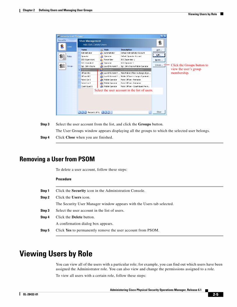
Step 3 Select the user account from the list, and click the Groups button.
The User Groups window appears displaying all the groups to which the selected user belongs.
Step 4 Click Close when you are finished.
Removing a User from PSOMTo delete a user account, follow these steps:
Procedure
Step 1 Click the Security icon in the Administration Console.
Step 2 Click the Users icon.
The Security User Manager window appears with the Users tab selected.
Step 3 Select the user account in the list of users.
Step 4 Click the Delete button.
A confirmation dialog box appears.
Step 5 Click Yes to permanently remove the user account from PSOM.
Viewing Users by RoleYou can view all of the users with a particular role; for example, you can find out which users have been assigned the Administrator role. You can also view and change the permissions assigned to a role.
To view all users with a certain role, follow these steps:
Click the Groups button to view the user’s group membership.
Select the user account in the list of users.
2-6Administering Cisco Physical Security Operations Manager, Release 6.1
OL-28432-01
Chapter 2 Defining Users and Managing User Groups Managing User Groups
Procedure
Step 1 Click the Security icon in the Administration Console.
The Security window appears.
Step 2 Click the Security Roles icon.
The Security User Manager window appears with the Roles tab selected.
Step 3 To see which users belong to a role, select a user role from the list and click the Members button.
The User Members window appears.
Click Close when you are finished.
Step 4 To see the permissions assigned to a user role, look in the lower half of the Security User Manager window.
Step 5 To change permissions assigned to a user role, select the role in the list and click Edit. The Edit Security Role window appears.
Step 6 Check or uncheck individual permissions under the Permissions area. Click OK when finished. See the “Permissions within PSOM” section on page 2-9 for information about the different permissions.
Note You can view your security permissions (for the login account you are currently using) by clicking Others and then Security Profile in the Navigation Pane of the Administration Console.
Managing User GroupsYou can create as many different user groups as you need to represent the functional operations of your security team, and then assign users to be members of these groups. User groups are useful with escalation of tasks within PSOM; for example, you can define a Supervisor group to whom alerts are escalated when they are not handled within the designated time frame. User groups are also useful for limiting the scope of access for certain users to specific Monitoring Zones or Monitoring Areas.
Creating a User GroupTo create a new user group, follow these steps:
Procedure
Step 1 Click the Security icon in the Administration Console.
The Security window appears.
Step 2 Click the User Groups icon.
The Security User Manager window appears with the Groups tab selected.
Step 3 Click the Add button to create a new user group.
The Add User Group window appears.
2-7Administering Cisco Physical Security Operations Manager, Release 6.1
OL-28432-01
Chapter 2 Defining Users and Managing User Groups Managing the Members of a User Group
Step 4 In the User Group Name field, enter a name for this new user group.
Step 5 In the Description field, enter information about this user group.
Step 6 Click the Add button to assign users to be members of this new group.
The Select User window appears.
Step 7 Select the users that should be members of this group. Use CTRL-click or SHIFT-click to select multiple users.
Step 8 Click OK.
The Add User Group window shows your new user group.
Step 9 Click OK to save your new group.
Editing a User GroupTo edit a user group, follow these steps:
Procedure
Step 1 Click the Security icon in the Administration Console.
The Security window appears.
Step 2 Click the User Groups icon.
The Security User Manager window appears with the Groups tab selected.
Step 3 Select the user group you want to change, and click the Edit button.
The Edit User Group window appears.
Step 4 To change the description of the group, change the text in the Description field.
Step 5 To remove a member from the group, select the member in the list under User Group Members, and click the Remove button. A confirmation appears.
Click Yes to remove the user.
Step 6 To add more members to the group, click the Add button.
The Select User window appears.
a. Select the users that should be members of this group. Use CTRL and SHIFT to select multiple users.
b. Click OK.
Step 7 Click OK to save your changes to the user group.
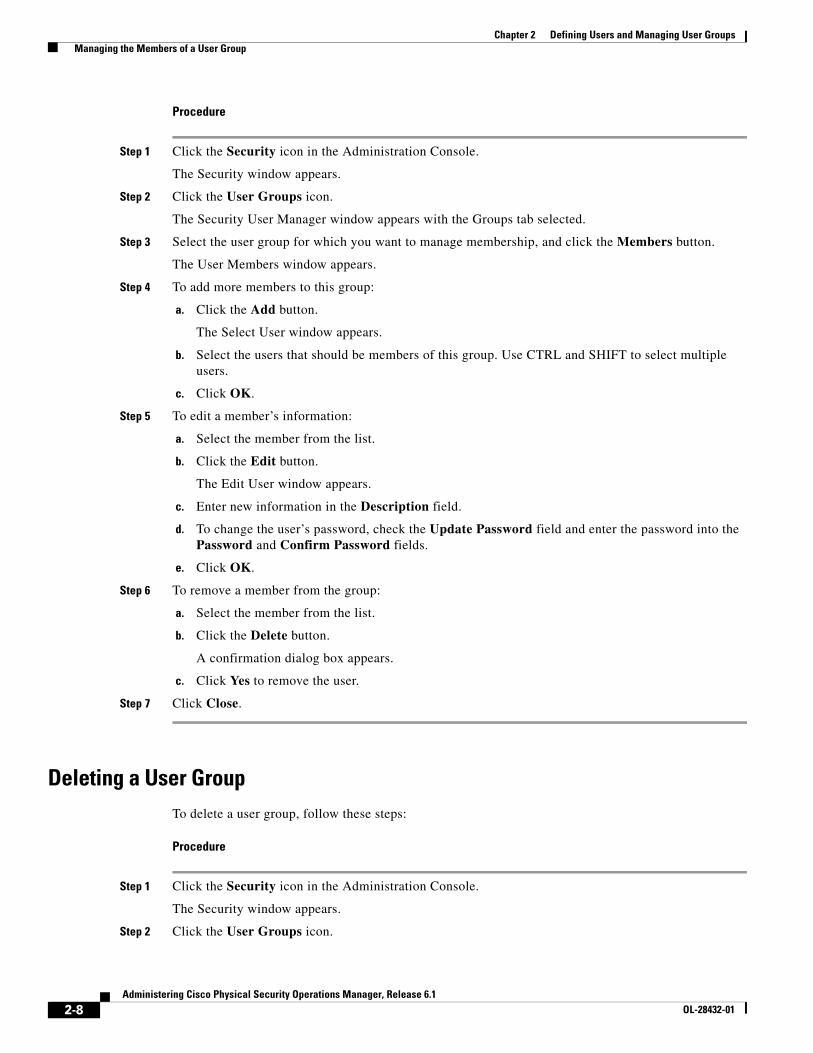
Managing the Members of a User GroupTo manage the members of a user group, follow these steps:
2-8Administering Cisco Physical Security Operations Manager, Release 6.1
OL-28432-01
Chapter 2 Defining Users and Managing User Groups Managing the Members of a User Group
Procedure
Step 1 Click the Security icon in the Administration Console.
The Security window appears.
Step 2 Click the User Groups icon.
The Security User Manager window appears with the Groups tab selected.
Step 3 Select the user group for which you want to manage membership, and click the Members button.
The User Members window appears.
Step 4 To add more members to this group:
a. Click the Add button.
The Select User window appears.
b. Select the users that should be members of this group. Use CTRL and SHIFT to select multiple users.
c. Click OK.
Step 5 To edit a member’s information:
a. Select the member from the list.
b. Click the Edit button.
The Edit User window appears.
c. Enter new information in the Description field.
d. To change the user’s password, check the Update Password field and enter the password into the Password and Confirm Password fields.
e. Click OK.
Step 6 To remove a member from the group:
a. Select the member from the list.
b. Click the Delete button.
A confirmation dialog box appears.
c. Click Yes to remove the user.
Step 7 Click Close.
Deleting a User GroupTo delete a user group, follow these steps:
Procedure
Step 1 Click the Security icon in the Administration Console.
The Security window appears.
Step 2 Click the User Groups icon.
2-9Administering Cisco Physical Security Operations Manager, Release 6.1
OL-28432-01
Chapter 2 Defining Users and Managing User Groups Permissions within PSOM
The Security User Manager window appears with the Groups tab selected.
Step 3 Select the user group you want to change, and click the Delete button.
A confirmation dialog box appears.
Step 4 Click Yes to delete the group.
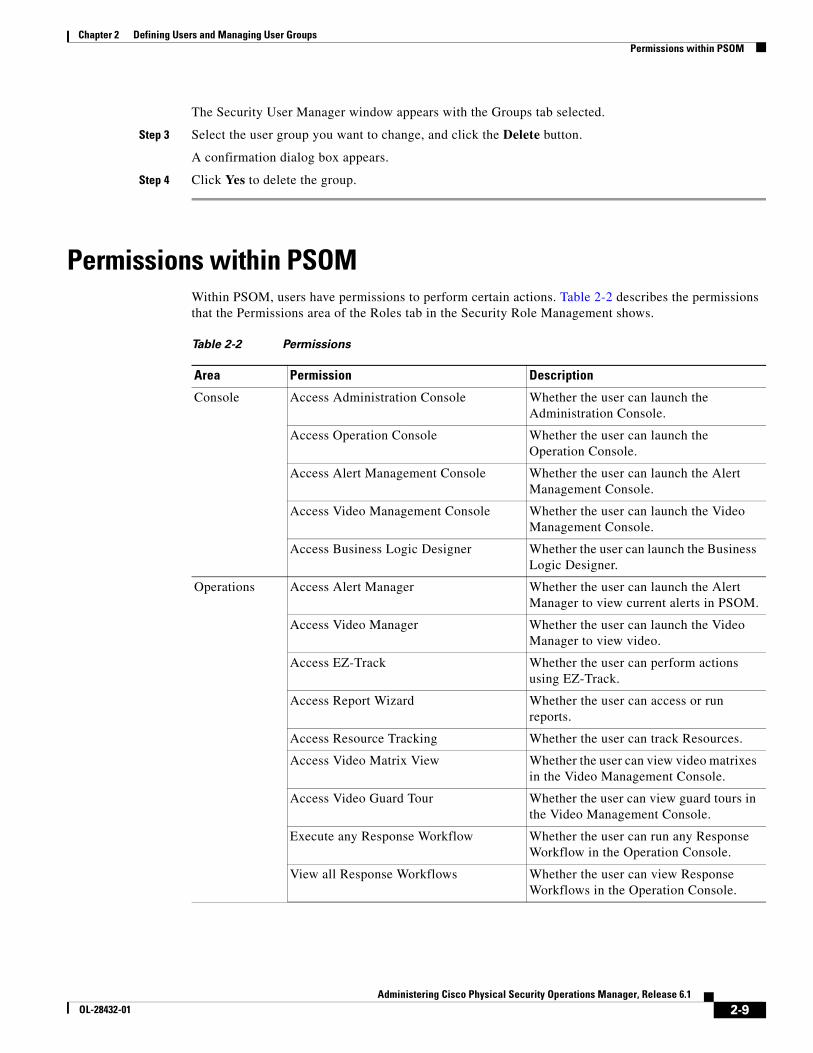
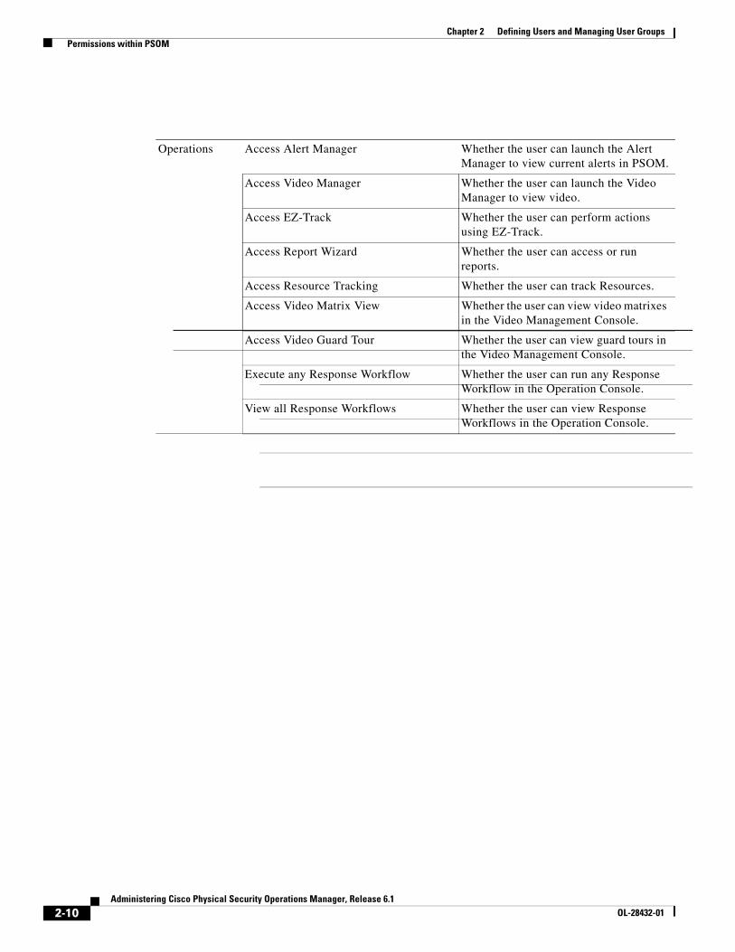
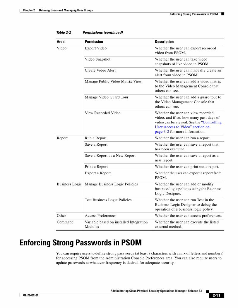
Permissions within PSOMWithin PSOM, users have permissions to perform certain actions. Table 2-2 describes the permissions that the Permissions area of the Roles tab in the Security Role Management shows.
Table 2-2 Permissions
Area Permission Description
Console Access Administration Console Whether the user can launch the Administration Console.
Access Operation Console Whether the user can launch the Operation Console.
Access Alert Management Console Whether the user can launch the Alert Management Console.
Access Video Management Console Whether the user can launch the Video Management Console.
Access Business Logic Designer Whether the user can launch the Business Logic Designer.
Operations Access Alert Manager Whether the user can launch the Alert Manager to view current alerts in PSOM.
Access Video Manager Whether the user can launch the Video Manager to view video.
Access EZ-Track Whether the user can perform actions using EZ-Track.
Access Report Wizard Whether the user can access or run reports.
Access Resource Tracking Whether the user can track Resources.
Access Video Matrix View Whether the user can view video matrixes in the Video Management Console.
Access Video Guard Tour Whether the user can view guard tours in the Video Management Console.
Execute any Response Workflow Whether the user can run any Response Workflow in the Operation Console.
View all Response Workflows Whether the user can view Response Workflows in the Operation Console.
2-10Administering Cisco Physical Security Operations Manager, Release 6.1
OL-28432-01
Chapter 2 Defining Users and Managing User Groups Permissions within PSOM
Operations Access Alert Manager Whether the user can launch the Alert Manager to view current alerts in PSOM.
Access Video Manager Whether the user can launch the Video Manager to view video.
Access EZ-Track Whether the user can perform actions using EZ-Track.
Access Report Wizard Whether the user can access or run reports.
Access Resource Tracking Whether the user can track Resources.
Access Video Matrix View Whether the user can view video matrixes in the Video Management Console.
Access Video Guard Tour Whether the user can view guard tours in the Video Management Console.
Execute any Response Workflow Whether the user can run any Response Workflow in the Operation Console.
View all Response Workflows Whether the user can view Response Workflows in the Operation Console.
2-11Administering Cisco Physical Security Operations Manager, Release 6.1
OL-28432-01
Chapter 2 Defining Users and Managing User Groups Enforcing Strong Passwords in PSOM
Enforcing Strong Passwords in PSOMYou can require users to define strong passwords (at least 8 characters with a mix of letters and numbers) for accessing PSOM from the Administration Console Preferences area. You can also require users to update passwords at whatever frequency is desired for adequate security.
Video Export Video Whether the user can export recorded video from PSOM.
Video Snapshot Whether the user can take video snapshots of live video in PSOM.
Create Video Alert Whether the user can manually create an alert from video in PSOM.
Manage Public Video Matrix View Whether the user can add a video matrix to the Video Management Console that others can see.
Manage Video Guard Tour Whether the user can add a guard tour to the Video Management Console that others can see.
View Recorded Video Whether the user can view recorded video, and if so, how many past days of video can be viewed. See the “Controlling User Access to Video” section on page 3-2 for more information.
Report Run a Report Whether the user can run a report.
Save a Report Whether the user can save a report that has been executed.
Save a Report as a New Report Whether the user can save a report as a new report.
Print a Report Whether the user can print out a report.
Export a Report Whether the user can export a report from PSOM.
Business Logic Manage Business Logic Policies Whether the user can add or modify business logic policies using the Business Logic Designer.
Test Business Logic Policies Whether the user can run Test in the Business Logic Designer to debug the operation of a business logic policy.
Other Access Preferences Whether the user can access preferences.
Command Variable based on installed Integration Modules
Whether the user can execute the listed external method.
Table 2-2 Permissions (continued)
Area Permission Description
2-12Administering Cisco Physical Security Operations Manager, Release 6.1
OL-28432-01
Chapter 2 Defining Users and Managing User Groups Enforcing Strong Passwords in PSOM
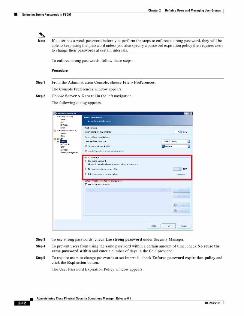
Note If a user has a weak password before you perform the steps to enforce a strong password, they will be able to keep using that password unless you also specify a password expiration policy that requires users to change their passwords at certain intervals.
To enforce strong passwords, follow these steps:
Procedure
Step 1 From the Administration Console, choose File > Preferences.
The Console Preferences window appears.
Step 2 Choose Server > General in the left navigation.
The following dialog appears.
Step 3 To use strong passwords, check Use strong password under Security Manager.
Step 4 To prevent users from using the same password within a certain amount of time, check No reuse the same password within and enter a number of days in the field provided.
Step 5 To require users to change passwords at set intervals, check Enforce password expiration policy and click the Expiration button.
The User Password Expiration Policy window appears.
2-13Administering Cisco Physical Security Operations Manager, Release 6.1
OL-28432-01
Chapter 2 Defining Users and Managing User Groups Single Sign On and User Management
Step 6 Determine the default policy for the interval at which passwords will expire by clicking the Password will expire in option and entering a number of days in the field provided. Otherwise, click Password will never expire.
Step 7 To set an expiration policy specific to different security roles, select the security role from the table and enter a number of days in the field at the far right.
Step 8 Click OK when finished.
Step 9 Click Apply or OK in the Console Preferences window to save your changes.
Single Sign On and User ManagementWhen logging in to PSOM, you can choose to use Single Sign On (SSO) and thereby leverage Windows authentication. To log in to PSOM using SSO, you must enable the PSOM Web Service to use SSO.
Once logged in to PSOM using SSO, in order to add or remove PSOM users the Windows administrator account used to login to PSOM must have privileges for adding or removing users from an Active Directory group. When SSO is in effect, PSOM users are managed using the PxWebServiceGroup in Active Directory. Therefore, the Windows administrator account you use to login to PSOM should belong to the Account Operators group in Active Directory so that you have appropriate privileges.
If your environment has tight permissions, you can follow the procedure in the “Configuring Active Directory for PSOM” section on page 2-13 to set up security groups in Active Directory that provide the necessary permissions for PSOM to function properly.
Configuring Active Directory for PSOMIf your environment has tight permissions, you can follow the procedure in this section to set up security groups in Active Directory that provide the necessary permissions for PSOM to function properly.
To configure Active Directory for PSOM, follow these steps:
Procedure
Step 1 Launch Active Directory.
Step 2 Within Active Directory, create two security groups in the local domain:
• PxAdminGroup—Will contain all PSOM administrator accounts. You need to add this domain group to the “Administrators” group on each machine where a PSOM Console is running.
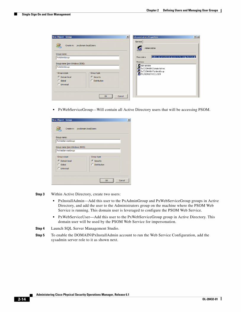
2-14Administering Cisco Physical Security Operations Manager, Release 6.1
OL-28432-01
Chapter 2 Defining Users and Managing User Groups Single Sign On and User Management
• PxWebServiceGroup—Will contain all Active Directory users that will be accessing PSOM.
Step 3 Within Active Directory, create two users:
• PxInstallAdmin—Add this user to the PxAdminGroup and PxWebServiceGroup groups in Active Directory, and add the user to the Administrators group on the machine where the PSOM Web Service is running. This domain user is leveraged to configure the PSOM Web Service.
• PxWebServiceUser—Add this user to the PxWebServiceGroup group in Active Directory. This domain user will be used by the PSOM Web Service for impersonation.
Step 4 Launch SQL Server Management Studio.
Step 5 To enable the DOMAIN\PxInstallAdmin account to run the Web Service Configuration, add the sysadmin server role to it as shown next.
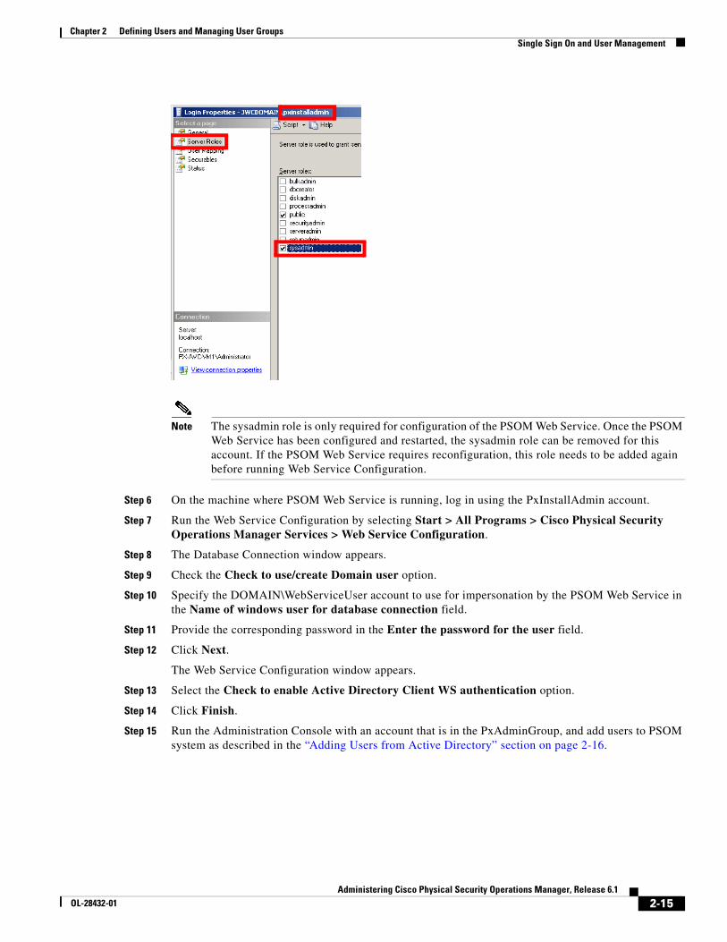
2-15Administering Cisco Physical Security Operations Manager, Release 6.1
OL-28432-01
Chapter 2 Defining Users and Managing User Groups Single Sign On and User Management
Note The sysadmin role is only required for configuration of the PSOM Web Service. Once the PSOM Web Service has been configured and restarted, the sysadmin role can be removed for this account. If the PSOM Web Service requires reconfiguration, this role needs to be added again before running Web Service Configuration.
Step 6 On the machine where PSOM Web Service is running, log in using the PxInstallAdmin account.
Step 7 Run the Web Service Configuration by selecting Start > All Programs > Cisco Physical Security Operations Manager Services > Web Service Configuration.
Step 8 The Database Connection window appears.
Step 9 Check the Check to use/create Domain user option.
Step 10 Specify the DOMAIN\WebServiceUser account to use for impersonation by the PSOM Web Service in the Name of windows user for database connection field.
Step 11 Provide the corresponding password in the Enter the password for the user field.
Step 12 Click Next.
The Web Service Configuration window appears.
Step 13 Select the Check to enable Active Directory Client WS authentication option.
Step 14 Click Finish.
Step 15 Run the Administration Console with an account that is in the PxAdminGroup, and add users to PSOM system as described in the “Adding Users from Active Directory” section on page 2-16.
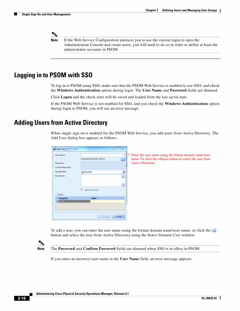
2-16Administering Cisco Physical Security Operations Manager, Release 6.1
OL-28432-01
Chapter 2 Defining Users and Managing User Groups Single Sign On and User Management
Note If the Web Service Configuration instructs you to use the current login to open the Administration Console and create users, you will need to do so in order to define at least the administrator accounts in PSOM.
Logging in to PSOM with SSOTo log in to PSOM using SSO, make sure that the PSOM Web Service is enabled to use SSO, and check the Windows Authentication option during login. The User Name and Password fields are dimmed.
Click Logon and the check state will be saved and loaded from the last saved state.
If the PSOM Web Service is not enabled for SSO, and you check the Windows Authentication option during login to PSOM, you will see an error message.
Adding Users from Active DirectoryWhen single sign on is enabled for the PSOM Web Service, you add users from Active Directory. The Add User dialog box appears as follows.
To add a user, you can enter the user name using the format domain name\user name, or click the button and select the user from Active Directory using the Select Domain User window.
Note The Password and Confirm Password fields are dimmed when SSO is in effect in PSOM.
If you enter an incorrect user name in the User Name field, an error message appears.
Enter the user name using the format domain name\user name. Or click the ellipses button to select the user from Active Directory.
2-17Administering Cisco Physical Security Operations Manager, Release 6.1
OL-28432-01
Chapter 2 Defining Users and Managing User Groups Identity Management in PSOM
Identity Management in PSOMIn the Operation Console, operators can click the Investigate User button in the Alert Details window of the Operations Console to display additional badge details for a user. PSOM leverages the appropriate Integration Module to access badge details for the user from the relevant third-party contact database. This feature is only supported for certain Integration Modules; for example, Lenel Integration Module.
If you use supported third-party software (for example, QuantumSecure) that can retrieve relevant badge details when the Investigate User button is clicked, you can set a server preference from the Administration Console to designate the URL where that third-party identity management software is running.
To designate identity management software, follow these steps:
Procedure
Step 1 Select File > Preferences.
Step 2 Click Identity Management under Server.
Step 3 Check the Use following URL to investigate user option.
Step 4 Enter the IP address or server name of the machine hosting the third-party identity management software in the Server Name field.
Step 5 Enter the URL for accessing the identity management software in the URL to Investigate User field. At the end of the URL, add the following syntax to pass the user badge ID from PSOM to the identity management software when the Investigate User button is clicked in the Alert Details window:
%BADGEID%
The full URL may look similar to the following:
safe/qspersonex.aspx?ActionType=2&FormID=5&SystemID=10&ParamID=%BADGEID%
Step 6 Click OK.

2-18Administering Cisco Physical Security Operations Manager, Release 6.1
OL-28432-01
Chapter 2 Defining Users and Managing User Groups Identity Management in PSOM
C H A P T E R
3-1Administering Cisco Physical Security Operations Manager, Release 6.1
OL-28432-01
3Configuring Video Services
This chapter covers the basic steps to enable video streaming in the Operation Console. For the titles of additional configuration documents specific to the various supported video servers, see the “Granting Access to PSOM from Video Services” section on page 3-3.
This chapter includes these topics:
• Enabling Video Integration with PSOM, page 3-1
• Configuring Access to Video Servers for Monitoring, page 3-1
• Adding new Sensors for Video Cameras, page 3-2
• Controlling User Access to Video, page 3-2
• Granting Access to PSOM from Video Services, page 3-3
• Performing Batch Imports for Video Camera Sensors, page 3-3
• Managing Video Matrix Views and Guard Tours, page 3-4
Enabling Video Integration with PSOMThere are two methods for enabling video integration with PSOM:
• Manually enter camera information into PSOM using the Administration Console. Use this method if you only have a limited number of cameras to configure. See the “Configuring Access to Video Servers for Monitoring” section on page 3-1.
• Perform a batch import of cameras. If you have hundreds or thousands of video cameras to integrate with PSOM, you will want to use this method. Using this method, you will obtain sensor information from the appropriate Integration Module, save it to XML, make whatever changes are necessary using Excel or other spreadsheet, and import the result into PSOM to define all video cameras from your video server at once. See the “Performing Batch Imports for Video Camera Sensors” section on page 3-3.
Configuring Access to Video Servers for MonitoringTo enable manual video integration, you need to obtain some information from the video server configuration.
For each video camera, you need information such as:
• DVR/NVR server name or IP address
3-2Administering Cisco Physical Security Operations Manager, Release 6.1
OL-28432-01
Chapter 3 Configuring Video Services Adding new Sensors for Video Cameras
• Server login name
• Server login password
You can integrate as many different video servers as you wish in PSOM.
To manually configure access to video servers in PSOM for monitoring, follow these steps:
Procedure
Step 1 Click the Video Integration icon in the tools area of the Administration Console.
The Video window appears.
Step 2 Click Video Services to configure access to a video server.
The Video Service Integration Module Configuration window appears.
Step 3 Choose the video service that matches your environment. You might have more than one type of video server in use.
Note See the “Granting Access to PSOM from Video Services” section on page 3-3 for a list of the video services with which PSOM was integrated at the time of release. Contact your Cisco representative to determine which video services have been integrated post-release.
Follow the instructions in the specific configuration documents for supported video services to complete configuration using the Video Service Integration Module Configuration window. See the “Granting Access to PSOM from Video Services” section on page 3-3 for a list of these additional documents.
After video service configuration, hover the mouse over the icon at the bottom right corner of the Administration Console window to display the currently initialized video service, including the built-in AVI demo video service. This helps to troubleshoot the available video services on the working machine.
Adding new Sensors for Video CamerasAfter you have completed Video Server configuration, the next step is to add sensors to PSOM for the video cameras following the instructions in the “Adding new Sensors for Video Cameras” section on page 3-2. You can also import video sensors by batch; see the “Performing Batch Imports for Video Camera Sensors” section on page 3-3.
Controlling User Access to VideoYou can set user permissions that control whether users can view recorded video, export video, take snapshots, create video alerts, and manage video matrixes or guard tours. See the “Permissions within PSOM” section on page 2-9 for information.
When you assign a user the permission to view recorded video, you can also determine how many past days of recorded video they are allowed to see.
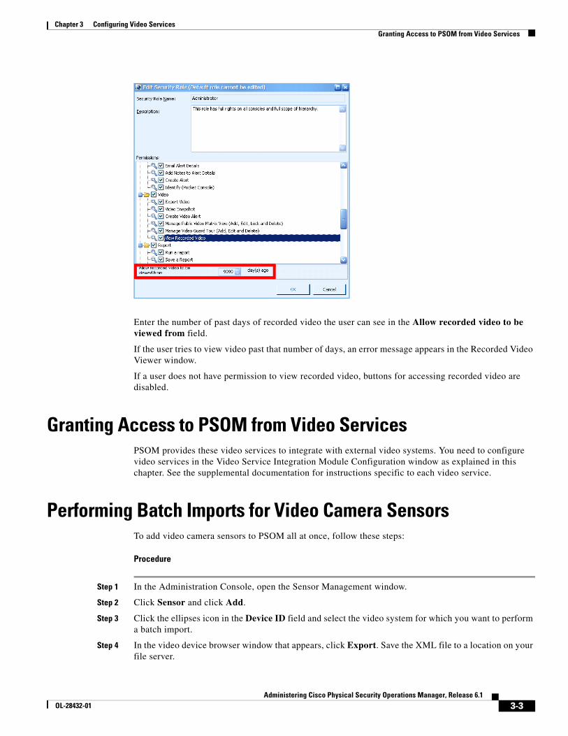
3-3Administering Cisco Physical Security Operations Manager, Release 6.1
OL-28432-01
Chapter 3 Configuring Video Services Granting Access to PSOM from Video Services
Enter the number of past days of recorded video the user can see in the Allow recorded video to be viewed from field.
If the user tries to view video past that number of days, an error message appears in the Recorded Video Viewer window.
If a user does not have permission to view recorded video, buttons for accessing recorded video are disabled.
Granting Access to PSOM from Video ServicesPSOM provides these video services to integrate with external video systems. You need to configure video services in the Video Service Integration Module Configuration window as explained in this chapter. See the supplemental documentation for instructions specific to each video service.
Performing Batch Imports for Video Camera SensorsTo add video camera sensors to PSOM all at once, follow these steps:
Procedure
Step 1 In the Administration Console, open the Sensor Management window.
Step 2 Click Sensor and click Add.
Step 3 Click the ellipses icon in the Device ID field and select the video system for which you want to perform a batch import.
Step 4 In the video device browser window that appears, click Export. Save the XML file to a location on your file server.
3-4Administering Cisco Physical Security Operations Manager, Release 6.1
OL-28432-01
Chapter 3 Configuring Video Services Managing Video Matrix Views and Guard Tours
Step 5 Back in the Sensor Management window, click the Sensor Group icon.
Step 6 Click Import and select the XML file that you just created. This process will create the appropriate type of Sensors for your video cameras.
Step 7 Restart all services and the verify addition of the video server’s sensor type.
Managing Video Matrix Views and Guard ToursYou can set up video matrix views and guard tours in the Video Management Console. Instructions are covered in “Using the Video Management Console” in section in Using Cisco Physical Security Operations Manager.
You can launch the Video Management Console from the PSOM Administration Console.
To launch the Video Management Console, follow these steps:
Procedure
Step 1 Click the Video Integration icon in the tools area of the Administration Console.
The Video window appears.
Step 2 Click Video Console to launch the Video Management Console.
The Video Management Console appears.
See “Using the Video Management Console” section in Using Cisco Physical Security Operations Manager for instructions on setting up video matrix views and guard tours.
C H A P T E R
4-1Administering Cisco Physical Security Operations Manager, Release 6.1
OL-28432-01
4Defining Locations
The first step to defining your Monitoring Areas and Monitoring Zones is to establish the Locations, or physical spaces, within your environment that will be monitored by PSOM.
This chapter includes these topics:
• Planning Locations for Your Environment, page 4-1
• Adding Locations to PSOM, page 4-2
• Editing Locations, page 4-2
• Deleting Locations, page 4-3
• Importing or Exporting Location Names, page 4-3
Planning Locations for Your EnvironmentLocations are the physical spaces in your environment that will be monitored by PSOM. When you start adding sensors to PSOM, you will need to assign each of them to a Location. So your Locations should be places where there are Sensors you want to integrate with PSOM for monitoring.
Setting up Locations within PSOM is much easier if you have first performed some planning.Table 4-1 shows a sample plan for Locations within a building that lists Location names and describes their physical spaces.
Tip Make your names and descriptions detailed so that operators will instantly know exactly where alerts are taking place when they see the Location.
Note For a table to help you with Location planning, see the “Locations Planning” section on page A-4.
Table 4-1 Sample planning for Locations
Location Name Description
Public Elevator 1 The public elevator located on level 1 by baggage claim #1
Ticket Counters - American The 5 ticket counters for American Airlines
Baggage 1 Baggage carousel #1
Checkpoint 1 Security check area 1 on the east side of terminal 1
4-2Administering Cisco Physical Security Operations Manager, Release 6.1
OL-28432-01
Chapter 4 Defining Locations Adding Locations to PSOM
Adding Locations to PSOMTo add a Location to PSOM, follow these steps:
Procedure
Step 1 Click the Environment icon in the Administration Console.
The Environment window appears.
Step 2 Click Location Names to manage your Locations.
The Manage Location Names window appears.
Step 3 Click the New button.
The Add Location window appears.
Step 4 In the Location Name field enter the name you want to assign to this place.
Step 5 In the Description field, enter a detailed description of the Location that will tell operators exactly where it is in the security environment.
For example, “Elevator on 1st floor close to the Baggage Claim 1 area.”
Step 6 Click OK to save the Location to the database.
Step 7 Repeat this procedure to define each Location.
When you finish adding Locations, they will all appear when you access the Manage Location Names window.
Editing LocationsAs operators in your organization use PSOM, you may discover that some Location names or descriptions need to change to enable faster response times. You can edit Location names and descriptions using the Administration Console.
To edit a Location, follow these steps:
Procedure
Step 1 Click the Environment icon in the Administration Console.
The Environment window appears.
Step 2 Click Location Names to manage your Locations.
The Manage Location Names window appears.
Step 3 Select the Location you want to edit from the list.
Step 4 Click the Edit button.
The Edit Location window appears.
Step 5 To change the Location name, enter a new name in the Location Name field.
Step 6 To change the Location description, enter a new description in the Description field.
4-3Administering Cisco Physical Security Operations Manager, Release 6.1
OL-28432-01
Chapter 4 Defining Locations Deleting Locations
For example, “Elevator on 1st floor close to the Baggage Claim 1 area.”
Step 7 Click OK to store your changes to the database.
Deleting LocationsIf changes occur within the physical environment, you may find it necessary to remove Locations from PSOM.
To remove a Location from PSOM, follow these steps:
Procedure
Step 1 Click the Environment icon in the Administration Console.
The Environment window appears.
Step 2 Click Location Names to manage your Locations.
The Manage Location Names window appears.
Step 3 Select the Location you want to remove from the list.
Step 4 Click the Delete button.
A confirmation dialog box appears.
Step 5 Click OK to remove the Location from PSOM.
Note Related Sensors, Monitoring Areas and Monitoring Zones will be affected when you remove a Location from PSOM. Sensors that are associated with this Location may become orphaned if you delete the Location.
If changes occur within the physical environment, you may find it necessary to remove Locations from PSOM.
Importing or Exporting Location NamesYou can export Location definitions from PSOM to an XML file, update the XML content in Microsoft Excel, and import the updated Location definitions to PSOM.
Note See the “Importing and Exporting Sensors, Sensor Groups, and Intercom Groups with PSOM” section on page 6-20 for information about how to open the XML file in Microsoft Excel, edit the data, and save the correct format for re-import to PSOM.
4-4Administering Cisco Physical Security Operations Manager, Release 6.1
OL-28432-01
Chapter 4 Defining Locations Importing or Exporting Location Names
To export or import Locations, follow these steps:
Procedure
Step 1 Click the Environment icon in the Administration Console.
The Environment window appears.
Step 2 Click Location Names to manage your Locations.
The Manage Location Names window appears.
Step 3 Click Import to import Location names from an XML file (should be named PxLocation.xml), then select the XML file on your system that has the definitions.
Step 4 Click Export to save an XML file with the Location names defined in PSOM. It will save the file as PxLocation.xml.
C H A P T E R
5-1Administering Cisco Physical Security Operations Manager, Release 6.1
OL-28432-01
5Managing Monitoring Areas and Monitoring Zones
After you set up Locations and Sensors in PSOM, you can define Monitoring Areas and Monitoring Zones, and then create the Monitoring Hierarchy for traversing across your security environment.
This chapter explains:
• The difference between Monitoring Areas and Monitoring Zones.
• How to add a Monitoring Area to PSOM and include Sensor Groups as members.
• How to add a Monitoring Zone to PSOM and include Monitoring Areas as members.
• Establish the Monitoring Hierarchy that allows users to traverse the security environment from the Navigation Pane in the Operation Console.
This chapter includes these topics:
• Understanding the Monitoring Hierarchy, page 5-1
• Planning Monitoring Areas and Monitoring Zones, page 5-3
• Adding Monitoring Areas to PSOM, page 5-3
• Adding Monitoring Zones to PSOM, page 5-4
• Setting up the Monitoring Hierarchy, page 5-4
• Adding Maps to Monitoring Areas and Monitoring Zones, page 5-9
• Editing or Deleting Monitoring Zones, page 5-10
• Importing or Exporting Monitoring Areas, page 5-10
• Reordering the Monitoring Hierarchy, page 5-11
Understanding the Monitoring HierarchyWithin the Operation Console, users navigate through the security environment using the Monitoring Hierarchy, which is comprised of nested levels of Monitoring Zones which, at the deepest level, contain Monitoring Areas.
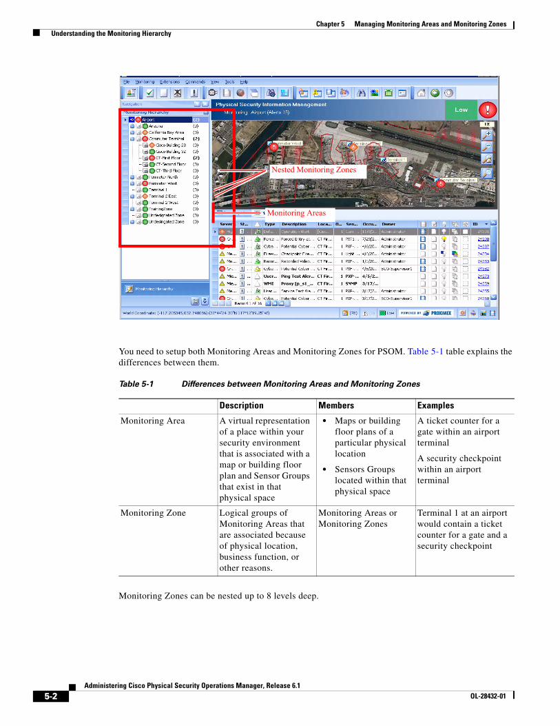
5-2Administering Cisco Physical Security Operations Manager, Release 6.1
OL-28432-01
Chapter 5 Managing Monitoring Areas and Monitoring Zones Understanding the Monitoring Hierarchy
You need to setup both Monitoring Areas and Monitoring Zones for PSOM. Table 5-1 table explains the differences between them.
Monitoring Zones can be nested up to 8 levels deep.
Nested Monitoring Zones
Monitoring Areas
Table 5-1 Differences between Monitoring Areas and Monitoring Zones
Description Members Examples
Monitoring Area A virtual representation of a place within your security environment that is associated with a map or building floor plan and Sensor Groups that exist in that physical space
• Maps or building floor plans of a particular physical location
• Sensors Groups located within that physical space
A ticket counter for a gate within an airport terminal
A security checkpoint within an airport terminal
Monitoring Zone Logical groups of Monitoring Areas that are associated because of physical location, business function, or other reasons.
Monitoring Areas or Monitoring Zones
Terminal 1 at an airport would contain a ticket counter for a gate and a security checkpoint
5-3Administering Cisco Physical Security Operations Manager, Release 6.1
OL-28432-01
Chapter 5 Managing Monitoring Areas and Monitoring Zones Planning Monitoring Areas and Monitoring Zones
Planning Monitoring Areas and Monitoring ZonesPlanning the structure of your surveillance environment might streamline your configuration of Monitoring Areas and Monitoring Zones.
You can use the planning tables in the following sections to determine the structure top-down from Monitoring Zones to Monitoring Areas:
• Monitoring Zone Planning, page A-6
• Monitoring Areas Planning, page A-7
Adding Monitoring Areas to PSOMTo add a Monitoring Area, follow these steps:
Procedure
Step 1 Click the Environment icon in the Administration Console.
The Environment window appears.
Step 2 Click the Monitoring Areas icon.
The Manage Monitoring Areas window appears.
Step 3 Click the New button.
The Cisco Physical Security Operations Manager Area Wizard window appears.
Step 4 In the Monitoring Area Name field, enter a name for this Monitoring Area.
Step 5 In the Description field, provide a detailed description of the location this Monitoring Area represents.
Step 6 Click Next.
Step 7 The Monitoring Area - Member window appears.
Step 8 Click the Add button to associate Sensors with this Monitoring Area.
The Select Sensors window appears.
Step 9 Check boxes for all Sensors in the list you want to include. You can refine the list of Sensors displayed in the list by typing the first few characters of the items you’re seeking in the filter field at the top of the list.
Step 10 Click OK when you’re finished adding Sensors to the Monitoring Area.
Step 11 At the Monitoring Area - Member screen, click Next to continue.
The Monitoring Area - Security window appears.
This screen shows the users that are allowed to access the Monitoring Area.
Note For this product release, all users are allowed access to Monitoring Areas by default. This setting cannot be changed.
Step 12 Click Finish to save your Monitoring Area to PSOM.
5-4Administering Cisco Physical Security Operations Manager, Release 6.1
OL-28432-01
Chapter 5 Managing Monitoring Areas and Monitoring Zones Adding Monitoring Zones to PSOM
Adding Monitoring Zones to PSOMTo add a Monitoring Zone, follow these steps:
Procedure
Step 1 Click the Environment icon in the Administration Console.
The Environment window appears.
Step 2 Click the Monitoring Zones icon.
The Manage Monitoring Zones window appears.
Step 3 Click the New button.
The Cisco Physical Security Operations Manager Zone Wizard window appears.
Step 4 Enter a name for the Monitoring Zone in the Monitoring Zone Name field.
Step 5 Enter a detailed description of the physical or logical space covered by this Monitoring Zone in the Description field.
Step 6 Click Next.
The Monitoring Zone - Member window appears.
Step 7 Click the Add button to associate Monitoring Areas with this Monitoring Zone.
The Manage Monitoring Areas window appears.
Step 8 Check the boxes for all Monitoring Areas that should be associated with this Monitoring Zone. To filter the list of Monitoring Areas displayed, type the first few characters of the Monitoring Area you’re seeking in the filter field at the top of the list.
Step 9 Click OK when you are finished selecting Monitoring Areas.
Step 10 The Monitoring Zone - Member window reappears.
Step 11 Click Next.
The Monitoring Zone - Security window appears.
Step 12 If you want all users to access this Monitoring Zone, leave the All Users option checked. Otherwise, check the User Groups option and click Add to select user groups that can access this Monitoring Zone.
The Select User Group window appears.
Choose the groups that can access this Monitoring Zone and click OK.
Step 13 Click Finish to save your Monitoring Zone to PSOM.
Setting up the Monitoring HierarchyThe structure you define for the Monitoring Hierarchy in the Administration Console is what appears to users in the Navigation Pane of the Operation Console. It is the list-type view of Monitoring Zones and Monitoring Areas that allows operators to traverse the monitoring environment with simple point-and-click actions.
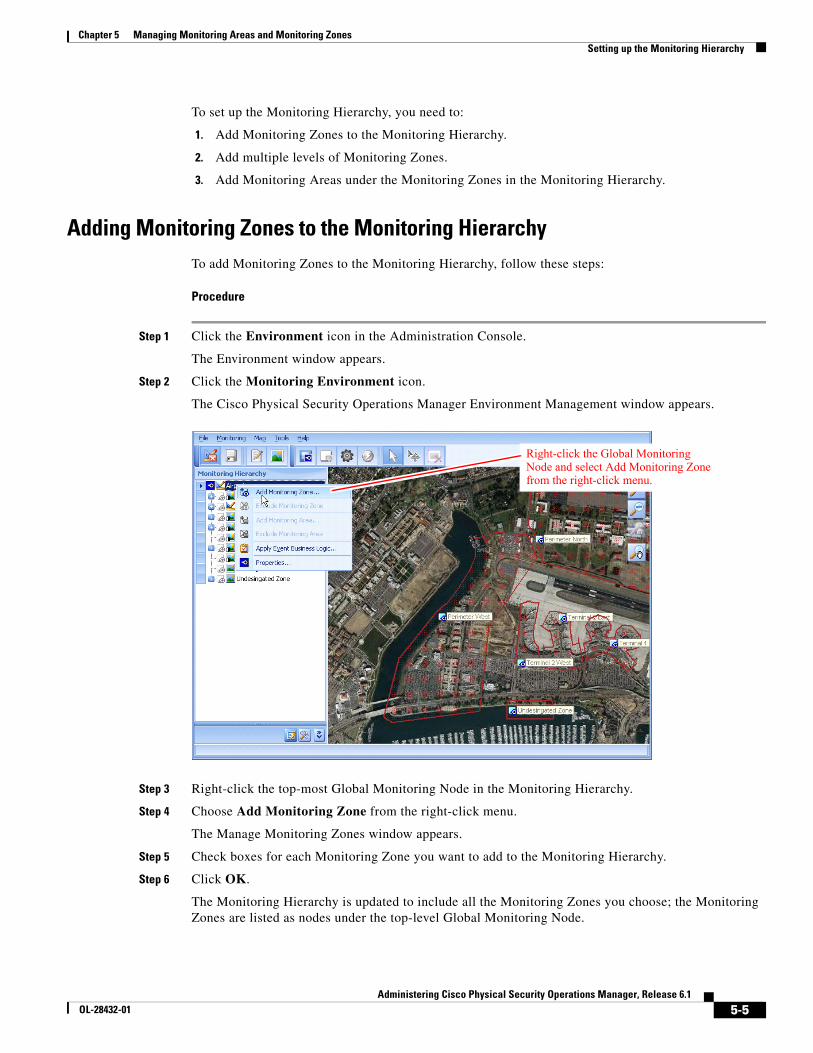
5-5Administering Cisco Physical Security Operations Manager, Release 6.1
OL-28432-01
Chapter 5 Managing Monitoring Areas and Monitoring Zones Setting up the Monitoring Hierarchy
To set up the Monitoring Hierarchy, you need to:
1. Add Monitoring Zones to the Monitoring Hierarchy.
2. Add multiple levels of Monitoring Zones.
3. Add Monitoring Areas under the Monitoring Zones in the Monitoring Hierarchy.
Adding Monitoring Zones to the Monitoring HierarchyTo add Monitoring Zones to the Monitoring Hierarchy, follow these steps:
Procedure
Step 1 Click the Environment icon in the Administration Console.
The Environment window appears.
Step 2 Click the Monitoring Environment icon.
The Cisco Physical Security Operations Manager Environment Management window appears.
Step 3 Right-click the top-most Global Monitoring Node in the Monitoring Hierarchy.
Step 4 Choose Add Monitoring Zone from the right-click menu.
The Manage Monitoring Zones window appears.
Step 5 Check boxes for each Monitoring Zone you want to add to the Monitoring Hierarchy.
Step 6 Click OK.
The Monitoring Hierarchy is updated to include all the Monitoring Zones you choose; the Monitoring Zones are listed as nodes under the top-level Global Monitoring Node.
Right-click the Global Monitoring Node and select Add Monitoring Zone from the right-click menu.
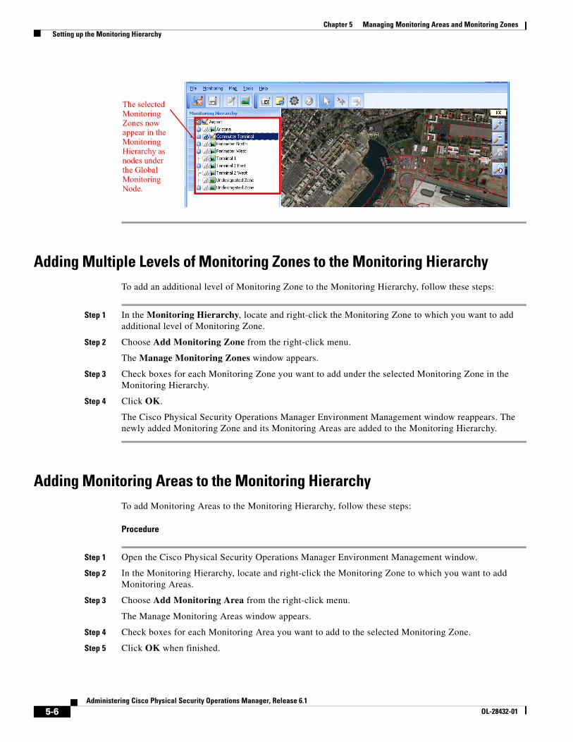
5-6Administering Cisco Physical Security Operations Manager, Release 6.1
OL-28432-01
Chapter 5 Managing Monitoring Areas and Monitoring Zones Setting up the Monitoring Hierarchy
Adding Multiple Levels of Monitoring Zones to the Monitoring HierarchyTo add an additional level of Monitoring Zone to the Monitoring Hierarchy, follow these steps:
Step 1 In the Monitoring Hierarchy, locate and right-click the Monitoring Zone to which you want to add additional level of Monitoring Zone.
Step 2 Choose Add Monitoring Zone from the right-click menu.
The Manage Monitoring Zones window appears.
Step 3 Check boxes for each Monitoring Zone you want to add under the selected Monitoring Zone in the Monitoring Hierarchy.
Step 4 Click OK.
The Cisco Physical Security Operations Manager Environment Management window reappears. The newly added Monitoring Zone and its Monitoring Areas are added to the Monitoring Hierarchy.
Adding Monitoring Areas to the Monitoring HierarchyTo add Monitoring Areas to the Monitoring Hierarchy, follow these steps:
Procedure
Step 1 Open the Cisco Physical Security Operations Manager Environment Management window.
Step 2 In the Monitoring Hierarchy, locate and right-click the Monitoring Zone to which you want to add Monitoring Areas.
Step 3 Choose Add Monitoring Area from the right-click menu.
The Manage Monitoring Areas window appears.
Step 4 Check boxes for each Monitoring Area you want to add to the selected Monitoring Zone.
Step 5 Click OK when finished.
The selected Monitoring Zones now appear in the Monitoring Hierarchy as nodes under the Global Monitoring Node.
5-7Administering Cisco Physical Security Operations Manager, Release 6.1
OL-28432-01
Chapter 5 Managing Monitoring Areas and Monitoring Zones Setting up the Monitoring Hierarchy
The Monitoring Hierarchy is updated to list all the Monitoring Areas you chose as nodes under the Monitoring Zone.
Removing nodes from the Monitoring HierarchyTo exclude a Monitoring Zone from the Monitoring Hierarchy, follow these steps:
Procedure
Step 1 Right-click the Monitoring Zone and choose Exclude Monitoring Zone.
A confirmation dialog box appears.
Step 2 Click the Yes button to confirm the exclusion of the Monitoring Node.
To exclude a Monitoring Area from the Monitoring Hierarchy, follow these steps:
Procedure
Step 1 Right-click the Monitoring Area and choose Exclude Monitoring Area.
A confirmation dialog box appears.
Step 2 Click the Yes button.
In either case, the Monitoring Node is excluded from the Monitoring Hierarchy, but the underlying configuration for the Monitoring Zone or Monitoring Area is unaffected; the Monitoring Node will stay defined in PSOM.
Viewing Properties for Monitoring NodesTo view properties for a Monitoring Node, follow these steps:
Procedure
Step 1 Right-click the Monitoring Node and choose Properties from the right-click menu.
The Properties window appears with the General tab selected.
Note The windows shown in this section are for Monitoring Zone properties.
Step 2 To view the Monitoring Areas and Sensors that are members of this Monitoring Zone, click the Member tab.
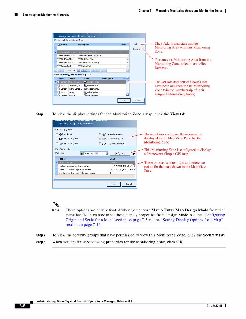
5-8Administering Cisco Physical Security Operations Manager, Release 6.1
OL-28432-01
Chapter 5 Managing Monitoring Areas and Monitoring Zones Setting up the Monitoring Hierarchy
Step 3 To view the display settings for the Monitoring Zone’s map, click the View tab.
Note These options are only activated when you choose Map > Enter Map Design Mode from the menu bar. To learn how to set these display properties from Design Mode, see the “Configuring Origin and Scale for a Map” section on page 7-5and the “Setting Display Options for a Map” section on page 7-13.
Step 4 To view the security groups that have permission to view this Monitoring Zone, click the Security tab.
Step 5 When you are finished viewing properties for the Monitoring Zone, click OK.
The Sensors and Sensor Groups that have been assigned to this Monitoring Zone (via the membership of their assigned Monitoring Areas).
Click Add to associate another Monitoring Area with this Monitoring Zone.
To remove a Monitoring Area from the Monitoring Zone, select it and click Remove.
These options configure the information displayed in the Map View Pane for the Monitoring Zone.
These options set the origin and reference points for the map shown in the Map View Pane.
This Monitoring Zone is configured to display a Framework Simple GIS map.
5-9Administering Cisco Physical Security Operations Manager, Release 6.1
OL-28432-01
Chapter 5 Managing Monitoring Areas and Monitoring Zones Adding Maps to Monitoring Areas and Monitoring Zones
Adding Maps to Monitoring Areas and Monitoring ZonesThe next step to defining your Monitoring Zones and Monitoring Areas is to add appropriate background map or building plan images that will be displayed in the Map View Pane when the Monitoring Zone or Monitoring Area is selected in the Navigation Pane. See the “Adding Background Map Images” section on page 7-4 for instructions.
Editing or Deleting Monitoring AreasTo edit or delete a Monitoring Area: follow these steps:
Procedure
Step 1 Click the Environment icon in the Administration Console.
The Environment window appears.
Step 2 Click the Monitoring Areas icon.
The Manage Monitoring Areas window appears.
Step 3 To edit a Monitoring Area, choose it and click the Edit button.
Note You can remove a monitoring area by choosing it and clicking Delete.
The Monitoring Area Properties window appears.
a. Enter a new name or description for the Monitoring Area on the General tab.
b. Click the Member tab.
c. To remove a Sensor from the Monitoring Area, choose it and click Remove.
d. To add a Sensor to the Monitoring Area, click Add.
The Select Sensors window appears where you can choose the Sensors you want to add and click Add.
e. To move the Monitoring Area to a different part of the Monitoring Hierarchy, click the Move To button.
The Monitoring Tree - Select Area window appears.
Choose the location where you want to move the Monitoring Area and click OK.
f. Click OK to store your changes. Any changes will be immediately reflected in the Monitoring Hierarchy.
Step 4 To delete a Monitoring Area, click the Delete button. A confirmation dialog box appears. Click Yes to confirm the deletion. The Monitoring Area will be removed from the Monitoring Hierarchy; and the Monitoring Area will be removed from the PSOM configuration.
5-10Administering Cisco Physical Security Operations Manager, Release 6.1
OL-28432-01
Chapter 5 Managing Monitoring Areas and Monitoring Zones Editing or Deleting Monitoring Zones
Editing or Deleting Monitoring ZonesTo edit or delete a Monitoring Zone, follow these steps:
Procedure
Step 1 Click the Environment icon in the Administration Console.
The Environment window appears.
Step 2 Click the Monitoring Zones icon.
The Manage Monitoring Zones window appears.
Step 3 To edit a Monitoring Zone, click the Edit button. In the Edit Monitoring Zone window you can change the name or description of the Monitoring Zone.
You can remove a monitoring zone by clicking the Delete button.
a. You can add Monitoring Areas to this Monitoring Zone by clicking the Member tab. Click the Add button to add a Monitoring Area.
b. You can change map view settings for the Monitoring Zone by clicking the View tab.
c. You can change the security settings for the Monitoring Zone by clicking the Security tab. Click User Groups and click the Add button to give a specific user group access to this Monitoring Zone. Choose a user group and click OK.
d. Click OK to store your changes. These changes will automatically be made to the Monitoring Hierarchy.
Step 4 To delete a Monitoring Zone, click the Delete button. A confirmation dialog box appears. Click Yes to confirm the deletion. The Monitoring Zone and its associated Monitoring Areas are removed from the Monitoring Hierarchy. While the Monitoring Zone is deleted (it has also been removed from the PSOM configuration), its associated Monitoring Areas are not deleted from PSOM; they can be re-assigned to a different Monitoring Zone.
Importing or Exporting Monitoring AreasYou can export Monitoring Area definitions from PSOM to an XML file, update the XML content in Microsoft Excel, and import the updated Monitoring Area definitions to PSOM.
Note See the “Importing and Exporting Sensors, Sensor Groups, and Intercom Groups with PSOM” section on page 6-20 for information about how to open the XML file in Microsoft Excel, edit the data, and save out to the correct format for reimport to PSOM.
To export or import Monitoring Areas, follow these steps:
Procedure
Step 1 Click the Environment icon in the Administration Console.
The Environment window appears.
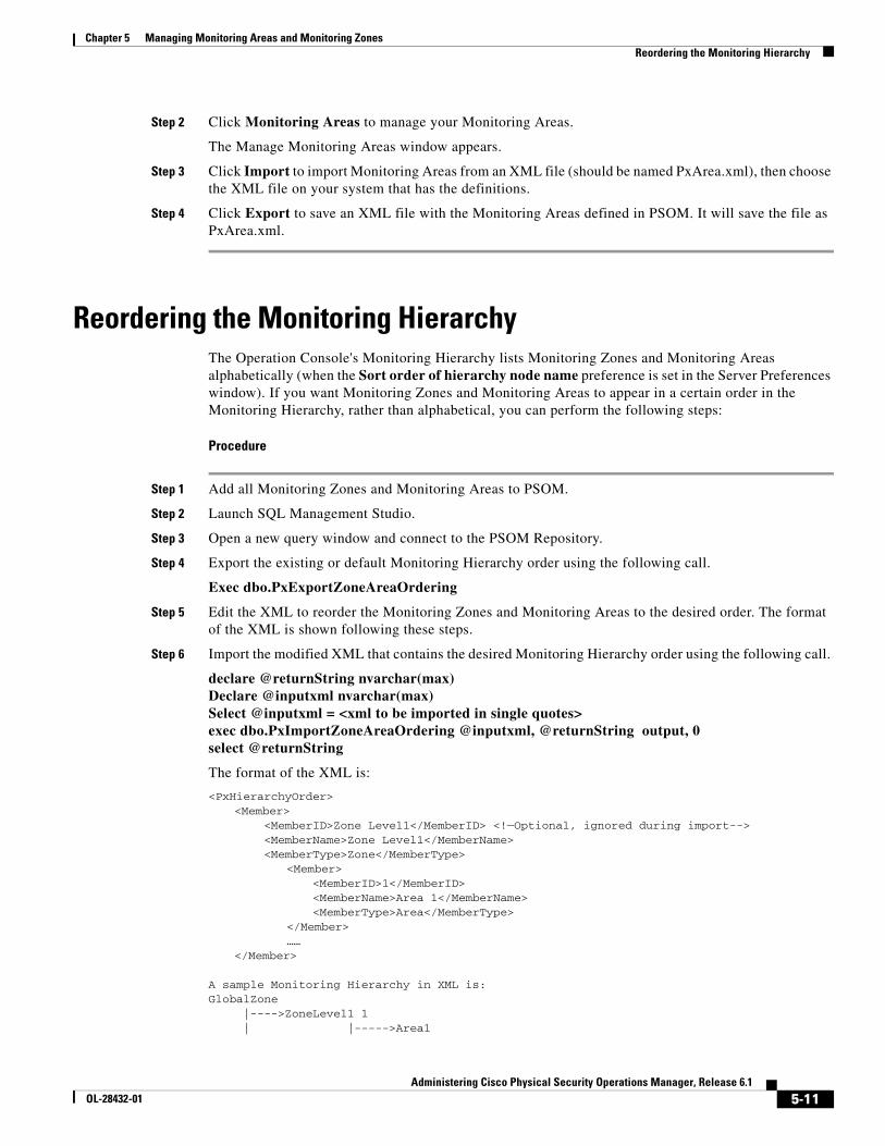
5-11Administering Cisco Physical Security Operations Manager, Release 6.1
OL-28432-01
Chapter 5 Managing Monitoring Areas and Monitoring Zones Reordering the Monitoring Hierarchy
Step 2 Click Monitoring Areas to manage your Monitoring Areas.
The Manage Monitoring Areas window appears.
Step 3 Click Import to import Monitoring Areas from an XML file (should be named PxArea.xml), then choose the XML file on your system that has the definitions.
Step 4 Click Export to save an XML file with the Monitoring Areas defined in PSOM. It will save the file as PxArea.xml.
Reordering the Monitoring HierarchyThe Operation Console's Monitoring Hierarchy lists Monitoring Zones and Monitoring Areas alphabetically (when the Sort order of hierarchy node name preference is set in the Server Preferences window). If you want Monitoring Zones and Monitoring Areas to appear in a certain order in the Monitoring Hierarchy, rather than alphabetical, you can perform the following steps:
Procedure
Step 1 Add all Monitoring Zones and Monitoring Areas to PSOM.
Step 2 Launch SQL Management Studio.
Step 3 Open a new query window and connect to the PSOM Repository.
Step 4 Export the existing or default Monitoring Hierarchy order using the following call.
Exec dbo.PxExportZoneAreaOrdering
Step 5 Edit the XML to reorder the Monitoring Zones and Monitoring Areas to the desired order. The format of the XML is shown following these steps.
Step 6 Import the modified XML that contains the desired Monitoring Hierarchy order using the following call.
declare @returnString nvarchar(max)Declare @inputxml nvarchar(max)Select @inputxml = <xml to be imported in single quotes>exec dbo.PxImportZoneAreaOrdering @inputxml, @returnString output, 0select @returnString
The format of the XML is:
<PxHierarchyOrder><Member>
<MemberID>Zone Level1</MemberID> <!—Optional, ignored during import--> <MemberName>Zone Level1</MemberName> <MemberType>Zone</MemberType>
<Member> <MemberID>1</MemberID> <MemberName>Area 1</MemberName> <MemberType>Area</MemberType>
</Member>……
</Member>
A sample Monitoring Hierarchy in XML is:GlobalZone |---->ZoneLevel1 1 | |----->Area1
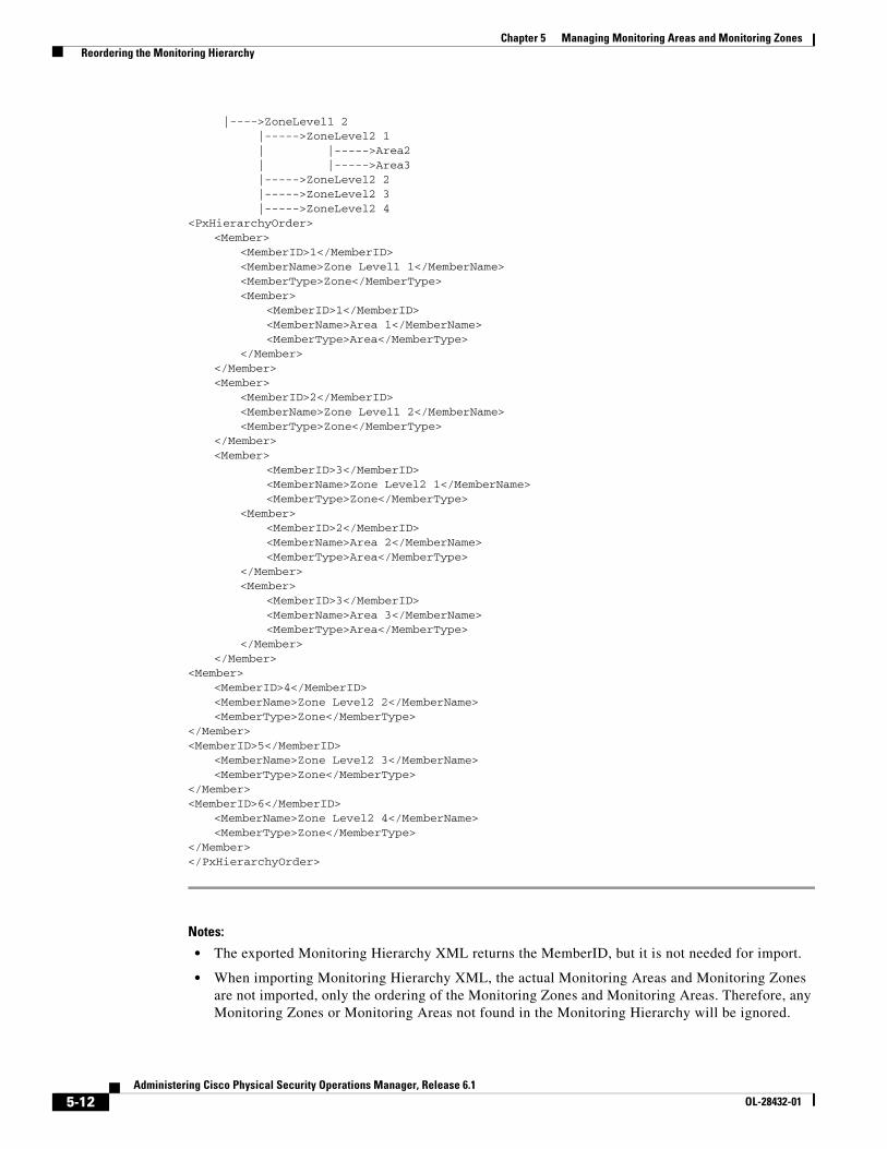
5-12Administering Cisco Physical Security Operations Manager, Release 6.1
OL-28432-01
Chapter 5 Managing Monitoring Areas and Monitoring Zones Reordering the Monitoring Hierarchy
|---->ZoneLevel1 2 |----->ZoneLevel2 1 | |----->Area2 | |----->Area3 |----->ZoneLevel2 2 |----->ZoneLevel2 3 |----->ZoneLevel2 4<PxHierarchyOrder>
<Member><MemberID>1</MemberID><MemberName>Zone Level1 1</MemberName><MemberType>Zone</MemberType><Member>
<MemberID>1</MemberID><MemberName>Area 1</MemberName><MemberType>Area</MemberType>
</Member></Member><Member>
<MemberID>2</MemberID><MemberName>Zone Level1 2</MemberName><MemberType>Zone</MemberType>
</Member><Member>
<MemberID>3</MemberID><MemberName>Zone Level2 1</MemberName><MemberType>Zone</MemberType>
<Member><MemberID>2</MemberID><MemberName>Area 2</MemberName><MemberType>Area</MemberType>
</Member><Member>
<MemberID>3</MemberID><MemberName>Area 3</MemberName><MemberType>Area</MemberType>
</Member></Member>
<Member><MemberID>4</MemberID><MemberName>Zone Level2 2</MemberName><MemberType>Zone</MemberType>
</Member><MemberID>5</MemberID>
<MemberName>Zone Level2 3</MemberName><MemberType>Zone</MemberType>
</Member><MemberID>6</MemberID>
<MemberName>Zone Level2 4</MemberName><MemberType>Zone</MemberType>
</Member></PxHierarchyOrder>
Notes:
• The exported Monitoring Hierarchy XML returns the MemberID, but it is not needed for import.
• When importing Monitoring Hierarchy XML, the actual Monitoring Areas and Monitoring Zones are not imported, only the ordering of the Monitoring Zones and Monitoring Areas. Therefore, any Monitoring Zones or Monitoring Areas not found in the Monitoring Hierarchy will be ignored.
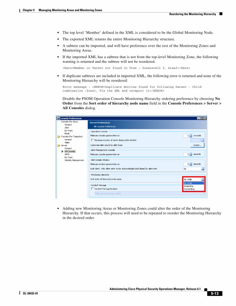
5-13Administering Cisco Physical Security Operations Manager, Release 6.1
OL-28432-01
Chapter 5 Managing Monitoring Areas and Monitoring Zones Reordering the Monitoring Hierarchy
• The top level ‘Member’ defined in the XML is considered to be the Global Monitoring Node.
• The exported XML returns the entire Monitoring Hierarchy structure.
• A subtree can be imported, and will have preference over the rest of the Monitoring Zones and Monitoring Areas.
• If the imported XML has a subtree that is not from the top-level Monitoring Zone, the following warning is returned and the subtree will not be reordered.
<Warn>Member or Parent not found in Tree : ZoneLevel2 2, Area3</Warn>
• If duplicate subtrees are included in imported XML, the following error is returned and none of the Monitoring Hierarchy will be reordered:
Error message : <ERROR>Duplicate Entries found for following Parent - Child combination :Zone1, Fix the XML and reimport it</ERROR>
Disable the PSOM Operation Console Monitoring Hierarchy ordering preference by choosing No Order from the Sort order of hierarchy node name field in the Console Preferences > Server > All Consoles dialog.
• Adding new Monitoring Areas or Monitoring Zones could alter the order of the Monitoring Hierarchy. If that occurs, this process will need to be repeated to reorder the Monitoring Hierarchy in the desired order.

5-14Administering Cisco Physical Security Operations Manager, Release 6.1
OL-28432-01
Chapter 5 Managing Monitoring Areas and Monitoring Zones Reordering the Monitoring Hierarchy

C H A P T E R
6-1Administering Cisco Physical Security Operations Manager, Release 6.1
OL-28432-01
6Managing Sensors
Every physical sensor in your environment (video cameras and access control devices) needs to be represented in PSOM with a Sensor definition.
• This chapter explains how to:
• Add access control devices as Sensors in PSOM
• Add video camera devices from video servers as Sensors in PSOM
• Add other types of devices—such as hazard detection devices—as Sensors in PSOM
• Add camera view angle, distance, direction and field of view to the Sensor definition
• Group Sensors together for monitoring certain locations
• Group intercom devices together
• Import and export Sensors, Sensor Groups, and Intercom Groups with PSOM
This chapter includes these topics:
• Types of Sensors and Connectors, page 6-1
• Planning Sensor Integration, page 6-3
• Adding new Sensors for Access Control Devices, page 6-3
• Adding new Sensors for Video Cameras, page 6-5
• Adding new Sensors for Other Types of Devices, page 6-8
• Using the Extended URL Property, page 6-13
• Editing Sensors, page 6-14
• Grouping Sensors, page 6-16
• Managing Intercom Groups, page 6-18
• Editing an Intercom Group, page 6-19
• Importing and Exporting Sensors, Sensor Groups, and Intercom Groups with PSOM, page 6-20
• Create Custom Sensor Icons, page 6-24
Types of Sensors and ConnectorsTo enable monitoring by PSOM, you must add Sensor definitions for all sensor devices in your environment. To create Sensors using the Administration Console, you will need to have Integration Modules or Video Services installed and configured.
6-2Administering Cisco Physical Security Operations Manager, Release 6.1
OL-28432-01
Chapter 6 Managing Sensors Types of Sensors and Connectors
PSOM integrates with many types of sensors, including:
• Access control systems, such as Software House CCure, or Hirsch Velocity
• Camera, digital video recorder (DVR), network video recorder (NVR) systems such as Pelco DX-8000, Nice NiceVision, Verint Nextiva, Bosch DiBos, or Vicon ViconNet
• Hazard or fire detector systems such RAE Systems
• Intelligent video (IV) systems such as ObjectVideo VEW or Vidient SmartCatch
• Intercom or Public Announcement (PA) systems such as Commend Intercom
• Radar and sonar devices
• Digital signage systems
• Microwave systems
• Electronic fence systems
• Intrusion detection systems
• Emergency duress systems
• IP devices
• HVAC (heating, ventilating and air conditioning systems)
• BAC (Basic Access Control (BAC) systems used to read passports)
• Glass Break Detector
• Seismic Detector
• UPS (Universal Power Supply)
• Gas Detector
• Social Network
• Auxiliary Input
• Auxiliary Output
• Panel Input
• Panel Output
• Card Reader
• Panel
• Door Contact
• Door
• Room
• Building
• Elevator
• Receiver
• Video Analytics Server
• DVR NVR
• Video Encoder
After Sensors are added to PSOM for each device, they can be associated with certain locations and then grouped together as necessary.
6-3Administering Cisco Physical Security Operations Manager, Release 6.1
OL-28432-01
Chapter 6 Managing Sensors Planning Sensor Integration
Planning Sensor IntegrationPSOM can access the database for external systems (such as Cisco Physical Access Control system) to obtain a list of active devices if the connection has been established and is active. Otherwise, you will need to know the device IDs of all devices to be monitored by PSOM. See the Integration Module documentation for instructions on integrating various external systems with PSOM; install PxDocSetup.msi to obtain all PSOM documentation.
PSOM can also access video servers (such as Vicon Video Server) to obtain a list of active video camera devices if the connection has been established and is active. For better presentation in PSOM, you can optionally add information about the camera’s view range angle (in degrees), view distance (in feet), and view direction (in degrees). You will need to collect this information for each video camera you are adding to PSOM.
For a table to help you with video camera planning, see the “Video Camera Planning” section on page A-5.
Note Camera view direction moves counter-clockwise (0 to 359 degrees); 0 degrees means the camera is pointing to the right, 180 degrees indicates the camera is pointing to the left.
Adding new Sensors for Access Control DevicesTo add a new Sensor for an access control device, follow these steps:
Procedure
Step 1 Click the Environment icon in the Administration Console.
The Environment window appears.
Step 2 Click the Sensors icon.
The Sensor Management window appears.
Step 3 Click the Sensor icon to display a list of all Sensors defined for PSOM.
Step 4 Click the Add button to create a new Sensor definition.
The Add New Sensor window appears.
Step 5 In the Sensor Name field, enter the name you want displayed for this Sensor on the maps in the Map View Pane and in the Alert Details window of the Operation Console.
Step 6 From the Sensor Type field, select the type of your access control system, for example Access Control - Hirsch Velocity.
If you want to sort the sensor types by vendor, click the button and select the access control sensor from the Sensor Type field according to vendor.
Step 7 In the Description field, enter details that will help operators identify this access control device quickly when an alert condition happens.
Step 8 Click the button in the Device ID field to connect to the access control system’s database and view a list of all access devices.
A window opens with a list of all devices.
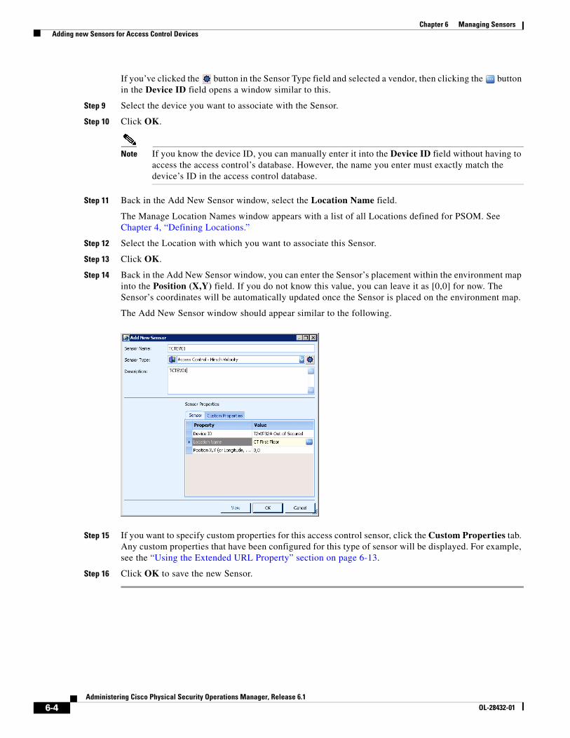
6-4Administering Cisco Physical Security Operations Manager, Release 6.1
OL-28432-01
Chapter 6 Managing Sensors Adding new Sensors for Access Control Devices
If you’ve clicked the button in the Sensor Type field and selected a vendor, then clicking the button in the Device ID field opens a window similar to this.
Step 9 Select the device you want to associate with the Sensor.
Step 10 Click OK.
Note If you know the device ID, you can manually enter it into the Device ID field without having to access the access control’s database. However, the name you enter must exactly match the device’s ID in the access control database.
Step 11 Back in the Add New Sensor window, select the Location Name field.
The Manage Location Names window appears with a list of all Locations defined for PSOM. See Chapter 4, “Defining Locations.”
Step 12 Select the Location with which you want to associate this Sensor.
Step 13 Click OK.
Step 14 Back in the Add New Sensor window, you can enter the Sensor’s placement within the environment map into the Position (X,Y) field. If you do not know this value, you can leave it as [0,0] for now. The Sensor’s coordinates will be automatically updated once the Sensor is placed on the environment map.
The Add New Sensor window should appear similar to the following.
Step 15 If you want to specify custom properties for this access control sensor, click the Custom Properties tab. Any custom properties that have been configured for this type of sensor will be displayed. For example, see the “Using the Extended URL Property” section on page 6-13.
Step 16 Click OK to save the new Sensor.
6-5Administering Cisco Physical Security Operations Manager, Release 6.1
OL-28432-01
Chapter 6 Managing Sensors Adding new Sensors for Video Cameras
Adding new Sensors for Video CamerasPSOM supports these types of video cameras: stationary, PTZ, infrared and other. When adding a Sensor for a video camera, you complete the same information for each type of video camera.
Note You can perform a batch import of video camera sensors to PSOM. See the “Performing Batch Imports for Video Camera Sensors” section on page 3-3.
There are special settings to configure EZ-Track. See Chapter 12, “Setting Up EZ-Track.”
To add a new Sensor for a video camera, follow these steps:
Procedure
Step 1 Click the Environment icon in the Administration Console.
The Environment window appears.
Step 2 Click the Sensors icon.
The Sensor Management window appears.
Step 3 Click the Sensor icon to display a list of all Sensors currently defined for PSOM.
Step 4 Click the Add button to create a new Sensor definition.
The Add New Sensor window appears.
Step 5 In the Sensor Name field, enter the name you want displayed for this Sensor on the maps in the Map View Pane and in the Alert Details window of the Operation Console.
Step 6 From the Sensor Type field, select one of the video camera types. For example, select Camera - Stationary, Camera - PTZ, Camera - Infrared, or Camera - Other.
Step 7 In the Description field, enter details that will help operators identify this video camera quickly when an alert condition happens.
Step 8 Click the button in the Device ID field to connect to the video server’s database and view a list of all video cameras.
A window opens with a list of all video cameras in the video server’s database.
Note If PSOM cannot access the video server to display a list of camera sensors, you will need to manually enter the camera information into the Add New Sensor window.
Step 9 Select the video camera device you want to associate with the Sensor.
Step 10 Click OK.
Note If you know the device ID, you can manually enter it into the Device ID field without having to access the video server’s database. The camera sensor's device ID is different from the device name and each vendor has a different format.
If the video server supports it, you can export the Sensor list to XML, modify the Sensor information, and then re-import the XML into PSOM. See “Importing and Exporting Sensors, Sensor Groups, and Intercom Groups with PSOM” section on page 6-20.
6-6Administering Cisco Physical Security Operations Manager, Release 6.1
OL-28432-01
Chapter 6 Managing Sensors Adding new Sensors for Video Cameras
Step 11 Back in the Add New Sensor window, select the Location Name field.
The Manage Location Names window appears with a list of all Locations defined for PSOM. See Chapter 4, “Defining Locations.”
Step 12 Select the Location with which you want to associate this Sensor.
Step 13 Click OK.
Step 14 Back in the Add New Sensor window, you can enter the Sensor’s placement within the environment map into the Position (X,Y) field.
Note If you do not know this value, you can leave it as [0,0] for now. The Sensor’s coordinates will be automatically updated once the Sensor is placed on the map.
Note You can enter the camera’s range angle, distance and orientation in this dialog box, or you can visually provide this information when you add the camera Sensor to a map. See the “Adding Sensors to a Map” section on page 7-19 for details.
Step 15 In the Range Angle (degree) field, enter the width of the camera’s viewing area in degrees.
Step 16 In the Range Distance (ft) field, enter the distance in feet from the camera to the farthest point it can accurately view.
Step 17 In the View Orientation (degree) field, enter the angle of the camera view in degrees (counter-clockwise from 0-359 degrees). 0 degrees indicates the camera is pointing to the right, 180 degrees indicates the camera is pointing to the left.
Note All of these settings are important for setting up EZ-Track. See the Chapter 12, “Setting Up EZ-Track.”
Step 18 To add a field of view (FOV) image to the Sensor definition, click the View button.
The Live Video Viewer window appears.
Step 19 Click the Snapshot button in the Live Video Viewer to capture a still image.
The camera FOV is displayed in the Add New Sensor window.
If you’re configuring a PTZ camera, see the “Setting up PTZ Preset Positions” section on page 6-6.
Step 20 If you want to specify custom properties for this camera Sensor, click the Custom Properties tab. Any custom properties that have been configured for this type of sensor will be displayed. For example, see the “Using the Extended URL Property” section on page 6-13.
Step 21 Click OK to save the new Sensor.
Setting up PTZ Preset PositionsBy defining sensor views for a PTZ camera sensor, you can enable PTZ cameras in PSOM to visually move between actual preset positions that are defined in the video management system.
The following PTZ Sensor has three sensor views defined for it.
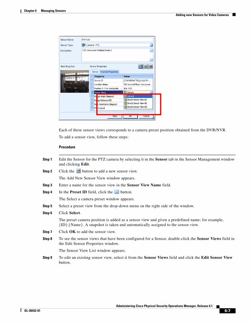
6-7Administering Cisco Physical Security Operations Manager, Release 6.1
OL-28432-01
Chapter 6 Managing Sensors Adding new Sensors for Video Cameras
Each of these sensor views corresponds to a camera preset position obtained from the DVR/NVR.
To add a sensor view, follow these steps:
Procedure
Step 1 Edit the Sensor for the PTZ camera by selecting it in the Sensor tab in the Sensor Management window and clicking Edit.
Step 2 Click the button to add a new sensor view.
The Add New Sensor View window appears.
Step 3 Enter a name for the sensor view in the Sensor View Name field.
Step 4 In the Preset ID field, click the button.
The Select a camera preset window appears.
Step 5 Select a preset view from the drop-down menu on the right side of the window.
Step 6 Click Select.
The preset camera position is added as a sensor view and given a predefined name; for example, {ID};{Name}. A snapshot is taken and automatically assigned to the sensor view.
Step 7 Click OK to add the sensor view.
Step 8 To see the sensor views that have been configured for a Sensor, double-click the Sensor Views field in the Edit Sensor Properties window.
The Sensor View List window appears.
Step 9 To edit an existing sensor view, select it from the Sensor Views field and click the Edit Sensor View button.
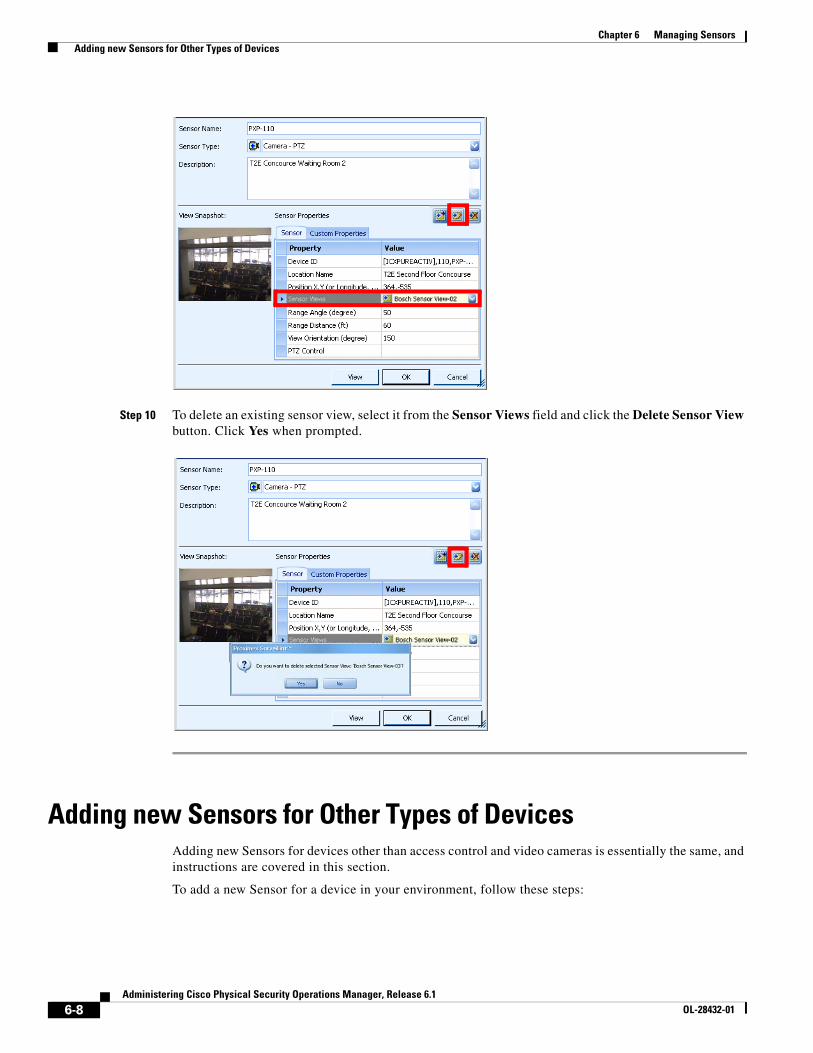
6-8Administering Cisco Physical Security Operations Manager, Release 6.1
OL-28432-01
Chapter 6 Managing Sensors Adding new Sensors for Other Types of Devices
Step 10 To delete an existing sensor view, select it from the Sensor Views field and click the Delete Sensor View button. Click Yes when prompted.
Adding new Sensors for Other Types of DevicesAdding new Sensors for devices other than access control and video cameras is essentially the same, and instructions are covered in this section.
To add a new Sensor for a device in your environment, follow these steps:
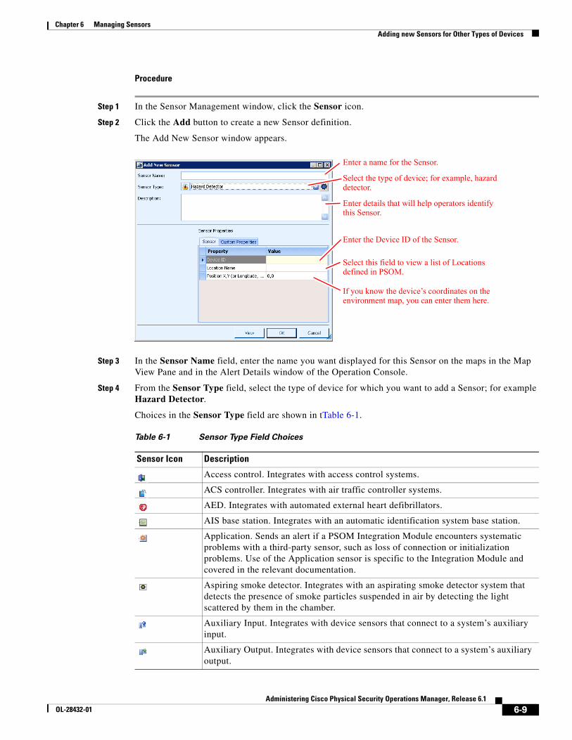
6-9Administering Cisco Physical Security Operations Manager, Release 6.1
OL-28432-01
Chapter 6 Managing Sensors Adding new Sensors for Other Types of Devices
Procedure
Step 1 In the Sensor Management window, click the Sensor icon.
Step 2 Click the Add button to create a new Sensor definition.
The Add New Sensor window appears.
Step 3 In the Sensor Name field, enter the name you want displayed for this Sensor on the maps in the Map View Pane and in the Alert Details window of the Operation Console.
Step 4 From the Sensor Type field, select the type of device for which you want to add a Sensor; for example Hazard Detector.
Choices in the Sensor Type field are shown in tTable 6-1.
Enter a name for the Sensor.
Select the type of device; for example, hazard detector.
Enter details that will help operators identify this Sensor.
Enter the Device ID of the Sensor.
Select this field to view a list of Locations defined in PSOM.
If you know the device’s coordinates on the environment map, you can enter them here.
Table 6-1 Sensor Type Field Choices
Sensor Icon Description
Access control. Integrates with access control systems.
ACS controller. Integrates with air traffic controller systems.
AED. Integrates with automated external heart defibrillators.
AIS base station. Integrates with an automatic identification system base station.
Application. Sends an alert if a PSOM Integration Module encounters systematic problems with a third-party sensor, such as loss of connection or initialization problems. Use of the Application sensor is specific to the Integration Module and covered in the relevant documentation.
Aspiring smoke detector. Integrates with an aspirating smoke detector system that detects the presence of smoke particles suspended in air by detecting the light scattered by them in the chamber.
Auxiliary Input. Integrates with device sensors that connect to a system’s auxiliary input.
Auxiliary Output. Integrates with device sensors that connect to a system’s auxiliary output.
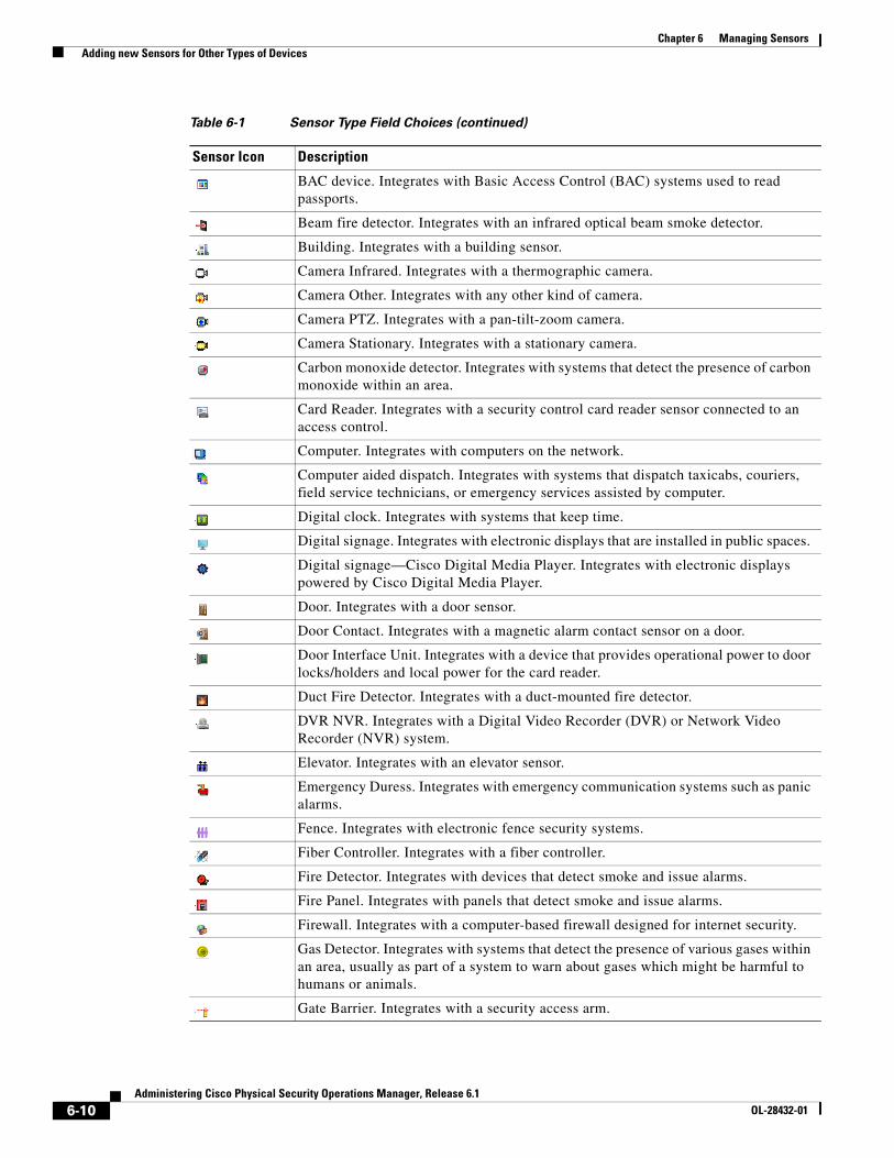
6-10Administering Cisco Physical Security Operations Manager, Release 6.1
OL-28432-01
Chapter 6 Managing Sensors Adding new Sensors for Other Types of Devices
BAC device. Integrates with Basic Access Control (BAC) systems used to read passports.
Beam fire detector. Integrates with an infrared optical beam smoke detector.
Building. Integrates with a building sensor.
Camera Infrared. Integrates with a thermographic camera.
Camera Other. Integrates with any other kind of camera.
Camera PTZ. Integrates with a pan-tilt-zoom camera.
Camera Stationary. Integrates with a stationary camera.
Carbon monoxide detector. Integrates with systems that detect the presence of carbon monoxide within an area.
Card Reader. Integrates with a security control card reader sensor connected to an access control.
Computer. Integrates with computers on the network.
Computer aided dispatch. Integrates with systems that dispatch taxicabs, couriers, field service technicians, or emergency services assisted by computer.
Digital clock. Integrates with systems that keep time.
Digital signage. Integrates with electronic displays that are installed in public spaces.
Digital signage—Cisco Digital Media Player. Integrates with electronic displays powered by Cisco Digital Media Player.
Door. Integrates with a door sensor.
Door Contact. Integrates with a magnetic alarm contact sensor on a door.
Door Interface Unit. Integrates with a device that provides operational power to door locks/holders and local power for the card reader.
Duct Fire Detector. Integrates with a duct-mounted fire detector.
DVR NVR. Integrates with a Digital Video Recorder (DVR) or Network Video Recorder (NVR) system.
Elevator. Integrates with an elevator sensor.
Emergency Duress. Integrates with emergency communication systems such as panic alarms.
Fence. Integrates with electronic fence security systems.
Fiber Controller. Integrates with a fiber controller.
Fire Detector. Integrates with devices that detect smoke and issue alarms.
Fire Panel. Integrates with panels that detect smoke and issue alarms.
Firewall. Integrates with a computer-based firewall designed for internet security.
Gas Detector. Integrates with systems that detect the presence of various gases within an area, usually as part of a system to warn about gases which might be harmful to humans or animals.
Gate Barrier. Integrates with a security access arm.
Table 6-1 Sensor Type Field Choices (continued)
Sensor Icon Description
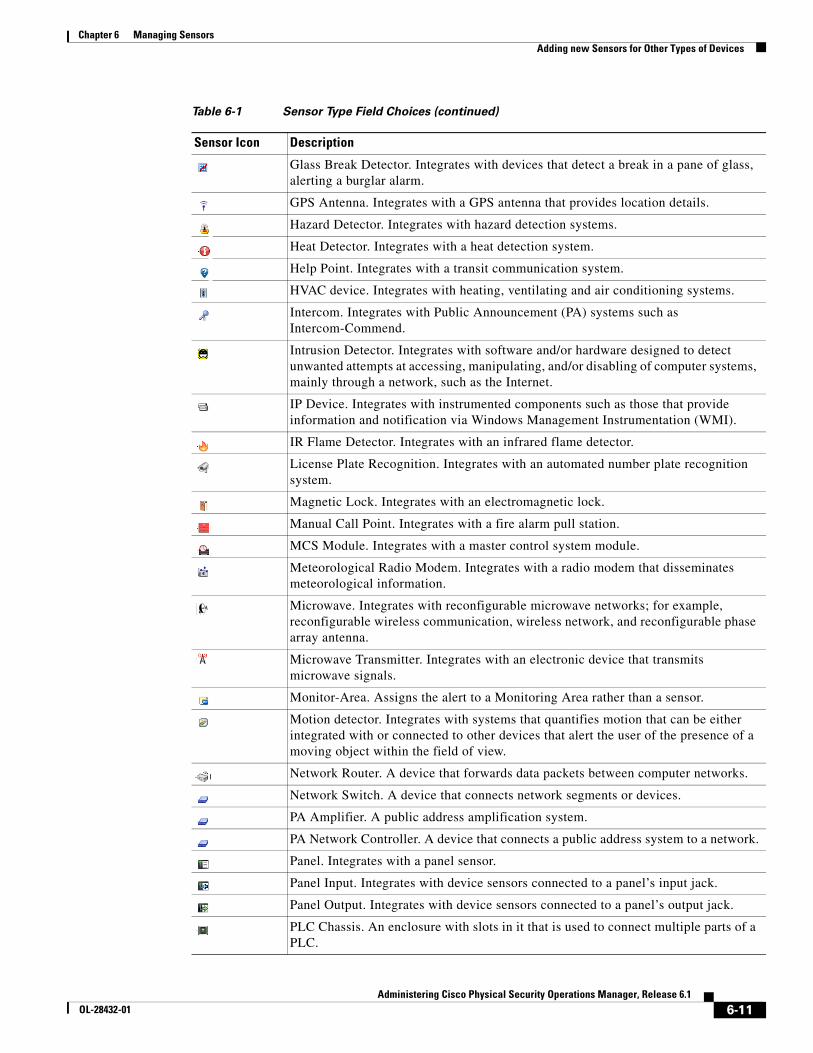
6-11Administering Cisco Physical Security Operations Manager, Release 6.1
OL-28432-01
Chapter 6 Managing Sensors Adding new Sensors for Other Types of Devices
Glass Break Detector. Integrates with devices that detect a break in a pane of glass, alerting a burglar alarm.
GPS Antenna. Integrates with a GPS antenna that provides location details.
Hazard Detector. Integrates with hazard detection systems.
Heat Detector. Integrates with a heat detection system.
Help Point. Integrates with a transit communication system.
HVAC device. Integrates with heating, ventilating and air conditioning systems.
Intercom. Integrates with Public Announcement (PA) systems such as Intercom-Commend.
Intrusion Detector. Integrates with software and/or hardware designed to detect unwanted attempts at accessing, manipulating, and/or disabling of computer systems, mainly through a network, such as the Internet.
IP Device. Integrates with instrumented components such as those that provide information and notification via Windows Management Instrumentation (WMI).
IR Flame Detector. Integrates with an infrared flame detector.
License Plate Recognition. Integrates with an automated number plate recognition system.
Magnetic Lock. Integrates with an electromagnetic lock.
Manual Call Point. Integrates with a fire alarm pull station.
MCS Module. Integrates with a master control system module.
Meteorological Radio Modem. Integrates with a radio modem that disseminates meteorological information.
Microwave. Integrates with reconfigurable microwave networks; for example, reconfigurable wireless communication, wireless network, and reconfigurable phase array antenna.
Microwave Transmitter. Integrates with an electronic device that transmits microwave signals.
Monitor-Area. Assigns the alert to a Monitoring Area rather than a sensor.
Motion detector. Integrates with systems that quantifies motion that can be either integrated with or connected to other devices that alert the user of the presence of a moving object within the field of view.
Network Router. A device that forwards data packets between computer networks.
Network Switch. A device that connects network segments or devices.
PA Amplifier. A public address amplification system.
PA Network Controller. A device that connects a public address system to a network.
Panel. Integrates with a panel sensor.
Panel Input. Integrates with device sensors connected to a panel’s input jack.
Panel Output. Integrates with device sensors connected to a panel’s output jack.
PLC Chassis. An enclosure with slots in it that is used to connect multiple parts of a PLC.
Table 6-1 Sensor Type Field Choices (continued)
Sensor Icon Description
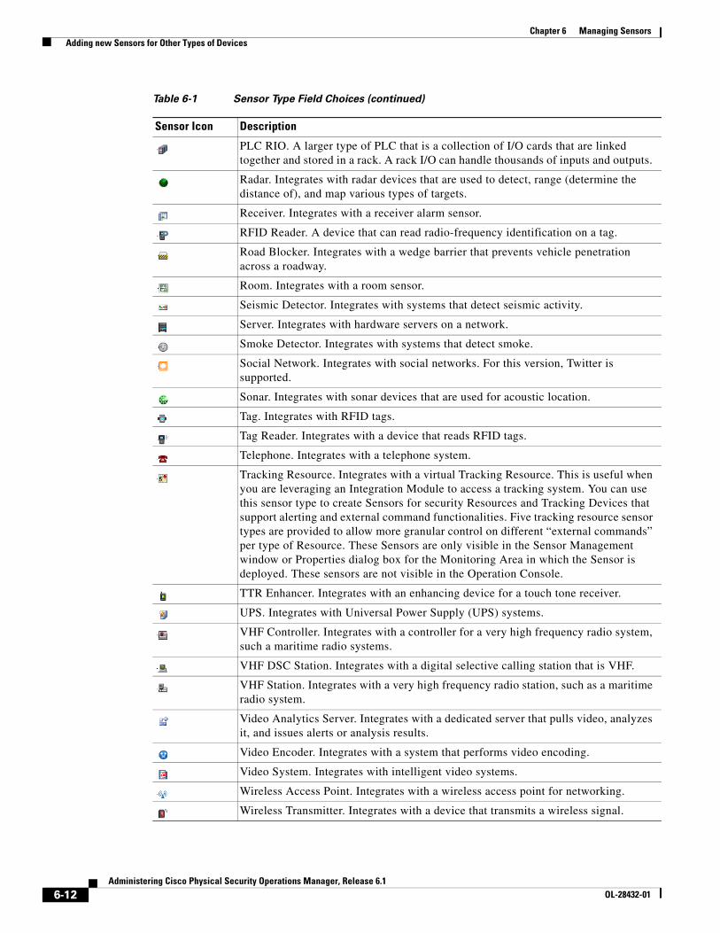
6-12Administering Cisco Physical Security Operations Manager, Release 6.1
OL-28432-01
Chapter 6 Managing Sensors Adding new Sensors for Other Types of Devices
PLC RIO. A larger type of PLC that is a collection of I/O cards that are linked together and stored in a rack. A rack I/O can handle thousands of inputs and outputs.
Radar. Integrates with radar devices that are used to detect, range (determine the distance of), and map various types of targets.
Receiver. Integrates with a receiver alarm sensor.
RFID Reader. A device that can read radio-frequency identification on a tag.
Road Blocker. Integrates with a wedge barrier that prevents vehicle penetration across a roadway.
Room. Integrates with a room sensor.
Seismic Detector. Integrates with systems that detect seismic activity.
Server. Integrates with hardware servers on a network.
Smoke Detector. Integrates with systems that detect smoke.
Social Network. Integrates with social networks. For this version, Twitter is supported.
Sonar. Integrates with sonar devices that are used for acoustic location.
Tag. Integrates with RFID tags.
Tag Reader. Integrates with a device that reads RFID tags.
Telephone. Integrates with a telephone system.
Tracking Resource. Integrates with a virtual Tracking Resource. This is useful when you are leveraging an Integration Module to access a tracking system. You can use this sensor type to create Sensors for security Resources and Tracking Devices that support alerting and external command functionalities. Five tracking resource sensor types are provided to allow more granular control on different “external commands” per type of Resource. These Sensors are only visible in the Sensor Management window or Properties dialog box for the Monitoring Area in which the Sensor is deployed. These sensors are not visible in the Operation Console.
TTR Enhancer. Integrates with an enhancing device for a touch tone receiver.
UPS. Integrates with Universal Power Supply (UPS) systems.
VHF Controller. Integrates with a controller for a very high frequency radio system, such a maritime radio systems.
VHF DSC Station. Integrates with a digital selective calling station that is VHF.
VHF Station. Integrates with a very high frequency radio station, such as a maritime radio system.
Video Analytics Server. Integrates with a dedicated server that pulls video, analyzes it, and issues alerts or analysis results.
Video Encoder. Integrates with a system that performs video encoding.
Video System. Integrates with intelligent video systems.
Wireless Access Point. Integrates with a wireless access point for networking.
Wireless Transmitter. Integrates with a device that transmits a wireless signal.
Table 6-1 Sensor Type Field Choices (continued)
Sensor Icon Description
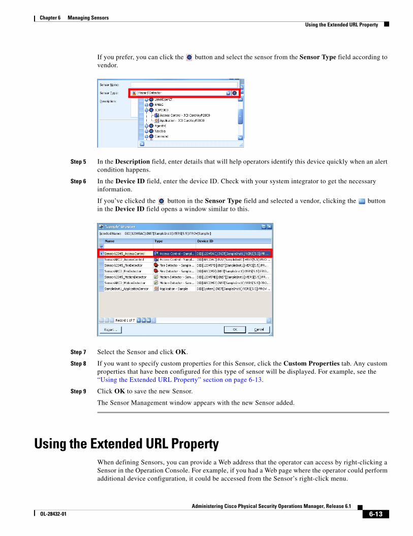
6-13Administering Cisco Physical Security Operations Manager, Release 6.1
OL-28432-01
Chapter 6 Managing Sensors Using the Extended URL Property
If you prefer, you can click the button and select the sensor from the Sensor Type field according to vendor.
Step 5 In the Description field, enter details that will help operators identify this device quickly when an alert condition happens.
Step 6 In the Device ID field, enter the device ID. Check with your system integrator to get the necessary information.
If you’ve clicked the button in the Sensor Type field and selected a vendor, clicking the button in the Device ID field opens a window similar to this.
Step 7 Select the Sensor and click OK.
Step 8 If you want to specify custom properties for this Sensor, click the Custom Properties tab. Any custom properties that have been configured for this type of sensor will be displayed. For example, see the “Using the Extended URL Property” section on page 6-13.
Step 9 Click OK to save the new Sensor.
The Sensor Management window appears with the new Sensor added.
Using the Extended URL PropertyWhen defining Sensors, you can provide a Web address that the operator can access by right-clicking a Sensor in the Operation Console. For example, if you had a Web page where the operator could perform additional device configuration, it could be accessed from the Sensor’s right-click menu.
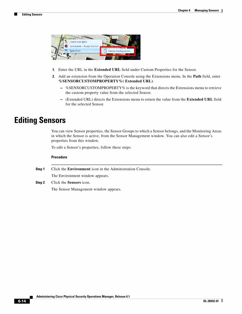
6-14Administering Cisco Physical Security Operations Manager, Release 6.1
OL-28432-01
Chapter 6 Managing Sensors Editing Sensors
1. Enter the URL in the Extended URL field under Custom Properties for the Sensor.
2. Add an extension from the Operation Console using the Extensions menu. In the Path field, enter %SENSORCUSTOMPROPERTY%( Extended URL).
– %SENSORCUSTOMPROPERTY% is the keyword that directs the Extensions menu to retrieve the custom property value from the selected Sensor.
– (Extended URL) directs the Extensions menu to return the value from the Extended URL field for the selected Sensor.
Editing SensorsYou can view Sensor properties, the Sensor Groups to which a Sensor belongs, and the Monitoring Areas in which the Sensor is active, from the Sensor Management window. You can also edit a Sensor’s properties from this window.
To edit a Sensor’s properties, follow these steps:
Procedure
Step 1 Click the Environment icon in the Administration Console.
The Environment window appears.
Step 2 Click the Sensors icon.
The Sensor Management window appears.
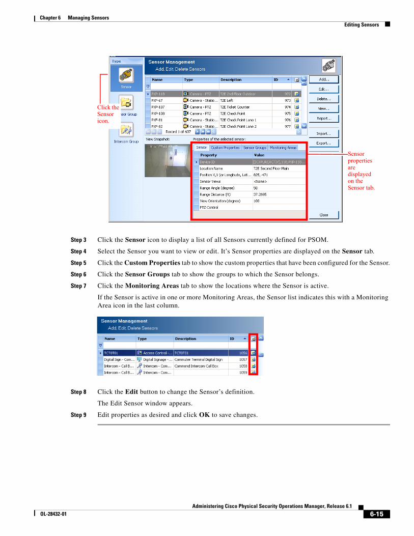
6-15Administering Cisco Physical Security Operations Manager, Release 6.1
OL-28432-01
Chapter 6 Managing Sensors Editing Sensors
Step 3 Click the Sensor icon to display a list of all Sensors currently defined for PSOM.
Step 4 Select the Sensor you want to view or edit. It’s Sensor properties are displayed on the Sensor tab.
Step 5 Click the Custom Properties tab to show the custom properties that have been configured for the Sensor.
Step 6 Click the Sensor Groups tab to show the groups to which the Sensor belongs.
Step 7 Click the Monitoring Areas tab to show the locations where the Sensor is active.
If the Sensor is active in one or more Monitoring Areas, the Sensor list indicates this with a Monitoring Area icon in the last column.
Step 8 Click the Edit button to change the Sensor’s definition.
The Edit Sensor window appears.
Step 9 Edit properties as desired and click OK to save changes.
Click the Sensor icon.
Sensor properties are displayed on the Sensor tab.
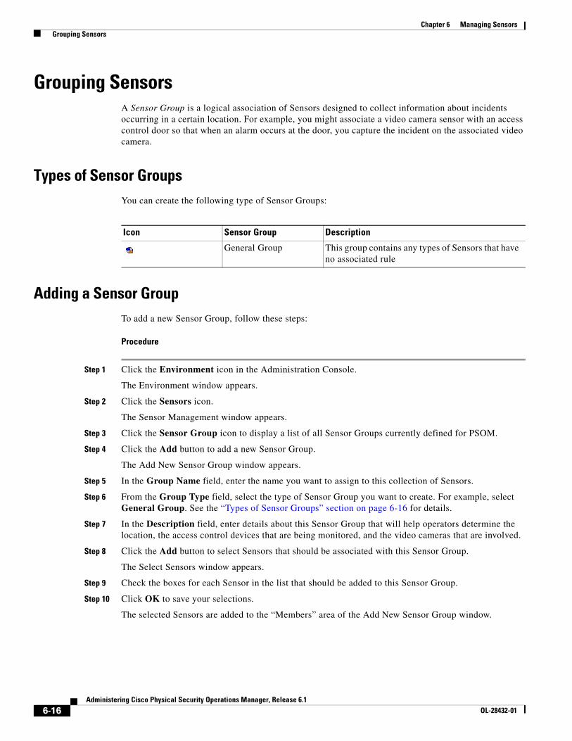
6-16Administering Cisco Physical Security Operations Manager, Release 6.1
OL-28432-01
Chapter 6 Managing Sensors Grouping Sensors
Grouping SensorsA Sensor Group is a logical association of Sensors designed to collect information about incidents occurring in a certain location. For example, you might associate a video camera sensor with an access control door so that when an alarm occurs at the door, you capture the incident on the associated video camera.
Types of Sensor GroupsYou can create the following type of Sensor Groups:
Adding a Sensor GroupTo add a new Sensor Group, follow these steps:
Procedure
Step 1 Click the Environment icon in the Administration Console.
The Environment window appears.
Step 2 Click the Sensors icon.
The Sensor Management window appears.
Step 3 Click the Sensor Group icon to display a list of all Sensor Groups currently defined for PSOM.
Step 4 Click the Add button to add a new Sensor Group.
The Add New Sensor Group window appears.
Step 5 In the Group Name field, enter the name you want to assign to this collection of Sensors.
Step 6 From the Group Type field, select the type of Sensor Group you want to create. For example, select General Group. See the “Types of Sensor Groups” section on page 6-16 for details.
Step 7 In the Description field, enter details about this Sensor Group that will help operators determine the location, the access control devices that are being monitored, and the video cameras that are involved.
Step 8 Click the Add button to select Sensors that should be associated with this Sensor Group.
The Select Sensors window appears.
Step 9 Check the boxes for each Sensor in the list that should be added to this Sensor Group.
Step 10 Click OK to save your selections.
The selected Sensors are added to the “Members” area of the Add New Sensor Group window.
Icon Sensor Group Description
General Group This group contains any types of Sensors that have no associated rule
6-17Administering Cisco Physical Security Operations Manager, Release 6.1
OL-28432-01
Chapter 6 Managing Sensors Grouping Sensors
Note If your Sensor Group includes a PTZ camera, the primary sensor view configured for the PTZ camera appears under View Name. You can also configure a sensor view for the group as described in the “Editing a Sensor Group” section on page 6-17.
Step 11 Click OK to save your Sensor Group.
Editing a Sensor GroupYou may want to edit a Sensor Group to change its member Sensors, or to modify its description.
Note If you add or remove members in a Sensor Group, you need to first remove the Sensor Group from its Monitoring Area. Once you’ve modified membership to the Sensor Group, you can re-assign the Sensor Group to the Monitoring Area. See the “Editing or Deleting Monitoring Areas” section on page 5-9.
To edit a Sensor Group, follow these steps:
Procedure
Step 1 Click the Environment icon in the Administration Console.
The Environment window appears.
Step 2 Click the Sensors icon.
The Sensor Management window appears.
Step 3 Click the Sensor Group icon to display a list of all Sensor Groups currently defined for PSOM.
Step 4 Select the Sensor Group from the list and click the Edit button to change it.
The Edit Sensor Group Properties window appears.
Step 5 To change the Sensor Group’s type, make a different selection from the Group Type field.
Step 6 To change the description, enter modifications in the Description field.
Step 7 To add new members to the Sensor Group, click the Add button. When the Select Sensors window appears, check boxes for the Sensors you want to add to the Sensor Group, and click OK.
Step 8 To remove a member from the Sensor Group, select the Sensor from the list under “Members...” and click the Remove button.
Step 9 To change the primary sensor view for a PTZ camera in the Sensor Group, select the PTZ camera from the “Members...” list and click Sensor View.
The Sensor View List window appears.
a. Select the view you want to assign to the PTZ camera for this Sensor Group and click OK.
b. Click View to define a new view for the Sensor Group. The Live Video Viewer appears to allow you to select the new view.
Step 10 Click OK to save your changes.
6-18Administering Cisco Physical Security Operations Manager, Release 6.1
OL-28432-01
Chapter 6 Managing Sensors Managing Intercom Groups
Deleting a Sensor GroupTo remove a Sensor Group, follow these steps:
Procedure
Step 1 Click the Environment icon in the Administration Console.
The Environment window appears.
Step 2 Click the Sensors icon.
Step 3 Click the Sensor Group icon.
The Sensor Management window appears.
Step 4 Click the Sensor Group icon to display a list of all Sensor Groups.
Step 5 Select the Sensor Group you want to remove, and click the Delete button.
A confirmation dialog box appears.
Step 6 Click Yes to verify the deletion.
Managing Intercom GroupsYou can group intercom devices together in PSOM so that you can broadcast announcements to these devices from PSOM.
Adding an Intercom GroupTo add a new Intercom Group, follow these steps:
Procedure
Step 1 Click the Environment icon in the Administration Console.
The Environment window appears.
Step 2 Click the Sensors icon.
The Sensor Management window appears.
Step 3 Click the Intercom Group icon to display a list of all Intercom Groups currently defined for PSOM.
Step 4 Click the Add button to add a new Intercom Group.
The Add New Intercom Group window appears.
Step 5 In the Group Name field, enter the name you want to assign to this collection of intercom devices.
In the Group Device ID field, enter the device ID to associate with this Intercom Group.
Step 6 In the Description field, enter details about this Intercom Group that will help operators determine the location, the intercom devices that are being monitored.
Step 7 Click the Add button to select intercom devices to associate with this group.
6-19Administering Cisco Physical Security Operations Manager, Release 6.1
OL-28432-01
Chapter 6 Managing Sensors Editing an Intercom Group
The Select Sensors window appears.
Step 8 Check boxes for each intercom device in the list that should be added to this Intercom Group.
Step 9 Click OK to save your selections.
The selected intercom devices are added to the Members area of the Add New Intercom Group window.
Step 10 Click OK to save your Intercom Group.
Editing an Intercom GroupYou may want to edit an Intercom Group to change its members, or to modify its description.
Note If you add or remove members in an Intercom Group, you need to first remove the Intercom Group from its Monitoring Area. Once you’ve modified membership to the Intercom Group, you can re-assign the Intercom Group to the Monitoring Area. See the “Editing or Deleting Monitoring Areas” section on page 5-9.
To edit an Intercom Group, follow these steps:
Procedure
Step 1 Click the Environment icon in the Administration Console.
The Environment window appears.
Step 2 Click the Sensors icon.
The Sensor Management window appears.
Step 3 Click the Intercom Group icon to display a list of all Intercom Groups currently defined for PSOM.
Step 4 Select the group from the list and click the Edit button to change it.
The Edit Intercom Group Properties window appears.
Step 5 To change the group’s device ID, enter a different ID in the Group Device ID field.
Step 6 To change the description, enter modifications in the Description field.
Step 7 To add new members to the Intercom Group, click the Add button. When the Select Sensors window appears, check boxes for the intercom devices you want to add to the Intercom Group, and click OK.
Step 8 To remove a member from the Intercom Group, select the device from the list under “Members...” and click the Remove button.
Step 9 Click OK to save your changes.

6-20Administering Cisco Physical Security Operations Manager, Release 6.1
OL-28432-01
Chapter 6 Managing Sensors Importing and Exporting Sensors, Sensor Groups, and Intercom Groups with PSOM
Deleting an Intercom GroupTo remove an Intercom Group, follow these steps:
Procedure
Step 1 Click the Environment icon in the Administration Console.
The Environment window appears.
Step 2 Click the Sensors icon.
Step 3 Click the Intercom Group icon.
The Sensor Management window appears.
Step 4 Click the Intercom Group icon to display a list of all Intercom Groups currently defined for PSOM.
Step 5 Select the Intercom Group you want to remove, and click the Delete button.
A confirmation dialog box appears.
Step 6 Click Yes to verify the deletion.
Importing and Exporting Sensors, Sensor Groups, and Intercom Groups with PSOM
You can import Sensors, Sensor Groups, Intercom Groups, and Locations to PSOM using Microsoft Excel; you can also export these definitions to Excel from PSOM.
Note These procedures have been verified using Excel 2007. If you are using Excel 2003 or later, you can save the XML file as XML Data for reimport to PSOM.
To import Sensors to PSOM, follow these steps:
Procedure
Step 1 Open the PxSensor.XML file in Excel 2007.
For Sensor Groups, open the PxSensorGroup.XML file, and for Intercom Groups, open the PxIntercomGroup.XML file.
Step 2 When prompted, choose to open the XML file as an XML table; select As an XML table and click OK.
Step 3 When prompted, click OK.
Step 4 In Excel, click Save As > Other Formats.
Step 5 From the list of formats that appears, select XML Data (*.xml).
6-21Administering Cisco Physical Security Operations Manager, Release 6.1
OL-28432-01
Chapter 6 Managing Sensors Importing and Exporting Sensors, Sensor Groups, and Intercom Groups with PSOM
Step 6 In the window that appears, enter a name in the File name field and click Save.
Step 7 Modify the table to add your new Sensors. You must provide values for each column for your new Sensor.
Special characters cannot be used in XML strings. You can substitute the following syntax for special characters.
For example, if you have a SensorDescription of “Area A & B”, you will use “Area A & B”.
Step 8 Save the XML table as an XML Data file; select XML Data (*.xml) from the Save as Type field and click Save.
Step 9 When prompted, click Continue.
Step 10 Save the XML file.
Now you can import the Sensor definitions XML file into PSOM.
Step 11 Click the Environment icon in the Administration Console.
The Environment window appears.
Step 12 Click Sensors.
The Sensor Management window appears.
Step 13 Click Sensor to view Sensors.
Note Click Sensor Group to view Sensor Groups or click Intercom Group to view Intercom Groups.
Step 14 Click Import to import Sensor definitions from an XML file, then select the XML file on your system that has the definitions.
Character Substitute
& &
< <
> >
“ "
‘ '
6-22Administering Cisco Physical Security Operations Manager, Release 6.1
OL-28432-01
Chapter 6 Managing Sensors Importing and Exporting Sensors, Sensor Groups, and Intercom Groups with PSOM
Note You can also click Export to save an XML file with the Sensor definitions stored in PSOM. It will save the file as PxSensor.xml for Sensors, PxSensorGroup.xml for Sensor Groups, and PxIntercomGroup.xml for Intercom Groups.
If the XML file size you are importing exceeds 2 MB (roughly 4000 sensors), the import process will either timeout or fail immediately without importing sensors. To avoid this problem, split the XML file into multiple files that are smaller than 2 MB each, and import the XML files one at a time.
Sensors are created in "Default Location".
Updating Sensors with a Web Service CallYou may wish to update Sensor information in PSOM from your application using an XML file; conversely, you may wish to pull Sensor information from PSOM into your application. PSOM provides these web service calls:
• ExportDBObject <LoginID>, <Object Type>, <File Name with full path>
• ImportDBObject <LoginID>, <Object Type>, <File Name with full path>
where Object Type can be a value from 1-3 representing the following:
For example, the following syntax instructs PSOM to export all Sensor information in XML to “C:\output\sensor.xml”:
ExportDBObject myLogin, 2, “c:\output\sensor.xml”
When updating information in PSOM, the SensorName property is used to determine whether the Sensor already exists and should be updated, or whether the Sensor is new and should be created. For Sensor Groups, the SensorGroupName property is used. If a sensor exists in PSOM, but is not included in the XML you are uploading, then no change is made to that sensor in PSOM. In other words, XML for import operations only needs to contain changed and new Sensors.
Structure of XML for Sensor definitions
The structure of the XML for Sensors is as follows.
<Sensor><SensorName>Hirsch Expansion Input</SensorName><SensorDescription>Expansion Input Access Control</SensorDescription><SensorTypeName>Access Control</SensorTypeName><LocationName>Office1</LocationName><ConfigStatus>0</ConfigStatus><DeviceID><![CDATA[AED Alarm CP5]]></DeviceID><DeviceXML></DeviceXML>
1 Location
2 Sensor
3 SensorGroup
6-23Administering Cisco Physical Security Operations Manager, Release 6.1
OL-28432-01
Chapter 6 Managing Sensors Importing and Exporting Sensors, Sensor Groups, and Intercom Groups with PSOM
<PositionX>-1.216291</PositionX><PositionY>3.6883777</PositionY><PositionZ>0.0000000</PositionZ><ViewRangeAngle>0</ViewRangeAngle><ViewRangeDistance>0</ViewRangeDistance><ViewOrientation>0 </ViewOrientation><UIState>0</UIState>
</Sensor>
Structure of XML for Sensor Group definitions
The structure of the XML for a Sensor Group is as follows.
<SensorGroup><Name>CCure Grp2</Name><Description></Description><TypeName>Access Control-Camera</TypeName><SubTypeName>SoftwareHouse-CCure</SubTypeName><Member>
<MemberName>NonDoor</MemberName><MemberTypeName>Access Control</MemberTypeName><MemberSubTypeName>SoftwareHouse-CCure</MemberSubTypeName><LocationName>[CCure Area 1]</LocationName><DeviceID><![CDATA[2087]]></DeviceID><DeviceXML></DeviceXML>
</Member></SensorGroup>
You can use the <PxSensorGroupImport> command to create a new Sensor Group, as well as create new Sensors within it. In this case, the DeviceID must contain a value for the new member.
Return Values
Successful operations receive the following return value.
<WSSERVICE NAME="Export or Import DBObjects"><STATUS>0</STATUS><RESULT COUNT="0">
<REASON>Output written to file successfully</REASON></RESULT>
</WSSERVICE>
If an output file and path is not specified by your call, the returned XML includes the structure of the Sensor, Sensor Group, or Location data that is being imported or exported. The following example shows an update to Location data.
<WSSERVICE NAME="Export or Import DB Objects"><STATUS>0</STATUS><RESULT COUNT="0"> <ExportDBObject>
<Location><LocationName>dummyloc</LocationName><LocationDescription>dummyloc</LocationDescription>
</Location><Location>
<LocationName>Office10</LocationName><LocationDescription>Office10</LocationDescription>
</Location></ExportDBObject></RESULT>
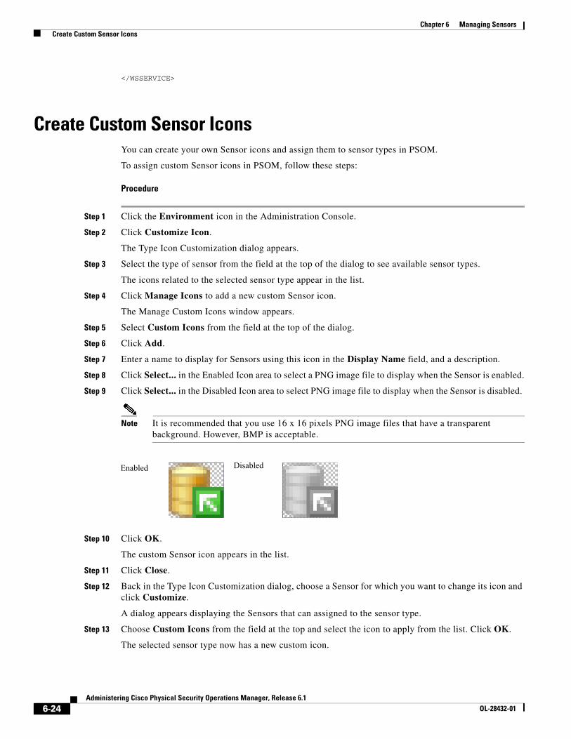
6-24Administering Cisco Physical Security Operations Manager, Release 6.1
OL-28432-01
Chapter 6 Managing Sensors Create Custom Sensor Icons
</WSSERVICE>
Create Custom Sensor IconsYou can create your own Sensor icons and assign them to sensor types in PSOM.
To assign custom Sensor icons in PSOM, follow these steps:
Procedure
Step 1 Click the Environment icon in the Administration Console.
Step 2 Click Customize Icon.
The Type Icon Customization dialog appears.
Step 3 Select the type of sensor from the field at the top of the dialog to see available sensor types.
The icons related to the selected sensor type appear in the list.
Step 4 Click Manage Icons to add a new custom Sensor icon.
The Manage Custom Icons window appears.
Step 5 Select Custom Icons from the field at the top of the dialog.
Step 6 Click Add.
Step 7 Enter a name to display for Sensors using this icon in the Display Name field, and a description.
Step 8 Click Select... in the Enabled Icon area to select a PNG image file to display when the Sensor is enabled.
Step 9 Click Select... in the Disabled Icon area to select PNG image file to display when the Sensor is disabled.
Note It is recommended that you use 16 x 16 pixels PNG image files that have a transparent background. However, BMP is acceptable.
Step 10 Click OK.
The custom Sensor icon appears in the list.
Step 11 Click Close.
Step 12 Back in the Type Icon Customization dialog, choose a Sensor for which you want to change its icon and click Customize.
A dialog appears displaying the Sensors that can assigned to the sensor type.
Step 13 Choose Custom Icons from the field at the top and select the icon to apply from the list. Click OK.
The selected sensor type now has a new custom icon.
Enabled Disabled

6-25Administering Cisco Physical Security Operations Manager, Release 6.1
OL-28432-01
Chapter 6 Managing Sensors Create Custom Sensor Icons
Step 14 Restart the Operation Console to apply the changes. If you do not restart the Operation Console, the custom icon will not appear for the sensor type on the map.

6-26Administering Cisco Physical Security Operations Manager, Release 6.1
OL-28432-01
Chapter 6 Managing Sensors Create Custom Sensor Icons

C H A P T E R
7-1Administering Cisco Physical Security Operations Manager, Release 6.1
OL-28432-01
7Designing Maps
To enable the view provided in the Map View Pane of the Operation Console, you must design the maps shown for each Monitoring Zone and Monitoring Area within PSOM.
This chapter covers how to use the Map Design Mode to:
• Provide background images for maps that offer an aerial view or building floor plan.
• Configure the origin and scale for a map. Optionally, configure GPS coordinates for maps.
• Add Sensors to a map for each video camera and access control device in the environment.
This chapter includes these topics:
• Entering Map Design Mode, page 7-1
• Adding Background Map Images, page 7-4
• Configuring Origin and Scale for a Map, page 7-5
• Setting Display Options for a Map, page 7-13
• Drawing a Monitoring Zone Boundary or Monitoring Area Boundary on a Map, page 7-14
• Adding Sensors to a Map, page 7-19
• Adding Navigation to Maps, page 7-25
• Adding URL Links to Maps, page 7-28
• Adding Notes to Maps, page 7-30
• Editing and Deleting Items from the Map, page 7-31
• Setting the Sort order of the Monitoring Hierarchy, page 7-32
• Integrating GIS maps with PSOM, page 7-32
Entering Map Design ModeYou need to design maps for each Monitoring Zone and Monitoring Area within PSOM, including the top-level Global Monitoring Node. The process for configuring maps and their properties is the same for all levels of nodes in the Monitoring Hierarchy—from the Map Design Mode, you perform all actions in this chapter for each Monitoring Node.
To enable Map Design Mode for all nodes in the Monitoring Hierarchy at once, follow the instructions below to enter Map Design Mode for the Global Monitoring Node.
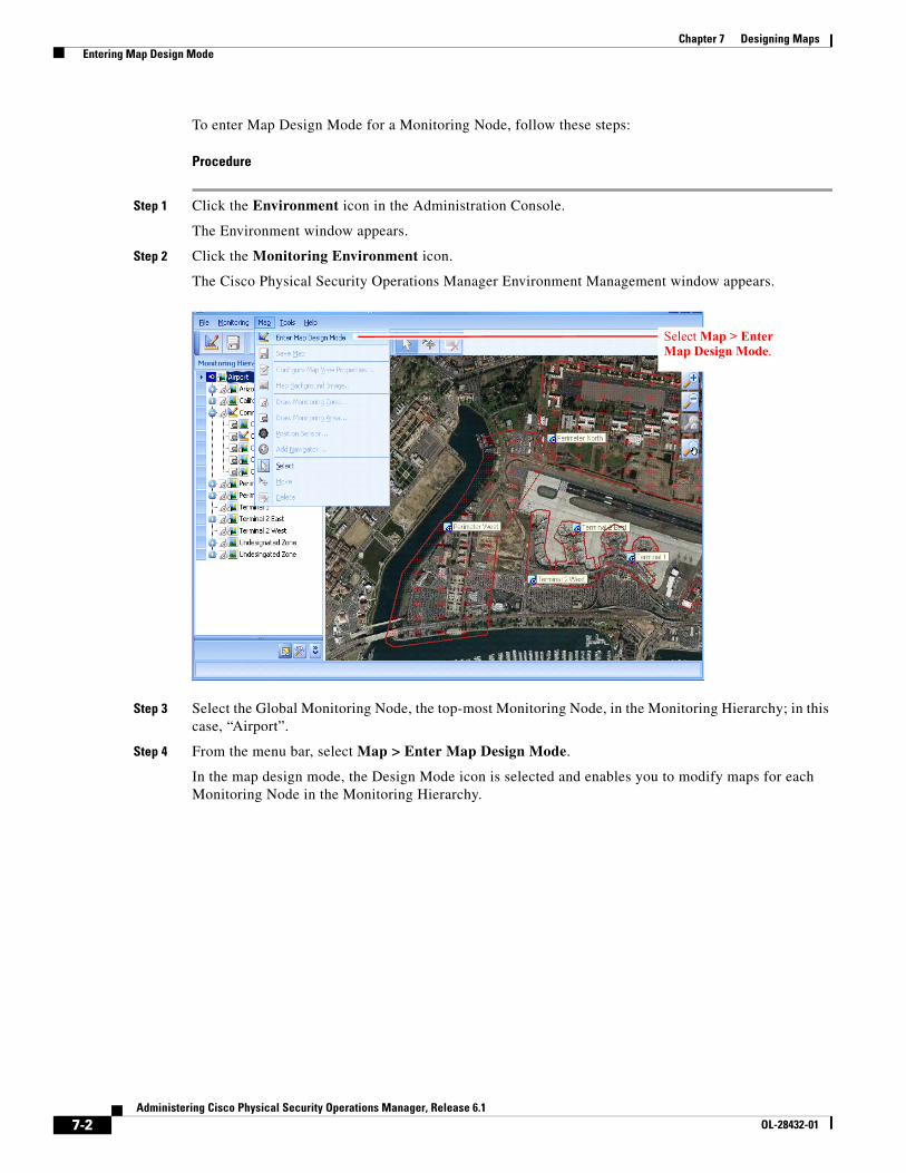
7-2Administering Cisco Physical Security Operations Manager, Release 6.1
OL-28432-01
Chapter 7 Designing Maps Entering Map Design Mode
To enter Map Design Mode for a Monitoring Node, follow these steps:
Procedure
Step 1 Click the Environment icon in the Administration Console.
The Environment window appears.
Step 2 Click the Monitoring Environment icon.
The Cisco Physical Security Operations Manager Environment Management window appears.
Step 3 Select the Global Monitoring Node, the top-most Monitoring Node, in the Monitoring Hierarchy; in this case, “Airport”.
Step 4 From the menu bar, select Map > Enter Map Design Mode.
In the map design mode, the Design Mode icon is selected and enables you to modify maps for each Monitoring Node in the Monitoring Hierarchy.
Select Map > Enter Map Design Mode.
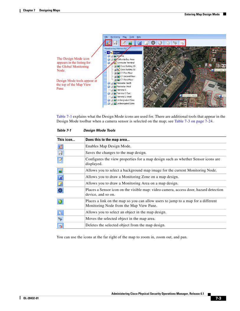
7-3Administering Cisco Physical Security Operations Manager, Release 6.1
OL-28432-01
Chapter 7 Designing Maps Entering Map Design Mode
Table 7-1 explains what the Design Mode icons are used for. There are additional tools that appear in the Design Mode toolbar when a camera sensor is selected on the map; see Table 7-3 on page 7-24.
You can use the icons at the far right of the map to zoom in, zoom out, and pan.
The Design Mode icon appears in the listing for the Global Monitoring Node.
Design Mode tools appear at the top of the Map View Pane.
Table 7-1 Design Mode Tools
This icon... Does this to the map area...
Enables Map Design Mode.
Saves the changes to the map design.
Configures the view properties for a map design such as whether Sensor icons are displayed.
Allows you to select a background map image for the current Monitoring Node.
Allows you to draw a Monitoring Zone on a map design.
Allows you to draw a Monitoring Area on a map design.
Places a Sensor icon on the visible map: video camera, access door, hazard detection device, and so on.
Places a link on the map so you can allow users to jump to a map for a different Monitoring Node from the Map View Pane.
Allows you to select an object in the map design.
Moves the selected object in the map area.
Deletes the selected object from the map design.
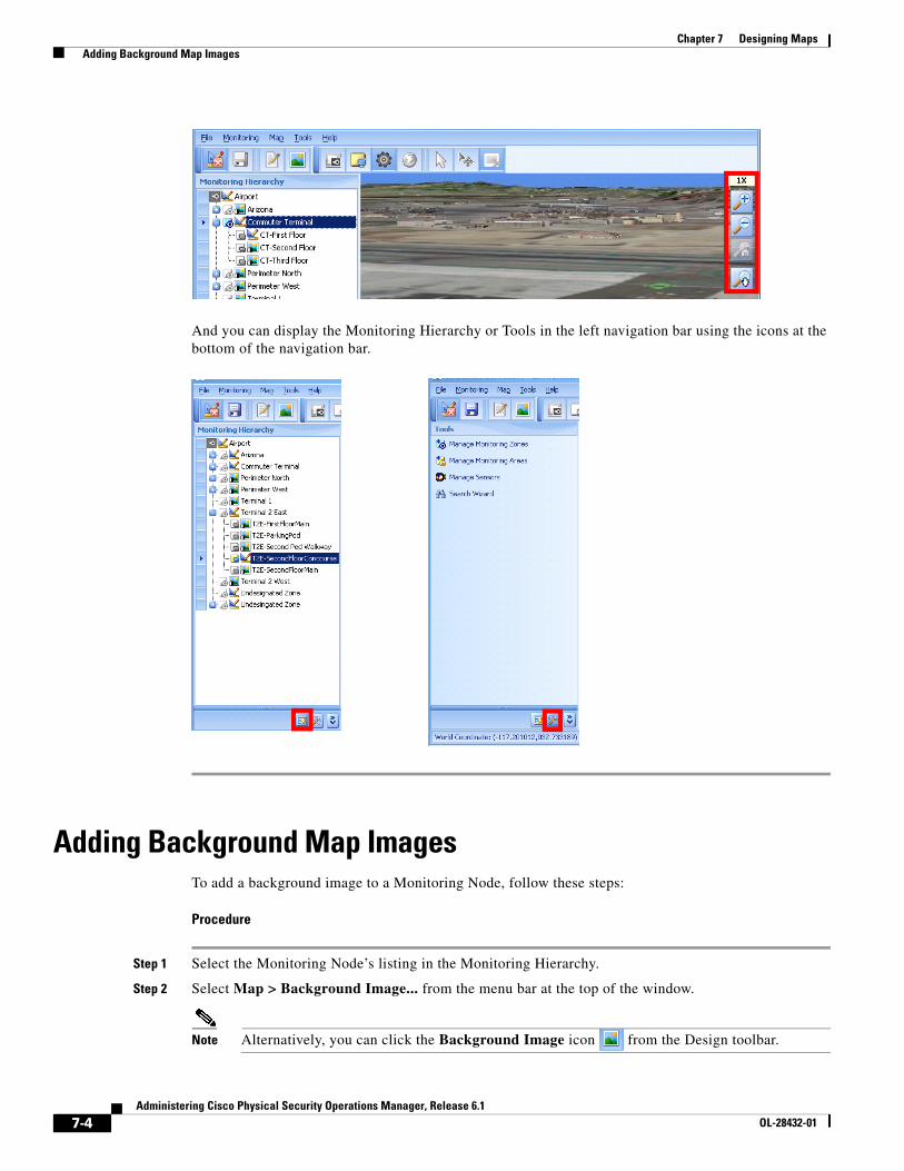
7-4Administering Cisco Physical Security Operations Manager, Release 6.1
OL-28432-01
Chapter 7 Designing Maps Adding Background Map Images
And you can display the Monitoring Hierarchy or Tools in the left navigation bar using the icons at the bottom of the navigation bar.
Adding Background Map ImagesTo add a background image to a Monitoring Node, follow these steps:
Procedure
Step 1 Select the Monitoring Node’s listing in the Monitoring Hierarchy.
Step 2 Select Map > Background Image... from the menu bar at the top of the window.
Note Alternatively, you can click the Background Image icon from the Design toolbar.
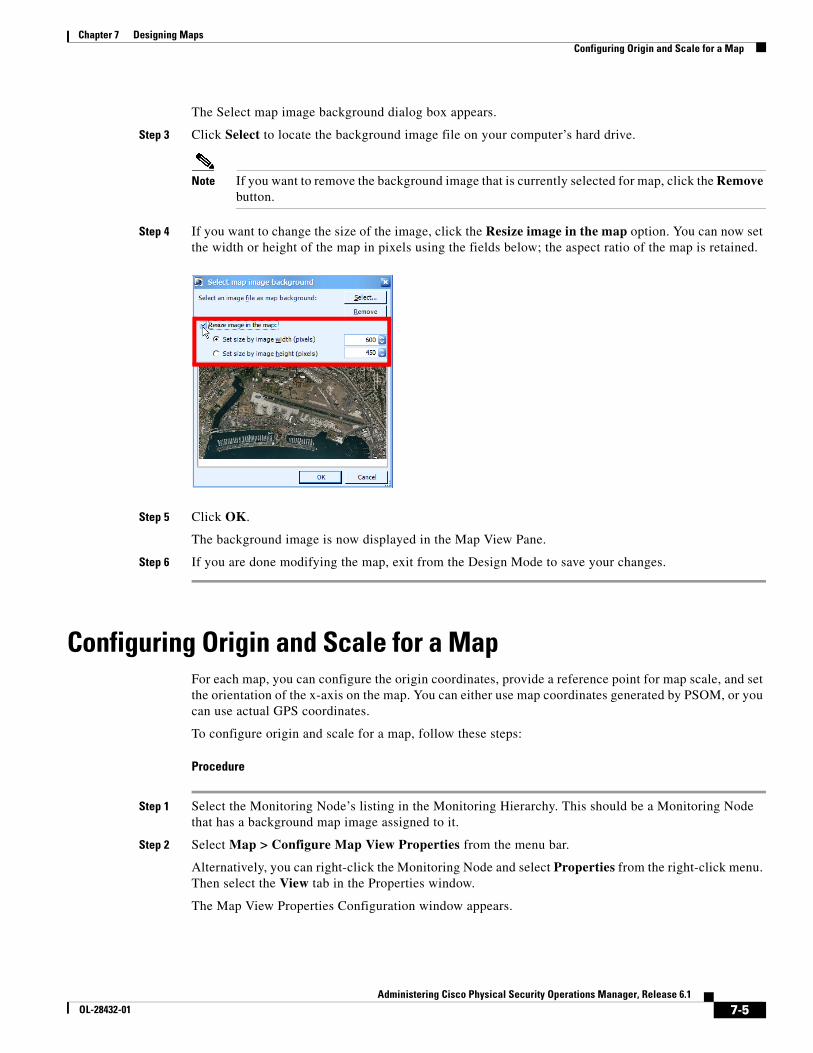
7-5Administering Cisco Physical Security Operations Manager, Release 6.1
OL-28432-01
Chapter 7 Designing Maps Configuring Origin and Scale for a Map
The Select map image background dialog box appears.
Step 3 Click Select to locate the background image file on your computer’s hard drive.
Note If you want to remove the background image that is currently selected for map, click the Remove button.
Step 4 If you want to change the size of the image, click the Resize image in the map option. You can now set the width or height of the map in pixels using the fields below; the aspect ratio of the map is retained.
Step 5 Click OK.
The background image is now displayed in the Map View Pane.
Step 6 If you are done modifying the map, exit from the Design Mode to save your changes.
Configuring Origin and Scale for a MapFor each map, you can configure the origin coordinates, provide a reference point for map scale, and set the orientation of the x-axis on the map. You can either use map coordinates generated by PSOM, or you can use actual GPS coordinates.
To configure origin and scale for a map, follow these steps:
Procedure
Step 1 Select the Monitoring Node’s listing in the Monitoring Hierarchy. This should be a Monitoring Node that has a background map image assigned to it.
Step 2 Select Map > Configure Map View Properties from the menu bar.
Alternatively, you can right-click the Monitoring Node and select Properties from the right-click menu. Then select the View tab in the Properties window.
The Map View Properties Configuration window appears.
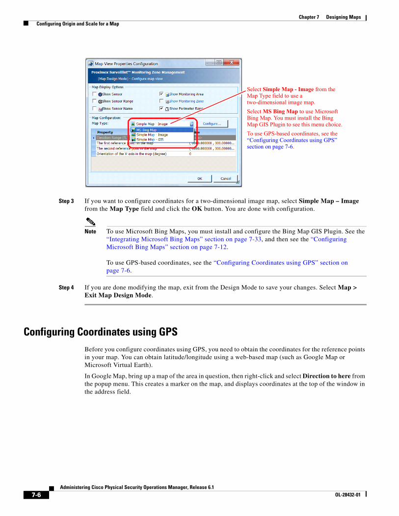
7-6Administering Cisco Physical Security Operations Manager, Release 6.1
OL-28432-01
Chapter 7 Designing Maps Configuring Origin and Scale for a Map
Step 3 If you want to configure coordinates for a two-dimensional image map, select Simple Map – Image from the Map Type field and click the OK button. You are done with configuration.
Note To use Microsoft Bing Maps, you must install and configure the Bing Map GIS Plugin. See the “Integrating Microsoft Bing Maps” section on page 7-33, and then see the “Configuring Microsoft Bing Maps” section on page 7-12.
To use GPS-based coordinates, see the “Configuring Coordinates using GPS” section on page 7-6.
Step 4 If you are done modifying the map, exit from the Design Mode to save your changes. Select Map > Exit Map Design Mode.
Configuring Coordinates using GPSBefore you configure coordinates using GPS, you need to obtain the coordinates for the reference points in your map. You can obtain latitude/longitude using a web-based map (such as Google Map or Microsoft Virtual Earth).
In Google Map, bring up a map of the area in question, then right-click and select Direction to here from the popup menu. This creates a marker on the map, and displays coordinates at the top of the window in the address field.
Select Simple Map - Image from the Map Type field to use a two-dimensional image map.
Select MS Bing Map to use Microsoft Bing Map. You must install the Bing Map GIS Plugin to see this menu choice.
To use GPS-based coordinates, see the “Configuring Coordinates using GPS” section on page 7-6.
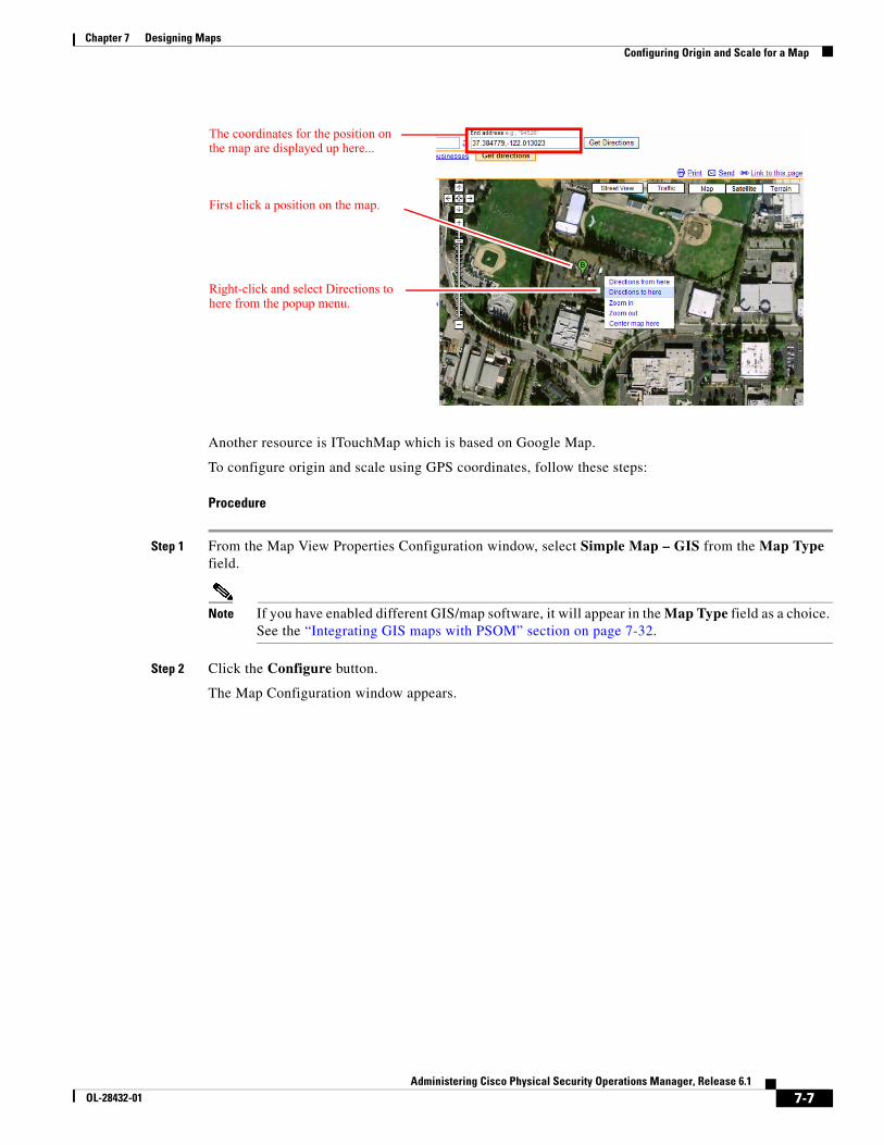
7-7Administering Cisco Physical Security Operations Manager, Release 6.1
OL-28432-01
Chapter 7 Designing Maps Configuring Origin and Scale for a Map
Another resource is ITouchMap which is based on Google Map.
To configure origin and scale using GPS coordinates, follow these steps:
Procedure
Step 1 From the Map View Properties Configuration window, select Simple Map – GIS from the Map Type field.
Note If you have enabled different GIS/map software, it will appear in the Map Type field as a choice. See the “Integrating GIS maps with PSOM” section on page 7-32.
Step 2 Click the Configure button.
The Map Configuration window appears.
The coordinates for the position on the map are displayed up here...
First click a position on the map.
Right-click and select Directions to here from the popup menu.
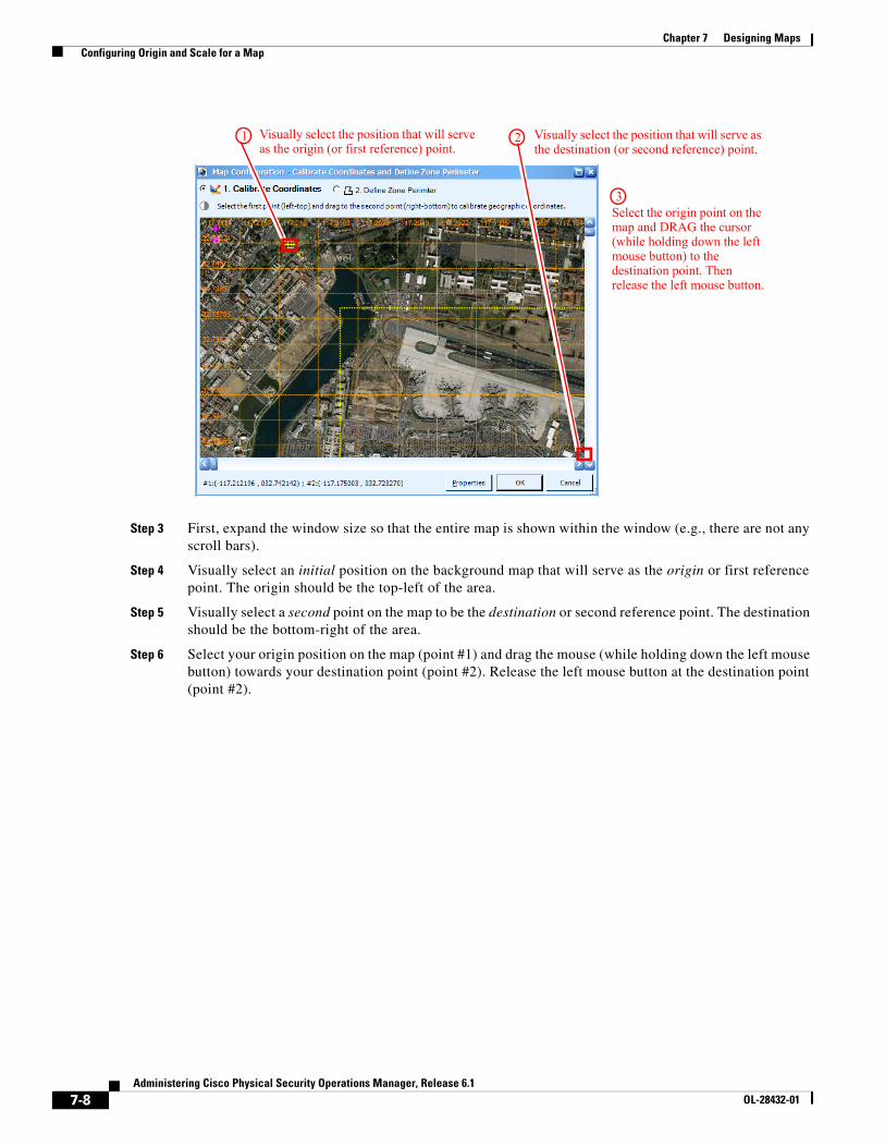
7-8Administering Cisco Physical Security Operations Manager, Release 6.1
OL-28432-01
Chapter 7 Designing Maps Configuring Origin and Scale for a Map
Step 3 First, expand the window size so that the entire map is shown within the window (e.g., there are not any scroll bars).
Step 4 Visually select an initial position on the background map that will serve as the origin or first reference point. The origin should be the top-left of the area.
Step 5 Visually select a second point on the map to be the destination or second reference point. The destination should be the bottom-right of the area.
Step 6 Select your origin position on the map (point #1) and drag the mouse (while holding down the left mouse button) towards your destination point (point #2). Release the left mouse button at the destination point (point #2).
Visually select the position that will serve as the origin (or first reference) point.
Visually select the position that will serve as the destination (or second reference) point.
1 2
3Select the origin point on the map and DRAG the cursor (while holding down the left mouse button) to the destination point. Then release the left mouse button.
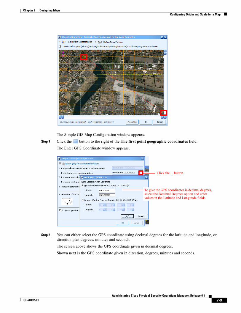
7-9Administering Cisco Physical Security Operations Manager, Release 6.1
OL-28432-01
Chapter 7 Designing Maps Configuring Origin and Scale for a Map
The Simple GIS Map Configuration window appears.
Step 7 Click the button to the right of the The first point geographic coordinates field.
The Enter GPS Coordinate window appears.
Step 8 You can either select the GPS coordinate using decimal degrees for the latitude and longitude, or direction plus degrees, minutes and seconds.
The screen above shows the GPS coordinate given in decimal degrees.
Shown next is the GPS coordinate given in direction, degrees, minutes and seconds.
Click the ... button.
To give the GPS coordinates in decimal degrees, select the Decimal Degrees option and enter values in the Latitude and Longitude fields.
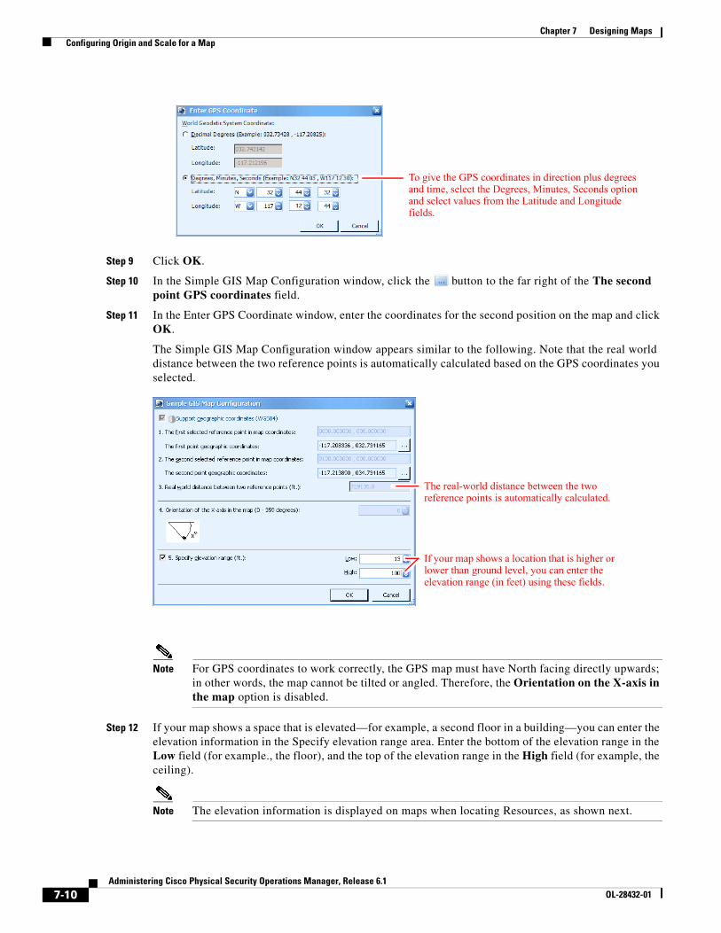
7-10Administering Cisco Physical Security Operations Manager, Release 6.1
OL-28432-01
Chapter 7 Designing Maps Configuring Origin and Scale for a Map
Step 9 Click OK.
Step 10 In the Simple GIS Map Configuration window, click the button to the far right of the The second point GPS coordinates field.
Step 11 In the Enter GPS Coordinate window, enter the coordinates for the second position on the map and click OK.
The Simple GIS Map Configuration window appears similar to the following. Note that the real world distance between the two reference points is automatically calculated based on the GPS coordinates you selected.
Note For GPS coordinates to work correctly, the GPS map must have North facing directly upwards; in other words, the map cannot be tilted or angled. Therefore, the Orientation on the X-axis in the map option is disabled.
Step 12 If your map shows a space that is elevated—for example, a second floor in a building—you can enter the elevation information in the Specify elevation range area. Enter the bottom of the elevation range in the Low field (for example., the floor), and the top of the elevation range in the High field (for example, the ceiling).
Note The elevation information is displayed on maps when locating Resources, as shown next.
To give the GPS coordinates in direction plus degrees and time, select the Degrees, Minutes, Seconds option and select values from the Latitude and Longitude fields.
The real-world distance between the two reference points is automatically calculated.
If your map shows a location that is higher or lower than ground level, you can enter the elevation range (in feet) using these fields.
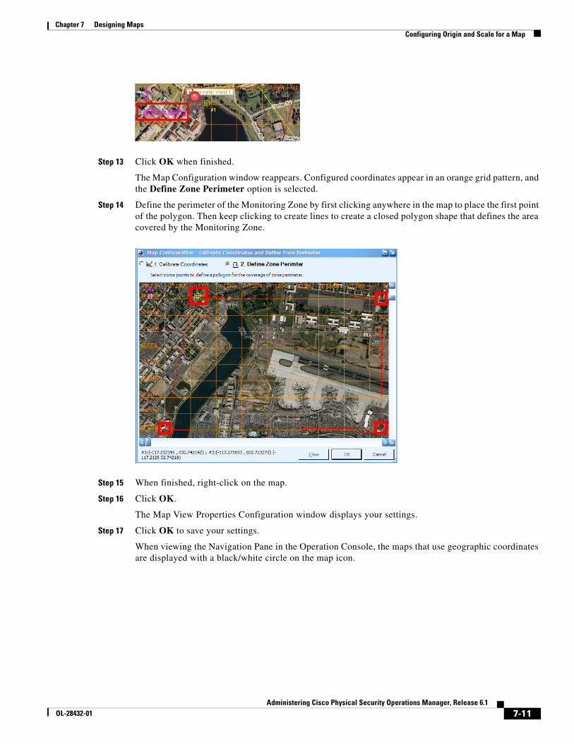
7-11Administering Cisco Physical Security Operations Manager, Release 6.1
OL-28432-01
Chapter 7 Designing Maps Configuring Origin and Scale for a Map
Step 13 Click OK when finished.
The Map Configuration window reappears. Configured coordinates appear in an orange grid pattern, and the Define Zone Perimeter option is selected.
Step 14 Define the perimeter of the Monitoring Zone by first clicking anywhere in the map to place the first point of the polygon. Then keep clicking to create lines to create a closed polygon shape that defines the area covered by the Monitoring Zone.
Step 15 When finished, right-click on the map.
Step 16 Click OK.
The Map View Properties Configuration window displays your settings.
Step 17 Click OK to save your settings.
When viewing the Navigation Pane in the Operation Console, the maps that use geographic coordinates are displayed with a black/white circle on the map icon.
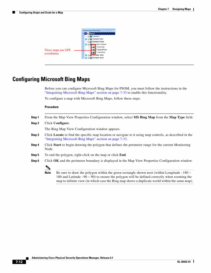
7-12Administering Cisco Physical Security Operations Manager, Release 6.1
OL-28432-01
Chapter 7 Designing Maps Configuring Origin and Scale for a Map
Configuring Microsoft Bing MapsBefore you can configure Microsoft Bing Maps for PSOM, you must follow the instructions in the “Integrating Microsoft Bing Maps” section on page 7-33 to enable this functionality.
To configure a map with Microsoft Bing Maps, follow these steps:
Procedure
Step 1 From the Map View Properties Configuration window, select MS Bing Map from the Map Type field.
Step 2 Click Configure.
The Bing Map View Configuration window appears.
Step 3 Click Locate to find the specific map location or navigate to it using map controls, as described in the “Integrating Microsoft Bing Maps” section on page 7-33.
Step 4 Click Start to begin drawing the polygon that defines the perimeter range for the current Monitoring Node.
Step 5 To end the polygon, right-click on the map or click End.
Step 6 Click OK and the perimeter boundary is displayed in the Map View Properties Configuration window.
Note Be sure to draw the polygon within the green rectangle shown next (within Longitude –180 ~ 180 and Latitude –90 ~ 90) to ensure the polygon will be defined correctly when zooming the map to infinite view (in which case the Bing map shows a duplicate world within the same map).
These maps use GPS coordinates.
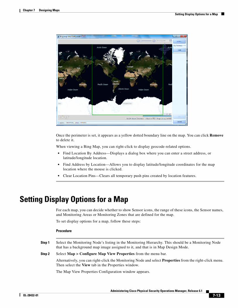
7-13Administering Cisco Physical Security Operations Manager, Release 6.1
OL-28432-01
Chapter 7 Designing Maps Setting Display Options for a Map
Once the perimeter is set, it appears as a yellow dotted boundary line on the map. You can click Remove to delete it.
When viewing a Bing Map, you can right-click to display geocode-related options.
• Find Location By Address—Displays a dialog box where you can enter a street address, or latitude/longitude location.
• Find Address by Location—Allows you to display latitude/longitude coordinates for the map location where the mouse is clicked.
• Clear Location Pins—Clears all temporary push pins created by location features.
Setting Display Options for a MapFor each map, you can decide whether to show Sensor icons, the range of these icons, the Sensor names, and Monitoring Areas or Monitoring Zones that are defined for the map.
To set display options for a map, follow these steps:
Procedure
Step 1 Select the Monitoring Node’s listing in the Monitoring Hierarchy. This should be a Monitoring Node that has a background map image assigned to it, and that is in Map Design Mode.
Step 2 Select Map > Configure Map View Properties from the menu bar.
Alternatively, you can right-click the Monitoring Node and select Properties from the right-click menu. Then select the View tab in the Properties window.
The Map View Properties Configuration window appears.
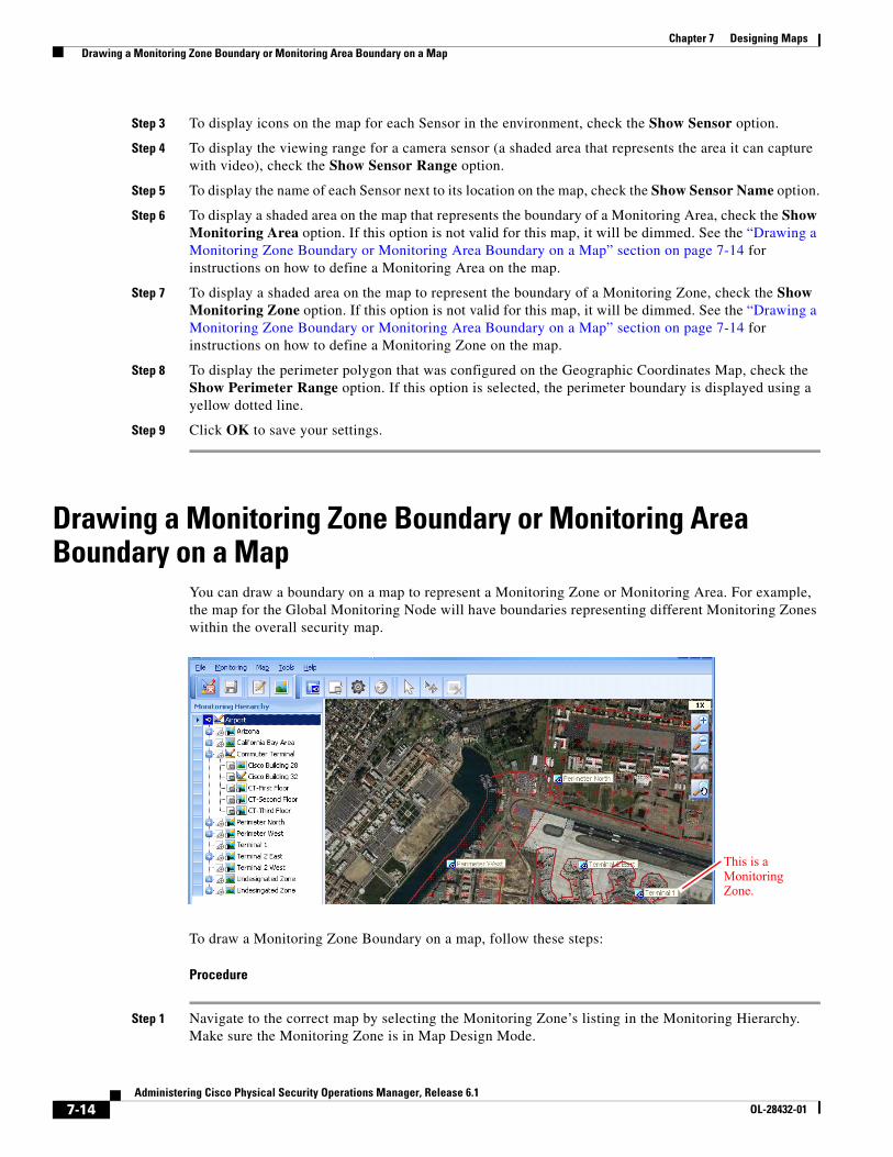
7-14Administering Cisco Physical Security Operations Manager, Release 6.1
OL-28432-01
Chapter 7 Designing Maps Drawing a Monitoring Zone Boundary or Monitoring Area Boundary on a Map
Step 3 To display icons on the map for each Sensor in the environment, check the Show Sensor option.
Step 4 To display the viewing range for a camera sensor (a shaded area that represents the area it can capture with video), check the Show Sensor Range option.
Step 5 To display the name of each Sensor next to its location on the map, check the Show Sensor Name option.
Step 6 To display a shaded area on the map that represents the boundary of a Monitoring Area, check the Show Monitoring Area option. If this option is not valid for this map, it will be dimmed. See the “Drawing a Monitoring Zone Boundary or Monitoring Area Boundary on a Map” section on page 7-14 for instructions on how to define a Monitoring Area on the map.
Step 7 To display a shaded area on the map to represent the boundary of a Monitoring Zone, check the Show Monitoring Zone option. If this option is not valid for this map, it will be dimmed. See the “Drawing a Monitoring Zone Boundary or Monitoring Area Boundary on a Map” section on page 7-14 for instructions on how to define a Monitoring Zone on the map.
Step 8 To display the perimeter polygon that was configured on the Geographic Coordinates Map, check the Show Perimeter Range option. If this option is selected, the perimeter boundary is displayed using a yellow dotted line.
Step 9 Click OK to save your settings.
Drawing a Monitoring Zone Boundary or Monitoring Area Boundary on a Map
You can draw a boundary on a map to represent a Monitoring Zone or Monitoring Area. For example, the map for the Global Monitoring Node will have boundaries representing different Monitoring Zones within the overall security map.
To draw a Monitoring Zone Boundary on a map, follow these steps:
Procedure
Step 1 Navigate to the correct map by selecting the Monitoring Zone’s listing in the Monitoring Hierarchy. Make sure the Monitoring Zone is in Map Design Mode.
This is a Monitoring Zone.
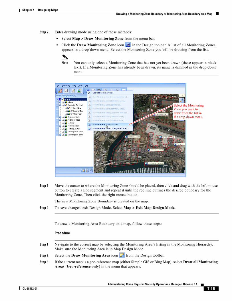
7-15Administering Cisco Physical Security Operations Manager, Release 6.1
OL-28432-01
Chapter 7 Designing Maps Drawing a Monitoring Zone Boundary or Monitoring Area Boundary on a Map
Step 2 Enter drawing mode using one of these methods:
• Select Map > Draw Monitoring Zone from the menu bar.
• Click the Draw Monitoring Zone icon in the Design toolbar. A list of all Monitoring Zones appears in a drop-down menu. Select the Monitoring Zone you will be drawing from the list.
Note You can only select a Monitoring Zone that has not yet been drawn (these appear in black text). If a Monitoring Zone has already been drawn, its name is dimmed in the drop-down menu.
Step 3 Move the cursor to where the Monitoring Zone should be placed, then click and drag with the left mouse button to create a line segment and repeat it until the red line outlines the desired boundary for the Monitoring Zone. Then click the right mouse button.
The new Monitoring Zone Boundary is created on the map.
Step 4 To save changes, exit Design Mode. Select Map > Exit Map Design Mode.
To draw a Monitoring Area Boundary on a map, follow these steps:
Procedure
Step 1 Navigate to the correct map by selecting the Monitoring Area’s listing in the Monitoring Hierarchy. Make sure the Monitoring Area is in Map Design Mode.
Step 2 Select the Draw Monitoring Area icon from the Design toolbar.
Step 3 If the current map is a geo-reference map (either Simple GIS or Bing Map), select Draw all Monitoring Areas (Geo-reference only) in the menu that appears.
Select the Monitoring Zone you want to draw from the list in the drop-down menu.
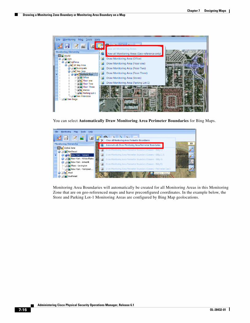
7-16Administering Cisco Physical Security Operations Manager, Release 6.1
OL-28432-01
Chapter 7 Designing Maps Drawing a Monitoring Zone Boundary or Monitoring Area Boundary on a Map
You can select Automatically Draw Monitoring Area Perimeter Boundaries for Bing Maps.
Monitoring Area Boundaries will automatically be created for all Monitoring Areas in this Monitoring Zone that are on geo-referenced maps and have preconfigured coordinates. In the example below, the Store and Parking Lot-1 Monitoring Areas are configured by Bing Map geolocations.
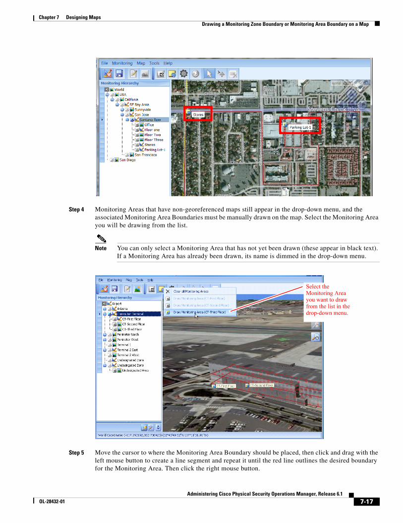
7-17Administering Cisco Physical Security Operations Manager, Release 6.1
OL-28432-01
Chapter 7 Designing Maps Drawing a Monitoring Zone Boundary or Monitoring Area Boundary on a Map
Step 4 Monitoring Areas that have non-georeferenced maps still appear in the drop-down menu, and the associated Monitoring Area Boundaries must be manually drawn on the map. Select the Monitoring Area you will be drawing from the list.
Note You can only select a Monitoring Area that has not yet been drawn (these appear in black text). If a Monitoring Area has already been drawn, its name is dimmed in the drop-down menu.
Step 5 Move the cursor to where the Monitoring Area Boundary should be placed, then click and drag with the left mouse button to create a line segment and repeat it until the red line outlines the desired boundary for the Monitoring Area. Then click the right mouse button.
Select the Monitoring Area you want to draw from the list in the drop-down menu.
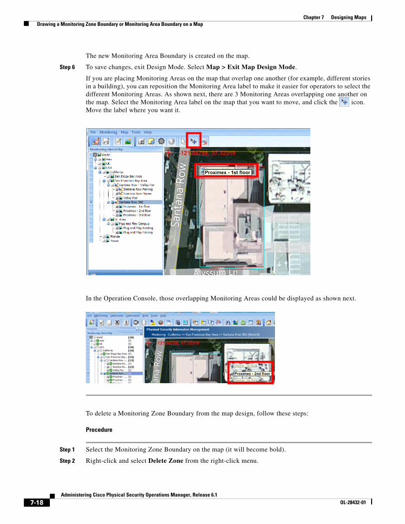
7-18Administering Cisco Physical Security Operations Manager, Release 6.1
OL-28432-01
Chapter 7 Designing Maps Drawing a Monitoring Zone Boundary or Monitoring Area Boundary on a Map
The new Monitoring Area Boundary is created on the map.
Step 6 To save changes, exit Design Mode. Select Map > Exit Map Design Mode.
If you are placing Monitoring Areas on the map that overlap one another (for example, different stories in a building), you can reposition the Monitoring Area label to make it easier for operators to select the different Monitoring Areas. As shown next, there are 3 Monitoring Areas overlapping one another on the map. Select the Monitoring Area label on the map that you want to move, and click the icon. Move the label where you want it.
In the Operation Console, those overlapping Monitoring Areas could be displayed as shown next.
To delete a Monitoring Zone Boundary from the map design, follow these steps:
Procedure
Step 1 Select the Monitoring Zone Boundary on the map (it will become bold).
Step 2 Right-click and select Delete Zone from the right-click menu.
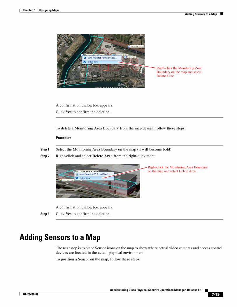
7-19Administering Cisco Physical Security Operations Manager, Release 6.1
OL-28432-01
Chapter 7 Designing Maps Adding Sensors to a Map
A confirmation dialog box appears.
Click Yes to confirm the deletion.
To delete a Monitoring Area Boundary from the map design, follow these steps:
Procedure
Step 1 Select the Monitoring Area Boundary on the map (it will become bold).
Step 2 Right-click and select Delete Area from the right-click menu.
A confirmation dialog box appears.
Step 3 Click Yes to confirm the deletion.
Adding Sensors to a MapThe next step is to place Sensor icons on the map to show where actual video cameras and access control devices are located in the actual physical environment.
To position a Sensor on the map, follow these steps:
Right-click the Monitoring Zone Boundary on the map and select Delete Zone.
Right-click the Monitoring Area Boundary on the map and select Delete Area.
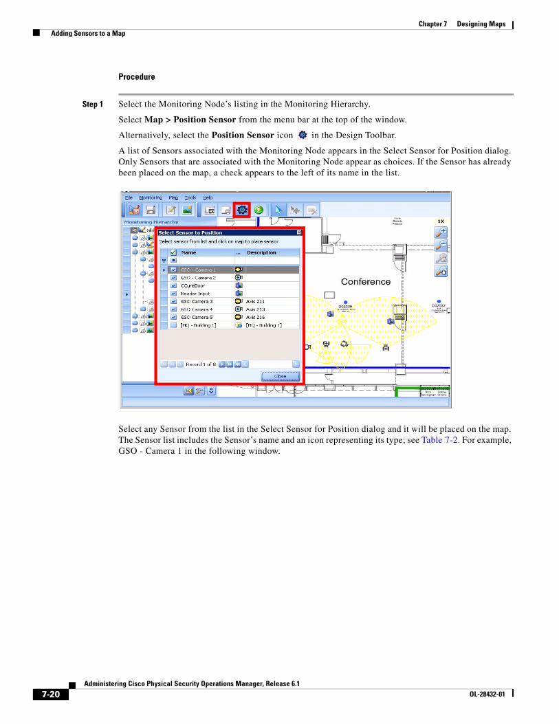
7-20Administering Cisco Physical Security Operations Manager, Release 6.1
OL-28432-01
Chapter 7 Designing Maps Adding Sensors to a Map
Procedure
Step 1 Select the Monitoring Node’s listing in the Monitoring Hierarchy.
Select Map > Position Sensor from the menu bar at the top of the window.
Alternatively, select the Position Sensor icon in the Design Toolbar.
A list of Sensors associated with the Monitoring Node appears in the Select Sensor for Position dialog. Only Sensors that are associated with the Monitoring Node appear as choices. If the Sensor has already been placed on the map, a check appears to the left of its name in the list.
Select any Sensor from the list in the Select Sensor for Position dialog and it will be placed on the map. The Sensor list includes the Sensor’s name and an icon representing its type; see Table 7-2. For example, GSO - Camera 1 in the following window.
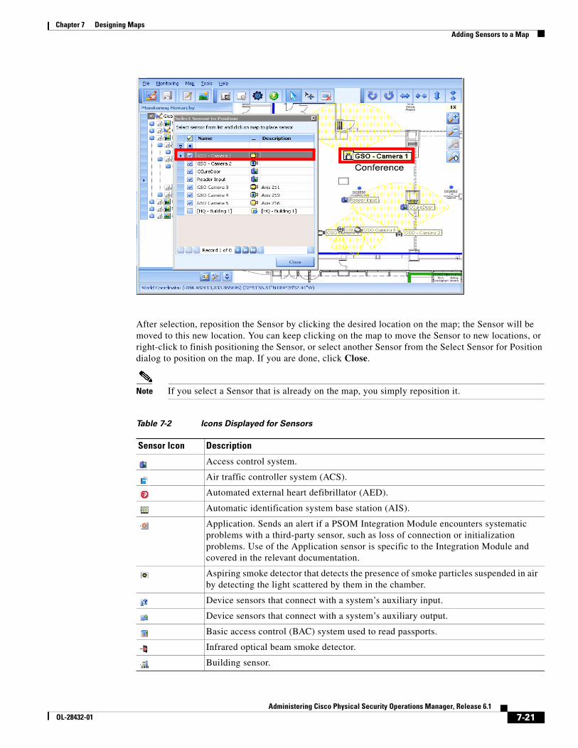
7-21Administering Cisco Physical Security Operations Manager, Release 6.1
OL-28432-01
Chapter 7 Designing Maps Adding Sensors to a Map
After selection, reposition the Sensor by clicking the desired location on the map; the Sensor will be moved to this new location. You can keep clicking on the map to move the Sensor to new locations, or right-click to finish positioning the Sensor, or select another Sensor from the Select Sensor for Position dialog to position on the map. If you are done, click Close.
Note If you select a Sensor that is already on the map, you simply reposition it.
Table 7-2 Icons Displayed for Sensors
Sensor Icon Description
Access control system.
Air traffic controller system (ACS).
Automated external heart defibrillator (AED).
Automatic identification system base station (AIS).
Application. Sends an alert if a PSOM Integration Module encounters systematic problems with a third-party sensor, such as loss of connection or initialization problems. Use of the Application sensor is specific to the Integration Module and covered in the relevant documentation.
Aspiring smoke detector that detects the presence of smoke particles suspended in air by detecting the light scattered by them in the chamber.
Device sensors that connect with a system’s auxiliary input.
Device sensors that connect with a system’s auxiliary output.
Basic access control (BAC) system used to read passports.
Infrared optical beam smoke detector.
Building sensor.
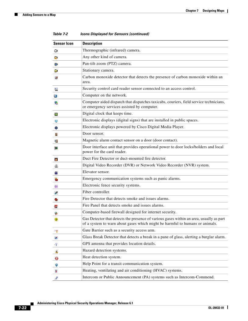
7-22Administering Cisco Physical Security Operations Manager, Release 6.1
OL-28432-01
Chapter 7 Designing Maps Adding Sensors to a Map
Thermographic (infrared) camera.
Any other kind of camera.
Pan-tilt-zoom (PTZ) camera.
Stationary camera.
Carbon monoxide detector that detects the presence of carbon monoxide within an area.
Security control card reader sensor connected to an access control.
Computer on the network.
Computer aided dispatch that dispatches taxicabs, couriers, field service technicians, or emergency services assisted by computer.
Digital clock that keeps time.
Electronic displays (digital signs) that are installed in public spaces.
Electronic displays powered by Cisco Digital Media Player.
Door sensor.
Magnetic alarm contact sensor on a door (door contact).
Door interface unit that provides operational power to door locks/holders and local power for the card reader.
Duct Fire Detector or duct-mounted fire detector.
Digital Video Recorder (DVR) or Network Video Recorder (NVR) system.
Elevator sensor.
Emergency communication systems such as panic alarms.
Electronic fence security systems.
Fiber controller.
Fire Detector that detects smoke and issues alarms.
Fire Panel that detects smoke and issues alarms.
Computer-based firewall designed for internet security.
Gas Detector that detects the presence of various gases within an area, usually as part of a system to warn about gases which might be harmful to humans or animals.
Gate Barrier such as a security access arm.
Glass Break Detector that detects a break in a pane of glass, alerting a burglar alarm.
GPS antenna that provides location details.
Hazard detection systems.
Heat detection system.
Help Point for a transit communication system.
Heating, ventilating and air conditioning (HVAC) systems.
Intercom or Public Announcement (PA) systems such as Intercom-Commend.
Table 7-2 Icons Displayed for Sensors (continued)
Sensor Icon Description
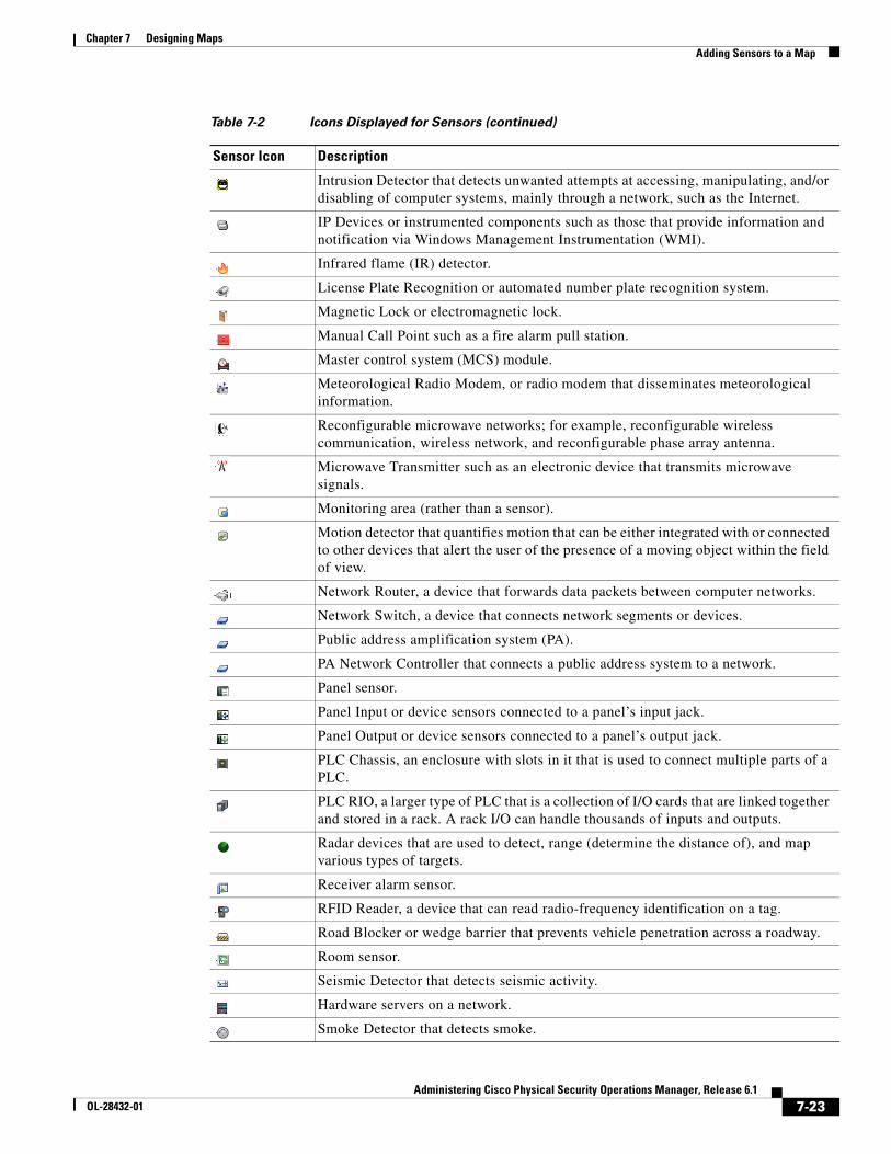
7-23Administering Cisco Physical Security Operations Manager, Release 6.1
OL-28432-01
Chapter 7 Designing Maps Adding Sensors to a Map
Intrusion Detector that detects unwanted attempts at accessing, manipulating, and/or disabling of computer systems, mainly through a network, such as the Internet.
IP Devices or instrumented components such as those that provide information and notification via Windows Management Instrumentation (WMI).
Infrared flame (IR) detector.
License Plate Recognition or automated number plate recognition system.
Magnetic Lock or electromagnetic lock.
Manual Call Point such as a fire alarm pull station.
Master control system (MCS) module.
Meteorological Radio Modem, or radio modem that disseminates meteorological information.
Reconfigurable microwave networks; for example, reconfigurable wireless communication, wireless network, and reconfigurable phase array antenna.
Microwave Transmitter such as an electronic device that transmits microwave signals.
Monitoring area (rather than a sensor).
Motion detector that quantifies motion that can be either integrated with or connected to other devices that alert the user of the presence of a moving object within the field of view.
Network Router, a device that forwards data packets between computer networks.
Network Switch, a device that connects network segments or devices.
Public address amplification system (PA).
PA Network Controller that connects a public address system to a network.
Panel sensor.
Panel Input or device sensors connected to a panel’s input jack.
Panel Output or device sensors connected to a panel’s output jack.
PLC Chassis, an enclosure with slots in it that is used to connect multiple parts of a PLC.
PLC RIO, a larger type of PLC that is a collection of I/O cards that are linked together and stored in a rack. A rack I/O can handle thousands of inputs and outputs.
Radar devices that are used to detect, range (determine the distance of), and map various types of targets.
Receiver alarm sensor.
RFID Reader, a device that can read radio-frequency identification on a tag.
Road Blocker or wedge barrier that prevents vehicle penetration across a roadway.
Room sensor.
Seismic Detector that detects seismic activity.
Hardware servers on a network.
Smoke Detector that detects smoke.
Table 7-2 Icons Displayed for Sensors (continued)
Sensor Icon Description
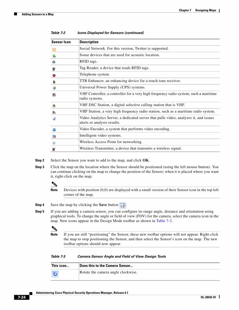
7-24Administering Cisco Physical Security Operations Manager, Release 6.1
OL-28432-01
Chapter 7 Designing Maps Adding Sensors to a Map
Step 2 Select the Sensor you want to add to the map, and click OK.
Step 3 Click the map on the location where the Sensor should be positioned (using the left mouse button). You can continue clicking on the map to change the position of the Sensor; when it is placed where you want it, right-click on the map.
Note Devices with position (0,0) are displayed with a small version of their Sensor icon in the top left corner of the map.
Step 4 Save the map by clicking the Save button .
Step 5 If you are adding a camera sensor, you can configure its range angle, distance and orientation using graphical tools. To change the angle or field of view (FOV) for the camera, select the camera icon in the map. New icons appear in the Design Mode toolbar as shown in Table 7-3.
Note If you are still “positioning” the Sensor, these new toolbar options will not appear. Right-click the map to stop positioning the Sensor, and then select the Sensor’s icon on the map. The new toolbar options should now appear.
Social Network. For this version, Twitter is supported.
Sonar devices that are used for acoustic location.
RFID tags.
Tag Reader, a device that reads RFID tags.
Telephone system.
TTR Enhancer, an enhancing device for a touch tone receiver.
Universal Power Supply (UPS) systems.
VHF Controller, a controller for a very high frequency radio system, such a maritime radio systems.
VHF DSC Station, a digital selective calling station that is VHF.
VHF Station, a very high frequency radio station, such as a maritime radio system.
Video Analytics Server, a dedicated server that pulls video, analyzes it, and issues alerts or analysis results.
Video Encoder, a system that performs video encoding.
Intelligent video systems.
Wireless Access Point for networking.
Wireless Transmitter, a device that transmits a wireless signal.
Table 7-2 Icons Displayed for Sensors (continued)
Sensor Icon Description
Table 7-3 Camera Sensor Angle and Field of View Design Tools
This icon... Does this to the Camera Sensor...
Rotate the camera angle clockwise.
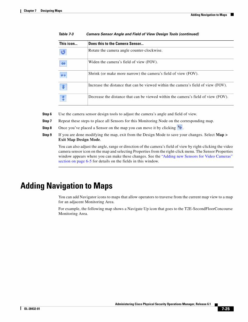
7-25Administering Cisco Physical Security Operations Manager, Release 6.1
OL-28432-01
Chapter 7 Designing Maps Adding Navigation to Maps
Step 6 Use the camera sensor design tools to adjust the camera’s angle and field of view.
Step 7 Repeat these steps to place all Sensors for this Monitoring Node on the corresponding map.
Step 8 Once you’ve placed a Sensor on the map you can move it by clicking .
Step 9 If you are done modifying the map, exit from the Design Mode to save your changes. Select Map > Exit Map Design Mode.
You can also adjust the angle, range or direction of the camera’s field of view by right-clicking the video camera sensor icon on the map and selecting Properties from the right-click menu. The Sensor Properties window appears where you can make these changes. See the “Adding new Sensors for Video Cameras” section on page 6-5 for details on the fields in this window.
Adding Navigation to MapsYou can add Navigator icons to maps that allow operators to traverse from the current map view to a map for an adjacent Monitoring Area.
For example, the following map shows a Navigate Up icon that goes to the T2E-SecondFloorConcourse Monitoring Area.
Rotate the camera angle counter-clockwise.
Widen the camera’s field of view (FOV).
Shrink (or make more narrow) the camera’s field of view (FOV).
Increase the distance that can be viewed within the camera’s field of view (FOV).
Decrease the distance that can be viewed within the camera’s field of view (FOV).
Table 7-3 Camera Sensor Angle and Field of View Design Tools (continued)
This icon... Does this to the Camera Sensor...
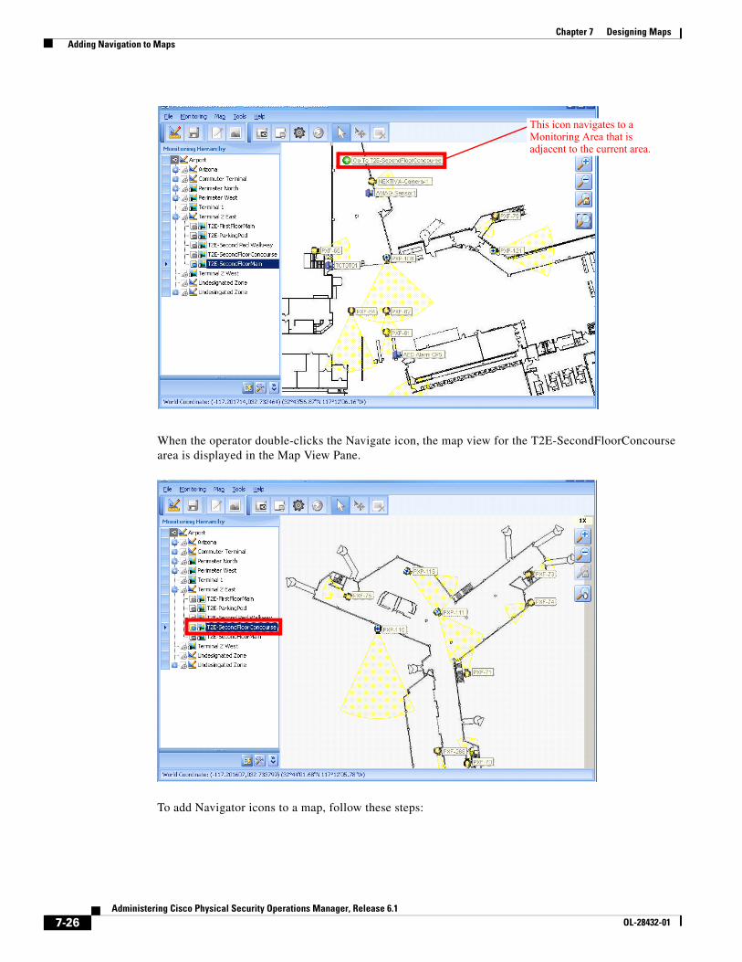
7-26Administering Cisco Physical Security Operations Manager, Release 6.1
OL-28432-01
Chapter 7 Designing Maps Adding Navigation to Maps
When the operator double-clicks the Navigate icon, the map view for the T2E-SecondFloorConcourse area is displayed in the Map View Pane.
To add Navigator icons to a map, follow these steps:
This icon navigates to a Monitoring Area that is adjacent to the current area.
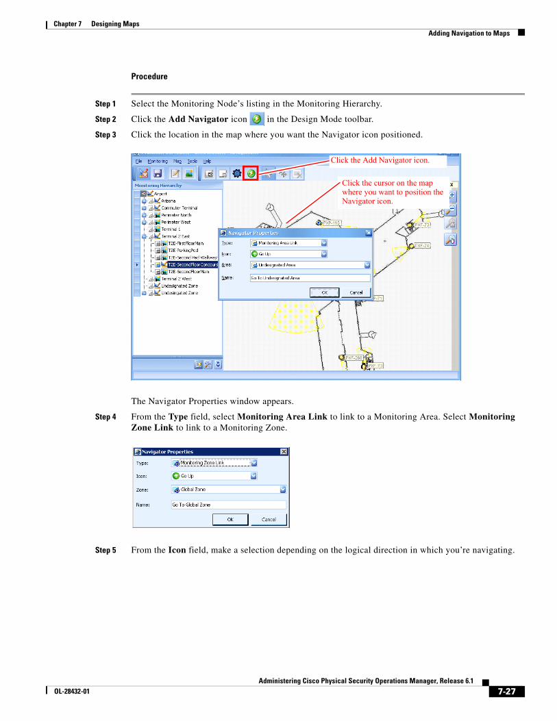
7-27Administering Cisco Physical Security Operations Manager, Release 6.1
OL-28432-01
Chapter 7 Designing Maps Adding Navigation to Maps
Procedure
Step 1 Select the Monitoring Node’s listing in the Monitoring Hierarchy.
Step 2 Click the Add Navigator icon in the Design Mode toolbar.
Step 3 Click the location in the map where you want the Navigator icon positioned.
The Navigator Properties window appears.
Step 4 From the Type field, select Monitoring Area Link to link to a Monitoring Area. Select Monitoring Zone Link to link to a Monitoring Zone.
Step 5 From the Icon field, make a selection depending on the logical direction in which you’re navigating.
Click the Add Navigator icon.
Click the cursor on the map where you want to position the Navigator icon.
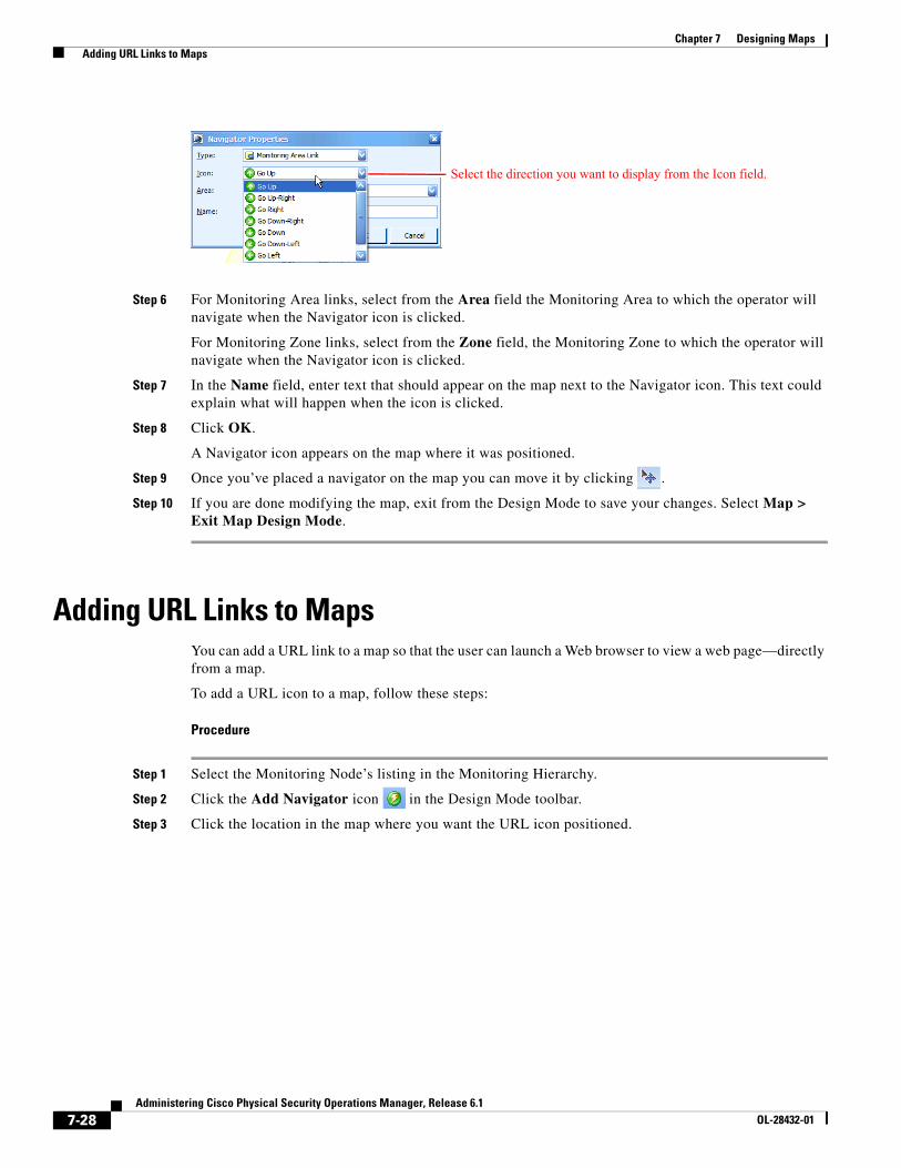
7-28Administering Cisco Physical Security Operations Manager, Release 6.1
OL-28432-01
Chapter 7 Designing Maps Adding URL Links to Maps
Step 6 For Monitoring Area links, select from the Area field the Monitoring Area to which the operator will navigate when the Navigator icon is clicked.
For Monitoring Zone links, select from the Zone field, the Monitoring Zone to which the operator will navigate when the Navigator icon is clicked.
Step 7 In the Name field, enter text that should appear on the map next to the Navigator icon. This text could explain what will happen when the icon is clicked.
Step 8 Click OK.
A Navigator icon appears on the map where it was positioned.
Step 9 Once you’ve placed a navigator on the map you can move it by clicking .
Step 10 If you are done modifying the map, exit from the Design Mode to save your changes. Select Map > Exit Map Design Mode.
Adding URL Links to MapsYou can add a URL link to a map so that the user can launch a Web browser to view a web page—directly from a map.
To add a URL icon to a map, follow these steps:
Procedure
Step 1 Select the Monitoring Node’s listing in the Monitoring Hierarchy.
Step 2 Click the Add Navigator icon in the Design Mode toolbar.
Step 3 Click the location in the map where you want the URL icon positioned.
Select the direction you want to display from the Icon field.
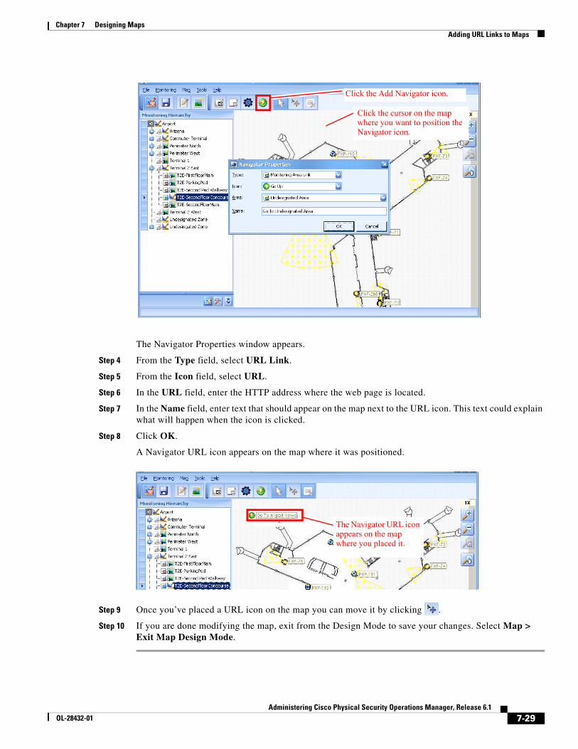
7-29Administering Cisco Physical Security Operations Manager, Release 6.1
OL-28432-01
Chapter 7 Designing Maps Adding URL Links to Maps
The Navigator Properties window appears.
Step 4 From the Type field, select URL Link.
Step 5 From the Icon field, select URL.
Step 6 In the URL field, enter the HTTP address where the web page is located.
Step 7 In the Name field, enter text that should appear on the map next to the URL icon. This text could explain what will happen when the icon is clicked.
Step 8 Click OK.
A Navigator URL icon appears on the map where it was positioned.
Step 9 Once you’ve placed a URL icon on the map you can move it by clicking .
Step 10 If you are done modifying the map, exit from the Design Mode to save your changes. Select Map > Exit Map Design Mode.
Click the Add Navigator icon.
Click the cursor on the map where you want to position the Navigator icon.
The Navigator URL icon appears on the map where you placed it.
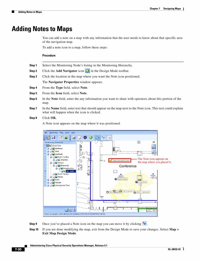
7-30Administering Cisco Physical Security Operations Manager, Release 6.1
OL-28432-01
Chapter 7 Designing Maps Adding Notes to Maps
Adding Notes to MapsYou can add a note on a map with any information that the user needs to know about that specific area of the navigation map.
To add a note icon to a map, follow these steps:
Procedure
Step 1 Select the Monitoring Node’s listing in the Monitoring Hierarchy.
Step 2 Click the Add Navigator icon in the Design Mode toolbar.
Step 3 Click the location in the map where you want the Note icon positioned.
The Navigator Properties window appears.
Step 4 From the Type field, select Note.
Step 5 From the Icon field, select Note.
Step 6 In the Note field, enter the any information you want to share with operators about this portion of the map.
Step 7 In the Name field, enter text that should appear on the map next to the Note icon. This text could explain what will happen when the icon is clicked.
Step 8 Click OK.
A Note icon appears on the map where it was positioned.
Step 9 Once you’ve placed a Note icon on the map you can move it by clicking .
Step 10 If you are done modifying the map, exit from the Design Mode to save your changes. Select Map > Exit Map Design Mode.
The Note icon appears on the map where you placed it.
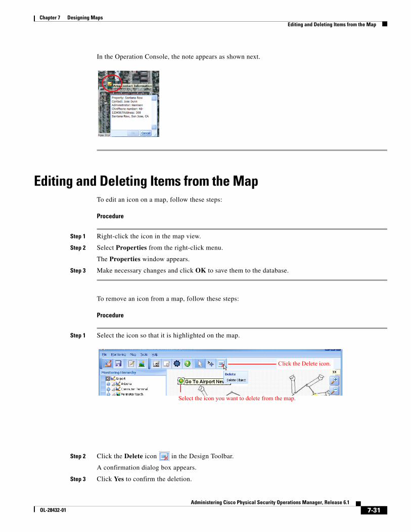
7-31Administering Cisco Physical Security Operations Manager, Release 6.1
OL-28432-01
Chapter 7 Designing Maps Editing and Deleting Items from the Map
In the Operation Console, the note appears as shown next.
Editing and Deleting Items from the MapTo edit an icon on a map, follow these steps:
Procedure
Step 1 Right-click the icon in the map view.
Step 2 Select Properties from the right-click menu.
The Properties window appears.
Step 3 Make necessary changes and click OK to save them to the database.
To remove an icon from a map, follow these steps:
Procedure
Step 1 Select the icon so that it is highlighted on the map.
Step 2 Click the Delete icon in the Design Toolbar.
A confirmation dialog box appears.
Step 3 Click Yes to confirm the deletion.
Select the icon you want to delete from the map.
Click the Delete icon.
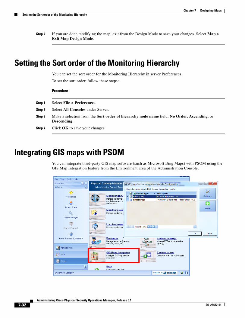
7-32Administering Cisco Physical Security Operations Manager, Release 6.1
OL-28432-01
Chapter 7 Designing Maps Setting the Sort order of the Monitoring Hierarchy
Step 4 If you are done modifying the map, exit from the Design Mode to save your changes. Select Map > Exit Map Design Mode.
Setting the Sort order of the Monitoring HierarchyYou can set the sort order for the Monitoring Hierarchy in server Preferences.
To set the sort order, follow these steps:
Procedure
Step 1 Select File > Preferences.
Step 2 Select All Consoles under Server.
Step 3 Make a selection from the Sort order of hierarchy node name field: No Order, Ascending, or Descending.
Step 4 Click OK to save your changes.
Integrating GIS maps with PSOMYou can integrate third-party GIS map software (such as Microsoft Bing Maps) with PSOM using the GIS Map Integration feature from the Environment area of the Administration Console.
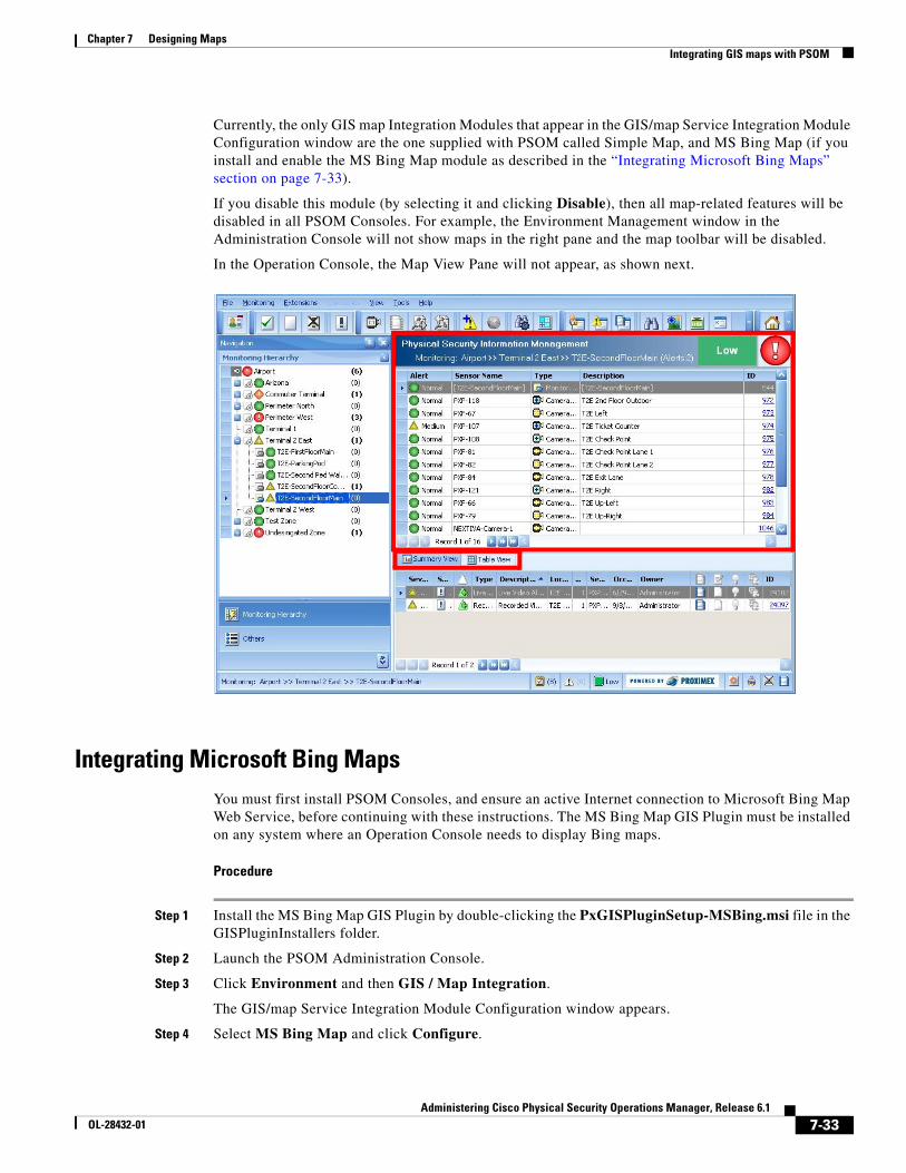
7-33Administering Cisco Physical Security Operations Manager, Release 6.1
OL-28432-01
Chapter 7 Designing Maps Integrating GIS maps with PSOM
Currently, the only GIS map Integration Modules that appear in the GIS/map Service Integration Module Configuration window are the one supplied with PSOM called Simple Map, and MS Bing Map (if you install and enable the MS Bing Map module as described in the “Integrating Microsoft Bing Maps” section on page 7-33).
If you disable this module (by selecting it and clicking Disable), then all map-related features will be disabled in all PSOM Consoles. For example, the Environment Management window in the Administration Console will not show maps in the right pane and the map toolbar will be disabled.
In the Operation Console, the Map View Pane will not appear, as shown next.
Integrating Microsoft Bing MapsYou must first install PSOM Consoles, and ensure an active Internet connection to Microsoft Bing Map Web Service, before continuing with these instructions. The MS Bing Map GIS Plugin must be installed on any system where an Operation Console needs to display Bing maps.
Procedure
Step 1 Install the MS Bing Map GIS Plugin by double-clicking the PxGISPluginSetup-MSBing.msi file in the GISPluginInstallers folder.
Step 2 Launch the PSOM Administration Console.
Step 3 Click Environment and then GIS / Map Integration.
The GIS/map Service Integration Module Configuration window appears.
Step 4 Select MS Bing Map and click Configure.

7-34Administering Cisco Physical Security Operations Manager, Release 6.1
OL-28432-01
Chapter 7 Designing Maps Integrating GIS maps with PSOM
The Bing Map Server Configuration window appears.
Step 5 If you want to use your own Microsoft Bing Map account, check the Use Bing Map Key option and enter the key into the space provided.
Note If the key is invalid, an “Invalid Credentials” message will be overlaid on the map when you click Configure:
Step 6 Click Configure to set the default view presented to users when configuring individual Monitoring Zone/Monitoring Area maps. The default parameters include: Zoom Level, Center Location, and Map mode (Aerial or Aerial/Road).
There are several ways to pinpoint the desired scope and location for the desired map view using the Bing Map Viewer that appears when you click Configure:
• On-Screen Navigation Controls—These controls appear when the mouse hovers in the right-upper corner of the map. Use the controls to move left, up, right, and down. Center button resets to the default view location and zoom level according to previous configuration.
• Zoom Controls—These controls appear when the mouse hovers at the top of the map: Zoom in, out. The mouse wheel can also be used to zoom in and out.
• Map Style Controls—Use this control to switch to a different mode for map style: Aerial (with label), Aerial, Road.
• Map Style Controls—Use this control to switch to a different mode for map style: Aerial (with label), Aerial, Road.
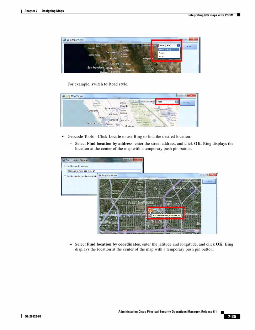
7-35Administering Cisco Physical Security Operations Manager, Release 6.1
OL-28432-01
Chapter 7 Designing Maps Integrating GIS maps with PSOM
For example, switch to Road style.
• Geocode Tools—Click Locate to use Bing to find the desired location:
– Select Find location by address, enter the street address, and click OK. Bing displays the location at the center of the map with a temporary push pin button.
– Select Find location by coordinates, enter the latitude and longitude, and click OK. Bing displays the location at the center of the map with a temporary push pin button.
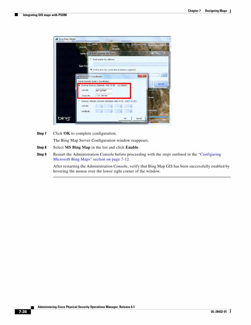
7-36Administering Cisco Physical Security Operations Manager, Release 6.1
OL-28432-01
Chapter 7 Designing Maps Integrating GIS maps with PSOM
Step 7 Click OK to complete configuration.
The Bing Map Server Configuration window reappears.
Step 8 Select MS Bing Map in the list and click Enable.
Step 9 Restart the Administration Console before proceeding with the steps outlined in the “Configuring Microsoft Bing Maps” section on page 7-12.
After restarting the Administration Console, verify that Bing Map GIS has been successfully enabled by hovering the mouse over the lower right corner of the window.
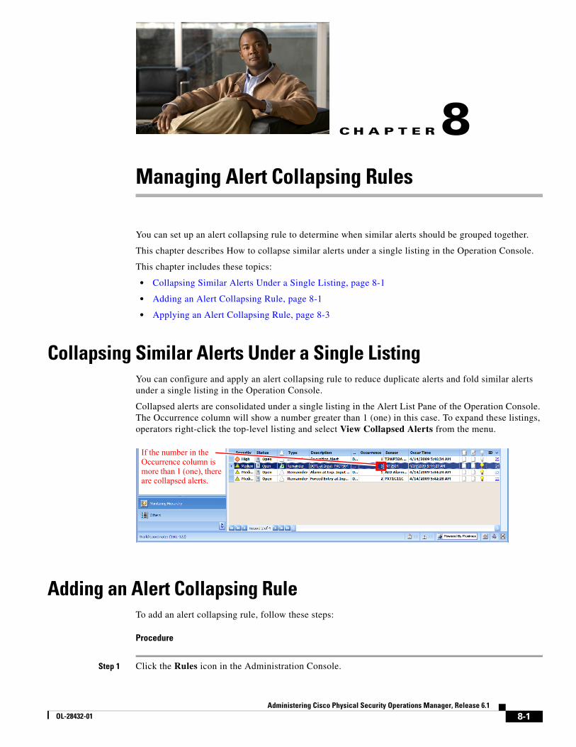
C H A P T E R
8-1Administering Cisco Physical Security Operations Manager, Release 6.1
OL-28432-01
8Managing Alert Collapsing Rules
You can set up an alert collapsing rule to determine when similar alerts should be grouped together.
This chapter describes How to collapse similar alerts under a single listing in the Operation Console.
This chapter includes these topics:
• Collapsing Similar Alerts Under a Single Listing, page 8-1
• Adding an Alert Collapsing Rule, page 8-1
• Applying an Alert Collapsing Rule, page 8-3
Collapsing Similar Alerts Under a Single ListingYou can configure and apply an alert collapsing rule to reduce duplicate alerts and fold similar alerts under a single listing in the Operation Console.
Collapsed alerts are consolidated under a single listing in the Alert List Pane of the Operation Console. The Occurrence column will show a number greater than 1 (one) in this case. To expand these listings, operators right-click the top-level listing and select View Collapsed Alerts from the menu.
Adding an Alert Collapsing RuleTo add an alert collapsing rule, follow these steps:
Procedure
Step 1 Click the Rules icon in the Administration Console.
If the number in the Occurrence column is more than 1 (one), there are collapsed alerts.
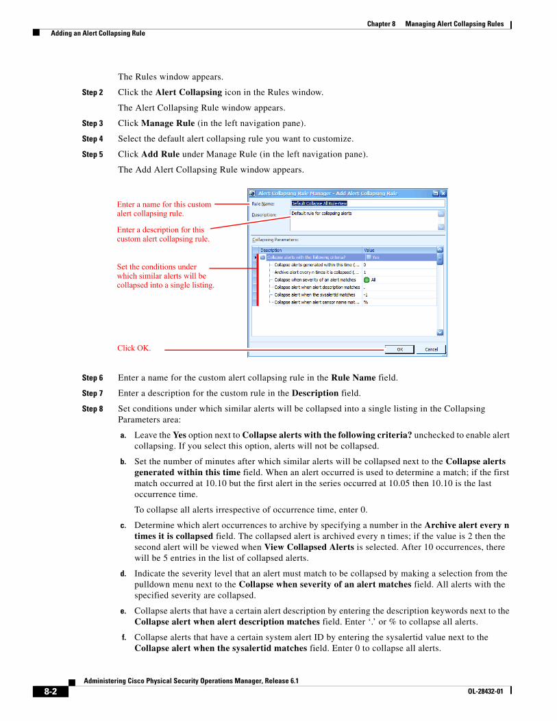
8-2Administering Cisco Physical Security Operations Manager, Release 6.1
OL-28432-01
Chapter 8 Managing Alert Collapsing Rules Adding an Alert Collapsing Rule
The Rules window appears.
Step 2 Click the Alert Collapsing icon in the Rules window.
The Alert Collapsing Rule window appears.
Step 3 Click Manage Rule (in the left navigation pane).
Step 4 Select the default alert collapsing rule you want to customize.
Step 5 Click Add Rule under Manage Rule (in the left navigation pane).
The Add Alert Collapsing Rule window appears.
Step 6 Enter a name for the custom alert collapsing rule in the Rule Name field.
Step 7 Enter a description for the custom rule in the Description field.
Step 8 Set conditions under which similar alerts will be collapsed into a single listing in the Collapsing Parameters area:
a. Leave the Yes option next to Collapse alerts with the following criteria? unchecked to enable alert collapsing. If you select this option, alerts will not be collapsed.
b. Set the number of minutes after which similar alerts will be collapsed next to the Collapse alerts generated within this time field. When an alert occurred is used to determine a match; if the first match occurred at 10.10 but the first alert in the series occurred at 10.05 then 10.10 is the last occurrence time.
To collapse all alerts irrespective of occurrence time, enter 0.
c. Determine which alert occurrences to archive by specifying a number in the Archive alert every n times it is collapsed field. The collapsed alert is archived every n times; if the value is 2 then the second alert will be viewed when View Collapsed Alerts is selected. After 10 occurrences, there will be 5 entries in the list of collapsed alerts.
d. Indicate the severity level that an alert must match to be collapsed by making a selection from the pulldown menu next to the Collapse when severity of an alert matches field. All alerts with the specified severity are collapsed.
e. Collapse alerts that have a certain alert description by entering the description keywords next to the Collapse alert when alert description matches field. Enter ‘.’ or % to collapse all alerts.
f. Collapse alerts that have a certain system alert ID by entering the sysalertid value next to the Collapse alert when the sysalertid matches field. Enter 0 to collapse all alerts.
Enter a name for this custom alert collapsing rule.
Enter a description for this custom alert collapsing rule.
Set the conditions under which similar alerts will be collapsed into a single listing.
Click OK.
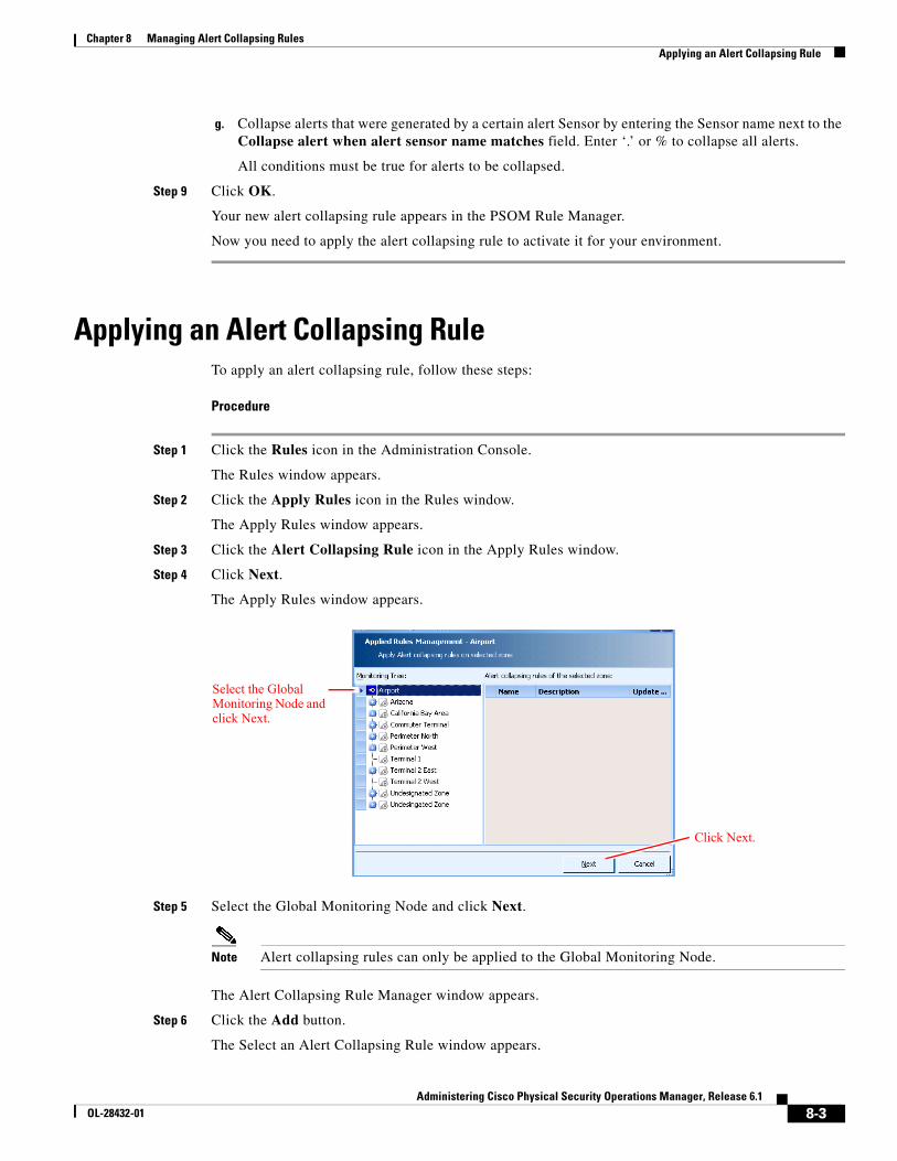
8-3Administering Cisco Physical Security Operations Manager, Release 6.1
OL-28432-01
Chapter 8 Managing Alert Collapsing Rules Applying an Alert Collapsing Rule
g. Collapse alerts that were generated by a certain alert Sensor by entering the Sensor name next to the Collapse alert when alert sensor name matches field. Enter ‘.’ or % to collapse all alerts.
All conditions must be true for alerts to be collapsed.
Step 9 Click OK.
Your new alert collapsing rule appears in the PSOM Rule Manager.
Now you need to apply the alert collapsing rule to activate it for your environment.
Applying an Alert Collapsing RuleTo apply an alert collapsing rule, follow these steps:
Procedure
Step 1 Click the Rules icon in the Administration Console.
The Rules window appears.
Step 2 Click the Apply Rules icon in the Rules window.
The Apply Rules window appears.
Step 3 Click the Alert Collapsing Rule icon in the Apply Rules window.
Step 4 Click Next.
The Apply Rules window appears.
Step 5 Select the Global Monitoring Node and click Next.
Note Alert collapsing rules can only be applied to the Global Monitoring Node.
The Alert Collapsing Rule Manager window appears.
Step 6 Click the Add button.
The Select an Alert Collapsing Rule window appears.
Select the Global Monitoring Node and click Next.
Click Next.
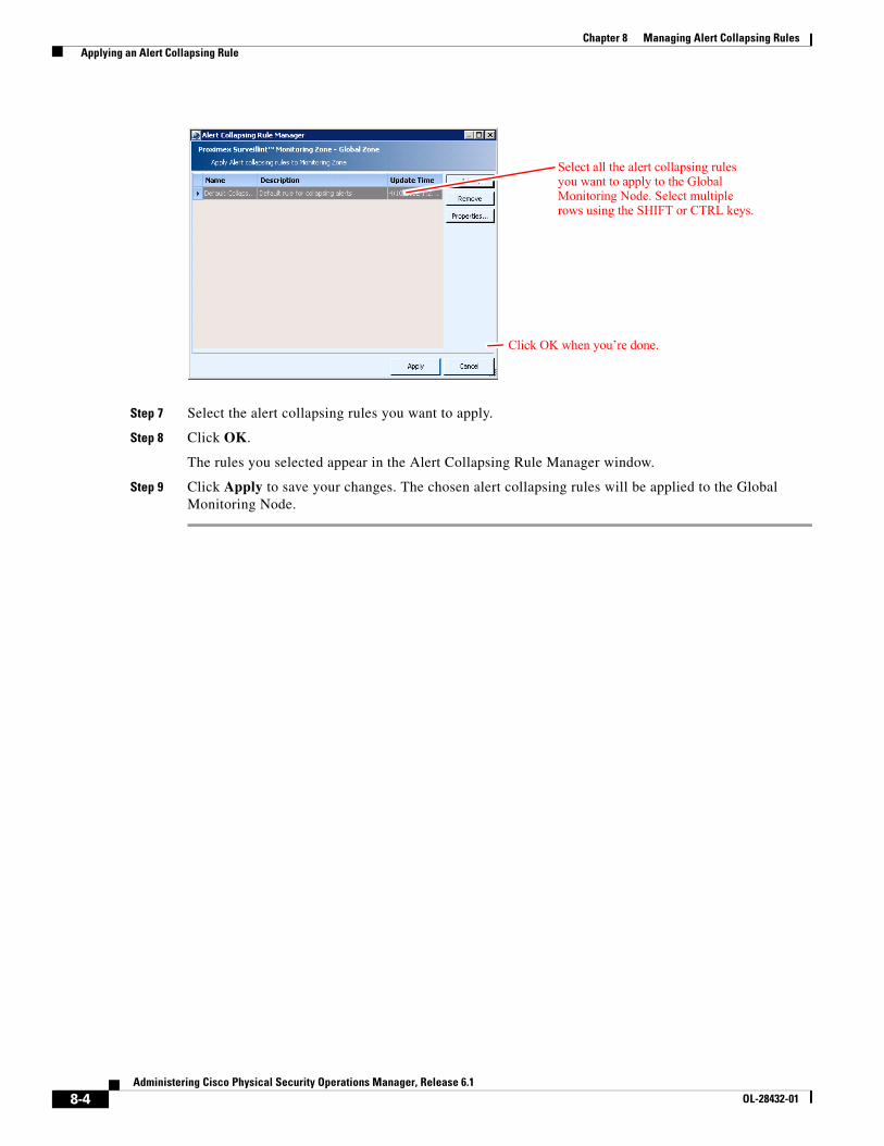
8-4Administering Cisco Physical Security Operations Manager, Release 6.1
OL-28432-01
Chapter 8 Managing Alert Collapsing Rules Applying an Alert Collapsing Rule
Step 7 Select the alert collapsing rules you want to apply.
Step 8 Click OK.
The rules you selected appear in the Alert Collapsing Rule Manager window.
Step 9 Click Apply to save your changes. The chosen alert collapsing rules will be applied to the Global Monitoring Node.
Select all the alert collapsing rules you want to apply to the Global Monitoring Node. Select multiple rows using the SHIFT or CTRL keys.
Click OK when you’re done.
C H A P T E R
9-1Administering Cisco Physical Security Operations Manager, Release 6.1
OL-28432-01
9Customizing Reports
Within the Operation Console, operators have a number of reports they can execute to monitor response times and other administrative functions. From the Administration Console, all of these reports can be customized.
This chapter covers:
• Types of default reports provided by PSOM
• How to customize a default report
This chapter includes these topics:
• Types of Default Reports, page 9-1
• Customizing a Report, page 9-2
• Modifying a Custom Report, page 9-6
• Deleting a Custom Report, page 9-7
• Setting a Default Directory for Incident Packages, page 9-8
Types of Default ReportsFrom the Operation Console, operators can run the default reports that Table 9-1 describes.
Table 9-1 Reports that Operators can Generate with the Report Wizard
Report What it Tells You...
Alert Count Daily Report How many alerts occurred each day of the week for the specified time period. It includes information about the types and severity of alerts, as well as the locations of Sensors that generated them.
Alert Count Hourly Report How many alerts occurred each hour of the day for the specified time period. It includes information about the types and severity of alerts, as well as the locations of Sensors that generated them.
Alert Detail Report What alerts occurred during the specified time period. It includes details about the alerts including: severity, status, alert type, Sensor, Location, and occur time.
Alert Response Time By Alert Type Report
How long it took, on average, to respond to alerts. It shows the average response time for different alert types, alert severities, and Monitoring Zones/Monitoring Areas/Sensors.
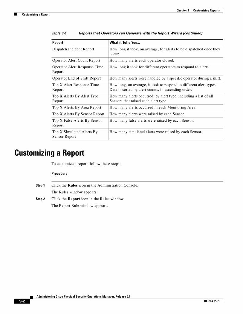
9-2Administering Cisco Physical Security Operations Manager, Release 6.1
OL-28432-01
Chapter 9 Customizing Reports Customizing a Report
Customizing a ReportTo customize a report, follow these steps:
Procedure
Step 1 Click the Rules icon in the Administration Console.
The Rules window appears.
Step 2 Click the Report icon in the Rules window.
The Report Rule window appears.
Dispatch Incident Report How long it took, on average, for alerts to be dispatched once they occur.
Operator Alert Count Report How many alerts each operator closed.
Operator Alert Response Time Report
How long it took for different operators to respond to alerts.
Operator End of Shift Report How many alerts were handled by a specific operator during a shift.
Top X Alert Response Time Report
How long, on average, it took to respond to different alert types. Data is sorted by alert counts, in ascending order.
Top X Alerts By Alert Type Report
How many alerts occurred, by alert type, including a list of all Sensors that raised each alert type.
Top X Alerts By Area Report How many alerts occurred in each Monitoring Area.
Top X Alerts By Sensor Report How many alerts were raised by each Sensor.
Top X False Alerts By Sensor Report
How many false alerts were raised by each Sensor.
Top X Simulated Alerts By Sensor Report
How many simulated alerts were raised by each Sensor.
Table 9-1 Reports that Operators can Generate with the Report Wizard (continued)
Report What it Tells You...
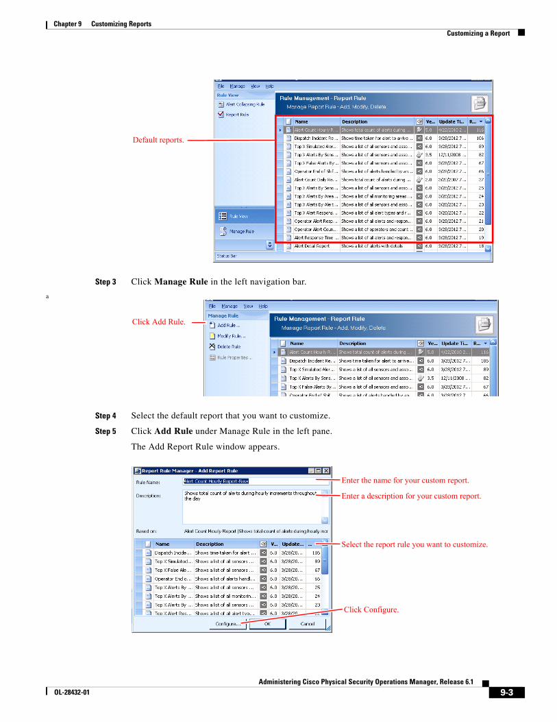
9-3Administering Cisco Physical Security Operations Manager, Release 6.1
OL-28432-01
Chapter 9 Customizing Reports Customizing a Report
Step 3 Click Manage Rule in the left navigation bar.
a
Step 4 Select the default report that you want to customize.
Step 5 Click Add Rule under Manage Rule in the left pane.
The Add Report Rule window appears.
Default reports.
Click Add Rule.
Enter the name for your custom report.
Enter a description for your custom report.
Select the report rule you want to customize.
Click Configure.
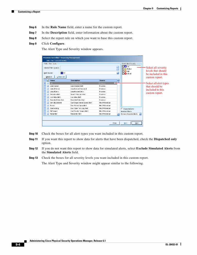
9-4Administering Cisco Physical Security Operations Manager, Release 6.1
OL-28432-01
Chapter 9 Customizing Reports Customizing a Report
Step 6 In the Rule Name field, enter a name for the custom report.
Step 7 In the Description field, enter information about the custom report.
Step 8 Select the report rule on which you want to base this custom report.
Step 9 Click Configure.
The Alert Type and Severity window appears.
Step 10 Check the boxes for all alert types you want included in this custom report.
Step 11 If you want this report to show data for alerts that have been dispatched, check the Dispatched only option.
Step 12 If you do not want this report to show data for simulated alerts, select Exclude Simulated Alerts from the Simulated Alerts field.
Step 13 Check the boxes for all severity levels you want included in this custom report.
The Alert Type and Severity window might appear similar to the following.
Select all severity levels that should be included in this custom report.
Select all alert types that should be included in this custom report.
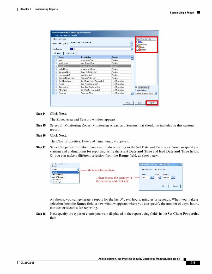
9-5Administering Cisco Physical Security Operations Manager, Release 6.1
OL-28432-01
Chapter 9 Customizing Reports Customizing a Report
Step 14 Click Next.
The Zone, Area and Sensors window appears.
Step 15 Select all Monitoring Zones, Monitoring Areas, and Sensors that should be included in this custom report.
Step 16 Click Next.
The Chart Properties, Date and Time window appears.
Step 17 Select the period for which you want to do reporting in the Set Date and Time area. You can specify a starting and ending point for reporting using the Start Date and Time and End Date and Time fields. Or you can make a different selection from the Range field, as shown next.
As shown, you can generate a report for the last N days, hours, minutes or seconds. When you make a selection from the Range field, a new window appears where you can specify the number of days, hours, minutes or seconds for reporting.
Step 18 Next specify the types of charts you want displayed in the report using fields in the Set Chart Properties field.
Make a selection here....
...then choose the quantity in this window and click OK.
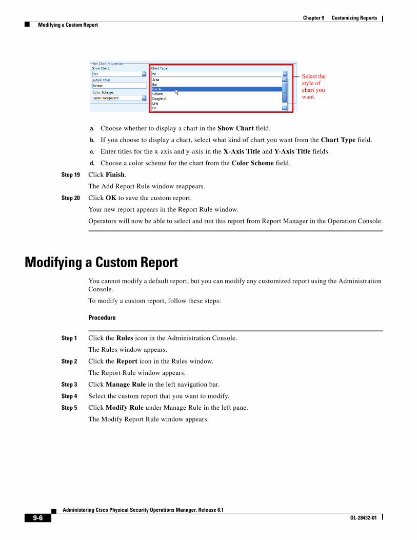
9-6Administering Cisco Physical Security Operations Manager, Release 6.1
OL-28432-01
Chapter 9 Customizing Reports Modifying a Custom Report
a. Choose whether to display a chart in the Show Chart field.
b. If you choose to display a chart, select what kind of chart you want from the Chart Type field.
c. Enter titles for the x-axis and y-axis in the X-Axis Title and Y-Axis Title fields.
d. Choose a color scheme for the chart from the Color Scheme field.
Step 19 Click Finish.
The Add Report Rule window reappears.
Step 20 Click OK to save the custom report.
Your new report appears in the Report Rule window.
Operators will now be able to select and run this report from Report Manager in the Operation Console.
Modifying a Custom ReportYou cannot modify a default report, but you can modify any customized report using the Administration Console.
To modify a custom report, follow these steps:
Procedure
Step 1 Click the Rules icon in the Administration Console.
The Rules window appears.
Step 2 Click the Report icon in the Rules window.
The Report Rule window appears.
Step 3 Click Manage Rule in the left navigation bar.
Step 4 Select the custom report that you want to modify.
Step 5 Click Modify Rule under Manage Rule in the left pane.
The Modify Report Rule window appears.
Select the style of chart you want.
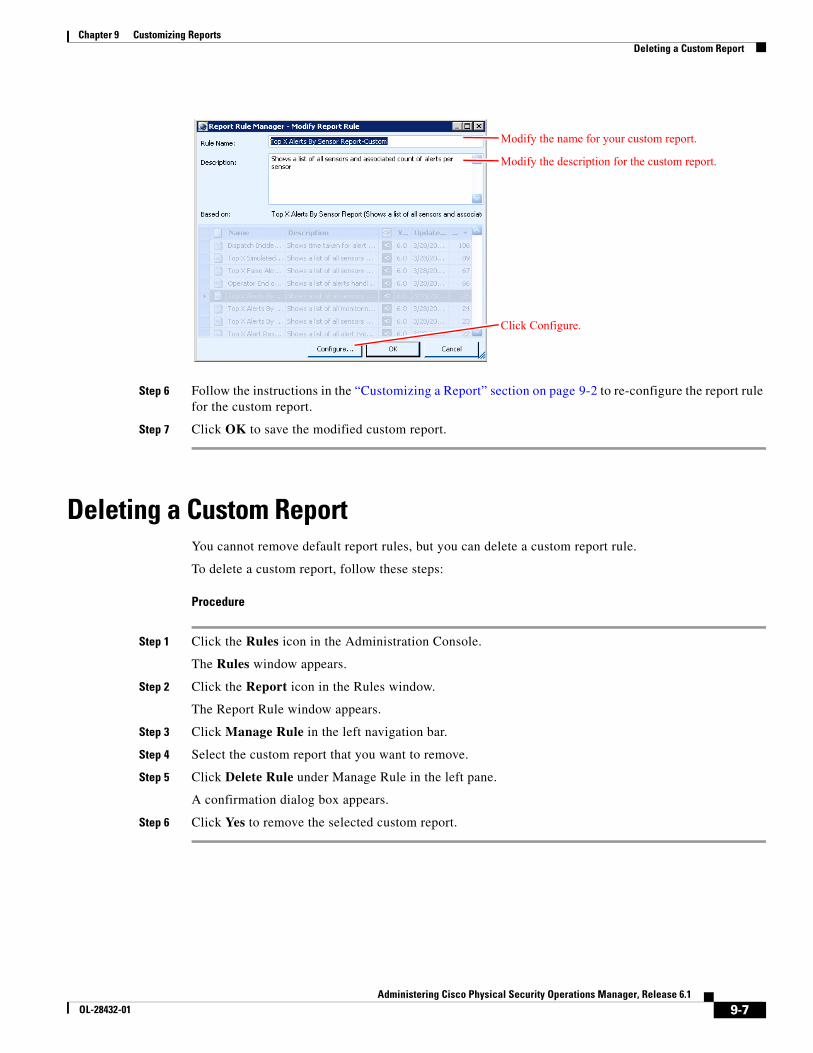
9-7Administering Cisco Physical Security Operations Manager, Release 6.1
OL-28432-01
Chapter 9 Customizing Reports Deleting a Custom Report
Step 6 Follow the instructions in the “Customizing a Report” section on page 9-2 to re-configure the report rule for the custom report.
Step 7 Click OK to save the modified custom report.
Deleting a Custom ReportYou cannot remove default report rules, but you can delete a custom report rule.
To delete a custom report, follow these steps:
Procedure
Step 1 Click the Rules icon in the Administration Console.
The Rules window appears.
Step 2 Click the Report icon in the Rules window.
The Report Rule window appears.
Step 3 Click Manage Rule in the left navigation bar.
Step 4 Select the custom report that you want to remove.
Step 5 Click Delete Rule under Manage Rule in the left pane.
A confirmation dialog box appears.
Step 6 Click Yes to remove the selected custom report.
Modify the name for your custom report.
Modify the description for the custom report.
Click Configure.
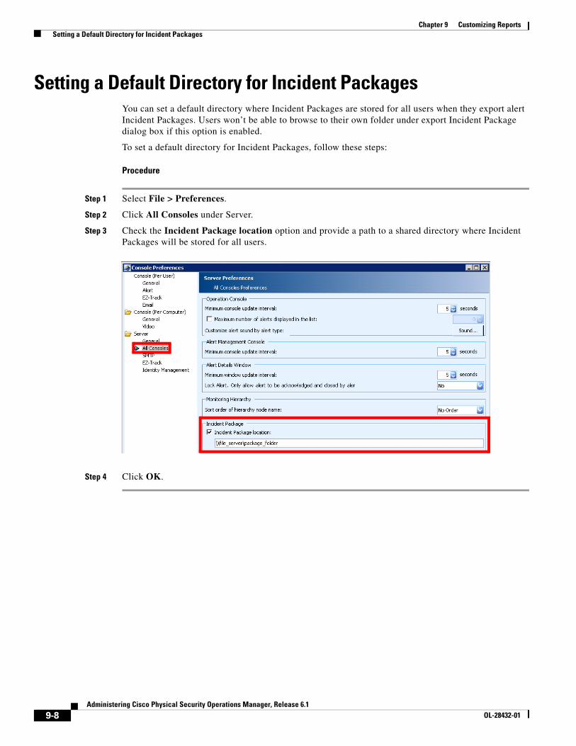
9-8Administering Cisco Physical Security Operations Manager, Release 6.1
OL-28432-01
Chapter 9 Customizing Reports Setting a Default Directory for Incident Packages
Setting a Default Directory for Incident PackagesYou can set a default directory where Incident Packages are stored for all users when they export alert Incident Packages. Users won’t be able to browse to their own folder under export Incident Package dialog box if this option is enabled.
To set a default directory for Incident Packages, follow these steps:
Procedure
Step 1 Select File > Preferences.
Step 2 Click All Consoles under Server.
Step 3 Check the Incident Package location option and provide a path to a shared directory where Incident Packages will be stored for all users.
Step 4 Click OK.

C H A P T E R
10-1Administering Cisco Physical Security Operations Manager, Release 6.1
OL-28432-01
10Managing Tracking Devices and Resources
Within the Operation Console, operators can monitor the movements of Tracking Devices and security Resources within the environment. In the Administration Console, you can:
• Configure GPS geographic coordinates for all maps within the PSOM environment. See the “Configuring Coordinates using GPS” section on page 7-6 for instructions.
• View and activate/deactivate Resources within PSOM that represent security officers, vehicles, or other assets within your environment.
• View and activate/deactivate Tracking Devices within PSOM that integrate with external 3rd party tracking services so that the location of these devices is displayed in the Operation Console.
Before proceeding with this chapter, refer to PSOM Integration Module documentation for instructions on integrating your third-party security systems with PSOM so that Resources and Tracking Devices can automatically be defined.
This chapter includes these topics:
• Viewing Security Resources, page 10-1
• Understanding Tracking Devices, page 10-2
• Customize Colors for Tracking Objects, page 10-4
• Setting How Many Tracking Points to Display, page 10-6
Viewing Security ResourcesSecurity Resources are assets within your environment including:
• People
• Land vehicles
• Water vehicles
• Air vehicles
• Generic assets
• Security officers
• Law enforcement officers
• Law enforcement vehicles
• Emergency vehicles (fire, ambulance, etc.)
10-2Administering Cisco Physical Security Operations Manager, Release 6.1
OL-28432-01
Chapter 10 Managing Tracking Devices and Resources Understanding Tracking Devices
Each security Resource can be associated with a Tracking Device within PSOM; for example, a security officer could carry a Tracking Device to show his position within the environment. PSOM integrates with 3rd party location service applications to display the current location, or historical trail of locations for a security Resource, within the Operation Console.
To view security Resources defined in PSOM, follow these steps:
Procedure
Step 1 Click the Environment icon in the Administration Console.
The Environment window appears.
Step 2 Click the Resources icon.
The Security Resource Manager window appears.
Step 3 Click Properties.
The Edit Security Resource window appears.
Step 4 To change the name associated with the Resource, enter a new name in the Resource Name field.
Step 5 To change the type assigned to the Resource, make a selection from the Resource Type field.
Step 6 To change the description, enter modifications in the Description field.
Step 7 Click OK.
Activating or Deactivating a ResourceTo activate or deactivate a Resource, follow these steps:
Procedure
Step 1 Click the Environment icon in the Administration Console.
The Environment window appears.
Step 2 Click the Resources icon.
The Security Resource Manager window appears.
Step 3 Select the Resource and click the Deactivate button to disable it, or the Activate button to enable it.
Step 4 Click Yes in the confirmation dialog box to verify the operation.
Resources that have been deactivated appear with a greyed-out icon in the Resource list in the Security Resource Manager. Active Resources appear with green icons.
Understanding Tracking DevicesTracking Devices are wireless electronic devices whose GPS (global positioning system) coordinates can be viewed on an electronic map using specialized software. PSOM synchronizes with integrated subsystems to create Tracking Devices that appear on maps including:
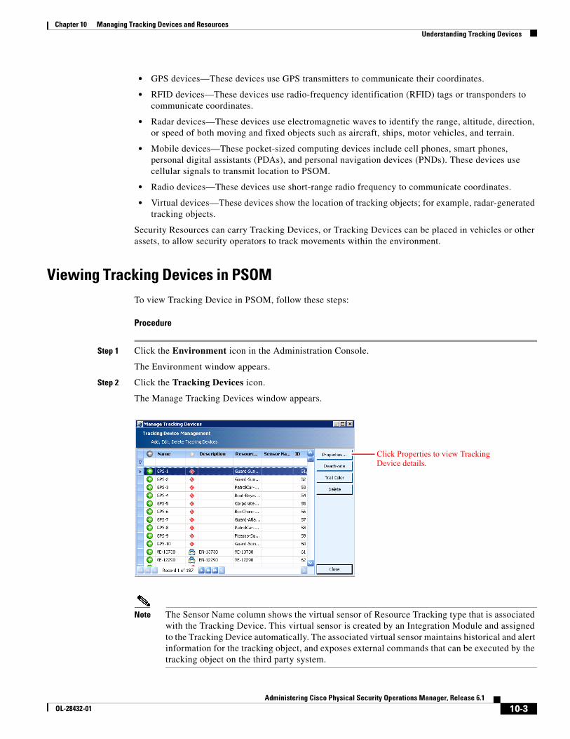
10-3Administering Cisco Physical Security Operations Manager, Release 6.1
OL-28432-01
Chapter 10 Managing Tracking Devices and Resources Understanding Tracking Devices
• GPS devices—These devices use GPS transmitters to communicate their coordinates.
• RFID devices—These devices use radio-frequency identification (RFID) tags or transponders to communicate coordinates.
• Radar devices—These devices use electromagnetic waves to identify the range, altitude, direction, or speed of both moving and fixed objects such as aircraft, ships, motor vehicles, and terrain.
• Mobile devices—These pocket-sized computing devices include cell phones, smart phones, personal digital assistants (PDAs), and personal navigation devices (PNDs). These devices use cellular signals to transmit location to PSOM.
• Radio devices—These devices use short-range radio frequency to communicate coordinates.
• Virtual devices—These devices show the location of tracking objects; for example, radar-generated tracking objects.
Security Resources can carry Tracking Devices, or Tracking Devices can be placed in vehicles or other assets, to allow security operators to track movements within the environment.
Viewing Tracking Devices in PSOMTo view Tracking Device in PSOM, follow these steps:
Procedure
Step 1 Click the Environment icon in the Administration Console.
The Environment window appears.
Step 2 Click the Tracking Devices icon.
The Manage Tracking Devices window appears.
Note The Sensor Name column shows the virtual sensor of Resource Tracking type that is associated with the Tracking Device. This virtual sensor is created by an Integration Module and assigned to the Tracking Device automatically. The associated virtual sensor maintains historical and alert information for the tracking object, and exposes external commands that can be executed by the tracking object on the third party system.
Click Properties to view Tracking Device details.
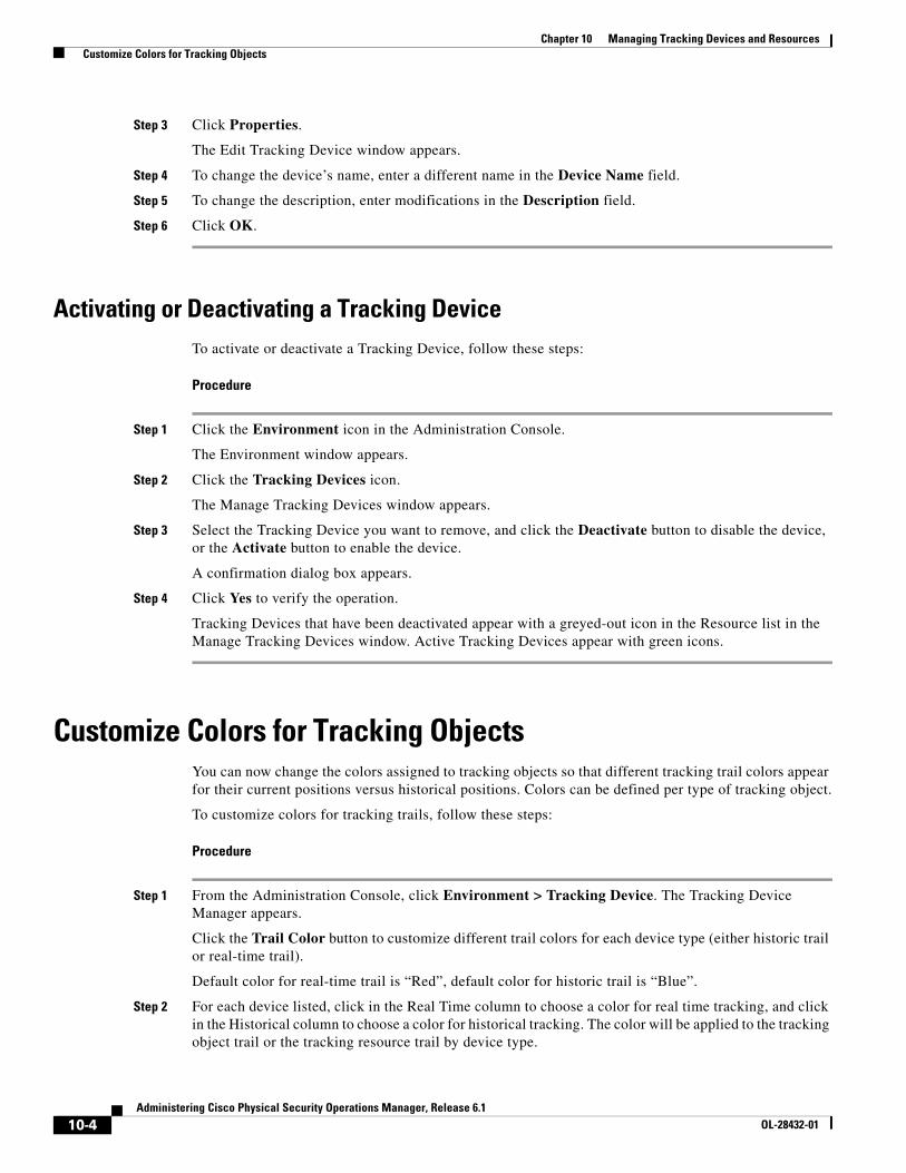
10-4Administering Cisco Physical Security Operations Manager, Release 6.1
OL-28432-01
Chapter 10 Managing Tracking Devices and Resources Customize Colors for Tracking Objects
Step 3 Click Properties.
The Edit Tracking Device window appears.
Step 4 To change the device’s name, enter a different name in the Device Name field.
Step 5 To change the description, enter modifications in the Description field.
Step 6 Click OK.
Activating or Deactivating a Tracking DeviceTo activate or deactivate a Tracking Device, follow these steps:
Procedure
Step 1 Click the Environment icon in the Administration Console.
The Environment window appears.
Step 2 Click the Tracking Devices icon.
The Manage Tracking Devices window appears.
Step 3 Select the Tracking Device you want to remove, and click the Deactivate button to disable the device, or the Activate button to enable the device.
A confirmation dialog box appears.
Step 4 Click Yes to verify the operation.
Tracking Devices that have been deactivated appear with a greyed-out icon in the Resource list in the Manage Tracking Devices window. Active Tracking Devices appear with green icons.
Customize Colors for Tracking ObjectsYou can now change the colors assigned to tracking objects so that different tracking trail colors appear for their current positions versus historical positions. Colors can be defined per type of tracking object.
To customize colors for tracking trails, follow these steps:
Procedure
Step 1 From the Administration Console, click Environment > Tracking Device. The Tracking Device Manager appears.
Click the Trail Color button to customize different trail colors for each device type (either historic trail or real-time trail).
Default color for real-time trail is “Red”, default color for historic trail is “Blue”.
Step 2 For each device listed, click in the Real Time column to choose a color for real time tracking, and click in the Historical column to choose a color for historical tracking. The color will be applied to the tracking object trail or the tracking resource trail by device type.
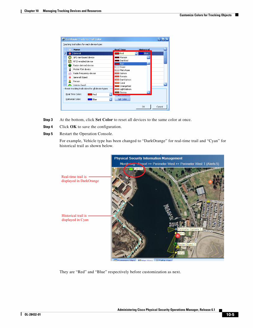
10-5Administering Cisco Physical Security Operations Manager, Release 6.1
OL-28432-01
Chapter 10 Managing Tracking Devices and Resources Customize Colors for Tracking Objects
Step 3 At the bottom, click Set Color to reset all devices to the same color at once.
Step 4 Click OK to save the configuration.
Step 5 Restart the Operation Console.
For example, Vehicle type has been changed to “DarkOrange” for real-time trail and “Cyan” for historical trail as shown below.
They are “Red” and “Blue” respectively before customization as next.
Real-time trail is displayed in DarkOrange
Historical trail is displayed in Cyan
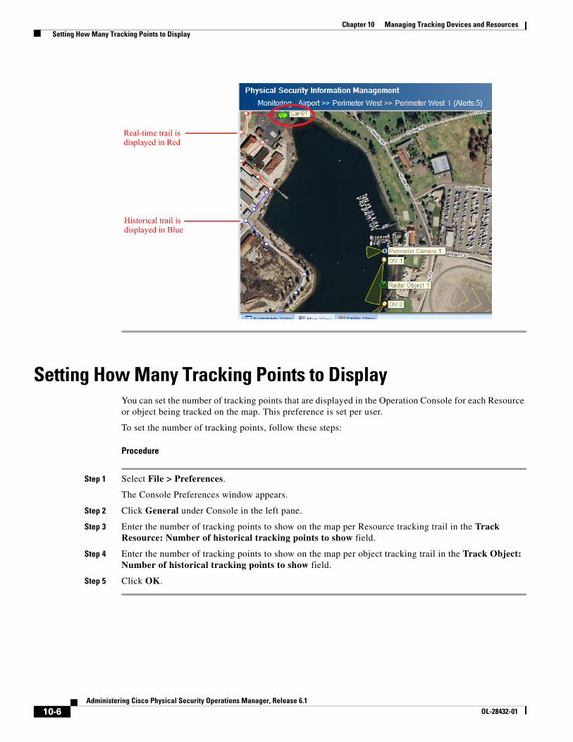
10-6Administering Cisco Physical Security Operations Manager, Release 6.1
OL-28432-01
Chapter 10 Managing Tracking Devices and Resources Setting How Many Tracking Points to Display
Setting How Many Tracking Points to DisplayYou can set the number of tracking points that are displayed in the Operation Console for each Resource or object being tracked on the map. This preference is set per user.
To set the number of tracking points, follow these steps:
Procedure
Step 1 Select File > Preferences.
The Console Preferences window appears.
Step 2 Click General under Console in the left pane.
Step 3 Enter the number of tracking points to show on the map per Resource tracking trail in the Track Resource: Number of historical tracking points to show field.
Step 4 Enter the number of tracking points to show on the map per object tracking trail in the Track Object: Number of historical tracking points to show field.
Step 5 Click OK.
Real-time trail is displayed in Red
Historical trail is displayed in Blue
C H A P T E R
11-1Administering Cisco Physical Security Operations Manager, Release 6.1
OL-28432-01
11Integrating Sensors with External Systems, Registering Third-Party Alarm Types, and Configuring Integration Modules
To synchronize information between external intrusion detection systems and PSOM, you must define sensor mappings that correlate sensor names between the systems. PSOM also allows you to register alarm types from third-party systems, define your own alarm types, and configure access to external systems with Integration Modules.
This chapter explains:
• How information is synchronized between PSOM and external intrusion detection systems using sensor mappings.
• How to create a new sensor mapping.
• How to edit or delete a sensor mapping.
• How to register a third-party alarm type.
• How to create a custom alert type.
• How to begin configuration of Integration Modules.
This chapter includes these topics:
• Overview of Sensor Mappings, page 11-1
• Mapping a Sensor, page 11-2
• Editing or Deleting a Sensor Mapping, page 11-3
• Registering Third-Party Alarms, page 11-3
• Editing or Deleting a Registered Alert Type, page 11-5
• Creating a Custom Alert Type, page 11-5
• Creating a System Alert Type, page 11-7
• Configuring Integration Modules for External Systems Integration, page 11-8
Overview of Sensor MappingsA sensor mapping within PSOM is a two-way event connector that synchronizes information in PSOM with information in external intrusion detection systems. The sensor mapping works by correlating the Sensor names in PSOM with the names for the same devices within the external system.
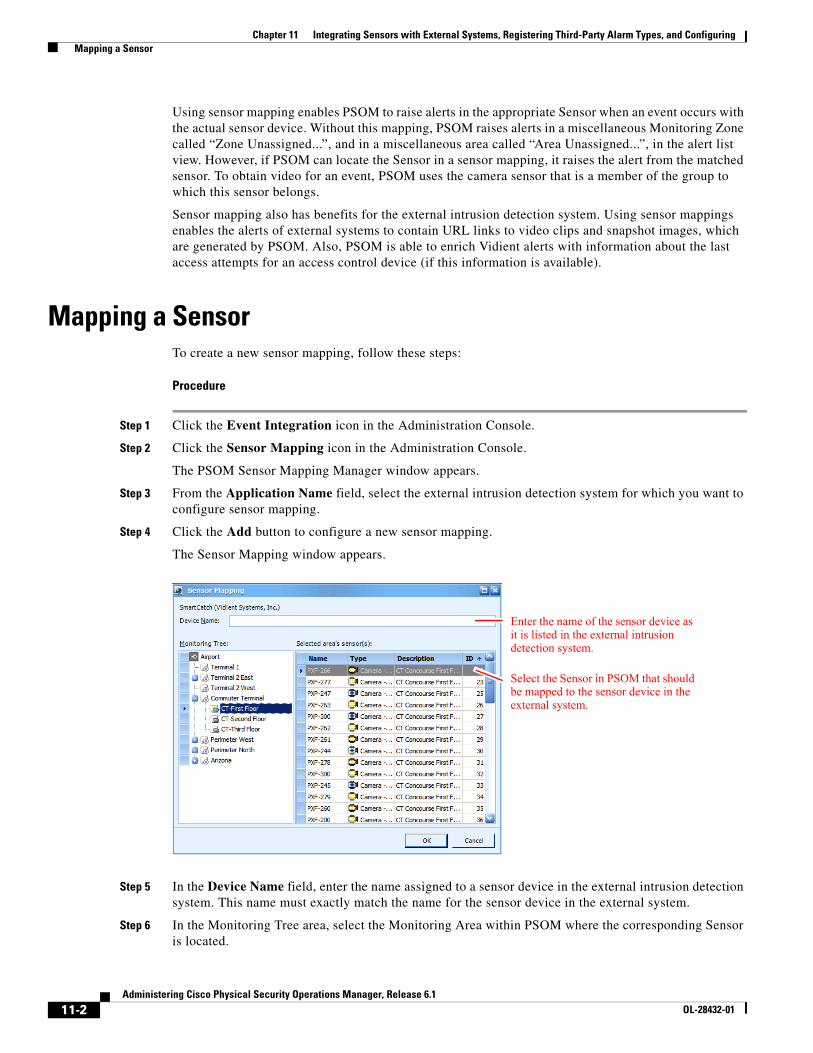
11-2Administering Cisco Physical Security Operations Manager, Release 6.1
OL-28432-01
Chapter 11 Integrating Sensors with External Systems, Registering Third-Party Alarm Types, and Configuring Mapping a Sensor
Using sensor mapping enables PSOM to raise alerts in the appropriate Sensor when an event occurs with the actual sensor device. Without this mapping, PSOM raises alerts in a miscellaneous Monitoring Zone called “Zone Unassigned...”, and in a miscellaneous area called “Area Unassigned...”, in the alert list view. However, if PSOM can locate the Sensor in a sensor mapping, it raises the alert from the matched sensor. To obtain video for an event, PSOM uses the camera sensor that is a member of the group to which this sensor belongs.
Sensor mapping also has benefits for the external intrusion detection system. Using sensor mappings enables the alerts of external systems to contain URL links to video clips and snapshot images, which are generated by PSOM. Also, PSOM is able to enrich Vidient alerts with information about the last access attempts for an access control device (if this information is available).
Mapping a SensorTo create a new sensor mapping, follow these steps:
Procedure
Step 1 Click the Event Integration icon in the Administration Console.
Step 2 Click the Sensor Mapping icon in the Administration Console.
The PSOM Sensor Mapping Manager window appears.
Step 3 From the Application Name field, select the external intrusion detection system for which you want to configure sensor mapping.
Step 4 Click the Add button to configure a new sensor mapping.
The Sensor Mapping window appears.
Step 5 In the Device Name field, enter the name assigned to a sensor device in the external intrusion detection system. This name must exactly match the name for the sensor device in the external system.
Step 6 In the Monitoring Tree area, select the Monitoring Area within PSOM where the corresponding Sensor is located.
Enter the name of the sensor device as it is listed in the external intrusion detection system.
Select the Sensor in PSOM that should be mapped to the sensor device in the external system.
11-3Administering Cisco Physical Security Operations Manager, Release 6.1
OL-28432-01
Chapter 11 Integrating Sensors with External Systems, Registering Third-Party Alarm Types, and Configuring Editing or Deleting a Sensor Mapping
Step 7 In the Sensors list, select the Sensor name with which the external sensor device should be correlated.
Step 8 Click OK to save the mapping.
The new mapping appears in the Sensor Mapping Manager window.
Editing or Deleting a Sensor MappingTo edit or delete a sensor mapping, follow these steps:
Procedure
Step 1 Click the Event Integration icon in the Administration Console.
Step 2 Click the Sensor Mapping icon in the Administration Console.
The PSOM Sensor Mapping Manager window appears.
Step 3 From the Application Name field, select the external intrusion detection system for which you want to edit or remove a sensor mapping.
Step 4 Select the sensor mapping you want to edit or delete from the list of mappings.
Step 5 To edit a sensor mapping, click the Edit button.
The Sensor Mapping window appears.
Step 6 Change the name in the Device Name field if necessary.
Step 7 Select a new Sensor from the list if necessary
Step 8 Click OK.
Step 9 To remove a sensor mapping:
a. Click the Delete button.
A confirmation dialog box appears.
b. Click Yes to proceed with the deletion.
Step 10 Click Close to close the Sensor Mapping window.
Registering Third-Party AlarmsTo allow better integration with third-party alarm sources (for example for tracking, assigning alert tasks or default severity levels), you can register these external alarm types with PSOM.
Note If you do not register specific third-party alarms, PSOM will create one alarm type per external alert source. For example, PSOM will create a single default alarm type for both a Tailgating and Duress alarm if you do not register each of these third-party alarms separately; in this situation, the same alert task and escalation must be applied to these different third-party alarms because PSOM views them as a single type of alarm.
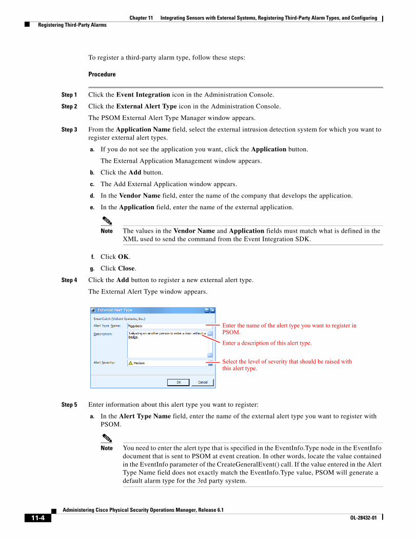
11-4Administering Cisco Physical Security Operations Manager, Release 6.1
OL-28432-01
Chapter 11 Integrating Sensors with External Systems, Registering Third-Party Alarm Types, and Configuring Registering Third-Party Alarms
To register a third-party alarm type, follow these steps:
Procedure
Step 1 Click the Event Integration icon in the Administration Console.
Step 2 Click the External Alert Type icon in the Administration Console.
The PSOM External Alert Type Manager window appears.
Step 3 From the Application Name field, select the external intrusion detection system for which you want to register external alert types.
a. If you do not see the application you want, click the Application button.
The External Application Management window appears.
b. Click the Add button.
c. The Add External Application window appears.
d. In the Vendor Name field, enter the name of the company that develops the application.
e. In the Application field, enter the name of the external application.
Note The values in the Vendor Name and Application fields must match what is defined in the XML used to send the command from the Event Integration SDK.
f. Click OK.
g. Click Close.
Step 4 Click the Add button to register a new external alert type.
The External Alert Type window appears.
Step 5 Enter information about this alert type you want to register:
a. In the Alert Type Name field, enter the name of the external alert type you want to register with PSOM.
Note You need to enter the alert type that is specified in the EventInfo.Type node in the EventInfo document that is sent to PSOM at event creation. In other words, locate the value contained in the EventInfo parameter of the CreateGeneralEvent() call. If the value entered in the Alert Type Name field does not exactly match the EventInfo.Type value, PSOM will generate a default alarm type for the 3rd party system.
Enter the name of the alert type you want to register in PSOM.
Select the level of severity that should be raised with this alert type.
Enter a description of this alert type.
11-5Administering Cisco Physical Security Operations Manager, Release 6.1
OL-28432-01
Chapter 11 Integrating Sensors with External Systems, Registering Third-Party Alarm Types, and Configuring Editing or Deleting a Registered Alert Type
b. In the Description field, provide a description of this alert type.
c. From the Alert Severity field, select the level of importance to assign to this alert type.
d. Click OK.
The PSOM External Alert Type Manager window shows the new registered alert type.
Editing or Deleting a Registered Alert TypeTo edit or delete a registered alert type, follow these steps:
Procedure
Step 1 Click the Event Integration icon in the Administration Console.
Step 2 Click the External Alert Type icon in the Administration Console.
The PSOM External Alert Type Manager window appears.
Step 3 From the Application Name field, select the external intrusion detection system for which you want to edit or remove a registered alert type.
Step 4 Select the registered alert type you want to edit or delete from the list.
Step 5 To edit a registered alert type:
a. Click the Edit button. The External Alert Type window appears.
b. Change the name in the Alert Type Name field if necessary.
c. Select a new severity from the Alert Severity field if necessary
d. Click OK.
Step 6 To remove a registered alert type:
a. Click the Delete button. A confirmation dialog box appears.
b. Click Yes to proceed with the deletion.
Step 7 Click Close to close the External Alert Type Manager window.
Creating a Custom Alert TypeYou can create a custom alert type to handle task-oriented types of alerts such as reminding operators to check video cameras periodically.
To create a custom alert type, follow these steps:
Procedure
Step 1 Click the Event Integration icon in the Administration Console.
Step 2 Click the User Alert Type icon in the Administration Console.
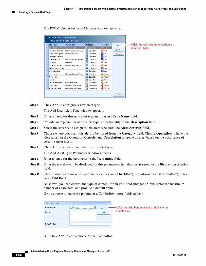
11-6Administering Cisco Physical Security Operations Manager, Release 6.1
OL-28432-01
Chapter 11 Integrating Sensors with External Systems, Registering Third-Party Alarm Types, and Configuring Creating a Custom Alert Type
The PSOM User Alert Type Manager window appears.
Step 3 Click Add to configure a new alert type.
The Add User Alert Type window appears.
Step 4 Enter a name for this new alert type in the Alert Type Name field.
Step 5 Provide an explanation of the alert type’s functionality in the Description field.
Step 6 Select the severity to assign to this alert type from the Alert Severity field.
Step 7 Choose where you want this alert to be raised from the Category field. Choose Operation to have the alert raised in the Operation Console, and Correlation to create an alert based on the occurrence of certain sensor alerts.
Step 8 Click Add to enter a parameter for this alert type.
The Add Alert Type Parameter window appears.
Step 9 Enter a name for the parameter in the Item name field.
Step 10 Enter the text that will be displayed for this parameter when the alert is raised in the Display description field.
Step 11 Choose whether to make this parameter a checkbox (CheckBox), drop-down menu (ComboBox), or text area (Edit Box).
As shown, you can control the type of content for an Edit field (integer or text), enter the maximum number of characters, and provide a default value.
If you choose to make the parameter a ComboBox, more fields appear.
a. Click Add to add a choice to the ComboBox.
Click the Add button to configure a new alert type.
Click the Add button to add a choice to the ComboBox.
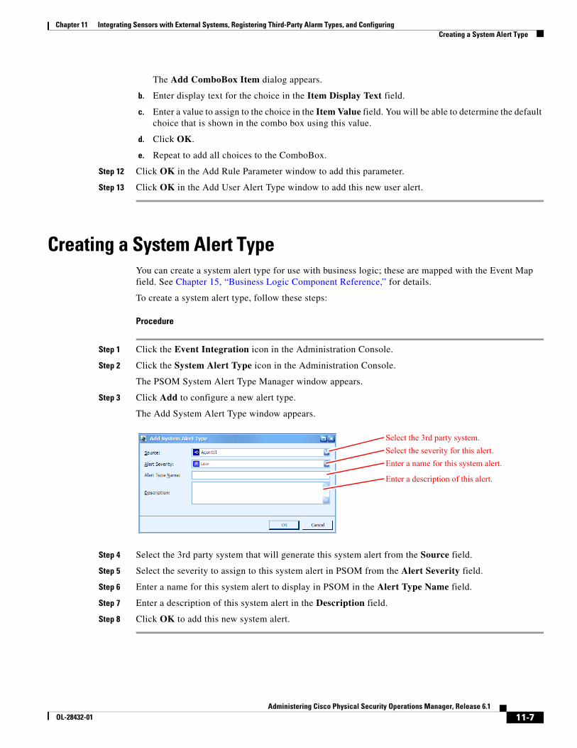
11-7Administering Cisco Physical Security Operations Manager, Release 6.1
OL-28432-01
Chapter 11 Integrating Sensors with External Systems, Registering Third-Party Alarm Types, and Configuring Creating a System Alert Type
The Add ComboBox Item dialog appears.
b. Enter display text for the choice in the Item Display Text field.
c. Enter a value to assign to the choice in the Item Value field. You will be able to determine the default choice that is shown in the combo box using this value.
d. Click OK.
e. Repeat to add all choices to the ComboBox.
Step 12 Click OK in the Add Rule Parameter window to add this parameter.
Step 13 Click OK in the Add User Alert Type window to add this new user alert.
Creating a System Alert TypeYou can create a system alert type for use with business logic; these are mapped with the Event Map field. See Chapter 15, “Business Logic Component Reference,” for details.
To create a system alert type, follow these steps:
Procedure
Step 1 Click the Event Integration icon in the Administration Console.
Step 2 Click the System Alert Type icon in the Administration Console.
The PSOM System Alert Type Manager window appears.
Step 3 Click Add to configure a new alert type.
The Add System Alert Type window appears.
Step 4 Select the 3rd party system that will generate this system alert from the Source field.
Step 5 Select the severity to assign to this system alert in PSOM from the Alert Severity field.
Step 6 Enter a name for this system alert to display in PSOM in the Alert Type Name field.
Step 7 Enter a description of this system alert in the Description field.
Step 8 Click OK to add this new system alert.
Select the 3rd party system.
Select the severity for this alert.
Enter a name for this system alert.
Enter a description of this alert.
11-8Administering Cisco Physical Security Operations Manager, Release 6.1
OL-28432-01
Chapter 11 Integrating Sensors with External Systems, Registering Third-Party Alarm Types, and Configuring Configuring Integration Modules for External Systems Integration
Configuring Integration Modules for External Systems Integration
You can configure PSOM to integrate with external systems by defining instances of the appropriate Integration Modules.
To configure an Integration Module, follow these steps:
Procedure
Step 1 Click the Event Integration icon in the Administration Console.
Step 2 Click the Integration Modules icon in the Administration Console.
The General Integration Module Configuration window appears.
Step 3 Select the Integration Module for which you want to configure an external system, and click Add Instance.
Note Only Integration Modules that have been installed on this system appear in the General Integration Module Configuration window.
Refer to the Integration Module documentation for the external system you are trying to configure for the remaining configuration steps.
C H A P T E R
12-1Administering Cisco Physical Security Operations Manager, Release 6.1
OL-28432-01
12Setting Up EZ-Track
EZ-Track enables security teams to track suspects across video cameras with simple point-and-click operations. There are configurations in the Administration tool to set up EZ-Track.
This chapter explains how to:
• Prepare video camera sensors for EZ-Track.
• Configure EZ-Track navigation for camera sensors in your PSOM environment.
• Import an EZ-Track configuration from an XML file.
• Enable backward tracking with EZ-Track (Backward).
This chapter includes these topics:
• How Operators use EZ-Track, page 12-1
• Configuring PSOM for EZ-Track, page 12-3
• Enabling EZ-Track (Backward), page 12-14
• Configuring EZ-Track in Batch with XML Configuration File, page 12-15
• Exporting Your EZ-Track Configuration, page 12-17
• Setting the Location of Track Link Video Packages, page 12-17
How Operators use EZ-TrackFrom the Operation Console, operators use EZ-Track to follow suspects across adjacent camera views with simple point-and-click. They do not need to know any Sensor names, or where camera sensors are geographically located—EZ-Track takes all the guesswork out of it.
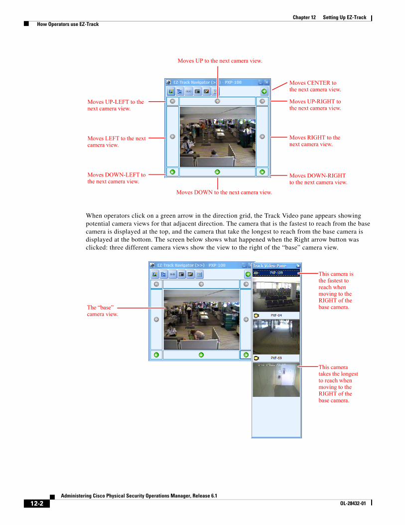
12-2Administering Cisco Physical Security Operations Manager, Release 6.1
OL-28432-01
Chapter 12 Setting Up EZ-Track How Operators use EZ-Track
When operators click on a green arrow in the direction grid, the Track Video pane appears showing potential camera views for that adjacent direction. The camera that is the fastest to reach from the base camera is displayed at the top, and the camera that take the longest to reach from the base camera is displayed at the bottom. The screen below shows what happened when the Right arrow button was clicked: three different camera views show the view to the right of the “base” camera view.
Moves UP to the next camera view.
Moves DOWN to the next camera view.
Moves RIGHT to the next camera view.
Moves DOWN-RIGHT to the next camera view.
Moves UP-RIGHT to the next camera view.
Moves LEFT to the next camera view.
Moves DOWN-LEFT to the next camera view.
Moves UP-LEFT to the next camera view.
Moves CENTER to the next camera view.
The “base” camera view.
This camera is the fastest to reach when moving to the RIGHT of the base camera.
This camera takes the longest to reach when moving to the RIGHT of the base camera.
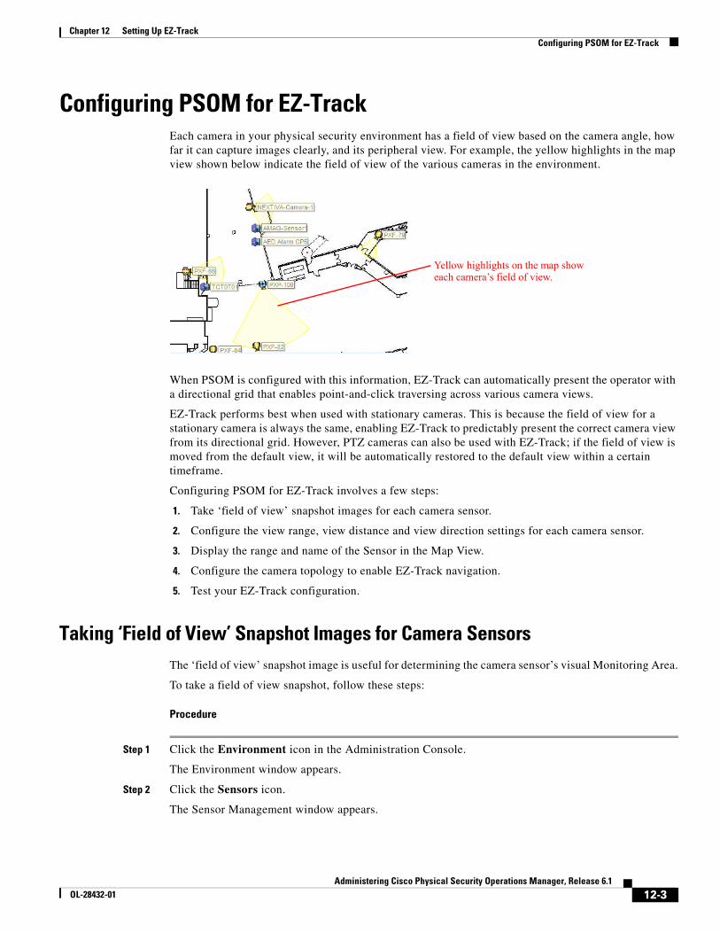
12-3Administering Cisco Physical Security Operations Manager, Release 6.1
OL-28432-01
Chapter 12 Setting Up EZ-Track Configuring PSOM for EZ-Track
Configuring PSOM for EZ-TrackEach camera in your physical security environment has a field of view based on the camera angle, how far it can capture images clearly, and its peripheral view. For example, the yellow highlights in the map view shown below indicate the field of view of the various cameras in the environment.
When PSOM is configured with this information, EZ-Track can automatically present the operator with a directional grid that enables point-and-click traversing across various camera views.
EZ-Track performs best when used with stationary cameras. This is because the field of view for a stationary camera is always the same, enabling EZ-Track to predictably present the correct camera view from its directional grid. However, PTZ cameras can also be used with EZ-Track; if the field of view is moved from the default view, it will be automatically restored to the default view within a certain timeframe.
Configuring PSOM for EZ-Track involves a few steps:
1. Take ‘field of view’ snapshot images for each camera sensor.
2. Configure the view range, view distance and view direction settings for each camera sensor.
3. Display the range and name of the Sensor in the Map View.
4. Configure the camera topology to enable EZ-Track navigation.
5. Test your EZ-Track configuration.
Taking ‘Field of View’ Snapshot Images for Camera SensorsThe ‘field of view’ snapshot image is useful for determining the camera sensor’s visual Monitoring Area.
To take a field of view snapshot, follow these steps:
Procedure
Step 1 Click the Environment icon in the Administration Console.
The Environment window appears.
Step 2 Click the Sensors icon.
The Sensor Management window appears.
Yellow highlights on the map show each camera’s field of view.
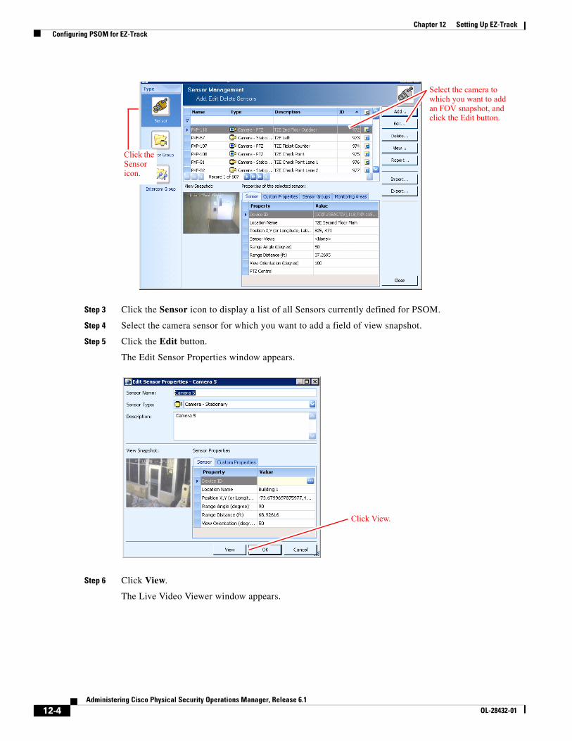
12-4Administering Cisco Physical Security Operations Manager, Release 6.1
OL-28432-01
Chapter 12 Setting Up EZ-Track Configuring PSOM for EZ-Track
Step 3 Click the Sensor icon to display a list of all Sensors currently defined for PSOM.
Step 4 Select the camera sensor for which you want to add a field of view snapshot.
Step 5 Click the Edit button.
The Edit Sensor Properties window appears.
Step 6 Click View.
The Live Video Viewer window appears.
Click the Sensor icon.
Select the camera to which you want to add an FOV snapshot, and click the Edit button.
Click View.
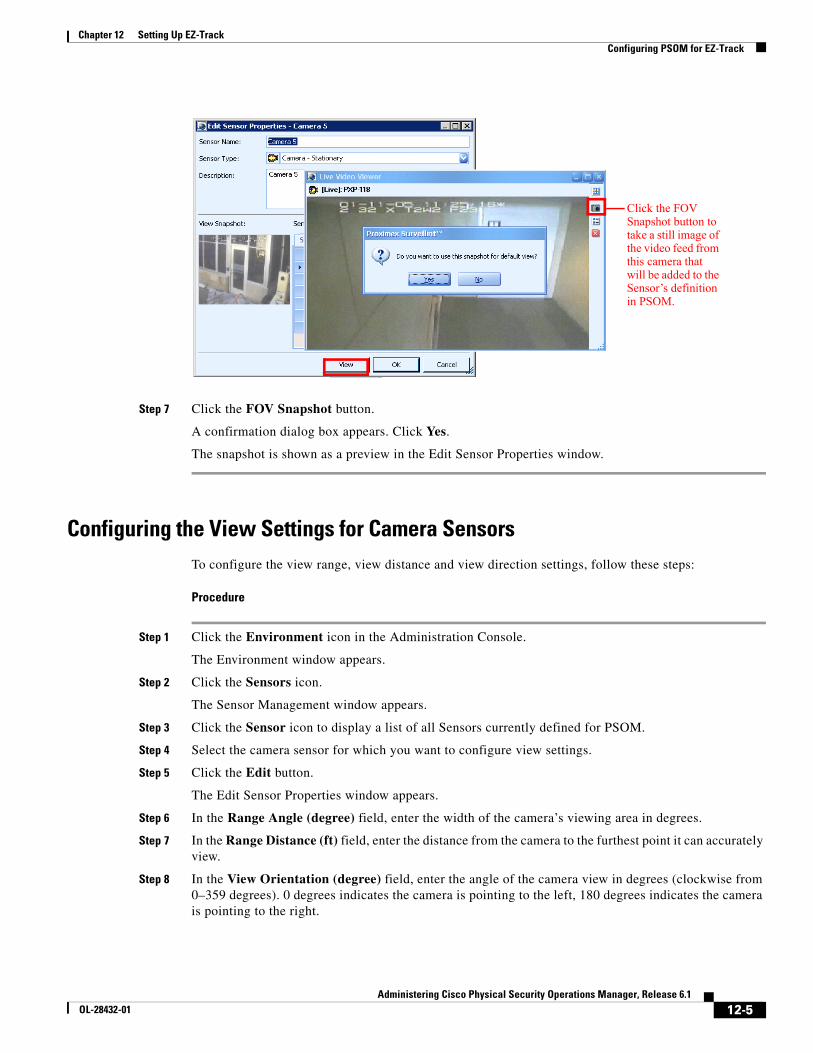
12-5Administering Cisco Physical Security Operations Manager, Release 6.1
OL-28432-01
Chapter 12 Setting Up EZ-Track Configuring PSOM for EZ-Track
Step 7 Click the FOV Snapshot button.
A confirmation dialog box appears. Click Yes.
The snapshot is shown as a preview in the Edit Sensor Properties window.
Configuring the View Settings for Camera SensorsTo configure the view range, view distance and view direction settings, follow these steps:
Procedure
Step 1 Click the Environment icon in the Administration Console.
The Environment window appears.
Step 2 Click the Sensors icon.
The Sensor Management window appears.
Step 3 Click the Sensor icon to display a list of all Sensors currently defined for PSOM.
Step 4 Select the camera sensor for which you want to configure view settings.
Step 5 Click the Edit button.
The Edit Sensor Properties window appears.
Step 6 In the Range Angle (degree) field, enter the width of the camera’s viewing area in degrees.
Step 7 In the Range Distance (ft) field, enter the distance from the camera to the furthest point it can accurately view.
Step 8 In the View Orientation (degree) field, enter the angle of the camera view in degrees (clockwise from 0–359 degrees). 0 degrees indicates the camera is pointing to the left, 180 degrees indicates the camera is pointing to the right.
Click the FOV Snapshot button to take a still image of the video feed from this camera that will be added to the Sensor’s definition in PSOM.
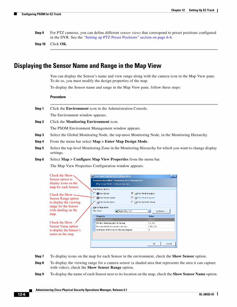
12-6Administering Cisco Physical Security Operations Manager, Release 6.1
OL-28432-01
Chapter 12 Setting Up EZ-Track Configuring PSOM for EZ-Track
Step 9 For PTZ cameras, you can define different sensor views that correspond to preset positions configured in the DVR. See the “Setting up PTZ Preset Positions” section on page 6-6.
Step 10 Click OK.
Displaying the Sensor Name and Range in the Map ViewYou can display the Sensor’s name and view range along with the camera icon in the Map View pane. To do so, you must modify the design properties of the map.
To display the Sensor name and range in the Map View pane, follow these steps:
Procedure
Step 1 Click the Environment icon in the Administration Console.
The Environment window appears.
Step 2 Click the Monitoring Environment icon.
The PSOM Environment Management window appears.
Step 3 Select the Global Monitoring Node, the top-most Monitoring Node, in the Monitoring Hierarchy.
Step 4 From the menu bar select Map > Enter Map Design Mode.
Step 5 Select the top-level Monitoring Zone in the Monitoring Hierarchy for which you want to change display settings.
Step 6 Select Map > Configure Map View Properties from the menu bar.
The Map View Properties Configuration window appears.
Step 7 To display icons on the map for each Sensor in the environment, check the Show Sensor option.
Step 8 To display the viewing range for a camera sensor (a shaded area that represents the area it can capture with video), check the Show Sensor Range option.
Step 9 To display the name of each Sensor next to its location on the map, check the Show Sensor Name option.
Check the Show Sensor option to display icons on the map for each Sensor.
Check the Show Sensor Range option to display the viewing range for the Sensor with shading on the map.
Check the Show Sensor Name option to display the Sensor’s name on the map.
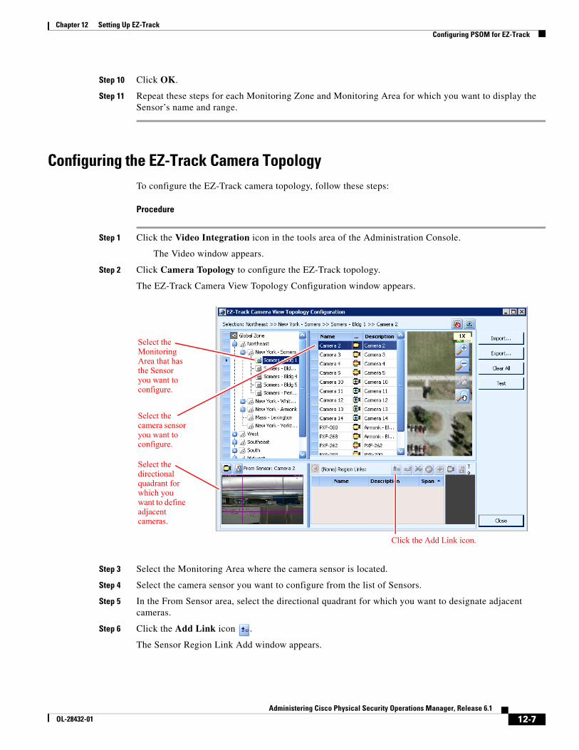
12-7Administering Cisco Physical Security Operations Manager, Release 6.1
OL-28432-01
Chapter 12 Setting Up EZ-Track Configuring PSOM for EZ-Track
Step 10 Click OK.
Step 11 Repeat these steps for each Monitoring Zone and Monitoring Area for which you want to display the Sensor’s name and range.
Configuring the EZ-Track Camera TopologyTo configure the EZ-Track camera topology, follow these steps:
Procedure
Step 1 Click the Video Integration icon in the tools area of the Administration Console.
The Video window appears.
Step 2 Click Camera Topology to configure the EZ-Track topology.
The EZ-Track Camera View Topology Configuration window appears.
Step 3 Select the Monitoring Area where the camera sensor is located.
Step 4 Select the camera sensor you want to configure from the list of Sensors.
Step 5 In the From Sensor area, select the directional quadrant for which you want to designate adjacent cameras.
Step 6 Click the Add Link icon .
The Sensor Region Link Add window appears.
Select the Monitoring Area that has the Sensor you want to configure.
Select the camera sensor you want to configure.
Select the directional quadrant for which you want to define adjacent cameras.
Click the Add Link icon.
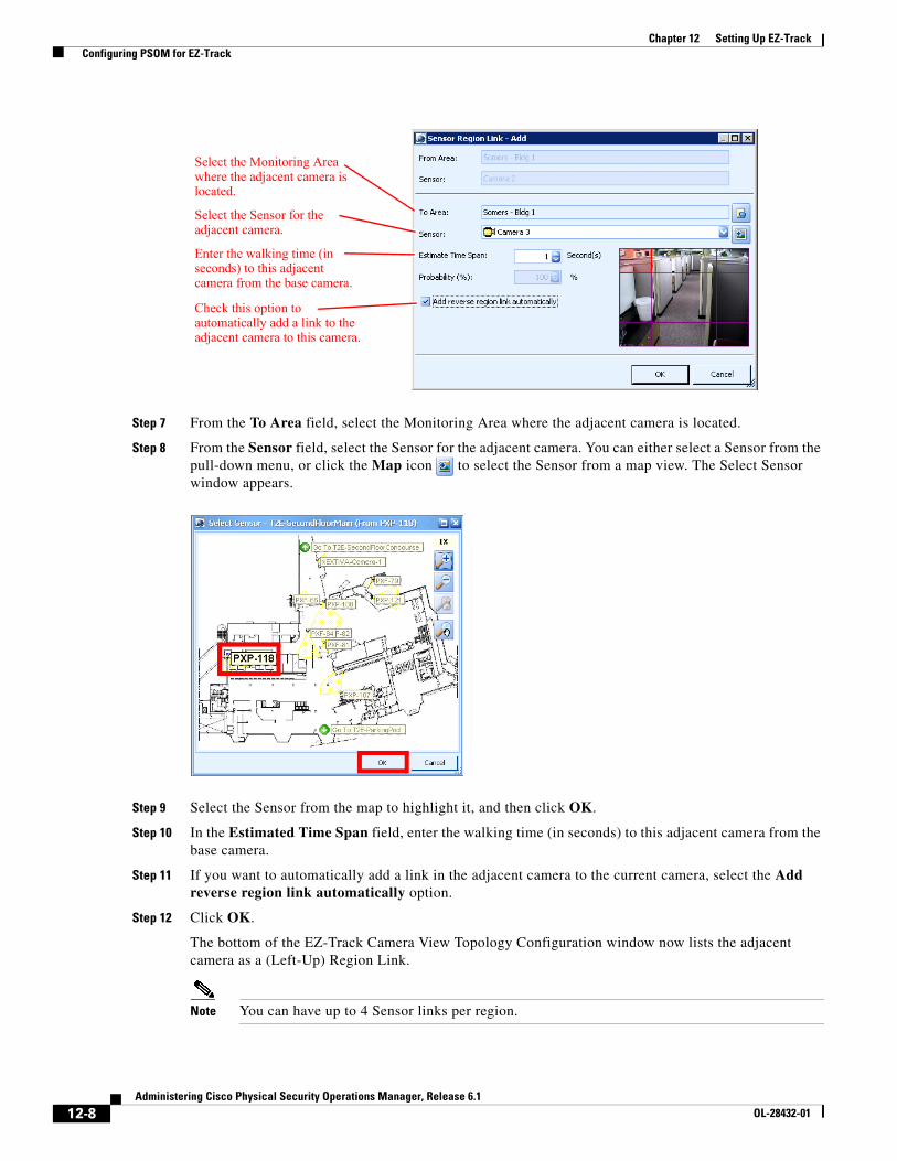
12-8Administering Cisco Physical Security Operations Manager, Release 6.1
OL-28432-01
Chapter 12 Setting Up EZ-Track Configuring PSOM for EZ-Track
Step 7 From the To Area field, select the Monitoring Area where the adjacent camera is located.
Step 8 From the Sensor field, select the Sensor for the adjacent camera. You can either select a Sensor from the pull-down menu, or click the Map icon to select the Sensor from a map view. The Select Sensor window appears.
Step 9 Select the Sensor from the map to highlight it, and then click OK.
Step 10 In the Estimated Time Span field, enter the walking time (in seconds) to this adjacent camera from the base camera.
Step 11 If you want to automatically add a link in the adjacent camera to the current camera, select the Add reverse region link automatically option.
Step 12 Click OK.
The bottom of the EZ-Track Camera View Topology Configuration window now lists the adjacent camera as a (Left-Up) Region Link.
Note You can have up to 4 Sensor links per region.
Check this option to automatically add a link to the adjacent camera to this camera.
Select the Monitoring Area where the adjacent camera is located.
Select the Sensor for the adjacent camera.
Enter the walking time (in seconds) to this adjacent camera from the base camera.
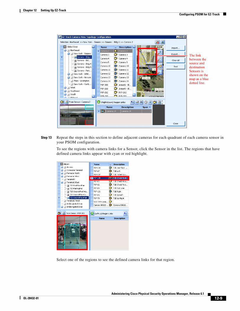
12-9Administering Cisco Physical Security Operations Manager, Release 6.1
OL-28432-01
Chapter 12 Setting Up EZ-Track Configuring PSOM for EZ-Track
Step 13 Repeat the steps in this section to define adjacent cameras for each quadrant of each camera sensor in your PSOM configuration.
To see the regions with camera links for a Sensor, click the Sensor in the list. The regions that have defined camera links appear with cyan or red highlight.
Select one of the regions to see the defined camera links for that region.
The link between the source and destination Sensors is shown on the map as a blue dotted line.
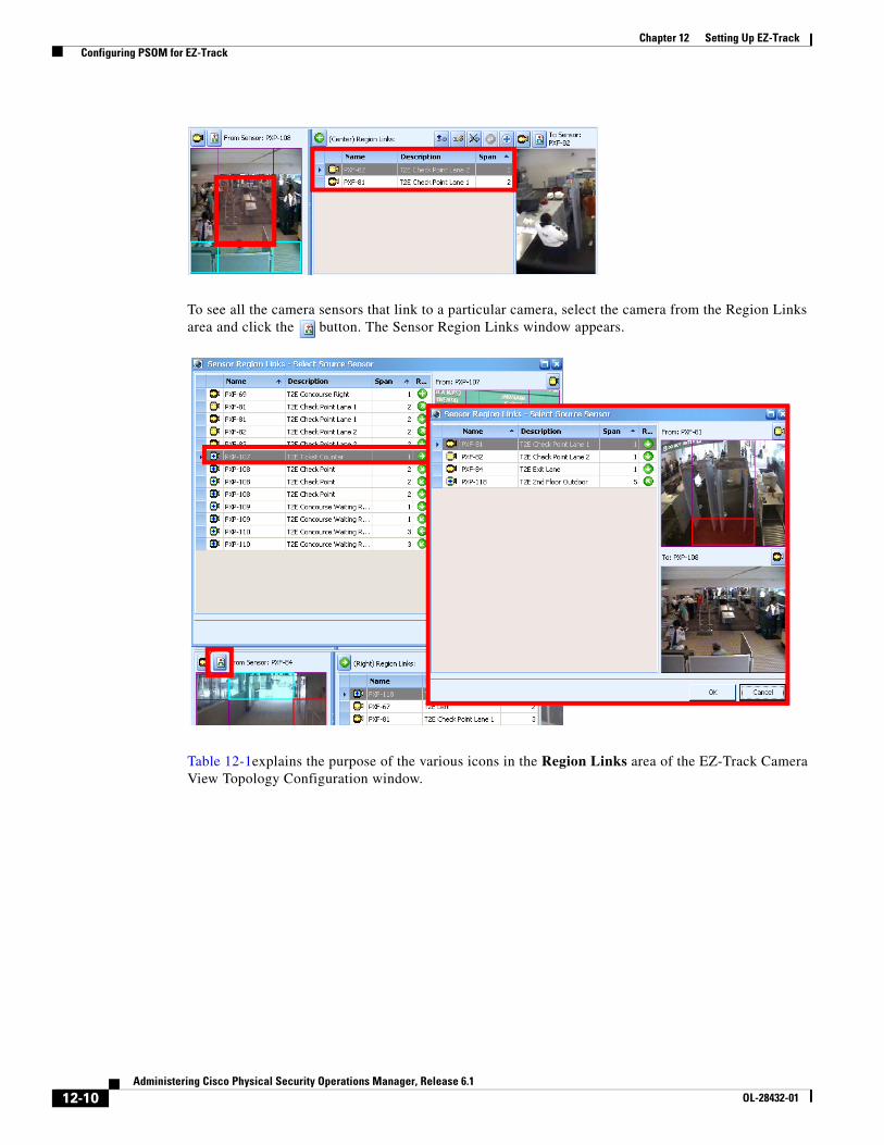
12-10Administering Cisco Physical Security Operations Manager, Release 6.1
OL-28432-01
Chapter 12 Setting Up EZ-Track Configuring PSOM for EZ-Track
To see all the camera sensors that link to a particular camera, select the camera from the Region Links area and click the button. The Sensor Region Links window appears.
Table 12-1explains the purpose of the various icons in the Region Links area of the EZ-Track Camera View Topology Configuration window.
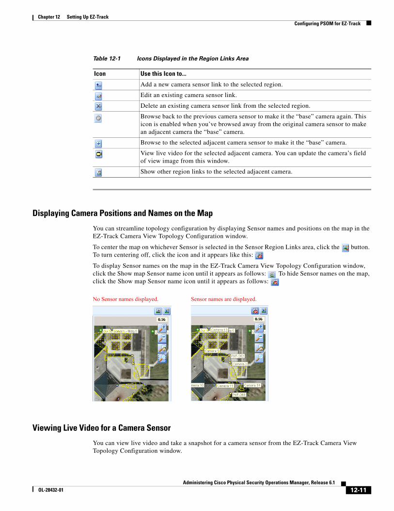
12-11Administering Cisco Physical Security Operations Manager, Release 6.1
OL-28432-01
Chapter 12 Setting Up EZ-Track Configuring PSOM for EZ-Track
Displaying Camera Positions and Names on the Map
You can streamline topology configuration by displaying Sensor names and positions on the map in the EZ-Track Camera View Topology Configuration window.
To center the map on whichever Sensor is selected in the Sensor Region Links area, click the button. To turn centering off, click the icon and it appears like this:
To display Sensor names on the map in the EZ-Track Camera View Topology Configuration window, click the Show map Sensor name icon until it appears as follows: To hide Sensor names on the map, click the Show map Sensor name icon until it appears as follows:
Viewing Live Video for a Camera Sensor
You can view live video and take a snapshot for a camera sensor from the EZ-Track Camera View Topology Configuration window.
Table 12-1 Icons Displayed in the Region Links Area
Icon Use this Icon to...
Add a new camera sensor link to the selected region.
Edit an existing camera sensor link.
Delete an existing camera sensor link from the selected region.
Browse back to the previous camera sensor to make it the “base” camera again. This icon is enabled when you’ve browsed away from the original camera sensor to make an adjacent camera the “base” camera.
Browse to the selected adjacent camera sensor to make it the “base” camera.
View live video for the selected adjacent camera. You can update the camera’s field of view image from this window.
Show other region links to the selected adjacent camera.
No Sensor names displayed. Sensor names are displayed.
12-12Administering Cisco Physical Security Operations Manager, Release 6.1
OL-28432-01
Chapter 12 Setting Up EZ-Track Configuring PSOM for EZ-Track
To do so, click the Live Video icon . The Live Video Viewer window appears. Click the FOV Snapshot link to capture a snapshot for the camera sensor.
Editing a Link to an Adjacent Camera
To edit the properties of an adjacent camera, follow these steps:
Procedure
Step 1 Select the adjacent camera in the EZ-Track Camera View Topology Configuration window.
Step 2 Click the Edit Link icon .
The Sensor Region Link - Modify window appears.
Step 3 Change the number of seconds in the Estimate Time Span field to modify how long it takes to walk to this camera sensor from the base camera.
Step 4 Click OK.
Deleting a Link to an Adjacent Camera
To remove a link to an adjacent camera, follow these steps:
Procedure
Step 1 Select the adjacent camera in the EZ-Track Camera View Topology Configuration window.
Step 2 Click the Delete Link icon .
A confirmation dialog box appears.
Step 3 Click Yes to delete the link to this adjacent camera.
Making an Adjacent Camera the new “Base” cameraYou can make an adjacent camera the new “base” camera, and then change back to the original base camera, using the Browse To icon and Browse Back icon .
Viewing Other Region Links to an Adjacent CameraYou can view all the region links to an adjacent camera.
To view other region links, follow these steps:
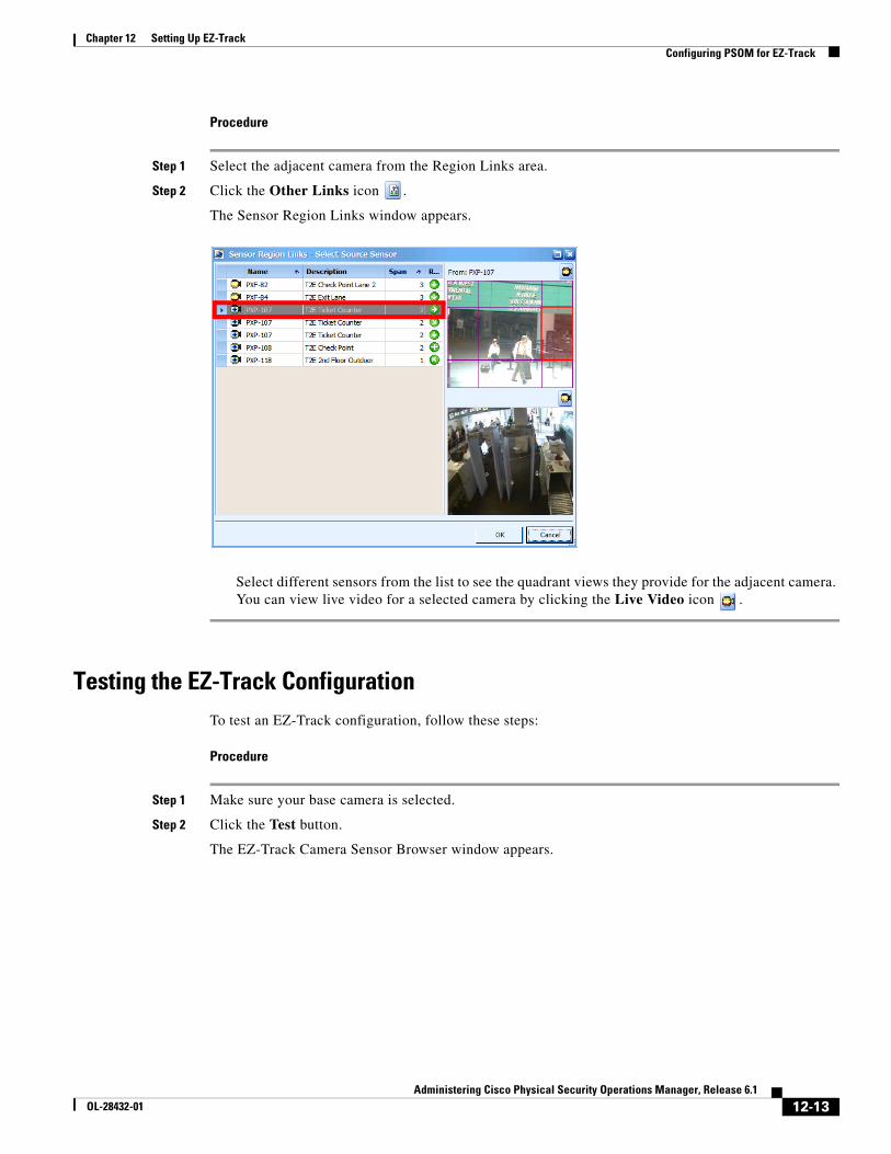
12-13Administering Cisco Physical Security Operations Manager, Release 6.1
OL-28432-01
Chapter 12 Setting Up EZ-Track Configuring PSOM for EZ-Track
Procedure
Step 1 Select the adjacent camera from the Region Links area.
Step 2 Click the Other Links icon .
The Sensor Region Links window appears.
Select different sensors from the list to see the quadrant views they provide for the adjacent camera. You can view live video for a selected camera by clicking the Live Video icon .
Testing the EZ-Track ConfigurationTo test an EZ-Track configuration, follow these steps:
Procedure
Step 1 Make sure your base camera is selected.
Step 2 Click the Test button.
The EZ-Track Camera Sensor Browser window appears.
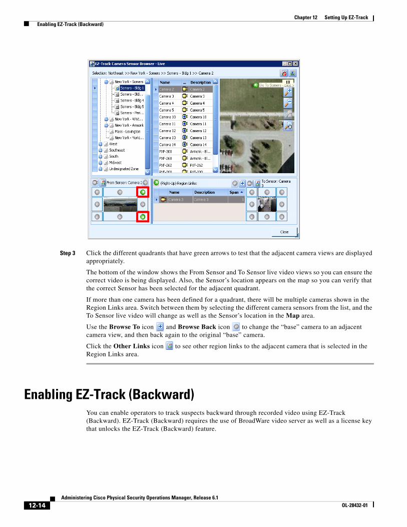
12-14Administering Cisco Physical Security Operations Manager, Release 6.1
OL-28432-01
Chapter 12 Setting Up EZ-Track Enabling EZ-Track (Backward)
Step 3 Click the different quadrants that have green arrows to test that the adjacent camera views are displayed appropriately.
The bottom of the window shows the From Sensor and To Sensor live video views so you can ensure the correct video is being displayed. Also, the Sensor’s location appears on the map so you can verify that the correct Sensor has been selected for the adjacent quadrant.
If more than one camera has been defined for a quadrant, there will be multiple cameras shown in the Region Links area. Switch between them by selecting the different camera sensors from the list, and the To Sensor live video will change as well as the Sensor’s location in the Map area.
Use the Browse To icon and Browse Back icon to change the “base” camera to an adjacent camera view, and then back again to the original “base” camera.
Click the Other Links icon to see other region links to the adjacent camera that is selected in the Region Links area.
Enabling EZ-Track (Backward)You can enable operators to track suspects backward through recorded video using EZ-Track (Backward). EZ-Track (Backward) requires the use of BroadWare video server as well as a license key that unlocks the EZ-Track (Backward) feature.
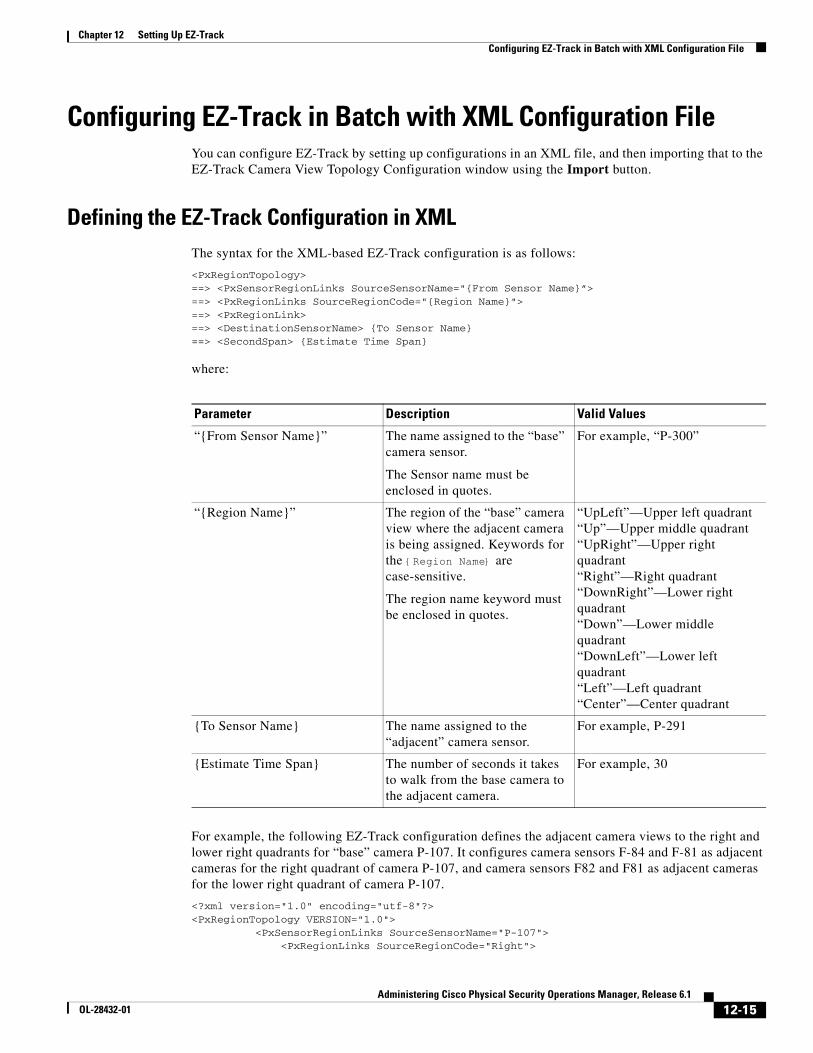
12-15Administering Cisco Physical Security Operations Manager, Release 6.1
OL-28432-01
Chapter 12 Setting Up EZ-Track Configuring EZ-Track in Batch with XML Configuration File
Configuring EZ-Track in Batch with XML Configuration FileYou can configure EZ-Track by setting up configurations in an XML file, and then importing that to the EZ-Track Camera View Topology Configuration window using the Import button.
Defining the EZ-Track Configuration in XMLThe syntax for the XML-based EZ-Track configuration is as follows:
<PxRegionTopology>==> <PxSensorRegionLinks SourceSensorName="{From Sensor Name}”>==> <PxRegionLinks SourceRegionCode="{Region Name}">==> <PxRegionLink>==> <DestinationSensorName> {To Sensor Name}==> <SecondSpan> {Estimate Time Span}
where:
For example, the following EZ-Track configuration defines the adjacent camera views to the right and lower right quadrants for “base” camera P-107. It configures camera sensors F-84 and F-81 as adjacent cameras for the right quadrant of camera P-107, and camera sensors F82 and F81 as adjacent cameras for the lower right quadrant of camera P-107.
<?xml version="1.0" encoding="utf-8"?><PxRegionTopology VERSION="1.0">
<PxSensorRegionLinks SourceSensorName="P-107"><PxRegionLinks SourceRegionCode="Right">
Parameter Description Valid Values
“{From Sensor Name}” The name assigned to the “base” camera sensor.
The Sensor name must be enclosed in quotes.
For example, “P-300”
“{Region Name}” The region of the “base” camera view where the adjacent camera is being assigned. Keywords for the {Region Name} are case-sensitive.
The region name keyword must be enclosed in quotes.
“UpLeft”—Upper left quadrant“Up”—Upper middle quadrant“UpRight”—Upper right quadrant“Right”—Right quadrant“DownRight”—Lower right quadrant“Down”—Lower middle quadrant“DownLeft”—Lower left quadrant“Left”—Left quadrant“Center”—Center quadrant
{To Sensor Name} The name assigned to the “adjacent” camera sensor.
For example, P-291
{Estimate Time Span} The number of seconds it takes to walk from the base camera to the adjacent camera.
For example, 30
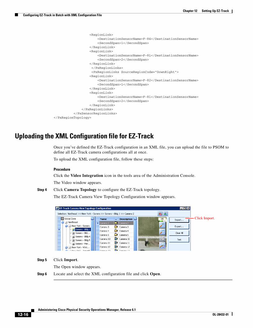
12-16Administering Cisco Physical Security Operations Manager, Release 6.1
OL-28432-01
Chapter 12 Setting Up EZ-Track Configuring EZ-Track in Batch with XML Configuration File
<RegionLink><DestinationSensorName>F-84</DestinationSensorName><SecondSpan>1</SecondSpan>
</RegionLink><RegionLink>
<DestinationSensorName>F-81</DestinationSensorName><SecondSpan>2</SecondSpan>
</RegionLink></PxRegionLinks><PxRegionLinks SourceRegionCode="DownRight">
<RegionLink><DestinationSensorName>F-82</DestinationSensorName><SecondSpan>1</SecondSpan>
</RegionLink><RegionLink>
<DestinationSensorName>F-81</DestinationSensorName><SecondSpan>2</SecondSpan>
</RegionLink></PxRegionLinks>
</PxSensorRegionLinks></PxRegionTopology>
Uploading the XML Configuration file for EZ-TrackOnce you’ve defined the EZ-Track configuration in an XML file, you can upload the file to PSOM to define all EZ-Track camera configurations all at once.
To upload the XML configuration file, follow these steps:
Procedure
Click the Video Integration icon in the tools area of the Administration Console.
The Video window appears.
Step 4 Click Camera Topology to configure the EZ-Track topology.
The EZ-Track Camera View Topology Configuration window appears.
Step 5 Click Import.
The Open window appears.
Step 6 Locate and select the XML configuration file and click Open.
Click Import.
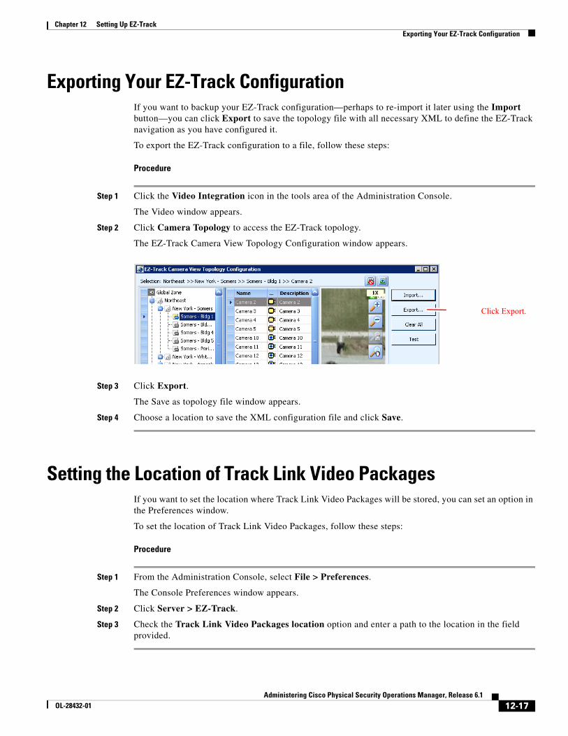
12-17Administering Cisco Physical Security Operations Manager, Release 6.1
OL-28432-01
Chapter 12 Setting Up EZ-Track Exporting Your EZ-Track Configuration
Exporting Your EZ-Track ConfigurationIf you want to backup your EZ-Track configuration—perhaps to re-import it later using the Import button—you can click Export to save the topology file with all necessary XML to define the EZ-Track navigation as you have configured it.
To export the EZ-Track configuration to a file, follow these steps:
Procedure
Step 1 Click the Video Integration icon in the tools area of the Administration Console.
The Video window appears.
Step 2 Click Camera Topology to access the EZ-Track topology.
The EZ-Track Camera View Topology Configuration window appears.
Step 3 Click Export.
The Save as topology file window appears.
Step 4 Choose a location to save the XML configuration file and click Save.
Setting the Location of Track Link Video PackagesIf you want to set the location where Track Link Video Packages will be stored, you can set an option in the Preferences window.
To set the location of Track Link Video Packages, follow these steps:
Procedure
Step 1 From the Administration Console, select File > Preferences.
The Console Preferences window appears.
Step 2 Click Server > EZ-Track.
Step 3 Check the Track Link Video Packages location option and enter a path to the location in the field provided.
Click Export.

12-18Administering Cisco Physical Security Operations Manager, Release 6.1
OL-28432-01
Chapter 12 Setting Up EZ-Track Setting the Location of Track Link Video Packages
C H A P T E R
13-1Administering Cisco Physical Security Operations Manager, Release 6.1
OL-28432-01
13Managing Response Workflows
You can configure response tasks that specify “best practices” for the actions that an operator should take to resolve alerts. You can then configure Response Workflows in the Business Logic Designer that generate checklists of actions operators must take when certain types of alerts are raised. With these rules in place, it is easy for operators to follow standardized procedures which leads to fewer errors in response and more importantly a faster time to response.
This chapter describes:
• How Response Workflows work in the Operation Console
• An overview of how to build Response Workflows using the Business Logic Designer
• Preferences that can be set to control how operators interact with Response Workflows
• User permissions that can be set for Response Workflows
This chapter includes these topics:
• Response Workflows within the Operation Console, page 13-1
• Enforcing Task Completion in the Operation Console, page 13-2
• Designing Response Workflows, page 13-3
• Modifying the Default Response Workflow, page 13-7
• Setting Up Notification for Response Workflows, page 13-11
• How Response Workflows are Triggered, page 13-13
• Diagnosing Response Workflows, page 13-14
• Managing User Permissions to Response Workflows, page 13-15
Response Workflows within the Operation ConsoleWithin the Operation Console, operators can be assigned specific Response Workflows to complete before an alert can be acknowledged or closed. Configuring task checklists for alerts helps ensure that operators take appropriate action when an alert occurs, as defined by the security experts at your company. Within the Operation Console, the Response Workflow Pane on the right side of the window shows operators their progress towards fulfilling their responsibilities for various alerts.
Operators can access Response Workflows by double-clicking a progress bar in the Response Workflow pane to bring up the Alert Details window. Then they can click the Progress bar to view the task checklist for the alert in a separate window.
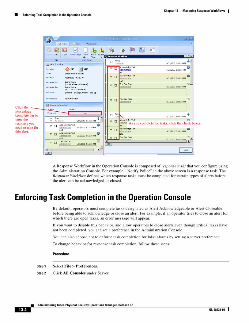
13-2Administering Cisco Physical Security Operations Manager, Release 6.1
OL-28432-01
Chapter 13 Managing Response Workflows Enforcing Task Completion in the Operation Console
A Response Workflow in the Operation Console is composed of response tasks that you configure using the Administration Console. For example, “Notify Police” in the above screen is a response task. The Response Workflow defines which response tasks must be completed for certain types of alerts before the alert can be acknowledged or closed.
Enforcing Task Completion in the Operation ConsoleBy default, operators must complete tasks designated as Alert Acknowledgeable or Alert Closeable before being able to acknowledge or close an alert. For example, if an operator tries to close an alert for which there are open tasks, an error message will appear.
If you want to disable this behavior, and allow operators to close alerts even though critical tasks have not been completed, you can set a preference in the Administration Console.
You can also choose not to enforce task completion for false alarms by setting a server preference.
To change behavior for response task completion, follow these steps:
Procedure
Step 1 Select File > Preferences.
Step 2 Click All Consoles under Server.
Click the percentage complete bar to view the response you need to take for this alert.
As you complete the tasks, click the check boxes.
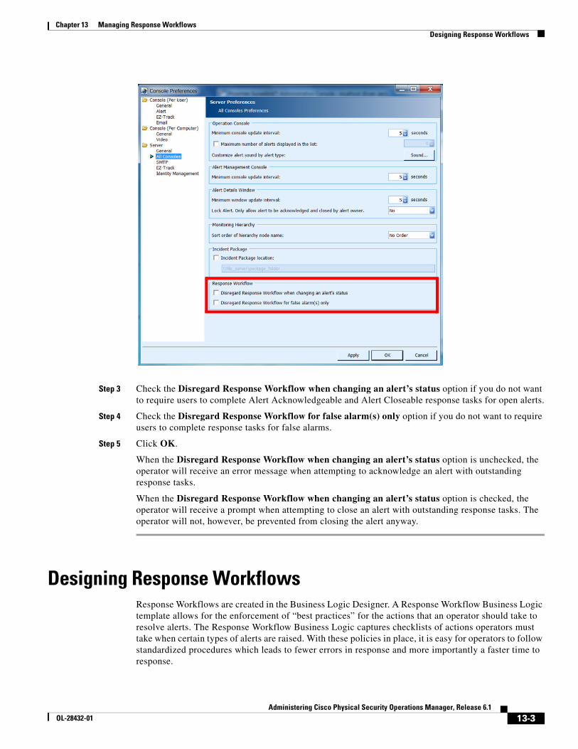
13-3Administering Cisco Physical Security Operations Manager, Release 6.1
OL-28432-01
Chapter 13 Managing Response Workflows Designing Response Workflows
Step 3 Check the Disregard Response Workflow when changing an alert’s status option if you do not want to require users to complete Alert Acknowledgeable and Alert Closeable response tasks for open alerts.
Step 4 Check the Disregard Response Workflow for false alarm(s) only option if you do not want to require users to complete response tasks for false alarms.
Step 5 Click OK.
When the Disregard Response Workflow when changing an alert’s status option is unchecked, the operator will receive an error message when attempting to acknowledge an alert with outstanding response tasks.
When the Disregard Response Workflow when changing an alert’s status option is checked, the operator will receive a prompt when attempting to close an alert with outstanding response tasks. The operator will not, however, be prevented from closing the alert anyway.
Designing Response WorkflowsResponse Workflows are created in the Business Logic Designer. A Response Workflow Business Logic template allows for the enforcement of “best practices” for the actions that an operator should take to resolve alerts. The Response Workflow Business Logic captures checklists of actions operators must take when certain types of alerts are raised. With these policies in place, it is easy for operators to follow standardized procedures which leads to fewer errors in response and more importantly a faster time to response.
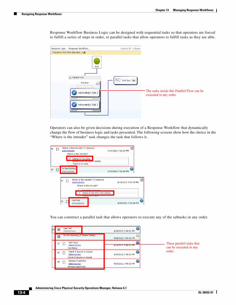
13-4Administering Cisco Physical Security Operations Manager, Release 6.1
OL-28432-01
Chapter 13 Managing Response Workflows Designing Response Workflows
Response Workflow Business Logic can be designed with sequential tasks so that operators are forced to fulfill a series of steps in order, or parallel tasks that allow operators to fulfill tasks as they are able.
Operators can also be given decisions during execution of a Response Workflow that dynamically change the flow of business logic and tasks presented. The following screens show how the choice in the “Where is the intruder” task changes the task that follows it.
You can construct a parallel task that allows operators to execute any of the subtasks in any order.
The tasks inside this Parallel Flow can be executed in any order.
Three parallel tasks that can be executed in any order.
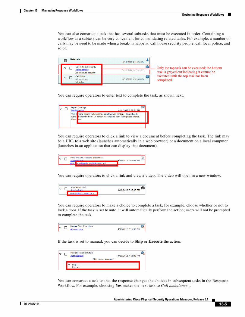
13-5Administering Cisco Physical Security Operations Manager, Release 6.1
OL-28432-01
Chapter 13 Managing Response Workflows Designing Response Workflows
You can also construct a task that has several subtasks that must be executed in order. Containing a workflow as a subtask can be very convenient for consolidating related tasks. For example, a number of calls may be need to be made when a break-in happens: call house security people, call local police, and so on.
You can require operators to enter text to complete the task, as shown next.
You can require operators to click a link to view a document before completing the task. The link may be a URL to a web site (launches automatically in a web browser) or a document on a local computer (launches in an application that can display that document).
You can require operators to click a link and view a video. The video will open in a new window.
You can require operators to make a choice to complete a task; for example, choose whether or not to lock a door. If the task is set to auto, it will automatically perform the action; users will not be prompted to complete the task.
If the task is set to manual, you can decide to Skip or Execute the action.
You can construct a task so that the response changes the choices in subsequent tasks in the Response Workflow. For example, choosing Yes makes the next task to Call ambulance...
Only the top task can be executed; the bottom task is greyed out indicating it cannot be executed until the top task has been completed.
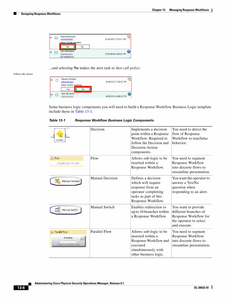
13-6Administering Cisco Physical Security Operations Manager, Release 6.1
OL-28432-01
Chapter 13 Managing Response Workflows Designing Response Workflows
...and selecting No makes the next task to Just call police.
follows the choice
Some business logic components you will need to build a Response Workflow Business Logic template include those in Table 13-1.
Table 13-1 Response Workflow Business Logic Components
Decision Implements a decision point within a Response Workflow. Required to follow the Decision and Decision-Action components.
You need to direct the flow of Response Workflow to true/false behavior.
Flow Allows sub-logic to be inserted within a Response Workflow.
You need to segment Response Workflow into discrete flows to streamline presentation.
Manual Decision Defines a decision which will require response from an operator completing tasks as part of this Response Workflow.
You want the operator to answer a Yes/No question when responding to an alert.
Manual Switch Enables redirection to up to 10 branches within a Response Workflow.
You want to provide different branches of Response Workflow for the operator to select and execute.
Parallel Flow Allows sub-logic to be inserted within a Response Workflow and executed simultaneously with other business logic.
You need to segment Response Workflow into discrete flows to streamline presentation.
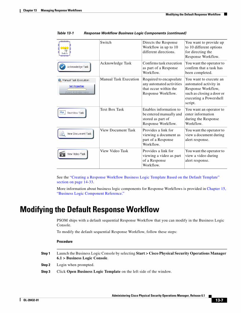
13-7Administering Cisco Physical Security Operations Manager, Release 6.1
OL-28432-01
Chapter 13 Managing Response Workflows Modifying the Default Response Workflow
See the “Creating a Response Workflow Business Logic Template Based on the Default Template” section on page 14-33.
More information about business logic components for Response Workflows is provided in Chapter 15, “Business Logic Component Reference.”
Modifying the Default Response WorkflowPSOM ships with a default sequential Response Workflow that you can modify in the Business Logic Console.
To modify the default sequential Response Workflow, follow these steps:
Procedure
Step 1 Launch the Business Logic Console by selecting Start > Cisco Physical Security Operations Manager 6.1 > Business Logic Console.
Step 2 Login when prompted.
Step 3 Click Open Business Logic Template on the left side of the window.
Switch Directs the Response Workflow in up to 10 different directions.
You want to provide up to 10 different options for directing the Response Workflow.
Acknowledge Task Confirms task execution as part of a Response Workflow.
You want the operator to confirm that a task has been completed.
Manual Task Execution Required to encapsulate any automated activities that occur within the Response Workflow.
You want to execute an automated activity in Response Workflow, such as closing a door or executing a Powershell script.
Text Box Task Enables information to be entered manually and stored as part of Response Workflow.
You want an operator to enter information during the Response Workflow.
View Document Task Provides a link for viewing a document as part of a Response Workflow.
You want the operator to view a document during alert response.
View Video Task Provides a link for viewing a video as part of a Response Workflow.
You want the operator to view a video during alert response.
Table 13-1 Response Workflow Business Logic Components (continued)
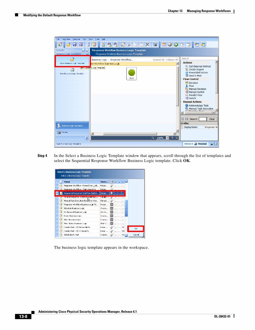
13-8Administering Cisco Physical Security Operations Manager, Release 6.1
OL-28432-01
Chapter 13 Managing Response Workflows Modifying the Default Response Workflow
Step 4 In the Select a Business Logic Template window that appears, scroll through the list of templates and select the Sequential Response Workflow Business Logic template. Click OK.
The business logic template appears in the workspace.
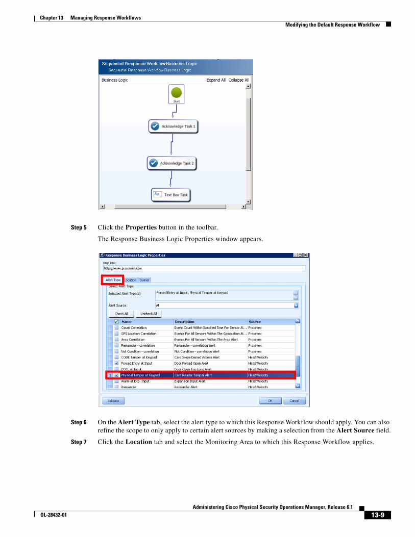
13-9Administering Cisco Physical Security Operations Manager, Release 6.1
OL-28432-01
Chapter 13 Managing Response Workflows Modifying the Default Response Workflow
Step 5 Click the Properties button in the toolbar.
The Response Business Logic Properties window appears.
Step 6 On the Alert Type tab, select the alert type to which this Response Workflow should apply. You can also refine the scope to only apply to certain alert sources by making a selection from the Alert Source field.
Step 7 Click the Location tab and select the Monitoring Area to which this Response Workflow applies.
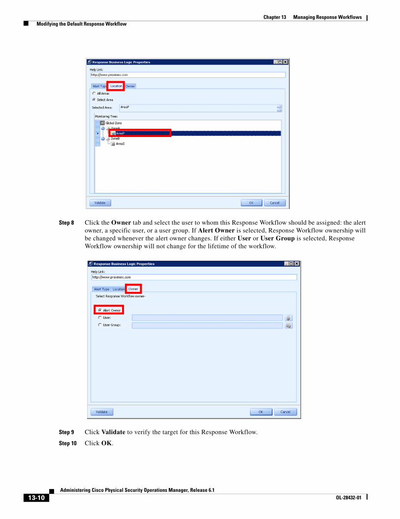
13-10Administering Cisco Physical Security Operations Manager, Release 6.1
OL-28432-01
Chapter 13 Managing Response Workflows Modifying the Default Response Workflow
Step 8 Click the Owner tab and select the user to whom this Response Workflow should be assigned: the alert owner, a specific user, or a user group. If Alert Owner is selected, Response Workflow ownership will be changed whenever the alert owner changes. If either User or User Group is selected, Response Workflow ownership will not change for the lifetime of the workflow.
Step 9 Click Validate to verify the target for this Response Workflow.
Step 10 Click OK.
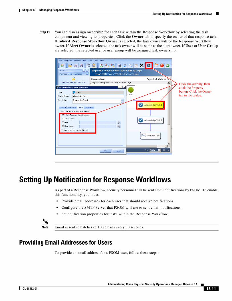
13-11Administering Cisco Physical Security Operations Manager, Release 6.1
OL-28432-01
Chapter 13 Managing Response Workflows Setting Up Notification for Response Workflows
Step 11 You can also assign ownership for each task within the Response Workflow by selecting the task component and viewing its properties. Click the Owner tab to specify the owner of that response task. If Inherit Response Workflow Owner is selected, the task owner will be the Response Workflow owner. If Alert Owner is selected, the task owner will be same as the alert owner. If User or User Group are selected, the selected user or user group will be assigned task ownership.
Setting Up Notification for Response WorkflowsAs part of a Response Workflow, security personnel can be sent email notifications by PSOM. To enable this functionality, you must:
• Provide email addresses for each user that should receive notifications.
• Configure the SMTP Server that PSOM will use to sent email notifications.
• Set notification properties for tasks within the Response Workflow.
Note Email is sent in batches of 100 emails every 30 seconds.
Providing Email Addresses for UsersTo provide an email address for a PSOM user, follow these steps:
Click the activity, then click the Property button. Click the Owner tab in the dialog.
13-12Administering Cisco Physical Security Operations Manager, Release 6.1
OL-28432-01
Chapter 13 Managing Response Workflows Setting Up Notification for Response Workflows
Procedure
Step 1 Click the Security icon in the Administration Console.
Step 2 Click the Users icon.
The Security User Manager window appears with the Users tab selected.
Step 3 Select the user account for which you want to provide an email address, and click the Edit button.
The Edit User window appears.
Step 4 Enter the email address to which to send notifications from the Response Workflow in the E-mail field.
Step 5 Click OK.
Configuring the SMTP ServerFor PSOM to send email notifications, it must have an SMTP server defined that it can use to send email.
To define an SMTP server, follow these steps:
Procedure
Step 1 Select File > Preferences.
Step 2 Click SMTP under Server.
Step 3 Click Add.
Step 4 Enter the host name or IP address where the SMTP server is running in the Server Name field.
Step 5 Enter the port number under which the SMTP server is running in the Port field. If you choose to use secured communications, be sure to specify the correct port number for SSL or TLS connections.
Step 6 Enter the domain under which the SMTP server is running in the Domain field.
Step 7 Enter the user name for logging into the SMTP server in the User Name field.
Step 8 Enter the password for the SMTP account in the Password field.
Step 9 Enter the email address to use for primary contact in the Contact email field.
Step 10 Check the Use Secure Connection option if you want to send emails using an SSL or TLS connection.
Step 11 Click Test Email to test the connection to the SMTP server. If the email was sent succesfully, a success message appears. Otherwise you might see an error message.
Set Notification Properties for TasksWithin Response Workflow tasks, you must set the notification properties for that task. For example, the Notification tab of an Acknowledge Task is shown next.
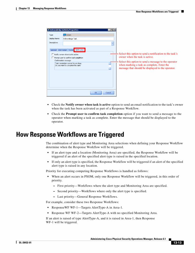
13-13Administering Cisco Physical Security Operations Manager, Release 6.1
OL-28432-01
Chapter 13 Managing Response Workflows How Response Workflows are Triggered
• Check the Notify owner when task is active option to send an email notification to the task’s owner when the task has been activated as part of a Response Workflow.
• Check the Prompt user to confirm task completion option if you want to send a message to the operator when marking a task as complete. Enter the message that should be displayed to the operator.
How Response Workflows are TriggeredThe combination of alert type and Monitoring Area selections when defining your Response Workflow determine when the Response Workflow will be triggered.
• If an alert type and a location (Monitoring Area) are specified, the Response Workflow will be triggered if an alert of the specified alert type is raised in the specified location.
• If only an alert type is specified, the Response Workflow will be triggered if an alert of the specified alert type is raised in any location.
Priority for executing competing Response Workflows is handled as follows:
• When an alert occurs in PSOM, only one Response Workflow will be triggered, in this order of priority.
– First priority—Workflows where the alert type and Monitoring Area are specified.
– Second priority—Workflows where only the alert type is specified.
– Last priority—General Response Workflows.
For example, consider these two Response Workflows:
• ResponseWF WF-1—Targets AlertType-A in Area-1.
• Response WF WF-2—Targets AlertType-A with no specified Monitoring Area.
If an alert is raised of type AlertType-A, and it is raised in Area-1, then Response WF-1 will be triggered.
Select this option to send a notification to the task’s owner when the task is active.
Select this option to send a message to the operator when marking a task as complete. Enter the message that should be displayed to the operator.
13-14Administering Cisco Physical Security Operations Manager, Release 6.1
OL-28432-01
Chapter 13 Managing Response Workflows Diagnosing Response Workflows
If an alert is raised of type AlertType-A and it is not raised in Area-1, then Response WF-2 will be triggered.
Diagnosing Response WorkflowsAs administrator, you can review the Response Workflows that are currently active in PSOM and diagnose response performance.
To diagnose the performance of Response Workflows in PSOM, follow these steps:
Procedure
Step 1 Click the Diagnostics icon in the Administration Console.
The Diagnostics window appears.
Step 2 Click the Response Workflows icon.
The Response Workflow Parameters window appears.
Step 3 Choose a time range to retrieve results from the Range field, or enter specific start and end times from the Start Time and End Time fields.
Step 4 Select a status for retrieving Response Workflow data from the Status field: All, Started, Pending, Completed, Canceled.
Step 5 Click OK.
Results appear and can be printed by clicking Report...
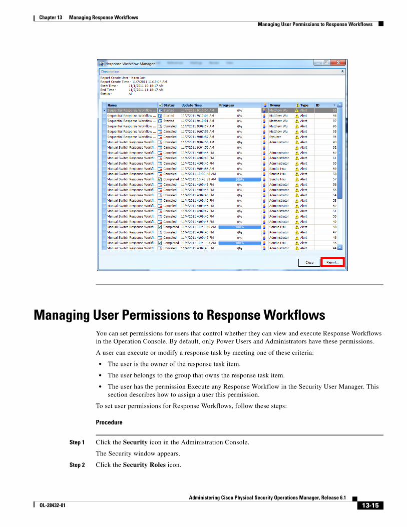
13-15Administering Cisco Physical Security Operations Manager, Release 6.1
OL-28432-01
Chapter 13 Managing Response Workflows Managing User Permissions to Response Workflows
Managing User Permissions to Response WorkflowsYou can set permissions for users that control whether they can view and execute Response Workflows in the Operation Console. By default, only Power Users and Administrators have these permissions.
A user can execute or modify a response task by meeting one of these criteria:
• The user is the owner of the response task item.
• The user belongs to the group that owns the response task item.
• The user has the permission Execute any Response Workflow in the Security User Manager. This section describes how to assign a user this permission.
To set user permissions for Response Workflows, follow these steps:
Procedure
Step 1 Click the Security icon in the Administration Console.
The Security window appears.
Step 2 Click the Security Roles icon.

13-16Administering Cisco Physical Security Operations Manager, Release 6.1
OL-28432-01
Chapter 13 Managing Response Workflows Managing User Permissions to Response Workflows
The Security User Manager window appears with the Roles tab selected.
Step 3 To change permissions assigned to a user role, select the role in the list and click Edit. The Edit Security Role window appears.
Step 4 Check or uncheck these permissions under the Permissions area: Execute any Response Workflow and View all Response Workflows.
Step 5 Click OK when finished.

C H A P T E R
14-1Administering Cisco Physical Security Operations Manager, Release 6.1
OL-28432-01
14Managing Business Logic
In PSOM, business logic is used to raise alerts based on predefined conditions and handle post-alert response management actions that should be taken when certain alerts are raised. The business logic templates capture your business processes and requirements for alert creation and response based on the alert’s status, schedule, Monitoring Area or threat level. Business logic allows security personnel to concentrate on execution of planned responses instead of reassessing unfolding situations. It enables optimal response to real-time tasks, reducing vulnerability, and frees the attention of responding individuals so they can better respond to any unplanned turn of events.
PSOM supplies business logic templates that you can customize for your own needs. Once a business logic template is applied to the Monitoring Hierarchy, it becomes business logic policy.
You can also design and configure business logic templates using the Business Logic Designer, and then test and verify their behavior using the Business Logic Designer. The PSOM business logic engine is based on common off-the-shelf (COTS) technology. PSOM uses the advanced business logic engine embedded in Microsoft .NET Framework version 4.0. This engine was originally built for Microsoft BizTalk Server and is designed for enterprise use, highly scalable, and extremely flexible.
Note .NET Framework version 4.0 and PowerShell 2.0 are required to use PSOM business logic.
This chapter includes these topics:
• Designing Business Logic in the Business Logic Designer, page 14-1
• Managing Business Logic using Templates, page 14-7
• Testing Business Logic Templates in the Business Logic Designer, page 14-38
• Applying Business Logic Policies, page 14-41
• Importing and Exporting Business Logic Templates, page 14-45
• Using Global System Variables in Business Logic, page 14-46
• Storing PowerShell Scripts for Business Logic, page 14-47
Designing Business Logic in the Business Logic DesignerTo design business logic in the Business Logic Designer, follow these steps:
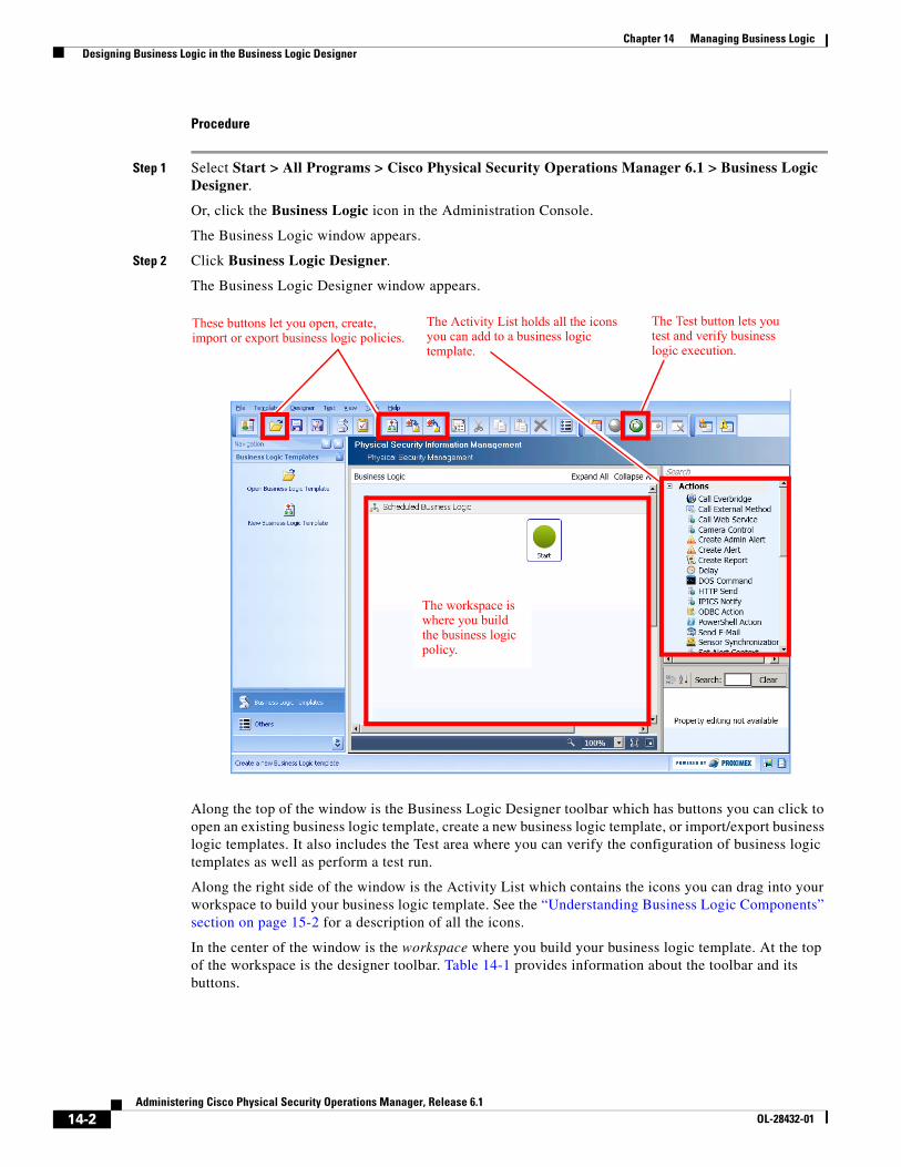
14-2Administering Cisco Physical Security Operations Manager, Release 6.1
OL-28432-01
Chapter 14 Managing Business Logic Designing Business Logic in the Business Logic Designer
Procedure
Step 1 Select Start > All Programs > Cisco Physical Security Operations Manager 6.1 > Business Logic Designer.
Or, click the Business Logic icon in the Administration Console.
The Business Logic window appears.
Step 2 Click Business Logic Designer.
The Business Logic Designer window appears.
Along the top of the window is the Business Logic Designer toolbar which has buttons you can click to open an existing business logic template, create a new business logic template, or import/export business logic templates. It also includes the Test area where you can verify the configuration of business logic templates as well as perform a test run.
Along the right side of the window is the Activity List which contains the icons you can drag into your workspace to build your business logic template. See the “Understanding Business Logic Components” section on page 15-2 for a description of all the icons.
In the center of the window is the workspace where you build your business logic template. At the top of the workspace is the designer toolbar. Table 14-1 provides information about the toolbar and its buttons.
These buttons let you open, create, import or export business logic policies.
The Test button lets you test and verify business logic execution.
The Activity List holds all the icons you can add to a business logic template.
The workspace is where you build the business logic policy.
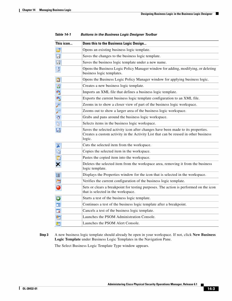
14-3Administering Cisco Physical Security Operations Manager, Release 6.1
OL-28432-01
Chapter 14 Managing Business Logic Designing Business Logic in the Business Logic Designer
Step 3 A new business logic template should already be open in your workspace. If not, click New Business Logic Template under Business Logic Templates in the Navigation Pane.
The Select Business Logic Template Type window appears.
Table 14-1 Buttons in the Business Logic Designer Toolbar
This icon... Does this to the Business Logic Design...
Opens an existing business logic template.
Saves the changes to the business logic template.
Saves the business logic template under a new name.
Opens the Business Logic Policy Manager window for adding, modifying, or deleting business logic templates.
Opens the Business Logic Policy Manager window for applying business logic.
Creates a new business logic template.
Imports an XML file that defines a business logic template.
Exports the current business logic template configuration to an XML file.
Zooms in to show a closer view of part of the business logic workspace.
Zooms out to show a larger area of the business logic workspace.
Grabs and pans around the business logic workspace.
Selects items in the business logic workspace.
Saves the selected activity icon after changes have been made to its properties. Creates a custom activity in the Activity List that can be reused in other business logic.
Cuts the selected item from the workspace.
Copies the selected item in the workspace.
Pastes the copied item into the workspace.
Deletes the selected item from the workspace area, removing it from the business logic template.
Displays the Properties window for the icon that is selected in the workspace.
Verifies the current configuration of the business logic template.
Sets or clears a breakpoint for testing purposes. The action is performed on the icon that is selected in the workspace.
Starts a test of the business logic template.
Continues a test of the business logic template after a breakpoint.
Cancels a test of the business logic template.
Launches the PSOM Administration Console.
Launches the PSOM Alert Console.
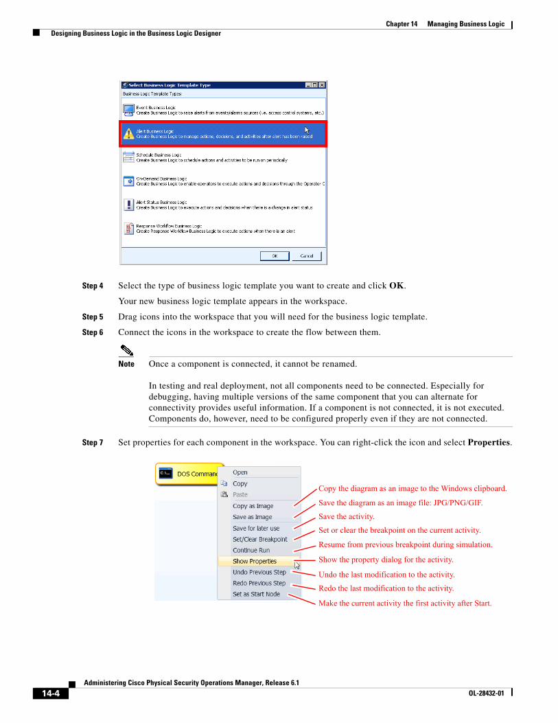
14-4Administering Cisco Physical Security Operations Manager, Release 6.1
OL-28432-01
Chapter 14 Managing Business Logic Designing Business Logic in the Business Logic Designer
Step 4 Select the type of business logic template you want to create and click OK.
Your new business logic template appears in the workspace.
Step 5 Drag icons into the workspace that you will need for the business logic template.
Step 6 Connect the icons in the workspace to create the flow between them.
Note Once a component is connected, it cannot be renamed.
In testing and real deployment, not all components need to be connected. Especially for debugging, having multiple versions of the same component that you can alternate for connectivity provides useful information. If a component is not connected, it is not executed. Components do, however, need to be configured properly even if they are not connected.
Step 7 Set properties for each component in the workspace. You can right-click the icon and select Properties.
Copy the diagram as an image to the Windows clipboard.
Save the diagram as an image file: JPG/PNG/GIF.
Save the activity.
Set or clear the breakpoint on the current activity.
Resume from previous breakpoint during simulation.
Show the property dialog for the activity.
Undo the last modification to the activity.
Redo the last modification to the activity.
Make the current activity the first activity after Start.
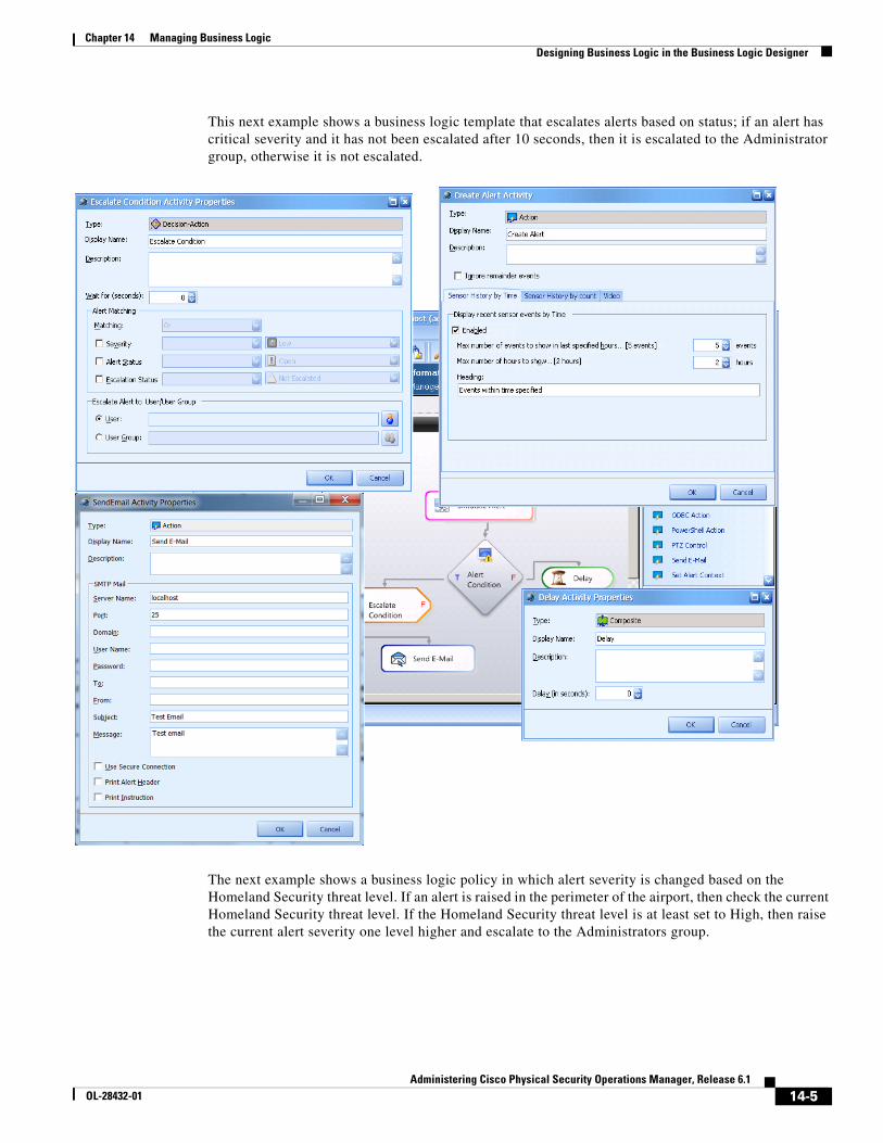
14-5Administering Cisco Physical Security Operations Manager, Release 6.1
OL-28432-01
Chapter 14 Managing Business Logic Designing Business Logic in the Business Logic Designer
This next example shows a business logic template that escalates alerts based on status; if an alert has critical severity and it has not been escalated after 10 seconds, then it is escalated to the Administrator group, otherwise it is not escalated.
The next example shows a business logic policy in which alert severity is changed based on the Homeland Security threat level. If an alert is raised in the perimeter of the airport, then check the current Homeland Security threat level. If the Homeland Security threat level is at least set to High, then raise the current alert severity one level higher and escalate to the Administrators group.
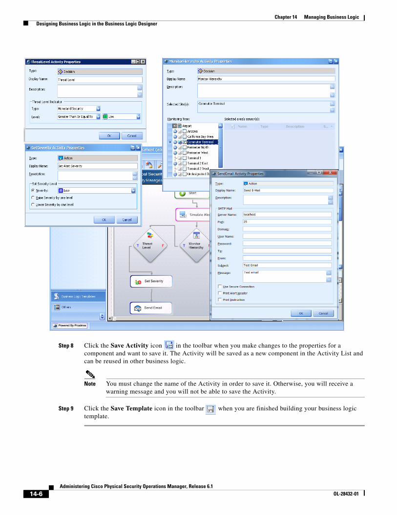
14-6Administering Cisco Physical Security Operations Manager, Release 6.1
OL-28432-01
Chapter 14 Managing Business Logic Designing Business Logic in the Business Logic Designer
Step 8 Click the Save Activity icon in the toolbar when you make changes to the properties for a component and want to save it. The Activity will be saved as a new component in the Activity List and can be reused in other business logic.
Note You must change the name of the Activity in order to save it. Otherwise, you will receive a warning message and you will not be able to save the Activity.
Step 9 Click the Save Template icon in the toolbar when you are finished building your business logic template.
14-7Administering Cisco Physical Security Operations Manager, Release 6.1
OL-28432-01
Chapter 14 Managing Business Logic Managing Business Logic using Templates
Managing Business Logic using TemplatesPSOM supplies business logic templates that you can customize for your own needs. There are several different types of business logic templates:
• Event Business Logic—determines which events from existing alarming systems should be raised as alerts in PSOM. Business logic can be defined so that only certain event types will be raised as alerts, and that different severity and actions will be associated with certain events so that alerts in PSOM have the appropriate severity and associated actions. When applied to the Monitoring Hierarchy, the default template automatically pulls events from Integration Modules into PSOM as alerts on the corresponding Sensors and Monitoring Areas.
• Alert Business Logic—defines alert response based on the alert’s status, schedule, Monitoring Area, or threat level after an alert has been created.
• Schedule Business Logic—provides a calendar-based execution of business processes. For example, an RSS Alerts activity can be defined to generate alerts from RSS feeds such as severe weather alerts from the Weather Channel or earthquake alerts from U.S. Geological Survey.
• On-Demand Business Logic—enables custom actions to be added to the Operation Console to allow operators to execute functionality such as disarm a Sensor or start a group intercom conversation from a Monitoring Area.
• Alert Status Business Logic—defines business logic that should occur upon status changes for selected alert types.
• Response Workflow Business Logic—defines actions that operators should take to respond to alert conditions.
Inside business logic templates you can add actions (such as sending email or launching programs when certain conditions are met) and you can integrate PowerShell scripts for complex decisions or data correlation with existing systems (such as Microsoft SQL Server or Exchange Server).
Creating an Event Business Logic Template Based on the Default TemplateAn Event Business Logic template determines which events from an access control device should raise alerts within PSOM, and the appropriate severity and actions that should be associated with those alerts. For example, when a suspect tampers with a card reader a Critical alert might be raised and a notification email sent to appropriate people; however, in a case involving a Sensor that is open too long, a Medium risk alert may be raised without any email notification. Event Business Logic templates can be customized based on the sensor type and location.
You can create a single Event Business Logic template that triggers the same action and assigns the same severity level in PSOM for multiple alert types. Alert types are matched based on the alert description or a customized “event match” string that should correlate to the event’s ID or description in the 3rd party system. Matching is performed using exact matching or regular expressions.
A remainder policy enables all unspecified alert types to be handled by this alert, except whatever alerts are specifically excluded using a filter mapping.
The alert generated by Event Business Logic is calculated per Sensor, per Monitoring Area, per business logic policy, per event. For example, assume there is 1 external device that maps to 2 Sensors in PSOM, and each Sensor resides in 2 Monitoring Areas (total of 4 Monitoring Areas containing 2 Sensors), and 2 Event Business Logic policies are applied in PSOM related to the device. In this case, 8 alerts will be generated in PSOM for each event generated by the device.
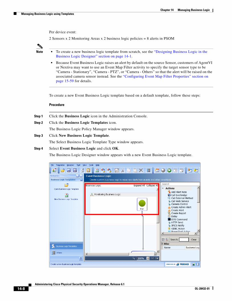
14-8Administering Cisco Physical Security Operations Manager, Release 6.1
OL-28432-01
Chapter 14 Managing Business Logic Managing Business Logic using Templates
Per device event:
2 Sensors x 2 Monitoring Areas x 2 business logic policies = 8 alerts in PSOM
Note • To create a new business logic template from scratch, see the “Designing Business Logic in the Business Logic Designer” section on page 14-1.
• Because Event Business Logic raises an alert by default on the source Sensor, customers of AgentVI or Nextiva may want to use an Event Map Filter activity to specify the target sensor type to be “Camera - Stationary”, “Camera - PTZ”, or “Camera - Others” so that the alert will be raised on the associated camera sensor instead. See the “Configuring Event Map Filter Properties” section on page 15-59 for details.
To create a new Event Business Logic template based on a default template, follow these steps:
Procedure
Step 1 Click the Business Logic icon in the Administration Console.
Step 2 Click the Business Logic Templates icon.
The Business Logic Policy Manager window appears.
Step 3 Click New Business Logic Template.
The Select Business Logic Template Type window appears.
Step 4 Select Event Business Logic and click OK.
The Business Logic Designer window appears with a new Event Business Logic template.
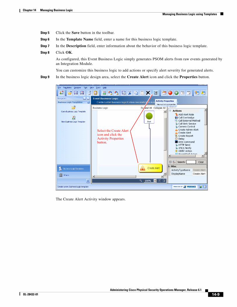
14-9Administering Cisco Physical Security Operations Manager, Release 6.1
OL-28432-01
Chapter 14 Managing Business Logic Managing Business Logic using Templates
Step 5 Click the Save button in the toolbar.
Step 6 In the Template Name field, enter a name for this business logic template.
Step 7 In the Description field, enter information about the behavior of this business logic template.
Step 8 Click OK.
As configured, this Event Business Logic simply generates PSOM alerts from raw events generated by an Integration Module.
You can customize this business logic to add actions or specify alert severity for generated alerts.
Step 9 In the business logic design area, select the Create Alert icon and click the Properties button.
The Create Alert Activity window appears.
Select the Create Alert icon and click the Activity Properties button.
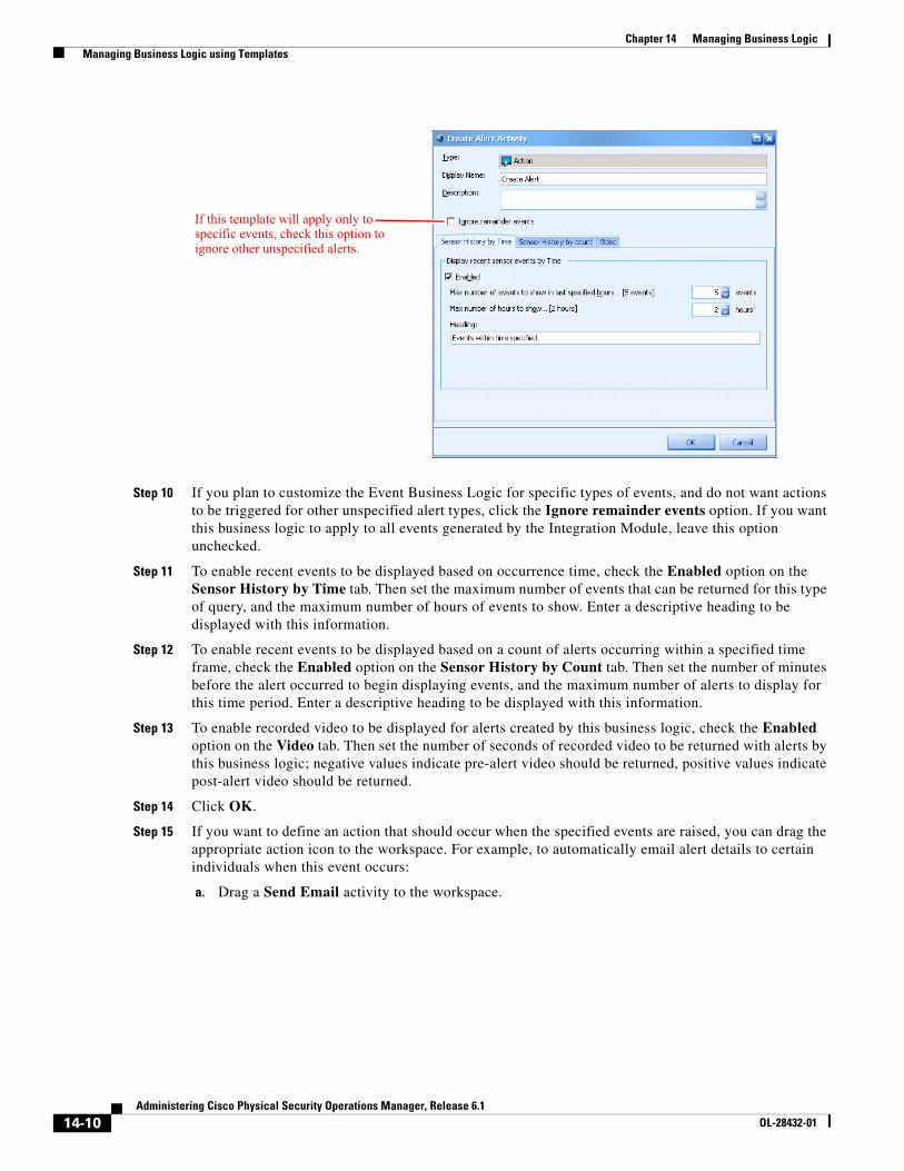
14-10Administering Cisco Physical Security Operations Manager, Release 6.1
OL-28432-01
Chapter 14 Managing Business Logic Managing Business Logic using Templates
Step 10 If you plan to customize the Event Business Logic for specific types of events, and do not want actions to be triggered for other unspecified alert types, click the Ignore remainder events option. If you want this business logic to apply to all events generated by the Integration Module, leave this option unchecked.
Step 11 To enable recent events to be displayed based on occurrence time, check the Enabled option on the Sensor History by Time tab. Then set the maximum number of events that can be returned for this type of query, and the maximum number of hours of events to show. Enter a descriptive heading to be displayed with this information.
Step 12 To enable recent events to be displayed based on a count of alerts occurring within a specified time frame, check the Enabled option on the Sensor History by Count tab. Then set the number of minutes before the alert occurred to begin displaying events, and the maximum number of alerts to display for this time period. Enter a descriptive heading to be displayed with this information.
Step 13 To enable recorded video to be displayed for alerts created by this business logic, check the Enabled option on the Video tab. Then set the number of seconds of recorded video to be returned with alerts by this business logic; negative values indicate pre-alert video should be returned, positive values indicate post-alert video should be returned.
Step 14 Click OK.
Step 15 If you want to define an action that should occur when the specified events are raised, you can drag the appropriate action icon to the workspace. For example, to automatically email alert details to certain individuals when this event occurs:
a. Drag a Send Email activity to the workspace.
If this template will apply only to specific events, check this option to ignore other unspecified alerts.
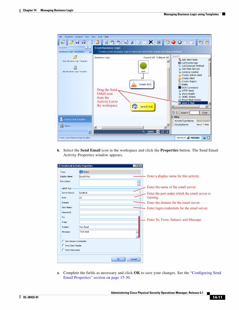
14-11Administering Cisco Physical Security Operations Manager, Release 6.1
OL-28432-01
Chapter 14 Managing Business Logic Managing Business Logic using Templates
b. Select the Send Email icon in the workspace and click the Properties button. The Send Email Activity Properties window appears.
c. Complete the fields as necessary and click OK to save your changes. See the “Configuring Send Email Properties” section on page 15-30.
Drag the Send EMail icon from the Activity List to the workspace.
Enter a display name for this activity.
Enter the name of the email server.
Enter the port under which the email server is running.
Enter the domain for the email server.
Enter login credentials for the email server.
Enter To, From, Subject, and Message.
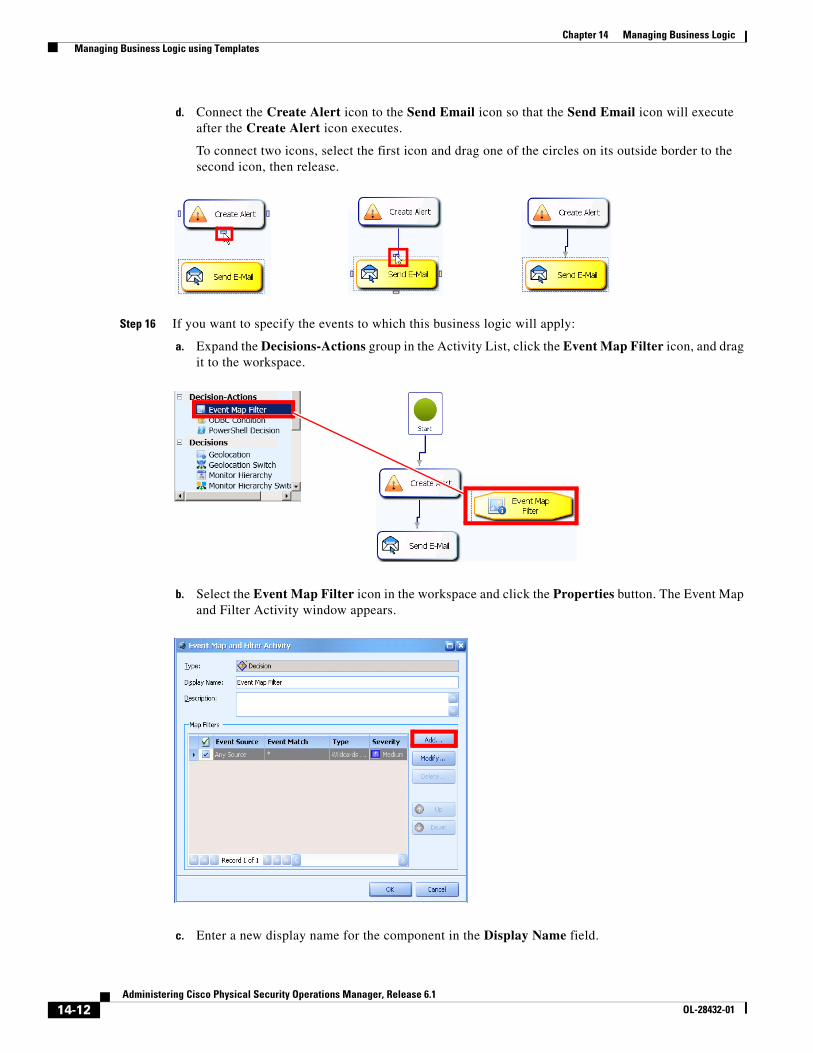
14-12Administering Cisco Physical Security Operations Manager, Release 6.1
OL-28432-01
Chapter 14 Managing Business Logic Managing Business Logic using Templates
d. Connect the Create Alert icon to the Send Email icon so that the Send Email icon will execute after the Create Alert icon executes.
To connect two icons, select the first icon and drag one of the circles on its outside border to the second icon, then release.
Step 16 If you want to specify the events to which this business logic will apply:
a. Expand the Decisions-Actions group in the Activity List, click the Event Map Filter icon, and drag it to the workspace.
b. Select the Event Map Filter icon in the workspace and click the Properties button. The Event Map and Filter Activity window appears.
c. Enter a new display name for the component in the Display Name field.
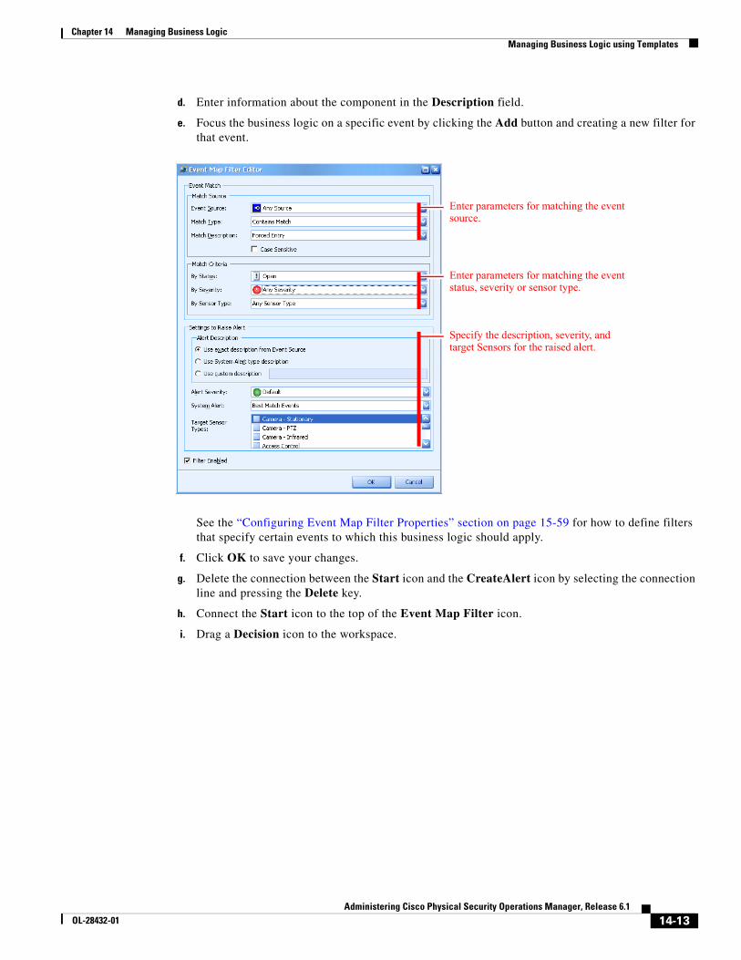
14-13Administering Cisco Physical Security Operations Manager, Release 6.1
OL-28432-01
Chapter 14 Managing Business Logic Managing Business Logic using Templates
d. Enter information about the component in the Description field.
e. Focus the business logic on a specific event by clicking the Add button and creating a new filter for that event.
See the “Configuring Event Map Filter Properties” section on page 15-59 for how to define filters that specify certain events to which this business logic should apply.
f. Click OK to save your changes.
g. Delete the connection between the Start icon and the CreateAlert icon by selecting the connection line and pressing the Delete key.
h. Connect the Start icon to the top of the Event Map Filter icon.
i. Drag a Decision icon to the workspace.
Enter parameters for matching the event source.
Enter parameters for matching the event status, severity or sensor type.
Specify the description, severity, and target Sensors for the raised alert.
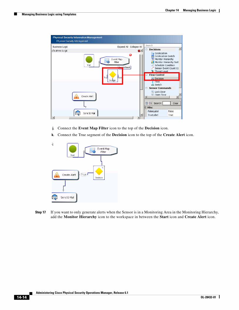
14-14Administering Cisco Physical Security Operations Manager, Release 6.1
OL-28432-01
Chapter 14 Managing Business Logic Managing Business Logic using Templates
j. Connect the Event Map Filter icon to the top of the Decision icon.
k. Connect the True segment of the Decision icon to the top of the Create Alert icon.
Step 17 If you want to only generate alerts when the Sensor is in a Monitoring Area in the Monitoring Hierarchy, add the Monitor Hierarchy icon to the workspace in between the Start icon and Create Alert icon.
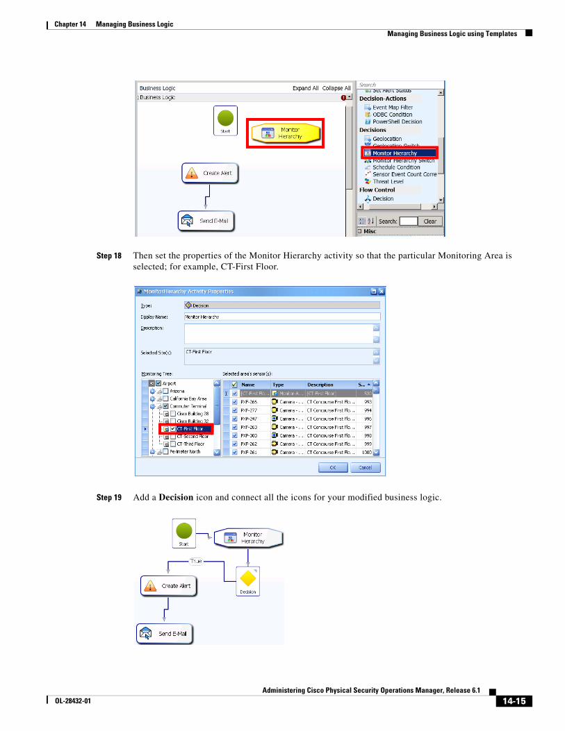
14-15Administering Cisco Physical Security Operations Manager, Release 6.1
OL-28432-01
Chapter 14 Managing Business Logic Managing Business Logic using Templates
Step 18 Then set the properties of the Monitor Hierarchy activity so that the particular Monitoring Area is selected; for example, CT-First Floor.
Step 19 Add a Decision icon and connect all the icons for your modified business logic.
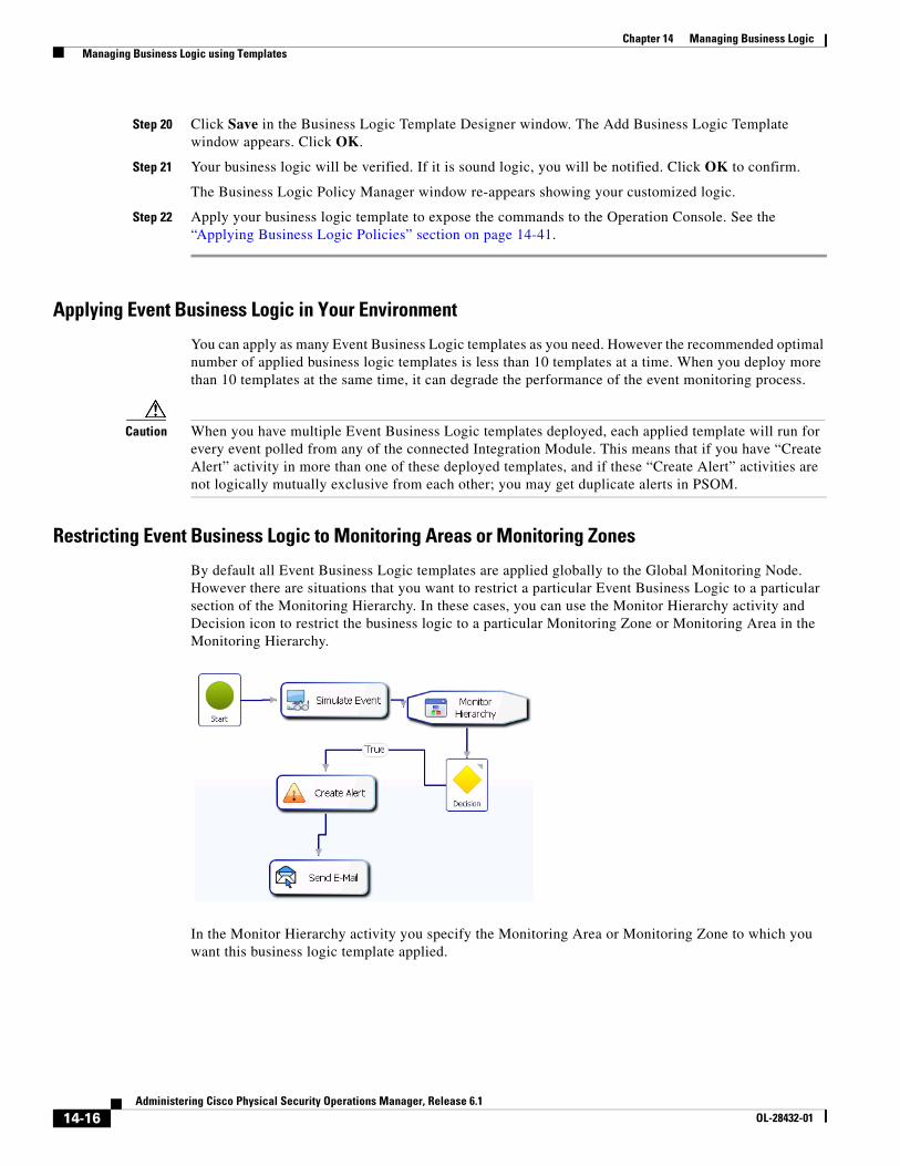
14-16Administering Cisco Physical Security Operations Manager, Release 6.1
OL-28432-01
Chapter 14 Managing Business Logic Managing Business Logic using Templates
Step 20 Click Save in the Business Logic Template Designer window. The Add Business Logic Template window appears. Click OK.
Step 21 Your business logic will be verified. If it is sound logic, you will be notified. Click OK to confirm.
The Business Logic Policy Manager window re-appears showing your customized logic.
Step 22 Apply your business logic template to expose the commands to the Operation Console. See the “Applying Business Logic Policies” section on page 14-41.
Applying Event Business Logic in Your Environment
You can apply as many Event Business Logic templates as you need. However the recommended optimal number of applied business logic templates is less than 10 templates at a time. When you deploy more than 10 templates at the same time, it can degrade the performance of the event monitoring process.
Caution When you have multiple Event Business Logic templates deployed, each applied template will run for every event polled from any of the connected Integration Module. This means that if you have “Create Alert” activity in more than one of these deployed templates, and if these “Create Alert” activities are not logically mutually exclusive from each other; you may get duplicate alerts in PSOM.
Restricting Event Business Logic to Monitoring Areas or Monitoring Zones
By default all Event Business Logic templates are applied globally to the Global Monitoring Node. However there are situations that you want to restrict a particular Event Business Logic to a particular section of the Monitoring Hierarchy. In these cases, you can use the Monitor Hierarchy activity and Decision icon to restrict the business logic to a particular Monitoring Zone or Monitoring Area in the Monitoring Hierarchy.
In the Monitor Hierarchy activity you specify the Monitoring Area or Monitoring Zone to which you want this business logic template applied.
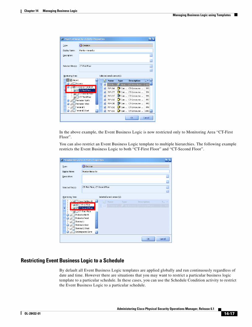
14-17Administering Cisco Physical Security Operations Manager, Release 6.1
OL-28432-01
Chapter 14 Managing Business Logic Managing Business Logic using Templates
In the above example, the Event Business Logic is now restricted only to Monitoring Area “CT-First Floor”.
You can also restrict an Event Business Logic template to multiple hierarchies. The following example restricts the Event Business Logic to both “CT-First Floor” and “CT-Second Floor”.
Restricting Event Business Logic to a Schedule
By default all Event Business Logic templates are applied globally and run continuously regardless of date and time. However there are situations that you may want to restrict a particular business logic template to a particular schedule. In these cases, you can use the Schedule Condition activity to restrict the Event Business Logic to a particular schedule.
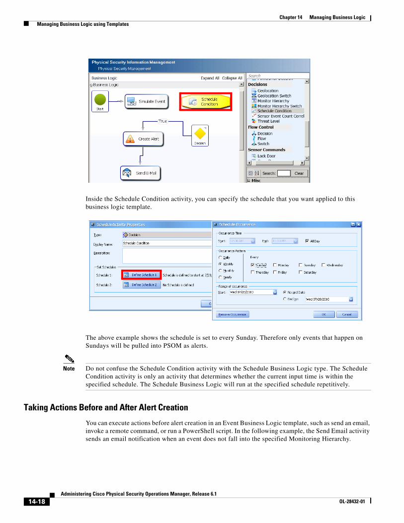
14-18Administering Cisco Physical Security Operations Manager, Release 6.1
OL-28432-01
Chapter 14 Managing Business Logic Managing Business Logic using Templates
Inside the Schedule Condition activity, you can specify the schedule that you want applied to this business logic template.
The above example shows the schedule is set to every Sunday. Therefore only events that happen on Sundays will be pulled into PSOM as alerts.
Note Do not confuse the Schedule Condition activity with the Schedule Business Logic type. The Schedule Condition activity is only an activity that determines whether the current input time is within the specified schedule. The Schedule Business Logic will run at the specified schedule repetitively.
Taking Actions Before and After Alert Creation
You can execute actions before alert creation in an Event Business Logic template, such as send an email, invoke a remote command, or run a PowerShell script. In the following example, the Send Email activity sends an email notification when an event does not fall into the specified Monitoring Hierarchy.

14-19Administering Cisco Physical Security Operations Manager, Release 6.1
OL-28432-01
Chapter 14 Managing Business Logic Managing Business Logic using Templates
To execute actions after an alert has been created, you need to use the Alert Business Logic template to deploy these actions. For example, escalate an alert to certain personnel after the alert has been created.
Or send email notifications after an alert has been created.
Creating an Alert Business Logic Template Based on the Default TemplateAn Alert Business Logic template determines the specific actions, decisions, and activities that should be occur when alerts are raised in PSOM. The default Alert Business Logic template contains only a Start icon.
To create a new Alert Business Logic template based on a default template, follow these steps:
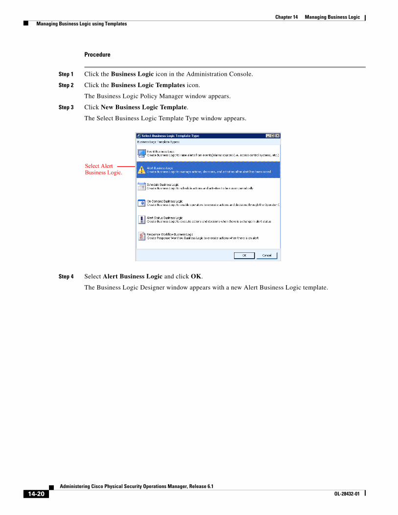
14-20Administering Cisco Physical Security Operations Manager, Release 6.1
OL-28432-01
Chapter 14 Managing Business Logic Managing Business Logic using Templates
Procedure
Step 1 Click the Business Logic icon in the Administration Console.
Step 2 Click the Business Logic Templates icon.
The Business Logic Policy Manager window appears.
Step 3 Click New Business Logic Template.
The Select Business Logic Template Type window appears.
Step 4 Select Alert Business Logic and click OK.
The Business Logic Designer window appears with a new Alert Business Logic template.
Select Alert Business Logic.
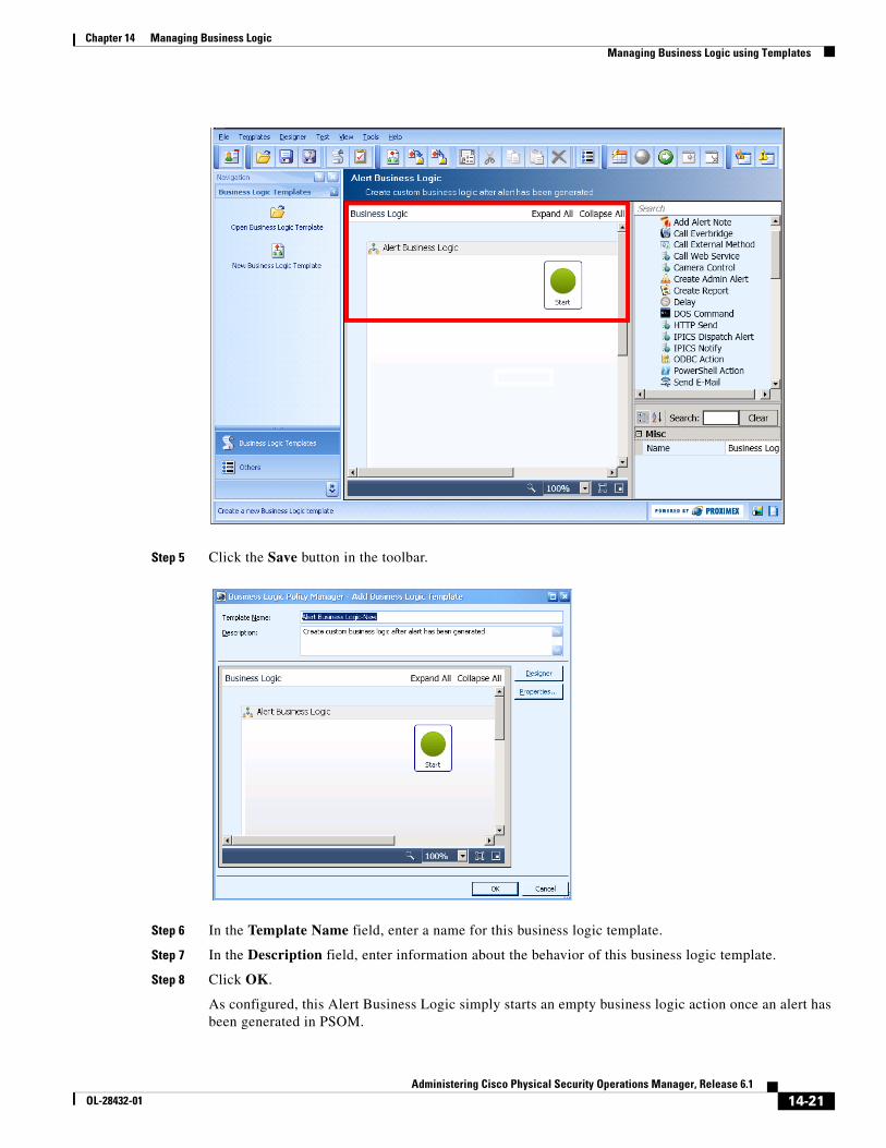
14-21Administering Cisco Physical Security Operations Manager, Release 6.1
OL-28432-01
Chapter 14 Managing Business Logic Managing Business Logic using Templates
Step 5 Click the Save button in the toolbar.
Step 6 In the Template Name field, enter a name for this business logic template.
Step 7 In the Description field, enter information about the behavior of this business logic template.
Step 8 Click OK.
As configured, this Alert Business Logic simply starts an empty business logic action once an alert has been generated in PSOM.
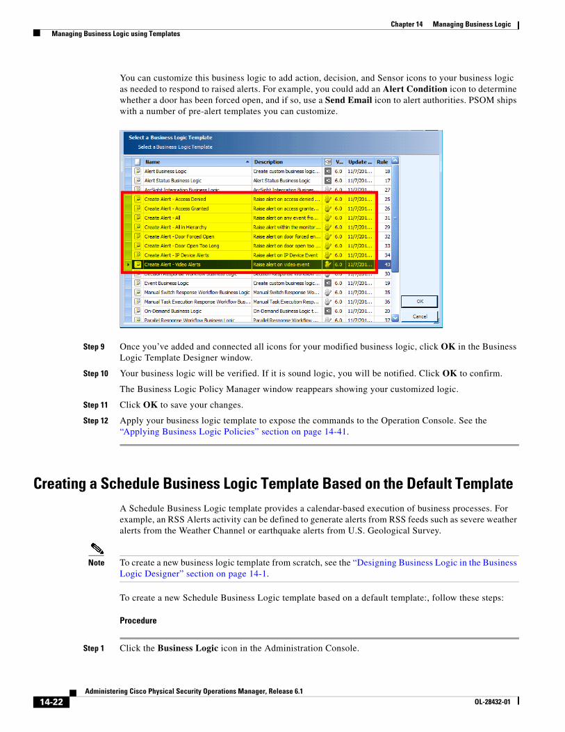
14-22Administering Cisco Physical Security Operations Manager, Release 6.1
OL-28432-01
Chapter 14 Managing Business Logic Managing Business Logic using Templates
You can customize this business logic to add action, decision, and Sensor icons to your business logic as needed to respond to raised alerts. For example, you could add an Alert Condition icon to determine whether a door has been forced open, and if so, use a Send Email icon to alert authorities. PSOM ships with a number of pre-alert templates you can customize.
Step 9 Once you’ve added and connected all icons for your modified business logic, click OK in the Business Logic Template Designer window.
Step 10 Your business logic will be verified. If it is sound logic, you will be notified. Click OK to confirm.
The Business Logic Policy Manager window reappears showing your customized logic.
Step 11 Click OK to save your changes.
Step 12 Apply your business logic template to expose the commands to the Operation Console. See the “Applying Business Logic Policies” section on page 14-41.
Creating a Schedule Business Logic Template Based on the Default TemplateA Schedule Business Logic template provides a calendar-based execution of business processes. For example, an RSS Alerts activity can be defined to generate alerts from RSS feeds such as severe weather alerts from the Weather Channel or earthquake alerts from U.S. Geological Survey.
Note To create a new business logic template from scratch, see the “Designing Business Logic in the Business Logic Designer” section on page 14-1.
To create a new Schedule Business Logic template based on a default template:, follow these steps:
Procedure
Step 1 Click the Business Logic icon in the Administration Console.
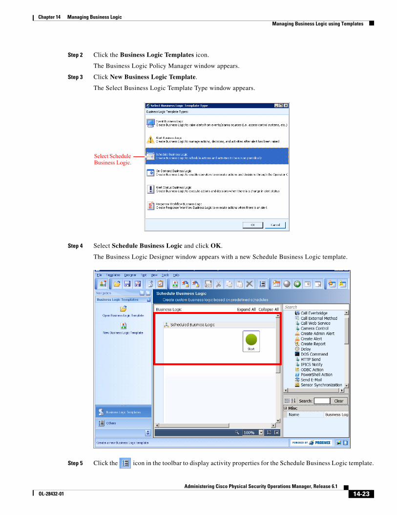
14-23Administering Cisco Physical Security Operations Manager, Release 6.1
OL-28432-01
Chapter 14 Managing Business Logic Managing Business Logic using Templates
Step 2 Click the Business Logic Templates icon.
The Business Logic Policy Manager window appears.
Step 3 Click New Business Logic Template.
The Select Business Logic Template Type window appears.
Step 4 Select Schedule Business Logic and click OK.
The Business Logic Designer window appears with a new Schedule Business Logic template.
Step 5 Click the icon in the toolbar to display activity properties for the Schedule Business Logic template.
Select Schedule Business Logic.
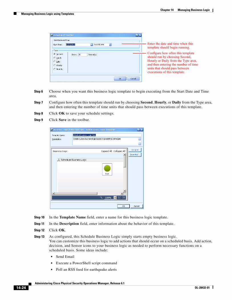
14-24Administering Cisco Physical Security Operations Manager, Release 6.1
OL-28432-01
Chapter 14 Managing Business Logic Managing Business Logic using Templates
Step 6 Choose when you want this business logic template to begin executing from the Start Date and Time area.
Step 7 Configure how often this template should run by choosing Second, Hourly, or Daily from the Type area, and then entering the number of time units that should pass between executions of this template.
Step 8 Click OK to save your schedule settings.
Step 9 Click Save in the toolbar.
Step 10 In the Template Name field, enter a name for this business logic template.
Step 11 In the Description field, enter information about the behavior of this template.
Step 12 Click OK.
Step 13 As configured, this Schedule Business Logic simply starts empty business logic.You can customize this business logic to add actions that should occur on a scheduled basis. Add action, decision, and Sensor icons to your business logic as needed to perform necessary functions on a scheduled basis. Some ideas include:
• Send Email
• Execute a PowerShell script command
• Poll an RSS feed for earthquake alerts
Enter the date and time when this template should begin running.
Configure how often this template should run by choosing Second, Hourly or Daily from the Type area, and then entering the number of time units that should pass between executions of this template.
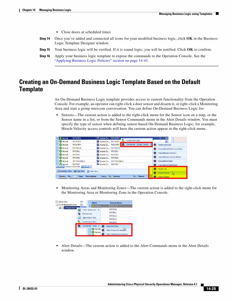
14-25Administering Cisco Physical Security Operations Manager, Release 6.1
OL-28432-01
Chapter 14 Managing Business Logic Managing Business Logic using Templates
• Close doors at scheduled times
Step 14 Once you’ve added and connected all icons for your modified business logic, click OK in the Business Logic Template Designer window.
Step 15 Your business logic will be verified. If it is sound logic, you will be notified. Click OK to confirm.
Step 16 Apply your business logic template to expose the commands to the Operation Console. See the “Applying Business Logic Policies” section on page 14-41.
Creating an On-Demand Business Logic Template Based on the Default Template
An On-Demand Business Logic template provides access to custom functionality from the Operation Console. For example, an operator can right-click a door sensor and disarm it, or right-click a Monitoring Area and start a group intercom conversation. You can define On-Demand Business Logic for:
• Sensors—The custom action is added to the right-click menu for the Sensor icon on a map, or the Sensor name in a list, or from the Sensor Commands menu in the Alert Details window. You must specify the type of sensor when defining sensor-based On-Demand Business Logic; for example, Hirsch-Velocity access controls will have the custom action appear in the right-click menu.
• Monitoring Areas and Monitoring Zones—The custom action is added to the right-click menu for the Monitoring Area or Monitoring Zone in the Operation Console.
• Alert Details—The custom action is added to the Alert Commands menu in the Alert Details window.
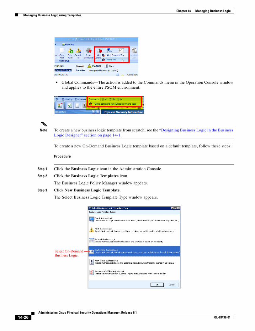
14-26Administering Cisco Physical Security Operations Manager, Release 6.1
OL-28432-01
Chapter 14 Managing Business Logic Managing Business Logic using Templates
• Global Commands—The action is added to the Commands menu in the Operation Console window and applies to the entire PSOM environment.
Note To create a new business logic template from scratch, see the “Designing Business Logic in the Business Logic Designer” section on page 14-1.
To create a new On-Demand Business Logic template based on a default template, follow these steps:
Procedure
Step 1 Click the Business Logic icon in the Administration Console.
Step 2 Click the Business Logic Templates icon.
The Business Logic Policy Manager window appears.
Step 3 Click New Business Logic Template.
The Select Business Logic Template Type window appears.
Select On-Demand Business Logic.
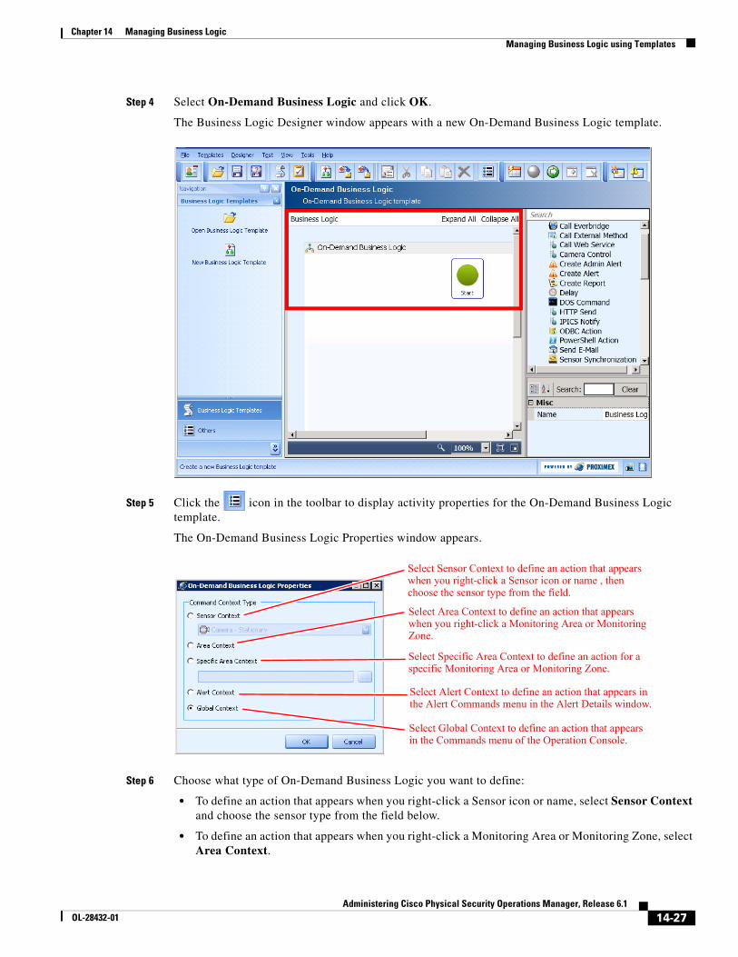
14-27Administering Cisco Physical Security Operations Manager, Release 6.1
OL-28432-01
Chapter 14 Managing Business Logic Managing Business Logic using Templates
Step 4 Select On-Demand Business Logic and click OK.
The Business Logic Designer window appears with a new On-Demand Business Logic template.
Step 5 Click the icon in the toolbar to display activity properties for the On-Demand Business Logic template.
The On-Demand Business Logic Properties window appears.
Step 6 Choose what type of On-Demand Business Logic you want to define:
• To define an action that appears when you right-click a Sensor icon or name, select Sensor Context and choose the sensor type from the field below.
• To define an action that appears when you right-click a Monitoring Area or Monitoring Zone, select Area Context.
Select Sensor Context to define an action that appears when you right-click a Sensor icon or name , then choose the sensor type from the field.
Select Area Context to define an action that appears when you right-click a Monitoring Area or Monitoring Zone.
Select Alert Context to define an action that appears in the Alert Commands menu in the Alert Details window.
Select Global Context to define an action that appears in the Commands menu of the Operation Console.
Select Specific Area Context to define an action for a specific Monitoring Area or Monitoring Zone.
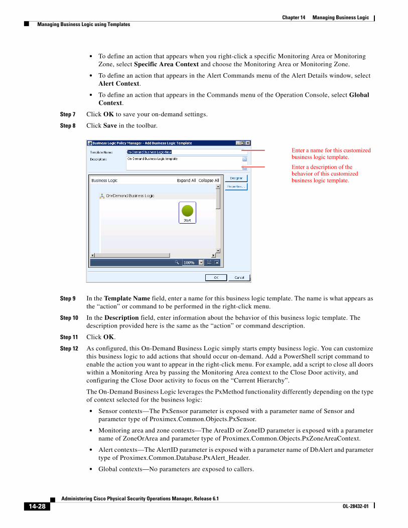
14-28Administering Cisco Physical Security Operations Manager, Release 6.1
OL-28432-01
Chapter 14 Managing Business Logic Managing Business Logic using Templates
• To define an action that appears when you right-click a specific Monitoring Area or Monitoring Zone, select Specific Area Context and choose the Monitoring Area or Monitoring Zone.
• To define an action that appears in the Alert Commands menu of the Alert Details window, select Alert Context.
• To define an action that appears in the Commands menu of the Operation Console, select Global Context.
Step 7 Click OK to save your on-demand settings.
Step 8 Click Save in the toolbar.
Step 9 In the Template Name field, enter a name for this business logic template. The name is what appears as the “action” or command to be performed in the right-click menu.
Step 10 In the Description field, enter information about the behavior of this business logic template. The description provided here is the same as the “action” or command description.
Step 11 Click OK.
Step 12 As configured, this On-Demand Business Logic simply starts empty business logic. You can customize this business logic to add actions that should occur on-demand. Add a PowerShell script command to enable the action you want to appear in the right-click menu. For example, add a script to close all doors within a Monitoring Area by passing the Monitoring Area context to the Close Door activity, and configuring the Close Door activity to focus on the “Current Hierarchy”.
The On-Demand Business Logic leverages the PxMethod functionality differently depending on the type of context selected for the business logic:
• Sensor contexts—The PxSensor parameter is exposed with a parameter name of Sensor and parameter type of Proximex.Common.Objects.PxSensor.
• Monitoring area and zone contexts—The AreaID or ZoneID parameter is exposed with a parameter name of ZoneOrArea and parameter type of Proximex.Common.Objects.PxZoneAreaContext.
• Alert contexts—The AlertID parameter is exposed with a parameter name of DbAlert and parameter type of Proximex.Common.Database.PxAlert_Header.
• Global contexts—No parameters are exposed to callers.
Enter a name for this customized business logic template.
Enter a description of the behavior of this customized business logic template.
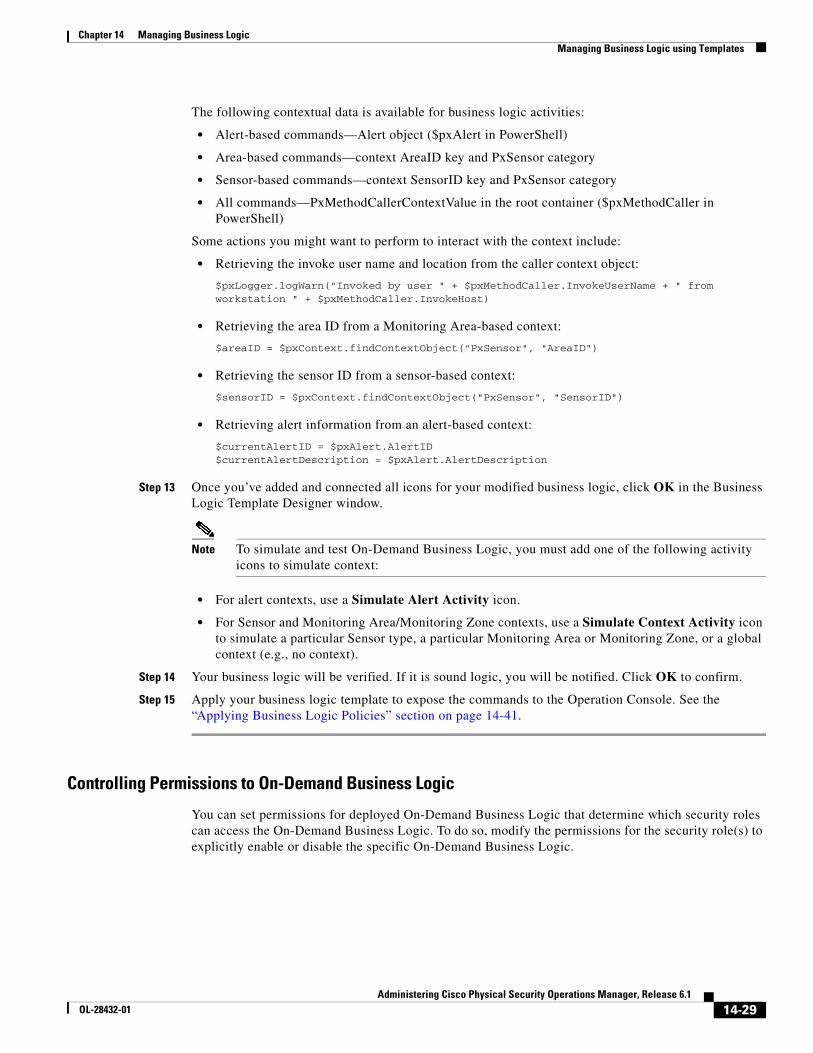
14-29Administering Cisco Physical Security Operations Manager, Release 6.1
OL-28432-01
Chapter 14 Managing Business Logic Managing Business Logic using Templates
The following contextual data is available for business logic activities:
• Alert-based commands—Alert object ($pxAlert in PowerShell)
• Area-based commands—context AreaID key and PxSensor category
• Sensor-based commands—context SensorID key and PxSensor category
• All commands—PxMethodCallerContextValue in the root container ($pxMethodCaller in PowerShell)
Some actions you might want to perform to interact with the context include:
• Retrieving the invoke user name and location from the caller context object:
$pxLogger.logWarn("Invoked by user " + $pxMethodCaller.InvokeUserName + " from workstation " + $pxMethodCaller.InvokeHost)
• Retrieving the area ID from a Monitoring Area-based context:
$areaID = $pxContext.findContextObject("PxSensor", "AreaID")
• Retrieving the sensor ID from a sensor-based context:
$sensorID = $pxContext.findContextObject("PxSensor", "SensorID")
• Retrieving alert information from an alert-based context:
$currentAlertID = $pxAlert.AlertID$currentAlertDescription = $pxAlert.AlertDescription
Step 13 Once you’ve added and connected all icons for your modified business logic, click OK in the Business Logic Template Designer window.
Note To simulate and test On-Demand Business Logic, you must add one of the following activity icons to simulate context:
• For alert contexts, use a Simulate Alert Activity icon.
• For Sensor and Monitoring Area/Monitoring Zone contexts, use a Simulate Context Activity icon to simulate a particular Sensor type, a particular Monitoring Area or Monitoring Zone, or a global context (e.g., no context).
Step 14 Your business logic will be verified. If it is sound logic, you will be notified. Click OK to confirm.
Step 15 Apply your business logic template to expose the commands to the Operation Console. See the “Applying Business Logic Policies” section on page 14-41.
Controlling Permissions to On-Demand Business Logic
You can set permissions for deployed On-Demand Business Logic that determine which security roles can access the On-Demand Business Logic. To do so, modify the permissions for the security role(s) to explicitly enable or disable the specific On-Demand Business Logic.
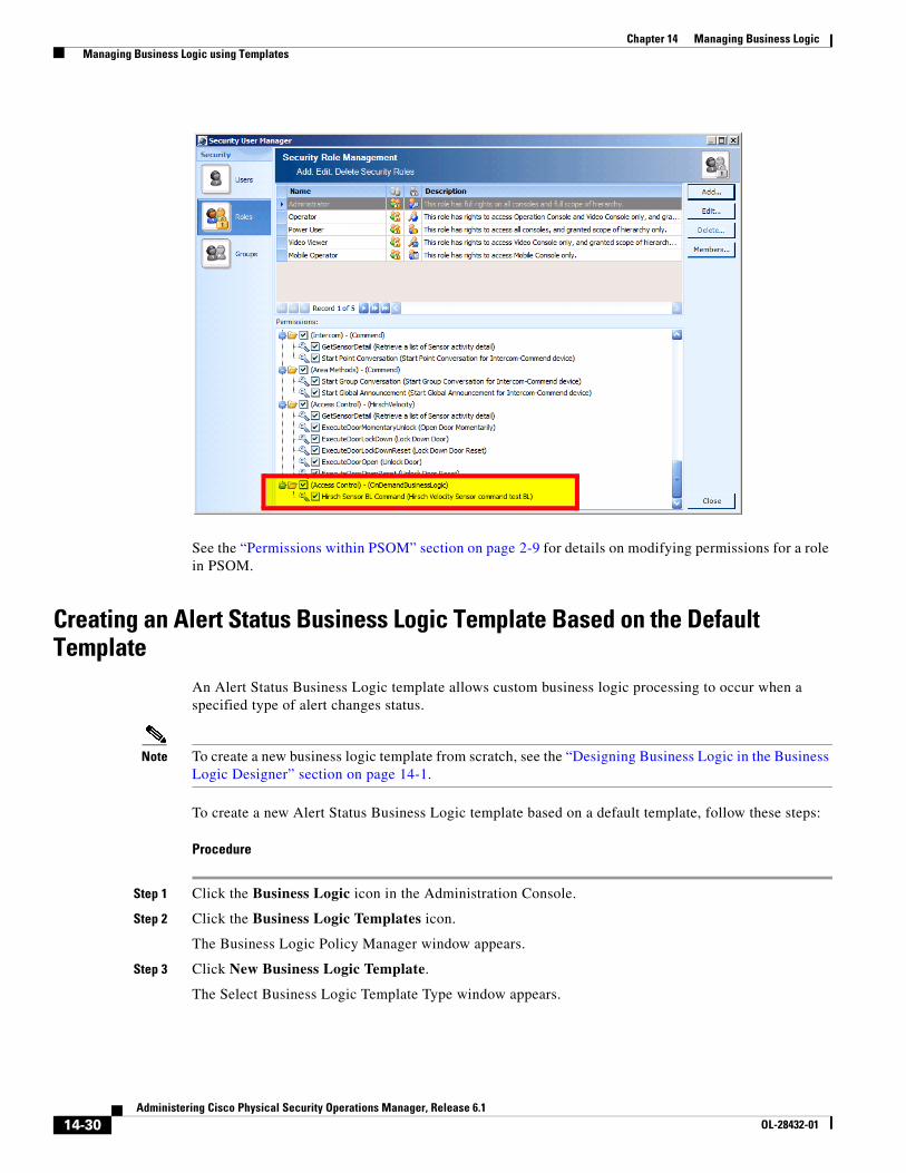
14-30Administering Cisco Physical Security Operations Manager, Release 6.1
OL-28432-01
Chapter 14 Managing Business Logic Managing Business Logic using Templates
See the “Permissions within PSOM” section on page 2-9 for details on modifying permissions for a role in PSOM.
Creating an Alert Status Business Logic Template Based on the Default Template
An Alert Status Business Logic template allows custom business logic processing to occur when a specified type of alert changes status.
Note To create a new business logic template from scratch, see the “Designing Business Logic in the Business Logic Designer” section on page 14-1.
To create a new Alert Status Business Logic template based on a default template, follow these steps:
Procedure
Step 1 Click the Business Logic icon in the Administration Console.
Step 2 Click the Business Logic Templates icon.
The Business Logic Policy Manager window appears.
Step 3 Click New Business Logic Template.
The Select Business Logic Template Type window appears.
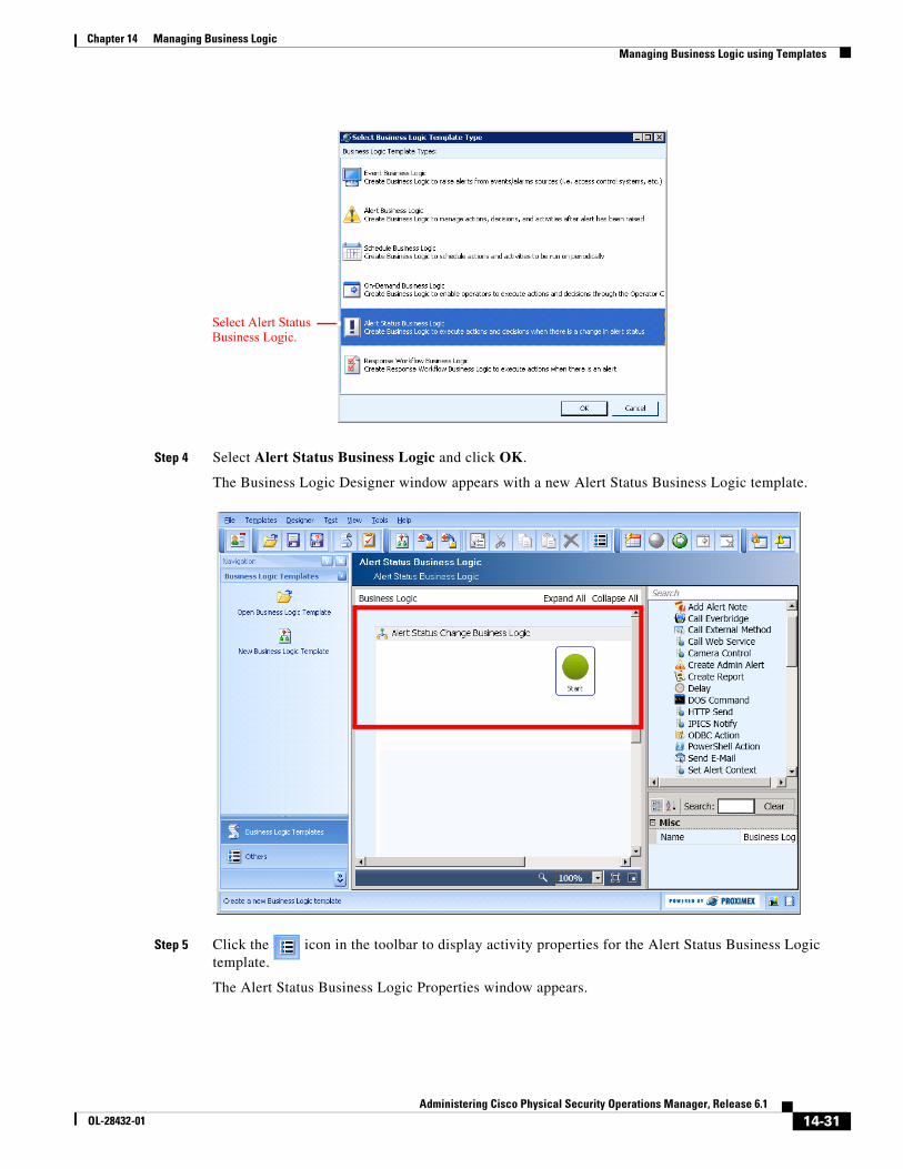
14-31Administering Cisco Physical Security Operations Manager, Release 6.1
OL-28432-01
Chapter 14 Managing Business Logic Managing Business Logic using Templates
Step 4 Select Alert Status Business Logic and click OK.
The Business Logic Designer window appears with a new Alert Status Business Logic template.
Step 5 Click the icon in the toolbar to display activity properties for the Alert Status Business Logic template.
The Alert Status Business Logic Properties window appears.
Select Alert Status Business Logic.
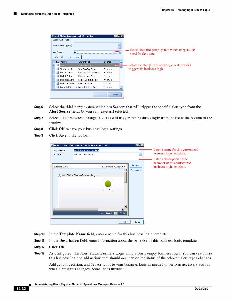
14-32Administering Cisco Physical Security Operations Manager, Release 6.1
OL-28432-01
Chapter 14 Managing Business Logic Managing Business Logic using Templates
Step 6 Select the third-party system which has Sensors that will trigger the specific alert type from the Alert Source field. Or you can leave All selected.
Step 7 Select all alerts whose change in status will trigger this business logic from the list at the bottom of the window.
Step 8 Click OK to save your business logic settings.
Step 9 Click Save in the toolbar.
Step 10 In the Template Name field, enter a name for this business logic template.
Step 11 In the Description field, enter information about the behavior of this business logic template.
Step 12 Click OK.
Step 13 As configured, this Alert Status Business Logic simply starts empty business logic. You can customize this business logic to add actions that should occur when the status of the selected alert types changes.
Add action, decision, and Sensor icons to your business logic as needed to perform necessary actions when alert status changes. Some ideas include:
Select the third-party system which triggers the specific alert type.
Select the alert(s) whose change in status will trigger this business logic.
Enter a name for this customized business logic template.
Enter a description of the behavior of this customized business logic template.
14-33Administering Cisco Physical Security Operations Manager, Release 6.1
OL-28432-01
Chapter 14 Managing Business Logic Managing Business Logic using Templates
• Dispatch a notification automatically to CISCO IPICS when an alert is acknowledged using the IPICS Notify activity.
• Execute a PowerShell script command. For example, you might use a PowerShell script to retrieve the alert ID, previous status and current status of the alert.
$curStatus = $pxAlert.Status$prevStatus = $pxAlert.PrevStatus$tempAlertId = $pxAlert.AlertID $pxLogger.logWarn("Alert " + $tempAlertId + " changed from ‘" + $prevStatus + "’ to ‘" + $curStatus + “’”)
Note You cannot use the Set Status activity in this business logic.
Step 14 Once you’ve added and connected all icons for your modified business logic, click OK in the Business Logic Template Designer window.
Step 15 Your business logic will be verified. If it is sound logic, you will be notified. Click OK to confirm.
Step 16 Apply your business logic template to expose the commands to the Operation Console. See the “Applying Business Logic Policies” section on page 14-41.
Creating a Response Workflow Business Logic Template Based on the Default Template
A Response Workflow Business Logic template allows for the enforcement of “best practices” for the actions that an operator should take to resolve alerts. The Response Workflow Business Logic captures checklists of actions operators must take when certain types of alerts are raised. With these policies in place, it is easy for operators to follow standardized procedures which leads to fewer errors in response and more importantly a faster time to response.
Response Workflow Business Logic can be designed with sequential tasks so that operators are forced to fulfill a series of steps in order, or parallel tasks that allow operators to fulfill tasks as they are able. Operators can also be given decisions during execution of a Response Workflow that change the flow of business logic and tasks presented.
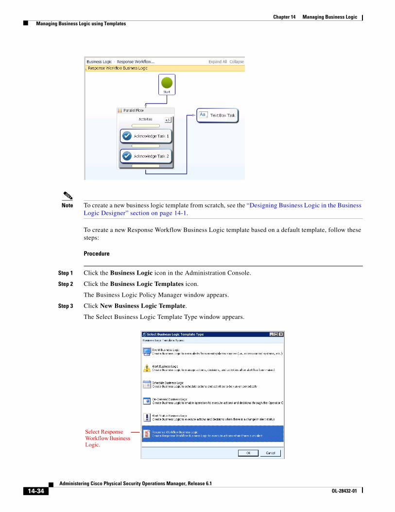
14-34Administering Cisco Physical Security Operations Manager, Release 6.1
OL-28432-01
Chapter 14 Managing Business Logic Managing Business Logic using Templates
Note To create a new business logic template from scratch, see the “Designing Business Logic in the Business Logic Designer” section on page 14-1.
To create a new Response Workflow Business Logic template based on a default template, follow these steps:
Procedure
Step 1 Click the Business Logic icon in the Administration Console.
Step 2 Click the Business Logic Templates icon.
The Business Logic Policy Manager window appears.
Step 3 Click New Business Logic Template.
The Select Business Logic Template Type window appears.
Select Response Workflow Business Logic.
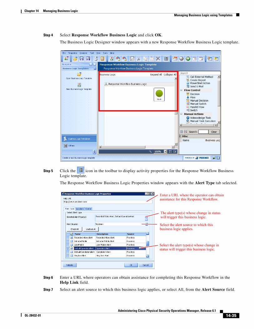
14-35Administering Cisco Physical Security Operations Manager, Release 6.1
OL-28432-01
Chapter 14 Managing Business Logic Managing Business Logic using Templates
Step 4 Select Response Workflow Business Logic and click OK.
The Business Logic Designer window appears with a new Response Workflow Business Logic template.
Step 5 Click the icon in the toolbar to display activity properties for the Response Workflow Business Logic template.
The Response Workflow Business Logic Properties window appears with the Alert Type tab selected.
Step 6 Enter a URL where operators can obtain assistance for completing this Response Workflow in the Help Link field.
Step 7 Select an alert source to which this business logic applies, or select All, from the Alert Source field.
The alert type(s) whose change in status will trigger this business logic.
Enter a URL where the operator can obtain assistance for this Response Workflow.
Select the alert source to which this business logic applies.
Select the alert type(s) whose change in status will trigger this business logic.
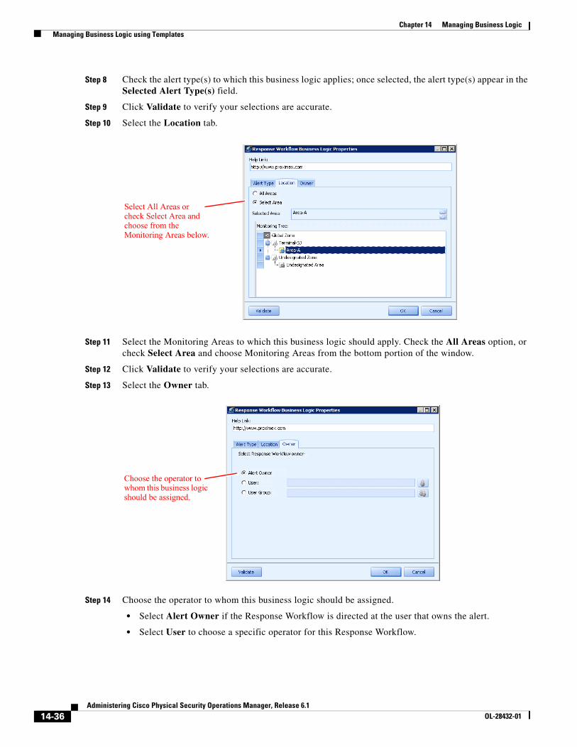
14-36Administering Cisco Physical Security Operations Manager, Release 6.1
OL-28432-01
Chapter 14 Managing Business Logic Managing Business Logic using Templates
Step 8 Check the alert type(s) to which this business logic applies; once selected, the alert type(s) appear in the Selected Alert Type(s) field.
Step 9 Click Validate to verify your selections are accurate.
Step 10 Select the Location tab.
Step 11 Select the Monitoring Areas to which this business logic should apply. Check the All Areas option, or check Select Area and choose Monitoring Areas from the bottom portion of the window.
Step 12 Click Validate to verify your selections are accurate.
Step 13 Select the Owner tab.
Step 14 Choose the operator to whom this business logic should be assigned.
• Select Alert Owner if the Response Workflow is directed at the user that owns the alert.
• Select User to choose a specific operator for this Response Workflow.
Select All Areas or check Select Area and choose from the Monitoring Areas below.
Choose the operator to whom this business logic should be assigned.
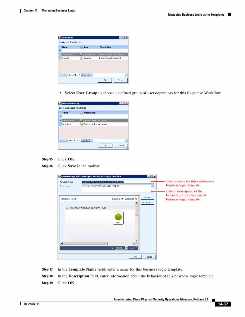
14-37Administering Cisco Physical Security Operations Manager, Release 6.1
OL-28432-01
Chapter 14 Managing Business Logic Managing Business Logic using Templates
• Select User Group to choose a defined group of users/operators for this Response Workflow.
Step 15 Click OK.
Step 16 Click Save in the toolbar.
Step 17 In the Template Name field, enter a name for this business logic template.
Step 18 In the Description field, enter information about the behavior of this business logic template.
Step 19 Click OK.
Enter a name for this customized business logic template.
Enter a description of the behavior of this customized business logic template.
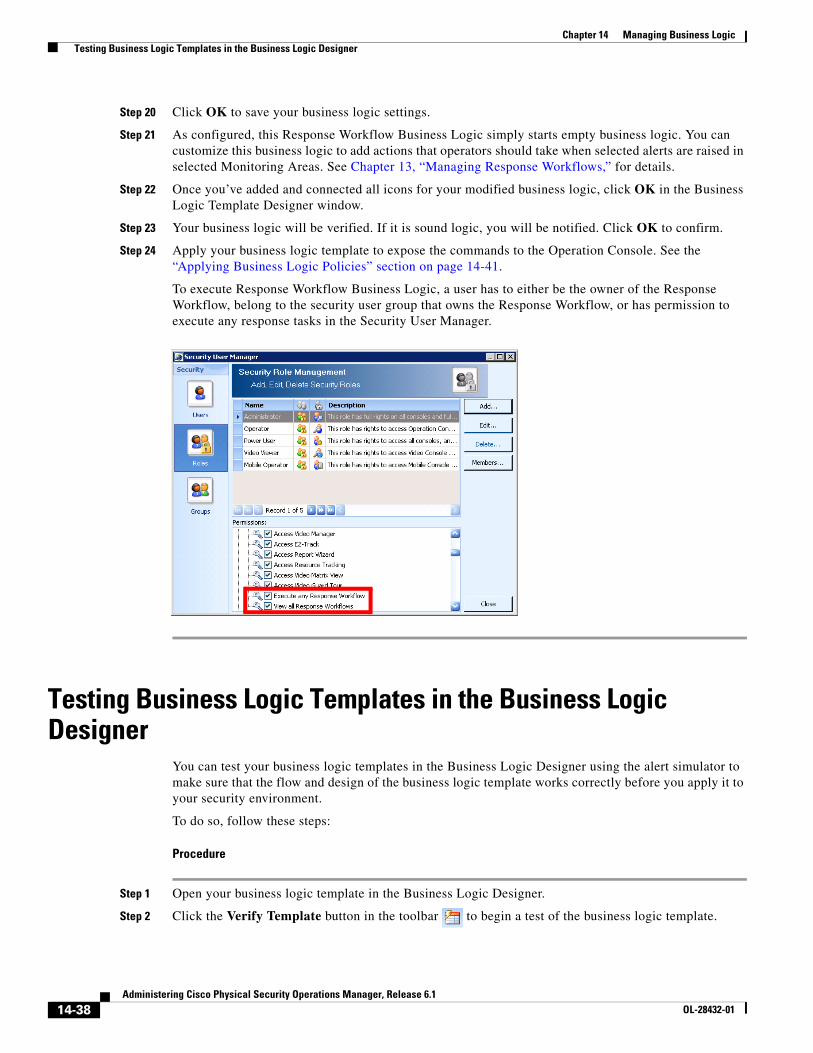
14-38Administering Cisco Physical Security Operations Manager, Release 6.1
OL-28432-01
Chapter 14 Managing Business Logic Testing Business Logic Templates in the Business Logic Designer
Step 20 Click OK to save your business logic settings.
Step 21 As configured, this Response Workflow Business Logic simply starts empty business logic. You can customize this business logic to add actions that operators should take when selected alerts are raised in selected Monitoring Areas. See Chapter 13, “Managing Response Workflows,” for details.
Step 22 Once you’ve added and connected all icons for your modified business logic, click OK in the Business Logic Template Designer window.
Step 23 Your business logic will be verified. If it is sound logic, you will be notified. Click OK to confirm.
Step 24 Apply your business logic template to expose the commands to the Operation Console. See the “Applying Business Logic Policies” section on page 14-41.
To execute Response Workflow Business Logic, a user has to either be the owner of the Response Workflow, belong to the security user group that owns the Response Workflow, or has permission to execute any response tasks in the Security User Manager.
Testing Business Logic Templates in the Business Logic Designer
You can test your business logic templates in the Business Logic Designer using the alert simulator to make sure that the flow and design of the business logic template works correctly before you apply it to your security environment.
To do so, follow these steps:
Procedure
Step 1 Open your business logic template in the Business Logic Designer.
Step 2 Click the Verify Template button in the toolbar to begin a test of the business logic template.
14-39Administering Cisco Physical Security Operations Manager, Release 6.1
OL-28432-01
Chapter 14 Managing Business Logic Testing Business Logic Templates in the Business Logic Designer
Step 3 If you want to pause test execution of the business logic at certain activities, select the appropriate icon within the business logic and click Test - Set Breakpoint in the toolbar . A red dot appears on the icon within the workspace.
Step 4 Click Test - Start in the toolbar to begin testing the business logic template. At each breakpoint, the test execution will pause. To resume the test execution after a breakpoint, click Test - Next Step in the toolbar .
Step 5 If you want to stop the test execution while it is running, click Test - Cancel in the toolbar .
Step 6 Click Save Template in the toolbar when you are finished testing your business logic template.
Note You do not need to remove the SimulateAlert icon from your business logic templates before applying them to your PSOM environment. PSOM ignores these icons for actual runtime deployment. However, if the alert used by the SimulateAlert icon is deleted in PSOM, running the business logic template in Test mode may result in incomplete alert details for testing purposes (such as information presented in the Description and Tasks areas of the Alert Details window).
Debugging Business Logic Templates that Include CorrelateCondition Components
Debugging and fine-tuning business logic templates that incorporate CorrelateCondition components is similar to debugging other business logic templates. You should simulate alerts, set breakpoints, and step through the execution of the business logic template to determine the results of each activity.
However, you do need to be sure that PSOM is populated with the types of alerts that you are going to correlate in your business logic template. To do so, you need to set up a test environment on a non-production server. Testing and debugging business logic in a production environment can cause false information to appear to security operators in the Operation Console.
Procedure
Step 1 On a non-production server, install and configure the PSOM software.
Step 2 Restore a backup of your production database to your testing environment.
Step 3 Remove the application of existing applied business logic templates to avoid distracting interactions that will inhibit your ability to debug the current business logic template; do not delete these templates, but remove their application within the environment.
Step 4 In your business logic template, create multiple SimAlert components, each based on relevant pre-existing alerts. A CorrelateCondition must have at least two alerts available for correlation. Therefore, you should create SimAlert components for all relevant alerts so that they can be used for debugging.
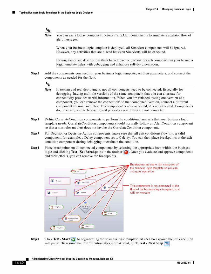
14-40Administering Cisco Physical Security Operations Manager, Release 6.1
OL-28432-01
Chapter 14 Managing Business Logic Testing Business Logic Templates in the Business Logic Designer
Note You can use a Delay component between SimAlert components to simulate a realistic flow of alert messages.
When your business logic template is deployed, all SimAlert components will be ignored. However, any activities that are placed between SimAlerts will be executed.
Having names and descriptions that characterize the purpose of each component in your business logic template helps with debugging and enhances self-documentation.
Step 5 Add the components you need for your business logic template, set their parameters, and connect the components as needed for the flow.
Note In testing and real deployment, not all components need to be connected. Especially for debugging, having multiple versions of the same component that you can alternate for connectivity provides useful information. When you are finished testing one version of a component, you can remove the connections to that component version, connect a different component version, and retest. If a component is not connected, it is not executed. Components do, however, need to be configured properly even if they are not connected.
Step 6 Define CorrelateCondition components to perform the conditional analysis that your business logic template needs. CorrelateCondition components should normally follow an AlertCondition component so that a non-relevant alert does not invoke the CorrelateCondition component.
Step 7 For Decision or Decision-Action components, make sure that all exit conditions flow into a valid component; for example, a Delay component set to 0 delay. You can then place breakpoints at the exit condition component during debugging to evaluate the condition.
Step 8 Place breakpoints on all connected components by selecting the appropriate icon within the business logic and clicking Test - Set Breakpoint in the toolbar . Once you evaluate and approve components and their effects, you can remove the breakpoints.
Step 9 Click Test - Start to begin testing the business logic template. At each breakpoint, the test execution will pause. To resume the test execution after a breakpoint, click Test - Next Step .
This component is not connected to the flow of the business logic template, so it will not execute.
Breakpoints are set to halt execution of the business logic template so you can debug its operation.
14-41Administering Cisco Physical Security Operations Manager, Release 6.1
OL-28432-01
Chapter 14 Managing Business Logic Applying Business Logic Policies
Step 10 During testing, keep the Operation Console window open and examine the results of your business logic template as you step through it.
Step 11 Once you are satisfied, open the Administrator Console and reapply the business logic templates that are normally deployed on the production server.
Step 12 Click Test - Start to begin testing the business logic template in a simulated production environment. Now you will verify that your business logic template behaves appropriately and does not impact other executing business logic templates.
Note You may need to modify the business logic template slightly to change the AlertCondition components so as to minimize the “crosstalk” between business logic templates.
Step 13 One you have verified your business logic template in a production environment, save it by clicking Save Template in the toolbar .
Step 14 Click Export Business Logic in the toolbar to save the business logic template to an XML file on your network.
Step 15 In your production PSOM system, launch the Business Logic Designer.
Step 16 Click Import Business Logic in the toolbar , and select the XML file you saved from the test environment.
Step 17 Click Save Template in the toolbar .
Step 18 Apply your business logic template as described in the “Applying Business Logic Policies” section on page 14-41.
Debugging Business Logic Templates that Include Delay LoopsAvoid infinite loops by ensuring that there is an exit condition for the decision component with which the Delay component is looping. Please debug your business logic carefully before deploying it to servers. You can verify whether your business logic is in an infinite loop by examining the log located at C:\Program Files\Cisco PSOM\Managed Services\log\PxBLService_log.txts.
If the business logic is stuck in an infinite loop, you can stop it by removing the application of the business logic template in PSOM.
Applying Business Logic PoliciesOnce you have a business logic template configured, you need to apply it to the Global Monitoring Node in PSOM so that it will take effect as a business logic policy.
To apply a business logic policy from the Business Logic Designer, follow these steps:
Procedure
Step 1 From the Business Logic Designer, click the Apply Policies button in the Business Logic Designer toolbar.
Step 2 The Business Logic Policy Manager window appears.
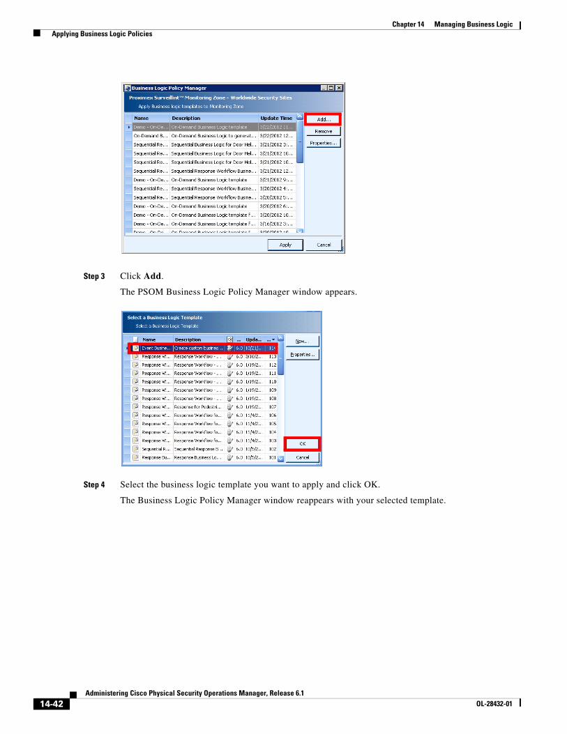
14-42Administering Cisco Physical Security Operations Manager, Release 6.1
OL-28432-01
Chapter 14 Managing Business Logic Applying Business Logic Policies
Step 3 Click Add.
The PSOM Business Logic Policy Manager window appears.
Step 4 Select the business logic template you want to apply and click OK.
The Business Logic Policy Manager window reappears with your selected template.
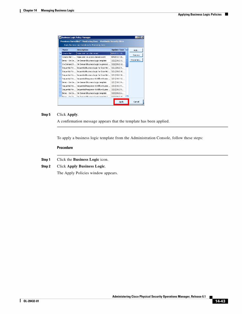
14-43Administering Cisco Physical Security Operations Manager, Release 6.1
OL-28432-01
Chapter 14 Managing Business Logic Applying Business Logic Policies
Step 5 Click Apply.
A confirmation message appears that the template has been applied.
To apply a business logic template from the Administration Console, follow these steps:
Procedure
Step 1 Click the Business Logic icon.
Step 2 Click Apply Business Logic.
The Apply Policies window appears.
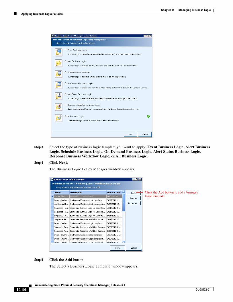
14-44Administering Cisco Physical Security Operations Manager, Release 6.1
OL-28432-01
Chapter 14 Managing Business Logic Applying Business Logic Policies
Step 3 Select the type of business logic template you want to apply: Event Business Logic, Alert Business Logic, Schedule Business Logic, On-Demand Business Logic, Alert Status Business Logic, Response Business Workflow Logic, or All Business Logic.
Step 4 Click Next.
The Business Logic Policy Manager window appears.
Step 5 Click the Add button.
The Select a Business Logic Template window appears.
Click the Add button to add a business logic template.
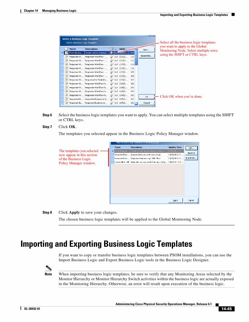
14-45Administering Cisco Physical Security Operations Manager, Release 6.1
OL-28432-01
Chapter 14 Managing Business Logic Importing and Exporting Business Logic Templates
Step 6 Select the business logic templates you want to apply. You can select multiple templates using the SHIFT or CTRL keys.
Step 7 Click OK.
The templates you selected appear in the Business Logic Policy Manager window.
Step 8 Click Apply to save your changes.
The chosen business logic templates will be applied to the Global Monitoring Node.
Importing and Exporting Business Logic TemplatesIf you want to copy or transfer business logic templates between PSOM installations, you can use the Import Business Logic and Export Business Logic tools in the Business Logic Designer.
Note When importing business logic templates, be sure to verify that any Monitoring Areas selected by the Monitor Hierarchy or Monitor Hierarchy Switch activities within the business logic are actually exposed in the Monitoring Hierarchy. Otherwise, an error will result upon execution of the business logic.
Select all the business logic templates you want to apply to the Global Monitoring Node. Select multiple rows using the SHIFT or CTRL keys.
Click OK when you’re done.
The templates you selected now appear in this section of the Business Logic Policy Manager window.
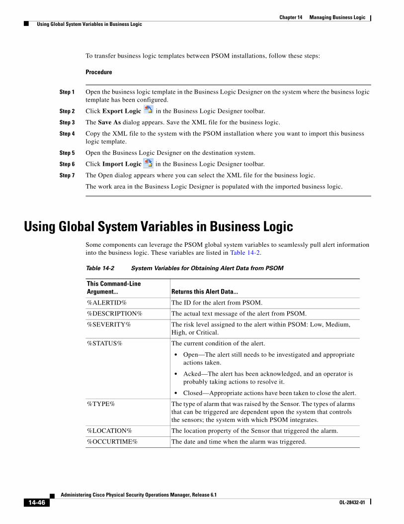
14-46Administering Cisco Physical Security Operations Manager, Release 6.1
OL-28432-01
Chapter 14 Managing Business Logic Using Global System Variables in Business Logic
To transfer business logic templates between PSOM installations, follow these steps:
Procedure
Step 1 Open the business logic template in the Business Logic Designer on the system where the business logic template has been configured.
Step 2 Click Export Logic in the Business Logic Designer toolbar.
Step 3 The Save As dialog appears. Save the XML file for the business logic.
Step 4 Copy the XML file to the system with the PSOM installation where you want to import this business logic template.
Step 5 Open the Business Logic Designer on the destination system.
Step 6 Click Import Logic in the Business Logic Designer toolbar.
Step 7 The Open dialog appears where you can select the XML file for the business logic.
The work area in the Business Logic Designer is populated with the imported business logic.
Using Global System Variables in Business LogicSome components can leverage the PSOM global system variables to seamlessly pull alert information into the business logic. These variables are listed in Table 14-2.
Table 14-2 System Variables for Obtaining Alert Data from PSOM
This Command-Line Argument... Returns this Alert Data...
%ALERTID% The ID for the alert from PSOM.
%DESCRIPTION% The actual text message of the alert from PSOM.
%SEVERITY% The risk level assigned to the alert within PSOM: Low, Medium, High, or Critical.
%STATUS% The current condition of the alert.
• Open—The alert still needs to be investigated and appropriate actions taken.
• Acked—The alert has been acknowledged, and an operator is probably taking actions to resolve it.
• Closed—Appropriate actions have been taken to close the alert.
%TYPE% The type of alarm that was raised by the Sensor. The types of alarms that can be triggered are dependent upon the system that controls the sensors; the system with which PSOM integrates.
%LOCATION% The location property of the Sensor that triggered the alarm.
%OCCURTIME% The date and time when the alarm was triggered.
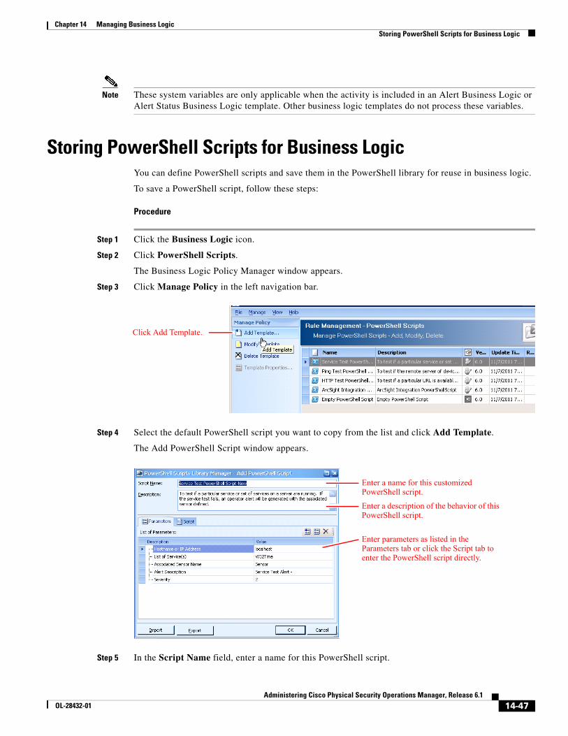
14-47Administering Cisco Physical Security Operations Manager, Release 6.1
OL-28432-01
Chapter 14 Managing Business Logic Storing PowerShell Scripts for Business Logic
Note These system variables are only applicable when the activity is included in an Alert Business Logic or Alert Status Business Logic template. Other business logic templates do not process these variables.
Storing PowerShell Scripts for Business LogicYou can define PowerShell scripts and save them in the PowerShell library for reuse in business logic.
To save a PowerShell script, follow these steps:
Procedure
Step 1 Click the Business Logic icon.
Step 2 Click PowerShell Scripts.
The Business Logic Policy Manager window appears.
Step 3 Click Manage Policy in the left navigation bar.
Step 4 Select the default PowerShell script you want to copy from the list and click Add Template.
The Add PowerShell Script window appears.
Step 5 In the Script Name field, enter a name for this PowerShell script.
Click Add Template.
Enter a name for this customized PowerShell script.
Enter a description of the behavior of this PowerShell script.
Enter parameters as listed in the Parameters tab or click the Script tab to enter the PowerShell script directly.
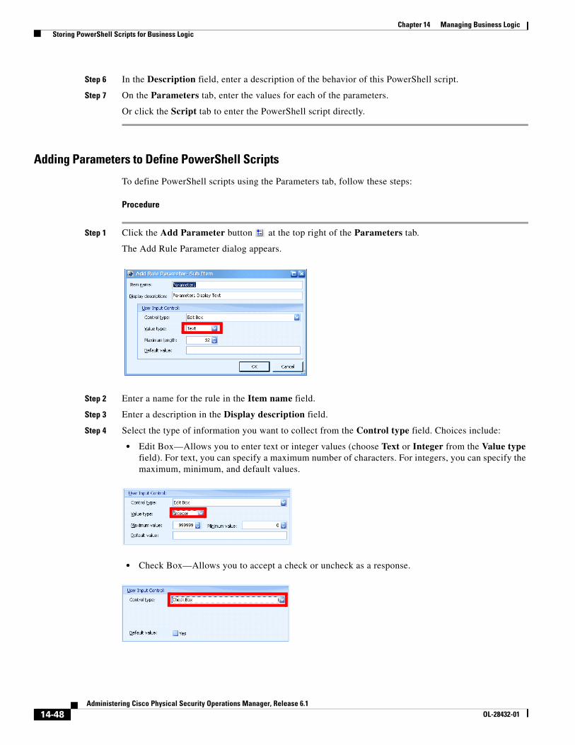
14-48Administering Cisco Physical Security Operations Manager, Release 6.1
OL-28432-01
Chapter 14 Managing Business Logic Storing PowerShell Scripts for Business Logic
Step 6 In the Description field, enter a description of the behavior of this PowerShell script.
Step 7 On the Parameters tab, enter the values for each of the parameters.
Or click the Script tab to enter the PowerShell script directly.
Adding Parameters to Define PowerShell Scripts
To define PowerShell scripts using the Parameters tab, follow these steps:
Procedure
Step 1 Click the Add Parameter button at the top right of the Parameters tab.
The Add Rule Parameter dialog appears.
Step 2 Enter a name for the rule in the Item name field.
Step 3 Enter a description in the Display description field.
Step 4 Select the type of information you want to collect from the Control type field. Choices include:
• Edit Box—Allows you to enter text or integer values (choose Text or Integer from the Value type field). For text, you can specify a maximum number of characters. For integers, you can specify the maximum, minimum, and default values.
• Check Box—Allows you to accept a check or uncheck as a response.
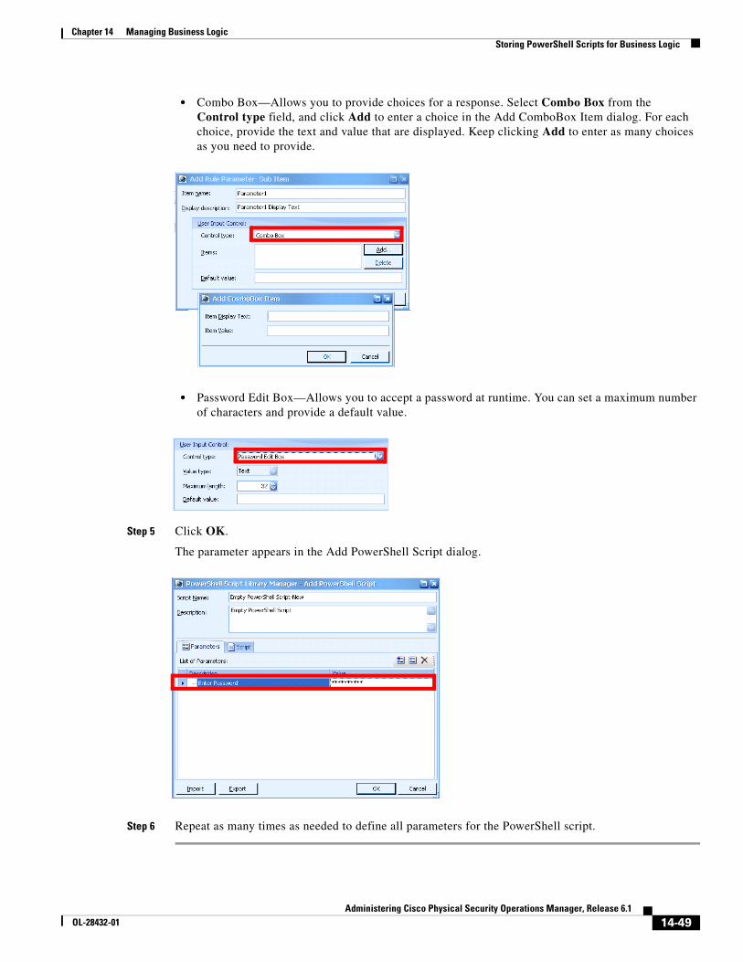
14-49Administering Cisco Physical Security Operations Manager, Release 6.1
OL-28432-01
Chapter 14 Managing Business Logic Storing PowerShell Scripts for Business Logic
• Combo Box—Allows you to provide choices for a response. Select Combo Box from the Control type field, and click Add to enter a choice in the Add ComboBox Item dialog. For each choice, provide the text and value that are displayed. Keep clicking Add to enter as many choices as you need to provide.
• Password Edit Box—Allows you to accept a password at runtime. You can set a maximum number of characters and provide a default value.
Step 5 Click OK.
The parameter appears in the Add PowerShell Script dialog.
Step 6 Repeat as many times as needed to define all parameters for the PowerShell script.
14-50Administering Cisco Physical Security Operations Manager, Release 6.1
OL-28432-01
Chapter 14 Managing Business Logic Storing PowerShell Scripts for Business Logic
Adding Scripts to the Script Area
If you want to write the PowerShell script in a different script editor (such as Notepad or an open source tool like Power GUI Editor), click the button in the Script area, and navigate to select your script editor. Once you’ve finished writing and debugging your code, you can copy and paste it into the text area of the Add PowerShell Script window. See the “Setting Up PowerShell Scripts” section on page 14-50, the “PowerShell Script Format” section on page 14-51, the “Passing Objects in PowerShell Scripts Using Script Variables” section on page 14-52, and the “Understanding Activity Contexts” section on page 14-54 for information you’ll need to write PowerShell scripts directly in the Script area.
Setting Up PowerShell ScriptsYou can set up PowerShell Scripts to perform a variety of functions within PSOM. PowerShell Scripts can be used as part of a business logic policy to execute custom scripts. Through Microsoft’s scripting language, you can predefine specific logic, or issue commands and actions to be taken on external security or related systems as a part of the security workflow or process. For example, you could use a PowerShell Action component to correlate data with existing systems including Microsoft SQL Server and Exchange Server.
When creating PowerShell Scripts, you can copy and paste code to create the script, and you can add user interface controls to enable script variables to be set at runtime.
PowerShell Scripts are currently deployed as part of a business logic template; therefore, you do not need to apply a PowerShell Script to Monitoring Areas.
Note You must have PowerShell installed on your system to execute PowerShell Action components. PowerShell requires Windows XP SP2 or later, and Windows Server 2003 SP1 or later. You can download PowerShell from the Microsoft website.
In your PowerShell Script, you can issue the global variables shown in Table 14-3 to obtain data from PSOM when using an Alert Business Logic or Alert Status Business Logic template.
Note For more concise and flexible scripts, you can pass objects into and out of PowerShell components within business logic. See the “Passing Objects in PowerShell Scripts Using Script Variables” section on page 14-52.
Table 14-3 Global variables for obtaining alert data from PSOM
This Global Variable... Returns this Alert Data...
$global:AlertID The ID for the alert from PSOM.
$global:AlertDescription The actual text message of the alert from PSOM.
$global:AlertSeverity The risk level assigned to the alert within PSOM: Low, Medium, High, or Critical.
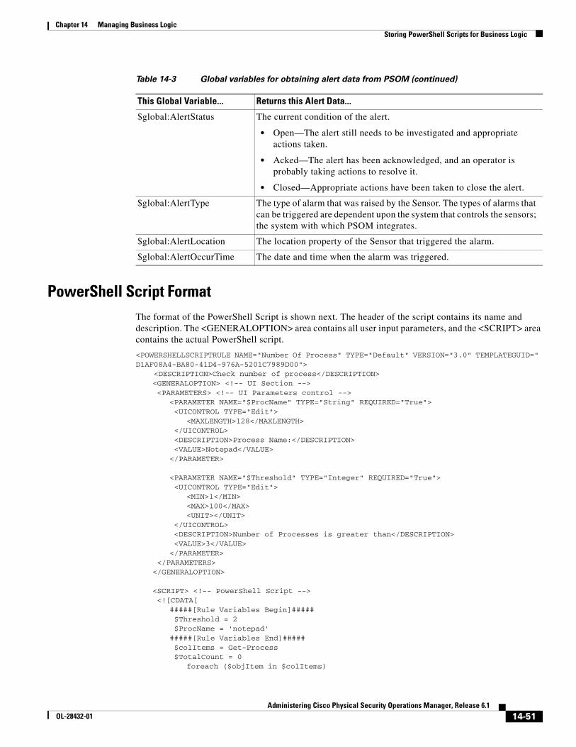
14-51Administering Cisco Physical Security Operations Manager, Release 6.1
OL-28432-01
Chapter 14 Managing Business Logic Storing PowerShell Scripts for Business Logic
PowerShell Script FormatThe format of the PowerShell Script is shown next. The header of the script contains its name and description. The <GENERALOPTION> area contains all user input parameters, and the <SCRIPT> area contains the actual PowerShell script.
<POWERSHELLSCRIPTRULE NAME="Number Of Process" TYPE="Default" VERSION="3.0" TEMPLATEGUID=" D1AF08A4-BA80-41D4-976A-5201C7989D00"> <DESCRIPTION>Check number of process</DESCRIPTION>
<GENERALOPTION> <!-- UI Section --> <PARAMETERS> <!-- UI Parameters control -->
<PARAMETER NAME="$ProcName" TYPE="String" REQUIRED="True"> <UICONTROL TYPE="Edit">
<MAXLENGTH>128</MAXLENGTH> </UICONTROL> <DESCRIPTION>Process Name:</DESCRIPTION> <VALUE>Notepad</VALUE></PARAMETER>
<PARAMETER NAME="$Threshold" TYPE="Integer" REQUIRED="True"> <UICONTROL TYPE="Edit">
<MIN>1</MIN><MAX>100</MAX><UNIT></UNIT>
</UICONTROL> <DESCRIPTION>Number of Processes is greater than</DESCRIPTION> <VALUE>3</VALUE></PARAMETER>
</PARAMETERS></GENERALOPTION>
<SCRIPT> <!-- PowerShell Script --> <![CDATA[
#####[Rule Variables Begin]##### $Threshold = 2 $ProcName = 'notepad'#####[Rule Variables End]##### $colItems = Get-Process $TotalCount = 0
foreach ($objItem in $colItems)
$global:AlertStatus The current condition of the alert.
• Open—The alert still needs to be investigated and appropriate actions taken.
• Acked—The alert has been acknowledged, and an operator is probably taking actions to resolve it.
• Closed—Appropriate actions have been taken to close the alert.
$global:AlertType The type of alarm that was raised by the Sensor. The types of alarms that can be triggered are dependent upon the system that controls the sensors; the system with which PSOM integrates.
$global:AlertLocation The location property of the Sensor that triggered the alarm.
$global:AlertOccurTime The date and time when the alarm was triggered.
Table 14-3 Global variables for obtaining alert data from PSOM (continued)
This Global Variable... Returns this Alert Data...
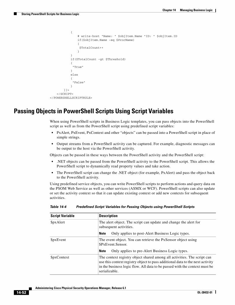
14-52Administering Cisco Physical Security Operations Manager, Release 6.1
OL-28432-01
Chapter 14 Managing Business Logic Storing PowerShell Scripts for Business Logic
{# write-host "Name: " $objItem.Name "ID: " $objItem.IDif($objItem.Name -eq $ProcName){ $TotalCount++}
}if($TotalCount -gt $Threshold){ "True"}else{ "False"}
]]></SCRIPT>
</POWERSHELLSCRIPTRULE>
Passing Objects in PowerShell Scripts Using Script VariablesWhen using PowerShell scripts in Business Logic templates, you can pass objects into the PowerShell script as well as from the PowerShell script using predefined script variables:
• PxAlert, PxEvent, PxContext and other “objects” can be passed into a PowerShell script in place of simple strings.
• Output streams from a PowerShell activity can be captured. For example, diagnostic messages can be output to the host via the PowerShell activity.
Objects can be passed in these ways between the PowerShell activity and the PowerShell script:
• .NET objects can be passed from the PowerShell activity to the PowerShell script. This allows the PowerShell script to dynamically read property values and take action.
• The PowerShell script can change the .NET object (for example, PxAlert) and pass the object back to the PowerShell activity.
Using predefined service objects, you can write PowerShell scripts to perform actions and query data on the PSOM Web Service as well as other services (ASMX or WCF). PowerShell scripts can also update or set the activity context so that it can update existing context or add new contexts for subsequent activities.
Table 14-4 Predefined Script Variables for Passing Objects using PowerShell Scripts
Script Variable Description
$pxAlert The alert object. The script can update and change the alert for subsequent activities.
Note Only applies to post-Alert Business Logic types.
$pxEvent The event object. You can retrieve the PxSensor object using $PxEvent.Sensor.
Note Only applies to pre-Alert Business Logic types.
$pxContext The context registry object shared among all activities. The script can use this context registry object to pass additional data to the next activity in the business logic flow. All data to be passed with the context must be serializable.
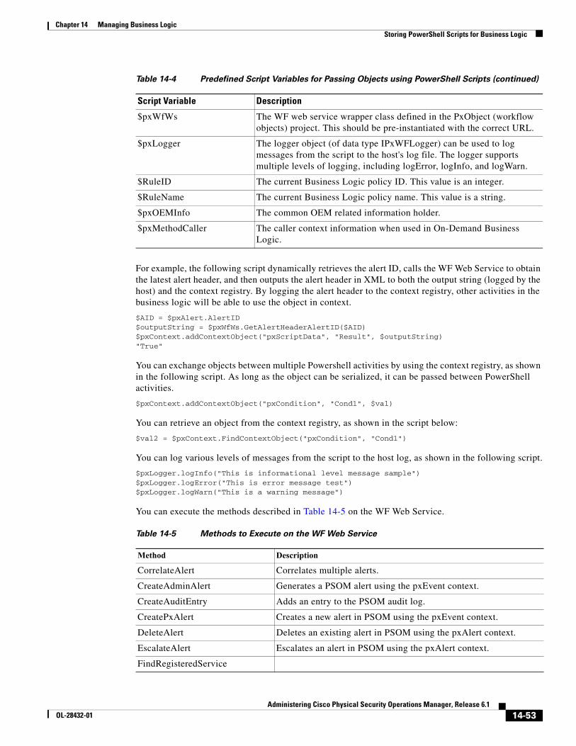
14-53Administering Cisco Physical Security Operations Manager, Release 6.1
OL-28432-01
Chapter 14 Managing Business Logic Storing PowerShell Scripts for Business Logic
For example, the following script dynamically retrieves the alert ID, calls the WF Web Service to obtain the latest alert header, and then outputs the alert header in XML to both the output string (logged by the host) and the context registry. By logging the alert header to the context registry, other activities in the business logic will be able to use the object in context.
$AID = $pxAlert.AlertID$outputString = $pxWfWs.GetAlertHeaderAlertID($AID)$pxContext.addContextObject("pxScriptData", "Result", $outputString)"True"
You can exchange objects between multiple Powershell activities by using the context registry, as shown in the following script. As long as the object can be serialized, it can be passed between PowerShell activities.
$pxContext.addContextObject("pxCondition", "Cond1", $val)
You can retrieve an object from the context registry, as shown in the script below:
$val2 = $pxContext.FindContextObject("pxCondition", "Cond1")
You can log various levels of messages from the script to the host log, as shown in the following script.
$pxLogger.logInfo("This is informational level message sample")$pxLogger.logError("This is error message test")$pxLogger.logWarn("This is a warning message")
You can execute the methods described in Table 14-5 on the WF Web Service.
$pxWfWs The WF web service wrapper class defined in the PxObject (workflow objects) project. This should be pre-instantiated with the correct URL.
$pxLogger The logger object (of data type IPxWFLogger) can be used to log messages from the script to the host's log file. The logger supports multiple levels of logging, including logError, logInfo, and logWarn.
$RuleID The current Business Logic policy ID. This value is an integer.
$RuleName The current Business Logic policy name. This value is a string.
$pxOEMInfo The common OEM related information holder.
$pxMethodCaller The caller context information when used in On-Demand Business Logic.
Table 14-4 Predefined Script Variables for Passing Objects using PowerShell Scripts (continued)
Script Variable Description
Table 14-5 Methods to Execute on the WF Web Service
Method Description
CorrelateAlert Correlates multiple alerts.
CreateAdminAlert Generates a PSOM alert using the pxEvent context.
CreateAuditEntry Adds an entry to the PSOM audit log.
CreatePxAlert Creates a new alert in PSOM using the pxEvent context.
DeleteAlert Deletes an existing alert in PSOM using the pxAlert context.
EscalateAlert Escalates an alert in PSOM using the pxAlert context.
FindRegisteredService
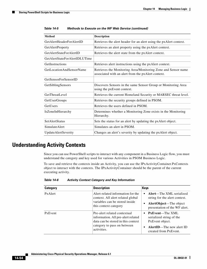
14-54Administering Cisco Physical Security Operations Manager, Release 6.1
OL-28432-01
Chapter 14 Managing Business Logic Storing PowerShell Scripts for Business Logic
Understanding Activity ContextsSince you can use PowerShell scripts to interact with any component in a Business Logic flow, you must understand the category and key used for various Activities in PSOM Business Logic.
To save and retrieve the contexts inside an Activity, you can use the IPxActivityContainer.PxContexts object to interact with the contexts. The IPxActivityContainer should be the parent of the current executing activity.
GetAlertHeaderForAlertID Retrieves the alert header for an alert using the pxAlert context.
GetAlertProperty Retrieves an alert property using the pxAlert context.
GetAlertStateForAlertID Retrieves the alert state from the pxAlert context.
GetAlertStateForAlertIDLUTime
GetInstructions Retrieves alert instructions using the pxAlert context.
GetLocationAndSensorName Retrieves the Monitoring Area/Monitoring Zone and Sensor name associated with an alert from the pxAlert context.
GetSensorForSensorID
GetSiblingSensors Discovers Sensors in the same Sensor Group or Monitoring Area using the pxEvent context.
GetThreatLevel Retrieves the current Homeland Security or MARSEC threat level.
GetUserGroups Retrieves the security groups defined in PSOM.
GetUsers Retrieves the users defined in PSOM.
IsZoneInHierarchy Determines whether a Monitoring Zone exists in the Monitoring Hierarchy.
SetAlertStatus Sets the status for an alert by updating the pxAlert object.
SimulateAlert Simulates an alert in PSOM.
UpdateAlertSeverity Changes an alert’s severity by updating the pxAlert object.
Table 14-5 Methods to Execute on the WF Web Service (continued)
Method Description
Table 14-6 Activity Context Category and Key Information
Category Description Keys
PxAlert Alert-related information for the context. All alert related global variables can be stored inside this context category
• Alert—The XML serialized string for the alert context.
• AlertObject—The object presentation of the WF alert.
PxEvent Pre-alert related contextual information. All pre-alert related data can be stored in this context category to pass on between activities.
• PxEvent—The XML serialized string of the PxEvent object.
• AlertID—The new alert ID created from PxEvent.
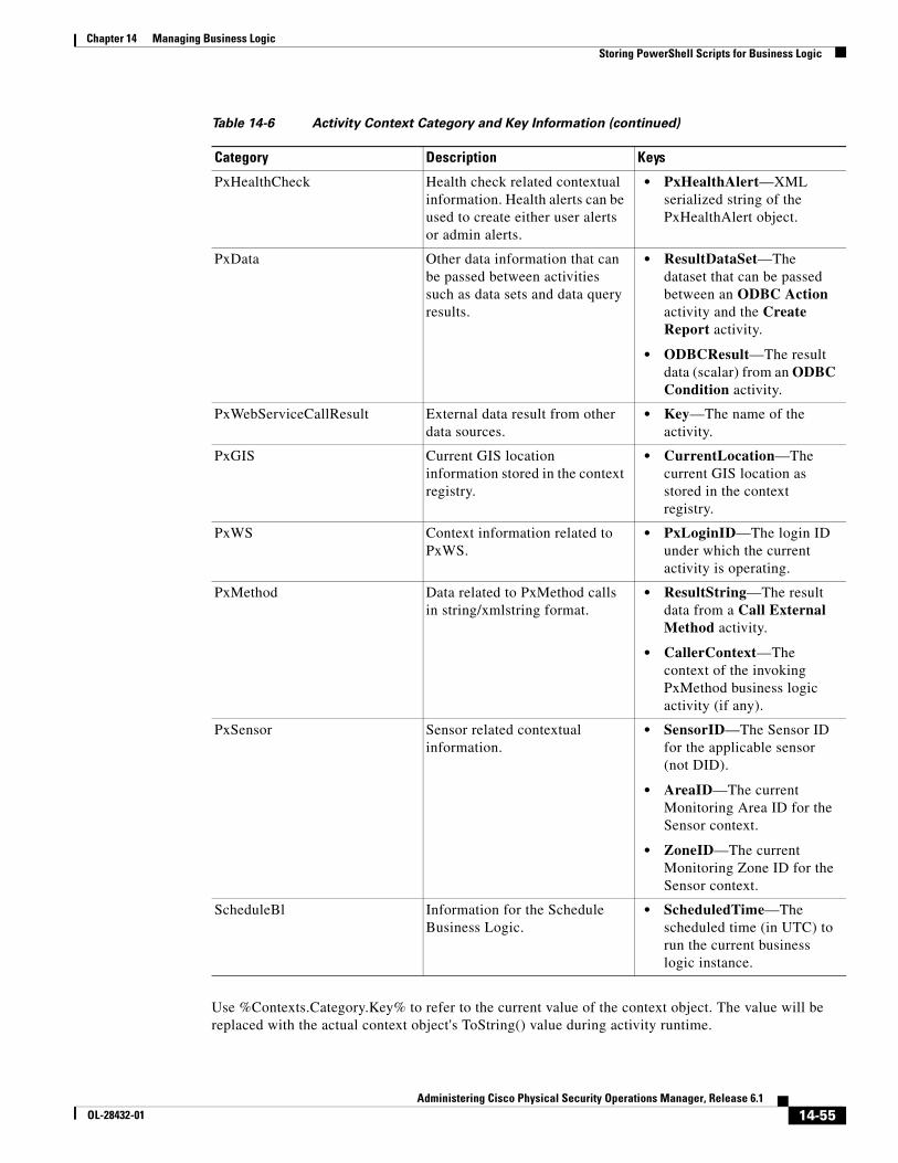
14-55Administering Cisco Physical Security Operations Manager, Release 6.1
OL-28432-01
Chapter 14 Managing Business Logic Storing PowerShell Scripts for Business Logic
Use %Contexts.Category.Key% to refer to the current value of the context object. The value will be replaced with the actual context object's ToString() value during activity runtime.
PxHealthCheck Health check related contextual information. Health alerts can be used to create either user alerts or admin alerts.
• PxHealthAlert—XML serialized string of the PxHealthAlert object.
PxData Other data information that can be passed between activities such as data sets and data query results.
• ResultDataSet—The dataset that can be passed between an ODBC Action activity and the Create Report activity.
• ODBCResult—The result data (scalar) from an ODBC Condition activity.
PxWebServiceCallResult External data result from other data sources.
• Key—The name of the activity.
PxGIS Current GIS location information stored in the context registry.
• CurrentLocation—The current GIS location as stored in the context registry.
PxWS Context information related to PxWS.
• PxLoginID—The login ID under which the current activity is operating.
PxMethod Data related to PxMethod calls in string/xmlstring format.
• ResultString—The result data from a Call External Method activity.
• CallerContext—The context of the invoking PxMethod business logic activity (if any).
PxSensor Sensor related contextual information.
• SensorID—The Sensor ID for the applicable sensor (not DID).
• AreaID—The current Monitoring Area ID for the Sensor context.
• ZoneID—The current Monitoring Zone ID for the Sensor context.
ScheduleBl Information for the Schedule Business Logic.
• ScheduledTime—The scheduled time (in UTC) to run the current business logic instance.
Table 14-6 Activity Context Category and Key Information (continued)
Category Description Keys
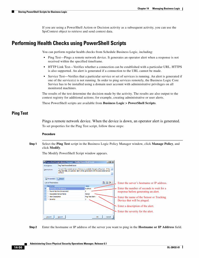
14-56Administering Cisco Physical Security Operations Manager, Release 6.1
OL-28432-01
Chapter 14 Managing Business Logic Storing PowerShell Scripts for Business Logic
If you are using a PowerShell Action or Decision activity as a subsequent activity, you can use the $pxContext object to retrieve and send context data.
Performing Health Checks using PowerShell ScriptsYou can perform regular health checks from Schedule Business Logic, including:
• Ping Test—Pings a remote network device. It generates an operator alert when a response is not received within the specified timeframe.
• HTTP Link Test—Verifies whether a connection can be established with a particular URL. HTTPS is also supported. An alert is generated if a connection to the URL cannot be made.
• Service Test—Verifies that a particular service or set of services is running. An alert is generated if one of the service(s) is not running. In order to ping services remotely, the Business Logic Core Service has to be installed using a domain user account with administrative privileges on all monitored machines.
The results of the test determine the decision made by the activity. The results are also output to the context registry for additional actions; for example, creating administrative or user alerts.
These PowerShell scripts are available from Business Logic > PowerShell Scripts.
Ping Test
Pings a remote network device. When the device is down, an operator alert is generated.To set properties for the Ping Test script, follow these steps:
Procedure
Step 1 Select the Ping Test script in the Business Logic Policy Manager window, click Manage Policy, and click Modify.
The Modify PowerShell Script window appears.
Step 2 Enter the hostname or IP address of the server you want to ping in the Hostname or IP Address field.
Enter the server’s hostname or IP address.
Enter the number of seconds to wait for a response before generating an alert.
Enter the name of the Sensor or Tracking Device that will be pinged.
Enter a description of the alert.
Enter the severity for the alert.
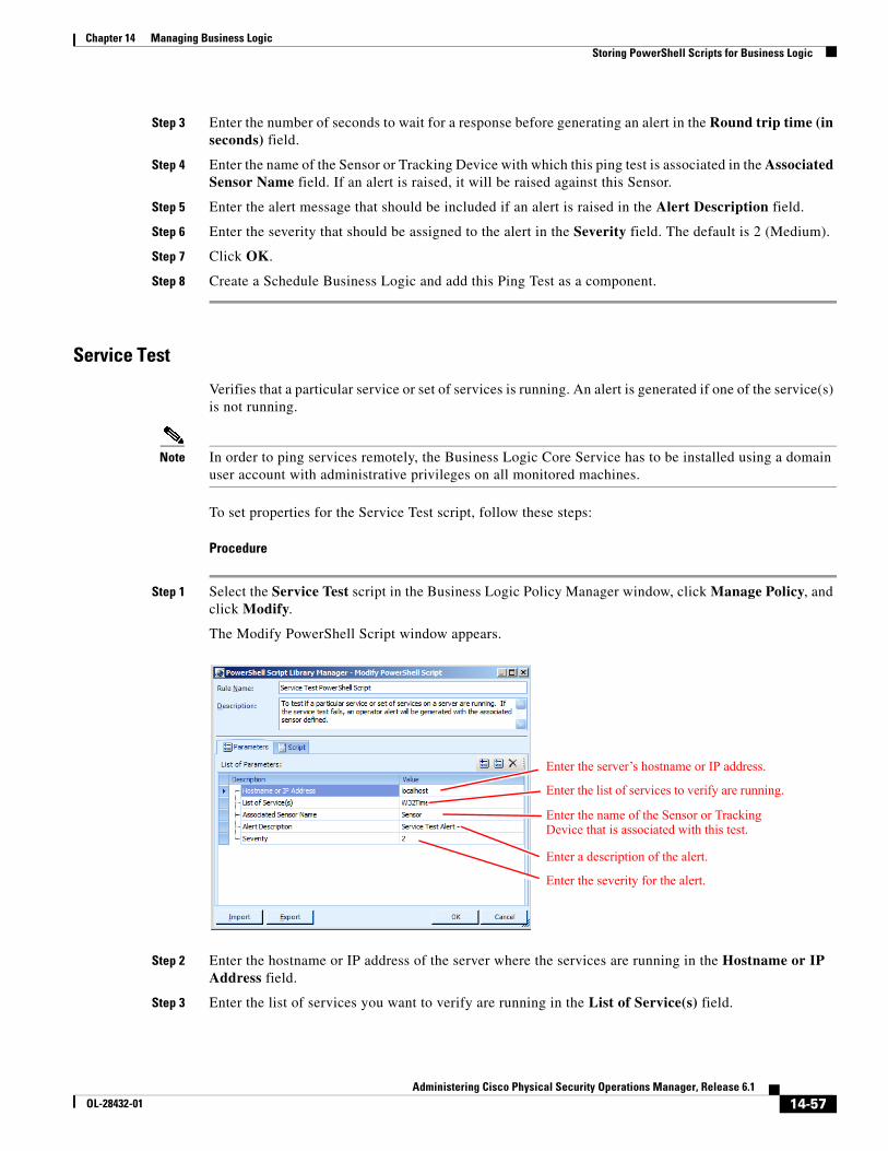
14-57Administering Cisco Physical Security Operations Manager, Release 6.1
OL-28432-01
Chapter 14 Managing Business Logic Storing PowerShell Scripts for Business Logic
Step 3 Enter the number of seconds to wait for a response before generating an alert in the Round trip time (in seconds) field.
Step 4 Enter the name of the Sensor or Tracking Device with which this ping test is associated in the Associated Sensor Name field. If an alert is raised, it will be raised against this Sensor.
Step 5 Enter the alert message that should be included if an alert is raised in the Alert Description field.
Step 6 Enter the severity that should be assigned to the alert in the Severity field. The default is 2 (Medium).
Step 7 Click OK.
Step 8 Create a Schedule Business Logic and add this Ping Test as a component.
Service Test
Verifies that a particular service or set of services is running. An alert is generated if one of the service(s) is not running.
Note In order to ping services remotely, the Business Logic Core Service has to be installed using a domain user account with administrative privileges on all monitored machines.
To set properties for the Service Test script, follow these steps:
Procedure
Step 1 Select the Service Test script in the Business Logic Policy Manager window, click Manage Policy, and click Modify.
The Modify PowerShell Script window appears.
Step 2 Enter the hostname or IP address of the server where the services are running in the Hostname or IP Address field.
Step 3 Enter the list of services you want to verify are running in the List of Service(s) field.
Enter the server’s hostname or IP address.
Enter the list of services to verify are running.
Enter the name of the Sensor or Tracking Device that is associated with this test.
Enter a description of the alert.
Enter the severity for the alert.
14-58Administering Cisco Physical Security Operations Manager, Release 6.1
OL-28432-01
Chapter 14 Managing Business Logic Storing PowerShell Scripts for Business Logic
Step 4 Enter the name of the Sensor or Tracking Device with which this services test is associated in the Associated Sensor Name field. If an alert is raised, it will be raised against this Sensor.
Step 5 Enter the alert message that should be included if an alert is raised in the Alert Description field.
Step 6 Enter the severity that should be assigned to the alert in the Severity field. The default is 2 (Medium).
Step 7 Click OK.
Step 8 Create a Schedule Business Logic and add this Service Test as a component.
HTTP Test
Verifies whether a connection can be established with a particular URL. HTTPS is also supported. An alert is generated if a connection to the URL cannot be made.
To set properties for the HTPP Test script, follow these steps:
Procedure
Step 1 Select the HTTP Test script in the Business Logic Policy Manager window, click Manage Policy, and click Modify.
The Modify PowerShell Script window appears.
Step 2 Enter the URL you want to connect to in the URL field.
Step 3 Enter the name of the Sensor or Tracking Device with which this HTTP test is associated in the Associated Sensor Name field. If an alert is raised, it will be raised against this Sensor.
Step 4 Enter the alert message that should be included if an alert is raised in the Alert Description field.
Step 5 Enter the severity that should be assigned to the alert in the Severity field. The default is 2 (Medium).
Step 6 If authentication is required by the URL with which you are connecting, enter login credentials in the User Name and User Password fields.
Step 7 Click OK.
Step 8 Create a Schedule Business Logic and add this HTTP Test as a component.
C H A P T E R
15-1Administering Cisco Physical Security Operations Manager, Release 6.1
OL-28432-01
15Business Logic Component Reference
Using business logic templates, you can capture the unique business processes and procedures for responding to alerts within your environment. Business logic templates are built using different components that can be dragged into your workspace to define the conditions that must be met for certain actions to occur.
This chapter includes these topics:
• Understanding Business Logic Components, page 15-2
• Configuring Add Alert Note Properties, page 15-10
• Configuring Call Everbridge Properties, page 15-10
• Configuring Call External Method Properties, page 15-12
• Configuring Call Web Service Properties, page 15-15
• Configuring Camera Control Properties, page 15-16
• Configuring Create Admin Alert Properties, page 15-17
• Configuring Create Alert Properties, page 15-18
• Configuring Create Report Properties, page 15-21
• Configuring Delay Properties, page 15-22
• Configuring DOS Command Properties, page 15-23
• Configuring HTTP Send Properties, page 15-24
• Configuring IPICS Dispatch Alert Properties, page 15-26
• Configuring IPICS Notify Alert Properties, page 15-27
• Configuring ODBC Action Properties, page 15-27
• Configuring PowerShell Action Properties, page 15-28
• Configuring Send Email Properties, page 15-30
• Configuring Sensor Synchronization Properties, page 15-31
• Configuring Set Alert Context Properties, page 15-32
• Configuring Set Alert Instruction Properties, page 15-32
• Configuring Set Alert Severity Properties, page 15-33
• Configuring Set Alert Status Properties, page 15-33
• Configuring SNMP Request Properties, page 15-34
• Configuring Alert Condition Properties, page 15-36
15-2Administering Cisco Physical Security Operations Manager, Release 6.1
OL-28432-01
Chapter 15 Business Logic Component Reference Understanding Business Logic Components
• Configuring Geo-Location Properties, page 15-38
• Configuring Geo-Location Switch Properties, page 15-39
• Configuring Monitor Hierarchy Properties, page 15-41
• Configuring Monitor Hierarchy Switch Properties, page 15-42
• Configuring Schedule Condition Properties, page 15-43
• Configuring Sensor Event Count Correlation Properties, page 15-44
• Configuring Threat Level Properties, page 15-45
• Using Decision Components, page 15-46
• Using Flow Components, page 15-46
• Using Switch Components, page 15-47
• Configuring Manual Decision Properties, page 15-47
• Configuring Manual Switch Properties, page 15-49
• Using Parallel Flow Components, page 15-51
• Configuring Simulate Alert Properties, page 15-52
• Configuring Simulate Contexts Properties, page 15-52
• Configuring Simulate Event Properties, page 15-53
• Configuring Correlate Condition Properties, page 15-54
• Configuring Event Map Filter Properties, page 15-59
• Configuring Escalate Condition Properties, page 15-63
• Configuring ODBC Condition Properties, page 15-64
• Configuring PowerShell Decision Properties, page 15-65
• Configuring RSS Alerts Properties, page 15-71
• Configuring Acknowledge Task Properties, page 15-72
• Configuring Manual Task Execution Properties, page 15-74
• Configuring Text Box Task Properties, page 15-76
• Configuring View Document Task Properties, page 15-77
• Configuring View Video Task Properties, page 15-78
• Configuring Lock Door Properties, page 15-80
• Configuring Open Door Properties, page 15-81
• Configuring Open Door Momentarily Properties, page 15-82
Understanding Business Logic ComponentsBusiness logic components include these basic types:
• Actions—These components define what should happen when conditions are met and have a single output point. For example, the Start component launches the execution of the business logic template; every business logic template must begin with a Start component.
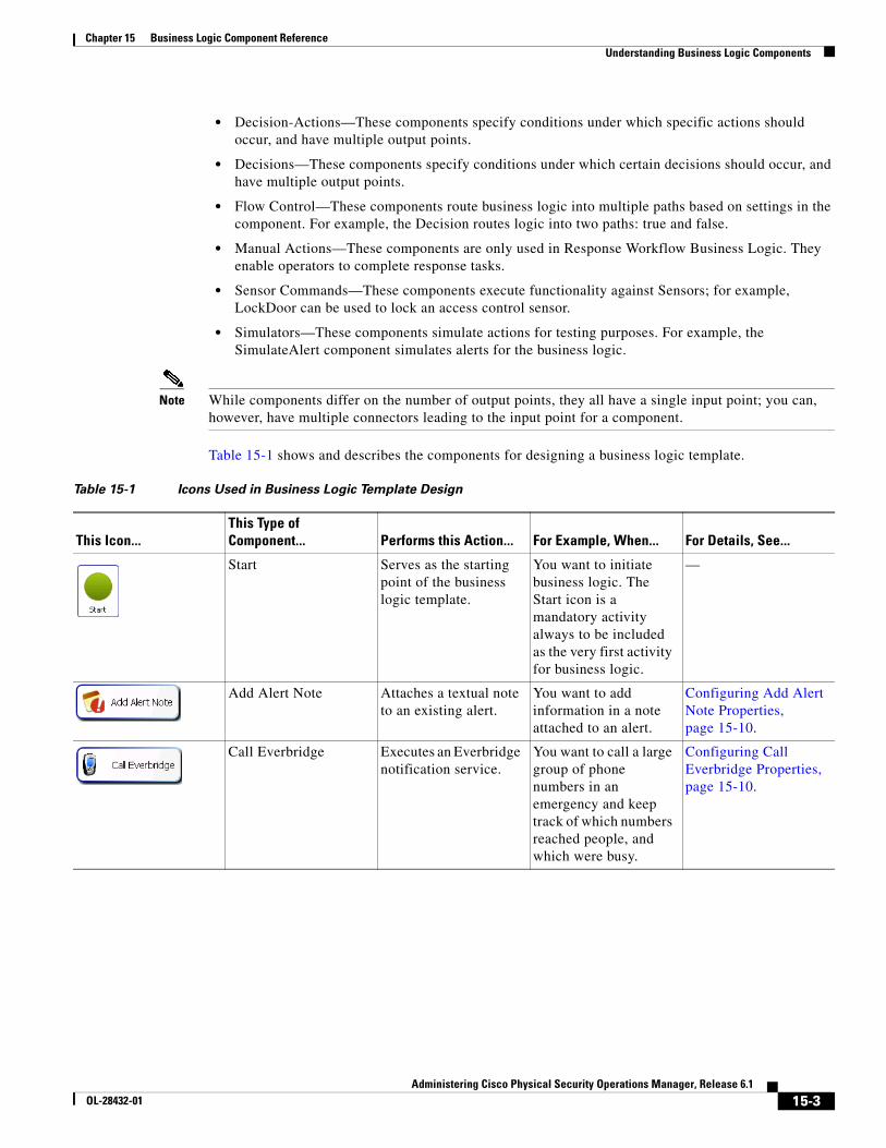
15-3Administering Cisco Physical Security Operations Manager, Release 6.1
OL-28432-01
Chapter 15 Business Logic Component Reference Understanding Business Logic Components
• Decision-Actions—These components specify conditions under which specific actions should occur, and have multiple output points.
• Decisions—These components specify conditions under which certain decisions should occur, and have multiple output points.
• Flow Control—These components route business logic into multiple paths based on settings in the component. For example, the Decision routes logic into two paths: true and false.
• Manual Actions—These components are only used in Response Workflow Business Logic. They enable operators to complete response tasks.
• Sensor Commands—These components execute functionality against Sensors; for example, LockDoor can be used to lock an access control sensor.
• Simulators—These components simulate actions for testing purposes. For example, the SimulateAlert component simulates alerts for the business logic.
Note While components differ on the number of output points, they all have a single input point; you can, however, have multiple connectors leading to the input point for a component.
Table 15-1 shows and describes the components for designing a business logic template.
Table 15-1 Icons Used in Business Logic Template Design
This Icon...This Type of Component... Performs this Action... For Example, When... For Details, See...
Start Serves as the starting point of the business logic template.
You want to initiate business logic. The Start icon is a mandatory activity always to be included as the very first activity for business logic.
—
Add Alert Note Attaches a textual note to an existing alert.
You want to add information in a note attached to an alert.
Configuring Add Alert Note Properties, page 15-10.
Call Everbridge Executes an Everbridge notification service.
You want to call a large group of phone numbers in an emergency and keep track of which numbers reached people, and which were busy.
Configuring Call Everbridge Properties, page 15-10.
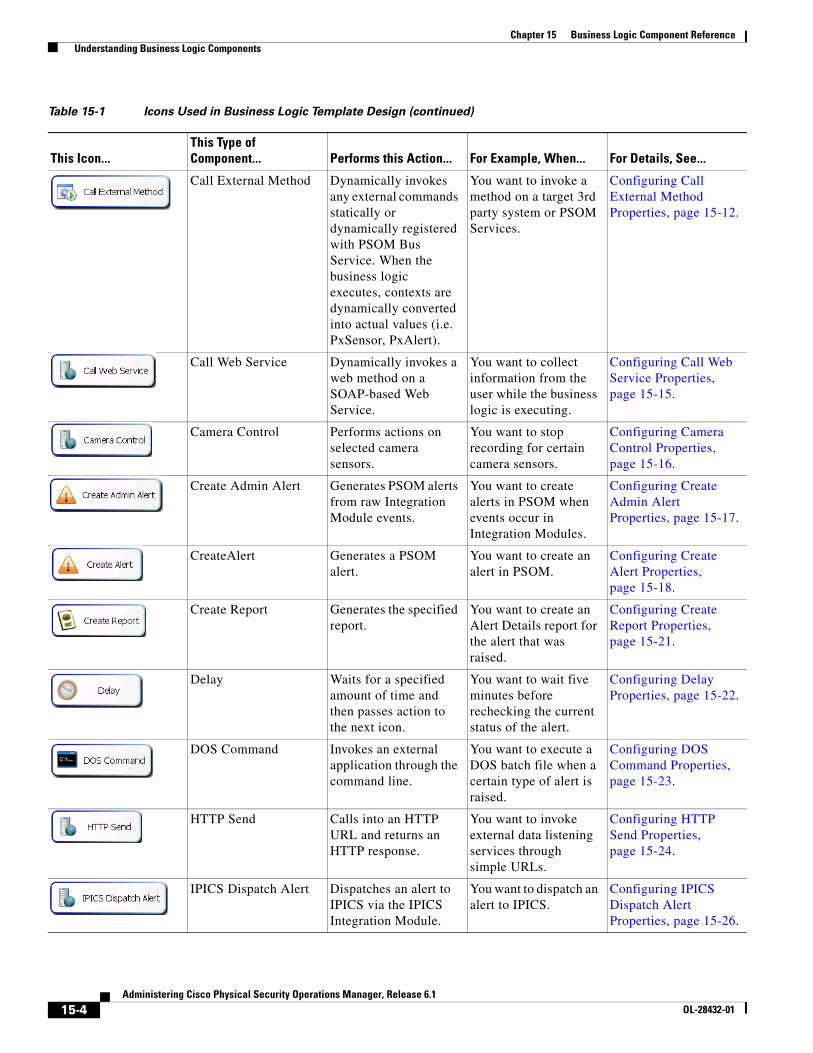
15-4Administering Cisco Physical Security Operations Manager, Release 6.1
OL-28432-01
Chapter 15 Business Logic Component Reference Understanding Business Logic Components
Call External Method Dynamically invokes any external commands statically or dynamically registered with PSOM Bus Service. When the business logic executes, contexts are dynamically converted into actual values (i.e. PxSensor, PxAlert).
You want to invoke a method on a target 3rd party system or PSOM Services.
Configuring Call External Method Properties, page 15-12.
Call Web Service Dynamically invokes a web method on a SOAP-based Web Service.
You want to collect information from the user while the business logic is executing.
Configuring Call Web Service Properties, page 15-15.
Camera Control Performs actions on selected camera sensors.
You want to stop recording for certain camera sensors.
Configuring Camera Control Properties, page 15-16.
Create Admin Alert Generates PSOM alerts from raw Integration Module events.
You want to create alerts in PSOM when events occur in Integration Modules.
Configuring Create Admin Alert Properties, page 15-17.
CreateAlert Generates a PSOM alert.
You want to create an alert in PSOM.
Configuring Create Alert Properties, page 15-18.
Create Report Generates the specified report.
You want to create an Alert Details report for the alert that was raised.
Configuring Create Report Properties, page 15-21.
Delay Waits for a specified amount of time and then passes action to the next icon.
You want to wait five minutes before rechecking the current status of the alert.
Configuring Delay Properties, page 15-22.
DOS Command Invokes an external application through the command line.
You want to execute a DOS batch file when a certain type of alert is raised.
Configuring DOS Command Properties, page 15-23.
HTTP Send Calls into an HTTP URL and returns an HTTP response.
You want to invoke external data listening services through simple URLs.
Configuring HTTP Send Properties, page 15-24.
IPICS Dispatch Alert Dispatches an alert to IPICS via the IPICS Integration Module.
You want to dispatch an alert to IPICS.
Configuring IPICS Dispatch Alert Properties, page 15-26.
Table 15-1 Icons Used in Business Logic Template Design (continued)
This Icon...This Type of Component... Performs this Action... For Example, When... For Details, See...
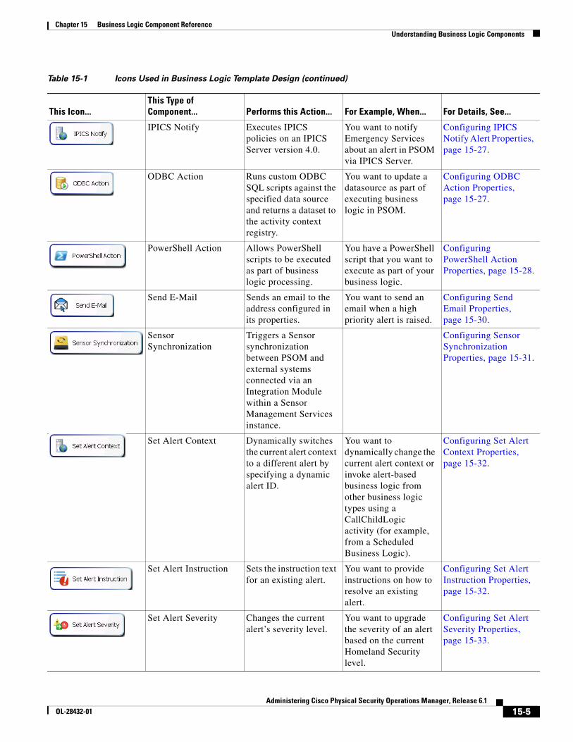
15-5Administering Cisco Physical Security Operations Manager, Release 6.1
OL-28432-01
Chapter 15 Business Logic Component Reference Understanding Business Logic Components
IPICS Notify Executes IPICS policies on an IPICS Server version 4.0.
You want to notify Emergency Services about an alert in PSOM via IPICS Server.
Configuring IPICS Notify Alert Properties, page 15-27.
ODBC Action Runs custom ODBC SQL scripts against the specified data source and returns a dataset to the activity context registry.
You want to update a datasource as part of executing business logic in PSOM.
Configuring ODBC Action Properties, page 15-27.
PowerShell Action Allows PowerShell scripts to be executed as part of business logic processing.
You have a PowerShell script that you want to execute as part of your business logic.
Configuring PowerShell Action Properties, page 15-28.
Send E-Mail Sends an email to the address configured in its properties.
You want to send an email when a high priority alert is raised.
Configuring Send Email Properties, page 15-30.
Sensor Synchronization
Triggers a Sensor synchronization between PSOM and external systems connected via an Integration Module within a Sensor Management Services instance.
Configuring Sensor Synchronization Properties, page 15-31.
Set Alert Context Dynamically switches the current alert context to a different alert by specifying a dynamic alert ID.
You want to dynamically change the current alert context or invoke alert-based business logic from other business logic types using a CallChildLogic activity (for example, from a Scheduled Business Logic).
Configuring Set Alert Context Properties, page 15-32.
Set Alert Instruction Sets the instruction text for an existing alert.
You want to provide instructions on how to resolve an existing alert.
Configuring Set Alert Instruction Properties, page 15-32.
Set Alert Severity Changes the current alert’s severity level.
You want to upgrade the severity of an alert based on the current Homeland Security level.
Configuring Set Alert Severity Properties, page 15-33.
Table 15-1 Icons Used in Business Logic Template Design (continued)
This Icon...This Type of Component... Performs this Action... For Example, When... For Details, See...
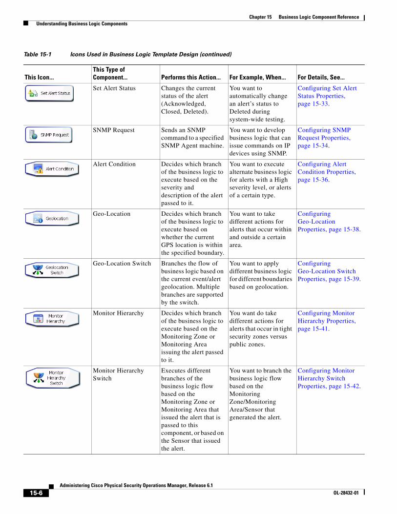
15-6Administering Cisco Physical Security Operations Manager, Release 6.1
OL-28432-01
Chapter 15 Business Logic Component Reference Understanding Business Logic Components
Set Alert Status Changes the current status of the alert (Acknowledged, Closed, Deleted).
You want to automatically change an alert’s status to Deleted during system-wide testing.
Configuring Set Alert Status Properties, page 15-33.
SNMP Request Sends an SNMP command to a specified SNMP Agent machine.
You want to develop business logic that can issue commands on IP devices using SNMP.
Configuring SNMP Request Properties, page 15-34.
Alert Condition Decides which branch of the business logic to execute based on the severity and description of the alert passed to it.
You want to execute alternate business logic for alerts with a High severity level, or alerts of a certain type.
Configuring Alert Condition Properties, page 15-36.
Geo-Location Decides which branch of the business logic to execute based on whether the current GPS location is within the specified boundary.
You want to take different actions for alerts that occur within and outside a certain area.
Configuring Geo-Location Properties, page 15-38.
Geo-Location Switch Branches the flow of business logic based on the current event/alert geolocation. Multiple branches are supported by the switch.
You want to apply different business logic for different boundaries based on geolocation.
Configuring Geo-Location Switch Properties, page 15-39.
Monitor Hierarchy Decides which branch of the business logic to execute based on the Monitoring Zone or Monitoring Area issuing the alert passed to it.
You want do take different actions for alerts that occur in tight security zones versus public zones.
Configuring Monitor Hierarchy Properties, page 15-41.
Monitor Hierarchy Switch
Executes different branches of the business logic flow based on the Monitoring Zone or Monitoring Area that issued the alert that is passed to this component, or based on the Sensor that issued the alert.
You want to branch the business logic flow based on the Monitoring Zone/Monitoring Area/Sensor that generated the alert.
Configuring Monitor Hierarchy Switch Properties, page 15-42.
Table 15-1 Icons Used in Business Logic Template Design (continued)
This Icon...This Type of Component... Performs this Action... For Example, When... For Details, See...
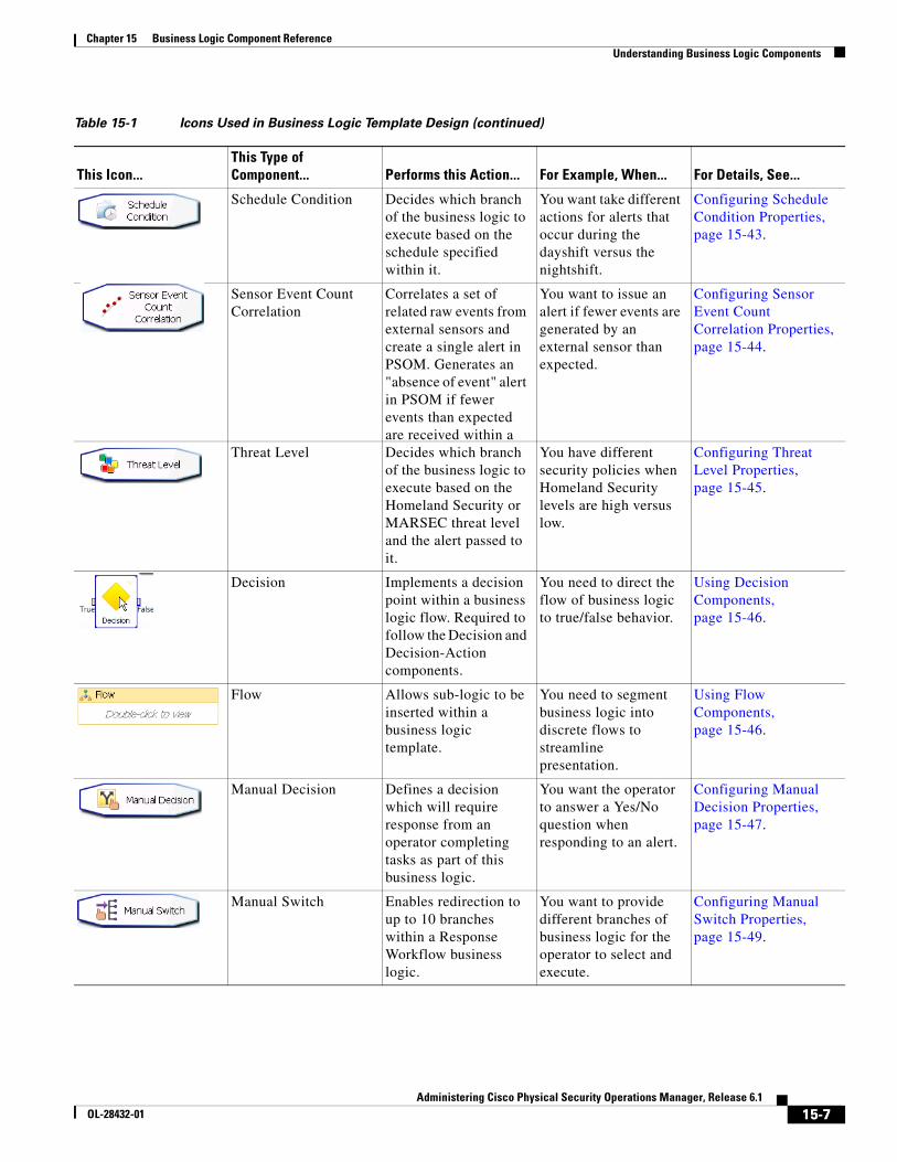
15-7Administering Cisco Physical Security Operations Manager, Release 6.1
OL-28432-01
Chapter 15 Business Logic Component Reference Understanding Business Logic Components
Schedule Condition Decides which branch of the business logic to execute based on the schedule specified within it.
You want take different actions for alerts that occur during the dayshift versus the nightshift.
Configuring Schedule Condition Properties, page 15-43.
Sensor Event Count Correlation
Correlates a set of related raw events from external sensors and create a single alert in PSOM. Generates an "absence of event" alert in PSOM if fewer events than expected are received within a
You want to issue an alert if fewer events are generated by an external sensor than expected.
Configuring Sensor Event Count Correlation Properties, page 15-44.
Threat Level Decides which branch of the business logic to execute based on the Homeland Security or MARSEC threat level and the alert passed to it.
You have different security policies when Homeland Security levels are high versus low.
Configuring Threat Level Properties, page 15-45.
Decision Implements a decision point within a business logic flow. Required to follow the Decision and Decision-Action components.
You need to direct the flow of business logic to true/false behavior.
Using Decision Components, page 15-46.
Flow Allows sub-logic to be inserted within a business logic template.
You need to segment business logic into discrete flows to streamline presentation.
Using Flow Components, page 15-46.
Manual Decision Defines a decision which will require response from an operator completing tasks as part of this business logic.
You want the operator to answer a Yes/No question when responding to an alert.
Configuring Manual Decision Properties, page 15-47.
Manual Switch Enables redirection to up to 10 branches within a Response Workflow business logic.
You want to provide different branches of business logic for the operator to select and execute.
Configuring Manual Switch Properties, page 15-49.
Table 15-1 Icons Used in Business Logic Template Design (continued)
This Icon...This Type of Component... Performs this Action... For Example, When... For Details, See...
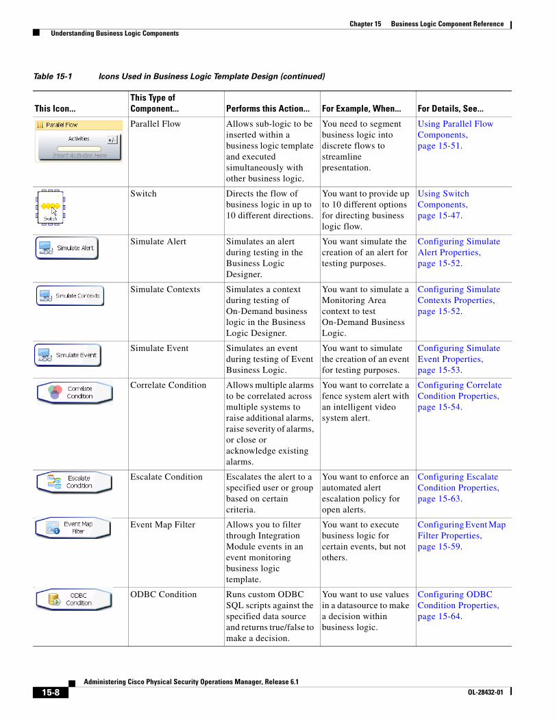
15-8Administering Cisco Physical Security Operations Manager, Release 6.1
OL-28432-01
Chapter 15 Business Logic Component Reference Understanding Business Logic Components
Parallel Flow Allows sub-logic to be inserted within a business logic template and executed simultaneously with other business logic.
You need to segment business logic into discrete flows to streamline presentation.
Using Parallel Flow Components, page 15-51.
Switch Directs the flow of business logic in up to 10 different directions.
You want to provide up to 10 different options for directing business logic flow.
Using Switch Components, page 15-47.
Simulate Alert Simulates an alert during testing in the Business Logic Designer.
You want simulate the creation of an alert for testing purposes.
Configuring Simulate Alert Properties, page 15-52.
Simulate Contexts Simulates a context during testing of On-Demand business logic in the Business Logic Designer.
You want to simulate a Monitoring Area context to test On-Demand Business Logic.
Configuring Simulate Contexts Properties, page 15-52.
Simulate Event Simulates an event during testing of Event Business Logic.
You want to simulate the creation of an event for testing purposes.
Configuring Simulate Event Properties, page 15-53.
Correlate Condition Allows multiple alarms to be correlated across multiple systems to raise additional alarms, raise severity of alarms, or close or acknowledge existing alarms.
You want to correlate a fence system alert with an intelligent video system alert.
Configuring Correlate Condition Properties, page 15-54.
Escalate Condition Escalates the alert to a specified user or group based on certain criteria.
You want to enforce an automated alert escalation policy for open alerts.
Configuring Escalate Condition Properties, page 15-63.
Event Map Filter Allows you to filter through Integration Module events in an event monitoring business logic template.
You want to execute business logic for certain events, but not others.
Configuring Event Map Filter Properties, page 15-59.
ODBC Condition Runs custom ODBC SQL scripts against the specified data source and returns true/false to make a decision.
You want to use values in a datasource to make a decision within business logic.
Configuring ODBC Condition Properties, page 15-64.
Table 15-1 Icons Used in Business Logic Template Design (continued)
This Icon...This Type of Component... Performs this Action... For Example, When... For Details, See...
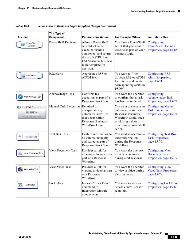
15-9Administering Cisco Physical Security Operations Manager, Release 6.1
OL-28432-01
Chapter 15 Business Logic Component Reference Understanding Business Logic Components
PowerShell Decision Allow a PowerShell scriptblock to be executed inside a component and return the result (TRUE or FALSE) to the business logic template for decision.
You have a PowerShell script that you want to execute as part of your business logic.
Configuring PowerShell Decision Properties, page 15-65.
RSSAlerts Aggregates RSS or ATOM feeds.
You want to filter through RSS or ATOM feed items and create corresponding alerts in PSOM.
Configuring RSS Alerts Properties, page 15-71.
Acknowledge Task Confirms task execution as part of a Response Workflow.
You want the operator to confirm that a task has been completed.
Configuring Acknowledge Task Properties, page 15-72.
Manual Task Execution Required to encapsulate any automated activities that occur within Response Business Workflow Logic.
You want to execute an automated activity in Response Business Workflow Logic, such as closing a door or executing a Powershell script.
Configuring Manual Task Execution Properties, page 15-74.
Text Box Task Enables information to be entered manually and stored as part of Response Workflow.
You want an operator to enter information during the Response Workflow.
Configuring Text Box Task Properties, page 15-76.
View Document Task Provides a link for viewing a document as part of a Response Workflow.
You want the operator to view a document during alert response.
Configuring View Document Task Properties, page 15-77.
View Video Task Provides a link for viewing a video as part of a Response Workflow.
You want the operator to view a video during alert response.
Configuring View Video Task Properties, page 15-78.
Lock Door Issues a “Lock Door” command to Integration Module door sensors.
You want to lock an access control sensor remotely.
Configuring Lock Door Properties, page 15-80.
Table 15-1 Icons Used in Business Logic Template Design (continued)
This Icon...This Type of Component... Performs this Action... For Example, When... For Details, See...
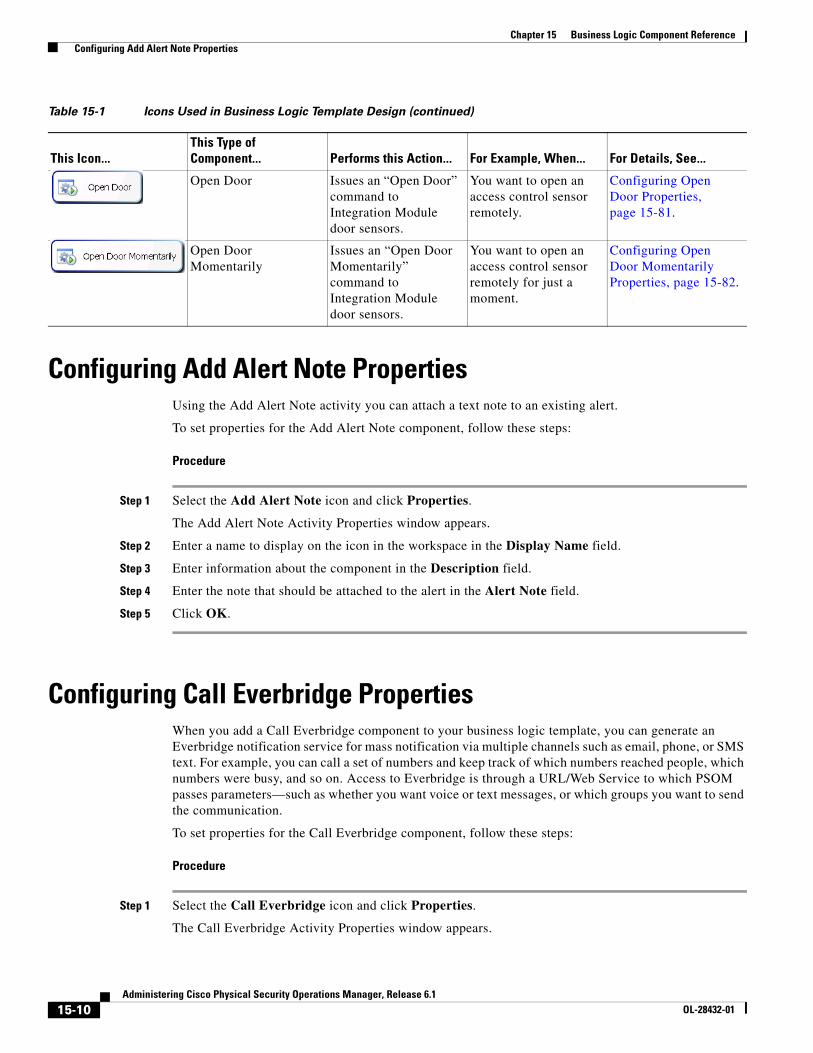
15-10Administering Cisco Physical Security Operations Manager, Release 6.1
OL-28432-01
Chapter 15 Business Logic Component Reference Configuring Add Alert Note Properties
Configuring Add Alert Note PropertiesUsing the Add Alert Note activity you can attach a text note to an existing alert.
To set properties for the Add Alert Note component, follow these steps:
Procedure
Step 1 Select the Add Alert Note icon and click Properties.
The Add Alert Note Activity Properties window appears.
Step 2 Enter a name to display on the icon in the workspace in the Display Name field.
Step 3 Enter information about the component in the Description field.
Step 4 Enter the note that should be attached to the alert in the Alert Note field.
Step 5 Click OK.
Configuring Call Everbridge PropertiesWhen you add a Call Everbridge component to your business logic template, you can generate an Everbridge notification service for mass notification via multiple channels such as email, phone, or SMS text. For example, you can call a set of numbers and keep track of which numbers reached people, which numbers were busy, and so on. Access to Everbridge is through a URL/Web Service to which PSOM passes parameters—such as whether you want voice or text messages, or which groups you want to send the communication.
To set properties for the Call Everbridge component, follow these steps:
Procedure
Step 1 Select the Call Everbridge icon and click Properties.
The Call Everbridge Activity Properties window appears.
Open Door Issues an “Open Door” command to Integration Module door sensors.
You want to open an access control sensor remotely.
Configuring Open Door Properties, page 15-81.
Open Door Momentarily
Issues an “Open Door Momentarily” command to Integration Module door sensors.
You want to open an access control sensor remotely for just a moment.
Configuring Open Door Momentarily Properties, page 15-82.
Table 15-1 Icons Used in Business Logic Template Design (continued)
This Icon...This Type of Component... Performs this Action... For Example, When... For Details, See...
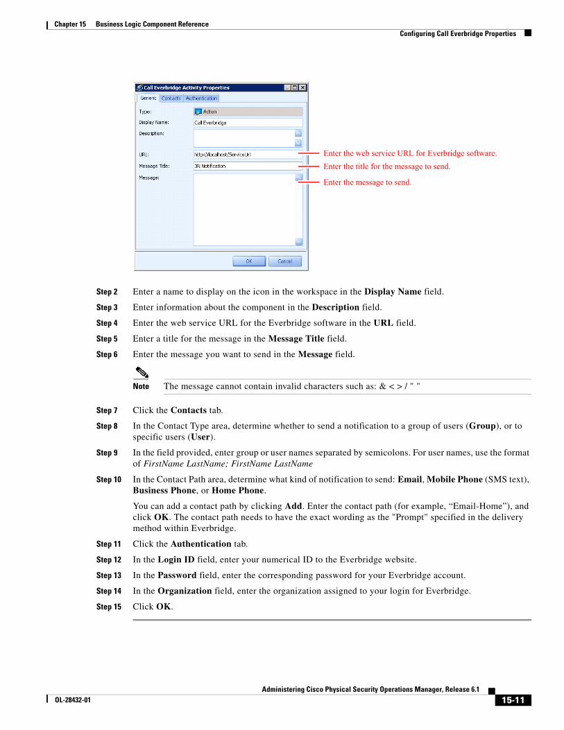
15-11Administering Cisco Physical Security Operations Manager, Release 6.1
OL-28432-01
Chapter 15 Business Logic Component Reference Configuring Call Everbridge Properties
Step 2 Enter a name to display on the icon in the workspace in the Display Name field.
Step 3 Enter information about the component in the Description field.
Step 4 Enter the web service URL for the Everbridge software in the URL field.
Step 5 Enter a title for the message in the Message Title field.
Step 6 Enter the message you want to send in the Message field.
Note The message cannot contain invalid characters such as: & < > / " "
Step 7 Click the Contacts tab.
Step 8 In the Contact Type area, determine whether to send a notification to a group of users (Group), or to specific users (User).
Step 9 In the field provided, enter group or user names separated by semicolons. For user names, use the format of FirstName LastName; FirstName LastName
Step 10 In the Contact Path area, determine what kind of notification to send: Email, Mobile Phone (SMS text), Business Phone, or Home Phone.
You can add a contact path by clicking Add. Enter the contact path (for example, “Email-Home”), and click OK. The contact path needs to have the exact wording as the "Prompt" specified in the delivery method within Everbridge.
Step 11 Click the Authentication tab.
Step 12 In the Login ID field, enter your numerical ID to the Everbridge website.
Step 13 In the Password field, enter the corresponding password for your Everbridge account.
Step 14 In the Organization field, enter the organization assigned to your login for Everbridge.
Step 15 Click OK.
Enter the web service URL for Everbridge software.
Enter the title for the message to send.
Enter the message to send.
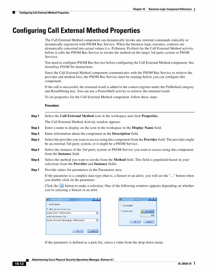
15-12Administering Cisco Physical Security Operations Manager, Release 6.1
OL-28432-01
Chapter 15 Business Logic Component Reference Configuring Call External Method Properties
Configuring Call External Method PropertiesThe Call External Method component can dynamically invoke any external commands statically or dynamically registered with PSOM Bus Service. When the business logic executes, contexts are dynamically converted into actual values (i.e. PxSensor, PxAlert) by the Call External Method activity, before it calls the PSOM Bus Service to invoke the method on the target 3rd party system or PSOM Services.
You need to configure PSOM Bus Service before configuring the Call External Method component. See Installing PSOM for instructions.
Since the Call External Method component communicates with the PSOM Bus Service to retrieve the provider and method lists, the PSOM Bus Service must be running before you can configure this component.
If the call is successful, the returned result is added to the context register under the PxMethod category and ResultString key. You can use a PowerShell activity to retrieve the returned result.
To set properties for the Call External Method component, follow these steps:
Procedure
Step 1 Select the Call External Method icon in the workspace and click Properties.
The Call External Method Activity window appears.
Step 2 Enter a name to display on the icon in the workspace in the Display Name field.
Step 3 Enter information about the component in the Description field.
Step 4 Select the provider you want to access using this component from the Provider field. The provider might be an external 3rd-party system, or it might be a PSOM Service.
Step 5 Select the instance of the 3rd-party system or PSOM Service you want to access using this component from the Instance field.
Step 6 Select the method you want to invoke from the Method field. This field is populated based on your selections from the Provider and Instance fields.
Step 7 Provide values for parameters in the Parameters area.
If the parameter is a complex data type (that is, a Sensor or an alert), you will see the "..." button when you double click on the parameter.
Click the button to make a selection. One of the following windows appears depending on whether you’re selecting a Sensor or an alert.
If the parameter is defined as a pick list, select a value from the drop-down menu.
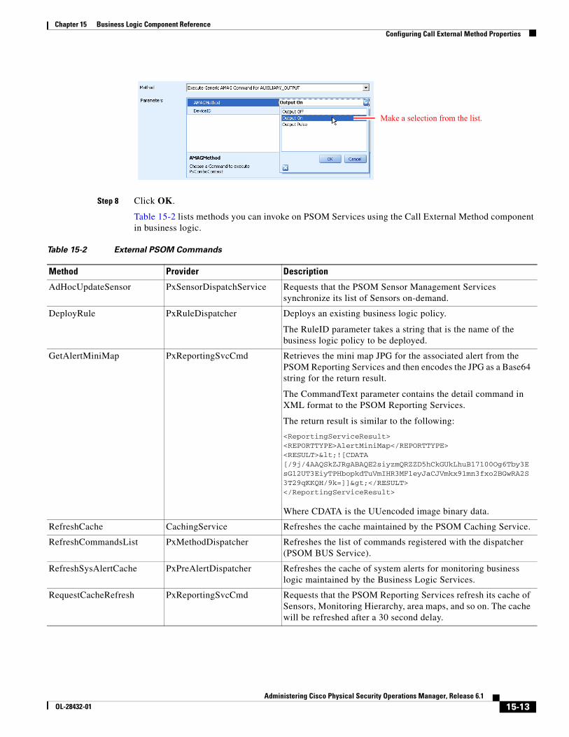
15-13Administering Cisco Physical Security Operations Manager, Release 6.1
OL-28432-01
Chapter 15 Business Logic Component Reference Configuring Call External Method Properties
Step 8 Click OK.
Table 15-2 lists methods you can invoke on PSOM Services using the Call External Method component in business logic.
Make a selection from the list.
Table 15-2 External PSOM Commands
Method Provider Description
AdHocUpdateSensor PxSensorDispatchService Requests that the PSOM Sensor Management Services synchronize its list of Sensors on-demand.
DeployRule PxRuleDispatcher Deploys an existing business logic policy.
The RuleID parameter takes a string that is the name of the business logic policy to be deployed.
GetAlertMiniMap PxReportingSvcCmd Retrieves the mini map JPG for the associated alert from the PSOM Reporting Services and then encodes the JPG as a Base64 string for the return result.
The CommandText parameter contains the detail command in XML format to the PSOM Reporting Services.
The return result is similar to the following:
<ReportingServiceResult><REPORTTYPE>AlertMiniMap</REPORTTYPE><RESULT><![CDATA [/9j/4AAQSkZJRgABAQE2siyzmQRZZD5hCkGUkLhuB17100Og6Tby3EsGl2UT3EiyTPHbopkdTuVmIHR3MFleyJaCJVmkx91mn3fxo2BGwRA2S3T29qKKQH/9k=]]></RESULT></ReportingServiceResult>
Where CDATA is the UUencoded image binary data.
RefreshCache CachingService Refreshes the cache maintained by the PSOM Caching Service.
RefreshCommandsList PxMethodDispatcher Refreshes the list of commands registered with the dispatcher (PSOM BUS Service).
RefreshSysAlertCache PxPreAlertDispatcher Refreshes the cache of system alerts for monitoring business logic maintained by the Business Logic Services.
RequestCacheRefresh PxReportingSvcCmd Requests that the PSOM Reporting Services refresh its cache of Sensors, Monitoring Hierarchy, area maps, and so on. The cache will be refreshed after a 30 second delay.
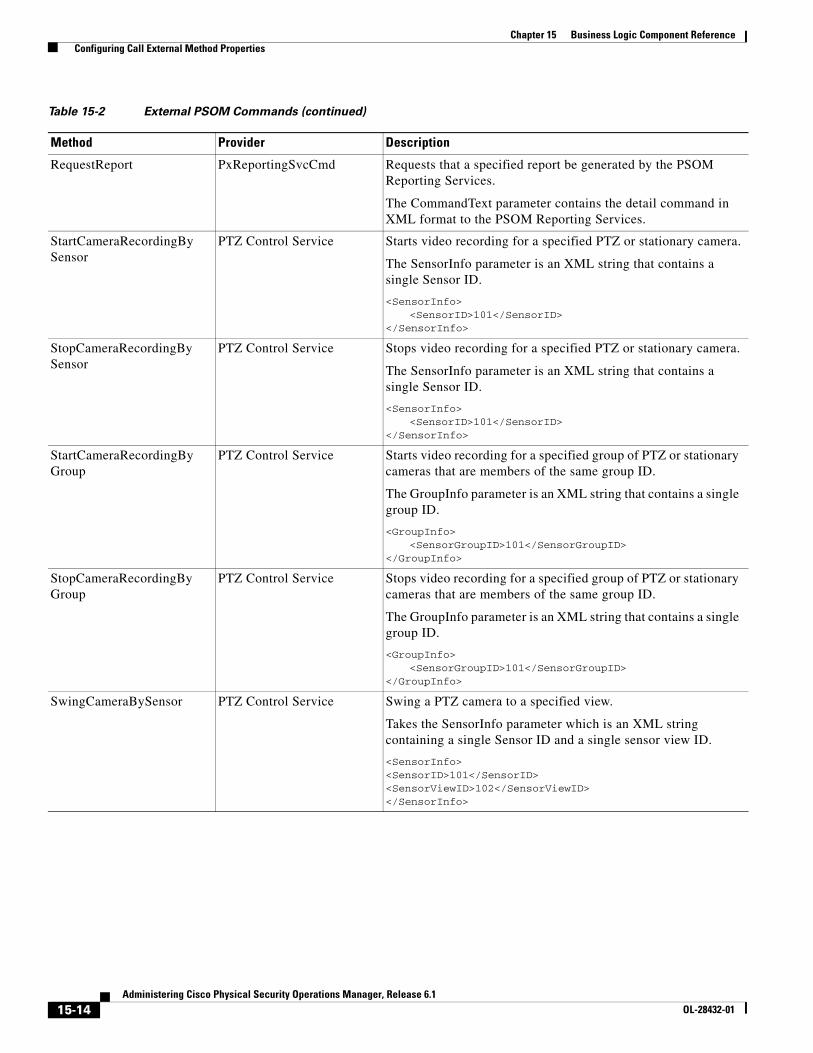
15-14Administering Cisco Physical Security Operations Manager, Release 6.1
OL-28432-01
Chapter 15 Business Logic Component Reference Configuring Call External Method Properties
RequestReport PxReportingSvcCmd Requests that a specified report be generated by the PSOM Reporting Services.
The CommandText parameter contains the detail command in XML format to the PSOM Reporting Services.
StartCameraRecordingBySensor
PTZ Control Service Starts video recording for a specified PTZ or stationary camera.
The SensorInfo parameter is an XML string that contains a single Sensor ID.
<SensorInfo><SensorID>101</SensorID>
</SensorInfo>
StopCameraRecordingBySensor
PTZ Control Service Stops video recording for a specified PTZ or stationary camera.
The SensorInfo parameter is an XML string that contains a single Sensor ID.
<SensorInfo><SensorID>101</SensorID>
</SensorInfo>
StartCameraRecordingByGroup
PTZ Control Service Starts video recording for a specified group of PTZ or stationary cameras that are members of the same group ID.
The GroupInfo parameter is an XML string that contains a single group ID.
<GroupInfo><SensorGroupID>101</SensorGroupID>
</GroupInfo>
StopCameraRecordingByGroup
PTZ Control Service Stops video recording for a specified group of PTZ or stationary cameras that are members of the same group ID.
The GroupInfo parameter is an XML string that contains a single group ID.
<GroupInfo><SensorGroupID>101</SensorGroupID>
</GroupInfo>
SwingCameraBySensor PTZ Control Service Swing a PTZ camera to a specified view.
Takes the SensorInfo parameter which is an XML string containing a single Sensor ID and a single sensor view ID.
<SensorInfo><SensorID>101</SensorID><SensorViewID>102</SensorViewID></SensorInfo>
Table 15-2 External PSOM Commands (continued)
Method Provider Description
15-15Administering Cisco Physical Security Operations Manager, Release 6.1
OL-28432-01
Chapter 15 Business Logic Component Reference Configuring Call Web Service Properties
Configuring Call Web Service PropertiesWhen you add a Call Web Service component to your business logic template, you can dynamically invoke SOAP-based web services by suppling a Web Services Description Language (WSDL) location at design time, and then through introspection allowing the user to invoke a method and pass parameters to it. The parameter values can be specified or determined using templates (template values will be substituted with actual values at runtime).
Return results from this component are stored in the context registry under the PxWebServiceCallResult category where the key is the name of the activity.
To set properties for the Call Web Service component, follow these steps:
Procedure
Step 1 Select the Call Web Service icon in the workspace and click Properties.
The Generic WebService Call Activity window appears.
SwingCameraBySensorGroup
PTZ Control Service Swing all PTZ cameras in one or more Sensor Groups.
Takes the GroupInfo parameter which is an XML string containing one or more Sensor Group ID(s).
<GroupInfo><SensorGroupID>101</SensorGroupID><SensorGroupID>102</SensorGroupID></GroupInfo>
Sensor view is specified in the Administration Console when you configure Sensor Groups that contain PTZ cameras.
UndeployRule PxRuleDispatcher Undeploys an existing business logic policy.
The RuleID parameter takes a string that is the name of the business logic policy to be undeployed.
Table 15-2 External PSOM Commands (continued)
Method Provider Description
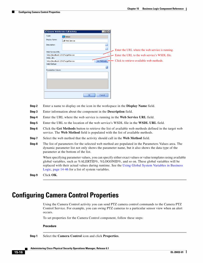
15-16Administering Cisco Physical Security Operations Manager, Release 6.1
OL-28432-01
Chapter 15 Business Logic Component Reference Configuring Camera Control Properties
Step 2 Enter a name to display on the icon in the workspace in the Display Name field.
Step 3 Enter information about the component in the Description field.
Step 4 Enter the URL where the web service is running in the Web Service URL field.
Step 5 Enter the URL to the location of the web service's WSDL file in the WSDL URL field.
Step 6 Click the Get Methods button to retrieve the list of available web methods defined in the target web service. The Web Method field is populated with the list of available methods.
Step 7 Select the web method that the activity should call in the Web Method field.
Step 8 The list of parameters for the selected web method are populated in the Parameters Values area. The dynamic parameter list not only shows the parameter name, but it also shows the data type of the parameter at the bottom of the list.
When specifying parameter values, you can specify either exact values or value templates using available global variables, such as %ALERTID%, %LOGONID%, and so on. These global variables will be replaced with their actual values during runtime. See the Using Global System Variables in Business Logic, page 14-46 for a list of system variables.
Step 9 Click OK.
Configuring Camera Control PropertiesUsing the Camera Control activity you can send PTZ camera control commands to the Camera PTZ Control Service. For example, you can swing PTZ cameras to a particular sensor view when an alert occurs.
To set properties for the Camera Control component, follow these steps:
Procedure
Step 1 Select the Camera Control icon and click Properties.
Enter the URL where the web service is running.
Enter the URL to the web service’s WSDL file.
Click to retrieve available web methods.
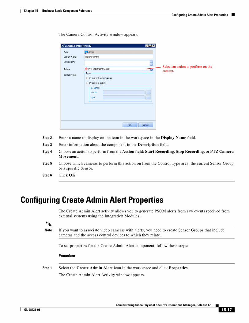
15-17Administering Cisco Physical Security Operations Manager, Release 6.1
OL-28432-01
Chapter 15 Business Logic Component Reference Configuring Create Admin Alert Properties
The Camera Control Activity window appears.
Step 2 Enter a name to display on the icon in the workspace in the Display Name field.
Step 3 Enter information about the component in the Description field.
Step 4 Choose an action to perform from the Action field: Start Recording, Stop Recording, or PTZ Camera Movement.
Step 5 Choose which cameras to perform this action on from the Control Type area: the current Sensor Group or a specific Sensor.
Step 6 Click OK.
Configuring Create Admin Alert PropertiesThe Create Admin Alert activity allows you to generate PSOM alerts from raw events received from external systems using the Integration Modules.
Note If you want to associate video cameras with alerts, you need to create Sensor Groups that include cameras and the access control devices to which they relate.
To set properties for the Create Admin Alert component, follow these steps:
Procedure
Step 1 Select the Create Admin Alert icon in the workspace and click Properties.
The Create Admin Alert Activity window appears.
Select an action to perform on the camera.
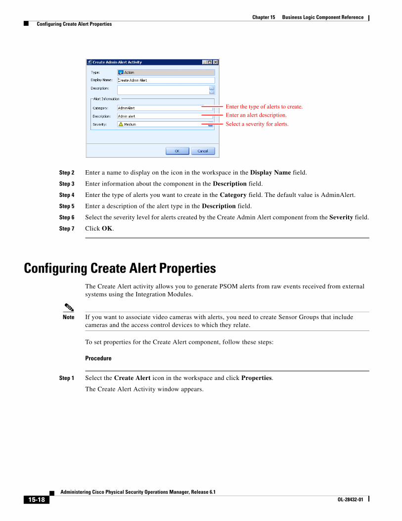
15-18Administering Cisco Physical Security Operations Manager, Release 6.1
OL-28432-01
Chapter 15 Business Logic Component Reference Configuring Create Alert Properties
Step 2 Enter a name to display on the icon in the workspace in the Display Name field.
Step 3 Enter information about the component in the Description field.
Step 4 Enter the type of alerts you want to create in the Category field. The default value is AdminAlert.
Step 5 Enter a description of the alert type in the Description field.
Step 6 Select the severity level for alerts created by the Create Admin Alert component from the Severity field.
Step 7 Click OK.
Configuring Create Alert PropertiesThe Create Alert activity allows you to generate PSOM alerts from raw events received from external systems using the Integration Modules.
Note If you want to associate video cameras with alerts, you need to create Sensor Groups that include cameras and the access control devices to which they relate.
To set properties for the Create Alert component, follow these steps:
Procedure
Step 1 Select the Create Alert icon in the workspace and click Properties.
The Create Alert Activity window appears.
Enter the type of alerts to create.
Enter an alert description.
Select a severity for alerts.
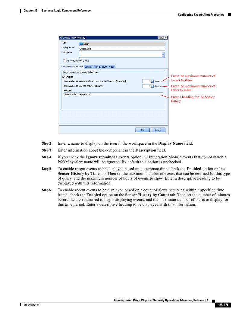
15-19Administering Cisco Physical Security Operations Manager, Release 6.1
OL-28432-01
Chapter 15 Business Logic Component Reference Configuring Create Alert Properties
Step 2 Enter a name to display on the icon in the workspace in the Display Name field.
Step 3 Enter information about the component in the Description field.
Step 4 If you check the Ignore remainder events option, all Integration Module events that do not match a PSOM sysalert name will be ignored. By default this option is unchecked.
Step 5 To enable recent events to be displayed based on occurrence time, check the Enabled option on the Sensor History by Time tab. Then set the maximum number of events that can be returned for this type of query, and the maximum number of hours of events to show. Enter a descriptive heading to be displayed with this information.
Step 6 To enable recent events to be displayed based on a count of alerts occurring within a specified time frame, check the Enabled option on the Sensor History by Count tab. Then set the number of minutes before the alert occurred to begin displaying events, and the maximum number of alerts to display for this time period. Enter a descriptive heading to be displayed with this information.
Enter the maximum number of events to show.
Enter the maximum number of hours to show.
Enter a heading for the Sensor history.
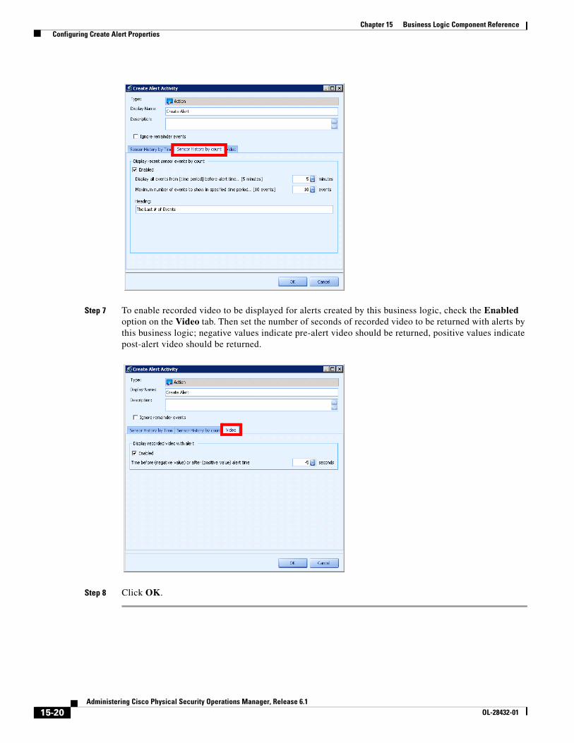
15-20Administering Cisco Physical Security Operations Manager, Release 6.1
OL-28432-01
Chapter 15 Business Logic Component Reference Configuring Create Alert Properties
Step 7 To enable recorded video to be displayed for alerts created by this business logic, check the Enabled option on the Video tab. Then set the number of seconds of recorded video to be returned with alerts by this business logic; negative values indicate pre-alert video should be returned, positive values indicate post-alert video should be returned.
Step 8 Click OK.
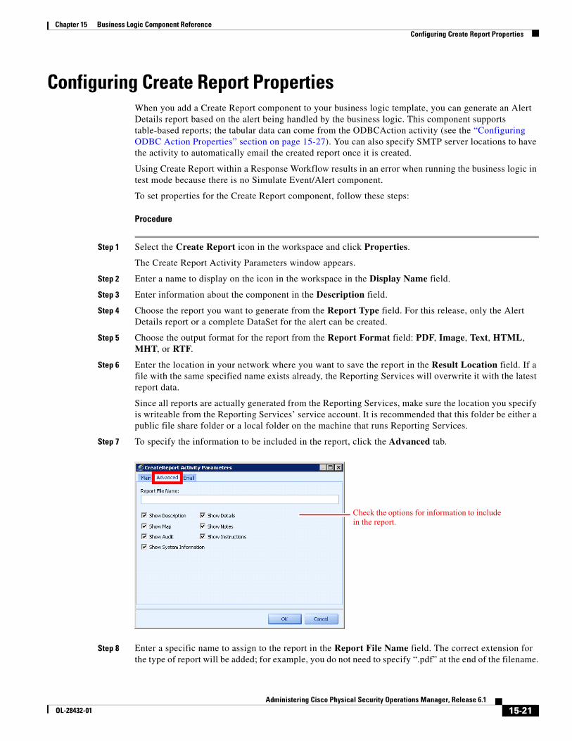
15-21Administering Cisco Physical Security Operations Manager, Release 6.1
OL-28432-01
Chapter 15 Business Logic Component Reference Configuring Create Report Properties
Configuring Create Report PropertiesWhen you add a Create Report component to your business logic template, you can generate an Alert Details report based on the alert being handled by the business logic. This component supports table-based reports; the tabular data can come from the ODBCAction activity (see the “Configuring ODBC Action Properties” section on page 15-27). You can also specify SMTP server locations to have the activity to automatically email the created report once it is created.
Using Create Report within a Response Workflow results in an error when running the business logic in test mode because there is no Simulate Event/Alert component.
To set properties for the Create Report component, follow these steps:
Procedure
Step 1 Select the Create Report icon in the workspace and click Properties.
The Create Report Activity Parameters window appears.
Step 2 Enter a name to display on the icon in the workspace in the Display Name field.
Step 3 Enter information about the component in the Description field.
Step 4 Choose the report you want to generate from the Report Type field. For this release, only the Alert Details report or a complete DataSet for the alert can be created.
Step 5 Choose the output format for the report from the Report Format field: PDF, Image, Text, HTML, MHT, or RTF.
Step 6 Enter the location in your network where you want to save the report in the Result Location field. If a file with the same specified name exists already, the Reporting Services will overwrite it with the latest report data.
Since all reports are actually generated from the Reporting Services, make sure the location you specify is writeable from the Reporting Services’ service account. It is recommended that this folder be either a public file share folder or a local folder on the machine that runs Reporting Services.
Step 7 To specify the information to be included in the report, click the Advanced tab.
Step 8 Enter a specific name to assign to the report in the Report File Name field. The correct extension for the type of report will be added; for example, you do not need to specify “.pdf” at the end of the filename.
Check the options for information to include in the report.
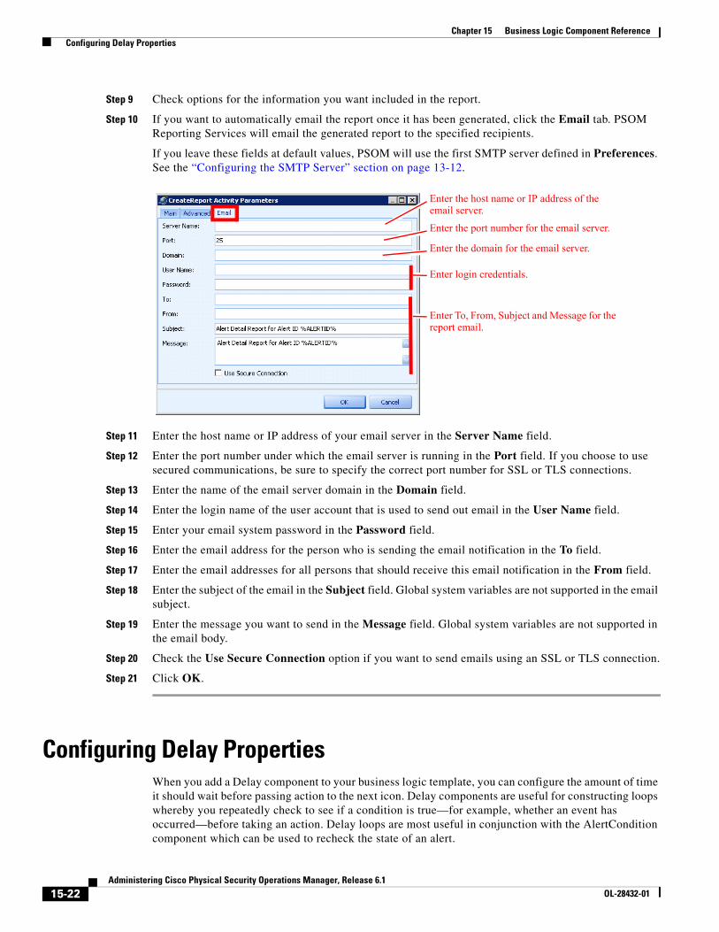
15-22Administering Cisco Physical Security Operations Manager, Release 6.1
OL-28432-01
Chapter 15 Business Logic Component Reference Configuring Delay Properties
Step 9 Check options for the information you want included in the report.
Step 10 If you want to automatically email the report once it has been generated, click the Email tab. PSOM Reporting Services will email the generated report to the specified recipients.
If you leave these fields at default values, PSOM will use the first SMTP server defined in Preferences. See the “Configuring the SMTP Server” section on page 13-12.
Step 11 Enter the host name or IP address of your email server in the Server Name field.
Step 12 Enter the port number under which the email server is running in the Port field. If you choose to use secured communications, be sure to specify the correct port number for SSL or TLS connections.
Step 13 Enter the name of the email server domain in the Domain field.
Step 14 Enter the login name of the user account that is used to send out email in the User Name field.
Step 15 Enter your email system password in the Password field.
Step 16 Enter the email address for the person who is sending the email notification in the To field.
Step 17 Enter the email addresses for all persons that should receive this email notification in the From field.
Step 18 Enter the subject of the email in the Subject field. Global system variables are not supported in the email subject.
Step 19 Enter the message you want to send in the Message field. Global system variables are not supported in the email body.
Step 20 Check the Use Secure Connection option if you want to send emails using an SSL or TLS connection.
Step 21 Click OK.
Configuring Delay PropertiesWhen you add a Delay component to your business logic template, you can configure the amount of time it should wait before passing action to the next icon. Delay components are useful for constructing loops whereby you repeatedly check to see if a condition is true—for example, whether an event has occurred—before taking an action. Delay loops are most useful in conjunction with the AlertCondition component which can be used to recheck the state of an alert.
Enter the host name or IP address of the email server.
Enter the port number for the email server.
Enter the domain for the email server.
Enter login credentials.
Enter To, From, Subject and Message for the report email.
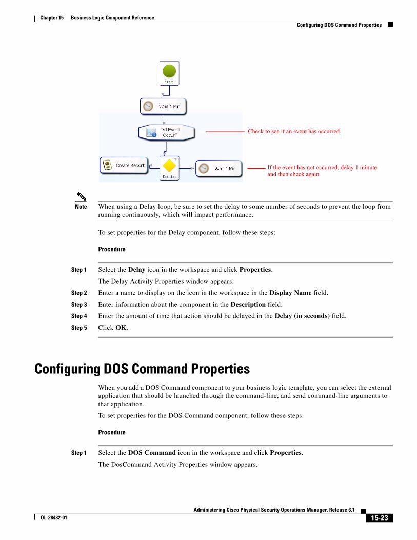
15-23Administering Cisco Physical Security Operations Manager, Release 6.1
OL-28432-01
Chapter 15 Business Logic Component Reference Configuring DOS Command Properties
Note When using a Delay loop, be sure to set the delay to some number of seconds to prevent the loop from running continuously, which will impact performance.
To set properties for the Delay component, follow these steps:
Procedure
Step 1 Select the Delay icon in the workspace and click Properties.
The Delay Activity Properties window appears.
Step 2 Enter a name to display on the icon in the workspace in the Display Name field.
Step 3 Enter information about the component in the Description field.
Step 4 Enter the amount of time that action should be delayed in the Delay (in seconds) field.
Step 5 Click OK.
Configuring DOS Command PropertiesWhen you add a DOS Command component to your business logic template, you can select the external application that should be launched through the command-line, and send command-line arguments to that application.
To set properties for the DOS Command component, follow these steps:
Procedure
Step 1 Select the DOS Command icon in the workspace and click Properties.
The DosCommand Activity Properties window appears.
Check to see if an event has occurred.
If the event has not occurred, delay 1 minute and then check again.
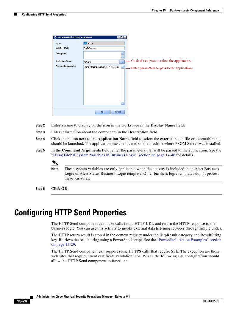
15-24Administering Cisco Physical Security Operations Manager, Release 6.1
OL-28432-01
Chapter 15 Business Logic Component Reference Configuring HTTP Send Properties
Step 2 Enter a name to display on the icon in the workspace in the Display Name field.
Step 3 Enter information about the component in the Description field.
Step 4 Click the button next to the Application Name field to select the external batch file or executable that should be launched. The application must be located on the machine where PSOM Server was installed.
Step 5 In the Command Arguments field, enter the parameters that will be passed to the application. See the “Using Global System Variables in Business Logic” section on page 14-46 for details.
Note These system variables are only applicable when the activity is included in an Alert Business Logic or Alert Status Business Logic template. Other business logic templates do not process these variables.
Step 6 Click OK.
Configuring HTTP Send PropertiesThe HTTP Send component can make calls into a HTTP URL and return the HTTP response to the business logic. You can use this activity to invoke external data listening services through simple URLs.
The HTTP return result is stored in the context registry under the HttpResult category and ResultString key. Retrieve the result string using a PowerShell script. See the “PowerShell Action Examples” section on page 15-29.
The HTTP Send component can support some HTTPS calls that require SSL. The exception are those web sites that require client certificate validation. For IIS 7.0, the following site configuration should allow the HTTP Send component to function:
Click the ellipses to select the application.
Enter parameters to pass to the application.
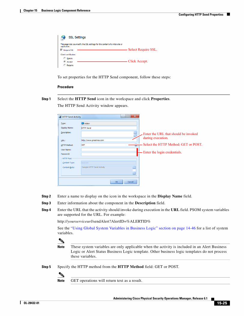
15-25Administering Cisco Physical Security Operations Manager, Release 6.1
OL-28432-01
Chapter 15 Business Logic Component Reference Configuring HTTP Send Properties
To set properties for the HTTP Send component, follow these steps:
Procedure
Step 1 Select the HTTP Send icon in the workspace and click Properties.
The HTTP Send Activity window appears.
Step 2 Enter a name to display on the icon in the workspace in the Display Name field.
Step 3 Enter information about the component in the Description field.
Step 4 Enter the URL that the activity should invoke during execution in the URL field. PSOM system variables are supported for the URL. For example:
http://yourserviceurl/sendAlert?AlertID=%ALERTID%
See the “Using Global System Variables in Business Logic” section on page 14-46 for a list of system variables.
Note These system variables are only applicable when the activity is included in an Alert Business Logic or Alert Status Business Logic template. Other business logic templates do not process these variables.
Step 5 Specify the HTTP method from the HTTP Method field: GET or POST.
Note GET operations will return text as a result.
Select Require SSL.
Click Accept.
Enter the URL that should be invoked during execution.
Select the HTTP Method: GET or POST.
Enter the login credentials.
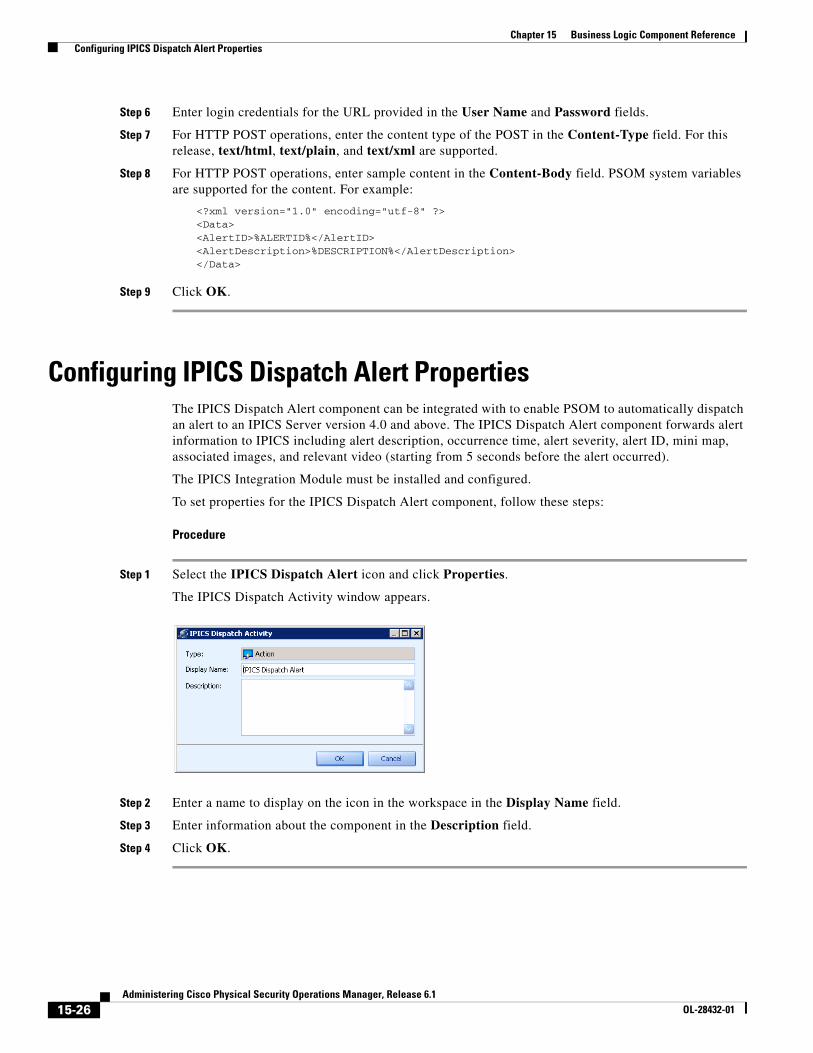
15-26Administering Cisco Physical Security Operations Manager, Release 6.1
OL-28432-01
Chapter 15 Business Logic Component Reference Configuring IPICS Dispatch Alert Properties
Step 6 Enter login credentials for the URL provided in the User Name and Password fields.
Step 7 For HTTP POST operations, enter the content type of the POST in the Content-Type field. For this release, text/html, text/plain, and text/xml are supported.
Step 8 For HTTP POST operations, enter sample content in the Content-Body field. PSOM system variables are supported for the content. For example:
<?xml version="1.0" encoding="utf-8" ?><Data><AlertID>%ALERTID%</AlertID><AlertDescription>%DESCRIPTION%</AlertDescription></Data>
Step 9 Click OK.
Configuring IPICS Dispatch Alert PropertiesThe IPICS Dispatch Alert component can be integrated with to enable PSOM to automatically dispatch an alert to an IPICS Server version 4.0 and above. The IPICS Dispatch Alert component forwards alert information to IPICS including alert description, occurrence time, alert severity, alert ID, mini map, associated images, and relevant video (starting from 5 seconds before the alert occurred).
The IPICS Integration Module must be installed and configured.
To set properties for the IPICS Dispatch Alert component, follow these steps:
Procedure
Step 1 Select the IPICS Dispatch Alert icon and click Properties.
The IPICS Dispatch Activity window appears.
Step 2 Enter a name to display on the icon in the workspace in the Display Name field.
Step 3 Enter information about the component in the Description field.
Step 4 Click OK.
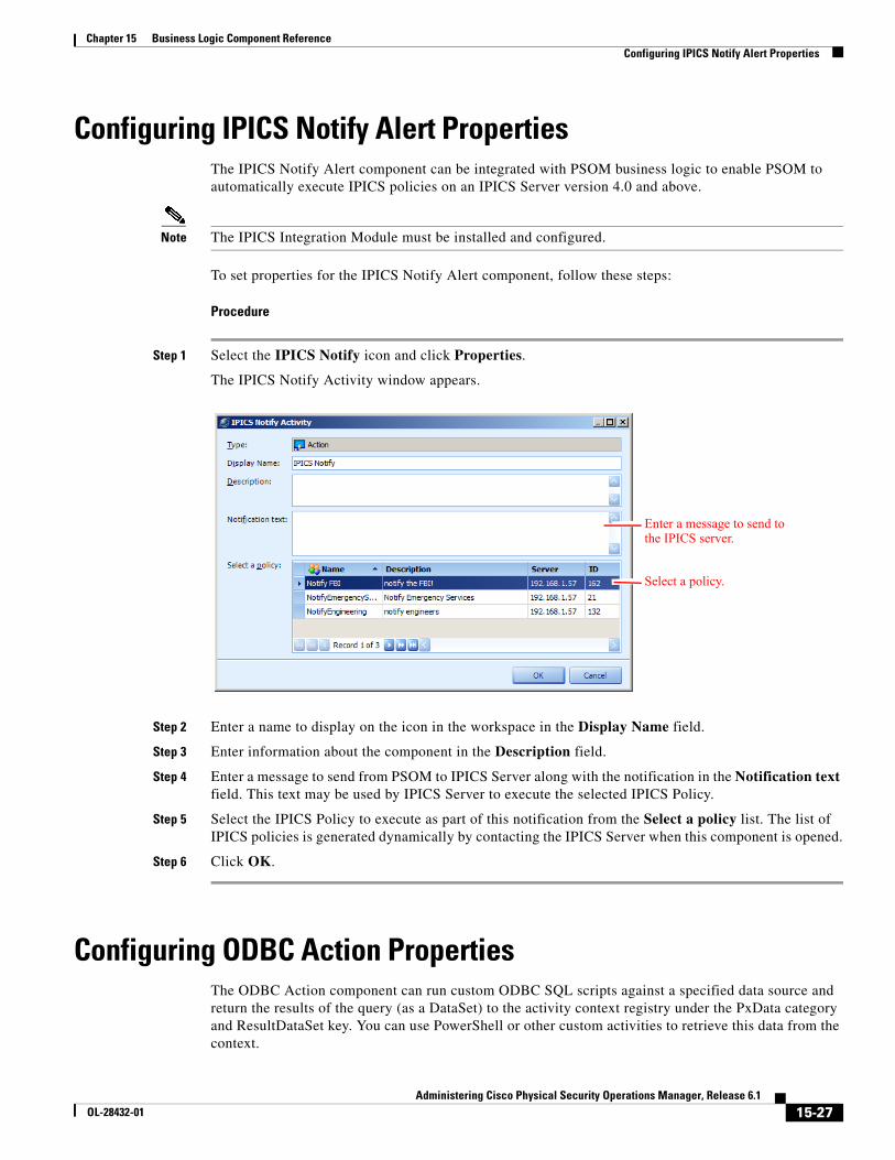
15-27Administering Cisco Physical Security Operations Manager, Release 6.1
OL-28432-01
Chapter 15 Business Logic Component Reference Configuring IPICS Notify Alert Properties
Configuring IPICS Notify Alert PropertiesThe IPICS Notify Alert component can be integrated with PSOM business logic to enable PSOM to automatically execute IPICS policies on an IPICS Server version 4.0 and above.
Note The IPICS Integration Module must be installed and configured.
To set properties for the IPICS Notify Alert component, follow these steps:
Procedure
Step 1 Select the IPICS Notify icon and click Properties.
The IPICS Notify Activity window appears.
Step 2 Enter a name to display on the icon in the workspace in the Display Name field.
Step 3 Enter information about the component in the Description field.
Step 4 Enter a message to send from PSOM to IPICS Server along with the notification in the Notification text field. This text may be used by IPICS Server to execute the selected IPICS Policy.
Step 5 Select the IPICS Policy to execute as part of this notification from the Select a policy list. The list of IPICS policies is generated dynamically by contacting the IPICS Server when this component is opened.
Step 6 Click OK.
Configuring ODBC Action PropertiesThe ODBC Action component can run custom ODBC SQL scripts against a specified data source and return the results of the query (as a DataSet) to the activity context registry under the PxData category and ResultDataSet key. You can use PowerShell or other custom activities to retrieve this data from the context.
Enter a message to send to the IPICS server.
Select a policy.
15-28Administering Cisco Physical Security Operations Manager, Release 6.1
OL-28432-01
Chapter 15 Business Logic Component Reference Configuring PowerShell Action Properties
For example, the following PowerShell script retrieves the dataset result from the ODBC query:
$r = $pxContext.FindContextObject("PxData", "ResultDataSet")
To set properties for the ODBC Action component, follow these steps:
Procedure
Step 1 Select the ODBC Action icon in the workspace and click Properties.
The ODBC Action Activity Properties window appears.
Step 2 Enter a name to display on the icon in the workspace in the Display Name field.
Step 3 Enter information about the component in the Description field.
Step 4 Enter information for the ODBC data source in the ODBC Connection area:
a. In the Driver field, enter the ODBC driver used to access this data source.
b. In the DB Server field, enter the server where the ODBC database is running.
c. In the Database field, enter the name of the database you want to access.
d. In the DB Login field, enter the login name for accessing the database.
e. In the DB Password field, enter the corresponding password.
Step 5 Enter a custom SQL script to execute against the datasource in the DB Query area.
Step 6 Click OK.
Configuring PowerShell Action PropertiesYou can configure a PowerShell Action component to execute PowerShell scripts synchronously and asynchronously. The PowerShell Action component supports logging, object passing, calls to a WF Web Service, and passing and creating contextual data between activities in a business logic design.
See the “Setting Up PowerShell Scripts” section on page 14-50 for details on defining PowerShell Scripts. This section describes how to add them as components to business logic templates.
Note You must have PowerShell installed on your system to execute PowerShell Action component. PowerShell requires Windows XP SP2 or later, and Windows Server 2003 SP1 or later. You can download PowerShell from the Microsoft website.
To set properties for the PowerShell Action component, follow these steps:
Procedure
Step 1 Select the PowerShell Action icon and click Properties.
The PowerShell Activity Properties window appears.
Step 2 Enter a name to display on the icon in the workspace in the Display Name field.
Step 3 Enter information about the component in the Description field.
Step 4 To select a PowerShell script, click the button in the Script Template field.
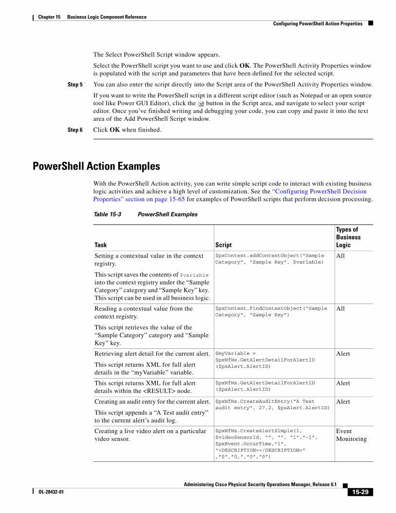
15-29Administering Cisco Physical Security Operations Manager, Release 6.1
OL-28432-01
Chapter 15 Business Logic Component Reference Configuring PowerShell Action Properties
The Select PowerShell Script window appears.
Select the PowerShell script you want to use and click OK. The PowerShell Activity Properties window is populated with the script and parameters that have been defined for the selected script.
Step 5 You can also enter the script directly into the Script area of the PowerShell Activity Properties window.
If you want to write the PowerShell script in a different script editor (such as Notepad or an open source tool like Power GUI Editor), click the button in the Script area, and navigate to select your script editor. Once you’ve finished writing and debugging your code, you can copy and paste it into the text area of the Add PowerShell Script window.
Step 6 Click OK when finished.
PowerShell Action ExamplesWith the PowerShell Action activity, you can write simple script code to interact with existing business logic activities and achieve a high level of customization. See the “Configuring PowerShell Decision Properties” section on page 15-65 for examples of PowerShell scripts that perform decision processing.
Table 15-3 PowerShell Examples
Task Script
Types of Business Logic
Setting a contextual value in the context registry.
This script saves the contents of $variable into the context registry under the “Sample Category” category and “Sample Key” key. This script can be used in all business logic.
$pxContext.addContextObject(“Sample Category”, “Sample Key”, $variable)
All
Reading a contextual value from the context registry.
This script retrieves the value of the “Sample Category” category and “Sample Key” key.
$pxContext.FindContextObject(“Sample Category”, “Sample Key”)
All
Retrieving alert detail for the current alert.
This script returns XML for full alert details in the “myVariable” variable.
$myVariable = $pxWfWs.GetAlertDetailForAlertID ($pxAlert.AlertID)
Alert
This script returns XML for full alert details within the <RESULT> node.
$pxWfWs.GetAlertDetailForAlertID ($pxAlert.AlertID)
Alert
Creating an audit entry for the current alert.
This script appends a “A Test audit entry” to the current alert’s audit log.
$pxWfWs.CreateAuditEntry(“A Test audit entry”, 27,2, $pxAlert.AlertID)
Alert
Creating a live video alert on a particular video sensor.
$pxWfWs.CreateAlertSimple(1, $videoSensorId, “”, “”, “1”,”-1”, $pxEvent.OccurTime,”1”, “<DESCRIPTION></DESCRIPTION>” ,”0”,”0,”,”0”,”0”)
Event Monitoring
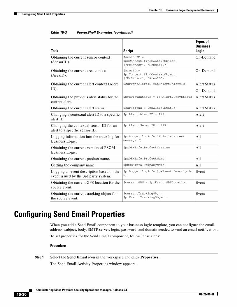
15-30Administering Cisco Physical Security Operations Manager, Release 6.1
OL-28432-01
Chapter 15 Business Logic Component Reference Configuring Send Email Properties
Configuring Send Email PropertiesWhen you add a Send Email component to your business logic template, you can configure the email address, subject, body, SMTP server, login, password, and domain needed to send an email notification.
To set properties for the Send Email component, follow these steps:
Procedure
Step 1 Select the Send Email icon in the workspace and click Properties.
The Send Email Activity Properties window appears.
Obtaining the current sensor context (SensorID).
$sensorID = $pxContext.findContextObject ("PxSensor", "SensorID")
On-Demand
Obtaining the current area context (AreaID).
$areaID = $pxContext.findContextObject ("PxSensor", "AreaID")
On-Demand
Obtaining the current alert context (Alert ID).
$currentAlertID =$pxAlert.AlertID Alert Status
On-Demand
Obtaining the previous alert status for the current alert.
$previousStatus = $pxAlert.PrevStatus Alert Status
Obtaining the current alert status. $curStatus = $pxAlert.Status Alert Status
Changing a contexual alert ID to a specific alert ID.
$pxAlert.AlertID = 123 Alert
Changing the contexual sensor ID for an alert to a specific sensor ID.
$pxAlert.SensorID = 123 Alert
Logging information into the trace log for Business Logic.
$pxLogger.logInfo("This is a test message.")
All
Obtaining the current version of PSOM Business Logic.
$pxOEMInfo.ProductVersion All
Obtaining the current product name. $pxOEMInfo.ProductName All
Getting the company name. $pxOEMInfo.CompanyName All
Logging an event description based on the event issued by the 3rd party system.
$pxLogger.logInfo($pxEvent.Description)
Event
Obtaining the current GPS location for the source event.
$currentGPS = $pxEvent.GPSLocation Event
Obtaining the current tracking object for the source event.
$currentTrackingObj = $pxEvent.TrackingObject
Event
Table 15-3 PowerShell Examples (continued)
Task Script
Types of Business Logic
15-31Administering Cisco Physical Security Operations Manager, Release 6.1
OL-28432-01
Chapter 15 Business Logic Component Reference Configuring Sensor Synchronization Properties
Note If an SMTP server has been defined in Preferences, these values will be prepopulated in the SMTP Mail section of the Send Email activity. You may override these default values. See the “Configuring the SMTP Server” section on page 13-12.
Step 2 Enter a name to display on the icon in the workspace in the Display Name field.
Step 3 Enter information about the component in the Description field.
Step 4 Enter the host name or IP address of your email server in the Server Name field.
Step 5 Enter the port number under which the email server is running in the Port field. If you choose to use secured communications, be sure to specify the correct port number for SSL or TLS connections.
Step 6 Enter the name of the email server domain in the Domain field.
Step 7 Enter the email address for the user account that is used to send out email in the User Name field.
Step 8 Enter your email system password in the Password field.
Step 9 Enter the email address for the person who is sending the email notification in the To field.
Step 10 Enter the email addresses for all persons that should receive this email notification in the From field.
Step 11 Enter the subject of the email in the Subject field.
Step 12 Enter the message you want to send in the Message field.
Note In the Subject and Message fields, you can use system variables defined with ‘%VARIABLE%’ where VARIABLE is the system variable in all capital letters. When these system variables are used, then PSOM will replace them with the right values and create the email. To use a combination of strings and variables, the string must precede the variable.
For example:
net send MyMachineName hello %ALERTID%
See the “Using Global System Variables in Business Logic” section on page 14-46 for a list of system variables you can use to pass PSOM system information in the email.
Step 13 Check the Use Secure Connection option if you want to send emails using an SSL or TLS connection.
Step 14 If you want to include the alert details in the email body, check the Print Alert Header option.
Step 15 If you want to include alert response instructions in the email body, check the Print Instruction option.
Step 16 Click OK.
Configuring Sensor Synchronization PropertiesWhen you add a Sensor Synchronization component to your business logic template, you can trigger a sensor synchronization between PSOM and external systems connected via an Integration Module within a Sensor Management Services instance. This component can be used in On-Demand or Schedule Business Logic.
To set properties for the Sensor Synchronization component, follow these steps:
15-32Administering Cisco Physical Security Operations Manager, Release 6.1
OL-28432-01
Chapter 15 Business Logic Component Reference Configuring Set Alert Context Properties
Procedure
Step 1 Select the Sensor Synchronization icon in the workspace and click Properties.
The Sensor Synchronization Activity Properties window appears.
Step 2 Enter a name to display on the icon in the workspace in the Display Name field.
Step 3 Enter information about the component in the Description field.
Step 4 Click OK.
Configuring Set Alert Context PropertiesThe Set Alert Context component allows you to dynamically switch the current alert context to a different alert by specifying a dynamic alert ID. This is useful in scenarios where you want to dynamically change the current alert context or invoke an alert-based business logic from other business logic types using a Call Child Logic activity, (for example, from a Schedule Business Logic template).
To set properties for the Set Alert Context component:, follow these steps:
Procedure
Step 1 Select the Set Alert Context icon in the workspace and click Properties.
The SetAlertContext Properties window appears.
Step 2 Enter a name to display on the icon in the workspace in the Display Name field.
Step 3 Enter information about the component in the Description field.
Step 4 Enter the category (defined in the dynamic business logic context) that contains the AlertID in the Category field.
Step 5 Enter the key (defined in the dynamic business logic context) that contains the AlertID in the Key field.
Step 6 Click OK.
Notes:
• If the AlertID cannot be found in the specified category and key, no alert context will be set.
• If no alert can be found with the dynamically-loaded AlertID, the alert context will not be set.
• Once an alert context is set, you can run other alert-specified activities within the same business logic template. For example, you can use SetSeverity, SetStatus, or AlertCondition activities after the SetAlertContext activity.
For example, you can acknowledge an alert using the dynamic alert context.
Configuring Set Alert Instruction PropertiesWhen you add a Set Alert Instruction component to your business logic template, you can add information to the instructions for an existing alert.
15-33Administering Cisco Physical Security Operations Manager, Release 6.1
OL-28432-01
Chapter 15 Business Logic Component Reference Configuring Set Alert Severity Properties
To set properties for the Set Alert Instruction component, follow these steps:
Procedure
Step 1 Select the Set Alert Instruction icon in the workspace and click Properties.
The Set Alert Instruction Properties window appears.
Step 2 Enter a name to display on the icon in the workspace in the Display Name field.
Step 3 Enter information about the component in the Description field.
Step 4 Enter the instructions that should be added to the alert in the Alert Instruction field.
Step 5 Click OK.
Configuring Set Alert Severity PropertiesWhen you add a Set Alert Severity component to your business logic template, you can configure the severity of the alert that is being handled by the business logic.
To set properties for the Set Alert Severity component, follow these steps:
Procedure
Step 1 Select the Set Alert Severity icon in the workspace and click Properties.
The Set Severity Activity Properties window appears.
Step 2 Enter a name to display on the icon in the workspace in the Display Name field.
Step 3 Enter information about the component in the Description field.
Step 4 Set the severity level assigned to the alert using one of these methods:
• Choose a severity level from the Severity field if you want to set a specific severity level for the alert.
• Select the Raise Severity by one level option if you want to raise the severity level for the alert.
• Select the Lower Severity by one level option if you want to reduce the severity level for the alert.
Step 5 Click OK.
Configuring Set Alert Status PropertiesWhen you add a Set Alert Status component to your business logic template, you can configure the status assigned to the alert that is being handled by the business logic.
To set properties for the Set Alert Status component, follow these steps:
15-34Administering Cisco Physical Security Operations Manager, Release 6.1
OL-28432-01
Chapter 15 Business Logic Component Reference Configuring SNMP Request Properties
Procedure
Step 1 Select the Set Alert Status icon in the workspace and click Properties.
The SetStatus Activity Properties window appears.
Step 2 Enter a name to display on the icon in the workspace in the Display Name field.
Step 3 Enter information about the component in the Description field.
Step 4 Set the status assigned to the alert from the Status field.
Note Once the status has been set to Deleted, the status cannot subsequently be reset to any other value during execution of this business logic template. In other words, once an alert has a status of Deleted, it cannot subsequently be assigned a status of Open or Acknowledged.
Step 5 Click OK.
Configuring SNMP Request PropertiesThe SNMP Request activity allows users to send an SNMP command to a specified SNMP Agent machine. The results are stored in the context, and can then be retrieved by following activities for further processing. For SolarWinds Orion integration, this business logic activity allows you to develop business logic that can issue commands on SolarWinds Orion IP devices using SNMP.
The return result is stored in the context registry under the SNMPResult category and ResultString key. Retrieve the result string using a PowerShell script.
To set properties for the SNMP Request component, follow these steps:
Procedure
Step 1 Select the SNMP Request icon in the workspace and click Properties.
The SNMP Request Activity window appears.
Step 2 Enter a name to display on the icon in the workspace in the Display Name field.
Step 3 Enter information about the component in the Description field.
Step 4 In the Agent area:
a. Enter the IP address of the SNMP Agent in the Address field.
b. Enter the SNMP authentication string used to communicate with the SNMP Agent in the Community String field. The default is public.
In the Request area:
a. Enter the SNMP identifier for the desired object in the Object Identifier field.
b. Select the SNMP command you want to issue from the Request Type field. The supported commands are Get, GetNext, and Set.
c. When issuing Set requests, select the SNMP Type of the object being set from the Object Type field.
15-35Administering Cisco Physical Security Operations Manager, Release 6.1
OL-28432-01
Chapter 15 Business Logic Component Reference Configuring SNMP Request Properties
d. When issuing Set requests, enter the new parameter value to which the SNMP object should be set in the Object Value field.
Step 5 Click OK.
Sample ResultsThe result from an SNMP Request activity is an XML string. A sample is shown next.
<SNMPRequestReturn xmlns:xsi="http://www.w3.org/2001/XMLSchema-instance" xmlns:xsd="http://www.w3.org/2001/XMLSchema"> <SnmpRequest> <Address>192.168.1.177</Address> <Request>Get</Request> <OID>.1.3.6.1.2.1.1.1.0</OID> <Value /> <Type /> </SnmpRequest> <ReturnCode>0</ReturnCode> <VarBindList> <VarBind> <OID>1.3.6.1.2.1.1.1.0</OID> <Value>Hardware: x86 Family 6 Model 23 Stepping 7 AT/AT COMPATIBLE - Software:
Windows Version 5.2 (Build 3790 Multiprocessor Free)</Value> <Type>OCTETS</Type> </VarBind> </VarBindList></SNMPRequestReturn>
The resulting string contains the original request, the return code, and any results in a VarBindList tag. If successful, the ReturnCode is 0, and the returned values are embedded as one or more VarBinds containing the object identifier (OID), Value of the object, and object Type.
Sample RequestThe SNMP Request activity invokes a companion executable—PxServices.Integration.SNMPRequest.exe—that must be present in the C:/Program Files/Cisco PSOM/Cisco Physical Security Operations Manager 6.0/Bin and the Cisco PSOM /Managed Services/Bin directories in order for the activity to function. This executable should be installed when you execute PxManagedServicesSetup.msi and PxConsoleSetup.msi during PSOM installation, and can be invoked directly for troubleshooting purposes from the command line.
PxSNMPRequest -A <agent> -CS <communitystring> -R <request:GET|GETNEXT|SET> -O <OID> -V <value> -OUT <resultFile>
where:
Parameter Description Example
Agent The IP address of the machine where the SNMP Agent is running.
192.168.1.177
Community String The SNMP authentication string used to communicate with the SNMP Agent.
public
15-36Administering Cisco Physical Security Operations Manager, Release 6.1
OL-28432-01
Chapter 15 Business Logic Component Reference Configuring Alert Condition Properties
For example:
PxServices.Integration.SNMPRequest.exe -A 192.168.1.177 -CS public -R Get -O .1.3.6.1.2.1.1.1.0 -OUT PxSNMPResult_634214587338639578.xml
Configuring Alert Condition PropertiesWhen you add an Alert Condition component to your business logic, you can configure the properties by which the component decides to direct alerts to different branches of the business logic. The decision is based on the severity and description of the alert.
To set properties for the Alert Condition component, follow these steps:
Procedure
Step 1 Select the Alert Condition icon in the workspace and click the Properties button.
The AlertCondition Activity Properties window appears.
Step 2 Enter a name to display on the icon in the workspace in the Display Name field.
Step 3 Enter information about the component in the Description field.
Step 4 To make a decision based on an alert’s status, check the Status option and select statuses to match (Open, Acknowledged, Closed, or Deleted). If the current status matches any of the checked statuses, the AlertCondition will be met.
Step 5 To make a decision based on an alert’s description, check the Description option and enter the appropriate text in the field provided.
Step 6 To make a decision based on an alert’s severity, check the Severity option and select the severity level. You can choose to match severity levels that are greater than or equal to, equal to, or less than or equal to the selected severity level.
Step 7 To make a decision based on an alert’s detail header, check the Detail Header option and reference the information that should be found for a match. The information referenced by this field is often found in the event description in the Alert Details window:
Request Type The SNMP command you want to issue: Get, GetNext, or Set.
Get
Object Identifier The SNMP identifier for the desired object. .1.3.6.1.2.1.1.1.0
Value When issuing Set requests, provide the new parameter value to which the SNMP object should be set.
—
Value Type When issuing Set requests, the SNMP Type of the object being set.
—
Output file Optional XML file to store results of the SNMP command. Defaults to the Operation Console if a file is not provided.
PxSNMPResult_634214587338639578.xml
Parameter Description Example
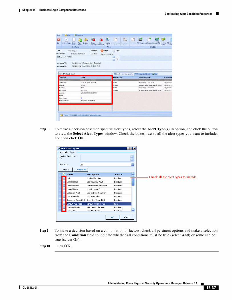
15-37Administering Cisco Physical Security Operations Manager, Release 6.1
OL-28432-01
Chapter 15 Business Logic Component Reference Configuring Alert Condition Properties
Step 8 To make a decision based on specific alert types, select the Alert Type(s) in option, and click the button to view the Select Alert Types window. Check the boxes next to all the alert types you want to include, and then click OK.
Step 9 To make a decision based on a combination of factors, check all pertinent options and make a selection from the Condition field to indicate whether all conditions must be true (select And) or some can be true (select Or).
Step 10 Click OK.
Check all the alert types to include.
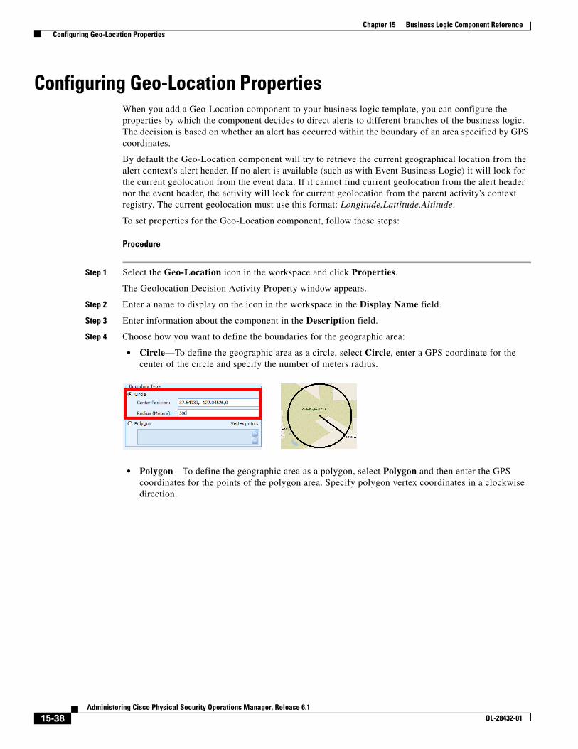
15-38Administering Cisco Physical Security Operations Manager, Release 6.1
OL-28432-01
Chapter 15 Business Logic Component Reference Configuring Geo-Location Properties
Configuring Geo-Location PropertiesWhen you add a Geo-Location component to your business logic template, you can configure the properties by which the component decides to direct alerts to different branches of the business logic. The decision is based on whether an alert has occurred within the boundary of an area specified by GPS coordinates.
By default the Geo-Location component will try to retrieve the current geographical location from the alert context's alert header. If no alert is available (such as with Event Business Logic) it will look for the current geolocation from the event data. If it cannot find current geolocation from the alert header nor the event header, the activity will look for current geolocation from the parent activity's context registry. The current geolocation must use this format: Longitude,Lattitude,Altitude.
To set properties for the Geo-Location component, follow these steps:
Procedure
Step 1 Select the Geo-Location icon in the workspace and click Properties.
The Geolocation Decision Activity Property window appears.
Step 2 Enter a name to display on the icon in the workspace in the Display Name field.
Step 3 Enter information about the component in the Description field.
Step 4 Choose how you want to define the boundaries for the geographic area:
• Circle—To define the geographic area as a circle, select Circle, enter a GPS coordinate for the center of the circle and specify the number of meters radius.
• Polygon—To define the geographic area as a polygon, select Polygon and then enter the GPS coordinates for the points of the polygon area. Specify polygon vertex coordinates in a clockwise direction.
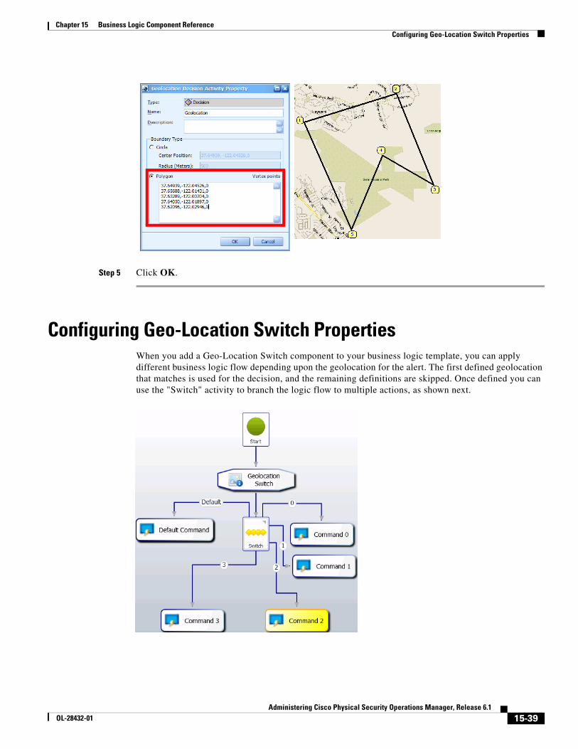
15-39Administering Cisco Physical Security Operations Manager, Release 6.1
OL-28432-01
Chapter 15 Business Logic Component Reference Configuring Geo-Location Switch Properties
Step 5 Click OK.
Configuring Geo-Location Switch PropertiesWhen you add a Geo-Location Switch component to your business logic template, you can apply different business logic flow depending upon the geolocation for the alert. The first defined geolocation that matches is used for the decision, and the remaining definitions are skipped. Once defined you can use the "Switch" activity to branch the logic flow to multiple actions, as shown next.
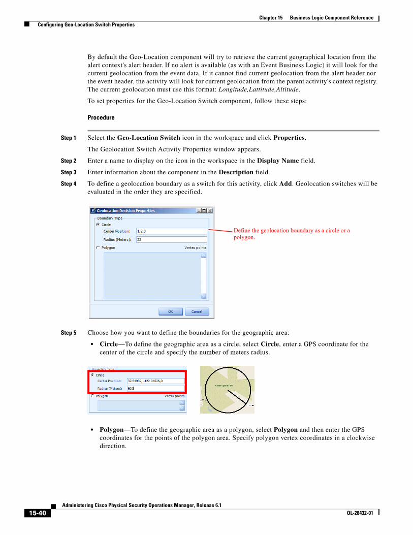
15-40Administering Cisco Physical Security Operations Manager, Release 6.1
OL-28432-01
Chapter 15 Business Logic Component Reference Configuring Geo-Location Switch Properties
By default the Geo-Location component will try to retrieve the current geographical location from the alert context's alert header. If no alert is available (as with an Event Business Logic) it will look for the current geolocation from the event data. If it cannot find current geolocation from the alert header nor the event header, the activity will look for current geolocation from the parent activity's context registry. The current geolocation must use this format: Longitude,Lattitude,Altitude.
To set properties for the Geo-Location Switch component, follow these steps:
Procedure
Step 1 Select the Geo-Location Switch icon in the workspace and click Properties.
The Geolocation Switch Activity Properties window appears.
Step 2 Enter a name to display on the icon in the workspace in the Display Name field.
Step 3 Enter information about the component in the Description field.
Step 4 To define a geolocation boundary as a switch for this activity, click Add. Geolocation switches will be evaluated in the order they are specified.
Step 5 Choose how you want to define the boundaries for the geographic area:
• Circle—To define the geographic area as a circle, select Circle, enter a GPS coordinate for the center of the circle and specify the number of meters radius.
• Polygon—To define the geographic area as a polygon, select Polygon and then enter the GPS coordinates for the points of the polygon area. Specify polygon vertex coordinates in a clockwise direction.
Define the geolocation boundary as a circle or a polygon.
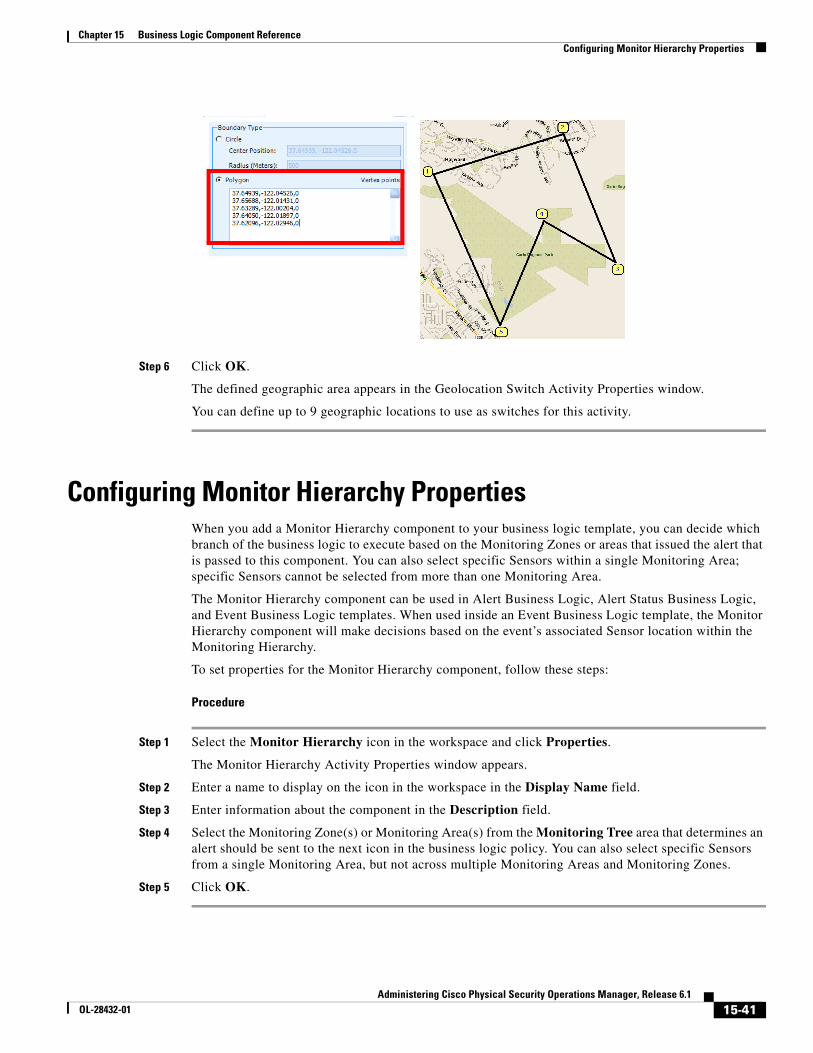
15-41Administering Cisco Physical Security Operations Manager, Release 6.1
OL-28432-01
Chapter 15 Business Logic Component Reference Configuring Monitor Hierarchy Properties
Step 6 Click OK.
The defined geographic area appears in the Geolocation Switch Activity Properties window.
You can define up to 9 geographic locations to use as switches for this activity.
Configuring Monitor Hierarchy PropertiesWhen you add a Monitor Hierarchy component to your business logic template, you can decide which branch of the business logic to execute based on the Monitoring Zones or areas that issued the alert that is passed to this component. You can also select specific Sensors within a single Monitoring Area; specific Sensors cannot be selected from more than one Monitoring Area.
The Monitor Hierarchy component can be used in Alert Business Logic, Alert Status Business Logic, and Event Business Logic templates. When used inside an Event Business Logic template, the Monitor Hierarchy component will make decisions based on the event’s associated Sensor location within the Monitoring Hierarchy.
To set properties for the Monitor Hierarchy component, follow these steps:
Procedure
Step 1 Select the Monitor Hierarchy icon in the workspace and click Properties.
The Monitor Hierarchy Activity Properties window appears.
Step 2 Enter a name to display on the icon in the workspace in the Display Name field.
Step 3 Enter information about the component in the Description field.
Step 4 Select the Monitoring Zone(s) or Monitoring Area(s) from the Monitoring Tree area that determines an alert should be sent to the next icon in the business logic policy. You can also select specific Sensors from a single Monitoring Area, but not across multiple Monitoring Areas and Monitoring Zones.
Step 5 Click OK.
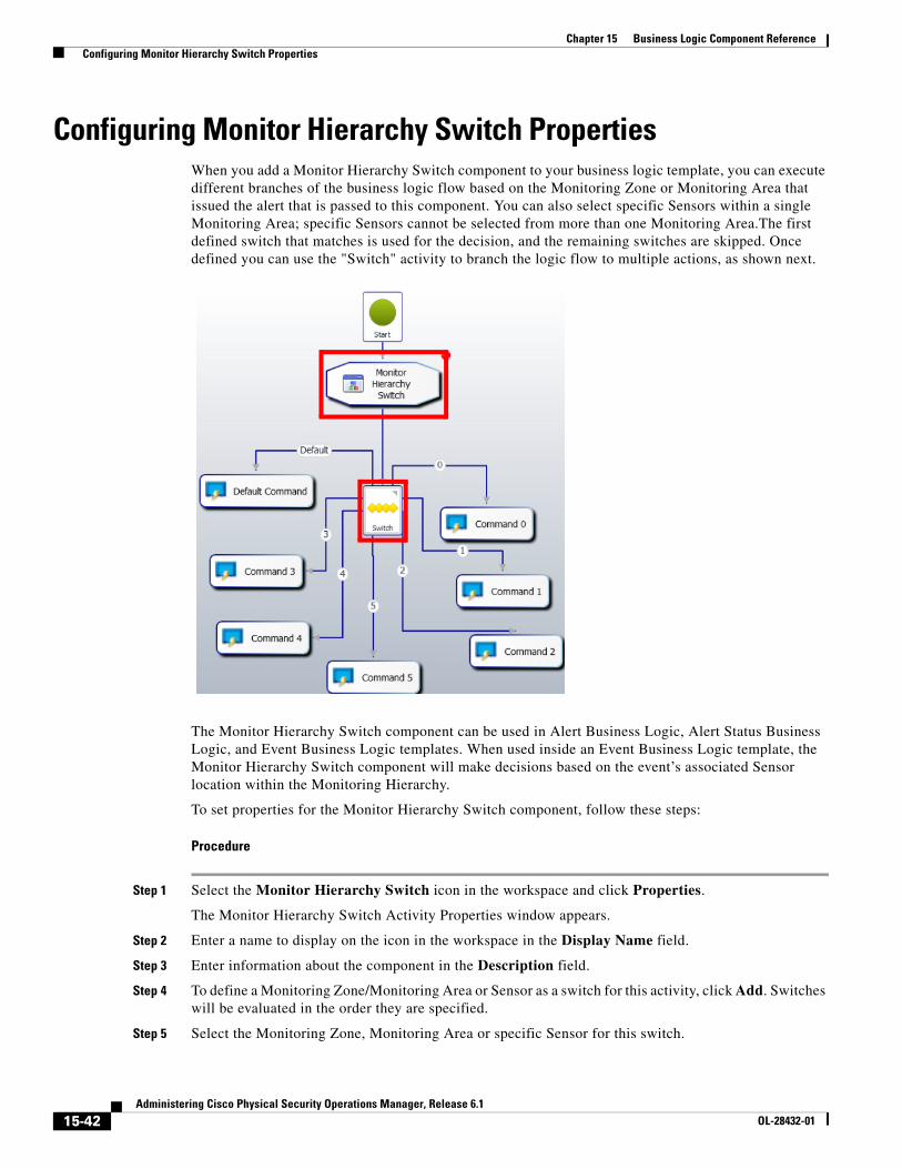
15-42Administering Cisco Physical Security Operations Manager, Release 6.1
OL-28432-01
Chapter 15 Business Logic Component Reference Configuring Monitor Hierarchy Switch Properties
Configuring Monitor Hierarchy Switch PropertiesWhen you add a Monitor Hierarchy Switch component to your business logic template, you can execute different branches of the business logic flow based on the Monitoring Zone or Monitoring Area that issued the alert that is passed to this component. You can also select specific Sensors within a single Monitoring Area; specific Sensors cannot be selected from more than one Monitoring Area.The first defined switch that matches is used for the decision, and the remaining switches are skipped. Once defined you can use the "Switch" activity to branch the logic flow to multiple actions, as shown next.
The Monitor Hierarchy Switch component can be used in Alert Business Logic, Alert Status Business Logic, and Event Business Logic templates. When used inside an Event Business Logic template, the Monitor Hierarchy Switch component will make decisions based on the event’s associated Sensor location within the Monitoring Hierarchy.
To set properties for the Monitor Hierarchy Switch component, follow these steps:
Procedure
Step 1 Select the Monitor Hierarchy Switch icon in the workspace and click Properties.
The Monitor Hierarchy Switch Activity Properties window appears.
Step 2 Enter a name to display on the icon in the workspace in the Display Name field.
Step 3 Enter information about the component in the Description field.
Step 4 To define a Monitoring Zone/Monitoring Area or Sensor as a switch for this activity, click Add. Switches will be evaluated in the order they are specified.
Step 5 Select the Monitoring Zone, Monitoring Area or specific Sensor for this switch.
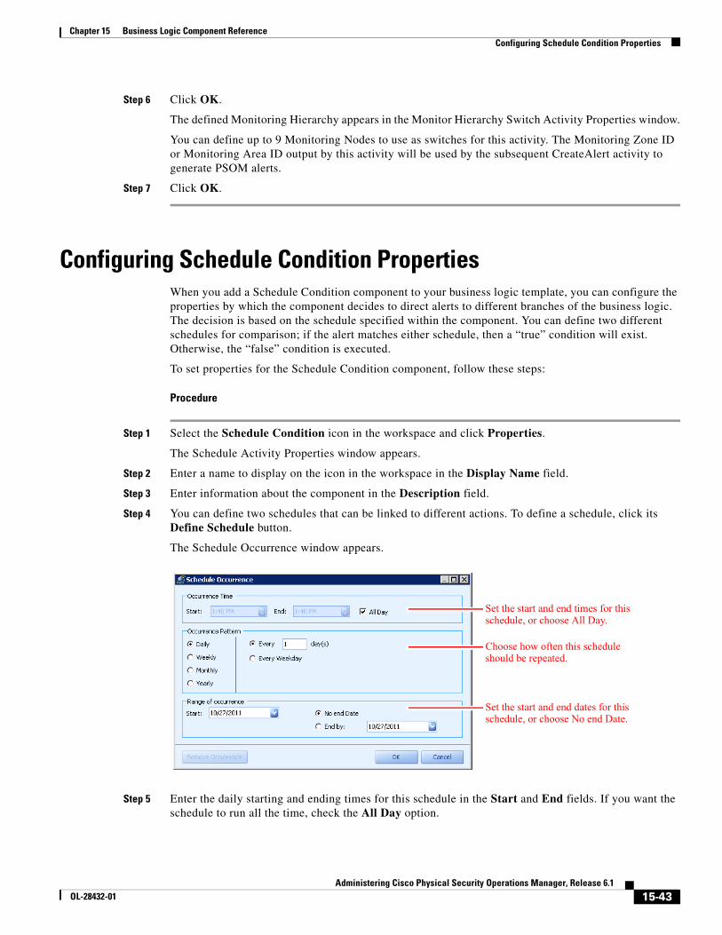
15-43Administering Cisco Physical Security Operations Manager, Release 6.1
OL-28432-01
Chapter 15 Business Logic Component Reference Configuring Schedule Condition Properties
Step 6 Click OK.
The defined Monitoring Hierarchy appears in the Monitor Hierarchy Switch Activity Properties window.
You can define up to 9 Monitoring Nodes to use as switches for this activity. The Monitoring Zone ID or Monitoring Area ID output by this activity will be used by the subsequent CreateAlert activity to generate PSOM alerts.
Step 7 Click OK.
Configuring Schedule Condition PropertiesWhen you add a Schedule Condition component to your business logic template, you can configure the properties by which the component decides to direct alerts to different branches of the business logic. The decision is based on the schedule specified within the component. You can define two different schedules for comparison; if the alert matches either schedule, then a “true” condition will exist. Otherwise, the “false” condition is executed.
To set properties for the Schedule Condition component, follow these steps:
Procedure
Step 1 Select the Schedule Condition icon in the workspace and click Properties.
The Schedule Activity Properties window appears.
Step 2 Enter a name to display on the icon in the workspace in the Display Name field.
Step 3 Enter information about the component in the Description field.
Step 4 You can define two schedules that can be linked to different actions. To define a schedule, click its Define Schedule button.
The Schedule Occurrence window appears.
Step 5 Enter the daily starting and ending times for this schedule in the Start and End fields. If you want the schedule to run all the time, check the All Day option.
Set the start and end times for this schedule, or choose All Day.
Choose how often this schedule should be repeated.
Set the start and end dates for this schedule, or choose No end Date.
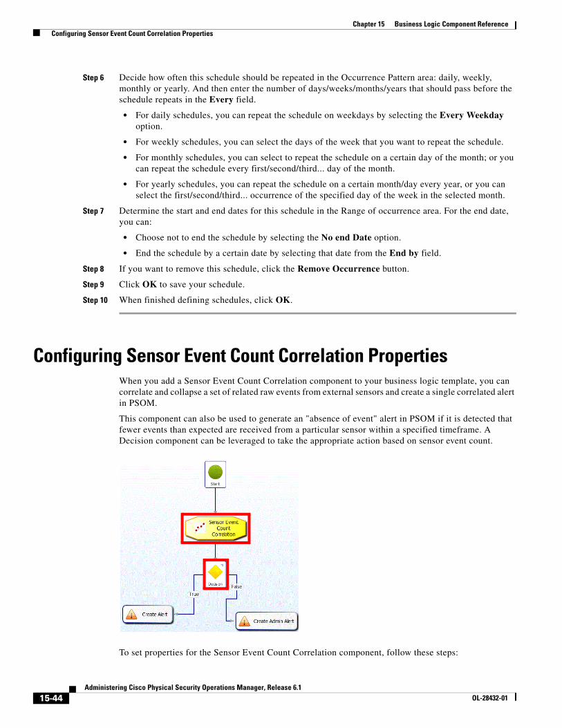
15-44Administering Cisco Physical Security Operations Manager, Release 6.1
OL-28432-01
Chapter 15 Business Logic Component Reference Configuring Sensor Event Count Correlation Properties
Step 6 Decide how often this schedule should be repeated in the Occurrence Pattern area: daily, weekly, monthly or yearly. And then enter the number of days/weeks/months/years that should pass before the schedule repeats in the Every field.
• For daily schedules, you can repeat the schedule on weekdays by selecting the Every Weekday option.
• For weekly schedules, you can select the days of the week that you want to repeat the schedule.
• For monthly schedules, you can select to repeat the schedule on a certain day of the month; or you can repeat the schedule every first/second/third... day of the month.
• For yearly schedules, you can repeat the schedule on a certain month/day every year, or you can select the first/second/third... occurrence of the specified day of the week in the selected month.
Step 7 Determine the start and end dates for this schedule in the Range of occurrence area. For the end date, you can:
• Choose not to end the schedule by selecting the No end Date option.
• End the schedule by a certain date by selecting that date from the End by field.
Step 8 If you want to remove this schedule, click the Remove Occurrence button.
Step 9 Click OK to save your schedule.
Step 10 When finished defining schedules, click OK.
Configuring Sensor Event Count Correlation PropertiesWhen you add a Sensor Event Count Correlation component to your business logic template, you can correlate and collapse a set of related raw events from external sensors and create a single correlated alert in PSOM.
This component can also be used to generate an "absence of event" alert in PSOM if it is detected that fewer events than expected are received from a particular sensor within a specified timeframe. A Decision component can be leveraged to take the appropriate action based on sensor event count.
To set properties for the Sensor Event Count Correlation component, follow these steps:
15-45Administering Cisco Physical Security Operations Manager, Release 6.1
OL-28432-01
Chapter 15 Business Logic Component Reference Configuring Threat Level Properties
Procedure
Step 1 Select the Sensor Event Count Correlation icon in the workspace and click Properties.
The Sensor Event Count Correlation Activity window appears.
Step 2 Enter a name to display on the icon in the workspace in the Display Name field.
Step 3 Enter information about the component in the Description field.
Step 4 Choose the Sensor to monitor by clicking the ellipses button in the Selected Sensor field.
The Sensor Mapping window appears.
Step 5 Select the Sensor that should be monitored and click OK.
Step 6 From the Event Count field, select Greater Than or Equal To or Less Than, depending on whether you want to specify that more events happened than expected, or less events occurred. Then specify the event count that triggers an alert.
Step 7 Specify the timeframe (in seconds) over which the event count should occur in the Time Window field.
Step 8 Click OK.
Configuring Threat Level PropertiesWhen you add a Threat Level component to your business logic template, you can configure the properties by which the component decides to direct alerts to different branches of the business logic . The decision is based on the threat level of Homeland Security or MARSEC configured in PSOM.
To set properties for the Threat Level component, follow these steps:
Procedure
Step 1 Select the Threat Level icon in the workspace and click Properties.
The Threat Level Activity Properties window appears.
Step 2 Enter a name to display on the icon in the workspace in the Display Name field.
Step 3 Enter information about the component in the Description field.
Step 4 If you want to make a decision based on Homeland Security, select Homeland Security from the Type field, and choose Low, Guarded, Elevated, High, or Severe from the Level field. You can select whether the level should be Equal To, Greater Than or Equal To, or Less Than or Equal To from the first drop-down menu next to the Level field.
Step 5 If you want to make a decision based on MARSEC, select MARSEC from the Type field, and choose MARSEC 1, MARSEC 2, or MARSEC 3 from the Level field. You can select whether the level should be Equal To, Greater Than or Equal To, or Less Than or Equal To from the first drop-down menu next to the Level field.
Step 6 Click OK.
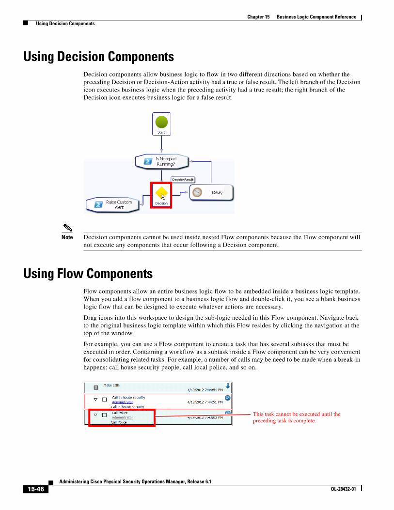
15-46Administering Cisco Physical Security Operations Manager, Release 6.1
OL-28432-01
Chapter 15 Business Logic Component Reference Using Decision Components
Using Decision ComponentsDecision components allow business logic to flow in two different directions based on whether the preceding Decision or Decision-Action activity had a true or false result. The left branch of the Decision icon executes business logic when the preceding activity had a true result; the right branch of the Decision icon executes business logic for a false result.
Note Decision components cannot be used inside nested Flow components because the Flow component will not execute any components that occur following a Decision component.
Using Flow ComponentsFlow components allow an entire business logic flow to be embedded inside a business logic template. When you add a flow component to a business logic flow and double-click it, you see a blank business logic flow that can be designed to execute whatever actions are necessary.
Drag icons into this workspace to design the sub-logic needed in this Flow component. Navigate back to the original business logic template within which this Flow resides by clicking the navigation at the top of the window.
For example, you can use a Flow component to create a task that has several subtasks that must be executed in order. Containing a workflow as a subtask inside a Flow component can be very convenient for consolidating related tasks. For example, a number of calls may be need to be made when a break-in happens: call house security people, call local police, and so on.
This task cannot be executed until the preceding task is complete.
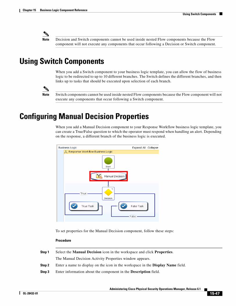
15-47Administering Cisco Physical Security Operations Manager, Release 6.1
OL-28432-01
Chapter 15 Business Logic Component Reference Using Switch Components
Note Decision and Switch components cannot be used inside nested Flow components because the Flow component will not execute any components that occur following a Decision or Switch component.
Using Switch ComponentsWhen you add a Switch component to your business logic template, you can allow the flow of business logic to be redirected to up to 10 different branches. The Switch defines the different branches, and then links up to tasks that should be executed upon selection of each branch.
Note Switch components cannot be used inside nested Flow components because the Flow component will not execute any components that occur following a Switch component.
Configuring Manual Decision PropertiesWhen you add a Manual Decision component to your Response Workflow business logic template, you can create a True/False question to which the operator must respond when handling an alert. Depending on the response, a different branch of the business logic is executed.
To set properties for the Manual Decision component, follow these steps:
Procedure
Step 1 Select the Manual Decision icon in the workspace and click Properties.
The Manual Decision Activity Properties window appears.
Step 2 Enter a name to display on the icon in the workspace in the Display Name field.
Step 3 Enter information about the component in the Description field.
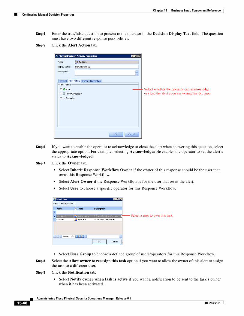
15-48Administering Cisco Physical Security Operations Manager, Release 6.1
OL-28432-01
Chapter 15 Business Logic Component Reference Configuring Manual Decision Properties
Step 4 Enter the true/false question to present to the operator in the Decision Display Text field. The question must have two different response possibilities.
Step 5 Click the Alert Action tab.
Step 6 If you want to enable the operator to acknowledge or close the alert when answering this question, select the appropriate option. For example, selecting Acknowledgeable enables the operator to set the alert’s status to Acknowledged.
Step 7 Click the Owner tab.
• Select Inherit Response Workflow Owner if the owner of this response should be the user that owns this Response Workflow.
• Select Alert Owner if the Response Workflow is for the user that owns the alert.
• Select User to choose a specific operator for this Response Workflow.
• Select User Group to choose a defined group of users/operators for this Response Workflow.
Step 8 Select the Allow owner to reassign this task option if you want to allow the owner of this alert to assign the task to a different user.
Step 9 Click the Notification tab.
• Select Notify owner when task is active if you want a notification to be sent to the task’s owner when it has been activated.
Select whether the operator can acknowledge or close the alert upon answering this decision.
Select a user to own this task.
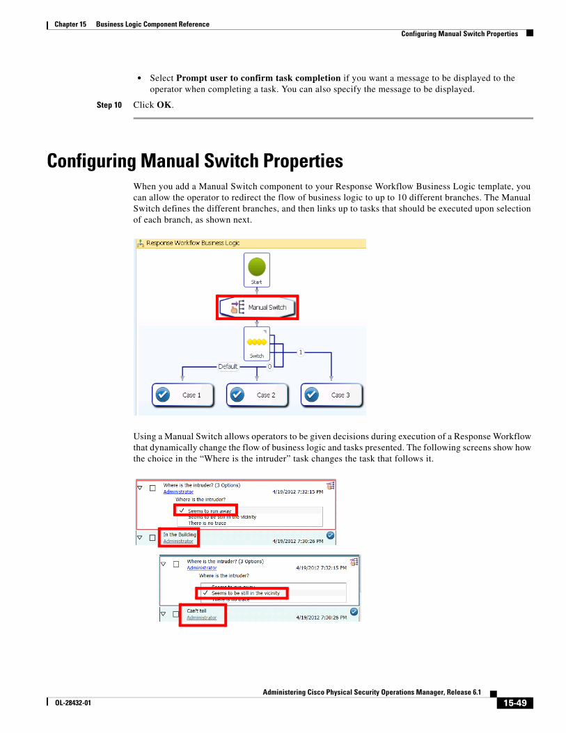
15-49Administering Cisco Physical Security Operations Manager, Release 6.1
OL-28432-01
Chapter 15 Business Logic Component Reference Configuring Manual Switch Properties
• Select Prompt user to confirm task completion if you want a message to be displayed to the operator when completing a task. You can also specify the message to be displayed.
Step 10 Click OK.
Configuring Manual Switch PropertiesWhen you add a Manual Switch component to your Response Workflow Business Logic template, you can allow the operator to redirect the flow of business logic to up to 10 different branches. The Manual Switch defines the different branches, and then links up to tasks that should be executed upon selection of each branch, as shown next.
Using a Manual Switch allows operators to be given decisions during execution of a Response Workflow that dynamically change the flow of business logic and tasks presented. The following screens show how the choice in the “Where is the intruder” task changes the task that follows it.
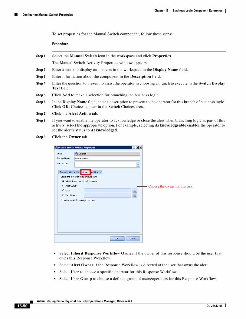
15-50Administering Cisco Physical Security Operations Manager, Release 6.1
OL-28432-01
Chapter 15 Business Logic Component Reference Configuring Manual Switch Properties
To set properties for the Manual Switch component, follow these steps:
Procedure
Step 1 Select the Manual Switch icon in the workspace and click Properties.
The Manual Switch Activity Properties window appears.
Step 2 Enter a name to display on the icon in the workspace in the Display Name field.
Step 3 Enter information about the component in the Description field.
Step 4 Enter the question to present to assist the operator in choosing a branch to execute in the Switch Display Text field.
Step 5 Click Add to make a selection for branching the business logic.
Step 6 In the Display Name field, enter a description to present to the operator for this branch of business logic. Click OK. Choices appear in the Switch Choices area.
Step 7 Click the Alert Action tab.
Step 8 If you want to enable the operator to acknowledge or close the alert when branching logic as part of this activity, select the appropriate option. For example, selecting Acknowledgeable enables the operator to set the alert’s status to Acknowledged.
Step 9 Click the Owner tab.
• Select Inherit Response Workflow Owner if the owner of this response should be the user that owns this Response Workflow.
• Select Alert Owner if the Response Workflow is directed at the user that owns the alert.
• Select User to choose a specific operator for this Response Workflow.
• Select User Group to choose a defined group of users/operators for this Response Workflow.
Choose the owner for this task.
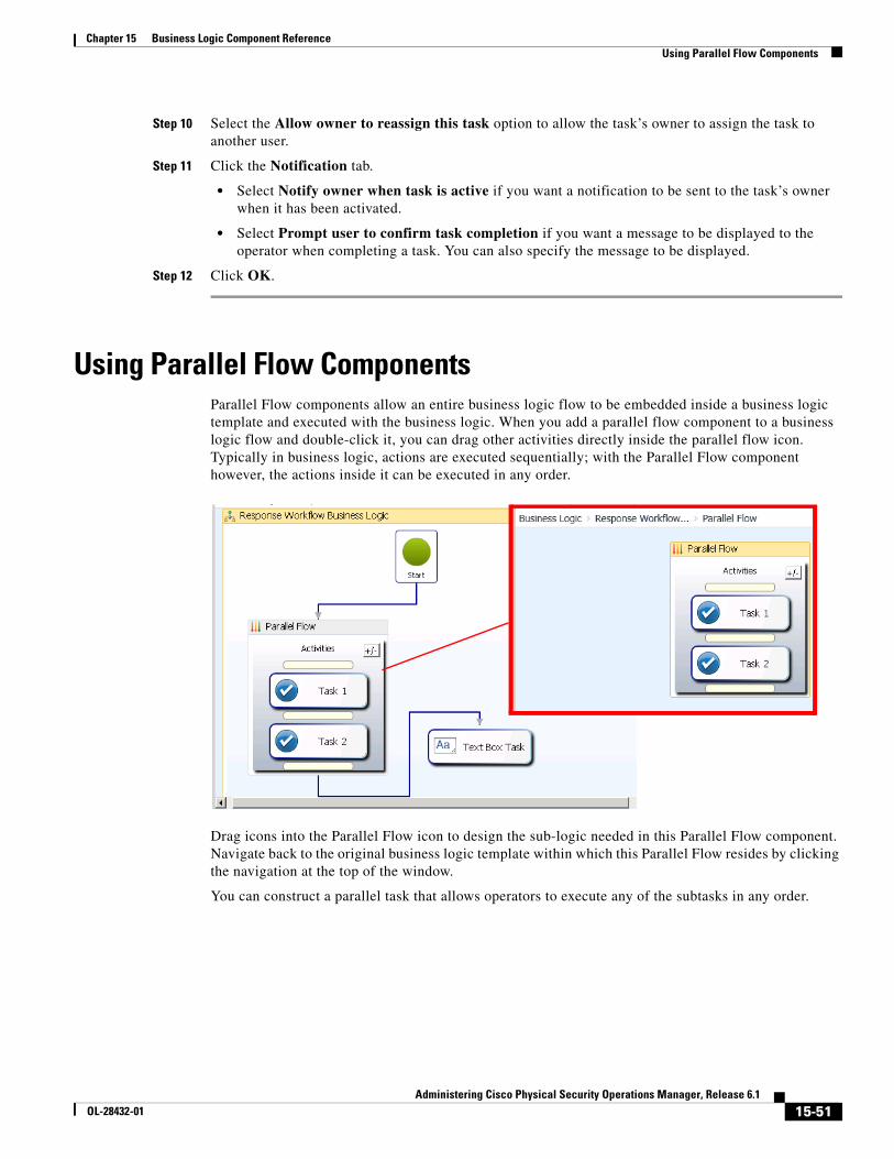
15-51Administering Cisco Physical Security Operations Manager, Release 6.1
OL-28432-01
Chapter 15 Business Logic Component Reference Using Parallel Flow Components
Step 10 Select the Allow owner to reassign this task option to allow the task’s owner to assign the task to another user.
Step 11 Click the Notification tab.
• Select Notify owner when task is active if you want a notification to be sent to the task’s owner when it has been activated.
• Select Prompt user to confirm task completion if you want a message to be displayed to the operator when completing a task. You can also specify the message to be displayed.
Step 12 Click OK.
Using Parallel Flow ComponentsParallel Flow components allow an entire business logic flow to be embedded inside a business logic template and executed with the business logic. When you add a parallel flow component to a business logic flow and double-click it, you can drag other activities directly inside the parallel flow icon. Typically in business logic, actions are executed sequentially; with the Parallel Flow component however, the actions inside it can be executed in any order.
Drag icons into the Parallel Flow icon to design the sub-logic needed in this Parallel Flow component. Navigate back to the original business logic template within which this Parallel Flow resides by clicking the navigation at the top of the window.
You can construct a parallel task that allows operators to execute any of the subtasks in any order.
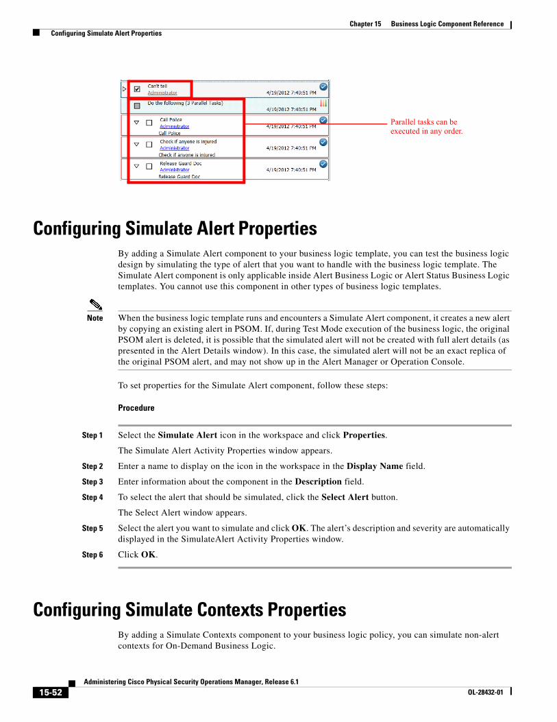
15-52Administering Cisco Physical Security Operations Manager, Release 6.1
OL-28432-01
Chapter 15 Business Logic Component Reference Configuring Simulate Alert Properties
Configuring Simulate Alert PropertiesBy adding a Simulate Alert component to your business logic template, you can test the business logic design by simulating the type of alert that you want to handle with the business logic template. The Simulate Alert component is only applicable inside Alert Business Logic or Alert Status Business Logic templates. You cannot use this component in other types of business logic templates.
Note When the business logic template runs and encounters a Simulate Alert component, it creates a new alert by copying an existing alert in PSOM. If, during Test Mode execution of the business logic, the original PSOM alert is deleted, it is possible that the simulated alert will not be created with full alert details (as presented in the Alert Details window). In this case, the simulated alert will not be an exact replica of the original PSOM alert, and may not show up in the Alert Manager or Operation Console.
To set properties for the Simulate Alert component, follow these steps:
Procedure
Step 1 Select the Simulate Alert icon in the workspace and click Properties.
The Simulate Alert Activity Properties window appears.
Step 2 Enter a name to display on the icon in the workspace in the Display Name field.
Step 3 Enter information about the component in the Description field.
Step 4 To select the alert that should be simulated, click the Select Alert button.
The Select Alert window appears.
Step 5 Select the alert you want to simulate and click OK. The alert’s description and severity are automatically displayed in the SimulateAlert Activity Properties window.
Step 6 Click OK.
Configuring Simulate Contexts PropertiesBy adding a Simulate Contexts component to your business logic policy, you can simulate non-alert contexts for On-Demand Business Logic.
Parallel tasks can be executed in any order.
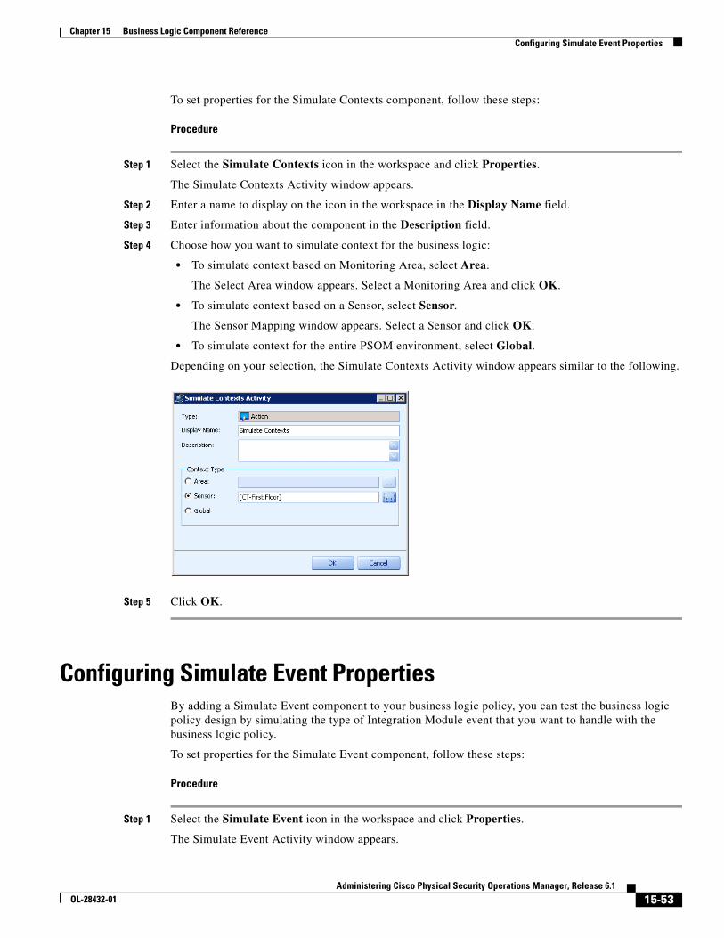
15-53Administering Cisco Physical Security Operations Manager, Release 6.1
OL-28432-01
Chapter 15 Business Logic Component Reference Configuring Simulate Event Properties
To set properties for the Simulate Contexts component, follow these steps:
Procedure
Step 1 Select the Simulate Contexts icon in the workspace and click Properties.
The Simulate Contexts Activity window appears.
Step 2 Enter a name to display on the icon in the workspace in the Display Name field.
Step 3 Enter information about the component in the Description field.
Step 4 Choose how you want to simulate context for the business logic:
• To simulate context based on Monitoring Area, select Area.
The Select Area window appears. Select a Monitoring Area and click OK.
• To simulate context based on a Sensor, select Sensor.
The Sensor Mapping window appears. Select a Sensor and click OK.
• To simulate context for the entire PSOM environment, select Global.
Depending on your selection, the Simulate Contexts Activity window appears similar to the following.
Step 5 Click OK.
Configuring Simulate Event PropertiesBy adding a Simulate Event component to your business logic policy, you can test the business logic policy design by simulating the type of Integration Module event that you want to handle with the business logic policy.
To set properties for the Simulate Event component, follow these steps:
Procedure
Step 1 Select the Simulate Event icon in the workspace and click Properties.
The Simulate Event Activity window appears.
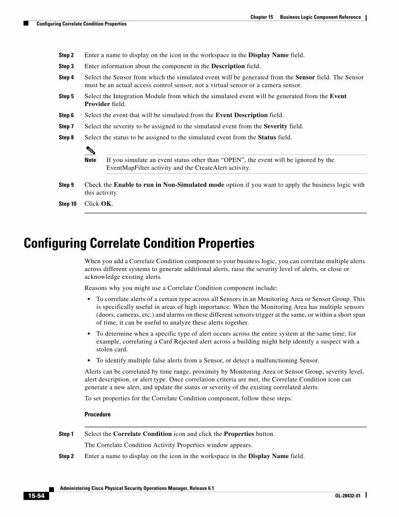
15-54Administering Cisco Physical Security Operations Manager, Release 6.1
OL-28432-01
Chapter 15 Business Logic Component Reference Configuring Correlate Condition Properties
Step 2 Enter a name to display on the icon in the workspace in the Display Name field.
Step 3 Enter information about the component in the Description field.
Step 4 Select the Sensor from which the simulated event will be generated from the Sensor field. The Sensor must be an actual access control sensor, not a virtual sensor or a camera sensor.
Step 5 Select the Integration Module from which the simulated event will be generated from the Event Provider field.
Step 6 Select the event that will be simulated from the Event Description field.
Step 7 Select the severity to be assigned to the simulated event from the Severity field.
Step 8 Select the status to be assigned to the simulated event from the Status field.
Note If you simulate an event status other than “OPEN”, the event will be ignored by the EventMapFilter activity and the CreateAlert activity.
Step 9 Check the Enable to run in Non-Simulated mode option if you want to apply the business logic with this activity.
Step 10 Click OK.
Configuring Correlate Condition PropertiesWhen you add a Correlate Condition component to your business logic, you can correlate multiple alerts across different systems to generate additional alerts, raise the severity level of alerts, or close or acknowledge existing alerts.
Reasons why you might use a Correlate Condition component include:
• To correlate alerts of a certain type across all Sensors in an Monitoring Area or Sensor Group. This is specifically useful in areas of high importance. When the Monitoring Area has multiple sensors (doors, cameras, etc.) and alarms on these different sensors trigger at the same, or within a short span of time, it can be useful to analyze these alerts together.
• To determine when a specific type of alert occurs across the entire system at the same time; for example, correlating a Card Rejected alert across a building might help identify a suspect with a stolen card.
• To identify multiple false alerts from a Sensor, or detect a malfunctioning Sensor.
Alerts can be correlated by time range, proximity by Monitoring Area or Sensor Group, severity level, alert description, or alert type. Once correlation criteria are met, the Correlate Condition icon can generate a new alert, and update the status or severity of the existing correlated alerts.
To set properties for the Correlate Condition component, follow these steps:
Procedure
Step 1 Select the Correlate Condition icon and click the Properties button.
The Correlate Condition Activity Properties window appears.
Step 2 Enter a name to display on the icon in the workspace in the Display Name field.
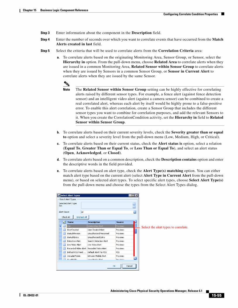
15-55Administering Cisco Physical Security Operations Manager, Release 6.1
OL-28432-01
Chapter 15 Business Logic Component Reference Configuring Correlate Condition Properties
Step 3 Enter information about the component in the Description field.
Step 4 Enter the number of seconds over which you want to correlate events that have occurred from the Match Alerts created in last field.
Step 5 Select the criteria that will be used to correlate alerts from the Correlation Criteria area:
a. To correlate alerts based on the originating Monitoring Area, Sensor Group, or Sensor, select the Hierarchy in option. From the pull-down menu, choose Related Area to correlate alerts when they are issued in a common Monitoring Area, Related Sensor within Sensor Group to correlate alerts when they are issued by Sensors in a common Sensor Group, or Sensor in Current Alert to correlate alerts when they are issued by the same Sensor.
Note The Related Sensor within Sensor Group setting can be highly effective for correlating alerts raised by different sensor types. For example, a fence alert (against fence detection sensor) and an intelligent video alert (against a camera sensor) can be combined to create a real correlated alert, whereas each alert by itself would be highly prone to a false-positive error. To enable this alert correlation, create a Sensor Group that includes the different sensor types you want to combine for correlation purposes, and add the relevant Sensors to it. When you create the CorrelationCondition activity, set the Hierarchy in field to Related Sensor within Sensor Group.
b. To correlate alerts based on their current severity levels, check the Severity greater than or equal to option and select a severity level from the pull-down menu (Low, Medium, High, or Critical).
c. To correlate alerts based on their current status, check the Alert status is option, select a relation (Equal To, Greater Than or Equal To, or Less Than or Equal To), and select an alert status (Open, Acknowledged, or Closed).
d. To correlate alerts based on a common description, check the Description contains option and enter the descriptive words in the field provided.
e. To correlate alerts based on alert type, check the Alert Type(s) matching option. You can either match alert type based on the current alert (select Alert Type in Current Alert from the pull-down menu), or based on selected alert types. To select specific alert types, choose Select Alert Type(s) from the pull-down menu and choose the types from the Select Alert Types dialog.
Select the alert types to correlate.
15-56Administering Cisco Physical Security Operations Manager, Release 6.1
OL-28432-01
Chapter 15 Business Logic Component Reference Configuring Correlate Condition Properties
Note In most cases, you should set the Alert Type(s) in option as part of your correlation criteria to specific and limited alert types. If you do not use this option, or if you simply select all alert types for correlation, you may experience unwanted behavior including the creation of correlation alerts that trigger additional correlation activities.
Step 6 Choose the action to take when alerts are correlated from the Action area.
a. To generate a new alert, select the Create Correlation Alert with option. Select DefaultCorrelationAlert from the Alert Type field (or select a custom correlation alert), choose an alert severity to assign this alert from the Severity field (Low, Medium, High, or Critical), and select the sensor type for this alert from the Relative Sensor Type field (shown next).
b. If you choose the Create Correlation Alert with option, PSOM will create a new alert that combines the multiple input alerts into one new correlated alert. To perform an action on this new correlated alert, you must check the Use Correlation Alert for subsequent activities option as well. Otherwise, actions may be performed on just one of the multiple input alerts.
c. To update the status of the correlated alerts, select the Update Status of Correlated Alerts option and choose the appropriate status from the pull-down menu (Acknowledged or Closed).
d. To update the severity of the correlated alerts, select the Update Severity of Correlated Alerts option and choose the severity to assign from the pull-down menu (Low, Medium, High, or Critical).
Step 7 Click OK.
The following business logic design uses SimulateAlert components connected with a Delay component. This flow simulates the alerts that this business logic policy is designed to correlate; the Delay component simulates a realistic timeframe during which the alerts are raised. Once both alerts have been raised, the CorrelateCondition component performs its work.
Select the sensor type to be associated with the alert.
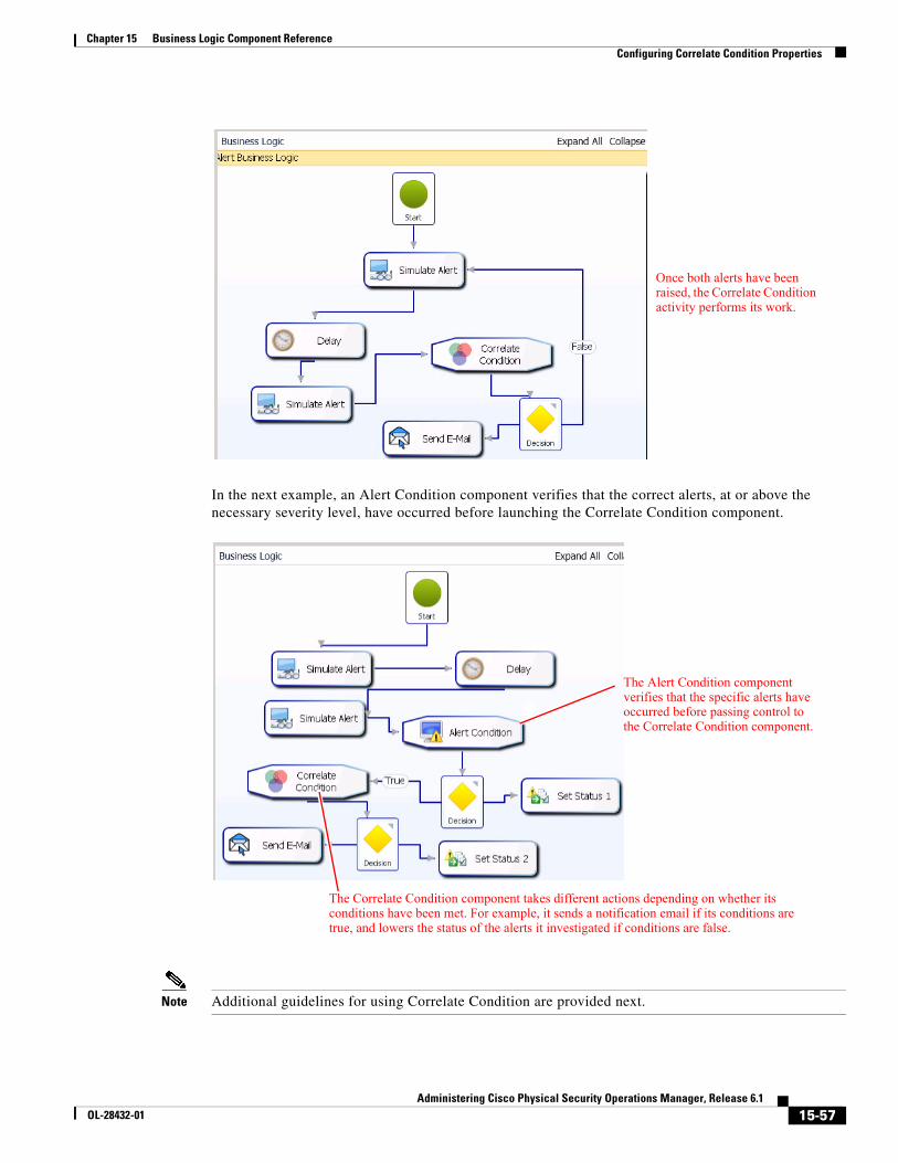
15-57Administering Cisco Physical Security Operations Manager, Release 6.1
OL-28432-01
Chapter 15 Business Logic Component Reference Configuring Correlate Condition Properties
In the next example, an Alert Condition component verifies that the correct alerts, at or above the necessary severity level, have occurred before launching the Correlate Condition component.
Note Additional guidelines for using Correlate Condition are provided next.
Once both alerts have been raised, the Correlate Condition activity performs its work.
The Alert Condition component verifies that the specific alerts have occurred before passing control to the Correlate Condition component.
The Correlate Condition component takes different actions depending on whether its conditions have been met. For example, it sends a notification email if its conditions are true, and lowers the status of the alerts it investigated if conditions are false.
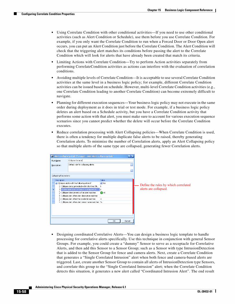
15-58Administering Cisco Physical Security Operations Manager, Release 6.1
OL-28432-01
Chapter 15 Business Logic Component Reference Configuring Correlate Condition Properties
• Using Correlate Condition with other conditional activities—If you need to use other conditional activities (such as Alert Condition or Schedule), use them before you use Correlate Condition. For example, if you only want the Correlate Condition to run when a Forced Door or Door Open alert occurs, you can put an Alert Condition just before the Correlate Condition. The Alert Condition will check that the triggering alert matches its conditions before passing the alert to the Correlate Condition which will look for alerts that have already been created that match its criteria.
• Limiting Actions with Correlate Condition—Try to perform Action activities separately from performing CorrelateCondition activities as actions can interfere with the evaluation of correlation conditions.
• Avoiding multiple levels of Correlate Condition—It is acceptable to use several Correlate Condition activities at the same level in a business logic policy; for example, different Correlate Condition activities can be issued based on schedule. However, multi-level Correlate Condition activities (e.g., one Correlate Condition leading to another Correlate Condition) can become extremely difficult to navigate.
• Planning for different execution sequences—Your business logic policy may not execute in the same order during deployment as it does in trial or test mode. For example, if a business logic policy deletes an alert based on a Schedule activity, but you have a Correlate Condition activity that performs some action with that alert, you must make sure to account for various execution sequence scenarios since you cannot predict whether the delete will occur before the Correlate Condition executes.
• Reduce correlation processing with Alert Collapsing policies—When Correlate Condition is used, there is often a tendency for multiple duplicate false alerts to be raised, thereby generating Correlation alerts. To minimize the number of Correlation alerts, apply an Alert Collapsing policy so that multiple alerts of the same type are collapsed, generating fewer Correlation alerts.
• Designing coordinated Correlative Alerts—You can design a business logic template to handle processing for correlative alerts specifically. Use this technique in conjunction with general Sensor Groups. For example, you could create a “dummy” Sensor to serve as a receptacle for Correlative Alerts, and then add this Sensor to a Sensor Group; such as a Sensor with type IntrusionDetection that is added to the Sensor Group for fence and camera alerts. Next, create a Correlate Condition that generates a “Single Correlated Intrusion” alert when both fence and camera-based alerts are triggered. Last, create another Sensor Group to contain all alerts of IntrusionDetection type Sensors, and correlate this group to the “Single Correlated Intrusion” alert; when the Correlate Condition detects this situation, it generates a new alert called “Coordinated Intrusion Alert”. The end result
Define the rules by which correlated alerts are collapsed.
15-59Administering Cisco Physical Security Operations Manager, Release 6.1
OL-28432-01
Chapter 15 Business Logic Component Reference Configuring Event Map Filter Properties
is that this “Coordinated Intrusion Alert” tells the security staff that there is a coordinated attack on the facility as multiple correlative alerts (against fence and intelligent video) have risen at the same time in multiple places. Another business logic template can send an email to local police when a “Coordinated Intrusion Alert” is detected.
Configuring Event Map Filter PropertiesWhen you add an Event Map Filter component to your business logic template, you can filter Integration Module events for an Event Business Logic template. Events that meet the criteria specified in the Event Map Filter component are created as alerts in PSOM with the defined severity against the selected sensor type. You can define as many filters in the Event Map Filter component as you need.
Note • If you want to receive all Integration Module events into PSOM as alerts, you do not need to use this activity. However if you want to perform advanced filtering and specify the parameters for raised alerts, then you can use this activity.
• Because Event Business Logic raises an alert by default on the source sensor, customers of AgentVI or Nextiva may want to use an Event Map Filter activity to specify the target sensor type to be “Camera - Stationary”, “Camera - PTZ”, or “Camera - Others” so that the alert will be raised on the associated camera sensor instead.
To set properties for the Event Map Filter component, follow these steps:
Procedure
Step 1 Select the Event Map Filter icon in the workspace and click Properties.
The Event Map and Filter Activity window appears.
Step 2 Enter a name to display on the icon in the workspace in the Display Name field.
Step 3 Enter information about the component in the Description field.
Step 4 To add a new filter:
a. Click Add. The Event Map Filter Editor window appears.
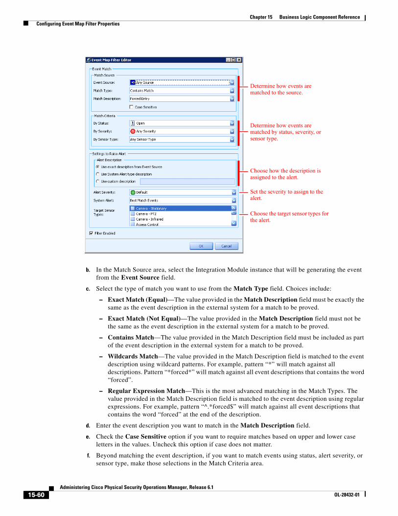
15-60Administering Cisco Physical Security Operations Manager, Release 6.1
OL-28432-01
Chapter 15 Business Logic Component Reference Configuring Event Map Filter Properties
b. In the Match Source area, select the Integration Module instance that will be generating the event from the Event Source field.
c. Select the type of match you want to use from the Match Type field. Choices include:
– Exact Match (Equal)—The value provided in the Match Description field must be exactly the same as the event description in the external system for a match to be proved.
– Exact Match (Not Equal)—The value provided in the Match Description field must not be the same as the event description in the external system for a match to be proved.
– Contains Match—The value provided in the Match Description field must be included as part of the event description in the external system for a match to be proved.
– Wildcards Match—The value provided in the Match Description field is matched to the event description using wildcard patterns. For example, pattern “*” will match against all descriptions. Pattern “*forced*” will match against all event descriptions that contains the word “forced”.
– Regular Expression Match—This is the most advanced matching in the Match Types. The value provided in the Match Description field is matched to the event description using regular expressions. For example, pattern “^.*forced$” will match against all event descriptions that contains the word “forced” at the end of the description.
d. Enter the event description you want to match in the Match Description field.
e. Check the Case Sensitive option if you want to require matches based on upper and lower case letters in the values. Uncheck this option if case does not matter.
f. Beyond matching the event description, if you want to match events using status, alert severity, or sensor type, make those selections in the Match Criteria area.
Determine how events are matched to the source.
Determine how events are matched by status, severity, or sensor type.
Choose how the description is assigned to the alert.
Set the severity to assign to the alert.
Choose the target sensor types for the alert.
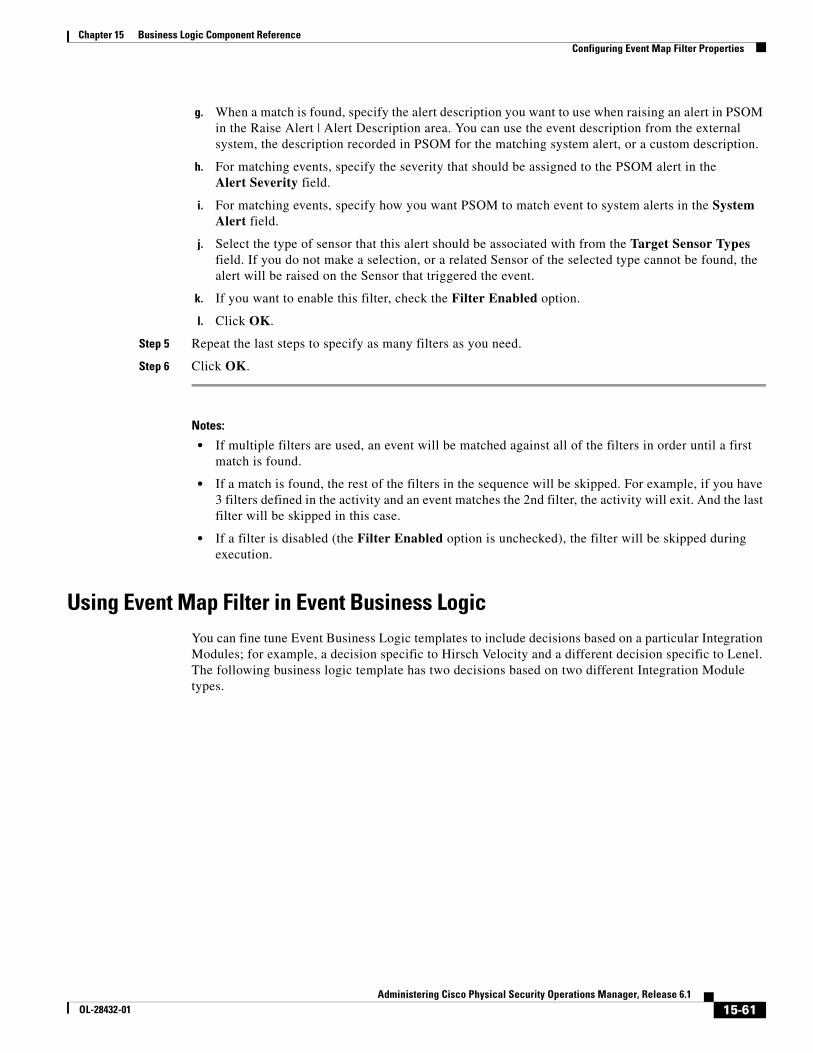
15-61Administering Cisco Physical Security Operations Manager, Release 6.1
OL-28432-01
Chapter 15 Business Logic Component Reference Configuring Event Map Filter Properties
g. When a match is found, specify the alert description you want to use when raising an alert in PSOM in the Raise Alert | Alert Description area. You can use the event description from the external system, the description recorded in PSOM for the matching system alert, or a custom description.
h. For matching events, specify the severity that should be assigned to the PSOM alert in the Alert Severity field.
i. For matching events, specify how you want PSOM to match event to system alerts in the System Alert field.
j. Select the type of sensor that this alert should be associated with from the Target Sensor Types field. If you do not make a selection, or a related Sensor of the selected type cannot be found, the alert will be raised on the Sensor that triggered the event.
k. If you want to enable this filter, check the Filter Enabled option.
l. Click OK.
Step 5 Repeat the last steps to specify as many filters as you need.
Step 6 Click OK.
Notes:
• If multiple filters are used, an event will be matched against all of the filters in order until a first match is found.
• If a match is found, the rest of the filters in the sequence will be skipped. For example, if you have 3 filters defined in the activity and an event matches the 2nd filter, the activity will exit. And the last filter will be skipped in this case.
• If a filter is disabled (the Filter Enabled option is unchecked), the filter will be skipped during execution.
Using Event Map Filter in Event Business LogicYou can fine tune Event Business Logic templates to include decisions based on a particular Integration Modules; for example, a decision specific to Hirsch Velocity and a different decision specific to Lenel. The following business logic template has two decisions based on two different Integration Module types.
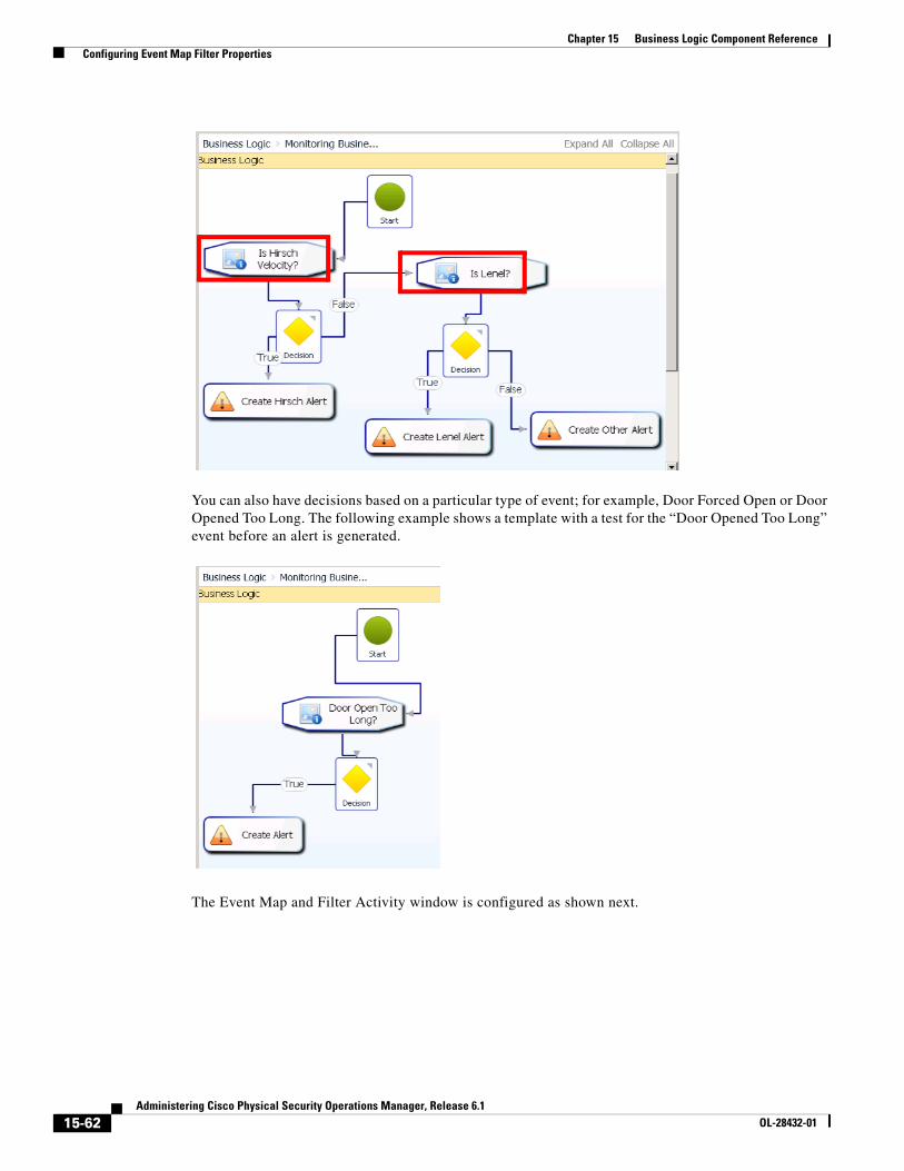
15-62Administering Cisco Physical Security Operations Manager, Release 6.1
OL-28432-01
Chapter 15 Business Logic Component Reference Configuring Event Map Filter Properties
You can also have decisions based on a particular type of event; for example, Door Forced Open or Door Opened Too Long. The following example shows a template with a test for the “Door Opened Too Long” event before an alert is generated.
The Event Map and Filter Activity window is configured as shown next.
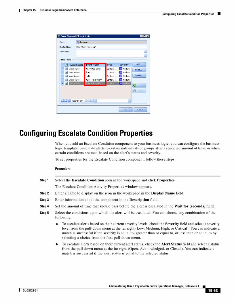
15-63Administering Cisco Physical Security Operations Manager, Release 6.1
OL-28432-01
Chapter 15 Business Logic Component Reference Configuring Escalate Condition Properties
Configuring Escalate Condition PropertiesWhen you add an Escalate Condition component to your business logic, you can configure the business logic template to escalate alerts to certain individuals or groups after a specified amount of time, or when certain conditions are met, based on the alert’s status and severity.
To set properties for the Escalate Condition component, follow these steps:
Procedure
Step 1 Select the Escalate Condition icon in the workspace and click Properties.
The Escalate Condition Activity Properties window appears.
Step 2 Enter a name to display on the icon in the workspace in the Display Name field.
Step 3 Enter information about the component in the Description field.
Step 4 Set the amount of time that should pass before the alert is escalated in the Wait for (seconds) field.
Step 5 Select the conditions upon which the alert will be escalated. You can choose any combination of the following:
a. To escalate alerts based on their current severity levels, check the Severity field and select a severity level from the pull-down menu at the far right (Low, Medium, High, or Critical). You can indicate a match is successful if the severity is equal to, greater than or equal to, or less than or equal to by selecting a choice from the first pull-down menu.
b. To escalate alerts based on their current alert status, check the Alert Status field and select a status from the pull-down menu at the far right (Open, Acknowledged, or Closed). You can indicate a match is successful if the alert status is equal to the selected status.
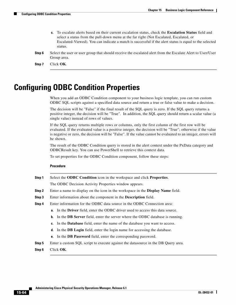
15-64Administering Cisco Physical Security Operations Manager, Release 6.1
OL-28432-01
Chapter 15 Business Logic Component Reference Configuring ODBC Condition Properties
c. To escalate alerts based on their current escalation status, check the Escalation Status field and select a status from the pull-down menu at the far right (Not Escalated, Escalated, or Escalated-Viewed). You can indicate a match is successful if the alert status is equal to the selected status.
Step 6 Select the user or user group that should receive the escalated alert from the Escalate Alert to User/User Group area.
Step 7 Click OK.
Configuring ODBC Condition PropertiesWhen you add an ODBC Condition component to your business logic template, you can run custom ODBC SQL scripts against a specified data source and return a true or false value to make a decision.
The decision will be "False" if the final result of the SQL query is zero. If the SQL query returns a positive integer, the decision will be "True". In addition, the SQL query should return a scalar value (a single value) instead of rows of values.
If the SQL query returns multiple rows or columns, only the first column of the first row will be evaluated. If the evaluated value is a positive integer, the decision will be "True"; otherwise if the value is negative or zero, the decision will be "False". If the value cannot be evaluated to an integer, errors will be shown.
The result of the ODBC Condition query is stored in the alert context under the PxData category and ODBCResult key. You can use PowerShell to retrieve this context data.
To set properties for the ODBC Condition component, follow these steps:
Procedure
Step 1 Select the ODBC Condition icon in the workspace and click Properties.
The ODBC Decision Activity Properties window appears.
Step 2 Enter a name to display on the icon in the workspace in the Display Name field.
Step 3 Enter information about the component in the Description field.
Step 4 Enter information for the ODBC data source in the ODBC Connection area:
a. In the Driver field, enter the ODBC driver used to access this data source.
b. In the DB Server field, enter the server where the ODBC database is running.
c. In the Database field, enter the name of the database you want to access.
d. In the DB Login field, enter the login name for accessing the database.
e. In the DB Password field, enter the corresponding password.
Step 5 Enter a custom SQL script to execute against the datasource in the DB Query area.
Step 6 Click OK.
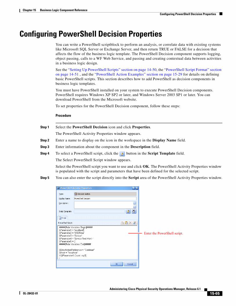
15-65Administering Cisco Physical Security Operations Manager, Release 6.1
OL-28432-01
Chapter 15 Business Logic Component Reference Configuring PowerShell Decision Properties
Configuring PowerShell Decision PropertiesYou can write a PowerShell scriptblock to perform an analysis, or correlate data with existing systems like Microsoft SQL Server or Exchange Server, and then return TRUE or FALSE for a decision that affects the flow of the business logic template. The PowerShell Decision component supports logging, object passing, calls to a WF Web Service, and passing and creating contextual data between activities in a business logic design.
See the “Setting Up PowerShell Scripts” section on page 14-50, the “PowerShell Script Format” section on page 14-51 , and the “PowerShell Action Examples” section on page 15-29 for details on defining basic PowerShell scripts. This section describes how to add PowerShell as decision components in business logic templates.
You must have PowerShell installed on your system to execute PowerShell Decision components. PowerShell requires Windows XP SP2 or later, and Windows Server 2003 SP1 or later. You can download PowerShell from the Microsoft website.
To set properties for the PowerShell Decision component, follow these steps:
Procedure
Step 1 Select the PowerShell Decision icon and click Properties.
The PowerShell Activity Properties window appears.
Step 2 Enter a name to display on the icon in the workspace in the Display Name field.
Step 3 Enter information about the component in the Description field.
Step 4 To select a PowerShell script, click the button in the Script Template field.
The Select PowerShell Script window appears.
Select the PowerShell script you want to use and click OK. The PowerShell Activity Properties window is populated with the script and parameters that have been defined for the selected script.
Step 5 You can also enter the script directly into the Script area of the PowerShell Activity Properties window.
Enter the PowerShell script.
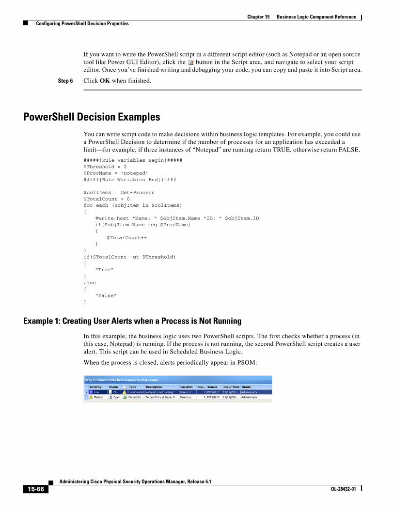
15-66Administering Cisco Physical Security Operations Manager, Release 6.1
OL-28432-01
Chapter 15 Business Logic Component Reference Configuring PowerShell Decision Properties
If you want to write the PowerShell script in a different script editor (such as Notepad or an open source tool like Power GUI Editor), click the button in the Script area, and navigate to select your script editor. Once you’ve finished writing and debugging your code, you can copy and paste it into Script area.
Step 6 Click OK when finished.
PowerShell Decision ExamplesYou can write script code to make decisions within business logic templates. For example, you could use a PowerShell Decision to determine if the number of processes for an application has exceeded a limit—for example, if three instances of “Notepad” are running return TRUE, otherwise return FALSE.
#####[Rule Variables Begin]#####$Threshold = 2$ProcName = ‘notepad’#####[Rule Variables End]#####
$colItems = Get-Process$TotalCount = 0for each ($objItem in $colItems){
#write-host “Name: “ $objItem.Name “ID: “ $objItem.IDif($objItem.Name -eq $ProcName){
$TotalCount++}
}if($TotalCount -gt $Threshold){
“True”}else{
“False”}
Example 1: Creating User Alerts when a Process is Not Running
In this example, the business logic uses two PowerShell scripts. The first checks whether a process (in this case, Notepad) is running. If the process is not running, the second PowerShell script creates a user alert. This script can be used in Scheduled Business Logic.
When the process is closed, alerts periodically appear in PSOM:
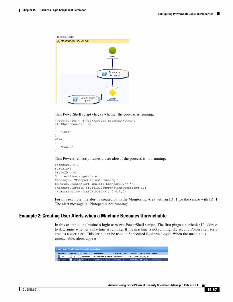
15-67Administering Cisco Physical Security Operations Manager, Release 6.1
OL-28432-01
Chapter 15 Business Logic Component Reference Configuring PowerShell Decision Properties
This PowerShell script checks whether the process is running:
$procCounter = @(Get-Process notepad*).Countif ($procCounter -ge 1){ "TRUE"}else{ "FALSE"}
This Powershell script raises a user alert if the process is not running:
$sensorID = 1$areaId=1$ruleID = -1$currentTime = get-date$message= "Notepad is not running!"$pxWFWS.CreateAlertSimple(1,$sensorID,"","",$message,$areaID,$ruleID,$currentTime.ToString(),1,"<DESCRIPTION></DESCRIPTION>", 0,0,0,0)
For this example, the alert is created on in the Monitoring Area with an ID=1 for the sensor with ID=1. The alert message is “Notepad is not running”.
Example 2: Creating User Alerts when a Machine Becomes Unreachable
In this example, the business logic uses two PowerShell scripts. The first pings a particular IP address to determine whether a machine is running. If the machine is not running, the second PowerShell script creates a user alert. This script can be used in Scheduled Business Logic. When the machine is unreachable, alerts appear:
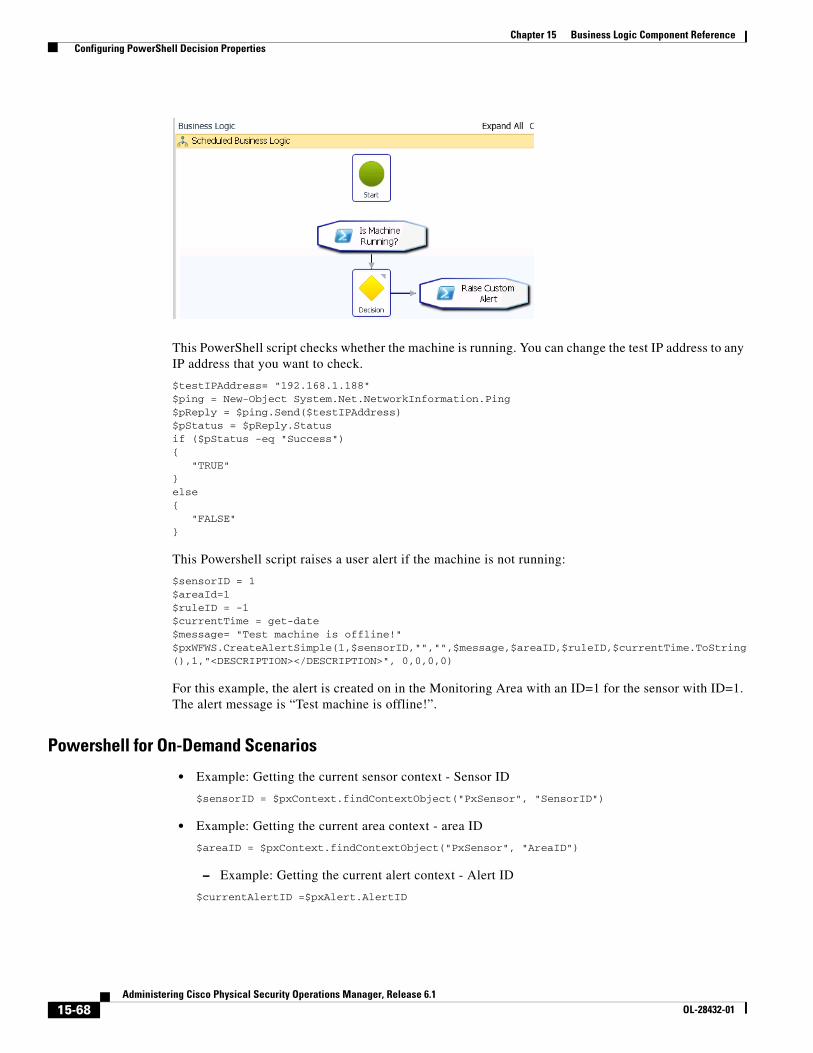
15-68Administering Cisco Physical Security Operations Manager, Release 6.1
OL-28432-01
Chapter 15 Business Logic Component Reference Configuring PowerShell Decision Properties
This PowerShell script checks whether the machine is running. You can change the test IP address to any IP address that you want to check.
$testIPAddress= "192.168.1.188"$ping = New-Object System.Net.NetworkInformation.Ping$pReply = $ping.Send($testIPAddress)$pStatus = $pReply.Statusif ($pStatus -eq "Success"){ "TRUE"}else{ "FALSE"}
This Powershell script raises a user alert if the machine is not running:
$sensorID = 1$areaId=1$ruleID = -1$currentTime = get-date$message= "Test machine is offline!"$pxWFWS.CreateAlertSimple(1,$sensorID,"","",$message,$areaID,$ruleID,$currentTime.ToString(),1,"<DESCRIPTION></DESCRIPTION>", 0,0,0,0)
For this example, the alert is created on in the Monitoring Area with an ID=1 for the sensor with ID=1. The alert message is “Test machine is offline!”.
Powershell for On-Demand Scenarios
• Example: Getting the current sensor context - Sensor ID
$sensorID = $pxContext.findContextObject("PxSensor", "SensorID")
• Example: Getting the current area context - area ID
$areaID = $pxContext.findContextObject("PxSensor", "AreaID")
– Example: Getting the current alert context - Alert ID
$currentAlertID =$pxAlert.AlertID
15-69Administering Cisco Physical Security Operations Manager, Release 6.1
OL-28432-01
Chapter 15 Business Logic Component Reference Configuring PowerShell Decision Properties
Powershell for Alert Status Change Scenarios
• Example: Getting the previous alert status for the current alert
$previousStatus = $pxAlert.PrevStatus
• Example: Getting the current alert ID
$currentAlertID = $pxAlert.AlertID
• Example: Getting the current alert status
$curStatus = $pxAlert.Status
Powershell for Post-Alert Scenarios
• Example: Changing contexual alert ID to a specific alert ID
$pxAlert.AlertID = 123
• Example: Changing contexual sensor ID (associated with alert) to a specific sensor ID
$pxAlert.SensorID = 123
• Example: Retrieving alert detail for the current alert
$pxWfWs.GetAlertDetailForAlertID($pxAlert.AlertID)
This call returns the full XML for the alert detail inside the <RESULT> node.
Powershell for Generic Business Logic Scenarios
• Example: Setting a contexual value in the context registry
$pxContext.addContextObject("your_category", "your_key", $variable)
• Saves a single value ($variable) into the context registery under your_category category with your_key as the key.
For example, explicitly set an alert ID in a context and then use the SetAlertContext activity to switch the alert context.
$pxContext.addContextObject("PxDemo", "AlertID", "123")
where the "123" is the target alert ID.
• Example: Reading a contextual value from the context registry
$variable = $pxContext.FindContextObject("your_category", "your_key")
Retrieving a single value from the context registry under your_category category with your_key as the key.
• Example: Logging information into the Business Logic trace log
$pxLogger.logInfo("This is a test message.")
• Example: Create an audit entry for the current alert
$pxWfWs.CreateAuditEntry("Hello, world!", 27, 2, $pxAlert.AlertID)
15-70Administering Cisco Physical Security Operations Manager, Release 6.1
OL-28432-01
Chapter 15 Business Logic Component Reference Configuring PowerShell Decision Properties
• Example: Getting the current PSOM BL version installed
$pxOEMInfo.ProductVersion
• Example: Getting the current product name
$pxOEMInfo.ProductName
• Example: Getting the company name for the current product
$pxOEMInfo.CompanyName
Powershell for Monitoring Rules (Pre-Alert) Scenarios
• Example: Logging the description of the event from the raw connector event
$pxLogger.logInfo($pxEvent.Description)
• Example: Getting current GPS Location of the source event
$currentGPS = $pxEvent.GPSLocation
• Example: Getting current Tracking Object of the source event
$currentTrackingObj = $pxEvent.TrackingObject
• Example: Creating a video alert on a particular Sensor
$pxWfWs.CreateAlertSimple(1, 3, "", "", "Test Video Alert", "1", "-1", $pxEvent.OccurTime, "1", "<DESCRIPTION></DESCRIPTION>", "0","0","0","0")
Powershell for Sensor Context Scenarios
• Example: Decision whether current Sensor context belong to a specified Sensor Group:
$checkGroupID = 101if ($SensorQuery.isCurrentSensorInGroup($checkGroupID)){"True"}else{"False"}
Note Default result of isCurrentSensorInGroup will be false.
• Example: Decision whether current Sensor context is a sibling of a specific Sensor
$referenceSensorID = 101if($SensorQuery.isCurrentSensorSiblingOfSensor($referenceSensorID)){"True"}else{"False"}
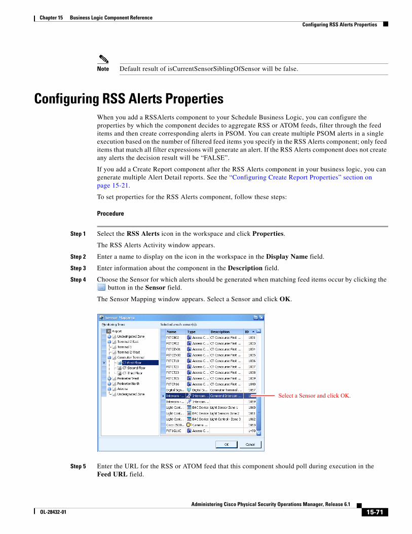
15-71Administering Cisco Physical Security Operations Manager, Release 6.1
OL-28432-01
Chapter 15 Business Logic Component Reference Configuring RSS Alerts Properties
Note Default result of isCurrentSensorSiblingOfSensor will be false.
Configuring RSS Alerts PropertiesWhen you add a RSSAlerts component to your Schedule Business Logic, you can configure the properties by which the component decides to aggregate RSS or ATOM feeds, filter through the feed items and then create corresponding alerts in PSOM. You can create multiple PSOM alerts in a single execution based on the number of filtered feed items you specify in the RSS Alerts component; only feed items that match all filter expressions will generate an alert. If the RSS Alerts component does not create any alerts the decision result will be “FALSE”.
If you add a Create Report component after the RSS Alerts component in your business logic, you can generate multiple Alert Detail reports. See the “Configuring Create Report Properties” section on page 15-21.
To set properties for the RSS Alerts component, follow these steps:
Procedure
Step 1 Select the RSS Alerts icon in the workspace and click Properties.
The RSS Alerts Activity window appears.
Step 2 Enter a name to display on the icon in the workspace in the Display Name field.
Step 3 Enter information about the component in the Description field.
Step 4 Choose the Sensor for which alerts should be generated when matching feed items occur by clicking the button in the Sensor field.
The Sensor Mapping window appears. Select a Sensor and click OK.
Step 5 Enter the URL for the RSS or ATOM feed that this component should poll during execution in the Feed URL field.
Select a Sensor and click OK.
15-72Administering Cisco Physical Security Operations Manager, Release 6.1
OL-28432-01
Chapter 15 Business Logic Component Reference Configuring Acknowledge Task Properties
Step 6 Enter the access credentials for the feed in the User Name and Password fields.
Step 7 If you want to filter the alerts received from the feed URL to only create PSOM alerts under certain conditions:
a. Select the Filter Enabled option. Once enabled, only those feeds that match all filter criteria will create alerts in PSOM.
b. Enter text into the Title field that should appear in the title of a feed for it to result in a PSOM alert. Filter criteria is case-sensitive.
c. Enter text into the Description field that should appear in the description of a feed for it to result in a PSOM alert. Filter criteria is case-sensitive.
d. In the Category field, enter the category to which a feed must belong before a PSOM alert will be created. Filter criteria is case-sensitive.
Step 8 Click OK.
Notes
• The filter uses a Regular Expression for matches. A feed must meet all filter criteria before an alert is created in PSOM. If you do not want to specify a filtering criteria, leave it as “.” as it will match against all characters in that field. To match multiple words, use the a regular expression for exact matching on the RSS title:
.*\s+(Mobile|weather)\s+.*
• The RSS Alerts activity can only be used inside Schedule Business Logic templates.
• The RSS Alerts activity supports simulation directly without the need for a Simulate Alert activity. Only a Start icon and RSS Alerts activity are needed inside a Schedule Business Logic template to generate RSS alerts. Those alerts will be marked as “Simulated” alerts as seen from either the Operation Console or Alert Console.
• Some feeds are not supported in this release (such as Google news).
• Test feeds in the Business Logic Designer before deploying the business logic template. All RSS alerts created inside the Business Logic Designer will appear as “Simulated” in the Operation Console.
Configuring Acknowledge Task PropertiesThe Acknowledge Task allows operators to confirm task completion within a Response Workflow Business Logic.
To set properties for the Acknowledge Task component, follow these steps:
Procedure
Step 1 Select the Acknowledge Task icon in the workspace and click Properties.
The Acknowledge Activity Properties window appears.
Step 2 Enter a name to display on the icon in the workspace in the Display Name field.
Step 3 Enter information about the component in the Description field.
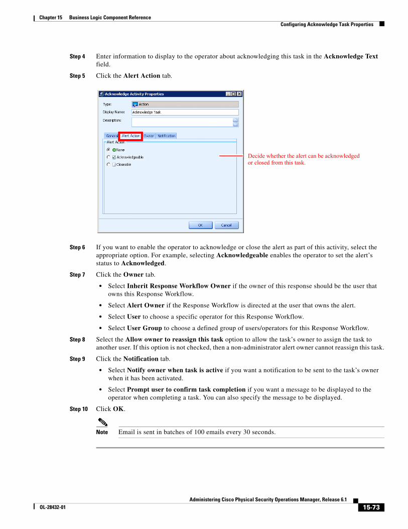
15-73Administering Cisco Physical Security Operations Manager, Release 6.1
OL-28432-01
Chapter 15 Business Logic Component Reference Configuring Acknowledge Task Properties
Step 4 Enter information to display to the operator about acknowledging this task in the Acknowledge Text field.
Step 5 Click the Alert Action tab.
Step 6 If you want to enable the operator to acknowledge or close the alert as part of this activity, select the appropriate option. For example, selecting Acknowledgeable enables the operator to set the alert’s status to Acknowledged.
Step 7 Click the Owner tab.
• Select Inherit Response Workflow Owner if the owner of this response should be the user that owns this Response Workflow.
• Select Alert Owner if the Response Workflow is directed at the user that owns the alert.
• Select User to choose a specific operator for this Response Workflow.
• Select User Group to choose a defined group of users/operators for this Response Workflow.
Step 8 Select the Allow owner to reassign this task option to allow the task’s owner to assign the task to another user. If this option is not checked, then a non-administrator alert owner cannot reassign this task.
Step 9 Click the Notification tab.
• Select Notify owner when task is active if you want a notification to be sent to the task’s owner when it has been activated.
• Select Prompt user to confirm task completion if you want a message to be displayed to the operator when completing a task. You can also specify the message to be displayed.
Step 10 Click OK.
Note Email is sent in batches of 100 emails every 30 seconds.
Decide whether the alert can be acknowledged or closed from this task.
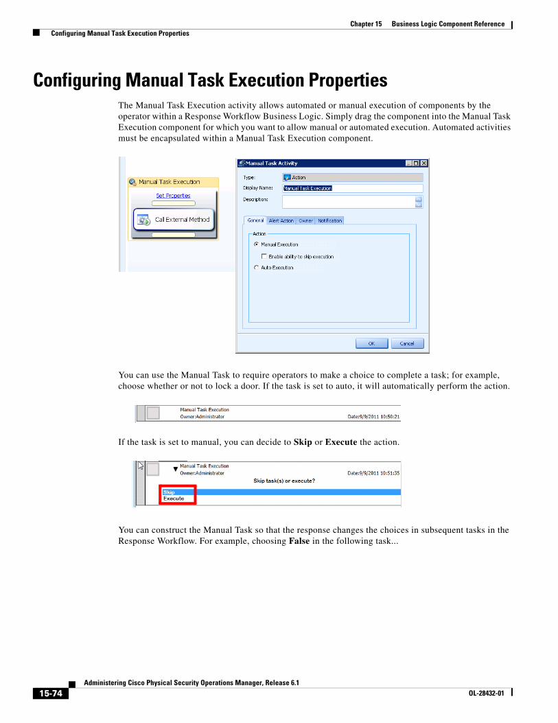
15-74Administering Cisco Physical Security Operations Manager, Release 6.1
OL-28432-01
Chapter 15 Business Logic Component Reference Configuring Manual Task Execution Properties
Configuring Manual Task Execution PropertiesThe Manual Task Execution activity allows automated or manual execution of components by the operator within a Response Workflow Business Logic. Simply drag the component into the Manual Task Execution component for which you want to allow manual or automated execution. Automated activities must be encapsulated within a Manual Task Execution component.
You can use the Manual Task to require operators to make a choice to complete a task; for example, choose whether or not to lock a door. If the task is set to auto, it will automatically perform the action.
If the task is set to manual, you can decide to Skip or Execute the action.
You can construct the Manual Task so that the response changes the choices in subsequent tasks in the Response Workflow. For example, choosing False in the following task...
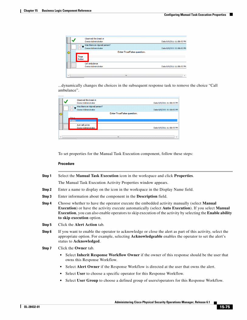
15-75Administering Cisco Physical Security Operations Manager, Release 6.1
OL-28432-01
Chapter 15 Business Logic Component Reference Configuring Manual Task Execution Properties
...dynamically changes the choices in the subsequent response task to remove the choice “Call ambulance”.follows the choice
To set properties for the Manual Task Execution component, follow these steps:
Procedure
Step 1 Select the Manual Task Execution icon in the workspace and click Properties.
The Manual Task Execution Activity Properties window appears.
Step 2 Enter a name to display on the icon in the workspace in the Display Name field.
Step 3 Enter information about the component in the Description field.
Step 4 Choose whether to have the operator execute the embedded activity manually (select Manual Execution) or have the activity execute automatically (select Auto Execution). If you select Manual Execution, you can also enable operators to skip execution of the activity by selecting the Enable ability to skip execution option.
Step 5 Click the Alert Action tab.
Step 6 If you want to enable the operator to acknowledge or close the alert as part of this activity, select the appropriate option. For example, selecting Acknowledgeable enables the operator to set the alert’s status to Acknowledged.
Step 7 Click the Owner tab.
• Select Inherit Response Workflow Owner if the owner of this response should be the user that owns this Response Workflow.
• Select Alert Owner if the Response Workflow is directed at the user that owns the alert.
• Select User to choose a specific operator for this Response Workflow.
• Select User Group to choose a defined group of users/operators for this Response Workflow.
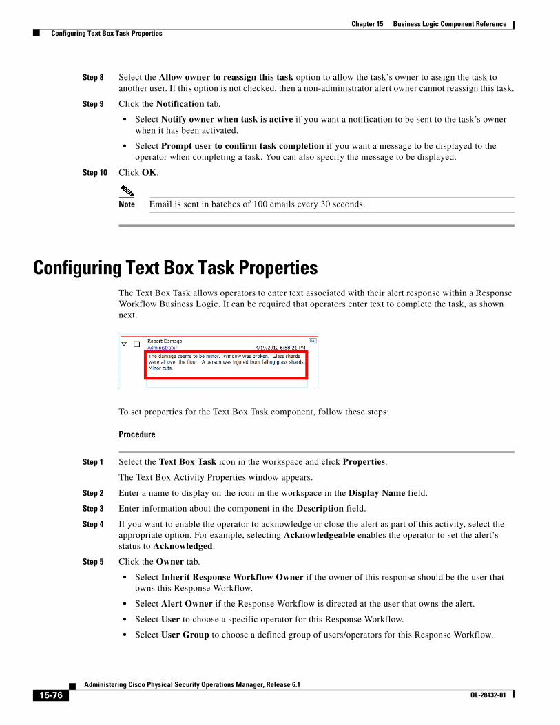
15-76Administering Cisco Physical Security Operations Manager, Release 6.1
OL-28432-01
Chapter 15 Business Logic Component Reference Configuring Text Box Task Properties
Step 8 Select the Allow owner to reassign this task option to allow the task’s owner to assign the task to another user. If this option is not checked, then a non-administrator alert owner cannot reassign this task.
Step 9 Click the Notification tab.
• Select Notify owner when task is active if you want a notification to be sent to the task’s owner when it has been activated.
• Select Prompt user to confirm task completion if you want a message to be displayed to the operator when completing a task. You can also specify the message to be displayed.
Step 10 Click OK.
Note Email is sent in batches of 100 emails every 30 seconds.
Configuring Text Box Task PropertiesThe Text Box Task allows operators to enter text associated with their alert response within a Response Workflow Business Logic. It can be required that operators enter text to complete the task, as shown next.
To set properties for the Text Box Task component, follow these steps:
Procedure
Step 1 Select the Text Box Task icon in the workspace and click Properties.
The Text Box Activity Properties window appears.
Step 2 Enter a name to display on the icon in the workspace in the Display Name field.
Step 3 Enter information about the component in the Description field.
Step 4 If you want to enable the operator to acknowledge or close the alert as part of this activity, select the appropriate option. For example, selecting Acknowledgeable enables the operator to set the alert’s status to Acknowledged.
Step 5 Click the Owner tab.
• Select Inherit Response Workflow Owner if the owner of this response should be the user that owns this Response Workflow.
• Select Alert Owner if the Response Workflow is directed at the user that owns the alert.
• Select User to choose a specific operator for this Response Workflow.
• Select User Group to choose a defined group of users/operators for this Response Workflow.
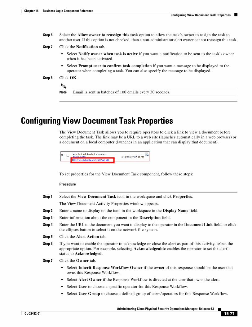
15-77Administering Cisco Physical Security Operations Manager, Release 6.1
OL-28432-01
Chapter 15 Business Logic Component Reference Configuring View Document Task Properties
Step 6 Select the Allow owner to reassign this task option to allow the task’s owner to assign the task to another user. If this option is not checked, then a non-administrator alert owner cannot reassign this task.
Step 7 Click the Notification tab.
• Select Notify owner when task is active if you want a notification to be sent to the task’s owner when it has been activated.
• Select Prompt user to confirm task completion if you want a message to be displayed to the operator when completing a task. You can also specify the message to be displayed.
Step 8 Click OK.
Note Email is sent in batches of 100 emails every 30 seconds.
Configuring View Document Task PropertiesThe View Document Task allows you to require operators to click a link to view a document before completing the task. The link may be a URL to a web site (launches automatically in a web browser) or a document on a local computer (launches in an application that can display that document).
To set properties for the View Document Task component, follow these steps:
Procedure
Step 1 Select the View Document Task icon in the workspace and click Properties.
The View Document Activity Properties window appears.
Step 2 Enter a name to display on the icon in the workspace in the Display Name field.
Step 3 Enter information about the component in the Description field.
Step 4 Enter the URL to the document you want to display to the operator in the Document Link field, or click the ellipses button to select it on the network file system.
Step 5 Click the Alert Action tab.
Step 6 If you want to enable the operator to acknowledge or close the alert as part of this activity, select the appropriate option. For example, selecting Acknowledgeable enables the operator to set the alert’s status to Acknowledged.
Step 7 Click the Owner tab.
• Select Inherit Response Workflow Owner if the owner of this response should be the user that owns this Response Workflow.
• Select Alert Owner if the Response Workflow is directed at the user that owns the alert.
• Select User to choose a specific operator for this Response Workflow.
• Select User Group to choose a defined group of users/operators for this Response Workflow.
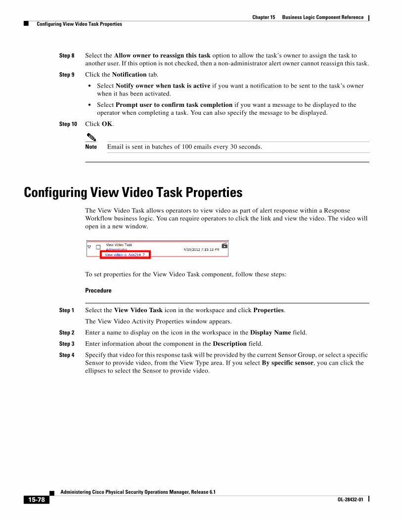
15-78Administering Cisco Physical Security Operations Manager, Release 6.1
OL-28432-01
Chapter 15 Business Logic Component Reference Configuring View Video Task Properties
Step 8 Select the Allow owner to reassign this task option to allow the task’s owner to assign the task to another user. If this option is not checked, then a non-administrator alert owner cannot reassign this task.
Step 9 Click the Notification tab.
• Select Notify owner when task is active if you want a notification to be sent to the task’s owner when it has been activated.
• Select Prompt user to confirm task completion if you want a message to be displayed to the operator when completing a task. You can also specify the message to be displayed.
Step 10 Click OK.
Note Email is sent in batches of 100 emails every 30 seconds.
Configuring View Video Task PropertiesThe View Video Task allows operators to view video as part of alert response within a Response Workflow business logic. You can require operators to click the link and view the video. The video will open in a new window.
To set properties for the View Video Task component, follow these steps:
Procedure
Step 1 Select the View Video Task icon in the workspace and click Properties.
The View Video Activity Properties window appears.
Step 2 Enter a name to display on the icon in the workspace in the Display Name field.
Step 3 Enter information about the component in the Description field.
Step 4 Specify that video for this response task will be provided by the current Sensor Group, or select a specific Sensor to provide video, from the View Type area. If you select By specific sensor, you can click the ellipses to select the Sensor to provide video.
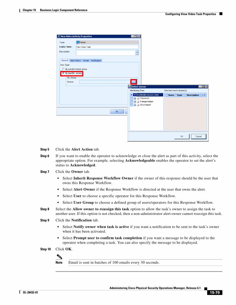
15-79Administering Cisco Physical Security Operations Manager, Release 6.1
OL-28432-01
Chapter 15 Business Logic Component Reference Configuring View Video Task Properties
Step 5 Click the Alert Action tab.
Step 6 If you want to enable the operator to acknowledge or close the alert as part of this activity, select the appropriate option. For example, selecting Acknowledgeable enables the operator to set the alert’s status to Acknowledged.
Step 7 Click the Owner tab.
• Select Inherit Response Workflow Owner if the owner of this response should be the user that owns this Response Workflow.
• Select Alert Owner if the Response Workflow is directed at the user that owns the alert.
• Select User to choose a specific operator for this Response Workflow.
• Select User Group to choose a defined group of users/operators for this Response Workflow.
Step 8 Select the Allow owner to reassign this task option to allow the task’s owner to assign the task to another user. If this option is not checked, then a non-administrator alert owner cannot reassign this task.
Step 9 Click the Notification tab.
• Select Notify owner when task is active if you want a notification to be sent to the task’s owner when it has been activated.
• Select Prompt user to confirm task completion if you want a message to be displayed to the operator when completing a task. You can also specify the message to be displayed.
Step 10 Click OK.
Note Email is sent in batches of 100 emails every 30 seconds.
15-80Administering Cisco Physical Security Operations Manager, Release 6.1
OL-28432-01
Chapter 15 Business Logic Component Reference Configuring Lock Door Properties
Configuring Lock Door PropertiesThe Lock Door activity allows you to issue a “Lock Door” command to Integration Module door sensors. This activity is part of the Sensor Commands activity list.
Note PSOM Bus Service must be running for this component to complete successfully in a runtime environment.
To set properties for the Lock Door component, follow these steps:
Procedure
Step 1 Select the Lock Door icon in the workspace and click Properties.
The Lock Door Activity window appears.
Step 2 Enter a name to display on the icon in the workspace in the Display Name field.
Step 3 Enter information about the component in the Description field.
Step 4 In the Door(s) field, make a choice:
• Leave Current sensor selected to apply the command to whichever access control is being handled by the business logic when Lock Door is called. For Event Business Logic, the current Sensor is the Sensor associated with the source event. For Alert Business Logic or Alert Status Business Logic, the current Sensor is the Sensor associated with the PSOM alert.
Note Current sensor is not supported for Schedule Business Logic.
• Apply the command to a sibling or specific Sensor. Click the button.
The Sensor Context Editor window appears.
Select the All sibling sensor of sensor type option to apply the command to a sibling Sensor, and choose the sensor type and Sensor Group from the fields.
Select the Current hierarchy option to apply the command to all access control Sensors in the current Monitoring Area or Monitoring Zone.
Note Current hierarchy is not supported for On-Demand Business Logic.
When Current hierarchy is selected, the Lock Door component will first try to obtain the ZoneID from the activity context registry (category PxSensor, key ZoneID); then the AreaID (category PxSensor, key AreaID). Finally, it will try to obtain the AreaID from the associated PxAlert or PxEvent directly.
Select the Specific sensor, sensors, or area/zone option to apply the command to a specific Sensor and click the button. The Hierarchy sensor list picker window appears where you can navigate the Monitoring Hierarchy and select the Sensor to which this command should be applied. Click OK when finished.
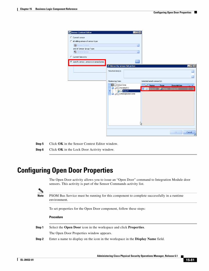
15-81Administering Cisco Physical Security Operations Manager, Release 6.1
OL-28432-01
Chapter 15 Business Logic Component Reference Configuring Open Door Properties
Step 5 Click OK in the Sensor Context Editor window.
Step 6 Click OK in the Lock Door Activity window.
Configuring Open Door PropertiesThe Open Door activity allows you to issue an “Open Door” command to Integration Module door sensors. This activity is part of the Sensor Commands activity list.
Note PSOM Bus Service must be running for this component to complete successfully in a runtime environment.
To set properties for the Open Door component, follow these steps:
Procedure
Step 1 Select the Open Door icon in the workspace and click Properties.
The Open Door Properties window appears.
Step 2 Enter a name to display on the icon in the workspace in the Display Name field.
15-82Administering Cisco Physical Security Operations Manager, Release 6.1
OL-28432-01
Chapter 15 Business Logic Component Reference Configuring Open Door Momentarily Properties
Step 3 Enter information about the component in the Description field.
Step 4 In the Door(s) field, make a choice:
• Leave Current sensor selected to apply the command to whichever access control is being handled by the business logic when Open Door is called. For Event Business Logic, the current Sensor is the Sensor associated with the source event. For Alert Business Logic or Alert Status Business Logic, the current Sensor is the Sensor associated with the PSOM alert.
Note Current sensor is not supported for Schedule Business Logic.
• Apply the command to a sibling or specific Sensor. Click the button.
The Sensor Context Editor window appears.
Select the All sibling sensor of sensor type option to apply the command to a sibling Sensor, and choose the sensor type and Sensor Group from the fields.
Select the Current hierarchy option to apply the command to all access control Sensors in the current Monitoring Area or Monitoring Zone.
Note Current hierarchy is not supported for On-Demand Business Logic.
When Current hierarchy is selected, the Open Door component will first try to obtain the ZoneID from the activity context registry (category PxSensor, key ZoneID); then the AreaID (category PxSensor, key AreaID). Finally, it will try to obtain the AreaID from the associated PxAlert or PxEvent directly.
Select the Specific sensor, sensors, or areas/zones option to apply the command to a specific Sensor and click the button. The Hierarchy sensor list picker window appears where you can navigate the Monitoring Hierarchy and select the Sensor to which this command should be applied. Click OK when finished.
Step 5 Click OK in the Sensor Context Editor window.
Step 6 Click OK in the Open Door Activity window.
Configuring Open Door Momentarily PropertiesThe Open Door Momentarily activity allows you to issue an “Open Door Momentarily” command to Integration Module door sensors. This activity is part of the Sensor Commands activity list.
Note PSOM Bus Service must be running for this component to complete successfully in a runtime environment.
To set properties for the Open Door Momentarily component, follow these steps:
Procedure
Step 1 Select the Open Door Momentarily icon in the workspace and click Properties.
15-83Administering Cisco Physical Security Operations Manager, Release 6.1
OL-28432-01
Chapter 15 Business Logic Component Reference Configuring Open Door Momentarily Properties
The Open Door Momentarily Activity window appears.
Step 2 Enter a name to display on the icon in the workspace in the Display Name field.
Step 3 Enter information about the component in the Description field.
Step 4 In the Door(s) field, make a choice:
• Leave Current sensor selected to apply the command to whichever access control is being handled by the business logic when Open Door Momentarily is called. For Event Business Logic, the current Sensor is the Sensor associated with the source event. For Alert Business Logic or Alert Status Business Logic, the current Sensor is the Sensor associated with the PSOM alert.
Note Current sensor is not supported for Schedule Business Logic.
• Apply the command to a sibling or specific Sensor. Click the button.
The Sensor Context Editor window appears.
Select the All sibling sensor of sensor type option to apply the command to a sibling Sensor, and choose the sensor type and Sensor Group from the fields.
Select the Current hierarchy option to apply the command to all access control sensors in the current Monitoring Area or Monitoring Zone.
Note Current hierarchy is not supported for On-Demand Business Logic.
When Current hierarchy is selected, the Open Door component will first try to obtain the ZoneID from the activity context registry (category PxSensor, key ZoneID); then the AreaID (category PxSensor, key AreaID). Finally, it will try to obtain the AreaID from the associated PxAlert or PxEvent directly.
Select the Specific sensor, sensors, or areas/zones option to apply the command to a specific Sensor and click the button. The Hierarchy sensor list picker window appears where you can navigate the Monitoring Hierarchy and select the Sensor to which this command should be applied. Click OK when finished.
Step 5 Click OK in the Sensor Context Editor window.
Step 6 Click OK in the Open Door Momentarily Activity window.

15-84Administering Cisco Physical Security Operations Manager, Release 6.1
OL-28432-01
Chapter 15 Business Logic Component Reference Configuring Open Door Momentarily Properties
C H A P T E R
16-1Administering Cisco Physical Security Operations Manager, Release 6.1
OL-28432-01
16Diagnosing System Tasks and Alerts
PSOM logs information about alerts raised by sensor devices—this information can be viewed in both the Operation Console and Administration Console. See Using Cisco Physical Security Operations Manager for instructions to access alert details.
For the Administration Console only, PSOM also logs information about system-related alerts that have been raised to notify the administrator about such things as services restarting. You can also generate an audit trail of all activity that has occurred in PSOM.
This chapter includes these topics:
• Diagnosing Administrative Alerts, page 16-1
• Diagnosing Monitoring Alerts, page 16-2
• Producing an Audit Trail of All Activity in PSOM, page 16-4
• Diagnosing Response Workflows, page 16-7
Diagnosing Administrative AlertsPSOM raises alerts when services are terminated or restarted, as well as under other conditions. You can acknowledge, close and delete these alerts.
To diagnose administrative alerts, follow these steps:
Procedure
Step 1 Click the Diagnostics icon in the Administration Console.
The Diagnostics window appears.
Step 2 Click the Administrative Alerts icon.
The Administrative Alert Management window appears.
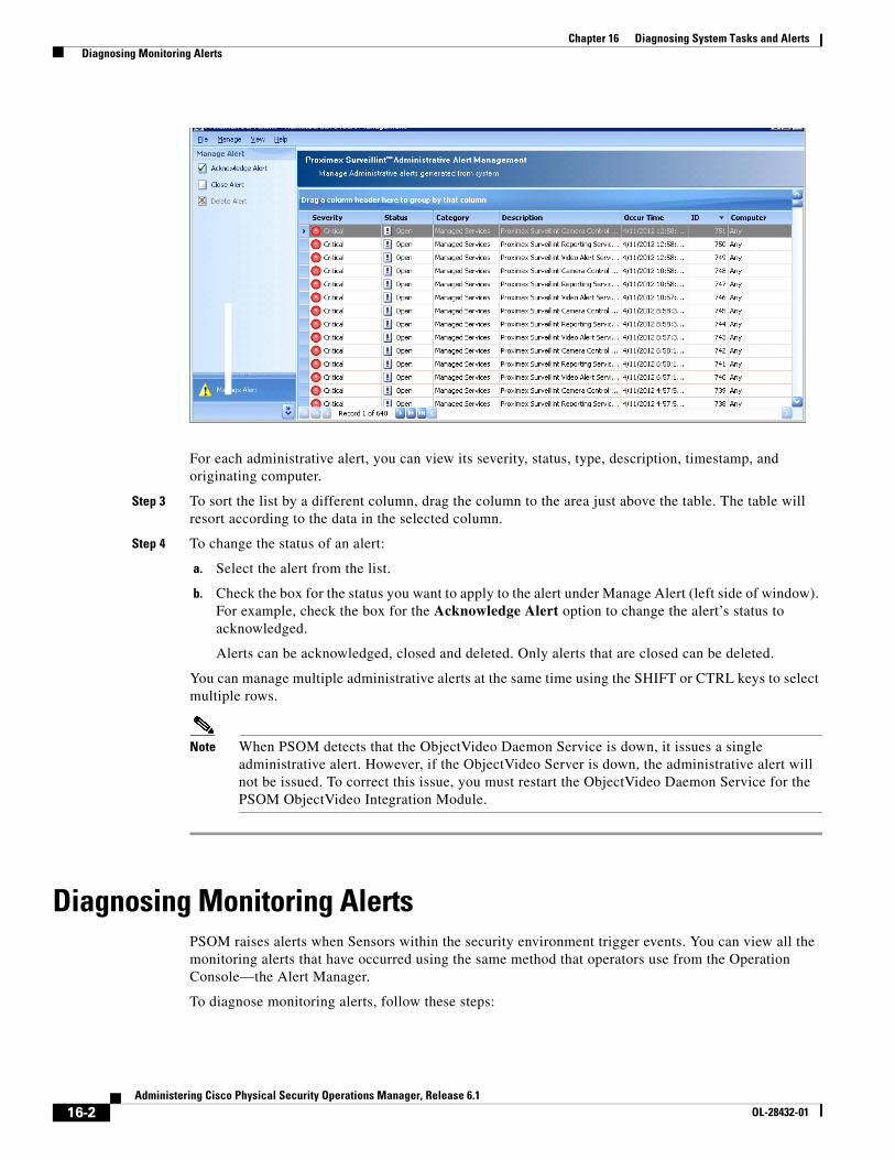
16-2Administering Cisco Physical Security Operations Manager, Release 6.1
OL-28432-01
Chapter 16 Diagnosing System Tasks and Alerts Diagnosing Monitoring Alerts
For each administrative alert, you can view its severity, status, type, description, timestamp, and originating computer.
Step 3 To sort the list by a different column, drag the column to the area just above the table. The table will resort according to the data in the selected column.
Step 4 To change the status of an alert:
a. Select the alert from the list.
b. Check the box for the status you want to apply to the alert under Manage Alert (left side of window). For example, check the box for the Acknowledge Alert option to change the alert’s status to acknowledged.
Alerts can be acknowledged, closed and deleted. Only alerts that are closed can be deleted.
You can manage multiple administrative alerts at the same time using the SHIFT or CTRL keys to select multiple rows.
Note When PSOM detects that the ObjectVideo Daemon Service is down, it issues a single administrative alert. However, if the ObjectVideo Server is down, the administrative alert will not be issued. To correct this issue, you must restart the ObjectVideo Daemon Service for the PSOM ObjectVideo Integration Module.
Diagnosing Monitoring AlertsPSOM raises alerts when Sensors within the security environment trigger events. You can view all the monitoring alerts that have occurred using the same method that operators use from the Operation Console—the Alert Manager.
To diagnose monitoring alerts, follow these steps:
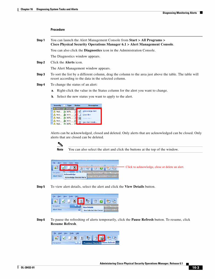
16-3Administering Cisco Physical Security Operations Manager, Release 6.1
OL-28432-01
Chapter 16 Diagnosing System Tasks and Alerts Diagnosing Monitoring Alerts
Procedure
Step 1 You can launch the Alert Management Console from Start > All Programs >Cisco Physical Security Operations Manager 6.1 > Alert Management Console.
You can also click the Diagnostics icon in the Administration Console.
The Diagnostics window appears.
Step 2 Click the Alerts icon.
The Alert Management window appears.
Step 3 To sort the list by a different column, drag the column to the area just above the table. The table will resort according to the data in the selected column.
Step 4 To change the status of an alert:
a. Right-click the value in the Status column for the alert you want to change.
b. Select the new status you want to apply to the alert.
Alerts can be acknowledged, closed and deleted. Only alerts that are acknowledged can be closed. Only alerts that are closed can be deleted.
Note You can also select the alert and click the buttons at the top of the window.
Step 5 To view alert details, select the alert and click the View Details button.
Step 6 To pause the refreshing of alerts temporarily, click the Pause Refresh button. To resume, click Resume Refresh.
Click to acknowledge, close or delete an alert.
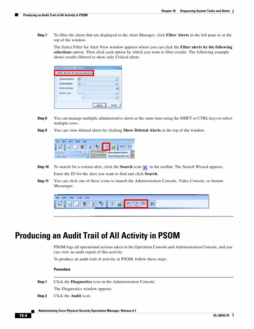
16-4Administering Cisco Physical Security Operations Manager, Release 6.1
OL-28432-01
Chapter 16 Diagnosing System Tasks and Alerts Producing an Audit Trail of All Activity in PSOM
Step 7 To filter the alerts that are displayed in the Alert Manager, click Filter Alerts in the left pane or at the top of the window.
The Select Filter for Alert View window appears where you can click the Filter alerts by the following selections option. Then click each option by which you want to filter results. The following example shows results filtered to show only Critical alerts.
Step 8 You can manage multiple administrative alerts at the same time using the SHIFT or CTRL keys to select multiple rows.
Step 9 You can view deleted alerts by clicking Show Deleted Alerts at the top of the window.
Step 10 To search for a certain alert, click the Search icon in the toolbar. The Search Wizard appears.
Enter the ID for the alert you want to find and click Search.
Step 11 You can click one of these icons to launch the Administration Console, Video Console, or Instant Messenger.
Producing an Audit Trail of All Activity in PSOMPSOM logs all operational actions taken in the Operation Console and Administration Console, and you can view an audit report of this activity.
To produce an audit trail of activity in PSOM, follow these steps:
Procedure
Step 1 Click the Diagnostics icon in the Administration Console.
The Diagnostics window appears.
Step 2 Click the Audit icon.
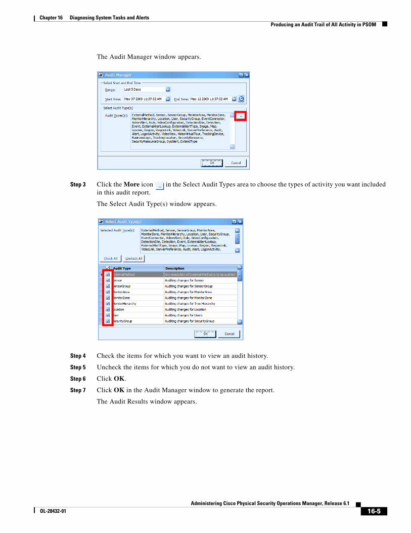
16-5Administering Cisco Physical Security Operations Manager, Release 6.1
OL-28432-01
Chapter 16 Diagnosing System Tasks and Alerts Producing an Audit Trail of All Activity in PSOM
The Audit Manager window appears.
Step 3 Click the More icon in the Select Audit Types area to choose the types of activity you want included in this audit report.
The Select Audit Type(s) window appears.
Step 4 Check the items for which you want to view an audit history.
Step 5 Uncheck the items for which you do not want to view an audit history.
Step 6 Click OK.
Step 7 Click OK in the Audit Manager window to generate the report.
The Audit Results window appears.
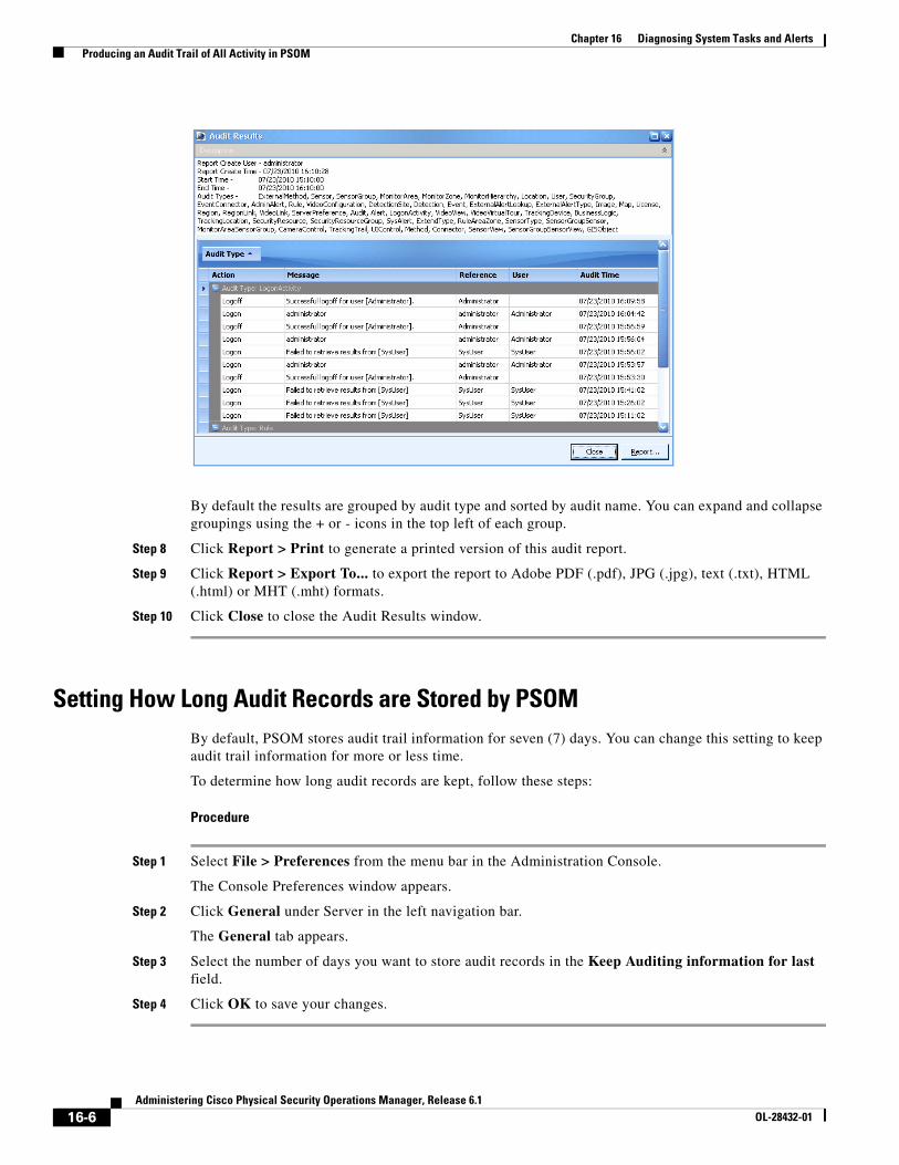
16-6Administering Cisco Physical Security Operations Manager, Release 6.1
OL-28432-01
Chapter 16 Diagnosing System Tasks and Alerts Producing an Audit Trail of All Activity in PSOM
By default the results are grouped by audit type and sorted by audit name. You can expand and collapse groupings using the + or - icons in the top left of each group.
Step 8 Click Report > Print to generate a printed version of this audit report.
Step 9 Click Report > Export To... to export the report to Adobe PDF (.pdf), JPG (.jpg), text (.txt), HTML (.html) or MHT (.mht) formats.
Step 10 Click Close to close the Audit Results window.
Setting How Long Audit Records are Stored by PSOMBy default, PSOM stores audit trail information for seven (7) days. You can change this setting to keep audit trail information for more or less time.
To determine how long audit records are kept, follow these steps:
Procedure
Step 1 Select File > Preferences from the menu bar in the Administration Console.
The Console Preferences window appears.
Step 2 Click General under Server in the left navigation bar.
The General tab appears.
Step 3 Select the number of days you want to store audit records in the Keep Auditing information for last field.
Step 4 Click OK to save your changes.
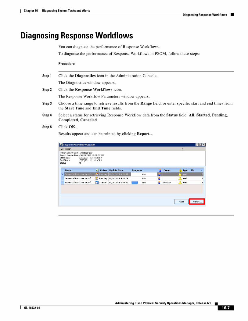
16-7Administering Cisco Physical Security Operations Manager, Release 6.1
OL-28432-01
Chapter 16 Diagnosing System Tasks and Alerts Diagnosing Response Workflows
Diagnosing Response WorkflowsYou can diagnose the performance of Response Workflows.
To diagnose the performance of Response Workflows in PSOM, follow these steps:
Procedure
Step 1 Click the Diagnostics icon in the Administration Console.
The Diagnostics window appears.
Step 2 Click the Response Workflows icon.
The Response Workflow Parameters window appears.
Step 3 Choose a time range to retrieve results from the Range field, or enter specific start and end times from the Start Time and End Time fields.
Step 4 Select a status for retrieving Response Workflow data from the Status field: All, Started, Pending, Completed, Canceled.
Step 5 Click OK.
Results appear and can be printed by clicking Report...

16-8Administering Cisco Physical Security Operations Manager, Release 6.1
OL-28432-01
Chapter 16 Diagnosing System Tasks and Alerts Diagnosing Response Workflows

C H A P T E R
17-1Administering Cisco Physical Security Operations Manager, Release 6.1
OL-28432-01
17Monitoring System Health
The System Health Diagnostic Tools monitor the PSOM system runtime behavior and health using agents that are polled to collect data and raise any alarms if necessary.
• Supports health monitoring of Managed Services using both poll and push
• Monitors application logic and system resources (such as physical memory consumption, CPU utilization, network bandwidth usage)
• Monitors event data flow
• Verifies connectivity with Connector Web Services, Integration Modules, PSOM Web Service, and PSOM Repository
• Centralizes monitoring with a console that aids visualizing the health check alarms and metrics
• Creates administrative alerts for high severity health check alarms using notification agents
This chapter includes these topics:
• Logging Into the System Health Diagnostic Tools, page 17-1
• Navigating Resources, page 17-2
• Viewing Alarms, page 17-6
• Viewing Alarms, page 17-6
Logging Into the System Health Diagnostic ToolsTo log in to the System Health Diagnostic Tools, follow these steps:
Procedure
Double click the PxHealthDiagConsole.exe file located in C:\Program Files (x86)\Cisco PSOM\ Managed Services\Bin\
The System Health Diagnostic Tools window appears.
Step 1 Select View > Refresh to populate the window with statistics.
Step 2 Expand the navigation tree on the left of the window and select items for which to display statistics.
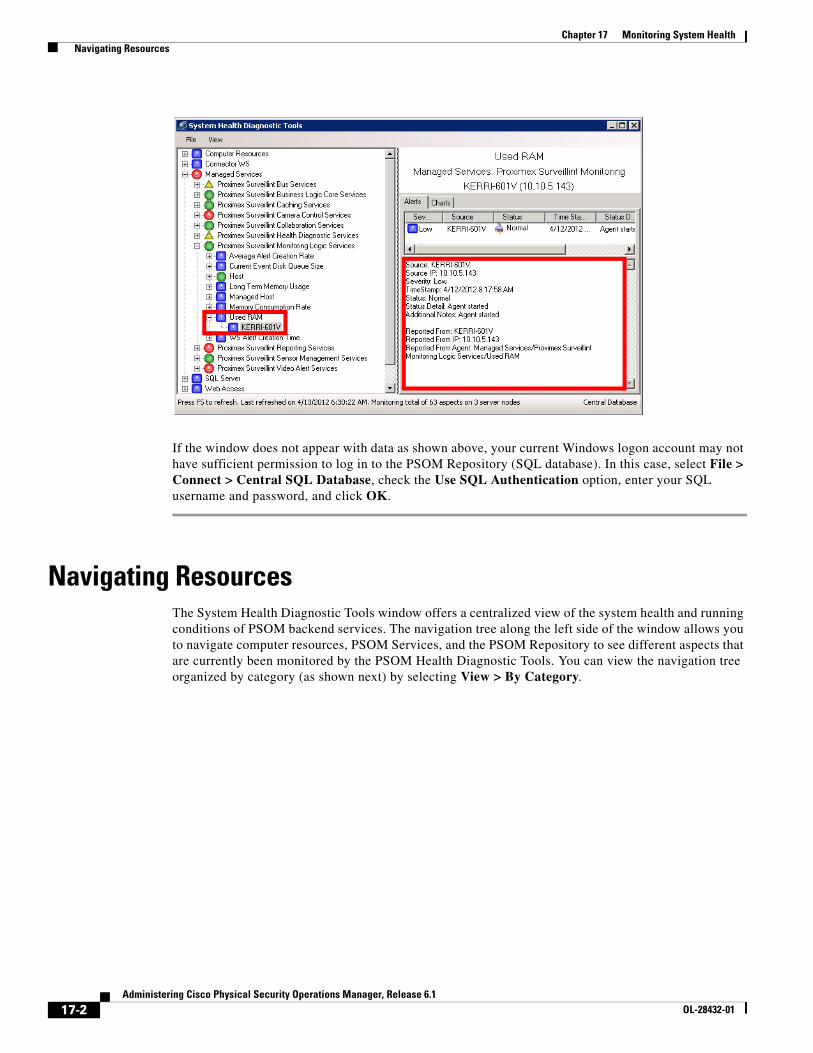
17-2Administering Cisco Physical Security Operations Manager, Release 6.1
OL-28432-01
Chapter 17 Monitoring System Health Navigating Resources
If the window does not appear with data as shown above, your current Windows logon account may not have sufficient permission to log in to the PSOM Repository (SQL database). In this case, select File > Connect > Central SQL Database, check the Use SQL Authentication option, enter your SQL username and password, and click OK.
Navigating ResourcesThe System Health Diagnostic Tools window offers a centralized view of the system health and running conditions of PSOM backend services. The navigation tree along the left side of the window allows you to navigate computer resources, PSOM Services, and the PSOM Repository to see different aspects that are currently been monitored by the PSOM Health Diagnostic Tools. You can view the navigation tree organized by category (as shown next) by selecting View > By Category.
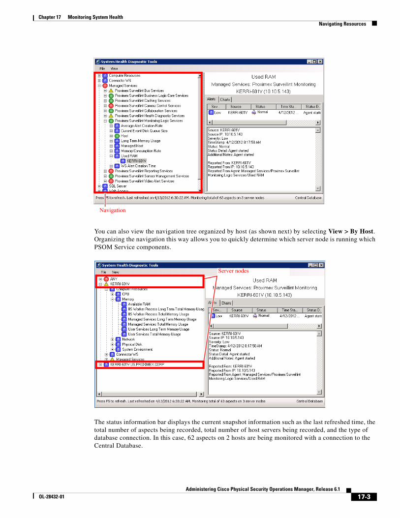
17-3Administering Cisco Physical Security Operations Manager, Release 6.1
OL-28432-01
Chapter 17 Monitoring System Health Navigating Resources
You can also view the navigation tree organized by host (as shown next) by selecting View > By Host. Organizing the navigation this way allows you to quickly determine which server node is running which PSOM Service components.
The status information bar displays the current snapshot information such as the last refreshed time, the total number of aspects being recorded, total number of host servers being recorded, and the type of database connection. In this case, 62 aspects on 2 hosts are being monitored with a connection to the Central Database.
Navigation
Server nodes
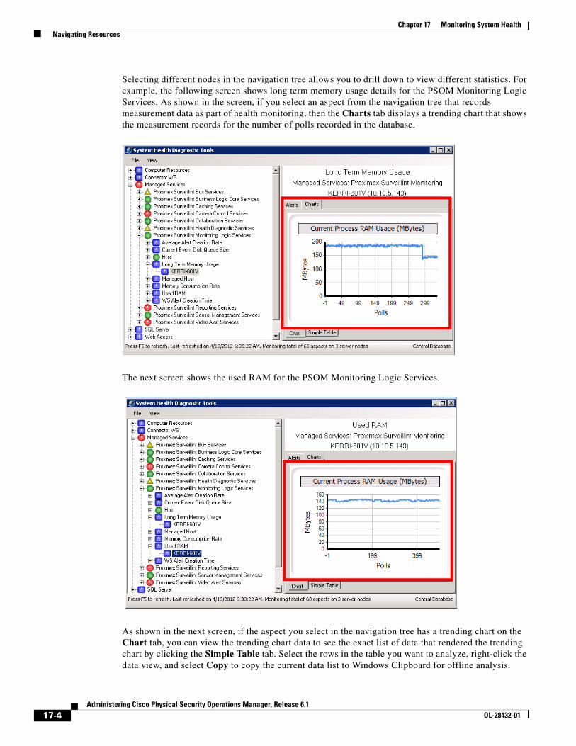
17-4Administering Cisco Physical Security Operations Manager, Release 6.1
OL-28432-01
Chapter 17 Monitoring System Health Navigating Resources
Selecting different nodes in the navigation tree allows you to drill down to view different statistics. For example, the following screen shows long term memory usage details for the PSOM Monitoring Logic Services. As shown in the screen, if you select an aspect from the navigation tree that records measurement data as part of health monitoring, then the Charts tab displays a trending chart that shows the measurement records for the number of polls recorded in the database.
The next screen shows the used RAM for the PSOM Monitoring Logic Services.
As shown in the next screen, if the aspect you select in the navigation tree has a trending chart on the Chart tab, you can view the trending chart data to see the exact list of data that rendered the trending chart by clicking the Simple Table tab. Select the rows in the table you want to analyze, right-click the data view, and select Copy to copy the current data list to Windows Clipboard for offline analysis.
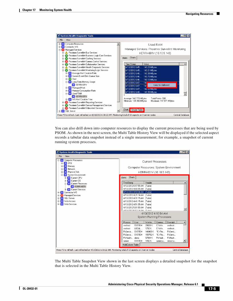
17-5Administering Cisco Physical Security Operations Manager, Release 6.1
OL-28432-01
Chapter 17 Monitoring System Health Navigating Resources
You can also drill down into computer resources to display the current processes that are being used by PSOM. As shown in the next screen, the Multi Table History View will be displayed if the selected aspect records a tabular data snapshot instead of a single measurement; for example, a snapshot of current running system processes.
The Multi Table Snapshot View shown in the last screen displays a detailed snapshot for the snapshot that is selected in the Multi Table History View.
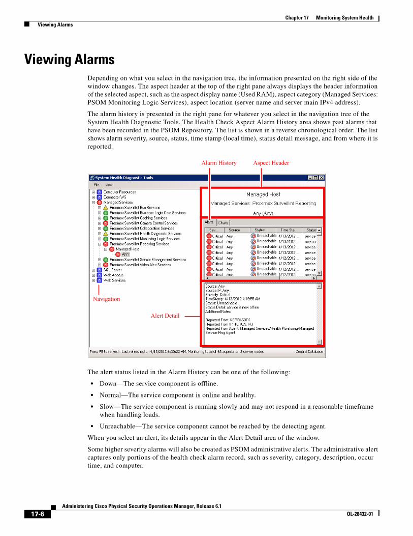
17-6Administering Cisco Physical Security Operations Manager, Release 6.1
OL-28432-01
Chapter 17 Monitoring System Health Viewing Alarms
Viewing AlarmsDepending on what you select in the navigation tree, the information presented on the right side of the window changes. The aspect header at the top of the right pane always displays the header information of the selected aspect, such as the aspect display name (Used RAM), aspect category (Managed Services: PSOM Monitoring Logic Services), aspect location (server name and server main IPv4 address).
The alarm history is presented in the right pane for whatever you select in the navigation tree of the System Health Diagnostic Tools. The Health Check Aspect Alarm History area shows past alarms that have been recorded in the PSOM Repository. The list is shown in a reverse chronological order. The list shows alarm severity, source, status, time stamp (local time), status detail message, and from where it is reported.
The alert status listed in the Alarm History can be one of the following:
• Down—The service component is offline.
• Normal—The service component is online and healthy.
• Slow—The service component is running slowly and may not respond in a reasonable timeframe when handling loads.
• Unreachable—The service component cannot be reached by the detecting agent.
When you select an alert, its details appear in the Alert Detail area of the window.
Some higher severity alarms will also be created as PSOM administrative alerts. The administrative alert captures only portions of the health check alarm record, such as severity, category, description, occur time, and computer.
Navigation
Alarm History Aspect Header
Alert Detail

17-7Administering Cisco Physical Security Operations Manager, Release 6.1
OL-28432-01
Chapter 17 Monitoring System Health Viewing Statistics When Offline
Viewing Statistics When OfflinePeriodically the System Health Diagnostic Tools will take a snapshot of the central health monitoring data store and save it into the local machine for diagnostic purposes. If you do not have access to the PSOM Repository directly, or if the central database is currently unavailable, you can view health monitoring data from the local snapshot offline data store by selecting File > Connect > Local Offline Cache. Then press F5 to refresh the window to render data from the offline local cache. By default, the System Health Diagnostic Tools takes a snapshot every 30 minutes; therefore, snapshot data could be up to 30 minutes stale.

17-8Administering Cisco Physical Security Operations Manager, Release 6.1
OL-28432-01
Chapter 17 Monitoring System Health Viewing Statistics When Offline

A-1Administering Cisco Physical Security Operations Manager, Release 6.1
OL-28432-01
A P P E N D I X APlanning Worksheets
This appendix includes worksheets you can use for planning your PSOM environment. Feel free to make copies of these worksheets.
This appendix includes these sections:
• Access Control System Integration Planning, page A-2
• User Deployment Planning, page A-3
• Locations Planning, page A-4
• Video Camera Planning, page A-5
• Monitoring Zone Planning, page A-6
• Monitoring Areas Planning, page A-7
• Task Items Planning, page A-8
• Response Workflow Planning, page A-9
• EZ-Track Planning, page A-10

A-2Administering Cisco Physical Security Operations Manager, Release 6.1
OL-28432-01
Appendix A Planning Worksheets Access Control System Integration Planning
Access Control System Integration PlanningTable A-1 Access Control System Integration Planning
Access Control # IP Address Server Login Name Server Login Password

A-3Administering Cisco Physical Security Operations Manager, Release 6.1
OL-28432-01
Appendix A Planning Worksheets User Deployment Planning
User Deployment PlanningTable A-2 User Deployment Planning
Employee User Name Password User Role User Group Description

A-4Administering Cisco Physical Security Operations Manager, Release 6.1
OL-28432-01
Appendix A Planning Worksheets Locations Planning
Locations PlanningTable A-3 Locations Planning
Location Name Description

A-5Administering Cisco Physical Security Operations Manager, Release 6.1
OL-28432-01
Appendix A Planning Worksheets Video Camera Planning
Video Camera PlanningTable A-4 Video Camera Planning
Device ID LocationView Range (in degrees)
View Distance (in feet)
View Direction (in degrees

A-6Administering Cisco Physical Security Operations Manager, Release 6.1
OL-28432-01
Appendix A Planning Worksheets Monitoring Zone Planning
Monitoring Zone PlanningTable A-5 Monitoring Zone Planning
Monitoring Zone Description Areas that should be included

A-7Administering Cisco Physical Security Operations Manager, Release 6.1
OL-28432-01
Appendix A Planning Worksheets Monitoring Areas Planning
Monitoring Areas PlanningTable A-6 Monitoring Areas Planning
Monitoring Area Description Sensor Groups to include

A-8Administering Cisco Physical Security Operations Manager, Release 6.1
OL-28432-01
Appendix A Planning Worksheets Task Items Planning
Task Items PlanningTable A-7 Task Items Planning
Task ItemRequired to Acknowledge Alerts? Required to Close Alerts?
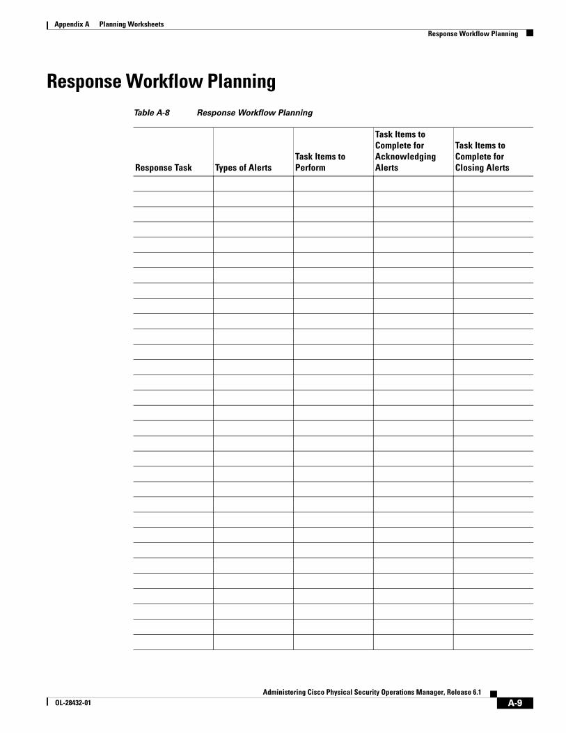
A-9Administering Cisco Physical Security Operations Manager, Release 6.1
OL-28432-01
Appendix A Planning Worksheets Response Workflow Planning
Response Workflow PlanningTable A-8 Response Workflow Planning
Response Task Types of AlertsTask Items to Perform
Task Items to Complete for Acknowledging Alerts
Task Items to Complete for Closing Alerts

A-10Administering Cisco Physical Security Operations Manager, Release 6.1
OL-28432-01
Appendix A Planning Worksheets EZ-Track Planning
EZ-Track PlanningTable A-9 EZ-Track Planning
Source Video Camera
UP Sensor #
Seconds Walk to Up
DOWN Sensor #
Seconds Walk to Down
LEFT Sensor #
Seconds Walk to Left
RIGHT Sensor #
Seconds Walk to Right
B-1Administering Cisco Physical Security Operations Manager, Release 6.1
OL-28432-01
A P P E N D I X BBackup and Restore PSOM Database
This appendix explains how to back up and restore PSOM database.
This appendix includes these sections:
• Scheduled Backup of the PSOM Database, page B-1
• Manually Backing up the PSOM Database, page B-3
• Restoring the PSOM Database, page B-6
• Cleaning up after Database Migration, page B-8
• Grooming the PSOM Database, page B-12
Scheduled Backup of the PSOM DatabaseYou can configure when the PSOM database is scheduled for backup.
To configure the backup schedule for the PSOM database, follow these steps:
Procedure
Step 1 Click Tools in the Navigation bar, and then click Configure DB and Services.
A window appears asking you to log off PSOM.
Step 2 Click Yes.
The Configure Database and Services window appears.
Step 3 Click Schedule DB Backup.
The Server and Database for Repository window appears.
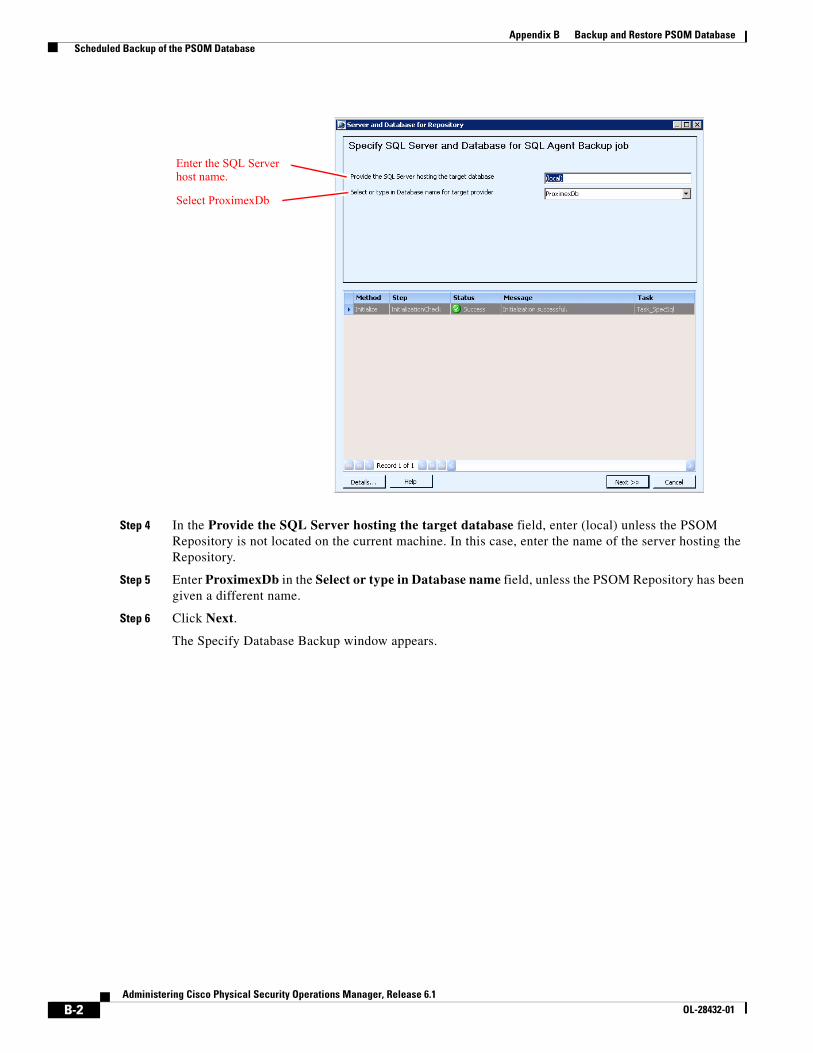
B-2Administering Cisco Physical Security Operations Manager, Release 6.1
OL-28432-01
Appendix B Backup and Restore PSOM Database Scheduled Backup of the PSOM Database
Step 4 In the Provide the SQL Server hosting the target database field, enter (local) unless the PSOM Repository is not located on the current machine. In this case, enter the name of the server hosting the Repository.
Step 5 Enter ProximexDb in the Select or type in Database name field, unless the PSOM Repository has been given a different name.
Step 6 Click Next.
The Specify Database Backup window appears.
Enter the SQL Server host name.
Select ProximexDb
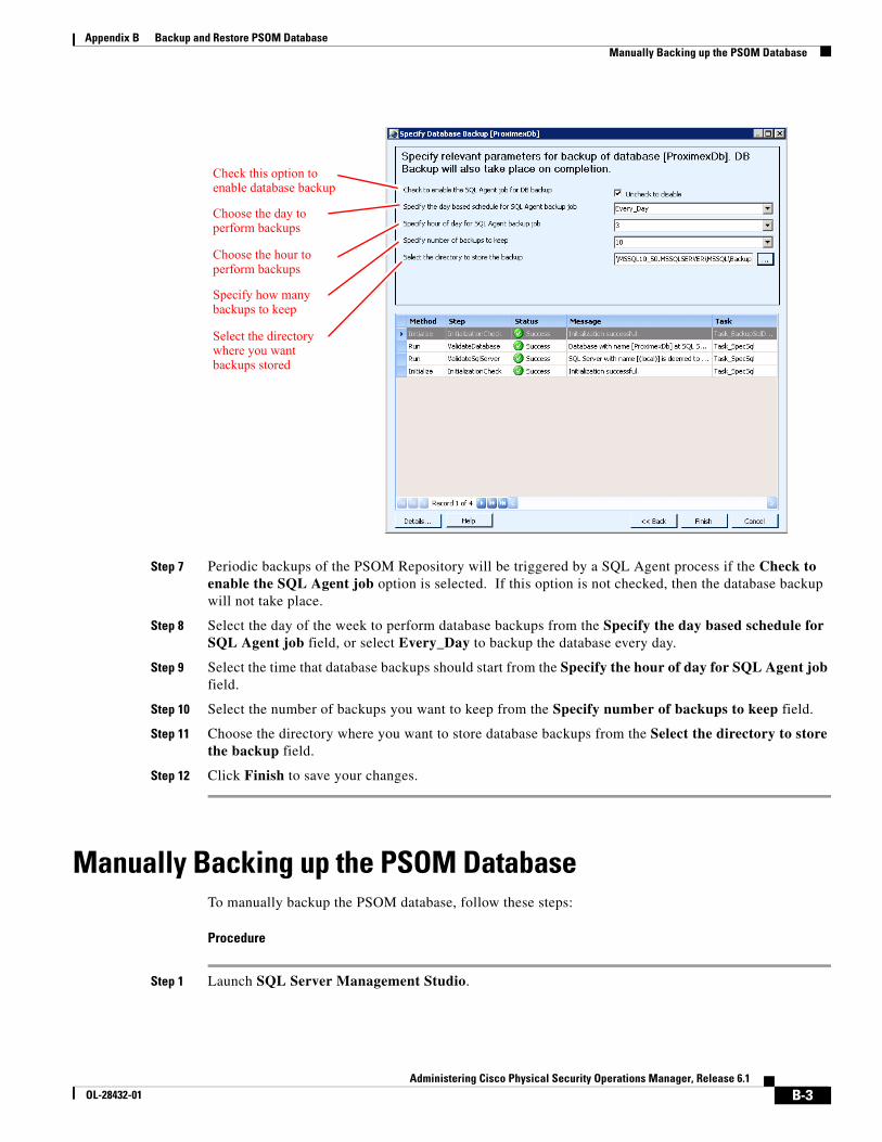
B-3Administering Cisco Physical Security Operations Manager, Release 6.1
OL-28432-01
Appendix B Backup and Restore PSOM Database Manually Backing up the PSOM Database
Step 7 Periodic backups of the PSOM Repository will be triggered by a SQL Agent process if the Check to enable the SQL Agent job option is selected. If this option is not checked, then the database backup will not take place.
Step 8 Select the day of the week to perform database backups from the Specify the day based schedule for SQL Agent job field, or select Every_Day to backup the database every day.
Step 9 Select the time that database backups should start from the Specify the hour of day for SQL Agent job field.
Step 10 Select the number of backups you want to keep from the Specify number of backups to keep field.
Step 11 Choose the directory where you want to store database backups from the Select the directory to store the backup field.
Step 12 Click Finish to save your changes.
Manually Backing up the PSOM DatabaseTo manually backup the PSOM database, follow these steps:
Procedure
Step 1 Launch SQL Server Management Studio.
Check this option to enable database backup
Choose the day to perform backups
Choose the hour to perform backups
Specify how many backups to keep
Select the directory where you want backups stored
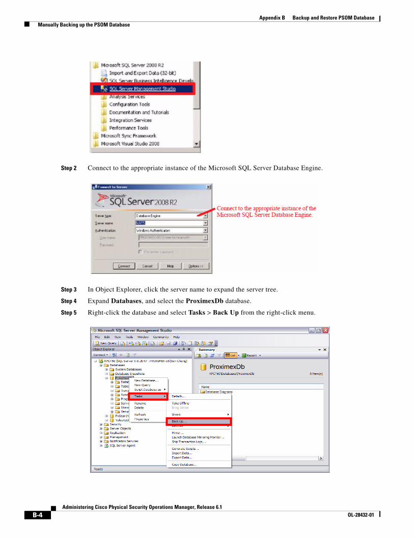
B-4Administering Cisco Physical Security Operations Manager, Release 6.1
OL-28432-01
Appendix B Backup and Restore PSOM Database Manually Backing up the PSOM Database
Step 2 Connect to the appropriate instance of the Microsoft SQL Server Database Engine.
Step 3 In Object Explorer, click the server name to expand the server tree.
Step 4 Expand Databases, and select the ProximexDb database.
Step 5 Right-click the database and select Tasks > Back Up from the right-click menu.
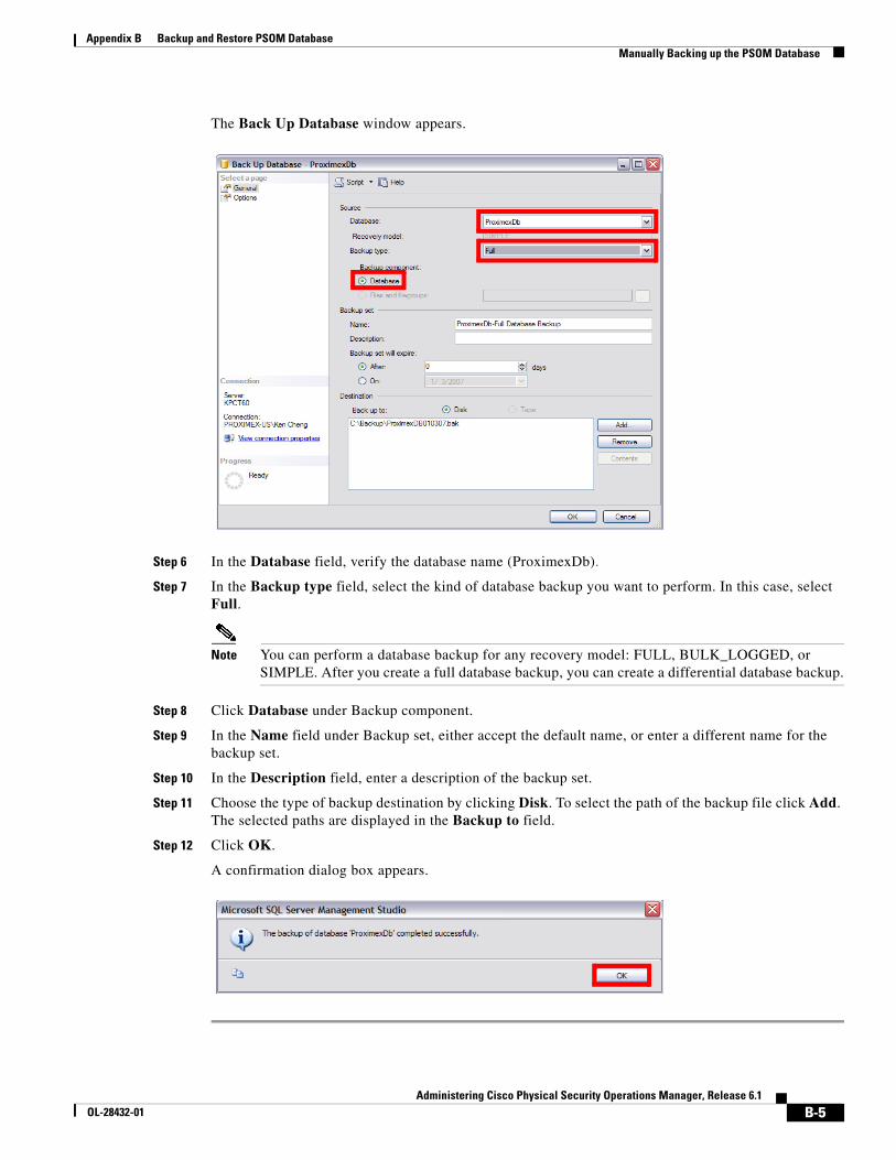
B-5Administering Cisco Physical Security Operations Manager, Release 6.1
OL-28432-01
Appendix B Backup and Restore PSOM Database Manually Backing up the PSOM Database
The Back Up Database window appears.
Step 6 In the Database field, verify the database name (ProximexDb).
Step 7 In the Backup type field, select the kind of database backup you want to perform. In this case, select Full.
Note You can perform a database backup for any recovery model: FULL, BULK_LOGGED, or SIMPLE. After you create a full database backup, you can create a differential database backup.
Step 8 Click Database under Backup component.
Step 9 In the Name field under Backup set, either accept the default name, or enter a different name for the backup set.
Step 10 In the Description field, enter a description of the backup set.
Step 11 Choose the type of backup destination by clicking Disk. To select the path of the backup file click Add. The selected paths are displayed in the Backup to field.
Step 12 Click OK.
A confirmation dialog box appears.
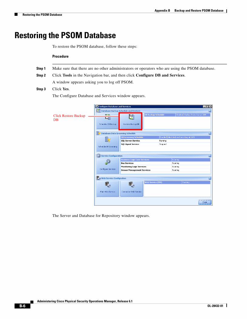
B-6Administering Cisco Physical Security Operations Manager, Release 6.1
OL-28432-01
Appendix B Backup and Restore PSOM Database Restoring the PSOM Database
Restoring the PSOM DatabaseTo restore the PSOM database, follow these steps:
Procedure
Step 1 Make sure that there are no other administrators or operators who are using the PSOM database.
Step 2 Click Tools in the Navigation bar, and then click Configure DB and Services.
A window appears asking you to log off PSOM.
Step 3 Click Yes.
The Configure Database and Services window appears.
The Server and Database for Repository window appears.
Click Restore Backup DB
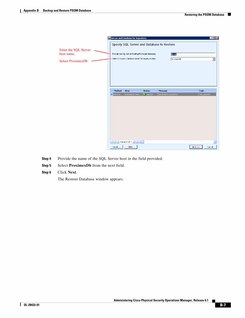
B-7Administering Cisco Physical Security Operations Manager, Release 6.1
OL-28432-01
Appendix B Backup and Restore PSOM Database Restoring the PSOM Database
Step 4 Provide the name of the SQL Server host in the field provided.
Step 5 Select ProximexDb from the next field.
Step 6 Click Next.
The Restore Database window appears.
Enter the SQL Server host name.
Select ProximexDb
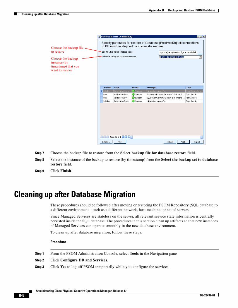
B-8Administering Cisco Physical Security Operations Manager, Release 6.1
OL-28432-01
Appendix B Backup and Restore PSOM Database Cleaning up after Database Migration
Step 7 Choose the backup file to restore from the Select backup file for database restore field.
Step 8 Select the instance of the backup to restore (by timestamp) from the Select the backup set to database restore field.
Step 9 Click Finish.
Cleaning up after Database MigrationThese procedures should be followed after moving or restoring the PSOM Repository (SQL database to a different environment—such as a different network, host machine, or set of servers.
Since Managed Services are stateless on the server, all relevant service state information is centrally persisted inside the SQL database. The procedures in this section clean up artifacts so that new instances of Managed Services can operate smoothly in the new database environment.
To clean up after database migration, follow these steps:
Procedure
Step 1 From the PSOM Administration Console, select Tools in the Navigation pane
Step 2 Click Configure DB and Services.
Step 3 Click Yes to log off PSOM temporarily while you configure the services.
Choose the backup file to restore
Choose the backup instance (by timestamp) that you want to restore
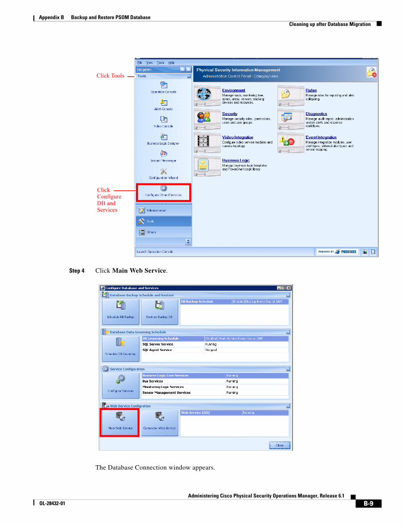
B-9Administering Cisco Physical Security Operations Manager, Release 6.1
OL-28432-01
Appendix B Backup and Restore PSOM Database Cleaning up after Database Migration
Step 4 Click Main Web Service.
The Database Connection window appears.
Click Configure DB and Services
Click Tools
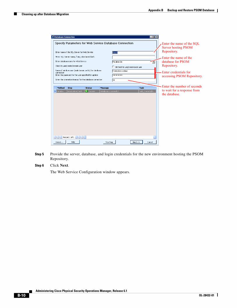
B-10Administering Cisco Physical Security Operations Manager, Release 6.1
OL-28432-01
Appendix B Backup and Restore PSOM Database Cleaning up after Database Migration
Step 5 Provide the server, database, and login credentials for the new environment hosting the PSOM Repository.
Step 6 Click Next.
The Web Service Configuration window appears.
Enter the name of the SQL Server hosting PSOM Repository.
Enter the name of the database for PSOM Repository.
Enter credentials for accessing PSOM Repository.
Enter the number of seconds to wait for a response from the database.
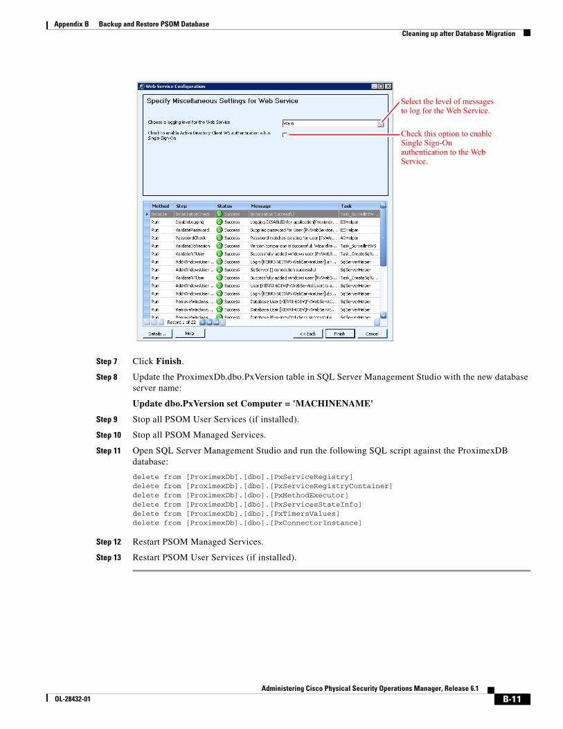
B-11Administering Cisco Physical Security Operations Manager, Release 6.1
OL-28432-01
Appendix B Backup and Restore PSOM Database Cleaning up after Database Migration
Step 7 Click Finish.
Step 8 Update the ProximexDb.dbo.PxVersion table in SQL Server Management Studio with the new database server name:
Update dbo.PxVersion set Computer = 'MACHINENAME'
Step 9 Stop all PSOM User Services (if installed).
Step 10 Stop all PSOM Managed Services.
Step 11 Open SQL Server Management Studio and run the following SQL script against the ProximexDB database:
delete from [ProximexDb].[dbo].[PxServiceRegistry]delete from [ProximexDb].[dbo].[PxServiceRegistryContainer]delete from [ProximexDb].[dbo].[PxMethodExecutor]delete from [ProximexDb].[dbo].[PxServicesStateInfo]delete from [ProximexDb].[dbo].[PxTimersValues]delete from [ProximexDb].[dbo].[PxConnectorInstance]
Step 12 Restart PSOM Managed Services.
Step 13 Restart PSOM User Services (if installed).
Select the level of messages to log for the Web Service.
Check this option to enable Single Sign-On authentication to the Web Service.
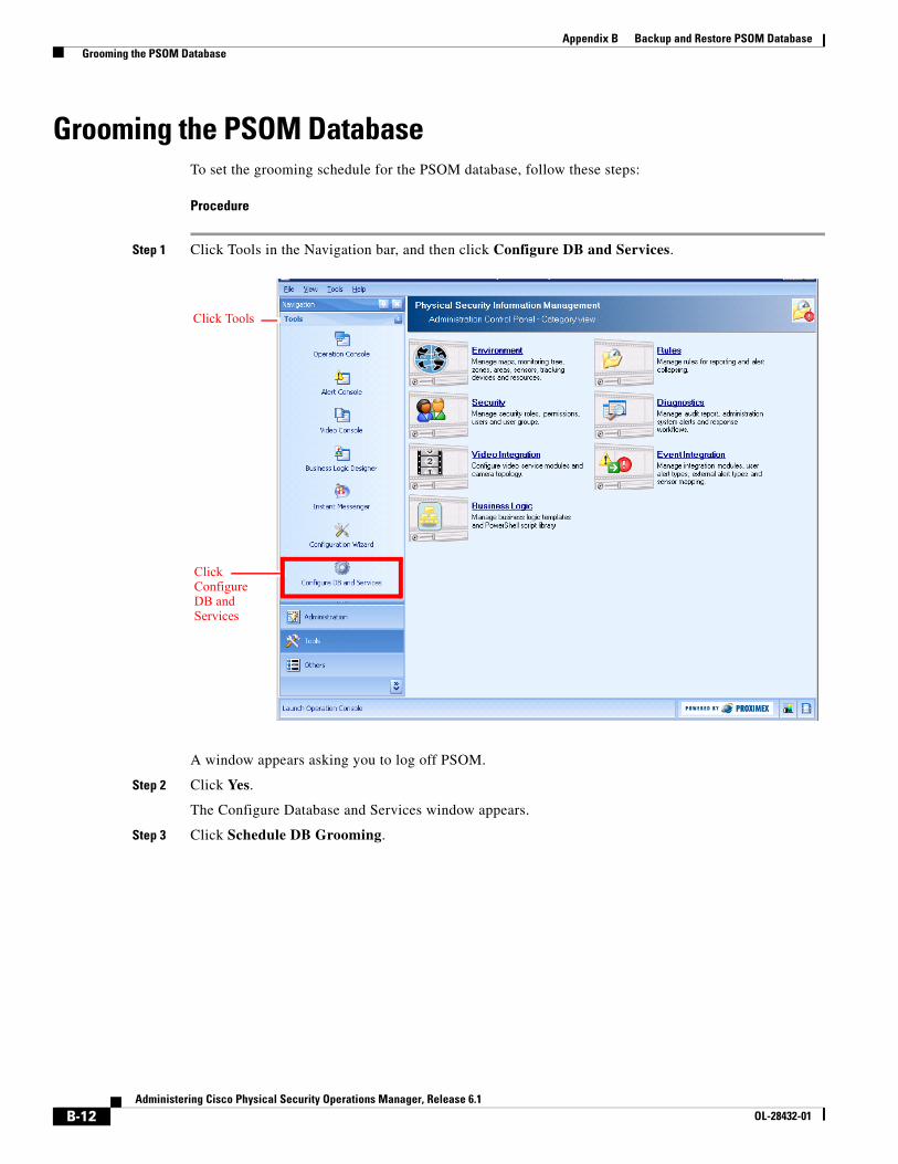
B-12Administering Cisco Physical Security Operations Manager, Release 6.1
OL-28432-01
Appendix B Backup and Restore PSOM Database Grooming the PSOM Database
Grooming the PSOM DatabaseTo set the grooming schedule for the PSOM database, follow these steps:
Procedure
Step 1 Click Tools in the Navigation bar, and then click Configure DB and Services.
A window appears asking you to log off PSOM.
Step 2 Click Yes.
The Configure Database and Services window appears.
Step 3 Click Schedule DB Grooming.
Click Configure DB and Services
Click Tools
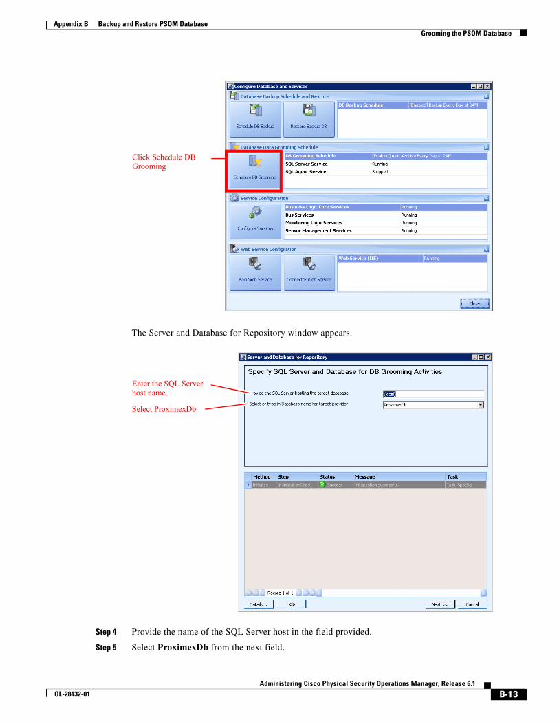
B-13Administering Cisco Physical Security Operations Manager, Release 6.1
OL-28432-01
Appendix B Backup and Restore PSOM Database Grooming the PSOM Database
The Server and Database for Repository window appears.
Step 4 Provide the name of the SQL Server host in the field provided.
Step 5 Select ProximexDb from the next field.
Click Schedule DB Grooming
Enter the SQL Server host name.
Select ProximexDb
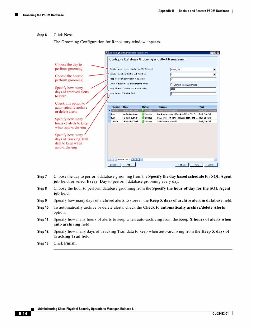
B-14Administering Cisco Physical Security Operations Manager, Release 6.1
OL-28432-01
Appendix B Backup and Restore PSOM Database Grooming the PSOM Database
Step 6 Click Next.
The Grooming Configuration for Repository window appears.
Step 7 Choose the day to perform database grooming from the Specify the day based schedule for SQL Agent job field, or select Every_Day to perform database grooming every day.
Step 8 Choose the hour to perform database grooming from the Specify the hour of day for the SQL Agent job field.
Step 9 Specify how many days of archived alerts to store in the Keep X days of archive alert in database field.
Step 10 To automatically archive or delete alerts, check the Check to automatically archive/delete Alerts option.
Step 11 Specify how many hours of alerts to keep when auto-archiving from the Keep X hours of alerts when auto archiving field.
Step 12 Specify how many days of Tracking Trail data to keep when auto-archiving from the Keep X days of Tracking Trail field.
Step 13 Click Finish.
Choose the day to perform grooming
Choose the hour to perform grooming
Specify how many days of archived alerts to store
Check this option to automatically archive or delete alerts
Specify how many hours of alerts to keep when auto-archiving
Specify how many days of Tracking Trail data to keep when auto-archiving
C-1Administering Cisco Physical Security Operations Manager, Release 6.1
OL-28432-01
A P P E N D I X CReconfiguring PSOM Services
This appendix explains how to reconfigure PSOM Services, PSOM Web Service, and PSOM Connector Web Service after the initial deployment.
This appendix includes these sections:
• Reconfiguring Settings for PSOM Services, page C-1
• Specifying Custom Parsing, page C-23
• Changing the Configuration of the PSOM Web Service, page C-26
• Configuring Failover for PSOM Web Service, page C-29
• Reconfiguring the Connector Web Service, page C-31
• Reconfiguring Settings for PSOM User Services, page C-38
Reconfiguring Settings for PSOM ServicesYou can change the configuration of PSOM Services after the initial deployment of PSOM.
Note You must be a member of the local Administrators group to launch Services Configuration.
To reconfigure PSOM Services, follow these steps:
Procedure
Step 1 From the Start menu, select All Programs > Cisco Physical Security Operations Manager Services > Services Configuration.
Or from the PSOM Administration Console:
a. Select Tools in the Navigation pane
b. Click Configure DB and Services.
c. Click Yes to log off PSOM temporarily while you configure the services.
d. Click Configure Services.
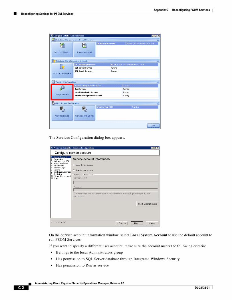
C-2Administering Cisco Physical Security Operations Manager, Release 6.1
OL-28432-01
Appendix C Reconfiguring PSOM Services Reconfiguring Settings for PSOM Services
The Services Configuration dialog box appears.
On the Service account information window, select Local System Account to use the default account to run PSOM Services.
If you want to specify a different user account, make sure the account meets the following criteria:
• Belongs to the local Administrators group
• Has permission to SQL Server database through Integrated Windows Security
• Has permission to Run as service
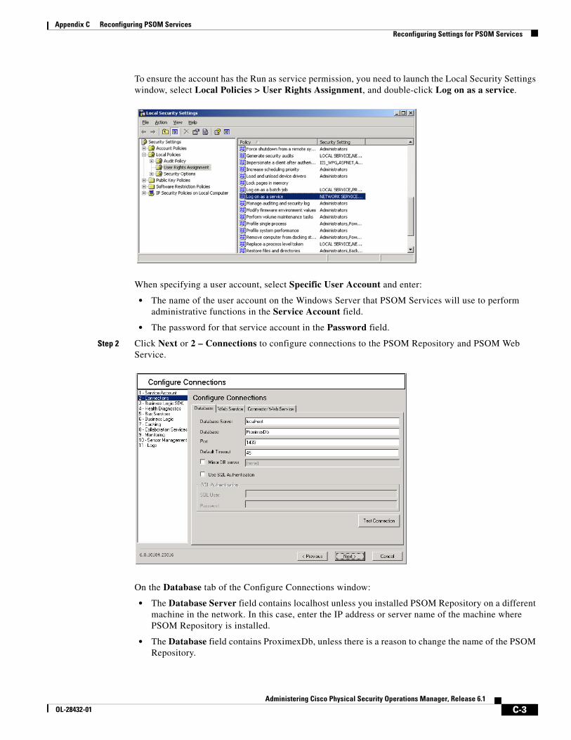
C-3Administering Cisco Physical Security Operations Manager, Release 6.1
OL-28432-01
Appendix C Reconfiguring PSOM Services Reconfiguring Settings for PSOM Services
To ensure the account has the Run as service permission, you need to launch the Local Security Settings window, select Local Policies > User Rights Assignment, and double-click Log on as a service.
When specifying a user account, select Specific User Account and enter:
• The name of the user account on the Windows Server that PSOM Services will use to perform administrative functions in the Service Account field.
• The password for that service account in the Password field.
Step 2 Click Next or 2 – Connections to configure connections to the PSOM Repository and PSOM Web Service.
On the Database tab of the Configure Connections window:
• The Database Server field contains localhost unless you installed PSOM Repository on a different machine in the network. In this case, enter the IP address or server name of the machine where PSOM Repository is installed.
• The Database field contains ProximexDb, unless there is a reason to change the name of the PSOM Repository.
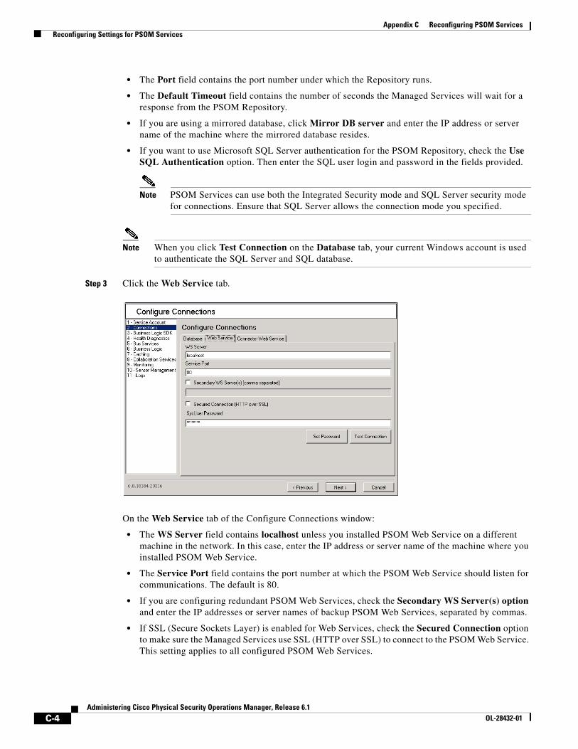
C-4Administering Cisco Physical Security Operations Manager, Release 6.1
OL-28432-01
Appendix C Reconfiguring PSOM Services Reconfiguring Settings for PSOM Services
• The Port field contains the port number under which the Repository runs.
• The Default Timeout field contains the number of seconds the Managed Services will wait for a response from the PSOM Repository.
• If you are using a mirrored database, click Mirror DB server and enter the IP address or server name of the machine where the mirrored database resides.
• If you want to use Microsoft SQL Server authentication for the PSOM Repository, check the Use SQL Authentication option. Then enter the SQL user login and password in the fields provided.
Note PSOM Services can use both the Integrated Security mode and SQL Server security mode for connections. Ensure that SQL Server allows the connection mode you specified.
Note When you click Test Connection on the Database tab, your current Windows account is used to authenticate the SQL Server and SQL database.
Step 3 Click the Web Service tab.
On the Web Service tab of the Configure Connections window:
• The WS Server field contains localhost unless you installed PSOM Web Service on a different machine in the network. In this case, enter the IP address or server name of the machine where you installed PSOM Web Service.
• The Service Port field contains the port number at which the PSOM Web Service should listen for communications. The default is 80.
• If you are configuring redundant PSOM Web Services, check the Secondary WS Server(s) option and enter the IP addresses or server names of backup PSOM Web Services, separated by commas.
• If SSL (Secure Sockets Layer) is enabled for Web Services, check the Secured Connection option to make sure the Managed Services use SSL (HTTP over SSL) to connect to the PSOM Web Service. This setting applies to all configured PSOM Web Services.
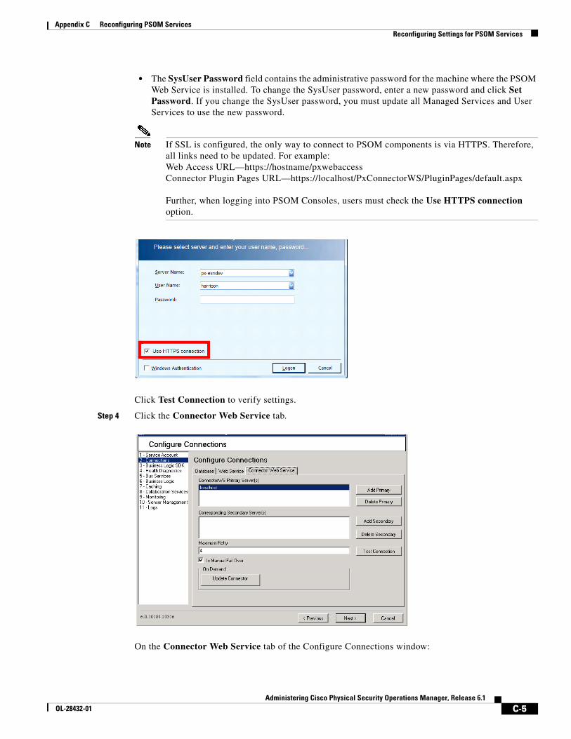
C-5Administering Cisco Physical Security Operations Manager, Release 6.1
OL-28432-01
Appendix C Reconfiguring PSOM Services Reconfiguring Settings for PSOM Services
• The SysUser Password field contains the administrative password for the machine where the PSOM Web Service is installed. To change the SysUser password, enter a new password and click Set Password. If you change the SysUser password, you must update all Managed Services and User Services to use the new password.
Note If SSL is configured, the only way to connect to PSOM components is via HTTPS. Therefore, all links need to be updated. For example:Web Access URL—https://hostname/pxwebaccessConnector Plugin Pages URL—https://localhost/PxConnectorWS/PluginPages/default.aspx
Further, when logging into PSOM Consoles, users must check the Use HTTPS connection option.
Click Test Connection to verify settings.
Step 4 Click the Connector Web Service tab.
On the Connector Web Service tab of the Configure Connections window:
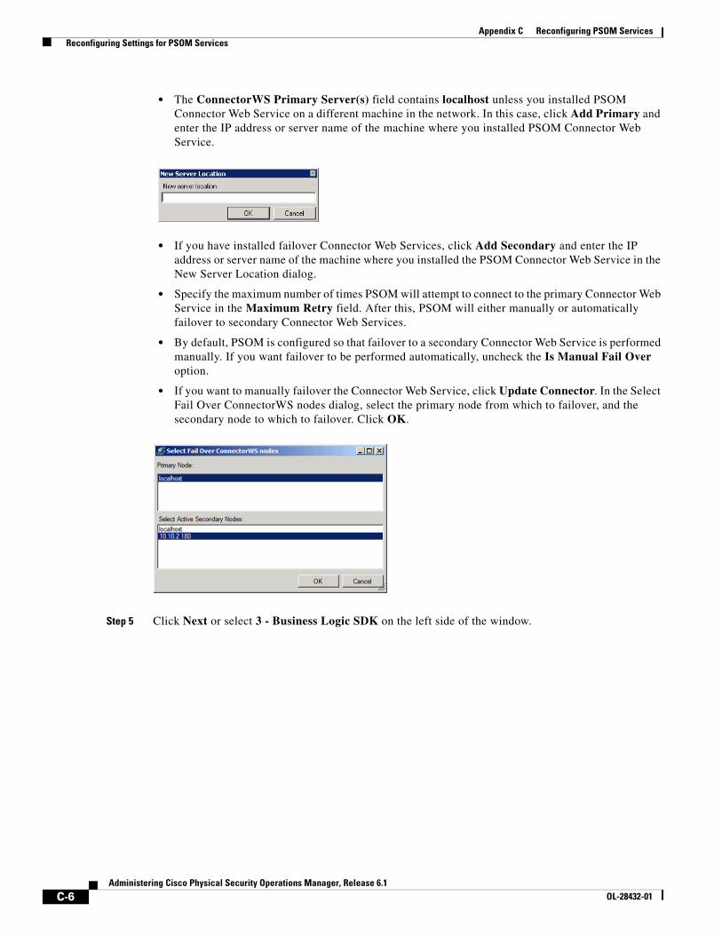
C-6Administering Cisco Physical Security Operations Manager, Release 6.1
OL-28432-01
Appendix C Reconfiguring PSOM Services Reconfiguring Settings for PSOM Services
• The ConnectorWS Primary Server(s) field contains localhost unless you installed PSOM Connector Web Service on a different machine in the network. In this case, click Add Primary and enter the IP address or server name of the machine where you installed PSOM Connector Web Service.
• If you have installed failover Connector Web Services, click Add Secondary and enter the IP address or server name of the machine where you installed the PSOM Connector Web Service in the New Server Location dialog.
• Specify the maximum number of times PSOM will attempt to connect to the primary Connector Web Service in the Maximum Retry field. After this, PSOM will either manually or automatically failover to secondary Connector Web Services.
• By default, PSOM is configured so that failover to a secondary Connector Web Service is performed manually. If you want failover to be performed automatically, uncheck the Is Manual Fail Over option.
• If you want to manually failover the Connector Web Service, click Update Connector. In the Select Fail Over ConnectorWS nodes dialog, select the primary node from which to failover, and the secondary node to which to failover. Click OK.
Step 5 Click Next or select 3 - Business Logic SDK on the left side of the window.
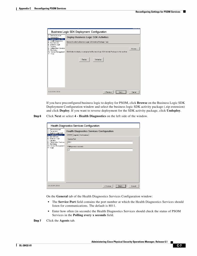
C-7Administering Cisco Physical Security Operations Manager, Release 6.1
OL-28432-01
Appendix C Reconfiguring PSOM Services Reconfiguring Settings for PSOM Services
If you have preconfigured business logic to deploy for PSOM, click Browse on the Business Logic SDK Deployment Configuration window and select the business logic SDK activity package (.zip extension) and click Deploy. If you want to reverse deployment for the SDK activity package, click Undeploy.
Step 6 Click Next or select 4 - Health Diagnostics on the left side of the window.
On the General tab of the Health Diagnostics Services Configuration window:
• The Service Port field contains the port number at which the Health Diagnostics Services should listen for communications. The default is 8011.
• Enter how often (in seconds) the Health Diagnostics Services should check the status of PSOM Services in the Polling every x seconds field.
Step 7 Click the Agents tab.
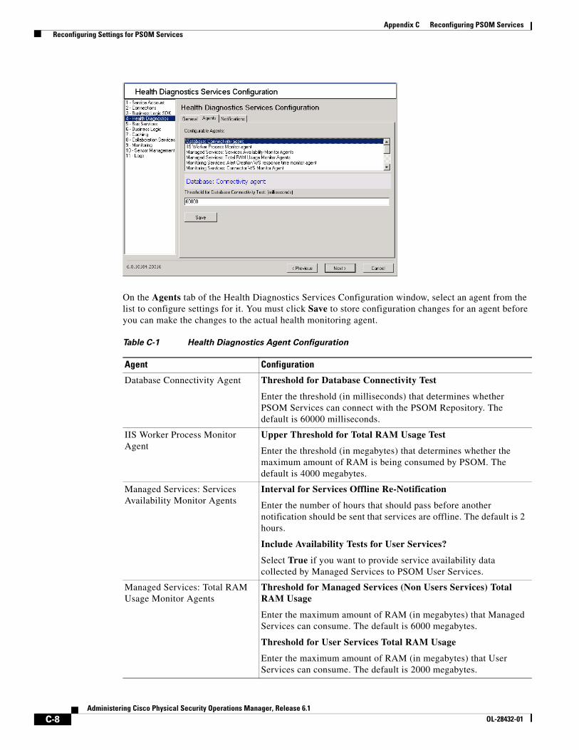
C-8Administering Cisco Physical Security Operations Manager, Release 6.1
OL-28432-01
Appendix C Reconfiguring PSOM Services Reconfiguring Settings for PSOM Services
On the Agents tab of the Health Diagnostics Services Configuration window, select an agent from the list to configure settings for it. You must click Save to store configuration changes for an agent before you can make the changes to the actual health monitoring agent.
Table C-1 Health Diagnostics Agent Configuration
Agent Configuration
Database Connectivity Agent Threshold for Database Connectivity Test
Enter the threshold (in milliseconds) that determines whether PSOM Services can connect with the PSOM Repository. The default is 60000 milliseconds.
IIS Worker Process Monitor Agent
Upper Threshold for Total RAM Usage Test
Enter the threshold (in megabytes) that determines whether the maximum amount of RAM is being consumed by PSOM. The default is 4000 megabytes.
Managed Services: Services Availability Monitor Agents
Interval for Services Offline Re-Notification
Enter the number of hours that should pass before another notification should be sent that services are offline. The default is 2 hours.
Include Availability Tests for User Services?
Select True if you want to provide service availability data collected by Managed Services to PSOM User Services.
Managed Services: Total RAM Usage Monitor Agents
Threshold for Managed Services (Non Users Services) Total RAM Usage
Enter the maximum amount of RAM (in megabytes) that Managed Services can consume. The default is 6000 megabytes.
Threshold for User Services Total RAM Usage
Enter the maximum amount of RAM (in megabytes) that User Services can consume. The default is 2000 megabytes.
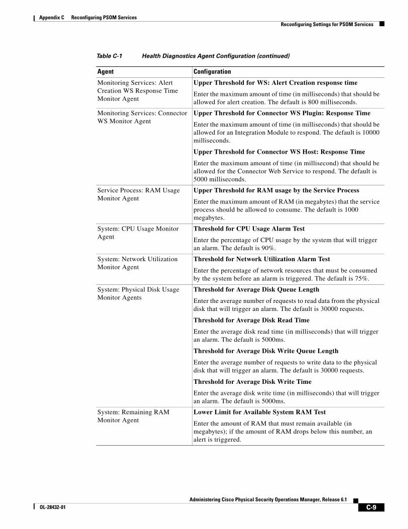
C-9Administering Cisco Physical Security Operations Manager, Release 6.1
OL-28432-01
Appendix C Reconfiguring PSOM Services Reconfiguring Settings for PSOM Services
Monitoring Services: Alert Creation WS Response Time Monitor Agent
Upper Threshold for WS: Alert Creation response time
Enter the maximum amount of time (in milliseconds) that should be allowed for alert creation. The default is 800 milliseconds.
Monitoring Services: Connector WS Monitor Agent
Upper Threshold for Connector WS Plugin: Response Time
Enter the maximum amount of time (in milliseconds) that should be allowed for an Integration Module to respond. The default is 10000 milliseconds.
Upper Threshold for Connector WS Host: Response Time
Enter the maximum amount of time (in millisecond) that should be allowed for the Connector Web Service to respond. The default is 5000 milliseconds.
Service Process: RAM Usage Monitor Agent
Upper Threshold for RAM usage by the Service Process
Enter the maximum amount of RAM (in megabytes) that the service process should be allowed to consume. The default is 1000 megabytes.
System: CPU Usage Monitor Agent
Threshold for CPU Usage Alarm Test
Enter the percentage of CPU usage by the system that will trigger an alarm. The default is 90%.
System: Network Utilization Monitor Agent
Threshold for Network Utilization Alarm Test
Enter the percentage of network resources that must be consumed by the system before an alarm is triggered. The default is 75%.
System: Physical Disk Usage Monitor Agents
Threshold for Average Disk Queue Length
Enter the average number of requests to read data from the physical disk that will trigger an alarm. The default is 30000 requests.
Threshold for Average Disk Read Time
Enter the average disk read time (in milliseconds) that will trigger an alarm. The default is 5000ms.
Threshold for Average Disk Write Queue Length
Enter the average number of requests to write data to the physical disk that will trigger an alarm. The default is 30000 requests.
Threshold for Average Disk Write Time
Enter the average disk write time (in milliseconds) that will trigger an alarm. The default is 5000ms.
System: Remaining RAM Monitor Agent
Lower Limit for Available System RAM Test
Enter the amount of RAM that must remain available (in megabytes); if the amount of RAM drops below this number, an alert is triggered.
Table C-1 Health Diagnostics Agent Configuration (continued)
Agent Configuration
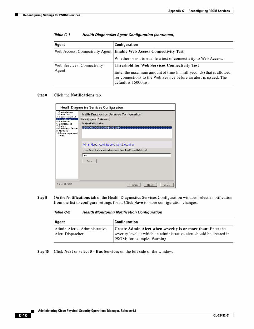
C-10Administering Cisco Physical Security Operations Manager, Release 6.1
OL-28432-01
Appendix C Reconfiguring PSOM Services Reconfiguring Settings for PSOM Services
Step 8 Click the Notifications tab.
Step 9 On the Notifications tab of the Health Diagnostics Services Configuration window, select a notification from the list to configure settings for it. Click Save to store configuration changes.
Step 10 Click Next or select 5 - Bus Services on the left side of the window.
Web Access: Connectivity Agent Enable Web Access Connectivity Test
Whether or not to enable a test of connectivity to Web Access.
Web Services: Connectivity Agent
Threshold for Web Services Connectivity Test
Enter the maximum amount of time (in milliseconds) that is allowed for connections to the Web Service before an alert is issued. The default is 15000ms.
Table C-2 Health Monitoring Notification Configuration
Agent Configuration
Admin Alerts: Administrative Alert Dispatcher
Create Admin Alert when severity is or more than: Enter the severity level at which an administrative alert should be created in PSOM; for example, Warning.
Table C-1 Health Diagnostics Agent Configuration (continued)
Agent Configuration
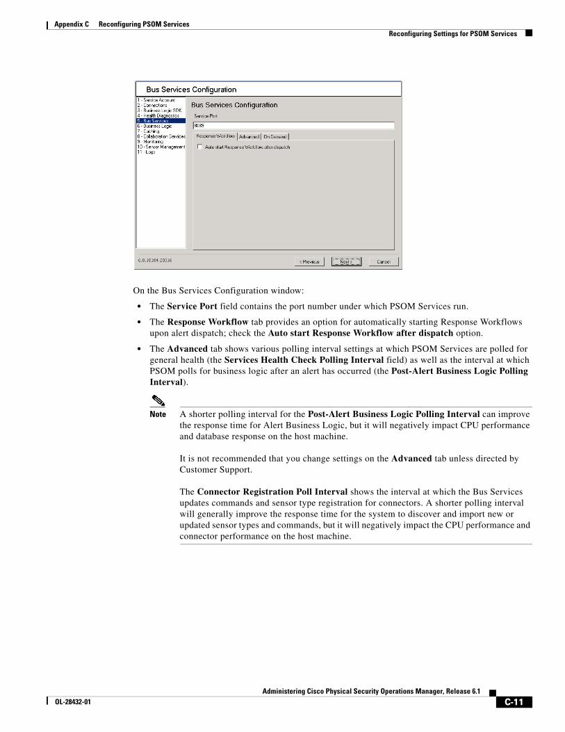
C-11Administering Cisco Physical Security Operations Manager, Release 6.1
OL-28432-01
Appendix C Reconfiguring PSOM Services Reconfiguring Settings for PSOM Services
On the Bus Services Configuration window:
• The Service Port field contains the port number under which PSOM Services run.
• The Response Workflow tab provides an option for automatically starting Response Workflows upon alert dispatch; check the Auto start Response Workflow after dispatch option.
• The Advanced tab shows various polling interval settings at which PSOM Services are polled for general health (the Services Health Check Polling Interval field) as well as the interval at which PSOM polls for business logic after an alert has occurred (the Post-Alert Business Logic Polling Interval).
Note A shorter polling interval for the Post-Alert Business Logic Polling Interval can improve the response time for Alert Business Logic, but it will negatively impact CPU performance and database response on the host machine.
It is not recommended that you change settings on the Advanced tab unless directed by Customer Support.
The Connector Registration Poll Interval shows the interval at which the Bus Services updates commands and sensor type registration for connectors. A shorter polling interval will generally improve the response time for the system to discover and import new or updated sensor types and commands, but it will negatively impact the CPU performance and connector performance on the host machine.
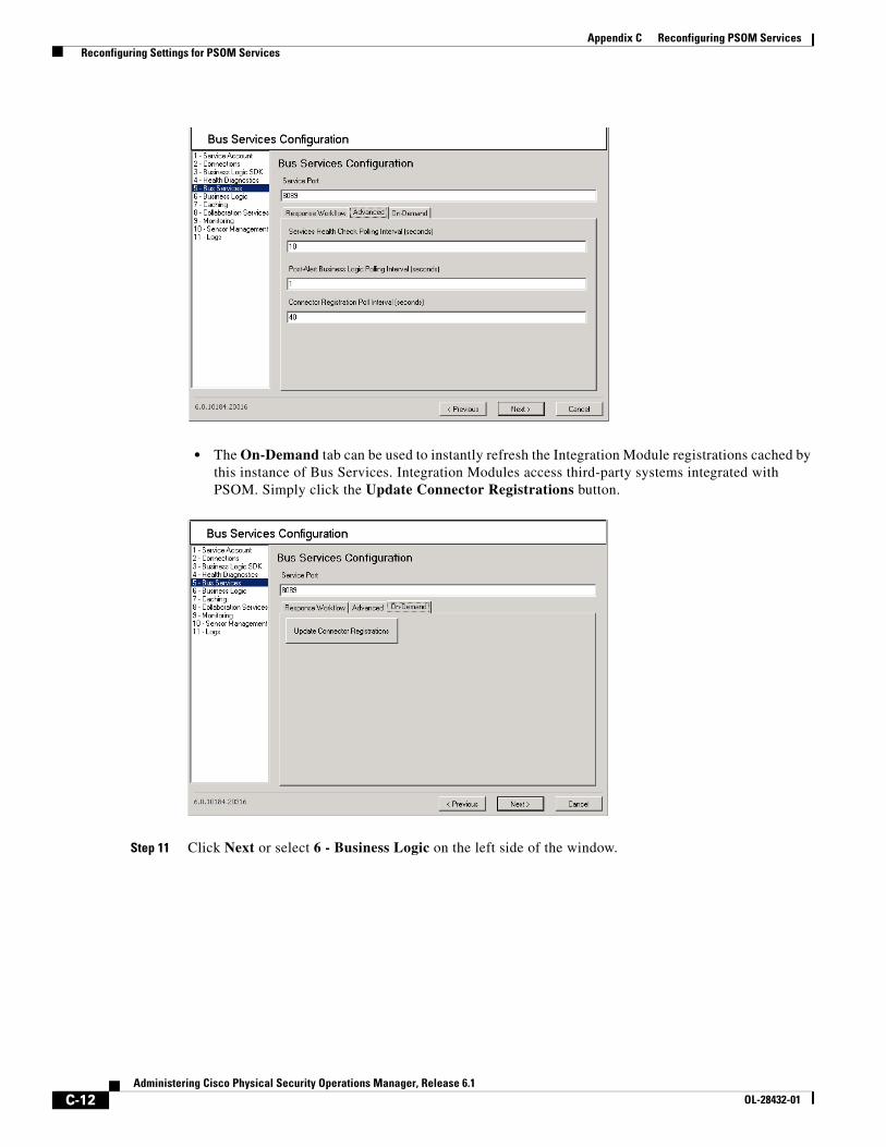
C-12Administering Cisco Physical Security Operations Manager, Release 6.1
OL-28432-01
Appendix C Reconfiguring PSOM Services Reconfiguring Settings for PSOM Services
• The On-Demand tab can be used to instantly refresh the Integration Module registrations cached by this instance of Bus Services. Integration Modules access third-party systems integrated with PSOM. Simply click the Update Connector Registrations button.
Step 11 Click Next or select 6 - Business Logic on the left side of the window.
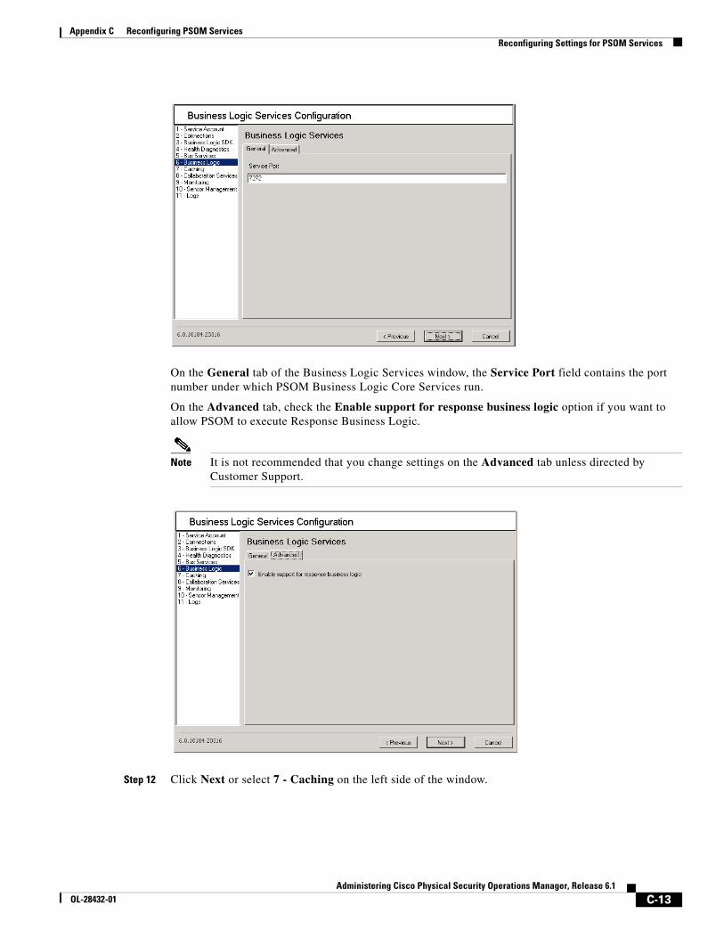
C-13Administering Cisco Physical Security Operations Manager, Release 6.1
OL-28432-01
Appendix C Reconfiguring PSOM Services Reconfiguring Settings for PSOM Services
On the General tab of the Business Logic Services window, the Service Port field contains the port number under which PSOM Business Logic Core Services run.
On the Advanced tab, check the Enable support for response business logic option if you want to allow PSOM to execute Response Business Logic.
Note It is not recommended that you change settings on the Advanced tab unless directed by Customer Support.
Step 12 Click Next or select 7 - Caching on the left side of the window.
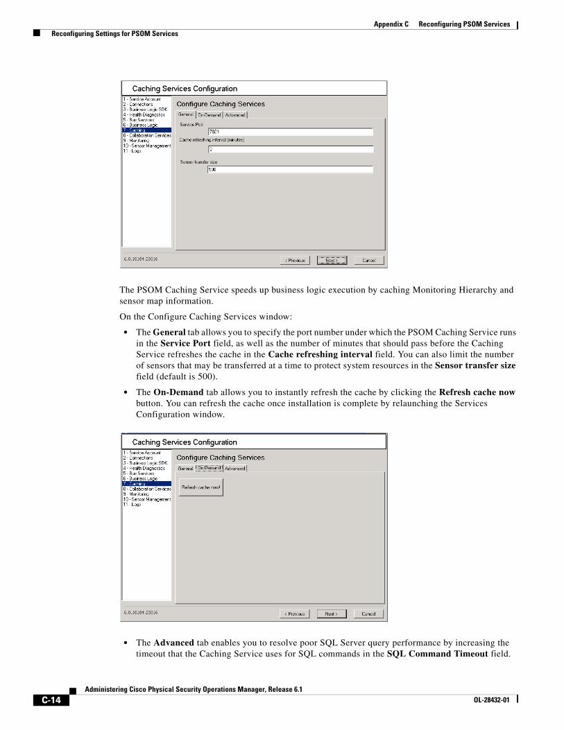
C-14Administering Cisco Physical Security Operations Manager, Release 6.1
OL-28432-01
Appendix C Reconfiguring PSOM Services Reconfiguring Settings for PSOM Services
The PSOM Caching Service speeds up business logic execution by caching Monitoring Hierarchy and sensor map information.
On the Configure Caching Services window:
• The General tab allows you to specify the port number under which the PSOM Caching Service runs in the Service Port field, as well as the number of minutes that should pass before the Caching Service refreshes the cache in the Cache refreshing interval field. You can also limit the number of sensors that may be transferred at a time to protect system resources in the Sensor transfer size field (default is 500).
• The On-Demand tab allows you to instantly refresh the cache by clicking the Refresh cache now button. You can refresh the cache once installation is complete by relaunching the Services Configuration window.
• The Advanced tab enables you to resolve poor SQL Server query performance by increasing the timeout that the Caching Service uses for SQL commands in the SQL Command Timeout field.
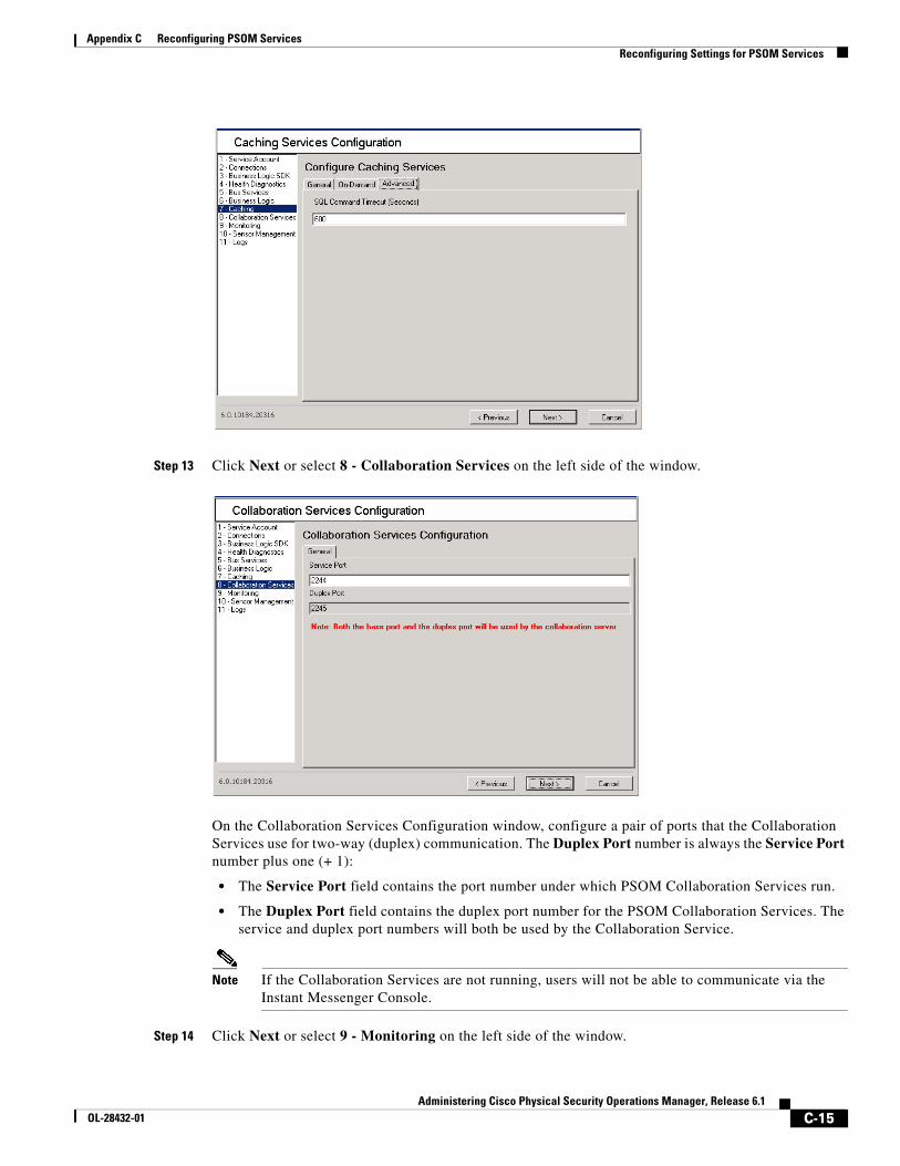
C-15Administering Cisco Physical Security Operations Manager, Release 6.1
OL-28432-01
Appendix C Reconfiguring PSOM Services Reconfiguring Settings for PSOM Services
Step 13 Click Next or select 8 - Collaboration Services on the left side of the window.
On the Collaboration Services Configuration window, configure a pair of ports that the Collaboration Services use for two-way (duplex) communication. The Duplex Port number is always the Service Port number plus one (+ 1):
• The Service Port field contains the port number under which PSOM Collaboration Services run.
• The Duplex Port field contains the duplex port number for the PSOM Collaboration Services. The service and duplex port numbers will both be used by the Collaboration Service.
Note If the Collaboration Services are not running, users will not be able to communicate via the Instant Messenger Console.
Step 14 Click Next or select 9 - Monitoring on the left side of the window.
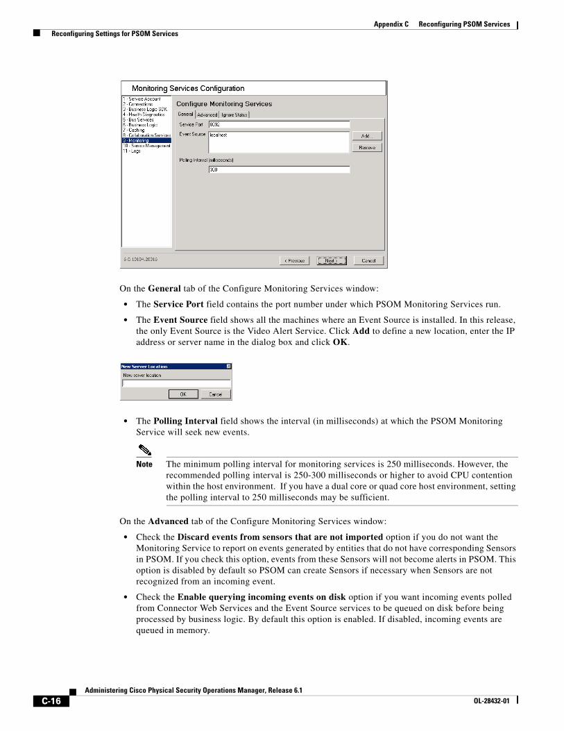
C-16Administering Cisco Physical Security Operations Manager, Release 6.1
OL-28432-01
Appendix C Reconfiguring PSOM Services Reconfiguring Settings for PSOM Services
On the General tab of the Configure Monitoring Services window:
• The Service Port field contains the port number under which PSOM Monitoring Services run.
• The Event Source field shows all the machines where an Event Source is installed. In this release, the only Event Source is the Video Alert Service. Click Add to define a new location, enter the IP address or server name in the dialog box and click OK.
• The Polling Interval field shows the interval (in milliseconds) at which the PSOM Monitoring Service will seek new events.
Note The minimum polling interval for monitoring services is 250 milliseconds. However, the recommended polling interval is 250-300 milliseconds or higher to avoid CPU contention within the host environment. If you have a dual core or quad core host environment, setting the polling interval to 250 milliseconds may be sufficient.
On the Advanced tab of the Configure Monitoring Services window:
• Check the Discard events from sensors that are not imported option if you do not want the Monitoring Service to report on events generated by entities that do not have corresponding Sensors in PSOM. If you check this option, events from these Sensors will not become alerts in PSOM. This option is disabled by default so PSOM can create Sensors if necessary when Sensors are not recognized from an incoming event.
• Check the Enable querying incoming events on disk option if you want incoming events polled from Connector Web Services and the Event Source services to be queued on disk before being processed by business logic. By default this option is enabled. If disabled, incoming events are queued in memory.
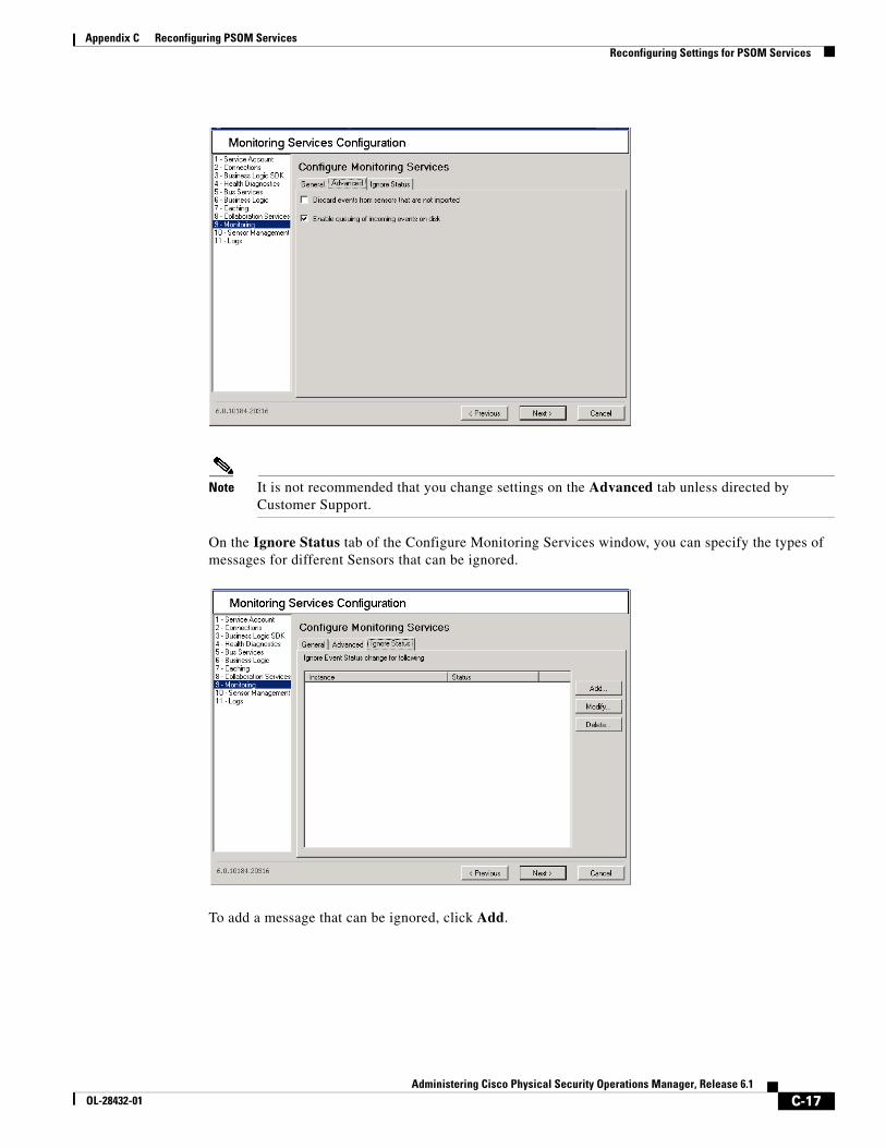
C-17Administering Cisco Physical Security Operations Manager, Release 6.1
OL-28432-01
Appendix C Reconfiguring PSOM Services Reconfiguring Settings for PSOM Services
Note It is not recommended that you change settings on the Advanced tab unless directed by Customer Support.
On the Ignore Status tab of the Configure Monitoring Services window, you can specify the types of messages for different Sensors that can be ignored.
To add a message that can be ignored, click Add.
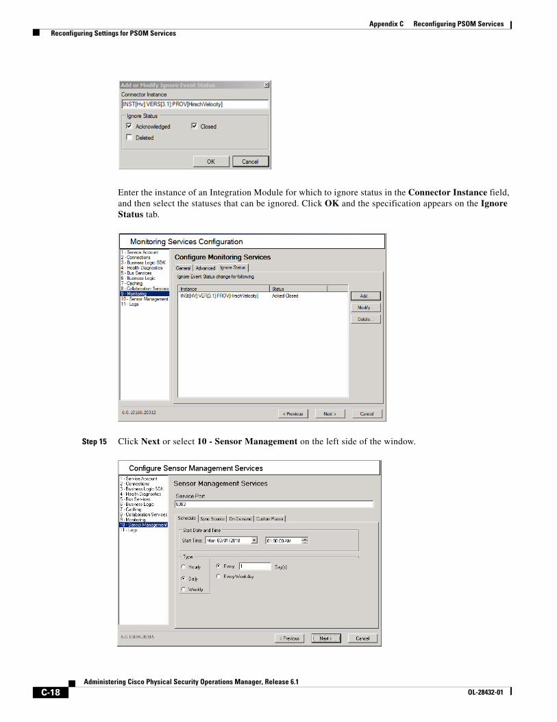
C-18Administering Cisco Physical Security Operations Manager, Release 6.1
OL-28432-01
Appendix C Reconfiguring PSOM Services Reconfiguring Settings for PSOM Services
Enter the instance of an Integration Module for which to ignore status in the Connector Instance field, and then select the statuses that can be ignored. Click OK and the specification appears on the Ignore Status tab.
Step 15 Click Next or select 10 - Sensor Management on the left side of the window.
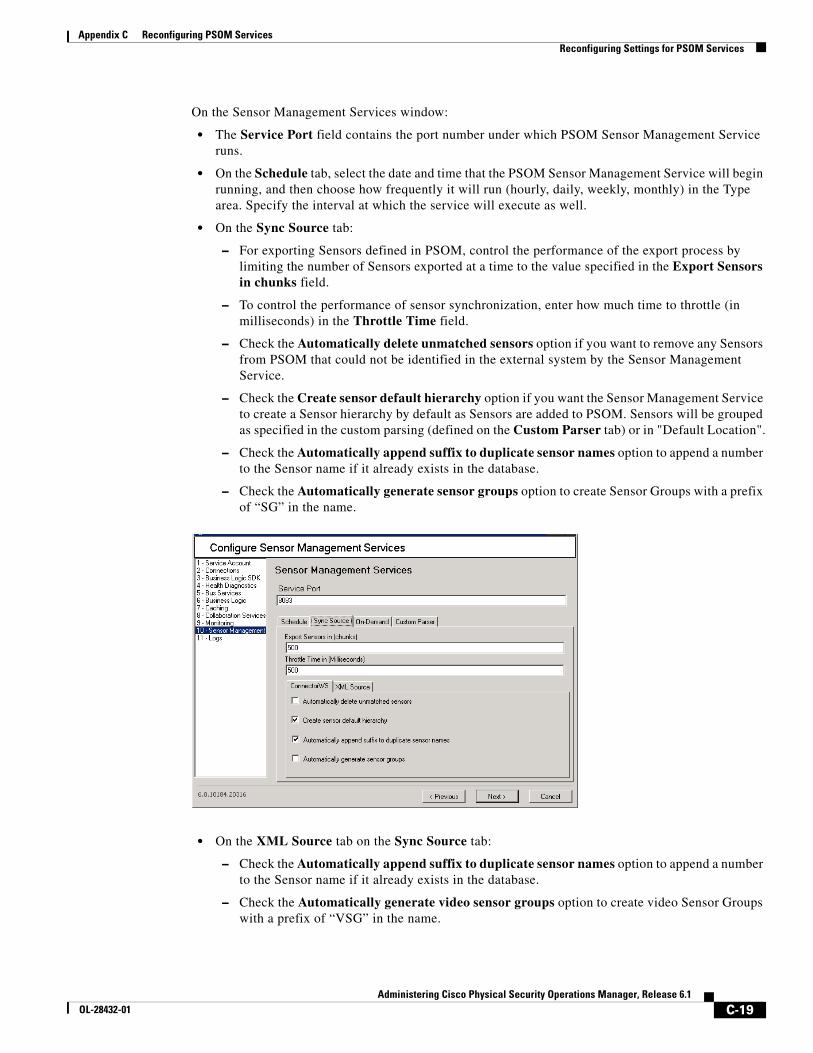
C-19Administering Cisco Physical Security Operations Manager, Release 6.1
OL-28432-01
Appendix C Reconfiguring PSOM Services Reconfiguring Settings for PSOM Services
On the Sensor Management Services window:
• The Service Port field contains the port number under which PSOM Sensor Management Service runs.
• On the Schedule tab, select the date and time that the PSOM Sensor Management Service will begin running, and then choose how frequently it will run (hourly, daily, weekly, monthly) in the Type area. Specify the interval at which the service will execute as well.
• On the Sync Source tab:
– For exporting Sensors defined in PSOM, control the performance of the export process by limiting the number of Sensors exported at a time to the value specified in the Export Sensors in chunks field.
– To control the performance of sensor synchronization, enter how much time to throttle (in milliseconds) in the Throttle Time field.
– Check the Automatically delete unmatched sensors option if you want to remove any Sensors from PSOM that could not be identified in the external system by the Sensor Management Service.
– Check the Create sensor default hierarchy option if you want the Sensor Management Service to create a Sensor hierarchy by default as Sensors are added to PSOM. Sensors will be grouped as specified in the custom parsing (defined on the Custom Parser tab) or in "Default Location".
– Check the Automatically append suffix to duplicate sensor names option to append a number to the Sensor name if it already exists in the database.
– Check the Automatically generate sensor groups option to create Sensor Groups with a prefix of “SG” in the name.
• On the XML Source tab on the Sync Source tab:
– Check the Automatically append suffix to duplicate sensor names option to append a number to the Sensor name if it already exists in the database.
– Check the Automatically generate video sensor groups option to create video Sensor Groups with a prefix of “VSG” in the name.
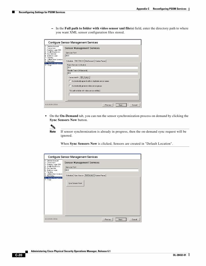
C-20Administering Cisco Physical Security Operations Manager, Release 6.1
OL-28432-01
Appendix C Reconfiguring PSOM Services Reconfiguring Settings for PSOM Services
– In the Full path to folder with video sensor xml file(s) field, enter the directory path to where you want XML sensor configuration files stored.
• On the On-Demand tab, you can run the sensor synchronization process on demand by clicking the Sync Sensors Now button.
Note If sensor synchronization is already in progress, then the on-demand sync request will be ignored.
When Sync Sensors Now is clicked, Sensors are created in "Default Location".
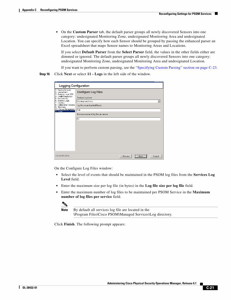
C-21Administering Cisco Physical Security Operations Manager, Release 6.1
OL-28432-01
Appendix C Reconfiguring PSOM Services Reconfiguring Settings for PSOM Services
• On the Custom Parser tab, the default parser groups all newly discovered Sensors into one category: undesignated Monitoring Zone, undesignated Monitoring Area and undesignated Location. You can specify how each Sensor should be grouped by passing the enhanced parser an Excel spreadsheet that maps Sensor names to Monitoring Areas and Locations.
If you select Default Parser from the Select Parser field, the values in the other fields either are dimmed or ignored. The default parser groups all newly discovered Sensors into one category: undesignated Monitoring Zone, undesignated Monitoring Area and undesignated Location.
If you want to perform custom parsing, see the “Specifying Custom Parsing” section on page C-23.
Step 16 Click Next or select 11 - Logs in the left side of the window.
On the Configure Log Files window:
• Select the level of events that should be maintained in the PSOM log files from the Services Log Level field.
• Enter the maximum size per log file (in bytes) in the Log file size per log file field.
• Enter the maximum number of log files to be maintained per PSOM Service in the Maximum number of log files per service field.
Note By default all services log file are located in the \Program Files\Cisco PSOM\Managed Services\Log directory.
Click Finish. The following prompt appears:
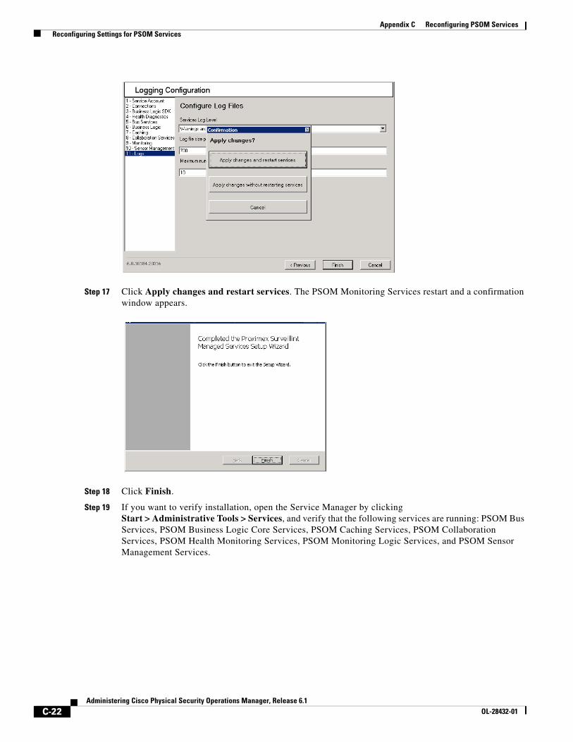
C-22Administering Cisco Physical Security Operations Manager, Release 6.1
OL-28432-01
Appendix C Reconfiguring PSOM Services Reconfiguring Settings for PSOM Services
Step 17 Click Apply changes and restart services. The PSOM Monitoring Services restart and a confirmation window appears.
Step 18 Click Finish.
Step 19 If you want to verify installation, open the Service Manager by clicking Start > Administrative Tools > Services, and verify that the following services are running: PSOM Bus Services, PSOM Business Logic Core Services, PSOM Caching Services, PSOM Collaboration Services, PSOM Health Monitoring Services, PSOM Monitoring Logic Services, and PSOM Sensor Management Services.
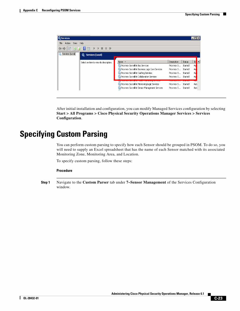
C-23Administering Cisco Physical Security Operations Manager, Release 6.1
OL-28432-01
Appendix C Reconfiguring PSOM Services Specifying Custom Parsing
After initial installation and configuration, you can modify Managed Services configuration by selecting Start > All Programs > Cisco Physical Security Operations Manager Services > Services Configuration.
Specifying Custom ParsingYou can perform custom parsing to specify how each Sensor should be grouped in PSOM. To do so, you will need to supply an Excel spreadsheet that has the name of each Sensor matched with its associated Monitoring Zone, Monitoring Area, and Location.
To specify custom parsing, follow these steps:
Procedure
Step 1 Navigate to the Custom Parser tab under 7–Sensor Management of the Services Configuration window.
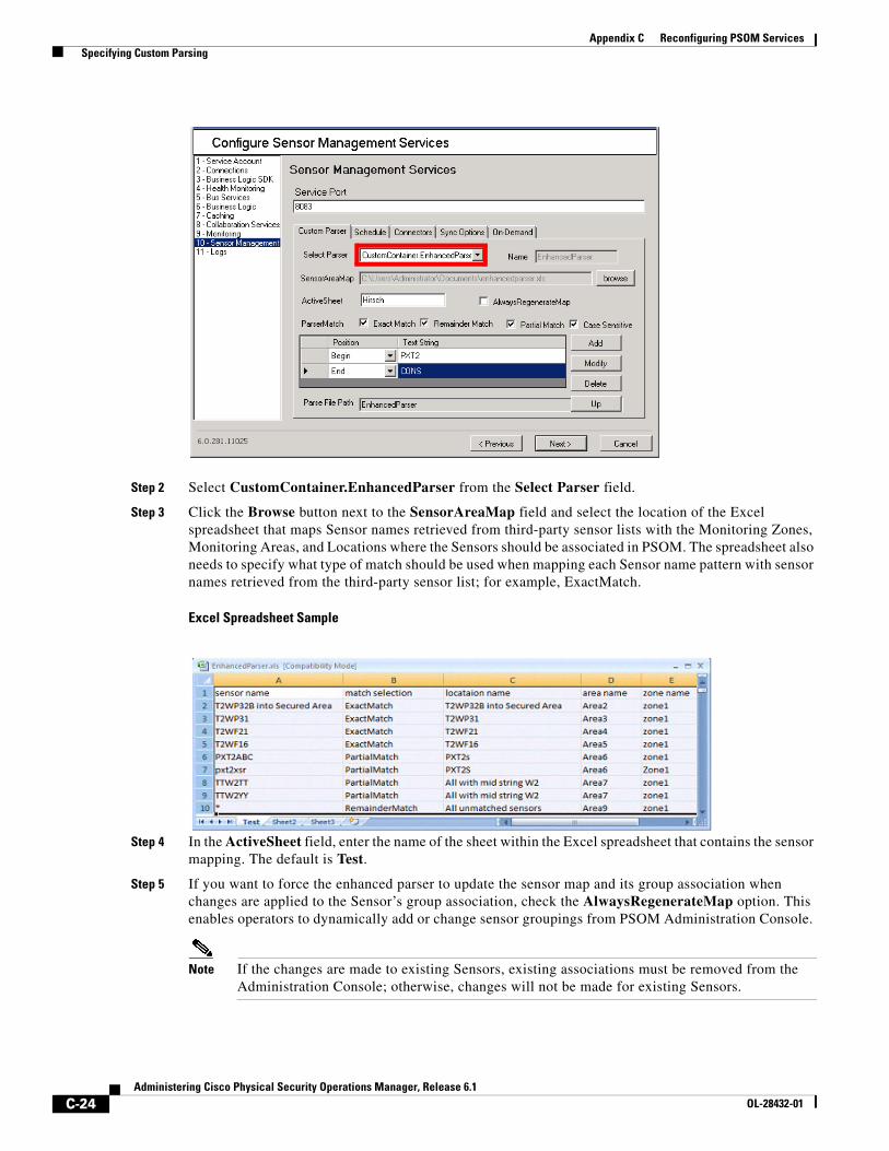
C-24Administering Cisco Physical Security Operations Manager, Release 6.1
OL-28432-01
Appendix C Reconfiguring PSOM Services Specifying Custom Parsing
Step 2 Select CustomContainer.EnhancedParser from the Select Parser field.
Step 3 Click the Browse button next to the SensorAreaMap field and select the location of the Excel spreadsheet that maps Sensor names retrieved from third-party sensor lists with the Monitoring Zones, Monitoring Areas, and Locations where the Sensors should be associated in PSOM. The spreadsheet also needs to specify what type of match should be used when mapping each Sensor name pattern with sensor names retrieved from the third-party sensor list; for example, ExactMatch.
Excel Spreadsheet Sample
Step 4 In the ActiveSheet field, enter the name of the sheet within the Excel spreadsheet that contains the sensor mapping. The default is Test.
Step 5 If you want to force the enhanced parser to update the sensor map and its group association when changes are applied to the Sensor’s group association, check the AlwaysRegenerateMap option. This enables operators to dynamically add or change sensor groupings from PSOM Administration Console.
Note If the changes are made to existing Sensors, existing associations must be removed from the Administration Console; otherwise, changes will not be made for existing Sensors.
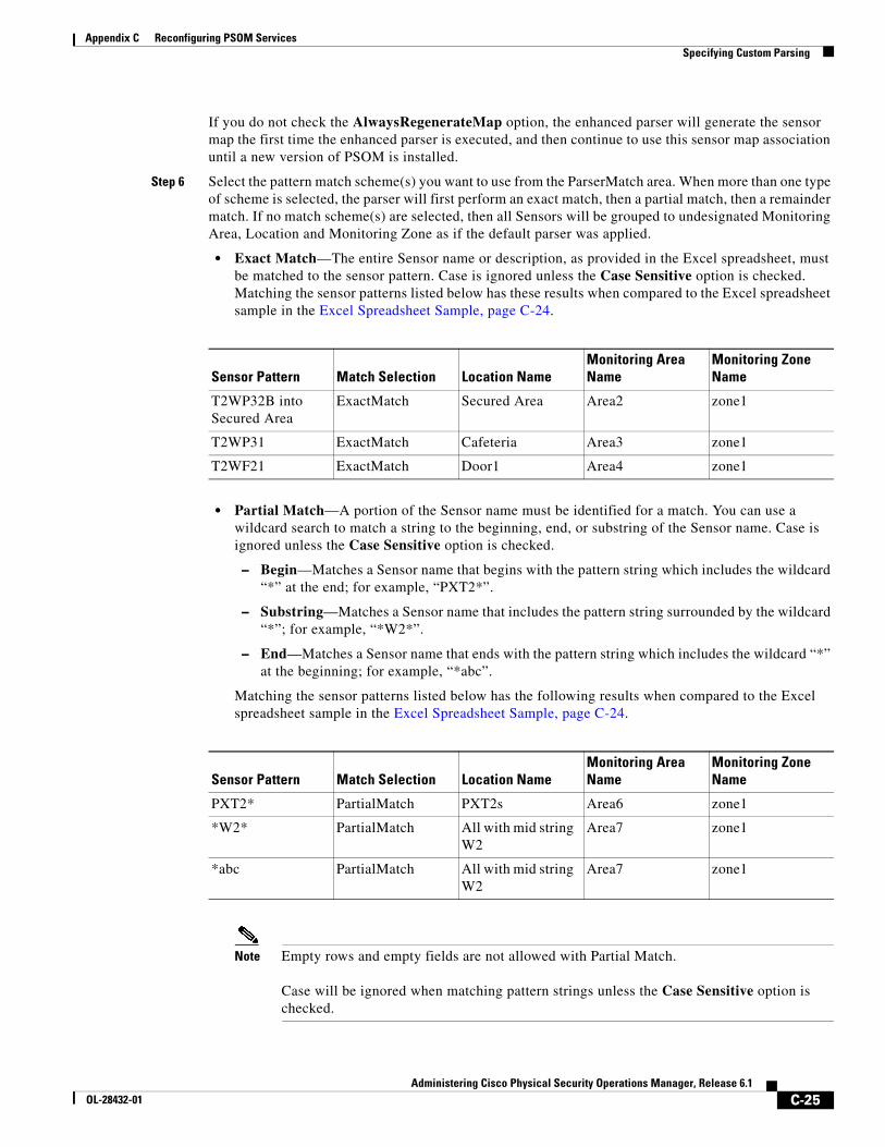
C-25Administering Cisco Physical Security Operations Manager, Release 6.1
OL-28432-01
Appendix C Reconfiguring PSOM Services Specifying Custom Parsing
If you do not check the AlwaysRegenerateMap option, the enhanced parser will generate the sensor map the first time the enhanced parser is executed, and then continue to use this sensor map association until a new version of PSOM is installed.
Step 6 Select the pattern match scheme(s) you want to use from the ParserMatch area. When more than one type of scheme is selected, the parser will first perform an exact match, then a partial match, then a remainder match. If no match scheme(s) are selected, then all Sensors will be grouped to undesignated Monitoring Area, Location and Monitoring Zone as if the default parser was applied.
• Exact Match—The entire Sensor name or description, as provided in the Excel spreadsheet, must be matched to the sensor pattern. Case is ignored unless the Case Sensitive option is checked. Matching the sensor patterns listed below has these results when compared to the Excel spreadsheet sample in the Excel Spreadsheet Sample, page C-24.
• Partial Match—A portion of the Sensor name must be identified for a match. You can use a wildcard search to match a string to the beginning, end, or substring of the Sensor name. Case is ignored unless the Case Sensitive option is checked.
– Begin—Matches a Sensor name that begins with the pattern string which includes the wildcard “*” at the end; for example, “PXT2*”.
– Substring—Matches a Sensor name that includes the pattern string surrounded by the wildcard “*”; for example, “*W2*”.
– End—Matches a Sensor name that ends with the pattern string which includes the wildcard “*” at the beginning; for example, “*abc”.
Matching the sensor patterns listed below has the following results when compared to the Excel spreadsheet sample in the Excel Spreadsheet Sample, page C-24.
Note Empty rows and empty fields are not allowed with Partial Match.
Case will be ignored when matching pattern strings unless the Case Sensitive option is checked.
Sensor Pattern Match Selection Location NameMonitoring Area Name
Monitoring Zone Name
T2WP32B into Secured Area
ExactMatch Secured Area Area2 zone1
T2WP31 ExactMatch Cafeteria Area3 zone1
T2WF21 ExactMatch Door1 Area4 zone1
Sensor Pattern Match Selection Location NameMonitoring Area Name
Monitoring Zone Name
PXT2* PartialMatch PXT2s Area6 zone1
*W2* PartialMatch All with mid string W2
Area7 zone1
*abc PartialMatch All with mid string W2
Area7 zone1
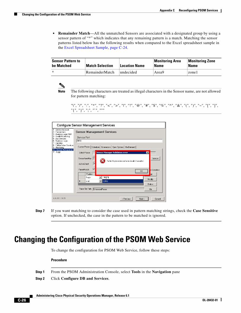
C-26Administering Cisco Physical Security Operations Manager, Release 6.1
OL-28432-01
Appendix C Reconfiguring PSOM Services Changing the Configuration of the PSOM Web Service
• Remainder Match—All the unmatched Sensors are associated with a designated group by using a sensor pattern of “*” which indicates that any remaining pattern is a match. Matching the sensor patterns listed below has the following results when compared to the Excel spreadsheet sample in the Excel Spreadsheet Sample, page C-24.
Note The following characters are treated as illegal characters in the Sensor name, are not allowed for pattern matching:
"\", "/", ":", "*", "?", "<", ">", "|", "!", "@", "#", "$", "%", "^", "&", "(", ")", "~", "[", "]", "{", "}", ";", "`", """
Step 7 If you want matching to consider the case used in pattern matching strings, check the Case Sensitive option. If unchecked, the case in the pattern to be matched is ignored.
Changing the Configuration of the PSOM Web ServiceTo change the configuration for PSOM Web Service, follow these steps:
Procedure
Step 1 From the PSOM Administration Console, select Tools in the Navigation pane
Step 2 Click Configure DB and Services.
Sensor Pattern to be Matched Match Selection Location Name
Monitoring Area Name
Monitoring Zone Name
* RemainderMatch undecided Area9 zone1
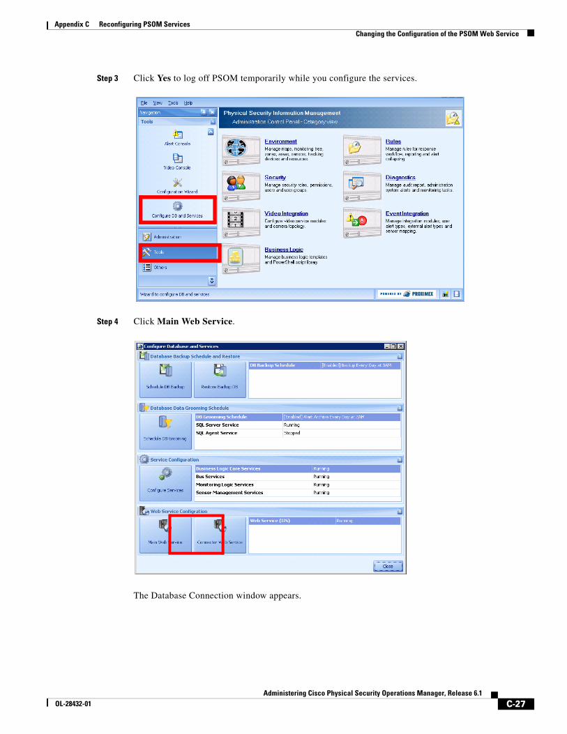
C-27Administering Cisco Physical Security Operations Manager, Release 6.1
OL-28432-01
Appendix C Reconfiguring PSOM Services Changing the Configuration of the PSOM Web Service
Step 3 Click Yes to log off PSOM temporarily while you configure the services.
Step 4 Click Main Web Service.
The Database Connection window appears.
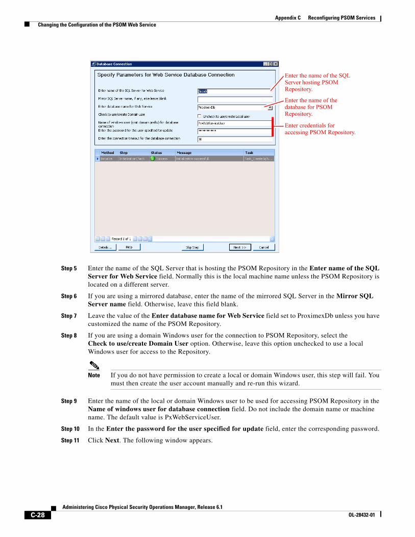
C-28Administering Cisco Physical Security Operations Manager, Release 6.1
OL-28432-01
Appendix C Reconfiguring PSOM Services Changing the Configuration of the PSOM Web Service
Step 5 Enter the name of the SQL Server that is hosting the PSOM Repository in the Enter name of the SQL Server for Web Service field. Normally this is the local machine name unless the PSOM Repository is located on a different server.
Step 6 If you are using a mirrored database, enter the name of the mirrored SQL Server in the Mirror SQL Server name field. Otherwise, leave this field blank.
Step 7 Leave the value of the Enter database name for Web Service field set to ProximexDb unless you have customized the name of the PSOM Repository.
Step 8 If you are using a domain Windows user for the connection to PSOM Repository, select the Check to use/create Domain User option. Otherwise, leave this option unchecked to use a local Windows user for access to the Repository.
Note If you do not have permission to create a local or domain Windows user, this step will fail. You must then create the user account manually and re-run this wizard.
Step 9 Enter the name of the local or domain Windows user to be used for accessing PSOM Repository in the Name of windows user for database connection field. Do not include the domain name or machine name. The default value is PxWebServiceUser.
Step 10 In the Enter the password for the user specified for update field, enter the corresponding password.
Step 11 Click Next. The following window appears.
Enter the name of the SQL Server hosting PSOM Repository.
Enter the name of the database for PSOM Repository.
Enter credentials for accessing PSOM Repository.
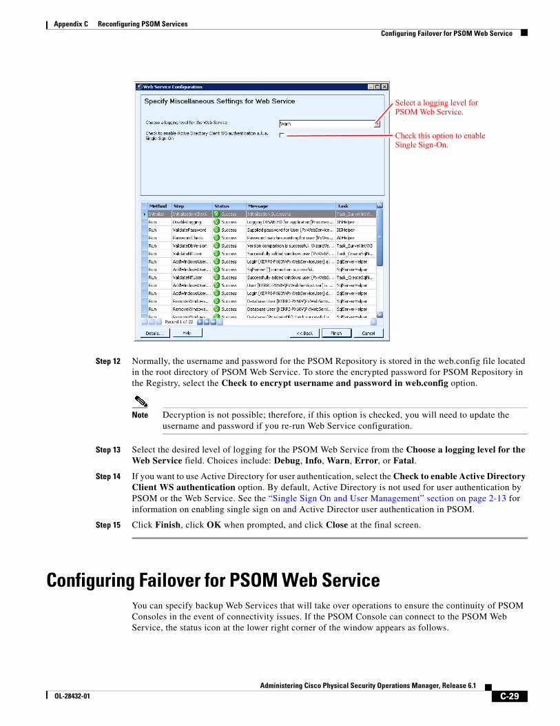
C-29Administering Cisco Physical Security Operations Manager, Release 6.1
OL-28432-01
Appendix C Reconfiguring PSOM Services Configuring Failover for PSOM Web Service
Step 12 Normally, the username and password for the PSOM Repository is stored in the web.config file located in the root directory of PSOM Web Service. To store the encrypted password for PSOM Repository in the Registry, select the Check to encrypt username and password in web.config option.
Note Decryption is not possible; therefore, if this option is checked, you will need to update the username and password if you re-run Web Service configuration.
Step 13 Select the desired level of logging for the PSOM Web Service from the Choose a logging level for the Web Service field. Choices include: Debug, Info, Warn, Error, or Fatal.
Step 14 If you want to use Active Directory for user authentication, select the Check to enable Active Directory Client WS authentication option. By default, Active Directory is not used for user authentication by PSOM or the Web Service. See the “Single Sign On and User Management” section on page 2-13 for information on enabling single sign on and Active Director user authentication in PSOM.
Step 15 Click Finish, click OK when prompted, and click Close at the final screen.
Configuring Failover for PSOM Web ServiceYou can specify backup Web Services that will take over operations to ensure the continuity of PSOM Consoles in the event of connectivity issues. If the PSOM Console can connect to the PSOM Web Service, the status icon at the lower right corner of the window appears as follows.
Select a logging level for PSOM Web Service.
Check this option to enable Single Sign-On.
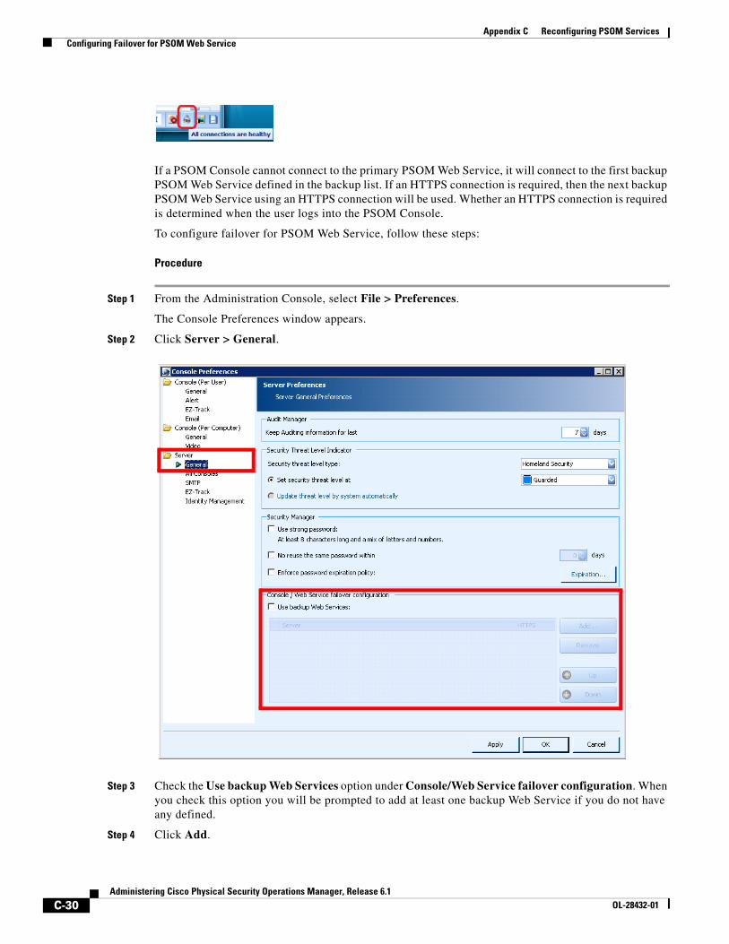
C-30Administering Cisco Physical Security Operations Manager, Release 6.1
OL-28432-01
Appendix C Reconfiguring PSOM Services Configuring Failover for PSOM Web Service
If a PSOM Console cannot connect to the primary PSOM Web Service, it will connect to the first backup PSOM Web Service defined in the backup list. If an HTTPS connection is required, then the next backup PSOM Web Service using an HTTPS connection will be used. Whether an HTTPS connection is required is determined when the user logs into the PSOM Console.
To configure failover for PSOM Web Service, follow these steps:
Procedure
Step 1 From the Administration Console, select File > Preferences.
The Console Preferences window appears.
Step 2 Click Server > General.
Step 3 Check the Use backup Web Services option under Console/Web Service failover configuration. When you check this option you will be prompted to add at least one backup Web Service if you do not have any defined.
Step 4 Click Add.
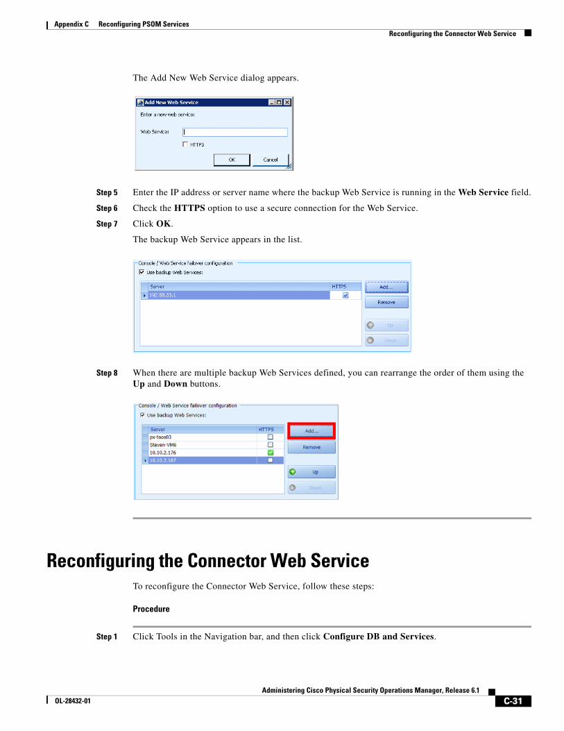
C-31Administering Cisco Physical Security Operations Manager, Release 6.1
OL-28432-01
Appendix C Reconfiguring PSOM Services Reconfiguring the Connector Web Service
The Add New Web Service dialog appears.
Step 5 Enter the IP address or server name where the backup Web Service is running in the Web Service field.
Step 6 Check the HTTPS option to use a secure connection for the Web Service.
Step 7 Click OK.
The backup Web Service appears in the list.
Step 8 When there are multiple backup Web Services defined, you can rearrange the order of them using the Up and Down buttons.
Reconfiguring the Connector Web ServiceTo reconfigure the Connector Web Service, follow these steps:
Procedure
Step 1 Click Tools in the Navigation bar, and then click Configure DB and Services.
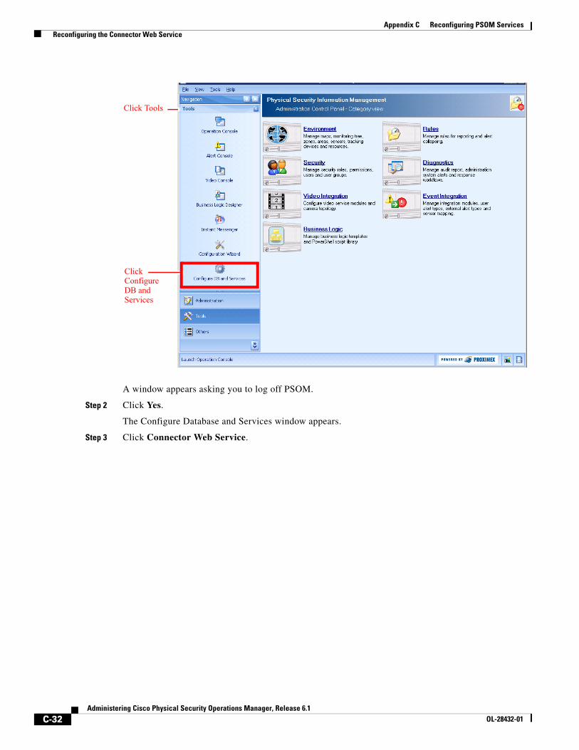
C-32Administering Cisco Physical Security Operations Manager, Release 6.1
OL-28432-01
Appendix C Reconfiguring PSOM Services Reconfiguring the Connector Web Service
A window appears asking you to log off PSOM.
Step 2 Click Yes.
The Configure Database and Services window appears.
Step 3 Click Connector Web Service.
Click Configure DB and Services
Click Tools
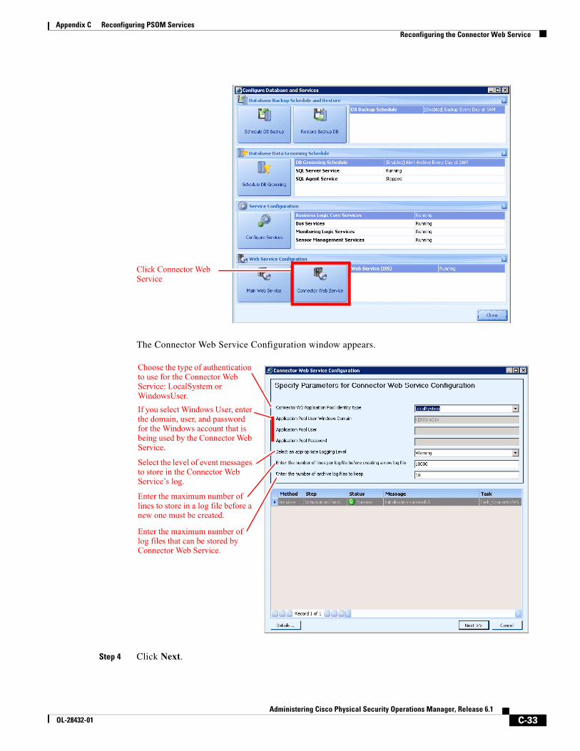
C-33Administering Cisco Physical Security Operations Manager, Release 6.1
OL-28432-01
Appendix C Reconfiguring PSOM Services Reconfiguring the Connector Web Service
The Connector Web Service Configuration window appears.
Step 4 Click Next.
Click Connector Web Service
Enter the maximum number of log files that can be stored by Connector Web Service.
Choose the type of authentication to use for the Connector Web Service: LocalSystem or WindowsUser.
If you select Windows User, enter the domain, user, and password for the Windows account that is being used by the Connector Web Service.
Select the level of event messages to store in the Connector Web Service’s log.
Enter the maximum number of lines to store in a log file before a new one must be created.
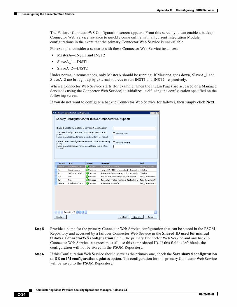
C-34Administering Cisco Physical Security Operations Manager, Release 6.1
OL-28432-01
Appendix C Reconfiguring PSOM Services Reconfiguring the Connector Web Service
The Failover ConnectorWS Configuration screen appears. From this screen you can enable a backup Connector Web Service instance to quickly come online with all current Integration Module configurations in the event that the primary Connector Web Service is unavailable.
For example, consider a scenario with these Connector Web Service instances:
• MasterA—INST1 and INST2
• SlaveA_1—INST1
• SlaveA_2—INST2
Under normal circumstances, only MasterA should be running. If MasterA goes down, SlaveA_1 and SlaveA_2 are brought up by external sources to run INST1 and INST2, respectively.
When a Connector Web Service starts (for example, when the Plugin Pages are accessed or a Managed Service is using the Connector Web Service) it initializes itself using the configuration specified on the following screen.
If you do not want to configure a backup Connector Web Service for failover, then simply click Next.
Step 5 Provide a name for the primary Connector Web Service configuration that can be stored in the PSOM Repository and accessed by a failover Connector Web Service in the Shared ID used for manual failover ConnectorWS configuration field. The primary Connector Web Service and any backup Connector Web Service instances must all use this same shared ID. If this field is left blank, the configuration will not be stored in the PSOM Repository.
Step 6 If this Configuration Web Service should serve as the primary one, check the Save shared configuration to DB on IM configuration updates option. The configuration for this primary Connector Web Service will be saved to the PSOM Repository.
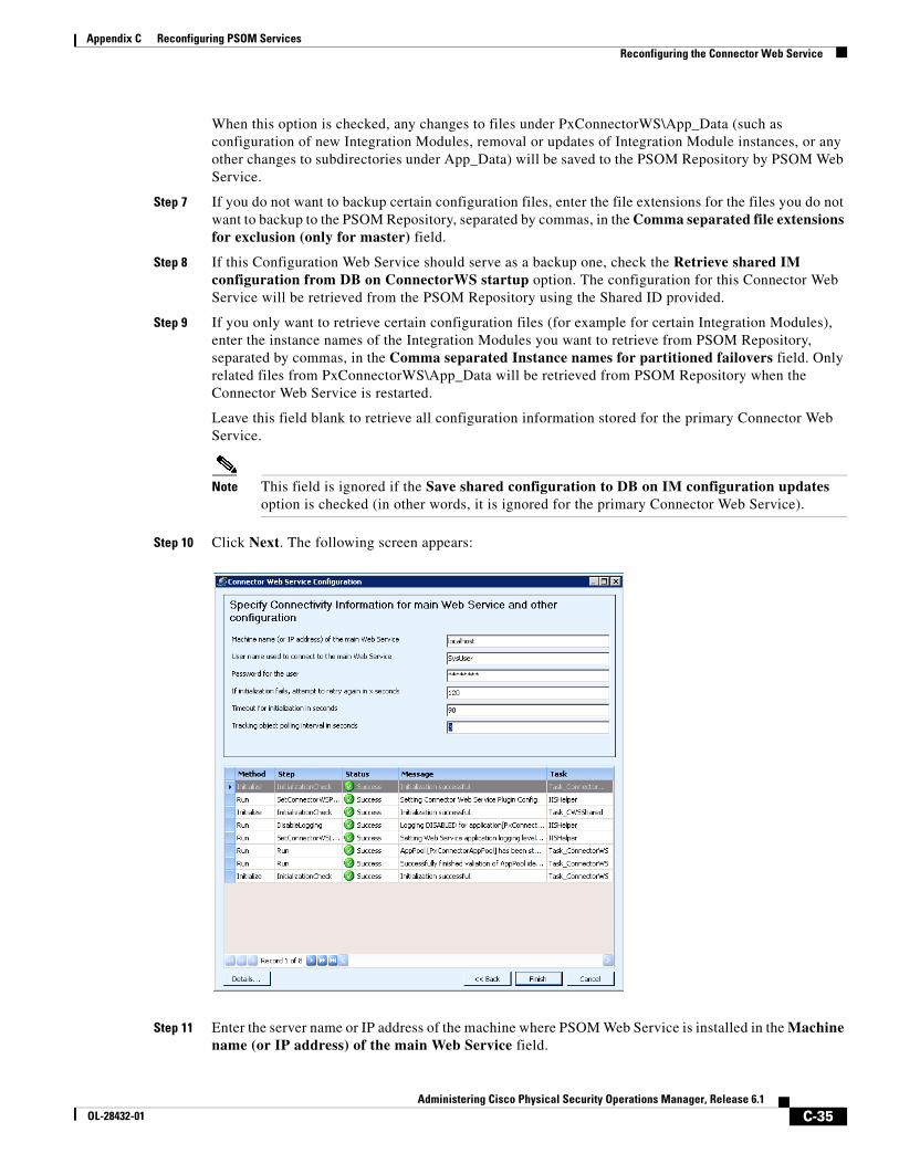
C-35Administering Cisco Physical Security Operations Manager, Release 6.1
OL-28432-01
Appendix C Reconfiguring PSOM Services Reconfiguring the Connector Web Service
When this option is checked, any changes to files under PxConnectorWS\App_Data (such as configuration of new Integration Modules, removal or updates of Integration Module instances, or any other changes to subdirectories under App_Data) will be saved to the PSOM Repository by PSOM Web Service.
Step 7 If you do not want to backup certain configuration files, enter the file extensions for the files you do not want to backup to the PSOM Repository, separated by commas, in the Comma separated file extensions for exclusion (only for master) field.
Step 8 If this Configuration Web Service should serve as a backup one, check the Retrieve shared IM configuration from DB on ConnectorWS startup option. The configuration for this Connector Web Service will be retrieved from the PSOM Repository using the Shared ID provided.
Step 9 If you only want to retrieve certain configuration files (for example for certain Integration Modules), enter the instance names of the Integration Modules you want to retrieve from PSOM Repository, separated by commas, in the Comma separated Instance names for partitioned failovers field. Only related files from PxConnectorWS\App_Data will be retrieved from PSOM Repository when the Connector Web Service is restarted.
Leave this field blank to retrieve all configuration information stored for the primary Connector Web Service.
Note This field is ignored if the Save shared configuration to DB on IM configuration updates option is checked (in other words, it is ignored for the primary Connector Web Service).
Step 10 Click Next. The following screen appears:
Step 11 Enter the server name or IP address of the machine where PSOM Web Service is installed in the Machine name (or IP address) of the main Web Service field.

C-36Administering Cisco Physical Security Operations Manager, Release 6.1
OL-28432-01
Appendix C Reconfiguring PSOM Services Reconfiguring the Connector Web Service
Note PSOM Web Service must be installed before the Connector Web Service installation is performed.
Step 12 Enter the username for connecting to PSOM Web Service in the User name used to connect to the main Web Service field. Administrator is the default.
Step 13 Enter the password for connecting to PSOM Web Service in the Password for the user field. The default password is provided.
Step 14 Enter the number of seconds the Connector Web Service should wait before reattempting to initialize an Integration Module in the If initialization fails, attempt to retry again in x seconds field. If initialization fails, PSOM creates an alert against the application sensor for the failed instance.
Step 15 Enter the number of seconds the Connector Web Service should wait for an Integration Module to complete initialization in the Timeout for initialization in seconds field.
Step 16 Enter the number of seconds that Integration Modules should wait between requests for tracking trail information in the Tracking object polling interval in seconds field. This field only pertains to Integration Modules that convey tracking trail information to external 3rd party systems.
Step 17 Click Finish. Click OK when prompted, then Close to complete installation.
Step 18 Test whether the Connector Web Service is installed correctly.
a. Open a web browser and navigate to http://localhost/PxConnectorWS/PluginPages/default.aspx. The following window should appear.
Note If you do not see this window, then ASP.NET may not be installed or allowed.
You can also access the Connector PlugIn Pages from the Start menu: Start > All Programs > Cisco Physical Security Operations Manager Services > Connector Plugin Page.
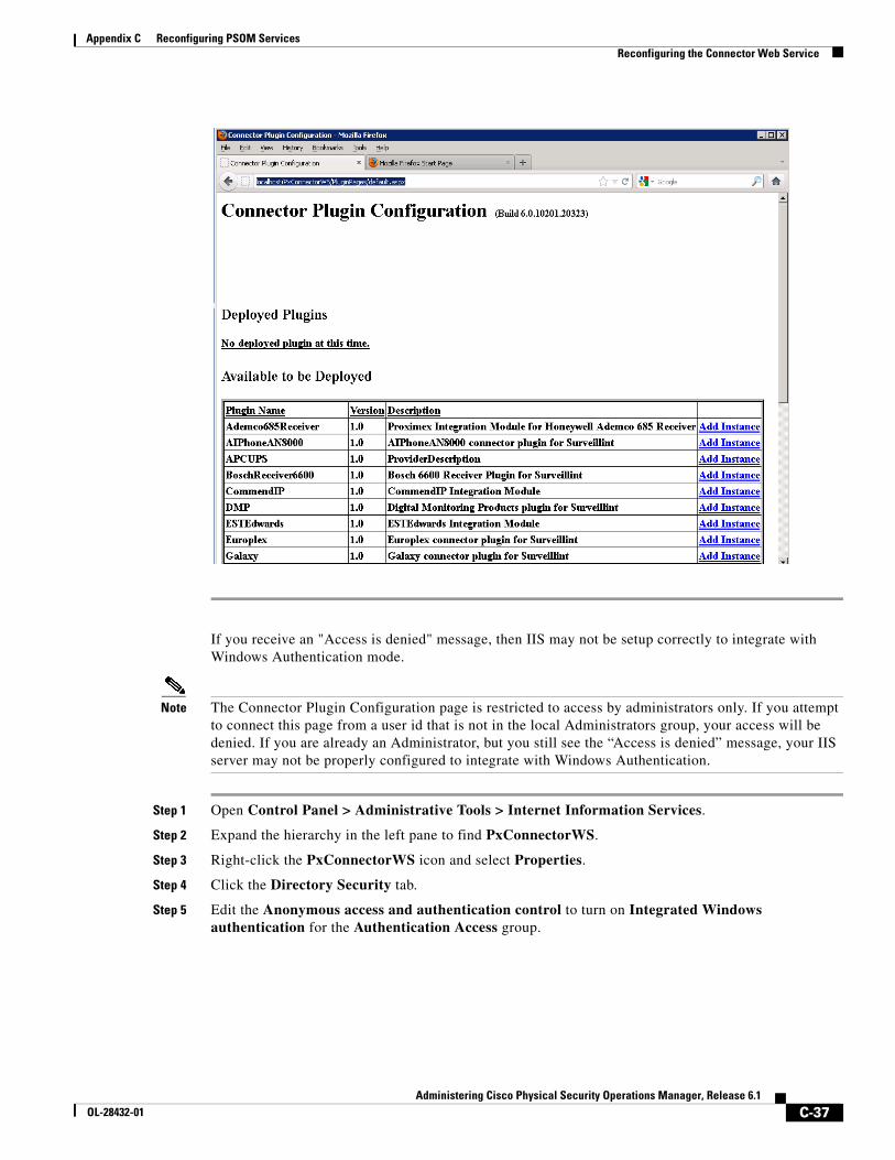
C-37Administering Cisco Physical Security Operations Manager, Release 6.1
OL-28432-01
Appendix C Reconfiguring PSOM Services Reconfiguring the Connector Web Service
If you receive an "Access is denied" message, then IIS may not be setup correctly to integrate with Windows Authentication mode.
Note The Connector Plugin Configuration page is restricted to access by administrators only. If you attempt to connect this page from a user id that is not in the local Administrators group, your access will be denied. If you are already an Administrator, but you still see the “Access is denied” message, your IIS server may not be properly configured to integrate with Windows Authentication.
Step 1 Open Control Panel > Administrative Tools > Internet Information Services.
Step 2 Expand the hierarchy in the left pane to find PxConnectorWS.
Step 3 Right-click the PxConnectorWS icon and select Properties.
Step 4 Click the Directory Security tab.
Step 5 Edit the Anonymous access and authentication control to turn on Integrated Windows authentication for the Authentication Access group.
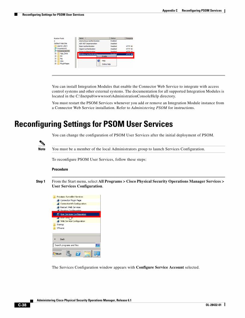
C-38Administering Cisco Physical Security Operations Manager, Release 6.1
OL-28432-01
Appendix C Reconfiguring PSOM Services Reconfiguring Settings for PSOM User Services
You can install Integration Modules that enable the Connector Web Service to integrate with access control systems and other external systems. The documentation for all supported Integration Modules is located in the C:\Inetpub\wwwroot\AdministrationConsoleHelp directory.
You must restart the PSOM Services whenever you add or remove an Integration Module instance from a Connector Web Service installation. Refer to Administering PSOM for instructions.
Reconfiguring Settings for PSOM User ServicesYou can change the configuration of PSOM User Services after the initial deployment of PSOM.
Note You must be a member of the local Administrators group to launch Services Configuration.
To reconfigure PSOM User Services, follow these steps:
Procedure
Step 1 From the Start menu, select All Programs > Cisco Physical Security Operations Manager Services > User Services Configuration.
The Services Configuration window appears with Configure Service Account selected.
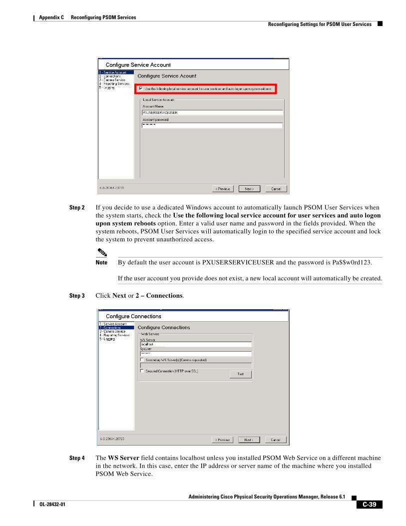
C-39Administering Cisco Physical Security Operations Manager, Release 6.1
OL-28432-01
Appendix C Reconfiguring PSOM Services Reconfiguring Settings for PSOM User Services
Step 2 If you decide to use a dedicated Windows account to automatically launch PSOM User Services when the system starts, check the Use the following local service account for user services and auto logon upon system reboots option. Enter a valid user name and password in the fields provided. When the system reboots, PSOM User Services will automatically login to the specified service account and lock the system to prevent unauthorized access.
Note By default the user account is PXUSERSERVICEUSER and the password is Pa$$w0rd123.
If the user account you provide does not exist, a new local account will automatically be created.
Step 3 Click Next or 2 – Connections.
Step 4 The WS Server field contains localhost unless you installed PSOM Web Service on a different machine in the network. In this case, enter the IP address or server name of the machine where you installed PSOM Web Service.
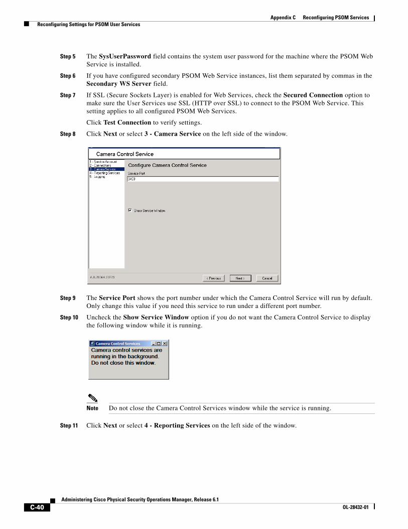
C-40Administering Cisco Physical Security Operations Manager, Release 6.1
OL-28432-01
Appendix C Reconfiguring PSOM Services Reconfiguring Settings for PSOM User Services
Step 5 The SysUserPassword field contains the system user password for the machine where the PSOM Web Service is installed.
Step 6 If you have configured secondary PSOM Web Service instances, list them separated by commas in the Secondary WS Server field.
Step 7 If SSL (Secure Sockets Layer) is enabled for Web Services, check the Secured Connection option to make sure the User Services use SSL (HTTP over SSL) to connect to the PSOM Web Service. This setting applies to all configured PSOM Web Services.
Click Test Connection to verify settings.
Step 8 Click Next or select 3 - Camera Service on the left side of the window.
Step 9 The Service Port shows the port number under which the Camera Control Service will run by default. Only change this value if you need this service to run under a different port number.
Step 10 Uncheck the Show Service Window option if you do not want the Camera Control Service to display the following window while it is running.
Note Do not close the Camera Control Services window while the service is running.
Step 11 Click Next or select 4 - Reporting Services on the left side of the window.
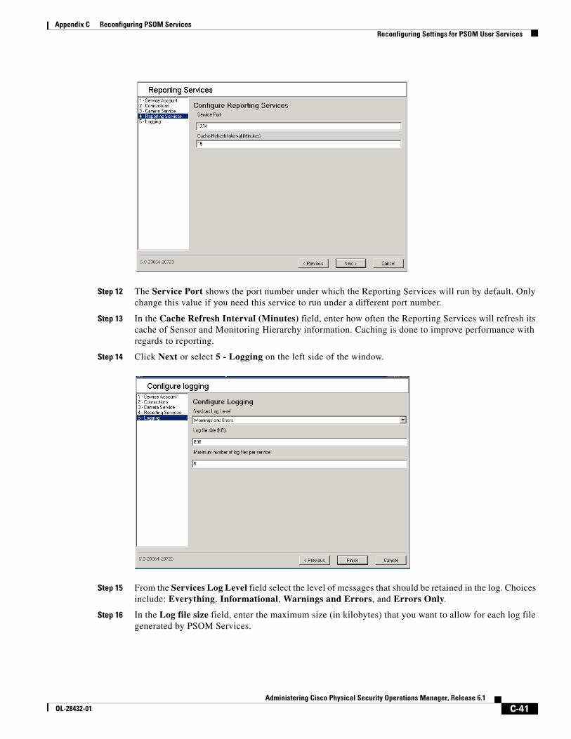
C-41Administering Cisco Physical Security Operations Manager, Release 6.1
OL-28432-01
Appendix C Reconfiguring PSOM Services Reconfiguring Settings for PSOM User Services
Step 12 The Service Port shows the port number under which the Reporting Services will run by default. Only change this value if you need this service to run under a different port number.
Step 13 In the Cache Refresh Interval (Minutes) field, enter how often the Reporting Services will refresh its cache of Sensor and Monitoring Hierarchy information. Caching is done to improve performance with regards to reporting.
Step 14 Click Next or select 5 - Logging on the left side of the window.
Step 15 From the Services Log Level field select the level of messages that should be retained in the log. Choices include: Everything, Informational, Warnings and Errors, and Errors Only.
Step 16 In the Log file size field, enter the maximum size (in kilobytes) that you want to allow for each log file generated by PSOM Services.
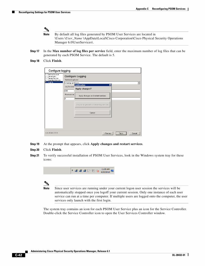
C-42Administering Cisco Physical Security Operations Manager, Release 6.1
OL-28432-01
Appendix C Reconfiguring PSOM Services Reconfiguring Settings for PSOM User Services
Note By default all log files generated by PSOM User Services are located in\Users \User_Name \AppData\Local\Cisco Corporation\Cisco Physical Security Operations Manager 6.0\UserServices\.
Step 17 In the Max number of log files per service field, enter the maximum number of log files that can be generated by each PSOM Service. The default is 5.
Step 18 Click Finish.
Step 19 At the prompt that appears, click Apply changes and restart services.
Step 20 Click Finish.
Step 21 To verify successful installation of PSOM User Services, look in the Windows system tray for these icons:
Note Since user services are running under your current logon user session the services will be automatically stopped once you logoff your current session. Only one instance of each user service can run at a time per computer. If multiple users are logged onto the computer, the user services only launch with the first login.
The system tray contains an icon for each PSOM User Service plus an icon for the Service Controller. Double-click the Service Controller icon to open the User Services Controller window.
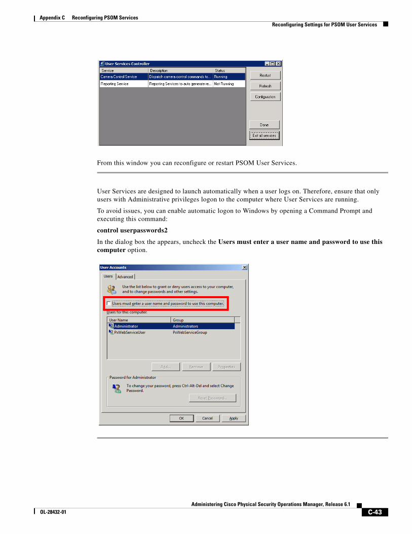
C-43Administering Cisco Physical Security Operations Manager, Release 6.1
OL-28432-01
Appendix C Reconfiguring PSOM Services Reconfiguring Settings for PSOM User Services
From this window you can reconfigure or restart PSOM User Services.
User Services are designed to launch automatically when a user logs on. Therefore, ensure that only users with Administrative privileges logon to the computer where User Services are running.
To avoid issues, you can enable automatic logon to Windows by opening a Command Prompt and executing this command:
control userpasswords2
In the dialog box the appears, uncheck the Users must enter a user name and password to use this computer option.

C-44Administering Cisco Physical Security Operations Manager, Release 6.1
OL-28432-01
Appendix C Reconfiguring PSOM Services Reconfiguring Settings for PSOM User Services
IN-1Administering Cisco Physical Security Operations Manager, Release 6.1
OL-28432-01
I N D E X
A
access control devices
adding sensor for 6-3
connecting to 6-3
integration planning A-2
location, associating with 6-4
placing on map 7-19 to 7-25
Access Control Service
starting 1-20
action rule
command-line arguments for 14-46, 14-50, 14-52
adding
locations 4-2
monitoring areas 5-3
monitoring zones 5-4
sensors
access control devices 6-3, 6-5
video cameras 6-5
user accounts 2-2 to 2-3
user groups 2-6 to 2-7
video cameras to PSOM 3-1 to 3-2
Administration Console, overview 1-9 to 1-11
administration tasks
overview 1-6
user accounts 2-1
administrative alerts, diagnosing 16-1 to 16-2
administrative reports
Alert Count Daily Report 9-1
Alert Count Hourly Report 9-1
Alert Detail Report 9-1
Alert Response Time by Alert Type Report 9-1
customizing default 9-2 to 9-6, 10-1
Operator Alert Count Report 9-2
Operator Alert Response Time Report 9-2
Top X Alert Response Time Report 9-2
Top X Alerts by Alert Type Report 9-2
Top X Alerts by Area Report 9-2
Top X Alerts by Sensor Report 9-2
types of 9-1 to 9-2, 10-2
administrators, defined 2-1
alarms, third-party integration 11-3
deleting alert types 11-5
modifying alert types 11-5
Alert Count Daily Report 9-1
Alert Count Hourly Report 9-1
Alert Detail Report 9-1
Alert List Pane, what is 1-4
Alert Response Time by Alert Type Report 9-1
B
background image for map, adding 7-4 to 7-5
backup PSOM database
manually performing B-3
scheduled B-1, C-1, C-38
C
customizing default reports 9-2 to 9-6, 10-1
alert types to include 9-4
chart type to use 9-5
deleting 9-7
modifying 9-6
monitoring areas to include 9-5
monitoring zones to include 9-5
Index
IN-2Administering Cisco Physical Security Operations Manager, Release 6.1
OL-28432-01
sensors to include 9-5
severity levels to include 9-4
time period for reporting 9-5
D
database for PSOM
backup manually B-3
restoring B-6
scheduled backups B-1, C-1, C-38
deleting
custom reports 9-7
locations 4-3
monitoring areas 5-9
monitoring zones 5-10
registered alert types 11-5
sensor groups 6-18, 6-20
sensor mappings 11-3
user groups 2-8 to 2-9
users 2-5
deploying PSOM
locations, planning 4-1
monitoring areas and zones, planning 5-3
monitoring services 1-2
planning 4-1
sensor integration, planning 6-3
user accounts, planning 2-2
diagnosing problems
administrative alerts 16-1 to 16-2
monitoring alerts 16-2 to 16-4
display options for maps, setting 7-13 to 7-14
dock window 1-11
E
editing
custom reports 9-6 to 9-7
locations 4-2
monitoring areas 5-9
monitoring zones 5-10
passwords for users 2-4
registered alert types 11-5
sensor groups 6-17, 6-19
sensor mappings 11-3
user groups 2-7
user names 2-4
external alarms, registering with PSOM 11-3
deleting alert types 11-5
modifying alert types 11-5
external application, launching upon alert
command-line arguments 14-46, 14-50, 14-52
external intrusion detection system, integrating with 11-1
EZ-Track
Add Link icon 12-11
base camera view, changing 12-12
batch configuration 12-15 to 12-16
exporting from PSOM 12-17
uploading XML file 12-16
XML syntax 12-15
Browse Back icon 12-11
Browse To icon 12-11
camera topology, configuring 12-7 to 12-11
configuring 12-3 to 12-13
Delete Link icon 12-11
Edit Link icon 12-11
how used by operators 12-1
link
adding 12-7, 12-11
deleting 12-12
editing 12-12
region links, viewing 12-12
live video for sensor, viewing 12-11
Live Video icon 12-11
map
sensor names, showing 12-11
sensors, showing 12-11
planning worksheets A-10
Index
IN-3Administering Cisco Physical Security Operations Manager, Release 6.1
OL-28432-01
PTZ cameras with 12-3
sensor
name, displaying 12-6 to 12-7
range, displaying 12-6 to 12-7
Show Links icon 12-11
snapshot ’field of view’ images 12-3 to 12-5
stationary cameras with 12-3
testing a configuration 12-13 to 12-14
video cameras
view direction configuring 12-5 to 12-6
view distance, configuring 12-5 to 12-6
view range, configuring 12-5 to 12-6
what it does 12-1
XML configuration 12-15 to 12-16
exporting from PSOM 12-17
syntax 12-15
uploading 12-16
F
field of view for camera, adding 6-6
FOV for camera, adding 6-6
G
group, user
creating 2-6 to 2-7
deleting 2-8 to 2-9
editing 2-7
members, managing 2-7 to 2-8
H
Hazard detector devices
adding sensors for 6-8
Homeland Security levels, setting 1-14
I
integrating with third-party alarm sources 11-3
K
Knowledge Service
defined 1-2
starting 1-20
L
locations
adding 4-2
defined 4-1
deleting 4-3
editing 4-2 to 4-3
logs stored by PSOM 16-1, 17-1
M
maps, designing
background image, adding 7-4 to 7-5
deleting icons from map 7-31
display options, setting 7-13 to 7-14
editing items on map 7-31
Map Design Mode, starting 7-1 to 7-3
monitoring area, drawing on map 7-15 to 7-18
monitoring zone, drawing on map 7-14 to 7-15
navigation, adding 7-25 to 7-28
origin coordinates, setting 7-5 to 7-6
scale, setting 7-5 to 7-6
sensor icons 7-21
sensor name, showing 12-6
sensor range, showing 12-6
sensors, placing on map 7-19 to 7-25
tools for 7-3
URL links, adding 7-28 to 7-29, 7-30
Index
IN-4Administering Cisco Physical Security Operations Manager, Release 6.1
OL-28432-01
MARSEC levels, setting 1-14
monitoring alerts, diagnosing 16-2 to 16-4
monitoring area
adding 5-3, 5-6
defined 5-1
deleting 5-9
deleting from map 7-19
drawing on map 7-15 to 7-18
editing 5-9
monitoring tree, adding to 5-7
monitoring zone, adding to 5-4
planning A-7
monitoring environment, setting up
locations 4-2
maps, designing 7-1 to 7-32
monitoring areas, adding 5-3
monitoring tree, setting up 5-7
monitoring zones, adding 5-4
sensors, access control 6-3
sensors, video cameras 6-5
monitoring rule
applied to monitoring areas 8-3
Monitoring Service
starting 1-20
monitoring services
defined 1-2
starting and stopping 1-20
monitoring tree
adding
monitoring area 5-7
monitoring zone 5-5 to 5-6
node properties, viewing 5-7
setting up 5-7
monitoring zone
adding 5-4, 5-4
adding maps, monitoring area 5-9
adding multiple levels 5-6
defined 5-1
deleting 5-10
deleting from map 7-18
drawing on map 7-14 to 7-15
editing 5-10, 5-10
members, adding 5-4
monitoring tree, adding to 5-5
planning A-6
N
navigation
adding to maps 7-25 to 7-28
setting up 5-7
Navigation Pane, what is 1-4
O
Operation Console
overview 1-4 to 1-5
Operator Alert Count Report 9-2
Operator Alert Response Time Report 9-2
operators, defined 2-1
origin coordinates for map, setting 7-5 to 7-6
overview of Administration Console 1-9 to 1-11
overview of Operation Console 1-4 to 1-5
P
password, changing 2-3
physical spaces in PSOM, setting up 4-1
planning
access control system integration A-2
EZ-Track configuration A-10
monitoring areas A-7
monitoring zones A-6
response tasks rules A-9
task items A-8
user accounts A-3
video camera settings A-5
Index
IN-5Administering Cisco Physical Security Operations Manager, Release 6.1
OL-28432-01
PSOM Server
database
backing up manually B-3
restoring B-6
scheduled backups B-1, C-1, C-38
defined 1-2
PSOM UI, defined 1-2
PTZ cameras
EZ-Track, using with 12-3
R
range angle for camera, adding 6-6
range distance for camera, adding 6-6
registering third-party alarms 11-3
deleting alert types 11-5
modifying alert types 11-5
removing user accounts 2-5
reports
Alert Count Daily Report 9-1
Alert Count Hourly Report 9-1
Alert Detail Report 9-1
Alert Response Time by Alert Type Report 9-1
customizing default 9-2 to 9-6, 10-1
alert types to include 9-4
chart type to use 9-5
deleting 9-7
modifying 9-6
monitoring areas to include 9-5
monitoring zones to include 9-5
sensors to include 9-5
severity levels to include 9-4
time period for reporting 9-5
Operator Alert Count Report 9-2
Operator Alert Response Time Report 9-2
Top X Alert Response Time Report 9-2
Top X Alerts by Alert Type Report 9-2
Top X Alerts by Area Report 9-2
Top X Alerts by Sensor Report 9-2
types of 9-1 to 9-2, 10-2
response task items
in Operation Console 13-1
what are 13-1
response tasks rules
planning A-9
Response Workflow Pane in Operation Console 13-1
response workflow rules
in Operation Console 13-1
what are 13-1
restore PSOM database B-6
S
scale for map, setting 7-5 to 7-6
sensor group
Access Control/Camera Group, defined 6-16
adding 6-16, 6-18
deleting 6-18, 6-20
editing 6-17, 6-19
monitoring area, adding to 5-3
sensor mapping, defined 11-1
sensors
access control devices, adding 6-3
connecting to 6-3, 6-5
connecting to access control devices 6-3
displaying icons on map 12-6
grouping 6-16
icons on map 7-21
location, associating with 6-4, 6-6
mapping
creating new 11-2 to 11-3
defined 11-1
deleting 11-3
editing 11-3
monitoring area, adding to 5-3
name, showing on map 12-6
placing on maps 7-19 to 7-25
planning integration 6-3
Index
IN-6Administering Cisco Physical Security Operations Manager, Release 6.1
OL-28432-01
types of 6-1
video cameras
adding 6-5
field of view, adding 6-6
range angle, adding 6-6
range distance, adding 6-6
sensor range, showing on maps 12-6
view direction, adding 12-5
view distance, adding 12-5
view orientation, adding 6-6
view range, adding 12-5
starting monitoring services 1-20
stopping monitoring services 1-20
subscriptions to video servers 3-3
suspects, following with EZ-Track 12-1
system alert type, creating 11-7
T
task items
planning A-8
tasks, administration 1-6
tools to use 1-9
third-party alarms, registering with PSOM 11-3
deleting alert types 11-5
modifying alert types 11-5
topology for EZ-Track, configuring 12-7 to 12-11
Top X Alert Response Time Report 9-2
Top X Alerts by Alert Type Report 9-2
Top X Alerts by Area Report 9-2
Top X Alerts by Sensor Report 9-2
tracking suspects with EZ-Track 12-1
troubleshooting
administrative alerts 16-1 to 16-2
monitoring alerts 16-2 to 16-4
U
undock window 1-11
URL links, adding to maps 7-28 to 7-29, 7-30
user accounts
adding 2-2 to 2-3
administering 2-1
deployment planning 2-2
monitoring zone, privileges to 5-4
name, cannot change 2-4
password, changing 2-3
planning A-3
removing 2-5
user group
creating 2-6 to 2-7
deleting 2-8 to 2-9
editing 2-7
members, managing 2-7 to 2-8
user roles, types of 2-1
V
video cameras
adding sensor for 6-5
adding to PSOM 3-1 to 3-2
connecting to 6-3, 6-5
EZ-Track, configuring for 12-3 to 12-6
field of view, adding 6-6
location, associating with 6-6
placing on map 7-19 to 7-25
range angle, adding 6-6
range distance, adding 6-6
sensor range, showing on maps 12-6
suspects, following with EZ-Track 12-1
topology for EZ-Track, configuring 12-7 to 12-11
view direction, adding 12-5
view distance, adding 12-5
view orientation, adding 6-6
view range, adding 12-5
Index
IN-7Administering Cisco Physical Security Operations Manager, Release 6.1
OL-28432-01
Video Control Services Database
starting 1-20
video servers, subscriptions to 3-3
view direction for camera, adding 12-5
view distance for camera, adding 12-5
view orientation for camera, adding 6-6
view range for camera, adding 12-5
W
worksheets
access control system integration A-2
EZ-Track planning A-10
monitoring areas planning A-7
monitoring zones planning A-6
response tasks rules planning A-9
task items planning A-8
user accounts A-3
video camera view settings A-5

Index
IN-8Administering Cisco Physical Security Operations Manager, Release 6.1
OL-28432-01
Related Documents