ACOUSTIC TRANMISSION LOSS AND * 0 o • STRUCTUREBORNE NOISE TRANSMISSION TESTS nor ON A LASCOR AND A REFERENCE STEEL PANEL N C. NORWOOD m MRL-TN-623 I' o• SEPTEMBER 1993 D)TIC ••: 94-01965 •I. millnll 0 L APPROVED Commmweath of Ausira,.: FOR PUBLIC RELEASF I* 0 •'> M'" ATERIALS RESEAR(CH L \I•)I~\'I'( I)RY DSTO . $- . _-- ..-- T 0

Welcome message from author
This document is posted to help you gain knowledge. Please leave a comment to let me know what you think about it! Share it to your friends and learn new things together.
Transcript
ACOUSTIC TRANMISSION LOSS AND * 0
o • STRUCTUREBORNE NOISE TRANSMISSION TESTSnor ON A LASCOR AND A REFERENCE STEEL PANEL
N C. NORWOOD m
MRL-TN-623 I'o• SEPTEMBER 1993
D)TIC ••:
94-01965•I. millnll 0
L APPROVED Commmweath of Ausira,.:
FOR PUBLIC RELEASF
I* 0
•'> M'" ATERIALS RESEAR(CH L \I•)I~\'I'( I)RYDSTO
. $- . _-- ..--T 0
I _
+0
* •
Acoustic Transmission Loss andStructureborne Noise Transmission Tests
on a LASCOR and a Reference Steel 0Panel
C. Norwood
MRL Technical NoteMRL-TN-623
Abstract
LASCOR is a laser welded corrugated steel sandwich developed as a lightweight constructfor shi.p superstructures. Tests were pedirmd to measure acoustic transmission loss and •structureborne noise transmission for both a LASCOR panel and a reference conventionalrib-stiffened steel panel. This report outlines the test methods used and compares theresults for the two panels.
NrFIS CRA&I
1CIC TAB 0
U 1,11-o*'.c UI---..
-..y 0I
- . -.t •L ;,., / I
: 00
DEPARTMENT OF DEFENCEDSTO MATERIALS RESEARCH LABORATORY
;r4" " 21 173
*0
4* 0
• 0
Published by
DSTO Materials Research Laboratory 0 0Cordite Avenue, MaribyrnongVictoria, 3032 Australia
Telephone: (03) 246 8111Fax: (03) 246 8999© Commonwealth of Australia 1993AR No. 008-225
APPROVED FOR PUBLIC RELEASE 0
Contents 0
1. INTRODUCTION 5
2. PANEL DETAILS AND CONSTRUCTION 6
* 03. TEST DESCRIPTIONS 63.1 General 63.2 Acoustic Transmission Loss 93.3 Structureborne Noise Transmission 10
*
4. RESULTS 104. Acoustic Transmisstcn Loss 104.2 Structureborne Noise Transmission 17
*5. CONCLUSIONS 27
6. ACKNOWLEDGEMENTS 28
.R0N07. REFERENCES 28
* 0
*
*
*
* 0
* 0
S-- -
* --
Acoustic Transmission Loss andStructureborste Noise Transmission Tests
on a LASCOR and a Reference SteelPanel
1. Introduction
In recent years there have been several examples of crippling fires on warshipswhere aluminium superstructures have been perceived to exacerbate rather than * * 0limit the severity of damage. These include the loss of HMS Galahad in theFalklands and the USS Stark in the Persian Gulf. The very high thermalccnductivity and low melting point and softening temperatures of aluminiumalloys are now regarded as unacceptable trade-offs for the advantages of lowdensity and high stiffness per unit weight which provide a strong lightweightsuperstructure, even though the blame for the very extensive damage lies far 0more with the large amount of combustible material packaged in theSuperstructure.
Following these incidents a collaborative program was established to developalternative ship superstructure materials. Information Exchange Program (IEP)ABC-36 Ship Structures, is a collaborative research program between USA, UK,Canada and Australia, which is working on the development of lightweight, laserwelded ship structural panels. Other materials being investigated are glassreinforced plastics (GRP) and GRP-foam sandwich constructions.
LASCOR is a laser welded corrugated steel sandwich construct, designed tocombine the features of low density of aluminium alloy with the perceivedadvantages of traditional steel superstructures, and is being evaluated as part of 0ABC-36. Australia's contribution to the program is to undertake the noiseattenu~ation testing of the candidate constructs. MRL was asked to devise andcarry out a series of tests to measure the acoustic transmission loss andstructureborne noise transmission characteristics of a representative LASCORpanel and compare these with those of a reference, conventional rib-stiffened steelpanel of the same overall dimensions. 0
* 0
0 0
Two tests were undertaken, these were: 4(i) acoustic transmission loss(ii) structure borne noise transmission. 0 0
2. Panel Details and Construction* 0
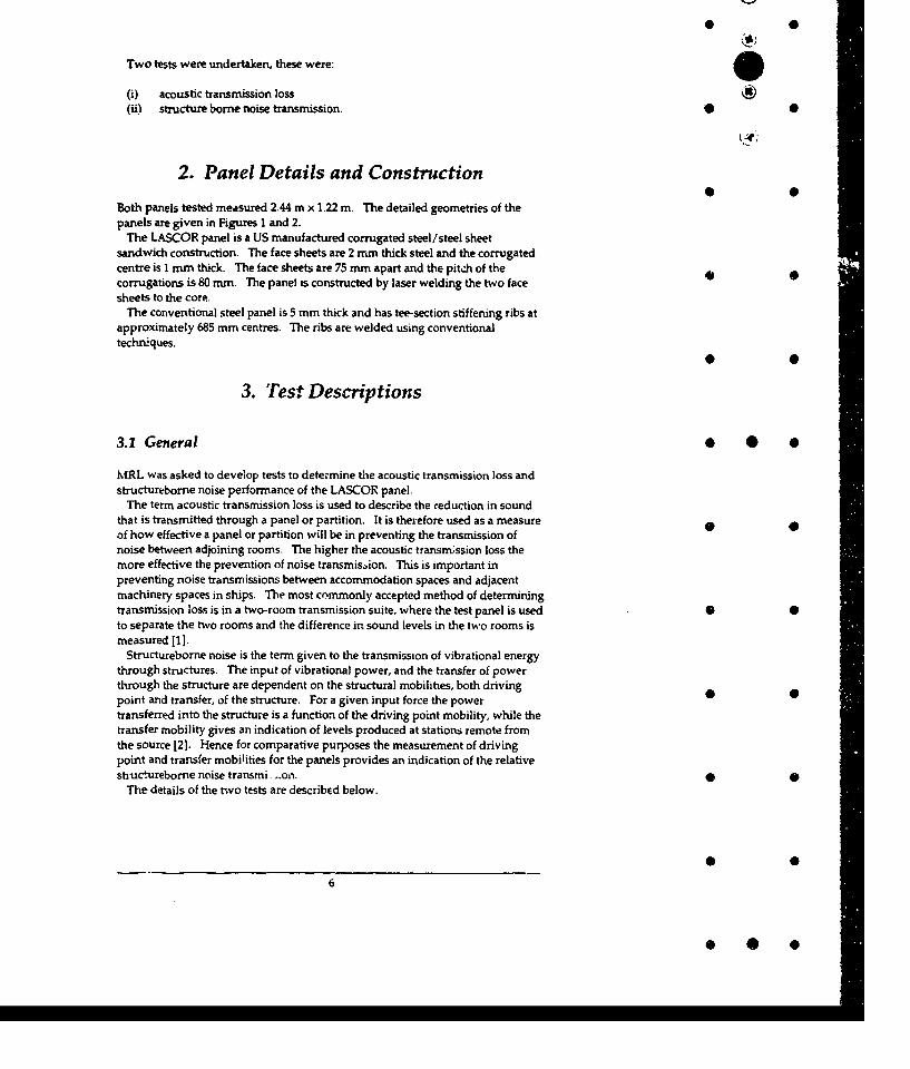
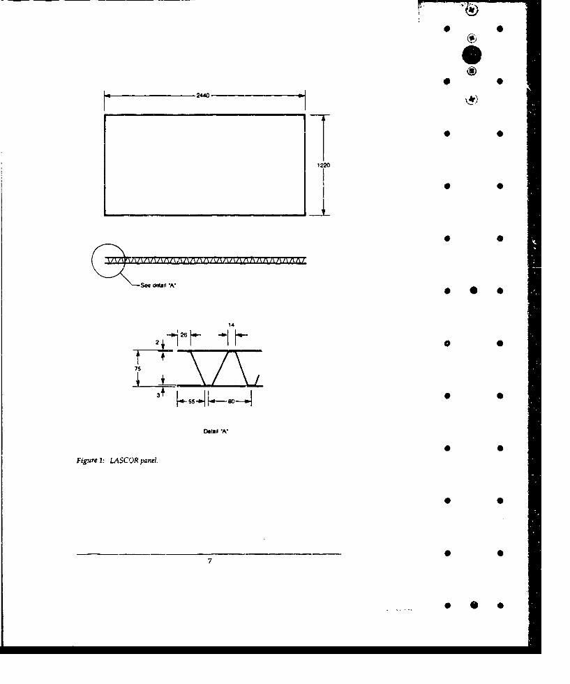
Both panels tested measured 2.44 m x 1.22 m. The detailed geometries of thepanels are given in Figures 1 and 2.
The LASCOR panel is a US manufactured corrugated steel/steel sheetsandwich construction. The face sheets are 2 mm thick steel and the corrugatedcentre is 1 mm thick. The face sheets are 75 mm apart and the pitch of thecorrugations is 80 mm. The panel is constructed by laser welding the two facesheets to the core.
The conventional steel panel is 5 mm thick and has tee-section stiffening ribs atapproximately 685 mm centres. The ribs are welded using conventionaltechniques.
3. Test Descriptions
3.1 General * 0 0
MRL was asked to develop tests to determine the acoustic transmission loss andstructureborne noise performance of the LASCOR panel.
The term acoustic transmission loss is used to describe the reduction in soundthat is transmitted through a panel or partition. It is therefore used as a measureof how effective a panel or partition will be in preventing the transmission ofnoise between adjoining rooms. The higher the acoustic transmrssion loss themore effective the prevention of noise transmission. This is important inpreventing noise transmissions between accommodation spaces and adjacentmachinery spaces in ships. The most commonly accepted method of determiningtransmission loss is in a two-room transmission suite, where the test panel is used . 4to separate the two rooms and the difference in sound levels in the two rooms ismeasured [1].
Structureborne noise is the term given to the transmission of vibrational energythrough structures. The input of vibrational power, and the transfer of powerthrough the structure are dependent on the structural mobilities, both driving 49point and transfer, of the structure. For a given input force the powertransferred into the structure is a function of the driving point mobility, while thetransfer mobility gives an indication of levels produced at stations remote fromthe source [2). Hence for comparative purposes the measurement of drivingpoint and transfer mobilities for the panels provides an indication of the relativestiuclureborne noise transmi. .on. 0 0
The details of the two tests are described below.
6
-~2440-
1220
0 0
* 00
14
30
Detail A
*Figure 1: LASCOR panel.
* 0
190
________Mal__II II I200
~ 1 ~ .1 - I I I 0II IL "I I
100
Dow 0
Figure2* 0eeecea
3.2 Acoustic Transmission Loss
The acoustic transmission loss test was carried out at the Department of AppliedPhysics, Royal Melbourne Institute of Technology in a two-room transmission 0suite, consisting of a pair of reverberant rooms with an aperture between. Therooms are constructed of 305 mm reinforced concrete, supported on laminated-rubber isolators and acoustically decoupled from one another by a layer of 50 mmthick cork. The source room has a volume of 115.49 m3 and the receiving room avolume of 120.14 m3. The rooms comply with the requirements of AS 1191-1985
[1].The opening between the two rooms is 10.69 m2 compared with the panel area
of 2.98 m 2. A filler wall consisting of a double layer of clay bricks with 10 mmmortar between was used to reduce the aperture size. The samples were placedin the aperture and sealed around the edge with silicone sealant on both sides.The effect of the filler wall is taken into account in the determination of the panelacoustic transmission loss. After the panels had been tested the aperture in thefiller wall was bricked in and the acoustic transmission loss of the filler wall wasmeasured. The results for the panels were then corrected using these data inaccordance with AS 1191.
The transmission loss was determined in accordance with AS 1191 over 18contiguous third octave bands, centre frequencies from 100 Hz tu 5000 Hz. 0 0
The acoustic transmission Ifss (R) is given by the expression
R = 101og, 0(P, / P2 )
where P, = the sound power incident on the panel •P2 = the sound power transmitted through and radiated by the panel.
The sound fields within both the source room and the receiving room werediffuse. As the sound power cannot be measured directly in this experimentalset up, an indirect method of determination was adopted, as follows. Theacoustic transmission loss car. be defined in terms of measurable quantities [1) 0and is expressed as
R = D + 10log10 (S/A)
where D = average sound pressure level difference in dBS = area of partition under test in M2
, in this case 2.98 m2 •
!., = equivalent absorption area in the receiving room in M2
The average sound pressure level difference (D) is given by
D = Lp, -- Lp, 0
where Lp, = average sound pressure level in the source room in dBLpr = average sound pressure level in the receiving room in dB
* 0
9
* 0
3.3 Structureborne Noise Transmission
As a comparative measure of the structuiebome noise transmission performanceof each panel the driving point and transfer mobilities were measured at a 0 •number of locations on the panels.
Mobility is a complex quantity which is a function of frequency and is definedas
V
F.
where F, = the applied force at point iV, = the response velocity at point j
for i = j it is the driving pointit is the transfer mobility •
Each panel was suspended by light cable, which provided an easily repeatablesupport condition, and was excited using an impact hammer. The input forcewas measured using a force transducer and accelerometers were used to measurethe panel response at various locations. The data were collected and processedusing an HP 3566A 8 channel analyser.
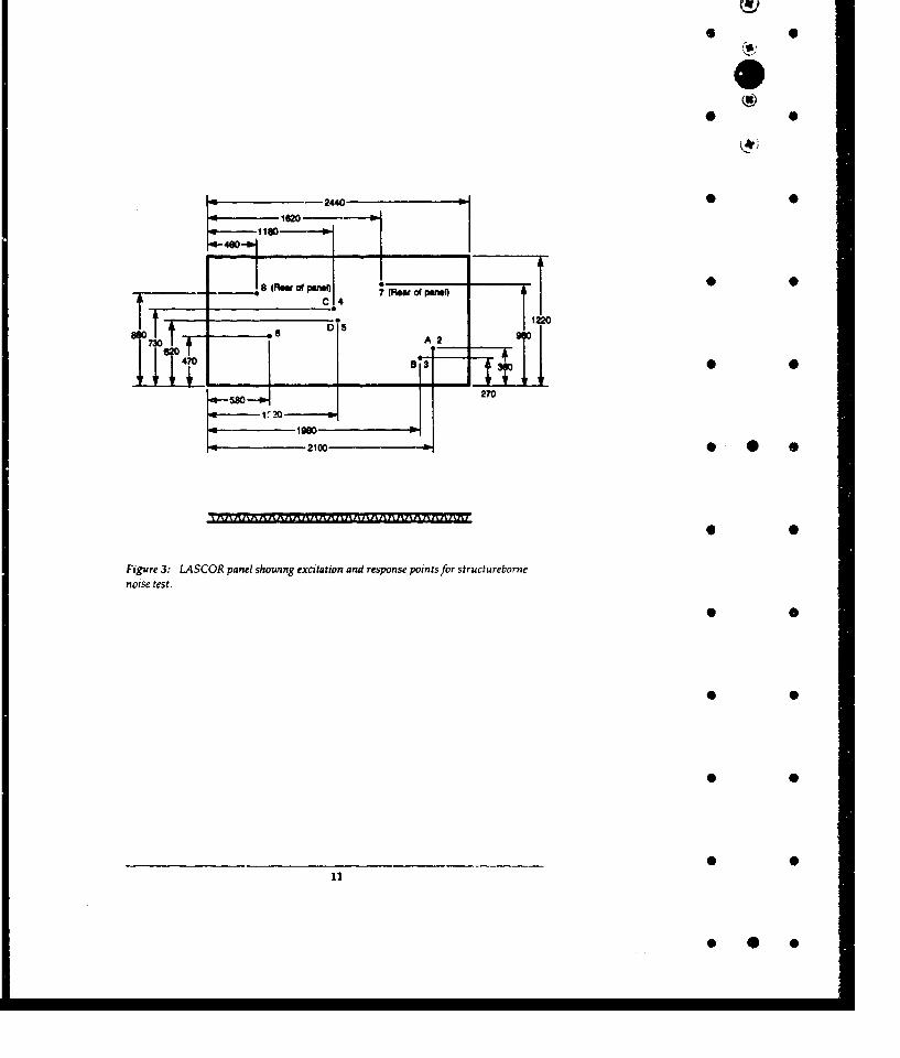
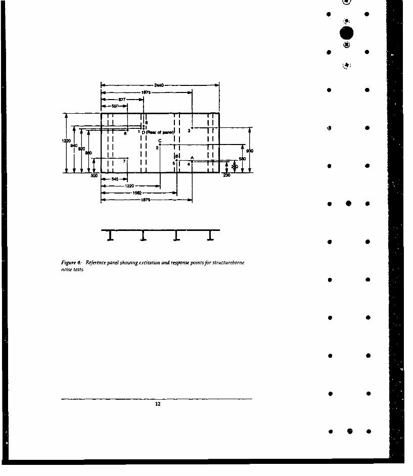
Each panel was excited at four different locations, in turn, and the responsemeasured at the driving point and six other locations. The LASCOR panel wasexcited near the centre, both over a corrugation rib and between ribs; and offcentre again both over a rib and between ribs. The reference panel was excited inthe centre of the panel, on one of the stiffeners, off centre between two stiffeners • 0 *and on the back of one of the stiffenecs. Locations for excitation points andresponse points for each panel are shown in Figures 3 and 4.
4. Results
4.1 Acoustic Transmission Loss
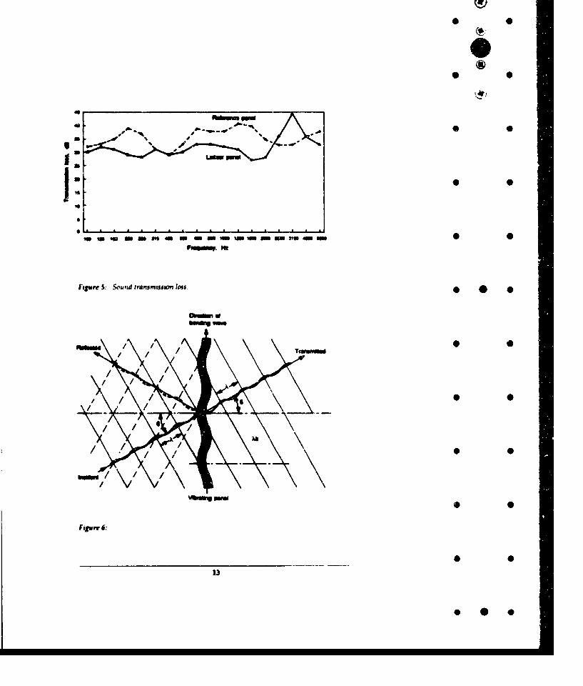
The measured airborne acoustic transmission loss, R expressed in dB, at each one-third octave bandwidth centre frequency for both panels is given in Table 1, andis plotted in Figure 3.
The acoustic transmission loss for the reference panel is in general greater thanthat for the LASCOR panel. The LASCOR panel only has a value of R higherthan the reference panel in the 2500 Hz to 4000 Hz range. In this frequency rangethere is a pronounced peak in the LASCOR panel R, while the reference panelshows a dip, which is associated coincidence affects. At other frequencies the Rof the reference panel is up to 10 dB higher.
Wave coincidence occurs when the trace wavelength of an incident plane soundwave is such that X/sinO is equal to X,, the wavelength of a free bending wavc inthe panel, Figuie 6. When this occurs the intensity of the transmitted waveapproaches the intensity of the incident wave.
10
*III
* 0
-2440 :1620 -I
1180 IN
a (ROWapnI of Li7 (Fiw-p m ne4D , 7 (OW f PWQ - 11220
A2 9
S270
Figure3: 3-. SCOR panel showing excitation and response points for structurebornenoise test.
* 0
* 0
* 0
11
* 0 0
0
I T-IIIIM CI I II II __ __
940 2I goTso AII ° - lILiiJ 12 -300II1 II IsI mm 0
1871- * . .0
Figure 4: Reference panel shouing excitation and response points for structurebornenoise tests.
0 0
• 0
12
* *.•
* 0wev
F#wr 3 &un rasmssonlosOwdre *
T.4,-
Al
13
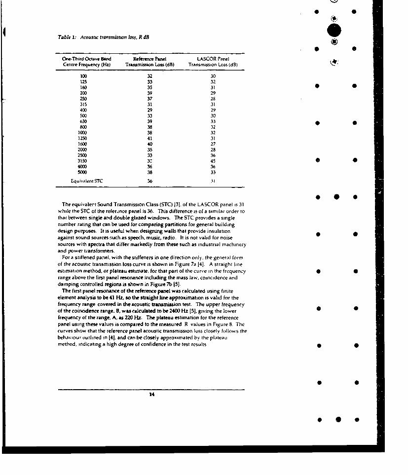
Table 1: Acoustic transmission loss. R dB
One-Third Octave Band Reference Panel LASCOR PanelCentre Frequency (Hz) Transmission Loss (dB) Transmission Loss (dB)
100 32 30125 33 32160 35 31 0200 39 29250 37 28315 31 31400 29 29500 33 30630 39 33800 38 32
1000 38 321250 41 311600 40 272000 35 282500 33 363150 32 45 0 04000 36 365000 38 33
Equivalent STC 36 31
The equivalert Sound Transmission Class (STC) 13]. of the LASCOR panel is 31while the STC of the refer..nce panel is 36. This difference is of a similar order tothat between single and double glazed windows. The STC provides a singlenumber rating that can be used for comparing partitions for general buildingdesign purposes. It is useful when designing walls that provide insulation •against sound sources such as speech, music, radio. It is not valid for noisesources with spectra that differ markedly from these such as industrial machineryand power transformers.
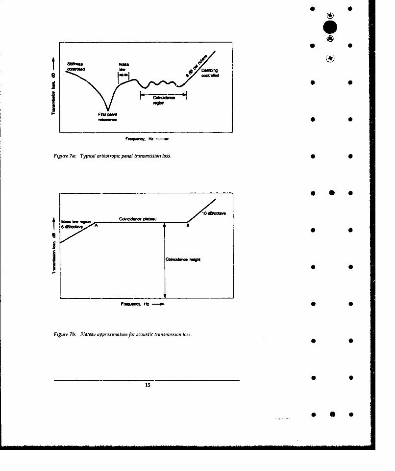
For a stiffened panel, with the stiffeners in one direction only. the general formof the acoustic transmission loss curve is shown in Figure 7a 14]. A straight lineestimation method, or plateau estimate, for that part of the curve in the frequency • 0range above the first panel resonance including the mass law, coincidence anddamping cont7olled regions is shown in Figure 7b 151.
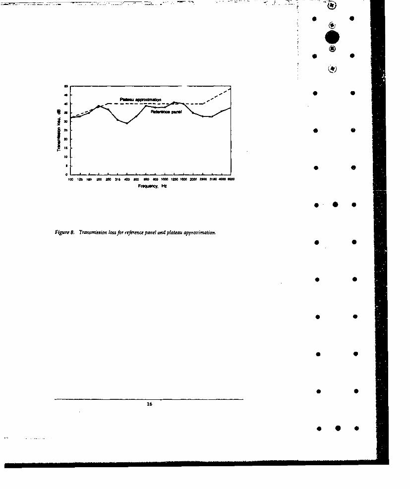
The first panel resonance of the refetence panel was calculated using finiteelement analysis to be 41 Hz, so the straight line approximation is valid for thefrequency range covered in the acoustic transmission test. The upper frequencyof the coincidence range. B, was calculated to be 2400 Hz 15]. giving the lower •frequency of the range, A, as 220 Hz. The plateau estimation for the referencepanel using these values is compared to the measured R values in Figure 8 Thecurves show that the reference panel acoustic transmission loss closely follows thebehaviour outlined in 141. and can be closely approximated by the plateatimethod, indicating a high degree of confidence in the test results.
14
* 0 0
*0
* 0
m •mg
Vrg~aucy. Iz -...- n
Figure 7a: Typical orthotropic panel trrnsmission loss. 0 0
10 dB/actav
C , •.--M •
* 40
Cokidm hugM
Frsqaency. W
Figure 7b: Plateau approximation for acoustic transmission loss.
15
410..
* 0UO
4. 0
10
100 12a ao 203G 0 Ma 315 40 No iet 20M n 1010 IOW 4000 40Ma
Frequwicy. W~
Figure 8: Transmission loss fJr reference panel and plateau approximation.
1 0
* 0
16
* 0 0
* 0
Panel size and aspec.t ratio will only affect the results if edge effects become
important. The resorant frequencies of the panels will change, depending onsize and shapt. However the coincidence frequencies of the panels shouldremain constant, unless the panels become small enough for the edge effects to 0 •dominate. For the reference panel the lower coincidence frequency was 220 Hz,and the wave length appioximately 0.5 m, so for the panel size tested edge effectswould not have been important.
4.2 Structureborne Noise Transmission •
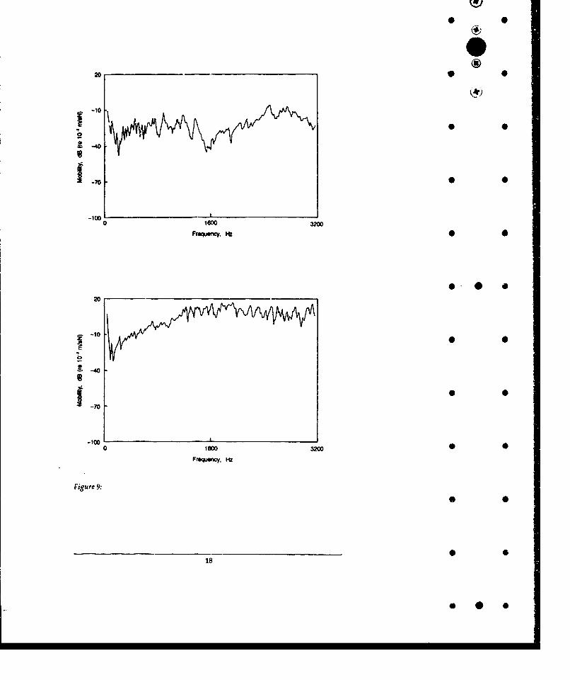
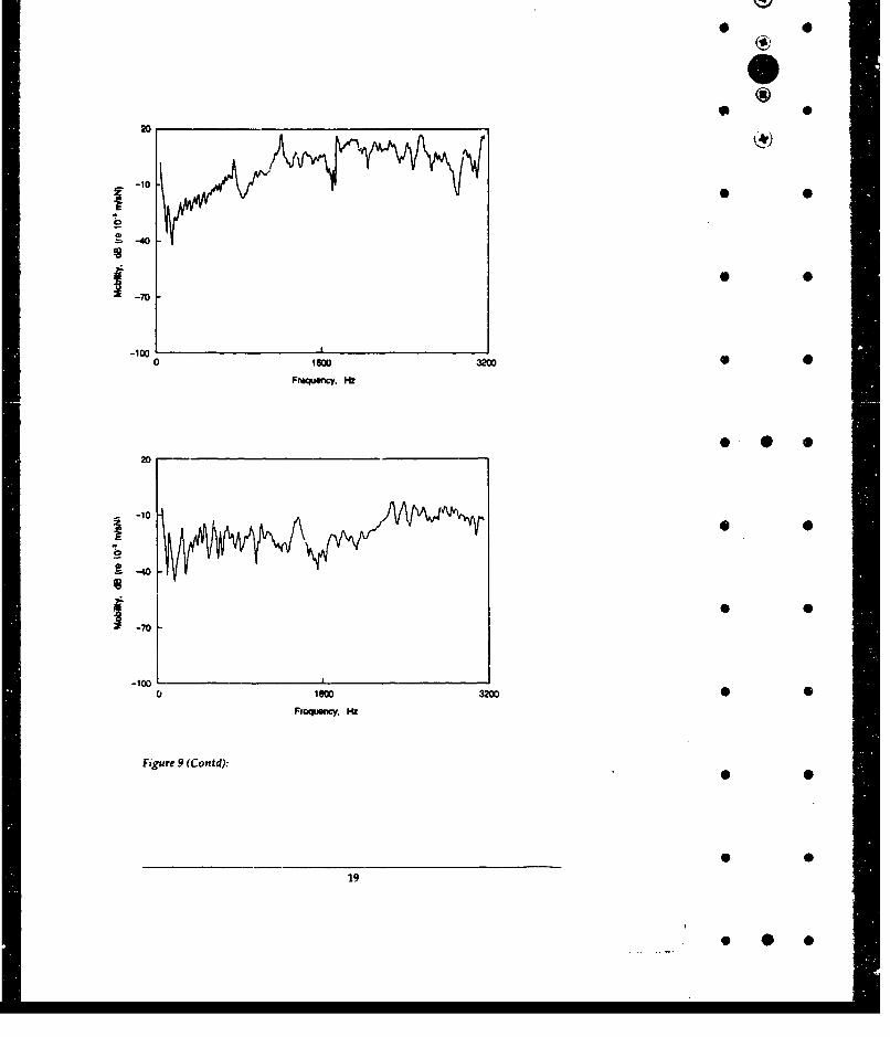
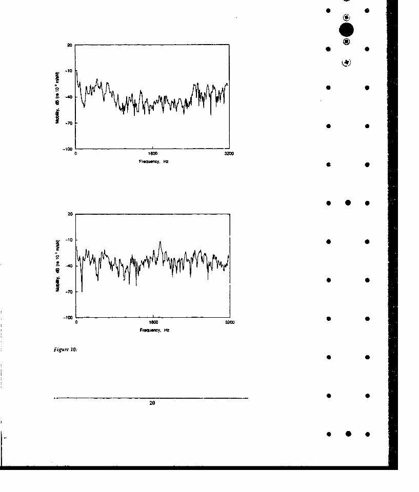
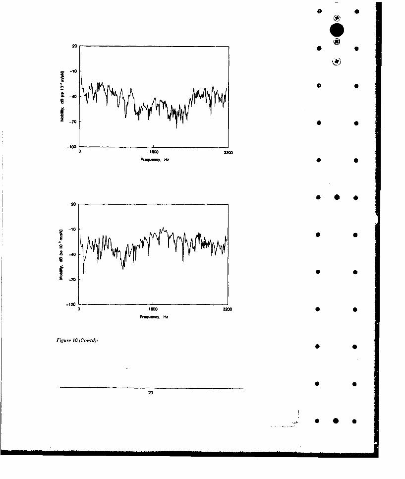
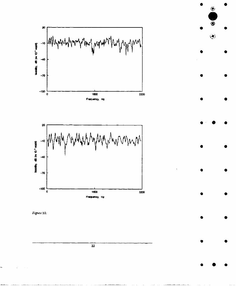
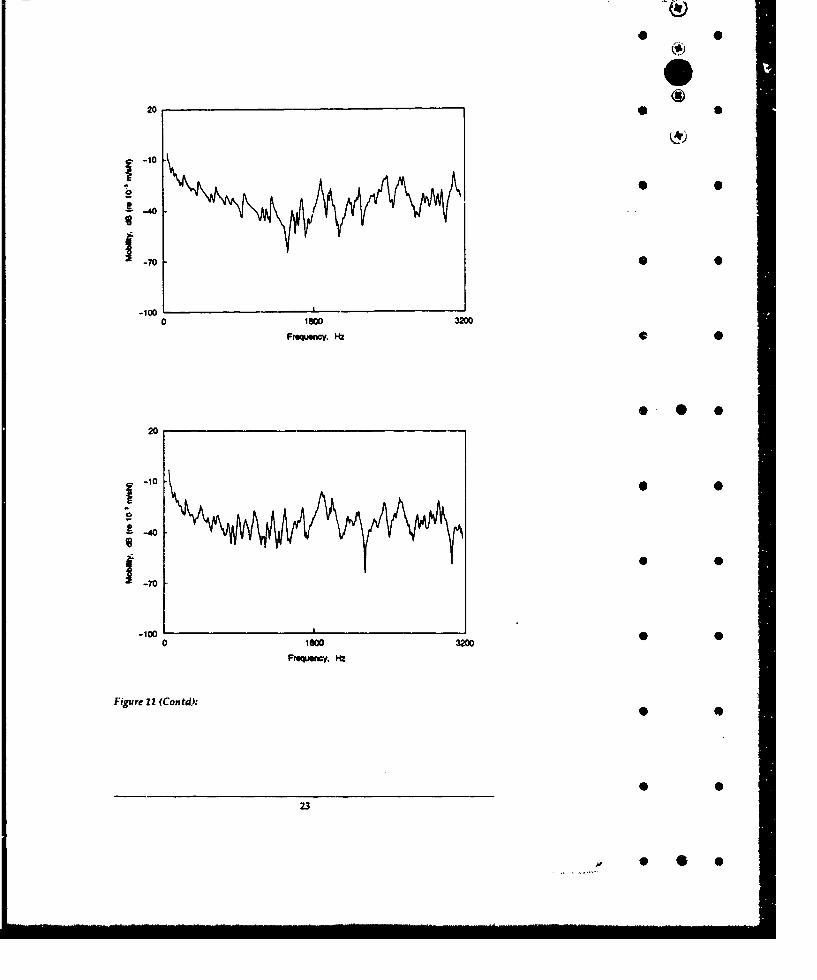
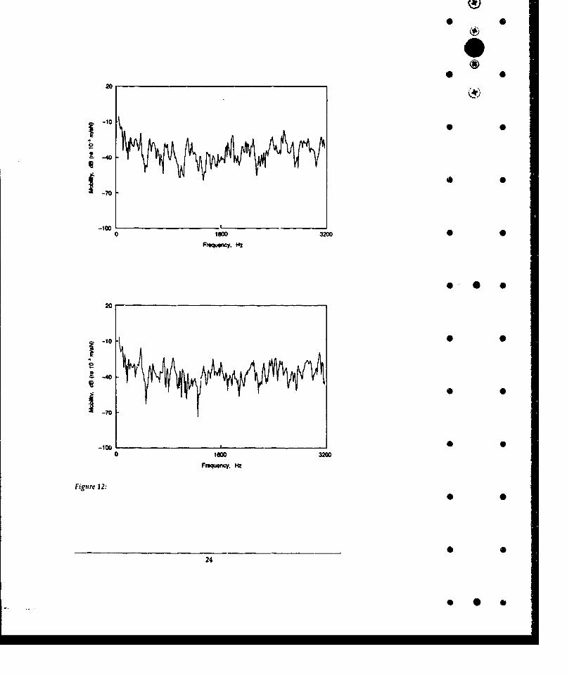
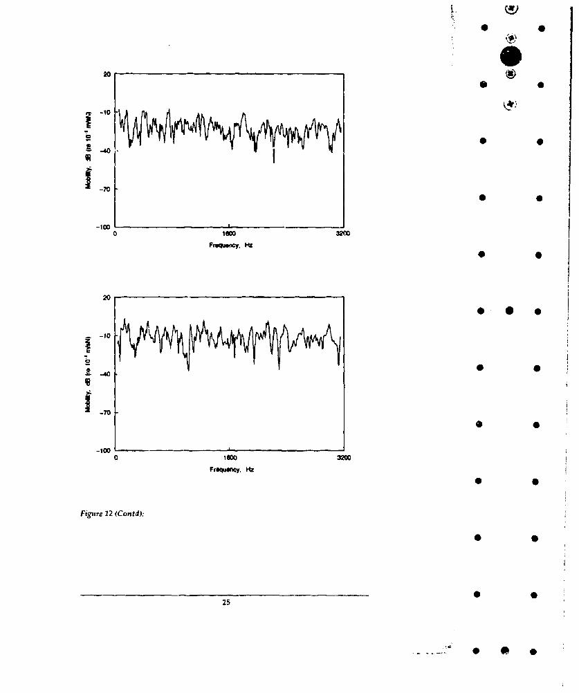
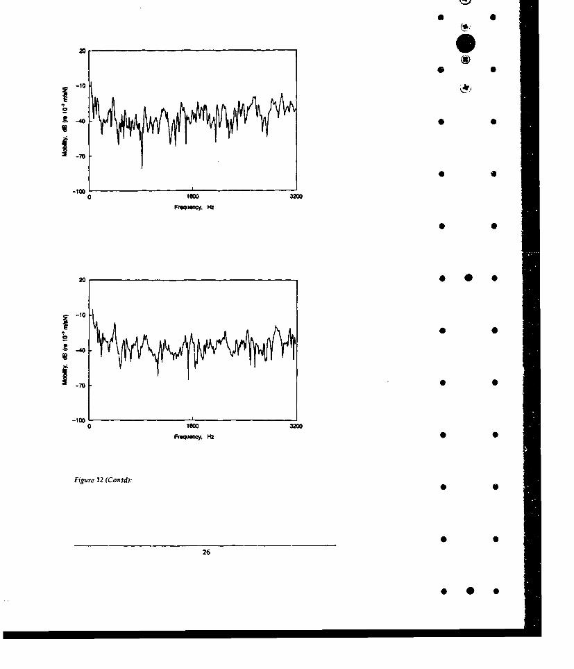
Plots of the magnitude of typical driving point mobility and transfer mobilities foreach excitation point for the LASCOR panel are shown in Figures 9 and 10 and forthe reference panel in Figures 11 and 12. Table 2 summarises the averagemobility level magnitudes for the two panels.
For both panels the mobility levels for excitation between ribs are higher than 01when for excitation on a rib. This is because the local panel stiffness is lowerbetween ribs, and the driving point mobilities are primarily dependent upon thelocal structure around the excitation point. Both panels showed similardifferences in driving point mobilities for excitation on a rib and excitationbetween ribs.
The magnitude of the driving point mobilities between the ribs for the reference •
panel apýjroximate to a straight line, Figure 11, equivalent to the driving pointmobility of an infinite plate of the same thickness [6).
When comparing the driving point mobilities of the LASCOR panel with thoseof the reference panel it can be seen that the LASCOR panel mobility is higher forthe corresponding location (fable 2). The results in order of increasing mobility 0 * *may be generalised as reference panel on a rib, LASCOR panel on a rib, referencepanel between ribs and LASCOR panel between ribs.
For the reference panel the transfer mobilities within the same section are higherthan those across one or two rib stiffeners. Yhe transfer mobility across two ribswas similar to that across a single rib. Similarly the transfer mobility to a pointon an adjacent rib was similar to that for a non-adjacent rib. • •
For the LASCOR panel the transfer mobilities to locations between ribs werehigher than for locations on ribs. The transfer mobilities decreased as theresponse location moved away from the excitation point, so those locationsfurtherest away from the source were slightly lower than those at acorresponding location near the source. Additionally, the transfer mobilities •when the panel was excited on a rib were lower than when excited between ribs.
The magnitude of the transfer mobilities of the two panels was similar forcorresponding locations.
The higher driving point mobilities of the LASCOR panel mean that for a givenexcitation a higher power will be transmitted in to the structure since the inputpower is given by [2] •
P = < V: > = < F >Re(M,)
Re (M' )
where Ff is the excitation point force 4 0<Vf> is the excitation point velocityRe (Mf) is the real part of the driving point mobility
17
* 0
*
4
20
-40
1 -7000
-1000 16 32M0
Frquency. w~0
20
-10
Froquwirc'y,
Figure 9:i s-100
18
* @0•
* 0
20,4
~-70
-100 0020
Froquency. W~
20
-4 -0
07 0
00
* 0
20 * 0
-Q-
Freu.cy .270
-100 r
FmwwCy. H •
20
o 100o 3200
Fr*qLuecy. MZ
Figurc 10:
2 0
20
K 0 0
* l
0
-10
-40
-70
-1000 1D00 3200
Frequency. I-a
20
-10
-0
o - 0
-70
0 16 00 3 2 0 0 0
Frequency. o,
Figure 10 (Contd):
21
*
20!®
70
-1000 1600 3200
Frequowcy. m.2
20__ _ _ _ _ _ _ _ 0
-0
-4000
-70
-10010 1000 3200
Frqtwrcy, Hz
Figure 11:
2 2
22.
200
-,o)
-70
20 0
~-10
470
0 1600 3200
Froquwcy. W
203
200
240
-70
-100
200
-0-
'-70 6
0 1=) 3200 0Fmwwcy. m!
20
* 0 012
240
20
-10
g- -10
-lo0 Iwo0 3200
Frequency, Ha
20
-- 40
1-70
-100---0 60 3200
FROWWKnY. Hz
Figure 12 (Contd):
25*0
2 0
____O
-10 0 0
3
2 0
-10I
*40
00100 3200
FrgqseiCY. M
* 0
~-40
0 100 3200
Figure 12 (Contd):
26
* @ 0•
* 0
ICIS
-10
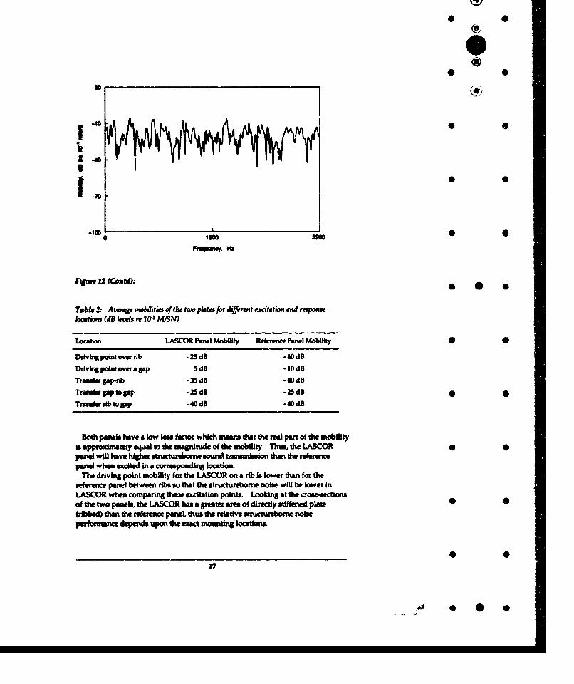
F4. 12 (Cemtf):.
Tebr 2: Awrqt nsibiem of tht to plates for di#) t tzaterm avid raomboctiow (d4 kvws rt 103 A4MSN)
Locabon LAS Panel Mobility Refenoc PWe Mobility 0
Drdvft point over rib -25 dB -40dB
DdIvbf point ovw a•gap 5dB -. OdBTmOWierapb - dB -.4dBTruusr ap to gap 25dB -25dB 0Trnmusrrb to Ipp -40dB -40dB
BDcv panels have a low los factor which manes that the real part of the mobilityx appwdmatefy eqWa to the magnitude of the mobility. Thus, the LASCOR 0- will have h4i;h uiructurbome sound tramsoni than the refereepanel when excited in a corresponding location.
The driving point mobility for the LASCOR on a rib is lower thn for therefference panel betwee ribs so that the structureborne noise will be lower InLASCOR when comparing the excitatio points. Looking at the crose-sectionsof the two panels, the LASCOR has a greater ae of directly stiffened plate •
(ribbed) than the refvence panel thus the mlative structurbone noiseperformance depends upon the exact mountn locations.
__ __ __ __ __ __ __• 0
Panel size and aspect ratio will only affect the results at lower frequencies,where panel resonance are important. At higher frequencies the mobilites aredependent on the local panel stiffness and approximate to the mobilities for an ()infinite pare. * 0
5. Conclusions
1. The LASCOR panel has a lower transmission loss than the reference panelexcept in the 2500 Hz and 3150 HLz centre frequency, one third octave bands,and the equivalent STC of the LASCOR panel is 5 dB lower than for thereference panel. This means that there will be higher acoustic transmissionbetween compartments separated by LASCOR partitions than by standardpartitions.
2. The LASCOR panel has higher driving point mobility ,and similar transfermobilities compared with the reference panel, for corresponding excitationlocation. This means that there will be higher structureborne noisetransmission with the LASCOR panel for the same excitation location.
6. Acknowledgements
The author wishes to acknowledge thw assistance given by Mr Ken Cook andMr Peter Dale, Applied Physics Department at Royal Melbourne Institute ofTechnology, in undertaking the acoustic transmission loss tests; andMr M. O'Reilly and Mr Y.K. Tso, MRL, in undertaking the structureborne noisetests.
*
7. References
1. AS 1191-1985: Method for laboratory measurement of airborne sound •transmission loss of building partitions.
2. White, R.G. (1976).Measurement of transfer functions and power flow in structures, Proceedingsof International Symposium on Shipboard Acoustics, pp. 247-266. •
3. Crocker, M.j. and Kessler, F.M. (1982).Noise and noise control, Vol. II, CRC Press.
4. Bies, D. and Hanson, C. (1988).Engineering noise control, Unwin Hyman Ltd. 0 0
28
* 00
* 0
5. Norton, M.P. (1989).
Fundamentals of noise and vibration anal -is for engineers, CambridgeUniversity Press.
* 06. Goyder, H.G.D. and White, R.G. (1980).
Vibration power flow from machines into built-up structures, Part 1:Introduction and approximate analyses of beam and plate-like foundations,Journal of Sound and Vibration, 68 (1), pp. 59-75.
2 9
* 0
* 0
* 0 0
* 0
* 9
* 0
29
.,) 0 * S
SECUR YCLASOICA1nON OF THI PAGE UNCLASSIFIED Ci
REPORT NO. AR NO. REPORT SECURITY CLASSIFICATIONMRL-TN-623 AR-006-225 Unclassified
TITfLE 0
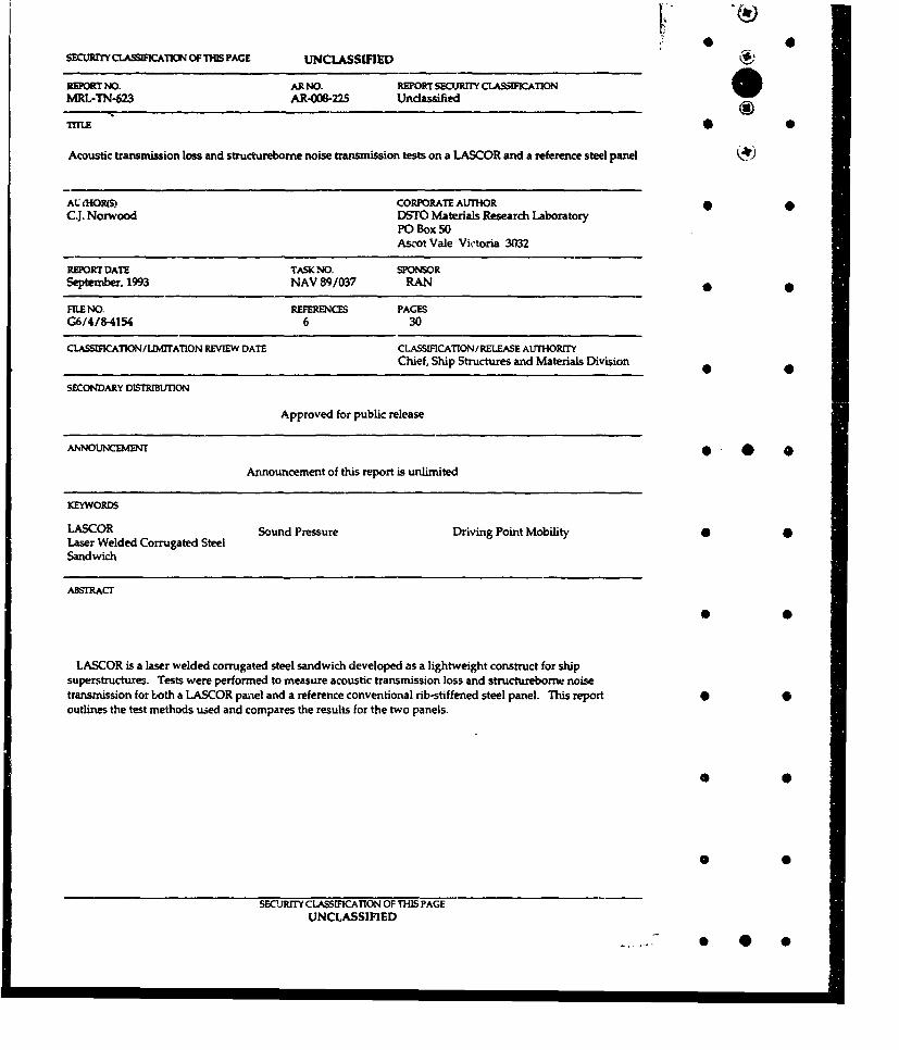
Acoustic transmission loss and structureborne noise transmission tests on a LASCOR and a reference steel panel
AUL -OR(S) CORPORATE AUTHORC.J. Norwood DSTO Materials Research Laboratory
PO Box 50Ascot Vale Victoria 3032
REPORT DATE TASK NO. SPONORSeptember, 1993 NAV 89/037 RAN
FILE NO. REFERENCES PAGESG6/4/8-4154 6 30CLASSIMCATION/aMrrATION REVIEW DATE CLASSIFICATION/ RELEASE AUrTHORITY
Chief, Ship Structures and Materials Division
SECONDARY DMSTRIBUTON
Approved for public release
ANNOUNCEMENT* * *Announcement of this report is unlimited
KEYWORDS
LASCOR Sound Pressure Driving Point Mobility 6 0Laser Welded Corrugated SteelSandwich
ABSTRACT
* 0
LASCOR is a laser welded corrugated steel sandwich developed as a lightweight construct for shipsuperstructures. Tests were performed to measure acoustic transmission loss and structureborne noisetransmission for both a LASCOR panel and a reference conventional rib-stiffened steel panel. This report 0 •outlines the test methods used and compares the results for the two panels.
* S
* 0
SECURITY CLASSMIICATION OF THIS PAGE
UNCLASSIFIED
- 0 @0
0 0
Acoustic Transmission Loss and Structureborne Noise Transmission 4Tests on a LASCOR and a Reference Steel Panel
C. Norwood
(MRL-TN-623)
DISTRIBUTION LIST * 0
Director, MRLChief, Ship Structures and Materials DivisionDr J.C. RitterMr C. NorwoodMRL Information Service
Chief, Defence Scientist (for CDS, FASSP, ASSCM) (1 copy only)Director, Surveillance Research LaboratoryDirector, (for Library), Aeronautical Research LaboratoryDirector, Electronics Research Laboratory * 0Head, Information Centre, Defence Intelligence OrganisationOIC, Technical Reports Centre, Defence Central LibraryOfficer in Charge, Document Exchange Centre (8 copies)Army Scientific Adviser, Russell OfficesAir Force Scientific Adviser, Russell OfficesNavy Scientific Adviser, Russell OfficesScientific Adviser, Defence CentralDirector General Force Development (Land)Senior Librarian, Main Library, DSTOSLibrarian, MRL-Sydney - data sheet onlyLibrarian, H Block 0UK/USA/CAN/ABCA Armies Standardisation Rep, c/- DATD (NSO) (3 copies)Librarian, Australian Defence Force AcademyCounsellor. Defence Science. Embassy of Australia - data sheet onlyCounsellor, Defence Science, Australian High Commission - data sheet onlyScientific Adviser to DSTC Malaysia, c/- Defence Adviser - data sheet onlyScientific Adviser to MRDC Thailand, C!- Defence Attache - data sheet only •Head of Staff, British Defence Research end Supply Staff (Australia)NASA Senior Scientific Representative in AustraliaINSPEC: Acquisitions Section Institution of Electrical EngineersHead Librarian, Australian Nuclear Science and Technology OrganisationSenior Librarian, Hargrave Library, Monash University •Library - Exchange Desk, National Institute of Standards arid Technology, USExchange Section, British Library Document Supply CentrePeriodicals Recording Section, Science Reference and Information Service, UKLibrary, Chemical Abstracts Reference ServiceEngineering Societies Library, USDocuments Librarian, The Center for Research Libraries, US
DGNERDNAProject Director Anzac Frigate Project
* 0
*i
Related Documents


![Tranmission Planning[1]](https://static.cupdf.com/doc/110x72/577cc3b71a28aba71196f7e0/tranmission-planning1.jpg)