Induction AC Motors/Gearmotors

Welcome message from author
This document is posted to help you gain knowledge. Please leave a comment to let me know what you think about it! Share it to your friends and learn new things together.
Transcript

Induction AC Motors/Gearmotors
10
R
Catalog S-14
P E R M A N E N T S P L I T C A P A C I T O RM O T O R SPermanent Split Capacitor motors, Bodine types “CI”and “YC”, are designed for single speed applicationsusing single phase power. They are recommended forcontinuous duty applications or start-stop applicationswith up to 10 starts per minute. Bodine types “CI” and“YC” motors feature high efficiency and reliable service.These motors require continuous duty, motor-runcapacitors connected in the auxiliary winding circuit toproduce starting torque.
Non-Synchronous designs provide the highest outputpower of permanent split capacitor motors. Speedchange will be less than 6% from No-Load to FullLoad. Available starting torque is approximately thesame as rated torque.
Synchronous designs provide exact speed from No-Load to Full Load. Power output is lower than non-synchronous motors of the same size. Available startingtorque is approximately the same as rated torque.
S P L I T P H A S E M O T O R SSplit Phase motors, Bodine types “SI” and “SY”, aredesigned for single speed applications using singlephase power. They are recommended for continuousduty applications or start-stop applications with up to6 starts per hour. The specially designed auxiliarywinding produces starting torque and is thendisconnected by an internal, mechanical, centrifugalstarting switch. Because of this switch 60 Hz motorscannot be operated at 50 Hz. No start or run capacitoris required. However, an electrolytic start capacitormay be connected in series with the auxiliary windingto increase starting torque and reduce starting current.Suggested values for these capacitors are shown inthe table at the top of page 30.
Non-Synchronous designs provide the highest outputpower of split phase motors. Speed change will beless than 6% from No-Load to Full Load. Availablestarting torque is typically 1.5 to 3 times rated torque.
Synchronous designs provide exact speed from No-Load to Full Load. Power output is lower than non-synchronous motors of the same size. Availablestarting torque is typically somewhat higher thanrated torque.
A C T E C H N I C A L I N F O R M A T I O N
R F R A M E A C M O T O R I N F O R M A T I O N
IP 44 ConstructionWith a properly installed die cast terminal box (modelno. 0984 or model no. 5982), Bodine “R” Frame motorsand gearmotors meet IP 44 construction as specifiedin IEC standard 34-5. The IP 44 designation meansthat a motor is designed to protect against solidbodies greater than 1 mm and water splashed fromany direction.
Electrolytic Capacitors with 42R and48R Split Phase 115/230 Volt MotorsStarting current for split phase motors is significantlyhigher than running current. The insertion of anelectrolytic capacitor in the starting winding circuit(white leads) of nine wire split phase motors canreduce starting current by approximately 50%.Suggested electrolytic capacitor values are listedbelow. Bodine does not supply these capacitors.
48R Frame Motors and NEMA StandardsStocked 48R motors are 48 frame diameter motorswith NEMA 56 frame face mounting shield andshaft. With the motor base removed, the mountingface and shaft configuration meet NEMA 56standard dimensions, enabling these stockedmotors to be used in conjunction with manyseparable gearheads available.
Because Bodine 48R frame motors are shorterthan typical competitive 48 frame motors ofequivalent horsepower rating, the dimension fromthe face to the first base mounting hole(designated “BA” by NEMA) is shorter than 48NEMA standard for these motors.
Please contact the factory for inverter dutyapplication requirements.
Motor/Gearmotor Voltage ConnectionModel No. 115 Volt 230 Volt0284 180 mfd. 64 mfd.0285 145 mfd. 43 mfd.0661, 0662, 0663, 0664 180 mfd. 64 mfd.0251 140 mfd. –0253, 0254 300 mfd. –0255 220 mfd. –
3 P H A S E M O T O R S3 Phase motors, Bodine types “PP” and “YP”, aredesigned for single speed applications using 3phase power. In addition, dual voltage, 230/460VAC, 3 phase motors may be used in variablespeed applications using 230 volt output ACvariable frequency (VF) drives. 3 phase motorsare recommended for continuous duty appli-cations or start-stop applications with up to 10starts per minute. Bodine types “PP” and “YP”motors feature high efficiency and reliableservice. Non-synchronous designs provide thehighest output power of all AC induction motors.Speed change will be less than 6% from No-Loadto Full Load. Available starting torque is typically1.5 to 3 times rated torque.
Synchronous designs provide exact speed fromNo-Load to Full Load. Horsepower rating is lowerthan non-synchronous motors of the same size.Available starting torque is typically somewhathigher than rated torque.
C E C E R T I F I C A T O NBodine motors and gearmotors meet CE standards.See page 4 for more information.
11
R
Catalog S-14
INT
RO
DU
CT
ION
IND
EX
PE
RM
AN
EN
T M
AG
NE
T D
CIN
TE
RN
AT
ION
AL
BR
US
HL
ES
S D
CIN
DU
CT
ION
AC
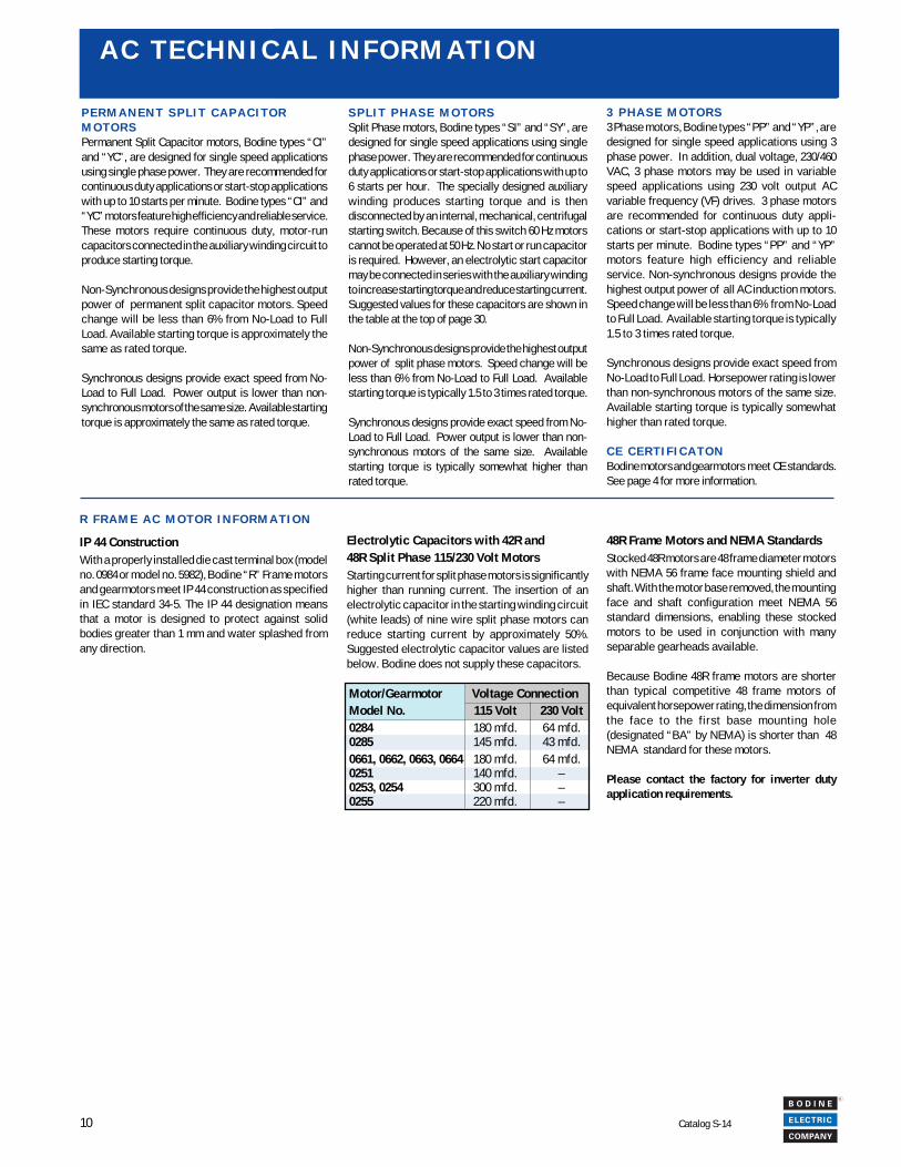
LINEBLUE-YEL TR.BLACK-YEL TR.
LINEBLUEBLACKGRN-YEL TR. (GRD)
LINEBLUE-YEL TR.BLACK
LINEBLUEBLACK-YEL TR.GRN-YEL TR. (GRD)
Connect as shown above for clockwise rotation while viewingthe output shaft. To reverse direction transpose the blackand black-yel. tr. leads.
0 7 4 1 0 2 9 70 7 4 1 0 2 9 2 0 7 4 1 0 2 9 3 0 7 4 1 0 2 9 6 0 7 4 1 0 0 0 7 O R 0 7 4 1 0 1 0 2
To reverse direction transpose anytwo leads.
To reverse direction transpose red and blue leads.To reverse direction transpose red and black leads. To reverse direction transpose any two leads orcombinations.
0 7 4 1 0 0 2 10 7 4 1 0 0 1 9
BLACK
LINE
LINE
LINE
BLK-GRN TR.BLK-YEL TR.BLUE-YEL TR.RED-YEL TR.
BLUEBLUE-GRN TR.
REDRED GRN TR.
BLACK
BLK.-YEL TR.BLK-GRN TR.BLUE-YEL TR.
BLUE-GRN TR.BLUE
RED-YEL TR.RED-GRN TR.
RED
GRN-YEL TR (GRD) GRN-YEL TR (GRD)
230V 460V
A C T E C H N I C A L I N F O R M A T I O NC O N N E C T I O N D I A G R A M S
0 7 4 1 0 0 1 2 O R 0 7 4 1 0 1 0 3( 9 L E A D S , 2 3 0 / 4 6 0 V )
LINE
RED (CW)
BLACK (CCW)
LINEBLUE
GRN-YEL TR. (GRD)
LINE
REDBLACK
LINEBLUEWHITE
GRN-YEL TR. (GRD)
Connect as shown above for clockwise rotation while viewingthe output shaft. To reverse direction transpose the black andblack -yel. tr. leads.
BLACK-YEL TR.
LINE
LOW VOLTAGE HIGH VOLTAGE
BLUE-YEL TR.RED-YEL TR.BROWN
BLUEYELLOW
GRN-YEL TR (GRD) GRN-YEL TR (GRD)
BLACK
BLACK-YEL TR.BLUE-YEL. TR.
B R O W N
BLUE
RED-YEL TR.
YELLOW
LINE REDWHITE
WHITEBLACKRED
Connect as shown above for clockwise rotation while viewing the output shaft. To reverse direction with 115 V connection, transpose blue -yel. tr. and brown leads with white. Toreverse direction with 230 V connection, transpose blue yel. tr with white lead.
BLACK-YEL TR.
BLACK
RED-YEL TR.BLUE
REDBLUE-YEL TR.
BLACK-YEL TR.BLUE
BLACKRED-YEL TR.
REDBLUE-YEL TR.
LINE
LINE
LOW VOLTAGE
GRN-YEL TR (GRD) GRN-YEL TR (GRD)
HIGH VOLTAGE
To reverse direction transpose blue and blue-yel. tr. leads.
0 7 4 1 0 2 9 4 0 7 4 1 0 2 9 5
GRN-YEL TR. (GRD)
LINEBLACKBLUE
LINEBLACK-YEL TR.BLUE-YEL TR.
GRN-YEL TR. (GRD)
LINEBLACK-YEL TR.BLUE
LINEBLACKBLUE-YEL TR. LINE
LINELINE
BLACKREDBLUE
GRN-YEL TR. (GRD)
0 7 4 1 0 2 9 8 ( 9 L E A D S , 1 1 5 / 2 3 0 V ) 0 7 4 1 0 2 9 9 ( 9 L E A D S , 1 1 5 / 2 3 0 V )
LINE
LINE
BLUEYELLOW
BLK.-YEL TR.WHITE
BROWNBLUE
BLUE-YEL TR.RED
GRN-YEL TR (GRD) GRN-YEL TR (GRD)
HIGH VOLTAGE
WHITE.BLACK-YEL TR.RED-YEL TR.
BROWNBLUE-YEL TR.BLACKRED
RED-YEL TR.BLACK
YELLOW
LOW VOLTAGE
BLACK-YEL TR.RED-YEL TR.BLUE-YEL TR.
LOW VOLTAGE HIGH VOLTAGE
BLACK
RED
BLUE
BLACKRED
BLACK-YEL TR.BLUE-YEL. TR.LINE
RED-YEL TR.
LINE BLUE
GRN-YEL TR (GRD) GRN-YEL TR (GRD)
12
R
Catalog S-14
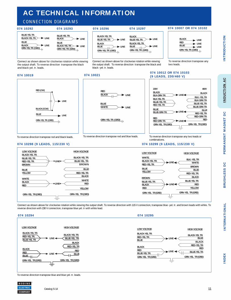
T E C H N I C A L I N F O R M A T I O NBodine AC torque motors are designed to run atstall or produce reverse torque intermittently at ratedvoltage. They may be used at stall or to producereverse torque continuously at the reduced voltageshown in the specification table. AC torque motorsare specially designed permanent split capacitormotors. They are often used in winding applicationson the take-up reel. When the reel is empty, it rotatesat its highest speed, but does not require much torque.When the reel is full, it rotates at a low speed andrequires more torque. Torque motors can also beused in tensioning or holding applications. Theycan safely produce reverse torque while beingbackdriven at any normal operating speed. Reversetorque will be approximately equal to stall torque.
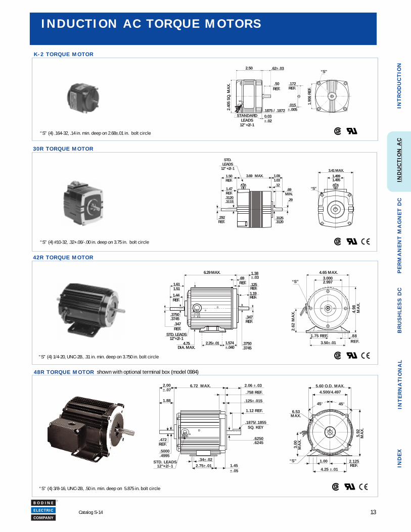
I N D U C T I O N A C T O R Q U E M O T O R S
They have high slip rotors that produce near linearspeed torque characteristics (see figure 1).Maximum torque is produced at stall with lesstorque available as the motor speeds up in theforward direction.
S T A N D A R D F E A T U R E S• Will operate satisfactorily on 50 or 60 Hz• Special rotor provides excellent performance
for holding, winding and tensioning applications• Special windings can provide locked rotor or
reverse torque intermittently at rated voltage orcontinuously at reduced voltage
• Totally enclosed non-ventilated IP-20 rating• Permanently lubricated, noise tested ball
bearings• Locked bearing design on 30R, 42R, and 48R
minimizes shaft endplay
rpm @ Torque Watts Max. On Time % Duty Weight Capacitor Product ModelNo Load (oz in.) (min.) Cycle V Hz (lbs.) Part No. Type Number
1580 7.0 22 5 40 115 60 2.25 494 00054* KCI-26 06211570 3.5 12 – 100 83 60 2.25 494 00054* KCI-26 06211310 6.0 19 5 40 115 50 2.25 494 00054* KCI-26 06211300 4.0 13 – 100 92 50 2.25 494 00054* KCI-26 06211660 25 52 30 50 115 60 4.75 494 29449 30R2FECI 56251645 19 40 – 100 100 60 4.75 494 29449 30R2FECI 56251425 25 47 30 50 115 50 4.75 494 29449 30R2FECI 56251420 19 36 – 100 100 50 4.75 494 29449 30R2FECI 56251690 38 85 28 40 115 60 12.5 494 00031 42R6FECI 26281680 22 49 – 100 87 60 12.5 494 00031 42R6FECI 26281445 38 82 28 40 115 50 12.5 494 00031 42R6FECI 26281435 22 47 – 100 87 50 12.5 494 00031 42R6FECI 26281560 65 120 15 40 115 60 20 494 00033 48R6FECI 06321560 32 60 – 100 80 60 20 494 00033 48R6FECI 06321370 68 96 15 40 115 50 20 494 00033 48R6FECI 06321360 34 58 – 100 80 50 20 494 00033 48R6FECI 0632
L O C K E D R O T O R
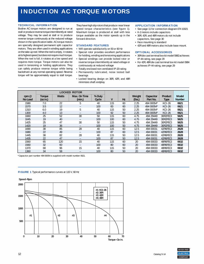
Speed–Rpm
2000
1500
1000
500
#1 #2 #3 #4
0 10 20 30 40 50 60 70Torque–Oz-in.
#1: KCI-26#2: 30R#3: 42R#4: 48R
F I G U R E 1 Typical performance curves at 115 V, 60 Hz
*Capacitor part number 494 00054 is supplied with model number 0621.
A P P L I C A T I O N I N F O R M A T I O N• See page 11 for connection diagram 074 10021• K-2 motors include capacitors• 30R, 42R, and 48R motors do not include
capacitors, See page 30• Face mounting is standard• 42R and 48R motors also include base mount.
O P T I O N A L A C C E S S O R I E S• 30R die cast terminal box kit model 5982 achieves
IP-44 rating, see page 29• For 42R, 48R die cast terminal box kit model 0984
achieves IP-44 rating, see page 29
13
R
Catalog S-14
INT
RO
DU
CT
ION
IND
EX
PE
RM
AN
EN
T M
AG
NE
T D
CIN
TE
RN
AT
ION
AL
BR
US
HL
ES
S D
CIN
DU
CT
ION
AC
I N D U C T I O N A C T O R Q U E M O T O R S
“S” (4) .164-32, .14 in. min. deep on 2.68±.01 in. bolt circle
“S” (4) #10-32, .32+.06/-.00 in. deep on 3.75 in. bolt circle
“S” (4) 1/4-20, UNC-2B, .31 in. min. deep on 3.750 in. bolt circle
“S” (4) 3/8-16, UNC-2B, .50 in. min. deep on 5.875 in. bolt circle
6.29 MAX.
1.574±.040
1.38±.03
1.19REF.
.69REF.
.3750
.37452.25±.014.75
DIA. MAX.
. 8 8R E F.
1.75 REF.
3.50±.01
2.62
MA
X. 4.
98M
AX
.
STD. LEADS12"+2/-1
.347REF.
3.0002.997
4.65 MAX.
“S”.125REF.
1.611.51
.3750
.3745.347REF.
1.44REF.
“S” 1.00 2.125REF.
4.25 ± .01
3.00
MA
X.
5.92
MA
X.
5 .60 O.D. MAX.4.500/4.497
45° 45°
6.53MAX.
6.72 MAX. 2.06 ± .03
.758 REF.
.125± .015
1.12 REF.
.1875/.1855SQ. KEY
.6250
.6245
1.45± .05
2.75± .01.34± .02STD. LEADS
12"+2/-1
2.00± .07
1.88
.5000
.4995
.472REF.
.50REF.
0.03±.02
.1875 / .1872STANDARD
LEADS12" +2/-1
2.40
5 SQ
. MA
X.
2.50 .62±.03“S”
1.90
6 RE
F.
.172REF.
.015±.005
K - 2 T O R Q U E M O T O R
3 0 R T O R Q U E M O T O R
4 2 R T O R Q U E M O T O R
4 8 R T O R Q U E M O T O R shown with optional terminal box (model 0984)
“S”
1.4991.495
3.41 MAX.
STD.LEADS
12" +2/-1
.29
.69MIN.
1.091.03.12
3.69 MAX.
.3125
.3120
.3120
.3115
.292REF.
1.47REF.
1.50REF.
14
R
Catalog S-14
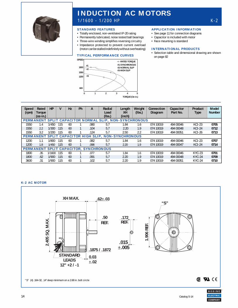
K - 2 A C M O T O R
P E R M A N E N T S P L I T C A P A C I T O R H I G H S L I P , N O N - S Y N C H R O N O U S
Speed Rated HP V Hz Ph A Radial Length Weight Connection Capacitor Product Model(rpm) Torque Load XH (lbs.) Diagram Part No. Type Number
(oz-in.) (lbs.) (inch)
1550 1.4 1/450 115 60 1 .080 5.7 1.84 1.6 074 10019 494 00046 KCI-23 07051550 2.2 1/300 115 60 1 .104 5.7 2.20 1.9 074 10019 494 00048 KCI-24 07121550 3.2 1/200 115 60 1 .124 5.7 2.50 2.2 074 10019 494 00051 KCI-26 0713
1200 1.1 1/800 115 60 1 .082 5.7 1.84 1.6 074 10019 494 00046 KCI-23 07071200 1.8 1/450 115 60 1 .098 5.7 2.20 1.9 074 10019 494 00047 KCI-24 0714
1800 .35 1/1600 115 60 1 .077 5.7 1.84 1.6 074 10019 494 00046 KYC-23 07011800 .62 1/900 115 60 1 .091 5.7 2.20 1.9 074 10019 494 00048 KYC-24 07093600 .31 1/900 115 60 1 .102 5.7 2.20 1.9 074 10019 494 00051 KYC-24 0710
S T A N D A R D F E A T U R E S• Totally enclosed, non-ventilated IP-20 rating• Permanently lubricated, noise tested ball bearings• Three-wire winding simplifies reversing circuitry• Impedance protected to prevent current overload
(motor can be stalled indefinitely without overheating)
I N D U C T I O N A C M O T O R S1 / 1 6 0 0 - 1 / 2 0 0 H P K - 2
P E R M A N E N T S P L I T C A P A C I T O R N O R M A L S L I P , N O N - S Y N C H R O N O U S
“S” (4) .164-32, .14" deep minimum on a 2.68 in. bolt circle
T Y P I C A L P E R F O R M A N C E C U R V E S
-RATED TORQUE
#1
#3
#2
#1-SYNCHRONOUS#2-NORMAL SLIP#3-HIGH SLIP
SPEED
1800
1200
1550
600
0 1 2 3 4 5TORQUE (Oz-in.)
A P P L I C A T I O N I N F O R M A T I O N• See page 11 for connection diagrams• Capacitor is included with motor• Face mounting is standard
I N T E R N A T I O N A L P R O D U C T S• Selection table and dimensional drawing are shown
on page 82
.50REF.
0.03±.02
.1875 / .1872STANDARD
LEADS12” +2 / -1
2.40
5 SQ
. MA
X.
XH MAX. .62±.03
.172REF.
.015±.005
“S”
1.90
6 RE
F. P E R M A N E N T S P L I T C A P A C I T O R , S Y N C H R O N O U S
15
R
Catalog S-14
INT
RO
DU
CT
ION
IND
EX
PE
RM
AN
EN
T M
AG
NE
T D
CIN
TE
RN
AT
ION
AL
BR
US
HL
ES
S D
CIN
DU
CT
ION
AC
Speed Rated HP V Hz Ph A Radial Length Weight Connection Capacitor Product Model(rpm) Torque Load XH (lbs.) Diagram Part No. Type Number
(oz-in.) (lbs.) (inch)
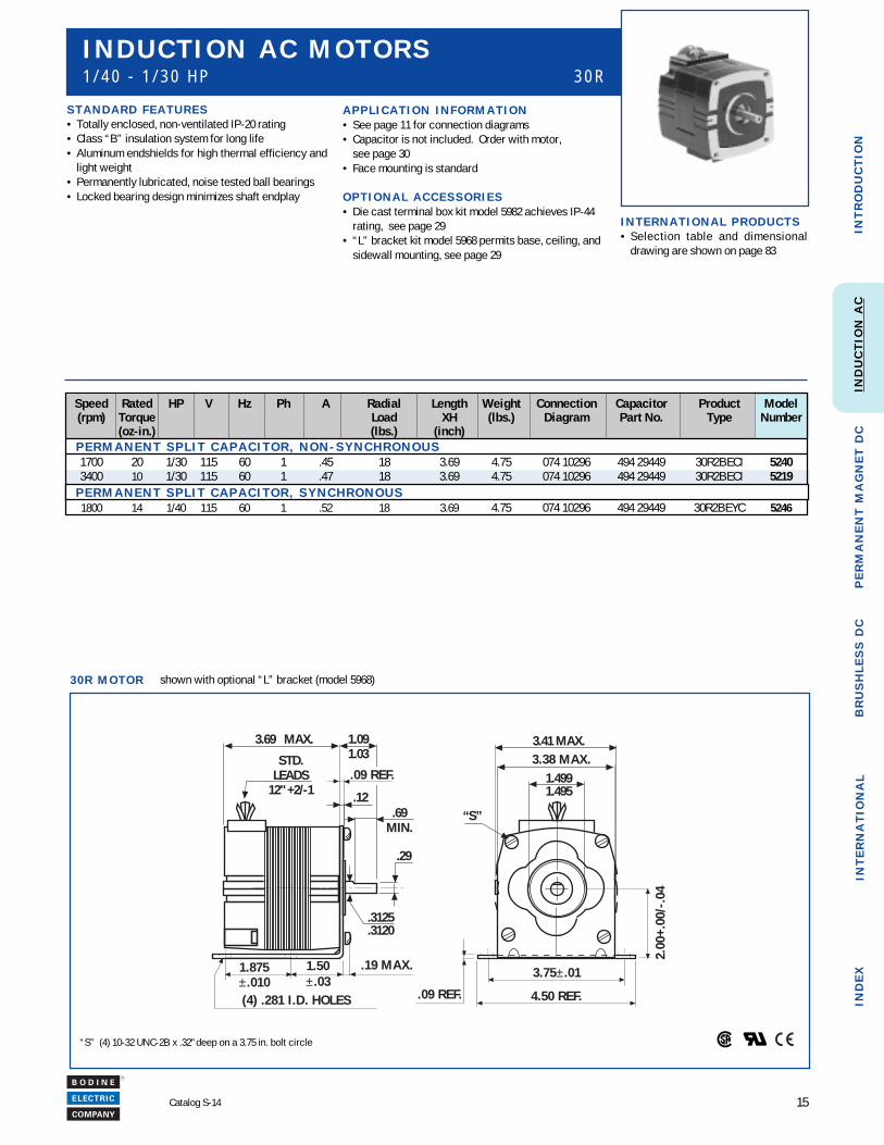
1700 20 1/30 115 60 1 .45 18 3.69 4.75 074 10296 494 29449 30R2BECI 52403400 10 1/30 115 60 1 .47 18 3.69 4.75 074 10296 494 29449 30R2BECI 5219
1800 14 1/40 115 60 1 .52 18 3.69 4.75 074 10296 494 29449 30R2BEYC 5246
S T A N D A R D F E A T U R E S• Totally enclosed, non-ventilated IP-20 rating• Class “B” insulation system for long life• Aluminum endshields for high thermal efficiency and
light weight• Permanently lubricated, noise tested ball bearings• Locked bearing design minimizes shaft endplay
I N D U C T I O N A C M O T O R S1 / 4 0 - 1 / 3 0 H P 3 0 R
“S” (4) 10-32 UNC-2B x .32" deep on a 3.75 in. bolt circle
A P P L I C A T I O N I N F O R M A T I O N• See page 11 for connection diagrams• Capacitor is not included. Order with motor,
see page 30• Face mounting is standard
O P T I O N A L A C C E S S O R I E S• Die cast terminal box kit model 5982 achieves IP-44
rating, see page 29• “L” bracket kit model 5968 permits base, ceiling, and
sidewall mounting, see page 29
I N T E R N A T I O N A L P R O D U C T S• Selection table and dimensional
drawing are shown on page 83
3 0 R M O T O R shown with optional “L” bracket (model 5968)
P E R M A N E N T S P L I T C A P A C I T O R , N O N - S Y N C H R O N O U S
P E R M A N E N T S P L I T C A P A C I T O R , S Y N C H R O N O U S
“S”
1.4991.495
3.41 MAX.STD.
LEADS12" +2/-1
.29
.69MIN.
1.091.03
.12
3.69 MAX.
.3125
.3120
2.00
+.00
/-.0
4
3.75±.01
4.50 REF..09 REF.
3.38 MAX.
.19 MAX.1.50±.03
1.875±.010(4) .281 I.D. HOLES
.09 REF.
16
R
Catalog S-14
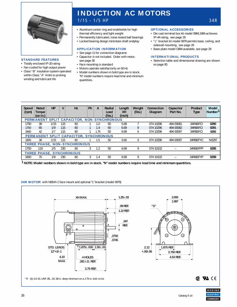
3 4 R M O T O R with NEMA C face mount and optional "L" bracket (model 0979)
Speed Rated HP V Hz Ph A Radial Length Weight Connection Capacitor Product Model(rpm) Torque Load XH (lbs.) Diagram Part No. Type Number1
(oz-in.) (lbs.) (inch)
1700 39 1/15 115 60 1 1.0 50 5.69 7 074 10296 494 00081 34R4BFCI 02901700 65 1/9 115 60 1 1.4 50 6.69 9 074 10296 494 00082 34R6BFCI 02913400 42 1/7 115 60 1 1.75 50 6.69 9 074 10296 494 00097 34R6BFCI 0293
1800 38 1/15 115 60 1 1.5 50 6.69 9 074 10296 494 00097 34R6BFYC N0297
1700 119 1/5 230 60 3 1.2 50 6.69 9 074 10102 – 34R6BFPP 0295
1800 70 1/8 230 60 3 1.4 50 6.69 9 074 10102 – 34R6BFYP 0299
I N D U C T I O N A C M O T O R S1 / 1 5 - 1 / 5 H P 3 4 R
T H R E E P H A S E , N O N - S Y N C H R O N O U S
P E R M A N E N T S P L I T C A P A C I T O R , S Y N C H R O N O U S
P E R M A N E N T S P L I T C A P A C I T O R , N O N - S Y N C H R O N O U S
T H R E E P H A S E , S Y N C H R O N O U S
S T A N D A R D F E A T U R E S• Totally enclosed IP-20 rating• Fan cooled for high output power• Class “B” insulation system operated
within Class “A” limits to prolongwinding and lubricant life
• Aluminum center ring and endshields for highthermal efficiency and light weight
• Permanently lubricated, noise tested ball bearings• Locked bearing design minimizes shaft endplay
A P P L I C A T I O N I N F O R M A T I O N• See page 11 for connection diagrams• Capacitor is not included. Order with motor,
see page 30• Face mounting is standard• Motors operate satisfactorily on 50 Hz• Model numbers shown in bold type are in stock.
"N" model numbers require lead time and minimumquantities.
O P T I O N A L A C C E S S O R I E S• Die cast terminal box kit model 0984,1984 achieves
IP-44 rating, see page 29• “L” bracket kit model 0979 permits base, ceiling, and
sidewall mounting, see page 29• Base plate model O994 available, see page 29
I N T E R N A T I O N A L P R O D U C T S• Selection table and dimensional drawing are shown
on page 83
“S” (4) 1/4-20, UNF-2B,..31/.38 in. deep minimum on a 2.75 in. bolt circle
XH MAX. 1.25±.03
.09 REF.1.12 REF.
.347REF.
.3750
.3745
4.10MAX.
1.875 REF.3.750 REF.
4.53 REF.
2.12+.00/.06
3.75 REF.
1.50±.031.875±.030STD. LEADS12"+2/-1
“S”
2.0001.997
4 HOLES.281 I.D. REF.
1 NOTE: Model numbers shown in bold type are in stock. "N" model numbers require lead time and minimum quantities.
17
R
Catalog S-14
INT
RO
DU
CT
ION
IND
EX
PE
RM
AN
EN
T M
AG
NE
T D
CIN
TE
RN
AT
ION
AL
BR
US
HL
ES
S D
CIN
DU
CT
ION
AC
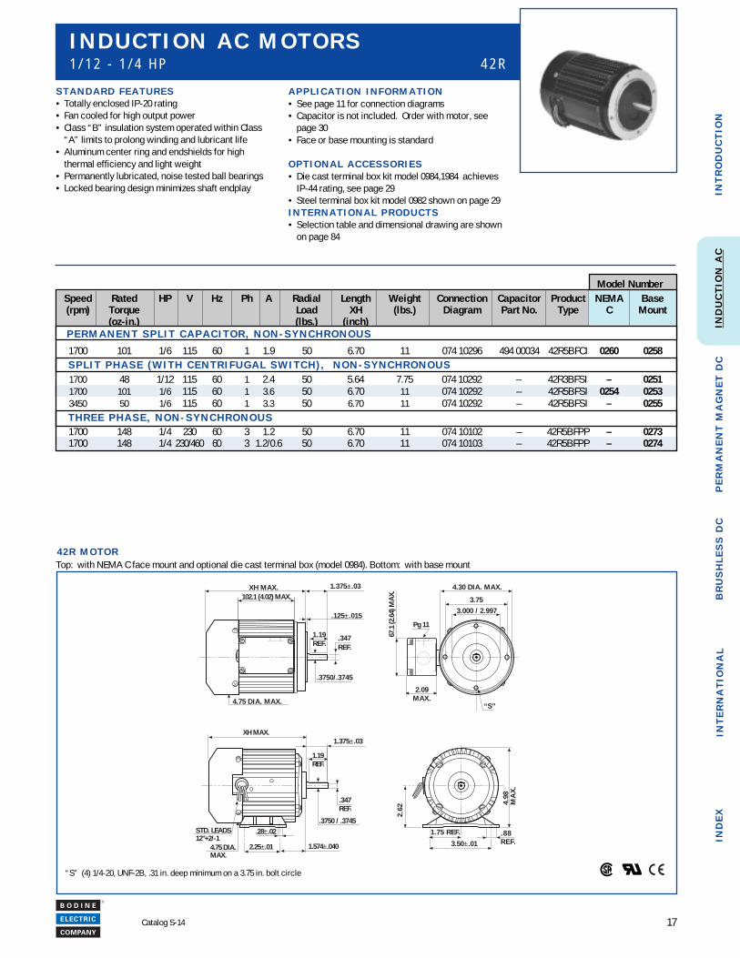
4 2 R M O T O R
S T A N D A R D F E A T U R E S• Totally enclosed IP-20 rating• Fan cooled for high output power• Class “B” insulation system operated within Class
“A” limits to prolong winding and lubricant life• Aluminum center ring and endshields for high
thermal efficiency and light weight• Permanently lubricated, noise tested ball bearings• Locked bearing design minimizes shaft endplay
A P P L I C A T I O N I N F O R M A T I O N• See page 11 for connection diagrams• Capacitor is not included. Order with motor, see
page 30• Face or base mounting is standard
O P T I O N A L A C C E S S O R I E S• Die cast terminal box kit model 0984,1984 achieves
IP-44 rating, see page 29• Steel terminal box kit model 0982 shown on page 29I N T E R N A T I O N A L P R O D U C T S• Selection table and dimensional drawing are shown
on page 84
I N D U C T I O N A C M O T O R S1 / 1 2 - 1 / 4 H P 4 2 R
“S” (4) 1/4-20, UNF-2B, .31 in. deep minimum on a 3.75 in. bolt circle
XH MAX.
1.574±.040
1.375±.03
1.19REF.
.3750 / .3745.28±.02
2.25±.014.75 DIA.MAX.
. 8 8R E F.
1.75 REF.
3.50±.01
2.62
4.98
MA
X.
STD. LEADS12"+2/-1
.347REF.
1.375±.03XH MAX.
.125±.0153.000 / 2.997
4.75 DIA. MAX.
1.19REF.
.3750/.3745
4.30 DIA. MAX.
3.75
“S”
.347REF.
102.1 (4.02) MAX.
67.1
(2.6
4) M
AX.
2.09MAX.
Pg 11
Model Number
Top: with NEMA C face mount and optional die cast terminal box (model 0984). Bottom: with base mount
Speed Rated HP V Hz Ph A Radial Length Weight Connection Capacitor Product NEMA Base(rpm) Torque Load XH (lbs.) Diagram Part No. Type C Mount
(oz-in.) (lbs.) (inch)
1700 101 1/6 115 60 1 1.9 50 6.70 11 074 10296 494 00034 42R5BFCI 0260 0258 S P L I T P H A S E ( W I T H C E N T R I F U G A L S W I T C H ) , N O N - S Y N C H R O N O U S
1700 48 1/12 115 60 1 2.4 50 5.64 7.75 074 10292 – 42R3BFSI – 02511700 101 1/6 115 60 1 3.6 50 6.70 11 074 10292 – 42R5BFSI 0254 02533450 50 1/6 115 60 1 3.3 50 6.70 11 074 10292 – 42R5BFSI – 0255
T H R E E P H A S E , N O N - S Y N C H R O N O U S1700 148 1/4 230 60 3 1.2 50 6.70 11 074 10102 – 42R5BFPP – 02731700 148 1/4 230/460 60 3 1.2/0.6 50 6.70 11 074 10103 – 42R5BFPP – 0274
P E R M A N E N T S P L I T C A P A C I T O R , N O N - S Y N C H R O N O U S
18
R
Catalog S-14
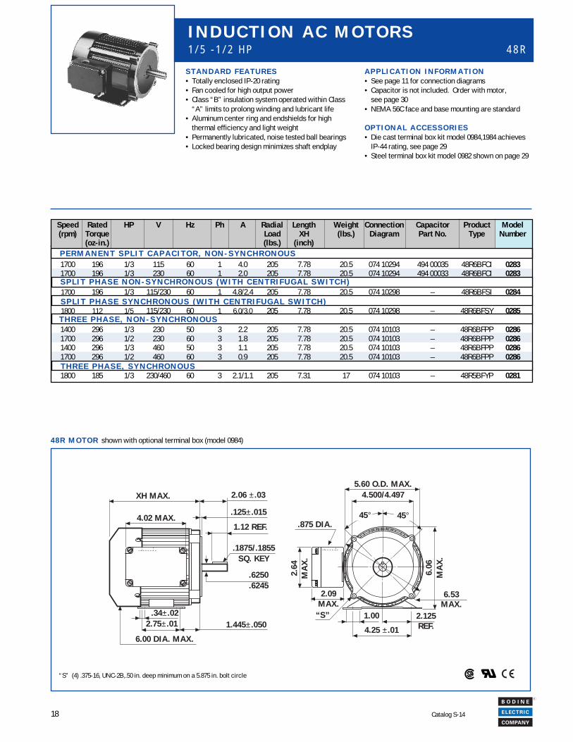
4 8 R M O T O R shown with optional terminal box (model 0984)
I N D U C T I O N A C M O T O R S1 / 5 - 1 / 2 H P 4 8 R
“S” 1.00 2.125REF.4.25 ± .01
6.06
MA
X.
5 .60 O.D. MAX.4.500/4.497
45° 45°
6.53MAX.
XH MAX. 2.06 ± .03
.125± .015
1.12 REF.
.1875/.1855SQ. KEY
.6250
.6245
1.445± .0502.75± .01.34± .02
6.00 DIA. MAX.
4.02 MAX.
2.64
MA
X.
2 .09MAX.
.875 DIA.
“S” (4) .375-16, UNC-2B,.50 in. deep minimum on a 5.875 in. bolt circle
A P P L I C A T I O N I N F O R M A T I O N• See page 11 for connection diagrams• Capacitor is not included. Order with motor,
see page 30• NEMA 56C face and base mounting are standard
O P T I O N A L A C C E S S O R I E S• Die cast terminal box kit model 0984,1984 achieves
IP-44 rating, see page 29• Steel terminal box kit model 0982 shown on page 29
S T A N D A R D F E A T U R E S• Totally enclosed IP-20 rating• Fan cooled for high output power• Class “B” insulation system operated within Class
“A” limits to prolong winding and lubricant life• Aluminum center ring and endshields for high
thermal efficiency and light weight• Permanently lubricated, noise tested ball bearings• Locked bearing design minimizes shaft endplay
Speed Rated HP V Hz Ph A Radial Length Weight Connection Capacitor Product Model(rpm) Torque Load XH (lbs.) Diagram Part No. Type Number
(oz-in.) (lbs.) (inch)
1700 196 1/3 115 60 1 4.0 205 7.78 20.5 074 10294 494 00035 48R6BFCI 02831700 196 1/3 230 60 1 2.0 205 7.78 20.5 074 10294 494 00033 48R6BFCI 0283
1700 196 1/3 115/230 60 1 4.8/2.4 205 7.78 20.5 074 10298 – 48R6BFSI 0284
1800 112 1/5 115/230 60 1 6.0/3.0 205 7.78 20.5 074 10298 – 48R6BFSY 0285
1400 296 1/3 230 50 3 2.2 205 7.78 20.5 074 10103 – 48R6BFPP 02861700 296 1/2 230 60 3 1.8 205 7.78 20.5 074 10103 – 48R6BFPP 02861400 296 1/3 460 50 3 1.1 205 7.78 20.5 074 10103 – 48R6BFPP 02861700 296 1/2 460 60 3 0.9 205 7.78 20.5 074 10103 – 48R6BFPP 0286
1800 185 1/3 230/460 60 3 2.1/1.1 205 7.31 17 074 10103 – 48R5BFYP 0281
S P L I T P H A S E N O N - S Y N C H R O N O U S ( W I T H C E N T R I F U G A L S W I T C H )
S P L I T P H A S E S Y N C H R O N O U S ( W I T H C E N T R I F U G A L S W I T C H )
T H R E E P H A S E , N O N - S Y N C H R O N O U S
T H R E E P H A S E , S Y N C H R O N O U S
P E R M A N E N T S P L I T C A P A C I T O R , N O N - S Y N C H R O N O U S
19
R
Catalog S-14
INT
RO
DU
CT
ION
IND
EX
PE
RM
AN
EN
T M
AG
NE
T D
CIN
TE
RN
AT
ION
AL
BR
US
HL
ES
S D
CIN
DU
CT
ION
AC
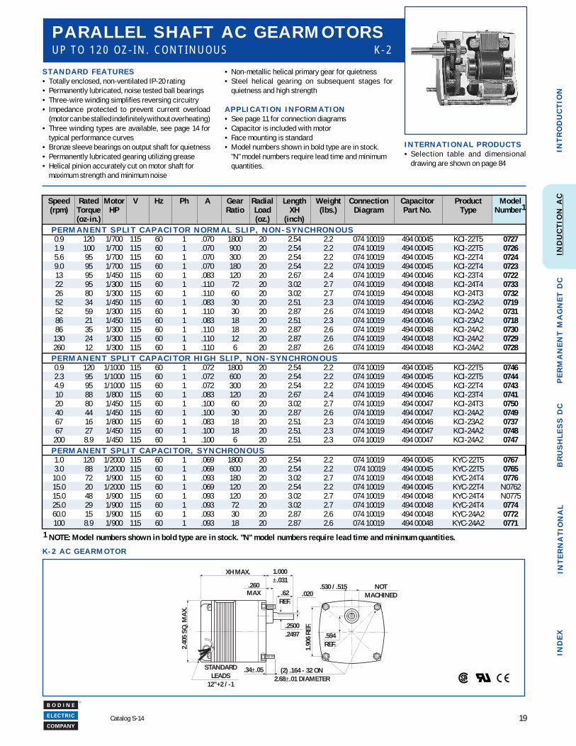
1 2 0 O Z . - I N . M A X I M U M
K - 2 A C G E A R M O T O R
P A R A L L E L S H A F T A C G E A R M O T O R SU P T O 1 2 0 O Z - I N . C O N T I N U O U S K - 2
S T A N D A R D F E A T U R E S• Totally enclosed, non-ventilated IP-20 rating• Permanently lubricated, noise tested ball bearings• Three-wire winding simplifies reversing circuitry• Impedance protected to prevent current overload
(motor can be stalled indefinitely without overheating)• Three winding types are available, see page 14 for
typical performance curves• Bronze sleeve bearings on output shaft for quietness• Permanently lubricated gearing utilizing grease• Helical pinion accurately cut on motor shaft for
maximum strength and minimum noise
• Non-metallic helical primary gear for quietness• Steel helical gearing on subsequent stages for
quietness and high strength
A P P L I C A T I O N I N F O R M A T I O N• See page 11 for connection diagrams• Capacitor is included with motor• Face mounting is standard• Model numbers shown in bold type are in stock.
"N" model numbers require lead time and minimumquantities.
I N T E R N A T I O N A L P R O D U C T S• Selection table and dimensional
drawing are shown on page 84
1 NOTE: Model numbers shown in bold type are in stock. "N" model numbers require lead time and minimum quantities.
Speed Rated Motor V Hz Ph A Gear Radial Length Weight Connection Capacitor Product Model(rpm) Torque HP Ratio Load XH (lbs.) Diagram Part No. Type Number1
(oz-in.) (oz.) (inch) P E R M A N E N T S P L I T C A P A C I T O R N O R M A L S L I P , N O N - S Y N C H R O N O U S
0.9 120 1/700 115 60 1 .070 1800 20 2.54 2.2 074 10019 494 00045 KCI-22T5 07271.9 100 1/700 115 60 1 .070 900 20 2.54 2.2 074 10019 494 00045 KCI-22T5 07265.6 95 1/700 115 60 1 .070 300 20 2.54 2.2 074 10019 494 00045 KCI-22T4 07249.0 95 1/700 115 60 1 .070 180 20 2.54 2.2 074 10019 494 00045 KCI-22T4 072313 95 1/450 115 60 1 .083 120 20 2.67 2.4 074 10019 494 00046 KCI-23T4 072222 95 1/300 115 60 1 .110 72 20 3.02 2.7 074 10019 494 00048 KCI-24T4 073326 80 1/300 115 60 1 .110 60 20 3.02 2.7 074 10019 494 00048 KCI-24T3 073252 34 1/450 115 60 1 .083 30 20 2.51 2.3 074 10019 494 00046 KCI-23A2 071952 59 1/300 115 60 1 .110 30 20 2.87 2.6 074 10019 494 00048 KCI-24A2 073186 21 1/450 115 60 1 .083 18 20 2.51 2.3 074 10019 494 00046 KCI-23A2 071886 35 1/300 115 60 1 .110 18 20 2.87 2.6 074 10019 494 00048 KCI-24A2 0730
130 24 1/300 115 60 1 .110 12 20 2.87 2.6 074 10019 494 00048 KCI-24A2 0729260 12 1/300 115 60 1 .110 6 20 2.87 2.6 074 10019 494 00048 KCI-24A2 0728
P E R M A N E N T S P L I T C A P A C I T O R H I G H S L I P , N O N - S Y N C H R O N O U S0.9 120 1/1000 115 60 1 .072 1800 20 2.54 2.2 074 10019 494 00045 KCI-22T5 07462.3 95 1/1000 115 60 1 .072 600 20 2.54 2.2 074 10019 494 00045 KCI-22T5 07444.9 95 1/1000 115 60 1 .072 300 20 2.54 2.2 074 10019 494 00045 KCI-22T4 074310 88 1/800 115 60 1 .083 120 20 2.67 2.4 074 10019 494 00046 KCI-23T4 074120 80 1/450 115 60 1 .100 60 20 3.02 2.7 074 10019 494 00047 KCI-24T3 075040 44 1/450 115 60 1 .100 30 20 2.87 2.6 074 10019 494 00047 KCI-24A2 074967 16 1/800 115 60 1 .083 18 20 2.51 2.3 074 10019 494 00046 KCI-23A2 073767 27 1/450 115 60 1 .100 18 20 2.51 2.3 074 10019 494 00047 KCI-24A2 0748
200 8.9 1/450 115 60 1 .100 6 20 2.51 2.3 074 10019 494 00047 KCI-24A2 0747 P E R M A N E N T S P L I T C A P A C I T O R , S Y N C H R O N O U S
1.0 120 1/2000 115 60 1 .069 1800 20 2.54 2.2 074 10019 494 00045 KYC-22T5 07673.0 88 1/2000 115 60 1 .069 600 20 2.54 2.2 074 10019 494 00045 KYC-22T5 0765
10.0 72 1/900 115 60 1 .093 180 20 3.02 2.7 074 10019 494 00048 KYC-24T4 077615.0 20 1/2000 115 60 1 .069 120 20 2.54 2.2 074 10019 494 00045 KYC-22T4 N076215.0 48 1/900 115 60 1 .093 120 20 3.02 2.7 074 10019 494 00048 KYC-24T4 N077525.0 29 1/900 115 60 1 .093 72 20 3.02 2.7 074 10019 494 00048 KYC-24T4 077460.0 15 1/900 115 60 1 .093 30 20 2.87 2.6 074 10019 494 00048 KYC-24A2 0772100 8.9 1/900 115 60 1 .093 18 20 2.87 2.6 074 10019 494 00048 KYC-24A2 0771
XH MAX. 25.40 ±.788(1.000±.031)
.260MAX .62
REF.
.2500
.2497
.020
2.40
5 SQ
. MA
X.
STANDARDLEADS
12”+2 / -1
.34±.05 (2) .164 - 32 ON2.68±.01 DIAMETER
.594REF.
.530 / .515 NOTMACHINED
1.90
6 RE
F.
1.000±.031
20
R
Catalog S-14
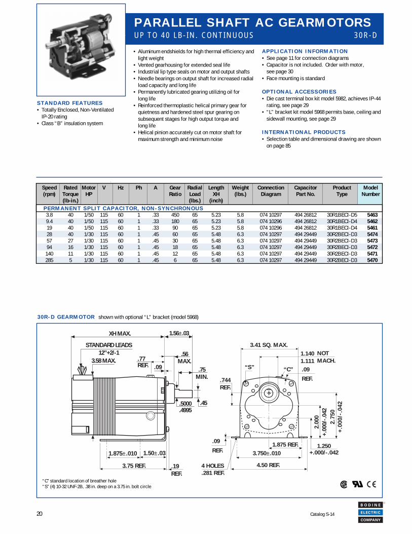
Speed Rated Motor V Hz Ph A Gear Radial Length Weight Connection Capacitor Product Model(rpm) Torque HP Ratio Load XH (lbs.) Diagram Part No. Type Number
(lb-in.) (lbs.) (inch) P E R M A N E N T S P L I T C A P A C I T O R , N O N - S Y N C H R O N O U S
3.8 40 1/50 115 60 1 .33 450 65 5.23 5.8 074 10297 494 26812 30R1BECI-D5 54639.4 40 1/50 115 60 1 .33 180 65 5.23 5.8 074 10296 494 26812 30R1BECI-D4 546219 40 1/50 115 60 1 .33 90 65 5.23 5.8 074 10296 494 26812 30R1BECI-D4 546128 40 1/30 115 60 1 .45 60 65 5.48 6.3 074 10297 494 29449 30R2BECI-D3 547457 27 1/30 115 60 1 .45 30 65 5.48 6.3 074 10297 494 29449 30R2BECI-D3 547394 16 1/30 115 60 1 .45 18 65 5.48 6.3 074 10297 494 29449 30R2BECI-D3 5472
140 11 1/30 115 60 1 .45 12 65 5.48 6.3 074 10297 494 29449 30R2BECI-D3 5471285 5 1/30 115 60 1 .45 6 65 5.48 6.3 074 10297 494 29449 30R2BECI-D3 5470
A P P L I C A T I O N I N F O R M A T I O N• See page 11 for connection diagrams• Capacitor is not included. Order with motor,
see page 30• Face mounting is standard
O P T I O N A L A C C E S S O R I E S• Die cast terminal box kit model 5982, achieves IP-44
rating, see page 29• “L” bracket kit model 5968 permits base, ceiling and
sidewall mounting, see page 29
I N T E R N A T I O N A L P R O D U C T S• Selection table and dimensional drawing are shown
on page 85
P A R A L L E L S H A F T A C G E A R M O T O R SU P T O 4 0 L B - I N . C O N T I N U O U S 3 0 R - D
1.56±.03
.56MAX.
.45.5000.4995
XH MAX.
3.58 MAX.
3.41 SQ. MAX.1.1401.111
“C” .09
REF.
1.250+.000/-.042
2.00
0+.
000/
-.04
22.
750
+.00
0/-.
042
1.875 REF.3.750±.010
4.50 REF.
.09
REF.
“S”
.744REF.
NOTMACH.
4 HOLES.281 REF.
STANDARD LEADS12”+2/-1
.75MIN.
.77REF.
.19REF.
1.50±.031.875±.010
3.75 REF.
.09
“C” standard location of breather hole“S” (4) 10-32 UNF-2B, .38 in. deep on a 3.75 in. bolt circle
S T A N D A R D F E A T U R E S• Totally Enclosed, Non-Ventilated
IP-20 rating• Class “B” insulation system
• Aluminum endshields for high thermal efficiency andlight weight
• Vented gearhousing for extended seal life• Industrial lip type seals on motor and output shafts• Needle bearings on output shaft for increased radial
load capacity and long life• Permanently lubricated gearing utilizing oil for
long life• Reinforced thermoplastic helical primary gear for
quietness and hardened steel spur gearing onsubsequent stages for high output torque andlong life
• Helical pinion accurately cut on motor shaft formaximum strength and minimum noise
shown with optional “L” bracket (model 5968)3 0 R - D G E A R M O T O R
21
R
Catalog S-14
INT
RO
DU
CT
ION
IND
EX
PE
RM
AN
EN
T M
AG
NE
T D
CIN
TE
RN
AT
ION
AL
BR
US
HL
ES
S D
CIN
DU
CT
ION
AC
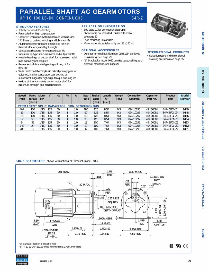
3 4 R - Z G E A R M O T O R
Speed Rated Motor V Hz Ph A Gear Radial Length Weight Connection Capacitor Product Model(rpm) Torque HP Ratio Load XH (lbs.) Diagram Part No. Type Number
(lb-in.) (lbs.) (inch) P E R M A N E N T S P L I T C A P A C I T O R , N O N - S Y N C H R O N O U S
9.4 100 1/15 115 60 1 1.0 180 125 8.54 9.3 074 10296 494 00081 34R4BFCI-Z4 044919 100 1/15 115 60 1 1.0 90 125 8.54 9.3 074 10296 494 00081 34R4BFCI-Z4 044828 100 1/15 115 60 1 1.0 60 125 8.54 9.3 074 10297 494 00081 34R4BFCI-Z3 045557 56 1/15 115 60 1 1.0 30 125 8.54 9.3 074 10297 494 00081 34R4BFCI-Z3 045494 36 1/15 115 60 1 1.0 18 100 7.64 9.3 074 10296 494 00081 34R4BFCI-Z2 0453
142 24 1/15 115 60 1 1.0 12 100 7.64 9.3 074 10296 494 00081 34R4BFCI-Z2 0452283 12 1/15 115 60 1 1.0 6 100 7.64 9.3 074 10296 494 00081 34R4BFCI-Z2 0451
S T A N D A R D F E A T U R E S• Totally enclosed IP-20 rating• Fan cooled for high output power• Class “B” insulation system operated within Class
“A” limits to prolong winding and lubricant life• Aluminum center ring and endshields for high
thermal efficiency and light weight• Vented gearhousing for extended seal life• Industrial lip type seals on motor and output shafts• Needle bearings on output shaft for increased radial
load capacity and long life• Permanently lubricated gearing utilizing oil for
long life• Wide reinforced thermoplastic helical primary gear for
quietness and hardened steel spur gearing onsubsequent stages for high output torque and long life
• Helical pinion accurately cut on motor shaft formaximum strength and minimum noise
A P P L I C A T I O N I N F O R M A T I O N• See page 11 for connection diagrams• Capacitor is not included. Order with motor,
see page 30• Face mounting is standard• Motors operate satisfactorily on 115 V, 50 Hz
O P T I O N A L A C C E S S O R I E S• Die cast terminal box kit model 0984,1984 achieves
IP-44 rating, see page 29• “L” bracket kit model 0980 permits base, ceiling, and
sidewall mounting, see page 29
P A R A L L E L S H A F T A C G E A R M O T O R SU P T O 1 0 0 L B - I N . C O N T I N U O U S 3 4 R - Z
“C” standard location of breather hole“S” (4) 10-32 UNF-2B, .38" deep minimum on a 3.75 in. bolt circle
XH MAX.
.30 MAX.“C”
.75REF.
1.56REF.
.5000/.4995
.78
.19 MAX.
1.50±.031.875±.03
3.75 REF.
4 HOLES.281
STANDARDLEADS
12” +2/-1
4.10MAX.
3.40 MAX.
1.140/1.115NOT
MACH..45
REF. “C”
3.00
+.0
0/-.
06
2.25
+.00
/-.0
6
1.50+.00/-.06
1.875REF.
4.50 REF.
3.750 REF.
.134 REF.
“S”
.134
.125 /.123SQ. KEY
MIN. FULLDEPTH OF FLAT
shown with optional “L” bracket (model 0980)
I N T E R N A T I O N A L P R O D U C T S• Selection table and dimensional
drawing are shown on page 85
22
R
Catalog S-14
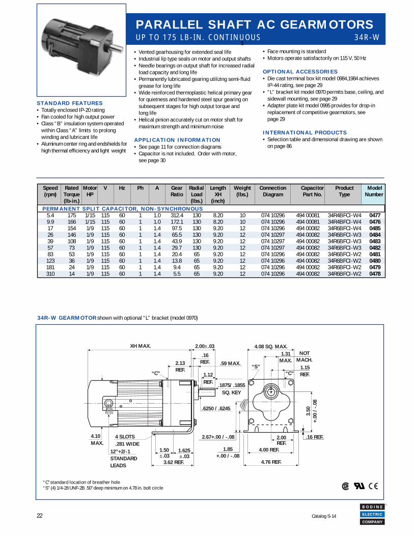
3 4 R - W G E A R M O T O R shown with optional “L” bracket (model 0970)
Speed Rated Motor V Hz Ph A Gear Radial Length Weight Connection Capacitor Product Model(rpm) Torque HP Ratio Load XH (lbs.) Diagram Part No. Type Number
(lb-in.) (lbs.) (inch) P E R M A N E N T S P L I T C A P A C I T O R , N O N - S Y N C H R O N O U S
5.4 175 1/15 115 60 1 1.0 312.4 130 8.20 10 074 10296 494 00081 34R4BFCI-W4 04779.9 166 1/15 115 60 1 1.0 172.1 130 8.20 10 074 10296 494 00081 34R4BFCI-W4 047617 154 1/9 115 60 1 1.4 97.5 130 9.20 12 074 10296 494 00082 34R6BFCI-W4 048526 146 1/9 115 60 1 1.4 65.5 130 9.20 12 074 10297 494 00082 34R6BFCI-W3 048439 108 1/9 115 60 1 1.4 43.9 130 9.20 12 074 10297 494 00082 34R6BFCI-W3 048357 73 1/9 115 60 1 1.4 29.7 130 9.20 12 074 10297 494 00082 34R6BFCI-W3 048283 53 1/9 115 60 1 1.4 20.4 65 9.20 12 074 10296 494 00082 34R6BFCI-W2 0481
123 36 1/9 115 60 1 1.4 13.8 65 9.20 12 074 10296 494 00082 34R6BFCI-W2 0480181 24 1/9 115 60 1 1.4 9.4 65 9.20 12 074 10296 494 00082 34R6BFCI-W2 0479310 14 1/9 115 60 1 1.4 5.5 65 9.20 12 074 10296 494 00082 34R6BFCI-W2 0478
• Face mounting is standard• Motors operate satisfactorily on 115 V, 50 Hz
O P T I O N A L A C C E S S O R I E S• Die cast terminal box kit model 0984,1984 achieves
IP-44 rating, see page 29• “L” bracket kit model 0970 permits base, ceiling, and
sidewall mounting, see page 29• Adapter plate kit model 0995 provides for drop-in
replacement of competitive gearmotors, seepage 29
I N T E R N A T I O N A L P R O D U C T S• Selection table and dimensional drawing are shown
on page 86
P A R A L L E L S H A F T A C G E A R M O T O R SU P T O 1 7 5 L B - I N . C O N T I N U O U S 3 4 R - W
XH MAX. 2.00±.03
.59 MAX.
1.12REF. .1875/ .1855
SQ. KEY
.6250 / .6245
1.50±.03
3.62 REF.
4 SLOTS.281 WIDE
4.10MAX.
12”+2/-1STANDARDLEADS
“C”
2.13REF.
2.00REF.
4.00 REF.
4.76 REF.
.16 REF.
3.50
+.00
/ -
.08
2.67+.00 / -.08
1.85+.00 / -.08
4.08 SQ. MAX.1.31
MAX.1.15REF.“C”
NOTMACH.
“S”
.16REF.
1.625±.03
“C”standard location of breather hole“S” (4) 1/4-28 UNF-2B .50" deep minimum on 4.78 in. bolt circle
S T A N D A R D F E A T U R E S• Totally enclosed IP-20 rating• Fan cooled for high output power• Class “B” insulation system operated
within Class “A” limits to prolongwinding and lubricant life
• Aluminum center ring and endshields forhigh thermal efficiency and light weight
• Vented gearhousing for extended seal life• Industrial lip type seals on motor and output shafts• Needle bearings on output shaft for increased radial
load capacity and long life• Permanently lubricated gearing utilizing semi-fluid
grease for long life• Wide reinforced thermoplastic helical primary gear
for quietness and hardened steel spur gearing onsubsequent stages for high output torque andlong life
• Helical pinion accurately cut on motor shaft formaximum strength and minimum noise
A P P L I C A T I O N I N F O R M A T I O N• See page 11 for connection diagrams• Capacitor is not included. Order with motor,
see page 30
1
23
R
Catalog S-14
INT
RO
DU
CT
ION
IND
EX
PE
RM
AN
EN
T M
AG
NE
T D
CIN
TE
RN
AT
ION
AL
BR
US
HL
ES
S D
CIN
DU
CT
ION
AC
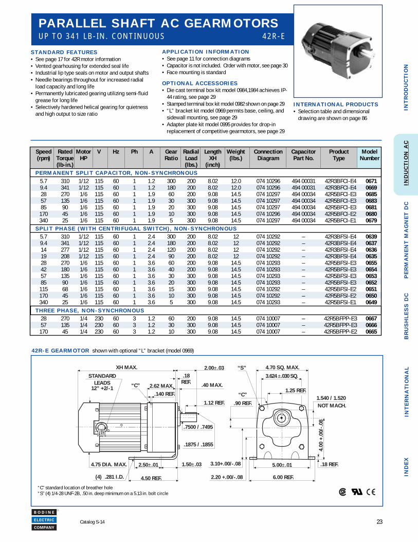
4 2 R - E G E A R M O T O R shown with optional “L” bracket (model 0969)
P A R A L L E L S H A F T A C G E A R M O T O R SU P T O 3 4 1 L B - I N . C O N T I N U O U S 4 2 R - E
A P P L I C A T I O N I N F O R M A T I O N• See page 11 for connection diagrams• Capacitor is not included. Order with motor, see page 30• Face mounting is standard
O P T I O N A L A C C E S S O R I E S• Die cast terminal box kit model 0984,1984 achieves IP-
44 rating, see page 29• Stamped terminal box kit model 0982 shown on page 29• “L” bracket kit model 0969 permits base, ceiling, and
sidewall mounting, see page 29• Adapter plate kit model 0995 provides for drop-in
replacement of competitive gearmotors, see page 29
S T A N D A R D F E A T U R E S• See page 17 for 42R motor information• Vented gearhousing for extended seal life• Industrial lip type seals on motor and output shafts• Needle bearings throughout for increased radial
load capacity and long life• Permanently lubricated gearing utilizing semi-fluid
grease for long life• Selectively hardened helical gearing for quietness
and high output to size ratio
Speed Rated Motor V Hz Ph A Gear Radial Length Weight Connection Capacitor Product Model(rpm) Torque HP Ratio Load XH (lbs.) Diagram Part No. Type Number
(lb-in.) (lbs.) (inch) P E R M A N E N T S P L I T C A P A C I T O R , N O N - S Y N C H R O N O U S
5.7 310 1/12 115 60 1 1.2 300 200 8.02 12.0 074 10296 494 00031 42R3BFCI-E4 06719.4 341 1/12 115 60 1 1.2 180 200 8.02 12.0 074 10296 494 00031 42R3BFCI-E4 066928 270 1/6 115 60 1 1.9 60 200 9.08 14.5 074 10297 494 00034 42R5BFCI-E3 068557 135 1/6 115 60 1 1.9 30 300 9.08 14.5 074 10297 494 00034 42R5BFCI-E3 068385 90 1/6 115 60 1 1.9 20 300 9.08 14.5 074 10297 494 00034 42R5BFCI-E3 0681
170 45 1/6 115 60 1 1.9 10 300 9.08 14.5 074 10296 494 00034 42R5BFCI-E2 0680340 25 1/6 115 60 1 1.9 5 300 9.08 14.5 074 10297 494 00034 42R5BFCI-E1 0679
S P L I T P H A S E ( W I T H C E N T R I F U G A L S W I T C H ) , N O N - S Y N C H R O N O U S5.7 310 1/12 115 60 1 2.4 300 200 8.02 12 074 10292 – 42R3BFSI-E4 06399.4 341 1/12 115 60 1 2.4 180 200 8.02 12 074 10292 – 42R3BFSI-E4 063714 277 1/12 115 60 1 2.4 120 200 8.02 12 074 10292 – 42R3BFSI-E4 063619 208 1/12 115 60 1 2.4 90 200 8.02 12 074 10292 – 42R3BFSI-E4 063528 270 1/6 115 60 1 3.6 60 200 9.08 14.5 074 10293 – 42R5BFSI-E3 065542 180 1/6 115 60 1 3.6 40 200 9.08 14.5 074 10293 – 42R5BFSI-E3 065457 135 1/6 115 60 1 3.6 30 300 9.08 14.5 074 10293 – 42R5BFSI-E3 065385 90 1/6 115 60 1 3.6 20 300 9.08 14.5 074 10293 – 42R5BFSI-E3 0652
115 68 1/6 115 60 1 3.6 15 300 9.08 14.5 074 10292 – 42R5BFSI-E2 0651170 45 1/6 115 60 1 3.6 10 300 9.08 14.5 074 10292 – 42R5BFSI-E2 0650340 25 1/6 115 60 1 3.6 5 300 9.08 14.5 074 10293 – 42R5BFSI-E1 0649
T H R E E P H A S E , N O N - S Y N C H R O N O U S28 270 1/4 230 60 3 1.2 60 200 9.08 14.5 074 10007 – 42R5BFPP-E3 066757 135 1/4 230 60 3 1.2 30 300 9.08 14.5 074 10007 – 42R5BFPP-E3 0666
170 45 1/4 230 60 3 1.2 10 300 9.08 14.5 074 10007 – 42R5BFPP-E2 0665
“C” standard location of breather hole“S” (4) 1/4-28 UNF-2B, .50 in. deep minimum on a 5.13 in. bolt circle
I N T E R N A T I O N A L P R O D U C T S• Selection table and dimensional
drawing are shown on page 86
XH MAX.
2.62 MAX.
1.12 REF.
.7500 / .7495
4.50 REF.
1.50±.032.50±.01
4.70 SQ. MAX.
1.540 / 1.520
4.00
+.0
0/-.
08
.18 REF.5.00±.01
6.00 REF.2.20 +.00/-.08
3.10+.00/-.08
.90 REF.
“C”
.1875 / .1855
“C”
2.00±.03
.40 MAX.
(4) .281 I.D.
.140 REF.
4.75 DIA. MAX.
NOT MACH.
“S”.18
REF.3.624 ±.030 SQ.
1.25 REF.
STANDARDLEADS
12” +2/-1
24
R
Catalog S-14
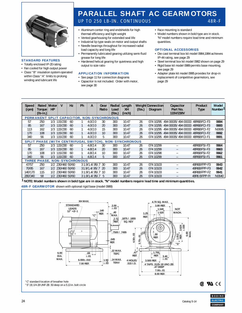
• Face mounting is standard• Model numbers shown in bold type are in stock.
"N" model numbers require lead time and minimumquantities.
O P T I O N A L A C C E S S O R I E S• Die cast terminal box kit model 0984,1984 achieves
IP-44 rating, see page 29• Steel terminal box kit model 0982 shown on page 29• Rigid base kit model 0989 permits base mounting,
see page 29• Adapter plate kit model 0995 provides for drop-in
replacement of competitive gearmotors, seepage 29
P A R A L L E L S H A F T A C G E A R M O T O R SU P T O 2 5 0 L B - I N . C O N T I N U O U S 4 8 R - F
4 8 R - F G E A R M O T O R
XH MAX.
1.12REF.
.7500 / .7495
“C”.1875 / .1855
SQ. KEY
2.00±.03
.40MAX.
.140REF.
8.00 REF.7.00±.01
4 TAPS .3125-18 UNC-2B.47 DEEP
3.500 REF.
3.40±.01
1.700REF.
.90REF.
4 HOLES.515 I.D.
4.50
±.03
.47REF.
3.70
±.01
1.81
2R
EF.
3.62
4±.
030
6.69
MA
X.
4.70 SQ. MAX.3.80 REF.
1.5401.520
NOTMACH.1.25
REF.
.045REF.
.69±.01
6.00DIA.
MAX. 6.000±.0107.00 REF.
1.50±.03
.22 MAX.TEFC
.14 MAX.TENV
”S“
STANDARDLEADS
12” +2/-1
“C” standard location of breather hole“S” (4) 1/4-28 UNF-2B .50 deep on a 5.13 in. bolt circle
Speed Rated Motor V Hz Ph A Gear Radial Length Weight Connection Capacitor Product Model(rpm) Torque HP Ratio Load XH (lbs.) Diagram Part No. Type Number1
(lb-in.) (lbs.) (inch) 115V/230V P E R M A N E N T S P L I T C A P A C I T O R , N O N - S Y N C H R O N O U S
57 250 1/3 115/230 60 1 4.0/2.0 30 300 10.47 26 074 10295 494 00035/ 494 00033 48R6BFCI-F3 069485 167 1/3 115/230 60 1 4.0/2.0 20 300 10.47 26 074 10295 494 00035/ 494 00033 48R6BFCI-F3 0693
113 162 1/3 115/230 60 1 4.0/2.0 15 300 10.47 26 074 10295 494 00035/ 494 00033 48R6BFCI-F2 N0695170 108 1/3 115/230 60 1 4.0/2.0 10 300 10.47 26 074 10295 494 00035/ 494 00033 48R6BFCI-F2 0692340 56 1/3 115/230 60 1 4.0/2.0 5 300 10.47 26 074 10295 494 00035/ 494 00033 48R6BFCI-F1 0691
S P L I T P H A S E ( W I T H C E N T R I F U G A L S W I T C H ) , N O N - S Y N C H R O N O U S57 250 1/3 115/230 60 1 4.8/2.4 30 300 10.47 26 074 10299 – 48R6BFSI-F3 066485 167 1/3 115/230 60 1 4.8/2.4 20 300 10.47 26 074 10299 – 48R6BFSI-F3 0663
170 108 1/3 115/230 60 1 4.8/2.4 10 300 10.47 26 074 10298 – 48R6BFSI-F2 0662340 56 1/3 115/230 60 1 4.8/2.4 5 300 10.47 26 074 10299 – 48R6BFSI-F1 0661
T H R E E P H A S E , N O N - S Y N C H R O N O U S47/57 250 1/2 230/460 50/60 3 1.9/1.4/.95/.7 30 300 10.47 26 074 10103 – 48R6BFPP-F3 064370/85 167 1/2 230/460 50/60 31.9/1.4/.95/.7
.20 300 10.47 26 074 10103 – 48R6BFPP-F3 0642
140/170 115 1/2 230/460 50/60 3 1.9/1.4/.95/.7 10 300 10.47 26 074 10103 – 48R6BFPP-F2 0641280/340 58 1/2 230/460 50/60 3 1.9/1.4/.95/.7 5 300 10.47 26 074 10103 – 48R6 BFPP-FI N0640
S T A N D A R D F E A T U R E S• Totally enclosed IP-20 rating• Fan cooled for high output power• Class “B” insulation system operated
within Class “A” limits to prolongwinding and lubricant life
• Aluminum center ring and endshields for highthermal efficiency and light weight
• Vented gearhousing for extended seal life• Industrial lip type seals on motor and output shafts• Needle bearings throughout for increased radial
load capacity and long life• Permanently lubricated gearing utilizing semi-fluid
grease for long life• Hardened helical gearing for quietness and high
output to size ratio
A P P L I C A T I O N I N F O R M A T I O N• See page 11 for connection diagrams• Capacitor is not included. Order with motor,
see page 30
shown with optional rigid base (model 0989)
1 NOTE: Model numbers shown in bold type are in stock. "N" model numbers require lead time and minimum quantities.
25
R
Catalog S-14
INT
RO
DU
CT
ION
IND
EX
PE
RM
AN
EN
T M
AG
NE
T D
CIN
TE
RN
AT
ION
AL
BR
US
HL
ES
S D
CIN
DU
CT
ION
AC
Speed Rated Motor V Hz Ph A Gear Radial Length Weight Connection Capacitor Product Model(rpm) Torque HP Ratio Load XH (lbs.) Diagram Part No. Type Number
(lb-in.) (lbs.) (inch) P E R M A N E N T S P L I T C A P A C I T O R , N O N - S Y N C H R O N O U S
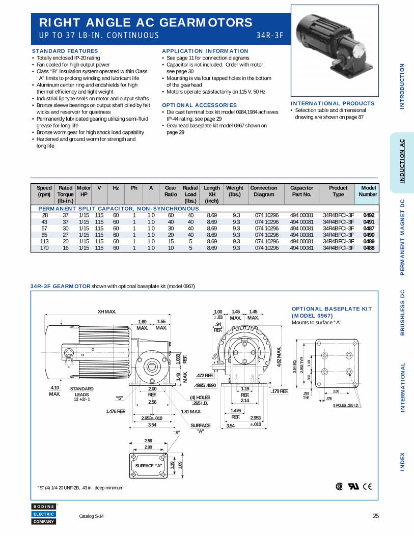
28 37 1/15 115 60 1 1.0 60 40 8.69 9.3 074 10296 494 00081 34R4BFCI-3F 049243 37 1/15 115 60 1 1.0 40 40 8.69 9.3 074 10296 494 00081 34R4BFCI-3F 049157 30 1/15 115 60 1 1.0 30 40 8.69 9.3 074 10296 494 00081 34R4BFCI-3F 048785 27 1/15 115 60 1 1.0 20 40 8.69 9.3 074 10296 494 00081 34R4BFCI-3F 0490
113 20 1/15 115 60 1 1.0 15 5 8.69 9.3 074 10296 494 00081 34R4BFCI-3F 0489170 16 1/15 115 60 1 1.0 10 5 8.69 9.3 074 10296 494 00081 34R4BFCI-3F 0488
1.69
2.00
1.19
2.56
“S”
SURFACE “A”
1.19
.882
2.95
3 TY
P.
3.54
SQ
.
.293TYP.
2.00
.476
8 HOLES, .265 I.D.
O P T I O N A L B A S E P L A T E K I T( M O D E L 0 9 6 7 )Mounts to surface “A”
3 4 R - 3 F G E A R M O T O R shown with optional baseplate kit (model 0967)
S T A N D A R D F E A T U R E S• Totally enclosed IP-20 rating• Fan cooled for high output power• Class “B” insulation system operated within Class
“A” limits to prolong winding and lubricant life• Aluminum center ring and endshields for high
thermal efficiency and light weight• Industrial lip type seals on motor and output shafts• Bronze sleeve bearings on output shaft oiled by felt
wicks and reservoir for quietness• Permanently lubricated gearing utilizing semi-fluid
grease for long life• Bronze worm gear for high shock load capability• Hardened and ground worm for strength and
long life
A P P L I C A T I O N I N F O R M A T I O N• See page 11 for connection diagrams• Capacitor is not included. Order with motor,
see page 30• Mounting is via four tapped holes in the bottom
of the gearhead• Motors operate satisfactorily on 115 V, 50 Hz
O P T I O N A L A C C E S S O R I E S• Die cast terminal box kit model 0984,1984 achieves
IP-44 rating, see page 29• Gearhead baseplate kit model 0967 shown on
page 29
R I G H T A N G L E A C G E A R M O T O R SU P T O 3 7 L B - I N . C O N T I N U O U S 3 4 R - 3 F
“S” (4) 1/4-20 UNF-2B, .43 in. deep minimum
I N T E R N A T I O N A L P R O D U C T S• Selection table and dimensional
drawing are shown on page 87
1.60MAX.
1.00±.03
1.45MAX.
1.45MAX.
1.08
3RE
F.1.
48M
AX.
1.81 MAX.1.476 REF.2.953±.010
2.00REF.
.
3.54
“S”
XH MAX.
1.476REF.
.94REF.
.472 REF.
.4995/.49901.19REF.
.179 REF.
4.62
MA
X.
2.953±.0103.54
(4) HOLES.265 I.D.2.56 2.14
1.55MAX.
4.10MAX.
SURFACE"A"
STANDARDLEADS
12 +2/-1
26
R
Catalog S-14
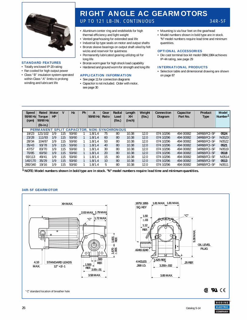
3 4 R - 5 F G E A R M O T O R
R I G H T A N G L E A C G E A R M O T O R SU P T O 1 2 1 L B - I N . C O N T I N U O U S 3 4 R - 5 F
• Mounting is via four feet on the gearhead• Model numbers shown in bold type are in stock.
"N" model numbers require lead time and minimumquantities.
O P T I O N A L A C C E S S O R I E S• Die cast terminal box kit model 0984,1984 achieves
IP-44 rating, see page 29
I N T E R N A T I O N A L P R O D U C T S• Selection table and dimensional drawing are shown
on page 87
XH MAX.
STANDARD LEADS 12" +2/-1
4.10MAX.
3.58 MAX.
3.00±.01
2.03 MAX. 1.79 MAX.
1.72 MAX.
1.60
1RE
F.1.
670
±.00
5
.593REF.1.500
REF.
“C”
.6245/.6240
1.81 MAX. 1.81 MAX.
“C”
.25 REF.
3.85 MAX.
3.250±.032
1.625 REF.4 HOLES.268 I.D.
1.12REF.
1.50±.03
.1875/.1855SQ. KEY
5.38
MA
X.
OIL LEVELPLUG
“C” standard location of breather hole
Speed Rated Motor V Hz Ph A Gear Radial Length Weight Connection Capacitor Product Model50/60 Hz Torque HP 50/60 Hz Ratio Load XH (lbs.) Diagram Part No. Type Number1
(rpm) 50/60 Hz (lbs.) (inch)(lb-in.)
P E R M A N E N T S P L I T C A P A C I T O R , N O N - S Y N C H R O N O U S19/23 121/102 1/9 115 50/60 1 1.8/1.4 75 80 10.38 12.0 074 10296 494 00082 34R6BFCI-5F 052423/28 111/93 1/9 115 50/60 1 1.8/1.4 60 80 10.38 12.0 074 10296 494 00082 34R6BFCI-5F N052328/34 104/87 1/9 115 50/60 1 1.8/1.4 50 80 10.38 12.0 074 10296 494 00082 34R6BFCI-5F N052235/43 93/78 1/9 115 50/60 1 1.8/1.4 40 80 10.38 12.0 074 10296 494 00082 34R6BFCI-5F 052147/57 83/70 1/9 115 50/60 1 1.8/1.4 30 80 10.38 12.0 074 10296 494 00082 34R6BFCI-5F N051970/85 60/50 1/9 115 50/60 1 1.8/1.4 20 80 10.38 12.0 074 10296 494 00082 34R6BFCI-5F 0518
93/113 49/41 1/9 115 50/60 1 1.8/1.4 15 80 10.38 12.0 074 10296 494 00082 34R6BFCI-5F N0514140/170 35/29 1/9 115 50/60 1 1.8/1.4 10 80 10.38 12.0 074 10296 494 00082 34R6BFCI-5F 0513280/340 19/16 1/9 115 50/60 1 1.8/1.4 5 80 10.38 12.0 074 10296 494 00082 34R6BFCI-5F N0511
• Aluminum center ring and endshields for highthermal efficiency and light weight
• Vented gearhousing for extended seal life• Industrial lip type seals on motor and output shafts• Bronze sleeve bearings on output shaft oiled by felt
wicks and reservoir for quietness• Permanently lubricated gearing utilizing oil for
long life• Bronze worm gear for high shock load capability• Hardened and ground worm for strength and long life
A P P L I C A T I O N I N F O R M A T I O N• See page 11 for connection diagrams• Capacitor is not included. Order with motor,
see page 30
S T A N D A R D F E A T U R E S• Totally enclosed IP-20 rating• Fan cooled for high output power• Class “B” insulation system operated
within Class “A” limits to prolongwinding and lubricant life
1 NOTE: Model numbers shown in bold type are in stock. "N" model numbers require lead time and minimum quantities.
27
R
Catalog S-14
INT
RO
DU
CT
ION
IND
EX
PE
RM
AN
EN
T M
AG
NE
T D
CIN
TE
RN
AT
ION
AL
BR
US
HL
ES
S D
CIN
DU
CT
ION
AC
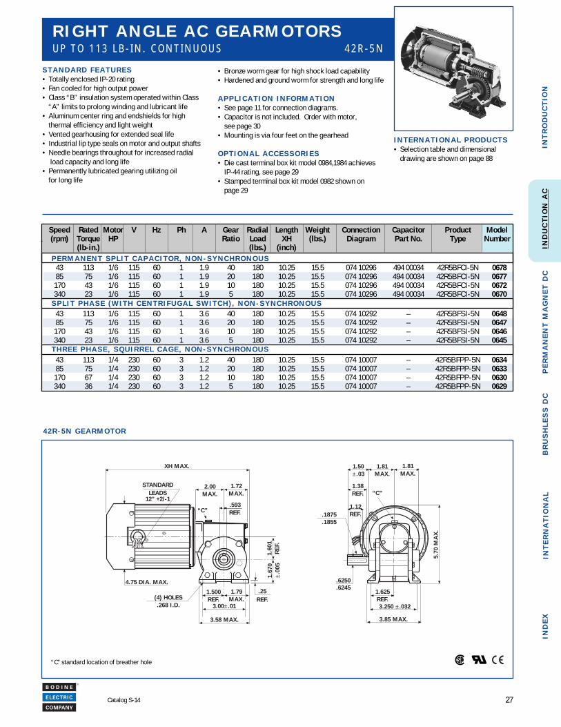
4 2 R - 5 N G E A R M O T O R
S T A N D A R D F E A T U R E S• Totally enclosed IP-20 rating• Fan cooled for high output power• Class “B” insulation system operated within Class
“A” limits to prolong winding and lubricant life• Aluminum center ring and endshields for high
thermal efficiency and light weight• Vented gearhousing for extended seal life• Industrial lip type seals on motor and output shafts• Needle bearings throughout for increased radial
load capacity and long life• Permanently lubricated gearing utilizing oil
for long life
• Bronze worm gear for high shock load capability• Hardened and ground worm for strength and long life
A P P L I C A T I O N I N F O R M A T I O N• See page 11 for connection diagrams.• Capacitor is not included. Order with motor,
see page 30• Mounting is via four feet on the gearhead
O P T I O N A L A C C E S S O R I E S• Die cast terminal box kit model 0984,1984 achieves
IP-44 rating, see page 29• Stamped terminal box kit model 0982 shown on
page 29
R I G H T A N G L E A C G E A R M O T O R SU P T O 1 1 3 L B - I N . C O N T I N U O U S 4 2 R - 5 N
“C” standard location of breather hole
XH MAX.
1.60
1R
EF.
1.67
0±.
005
.25REF.
3.58 MAX.
3.00± .01
1.79MAX.
1.500REF.
4.75 DIA. MAX.
2.00MAX.
1.72MAX.
.593REF.
(4) HOLES.268 I .D.
STANDARDLEADS
12” +2/-1
5.70
MA
X.
3 .85 MAX.
3.250 ± .032
1.625REF.
.6250
.6245
1.12REF.
1.38REF.
1.50± .03
1.81MAX.
“C”
.1875
.1855
1.81MAX.
“C”
Speed Rated Motor V Hz Ph A Gear Radial Length Weight Connection Capacitor Product Model(rpm) Torque HP Ratio Load XH (lbs.) Diagram Part No. Type Number
(lb-in.) (lbs.) (inch) P E R M A N E N T S P L I T C A P A C I T O R , N O N - S Y N C H R O N O U S
43 113 1/6 115 60 1 1.9 40 180 10.25 15.5 074 10296 494 00034 42R5BFCI-5N 067885 75 1/6 115 60 1 1.9 20 180 10.25 15.5 074 10296 494 00034 42R5BFCI-5N 0677
170 43 1/6 115 60 1 1.9 10 180 10.25 15.5 074 10296 494 00034 42R5BFCI-5N 0672340 23 1/6 115 60 1 1.9 5 180 10.25 15.5 074 10296 494 00034 42R5BFCI-5N 0670
S P L I T P H A S E ( W I T H C E N T R I F U G A L S W I T C H ) , N O N - S Y N C H R O N O U S43 113 1/6 115 60 1 3.6 40 180 10.25 15.5 074 10292 – 42R5BFSI-5N 064885 75 1/6 115 60 1 3.6 20 180 10.25 15.5 074 10292 – 42R5BFSI-5N 0647
170 43 1/6 115 60 1 3.6 10 180 10.25 15.5 074 10292 – 42R5BFSI-5N 0646340 23 1/6 115 60 1 3.6 5 180 10.25 15.5 074 10292 – 42R5BFSI-5N 0645
T H R E E P H A S E , S Q U I R R E L C A G E , N O N - S Y N C H R O N O U S43 113 1/4 230 60 3 1.2 40 180 10.25 15.5 074 10007 – 42R5BFPP-5N 063485 75 1/4 230 60 3 1.2 20 180 10.25 15.5 074 10007 – 42R5BFPP-5N 0633
170 67 1/4 230 60 3 1.2 10 180 10.25 15.5 074 10007 – 42R5BFPP-5N 0630340 36 1/4 230 60 3 1.2 5 180 10.25 15.5 074 10007 – 42R5BFPP-5N 0629
I N T E R N A T I O N A L P R O D U C T S• Selection table and dimensional
drawing are shown on page 88
28
R
Catalog S-14
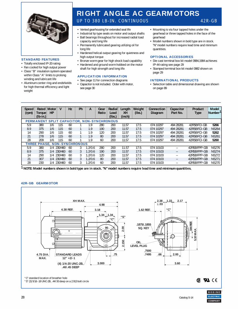
4 2 R - G B G E A R M O T O R
R I G H T A N G L E A C G E A R M O T O R SU P T O 3 8 0 L B - I N . C O N T I N U O U S 4 2 R - G B
“C” standard location of breather hole“S” (3) 5/16 -18 UNC-2B, .44/.50 deep on a 2.913 bolt circle
• Mounting is via four tapped holes under thegearhead or three tapped holes in the face of thegearhead
• Model numbers shown in bold type are in stock."N" model numbers require lead time and minimumquantities.
O P T I O N A L A C C E S S O R I E S• Die cast terminal box kit model 0984,1984 achieves
IP-44 rating see page 29• Stamped terminal box kit model 0982 shown on
page 29
I N T E R N A T I O N A L P R O D U C T S• Selection table and dimensional drawing are shown
on page 89
Speed Rated Motor V Hz Ph A Gear Radial Length Weight Connection Capacitor Product Model(rpm) Torque HP Ratio Load XH (lbs.) Diagram Part No. Type Number1
(lb-in.) (lbs.) (inch) P E R M A N E N T S P L I T C A P A C I T O R , N O N - S Y N C H R O N O U S
5.9 380 1/6 115 60 1 1.9 280 200 11.57 17.5 074 10297 494 28281 42R5BFCI-GB 52668.9 375 1/6 115 60 1 1.9 190 200 11.57 17.5 074 10297 494 28281 42R5BFCI-GB N526414 290 1/6 115 60 1 1.9 120 200 11.57 17.5 074 10297 494 28281 42R5BFCI-GB 526221 278 1/6 115 60 1 1.9 80 200 11.57 17.5 074 10297 494 28281 42R5BFCI-GB N526128 209 1/6 115 60 1 1.9 60 200 11.57 17.5 074 10297 494 28281 42R5BFCI-GB 5260
T H R E E P H A S E , N O N - S Y N C H R O N O U S5.9 380 1/4 230/460 60 3 1.2/0.6 280 200 11.57 17.5 074 10103 – 42R5BFPP-GB N52768.9 375 1/4 230/460 60 3 1.2/0.6 190 200 11.57 17.5 074 10103 – 42R5BFPP-GB N527414 290 1/4 230/460 60 3 1.2/0.6 120 200 11.57 17.5 074 10103 – 42R5BFPP-GB N527221 307 1/4 230/460 60 3 1.2/0.6 80 200 11.57 17.5 074 10103 – 42R5BFPP-GB N527128 230 1/4 230/460 60 3 1.2/0.6 60 200 11.57 17.5 074 10103 – 42R5BFPP-GB N5270
• Vented gearhousing for extended seal life• Industrial lip type seals on motor and output shafts• Ball bearings throughout for increased radial load
capacity and long life• Permanently lubricated gearing utilizing oil for
long life• Hardened helical output gearing for quietness and
high output torque• Bronze worm gear for high shock load capability• Hardened and ground worm hobbed on the motor
shaft for high strength and long life
A P P L I C A T I O N I N F O R M A T I O N• See page 11 for connection diagrams• Capacitor is not included. Order with motor,
see page 30
S T A N D A R D F E A T U R E S• Totally enclosed IP-20 rating• Fan cooled for high output power• Class “B” insulation system operated
within Class “A” limits to prolongwinding and lubricant life
• Aluminum center ring and endshieldsfor high thermal efficiency and lightweight
XH MAX.
4.38 REF.
4.75 DIA.MAX.
STANDARD LEADS12” +2/-1
“C”
4.98
2.15
0
1 .34 1.34
90
3.000
.75
“S”
(4) 1/4-20 UNC-2B,.40/.45 DEEP
3.18
2.00
“C”
.7500
.7495
.1875/.1855SQ. KEY
1.62 REF.
2.38± .03
.66 2.00
5.10
MA
X.
1 .22 2.17
3.60
OILLEVEL PLUG
.544
REF
.
1 NOTE: Model numbers shown in bold type are in stock. "N" model numbers require lead time and minimum quantities.
29
R
Catalog S-14
INT
RO
DU
CT
ION
IND
EX
PE
RM
AN
EN
T M
AG
NE
T D
CIN
TE
RN
AT
ION
AL
BR
US
HL
ES
S D
CIN
DU
CT
ION
AC
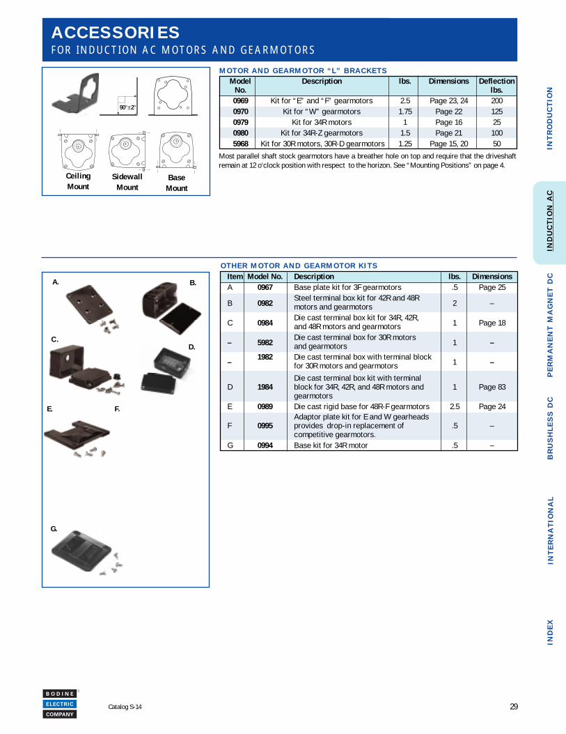
A C C E S S O R I E SF O R I N D U C T I O N A C M O T O R S A N D G E A R M O T O R S
Item Model No. Description lbs. DimensionsA 0967 Base plate kit for 3F gearmotors .5 Page 25
B 0982Steel terminal box kit for 42R and 48R
2 –motors and gearmotors
C 0984Die cast terminal box kit for 34R, 42R,
1 Page 18and 48R motors and gearmotors
– 5982Die cast terminal box for 30R motors
1 –and gearmotors
–1982 Die cast terminal box with terminal block
1 –for 30R motors and gearmotors
Die cast terminal box kit with terminalD 1984 block for 34R, 42R, and 48R motors and 1 Page 83
gearmotorsE 0989 Die cast rigid base for 48R-F gearmotors 2.5 Page 24
Adaptor plate kit for E and W gearheadsF 0995 provides drop-in replacement of .5 –
competitive gearmotors.G 0994 Base kit for 34R motor .5 –
O T H E R M O T O R A N D G E A R M O T O R K I T S
M O T O R A N D G E A R M O T O R “ L ” B R A C K E T S
90°±2°
CeilingMount
SidewallMount
BaseMount
Most parallel shaft stock gearmotors have a breather hole on top and require that the driveshaftremain at 12 o‘clock position with respect to the horizon. See “Mounting Positions” on page 4.
C .
A.
F.
B.
Model Description lbs. Dimensions DeflectionNo. lbs.0969 Kit for “E” and “F” gearmotors 2.5 Page 23, 24 2000970 Kit for “W” gearmotors 1.75 Page 22 1250979 Kit for 34R motors 1 Page 16 250980 Kit for 34R-Z gearmotors 1.5 Page 21 1005968 Kit for 30R motors, 30R-D gearmotors 1.25 Page 15, 20 50
G.
D.
E.
30
R
Catalog S-14
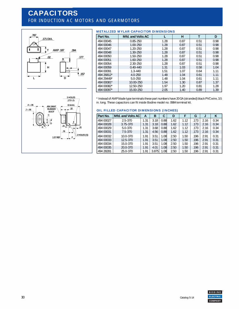
C A P A C I T O R SF O R I N D U C T I O N A C M O T O R S A N D G E A R M O T O R S
Part No. Mfd. and Volts AC L H T D494 00045 0.85-250 1.28 0.87 0.51 0.98494 00046 1.00-250 1.28 0.87 0.51 0.98494 00047 1.20-250 1.28 0.87 0.51 0.98494 00048 1.30-250 1.28 0.87 0.51 0.98494 00050 1.50-250 1.28 0.87 0.51 0.98494 00051 1.60-250 1.28 0.87 0.51 0.98494 00054 2.30-250 1.28 0.87 0.51 0.98494 00059 0.40-440 1.31 1.03 0.58 1.04494 00091 1.3-440 1.51 1.07 0.64 1.11494 26812* 4.0-250 1.48 1.04 0.61 1.11494 29449* 5.0-250 1.48 1.04 0.61 1.11494 00081* 10.00-250 1.54 1.30 0.87 1.37494 00082* 12.50-250 1.97 1.20 0.81 1.28494 00097* 15.00-250 2.05 1.40 0.89 1.39
M E T A L I Z E D M Y L A R C A P A C I T O R D I M E N S I O N S
T
.787.171 DIA.
.02
H
AMP .187
L D
.394
.177
.157
Part No. Mfd. and Volts AC A B C D F G J K494 00027 2.5-370 1.31 3.18 0.88 1.62 1.12 .173 2.16 0.34494 00028 3.75-370 1.31 3.18 0.88 1.62 1.12 .173 2.16 0.34494 00029 5.0-370 1.31 3.68 0.88 1.62 1.12 .173 2.16 0.34494 00031 7.5-370 1.31 4.56 0.88 1.62 1.12 .173 2.16 0.34494 00032 10.0-370 1.91 3.51 1.08 2.50 1.50 .196 2.91 0.31494 00033 12.5-370 1.91 3.51 1.08 2.50 1.50 .196 2.91 0.31494 00034 15.0-370 1.91 3.51 1.08 2.50 1.50 .196 2.91 0.31494 00035 20.0-370 1.91 4.01 1.08 2.50 1.50 .196 2.91 0.31494 28281 25.0-370 1.91 3.875 1.08 2.50 1.50 .196 2.91 0.31
O I L F I L L E D C A P A C I T O R D I M E N S I O N S ( I N C H E S )
* Instead of AMP blade type terminals these part numbers have 20 GA (stranded) black PVC wire, 3.5in. long. These capacitors can fit inside Bodine model no. 0984 terminal kit.
C
D
K
A ±.06
J ±.06
B MAX..32
.31
.78
.31
1.57 REF F2 HOLES (G)
494 24647 RUBBER
BOOT
3 HOLES .173 I.D.
Related Documents