Parameter Reference Guide Unidrive M701 Regeneration Mode Issue: 01.19.00

Welcome message from author
This document is posted to help you gain knowledge. Please leave a comment to let me know what you think about it! Share it to your friends and learn new things together.
Transcript
Parameter Reference Guide
Unidrive M701 Regeneration Mode
Issue: 01.19.00
About Parameter Reference GuideThe manufacturer accepts no liability for any consequences resulting from inappropriate, negligent or incorrect installation or adjustment of the optionaloperating parameters of the equipment or from mismatching the variable speed drive with the motor.
The contents of this guide are believed to be correct at the time of printing. In the interests of a commitment to a policy of continuous development andimprovement, the manufacturer reserves the right to change the specification of the product or its performance, or the contents of the guide, withoutnotice.
All rights reserved. No parts of this guide may be reproduced or transmitted in any form or by any means, electrical or mechanical includingphotocopying, recording or by an information storage or retrieval system, without permission in writing from the publisher.
Copyright © September 2018 Control Techniques LtdIssue Number: 01.19.00
Unidrive M701 Firmware Version: V01.19.00.00
Unidrive M701 Project Last Modified: 30-Aug-2018 15:58:03
HTML Generator Version: 3.4.3.23943
2 Unidrive M701 Parameter Reference GuideIssue: 01.19.00
Parameter mm.000Parameter mm.000 (mm.000) is one parameter that can be accessed from every drive menu so that the user can initiate various actions by setting avalue in this parameter and then performing a drive reset. If the action is completed successfully parameter mm.000 is cleared when the action iscomplete. If the action is not started because the value does not correspond to an action, or because the action is not allowed (i.e. an attempt is madeto load defaults and the drive is enabled), parameter mm.000 is not cleared. If the action is started and then fails a trip is produced and parametermm.000 is not cleared.
There could be some conflict between the actions of Parameter mm.000 (mm.000) and Parameter Cloning (11.042) when the drive is reset. IfParameter Cloning (11.042) has a value of 1 or 2 and a valid action is required from the value of parameter mm.000 then only the action required byparameter mm.000 is performed, but on successful completion of the action both parameters are cleared. If Parameter Cloning (11.042) has any othervalue it is not affected.
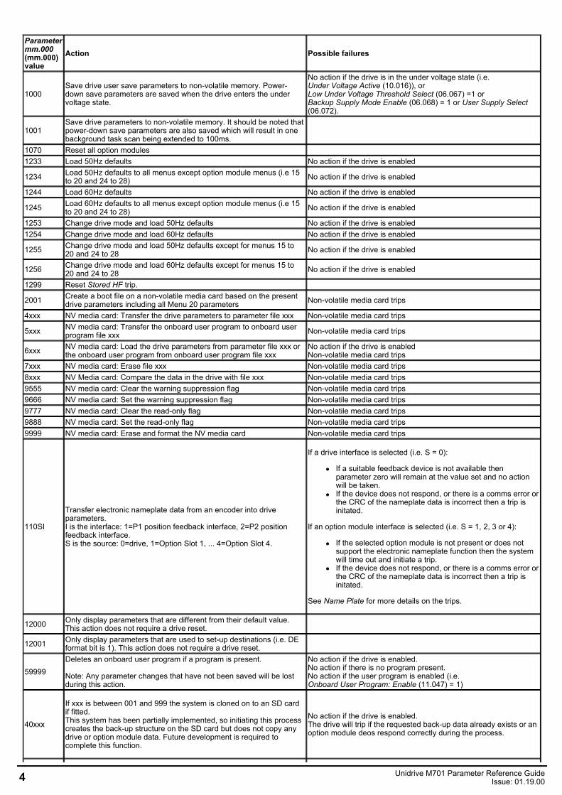
The table below shows the possible actions that can be initiated with Parameter mm.000 (mm.000).
Unidrive M701 Parameter Reference GuideIssue: 01.19.00 3
Parametermm.000(mm.000)value
Action Possible failures
1000Save drive user save parameters to non-volatile memory. Power-down save parameters are saved when the drive enters the undervoltage state.
No action if the drive is in the under voltage state (i.e.Under Voltage Active (10.016)), orLow Under Voltage Threshold Select (06.067) =1 orBackup Supply Mode Enable (06.068) = 1 or User Supply Select(06.072).
1001Save drive parameters to non-volatile memory. It should be noted thatpower-down save parameters are also saved which will result in onebackground task scan being extended to 100ms.
1070 Reset all option modules1233 Load 50Hz defaults No action if the drive is enabled
1234 Load 50Hz defaults to all menus except option module menus (i.e 15to 20 and 24 to 28) No action if the drive is enabled
1244 Load 60Hz defaults No action if the drive is enabled
1245 Load 60Hz defaults to all menus except option module menus (i.e 15to 20 and 24 to 28) No action if the drive is enabled
1253 Change drive mode and load 50Hz defaults No action if the drive is enabled1254 Change drive mode and load 60Hz defaults No action if the drive is enabled
1255 Change drive mode and load 50Hz defaults except for menus 15 to20 and 24 to 28 No action if the drive is enabled
1256 Change drive mode and load 60Hz defaults except for menus 15 to20 and 24 to 28 No action if the drive is enabled
1299 Reset Stored HF trip.
2001 Create a boot file on a non-volatile media card based on the presentdrive parameters including all Menu 20 parameters Non-volatile media card trips
4xxx NV media card: Transfer the drive parameters to parameter file xxx Non-volatile media card trips
5xxx NV media card: Transfer the onboard user program to onboard userprogram file xxx Non-volatile media card trips
6xxx NV media card: Load the drive parameters from parameter file xxx orthe onboard user program from onboard user program file xxx
No action if the drive is enabledNon-volatile media card trips
7xxx NV media card: Erase file xxx Non-volatile media card trips8xxx NV Media card: Compare the data in the drive with file xxx Non-volatile media card trips9555 NV media card: Clear the warning suppression flag Non-volatile media card trips9666 NV media card: Set the warning suppression flag Non-volatile media card trips9777 NV media card: Clear the read-only flag Non-volatile media card trips9888 NV media card: Set the read-only flag Non-volatile media card trips9999 NV media card: Erase and format the NV media card Non-volatile media card trips
110SI
Transfer electronic nameplate data from an encoder into driveparameters.I is the interface: 1=P1 position feedback interface, 2=P2 positionfeedback interface.S is the source: 0=drive, 1=Option Slot 1, ... 4=Option Slot 4.
If a drive interface is selected (i.e. S = 0):
If a suitable feedback device is not available thenparameter zero will remain at the value set and no actionwill be taken.If the device does not respond, or there is a comms error orthe CRC of the nameplate data is incorrect then a trip isinitated.
If an option module interface is selected (i.e. S = 1, 2, 3 or 4):
If the selected option module is not present or does notsupport the electronic nameplate function then the systemwill time out and initiate a trip.If the device does not respond, or there is a comms error orthe CRC of the nameplate data is incorrect then a trip isinitated.
See Name Plate for more details on the trips.
12000 Only display parameters that are different from their default value.This action does not require a drive reset.
12001 Only display parameters that are used to set-up destinations (i.e. DEformat bit is 1). This action does not require a drive reset.
59999Deletes an onboard user program if a program is present.
Note: Any parameter changes that have not been saved will be lostduring this action.
No action if the drive is enabled.No action if there is no program present.No action if the user program is enabled (i.e.Onboard User Program: Enable (11.047) = 1)
40xxx
If xxx is between 001 and 999 the system is cloned on to an SD cardif fitted.This system has been partially implemented, so initiating this processcreates the back-up structure on the SD card but does not copy anydrive or option module data. Future development is required tocomplete this function.
No action if the drive is enabled.The drive will trip if the requested back-up data already exists or anoption module deos respond correctly during the process.
4 Unidrive M701 Parameter Reference GuideIssue: 01.19.00
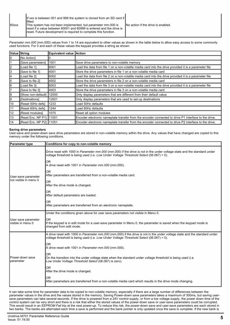
60xxx
If xxx is between 001 and 999 the system is cloned from an SD card iffitted.This system has not been implemented, but parameter mm.000 isreset if a value between 60001 and 60999 is entered and the drive isreset. Future development is required to complete this function.
No action if the drive is enabled.
Parameter mm.000 (mm.000) values from 1 to 14 are equivalent to other values as shown in the table below to allow easy access to some commonlyused functions. For 0 and each of these values the keypad provides a string as shown.
Value String Equivalent value Action0 [No Action] 01 [Save parameters] 1001 Save drive parameters to non-volatile memory2 [Load file 1] 6001 Load the data from file 1 on a non-volatile media card into the drive provided it is a parameter file3 [Save to file 1] 4001 Store the drive parameters in file 1 on a non-volatile media card4 [Load file 2] 6002 Load the data from file 2 on a non-volatile media card into the drive provided it is a parameter file5 [Save to file 2] 4002 Store the drive parameters in file 2 on a non-volatile media card6 [Load file 3] 6003 Load the data from file 3 on a non-volatile media card into the drive provided it is a parameter file7 [Save to file 3] 4003 Store the drive parameters in file 3 on a non-volatile media card8 [Show non-default] 12000 Only display parameters that are different from their default value9 [Destinations] 12001 Only display parameters that are used to set-up destinations10 [Reset 50Hz defs] 1233 Load 50Hz defaults11 [Reset 60Hz defs] 1244 Load 60Hz defaults12 [Reset modules] 1070 Reset all option modules13 [Read Enc. NP P1] 11001 Encoder electronic nameplate transfer from the encoder connected to drive P1 interface to the drive.14 [Read Enc. NP P2] 11051 Encoder electronic nameplate transfer from the encoder connected to drive P2 interface to the drive.
Saving drive parametersUser-save and power-down save drive parameters are stored in non-volatile memory within the drive. Any values that have changed are copied to thismemory under the following conditions.
Parameter type Conditions for copy to non-volatile memory
User-save parameternot visible in menu 0
Drive reset with 1000 in Parameter mm.000 (mm.000) if the drive is not in the under voltage state and the standard undervoltage threshold is being used (i.e. Low Under Voltage Threshold Select (06.067) = 0).
OR A drive reset with 1001 in Parameter mm.000 (mm.000).
ORAfter parameters are transferred from a non-volatile media card.
ORAfter the drive mode is changed.
ORAfter default parameters are loaded.
ORAfter parameters are transferred from an electronic nameplate.
User save parametervisible in menu 0
Under the conditions given above for user save parameters not visible in Menu 0.
ORIf the keypad is in edit mode for a user-save parameter in Menu 0, the parameter is saved when the keypad mode ischanged from edit mode.
Power-down saveparameter
A drive reset with 1000 in Parameter mm.000 (mm.000) if the drive is not in the under voltage state and the standard undervoltage threshold is being used (i.e. Low Under Voltage Threshold Select (06.067) = 0).
OR A drive reset with 1001 in Parameter mm.000 (mm.000).
OROn the transition into the under voltage state when the standard under voltage threshold is being used (i.e.Low Under Voltage Threshold Select (06.067) is zero).
ORAfter the drive mode is changed.
ORAfter parameters are transferred from a non-volatile media card which results in the drive mode changing.
It can take some time for parameter data to be copied to non-volatile memory, especially if there are a large number of differences between theparameter values in the drive and the values stored in the memory. Saving Power-down save parameters takes a maximum of 300ms, but saving user-save parameters can take several seconds. If the drive is powered from a 24V control supply, or from a low voltage supply, the power down time of thecontrol system can be very short and there is a risk that either the stored values of the power-down save or user-save parameters could be corrupted.This would result in an EEPROM Fail trip at the next power-up. To reduce this risk, the power-down save and user-save parameters are each stored intwo banks. The banks are alternated each time a save is performed and the bank pointer is only updated once the save is complete. If the new bank is
Unidrive M701 Parameter Reference GuideIssue: 01.19.00 5
corrupted a User Save or Power Down Save is initiated at the next power-up indicating an error in the user-save or power-down save data respectively,and the data from the old bank is used. The following points should be noted:
1. If a User Save or Power Down Save trip occur at power-up then parameter changes made before power down will be lost. To clear these trips aparameter save must be performed. If both the user-save and power-down save data is corrupted then a Power Down Save trip is produced.
2. When a Menu 0 parameter is changed its value is saved immediately to the active bank and the bank pointer is not changed. Thereforechanges made via Menu 0 are not lost if a User Save trip occurs at power-up.
3. When the drive mode changes all the data in both banks in the non-volatile memory is cleared and the default parameters are saved in bothbanks. Therefore there is an extended parameter saving period immediately after a drive mode change.
4. Two banks are not provided in non-volatile media cards therefore the card could be corrupted if the power is removed when the drive is writingdata to the card.
Loading defaultsA drive reset with 1233 in Parameter mm.000 (mm.000) loads the defaults defined for each parameter. If defaults are loaded with 1244 in Parametermm.000 (mm.000) then the parameters in the table below have different defaults that are intended for the 60Hz regions.
Parameter Default Drive modes Drive voltage ratingMaximum reference clamp (01.006) 60.0Hz Open-loop AllMaximum reference clamp (01.006) 1800rpm RFC-A AllStandard Ramp Voltage (02.008) 775V Open-loop, RFC-A, RFC-S 400VRated Frequency (05.006) 60.0Hz Open-loop, RFC-A AllRated Load rpm (05.008) 1800rpm Open-loop AllRated Load rpm (05.008) 1770rpm RFC-A AllRated Voltage (05.009) 460V Open-loop, RFC-A, RFC-S 400VM2 Maximum Reference Clamp (21.001) 60.0Hz Open-loop AllM2 Maximum Reference Clamp (21.001) 1800rpm RFC-A AllM2 Rated Frequency (21.006) 60.0Hz Open-loop, RFC-A AllM2 Rated Load rpm (21.008) 1800rpm Open-loop AllM2 Rated Load rpm (21.008) 1770rpm RFC-A AllM2 Rated Voltage (21.009) 460V Open-loop, RFC-A, RFC-S All
Non-volatile media card data transferDetails of the data that can be stored on a non-volatile media card and the methods to transfer/access this data are given in Menu 11.
Stored HF tripsWhen the drive is subsequently powered up a Stored HF trip is initiated where the sub-trip number is the number of the HF trip that last occurred. Thistrip will occur at every power-up until it is reset. The trip can only be reset by first entering 1299 into Parameter mm.000 (mm.000). If the drive ispowered up and a Stored HF trip occurs, Onboard User Program: Enable (Pr 11.047) is reset to zero to prevent the on-board user program fromrunning. This ensures that the user program can be changed or erased in case it causes an HF trip at every power-up. Once the Stored HF is cleared, itis necessary to power cycle the drive or to re-download the user program to allow the program to restart.
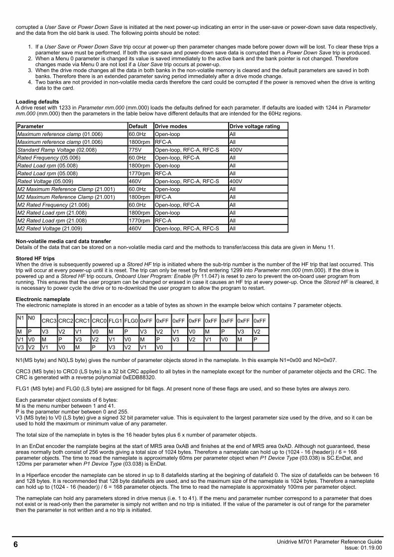
Electronic nameplateThe electronic nameplate is stored in an encoder as a table of bytes as shown in the example below which contains 7 parameter objects.
N1
N0 CRC3 CRC2 CRC1 CRC0 FLG1 FLG0 0xFF 0xFF 0xFF 0xFF 0xFF 0xFF 0xFF 0xFF
M P V3 V2 V1 V0 M P V3 V2 V1 V0 M P V3 V2V1 V0 M P V3 V2 V1 V0 M P V3 V2 V1 V0 M PV3 V2 V1 V0 M P V3 V2 V1 V0
N1(MS byte) and N0(LS byte) gives the number of parameter objects stored in the nameplate. In this example N1=0x00 and N0=0x07.
CRC3 (MS byte) to CRC0 (LS byte) is a 32 bit CRC applied to all bytes in the nameplate except for the number of parameter objects and the CRC. TheCRC is generated with a reverse polynomial 0xEDB88320.
FLG1 (MS byte) and FLG0 (LS byte) are assigned for bit flags. At present none of these flags are used, and so these bytes are always zero.
Each parameter object consists of 6 bytes:M is the menu number between 1 and 41.P is the parameter number between 0 and 255.V3 (MS byte) to V0 (LS byte) give a signed 32 bit parameter value. This is equivalent to the largest parameter size used by the drive, and so it can beused to hold the maximum or minimum value of any parameter.
The total size of the nameplate in bytes is the 16 header bytes plus 6 x number of parameter objects.
In an EnDat encoder the namplate begins at the start of MRS area 0xAB and finishes at the end of MRS area 0xAD. Although not guaranteed, theseareas normally both consist of 256 words giving a total size of 1024 bytes. Therefore a nameplate can hold up to (1024 - 16 (header)) / 6 = 168parameter objects. The time to read the nameplate is approximately 60ms per parameter object when P1 Device Type (03.038) is SC.EnDat, and120ms per parameter when P1 Device Type (03.038) is EnDat.
In a Hiperface encoder the nameplate can be stored in up to 8 datafields starting at the begining of datafield 0. The size of datafields can be between 16and 128 bytes. It is recommended that 128 byte datafields are used, and so the maximum size of the nameplate is 1024 bytes. Therefore a nameplatecan hold up to (1024 - 16 (header)) / 6 = 168 parameter objects. The time to read the nameplate is approximately 100ms per parameter object.
The nameplate can hold any parameters stored in drive menus (i.e. 1 to 41). If the menu and parameter number correspond to a parameter that doesnot exist or is read-only then the parameter is simply not written and no trip is initiated. If the value of the parameter is out of range for the parameterthen the parameter is not written and a no trip is initiated.
6 Unidrive M701 Parameter Reference GuideIssue: 01.19.00
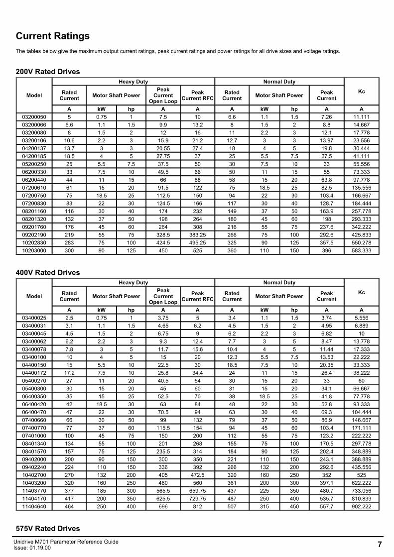
Current RatingsThe tables below give the maximum output current ratings, peak current ratings and power ratings for all drive sizes and voltage ratings.
200V Rated Drives
Model
Heavy Duty Normal Duty
KcRatedCurrent Motor Shaft Power
PeakCurrent
Open LoopPeak
Current RFCRated
Current Motor Shaft Power PeakCurrent
A kW hp A A A kW hp A A03200050 5 0.75 1 7.5 10 6.6 1.1 1.5 7.26 11.11103200066 6.6 1.1 1.5 9.9 13.2 8 1.5 2 8.8 14.66703200080 8 1.5 2 12 16 11 2.2 3 12.1 17.77803200106 10.6 2.2 3 15.9 21.2 12.7 3 3 13.97 23.55604200137 13.7 3 3 20.55 27.4 18 4 5 19.8 30.44404200185 18.5 4 5 27.75 37 25 5.5 7.5 27.5 41.11105200250 25 5.5 7.5 37.5 50 30 7.5 10 33 55.55606200330 33 7.5 10 49.5 66 50 11 15 55 73.33306200440 44 11 15 66 88 58 15 20 63.8 97.77807200610 61 15 20 91.5 122 75 18.5 25 82.5 135.55607200750 75 18.5 25 112.5 150 94 22 30 103.4 166.66707200830 83 22 30 124.5 166 117 30 40 128.7 184.44408201160 116 30 40 174 232 149 37 50 163.9 257.77808201320 132 37 50 198 264 180 45 60 198 293.33309201760 176 45 60 264 308 216 55 75 237.6 342.22209202190 219 55 75 328.5 383.25 266 75 100 292.6 425.83310202830 283 75 100 424.5 495.25 325 90 125 357.5 550.27810203000 300 90 125 450 525 360 110 150 396 583.333
400V Rated Drives
Model
Heavy Duty Normal Duty
KcRatedCurrent Motor Shaft Power
PeakCurrent
Open LoopPeak
Current RFCRated
Current Motor Shaft Power PeakCurrent
A kW hp A A A kW hp A A03400025 2.5 0.75 1 3.75 5 3.4 1.1 1.5 3.74 5.55603400031 3.1 1.1 1.5 4.65 6.2 4.5 1.5 2 4.95 6.88903400045 4.5 1.5 2 6.75 9 6.2 2.2 3 6.82 1003400062 6.2 2.2 3 9.3 12.4 7.7 3 5 8.47 13.77803400078 7.8 3 5 11.7 15.6 10.4 4 5 11.44 17.33303400100 10 4 5 15 20 12.3 5.5 7.5 13.53 22.22204400150 15 5.5 10 22.5 30 18.5 7.5 10 20.35 33.33304400172 17.2 7.5 10 25.8 34.4 24 11 15 26.4 38.22205400270 27 11 20 40.5 54 30 15 20 33 6005400300 30 15 20 45 60 31 15 20 34.1 66.66706400350 35 15 25 52.5 70 38 18.5 25 41.8 77.77806400420 42 18.5 30 63 84 48 22 30 52.8 93.33306400470 47 22 30 70.5 94 63 30 40 69.3 104.44407400660 66 30 50 99 132 79 37 50 86.9 146.66707400770 77 37 60 115.5 154 94 45 60 103.4 171.11107401000 100 45 75 150 200 112 55 75 123.2 222.22208401340 134 55 100 201 268 155 75 100 170.5 297.77808401570 157 75 125 235.5 314 184 90 125 202.4 348.88909402000 200 90 150 300 350 221 110 150 243.1 388.88909402240 224 110 150 336 392 266 132 200 292.6 435.55610402700 270 132 200 405 472.5 320 160 250 352 52510403200 320 160 250 480 560 361 200 300 397.1 622.22211403770 377 185 300 565.5 659.75 437 225 350 480.7 733.05611404170 417 200 350 625.5 729.75 487 250 400 535.7 810.83311404640 464 250 400 696 812 507 315 450 557.7 902.222
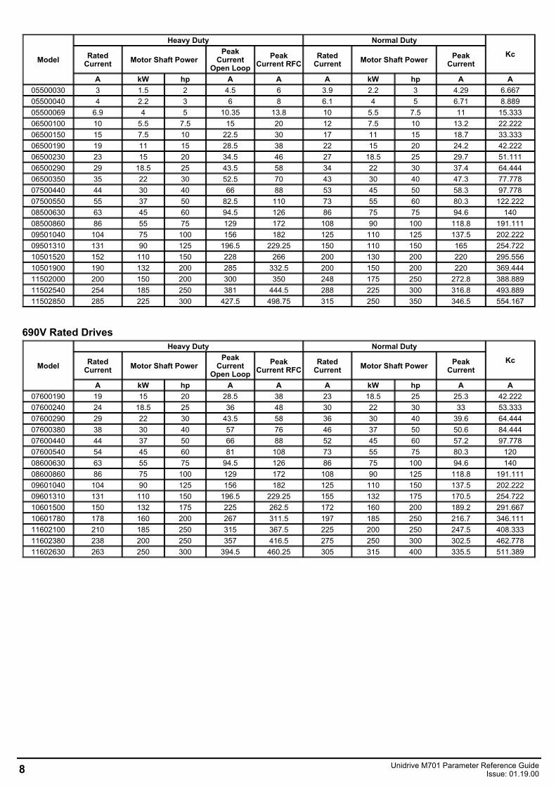
575V Rated DrivesUnidrive M701 Parameter Reference GuideIssue: 01.19.00 7
Model
Heavy Duty Normal Duty
KcRatedCurrent Motor Shaft Power
PeakCurrent
Open LoopPeak
Current RFCRated
Current Motor Shaft Power PeakCurrent
A kW hp A A A kW hp A A05500030 3 1.5 2 4.5 6 3.9 2.2 3 4.29 6.66705500040 4 2.2 3 6 8 6.1 4 5 6.71 8.88905500069 6.9 4 5 10.35 13.8 10 5.5 7.5 11 15.33306500100 10 5.5 7.5 15 20 12 7.5 10 13.2 22.22206500150 15 7.5 10 22.5 30 17 11 15 18.7 33.33306500190 19 11 15 28.5 38 22 15 20 24.2 42.22206500230 23 15 20 34.5 46 27 18.5 25 29.7 51.11106500290 29 18.5 25 43.5 58 34 22 30 37.4 64.44406500350 35 22 30 52.5 70 43 30 40 47.3 77.77807500440 44 30 40 66 88 53 45 50 58.3 97.77807500550 55 37 50 82.5 110 73 55 60 80.3 122.22208500630 63 45 60 94.5 126 86 75 75 94.6 14008500860 86 55 75 129 172 108 90 100 118.8 191.11109501040 104 75 100 156 182 125 110 125 137.5 202.22209501310 131 90 125 196.5 229.25 150 110 150 165 254.72210501520 152 110 150 228 266 200 130 200 220 295.55610501900 190 132 200 285 332.5 200 150 200 220 369.44411502000 200 150 200 300 350 248 175 250 272.8 388.88911502540 254 185 250 381 444.5 288 225 300 316.8 493.88911502850 285 225 300 427.5 498.75 315 250 350 346.5 554.167
690V Rated Drives
Model
Heavy Duty Normal Duty
KcRatedCurrent Motor Shaft Power
PeakCurrent
Open LoopPeak
Current RFCRated
Current Motor Shaft Power PeakCurrent
A kW hp A A A kW hp A A07600190 19 15 20 28.5 38 23 18.5 25 25.3 42.22207600240 24 18.5 25 36 48 30 22 30 33 53.33307600290 29 22 30 43.5 58 36 30 40 39.6 64.44407600380 38 30 40 57 76 46 37 50 50.6 84.44407600440 44 37 50 66 88 52 45 60 57.2 97.77807600540 54 45 60 81 108 73 55 75 80.3 12008600630 63 55 75 94.5 126 86 75 100 94.6 14008600860 86 75 100 129 172 108 90 125 118.8 191.11109601040 104 90 125 156 182 125 110 150 137.5 202.22209601310 131 110 150 196.5 229.25 155 132 175 170.5 254.72210601500 150 132 175 225 262.5 172 160 200 189.2 291.66710601780 178 160 200 267 311.5 197 185 250 216.7 346.11111602100 210 185 250 315 367.5 225 200 250 247.5 408.33311602380 238 200 250 357 416.5 275 250 300 302.5 462.77811602630 263 250 300 394.5 460.25 305 315 400 335.5 511.389
8 Unidrive M701 Parameter Reference GuideIssue: 01.19.00
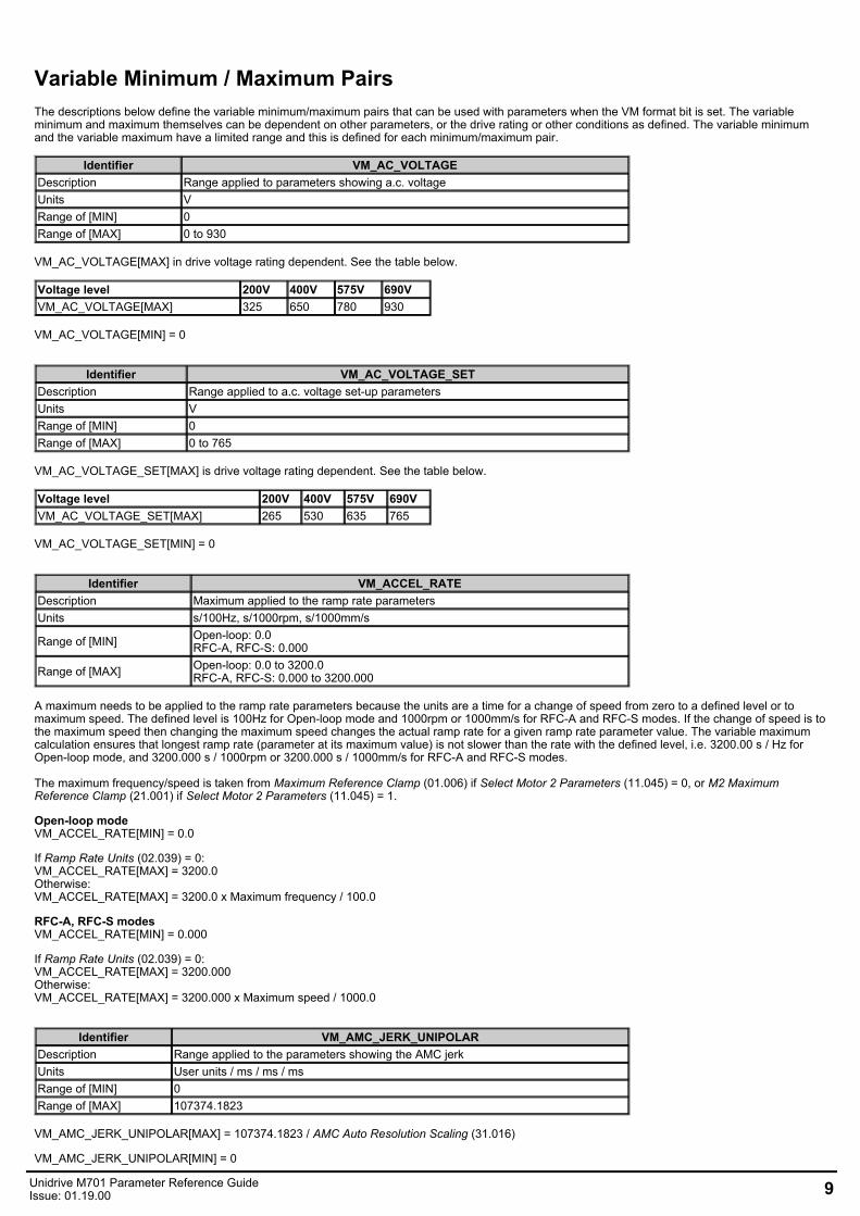
Variable Minimum / Maximum PairsThe descriptions below define the variable minimum/maximum pairs that can be used with parameters when the VM format bit is set. The variableminimum and maximum themselves can be dependent on other parameters, or the drive rating or other conditions as defined. The variable minimumand the variable maximum have a limited range and this is defined for each minimum/maximum pair.
Identifier VM_AC_VOLTAGEDescription Range applied to parameters showing a.c. voltageUnits VRange of [MIN] 0Range of [MAX] 0 to 930
VM_AC_VOLTAGE[MAX] in drive voltage rating dependent. See the table below.
Voltage level 200V 400V 575V 690VVM_AC_VOLTAGE[MAX] 325 650 780 930
VM_AC_VOLTAGE[MIN] = 0
Identifier VM_AC_VOLTAGE_SETDescription Range applied to a.c. voltage set-up parametersUnits VRange of [MIN] 0Range of [MAX] 0 to 765
VM_AC_VOLTAGE_SET[MAX] is drive voltage rating dependent. See the table below.
Voltage level 200V 400V 575V 690VVM_AC_VOLTAGE_SET[MAX] 265 530 635 765
VM_AC_VOLTAGE_SET[MIN] = 0
Identifier VM_ACCEL_RATEDescription Maximum applied to the ramp rate parametersUnits s/100Hz, s/1000rpm, s/1000mm/s
Range of [MIN] Open-loop: 0.0RFC-A, RFC-S: 0.000
Range of [MAX] Open-loop: 0.0 to 3200.0RFC-A, RFC-S: 0.000 to 3200.000
A maximum needs to be applied to the ramp rate parameters because the units are a time for a change of speed from zero to a defined level or tomaximum speed. The defined level is 100Hz for Open-loop mode and 1000rpm or 1000mm/s for RFC-A and RFC-S modes. If the change of speed is tothe maximum speed then changing the maximum speed changes the actual ramp rate for a given ramp rate parameter value. The variable maximumcalculation ensures that longest ramp rate (parameter at its maximum value) is not slower than the rate with the defined level, i.e. 3200.00 s / Hz forOpen-loop mode, and 3200.000 s / 1000rpm or 3200.000 s / 1000mm/s for RFC-A and RFC-S modes. The maximum frequency/speed is taken from Maximum Reference Clamp (01.006) if Select Motor 2 Parameters (11.045) = 0, or M2 MaximumReference Clamp (21.001) if Select Motor 2 Parameters (11.045) = 1.
Open-loop modeVM_ACCEL_RATE[MIN] = 0.0
If Ramp Rate Units (02.039) = 0:VM_ACCEL_RATE[MAX] = 3200.0Otherwise:VM_ACCEL_RATE[MAX] = 3200.0 x Maximum frequency / 100.0
RFC-A, RFC-S modesVM_ACCEL_RATE[MIN] = 0.000
If Ramp Rate Units (02.039) = 0:VM_ACCEL_RATE[MAX] = 3200.000Otherwise:VM_ACCEL_RATE[MAX] = 3200.000 x Maximum speed / 1000.0
Identifier VM_AMC_JERK_UNIPOLARDescription Range applied to the parameters showing the AMC jerkUnits User units / ms / ms / msRange of [MIN] 0Range of [MAX] 107374.1823
VM_AMC_JERK_UNIPOLAR[MAX] = 107374.1823 / AMC Auto Resolution Scaling (31.016)
VM_AMC_JERK_UNIPOLAR[MIN] = 0
Unidrive M701 Parameter Reference GuideIssue: 01.19.00 9
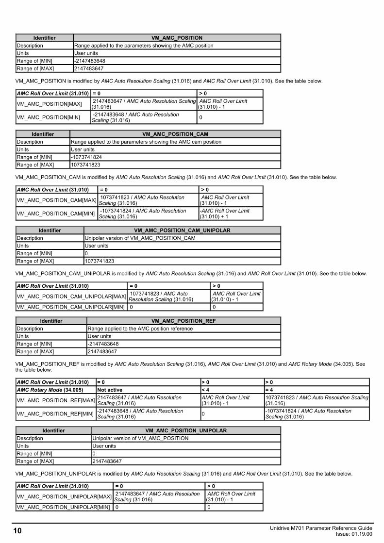
AMC Roll Over Limit (31.010) = 0 > 0
VM_AMC_POSITION[MAX] 2147483647 / AMC Auto Resolution Scaling(31.016)
AMC Roll Over Limit(31.010) - 1
VM_AMC_POSITION[MIN] -2147483648 / AMC Auto ResolutionScaling (31.016) 0
AMC Roll Over Limit (31.010) = 0 > 0
VM_AMC_POSITION_CAM[MAX] 1073741823 / AMC Auto ResolutionScaling (31.016)
AMC Roll Over Limit(31.010) - 1
VM_AMC_POSITION_CAM[MIN] -1073741824 / AMC Auto ResolutionScaling (31.016)
-AMC Roll Over Limit(31.010) + 1
AMC Roll Over Limit (31.010) = 0 > 0
VM_AMC_POSITION_CAM_UNIPOLAR[MAX] 1073741823 / AMC AutoResolution Scaling (31.016)
AMC Roll Over Limit(31.010) - 1
VM_AMC_POSITION_CAM_UNIPOLAR[MIN] 0 0
AMC Roll Over Limit (31.010) = 0 > 0 > 0AMC Rotary Mode (34.005) Not active < 4 = 4
VM_AMC_POSITION_REF[MAX] 2147483647 / AMC Auto ResolutionScaling (31.016)
AMC Roll Over Limit(31.010) - 1
1073741823 / AMC Auto Resolution Scaling(31.016)
VM_AMC_POSITION_REF[MIN] -2147483648 / AMC Auto ResolutionScaling (31.016) 0 -1073741824 / AMC Auto Resolution
Scaling (31.016)
AMC Roll Over Limit (31.010) = 0 > 0
VM_AMC_POSITION_UNIPOLAR[MAX] 2147483647 / AMC Auto ResolutionScaling (31.016)
AMC Roll Over Limit(31.010) - 1
VM_AMC_POSITION_UNIPOLAR[MIN] 0 0
Identifier VM_AMC_POSITIONDescription Range applied to the parameters showing the AMC positionUnits User unitsRange of [MIN] -2147483648Range of [MAX] 2147483647
VM_AMC_POSITION is modified by AMC Auto Resolution Scaling (31.016) and AMC Roll Over Limit (31.010). See the table below.
Identifier VM_AMC_POSITION_CAMDescription Range applied to the parameters showing the AMC cam positionUnits User unitsRange of [MIN] -1073741824Range of [MAX] 1073741823
VM_AMC_POSITION_CAM is modified by AMC Auto Resolution Scaling (31.016) and AMC Roll Over Limit (31.010). See the table below.
Identifier VM_AMC_POSITION_CAM_UNIPOLARDescription Unipolar version of VM_AMC_POSITION_CAMUnits User unitsRange of [MIN] 0Range of [MAX] 1073741823
VM_AMC_POSITION_CAM_UNIPOLAR is modified by AMC Auto Resolution Scaling (31.016) and AMC Roll Over Limit (31.010). See the table below.
Identifier VM_AMC_POSITION_REFDescription Range applied to the AMC position referenceUnits User unitsRange of [MIN] -2147483648Range of [MAX] 2147483647
VM_AMC_POSITION_REF is modified by AMC Auto Resolution Scaling (31.016), AMC Roll Over Limit (31.010) and AMC Rotary Mode (34.005). Seethe table below.
Identifier VM_AMC_POSITION_UNIPOLARDescription Unipolar version of VM_AMC_POSITIONUnits User unitsRange of [MIN] 0Range of [MAX] 2147483647
VM_AMC_POSITION_UNIPOLAR is modified by AMC Auto Resolution Scaling (31.016) and AMC Roll Over Limit (31.010). See the table below.
10 Unidrive M701 Parameter Reference GuideIssue: 01.19.00
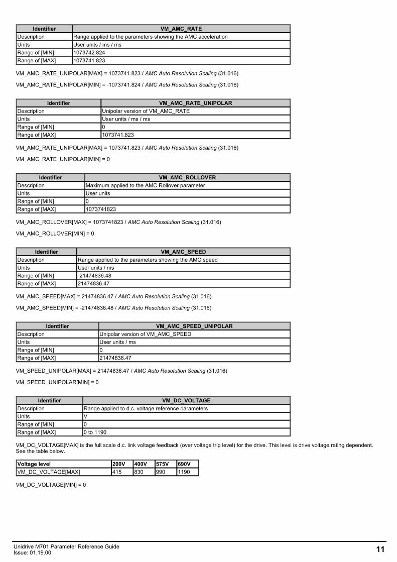
Identifier VM_AMC_RATEDescription Range applied to the parameters showing the AMC accelerationUnits User units / ms / msRange of [MIN] 1073742.824Range of [MAX] 1073741.823
VM_AMC_RATE_UNIPOLAR[MAX] = 1073741.823 / AMC Auto Resolution Scaling (31.016)
VM_AMC_RATE_UNIPOLAR[MIN] = -1073741.824 / AMC Auto Resolution Scaling (31.016)
Identifier VM_AMC_RATE_UNIPOLARDescription Unipolar version of VM_AMC_RATEUnits User units / ms / msRange of [MIN] 0Range of [MAX] 1073741.823
VM_AMC_RATE_UNIPOLAR[MAX] = 1073741.823 / AMC Auto Resolution Scaling (31.016)
VM_AMC_RATE_UNIPOLAR[MIN] = 0
Identifier VM_AMC_ROLLOVERDescription Maximum applied to the AMC Rollover parameterUnits User unitsRange of [MIN] 0Range of [MAX] 1073741823
VM_AMC_ROLLOVER[MAX] = 1073741823 / AMC Auto Resolution Scaling (31.016)
VM_AMC_ROLLOVER[MIN] = 0
Identifier VM_AMC_SPEEDDescription Range applied to the parameters showing the AMC speedUnits User units / msRange of [MIN] -21474836.48Range of [MAX] 21474836.47
VM_AMC_SPEED[MAX] = 21474836.47 / AMC Auto Resolution Scaling (31.016)
VM_AMC_SPEED[MIN] = -21474836.48 / AMC Auto Resolution Scaling (31.016)
Identifier VM_AMC_SPEED_UNIPOLARDescription Unipolar version of VM_AMC_SPEEDUnits User units / msRange of [MIN] 0Range of [MAX] 21474836.47
VM_SPEED_UNIPOLAR[MAX] = 21474836.47 / AMC Auto Resolution Scaling (31.016)
VM_SPEED_UNIPOLAR[MIN] = 0
Identifier VM_DC_VOLTAGEDescription Range applied to d.c. voltage reference parametersUnits VRange of [MIN] 0Range of [MAX] 0 to 1190
VM_DC_VOLTAGE[MAX] is the full scale d.c. link voltage feedback (over voltage trip level) for the drive. This level is drive voltage rating dependent.See the table below.
Voltage level 200V 400V 575V 690VVM_DC_VOLTAGE[MAX] 415 830 990 1190
VM_DC_VOLTAGE[MIN] = 0
Unidrive M701 Parameter Reference GuideIssue: 01.19.00 11
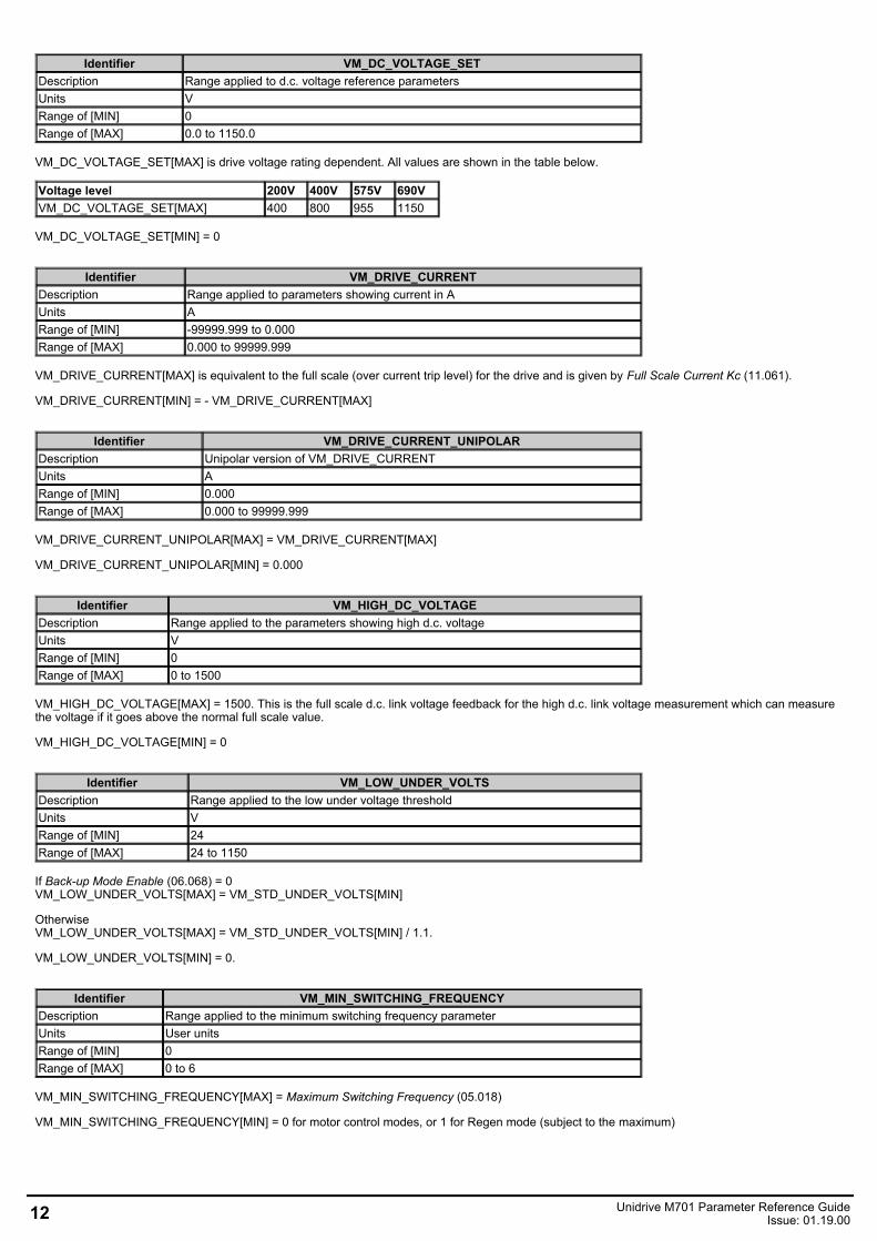
Identifier VM_DC_VOLTAGE_SETDescription Range applied to d.c. voltage reference parametersUnits VRange of [MIN] 0Range of [MAX] 0.0 to 1150.0
VM_DC_VOLTAGE_SET[MAX] is drive voltage rating dependent. All values are shown in the table below.
Voltage level 200V 400V 575V 690VVM_DC_VOLTAGE_SET[MAX] 400 800 955 1150
VM_DC_VOLTAGE_SET[MIN] = 0
Identifier VM_DRIVE_CURRENTDescription Range applied to parameters showing current in AUnits ARange of [MIN] -99999.999 to 0.000Range of [MAX] 0.000 to 99999.999
VM_DRIVE_CURRENT[MAX] is equivalent to the full scale (over current trip level) for the drive and is given by Full Scale Current Kc (11.061).
VM_DRIVE_CURRENT[MIN] = - VM_DRIVE_CURRENT[MAX]
Identifier VM_DRIVE_CURRENT_UNIPOLARDescription Unipolar version of VM_DRIVE_CURRENTUnits ARange of [MIN] 0.000Range of [MAX] 0.000 to 99999.999
VM_DRIVE_CURRENT_UNIPOLAR[MAX] = VM_DRIVE_CURRENT[MAX]
VM_DRIVE_CURRENT_UNIPOLAR[MIN] = 0.000
Identifier VM_HIGH_DC_VOLTAGEDescription Range applied to the parameters showing high d.c. voltageUnits VRange of [MIN] 0Range of [MAX] 0 to 1500
VM_HIGH_DC_VOLTAGE[MAX] = 1500. This is the full scale d.c. link voltage feedback for the high d.c. link voltage measurement which can measurethe voltage if it goes above the normal full scale value.
VM_HIGH_DC_VOLTAGE[MIN] = 0
Identifier VM_LOW_UNDER_VOLTSDescription Range applied to the low under voltage thresholdUnits VRange of [MIN] 24Range of [MAX] 24 to 1150
If Back-up Mode Enable (06.068) = 0VM_LOW_UNDER_VOLTS[MAX] = VM_STD_UNDER_VOLTS[MIN]
OtherwiseVM_LOW_UNDER_VOLTS[MAX] = VM_STD_UNDER_VOLTS[MIN] / 1.1.
VM_LOW_UNDER_VOLTS[MIN] = 0.
Identifier VM_MIN_SWITCHING_FREQUENCYDescription Range applied to the minimum switching frequency parameterUnits User unitsRange of [MIN] 0Range of [MAX] 0 to 6
VM_MIN_SWITCHING_FREQUENCY[MAX] = Maximum Switching Frequency (05.018)
VM_MIN_SWITCHING_FREQUENCY[MIN] = 0 for motor control modes, or 1 for Regen mode (subject to the maximum)
12 Unidrive M701 Parameter Reference GuideIssue: 01.19.00
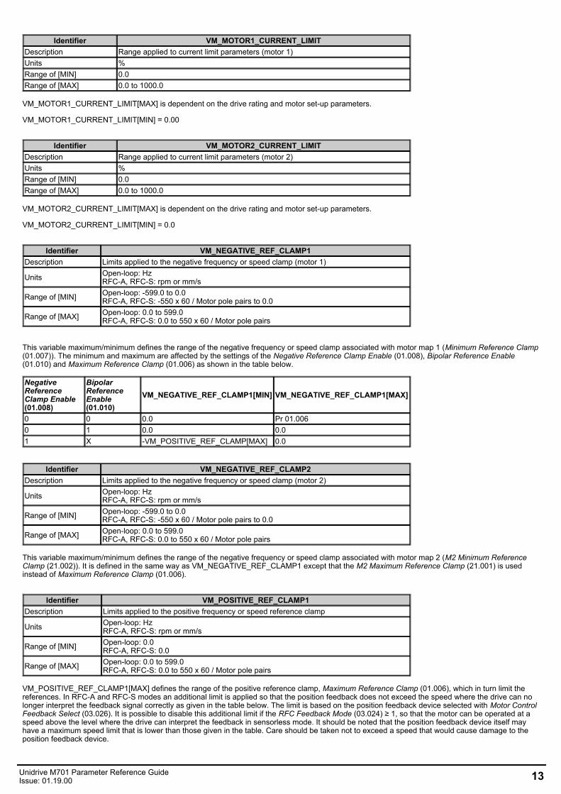
Identifier VM_MOTOR1_CURRENT_LIMITDescription Range applied to current limit parameters (motor 1)Units %Range of [MIN] 0.0Range of [MAX] 0.0 to 1000.0
VM_MOTOR1_CURRENT_LIMIT[MAX] is dependent on the drive rating and motor set-up parameters.
VM_MOTOR1_CURRENT_LIMIT[MIN] = 0.00
Identifier VM_MOTOR2_CURRENT_LIMITDescription Range applied to current limit parameters (motor 2)Units %Range of [MIN] 0.0Range of [MAX] 0.0 to 1000.0
VM_MOTOR2_CURRENT_LIMIT[MAX] is dependent on the drive rating and motor set-up parameters.
VM_MOTOR2_CURRENT_LIMIT[MIN] = 0.0
Identifier VM_NEGATIVE_REF_CLAMP1Description Limits applied to the negative frequency or speed clamp (motor 1)
Units Open-loop: HzRFC-A, RFC-S: rpm or mm/s
Range of [MIN] Open-loop: -599.0 to 0.0RFC-A, RFC-S: -550 x 60 / Motor pole pairs to 0.0
Range of [MAX] Open-loop: 0.0 to 599.0RFC-A, RFC-S: 0.0 to 550 x 60 / Motor pole pairs
This variable maximum/minimum defines the range of the negative frequency or speed clamp associated with motor map 1 (Minimum Reference Clamp(01.007)). The minimum and maximum are affected by the settings of the Negative Reference Clamp Enable (01.008), Bipolar Reference Enable(01.010) and Maximum Reference Clamp (01.006) as shown in the table below.
NegativeReferenceClamp Enable(01.008)
BipolarReferenceEnable(01.010)
VM_NEGATIVE_REF_CLAMP1[MIN] VM_NEGATIVE_REF_CLAMP1[MAX]
0 0 0.0 Pr 01.0060 1 0.0 0.01 X -VM_POSITIVE_REF_CLAMP[MAX] 0.0
Identifier VM_NEGATIVE_REF_CLAMP2Description Limits applied to the negative frequency or speed clamp (motor 2)
Units Open-loop: HzRFC-A, RFC-S: rpm or mm/s
Range of [MIN] Open-loop: -599.0 to 0.0RFC-A, RFC-S: -550 x 60 / Motor pole pairs to 0.0
Range of [MAX] Open-loop: 0.0 to 599.0RFC-A, RFC-S: 0.0 to 550 x 60 / Motor pole pairs
This variable maximum/minimum defines the range of the negative frequency or speed clamp associated with motor map 2 (M2 Minimum ReferenceClamp (21.002)). It is defined in the same way as VM_NEGATIVE_REF_CLAMP1 except that the M2 Maximum Reference Clamp (21.001) is usedinstead of Maximum Reference Clamp (01.006).
Identifier VM_POSITIVE_REF_CLAMP1Description Limits applied to the positive frequency or speed reference clamp
Units Open-loop: HzRFC-A, RFC-S: rpm or mm/s
Range of [MIN] Open-loop: 0.0RFC-A, RFC-S: 0.0
Range of [MAX] Open-loop: 0.0 to 599.0RFC-A, RFC-S: 0.0 to 550 x 60 / Motor pole pairs
VM_POSITIVE_REF_CLAMP1[MAX] defines the range of the positive reference clamp, Maximum Reference Clamp (01.006), which in turn limit thereferences. In RFC-A and RFC-S modes an additional limit is applied so that the position feedback does not exceed the speed where the drive can nolonger interpret the feedback signal correctly as given in the table below. The limit is based on the position feedback device selected with Motor ControlFeedback Select (03.026). It is possible to disable this additional limit if the RFC Feedback Mode (03.024) ≥ 1, so that the motor can be operated at aspeed above the level where the drive can interpret the feedback in sensorless mode. It should be noted that the position feedback device itself mayhave a maximum speed limit that is lower than those given in the table. Care should be taken not to exceed a speed that would cause damage to theposition feedback device.
Unidrive M701 Parameter Reference GuideIssue: 01.19.00 13
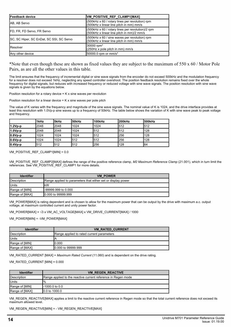
Feedback device VM_POSITIVE_REF_CLAMP1[MAX]
AB, AB Servo (500kHz x 60 / rotary lines per revolution) rpm(500kHz x linear line pitch in mm) mm/s
FD, FR, FD Servo, FR Servo (500kHz x 60 / rotary lines per revolution)/2 rpm(500kHz x linear line pitch in mm)/2 mm/s
SC, SC Hiper, SC EnDat, SC SSI, SC Servo (500kHz x 60 / sine waves per revolution) rpm(500kHz x linear line pitch in mm) mm/s
Resolver 30000 rpm*(250Hz x pole pitch in mm) mm/s
Any other device 50000.0 rpm or mm/s*
*Note that even though these are shown as fixed values they are subject to the maximum of 550 x 60 / Motor PolePairs, as are all the other values in this table.The limit ensures that the frequency of incremental digital or sine wave signals from the encoder do not exceed 500kHz and the modulation frequencyfor a resolver does not exceed 1kHz, neglecting any speed controller overshoot. The position feedback resolution remains fixed over the wholefrequency for digital signals, but reduces with increased frequency or reduced voltage with sine wave signals. The position resolution with sine wavesignals is given by the equations below.
Position resolution for a rotary device = K x sine waves per revolution
Position resolution for a linear device = K x sine waves per pole pitch
The value of K varies with the frequency and magnitude of the sine wave signals. The nominal value of K is 1024, and the drive interface provides atleast this resolution with 1.0Vp-p sine waves up to a frequency of 50kHz. The table below shows the variation of K with sine wave peak to peak voltageand frequency.
1kHz 5kHz 50kHz 100kHz 200kHz 500kHz1.2Vp-p 2048 2048 1024 1024 512 5121.0Vp-p 2048 2048 1024 512 512 1280.8Vp-p 1024 1024 1024 512 256 1280.6Vp-p 1024 1024 512 512 256 1280.4Vp-p 512 512 512 256 128 64
VM_POSITIVE_REF_CLAMP1[MIN] = 0.0
VM_POSITIVE_REF_CLAMP2[MAX] defines the range of the positive reference clamp, M2 Maximum Reference Clamp (21.001), which in turn limit thereferences. See VM_POSITIVE_REF_CLAMP1 for more details.
Identifier VM_POWERDescription Range applied to parameters that either set or display powerUnits kWRange of [MIN] -99999.999 to 0.000Range of [MAX] 0.000 to 99999.999
VM_POWER[MAX] is rating dependent and is chosen to allow for the maximum power that can be output by the drive with maximum a.c. outputvoltage, at maximum controlled current and unity power factor.
VM_POWER[MAX] = √3 x VM_AC_VOLTAGE[MAX] x VM_DRIVE_CURRENT[MAX] / 1000
VM_POWER[MIN] = -VM_POWER[MAX]
Identifier VM_RATED_CURRENTDescription Range applied to rated current parametersUnits ARange of [MIN] 0.000Range of [MAX] 0.000 to 99999.999
VM_RATED_CURRENT [MAX] = Maximum Rated Current (11.060) and is dependent on the drive rating.
VM_RATED_CURRENT [MIN] = 0.000
Identifier VM_REGEN_REACTIVEDescription Range applied to the reactive current reference in Regen modeUnits %Range of [MIN] -1000.0 to 0.0Range of [MAX] 0.0 to 1000.0
VM_REGEN_REACTIVE[MAX] applies a limit to the reactive current reference in Regen mode so that the total current reference does not exceed itsmaximum allowed level.
VM_REGEN_REACTIVE[MIN] = - VM_REGEN_REACTIVE[MAX]
14 Unidrive M701 Parameter Reference GuideIssue: 01.19.00
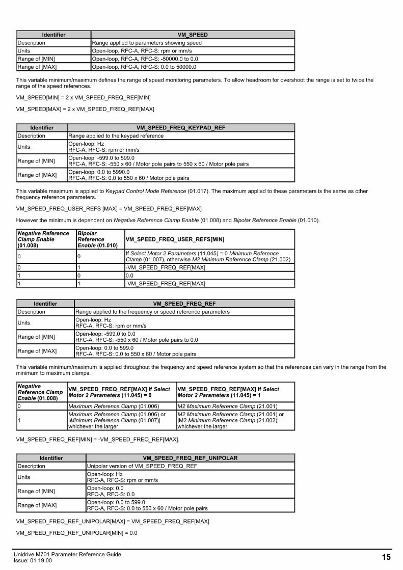
Identifier VM_SPEEDDescription Range applied to parameters showing speedUnits Open-loop, RFC-A, RFC-S: rpm or mm/sRange of [MIN] Open-loop, RFC-A, RFC-S: -50000.0 to 0.0Range of [MAX] Open-loop, RFC-A, RFC-S: 0.0 to 50000.0
This variable minimum/maximum defines the range of speed monitoring parameters. To allow headroom for overshoot the range is set to twice therange of the speed references.
VM_SPEED[MIN] = 2 x VM_SPEED_FREQ_REF[MIN]
VM_SPEED[MAX] = 2 x VM_SPEED_FREQ_REF[MAX]
Identifier VM_SPEED_FREQ_KEYPAD_REFDescription Range applied to the keypad reference
Units Open-loop: HzRFC-A, RFC-S: rpm or mm/s
Range of [MIN] Open-loop: -599.0 to 599.0RFC-A, RFC-S: -550 x 60 / Motor pole pairs to 550 x 60 / Motor pole pairs
Range of [MAX] Open-loop: 0.0 to 5990.0RFC-A, RFC-S: 0.0 to 550 x 60 / Motor pole pairs
This variable maximum is applied to Keypad Control Mode Reference (01.017). The maximum applied to these parameters is the same as otherfrequency reference parameters.
VM_SPEED_FREQ_USER_REFS [MAX] = VM_SPEED_FREQ_REF[MAX]
However the minimum is dependent on Negative Reference Clamp Enable (01.008) and Bipolar Reference Enable (01.010).
Negative ReferenceClamp Enable(01.008)
BipolarReferenceEnable (01.010)
VM_SPEED_FREQ_USER_REFS[MIN]
0 0 If Select Motor 2 Parameters (11.045) = 0 Minimum ReferenceClamp (01.007), otherwise M2 Minimum Reference Clamp (21.002)
0 1 -VM_SPEED_FREQ_REF[MAX]1 0 0.01 1 -VM_SPEED_FREQ_REF[MAX]
Identifier VM_SPEED_FREQ_REFDescription Range applied to the frequency or speed reference parameters
Units Open-loop: HzRFC-A, RFC-S: rpm or mm/s
Range of [MIN] Open-loop: -599.0 to 0.0RFC-A, RFC-S: -550 x 60 / Motor pole pairs to 0.0
Range of [MAX] Open-loop: 0.0 to 599.0RFC-A, RFC-S: 0.0 to 550 x 60 / Motor pole pairs
This variable minimum/maximum is applied throughout the frequency and speed reference system so that the references can vary in the range from theminimum to maximum clamps.
NegativeReference ClampEnable (01.008)
VM_SPEED_FREQ_REF[MAX] if SelectMotor 2 Parameters (11.045) = 0
VM_SPEED_FREQ_REF[MAX] if SelectMotor 2 Parameters (11.045) = 1
0 Maximum Reference Clamp (01.006) M2 Maximum Reference Clamp (21.001)
1Maximum Reference Clamp (01.006) or|Minimum Reference Clamp (01.007)|whichever the larger
M2 Maximum Reference Clamp (21.001) or|M2 Minimum Reference Clamp (21.002)|whichever the larger
VM_SPEED_FREQ_REF[MIN] = -VM_SPEED_FREQ_REF[MAX].
Identifier VM_SPEED_FREQ_REF_UNIPOLARDescription Unipolar version of VM_SPEED_FREQ_REF
Units Open-loop: HzRFC-A, RFC-S: rpm or mm/s
Range of [MIN] Open-loop: 0.0RFC-A, RFC-S: 0.0
Range of [MAX] Open-loop: 0.0 to 599.0RFC-A, RFC-S: 0.0 to 550 x 60 / Motor pole pairs
VM_SPEED_FREQ_REF_UNIPOLAR[MAX] = VM_SPEED_FREQ_REF[MAX]
VM_SPEED_FREQ_REF_UNIPOLAR[MIN] = 0.0
Unidrive M701 Parameter Reference GuideIssue: 01.19.00 15
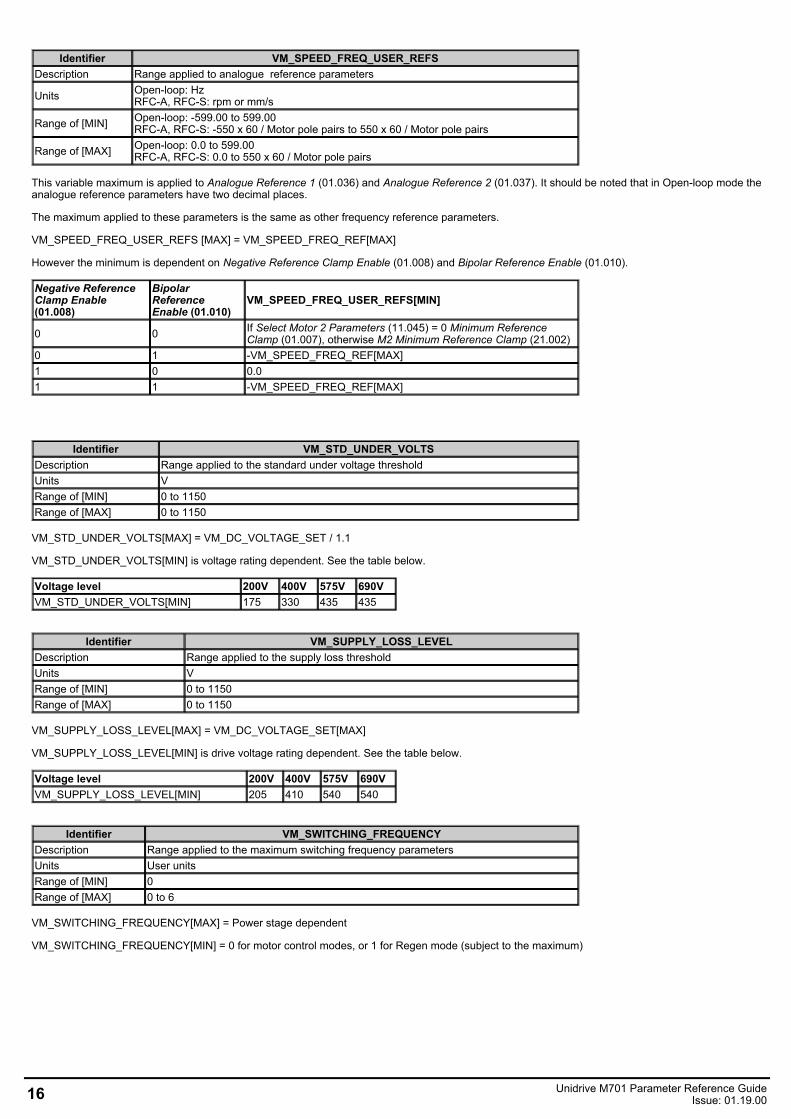
Identifier VM_SPEED_FREQ_USER_REFSDescription Range applied to analogue reference parameters
Units Open-loop: HzRFC-A, RFC-S: rpm or mm/s
Range of [MIN] Open-loop: -599.00 to 599.00RFC-A, RFC-S: -550 x 60 / Motor pole pairs to 550 x 60 / Motor pole pairs
Range of [MAX] Open-loop: 0.0 to 599.00RFC-A, RFC-S: 0.0 to 550 x 60 / Motor pole pairs
This variable maximum is applied to Analogue Reference 1 (01.036) and Analogue Reference 2 (01.037). It should be noted that in Open-loop mode theanalogue reference parameters have two decimal places.
The maximum applied to these parameters is the same as other frequency reference parameters.
VM_SPEED_FREQ_USER_REFS [MAX] = VM_SPEED_FREQ_REF[MAX]
However the minimum is dependent on Negative Reference Clamp Enable (01.008) and Bipolar Reference Enable (01.010).
Negative ReferenceClamp Enable(01.008)
BipolarReferenceEnable (01.010)
VM_SPEED_FREQ_USER_REFS[MIN]
0 0 If Select Motor 2 Parameters (11.045) = 0 Minimum ReferenceClamp (01.007), otherwise M2 Minimum Reference Clamp (21.002)
0 1 -VM_SPEED_FREQ_REF[MAX]1 0 0.01 1 -VM_SPEED_FREQ_REF[MAX]
Identifier VM_STD_UNDER_VOLTSDescription Range applied to the standard under voltage thresholdUnits VRange of [MIN] 0 to 1150Range of [MAX] 0 to 1150
VM_STD_UNDER_VOLTS[MAX] = VM_DC_VOLTAGE_SET / 1.1
VM_STD_UNDER_VOLTS[MIN] is voltage rating dependent. See the table below.
Voltage level 200V 400V 575V 690VVM_STD_UNDER_VOLTS[MIN] 175 330 435 435
Identifier VM_SUPPLY_LOSS_LEVELDescription Range applied to the supply loss thresholdUnits VRange of [MIN] 0 to 1150Range of [MAX] 0 to 1150
VM_SUPPLY_LOSS_LEVEL[MAX] = VM_DC_VOLTAGE_SET[MAX]
VM_SUPPLY_LOSS_LEVEL[MIN] is drive voltage rating dependent. See the table below.
Voltage level 200V 400V 575V 690VVM_SUPPLY_LOSS_LEVEL[MIN] 205 410 540 540
Identifier VM_SWITCHING_FREQUENCYDescription Range applied to the maximum switching frequency parametersUnits User unitsRange of [MIN] 0Range of [MAX] 0 to 6
VM_SWITCHING_FREQUENCY[MAX] = Power stage dependent
VM_SWITCHING_FREQUENCY[MIN] = 0 for motor control modes, or 1 for Regen mode (subject to the maximum)
16 Unidrive M701 Parameter Reference GuideIssue: 01.19.00
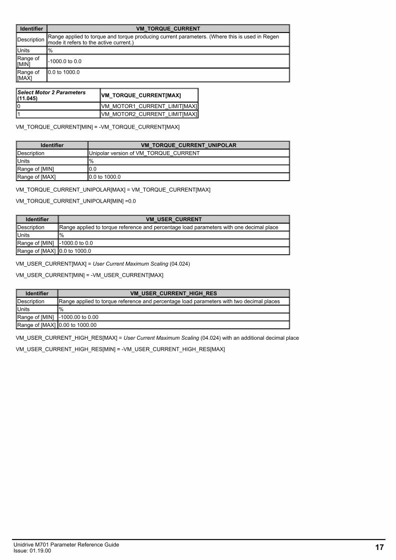
Identifier VM_TORQUE_CURRENT
Description Range applied to torque and torque producing current parameters. (Where this is used in Regenmode it refers to the active current.)
Units %Range of[MIN] -1000.0 to 0.0
Range of[MAX]
0.0 to 1000.0
Select Motor 2 Parameters(11.045) VM_TORQUE_CURRENT[MAX]
0 VM_MOTOR1_CURRENT_LIMIT[MAX]1 VM_MOTOR2_CURRENT_LIMIT[MAX]
VM_TORQUE_CURRENT[MIN] = -VM_TORQUE_CURRENT[MAX]
Identifier VM_TORQUE_CURRENT_UNIPOLARDescription Unipolar version of VM_TORQUE_CURRENTUnits %Range of [MIN] 0.0Range of [MAX] 0.0 to 1000.0
VM_TORQUE_CURRENT_UNIPOLAR[MAX] = VM_TORQUE_CURRENT[MAX]
VM_TORQUE_CURRENT_UNIPOLAR[MIN] =0.0
Identifier VM_USER_CURRENTDescription Range applied to torque reference and percentage load parameters with one decimal placeUnits %Range of [MIN] -1000.0 to 0.0Range of [MAX] 0.0 to 1000.0
VM_USER_CURRENT[MAX] = User Current Maximum Scaling (04.024)
VM_USER_CURRENT[MIN] = -VM_USER_CURRENT[MAX]
Identifier VM_USER_CURRENT_HIGH_RESDescription Range applied to torque reference and percentage load parameters with two decimal placesUnits %Range of [MIN] -1000.00 to 0.00Range of [MAX] 0.00 to 1000.00
VM_USER_CURRENT_HIGH_RES[MAX] = User Current Maximum Scaling (04.024) with an additional decimal place
VM_USER_CURRENT_HIGH_RES[MIN] = -VM_USER_CURRENT_HIGH_RES[MAX]
Unidrive M701 Parameter Reference GuideIssue: 01.19.00 17
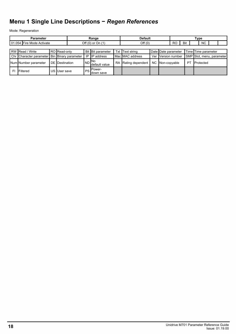
Menu 1 Single Line Descriptions − Regen ReferencesMode: Regeneration
Parameter Range Default Type01.054 Fire Mode Activate Off (0) or On (1) Off (0) RO Bit NC
RW Read / Write RO Read-only Bit Bit parameter Txt Text string Date Date parameter Time Time parameterChr Character parameter Bin Binary parameter IP IP address Mac MAC address Ver Version number SMP Slot, menu, parameter
Num Number parameter DE Destination ND Nodefault value RA Rating dependent NC Non-copyable PT Protected
FI Filtered US User save PS Power-down save
18 Unidrive M701 Parameter Reference GuideIssue: 01.19.00
Menu 1 − Regen ReferencesMode: Regeneration
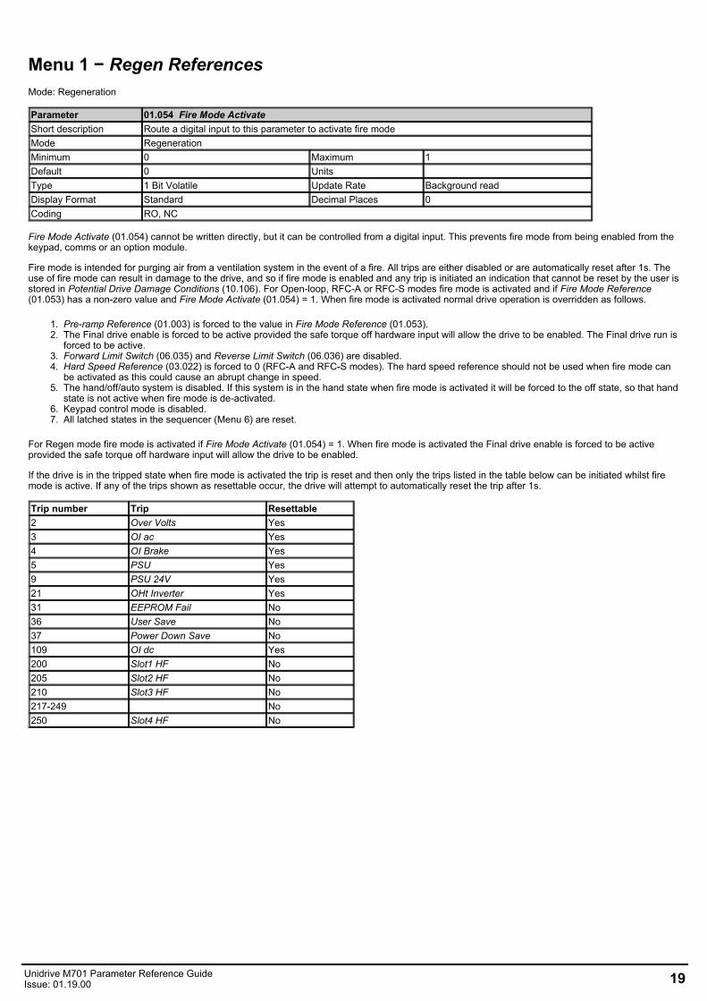
Parameter 01.054 Fire Mode ActivateShort description Route a digital input to this parameter to activate fire modeMode RegenerationMinimum 0 Maximum 1Default 0 Units Type 1 Bit Volatile Update Rate Background readDisplay Format Standard Decimal Places 0Coding RO, NC
Fire Mode Activate (01.054) cannot be written directly, but it can be controlled from a digital input. This prevents fire mode from being enabled from thekeypad, comms or an option module.
Fire mode is intended for purging air from a ventilation system in the event of a fire. All trips are either disabled or are automatically reset after 1s. Theuse of fire mode can result in damage to the drive, and so if fire mode is enabled and any trip is initiated an indication that cannot be reset by the user isstored in Potential Drive Damage Conditions (10.106). For Open-loop, RFC-A or RFC-S modes fire mode is activated and if Fire Mode Reference(01.053) has a non-zero value and Fire Mode Activate (01.054) = 1. When fire mode is activated normal drive operation is overridden as follows.
1. Pre-ramp Reference (01.003) is forced to the value in Fire Mode Reference (01.053).2. The Final drive enable is forced to be active provided the safe torque off hardware input will allow the drive to be enabled. The Final drive run is
forced to be active.3. Forward Limit Switch (06.035) and Reverse Limit Switch (06.036) are disabled.4. Hard Speed Reference (03.022) is forced to 0 (RFC-A and RFC-S modes). The hard speed reference should not be used when fire mode can
be activated as this could cause an abrupt change in speed.5. The hand/off/auto system is disabled. If this system is in the hand state when fire mode is activated it will be forced to the off state, so that hand
state is not active when fire mode is de-activated.6. Keypad control mode is disabled.7. All latched states in the sequencer (Menu 6) are reset.
For Regen mode fire mode is activated if Fire Mode Activate (01.054) = 1. When fire mode is activated the Final drive enable is forced to be activeprovided the safe torque off hardware input will allow the drive to be enabled.
If the drive is in the tripped state when fire mode is activated the trip is reset and then only the trips listed in the table below can be initiated whilst firemode is active. If any of the trips shown as resettable occur, the drive will attempt to automatically reset the trip after 1s.
Trip number Trip Resettable2 Over Volts Yes3 OI ac Yes4 OI Brake Yes5 PSU Yes9 PSU 24V Yes21 OHt Inverter Yes31 EEPROM Fail No36 User Save No37 Power Down Save No109 OI dc Yes200 Slot1 HF No205 Slot2 HF No210 Slot3 HF No217-249 No250 Slot4 HF No
Unidrive M701 Parameter Reference GuideIssue: 01.19.00 19
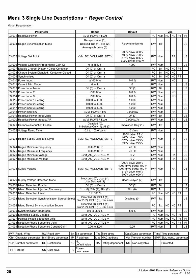
Menu 3 Single Line Descriptions − Regen ControlMode: Regeneration
Parameter Range Default Type03.001 Reactive Power ±VM_POWER kVAr RO Num ND NC PT FI
03.004 Regen Syncronisation ModeRe‑syncronise (0),
Delayed Trip (1), Trip (2),Auto‑synchronise (3)
Re‑syncronise (0) RW Txt US
03.005 Voltage Set Point ±VM_DC_VOLTAGE_SET V200V drive: 350 V400V drive: 700 V575V drive: 835 V
690V drive: 1100 VRW Num RA US
03.006 Voltage Controller Proportional Gain Kp 0 to 65535 4000 RW Num US03.007 Disable Charge System / Close Contactor Off (0) or On (1) RO Bit ND NC PT 03.008 Charge System Disabled / Contactor Closed Off (0) or On (1) RO Bit ND NC 03.009 Synchronised Off (0) or On (1) RO Bit ND NC PT 03.010 Power Input 1 ±100.0 % 0.0 % RW Num NC 03.011 Current Trim Mode 0 to 1 0 RW Num US03.012 Power Input Mode Off (0) or On (1) Off (0) RW Bit US03.013 Power Input 2 ±100.0 % 0.0 % RW Num NC 03.014 Power Input 3 ±100.0 % 0.0 % RW Num NC 03.015 Power Input 1 Scaling 0.000 to 4.000 1.000 RW Num US03.016 Power Input 2 Scaling 0.000 to 4.000 1.000 RW Num US03.017 Power Input 3 Scaling 0.000 to 4.000 1.000 RW Num US03.018 Power Input kW ±VM_POWER kW 0.000 kW RW Num RA 03.019 Reactive Power Input Mode Off (0) or On (1) Off (0) RW Bit US03.020 Reactive Power Input kVAR ±VM_POWER kVAr 0.000 kVAr RW Num RA US
03.021 Harmonic Reduction Enable Disabled (0),Imbalance Only (1), All (2) Imbalance Only (1) RW Txt US
03.022 Voltage Ramp Time 0.1 to 100.0 V/ms 1.0 V/ms RW Num US
03.023 Regen Supply Loss a.c. Level ±VM_AC_VOLTAGE_SET V200V drive: 75 V
400V drive: 150 V575V drive: 225 V690V drive: 225 V
RW Num RA US
03.024 Regen Minimum Frequency 10 to 200 Hz 40 Hz RW Num US03.025 Regen Maximum Frequency 10 to 200 Hz 70 Hz RW Num US03.026 Regen Minimum Voltage ±VM_AC_VOLTAGE V 0 V RW Num RA US03.027 Regen Maximum Voltage ±VM_AC_VOLTAGE V 0 V RW Num RA US
03.028 Supply Voltage ±VM_AC_VOLTAGE_SET V
200V drive: 230 V400V drive 50Hz: 400 V400V drive 60Hz: 460 V
575V drive: 575 V690V drive: 690 V
RW Num RA US
03.029 Supply Voltage Detection Mode Measured (0), User (1),User Delayed (2) User Delayed (2) RW Txt US
03.030 Island Detection Enable Off (0) or On (1) Off (0) RW Bit US03.031 Island Detection Injection Frequency 1Hz (0), 2Hz (1), 4Hz (2) 1Hz (0) RW Txt US03.032 Island Detection Level 0 to 100 % RO Num ND NC PT
03.033 Island Detection Synchronisation Source Select Disabled (0), Slot 1 (1),Slot 2 (2), Slot 3 (3), Slot 4 (4) Disabled (0) RW Txt US
03.034 Island Detect Synchronisation Source Disabled (0), Slot 1 (1),Slot 2 (2), Slot 3 (3), Slot 4 (4) RO Txt ND NC PT
03.035 Synchronisation Headroom 0.0 to 25.0 % 5.0 % RW Num US03.036 Estimated Supply Voltage ±VM_AC_VOLTAGE V RO Num ND NC PT 03.037 Positive Phase Sequence Volts ±VM_AC_VOLTAGE V RO Num ND NC PT FI03.038 Negative Phase Sequence Volts ±VM_AC_VOLTAGE V RO Num ND NC PT FI03.039 Negative Phase Sequence Current Gain 0.00 to 1.00 0.05 RW Num US
RW Read / Write RO Read-only Bit Bit parameter Txt Text string Date Date parameter Time Time parameterChr Character parameter Bin Binary parameter IP IP address Mac MAC address Ver Version number SMP Slot, menu, parameter
Num Number parameter DE Destination ND Nodefault value RA Rating dependent NC Non-copyable PT Protected
FI Filtered US User save PS Power-down save
20 Unidrive M701 Parameter Reference GuideIssue: 01.19.00
Menu 3 − Regen ControlMode: Regeneration
Unidrive M701 Parameter Reference GuideIssue: 01.19.00 21
22 Unidrive M701 Parameter Reference GuideIssue: 01.19.00
Parameter 03.001 Reactive PowerShort description Mode RegenerationMinimum −VM_POWER Maximum VM_POWERDefault Units kVArType 32 Bit Volatile Update Rate Background writeDisplay Format Standard Decimal Places 3Coding RO, FI, VM, ND, NC, PT
Output Power (05.003) and Reactive Power (03.001) are the power and VAR's respectively that flow from the supply to the drive. When Reactive Power(03.001) is positive the phase current flowing from the supply to the drive contains a component that lags the respective phase voltage, and so theregen system appears like and inductance connected to the supply and imports VARs. When Reactive Power (03.001) is negative the phase currentflowing from the supply contains a component which leads the respective phase voltage, and so the regen system appears like a capacitanceconnected to the supply and exports VARs.
Parameter 03.004 Regen Syncronisation ModeShort description Regen Syncronisation ModeMode RegenerationMinimum 0 Maximum 3Default 0 Units Type 8 Bit User Save Update Rate Background readDisplay Format Standard Decimal Places 0Coding RW, TE
Value Text0 Re-syncronise1 Delayed Trip2 Trip3 Auto-synchronise
When the system is enabled it attempts to synchronise to the supply. If the supply has significant distortion then the synchronisation process may failand cause an over-current condition to be detected. The system will automatically reset the detected over-current condition and continue to attempt tosynchronise. Once the system is synchronised, then if synchronisation is subsequently lost, or an over-current condition caused by a supply transientoccurs, or supply loss is detected (i.e. Supply Loss (10.015) = 1), then the action taken is defined by Regen Syncronisation Mode (03.004) as givenbelow. (It should be noted that the over-current condition will only be reset automatically ten times in any 10s period before an OI ac trip is produced.)
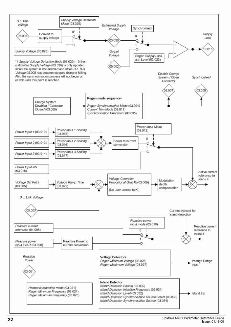
0: Re-synchroniseIf supply loss is detected the system will attempt to re-synchronise when the supply loss condition is no longer active. If an over-current trip occurs thesystem will attempt to resynchronise. If Supply Voltage Detection Mode (03.029) = 0 or 2 re-synchronisation will only begin if D.c. Bus Voltage(05.005) has stopped rising or falling. For Supply Voltage Detection Mode (03.029) = 0, this is so the supply voltage can be estimated from the level ofthe d.c. link voltage. If Supply Voltage Detection Mode (03.029) = 1 rapid resynchronisation is possible because the system does not wait for the d.c.link voltage to stop falling before attempting to re-synchronise.
1: Delayed TripThe system operates in the same way as "Re-synchronise" mode except that a Line Sync trip is initiated if synchronisation takes more than 30s.
2: Immediate TripThe system operates in the same way as "Re-synchronise" mode except that a Line Sync trip is initiated if synchronisation takes more than 30s,and Line Sync trip is produced immediately if supply loss is detected while the system is synchronised.
3: Auto-synchroniseIf an over-current condition is detected then this is reset. The system will simulate the supply angle based on the supply conditions before the over-current condition and restart the system within 10ms. If supply loss is detected the system will simulate the supply angle based on the supply conditions before supply loss was detected. This allows theinverter to remain active during the supply loss period and it is possible for reactive current to flow into the supply in the normal way, but the activecurrent is held at zero. As the active current is held at zero the d.c. link must be held at the required level externally, therefore this mode is only suitablefor an application where an external system connected to the d.c. terminals and holds the d.c. voltage at a suitable level. Regen Supply Loss a.c. Level(03.023) should be set to a level that is higher than the likely voltage seen at the inverter terminals due to any current being fed into the supply (e.g.10% of nominal supply voltage) or else the system will attempt to synchronise to its own output voltage. If Supply Loss (10.015) remains active for morethan 2.0s then an Island.2 trip is initiated. The diagram below shows the timing and minimum voltage envelope for auto-synchronisation. If the requiredtiming and voltage for transient fault ride-through lies within this envelope then the auto-synchronisation can be used to meet the requirements.
Unidrive M701 Parameter Reference GuideIssue: 01.19.00 23
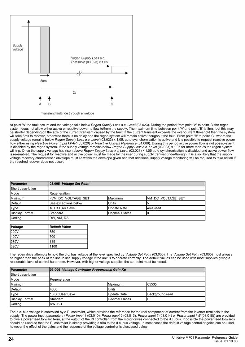
At point 'A' the fault occurs and the voltage falls below Regen Supply Loss a.c. Level (03.023). During the period from point 'A' to point 'B' the regensystem does not allow either active or reactive power to flow to/from the supply. The maximum time between point 'A' and point 'B' is 8ms, but this maybe shorter depending on the size of the current transient caused by the fault. If the current transient exceeds the over-current threshold then the systemwill take 8ms to recover, otherwise there is no delay and the regen system will remain active thoughout the fault. From point 'B' to point 'C', where thesupply voltage remains below Regen Supply Loss a.c. Level (03.023) x 1.05, auto-sysnchornisation is active and it is possible to request reactive powerflow either using Reactive Power Input kVAR (03.020) or Reactive Current Reference (04.008). During this period active power flow is not possible as itis disabled by the regen system. If the supply voltage remains below Regen Supply Loss a.c. Level (03.023) x 1.05 for more than 2s the regen systemwill trip. Once the supply voltage has risen above Regen Supply Loss a.c. Level (03.023) x 1.05 auto-synchronisation is disabled and active power flowis re-enabled. The request for reactive and active power must be made by the user during supply tranisent ride-through. It is also likely that the supplyvoltage recovery characteristic envelope must lie within the envelope given and that additional supply voltage monitoring will be required to take action ifthe required recover does not occur.
Parameter 03.005 Voltage Set PointShort description Mode RegenerationMinimum −VM_DC_VOLTAGE_SET Maximum VM_DC_VOLTAGE_SETDefault See exceptions below Units VType 16 Bit User Save Update Rate 4ms readDisplay Format Standard Decimal Places 0Coding RW, VM, RA
Voltage Default Value200V 350400V 700575V 835690V 1100
The regen drive attempts to hold the d.c. bus voltage at the level specified by Voltage Set Point (03.005). The Voltage Set Point (03.005) must alwaysbe higher than the peak of the line to line supply voltage if the unit is to operate correctly. The default values can be used with most supplies giving areasonable level of control headroom. However, with higher voltage supplies the set-point must be raised.
Parameter 03.006 Voltage Controller Proportional Gain KpShort description Mode RegenerationMinimum 0 Maximum 65535Default 4000 Units Type 16 Bit User Save Update Rate Background readDisplay Format Standard Decimal Places 0Coding RW, BU
The d.c. bus voltage is controlled by a PI controller, which provides the reference for the real component of current from the inverter terminals to thesupply. The power input parameters (Power Input 1 (03.010), Power Input 2 (03.013), Power Input 3 (03.014) or Power Input kW (03.018)) are providedto give a power feed forward term, at the output of the PI controller, from the motor drives connected to the d.c. bus. If possible the power feed forwardsshould be used so that the PI controller is simply providing a trim to the d.c. bus voltage. In most cases the default voltage controller gains can be used,however the effect of the gains and the response of the voltage controller is discussed below.
24 Unidrive M701 Parameter Reference GuideIssue: 01.19.00
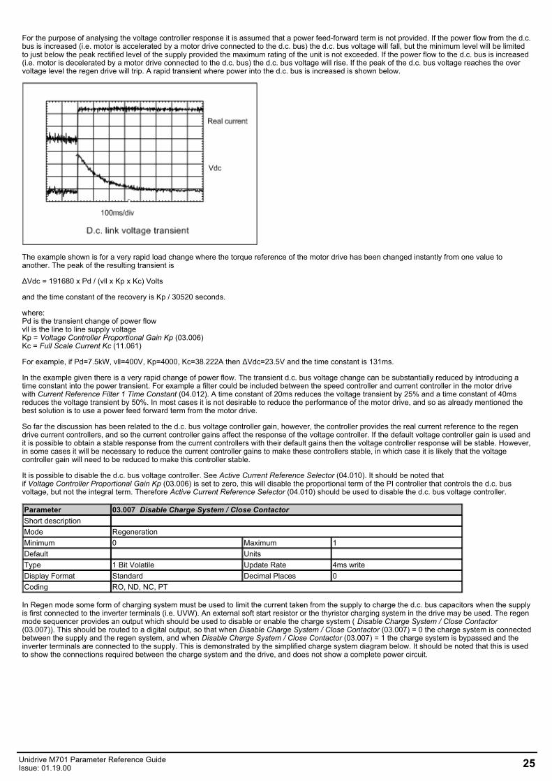
For the purpose of analysing the voltage controller response it is assumed that a power feed-forward term is not provided. If the power flow from the d.c.bus is increased (i.e. motor is accelerated by a motor drive connected to the d.c. bus) the d.c. bus voltage will fall, but the minimum level will be limitedto just below the peak rectified level of the supply provided the maximum rating of the unit is not exceeded. If the power flow to the d.c. bus is increased(i.e. motor is decelerated by a motor drive connected to the d.c. bus) the d.c. bus voltage will rise. If the peak of the d.c. bus voltage reaches the overvoltage level the regen drive will trip. A rapid transient where power into the d.c. bus is increased is shown below.
The example shown is for a very rapid load change where the torque reference of the motor drive has been changed instantly from one value toanother. The peak of the resulting transient is
ΔVdc = 191680 x Pd / (vll x Kp x Kc) Volts
and the time constant of the recovery is Kp / 30520 seconds.
where:Pd is the transient change of power flowvll is the line to line supply voltageKp = Voltage Controller Proportional Gain Kp (03.006)Kc = Full Scale Current Kc (11.061)
For example, if Pd=7.5kW, vll=400V, Kp=4000, Kc=38.222A then ΔVdc=23.5V and the time constant is 131ms.
In the example given there is a very rapid change of power flow. The transient d.c. bus voltage change can be substantially reduced by introducing atime constant into the power transient. For example a filter could be included between the speed controller and current controller in the motor drivewith Current Reference Filter 1 Time Constant (04.012). A time constant of 20ms reduces the voltage transient by 25% and a time constant of 40msreduces the voltage transient by 50%. In most cases it is not desirable to reduce the performance of the motor drive, and so as already mentioned thebest solution is to use a power feed forward term from the motor drive.
So far the discussion has been related to the d.c. bus voltage controller gain, however, the controller provides the real current reference to the regendrive current controllers, and so the current controller gains affect the response of the voltage controller. If the default voltage controller gain is used andit is possible to obtain a stable response from the current controllers with their default gains then the voltage controller response will be stable. However,in some cases it will be necessary to reduce the current controller gains to make these controllers stable, in which case it is likely that the voltagecontroller gain will need to be reduced to make this controller stable.
It is possible to disable the d.c. bus voltage controller. See Active Current Reference Selector (04.010). It should be noted thatif Voltage Controller Proportional Gain Kp (03.006) is set to zero, this will disable the proportional term of the PI controller that controls the d.c. busvoltage, but not the integral term. Therefore Active Current Reference Selector (04.010) should be used to disable the d.c. bus voltage controller.
Parameter 03.007 Disable Charge System / Close ContactorShort description Mode RegenerationMinimum 0 Maximum 1Default Units Type 1 Bit Volatile Update Rate 4ms writeDisplay Format Standard Decimal Places 0Coding RO, ND, NC, PT
In Regen mode some form of charging system must be used to limit the current taken from the supply to charge the d.c. bus capacitors when the supplyis first connected to the inverter terminals (i.e. UVW). An external soft start resistor or the thyristor charging system in the drive may be used. The regenmode sequencer provides an output which should be used to disable or enable the charge system ( Disable Charge System / Close Contactor(03.007)). This should be routed to a digital output, so that when Disable Charge System / Close Contactor (03.007) = 0 the charge system is connectedbetween the supply and the regen system, and when Disable Charge System / Close Contactor (03.007) = 1 the charge system is bypassed and theinverter terminals are connected to the supply. This is demonstrated by the simplified charge system diagram below. It should be noted that this is usedto show the connections required between the charge system and the drive, and does not show a complete power circuit.
Unidrive M701 Parameter Reference GuideIssue: 01.19.00 25
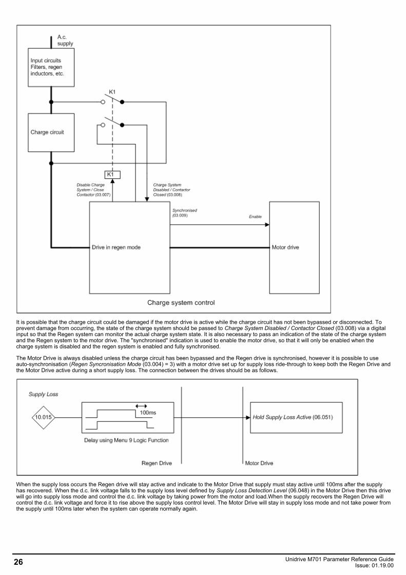
It is possible that the charge circuit could be damaged if the motor drive is active while the charge circuit has not been bypassed or disconnected. Toprevent damage from occurring, the state of the charge system should be passed to Charge System Disabled / Contactor Closed (03.008) via a digitalinput so that the Regen system can monitor the actual charge system state. It is also necessary to pass an indication of the state of the charge systemand the Regen system to the motor drive. The "synchronised" indication is used to enable the motor drive, so that it will only be enabled when thecharge system is disabled and the regen system is enabled and fully synchronised.
The Motor Drive is always disabled unless the charge circuit has been bypassed and the Regen drive is synchronised, however it is possible to useauto-synchronisation (Regen Syncronisation Mode (03.004) = 3) with a motor drive set up for supply loss ride-through to keep both the Regen Drive andthe Motor Drive active during a short supply loss. The connection between the drives should be as follows.
When the supply loss occurs the Regen drive will stay active and indicate to the Motor Drive that supply must stay active until 100ms after the supplyhas recovered. When the d.c. link voltage falls to the supply loss level defined by Supply Loss Detection Level (06.048) in the Motor Drive then this drivewill go into supply loss mode and control the d.c. link voltage by taking power from the motor and load.When the supply recovers the Regen Drive willcontrol the d.c. link voltage and force it to rise above the supply loss control level. The Motor Drive will stay in supply loss mode and not take power fromthe supply until 100ms later when the system can operate normally again.
26 Unidrive M701 Parameter Reference GuideIssue: 01.19.00
Parameter 03.008 Charge System Disabled / Contactor ClosedShort description Mode RegenerationMinimum 0 Maximum 1Default Units Type 1 Bit Volatile Update Rate 4ms readDisplay Format Standard Decimal Places 0Coding RO, ND, NC
See Disable Charge System / Close Contactor (03.007).
Parameter 03.009 SynchronisedShort description Regen system is synchronised to the supplyMode RegenerationMinimum 0 Maximum 1Default Units Type 1 Bit Volatile Update Rate 4ms writeDisplay Format Standard Decimal Places 0Coding RO, ND, NC, PT
See Disable Charge System / Close Contactor (03.007).
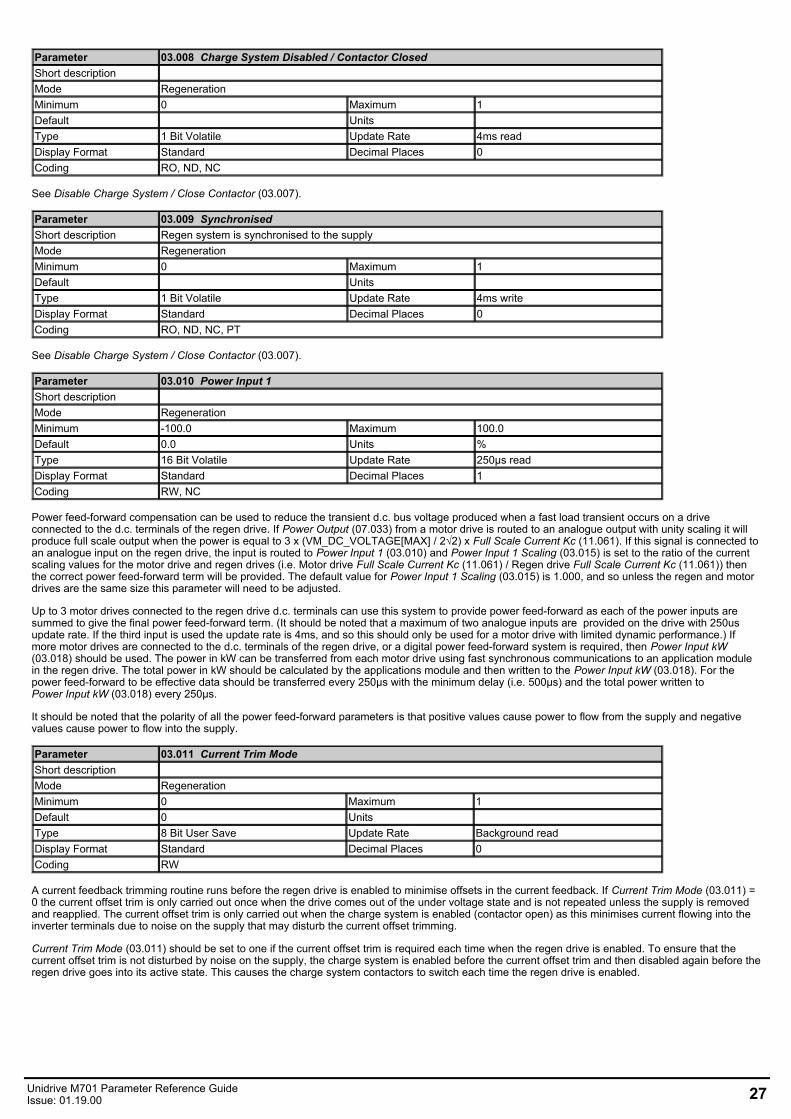
Parameter 03.010 Power Input 1Short description Mode RegenerationMinimum -100.0 Maximum 100.0Default 0.0 Units %Type 16 Bit Volatile Update Rate 250µs readDisplay Format Standard Decimal Places 1Coding RW, NC
Power feed-forward compensation can be used to reduce the transient d.c. bus voltage produced when a fast load transient occurs on a driveconnected to the d.c. terminals of the regen drive. If Power Output (07.033) from a motor drive is routed to an analogue output with unity scaling it willproduce full scale output when the power is equal to 3 x (VM_DC_VOLTAGE[MAX] / 2√2) x Full Scale Current Kc (11.061). If this signal is connected toan analogue input on the regen drive, the input is routed to Power Input 1 (03.010) and Power Input 1 Scaling (03.015) is set to the ratio of the currentscaling values for the motor drive and regen drives (i.e. Motor drive Full Scale Current Kc (11.061) / Regen drive Full Scale Current Kc (11.061)) thenthe correct power feed-forward term will be provided. The default value for Power Input 1 Scaling (03.015) is 1.000, and so unless the regen and motordrives are the same size this parameter will need to be adjusted.
Up to 3 motor drives connected to the regen drive d.c. terminals can use this system to provide power feed-forward as each of the power inputs aresummed to give the final power feed-forward term. (It should be noted that a maximum of two analogue inputs are provided on the drive with 250usupdate rate. If the third input is used the update rate is 4ms, and so this should only be used for a motor drive with limited dynamic performance.) Ifmore motor drives are connected to the d.c. terminals of the regen drive, or a digital power feed-forward system is required, then Power Input kW(03.018) should be used. The power in kW can be transferred from each motor drive using fast synchronous communications to an application modulein the regen drive. The total power in kW should be calculated by the applications module and then written to the Power Input kW (03.018). For thepower feed-forward to be effective data should be transferred every 250μs with the minimum delay (i.e. 500μs) and the total power written toPower Input kW (03.018) every 250μs.
It should be noted that the polarity of all the power feed-forward parameters is that positive values cause power to flow from the supply and negativevalues cause power to flow into the supply.
Parameter 03.011 Current Trim ModeShort description Mode RegenerationMinimum 0 Maximum 1Default 0 Units Type 8 Bit User Save Update Rate Background readDisplay Format Standard Decimal Places 0Coding RW
A current feedback trimming routine runs before the regen drive is enabled to minimise offsets in the current feedback. If Current Trim Mode (03.011) =0 the current offset trim is only carried out once when the drive comes out of the under voltage state and is not repeated unless the supply is removedand reapplied. The current offset trim is only carried out when the charge system is enabled (contactor open) as this minimises current flowing into theinverter terminals due to noise on the supply that may disturb the current offset trimming.
Current Trim Mode (03.011) should be set to one if the current offset trim is required each time when the regen drive is enabled. To ensure that thecurrent offset trim is not disturbed by noise on the supply, the charge system is enabled before the current offset trim and then disabled again before theregen drive goes into its active state. This causes the charge system contactors to switch each time the regen drive is enabled.
Unidrive M701 Parameter Reference GuideIssue: 01.19.00 27
Parameter 03.012 Power Input ModeShort description Mode RegenerationMinimum 0 Maximum 1Default 0 Units Type 1 Bit User Save Update Rate Background readDisplay Format Standard Decimal Places 0Coding RW
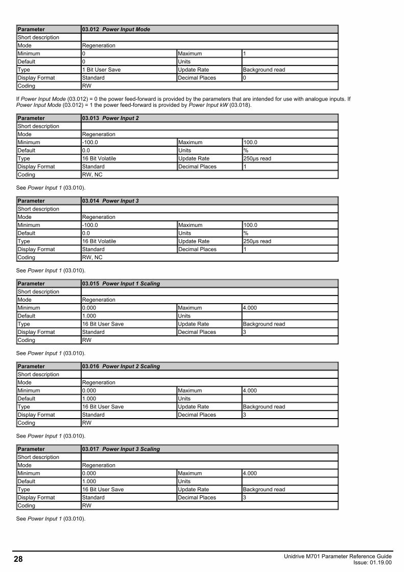
If Power Input Mode (03.012) = 0 the power feed-forward is provided by the parameters that are intended for use with analogue inputs. IfPower Input Mode (03.012) = 1 the power feed-forward is provided by Power Input kW (03.018).
Parameter 03.013 Power Input 2Short description Mode RegenerationMinimum -100.0 Maximum 100.0Default 0.0 Units %Type 16 Bit Volatile Update Rate 250µs readDisplay Format Standard Decimal Places 1Coding RW, NC
See Power Input 1 (03.010).
Parameter 03.014 Power Input 3Short description Mode RegenerationMinimum -100.0 Maximum 100.0Default 0.0 Units %Type 16 Bit Volatile Update Rate 250µs readDisplay Format Standard Decimal Places 1Coding RW, NC
See Power Input 1 (03.010).
Parameter 03.015 Power Input 1 ScalingShort description Mode RegenerationMinimum 0.000 Maximum 4.000Default 1.000 Units Type 16 Bit User Save Update Rate Background readDisplay Format Standard Decimal Places 3Coding RW
See Power Input 1 (03.010).
Parameter 03.016 Power Input 2 ScalingShort description Mode RegenerationMinimum 0.000 Maximum 4.000Default 1.000 Units Type 16 Bit User Save Update Rate Background readDisplay Format Standard Decimal Places 3Coding RW
See Power Input 1 (03.010).
Parameter 03.017 Power Input 3 ScalingShort description Mode RegenerationMinimum 0.000 Maximum 4.000Default 1.000 Units Type 16 Bit User Save Update Rate Background readDisplay Format Standard Decimal Places 3Coding RW
See Power Input 1 (03.010).
28 Unidrive M701 Parameter Reference GuideIssue: 01.19.00
Parameter 03.018 Power Input kWShort description Mode RegenerationMinimum −VM_POWER Maximum VM_POWERDefault 0.000 Units kWType 32 Bit Volatile Update Rate 250µs readDisplay Format Standard Decimal Places 3Coding RW, VM, RA, NC
See Power Input 1 (03.010).
Parameter 03.019 Reactive Power Input ModeShort description Mode RegenerationMinimum 0 Maximum 1Default 0 Units Type 1 Bit User Save Update Rate Background readDisplay Format Standard Decimal Places 0Coding RW
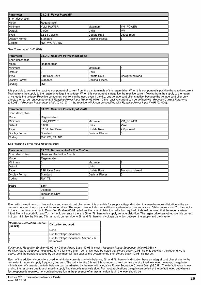
It is possible to control the reactive component of current from the a.c. terminals of the regen drive. When this component is positive the reactive currentflowing from the supply to the regen drive lags the voltage. When this component is negative the reactive current flowing from the supply to the regendrive leads the voltage. Reactive component control can be used even if the d.c. bus voltage controller is active, because the voltage controller onlyaffects the real current component. If Reactive Power Input Mode (03.019) = 0 the reactive current can be defined with Reactive Current Reference(04.008). If Reactive Power Input Mode (03.019) = 1 the reactive kVAR can be specified with Reactive Power Input kVAR (03.020).
Parameter 03.020 Reactive Power Input kVARShort description Mode RegenerationMinimum −VM_POWER Maximum VM_POWERDefault 0.000 Units kVArType 32 Bit User Save Update Rate 250µs readDisplay Format Standard Decimal Places 3Coding RW, VM, RA, NC
See Reactive Power Input Mode (03.019).
Parameter 03.021 Harmonic Reduction EnableShort description Harmonic Reduction EnableMode RegenerationMinimum 0 Maximum 2Default 1 Units Type 8 Bit User Save Update Rate Background readDisplay Format Standard Decimal Places 0Coding RW, TE
Value Text0 Disabled1 Imbalance Only2 All
Even with the optimum d.c. bus voltage and current controller set-up it is possible for supply voltage distortion to cause harmonic distortion in the a.c.currents between the supply and the regen drive. The regen drive includes an additional system to reduce imbalance, 5th harmonics and 7th harmonicsin the a.c. currents. Harmonic Reduction Enable (03.021) defines the type of distortion reduction required. It should be noted that the regen systemintput filter will absorb 5th and 7th harmonic currents if there is 5th or 7th harmonic supply voltage distortion. The regen drive cannot reduce this current,but can minimise the 5th and 7th harmonic current due to 5th and 7th harmonic voltage distortion between the supply and the inverter.
Harmonic Reduction Enable(03.021) Distortion reduced
0 None1 Due to voltage imbalance
2 Due to voltage imbalance, 5th and 7thharmonics
If Harmonic Reduction Enable (03.021) > 0 then Phase Loss (10.081) is set if Negative Phase Sequence Volts (03.038) >Positive Phase Sequence Volts (03.037) / 2 for more than 100ms. It should be noted that Phase Loss (10.081) is only set when the regen drive isactive, so if the transient caused by an asymmetrical fault causes the system to trip then Phase Loss (10.081) is not set.
Each of the additional controllers used to minimise currents due to imbalance, 5th and 7th harmonic distortion have an integral controller similar to thecontroller for normal supply frequency currents. The gains for the 5th and 7th harmonic current control are at a fixed low level, however, the gain forminimisation of currents due to imbalance can be adjusted by the user with Negative Phase Sequence Current Gain (03.039). The default value is low,and so the response due to a change in supply imbalance is relatively slow. For most applications the gain can be left at the default level, but where afast response is required, i.e. contiued operation in the presence of an asymmetrical fault, the level should be
Unidrive M701 Parameter Reference GuideIssue: 01.19.00 29
increased. Negative Phase Sequence Current Gain (03.039) defines the gain used for control of currents due to imbalance as a proportionof Current Controller Ki Gain (04.014). Care should be taken when increasing this value as the system stabilty may be reduced particularly with a weaksupply.
Parameter 03.022 Voltage Ramp TimeShort description Mode RegenerationMinimum 0.1 Maximum 100.0Default 1.0 Units V/msType 16 Bit User Save Update Rate Background readDisplay Format Standard Decimal Places 1Coding RW
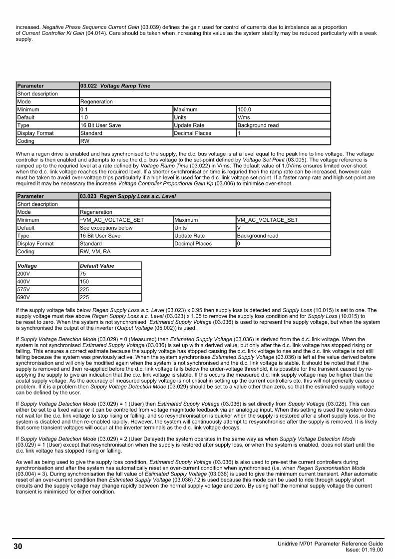
When a regen drive is enabled and has synchronised to the supply, the d.c. bus voltage is at a level equal to the peak line to line voltage. The voltagecontroller is then enabled and attempts to raise the d.c. bus voltage to the set-point defined by Voltage Set Point (03.005). The voltage reference isramped up to the requried level at a rate defined by Voltage Ramp Time (03.022) in V/ms. The default value of 1.0V/ms ensures limited over-shootwhen the d.c. link voltage reaches the required level. If a shorter synchronisation time is requried then the ramp rate can be increased, however caremust be taken to avoid over-voltage trips particularly if a high level is used for the d.c. link voltage set-point. If a faster ramp rate and high set-point arerequired it may be necessary the increase Voltage Controller Proportional Gain Kp (03.006) to minimise over-shoot.
Parameter 03.023 Regen Supply Loss a.c. LevelShort description Mode RegenerationMinimum −VM_AC_VOLTAGE_SET Maximum VM_AC_VOLTAGE_SETDefault See exceptions below Units VType 16 Bit User Save Update Rate Background readDisplay Format Standard Decimal Places 0Coding RW, VM, RA
Voltage Default Value200V 75400V 150575V 225690V 225
If the supply voltage falls below Regen Supply Loss a.c. Level (03.023) x 0.95 then supply loss is detected and Supply Loss (10.015) is set to one. Thesupply voltage must rise above Regen Supply Loss a.c. Level (03.023) x 1.05 to remove the supply loss condition and for Supply Loss (10.015) tobe reset to zero. When the system is not synchronised Estimated Supply Voltage (03.036) is used to represent the supply voltage, but when the systemis synchronised the output of the inverter (Output Voltage (05.002)) is used.
If Supply Voltage Detection Mode (03.029) = 0 (Measured) then Estimated Supply Voltage (03.036) is derived from the d.c. link voltage. When thesystem is not synchronised Estimated Supply Voltage (03.036) is set up with a derived value, but only after the d.c. link voltage has stopped rising orfalling. This ensures a correct estimate because the supply voltage has stopped causing the d.c. link voltage to rise and the d.c. link voltage is not stillfalling because the system was previously active. When the system synchronises Estimated Supply Voltage (03.036) is left at the value derived beforesynchronisation and will only be modified again when the system is not synchronised and the d.c. link voltage is stable. It should be noted that if thesupply is removed and then re-applied before the d.c. link voltage falls below the under-voltage threshold, it is possible for the transient caused by re-applying the supply to give an indication that the d.c. link voltage is stable. If this occurs the measured d.c. link supply voltage may be higher than theacutal supply voltage. As the accuracy of measured supply voltage is not critical in setting up the current controllers etc. this will not generally cause aproblem. If it is a problem then Supply Voltage Detection Mode (03.029) should be set to a value other than zero, so that the estimated supply voltagecan be defined by the user.
If Supply Voltage Detection Mode (03.029) = 1 (User) then Estimated Supply Voltage (03.036) is set directly from Supply Voltage (03.028). This caneither be set to a fixed value or it can be controlled from voltage magnitude feedback via an analogue input. When this setting is used the system doesnot wait for the d.c. link voltage to stop rising or falling, and so resynchronisation is quicker when the supply is restored after a short supply loss, or thesystem is disabled and then re-enabled rapidly. However, the system will continuously attempt to resysnchronise after the supply is removed. It is likelythat some transient voltages will occur at the inverter terminals as the d.c. link voltage decays.
If Supply Voltage Detection Mode (03.029) = 2 (User Delayed) the system operates in the same way as when Supply Voltage Detection Mode(03.029) = 1 (User) except that resynchronisation when the supply is restored after supply loss, or when the system is enabled, does not start until thed.c. link voltage has stopped rising or falling.
As well as being used to give the supply loss condition, Estimated Supply Voltage (03.036) is also used to pre-set the current controllers duringsynchronisation and after the system has automatically reset an over-current condition when synchronised (i.e. when Regen Syncronisation Mode(03.004) = 3). During synchronisation the full value of Estimated Supply Voltage (03.036) is used to give the minimum current transient. After automaticreset of an over-current condition then Estimated Supply Voltage (03.036) / 2 is used because this mode can be used to ride through supply shortcircuits and the supply voltage may change rapidly between the normal supply voltage and zero. By using half the nominal supply voltage the currenttransient is minimised for either condition.
30 Unidrive M701 Parameter Reference GuideIssue: 01.19.00
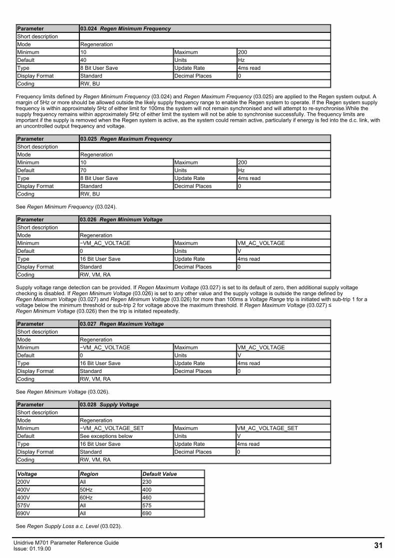
Parameter 03.024 Regen Minimum FrequencyShort description Mode RegenerationMinimum 10 Maximum 200Default 40 Units HzType 8 Bit User Save Update Rate 4ms readDisplay Format Standard Decimal Places 0Coding RW, BU
Frequency limits defined by Regen Minimum Frequency (03.024) and Regen Maximum Frequency (03.025) are applied to the Regen system output. Amargin of 5Hz or more should be allowed outside the likely supply frequency range to enable the Regen system to operate. If the Regen system supplyfrequency is within approximately 5Hz of either limit for 100ms the system will not remain synchronised and will attempt to re-synchronise.While thesupply frequency remains within approximately 5Hz of either limit the system will not be able to synchronise successfully. The frequency limits areimportant if the supply is removed when the Regen system is active, as the system could remain active, particularly if energy is fed into the d.c. link, withan uncontrolled output frequency and voltage.
Parameter 03.025 Regen Maximum FrequencyShort description Mode RegenerationMinimum 10 Maximum 200Default 70 Units HzType 8 Bit User Save Update Rate 4ms readDisplay Format Standard Decimal Places 0Coding RW, BU
See Regen Minimum Frequency (03.024).
Parameter 03.026 Regen Minimum VoltageShort description Mode RegenerationMinimum −VM_AC_VOLTAGE Maximum VM_AC_VOLTAGEDefault 0 Units VType 16 Bit User Save Update Rate 4ms readDisplay Format Standard Decimal Places 0Coding RW, VM, RA
Supply voltage range detection can be provided. If Regen Maximum Voltage (03.027) is set to its default of zero, then additional supply voltagechecking is disabled. If Regen Minimum Voltage (03.026) is set to any other value and the supply voltage is outside the range defined byRegen Maximum Voltage (03.027) and Regen Minimum Voltage (03.026) for more than 100ms a Voltage Range trip is initiated with sub-trip 1 for avoltage below the minimum threshold or sub-trip 2 for voltage above the maximum threshold. If Regen Maximum Voltage (03.027) ≤Regen Minimum Voltage (03.026) then the trip is initated repeatedly.
Parameter 03.027 Regen Maximum VoltageShort description Mode RegenerationMinimum −VM_AC_VOLTAGE Maximum VM_AC_VOLTAGEDefault 0 Units VType 16 Bit User Save Update Rate 4ms readDisplay Format Standard Decimal Places 0Coding RW, VM, RA
See Regen Minimum Voltage (03.026).
Parameter 03.028 Supply VoltageShort description Mode RegenerationMinimum −VM_AC_VOLTAGE_SET Maximum VM_AC_VOLTAGE_SETDefault See exceptions below Units VType 16 Bit User Save Update Rate 4ms readDisplay Format Standard Decimal Places 0Coding RW, VM, RA
Voltage Region Default Value200V All 230400V 50Hz 400400V 60Hz 460575V All 575690V All 690
See Regen Supply Loss a.c. Level (03.023).
Unidrive M701 Parameter Reference GuideIssue: 01.19.00 31
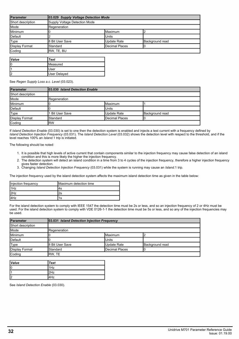
Parameter 03.029 Supply Voltage Detection ModeShort description Supply Voltage Detection ModeMode RegenerationMinimum 0 Maximum 2Default 2 Units Type 8 Bit User Save Update Rate Background readDisplay Format Standard Decimal Places 0Coding RW, TE, BU
Value Text0 Measured1 User2 User Delayed
See Regen Supply Loss a.c. Level (03.023).
Parameter 03.030 Island Detection EnableShort description Mode RegenerationMinimum 0 Maximum 1Default 0 Units Type 1 Bit User Save Update Rate Background readDisplay Format Standard Decimal Places 0Coding RW
If Island Detection Enable (03.030) is set to one then the detection system is enabled and injects a test current with a frequency defined byIsland Detection Injection Frequency (03.031). The Island Detection Level (03.032) shows the detection level with respect to the threshold, and if thelevel reaches 100% an Island.1 trip is initiated.
The following should be noted:
1. It is possible that high levels of active current that contain components similar to the injection frequency may cause false detection of an islandcondition and this is more likely the higher the injection frequency.
2. The detection system will detect an island condition in a time from 3 to 4 cycles of the injection frequency, therefore a higher injection frequencygives faster detection.
3. Changing Island Detection Injection Frequency (03.031) while the system is running may cause an Island.1 trip.
The injection frequency used by the island detection system affects the maximum island detection time as given in the table below:
Injection frequency Maximum detection time1Hz 4s2Hz 2s4Hz 1s
For the island detection system to comply with IEEE 1547 the detection time must be 2s or less, and so an injection frequency of 2 or 4Hz must beused. For the island detection system to comply with VDE 0126-1-1 the detection time must be 5s or less, and so any of the injection frequencies maybe used.
Parameter 03.031 Island Detection Injection FrequencyShort description Mode RegenerationMinimum 0 Maximum 2Default 0 Units Type 8 Bit User Save Update Rate Background readDisplay Format Standard Decimal Places 0Coding RW, TE
Value Text0 1Hz1 2Hz2 4Hz
See Island Detection Enable (03.030).
32 Unidrive M701 Parameter Reference GuideIssue: 01.19.00
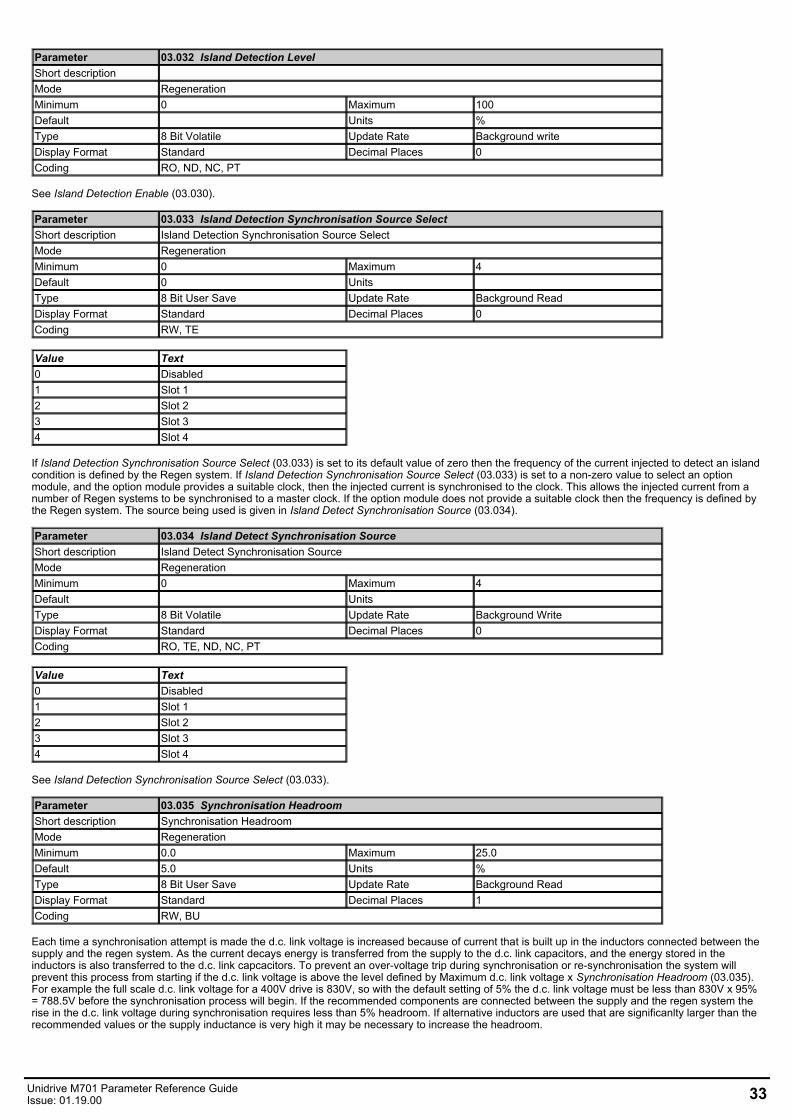
Parameter 03.032 Island Detection LevelShort description Mode RegenerationMinimum 0 Maximum 100Default Units %Type 8 Bit Volatile Update Rate Background writeDisplay Format Standard Decimal Places 0Coding RO, ND, NC, PT
See Island Detection Enable (03.030).
Parameter 03.033 Island Detection Synchronisation Source SelectShort description Island Detection Synchronisation Source SelectMode RegenerationMinimum 0 Maximum 4Default 0 Units Type 8 Bit User Save Update Rate Background ReadDisplay Format Standard Decimal Places 0Coding RW, TE
Value Text0 Disabled1 Slot 12 Slot 23 Slot 34 Slot 4
If Island Detection Synchronisation Source Select (03.033) is set to its default value of zero then the frequency of the current injected to detect an islandcondition is defined by the Regen system. If Island Detection Synchronisation Source Select (03.033) is set to a non-zero value to select an optionmodule, and the option module provides a suitable clock, then the injected current is synchronised to the clock. This allows the injected current from anumber of Regen systems to be synchronised to a master clock. If the option module does not provide a suitable clock then the frequency is defined bythe Regen system. The source being used is given in Island Detect Synchronisation Source (03.034).
Parameter 03.034 Island Detect Synchronisation SourceShort description Island Detect Synchronisation SourceMode RegenerationMinimum 0 Maximum 4Default Units Type 8 Bit Volatile Update Rate Background WriteDisplay Format Standard Decimal Places 0Coding RO, TE, ND, NC, PT
Value Text0 Disabled1 Slot 12 Slot 23 Slot 34 Slot 4
See Island Detection Synchronisation Source Select (03.033).
Parameter 03.035 Synchronisation HeadroomShort description Synchronisation HeadroomMode RegenerationMinimum 0.0 Maximum 25.0Default 5.0 Units %Type 8 Bit User Save Update Rate Background ReadDisplay Format Standard Decimal Places 1Coding RW, BU
Each time a synchronisation attempt is made the d.c. link voltage is increased because of current that is built up in the inductors connected between thesupply and the regen system. As the current decays energy is transferred from the supply to the d.c. link capacitors, and the energy stored in theinductors is also transferred to the d.c. link capcacitors. To prevent an over-voltage trip during synchronisation or re-synchronisation the system willprevent this process from starting if the d.c. link voltage is above the level defined by Maximum d.c. link voltage x Synchronisation Headroom (03.035).For example the full scale d.c. link voltage for a 400V drive is 830V, so with the default setting of 5% the d.c. link voltage must be less than 830V x 95%= 788.5V before the synchronisation process will begin. If the recommended components are connected between the supply and the regen system therise in the d.c. link voltage during synchronisation requires less than 5% headroom. If alternative inductors are used that are significanlty larger than therecommended values or the supply inductance is very high it may be necessary to increase the headroom.
Unidrive M701 Parameter Reference GuideIssue: 01.19.00 33
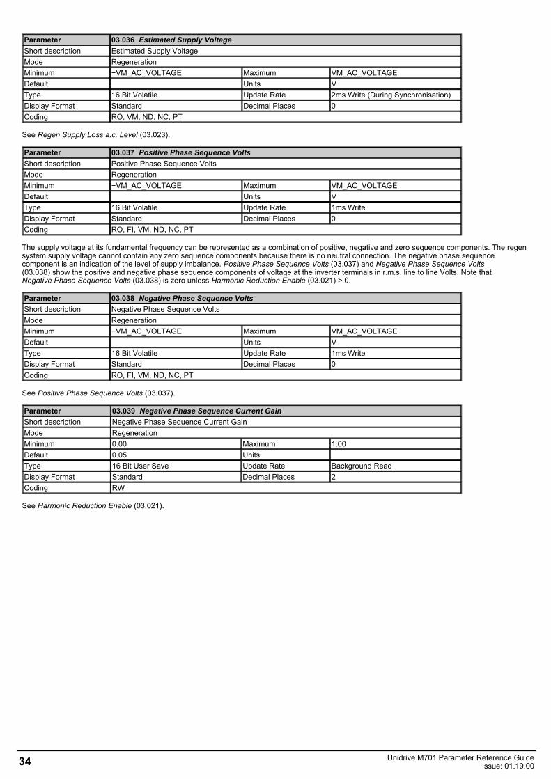
Parameter 03.036 Estimated Supply VoltageShort description Estimated Supply VoltageMode RegenerationMinimum −VM_AC_VOLTAGE Maximum VM_AC_VOLTAGEDefault Units VType 16 Bit Volatile Update Rate 2ms Write (During Synchronisation)Display Format Standard Decimal Places 0Coding RO, VM, ND, NC, PT
See Regen Supply Loss a.c. Level (03.023).
Parameter 03.037 Positive Phase Sequence VoltsShort description Positive Phase Sequence VoltsMode RegenerationMinimum −VM_AC_VOLTAGE Maximum VM_AC_VOLTAGEDefault Units VType 16 Bit Volatile Update Rate 1ms WriteDisplay Format Standard Decimal Places 0Coding RO, FI, VM, ND, NC, PT
The supply voltage at its fundamental frequency can be represented as a combination of positive, negative and zero sequence components. The regensystem supply voltage cannot contain any zero sequence components because there is no neutral connection. The negative phase sequencecomponent is an indication of the level of supply imbalance. Positive Phase Sequence Volts (03.037) and Negative Phase Sequence Volts(03.038) show the positive and negative phase sequence components of voltage at the inverter terminals in r.m.s. line to line Volts. Note thatNegative Phase Sequence Volts (03.038) is zero unless Harmonic Reduction Enable (03.021) > 0.
Parameter 03.038 Negative Phase Sequence VoltsShort description Negative Phase Sequence VoltsMode RegenerationMinimum −VM_AC_VOLTAGE Maximum VM_AC_VOLTAGEDefault Units VType 16 Bit Volatile Update Rate 1ms WriteDisplay Format Standard Decimal Places 0Coding RO, FI, VM, ND, NC, PT
See Positive Phase Sequence Volts (03.037).
Parameter 03.039 Negative Phase Sequence Current GainShort description Negative Phase Sequence Current GainMode RegenerationMinimum 0.00 Maximum 1.00Default 0.05 Units Type 16 Bit User Save Update Rate Background ReadDisplay Format Standard Decimal Places 2Coding RW
See Harmonic Reduction Enable (03.021).
34 Unidrive M701 Parameter Reference GuideIssue: 01.19.00
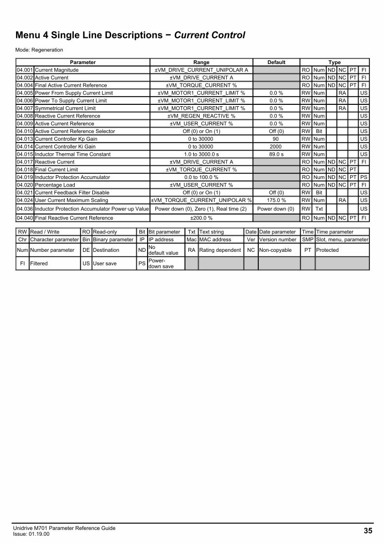
Menu 4 Single Line Descriptions − Current ControlMode: Regeneration
Parameter Range Default Type04.001 Current Magnitude ±VM_DRIVE_CURRENT_UNIPOLAR A RO Num ND NC PT FI04.002 Active Current ±VM_DRIVE_CURRENT A RO Num ND NC PT FI04.004 Final Active Current Reference ±VM_TORQUE_CURRENT % RO Num ND NC PT FI04.005 Power From Supply Current Limit ±VM_MOTOR1_CURRENT_LIMIT % 0.0 % RW Num RA US04.006 Power To Supply Current Limit ±VM_MOTOR1_CURRENT_LIMIT % 0.0 % RW Num RA US04.007 Symmetrical Current Limit ±VM_MOTOR1_CURRENT_LIMIT % 0.0 % RW Num RA US04.008 Reactive Current Reference ±VM_REGEN_REACTIVE % 0.0 % RW Num US04.009 Active Current Reference ±VM_USER_CURRENT % 0.0 % RW Num US04.010 Active Current Reference Selector Off (0) or On (1) Off (0) RW Bit US04.013 Current Controller Kp Gain 0 to 30000 90 RW Num US04.014 Current Controller Ki Gain 0 to 30000 2000 RW Num US04.015 Inductor Thermal Time Constant 1.0 to 3000.0 s 89.0 s RW Num US04.017 Reactive Current ±VM_DRIVE_CURRENT A RO Num ND NC PT FI04.018 Final Current Limit ±VM_TORQUE_CURRENT % RO Num ND NC PT 04.019 Inductor Protection Accumulator 0.0 to 100.0 % RO Num ND NC PT PS04.020 Percentage Load ±VM_USER_CURRENT % RO Num ND NC PT FI04.021 Current Feedback Filter Disable Off (0) or On (1) Off (0) RW Bit US04.024 User Current Maximum Scaling ±VM_TORQUE_CURRENT_UNIPOLAR % 175.0 % RW Num RA US04.036 Inductor Protection Accumulator Power‑up Value Power down (0), Zero (1), Real time (2) Power down (0) RW Txt US
04.040 Final Reactive Current Reference ±200.0 % RO Num ND NC PT FI
RW Read / Write RO Read-only Bit Bit parameter Txt Text string Date Date parameter Time Time parameterChr Character parameter Bin Binary parameter IP IP address Mac MAC address Ver Version number SMP Slot, menu, parameter
Num Number parameter DE Destination ND Nodefault value RA Rating dependent NC Non-copyable PT Protected
FI Filtered US User save PS Power-down save
Unidrive M701 Parameter Reference GuideIssue: 01.19.00 35
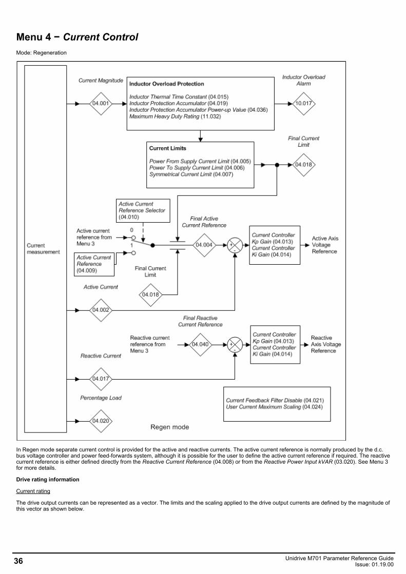
Menu 4 − Current ControlMode: Regeneration
In Regen mode separate current control is provided for the active and reactive currents. The active current reference is normally produced by the d.c.bus voltage controller and power feed-forwards system, although it is possible for the user to define the active current reference if required. The reactivecurrent reference is either defined directly from the Reactive Current Reference (04.008) or from the Reactive Power Input kVAR (03.020). See Menu 3for more details.
Drive rating information
Current rating
The drive output currents can be represented as a vector. The limits and the scaling applied to the drive output currents are defined by the magnitude ofthis vector as shown below.
36 Unidrive M701 Parameter Reference GuideIssue: 01.19.00
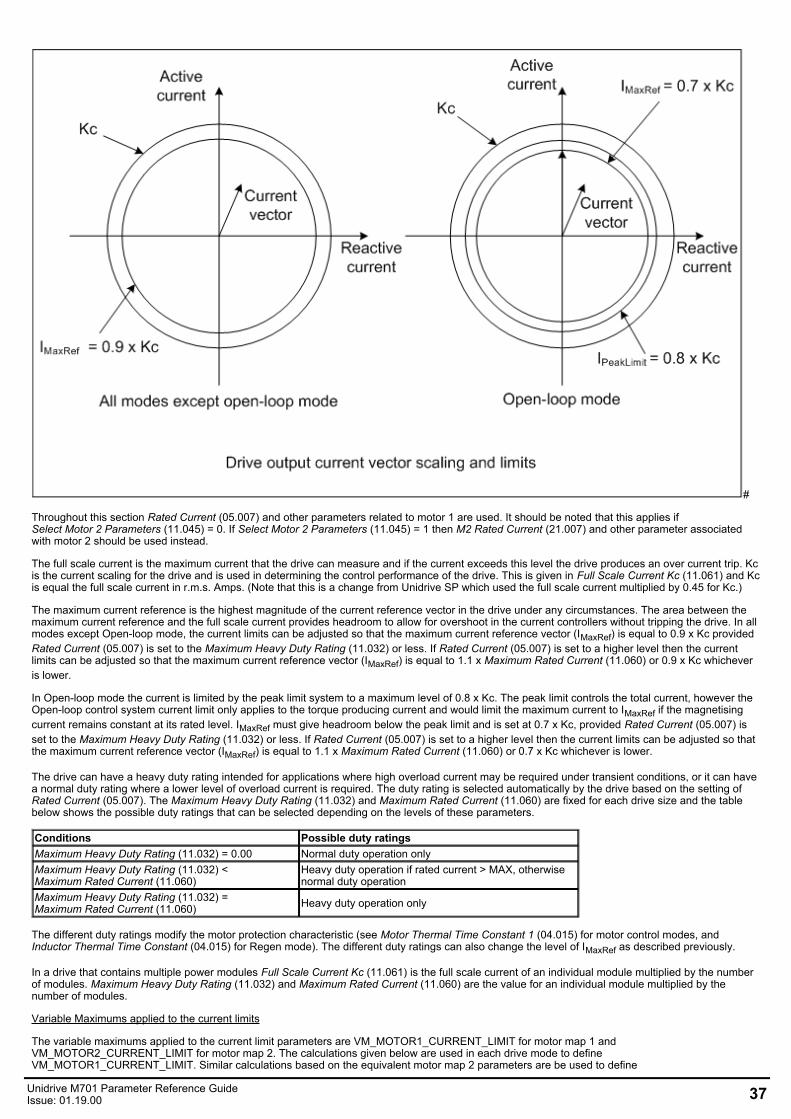
#
Throughout this section Rated Current (05.007) and other parameters related to motor 1 are used. It should be noted that this applies ifSelect Motor 2 Parameters (11.045) = 0. If Select Motor 2 Parameters (11.045) = 1 then M2 Rated Current (21.007) and other parameter associatedwith motor 2 should be used instead.
The full scale current is the maximum current that the drive can measure and if the current exceeds this level the drive produces an over current trip. Kcis the current scaling for the drive and is used in determining the control performance of the drive. This is given in Full Scale Current Kc (11.061) and Kcis equal the full scale current in r.m.s. Amps. (Note that this is a change from Unidrive SP which used the full scale current multiplied by 0.45 for Kc.)
The maximum current reference is the highest magnitude of the current reference vector in the drive under any circumstances. The area between themaximum current reference and the full scale current provides headroom to allow for overshoot in the current controllers without tripping the drive. In allmodes except Open-loop mode, the current limits can be adjusted so that the maximum current reference vector (IMaxRef) is equal to 0.9 x Kc providedRated Current (05.007) is set to the Maximum Heavy Duty Rating (11.032) or less. If Rated Current (05.007) is set to a higher level then the currentlimits can be adjusted so that the maximum current reference vector (IMaxRef) is equal to 1.1 x Maximum Rated Current (11.060) or 0.9 x Kc whicheveris lower.
In Open-loop mode the current is limited by the peak limit system to a maximum level of 0.8 x Kc. The peak limit controls the total current, however theOpen-loop control system current limit only applies to the torque producing current and would limit the maximum current to IMaxRef if the magnetisingcurrent remains constant at its rated level. IMaxRef must give headroom below the peak limit and is set at 0.7 x Kc, provided Rated Current (05.007) isset to the Maximum Heavy Duty Rating (11.032) or less. If Rated Current (05.007) is set to a higher level then the current limits can be adjusted so thatthe maximum current reference vector (IMaxRef) is equal to 1.1 x Maximum Rated Current (11.060) or 0.7 x Kc whichever is lower.
The drive can have a heavy duty rating intended for applications where high overload current may be required under transient conditions, or it can havea normal duty rating where a lower level of overload current is required. The duty rating is selected automatically by the drive based on the setting ofRated Current (05.007). The Maximum Heavy Duty Rating (11.032) and Maximum Rated Current (11.060) are fixed for each drive size and the tablebelow shows the possible duty ratings that can be selected depending on the levels of these parameters.
Conditions Possible duty ratingsMaximum Heavy Duty Rating (11.032) = 0.00 Normal duty operation onlyMaximum Heavy Duty Rating (11.032) <Maximum Rated Current (11.060)
Heavy duty operation if rated current > MAX, otherwisenormal duty operation
Maximum Heavy Duty Rating (11.032) =Maximum Rated Current (11.060) Heavy duty operation only
The different duty ratings modify the motor protection characteristic (see Motor Thermal Time Constant 1 (04.015) for motor control modes, andInductor Thermal Time Constant (04.015) for Regen mode). The different duty ratings can also change the level of IMaxRef as described previously.
In a drive that contains multiple power modules Full Scale Current Kc (11.061) is the full scale current of an individual module multiplied by the numberof modules. Maximum Heavy Duty Rating (11.032) and Maximum Rated Current (11.060) are the value for an individual module multiplied by thenumber of modules.
Variable Maximums applied to the current limits
The variable maximums applied to the current limit parameters are VM_MOTOR1_CURRENT_LIMIT for motor map 1 andVM_MOTOR2_CURRENT_LIMIT for motor map 2. The calculations given below are used in each drive mode to defineVM_MOTOR1_CURRENT_LIMIT. Similar calculations based on the equivalent motor map 2 parameters are be used to define
Unidrive M701 Parameter Reference GuideIssue: 01.19.00 37
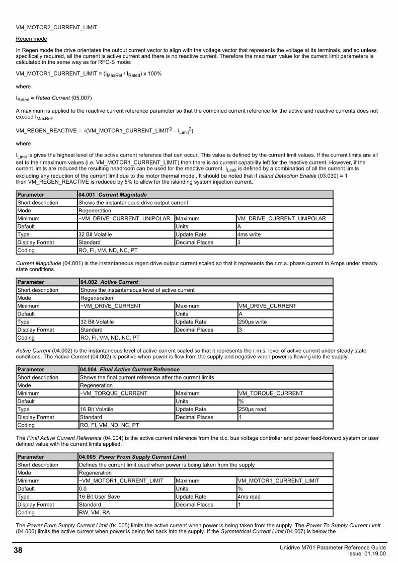
VM_MOTOR2_CURRENT_LIMIT.
Regen mode
In Regen mode the drive orientates the output current vector to align with the voltage vector that represents the voltage at its terminals, and so unlessspecifically required, all the current is active current and there is no reactive current. Therefore the maximum value for the current limit parameters iscalculated in the same way as for RFC-S mode:
VM_MOTOR1_CURRENT_LIMIT = (IMaxRef / IRated) x 100%
where
IRated = Rated Current (05.007)
A maximum is applied to the reactive current reference parameter so that the combined current reference for the active and reactive currents does notexceed IMaxRef.
VM_REGEN_REACTIVE = √(VM_MOTOR1_CURRENT_LIMIT2 – ILimit2)
where
ILimit is gives the highest level of the active current reference that can occur. This value is defined by the current limit values. If the current limits are allset to their maximum values (i.e. VM_MOTOR1_CURRENT_LIMIT) then there is no current capability left for the reactive current. However, if thecurrent limits are reduced the resulting headroom can be used for the reactive current. ILimit is defined by a combination of all the current limitsexcluding any reduction of the current limit due to the motor thermal model, It should be noted that if Island Detection Enable (03.030) = 1then VM_REGEN_REACTIVE is reduced by 5% to allow for the islanding system injection current.
Parameter 04.001 Current MagnitudeShort description Shows the instantaneous drive output currentMode RegenerationMinimum −VM_DRIVE_CURRENT_UNIPOLAR Maximum VM_DRIVE_CURRENT_UNIPOLARDefault Units AType 32 Bit Volatile Update Rate 4ms writeDisplay Format Standard Decimal Places 3Coding RO, FI, VM, ND, NC, PT
Current Magnitude (04.001) is the instantaneous regen drive output current scaled so that it represents the r.m.s. phase current in Amps under steadystate conditions.
Parameter 04.002 Active CurrentShort description Shows the instantaneous level of active currentMode RegenerationMinimum −VM_DRIVE_CURRENT Maximum VM_DRIVE_CURRENTDefault Units AType 32 Bit Volatile Update Rate 250µs writeDisplay Format Standard Decimal Places 3Coding RO, FI, VM, ND, NC, PT
Active Current (04.002) is the instantaneous level of active current scaled so that it represents the r.m.s. level of active current under steady stateconditions. The Active Current (04.002) is positive when power is flow from the supply and negative when power is flowing into the supply.
Parameter 04.004 Final Active Current ReferenceShort description Shows the final current reference after the current limitsMode RegenerationMinimum −VM_TORQUE_CURRENT Maximum VM_TORQUE_CURRENTDefault Units %Type 16 Bit Volatile Update Rate 250µs readDisplay Format Standard Decimal Places 1Coding RO, FI, VM, ND, NC, PT
The Final Active Current Reference (04.004) is the active current reference from the d.c. bus voltage controller and power feed-forward system or userdefined value with the current limits applied.
Parameter 04.005 Power From Supply Current LimitShort description Defines the current limit used when power is being taken from the supplyMode RegenerationMinimum −VM_MOTOR1_CURRENT_LIMIT Maximum VM_MOTOR1_CURRENT_LIMITDefault 0.0 Units %Type 16 Bit User Save Update Rate 4ms readDisplay Format Standard Decimal Places 1Coding RW, VM, RA
The Power From Supply Current Limit (04.005) limits the active current when power is being taken from the supply. The Power To Supply Current Limit(04.006) limits the active current when power is being fed back into the supply. If the Symmetrical Current Limit (04.007) is below the
38 Unidrive M701 Parameter Reference GuideIssue: 01.19.00
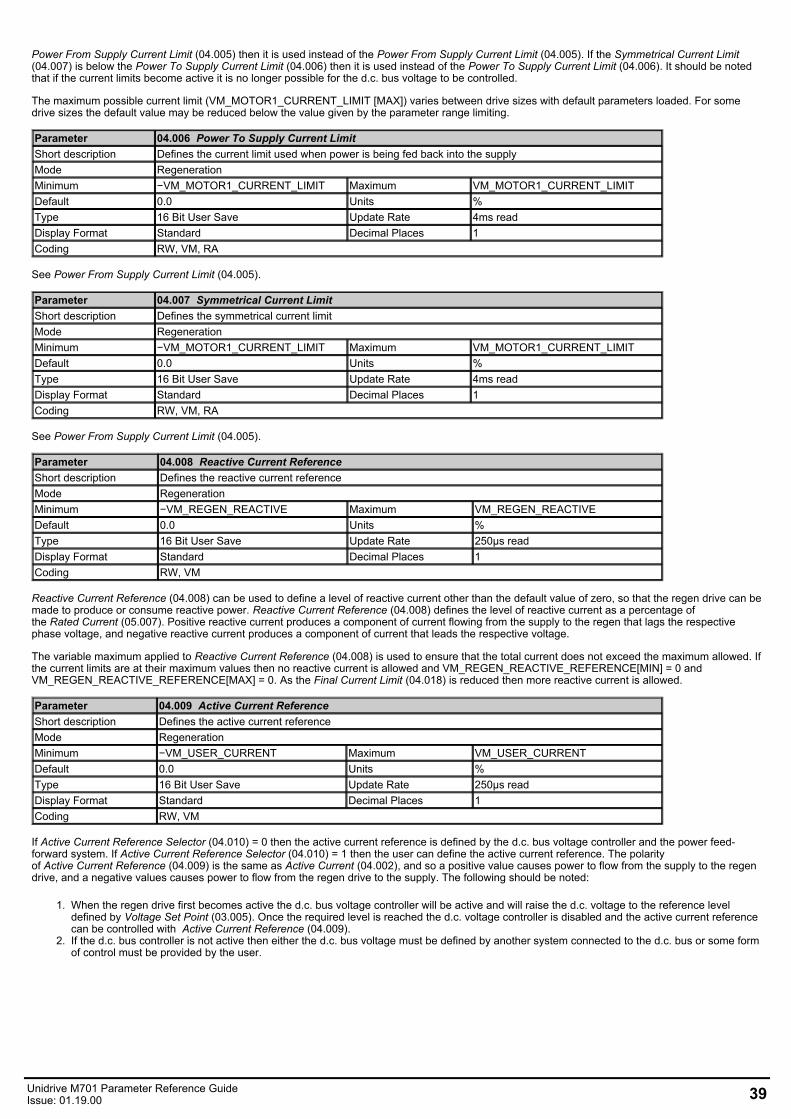
Power From Supply Current Limit (04.005) then it is used instead of the Power From Supply Current Limit (04.005). If the Symmetrical Current Limit(04.007) is below the Power To Supply Current Limit (04.006) then it is used instead of the Power To Supply Current Limit (04.006). It should be notedthat if the current limits become active it is no longer possible for the d.c. bus voltage to be controlled.
The maximum possible current limit (VM_MOTOR1_CURRENT_LIMIT [MAX]) varies between drive sizes with default parameters loaded. For somedrive sizes the default value may be reduced below the value given by the parameter range limiting.
Parameter 04.006 Power To Supply Current LimitShort description Defines the current limit used when power is being fed back into the supplyMode RegenerationMinimum −VM_MOTOR1_CURRENT_LIMIT Maximum VM_MOTOR1_CURRENT_LIMITDefault 0.0 Units %Type 16 Bit User Save Update Rate 4ms readDisplay Format Standard Decimal Places 1Coding RW, VM, RA
See Power From Supply Current Limit (04.005).
Parameter 04.007 Symmetrical Current LimitShort description Defines the symmetrical current limitMode RegenerationMinimum −VM_MOTOR1_CURRENT_LIMIT Maximum VM_MOTOR1_CURRENT_LIMITDefault 0.0 Units %Type 16 Bit User Save Update Rate 4ms readDisplay Format Standard Decimal Places 1Coding RW, VM, RA
See Power From Supply Current Limit (04.005).
Parameter 04.008 Reactive Current ReferenceShort description Defines the reactive current referenceMode RegenerationMinimum −VM_REGEN_REACTIVE Maximum VM_REGEN_REACTIVEDefault 0.0 Units %Type 16 Bit User Save Update Rate 250µs readDisplay Format Standard Decimal Places 1Coding RW, VM
Reactive Current Reference (04.008) can be used to define a level of reactive current other than the default value of zero, so that the regen drive can bemade to produce or consume reactive power. Reactive Current Reference (04.008) defines the level of reactive current as a percentage ofthe Rated Current (05.007). Positive reactive current produces a component of current flowing from the supply to the regen that lags the respectivephase voltage, and negative reactive current produces a component of current that leads the respective voltage.
The variable maximum applied to Reactive Current Reference (04.008) is used to ensure that the total current does not exceed the maximum allowed. Ifthe current limits are at their maximum values then no reactive current is allowed and VM_REGEN_REACTIVE_REFERENCE[MIN] = 0 andVM_REGEN_REACTIVE_REFERENCE[MAX] = 0. As the Final Current Limit (04.018) is reduced then more reactive current is allowed.
Parameter 04.009 Active Current ReferenceShort description Defines the active current referenceMode RegenerationMinimum −VM_USER_CURRENT Maximum VM_USER_CURRENTDefault 0.0 Units %Type 16 Bit User Save Update Rate 250µs readDisplay Format Standard Decimal Places 1Coding RW, VM
If Active Current Reference Selector (04.010) = 0 then the active current reference is defined by the d.c. bus voltage controller and the power feed-forward system. If Active Current Reference Selector (04.010) = 1 then the user can define the active current reference. The polarityof Active Current Reference (04.009) is the same as Active Current (04.002), and so a positive value causes power to flow from the supply to the regendrive, and a negative values causes power to flow from the regen drive to the supply. The following should be noted:
1. When the regen drive first becomes active the d.c. bus voltage controller will be active and will raise the d.c. voltage to the reference leveldefined by Voltage Set Point (03.005). Once the required level is reached the d.c. voltage controller is disabled and the active current referencecan be controlled with Active Current Reference (04.009).
2. If the d.c. bus controller is not active then either the d.c. bus voltage must be defined by another system connected to the d.c. bus or some formof control must be provided by the user.
Unidrive M701 Parameter Reference GuideIssue: 01.19.00 39
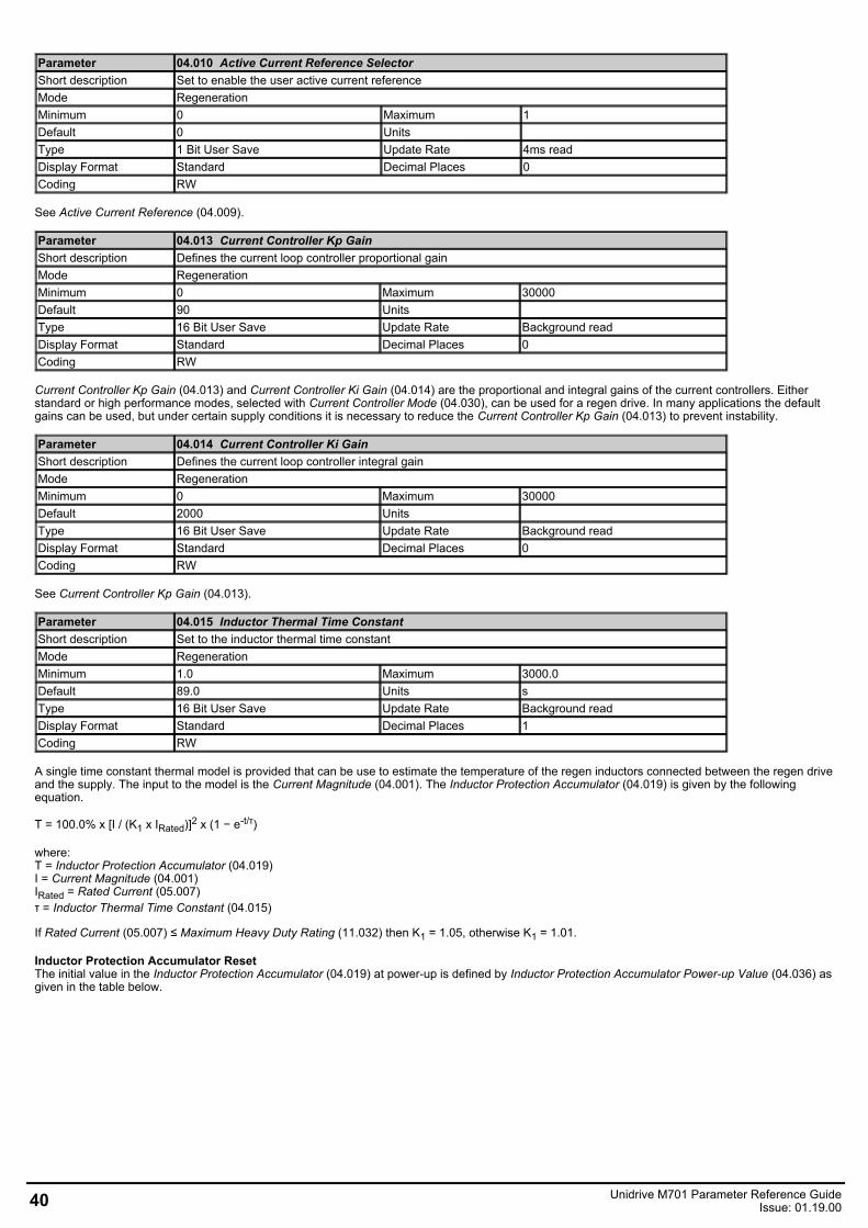
Parameter 04.010 Active Current Reference SelectorShort description Set to enable the user active current referenceMode RegenerationMinimum 0 Maximum 1Default 0 Units Type 1 Bit User Save Update Rate 4ms readDisplay Format Standard Decimal Places 0Coding RW
See Active Current Reference (04.009).
Parameter 04.013 Current Controller Kp GainShort description Defines the current loop controller proportional gainMode RegenerationMinimum 0 Maximum 30000Default 90 Units Type 16 Bit User Save Update Rate Background readDisplay Format Standard Decimal Places 0Coding RW
Current Controller Kp Gain (04.013) and Current Controller Ki Gain (04.014) are the proportional and integral gains of the current controllers. Eitherstandard or high performance modes, selected with Current Controller Mode (04.030), can be used for a regen drive. In many applications the defaultgains can be used, but under certain supply conditions it is necessary to reduce the Current Controller Kp Gain (04.013) to prevent instability.
Parameter 04.014 Current Controller Ki GainShort description Defines the current loop controller integral gainMode RegenerationMinimum 0 Maximum 30000Default 2000 Units Type 16 Bit User Save Update Rate Background readDisplay Format Standard Decimal Places 0Coding RW
See Current Controller Kp Gain (04.013).
Parameter 04.015 Inductor Thermal Time ConstantShort description Set to the inductor thermal time constantMode RegenerationMinimum 1.0 Maximum 3000.0Default 89.0 Units sType 16 Bit User Save Update Rate Background readDisplay Format Standard Decimal Places 1Coding RW
A single time constant thermal model is provided that can be use to estimate the temperature of the regen inductors connected between the regen driveand the supply. The input to the model is the Current Magnitude (04.001). The Inductor Protection Accumulator (04.019) is given by the followingequation.
T = 100.0% x [I / (K1 x IRated)]2 x (1 − e-t/τ)
where:T = Inductor Protection Accumulator (04.019)I = Current Magnitude (04.001)IRated = Rated Current (05.007)τ = Inductor Thermal Time Constant (04.015)
If Rated Current (05.007) ≤ Maximum Heavy Duty Rating (11.032) then K1 = 1.05, otherwise K1 = 1.01.
Inductor Protection Accumulator ResetThe initial value in the Inductor Protection Accumulator (04.019) at power-up is defined by Inductor Protection Accumulator Power-up Value (04.036) asgiven in the table below.
40 Unidrive M701 Parameter Reference GuideIssue: 01.19.00
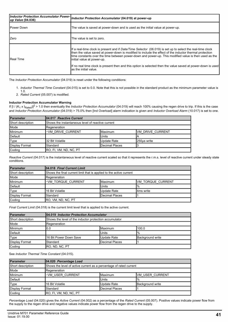
Inductor Protection Accumulator Power-up Value (04.036) Inductor Protection Accumulator (04.019) at power-up
Power Down The value is saved at power-down and is used as the initial value at power-up.
Zero The value is set to zero.
Real Time
If a real-time clock is present and if Date/Time Selector (06.019) is set up to select the real-time clockthen the value saved at power-down is modified to include the effect of the inductor thermal protectiontime constants over the time between power-down and power-up. This modified value is then used as theinitial value at power-up.
If no real time clock is present then and this option is selected then the value saved at power-down is usedas the initial value.
The Inductor Protection Accumulator (04.019) is reset under the following conditions:
1. Inductor Thermal Time Constant (04.015) is set to 0.0. Note that this is not possible in the standard product as the minimum parameter value is1.0.
2. Rated Current (05.007) is modified.
Inductor Protection Accumulator Warning If [I / (K1 x IRated)]2 > 1.0 then eventually the Inductor Protection Accumulator (04.019) will reach 100% causing the regen drive to trip. If this is the caseand Inductor Protection Accumulator (04.019) > 75.0% then [Ind Overload] alarm indication is given and Inductor Overload Alarm (10.017) is set to one.
Parameter 04.017 Reactive CurrentShort description Shows the instantaneous level of reactive currentMode RegenerationMinimum −VM_DRIVE_CURRENT Maximum VM_DRIVE_CURRENTDefault Units AType 32 Bit Volatile Update Rate 250µs writeDisplay Format Standard Decimal Places 3Coding RO, FI, VM, ND, NC, PT
Reactive Current (04.017) is the instantaneous level of reactive current scaled so that it represents the r.m.s. level of reactive current under steady stateconditions.
Parameter 04.018 Final Current LimitShort description Shows the final current limit that is applied to the active currentMode RegenerationMinimum −VM_TORQUE_CURRENT Maximum VM_TORQUE_CURRENTDefault Units %Type 16 Bit Volatile Update Rate 4ms writeDisplay Format Standard Decimal Places 1Coding RO, VM, ND, NC, PT
Final Current Limit (04.018) is the current limit level that is applied to the active current.
Parameter 04.019 Inductor Protection AccumulatorShort description Shows the level of the inductor protection accumulatorMode RegenerationMinimum 0.0 Maximum 100.0Default Units %Type 16 Bit Power Down Save Update Rate Background writeDisplay Format Standard Decimal Places 1Coding RO, ND, NC, PT
See Inductor Thermal Time Constant (04.015).
Parameter 04.020 Percentage LoadShort description Shows the level of active current as a percentage of rated currentMode RegenerationMinimum −VM_USER_CURRENT Maximum VM_USER_CURRENTDefault Units %Type 16 Bit Volatile Update Rate Background writeDisplay Format Standard Decimal Places 1Coding RO, FI, VM, ND, NC, PT
Percentage Load (04.020) gives the Active Current (04.002) as a percentage of the Rated Current (05.007). Positive values indicate power flow fromthe supply to the regen drive and negative values indicate power flow from the regen drive to the supply.
Unidrive M701 Parameter Reference GuideIssue: 01.19.00 41
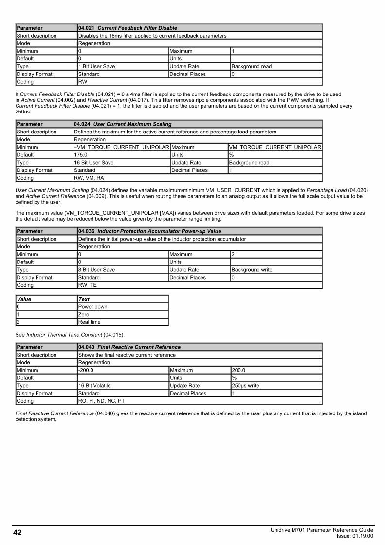
Parameter 04.021 Current Feedback Filter DisableShort description Disables the 16ms filter applied to current feedback parametersMode RegenerationMinimum 0 Maximum 1Default 0 Units Type 1 Bit User Save Update Rate Background readDisplay Format Standard Decimal Places 0Coding RW
If Current Feedback Filter Disable (04.021) = 0 a 4ms filter is applied to the current feedback components measured by the drive to be usedin Active Current (04.002) and Reactive Current (04.017). This filter removes ripple components associated with the PWM switching. IfCurrent Feedback Filter Disable (04.021) = 1, the filter is disabled and the user parameters are based on the current components sampled every250us.
Parameter 04.024 User Current Maximum ScalingShort description Defines the maximum for the active current reference and percentage load parametersMode RegenerationMinimum −VM_TORQUE_CURRENT_UNIPOLAR Maximum VM_TORQUE_CURRENT_UNIPOLARDefault 175.0 Units %Type 16 Bit User Save Update Rate Background readDisplay Format Standard Decimal Places 1Coding RW, VM, RA
User Current Maximum Scaling (04.024) defines the variable maximum/minimum VM_USER_CURRENT which is applied to Percentage Load (04.020)and Active Current Reference (04.009). This is useful when routing these parameters to an analog output as it allows the full scale output value to bedefined by the user.
The maximum value (VM_TORQUE_CURRENT_UNIPOLAR [MAX]) varies between drive sizes with default parameters loaded. For some drive sizesthe default value may be reduced below the value given by the parameter range limiting.
Parameter 04.036 Inductor Protection Accumulator Power-up ValueShort description Defines the initial power-up value of the inductor protection accumulatorMode RegenerationMinimum 0 Maximum 2Default 0 Units Type 8 Bit User Save Update Rate Background writeDisplay Format Standard Decimal Places 0Coding RW, TE
Value Text0 Power down1 Zero2 Real time
See Inductor Thermal Time Constant (04.015).
Parameter 04.040 Final Reactive Current ReferenceShort description Shows the final reactive current referenceMode RegenerationMinimum -200.0 Maximum 200.0Default Units %Type 16 Bit Volatile Update Rate 250µs writeDisplay Format Standard Decimal Places 1Coding RO, FI, ND, NC, PT
Final Reactive Current Reference (04.040) gives the reactive current reference that is defined by the user plus any current that is injected by the islanddetection system.
42 Unidrive M701 Parameter Reference GuideIssue: 01.19.00
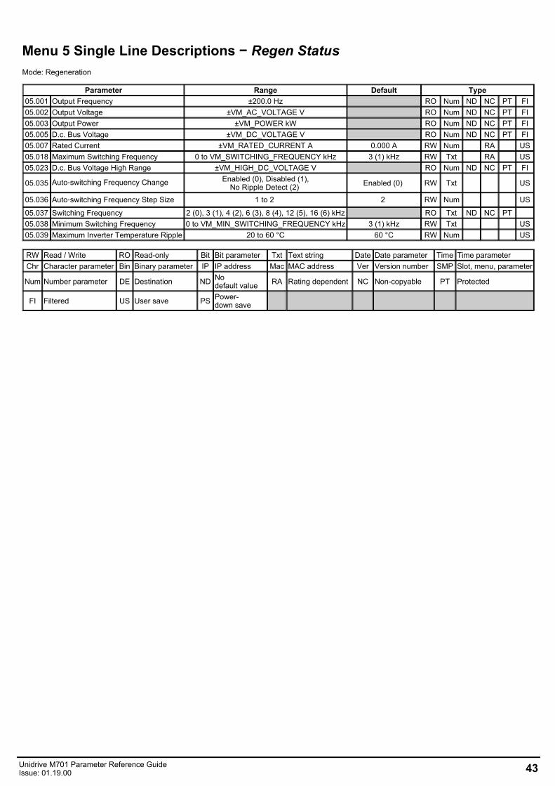
Menu 5 Single Line Descriptions − Regen StatusMode: Regeneration
Parameter Range Default Type05.001 Output Frequency ±200.0 Hz RO Num ND NC PT FI05.002 Output Voltage ±VM_AC_VOLTAGE V RO Num ND NC PT FI05.003 Output Power ±VM_POWER kW RO Num ND NC PT FI05.005 D.c. Bus Voltage ±VM_DC_VOLTAGE V RO Num ND NC PT FI05.007 Rated Current ±VM_RATED_CURRENT A 0.000 A RW Num RA US05.018 Maximum Switching Frequency 0 to VM_SWITCHING_FREQUENCY kHz 3 (1) kHz RW Txt RA US05.023 D.c. Bus Voltage High Range ±VM_HIGH_DC_VOLTAGE V RO Num ND NC PT FI
05.035 Auto‑switching Frequency Change Enabled (0), Disabled (1),No Ripple Detect (2) Enabled (0) RW Txt US
05.036 Auto‑switching Frequency Step Size 1 to 2 2 RW Num US
05.037 Switching Frequency 2 (0), 3 (1), 4 (2), 6 (3), 8 (4), 12 (5), 16 (6) kHz RO Txt ND NC PT 05.038 Minimum Switching Frequency 0 to VM_MIN_SWITCHING_FREQUENCY kHz 3 (1) kHz RW Txt US05.039 Maximum Inverter Temperature Ripple 20 to 60 °C 60 °C RW Num US
RW Read / Write RO Read-only Bit Bit parameter Txt Text string Date Date parameter Time Time parameterChr Character parameter Bin Binary parameter IP IP address Mac MAC address Ver Version number SMP Slot, menu, parameter
Num Number parameter DE Destination ND Nodefault value RA Rating dependent NC Non-copyable PT Protected
FI Filtered US User save PS Power-down save
Unidrive M701 Parameter Reference GuideIssue: 01.19.00 43
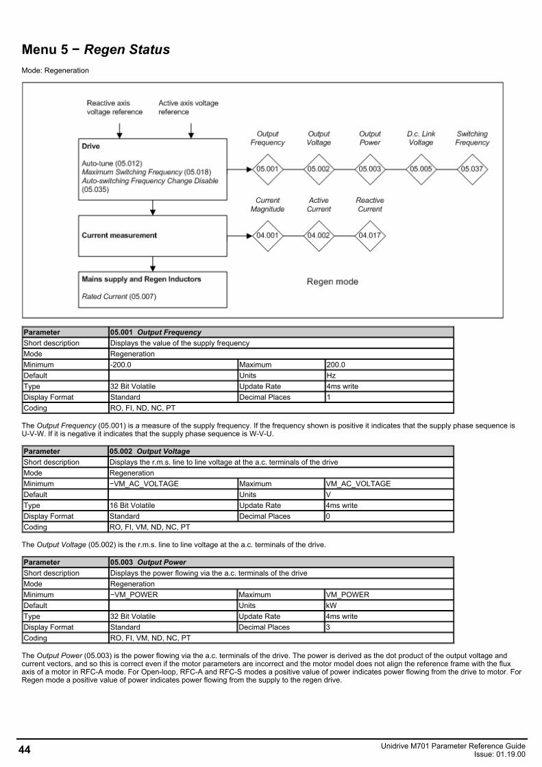
Menu 5 − Regen StatusMode: Regeneration
Parameter 05.001 Output FrequencyShort description Displays the value of the supply frequencyMode RegenerationMinimum -200.0 Maximum 200.0Default Units HzType 32 Bit Volatile Update Rate 4ms writeDisplay Format Standard Decimal Places 1Coding RO, FI, ND, NC, PT
The Output Frequency (05.001) is a measure of the supply frequency. If the frequency shown is positive it indicates that the supply phase sequence isU-V-W. If it is negative it indicates that the supply phase sequence is W-V-U.
Parameter 05.002 Output VoltageShort description Displays the r.m.s. line to line voltage at the a.c. terminals of the driveMode RegenerationMinimum −VM_AC_VOLTAGE Maximum VM_AC_VOLTAGEDefault Units VType 16 Bit Volatile Update Rate 4ms writeDisplay Format Standard Decimal Places 0Coding RO, FI, VM, ND, NC, PT
The Output Voltage (05.002) is the r.m.s. line to line voltage at the a.c. terminals of the drive.
Parameter 05.003 Output PowerShort description Displays the power flowing via the a.c. terminals of the driveMode RegenerationMinimum −VM_POWER Maximum VM_POWERDefault Units kWType 32 Bit Volatile Update Rate 4ms writeDisplay Format Standard Decimal Places 3Coding RO, FI, VM, ND, NC, PT
The Output Power (05.003) is the power flowing via the a.c. terminals of the drive. The power is derived as the dot product of the output voltage andcurrent vectors, and so this is correct even if the motor parameters are incorrect and the motor model does not align the reference frame with the fluxaxis of a motor in RFC-A mode. For Open-loop, RFC-A and RFC-S modes a positive value of power indicates power flowing from the drive to motor. ForRegen mode a positive value of power indicates power flowing from the supply to the regen drive.
44 Unidrive M701 Parameter Reference GuideIssue: 01.19.00
Parameter 05.005 D.c. Bus VoltageShort description Displays the voltage across the d.c. link of the driveMode RegenerationMinimum −VM_DC_VOLTAGE Maximum VM_DC_VOLTAGEDefault Units VType 16 Bit Volatile Update Rate Background readDisplay Format Standard Decimal Places 0Coding RO, FI, VM, ND, NC, PT
D.c. Bus Voltage (05.005) gives the voltage across the d.c. link of the drive.
Parameter 05.007 Rated CurrentShort description Set to the rated current rated of the regen inductorMode RegenerationMinimum −VM_RATED_CURRENT Maximum VM_RATED_CURRENTDefault 0.000 Units AType 32 Bit User Save Update Rate Background readDisplay Format Standard Decimal Places 3Coding RW, VM, RA
Rated Current (05.007) is used to define rated operating conditions for regen inductor thermal protection. See Inductor Thermal Time Constant(04.015).
Parameter 05.018 Maximum Switching FrequencyShort description Defines the maximum switching frequency that can be used by the driveMode RegenerationMinimum 0 Maximum VM_SWITCHING_FREQUENCYDefault 1 Units kHzType 8 Bit User Save Update Rate Background readDisplay Format Standard Decimal Places 0Coding RW, TE, VM, RA
Value Text0 21 32 43 64 85 126 16
Maximum Switching Frequency (05.018) should be set to the required PWM switching frequency. The drive inverter will operate at this frequency unlessthe inverter temperature becomes too hot. Under these conditions the drive will reduce the switching frequency in an attempt to avoid tripping (seeAuto-switching Frequency Change (05.035) ). The actual switching frequency is shown in Switching Frequency (05.037). The switching frequency has adirect effect on the sample rate for the current controllers (see Current Controller Kp Gain (04.013)). All other control tasks are at a fixed rate.
TaskSpeed controller (RFC-A,RFC-S) 250μs
D.c. link voltage controller 1msFlux controller (RFC-A, RFC-S) 1ms
Parameter 05.023 D.c. Bus Voltage High RangeShort description Displays the d.c. bus level but with a higher rangeMode RegenerationMinimum −VM_HIGH_DC_VOLTAGE Maximum VM_HIGH_DC_VOLTAGEDefault Units VType 16 Bit Volatile Update Rate Background readDisplay Format Standard Decimal Places 0Coding RO, FI, VM, ND, NC, PT
D.c. Bus Voltage High Range (05.023) provides voltage feedback that has lower resolution and a higher range than D.c. Bus Voltage (05.005), and so itis possible to determine the d.c. link voltage even if this exceeds the level of the over-voltage trip. It should be noted that due to tolerances,D.c. Bus Voltage High Range (05.023) may not correspond exactly with the level given by D.c. Bus Voltage (05.005). In a system with parallel powermodules where the control pod is remote from any of the power modules, this parameter always shows zero.
Unidrive M701 Parameter Reference GuideIssue: 01.19.00 45
Parameter 05.035 Auto-switching Frequency ChangeShort description Defines auto-switching frequency control with thermal modelMode RegenerationMinimum 0 Maximum 2Default 0 Units Type 8 Bit User Save Update Rate Background readDisplay Format Standard Decimal Places 0Coding RW, TE
Value Text0 Enabled1 Disabled2 No Ripple Detect
The drive inverter can be damaged if the temperature is too high. The inverter can also be damaged or the lifetime of the power devices reduced, if thetemperature ripple of the devices is too high. Auto-switching Frequency Change (05.035) defines the action taken if the drive inverter becomes too hotor the temperature ripple becomes too high.
Enabled:If the inverter becomes too hot or the ripple temperature is higher than the level defined by Maximum Inverter Temperature Ripple (05.039) theswitching frequency is reduced in an attempt to prevent tripping.
Disabled:The switching frequency is not reduced, and so the drive will trip if the inverter is too hot or the temperature ripple is too high.
No Ripple Detect:The switching frequency is reduced if the inverter temperature, but not the temperature ripple is too high. If the temperature ripple exceeds the leveldefined by Maximum Inverter Temperature Ripple (05.039) then the drive will trip.
The switching frequency is changed in steps defined by Auto-switching Frequency Step Size (05.036). For example with a switching frequency of 16kHzand a step size of two, the frequency will be reduced to 8kHz, then 4kHz etc. Minimum Switching Frequency (05.038) defines the minimum switchingfrequency that the system will attempt to use. If the switching frequency needs to switch to a lower level, then the drive will trip.If Minimum Switching Frequency is changed the new value will only become active when Switching Frequency is at or above the minimum value.
Parameter 05.036 Auto-switching Frequency Step SizeShort description Auto-switching frequency redcution step sizeMode RegenerationMinimum 1 Maximum 2Default 2 Units Type 8 Bit User Save Update Rate Background readDisplay Format Standard Decimal Places 0Coding RW
See Auto-switching Frequency Change (05.035).
Parameter 05.037 Switching FrequencyShort description Displays the current switching frequency used by the driveMode RegenerationMinimum 0 Maximum 6Default Units kHzType 8 Bit Volatile Update Rate Background writeDisplay Format Standard Decimal Places 0Coding RO, TE, ND, NC, PT
Value Text0 21 32 43 64 85 126 16
Shows the actual inverter switching frequency after the auto-change function.
46 Unidrive M701 Parameter Reference GuideIssue: 01.19.00
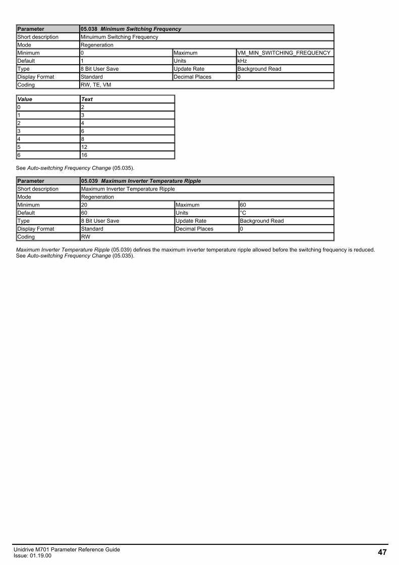
Parameter 05.038 Minimum Switching FrequencyShort description Minuimum Switching FrequencyMode RegenerationMinimum 0 Maximum VM_MIN_SWITCHING_FREQUENCYDefault 1 Units kHzType 8 Bit User Save Update Rate Background ReadDisplay Format Standard Decimal Places 0Coding RW, TE, VM
Value Text0 21 32 43 64 85 126 16
See Auto-switching Frequency Change (05.035).
Parameter 05.039 Maximum Inverter Temperature RippleShort description Maximum Inverter Temperature RippleMode RegenerationMinimum 20 Maximum 60Default 60 Units °CType 8 Bit User Save Update Rate Background ReadDisplay Format Standard Decimal Places 0Coding RW
Maximum Inverter Temperature Ripple (05.039) defines the maximum inverter temperature ripple allowed before the switching frequency is reduced.See Auto-switching Frequency Change (05.035).
Unidrive M701 Parameter Reference GuideIssue: 01.19.00 47
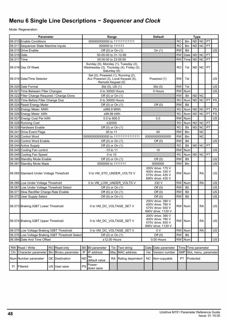
Menu 6 Single Line Descriptions − Sequencer and ClockMode: Regeneration
Parameter Range Default Type06.010 Enable Conditions 000000000000 to 111111111111 RO Bin ND NC PT 06.011 Sequencer State Machine Inputs 000000 to 111111 RO Bin ND NC PT 06.015 Drive Enable Off (0) or On (1) On (1) RW Bit US06.016 Date 00-00-00 to 31-12-99 RW Date ND NC PT 06.017 Time 00:00:00 to 23:59:59 RW Time ND NC PT
06.018 Day Of WeekSunday (0), Monday (1), Tuesday (2),
Wednesday (3), Thursday (4), Friday (5),Saturday (6)
RO Txt ND NC PT
06.019 Date/Time Selector Set (0), Powered (1), Running (2),
Acc Powered (3), Local Keypad (4),Remote Keypad (5)
Powered (1) RW Txt US
06.020 Date Format Std (0), US (1) Std (0) RW Txt US06.021 Time Between Filter Changes 0 to 30000 Hours 0 Hours RW Num US06.022 Filter Change Required / Change Done Off (0) or On (1) RW Bit ND NC 06.023 Time Before Filter Change Due 0 to 30000 Hours RO Num ND NC PT PS06.024 Reset Energy Meter Off (0) or On (1) Off (0) RW Bit 06.025 Energy Meter: MWh ±999.9 MWh RO Num ND NC PT PS06.026 Energy Meter: kWh ±99.99 kWh RO Num ND NC PT PS06.027 Energy Cost Per kWh 0.0 to 600.0 0.0 RW Num US06.028 Running Cost ±32000 RO Num ND NC PT 06.029 Hardware Enable Off (0) or On (1) RO Bit ND NC PT 06.041 Drive Event Flags 00 to 11 00 RW Bin NC 06.042 Control Word 000000000000000 to 111111111111111 000000000000000 RW Bin NC 06.043 Control Word Enable Off (0) or On (1) Off (0) RW Bit US06.044 Active Supply Off (0) or On (1) RO Bit ND NC PT 06.045 Cooling Fan control -10 to 11 10 RW Num US06.046 Cooling Fan Speed 0 to 10 RO Num ND NC PT 06.060 Standby Mode Enable Off (0) or On (1) Off (0) RW Bit US06.061 Standby Mode Mask 0000000 to 1111111 0000000 RW Bin US
06.065 Standard Under Voltage Threshold 0 to VM_STD_UNDER_VOLTS V200V drive: 175 V400V drive: 330 V575V drive: 435 V690V drive: 435 V
RW Num RA US
06.066 Low Under Voltage Threshold 0 to VM_LOW_UNDER_VOLTS V 330 V RW Num RA US06.067 Low Under Voltage Threshold Select Off (0) or On (1) Off (0) RW Bit US06.071 Slow Rectifier Charge Rate Enable Off (0) or On (1) Off (0) RW Bit US06.072 User Supply Select Off (0) or On (1) Off (0) RW Bit US
06.073 Braking IGBT Lower Threshold 0 to VM_DC_VOLTAGE_SET V200V drive: 390 V400V drive: 780 V575V drive: 930 V
690V drive: 1120 VRW Num RA US
06.074 Braking IGBT Upper Threshold 0 to VM_DC_VOLTAGE_SET V200V drive: 390 V400V drive: 780 V575V drive: 930 V
690V drive: 1120 VRW Num RA US
06.075 Low Voltage Braking IGBT Threshold 0 to VM_DC_VOLTAGE_SET V 0 V RW Num RA US06.076 Low Voltage Braking IGBT Threshold Select Off (0) or On (1) Off (0) RW Bit 06.084 Date And Time Offset ±12.00 Hours 0.00 Hours RW Num US
RW Read / Write RO Read-only Bit Bit parameter Txt Text string Date Date parameter Time Time parameterChr Character parameter Bin Binary parameter IP IP address Mac MAC address Ver Version number SMP Slot, menu, parameter
Num Number parameter DE Destination ND Nodefault value RA Rating dependent NC Non-copyable PT Protected
FI Filtered US User save PS Power-down save
48 Unidrive M701 Parameter Reference GuideIssue: 01.19.00
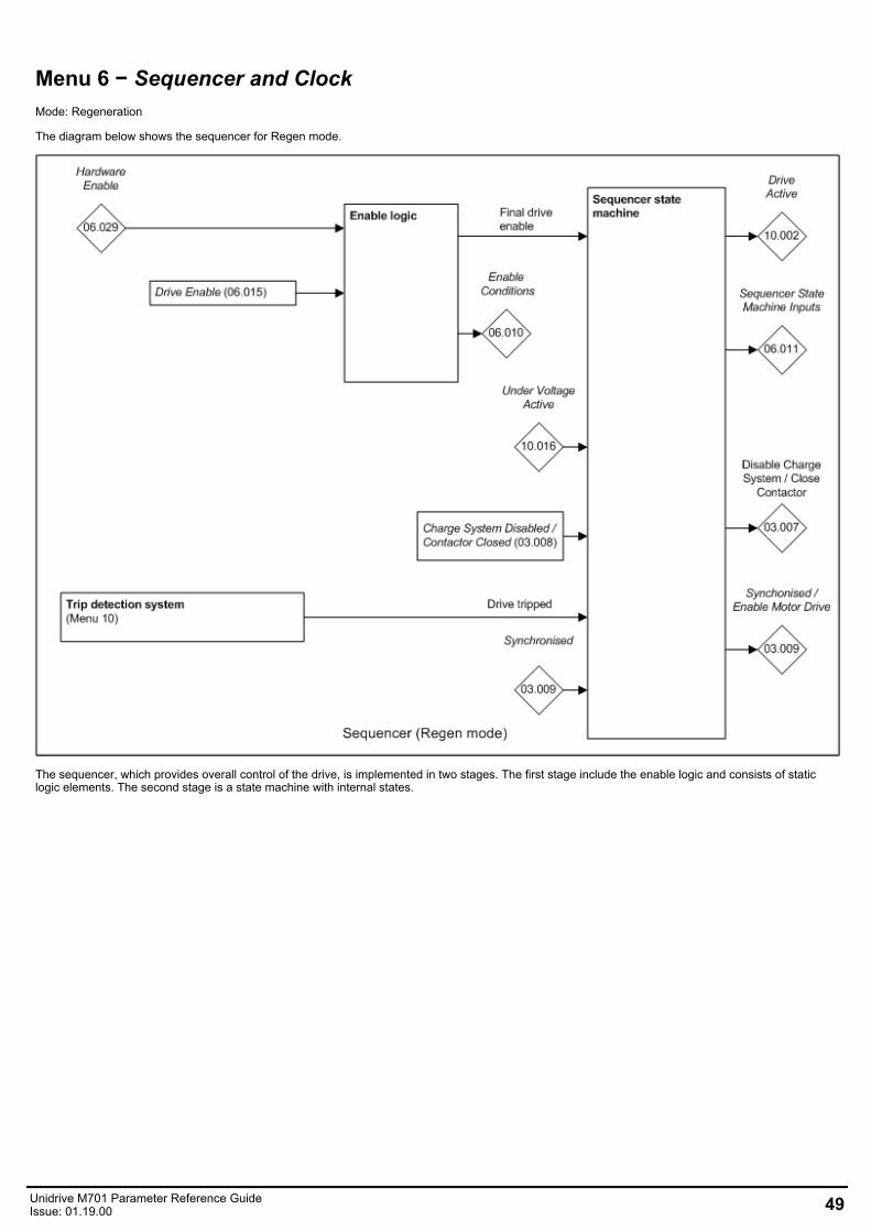
Menu 6 − Sequencer and ClockMode: Regeneration
The diagram below shows the sequencer for Regen mode.
The sequencer, which provides overall control of the drive, is implemented in two stages. The first stage include the enable logic and consists of staticlogic elements. The second stage is a state machine with internal states.
Unidrive M701 Parameter Reference GuideIssue: 01.19.00 49
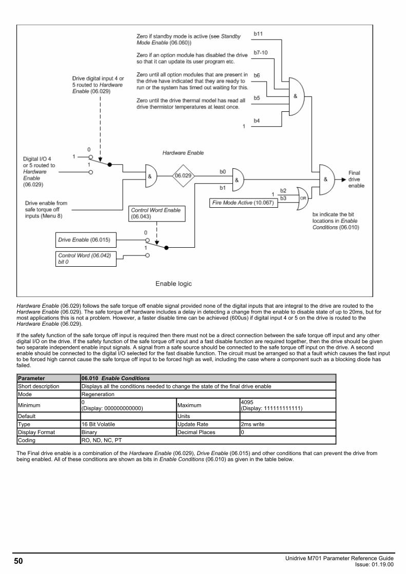
Hardware Enable (06.029) follows the safe torque off enable signal provided none of the digital inputs that are integral to the drive are routed to theHardware Enable (06.029). The safe torque off hardware includes a delay in detecting a change from the enable to disable state of up to 20ms, but formost applications this is not a problem. However, a faster disable time can be achieved (600us) if digital input 4 or 5 on the drive is routed to theHardware Enable (06.029).
If the safety function of the safe torque off input is required then there must not be a direct connection between the safe torque off input and any otherdigital I/O on the drive. If the safety function of the safe torque off input and a fast disable function are required together, then the drive should be giventwo separate independent enable input signals. A signal from a safe source should be connected to the safe torque off input on the drive. A secondenable should be connected to the digital I/O selected for the fast disable function. The circuit must be arranged so that a fault which causes the fast inputto be forced high cannot cause the safe torque off input to be forced high as well, including the case where a component such as a blocking diode hasfailed.
Parameter 06.010 Enable ConditionsShort description Displays all the conditions needed to change the state of the final drive enableMode Regeneration
Minimum 0(Display: 000000000000) Maximum 4095
(Display: 111111111111)Default Units Type 16 Bit Volatile Update Rate 2ms writeDisplay Format Binary Decimal Places 0Coding RO, ND, NC, PT
The Final drive enable is a combination of the Hardware Enable (06.029), Drive Enable (06.015) and other conditions that can prevent the drive frombeing enabled. All of these conditions are shown as bits in Enable Conditions (06.010) as given in the table below.
50 Unidrive M701 Parameter Reference GuideIssue: 01.19.00
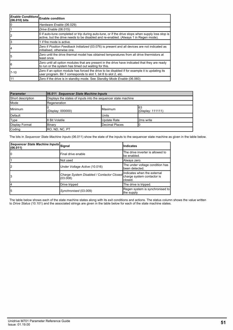
Enable Conditions(06.010) bits Enable condition
0 Hardware Enable (06.029)1 Drive Enable (06.015)
2 0 if auto-tune completed or trip during auto-tune, or if the drive stops when supply loss stop isactive, but the drive needs to be disabled and re-enabled. (Always 1 in Regen mode).
3 1 if fire mode is active.
4 Zero if Position Feedback Initialized (03.076) is present and all devices are not indicated asinitialised, otherwise one.
5 Zero until the drive thermal model has obtained temperatures from all drive thermistors atleast once.
6 Zero until all option modules that are present in the drive have indicated that they are readyto run or the system has timed out waiting for this.
7-10 Zero if an option module has forced the drive to be disabled if for example it is updating itsuser program. Bit 7 corresponds to slot 1, bit 8 to slot 2, etc.
11 Zero if the drive is in standby mode. See Standby Mode Enable (06.060)
Parameter 06.011 Sequencer State Machine InputsShort description Displays the states of inputs into the sequencer state machineMode Regeneration
Minimum 0(Display: 000000) Maximum 63
(Display: 111111)Default Units Type 8 Bit Volatile Update Rate 2ms writeDisplay Format Binary Decimal Places 0Coding RO, ND, NC, PT
The bits in Sequencer State Machine Inputs (06.011) show the state of the inputs to the sequencer state machine as given in the table below.
Sequencer State Machine Inputs(06.011) Signal Indicates
0 Final drive enable The drive inverter is allowed tobe enabled.
1 Not used Always zero.
2 Under Voltage Active (10.016) The under voltage condition hasbeen detected.
3 Charge System Disabled / Contactor Closed(03.008)
Indicates when the externalcharge system contactor isclosed.
4 Drive tripped The drive is tripped.
5 Synchronised (03.009) Regen system is synchronised tothe supply
The table below shows each of the state machine states along with its exit conditions and actions. The status column shows the value writtento Drive Status (10.101) and the associated strings are given in the table below for each of the state machine states.
Unidrive M701 Parameter Reference GuideIssue: 01.19.00 51
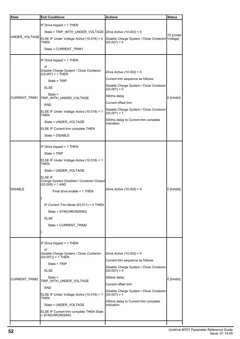
State Exit Conditions Actions Status
UNDER_VOLTAGE
IF Drive tripped = 1 THEN
State = TRIP_WITH_UNDER_VOLTAGE
ELSE IF Under Voltage Active (10.016) = 0THEN
State = CURRENT_TRIM1
Drive Active (10.002) = 0
Disable Charge System / Close Contactor(03.007) = 0
15 [UnderVoltage]
CURRENT_TRIM1
IF Drive tripped = 1 THEN
IFDisable Charge System / Close Contactor(03.007) = 1 THEN
State = TRIP
ELSE
State =TRIP_WITH_UNDER_VOLTAGE
END
ELSE IF Under Voltage Active (10.016) = 1THEN
State = UNDER_VOLTAGE
ELSE IF Current trim complete THEN
State = DISABLE
Drive Active (10.002) = 0
Current trim sequence as follows:
Disable Charge System / Close Contactor(03.007) = 0
500ms delay
Current offset trim
Disable Charge System / Close Contactor(03.007) = 1
500ms delay to Current trim completeindication
0 [Inhibit]
DISABLE
IF Drive tripped = 1 THEN
State = TRIP
ELSE IF Under Voltage Active (10.016) = 1THEN
State = UNDER_VOLTAGE
ELSE IFCharge System Disabled / Contactor Closed(03.008) = 1 AND
Final drive enable = 1 THEN
IF Current Trim Mode (03.011) = 0 THEN
State = SYNCHRONISING
ELSE
State = CURRENT_TRIM2
Drive Active (10.002) = 0 0 [Inhibit]
CURRENT_TRIM2
IF Drive tripped = 1 THEN
IFDisable Charge System / Close Contactor(03.007)) = 1 THEN
State = TRIP
ELSE
State =TRIP_WITH_UNDER_VOLTAGE
END
ELSE IF Under Voltage Active (10.016) = 1THEN
State = UNDER_VOLTAGE
ELSE IF Current trim complete THEN State= SYNCHRONISING
Drive Active (10.002) = 0
Current trim sequence as follows:
Disable Charge System / Close Contactor(03.007) = 0
500ms delay
Current offset trim
Disable Charge System / Close Contactor(03.007) = 1
500ms delay to Current trim completeindication
0 [Inhibit]
52 Unidrive M701 Parameter Reference GuideIssue: 01.19.00
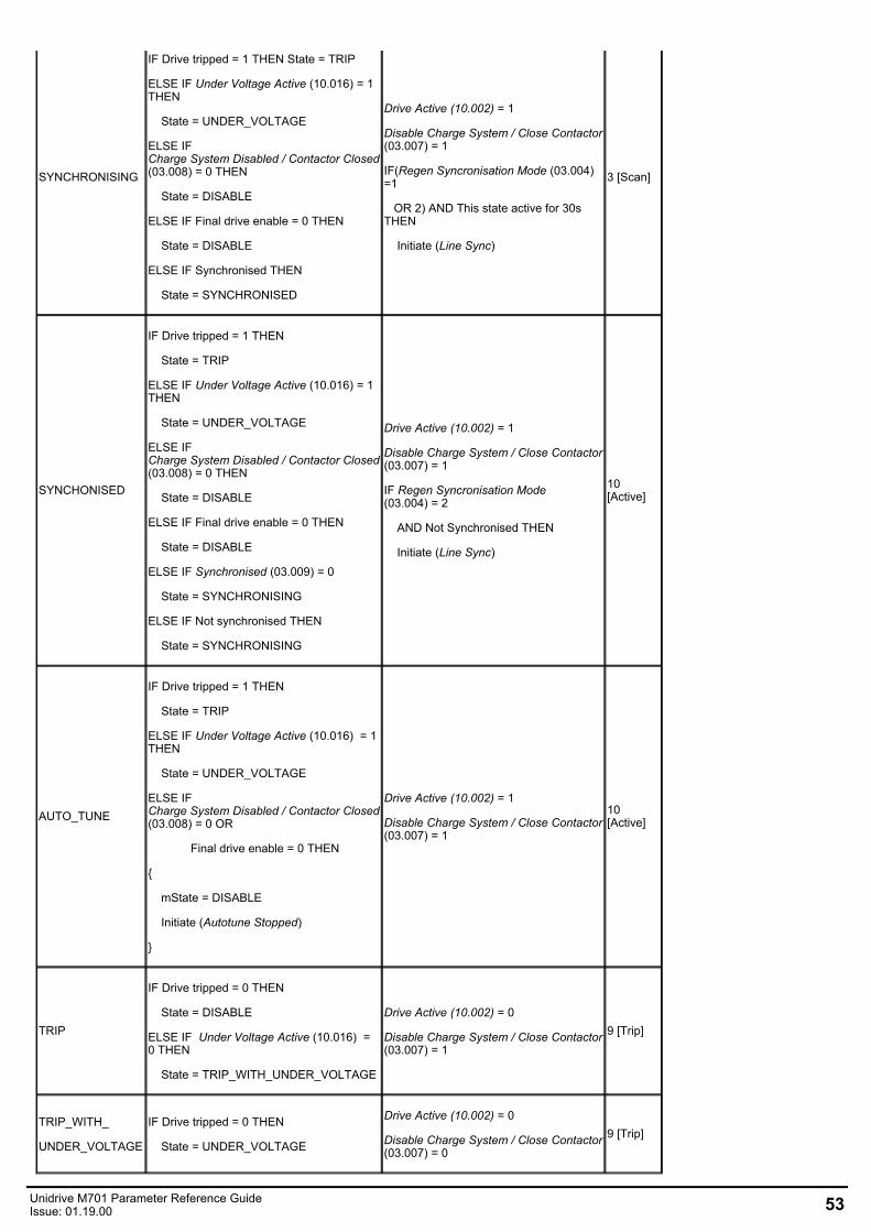
SYNCHRONISING
IF Drive tripped = 1 THEN State = TRIP
ELSE IF Under Voltage Active (10.016) = 1THEN
State = UNDER_VOLTAGE
ELSE IFCharge System Disabled / Contactor Closed(03.008) = 0 THEN
State = DISABLE
ELSE IF Final drive enable = 0 THEN
State = DISABLE
ELSE IF Synchronised THEN
State = SYNCHRONISED
Drive Active (10.002) = 1
Disable Charge System / Close Contactor(03.007) = 1
IF(Regen Syncronisation Mode (03.004) =1
OR 2) AND This state active for 30sTHEN
Initiate (Line Sync)
3 [Scan]
SYNCHONISED
IF Drive tripped = 1 THEN
State = TRIP
ELSE IF Under Voltage Active (10.016) = 1THEN
State = UNDER_VOLTAGE
ELSE IFCharge System Disabled / Contactor Closed(03.008) = 0 THEN
State = DISABLE
ELSE IF Final drive enable = 0 THEN
State = DISABLE
ELSE IF Synchronised (03.009) = 0
State = SYNCHRONISING
ELSE IF Not synchronised THEN
State = SYNCHRONISING
Drive Active (10.002) = 1
Disable Charge System / Close Contactor(03.007) = 1
IF Regen Syncronisation Mode(03.004) = 2
AND Not Synchronised THEN
Initiate (Line Sync)
10[Active]
AUTO_TUNE
IF Drive tripped = 1 THEN
State = TRIP
ELSE IF Under Voltage Active (10.016) = 1THEN
State = UNDER_VOLTAGE
ELSE IFCharge System Disabled / Contactor Closed(03.008) = 0 OR
Final drive enable = 0 THEN
mState = DISABLE
Initiate (Autotune Stopped)
Drive Active (10.002) = 1
Disable Charge System / Close Contactor(03.007) = 1
10[Active]
TRIP
IF Drive tripped = 0 THEN
State = DISABLE
ELSE IF Under Voltage Active (10.016) =0 THEN
State = TRIP_WITH_UNDER_VOLTAGE
Drive Active (10.002) = 0
Disable Charge System / Close Contactor(03.007) = 1
9 [Trip]
TRIP_WITH_
UNDER_VOLTAGE
IF Drive tripped = 0 THEN
State = UNDER_VOLTAGE
Drive Active (10.002) = 0
Disable Charge System / Close Contactor(03.007) = 0
9 [Trip]
Unidrive M701 Parameter Reference GuideIssue: 01.19.00 53
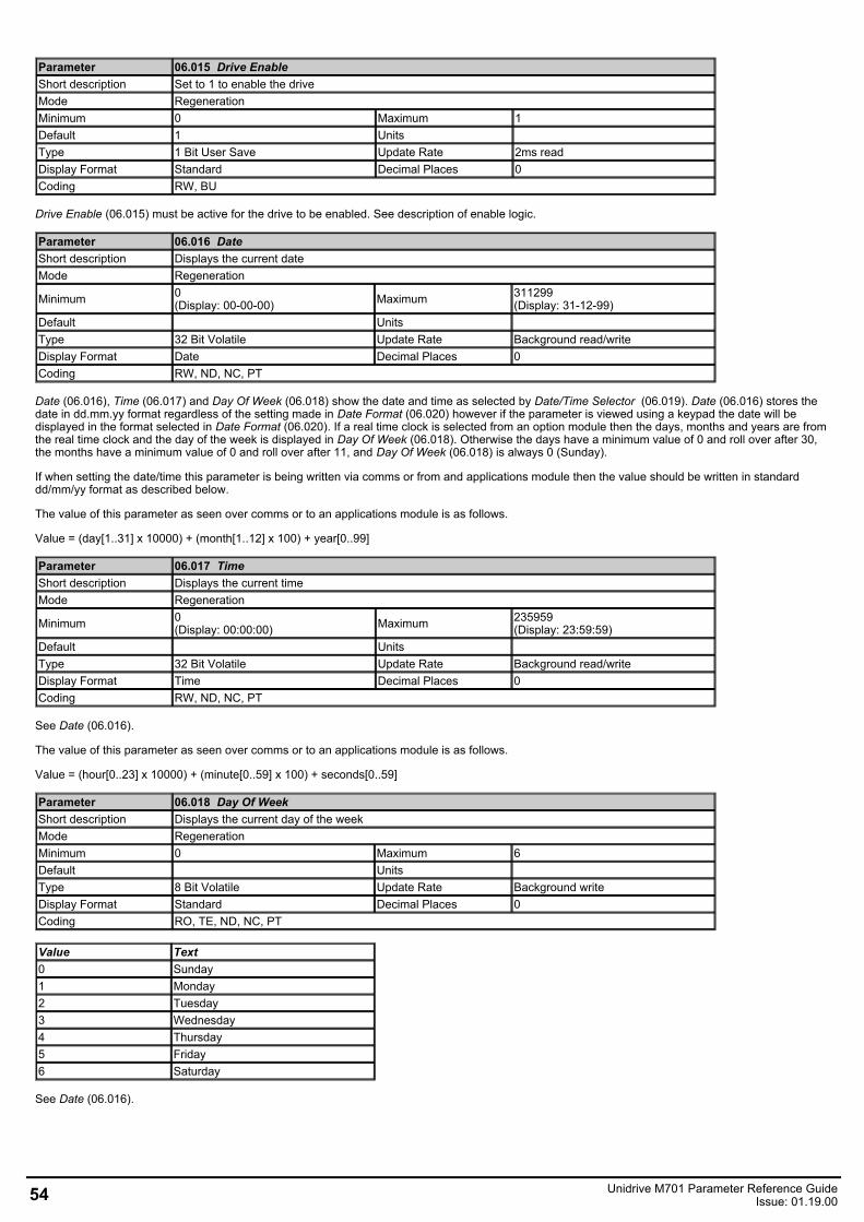
Parameter 06.015 Drive EnableShort description Set to 1 to enable the driveMode RegenerationMinimum 0 Maximum 1Default 1 Units Type 1 Bit User Save Update Rate 2ms readDisplay Format Standard Decimal Places 0Coding RW, BU
Drive Enable (06.015) must be active for the drive to be enabled. See description of enable logic.
Parameter 06.016 DateShort description Displays the current dateMode Regeneration
Minimum 0(Display: 00-00-00) Maximum 311299
(Display: 31-12-99)Default Units Type 32 Bit Volatile Update Rate Background read/writeDisplay Format Date Decimal Places 0Coding RW, ND, NC, PT
Date (06.016), Time (06.017) and Day Of Week (06.018) show the date and time as selected by Date/Time Selector (06.019). Date (06.016) stores thedate in dd.mm.yy format regardless of the setting made in Date Format (06.020) however if the parameter is viewed using a keypad the date will bedisplayed in the format selected in Date Format (06.020). If a real time clock is selected from an option module then the days, months and years are fromthe real time clock and the day of the week is displayed in Day Of Week (06.018). Otherwise the days have a minimum value of 0 and roll over after 30,the months have a minimum value of 0 and roll over after 11, and Day Of Week (06.018) is always 0 (Sunday).
If when setting the date/time this parameter is being written via comms or from and applications module then the value should be written in standarddd/mm/yy format as described below.
The value of this parameter as seen over comms or to an applications module is as follows.
Value = (day[1..31] x 10000) + (month[1..12] x 100) + year[0..99]
Parameter 06.017 TimeShort description Displays the current timeMode Regeneration
Minimum 0(Display: 00:00:00) Maximum 235959
(Display: 23:59:59)Default Units Type 32 Bit Volatile Update Rate Background read/writeDisplay Format Time Decimal Places 0Coding RW, ND, NC, PT
See Date (06.016).
The value of this parameter as seen over comms or to an applications module is as follows.
Value = (hour[0..23] x 10000) + (minute[0..59] x 100) + seconds[0..59]
Parameter 06.018 Day Of WeekShort description Displays the current day of the weekMode RegenerationMinimum 0 Maximum 6Default Units Type 8 Bit Volatile Update Rate Background writeDisplay Format Standard Decimal Places 0Coding RO, TE, ND, NC, PT
Value Text0 Sunday1 Monday2 Tuesday3 Wednesday4 Thursday5 Friday6 Saturday
See Date (06.016).
54 Unidrive M701 Parameter Reference GuideIssue: 01.19.00
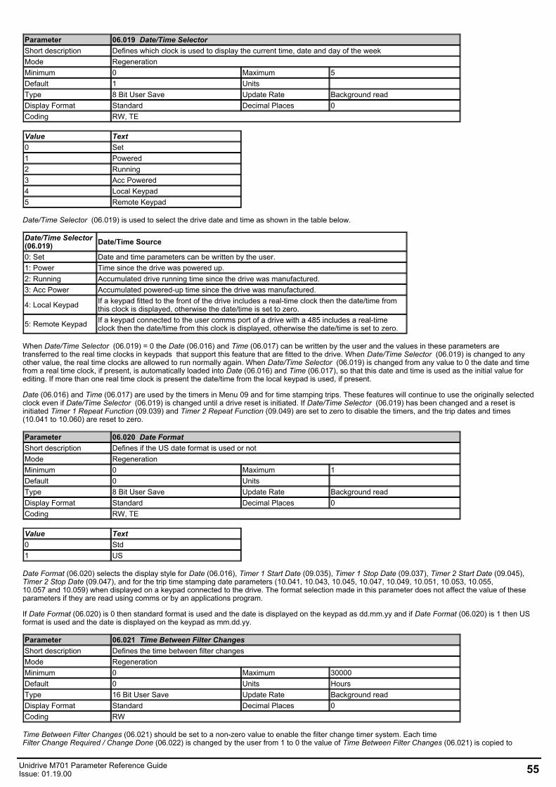
Parameter 06.019 Date/Time SelectorShort description Defines which clock is used to display the current time, date and day of the weekMode RegenerationMinimum 0 Maximum 5Default 1 Units Type 8 Bit User Save Update Rate Background readDisplay Format Standard Decimal Places 0Coding RW, TE
Value Text0 Set1 Powered2 Running3 Acc Powered4 Local Keypad5 Remote Keypad
Date/Time Selector (06.019) is used to select the drive date and time as shown in the table below.
Date/Time Selector (06.019) Date/Time Source
0: Set Date and time parameters can be written by the user.1: Power Time since the drive was powered up.2: Running Accumulated drive running time since the drive was manufactured.3: Acc Power Accumulated powered-up time since the drive was manufactured.
4: Local Keypad If a keypad fitted to the front of the drive includes a real-time clock then the date/time fromthis clock is displayed, otherwise the date/time is set to zero.
5: Remote Keypad If a keypad connected to the user comms port of a drive with a 485 includes a real-timeclock then the date/time from this clock is displayed, otherwise the date/time is set to zero.
When Date/Time Selector (06.019) = 0 the Date (06.016) and Time (06.017) can be written by the user and the values in these parameters aretransferred to the real time clocks in keypads that support this feature that are fitted to the drive. When Date/Time Selector (06.019) is changed to anyother value, the real time clocks are allowed to run normally again. When Date/Time Selector (06.019) is changed from any value to 0 the date and timefrom a real time clock, if present, is automatically loaded into Date (06.016) and Time (06.017), so that this date and time is used as the initial value forediting. If more than one real time clock is present the date/time from the local keypad is used, if present.
Date (06.016) and Time (06.017) are used by the timers in Menu 09 and for time stamping trips. These features will continue to use the originally selectedclock even if Date/Time Selector (06.019) is changed until a drive reset is initiated. If Date/Time Selector (06.019) has been changed and a reset isinitiated Timer 1 Repeat Function (09.039) and Timer 2 Repeat Function (09.049) are set to zero to disable the timers, and the trip dates and times(10.041 to 10.060) are reset to zero.
Parameter 06.020 Date FormatShort description Defines if the US date format is used or notMode RegenerationMinimum 0 Maximum 1Default 0 Units Type 8 Bit User Save Update Rate Background readDisplay Format Standard Decimal Places 0Coding RW, TE
Value Text0 Std1 US
Date Format (06.020) selects the display style for Date (06.016), Timer 1 Start Date (09.035), Timer 1 Stop Date (09.037), Timer 2 Start Date (09.045),Timer 2 Stop Date (09.047), and for the trip time stamping date parameters (10.041, 10.043, 10.045, 10.047, 10.049, 10.051, 10.053, 10.055,10.057 and 10.059) when displayed on a keypad connected to the drive. The format selection made in this parameter does not affect the value of theseparameters if they are read using comms or by an applications program.
If Date Format (06.020) is 0 then standard format is used and the date is displayed on the keypad as dd.mm.yy and if Date Format (06.020) is 1 then USformat is used and the date is displayed on the keypad as mm.dd.yy.
Parameter 06.021 Time Between Filter ChangesShort description Defines the time between filter changesMode RegenerationMinimum 0 Maximum 30000Default 0 Units HoursType 16 Bit User Save Update Rate Background readDisplay Format Standard Decimal Places 0Coding RW
Time Between Filter Changes (06.021) should be set to a non-zero value to enable the filter change timer system. Each timeFilter Change Required / Change Done (06.022) is changed by the user from 1 to 0 the value of Time Between Filter Changes (06.021) is copied to
Unidrive M701 Parameter Reference GuideIssue: 01.19.00 55
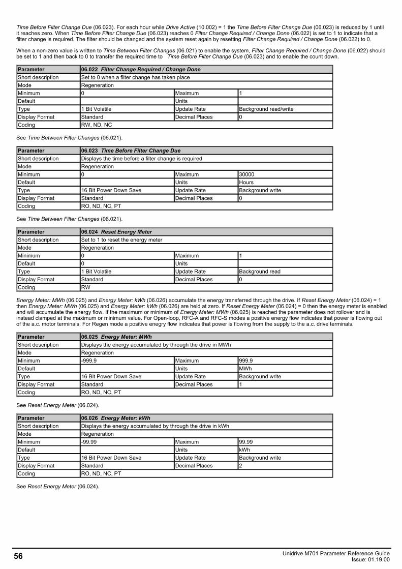
Time Before Filter Change Due (06.023). For each hour while Drive Active (10.002) = 1 the Time Before Filter Change Due (06.023) is reduced by 1 untilit reaches zero. When Time Before Filter Change Due (06.023) reaches 0 Filter Change Required / Change Done (06.022) is set to 1 to indicate that afilter change is required. The filter should be changed and the system reset again by resetting Filter Change Required / Change Done (06.022) to 0.
When a non-zero value is written to Time Between Filter Changes (06.021) to enable the system, Filter Change Required / Change Done (06.022) shouldbe set to 1 and then back to 0 to transfer the required time to Time Before Filter Change Due (06.023) and to enable the count down.
Parameter 06.022 Filter Change Required / Change DoneShort description Set to 0 when a filter change has taken placeMode RegenerationMinimum 0 Maximum 1Default Units Type 1 Bit Volatile Update Rate Background read/writeDisplay Format Standard Decimal Places 0Coding RW, ND, NC
See Time Between Filter Changes (06.021).
Parameter 06.023 Time Before Filter Change DueShort description Displays the time before a filter change is requiredMode RegenerationMinimum 0 Maximum 30000Default Units HoursType 16 Bit Power Down Save Update Rate Background writeDisplay Format Standard Decimal Places 0Coding RO, ND, NC, PT
See Time Between Filter Changes (06.021).
Parameter 06.024 Reset Energy MeterShort description Set to 1 to reset the energy meterMode RegenerationMinimum 0 Maximum 1Default 0 Units Type 1 Bit Volatile Update Rate Background readDisplay Format Standard Decimal Places 0Coding RW
Energy Meter: MWh (06.025) and Energy Meter: kWh (06.026) accumulate the energy transferred through the drive. If Reset Energy Meter (06.024) = 1then Energy Meter: MWh (06.025) and Energy Meter: kWh (06.026) are held at zero. If Reset Energy Meter (06.024) = 0 then the energy meter is enabledand will accumulate the energy flow. If the maximum or minimum of Energy Meter: MWh (06.025) is reached the parameter does not rollover and isinstead clamped at the maximum or minimum value. For Open-loop, RFC-A and RFC-S modes a positive energy flow indicates that power is flowing outof the a.c. motor terminals. For Regen mode a positive enegry flow indicates that power is flowing from the supply to the a.c. drive terminals.
Parameter 06.025 Energy Meter: MWhShort description Displays the energy accumulated by through the drive in MWhMode RegenerationMinimum -999.9 Maximum 999.9Default Units MWhType 16 Bit Power Down Save Update Rate Background writeDisplay Format Standard Decimal Places 1Coding RO, ND, NC, PT
See Reset Energy Meter (06.024).
Parameter 06.026 Energy Meter: kWhShort description Displays the energy accumulated by through the drive in kWhMode RegenerationMinimum -99.99 Maximum 99.99Default Units kWhType 16 Bit Power Down Save Update Rate Background writeDisplay Format Standard Decimal Places 2Coding RO, ND, NC, PT
See Reset Energy Meter (06.024).
56 Unidrive M701 Parameter Reference GuideIssue: 01.19.00
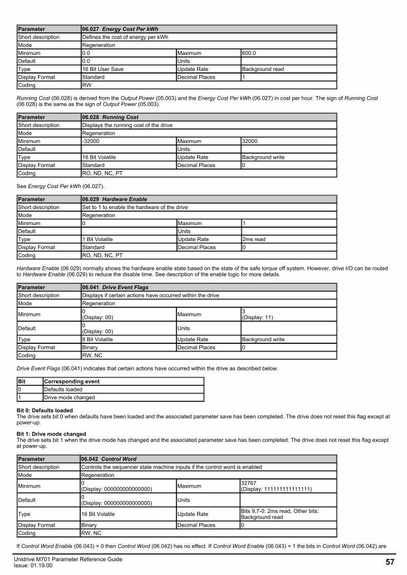
Parameter 06.027 Energy Cost Per kWhShort description Defines the cost of energy per kWhMode RegenerationMinimum 0.0 Maximum 600.0Default 0.0 Units Type 16 Bit User Save Update Rate Background readDisplay Format Standard Decimal Places 1Coding RW
Running Cost (06.028) is derived from the Output Power (05.003) and the Energy Cost Per kWh (06.027) in cost per hour. The sign of Running Cost(06.028) is the same as the sign of Output Power (05.003).
Parameter 06.028 Running CostShort description Displays the running cost of the driveMode RegenerationMinimum -32000 Maximum 32000Default Units Type 16 Bit Volatile Update Rate Background writeDisplay Format Standard Decimal Places 0Coding RO, ND, NC, PT
See Energy Cost Per kWh (06.027).
Parameter 06.029 Hardware EnableShort description Set to 1 to enable the hardware of the driveMode RegenerationMinimum 0 Maximum 1Default Units Type 1 Bit Volatile Update Rate 2ms readDisplay Format Standard Decimal Places 0Coding RO, ND, NC, PT
Hardware Enable (06.029) normally shows the hardware enable state based on the state of the safe torque off system. However, drive I/O can be routedto Hardware Enable (06.029) to reduce the disable time. See description of the enable logic for more details.
Parameter 06.041 Drive Event FlagsShort description Displays if certain actions have occurred within the driveMode Regeneration
Minimum 0(Display: 00) Maximum 3
(Display: 11)
Default 0(Display: 00) Units
Type 8 Bit Volatile Update Rate Background writeDisplay Format Binary Decimal Places 0Coding RW, NC
Drive Event Flags (06.041) indicates that certain actions have occurred within the drive as described below.
Bit Corresponding event0 Defaults loaded1 Drive mode changed
Bit 0: Defaults loadedThe drive sets bit 0 when defaults have been loaded and the associated parameter save has been completed. The drive does not reset this flag except atpower-up.
Bit 1: Drive mode changedThe drive sets bit 1 when the drive mode has changed and the associated parameter save has been completed. The drive does not reset this flag exceptat power-up.
Parameter 06.042 Control WordShort description Controls the sequencer state machine inputs if the control word is enabledMode Regeneration
Minimum 0(Display: 000000000000000) Maximum 32767
(Display: 111111111111111)
Default 0(Display: 000000000000000) Units
Type 16 Bit Volatile Update Rate Bits 9,7-0: 2ms read, Other bits:Background read
Display Format Binary Decimal Places 0Coding RW, NC
If Control Word Enable (06.043) = 0 then Control Word (06.042) has no effect. If Control Word Enable (06.043) = 1 the bits in Control Word (06.042) are
Unidrive M701 Parameter Reference GuideIssue: 01.19.00 57
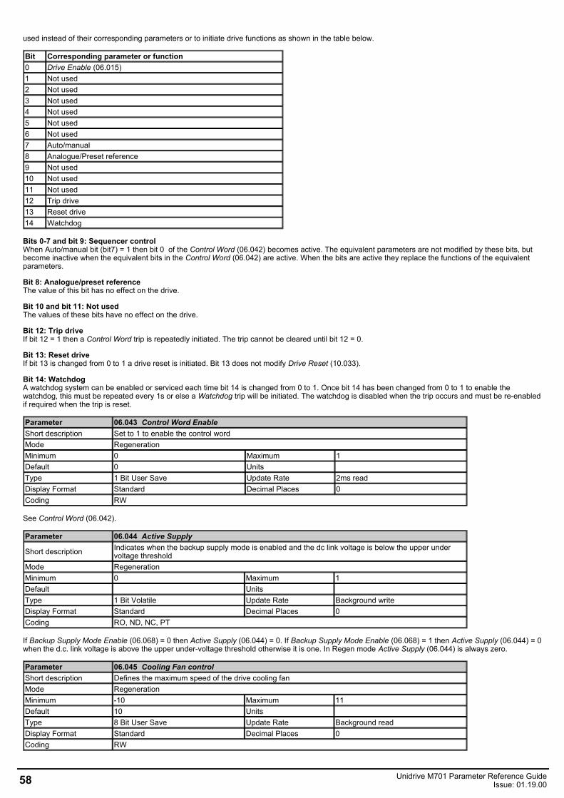
used instead of their corresponding parameters or to initiate drive functions as shown in the table below.
Bit Corresponding parameter or function0 Drive Enable (06.015)1 Not used2 Not used3 Not used4 Not used5 Not used6 Not used7 Auto/manual8 Analogue/Preset reference9 Not used10 Not used11 Not used12 Trip drive13 Reset drive14 Watchdog
Bits 0-7 and bit 9: Sequencer controlWhen Auto/manual bit (bit7) = 1 then bit 0 of the Control Word (06.042) becomes active. The equivalent parameters are not modified by these bits, butbecome inactive when the equivalent bits in the Control Word (06.042) are active. When the bits are active they replace the functions of the equivalentparameters.
Bit 8: Analogue/preset referenceThe value of this bit has no effect on the drive.
Bit 10 and bit 11: Not usedThe values of these bits have no effect on the drive.
Bit 12: Trip driveIf bit 12 = 1 then a Control Word trip is repeatedly initiated. The trip cannot be cleared until bit 12 = 0.
Bit 13: Reset driveIf bit 13 is changed from 0 to 1 a drive reset is initiated. Bit 13 does not modify Drive Reset (10.033).
Bit 14: WatchdogA watchdog system can be enabled or serviced each time bit 14 is changed from 0 to 1. Once bit 14 has been changed from 0 to 1 to enable thewatchdog, this must be repeated every 1s or else a Watchdog trip will be initiated. The watchdog is disabled when the trip occurs and must be re-enabledif required when the trip is reset.
Parameter 06.043 Control Word EnableShort description Set to 1 to enable the control wordMode RegenerationMinimum 0 Maximum 1Default 0 Units Type 1 Bit User Save Update Rate 2ms readDisplay Format Standard Decimal Places 0Coding RW
See Control Word (06.042).
Parameter 06.044 Active Supply
Short description Indicates when the backup supply mode is enabled and the dc link voltage is below the upper undervoltage threshold
Mode RegenerationMinimum 0 Maximum 1Default Units Type 1 Bit Volatile Update Rate Background writeDisplay Format Standard Decimal Places 0Coding RO, ND, NC, PT
If Backup Supply Mode Enable (06.068) = 0 then Active Supply (06.044) = 0. If Backup Supply Mode Enable (06.068) = 1 then Active Supply (06.044) = 0when the d.c. link voltage is above the upper under-voltage threshold otherwise it is one. In Regen mode Active Supply (06.044) is always zero.
Parameter 06.045 Cooling Fan controlShort description Defines the maximum speed of the drive cooling fanMode RegenerationMinimum -10 Maximum 11Default 10 Units Type 8 Bit User Save Update Rate Background readDisplay Format Standard Decimal Places 0Coding RW
58 Unidrive M701 Parameter Reference GuideIssue: 01.19.00
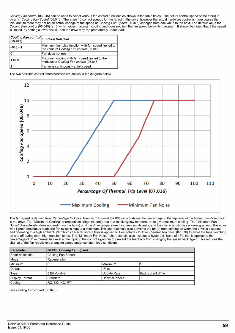
Cooling Fan control (06.045) can be used to select various fan control functions as shown in the table below. The actual control speed of the fan(s) ingiven in Cooling Fan Speed (06.046). There are 10 control speeds for the fan(s) in the drive, however the actual hardware control is more coarse thanthis, and so there may not be an actual change of fan speed as Cooling Fan Speed (06.046) changes from one value to the next. The default value forCooling Fan control (06.045) is 10, which gives maximum cooling and does not limit the fan speed below its maximum. It should be noted that if the speedis limited, by setting a lower value, then the drive may trip prematurely under load.
Cooling Fan control(06.045) Function Selected
-10 to -1 Minimum fan noise function with fan speed limited tothe value of Cooling Fan control (06.045).
0 Fan does not run.
1 to 10 Maximum cooling with fan speed limited to themodulus of Cooling Fan control (06.045).
11 Fan runs continuously at full speed.
The two possible control characteristics are shown in the diagram below.
The fan speed is derived from Percentage Of Drive Thermal Trip Level (07.036) which shows the percentage to the trip level of the hottest monitored pointin the drive. The "Maximum Cooling" characteristic brings the fan(s) on at a relatively low temperature to give maximum cooling. The "Minimum FanNoise" characteristic does not switch on the fan(s) until the drive temperature has risen significantly, and the characteristic has a lower gradient. Thereforewith lighter continuous loads the fan noise is kept to a minimum. This characteristic also prevents the fan(s) from coming on when the drive is disabledand operating in a high ambient. With both characteristics a filter is applied to Percentage Of Drive Thermal Trip Level (07.036) to avoid the fans switchingon and off during short high transient loads. The "Minimum Fan Noise" characteristic also includes a hysteresis band of 15% that is applied to thepercentage of drive thermal trip level at the input to the control algorithm to prevent the feedback from changing the speed back again. This reduces thechance of the fan repetitively changing speed under constant load conditions.
Parameter 06.046 Cooling Fan SpeedShort description Cooling Fan SpeedMode RegenerationMinimum 0 Maximum 10Default Units Type 8 Bit Volatile Update Rate Background WriteDisplay Format Standard Decimal Places 0Coding RO, ND, NC, PT
See Cooling Fan control (06.045).
Unidrive M701 Parameter Reference GuideIssue: 01.19.00 59
Parameter 06.060 Standby Mode EnableShort description Set to 1 enable standby modeMode RegenerationMinimum 0 Maximum 1Default 0 Units Type 1 Bit User Save Update Rate Background readDisplay Format Standard Decimal Places 0Coding RW
If Standby Mode Enable (06.060) = 1 then the drive will go into the standby power state whenever Drive Active (10.002) = 0 with a delay of 30s. In thisstate the LED on the front of the drive flashes 0.5s on and 5s off, the drive cannot be enabled and the following actions are taken as defined by theStandby Mode Mask (06.061). Actions are enabled by setting the appropriate bit to 1. Once standby mode has become active it will remain active, even ifan attempt is made subsequently to enable the drive, until Standby Mode Enable (06.060) is set to 0.
Standby Mode Mask(06.061) bits Action
0Turn off the drive position feedback power supply.On leaving standby mode the drive position feedbackinterfaces will be re-initialised.
1 Turn off the power supply to a keypad fitted to thedrive.
2 Turn off the drive 24V output.
3 Request that the option module in option slot 1 to gointo the standby power mode
4 Request that the option module in option slot 2 to gointo the standby power mode
5 Request that the option module in option slot 3 to gointo the standby power mode
6 Request that the option module in option slot 4 to gointo the standby power mode
Parameter 06.061 Standby Mode MaskShort description Defines the actions of the drive with standby mode is enabledMode Regeneration
Minimum 0(Display: 0000000) Maximum 127
(Display: 1111111)
Default 0(Display: 0000000) Units
Type 8 Bit User Save Update Rate Background readDisplay Format Binary Decimal Places 0Coding RW, BU
See Standby Mode Enable (06.060).
Parameter 06.065 Standard Under Voltage ThresholdShort description Defines the standard under voltage thresholdMode RegenerationMinimum 0 Maximum VM_STD_UNDER_VOLTSDefault See exceptions below Units VType 16 Bit User Save Update Rate Background readDisplay Format Standard Decimal Places 0Coding RW, VM, RA, BU
Voltage Default Value200V 175400V 330575V 435690V 435
Under-voltage and power supply control
60 Unidrive M701 Parameter Reference GuideIssue: 01.19.00
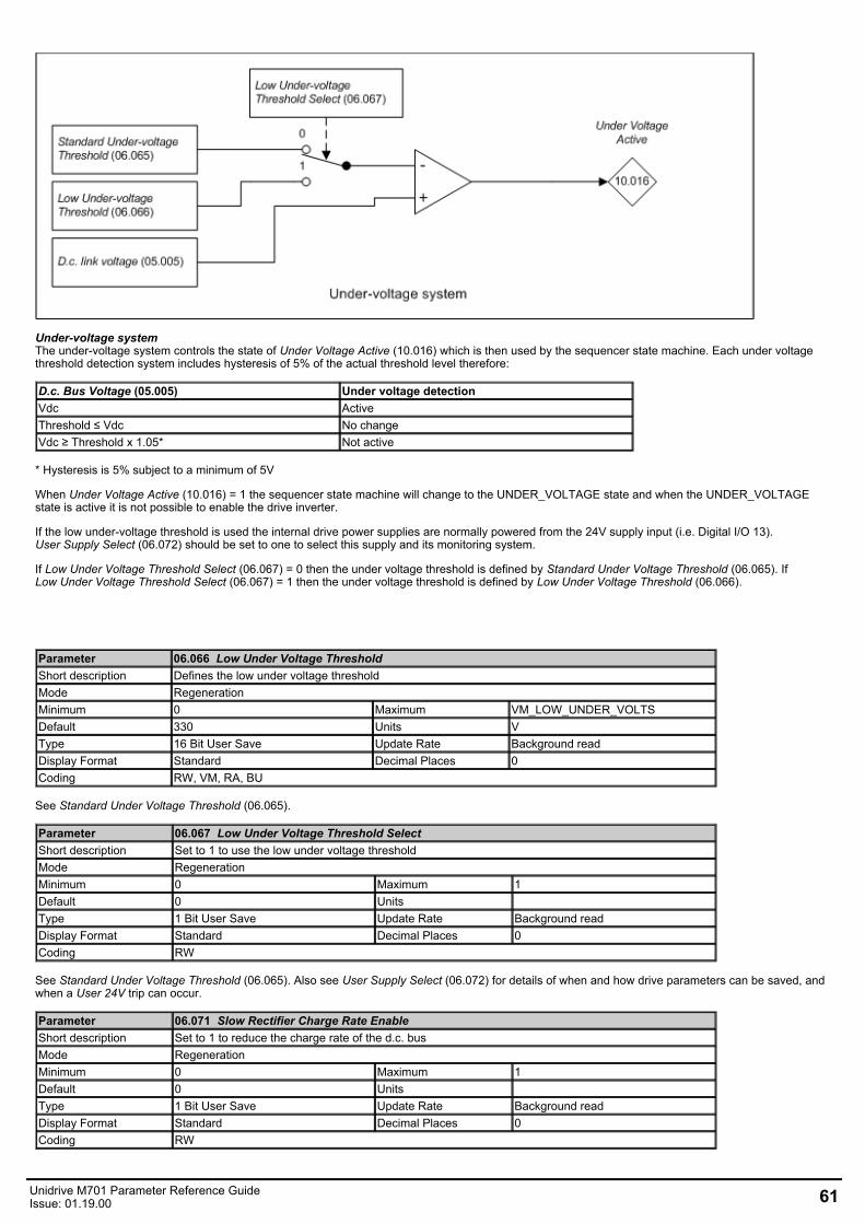
Under-voltage systemThe under-voltage system controls the state of Under Voltage Active (10.016) which is then used by the sequencer state machine. Each under voltagethreshold detection system includes hysteresis of 5% of the actual threshold level therefore:
D.c. Bus Voltage (05.005) Under voltage detectionVdc ActiveThreshold ≤ Vdc No changeVdc ≥ Threshold x 1.05* Not active
* Hysteresis is 5% subject to a minimum of 5V
When Under Voltage Active (10.016) = 1 the sequencer state machine will change to the UNDER_VOLTAGE state and when the UNDER_VOLTAGEstate is active it is not possible to enable the drive inverter.
If the low under-voltage threshold is used the internal drive power supplies are normally powered from the 24V supply input (i.e. Digital I/O 13).User Supply Select (06.072) should be set to one to select this supply and its monitoring system.
If Low Under Voltage Threshold Select (06.067) = 0 then the under voltage threshold is defined by Standard Under Voltage Threshold (06.065). IfLow Under Voltage Threshold Select (06.067) = 1 then the under voltage threshold is defined by Low Under Voltage Threshold (06.066).
Parameter 06.066 Low Under Voltage ThresholdShort description Defines the low under voltage thresholdMode RegenerationMinimum 0 Maximum VM_LOW_UNDER_VOLTSDefault 330 Units VType 16 Bit User Save Update Rate Background readDisplay Format Standard Decimal Places 0Coding RW, VM, RA, BU
See Standard Under Voltage Threshold (06.065).
Parameter 06.067 Low Under Voltage Threshold SelectShort description Set to 1 to use the low under voltage thresholdMode RegenerationMinimum 0 Maximum 1Default 0 Units Type 1 Bit User Save Update Rate Background readDisplay Format Standard Decimal Places 0Coding RW
See Standard Under Voltage Threshold (06.065). Also see User Supply Select (06.072) for details of when and how drive parameters can be saved, andwhen a User 24V trip can occur.
Parameter 06.071 Slow Rectifier Charge Rate EnableShort description Set to 1 to reduce the charge rate of the d.c. busMode RegenerationMinimum 0 Maximum 1Default 0 Units Type 1 Bit User Save Update Rate Background readDisplay Format Standard Decimal Places 0Coding RW
Unidrive M701 Parameter Reference GuideIssue: 01.19.00 61
For frame size 07 drives and larger, which use a d.c. link charge system based on a half controlled thyristor input bridge, the rate at which the d.c. bus ischarged can be reduced by setting Slow Rectifier Charge Rate Enable (06.071) to one. This will reduce the charging current which may be required ifsignificant additional capacitance is added to the d.c. link to prevent rupturing of input fuses.
Parameter 06.072 User Supply SelectShort description Set to 1 to select the supply from the user 24V inputMode RegenerationMinimum 0 Maximum 1Default 0 Units Type 1 Bit User Save Update Rate Background readDisplay Format Standard Decimal Places 0Coding RW
The power for the drive control system is either taken from the user 24V power supply or the main supply (i.e. derived from the power circuit d.c. link). IfLow Under Voltage Threshold Select (06.067) = 0 and Backup Supply Mode Enable (06.068) = 0 and User Supply Select (06.072) = 0 then thesupply used is determined as follows for drive sizes 5 and below. (For drive sizes 6 and above a diode OR system is used to select the required powersupply, and so this is done automatically in hardware.)
1. When the drive first powers up it tries to use the main supply or the user 24V supply in turn until the drive starts up, beginning with the mainsupply.
2. If the main supply is active and the d.c. link voltage (D.c. Bus Voltage (05.005)) falls to a level where it is no longer possible to communicate withthe power stage then the drive attempts to switch over to the user 24V supply. If the user 24V supply is not present then the drive will powerdown, otherwise it will continue to run off the user 24V supply. The level at which the power stage powers down depends on whether the user 24Vsupply is present or not. However this is maybe below half the minimum for Standard Under Voltage Threshold (06.065) depending on the drivepower supply loading from option modules, encoders, I/O etc.
3. If the user 24V supply is being used and the d.c. link voltage (D.c. Bus Voltage (05.005)) rises above 95% of the minimum forStandard Under Voltage Threshold (06.065) then the drive attempts to switch to the main supply.
The following should be noted:
1. Parameters can be saved by setting Parameter mm.000 (mm.000) to 1000 (not in under-voltage state), or to 1 or 1001 (in any state) and initiatinga drive reset. Power-down save parameters are saved when the under-voltage state becomes active.
2. If the drive is powered from the user 24V supply and then the main supply is activated but is not above 95% of the minimum forStandard Under Voltage Threshold (06.065) then the drive will continue to be powered from the user 24V supply. If the user 24V supply issubsequently removed the drive will power down, but then if the main supply is high enough will power up again on the main supply.
3. Although the drive can run off power derived from its d.c. link at a level well below the minimum for Standard Under Voltage Threshold(06.065) the level down to which it will operate depends on the loading applied by option modules, position feedback devices and I/O. For reliableoperation it is advisable that the d.c. link voltage is above 90% of the minimum for Standard Under Voltage Threshold (06.065) when the 24Vsupply is not present.
4. It is possible to initiate saving power-down save parameters by forcing the drive into the under-voltage state by changingLow Under Voltage Threshold Select (06.067) from 1 to 0 when the d.c. link voltage is below 90% of the minimum ofStandard Under Voltage Threshold (06.065). This is not advisable because failure of the 24V supply or the main supply at this point could result incorruption of the drive parameters saved in non-volatile memory.
If Low Under Voltage Threshold Select (06.067) = 1 or Backup Supply Mode Enable (06.068) = 1 or User Supply Select (06.072) = 1 then the 24V usersupply is always selected. If the user 24V supply is not present then a User 24V is initiated. The following should be noted:
1. The drive will still power-up on the main supply even if the user 24V supply is not present because the drive tries each supply in turn to power up,however the drive will remain in the tripped state until the user 24V supply is activated.
2. Parameters can only be saved by setting Parameter mm.000 (mm.000) to1001 and initiating a drive reset. Power-down save parameters are notsaved when the under-voltage state becomes active.
Parameter 06.073 Braking IGBT Lower ThresholdShort description Defines the lowest level of the d.c. bus voltage where the braking IGBT becomes activeMode RegenerationMinimum 0 Maximum VM_DC_VOLTAGE_SETDefault See exceptions below Units VType 16 Bit User Save Update Rate 4ms readDisplay Format Standard Decimal Places 0Coding RW, VM, RA, BU
Voltage Default Value200V 390400V 780575V 930690V 1120
Braking IGBT Lower Threshold (06.073) defines the lowest level of D.c. Bus Voltage (05.005) where the braking IGBT will become active andBraking IGBT Upper Threshold (06.074) defines the level of D.c. Bus Voltage (05.005) where the braking IGBT will be on continuously. When the brakingIGBT is turned on it will remain on for at least 1ms. The braking IGBT on-time is defined by the thresholds and the d.c. link voltage as given in the tablebelow where L = Braking IGBT Lower Threshold (06.073) and U = Braking IGBT Upper Threshold (06.074).
D.c. link voltage level On-timeD.c. Bus Voltage (05.005) 0%L ≤ D.c. Bus Voltage (05.005) [(D.c. Bus Voltage (05.005) - L) / (U - L)] x 100%D.c. Bus Voltage (05.005) ≥ U 100%
62 Unidrive M701 Parameter Reference GuideIssue: 01.19.00
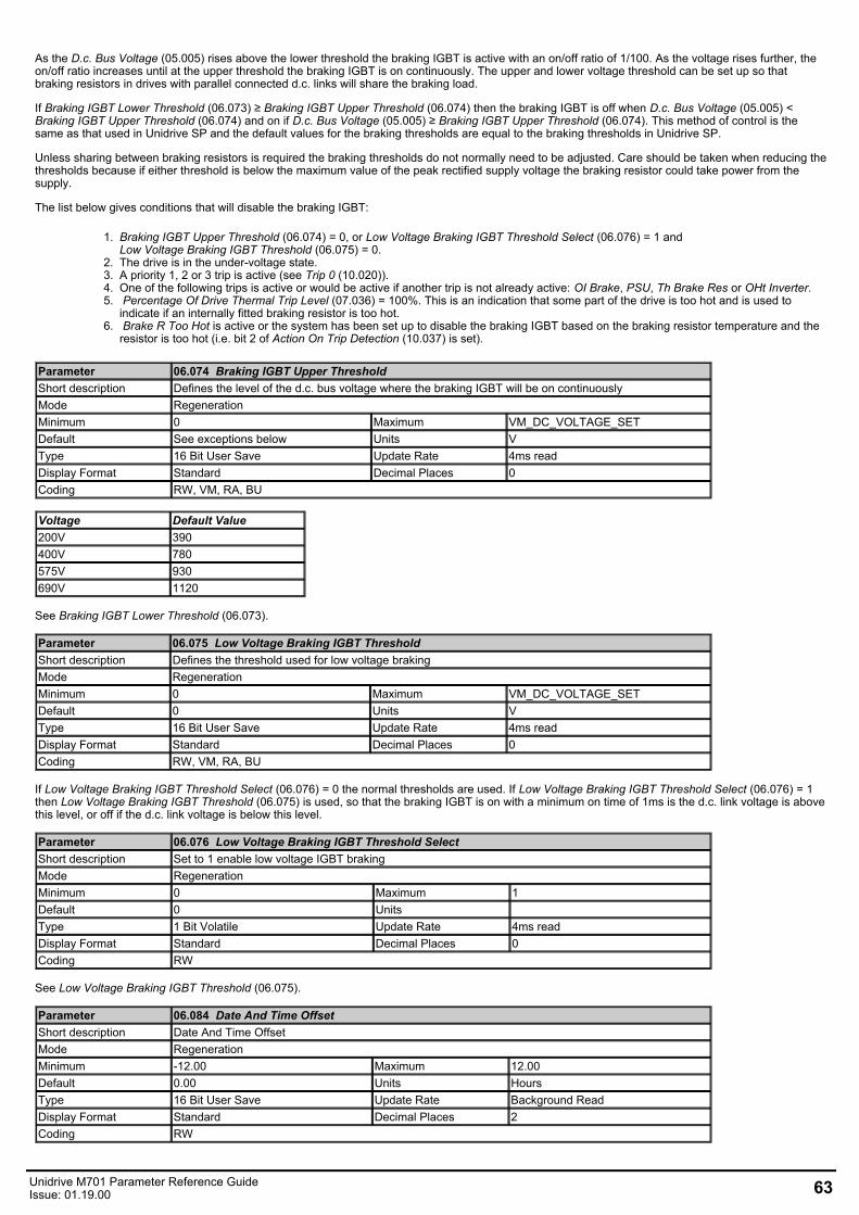
As the D.c. Bus Voltage (05.005) rises above the lower threshold the braking IGBT is active with an on/off ratio of 1/100. As the voltage rises further, theon/off ratio increases until at the upper threshold the braking IGBT is on continuously. The upper and lower voltage threshold can be set up so thatbraking resistors in drives with parallel connected d.c. links will share the braking load.
If Braking IGBT Lower Threshold (06.073) ≥ Braking IGBT Upper Threshold (06.074) then the braking IGBT is off when D.c. Bus Voltage (05.005) <Braking IGBT Upper Threshold (06.074) and on if D.c. Bus Voltage (05.005) ≥ Braking IGBT Upper Threshold (06.074). This method of control is thesame as that used in Unidrive SP and the default values for the braking thresholds are equal to the braking thresholds in Unidrive SP.
Unless sharing between braking resistors is required the braking thresholds do not normally need to be adjusted. Care should be taken when reducing thethresholds because if either threshold is below the maximum value of the peak rectified supply voltage the braking resistor could take power from thesupply.
The list below gives conditions that will disable the braking IGBT:
1. Braking IGBT Upper Threshold (06.074) = 0, or Low Voltage Braking IGBT Threshold Select (06.076) = 1 andLow Voltage Braking IGBT Threshold (06.075) = 0.
2. The drive is in the under-voltage state.3. A priority 1, 2 or 3 trip is active (see Trip 0 (10.020)).4. One of the following trips is active or would be active if another trip is not already active: OI Brake, PSU, Th Brake Res or OHt Inverter. 5. Percentage Of Drive Thermal Trip Level (07.036) = 100%. This is an indication that some part of the drive is too hot and is used to
indicate if an internally fitted braking resistor is too hot.6. Brake R Too Hot is active or the system has been set up to disable the braking IGBT based on the braking resistor temperature and the
resistor is too hot (i.e. bit 2 of Action On Trip Detection (10.037) is set).
Parameter 06.074 Braking IGBT Upper ThresholdShort description Defines the level of the d.c. bus voltage where the braking IGBT will be on continuouslyMode RegenerationMinimum 0 Maximum VM_DC_VOLTAGE_SETDefault See exceptions below Units VType 16 Bit User Save Update Rate 4ms readDisplay Format Standard Decimal Places 0Coding RW, VM, RA, BU
Voltage Default Value200V 390400V 780575V 930690V 1120
See Braking IGBT Lower Threshold (06.073).
Parameter 06.075 Low Voltage Braking IGBT ThresholdShort description Defines the threshold used for low voltage brakingMode RegenerationMinimum 0 Maximum VM_DC_VOLTAGE_SETDefault 0 Units VType 16 Bit User Save Update Rate 4ms readDisplay Format Standard Decimal Places 0Coding RW, VM, RA, BU
If Low Voltage Braking IGBT Threshold Select (06.076) = 0 the normal thresholds are used. If Low Voltage Braking IGBT Threshold Select (06.076) = 1then Low Voltage Braking IGBT Threshold (06.075) is used, so that the braking IGBT is on with a minimum on time of 1ms is the d.c. link voltage is abovethis level, or off if the d.c. link voltage is below this level.
Parameter 06.076 Low Voltage Braking IGBT Threshold SelectShort description Set to 1 enable low voltage IGBT brakingMode RegenerationMinimum 0 Maximum 1Default 0 Units Type 1 Bit Volatile Update Rate 4ms readDisplay Format Standard Decimal Places 0Coding RW
See Low Voltage Braking IGBT Threshold (06.075).
Parameter 06.084 Date And Time OffsetShort description Date And Time OffsetMode RegenerationMinimum -12.00 Maximum 12.00Default 0.00 Units HoursType 16 Bit User Save Update Rate Background ReadDisplay Format Standard Decimal Places 2Coding RW
Unidrive M701 Parameter Reference GuideIssue: 01.19.00 63
Date And Time Offset (06.084) is an offset, specified in hours, that can be applied to the Time (06.017). If the offset applied causes the time to roll-overmidnight then the Date (06.016) and Day Of Week (06.018) are also modified. The offset is only applied when the clock source is a clock derived from akeypad, i.e. Date/Time Selector (06.019) > 3. The offset can be used for time zone offsets or daylight saving time etc.
64 Unidrive M701 Parameter Reference GuideIssue: 01.19.00
Menu 7 Single Line Descriptions − Analog I/OMode: Regeneration
Unidrive M701 Parameter Reference GuideIssue: 01.19.00 65
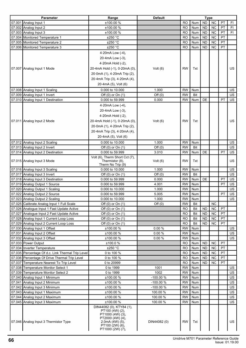
Parameter Range Default Type07.001 Analog Input 1 ±100.00 % RO Num ND NC PT FI07.002 Analog Input 2 ±100.00 % RO Num ND NC PT FI07.003 Analog Input 3 ±100.00 % RO Num ND NC PT FI07.004 Monitored Temperature 1 ±250 °C RO Num ND NC PT 07.005 Monitored Temperature 2 ±250 °C RO Num ND NC PT 07.006 Monitored Temperature 3 ±250 °C RO Num ND NC PT
07.007 Analog Input 1 Mode
4‑20mA Low (-4),20‑4mA Low (-3),4‑20mA Hold (-2),
20‑4mA Hold (-1), 0‑20mA (0),20‑0mA (1), 4‑20mA Trip (2),20‑4mA Trip (3), 4‑20mA (4),
20‑4mA (5), Volt (6)
Volt (6) RW Txt US
07.008 Analog Input 1 Scaling 0.000 to 10.000 1.000 RW Num US07.009 Analog Input 1 Invert Off (0) or On (1) Off (0) RW Bit US07.010 Analog Input 1 Destination 0.000 to 59.999 0.000 RW Num DE PT US
07.011 Analog Input 2 Mode
4‑20mA Low (-4),20‑4mA Low (-3),4‑20mA Hold (-2),
20‑4mA Hold (-1), 0‑20mA (0),20‑0mA (1), 4‑20mA Trip (2),20‑4mA Trip (3), 4‑20mA (4),
20‑4mA (5), Volt (6)
Volt (6) RW Txt US
07.012 Analog Input 2 Scaling 0.000 to 10.000 1.000 RW Num US07.013 Analog Input 2 Invert Off (0) or On (1) Off (0) RW Bit US07.014 Analog Input 2 Destination 0.000 to 59.999 3.010 RW Num DE PT US
07.015 Analog Input 3 ModeVolt (6), Therm Short Cct (7),
Thermistor (8),Therm No Trip (9)
Volt (6) RW Txt US
07.016 Analog Input 3 Scaling 0.000 to 10.000 1.000 RW Num US07.017 Analog Input 3 Invert Off (0) or On (1) Off (0) RW Bit US07.018 Analog Input 3 Destination 0.000 to 59.999 0.000 RW Num DE PT US07.019 Analog Output 1 Source 0.000 to 59.999 4.001 RW Num PT US07.020 Analog Output 1 Scaling 0.000 to 10.000 1.000 RW Num US07.022 Analog Output 2 Source 0.000 to 59.999 5.005 RW Num PT US07.023 Analog Output 2 Scaling 0.000 to 10.000 1.000 RW Num US07.025 Calibrate Analog Input 1 Full Scale Off (0) or On (1) Off (0) RW Bit NC 07.026 Analogue Input 1 Fast Update Active Off (0) or On (1) RO Bit ND NC PT 07.027 Analogue Input 2 Fast Update Active Off (0) or On (1) RO Bit ND NC PT 07.028 Analog Input 1 Current Loop Loss Off (0) or On (1) RO Bit ND NC PT 07.029 Analog Input 2 Current Loop Loss Off (0) or On (1) RO Bit ND NC PT 07.030 Analog Input 1 Offset ±100.00 % 0.00 % RW Num US07.031 Analog Input 2 Offset ±100.00 % 0.00 % RW Num US07.032 Analog Input 3 Offset ±100.00 % 0.00 % RW Num US07.033 Power Output ±100.0 % RO Num ND NC PT 07.034 Inverter Temperature ±250 °C RO Num ND NC PT 07.035 Percentage Of d.c. Link Thermal Trip Level 0 to 100 % RO Num ND NC PT 07.036 Percentage Of Drive Thermal Trip Level 0 to 100 % RO Num ND NC PT 07.037 Temperature Nearest To Trip Level 0 to 20999 RO Num ND NC PT 07.038 Temperature Monitor Select 1 0 to 1999 1001 RW Num US07.039 Temperature Monitor Select 2 0 to 1999 1002 RW Num US07.040 Analog Input 1 Minimum ±100.00 % -100.00 % RW Num US07.041 Analog Input 2 Minimum ±100.00 % -100.00 % RW Num US07.042 Analog Input 3 Minimum ±100.00 % -100.00 % RW Num US07.043 Analog Input 1 Maximum ±100.00 % 100.00 % RW Num US07.044 Analog Input 2 Maximum ±100.00 % 100.00 % RW Num US07.045 Analog Input 3 Maximum ±100.00 % 100.00 % RW Num US
07.046 Analog Input 3 Thermistor Type
DIN44082 (0), KTY84 (1),PT100 (4W) (2),
PT1000 (4W) (3),PT2000 (4W) (4),2.0mA (4W) (5),PT100 (2W) (6),
PT1000 (2W) (7),
DIN44082 (0) RW Txt US
66 Unidrive M701 Parameter Reference GuideIssue: 01.19.00
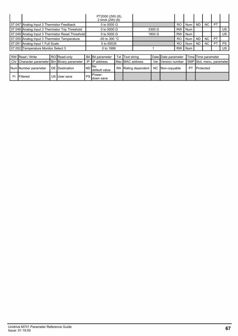
PT2000 (2W) (8),2.0mA (2W) (9)
07.047 Analog Input 3 Thermistor Feedback 0 to 5000 Ω RO Num ND NC PT 07.048 Analog Input 3 Thermistor Trip Threshold 0 to 5000 Ω 3300 Ω RW Num US07.049 Analog Input 3 Thermistor Reset Threshold 0 to 5000 Ω 1800 Ω RW Num US07.050 Analog Input 3 Thermistor Temperature -50 to 300 °C RO Num ND NC PT 07.051 Analog Input 1 Full Scale 0 to 65535 RO Num ND NC PT PS07.052 Temperature Monitor Select 3 0 to 1999 1 RW Num US
RW Read / Write RO Read-only Bit Bit parameter Txt Text string Date Date parameter Time Time parameterChr Character parameter Bin Binary parameter IP IP address Mac MAC address Ver Version number SMP Slot, menu, parameter
Num Number parameter DE Destination ND Nodefault value RA Rating dependent NC Non-copyable PT Protected
FI Filtered US User save PS Power-down save
Unidrive M701 Parameter Reference GuideIssue: 01.19.00 67
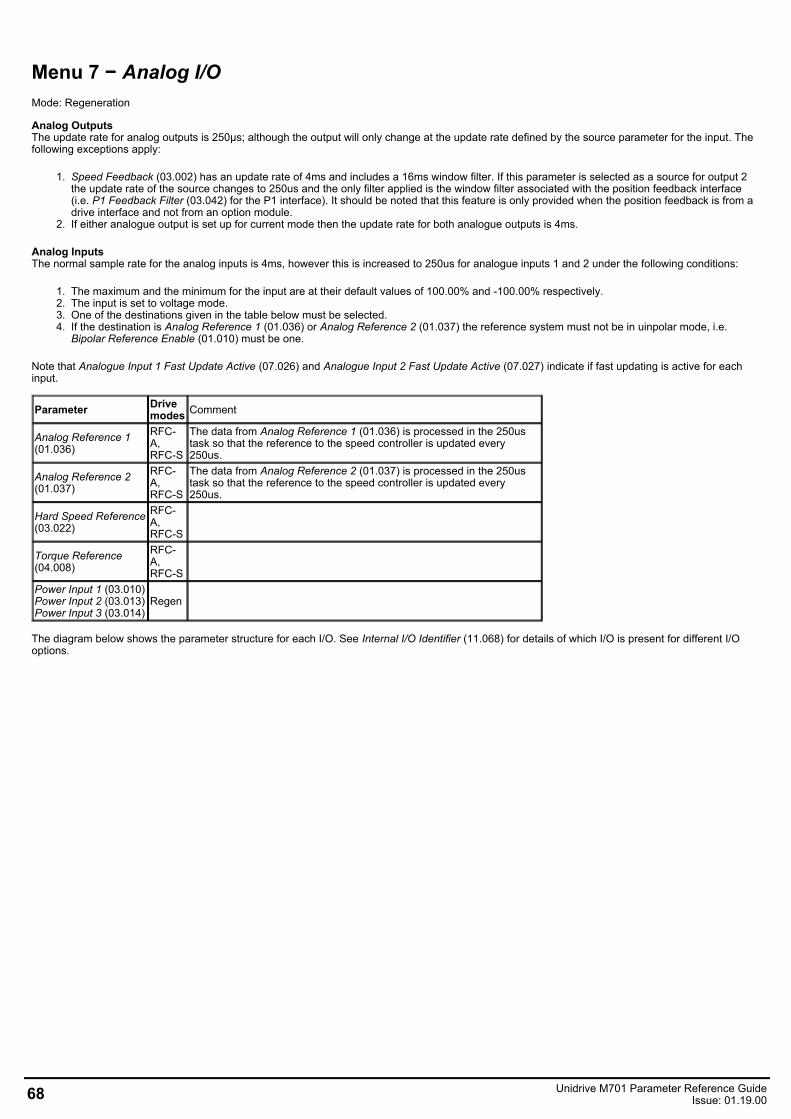
Menu 7 − Analog I/OMode: Regeneration
Analog OutputsThe update rate for analog outputs is 250μs; although the output will only change at the update rate defined by the source parameter for the input. Thefollowing exceptions apply:
1. Speed Feedback (03.002) has an update rate of 4ms and includes a 16ms window filter. If this parameter is selected as a source for output 2the update rate of the source changes to 250us and the only filter applied is the window filter associated with the position feedback interface(i.e. P1 Feedback Filter (03.042) for the P1 interface). It should be noted that this feature is only provided when the position feedback is from adrive interface and not from an option module.
2. If either analogue output is set up for current mode then the update rate for both analogue outputs is 4ms.
Analog InputsThe normal sample rate for the analog inputs is 4ms, however this is increased to 250us for analogue inputs 1 and 2 under the following conditions:
1. The maximum and the minimum for the input are at their default values of 100.00% and -100.00% respectively.2. The input is set to voltage mode.3. One of the destinations given in the table below must be selected.4. If the destination is Analog Reference 1 (01.036) or Analog Reference 2 (01.037) the reference system must not be in uinpolar mode, i.e.
Bipolar Reference Enable (01.010) must be one.
Note that Analogue Input 1 Fast Update Active (07.026) and Analogue Input 2 Fast Update Active (07.027) indicate if fast updating is active for eachinput.
Parameter Drivemodes Comment
Analog Reference 1(01.036)
RFC-A,RFC-S
The data from Analog Reference 1 (01.036) is processed in the 250ustask so that the reference to the speed controller is updated every250us.
Analog Reference 2(01.037)
RFC-A,RFC-S
The data from Analog Reference 2 (01.037) is processed in the 250ustask so that the reference to the speed controller is updated every250us.
Hard Speed Reference(03.022)
RFC-A,RFC-S
Torque Reference(04.008)
RFC-A,RFC-S
Power Input 1 (03.010)Power Input 2 (03.013)Power Input 3 (03.014)
Regen
The diagram below shows the parameter structure for each I/O. See Internal I/O Identifier (11.068) for details of which I/O is present for different I/Ooptions.
68 Unidrive M701 Parameter Reference GuideIssue: 01.19.00
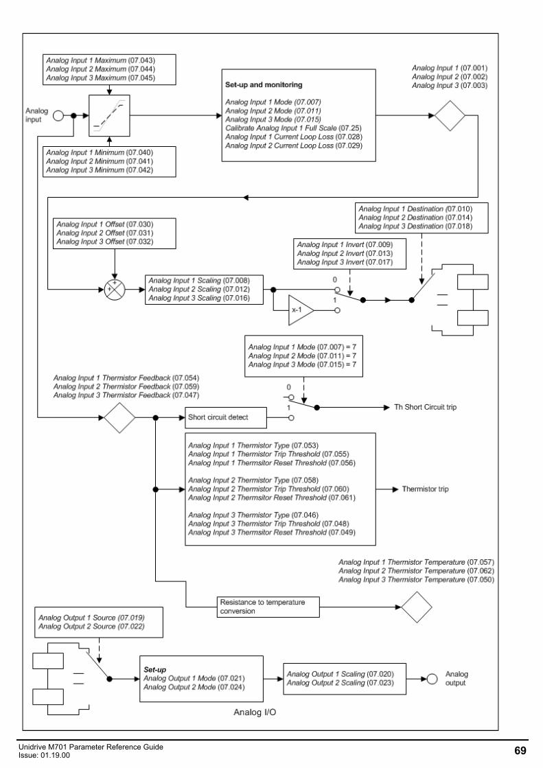
Unidrive M701 Parameter Reference GuideIssue: 01.19.00 69
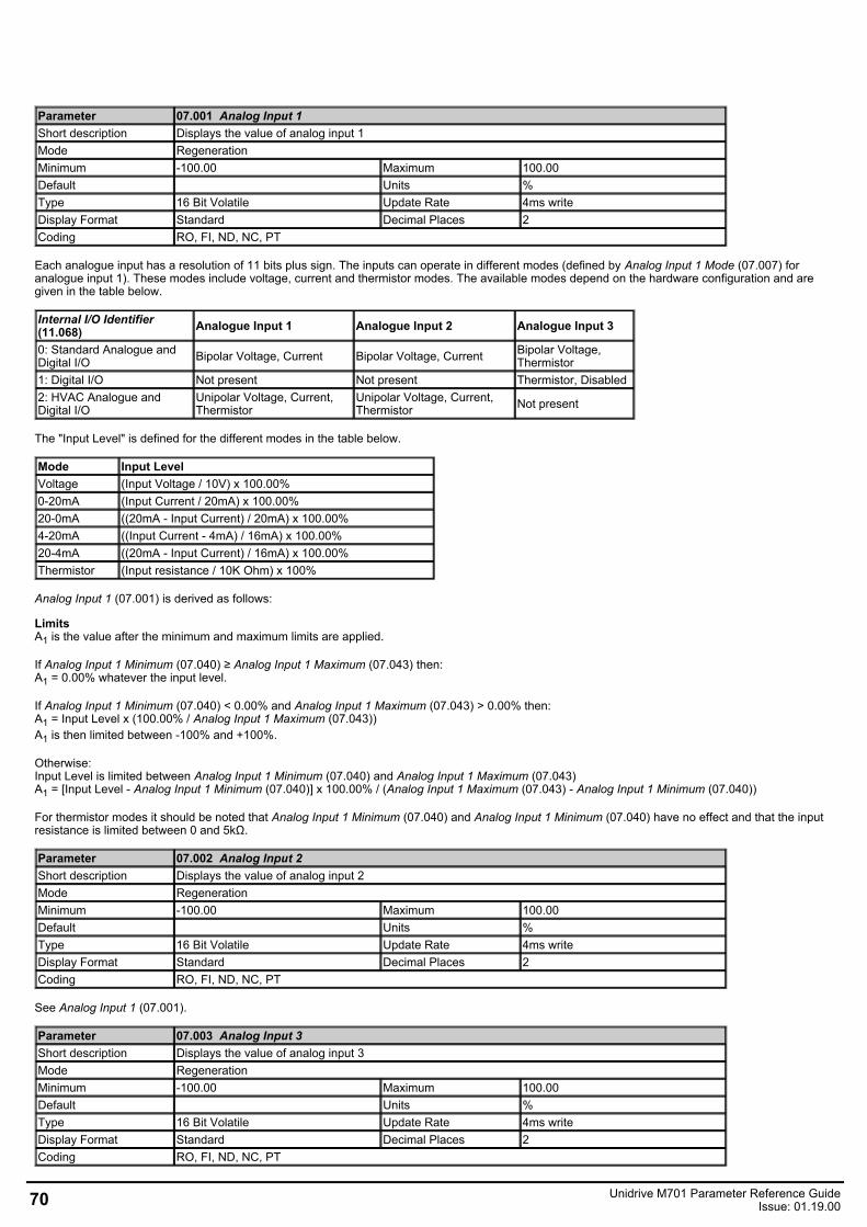
Parameter 07.001 Analog Input 1Short description Displays the value of analog input 1Mode RegenerationMinimum -100.00 Maximum 100.00Default Units %Type 16 Bit Volatile Update Rate 4ms writeDisplay Format Standard Decimal Places 2Coding RO, FI, ND, NC, PT
Each analogue input has a resolution of 11 bits plus sign. The inputs can operate in different modes (defined by Analog Input 1 Mode (07.007) foranalogue input 1). These modes include voltage, current and thermistor modes. The available modes depend on the hardware configuration and aregiven in the table below.
Internal I/O Identifier(11.068) Analogue Input 1 Analogue Input 2 Analogue Input 3
0: Standard Analogue andDigital I/O Bipolar Voltage, Current Bipolar Voltage, Current Bipolar Voltage,
Thermistor1: Digital I/O Not present Not present Thermistor, Disabled2: HVAC Analogue andDigital I/O
Unipolar Voltage, Current,Thermistor
Unipolar Voltage, Current,Thermistor Not present
The "Input Level" is defined for the different modes in the table below.
Mode Input LevelVoltage (Input Voltage / 10V) x 100.00%0-20mA (Input Current / 20mA) x 100.00%20-0mA ((20mA - Input Current) / 20mA) x 100.00%4-20mA ((Input Current - 4mA) / 16mA) x 100.00%20-4mA ((20mA - Input Current) / 16mA) x 100.00%Thermistor (Input resistance / 10K Ohm) x 100%
Analog Input 1 (07.001) is derived as follows:
LimitsA1 is the value after the minimum and maximum limits are applied.
If Analog Input 1 Minimum (07.040) ≥ Analog Input 1 Maximum (07.043) then:A1 = 0.00% whatever the input level.
If Analog Input 1 Minimum (07.040) < 0.00% and Analog Input 1 Maximum (07.043) > 0.00% then:A1 = Input Level x (100.00% / Analog Input 1 Maximum (07.043))A1 is then limited between -100% and +100%.
Otherwise:Input Level is limited between Analog Input 1 Minimum (07.040) and Analog Input 1 Maximum (07.043)A1 = [Input Level - Analog Input 1 Minimum (07.040)] x 100.00% / (Analog Input 1 Maximum (07.043) - Analog Input 1 Minimum (07.040))
For thermistor modes it should be noted that Analog Input 1 Minimum (07.040) and Analog Input 1 Minimum (07.040) have no effect and that the inputresistance is limited between 0 and 5kΩ.
Parameter 07.002 Analog Input 2Short description Displays the value of analog input 2Mode RegenerationMinimum -100.00 Maximum 100.00Default Units %Type 16 Bit Volatile Update Rate 4ms writeDisplay Format Standard Decimal Places 2Coding RO, FI, ND, NC, PT
See Analog Input 1 (07.001).
Parameter 07.003 Analog Input 3Short description Displays the value of analog input 3Mode RegenerationMinimum -100.00 Maximum 100.00Default Units %Type 16 Bit Volatile Update Rate 4ms writeDisplay Format Standard Decimal Places 2Coding RO, FI, ND, NC, PT
70 Unidrive M701 Parameter Reference GuideIssue: 01.19.00
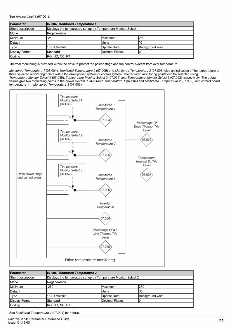
See Analog Input 1 (07.001).
Parameter 07.004 Monitored Temperature 1Short description Displays the temperature set up by Temperature Monitor Select 1Mode RegenerationMinimum -250 Maximum 250Default Units °CType 16 Bit Volatile Update Rate Background writeDisplay Format Standard Decimal Places 0Coding RO, ND, NC, PT
Thermal monitoring is provided within the drive to protect the power stage and the control system from over temperature.
Monitored Temperature 1 (07.004), Monitored Temperature 2 (07.005) and Monitored Temperature 3 (07.006) give an indication of the temperature ofthree selected monitoring points within the drive power system or control system. The required monitoring points can be selected usingTemperature Monitor Select 1 (07.038), Temperature Monitor Select 2 (07.039) and Temperature Monitor Select 3 (07.052) respectively. The defaultvalues give two monitoring points in the power system in Monitored Temperature 1 (07.004) and Monitored Temperature 2 (07.005), and control boardtemperature 1 in Monitored Temperature 3 (07.006).
Parameter 07.005 Monitored Temperature 2Short description Displays the temperature set up by Temperature Monitor Select 2Mode RegenerationMinimum -250 Maximum 250Default Units °CType 16 Bit Volatile Update Rate Background writeDisplay Format Standard Decimal Places 0Coding RO, ND, NC, PT
See Monitored Temperature 1 (07.004) for details.
Unidrive M701 Parameter Reference GuideIssue: 01.19.00 71
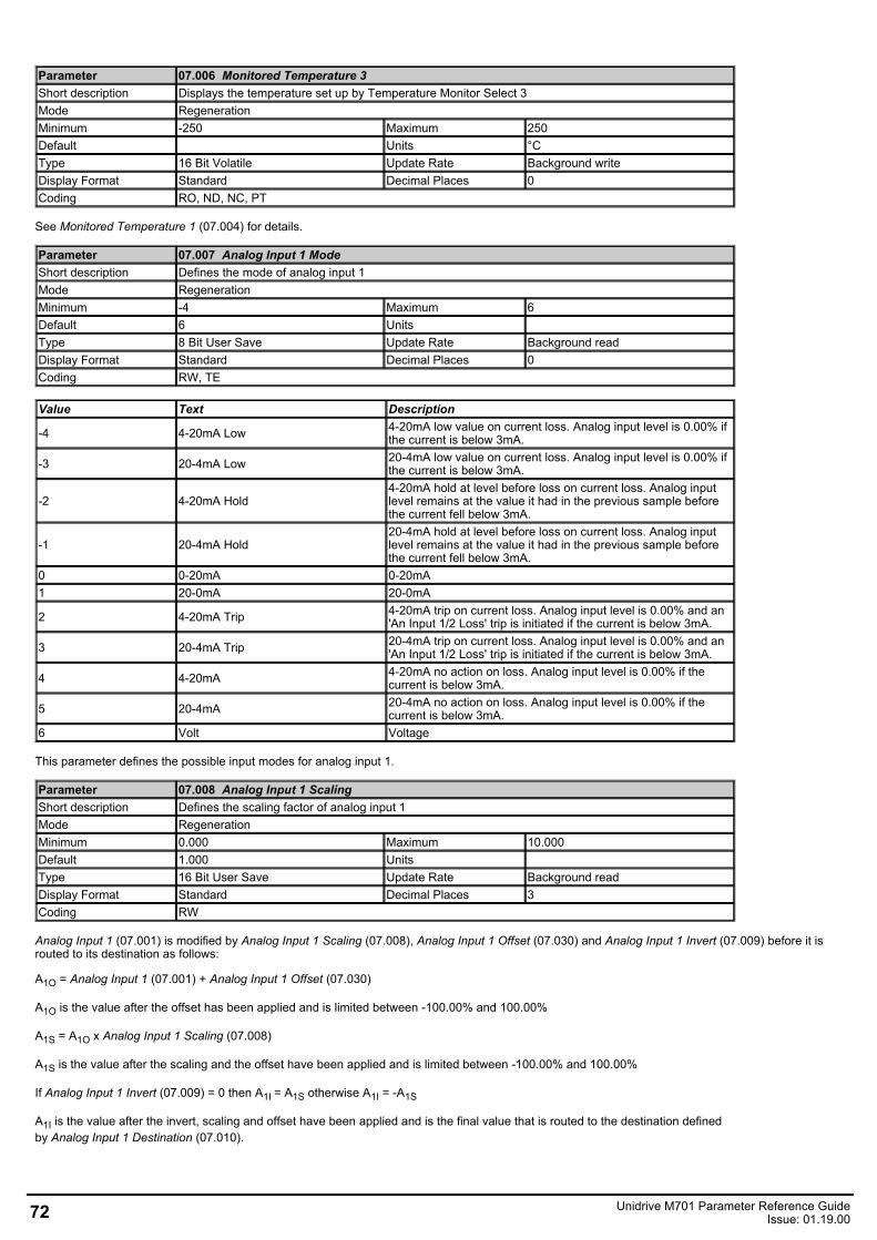
Parameter 07.006 Monitored Temperature 3Short description Displays the temperature set up by Temperature Monitor Select 3Mode RegenerationMinimum -250 Maximum 250Default Units °CType 16 Bit Volatile Update Rate Background writeDisplay Format Standard Decimal Places 0Coding RO, ND, NC, PT
See Monitored Temperature 1 (07.004) for details.
Parameter 07.007 Analog Input 1 ModeShort description Defines the mode of analog input 1Mode RegenerationMinimum -4 Maximum 6Default 6 Units Type 8 Bit User Save Update Rate Background readDisplay Format Standard Decimal Places 0Coding RW, TE
Value Text Description
-4 4-20mA Low 4-20mA low value on current loss. Analog input level is 0.00% ifthe current is below 3mA.
-3 20-4mA Low 20-4mA low value on current loss. Analog input level is 0.00% ifthe current is below 3mA.
-2 4-20mA Hold4-20mA hold at level before loss on current loss. Analog inputlevel remains at the value it had in the previous sample beforethe current fell below 3mA.
-1 20-4mA Hold20-4mA hold at level before loss on current loss. Analog inputlevel remains at the value it had in the previous sample beforethe current fell below 3mA.
0 0-20mA 0-20mA1 20-0mA 20-0mA
2 4-20mA Trip 4-20mA trip on current loss. Analog input level is 0.00% and an'An Input 1/2 Loss' trip is initiated if the current is below 3mA.
3 20-4mA Trip 20-4mA trip on current loss. Analog input level is 0.00% and an'An Input 1/2 Loss' trip is initiated if the current is below 3mA.
4 4-20mA 4-20mA no action on loss. Analog input level is 0.00% if thecurrent is below 3mA.
5 20-4mA 20-4mA no action on loss. Analog input level is 0.00% if thecurrent is below 3mA.
6 Volt Voltage
This parameter defines the possible input modes for analog input 1.
Parameter 07.008 Analog Input 1 ScalingShort description Defines the scaling factor of analog input 1Mode RegenerationMinimum 0.000 Maximum 10.000Default 1.000 Units Type 16 Bit User Save Update Rate Background readDisplay Format Standard Decimal Places 3Coding RW
Analog Input 1 (07.001) is modified by Analog Input 1 Scaling (07.008), Analog Input 1 Offset (07.030) and Analog Input 1 Invert (07.009) before it isrouted to its destination as follows:
A1O = Analog Input 1 (07.001) + Analog Input 1 Offset (07.030)
A1O is the value after the offset has been applied and is limited between -100.00% and 100.00%
A1S = A1O x Analog Input 1 Scaling (07.008)
A1S is the value after the scaling and the offset have been applied and is limited between -100.00% and 100.00%
If Analog Input 1 Invert (07.009) = 0 then A1I = A1S otherwise A1I = -A1S
A1I is the value after the invert, scaling and offset have been applied and is the final value that is routed to the destination definedby Analog Input 1 Destination (07.010).
72 Unidrive M701 Parameter Reference GuideIssue: 01.19.00
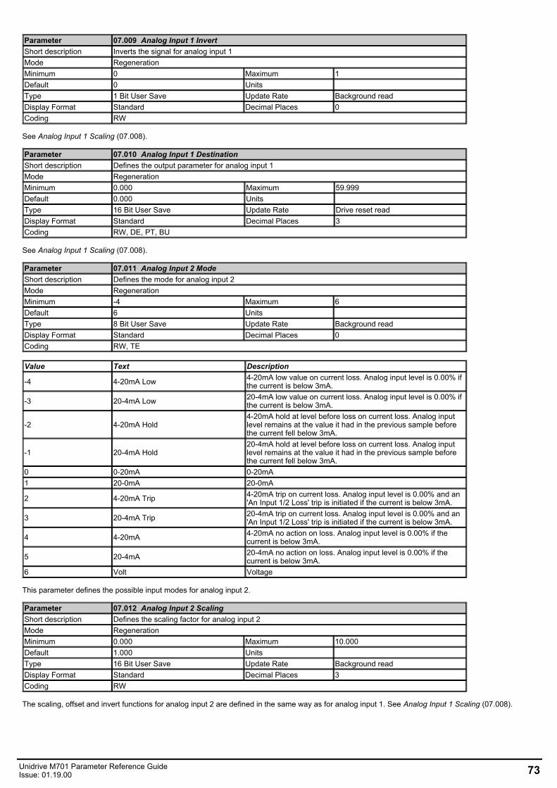
Parameter 07.009 Analog Input 1 InvertShort description Inverts the signal for analog input 1Mode RegenerationMinimum 0 Maximum 1Default 0 Units Type 1 Bit User Save Update Rate Background readDisplay Format Standard Decimal Places 0Coding RW
See Analog Input 1 Scaling (07.008).
Parameter 07.010 Analog Input 1 DestinationShort description Defines the output parameter for analog input 1Mode RegenerationMinimum 0.000 Maximum 59.999Default 0.000 Units Type 16 Bit User Save Update Rate Drive reset readDisplay Format Standard Decimal Places 3Coding RW, DE, PT, BU
See Analog Input 1 Scaling (07.008).
Parameter 07.011 Analog Input 2 ModeShort description Defines the mode for analog input 2Mode RegenerationMinimum -4 Maximum 6Default 6 Units Type 8 Bit User Save Update Rate Background readDisplay Format Standard Decimal Places 0Coding RW, TE
Value Text Description
-4 4-20mA Low 4-20mA low value on current loss. Analog input level is 0.00% ifthe current is below 3mA.
-3 20-4mA Low 20-4mA low value on current loss. Analog input level is 0.00% ifthe current is below 3mA.
-2 4-20mA Hold4-20mA hold at level before loss on current loss. Analog inputlevel remains at the value it had in the previous sample beforethe current fell below 3mA.
-1 20-4mA Hold20-4mA hold at level before loss on current loss. Analog inputlevel remains at the value it had in the previous sample beforethe current fell below 3mA.
0 0-20mA 0-20mA1 20-0mA 20-0mA
2 4-20mA Trip 4-20mA trip on current loss. Analog input level is 0.00% and an'An Input 1/2 Loss' trip is initiated if the current is below 3mA.
3 20-4mA Trip 20-4mA trip on current loss. Analog input level is 0.00% and an'An Input 1/2 Loss' trip is initiated if the current is below 3mA.
4 4-20mA 4-20mA no action on loss. Analog input level is 0.00% if thecurrent is below 3mA.
5 20-4mA 20-4mA no action on loss. Analog input level is 0.00% if thecurrent is below 3mA.
6 Volt Voltage
This parameter defines the possible input modes for analog input 2.
Parameter 07.012 Analog Input 2 ScalingShort description Defines the scaling factor for analog input 2Mode RegenerationMinimum 0.000 Maximum 10.000Default 1.000 Units Type 16 Bit User Save Update Rate Background readDisplay Format Standard Decimal Places 3Coding RW
The scaling, offset and invert functions for analog input 2 are defined in the same way as for analog input 1. See Analog Input 1 Scaling (07.008).
Unidrive M701 Parameter Reference GuideIssue: 01.19.00 73
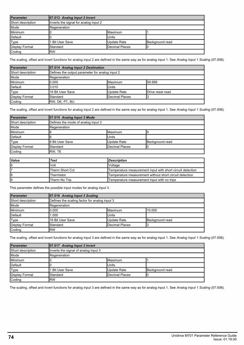
Parameter 07.013 Analog Input 2 InvertShort description Inverts the signal for analog input 2Mode RegenerationMinimum 0 Maximum 1Default 0 Units Type 1 Bit User Save Update Rate Background readDisplay Format Standard Decimal Places 0Coding RW
The scaling, offset and invert functions for analog input 2 are defined in the same way as for analog input 1. See Analog Input 1 Scaling (07.008).
Parameter 07.014 Analog Input 2 DestinationShort description Defines the output parameter for analog input 2Mode RegenerationMinimum 0.000 Maximum 59.999Default 3.010 Units Type 16 Bit User Save Update Rate Drive reset readDisplay Format Standard Decimal Places 3Coding RW, DE, PT, BU
The scaling, offset and invert functions for analog input 2 are defined in the same way as for analog input 1. See Analog Input 1 Scaling (07.008).
Parameter 07.015 Analog Input 3 ModeShort description Defines the mode of analog input 3Mode RegenerationMinimum 6 Maximum 9Default 6 Units Type 8 Bit User Save Update Rate Background readDisplay Format Standard Decimal Places 0Coding RW, TE
Value Text Description6 Volt Voltage7 Therm Short Cct Temperature measurement input with short circuit detection8 Thermistor Temperature measurement without short circuit detection9 Therm No Trip Temperature measurement input with no trips
This parameter defines the possible input modes for analog input 3.
Parameter 07.016 Analog Input 3 ScalingShort description Defines the scaling factor for analog input 3Mode RegenerationMinimum 0.000 Maximum 10.000Default 1.000 Units Type 16 Bit User Save Update Rate Background readDisplay Format Standard Decimal Places 3Coding RW
The scaling, offset and invert functions for analog input 3 are defined in the same way as for analog input 1. See Analog Input 1 Scaling (07.008).
Parameter 07.017 Analog Input 3 InvertShort description Inverts the signal of analog input 3Mode RegenerationMinimum 0 Maximum 1Default 0 Units Type 1 Bit User Save Update Rate Background readDisplay Format Standard Decimal Places 0Coding RW
The scaling, offset and invert functions for analog input 3 are defined in the same way as for analog input 1. See Analog Input 1 Scaling (07.008).
74 Unidrive M701 Parameter Reference GuideIssue: 01.19.00
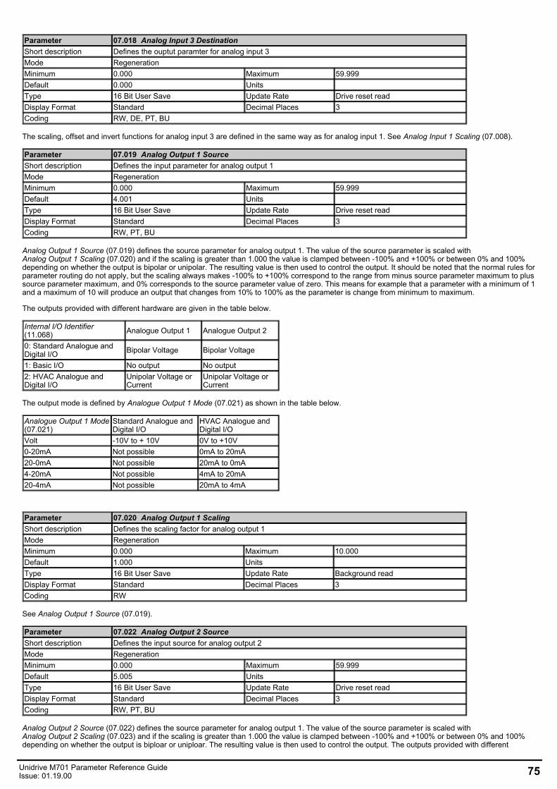
Parameter 07.018 Analog Input 3 DestinationShort description Defines the ouptut paramter for analog input 3Mode RegenerationMinimum 0.000 Maximum 59.999Default 0.000 Units Type 16 Bit User Save Update Rate Drive reset readDisplay Format Standard Decimal Places 3Coding RW, DE, PT, BU
The scaling, offset and invert functions for analog input 3 are defined in the same way as for analog input 1. See Analog Input 1 Scaling (07.008).
Parameter 07.019 Analog Output 1 SourceShort description Defines the input parameter for analog output 1Mode RegenerationMinimum 0.000 Maximum 59.999Default 4.001 Units Type 16 Bit User Save Update Rate Drive reset readDisplay Format Standard Decimal Places 3Coding RW, PT, BU
Analog Output 1 Source (07.019) defines the source parameter for analog output 1. The value of the source parameter is scaled withAnalog Output 1 Scaling (07.020) and if the scaling is greater than 1.000 the value is clamped between -100% and +100% or between 0% and 100%depending on whether the output is bipolar or unipolar. The resulting value is then used to control the output. It should be noted that the normal rules forparameter routing do not apply, but the scaling always makes -100% to +100% correspond to the range from minus source parameter maximum to plussource parameter maximum, and 0% corresponds to the source parameter value of zero. This means for example that a parameter with a minimum of 1and a maximum of 10 will produce an output that changes from 10% to 100% as the parameter is change from minimum to maximum.
The outputs provided with different hardware are given in the table below.
Internal I/O Identifier(11.068) Analogue Output 1 Analogue Output 2
0: Standard Analogue andDigital I/O Bipolar Voltage Bipolar Voltage
1: Basic I/O No output No output2: HVAC Analogue andDigital I/O
Unipolar Voltage orCurrent
Unipolar Voltage orCurrent
The output mode is defined by Analogue Output 1 Mode (07.021) as shown in the table below.
Analogue Output 1 Mode(07.021)
Standard Analogue andDigital I/O
HVAC Analogue andDigital I/O
Volt -10V to + 10V 0V to +10V0-20mA Not possible 0mA to 20mA20-0mA Not possible 20mA to 0mA4-20mA Not possible 4mA to 20mA20-4mA Not possible 20mA to 4mA
Parameter 07.020 Analog Output 1 ScalingShort description Defines the scaling factor for analog output 1Mode RegenerationMinimum 0.000 Maximum 10.000Default 1.000 Units Type 16 Bit User Save Update Rate Background readDisplay Format Standard Decimal Places 3Coding RW
See Analog Output 1 Source (07.019).
Parameter 07.022 Analog Output 2 SourceShort description Defines the input source for analog output 2Mode RegenerationMinimum 0.000 Maximum 59.999Default 5.005 Units Type 16 Bit User Save Update Rate Drive reset readDisplay Format Standard Decimal Places 3Coding RW, PT, BU
Analog Output 2 Source (07.022) defines the source parameter for analog output 1. The value of the source parameter is scaled withAnalog Output 2 Scaling (07.023) and if the scaling is greater than 1.000 the value is clamped between -100% and +100% or between 0% and 100%depending on whether the output is biploar or uniploar. The resulting value is then used to control the output. The outputs provided with different
Unidrive M701 Parameter Reference GuideIssue: 01.19.00 75
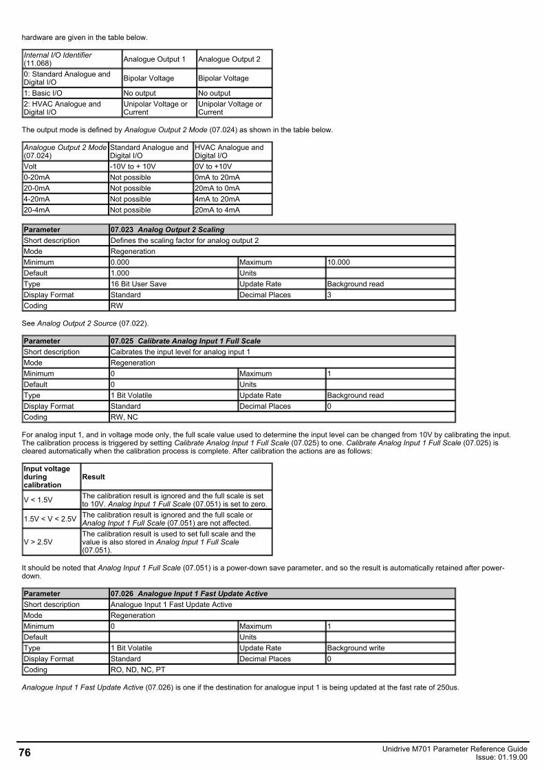
hardware are given in the table below.
Internal I/O Identifier(11.068) Analogue Output 1 Analogue Output 2
0: Standard Analogue andDigital I/O Bipolar Voltage Bipolar Voltage
1: Basic I/O No output No output2: HVAC Analogue andDigital I/O
Unipolar Voltage orCurrent
Unipolar Voltage orCurrent
The output mode is defined by Analogue Output 2 Mode (07.024) as shown in the table below.
Analogue Output 2 Mode(07.024)
Standard Analogue andDigital I/O
HVAC Analogue andDigital I/O
Volt -10V to + 10V 0V to +10V0-20mA Not possible 0mA to 20mA20-0mA Not possible 20mA to 0mA4-20mA Not possible 4mA to 20mA20-4mA Not possible 20mA to 4mA
Parameter 07.023 Analog Output 2 ScalingShort description Defines the scaling factor for analog output 2Mode RegenerationMinimum 0.000 Maximum 10.000Default 1.000 Units Type 16 Bit User Save Update Rate Background readDisplay Format Standard Decimal Places 3Coding RW
See Analog Output 2 Source (07.022).
Parameter 07.025 Calibrate Analog Input 1 Full ScaleShort description Caibrates the input level for analog input 1Mode RegenerationMinimum 0 Maximum 1Default 0 Units Type 1 Bit Volatile Update Rate Background readDisplay Format Standard Decimal Places 0Coding RW, NC
For analog input 1, and in voltage mode only, the full scale value used to determine the input level can be changed from 10V by calibrating the input.The calibration process is triggered by setting Calibrate Analog Input 1 Full Scale (07.025) to one. Calibrate Analog Input 1 Full Scale (07.025) iscleared automatically when the calibration process is complete. After calibration the actions are as follows:
Input voltageduringcalibration
Result
V < 1.5V The calibration result is ignored and the full scale is setto 10V. Analog Input 1 Full Scale (07.051) is set to zero.
1.5V < V < 2.5V The calibration result is ignored and the full scale orAnalog Input 1 Full Scale (07.051) are not affected.
V > 2.5VThe calibration result is used to set full scale and thevalue is also stored in Analog Input 1 Full Scale(07.051).
It should be noted that Analog Input 1 Full Scale (07.051) is a power-down save parameter, and so the result is automatically retained after power-down.
Parameter 07.026 Analogue Input 1 Fast Update ActiveShort description Analogue Input 1 Fast Update ActiveMode RegenerationMinimum 0 Maximum 1Default Units Type 1 Bit Volatile Update Rate Background writeDisplay Format Standard Decimal Places 0Coding RO, ND, NC, PT
Analogue Input 1 Fast Update Active (07.026) is one if the destination for analogue input 1 is being updated at the fast rate of 250us.
76 Unidrive M701 Parameter Reference GuideIssue: 01.19.00
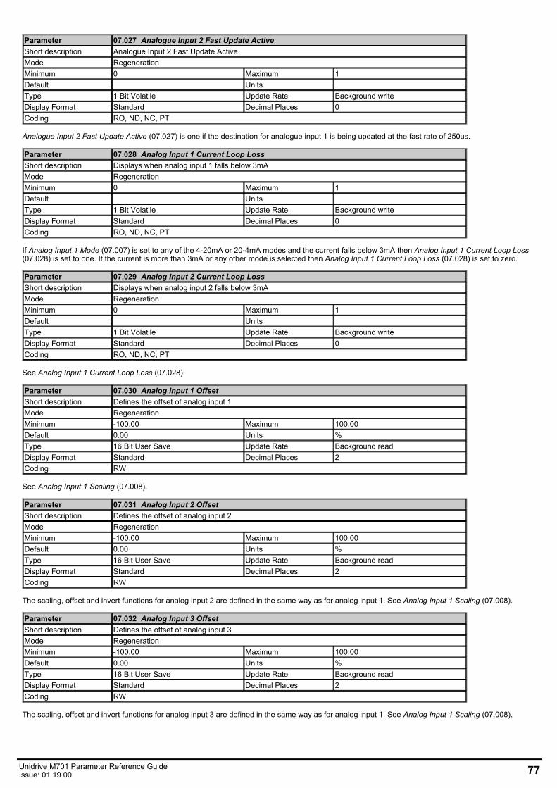
Parameter 07.027 Analogue Input 2 Fast Update ActiveShort description Analogue Input 2 Fast Update ActiveMode RegenerationMinimum 0 Maximum 1Default Units Type 1 Bit Volatile Update Rate Background writeDisplay Format Standard Decimal Places 0Coding RO, ND, NC, PT
Analogue Input 2 Fast Update Active (07.027) is one if the destination for analogue input 1 is being updated at the fast rate of 250us.
Parameter 07.028 Analog Input 1 Current Loop LossShort description Displays when analog input 1 falls below 3mAMode RegenerationMinimum 0 Maximum 1Default Units Type 1 Bit Volatile Update Rate Background writeDisplay Format Standard Decimal Places 0Coding RO, ND, NC, PT
If Analog Input 1 Mode (07.007) is set to any of the 4-20mA or 20-4mA modes and the current falls below 3mA then Analog Input 1 Current Loop Loss(07.028) is set to one. If the current is more than 3mA or any other mode is selected then Analog Input 1 Current Loop Loss (07.028) is set to zero.
Parameter 07.029 Analog Input 2 Current Loop LossShort description Displays when analog input 2 falls below 3mAMode RegenerationMinimum 0 Maximum 1Default Units Type 1 Bit Volatile Update Rate Background writeDisplay Format Standard Decimal Places 0Coding RO, ND, NC, PT
See Analog Input 1 Current Loop Loss (07.028).
Parameter 07.030 Analog Input 1 OffsetShort description Defines the offset of analog input 1Mode RegenerationMinimum -100.00 Maximum 100.00Default 0.00 Units %Type 16 Bit User Save Update Rate Background readDisplay Format Standard Decimal Places 2Coding RW
See Analog Input 1 Scaling (07.008).
Parameter 07.031 Analog Input 2 OffsetShort description Defines the offset of analog input 2Mode RegenerationMinimum -100.00 Maximum 100.00Default 0.00 Units %Type 16 Bit User Save Update Rate Background readDisplay Format Standard Decimal Places 2Coding RW
The scaling, offset and invert functions for analog input 2 are defined in the same way as for analog input 1. See Analog Input 1 Scaling (07.008).
Parameter 07.032 Analog Input 3 OffsetShort description Defines the offset of analog input 3Mode RegenerationMinimum -100.00 Maximum 100.00Default 0.00 Units %Type 16 Bit User Save Update Rate Background readDisplay Format Standard Decimal Places 2Coding RW
The scaling, offset and invert functions for analog input 3 are defined in the same way as for analog input 1. See Analog Input 1 Scaling (07.008).
Unidrive M701 Parameter Reference GuideIssue: 01.19.00 77
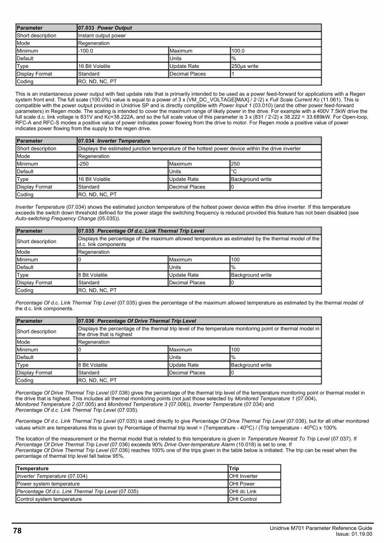
Parameter 07.033 Power OutputShort description Instant output powerMode RegenerationMinimum -100.0 Maximum 100.0Default Units %Type 16 Bit Volatile Update Rate 250µs writeDisplay Format Standard Decimal Places 1Coding RO, ND, NC, PT
This is an instantaneous power output with fast update rate that is primarily intended to be used as a power feed-forward for applications with a Regensystem front end. The full scale (100.0%) value is equal to a power of 3 x (VM_DC_VOLTAGE[MAX] / 2√2) x Full Scale Current Kc (11.061). This iscompatible with the power output provided in Unidrive SP and is directly comptible with Power Input 1 (03.010) (and the other power feed-forwardparameters) in Regen mode. The scaling is intended to cover the maximum range of likely power in the drive. For example with a 400V 7.5kW drive thefull scale d.c. link voltage is 831V and Kc=38.222A, and so the full scale value of this parameter is 3 x (831 / 2√2) x 38.222 = 33.689kW. For Open-loop,RFC-A and RFC-S modes a positive value of power indicates power flowing from the drive to motor. For Regen mode a positive value of powerindicates power flowing from the supply to the regen drive.
Parameter 07.034 Inverter TemperatureShort description Displays the estimated junction temperature of the hottest power device within the drive inverterMode RegenerationMinimum -250 Maximum 250Default Units °CType 16 Bit Volatile Update Rate Background writeDisplay Format Standard Decimal Places 0Coding RO, ND, NC, PT
Inverter Temperature (07.034) shows the estimated junction temperature of the hottest power device within the drive inverter. If this temperatureexceeds the switch down threshold defined for the power stage the switching frequency is reduced provided this feature has not been disabled (seeAuto-switching Frequency Change (05.035)).
Parameter 07.035 Percentage Of d.c. Link Thermal Trip Level
Short description Displays the percentage of the maximum allowed temperature as estimated by the thermal model of thed.c. link components
Mode RegenerationMinimum 0 Maximum 100Default Units %Type 8 Bit Volatile Update Rate Background writeDisplay Format Standard Decimal Places 0Coding RO, ND, NC, PT
Percentage Of d.c. Link Thermal Trip Level (07.035) gives the percentage of the maximum allowed temperature as estimated by the thermal model ofthe d.c. link components.
Parameter 07.036 Percentage Of Drive Thermal Trip Level
Short description Displays the percentage of the thermal trip level of the temperature monitoring point or thermal model inthe drive that is highest
Mode RegenerationMinimum 0 Maximum 100Default Units %Type 8 Bit Volatile Update Rate Background writeDisplay Format Standard Decimal Places 0Coding RO, ND, NC, PT
Percentage Of Drive Thermal Trip Level (07.036) gives the percentage of the thermal trip level of the temperature monitoring point or thermal model inthe drive that is highest. This includes all thermal monitoring points (not just those selected by Monitored Temperature 1 (07.004),Monitored Temperature 2 (07.005) and Monitored Temperature 3 (07.006)), Inverter Temperature (07.034) andPercentage Of d.c. Link Thermal Trip Level (07.035).
Percentage Of d.c. Link Thermal Trip Level (07.035) is used directly to give Percentage Of Drive Thermal Trip Level (07.036), but for all other monitoredvalues which are temperatures this is given by Percentage of thermal trip level = (Temperature - 40oC) / (Trip temperature - 40oC) x 100%
The location of the measurement or the thermal model that is related to this temperature is given in Temperature Nearest To Trip Level (07.037). IfPercentage Of Drive Thermal Trip Level (07.036) exceeds 90% Drive Over-temperature Alarm (10.018) is set to one. IfPercentage Of Drive Thermal Trip Level (07.036) reaches 100% one of the trips given in the table below is initiated. The trip can be reset when thepercentage of thermal trip level fall below 95%.
Temperature TripInverter Temperature (07.034) OHt InverterPower system temperature OHt PowerPercentage Of d.c. Link Thermal Trip Level (07.035) OHt dc LinkControl system temperature OHt Control
78 Unidrive M701 Parameter Reference GuideIssue: 01.19.00
Parameter 07.037 Temperature Nearest To Trip Level
Short description Displays the thermistor location or the model that corresponds to the value shown in Percentage OfDrive Thermal Trip Level
Mode RegenerationMinimum 0 Maximum 20999Default Units Type 16 Bit Volatile Update Rate Background writeDisplay Format Standard Decimal Places 0Coding RO, ND, NC, PT
Temperature Nearest To Trip Level (07.037) shows the thermistor location or the model that corresponds to the value shownin Percentage Of Drive Thermal Trip Level (07.036) in the form xxyzz as shown in the table below.
Source xx y zzControl system 00 0 01: Control board thermistor 1Control system 00 0 02: Control board thermistor 2Control system 00 0 03: I/O board thermistor (or internal braking resistor in servo Drive)Control system 00 1 00: Inverter thermal modelControl system 00 2 00: D.c. link thermal modelControl system 00 3 00: Braking IGBT thermal modelPower system 01 0 zz: Thermistor location defined by zz in the power systemPower system 01 Rectifier number zz: Thermistor location defined by zz in the rectifier
Parameter 07.038 Temperature Monitor Select 1Short description Defines the temperature to be monitored in Monitored Temperature 1Mode RegenerationMinimum 0 Maximum 1999Default 1001 Units Type 16 Bit User Save Update Rate Background readDisplay Format Standard Decimal Places 0Coding RW
Temperature Monitor Select 1 (07.038) selects the temperature to be monitored in Monitored Temperature 1 (07.004) using the format givenfor Temperature Nearest To Trip Level (07.037). If the monitoring point selected does not exist then the monitored temperature is always zero. Thetable below shows the monitoring points that can be selected.
Source xx y zzControl system 00 0 01: Control board thermistor 1Control system 00 0 02: Control board thermistor 2Control system 00 0 03: I/O board thermistor (or internal braking resistor in Servo Drive)Control system 00 1 00: Inverter thermal modelControl system 00 3 00: Braking IGBT thermal modelControl system 00 4 00: Rectifier thermal modelPower system 01 0 zz: Thermistor location defined by zz in the power systemPower system 01 Rectifier number zz: Thermistor location defined by zz in the rectifier
For a multi-module power system the power system measurement that can be selected is shown in the table below. It should be noted that the specificpower module cannot be selected and that the highest temperature from each of the power modules is given.
Source xx y zzPower system 01 0 01: U phase power device thermistorPower system 01 0 02: V phase power device thermistorPower system 01 0 03: W phase power device thermistorPower system 01 0 04: General rectifier thermistorsPower system 01 0 05: General power system thermistor
Parameter 07.039 Temperature Monitor Select 2Short description Defines the temperature to be monitored in Monitored Temperature 2Mode RegenerationMinimum 0 Maximum 1999Default 1002 Units Type 16 Bit User Save Update Rate Background readDisplay Format Standard Decimal Places 0Coding RW
See Temperature Monitor Select 1 (07.038).
Unidrive M701 Parameter Reference GuideIssue: 01.19.00 79

Parameter 07.040 Analog Input 1 MinimumShort description Defines the minimum value for analog input 1Mode RegenerationMinimum -100.00 Maximum 100.00Default -100.00 Units %Type 16 Bit User Save Update Rate Background readDisplay Format Standard Decimal Places 2Coding RW
See Analog Input 1 (07.001).
Parameter 07.041 Analog Input 2 MinimumShort description Defines the minimum value for analog input 2Mode RegenerationMinimum -100.00 Maximum 100.00Default -100.00 Units %Type 16 Bit User Save Update Rate Background readDisplay Format Standard Decimal Places 2Coding RW
See Analog Input 1 (07.001).
Parameter 07.042 Analog Input 3 MinimumShort description Defines the minimum value for analog input 3Mode RegenerationMinimum -100.00 Maximum 100.00Default -100.00 Units %Type 16 Bit User Save Update Rate Background readDisplay Format Standard Decimal Places 2Coding RW
See Analog Input 1 (07.001).
Parameter 07.043 Analog Input 1 MaximumShort description Defines the maximum value for analog input 1Mode RegenerationMinimum -100.00 Maximum 100.00Default 100.00 Units %Type 16 Bit User Save Update Rate Background readDisplay Format Standard Decimal Places 2Coding RW
See Analog Input 1 (07.001).
Parameter 07.044 Analog Input 2 MaximumShort description Defines the maximum value for analog input 2Mode RegenerationMinimum -100.00 Maximum 100.00Default 100.00 Units %Type 16 Bit User Save Update Rate Background readDisplay Format Standard Decimal Places 2Coding RW
See Analog Input 1 (07.001).
Parameter 07.045 Analog Input 3 MaximumShort description Defines the maximum value for analog input 3Mode RegenerationMinimum -100.00 Maximum 100.00Default 100.00 Units %Type 16 Bit User Save Update Rate Background readDisplay Format Standard Decimal Places 2Coding RW
See Analog Input 1 (07.001).
80 Unidrive M701 Parameter Reference GuideIssue: 01.19.00
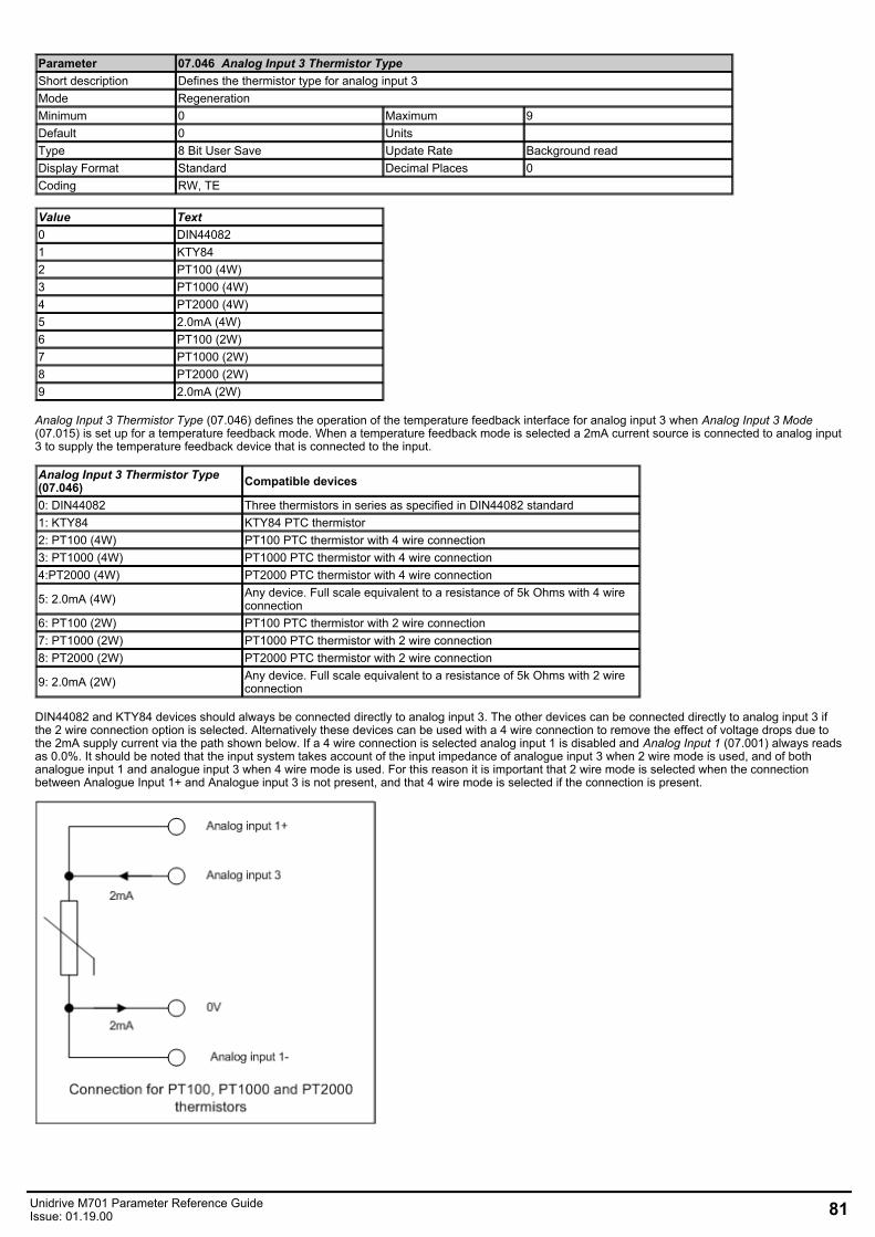
Parameter 07.046 Analog Input 3 Thermistor TypeShort description Defines the thermistor type for analog input 3Mode RegenerationMinimum 0 Maximum 9Default 0 Units Type 8 Bit User Save Update Rate Background readDisplay Format Standard Decimal Places 0Coding RW, TE
Value Text0 DIN440821 KTY842 PT100 (4W)3 PT1000 (4W)4 PT2000 (4W)5 2.0mA (4W)6 PT100 (2W)7 PT1000 (2W)8 PT2000 (2W)9 2.0mA (2W)
Analog Input 3 Thermistor Type (07.046) defines the operation of the temperature feedback interface for analog input 3 when Analog Input 3 Mode(07.015) is set up for a temperature feedback mode. When a temperature feedback mode is selected a 2mA current source is connected to analog input3 to supply the temperature feedback device that is connected to the input.
Analog Input 3 Thermistor Type(07.046) Compatible devices
0: DIN44082 Three thermistors in series as specified in DIN44082 standard1: KTY84 KTY84 PTC thermistor2: PT100 (4W) PT100 PTC thermistor with 4 wire connection3: PT1000 (4W) PT1000 PTC thermistor with 4 wire connection4:PT2000 (4W) PT2000 PTC thermistor with 4 wire connection
5: 2.0mA (4W) Any device. Full scale equivalent to a resistance of 5k Ohms with 4 wireconnection
6: PT100 (2W) PT100 PTC thermistor with 2 wire connection7: PT1000 (2W) PT1000 PTC thermistor with 2 wire connection8: PT2000 (2W) PT2000 PTC thermistor with 2 wire connection
9: 2.0mA (2W) Any device. Full scale equivalent to a resistance of 5k Ohms with 2 wireconnection
DIN44082 and KTY84 devices should always be connected directly to analog input 3. The other devices can be connected directly to analog input 3 ifthe 2 wire connection option is selected. Alternatively these devices can be used with a 4 wire connection to remove the effect of voltage drops due tothe 2mA supply current via the path shown below. If a 4 wire connection is selected analog input 1 is disabled and Analog Input 1 (07.001) always readsas 0.0%. It should be noted that the input system takes account of the input impedance of analogue input 3 when 2 wire mode is used, and of bothanalogue input 1 and analogue input 3 when 4 wire mode is used. For this reason it is important that 2 wire mode is selected when the connectionbetween Analogue Input 1+ and Analogue input 3 is not present, and that 4 wire mode is selected if the connection is present.
Unidrive M701 Parameter Reference GuideIssue: 01.19.00 81
Parameter 07.047 Analog Input 3 Thermistor FeedbackShort description Displays the measured resistance of analog input 3Mode RegenerationMinimum 0 Maximum 5000Default Units ΩType 16 Bit Volatile Update Rate Background writeDisplay Format Standard Decimal Places 0Coding RO, ND, NC, PT
Analog Input 3 Thermistor Feedback (07.047) shows the measured resistance.
Parameter 07.048 Analog Input 3 Thermistor Trip ThresholdShort description Defines the thermistor trip threshold for analog input 3Mode RegenerationMinimum 0 Maximum 5000Default 3300 Units ΩType 16 Bit User Save Update Rate Background readDisplay Format Standard Decimal Places 0Coding RW
Over-temperature detection becomes active for input 3 if Analog Input 3 Thermistor Feedback (07.047) > Analog Input 3 Thermistor Trip Threshold(07.048). Over-temperature becomes inactive for input 3 if Analog Input 3 Thermistor Feedback (07.047) < Analog Input 3 Thermistor Reset Threshold(07.049). If Analog Input 3 Mode (07.015) is 7 or 8 (i.e. tripping is enabled) an Thermistor.003 trip is initiated. The default values forAnalog Input 3 Thermistor Trip Threshold (07.048) and Analog Input 3 Thermistor Reset Threshold (07.049) are the levels specified in the DIN 44082standard.
Parameter 07.049 Analog Input 3 Thermistor Reset ThresholdShort description Defines the thermistor reset threshold for analog input 3Mode RegenerationMinimum 0 Maximum 5000Default 1800 Units ΩType 16 Bit User Save Update Rate Background readDisplay Format Standard Decimal Places 0Coding RW
See Analog Input 3 Thermistor Trip Threshold (07.048).
Parameter 07.050 Analog Input 3 Thermistor Temperature
Short description Displays the temperature of the device based on the resistance to temperature characteristic for thespecified device
Mode RegenerationMinimum -50 Maximum 300Default Units °CType 16 Bit Volatile Update Rate Background writeDisplay Format Standard Decimal Places 0Coding RO, ND, NC, PT
If a KTY84, PT100, PT1000 or PT2000 type device is selected for temperature feedback then Analog Input 3 Thermistor Temperature (07.050) showsthe temperature of the device based on the resistance to temperature characteristic specified for this device. OtherwiseAnalog Input 3 Thermistor Temperature (07.050) = 0.0.
Parameter 07.051 Analog Input 1 Full ScaleShort description Displays the full scale value of analog input 1Mode RegenerationMinimum 0 Maximum 65535Default Units Type 16 Bit Power Down Save Update Rate Background writeDisplay Format Standard Decimal Places 0Coding RO, ND, NC, PT, BU
See Calibrate Analog Input 1 Full Scale (07.025).
Parameter 07.052 Temperature Monitor Select 3Short description Defines the temperature to be monitored in Monitored Temperature 3Mode RegenerationMinimum 0 Maximum 1999Default 1 Units Type 16 Bit User Save Update Rate Background readDisplay Format Standard Decimal Places 0Coding RW
82 Unidrive M701 Parameter Reference GuideIssue: 01.19.00
See Temperature Monitor Select 1 (07.038).
Unidrive M701 Parameter Reference GuideIssue: 01.19.00 83
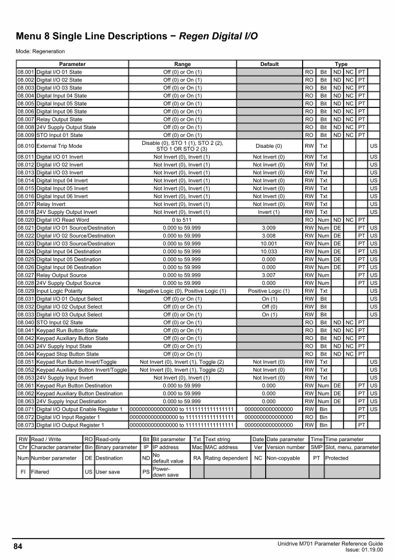
Menu 8 Single Line Descriptions − Regen Digital I/OMode: Regeneration
Parameter Range Default Type08.001 Digital I/O 01 State Off (0) or On (1) RO Bit ND NC PT 08.002 Digital I/O 02 State Off (0) or On (1) RO Bit ND NC PT 08.003 Digital I/O 03 State Off (0) or On (1) RO Bit ND NC PT 08.004 Digital Input 04 State Off (0) or On (1) RO Bit ND NC PT 08.005 Digital Input 05 State Off (0) or On (1) RO Bit ND NC PT 08.006 Digital Input 06 State Off (0) or On (1) RO Bit ND NC PT 08.007 Relay Output State Off (0) or On (1) RO Bit ND NC PT 08.008 24V Supply Output State Off (0) or On (1) RO Bit ND NC PT 08.009 STO Input 01 State Off (0) or On (1) RO Bit ND NC PT
08.010 External Trip Mode Disable (0), STO 1 (1), STO 2 (2),STO 1 OR STO 2 (3) Disable (0) RW Txt US
08.011 Digital I/O 01 Invert Not Invert (0), Invert (1) Not Invert (0) RW Txt US08.012 Digital I/O 02 Invert Not Invert (0), Invert (1) Not Invert (0) RW Txt US08.013 Digital I/O 03 Invert Not Invert (0), Invert (1) Not Invert (0) RW Txt US08.014 Digital Input 04 Invert Not Invert (0), Invert (1) Not Invert (0) RW Txt US08.015 Digital Input 05 Invert Not Invert (0), Invert (1) Not Invert (0) RW Txt US08.016 Digital Input 06 Invert Not Invert (0), Invert (1) Not Invert (0) RW Txt US08.017 Relay Invert Not Invert (0), Invert (1) Not Invert (0) RW Txt US08.018 24V Supply Output Invert Not Invert (0), Invert (1) Invert (1) RW Txt US08.020 Digital I/O Read Word 0 to 511 RO Num ND NC PT 08.021 Digital I/O 01 Source/Destination 0.000 to 59.999 3.009 RW Num DE PT US08.022 Digital I/O 02 Source/Destination 0.000 to 59.999 3.008 RW Num DE PT US08.023 Digital I/O 03 Source/Destination 0.000 to 59.999 10.001 RW Num DE PT US08.024 Digital Input 04 Destination 0.000 to 59.999 10.033 RW Num DE PT US08.025 Digital Input 05 Destination 0.000 to 59.999 0.000 RW Num DE PT US08.026 Digital Input 06 Destination 0.000 to 59.999 0.000 RW Num DE PT US08.027 Relay Output Source 0.000 to 59.999 3.007 RW Num PT US08.028 24V Supply Output Source 0.000 to 59.999 0.000 RW Num PT US08.029 Input Logic Polarity Negative Logic (0), Positive Logic (1) Positive Logic (1) RW Txt US08.031 Digital I/O 01 Output Select Off (0) or On (1) On (1) RW Bit US08.032 Digital I/O 02 Output Select Off (0) or On (1) Off (0) RW Bit US08.033 Digital I/O 03 Output Select Off (0) or On (1) On (1) RW Bit US08.040 STO Input 02 State Off (0) or On (1) RO Bit ND NC PT 08.041 Keypad Run Button State Off (0) or On (1) RO Bit ND NC PT 08.042 Keypad Auxiliary Button State Off (0) or On (1) RO Bit ND NC PT 08.043 24V Supply Input State Off (0) or On (1) RO Bit ND NC PT 08.044 Keypad Stop Button State Off (0) or On (1) RO Bit ND NC PT 08.051 Keypad Run Button Invert/Toggle Not Invert (0), Invert (1), Toggle (2) Not Invert (0) RW Txt US08.052 Keypad Auxiliary Button Invert/Toggle Not Invert (0), Invert (1), Toggle (2) Not Invert (0) RW Txt US08.053 24V Supply Input Invert Not Invert (0), Invert (1) Not Invert (0) RW Txt US08.061 Keypad Run Button Destination 0.000 to 59.999 0.000 RW Num DE PT US08.062 Keypad Auxiliary Button Destination 0.000 to 59.999 0.000 RW Num DE PT US08.063 24V Supply Input Destination 0.000 to 59.999 0.000 RW Num DE PT US08.071 Digital I/O Output Enable Register 1 0000000000000000 to 1111111111111111 0000000000000000 RW Bin PT US08.072 Digital I/O Input Register 1 0000000000000000 to 1111111111111111 0000000000000000 RO Bin PT 08.073 Digital I/O Output Register 1 0000000000000000 to 1111111111111111 0000000000000000 RW Bin PT
RW Read / Write RO Read-only Bit Bit parameter Txt Text string Date Date parameter Time Time parameterChr Character parameter Bin Binary parameter IP IP address Mac MAC address Ver Version number SMP Slot, menu, parameter
Num Number parameter DE Destination ND Nodefault value RA Rating dependent NC Non-copyable PT Protected
FI Filtered US User save PS Power-down save
84 Unidrive M701 Parameter Reference GuideIssue: 01.19.00
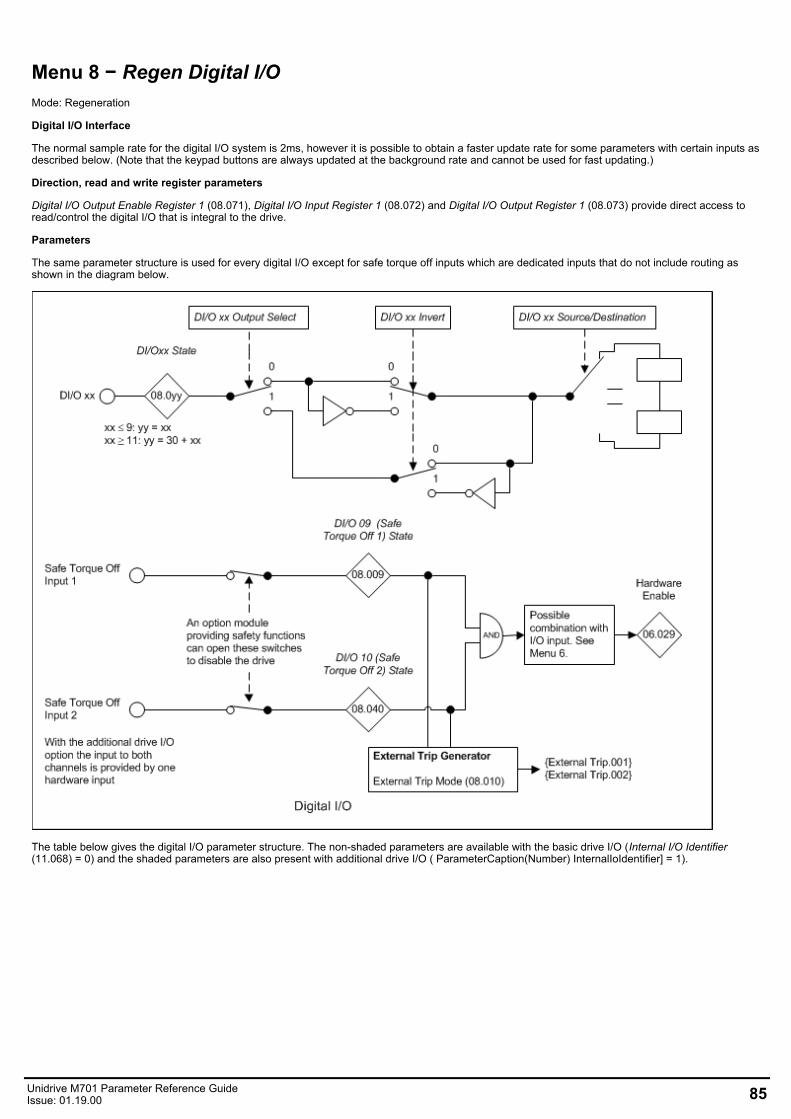
Menu 8 − Regen Digital I/OMode: Regeneration
Digital I/O Interface
The normal sample rate for the digital I/O system is 2ms, however it is possible to obtain a faster update rate for some parameters with certain inputs asdescribed below. (Note that the keypad buttons are always updated at the background rate and cannot be used for fast updating.)
Direction, read and write register parameters
Digital I/O Output Enable Register 1 (08.071), Digital I/O Input Register 1 (08.072) and Digital I/O Output Register 1 (08.073) provide direct access toread/control the digital I/O that is integral to the drive.
Parameters
The same parameter structure is used for every digital I/O except for safe torque off inputs which are dedicated inputs that do not include routing asshown in the diagram below.
The table below gives the digital I/O parameter structure. The non-shaded parameters are available with the basic drive I/O (Internal I/O Identifier(11.068) = 0) and the shaded parameters are also present with additional drive I/O ( ParameterCaption(Number) InternalIoIdentifier] = 1).
Unidrive M701 Parameter Reference GuideIssue: 01.19.00 85
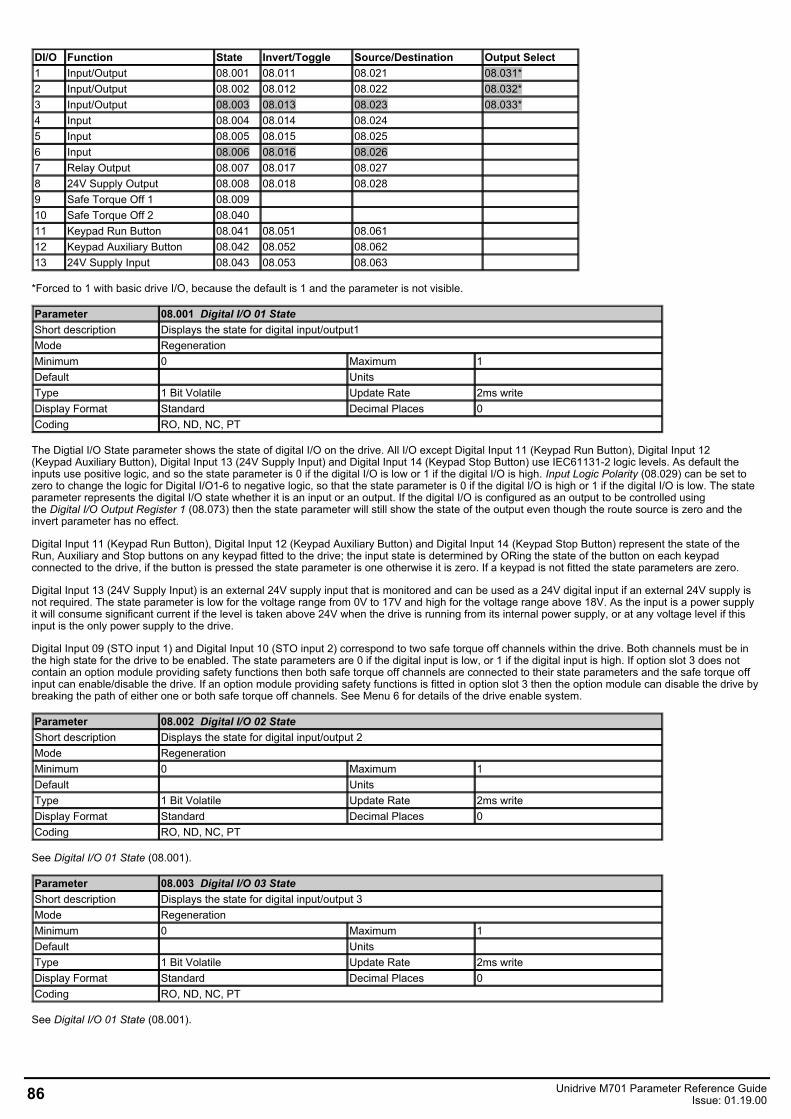
DI/O Function State Invert/Toggle Source/Destination Output Select1 Input/Output 08.001 08.011 08.021 08.031*2 Input/Output 08.002 08.012 08.022 08.032*3 Input/Output 08.003 08.013 08.023 08.033*4 Input 08.004 08.014 08.0245 Input 08.005 08.015 08.0256 Input 08.006 08.016 08.0267 Relay Output 08.007 08.017 08.0278 24V Supply Output 08.008 08.018 08.0289 Safe Torque Off 1 08.00910 Safe Torque Off 2 08.04011 Keypad Run Button 08.041 08.051 08.06112 Keypad Auxiliary Button 08.042 08.052 08.06213 24V Supply Input 08.043 08.053 08.063
*Forced to 1 with basic drive I/O, because the default is 1 and the parameter is not visible.
Parameter 08.001 Digital I/O 01 StateShort description Displays the state for digital input/output1Mode RegenerationMinimum 0 Maximum 1Default Units Type 1 Bit Volatile Update Rate 2ms writeDisplay Format Standard Decimal Places 0Coding RO, ND, NC, PT
The Digtial I/O State parameter shows the state of digital I/O on the drive. All I/O except Digital Input 11 (Keypad Run Button), Digital Input 12(Keypad Auxiliary Button), Digital Input 13 (24V Supply Input) and Digital Input 14 (Keypad Stop Button) use IEC61131-2 logic levels. As default theinputs use positive logic, and so the state parameter is 0 if the digital I/O is low or 1 if the digital I/O is high. Input Logic Polarity (08.029) can be set tozero to change the logic for Digital I/O1-6 to negative logic, so that the state parameter is 0 if the digital I/O is high or 1 if the digital I/O is low. The stateparameter represents the digital I/O state whether it is an input or an output. If the digital I/O is configured as an output to be controlled usingthe Digital I/O Output Register 1 (08.073) then the state parameter will still show the state of the output even though the route source is zero and theinvert parameter has no effect.
Digital Input 11 (Keypad Run Button), Digital Input 12 (Keypad Auxiliary Button) and Digital Input 14 (Keypad Stop Button) represent the state of theRun, Auxiliary and Stop buttons on any keypad fitted to the drive; the input state is determined by ORing the state of the button on each keypadconnected to the drive, if the button is pressed the state parameter is one otherwise it is zero. If a keypad is not fitted the state parameters are zero.
Digital Input 13 (24V Supply Input) is an external 24V supply input that is monitored and can be used as a 24V digital input if an external 24V supply isnot required. The state parameter is low for the voltage range from 0V to 17V and high for the voltage range above 18V. As the input is a power supplyit will consume significant current if the level is taken above 24V when the drive is running from its internal power supply, or at any voltage level if thisinput is the only power supply to the drive.
Digital Input 09 (STO input 1) and Digital Input 10 (STO input 2) correspond to two safe torque off channels within the drive. Both channels must be inthe high state for the drive to be enabled. The state parameters are 0 if the digital input is low, or 1 if the digital input is high. If option slot 3 does notcontain an option module providing safety functions then both safe torque off channels are connected to their state parameters and the safe torque offinput can enable/disable the drive. If an option module providing safety functions is fitted in option slot 3 then the option module can disable the drive bybreaking the path of either one or both safe torque off channels. See Menu 6 for details of the drive enable system.
Parameter 08.002 Digital I/O 02 StateShort description Displays the state for digital input/output 2Mode RegenerationMinimum 0 Maximum 1Default Units Type 1 Bit Volatile Update Rate 2ms writeDisplay Format Standard Decimal Places 0Coding RO, ND, NC, PT
See Digital I/O 01 State (08.001).
Parameter 08.003 Digital I/O 03 StateShort description Displays the state for digital input/output 3Mode RegenerationMinimum 0 Maximum 1Default Units Type 1 Bit Volatile Update Rate 2ms writeDisplay Format Standard Decimal Places 0Coding RO, ND, NC, PT
See Digital I/O 01 State (08.001).
86 Unidrive M701 Parameter Reference GuideIssue: 01.19.00
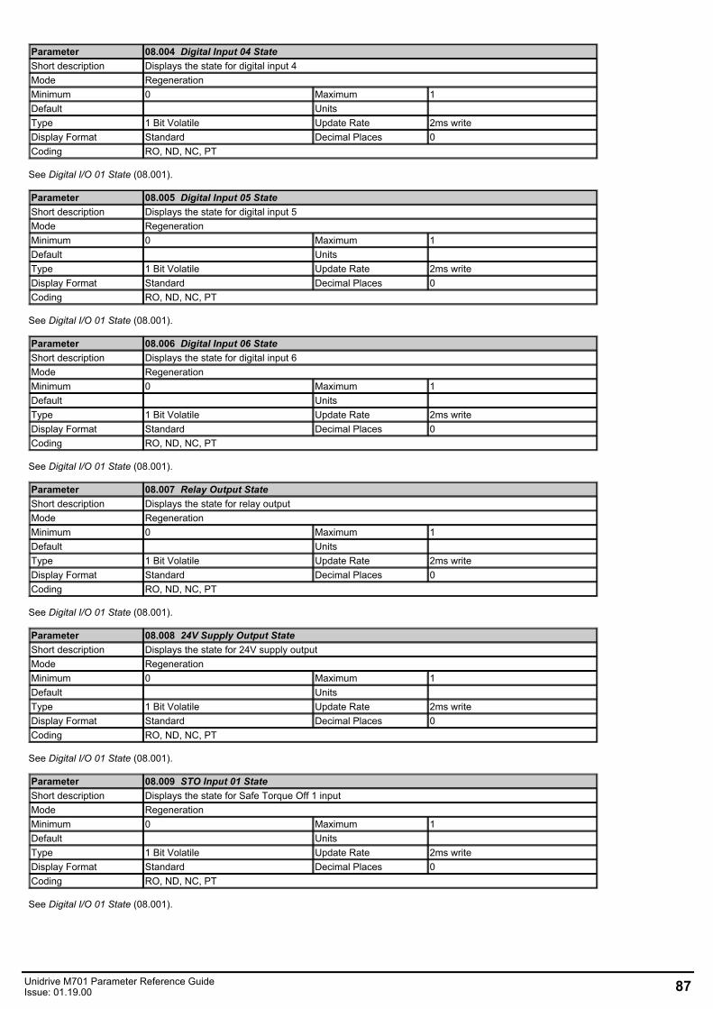
Parameter 08.004 Digital Input 04 StateShort description Displays the state for digital input 4Mode RegenerationMinimum 0 Maximum 1Default Units Type 1 Bit Volatile Update Rate 2ms writeDisplay Format Standard Decimal Places 0Coding RO, ND, NC, PT
See Digital I/O 01 State (08.001).
Parameter 08.005 Digital Input 05 StateShort description Displays the state for digital input 5Mode RegenerationMinimum 0 Maximum 1Default Units Type 1 Bit Volatile Update Rate 2ms writeDisplay Format Standard Decimal Places 0Coding RO, ND, NC, PT
See Digital I/O 01 State (08.001).
Parameter 08.006 Digital Input 06 StateShort description Displays the state for digital input 6Mode RegenerationMinimum 0 Maximum 1Default Units Type 1 Bit Volatile Update Rate 2ms writeDisplay Format Standard Decimal Places 0Coding RO, ND, NC, PT
See Digital I/O 01 State (08.001).
Parameter 08.007 Relay Output StateShort description Displays the state for relay outputMode RegenerationMinimum 0 Maximum 1Default Units Type 1 Bit Volatile Update Rate 2ms writeDisplay Format Standard Decimal Places 0Coding RO, ND, NC, PT
See Digital I/O 01 State (08.001).
Parameter 08.008 24V Supply Output StateShort description Displays the state for 24V supply outputMode RegenerationMinimum 0 Maximum 1Default Units Type 1 Bit Volatile Update Rate 2ms writeDisplay Format Standard Decimal Places 0Coding RO, ND, NC, PT
See Digital I/O 01 State (08.001).
Parameter 08.009 STO Input 01 StateShort description Displays the state for Safe Torque Off 1 inputMode RegenerationMinimum 0 Maximum 1Default Units Type 1 Bit Volatile Update Rate 2ms writeDisplay Format Standard Decimal Places 0Coding RO, ND, NC, PT
See Digital I/O 01 State (08.001).
Unidrive M701 Parameter Reference GuideIssue: 01.19.00 87
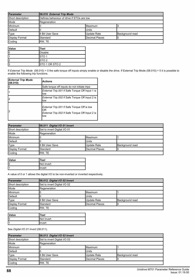
Parameter 08.010 External Trip ModeShort description Defines behaviour of drive if STOs are lowMode RegenerationMinimum 0 Maximum 3Default 0 Units Type 8 Bit User Save Update Rate Background readDisplay Format Standard Decimal Places 0Coding RW, TE
Value Text0 Disable1 STO 12 STO 23 STO 1 OR STO 2
If External Trip Mode (08.010) = 0 the safe torque off inputs simply enable or disable the drive. If External Trip Mode (08.010) > 0 it is possible toenable the following trip functions.
External Trip Mode (08.010) Actions
0 Safe torque off inputs do not initiate trips
1 External Trip.001 if Safe Torque Off Input 1 islow
2 External Trip.002 if Safe Torque Off Input 2 islow
3External Trip.001 if Safe Torque Off is lowORExternal Trip.002 if Safe Torque Off Input 2 islow
Parameter 08.011 Digital I/O 01 InvertShort description Set to invert Digital I/O 01Mode RegenerationMinimum 0 Maximum 1Default 0 Units Type 8 Bit User Save Update Rate Background readDisplay Format Standard Decimal Places 0Coding RW, TE
Value Text0 Not Invert1 Invert
A value of 0 or 1 allows the digital I/O to be non-inverted or inverted respectively.
Parameter 08.012 Digital I/O 02 InvertShort description Set to invert Digital I/O 02Mode RegenerationMinimum 0 Maximum 1Default 0 Units Type 8 Bit User Save Update Rate Background readDisplay Format Standard Decimal Places 0Coding RW, TE
Value Text0 Not Invert1 Invert
See Digital I/O 01 Invert (08.011).
Parameter 08.013 Digital I/O 03 InvertShort description Set to invert Digital I/O 03Mode RegenerationMinimum 0 Maximum 1Default 0 Units Type 8 Bit User Save Update Rate Background readDisplay Format Standard Decimal Places 0Coding RW, TE
88 Unidrive M701 Parameter Reference GuideIssue: 01.19.00
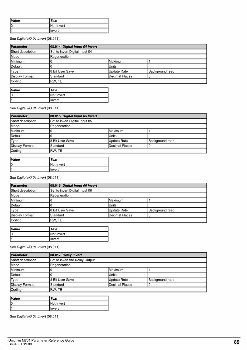
Value Text0 Not Invert1 Invert
See Digital I/O 01 Invert (08.011).
Parameter 08.014 Digital Input 04 InvertShort description Set to invert Digital Input 04Mode RegenerationMinimum 0 Maximum 1Default 0 Units Type 8 Bit User Save Update Rate Background readDisplay Format Standard Decimal Places 0Coding RW, TE
Value Text0 Not Invert1 Invert
See Digital I/O 01 Invert (08.011).
Parameter 08.015 Digital Input 05 InvertShort description Set to invert Digital Input 05Mode RegenerationMinimum 0 Maximum 1Default 0 Units Type 8 Bit User Save Update Rate Background readDisplay Format Standard Decimal Places 0Coding RW, TE
Value Text0 Not Invert1 Invert
See Digital I/O 01 Invert (08.011).
Parameter 08.016 Digital Input 06 InvertShort description Set to invert Digital Input 06Mode RegenerationMinimum 0 Maximum 1Default 0 Units Type 8 Bit User Save Update Rate Background readDisplay Format Standard Decimal Places 0Coding RW, TE
Value Text0 Not Invert1 Invert
See Digital I/O 01 Invert (08.011).
Parameter 08.017 Relay InvertShort description Set to invert the Relay OutputMode RegenerationMinimum 0 Maximum 1Default 0 Units Type 8 Bit User Save Update Rate Background readDisplay Format Standard Decimal Places 0Coding RW, TE
Value Text0 Not Invert1 Invert
See Digital I/O 01 Invert (08.011).
Unidrive M701 Parameter Reference GuideIssue: 01.19.00 89
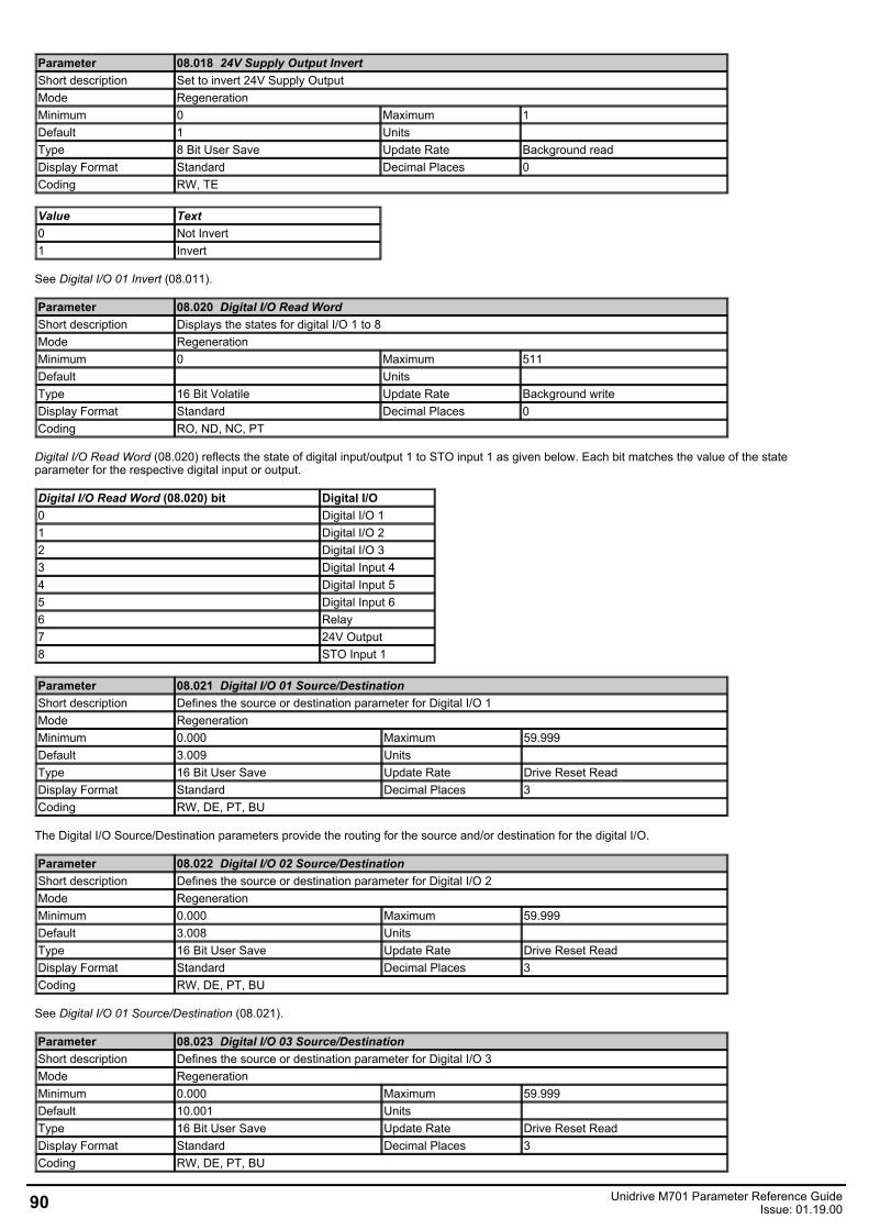
Parameter 08.018 24V Supply Output InvertShort description Set to invert 24V Supply OutputMode RegenerationMinimum 0 Maximum 1Default 1 Units Type 8 Bit User Save Update Rate Background readDisplay Format Standard Decimal Places 0Coding RW, TE
Value Text0 Not Invert1 Invert
See Digital I/O 01 Invert (08.011).
Parameter 08.020 Digital I/O Read WordShort description Displays the states for digital I/O 1 to 8Mode RegenerationMinimum 0 Maximum 511Default Units Type 16 Bit Volatile Update Rate Background writeDisplay Format Standard Decimal Places 0Coding RO, ND, NC, PT
Digital I/O Read Word (08.020) reflects the state of digital input/output 1 to STO input 1 as given below. Each bit matches the value of the stateparameter for the respective digital input or output.
Digital I/O Read Word (08.020) bit Digital I/O0 Digital I/O 11 Digital I/O 22 Digital I/O 33 Digital Input 44 Digital Input 55 Digital Input 66 Relay7 24V Output8 STO Input 1
Parameter 08.021 Digital I/O 01 Source/DestinationShort description Defines the source or destination parameter for Digital I/O 1Mode RegenerationMinimum 0.000 Maximum 59.999Default 3.009 Units Type 16 Bit User Save Update Rate Drive Reset ReadDisplay Format Standard Decimal Places 3Coding RW, DE, PT, BU
The Digital I/O Source/Destination parameters provide the routing for the source and/or destination for the digital I/O.
Parameter 08.022 Digital I/O 02 Source/DestinationShort description Defines the source or destination parameter for Digital I/O 2Mode RegenerationMinimum 0.000 Maximum 59.999Default 3.008 Units Type 16 Bit User Save Update Rate Drive Reset ReadDisplay Format Standard Decimal Places 3Coding RW, DE, PT, BU
See Digital I/O 01 Source/Destination (08.021).
Parameter 08.023 Digital I/O 03 Source/DestinationShort description Defines the source or destination parameter for Digital I/O 3Mode RegenerationMinimum 0.000 Maximum 59.999Default 10.001 Units Type 16 Bit User Save Update Rate Drive Reset ReadDisplay Format Standard Decimal Places 3Coding RW, DE, PT, BU
90 Unidrive M701 Parameter Reference GuideIssue: 01.19.00
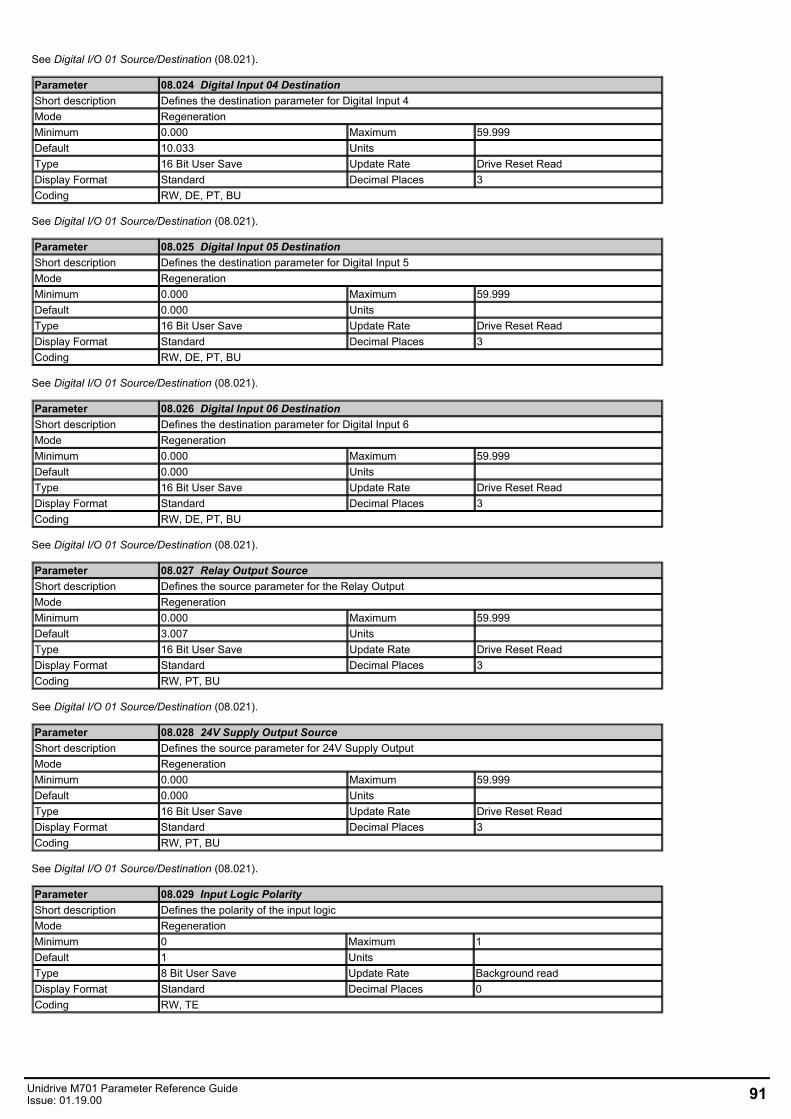
See Digital I/O 01 Source/Destination (08.021).
Parameter 08.024 Digital Input 04 DestinationShort description Defines the destination parameter for Digital Input 4Mode RegenerationMinimum 0.000 Maximum 59.999Default 10.033 Units Type 16 Bit User Save Update Rate Drive Reset ReadDisplay Format Standard Decimal Places 3Coding RW, DE, PT, BU
See Digital I/O 01 Source/Destination (08.021).
Parameter 08.025 Digital Input 05 DestinationShort description Defines the destination parameter for Digital Input 5Mode RegenerationMinimum 0.000 Maximum 59.999Default 0.000 Units Type 16 Bit User Save Update Rate Drive Reset ReadDisplay Format Standard Decimal Places 3Coding RW, DE, PT, BU
See Digital I/O 01 Source/Destination (08.021).
Parameter 08.026 Digital Input 06 DestinationShort description Defines the destination parameter for Digital Input 6Mode RegenerationMinimum 0.000 Maximum 59.999Default 0.000 Units Type 16 Bit User Save Update Rate Drive Reset ReadDisplay Format Standard Decimal Places 3Coding RW, DE, PT, BU
See Digital I/O 01 Source/Destination (08.021).
Parameter 08.027 Relay Output SourceShort description Defines the source parameter for the Relay OutputMode RegenerationMinimum 0.000 Maximum 59.999Default 3.007 Units Type 16 Bit User Save Update Rate Drive Reset ReadDisplay Format Standard Decimal Places 3Coding RW, PT, BU
See Digital I/O 01 Source/Destination (08.021).
Parameter 08.028 24V Supply Output SourceShort description Defines the source parameter for 24V Supply OutputMode RegenerationMinimum 0.000 Maximum 59.999Default 0.000 Units Type 16 Bit User Save Update Rate Drive Reset ReadDisplay Format Standard Decimal Places 3Coding RW, PT, BU
See Digital I/O 01 Source/Destination (08.021).
Parameter 08.029 Input Logic PolarityShort description Defines the polarity of the input logicMode RegenerationMinimum 0 Maximum 1Default 1 Units Type 8 Bit User Save Update Rate Background readDisplay Format Standard Decimal Places 0Coding RW, TE
Unidrive M701 Parameter Reference GuideIssue: 01.19.00 91
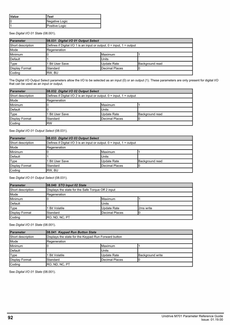
Value Text0 Negative Logic1 Positive Logic
See Digital I/O 01 State (08.001).
Parameter 08.031 Digital I/O 01 Output SelectShort description Defines if Digital I/O 1 is an input or output. 0 = input, 1 = outputMode RegenerationMinimum 0 Maximum 1Default 1 Units Type 1 Bit User Save Update Rate Background readDisplay Format Standard Decimal Places 0Coding RW, BU
The Digital I/O Output Select parameters allow the I/O to be selected as an input (0) or an output (1). These parameters are only present for digital I/Othat can be used as an input or output.
Parameter 08.032 Digital I/O 02 Output SelectShort description Defines if Digital I/O 2 is an input or output. 0 = input, 1 = outputMode RegenerationMinimum 0 Maximum 1Default 0 Units Type 1 Bit User Save Update Rate Background readDisplay Format Standard Decimal Places 0Coding RW
See Digital I/O 01 Output Select (08.031).
Parameter 08.033 Digital I/O 03 Output SelectShort description Defines if Digital I/O 3 is an input or output. 0 = input, 1 = outputMode RegenerationMinimum 0 Maximum 1Default 1 Units Type 1 Bit User Save Update Rate Background readDisplay Format Standard Decimal Places 0Coding RW, BU
See Digital I/O 01 Output Select (08.031).
Parameter 08.040 STO Input 02 StateShort description Displays the state for the Safe Torque Off 2 inputMode RegenerationMinimum 0 Maximum 1Default Units Type 1 Bit Volatile Update Rate 2ms writeDisplay Format Standard Decimal Places 0Coding RO, ND, NC, PT
See Digital I/O 01 State (08.001).
Parameter 08.041 Keypad Run Button StateShort description Displays the state for the Keypad Run Forward buttonMode RegenerationMinimum 0 Maximum 1Default Units Type 1 Bit Volatile Update Rate Background writeDisplay Format Standard Decimal Places 0Coding RO, ND, NC, PT
See Digital I/O 01 State (08.001).
92 Unidrive M701 Parameter Reference GuideIssue: 01.19.00
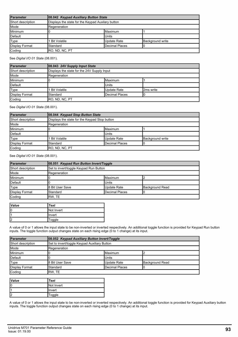
Parameter 08.042 Keypad Auxiliary Button StateShort description Displays the state for the Keypad Auxilary buttonMode RegenerationMinimum 0 Maximum 1Default Units Type 1 Bit Volatile Update Rate Background writeDisplay Format Standard Decimal Places 0Coding RO, ND, NC, PT
See Digital I/O 01 State (08.001).
Parameter 08.043 24V Supply Input StateShort description Displays the state for the 24V Supply InputMode RegenerationMinimum 0 Maximum 1Default Units Type 1 Bit Volatile Update Rate 2ms writeDisplay Format Standard Decimal Places 0Coding RO, ND, NC, PT
See Digital I/O 01 State (08.001).
Parameter 08.044 Keypad Stop Button StateShort description Displays the state for the Keypad Stop buttonMode RegenerationMinimum 0 Maximum 1Default Units Type 1 Bit Volatile Update Rate Background writeDisplay Format Standard Decimal Places 0Coding RO, ND, NC, PT
See Digital I/O 01 State (08.001).
Parameter 08.051 Keypad Run Button Invert/ToggleShort description Set to invert/toggle Keypad Run ButtonMode RegenerationMinimum 0 Maximum 2Default 0 Units Type 8 Bit User Save Update Rate Background ReadDisplay Format Standard Decimal Places 0Coding RW, TE
Value Text0 Not Invert1 Invert2 Toggle
A value of 0 or 1 allows the input state to be non-inverted or inverted respectively. An additional toggle function is provided for Keypad Run buttoninputs. The toggle function output changes state on each rising edge (0 to 1 change) at its input.
Parameter 08.052 Keypad Auxiliary Button Invert/ToggleShort description Set to invert/toggle Keypad Auxiliary ButtonMode RegenerationMinimum 0 Maximum 2Default 0 Units Type 8 Bit User Save Update Rate Background ReadDisplay Format Standard Decimal Places 0Coding RW, TE
Value Text0 Not Invert1 Invert2 Toggle
A value of 0 or 1 allows the input state to be non-inverted or inverted respectively. An additional toggle function is provided for Keypad Auxiliary buttoninputs. The toggle function output changes state on each rising edge (0 to 1 change) at its input.
Unidrive M701 Parameter Reference GuideIssue: 01.19.00 93
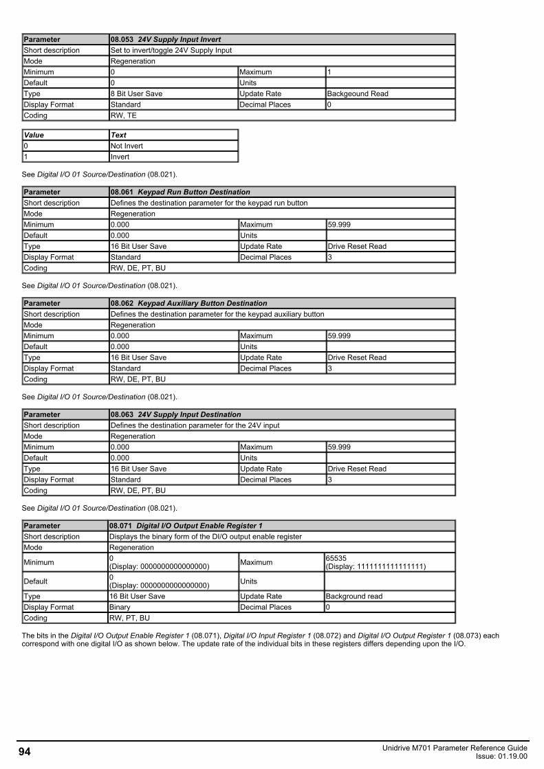
Parameter 08.053 24V Supply Input InvertShort description Set to invert/toggle 24V Supply InputMode RegenerationMinimum 0 Maximum 1Default 0 Units Type 8 Bit User Save Update Rate Backgeound ReadDisplay Format Standard Decimal Places 0Coding RW, TE
Value Text0 Not Invert1 Invert
See Digital I/O 01 Source/Destination (08.021).
Parameter 08.061 Keypad Run Button DestinationShort description Defines the destination parameter for the keypad run buttonMode RegenerationMinimum 0.000 Maximum 59.999Default 0.000 Units Type 16 Bit User Save Update Rate Drive Reset ReadDisplay Format Standard Decimal Places 3Coding RW, DE, PT, BU
See Digital I/O 01 Source/Destination (08.021).
Parameter 08.062 Keypad Auxiliary Button DestinationShort description Defines the destination parameter for the keypad auxiliary buttonMode RegenerationMinimum 0.000 Maximum 59.999Default 0.000 Units Type 16 Bit User Save Update Rate Drive Reset ReadDisplay Format Standard Decimal Places 3Coding RW, DE, PT, BU
See Digital I/O 01 Source/Destination (08.021).
Parameter 08.063 24V Supply Input DestinationShort description Defines the destination parameter for the 24V inputMode RegenerationMinimum 0.000 Maximum 59.999Default 0.000 Units Type 16 Bit User Save Update Rate Drive Reset ReadDisplay Format Standard Decimal Places 3Coding RW, DE, PT, BU
See Digital I/O 01 Source/Destination (08.021).
Parameter 08.071 Digital I/O Output Enable Register 1Short description Displays the binary form of the DI/O output enable registerMode Regeneration
Minimum 0(Display: 0000000000000000) Maximum 65535
(Display: 1111111111111111)
Default 0(Display: 0000000000000000) Units
Type 16 Bit User Save Update Rate Background readDisplay Format Binary Decimal Places 0Coding RW, PT, BU
The bits in the Digital I/O Output Enable Register 1 (08.071), Digital I/O Input Register 1 (08.072) and Digital I/O Output Register 1 (08.073) eachcorrespond with one digital I/O as shown below. The update rate of the individual bits in these registers differs depending upon the I/O.
94 Unidrive M701 Parameter Reference GuideIssue: 01.19.00
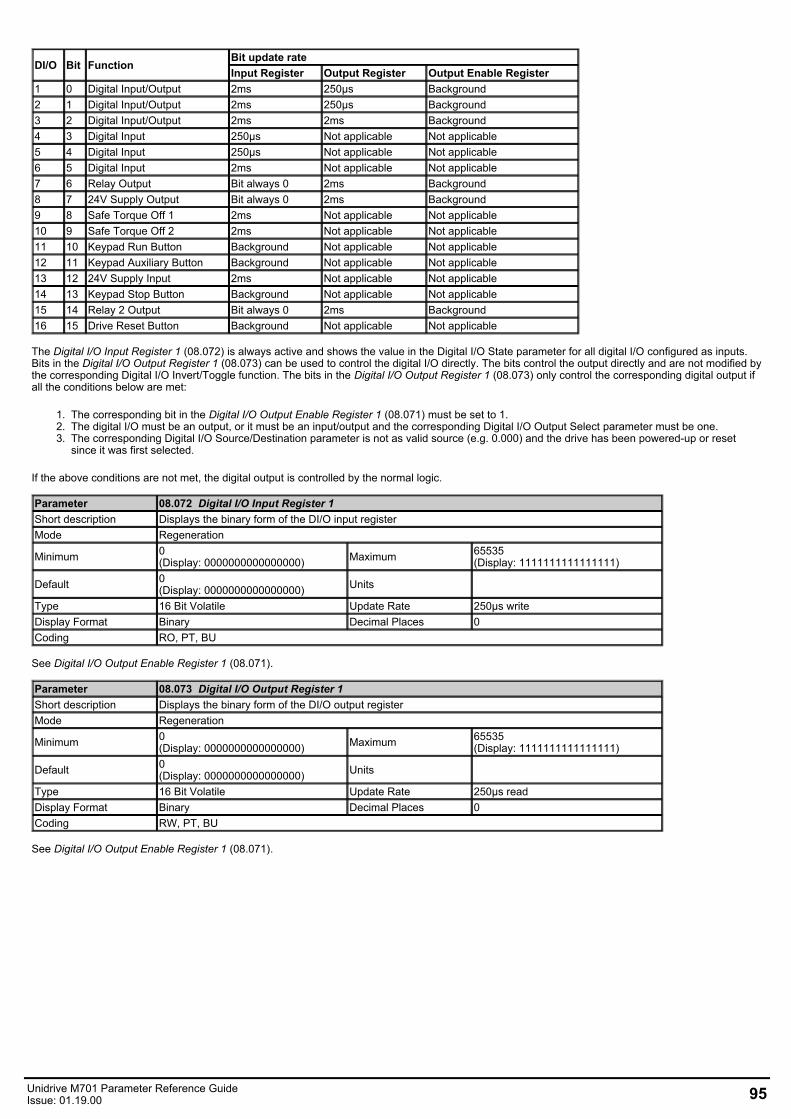
DI/O Bit FunctionBit update rateInput Register Output Register Output Enable Register
1 0 Digital Input/Output 2ms 250μs Background2 1 Digital Input/Output 2ms 250μs Background3 2 Digital Input/Output 2ms 2ms Background4 3 Digital Input 250μs Not applicable Not applicable5 4 Digital Input 250μs Not applicable Not applicable6 5 Digital Input 2ms Not applicable Not applicable7 6 Relay Output Bit always 0 2ms Background8 7 24V Supply Output Bit always 0 2ms Background9 8 Safe Torque Off 1 2ms Not applicable Not applicable10 9 Safe Torque Off 2 2ms Not applicable Not applicable11 10 Keypad Run Button Background Not applicable Not applicable12 11 Keypad Auxiliary Button Background Not applicable Not applicable13 12 24V Supply Input 2ms Not applicable Not applicable14 13 Keypad Stop Button Background Not applicable Not applicable15 14 Relay 2 Output Bit always 0 2ms Background16 15 Drive Reset Button Background Not applicable Not applicable
The Digital I/O Input Register 1 (08.072) is always active and shows the value in the Digital I/O State parameter for all digital I/O configured as inputs.Bits in the Digital I/O Output Register 1 (08.073) can be used to control the digital I/O directly. The bits control the output directly and are not modified bythe corresponding Digital I/O Invert/Toggle function. The bits in the Digital I/O Output Register 1 (08.073) only control the corresponding digital output ifall the conditions below are met:
1. The corresponding bit in the Digital I/O Output Enable Register 1 (08.071) must be set to 1.2. The digital I/O must be an output, or it must be an input/output and the corresponding Digital I/O Output Select parameter must be one.3. The corresponding Digital I/O Source/Destination parameter is not as valid source (e.g. 0.000) and the drive has been powered-up or reset
since it was first selected.
If the above conditions are not met, the digital output is controlled by the normal logic.
Parameter 08.072 Digital I/O Input Register 1Short description Displays the binary form of the DI/O input registerMode Regeneration
Minimum 0(Display: 0000000000000000) Maximum 65535
(Display: 1111111111111111)
Default 0(Display: 0000000000000000) Units
Type 16 Bit Volatile Update Rate 250µs writeDisplay Format Binary Decimal Places 0Coding RO, PT, BU
See Digital I/O Output Enable Register 1 (08.071).
Parameter 08.073 Digital I/O Output Register 1Short description Displays the binary form of the DI/O output registerMode Regeneration
Minimum 0(Display: 0000000000000000) Maximum 65535
(Display: 1111111111111111)
Default 0(Display: 0000000000000000) Units
Type 16 Bit Volatile Update Rate 250µs readDisplay Format Binary Decimal Places 0Coding RW, PT, BU
See Digital I/O Output Enable Register 1 (08.071).
Unidrive M701 Parameter Reference GuideIssue: 01.19.00 95
Menu 9 Single Line Descriptions − User Functions 1Mode: Regeneration
96 Unidrive M701 Parameter Reference GuideIssue: 01.19.00
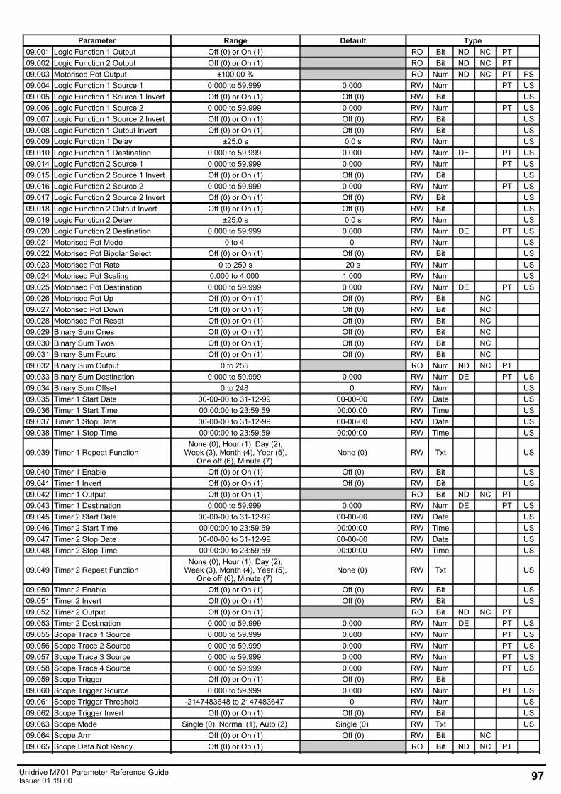
Parameter Range Default Type09.001 Logic Function 1 Output Off (0) or On (1) RO Bit ND NC PT 09.002 Logic Function 2 Output Off (0) or On (1) RO Bit ND NC PT 09.003 Motorised Pot Output ±100.00 % RO Num ND NC PT PS09.004 Logic Function 1 Source 1 0.000 to 59.999 0.000 RW Num PT US09.005 Logic Function 1 Source 1 Invert Off (0) or On (1) Off (0) RW Bit US09.006 Logic Function 1 Source 2 0.000 to 59.999 0.000 RW Num PT US09.007 Logic Function 1 Source 2 Invert Off (0) or On (1) Off (0) RW Bit US09.008 Logic Function 1 Output Invert Off (0) or On (1) Off (0) RW Bit US09.009 Logic Function 1 Delay ±25.0 s 0.0 s RW Num US09.010 Logic Function 1 Destination 0.000 to 59.999 0.000 RW Num DE PT US09.014 Logic Function 2 Source 1 0.000 to 59.999 0.000 RW Num PT US09.015 Logic Function 2 Source 1 Invert Off (0) or On (1) Off (0) RW Bit US09.016 Logic Function 2 Source 2 0.000 to 59.999 0.000 RW Num PT US09.017 Logic Function 2 Source 2 Invert Off (0) or On (1) Off (0) RW Bit US09.018 Logic Function 2 Output Invert Off (0) or On (1) Off (0) RW Bit US09.019 Logic Function 2 Delay ±25.0 s 0.0 s RW Num US09.020 Logic Function 2 Destination 0.000 to 59.999 0.000 RW Num DE PT US09.021 Motorised Pot Mode 0 to 4 0 RW Num US09.022 Motorised Pot Bipolar Select Off (0) or On (1) Off (0) RW Bit US09.023 Motorised Pot Rate 0 to 250 s 20 s RW Num US09.024 Motorised Pot Scaling 0.000 to 4.000 1.000 RW Num US09.025 Motorised Pot Destination 0.000 to 59.999 0.000 RW Num DE PT US09.026 Motorised Pot Up Off (0) or On (1) Off (0) RW Bit NC 09.027 Motorised Pot Down Off (0) or On (1) Off (0) RW Bit NC 09.028 Motorised Pot Reset Off (0) or On (1) Off (0) RW Bit NC 09.029 Binary Sum Ones Off (0) or On (1) Off (0) RW Bit NC 09.030 Binary Sum Twos Off (0) or On (1) Off (0) RW Bit NC 09.031 Binary Sum Fours Off (0) or On (1) Off (0) RW Bit NC 09.032 Binary Sum Output 0 to 255 RO Num ND NC PT 09.033 Binary Sum Destination 0.000 to 59.999 0.000 RW Num DE PT US09.034 Binary Sum Offset 0 to 248 0 RW Num US09.035 Timer 1 Start Date 00-00-00 to 31-12-99 00-00-00 RW Date US09.036 Timer 1 Start Time 00:00:00 to 23:59:59 00:00:00 RW Time US09.037 Timer 1 Stop Date 00-00-00 to 31-12-99 00-00-00 RW Date US09.038 Timer 1 Stop Time 00:00:00 to 23:59:59 00:00:00 RW Time US
09.039 Timer 1 Repeat FunctionNone (0), Hour (1), Day (2),
Week (3), Month (4), Year (5),One off (6), Minute (7)
None (0) RW Txt US
09.040 Timer 1 Enable Off (0) or On (1) Off (0) RW Bit US09.041 Timer 1 Invert Off (0) or On (1) Off (0) RW Bit US09.042 Timer 1 Output Off (0) or On (1) RO Bit ND NC PT 09.043 Timer 1 Destination 0.000 to 59.999 0.000 RW Num DE PT US09.045 Timer 2 Start Date 00-00-00 to 31-12-99 00-00-00 RW Date US09.046 Timer 2 Start Time 00:00:00 to 23:59:59 00:00:00 RW Time US09.047 Timer 2 Stop Date 00-00-00 to 31-12-99 00-00-00 RW Date US09.048 Timer 2 Stop Time 00:00:00 to 23:59:59 00:00:00 RW Time US
09.049 Timer 2 Repeat FunctionNone (0), Hour (1), Day (2),
Week (3), Month (4), Year (5),One off (6), Minute (7)
None (0) RW Txt US
09.050 Timer 2 Enable Off (0) or On (1) Off (0) RW Bit US09.051 Timer 2 Invert Off (0) or On (1) Off (0) RW Bit US09.052 Timer 2 Output Off (0) or On (1) RO Bit ND NC PT 09.053 Timer 2 Destination 0.000 to 59.999 0.000 RW Num DE PT US09.055 Scope Trace 1 Source 0.000 to 59.999 0.000 RW Num PT US09.056 Scope Trace 2 Source 0.000 to 59.999 0.000 RW Num PT US09.057 Scope Trace 3 Source 0.000 to 59.999 0.000 RW Num PT US09.058 Scope Trace 4 Source 0.000 to 59.999 0.000 RW Num PT US09.059 Scope Trigger Off (0) or On (1) Off (0) RW Bit 09.060 Scope Trigger Source 0.000 to 59.999 0.000 RW Num PT US09.061 Scope Trigger Threshold -2147483648 to 2147483647 0 RW Num US09.062 Scope Trigger Invert Off (0) or On (1) Off (0) RW Bit US09.063 Scope Mode Single (0), Normal (1), Auto (2) Single (0) RW Txt US09.064 Scope Arm Off (0) or On (1) Off (0) RW Bit NC 09.065 Scope Data Not Ready Off (0) or On (1) RO Bit ND NC PT
Unidrive M701 Parameter Reference GuideIssue: 01.19.00 97
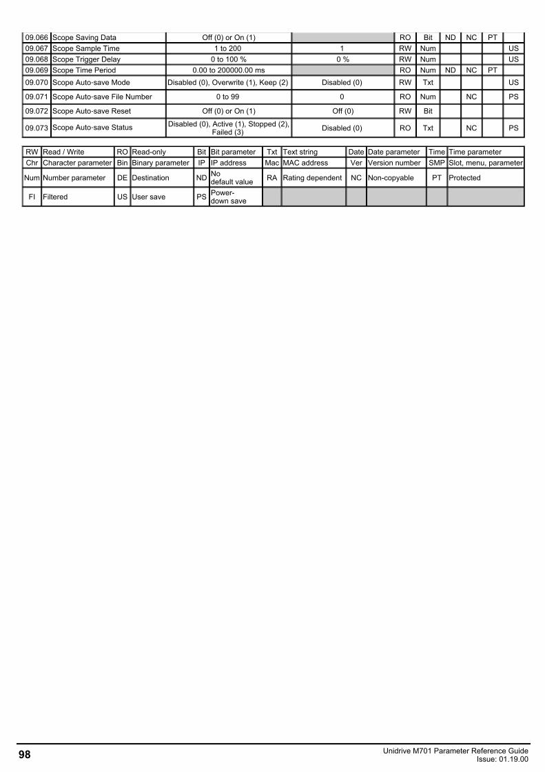
09.066 Scope Saving Data Off (0) or On (1) RO Bit ND NC PT 09.067 Scope Sample Time 1 to 200 1 RW Num US09.068 Scope Trigger Delay 0 to 100 % 0 % RW Num US09.069 Scope Time Period 0.00 to 200000.00 ms RO Num ND NC PT 09.070 Scope Auto‑save Mode Disabled (0), Overwrite (1), Keep (2) Disabled (0) RW Txt US
09.071 Scope Auto‑save File Number 0 to 99 0 RO Num NC PS
09.072 Scope Auto‑save Reset Off (0) or On (1) Off (0) RW Bit
09.073 Scope Auto‑save Status Disabled (0), Active (1), Stopped (2),Failed (3) Disabled (0) RO Txt NC PS
RW Read / Write RO Read-only Bit Bit parameter Txt Text string Date Date parameter Time Time parameterChr Character parameter Bin Binary parameter IP IP address Mac MAC address Ver Version number SMP Slot, menu, parameter
Num Number parameter DE Destination ND Nodefault value RA Rating dependent NC Non-copyable PT Protected
FI Filtered US User save PS Power-down save
98 Unidrive M701 Parameter Reference GuideIssue: 01.19.00
Menu 9 − User Functions 1Mode: Regeneration
Menu 9 provides the parameters for the following features:
1. Logic functions2. Motorised Pot3. Binary Sum4. Timers5. Scope function
Unidrive M701 Parameter Reference GuideIssue: 01.19.00 99
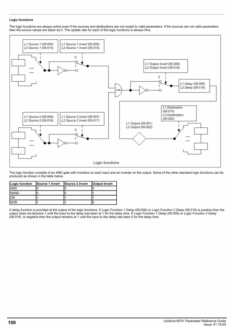
Logic functions
The logic functions are always active even if the sources and destinations are not routed to valid parameters. If the sources are not valid parametersthen the source values are taken as 0. The update rate for each of the logic functions is always 4ms.
The logic function consists of an AND gate with inverters on each input and an inverter on the output. Some of the other standard logic functions can beproduced as shown in the table below.
Logic function Source 1 Invert Source 2 Invert Output InvertAND 0 0 0NAND 0 0 1OR 1 1 1NOR 1 1 0
A delay function is provided at the output of the logic functions. If Logic Function 1 Delay (09.009) or Logic Function 2 Delay (09.019) is positive then theoutput does not become 1 until the input to the delay has been at 1 for the delay time. If Logic Function 1 Delay (09.009) or Logic Function 2 Delay(09.019) is negative then the output remains at 1 until the input to the delay has been 0 for the delay time.
100 Unidrive M701 Parameter Reference GuideIssue: 01.19.00
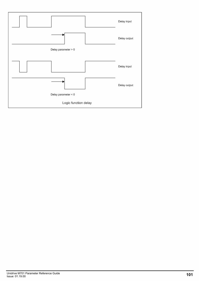
Unidrive M701 Parameter Reference GuideIssue: 01.19.00 101
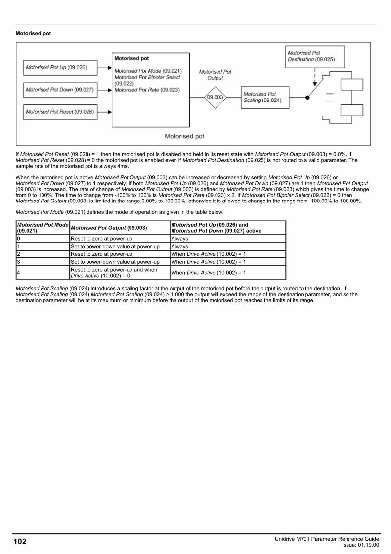
Motorised pot
If Motorised Pot Reset (09.028) = 1 then the motorised pot is disabled and held in its reset state with Motorised Pot Output (09.003) = 0.0%. IfMotorised Pot Reset (09.028) = 0 the motorised pot is enabled even if Motorised Pot Destination (09.025) is not routed to a valid parameter. Thesample rate of the motorised pot is always 4ms.
When the motorised pot is active Motorised Pot Output (09.003) can be increased or decreased by setting Motorised Pot Up (09.026) orMotorised Pot Down (09.027) to 1 respectively. If both Motorised Pot Up (09.026) and Motorised Pot Down (09.027) are 1 then Motorised Pot Output(09.003) is increased. The rate of change of Motorised Pot Output (09.003) is defined by Motorised Pot Rate (09.023) which gives the time to changefrom 0 to 100%. The time to change from -100% to 100% is Motorised Pot Rate (09.023) x 2. If Motorised Pot Bipolar Select (09.022) = 0 thenMotorised Pot Output (09.003) is limited in the range 0.00% to 100.00%, otherwise it is allowed to change in the range from -100.00% to 100.00%.
Motorised Pot Mode (09.021) defines the mode of operation as given in the table below.
Motorised Pot Mode(09.021) Motorised Pot Output (09.003) Motorised Pot Up (09.026) and
Motorised Pot Down (09.027) active0 Reset to zero at power-up Always1 Set to power-down value at power-up Always2 Reset to zero at power-up When Drive Active (10.002) = 13 Set to power-down value at power-up When Drive Active (10.002) = 1
4 Reset to zero at power-up and whenDrive Active (10.002) = 0 When Drive Active (10.002) = 1
Motorised Pot Scaling (09.024) introduces a scaling factor at the output of the motorised pot before the output is routed to the destination. IfMotorised Pot Scaling (09.024) Motorised Pot Scaling (09.024) > 1.000 the output will exceed the range of the destination parameter, and so thedestination parameter will be at its maximum or minimum before the output of the motorised pot reaches the limits of its range.
102 Unidrive M701 Parameter Reference GuideIssue: 01.19.00
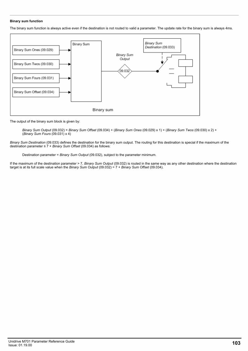
Binary sum function
The binary sum function is always active even if the destination is not routed to valid a parameter. The update rate for the binary sum is always 4ms.
The output of the binary sum block is given by:
Binary Sum Output (09.032) = Binary Sum Offset (09.034) + (Binary Sum Ones (09.029) x 1) + (Binary Sum Twos (09.030) x 2) +(Binary Sum Fours (09.031) x 4)
Binary Sum Destination (09.033) defines the destination for the binary sum output. The routing for this destination is special if the maximum of thedestination parameter ≤ 7 + Binary Sum Offset (09.034) as follows:
Destination parameter = Binary Sum Output (09.032), subject to the parameter minimum.
If the maximum of the destination parameter > 7, Binary Sum Output (09.032) is routed in the same way as any other destination where the destinationtarget is at its full scale value when the Binary Sum Output (09.032) = 7 + Binary Sum Offset (09.034).
Unidrive M701 Parameter Reference GuideIssue: 01.19.00 103
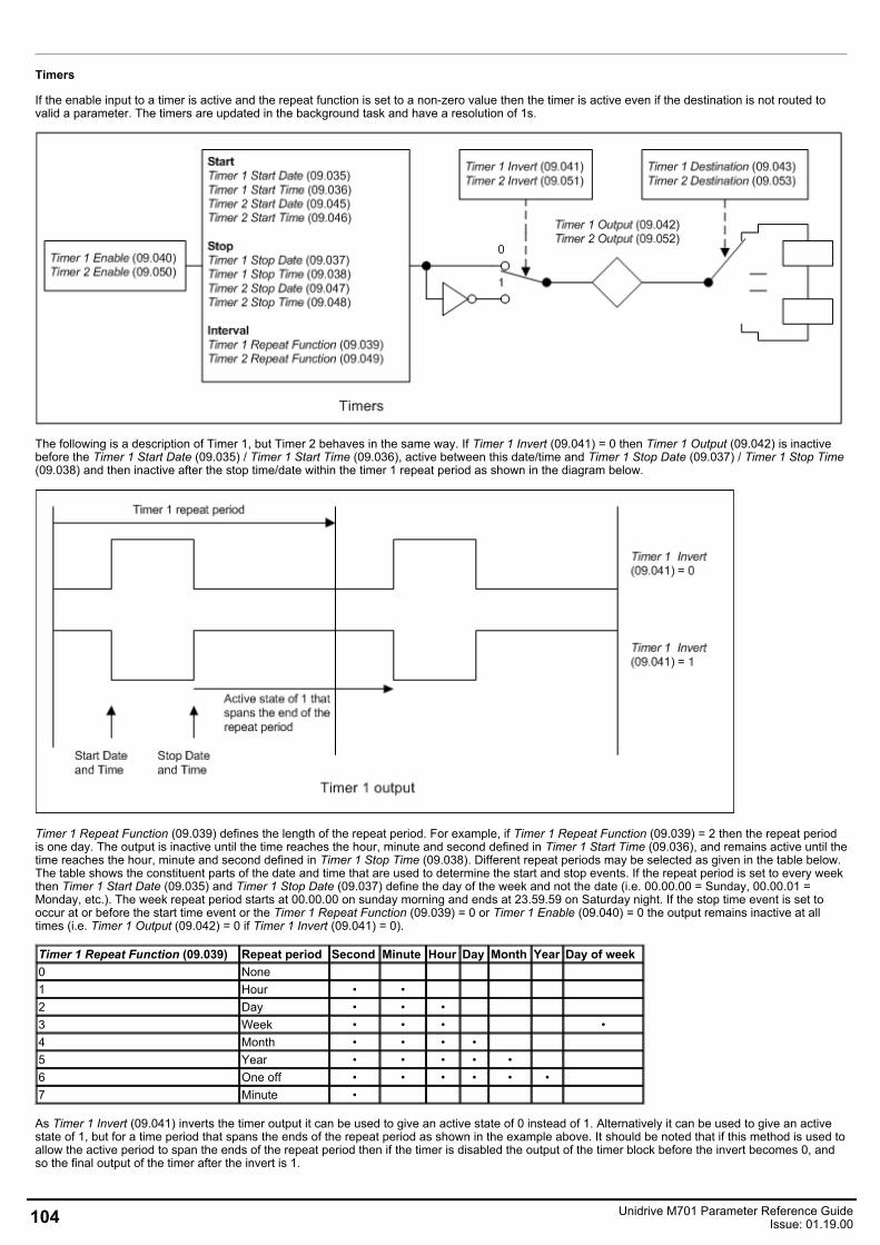
Timers
If the enable input to a timer is active and the repeat function is set to a non-zero value then the timer is active even if the destination is not routed tovalid a parameter. The timers are updated in the background task and have a resolution of 1s.
The following is a description of Timer 1, but Timer 2 behaves in the same way. If Timer 1 Invert (09.041) = 0 then Timer 1 Output (09.042) is inactivebefore the Timer 1 Start Date (09.035) / Timer 1 Start Time (09.036), active between this date/time and Timer 1 Stop Date (09.037) / Timer 1 Stop Time(09.038) and then inactive after the stop time/date within the timer 1 repeat period as shown in the diagram below.
Timer 1 Repeat Function (09.039) defines the length of the repeat period. For example, if Timer 1 Repeat Function (09.039) = 2 then the repeat periodis one day. The output is inactive until the time reaches the hour, minute and second defined in Timer 1 Start Time (09.036), and remains active until thetime reaches the hour, minute and second defined in Timer 1 Stop Time (09.038). Different repeat periods may be selected as given in the table below.The table shows the constituent parts of the date and time that are used to determine the start and stop events. If the repeat period is set to every weekthen Timer 1 Start Date (09.035) and Timer 1 Stop Date (09.037) define the day of the week and not the date (i.e. 00.00.00 = Sunday, 00.00.01 =Monday, etc.). The week repeat period starts at 00.00.00 on sunday morning and ends at 23.59.59 on Saturday night. If the stop time event is set tooccur at or before the start time event or the Timer 1 Repeat Function (09.039) = 0 or Timer 1 Enable (09.040) = 0 the output remains inactive at alltimes (i.e. Timer 1 Output (09.042) = 0 if Timer 1 Invert (09.041) = 0).
Timer 1 Repeat Function (09.039) Repeat period Second Minute Hour Day Month Year Day of week0 None1 Hour • •2 Day • • •3 Week • • • •4 Month • • • •5 Year • • • • •6 One off • • • • • •7 Minute •
As Timer 1 Invert (09.041) inverts the timer output it can be used to give an active state of 0 instead of 1. Alternatively it can be used to give an activestate of 1, but for a time period that spans the ends of the repeat period as shown in the example above. It should be noted that if this method is used toallow the active period to span the ends of the repeat period then if the timer is disabled the output of the timer block before the invert becomes 0, andso the final output of the timer after the invert is 1.
104 Unidrive M701 Parameter Reference GuideIssue: 01.19.00

If Date/Time Selector (06.019) is changed and the drive is reset then the source for the timers will change, therefore Timer 1 Repeat Function(09.039) and Timer 2 Repeat Function (09.049) are reset to 0 to disable the timers, and the date and time entries in the trip log are cleared.
Unidrive M701 Parameter Reference GuideIssue: 01.19.00 105
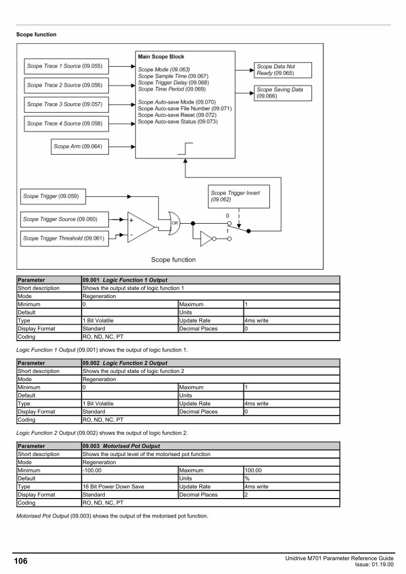
Scope function
Parameter 09.001 Logic Function 1 OutputShort description Shows the output state of logic function 1Mode RegenerationMinimum 0 Maximum 1Default Units Type 1 Bit Volatile Update Rate 4ms writeDisplay Format Standard Decimal Places 0Coding RO, ND, NC, PT
Logic Function 1 Output (09.001) shows the output of logic function 1.
Parameter 09.002 Logic Function 2 OutputShort description Shows the output state of logic function 2Mode RegenerationMinimum 0 Maximum 1Default Units Type 1 Bit Volatile Update Rate 4ms writeDisplay Format Standard Decimal Places 0Coding RO, ND, NC, PT
Logic Function 2 Output (09.002) shows the output of logic function 2.
Parameter 09.003 Motorised Pot OutputShort description Shows the output level of the motorised pot functionMode RegenerationMinimum -100.00 Maximum 100.00Default Units %Type 16 Bit Power Down Save Update Rate 4ms writeDisplay Format Standard Decimal Places 2Coding RO, ND, NC, PT
Motorised Pot Output (09.003) shows the output of the motorised pot function.
106 Unidrive M701 Parameter Reference GuideIssue: 01.19.00
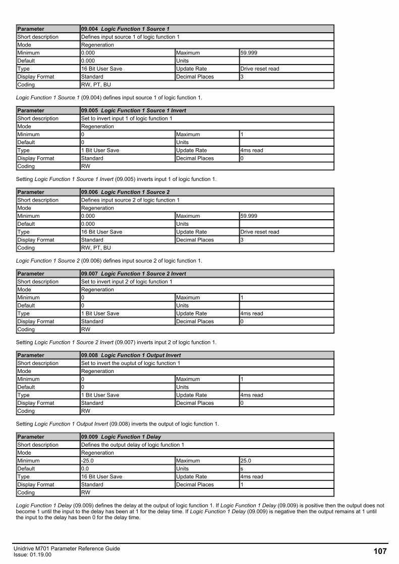
Parameter 09.004 Logic Function 1 Source 1Short description Defines input source 1 of logic function 1Mode RegenerationMinimum 0.000 Maximum 59.999Default 0.000 Units Type 16 Bit User Save Update Rate Drive reset readDisplay Format Standard Decimal Places 3Coding RW, PT, BU
Logic Function 1 Source 1 (09.004) defines input source 1 of logic function 1.
Parameter 09.005 Logic Function 1 Source 1 InvertShort description Set to invert input 1 of logic function 1Mode RegenerationMinimum 0 Maximum 1Default 0 Units Type 1 Bit User Save Update Rate 4ms readDisplay Format Standard Decimal Places 0Coding RW
Setting Logic Function 1 Source 1 Invert (09.005) inverts input 1 of logic function 1.
Parameter 09.006 Logic Function 1 Source 2Short description Defines input source 2 of logic function 1Mode RegenerationMinimum 0.000 Maximum 59.999Default 0.000 Units Type 16 Bit User Save Update Rate Drive reset readDisplay Format Standard Decimal Places 3Coding RW, PT, BU
Logic Function 1 Source 2 (09.006) defines input source 2 of logic function 1.
Parameter 09.007 Logic Function 1 Source 2 InvertShort description Set to invert input 2 of logic function 1Mode RegenerationMinimum 0 Maximum 1Default 0 Units Type 1 Bit User Save Update Rate 4ms readDisplay Format Standard Decimal Places 0Coding RW
Setting Logic Function 1 Source 2 Invert (09.007) inverts input 2 of logic function 1.
Parameter 09.008 Logic Function 1 Output InvertShort description Set to invert the ouptut of logic function 1Mode RegenerationMinimum 0 Maximum 1Default 0 Units Type 1 Bit User Save Update Rate 4ms readDisplay Format Standard Decimal Places 0Coding RW
Setting Logic Function 1 Output Invert (09.008) inverts the output of logic function 1.
Parameter 09.009 Logic Function 1 DelayShort description Defines the output delay of logic function 1Mode RegenerationMinimum -25.0 Maximum 25.0Default 0.0 Units sType 16 Bit User Save Update Rate 4ms readDisplay Format Standard Decimal Places 1Coding RW
Logic Function 1 Delay (09.009) defines the delay at the output of logic function 1. If Logic Function 1 Delay (09.009) is positive then the output does notbecome 1 until the input to the delay has been at 1 for the delay time. If Logic Function 1 Delay (09.009) is negative then the output remains at 1 untilthe input to the delay has been 0 for the delay time.
Unidrive M701 Parameter Reference GuideIssue: 01.19.00 107
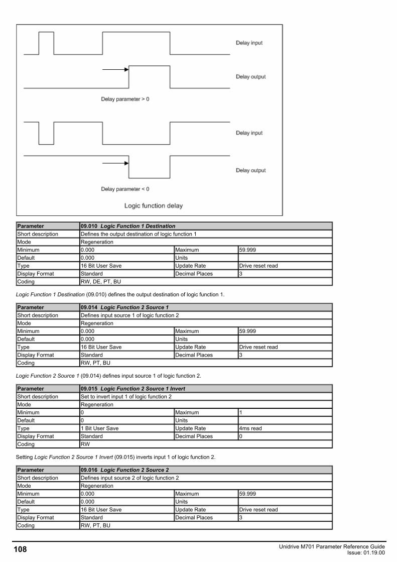
Parameter 09.010 Logic Function 1 DestinationShort description Defines the output destination of logic function 1Mode RegenerationMinimum 0.000 Maximum 59.999Default 0.000 Units Type 16 Bit User Save Update Rate Drive reset readDisplay Format Standard Decimal Places 3Coding RW, DE, PT, BU
Logic Function 1 Destination (09.010) defines the output destination of logic function 1.
Parameter 09.014 Logic Function 2 Source 1Short description Defines input source 1 of logic function 2Mode RegenerationMinimum 0.000 Maximum 59.999Default 0.000 Units Type 16 Bit User Save Update Rate Drive reset readDisplay Format Standard Decimal Places 3Coding RW, PT, BU
Logic Function 2 Source 1 (09.014) defines input source 1 of logic function 2.
Parameter 09.015 Logic Function 2 Source 1 InvertShort description Set to invert input 1 of logic function 2Mode RegenerationMinimum 0 Maximum 1Default 0 Units Type 1 Bit User Save Update Rate 4ms readDisplay Format Standard Decimal Places 0Coding RW
Setting Logic Function 2 Source 1 Invert (09.015) inverts input 1 of logic function 2.
Parameter 09.016 Logic Function 2 Source 2Short description Defines input source 2 of logic function 2Mode RegenerationMinimum 0.000 Maximum 59.999Default 0.000 Units Type 16 Bit User Save Update Rate Drive reset readDisplay Format Standard Decimal Places 3Coding RW, PT, BU
108 Unidrive M701 Parameter Reference GuideIssue: 01.19.00
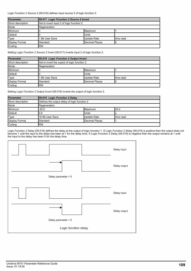
Logic Function 2 Source 2 (09.016) defines input source 2 of logic function 2.
Parameter 09.017 Logic Function 2 Source 2 InvertShort description Set to invert input 2 of logic function 2Mode RegenerationMinimum 0 Maximum 1Default 0 Units Type 1 Bit User Save Update Rate 4ms readDisplay Format Standard Decimal Places 0Coding RW
Setting Logic Function 2 Source 2 Invert (09.017) inverts input 2 of logic function 2.
Parameter 09.018 Logic Function 2 Output InvertShort description Set to invert the ouptut of logic function 2Mode RegenerationMinimum 0 Maximum 1Default 0 Units Type 1 Bit User Save Update Rate 4ms readDisplay Format Standard Decimal Places 0Coding RW
Setting Logic Function 2 Output Invert (09.018) inverts the output of logic function 2.
Parameter 09.019 Logic Function 2 DelayShort description Defines the output delay of logic function 2Mode RegenerationMinimum -25.0 Maximum 25.0Default 0.0 Units sType 16 Bit User Save Update Rate 4ms readDisplay Format Standard Decimal Places 1Coding RW
Logic Function 2 Delay (09.019) defines the delay at the output of logic function 1. If Logic Function 2 Delay (09.019) is positive then the output does notbecome 1 until the input to the delay has been at 1 for the delay time. If Logic Function 2 Delay (09.019) is negative then the output remains at 1 untilthe input to the delay has been 0 for the delay time.
Unidrive M701 Parameter Reference GuideIssue: 01.19.00 109
Parameter 09.020 Logic Function 2 DestinationShort description Defines the output destination of logic function 2Mode RegenerationMinimum 0.000 Maximum 59.999Default 0.000 Units Type 16 Bit User Save Update Rate Drive reset readDisplay Format Standard Decimal Places 3Coding RW, DE, PT, BU
Logic Function 2 Destination (09.020) defines the output destination of logic function 2.
Parameter 09.021 Motorised Pot ModeShort description Defines the motorised pot modeMode RegenerationMinimum 0 Maximum 4Default 0 Units Type 8 Bit User Save Update Rate Background readDisplay Format Standard Decimal Places 0Coding RW
Motorised Pot Mode (09.021) defines the mode of operation as given in the table below.
Motorised Pot Mode(09.021) Motorised Pot Output (09.003) Motorised Pot Up (09.026) and
Motorised Pot Down (09.027) active0 Reset to zero at power-up Always1 Set to power-down value at power-up Always2 Reset to zero at power-up When Drive Active (10.002) = 13 Set to power-down value at power-up When Drive Active (10.002) = 1
4 Reset to zero at power-up and whenDrive Active (10.002) = 0 When Drive Active (10.002) = 1
Parameter 09.022 Motorised Pot Bipolar SelectShort description Set to enable bipolar operation of the motorised potMode RegenerationMinimum 0 Maximum 1Default 0 Units Type 1 Bit User Save Update Rate 4ms readDisplay Format Standard Decimal Places 0Coding RW
If Motorised Pot Bipolar Select (09.022) = 0 then Motorised Pot Output (09.003) is limited in the range 0.00% to 100.00%, otherwise it is allowed tochange in the range from -100.00% to 100.00%.
Parameter 09.023 Motorised Pot RateShort description Defines the rate of change of the motorised pot outputMode RegenerationMinimum 0 Maximum 250Default 20 Units sType 8 Bit User Save Update Rate BackgroundDisplay Format Standard Decimal Places 0Coding RW, BU
The rate of change of Motorised Pot Output (09.003) is defined by Motorised Pot Rate (09.023) which gives the time to change from 0 to 100%. Thetime to change from -100% to 100% is Motorised Pot Rate (09.023) x 2.
Parameter 09.024 Motorised Pot ScalingShort description Defines the scaling factor for the motorised pot outputMode RegenerationMinimum 0.000 Maximum 4.000Default 1.000 Units Type 16 Bit User Save Update Rate 4ms readDisplay Format Standard Decimal Places 3Coding RW
Motorised Pot Scaling (09.024) introduces a scaling factor at the output of the motorised pot before the output is routed to the destination. IfMotorised Pot Scaling (09.024) Motorised Pot Scaling (09.024) > 1.000 the output will exceed the range of the destination parameter, and so thedestination parameter will be at its maximum or minimum before the output of the motorised pot reaches the limits of its range.
110 Unidrive M701 Parameter Reference GuideIssue: 01.19.00
Parameter 09.025 Motorised Pot DestinationShort description Defines the output destination of the motorised potMode RegenerationMinimum 0.000 Maximum 59.999Default 0.000 Units Type 16 Bit User Save Update Rate Drive reset readDisplay Format Standard Decimal Places 3Coding RW, DE, PT, BU
Logic Function 2 Destination (09.020) defines the output destination of the motorised pot function.
Parameter 09.026 Motorised Pot UpShort description Set to increase the motorised pot outputMode RegenerationMinimum 0 Maximum 1Default 0 Units Type 1 Bit Volatile Update Rate 4ms readDisplay Format Standard Decimal Places 0Coding RW, NC
If Motorised Pot Up (09.026) = 1, then the Motorised Pot Output (09.003) will increase.
Parameter 09.027 Motorised Pot DownShort description Set to decrese the motorised pot outputMode RegenerationMinimum 0 Maximum 1Default 0 Units Type 1 Bit Volatile Update Rate 4ms readDisplay Format Standard Decimal Places 0Coding RW, NC
If Motorised Pot Down (09.027) = 1, then the Motorised Pot Output (09.003) will decrease.
Parameter 09.028 Motorised Pot ResetShort description Set to reset the motorised pot output to zeroMode RegenerationMinimum 0 Maximum 1Default 0 Units Type 1 Bit Volatile Update Rate 4ms readDisplay Format Standard Decimal Places 0Coding RW, NC
If Motorised Pot Reset (09.028) = 1 then the motorised pot is disabled and held in its reset state with Motorised Pot Output (09.003) = 0.0%. IfMotorised Pot Reset (09.028) = 0 the motorised pot is enabled even if Motorised Pot Destination (09.025) is not routed to a valid parameter.
Parameter 09.029 Binary Sum OnesShort description Set to add one to the binary sum outputMode RegenerationMinimum 0 Maximum 1Default 0 Units Type 1 Bit Volatile Update Rate 4ms readDisplay Format Standard Decimal Places 0Coding RW, NC
See Binary Sum Output (09.032).
Parameter 09.030 Binary Sum TwosShort description Set to add two to the binary sum outputMode RegenerationMinimum 0 Maximum 1Default 0 Units Type 1 Bit Volatile Update Rate 4ms readDisplay Format Standard Decimal Places 0Coding RW, NC
See Binary Sum Output (09.032).
Unidrive M701 Parameter Reference GuideIssue: 01.19.00 111
Parameter 09.031 Binary Sum FoursShort description Set to add three to the binary sum outputMode RegenerationMinimum 0 Maximum 1Default 0 Units Type 1 Bit Volatile Update Rate 4ms readDisplay Format Standard Decimal Places 0Coding RW, NC
See Binary Sum Output (09.032).
Parameter 09.032 Binary Sum OutputShort description Shows the output level of the binary sumMode RegenerationMinimum 0 Maximum 255Default Units Type 8 Bit Volatile Update Rate 4ms writeDisplay Format Standard Decimal Places 0Coding RO, ND, NC, PT, BU
The output of the binary sum block is given by:
Binary Sum Output (09.032) = Binary Sum Offset (09.034) + (Binary Sum Ones (09.029) x 1) + (Binary Sum Twos (09.030) x 2) +(Binary Sum Fours (09.031) x 4)
Binary Sum Destination (09.033) defines the destination for the binary sum output. The routing for this destination is special if the maximum of thedestination parameter ≤ 7 + Binary Sum Offset (09.034) as follows:
Destination parameter = Binary Sum Output (09.032), subject to the parameter minimum.
If the maximum of the destination parameter > 7, Binary Sum Output (09.032) is routed in the same way as any other destination where the destinationtarget is at its full scale value when the Binary Sum Output (09.032) = 7 + Binary Sum Offset (09.034).
Parameter 09.033 Binary Sum DestinationShort description Defines the output destination of the binary sumMode RegenerationMinimum 0.000 Maximum 59.999Default 0.000 Units Type 16 Bit User Save Update Rate Drive reset readDisplay Format Standard Decimal Places 3Coding RW, DE, PT, BU
Binary Sum Destination (09.033) defines the destination for the binary sum output.
See Binary Sum Output (09.032) for more information.
Parameter 09.034 Binary Sum OffsetShort description Defines the offset added to the output of the binary sumMode RegenerationMinimum 0 Maximum 248Default 0 Units Type 8 Bit User Save Update Rate 4ms readDisplay Format Standard Decimal Places 0Coding RW, BU
See Binary Sum Output (09.032).
Parameter 09.035 Timer 1 Start DateShort description Defines the start date for timer 1Mode Regeneration
Minimum 0(Display: 00-00-00) Maximum 311299
(Display: 31-12-99)
Default 0(Display: 00-00-00) Units
Type 32 Bit User Save Update Rate Background readDisplay Format Date Decimal Places 0Coding RW
Timer 1 Start Date (09.035) defines the start date within the repeat period of timer 1.
See Timer 1 Repeat Function (09.039) for more information.
112 Unidrive M701 Parameter Reference GuideIssue: 01.19.00
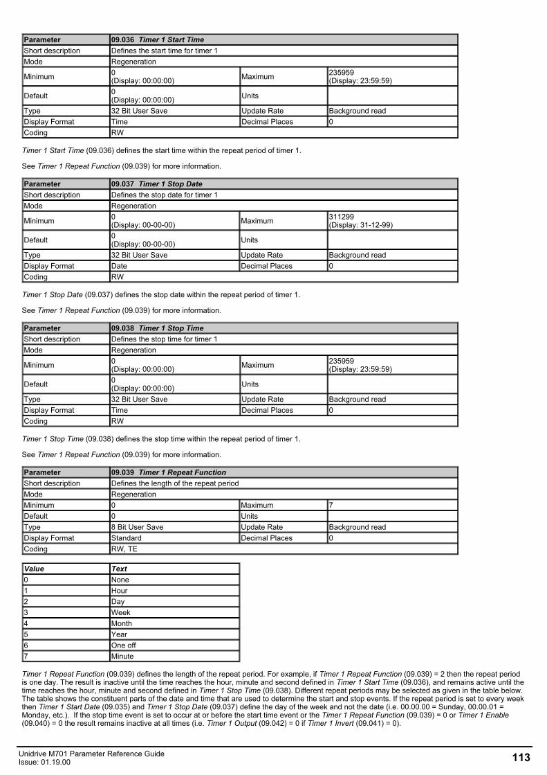
Parameter 09.036 Timer 1 Start TimeShort description Defines the start time for timer 1Mode Regeneration
Minimum 0(Display: 00:00:00) Maximum 235959
(Display: 23:59:59)
Default 0(Display: 00:00:00) Units
Type 32 Bit User Save Update Rate Background readDisplay Format Time Decimal Places 0Coding RW
Timer 1 Start Time (09.036) defines the start time within the repeat period of timer 1.
See Timer 1 Repeat Function (09.039) for more information.
Parameter 09.037 Timer 1 Stop DateShort description Defines the stop date for timer 1Mode Regeneration
Minimum 0(Display: 00-00-00) Maximum 311299
(Display: 31-12-99)
Default 0(Display: 00-00-00) Units
Type 32 Bit User Save Update Rate Background readDisplay Format Date Decimal Places 0Coding RW
Timer 1 Stop Date (09.037) defines the stop date within the repeat period of timer 1.
See Timer 1 Repeat Function (09.039) for more information.
Parameter 09.038 Timer 1 Stop TimeShort description Defines the stop time for timer 1Mode Regeneration
Minimum 0(Display: 00:00:00) Maximum 235959
(Display: 23:59:59)
Default 0(Display: 00:00:00) Units
Type 32 Bit User Save Update Rate Background readDisplay Format Time Decimal Places 0Coding RW
Timer 1 Stop Time (09.038) defines the stop time within the repeat period of timer 1.
See Timer 1 Repeat Function (09.039) for more information.
Parameter 09.039 Timer 1 Repeat FunctionShort description Defines the length of the repeat periodMode RegenerationMinimum 0 Maximum 7Default 0 Units Type 8 Bit User Save Update Rate Background readDisplay Format Standard Decimal Places 0Coding RW, TE
Value Text0 None1 Hour2 Day3 Week4 Month5 Year6 One off7 Minute
Timer 1 Repeat Function (09.039) defines the length of the repeat period. For example, if Timer 1 Repeat Function (09.039) = 2 then the repeat periodis one day. The result is inactive until the time reaches the hour, minute and second defined in Timer 1 Start Time (09.036), and remains active until thetime reaches the hour, minute and second defined in Timer 1 Stop Time (09.038). Different repeat periods may be selected as given in the table below.The table shows the constituent parts of the date and time that are used to determine the start and stop events. If the repeat period is set to every weekthen Timer 1 Start Date (09.035) and Timer 1 Stop Date (09.037) define the day of the week and not the date (i.e. 00.00.00 = Sunday, 00.00.01 =Monday, etc.). If the stop time event is set to occur at or before the start time event or the Timer 1 Repeat Function (09.039) = 0 or Timer 1 Enable(09.040) = 0 the result remains inactive at all times (i.e. Timer 1 Output (09.042) = 0 if Timer 1 Invert (09.041) = 0).
Unidrive M701 Parameter Reference GuideIssue: 01.19.00 113
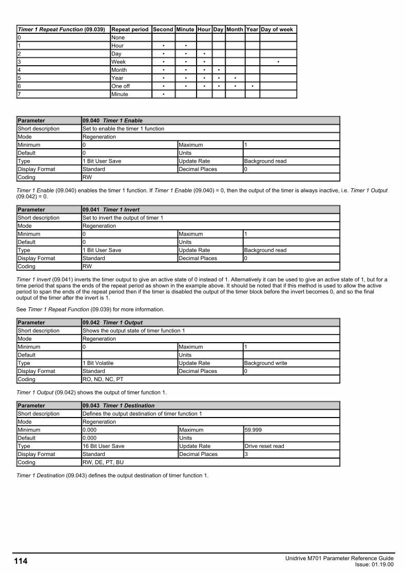
Timer 1 Repeat Function (09.039) Repeat period Second Minute Hour Day Month Year Day of week0 None1 Hour • •2 Day • • •3 Week • • • •4 Month • • • •5 Year • • • • •6 One off • • • • • •7 Minute •
Parameter 09.040 Timer 1 EnableShort description Set to enable the timer 1 functionMode RegenerationMinimum 0 Maximum 1Default 0 Units Type 1 Bit User Save Update Rate Background readDisplay Format Standard Decimal Places 0Coding RW
Timer 1 Enable (09.040) enables the timer 1 function. If Timer 1 Enable (09.040) = 0, then the output of the timer is always inactive, i.e. Timer 1 Output(09.042) = 0.
Parameter 09.041 Timer 1 InvertShort description Set to invert the output of timer 1Mode RegenerationMinimum 0 Maximum 1Default 0 Units Type 1 Bit User Save Update Rate Background readDisplay Format Standard Decimal Places 0Coding RW
Timer 1 Invert (09.041) inverts the timer output to give an active state of 0 instead of 1. Alternatively it can be used to give an active state of 1, but for atime period that spans the ends of the repeat period as shown in the example above. It should be noted that if this method is used to allow the activeperiod to span the ends of the repeat period then if the timer is disabled the output of the timer block before the invert becomes 0, and so the finaloutput of the timer after the invert is 1.
See Timer 1 Repeat Function (09.039) for more information.
Parameter 09.042 Timer 1 OutputShort description Shows the output state of timer function 1Mode RegenerationMinimum 0 Maximum 1Default Units Type 1 Bit Volatile Update Rate Background writeDisplay Format Standard Decimal Places 0Coding RO, ND, NC, PT
Timer 1 Output (09.042) shows the output of timer function 1.
Parameter 09.043 Timer 1 DestinationShort description Defines the output destination of timer function 1Mode RegenerationMinimum 0.000 Maximum 59.999Default 0.000 Units Type 16 Bit User Save Update Rate Drive reset readDisplay Format Standard Decimal Places 3Coding RW, DE, PT, BU
Timer 1 Destination (09.043) defines the output destination of timer function 1.
114 Unidrive M701 Parameter Reference GuideIssue: 01.19.00
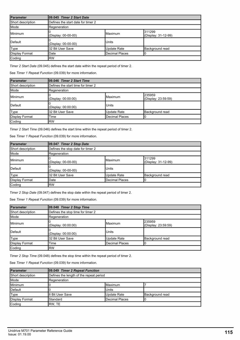
Parameter 09.045 Timer 2 Start DateShort description Defines the start date for timer 2Mode Regeneration
Minimum 0(Display: 00-00-00) Maximum 311299
(Display: 31-12-99)
Default 0(Display: 00-00-00) Units
Type 32 Bit User Save Update Rate Background readDisplay Format Date Decimal Places 0Coding RW
Timer 2 Start Date (09.045) defines the start date within the repeat period of timer 2.
See Timer 1 Repeat Function (09.039) for more information.
Parameter 09.046 Timer 2 Start TimeShort description Defines the start time for timer 2Mode Regeneration
Minimum 0(Display: 00:00:00) Maximum 235959
(Display: 23:59:59)
Default 0(Display: 00:00:00) Units
Type 32 Bit User Save Update Rate Background readDisplay Format Time Decimal Places 0Coding RW
Timer 2 Start Time (09.046) defines the start time within the repeat period of timer 2.
See Timer 1 Repeat Function (09.039) for more information.
Parameter 09.047 Timer 2 Stop DateShort description Defines the stop date for timer 2Mode Regeneration
Minimum 0(Display: 00-00-00) Maximum 311299
(Display: 31-12-99)
Default 0(Display: 00-00-00) Units
Type 32 Bit User Save Update Rate Background readDisplay Format Date Decimal Places 0Coding RW
Timer 2 Stop Date (09.047) defines the stop date within the repeat period of timer 2.
See Timer 1 Repeat Function (09.039) for more information.
Parameter 09.048 Timer 2 Stop TimeShort description Defines the stop time for timer 2Mode Regeneration
Minimum 0(Display: 00:00:00) Maximum 235959
(Display: 23:59:59)
Default 0(Display: 00:00:00) Units
Type 32 Bit User Save Update Rate Background readDisplay Format Time Decimal Places 0Coding RW
Timer 2 Stop Time (09.048) defines the stop time within the repeat period of timer 2.
See Timer 1 Repeat Function (09.039) for more information.
Parameter 09.049 Timer 2 Repeat FunctionShort description Defines the length of the repeat periodMode RegenerationMinimum 0 Maximum 7Default 0 Units Type 8 Bit User Save Update Rate Background readDisplay Format Standard Decimal Places 0Coding RW, TE
Unidrive M701 Parameter Reference GuideIssue: 01.19.00 115
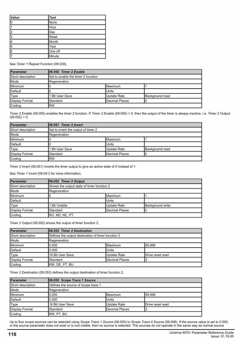
Value Text0 None1 Hour2 Day3 Week4 Month5 Year6 One off7 Minute
See Timer 1 Repeat Function (09.039).
Parameter 09.050 Timer 2 EnableShort description Set to enable the timer 2 functionMode RegenerationMinimum 0 Maximum 1Default 0 Units Type 1 Bit User Save Update Rate Background readDisplay Format Standard Decimal Places 0Coding RW
Timer 2 Enable (09.050) enables the timer 2 function. If Timer 2 Enable (09.050) = 0, then the output of the timer is always inactive, i.e. Timer 2 Output(09.052) = 0.
Parameter 09.051 Timer 2 InvertShort description Set to invert the output of timer 2Mode RegenerationMinimum 0 Maximum 1Default 0 Units Type 1 Bit User Save Update Rate Background readDisplay Format Standard Decimal Places 0Coding RW
Timer 2 Invert (09.051) inverts the timer output to give an active state of 0 instead of 1.
See Timer 1 Invert (09.041) for more information.
Parameter 09.052 Timer 2 OutputShort description Shows the output state of timer function 2Mode RegenerationMinimum 0 Maximum 1Default Units Type 1 Bit Volatile Update Rate Background writeDisplay Format Standard Decimal Places 0Coding RO, ND, NC, PT
Timer 2 Output (09.052) shows the output of timer function 2.
Parameter 09.053 Timer 2 DestinationShort description Defines the output destination of timer function 2Mode RegenerationMinimum 0.000 Maximum 59.999Default 0.000 Units Type 16 Bit User Save Update Rate Drive reset readDisplay Format Standard Decimal Places 3Coding RW, DE, PT, BU
Timer 2 Destination (09.053) defines the output destination of timer function 2.
Parameter 09.055 Scope Trace 1 SourceShort description Defines the source of scope trace 1Mode RegenerationMinimum 0.000 Maximum 59.999Default 0.000 Units Type 16 Bit User Save Update Rate Drive reset readDisplay Format Standard Decimal Places 3Coding RW, PT, BU
Up to four scope sources can be selected using Scope Trace 1 Source (09.055) to Scope Trace 4 Source (09.058). If the source value is set to 0.000,or the source parameter does not exist or is non-visible, then no source is selected. The sources do not operate in the same way as normal source
116 Unidrive M701 Parameter Reference GuideIssue: 01.19.00
parameters in that the input to the scope is the actual value of the parameter and not a value scaled to a percentage based on the range of theparameter. If a scope trace source parameter is modified the actual change is not effective until the drive is reset.
Parameter 09.056 Scope Trace 2 SourceShort description Defines the source of scope trace 2Mode RegenerationMinimum 0.000 Maximum 59.999Default 0.000 Units Type 16 Bit User Save Update Rate Drive reset readDisplay Format Standard Decimal Places 3Coding RW, PT, BU
See Scope Trace 1 Source (09.055).
Parameter 09.057 Scope Trace 3 SourceShort description Defines the source of scope trace 3Mode RegenerationMinimum 0.000 Maximum 59.999Default 0.000 Units Type 16 Bit User Save Update Rate Drive reset readDisplay Format Standard Decimal Places 3Coding RW, PT, BU
See Scope Trace 1 Source (09.055).
Parameter 09.058 Scope Trace 4 SourceShort description Defines the source of scope trace 4Mode RegenerationMinimum 0.000 Maximum 59.999Default 0.000 Units Type 16 Bit User Save Update Rate Drive reset readDisplay Format Standard Decimal Places 3Coding RW, PT, BU
See Scope Trace 1 Source (09.055).
Parameter 09.059 Scope TriggerShort description Set to trigger the scope functionMode RegenerationMinimum 0 Maximum 1Default 0 Units Type 1 Bit Volatile Update Rate 250µs readDisplay Format Standard Decimal Places 0Coding RW
The scope is triggered by a rising edge at the input to the main scope block. If Scope Trigger Source (09.060) is set at its default value of 0.000 then theoutput of the trigger threshold comparator is 0, and so the scope can be triggered with Scope Trigger (09.059). Scope Trigger Invert (09.062) can beused to invert the trigger signal.
Parameter 09.060 Scope Trigger SourceShort description Defines the source of the scope triggerMode RegenerationMinimum 0.000 Maximum 59.999Default 0.000 Units Type 16 Bit User Save Update Rate Background readDisplay Format Standard Decimal Places 3Coding RW, PT, BU
If Scope Trigger (09.059) = 0, the scope can be triggered based on the level of a parameter defined by Scope Trigger Source (09.060) andthe Scope Trigger Threshold (09.061). This source operates in the same way as the trace sources and a direct comparison is made between the actualparameter value and the threshold. Decimal places are ignored. The threshold detector output is 1 when the value from the scope trigger source isgreater than Scope Trigger Threshold (09.061). If Scope Trigger Source (09.060) = 0.000, or it is used to select a parameter that does not exist or isnon-visible, then the output of the threshold detector is 0.
Unidrive M701 Parameter Reference GuideIssue: 01.19.00 117
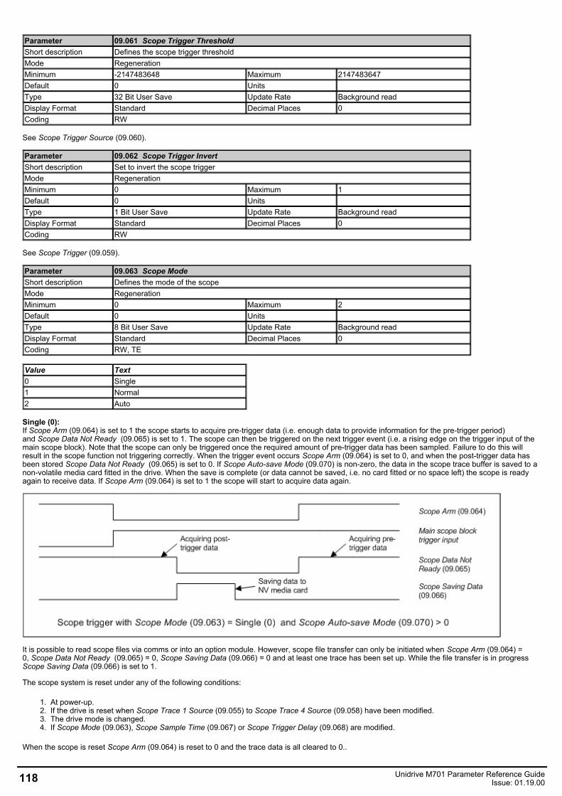
Parameter 09.061 Scope Trigger ThresholdShort description Defines the scope trigger thresholdMode RegenerationMinimum -2147483648 Maximum 2147483647Default 0 Units Type 32 Bit User Save Update Rate Background readDisplay Format Standard Decimal Places 0Coding RW
See Scope Trigger Source (09.060).
Parameter 09.062 Scope Trigger InvertShort description Set to invert the scope triggerMode RegenerationMinimum 0 Maximum 1Default 0 Units Type 1 Bit User Save Update Rate Background readDisplay Format Standard Decimal Places 0Coding RW
See Scope Trigger (09.059).
Parameter 09.063 Scope ModeShort description Defines the mode of the scopeMode RegenerationMinimum 0 Maximum 2Default 0 Units Type 8 Bit User Save Update Rate Background readDisplay Format Standard Decimal Places 0Coding RW, TE
Value Text0 Single1 Normal2 Auto
Single (0):If Scope Arm (09.064) is set to 1 the scope starts to acquire pre-trigger data (i.e. enough data to provide information for the pre-trigger period)and Scope Data Not Ready (09.065) is set to 1. The scope can then be triggered on the next trigger event (i.e. a rising edge on the trigger input of themain scope block). Note that the scope can only be triggered once the required amount of pre-trigger data has been sampled. Failure to do this willresult in the scope function not triggering correctly. When the trigger event occurs Scope Arm (09.064) is set to 0, and when the post-trigger data hasbeen stored Scope Data Not Ready (09.065) is set to 0. If Scope Auto-save Mode (09.070) is non-zero, the data in the scope trace buffer is saved to anon-volatile media card fitted in the drive. When the save is complete (or data cannot be saved, i.e. no card fitted or no space left) the scope is readyagain to receive data. If Scope Arm (09.064) is set to 1 the scope will start to acquire data again.
It is possible to read scope files via comms or into an option module. However, scope file transfer can only be initiated when Scope Arm (09.064) =0, Scope Data Not Ready (09.065) = 0, Scope Saving Data (09.066) = 0 and at least one trace has been set up. While the file transfer is in progressScope Saving Data (09.066) is set to 1.
The scope system is reset under any of the following conditions:
1. At power-up.2. If the drive is reset when Scope Trace 1 Source (09.055) to Scope Trace 4 Source (09.058) have been modified.3. The drive mode is changed.4. If Scope Mode (09.063), Scope Sample Time (09.067) or Scope Trigger Delay (09.068) are modified.
When the scope is reset Scope Arm (09.064) is reset to 0 and the trace data is all cleared to 0..
118 Unidrive M701 Parameter Reference GuideIssue: 01.19.00
Normal (1):The scope operates in the same way as single mode except that Scope Arm (09.064) is automatically set back to 1 after a time delay of 1s once thepost-trigger data has been acquired, and the scope data has been saved to a non-volatile media card if Scope Auto-save Mode (09.070) > 0.
Auto (2):After the scope system is reset Scope Data Not Ready (09.065) is set to 1 and the scope begins to acquire data. Once the buffer is fullScope Data Not Ready (09.065) is set to 0 and the scope continues to acquire data. Scope Arm (09.064) has no effect on data acquisition. ProvidedScope Data Not Ready (09.065) = 0 and Scope Saving Data (09.066) = 0 it is possible to read the data from the scope buffer as a scope file. Dataacquisition is stopped when the file transfer begins. When the file transfer is complete, data acquisition begins again and Scope Data Not Ready (09.065) is set to 1 for a period that is long enough to fill the scope buffer with new data.
Parameter 09.064 Scope ArmShort description Set to arm the scopeMode RegenerationMinimum 0 Maximum 1Default 0 Units Type 1 Bit Volatile Update Rate 250µs readDisplay Format Standard Decimal Places 0Coding RW, NC
See Scope Mode (09.063).
Parameter 09.065 Scope Data Not ReadyShort description Shows that the data in the scope buffer is not ready to be read outMode RegenerationMinimum 0 Maximum 1Default Units Type 1 Bit Volatile Update Rate 250µs writeDisplay Format Standard Decimal Places 0Coding RO, ND, NC, PT
See Scope Mode (09.063).
Parameter 09.066 Scope Saving DataShort description Shows when the scope is saving dataMode RegenerationMinimum 0 Maximum 1Default Units Type 1 Bit Volatile Update Rate Background writeDisplay Format Standard Decimal Places 0Coding RO, ND, NC, PT
See Scope Mode (09.063).
Parameter 09.067 Scope Sample TimeShort description Defines the sample time of the scopeMode RegenerationMinimum 1 Maximum 200Default 1 Units Type 8 Bit User Save Update Rate Background readDisplay Format Standard Decimal Places 0Coding RW, BU
Scope Sample Time (09.067) defines the sample rate of the scope function for all traces in 250μs units (i.e. if Scope Sample Time (09.067) = 4, thesample time is 1ms).
Parameter 09.068 Scope Trigger DelayShort description Defines how much pre-trigger data is stored by the scopeMode RegenerationMinimum 0 Maximum 100Default 0 Units %Type 8 Bit User Save Update Rate Background readDisplay Format Standard Decimal Places 0Coding RW
Scope Trigger Delay (09.068) defines how much data is stored before and after the scope is triggered. If Scope Trigger Delay (09.068) = 0% then nodata is stored before the trigger and all the data is after the trigger. If Scope Trigger Delay (09.068) = 100% then no data is stored after the trigger, butall the data is before the trigger.
Unidrive M701 Parameter Reference GuideIssue: 01.19.00 119
Parameter 09.069 Scope Time PeriodShort description Shows the time period covered by the scope bufferMode RegenerationMinimum 0.00 Maximum 200000.00Default Units msType 32 Bit Volatile Update Rate Background writeDisplay Format Standard Decimal Places 2Coding RO, ND, NC, PT
The scope function can capture up to 4000 bytes of parameter data. The Scope Time Period (09.069) gives the length of the time period covered by thescope buffer in milliseconds which depends on the number of traces stored, the sample time and the size of the parameters used as trace sources.
Sample time in milliseconds = (250 x 10-6 x Scope Sample Time (09.067)) x 1000
Size of trace data is the sum of the number of bytes in each of the trace sources selected by Scope Trace 1 Source (09.055) to Scope Trace 4 Source(09.058).
Scope Time Period (09.069) (ms) = 4000 x Sample time in milliseconds / Size of trace data
Parameter 09.070 Scope Auto-save ModeShort description Defines the mode for auto-saving scope files to the NV media cardMode RegenerationMinimum 0 Maximum 2Default 0 Units Type 8 Bit User Save Update Rate Background readDisplay Format Standard Decimal Places 0Coding RW, TE
Value Text0 Disabled1 Overwrite2 Keep
Auto-save mode can be used to store a scope file on a non-volatile media card at each trigger event. The auto-save system is held in resetif Scope Auto-save Reset (09.072) = 1. When the auto-save system is reset all the scope files in scope file folder on the NV media card aredeleted, Scope Auto-save File Number (09.071) is reset to 0 and the auto-save system is inactive. If any of the file operations fail duringreset Scope Auto-save Status (09.073) is 3 (Failed) when the reset is removed.
The following conditions must be met for auto-saving to be active:
1. Scope Auto-save Mode (09.070) is non-zero2. Scope Auto-save Reset (09.072) = 03. Scope Auto-save Status (09.073) = 1 (Active)4. Scope Mode (09.063) = 0 (Single) or 1 (Normal)
If auto-saving is active an attempt is made to copy the scope file to a non-volatile media card fitted to the drive each time the post-trigger data has beenacquired. The file name is SCP00XY.DAT, where XY is defined by Scope Auto-save File Number (09.071). If Scope Auto-save Mode (09.070) = 1(Overwrite) then a file is over-written if it already exists. If Scope Auto-save Mode (09.070) = 2 (Keep) then if the file already exists the auto-saveprocess is aborted. Scope Auto-save File Number (09.071) is incremented after a file is saved successfully and rolls over to 0 if it exceeds its maximumvalue.
If Scope Auto-save Status (09.073) = 0 (Disabled) and all the other conditions listed above for auto-saving to be active are met, then Scope Auto-save Status (09.073) changes to 1 (Active), so that auto-saving becomes active. If the scope file cannot be saved because the file existsand Scope Auto-save Mode (09.070) = 2 (Keep) then Scope Auto-save Status (09.073) is set to 2 (Stopped). If the scope file cannot be saved for anyother reason then Scope Auto-save Status (09.073) is set to 3 (Failed). If Scope Auto-save Status (09.073) is no longer 1 (Active), auto-saving isaborted. Auto-saving can be made active again by setting Scope Auto-save Reset (09.072) to 1 and then to 0. If Scope Auto-save Mode (09.070) = 0(Disabled) then Scope Auto-save Status (09.073) is set to 0 (Disabled), or if Scope Auto-save Mode (09.070) is non-zero then Scope Auto-save Status(09.073) is set to 1 (Active). It should be noted that Scope Auto-save Status (09.073) is a power-down save parameter, and so auto-save will remaininactive if Scope Auto-save Status (09.073) is 2 or 3 even if the drive is powered down and then powered up again.
Parameter 09.071 Scope Auto-save File NumberShort description Shows the file number to be used for the next auto-saved scope fileMode RegenerationMinimum 0 Maximum 99Default 0 Units Type 8 Bit Power Down Save Update Rate Background read/writeDisplay Format Standard Decimal Places 0Coding RO, NC
See Scope Auto-save Mode (09.070).
120 Unidrive M701 Parameter Reference GuideIssue: 01.19.00
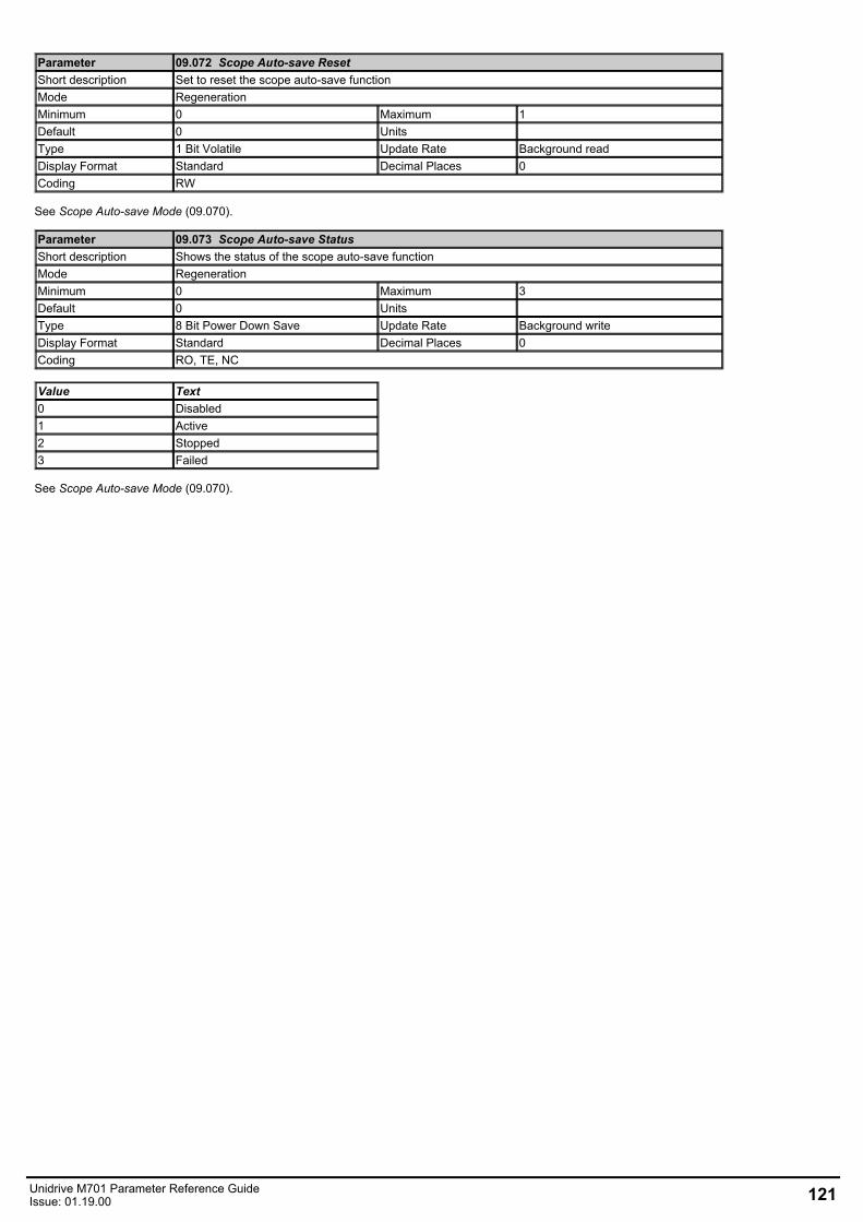
Parameter 09.072 Scope Auto-save ResetShort description Set to reset the scope auto-save functionMode RegenerationMinimum 0 Maximum 1Default 0 Units Type 1 Bit Volatile Update Rate Background readDisplay Format Standard Decimal Places 0Coding RW
See Scope Auto-save Mode (09.070).
Parameter 09.073 Scope Auto-save StatusShort description Shows the status of the scope auto-save functionMode RegenerationMinimum 0 Maximum 3Default 0 Units Type 8 Bit Power Down Save Update Rate Background writeDisplay Format Standard Decimal Places 0Coding RO, TE, NC
Value Text0 Disabled1 Active2 Stopped3 Failed
See Scope Auto-save Mode (09.070).
Unidrive M701 Parameter Reference GuideIssue: 01.19.00 121
Menu 10 Single Line Descriptions − Status and TripsMode: Regeneration
122 Unidrive M701 Parameter Reference GuideIssue: 01.19.00
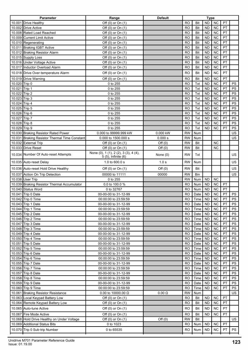
Parameter Range Default Type10.001 Drive Healthy Off (0) or On (1) RO Bit ND NC PT 10.002 Drive Active Off (0) or On (1) RO Bit ND NC PT 10.008 Rated Load Reached Off (0) or On (1) RO Bit ND NC PT 10.009 Current Limit Active Off (0) or On (1) RO Bit ND NC PT 10.010 Regenerating Off (0) or On (1) RO Bit ND NC PT 10.011 Braking IGBT Active Off (0) or On (1) RO Bit ND NC PT 10.012 Braking Resistor Alarm Off (0) or On (1) RO Bit ND NC PT 10.015 Supply Loss Off (0) or On (1) RO Bit ND NC PT 10.016 Under Voltage Active Off (0) or On (1) RO Bit ND NC PT 10.017 Inductor Overload Alarm Off (0) or On (1) RO Bit ND NC PT 10.018 Drive Over‑temperature Alarm Off (0) or On (1) RO Bit ND NC PT
10.019 Drive Warning Off (0) or On (1) RO Bit ND NC PT 10.020 Trip 0 0 to 255 RO Txt ND NC PT PS10.021 Trip 1 0 to 255 RO Txt ND NC PT PS10.022 Trip 2 0 to 255 RO Txt ND NC PT PS10.023 Trip 3 0 to 255 RO Txt ND NC PT PS10.024 Trip 4 0 to 255 RO Txt ND NC PT PS10.025 Trip 5 0 to 255 RO Txt ND NC PT PS10.026 Trip 6 0 to 255 RO Txt ND NC PT PS10.027 Trip 7 0 to 255 RO Txt ND NC PT PS10.028 Trip 8 0 to 255 RO Txt ND NC PT PS10.029 Trip 9 0 to 255 RO Txt ND NC PT PS10.030 Braking Resistor Rated Power 0.000 to 99999.999 kW 0.000 kW RW Num US10.031 Braking Resistor Thermal Time Constant 0.000 to 1500.000 s 0.000 s RW Num US10.032 External Trip Off (0) or On (1) Off (0) RW Bit NC 10.033 Drive Reset Off (0) or On (1) Off (0) RW Bit NC
10.034 Number Of Auto‑reset Attempts None (0), 1 (1), 2 (2), 3 (3), 4 (4),5 (5), Infinite (6) None (0) RW Txt US
10.035 Auto‑reset Delay 1.0 to 600.0 s 1.0 s RW Num US
10.036 Auto‑reset Hold Drive Healthy Off (0) or On (1) Off (0) RW Bit US
10.037 Action On Trip Detection 00000 to 11111 00000 RW Bin US10.038 User Trip 0 to 255 RW Num ND NC 10.039 Braking Resistor Thermal Accumulator 0.0 to 100.0 % RO Num ND NC PT 10.040 Status Word 0 to 32767 RO Num ND NC PT 10.041 Trip 0 Date 00-00-00 to 31-12-99 RO Date ND NC PT PS10.042 Trip 0 Time 00:00:00 to 23:59:59 RO Time ND NC PT PS10.043 Trip 1 Date 00-00-00 to 31-12-99 RO Date ND NC PT PS10.044 Trip 1 Time 00:00:00 to 23:59:59 RO Time ND NC PT PS10.045 Trip 2 Date 00-00-00 to 31-12-99 RO Date ND NC PT PS10.046 Trip 2 Time 00:00:00 to 23:59:59 RO Time ND NC PT PS10.047 Trip 3 Date 00-00-00 to 31-12-99 RO Date ND NC PT PS10.048 Trip 3 Time 00:00:00 to 23:59:59 RO Time ND NC PT PS10.049 Trip 4 Date 00-00-00 to 31-12-99 RO Date ND NC PT PS10.050 Trip 4 Time 00:00:00 to 23:59:59 RO Time ND NC PT PS10.051 Trip 5 Date 00-00-00 to 31-12-99 RO Date ND NC PT PS10.052 Trip 5 Time 00:00:00 to 23:59:59 RO Time ND NC PT PS10.053 Trip 6 Date 00-00-00 to 31-12-99 RO Date ND NC PT PS10.054 Trip 6 Time 00:00:00 to 23:59:59 RO Time ND NC PT PS10.055 Trip 7 Date 00-00-00 to 31-12-99 RO Date ND NC PT PS10.056 Trip 7 Time 00:00:00 to 23:59:59 RO Time ND NC PT PS10.057 Trip 8 Date 00-00-00 to 31-12-99 RO Date ND NC PT PS10.058 Trip 8 Time 00:00:00 to 23:59:59 RO Time ND NC PT PS10.059 Trip 9 Date 00-00-00 to 31-12-99 RO Date ND NC PT PS10.060 Trip 9 Time 00:00:00 to 23:59:59 RO Time ND NC PT PS10.061 Braking Resistor Resistance 0.00 to 10000.00 Ω 0.00 Ω RW Num US10.063 Local Keypad Battery Low Off (0) or On (1) RO Bit ND NC PT 10.064 Remote Keypad Battery Low Off (0) or On (1) RO Bit ND NC PT 10.065 Auto‑tune Active Off (0) or On (1) RO Bit ND NC PT
10.067 Fire Mode Active Off (0) or On (1) RO Bit ND NC PT 10.068 Hold Drive Healthy on Under Voltage Off (0) or On (1) Off (0) RW Bit US10.069 Additional Status Bits 0 to 1023 RO Num ND NC PT 10.070 Trip 0 Sub‑trip Number 0 to 65535 RO Num ND NC PT PS
Unidrive M701 Parameter Reference GuideIssue: 01.19.00 123
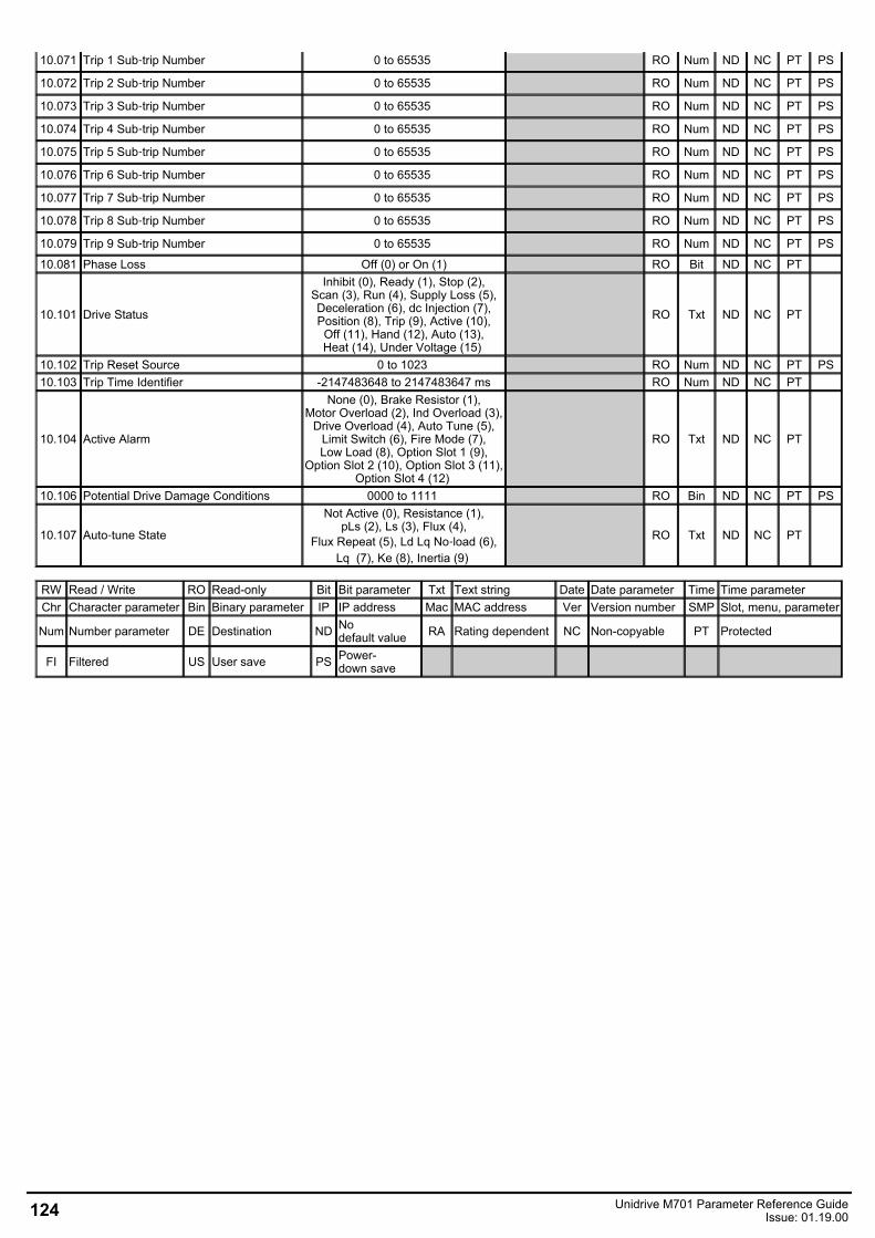
10.071 Trip 1 Sub‑trip Number 0 to 65535 RO Num ND NC PT PS
10.072 Trip 2 Sub‑trip Number 0 to 65535 RO Num ND NC PT PS
10.073 Trip 3 Sub‑trip Number 0 to 65535 RO Num ND NC PT PS
10.074 Trip 4 Sub‑trip Number 0 to 65535 RO Num ND NC PT PS
10.075 Trip 5 Sub‑trip Number 0 to 65535 RO Num ND NC PT PS
10.076 Trip 6 Sub‑trip Number 0 to 65535 RO Num ND NC PT PS
10.077 Trip 7 Sub‑trip Number 0 to 65535 RO Num ND NC PT PS
10.078 Trip 8 Sub‑trip Number 0 to 65535 RO Num ND NC PT PS
10.079 Trip 9 Sub‑trip Number 0 to 65535 RO Num ND NC PT PS
10.081 Phase Loss Off (0) or On (1) RO Bit ND NC PT
10.101 Drive Status
Inhibit (0), Ready (1), Stop (2),Scan (3), Run (4), Supply Loss (5),Deceleration (6), dc Injection (7),Position (8), Trip (9), Active (10),Off (11), Hand (12), Auto (13),Heat (14), Under Voltage (15)
RO Txt ND NC PT
10.102 Trip Reset Source 0 to 1023 RO Num ND NC PT PS10.103 Trip Time Identifier -2147483648 to 2147483647 ms RO Num ND NC PT
10.104 Active Alarm
None (0), Brake Resistor (1),Motor Overload (2), Ind Overload (3),
Drive Overload (4), Auto Tune (5),Limit Switch (6), Fire Mode (7),Low Load (8), Option Slot 1 (9),
Option Slot 2 (10), Option Slot 3 (11),Option Slot 4 (12)
RO Txt ND NC PT
10.106 Potential Drive Damage Conditions 0000 to 1111 RO Bin ND NC PT PS
10.107 Auto‑tune State
Not Active (0), Resistance (1),pLs (2), Ls (3), Flux (4),
Flux Repeat (5), Ld Lq No‑load (6),Lq (7), Ke (8), Inertia (9)
RO Txt ND NC PT
RW Read / Write RO Read-only Bit Bit parameter Txt Text string Date Date parameter Time Time parameterChr Character parameter Bin Binary parameter IP IP address Mac MAC address Ver Version number SMP Slot, menu, parameter
Num Number parameter DE Destination ND Nodefault value RA Rating dependent NC Non-copyable PT Protected
FI Filtered US User save PS Power-down save
124 Unidrive M701 Parameter Reference GuideIssue: 01.19.00
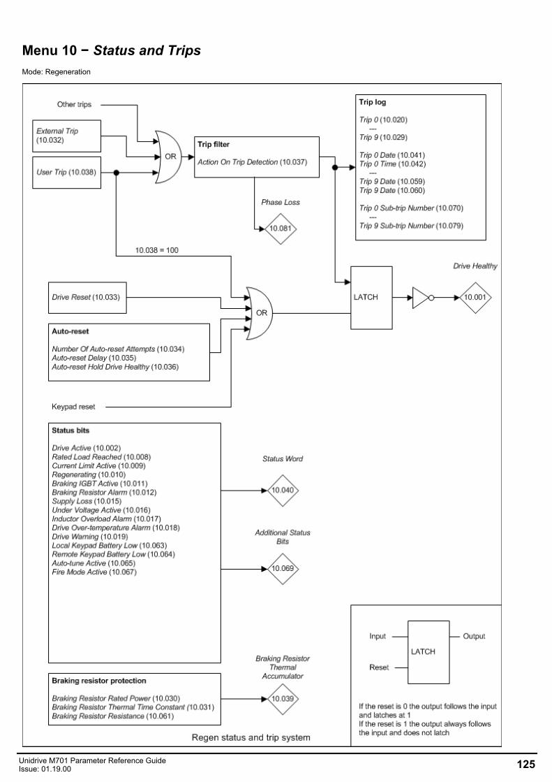
Menu 10 − Status and TripsMode: Regeneration
Unidrive M701 Parameter Reference GuideIssue: 01.19.00 125
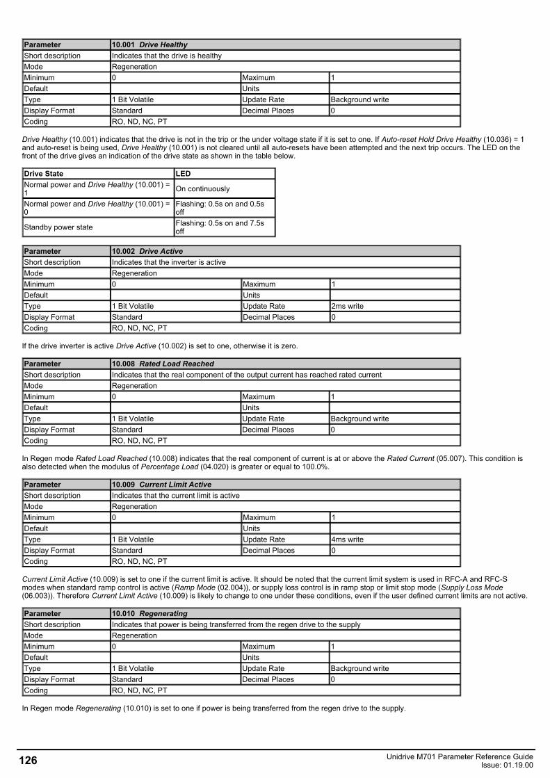
Parameter 10.001 Drive HealthyShort description Indicates that the drive is healthyMode RegenerationMinimum 0 Maximum 1Default Units Type 1 Bit Volatile Update Rate Background writeDisplay Format Standard Decimal Places 0Coding RO, ND, NC, PT
Drive Healthy (10.001) indicates that the drive is not in the trip or the under voltage state if it is set to one. If Auto-reset Hold Drive Healthy (10.036) = 1and auto-reset is being used, Drive Healthy (10.001) is not cleared until all auto-resets have been attempted and the next trip occurs. The LED on thefront of the drive gives an indication of the drive state as shown in the table below.
Drive State LEDNormal power and Drive Healthy (10.001) =1 On continuously
Normal power and Drive Healthy (10.001) =0
Flashing: 0.5s on and 0.5soff
Standby power state Flashing: 0.5s on and 7.5soff
Parameter 10.002 Drive ActiveShort description Indicates that the inverter is activeMode RegenerationMinimum 0 Maximum 1Default Units Type 1 Bit Volatile Update Rate 2ms writeDisplay Format Standard Decimal Places 0Coding RO, ND, NC, PT
If the drive inverter is active Drive Active (10.002) is set to one, otherwise it is zero.
Parameter 10.008 Rated Load ReachedShort description Indicates that the real component of the output current has reached rated currentMode RegenerationMinimum 0 Maximum 1Default Units Type 1 Bit Volatile Update Rate Background writeDisplay Format Standard Decimal Places 0Coding RO, ND, NC, PT
In Regen mode Rated Load Reached (10.008) indicates that the real component of current is at or above the Rated Current (05.007). This condition isalso detected when the modulus of Percentage Load (04.020) is greater or equal to 100.0%.
Parameter 10.009 Current Limit ActiveShort description Indicates that the current limit is activeMode RegenerationMinimum 0 Maximum 1Default Units Type 1 Bit Volatile Update Rate 4ms writeDisplay Format Standard Decimal Places 0Coding RO, ND, NC, PT
Current Limit Active (10.009) is set to one if the current limit is active. It should be noted that the current limit system is used in RFC-A and RFC-Smodes when standard ramp control is active (Ramp Mode (02.004)), or supply loss control is in ramp stop or limit stop mode (Supply Loss Mode(06.003)). Therefore Current Limit Active (10.009) is likely to change to one under these conditions, even if the user defined current limits are not active.
Parameter 10.010 RegeneratingShort description Indicates that power is being transferred from the regen drive to the supplyMode RegenerationMinimum 0 Maximum 1Default Units Type 1 Bit Volatile Update Rate Background writeDisplay Format Standard Decimal Places 0Coding RO, ND, NC, PT
In Regen mode Regenerating (10.010) is set to one if power is being transferred from the regen drive to the supply.
126 Unidrive M701 Parameter Reference GuideIssue: 01.19.00
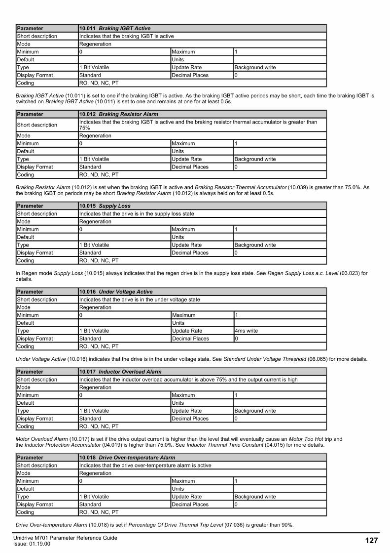
Parameter 10.011 Braking IGBT ActiveShort description Indicates that the braking IGBT is activeMode RegenerationMinimum 0 Maximum 1Default Units Type 1 Bit Volatile Update Rate Background writeDisplay Format Standard Decimal Places 0Coding RO, ND, NC, PT
Braking IGBT Active (10.011) is set to one if the braking IGBT is active. As the braking IGBT active periods may be short, each time the braking IGBT isswitched on Braking IGBT Active (10.011) is set to one and remains at one for at least 0.5s.
Parameter 10.012 Braking Resistor Alarm
Short description Indicates that the braking IGBT is active and the braking resistor thermal accumulator is greater than75%
Mode RegenerationMinimum 0 Maximum 1Default Units Type 1 Bit Volatile Update Rate Background writeDisplay Format Standard Decimal Places 0Coding RO, ND, NC, PT
Braking Resistor Alarm (10.012) is set when the braking IGBT is active and Braking Resistor Thermal Accumulator (10.039) is greater than 75.0%. Asthe braking IGBT on periods may be short Braking Resistor Alarm (10.012) is always held on for at least 0.5s.
Parameter 10.015 Supply LossShort description Indicates that the drive is in the supply loss stateMode RegenerationMinimum 0 Maximum 1Default Units Type 1 Bit Volatile Update Rate Background writeDisplay Format Standard Decimal Places 0Coding RO, ND, NC, PT
In Regen mode Supply Loss (10.015) always indicates that the regen drive is in the supply loss state. See Regen Supply Loss a.c. Level (03.023) fordetails.
Parameter 10.016 Under Voltage ActiveShort description Indicates that the drive is in the under voltage stateMode RegenerationMinimum 0 Maximum 1Default Units Type 1 Bit Volatile Update Rate 4ms writeDisplay Format Standard Decimal Places 0Coding RO, ND, NC, PT
Under Voltage Active (10.016) indicates that the drive is in the under voltage state. See Standard Under Voltage Threshold (06.065) for more details.
Parameter 10.017 Inductor Overload AlarmShort description Indicates that the inductor overload accumulator is above 75% and the output current is highMode RegenerationMinimum 0 Maximum 1Default Units Type 1 Bit Volatile Update Rate Background writeDisplay Format Standard Decimal Places 0Coding RO, ND, NC, PT
Motor Overload Alarm (10.017) is set if the drive output current is higher than the level that will eventually cause an Motor Too Hot trip andthe Inductor Protection Accumulator (04.019) is higher than 75.0%. See Inductor Thermal Time Constant (04.015) for more details.
Parameter 10.018 Drive Over-temperature AlarmShort description Indicates that the drive over-temperature alarm is activeMode RegenerationMinimum 0 Maximum 1Default Units Type 1 Bit Volatile Update Rate Background writeDisplay Format Standard Decimal Places 0Coding RO, ND, NC, PT
Drive Over-temperature Alarm (10.018) is set if Percentage Of Drive Thermal Trip Level (07.036) is greater than 90%.
Unidrive M701 Parameter Reference GuideIssue: 01.19.00 127
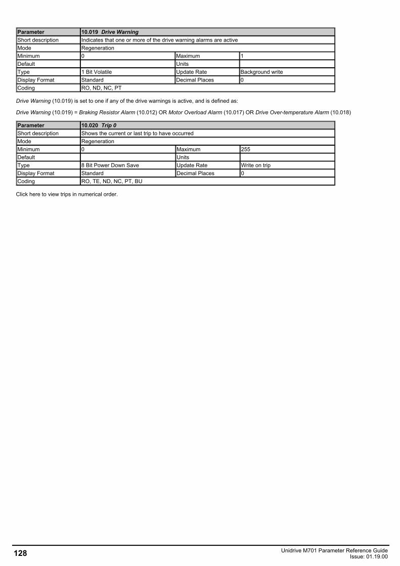
Parameter 10.019 Drive WarningShort description Indicates that one or more of the drive warning alarms are activeMode RegenerationMinimum 0 Maximum 1Default Units Type 1 Bit Volatile Update Rate Background writeDisplay Format Standard Decimal Places 0Coding RO, ND, NC, PT
Drive Warning (10.019) is set to one if any of the drive warnings is active, and is defined as:
Drive Warning (10.019) = Braking Resistor Alarm (10.012) OR Motor Overload Alarm (10.017) OR Drive Over-temperature Alarm (10.018)
Parameter 10.020 Trip 0Short description Shows the current or last trip to have occurredMode RegenerationMinimum 0 Maximum 255Default Units Type 8 Bit Power Down Save Update Rate Write on tripDisplay Format Standard Decimal Places 0Coding RO, TE, ND, NC, PT, BU
Click here to view trips in numerical order.
128 Unidrive M701 Parameter Reference GuideIssue: 01.19.00
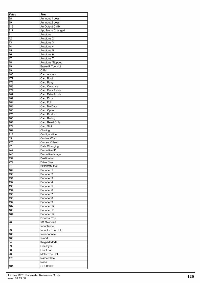
Value Text28 An Input 1 Loss29 An Input 2 Loss219 An Output Calib217 App Menu Changed11 Autotune 112 Autotune 213 Autotune 314 Autotune 415 Autotune 516 Autotune 617 Autotune 718 Autotune Stopped19 Brake R Too Hot99 CAM185 Card Access177 Card Boot178 Card Busy188 Card Compare179 Card Data Exists187 Card Drive Mode182 Card Error184 Card Full183 Card No Data180 Card Option175 Card Product186 Card Rating181 Card Read Only174 Card Slot102 Cloning111 Configuration35 Control Word225 Current Offset97 Data Changing247 Derivative ID248 Derivative Image199 Destination224 Drive Size31 EEPROM Fail189 Encoder 1190 Encoder 2191 Encoder 3192 Encoder 4193 Encoder 5194 Encoder 6195 Encoder 7196 Encoder 8197 Encoder 9162 Encoder 12163 Encoder 13164 Encoder 146 External Trip26 I/O Overload8 Inductance93 Inductor Too Hot103 Inter-connect160 Island34 Keypad Mode39 Line Sync38 Low Load20 Motor Too Hot176 Name Plate0 None101 OHt Brake
Unidrive M701 Parameter Reference GuideIssue: 01.19.00 129
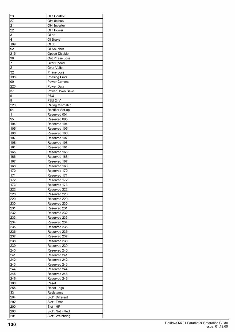
23 OHt Control27 OHt dc bus21 OHt Inverter22 OHt Power3 OI ac4 OI Brake109 OI dc92 OI Snubber215 Option Disable98 Out Phase Loss7 Over Speed2 Over Volts32 Phase Loss198 Phasing Error90 Power Comms220 Power Data37 Power Down Save5 PSU9 PSU 24V223 Rating Mismatch94 Rectifier Set-up1 Reserved 00195 Reserved 095104 Reserved 104105 Reserved 105106 Reserved 106107 Reserved 107108 Reserved 108161 Reserved 161165 Reserved 165166 Reserved 166167 Reserved 167168 Reserved 168170 Reserved 170171 Reserved 171172 Reserved 172173 Reserved 173222 Reserved 222228 Reserved 228229 Reserved 229230 Reserved 230231 Reserved 231232 Reserved 232233 Reserved 233234 Reserved 234235 Reserved 235236 Reserved 236237 Reserved 237238 Reserved 238239 Reserved 239240 Reserved 240241 Reserved 241242 Reserved 242243 Reserved 243244 Reserved 244245 Reserved 245246 Reserved 246100 Reset255 Reset Logs33 Resistance204 Slot1 Different202 Slot1 Error200 Slot1 HF203 Slot1 Not Fitted201 Slot1 Watchdog
130 Unidrive M701 Parameter Reference GuideIssue: 01.19.00
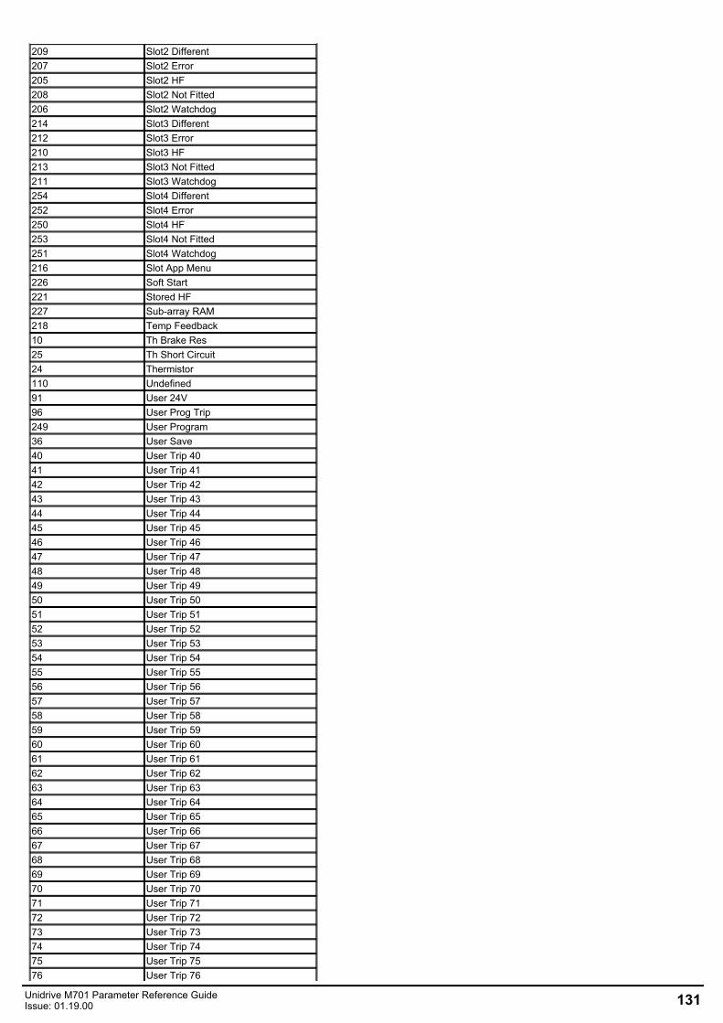
209 Slot2 Different207 Slot2 Error205 Slot2 HF208 Slot2 Not Fitted206 Slot2 Watchdog214 Slot3 Different212 Slot3 Error210 Slot3 HF213 Slot3 Not Fitted211 Slot3 Watchdog254 Slot4 Different252 Slot4 Error250 Slot4 HF253 Slot4 Not Fitted251 Slot4 Watchdog216 Slot App Menu226 Soft Start221 Stored HF227 Sub-array RAM218 Temp Feedback10 Th Brake Res25 Th Short Circuit24 Thermistor110 Undefined91 User 24V96 User Prog Trip249 User Program36 User Save40 User Trip 4041 User Trip 4142 User Trip 4243 User Trip 4344 User Trip 4445 User Trip 4546 User Trip 4647 User Trip 4748 User Trip 4849 User Trip 4950 User Trip 5051 User Trip 5152 User Trip 5253 User Trip 5354 User Trip 5455 User Trip 5556 User Trip 5657 User Trip 5758 User Trip 5859 User Trip 5960 User Trip 6061 User Trip 6162 User Trip 6263 User Trip 6364 User Trip 6465 User Trip 6566 User Trip 6667 User Trip 6768 User Trip 6869 User Trip 6970 User Trip 7071 User Trip 7172 User Trip 7273 User Trip 7374 User Trip 7475 User Trip 7576 User Trip 76
Unidrive M701 Parameter Reference GuideIssue: 01.19.00 131
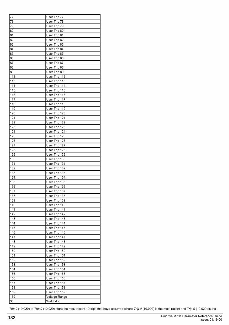
77 User Trip 7778 User Trip 7879 User Trip 7980 User Trip 8081 User Trip 8182 User Trip 8283 User Trip 8384 User Trip 8485 User Trip 8586 User Trip 8687 User Trip 8788 User Trip 8889 User Trip 89112 User Trip 112113 User Trip 113114 User Trip 114115 User Trip 115116 User Trip 116117 User Trip 117118 User Trip 118119 User Trip 119120 User Trip 120121 User Trip 121122 User Trip 122123 User Trip 123124 User Trip 124125 User Trip 125126 User Trip 126127 User Trip 127128 User Trip 128129 User Trip 129130 User Trip 130131 User Trip 131132 User Trip 132133 User Trip 133134 User Trip 134135 User Trip 135136 User Trip 136137 User Trip 137138 User Trip 138139 User Trip 139140 User Trip 140141 User Trip 141142 User Trip 142143 User Trip 143144 User Trip 144145 User Trip 145146 User Trip 146147 User Trip 147148 User Trip 148149 User Trip 149150 User Trip 150151 User Trip 151152 User Trip 152153 User Trip 153154 User Trip 154155 User Trip 155156 User Trip 156157 User Trip 157158 User Trip 158159 User Trip 159169 Voltage Range30 Watchdog
Trip 0 (10.020) to Trip 9 (10.029) store the most recent 10 trips that have occurred where Trip 0 (10.020) is the most recent and Trip 9 (10.029) is the
132 Unidrive M701 Parameter Reference GuideIssue: 01.19.00
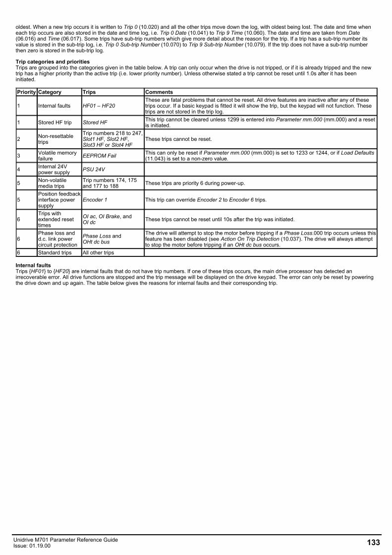
oldest. When a new trip occurs it is written to Trip 0 (10.020) and all the other trips move down the log, with oldest being lost. The date and time wheneach trip occurs are also stored in the date and time log, i.e. Trip 0 Date (10.041) to Trip 9 Time (10.060). The date and time are taken from Date(06.016) and Time (06.017). Some trips have sub-trip numbers which give more detail about the reason for the trip. If a trip has a sub-trip number itsvalue is stored in the sub-trip log, i.e. Trip 0 Sub-trip Number (10.070) to Trip 9 Sub-trip Number (10.079). If the trip does not have a sub-trip numberthen zero is stored in the sub-trip log.
Trip categories and prioritiesTrips are grouped into the categories given in the table below. A trip can only occur when the drive is not tripped, or if it is already tripped and the newtrip has a higher priority than the active trip (i.e. lower priority number). Unless otherwise stated a trip cannot be reset until 1.0s after it has beeninitiated.
Priority Category Trips Comments
1 Internal faults HF01 – HF20These are fatal problems that cannot be reset. All drive features are inactive after any of thesetrips occur. If a basic keypad is fitted it will show the trip, but the keypad will not function. Thesetrips are not stored in the trip log.
1 Stored HF trip Stored HF This trip cannot be cleared unless 1299 is entered into Parameter mm.000 (mm.000) and a resetis initiated.
2 Non-resettabletrips
Trip numbers 218 to 247,Slot1 HF, Slot2 HF,Slot3 HF or Slot4 HF
These trips cannot be reset.
3 Volatile memoryfailure EEPROM Fail This can only be reset if Parameter mm.000 (mm.000) is set to 1233 or 1244, or if Load Defaults
(11.043) is set to a non-zero value.
4 Internal 24Vpower supply PSU 24V
5 Non-volatilemedia trips
Trip numbers 174, 175and 177 to 188 These trips are priority 6 during power-up.
5Position feedbackinterface powersupply
Encoder 1 This trip can override Encoder 2 to Encoder 6 trips.
6Trips withextended resettimes
OI ac, OI Brake, andOI dc These trips cannot be reset until 10s after the trip was initiated.
6Phase loss andd.c. link powercircuit protection
Phase Loss andOHt dc bus
The drive will attempt to stop the motor before tripping if a Phase Loss.000 trip occurs unless thisfeature has been disabled (see Action On Trip Detection (10.037). The drive will always attemptto stop the motor before tripping if an OHt dc bus occurs.
6 Standard trips All other trips
Internal faultsTrips HF01 to HF20 are internal faults that do not have trip numbers. If one of these trips occurs, the main drive processor has detected anirrecoverable error. All drive functions are stopped and the trip message will be displayed on the drive keypad. The error can only be reset by poweringthe drive down and up again. The table below gives the reasons for internal faults and their corresponding trip.
Unidrive M701 Parameter Reference GuideIssue: 01.19.00 133
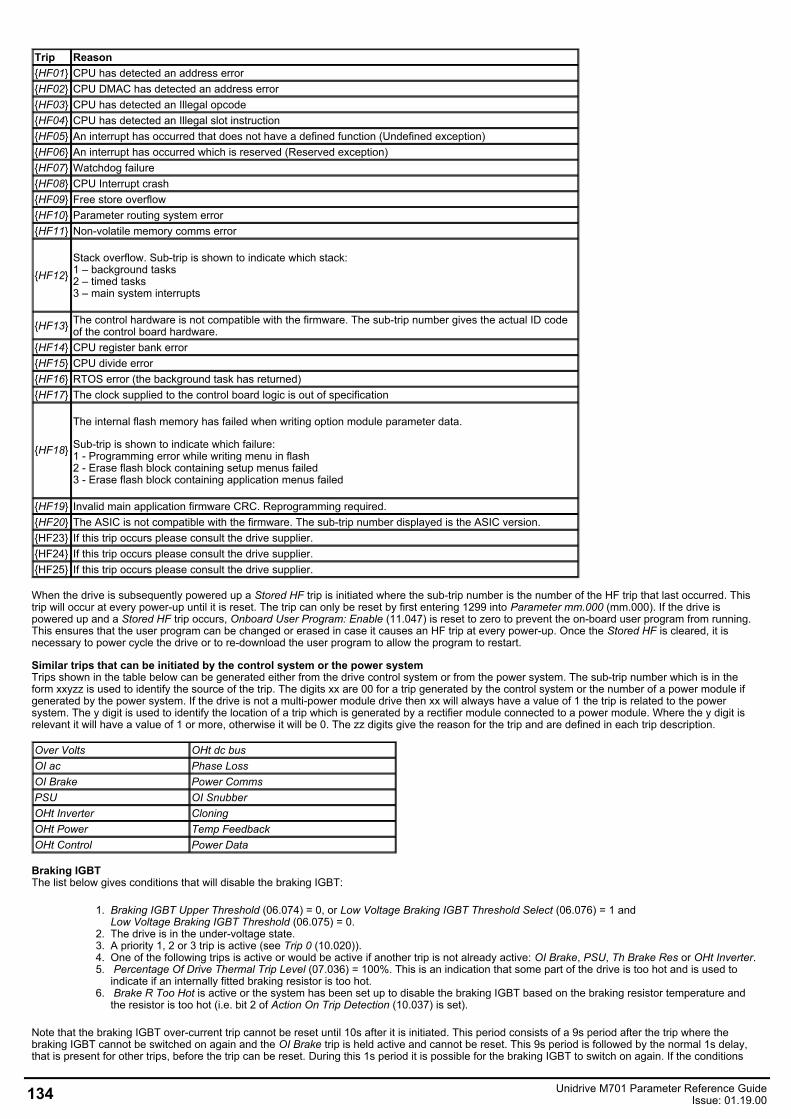
Trip ReasonHF01 CPU has detected an address errorHF02 CPU DMAC has detected an address errorHF03 CPU has detected an Illegal opcodeHF04 CPU has detected an Illegal slot instructionHF05 An interrupt has occurred that does not have a defined function (Undefined exception)HF06 An interrupt has occurred which is reserved (Reserved exception)HF07 Watchdog failureHF08 CPU Interrupt crashHF09 Free store overflowHF10 Parameter routing system errorHF11 Non-volatile memory comms error
HF12Stack overflow. Sub-trip is shown to indicate which stack:1 – background tasks2 – timed tasks3 – main system interrupts
HF13 The control hardware is not compatible with the firmware. The sub-trip number gives the actual ID codeof the control board hardware.
HF14 CPU register bank errorHF15 CPU divide errorHF16 RTOS error (the background task has returned)HF17 The clock supplied to the control board logic is out of specification
HF18
The internal flash memory has failed when writing option module parameter data.
Sub-trip is shown to indicate which failure:1 - Programming error while writing menu in flash2 - Erase flash block containing setup menus failed3 - Erase flash block containing application menus failed
HF19 Invalid main application firmware CRC. Reprogramming required.HF20 The ASIC is not compatible with the firmware. The sub-trip number displayed is the ASIC version.HF23 If this trip occurs please consult the drive supplier. HF24 If this trip occurs please consult the drive supplier. HF25 If this trip occurs please consult the drive supplier.
When the drive is subsequently powered up a Stored HF trip is initiated where the sub-trip number is the number of the HF trip that last occurred. Thistrip will occur at every power-up until it is reset. The trip can only be reset by first entering 1299 into Parameter mm.000 (mm.000). If the drive ispowered up and a Stored HF trip occurs, Onboard User Program: Enable (11.047) is reset to zero to prevent the on-board user program from running.This ensures that the user program can be changed or erased in case it causes an HF trip at every power-up. Once the Stored HF is cleared, it isnecessary to power cycle the drive or to re-download the user program to allow the program to restart.
Similar trips that can be initiated by the control system or the power systemTrips shown in the table below can be generated either from the drive control system or from the power system. The sub-trip number which is in theform xxyzz is used to identify the source of the trip. The digits xx are 00 for a trip generated by the control system or the number of a power module ifgenerated by the power system. If the drive is not a multi-power module drive then xx will always have a value of 1 the trip is related to the powersystem. The y digit is used to identify the location of a trip which is generated by a rectifier module connected to a power module. Where the y digit isrelevant it will have a value of 1 or more, otherwise it will be 0. The zz digits give the reason for the trip and are defined in each trip description.
Over Volts OHt dc busOI ac Phase LossOI Brake Power CommsPSU OI SnubberOHt Inverter CloningOHt Power Temp FeedbackOHt Control Power Data
Braking IGBTThe list below gives conditions that will disable the braking IGBT:
1. Braking IGBT Upper Threshold (06.074) = 0, or Low Voltage Braking IGBT Threshold Select (06.076) = 1 andLow Voltage Braking IGBT Threshold (06.075) = 0.
2. The drive is in the under-voltage state.3. A priority 1, 2 or 3 trip is active (see Trip 0 (10.020)).4. One of the following trips is active or would be active if another trip is not already active: OI Brake, PSU, Th Brake Res or OHt Inverter. 5. Percentage Of Drive Thermal Trip Level (07.036) = 100%. This is an indication that some part of the drive is too hot and is used to
indicate if an internally fitted braking resistor is too hot.6. Brake R Too Hot is active or the system has been set up to disable the braking IGBT based on the braking resistor temperature and
the resistor is too hot (i.e. bit 2 of Action On Trip Detection (10.037) is set).
Note that the braking IGBT over-current trip cannot be reset until 10s after it is initiated. This period consists of a 9s period after the trip where thebraking IGBT cannot be switched on again and the OI Brake trip is held active and cannot be reset. This 9s period is followed by the normal 1s delay,that is present for other trips, before the trip can be reset. During this 1s period it is possible for the braking IGBT to switch on again. If the conditions
134 Unidrive M701 Parameter Reference GuideIssue: 01.19.00
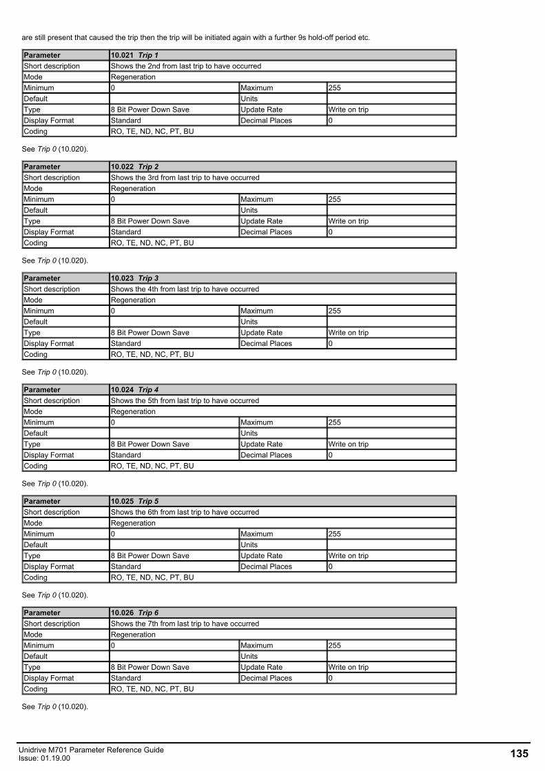
are still present that caused the trip then the trip will be initiated again with a further 9s hold-off period etc.
Parameter 10.021 Trip 1Short description Shows the 2nd from last trip to have occurredMode RegenerationMinimum 0 Maximum 255Default Units Type 8 Bit Power Down Save Update Rate Write on tripDisplay Format Standard Decimal Places 0Coding RO, TE, ND, NC, PT, BU
See Trip 0 (10.020).
Parameter 10.022 Trip 2Short description Shows the 3rd from last trip to have occurredMode RegenerationMinimum 0 Maximum 255Default Units Type 8 Bit Power Down Save Update Rate Write on tripDisplay Format Standard Decimal Places 0Coding RO, TE, ND, NC, PT, BU
See Trip 0 (10.020).
Parameter 10.023 Trip 3Short description Shows the 4th from last trip to have occurredMode RegenerationMinimum 0 Maximum 255Default Units Type 8 Bit Power Down Save Update Rate Write on tripDisplay Format Standard Decimal Places 0Coding RO, TE, ND, NC, PT, BU
See Trip 0 (10.020).
Parameter 10.024 Trip 4Short description Shows the 5th from last trip to have occurredMode RegenerationMinimum 0 Maximum 255Default Units Type 8 Bit Power Down Save Update Rate Write on tripDisplay Format Standard Decimal Places 0Coding RO, TE, ND, NC, PT, BU
See Trip 0 (10.020).
Parameter 10.025 Trip 5Short description Shows the 6th from last trip to have occurredMode RegenerationMinimum 0 Maximum 255Default Units Type 8 Bit Power Down Save Update Rate Write on tripDisplay Format Standard Decimal Places 0Coding RO, TE, ND, NC, PT, BU
See Trip 0 (10.020).
Parameter 10.026 Trip 6Short description Shows the 7th from last trip to have occurredMode RegenerationMinimum 0 Maximum 255Default Units Type 8 Bit Power Down Save Update Rate Write on tripDisplay Format Standard Decimal Places 0Coding RO, TE, ND, NC, PT, BU
See Trip 0 (10.020).
Unidrive M701 Parameter Reference GuideIssue: 01.19.00 135
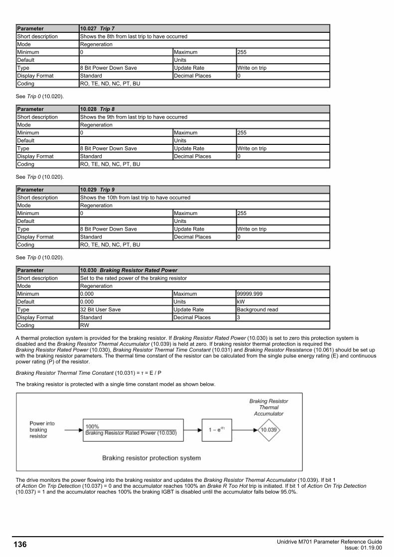
Parameter 10.027 Trip 7Short description Shows the 8th from last trip to have occurredMode RegenerationMinimum 0 Maximum 255Default Units Type 8 Bit Power Down Save Update Rate Write on tripDisplay Format Standard Decimal Places 0Coding RO, TE, ND, NC, PT, BU
See Trip 0 (10.020).
Parameter 10.028 Trip 8Short description Shows the 9th from last trip to have occurredMode RegenerationMinimum 0 Maximum 255Default Units Type 8 Bit Power Down Save Update Rate Write on tripDisplay Format Standard Decimal Places 0Coding RO, TE, ND, NC, PT, BU
See Trip 0 (10.020).
Parameter 10.029 Trip 9Short description Shows the 10th from last trip to have occurredMode RegenerationMinimum 0 Maximum 255Default Units Type 8 Bit Power Down Save Update Rate Write on tripDisplay Format Standard Decimal Places 0Coding RO, TE, ND, NC, PT, BU
See Trip 0 (10.020).
Parameter 10.030 Braking Resistor Rated PowerShort description Set to the rated power of the braking resistorMode RegenerationMinimum 0.000 Maximum 99999.999Default 0.000 Units kWType 32 Bit User Save Update Rate Background readDisplay Format Standard Decimal Places 3Coding RW
A thermal protection system is provided for the braking resistor. If Braking Resistor Rated Power (10.030) is set to zero this protection system isdisabled and the Braking Resistor Thermal Accumulator (10.039) is held at zero. If braking resistor thermal protection is required theBraking Resistor Rated Power (10.030), Braking Resistor Thermal Time Constant (10.031) and Braking Resistor Resistance (10.061) should be set upwith the braking resistor parameters. The thermal time constant of the resistor can be calculated from the single pulse energy rating (E) and continuouspower rating (P) of the resistor.
Braking Resistor Thermal Time Constant (10.031) = τ = E / P
The braking resistor is protected with a single time constant model as shown below.
The drive monitors the power flowing into the braking resistor and updates the Braking Resistor Thermal Accumulator (10.039). If bit 1of Action On Trip Detection (10.037) = 0 and the accumulator reaches 100% an Brake R Too Hot trip is initiated. If bit 1 of Action On Trip Detection(10.037) = 1 and the accumulator reaches 100% the braking IGBT is disabled until the accumulator falls below 95.0%.
136 Unidrive M701 Parameter Reference GuideIssue: 01.19.00
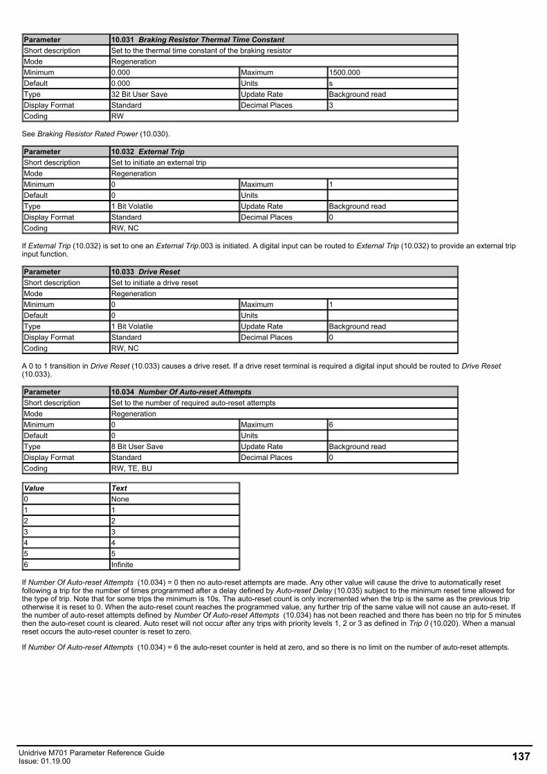
Parameter 10.031 Braking Resistor Thermal Time ConstantShort description Set to the thermal time constant of the braking resistorMode RegenerationMinimum 0.000 Maximum 1500.000Default 0.000 Units sType 32 Bit User Save Update Rate Background readDisplay Format Standard Decimal Places 3Coding RW
See Braking Resistor Rated Power (10.030).
Parameter 10.032 External TripShort description Set to initiate an external tripMode RegenerationMinimum 0 Maximum 1Default 0 Units Type 1 Bit Volatile Update Rate Background readDisplay Format Standard Decimal Places 0Coding RW, NC
If External Trip (10.032) is set to one an External Trip.003 is initiated. A digital input can be routed to External Trip (10.032) to provide an external tripinput function.
Parameter 10.033 Drive ResetShort description Set to initiate a drive resetMode RegenerationMinimum 0 Maximum 1Default 0 Units Type 1 Bit Volatile Update Rate Background readDisplay Format Standard Decimal Places 0Coding RW, NC
A 0 to 1 transition in Drive Reset (10.033) causes a drive reset. If a drive reset terminal is required a digital input should be routed to Drive Reset(10.033).
Parameter 10.034 Number Of Auto-reset AttemptsShort description Set to the number of required auto-reset attemptsMode RegenerationMinimum 0 Maximum 6Default 0 Units Type 8 Bit User Save Update Rate Background readDisplay Format Standard Decimal Places 0Coding RW, TE, BU
Value Text0 None1 12 23 34 45 56 Infinite
If Number Of Auto-reset Attempts (10.034) = 0 then no auto-reset attempts are made. Any other value will cause the drive to automatically resetfollowing a trip for the number of times programmed after a delay defined by Auto-reset Delay (10.035) subject to the minimum reset time allowed forthe type of trip. Note that for some trips the minimum is 10s. The auto-reset count is only incremented when the trip is the same as the previous tripotherwise it is reset to 0. When the auto-reset count reaches the programmed value, any further trip of the same value will not cause an auto-reset. Ifthe number of auto-reset attempts defined by Number Of Auto-reset Attempts (10.034) has not been reached and there has been no trip for 5 minutesthen the auto-reset count is cleared. Auto reset will not occur after any trips with priority levels 1, 2 or 3 as defined in Trip 0 (10.020). When a manualreset occurs the auto-reset counter is reset to zero.
If Number Of Auto-reset Attempts (10.034) = 6 the auto-reset counter is held at zero, and so there is no limit on the number of auto-reset attempts.
Unidrive M701 Parameter Reference GuideIssue: 01.19.00 137
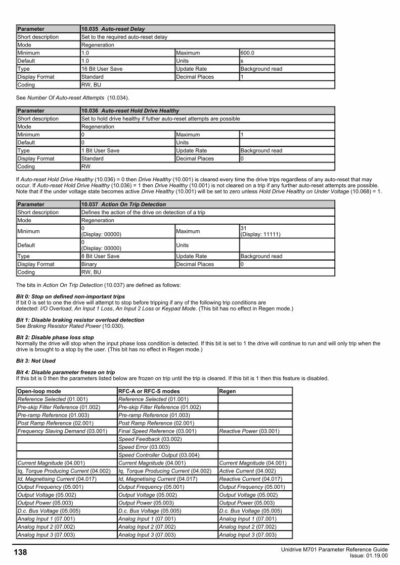
Parameter 10.035 Auto-reset DelayShort description Set to the required auto-reset delayMode RegenerationMinimum 1.0 Maximum 600.0Default 1.0 Units sType 16 Bit User Save Update Rate Background readDisplay Format Standard Decimal Places 1Coding RW, BU
See Number Of Auto-reset Attempts (10.034).
Parameter 10.036 Auto-reset Hold Drive HealthyShort description Set to hold drive healthy if futher auto-reset attempts are possibleMode RegenerationMinimum 0 Maximum 1Default 0 Units Type 1 Bit User Save Update Rate Background readDisplay Format Standard Decimal Places 0Coding RW
If Auto-reset Hold Drive Healthy (10.036) = 0 then Drive Healthy (10.001) is cleared every time the drive trips regardless of any auto-reset that mayoccur. If Auto-reset Hold Drive Healthy (10.036) = 1 then Drive Healthy (10.001) is not cleared on a trip if any further auto-reset attempts are possible.Note that if the under voltage state becomes active Drive Healthy (10.001) will be set to zero unless Hold Drive Healthy on Under Voltage (10.068) = 1.
Parameter 10.037 Action On Trip DetectionShort description Defines the action of the drive on detection of a tripMode Regeneration
Minimum 0(Display: 00000) Maximum 31
(Display: 11111)
Default 0(Display: 00000) Units
Type 8 Bit User Save Update Rate Background readDisplay Format Binary Decimal Places 0Coding RW, BU
The bits in Action On Trip Detection (10.037) are defined as follows:
Bit 0: Stop on defined non-important trips If bit 0 is set to one the drive will attempt to stop before tripping if any of the following trip conditions aredetected: I/O Overload, An Input 1 Loss, An Input 2 Loss or Keypad Mode. (This bit has no effect in Regen mode.)
Bit 1: Disable braking resistor overload detectionSee Braking Resistor Rated Power (10.030).
Bit 2: Disable phase loss stopNormally the drive will stop when the input phase loss condition is detected. If this bit is set to 1 the drive will continue to run and will only trip when thedrive is brought to a stop by the user. (This bit has no effect in Regen mode.)
Bit 3: Not Used
Bit 4: Disable parameter freeze on tripIf this bit is 0 then the parameters listed below are frozen on trip until the trip is cleared. If this bit is 1 then this feature is disabled.
Open-loop mode RFC-A or RFC-S modes RegenReference Selected (01.001) Reference Selected (01.001)Pre-skip Filter Reference (01.002) Pre-skip Filter Reference (01.002)Pre-ramp Reference (01.003) Pre-ramp Reference (01.003)Post Ramp Reference (02.001) Post Ramp Reference (02.001)Frequency Slaving Demand (03.001) Final Speed Reference (03.001) Reactive Power (03.001)
Speed Feedback (03.002)Speed Error (03.003)Speed Controller Output (03.004)
Current Magnitude (04.001) Current Magnitude (04.001) Current Magnitude (04.001)Iq, Torque Producing Current (04.002) Iq, Torque Producing Current (04.002) Active Current (04.002)Id, Magnetising Current (04.017) Id, Magnetising Current (04.017) Reactive Current (04.017)Output Frequency (05.001) Output Frequency (05.001) Output Frequency (05.001)Output Voltage (05.002) Output Voltage (05.002) Output Voltage (05.002)Output Power (05.003) Output Power (05.003) Output Power (05.003)D.c. Bus Voltage (05.005) D.c. Bus Voltage (05.005) D.c. Bus Voltage (05.005)Analog Input 1 (07.001) Analog Input 1 (07.001) Analog Input 1 (07.001)Analog Input 2 (07.002) Analog Input 2 (07.002) Analog Input 2 (07.002)Analog Input 3 (07.003) Analog Input 3 (07.003) Analog Input 3 (07.003)
138 Unidrive M701 Parameter Reference GuideIssue: 01.19.00
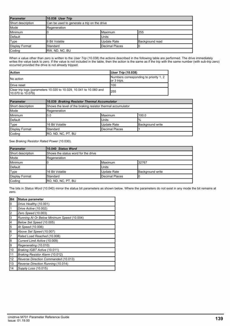
Parameter 10.038 User TripShort description Can be used to generate a trip on the driveMode RegenerationMinimum 0 Maximum 255Default Units Type 8 Bit Volatile Update Rate Background readDisplay Format Standard Decimal Places 0Coding RW, ND, NC, BU
When a value other than zero is written to the User Trip (10.038) the actions described in the following table are performed. The drive immediatelywrites the value back to zero. If the value is not included in the table, then the action is the same as if the trip with the same number (with sub-trip zero)occurred provided the drive is not already tripped.
Action User Trip (10.038)
No action Numbers corresponding to priority 1, 2or 3 trips.
Drive reset 100Clear trip logs (parameters 10.020 to 10.029, 10.041 to 10.060 and10.070 to 10.079) 255
Parameter 10.039 Braking Resistor Thermal AccumulatorShort description Shows the level of the braking resistor thermal accumulatorMode RegenerationMinimum 0.0 Maximum 100.0Default Units %Type 16 Bit Volatile Update Rate Background writeDisplay Format Standard Decimal Places 1Coding RO, ND, NC, PT, BU
See Braking Resistor Rated Power (10.030).
Parameter 10.040 Status WordShort description Shows the status word for the driveMode RegenerationMinimum 0 Maximum 32767Default Units Type 16 Bit Volatile Update Rate Background writeDisplay Format Standard Decimal Places 0Coding RO, ND, NC, PT, BU
The bits in Status Word (10.040) mirror the status bit parameters as shown below. Where the parameters do not exist in any mode the bit remains atzero.
Bit Status parameter0 Drive Healthy (10.001)1 Drive Active (10.002)2 Zero Speed (10.003)3 Running At Or Below Minimum Speed (10.004)4 Below Set Speed (10.005)5 At Speed (10.006)6 Above Set Speed (10.007)7 Rated Load Reached (10.008)8 Current Limit Active (10.009)9 Regenerating (10.010)10 Braking IGBT Active (10.011)11 Braking Resistor Alarm (10.012)12 Reverse Direction Commanded (10.013)13 Reverse Direction Running (10.014)14 Supply Loss (10.015)
Unidrive M701 Parameter Reference GuideIssue: 01.19.00 139
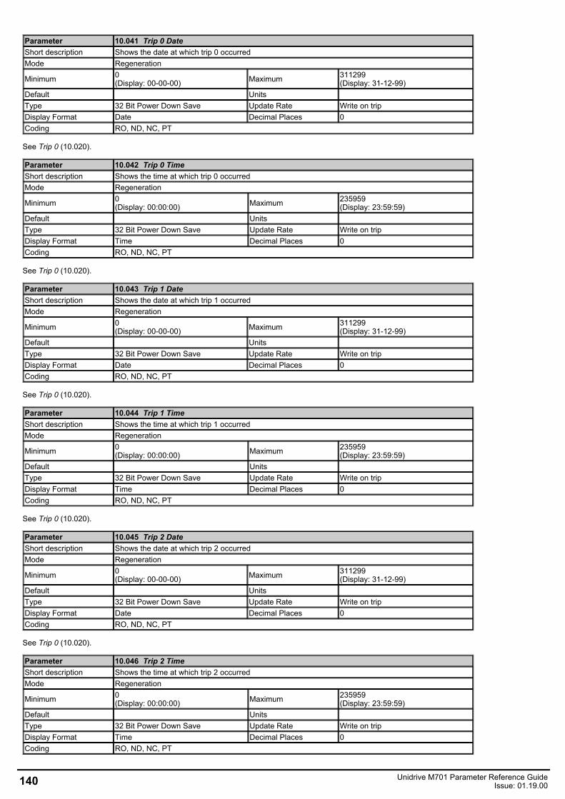
Parameter 10.041 Trip 0 DateShort description Shows the date at which trip 0 occurredMode Regeneration
Minimum 0(Display: 00-00-00) Maximum 311299
(Display: 31-12-99)Default Units Type 32 Bit Power Down Save Update Rate Write on tripDisplay Format Date Decimal Places 0Coding RO, ND, NC, PT
See Trip 0 (10.020).
Parameter 10.042 Trip 0 TimeShort description Shows the time at which trip 0 occurredMode Regeneration
Minimum 0(Display: 00:00:00) Maximum 235959
(Display: 23:59:59)Default Units Type 32 Bit Power Down Save Update Rate Write on tripDisplay Format Time Decimal Places 0Coding RO, ND, NC, PT
See Trip 0 (10.020).
Parameter 10.043 Trip 1 DateShort description Shows the date at which trip 1 occurredMode Regeneration
Minimum 0(Display: 00-00-00) Maximum 311299
(Display: 31-12-99)Default Units Type 32 Bit Power Down Save Update Rate Write on tripDisplay Format Date Decimal Places 0Coding RO, ND, NC, PT
See Trip 0 (10.020).
Parameter 10.044 Trip 1 TimeShort description Shows the time at which trip 1 occurredMode Regeneration
Minimum 0(Display: 00:00:00) Maximum 235959
(Display: 23:59:59)Default Units Type 32 Bit Power Down Save Update Rate Write on tripDisplay Format Time Decimal Places 0Coding RO, ND, NC, PT
See Trip 0 (10.020).
Parameter 10.045 Trip 2 DateShort description Shows the date at which trip 2 occurredMode Regeneration
Minimum 0(Display: 00-00-00) Maximum 311299
(Display: 31-12-99)Default Units Type 32 Bit Power Down Save Update Rate Write on tripDisplay Format Date Decimal Places 0Coding RO, ND, NC, PT
See Trip 0 (10.020).
Parameter 10.046 Trip 2 TimeShort description Shows the time at which trip 2 occurredMode Regeneration
Minimum 0(Display: 00:00:00) Maximum 235959
(Display: 23:59:59)Default Units Type 32 Bit Power Down Save Update Rate Write on tripDisplay Format Time Decimal Places 0Coding RO, ND, NC, PT
140 Unidrive M701 Parameter Reference GuideIssue: 01.19.00
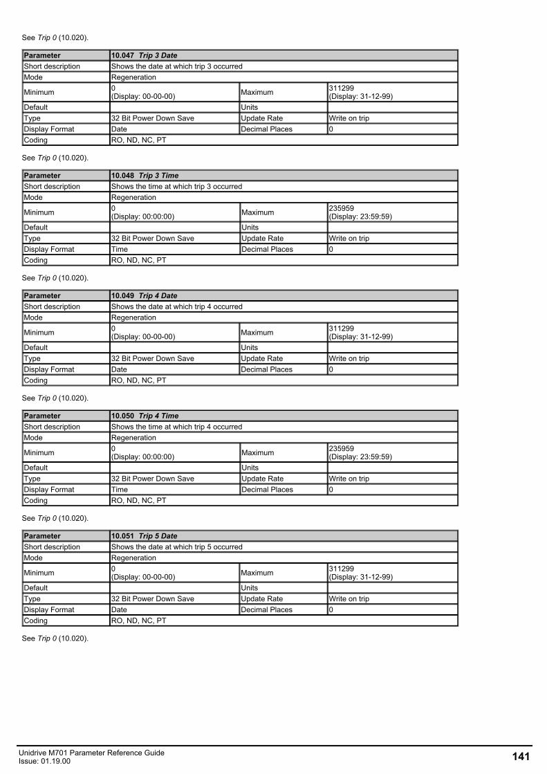
See Trip 0 (10.020).
Parameter 10.047 Trip 3 DateShort description Shows the date at which trip 3 occurredMode Regeneration
Minimum 0(Display: 00-00-00) Maximum 311299
(Display: 31-12-99)Default Units Type 32 Bit Power Down Save Update Rate Write on tripDisplay Format Date Decimal Places 0Coding RO, ND, NC, PT
See Trip 0 (10.020).
Parameter 10.048 Trip 3 TimeShort description Shows the time at which trip 3 occurredMode Regeneration
Minimum 0(Display: 00:00:00) Maximum 235959
(Display: 23:59:59)Default Units Type 32 Bit Power Down Save Update Rate Write on tripDisplay Format Time Decimal Places 0Coding RO, ND, NC, PT
See Trip 0 (10.020).
Parameter 10.049 Trip 4 DateShort description Shows the date at which trip 4 occurredMode Regeneration
Minimum 0(Display: 00-00-00) Maximum 311299
(Display: 31-12-99)Default Units Type 32 Bit Power Down Save Update Rate Write on tripDisplay Format Date Decimal Places 0Coding RO, ND, NC, PT
See Trip 0 (10.020).
Parameter 10.050 Trip 4 TimeShort description Shows the time at which trip 4 occurredMode Regeneration
Minimum 0(Display: 00:00:00) Maximum 235959
(Display: 23:59:59)Default Units Type 32 Bit Power Down Save Update Rate Write on tripDisplay Format Time Decimal Places 0Coding RO, ND, NC, PT
See Trip 0 (10.020).
Parameter 10.051 Trip 5 DateShort description Shows the date at which trip 5 occurredMode Regeneration
Minimum 0(Display: 00-00-00) Maximum 311299
(Display: 31-12-99)Default Units Type 32 Bit Power Down Save Update Rate Write on tripDisplay Format Date Decimal Places 0Coding RO, ND, NC, PT
See Trip 0 (10.020).
Unidrive M701 Parameter Reference GuideIssue: 01.19.00 141
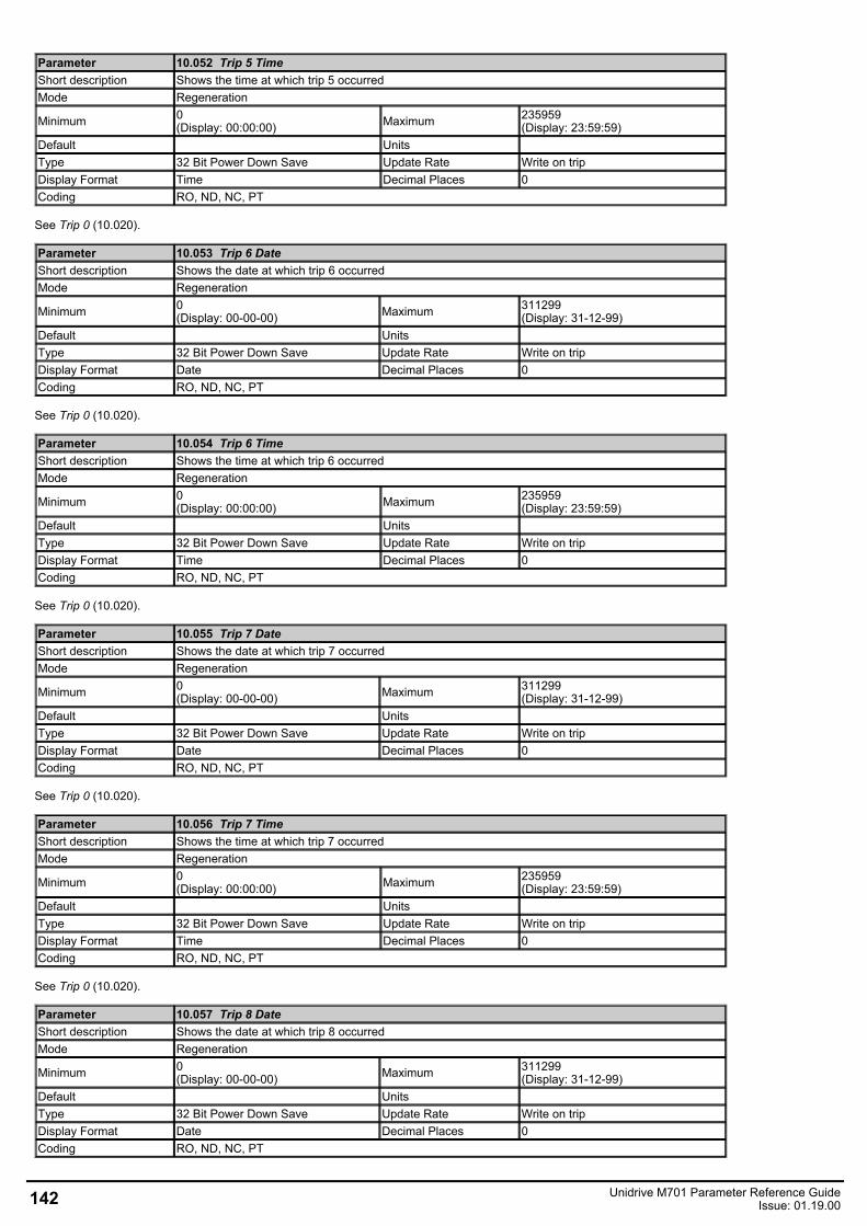
Parameter 10.052 Trip 5 TimeShort description Shows the time at which trip 5 occurredMode Regeneration
Minimum 0(Display: 00:00:00) Maximum 235959
(Display: 23:59:59)Default Units Type 32 Bit Power Down Save Update Rate Write on tripDisplay Format Time Decimal Places 0Coding RO, ND, NC, PT
See Trip 0 (10.020).
Parameter 10.053 Trip 6 DateShort description Shows the date at which trip 6 occurredMode Regeneration
Minimum 0(Display: 00-00-00) Maximum 311299
(Display: 31-12-99)Default Units Type 32 Bit Power Down Save Update Rate Write on tripDisplay Format Date Decimal Places 0Coding RO, ND, NC, PT
See Trip 0 (10.020).
Parameter 10.054 Trip 6 TimeShort description Shows the time at which trip 6 occurredMode Regeneration
Minimum 0(Display: 00:00:00) Maximum 235959
(Display: 23:59:59)Default Units Type 32 Bit Power Down Save Update Rate Write on tripDisplay Format Time Decimal Places 0Coding RO, ND, NC, PT
See Trip 0 (10.020).
Parameter 10.055 Trip 7 DateShort description Shows the date at which trip 7 occurredMode Regeneration
Minimum 0(Display: 00-00-00) Maximum 311299
(Display: 31-12-99)Default Units Type 32 Bit Power Down Save Update Rate Write on tripDisplay Format Date Decimal Places 0Coding RO, ND, NC, PT
See Trip 0 (10.020).
Parameter 10.056 Trip 7 TimeShort description Shows the time at which trip 7 occurredMode Regeneration
Minimum 0(Display: 00:00:00) Maximum 235959
(Display: 23:59:59)Default Units Type 32 Bit Power Down Save Update Rate Write on tripDisplay Format Time Decimal Places 0Coding RO, ND, NC, PT
See Trip 0 (10.020).
Parameter 10.057 Trip 8 DateShort description Shows the date at which trip 8 occurredMode Regeneration
Minimum 0(Display: 00-00-00) Maximum 311299
(Display: 31-12-99)Default Units Type 32 Bit Power Down Save Update Rate Write on tripDisplay Format Date Decimal Places 0Coding RO, ND, NC, PT
142 Unidrive M701 Parameter Reference GuideIssue: 01.19.00
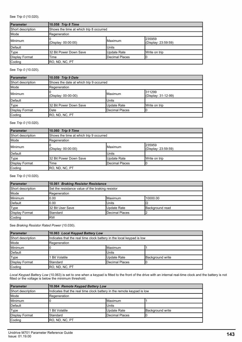
See Trip 0 (10.020).
Parameter 10.058 Trip 8 TimeShort description Shows the time at which trip 8 occurredMode Regeneration
Minimum 0(Display: 00:00:00) Maximum 235959
(Display: 23:59:59)Default Units Type 32 Bit Power Down Save Update Rate Write on tripDisplay Format Time Decimal Places 0Coding RO, ND, NC, PT
See Trip 0 (10.020).
Parameter 10.059 Trip 9 DateShort description Shows the date at which trip 9 occurredMode Regeneration
Minimum 0(Display: 00-00-00) Maximum 311299
(Display: 31-12-99)Default Units Type 32 Bit Power Down Save Update Rate Write on tripDisplay Format Date Decimal Places 0Coding RO, ND, NC, PT
See Trip 0 (10.020).
Parameter 10.060 Trip 9 TimeShort description Shows the time at which trip 9 occurredMode Regeneration
Minimum 0(Display: 00:00:00) Maximum 235959
(Display: 23:59:59)Default Units Type 32 Bit Power Down Save Update Rate Write on tripDisplay Format Time Decimal Places 0Coding RO, ND, NC, PT
See Trip 0 (10.020).
Parameter 10.061 Braking Resistor ResistanceShort description Set the resistance value of the braking resistorMode RegenerationMinimum 0.00 Maximum 10000.00Default 0.00 Units ΩType 32 Bit User Save Update Rate Background readDisplay Format Standard Decimal Places 2Coding RW
See Braking Resistor Rated Power (10.030).
Parameter 10.063 Local Keypad Battery LowShort description Indicates that the real time clock battery in the local keypad is lowMode RegenerationMinimum 0 Maximum 1Default Units Type 1 Bit Volatile Update Rate Background writeDisplay Format Standard Decimal Places 0Coding RO, ND, NC, PT
Local Keypad Battery Low (10.063) is set to one when a keypad is fitted to the front of the drive with an internal real-time clock and the battery is notfitted or the voltage is below the minimum threshold.
Parameter 10.064 Remote Keypad Battery LowShort description Indicates that the real time clock battery in the remote keypad is lowMode RegenerationMinimum 0 Maximum 1Default Units Type 1 Bit Volatile Update Rate Background writeDisplay Format Standard Decimal Places 0Coding RO, ND, NC, PT
Unidrive M701 Parameter Reference GuideIssue: 01.19.00 143
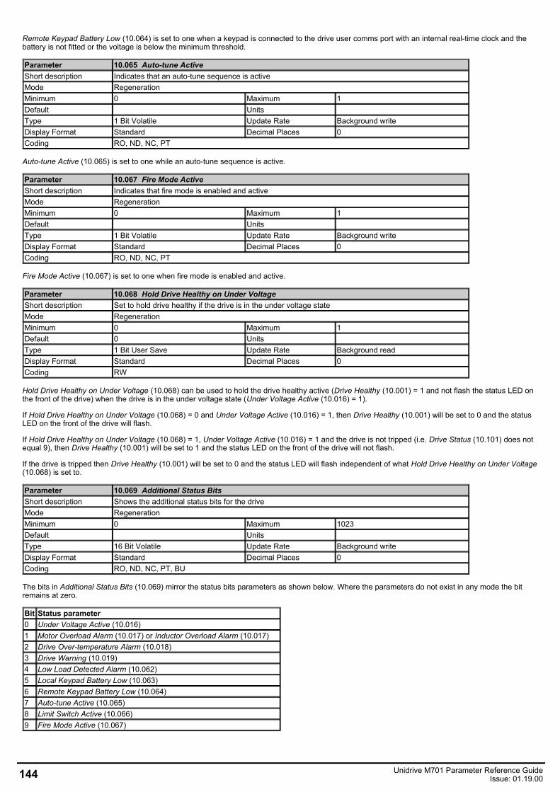
Remote Keypad Battery Low (10.064) is set to one when a keypad is connected to the drive user comms port with an internal real-time clock and thebattery is not fitted or the voltage is below the minimum threshold.
Parameter 10.065 Auto-tune ActiveShort description Indicates that an auto-tune sequence is activeMode RegenerationMinimum 0 Maximum 1Default Units Type 1 Bit Volatile Update Rate Background writeDisplay Format Standard Decimal Places 0Coding RO, ND, NC, PT
Auto-tune Active (10.065) is set to one while an auto-tune sequence is active.
Parameter 10.067 Fire Mode ActiveShort description Indicates that fire mode is enabled and activeMode RegenerationMinimum 0 Maximum 1Default Units Type 1 Bit Volatile Update Rate Background writeDisplay Format Standard Decimal Places 0Coding RO, ND, NC, PT
Fire Mode Active (10.067) is set to one when fire mode is enabled and active.
Parameter 10.068 Hold Drive Healthy on Under VoltageShort description Set to hold drive healthy if the drive is in the under voltage stateMode RegenerationMinimum 0 Maximum 1Default 0 Units Type 1 Bit User Save Update Rate Background readDisplay Format Standard Decimal Places 0Coding RW
Hold Drive Healthy on Under Voltage (10.068) can be used to hold the drive healthy active (Drive Healthy (10.001) = 1 and not flash the status LED onthe front of the drive) when the drive is in the under voltage state (Under Voltage Active (10.016) = 1).
If Hold Drive Healthy on Under Voltage (10.068) = 0 and Under Voltage Active (10.016) = 1, then Drive Healthy (10.001) will be set to 0 and the statusLED on the front of the drive will flash.
If Hold Drive Healthy on Under Voltage (10.068) = 1, Under Voltage Active (10.016) = 1 and the drive is not tripped (i.e. Drive Status (10.101) does notequal 9), then Drive Healthy (10.001) will be set to 1 and the status LED on the front of the drive will not flash.
If the drive is tripped then Drive Healthy (10.001) will be set to 0 and the status LED will flash independent of what Hold Drive Healthy on Under Voltage(10.068) is set to.
Parameter 10.069 Additional Status BitsShort description Shows the additional status bits for the driveMode RegenerationMinimum 0 Maximum 1023Default Units Type 16 Bit Volatile Update Rate Background writeDisplay Format Standard Decimal Places 0Coding RO, ND, NC, PT, BU
The bits in Additional Status Bits (10.069) mirror the status bits parameters as shown below. Where the parameters do not exist in any mode the bitremains at zero.
Bit Status parameter0 Under Voltage Active (10.016)1 Motor Overload Alarm (10.017) or Inductor Overload Alarm (10.017)2 Drive Over-temperature Alarm (10.018)3 Drive Warning (10.019)4 Low Load Detected Alarm (10.062)5 Local Keypad Battery Low (10.063)6 Remote Keypad Battery Low (10.064)7 Auto-tune Active (10.065)8 Limit Switch Active (10.066)9 Fire Mode Active (10.067)
144 Unidrive M701 Parameter Reference GuideIssue: 01.19.00
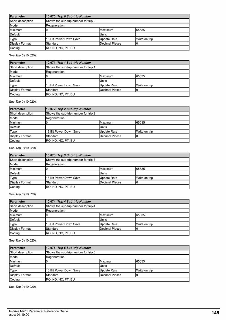
Parameter 10.070 Trip 0 Sub-trip NumberShort description Shows the sub-trip number for trip 0Mode RegenerationMinimum 0 Maximum 65535Default Units Type 16 Bit Power Down Save Update Rate Write on tripDisplay Format Standard Decimal Places 0Coding RO, ND, NC, PT, BU
See Trip 0 (10.020).
Parameter 10.071 Trip 1 Sub-trip NumberShort description Shows the sub-trip number for trip 1Mode RegenerationMinimum 0 Maximum 65535Default Units Type 16 Bit Power Down Save Update Rate Write on tripDisplay Format Standard Decimal Places 0Coding RO, ND, NC, PT, BU
See Trip 0 (10.020).
Parameter 10.072 Trip 2 Sub-trip NumberShort description Shows the sub-trip number for trip 2Mode RegenerationMinimum 0 Maximum 65535Default Units Type 16 Bit Power Down Save Update Rate Write on tripDisplay Format Standard Decimal Places 0Coding RO, ND, NC, PT, BU
See Trip 0 (10.020).
Parameter 10.073 Trip 3 Sub-trip NumberShort description Shows the sub-trip number for trip 3Mode RegenerationMinimum 0 Maximum 65535Default Units Type 16 Bit Power Down Save Update Rate Write on tripDisplay Format Standard Decimal Places 0Coding RO, ND, NC, PT, BU
See Trip 0 (10.020).
Parameter 10.074 Trip 4 Sub-trip NumberShort description Shows the sub-trip number for trip 4Mode RegenerationMinimum 0 Maximum 65535Default Units Type 16 Bit Power Down Save Update Rate Write on tripDisplay Format Standard Decimal Places 0Coding RO, ND, NC, PT, BU
See Trip 0 (10.020).
Parameter 10.075 Trip 5 Sub-trip NumberShort description Shows the sub-trip number for trip 5Mode RegenerationMinimum 0 Maximum 65535Default Units Type 16 Bit Power Down Save Update Rate Write on tripDisplay Format Standard Decimal Places 0Coding RO, ND, NC, PT, BU
See Trip 0 (10.020).
Unidrive M701 Parameter Reference GuideIssue: 01.19.00 145
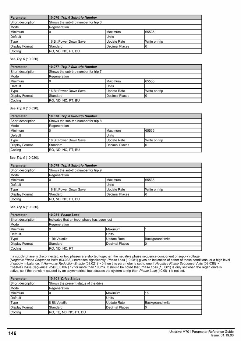
Parameter 10.076 Trip 6 Sub-trip NumberShort description Shows the sub-trip number for trip 6Mode RegenerationMinimum 0 Maximum 65535Default Units Type 16 Bit Power Down Save Update Rate Write on tripDisplay Format Standard Decimal Places 0Coding RO, ND, NC, PT, BU
See Trip 0 (10.020).
Parameter 10.077 Trip 7 Sub-trip NumberShort description Shows the sub-trip number for trip 7Mode RegenerationMinimum 0 Maximum 65535Default Units Type 16 Bit Power Down Save Update Rate Write on tripDisplay Format Standard Decimal Places 0Coding RO, ND, NC, PT, BU
See Trip 0 (10.020).
Parameter 10.078 Trip 8 Sub-trip NumberShort description Shows the sub-trip number for trip 8Mode RegenerationMinimum 0 Maximum 65535Default Units Type 16 Bit Power Down Save Update Rate Write on tripDisplay Format Standard Decimal Places 0Coding RO, ND, NC, PT, BU
See Trip 0 (10.020).
Parameter 10.079 Trip 9 Sub-trip NumberShort description Shows the sub-trip number for trip 9Mode RegenerationMinimum 0 Maximum 65535Default Units Type 16 Bit Power Down Save Update Rate Write on tripDisplay Format Standard Decimal Places 0Coding RO, ND, NC, PT, BU
See Trip 0 (10.020).
Parameter 10.081 Phase LossShort description Indicates that an input phase has been lostMode RegenerationMinimum 0 Maximum 1Default Units Type 1 Bit Volatile Update Rate Background writeDisplay Format Standard Decimal Places 0Coding RO, ND, NC, PT
If a supply phase is disconnected, or two phases are shorted together, the negative phase sequence component of supply voltage(Negative Phase Sequence Volts (03.038)) increases significantly. Phase Loss (10.081) gives an indication of either of these conditions, or a high levelof supply imbalance. If Harmonic Reduction Enable (03.021) > 0 then this parameter is set to one if Negative Phase Sequence Volts (03.038) >Positive Phase Sequence Volts (03.037) / 2 for more than 100ms. It should be noted that Phase Loss (10.081) is only set when the regen drive isactive, so if the transient caused by an asymmetrical fault causes the system to trip then Phase Loss (10.081) is not set.
Parameter 10.101 Drive StatusShort description Shows the present status of the driveMode RegenerationMinimum 0 Maximum 15Default Units Type 8 Bit Volatile Update Rate Background writeDisplay Format Standard Decimal Places 0Coding RO, TE, ND, NC, PT, BU
146 Unidrive M701 Parameter Reference GuideIssue: 01.19.00
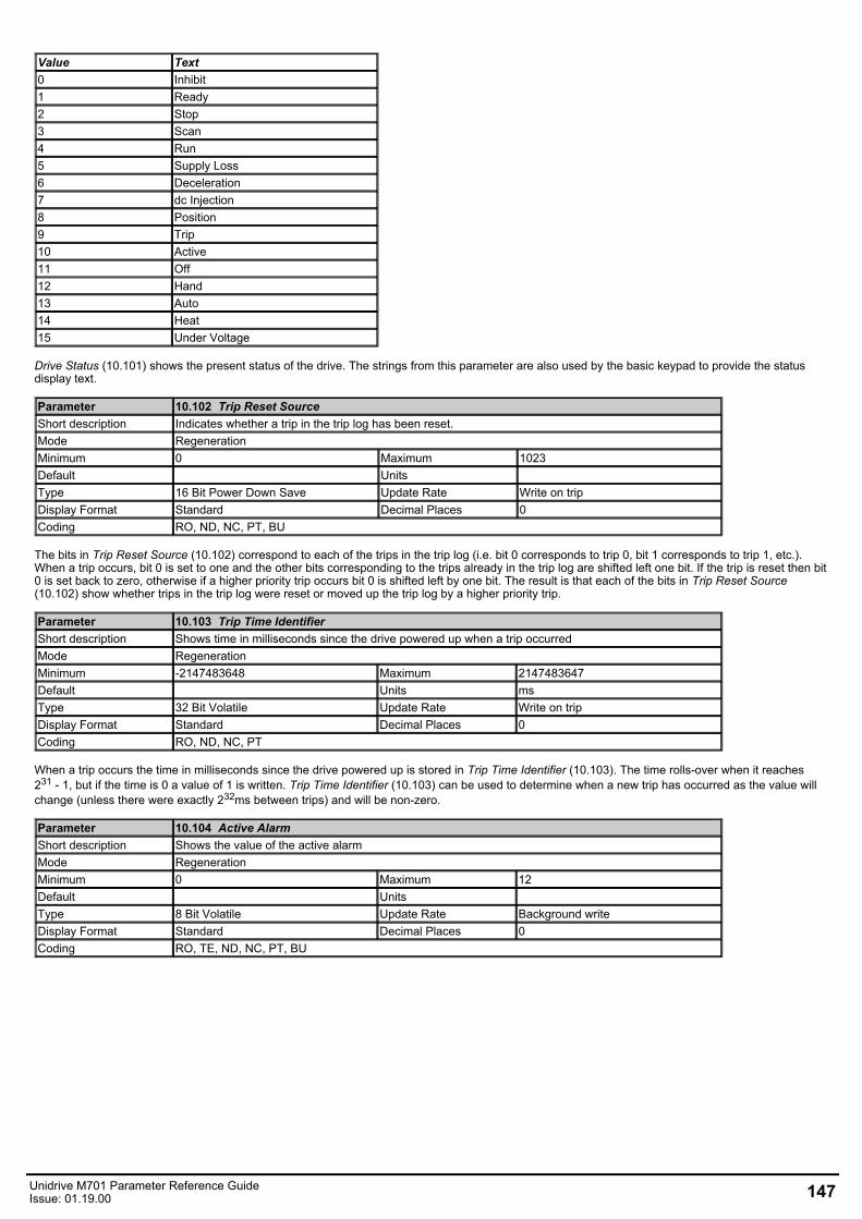
Value Text0 Inhibit1 Ready2 Stop3 Scan4 Run5 Supply Loss6 Deceleration7 dc Injection8 Position9 Trip10 Active11 Off12 Hand13 Auto14 Heat15 Under Voltage
Drive Status (10.101) shows the present status of the drive. The strings from this parameter are also used by the basic keypad to provide the statusdisplay text.
Parameter 10.102 Trip Reset SourceShort description Indicates whether a trip in the trip log has been reset.Mode RegenerationMinimum 0 Maximum 1023Default Units Type 16 Bit Power Down Save Update Rate Write on tripDisplay Format Standard Decimal Places 0Coding RO, ND, NC, PT, BU
The bits in Trip Reset Source (10.102) correspond to each of the trips in the trip log (i.e. bit 0 corresponds to trip 0, bit 1 corresponds to trip 1, etc.).When a trip occurs, bit 0 is set to one and the other bits corresponding to the trips already in the trip log are shifted left one bit. If the trip is reset then bit0 is set back to zero, otherwise if a higher priority trip occurs bit 0 is shifted left by one bit. The result is that each of the bits in Trip Reset Source(10.102) show whether trips in the trip log were reset or moved up the trip log by a higher priority trip.
Parameter 10.103 Trip Time IdentifierShort description Shows time in milliseconds since the drive powered up when a trip occurredMode RegenerationMinimum -2147483648 Maximum 2147483647Default Units msType 32 Bit Volatile Update Rate Write on tripDisplay Format Standard Decimal Places 0Coding RO, ND, NC, PT
When a trip occurs the time in milliseconds since the drive powered up is stored in Trip Time Identifier (10.103). The time rolls-over when it reaches231 - 1, but if the time is 0 a value of 1 is written. Trip Time Identifier (10.103) can be used to determine when a new trip has occurred as the value willchange (unless there were exactly 232ms between trips) and will be non-zero.
Parameter 10.104 Active AlarmShort description Shows the value of the active alarmMode RegenerationMinimum 0 Maximum 12Default Units Type 8 Bit Volatile Update Rate Background writeDisplay Format Standard Decimal Places 0Coding RO, TE, ND, NC, PT, BU
Unidrive M701 Parameter Reference GuideIssue: 01.19.00 147
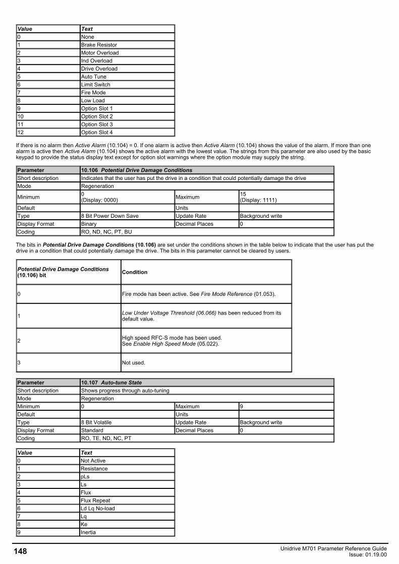
Value Text0 None1 Brake Resistor2 Motor Overload3 Ind Overload4 Drive Overload5 Auto Tune6 Limit Switch7 Fire Mode8 Low Load9 Option Slot 110 Option Slot 211 Option Slot 312 Option Slot 4
If there is no alarm then Active Alarm (10.104) = 0. If one alarm is active then Active Alarm (10.104) shows the value of the alarm. If more than onealarm is active then Active Alarm (10.104) shows the active alarm with the lowest value. The strings from this parameter are also used by the basickeypad to provide the status display text except for option slot warnings where the option module may supply the string.
Parameter 10.106 Potential Drive Damage ConditionsShort description Indicates that the user has put the drive in a condition that could potentially damage the driveMode Regeneration
Minimum 0(Display: 0000) Maximum 15
(Display: 1111)Default Units Type 8 Bit Power Down Save Update Rate Background writeDisplay Format Binary Decimal Places 0Coding RO, ND, NC, PT, BU
The bits in Potential Drive Damage Conditions (10.106) are set under the conditions shown in the table below to indicate that the user has put thedrive in a condition that could potentially damage the drive. The bits in this parameter cannot be cleared by users.
Potential Drive Damage Conditions(10.106) bit Condition
0 Fire mode has been active. See Fire Mode Reference (01.053).
1 Low Under Voltage Threshold (06.066) has been reduced from itsdefault value.
2 High speed RFC-S mode has been used.See Enable High Speed Mode (05.022).
3 Not used.
Parameter 10.107 Auto-tune StateShort description Shows progress through auto-tuningMode RegenerationMinimum 0 Maximum 9Default Units Type 8 Bit Volatile Update Rate Background writeDisplay Format Standard Decimal Places 0Coding RO, TE, ND, NC, PT
Value Text0 Not Active1 Resistance2 pLs3 Ls4 Flux5 Flux Repeat6 Ld Lq No-load7 Lq8 Ke9 Inertia
148 Unidrive M701 Parameter Reference GuideIssue: 01.19.00

No auto-tuning is provided at present in this mode, and so the parameter is always zero.
Unidrive M701 Parameter Reference GuideIssue: 01.19.00 149
Menu 11 Single Line Descriptions − MiscellaneousMode: Regeneration
150 Unidrive M701 Parameter Reference GuideIssue: 01.19.00
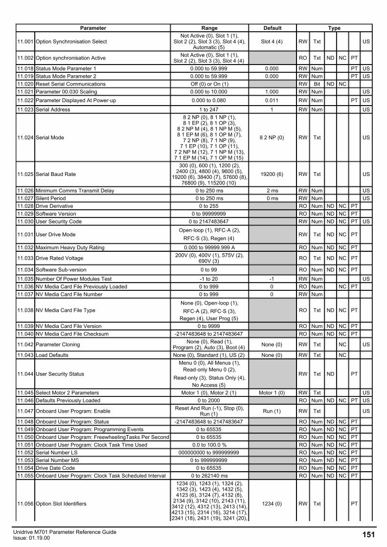
Parameter Range Default Type
11.001 Option Synchronisation SelectNot Active (0), Slot 1 (1),
Slot 2 (2), Slot 3 (3), Slot 4 (4),Automatic (5)
Slot 4 (4) RW Txt US
11.002 Option synchronisation Active Not Active (0), Slot 1 (1),Slot 2 (2), Slot 3 (3), Slot 4 (4) RO Txt ND NC PT
11.018 Status Mode Parameter 1 0.000 to 59.999 0.000 RW Num PT US11.019 Status Mode Parameter 2 0.000 to 59.999 0.000 RW Num PT US11.020 Reset Serial Communications Off (0) or On (1) RW Bit ND NC 11.021 Parameter 00.030 Scaling 0.000 to 10.000 1.000 RW Num US11.022 Parameter Displayed At Power‑up 0.000 to 0.080 0.011 RW Num PT US
11.023 Serial Address 1 to 247 1 RW Num US
11.024 Serial Mode
8 2 NP (0), 8 1 NP (1),8 1 EP (2), 8 1 OP (3),
8 2 NP M (4), 8 1 NP M (5),8 1 EP M (6), 8 1 OP M (7),
7 2 NP (8), 7 1 NP (9),7 1 EP (10), 7 1 OP (11),
7 2 NP M (12), 7 1 NP M (13),7 1 EP M (14), 7 1 OP M (15)
8 2 NP (0) RW Txt US
11.025 Serial Baud Rate300 (0), 600 (1), 1200 (2),
2400 (3), 4800 (4), 9600 (5),19200 (6), 38400 (7), 57600 (8),
76800 (9), 115200 (10) 19200 (6) RW Txt US
11.026 Minimum Comms Transmit Delay 0 to 250 ms 2 ms RW Num US11.027 Silent Period 0 to 250 ms 0 ms RW Num US11.028 Drive Derivative 0 to 255 RO Num ND NC PT 11.029 Software Version 0 to 99999999 RO Num ND NC PT 11.030 User Security Code 0 to 2147483647 RW Num ND NC PT US
11.031 User Drive ModeOpen‑loop (1), RFC‑A (2),
RFC‑S (3), Regen (4) RW Txt ND NC PT
11.032 Maximum Heavy Duty Rating 0.000 to 99999.999 A RO Num ND NC PT
11.033 Drive Rated Voltage 200V (0), 400V (1), 575V (2),690V (3) RO Txt ND NC PT
11.034 Software Sub‑version 0 to 99 RO Num ND NC PT
11.035 Number Of Power Modules Test -1 to 20 -1 RW Num US11.036 NV Media Card File Previously Loaded 0 to 999 0 RO Num NC PT 11.037 NV Media Card File Number 0 to 999 0 RW Num
11.038 NV Media Card File TypeNone (0), Open‑loop (1),RFC‑A (2), RFC‑S (3),
Regen (4), User Prog (5) RO Txt ND NC PT
11.039 NV Media Card File Version 0 to 9999 RO Num ND NC PT 11.040 NV Media Card File Checksum -2147483648 to 2147483647 RO Num ND NC PT
11.042 Parameter Cloning None (0), Read (1),Program (2), Auto (3), Boot (4) None (0) RW Txt NC US
11.043 Load Defaults None (0), Standard (1), US (2) None (0) RW Txt NC
11.044 User Security Status
Menu 0 (0), All Menus (1),Read‑only Menu 0 (2),
Read‑only (3), Status Only (4),No Access (5)
RW Txt ND PT
11.045 Select Motor 2 Parameters Motor 1 (0), Motor 2 (1) Motor 1 (0) RW Txt US11.046 Defaults Previously Loaded 0 to 2000 RO Num ND NC PT US
11.047 Onboard User Program: Enable Reset And Run (-1), Stop (0),Run (1) Run (1) RW Txt US
11.048 Onboard User Program: Status -2147483648 to 2147483647 RO Num ND NC PT 11.049 Onboard User Program: Programming Events 0 to 65535 RO Num ND NC PT 11.050 Onboard User Program: FreewheelingTasks Per Second 0 to 65535 RO Num ND NC PT 11.051 Onboard User Program: Clock Task Time Used 0.0 to 100.0 % RO Num ND NC PT 11.052 Serial Number LS 000000000 to 999999999 RO Num ND NC PT 11.053 Serial Number MS 0 to 999999999 RO Num ND NC PT 11.054 Drive Date Code 0 to 65535 RO Num ND NC PT 11.055 Onboard User Program: Clock Task Scheduled Interval 0 to 262140 ms RO Num ND NC PT
11.056 Option Slot Identifiers
1234 (0), 1243 (1), 1324 (2),1342 (3), 1423 (4), 1432 (5),4123 (6), 3124 (7), 4132 (8),
2134 (9), 3142 (10), 2143 (11),3412 (12), 4312 (13), 2413 (14),4213 (15), 2314 (16), 3214 (17),2341 (18), 2431 (19), 3241 (20),
1234 (0) RW Txt PT
Unidrive M701 Parameter Reference GuideIssue: 01.19.00 151
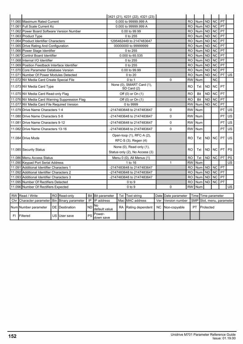
3421 (21), 4231 (22), 4321 (23) 11.060 Maximum Rated Current 0.000 to 99999.999 A RO Num ND NC PT 11.061 Full Scale Current Kc 0.000 to 99999.999 A RO Num ND NC PT 11.062 Power Board Software Version Number 0.00 to 99.99 RO Num ND NC PT 11.063 Product Type 0 to 255 RO Num ND NC PT 11.064 Product Identifier Characters 1295462449 to 2147483647 RO Num ND NC PT 11.065 Drive Rating And Configuration 00000000 to 99999999 RO Num ND NC PT 11.066 Power Stage Identifier 0 to 255 RO Num ND NC PT 11.067 Control Board Identifier 0.000 to 65.535 RO Num ND NC PT 11.068 Internal I/O Identifier 0 to 255 RO Num ND NC PT 11.069 Position Feedback Interface Identifier 0 to 255 RO Num ND NC PT 11.070 Core Parameter Database Version 0.00 to 99.99 RO Num ND NC PT 11.071 Number Of Power Modules Detected 0 to 20 RO Num ND NC PT US11.072 NV Media Card Create Special File 0 to 1 0 RW Num NC
11.073 NV Media Card Type None (0), SMART Card (1),SD Card (2) RO Txt ND NC PT
11.075 NV Media Card Read‑only Flag Off (0) or On (1) RO Bit ND NC PT
11.076 NV Media Card Warning Suppression Flag Off (0) or On (1) RO Bit ND NC PT 11.077 NV Media Card File Required Version 0 to 9999 RW Num ND NC PT 11.079 Drive Name Characters 1‑4 -2147483648 to 2147483647 0 RW Num PT US
11.080 Drive Name Characters 5‑8 -2147483648 to 2147483647 0 RW Num PT US
11.081 Drive Name Characters 9‑12 -2147483648 to 2147483647 0 RW Num PT US
11.082 Drive Name Characters 13‑16 -2147483648 to 2147483647 0 RW Num PT US
11.084 Drive ModeOpen‑loop (1), RFC‑A (2),
RFC‑S (3), Regen (4) RO Txt ND NC PT US
11.085 Security StatusNone (0), Read‑only (1),
Status‑only (2), No Access (3) RO Txt ND NC PT PS
11.086 Menu Access Status Menu 0 (0), All Menus (1) RO Txt ND NC PT PS11.090 Keypad Port Serial Address 1 to 16 1 RW Num US11.091 Additional Identifier Characters 1 -2147483648 to 2147483647 RO Num ND NC PT 11.092 Additional Identifier Characters 2 -2147483648 to 2147483647 RO Num ND NC PT 11.093 Additional Identifier Characters 3 -2147483648 to 2147483647 RO Num ND NC PT 11.095 Number Of Rectifiers Detected 0 to 9 RO Num ND NC PT 11.096 Number Of Rectifiers Expected 0 to 9 0 RW Num US
RW Read / Write RO Read-only Bit Bit parameter Txt Text string Date Date parameter Time Time parameterChr Character parameter Bin Binary parameter IP IP address Mac MAC address Ver Version number SMP Slot, menu, parameter
Num Number parameter DE Destination ND Nodefault value RA Rating dependent NC Non-copyable PT Protected
FI Filtered US User save PS Power-down save
152 Unidrive M701 Parameter Reference GuideIssue: 01.19.00
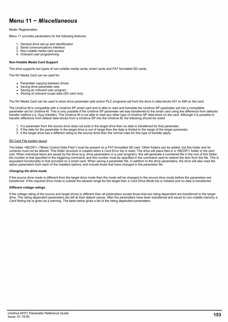
Menu 11 − MiscellaneousMode: Regeneration
Menu 11 provides parameters for the following features:
1. General drive set-up and identification2. Serial communications interface3. Non-volatile media card access4. Onboard user programming
Non-Volatile Media Card Support
The drive supports two types of non-volatile media cards; smart cards and FAT formatted SD cards.
The NV Media Card can be used for:
Parameter copying between drivesSaving drive parameter setsSaving an onboard user programStoring of onboard scope data (SD card only)
The NV Media Card can be used to store drive parameter sets and/or PLC programs set from the drive in data blocks 001 to 499 on the card.
The Unidrive M is compatible with a Unidrive SP smart card and is able to read and translate the Unidrive SP parameter set into a compatibleparameter set for Unidrive M. This is only possible if the Unidrive SP parameter set was transferred to the smart card using the difference from defaultstransfer method (i.e. 4yyy transfer). The Unidrive M is not able to read any other type of Unidrive SP data block on the card. Although it is possible totransfer difference from default data blocks from a Unidrive SP into the Unidrive M, the following should be noted:
1. If a parameter from the source drive does not exist in the target drive then no data is transferred for that parameter.2. If the data for the parameter in the target drive is out of range then the data is limited to the range of the target parameter.3. If the target drive has a different rating to the source drive then the normal rules for this type of transfer apply.
SD Card File system layout
The folder <MCDF/> ("Motor Control Data Files") must be present on a FAT-formatted SD card. Other folders can be added, but this folder and itscontents must not be altered. This folder structure is created when a Card Error trip is reset. The drive will place files in a <MCDF/> folder in the cardroot. When individual items are saved by the drive (e.g. drive parameters or a user program), this will generate a numbered file in the root of this folder;the number is that specified in the triggering command, and this number must be specified in the command used to restore the item from the file. This isequivalent functionality to that provided on a smart card. When saving a parameter file, in addition to the drive parameters, the drive will also read theoption parameters from each of the installed options, and include those that have changed in the parameter file.
Changing the drive mode
If the source drive mode is different from the target drive mode then the mode will be changed to the source drive mode before the parameters aretransferred. If the required drive mode is outside the allowed range for the target then a Card Drive Mode trip is initiated and no data is transferred.
Different voltage ratings
If the voltage rating of the source and target drives is different then all parameters except those that are rating dependent are transferred to the targetdrive. The rating dependent parameters are left at their default values. After the parameters have been transferred and saved to non-volatile memory aCard Rating trip is given as a warning. The table below gives a list of the rating dependent parameters.
Unidrive M701 Parameter Reference GuideIssue: 01.19.00 153
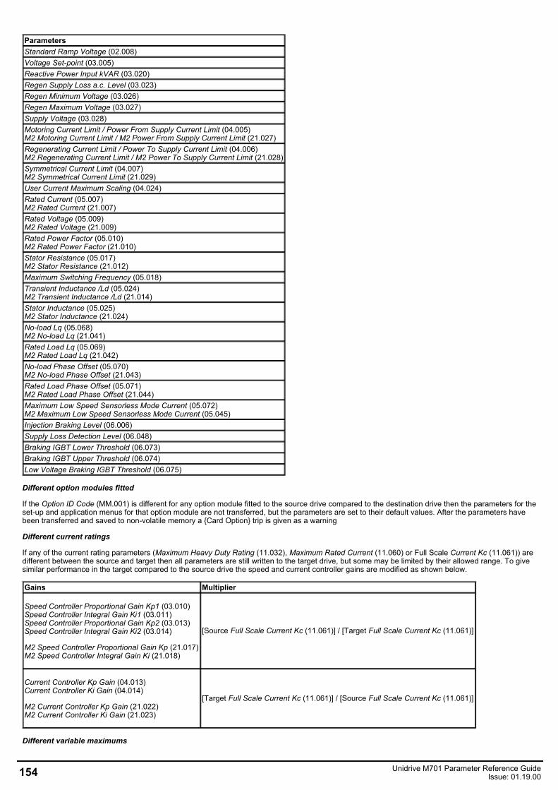
ParametersStandard Ramp Voltage (02.008)Voltage Set-point (03.005)Reactive Power Input kVAR (03.020)Regen Supply Loss a.c. Level (03.023)Regen Minimum Voltage (03.026)Regen Maximum Voltage (03.027)Supply Voltage (03.028)Motoring Current Limit / Power From Supply Current Limit (04.005)M2 Motoring Current Limit / M2 Power From Supply Current Limit (21.027)Regenerating Current Limit / Power To Supply Current Limit (04.006) M2 Regenerating Current Limit / M2 Power To Supply Current Limit (21.028)Symmetrical Current Limit (04.007)M2 Symmetrical Current Limit (21.029)User Current Maximum Scaling (04.024)Rated Current (05.007)M2 Rated Current (21.007)Rated Voltage (05.009)M2 Rated Voltage (21.009)Rated Power Factor (05.010)M2 Rated Power Factor (21.010)Stator Resistance (05.017)M2 Stator Resistance (21.012)Maximum Switching Frequency (05.018)Transient Inductance /Ld (05.024)M2 Transient Inductance /Ld (21.014)Stator Inductance (05.025)M2 Stator Inductance (21.024)No-load Lq (05.068)M2 No-load Lq (21.041)Rated Load Lq (05.069)M2 Rated Load Lq (21.042)No-load Phase Offset (05.070)M2 No-load Phase Offset (21.043)Rated Load Phase Offset (05.071)M2 Rated Load Phase Offset (21.044)Maximum Low Speed Sensorless Mode Current (05.072)M2 Maximum Low Speed Sensorless Mode Current (05.045)Injection Braking Level (06.006)Supply Loss Detection Level (06.048)Braking IGBT Lower Threshold (06.073)Braking IGBT Upper Threshold (06.074)Low Voltage Braking IGBT Threshold (06.075)
Different option modules fitted
If the Option ID Code (MM.001) is different for any option module fitted to the source drive compared to the destination drive then the parameters for theset-up and application menus for that option module are not transferred, but the parameters are set to their default values. After the parameters havebeen transferred and saved to non-volatile memory a Card Option trip is given as a warning
Different current ratings
If any of the current rating parameters (Maximum Heavy Duty Rating (11.032), Maximum Rated Current (11.060) or Full Scale Current Kc (11.061)) aredifferent between the source and target then all parameters are still written to the target drive, but some may be limited by their allowed range. To givesimilar performance in the target compared to the source drive the speed and current controller gains are modified as shown below.
Gains Multiplier
Speed Controller Proportional Gain Kp1 (03.010)Speed Controller Integral Gain Ki1 (03.011)Speed Controller Proportional Gain Kp2 (03.013)Speed Controller Integral Gain Ki2 (03.014)
M2 Speed Controller Proportional Gain Kp (21.017)M2 Speed Controller Integral Gain Ki (21.018)
[Source Full Scale Current Kc (11.061)] / [Target Full Scale Current Kc (11.061)]
Current Controller Kp Gain (04.013)Current Controller Ki Gain (04.014)
M2 Current Controller Kp Gain (21.022)M2 Current Controller Ki Gain (21.023)
[Target Full Scale Current Kc (11.061)] / [Source Full Scale Current Kc (11.061)]
Different variable maximums
154 Unidrive M701 Parameter Reference GuideIssue: 01.19.00
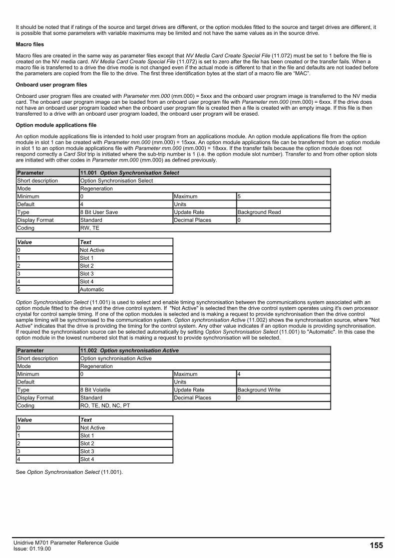
It should be noted that if ratings of the source and target drives are different, or the option modules fitted to the source and target drives are different, itis possible that some parameters with variable maximums may be limited and not have the same values as in the source drive.
Macro files
Macro files are created in the same way as parameter files except that NV Media Card Create Special File (11.072) must be set to 1 before the file iscreated on the NV media card. NV Media Card Create Special File (11.072) is set to zero after the file has been created or the transfer fails. When amacro file is transferred to a drive the drive mode is not changed even if the actual mode is different to that in the file and defaults are not loaded beforethe parameters are copied from the file to the drive. The first three identification bytes at the start of a macro file are “MAC”.
Onboard user program files
Onboard user program files are created with Parameter mm.000 (mm.000) = 5xxx and the onboard user program image is transferred to the NV mediacard. The onboard user program image can be loaded from an onboard user program file with Parameter mm.000 (mm.000) = 6xxx. If the drive doesnot have an onboard user program loaded when the onboard user program file is created then a file is created with an empty image. If this file is thentransferred to a drive with an onboard user program loaded, the onboard user program will be erased.
Option module applications file
An option module applications file is intended to hold user program from an applications module. An option module applications file from the optionmodule in slot 1 can be created with Parameter mm.000 (mm.000) = 15xxx. An option module applications file can be transferred from an option modulein slot 1 to an option module applications file with Parameter mm.000 (mm.000) = 18xxx. If the transfer fails because the option module does notrespond correctly a Card Slot trip is initiated where the sub-trip number is 1 (i.e. the option module slot number). Transfer to and from other option slotsare initiated with other codes in Parameter mm.000 (mm.000) as defined previously.
Parameter 11.001 Option Synchronisation SelectShort description Option Synchronisation SelectMode RegenerationMinimum 0 Maximum 5Default 4 Units Type 8 Bit User Save Update Rate Background ReadDisplay Format Standard Decimal Places 0Coding RW, TE
Value Text0 Not Active1 Slot 12 Slot 23 Slot 34 Slot 45 Automatic
Option Synchronisation Select (11.001) is used to select and enable timing synchronisation between the communications system associated with anoption module fitted to the drive and the drive control system. If "Not Active" is selected then the drive control system operates using it's own processorcrystal for control sample timing. If one of the option modules is selected and is making a request to provide synchronisation then the drive controlsample timing will be synchronised to the communication system. Option synchronisation Active (11.002) shows the synchronisation source, where "NotActive" indicates that the drive is providing the timing for the control system. Any other value indicates if an option module is providing synchronisation.If required the synchronisation source can be selected automatically by setting Option Synchronisation Select (11.001) to "Automatic". In this case theoption module in the lowest numbered slot that is making a request to provide synchronisation will be selected.
Parameter 11.002 Option synchronisation ActiveShort description Option synchronisation ActiveMode RegenerationMinimum 0 Maximum 4Default Units Type 8 Bit Volatile Update Rate Background WriteDisplay Format Standard Decimal Places 0Coding RO, TE, ND, NC, PT
Value Text0 Not Active1 Slot 12 Slot 23 Slot 34 Slot 4
See Option Synchronisation Select (11.001).
Unidrive M701 Parameter Reference GuideIssue: 01.19.00 155
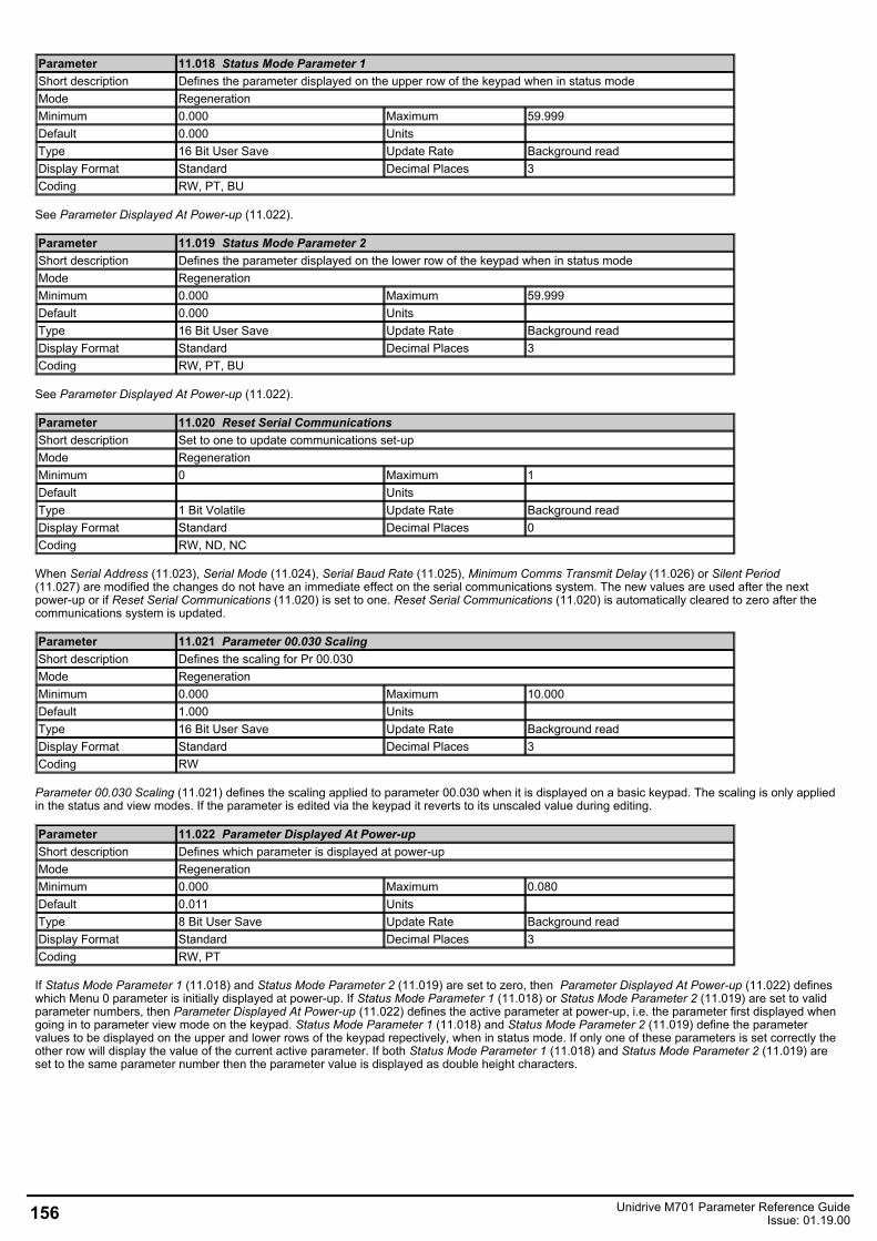
Parameter 11.018 Status Mode Parameter 1Short description Defines the parameter displayed on the upper row of the keypad when in status modeMode RegenerationMinimum 0.000 Maximum 59.999Default 0.000 Units Type 16 Bit User Save Update Rate Background readDisplay Format Standard Decimal Places 3Coding RW, PT, BU
See Parameter Displayed At Power-up (11.022).
Parameter 11.019 Status Mode Parameter 2Short description Defines the parameter displayed on the lower row of the keypad when in status modeMode RegenerationMinimum 0.000 Maximum 59.999Default 0.000 Units Type 16 Bit User Save Update Rate Background readDisplay Format Standard Decimal Places 3Coding RW, PT, BU
See Parameter Displayed At Power-up (11.022).
Parameter 11.020 Reset Serial CommunicationsShort description Set to one to update communications set-upMode RegenerationMinimum 0 Maximum 1Default Units Type 1 Bit Volatile Update Rate Background readDisplay Format Standard Decimal Places 0Coding RW, ND, NC
When Serial Address (11.023), Serial Mode (11.024), Serial Baud Rate (11.025), Minimum Comms Transmit Delay (11.026) or Silent Period(11.027) are modified the changes do not have an immediate effect on the serial communications system. The new values are used after the nextpower-up or if Reset Serial Communications (11.020) is set to one. Reset Serial Communications (11.020) is automatically cleared to zero after thecommunications system is updated.
Parameter 11.021 Parameter 00.030 ScalingShort description Defines the scaling for Pr 00.030Mode RegenerationMinimum 0.000 Maximum 10.000Default 1.000 Units Type 16 Bit User Save Update Rate Background readDisplay Format Standard Decimal Places 3Coding RW
Parameter 00.030 Scaling (11.021) defines the scaling applied to parameter 00.030 when it is displayed on a basic keypad. The scaling is only appliedin the status and view modes. If the parameter is edited via the keypad it reverts to its unscaled value during editing.
Parameter 11.022 Parameter Displayed At Power-upShort description Defines which parameter is displayed at power-upMode RegenerationMinimum 0.000 Maximum 0.080Default 0.011 Units Type 8 Bit User Save Update Rate Background readDisplay Format Standard Decimal Places 3Coding RW, PT
If Status Mode Parameter 1 (11.018) and Status Mode Parameter 2 (11.019) are set to zero, then Parameter Displayed At Power-up (11.022) defineswhich Menu 0 parameter is initially displayed at power-up. If Status Mode Parameter 1 (11.018) or Status Mode Parameter 2 (11.019) are set to validparameter numbers, then Parameter Displayed At Power-up (11.022) defines the active parameter at power-up, i.e. the parameter first displayed whengoing in to parameter view mode on the keypad. Status Mode Parameter 1 (11.018) and Status Mode Parameter 2 (11.019) define the parametervalues to be displayed on the upper and lower rows of the keypad repectively, when in status mode. If only one of these parameters is set correctly theother row will display the value of the current active parameter. If both Status Mode Parameter 1 (11.018) and Status Mode Parameter 2 (11.019) areset to the same parameter number then the parameter value is displayed as double height characters.
156 Unidrive M701 Parameter Reference GuideIssue: 01.19.00
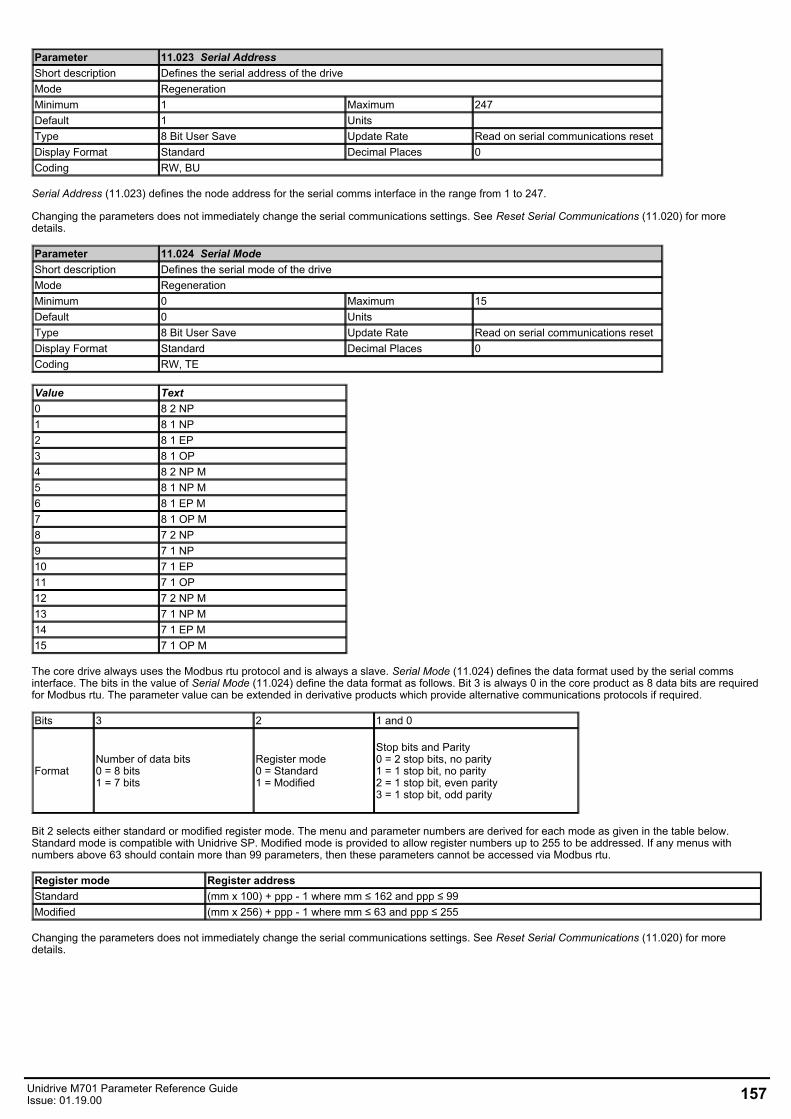
Parameter 11.023 Serial AddressShort description Defines the serial address of the driveMode RegenerationMinimum 1 Maximum 247Default 1 Units Type 8 Bit User Save Update Rate Read on serial communications resetDisplay Format Standard Decimal Places 0Coding RW, BU
Serial Address (11.023) defines the node address for the serial comms interface in the range from 1 to 247.
Changing the parameters does not immediately change the serial communications settings. See Reset Serial Communications (11.020) for moredetails.
Parameter 11.024 Serial ModeShort description Defines the serial mode of the driveMode RegenerationMinimum 0 Maximum 15Default 0 Units Type 8 Bit User Save Update Rate Read on serial communications resetDisplay Format Standard Decimal Places 0Coding RW, TE
Value Text0 8 2 NP1 8 1 NP2 8 1 EP3 8 1 OP4 8 2 NP M5 8 1 NP M6 8 1 EP M7 8 1 OP M8 7 2 NP9 7 1 NP10 7 1 EP11 7 1 OP12 7 2 NP M13 7 1 NP M14 7 1 EP M15 7 1 OP M
The core drive always uses the Modbus rtu protocol and is always a slave. Serial Mode (11.024) defines the data format used by the serial commsinterface. The bits in the value of Serial Mode (11.024) define the data format as follows. Bit 3 is always 0 in the core product as 8 data bits are requiredfor Modbus rtu. The parameter value can be extended in derivative products which provide alternative communications protocols if required.
Bits 3 2 1 and 0
FormatNumber of data bits0 = 8 bits1 = 7 bits
Register mode0 = Standard1 = Modified
Stop bits and Parity0 = 2 stop bits, no parity1 = 1 stop bit, no parity2 = 1 stop bit, even parity3 = 1 stop bit, odd parity
Bit 2 selects either standard or modified register mode. The menu and parameter numbers are derived for each mode as given in the table below.Standard mode is compatible with Unidrive SP. Modified mode is provided to allow register numbers up to 255 to be addressed. If any menus withnumbers above 63 should contain more than 99 parameters, then these parameters cannot be accessed via Modbus rtu.
Register mode Register addressStandard (mm x 100) + ppp - 1 where mm ≤ 162 and ppp ≤ 99Modified (mm x 256) + ppp - 1 where mm ≤ 63 and ppp ≤ 255
Changing the parameters does not immediately change the serial communications settings. See Reset Serial Communications (11.020) for moredetails.
Unidrive M701 Parameter Reference GuideIssue: 01.19.00 157
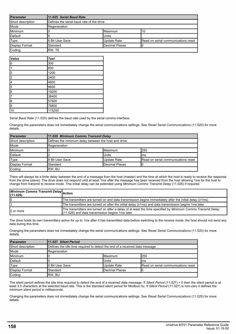
Parameter 11.025 Serial Baud RateShort description Defines the serial baud rate of the driveMode RegenerationMinimum 0 Maximum 10Default 6 Units Type 8 Bit User Save Update Rate Read on serial communications resetDisplay Format Standard Decimal Places 0Coding RW, TE
Value Text0 3001 6002 12003 24004 48005 96006 192007 384008 576009 7680010 115200
Serial Baud Rate (11.025) defines the baud rate used by the serial comms interface.
Changing the parameters does not immediately change the serial communications settings. See Reset Serial Communications (11.020) for moredetails.
Parameter 11.026 Minimum Comms Transmit DelayShort description Defines the minimum delay between the host and driveMode RegenerationMinimum 0 Maximum 250Default 2 Units msType 8 Bit User Save Update Rate Read on serial communications resetDisplay Format Standard Decimal Places 0Coding RW, BU
There will always be a finite delay between the end of a message from the host (master) and the time at which the host is ready to receive the responsefrom the drive (slave). The drive does not respond until at least 1ms after the message has been received from the host allowing 1ms for the host tochange from transmit to receive mode. This initial delay can be extended using Minimum Comms Transmit Delay (11.026) if required.
Minimum Comms Transmit Delay(11.026) Action
0 The transmitters are turned on and data transmission begins immediately after the initial delay (≥1ms)1 The transmitters are turned on after the initial delay (≥1ms) and data transmission begins 1ms later
2 or more The transmitters are turned on after a delay of at least the time specified by Minimum Comms Transmit Delay(11.026) and data transmission begins 1ms later
The drive holds its own transmitters active for up to 1ms after it has transmitted data before switching to the receive mode; the host should not send anydata during this time.
Changing the parameters does not immediately change the serial communications settings. See Reset Serial Communications (11.020) for moredetails.
Parameter 11.027 Silent PeriodShort description Defines the idle time required to detect the end of a received data messageMode RegenerationMinimum 0 Maximum 250Default 0 Units msType 8 Bit User Save Update Rate Read on serial communications resetDisplay Format Standard Decimal Places 0Coding RW, BU
The silent period defines the idle time required to detect the end of a received data message. If Silent Period (11.027) = 0 then the silent period is atleast 3.5 characters at the selected baud rate. This is the standard silent period for Modbus rtu. If Silent Period (11.027) is non-zero it defines theminimum silent period in milliseconds.
Changing the parameters does not immediately change the serial communications settings. See Reset Serial Communications (11.020) for moredetails.
158 Unidrive M701 Parameter Reference GuideIssue: 01.19.00
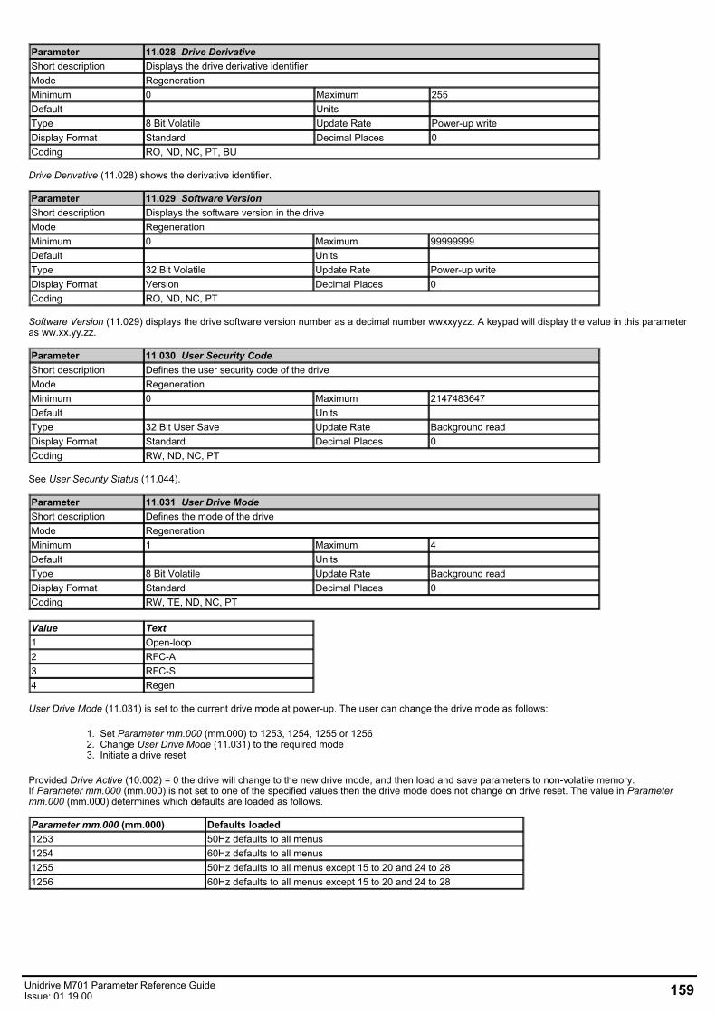
Parameter 11.028 Drive DerivativeShort description Displays the drive derivative identifierMode RegenerationMinimum 0 Maximum 255Default Units Type 8 Bit Volatile Update Rate Power-up writeDisplay Format Standard Decimal Places 0Coding RO, ND, NC, PT, BU
Drive Derivative (11.028) shows the derivative identifier.
Parameter 11.029 Software VersionShort description Displays the software version in the driveMode RegenerationMinimum 0 Maximum 99999999Default Units Type 32 Bit Volatile Update Rate Power-up writeDisplay Format Version Decimal Places 0Coding RO, ND, NC, PT
Software Version (11.029) displays the drive software version number as a decimal number wwxxyyzz. A keypad will display the value in this parameteras ww.xx.yy.zz.
Parameter 11.030 User Security CodeShort description Defines the user security code of the driveMode RegenerationMinimum 0 Maximum 2147483647Default Units Type 32 Bit User Save Update Rate Background readDisplay Format Standard Decimal Places 0Coding RW, ND, NC, PT
See User Security Status (11.044).
Parameter 11.031 User Drive ModeShort description Defines the mode of the driveMode RegenerationMinimum 1 Maximum 4Default Units Type 8 Bit Volatile Update Rate Background readDisplay Format Standard Decimal Places 0Coding RW, TE, ND, NC, PT
Value Text1 Open-loop2 RFC-A3 RFC-S4 Regen
User Drive Mode (11.031) is set to the current drive mode at power-up. The user can change the drive mode as follows:
1. Set Parameter mm.000 (mm.000) to 1253, 1254, 1255 or 12562. Change User Drive Mode (11.031) to the required mode3. Initiate a drive reset
Provided Drive Active (10.002) = 0 the drive will change to the new drive mode, and then load and save parameters to non-volatile memory.If Parameter mm.000 (mm.000) is not set to one of the specified values then the drive mode does not change on drive reset. The value in Parametermm.000 (mm.000) determines which defaults are loaded as follows.
Parameter mm.000 (mm.000) Defaults loaded1253 50Hz defaults to all menus1254 60Hz defaults to all menus1255 50Hz defaults to all menus except 15 to 20 and 24 to 281256 60Hz defaults to all menus except 15 to 20 and 24 to 28
Unidrive M701 Parameter Reference GuideIssue: 01.19.00 159
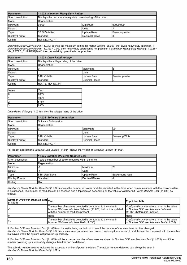
Parameter 11.032 Maximum Heavy Duty RatingShort description Displays the maximum heavy duty current rating of the driveMode RegenerationMinimum 0.000 Maximum 99999.999Default Units AType 32 Bit Volatile Update Rate Power-up writeDisplay Format Standard Decimal Places 3Coding RO, ND, NC, PT
Maximum Heavy Duty Rating (11.032) defines the maximum setting for Rated Current (05.007) that gives heavy duty operation. IfMaximum Heavy Duty Rating (11.032) = 0.000 then heavy duty operation is not possible. If Maximum Heavy Duty Rating (11.032) =VM_RATED_CURRENT[MAX] then normal duty operation is not possible.
Parameter 11.033 Drive Rated VoltageShort description Displays the voltage rating of the driveMode RegenerationMinimum 0 Maximum 3Default Units Type 8 Bit Volatile Update Rate Power-up writeDisplay Format Standard Decimal Places 0Coding RO, TE, ND, NC, PT
Value Text0 200V1 400V2 575V3 690V
Drive Rated Voltage (11.033) shows the voltage rating of the drive.
Parameter 11.034 Software Sub-versionShort description Software Sub-versionMode RegenerationMinimum 0 Maximum 99Default Units Type 8 Bit Volatile Update Rate Power-up WriteDisplay Format Standard Decimal Places 0Coding RO, ND, NC, PT
For legacy applications Software Sub-version (11.034) shows the yy part of Software Version (11.029).
Parameter 11.035 Number Of Power Modules TestShort description Tests the number of power modules within the driveMode RegenerationMinimum -1 Maximum 20Default -1 Units Type 8 Bit User Save Update Rate Background readDisplay Format Standard Decimal Places 0Coding RW
Number Of Power Modules Detected (11.071) shows the number of power modules detected in the drive when communications with the power systemis established. The number of modules can be checked and a trip initiated depending on the value of Number Of Power Modules Test (11.035) asfollows:
Number Of Power Modules Test(11.035) Test Trip if test fails
-1The number of modules detected is compared to the value inNumber Of Power Modules Detected (11.071) before it is updatedwith the number of modules present
Configuration.mmm where mmm is the valueof Number Of Power Modules Detected(11.071) before it is updated
0 None None
>0 The number of modules detected is compared to the value inNumber Of Power Modules Test (11.035)
Configuration.mmm where mmm is the valueof Number Of Power Modules Test (11.035)
If Number Of Power Modules Test (11.035) = -1 a test is being carried out to see if the number of modules detected has changed.Number Of Power Modules Detected (11.071) is a user save parameter, and so on power-up the number of modules can be compared with the numberlast saved when the system last powered up correctly.
If Number Of Power Modules Test (11.035) > 0 the expected number of modules are stored in Number Of Power Modules Test (11.035), and if thenumber powering up successfully changes then this can be detected.
The sub-trip number always indicates the expected number of power modules. The actual number detected can always be seen inNumber Of Power Modules Detected (11.071).
160 Unidrive M701 Parameter Reference GuideIssue: 01.19.00
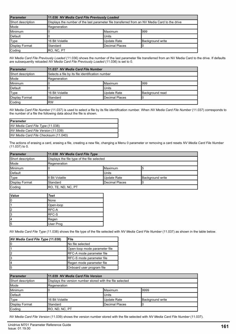
Parameter 11.036 NV Media Card File Previously LoadedShort description Displays the number of the last parameter file transferred from an NV Media Card to the driveMode RegenerationMinimum 0 Maximum 999Default 0 Units Type 16 Bit Volatile Update Rate Background writeDisplay Format Standard Decimal Places 0Coding RO, NC, PT
NV Media Card File Previously Loaded (11.036) shows the number of the last parameter file transferred from an NV Media Card to the drive. If defaultsare subsequently reloaded NV Media Card File Previously Loaded (11.036) is set to 0.
Parameter 11.037 NV Media Card File NumberShort description Selects a file by its file identification numberMode RegenerationMinimum 0 Maximum 999Default 0 Units Type 16 Bit Volatile Update Rate Background readDisplay Format Standard Decimal Places 0Coding RW
NV Media Card File Number (11.037) is used to select a file by its file identification number. When NV Media Card File Number (11.037) corresponds tothe number of a file the following data about the file is shown.
ParameterNV Media Card File Type (11.038)NV Media Card File Version (11.039)NV Media Card File Checksum (11.040)
The actions of erasing a card, erasing a file, creating a new file, changing a Menu 0 parameter or removing a card resets NV Media Card File Number(11.037) to 0.
Parameter 11.038 NV Media Card File TypeShort description Displays the file type of the file selectedMode RegenerationMinimum 0 Maximum 5Default Units Type 8 Bit Volatile Update Rate Background writeDisplay Format Standard Decimal Places 0Coding RO, TE, ND, NC, PT
Value Text0 None1 Open-loop2 RFC-A3 RFC-S4 Regen5 User Prog
NV Media Card File Type (11.038) shows the file type of the file selected with NV Media Card File Number (11.037) as shown in the table below.
NV Media Card File Type (11.038) File0 No file selected1 Open-loop mode parameter file2 RFC-A mode parameter file3 RFC-S mode parameter file4 Regen mode parameter file5 Onboard user program file
Parameter 11.039 NV Media Card File VersionShort description Displays the version number stored with the file selectedMode RegenerationMinimum 0 Maximum 9999Default Units Type 16 Bit Volatile Update Rate Background writeDisplay Format Standard Decimal Places 0Coding RO, ND, NC, PT
NV Media Card File Version (11.039) shows the version number stored with the file selected with NV Media Card File Number (11.037).
Unidrive M701 Parameter Reference GuideIssue: 01.19.00 161
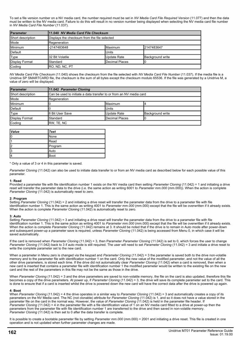
To set a file version number on a NV media card, the number required must be set in NV Media Card File Required Version (11.077) and then the datamust be written to the NV media card. Failure to do this will result in no version number being displayed when selecting the NV media card file numberin NV Media Card File Number (11.037).
Parameter 11.040 NV Media Card File ChecksumShort description Displays the checksum from the file selectedMode RegenerationMinimum -2147483648 Maximum 2147483647Default Units Type 32 Bit Volatile Update Rate Background writeDisplay Format Standard Decimal Places 0Coding RO, ND, NC, PT
NV Media Card File Checksum (11.040) shows the checksum from the file selected with NV Media Card File Number (11.037). If the media file is aUnidrive SP SMARTCARD file, the checksum is the sum of all bytes except the checksum modulo 65536. If the file was generated by a Unidrive M, avalue of zero will be displayed.
Parameter 11.042 Parameter CloningShort description Can be used to initiate a data transfer to or from an NV media cardMode RegenerationMinimum 0 Maximum 4Default 0 Units Type 8 Bit User Save Update Rate Background writeDisplay Format Standard Decimal Places 0Coding RW, TE, NC
Value Text0 None1 Read2 Program3 Auto4 Boot
* Only a value of 3 or 4 in this parameter is saved.
Parameter Cloning (11.042) can also be used to initiate data transfer to or from an NV media card as described below for each possible value of thisparameter.
1: ReadProvided a parameter file with file identification number 1 exists on the NV media card then setting Parameter Cloning (11.042) = 1 and initiating a drivereset will transfer the parameter data to the drive (i.e. the same action as writing 6001 to Parameter mm.000 (mm.000)). When the action is completeParameter Cloning (11.042) is automatically reset to zero.
2: ProgramSetting Parameter Cloning (11.042) = 2 and initiating a drive reset will transfer the parameter data from the drive to a parameter file with fileidentification number 1. This is the same action as writing 4001 to Parameter mm.000 (mm.000) except that the file will be overwritten if it already exists.When the action is complete Parameter Cloning (11.042) is automatically reset to zero.
3: AutoSetting Parameter Cloning (11.042) = 3 and initiating a drive reset will transfer the parameter data from the drive to a parameter file with fileidentification number 1. This is the same action as writing 4001 to Parameter mm.000 (mm.000) except that the file will be overwritten if it already exists.When the action is complete Parameter Cloning (11.042) remains at 3. It should be noted that if the drive is to remain in Auto mode after power-downand subsequent power-up a parameter save is required, unless Parameter Cloning (11.042) is being accessed from Menu 0, in which case it will besaved automatically.
If the card is removed when Parameter Cloning (11.042) = 3, then Parameter Parameter Cloning (11.042) is set to 0, which forces the user to changeParameter Cloning (11.042) back to 3 if auto mode is still required. The user will need to set Parameter Cloning (11.042) = 3 and initiate a drive reset towrite the complete parameter set to the new card.
When a parameter in Menu zero is changed via the keypad and Parameter Cloning (11.042) = 3 the parameter is saved both to the drive non-volatilememory and to the parameter file with identification number 1 on the card. Only the new value of the modified parameter, and not the value of all theother drive parameters, is stored each time. If the drive did not automatically clear Parameter Cloning (11.042) when a card is removed, then when anew card is inserted that contains a parameter file with identification number 1 the modified parameter would be written to the existing file on the newcard and the rest of the parameters in this file may not be the same as those in the drive.
When Parameter Cloning (11.042) = 3 and the drive parameters are saved to non-volatile memory, the file on the card is also updated, therefore this filebecomes a copy of the drive parameters. At power up, if Parameter Cloning (11.042) = 3, the drive will save its complete parameter set to the card. Thisis done to ensure that if a card is inserted whilst the drive is powered down the new card will have the correct data after the drive is powered up again.
4: BootWhen Parameter Cloning (11.042) = 4 the drive operates in a similar way to Parameter Cloning (11.042) = 3 and automatically creates a copy of itsparameters on the NV Media card. The NC (not clonable) attribute for Parameter Cloning (11.042) is 1, and so it does not have a value stored in theparameter file on the card in the normal way. However, the value of Parameter Cloning (11.042) is held in the parameter file header. IfParameter Cloning (11.042) = 4 in the parameter file with a file identification value of 1 on an NV media card fitted to a drive at power-up then theparameters from the parameter file with file identification number 1 are transferred to the drive and then saved in non-volatile memory.Parameter Cloning (11.042) is then set to 0 after the data transfer is complete.
It is possible to create a bootable parameter file by setting Parameter mm.000 (mm.000) = 2001 and initiating a drive reset. This file is created in oneoperation and is not updated when further parameter changes are made.
162 Unidrive M701 Parameter Reference GuideIssue: 01.19.00
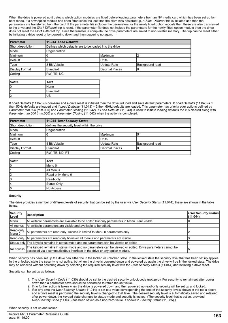
When the drive is powered up it detects which option modules are fitted before loading parameters from an NV media card which has been set up forboot mode. If a new option module has been fitted since the last time the drive was powered up, a Slot1 Different trip is initiated and then theparameters are transferred from the card. If the parameter file includes the parameters for the newly fitted option module then these are also transferredto the drive and the Slot1 Different trip is reset. If the parameter file does not include the parameters for the newly fitted option module then the drivedoes not reset the Slot1 Different trip. Once the transfer is complete the drive parameters are saved to non-volatile memory. The trip can be reset eitherby initiating a drive reset or by powering down and then powering up again.
Parameter 11.043 Load DefaultsShort description Defines which defaults are to be loaded into the driveMode RegenerationMinimum 0 Maximum 2Default 0 Units Type 8 Bit Volatile Update Rate Background readDisplay Format Standard Decimal Places 0Coding RW, TE, NC
Value Text0 None1 Standard2 US
If Load Defaults (11.043) is non-zero and a drive reset is initiated then the drive will load and save default parameters. If Load Defaults (11.043) = 1then 50Hz defaults are loaded and if Load Defaults (11.043) = 2 then 60Hz defaults are loaded. This parameter has priority over actions defined byParameter mm.000 (mm.000) and Parameter Cloning (11.042). If Load Defaults (11.043) is used to initiate loading defaults the it is cleared along withParameter mm.000 (mm.000) and Parameter Cloning (11.042) when the action is completed.
Parameter 11.044 User Security StatusShort description defines the security level within the driveMode RegenerationMinimum 0 Maximum 5Default Units Type 8 Bit Volatile Update Rate Background readDisplay Format Standard Decimal Places 0Coding RW, TE, ND, PT
Value Text0 Menu 01 All Menus2 Read-only Menu 03 Read-only4 Status Only5 No Access
Security
The drive provides a number of different levels of security that can be set by the user via User Security Status (11.044); these are shown in the tablebelow.
SecurityLevel Description User Security Status
(11.044)Menu 0 All writable parameters are available to be edited but only parameters in Menu 0 are visible. 0All menus All writable parameters are visible and available to be edited. 1Read-onlyMenu 0 All parameters are read-only. Access is limited to Menu 0 parameters only. 2
Read-only All parameters are read-only however all menus and parameters are visible. 3Status only The keypad remains in status mode and no parameters can be viewed or edited 4
No access The keypad remains in status mode and no parameters can be viewed or edited. Drive parameters cannot beaccessed via a comms/fieldbus interface in the drive or any option module. 5
When security has been set up the drive can either be in the locked or unlocked state. In the locked state the security level that has been set up applies.In the unlocked state the security is not active, but when the drive is powered down and powered up again the drive will be in the locked state. The drivemay be relocked without powering down by selecting the required security level with the User Security Status (11.044) and initiating a drive reset.
Security can be set up as follows:
1. The User Security Code (11.030) should be set to the desired security unlock code (not zero). For security to remain set after powerdown then a parameter save should be performed to retain the set value.
2. If no further action is taken when the drive is powered down and then powered up read-only security will be set up and locked.3. If at any time the User Security Status (11.044) is set to a value corresponding the one of the security levels shown in the table above
and a drive reset is performed the security level is changed to that level. The desired security level is automatically saved and retainedafter power down, the keypad state changes to status mode and security is locked. (The security level that is active, providedUser Security Code (11.030) has been saved as a non-zero value, if shown in Security Status (11.085).)
When security is set up and locked:
Unidrive M701 Parameter Reference GuideIssue: 01.19.00 163
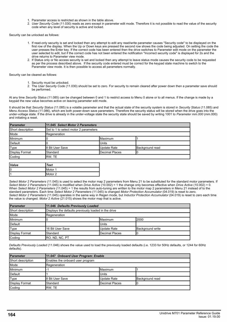
1. Parameter access is restricted as shown in the table above.2. User Security Code (11.030) reads as zero except in parameter edit mode. Therefore it is not possible to read the value of the security
code when any level of security is active and locked.
Security can be unlocked as follows:
1. If read-only security is set and locked then any attempt to edit any read/write parameter causes "Security code" to be displayed on thefirst row of the display. When the Up or Down keys are pressed the second row shows the code being adjusted. On setting the code theuser presses the Enter key. If the correct code has been entered then the drive switches to Parameter edit mode on the parameter theuser selected to edit, but if the correct code has not been entered the notification "Incorrect security code" is displayed for 2s and thedrive returns to Parameter view mode.
2. If Status only or No access security is set and locked then any attempt to leave status mode causes the security code to be requestedas per the process described above. If the security code entered must be correct for the keypad state machine to switch to theParameter view mode. It is then possible to access all parameters normally.
Security can be cleared as follows:
1. Security must be unlocked.2. The User Security Code (11.030) should be set to zero. For security to remain cleared after power down then a parameter save should
be performed.
At any time Security Status (11.085) can be changed between 0 and 1 to restrict access to Menu 0 alone or to all menus. If the change is made by akeypad the new value becomes active on leaving parameter edit mode.
It should be that Security Status (11.085) is a volatile parameter and that the actual state of the security system is stored in Security Status (11.085) andMenu Access Status (11.086), which are both power-down save parameters. Therefore the security status will be stored when the drive goes into theunder-voltage state. If the drive is already in the under-voltage state the security state should be saved by writing 1001 to Parameter mm.000 (mm.000)and initiating a reset.
Parameter 11.045 Select Motor 2 ParametersShort description Set to 1 to select motor 2 parametersMode RegenerationMinimum 0 Maximum 1Default 0 Units Type 8 Bit User Save Update Rate Background readDisplay Format Standard Decimal Places 0Coding RW, TE
Value Text0 Motor 11 Motor 2
Select Motor 2 Parameters (11.045) is used to select the motor map 2 parameters from Menu 21 to be substituted for the standard motor parameters. IfSelect Motor 2 Parameters (11.045) is modified when Drive Active (10.002) = 1 the change only becomes effective when Drive Active (10.002) = 0.When Select Motor 2 Parameters (11.045) = 1 the results from auto-tuning are written to the motor map 2 parameters in Menu 21 instead of to thestandard parameters. Each time Select Motor 2 Parameters (11.045) is changed Motor Protection Accumulator (04.019) is reset to zero.Select Motor 2 Parameters (11.045) operates in the same way in Regen mode, but Inductor Protection Accumulator (04.019) is reset to zero each timethe value is changed. Motor 2 Active (21.015) shows the motor map that is active.
Parameter 11.046 Defaults Previously LoadedShort description Displays the defaults previously loaded in the driveMode RegenerationMinimum 0 Maximum 2000Default Units Type 16 Bit User Save Update Rate Background writeDisplay Format Standard Decimal Places 0Coding RO, ND, NC, PT
Defaults Previously Loaded (11.046) shows the value used to load the previously loaded defaults (i.e. 1233 for 50Hz defaults, or 1244 for 60Hzdefaults).
Parameter 11.047 Onboard User Program: EnableShort description Enables the onboard user programMode RegenerationMinimum -1 Maximum 1Default 1 Units Type 8 Bit User Save Update Rate Background readDisplay Format Standard Decimal Places 0Coding RW, TE
164 Unidrive M701 Parameter Reference GuideIssue: 01.19.00
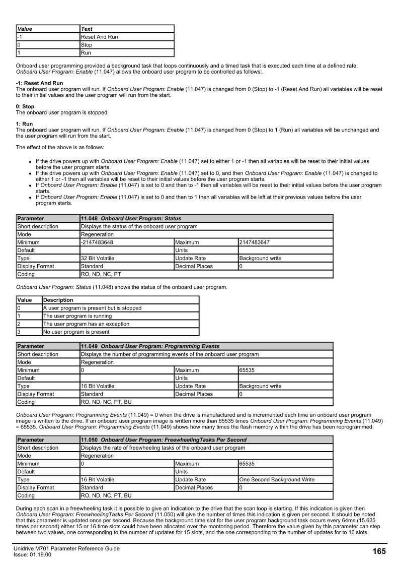
Value Text-1 Reset And Run0 Stop1 Run
Onboard user programming provided a background task that loops continuously and a timed task that is executed each time at a defined rate.Onboard User Program: Enable (11.047) allows the onboard user program to be controlled as follows:.
-1: Reset And RunThe onboard user program will run. If Onboard User Program: Enable (11.047) is changed from 0 (Stop) to -1 (Reset And Run) all variables will be resetto their initial values and the user program will run from the start.
0: StopThe onboard user program is stopped.
1: RunThe onboard user program will run. If Onboard User Program: Enable (11.047) is changed from 0 (Stop) to 1 (Run) all variables will be unchanged andthe user program will run from the start.
The effect of the above is as follows:
If the drive powers up with Onboard User Program: Enable (11.047) set to either 1 or -1 then all variables will be reset to their initial valuesbefore the user program starts.If the drive powers up with Onboard User Program: Enable (11.047) set to 0, and then Onboard User Program: Enable (11.047) is changed toeither 1 or -1 then all variables will be reset to their initial values before the user program starts.If Onboard User Program: Enable (11.047) is set to 0 and then to -1 then all variables will be reset to their initial values before the user programstarts.If Onboard User Program: Enable (11.047) is set to 0 and then to 1 then all variables will be left at their previous values before the userprogram starts.
Parameter 11.048 Onboard User Program: StatusShort description Displays the status of the onboard user programMode RegenerationMinimum -2147483648 Maximum 2147483647Default Units Type 32 Bit Volatile Update Rate Background writeDisplay Format Standard Decimal Places 0Coding RO, ND, NC, PT
Onboard User Program: Status (11.048) shows the status of the onboard user program.
Value Description0 A user program is present but is stopped1 The user program is running2 The user program has an exception3 No user program is present
Parameter 11.049 Onboard User Program: Programming EventsShort description Displays the number of programming events of the onboard user programMode RegenerationMinimum 0 Maximum 65535Default Units Type 16 Bit Volatile Update Rate Background writeDisplay Format Standard Decimal Places 0Coding RO, ND, NC, PT, BU
Onboard User Program: Programming Events (11.049) = 0 when the drive is manufactured and is incremented each time an onboard user programimage is written to the drive. If an onboard user program image is written more than 65535 times Onboard User Program: Programming Events (11.049)= 65535. Onboard User Program: Programming Events (11.049) shows how many times the flash memory within the drive has been reprogrammed.
Parameter 11.050 Onboard User Program: FreewheelingTasks Per SecondShort description Displays the rate of freewheeling tasks of the onboard user programMode RegenerationMinimum 0 Maximum 65535Default Units Type 16 Bit Volatile Update Rate One Second Background WriteDisplay Format Standard Decimal Places 0Coding RO, ND, NC, PT, BU
During each scan in a freewheeling task it is possible to give an indication to the drive that the scan loop is starting. If this indication is given thenOnboard User Program: FreewheelingTasks Per Second (11.050) will give the number of times this indication is given per second. It should be notedthat this parameter is updated once per second. Because the background time slot for the user program background task occurs every 64ms (15.625times per second) either 15 or 16 time slots could have been allocated over the montoring period. Therefore the value given by this parameter can stepbetween two values, one corresponding to the number of updates for 15 slots, and the one corresponding to the number of updates for to 16 slots.
Unidrive M701 Parameter Reference GuideIssue: 01.19.00 165
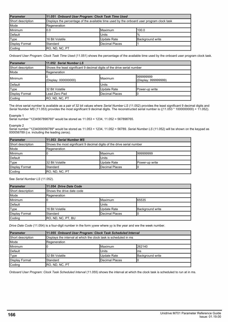
Parameter 11.051 Onboard User Program: Clock Task Time UsedShort description Displays the percentage of the available time used by the onboard user program clock taskMode RegenerationMinimum 0.0 Maximum 100.0Default Units %Type 16 Bit Volatile Update Rate Background writeDisplay Format Standard Decimal Places 1Coding RO, ND, NC, PT
Onboard User Program: Clock Task Time Used (11.051) shows the percentage of the available time used by the onboard user program clock task.
Parameter 11.052 Serial Number LSShort description Shows the least significant 9 decimal digits of the drive serial numberMode Regeneration
Minimum 0(Display: 000000000) Maximum 999999999
(Display: 999999999)Default Units Type 32 Bit Volatile Update Rate Power-up writeDisplay Format Lead Zero Pad Decimal Places 0Coding RO, ND, NC, PT
The drive serial number is available as a pair of 32 bit values where Serial Number LS (11.052) provides the least significant 9 decimal digits andSerial Number MS (11.053) provides the most significant 9 decimal digits. The reconstructed serial number is ((11.053 * 1000000000) + 11.052).
Example 1Serial number "1234567898765" would be stored as 11.053 = 1234, 11.052 = 567898765.
Example 2Serial number "1234000056789" would be stored as 11.053 = 1234, 11.052 = 56789. Serial Number LS (11.052) will be shown on the keypad as000056789 (i.e. including the leading zeros).
Parameter 11.053 Serial Number MSShort description Shows the most significant 9 decimal digits of the drive serial numberMode RegenerationMinimum 0 Maximum 999999999Default Units Type 32 Bit Volatile Update Rate Power-up writeDisplay Format Standard Decimal Places 0Coding RO, ND, NC, PT
See Serial Number LS (11.052).
Parameter 11.054 Drive Date CodeShort description Shows the drive date codeMode RegenerationMinimum 0 Maximum 65535Default Units Type 16 Bit Volatile Update Rate Background writeDisplay Format Standard Decimal Places 0Coding RO, ND, NC, PT, BU
Drive Date Code (11.054) is a four-digit number in the form yyww where yy is the year and ww the week number.
Parameter 11.055 Onboard User Program: Clock Task Scheduled IntervalShort description Displays the interval at which the clock task is scheduled in msMode RegenerationMinimum 0 Maximum 262140Default Units msType 32 Bit Volatile Update Rate Background writeDisplay Format Standard Decimal Places 0Coding RO, ND, NC, PT
Onboard User Program: Clock Task Scheduled Interval (11.055) shows the interval at which the clock task is scheduled to run at in ms.
166 Unidrive M701 Parameter Reference GuideIssue: 01.19.00
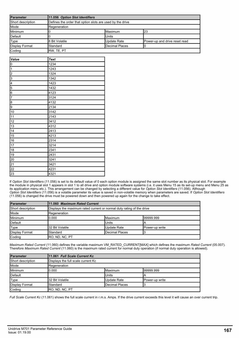
Parameter 11.056 Option Slot IdentifiersShort description Defines the order that option slots are used by the driveMode RegenerationMinimum 0 Maximum 23Default 0 Units Type 8 Bit Volatile Update Rate Power-up and drive reset readDisplay Format Standard Decimal Places 0Coding RW, TE, PT
Value Text0 12341 12432 13243 13424 14235 14326 41237 31248 41329 213410 314211 214312 341213 431214 241315 421316 231417 321418 234119 243120 324121 342122 423123 4321
If Option Slot Identifiers (11.056) is set to its default value of 0 each option module is assigned the same slot number as its physical slot. For examplethe module in physical slot 1 appears in slot 1 to all drive and option module software systems (i.e. it uses Menu 15 as its set-up menu and Menu 25 asits application menu etc.). This arrangement can be changed by selecting a different value for Option Slot Identifiers (11.056). AlthoughOption Slot Identifiers (11.056) is a volatile parameter its value is saved in non-volatile memory when parameters are saved. If Option Slot Identifiers(11.056) is changed the drive must be powered down and then powered up again for the change to take effect.
Parameter 11.060 Maximum Rated CurrentShort description Displays the maximum rated current or normal duty rating of the driveMode RegenerationMinimum 0.000 Maximum 99999.999Default Units AType 32 Bit Volatile Update Rate Power-up writeDisplay Format Standard Decimal Places 3Coding RO, ND, NC, PT
Maximum Rated Current (11.060) defines the variable maximum VM_RATED_CURRENT[MAX] which defines the maximum Rated Current (05.007).Therefore Maximum Rated Current (11.060) is the maximum rated current for normal duty operation (if normal duty operation is allowed).
Parameter 11.061 Full Scale Current KcShort description Displays the full scale current KcMode RegenerationMinimum 0.000 Maximum 99999.999Default Units AType 32 Bit Volatile Update Rate Power-up writeDisplay Format Standard Decimal Places 3Coding RO, ND, NC, PT
Full Scale Current Kc (11.061) shows the full scale current in r.m.s. Amps. If the drive current exceeds this level it will cause an over current trip.
Unidrive M701 Parameter Reference GuideIssue: 01.19.00 167
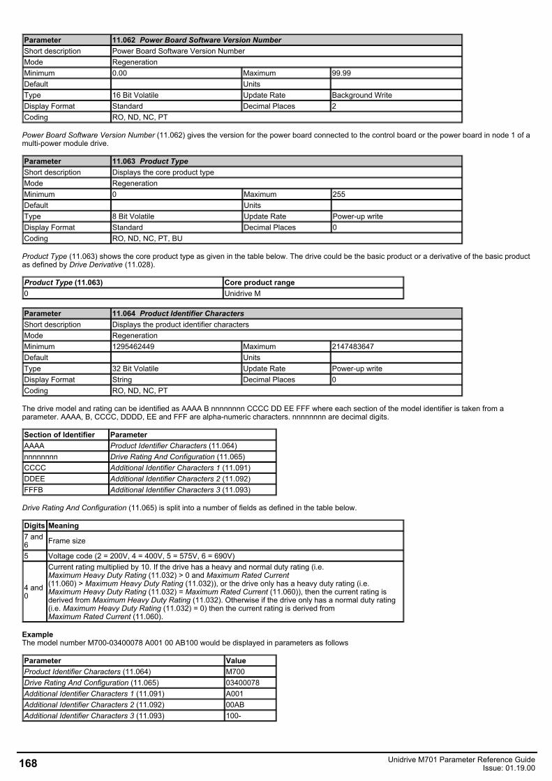
Parameter 11.062 Power Board Software Version NumberShort description Power Board Software Version NumberMode RegenerationMinimum 0.00 Maximum 99.99Default Units Type 16 Bit Volatile Update Rate Background WriteDisplay Format Standard Decimal Places 2Coding RO, ND, NC, PT
Power Board Software Version Number (11.062) gives the version for the power board connected to the control board or the power board in node 1 of amulti-power module drive.
Parameter 11.063 Product TypeShort description Displays the core product typeMode RegenerationMinimum 0 Maximum 255Default Units Type 8 Bit Volatile Update Rate Power-up writeDisplay Format Standard Decimal Places 0Coding RO, ND, NC, PT, BU
Product Type (11.063) shows the core product type as given in the table below. The drive could be the basic product or a derivative of the basic productas defined by Drive Derivative (11.028).
Product Type (11.063) Core product range0 Unidrive M
Parameter 11.064 Product Identifier CharactersShort description Displays the product identifier charactersMode RegenerationMinimum 1295462449 Maximum 2147483647Default Units Type 32 Bit Volatile Update Rate Power-up writeDisplay Format String Decimal Places 0Coding RO, ND, NC, PT
The drive model and rating can be identified as AAAA B nnnnnnnn CCCC DD EE FFF where each section of the model identifier is taken from aparameter. AAAA, B, CCCC, DDDD, EE and FFF are alpha-numeric characters. nnnnnnnn are decimal digits.
Section of Identifier ParameterAAAA Product Identifier Characters (11.064)nnnnnnnn Drive Rating And Configuration (11.065)CCCC Additional Identifier Characters 1 (11.091)DDEE Additional Identifier Characters 2 (11.092)FFFB Additional Identifier Characters 3 (11.093)
Drive Rating And Configuration (11.065) is split into a number of fields as defined in the table below.
Digits Meaning7 and6 Frame size
5 Voltage code (2 = 200V, 4 = 400V, 5 = 575V, 6 = 690V)
4 and0
Current rating multiplied by 10. If the drive has a heavy and normal duty rating (i.e.Maximum Heavy Duty Rating (11.032) > 0 and Maximum Rated Current(11.060) > Maximum Heavy Duty Rating (11.032)), or the drive only has a heavy duty rating (i.e.Maximum Heavy Duty Rating (11.032) = Maximum Rated Current (11.060)), then the current rating isderived from Maximum Heavy Duty Rating (11.032). Otherwise if the drive only has a normal duty rating(i.e. Maximum Heavy Duty Rating (11.032) = 0) then the current rating is derived fromMaximum Rated Current (11.060).
ExampleThe model number M700-03400078 A001 00 AB100 would be displayed in parameters as follows
Parameter ValueProduct Identifier Characters (11.064) M700Drive Rating And Configuration (11.065) 03400078Additional Identifier Characters 1 (11.091) A001Additional Identifier Characters 2 (11.092) 00ABAdditional Identifier Characters 3 (11.093) 100-
168 Unidrive M701 Parameter Reference GuideIssue: 01.19.00
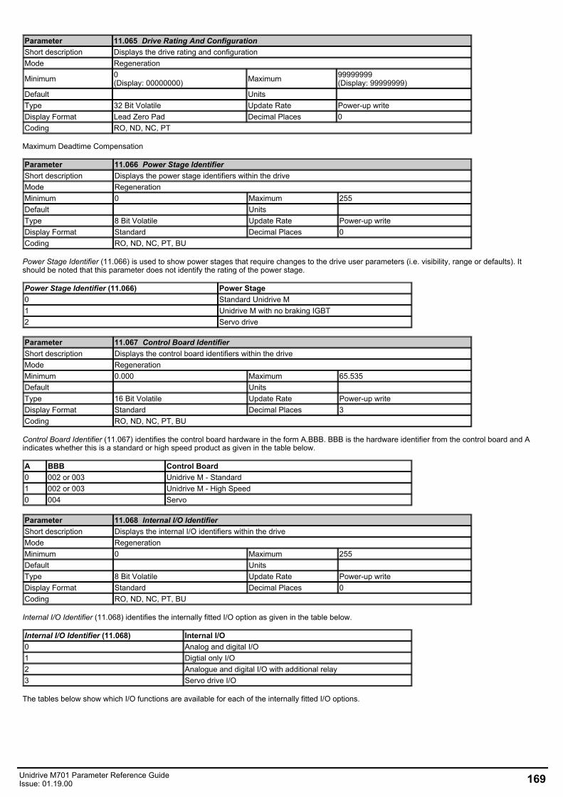
Parameter 11.065 Drive Rating And ConfigurationShort description Displays the drive rating and configurationMode Regeneration
Minimum 0(Display: 00000000) Maximum 99999999
(Display: 99999999)Default Units Type 32 Bit Volatile Update Rate Power-up writeDisplay Format Lead Zero Pad Decimal Places 0Coding RO, ND, NC, PT
Maximum Deadtime Compensation
Parameter 11.066 Power Stage IdentifierShort description Displays the power stage identifiers within the driveMode RegenerationMinimum 0 Maximum 255Default Units Type 8 Bit Volatile Update Rate Power-up writeDisplay Format Standard Decimal Places 0Coding RO, ND, NC, PT, BU
Power Stage Identifier (11.066) is used to show power stages that require changes to the drive user parameters (i.e. visibility, range or defaults). Itshould be noted that this parameter does not identify the rating of the power stage.
Power Stage Identifier (11.066) Power Stage0 Standard Unidrive M1 Unidrive M with no braking IGBT2 Servo drive
Parameter 11.067 Control Board IdentifierShort description Displays the control board identifiers within the driveMode RegenerationMinimum 0.000 Maximum 65.535Default Units Type 16 Bit Volatile Update Rate Power-up writeDisplay Format Standard Decimal Places 3Coding RO, ND, NC, PT, BU
Control Board Identifier (11.067) identifies the control board hardware in the form A.BBB. BBB is the hardware identifier from the control board and Aindicates whether this is a standard or high speed product as given in the table below.
A BBB Control Board0 002 or 003 Unidrive M - Standard1 002 or 003 Unidrive M - High Speed0 004 Servo
Parameter 11.068 Internal I/O IdentifierShort description Displays the internal I/O identifiers within the driveMode RegenerationMinimum 0 Maximum 255Default Units Type 8 Bit Volatile Update Rate Power-up writeDisplay Format Standard Decimal Places 0Coding RO, ND, NC, PT, BU
Internal I/O Identifier (11.068) identifies the internally fitted I/O option as given in the table below.
Internal I/O Identifier (11.068) Internal I/O0 Analog and digital I/O1 Digtial only I/O2 Analogue and digital I/O with additional relay3 Servo drive I/O
The tables below show which I/O functions are available for each of the internally fitted I/O options.
Unidrive M701 Parameter Reference GuideIssue: 01.19.00 169
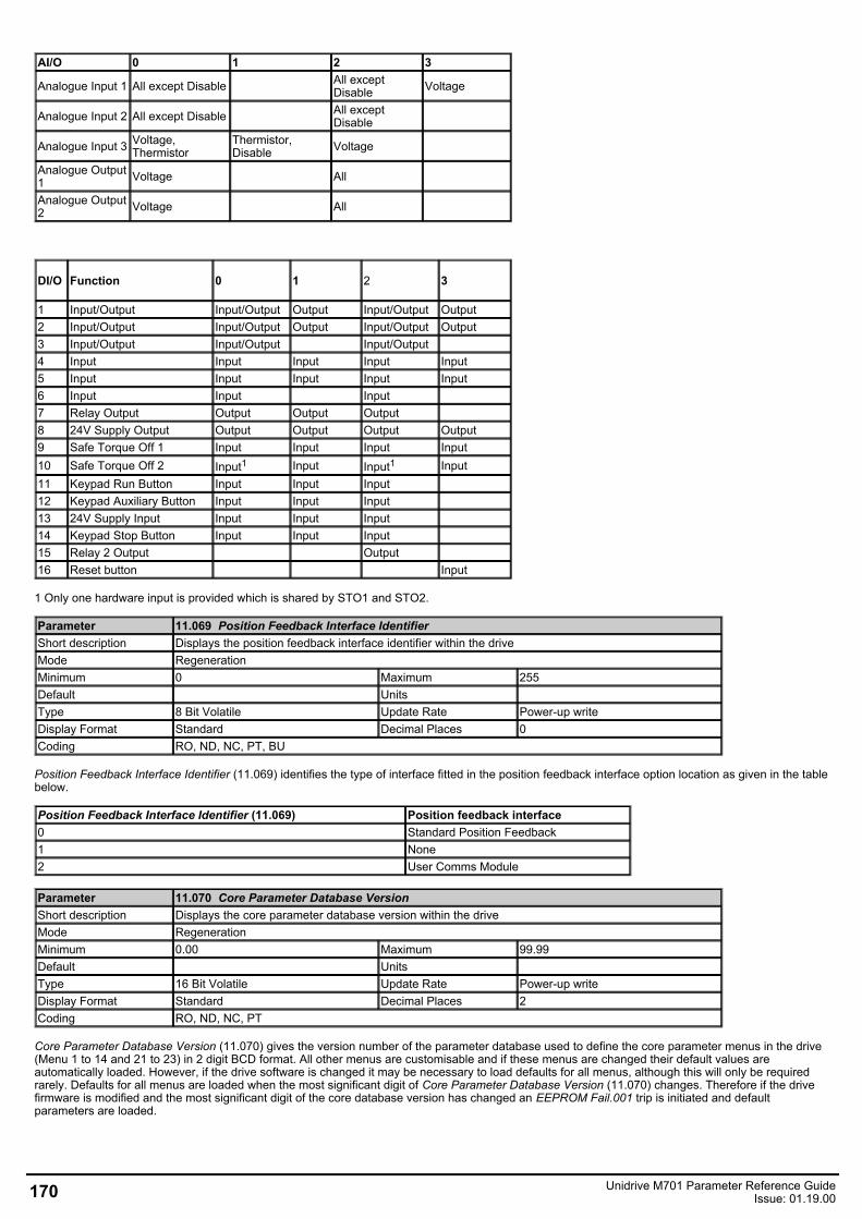
AI/O 0 1 2 3
Analogue Input 1 All except Disable All exceptDisable Voltage
Analogue Input 2 All except Disable All exceptDisable
Analogue Input 3 Voltage,Thermistor
Thermistor,Disable Voltage
Analogue Output1 Voltage All
Analogue Output2 Voltage All
DI/O Function 0 1 2 3
1 Input/Output Input/Output Output Input/Output Output 2 Input/Output Input/Output Output Input/Output Output3 Input/Output Input/Output Input/Output4 Input Input Input Input Input5 Input Input Input Input Input6 Input Input Input7 Relay Output Output Output Output8 24V Supply Output Output Output Output Output9 Safe Torque Off 1 Input Input Input Input10 Safe Torque Off 2 Input1 Input Input1 Input11 Keypad Run Button Input Input Input12 Keypad Auxiliary Button Input Input Input13 24V Supply Input Input Input Input14 Keypad Stop Button Input Input Input15 Relay 2 Output Output16 Reset button Input
1 Only one hardware input is provided which is shared by STO1 and STO2.
Parameter 11.069 Position Feedback Interface IdentifierShort description Displays the position feedback interface identifier within the driveMode RegenerationMinimum 0 Maximum 255Default Units Type 8 Bit Volatile Update Rate Power-up writeDisplay Format Standard Decimal Places 0Coding RO, ND, NC, PT, BU
Position Feedback Interface Identifier (11.069) identifies the type of interface fitted in the position feedback interface option location as given in the tablebelow.
Position Feedback Interface Identifier (11.069) Position feedback interface0 Standard Position Feedback1 None2 User Comms Module
Parameter 11.070 Core Parameter Database VersionShort description Displays the core parameter database version within the driveMode RegenerationMinimum 0.00 Maximum 99.99Default Units Type 16 Bit Volatile Update Rate Power-up writeDisplay Format Standard Decimal Places 2Coding RO, ND, NC, PT
Core Parameter Database Version (11.070) gives the version number of the parameter database used to define the core parameter menus in the drive(Menu 1 to 14 and 21 to 23) in 2 digit BCD format. All other menus are customisable and if these menus are changed their default values areautomatically loaded. However, if the drive software is changed it may be necessary to load defaults for all menus, although this will only be requiredrarely. Defaults for all menus are loaded when the most significant digit of Core Parameter Database Version (11.070) changes. Therefore if the drivefirmware is modified and the most significant digit of the core database version has changed an EEPROM Fail.001 trip is initiated and defaultparameters are loaded.
170 Unidrive M701 Parameter Reference GuideIssue: 01.19.00
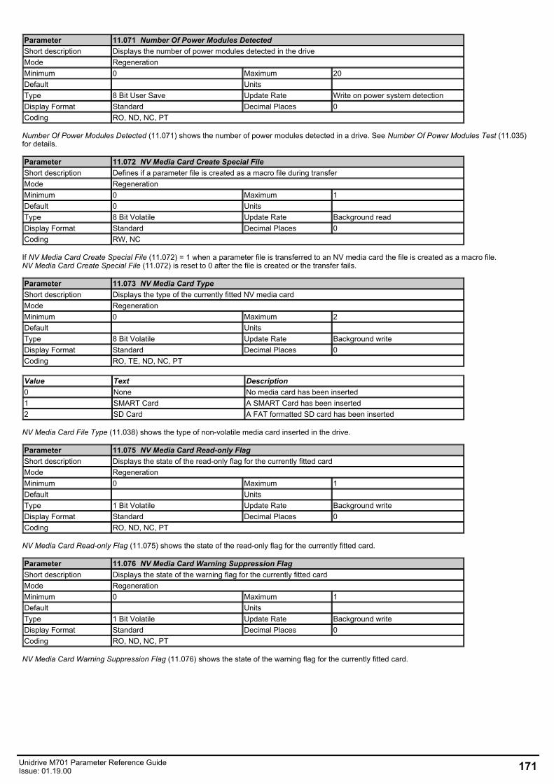
Parameter 11.071 Number Of Power Modules DetectedShort description Displays the number of power modules detected in the driveMode RegenerationMinimum 0 Maximum 20Default Units Type 8 Bit User Save Update Rate Write on power system detectionDisplay Format Standard Decimal Places 0Coding RO, ND, NC, PT
Number Of Power Modules Detected (11.071) shows the number of power modules detected in a drive. See Number Of Power Modules Test (11.035)for details.
Parameter 11.072 NV Media Card Create Special FileShort description Defines if a parameter file is created as a macro file during transferMode RegenerationMinimum 0 Maximum 1Default 0 Units Type 8 Bit Volatile Update Rate Background readDisplay Format Standard Decimal Places 0Coding RW, NC
If NV Media Card Create Special File (11.072) = 1 when a parameter file is transferred to an NV media card the file is created as a macro file.NV Media Card Create Special File (11.072) is reset to 0 after the file is created or the transfer fails.
Parameter 11.073 NV Media Card TypeShort description Displays the type of the currently fitted NV media cardMode RegenerationMinimum 0 Maximum 2Default Units Type 8 Bit Volatile Update Rate Background writeDisplay Format Standard Decimal Places 0Coding RO, TE, ND, NC, PT
Value Text Description0 None No media card has been inserted1 SMART Card A SMART Card has been inserted2 SD Card A FAT formatted SD card has been inserted
NV Media Card File Type (11.038) shows the type of non-volatile media card inserted in the drive.
Parameter 11.075 NV Media Card Read-only FlagShort description Displays the state of the read-only flag for the currently fitted cardMode RegenerationMinimum 0 Maximum 1Default Units Type 1 Bit Volatile Update Rate Background writeDisplay Format Standard Decimal Places 0Coding RO, ND, NC, PT
NV Media Card Read-only Flag (11.075) shows the state of the read-only flag for the currently fitted card.
Parameter 11.076 NV Media Card Warning Suppression FlagShort description Displays the state of the warning flag for the currently fitted cardMode RegenerationMinimum 0 Maximum 1Default Units Type 1 Bit Volatile Update Rate Background writeDisplay Format Standard Decimal Places 0Coding RO, ND, NC, PT
NV Media Card Warning Suppression Flag (11.076) shows the state of the warning flag for the currently fitted card.
Unidrive M701 Parameter Reference GuideIssue: 01.19.00 171
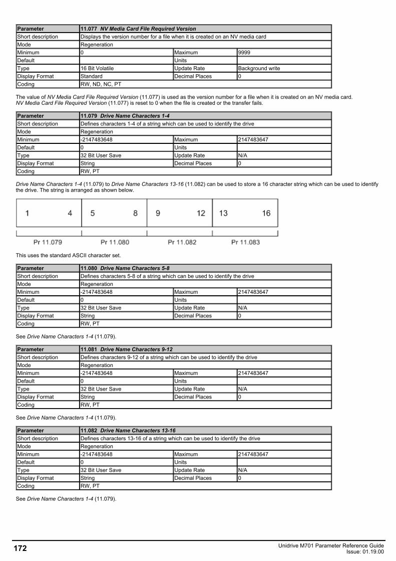
Parameter 11.077 NV Media Card File Required VersionShort description Displays the version number for a file when it is created on an NV media cardMode RegenerationMinimum 0 Maximum 9999Default Units Type 16 Bit Volatile Update Rate Background writeDisplay Format Standard Decimal Places 0Coding RW, ND, NC, PT
The value of NV Media Card File Required Version (11.077) is used as the version number for a file when it is created on an NV media card.NV Media Card File Required Version (11.077) is reset to 0 when the file is created or the transfer fails.
Parameter 11.079 Drive Name Characters 1-4Short description Defines characters 1-4 of a string which can be used to identify the driveMode RegenerationMinimum -2147483648 Maximum 2147483647Default 0 Units Type 32 Bit User Save Update Rate N/ADisplay Format String Decimal Places 0Coding RW, PT
Drive Name Characters 1-4 (11.079) to Drive Name Characters 13-16 (11.082) can be used to store a 16 character string which can be used to identifythe drive. The string is arranged as shown below.
This uses the standard ASCII character set.
Parameter 11.080 Drive Name Characters 5-8Short description Defines characters 5-8 of a string which can be used to identify the driveMode RegenerationMinimum -2147483648 Maximum 2147483647Default 0 Units Type 32 Bit User Save Update Rate N/ADisplay Format String Decimal Places 0Coding RW, PT
See Drive Name Characters 1-4 (11.079).
Parameter 11.081 Drive Name Characters 9-12Short description Defines characters 9-12 of a string which can be used to identify the driveMode RegenerationMinimum -2147483648 Maximum 2147483647Default 0 Units Type 32 Bit User Save Update Rate N/ADisplay Format String Decimal Places 0Coding RW, PT
See Drive Name Characters 1-4 (11.079).
Parameter 11.082 Drive Name Characters 13-16Short description Defines characters 13-16 of a string which can be used to identify the driveMode RegenerationMinimum -2147483648 Maximum 2147483647Default 0 Units Type 32 Bit User Save Update Rate N/ADisplay Format String Decimal Places 0Coding RW, PT
See Drive Name Characters 1-4 (11.079).
172 Unidrive M701 Parameter Reference GuideIssue: 01.19.00
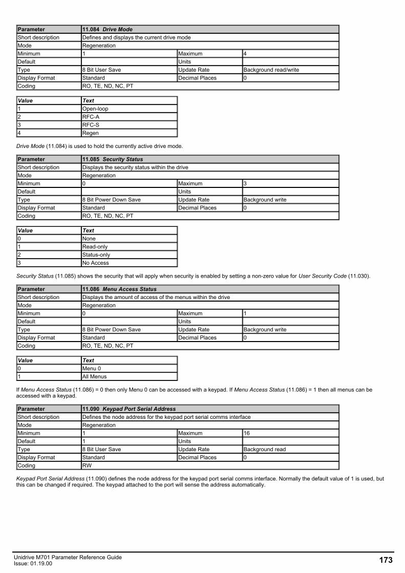
Parameter 11.084 Drive ModeShort description Defines and displays the current drive modeMode RegenerationMinimum 1 Maximum 4Default Units Type 8 Bit User Save Update Rate Background read/writeDisplay Format Standard Decimal Places 0Coding RO, TE, ND, NC, PT
Value Text1 Open-loop2 RFC-A3 RFC-S4 Regen
Drive Mode (11.084) is used to hold the currently active drive mode.
Parameter 11.085 Security StatusShort description Displays the security status within the driveMode RegenerationMinimum 0 Maximum 3Default Units Type 8 Bit Power Down Save Update Rate Background writeDisplay Format Standard Decimal Places 0Coding RO, TE, ND, NC, PT
Value Text0 None1 Read-only2 Status-only3 No Access
Security Status (11.085) shows the security that will apply when security is enabled by setting a non-zero value for User Security Code (11.030).
Parameter 11.086 Menu Access StatusShort description Displays the amount of access of the menus within the driveMode RegenerationMinimum 0 Maximum 1Default Units Type 8 Bit Power Down Save Update Rate Background writeDisplay Format Standard Decimal Places 0Coding RO, TE, ND, NC, PT
Value Text0 Menu 01 All Menus
If Menu Access Status (11.086) = 0 then only Menu 0 can be accessed with a keypad. If Menu Access Status (11.086) = 1 then all menus can beaccessed with a keypad.
Parameter 11.090 Keypad Port Serial AddressShort description Defines the node address for the keypad port serial comms interfaceMode RegenerationMinimum 1 Maximum 16Default 1 Units Type 8 Bit User Save Update Rate Background readDisplay Format Standard Decimal Places 0Coding RW
Keypad Port Serial Address (11.090) defines the node address for the keypad port serial comms interface. Normally the default value of 1 is used, butthis can be changed if required. The keypad attached to the port will sense the address automatically.
Unidrive M701 Parameter Reference GuideIssue: 01.19.00 173
Parameter 11.091 Additional Identifier Characters 1Short description Displays the additional identifier charactersMode RegenerationMinimum -2147483648 Maximum 2147483647Default Units Type 32 Bit Volatile Update Rate Power-up writeDisplay Format String Decimal Places 0Coding RO, ND, NC, PT
See Product Identifier Characters (11.064).
Parameter 11.092 Additional Identifier Characters 2Short description Displays the additional identifier charactersMode RegenerationMinimum -2147483648 Maximum 2147483647Default Units Type 32 Bit Volatile Update Rate Power-up writeDisplay Format String Decimal Places 0Coding RO, ND, NC, PT
See Product Identifier Characters (11.064).
Parameter 11.093 Additional Identifier Characters 3Short description Displays the additional identifier charactersMode RegenerationMinimum -2147483648 Maximum 2147483647Default Units Type 32 Bit Volatile Update Rate Power-up writeDisplay Format String Decimal Places 0Coding RO, ND, NC, PT
See Product Identifier Characters (11.064).
Parameter 11.095 Number Of Rectifiers DetectedShort description Number Of Rectifiers DetectedMode RegenerationMinimum 0 Maximum 9Default Units Type 8 Bit Volatile Update Rate Background WriteDisplay Format Standard Decimal Places 0Coding RO, ND, NC, PT
Indicates how many controlled rectifiers connected to the drive have been detected. See Number Of Rectifiers Expected (11.096).
Parameter 11.096 Number Of Rectifiers ExpectedShort description Number of rectifiers expected on each power stageMode RegenerationMinimum 0 Maximum 9Default 0 Units Type 8 Bit User Save Update Rate Background ReadDisplay Format Standard Decimal Places 0Coding RW
Number Of Rectifiers Expected (11.096) defines how many controlled rectifiers are expected on each power module. Within a complete drive with adiode input stage there are no controlled rectifiers. Within a complete drive with a controlled rectifier input stage there is one controlled rectifier. For adrive where external rectifiers are used the system can register up to nine controlled rectifiers. If Number Of Rectifiers Expected (11.096) = 0 then therectifier monitoring system is disabled and the drive does not check how many controlled rectifiers are present. This is the default setting and should beused for complete drives with internal rectifiers because the monitoring function is not necessary. If Number Of Rectifiers Expected (11.096) is set to anon-zero value a check is made to ensure that at least this number of external rectifiers are connected to each power module. If there are less externalrectifiers than defined by Number Of Rectifiers Expected (11.096) then a Configuration is initiated with the sub-trip indicating how many rectifers shouldbe present. See Trip 0 (10.020).
174 Unidrive M701 Parameter Reference GuideIssue: 01.19.00
Menu 12 Single Line Descriptions − User Functions 2Mode: Regeneration
Parameter Range Default Type12.001 Threshold Detector 1 Output Off (0) or On (1) RO Bit ND NC PT 12.002 Threshold Detector 2 Output Off (0) or On (1) RO Bit ND NC PT 12.003 Threshold Detector 1 Source 0.000 to 59.999 0.000 RW Num PT US12.004 Threshold Detector 1 Level 0.00 to 100.00 % 0.00 % RW Num US12.005 Threshold Detector 1 Hysteresis 0.00 to 25.00 % 0.00 % RW Num US12.006 Threshold Detector 1 Output Invert Off (0) or On (1) Off (0) RW Bit US12.007 Threshold Detector 1 Destination 0.000 to 59.999 0.000 RW Num DE PT US12.008 Variable Selector 1 Source 1 0.000 to 59.999 0.000 RW Num PT US12.009 Variable Selector 1 Source 2 0.000 to 59.999 0.000 RW Num PT US
12.010 Variable Selector 1 Mode
Input 1 (0), Input 2 (1), Add (2),Subtract (3), Multiply (4),
Divide (5), Time Const (6), Ramp (7), Modulus (8),
Powers (9), Sectional (10)
Input 1 (0) RW Txt US
12.011 Variable Selector 1 Destination 0.000 to 59.999 0.000 RW Num DE PT US12.012 Variable Selector 1 Output ±100.00 % RO Num ND NC PT 12.013 Variable Selector 1 Source 1 Scaling ±4.000 1.000 RW Num US12.014 Variable Selector 1 Source 2 Scaling ±4.000 1.000 RW Num US12.015 Variable Selector 1 Control 0.00 to 100.00 0.00 RW Num US12.016 Variable Selector 1 Enable Off (0) or On (1) On (1) RW Bit US12.023 Threshold Detector 2 Source 0.000 to 59.999 0.000 RW Num PT US12.024 Threshold Detector 2 Level 0.00 to 100.00 0.00 RW Num US12.025 Threshold Detector 2 Hysteresis 0.00 to 25.00 0.00 RW Num US12.026 Threshold Detector 2 Output Invert Off (0) or On (1) Off (0) RW Bit US12.027 Threshold Detector 2 Destination 0.000 to 59.999 0.000 RW Num DE PT US12.028 Variable Selector 2 Source 1 0.000 to 59.999 0.000 RW Num PT US12.029 Variable Selector 2 Source 2 0.000 to 59.999 0.000 RW Num PT US
12.030 Variable Selector 2 Mode
Input 1 (0), Input 2 (1), Add (2),Subtract (3), Multiply (4),
Divide (5), Time Const (6), Ramp (7), Modulus (8),
Powers (9), Sectional (10)
Input 1 (0) RW Txt US
12.031 Variable Selector 2 Destination 0.000 to 59.999 0.000 RW Num DE PT US12.032 Variable Selector 2 Output ±100.00 % RO Num ND NC PT 12.033 Variable Selector 2 Source 1 Scaling ±4.000 1.000 RW Num US12.034 Variable Selector 2 Source 2 Scaling ±4.000 1.000 RW Num US12.035 Variable Selector 2 Control 0.00 to 100.00 0.00 RW Num US12.036 Variable Selector 2 Enable Off (0) or On (1) On (1) RW Bit US
RW Read / Write RO Read-only Bit Bit parameter Txt Text string Date Date parameter Time Time parameterChr Character parameter Bin Binary parameter IP IP address Mac MAC address Ver Version number SMP Slot, menu, parameter
Num Number parameter DE Destination ND Nodefault value RA Rating dependent NC Non-copyable PT Protected
FI Filtered US User save PS Power-down save
Unidrive M701 Parameter Reference GuideIssue: 01.19.00 175
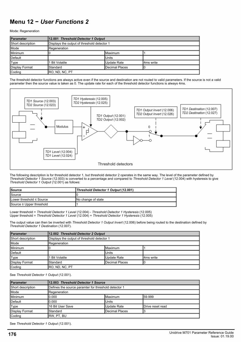
Menu 12 − User Functions 2Mode: Regeneration
Parameter 12.001 Threshold Detector 1 OutputShort description Displays the output of threshold detector 1Mode RegenerationMinimum 0 Maximum 1Default Units Type 1 Bit Volatile Update Rate 4ms writeDisplay Format Standard Decimal Places 0Coding RO, ND, NC, PT
The threshold detector functions are always active even if the source and destination are not routed to valid parameters. If the source is not a validparameter then the source value is taken as 0. The update rate for each of the threshold detector functions is always 4ms.
The following description is for threshold detector 1, but threshold detector 2 operates in the same way. The level of the parameter defined byThreshold Detector 1 Source (12.003) is converted to a percentage and compared to Threshold Detector 1 Level (12.004) with hysteresis to giveThreshold Detector 1 Output (12.001) as follows:
Source Threshold Detector 1 Output (12.001)Source 0Lower threshold ≤ Source No change of stateSource ≥ Upper threshold 1
Lower threshold = Threshold Detector 1 Level (12.004) - Threshold Detector 1 Hysteresis (12.005) Upper threshold = Threshold Detector 1 Level (12.004) + Threshold Detector 1 Hysteresis (12.005)
The output value can then be inverted with Threshold Detector 1 Output Invert (12.006) before being routed to the destination defined byThreshold Detector 1 Destination (12.007).
Parameter 12.002 Threshold Detector 2 OutputShort description Displays the output of threshold detector 1Mode RegenerationMinimum 0 Maximum 1Default Units Type 1 Bit Volatile Update Rate 4ms writeDisplay Format Standard Decimal Places 0Coding RO, ND, NC, PT
See Threshold Detector 1 Output (12.001).
Parameter 12.003 Threshold Detector 1 SourceShort description Defines the source paramter for threshold detector 1Mode RegenerationMinimum 0.000 Maximum 59.999Default 0.000 Units Type 16 Bit User Save Update Rate Drive reset readDisplay Format Standard Decimal Places 3Coding RW, PT, BU
See Threshold Detector 1 Output (12.001).
176 Unidrive M701 Parameter Reference GuideIssue: 01.19.00
Parameter 12.004 Threshold Detector 1 LevelShort description Defines the reference level for threshold detector 1Mode RegenerationMinimum 0.00 Maximum 100.00Default 0.00 Units %Type 16 Bit User Save Update Rate 4ms readDisplay Format Standard Decimal Places 2Coding RW
See Threshold Detector 1 Output (12.001).
Parameter 12.005 Threshold Detector 1 HysteresisShort description Defines the hysteresis for threshold detector 1Mode RegenerationMinimum 0.00 Maximum 25.00Default 0.00 Units %Type 16 Bit User Save Update Rate 4ms readDisplay Format Standard Decimal Places 2Coding RW
See Threshold Detector 1 Output (12.001).
Parameter 12.006 Threshold Detector 1 Output InvertShort description Set to 1 to invert the output of threshold detector 1Mode RegenerationMinimum 0 Maximum 1Default 0 Units Type 1 Bit User Save Update Rate 4ms readDisplay Format Standard Decimal Places 0Coding RW
See Threshold Detector 1 Output (12.001).
Parameter 12.007 Threshold Detector 1 DestinationShort description Defines the destination parameter for threshold detector 1Mode RegenerationMinimum 0.000 Maximum 59.999Default 0.000 Units Type 16 Bit User Save Update Rate Drive reset readDisplay Format Standard Decimal Places 3Coding RW, DE, PT, BU
See Threshold Detector 1 Output (12.001).
Parameter 12.008 Variable Selector 1 Source 1Short description Defines the 1st source parameter for variable selector 1Mode RegenerationMinimum 0.000 Maximum 59.999Default 0.000 Units Type 16 Bit User Save Update Rate Drive reset readDisplay Format Standard Decimal Places 3Coding RW, PT, BU
The variable selector functions are always active even if the source and destination are not routed to valid parameters. If a source is not a valid parameterthen the source value is taken as 0. The update rate for each of the variable selector functions is always 4ms.
Unidrive M701 Parameter Reference GuideIssue: 01.19.00 177
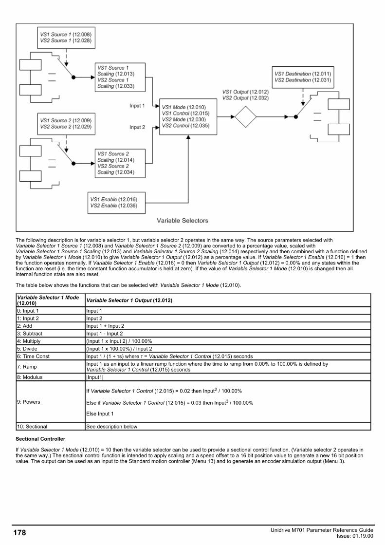
The following description is for variable selector 1, but variable selector 2 operates in the same way. The source parameters selected withVariable Selector 1 Source 1 (12.008) and Variable Selector 1 Source 2 (12.009) are converted to a percentage value, scaled withVariable Selector 1 Source 1 Scaling (12.013) and Variable Selector 1 Source 2 Scaling (12.014) respectively and then combined with a function definedby Variable Selector 1 Mode (12.010) to give Variable Selector 1 Output (12.012) as a percentage value. If Variable Selector 1 Enable (12.016) = 1 thenthe function operates normally. If Variable Selector 1 Enable (12.016) = 0 then Variable Selector 1 Output (12.012) = 0.00% and any states within thefunction are reset (i.e. the time constant function accumulator is held at zero). If the value of Variable Selector 1 Mode (12.010) is changed then allinternal function state are also reset.
The table below shows the functions that can be selected with Variable Selector 1 Mode (12.010).
Variable Selector 1 Mode(12.010) Variable Selector 1 Output (12.012)
0: Input 1 Input 11: Input 2 Input 22: Add Input 1 + Input 23: Subtract Input 1 - Input 24: Multiply (Input 1 x Input 2) / 100.00%5: Divide (Input 1 x 100.00%) / Input 26: Time Const Input 1 / (1 + τs) where τ = Variable Selector 1 Control (12.015) seconds
7: Ramp Input 1 as an input to a linear ramp function where the time to ramp from 0.00% to 100.00% is defined byVariable Selector 1 Control (12.015) seconds
8: Modulus |Input1|
9: Powers
If Variable Selector 1 Control (12.015) = 0.02 then Input2 / 100.00%
Else if Variable Selector 1 Control (12.015) = 0.03 then Input3 / 100.00%
Else Input 1
10: Sectional See description below
Sectional Controller
If Variable Selector 1 Mode (12.010) = 10 then the variable selector can be used to provide a sectional control function. (Variable selector 2 operates inthe same way.) The sectional control function is intended to apply scaling and a speed offset to a 16 bit position value to generate a new 16 bit positionvalue. The output can be used as an input to the Standard motion controller (Menu 13) and to generate an encoder simulation output (Menu 3).
178 Unidrive M701 Parameter Reference GuideIssue: 01.19.00
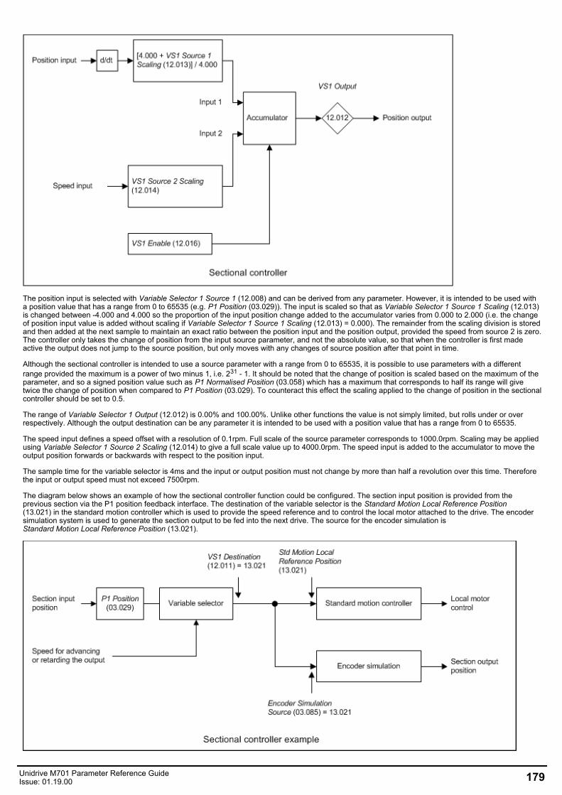
The position input is selected with Variable Selector 1 Source 1 (12.008) and can be derived from any parameter. However, it is intended to be used witha position value that has a range from 0 to 65535 (e.g. P1 Position (03.029)). The input is scaled so that as Variable Selector 1 Source 1 Scaling (12.013)is changed between -4.000 and 4.000 so the proportion of the input position change added to the accumulator varies from 0.000 to 2.000 (i.e. the changeof position input value is added without scaling if Variable Selector 1 Source 1 Scaling (12.013) = 0.000). The remainder from the scaling division is storedand then added at the next sample to maintain an exact ratio between the position input and the position output, provided the speed from source 2 is zero.The controller only takes the change of position from the input source parameter, and not the absolute value, so that when the controller is first madeactive the output does not jump to the source position, but only moves with any changes of source position after that point in time.
Although the sectional controller is intended to use a source parameter with a range from 0 to 65535, it is possible to use parameters with a differentrange provided the maximum is a power of two minus 1, i.e. 231 - 1. It should be noted that the change of position is scaled based on the maximum of theparameter, and so a signed position value such as P1 Normalised Position (03.058) which has a maximum that corresponds to half its range will givetwice the change of position when compared to P1 Position (03.029). To counteract this effect the scaling applied to the change of position in the sectionalcontroller should be set to 0.5.
The range of Variable Selector 1 Output (12.012) is 0.00% and 100.00%. Unlike other functions the value is not simply limited, but rolls under or overrespectively. Although the output destination can be any parameter it is intended to be used with a position value that has a range from 0 to 65535.
The speed input defines a speed offset with a resolution of 0.1rpm. Full scale of the source parameter corresponds to 1000.0rpm. Scaling may be appliedusing Variable Selector 1 Source 2 Scaling (12.014) to give a full scale value up to 4000.0rpm. The speed input is added to the accumulator to move theoutput position forwards or backwards with respect to the position input.
The sample time for the variable selector is 4ms and the input or output position must not change by more than half a revolution over this time. Thereforethe input or output speed must not exceed 7500rpm.
The diagram below shows an example of how the sectional controller function could be configured. The section input position is provided from theprevious section via the P1 position feedback interface. The destination of the variable selector is the Standard Motion Local Reference Position(13.021) in the standard motion controller which is used to provide the speed reference and to control the local motor attached to the drive. The encodersimulation system is used to generate the section output to be fed into the next drive. The source for the encoder simulation isStandard Motion Local Reference Position (13.021).
Unidrive M701 Parameter Reference GuideIssue: 01.19.00 179
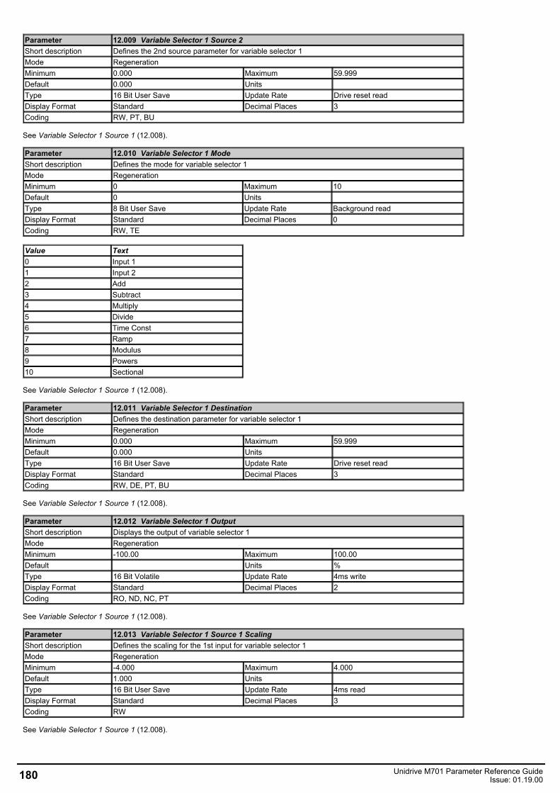
Parameter 12.009 Variable Selector 1 Source 2Short description Defines the 2nd source parameter for variable selector 1Mode RegenerationMinimum 0.000 Maximum 59.999Default 0.000 Units Type 16 Bit User Save Update Rate Drive reset readDisplay Format Standard Decimal Places 3Coding RW, PT, BU
See Variable Selector 1 Source 1 (12.008).
Parameter 12.010 Variable Selector 1 ModeShort description Defines the mode for variable selector 1Mode RegenerationMinimum 0 Maximum 10Default 0 Units Type 8 Bit User Save Update Rate Background readDisplay Format Standard Decimal Places 0Coding RW, TE
Value Text0 Input 11 Input 22 Add3 Subtract4 Multiply5 Divide6 Time Const7 Ramp8 Modulus9 Powers10 Sectional
See Variable Selector 1 Source 1 (12.008).
Parameter 12.011 Variable Selector 1 DestinationShort description Defines the destination parameter for variable selector 1Mode RegenerationMinimum 0.000 Maximum 59.999Default 0.000 Units Type 16 Bit User Save Update Rate Drive reset readDisplay Format Standard Decimal Places 3Coding RW, DE, PT, BU
See Variable Selector 1 Source 1 (12.008).
Parameter 12.012 Variable Selector 1 OutputShort description Displays the output of variable selector 1Mode RegenerationMinimum -100.00 Maximum 100.00Default Units %Type 16 Bit Volatile Update Rate 4ms writeDisplay Format Standard Decimal Places 2Coding RO, ND, NC, PT
See Variable Selector 1 Source 1 (12.008).
Parameter 12.013 Variable Selector 1 Source 1 ScalingShort description Defines the scaling for the 1st input for variable selector 1Mode RegenerationMinimum -4.000 Maximum 4.000Default 1.000 Units Type 16 Bit User Save Update Rate 4ms readDisplay Format Standard Decimal Places 3Coding RW
See Variable Selector 1 Source 1 (12.008).
180 Unidrive M701 Parameter Reference GuideIssue: 01.19.00
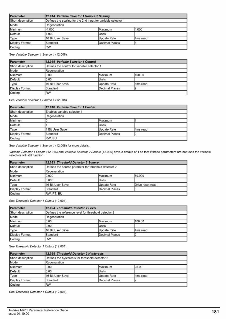
Parameter 12.014 Variable Selector 1 Source 2 ScalingShort description Defines the scaling for the 2nd input for variable selector 1Mode RegenerationMinimum -4.000 Maximum 4.000Default 1.000 Units Type 16 Bit User Save Update Rate 4ms readDisplay Format Standard Decimal Places 3Coding RW
See Variable Selector 1 Source 1 (12.008).
Parameter 12.015 Variable Selector 1 ControlShort description Defines the control for variable selector 1Mode RegenerationMinimum 0.00 Maximum 100.00Default 0.00 Units Type 16 Bit User Save Update Rate 4ms readDisplay Format Standard Decimal Places 2Coding RW
See Variable Selector 1 Source 1 (12.008).
Parameter 12.016 Variable Selector 1 EnableShort description Enables variable selector 1Mode RegenerationMinimum 0 Maximum 1Default 1 Units Type 1 Bit User Save Update Rate 4ms readDisplay Format Standard Decimal Places 0Coding RW, BU
See Variable Selector 1 Source 1 (12.008) for more details.
Variable Selector 1 Enable (12.016) and Variable Selector 2 Enable (12.036) have a default of 1 so that if these parameters are not used the variableselectors will still function.
Parameter 12.023 Threshold Detector 2 SourceShort description Defines the source paramter for threshold detector 2Mode RegenerationMinimum 0.000 Maximum 59.999Default 0.000 Units Type 16 Bit User Save Update Rate Drive reset readDisplay Format Standard Decimal Places 3Coding RW, PT, BU
See Threshold Detector 1 Output (12.001).
Parameter 12.024 Threshold Detector 2 LevelShort description Defines the reference level for threshold detector 2Mode RegenerationMinimum 0.00 Maximum 100.00Default 0.00 Units Type 16 Bit User Save Update Rate 4ms readDisplay Format Standard Decimal Places 2Coding RW
See Threshold Detector 1 Output (12.001).
Parameter 12.025 Threshold Detector 2 HysteresisShort description Defines the hysteresis for threshold detector 2Mode RegenerationMinimum 0.00 Maximum 25.00Default 0.00 Units Type 16 Bit User Save Update Rate 4ms readDisplay Format Standard Decimal Places 2Coding RW
See Threshold Detector 1 Output (12.001).
Unidrive M701 Parameter Reference GuideIssue: 01.19.00 181
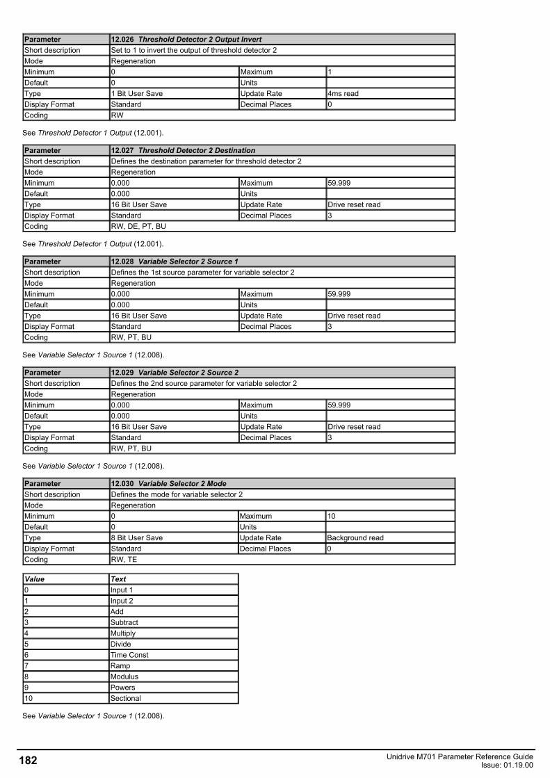
Parameter 12.026 Threshold Detector 2 Output InvertShort description Set to 1 to invert the output of threshold detector 2Mode RegenerationMinimum 0 Maximum 1Default 0 Units Type 1 Bit User Save Update Rate 4ms readDisplay Format Standard Decimal Places 0Coding RW
See Threshold Detector 1 Output (12.001).
Parameter 12.027 Threshold Detector 2 DestinationShort description Defines the destination parameter for threshold detector 2Mode RegenerationMinimum 0.000 Maximum 59.999Default 0.000 Units Type 16 Bit User Save Update Rate Drive reset readDisplay Format Standard Decimal Places 3Coding RW, DE, PT, BU
See Threshold Detector 1 Output (12.001).
Parameter 12.028 Variable Selector 2 Source 1Short description Defines the 1st source parameter for variable selector 2Mode RegenerationMinimum 0.000 Maximum 59.999Default 0.000 Units Type 16 Bit User Save Update Rate Drive reset readDisplay Format Standard Decimal Places 3Coding RW, PT, BU
See Variable Selector 1 Source 1 (12.008).
Parameter 12.029 Variable Selector 2 Source 2Short description Defines the 2nd source parameter for variable selector 2Mode RegenerationMinimum 0.000 Maximum 59.999Default 0.000 Units Type 16 Bit User Save Update Rate Drive reset readDisplay Format Standard Decimal Places 3Coding RW, PT, BU
See Variable Selector 1 Source 1 (12.008).
Parameter 12.030 Variable Selector 2 ModeShort description Defines the mode for variable selector 2Mode RegenerationMinimum 0 Maximum 10Default 0 Units Type 8 Bit User Save Update Rate Background readDisplay Format Standard Decimal Places 0Coding RW, TE
Value Text0 Input 11 Input 22 Add3 Subtract4 Multiply5 Divide6 Time Const7 Ramp8 Modulus9 Powers10 Sectional
See Variable Selector 1 Source 1 (12.008).
182 Unidrive M701 Parameter Reference GuideIssue: 01.19.00
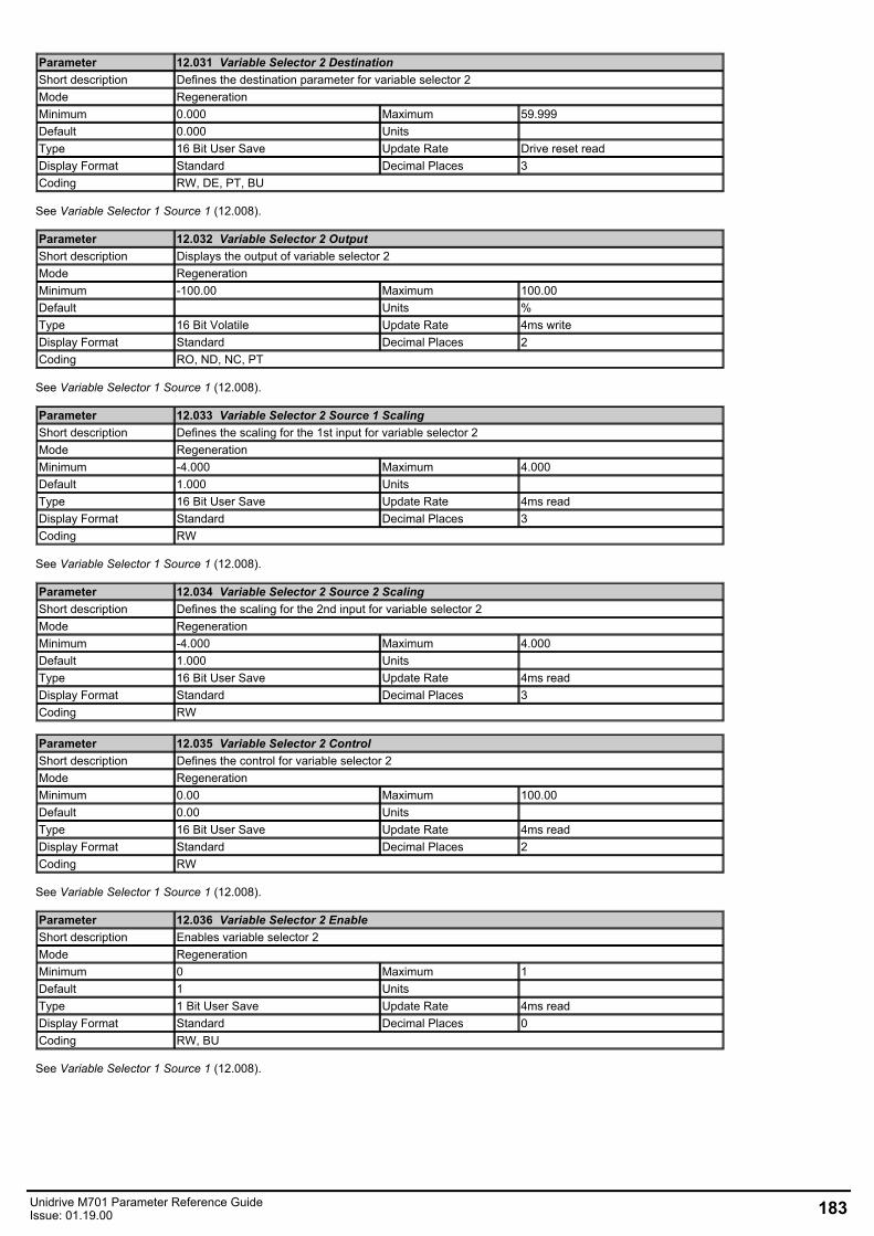
Parameter 12.031 Variable Selector 2 DestinationShort description Defines the destination parameter for variable selector 2Mode RegenerationMinimum 0.000 Maximum 59.999Default 0.000 Units Type 16 Bit User Save Update Rate Drive reset readDisplay Format Standard Decimal Places 3Coding RW, DE, PT, BU
See Variable Selector 1 Source 1 (12.008).
Parameter 12.032 Variable Selector 2 OutputShort description Displays the output of variable selector 2Mode RegenerationMinimum -100.00 Maximum 100.00Default Units %Type 16 Bit Volatile Update Rate 4ms writeDisplay Format Standard Decimal Places 2Coding RO, ND, NC, PT
See Variable Selector 1 Source 1 (12.008).
Parameter 12.033 Variable Selector 2 Source 1 ScalingShort description Defines the scaling for the 1st input for variable selector 2Mode RegenerationMinimum -4.000 Maximum 4.000Default 1.000 Units Type 16 Bit User Save Update Rate 4ms readDisplay Format Standard Decimal Places 3Coding RW
See Variable Selector 1 Source 1 (12.008).
Parameter 12.034 Variable Selector 2 Source 2 ScalingShort description Defines the scaling for the 2nd input for variable selector 2Mode RegenerationMinimum -4.000 Maximum 4.000Default 1.000 Units Type 16 Bit User Save Update Rate 4ms readDisplay Format Standard Decimal Places 3Coding RW
Parameter 12.035 Variable Selector 2 ControlShort description Defines the control for variable selector 2Mode RegenerationMinimum 0.00 Maximum 100.00Default 0.00 Units Type 16 Bit User Save Update Rate 4ms readDisplay Format Standard Decimal Places 2Coding RW
See Variable Selector 1 Source 1 (12.008).
Parameter 12.036 Variable Selector 2 EnableShort description Enables variable selector 2Mode RegenerationMinimum 0 Maximum 1Default 1 Units Type 1 Bit User Save Update Rate 4ms readDisplay Format Standard Decimal Places 0Coding RW, BU
See Variable Selector 1 Source 1 (12.008).
Unidrive M701 Parameter Reference GuideIssue: 01.19.00 183
Menu 14 Single Line Descriptions − User PID ControllerMode: Regeneration
184 Unidrive M701 Parameter Reference GuideIssue: 01.19.00
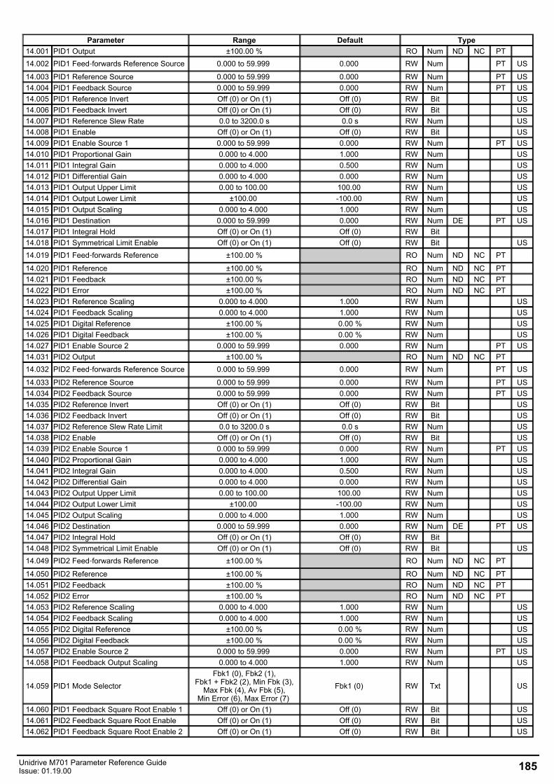
Parameter Range Default Type14.001 PID1 Output ±100.00 % RO Num ND NC PT 14.002 PID1 Feed‑forwards Reference Source 0.000 to 59.999 0.000 RW Num PT US
14.003 PID1 Reference Source 0.000 to 59.999 0.000 RW Num PT US14.004 PID1 Feedback Source 0.000 to 59.999 0.000 RW Num PT US14.005 PID1 Reference Invert Off (0) or On (1) Off (0) RW Bit US14.006 PID1 Feedback Invert Off (0) or On (1) Off (0) RW Bit US14.007 PID1 Reference Slew Rate 0.0 to 3200.0 s 0.0 s RW Num US14.008 PID1 Enable Off (0) or On (1) Off (0) RW Bit US14.009 PID1 Enable Source 1 0.000 to 59.999 0.000 RW Num PT US14.010 PID1 Proportional Gain 0.000 to 4.000 1.000 RW Num US14.011 PID1 Integral Gain 0.000 to 4.000 0.500 RW Num US14.012 PID1 Differential Gain 0.000 to 4.000 0.000 RW Num US14.013 PID1 Output Upper Limit 0.00 to 100.00 100.00 RW Num US14.014 PID1 Output Lower Limit ±100.00 -100.00 RW Num US14.015 PID1 Output Scaling 0.000 to 4.000 1.000 RW Num US14.016 PID1 Destination 0.000 to 59.999 0.000 RW Num DE PT US14.017 PID1 Integral Hold Off (0) or On (1) Off (0) RW Bit 14.018 PID1 Symmetrical Limit Enable Off (0) or On (1) Off (0) RW Bit US14.019 PID1 Feed‑forwards Reference ±100.00 % RO Num ND NC PT
14.020 PID1 Reference ±100.00 % RO Num ND NC PT 14.021 PID1 Feedback ±100.00 % RO Num ND NC PT 14.022 PID1 Error ±100.00 % RO Num ND NC PT 14.023 PID1 Reference Scaling 0.000 to 4.000 1.000 RW Num US14.024 PID1 Feedback Scaling 0.000 to 4.000 1.000 RW Num US14.025 PID1 Digital Reference ±100.00 % 0.00 % RW Num US14.026 PID1 Digital Feedback ±100.00 % 0.00 % RW Num US14.027 PID1 Enable Source 2 0.000 to 59.999 0.000 RW Num PT US14.031 PID2 Output ±100.00 % RO Num ND NC PT 14.032 PID2 Feed‑forwards Reference Source 0.000 to 59.999 0.000 RW Num PT US
14.033 PID2 Reference Source 0.000 to 59.999 0.000 RW Num PT US14.034 PID2 Feedback Source 0.000 to 59.999 0.000 RW Num PT US14.035 PID2 Reference Invert Off (0) or On (1) Off (0) RW Bit US14.036 PID2 Feedback Invert Off (0) or On (1) Off (0) RW Bit US14.037 PID2 Reference Slew Rate Limit 0.0 to 3200.0 s 0.0 s RW Num US14.038 PID2 Enable Off (0) or On (1) Off (0) RW Bit US14.039 PID2 Enable Source 1 0.000 to 59.999 0.000 RW Num PT US14.040 PID2 Proportional Gain 0.000 to 4.000 1.000 RW Num US14.041 PID2 Integral Gain 0.000 to 4.000 0.500 RW Num US14.042 PID2 Differential Gain 0.000 to 4.000 0.000 RW Num US14.043 PID2 Output Upper Limit 0.00 to 100.00 100.00 RW Num US14.044 PID2 Output Lower Limit ±100.00 -100.00 RW Num US14.045 PID2 Output Scaling 0.000 to 4.000 1.000 RW Num US14.046 PID2 Destination 0.000 to 59.999 0.000 RW Num DE PT US14.047 PID2 Integral Hold Off (0) or On (1) Off (0) RW Bit 14.048 PID2 Symmetrical Limit Enable Off (0) or On (1) Off (0) RW Bit US14.049 PID2 Feed‑forwards Reference ±100.00 % RO Num ND NC PT
14.050 PID2 Reference ±100.00 % RO Num ND NC PT 14.051 PID2 Feedback ±100.00 % RO Num ND NC PT 14.052 PID2 Error ±100.00 % RO Num ND NC PT 14.053 PID2 Reference Scaling 0.000 to 4.000 1.000 RW Num US14.054 PID2 Feedback Scaling 0.000 to 4.000 1.000 RW Num US14.055 PID2 Digital Reference ±100.00 % 0.00 % RW Num US14.056 PID2 Digital Feedback ±100.00 % 0.00 % RW Num US14.057 PID2 Enable Source 2 0.000 to 59.999 0.000 RW Num PT US14.058 PID1 Feedback Output Scaling 0.000 to 4.000 1.000 RW Num US
14.059 PID1 Mode Selector Fbk1 (0), Fbk2 (1),
Fbk1 + Fbk2 (2), Min Fbk (3),Max Fbk (4), Av Fbk (5),
Min Error (6), Max Error (7) Fbk1 (0) RW Txt US
14.060 PID1 Feedback Square Root Enable 1 Off (0) or On (1) Off (0) RW Bit US14.061 PID2 Feedback Square Root Enable Off (0) or On (1) Off (0) RW Bit US14.062 PID1 Feedback Square Root Enable 2 Off (0) or On (1) Off (0) RW Bit US
Unidrive M701 Parameter Reference GuideIssue: 01.19.00 185
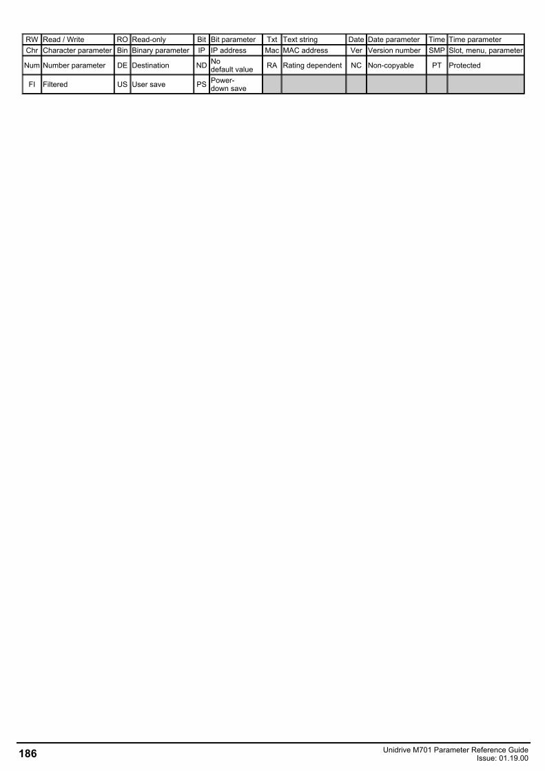
RW Read / Write RO Read-only Bit Bit parameter Txt Text string Date Date parameter Time Time parameterChr Character parameter Bin Binary parameter IP IP address Mac MAC address Ver Version number SMP Slot, menu, parameter
Num Number parameter DE Destination ND Nodefault value RA Rating dependent NC Non-copyable PT Protected
FI Filtered US User save PS Power-down save
186 Unidrive M701 Parameter Reference GuideIssue: 01.19.00
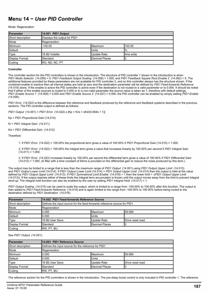
Menu 14 − User PID ControllerMode: Regeneration
Parameter 14.001 PID1 OutputShort description Displays the output for PID1Mode RegenerationMinimum -100.00 Maximum 100.00Default Units %Type 16 Bit Volatile Update Rate 4ms writeDisplay Format Standard Decimal Places 2Coding RO, ND, NC, PT
Controller
The controller section for the PID controllers is shown in the introduction. The structure of PID controller 1 shown in the introduction is whenPID1 Mode Selector (14.059) = 0, PID1 Feedback Output Scaling (14.058) = 1.000, and PID1 Feedback Square Root Enable 2 (14.062) = 0. Theadditional features provided by these parameters are not available for PID controller 2, and so this controller always has the structure shown. If thecombined enable is inactive then all internal states are held at zero and the destination parameter will be defined by PID1 Feed-forwards Reference (14.019) alone. If the enable is active the PID controller is active even if the destination is not routed to a valid parameter or to 0.000. It should be notedthat if either of the enable sources is routed to 0.000 or to a non-valid parameter the source value is taken as 1, therefore with default settings,PID1 Enable Source 1 (14.009) = 0.000 and PID1 Enable Source 2 (14.027) = 0.000, the PID controller can be enabled by simply setting PID1 Enable (14.008).
PID1 Error (14.022) is the difference between the reference and feedback produced by the reference and feedback systems described in the previoussections. The PID controller output is defined as follows:
PID1 Output (14.001) = PID1 Error (14.022) x [Kp + Ki/s + sKd/(0.064s + 1)]
Kp = PID1 Proportional Gain (14.010)
Ki = PID1 Integral Gain (14.011)
Kd = PID1 Differential Gain (14.012)
Therefore:
1. If PID1 Error (14.022) = 100.00% the proportional term gives a value of 100.00% if PID1 Proportional Gain (14.010) = 1.000.
2. If PID1 Error (14.022) = 100.00% the integral term gives a value that increases linearly by 100.00% per second if PID1 Integral Gain (14.011) = 1.000.
3. If PID1 Error (14.022) increases linearly by 100.00% per second the differential term gives a value of 100.00% if PID1 Differential Gain (14.012) = 1.000. (A filter with a time constant of 64ms is provided on the differential gain to reduce the noise produced by this term.)
The output may be limited to a range that is less than the maximum range of PID1 Output (14.001) using PID1 Output Upper Limit (14.013)and PID1 Output Lower Limit (14.014). If PID1 Output Lower Limit (14.014) > PID1 Output Upper Limit (14.013) then the output is held at the valuedefined by PID1 Output Upper Limit (14.013). If PID1 Symmetrical Limit Enable (14.018) = 1 then the lower limit = -(PID1 Output Upper Limit (14.013)). If the output reaches either of these limits the integral term accumulator is frozen until the output moves away from the limit to prevent integralwind-up. The integral hold function can also be enabled by the user by setting PID1 Integral Hold (14.017) = 1.
PID1 Output Scaling (14.015) can be used to scale the output, which is limited to a range from -100.00% to 100.00% after this function. The output isthen added to PID1 Feed-forwards Reference (14.019) and is again limited to the range from -100.00% to 100.00% before being routed to thedestination defined by PID1 Destination (14.016).
Parameter 14.002 PID1 Feed-forwards Reference SourceShort description Defines the input source for the feed-forwards reference source for PID1Mode RegenerationMinimum 0.000 Maximum 59.999Default 0.000 Units Type 16 Bit User Save Update Rate Drive reset readDisplay Format Standard Decimal Places 3Coding RW, PT, BU
See PID1 Output (14.001).
Parameter 14.003 PID1 Reference SourceShort description Defines the input source for the reference for PID1Mode RegenerationMinimum 0.000 Maximum 59.999Default 0.000 Units Type 16 Bit User Save Update Rate Drive reset readDisplay Format Standard Decimal Places 3Coding RW, PT, BU
The reference section for the PID controllers is shown in the introduction. The pre-sleep boost control is only included in PID controller 1. The reference
Unidrive M701 Parameter Reference GuideIssue: 01.19.00 187
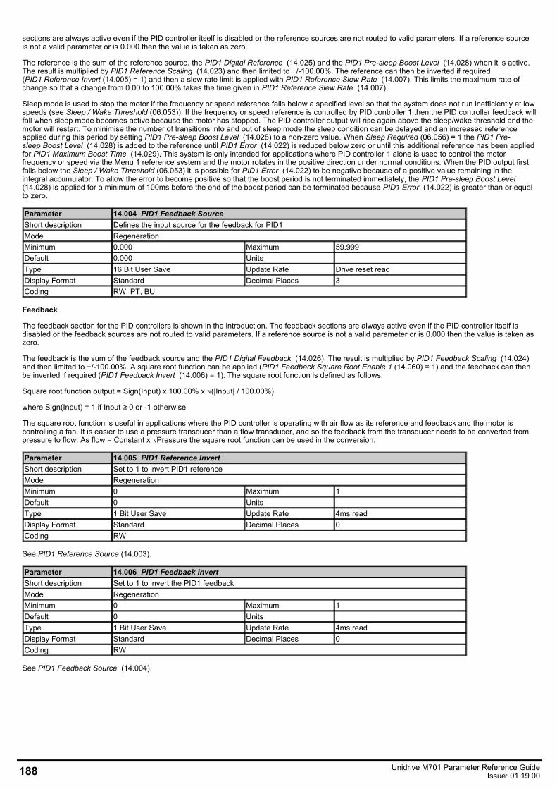
sections are always active even if the PID controller itself is disabled or the reference sources are not routed to valid parameters. If a reference sourceis not a valid parameter or is 0.000 then the value is taken as zero.
The reference is the sum of the reference source, the PID1 Digital Reference (14.025) and the PID1 Pre-sleep Boost Level (14.028) when it is active.The result is multiplied by PID1 Reference Scaling (14.023) and then limited to +/-100.00%. The reference can then be inverted if required(PID1 Reference Invert (14.005) = 1) and then a slew rate limit is applied with PID1 Reference Slew Rate (14.007). This limits the maximum rate ofchange so that a change from 0.00 to 100.00% takes the time given in PID1 Reference Slew Rate (14.007).
Sleep mode is used to stop the motor if the frequency or speed reference falls below a specified level so that the system does not run inefficiently at lowspeeds (see Sleep / Wake Threshold (06.053)). If the frequency or speed reference is controlled by PID controller 1 then the PID controller feedback willfall when sleep mode becomes active because the motor has stopped. The PID controller output will rise again above the sleep/wake threshold and themotor will restart. To minimise the number of transitions into and out of sleep mode the sleep condition can be delayed and an increased referenceapplied during this period by setting PID1 Pre-sleep Boost Level (14.028) to a non-zero value. When Sleep Required (06.056) = 1 the PID1 Pre-sleep Boost Level (14.028) is added to the reference until PID1 Error (14.022) is reduced below zero or until this additional reference has been appliedfor PID1 Maximum Boost Time (14.029). This system is only intended for applications where PID controller 1 alone is used to control the motorfrequency or speed via the Menu 1 reference system and the motor rotates in the positive direction under normal conditions. When the PID output firstfalls below the Sleep / Wake Threshold (06.053) it is possible for PID1 Error (14.022) to be negative because of a positive value remaining in theintegral accumulator. To allow the error to become positive so that the boost period is not terminated immediately, the PID1 Pre-sleep Boost Level (14.028) is applied for a minimum of 100ms before the end of the boost period can be terminated because PID1 Error (14.022) is greater than or equalto zero.
Parameter 14.004 PID1 Feedback SourceShort description Defines the input source for the feedback for PID1Mode RegenerationMinimum 0.000 Maximum 59.999Default 0.000 Units Type 16 Bit User Save Update Rate Drive reset readDisplay Format Standard Decimal Places 3Coding RW, PT, BU
Feedback
The feedback section for the PID controllers is shown in the introduction. The feedback sections are always active even if the PID controller itself isdisabled or the feedback sources are not routed to valid parameters. If a reference source is not a valid parameter or is 0.000 then the value is taken aszero.
The feedback is the sum of the feedback source and the PID1 Digital Feedback (14.026). The result is multiplied by PID1 Feedback Scaling (14.024)and then limited to +/-100.00%. A square root function can be applied (PID1 Feedback Square Root Enable 1 (14.060) = 1) and the feedback can thenbe inverted if required (PID1 Feedback Invert (14.006) = 1). The square root function is defined as follows.
Square root function output = Sign(Input) x 100.00% x √(|Input| / 100.00%)
where Sign(Input) = 1 if Input ≥ 0 or -1 otherwise
The square root function is useful in applications where the PID controller is operating with air flow as its reference and feedback and the motor iscontrolling a fan. It is easier to use a pressure transducer than a flow transducer, and so the feedback from the transducer needs to be converted frompressure to flow. As flow = Constant x √Pressure the square root function can be used in the conversion.
Parameter 14.005 PID1 Reference InvertShort description Set to 1 to invert PID1 referenceMode RegenerationMinimum 0 Maximum 1Default 0 Units Type 1 Bit User Save Update Rate 4ms readDisplay Format Standard Decimal Places 0Coding RW
See PID1 Reference Source (14.003).
Parameter 14.006 PID1 Feedback InvertShort description Set to 1 to invert the PID1 feedbackMode RegenerationMinimum 0 Maximum 1Default 0 Units Type 1 Bit User Save Update Rate 4ms readDisplay Format Standard Decimal Places 0Coding RW
See PID1 Feedback Source (14.004).
188 Unidrive M701 Parameter Reference GuideIssue: 01.19.00
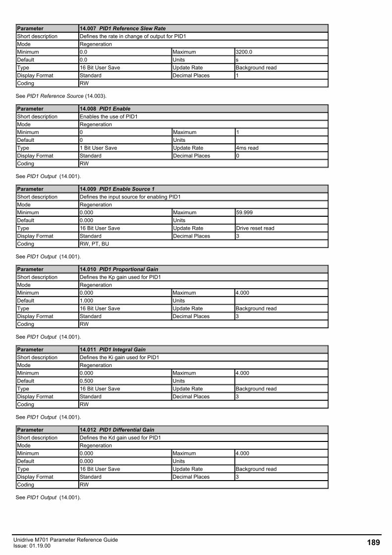
Parameter 14.007 PID1 Reference Slew RateShort description Defines the rate in change of output for PID1Mode RegenerationMinimum 0.0 Maximum 3200.0Default 0.0 Units sType 16 Bit User Save Update Rate Background readDisplay Format Standard Decimal Places 1Coding RW
See PID1 Reference Source (14.003).
Parameter 14.008 PID1 EnableShort description Enables the use of PID1Mode RegenerationMinimum 0 Maximum 1Default 0 Units Type 1 Bit User Save Update Rate 4ms readDisplay Format Standard Decimal Places 0Coding RW
See PID1 Output (14.001).
Parameter 14.009 PID1 Enable Source 1Short description Defines the input source for enabling PID1Mode RegenerationMinimum 0.000 Maximum 59.999Default 0.000 Units Type 16 Bit User Save Update Rate Drive reset readDisplay Format Standard Decimal Places 3Coding RW, PT, BU
See PID1 Output (14.001).
Parameter 14.010 PID1 Proportional GainShort description Defines the Kp gain used for PID1Mode RegenerationMinimum 0.000 Maximum 4.000Default 1.000 Units Type 16 Bit User Save Update Rate Background readDisplay Format Standard Decimal Places 3Coding RW
See PID1 Output (14.001).
Parameter 14.011 PID1 Integral GainShort description Defines the Ki gain used for PID1Mode RegenerationMinimum 0.000 Maximum 4.000Default 0.500 Units Type 16 Bit User Save Update Rate Background readDisplay Format Standard Decimal Places 3Coding RW
See PID1 Output (14.001).
Parameter 14.012 PID1 Differential GainShort description Defines the Kd gain used for PID1Mode RegenerationMinimum 0.000 Maximum 4.000Default 0.000 Units Type 16 Bit User Save Update Rate Background readDisplay Format Standard Decimal Places 3Coding RW
See PID1 Output (14.001).
Unidrive M701 Parameter Reference GuideIssue: 01.19.00 189
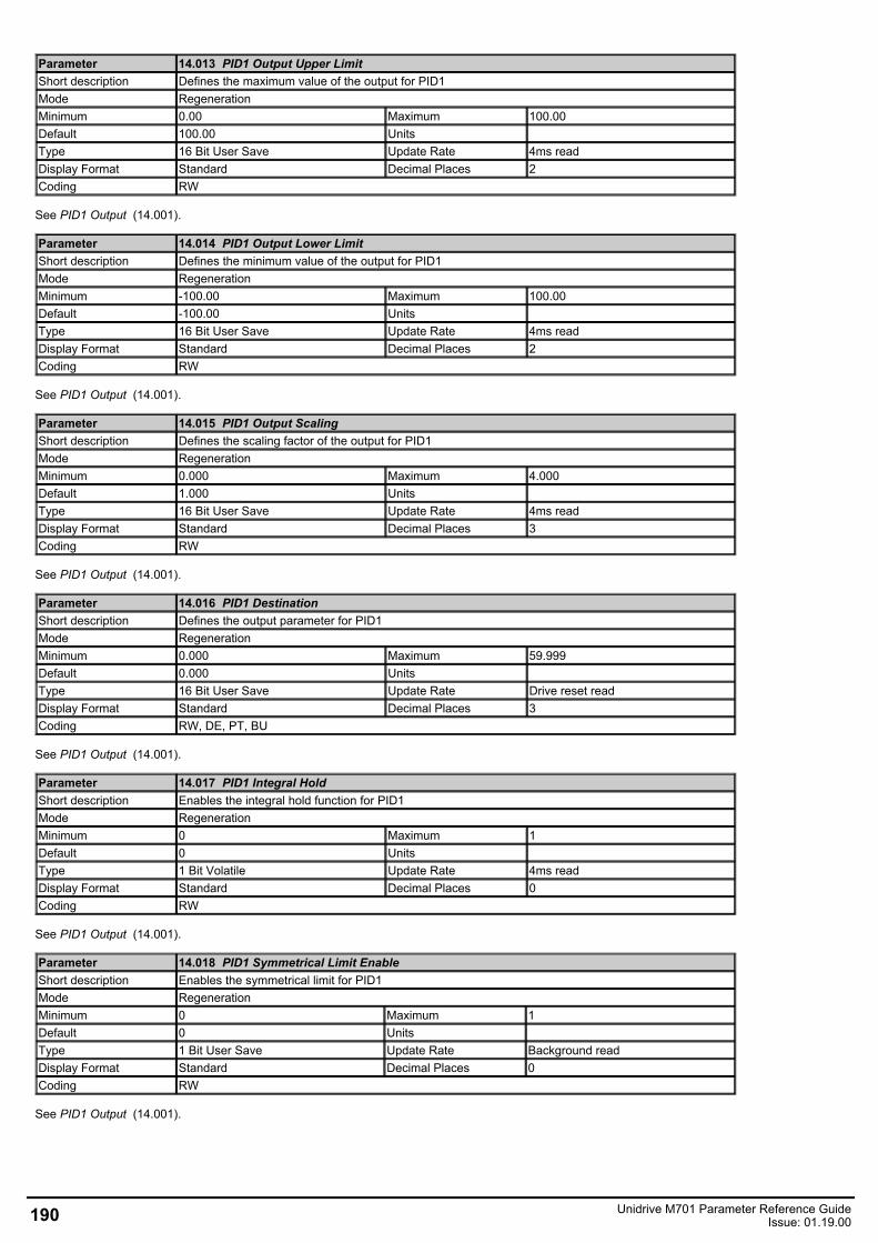
Parameter 14.013 PID1 Output Upper LimitShort description Defines the maximum value of the output for PID1Mode RegenerationMinimum 0.00 Maximum 100.00Default 100.00 Units Type 16 Bit User Save Update Rate 4ms readDisplay Format Standard Decimal Places 2Coding RW
See PID1 Output (14.001).
Parameter 14.014 PID1 Output Lower LimitShort description Defines the minimum value of the output for PID1Mode RegenerationMinimum -100.00 Maximum 100.00Default -100.00 Units Type 16 Bit User Save Update Rate 4ms readDisplay Format Standard Decimal Places 2Coding RW
See PID1 Output (14.001).
Parameter 14.015 PID1 Output ScalingShort description Defines the scaling factor of the output for PID1Mode RegenerationMinimum 0.000 Maximum 4.000Default 1.000 Units Type 16 Bit User Save Update Rate 4ms readDisplay Format Standard Decimal Places 3Coding RW
See PID1 Output (14.001).
Parameter 14.016 PID1 DestinationShort description Defines the output parameter for PID1Mode RegenerationMinimum 0.000 Maximum 59.999Default 0.000 Units Type 16 Bit User Save Update Rate Drive reset readDisplay Format Standard Decimal Places 3Coding RW, DE, PT, BU
See PID1 Output (14.001).
Parameter 14.017 PID1 Integral HoldShort description Enables the integral hold function for PID1Mode RegenerationMinimum 0 Maximum 1Default 0 Units Type 1 Bit Volatile Update Rate 4ms readDisplay Format Standard Decimal Places 0Coding RW
See PID1 Output (14.001).
Parameter 14.018 PID1 Symmetrical Limit EnableShort description Enables the symmetrical limit for PID1Mode RegenerationMinimum 0 Maximum 1Default 0 Units Type 1 Bit User Save Update Rate Background readDisplay Format Standard Decimal Places 0Coding RW
See PID1 Output (14.001).
190 Unidrive M701 Parameter Reference GuideIssue: 01.19.00
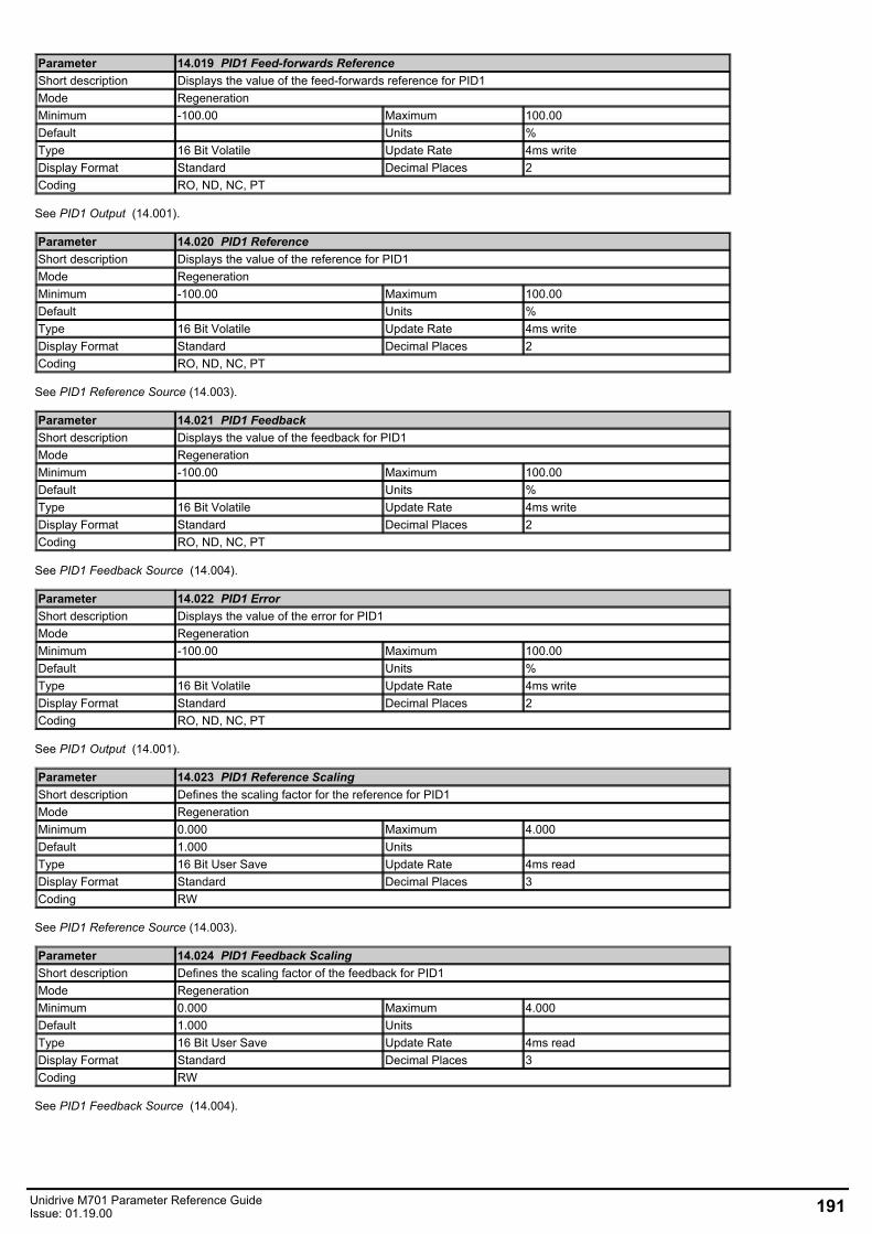
Parameter 14.019 PID1 Feed-forwards ReferenceShort description Displays the value of the feed-forwards reference for PID1Mode RegenerationMinimum -100.00 Maximum 100.00Default Units %Type 16 Bit Volatile Update Rate 4ms writeDisplay Format Standard Decimal Places 2Coding RO, ND, NC, PT
See PID1 Output (14.001).
Parameter 14.020 PID1 ReferenceShort description Displays the value of the reference for PID1Mode RegenerationMinimum -100.00 Maximum 100.00Default Units %Type 16 Bit Volatile Update Rate 4ms writeDisplay Format Standard Decimal Places 2Coding RO, ND, NC, PT
See PID1 Reference Source (14.003).
Parameter 14.021 PID1 FeedbackShort description Displays the value of the feedback for PID1Mode RegenerationMinimum -100.00 Maximum 100.00Default Units %Type 16 Bit Volatile Update Rate 4ms writeDisplay Format Standard Decimal Places 2Coding RO, ND, NC, PT
See PID1 Feedback Source (14.004).
Parameter 14.022 PID1 ErrorShort description Displays the value of the error for PID1Mode RegenerationMinimum -100.00 Maximum 100.00Default Units %Type 16 Bit Volatile Update Rate 4ms writeDisplay Format Standard Decimal Places 2Coding RO, ND, NC, PT
See PID1 Output (14.001).
Parameter 14.023 PID1 Reference ScalingShort description Defines the scaling factor for the reference for PID1Mode RegenerationMinimum 0.000 Maximum 4.000Default 1.000 Units Type 16 Bit User Save Update Rate 4ms readDisplay Format Standard Decimal Places 3Coding RW
See PID1 Reference Source (14.003).
Parameter 14.024 PID1 Feedback ScalingShort description Defines the scaling factor of the feedback for PID1Mode RegenerationMinimum 0.000 Maximum 4.000Default 1.000 Units Type 16 Bit User Save Update Rate 4ms readDisplay Format Standard Decimal Places 3Coding RW
See PID1 Feedback Source (14.004).
Unidrive M701 Parameter Reference GuideIssue: 01.19.00 191
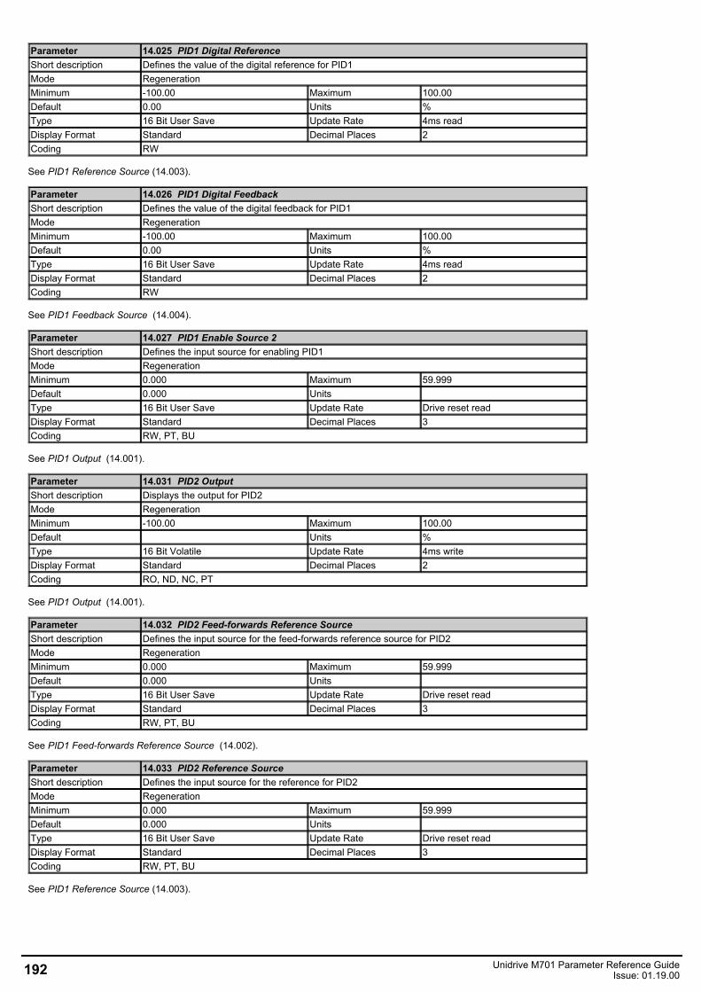
Parameter 14.025 PID1 Digital ReferenceShort description Defines the value of the digital reference for PID1Mode RegenerationMinimum -100.00 Maximum 100.00Default 0.00 Units %Type 16 Bit User Save Update Rate 4ms readDisplay Format Standard Decimal Places 2Coding RW
See PID1 Reference Source (14.003).
Parameter 14.026 PID1 Digital FeedbackShort description Defines the value of the digital feedback for PID1Mode RegenerationMinimum -100.00 Maximum 100.00Default 0.00 Units %Type 16 Bit User Save Update Rate 4ms readDisplay Format Standard Decimal Places 2Coding RW
See PID1 Feedback Source (14.004).
Parameter 14.027 PID1 Enable Source 2Short description Defines the input source for enabling PID1Mode RegenerationMinimum 0.000 Maximum 59.999Default 0.000 Units Type 16 Bit User Save Update Rate Drive reset readDisplay Format Standard Decimal Places 3Coding RW, PT, BU
See PID1 Output (14.001).
Parameter 14.031 PID2 OutputShort description Displays the output for PID2Mode RegenerationMinimum -100.00 Maximum 100.00Default Units %Type 16 Bit Volatile Update Rate 4ms writeDisplay Format Standard Decimal Places 2Coding RO, ND, NC, PT
See PID1 Output (14.001).
Parameter 14.032 PID2 Feed-forwards Reference SourceShort description Defines the input source for the feed-forwards reference source for PID2Mode RegenerationMinimum 0.000 Maximum 59.999Default 0.000 Units Type 16 Bit User Save Update Rate Drive reset readDisplay Format Standard Decimal Places 3Coding RW, PT, BU
See PID1 Feed-forwards Reference Source (14.002).
Parameter 14.033 PID2 Reference SourceShort description Defines the input source for the reference for PID2Mode RegenerationMinimum 0.000 Maximum 59.999Default 0.000 Units Type 16 Bit User Save Update Rate Drive reset readDisplay Format Standard Decimal Places 3Coding RW, PT, BU
See PID1 Reference Source (14.003).
192 Unidrive M701 Parameter Reference GuideIssue: 01.19.00
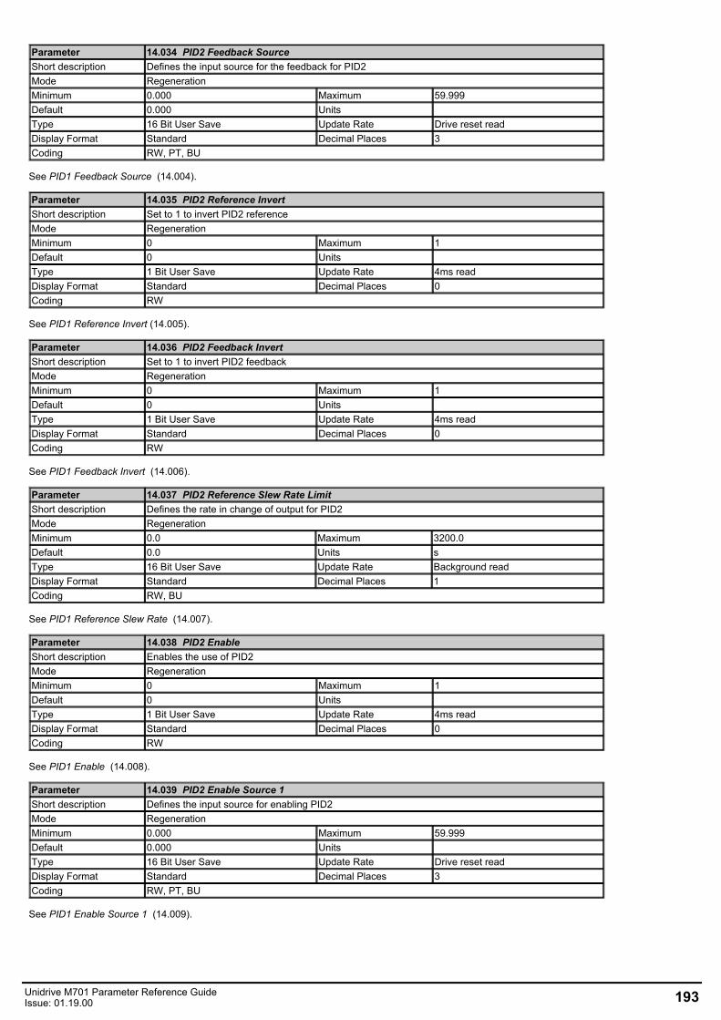
Parameter 14.034 PID2 Feedback SourceShort description Defines the input source for the feedback for PID2Mode RegenerationMinimum 0.000 Maximum 59.999Default 0.000 Units Type 16 Bit User Save Update Rate Drive reset readDisplay Format Standard Decimal Places 3Coding RW, PT, BU
See PID1 Feedback Source (14.004).
Parameter 14.035 PID2 Reference InvertShort description Set to 1 to invert PID2 referenceMode RegenerationMinimum 0 Maximum 1Default 0 Units Type 1 Bit User Save Update Rate 4ms readDisplay Format Standard Decimal Places 0Coding RW
See PID1 Reference Invert (14.005).
Parameter 14.036 PID2 Feedback InvertShort description Set to 1 to invert PID2 feedbackMode RegenerationMinimum 0 Maximum 1Default 0 Units Type 1 Bit User Save Update Rate 4ms readDisplay Format Standard Decimal Places 0Coding RW
See PID1 Feedback Invert (14.006).
Parameter 14.037 PID2 Reference Slew Rate LimitShort description Defines the rate in change of output for PID2Mode RegenerationMinimum 0.0 Maximum 3200.0Default 0.0 Units sType 16 Bit User Save Update Rate Background readDisplay Format Standard Decimal Places 1Coding RW, BU
See PID1 Reference Slew Rate (14.007).
Parameter 14.038 PID2 EnableShort description Enables the use of PID2Mode RegenerationMinimum 0 Maximum 1Default 0 Units Type 1 Bit User Save Update Rate 4ms readDisplay Format Standard Decimal Places 0Coding RW
See PID1 Enable (14.008).
Parameter 14.039 PID2 Enable Source 1Short description Defines the input source for enabling PID2Mode RegenerationMinimum 0.000 Maximum 59.999Default 0.000 Units Type 16 Bit User Save Update Rate Drive reset readDisplay Format Standard Decimal Places 3Coding RW, PT, BU
See PID1 Enable Source 1 (14.009).
Unidrive M701 Parameter Reference GuideIssue: 01.19.00 193
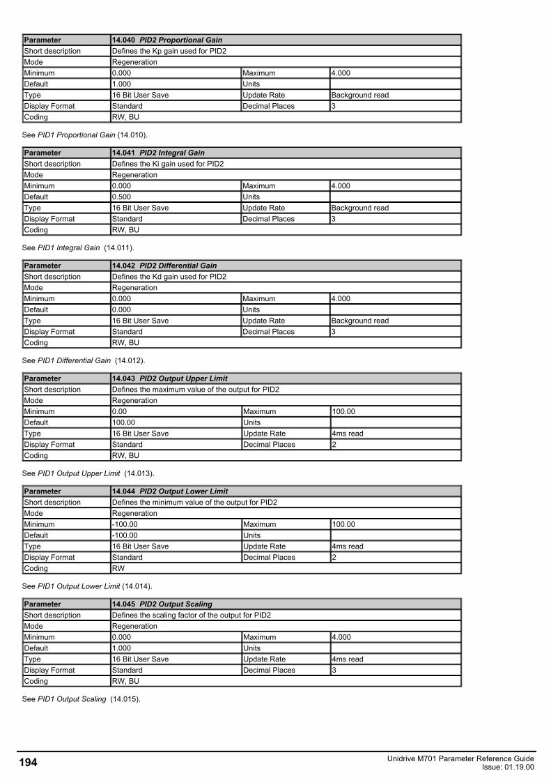
Parameter 14.040 PID2 Proportional GainShort description Defines the Kp gain used for PID2Mode RegenerationMinimum 0.000 Maximum 4.000Default 1.000 Units Type 16 Bit User Save Update Rate Background readDisplay Format Standard Decimal Places 3Coding RW, BU
See PID1 Proportional Gain (14.010).
Parameter 14.041 PID2 Integral GainShort description Defines the Ki gain used for PID2Mode RegenerationMinimum 0.000 Maximum 4.000Default 0.500 Units Type 16 Bit User Save Update Rate Background readDisplay Format Standard Decimal Places 3Coding RW, BU
See PID1 Integral Gain (14.011).
Parameter 14.042 PID2 Differential GainShort description Defines the Kd gain used for PID2Mode RegenerationMinimum 0.000 Maximum 4.000Default 0.000 Units Type 16 Bit User Save Update Rate Background readDisplay Format Standard Decimal Places 3Coding RW, BU
See PID1 Differential Gain (14.012).
Parameter 14.043 PID2 Output Upper LimitShort description Defines the maximum value of the output for PID2Mode RegenerationMinimum 0.00 Maximum 100.00Default 100.00 Units Type 16 Bit User Save Update Rate 4ms readDisplay Format Standard Decimal Places 2Coding RW, BU
See PID1 Output Upper Limit (14.013).
Parameter 14.044 PID2 Output Lower LimitShort description Defines the minimum value of the output for PID2Mode RegenerationMinimum -100.00 Maximum 100.00Default -100.00 Units Type 16 Bit User Save Update Rate 4ms readDisplay Format Standard Decimal Places 2Coding RW
See PID1 Output Lower Limit (14.014).
Parameter 14.045 PID2 Output ScalingShort description Defines the scaling factor of the output for PID2Mode RegenerationMinimum 0.000 Maximum 4.000Default 1.000 Units Type 16 Bit User Save Update Rate 4ms readDisplay Format Standard Decimal Places 3Coding RW, BU
See PID1 Output Scaling (14.015).
194 Unidrive M701 Parameter Reference GuideIssue: 01.19.00
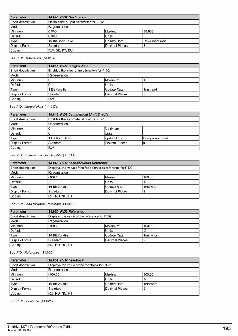
Parameter 14.046 PID2 DestinationShort description Defines the output parameter for PID2Mode RegenerationMinimum 0.000 Maximum 59.999Default 0.000 Units Type 16 Bit User Save Update Rate Drive reset readDisplay Format Standard Decimal Places 3Coding RW, DE, PT, BU
See PID1 Destination (14.016).
Parameter 14.047 PID2 Integral HoldShort description Enables the integral hold function for PID2Mode RegenerationMinimum 0 Maximum 1Default 0 Units Type 1 Bit Volatile Update Rate 4ms readDisplay Format Standard Decimal Places 0Coding RW
See PID1 Integral Hold (14.017).
Parameter 14.048 PID2 Symmetrical Limit EnableShort description Enables the symmetrical limit for PID2Mode RegenerationMinimum 0 Maximum 1Default 0 Units Type 1 Bit User Save Update Rate Background readDisplay Format Standard Decimal Places 0Coding RW
See PID1 Symmetrical Limit Enable (14.018).
Parameter 14.049 PID2 Feed-forwards ReferenceShort description Displays the value of the feed-forwards reference for PID2Mode RegenerationMinimum -100.00 Maximum 100.00Default Units %Type 16 Bit Volatile Update Rate 4ms writeDisplay Format Standard Decimal Places 2Coding RO, ND, NC, PT
See PID1 Feed-forwards Reference (14.019).
Parameter 14.050 PID2 ReferenceShort description Displays the value of the reference for PID2Mode RegenerationMinimum -100.00 Maximum 100.00Default Units %Type 16 Bit Volatile Update Rate 4ms writeDisplay Format Standard Decimal Places 2Coding RO, ND, NC, PT
See PID1 Reference (14.020).
Parameter 14.051 PID2 FeedbackShort description Displays the value of the feedback for PID2Mode RegenerationMinimum -100.00 Maximum 100.00Default Units %Type 16 Bit Volatile Update Rate 4ms writeDisplay Format Standard Decimal Places 2Coding RO, ND, NC, PT
See PID1 Feedback (14.021).
Unidrive M701 Parameter Reference GuideIssue: 01.19.00 195
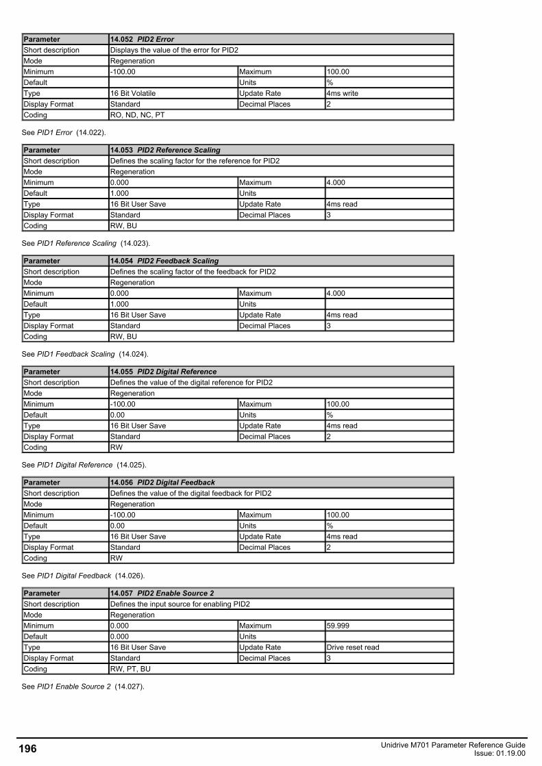
Parameter 14.052 PID2 ErrorShort description Displays the value of the error for PID2Mode RegenerationMinimum -100.00 Maximum 100.00Default Units %Type 16 Bit Volatile Update Rate 4ms writeDisplay Format Standard Decimal Places 2Coding RO, ND, NC, PT
See PID1 Error (14.022).
Parameter 14.053 PID2 Reference ScalingShort description Defines the scaling factor for the reference for PID2Mode RegenerationMinimum 0.000 Maximum 4.000Default 1.000 Units Type 16 Bit User Save Update Rate 4ms readDisplay Format Standard Decimal Places 3Coding RW, BU
See PID1 Reference Scaling (14.023).
Parameter 14.054 PID2 Feedback ScalingShort description Defines the scaling factor of the feedback for PID2Mode RegenerationMinimum 0.000 Maximum 4.000Default 1.000 Units Type 16 Bit User Save Update Rate 4ms readDisplay Format Standard Decimal Places 3Coding RW, BU
See PID1 Feedback Scaling (14.024).
Parameter 14.055 PID2 Digital ReferenceShort description Defines the value of the digital reference for PID2Mode RegenerationMinimum -100.00 Maximum 100.00Default 0.00 Units %Type 16 Bit User Save Update Rate 4ms readDisplay Format Standard Decimal Places 2Coding RW
See PID1 Digital Reference (14.025).
Parameter 14.056 PID2 Digital FeedbackShort description Defines the value of the digital feedback for PID2Mode RegenerationMinimum -100.00 Maximum 100.00Default 0.00 Units %Type 16 Bit User Save Update Rate 4ms readDisplay Format Standard Decimal Places 2Coding RW
See PID1 Digital Feedback (14.026).
Parameter 14.057 PID2 Enable Source 2Short description Defines the input source for enabling PID2Mode RegenerationMinimum 0.000 Maximum 59.999Default 0.000 Units Type 16 Bit User Save Update Rate Drive reset readDisplay Format Standard Decimal Places 3Coding RW, PT, BU
See PID1 Enable Source 2 (14.027).
196 Unidrive M701 Parameter Reference GuideIssue: 01.19.00
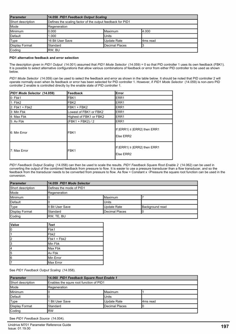
Parameter 14.058 PID1 Feedback Output ScalingShort description Defines the scaling factor of the output feedback for PID1Mode RegenerationMinimum 0.000 Maximum 4.000Default 1.000 Units Type 16 Bit User Save Update Rate 4ms readDisplay Format Standard Decimal Places 3Coding RW, BU
PID1 alternative feedback and error selection
The description given in PID1 Output (14.001) assumed that PID1 Mode Selector (14.059) = 0 so that PID controller 1 uses its own feedback (FBK1).It is possible to select alternative configurations that allow various combinations of feedback or error from either PID controller to be used as shownbelow.
PID1 Mode Selector (14.059) can be used to select the feedback and error as shown in the table below. It should be noted that PID controller 2 willoperate normally even when its feedback or error has been selected for PID controller 1. However, if PID1 Mode Selector (14.059) is non-zero PIDcontroller 2 enable is controlled directly by the enable state of PID controller 1.
PID1 Mode Selector (14.059) Feedback Error0: Fbk1 FBK1 ERR11: Fbk2 FBK2 ERR12: Fbk1 + Fbk2 FBK1 + FBK2 ERR13: Min Fbk Lowest of FBK1 or FBK2 ERR14: Max Fbk Highest of FBK1 or FBK2 ERR15: Av Fbk (FBK1 + FBK2) / 2 ERR1
6: Min Error FBK1If |ERR1| ≤ |ERR2| then ERR1
Else ERR2
7: Max Error FBK1If |ERR1| ≥ |ERR2| then ERR1
Else ERR2
PID1 Feedback Output Scaling (14.058) can then be used to scale the results. PID1 Feedback Square Root Enable 2 (14.062) can be used inconverting the output of the combined feedback from pressure to flow. It is easier to use a pressure transducer than a flow transducer, and so thefeedback from the transducer needs to be converted from pressure to flow. As flow = Constant x √Pressure the square root function can be used in theconversion.
Parameter 14.059 PID1 Mode SelectorShort description Defines the mode of PID1Mode RegenerationMinimum 0 Maximum 7Default 0 Units Type 8 Bit User Save Update Rate Background readDisplay Format Standard Decimal Places 0Coding RW, TE, BU
Value Text0 Fbk11 Fbk22 Fbk1 + Fbk23 Min Fbk4 Max Fbk5 Av Fbk6 Min Error7 Max Error
See PID1 Feedback Output Scaling (14.058).
Parameter 14.060 PID1 Feedback Square Root Enable 1Short description Enables the squre root function of PID1Mode RegenerationMinimum 0 Maximum 1Default 0 Units Type 1 Bit User Save Update Rate 4ms readDisplay Format Standard Decimal Places 0Coding RW
See PID1 Feedback Source (14.004).
Unidrive M701 Parameter Reference GuideIssue: 01.19.00 197
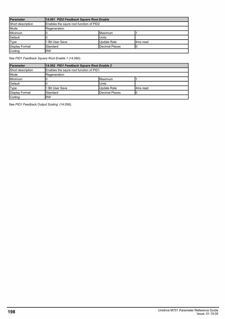
Parameter 14.061 PID2 Feedback Square Root EnableShort description Enables the squre root function of PID2Mode RegenerationMinimum 0 Maximum 1Default 0 Units Type 1 Bit User Save Update Rate 4ms readDisplay Format Standard Decimal Places 0Coding RW
See PID1 Feedback Square Root Enable 1 (14.060)
Parameter 14.062 PID1 Feedback Square Root Enable 2Short description Enables the squre root function of PID1Mode RegenerationMinimum 0 Maximum 1Default 0 Units Type 1 Bit User Save Update Rate 4ms readDisplay Format Standard Decimal Places 0Coding RW
See PID1 Feedback Output Scaling (14.058).
198 Unidrive M701 Parameter Reference GuideIssue: 01.19.00
Menu 18 Single Line Descriptions − Application Menu 1Mode: Regeneration
Unidrive M701 Parameter Reference GuideIssue: 01.19.00 199
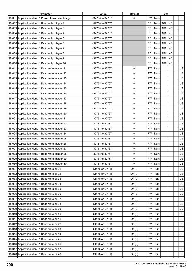
Parameter Range Default Type18.001 Application Menu 1 Power‑down Save Integer -32768 to 32767 0 RW Num PS
18.002 Application Menu 1 Read‑only Integer 2 -32768 to 32767 RO Num ND NC
18.003 Application Menu 1 Read‑only Integer 3 -32768 to 32767 RO Num ND NC
18.004 Application Menu 1 Read‑only Integer 4 -32768 to 32767 RO Num ND NC
18.005 Application Menu 1 Read‑only Integer 5 -32768 to 32767 RO Num ND NC
18.006 Application Menu 1 Read‑only Integer 6 -32768 to 32767 RO Num ND NC
18.007 Application Menu 1 Read‑only Integer 7 -32768 to 32767 RO Num ND NC
18.008 Application Menu 1 Read‑only Integer 8 -32768 to 32767 RO Num ND NC
18.009 Application Menu 1 Read‑only Integer 9 -32768 to 32767 RO Num ND NC
18.010 Application Menu 1 Read‑only Integer 10 -32768 to 32767 RO Num ND NC
18.011 Application Menu 1 Read‑write Integer 11 -32768 to 32767 0 RW Num US
18.012 Application Menu 1 Read‑write Integer 12 -32768 to 32767 0 RW Num US
18.013 Application Menu 1 Read‑write Integer 13 -32768 to 32767 0 RW Num US
18.014 Application Menu 1 Read‑write Integer 14 -32768 to 32767 0 RW Num US
18.015 Application Menu 1 Read‑write Integer 15 -32768 to 32767 0 RW Num US
18.016 Application Menu 1 Read‑write Integer 16 -32768 to 32767 0 RW Num US
18.017 Application Menu 1 Read‑write Integer 17 -32768 to 32767 0 RW Num US
18.018 Application Menu 1 Read‑write Integer 18 -32768 to 32767 0 RW Num US
18.019 Application Menu 1 Read‑write Integer 19 -32768 to 32767 0 RW Num US
18.020 Application Menu 1 Read‑write Integer 20 -32768 to 32767 0 RW Num US
18.021 Application Menu 1 Read‑write Integer 21 -32768 to 32767 0 RW Num US
18.022 Application Menu 1 Read‑write Integer 22 -32768 to 32767 0 RW Num US
18.023 Application Menu 1 Read‑write Integer 23 -32768 to 32767 0 RW Num US
18.024 Application Menu 1 Read‑write Integer 24 -32768 to 32767 0 RW Num US
18.025 Application Menu 1 Read‑write Integer 25 -32768 to 32767 0 RW Num US
18.026 Application Menu 1 Read‑write Integer 26 -32768 to 32767 0 RW Num US
18.027 Application Menu 1 Read‑write Integer 27 -32768 to 32767 0 RW Num US
18.028 Application Menu 1 Read‑write Integer 28 -32768 to 32767 0 RW Num US
18.029 Application Menu 1 Read‑write Integer 29 -32768 to 32767 0 RW Num US
18.030 Application Menu 1 Read‑write Integer 30 -32768 to 32767 0 RW Num US
18.031 Application Menu 1 Read‑write bit 31 Off (0) or On (1) Off (0) RW Bit US
18.032 Application Menu 1 Read‑write bit 32 Off (0) or On (1) Off (0) RW Bit US
18.033 Application Menu 1 Read‑write bit 33 Off (0) or On (1) Off (0) RW Bit US
18.034 Application Menu 1 Read‑write bit 34 Off (0) or On (1) Off (0) RW Bit US
18.035 Application Menu 1 Read‑write bit 35 Off (0) or On (1) Off (0) RW Bit US
18.036 Application Menu 1 Read‑write bit 36 Off (0) or On (1) Off (0) RW Bit US
18.037 Application Menu 1 Read‑write bit 37 Off (0) or On (1) Off (0) RW Bit US
18.038 Application Menu 1 Read‑write bit 38 Off (0) or On (1) Off (0) RW Bit US
18.039 Application Menu 1 Read‑write bit 39 Off (0) or On (1) Off (0) RW Bit US
18.040 Application Menu 1 Read‑write bit 40 Off (0) or On (1) Off (0) RW Bit US
18.041 Application Menu 1 Read‑write bit 41 Off (0) or On (1) Off (0) RW Bit US
18.042 Application Menu 1 Read‑write bit 42 Off (0) or On (1) Off (0) RW Bit US
18.043 Application Menu 1 Read‑write bit 43 Off (0) or On (1) Off (0) RW Bit US
18.044 Application Menu 1 Read‑write bit 44 Off (0) or On (1) Off (0) RW Bit US
18.045 Application Menu 1 Read‑write bit 45 Off (0) or On (1) Off (0) RW Bit US
18.046 Application Menu 1 Read‑write bit 46 Off (0) or On (1) Off (0) RW Bit US
18.047 Application Menu 1 Read‑write bit 47 Off (0) or On (1) Off (0) RW Bit US
18.048 Application Menu 1 Read‑write bit 48 Off (0) or On (1) Off (0) RW Bit US
200 Unidrive M701 Parameter Reference GuideIssue: 01.19.00
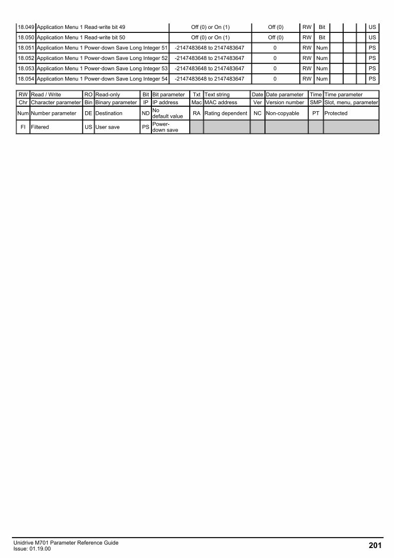
18.049 Application Menu 1 Read‑write bit 49 Off (0) or On (1) Off (0) RW Bit US
18.050 Application Menu 1 Read‑write bit 50 Off (0) or On (1) Off (0) RW Bit US
18.051 Application Menu 1 Power‑down Save Long Integer 51 -2147483648 to 2147483647 0 RW Num PS
18.052 Application Menu 1 Power‑down Save Long Integer 52 -2147483648 to 2147483647 0 RW Num PS
18.053 Application Menu 1 Power‑down Save Long Integer 53 -2147483648 to 2147483647 0 RW Num PS
18.054 Application Menu 1 Power‑down Save Long Integer 54 -2147483648 to 2147483647 0 RW Num PS
RW Read / Write RO Read-only Bit Bit parameter Txt Text string Date Date parameter Time Time parameterChr Character parameter Bin Binary parameter IP IP address Mac MAC address Ver Version number SMP Slot, menu, parameter
Num Number parameter DE Destination ND Nodefault value RA Rating dependent NC Non-copyable PT Protected
FI Filtered US User save PS Power-down save
Unidrive M701 Parameter Reference GuideIssue: 01.19.00 201
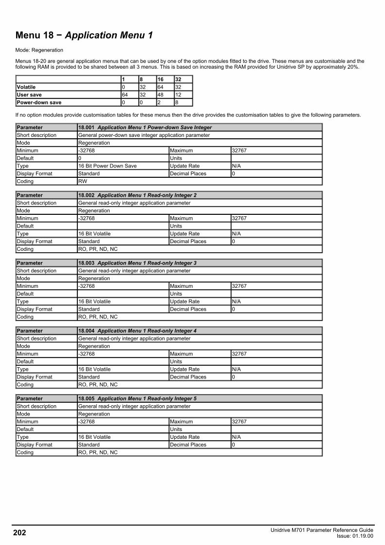
Menu 18 − Application Menu 1Mode: Regeneration
Menus 18-20 are general application menus that can be used by one of the option modules fitted to the drive. These menus are customisable and thefollowing RAM is provided to be shared between all 3 menus. This is based on increasing the RAM provided for Unidrive SP by approximately 20%.
1 8 16 32Volatile 0 32 64 32User save 64 32 48 12Power-down save 0 0 2 8
If no option modules provide customisation tables for these menus then the drive provides the customisation tables to give the following parameters.
Parameter 18.001 Application Menu 1 Power-down Save IntegerShort description General power-down save integer application parameterMode RegenerationMinimum -32768 Maximum 32767Default 0 Units Type 16 Bit Power Down Save Update Rate N/ADisplay Format Standard Decimal Places 0Coding RW
Parameter 18.002 Application Menu 1 Read-only Integer 2Short description General read-only integer application parameterMode RegenerationMinimum -32768 Maximum 32767Default Units Type 16 Bit Volatile Update Rate N/ADisplay Format Standard Decimal Places 0Coding RO, PR, ND, NC
Parameter 18.003 Application Menu 1 Read-only Integer 3Short description General read-only integer application parameterMode RegenerationMinimum -32768 Maximum 32767Default Units Type 16 Bit Volatile Update Rate N/ADisplay Format Standard Decimal Places 0Coding RO, PR, ND, NC
Parameter 18.004 Application Menu 1 Read-only Integer 4Short description General read-only integer application parameterMode RegenerationMinimum -32768 Maximum 32767Default Units Type 16 Bit Volatile Update Rate N/ADisplay Format Standard Decimal Places 0Coding RO, PR, ND, NC
Parameter 18.005 Application Menu 1 Read-only Integer 5Short description General read-only integer application parameterMode RegenerationMinimum -32768 Maximum 32767Default Units Type 16 Bit Volatile Update Rate N/ADisplay Format Standard Decimal Places 0Coding RO, PR, ND, NC
202 Unidrive M701 Parameter Reference GuideIssue: 01.19.00
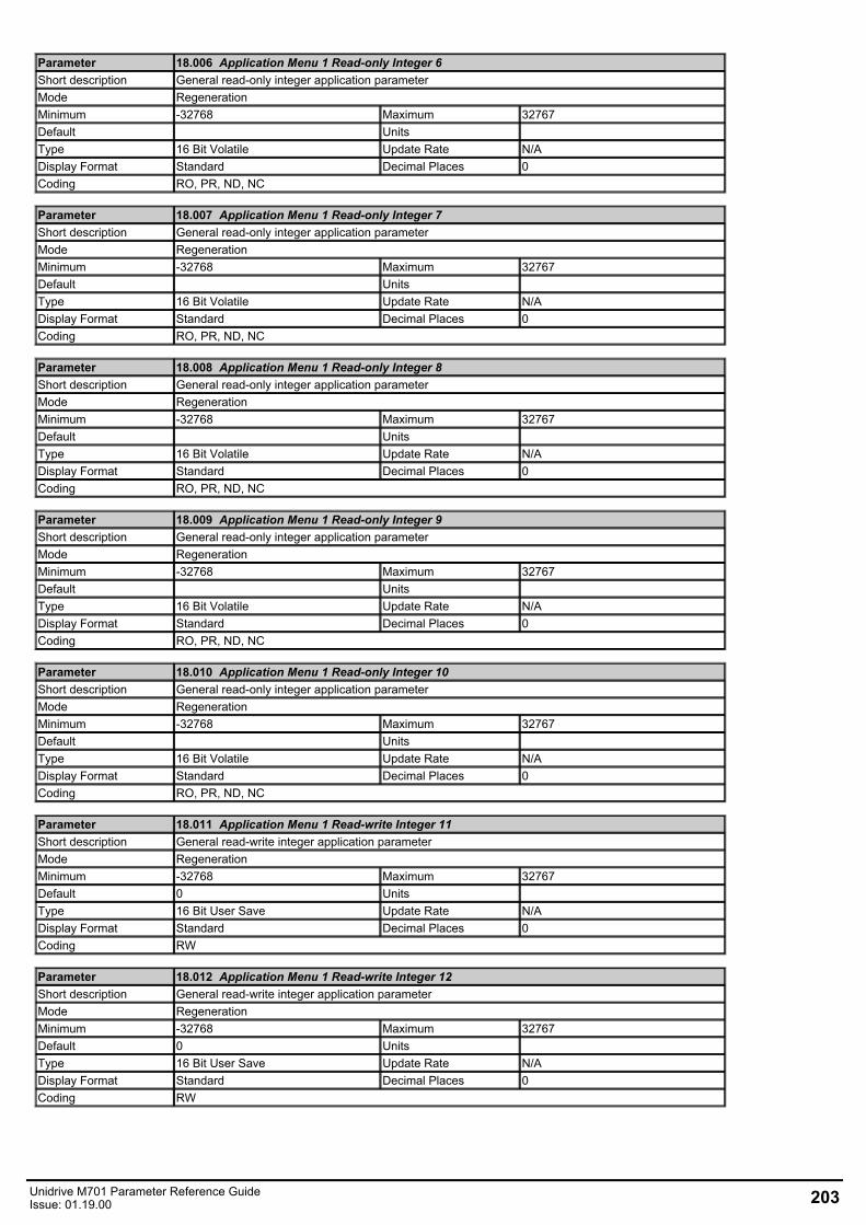
Parameter 18.006 Application Menu 1 Read-only Integer 6Short description General read-only integer application parameterMode RegenerationMinimum -32768 Maximum 32767Default Units Type 16 Bit Volatile Update Rate N/ADisplay Format Standard Decimal Places 0Coding RO, PR, ND, NC
Parameter 18.007 Application Menu 1 Read-only Integer 7Short description General read-only integer application parameterMode RegenerationMinimum -32768 Maximum 32767Default Units Type 16 Bit Volatile Update Rate N/ADisplay Format Standard Decimal Places 0Coding RO, PR, ND, NC
Parameter 18.008 Application Menu 1 Read-only Integer 8Short description General read-only integer application parameterMode RegenerationMinimum -32768 Maximum 32767Default Units Type 16 Bit Volatile Update Rate N/ADisplay Format Standard Decimal Places 0Coding RO, PR, ND, NC
Parameter 18.009 Application Menu 1 Read-only Integer 9Short description General read-only integer application parameterMode RegenerationMinimum -32768 Maximum 32767Default Units Type 16 Bit Volatile Update Rate N/ADisplay Format Standard Decimal Places 0Coding RO, PR, ND, NC
Parameter 18.010 Application Menu 1 Read-only Integer 10Short description General read-only integer application parameterMode RegenerationMinimum -32768 Maximum 32767Default Units Type 16 Bit Volatile Update Rate N/ADisplay Format Standard Decimal Places 0Coding RO, PR, ND, NC
Parameter 18.011 Application Menu 1 Read-write Integer 11Short description General read-write integer application parameterMode RegenerationMinimum -32768 Maximum 32767Default 0 Units Type 16 Bit User Save Update Rate N/ADisplay Format Standard Decimal Places 0Coding RW
Parameter 18.012 Application Menu 1 Read-write Integer 12Short description General read-write integer application parameterMode RegenerationMinimum -32768 Maximum 32767Default 0 Units Type 16 Bit User Save Update Rate N/ADisplay Format Standard Decimal Places 0Coding RW
Unidrive M701 Parameter Reference GuideIssue: 01.19.00 203
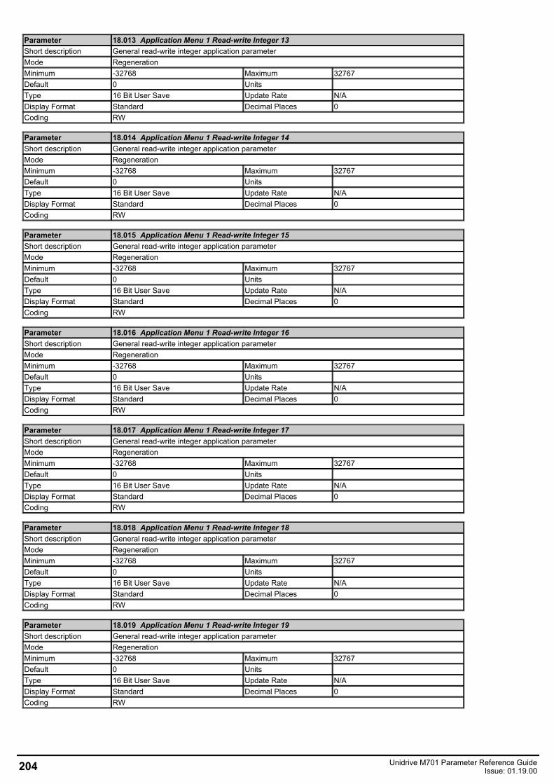
Parameter 18.013 Application Menu 1 Read-write Integer 13Short description General read-write integer application parameterMode RegenerationMinimum -32768 Maximum 32767Default 0 Units Type 16 Bit User Save Update Rate N/ADisplay Format Standard Decimal Places 0Coding RW
Parameter 18.014 Application Menu 1 Read-write Integer 14Short description General read-write integer application parameterMode RegenerationMinimum -32768 Maximum 32767Default 0 Units Type 16 Bit User Save Update Rate N/ADisplay Format Standard Decimal Places 0Coding RW
Parameter 18.015 Application Menu 1 Read-write Integer 15Short description General read-write integer application parameterMode RegenerationMinimum -32768 Maximum 32767Default 0 Units Type 16 Bit User Save Update Rate N/ADisplay Format Standard Decimal Places 0Coding RW
Parameter 18.016 Application Menu 1 Read-write Integer 16Short description General read-write integer application parameterMode RegenerationMinimum -32768 Maximum 32767Default 0 Units Type 16 Bit User Save Update Rate N/ADisplay Format Standard Decimal Places 0Coding RW
Parameter 18.017 Application Menu 1 Read-write Integer 17Short description General read-write integer application parameterMode RegenerationMinimum -32768 Maximum 32767Default 0 Units Type 16 Bit User Save Update Rate N/ADisplay Format Standard Decimal Places 0Coding RW
Parameter 18.018 Application Menu 1 Read-write Integer 18Short description General read-write integer application parameterMode RegenerationMinimum -32768 Maximum 32767Default 0 Units Type 16 Bit User Save Update Rate N/ADisplay Format Standard Decimal Places 0Coding RW
Parameter 18.019 Application Menu 1 Read-write Integer 19Short description General read-write integer application parameterMode RegenerationMinimum -32768 Maximum 32767Default 0 Units Type 16 Bit User Save Update Rate N/ADisplay Format Standard Decimal Places 0Coding RW
204 Unidrive M701 Parameter Reference GuideIssue: 01.19.00

Parameter 18.020 Application Menu 1 Read-write Integer 20Short description General read-write integer application parameterMode RegenerationMinimum -32768 Maximum 32767Default 0 Units Type 16 Bit User Save Update Rate N/ADisplay Format Standard Decimal Places 0Coding RW
Parameter 18.021 Application Menu 1 Read-write Integer 21Short description General read-write integer application parameterMode RegenerationMinimum -32768 Maximum 32767Default 0 Units Type 16 Bit User Save Update Rate N/ADisplay Format Standard Decimal Places 0Coding RW
Parameter 18.022 Application Menu 1 Read-write Integer 22Short description General read-write integer application parameterMode RegenerationMinimum -32768 Maximum 32767Default 0 Units Type 16 Bit User Save Update Rate N/ADisplay Format Standard Decimal Places 0Coding RW
Parameter 18.023 Application Menu 1 Read-write Integer 23Short description General read-write integer application parameterMode RegenerationMinimum -32768 Maximum 32767Default 0 Units Type 16 Bit User Save Update Rate N/ADisplay Format Standard Decimal Places 0Coding RW
Parameter 18.024 Application Menu 1 Read-write Integer 24Short description General read-write integer application parameterMode RegenerationMinimum -32768 Maximum 32767Default 0 Units Type 16 Bit User Save Update Rate N/ADisplay Format Standard Decimal Places 0Coding RW
Parameter 18.025 Application Menu 1 Read-write Integer 25Short description General read-write integer application parameterMode RegenerationMinimum -32768 Maximum 32767Default 0 Units Type 16 Bit User Save Update Rate N/ADisplay Format Standard Decimal Places 0Coding RW
Parameter 18.026 Application Menu 1 Read-write Integer 26Short description General read-write integer application parameterMode RegenerationMinimum -32768 Maximum 32767Default 0 Units Type 16 Bit User Save Update Rate N/ADisplay Format Standard Decimal Places 0Coding RW
Unidrive M701 Parameter Reference GuideIssue: 01.19.00 205
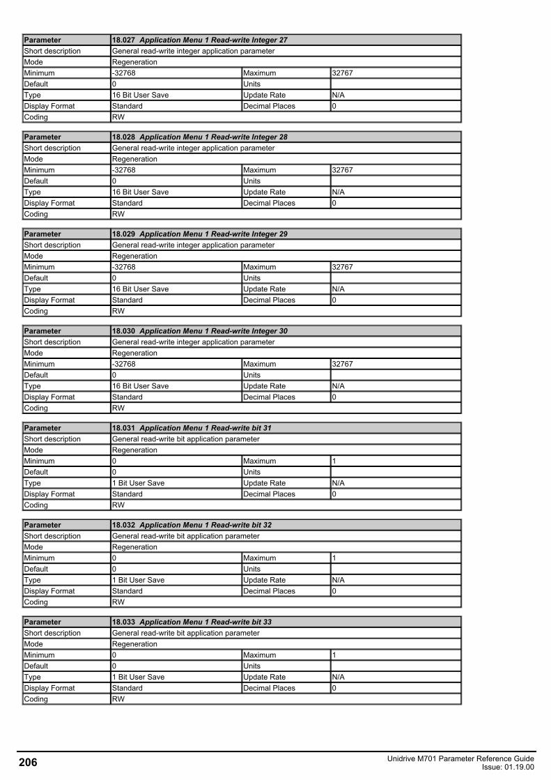
Parameter 18.027 Application Menu 1 Read-write Integer 27Short description General read-write integer application parameterMode RegenerationMinimum -32768 Maximum 32767Default 0 Units Type 16 Bit User Save Update Rate N/ADisplay Format Standard Decimal Places 0Coding RW
Parameter 18.028 Application Menu 1 Read-write Integer 28Short description General read-write integer application parameterMode RegenerationMinimum -32768 Maximum 32767Default 0 Units Type 16 Bit User Save Update Rate N/ADisplay Format Standard Decimal Places 0Coding RW
Parameter 18.029 Application Menu 1 Read-write Integer 29Short description General read-write integer application parameterMode RegenerationMinimum -32768 Maximum 32767Default 0 Units Type 16 Bit User Save Update Rate N/ADisplay Format Standard Decimal Places 0Coding RW
Parameter 18.030 Application Menu 1 Read-write Integer 30Short description General read-write integer application parameterMode RegenerationMinimum -32768 Maximum 32767Default 0 Units Type 16 Bit User Save Update Rate N/ADisplay Format Standard Decimal Places 0Coding RW
Parameter 18.031 Application Menu 1 Read-write bit 31Short description General read-write bit application parameterMode RegenerationMinimum 0 Maximum 1Default 0 Units Type 1 Bit User Save Update Rate N/ADisplay Format Standard Decimal Places 0Coding RW
Parameter 18.032 Application Menu 1 Read-write bit 32Short description General read-write bit application parameterMode RegenerationMinimum 0 Maximum 1Default 0 Units Type 1 Bit User Save Update Rate N/ADisplay Format Standard Decimal Places 0Coding RW
Parameter 18.033 Application Menu 1 Read-write bit 33Short description General read-write bit application parameterMode RegenerationMinimum 0 Maximum 1Default 0 Units Type 1 Bit User Save Update Rate N/ADisplay Format Standard Decimal Places 0Coding RW
206 Unidrive M701 Parameter Reference GuideIssue: 01.19.00
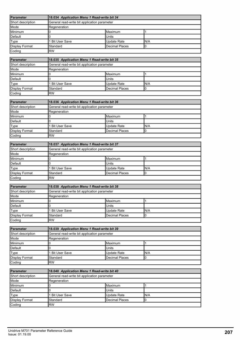
Parameter 18.034 Application Menu 1 Read-write bit 34Short description General read-write bit application parameterMode RegenerationMinimum 0 Maximum 1Default 0 Units Type 1 Bit User Save Update Rate N/ADisplay Format Standard Decimal Places 0Coding RW
Parameter 18.035 Application Menu 1 Read-write bit 35Short description General read-write bit application parameterMode RegenerationMinimum 0 Maximum 1Default 0 Units Type 1 Bit User Save Update Rate N/ADisplay Format Standard Decimal Places 0Coding RW
Parameter 18.036 Application Menu 1 Read-write bit 36Short description General read-write bit application parameterMode RegenerationMinimum 0 Maximum 1Default 0 Units Type 1 Bit User Save Update Rate N/ADisplay Format Standard Decimal Places 0Coding RW
Parameter 18.037 Application Menu 1 Read-write bit 37Short description General read-write bit application parameterMode RegenerationMinimum 0 Maximum 1Default 0 Units Type 1 Bit User Save Update Rate N/ADisplay Format Standard Decimal Places 0Coding RW
Parameter 18.038 Application Menu 1 Read-write bit 38Short description General read-write bit application parameterMode RegenerationMinimum 0 Maximum 1Default 0 Units Type 1 Bit User Save Update Rate N/ADisplay Format Standard Decimal Places 0Coding RW
Parameter 18.039 Application Menu 1 Read-write bit 39Short description General read-write bit application parameterMode RegenerationMinimum 0 Maximum 1Default 0 Units Type 1 Bit User Save Update Rate N/ADisplay Format Standard Decimal Places 0Coding RW
Parameter 18.040 Application Menu 1 Read-write bit 40Short description General read-write bit application parameterMode RegenerationMinimum 0 Maximum 1Default 0 Units Type 1 Bit User Save Update Rate N/ADisplay Format Standard Decimal Places 0Coding RW
Unidrive M701 Parameter Reference GuideIssue: 01.19.00 207
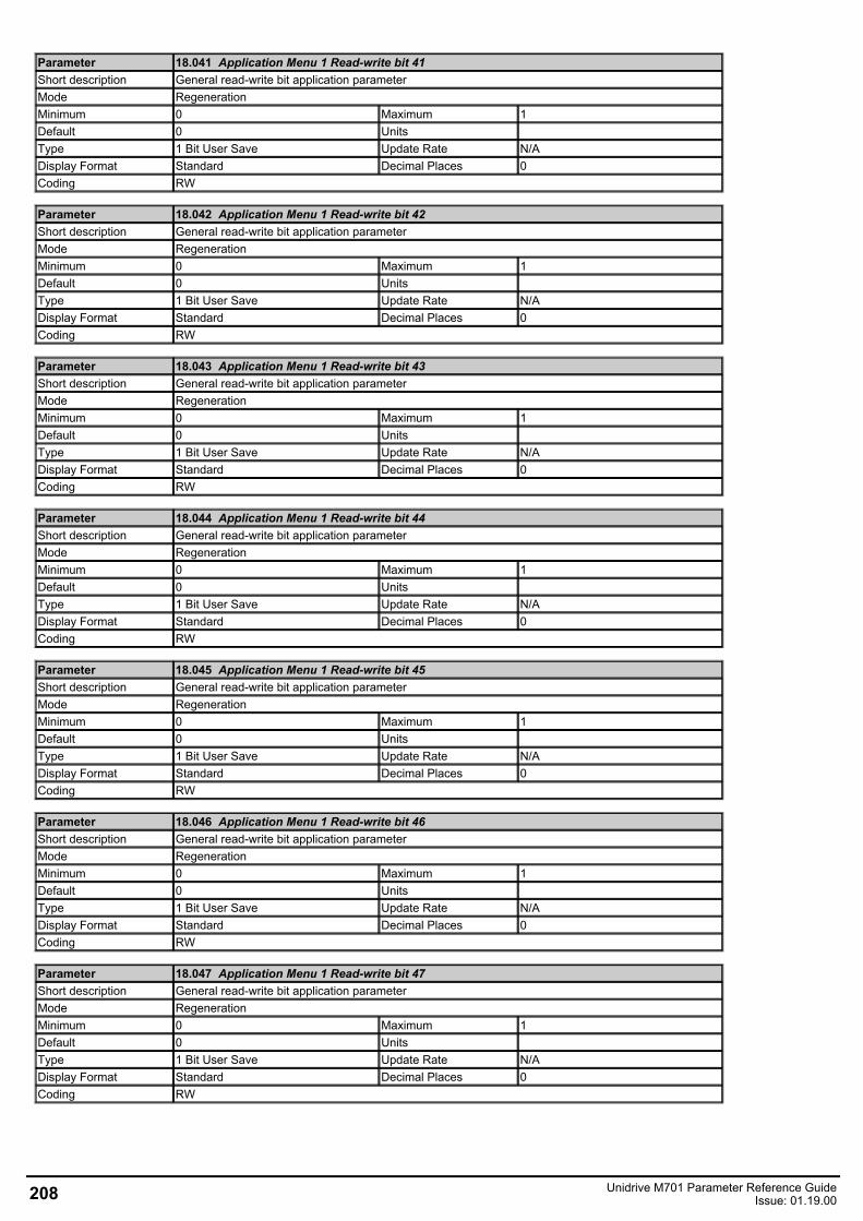
Parameter 18.041 Application Menu 1 Read-write bit 41Short description General read-write bit application parameterMode RegenerationMinimum 0 Maximum 1Default 0 Units Type 1 Bit User Save Update Rate N/ADisplay Format Standard Decimal Places 0Coding RW
Parameter 18.042 Application Menu 1 Read-write bit 42Short description General read-write bit application parameterMode RegenerationMinimum 0 Maximum 1Default 0 Units Type 1 Bit User Save Update Rate N/ADisplay Format Standard Decimal Places 0Coding RW
Parameter 18.043 Application Menu 1 Read-write bit 43Short description General read-write bit application parameterMode RegenerationMinimum 0 Maximum 1Default 0 Units Type 1 Bit User Save Update Rate N/ADisplay Format Standard Decimal Places 0Coding RW
Parameter 18.044 Application Menu 1 Read-write bit 44Short description General read-write bit application parameterMode RegenerationMinimum 0 Maximum 1Default 0 Units Type 1 Bit User Save Update Rate N/ADisplay Format Standard Decimal Places 0Coding RW
Parameter 18.045 Application Menu 1 Read-write bit 45Short description General read-write bit application parameterMode RegenerationMinimum 0 Maximum 1Default 0 Units Type 1 Bit User Save Update Rate N/ADisplay Format Standard Decimal Places 0Coding RW
Parameter 18.046 Application Menu 1 Read-write bit 46Short description General read-write bit application parameterMode RegenerationMinimum 0 Maximum 1Default 0 Units Type 1 Bit User Save Update Rate N/ADisplay Format Standard Decimal Places 0Coding RW
Parameter 18.047 Application Menu 1 Read-write bit 47Short description General read-write bit application parameterMode RegenerationMinimum 0 Maximum 1Default 0 Units Type 1 Bit User Save Update Rate N/ADisplay Format Standard Decimal Places 0Coding RW
208 Unidrive M701 Parameter Reference GuideIssue: 01.19.00
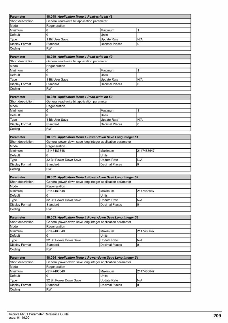
Parameter 18.048 Application Menu 1 Read-write bit 48Short description General read-write bit application parameterMode RegenerationMinimum 0 Maximum 1Default 0 Units Type 1 Bit User Save Update Rate N/ADisplay Format Standard Decimal Places 0Coding RW
Parameter 18.049 Application Menu 1 Read-write bit 49Short description General read-write bit application parameterMode RegenerationMinimum 0 Maximum 1Default 0 Units Type 1 Bit User Save Update Rate N/ADisplay Format Standard Decimal Places 0Coding RW
Parameter 18.050 Application Menu 1 Read-write bit 50Short description General read-write bit application parameterMode RegenerationMinimum 0 Maximum 1Default 0 Units Type 1 Bit User Save Update Rate N/ADisplay Format Standard Decimal Places 0Coding RW
Parameter 18.051 Application Menu 1 Power-down Save Long Integer 51Short description General power-down save long integer application parameterMode RegenerationMinimum -2147483648 Maximum 2147483647Default 0 Units Type 32 Bit Power Down Save Update Rate N/ADisplay Format Standard Decimal Places 0Coding RW
Parameter 18.052 Application Menu 1 Power-down Save Long Integer 52Short description General power-down save long integer application parameterMode RegenerationMinimum -2147483648 Maximum 2147483647Default 0 Units Type 32 Bit Power Down Save Update Rate N/ADisplay Format Standard Decimal Places 0Coding RW
Parameter 18.053 Application Menu 1 Power-down Save Long Integer 53Short description General power-down save long integer application parameterMode RegenerationMinimum -2147483648 Maximum 2147483647Default 0 Units Type 32 Bit Power Down Save Update Rate N/ADisplay Format Standard Decimal Places 0Coding RW
Parameter 18.054 Application Menu 1 Power-down Save Long Integer 54Short description General power-down save long integer application parameterMode RegenerationMinimum -2147483648 Maximum 2147483647Default 0 Units Type 32 Bit Power Down Save Update Rate N/ADisplay Format Standard Decimal Places 0Coding RW
Unidrive M701 Parameter Reference GuideIssue: 01.19.00 209
Menu 19 Single Line Descriptions − Application Menu 2Mode: Regeneration
210 Unidrive M701 Parameter Reference GuideIssue: 01.19.00
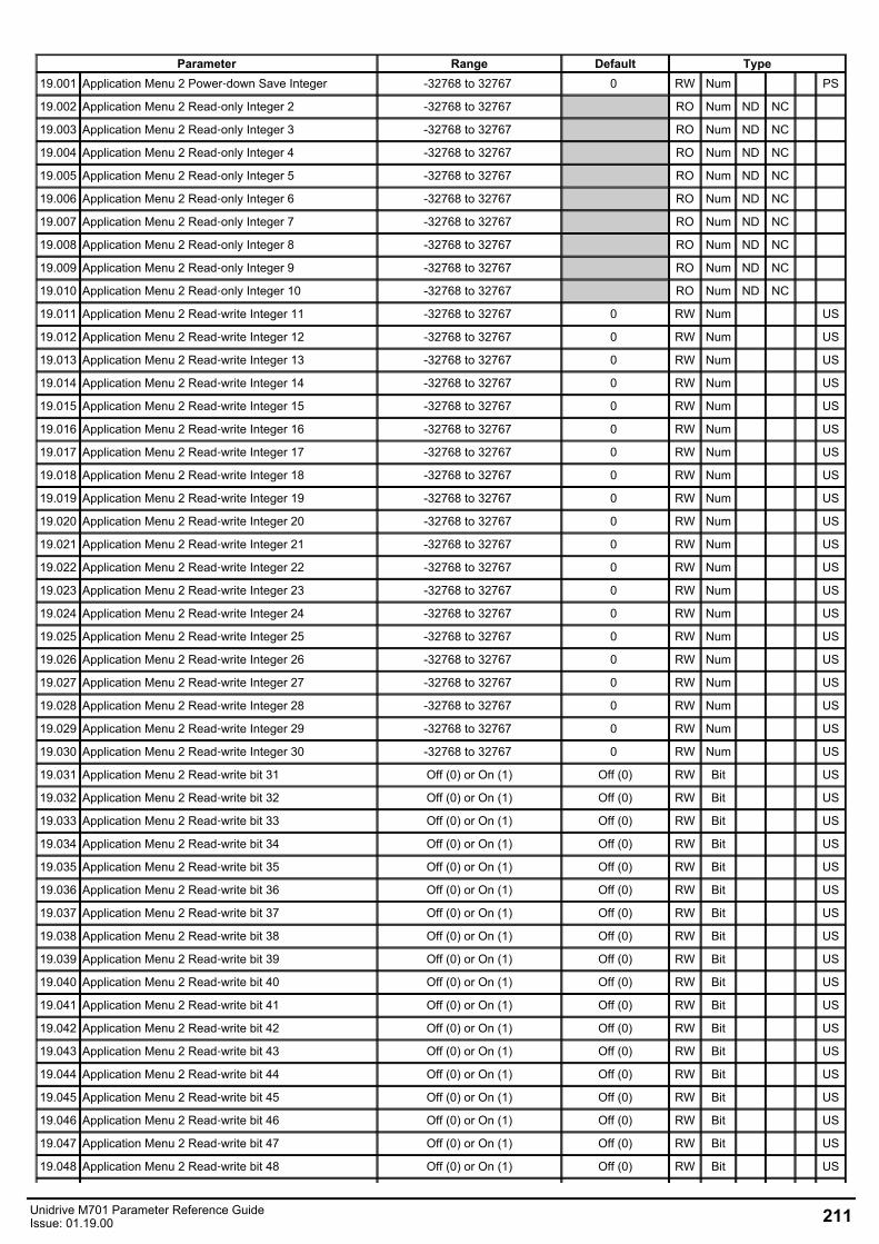
Parameter Range Default Type19.001 Application Menu 2 Power‑down Save Integer -32768 to 32767 0 RW Num PS
19.002 Application Menu 2 Read‑only Integer 2 -32768 to 32767 RO Num ND NC
19.003 Application Menu 2 Read‑only Integer 3 -32768 to 32767 RO Num ND NC
19.004 Application Menu 2 Read‑only Integer 4 -32768 to 32767 RO Num ND NC
19.005 Application Menu 2 Read‑only Integer 5 -32768 to 32767 RO Num ND NC
19.006 Application Menu 2 Read‑only Integer 6 -32768 to 32767 RO Num ND NC
19.007 Application Menu 2 Read‑only Integer 7 -32768 to 32767 RO Num ND NC
19.008 Application Menu 2 Read‑only Integer 8 -32768 to 32767 RO Num ND NC
19.009 Application Menu 2 Read‑only Integer 9 -32768 to 32767 RO Num ND NC
19.010 Application Menu 2 Read‑only Integer 10 -32768 to 32767 RO Num ND NC
19.011 Application Menu 2 Read‑write Integer 11 -32768 to 32767 0 RW Num US
19.012 Application Menu 2 Read‑write Integer 12 -32768 to 32767 0 RW Num US
19.013 Application Menu 2 Read‑write Integer 13 -32768 to 32767 0 RW Num US
19.014 Application Menu 2 Read‑write Integer 14 -32768 to 32767 0 RW Num US
19.015 Application Menu 2 Read‑write Integer 15 -32768 to 32767 0 RW Num US
19.016 Application Menu 2 Read‑write Integer 16 -32768 to 32767 0 RW Num US
19.017 Application Menu 2 Read‑write Integer 17 -32768 to 32767 0 RW Num US
19.018 Application Menu 2 Read‑write Integer 18 -32768 to 32767 0 RW Num US
19.019 Application Menu 2 Read‑write Integer 19 -32768 to 32767 0 RW Num US
19.020 Application Menu 2 Read‑write Integer 20 -32768 to 32767 0 RW Num US
19.021 Application Menu 2 Read‑write Integer 21 -32768 to 32767 0 RW Num US
19.022 Application Menu 2 Read‑write Integer 22 -32768 to 32767 0 RW Num US
19.023 Application Menu 2 Read‑write Integer 23 -32768 to 32767 0 RW Num US
19.024 Application Menu 2 Read‑write Integer 24 -32768 to 32767 0 RW Num US
19.025 Application Menu 2 Read‑write Integer 25 -32768 to 32767 0 RW Num US
19.026 Application Menu 2 Read‑write Integer 26 -32768 to 32767 0 RW Num US
19.027 Application Menu 2 Read‑write Integer 27 -32768 to 32767 0 RW Num US
19.028 Application Menu 2 Read‑write Integer 28 -32768 to 32767 0 RW Num US
19.029 Application Menu 2 Read‑write Integer 29 -32768 to 32767 0 RW Num US
19.030 Application Menu 2 Read‑write Integer 30 -32768 to 32767 0 RW Num US
19.031 Application Menu 2 Read‑write bit 31 Off (0) or On (1) Off (0) RW Bit US
19.032 Application Menu 2 Read‑write bit 32 Off (0) or On (1) Off (0) RW Bit US
19.033 Application Menu 2 Read‑write bit 33 Off (0) or On (1) Off (0) RW Bit US
19.034 Application Menu 2 Read‑write bit 34 Off (0) or On (1) Off (0) RW Bit US
19.035 Application Menu 2 Read‑write bit 35 Off (0) or On (1) Off (0) RW Bit US
19.036 Application Menu 2 Read‑write bit 36 Off (0) or On (1) Off (0) RW Bit US
19.037 Application Menu 2 Read‑write bit 37 Off (0) or On (1) Off (0) RW Bit US
19.038 Application Menu 2 Read‑write bit 38 Off (0) or On (1) Off (0) RW Bit US
19.039 Application Menu 2 Read‑write bit 39 Off (0) or On (1) Off (0) RW Bit US
19.040 Application Menu 2 Read‑write bit 40 Off (0) or On (1) Off (0) RW Bit US
19.041 Application Menu 2 Read‑write bit 41 Off (0) or On (1) Off (0) RW Bit US
19.042 Application Menu 2 Read‑write bit 42 Off (0) or On (1) Off (0) RW Bit US
19.043 Application Menu 2 Read‑write bit 43 Off (0) or On (1) Off (0) RW Bit US
19.044 Application Menu 2 Read‑write bit 44 Off (0) or On (1) Off (0) RW Bit US
19.045 Application Menu 2 Read‑write bit 45 Off (0) or On (1) Off (0) RW Bit US
19.046 Application Menu 2 Read‑write bit 46 Off (0) or On (1) Off (0) RW Bit US
19.047 Application Menu 2 Read‑write bit 47 Off (0) or On (1) Off (0) RW Bit US
19.048 Application Menu 2 Read‑write bit 48 Off (0) or On (1) Off (0) RW Bit US
Unidrive M701 Parameter Reference GuideIssue: 01.19.00 211
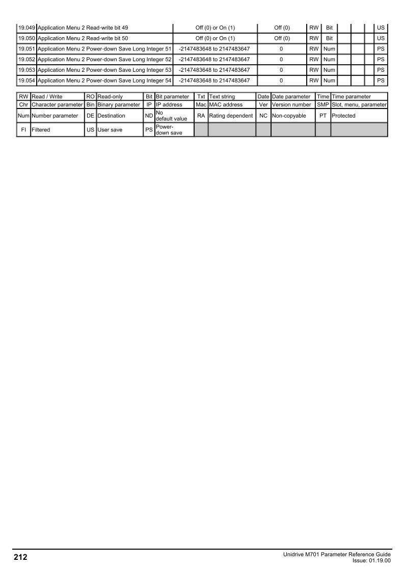
19.049 Application Menu 2 Read‑write bit 49 Off (0) or On (1) Off (0) RW Bit US
19.050 Application Menu 2 Read‑write bit 50 Off (0) or On (1) Off (0) RW Bit US
19.051 Application Menu 2 Power‑down Save Long Integer 51 -2147483648 to 2147483647 0 RW Num PS
19.052 Application Menu 2 Power‑down Save Long Integer 52 -2147483648 to 2147483647 0 RW Num PS
19.053 Application Menu 2 Power‑down Save Long Integer 53 -2147483648 to 2147483647 0 RW Num PS
19.054 Application Menu 2 Power‑down Save Long Integer 54 -2147483648 to 2147483647 0 RW Num PS
RW Read / Write RO Read-only Bit Bit parameter Txt Text string Date Date parameter Time Time parameterChr Character parameter Bin Binary parameter IP IP address Mac MAC address Ver Version number SMP Slot, menu, parameter
Num Number parameter DE Destination ND Nodefault value RA Rating dependent NC Non-copyable PT Protected
FI Filtered US User save PS Power-down save
212 Unidrive M701 Parameter Reference GuideIssue: 01.19.00
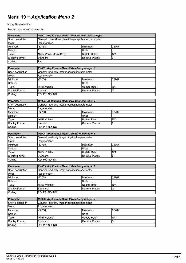
Menu 19 − Application Menu 2Mode: Regeneration
See the introduction to menu 18.
Parameter 19.001 Application Menu 2 Power-down Save IntegerShort description General power-down save integer application parameterMode RegenerationMinimum -32768 Maximum 32767Default 0 Units Type 16 Bit Power Down Save Update Rate N/ADisplay Format Standard Decimal Places 0Coding RW
Parameter 19.002 Application Menu 2 Read-only Integer 2Short description General read-only integer application parameterMode RegenerationMinimum -32768 Maximum 32767Default Units Type 16 Bit Volatile Update Rate N/ADisplay Format Standard Decimal Places 0Coding RO, PR, ND, NC
Parameter 19.003 Application Menu 2 Read-only Integer 3Short description General read-only integer application parameterMode RegenerationMinimum -32768 Maximum 32767Default Units Type 16 Bit Volatile Update Rate N/ADisplay Format Standard Decimal Places 0Coding RO, PR, ND, NC
Parameter 19.004 Application Menu 2 Read-only Integer 4Short description General read-only integer application parameterMode RegenerationMinimum -32768 Maximum 32767Default Units Type 16 Bit Volatile Update Rate N/ADisplay Format Standard Decimal Places 0Coding RO, PR, ND, NC
Parameter 19.005 Application Menu 2 Read-only Integer 5Short description General read-only integer application parameterMode RegenerationMinimum -32768 Maximum 32767Default Units Type 16 Bit Volatile Update Rate N/ADisplay Format Standard Decimal Places 0Coding RO, PR, ND, NC
Parameter 19.006 Application Menu 2 Read-only Integer 6Short description General read-only integer application parameterMode RegenerationMinimum -32768 Maximum 32767Default Units Type 16 Bit Volatile Update Rate N/ADisplay Format Standard Decimal Places 0Coding RO, PR, ND, NC
Unidrive M701 Parameter Reference GuideIssue: 01.19.00 213

Parameter 19.007 Application Menu 2 Read-only Integer 7Short description General read-only integer application parameterMode RegenerationMinimum -32768 Maximum 32767Default Units Type 16 Bit Volatile Update Rate N/ADisplay Format Standard Decimal Places 0Coding RO, PR, ND, NC
Parameter 19.008 Application Menu 2 Read-only Integer 8Short description General read-only integer application parameterMode RegenerationMinimum -32768 Maximum 32767Default Units Type 16 Bit Volatile Update Rate N/ADisplay Format Standard Decimal Places 0Coding RO, PR, ND, NC
Parameter 19.009 Application Menu 2 Read-only Integer 9Short description General read-only integer application parameterMode RegenerationMinimum -32768 Maximum 32767Default Units Type 16 Bit Volatile Update Rate N/ADisplay Format Standard Decimal Places 0Coding RO, PR, ND, NC
Parameter 19.010 Application Menu 2 Read-only Integer 10Short description General read-only integer application parameterMode RegenerationMinimum -32768 Maximum 32767Default Units Type 16 Bit Volatile Update Rate N/ADisplay Format Standard Decimal Places 0Coding RO, PR, ND, NC
Parameter 19.011 Application Menu 2 Read-write Integer 11Short description General read-write integer application parameterMode RegenerationMinimum -32768 Maximum 32767Default 0 Units Type 16 Bit User Save Update Rate N/ADisplay Format Standard Decimal Places 0Coding RW
Parameter 19.012 Application Menu 2 Read-write Integer 12Short description General read-write integer application parameterMode RegenerationMinimum -32768 Maximum 32767Default 0 Units Type 16 Bit User Save Update Rate N/ADisplay Format Standard Decimal Places 0Coding RW
Parameter 19.013 Application Menu 2 Read-write Integer 13Short description General read-write integer application parameterMode RegenerationMinimum -32768 Maximum 32767Default 0 Units Type 16 Bit User Save Update Rate N/ADisplay Format Standard Decimal Places 0Coding RW
214 Unidrive M701 Parameter Reference GuideIssue: 01.19.00

Parameter 19.014 Application Menu 2 Read-write Integer 14Short description General read-write integer application parameterMode RegenerationMinimum -32768 Maximum 32767Default 0 Units Type 16 Bit User Save Update Rate N/ADisplay Format Standard Decimal Places 0Coding RW
Parameter 19.015 Application Menu 2 Read-write Integer 15Short description General read-write integer application parameterMode RegenerationMinimum -32768 Maximum 32767Default 0 Units Type 16 Bit User Save Update Rate N/ADisplay Format Standard Decimal Places 0Coding RW
Parameter 19.016 Application Menu 2 Read-write Integer 16Short description General read-write integer application parameterMode RegenerationMinimum -32768 Maximum 32767Default 0 Units Type 16 Bit User Save Update Rate N/ADisplay Format Standard Decimal Places 0Coding RW
Parameter 19.017 Application Menu 2 Read-write Integer 17Short description General read-write integer application parameterMode RegenerationMinimum -32768 Maximum 32767Default 0 Units Type 16 Bit User Save Update Rate N/ADisplay Format Standard Decimal Places 0Coding RW
Parameter 19.018 Application Menu 2 Read-write Integer 18Short description General read-write integer application parameterMode RegenerationMinimum -32768 Maximum 32767Default 0 Units Type 16 Bit User Save Update Rate N/ADisplay Format Standard Decimal Places 0Coding RW
Parameter 19.019 Application Menu 2 Read-write Integer 19Short description General read-write integer application parameterMode RegenerationMinimum -32768 Maximum 32767Default 0 Units Type 16 Bit User Save Update Rate N/ADisplay Format Standard Decimal Places 0Coding RW
Parameter 19.020 Application Menu 2 Read-write Integer 20Short description General read-write integer application parameterMode RegenerationMinimum -32768 Maximum 32767Default 0 Units Type 16 Bit User Save Update Rate N/ADisplay Format Standard Decimal Places 0Coding RW
Unidrive M701 Parameter Reference GuideIssue: 01.19.00 215

Parameter 19.021 Application Menu 2 Read-write Integer 21Short description General read-write integer application parameterMode RegenerationMinimum -32768 Maximum 32767Default 0 Units Type 16 Bit User Save Update Rate N/ADisplay Format Standard Decimal Places 0Coding RW
Parameter 19.022 Application Menu 2 Read-write Integer 22Short description General read-write integer application parameterMode RegenerationMinimum -32768 Maximum 32767Default 0 Units Type 16 Bit User Save Update Rate N/ADisplay Format Standard Decimal Places 0Coding RW
Parameter 19.023 Application Menu 2 Read-write Integer 23Short description General read-write integer application parameterMode RegenerationMinimum -32768 Maximum 32767Default 0 Units Type 16 Bit User Save Update Rate N/ADisplay Format Standard Decimal Places 0Coding RW
Parameter 19.024 Application Menu 2 Read-write Integer 24Short description General read-write integer application parameterMode RegenerationMinimum -32768 Maximum 32767Default 0 Units Type 16 Bit User Save Update Rate N/ADisplay Format Standard Decimal Places 0Coding RW
Parameter 19.025 Application Menu 2 Read-write Integer 25Short description General read-write integer application parameterMode RegenerationMinimum -32768 Maximum 32767Default 0 Units Type 16 Bit User Save Update Rate N/ADisplay Format Standard Decimal Places 0Coding RW
Parameter 19.026 Application Menu 2 Read-write Integer 26Short description General read-write integer application parameterMode RegenerationMinimum -32768 Maximum 32767Default 0 Units Type 16 Bit User Save Update Rate N/ADisplay Format Standard Decimal Places 0Coding RW
Parameter 19.027 Application Menu 2 Read-write Integer 27Short description General read-write integer application parameterMode RegenerationMinimum -32768 Maximum 32767Default 0 Units Type 16 Bit User Save Update Rate N/ADisplay Format Standard Decimal Places 0Coding RW
216 Unidrive M701 Parameter Reference GuideIssue: 01.19.00
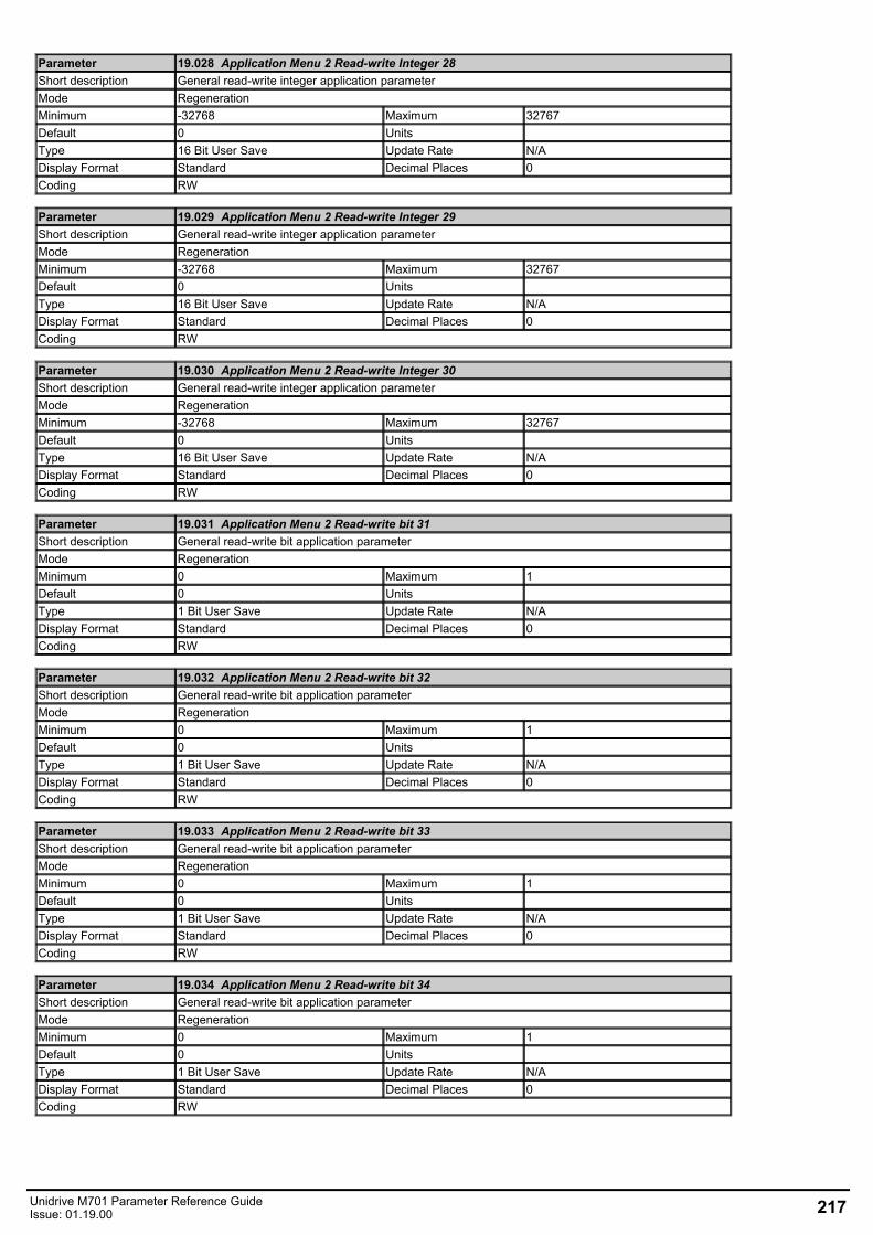
Parameter 19.028 Application Menu 2 Read-write Integer 28Short description General read-write integer application parameterMode RegenerationMinimum -32768 Maximum 32767Default 0 Units Type 16 Bit User Save Update Rate N/ADisplay Format Standard Decimal Places 0Coding RW
Parameter 19.029 Application Menu 2 Read-write Integer 29Short description General read-write integer application parameterMode RegenerationMinimum -32768 Maximum 32767Default 0 Units Type 16 Bit User Save Update Rate N/ADisplay Format Standard Decimal Places 0Coding RW
Parameter 19.030 Application Menu 2 Read-write Integer 30Short description General read-write integer application parameterMode RegenerationMinimum -32768 Maximum 32767Default 0 Units Type 16 Bit User Save Update Rate N/ADisplay Format Standard Decimal Places 0Coding RW
Parameter 19.031 Application Menu 2 Read-write bit 31Short description General read-write bit application parameterMode RegenerationMinimum 0 Maximum 1Default 0 Units Type 1 Bit User Save Update Rate N/ADisplay Format Standard Decimal Places 0Coding RW
Parameter 19.032 Application Menu 2 Read-write bit 32Short description General read-write bit application parameterMode RegenerationMinimum 0 Maximum 1Default 0 Units Type 1 Bit User Save Update Rate N/ADisplay Format Standard Decimal Places 0Coding RW
Parameter 19.033 Application Menu 2 Read-write bit 33Short description General read-write bit application parameterMode RegenerationMinimum 0 Maximum 1Default 0 Units Type 1 Bit User Save Update Rate N/ADisplay Format Standard Decimal Places 0Coding RW
Parameter 19.034 Application Menu 2 Read-write bit 34Short description General read-write bit application parameterMode RegenerationMinimum 0 Maximum 1Default 0 Units Type 1 Bit User Save Update Rate N/ADisplay Format Standard Decimal Places 0Coding RW
Unidrive M701 Parameter Reference GuideIssue: 01.19.00 217
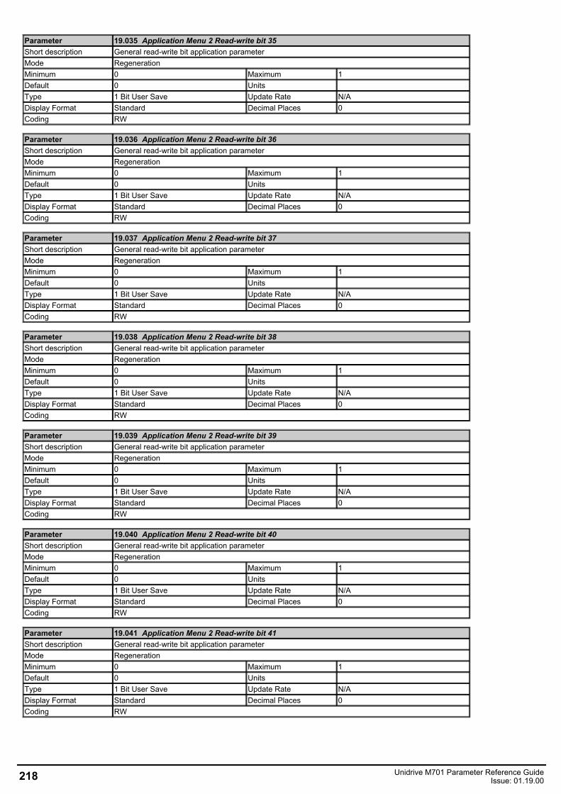
Parameter 19.035 Application Menu 2 Read-write bit 35Short description General read-write bit application parameterMode RegenerationMinimum 0 Maximum 1Default 0 Units Type 1 Bit User Save Update Rate N/ADisplay Format Standard Decimal Places 0Coding RW
Parameter 19.036 Application Menu 2 Read-write bit 36Short description General read-write bit application parameterMode RegenerationMinimum 0 Maximum 1Default 0 Units Type 1 Bit User Save Update Rate N/ADisplay Format Standard Decimal Places 0Coding RW
Parameter 19.037 Application Menu 2 Read-write bit 37Short description General read-write bit application parameterMode RegenerationMinimum 0 Maximum 1Default 0 Units Type 1 Bit User Save Update Rate N/ADisplay Format Standard Decimal Places 0Coding RW
Parameter 19.038 Application Menu 2 Read-write bit 38Short description General read-write bit application parameterMode RegenerationMinimum 0 Maximum 1Default 0 Units Type 1 Bit User Save Update Rate N/ADisplay Format Standard Decimal Places 0Coding RW
Parameter 19.039 Application Menu 2 Read-write bit 39Short description General read-write bit application parameterMode RegenerationMinimum 0 Maximum 1Default 0 Units Type 1 Bit User Save Update Rate N/ADisplay Format Standard Decimal Places 0Coding RW
Parameter 19.040 Application Menu 2 Read-write bit 40Short description General read-write bit application parameterMode RegenerationMinimum 0 Maximum 1Default 0 Units Type 1 Bit User Save Update Rate N/ADisplay Format Standard Decimal Places 0Coding RW
Parameter 19.041 Application Menu 2 Read-write bit 41Short description General read-write bit application parameterMode RegenerationMinimum 0 Maximum 1Default 0 Units Type 1 Bit User Save Update Rate N/ADisplay Format Standard Decimal Places 0Coding RW
218 Unidrive M701 Parameter Reference GuideIssue: 01.19.00

Parameter 19.042 Application Menu 2 Read-write bit 42Short description General read-write bit application parameterMode RegenerationMinimum 0 Maximum 1Default 0 Units Type 1 Bit User Save Update Rate N/ADisplay Format Standard Decimal Places 0Coding RW
Parameter 19.043 Application Menu 2 Read-write bit 43Short description General read-write bit application parameterMode RegenerationMinimum 0 Maximum 1Default 0 Units Type 1 Bit User Save Update Rate N/ADisplay Format Standard Decimal Places 0Coding RW
Parameter 19.044 Application Menu 2 Read-write bit 44Short description General read-write bit application parameterMode RegenerationMinimum 0 Maximum 1Default 0 Units Type 1 Bit User Save Update Rate N/ADisplay Format Standard Decimal Places 0Coding RW
Parameter 19.045 Application Menu 2 Read-write bit 45Short description General read-write bit application parameterMode RegenerationMinimum 0 Maximum 1Default 0 Units Type 1 Bit User Save Update Rate N/ADisplay Format Standard Decimal Places 0Coding RW
Parameter 19.046 Application Menu 2 Read-write bit 46Short description General read-write bit application parameterMode RegenerationMinimum 0 Maximum 1Default 0 Units Type 1 Bit User Save Update Rate N/ADisplay Format Standard Decimal Places 0Coding RW
Parameter 19.047 Application Menu 2 Read-write bit 47Short description General read-write bit application parameterMode RegenerationMinimum 0 Maximum 1Default 0 Units Type 1 Bit User Save Update Rate N/ADisplay Format Standard Decimal Places 0Coding RW
Parameter 19.048 Application Menu 2 Read-write bit 48Short description General read-write bit application parameterMode RegenerationMinimum 0 Maximum 1Default 0 Units Type 1 Bit User Save Update Rate N/ADisplay Format Standard Decimal Places 0Coding RW
Unidrive M701 Parameter Reference GuideIssue: 01.19.00 219
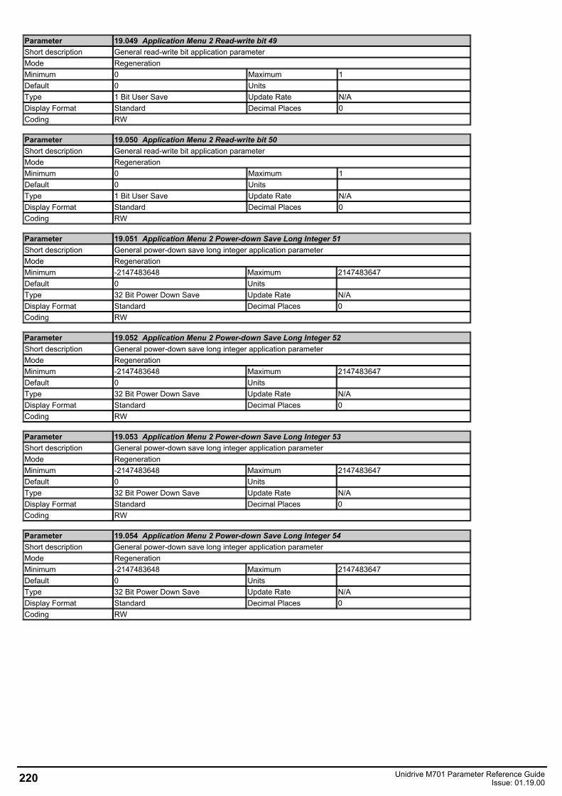
Parameter 19.049 Application Menu 2 Read-write bit 49Short description General read-write bit application parameterMode RegenerationMinimum 0 Maximum 1Default 0 Units Type 1 Bit User Save Update Rate N/ADisplay Format Standard Decimal Places 0Coding RW
Parameter 19.050 Application Menu 2 Read-write bit 50Short description General read-write bit application parameterMode RegenerationMinimum 0 Maximum 1Default 0 Units Type 1 Bit User Save Update Rate N/ADisplay Format Standard Decimal Places 0Coding RW
Parameter 19.051 Application Menu 2 Power-down Save Long Integer 51Short description General power-down save long integer application parameterMode RegenerationMinimum -2147483648 Maximum 2147483647Default 0 Units Type 32 Bit Power Down Save Update Rate N/ADisplay Format Standard Decimal Places 0Coding RW
Parameter 19.052 Application Menu 2 Power-down Save Long Integer 52Short description General power-down save long integer application parameterMode RegenerationMinimum -2147483648 Maximum 2147483647Default 0 Units Type 32 Bit Power Down Save Update Rate N/ADisplay Format Standard Decimal Places 0Coding RW
Parameter 19.053 Application Menu 2 Power-down Save Long Integer 53Short description General power-down save long integer application parameterMode RegenerationMinimum -2147483648 Maximum 2147483647Default 0 Units Type 32 Bit Power Down Save Update Rate N/ADisplay Format Standard Decimal Places 0Coding RW
Parameter 19.054 Application Menu 2 Power-down Save Long Integer 54Short description General power-down save long integer application parameterMode RegenerationMinimum -2147483648 Maximum 2147483647Default 0 Units Type 32 Bit Power Down Save Update Rate N/ADisplay Format Standard Decimal Places 0Coding RW
220 Unidrive M701 Parameter Reference GuideIssue: 01.19.00
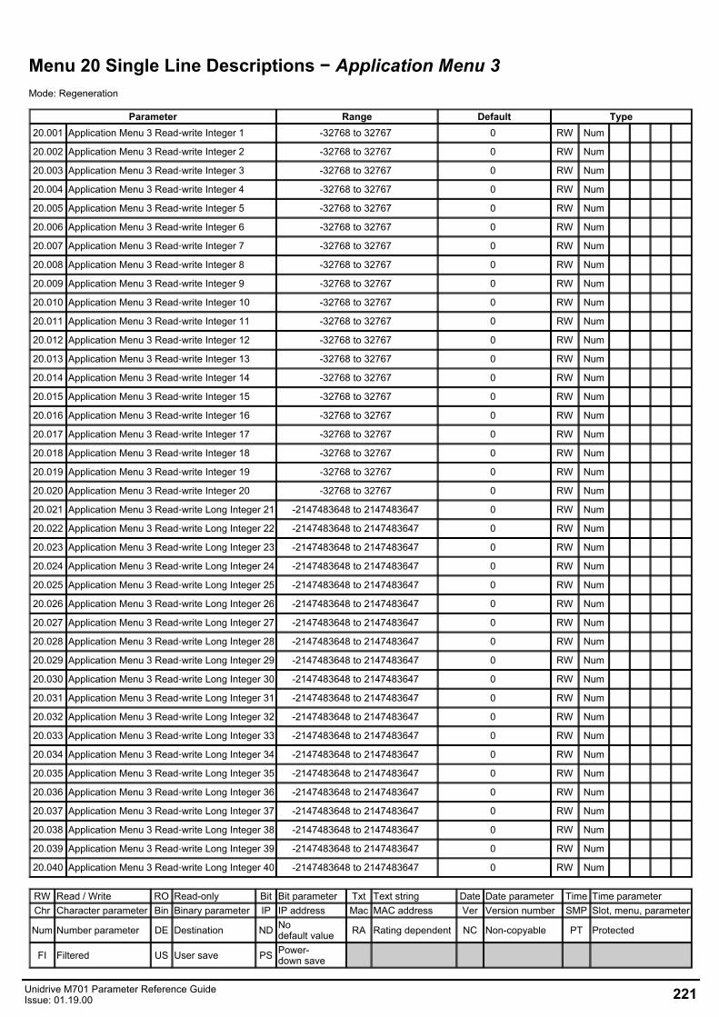
Menu 20 Single Line Descriptions − Application Menu 3Mode: Regeneration
Parameter Range Default Type20.001 Application Menu 3 Read‑write Integer 1 -32768 to 32767 0 RW Num
20.002 Application Menu 3 Read‑write Integer 2 -32768 to 32767 0 RW Num
20.003 Application Menu 3 Read‑write Integer 3 -32768 to 32767 0 RW Num
20.004 Application Menu 3 Read‑write Integer 4 -32768 to 32767 0 RW Num
20.005 Application Menu 3 Read‑write Integer 5 -32768 to 32767 0 RW Num
20.006 Application Menu 3 Read‑write Integer 6 -32768 to 32767 0 RW Num
20.007 Application Menu 3 Read‑write Integer 7 -32768 to 32767 0 RW Num
20.008 Application Menu 3 Read‑write Integer 8 -32768 to 32767 0 RW Num
20.009 Application Menu 3 Read‑write Integer 9 -32768 to 32767 0 RW Num
20.010 Application Menu 3 Read‑write Integer 10 -32768 to 32767 0 RW Num
20.011 Application Menu 3 Read‑write Integer 11 -32768 to 32767 0 RW Num
20.012 Application Menu 3 Read‑write Integer 12 -32768 to 32767 0 RW Num
20.013 Application Menu 3 Read‑write Integer 13 -32768 to 32767 0 RW Num
20.014 Application Menu 3 Read‑write Integer 14 -32768 to 32767 0 RW Num
20.015 Application Menu 3 Read‑write Integer 15 -32768 to 32767 0 RW Num
20.016 Application Menu 3 Read‑write Integer 16 -32768 to 32767 0 RW Num
20.017 Application Menu 3 Read‑write Integer 17 -32768 to 32767 0 RW Num
20.018 Application Menu 3 Read‑write Integer 18 -32768 to 32767 0 RW Num
20.019 Application Menu 3 Read‑write Integer 19 -32768 to 32767 0 RW Num
20.020 Application Menu 3 Read‑write Integer 20 -32768 to 32767 0 RW Num
20.021 Application Menu 3 Read‑write Long Integer 21 -2147483648 to 2147483647 0 RW Num
20.022 Application Menu 3 Read‑write Long Integer 22 -2147483648 to 2147483647 0 RW Num
20.023 Application Menu 3 Read‑write Long Integer 23 -2147483648 to 2147483647 0 RW Num
20.024 Application Menu 3 Read‑write Long Integer 24 -2147483648 to 2147483647 0 RW Num
20.025 Application Menu 3 Read‑write Long Integer 25 -2147483648 to 2147483647 0 RW Num
20.026 Application Menu 3 Read‑write Long Integer 26 -2147483648 to 2147483647 0 RW Num
20.027 Application Menu 3 Read‑write Long Integer 27 -2147483648 to 2147483647 0 RW Num
20.028 Application Menu 3 Read‑write Long Integer 28 -2147483648 to 2147483647 0 RW Num
20.029 Application Menu 3 Read‑write Long Integer 29 -2147483648 to 2147483647 0 RW Num
20.030 Application Menu 3 Read‑write Long Integer 30 -2147483648 to 2147483647 0 RW Num
20.031 Application Menu 3 Read‑write Long Integer 31 -2147483648 to 2147483647 0 RW Num
20.032 Application Menu 3 Read‑write Long Integer 32 -2147483648 to 2147483647 0 RW Num
20.033 Application Menu 3 Read‑write Long Integer 33 -2147483648 to 2147483647 0 RW Num
20.034 Application Menu 3 Read‑write Long Integer 34 -2147483648 to 2147483647 0 RW Num
20.035 Application Menu 3 Read‑write Long Integer 35 -2147483648 to 2147483647 0 RW Num
20.036 Application Menu 3 Read‑write Long Integer 36 -2147483648 to 2147483647 0 RW Num
20.037 Application Menu 3 Read‑write Long Integer 37 -2147483648 to 2147483647 0 RW Num
20.038 Application Menu 3 Read‑write Long Integer 38 -2147483648 to 2147483647 0 RW Num
20.039 Application Menu 3 Read‑write Long Integer 39 -2147483648 to 2147483647 0 RW Num
20.040 Application Menu 3 Read‑write Long Integer 40 -2147483648 to 2147483647 0 RW Num
RW Read / Write RO Read-only Bit Bit parameter Txt Text string Date Date parameter Time Time parameterChr Character parameter Bin Binary parameter IP IP address Mac MAC address Ver Version number SMP Slot, menu, parameter
Num Number parameter DE Destination ND Nodefault value RA Rating dependent NC Non-copyable PT Protected
FI Filtered US User save PS Power-down save
Unidrive M701 Parameter Reference GuideIssue: 01.19.00 221
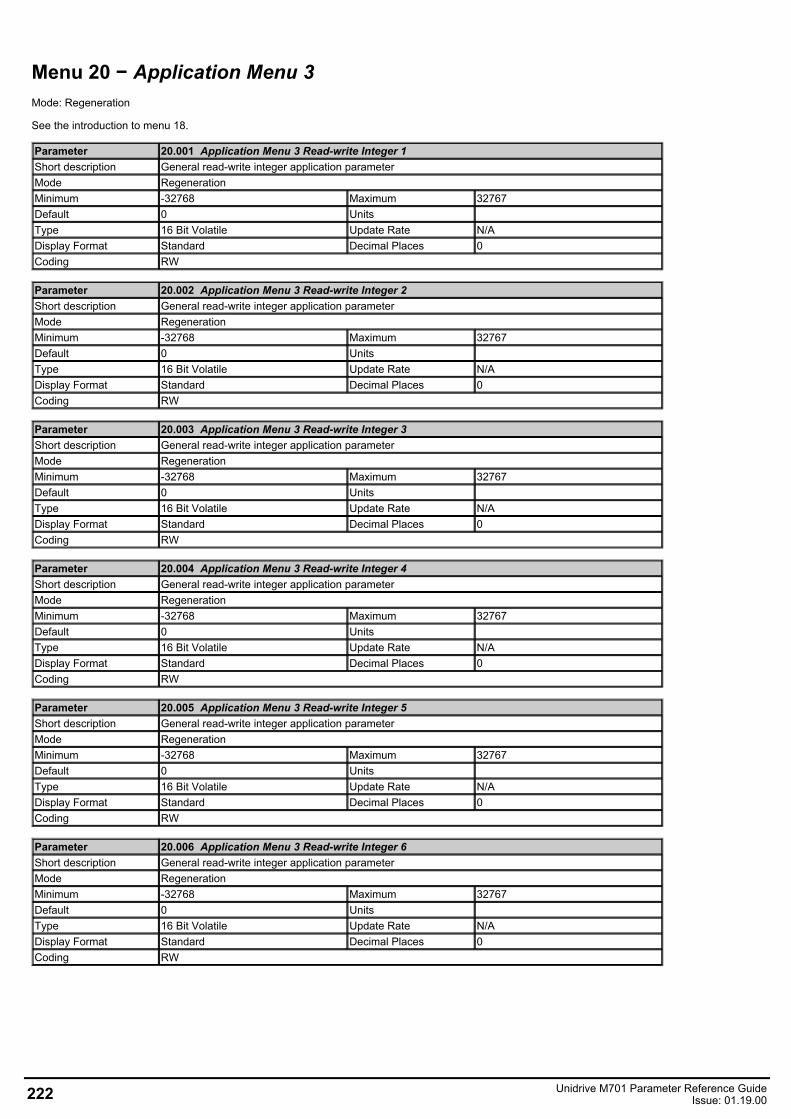
Menu 20 − Application Menu 3Mode: Regeneration
See the introduction to menu 18.
Parameter 20.001 Application Menu 3 Read-write Integer 1Short description General read-write integer application parameterMode RegenerationMinimum -32768 Maximum 32767Default 0 Units Type 16 Bit Volatile Update Rate N/ADisplay Format Standard Decimal Places 0Coding RW
Parameter 20.002 Application Menu 3 Read-write Integer 2Short description General read-write integer application parameterMode RegenerationMinimum -32768 Maximum 32767Default 0 Units Type 16 Bit Volatile Update Rate N/ADisplay Format Standard Decimal Places 0Coding RW
Parameter 20.003 Application Menu 3 Read-write Integer 3Short description General read-write integer application parameterMode RegenerationMinimum -32768 Maximum 32767Default 0 Units Type 16 Bit Volatile Update Rate N/ADisplay Format Standard Decimal Places 0Coding RW
Parameter 20.004 Application Menu 3 Read-write Integer 4Short description General read-write integer application parameterMode RegenerationMinimum -32768 Maximum 32767Default 0 Units Type 16 Bit Volatile Update Rate N/ADisplay Format Standard Decimal Places 0Coding RW
Parameter 20.005 Application Menu 3 Read-write Integer 5Short description General read-write integer application parameterMode RegenerationMinimum -32768 Maximum 32767Default 0 Units Type 16 Bit Volatile Update Rate N/ADisplay Format Standard Decimal Places 0Coding RW
Parameter 20.006 Application Menu 3 Read-write Integer 6Short description General read-write integer application parameterMode RegenerationMinimum -32768 Maximum 32767Default 0 Units Type 16 Bit Volatile Update Rate N/ADisplay Format Standard Decimal Places 0Coding RW
222 Unidrive M701 Parameter Reference GuideIssue: 01.19.00
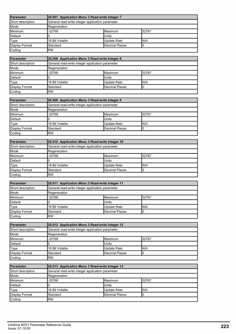
Parameter 20.007 Application Menu 3 Read-write Integer 7Short description General read-write integer application parameterMode RegenerationMinimum -32768 Maximum 32767Default 0 Units Type 16 Bit Volatile Update Rate N/ADisplay Format Standard Decimal Places 0Coding RW
Parameter 20.008 Application Menu 3 Read-write Integer 8Short description General read-write integer application parameterMode RegenerationMinimum -32768 Maximum 32767Default 0 Units Type 16 Bit Volatile Update Rate N/ADisplay Format Standard Decimal Places 0Coding RW
Parameter 20.009 Application Menu 3 Read-write Integer 9Short description General read-write integer application parameterMode RegenerationMinimum -32768 Maximum 32767Default 0 Units Type 16 Bit Volatile Update Rate N/ADisplay Format Standard Decimal Places 0Coding RW
Parameter 20.010 Application Menu 3 Read-write Integer 10Short description General read-write integer application parameterMode RegenerationMinimum -32768 Maximum 32767Default 0 Units Type 16 Bit Volatile Update Rate N/ADisplay Format Standard Decimal Places 0Coding RW
Parameter 20.011 Application Menu 3 Read-write Integer 11Short description General read-write integer application parameterMode RegenerationMinimum -32768 Maximum 32767Default 0 Units Type 16 Bit Volatile Update Rate N/ADisplay Format Standard Decimal Places 0Coding RW
Parameter 20.012 Application Menu 3 Read-write Integer 12Short description General read-write integer application parameterMode RegenerationMinimum -32768 Maximum 32767Default 0 Units Type 16 Bit Volatile Update Rate N/ADisplay Format Standard Decimal Places 0Coding RW
Parameter 20.013 Application Menu 3 Read-write Integer 13Short description General read-write integer application parameterMode RegenerationMinimum -32768 Maximum 32767Default 0 Units Type 16 Bit Volatile Update Rate N/ADisplay Format Standard Decimal Places 0Coding RW
Unidrive M701 Parameter Reference GuideIssue: 01.19.00 223
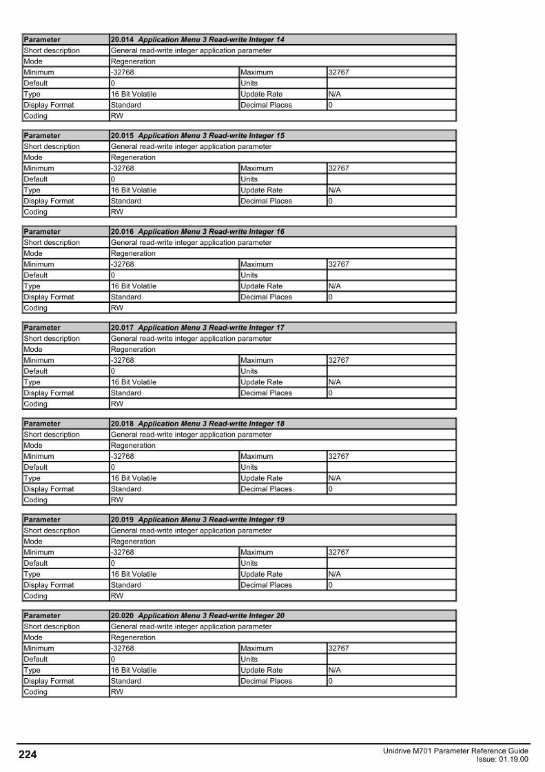
Parameter 20.014 Application Menu 3 Read-write Integer 14Short description General read-write integer application parameterMode RegenerationMinimum -32768 Maximum 32767Default 0 Units Type 16 Bit Volatile Update Rate N/ADisplay Format Standard Decimal Places 0Coding RW
Parameter 20.015 Application Menu 3 Read-write Integer 15Short description General read-write integer application parameterMode RegenerationMinimum -32768 Maximum 32767Default 0 Units Type 16 Bit Volatile Update Rate N/ADisplay Format Standard Decimal Places 0Coding RW
Parameter 20.016 Application Menu 3 Read-write Integer 16Short description General read-write integer application parameterMode RegenerationMinimum -32768 Maximum 32767Default 0 Units Type 16 Bit Volatile Update Rate N/ADisplay Format Standard Decimal Places 0Coding RW
Parameter 20.017 Application Menu 3 Read-write Integer 17Short description General read-write integer application parameterMode RegenerationMinimum -32768 Maximum 32767Default 0 Units Type 16 Bit Volatile Update Rate N/ADisplay Format Standard Decimal Places 0Coding RW
Parameter 20.018 Application Menu 3 Read-write Integer 18Short description General read-write integer application parameterMode RegenerationMinimum -32768 Maximum 32767Default 0 Units Type 16 Bit Volatile Update Rate N/ADisplay Format Standard Decimal Places 0Coding RW
Parameter 20.019 Application Menu 3 Read-write Integer 19Short description General read-write integer application parameterMode RegenerationMinimum -32768 Maximum 32767Default 0 Units Type 16 Bit Volatile Update Rate N/ADisplay Format Standard Decimal Places 0Coding RW
Parameter 20.020 Application Menu 3 Read-write Integer 20Short description General read-write integer application parameterMode RegenerationMinimum -32768 Maximum 32767Default 0 Units Type 16 Bit Volatile Update Rate N/ADisplay Format Standard Decimal Places 0Coding RW
224 Unidrive M701 Parameter Reference GuideIssue: 01.19.00
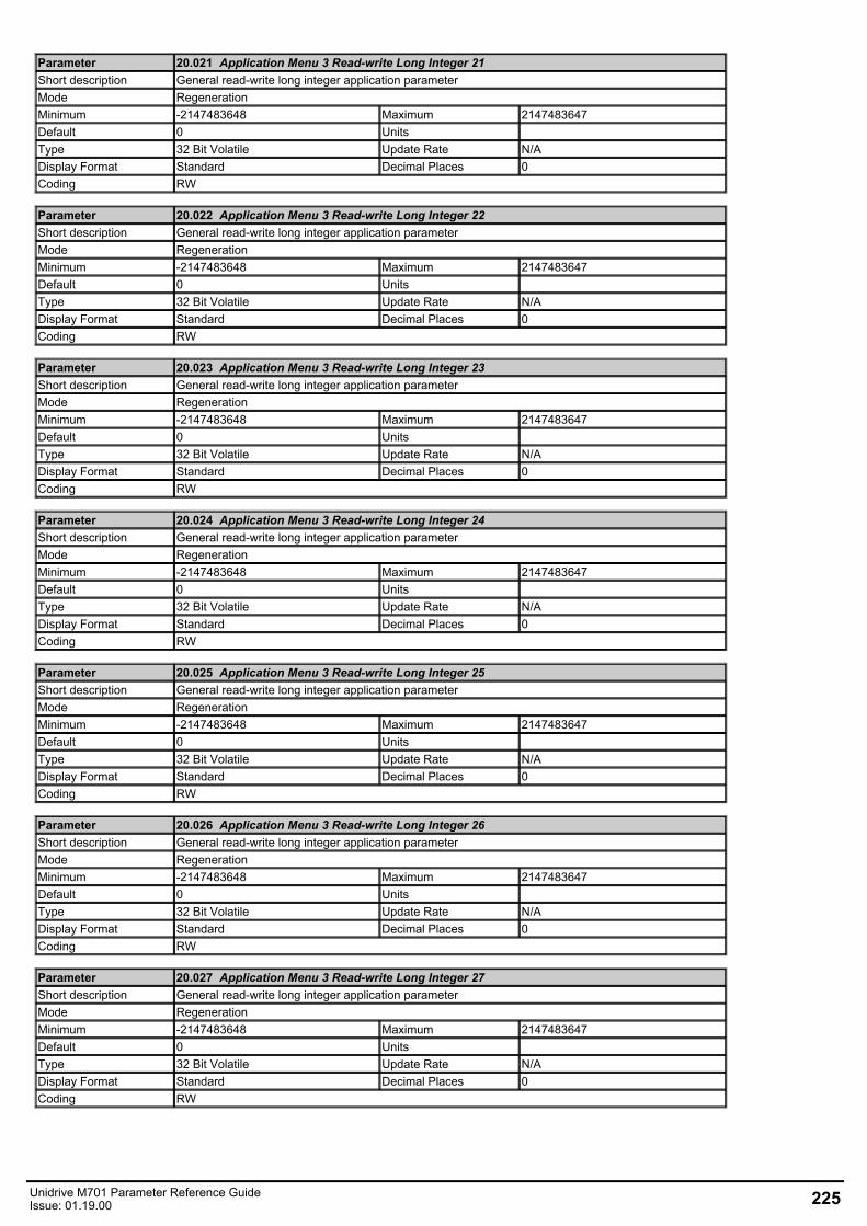
Parameter 20.021 Application Menu 3 Read-write Long Integer 21Short description General read-write long integer application parameterMode RegenerationMinimum -2147483648 Maximum 2147483647Default 0 Units Type 32 Bit Volatile Update Rate N/ADisplay Format Standard Decimal Places 0Coding RW
Parameter 20.022 Application Menu 3 Read-write Long Integer 22Short description General read-write long integer application parameterMode RegenerationMinimum -2147483648 Maximum 2147483647Default 0 Units Type 32 Bit Volatile Update Rate N/ADisplay Format Standard Decimal Places 0Coding RW
Parameter 20.023 Application Menu 3 Read-write Long Integer 23Short description General read-write long integer application parameterMode RegenerationMinimum -2147483648 Maximum 2147483647Default 0 Units Type 32 Bit Volatile Update Rate N/ADisplay Format Standard Decimal Places 0Coding RW
Parameter 20.024 Application Menu 3 Read-write Long Integer 24Short description General read-write long integer application parameterMode RegenerationMinimum -2147483648 Maximum 2147483647Default 0 Units Type 32 Bit Volatile Update Rate N/ADisplay Format Standard Decimal Places 0Coding RW
Parameter 20.025 Application Menu 3 Read-write Long Integer 25Short description General read-write long integer application parameterMode RegenerationMinimum -2147483648 Maximum 2147483647Default 0 Units Type 32 Bit Volatile Update Rate N/ADisplay Format Standard Decimal Places 0Coding RW
Parameter 20.026 Application Menu 3 Read-write Long Integer 26Short description General read-write long integer application parameterMode RegenerationMinimum -2147483648 Maximum 2147483647Default 0 Units Type 32 Bit Volatile Update Rate N/ADisplay Format Standard Decimal Places 0Coding RW
Parameter 20.027 Application Menu 3 Read-write Long Integer 27Short description General read-write long integer application parameterMode RegenerationMinimum -2147483648 Maximum 2147483647Default 0 Units Type 32 Bit Volatile Update Rate N/ADisplay Format Standard Decimal Places 0Coding RW
Unidrive M701 Parameter Reference GuideIssue: 01.19.00 225

Parameter 20.028 Application Menu 3 Read-write Long Integer 28Short description General read-write long integer application parameterMode RegenerationMinimum -2147483648 Maximum 2147483647Default 0 Units Type 32 Bit Volatile Update Rate N/ADisplay Format Standard Decimal Places 0Coding RW
Parameter 20.029 Application Menu 3 Read-write Long Integer 29Short description General read-write long integer application parameterMode RegenerationMinimum -2147483648 Maximum 2147483647Default 0 Units Type 32 Bit Volatile Update Rate N/ADisplay Format Standard Decimal Places 0Coding RW
Parameter 20.030 Application Menu 3 Read-write Long Integer 30Short description General read-write long integer application parameterMode RegenerationMinimum -2147483648 Maximum 2147483647Default 0 Units Type 32 Bit Volatile Update Rate N/ADisplay Format Standard Decimal Places 0Coding RW
Parameter 20.031 Application Menu 3 Read-write Long Integer 31Short description General read-write long integer application parameterMode RegenerationMinimum -2147483648 Maximum 2147483647Default 0 Units Type 32 Bit Volatile Update Rate N/ADisplay Format Standard Decimal Places 0Coding RW
Parameter 20.032 Application Menu 3 Read-write Long Integer 32Short description General read-write long integer application parameterMode RegenerationMinimum -2147483648 Maximum 2147483647Default 0 Units Type 32 Bit Volatile Update Rate N/ADisplay Format Standard Decimal Places 0Coding RW
Parameter 20.033 Application Menu 3 Read-write Long Integer 33Short description General read-write long integer application parameterMode RegenerationMinimum -2147483648 Maximum 2147483647Default 0 Units Type 32 Bit Volatile Update Rate N/ADisplay Format Standard Decimal Places 0Coding RW
Parameter 20.034 Application Menu 3 Read-write Long Integer 34Short description General read-write long integer application parameterMode RegenerationMinimum -2147483648 Maximum 2147483647Default 0 Units Type 32 Bit Volatile Update Rate N/ADisplay Format Standard Decimal Places 0Coding RW
226 Unidrive M701 Parameter Reference GuideIssue: 01.19.00
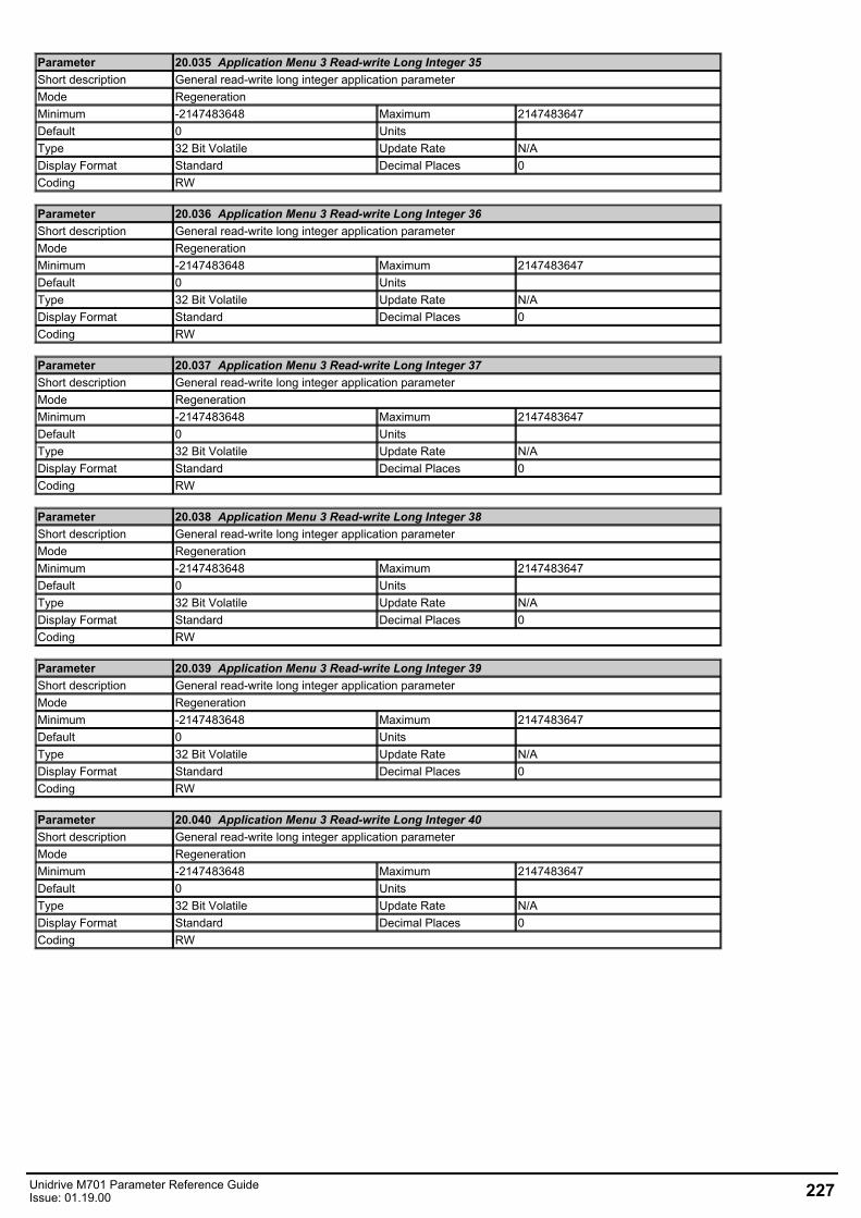
Parameter 20.035 Application Menu 3 Read-write Long Integer 35Short description General read-write long integer application parameterMode RegenerationMinimum -2147483648 Maximum 2147483647Default 0 Units Type 32 Bit Volatile Update Rate N/ADisplay Format Standard Decimal Places 0Coding RW
Parameter 20.036 Application Menu 3 Read-write Long Integer 36Short description General read-write long integer application parameterMode RegenerationMinimum -2147483648 Maximum 2147483647Default 0 Units Type 32 Bit Volatile Update Rate N/ADisplay Format Standard Decimal Places 0Coding RW
Parameter 20.037 Application Menu 3 Read-write Long Integer 37Short description General read-write long integer application parameterMode RegenerationMinimum -2147483648 Maximum 2147483647Default 0 Units Type 32 Bit Volatile Update Rate N/ADisplay Format Standard Decimal Places 0Coding RW
Parameter 20.038 Application Menu 3 Read-write Long Integer 38Short description General read-write long integer application parameterMode RegenerationMinimum -2147483648 Maximum 2147483647Default 0 Units Type 32 Bit Volatile Update Rate N/ADisplay Format Standard Decimal Places 0Coding RW
Parameter 20.039 Application Menu 3 Read-write Long Integer 39Short description General read-write long integer application parameterMode RegenerationMinimum -2147483648 Maximum 2147483647Default 0 Units Type 32 Bit Volatile Update Rate N/ADisplay Format Standard Decimal Places 0Coding RW
Parameter 20.040 Application Menu 3 Read-write Long Integer 40Short description General read-write long integer application parameterMode RegenerationMinimum -2147483648 Maximum 2147483647Default 0 Units Type 32 Bit Volatile Update Rate N/ADisplay Format Standard Decimal Places 0Coding RW
Unidrive M701 Parameter Reference GuideIssue: 01.19.00 227
Menu 22 Single Line Descriptions − Menu 0 Set-upMode: Regeneration
228 Unidrive M701 Parameter Reference GuideIssue: 01.19.00
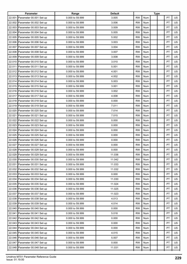
Parameter Range Default Type22.001 Parameter 00.001 Set‑up 0.000 to 59.999 3.005 RW Num PT US
22.002 Parameter 00.002 Set‑up 0.000 to 59.999 3.006 RW Num PT US
22.003 Parameter 00.003 Set‑up 0.000 to 59.999 3.009 RW Num PT US
22.004 Parameter 00.004 Set‑up 0.000 to 59.999 5.005 RW Num PT US
22.005 Parameter 00.005 Set‑up 0.000 to 59.999 5.002 RW Num PT US
22.006 Parameter 00.006 Set‑up 0.000 to 59.999 3.003 RW Num PT US
22.007 Parameter 00.007 Set‑up 0.000 to 59.999 3.004 RW Num PT US
22.008 Parameter 00.008 Set‑up 0.000 to 59.999 3.007 RW Num PT US
22.009 Parameter 00.009 Set‑up 0.000 to 59.999 3.008 RW Num PT US
22.010 Parameter 00.010 Set‑up 0.000 to 59.999 3.010 RW Num PT US
22.011 Parameter 00.011 Set‑up 0.000 to 59.999 5.001 RW Num PT US
22.012 Parameter 00.012 Set‑up 0.000 to 59.999 4.001 RW Num PT US
22.013 Parameter 00.013 Set‑up 0.000 to 59.999 4.002 RW Num PT US
22.014 Parameter 00.014 Set‑up 0.000 to 59.999 5.003 RW Num PT US
22.015 Parameter 00.015 Set‑up 0.000 to 59.999 3.001 RW Num PT US
22.016 Parameter 00.016 Set‑up 0.000 to 59.999 3.002 RW Num PT US
22.017 Parameter 00.017 Set‑up 0.000 to 59.999 4.008 RW Num PT US
22.018 Parameter 00.018 Set‑up 0.000 to 59.999 0.000 RW Num PT US
22.019 Parameter 00.019 Set‑up 0.000 to 59.999 7.011 RW Num PT US
22.020 Parameter 00.020 Set‑up 0.000 to 59.999 7.014 RW Num PT US
22.021 Parameter 00.021 Set‑up 0.000 to 59.999 7.015 RW Num PT US
22.022 Parameter 00.022 Set‑up 0.000 to 59.999 0.000 RW Num PT US
22.023 Parameter 00.023 Set‑up 0.000 to 59.999 0.000 RW Num PT US
22.024 Parameter 00.024 Set‑up 0.000 to 59.999 0.000 RW Num PT US
22.025 Parameter 00.025 Set‑up 0.000 to 59.999 0.000 RW Num PT US
22.026 Parameter 00.026 Set‑up 0.000 to 59.999 0.000 RW Num PT US
22.027 Parameter 00.027 Set‑up 0.000 to 59.999 0.000 RW Num PT US
22.028 Parameter 00.028 Set‑up 0.000 to 59.999 0.000 RW Num PT US
22.029 Parameter 00.029 Set‑up 0.000 to 59.999 11.036 RW Num PT US
22.030 Parameter 00.030 Set‑up 0.000 to 59.999 11.042 RW Num PT US
22.031 Parameter 00.031 Set‑up 0.000 to 59.999 11.033 RW Num PT US
22.032 Parameter 00.032 Set‑up 0.000 to 59.999 11.032 RW Num PT US
22.033 Parameter 00.033 Set‑up 0.000 to 59.999 0.000 RW Num PT US
22.034 Parameter 00.034 Set‑up 0.000 to 59.999 11.030 RW Num PT US
22.035 Parameter 00.035 Set‑up 0.000 to 59.999 11.024 RW Num PT US
22.036 Parameter 00.036 Set‑up 0.000 to 59.999 11.025 RW Num PT US
22.037 Parameter 00.037 Set‑up 0.000 to 59.999 11.023 RW Num PT US
22.038 Parameter 00.038 Set‑up 0.000 to 59.999 4.013 RW Num PT US
22.039 Parameter 00.039 Set‑up 0.000 to 59.999 4.014 RW Num PT US
22.040 Parameter 00.040 Set‑up 0.000 to 59.999 0.000 RW Num PT US
22.041 Parameter 00.041 Set‑up 0.000 to 59.999 5.018 RW Num PT US
22.042 Parameter 00.042 Set‑up 0.000 to 59.999 0.000 RW Num PT US
22.043 Parameter 00.043 Set‑up 0.000 to 59.999 0.000 RW Num PT US
22.044 Parameter 00.044 Set‑up 0.000 to 59.999 0.000 RW Num PT US
22.045 Parameter 00.045 Set‑up 0.000 to 59.999 4.015 RW Num PT US
22.046 Parameter 00.046 Set‑up 0.000 to 59.999 5.007 RW Num PT US
22.047 Parameter 00.047 Set‑up 0.000 to 59.999 0.000 RW Num PT US
22.048 Parameter 00.048 Set‑up 0.000 to 59.999 11.031 RW Num PT US
Unidrive M701 Parameter Reference GuideIssue: 01.19.00 229
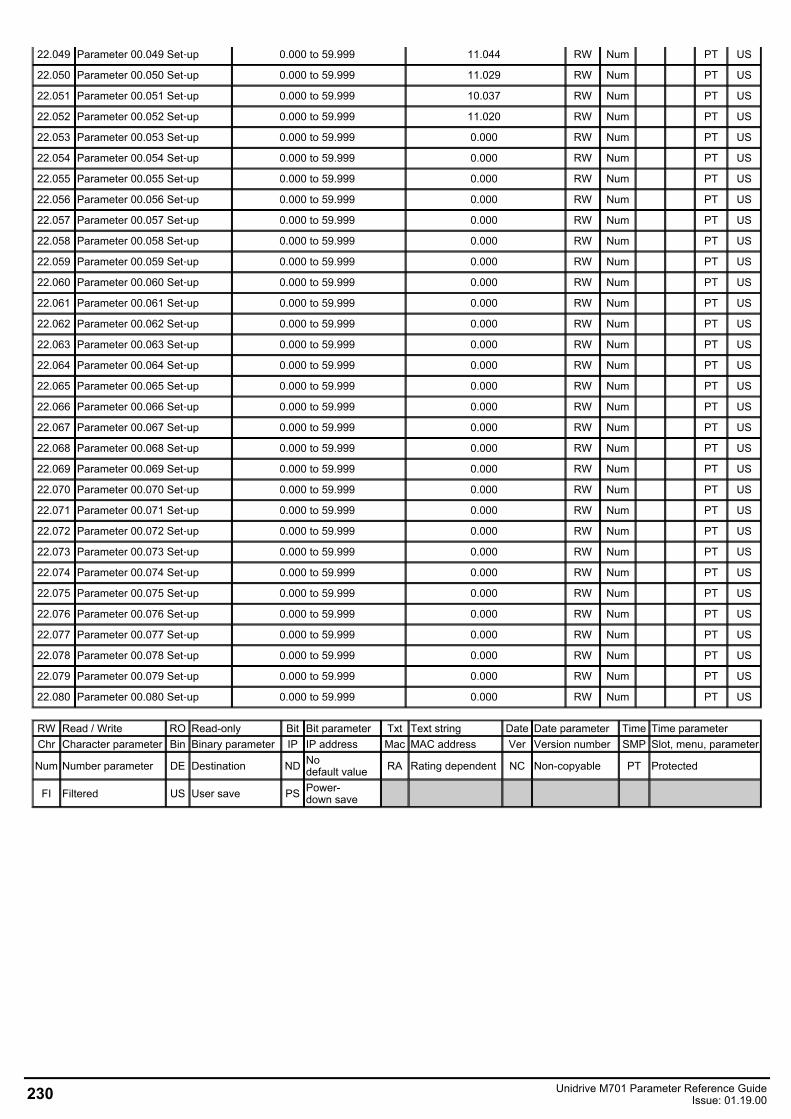
22.049 Parameter 00.049 Set‑up 0.000 to 59.999 11.044 RW Num PT US
22.050 Parameter 00.050 Set‑up 0.000 to 59.999 11.029 RW Num PT US
22.051 Parameter 00.051 Set‑up 0.000 to 59.999 10.037 RW Num PT US
22.052 Parameter 00.052 Set‑up 0.000 to 59.999 11.020 RW Num PT US
22.053 Parameter 00.053 Set‑up 0.000 to 59.999 0.000 RW Num PT US
22.054 Parameter 00.054 Set‑up 0.000 to 59.999 0.000 RW Num PT US
22.055 Parameter 00.055 Set‑up 0.000 to 59.999 0.000 RW Num PT US
22.056 Parameter 00.056 Set‑up 0.000 to 59.999 0.000 RW Num PT US
22.057 Parameter 00.057 Set‑up 0.000 to 59.999 0.000 RW Num PT US
22.058 Parameter 00.058 Set‑up 0.000 to 59.999 0.000 RW Num PT US
22.059 Parameter 00.059 Set‑up 0.000 to 59.999 0.000 RW Num PT US
22.060 Parameter 00.060 Set‑up 0.000 to 59.999 0.000 RW Num PT US
22.061 Parameter 00.061 Set‑up 0.000 to 59.999 0.000 RW Num PT US
22.062 Parameter 00.062 Set‑up 0.000 to 59.999 0.000 RW Num PT US
22.063 Parameter 00.063 Set‑up 0.000 to 59.999 0.000 RW Num PT US
22.064 Parameter 00.064 Set‑up 0.000 to 59.999 0.000 RW Num PT US
22.065 Parameter 00.065 Set‑up 0.000 to 59.999 0.000 RW Num PT US
22.066 Parameter 00.066 Set‑up 0.000 to 59.999 0.000 RW Num PT US
22.067 Parameter 00.067 Set‑up 0.000 to 59.999 0.000 RW Num PT US
22.068 Parameter 00.068 Set‑up 0.000 to 59.999 0.000 RW Num PT US
22.069 Parameter 00.069 Set‑up 0.000 to 59.999 0.000 RW Num PT US
22.070 Parameter 00.070 Set‑up 0.000 to 59.999 0.000 RW Num PT US
22.071 Parameter 00.071 Set‑up 0.000 to 59.999 0.000 RW Num PT US
22.072 Parameter 00.072 Set‑up 0.000 to 59.999 0.000 RW Num PT US
22.073 Parameter 00.073 Set‑up 0.000 to 59.999 0.000 RW Num PT US
22.074 Parameter 00.074 Set‑up 0.000 to 59.999 0.000 RW Num PT US
22.075 Parameter 00.075 Set‑up 0.000 to 59.999 0.000 RW Num PT US
22.076 Parameter 00.076 Set‑up 0.000 to 59.999 0.000 RW Num PT US
22.077 Parameter 00.077 Set‑up 0.000 to 59.999 0.000 RW Num PT US
22.078 Parameter 00.078 Set‑up 0.000 to 59.999 0.000 RW Num PT US
22.079 Parameter 00.079 Set‑up 0.000 to 59.999 0.000 RW Num PT US
22.080 Parameter 00.080 Set‑up 0.000 to 59.999 0.000 RW Num PT US
RW Read / Write RO Read-only Bit Bit parameter Txt Text string Date Date parameter Time Time parameterChr Character parameter Bin Binary parameter IP IP address Mac MAC address Ver Version number SMP Slot, menu, parameter
Num Number parameter DE Destination ND Nodefault value RA Rating dependent NC Non-copyable PT Protected
FI Filtered US User save PS Power-down save
230 Unidrive M701 Parameter Reference GuideIssue: 01.19.00
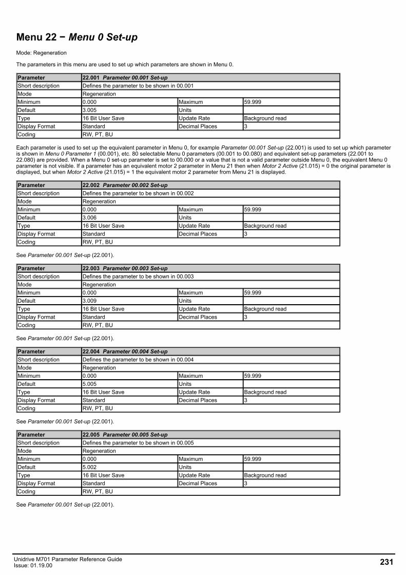
Menu 22 − Menu 0 Set-upMode: Regeneration
The parameters in this menu are used to set up which parameters are shown in Menu 0.
Parameter 22.001 Parameter 00.001 Set-upShort description Defines the parameter to be shown in 00.001Mode RegenerationMinimum 0.000 Maximum 59.999Default 3.005 Units Type 16 Bit User Save Update Rate Background readDisplay Format Standard Decimal Places 3Coding RW, PT, BU
Each parameter is used to set up the equivalent parameter in Menu 0, for example Parameter 00.001 Set-up (22.001) is used to set up which parameteris shown in Menu 0 Parameter 1 (00.001), etc. 80 selectable Menu 0 parameters (00.001 to 00.080) and equivalent set-up parameters (22.001 to22.080) are provided. When a Menu 0 set-up parameter is set to 00.000 or a value that is not a valid parameter outside Menu 0, the equivalent Menu 0parameter is not visible. If a parameter has an equivalent motor 2 parameter in Menu 21 then when Motor 2 Active (21.015) = 0 the original parameter isdisplayed, but when Motor 2 Active (21.015) = 1 the equivalent motor 2 parameter from Menu 21 is displayed.
Parameter 22.002 Parameter 00.002 Set-upShort description Defines the parameter to be shown in 00.002Mode RegenerationMinimum 0.000 Maximum 59.999Default 3.006 Units Type 16 Bit User Save Update Rate Background readDisplay Format Standard Decimal Places 3Coding RW, PT, BU
See Parameter 00.001 Set-up (22.001).
Parameter 22.003 Parameter 00.003 Set-upShort description Defines the parameter to be shown in 00.003Mode RegenerationMinimum 0.000 Maximum 59.999Default 3.009 Units Type 16 Bit User Save Update Rate Background readDisplay Format Standard Decimal Places 3Coding RW, PT, BU
See Parameter 00.001 Set-up (22.001).
Parameter 22.004 Parameter 00.004 Set-upShort description Defines the parameter to be shown in 00.004Mode RegenerationMinimum 0.000 Maximum 59.999Default 5.005 Units Type 16 Bit User Save Update Rate Background readDisplay Format Standard Decimal Places 3Coding RW, PT, BU
See Parameter 00.001 Set-up (22.001).
Parameter 22.005 Parameter 00.005 Set-upShort description Defines the parameter to be shown in 00.005Mode RegenerationMinimum 0.000 Maximum 59.999Default 5.002 Units Type 16 Bit User Save Update Rate Background readDisplay Format Standard Decimal Places 3Coding RW, PT, BU
See Parameter 00.001 Set-up (22.001).
Unidrive M701 Parameter Reference GuideIssue: 01.19.00 231

Parameter 22.006 Parameter 00.006 Set-upShort description Defines the parameter to be shown in 00.006Mode RegenerationMinimum 0.000 Maximum 59.999Default 3.003 Units Type 16 Bit User Save Update Rate Background readDisplay Format Standard Decimal Places 3Coding RW, PT, BU
See Parameter 00.001 Set-up (22.001).
Parameter 22.007 Parameter 00.007 Set-upShort description Defines the parameter to be shown in 00.007Mode RegenerationMinimum 0.000 Maximum 59.999Default 3.004 Units Type 16 Bit User Save Update Rate Background readDisplay Format Standard Decimal Places 3Coding RW, PT, BU
See Parameter 00.001 Set-up (22.001).
Parameter 22.008 Parameter 00.008 Set-upShort description Defines the parameter to be shown in 00.008Mode RegenerationMinimum 0.000 Maximum 59.999Default 3.007 Units Type 16 Bit User Save Update Rate Background readDisplay Format Standard Decimal Places 3Coding RW, PT, BU
See Parameter 00.001 Set-up (22.001).
Parameter 22.009 Parameter 00.009 Set-upShort description Defines the parameter to be shown in 00.009Mode RegenerationMinimum 0.000 Maximum 59.999Default 3.008 Units Type 16 Bit User Save Update Rate Background readDisplay Format Standard Decimal Places 3Coding RW, PT, BU
See Parameter 00.001 Set-up (22.001).
Parameter 22.010 Parameter 00.010 Set-upShort description Defines the parameter to be shown in 00.010Mode RegenerationMinimum 0.000 Maximum 59.999Default 3.010 Units Type 16 Bit User Save Update Rate Background readDisplay Format Standard Decimal Places 3Coding RW, PT, BU
See Parameter 00.001 Set-up (22.001).
Parameter 22.011 Parameter 00.011 Set-upShort description Defines the parameter to be shown in 00.011Mode RegenerationMinimum 0.000 Maximum 59.999Default 5.001 Units Type 16 Bit User Save Update Rate Background readDisplay Format Standard Decimal Places 3Coding RW, PT, BU
See Parameter 00.001 Set-up (22.001).
232 Unidrive M701 Parameter Reference GuideIssue: 01.19.00
Parameter 22.012 Parameter 00.012 Set-upShort description Defines the parameter to be shown in 00.012Mode RegenerationMinimum 0.000 Maximum 59.999Default 4.001 Units Type 16 Bit User Save Update Rate Background readDisplay Format Standard Decimal Places 3Coding RW, PT, BU
See Parameter 00.001 Set-up (22.001).
Parameter 22.013 Parameter 00.013 Set-upShort description Defines the parameter to be shown in 00.013Mode RegenerationMinimum 0.000 Maximum 59.999Default 4.002 Units Type 16 Bit User Save Update Rate Background readDisplay Format Standard Decimal Places 3Coding RW, PT, BU
See Parameter 00.001 Set-up (22.001).
Parameter 22.014 Parameter 00.014 Set-upShort description Defines the parameter to be shown in 00.014Mode RegenerationMinimum 0.000 Maximum 59.999Default 5.003 Units Type 16 Bit User Save Update Rate Background readDisplay Format Standard Decimal Places 3Coding RW, PT, BU
See Parameter 00.001 Set-up (22.001).
Parameter 22.015 Parameter 00.015 Set-upShort description Defines the parameter to be shown in 00.015Mode RegenerationMinimum 0.000 Maximum 59.999Default 3.001 Units Type 16 Bit User Save Update Rate Background readDisplay Format Standard Decimal Places 3Coding RW, PT, BU
See Parameter 00.001 Set-up (22.001).
Parameter 22.016 Parameter 00.016 Set-upShort description Defines the parameter to be shown in 00.016Mode RegenerationMinimum 0.000 Maximum 59.999Default 3.002 Units Type 16 Bit User Save Update Rate Background readDisplay Format Standard Decimal Places 3Coding RW, PT, BU
See Parameter 00.001 Set-up (22.001).
Parameter 22.017 Parameter 00.017 Set-upShort description Defines the parameter to be shown in 00.017Mode RegenerationMinimum 0.000 Maximum 59.999Default 4.008 Units Type 16 Bit User Save Update Rate Background readDisplay Format Standard Decimal Places 3Coding RW, PT, BU
See Parameter 00.001 Set-up (22.001).
Unidrive M701 Parameter Reference GuideIssue: 01.19.00 233

Parameter 22.018 Parameter 00.018 Set-upShort description Defines the parameter to be shown in 00.018Mode RegenerationMinimum 0.000 Maximum 59.999Default 0.000 Units Type 16 Bit User Save Update Rate Background readDisplay Format Standard Decimal Places 3Coding RW, PT, BU
See Parameter 00.001 Set-up (22.001).
Parameter 22.019 Parameter 00.019 Set-upShort description Defines the parameter to be shown in 00.019Mode RegenerationMinimum 0.000 Maximum 59.999Default 7.011 Units Type 16 Bit User Save Update Rate Background readDisplay Format Standard Decimal Places 3Coding RW, PT, BU
See Parameter 00.001 Set-up (22.001).
Parameter 22.020 Parameter 00.020 Set-upShort description Defines the parameter to be shown in 00.020Mode RegenerationMinimum 0.000 Maximum 59.999Default 7.014 Units Type 16 Bit User Save Update Rate Background readDisplay Format Standard Decimal Places 3Coding RW, PT, BU
See Parameter 00.001 Set-up (22.001).
Parameter 22.021 Parameter 00.021 Set-upShort description Defines the parameter to be shown in 00.021Mode RegenerationMinimum 0.000 Maximum 59.999Default 7.015 Units Type 16 Bit User Save Update Rate Background readDisplay Format Standard Decimal Places 3Coding RW, PT, BU
See Parameter 00.001 Set-up (22.001).
Parameter 22.022 Parameter 00.022 Set-upShort description Defines the parameter to be shown in 00.022Mode RegenerationMinimum 0.000 Maximum 59.999Default 0.000 Units Type 16 Bit User Save Update Rate Background readDisplay Format Standard Decimal Places 3Coding RW, PT, BU
See Parameter 00.001 Set-up (22.001).
Parameter 22.023 Parameter 00.023 Set-upShort description Defines the parameter to be shown in 00.023Mode RegenerationMinimum 0.000 Maximum 59.999Default 0.000 Units Type 16 Bit User Save Update Rate Background readDisplay Format Standard Decimal Places 3Coding RW, PT, BU
See Parameter 00.001 Set-up (22.001).
234 Unidrive M701 Parameter Reference GuideIssue: 01.19.00

Parameter 22.024 Parameter 00.024 Set-upShort description Defines the parameter to be shown in 00.024Mode RegenerationMinimum 0.000 Maximum 59.999Default 0.000 Units Type 16 Bit User Save Update Rate Background readDisplay Format Standard Decimal Places 3Coding RW, PT, BU
See Parameter 00.001 Set-up (22.001).
Parameter 22.025 Parameter 00.025 Set-upShort description Defines the parameter to be shown in 00.025Mode RegenerationMinimum 0.000 Maximum 59.999Default 0.000 Units Type 16 Bit User Save Update Rate Background readDisplay Format Standard Decimal Places 3Coding RW, PT, BU
See Parameter 00.001 Set-up (22.001).
Parameter 22.026 Parameter 00.026 Set-upShort description Defines the parameter to be shown in 00.026Mode RegenerationMinimum 0.000 Maximum 59.999Default 0.000 Units Type 16 Bit User Save Update Rate Background readDisplay Format Standard Decimal Places 3Coding RW, PT, BU
See Parameter 00.001 Set-up (22.001).
Parameter 22.027 Parameter 00.027 Set-upShort description Defines the parameter to be shown in 00.027Mode RegenerationMinimum 0.000 Maximum 59.999Default 0.000 Units Type 16 Bit User Save Update Rate Background readDisplay Format Standard Decimal Places 3Coding RW, PT, BU
See Parameter 00.001 Set-up (22.001).
Parameter 22.028 Parameter 00.028 Set-upShort description Defines the parameter to be shown in 00.028Mode RegenerationMinimum 0.000 Maximum 59.999Default 0.000 Units Type 16 Bit User Save Update Rate Background readDisplay Format Standard Decimal Places 3Coding RW, PT, BU
See Parameter 00.001 Set-up (22.001).
Parameter 22.029 Parameter 00.029 Set-upShort description Defines the parameter to be shown in 00.029Mode RegenerationMinimum 0.000 Maximum 59.999Default 11.036 Units Type 16 Bit User Save Update Rate Background readDisplay Format Standard Decimal Places 3Coding RW, PT, BU
See Parameter 00.001 Set-up (22.001).
Unidrive M701 Parameter Reference GuideIssue: 01.19.00 235

Parameter 22.030 Parameter 00.030 Set-upShort description Defines the parameter to be shown in 00.030Mode RegenerationMinimum 0.000 Maximum 59.999Default 11.042 Units Type 16 Bit User Save Update Rate Background readDisplay Format Standard Decimal Places 3Coding RW, PT, BU
See Parameter 00.001 Set-up (22.001).
Parameter 22.031 Parameter 00.031 Set-upShort description Defines the parameter to be shown in 00.031Mode RegenerationMinimum 0.000 Maximum 59.999Default 11.033 Units Type 16 Bit User Save Update Rate Background readDisplay Format Standard Decimal Places 3Coding RW, PT, BU
See Parameter 00.001 Set-up (22.001).
Parameter 22.032 Parameter 00.032 Set-upShort description Defines the parameter to be shown in 00.032Mode RegenerationMinimum 0.000 Maximum 59.999Default 11.032 Units Type 16 Bit User Save Update Rate Background readDisplay Format Standard Decimal Places 3Coding RW, PT, BU
See Parameter 00.001 Set-up (22.001).
Parameter 22.033 Parameter 00.033 Set-upShort description Defines the parameter to be shown in 00.033Mode RegenerationMinimum 0.000 Maximum 59.999Default 0.000 Units Type 16 Bit User Save Update Rate Background readDisplay Format Standard Decimal Places 3Coding RW, PT, BU
See Parameter 00.001 Set-up (22.001).
Parameter 22.034 Parameter 00.034 Set-upShort description Defines the parameter to be shown in 00.034Mode RegenerationMinimum 0.000 Maximum 59.999Default 11.030 Units Type 16 Bit User Save Update Rate Background readDisplay Format Standard Decimal Places 3Coding RW, PT, BU
See Parameter 00.001 Set-up (22.001).
Parameter 22.035 Parameter 00.035 Set-upShort description Defines the parameter to be shown in 00.035Mode RegenerationMinimum 0.000 Maximum 59.999Default 11.024 Units Type 16 Bit User Save Update Rate Background readDisplay Format Standard Decimal Places 3Coding RW, PT, BU
See Parameter 00.001 Set-up (22.001).
236 Unidrive M701 Parameter Reference GuideIssue: 01.19.00
Parameter 22.036 Parameter 00.036 Set-upShort description Defines the parameter to be shown in 00.036Mode RegenerationMinimum 0.000 Maximum 59.999Default 11.025 Units Type 16 Bit User Save Update Rate Background readDisplay Format Standard Decimal Places 3Coding RW, PT, BU
See Parameter 00.001 Set-up (22.001).
Parameter 22.037 Parameter 00.037 Set-upShort description Defines the parameter to be shown in 00.037Mode RegenerationMinimum 0.000 Maximum 59.999Default 11.023 Units Type 16 Bit User Save Update Rate Background readDisplay Format Standard Decimal Places 3Coding RW, PT, BU
See Parameter 00.001 Set-up (22.001).
Parameter 22.038 Parameter 00.038 Set-upShort description Defines the parameter to be shown in 00.038Mode RegenerationMinimum 0.000 Maximum 59.999Default 4.013 Units Type 16 Bit User Save Update Rate Background readDisplay Format Standard Decimal Places 3Coding RW, PT, BU
See Parameter 00.001 Set-up (22.001).
Parameter 22.039 Parameter 00.039 Set-upShort description Defines the parameter to be shown in 00.039Mode RegenerationMinimum 0.000 Maximum 59.999Default 4.014 Units Type 16 Bit User Save Update Rate Background readDisplay Format Standard Decimal Places 3Coding RW, PT, BU
See Parameter 00.001 Set-up (22.001).
Parameter 22.040 Parameter 00.040 Set-upShort description Defines the parameter to be shown in 00.040Mode RegenerationMinimum 0.000 Maximum 59.999Default 0.000 Units Type 16 Bit User Save Update Rate Background readDisplay Format Standard Decimal Places 3Coding RW, PT, BU
See Parameter 00.001 Set-up (22.001).
Parameter 22.041 Parameter 00.041 Set-upShort description Defines the parameter to be shown in 00.041Mode RegenerationMinimum 0.000 Maximum 59.999Default 5.018 Units Type 16 Bit User Save Update Rate Background readDisplay Format Standard Decimal Places 3Coding RW, PT, BU
See Parameter 00.001 Set-up (22.001).
Unidrive M701 Parameter Reference GuideIssue: 01.19.00 237

Parameter 22.042 Parameter 00.042 Set-upShort description Defines the parameter to be shown in 00.042Mode RegenerationMinimum 0.000 Maximum 59.999Default 0.000 Units Type 16 Bit User Save Update Rate Background readDisplay Format Standard Decimal Places 3Coding RW, PT, BU
See Parameter 00.001 Set-up (22.001).
Parameter 22.043 Parameter 00.043 Set-upShort description Defines the parameter to be shown in 00.043Mode RegenerationMinimum 0.000 Maximum 59.999Default 0.000 Units Type 16 Bit User Save Update Rate Background readDisplay Format Standard Decimal Places 3Coding RW, PT, BU
See Parameter 00.001 Set-up (22.001).
Parameter 22.044 Parameter 00.044 Set-upShort description Defines the parameter to be shown in 00.044Mode RegenerationMinimum 0.000 Maximum 59.999Default 0.000 Units Type 16 Bit User Save Update Rate Background readDisplay Format Standard Decimal Places 3Coding RW, PT, BU
See Parameter 00.001 Set-up (22.001).
Parameter 22.045 Parameter 00.045 Set-upShort description Defines the parameter to be shown in 00.045Mode RegenerationMinimum 0.000 Maximum 59.999Default 4.015 Units Type 16 Bit User Save Update Rate Background readDisplay Format Standard Decimal Places 3Coding RW, PT, BU
See Parameter 00.001 Set-up (22.001).
Parameter 22.046 Parameter 00.046 Set-upShort description Defines the parameter to be shown in 00.046Mode RegenerationMinimum 0.000 Maximum 59.999Default 5.007 Units Type 16 Bit User Save Update Rate Background readDisplay Format Standard Decimal Places 3Coding RW, PT, BU
See Parameter 00.001 Set-up (22.001).
Parameter 22.047 Parameter 00.047 Set-upShort description Defines the parameter to be shown in 00.047Mode RegenerationMinimum 0.000 Maximum 59.999Default 0.000 Units Type 16 Bit User Save Update Rate Background readDisplay Format Standard Decimal Places 3Coding RW, PT, BU
See Parameter 00.001 Set-up (22.001).
238 Unidrive M701 Parameter Reference GuideIssue: 01.19.00

Parameter 22.048 Parameter 00.048 Set-upShort description Defines the parameter to be shown in 00.048Mode RegenerationMinimum 0.000 Maximum 59.999Default 11.031 Units Type 16 Bit User Save Update Rate Background readDisplay Format Standard Decimal Places 3Coding RW, PT, BU
See Parameter 00.001 Set-up (22.001).
Parameter 22.049 Parameter 00.049 Set-upShort description Defines the parameter to be shown in 00.049Mode RegenerationMinimum 0.000 Maximum 59.999Default 11.044 Units Type 16 Bit User Save Update Rate Background readDisplay Format Standard Decimal Places 3Coding RW, PT, BU
See Parameter 00.001 Set-up (22.001).
Parameter 22.050 Parameter 00.050 Set-upShort description Defines the parameter to be shown in 00.050Mode RegenerationMinimum 0.000 Maximum 59.999Default 11.029 Units Type 16 Bit User Save Update Rate Background readDisplay Format Standard Decimal Places 3Coding RW, PT, BU
See Parameter 00.001 Set-up (22.001).
Parameter 22.051 Parameter 00.051 Set-upShort description Defines the parameter to be shown in 00.051Mode RegenerationMinimum 0.000 Maximum 59.999Default 10.037 Units Type 16 Bit User Save Update Rate Background readDisplay Format Standard Decimal Places 3Coding RW, PT, BU
See Parameter 00.001 Set-up (22.001).
Parameter 22.052 Parameter 00.052 Set-upShort description Defines the parameter to be shown in 00.052Mode RegenerationMinimum 0.000 Maximum 59.999Default 11.020 Units Type 16 Bit User Save Update Rate Background readDisplay Format Standard Decimal Places 3Coding RW, PT, BU
See Parameter 00.001 Set-up (22.001).
Parameter 22.053 Parameter 00.053 Set-upShort description Defines the parameter to be shown in 00.053Mode RegenerationMinimum 0.000 Maximum 59.999Default 0.000 Units Type 16 Bit User Save Update Rate Background readDisplay Format Standard Decimal Places 3Coding RW, PT, BU
See Parameter 00.001 Set-up (22.001).
Unidrive M701 Parameter Reference GuideIssue: 01.19.00 239

Parameter 22.054 Parameter 00.054 Set-upShort description Defines the parameter to be shown in 00.054Mode RegenerationMinimum 0.000 Maximum 59.999Default 0.000 Units Type 16 Bit User Save Update Rate Background readDisplay Format Standard Decimal Places 3Coding RW, PT, BU
See Parameter 00.001 Set-up (22.001).
Parameter 22.055 Parameter 00.055 Set-upShort description Defines the parameter to be shown in 00.055Mode RegenerationMinimum 0.000 Maximum 59.999Default 0.000 Units Type 16 Bit User Save Update Rate Background readDisplay Format Standard Decimal Places 3Coding RW, PT, BU
See Parameter 00.001 Set-up (22.001).
Parameter 22.056 Parameter 00.056 Set-upShort description Defines the parameter to be shown in 00.056Mode RegenerationMinimum 0.000 Maximum 59.999Default 0.000 Units Type 16 Bit User Save Update Rate Background readDisplay Format Standard Decimal Places 3Coding RW, PT, BU
See Parameter 00.001 Set-up (22.001).
Parameter 22.057 Parameter 00.057 Set-upShort description Defines the parameter to be shown in 00.057Mode RegenerationMinimum 0.000 Maximum 59.999Default 0.000 Units Type 16 Bit User Save Update Rate Background readDisplay Format Standard Decimal Places 3Coding RW, PT, BU
See Parameter 00.001 Set-up (22.001).
Parameter 22.058 Parameter 00.058 Set-upShort description Defines the parameter to be shown in 00.058Mode RegenerationMinimum 0.000 Maximum 59.999Default 0.000 Units Type 16 Bit User Save Update Rate Background readDisplay Format Standard Decimal Places 3Coding RW, PT, BU
See Parameter 00.001 Set-up (22.001).
Parameter 22.059 Parameter 00.059 Set-upShort description Defines the parameter to be shown in 00.059Mode RegenerationMinimum 0.000 Maximum 59.999Default 0.000 Units Type 16 Bit User Save Update Rate Background readDisplay Format Standard Decimal Places 3Coding RW, PT, BU
See Parameter 00.001 Set-up (22.001).
240 Unidrive M701 Parameter Reference GuideIssue: 01.19.00
Parameter 22.060 Parameter 00.060 Set-upShort description Defines the parameter to be shown in 00.060Mode RegenerationMinimum 0.000 Maximum 59.999Default 0.000 Units Type 16 Bit User Save Update Rate Background readDisplay Format Standard Decimal Places 3Coding RW, PT, BU
See Parameter 00.001 Set-up (22.001).
Parameter 22.061 Parameter 00.061 Set-upShort description Defines the parameter to be shown in 00.061Mode RegenerationMinimum 0.000 Maximum 59.999Default 0.000 Units Type 16 Bit User Save Update Rate Background readDisplay Format Standard Decimal Places 3Coding RW, PT, BU
See Parameter 00.001 Set-up (22.001).
Parameter 22.062 Parameter 00.062 Set-upShort description Defines the parameter to be shown in 00.062Mode RegenerationMinimum 0.000 Maximum 59.999Default 0.000 Units Type 16 Bit User Save Update Rate Background readDisplay Format Standard Decimal Places 3Coding RW, PT, BU
See Parameter 00.001 Set-up (22.001).
Parameter 22.063 Parameter 00.063 Set-upShort description Defines the parameter to be shown in 00.063Mode RegenerationMinimum 0.000 Maximum 59.999Default 0.000 Units Type 16 Bit User Save Update Rate Background readDisplay Format Standard Decimal Places 3Coding RW, PT, BU
See Parameter 00.001 Set-up (22.001).
Parameter 22.064 Parameter 00.064 Set-upShort description Defines the parameter to be shown in 00.064Mode RegenerationMinimum 0.000 Maximum 59.999Default 0.000 Units Type 16 Bit User Save Update Rate Background readDisplay Format Standard Decimal Places 3Coding RW, PT, BU
See Parameter 00.001 Set-up (22.001).
Parameter 22.065 Parameter 00.065 Set-upShort description Defines the parameter to be shown in 00.065Mode RegenerationMinimum 0.000 Maximum 59.999Default 0.000 Units Type 16 Bit User Save Update Rate Background readDisplay Format Standard Decimal Places 3Coding RW, PT, BU
See Parameter 00.001 Set-up (22.001).
Unidrive M701 Parameter Reference GuideIssue: 01.19.00 241
Parameter 22.066 Parameter 00.066 Set-upShort description Defines the parameter to be shown in 00.066Mode RegenerationMinimum 0.000 Maximum 59.999Default 0.000 Units Type 16 Bit User Save Update Rate Background readDisplay Format Standard Decimal Places 3Coding RW, PT, BU
See Parameter 00.001 Set-up (22.001).
Parameter 22.067 Parameter 00.067 Set-upShort description Defines the parameter to be shown in 00.067Mode RegenerationMinimum 0.000 Maximum 59.999Default 0.000 Units Type 16 Bit User Save Update Rate Background readDisplay Format Standard Decimal Places 3Coding RW, PT, BU
See Parameter 00.001 Set-up (22.001).
Parameter 22.068 Parameter 00.068 Set-upShort description Defines the parameter to be shown in 00.068Mode RegenerationMinimum 0.000 Maximum 59.999Default 0.000 Units Type 16 Bit User Save Update Rate Background readDisplay Format Standard Decimal Places 3Coding RW, PT, BU
See Parameter 00.001 Set-up (22.001).
Parameter 22.069 Parameter 00.069 Set-upShort description Defines the parameter to be shown in 00.069Mode RegenerationMinimum 0.000 Maximum 59.999Default 0.000 Units Type 16 Bit User Save Update Rate Background readDisplay Format Standard Decimal Places 3Coding RW, PT, BU
See Parameter 00.001 Set-up (22.001).
Parameter 22.070 Parameter 00.070 Set-upShort description Defines the parameter to be shown in 00.070Mode RegenerationMinimum 0.000 Maximum 59.999Default 0.000 Units Type 16 Bit User Save Update Rate Background readDisplay Format Standard Decimal Places 3Coding RW, PT, BU
See Parameter 00.001 Set-up (22.001).
Parameter 22.071 Parameter 00.071 Set-upShort description Defines the parameter to be shown in 00.071Mode RegenerationMinimum 0.000 Maximum 59.999Default 0.000 Units Type 16 Bit User Save Update Rate Background readDisplay Format Standard Decimal Places 3Coding RW, PT, BU
See Parameter 00.001 Set-up (22.001).
242 Unidrive M701 Parameter Reference GuideIssue: 01.19.00

Parameter 22.072 Parameter 00.072 Set-upShort description Defines the parameter to be shown in 00.072Mode RegenerationMinimum 0.000 Maximum 59.999Default 0.000 Units Type 16 Bit User Save Update Rate Background readDisplay Format Standard Decimal Places 3Coding RW, PT, BU
See Parameter 00.001 Set-up (22.001).
Parameter 22.073 Parameter 00.073 Set-upShort description Defines the parameter to be shown in 00.073Mode RegenerationMinimum 0.000 Maximum 59.999Default 0.000 Units Type 16 Bit User Save Update Rate Background readDisplay Format Standard Decimal Places 3Coding RW, PT, BU
See Parameter 00.001 Set-up (22.001).
Parameter 22.074 Parameter 00.074 Set-upShort description Defines the parameter to be shown in 00.074Mode RegenerationMinimum 0.000 Maximum 59.999Default 0.000 Units Type 16 Bit User Save Update Rate Background readDisplay Format Standard Decimal Places 3Coding RW, PT, BU
See Parameter 00.001 Set-up (22.001).
Parameter 22.075 Parameter 00.075 Set-upShort description Defines the parameter to be shown in 00.075Mode RegenerationMinimum 0.000 Maximum 59.999Default 0.000 Units Type 16 Bit User Save Update Rate Background readDisplay Format Standard Decimal Places 3Coding RW, PT, BU
See Parameter 00.001 Set-up (22.001).
Parameter 22.076 Parameter 00.076 Set-upShort description Defines the parameter to be shown in 00.076Mode RegenerationMinimum 0.000 Maximum 59.999Default 0.000 Units Type 16 Bit User Save Update Rate Background readDisplay Format Standard Decimal Places 3Coding RW, PT, BU
See Parameter 00.001 Set-up (22.001).
Parameter 22.077 Parameter 00.077 Set-upShort description Defines the parameter to be shown in 00.077Mode RegenerationMinimum 0.000 Maximum 59.999Default 0.000 Units Type 16 Bit User Save Update Rate Background readDisplay Format Standard Decimal Places 3Coding RW, PT, BU
See Parameter 00.001 Set-up (22.001).
Unidrive M701 Parameter Reference GuideIssue: 01.19.00 243
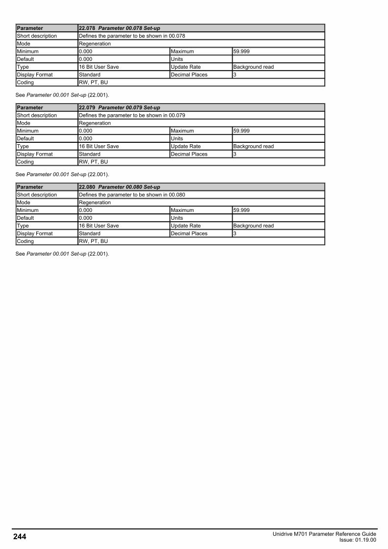
Parameter 22.078 Parameter 00.078 Set-upShort description Defines the parameter to be shown in 00.078Mode RegenerationMinimum 0.000 Maximum 59.999Default 0.000 Units Type 16 Bit User Save Update Rate Background readDisplay Format Standard Decimal Places 3Coding RW, PT, BU
See Parameter 00.001 Set-up (22.001).
Parameter 22.079 Parameter 00.079 Set-upShort description Defines the parameter to be shown in 00.079Mode RegenerationMinimum 0.000 Maximum 59.999Default 0.000 Units Type 16 Bit User Save Update Rate Background readDisplay Format Standard Decimal Places 3Coding RW, PT, BU
See Parameter 00.001 Set-up (22.001).
Parameter 22.080 Parameter 00.080 Set-upShort description Defines the parameter to be shown in 00.080Mode RegenerationMinimum 0.000 Maximum 59.999Default 0.000 Units Type 16 Bit User Save Update Rate Background readDisplay Format Standard Decimal Places 3Coding RW, PT, BU
See Parameter 00.001 Set-up (22.001).
244 Unidrive M701 Parameter Reference GuideIssue: 01.19.00
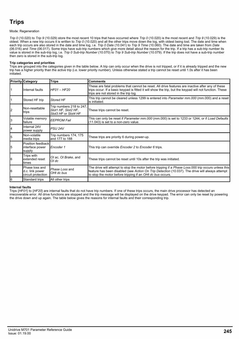
TripsMode: Regeneration
Trip 0 (10.020) to Trip 9 (10.029) store the most recent 10 trips that have occurred where Trip 0 (10.020) is the most recent and Trip 9 (10.029) is theoldest. When a new trip occurs it is written to Trip 0 (10.020) and all the other trips move down the log, with oldest being lost. The date and time wheneach trip occurs are also stored in the date and time log, i.e. Trip 0 Date (10.041) to Trip 9 Time (10.060). The date and time are taken from Date(06.016) and Time (06.017). Some trips have sub-trip numbers which give more detail about the reason for the trip. If a trip has a sub-trip number itsvalue is stored in the sub-trip log, i.e. Trip 0 Sub-trip Number (10.070) to Trip 9 Sub-trip Number (10.079). If the trip does not have a sub-trip numberthen zero is stored in the sub-trip log.
Trip categories and prioritiesTrips are grouped into the categories given in the table below. A trip can only occur when the drive is not tripped, or if it is already tripped and the newtrip has a higher priority than the active trip (i.e. lower priority number). Unless otherwise stated a trip cannot be reset until 1.0s after it has beeninitiated.
Priority Category Trips Comments
1 Internal faults HF01 – HF20These are fatal problems that cannot be reset. All drive features are inactive after any of thesetrips occur. If a basic keypad is fitted it will show the trip, but the keypad will not function. Thesetrips are not stored in the trip log.
1 Stored HF trip Stored HF This trip cannot be cleared unless 1299 is entered into Parameter mm.000 (mm.000) and a resetis initiated.
2 Non-resettabletrips
Trip numbers 218 to 247,Slot1 HF, Slot2 HF,Slot3 HF or Slot4 HF
These trips cannot be reset.
3 Volatile memoryfailure EEPROM Fail This can only be reset if Parameter mm.000 (mm.000) is set to 1233 or 1244, or if Load Defaults
(11.043) is set to a non-zero value.
4 Internal 24Vpower supply PSU 24V
5 Non-volatilemedia trips
Trip numbers 174, 175and 177 to 188 These trips are priority 6 during power-up.
5Position feedbackinterface powersupply
Encoder 1 This trip can override Encoder 2 to Encoder 6 trips.
6Trips withextended resettimes
OI ac, OI Brake, andOI dc These trips cannot be reset until 10s after the trip was initiated.
6Phase loss andd.c. link powercircuit protection
Phase Loss andOHt dc bus
The drive will attempt to stop the motor before tripping if a Phase Loss.000 trip occurs unless thisfeature has been disabled (see Action On Trip Detection (10.037). The drive will always attemptto stop the motor before tripping if an OHt dc bus occurs.
6 Standard trips All other trips
Internal faultsTrips HF01 to HF20 are internal faults that do not have trip numbers. If one of these trips occurs, the main drive processor has detected anirrecoverable error. All drive functions are stopped and the trip message will be displayed on the drive keypad. The error can only be reset by poweringthe drive down and up again. The table below gives the reasons for internal faults and their corresponding trip.
Unidrive M701 Parameter Reference GuideIssue: 01.19.00 245

Trip ReasonHF01 CPU has detected an address errorHF02 CPU DMAC has detected an address errorHF03 CPU has detected an Illegal opcodeHF04 CPU has detected an Illegal slot instructionHF05 An interrupt has occurred that does not have a defined function (Undefined exception)HF06 An interrupt has occurred which is reserved (Reserved exception)HF07 Watchdog failureHF08 CPU Interrupt crashHF09 Free store overflowHF10 Parameter routing system errorHF11 Non-volatile memory comms error
HF12Stack overflow. Sub-trip is shown to indicate which stack:1 – background tasks2 – timed tasks3 – main system interrupts
HF13 The control hardware is not compatible with the firmware. The sub-trip number gives the actual ID codeof the control board hardware.
HF14 CPU register bank errorHF15 CPU divide errorHF16 RTOS error (the background task has returned)HF17 The clock supplied to the control board logic is out of specification
HF18
The internal flash memory has failed when writing option module parameter data.
Sub-trip is shown to indicate which failure:1 - Programming error while writing menu in flash2 - Erase flash block containing setup menus failed3 - Erase flash block containing application menus failed
HF19 Invalid main application firmware CRC. Reprogramming required.HF20 The ASIC is not compatible with the firmware. The sub-trip number displayed is the ASIC version.HF23 If this trip occurs please consult the drive supplier. HF24 If this trip occurs please consult the drive supplier. HF25 If this trip occurs please consult the drive supplier.
When the drive is subsequently powered up a Stored HF trip is initiated where the sub-trip number is the number of the HF trip that last occurred. Thistrip will occur at every power-up until it is reset. The trip can only be reset by first entering 1299 into Parameter mm.000 (mm.000). If the drive ispowered up and a Stored HF trip occurs, Onboard User Program: Enable (11.047) is reset to zero to prevent the on-board user program from running.This ensures that the user program can be changed or erased in case it causes an HF trip at every power-up. Once the Stored HF is cleared, it isnecessary to power cycle the drive or to re-download the user program to allow the program to restart.
Similar trips that can be initiated by the control system or the power systemTrips shown in the table below can be generated either from the drive control system or from the power system. The sub-trip number which is in theform xxyzz is used to identify the source of the trip. The digits xx are 00 for a trip generated by the control system or the number of a power module ifgenerated by the power system. If the drive is not a multi-power module drive then xx will always have a value of 1 the trip is related to the powersystem. The y digit is used to identify the location of a trip which is generated by a rectifier module connected to a power module. Where the y digit isrelevant it will have a value of 1 or more, otherwise it will be 0. The zz digits give the reason for the trip and are defined in each trip description.
Over Volts OHt dc busOI ac Phase LossOI Brake Power CommsPSU OI SnubberOHt Inverter CloningOHt Power Temp FeedbackOHt Control Power Data
Braking IGBTThe list below gives conditions that will disable the braking IGBT:
1. Braking IGBT Upper Threshold (06.074) = 0, or Low Voltage Braking IGBT Threshold Select (06.076) = 1 andLow Voltage Braking IGBT Threshold (06.075) = 0.
2. The drive is in the under-voltage state.3. A priority 1, 2 or 3 trip is active (see Trip 0 (10.020)).4. One of the following trips is active or would be active if another trip is not already active: OI Brake, PSU, Th Brake Res or OHt Inverter. 5. Percentage Of Drive Thermal Trip Level (07.036) = 100%. This is an indication that some part of the drive is too hot and is used to
indicate if an internally fitted braking resistor is too hot.6. Brake R Too Hot is active or the system has been set up to disable the braking IGBT based on the braking resistor temperature and
the resistor is too hot (i.e. bit 2 of Action On Trip Detection (10.037) is set).
Note that the braking IGBT over-current trip cannot be reset until 10s after it is initiated. This period consists of a 9s period after the trip where thebraking IGBT cannot be switched on again and the OI Brake trip is held active and cannot be reset. This 9s period is followed by the normal 1s delay,that is present for other trips, before the trip can be reset. During this 1s period it is possible for the braking IGBT to switch on again. If the conditions
246 Unidrive M701 Parameter Reference GuideIssue: 01.19.00

are still present that caused the trip then the trip will be initiated again with a further 9s hold-off period etc.
Trips Summary (numerical order)
Unidrive M701 Parameter Reference GuideIssue: 01.19.00 247
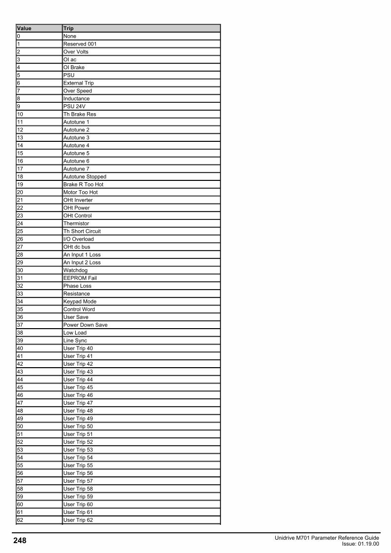
Value Trip0 None1 Reserved 0012 Over Volts3 OI ac4 OI Brake5 PSU6 External Trip7 Over Speed8 Inductance9 PSU 24V10 Th Brake Res11 Autotune 112 Autotune 213 Autotune 314 Autotune 415 Autotune 516 Autotune 617 Autotune 718 Autotune Stopped19 Brake R Too Hot20 Motor Too Hot21 OHt Inverter22 OHt Power23 OHt Control24 Thermistor25 Th Short Circuit26 I/O Overload27 OHt dc bus28 An Input 1 Loss29 An Input 2 Loss30 Watchdog31 EEPROM Fail32 Phase Loss33 Resistance34 Keypad Mode35 Control Word36 User Save37 Power Down Save38 Low Load39 Line Sync40 User Trip 4041 User Trip 4142 User Trip 4243 User Trip 4344 User Trip 4445 User Trip 4546 User Trip 4647 User Trip 4748 User Trip 4849 User Trip 4950 User Trip 5051 User Trip 5152 User Trip 5253 User Trip 5354 User Trip 5455 User Trip 5556 User Trip 5657 User Trip 5758 User Trip 5859 User Trip 5960 User Trip 6061 User Trip 6162 User Trip 62
248 Unidrive M701 Parameter Reference GuideIssue: 01.19.00
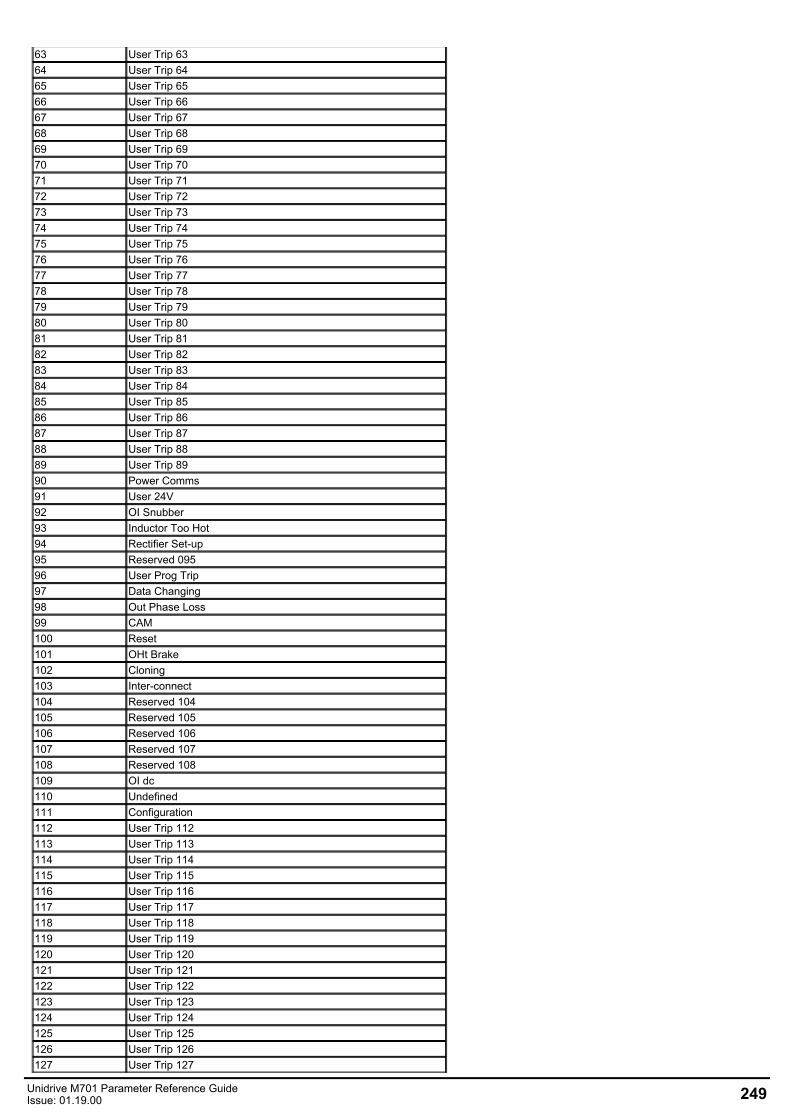
63 User Trip 6364 User Trip 6465 User Trip 6566 User Trip 6667 User Trip 6768 User Trip 6869 User Trip 6970 User Trip 7071 User Trip 7172 User Trip 7273 User Trip 7374 User Trip 7475 User Trip 7576 User Trip 7677 User Trip 7778 User Trip 7879 User Trip 7980 User Trip 8081 User Trip 8182 User Trip 8283 User Trip 8384 User Trip 8485 User Trip 8586 User Trip 8687 User Trip 8788 User Trip 8889 User Trip 8990 Power Comms91 User 24V92 OI Snubber93 Inductor Too Hot94 Rectifier Set-up95 Reserved 09596 User Prog Trip97 Data Changing98 Out Phase Loss99 CAM100 Reset101 OHt Brake102 Cloning103 Inter-connect104 Reserved 104105 Reserved 105106 Reserved 106107 Reserved 107108 Reserved 108109 OI dc110 Undefined111 Configuration112 User Trip 112113 User Trip 113114 User Trip 114115 User Trip 115116 User Trip 116117 User Trip 117118 User Trip 118119 User Trip 119120 User Trip 120121 User Trip 121122 User Trip 122123 User Trip 123124 User Trip 124125 User Trip 125126 User Trip 126127 User Trip 127
Unidrive M701 Parameter Reference GuideIssue: 01.19.00 249
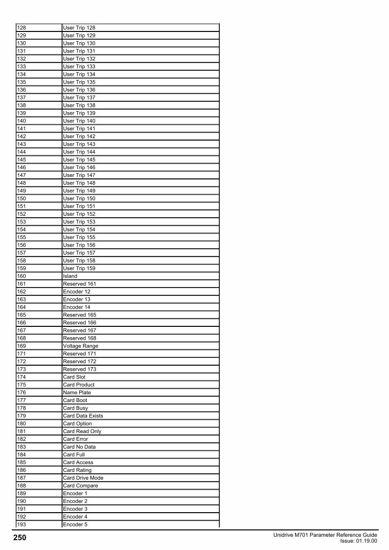
128 User Trip 128129 User Trip 129130 User Trip 130131 User Trip 131132 User Trip 132133 User Trip 133134 User Trip 134135 User Trip 135136 User Trip 136137 User Trip 137138 User Trip 138139 User Trip 139140 User Trip 140141 User Trip 141142 User Trip 142143 User Trip 143144 User Trip 144145 User Trip 145146 User Trip 146147 User Trip 147148 User Trip 148149 User Trip 149150 User Trip 150151 User Trip 151152 User Trip 152153 User Trip 153154 User Trip 154155 User Trip 155156 User Trip 156157 User Trip 157158 User Trip 158159 User Trip 159160 Island161 Reserved 161162 Encoder 12163 Encoder 13164 Encoder 14165 Reserved 165166 Reserved 166167 Reserved 167168 Reserved 168169 Voltage Range171 Reserved 171172 Reserved 172173 Reserved 173174 Card Slot175 Card Product176 Name Plate177 Card Boot178 Card Busy179 Card Data Exists180 Card Option181 Card Read Only182 Card Error183 Card No Data184 Card Full185 Card Access186 Card Rating187 Card Drive Mode188 Card Compare189 Encoder 1190 Encoder 2191 Encoder 3192 Encoder 4193 Encoder 5
250 Unidrive M701 Parameter Reference GuideIssue: 01.19.00
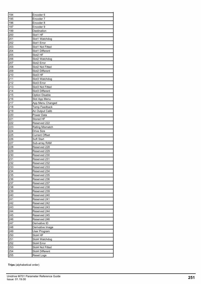
194 Encoder 6195 Encoder 7196 Encoder 8197 Encoder 9199 Destination200 Slot1 HF201 Slot1 Watchdog202 Slot1 Error203 Slot1 Not Fitted204 Slot1 Different205 Slot2 HF206 Slot2 Watchdog207 Slot2 Error208 Slot2 Not Fitted209 Slot2 Different210 Slot3 HF211 Slot3 Watchdog212 Slot3 Error213 Slot3 Not Fitted214 Slot3 Different215 Option Disable216 Slot App Menu217 App Menu Changed218 Temp Feedback219 An Output Calib220 Power Data221 Stored HF222 Reserved 222223 Rating Mismatch224 Drive Size225 Current Offset226 Soft Start227 Sub-array RAM228 Reserved 228229 Reserved 229230 Reserved 230231 Reserved 231232 Reserved 232233 Reserved 233234 Reserved 234235 Reserved 235236 Reserved 236237 Reserved 237238 Reserved 238239 Reserved 239240 Reserved 240241 Reserved 241242 Reserved 242243 Reserved 243244 Reserved 244245 Reserved 245246 Reserved 246247 Derivative ID248 Derivative Image249 User Program250 Slot4 HF251 Slot4 Watchdog252 Slot4 Error253 Slot4 Not Fitted254 Slot4 Different255 Reset Logs
Trips (alphabetical order)
Unidrive M701 Parameter Reference GuideIssue: 01.19.00 251
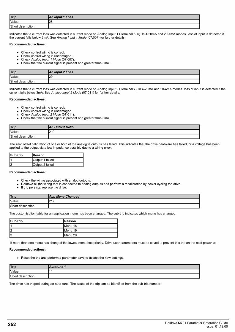
Trip An Input 1 LossValue 28Short description
Indicates that a current loss was detected in current mode on Analog Input 1 (Terminal 5, 6). In 4-20mA and 20-4mA modes. loss of input is detected ifthe current falls below 3mA. See Analog Input 1 Mode (07.007) for further details.
Recommended actions:
Check control wiring is correct.Check control wiring is undamaged.Check Analog Input 1 Mode (07.007).Check that the current signal is present and greater than 3mA.
Trip An Input 2 LossValue 29Short description
Indicates that a current loss was detected in current mode on Analog Input 2 (Terminal 7). In 4-20mA and 20-4mA modes. loss of input is detected if thecurrent falls below 3mA. See Analog Input 2 Mode (07.011) for further details.
Recommended actions:
Check control wiring is correct.Check control wiring is undamaged.Check Analog Input 2 Mode (07.011).Check that the current signal is present and greater than 3mA.
Trip An Output CalibValue 219Short description
The zero offset calibration of one or both of the analogue outputs has failed. This indicates that the drive hardware has failed, or a voltage has beenapplied to the output via a low impedance possibly due to a wiring error.
Sub-trip Reason1 Output 1 failed2 Output 2 failed
Recommended actions:
Check the wiring associated with analog outputs.Remove all the wiring that is connected to analog outputs and perform a recalibration by power cycling the drive.If trip persists, replace the drive.
Trip App Menu ChangedValue 217Short description
The customisation table for an application menu has been changed. The sub-trip indicates which menu has changed:
Sub-trip Reason1 Menu 182 Menu 193 Menu 20
If more than one menu has changed the lowest menu has priority. Drive user parameters must be saved to prevent this trip on the next power-up.
Recommended actions:
Reset the trip and perform a parameter save to accept the new settings.
Trip Autotune 1Value 11Short description
The drive has tripped during an auto-tune. The cause of the trip can be identified from the sub-trip number.
252 Unidrive M701 Parameter Reference GuideIssue: 01.19.00
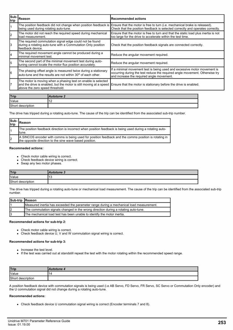
Sub-trip Reason Recommended actions
1 The position feedback did not change when position feedback isbeing used during rotating auto-tune.
Ensure that the motor is free to turn (i.e. mechanical brake is released).Check that the position feedback is selected correctly and operates correctly.
2 The motor did not reach the required speed during mechanicalload measurement.
Ensure that the motor is free to turn and that the static load plus inertia is nottoo large for the drive to accelerate within the test time.
3The required commutation signal edge could not be foundduring a rotating auto-tune with a Commutation Only positionfeedback device.
Check that the position feedback signals are connected correctly.
4 The required movement angle cannot be produced during aminimal movement test. Reduce the angular movement required.
5 The second part of the minimal movement test during auto-tuning cannot locate the motor flux position accurately. Reduce the angular movement required.
6 The phasing offset angle is measured twice during a stationaryauto-tune and the results are not within 30o of each other.
If a minimal movement test is being used and excessive motor movement isoccurring during the test reduce the required angle movement. Otherwise tryand increase the required angle movement.
7The motor is moving when a phasing test on enable is selectedand the drive is enabled, but the motor is still moving at a speedabove the zero speed threshold.
Ensure that the motor is stationary before the drive is enabled.
Trip Autotune 2Value 12Short description
The drive has tripped during a rotating auto-tune. The cause of the trip can be identified from the associated sub-trip number.
Sub-trip Reason
1 The position feedback direction is incorrect when position feedback is being used during a rotating auto-tune.
2 A SINCOS encoder with comms is being used for position feedback and the comms position is rotating inthe opposite direction to the sine wave based position.
Recommeded actions:
Check motor cable wiring is correct.Check feedback device wiring is correct.Swap any two motor phases.
Trip Autotune 3Value 13Short description
The drive has tripped during a rotating auto-tune or mechanical load measurement. The cause of the trip can be identified from the associated sub-tripnumber.
Sub-trip Reason1 Measured inertia has exceeded the parameter range during a mechanical load measurement.2 The commutation signals changed in the wrong direction during a rotating auto-tune.3 The mechanical load test has been unable to identify the motor inertia.
Recommended actions for sub-trip 2:
Check motor cable wiring is correct.Check feedback device U, V and W commutation signal wiring is correct.
Recommended actions for sub-trip 3:
Increase the test level.If the test was carried out at standstill repeat the test with the motor rotating within the recommended speed range.
Trip Autotune 4Value 14Short description
A position feedback device with commutation signals is being used (i.e AB Servo, FD Servo, FR Servo, SC Servo or Commutation Only encoder) andthe U commutation signal did not change during a rotating auto-tune.
Recommended actions:
Check feedback device U commutation signal wiring is correct (Encoder terminals 7 and 8).
Unidrive M701 Parameter Reference GuideIssue: 01.19.00 253
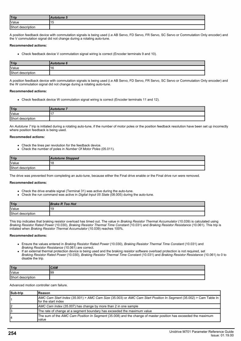
Trip Autotune 5Value 15Short description
A position feedback device with commutation signals is being used (i.e AB Servo, FD Servo, FR Servo, SC Servo or Commutation Only encoder) andthe V commutation signal did not change during a rotating auto-tune.
Recommended actions:
Check feedback device V commutation signal wiring is correct (Encoder terminals 9 and 10).
Trip Autotune 6Value 16Short description
A position feedback device with commutation signals is being used (i.e AB Servo, FD Servo, FR Servo, SC Servo or Commutation Only encoder) andthe W commutation signal did not change during a rotating auto-tune.
Recommended actions:
Check feedback device W commutation signal wiring is correct (Encoder terminals 11 and 12).
Trip Autotune 7Value 17Short description
An Autotune 7 trip is initiated during a rotating auto-tune, if the number of motor poles or the position feedback resolution have been set up incorrectlywhere position feedback is being used.
Recommeded actions:
Check the lines per revolution for the feedback device.Check the number of poles in Number Of Motor Poles (05.011).
Trip Autotune StoppedValue 18Short description
The drive was prevented from completing an auto-tune, because either the Final drive enable or the Final drive run were removed.
Recommended actions:
Check the drive enable signal (Terminal 31) was active during the auto-tune.Check the run command was active in Digital Input 05 State (08.005) during the auto-tune.
Trip Brake R Too HotValue 19Short description
This trip indicates that braking resistor overload has timed out. The value in Braking Resistor Thermal Accumulator (10.039) is calculated usingBraking Resistor Rated Power (10.030), Braking Resistor Thermal Time Constant (10.031) and Braking Resistor Resistance (10.061). This trip isinitiated when Braking Resistor Thermal Accumulator (10.039) reaches 100%.
Recommended actions:
Ensure the values entered in Braking Resistor Rated Power (10.030), Braking Resistor Thermal Time Constant (10.031) andBraking Resistor Resistance (10.061) are correct.If an external thermal protection device is being used and the braking resistor software overload protection is not required, setBraking Resistor Rated Power (10.030), Braking Resistor Thermal Time Constant (10.031) and Braking Resistor Resistance (10.061) to 0 todisable the trip.
Trip CAMValue 99Short description
Advanced motion controller cam failure.
Sub-trip Reason
1 AMC Cam Start Index (35.001) > AMC Cam Size (35.003) or AMC Cam Start Position In Segment (35.002) > Cam Table Infor the start index
2 AMC Cam Index (35.007) has change by more than 2 in one sample3 The rate of change at a segment boundary has exceeded the maximum value
4 The sum of the AMC Cam Position In Segment (35.008) and the change of master position has exceeded the maximumvalue
254 Unidrive M701 Parameter Reference GuideIssue: 01.19.00
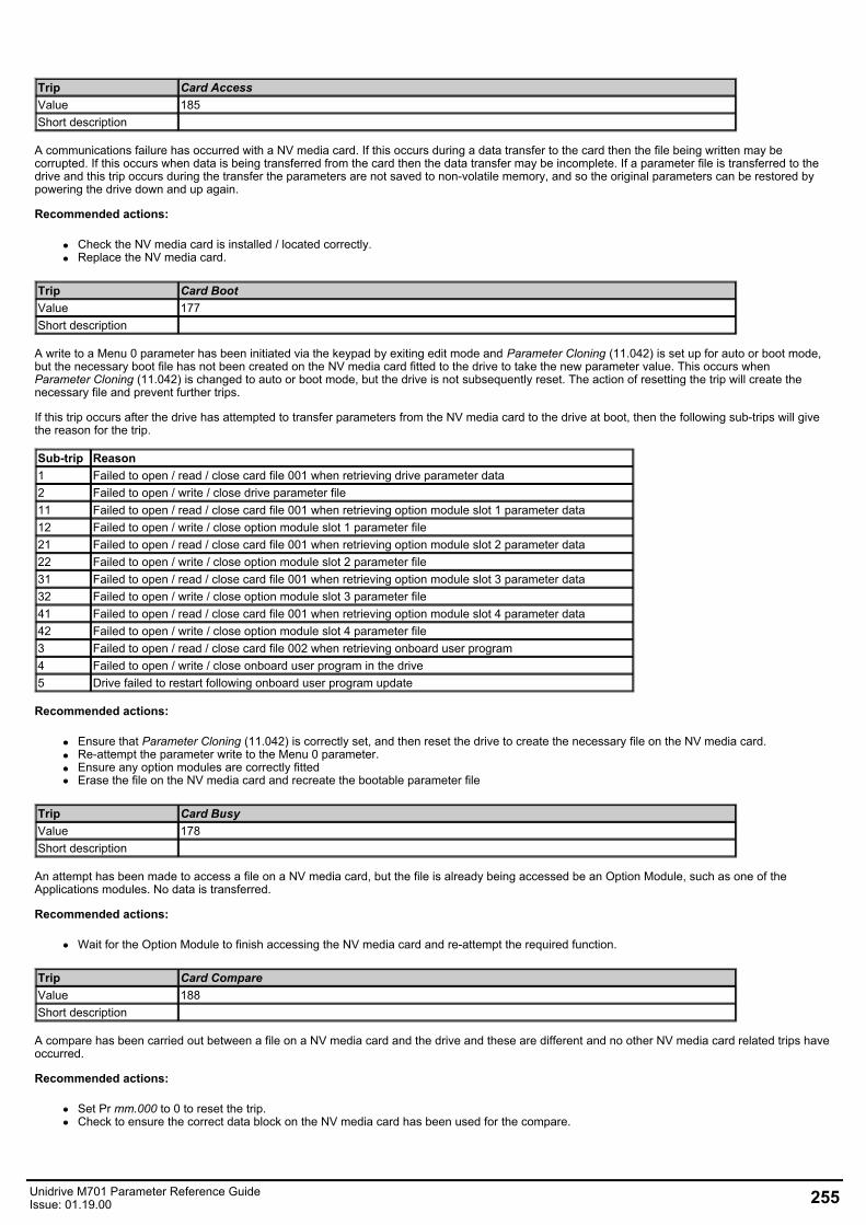
Trip Card AccessValue 185Short description
A communications failure has occurred with a NV media card. If this occurs during a data transfer to the card then the file being written may becorrupted. If this occurs when data is being transferred from the card then the data transfer may be incomplete. If a parameter file is transferred to thedrive and this trip occurs during the transfer the parameters are not saved to non-volatile memory, and so the original parameters can be restored bypowering the drive down and up again.
Recommended actions:
Check the NV media card is installed / located correctly.Replace the NV media card.
Trip Card BootValue 177Short description
A write to a Menu 0 parameter has been initiated via the keypad by exiting edit mode and Parameter Cloning (11.042) is set up for auto or boot mode,but the necessary boot file has not been created on the NV media card fitted to the drive to take the new parameter value. This occurs whenParameter Cloning (11.042) is changed to auto or boot mode, but the drive is not subsequently reset. The action of resetting the trip will create thenecessary file and prevent further trips.
If this trip occurs after the drive has attempted to transfer parameters from the NV media card to the drive at boot, then the following sub-trips will givethe reason for the trip.
Sub-trip Reason1 Failed to open / read / close card file 001 when retrieving drive parameter data2 Failed to open / write / close drive parameter file11 Failed to open / read / close card file 001 when retrieving option module slot 1 parameter data12 Failed to open / write / close option module slot 1 parameter file21 Failed to open / read / close card file 001 when retrieving option module slot 2 parameter data22 Failed to open / write / close option module slot 2 parameter file31 Failed to open / read / close card file 001 when retrieving option module slot 3 parameter data32 Failed to open / write / close option module slot 3 parameter file41 Failed to open / read / close card file 001 when retrieving option module slot 4 parameter data42 Failed to open / write / close option module slot 4 parameter file3 Failed to open / read / close card file 002 when retrieving onboard user program4 Failed to open / write / close onboard user program in the drive5 Drive failed to restart following onboard user program update
Recommended actions:
Ensure that Parameter Cloning (11.042) is correctly set, and then reset the drive to create the necessary file on the NV media card.Re-attempt the parameter write to the Menu 0 parameter.Ensure any option modules are correctly fittedErase the file on the NV media card and recreate the bootable parameter file
Trip Card BusyValue 178Short description
An attempt has been made to access a file on a NV media card, but the file is already being accessed be an Option Module, such as one of theApplications modules. No data is transferred.
Recommended actions:
Wait for the Option Module to finish accessing the NV media card and re-attempt the required function.
Trip Card CompareValue 188Short description
A compare has been carried out between a file on a NV media card and the drive and these are different and no other NV media card related trips haveoccurred.
Recommended actions:
Set Pr mm.000 to 0 to reset the trip.Check to ensure the correct data block on the NV media card has been used for the compare.
Unidrive M701 Parameter Reference GuideIssue: 01.19.00 255
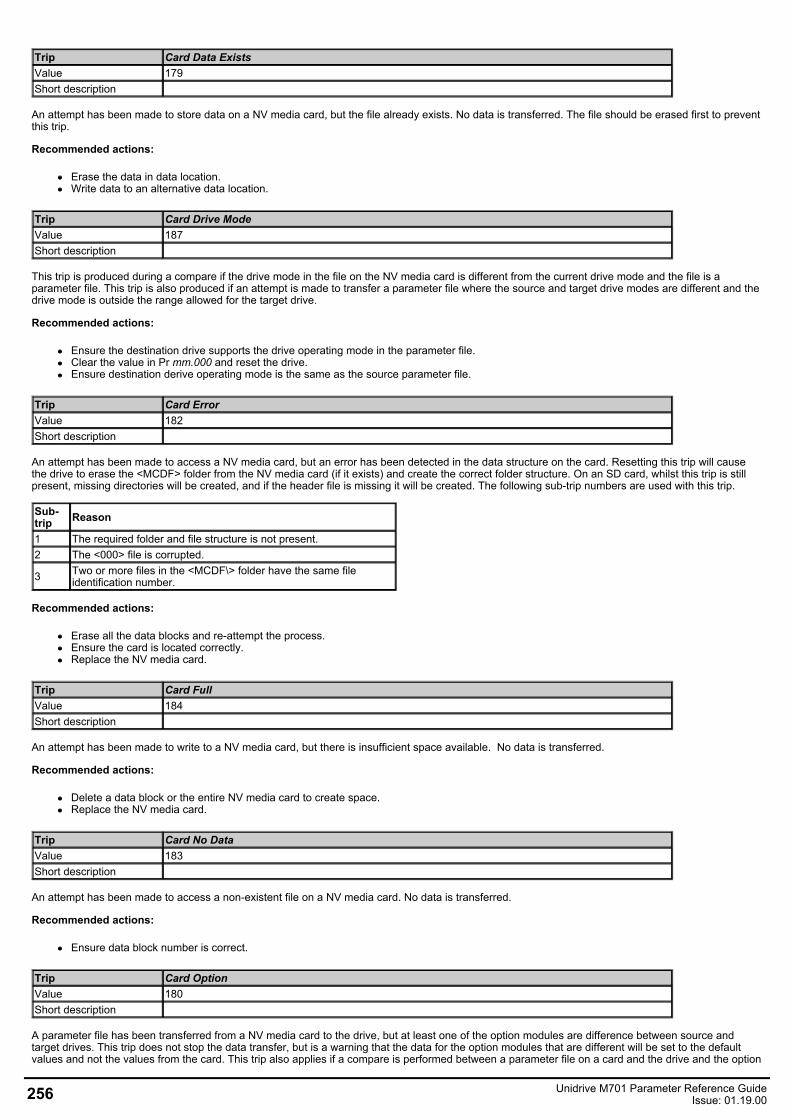
Trip Card Data ExistsValue 179Short description
An attempt has been made to store data on a NV media card, but the file already exists. No data is transferred. The file should be erased first to preventthis trip.
Recommended actions:
Erase the data in data location.Write data to an alternative data location.
Trip Card Drive ModeValue 187Short description
This trip is produced during a compare if the drive mode in the file on the NV media card is different from the current drive mode and the file is aparameter file. This trip is also produced if an attempt is made to transfer a parameter file where the source and target drive modes are different and thedrive mode is outside the range allowed for the target drive.
Recommended actions:
Ensure the destination drive supports the drive operating mode in the parameter file.Clear the value in Pr mm.000 and reset the drive.Ensure destination derive operating mode is the same as the source parameter file.
Trip Card ErrorValue 182Short description
An attempt has been made to access a NV media card, but an error has been detected in the data structure on the card. Resetting this trip will causethe drive to erase the <MCDF> folder from the NV media card (if it exists) and create the correct folder structure. On an SD card, whilst this trip is stillpresent, missing directories will be created, and if the header file is missing it will be created. The following sub-trip numbers are used with this trip.
Sub-trip Reason
1 The required folder and file structure is not present.2 The <000> file is corrupted.
3 Two or more files in the <MCDF\> folder have the same fileidentification number.
Recommended actions:
Erase all the data blocks and re-attempt the process.Ensure the card is located correctly.Replace the NV media card.
Trip Card FullValue 184Short description
An attempt has been made to write to a NV media card, but there is insufficient space available. No data is transferred.
Recommended actions:
Delete a data block or the entire NV media card to create space.Replace the NV media card.
Trip Card No DataValue 183Short description
An attempt has been made to access a non-existent file on a NV media card. No data is transferred.
Recommended actions:
Ensure data block number is correct.
Trip Card OptionValue 180Short description
A parameter file has been transferred from a NV media card to the drive, but at least one of the option modules are difference between source andtarget drives. This trip does not stop the data transfer, but is a warning that the data for the option modules that are different will be set to the defaultvalues and not the values from the card. This trip also applies if a compare is performed between a parameter file on a card and the drive and the option
256 Unidrive M701 Parameter Reference GuideIssue: 01.19.00
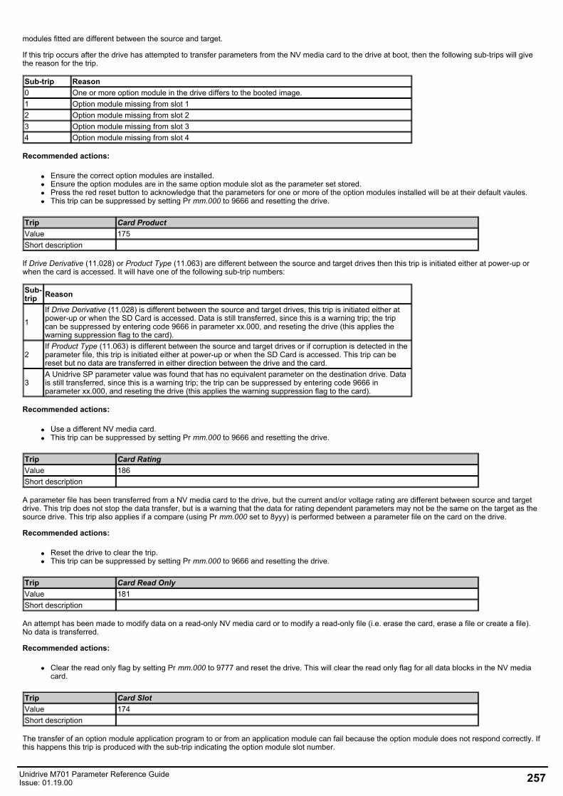
modules fitted are different between the source and target.
If this trip occurs after the drive has attempted to transfer parameters from the NV media card to the drive at boot, then the following sub-trips will givethe reason for the trip.
Sub-trip Reason0 One or more option module in the drive differs to the booted image.1 Option module missing from slot 12 Option module missing from slot 23 Option module missing from slot 34 Option module missing from slot 4
Recommended actions:
Ensure the correct option modules are installed.Ensure the option modules are in the same option module slot as the parameter set stored.Press the red reset button to acknowledge that the parameters for one or more of the option modules installed will be at their default vaules.This trip can be suppressed by setting Pr mm.000 to 9666 and resetting the drive.
Trip Card ProductValue 175Short description
If Drive Derivative (11.028) or Product Type (11.063) are different between the source and target drives then this trip is initiated either at power-up orwhen the card is accessed. It will have one of the following sub-trip numbers:
Sub-trip Reason
1If Drive Derivative (11.028) is different between the source and target drives, this trip is initiated either atpower-up or when the SD Card is accessed. Data is still transferred, since this is a warning trip; the tripcan be suppressed by entering code 9666 in parameter xx.000, and reseting the drive (this applies thewarning suppression flag to the card).
2If Product Type (11.063) is different between the source and target drives or if corruption is detected in theparameter file, this trip is initiated either at power-up or when the SD Card is accessed. This trip can bereset but no data are transferred in either direction between the drive and the card.
3A Unidrive SP parameter value was found that has no equivalent parameter on the destination drive. Datais still transferred, since this is a warning trip; the trip can be suppressed by entering code 9666 inparameter xx.000, and reseting the drive (this applies the warning suppression flag to the card).
Recommended actions:
Use a different NV media card.This trip can be suppressed by setting Pr mm.000 to 9666 and resetting the drive.
Trip Card RatingValue 186Short description
A parameter file has been transferred from a NV media card to the drive, but the current and/or voltage rating are different between source and targetdrive. This trip does not stop the data transfer, but is a warning that the data for rating dependent parameters may not be the same on the target as thesource drive. This trip also applies if a compare (using Pr mm.000 set to 8yyy) is performed between a parameter file on the card on the drive.
Recommended actions:
Reset the drive to clear the trip.This trip can be suppressed by setting Pr mm.000 to 9666 and resetting the drive.
Trip Card Read OnlyValue 181Short description
An attempt has been made to modify data on a read-only NV media card or to modify a read-only file (i.e. erase the card, erase a file or create a file).No data is transferred.
Recommended actions:
Clear the read only flag by setting Pr mm.000 to 9777 and reset the drive. This will clear the read only flag for all data blocks in the NV mediacard.
Trip Card SlotValue 174Short description
The transfer of an option module application program to or from an application module can fail because the option module does not respond correctly. Ifthis happens this trip is produced with the sub-trip indicating the option module slot number.
Unidrive M701 Parameter Reference GuideIssue: 01.19.00 257
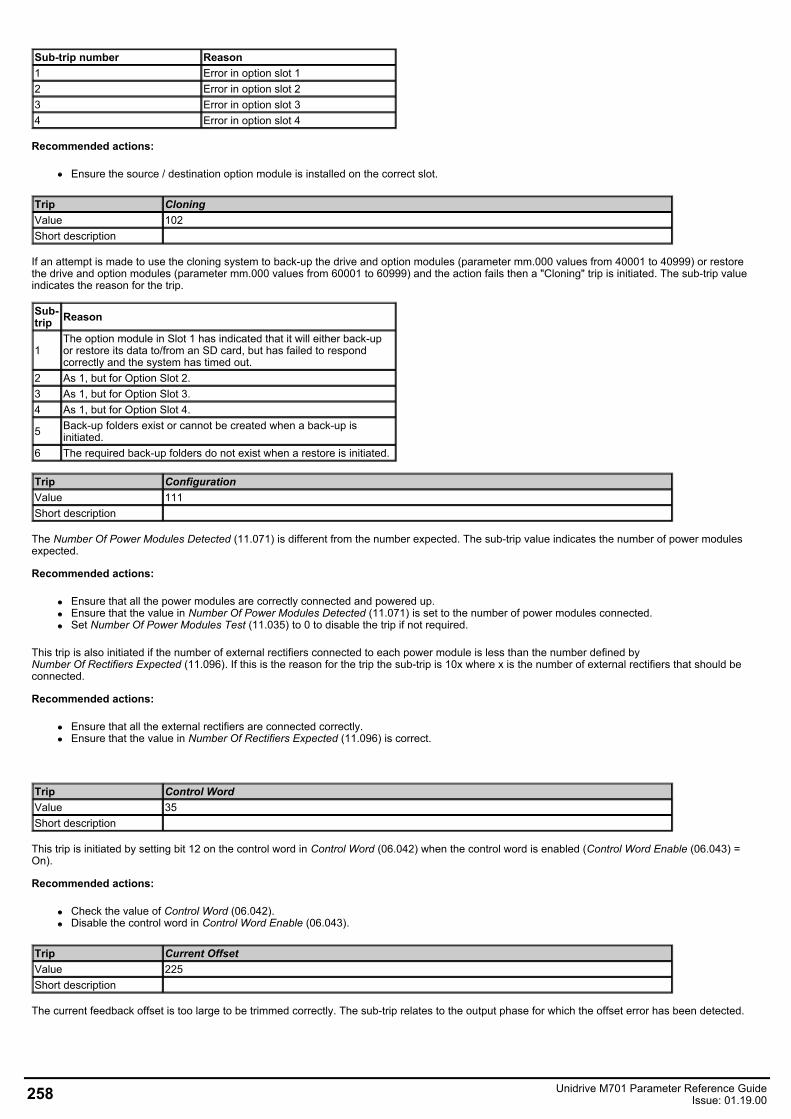
Sub-trip number Reason1 Error in option slot 12 Error in option slot 23 Error in option slot 34 Error in option slot 4
Recommended actions:
Ensure the source / destination option module is installed on the correct slot.
Trip CloningValue 102Short description
If an attempt is made to use the cloning system to back-up the drive and option modules (parameter mm.000 values from 40001 to 40999) or restorethe drive and option modules (parameter mm.000 values from 60001 to 60999) and the action fails then a "Cloning" trip is initiated. The sub-trip valueindicates the reason for the trip.
Sub-trip Reason
1The option module in Slot 1 has indicated that it will either back-upor restore its data to/from an SD card, but has failed to respondcorrectly and the system has timed out.
2 As 1, but for Option Slot 2.3 As 1, but for Option Slot 3.4 As 1, but for Option Slot 4.
5 Back-up folders exist or cannot be created when a back-up isinitiated.
6 The required back-up folders do not exist when a restore is initiated.
Trip ConfigurationValue 111Short description
The Number Of Power Modules Detected (11.071) is different from the number expected. The sub-trip value indicates the number of power modulesexpected.
Recommended actions:
Ensure that all the power modules are correctly connected and powered up.Ensure that the value in Number Of Power Modules Detected (11.071) is set to the number of power modules connected.Set Number Of Power Modules Test (11.035) to 0 to disable the trip if not required.
This trip is also initiated if the number of external rectifiers connected to each power module is less than the number defined byNumber Of Rectifiers Expected (11.096). If this is the reason for the trip the sub-trip is 10x where x is the number of external rectifiers that should beconnected.
Recommended actions:
Ensure that all the external rectifiers are connected correctly.Ensure that the value in Number Of Rectifiers Expected (11.096) is correct.
Trip Control WordValue 35Short description
This trip is initiated by setting bit 12 on the control word in Control Word (06.042) when the control word is enabled (Control Word Enable (06.043) =On).
Recommended actions:
Check the value of Control Word (06.042).Disable the control word in Control Word Enable (06.043).
Trip Current OffsetValue 225Short description
The current feedback offset is too large to be trimmed correctly. The sub-trip relates to the output phase for which the offset error has been detected.
258 Unidrive M701 Parameter Reference GuideIssue: 01.19.00
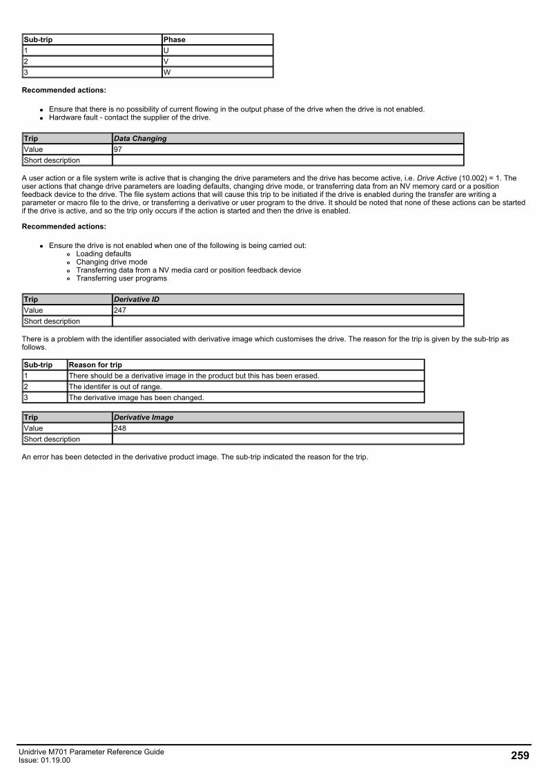
Sub-trip Phase1 U2 V3 W
Recommended actions:
Ensure that there is no possibility of current flowing in the output phase of the drive when the drive is not enabled.Hardware fault - contact the supplier of the drive.
Trip Data ChangingValue 97Short description
A user action or a file system write is active that is changing the drive parameters and the drive has become active, i.e. Drive Active (10.002) = 1. Theuser actions that change drive parameters are loading defaults, changing drive mode, or transferring data from an NV memory card or a positionfeedback device to the drive. The file system actions that will cause this trip to be initiated if the drive is enabled during the transfer are writing aparameter or macro file to the drive, or transferring a derivative or user program to the drive. It should be noted that none of these actions can be startedif the drive is active, and so the trip only occurs if the action is started and then the drive is enabled.
Recommended actions:
Ensure the drive is not enabled when one of the following is being carried out:Loading defaultsChanging drive modeTransferring data from a NV media card or position feedback deviceTransferring user programs
Trip Derivative IDValue 247Short description
There is a problem with the identifier associated with derivative image which customises the drive. The reason for the trip is given by the sub-trip asfollows.
Sub-trip Reason for trip1 There should be a derivative image in the product but this has been erased.2 The identifer is out of range.3 The derivative image has been changed.
Trip Derivative ImageValue 248Short description
An error has been detected in the derivative product image. The sub-trip indicated the reason for the trip.
Unidrive M701 Parameter Reference GuideIssue: 01.19.00 259
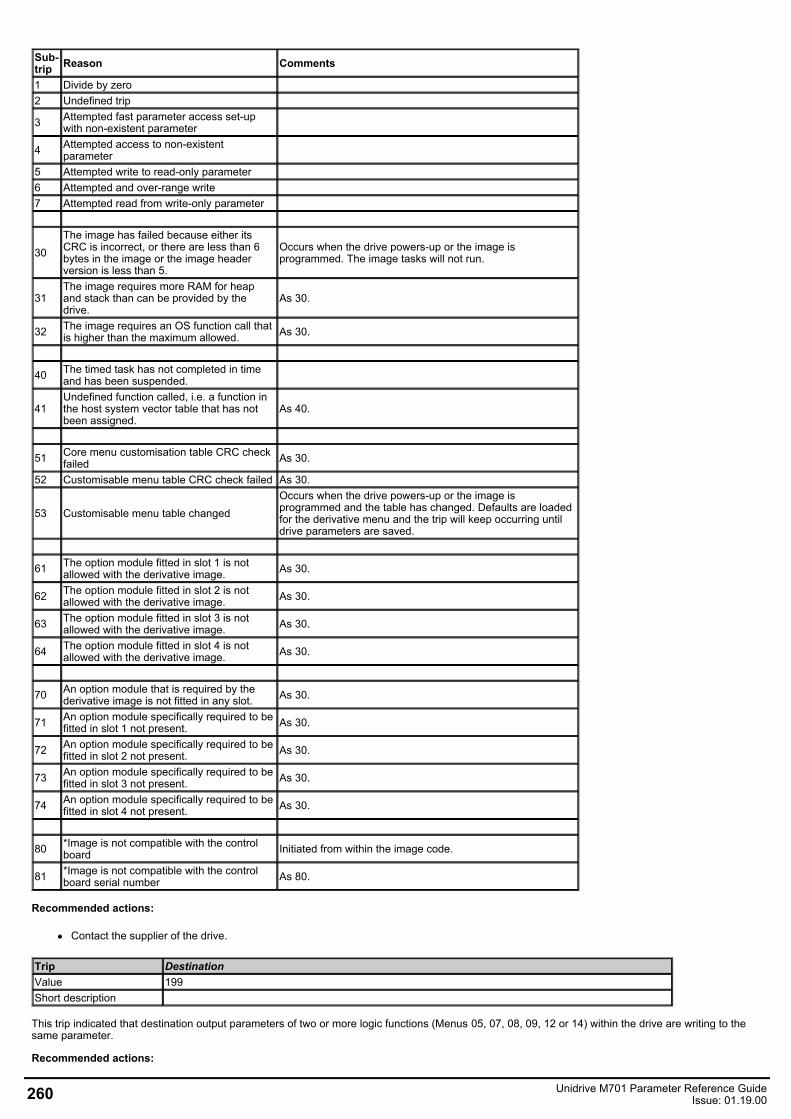
Sub-trip Reason Comments
1 Divide by zero 2 Undefined trip
3 Attempted fast parameter access set-upwith non-existent parameter
4 Attempted access to non-existentparameter
5 Attempted write to read-only parameter 6 Attempted and over-range write 7 Attempted read from write-only parameter
30The image has failed because either itsCRC is incorrect, or there are less than 6bytes in the image or the image headerversion is less than 5.
Occurs when the drive powers-up or the image isprogrammed. The image tasks will not run.
31The image requires more RAM for heapand stack than can be provided by thedrive.
As 30.
32 The image requires an OS function call thatis higher than the maximum allowed. As 30.
40 The timed task has not completed in timeand has been suspended.
41Undefined function called, i.e. a function inthe host system vector table that has notbeen assigned.
As 40.
51 Core menu customisation table CRC checkfailed As 30.
52 Customisable menu table CRC check failed As 30.
53 Customisable menu table changedOccurs when the drive powers-up or the image isprogrammed and the table has changed. Defaults are loadedfor the derivative menu and the trip will keep occurring untildrive parameters are saved.
61 The option module fitted in slot 1 is notallowed with the derivative image. As 30.
62 The option module fitted in slot 2 is notallowed with the derivative image. As 30.
63 The option module fitted in slot 3 is notallowed with the derivative image. As 30.
64 The option module fitted in slot 4 is notallowed with the derivative image. As 30.
70 An option module that is required by thederivative image is not fitted in any slot. As 30.
71 An option module specifically required to befitted in slot 1 not present. As 30.
72 An option module specifically required to befitted in slot 2 not present. As 30.
73 An option module specifically required to befitted in slot 3 not present. As 30.
74 An option module specifically required to befitted in slot 4 not present. As 30.
80 *Image is not compatible with the controlboard Initiated from within the image code.
81 *Image is not compatible with the controlboard serial number As 80.
Recommended actions:
Contact the supplier of the drive.
Trip DestinationValue 199Short description
This trip indicated that destination output parameters of two or more logic functions (Menus 05, 07, 08, 09, 12 or 14) within the drive are writing to thesame parameter.
Recommended actions:
260 Unidrive M701 Parameter Reference GuideIssue: 01.19.00
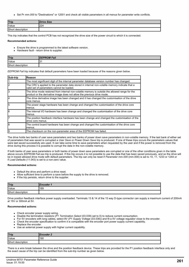
Set Pr mm.000 to "Destinations" or 12001 and check all visible parameters in all menus for parameter write conflicts.
Trip Drive SizeValue 224Short description
This trip indicates that the control PCB has not recognized the drive size of the power circuit to which it is connected.
Recommended actions:
Ensure the drive is programmed to the latest software version.Hardware fault - return drive to supplier.
Trip EEPROM FailValue 31Short description
EEPROM Fail trip indicates that default parameters have been loaded because of the reasons given below.
Sub-trip Reason1 The most significant digit of the internal parameter database version number has changed.2 The CRC’s applied to the parameter data stored in internal non-volatile memory indicate that a
valid set of parameters cannot be loaded.3 The drive mode restored from internal non-volatile memory is outside the allowed range for the
product or the derivative image does not allow the previous drive mode.4 The drive derivative image has been changed and it has changed the customisation of the drive
core menus.5 The power stage hardware has been change and changed the customisation of the drive core
menus.6 The internal I/O hardware has been change and changed the customisation of the drive core
menus.7 The position feedback interface hardware has been change and changed the customisation of the
drive core menus.8 The control board hardware has been change and changed the customisation of the drive core
menus.9 The checksum on the non-parameter area of the EEPROM has failed.
The drive holds two banks of user save parameters and two banks of power down save parameters in non-volatile memory. If the last bank of either setof parameters that was saved is corrupted a User Save or Power Down Save trip is produced. If one of these trips occurs the parameters values thatwere last saved successfully are used. It can take some time to save parameters when requested by the user and if the power is removed from thedrive during this process it is possible to corrupt the data in the non-volatile memory.
If both banks of user save parameters or both banks of power down save parameters are corrupted or one of the other conditions given in the tableabove occurs EEPROM Fail.xxx trip is produced. If this trip occurs it is not possible to use the data that has been saved previously, and so the drive willbe in lowest allowed drive mode with default parameters. The trip can only be reset if Parameter mm.000 (mm.000) is set to 10, 11, 1233 or 1244 orif Load Defaults (11.043) is set to a non-zero value.
Recommended actions:
Default the drive and perform a drive reset.Allow sufficient time to perform a save before the supply to the drive is removed.If the trip persists, return drive to the supplier.
Trip Encoder 1Value 189Short description
Drive position feedback interface power supply overloaded. Terminals 13 & 14 of the 15 way D-type connector can supply a maximum current of 200mAat 15V or 300mA at 5V.
Recommended actions:
Check encoder power supply wiring.Disable the termination resistors (P1 Termination Select (03.039) set to 0) to reduce current consumption.For 5V encoders with long cables, select 8V (P1 Supply Voltage (03.036)) and fit a 5V voltage regulator close to the encoder.Check the encoder specification to confirm it is compatible with the encoder port power supply current capability.Replace the encoder.Use an external power supply with higher current capability.
Trip Encoder 2Value 190Short description
There is a wire break between the drive and the position feedback device. These trips are provided for the P1 position feedback interface only andthe exact cause of the trip can be identified from the sub-trip number as given below.
Unidrive M701 Parameter Reference GuideIssue: 01.19.00 261
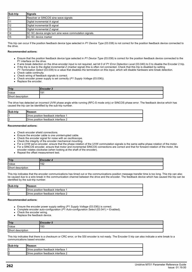
Sub-trip Signals1 Resolver or SINCOS sine wave signals11 Digital incremental A signal12 Digital incremental B signal13 Digital incremental Z signal14 SC SC device single turn sine wave commutation signals.15 SC SC device marker
This trip can occur if the position feedback device type selected in P1 Device Type (03.038) is not correct for the position feedback device connected tothe drive.
Recommended actions:
Ensure that the position feedback device type selected in P1 Device Type (03.038) is correct for the position feedback device connected to theP1 interface on the drive.If wire break detection on the drive encoder input is not required, set bit 0 of P1 Error Detection Level (03.040) to 0 to disable the Encoder 2 trip.If the trip is due to the digital incremental Z (marker signal) this is often not connected. Check that this trip is disabled by settingP1 Termination Select (03.039) to a value that disables the termination on this input, which will disable hardware wire break detection.Check cable continuity.Check wiring of feedback signals is correct.Check encoder power supply is set correctly (P1 Supply Voltage (03.036)).Replace the encoder.
Trip Encoder 3Value 191Short description
The drive has detected an incorrect UVW phase angle while running (RFC-S mode only) or SINCOS phase error. The feedback device which hascaused the trip can be identified by the sub-trip number.
Sub-trip Reason1 Drive position feedback interface 12 Drive position feedback interface 2
Recommended actions:
Check encoder shield connections.Ensure the encoder cable is one uninterrupted cable.Check the encoder signal for noise with an oscilloscope.Check the integrity of the encoder mechanical mounting.For a UVW servo encoder, ensure that the phase rotation of the UVW commutation signals is the same asthe phase rotation of the motor.For a SINCOS encoder, ensure that motor and incremental SINCOS connections are correct and that for forward rotation of the motor, theencoder rotates clockwise (when looking at the shaft of the encoder).Repeat the offset measurement test.
Trip Encoder 4Value 192Short description
This trip indicates that the encoder communications has timed out or the communications position message transfer time is too long. This trip can alsobe caused due to a wire break in the communication channel between the drive and the encoder. The feedback device which has caused the trip can beidentified by the sub-trip number.
Sub-trip Reason1 Drive position feedback interface 12 Drive position feedback interface 2
Recommended actions:
Ensure the encoder power supply setting (P1 Supply Voltage (03.036)) is correct.Complete encoder auto-configuration (P1 Auto-configuration Select (03.041) = Enabled).Check the encoder wiring.Replace the feedback device.
Trip Encoder 5Value 193Short description
This trip indicates that there is a checksum or CRC error, or the SSI encoder is not ready. The Encoder 5 trip can also indicate a wire break to acommunications based encoder.
Sub-trip Reason1 Drive position feedback interface 12 Drive position feedback interface 2
262 Unidrive M701 Parameter Reference GuideIssue: 01.19.00
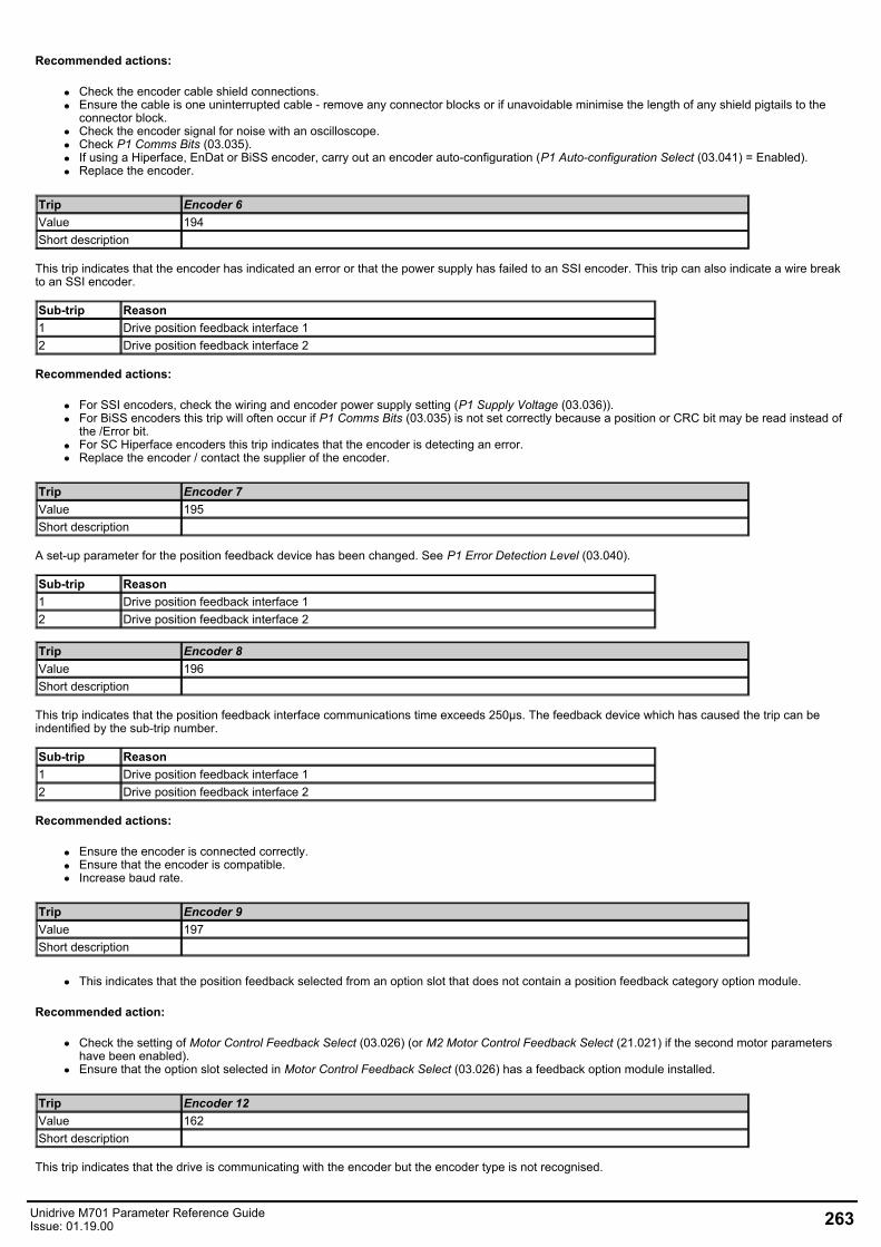
Recommended actions:
Check the encoder cable shield connections.Ensure the cable is one uninterrupted cable - remove any connector blocks or if unavoidable minimise the length of any shield pigtails to theconnector block.Check the encoder signal for noise with an oscilloscope.Check P1 Comms Bits (03.035).If using a Hiperface, EnDat or BiSS encoder, carry out an encoder auto-configuration (P1 Auto-configuration Select (03.041) = Enabled).Replace the encoder.
Trip Encoder 6Value 194Short description
This trip indicates that the encoder has indicated an error or that the power supply has failed to an SSI encoder. This trip can also indicate a wire breakto an SSI encoder.
Sub-trip Reason1 Drive position feedback interface 12 Drive position feedback interface 2
Recommended actions:
For SSI encoders, check the wiring and encoder power supply setting (P1 Supply Voltage (03.036)).For BiSS encoders this trip will often occur if P1 Comms Bits (03.035) is not set correctly because a position or CRC bit may be read instead ofthe /Error bit.For SC Hiperface encoders this trip indicates that the encoder is detecting an error.Replace the encoder / contact the supplier of the encoder.
Trip Encoder 7Value 195Short description
A set-up parameter for the position feedback device has been changed. See P1 Error Detection Level (03.040).
Sub-trip Reason1 Drive position feedback interface 12 Drive position feedback interface 2
Trip Encoder 8Value 196Short description
This trip indicates that the position feedback interface communications time exceeds 250µs. The feedback device which has caused the trip can beindentified by the sub-trip number.
Sub-trip Reason1 Drive position feedback interface 12 Drive position feedback interface 2
Recommended actions:
Ensure the encoder is connected correctly.Ensure that the encoder is compatible.Increase baud rate.
Trip Encoder 9Value 197Short description
This indicates that the position feedback selected from an option slot that does not contain a position feedback category option module.
Recommended action:
Check the setting of Motor Control Feedback Select (03.026) (or M2 Motor Control Feedback Select (21.021) if the second motor parametershave been enabled).Ensure that the option slot selected in Motor Control Feedback Select (03.026) has a feedback option module installed.
Trip Encoder 12Value 162Short description
This trip indicates that the drive is communicating with the encoder but the encoder type is not recognised.
Unidrive M701 Parameter Reference GuideIssue: 01.19.00 263
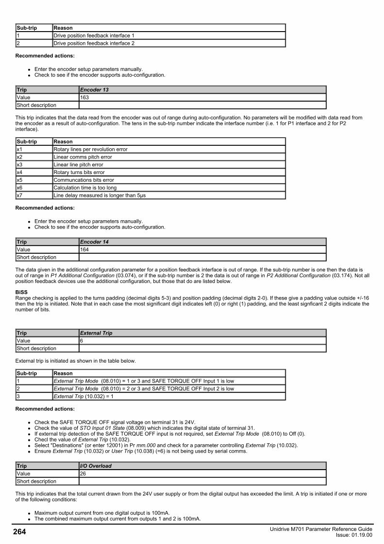
Sub-trip Reason1 Drive position feedback interface 12 Drive position feedback interface 2
Recommended actions:
Enter the encoder setup parameters manually.Check to see if the encoder supports auto-configuration.
Trip Encoder 13Value 163Short description
This trip indicates that the data read from the encoder was out of range during auto-configuration. No parameters will be modified with data read fromthe encoder as a result of auto-configuration. The tens in the sub-trip number indicate the interface number (i.e. 1 for P1 interface and 2 for P2interface).
Sub-trip Reasonx1 Rotary lines per revolution errorx2 Linear comms pitch errorx3 Linear line pitch errorx4 Rotary turns bits errorx5 Communcations bits errorx6 Calculation time is too longx7 Line delay measured is longer than 5µs
Recommended actions:
Enter the encoder setup parameters manually.Check to see if the encoder supports auto-configuration.
Trip Encoder 14Value 164Short description
The data given in the additional configuration parameter for a position feedback interface is out of range. If the sub-trip number is one then the data isout of range in P1 Additional Configuration (03.074), or if the sub-trip number is 2 the data is out of range in P2 Additional Configuration (03.174). Not allposition feedback devices use the additional configuration, but those that do are listed below.
BiSSRange checking is applied to the turns padding (decimal digits 5-3) and position padding (decimal digits 2-0). If these give a padding value outside +/-16then the trip is initiated. Note that in each case the most significant digit indicates left (0) or right (1) padding, and the least signficant 2 digits indicate thenumber of bits.
Trip External TripValue 6Short description
External trip is initiated as shown in the table below.
Sub-trip Reason1 External Trip Mode (08.010) = 1 or 3 and SAFE TORQUE OFF Input 1 is low2 External Trip Mode (08.010) = 2 or 3 and SAFE TORQUE OFF Input 2 is low3 External Trip (10.032) = 1
Recommended actions:
Check the SAFE TORQUE OFF signal voltage on terminal 31 is 24V.Check the value of STO Input 01 State (08.009) which indicates the digital state of terminal 31.If external trip detection of the SAFE TORQUE OFF input is not required, set External Trip Mode (08.010) to Off (0).Checl the value of External Trip (10.032).Select "Destinations" (or enter 12001) in Pr mm.000 and check for a parameter controlling External Trip (10.032).Ensure External Trip (10.032) or User Trip (10.038) (=6) is not being used by serial comms.
Trip I/O OverloadValue 26Short description
This trip indicates that the total current drawn from the 24V user supply or from the digital output has exceeded the limit. A trip is initiated if one or moreof the following conditions:
Maximum output current from one digital output is 100mA.The combined maximum output current from outputs 1 and 2 is 100mA.
264 Unidrive M701 Parameter Reference GuideIssue: 01.19.00
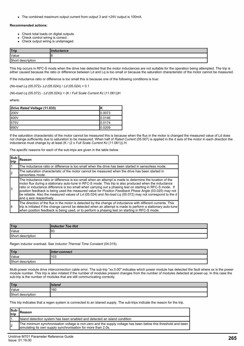
The combined maximum output current from output 3 and +24V output is 100mA.
Recommended actions:
Check total loads on digital outputs.Check control wiring is correct.Check output wiring is undamaged.
Trip InductanceValue 8Short description
This trip occurs in RFC-S mode when the drive has detected that the motor inductances are not suitable for the operation being attempted. The trip iseither caused because the ratio or difference between Ld and Lq is too small or because the saturation characteristic of the motor cannot be measured.
If the inductance ratio or difference is too small this is because one of the following conditions is true:
(No-load Lq (05.072)- Ld (05.024)) / Ld (05.024) < 0.1
(No-load Lq (05.072) - Ld (05.024)) < (K / Full Scale Current Kc (11.061))H
where:
Drive Rated Voltage (11.033) K200V 0.0073400V 0.0146575V 0.0174690V 0.0209
If the saturation characteristic of the motor cannot be measured this is because when the flux in the motor is changed the measured value of Ld doesnot change sufficiently due to saturation to be measured. When half of Rated Current (05.007) is applied in the d axis of the motor in each direction theinductance must change by at least (K / (2 x Full Scale Current Kc (11.061))) H.
The specific reasons for each of the sub-trips are given in the table below.
Sub-trip Reason
1 The inductance ratio or difference is too small when the drive has been started in sensorless mode.
2 The saturation characteristic of the motor cannot be measured when the drive has been started insensorless mode.
3
The inductance ratio or difference is too small when an attempt is made to determine the location of themotor flux during a stationary auto-tune in RFC-S mode. This trip is also produced when the inductanceratio or inductance difference is too small when carrying out a phasing test on starting in RFC-S mode. Ifposition feedback is being used the measured value for Position Feedback Phase Angle (03.025) may notbe reliable. Also the measured values of Ld (05.024) and No-load Lq (05.072) may not correspond to the dand q axis respectively.
4The direction of the flux in the motor is detected by the change of inductance with different currents. Thistrip is initiated if the change cannot be detected when an attempt is made to perform a stationary auto-tunewhen position feedback is being used, or to perform a phasing test on starting in RFC-S mode.
Trip Inductor Too HotValue 93Short description
Regen inductor overload. See Inductor Thermal Time Constant (04.015).
Trip Inter-connectValue 103Short description
Multi-power module drive interconnection cable error. The sub-trip "xx.0.00" indicates which power module has detected the fault where xx is the powermodule number. This trip is also initated if the number of modules present changes from the number of modules detected at power-up. In this case thesub-trip is the number of modules that are still communicating correctly.
Trip IslandValue 160Short description
This trip indicates that a regen system is connected to an islaned supply. The sub-trips indicate the reason for the trip.
Sub-trip Reason
1 Island detection system has been enabled and detected an island condition
2 The minimum synchronisation voltage is non-zero and the supply voltage has been below this threshold and beensimulating its own supply synchronisation for more than 2.0s.
Unidrive M701 Parameter Reference GuideIssue: 01.19.00 265
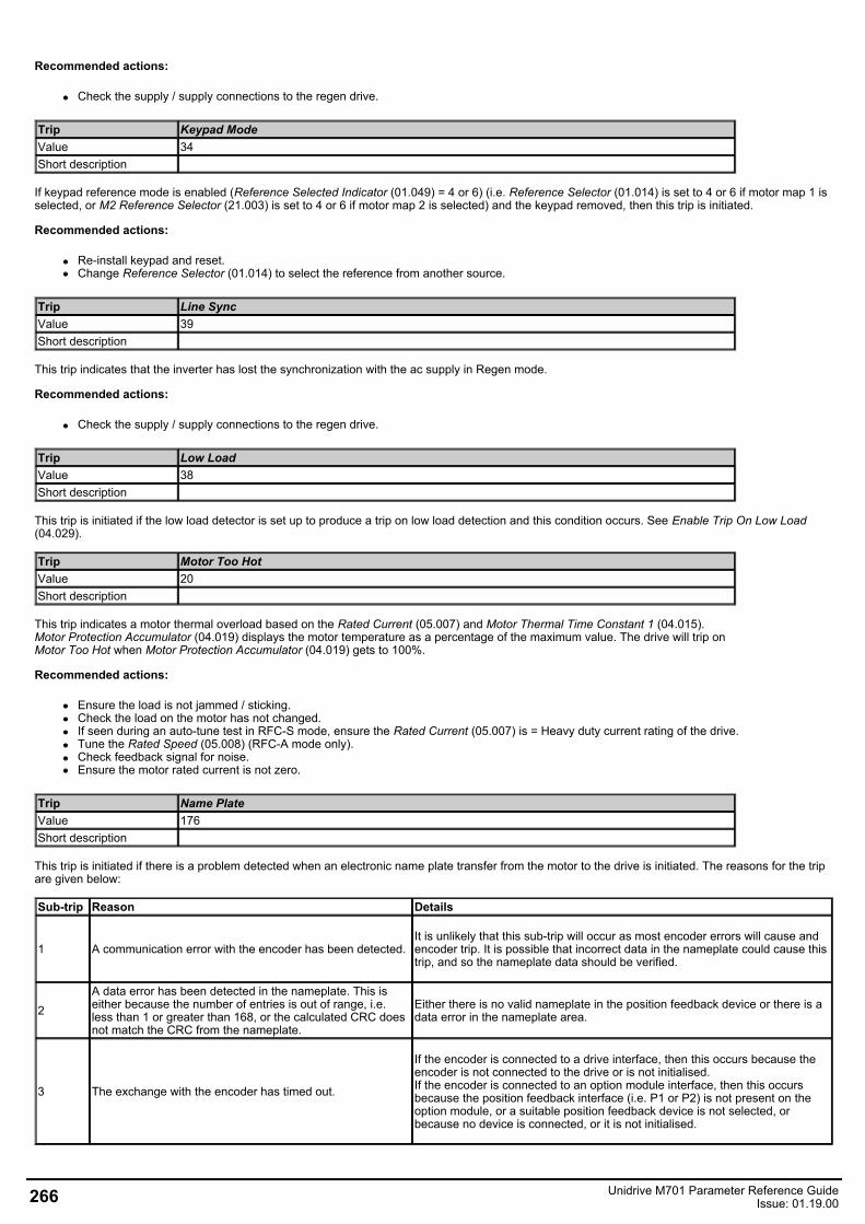
Recommended actions:
Check the supply / supply connections to the regen drive.
Trip Keypad ModeValue 34Short description
If keypad reference mode is enabled (Reference Selected Indicator (01.049) = 4 or 6) (i.e. Reference Selector (01.014) is set to 4 or 6 if motor map 1 isselected, or M2 Reference Selector (21.003) is set to 4 or 6 if motor map 2 is selected) and the keypad removed, then this trip is initiated.
Recommended actions:
Re-install keypad and reset.Change Reference Selector (01.014) to select the reference from another source.
Trip Line SyncValue 39Short description
This trip indicates that the inverter has lost the synchronization with the ac supply in Regen mode.
Recommended actions:
Check the supply / supply connections to the regen drive.
Trip Low LoadValue 38Short description
This trip is initiated if the low load detector is set up to produce a trip on low load detection and this condition occurs. See Enable Trip On Low Load(04.029).
Trip Motor Too HotValue 20Short description
This trip indicates a motor thermal overload based on the Rated Current (05.007) and Motor Thermal Time Constant 1 (04.015).Motor Protection Accumulator (04.019) displays the motor temperature as a percentage of the maximum value. The drive will trip onMotor Too Hot when Motor Protection Accumulator (04.019) gets to 100%.
Recommended actions:
Ensure the load is not jammed / sticking.Check the load on the motor has not changed.If seen during an auto-tune test in RFC-S mode, ensure the Rated Current (05.007) is = Heavy duty current rating of the drive.Tune the Rated Speed (05.008) (RFC-A mode only).Check feedback signal for noise.Ensure the motor rated current is not zero.
Trip Name PlateValue 176Short description
This trip is initiated if there is a problem detected when an electronic name plate transfer from the motor to the drive is initiated. The reasons for the tripare given below:
Sub-trip Reason Details
1 A communication error with the encoder has been detected.It is unlikely that this sub-trip will occur as most encoder errors will cause andencoder trip. It is possible that incorrect data in the nameplate could cause thistrip, and so the nameplate data should be verified.
2A data error has been detected in the nameplate. This iseither because the number of entries is out of range, i.e.less than 1 or greater than 168, or the calculated CRC doesnot match the CRC from the nameplate.
Either there is no valid nameplate in the position feedback device or there is adata error in the nameplate area.
3 The exchange with the encoder has timed out.
If the encoder is connected to a drive interface, then this occurs because theencoder is not connected to the drive or is not initialised.If the encoder is connected to an option module interface, then this occursbecause the position feedback interface (i.e. P1 or P2) is not present on theoption module, or a suitable position feedback device is not selected, orbecause no device is connected, or it is not initialised.
266 Unidrive M701 Parameter Reference GuideIssue: 01.19.00
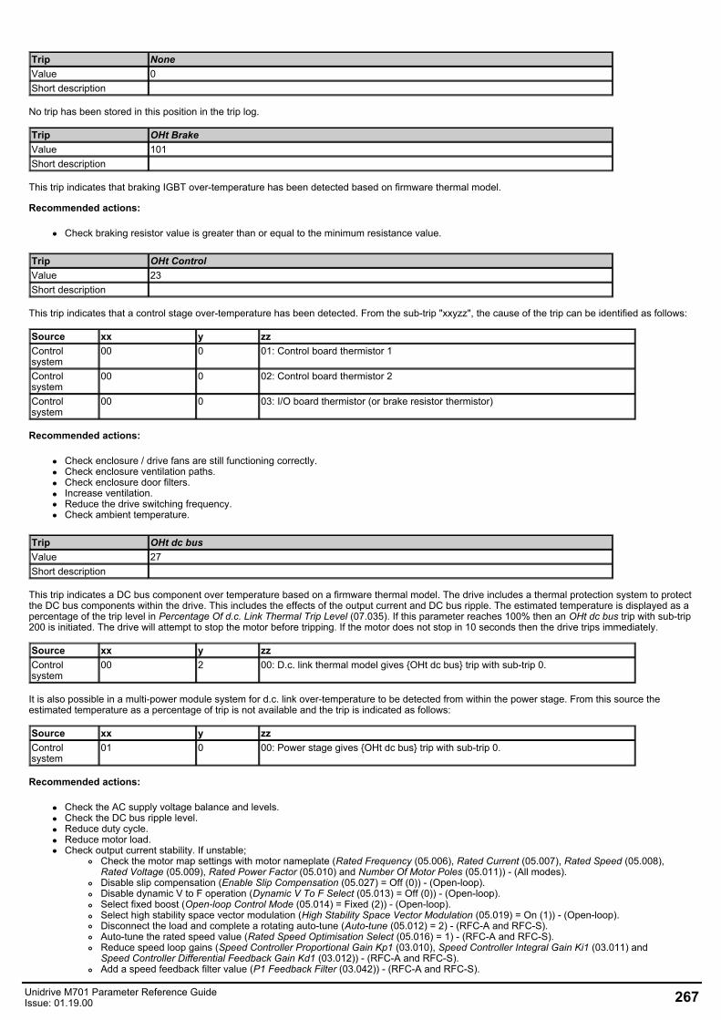
Trip NoneValue 0Short description
No trip has been stored in this position in the trip log.
Trip OHt BrakeValue 101Short description
This trip indicates that braking IGBT over-temperature has been detected based on firmware thermal model.
Recommended actions:
Check braking resistor value is greater than or equal to the minimum resistance value.
Trip OHt ControlValue 23Short description
This trip indicates that a control stage over-temperature has been detected. From the sub-trip "xxyzz", the cause of the trip can be identified as follows:
Source xx y zzControlsystem
00 0 01: Control board thermistor 1
Controlsystem
00 0 02: Control board thermistor 2
Controlsystem
00 0 03: I/O board thermistor (or brake resistor thermistor)
Recommended actions:
Check enclosure / drive fans are still functioning correctly.Check enclosure ventilation paths.Check enclosure door filters.Increase ventilation.Reduce the drive switching frequency.Check ambient temperature.
Trip OHt dc busValue 27Short description
This trip indicates a DC bus component over temperature based on a firmware thermal model. The drive includes a thermal protection system to protectthe DC bus components within the drive. This includes the effects of the output current and DC bus ripple. The estimated temperature is displayed as apercentage of the trip level in Percentage Of d.c. Link Thermal Trip Level (07.035). If this parameter reaches 100% then an OHt dc bus trip with sub-trip200 is initiated. The drive will attempt to stop the motor before tripping. If the motor does not stop in 10 seconds then the drive trips immediately.
Source xx y zzControlsystem
00 2 00: D.c. link thermal model gives OHt dc bus trip with sub-trip 0.
It is also possible in a multi-power module system for d.c. link over-temperature to be detected from within the power stage. From this source theestimated temperature as a percentage of trip is not available and the trip is indicated as follows:
Source xx y zzControlsystem
01 0 00: Power stage gives OHt dc bus trip with sub-trip 0.
Recommended actions:
Check the AC supply voltage balance and levels.Check the DC bus ripple level.Reduce duty cycle.Reduce motor load.Check output current stability. If unstable;
Check the motor map settings with motor nameplate (Rated Frequency (05.006), Rated Current (05.007), Rated Speed (05.008),Rated Voltage (05.009), Rated Power Factor (05.010) and Number Of Motor Poles (05.011)) - (All modes).Disable slip compensation (Enable Slip Compensation (05.027) = Off (0)) - (Open-loop).Disable dynamic V to F operation (Dynamic V To F Select (05.013) = Off (0)) - (Open-loop).Select fixed boost (Open-loop Control Mode (05.014) = Fixed (2)) - (Open-loop).Select high stability space vector modulation (High Stability Space Vector Modulation (05.019) = On (1)) - (Open-loop).Disconnect the load and complete a rotating auto-tune (Auto-tune (05.012) = 2) - (RFC-A and RFC-S).Auto-tune the rated speed value (Rated Speed Optimisation Select (05.016) = 1) - (RFC-A and RFC-S).Reduce speed loop gains (Speed Controller Proportional Gain Kp1 (03.010), Speed Controller Integral Gain Ki1 (03.011) andSpeed Controller Differential Feedback Gain Kd1 (03.012)) - (RFC-A and RFC-S).Add a speed feedback filter value (P1 Feedback Filter (03.042)) - (RFC-A and RFC-S).
Unidrive M701 Parameter Reference GuideIssue: 01.19.00 267
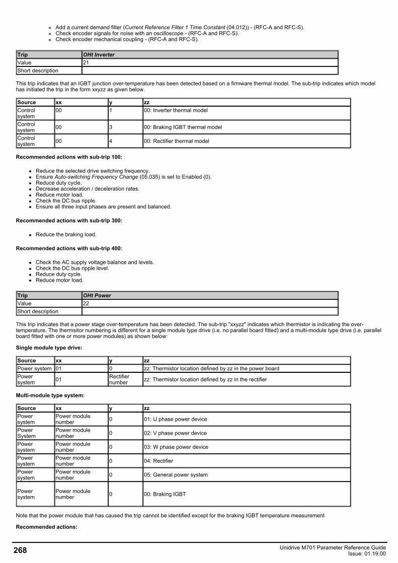
Add a current demand filter (Current Reference Filter 1 Time Constant (04.012)) - (RFC-A and RFC-S).Check encoder signals for noise with an oscilloscope - (RFC-A and RFC-S).Check encoder mechanical coupling - (RFC-A and RFC-S).
Trip OHt InverterValue 21Short description
This trip indicates that an IGBT junction over-temperature has been detected based on a firmware thermal model. The sub-trip indicates which modelhas initiated the trip in the form xxyzz as given below.
Source xx y zzControlsystem
00 1 00: Inverter thermal model
Controlsystem 00 3 00: Braking IGBT thermal model
Controlsystem 00 4 00: Rectifier thermal model
Recommended actions with sub-trip 100:
Reduce the selected drive switching frequency.Ensure Auto-switching Frequency Change (05.035) is set to Enabled (0).Reduce duty cycle.Decrease acceleration / deceleration rates.Reduce motor load.Check the DC bus ripple.Ensure all three input phases are present and balanced.
Recommended actions with sub-trip 300:
Reduce the braking load.
Recommended actions with sub-trip 400:
Check the AC supply voltage balance and levels.Check the DC bus ripple level.Reduce duty cycle.Reduce motor load.
Trip OHt PowerValue 22Short description
This trip indicates that a power stage over-temperature has been detected. The sub-trip "xxyzz" indicates which thermistor is indicating the over-temperature. The thermsitor numbering is different for a single module type drive (i.e. no parallel board fitted) and a multi-module type drive (i.e. parallelboard fitted with one or more power modules) as shown below:
Single module type drive:
Source xx y zzPower system 01 0 zz: Thermistor location defined by zz in the power boardPowersystem 01 Rectifier
number zz: Thermistor location defined by zz in the rectifier
Multi-module type system:
Source xx y zzPowersystem
Power modulenumber 0 01: U phase power device
PowerSystem
Power modulenumber 0 02: V phase power device
Power system
Power modulenumber 0 03: W phase power device
Power system
Power modulenumber 0 04: Rectifier
Power system
Power modulenumber 0 05: General power system
Powersystem
Power modulenumber 0 00: Braking IGBT
Note that the power module that has caused the trip cannot be identified except for the braking IGBT temperature measurement
Recommended actions:
268 Unidrive M701 Parameter Reference GuideIssue: 01.19.00
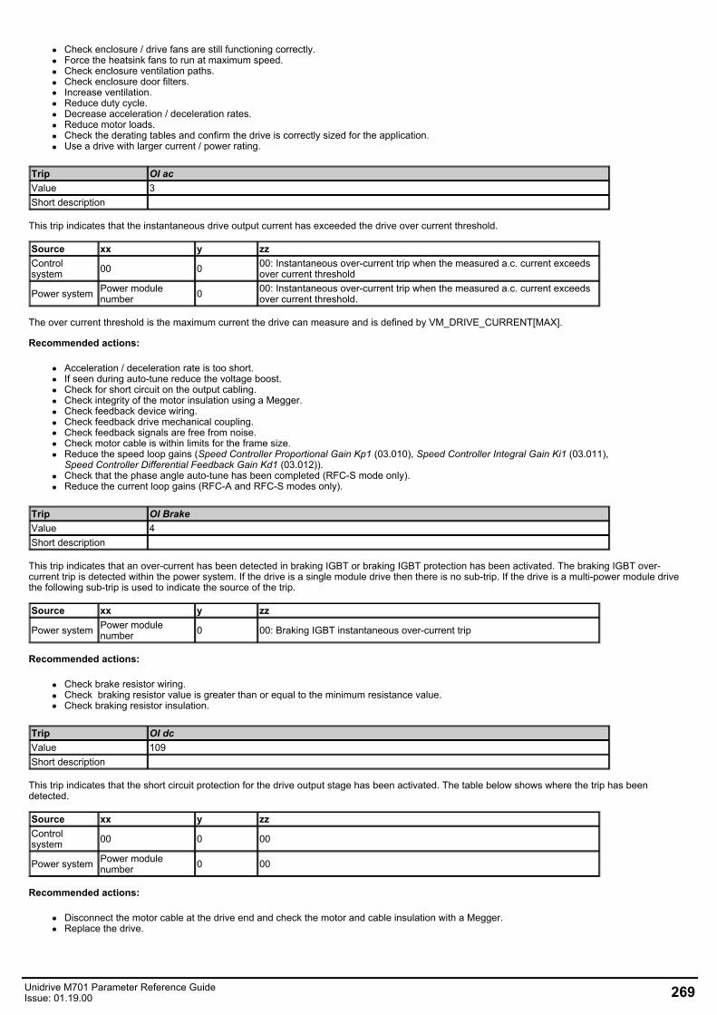
Check enclosure / drive fans are still functioning correctly.Force the heatsink fans to run at maximum speed.Check enclosure ventilation paths.Check enclosure door filters.Increase ventilation.Reduce duty cycle.Decrease acceleration / deceleration rates.Reduce motor loads.Check the derating tables and confirm the drive is correctly sized for the application.Use a drive with larger current / power rating.
Trip OI acValue 3Short description
This trip indicates that the instantaneous drive output current has exceeded the drive over current threshold.
Source xx y zzControlsystem 00 0 00: Instantaneous over-current trip when the measured a.c. current exceeds
over current threshold
Power system Power modulenumber 0 00: Instantaneous over-current trip when the measured a.c. current exceeds
over current threshold.
The over current threshold is the maximum current the drive can measure and is defined by VM_DRIVE_CURRENT[MAX].
Recommended actions:
Acceleration / deceleration rate is too short.If seen during auto-tune reduce the voltage boost.Check for short circuit on the output cabling.Check integrity of the motor insulation using a Megger.Check feedback device wiring.Check feedback drive mechanical coupling.Check feedback signals are free from noise.Check motor cable is within limits for the frame size.Reduce the speed loop gains (Speed Controller Proportional Gain Kp1 (03.010), Speed Controller Integral Gain Ki1 (03.011),Speed Controller Differential Feedback Gain Kd1 (03.012)).Check that the phase angle auto-tune has been completed (RFC-S mode only).Reduce the current loop gains (RFC-A and RFC-S modes only).
Trip OI BrakeValue 4Short description
This trip indicates that an over-current has been detected in braking IGBT or braking IGBT protection has been activated. The braking IGBT over-current trip is detected within the power system. If the drive is a single module drive then there is no sub-trip. If the drive is a multi-power module drivethe following sub-trip is used to indicate the source of the trip.
Source xx y zz
Power system Power modulenumber 0 00: Braking IGBT instantaneous over-current trip
Recommended actions:
Check brake resistor wiring.Check braking resistor value is greater than or equal to the minimum resistance value.Check braking resistor insulation.
Trip OI dcValue 109Short description
This trip indicates that the short circuit protection for the drive output stage has been activated. The table below shows where the trip has beendetected.
Source xx y zzControlsystem 00 0 00
Power system Power modulenumber 0 00
Recommended actions:
Disconnect the motor cable at the drive end and check the motor and cable insulation with a Megger.Replace the drive.
Unidrive M701 Parameter Reference GuideIssue: 01.19.00 269
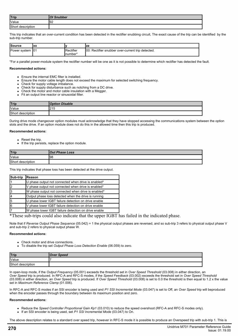
Trip OI SnubberValue 92Short description
This trip indicates that an over-current condition has been detected in the rectifier snubbing circuit, The exact cause of the trip can be identified by thesub-trip number.
Source xx y zzPower system 01 Rectifier
number*00: Rectifier snubber over-current trip detected.
*For a parallel power-module system the rectifier number will be one as it is not possible to determine which rectifier has detected the fault.
Recommended actions:
Ensure the internal EMC filter is installed.Ensure the motor cable length does not exceed the maximum for selected switching frequency.Check for supply voltage imbalance.Check for supply disturbance such as notching from a DC drive.Check the motor and motor cable insulation with a Megger.Fit an output line reactor or sinusoidal filter.
Trip Option DisableValue 215Short description
During drive mode changeover option modules must acknowledge that they have stopped accessing the communications system between the optionslots and the drive. If an option module does not do this in the allowed time then this trip is produced.
Recommended actions:
Reset the trip.If the trip persists, replace the option module.
Trip Out Phase LossValue 98Short description
This trip indicates that phase loss has been detected at the drive output.
Sub-trip Reason1 U phase output not connected when drive is enabled*2 V phase output not connected when drive is enabled*3 W phase output not connected when drive is enabled*4 Output phase loss detected when the drive is running5 U phase lower IGBT failure detection on drive enable6 V phase lower IGBT failure detection on drive enable7 W phase lower IGBT failure detection on drive enable
*These sub-trips could also indicate that the upper IGBT has failed in the indicated phase.Note that if Reverse Output Phase Sequence (05.042) = 1 the physical output phases are reversed, and so sub-trip 3 refers to physical output phase Vand sub-trip 2 refers to physical output phase W.
Recommended actions:
Check motor and drive connections.To disable the trip set Output Phase Loss Detection Enable (06.059) to zero.
Trip Over SpeedValue 7Short description
In open-loop mode, if the Output Frequency (05.001) exceeds the threshold set in Over Speed Threshold (03.008) in either direction, anOver Speed trip is produced. In RFC-A and RFC-S modes, if the Speed Feedback (03.002) exceeds the threshold set in Over Speed Threshold(03.008) in either direction, an Over Speed trip is produced. If Over Speed Threshold (03.008) is set to 0.0 the threshold is then equal to 1.2 x the valueset in Maximum Reference Clamp (01.006).
In RFC-A and RFC-S modes if an SSI encoder is being used and P1 SSI Incremental Mode (03.047) is set to Off, an Over Speed trip will beproducedwhen the encoder passes through the boundary between its maximum position and zero.
Recommended actions:
Reduce the Speed Controller Proportional Gain Kp1 (03.010) to reduce the speed overshoot (RFC-A and RFC-S modes only).If an SSI encoder is being used, set P1 SSI Incremental Mode (03.047) to On.
The above description relates to a standard over speed trip, however in RFC-S mode it is possible to produce an Overspeed trip with sub-trip 1. This is
270 Unidrive M701 Parameter Reference GuideIssue: 01.19.00
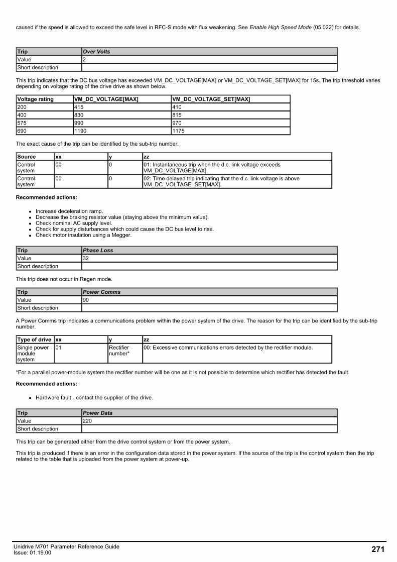
caused if the speed is allowed to exceed the safe level in RFC-S mode with flux weakening. See Enable High Speed Mode (05.022) for details.
Trip Over VoltsValue 2Short description
This trip indicates that the DC bus voltage has exceeded VM_DC_VOLTAGE[MAX] or VM_DC_VOLTAGE_SET[MAX] for 15s. The trip threshold variesdepending on voltage rating of the drive drive as shown below.
Voltage rating VM_DC_VOLTAGE[MAX] VM_DC_VOLTAGE_SET[MAX]200 415 410400 830 815575 990 970690 1190 1175
The exact cause of the trip can be identified by the sub-trip number.
Source xx y zzControlsystem
00 0 01: Instantaneous trip when the d.c. link voltage exceedsVM_DC_VOLTAGE[MAX].
Controlsystem
00 0 02: Time delayed trip indicating that the d.c. link voltage is aboveVM_DC_VOLTAGE_SET[MAX].
Recommended actions:
Increase deceleration ramp.Decrease the braking resistor value (staying above the minimum value).Check nominal AC supply level.Check for supply disturbances which could cause the DC bus level to rise.Check motor insulation using a Megger.
Trip Phase LossValue 32Short description
This trip does not occur in Regen mode.
Trip Power CommsValue 90Short description
A Power Comms trip indicates a communications problem within the power system of the drive. The reason for the trip can be identified by the sub-tripnumber.
Type of drive xx y zzSingle powermodulesystem
01 Rectifiernumber*
00: Excessive communications errors detected by the rectifier module.
*For a parallel power-module system the rectifier number will be one as it is not possible to determine which rectifier has detected the fault.
Recommended actions:
Hardware fault - contact the supplier of the drive.
Trip Power DataValue 220Short description
This trip can be generated either from the drive control system or from the power system.
This trip is produced if there is an error in the configuration data stored in the power system. If the source of the trip is the control system then the triprelated to the table that is uploaded from the power system at power-up.
Unidrive M701 Parameter Reference GuideIssue: 01.19.00 271
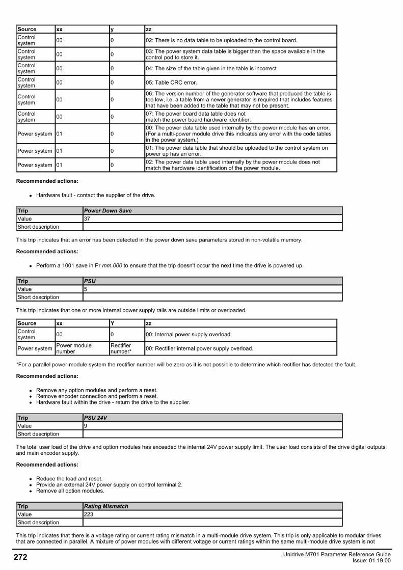
Source xx y zzControlsystem 00 0 02: There is no data table to be uploaded to the control board.
Controlsystem 00 0 03: The power system data table is bigger than the space available in the
control pod to store it.Controlsystem 00 0 04: The size of the table given in the table is incorrect
Controlsystem 00 0 05: Table CRC error.
Controlsystem 00 0
06: The version number of the generator software that produced the table istoo low, i.e. a table from a newer generator is required that includes featuresthat have been added to the table that may not be present.
Control system 00 0 07: The power board data table does not
match the power board hardware identifier.
Power system 01 000: The power data table used internally by the power module has an error.(For a multi-power module drive this indicates any error with the code tablesin the power system.)
Power system 01 0 01: The power data table that should be uploaded to the control system onpower up has an error.
Power system 01 0 02: The power data table used internally by the power module does notmatch the hardware identification of the power module.
Recommended actions:
Hardware fault - contact the supplier of the drive.
Trip Power Down SaveValue 37Short description
This trip indicates that an error has been detected in the power down save parameters stored in non-volatile memory.
Recommended actions:
Perform a 1001 save in Pr mm.000 to ensure that the trip doesn't occur the next time the drive is powered up.
Trip PSUValue 5Short description
This trip indicates that one or more internal power supply rails are outside limits or overloaded.
Source xx Y zzControlsystem 00 0 00: Internal power supply overload.
Power system Power modulenumber
Rectifiernumber* 00: Rectifier internal power supply overload.
*For a parallel power-module system the rectifier number will be zero as it is not possible to determine which rectifier has detected the fault.
Recommended actions:
Remove any option modules and perform a reset.Remove encoder connection and perform a reset.Hardware fault within the drive - return the drive to the supplier.
Trip PSU 24VValue 9Short description
The total user load of the drive and option modules has exceeded the internal 24V power supply limit. The user load consists of the drive digital outputsand main encoder supply.
Recommended actions:
Reduce the load and reset.Provide an external 24V power supply on control terminal 2.Remove all option modules.
Trip Rating MismatchValue 223Short description
This trip indicates that there is a voltage rating or current rating mismatch in a multi-module drive system. This trip is only applicable to modular drivesthat are connected in parallel. A mixture of power modules with different voltage or current ratings within the same multi-module drive system is not
272 Unidrive M701 Parameter Reference GuideIssue: 01.19.00
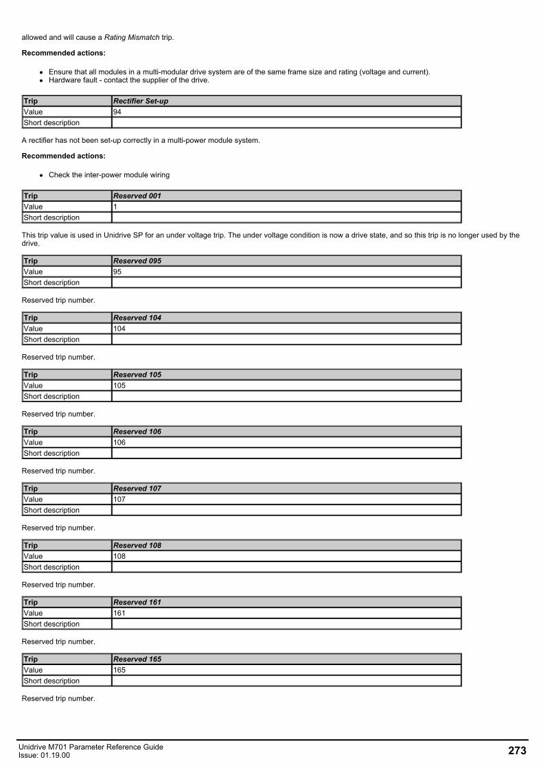
allowed and will cause a Rating Mismatch trip.
Recommended actions:
Ensure that all modules in a multi-modular drive system are of the same frame size and rating (voltage and current).Hardware fault - contact the supplier of the drive.
Trip Rectifier Set-upValue 94Short description
A rectifier has not been set-up correctly in a multi-power module system.
Recommended actions:
Check the inter-power module wiring
Trip Reserved 001Value 1Short description
This trip value is used in Unidrive SP for an under voltage trip. The under voltage condition is now a drive state, and so this trip is no longer used by thedrive.
Trip Reserved 095Value 95Short description
Reserved trip number.
Trip Reserved 104Value 104Short description
Reserved trip number.
Trip Reserved 105Value 105Short description
Reserved trip number.
Trip Reserved 106Value 106Short description
Reserved trip number.
Trip Reserved 107Value 107Short description
Reserved trip number.
Trip Reserved 108Value 108Short description
Reserved trip number.
Trip Reserved 161Value 161Short description
Reserved trip number.
Trip Reserved 165Value 165Short description
Reserved trip number.
Unidrive M701 Parameter Reference GuideIssue: 01.19.00 273
Trip Reserved 166Value 166Short description
Reserved trip number.
Trip Reserved 167Value 167Short description
Reserved trip number.
Trip Reserved 168Value 168Short description
Reserved trip number.
Trip Reserved 171Value 171Short description
Reserved trip number.
Trip Reserved 172Value 172Short description
Reserved trip number.
Trip Reserved 173Value 173Short description
Reserved trip number.
Trip Reserved 222Value 222Short description
If this trip occurs please consult the drive supplier.
Trip Reserved 228Value 228Short description
If this trip occurs please consult the drive supplier.
Trip Reserved 229Value 229Short description
Reserved trip number.
Trip Reserved 230Value 230Short description
Reserved trip number.
Trip Reserved 231Value 231Short description
Reserved trip number.
Trip Reserved 232Value 232Short description
Reserved trip number.
274 Unidrive M701 Parameter Reference GuideIssue: 01.19.00
Trip Reserved 233Value 233Short description
Reserved trip number.
Trip Reserved 234Value 234Short description
Reserved trip number.
Trip Reserved 235Value 235Short description
Reserved trip number.
Trip Reserved 236Value 236Short description
Reserved trip number.
Trip Reserved 237Value 237Short description
Reserved trip number.
Trip Reserved 238Value 238Short description
Reserved trip number.
Trip Reserved 239Value 239Short description
Reserved trip number.
Trip Reserved 240Value 240Short description
Reserved trip number.
Trip Reserved 241Value 241Short description
Reserved trip number.
Trip Reserved 242Value 242Short description
Reserved trip number.
Trip Reserved 243Value 243Short description
Reserved trip number.
Trip Reserved 244Value 244Short description
Reserved trip number.
Unidrive M701 Parameter Reference GuideIssue: 01.19.00 275
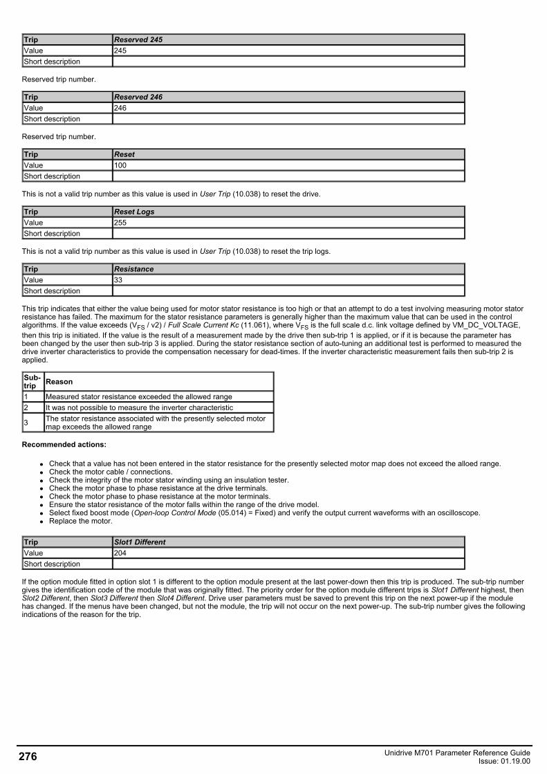
Trip Reserved 245Value 245Short description
Reserved trip number.
Trip Reserved 246Value 246Short description
Reserved trip number.
Trip ResetValue 100Short description
This is not a valid trip number as this value is used in User Trip (10.038) to reset the drive.
Trip Reset LogsValue 255Short description
This is not a valid trip number as this value is used in User Trip (10.038) to reset the trip logs.
Trip ResistanceValue 33Short description
This trip indicates that either the value being used for motor stator resistance is too high or that an attempt to do a test involving measuring motor statorresistance has failed. The maximum for the stator resistance parameters is generally higher than the maximum value that can be used in the controlalgorithms. If the value exceeds (VFS / v2) / Full Scale Current Kc (11.061), where VFS is the full scale d.c. link voltage defined by VM_DC_VOLTAGE,then this trip is initiated. If the value is the result of a measurement made by the drive then sub-trip 1 is applied, or if it is because the parameter hasbeen changed by the user then sub-trip 3 is applied. During the stator resistance section of auto-tuning an additional test is performed to measured thedrive inverter characteristics to provide the compensation necessary for dead-times. If the inverter characteristic measurement fails then sub-trip 2 isapplied.
Sub-trip Reason
1 Measured stator resistance exceeded the allowed range2 It was not possible to measure the inverter characteristic
3 The stator resistance associated with the presently selected motormap exceeds the allowed range
Recommended actions:
Check that a value has not been entered in the stator resistance for the presently selected motor map does not exceed the alloed range.Check the motor cable / connections.Check the integrity of the motor stator winding using an insulation tester.Check the motor phase to phase resistance at the drive terminals.Check the motor phase to phase resistance at the motor terminals.Ensure the stator resistance of the motor falls within the range of the drive model.Select fixed boost mode (Open-loop Control Mode (05.014) = Fixed) and verify the output current waveforms with an oscilloscope.Replace the motor.
Trip Slot1 DifferentValue 204Short description
If the option module fitted in option slot 1 is different to the option module present at the last power-down then this trip is produced. The sub-trip numbergives the identification code of the module that was originally fitted. The priority order for the option module different trips is Slot1 Different highest, thenSlot2 Different, then Slot3 Different then Slot4 Different. Drive user parameters must be saved to prevent this trip on the next power-up if the modulehas changed. If the menus have been changed, but not the module, the trip will not occur on the next power-up. The sub-trip number gives the followingindications of the reason for the trip.
276 Unidrive M701 Parameter Reference GuideIssue: 01.19.00
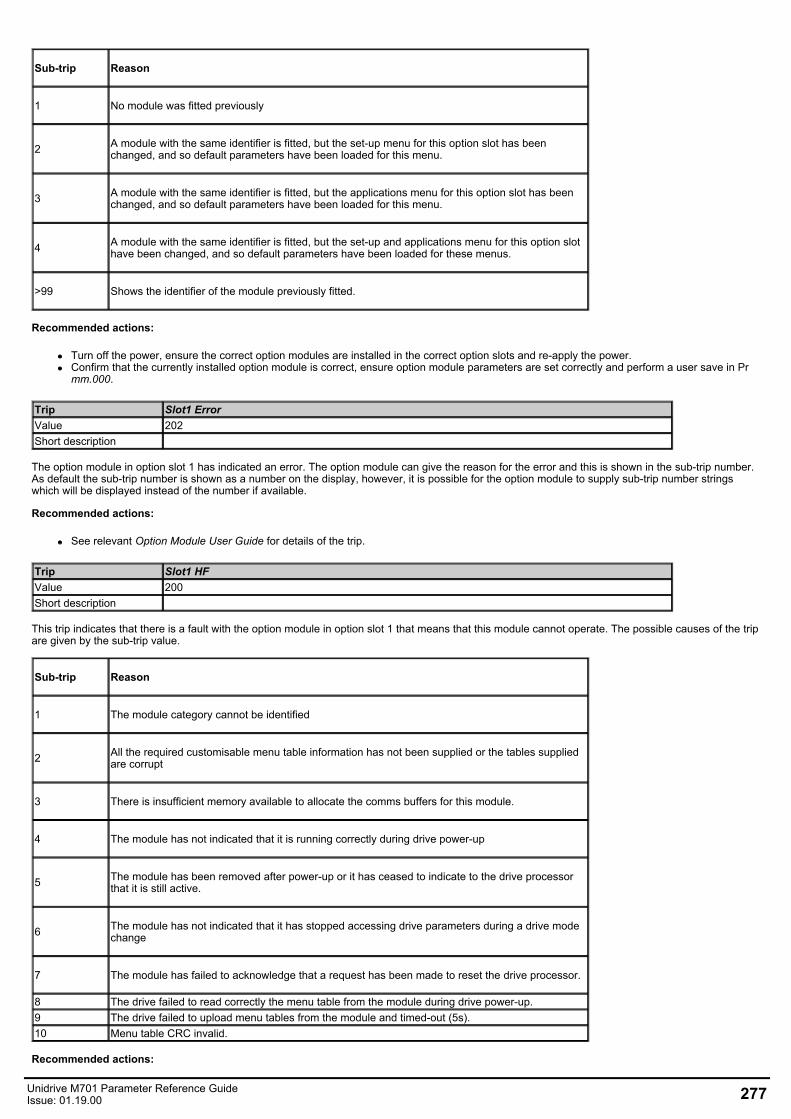
Sub-trip Reason
1 No module was fitted previously
2 A module with the same identifier is fitted, but the set-up menu for this option slot has beenchanged, and so default parameters have been loaded for this menu.
3 A module with the same identifier is fitted, but the applications menu for this option slot has beenchanged, and so default parameters have been loaded for this menu.
4 A module with the same identifier is fitted, but the set-up and applications menu for this option slothave been changed, and so default parameters have been loaded for these menus.
>99 Shows the identifier of the module previously fitted.
Recommended actions:
Turn off the power, ensure the correct option modules are installed in the correct option slots and re-apply the power.Confirm that the currently installed option module is correct, ensure option module parameters are set correctly and perform a user save in Prmm.000.
Trip Slot1 ErrorValue 202Short description
The option module in option slot 1 has indicated an error. The option module can give the reason for the error and this is shown in the sub-trip number.As default the sub-trip number is shown as a number on the display, however, it is possible for the option module to supply sub-trip number stringswhich will be displayed instead of the number if available.
Recommended actions:
See relevant Option Module User Guide for details of the trip.
Trip Slot1 HFValue 200Short description
This trip indicates that there is a fault with the option module in option slot 1 that means that this module cannot operate. The possible causes of the tripare given by the sub-trip value.
Sub-trip Reason
1 The module category cannot be identified
2 All the required customisable menu table information has not been supplied or the tables suppliedare corrupt
3 There is insufficient memory available to allocate the comms buffers for this module.
4 The module has not indicated that it is running correctly during drive power-up
5 The module has been removed after power-up or it has ceased to indicate to the drive processorthat it is still active.
6 The module has not indicated that it has stopped accessing drive parameters during a drive modechange
7 The module has failed to acknowledge that a request has been made to reset the drive processor.
8 The drive failed to read correctly the menu table from the module during drive power-up.9 The drive failed to upload menu tables from the module and timed-out (5s).10 Menu table CRC invalid.
Recommended actions:
Unidrive M701 Parameter Reference GuideIssue: 01.19.00 277
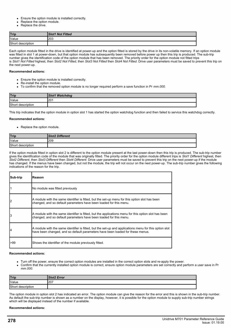
Ensure the option module is installed correctly.Replace the option module.Replace the drive.
Trip Slot1 Not FittedValue 203Short description
Each option module fitted in the drive is identified at power-up and the option fitted is stored by the drive in its non-volatile memory. If an option modulewas fitted in slot 1 at power-down, but that option module has subsequently been removed before power up then this trip is produced. The sub-tripnumber gives the identification code of the option module that has been removed. The priority order for the option module not fitted tripsis Slot1 Not Fitted highest, then Slot2 Not Fitted, then Slot3 Not Fitted then Slot4 Not Fitted. Drive user parameters must be saved to prevent this trip onthe next power-up.
Recommended actions:
Ensure the option module is installed correctly.Re-install the option module.To confirm that the removed option module is no longer required perform a save function in Pr mm.000.
Trip Slot1 WatchdogValue 201Short description
This trip indicates that the option module in option slot 1 has started the option watchdog function and then failed to service this watchdog correctly.
Recommended actions:
Replace the option module.
Trip Slot2 DifferentValue 209Short description
If the option module fitted in option slot 2 is different to the option module present at the last power-down then this trip is produced. The sub-trip numbergives the identification code of the module that was originally fitted. The priority order for the option module different trips is Slot1 Different highest, thenSlot2 Different, then Slot3 Different then Slot4 Different. Drive user parameters must be saved to prevent this trip on the next power-up if the modulehas changed. If the menus have been changed, but not the module, the trip will not occur on the next power-up. The sub-trip number gives the followingindications of the reason for the trip.
Sub-trip Reason
1 No module was fitted previously
2 A module with the same identifier is fitted, but the set-up menu for this option slot has beenchanged, and so default parameters have been loaded for this menu.
3 A module with the same identifier is fitted, but the applications menu for this option slot has beenchanged, and so default parameters have been loaded for this menu.
4 A module with the same identifier is fitted, but the set-up and applications menu for this option slothave been changed, and so default parameters have been loaded for these menus.
>99 Shows the identifier of the module previously fitted.
Recommended actions:
Turn off the power, ensure the correct option modules are installed in the correct option slots and re-apply the power.Confirm that the currently installed option module is correct, ensure option module parameters are set correctly and perform a user save in Prmm.000.
Trip Slot2 ErrorValue 207Short description
The option module in option slot 2 has indicated an error. The option module can give the reason for the error and this is shown in the sub-trip number.As default the sub-trip number is shown as a number on the display, however, it is possible for the option module to supply sub-trip number stringswhich will be displayed instead of the number if available.
Recommended actions:
278 Unidrive M701 Parameter Reference GuideIssue: 01.19.00
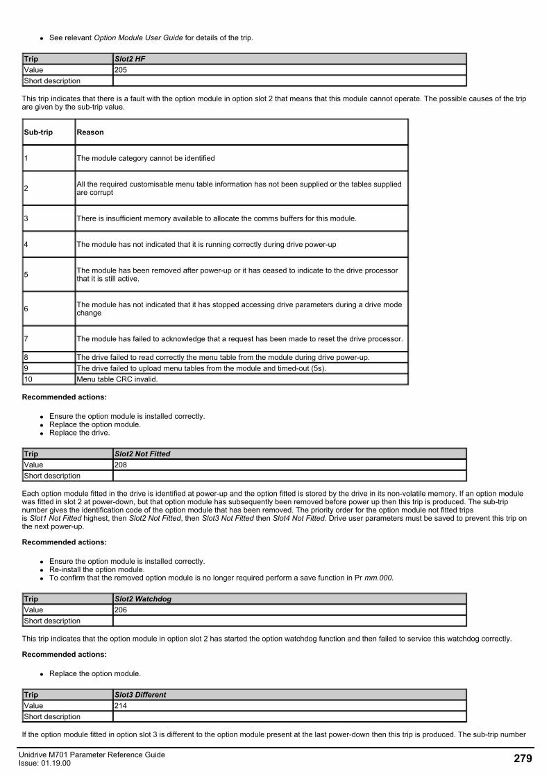
See relevant Option Module User Guide for details of the trip.
Trip Slot2 HFValue 205Short description
This trip indicates that there is a fault with the option module in option slot 2 that means that this module cannot operate. The possible causes of the tripare given by the sub-trip value.
Sub-trip Reason
1 The module category cannot be identified
2 All the required customisable menu table information has not been supplied or the tables suppliedare corrupt
3 There is insufficient memory available to allocate the comms buffers for this module.
4 The module has not indicated that it is running correctly during drive power-up
5 The module has been removed after power-up or it has ceased to indicate to the drive processorthat it is still active.
6 The module has not indicated that it has stopped accessing drive parameters during a drive modechange
7 The module has failed to acknowledge that a request has been made to reset the drive processor.
8 The drive failed to read correctly the menu table from the module during drive power-up.9 The drive failed to upload menu tables from the module and timed-out (5s).10 Menu table CRC invalid.
Recommended actions:
Ensure the option module is installed correctly.Replace the option module.Replace the drive.
Trip Slot2 Not FittedValue 208Short description
Each option module fitted in the drive is identified at power-up and the option fitted is stored by the drive in its non-volatile memory. If an option modulewas fitted in slot 2 at power-down, but that option module has subsequently been removed before power up then this trip is produced. The sub-tripnumber gives the identification code of the option module that has been removed. The priority order for the option module not fitted tripsis Slot1 Not Fitted highest, then Slot2 Not Fitted, then Slot3 Not Fitted then Slot4 Not Fitted. Drive user parameters must be saved to prevent this trip onthe next power-up.
Recommended actions:
Ensure the option module is installed correctly.Re-install the option module.To confirm that the removed option module is no longer required perform a save function in Pr mm.000.
Trip Slot2 WatchdogValue 206Short description
This trip indicates that the option module in option slot 2 has started the option watchdog function and then failed to service this watchdog correctly.
Recommended actions:
Replace the option module.
Trip Slot3 DifferentValue 214Short description
If the option module fitted in option slot 3 is different to the option module present at the last power-down then this trip is produced. The sub-trip number
Unidrive M701 Parameter Reference GuideIssue: 01.19.00 279

gives the identification code of the module that was originally fitted. The priority order for the option module different trips is Slot1 Different highest, thenSlot2 Different, then Slot3 Different then Slot4 Different. Drive user parameters must be saved to prevent this trip on the next power-up if the modulehas changed. If the menus have been changed, but not the module, the trip will not occur on the next power-up. The sub-trip number gives the followingindications of the reason for the trip.
Sub-trip Reason
1 No module was fitted previously
2 A module with the same identifier is fitted, but the set-up menu for this option slot has beenchanged, and so default parameters have been loaded for this menu.
3 A module with the same identifier is fitted, but the applications menu for this option slot has beenchanged, and so default parameters have been loaded for this menu.
4 A module with the same identifier is fitted, but the set-up and applications menu for this option slothave been changed, and so default parameters have been loaded for these menus.
>99 Shows the identifier of the module previously fitted.
Recommended actions:
Turn off the power, ensure the correct option modules are installed in the correct option slots and re-apply the power.Confirm that the currently installed option module is correct, ensure option module parameters are set correctly and perform a user save in Prmm.000.
Trip Slot3 ErrorValue 212Short description
The option module in option slot 3 has indicated an error. The option module can give the reason for the error and this is shown in the sub-trip number.As default the sub-trip number is shown as a number on the display, however, it is possible for the option module to supply sub-trip number stringswhich will be displayed instead of the number if available.
Recommended actions:
See relevant Option Module User Guide for details of the trip.
Trip Slot3 HFValue 210Short description
This trip indicates that there is a fault with the option module in option slot 3 that means that this module cannot operate. The possible causes of the tripare given by the sub-trip value.
280 Unidrive M701 Parameter Reference GuideIssue: 01.19.00
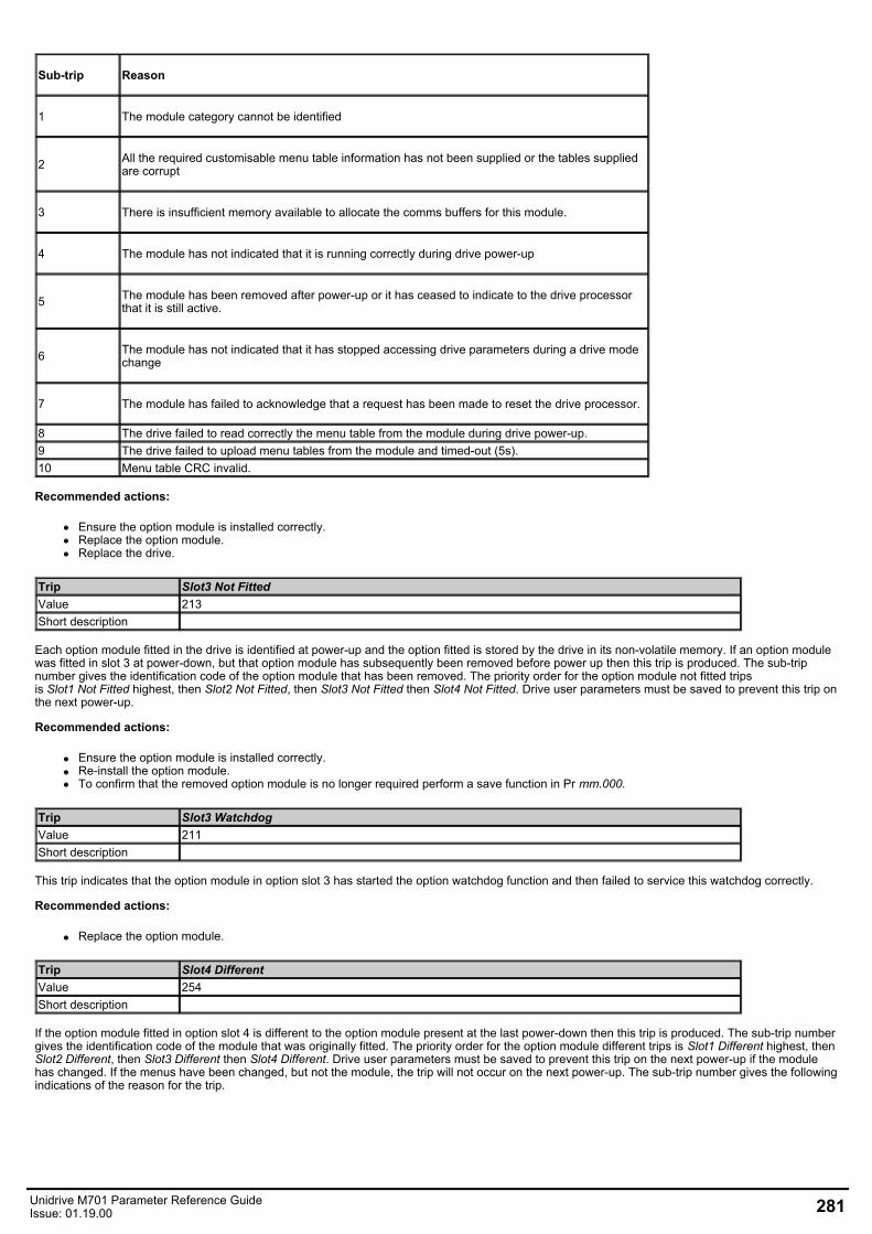
Sub-trip Reason
1 The module category cannot be identified
2 All the required customisable menu table information has not been supplied or the tables suppliedare corrupt
3 There is insufficient memory available to allocate the comms buffers for this module.
4 The module has not indicated that it is running correctly during drive power-up
5 The module has been removed after power-up or it has ceased to indicate to the drive processorthat it is still active.
6 The module has not indicated that it has stopped accessing drive parameters during a drive modechange
7 The module has failed to acknowledge that a request has been made to reset the drive processor.
8 The drive failed to read correctly the menu table from the module during drive power-up.9 The drive failed to upload menu tables from the module and timed-out (5s).10 Menu table CRC invalid.
Recommended actions:
Ensure the option module is installed correctly.Replace the option module.Replace the drive.
Trip Slot3 Not FittedValue 213Short description
Each option module fitted in the drive is identified at power-up and the option fitted is stored by the drive in its non-volatile memory. If an option modulewas fitted in slot 3 at power-down, but that option module has subsequently been removed before power up then this trip is produced. The sub-tripnumber gives the identification code of the option module that has been removed. The priority order for the option module not fitted tripsis Slot1 Not Fitted highest, then Slot2 Not Fitted, then Slot3 Not Fitted then Slot4 Not Fitted. Drive user parameters must be saved to prevent this trip onthe next power-up.
Recommended actions:
Ensure the option module is installed correctly.Re-install the option module.To confirm that the removed option module is no longer required perform a save function in Pr mm.000.
Trip Slot3 WatchdogValue 211Short description
This trip indicates that the option module in option slot 3 has started the option watchdog function and then failed to service this watchdog correctly.
Recommended actions:
Replace the option module.
Trip Slot4 DifferentValue 254Short description
If the option module fitted in option slot 4 is different to the option module present at the last power-down then this trip is produced. The sub-trip numbergives the identification code of the module that was originally fitted. The priority order for the option module different trips is Slot1 Different highest, thenSlot2 Different, then Slot3 Different then Slot4 Different. Drive user parameters must be saved to prevent this trip on the next power-up if the modulehas changed. If the menus have been changed, but not the module, the trip will not occur on the next power-up. The sub-trip number gives the followingindications of the reason for the trip.
Unidrive M701 Parameter Reference GuideIssue: 01.19.00 281
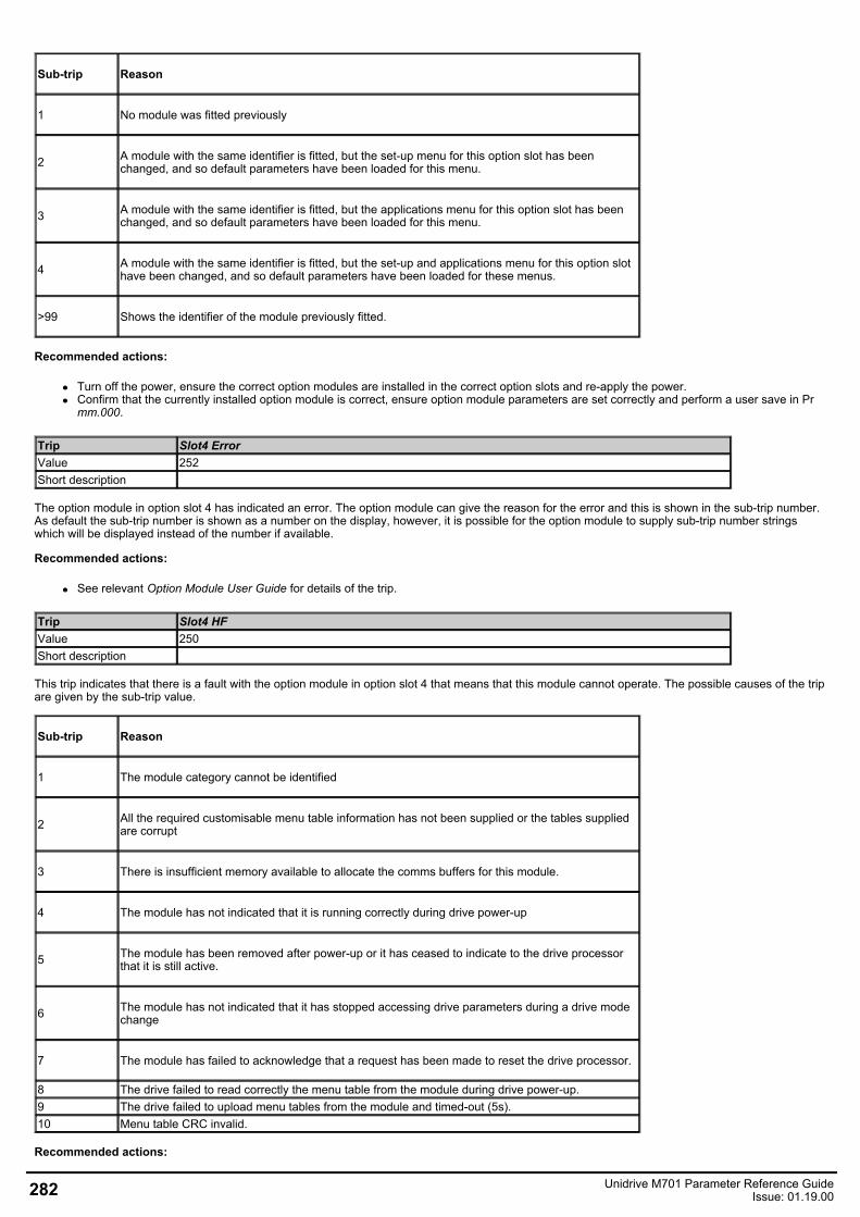
Sub-trip Reason
1 No module was fitted previously
2 A module with the same identifier is fitted, but the set-up menu for this option slot has beenchanged, and so default parameters have been loaded for this menu.
3 A module with the same identifier is fitted, but the applications menu for this option slot has beenchanged, and so default parameters have been loaded for this menu.
4 A module with the same identifier is fitted, but the set-up and applications menu for this option slothave been changed, and so default parameters have been loaded for these menus.
>99 Shows the identifier of the module previously fitted.
Recommended actions:
Turn off the power, ensure the correct option modules are installed in the correct option slots and re-apply the power.Confirm that the currently installed option module is correct, ensure option module parameters are set correctly and perform a user save in Prmm.000.
Trip Slot4 ErrorValue 252Short description
The option module in option slot 4 has indicated an error. The option module can give the reason for the error and this is shown in the sub-trip number.As default the sub-trip number is shown as a number on the display, however, it is possible for the option module to supply sub-trip number stringswhich will be displayed instead of the number if available.
Recommended actions:
See relevant Option Module User Guide for details of the trip.
Trip Slot4 HFValue 250Short description
This trip indicates that there is a fault with the option module in option slot 4 that means that this module cannot operate. The possible causes of the tripare given by the sub-trip value.
Sub-trip Reason
1 The module category cannot be identified
2 All the required customisable menu table information has not been supplied or the tables suppliedare corrupt
3 There is insufficient memory available to allocate the comms buffers for this module.
4 The module has not indicated that it is running correctly during drive power-up
5 The module has been removed after power-up or it has ceased to indicate to the drive processorthat it is still active.
6 The module has not indicated that it has stopped accessing drive parameters during a drive modechange
7 The module has failed to acknowledge that a request has been made to reset the drive processor.
8 The drive failed to read correctly the menu table from the module during drive power-up.9 The drive failed to upload menu tables from the module and timed-out (5s).10 Menu table CRC invalid.
Recommended actions:
282 Unidrive M701 Parameter Reference GuideIssue: 01.19.00
Ensure the option module is installed correctly.Replace the option module.Replace the drive.
Trip Slot4 Not FittedValue 253Short description
Each option module fitted in the drive is identified at power-up and the option fitted is stored by the drive in its non-volatile memory. If an option modulewas fitted in slot 4 at power-down, but that option module has subsequently been removed before power up then this trip is produced. The sub-tripnumber gives the identification code of the option module that has been removed. The priority order for the option module not fitted tripsis Slot1 Not Fitted highest, then Slot2 Not Fitted, then Slot3 Not Fitted then Slot4 Not Fitted. Drive user parameters must be saved to prevent this trip onthe next power-up.
Recommended actions:
Ensure the option module is installed correctly.Re-install the option module.To confirm that the removed option module is no longer required perform a save function in Pr mm.000.
Trip Slot4 WatchdogValue 251Short description
This trip indicates that the option module in option slot 4 has started the option watchdog function and then failed to service this watchdog correctly.
Recommended actions:
Replace the option module.
Trip Slot App MenuValue 216Short description
This trip indicates that more than one option slot has requested to customize application menus 18, 19 and 20. The sub-trip number indicates whichoption slot has been allowed to customize the menus.
Recommended actions:
Ensure that only one of the Application modules is configured to customize the application menus 18, 19 and 20.
Trip Soft StartValue 226Short description
This trip indicates that the soft start relay in the drive has failed to close or the soft start monitoring circuit has failed.
Recommended actions:
Hardware fault - contact the supplier of the drive.
Trip Stored HFValue 221Short description
If an HF01 to HF19 trip occurs then a Stored HF trip occurs each time the drive is powered up until this trip is reset. The sub-trip code is the number ofthe original HF trip. The Stored HF trip can only be reset by first writing 1299 to Pr mm.000 and resetting the drive.
Recommended actions:
Enter 1299 into Pr mm.000 and press reset to clear the trip.
Trip Sub-array RAMValue 227Short description
An option module, derivative image or user program image has requested more parameter RAM than is allowed. The RAM allocation is checked inorder of resulting sub-trip numbers, and so the failure with the highest sub-trip number is given. The sub-trip is calculated as (parameter size x 1000) +(parameter type x 100) + sub-array number. Note that if this trip occurs, all menu customisation provided by option modules, the derivative image or theuser program image is not used. The tables below show the values corresponding to the parts of the sub-trip number.
Unidrive M701 Parameter Reference GuideIssue: 01.19.00 283
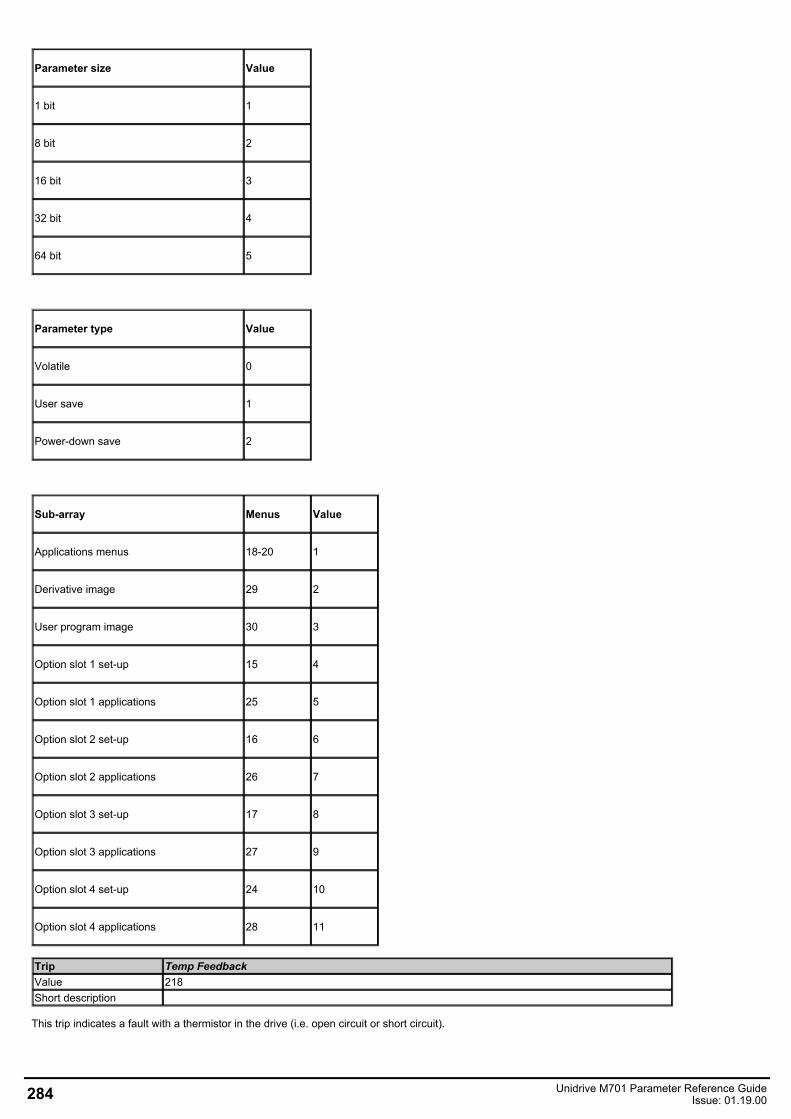
Parameter size Value
1 bit 1
8 bit 2
16 bit 3
32 bit 4
64 bit 5
Parameter type Value
Volatile 0
User save 1
Power-down save 2
Sub-array Menus Value
Applications menus 18-20 1
Derivative image 29 2
User program image 30 3
Option slot 1 set-up 15 4
Option slot 1 applications 25 5
Option slot 2 set-up 16 6
Option slot 2 applications 26 7
Option slot 3 set-up 17 8
Option slot 3 applications 27 9
Option slot 4 set-up 24 10
Option slot 4 applications 28 11
Trip Temp FeedbackValue 218Short description
This trip indicates a fault with a thermistor in the drive (i.e. open circuit or short circuit).
284 Unidrive M701 Parameter Reference GuideIssue: 01.19.00
Source xx y zz
Control board 00 00
01: Control board thermistor 102: Control board thermistor 203: I/O board thermistor:
Powersystem
Power module number 0
Zero for temperature feedback provided via power systemcomms.21, 22 and 23 for direct ELV temperature feedback.
Power system 01 Rectifiernumber* Always zero
*For a parallel power-module system the rectifier number will be one as it is not possible to determine which rectifier has detected the fault.
Recommended actions:
Hardware fault - contact the supplier of the drive.
Trip Th Brake ResValue 10Short description
If hardware based braking resistor thermal monitoring is provided and the resistor overheats this trip is initiated. If the braking resistor is not presentthen this trip must be disabled with bit 3 of Action On Trip Detection (10.037) to prevent this trip.
Recommended actions:
Check braking resistor wiring.Check braking resistor value is greater than or equal to the minimum resistance value.Check braking resistor insulation.
Trip Th Short CircuitValue 25Short description
This trip indicates that a temperature sensor connected to an analogue input or terminal 15 on the position feedback interface has a low impedance (i.e.< 50 Ohms). The cause of the trip can be identified by the sub-trip number.
Sub-trip Source
1Analogue input 1
2 Analogue input 2
3 Analogue input 3
4 Position feedback interface
Recommended actions:
Check temperature feedback connection.Replace sensor.
Trip ThermistorValue 24Short description
This trip indicates that a temperature sensor connected to one of the analogue inputs or terminal 15 on the position feedback interface (15 way D-typeconnector) has indicated an over-temperature. The source of the trip can be identified by the sub-trip number.
Unidrive M701 Parameter Reference GuideIssue: 01.19.00 285
Sub-trip Source
1 Analogue input 1
2 Analogue input 2
3 Analogue input 3
4 Position feedback interface
Recommended actions:
Check why the temperature measured by the sensor is too high temperature.Check temperature sensor connection.
Trip UndefinedValue 110Short description
This trip indicates that the power system has generated but did not identify the trip from the power system. The cause of the trip is unknown.
Recommended actions:
Hardware fault - contact the supplier of the drive.
Trip User 24VValue 91Short description
This trip is initiatied if User Supply Select (06.072) = 1 or Low Under Voltage Threshold Select (06.067) = 1 or Backup Supply Mode Enable (06.068) = 1and no user 24V present on the user 24V input.
Recommended actions:
Ensure that the user 24V supply is present on the control terminals.
Trip User Prog TripValue 96Short description
This trip can be initiated from within an onboard user program using a function call which defines the sub-trip number.
Recommended actions:
Check the user program.
Trip User ProgramValue 249Short description
An error has been detected in the onboard user program image. The sub-trip indicated the reason for the trip.
286 Unidrive M701 Parameter Reference GuideIssue: 01.19.00
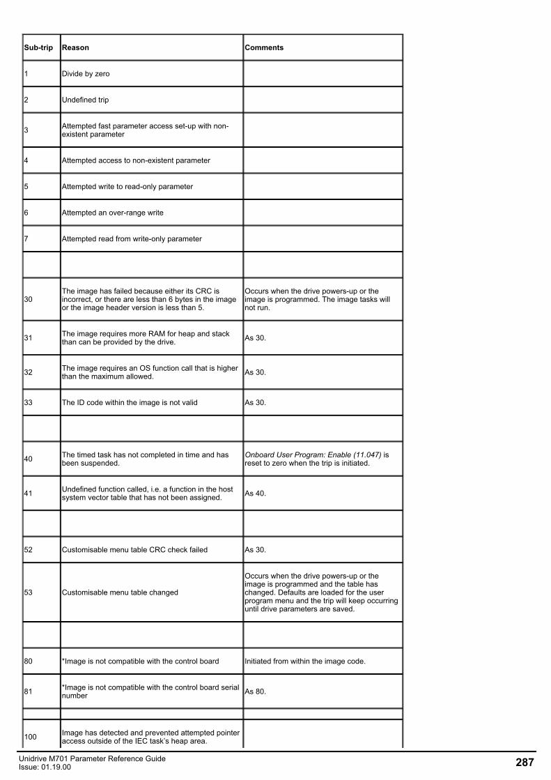
Sub-trip Reason Comments
1 Divide by zero
2 Undefined trip
3 Attempted fast parameter access set-up with non-existent parameter
4 Attempted access to non-existent parameter
5 Attempted write to read-only parameter
6 Attempted an over-range write
7 Attempted read from write-only parameter
30The image has failed because either its CRC isincorrect, or there are less than 6 bytes in the imageor the image header version is less than 5.
Occurs when the drive powers-up or theimage is programmed. The image tasks willnot run.
31 The image requires more RAM for heap and stackthan can be provided by the drive. As 30.
32 The image requires an OS function call that is higherthan the maximum allowed. As 30.
33 The ID code within the image is not valid As 30.
40 The timed task has not completed in time and hasbeen suspended.
Onboard User Program: Enable (11.047) isreset to zero when the trip is initiated.
41 Undefined function called, i.e. a function in the hostsystem vector table that has not been assigned. As 40.
52 Customisable menu table CRC check failed As 30.
53 Customisable menu table changed
Occurs when the drive powers-up or theimage is programmed and the table haschanged. Defaults are loaded for the userprogram menu and the trip will keep occurringuntil drive parameters are saved.
80 *Image is not compatible with the control board Initiated from within the image code.
81 *Image is not compatible with the control board serialnumber As 80.
100 Image has detected and prevented attempted pointeraccess outside of the IEC task’s heap area.
Unidrive M701 Parameter Reference GuideIssue: 01.19.00 287
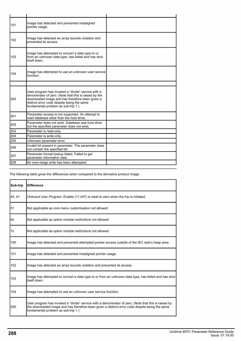
101 Image has detected and prevented misalignedpointer usage.
102 Image has detected an array bounds violation andprevented its access.
103Image has attempted to convert a data type to orfrom an unknown data type, has failed and has shutitself down.
104 Image has attempted to use an unknown user servicefunction.
200
User program has invoked a “divide” service with adenominator of zero. (Note that this is raised by thedownloaded image and has therefore been given adistinct error code despite being the samefundamental problem as sub-trip 1.)
201 Parameter access is not supported. An attempt toread database other than the host drive.
202 Parameter does not exist. Database was host drivebut the specified parameter does not exist.
203 Parameter is read-only.204 Parameter is write-only.205 Unknown parameter error.
206 Invalid bit present in parameter. The parameter doesnot contain the specified bit.
207 Parameter format lookup failed. Failed to getparameter information data.
208 An over-range write has been attempted.
The following table gives the differences when compared to the derivative product image.
Sub-trip Difference
40, 41 Onboard User Program: Enable (11.047) is reset to zero when the trip is initiated.
51 Not applicable as core menu customisation not allowed
6x Not applicable as option module restrictions not allowed
7x Not applicable as option module restrictions not allowed
100 Image has detected and prevented attempted pointer access outside of the IEC task’s heap area.
101 Image has detected and prevented misaligned pointer usage.
102 Image has detected an array bounds violation and prevented its access.
103 Image has attempted to convert a data type to or from an unknown data type, has failed and has shutitself down.
104 Image has attempted to use an unknown user service function.
200User program has invoked a “divide” service with a denominator of zero. (Note that this is raised bythe downloaded image and has therefore been given a distinct error code despite being the samefundamental problem as sub-trip 1.)
288 Unidrive M701 Parameter Reference GuideIssue: 01.19.00
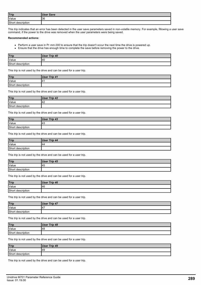
Trip User SaveValue 36Short description
This trip indicates that an error has been detected in the user save parameters saved in non-volatile memory. For example, fillowing a user savecommand, if the power to the drive was removed when the user parameters were being saved.
Recommended actions:
Perform a user save in Pr mm.000 to ensure that the trip doesn't occur the next time the drive is powered up.Ensure that the drive has enough time to complete the save before removing the power to the drive.
Trip User Trip 40Value 40Short description
This trip is not used by the drive and can be used for a user trip.
Trip User Trip 41Value 41Short description
This trip is not used by the drive and can be used for a user trip.
Trip User Trip 42Value 42Short description
This trip is not used by the drive and can be used for a user trip.
Trip User Trip 43Value 43Short description
This trip is not used by the drive and can be used for a user trip.
Trip User Trip 44Value 44Short description
This trip is not used by the drive and can be used for a user trip.
Trip User Trip 45Value 45Short description
This trip is not used by the drive and can be used for a user trip.
Trip User Trip 46Value 46Short description
This trip is not used by the drive and can be used for a user trip.
Trip User Trip 47Value 47Short description
This trip is not used by the drive and can be used for a user trip.
Trip User Trip 48Value 48Short description
This trip is not used by the drive and can be used for a user trip.
Trip User Trip 49Value 49Short description
This trip is not used by the drive and can be used for a user trip.
Unidrive M701 Parameter Reference GuideIssue: 01.19.00 289
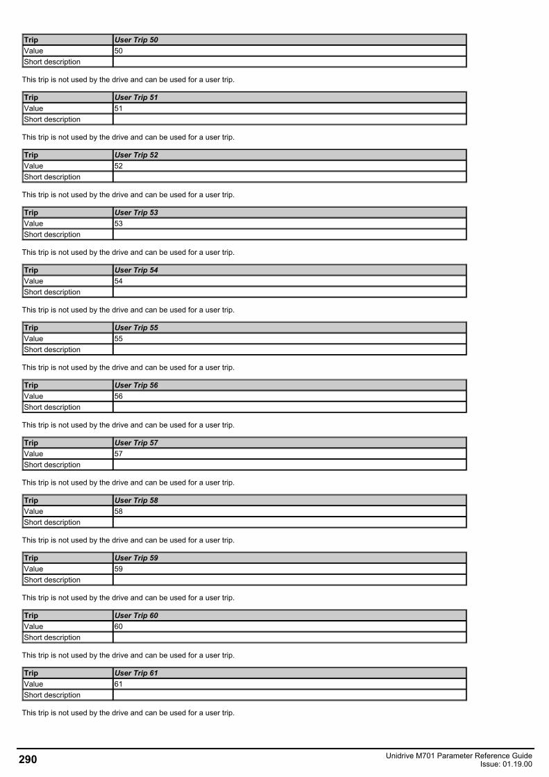
Trip User Trip 50Value 50Short description
This trip is not used by the drive and can be used for a user trip.
Trip User Trip 51Value 51Short description
This trip is not used by the drive and can be used for a user trip.
Trip User Trip 52Value 52Short description
This trip is not used by the drive and can be used for a user trip.
Trip User Trip 53Value 53Short description
This trip is not used by the drive and can be used for a user trip.
Trip User Trip 54Value 54Short description
This trip is not used by the drive and can be used for a user trip.
Trip User Trip 55Value 55Short description
This trip is not used by the drive and can be used for a user trip.
Trip User Trip 56Value 56Short description
This trip is not used by the drive and can be used for a user trip.
Trip User Trip 57Value 57Short description
This trip is not used by the drive and can be used for a user trip.
Trip User Trip 58Value 58Short description
This trip is not used by the drive and can be used for a user trip.
Trip User Trip 59Value 59Short description
This trip is not used by the drive and can be used for a user trip.
Trip User Trip 60Value 60Short description
This trip is not used by the drive and can be used for a user trip.
Trip User Trip 61Value 61Short description
This trip is not used by the drive and can be used for a user trip.
290 Unidrive M701 Parameter Reference GuideIssue: 01.19.00

Trip User Trip 62Value 62Short description
This trip is not used by the drive and can be used for a user trip.
Trip User Trip 63Value 63Short description
This trip is not used by the drive and can be used for a user trip.
Trip User Trip 64Value 64Short description
This trip is not used by the drive and can be used for a user trip.
Trip User Trip 65Value 65Short description
This trip is not used by the drive and can be used for a user trip.
Trip User Trip 66Value 66Short description
This trip is not used by the drive and can be used for a user trip.
Trip User Trip 67Value 67Short description
This trip is not used by the drive and can be used for a user trip.
Trip User Trip 68Value 68Short description
This trip is not used by the drive and can be used for a user trip.
Trip User Trip 69Value 69Short description
This trip is not used by the drive and can be used for a user trip.
Trip User Trip 70Value 70Short description
This trip is not used by the drive and can be used for a user trip.
Trip User Trip 71Value 71Short description
This trip is not used by the drive and can be used for a user trip.
Trip User Trip 72Value 72Short description
This trip is not used by the drive and can be used for a user trip.
Trip User Trip 73Value 73Short description
This trip is not used by the drive and can be used for a user trip.
Unidrive M701 Parameter Reference GuideIssue: 01.19.00 291
Trip User Trip 74Value 74Short description
This trip is not used by the drive and can be used for a user trip.
Trip User Trip 75Value 75Short description
This trip is not used by the drive and can be used for a user trip.
Trip User Trip 76Value 76Short description
This trip is not used by the drive and can be used for a user trip.
Trip User Trip 77Value 77Short description
This trip is not used by the drive and can be used for a user trip.
Trip User Trip 78Value 78Short description
This trip is not used by the drive and can be used for a user trip.
Trip User Trip 79Value 79Short description
This trip is not used by the drive and can be used for a user trip.
Trip User Trip 80Value 80Short description
This trip is not used by the drive and can be used for a user trip.
Trip User Trip 81Value 81Short description
This trip is not used by the drive and can be used for a user trip.
Trip User Trip 82Value 82Short description
This trip is not used by the drive and can be used for a user trip.
Trip User Trip 83Value 83Short description
This trip is not used by the drive and can be used for a user trip.
Trip User Trip 84Value 84Short description
This trip is not used by the drive and can be used for a user trip.
Trip User Trip 85Value 85Short description
This trip is not used by the drive and can be used for a user trip.
292 Unidrive M701 Parameter Reference GuideIssue: 01.19.00

Trip User Trip 86Value 86Short description
This trip is not used by the drive and can be used for a user trip.
Trip User Trip 87Value 87Short description
This trip is not used by the drive and can be used for a user trip.
Trip User Trip 88Value 88Short description
This trip is not used by the drive and can be used for a user trip.
Trip User Trip 89Value 89Short description
This trip is not used by the drive and can be used for a user trip.
Trip User Trip 112Value 112Short description
This trip is not used by the drive and can be used for a user trip.
Trip User Trip 113Value 113Short description
This trip is not used by the drive and can be used for a user trip.
Trip User Trip 114Value 114Short description
This trip is not used by the drive and can be used for a user trip.
Trip User Trip 115Value 115Short description
This trip is not used by the drive and can be used for a user trip.
Trip User Trip 116Value 116Short description
This trip is not used by the drive and can be used for a user trip.
Trip User Trip 117Value 117Short description
This trip is not used by the drive and can be used for a user trip.
Trip User Trip 118Value 118Short description
This trip is not used by the drive and can be used for a user trip.
Trip User Trip 119Value 119Short description
This trip is not used by the drive and can be used for a user trip.
Unidrive M701 Parameter Reference GuideIssue: 01.19.00 293

Trip User Trip 120Value 120Short description
This trip is not used by the drive and can be used for a user trip.
Trip User Trip 121Value 121Short description
This trip is not used by the drive and can be used for a user trip.
Trip User Trip 122Value 122Short description
This trip is not used by the drive and can be used for a user trip.
Trip User Trip 123Value 123Short description
This trip is not used by the drive and can be used for a user trip.
Trip User Trip 124Value 124Short description
This trip is not used by the drive and can be used for a user trip.
Trip User Trip 125Value 125Short description
This trip is not used by the drive and can be used for a user trip.
Trip User Trip 126Value 126Short description
This trip is not used by the drive and can be used for a user trip.
Trip User Trip 127Value 127Short description
This trip is not used by the drive and can be used for a user trip.
Trip User Trip 128Value 128Short description
This trip is not used by the drive and can be used for a user trip.
Trip User Trip 129Value 129Short description
This trip is not used by the drive and can be used for a user trip.
Trip User Trip 130Value 130Short description
This trip is not used by the drive and can be used for a user trip.
Trip User Trip 131Value 131Short description
This trip is not used by the drive and can be used for a user trip.
294 Unidrive M701 Parameter Reference GuideIssue: 01.19.00

Trip User Trip 132Value 132Short description
This trip is not used by the drive and can be used for a user trip.
Trip User Trip 133Value 133Short description
This trip is not used by the drive and can be used for a user trip.
Trip User Trip 134Value 134Short description
This trip is not used by the drive and can be used for a user trip.
Trip User Trip 135Value 135Short description
This trip is not used by the drive and can be used for a user trip.
Trip User Trip 136Value 136Short description
This trip is not used by the drive and can be used for a user trip.
Trip User Trip 137Value 137Short description
This trip is not used by the drive and can be used for a user trip.
Trip User Trip 138Value 138Short description
This trip is not used by the drive and can be used for a user trip.
Trip User Trip 139Value 139Short description
This trip is not used by the drive and can be used for a user trip.
Trip User Trip 140Value 140Short description
This trip is not used by the drive and can be used for a user trip.
Trip User Trip 141Value 141Short description
This trip is not used by the drive and can be used for a user trip.
Trip User Trip 142Value 142Short description
This trip is not used by the drive and can be used for a user trip.
Trip User Trip 143Value 143Short description
This trip is not used by the drive and can be used for a user trip.
Unidrive M701 Parameter Reference GuideIssue: 01.19.00 295
Trip User Trip 144Value 144Short description
This trip is not used by the drive and can be used for a user trip.
Trip User Trip 145Value 145Short description
This trip is not used by the drive and can be used for a user trip.
Trip User Trip 146Value 146Short description
This trip is not used by the drive and can be used for a user trip.
Trip User Trip 147Value 147Short description
This trip is not used by the drive and can be used for a user trip.
Trip User Trip 148Value 148Short description
This trip is not used by the drive and can be used for a user trip.
Trip User Trip 149Value 149Short description
This trip is not used by the drive and can be used for a user trip.
Trip User Trip 150Value 150Short description
This trip is not used by the drive and can be used for a user trip.
Trip User Trip 151Value 151Short description
This trip is not used by the drive and can be used for a user trip.
Trip User Trip 152Value 152Short description
This trip is not used by the drive and can be used for a user trip.
Trip User Trip 153Value 153Short description
This trip is not used by the drive and can be used for a user trip.
Trip User Trip 154Value 154Short description
This trip is not used by the drive and can be used for a user trip.
Trip User Trip 155Value 155Short description
This trip is not used by the drive and can be used for a user trip.
296 Unidrive M701 Parameter Reference GuideIssue: 01.19.00
Trip User Trip 156Value 156Short description
This trip is not used by the drive and can be used for a user trip.
Trip User Trip 157Value 157Short description
This trip is not used by the drive and can be used for a user trip.
Trip User Trip 158Value 158Short description
This trip is not used by the drive and can be used for a user trip.
Trip User Trip 159Value 159Short description
This trip is not used by the drive and can be used for a user trip.
Trip Voltage RangeValue 169Short description
This trip is initiated if the Regen Minimum Voltage (03.026) is set to a non-zero value and the supply voltage is outside the range defined byRegen Maximum Voltage (03.027) for more than 100ms.
Recommended actions:
Ensure the supply voltage is operating within the drive specification.Ensure Regen Minimum Voltage (03.026) and Regen Maximum Voltage (03.027) are set correctly.Check the supply voltage waveform using an oscilloscope.Reduce the level of supply disturbance.Set Regen Maximum Voltage (03.027) to zero to disable this trip.
Trip WatchdogValue 30Short description
This trip indicates that the control word watchdog has been enabled and has timed out.
Unidrive M701 Parameter Reference GuideIssue: 01.19.00 297
Related Documents