— ABB MEASUREMENT & ANALYTICS | APPLICATION NOTE ABB flow solutions For harsh environment applications Comprehensive flow solutions designed to meet almost any process condition Measurement made easy Focus areas • Downstream chemical, oil and gas applications • Molten sulfur • Delayed coker applications • Enhancing oil recovery

Welcome message from author
This document is posted to help you gain knowledge. Please leave a comment to let me know what you think about it! Share it to your friends and learn new things together.
Transcript
— A B B M E A SU R EM ENT & A N A LY TI C S | A PPLI C ATI O N NOTE
ABB flow solutionsFor harsh environment applications
Comprehensive flow solutions designed to meet almost any process condition
Measurement made easy
Focus areas• Downstream chemical, oil and gas applications
• Molten sulfur
• Delayed coker applications
• Enhancing oil recovery
2 A B B F LOW S O LUTI O N S H A R SH EN V I R O N M ENT A PPL I C ATI O NS | A PPL I C ATI O N N OTE A N/FLOW/014 - EN
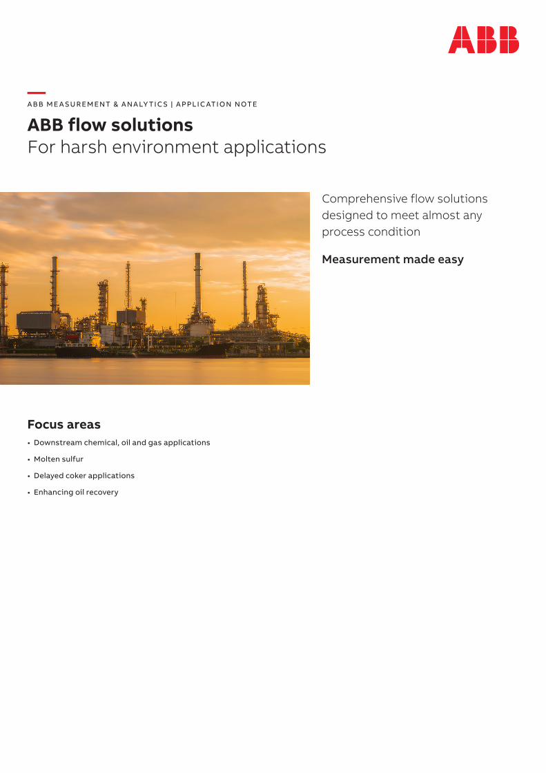
—Principle of operation Relying on the proven technology of differential pressure flow metering, WedgeMeter II flow elements take the next steps in offering reliable performance coupled with a low installation cost when compared to other technologies. Having no moving parts and a unique wear resistant ‘V’ shaped restriction, initial accuracy is maintained throughout the life of the meter, virtually eliminating routine maintenance schedules. Whether the measured process is dirty, viscous, hot, clean, abrasive or tends to foul, wedge flowmeters provide accurate measurements every time.
Wedge restriction creates pressure differential
Wedge element is characterized by HID ratio
D
H
—Designed to meet almost any process conditionClean fluids Whether liquid or gas, mass flow rates can be attained using
the multi-variable technology offered with today’s differential pressure transmitters
Erosive, abrasive slurries Withstands erosive conditions that would normally wear sensitive measurement surfaces found in orifice plate, turbine metering or positive displacement meters
Low conductivity fluids Fluids such as hydrocarbons that cannot be measured using magnetic flow metering devices
Viscous and Non-Newtonian fluids
Positive performance in flow regimes not attainable by other head loss meter types, oscillatory and mechanical meters.
Fluids that will gum or foul
Takes advantage of a unique flow restrictor to reduce fouling that occurs in meters employing vanes, moving parts or small diameter tubing
Fluids at extreme limits Easily adaptable to a wide range of fluid temperatures from cryogenic to 427 °C (800 °F)
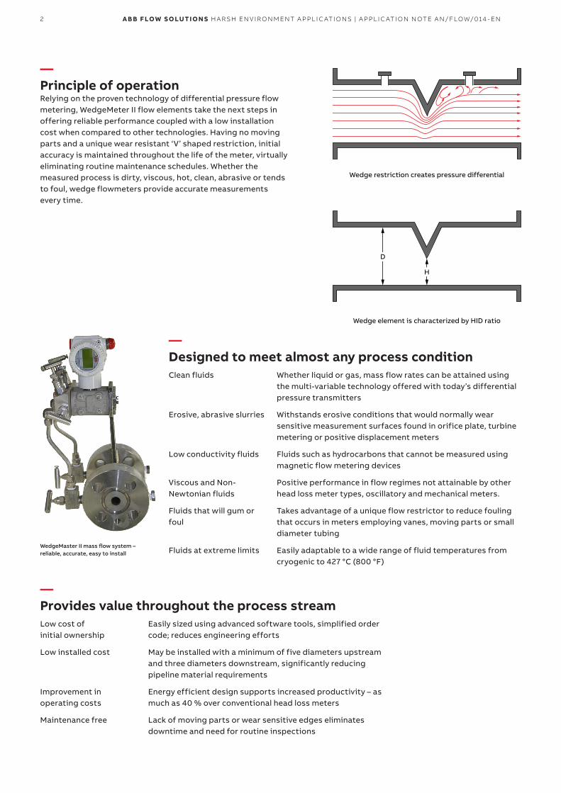
WedgeMaster II mass flow system – reliable, accurate, easy to install
—Provides value throughout the process streamLow cost of initial ownership
Easily sized using advanced software tools, simplified order code; reduces engineering efforts
Low installed cost May be installed with a minimum of five diameters upstream and three diameters downstream, significantly reducing pipeline material requirements
Improvement in operating costs
Energy efficient design supports increased productivity – as much as 40 % over conventional head loss meters
Maintenance free Lack of moving parts or wear sensitive edges eliminates downtime and need for routine inspections
3A B B F LOW S O LUTI O N S H A R SH EN V I R O N M ENT A PPL I C ATI O NS | A PPL I C ATI O N N OTE A N/FLOW/014 - EN
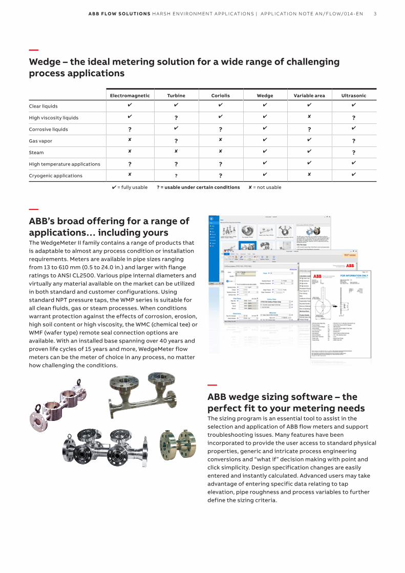
—Wedge – the ideal metering solution for a wide range of challenging process applications
Electromagnetic Turbine Coriolis Wedge Variable area Ultrasonic
Clear liquids
High viscosity liquids ? ?
Corrosive liquids ? ? ?
Gas vapor ? ?
Steam ?
High temperature applications ? ? ?
Cryogenic applications ? ?
= fully usable ? = usable under certain conditions = not usable
—ABB’s broad offering for a range of applications… including yoursThe WedgeMeter II family contains a range of products that is adaptable to almost any process condition or installation requirements. Meters are available in pipe sizes ranging from 13 to 610 mm (0.5 to 24.0 in.) and larger with flange ratings to ANSI CL2500. Various pipe internal diameters and virtually any material available on the market can be utilized in both standard and customer configurations. Using standard NPT pressure taps, the WMP series is suitable for all clean fluids, gas or steam processes. When conditions warrant protection against the effects of corrosion, erosion, high soil content or high viscosity, the WMC (chemical tee) or WMF (wafer type) remote seal connection options are available. With an installed base spanning over 40 years and proven life cycles of 15 years and more, WedgeMeter flow meters can be the meter of choice in any process, no matter how challenging the conditions.
—ABB wedge sizing software – the perfect fit to your metering needsThe sizing program is an essential tool to assist in the selection and application of ABB flow meters and support troubleshooting issues. Many features have been incorporated to provide the user access to standard physical properties, generic and intricate process engineering conversions and “what if” decision making with point and click simplicity. Design specification changes are easily entered and instantly calculated. Advanced users may take advantage of entering specific data relating to tap elevation, pipe roughness and process variables to further define the sizing criteria.
4 A B B F LOW S O LUTI O N S H A R SH EN V I R O N M ENT A PPL I C ATI O NS | A PPL I C ATI O N N OTE A N/FLOW/014 - EN
—WedgeMeter in downstream chemical, oil and gas applicationsIndustry benefit 1 – durability, stability and simplified maintenanceThe wedge flow element has no moving parts (unlike a turbine meter) or critical surface dimensions or sharp edges that must remain within strict tolerances for maximum accuracy (like an orifice plate). The wedge restriction inside the element has been designed to last the life of the installation, without replacement and without recalibration. For most applications, a wedge flow element can be installed directly in the process piping, without blocking valves and without any by-passes, since it almost never requires removal.
Industry benefit 2 – lowers the cost of ownershipAn important factor in the deciding which flowmeter to use for any application is the cost of ownership. Cost of ownership includes the initial cost to purchase the meter (and any ancillary equipment), the cost to install the meter, the maintenance cost and the operating cost. Initial cost and installation cost are one-time up front expenses. Maintenance and operating costs are incurred every year for the life of the meter. Under the properly process conditions, the wedge flow element is an “install and forget” type of meter that minimizes the end users cost of ownership.
Availability of elements in different materials of construction (carbon steel, stainless steel, Hastelloy and Monel) allow the lowest cost product to be bid given the rigors of the application.
When factory assembled with an ABB transmitter, the installed cost to the user is reduced by eliminating the need to integrate all the individual components associated with a head device on site. In the case of the pipe tap wedge element (WMP), the block manifold and a multi-variable transmitter can be integrated at the Warminster factory and shipped as a complete flow system, eliminating separate devices for static, differential pressure.
Industry benefit 4 – high accuracy and wide rangeabilityWhen ordered as an option, the wedge flow element is calibrated on water at the Warminster factory to an accuracy of +/- 0.5% or better, and supplied with a report containing the calibration test data. When coupled with the proper secondary device, system accuracy can be ± 1% of rate or better for a flow range of 3.5:1 (differential pressure range of 12:1), or ± 2% of rate or better for a flow range of 5:1 (differential pressure range of 25:1). The same accuracy is available for flow in the positive or reverse directions. This accuracy is based upon installation with the recommended runs of straight pipe upstream and downstream of the meter.
Industry benefit 5 – insensitivity to flow profile distortion and / or swirlWedge elements are highly insensitive to piping effects and generally require only 5D to 10D of straight pipe upstream, and 3D to 5D downstream. This insensitivity was demonstrated in the 1980s in a test conducted on a 4 in. pipe tap wedge element by Du Pont Engineering. Copies of the Du Pont test report are available from ABB (contact Paul Wilson) The wedge element was evaluated for calibration accuracy, repeatability and operation under a variety of upstream / downstream piping configurations including:
• Two elbows in the same plane 5D, 11D and 19D upstream
• A single elbow 5D upstream
• Three elbows close coupled 5D upstream
• A 6 by 4 in. concentric reducer 5D upstream
• A half open gate valve 6D and 13D upstream
• A tee 5D upstream
The conclusions from the test report were:
• Results were all well within the 0.5% specification
• Repeatability was 0.19 % of rate
• For most conditions tested the effects of the value of the discharge coefficient was 0.5 % or less (this corresponds to the error margin quoted for orifice plates installed with piping recommendations made in ASME “Fluid Meters”)
Industry benefit 6 – ability to solve the toughest application using special design configurationsSome flow meters can be limited to certain materials of construction, pipe id’s, pressure ratings etc. due to manufacturing processes and costs. Meters employing castings or fixed dimension components cannot provide cost effective solutions based on special designs. With the wedge flow element, virtually any material, pipe schedule (40>) and flange ratings to class 1500 or higher can be designed to meet specific applications. Redundant pressure taps for safety purposes and internal corrosion/erosion resistant coatings are available for the most demanding situation. Pressure taps can be configured to meet almost any mating seal or impulse piping requirement.
5A B B F LOW S O LUTI O N S H A R SH EN V I R O N M ENT A PPL I C ATI O NS | A PPL I C ATI O N N OTE A N/FLOW/014 - EN
—Wedge in molten sulfur applicationsMeasurement of molten sulfur using wedge flow elementsMost flow metering devices present challenges for accurate measurement when used on high viscosity fluids Many devices are either limited to low viscosity fluids either by nature of the technology employed or the effect of a high viscosity process may have on moving parts. Wedge flow meters can overcome these limitations by virtue of the unique measurement technology and ABB’s unrivaled remote seal transmitter technology. The basis of the applications noted below can be extended to various processes with favorable measurement results using ABB wedge flow solutions.
Molten sulfur is a by-product of crude oil refining and natural gas processing and is employed in the production of insecticides, synthetic fibers, plastics fertilizers, solvents, pigments, resins and various other products. Depending on the process temperature, viscosities can range from 6-100 cSt. and maintaining a steady flow is challenging as the fluid can plug lines and cause production outages.
The solution to this metering problem is ABB wedge flow elements, coupled to a suitable secondary transmitter with high temperature remote seal technology. The unique profile of the wedge restriction allows linear and accurate flow measurement at Reynolds numbers (Rd) down to 500. Most other differential devices are limited to Rd of 20000 and above. Integration of the remote seals into the wedge element eliminates problems of plugging associated with conventional impulse lines and allows the application of higher process temperatures to keep the fluid from solidifying.
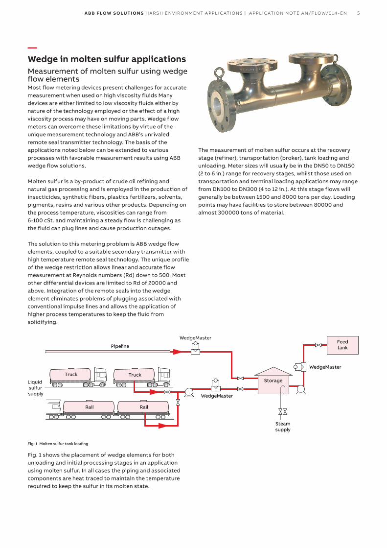
The measurement of molten sulfur occurs at the recovery stage (refiner), transportation (broker), tank loading and unloading. Meter sizes will usually be in the DN50 to DN150 (2 to 6 in.) range for recovery stages, whilst those used on transportation and terminal loading applications may range from DN100 to DN300 (4 to 12 in.). At this stage flows will generally be between 1500 and 8000 tons per day. Loading points may have facilities to store between 80000 and almost 300000 tons of material.
Liquid sulfur supply
Pipeline
TruckTruck
Rail Rail
WedgeMaster
WedgeMaster
WedgeMaster
Steamsupply
Storage
Feedtank
Fig. 1 Molten sulfur tank loading
Fig. 1 shows the placement of wedge elements for both unloading and initial processing stages in an application using molten sulfur. In all cases the piping and associated components are heat traced to maintain the temperature required to keep the sulfur in its molten state.
6 A B B F LOW S O LUTI O N S H A R SH EN V I R O N M ENT A PPL I C ATI O NS | A PPL I C ATI O N N OTE A N/FLOW/014 - EN
Fig. 4
Transmitter
Sealelement
Sealelement
Flowelement
Wedge horizontal installation
The full wedge solution requires the flow element, the secondary transmitter with remote seals and (possibly) isolation valves between the meter taps and the transmitter seals for future servicing needs. The horizontal installation profile as recommended in Fig. 4 enables free passage of liquids, solids and entrained air through the wedge restriction – an advantage over conventional orifice plate technology that causes a damming effect, leading to a buildup of process material on the measurement face. Vertical installations are allowed with flow in the upwards direction. This ensures the meter remains full of fluid at all times during measurement. Materials of construction used for the wedge should match those of the pipeline to ensure erosion and corrosion compatibility.
Key considerations when applying ABB’s wedge meters to slurry applications ( such as molten sulfur and others) are:
• Wedge offers an extended flow range, beyond that of conventional DP primaries
• Effects & maintenance of plugged impulse lines removed by the use of remote seal technology
• “V” shaped restriction reduces the possibility of process build up and allows free passage of multiphase fluids
• The measurement edge of the flow restriction does not rely on critical (i.e. sharp) edges for accurate performance
• No moving parts means reduced wear and maintenance
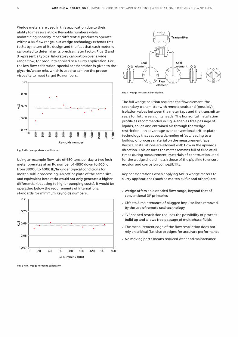
Wedge meters are used in this application due to their ability to measure at low Reynolds numbers while maintaining linearity. Most differential producers operate within a 4:1 flow range, but wedge technology extends this to 8:1 by nature of its design and the fact that each meter is calibrated to determine its precise meter factor. Figs. 2 and 3 represent a typical laboratory calibration over a wide range flow, for products applied to a slurry application. For the low flow calibration, special consideration is given to the glycerin/water mix, which is used to achieve the proper viscosity to meet target Rd numbers.
0
0.67
0.68
0.69
0.70
0.71
100
200
300
400
500
600
Reynolds number
Kd
2
700
800
900
100
0
110
0
120
0
Fig. 2 6 in. wedge viscous calibration
Using an example flow rate of 450 tons per day, a two inch meter operates at an Rd number of 4950 down to 500, or from 38000 to 4000 lb/hr under typical conditions for molten sulfur processing. An orifice plate of the same size and equivalent beta ratio would not only generate a higher differential (equating to higher pumping costs), it would be operating below the requirements of international standards for minimum Reynolds numbers.
00.67
0.68
0.69
0.70
0.71
20 40 60 80 100 120 140 160
Rd number x 1000
Kd
2
Fig. 3 6 in. wedge kerosene calibration

7A B B F LOW S O LUTI O N S H A R SH EN V I R O N M ENT A PPL I C ATI O NS | A PPL I C ATI O N N OTE A N/FLOW/014 - EN
—Wedge delayed coker applicationsThe flow measurement of high temperature/ high pressure processes provides unique challenges to ensure process integrity and meet economic returns. In the case of a delayed coker process, avoiding downtime can be the most critical consideration when choosing a flow meter.
Delayed coker processDelayed coking is a thermal cracking process used in petroleum refineries to take advantage of residuals found in bottoms and vacuum distillates after the breakdown of crude oil into usable consumer products. The process employs furnaces, transfer lines, coking drums and ancillary transportation lines that must be operated on a continuous basis to meet production demands and relies on minimal down time to meet that requirement. As the fluids move through the process, measurement points become more demanding from a longevity standpoint which is one of the most important factors in the selection of flow measurement and ancillary equipment.
Fig. 5 typifies most delayed coker processes, which are found after atmospheric and vacuum distillation and are processes that can yield gasoline and diesel fuels as well as other light distillates. Usually the process is duplicated to facilitate the routine cleaning of one drum while the other continues the distillation process. The details of coking processes can vary but principles remain the same when considering the fluid measurement of hot, viscous, abrasive fluids. Flow meters used in these processes must perform to stated requirements while withstanding the produced environment.
Wedge™ flow meter technology stands apart from other devices by virtue of providing true Dp flow measurement combined with unique enhancements well suited to coke processing. Relying on a non-contact, non-wearing (1) measurement edge, maintenance issues relating to wear, plugging and effects of abrasion are either reduced or eliminated completely. By design, wedge meters employ large diameter remote seal transmitter sensors at the high and low pressure ports and provides accuracy that exceeds other Dp technologies. Further to this, leak paths are reduced and measurement redundancy is achieved within one meter by using multiple tappings without increasing the installation footprint. Dual pressure tappings with isolation valves and purging systems (see Fig. 6) are the norm; triple tappings can be employed on meters sizes 6 inches and above. This configuration can then satisfy measurement redundancy and safety requirements without the need for multiple measuring elements
(1) Wedge flow meters exhibit a shear boundary between the process fluid and measurement restriction when operating in the recommended velocity range.
Heavy coker gas oil
Light coker gas oil
Light coker naptha
Butane / Butene
Fuel gas
Heavy coker naptha
Coke drums
Fired heater
Switchvalve
Coke drums
Fired heater Vacuum residue
Switchvalve
Pro
duc
t re
cove
ry
Fig. 5 Delayed coker process schematic
8 A B B F LOW S O LUTI O N S H A R SH EN V I R O N M ENT A PPL I C ATI O NS | A PPL I C ATI O N N OTE A N/FLOW/014 - EN
Coker process points employing wedge flow metersVarious types of flow measurements are required within a delayed coker process as identified below. In each case, wedge flow meters can provide a solution based on process conditions relating to high temperature and high pressure, the ability to withstand abrasive fluids, reduced piping requirements for flow conditioning and wetted material selection beyond conventional flow measurement devices. When coupled to all-welded, remote seal pressure transmitters with specialty diaphragm seal materials, operating performance is maintained, overall cost reduced and maintenance outages fall beyond normally scheduled downtimes.
Vacuum reduced crude (VRC) feedsTypically, VRC is fed from storage tanks but may also be delivered hot directly from the distillation unit. The fluid is pumped into a fractionator that will eventually separate vapors and liquids producing butanes, naphthas and heavy and light coker gas oils as byproducts of the coke drum processing. The bottoms of this unit are then fed to the heater furnaces at temperatures between 345 and 385 °C (650 and 720 °F) which can be beyond the process limits of most flow devices. Wedge flow meters employed with high temperature remote seal secondaries overcome the temperature limits of most other flow devices.
DistillationDistillation of the heated coke produces gases (C4), cracked gasoline, light and heavy gas oils and waste products. Each of these output streams are at high temperatures and pressures that may not be measured by commodity type flow meters (vortex, turbine) or would require more complex installation ( long lead impulse lines from Dp orifice to reduce the temperature). Relying on the high temperature capability of remote seal Dp pressure systems coupled with wedge flow primaries, these measurements are handled with a higher degree of confidence and less maintenance.
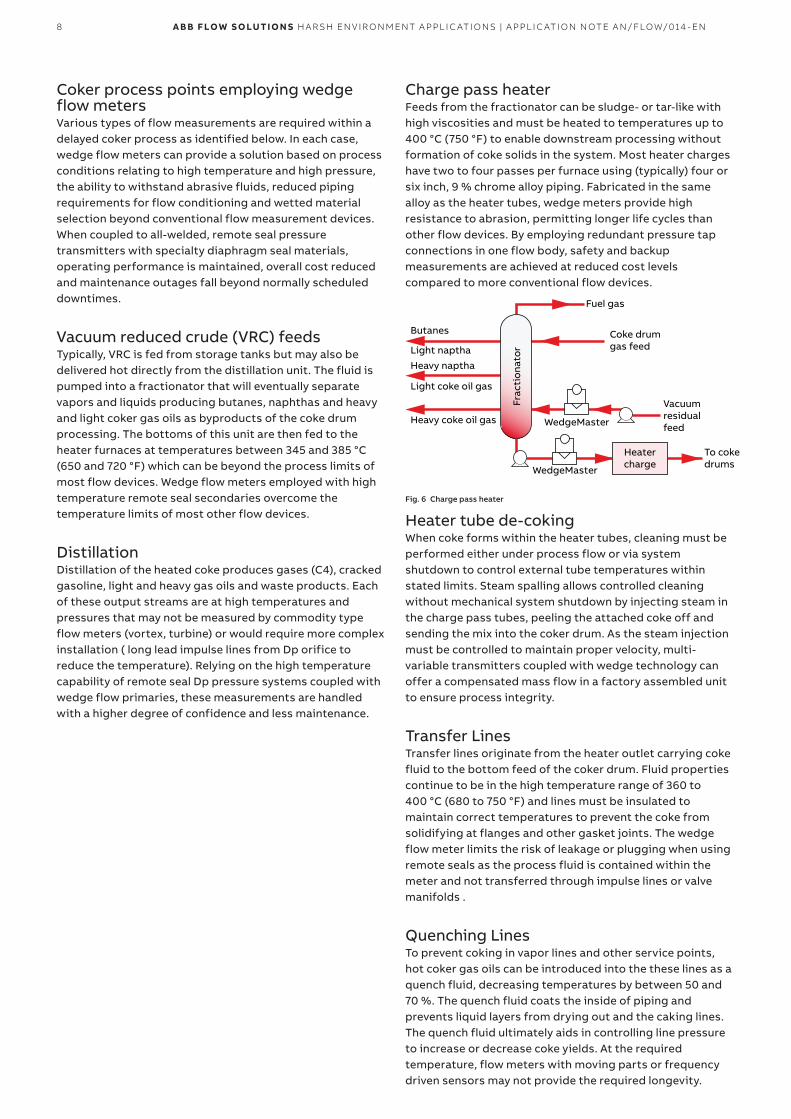
Charge pass heaterFeeds from the fractionator can be sludge- or tar-like with high viscosities and must be heated to temperatures up to 400 °C (750 °F) to enable downstream processing without formation of coke solids in the system. Most heater charges have two to four passes per furnace using (typically) four or six inch, 9 % chrome alloy piping. Fabricated in the same alloy as the heater tubes, wedge meters provide high resistance to abrasion, permitting longer life cycles than other flow devices. By employing redundant pressure tap connections in one flow body, safety and backup measurements are achieved at reduced cost levels compared to more conventional flow devices.
WedgeMaster
WedgeMaster
Vacuumresidualfeed
Coke drumgas feed
Fuel gas
Frac
tion
ator
Heavy coke oil gas
Light coke oil gas
Light naptha
Heavy naptha
Butanes
To cokedrums
Heatercharge
Fig. 6 Charge pass heater
Heater tube de-cokingWhen coke forms within the heater tubes, cleaning must be performed either under process flow or via system shutdown to control external tube temperatures within stated limits. Steam spalling allows controlled cleaning without mechanical system shutdown by injecting steam in the charge pass tubes, peeling the attached coke off and sending the mix into the coker drum. As the steam injection must be controlled to maintain proper velocity, multi-variable transmitters coupled with wedge technology can offer a compensated mass flow in a factory assembled unit to ensure process integrity.
Transfer LinesTransfer lines originate from the heater outlet carrying coke fluid to the bottom feed of the coker drum. Fluid properties continue to be in the high temperature range of 360 to 400 °C (680 to 750 °F) and lines must be insulated to maintain correct temperatures to prevent the coke from solidifying at flanges and other gasket joints. The wedge flow meter limits the risk of leakage or plugging when using remote seals as the process fluid is contained within the meter and not transferred through impulse lines or valve manifolds .
Quenching LinesTo prevent coking in vapor lines and other service points, hot coker gas oils can be introduced into the these lines as a quench fluid, decreasing temperatures by between 50 and 70 %. The quench fluid coats the inside of piping and prevents liquid layers from drying out and the caking lines. The quench fluid ultimately aids in controlling line pressure to increase or decrease coke yields. At the required temperature, flow meters with moving parts or frequency driven sensors may not provide the required longevity.
9A B B F LOW S O LUTI O N S H A R SH EN V I R O N M ENT A PPL I C ATI O NS | A PPL I C ATI O N N OTE A N/FLOW/014 - EN
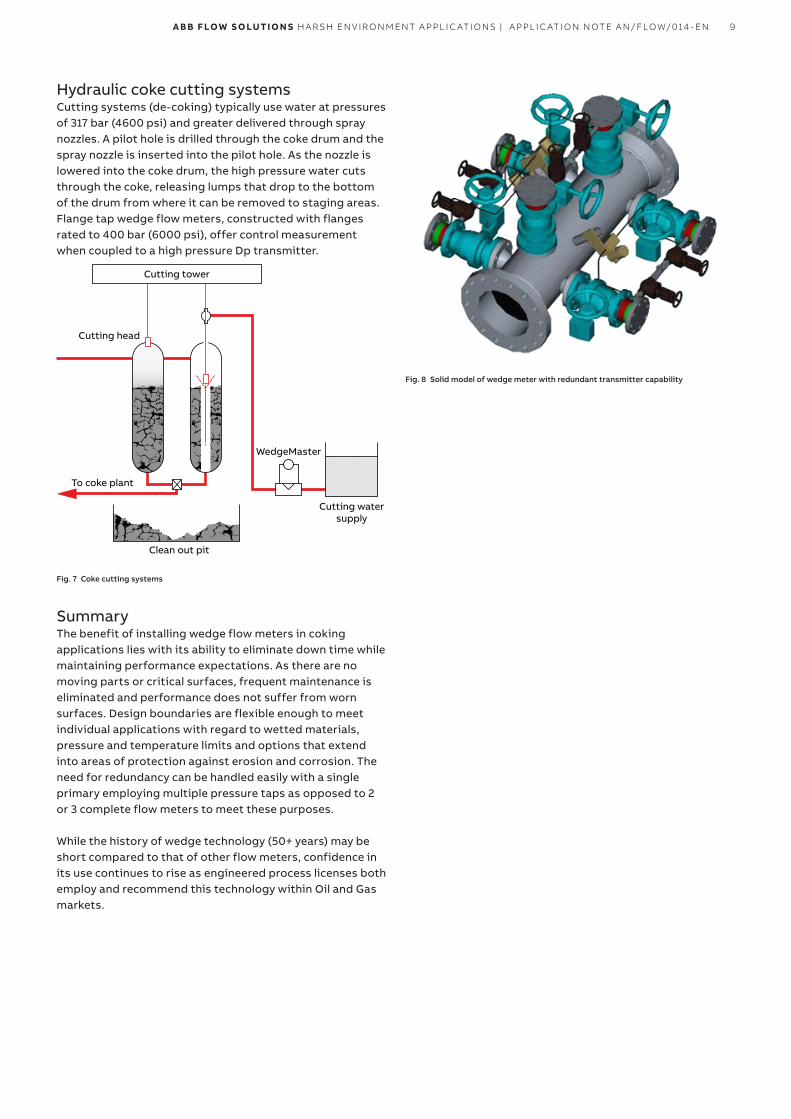
Hydraulic coke cutting systemsCutting systems (de-coking) typically use water at pressures of 317 bar (4600 psi) and greater delivered through spray nozzles. A pilot hole is drilled through the coke drum and the spray nozzle is inserted into the pilot hole. As the nozzle is lowered into the coke drum, the high pressure water cuts through the coke, releasing lumps that drop to the bottom of the drum from where it can be removed to staging areas. Flange tap wedge flow meters, constructed with flanges rated to 400 bar (6000 psi), offer control measurement when coupled to a high pressure Dp transmitter.
Cutting head
To coke plant
Clean out pit
Cutting watersupply
WedgeMaster
Cutting tower
Fig. 7 Coke cutting systems
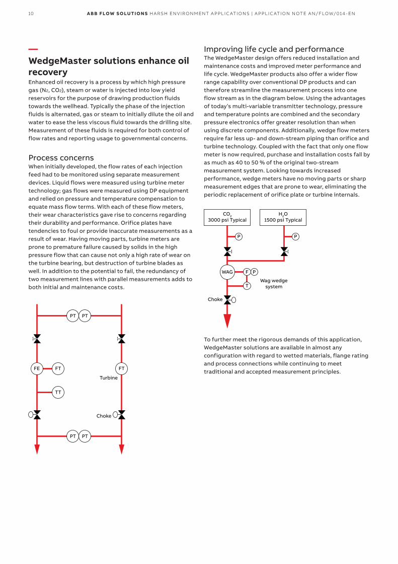
SummaryThe benefit of installing wedge flow meters in coking applications lies with its ability to eliminate down time while maintaining performance expectations. As there are no moving parts or critical surfaces, frequent maintenance is eliminated and performance does not suffer from worn surfaces. Design boundaries are flexible enough to meet individual applications with regard to wetted materials, pressure and temperature limits and options that extend into areas of protection against erosion and corrosion. The need for redundancy can be handled easily with a single primary employing multiple pressure taps as opposed to 2 or 3 complete flow meters to meet these purposes.
While the history of wedge technology (50+ years) may be short compared to that of other flow meters, confidence in its use continues to rise as engineered process licenses both employ and recommend this technology within Oil and Gas markets.
Fig. 8 Solid model of wedge meter with redundant transmitter capability
10 A B B F LOW S O LUTI O N S H A R SH EN V I R O N M ENT A PPL I C ATI O NS | A PPL I C ATI O N N OTE A N/FLOW/014 - EN
—WedgeMaster solutions enhance oil recoveryEnhanced oil recovery is a process by which high pressure gas (N2, CO2), steam or water is injected into low yield reservoirs for the purpose of drawing production fluids towards the wellhead. Typically the phase of the injection fluids is alternated, gas or steam to initially dilute the oil and water to ease the less viscous fluid towards the drilling site. Measurement of these fluids is required for both control of flow rates and reporting usage to governmental concerns.
Process concernsWhen initially developed, the flow rates of each injection feed had to be monitored using separate measurement devices. Liquid flows were measured using turbine meter technology; gas flows were measured using DP equipment and relied on pressure and temperature compensation to equate mass flow terms. With each of these flow meters, their wear characteristics gave rise to concerns regarding their durability and performance. Orifice plates have tendencies to foul or provide inaccurate measurements as a result of wear. Having moving parts, turbine meters are prone to premature failure caused by solids in the high pressure flow that can cause not only a high rate of wear on the turbine bearing, but destruction of turbine blades as well. In addition to the potential to fail, the redundancy of two measurement lines with parallel measurements adds to both initial and maintenance costs.
FE FT
TT
PT PT
PT PT
Choke
Turbine
FT
Improving life cycle and performanceThe WedgeMaster design offers reduced installation and maintenance costs and improved meter performance and life cycle. WedgeMaster products also offer a wider flow range capability over conventional DP products and can therefore streamline the measurement process into one flow stream as in the diagram below. Using the advantages of today’s multi-variable transmitter technology, pressure and temperature points are combined and the secondary pressure electronics offer greater resolution than when using discrete components. Additionally, wedge flow meters require far less up- and down-stream piping than orifice and turbine technology. Coupled with the fact that only one flow meter is now required, purchase and installation costs fall by as much as 40 to 50 % of the original two-stream measurement system. Looking towards increased performance, wedge meters have no moving parts or sharp measurement edges that are prone to wear, eliminating the periodic replacement of orifice plate or turbine internals.
P P
PF
T
WAG
CO23000 psi Typical
Choke
Wag wedgesystem
H2O1500 psi Typical
To further meet the rigorous demands of this application, WedgeMaster solutions are available in almost any configuration with regard to wetted materials, flange rating and process connections while continuing to meet traditional and accepted measurement principles.
11A B B F LOW S O LUTI O N S H A R SH EN V I R O N M ENT A PPL I C ATI O NS | A PPL I C ATI O N N OTE A N/FLOW/014 - EN
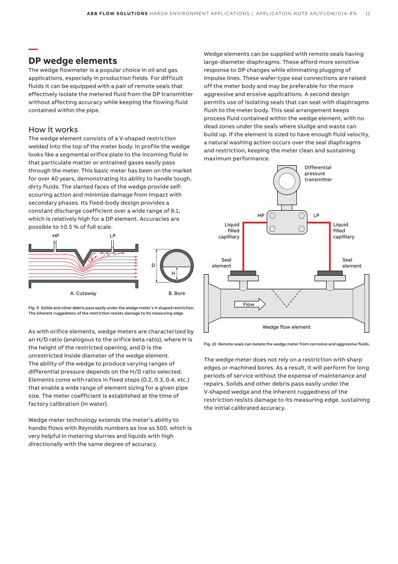
—DP wedge elementsThe wedge flowmeter is a popular choice in oil and gas applications, especially in production fields. For difficult fluids it can be equipped with a pair of remote seals that effectively isolate the metered fluid from the DP transmitter without affecting accuracy while keeping the flowing fluid contained within the pipe.
How it works The wedge element consists of a V-shaped restriction welded into the top of the meter body. In profile the wedge looks like a segmental orifice plate to the incoming fluid in that particulate matter or entrained gases easily pass through the meter. This basic meter has been on the market for over 40 years, demonstrating its ability to handle tough, dirty fluids. The slanted faces of the wedge provide self-scouring action and minimize damage from impact with secondary phases. Its fixed-body design provides a constant discharge coefficient over a wide range of 8:1, which is relatively high for a DP element. Accuracies are possible to ±0.5 % of full scale.
A. Cutaway B. Bore
H
D
HP LP
Fig. 9 Solids and other debris pass easily under the wedge meter’s V-shaped restriction. The inherent ruggedness of the restriction resists damage to its measuring edge.
As with orifice elements, wedge meters are characterized by an H/D ratio (analogous to the orifice beta ratio), where H is the height of the restricted opening, and D is the unrestricted inside diameter of the wedge element.The ability of the wedge to produce varying ranges of differential pressure depends on the H/D ratio selected. Elements come with ratios in fixed steps (0.2, 0.3, 0.4, etc.) that enable a wide range of element sizing for a given pipe size. The meter coefficient is established at the time of factory calibration (in water).
Wedge meter technology extends the meter’s ability to handle flows with Reynolds numbers as low as 500, which is very helpful in metering slurries and liquids with high directionally with the same degree of accuracy.
Wedge elements can be supplied with remote seals having large-diameter diaphragms. These afford more sensitive response to DP changes while eliminating plugging of impulse lines. These wafer-type seal connections are raised off the meter body and may be preferable for the more aggressive and erosive applications. A second design permits use of isolating seals that can seat with diaphragms flush to the meter body. This seal arrangement keeps process fluid contained within the wedge element, with no dead zones under the seals where sludge and waste can build up. If the element is sized to have enough fluid velocity, a natural washing action occurs over the seal diaphragms and restriction, keeping the meter clean and sustaining maximum performance.
Flow
Wedge flow element
Sealelement
Sealelement
Liquidfilledcapilliary
Differentialpressuretransmitter
Liquidfilled
capilliary
HP LP
Fig. 10 Remote seals can isolate the wedge meter from corrosive and aggressive fluids.
The wedge meter does not rely on a restriction with sharp edges or machined bores. As a result, it will perform for long periods of service without the expense of maintenance and repairs. Solids and other debris pass easily under the V-shaped wedge and the inherent ruggedness of the restriction resists damage to its measuring edge, sustaining the initial calibrated accuracy.
12 A B B F LOW S O LUTI O N S H A R SH EN V I R O N M ENT A PPL I C ATI O NS | A PPL I C ATI O N N OTE A N/FLOW/014 - EN
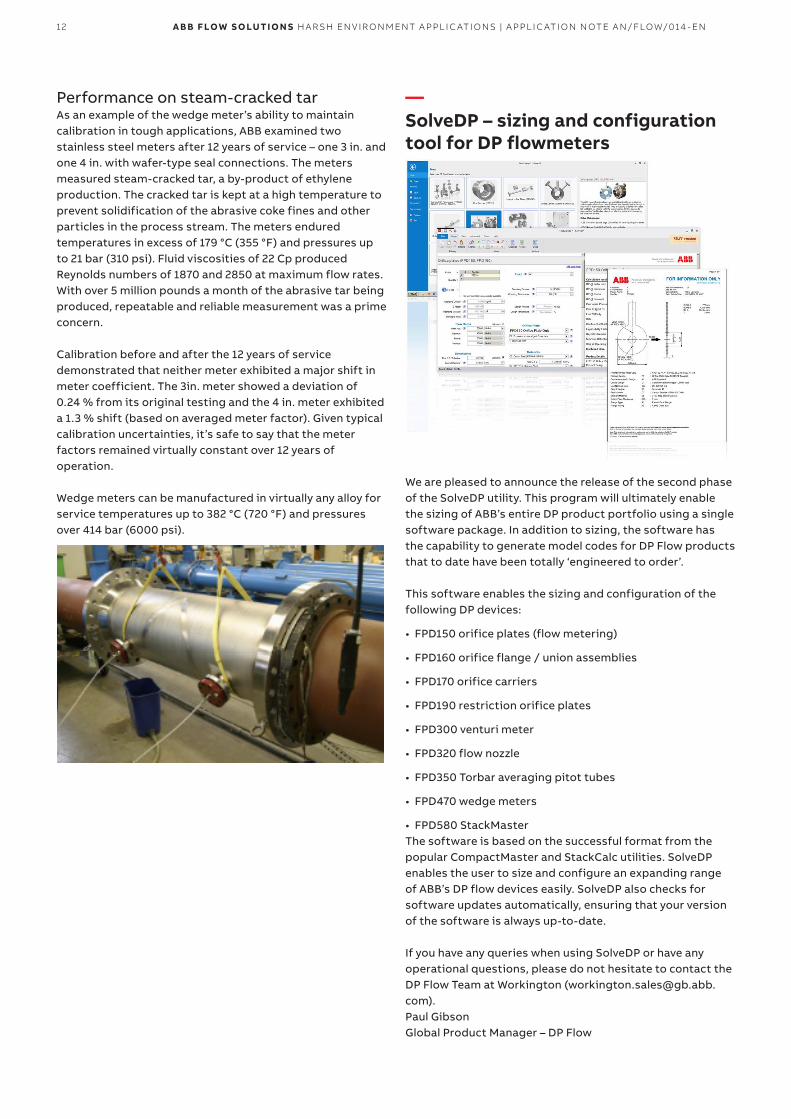
Performance on steam-cracked tarAs an example of the wedge meter’s ability to maintain calibration in tough applications, ABB examined two stainless steel meters after 12 years of service – one 3 in. and one 4 in. with wafer-type seal connections. The meters measured steam-cracked tar, a by-product of ethylene production. The cracked tar is kept at a high temperature to prevent solidification of the abrasive coke fines and other particles in the process stream. The meters endured temperatures in excess of 179 °C (355 °F) and pressures up to 21 bar (310 psi). Fluid viscosities of 22 Cp produced Reynolds numbers of 1870 and 2850 at maximum flow rates. With over 5 million pounds a month of the abrasive tar being produced, repeatable and reliable measurement was a prime concern.
Calibration before and after the 12 years of service demonstrated that neither meter exhibited a major shift in meter coefficient. The 3in. meter showed a deviation of 0.24 % from its original testing and the 4 in. meter exhibited a 1.3 % shift (based on averaged meter factor). Given typical calibration uncertainties, it’s safe to say that the meter factors remained virtually constant over 12 years of operation.
Wedge meters can be manufactured in virtually any alloy for service temperatures up to 382 °C (720 °F) and pressures over 414 bar (6000 psi).
—SolveDP – sizing and configuration tool for DP flowmeters
We are pleased to announce the release of the second phase of the SolveDP utility. This program will ultimately enable the sizing of ABB’s entire DP product portfolio using a single software package. In addition to sizing, the software has the capability to generate model codes for DP Flow products that to date have been totally ‘engineered to order’.
This software enables the sizing and configuration of the following DP devices:
• FPD150 orifice plates (flow metering)
• FPD160 orifice flange / union assemblies
• FPD170 orifice carriers
• FPD190 restriction orifice plates
• FPD300 venturi meter
• FPD320 flow nozzle
• FPD350 Torbar averaging pitot tubes
• FPD470 wedge meters
• FPD580 StackMasterThe software is based on the successful format from the popular CompactMaster and StackCalc utilities. SolveDP enables the user to size and configure an expanding range of ABB’s DP flow devices easily. SolveDP also checks for software updates automatically, ensuring that your version of the software is always up-to-date.
If you have any queries when using SolveDP or have any operational questions, please do not hesitate to contact the DP Flow Team at Workington ([email protected]).Paul GibsonGlobal Product Manager – DP Flow
13A B B F LOW S O LUTI O N S H A R SH EN V I R O N M ENT A PPL I C ATI O NS | A PPL I C ATI O N N OTE A N/FLOW/014 - EN
IntroductionSizing the range of ABB DP Flow devices currently requires the use of many different software packages. Some of the packages are becoming outdated, can be difficult to use and are incompatible with the latest computer operating systems.
This bulletin covers the second phase of the creation of a new sizing and engineering package with the following features and benefits:
• Maintains consistency with a common look and feel - similar to the latest DP sizing software (for example,
CompactMaster and StackCalc)
• Produces a sizing calculation - including key dimensions
• Produces a model code for the device - many of which are currently ‘engineered to order’
• Provides additional warnings and information - to aid our sales channels
• Includes auto-updating functionality - enables revision control - enables software changes to be made quickly - enables new products to be added as soon as released
• Easier operation of the software - all devices are sized within one format - user training is simplified as the techniques are
consistent from product-to-product
• Built-in user guide - view in-program or print for reference
• Existing software will be incorporated into the package - one software package will eventually cover all DP devices
• Sizing records for all types of DP devices can be saved in, and recalled from, a single project file.
• Entire DP product portfolio sizing / configuration reports will share the same look and feel
Fig. 11 SolveDP warranty screen
Extended product rangeThe new products are already included in ConfigureX and standard pricing will be introduced in near future.
The wedge meter pricing is differentiated by the 3 tapping options shown below:
FPD470_1 FPD470 Wedge flow meter with pipe tapsFPD470_2 FPD470 Wedge flow meter with flanged tapsFPD470_3 PD470 Wedge flow meter with chemical tees
The Torbar pricing is differentiated by the meter variants shown below:FPD350_1 FPD350 Series 100 In-line TorbarFPD350_3 FPD350 Series 300 TorbarFPD350_4 FPD350 Series 400 TorbarFPD350_5 FPD350 Series 500 TorbarFPD350_L6 FPD350 Series L6 RetractableFPD350_H6 FPD350 Series H6 Retractable TorbarFPD350_L7 FPD350 Series L7 Retractable TorbarFPD350_H7 FPD350 Series H7 Retractable TorbarFPD350_H8 FPD350 Series H8 Retractable Torbar
Orifice products and variantsFPD150 Orifice Plate (CSE, CQC, ESE, SSE)FPD160 Orifice Flange AssemblyFPD170 Orifice CarrierFPD180 Orifice Meter RunFPD190 Restriction OrificeFPD300 Venturi Flow MeterFPD320 Flow NozzleFPD580 Stack Master (FPD581,FPD583,FPD585)
To assist users in the process of migrating from the old Torbar and Wedge codes to the new FPD350 and FPD470 coding system, we have produced an Excel-based code conversion file for each of these products. Users can enter the old code in the appropriate file and see the nearest equivalent code in the new coding system. These files will be available for a short time after launch – send your email requests to:[email protected]
14 A B B F LOW S O LUTI O N S H A R SH EN V I R O N M ENT A PPL I C ATI O NS | A PPL I C ATI O N N OTE A N/FLOW/014 - EN
To maximize the capability of the LSUs to provide in-house quotations, every orifice, Wedge and Torbar application (and ultimately every DP flow calculation) should be sized by the LSU, using SolveDP. The resultant data file from the sizing process should be saved and sent to the factory every time:
• a DP meter sizing result or application is queried
• a quotation is requested for a DP meter
• a purchase order is placed for a DP meter
This process saves the unnecessary effort of entering the data twice (once at LSU and once in factory). It also simplifies:
• the handling of any queries and issues related to application sizing
• the resolution of any problems encountered with the operation of the software
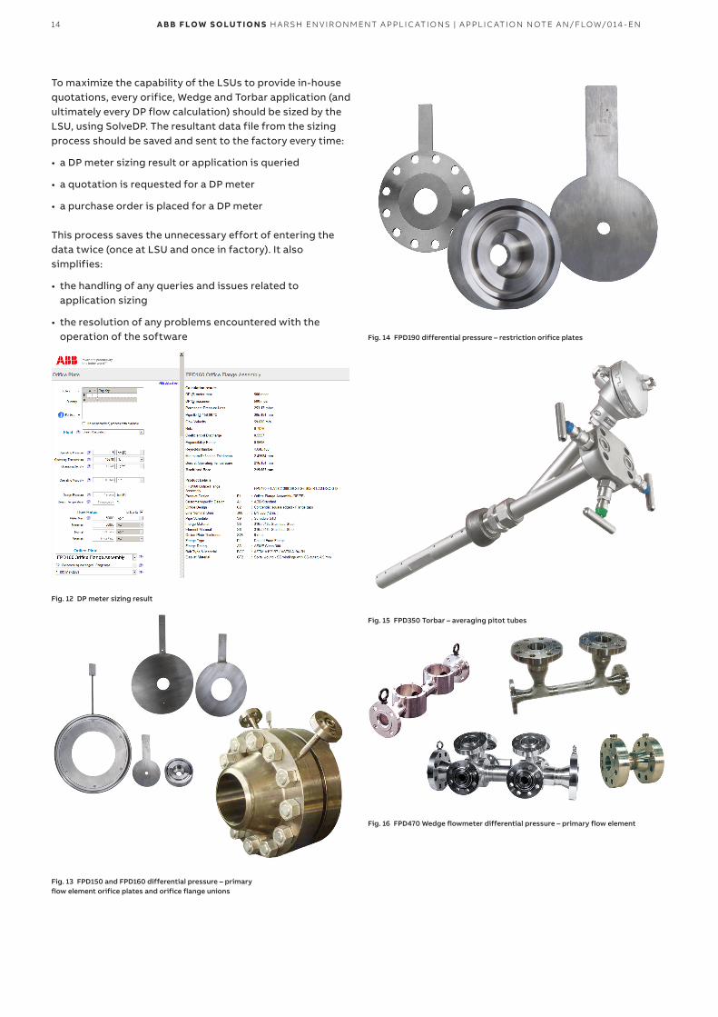
Fig. 12 DP meter sizing result
Fig. 13 FPD150 and FPD160 differential pressure – primary flow element orifice plates and orifice flange unions
Fig. 14 FPD190 differential pressure – restriction orifice plates
Fig. 15 FPD350 Torbar – averaging pitot tubes
Fig. 16 FPD470 Wedge flowmeter differential pressure – primary flow element
15A B B F LOW S O LUTI O N S H A R SH EN V I R O N M ENT A PPL I C ATI O NS | A PPL I C ATI O N N OTE A N/FLOW/014 - EN
Licence keys and software updatesSoftware evolves and improves, presenting the challenge of ensuring that every copy that has been issued is up-to-date. SolveDP resolves this challenge by incorporating an automatic update system, linked to a unique free-of-charge software licence key for every user’s PC. This ensures that, as the scope and functionality of SolveDP is extended and improved, users will get the benefit of any upgrades as soon as they are released. The licence key is currently restricted to ABB employees but, in time, it will be made available to customers and end users.
The auto-update feature prevents:
• the requirement to notify every user that an update has been issued
• the requirement to manually install new versions
• the software becoming ‘out-of-date’ due to updates not being applied
To access the software files and obtain a licence key and software updates:1. Send an email to [email protected], with the
subject line ‘SolveDP Licence’ and request a licence for yourself.
2. You will receive an email containing your licence key in the format: AB1C-WXYZ-ABCD-EFGH-5JKL-MNP5-JBCS
Note. This is a typical format for the key; your personal key is different and unique to your PC.
3. Keep the email safe. When the application has been installed, you are prompted to enter the key to activate SolveDP.
4. Download the installation file (setup.exe).5. Right click on the file and select ‘Run as administrator’ to
install SolveDP, following the on-screen instructions.6. Ensure you have a working internet connection (an
important requirement for the first installation) and run SolveDP for the first time.
7. Enter the licence key when requested, ensuring it is entered exactly as supplied (copy the key from the email and paste it into the box).
8. SolveDP checks for updates via your internet connection and downloads and installs them automatically.
Note. An internet connection must be available when SolveDP is first run – the software will not operate until the initial update check is complete. After the initial check, the software runs without an internet connection, for mobility purposes.
The automatic update function requires the computer to be connected to the internet periodically. SolveDP checks for updates every 7 days automatically. Updates can also be checked for manually at any time by selecting:‘Tools’ > ‘Updates’ > ‘Check’.
If SolveDP cannot contact the server (for example, because an internet connection is not available), update checking fails but the application continues to function.If SolveDP has been unable to contact the server for 14 days, an advisory message is displayed but the application continues to function.
If SolveDP has been unable to contact the server for 56 days, there is a risk that the application is out-of-date. To protect the user from the consequences of using out-of-date software, an error message is displayed and the application closes. However, if SolveDP is launched subsequently, and is able to contact the server, the application can check for updates, after which it can continue to be used for another 56 days.
16 A B B F LOW S O LUTI O N S H A R SH EN V I R O N M ENT A PPL I C ATI O NS | A PPL I C ATI O N N OTE A N/FLOW/014 - EN
Features and benefits• Sizes and configures all ABB DP flow meters*
- enables sizing of all members of the ABB DP family - enables configuration (coding) of all members
* once all upgrades have been released
• Updates automatically - free licence key - ensures the software is always up to date - requires regular internet connection for optimum update
frequency
• Includes dimensions of schedule pipe - select pipe size and schedule from table
(both metric and Imperial) - relevant dimensions and configuration are used
automatically in calculation and coding utilities
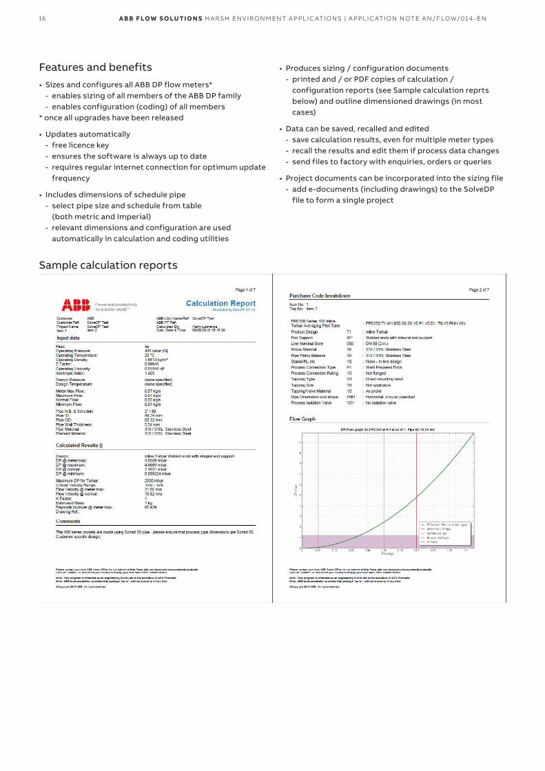
Sample calculation reports
• Produces sizing / configuration documents - printed and / or PDF copies of calculation /
configuration reports (see Sample calculation reprts below) and outline dimensioned drawings (in most cases)
• Data can be saved, recalled and edited - save calculation results, even for multiple meter types - recall the results and edit them if process data changes - send files to factory with enquiries, orders or queries
• Project documents can be incorporated into the sizing file - add e-documents (including drawings) to the SolveDP
file to form a single project
17A B B F LOW S O LUTI O N S H A R SH EN V I R O N M ENT A PPL I C ATI O NS | A PPL I C ATI O N N OTE A N/FLOW/014 - EN
—HOVF coatings from ABBExtreme harsh serviceThe ABB Wedge Meter was introduced to address harsh applications. Mining, Oil and Gas, Waste Water etc. These applications are ideally suited to the wedge meter. The bidirectional property of the wedge meter ensure that it will last many years of service, if wear is apparent over time, the wedge meter is often turned around and can then withstand many more years in service.
However, for extremely harsh service, where critical measurement requires the highest availability and integrity, it could be beneficial to ensure wear, erosion, corrosion etc. is limited as far as reasonably practical. ABB has offered hard coated wedge meters for many years.
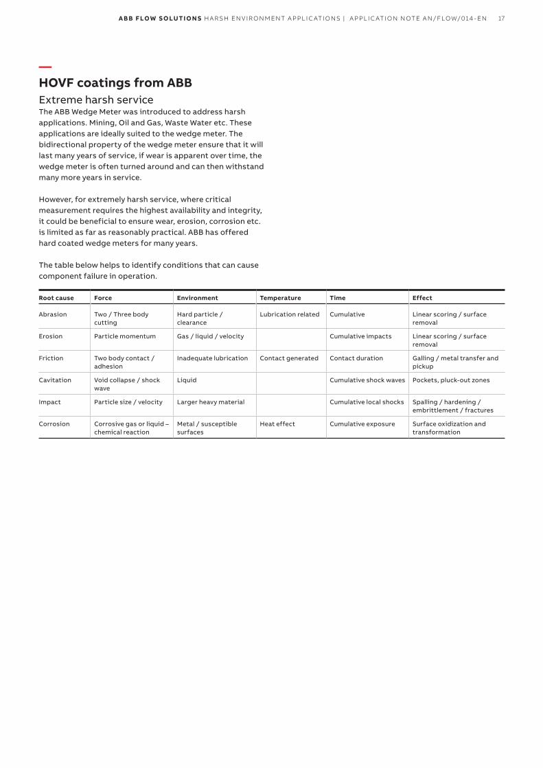
The table below helps to identify conditions that can cause component failure in operation.
Root cause Force Environment Temperature Time Effect
Abrasion Two / Three body cutting
Hard particle / clearance
Lubrication related Cumulative Linear scoring / surface removal
Erosion Particle momentum Gas / liquid / velocity Cumulative impacts Linear scoring / surface removal
Friction Two body contact / adhesion
Inadequate lubrication Contact generated Contact duration Galling / metal transfer and pickup
Cavitation Void collapse / shock wave
Liquid Cumulative shock waves Pockets, pluck-out zones
Impact Particle size / velocity Larger heavy material Cumulative local shocks Spalling / hardening / embrittlement / fractures
Corrosion Corrosive gas or liquid – chemical reaction
Metal / susceptible surfaces
Heat effect Cumulative exposure Surface oxidization and transformation
18 A B B F LOW S O LUTI O N S H A R SH EN V I R O N M ENT A PPL I C ATI O NS | A PPL I C ATI O N N OTE A N/FLOW/014 - EN
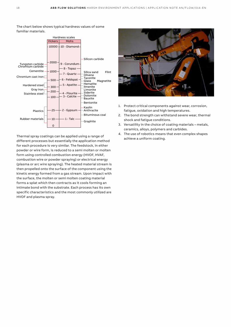
The chart below shows typical hardness values of some familiar materials.
Hardness scales
Silicon carbide
Tungsten carbideChromium carbide
Cementite
Chromium cast iron
Hardened steelGray iron
Stainless steel
Plastics
Rubber materials
Flint
Magnetite
Silica sandOliveneTaconiteGlassHematiteIlmeniteLimoniteSideriteDolomiteBauxiteBentonite
KaolinAnthracite
Bituminous coal
Graphite
Vickers Mohs
10 - Diamond10000
2000
1000
500
300
200
100
25
10
0
9 - Corundum
8 - Topaz
7 - Quartz
6 - Feldspat
5 - Apatite
4 - Flourite3 - Calcite
2 - Gypsum
1 - Talc
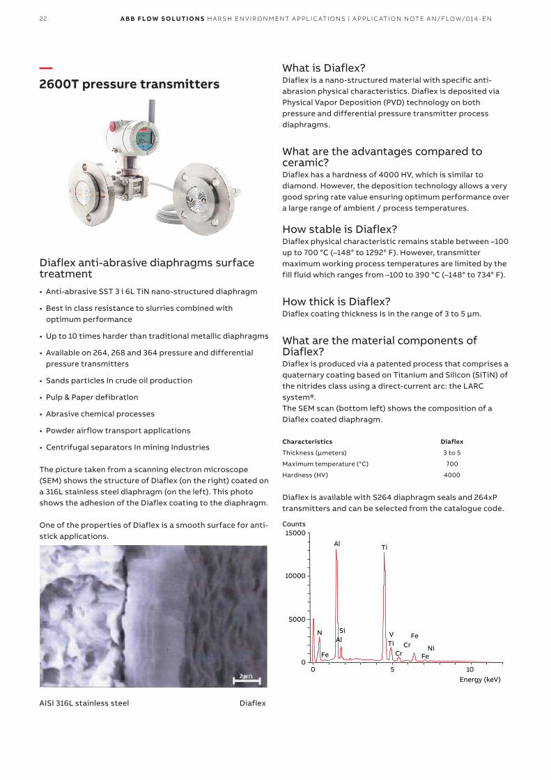
Thermal spray coatings can be applied using a range of different processes but essentially the application method for each procedure is very similar. The feedstock, in either powder or wire form, is reduced to a semi molten or molten form using controlled combustion energy (HVOF, HVAF, combustion wire or powder spraying) or electrical energy (plasma or arc wire spraying). The heated material stream is then propelled onto the surface of the component using the kinetic energy formed from a gas stream. Upon impact with the surface, the molten or semi molten coating material forms a splat which then contracts as it cools forming an intimate bond with the substrate. Each process has its own specific characteristics and the most commonly utilized are HVOF and plasma spray.
1. Protect critical components against wear, corrosion, fatigue, oxidation and high temperatures.
2. The bond strength can withstand severe wear, thermal shock and fatigue conditions.
3. Versatility in the choice of coating materials – metals, ceramics, alloys, polymers and carbides.
4. The use of robotics means that even complex shapes achieve a uniform coating.
19A B B F LOW S O LUTI O N S H A R SH EN V I R O N M ENT A PPL I C ATI O NS | A PPL I C ATI O N N OTE A N/FLOW/014 - EN
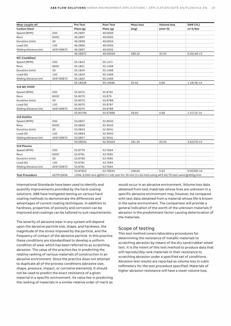
Wear couple ref Pre Test Post Test Mass loss Volume loss SWR (VL)Carbon Steel Plate (g) Plate (g) (mg) (mm^3) m^3/NmSpeed (RPM) 200 49.2897 49.0006Revs 6000 49.2897 49.0005Duration (min) 30 49.2899 49.0004Load (N) 130 49.2896 49.0005Sliding distance (m) 4297.69875 49.2897 49.0005
49.28972 49.00050 289.22 33.53 6.0014E-13WC Coat&SealSpeed (RPM) 200 55.1823 55.1471Revs 6000 55.1821 55.1468Duration (min) 30 55.1824 55.1468Load (N) 130 55.1824 55.1468Sliding distance (m) 4297.69875 55.1822 55.1468
55.18228 55.14686 35.42 0.66 1.1813E-14316 WC HVOF
Speed (RPM) 200 55.9075 55.8791Revs 6000 55.9075 55.879Duration (min) 30 55.9075 55.8788Load (N) 130 55.9075 55.8787Sliding distance (m) 4297.69875 55.9074 55.8788
55.90748 55.87888 28.60 0.68 1.2171E-14316 StelliteSpeed (RPM) 200 53.0857 52.9045Revs 6000 53.0856 52.9042Duration (min) 30 53.0853 52.9041Load (N) 130 53.0854 52.9043Sliding distance (m) 4297.69875 53.0857 52.9041
53.08554 52.90424 181.30 20.24 3.6227E-13316 PlasmaSpeed (RPM) 200 53.8779 53.7694Revs 6000 53.8781 53.7695Duration (min) 30 53.8780 53.7695Load (N) 130 53.8781 53.7694Sliding distance (m) 4297.69875 53.8781 53.7694
53.87810 53.76944 108.66 5.03 9.0030E-14Test Procedure ASTM G65A 130N, 6,000 revs @200 (+/-10) rpm for 30 min (3 x10 min) using AFS 50/70 test sand @300g/min
International Standards have been used to identify and quantify improvements provided by the hard coating solutions. ABB have instigated testing on various hard coating methods to demonstrate the differences and advantages of current coating techniques. In addition to hardness, properties of porosity and corrosion can be improved and coatings can be tailored to suit requirements.
The severity of abrasive wear in any system will depend upon the abrasive particle size, shape, and hardness, the magnitude of the stress imposed by the particle, and the frequency of contact of the abrasive particle. In this practice these conditions are standardized to develop a uniform condition of wear which has been referred to as scratching abrasion. The value of the practice lies in predicting the relative ranking of various materials of construction in an abrasive environment. Since the practice does not attempt to duplicate all of the process conditions (abrasive size, shape, pressure, impact, or corrosive elements), it should not be used to predict the exact resistance of a given material in a specific environment. Its value lies in predicting the ranking of materials in a similar relative order of merit as
would occur in an abrasive environment. Volume loss data obtained from test materials whose lives are unknown in a specific abrasive environment may, however, be compared with test data obtained from a material whose life is known in the same environment. The comparison will provide a general indication of the worth of the unknown materials if abrasion is the predominant factor causing deterioration of the materials.
Scope of testingThis test method covers laboratory procedures for determining the resistance of metallic materials to scratching abrasion by means of the dry sand/rubber wheel test. It is the intent of this test method to produce data that will reproducibly rank materials in their resistance to scratching abrasion under a specified set of conditions. Abrasion test results are reported as volume loss in cubic millimeters for the test procedure specified. Materials of higher abrasion resistance will have a lower volume loss.
20 A B B F LOW S O LUTI O N S H A R SH EN V I R O N M ENT A PPL I C ATI O NS | A PPL I C ATI O N N OTE A N/FLOW/014 - EN
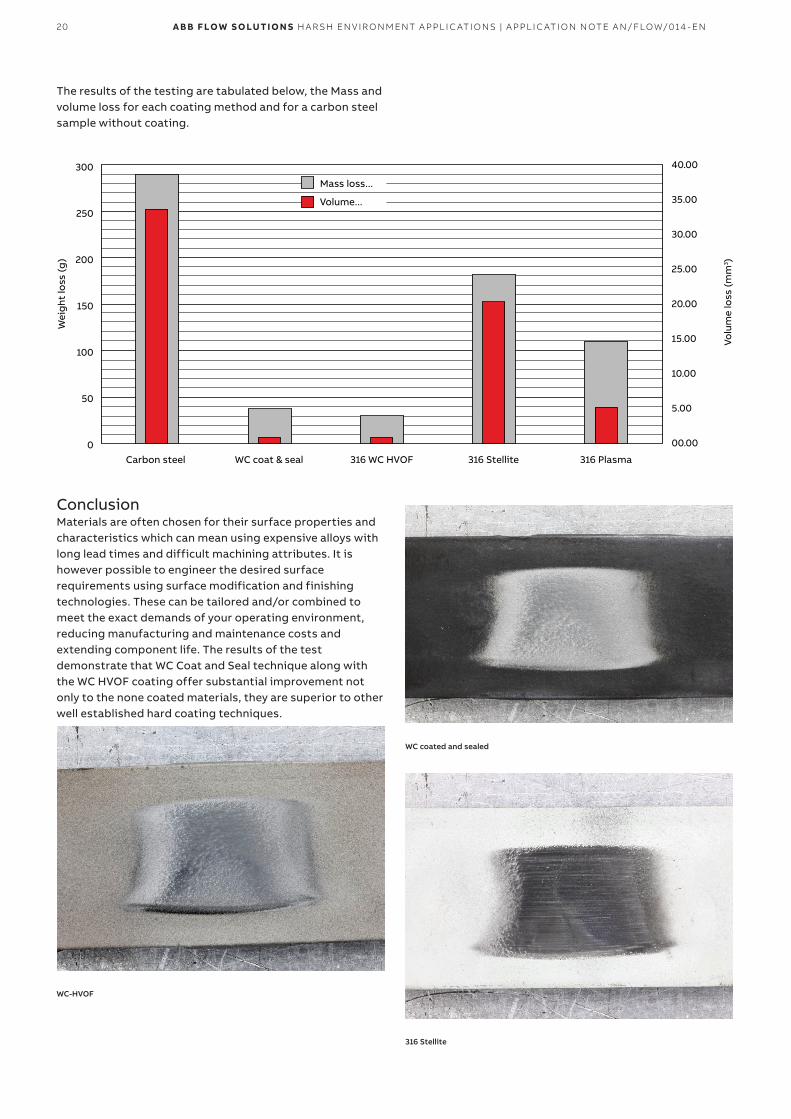
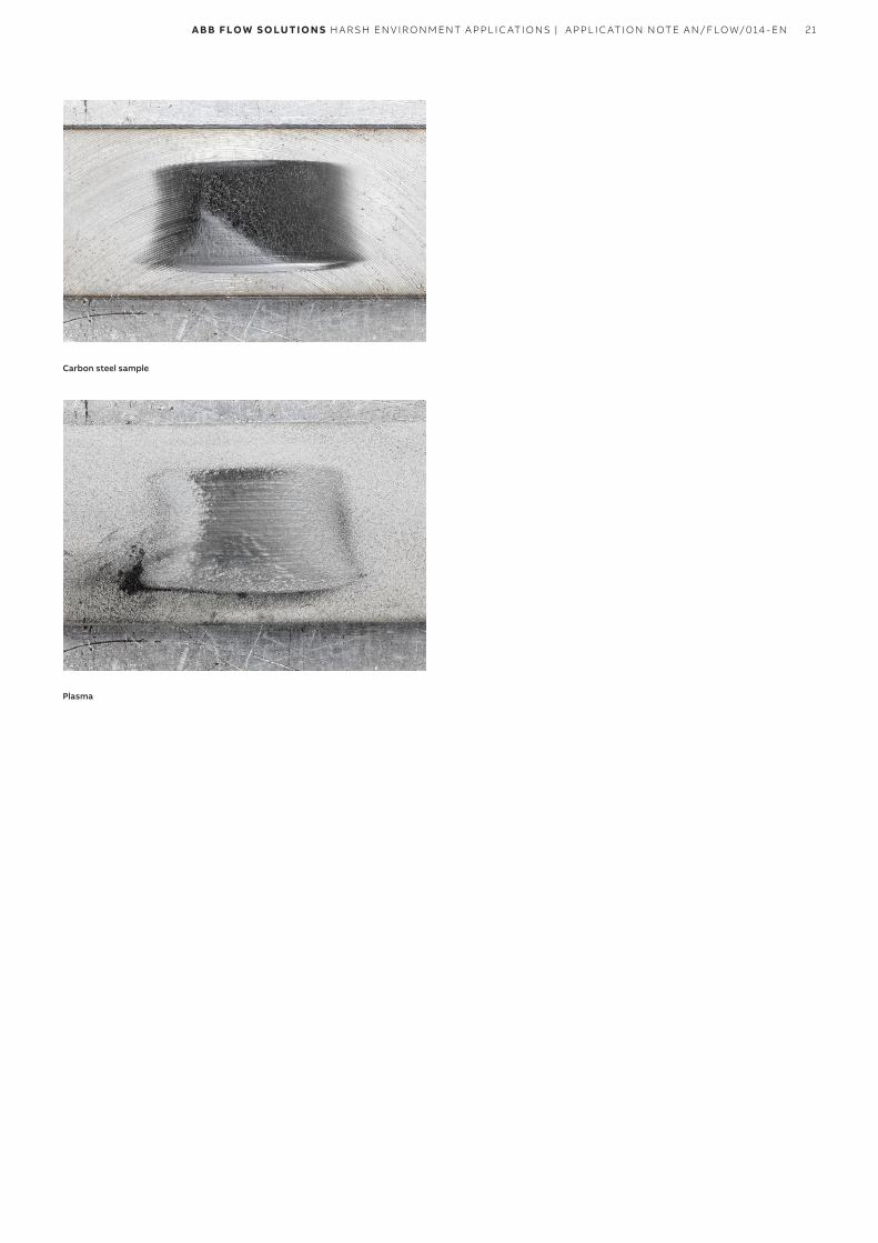
The results of the testing are tabulated below, the Mass and volume loss for each coating method and for a carbon steel sample without coating.
Mass loss...
Carbon steel0
50
100
150
Wei
ght
loss
(g)
Volu
me
loss
(mm
3 )200
250
300 40.00
35.00
30.00
25.00
20.00
15.00
10.00
5.00
00.00
WC coat & seal 316 WC HVOF 316 Stellite 316 Plasma
Volume...
ConclusionMaterials are often chosen for their surface properties and characteristics which can mean using expensive alloys with long lead times and difficult machining attributes. It is however possible to engineer the desired surface requirements using surface modification and finishing technologies. These can be tailored and/or combined to meet the exact demands of your operating environment, reducing manufacturing and maintenance costs and extending component life. The results of the test demonstrate that WC Coat and Seal technique along with the WC HVOF coating offer substantial improvement not only to the none coated materials, they are superior to other well established hard coating techniques.
WC-HVOF
WC coated and sealed
316 Stellite
21A B B F LOW S O LUTI O N S H A R SH EN V I R O N M ENT A PPL I C ATI O NS | A PPL I C ATI O N N OTE A N/FLOW/014 - EN
Carbon steel sample
Plasma
22 A B B F LOW S O LUTI O N S H A R SH EN V I R O N M ENT A PPL I C ATI O NS | A PPL I C ATI O N N OTE A N/FLOW/014 - EN
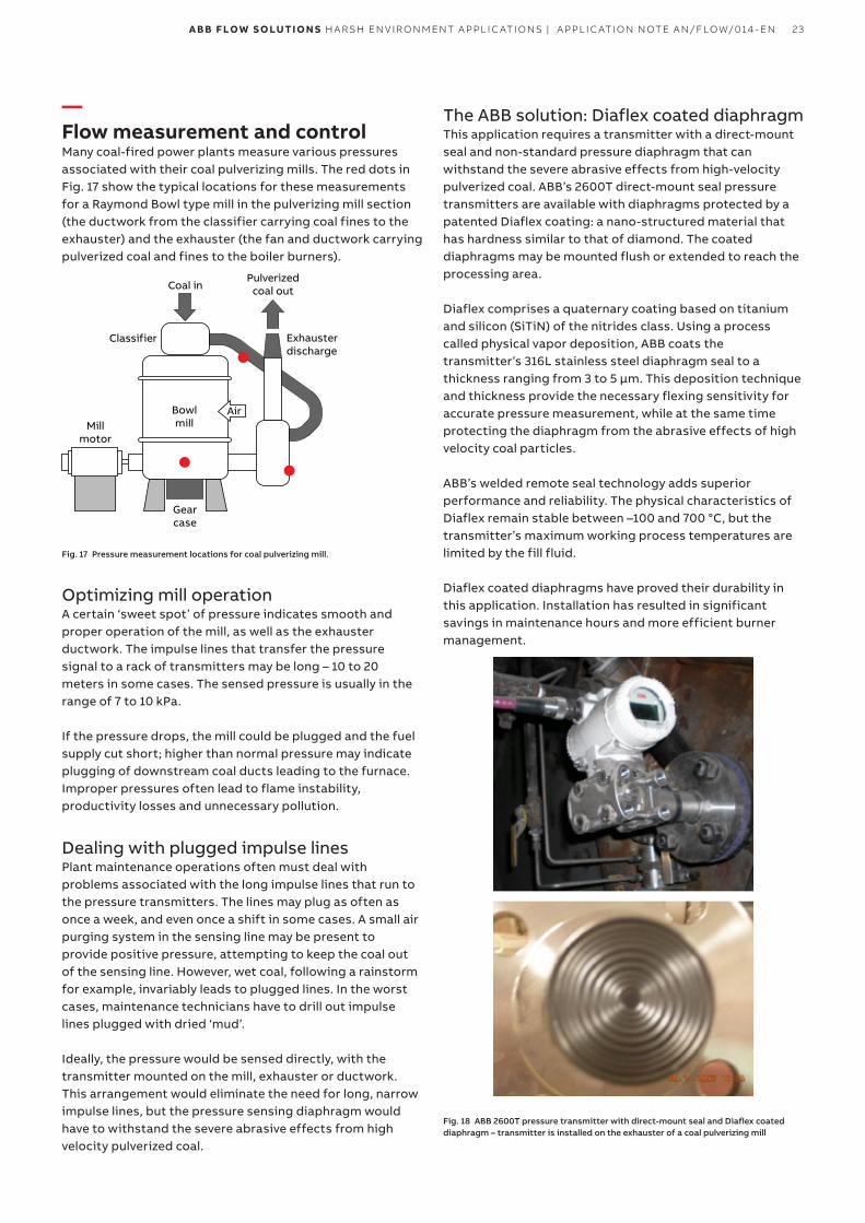
—2600T pressure transmitters
Diaflex anti-abrasive diaphragms surface treatment• Anti-abrasive SST 3 i 6L TiN nano-structured diaphragm
• Best in class resistance to slurries combined with optimum performance
• Up to 10 times harder than traditional metallic diaphragms
• Available on 264, 268 and 364 pressure and differential pressure transmitters
• Sands particles In crude oil production
• Pulp & Paper defibratlon
• Abrasive chemical processes
• Powder airflow transport applications
• Centrifugal separators In mining Industries
The picture taken from a scanning electron microscope (SEM) shows the structure of Diaflex (on the right) coated on a 316L stainless steel diaphragm (on the left). This photo shows the adhesion of the Diaflex coating to the diaphragm.
One of the properties of Diaflex is a smooth surface for anti-stick applications.
AISI 316L stainless steel Diaflex
What is Diaflex?Diaflex is a nano-structured material with specific anti-abrasion physical characteristics. Diaflex is deposited via Physical Vapor Deposition (PVD) technology on both pressure and differential pressure transmitter process diaphragms.
What are the advantages compared to ceramic?Diaflex has a hardness of 4000 HV, which is similar to diamond. However, the deposition technology allows a very good spring rate value ensuring optimum performance over a large range of ambient / process temperatures.
How stable is Diaflex?Diaflex physical characteristic remains stable between –100 up to 700 °C (–148° to 1292° F). However, transmitter maximum working process temperatures are limited by the fill fluid which ranges from –100 to 390 °C (–148° to 734° F).
How thick is Diaflex?Diaflex coating thickness is in the range of 3 to 5 μm.
What are the material components of Diaflex?Diaflex is produced via a patented process that comprises a quaternary coating based on Titanium and Silicon (SiTiN) of the nitrides class using a direct-current arc: the LARC system®.The SEM scan (bottom left) shows the composition of a Diaflex coated diaphragm.
Characteristics Diaflex
Thickness (μmeters) 3 to 5
Maximum temperature (°C) 700
Hardness (HV) 4000
Diaflex is available with S264 diaphragm seals and 264xP transmitters and can be selected from the catalogue code.
Counts
Energy (keV)
Al
AlSi
Ti
TiCr
CrFe
FeNi
VN
Fe
15000
10000
5000
00 5 10
23A B B F LOW S O LUTI O N S H A R SH EN V I R O N M ENT A PPL I C ATI O NS | A PPL I C ATI O N N OTE A N/FLOW/014 - EN
—Flow measurement and controlMany coal-fired power plants measure various pressures associated with their coal pulverizing mills. The red dots in Fig. 17 show the typical locations for these measurements for a Raymond Bowl type mill in the pulverizing mill section (the ductwork from the classifier carrying coal fines to the exhauster) and the exhauster (the fan and ductwork carrying pulverized coal and fines to the boiler burners).
Coal in
Gearcase
Exhausterdischarge
Classifier
AirBowlmillMill
motor
Pulverizedcoal out
Fig. 17 Pressure measurement locations for coal pulverizing mill.
Optimizing mill operationA certain ‘sweet spot’ of pressure indicates smooth and proper operation of the mill, as well as the exhauster ductwork. The impulse lines that transfer the pressure signal to a rack of transmitters may be long – 10 to 20 meters in some cases. The sensed pressure is usually in the range of 7 to 10 kPa.
If the pressure drops, the mill could be plugged and the fuel supply cut short; higher than normal pressure may indicate plugging of downstream coal ducts leading to the furnace. Improper pressures often lead to flame instability, productivity losses and unnecessary pollution.
Dealing with plugged impulse linesPlant maintenance operations often must deal with problems associated with the long impulse lines that run to the pressure transmitters. The lines may plug as often as once a week, and even once a shift in some cases. A small air purging system in the sensing line may be present to provide positive pressure, attempting to keep the coal out of the sensing line. However, wet coal, following a rainstorm for example, invariably leads to plugged lines. In the worst cases, maintenance technicians have to drill out impulse lines plugged with dried ‘mud’.
Ideally, the pressure would be sensed directly, with the transmitter mounted on the mill, exhauster or ductwork. This arrangement would eliminate the need for long, narrow impulse lines, but the pressure sensing diaphragm would have to withstand the severe abrasive effects from high velocity pulverized coal.
The ABB solution: Diaflex coated diaphragmThis application requires a transmitter with a direct-mount seal and non-standard pressure diaphragm that can withstand the severe abrasive effects from high-velocity pulverized coal. ABB’s 2600T direct-mount seal pressure transmitters are available with diaphragms protected by a patented Diaflex coating: a nano-structured material that has hardness similar to that of diamond. The coated diaphragms may be mounted flush or extended to reach the processing area.
Diaflex comprises a quaternary coating based on titanium and silicon (SiTiN) of the nitrides class. Using a process called physical vapor deposition, ABB coats the transmitter’s 316L stainless steel diaphragm seal to a thickness ranging from 3 to 5 μm. This deposition technique and thickness provide the necessary flexing sensitivity for accurate pressure measurement, while at the same time protecting the diaphragm from the abrasive effects of high velocity coal particles.
ABB’s welded remote seal technology adds superior performance and reliability. The physical characteristics of Diaflex remain stable between –100 and 700 °C, but the transmitter’s maximum working process temperatures are limited by the fill fluid.
Diaflex coated diaphragms have proved their durability in this application. Installation has resulted in significant savings in maintenance hours and more efficient burner management.
Fig. 18 ABB 2600T pressure transmitter with direct-mount seal and Diaflex coated diaphragm – transmitter is installed on the exhauster of a coal pulverizing mill
24 A B B F LOW S O LUTI O N S H A R SH EN V I R O N M ENT A PPL I C ATI O NS | A PPL I C ATI O N N OTE A N/FLOW/014 - EN
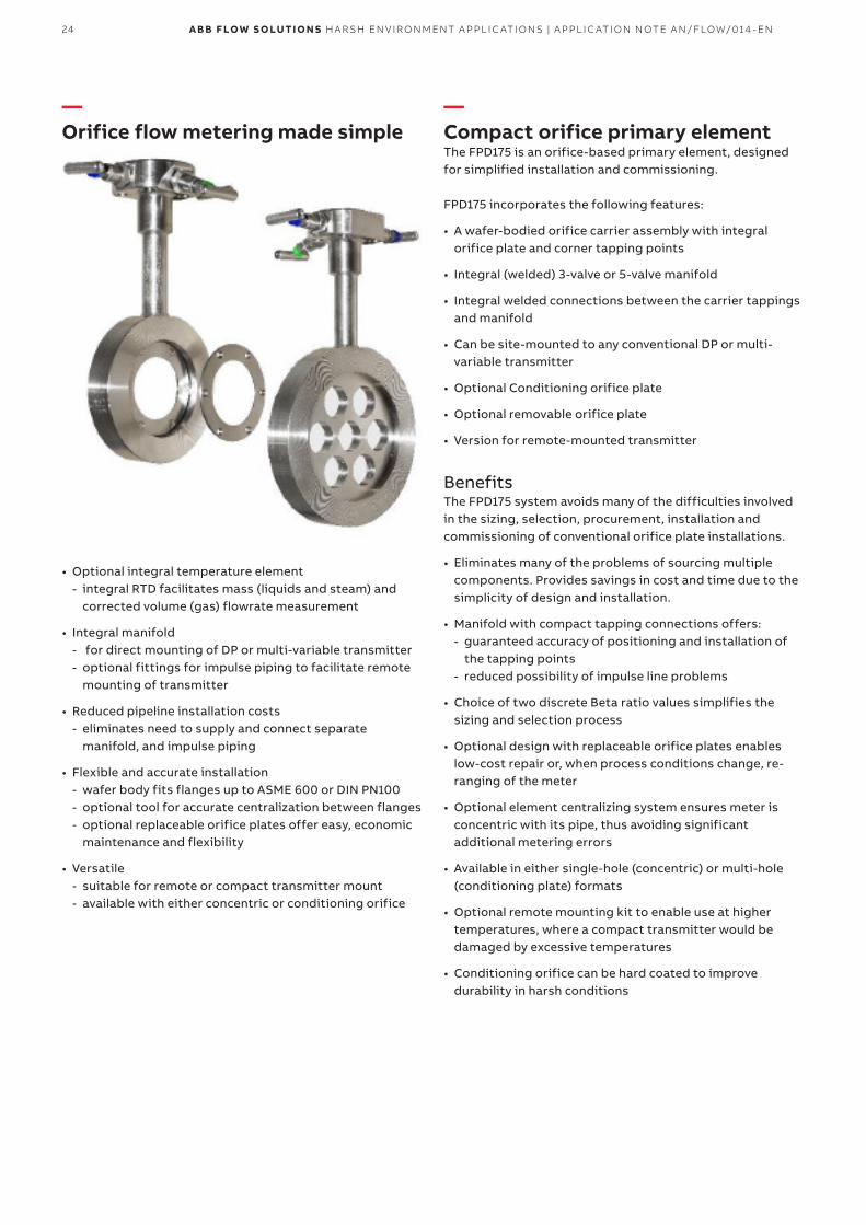
—Orifice flow metering made simple
• Optional integral temperature element - integral RTD facilitates mass (liquids and steam) and
corrected volume (gas) flowrate measurement
• Integral manifold - for direct mounting of DP or multi-variable transmitter - optional fittings for impulse piping to facilitate remote
mounting of transmitter
• Reduced pipeline installation costs - eliminates need to supply and connect separate
manifold, and impulse piping
• Flexible and accurate installation - wafer body fits flanges up to ASME 600 or DIN PN100 - optional tool for accurate centralization between flanges - optional replaceable orifice plates offer easy, economic
maintenance and flexibility
• Versatile - suitable for remote or compact transmitter mount - available with either concentric or conditioning orifice
—Compact orifice primary elementThe FPD175 is an orifice-based primary element, designed for simplified installation and commissioning.
FPD175 incorporates the following features:
• A wafer-bodied orifice carrier assembly with integral orifice plate and corner tapping points
• Integral (welded) 3-valve or 5-valve manifold
• Integral welded connections between the carrier tappings and manifold
• Can be site-mounted to any conventional DP or multi-variable transmitter
• Optional Conditioning orifice plate
• Optional removable orifice plate
• Version for remote-mounted transmitter
BenefitsThe FPD175 system avoids many of the difficulties involved in the sizing, selection, procurement, installation and commissioning of conventional orifice plate installations.
• Eliminates many of the problems of sourcing multiple components. Provides savings in cost and time due to the simplicity of design and installation.
• Manifold with compact tapping connections offers: - guaranteed accuracy of positioning and installation of
the tapping points - reduced possibility of impulse line problems
• Choice of two discrete Beta ratio values simplifies the sizing and selection process
• Optional design with replaceable orifice plates enables low-cost repair or, when process conditions change, re-ranging of the meter
• Optional element centralizing system ensures meter is concentric with its pipe, thus avoiding significant additional metering errors
• Available in either single-hole (concentric) or multi-hole (conditioning plate) formats
• Optional remote mounting kit to enable use at higher temperatures, where a compact transmitter would be damaged by excessive temperatures
• Conditioning orifice can be hard coated to improve durability in harsh conditions
25A B B F LOW S O LUTI O N S H A R SH EN V I R O N M ENT A PPL I C ATI O NS | A PPL I C ATI O N N OTE A N/FLOW/014 - EN
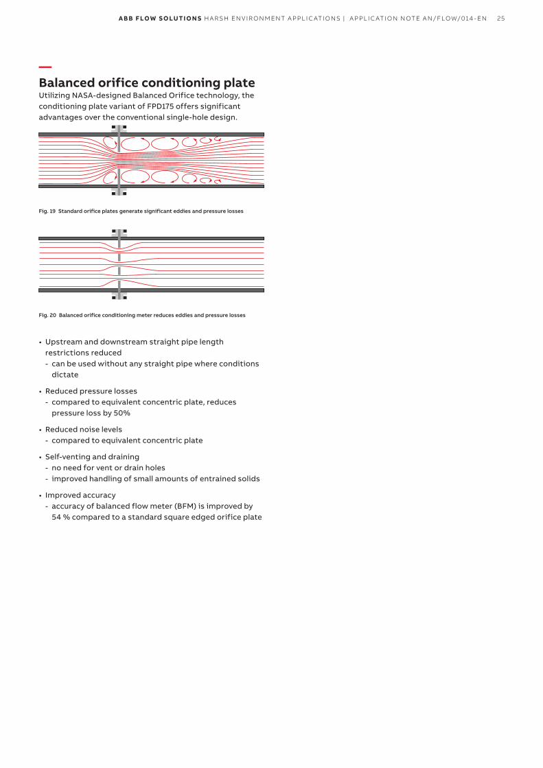
—Balanced orifice conditioning plateUtilizing NASA-designed Balanced Orifice technology, the conditioning plate variant of FPD175 offers significant advantages over the conventional single-hole design.
Fig. 19 Standard orifice plates generate significant eddies and pressure losses
Fig. 20 Balanced orifice conditioning meter reduces eddies and pressure losses
• Upstream and downstream straight pipe length restrictions reduced - can be used without any straight pipe where conditions
dictate
• Reduced pressure losses - compared to equivalent concentric plate, reduces
pressure loss by 50%
• Reduced noise levels - compared to equivalent concentric plate
• Self-venting and draining - no need for vent or drain holes - improved handling of small amounts of entrained solids
• Improved accuracy - accuracy of balanced flow meter (BFM) is improved by
54 % compared to a standard square edged orifice plate

26 A B B F LOW S O LUTI O N S H A R SH EN V I R O N M ENT A PPL I C ATI O NS | A PPL I C ATI O N N OTE A N/FLOW/014 - EN
—Notes

27A B B F LOW S O LUTI O N S H A R SH EN V I R O N M ENT A PPL I C ATI O NS | A PPL I C ATI O N N OTE A N/FLOW/014 - EN
AN
/F
LO
W/
014
-EN
0
5.2
017
—ABB Limited Measurement & Analytics Salterbeck Trading Estate, Workington Cumbria, CA14 5DS UK Tel: +44 (0)1946 830 611 Fax: +44 (0)1946 832 661 Mail: [email protected]
ABB Inc. Measurement & Analytics 125 E. County Line Road Warminster, PA 18974 USA Tel: +1 215 674 6000 Fax: +1 215 674 7183
abb.com/measurement
—We reserve the right to make technical changes or modify the contents of this document without prior notice. With regard to purchase orders, the agreed particulars shall prevail. ABB does not accept any responsibility whatsoever for potential errors or possible lack of information in this document.
We reserve all rights in this document and in the subject matter and illustrations contained therein. Any reproduction, disclosure to third parties or utilization of its contents – in whole or in parts – is forbidden without prior written consent of ABB.
© Copyright 2017 ABB.All rights reserved.
Related Documents