AA7075 bit for repairing AA2219 keyhole by filling friction stir welding Bing Han a , Yongxian Huang a,⇑ , Shixiong Lv a , Long Wan a , Jicai Feng a , Guansheng Fu b a State Key Laboratory of Advanced Welding and Joining, Harbin Institute of Technology, Harbin 150001, People’s Republic of China b Csr Zhuzhou Electric Locomotive Co., Ltd., Zhuzhou 412001, People’s Republic of China article info Article history: Received 16 January 2013 Accepted 27 March 2013 Available online 6 April 2013 Keywords: Filling friction stir welding Aluminum bit Keyhole Interface Mechanical property abstract In the present study, 7.8 mm thick AA2219 rolled plates were successfully filling friction stir welded (FFSW) without keyhole using a semi-consumable tool. The influences of the bit’s geometric parameters and the plunge speed on the joint’s mechanical properties were investigated. Microstructure of the joint, especially at the interface, was observed. The results revealed that the AA7075 bit’s employment was able to decrease the shedding bit material effectively. During tensile tests, the maximum ultimate tensile strength (UTS) and elongation of the joint were 179.6 MPa and 13.7%, equivalent to 96.6% and 99% of the original defect-free friction stir welding (FSW) joint, respectively. The defect-free FFSW joints were produced at lower plunge speeds, and the fracture locations were at the softened region within the heat affected zone (HAZ) adjacent to the thermo-mechanically affected zone (TMAZ) on the retreating side. With increasing the plunge speed, the fracture location was more mainly dependent on the interface strength instead of the hardness distribution. Crown Copyright Ó 2013 Published by Elsevier Ltd. All rights reserved. 1. Introduction Nowadays, high strength aluminum alloys have been applied as high strength-to-weight ratio materials [1]. Among them, the high- strength precipitate hardening Al–Zn–Mg–(Cu) 7000-series alumi- num alloys such as AA7075 are extensively used in automotive and aerospace structures for their lightweight and high strength [2]. And the heat treatable Al–Cu 2000-series aluminum alloys such as AA2219 also has a great potential for a wide range of applica- tions owing to their high specific-strength, good fracture tough- ness and excellent stress-corrosion resistance too [3,4]. Friction stir welding (FSW), a solid-state process invented at TWI (Cambridge, United Kingdom), in 1991, is being targeted by the industry for structurally demanding applications to provide high-performance benefits [5,6]. This new technology can join dif- ficult to weld aluminum alloys by traditional fusion techniques, for example alloys belonging to the 2000-series with limited weldabil- ity and the 7000-series generally not recommended for welding and joining, even if they are the more used aluminum alloys in aerospace applications [7]. FSW is shown not to cause severe dis- tortion and residual stresses generated are low compared to the traditional welding processes [6]. Weld defects, however, like groove, cavity and kissing bond are easily formed under improper parameters or technological conditions [8–10]. Emphatically, the keyhole inevitably remains at the end of the weld, from which the non-consumable welding tool entry probe has to be withdrawn after FSW or friction stir spot welding (FSSW). Both lap shear and cross-tension strengths are limited due to the relatively small bonding widths [11]. In view of the keyhole or other defects, the re-FSW process is feasible to restore the defects not only outside but also inside of the joints. However, new keyholes would be emerged as soon as the defects were repaired [12]. Up to now, a variety of methods and apparatuses have been developed to repair the keyhole in FSW welds. A solid state joining process called friction taper plug welding (FTPW) or friction hydro pillar processing (FHPP) has been invented by TWI during the 1990s, which involves drilling a tapered through hole into a plate. After that, a tapered plug with a similar included angle is friction welded to the matching surface of the hole in a few seconds by forcing the rotating plug against the drilled hole [13,14]. It can be used in several applications, for example, at the location of a de- fect or crack in offshore steel and aerospace aluminum structures that is intended to be repaired [15,16]. However, due to the use of the tapered plug without shoulder, stress concentration is going to be formed at the interface, and a tapered through hole and prop- er plug should be prepared to get defect free joints, especially for high melting point material thick structures due to the high flow stress. Furthermore, a novel apparatus called auto-adjusting pin tool has been developed by the National Aeronautics and Space Admin- istration, which can be used for materials of varying thickness, and the pin can be incrementally withdrawn from the work pieces dur- ing the final stage of the transverse, thus eliminating the exit key- hole in the weld [17]. And similarly, the retractable [18,19] or double acting re-filling tool [20], consisting of a separated outer 0261-3069/$ - see front matter Crown Copyright Ó 2013 Published by Elsevier Ltd. All rights reserved. http://dx.doi.org/10.1016/j.matdes.2013.03.089 ⇑ Corresponding author. Tel.: +86 451 86413951; fax: +86 451 86416186. E-mail address: [email protected] (Y. Huang). Materials and Design 51 (2013) 25–33 Contents lists available at SciVerse ScienceDirect Materials and Design journal homepage: www.elsevier.com/locate/matdes

Welcome message from author
This document is posted to help you gain knowledge. Please leave a comment to let me know what you think about it! Share it to your friends and learn new things together.
Transcript
Materials and Design 51 (2013) 25–33
Contents lists available at SciVerse ScienceDirect
Materials and Design
journal homepage: www.elsevier .com/locate /matdes
AA7075 bit for repairing AA2219 keyhole by filling friction stir welding
0261-3069/$ - see front matter Crown Copyright � 2013 Published by Elsevier Ltd. All rights reserved.http://dx.doi.org/10.1016/j.matdes.2013.03.089
⇑ Corresponding author. Tel.: +86 451 86413951; fax: +86 451 86416186.E-mail address: [email protected] (Y. Huang).
Bing Han a, Yongxian Huang a,⇑, Shixiong Lv a, Long Wan a, Jicai Feng a, Guansheng Fu b
a State Key Laboratory of Advanced Welding and Joining, Harbin Institute of Technology, Harbin 150001, People’s Republic of Chinab Csr Zhuzhou Electric Locomotive Co., Ltd., Zhuzhou 412001, People’s Republic of China
a r t i c l e i n f o
Article history:Received 16 January 2013Accepted 27 March 2013Available online 6 April 2013
Keywords:Filling friction stir weldingAluminum bitKeyholeInterfaceMechanical property
a b s t r a c t
In the present study, 7.8 mm thick AA2219 rolled plates were successfully filling friction stir welded(FFSW) without keyhole using a semi-consumable tool. The influences of the bit’s geometric parametersand the plunge speed on the joint’s mechanical properties were investigated. Microstructure of the joint,especially at the interface, was observed. The results revealed that the AA7075 bit’s employment was ableto decrease the shedding bit material effectively. During tensile tests, the maximum ultimate tensilestrength (UTS) and elongation of the joint were 179.6 MPa and 13.7%, equivalent to 96.6% and 99% ofthe original defect-free friction stir welding (FSW) joint, respectively. The defect-free FFSW joints wereproduced at lower plunge speeds, and the fracture locations were at the softened region within the heataffected zone (HAZ) adjacent to the thermo-mechanically affected zone (TMAZ) on the retreating side.With increasing the plunge speed, the fracture location was more mainly dependent on the interfacestrength instead of the hardness distribution.
Crown Copyright � 2013 Published by Elsevier Ltd. All rights reserved.
1. Introduction
Nowadays, high strength aluminum alloys have been applied ashigh strength-to-weight ratio materials [1]. Among them, the high-strength precipitate hardening Al–Zn–Mg–(Cu) 7000-series alumi-num alloys such as AA7075 are extensively used in automotive andaerospace structures for their lightweight and high strength [2].And the heat treatable Al–Cu 2000-series aluminum alloys suchas AA2219 also has a great potential for a wide range of applica-tions owing to their high specific-strength, good fracture tough-ness and excellent stress-corrosion resistance too [3,4].
Friction stir welding (FSW), a solid-state process invented atTWI (Cambridge, United Kingdom), in 1991, is being targeted bythe industry for structurally demanding applications to providehigh-performance benefits [5,6]. This new technology can join dif-ficult to weld aluminum alloys by traditional fusion techniques, forexample alloys belonging to the 2000-series with limited weldabil-ity and the 7000-series generally not recommended for weldingand joining, even if they are the more used aluminum alloys inaerospace applications [7]. FSW is shown not to cause severe dis-tortion and residual stresses generated are low compared to thetraditional welding processes [6]. Weld defects, however, likegroove, cavity and kissing bond are easily formed under improperparameters or technological conditions [8–10]. Emphatically, thekeyhole inevitably remains at the end of the weld, from whichthe non-consumable welding tool entry probe has to be withdrawn
after FSW or friction stir spot welding (FSSW). Both lap shear andcross-tension strengths are limited due to the relatively smallbonding widths [11]. In view of the keyhole or other defects, there-FSW process is feasible to restore the defects not only outsidebut also inside of the joints. However, new keyholes would beemerged as soon as the defects were repaired [12].
Up to now, a variety of methods and apparatuses have beendeveloped to repair the keyhole in FSW welds. A solid state joiningprocess called friction taper plug welding (FTPW) or friction hydropillar processing (FHPP) has been invented by TWI during the1990s, which involves drilling a tapered through hole into a plate.After that, a tapered plug with a similar included angle is frictionwelded to the matching surface of the hole in a few seconds byforcing the rotating plug against the drilled hole [13,14]. It canbe used in several applications, for example, at the location of a de-fect or crack in offshore steel and aerospace aluminum structuresthat is intended to be repaired [15,16]. However, due to the useof the tapered plug without shoulder, stress concentration is goingto be formed at the interface, and a tapered through hole and prop-er plug should be prepared to get defect free joints, especially forhigh melting point material thick structures due to the high flowstress.
Furthermore, a novel apparatus called auto-adjusting pin toolhas been developed by the National Aeronautics and Space Admin-istration, which can be used for materials of varying thickness, andthe pin can be incrementally withdrawn from the work pieces dur-ing the final stage of the transverse, thus eliminating the exit key-hole in the weld [17]. And similarly, the retractable [18,19] ordouble acting re-filling tool [20], consisting of a separated outer
26 B. Han et al. / Materials and Design 51 (2013) 25–33
shoulder and an inner pin, has been developed and applied to elim-inate the keyhole by controlling the relative movement of shoulderand pin at the final stage of welding. Uneconomically, all thesethree similar welding tools must be installed on exceedingly com-plex and expensive equipments.
In addition to the above, a new solid state spot joining processcalled friction bit joining (FBJ) has been developed relying on a spe-cial designed consumable joining bit [11,21,22]. The bondingwidths of the joints have been increased. The lap shear strengthof the FBJ spot is better than that of the self-piercing rivets, andthe FBJ is especially applied to join soft and hard materials combi-nations, such as AA5754 and DP980 steel [22]. The FBJ process iscarried out in two main steps: a cutting step and a joining step.During the cutting phase, the bit cut through the top layer of thetwo sheets to be joined. The heat is mainly generated by the
Fig. 1. Features of FFSW tool: (a) steel shoulder, (b) AA707
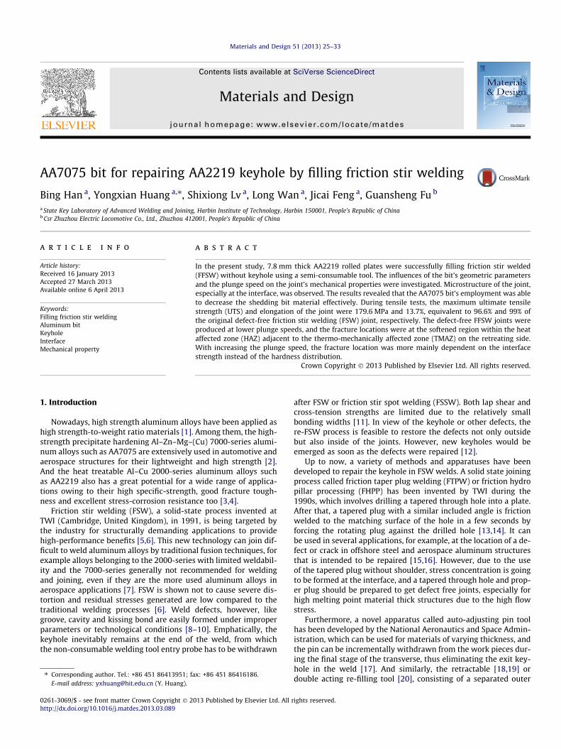
Fig. 2. Dissimilar AA2219/AA7075 FFSW plates with (a) FSW keyhole
friction between the bit and surrounding sheet materials. The bitis consumed as filler material that joins the sheets together. Atthe end of the joining phase, the spindle of the welding machineis stopped very rapidly and then restarted to separate the joiningbit from the weld [11,21,22].
Recently, a new technique called self-refilling friction stirwelding (SRFSW) has been proposed by Zhou et al. [23], whereconventional FSW process is transformed by adopting a series ofnon-consumable polycrystalline cubic boron nitride (PCBN) toolswith gradual change in geometry. Keyholes in 316L stainless steelplates left by friction stir processing (FSP) process have been suc-cessfully refilled by combined plastic deformation and flow ofthe material around the keyhole using the designed tools step bystep. Tensile test results show that the tensile specimens arefractured at the BM side, and the relative tensile strength and
5 bit and (c) assembled semi-consumable FFSW tool.
defects, (b) repaired keyhole and (c) repaired keyhole after FSP.
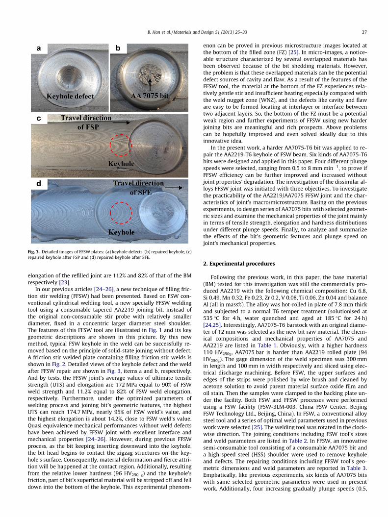
Fig. 3. Detailed images of FFSW plates: (a) keyhole defects, (b) repaired keyhole, (c)repaired keyhole after FSP and (d) repaired keyhole after SFE.
B. Han et al. / Materials and Design 51 (2013) 25–33 27
elongation of the refilled joint are 112% and 82% of that of the BMrespectively [23].
In our previous articles [24–26], a new technique of filling fric-tion stir welding (FFSW) had been presented. Based on FSW con-ventional cylindrical welding tool, a new specially FFSW weldingtool using a consumable tapered AA2219 joining bit, instead ofthe original non-consumable stir probe with relatively smallerdiameter, fixed in a concentric larger diameter steel shoulder.The features of this FFSW tool are illustrated in Fig. 1 and its keygeometric descriptions are shown in this picture. By this newmethod, typical FSW keyhole in the weld can be successfully re-moved based on the principle of solid-state joining without defect.A friction stir welded plate containing filling friction stir welds isshown in Fig. 2. Detailed views of the keyhole defect and the weldafter FFSW repair are shown in Fig. 3, items a and b, respectively.And by tests, the FFSW joint’s average values of ultimate tensilestrength (UTS) and elongation are 172 MPa equal to 90% of FSWweld strength and 11.2% equal to 82% of FSW weld elongation,respectively. Furthermore, under the optimized parameters ofwelding process and joining bit’s geometric features, the highestUTS can reach 174.7 MPa, nearly 95% of FSW weld’s value, andthe highest elongation is about 14.2%, close to FSW weld’s value.Quasi equivalence mechanical performances without weld defectshave been achieved by FFSW joint with excellent interface andmechanical properties [24–26]. However, during previous FFSWprocess, as the bit keeping inserting downward into the keyhole,the bit head begins to contact the zigzag structures on the key-hole’s surface. Consequently, material deformation and fierce attri-tion will be happened at the contact region. Additionally, resultingfrom the relative lower hardness (96 HV250 g) and the keyhole’sfriction, part of bit’s superficial material will be stripped off and felldown into the bottom of the keyhole. This experimental phenom-
enon can be proved in previous microstructure images located atthe bottom of the filled zone (FZ) [25]. In micro-images, a notice-able structure characterized by several overlapped materials hasbeen observed because of the bit shedding materials. However,the problem is that these overlapped materials can be the potentialdefect sources of cavity and flaw. As a result of the features of theFFSW tool, the material at the bottom of the FZ experiences rela-tively gentle stir and insufficient heating especially compared withthe weld nugget zone (WNZ), and the defects like cavity and flaware easy to be formed locating at interlayer or interface betweentwo adjacent layers. So, the bottom of the FZ must be a potentialweak region and further experiments of FFSW using new harderjoining bits are meaningful and rich prospects. Above problemscan be hopefully improved and even solved ideally due to thisinnovative idea.
In the present work, a harder AA7075-T6 bit was applied to re-pair the AA2219-T6 keyhole of FSW beam. Six kinds of AA7075-T6bits were designed and applied in this paper. Four different plungespeeds were selected, ranging from 0.5 to 8 mm min�1, to prove ifFFSW efficiency can be further improved and increased withoutjoint properties’ degradation. The investigation of the dissimilar al-loys FFSW joint was initiated with three objectives. To investigatethe practicability of the AA2219/AA7075 FFSW joint and the char-acteristics of joint’s macro/microstructure. Basing on the previousexperiments, to design series of AA7075 bits with selected geomet-ric sizes and examine the mechanical properties of the joint mainlyin terms of tensile strength, elongation and hardness distributionsunder different plunge speeds. Finally, to analyze and summarizethe effects of the bit’s geometric features and plunge speed onjoint’s mechanical properties.
2. Experimental procedures
Following the previous work, in this paper, the base material(BM) tested for this investigation was still the commercially pro-duced AA2219 with the following chemical composition: Cu 6.8,Si 0.49, Mn 0.32, Fe 0.23, Zr 0.2, V 0.08, Ti 0.06, Zn 0.04 and balanceAl (all in mass%). The alloy was hot-rolled in plate of 7.8 mm thickand subjected to a normal T6 temper treatment (solutionised at535 �C for 4 h, water quenched and aged at 185 �C for 24 h)[24,25]. Interestingly, AA7075-T6 barstock with an original diame-ter of 12 mm was selected as the new bit raw material. The chem-ical compositions and mechanical properties of AA7075 andAA2219 are listed in Table 1. Obviously, with a higher hardness110 HV250g, AA7075 bar is harder than AA2219 rolled plate (94HV250g). The gage dimension of the weld specimen was 300 mmin length and 100 mm in width respectively and sliced using elec-trical discharge machining. Before FSW, the upper surfaces andedges of the strips were polished by wire brush and cleaned byacetone solution to avoid parent material surface oxide film andoil stain. Then the samples were clamped to the backing plate un-der the facility. Both FSW and FFSW processes were performedusing a FSW facility (FSW-3LM-003, China FSW Center, BeijingFSW Technology Ltd., Beijing, China). In FSW, a conventional alloysteel tool and a series of optimal weld parameters used in previouswork were selected [25]. The welding tool was rotated in the clock-wise direction. The joining conditions including FSW tool’s sizesand weld parameters are listed in Table 2. In FFSW, an innovativesemi-consumable tool consisting of a consumable AA7075 bit anda high-speed steel (HSS) shoulder were used to remove keyholeand defects. The repairing conditions including FFSW tool’s geo-metric dimensions and weld parameters are reported in Table 3.Emphatically, like previous experiments, six kinds of AA7075 bitswith same selected geometric parameters were used in presentwork. Additionally, four increasing gradually plunge speeds (0.5,
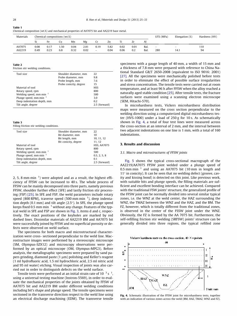
Table 1Chemical composition (wt.%) and mechanical properties of AA7075 bit and AA2219 base metal.
Materials Chemical compositions (wt.%) UTS (MPa) Elongation (%) Hardness (HV)
Si Fe Cu Mn Mg Cr Zn Ti Zr Al
AA7075 0.08 0.17 1.50 0.04 2.81 0.19 5.82 0.02 0.01 Bal. – – 110AA2219 0.49 0.23 6.8 0.32 0.02 – 0.04 0.06 0.2 Bal. 280 14.1 94
Table 2Friction stir welding conditions.
Tool size Shoulder diameter, mm 22Probe diameter, mm 9.8Probe length, mm 7.6Probe conicity, degree 15
Material of tool HSSRotary speed, rpm 800Welding speed, mm min�1 500Plunge speed, mm min�1 3.0Deep indentation depth, mm 0.2Tilt angle, degree 2.5 (forward)
Table 3Filling friction stir welding conditions.
Tool size Shoulder diameter, mm 22Bit diameter, mm 10Bit length, mm 10, 11, 12Bit conicity, degree 11, 12
Material of tool HSS, AA7075Rotary speed, rpm 800Welding speed, mm min�1 500Plunge speed, mm min�1 0.5, 2, 5, 8Deep indentation depth, mm 0.1Tilt angle, degree 2.5 (forward)
Fig. 4. Schematic illustration of the FFSW joint for microhardness tests, togetherwith an indication of various zones across the weld (BM, HAZ, TMAZ, WNZ and FZ).
28 B. Han et al. / Materials and Design 51 (2013) 25–33
2, 5, 8 mm min�1) were adopted and as a result, the highest effi-ciency of FFSW can be increased to 40 s. The whole process ofFFSW can be mainly decomposed into three parts, namely previousFFSW, shoulder further effect (SFE) and lastly friction stir process-ing (FSP) [25]. In SFE and FSP, the weld parameters include rotaryspeed (800 RPM), traverse speed (500 mm min�1), deep indenta-tion depth (0.1 mm) and tilt angle (2.5�). In SFE, the plunge speedkeeps fixed 0.5 mm min�1 without any change. Features of the typ-ical weld in SFE and FSP are shown in Fig. 3, items d and c, respec-tively. The exact positions of the keyholes are marked by reddashed lines. Dissimilar materials of AA2219 BM and AA7075 bitwere successfully joined by FFSW and no superficial porosity or de-fects were observed on weld surface.
The specimens for both macro and microstructural character-ization were cross- sectioned perpendicular to the weld line. Mac-rostructure images were performed by a stereoscopic microscope(SM, Olympus-SZX12) and microscopy observations were per-formed by an optical microscope (OM, Olympus-MPG3). Beforeanalysis, the metallographic specimens were prepared by sand pa-pers grinding, diamond paste (1 lm) polishing and Keller’s reagent(1 ml hydrofluoric acid, 1.5 ml hydrochloric acid, 2.5 ml nitric acidand 95 ml water) etching. Visual inspection of joints was also car-ried out in order to distinguish defects on the weld surface.
Tensile tests were performed at an initial strain rate of 10�3 s�1,using a universal testing machine (Instron-5569), in order to eval-uate the mechanical properties of the joints obtained by FFSW ofAA7075 bit and AA2219 BM under different welding conditionsincluding bit’s shape and plunge speed. The tensile specimens weresectioned in the transverse direction respect to the weld line usingan electrical discharge machining (EDM). The transverse tensile
specimens with a gauge length of 40 mm, a width of 15 mm anda thickness of 7.8 mm were prepared with reference to China Na-tional Standard GB/T 2650-2008 (equivalent to ISO 9016: 2001)[27]. All the specimens were mechanically polished before testsin order to eliminate the effect of possible surface irregularitiesand stress concentration. The tensile tests were carried out at roomtemperature, and at least 96 h after FFSW when the alloy reached anaturally aged stable condition [25]. After tensile tests, the fracturesurfaces were examined using a scanning electron microscope(SEM, Hitachi-570).
In microhardness tests, Vickers microhardness distributionmaps were measured on the cross section perpendicular to thewelding direction using a computerized digital microhardness tes-ter (HVS-1000) under a load of 250 g for 10 s. As schematicallyshown in Fig. 4, a total of four test lines were measured acrossthe cross-section at an interval of 2 mm, and the interval betweentwo adjacent indentations on one line is 1 mm, with a total of 160indentations.
3. Results and discussion
3.1. Macro and microstructures of FFSW joints
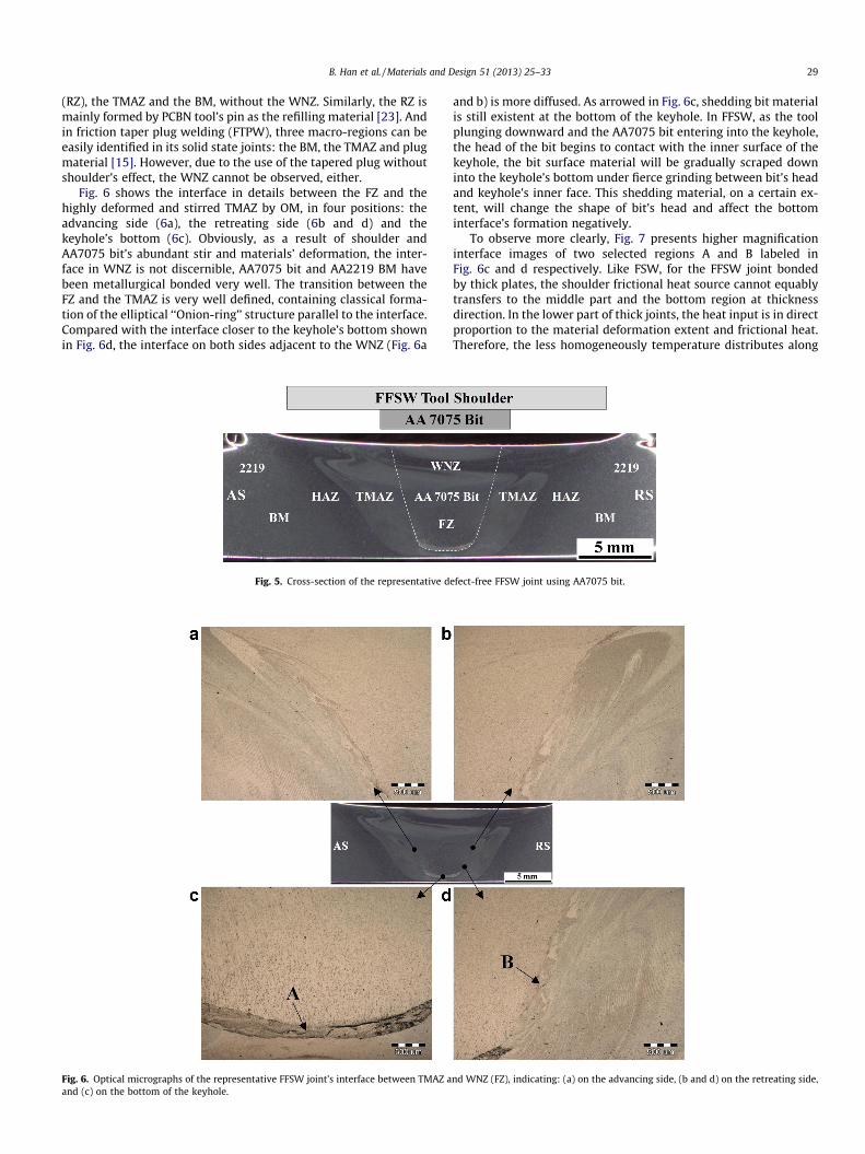
Fig. 5 shows the typical cross-sectional macrograph of theAA2219/AA7075 FFSW joint welded under a plunge speed of0.5 mm min�1 and using an AA7075 bit (10 mm in length and11� in conicity). It can be seen that no welding defect (groove, cav-ity and kissing bond) is detected on this joint. Like previous work,with suitable bits and plunge speeds, the filling materials are suf-ficient and excellent bonding interface can be achieved. Comparedwith the traditional FSW joints’ structure, the generalized profile ofthe FFSW joint can be normally divided into several similar typicalzones, i.e. the WNZ at the weld center, the HAZ surrounding theWNZ, the TMAZ between the WNZ and the HAZ, and the BM. TheFZ, however, which is totally different from the traditional zones,is observed in the center of the FSSW joint under the WNZ.Obviously, the FZ is formed by the AA 7075 bit. Furthermore, theself-refilling friction stir welding (SRFSW) joints’ structure can begenerally divided into three regions, the typical refilled zone
B. Han et al. / Materials and Design 51 (2013) 25–33 29
(RZ), the TMAZ and the BM, without the WNZ. Similarly, the RZ ismainly formed by PCBN tool’s pin as the refilling material [23]. Andin friction taper plug welding (FTPW), three macro-regions can beeasily identified in its solid state joints: the BM, the TMAZ and plugmaterial [15]. However, due to the use of the tapered plug withoutshoulder’s effect, the WNZ cannot be observed, either.
Fig. 6 shows the interface in details between the FZ and thehighly deformed and stirred TMAZ by OM, in four positions: theadvancing side (6a), the retreating side (6b and d) and thekeyhole’s bottom (6c). Obviously, as a result of shoulder andAA7075 bit’s abundant stir and materials’ deformation, the inter-face in WNZ is not discernible, AA7075 bit and AA2219 BM havebeen metallurgical bonded very well. The transition between theFZ and the TMAZ is very well defined, containing classical forma-tion of the elliptical ‘‘Onion-ring’’ structure parallel to the interface.Compared with the interface closer to the keyhole’s bottom shownin Fig. 6d, the interface on both sides adjacent to the WNZ (Fig. 6a
Fig. 5. Cross-section of the representative d
Fig. 6. Optical micrographs of the representative FFSW joint’s interface between TMAZ aand (c) on the bottom of the keyhole.
and b) is more diffused. As arrowed in Fig. 6c, shedding bit materialis still existent at the bottom of the keyhole. In FFSW, as the toolplunging downward and the AA7075 bit entering into the keyhole,the head of the bit begins to contact with the inner surface of thekeyhole, the bit surface material will be gradually scraped downinto the keyhole’s bottom under fierce grinding between bit’s headand keyhole’s inner face. This shedding material, on a certain ex-tent, will change the shape of bit’s head and affect the bottominterface’s formation negatively.
To observe more clearly, Fig. 7 presents higher magnificationinterface images of two selected regions A and B labeled inFig. 6c and d respectively. Like FSW, for the FFSW joint bondedby thick plates, the shoulder frictional heat source cannot equablytransfers to the middle part and the bottom region at thicknessdirection. In the lower part of thick joints, the heat input is in directproportion to the material deformation extent and frictional heat.Therefore, the less homogeneously temperature distributes along
efect-free FFSW joint using AA7075 bit.
nd WNZ (FZ), indicating: (a) on the advancing side, (b and d) on the retreating side,
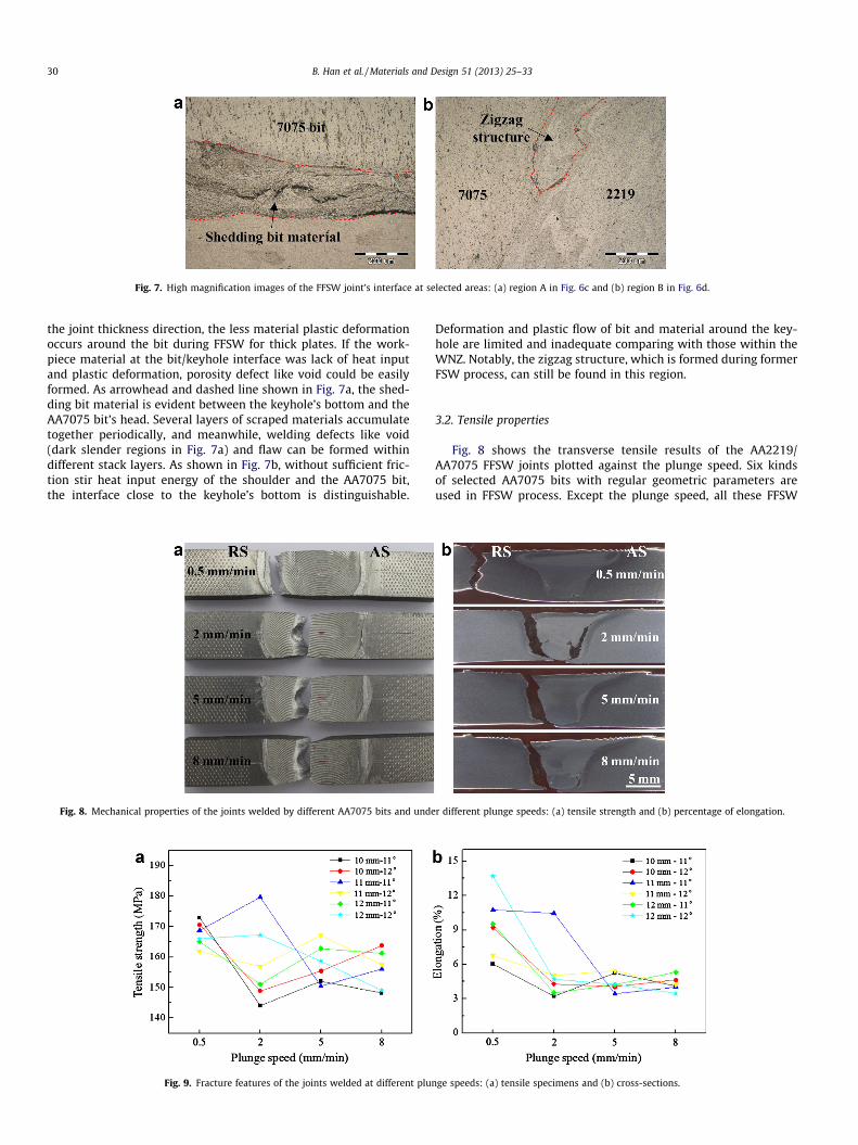
Fig. 7. High magnification images of the FFSW joint’s interface at selected areas: (a) region A in Fig. 6c and (b) region B in Fig. 6d.
30 B. Han et al. / Materials and Design 51 (2013) 25–33
the joint thickness direction, the less material plastic deformationoccurs around the bit during FFSW for thick plates. If the work-piece material at the bit/keyhole interface was lack of heat inputand plastic deformation, porosity defect like void could be easilyformed. As arrowhead and dashed line shown in Fig. 7a, the shed-ding bit material is evident between the keyhole’s bottom and theAA7075 bit’s head. Several layers of scraped materials accumulatetogether periodically, and meanwhile, welding defects like void(dark slender regions in Fig. 7a) and flaw can be formed withindifferent stack layers. As shown in Fig. 7b, without sufficient fric-tion stir heat input energy of the shoulder and the AA7075 bit,the interface close to the keyhole’s bottom is distinguishable.
Fig. 9. Fracture features of the joints welded at different plun
Fig. 8. Mechanical properties of the joints welded by different AA7075 bits and unde
Deformation and plastic flow of bit and material around the key-hole are limited and inadequate comparing with those within theWNZ. Notably, the zigzag structure, which is formed during formerFSW process, can still be found in this region.
3.2. Tensile properties
Fig. 8 shows the transverse tensile results of the AA2219/AA7075 FFSW joints plotted against the plunge speed. Six kindsof selected AA7075 bits with regular geometric parameters areused in FFSW process. Except the plunge speed, all these FFSW
ge speeds: (a) tensile specimens and (b) cross-sections.
r different plunge speeds: (a) tensile strength and (b) percentage of elongation.
B. Han et al. / Materials and Design 51 (2013) 25–33 31
joints are welded under the same optimized parameters listed inTable 3. Experimental results show that the plunge speed has anotable significant effect on joint’s strength and ductility. Obvi-ously, all joints have lower UTS and elongation than BM’s listedin Table 1. As shown in Fig. 8a, the joint’s UTS declines unsteadilywith increasing the plunge speed gradually. The maximum UTS is179.6 MPa, equivalent to 96.6% of the original no defect weld, usingthe bit of 10 mm in length and 11� in conicity, under a plungespeed of 2 mm min�1. In contrast to the variation trend in strength,as shown in Fig. 8b, the joint’s elongation declines sharply withincreasing the plunge speed from 0.5 to 2 mm min�1 due to thepresence of void defects. However, large fluctuation cannot be ob-served in spite of the plunge speed’s continued increase from 2 to8 mm min�1. The maximum elongation is 13.7%, close to the origi-nal weld’s value, using the bit of 12 mm in length and 12� in conic-ity, under a plunge speed of 2 mm min�1. For the original FSWweld, the average values of UTS and elongation are 65.6% and97.2% of the BM respectively. The synergetic restrictions of UTSand elongation allow the plunge speed not to increase higher than2 mm min�1. To make comparisons with SRFSW [23] on joints’ ten-sile properties, the optimal relative elongation of the FFSW joints(over 90% of the BM’s) is a little higher than that of the SRFSWjoints (only 82% of the BM’s). However, as a result of the differencesof these two techniques mainly on keyholes’ geometrical sizes andoriginal welds’ strengths, the maximum relative UTS of the FFSWjoints is lower than that of the SRFSW joints. It is important to notethat, the keyholes refilled during SRFSW process are all formed byformer FSP, and the keyholes’ geometrical sizes like diameter anddepth are obviously much less than those of the keyholes formedby former FSW before FFSW. It is easy to realize that the relativestrength of the weld containing the keyhole is going to be reducedwith the increase of the keyhole’s geometrical sizes. So, the geo-metrical sizes of the original keyholes are significant influencingfactors that causing the differences between FFSW and SRFSW onthe joints’ relative UTS.
Fig. 9 reveals the tensile fracture features of the FFSW jointswelded at various plunge speeds, using the bits of 10 mm in lengthand 12� in conicity. From the front face graph (see Fig. 9a),
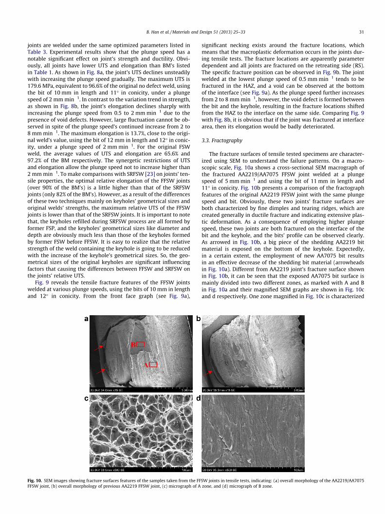
Fig. 10. SEM images showing fracture surfaces features of the samples taken from the FFFFSW joint, (b) overall morphology of previous AA2219 FFSW joint, (c) micrograph of A
significant necking exists around the fracture locations, whichmeans that the macroplastic deformation occurs in the joints dur-ing tensile tests. The fracture locations are apparently parameterdependent and all joints are fractured on the retreating side (RS).The specific fracture position can be observed in Fig. 9b. The jointwelded at the lowest plunge speed of 0.5 mm min�1 tends to befractured in the HAZ, and a void can be observed at the bottomof the interface (see Fig. 9a). As the plunge speed further increasesfrom 2 to 8 mm min�1, however, the void defect is formed betweenthe bit and the keyhole, resulting in the fracture locations shiftedfrom the HAZ to the interface on the same side. Comparing Fig. 9with Fig. 8b, it is obvious that if the joint was fractured at interfacearea, then its elongation would be badly deteriorated.
3.3. Fractography
The fracture surfaces of tensile tested specimens are character-ized using SEM to understand the failure patterns. On a macro-scopic scale, Fig. 10a shows a cross-sectional SEM macrograph ofthe fractured AA2219/AA7075 FFSW joint welded at a plungespeed of 5 mm min�1 and using the bit of 11 mm in length and11� in conicity. Fig. 10b presents a comparison of the fractographfeatures of the original AA2219 FFSW joint with the same plungespeed and bit. Obviously, these two joints’ fracture surfaces areboth characterized by fine dimples and tearing ridges, which arecreated generally in ductile fracture and indicating extensive plas-tic deformation. As a consequence of employing higher plungespeed, these two joints are both fractured on the interface of thebit and the keyhole, and the bits’ profile can be observed clearly.As arrowed in Fig. 10b, a big piece of the shedding AA2219 bitmaterial is exposed on the bottom of the keyhole. Expectedly,in a certain extent, the employment of new AA7075 bit resultsin an effective decrease of the shedding bit material (arrowheadsin Fig. 10a). Different from AA2219 joint’s fracture surface shownin Fig. 10b, it can be seen that the exposed AA7075 bit surface ismainly divided into two different zones, as marked with A and Bin Fig. 10a and their magnified SEM graphs are shown in Fig. 10cand d respectively. One zone magnified in Fig. 10c is characterized
SW joints in tensile tests, indicating: (a) overall morphology of the AA2219/AA7075zone, and (d) micrograph of B zone.
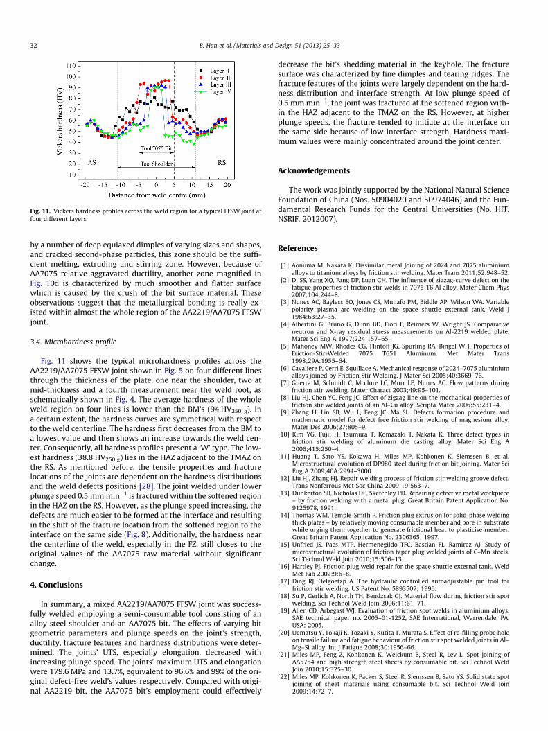
Fig. 11. Vickers hardness profiles across the weld region for a typical FFSW joint atfour different layers.
32 B. Han et al. / Materials and Design 51 (2013) 25–33
by a number of deep equiaxed dimples of varying sizes and shapes,and cracked second-phase particles, this zone should be the suffi-cient melting, extruding and stirring zone. However, because ofAA7075 relative aggravated ductility, another zone magnified inFig. 10d is characterized by much smoother and flatter surfacewhich is caused by the crush of the bit surface material. Theseobservations suggest that the metallurgical bonding is really ex-isted within almost the whole region of the AA2219/AA7075 FFSWjoint.
3.4. Microhardness profile
Fig. 11 shows the typical microhardness profiles across theAA2219/AA7075 FFSW joint shown in Fig. 5 on four different linesthrough the thickness of the plate, one near the shoulder, two atmid-thickness and a fourth measurement near the weld root, asschematically shown in Fig. 4. The average hardness of the wholeweld region on four lines is lower than the BM’s (94 HV250 g). Ina certain extent, the hardness curves are symmetrical with respectto the weld centerline. The hardness first decreases from the BM toa lowest value and then shows an increase towards the weld cen-ter. Consequently, all hardness profiles present a ‘W’ type. The low-est hardness (38.8 HV250 g) lies in the HAZ adjacent to the TMAZ onthe RS. As mentioned before, the tensile properties and fracturelocations of the joints are dependent on the hardness distributionsand the weld defects positions [28]. The joint welded under lowerplunge speed 0.5 mm min�1 is fractured within the softened regionin the HAZ on the RS. However, as the plunge speed increasing, thedefects are much easier to be formed at the interface and resultingin the shift of the fracture location from the softened region to theinterface on the same side (Fig. 8). Additionally, the hardness nearthe centerline of the weld, especially in the FZ, still closes to theoriginal values of the AA7075 raw material without significantchange.
4. Conclusions
In summary, a mixed AA2219/AA7075 FFSW joint was success-fully welded employing a semi-consumable tool consisting of analloy steel shoulder and an AA7075 bit. The effects of varying bitgeometric parameters and plunge speeds on the joint’s strength,ductility, fracture features and hardness distributions were deter-mined. The joints’ UTS, especially elongation, decreased withincreasing plunge speed. The joints’ maximum UTS and elongationwere 179.6 MPa and 13.7%, equivalent to 96.6% and 99% of the ori-ginal defect-free weld’s values respectively. Compared with origi-nal AA2219 bit, the AA7075 bit’s employment could effectively
decrease the bit’s shedding material in the keyhole. The fracturesurface was characterized by fine dimples and tearing ridges. Thefracture features of the joints were largely dependent on the hard-ness distribution and interface strength. At low plunge speed of0.5 mm min�1, the joint was fractured at the softened region with-in the HAZ adjacent to the TMAZ on the RS. However, at higherplunge speeds, the fracture tended to initiate at the interface onthe same side because of low interface strength. Hardness maxi-mum values were mainly concentrated around the joint center.
Acknowledgements
The work was jointly supported by the National Natural ScienceFoundation of China (Nos. 50904020 and 50974046) and the Fun-damental Research Funds for the Central Universities (No. HIT.NSRIF. 2012007).
References
[1] Aonuma M, Nakata K. Dissimilar metal Joining of 2024 and 7075 aluminiumalloys to titanium alloys by friction stir welding. Mater Trans 2011;52:948–52.
[2] Di SS, Yang XQ, Fang DP, Luan GH. The influence of zigzag-curve defect on thefatigue properties of friction stir welds in 7075-T6 Al alloy. Mater Chem Phys2007;104:244–8.
[3] Nunes AC, Bayless EO, Jones CS, Munafo PM, Biddle AP, Wilson WA. Variablepolarity plasma arc welding on the space shuttle external tank. Weld J1984;63:27–35.
[4] Albertini G, Bruno G, Dunn BD, Fiori F, Reimers W, Wright JS. Comparativeneutron and X-ray residual stress measurements on Al-2219 welded plate.Mater Sci Eng A 1997;224:157–65.
[5] Mahoney MW, Rhodes CG, Flintoff JG, Spurling RA, Bingel WH. Properties ofFriction-Stir-Welded 7075 T651 Aluminum. Met Mater Trans1998;29A:1955–64.
[6] Cavaliere P, Cerri E, Squillace A. Mechanical response of 2024–7075 aluminiumalloys joined by Friction Stir Welding. J Mater Sci 2005;40:3669–76.
[7] Guerra M, Schmidt C, Mcclure LC, Murr LE, Nunes AC. Flow patterns duringfriction stir welding. Mater Charact 2003;49:95–101.
[8] Liu HJ, Chen YC, Feng JC. Effect of zigzag line on the mechanical properties offriction stir welded joints of an Al–Cu alloy. Scripta Mater 2006;55:231–4.
[9] Zhang H, Lin SB, Wu L, Feng JC, Ma SL. Defects formation procedure andmathematic model for defect free friction stir welding of magnesium alloy.Mater Des 2006;27:805–9.
[10] Kim YG, Fujii H, Tsumura T, Komazaki T, Nakata K. Three defect types infriction stir welding of aluminum die casting alloy. Mater Sci Eng A2006;415:250–4.
[11] Huang T, Sato YS, Kokawa H, Miles MP, Kohkonen K, Siemssen B, et al.Microstructural evolution of DP980 steel during friction bit joining. Mater SciEng A 2009;40A:2994–3000.
[12] Liu HJ, Zhang HJ. Repair welding process of friction stir welding groove defect.Trans Nonferrous Met Soc China 2009;19:563–7.
[13] Dunkerton SB, Nicholas DE, Sketchley PD. Repairing defective metal workpiece– by friction welding with a metal plug. Great Britain Patent Application No.9125978, 1991.
[14] Thomas WM, Temple-Smith P. Friction plug extrusion for solid-phase weldingthick plates – by relatively moving consumable member and bore in substratewhile urging them together to generate frictional heat to plasticise member.Great Britain Patent Application No. 2306365; 1997.
[15] Unfried JS, Paes MTP, Hermenegildo TFC, Bastian FL, Ramirez AJ. Study ofmicrostructural evolution of friction taper plug welded joints of C–Mn steels.Sci Technol Weld Join 2010;15:506–13.
[16] Hartley PJ. Friction plug weld repair for the space shuttle external tank. WeldMet Fab 2002;9:6–8.
[17] Ding RJ, Oelgoetzp A. The hydraulic controlled autoadjustable pin tool forfriction stir welding. US Patent No. 5893507; 1996.
[18] Su P, Gerlich A, North TH, Bendzsak GJ. Material flow during friction stir spotwelding. Sci Technol Weld Join 2006;11:61–71.
[19] Allen CD, Arbegast WJ. Evaluation of friction spot welds in aluminium alloys.SAE technical paper no. 2005–01-1252, SAE International, Warrendale, PA,USA; 2005.
[20] Uematsu Y, Tokaji K, Tozaki Y, Kutita T, Murata S. Effect of re-filling probe holeon tensile failure and fatigue behaviour of friction stir spot welded joints in Al–Mg–Si alloy. Int J Fatigue 2008;30:1956–66.
[21] Miles MP, Feng Z, Kohkonen K, Weickum B, Steel R, Lev L. Spot joining ofAA5754 and high strength steel sheets by consumable bit. Sci Technol WeldJoin 2010;15:325–30.
[22] Miles MP, Kohkonen K, Packer S, Steel R, Siemssen B, Sato YS. Solid state spotjoining of sheet materials using consumable bit. Sci Technol Weld Join2009;14:72–7.

B. Han et al. / Materials and Design 51 (2013) 25–33 33
[23] Zhou L, Liu D, Nakata K, Tsumura T, Fujii H, Ikeuchi K, et al. New technique ofself-refilling friction stir welding to repair keyhole. Sci Technol Weld Join2012;17:649–55.
[24] Huang YX, Han B, Tian Y, Liu HJ, Lv SX, Feng JC, et al. New technique of fillingfriction stir welding. Sci Technol Weld Join 2011;16:497–501.
[25] Huang YX, Han B, Lv SX, Feng JC, Liu HJ, Leng JS, et al. Interface behaviours andmechanical properties of filling friction stir weld joining AA2219. Sci TechnolWeld Join 2012;17:225–30.
[26] Huang YX, Han B, Lv SX, Feng JC, Leng JS, Chen XB. The technique of fillingfriction stir welding for repairing the keyhole based on the principle of solidstate joining. Trans China Weld Inst 2012;33:5–8.
[27] GB/T 2650–2008/ISO 9016: 2001. Tensile test method on welded joints.Standardization Administration of the People’s Republic of China; 2008.
[28] Liu HJ, Fujii H, Maeda M, Nogi K. Tensile properties and fracture locations offriction-stir-welded joints of 2017-T351 aluminum alloy. J Mater ProcessTechnol 2003;142:692–6.
Related Documents