A simplified in vivo approach for evaluating the bioabsorbable behavior of candidate stent materials Daniel Pierson, 1 Jacob Edick, 2 Aaron Tauscher, 1 Ellen Pokorney, 1 Patrick Bowen, 2 Jesse Gelbaugh, 2 Jon Stinson, 3 Heather Getty, 3 Chee Huei Lee, 4 Jaroslaw Drelich, 2 Jeremy Goldman 1 1 Department of Biomedical Engineering, Michigan Technological University, Houghton, Michigan 49931-1295 2 Department of Materials Science and Engineering, Michigan Technological University, Houghton, Michigan 49931-1295 3 Boston Scientific Corporation, Maple Grove, Minnesota 55311-1566 4 Department of Physics, Michigan Technological University, Houghton, Michigan 49931-1295 Received 10 January 2011; revised 3 May 2011; accepted 21 June 2011 Published online 8 September 2011 in Wiley Online Library (wileyonlinelibrary.com). DOI: 10.1002/jbm.b.31922 Abstract: Metal stents are commonly used to revascularize occluded arteries. A bioabsorbable metal stent that harm- lessly erodes away over time may minimize the normal chronic risks associated with permanent implants. However, there is no simple, low-cost method of introducing candidate materials into the arterial environment. Here, we developed a novel experimental model where a biomaterial wire is implanted into a rat artery lumen (simulating bioabsorbable stent blood contact) or artery wall (simulating bioabsorbable stent matrix contact). We use this model to clarify the corro- sion mechanism of iron (99.5 wt %), which is a candidate bioabsorbable stent material due to its biocompatibility and mechanical strength. We found that iron wire encapsulation within the arterial wall extracellular matrix resulted in sub- stantial biocorrosion by 22 days, with a voluminous corrosion product retained within the vessel wall at 9 months. In con- trast, the blood-contacting luminal implant experienced mini- mal biocorrosion at 9 months. The importance of arterial blood versus arterial wall contact for regulating biocorrosion was confirmed with magnesium wires. We found that magnesium was highly corroded when placed in the arterial wall but was not corroded when exposed to blood in the arterial lumen for 3 weeks. The results demonstrate the capability of the vascular implantation model to conduct rapid in vivo assessments of vascular biomaterial corrosion behavior and to predict long- term biocorrosion behavior from material analyses. The results also highlight the critical role of the arterial environment (blood vs. matrix contact) in directing the corrosion behavior of biodegradable metals. V C 2011 Wiley Periodicals, Inc. J Biomed Mater Res Part B: Appl Biomater 100B: 58–67, 2012. Key Words: vascular stents, blood–material interaction, bio- degradation, biocompatibility/soft tissue How to cite this article: Pierson D, Edick J, Tauscher A, Pokorney E, Bowen P, Gelbaugh J, Stinson J, Getty H, Lee CH, Drelich J, Goldman J. 2012. A simplified in vivo approach for evaluating the bioabsorbable behavior of candidate stent materials. J Biomed Mater Res Part B 2012:100B:58–67. INTRODUCTION Vascular stents are metal scaffolds used to prop open athe- rosclerotic blood vessels and improve blood flow. Nonab- sorbable stents are permanent implants. 1–3 Unfortunately, the biological and mechanical environment of the vessel may challenge the long-term integrity of permanent stents. However, it has been hypothesized that stents placed in many atherosclerotic arteries may require only about 3–6 months of mechanical integrity for scaffolding. Bioabsorb- able or biodegradable stents that provide mechanical sup- port during vascular wall repair and then harmlessly erode after the vascular wall has stabilized may eliminate some of the potential chronic risks of permanent stents and may mitigate the complexity of repeat stenting at the same site in the event of restenosis. 4–8 Current efforts to develop a bioabsorbable or biodegrad- able stent have focused on magnesium based alloys, 9–12 poly-L-lactic acid (PLLA) polymers, 13–15 and high-weight percent iron. 16–19 Magnesium and iron stents degrade into physiological products, are immunologically inert, and pos- sess physical properties that are more similar to commercial stainless steel stents and cobalt chromium alloys than poly- mer bioabsorbable stent candidate materials. 7,20,21 In con- trast to iron, which experiences a relatively slow rate of Additional Supporting Information may be found in the online version of this article. Conflict of interest: No benefit of any kind will be received either directly or indirectly by the authors. Correspondence to: J. Goldman; e-mail: [email protected] Contract grant sponsor: Boston Scientific Corporation and National Institutes of Health; contract grant number: R21-HL-093568 and R15-HL- 093705 58 V C 2011 WILEY PERIODICALS, INC.

Welcome message from author
This document is posted to help you gain knowledge. Please leave a comment to let me know what you think about it! Share it to your friends and learn new things together.
Transcript
A simplified in vivo approach for evaluating the bioabsorbablebehavior of candidate stent materials
Daniel Pierson,1 Jacob Edick,2 Aaron Tauscher,1 Ellen Pokorney,1 Patrick Bowen,2
Jesse Gelbaugh,2 Jon Stinson,3 Heather Getty,3 Chee Huei Lee,4 Jaroslaw Drelich,2
Jeremy Goldman1
1Department of Biomedical Engineering, Michigan Technological University, Houghton, Michigan 49931-12952Department of Materials Science and Engineering, Michigan Technological University, Houghton, Michigan 49931-12953Boston Scientific Corporation, Maple Grove, Minnesota 55311-15664Department of Physics, Michigan Technological University, Houghton, Michigan 49931-1295
Received 10 January 2011; revised 3 May 2011; accepted 21 June 2011
Published online 8 September 2011 in Wiley Online Library (wileyonlinelibrary.com). DOI: 10.1002/jbm.b.31922
Abstract: Metal stents are commonly used to revascularize
occluded arteries. A bioabsorbable metal stent that harm-
lessly erodes away over time may minimize the normal
chronic risks associated with permanent implants. However,
there is no simple, low-cost method of introducing candidate
materials into the arterial environment. Here, we developed a
novel experimental model where a biomaterial wire is
implanted into a rat artery lumen (simulating bioabsorbable
stent blood contact) or artery wall (simulating bioabsorbable
stent matrix contact). We use this model to clarify the corro-
sion mechanism of iron (�99.5 wt %), which is a candidate
bioabsorbable stent material due to its biocompatibility and
mechanical strength. We found that iron wire encapsulation
within the arterial wall extracellular matrix resulted in sub-
stantial biocorrosion by 22 days, with a voluminous corrosion
product retained within the vessel wall at 9 months. In con-
trast, the blood-contacting luminal implant experienced mini-
mal biocorrosion at 9 months. The importance of arterial blood
versus arterial wall contact for regulating biocorrosion was
confirmed with magnesium wires. We found that magnesium
was highly corroded when placed in the arterial wall but was
not corroded when exposed to blood in the arterial lumen for 3
weeks. The results demonstrate the capability of the vascular
implantation model to conduct rapid in vivo assessments of
vascular biomaterial corrosion behavior and to predict long-
term biocorrosion behavior frommaterial analyses. The results
also highlight the critical role of the arterial environment
(blood vs. matrix contact) in directing the corrosion behavior
of biodegradable metals. VC 2011 Wiley Periodicals, Inc. J Biomed
Mater Res Part B: Appl Biomater 100B: 58–67, 2012.
Key Words: vascular stents, blood–material interaction, bio-
degradation, biocompatibility/soft tissue
How to cite this article: Pierson D, Edick J, Tauscher A, Pokorney E, Bowen P, Gelbaugh J, Stinson J, Getty H, Lee CH, Drelich J,Goldman J. 2012. A simplified in vivo approach for evaluating the bioabsorbable behavior of candidate stent materials. J BiomedMater Res Part B 2012:100B:58–67.
INTRODUCTION
Vascular stents are metal scaffolds used to prop open athe-rosclerotic blood vessels and improve blood flow. Nonab-sorbable stents are permanent implants.1–3 Unfortunately,the biological and mechanical environment of the vesselmay challenge the long-term integrity of permanent stents.However, it has been hypothesized that stents placed inmany atherosclerotic arteries may require only about 3–6months of mechanical integrity for scaffolding. Bioabsorb-able or biodegradable stents that provide mechanical sup-port during vascular wall repair and then harmlessly erodeafter the vascular wall has stabilized may eliminate some of
the potential chronic risks of permanent stents and maymitigate the complexity of repeat stenting at the same sitein the event of restenosis.4–8
Current efforts to develop a bioabsorbable or biodegrad-able stent have focused on magnesium based alloys,9–12
poly-L-lactic acid (PLLA) polymers,13–15 and high-weightpercent iron.16–19 Magnesium and iron stents degrade intophysiological products, are immunologically inert, and pos-sess physical properties that are more similar to commercialstainless steel stents and cobalt chromium alloys than poly-mer bioabsorbable stent candidate materials.7,20,21 In con-trast to iron, which experiences a relatively slow rate of
Additional Supporting Information may be found in the online version of this article.
Conflict of interest: No benefit of any kind will be received either directly or indirectly by the authors.
Correspondence to: J. Goldman; e-mail: [email protected]
Contract grant sponsor: Boston Scientific Corporation and National Institutes of Health; contract grant number: R21-HL-093568 and R15-HL-
093705
58 VC 2011 WILEY PERIODICALS, INC.
degradation, magnesium and PLLA stents experience ahigher rate of degradation following deployment that canresult in premature loss of mechanical integrity and early-vascular recoil.21 Furthermore, whereas iron stents areradio-opaque, magnesium and polymer stents are not visibleon an angiogram, which may hinder stent implantation.7,21
Polymer stents have further limitations including a greaterpotential for tissue incompatibility14 and the inability tofully expand with the use of balloon dilatation. Due to theirlower radial force compared with their stainless steel coun-terparts, a greater thickness is required for polymerstents.10 Although iron possesses more ideal propertiescompared with magnesium and polymer materials, the slowdegradation rate of iron may result in an extended presenceof iron stents in the artery.22 Thus, iron materials may needto be modified to produce a more suitable degradation rate.
Presently, there is no simple, low-cost method of intro-ducing candidate stent materials into the arterial environ-ment, necessitating reliance on unrealistic in vitro modelsor costly and time-consuming large animal stent implanta-tion studies. Here, we have developed a novel in vivo modelfor the early-in vivo evaluation of candidate stent materials.In this model, candidate stent materials are drawn into awire and implanted into the rat abdominal aorta wall orlumen to simulate a stent implantation. We demonstrate thecapability of this model by providing insight into the mecha-nism of iron degradation in vivo.
MATERIALS AND METHODS
Male Sprague Dawley rats from Harlan Labs were used inthe animal experiments. All animal experiments wereapproved by the animal care and use committee of MichiganTechnological University. NIH guidelines for the care anduse of laboratory animals (NIH Publication #85-23 Rev.1985) have been observed.
Wire sterilizationBefore implantation, iron wires were cleaned in a Pro-CleanerTM cleaning device (BioForce Nanosciences; Ames,IA) for 30 min. ProCleanerTM device is equipped with ahigh-intensity mercury vapor lamp generating UV illumina-tion that converts oxygen into ozone, which attacks andremoves molecular levels of organic contamination fromsmall samples.
Aortic implantationSprague Dawley rats (Harlan Labs) anesthetized with iso-flurane in oxygen gas were surgically implanted withannealed iron wire of 99.99þ wt % and 0.25 mm diameteror magnesium wire of 99.9þ wt % and 0.25 mm diameter(Goodfellow Corporation). Two different wire implantationmodels were used, a wall implant and a luminal implant. Inboth models, a 2-cm long sterilized metal wire was punc-tured into the abdominal aorta. For the aortic wall implants,the arterial adventitia was punctured with the metal wire,which was then led a distance of 15 mm within the adventi-tia. This wire was firmly embedded in the extracellularmatrix of the adventitia and did not become dislocated. For
the luminal implants, the artery was punctured with thewire, which was then led into the lumen for a distance ofapproximately 15 mm before puncturing the wall a secondtime to exteriorize the wire from the artery. Because theluminal wire implant became encapsulated in neointimal-like tissue at late time points, we also implanted wires intothe lumen with the wire bowed away from the endothelium.Thus, when luminally implanted, the wire was placed ingentle contact with the vessel wall, and in some cases, itwas bowed away from the vessel wall. The wires that werebowed away from the vessel wall remained free from encap-sulation in neointimal-like tissue. This approach allowed usto inspect luminal wires in the presence and absence ofneointimal-like tissue encapsulation. Following implantation,the portion of the wire remaining outside the artery at bothends was slightly bent to prevent dislocation. After 22 days,1.5, 3, 4.5, or 9 months, the rats were euthanized usingcarbon dioxide asphyxiation, and the wires or aortas con-taining the implanted wires were harvested for analysis.
HistologyRat aortas containing the iron wire implants were snap-fro-zen in liquid nitrogen and cryo-sectioned for histologicalanalysis. Samples were preserved in a �80�C freezer beforestaining. The samples were stained with hematoxylin andeosin, mounted in Permount solution, and imaged using anOlympus BX51, DP70 brightfield microscope.
Raman spectroscopyA Jobin-Yvon Lab RAM HR800 Raman Spectrometer wasused to analyze the corrosion products. The laser beam(wavelength 632 nm) was focused onto the sample to ana-lyze the resulting energy level of light reflected back to thedetector. The amount of energy absorption by the bondspresent within the sample creates the position and intensityof the characteristic peaks from the sample. Scans were per-formed from a minimum value of 100 cm�1 to a maximumvalue that varied between 1000 and 1500 cm�1. The result-ing peaks were compared with standard peaks of knownminerals for identification.
Scanning electron microscopy/energydispersive X-ray spectroscopyThe surface morphology and elemental analysis of iron sam-ples were carried out using the JEOL JSM 6400 Scanningelectron microscopy (SEM) equipped with energy dispersivespectrometer (EDS). The accelerating voltage used for allsamples was 20 kV and 39 mm working distance. Samplesrequiring images of the wires in cross section weremounted in epoxy [AeroMarine Epoxy Resin #300 and Aero-Marine ‘Non-Blushing’ Cycloaliphatic Epoxy Hardener #21at a 2:1 weight ratio (AeroMarine Products; San Diego, CA)].Wires with corrosion product on the surface were held ver-tically using super glue to prevent damage to the corrosionproduct. The wires were glued to a small piece of heavypaper using Loctite superglue. Fine tip tweezers were usedto hold the wires in place until the superglue cured. Oncecured the small piece of paper was then placed in a
ORIGINAL RESEARCH REPORT
JOURNAL OF BIOMEDICAL MATERIALS RESEARCH B: APPLIED BIOMATERIALS | JAN 2012 VOL 100B, ISSUE 1 59
mounting cup, and the AeroMarine epoxy and hardenerwere then added and allowed to cure overnight. The sam-ples were then cross sectioned and polished using 60, 120,240, 400, and 600 grit sandpapers in series. The fine polish-ing was carried out using a 6 lm diamond cloth and 0.5 lmalumina particles, in sequence.
RESULTS
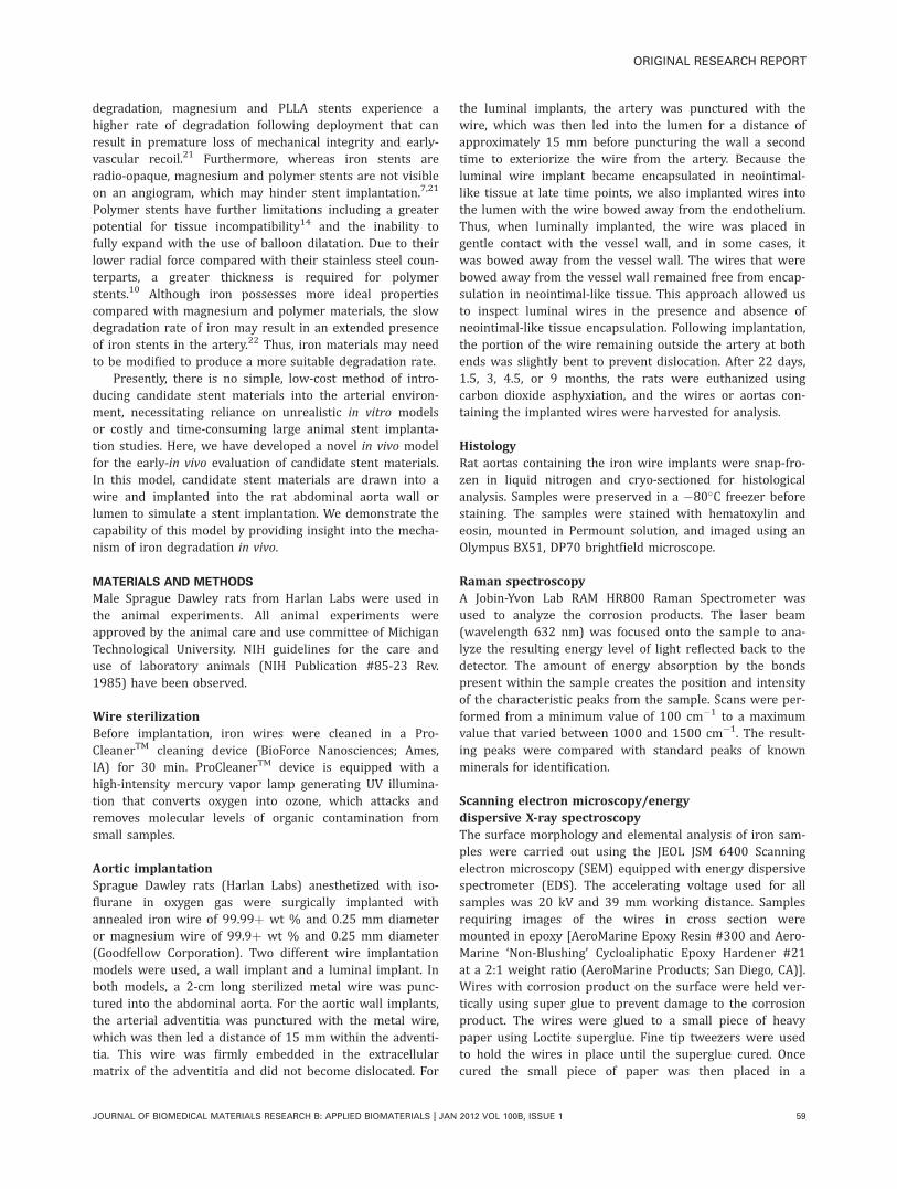
Tissue discoloration from the iron wire implantedwithin the arterial wallBrightfield images of the implanted iron wires were col-lected immediately following implantation [Figure 1(A,B)]and before explanation at 22 days [Figure 1(C,D)]. The ar-tery wall wire implant produced a brown-colored productin the tissue surrounding the wire [Figure 1(C)]. The lumi-nal wire did not produce visible corrosion product, althoughthe same brown corrosion product was present around theexteriorized portion of the wire [Figure 1(D)]. Thus, in bothmodels, corrosion product was observed on iron wire sur-rounded by biological tissue, but not on wire surrounded byflowing arterial blood.
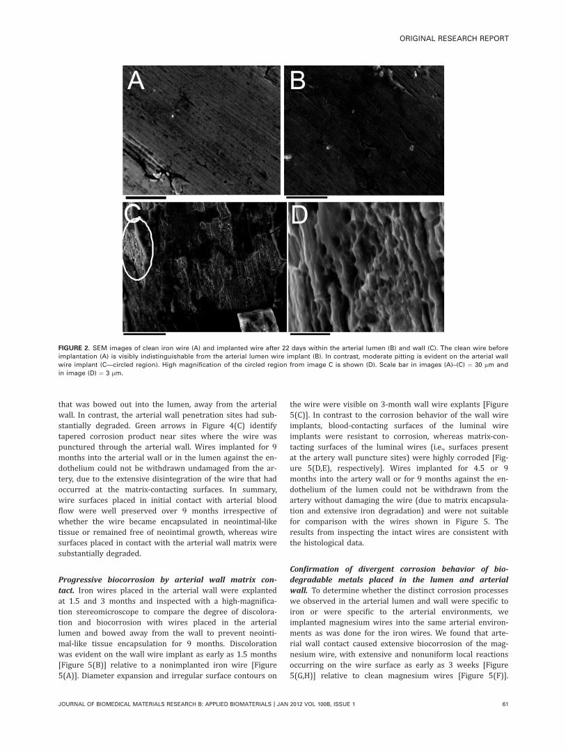
Pitting and corrosion product dispersion on the ironwire implanted into the arterial wallSurface morphology of the 22-day explanted iron was inves-tigated using SEM. The extracted samples were placed in a
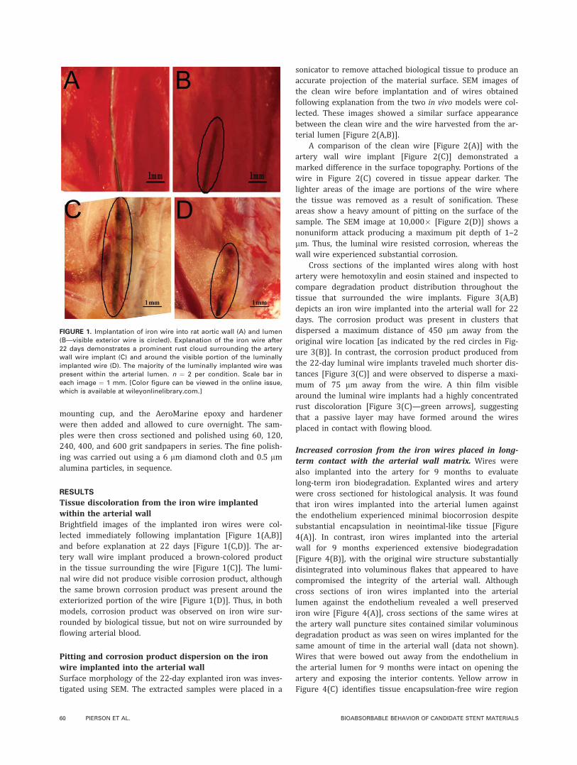
sonicator to remove attached biological tissue to produce anaccurate projection of the material surface. SEM images ofthe clean wire before implantation and of wires obtainedfollowing explanation from the two in vivo models were col-lected. These images showed a similar surface appearancebetween the clean wire and the wire harvested from the ar-terial lumen [Figure 2(A,B)].
A comparison of the clean wire [Figure 2(A)] with theartery wall wire implant [Figure 2(C)] demonstrated amarked difference in the surface topography. Portions of thewire in Figure 2(C) covered in tissue appear darker. Thelighter areas of the image are portions of the wire wherethe tissue was removed as a result of sonification. Theseareas show a heavy amount of pitting on the surface of thesample. The SEM image at 10,000� [Figure 2(D)] shows anonuniform attack producing a maximum pit depth of 1–2lm. Thus, the luminal wire resisted corrosion, whereas thewall wire experienced substantial corrosion.
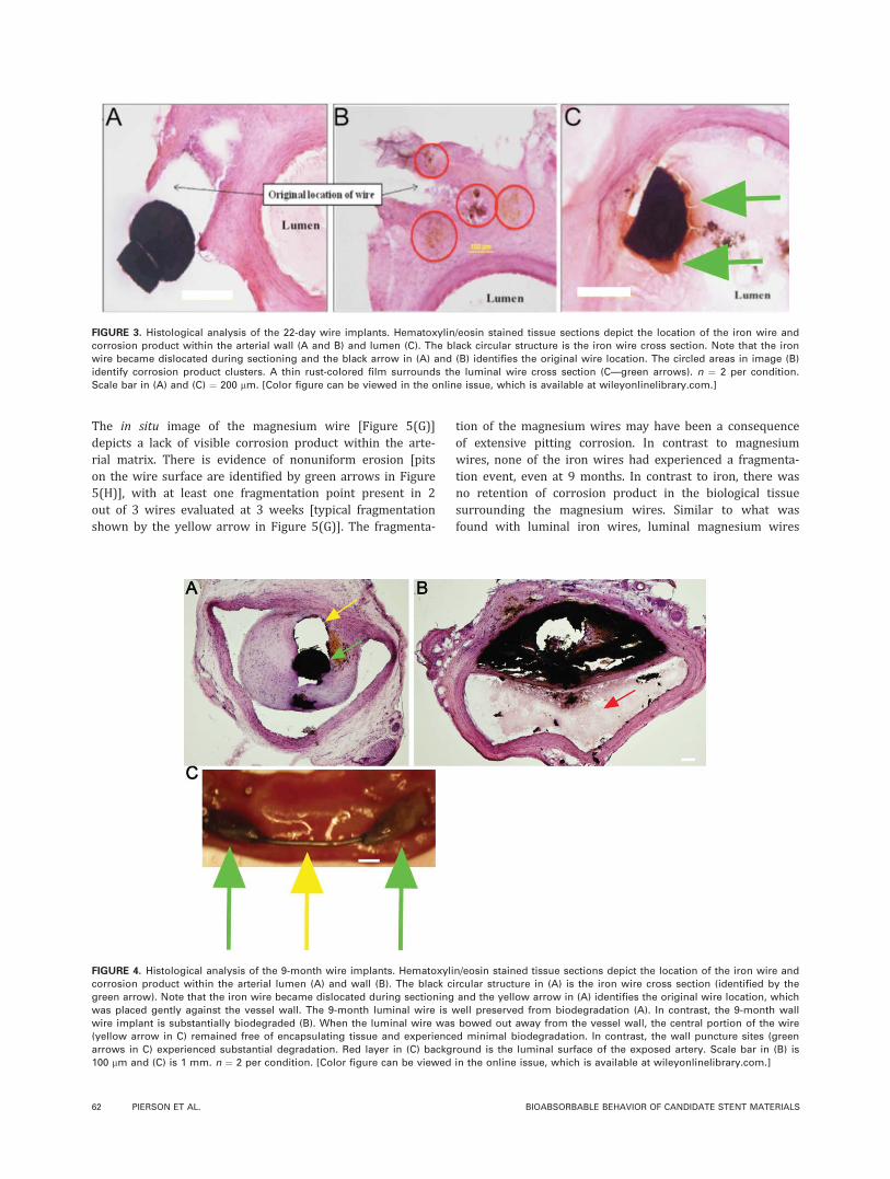
Cross sections of the implanted wires along with hostartery were hemotoxylin and eosin stained and inspected tocompare degradation product distribution throughout thetissue that surrounded the wire implants. Figure 3(A,B)depicts an iron wire implanted into the arterial wall for 22days. The corrosion product was present in clusters thatdispersed a maximum distance of 450 lm away from theoriginal wire location [as indicated by the red circles in Fig-ure 3(B)]. In contrast, the corrosion product produced fromthe 22-day luminal wire implants traveled much shorter dis-tances [Figure 3(C)] and were observed to disperse a maxi-mum of 75 lm away from the wire. A thin film visiblearound the luminal wire implants had a highly concentratedrust discoloration [Figure 3(C)—green arrows], suggestingthat a passive layer may have formed around the wiresplaced in contact with flowing blood.
Increased corrosion from the iron wires placed in long-term contact with the arterial wall matrix. Wires werealso implanted into the artery for 9 months to evaluatelong-term iron biodegradation. Explanted wires and arterywere cross sectioned for histological analysis. It was foundthat iron wires implanted into the arterial lumen againstthe endothelium experienced minimal biocorrosion despitesubstantial encapsulation in neointimal-like tissue [Figure4(A)]. In contrast, iron wires implanted into the arterialwall for 9 months experienced extensive biodegradation[Figure 4(B)], with the original wire structure substantiallydisintegrated into voluminous flakes that appeared to havecompromised the integrity of the arterial wall. Althoughcross sections of iron wires implanted into the arteriallumen against the endothelium revealed a well preservediron wire [Figure 4(A)], cross sections of the same wires atthe artery wall puncture sites contained similar voluminousdegradation product as was seen on wires implanted for thesame amount of time in the arterial wall (data not shown).Wires that were bowed out away from the endothelium inthe arterial lumen for 9 months were intact on opening theartery and exposing the interior contents. Yellow arrow inFigure 4(C) identifies tissue encapsulation-free wire region
FIGURE 1. Implantation of iron wire into rat aortic wall (A) and lumen
(B—visible exterior wire is circled). Explanation of the iron wire after
22 days demonstrates a prominent rust cloud surrounding the artery
wall wire implant (C) and around the visible portion of the luminally
implanted wire (D). The majority of the luminally implanted wire was
present within the arterial lumen. n ¼ 2 per condition. Scale bar in
each image ¼ 1 mm. [Color figure can be viewed in the online issue,
which is available at wileyonlinelibrary.com.]
60 PIERSON ET AL. BIOABSORBABLE BEHAVIOR OF CANDIDATE STENT MATERIALS
that was bowed out into the lumen, away from the arterialwall. In contrast, the arterial wall penetration sites had sub-stantially degraded. Green arrows in Figure 4(C) identifytapered corrosion product near sites where the wire waspunctured through the arterial wall. Wires implanted for 9months into the arterial wall or in the lumen against the en-dothelium could not be withdrawn undamaged from the ar-tery, due to the extensive disintegration of the wire that hadoccurred at the matrix-contacting surfaces. In summary,wire surfaces placed in initial contact with arterial bloodflow were well preserved over 9 months irrespective ofwhether the wire became encapsulated in neointimal-liketissue or remained free of neointimal growth, whereas wiresurfaces placed in contact with the arterial wall matrix weresubstantially degraded.
Progressive biocorrosion by arterial wall matrix con-tact. Iron wires placed in the arterial wall were explantedat 1.5 and 3 months and inspected with a high-magnifica-tion stereomicroscope to compare the degree of discolora-tion and biocorrosion with wires placed in the arteriallumen and bowed away from the wall to prevent neointi-mal-like tissue encapsulation for 9 months. Discolorationwas evident on the wall wire implant as early as 1.5 months[Figure 5(B)] relative to a nonimplanted iron wire [Figure5(A)]. Diameter expansion and irregular surface contours on
the wire were visible on 3-month wall wire explants [Figure5(C)]. In contrast to the corrosion behavior of the wall wireimplants, blood-contacting surfaces of the luminal wireimplants were resistant to corrosion, whereas matrix-con-tacting surfaces of the luminal wires (i.e., surfaces presentat the artery wall puncture sites) were highly corroded [Fig-ure 5(D,E), respectively]. Wires implanted for 4.5 or 9months into the artery wall or for 9 months against the en-dothelium of the lumen could not be withdrawn from theartery without damaging the wire (due to matrix encapsula-tion and extensive iron degradation) and were not suitablefor comparison with the wires shown in Figure 5. Theresults from inspecting the intact wires are consistent withthe histological data.
Confirmation of divergent corrosion behavior of bio-degradable metals placed in the lumen and arterialwall. To determine whether the distinct corrosion processeswe observed in the arterial lumen and wall were specific toiron or were specific to the arterial environments, weimplanted magnesium wires into the same arterial environ-ments as was done for the iron wires. We found that arte-rial wall contact caused extensive biocorrosion of the mag-nesium wire, with extensive and nonuniform local reactionsoccurring on the wire surface as early as 3 weeks [Figure5(G,H)] relative to clean magnesium wires [Figure 5(F)].
FIGURE 2. SEM images of clean iron wire (A) and implanted wire after 22 days within the arterial lumen (B) and wall (C). The clean wire before
implantation (A) is visibly indistinguishable from the arterial lumen wire implant (B). In contrast, moderate pitting is evident on the arterial wall
wire implant (C—circled region). High magnification of the circled region from image C is shown (D). Scale bar in images (A)–(C) ¼ 30 lm and
in image (D) ¼ 3 lm.
ORIGINAL RESEARCH REPORT
JOURNAL OF BIOMEDICAL MATERIALS RESEARCH B: APPLIED BIOMATERIALS | JAN 2012 VOL 100B, ISSUE 1 61
The in situ image of the magnesium wire [Figure 5(G)]depicts a lack of visible corrosion product within the arte-rial matrix. There is evidence of nonuniform erosion [pitson the wire surface are identified by green arrows in Figure5(H)], with at least one fragmentation point present in 2out of 3 wires evaluated at 3 weeks [typical fragmentationshown by the yellow arrow in Figure 5(G)]. The fragmenta-
tion of the magnesium wires may have been a consequenceof extensive pitting corrosion. In contrast to magnesiumwires, none of the iron wires had experienced a fragmenta-tion event, even at 9 months. In contrast to iron, there wasno retention of corrosion product in the biological tissuesurrounding the magnesium wires. Similar to what wasfound with luminal iron wires, luminal magnesium wires
FIGURE 4. Histological analysis of the 9-month wire implants. Hematoxylin/eosin stained tissue sections depict the location of the iron wire and
corrosion product within the arterial lumen (A) and wall (B). The black circular structure in (A) is the iron wire cross section (identified by the
green arrow). Note that the iron wire became dislocated during sectioning and the yellow arrow in (A) identifies the original wire location, which
was placed gently against the vessel wall. The 9-month luminal wire is well preserved from biodegradation (A). In contrast, the 9-month wall
wire implant is substantially biodegraded (B). When the luminal wire was bowed out away from the vessel wall, the central portion of the wire
(yellow arrow in C) remained free of encapsulating tissue and experienced minimal biodegradation. In contrast, the wall puncture sites (green
arrows in C) experienced substantial degradation. Red layer in (C) background is the luminal surface of the exposed artery. Scale bar in (B) is
100 lm and (C) is 1 mm. n ¼ 2 per condition. [Color figure can be viewed in the online issue, which is available at wileyonlinelibrary.com.]
FIGURE 3. Histological analysis of the 22-day wire implants. Hematoxylin/eosin stained tissue sections depict the location of the iron wire and
corrosion product within the arterial wall (A and B) and lumen (C). The black circular structure is the iron wire cross section. Note that the iron
wire became dislocated during sectioning and the black arrow in (A) and (B) identifies the original wire location. The circled areas in image (B)
identify corrosion product clusters. A thin rust-colored film surrounds the luminal wire cross section (C—green arrows). n ¼ 2 per condition.
Scale bar in (A) and (C) ¼ 200 lm. [Color figure can be viewed in the online issue, which is available at wileyonlinelibrary.com.]
62 PIERSON ET AL. BIOABSORBABLE BEHAVIOR OF CANDIDATE STENT MATERIALS
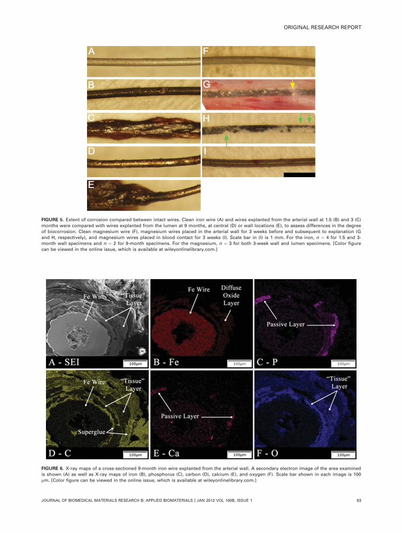
FIGURE 5. Extent of corrosion compared between intact wires. Clean iron wire (A) and wires explanted from the arterial wall at 1.5 (B) and 3 (C)
months were compared with wires explanted from the lumen at 9 months, at central (D) or wall locations (E), to assess differences in the degree
of biocorrosion. Clean magnesium wire (F), magnesium wires placed in the arterial wall for 3 weeks before and subsequent to explanation (G
and H, respectively), and magnesium wires placed in blood contact for 3 weeks (I). Scale bar in (I) is 1 mm. For the iron, n ¼ 4 for 1.5 and 3-
month wall specimens and n ¼ 2 for 9-month specimens. For the magnesium, n ¼ 3 for both 3-week wall and lumen specimens. [Color figure
can be viewed in the online issue, which is available at wileyonlinelibrary.com.]
FIGURE 6. X-ray maps of a cross-sectioned 9-month iron wire explanted from the arterial wall. A secondary electron image of the area examined
is shown (A) as well as X-ray maps of iron (B), phosphorus (C), carbon (D), calcium (E), and oxygen (F). Scale bar shown in each image is 100
lm. [Color figure can be viewed in the online issue, which is available at wileyonlinelibrary.com.]
ORIGINAL RESEARCH REPORT
JOURNAL OF BIOMEDICAL MATERIALS RESEARCH B: APPLIED BIOMATERIALS | JAN 2012 VOL 100B, ISSUE 1 63
appeared to have resisted corrosion [Figure 5(I)]. Thisappeared to be the case because no pits and a relativelyuniform surface coloration were evident on the magnesiumwire surface placed in contact with blood.
Elemental analysis of the 9-month iron wire at the arte-rial wall. Corroded iron wires were characterized usingEDS with the goal of identifying the elemental constituentsof the corrosion products. After being cross sectioned andpolished, elemental mapping was performed on the 9-monthiron sample from the arterial wall location (Figure 6). Thelayer surrounding the metallic surface apparent as a lightgray band on the secondary electron image (SEI) in [Figure6(A)]—is composed of an unknown matrix component, aniron oxide component, and a calcium- and phosphorus-bear-ing phase. Evidence for the matrix component comes fromthe carbon and oxygen compositional maps. The above-background amount of carbon and oxygen shown in the car-bon and oxygen maps [Figure 6(D,F), respectively] indicatethe presence of a tissue layer. Note that the iron wire maybe used as a reference for the carbon background signal,due to the carbon coating. The iron distribution map [Figure
6(B)] demonstrates that the oxide phase is voluminous, as itextends nearly all the way around the sample in a diffusering approximately 100 lm in thickness. It appears that thepieces of the passive layer [Figure 6(C,E)] are at the migra-tion front of an expanding layer of iron oxide, which isencapsulated in some type of binding matrix. There appearsto be no passive layer left intact on the surface of the wire,which would lead to further corrosion.
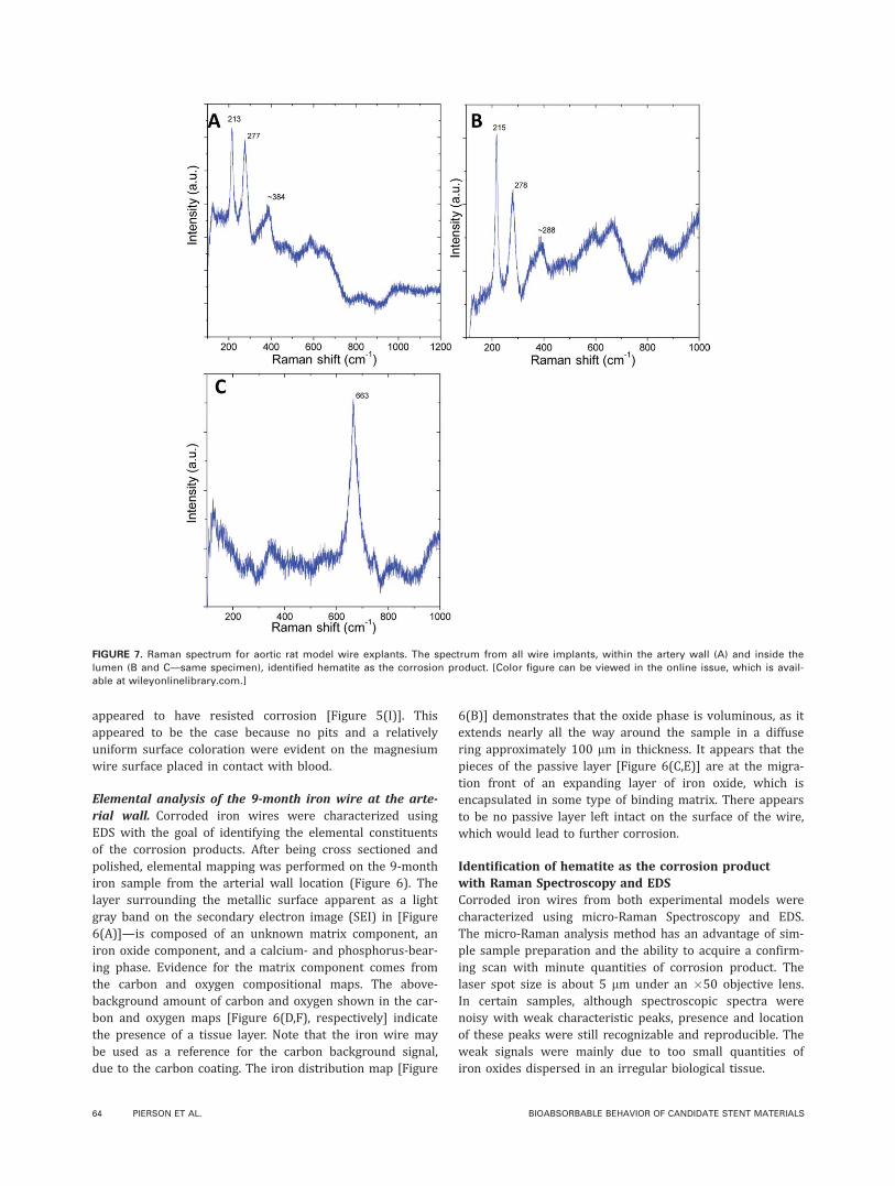
Identification of hematite as the corrosion productwith Raman Spectroscopy and EDSCorroded iron wires from both experimental models werecharacterized using micro-Raman Spectroscopy and EDS.The micro-Raman analysis method has an advantage of sim-ple sample preparation and the ability to acquire a confirm-ing scan with minute quantities of corrosion product. Thelaser spot size is about 5 lm under an �50 objective lens.In certain samples, although spectroscopic spectra werenoisy with weak characteristic peaks, presence and locationof these peaks were still recognizable and reproducible. Theweak signals were mainly due to too small quantities ofiron oxides dispersed in an irregular biological tissue.
FIGURE 7. Raman spectrum for aortic rat model wire explants. The spectrum from all wire implants, within the artery wall (A) and inside the
lumen (B and C—same specimen), identified hematite as the corrosion product. [Color figure can be viewed in the online issue, which is avail-
able at wileyonlinelibrary.com.]
64 PIERSON ET AL. BIOABSORBABLE BEHAVIOR OF CANDIDATE STENT MATERIALS
Several locations on each of the samples were scannedusing both types of analysis to obtain more consistentresults. The EDS analysis detected the presence of iron, oxy-gen, phosphorous, calcium, and potassium (Supporting In-formation Figure S1). The phosphorous and calcium mayhave been detected due to the presence of tissue or as amineralized passive layer present on the surface of the sam-ple. Phosphorous, calcium, and potassium may also havebeen incorporated into the corrosion product(s). The low-atomic percent of iron in the spectrum was most likelycaused by interference from the tissue on the surface.
The Raman spectrum for the wire implants from withinthe artery wall showed peaks at �213 cm�1 and �277cm�1 [Figure 7(A)]. Similarly, the luminal implanted wiresrevealed characteristic peaks at �215 cm�1 and �278 cm�1
[Figure 7(B)]. The characteristic peaks for both sampleswere compared with the Raman spectrum of hematite (Sup-porting Information Figure S2).23 The peaks from the testsamples resemble the two largest characteristic peaks ofhematite located at 225 cm�1 and 291 cm�1. It is apparentthat a shift in the spectrum occurred, a possible result of in-terference from retained biological material on the surfaceof the sample or, most likely, an artifact of the laser powerused to generate the spectrum (see Appendix). The shift tolower wavenumber is accounted for the anharmonic vibra-tion of the crystal lattice by higher laser power.
As presented in Figure 7(C), magnetite signal at663cm�1 could also be found in some areas of the lumi-nal implanted specimens. Magnetite has a prominentcharacteristic peak at �661 cm�1 (Supporting InformationFigure S3).24
Overall, Raman spectroscopy has proven to be a viablemethod for determining in vivo corrosion products. Thecapabilities of Raman spectroscopy supersede the limitationof most other analysis methods that require large quantitiesof product to obtain a confirming spectrum. However, thepresence of tissue or biomaterials on the sample or a high-laser power may cause complications because residual bio-material may absorb energy from the signal and the lasermay cause sample degradation, which can shift the peaklocations on the spectrum. Furthermore, subsequent studiesmay utilize mass spectrophotometry to help identify thecorrosion products that migrate into the tissue.
DISCUSSION
We have demonstrated the feasibility of a biodegradablemetallic wire implanted into a rat artery to serve as an ex-perimental model to investigate the corrosion behavior ofbiodegradable stent materials. Although the geometry of awire is not the same as a stent, this model allows fordetailed investigations at the interface between the candi-date metal and the arterial blood or wall matrix. Thisexperimental model may serve as a prescreening assay forcandidate stent materials before stent manufacturing andlarge animal studies. Although the iron wire used in theexperiments was only 20 mm long and 0.25 mm in dia-meter, we were able to assess surface topography, identifycorrosion products, and characterize corrosion product
diffusion with conventional approaches. We identified thecorrosion product formed around the near pure iron mate-rial as the iron oxide hematite and found that the hematiteparticles spread from the wire in a manner that dependedon the characteristics of the contacting biological material.We showed that immediate encapsulation of iron or magne-sium wires within the arterial wall was conducive to corro-sion, whereas wires implanted into the arterial lumen incontact with flowing arterial blood experienced minimalcorrosion. Corrosion products from the iron wire accumu-lated over 9 months and were retained in the arterial wallas voluminous flakes that threatened the integrity of the ar-terial wall. Although magnesium corroded more rapidlythan the iron, there was no visible retention of corrosionproducts within the vessel wall. The similar regulation ofiron and magnesium corrosion by the host environmentsuggests that corrosion resistance may be a general prop-erty of biodegradable metals placed in contact with flowingarterial blood and corrosion in the arterial wall may becaused by arterial wall constituents, such as vascular matrix,vascular cells, or due to the absence of contacting arterialblood. In contrast to magnesium and iron, conventionalstents are constructed from corrosion resistant alloys.1–3,25
We selected iron as the initial material to demonstratethe capability of the novel experimental model because ironmaterial has been used previously to construct experimentalstents, and there have been several reports on the corrosionprocess of pure iron in the arterial environment,16,21 allow-ing us to focus on developing the new animal model andassociated methodology for biomaterial microanalysis. Thepresent model does not simulate all aspects of stent/arteryinteraction, such as forces between the artery/implant andmechanical stretch-related injury to the arterial wall. A fur-ther limitation is that the wire implantation requires pierc-ing the aorta and producing injury/inflammation, whichmay influence the ensuing corrosion process. The animalmodel also lacks atherosclerotic lesions, which may containconsiderable calcium, phenotypically modulated smoothmuscle cells, and dysfunctional endothelial cells. However,the benefit of the rodent wire implantation approach rela-tive to a large animal stent implantation is that it can beused to quickly and with low-cost evaluate the corrosionbehavior of novel stent materials for prescreening beforematerials processing, stent manufacturing development, andlarge animal implantation studies. This provides an opportu-nity to gather initial observations into material degradationbehavior that can be used to assess the technical feasibilityto warrant continued investment in more thorough experi-mentation. Thus, we have developed a novel model for rapidprescreening of candidate stent materials and demonstratedthe capability of the model to assess biocorrosion in the ar-terial environment.
We found that arterial matrix-contacting iron or magne-sium wires experienced substantial biocorrosion relative toiron or magnesium wires that contacted flowing arterialblood. The mechanism for corrosion in the arterial wall isnot clear. Corrosion may be due to differences in the ionic,cellular, or material environments of the arterial wall
ORIGINAL RESEARCH REPORT
JOURNAL OF BIOMEDICAL MATERIALS RESEARCH B: APPLIED BIOMATERIALS | JAN 2012 VOL 100B, ISSUE 1 65
relative to arterial blood. The ion-rich blood may act to pas-sivate the metallic surface and protect the wire from corro-sion, whereas wires in the wall may passivate to a lesserextent or may not be protected by the passive layer. If morephosphate is present in one environment relative to another,for example, the potential for phosphate surface mineraliza-tion is greater. In fact, a calcium and phosphate-rich layerwas recorded on the implanted iron wire. Alternatively,there may be greater exposure to ionic iron or magne-sium (in the blood) than in the tissue, and thus less ofan electrochemical potential for corrosion. Unfortunately,the corrosion mechanism can be difficult to clarifyin vivo due to the complex cellular and material compo-sition of the arterial wall and the ionic composition ofarterial blood. The arterial wall contains a complex, elec-trically charged matrix material, along with vascular cellswithin the layers of the wall, both of which may regulateionic concentrations on the surface of the implantedmetal. Negatively charged proteoglycans present in thearterial matrix for example may repel phosphate ionsand thereby impede the formation of a protective phos-phate layer. The extracellular matrix may regulate the dif-fusion/retention of corrosion reactants and productsbased on the charge and pore size of the matrix. Vascu-lar smooth muscle cells are able to regulate their localionic environment.26–28 It may therefore be necessary toconduct in vitro studies to resolve the roles of the arte-rial blood, fibrous matrix, proteoglycans, and vascularcells in the corrosion process.
CONCLUSIONS
We have demonstrated the feasibility of an arterial wireimplantation model by comparing the short and long-termcorrosion behavior of iron, by comparing the corrosionbehavior of iron and magnesium, and demonstrating theimportance of the arterial environment for directing the cor-rosion process. We have also used this model to demon-strate that the degradation products of an iron arterialimplant are retained in an expanded form that may chal-lenge the long-term integrity of the artery, whereas magne-sium degradation products are not retained in the wall. Onthe basis of our novel findings, we speculate that blood-con-tacting surfaces of a deployed iron or magnesium stent mayexperience reduced corrosion, whereas surfaces of the stentthat are pressed against the endothelium and shielded fromthe blood may undergo biocorrosion. In the case of iron, thebiocorrosion product may be retained within the encapsu-lating neointima in an expanded form that may complicatenormal arterial function.
Because the chemical composition of biodegradablematerials may need to be modified to improve the perform-ance of biodegradable stents and candidate materials canbe more readily assessed when formed into a wire ratherthan a deployable stent, the present arterial wire implanta-tion model may be useful for developing materials withdegradation properties more suitable for vascular stentingapplications.
REFERENCES1. Camenzind E. Treatment of in-stent restenosis—Back to the
future? N Engl J Med 2006;355:2149–2151.
2. Kastrati A, Mehilli J, Pache J, Kaiser C, Valgimigli M, Kelbaek H,
Menichelli M, Sabate M, Suttorp MJ, Baumgart D, Seyfarth M,
Pfisterer ME, Schomig A. Analysis of 14 trials comparing siroli-
mus-eluting stents with bare-metal stents. N Engl J Med 2007;
356:1030–1039.
3. Koster R, Vieluf D, Kiehn M, Sommerauer M, Kahler J, Baldus S,
Meinertz T, Hamm CW. Nickel and molybdenum contact allergies
in patients with coronary in-stent restenosis. Lancet 2000;356:
1895–1897.
4. Yun YH, Dong ZY, Lee N, Liu YJ, Xue DC, Guo XF, Kuhlmann J,
Doepke A, Halsall HB, Heineman W, Sundaramurthy S, Schulz
MJ, Yin ZZ, Shanov V, Hurd D, Nagy P, Li WF, Fox C. Revolutio-
nizing biodegradable metals. Mater Today 2009;12:22–32.
5. Ramcharitar S, Serruys PW. Fully biodegradable coronary stents
progress to date. Am J Cardiovasc Drugs 2008;8:305–314.
6. Colombo A, Karvouni E. Biodegradable stents—‘‘Fulfilling the
mission and stepping away’’. Circulation 2000;102:371–373.
7. Erne P, Schier M, Resink TJ. The road to bioabsorbable stents:
Reaching clinical reality? Cardiovasc Intervent Radiol 2006;29:
11–16.
8. Hermawan H, Dube D, Mantovani D. Developments in metallic
biodegradable stents. Acta Biomater 2010;6:1693–1697.
9. Eggebrecht H, Rodermann J, Hunold P, Schmermund A, Bose D,
Haude M, Erbel R. Novel magnetic resonance-compatible coro-
nary stent—The absorbable magnesium-alloy stent. Circulation
2005;112:E303–E304.
10. Erbel R, Di Mario C, Bartunek J, Bonnier J, de Bruyne B, Eberli
FR, Erne P, Haude M, Heublein B, Horrigan M, Ilsley C, Bose D,
Koolen J, Luscher TF, Weissman N, Waksman R. Temporary scaf-
folding of coronary arteries with bioabsorbable magnesium
stents: A prospective, non-randomised multicentre trial. Lancet
2007;369:1869–1875.
11. Waksman R, Pakala R, Kuchulakanti PK, Baffour R, Hellinga D,
Seabron R, Tio FO, Wittchow E, Hartwig S, Harder C, Rohde R,
Heublein B, Andreae A, Waldmann KH, Haverich A. Safety and ef-
ficacy of bioabsorbable magnesium alloy stents in porcine coro-
nary arteries. Catheter Cardiovasc Interv 2006;68:607–617.
12. Heublein B, Rohde R, Kaese V, Niemeyer M, Hartung W, Haverich
A. Biocorrosion of magnesium alloys: A new principle in cardio-
vascular implant technology? Heart 2003;89:651–656.
13. Grube E, Sonoda S, Ikeno F, Honda Y, Kar S, Chan C, Gerckens U,
Lansky AJ, Fitzgerald PJ. Six- and twelve-month results from first
human experience using everolimus-eluting stents with bio-
absorbable polymer. Circulation 2004;109:2168–2171.
14. Tamai H, Igaki K, Kyo E, Kosuga K, Kawashima A, Matsui S,
Komori H, Tsuji T, Motohara S, Uehata H. Initial and 6-month
results of biodegradable poly-L-lactic acid coronary stents in
humans. Circulation 2000;102:399–404.
15. Middleton JC, Tipton AJ. Synthetic biodegradable polymers as
orthopedic devices. Biomaterials 2000;21:2335–2346.
16. Peuster M, Hesse C, Schloo T, Fink C, Beerbaum P, von Schna-kenburg C. Long-term biocompatibility of a corrodible peripheraliron stent in the porcine descending aorta. Biomaterials 2006;27:4955–4962.
17. Moravej M, Prima F, Fiset M, Mantovani D. Electroformed iron as
new biomaterial for degradable stents: Development process and
structure–properties relationship. Acta Biomater 2010;6:1726– 1735.
18. Moravej M, Purnama A, Fiset M, Couet J, Mantovani D. Electro-
formed pure iron as a new biomaterial for degradable stents:
In vitro degradation and preliminary cell viability studies. Acta
Biomater 2010;6:1843–1851.
19. Hermawan H, Dube D, Mantovani D. Degradable metallic bio-
materials: Design and development of Fe–Mn alloys for stents.
J Biomed Mater Res A 2010;93A:1–11.
20. di Mario C, Griffiths H, Goktekin O, Peeters N, Verbist J, BosiersM, Deloose K, Heublein B, Rohde R, Kasese V, Isley C, Erbel R.Drug-eluting bioabsorbable magnesium stent. J Interv Cardiol2004;17:391–395.
21. Waksman R, Pakala R, Baffour R, Seabron R, Hellinga D, Tio FO.
Short-term effects of biocorrodible iron stents in porcine coronary
arteries. J Interv Cardiol 2008;21:15–20.
66 PIERSON ET AL. BIOABSORBABLE BEHAVIOR OF CANDIDATE STENT MATERIALS
22. Peuster M, Wohlsein P, Brugmann M, Ehlerding M, Seidler K,
Fink C, Brauer H, Fischer A, Hausdorf G. A novel approach to tem-
porary stenting: Degradable cardiovascular stents produced from
corrodible metal—Results 6–18 months after implantation into
New Zealand white rabbits. Heart 2001;86:563–569.
23. Schlepp E. 2010. Hematite R050300-RRUFF Database: Raman, X-
ray, Infrared, and Chemistry. http://rruff.info/hematite/display¼default/R050300.
24. Scott M.2010. Magnetite R061111—RRUFF Database: Raman, X-
ray, Infrared, and Chemistry. http://rruff.info/hematite/display¼default/R061111.
25. Singh R, Dahotre NB. Corrosion degradation and prevention by
surface modification of biometallic materials. J Mater Sci Mater
Med 2007;18:725–751.
26. Giachelli CM. The emerging role of phosphate in vascular calcifi-
cation. Kidney Int 2009;75:890–897.
27. Li X, Yang HY, Giachelli CM. Role of the sodium-dependent phos-
phate cotransporter. Pit-1, in vascular smooth muscle cell calcifi-
cation. Circ Res 2006;98:905–912.
28. Jono S, McKee MD, Murry CE, Shioi A, Nishizawa Y, Mori K,
Morii H, Giachelli CM. Phosphate regulation of vascular smooth
muscle cell calcification. Circ Res 2000;87:E10–E17.
29. deFaria DLA, Silva SV, deOliveira MT. Raman microspectroscopy
of some iron oxides and oxyhydroxides. J Raman Spectrosc 1997;
28:873–878.
30. Oh SJ, Cook DC, Townsend HE. Characterization of iron oxides
commonly formed as corrosion products on steel. Hyperfine Inter
1998;112:59–65.
31. Bersani D, Lottici PP, Montenero A. Micro-Raman investigation of
iron oxide films and powders produced by sol–gel syntheses. J
Raman Spectrosc 1999;30:355–360.
32. Hanesch M. Raman spectroscopy of iron oxides and (oxy)hydrox-
ides at low laser power and possible applications in environmen-
tal magnetic studies. Geophys J Int 2009;177:941–948.
33. Larroumet D, Greenfield D, Akid R, Yarwood J. Raman spectro-
scopic studies of the corrosion of model iron electrodes in so-
dium chloride solution. J Raman Spectrosc 2007;38:1577–1585.
APPENDIX
Raman Spectroscopy of Iron OxidesRaman spectroscopy is useful to distinguish different ironoxides and oxyhydroxides compounds in rust composi-
tion.29,30 Various iron oxides and hydroxides have received alot of interest as corrosion products of steels, and the Ramanspectra are used as fingerprints to detect particular species.31
The most common iron oxides and hydroxides are hematite(a-Fe2O3), maghemite (b-Fe2O3), magnetite (Fe3O4), and goe-thite (a-FeOOH). Although it was claimed that iron oxides andhydroxides were poor light scatters,29,32 it was possible tocharacterize and distinguish these powders reliably at low-laser powers. In fact, low-laser power should be used to avoidsample degradation, which usually occurs under intense laserillumination and may lead to misinterpretation of the spectra.Due to the small size of our wire sample, micro-Raman spec-troscopy was used in this study to characterize the corrodedimplant materials.
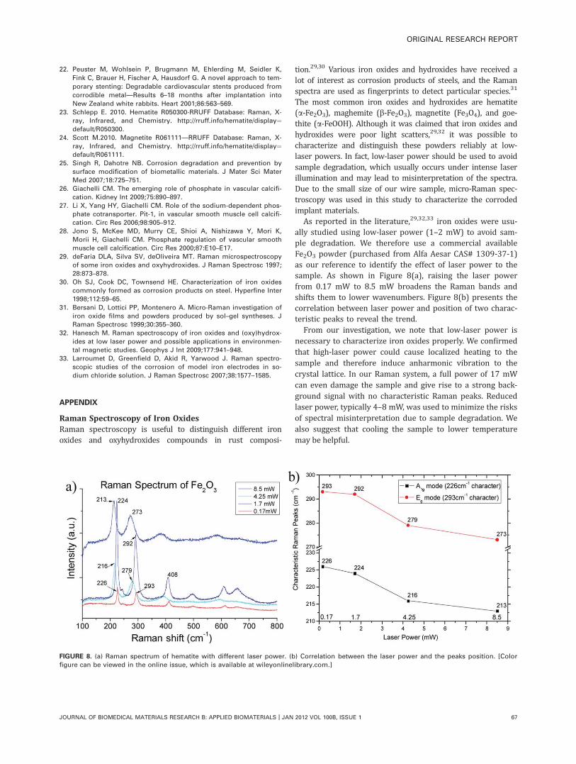
As reported in the literature,29,32,33 iron oxides were usu-ally studied using low-laser power (1–2 mW) to avoid sam-ple degradation. We therefore use a commercial availableFe2O3 powder (purchased from Alfa Aesar CAS# 1309-37-1)as our reference to identify the effect of laser power to thesample. As shown in Figure 8(a), raising the laser powerfrom 0.17 mW to 8.5 mW broadens the Raman bands andshifts them to lower wavenumbers. Figure 8(b) presents thecorrelation between laser power and position of two charac-teristic peaks to reveal the trend.
From our investigation, we note that low-laser power isnecessary to characterize iron oxides properly. We confirmedthat high-laser power could cause localized heating to thesample and therefore induce anharmonic vibration to thecrystal lattice. In our Raman system, a full power of 17 mWcan even damage the sample and give rise to a strong back-ground signal with no characteristic Raman peaks. Reducedlaser power, typically 4–8 mW, was used to minimize the risksof spectral misinterpretation due to sample degradation. Wealso suggest that cooling the sample to lower temperaturemay be helpful.
FIGURE 8. (a) Raman spectrum of hematite with different laser power. (b) Correlation between the laser power and the peaks position. [Color
figure can be viewed in the online issue, which is available at wileyonlinelibrary.com.]
ORIGINAL RESEARCH REPORT
JOURNAL OF BIOMEDICAL MATERIALS RESEARCH B: APPLIED BIOMATERIALS | JAN 2012 VOL 100B, ISSUE 1 67
Related Documents