Objective Age- hardening Al-Cu Al-Ag steels mecha- nisms 1 Microstructure-Properties: II Age Hardening 27-302 Lecture 9 Fall, 2002 Prof. A. D. Rollett

Welcome message from author
This document is posted to help you gain knowledge. Please leave a comment to let me know what you think about it! Share it to your friends and learn new things together.
Transcript

Objective
Age-
hardening
Al-Cu
Al-Ag
steels
mecha-
nisms
1
Microstructure-Properties: II
Age Hardening
27-302
Lecture 9
Fall, 2002
Prof. A. D. Rollett

Objective
Age-
hardening
Al-Cu
Al-Ag
steels
mecha-
nisms
2
Materials Tetrahedron
Microstructure Properties
Processing
Performance

Objective
Age-
hardening
Al-Cu
Al-Ag
steels
mecha-
nisms
3
Objective
• The objective of this lecture is to describe
the relationship between precipitation and
hardness as an example of a key
microstructure-property relationship.

Objective
Age-
hardening
Al-Cu
Al-Ag
steels
mecha-
nisms
4
References
• Phase transformations in metals and alloys, D.A.
Porter, & K.E. Easterling, Chapman & Hall.
• Materials Principles & Practice, Butterworth
Heinemann, Edited by C. Newey & G. Weaver.
• Mechanical Metallurgy, McGrawHill, G.E. Dieter, 3rd
Ed.
• Hull, D. and D. J. Bacon (1984). Introduction to
Dislocations. Oxford, UK, Pergamon.
• Courtney, T. H. (2000). Mechanical Behavior of
Materials. Boston, McGraw-Hill.

Objective
Age-
hardening
Al-Cu
Al-Ag
steels
mecha-
nisms
5
Notation
a := lattice parameter
e := strain, misfit (or similar quantity to
describe a hardening mechanism)
G := shear modulus
b := Burgers vector
r := Particle size (radius)
f VV(a) := volume fraction (of precipitates)
s := stress (macroscopic)
t := shear stress (critical value, in some cases)
g := boundary energy, e.g. anti-phase boundary
<L3> := mean intercept length (of precipitates)
l := mean spacing (of precipitates)
Objective
Age-
hardening
Al-Cu
Al-Ag
steels
mecha-
nisms
6
Age Hardening Curves
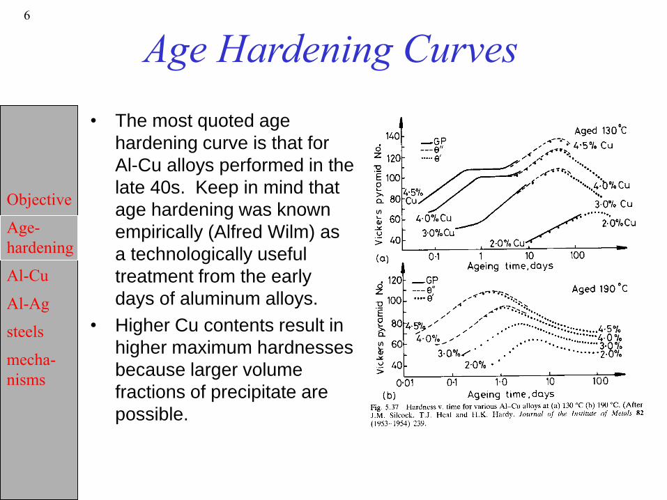
• The most quoted age
hardening curve is that for
Al-Cu alloys performed in the
late 40s. Keep in mind that
age hardening was known
empirically (Alfred Wilm) as
a technologically useful
treatment from the early
days of aluminum alloys.
• Higher Cu contents result in
higher maximum hardnesses
because larger volume
fractions of precipitate are
possible.

Objective
Age-
hardening
Al-Cu
Al-Ag
steels
mecha-
nisms
7
Al-Cu precipitation sequence
• The sequence is:a0 a1 + GP-zones a2 + q“ a3 + q’ a4 + q
• The phase are:an - fcc aluminum; nth subscript denotes each equilibriumGP zones - mono-atomic layers of Cu on (001)Al
q“ - thin discs, fully coherent with matrixq’ - disc-shaped, semi-coherent on (001)q’ bct. q - incoherent interface, ~spherical, complex body-centered tetragonal (bct).

Objective
Age-
hardening
Al-Cu
Al-Ag
steels
mecha-
nisms
8
Al-Cu ppt
structures
GP zone structure
Objective
Age-
hardening
Al-Cu
Al-Ag
steels
mecha-
nisms
9
Al-Cu microstructures
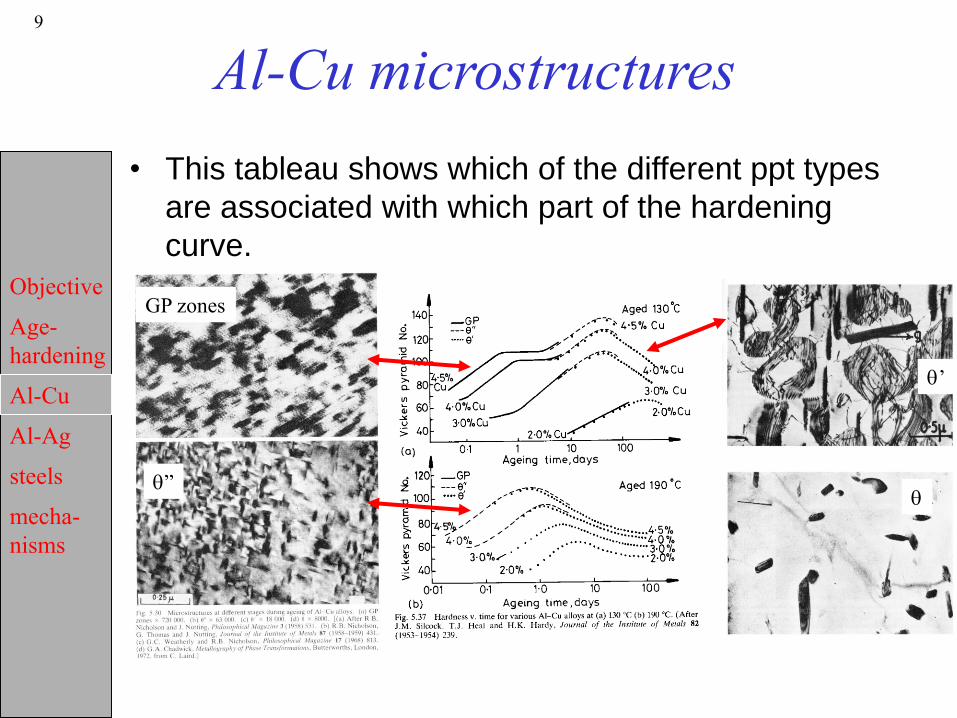
• This tableau shows which of the different ppt types
are associated with which part of the hardening
curve.
GP zones
q”
q’
q
Objective
Age-
hardening
Al-Cu
Al-Ag
steels
mecha-
nisms
10
Al-Cu driving forces
• Each precipitate has a different free energy curve w.r.t
composition. Exception is the GP zone, which may be
regarded as continuous with the alloy (leading to the
possibility of spinodal decomposition, discussed later).
• P&E fig. 5.27 illustrates the sequence of successively greater
free energy decreases and also successively greater ∆G*.
• P&E fig. 5.28 illustrates the point that the nucleation barriers
are much smaller for each individual nucleation step when the
next precipitate nucleates heterogeneously on the previous
structure.
Objective
Age-
hardening
Al-Cu
Al-Ag
steels
mecha-
nisms
11
Al-Cu phase relationships
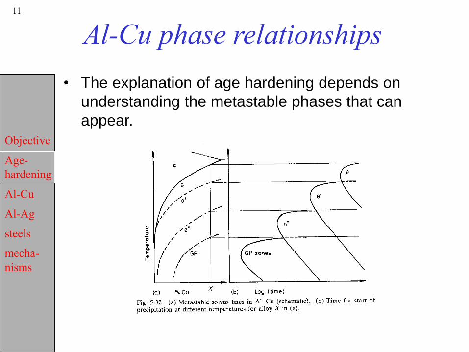
• The explanation of age hardening depends on
understanding the metastable phases that can
appear.
Objective
Age-
hardening
Al-Cu
Al-Ag
steels
mecha-
nisms
12
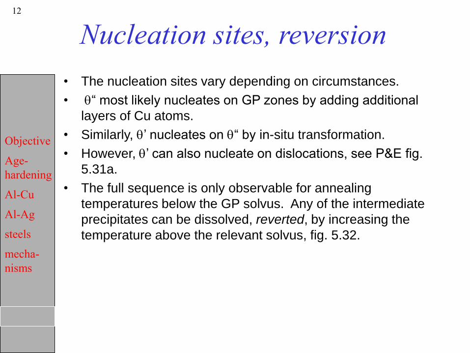
Nucleation sites, reversion
• The nucleation sites vary depending on circumstances.
• q“ most likely nucleates on GP zones by adding additional
layers of Cu atoms.
• Similarly, q’ nucleates on q“ by in-situ transformation.
• However, q’ can also nucleate on dislocations, see P&E fig.
5.31a.
• The full sequence is only observable for annealing
temperatures below the GP solvus. Any of the intermediate
precipitates can be dissolved, reverted, by increasing the
temperature above the relevant solvus, fig. 5.32.

Objective
Age-
hardening
Al-Cu
Al-Ag
steels
mecha-
nisms
13
Al-Ag: example 2
• The age hardening curve has the same double
peak as for the Al-Cu series, but the separation is
more pronounced.
Shewmon

Objective
Age-
hardening
Al-Cu
Al-Ag
steels
mecha-
nisms
14
Al-Ag, contd.
• GP zones are spherical (Ag atom is larger than Al).
• g’ is hcp with OR (0001)g//(111)a and [1120]g //[110]a;
heterogeneously nucleated on the stacking faults of
dislocations which provide sites of local hexagonal packing.
• g is also hcp with the same OR; forms plate-like precipitates.
A cellular mechanism can also occur.
Shewmon

Objective
Age-
hardening
Al-Cu
Al-Ag
steels
mecha-
nisms
15
Age hardening in steel: example 3
• It is important to understand that age hardening occurs in
almost any system in which the solid solubility decreases
appreciably with decreasing temperature. Ferrite has a very
low solubility for carbon and therefore age hardening (also
called quench hardening) occurs here too. To avoid it, the
soluble carbon levels must be reduced, which is a common
objective of the IF or interstitial-free steel grades. These have
additions of carbide formers such as Ti or Nb to sequester the
C.
Shewmon
Objective
Age-
hardening
Al-Cu
Al-Ag
steels
mecha-
nisms
16
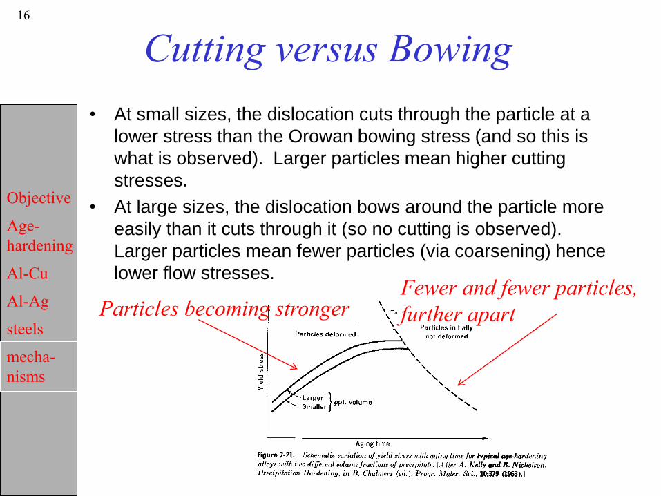
Cutting versus Bowing
• At small sizes, the dislocation cuts through the particle at a
lower stress than the Orowan bowing stress (and so this is
what is observed). Larger particles mean higher cutting
stresses.
• At large sizes, the dislocation bows around the particle more
easily than it cuts through it (so no cutting is observed).
Larger particles mean fewer particles (via coarsening) hence
lower flow stresses.
Particles becoming strongerFewer and fewer particles,
further apart
Objective
Age-
hardening
Al-Cu
Al-Ag
steels
mecha-
nisms
17
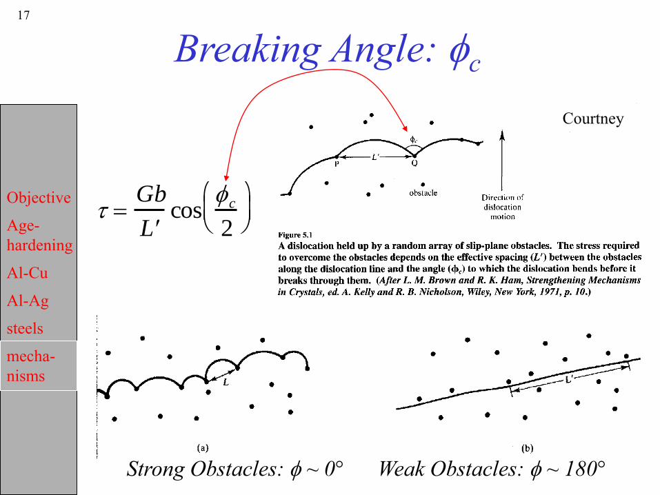
Breaking Angle: fc
Strong Obstacles: f ~ 0° Weak Obstacles: f ~ 180°
t Gb
L cos
fc
2
Courtney
Objective
Age-
hardening
Al-Cu
Al-Ag
steels
mecha-
nisms
18 Hardness -microstructure
relationships• In order to understand the relationship between microstructure
and hardness, we need to delve into the subject of hardening
mechanisms.
• The central concept is that the strength of a ductile material is
governed by dislocation flow past obstacles. Therefore
strength can be designed by controlling the density and nature
of the obstacles to dislocation motion. Most technological
(metallic) alloys rely on precipitation hardening in one form or
another to achieve high strengths. Ceramics, on the other
hand, are intrinsically harder and therefore the main objective
of strengthening is to increase their fracture toughness and
thereby increase their (reliable) load carrying capacity. The
objective of this discussion is therefore to bring your attention
to a number of ways in which we can understand and predict
the contributions to strength of different types of obstacle.

Objective
Age-
hardening
Al-Cu
Al-Ag
steels
mecha-
nisms
19
Strengthening Methods
• Microstructural Feature:
strength dependence.
• Dislocations: strain/work hardening
(discussed in 301): (dislocation spacing)1/2.
• Internal Boundaries: grain boundaries can
have a strong strengthening effect, i.e. the
Hall-Petch effect (discussed in 301): (grain
size)-1/2.
• Dislocation Boundaries (low angle
boundaries): (subgrain size)-1.
• Second Phase Particles: particle spacing.
• Solutes: (concentration)1/2.

Objective
Age-
hardening
Al-Cu
Al-Ag
steels
mecha-
nisms
20
Mechanisms of particle strengthening
1) Coherency Hardening: differences in density between the particle and
the matrix give rise to elastic stresses in the vicinity of the particle.
2) Chemical Hardening: creation of new surface when a particle is
sheared increases the area of the interphase boundary, which increases the
energy associated with the interface and hence an additional force must be
exerted on the dislocation to force it through the particle.
3) Order Hardening: passage of a dislocation through an ordered particle,
e.g. Ni3Al in superalloys, results in a disordered lattice and the creation of
antiphase boundaries.
4) Stacking-fault Hardening: a difference in stacking fault energy
between particle and matrix, e.g. Ag in Al, increases flow stress because of
the different separation of partial dislocations in the two phases.
5) Modulus Hardening: a large difference in elastic modulus results in
image forces when a dislocation in the matrix approaches a particle.
Consider, e.g., the difference between silver particles (nearly the same shear
modulus) and iron particles (much higher shear modulus) in aluminum.

Objective
Age-
hardening
Al-Cu
Al-Ag
steels
mecha-
nisms
21
Dislocations
• A re-statement of the governing equation for
strength controlled by obstacle spacing:
s M t 0 aGb /l Parameter Description Comments
s flow stress Experimentally acce ssible through mechan ical
tests
<M> Average Taylor factor Magnitude ~3 fo r tension or compression;
depends on the nature of the deformation, the
texture and the crystal structure, e.g. < M>~1.73
for torsion (cubic metals)
t Athermal stress Contributions from grain size hardening,
solutes, etc.a Geometrical factor This term accoun ts for both geo metrical factors,
and for thermal activation
G Shear Modulus Must choose appropriate shear modulus for the
slip plane used;
Temperature dependen t
b Burgers vector Derived from the force on a dislocation (Peach -
Koehler Eq.)
¦ dislocation density Equivalent to the reciprocal of a mean obstacle
spacing; depends on work hardening
l obstacle spacing Given a number density of particles, the mean
spacing, l=N1/2

Objective
Age-
hardening
Al-Cu
Al-Ag
steels
mecha-
nisms
22
crss versus density
Courtney

Objective
Age-
hardening
Al-Cu
Al-Ag
steels
mecha-
nisms
23
Dislocation Boundaries
• At large strains and higher temperatures, low angle
boundaries appear as a subgrain network forms.
We distinguish this microstructural feature from the
first two categories because the [lattice]
misorientations are much smaller (2-5°) than grain
boundaries (15°+) and they are distinct from
statistically stored dislocations. This strengthening
method is most important at high temperatures
where other microstructural features such as
solutes are weak.
• The contribution to the flow strength is typically
found to be proportional to (grain size)-1; this is in
contrast to the 1/√d dependence of the Hall-Patch
effect.

Objective
Age-
hardening
Al-Cu
Al-Ag
steels
mecha-
nisms
24
Solutes
• Solutes in a crystal act as obstacles to dislocation
motion through their elastic and/or chemical
interactions with dislocations. Most solutes are
weak hardeners except for the (technologically)
important class of interstitial solutes that induce
anisotropic distortions of the lattice, e.g. tetragonal
distortions of C in Fe.

Objective
Age-
hardening
Al-Cu
Al-Ag
steels
mecha-
nisms
25
Substitutional solutes
• Most Solutes have only a rather weak effect on strength. In
other words, even if you put several per cent of a soluble atom
into another element, you will not see a dramatic increase in
flow stress. These remarks can be quantified by going back to
the Orowan equation, i.e. the force balance between the
forward motion and the resisting force:
tcrss = µb/l.
• For substitutional solutes, the numerator in the RHS, i.e. the
reaction force from the solute atoms is of order Gb2/120,
which is a small number. This is so because the small
differences in size between solute and matrix atoms results in
a small interaction energy with dislocations. Thus they are
weak obstacles and dislocations remain nearly straight when
interacting with solutes (“weak obstacles”, 7slides before this).

Objective
Age-
hardening
Al-Cu
Al-Ag
steels
mecha-
nisms
26
Interstitial solutes
• Interstitials in bcc, however, can exert forces on the
order of Gb2/5 to Gb2/10, which are large values. In
this case, the dislocations bow out significantly
between the atoms, and the breaking angle
deviates significantly from 180°. In this case, the
concentration dependence is easy to obtain. The
spacing between interstitials is inversely
proportional to the (square root of the)
concentration, and so we can insert a spacing into
the standard (Orowan bowing) formula to get the
following, where A is a constant of order unity:
t = AGb(√c/b) = AG√c.
Objective
Age-
hardening
Al-Cu
Al-Ag
steels
mecha-
nisms
27
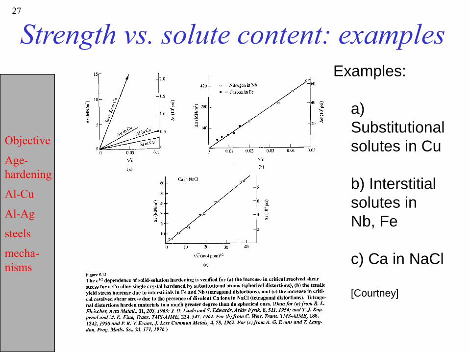
Strength vs. solute content: examplesExamples:
a)
Substitutional
solutes in Cu
b) Interstitial
solutes in
Nb, Fe
c) Ca in NaCl
[Courtney]
Objective
Age-
hardening
Al-Cu
Al-Ag
steels
mecha-
nisms
28
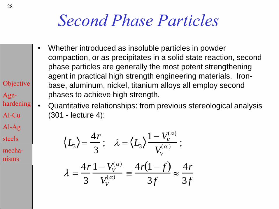
Second Phase Particles
• Whether introduced as insoluble particles in powder
compaction, or as precipitates in a solid state reaction, second
phase particles are generally the most potent strengthening
agent in practical high strength engineering materials. Iron-
base, aluminum, nickel, titanium alloys all employ second
phases to achieve high strength.
• Quantitative relationships: from previous stereological analysis
(301 - lecture 4):
L3 4r
3; l L3
1 VV
(a)
VV
(a ) ;
l 4r
3
1 VV
(a)
VV
(a) 4r 1 f
3 f
4r
3 f

Objective
Age-
hardening
Al-Cu
Al-Ag
steels
mecha-
nisms
29
Mechanisms of particle strengthening1) Coherency Hardening: differences in density between the
particle and the matrix give rise to elastic stresses in the vicinity of the particle.
2) Chemical Hardening: creation of new surface when a particle is sheared increases the area of the interphase boundary, which increases the energy associated with the interface and hence an additional force must be exerted on the dislocation to force it through the particle.
3) Order Hardening: passage of a dislocation through an ordered particle, e.g. Ni3Al in superalloys, results in a disordered lattice and the creation of antiphase boundaries.
4) Stacking-fault Hardening: a difference in stacking fault energy between particle and matrix, e.g. Ag in Al, increases flow stress because of the different separation of partial dislocations in the two phases.
5) Modulus Hardening: a large difference in elastic modulus results in image forces when a dislocation in the matrix approaches a particle. Consider, e.g., the difference between silver particles (nearly the same shear modulus) and iron particles (much higher shear modulus) in aluminum.

Objective
Age-
hardening
Al-Cu
Al-Ag
steels
mecha-
nisms
30
Coherency hardening
Differences in density between the particle and the matrix give
rise to elastic stresses in the vicinity of the particle. This has
been analyzed on the basis of the elastic stresses that exist in
the matrix adjacent to a particle that has a different lattice
parameter than the matrix. Ignoring differences in modulus for
now, and setting a parameter, e, that approximates a strain to
characterize the magnitude of the effect. For
e = (aparticle – amatrix )/ amatrix
t = 7|e|3/2 G(rf/b)1/2
• This mechanism applies to the early stages of precipitation,
e.g. strengthening by GP zones.
Objective
Age-
hardening
Al-Cu
Al-Ag
steels
mecha-
nisms
31
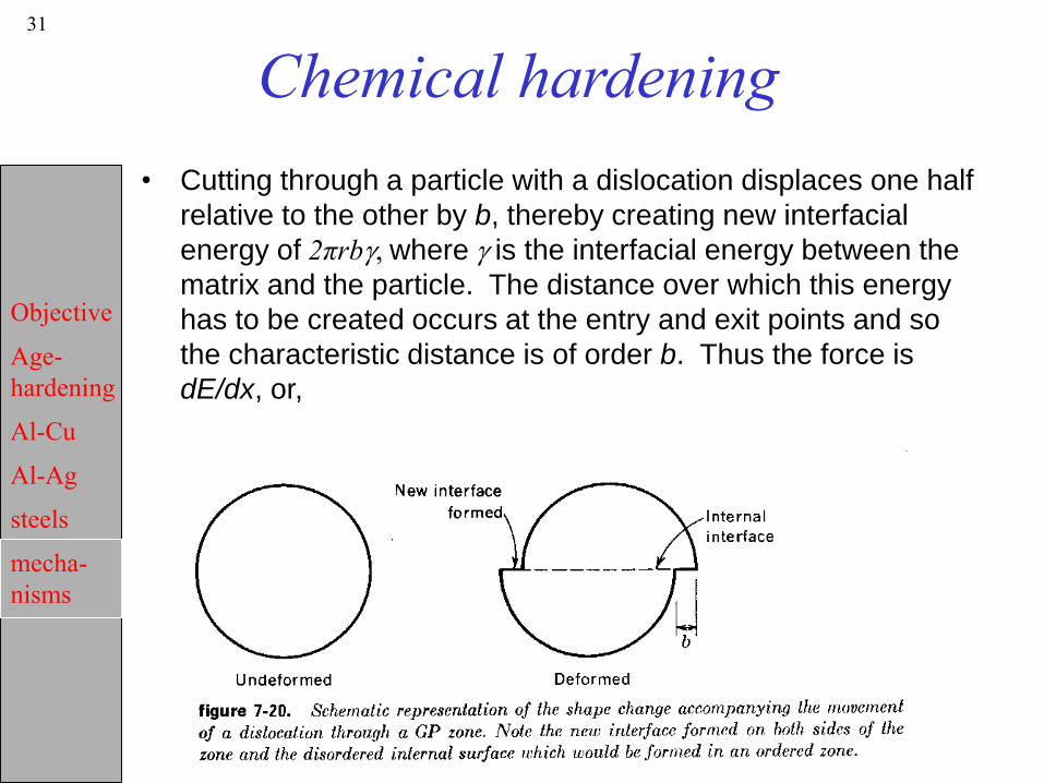
Chemical hardening
• Cutting through a particle with a dislocation displaces one half
relative to the other by b, thereby creating new interfacial
energy of 2πrbg, where g is the interfacial energy between the
matrix and the particle. The distance over which this energy
has to be created occurs at the entry and exit points and so
the characteristic distance is of order b. Thus the force is
dE/dx, or,
F = 2πrbg/2b πrg
Objective
Age-
hardening
Al-Cu
Al-Ag
steels
mecha-
nisms
32
Chemical hardening, contd.
• If the dislocations are straight, we can approximate the
spacing between particles as L=2r/f. Dividing the force by bL
to find the stress,
t = πfg/2b.
• A more realistic approach produces the following relationship.
t = 2G{g/Gr}3/2(fr/b)1/2
• Courtney defines a chemical hardening parameter, ech = g/Gr,
related to the interfacial energy, modulus and particle size.
This parameter is precisely analogous to the same parameter
used, e.g. in APB hardening. Chemical hardening applies
only in the early stages of precipitation.

Objective
Age-
hardening
Al-Cu
Al-Ag
steels
mecha-
nisms
33
Order Hardening
• The hardening depends on the product of the antiphase-
boundary energy (APBE) and the area swept by a dislocation
in a particle. Thus the increase in flow stress is given by:
t = πf{APBE}/2b
• In general, low values of the APBE not only predict small
increments in hardness, but also the result that the
dislocations can move through the particles independently of
one another. A more detailed analysis, not presented here,
shows a square root dependence on volume fraction, with
particle size,
t = 0.7 Ge3/2 √(fr/b)
eord= APBE/Gb
• Important for
Ni-based superalloys
Objective
Age-
hardening
Al-Cu
Al-Ag
steels
mecha-
nisms
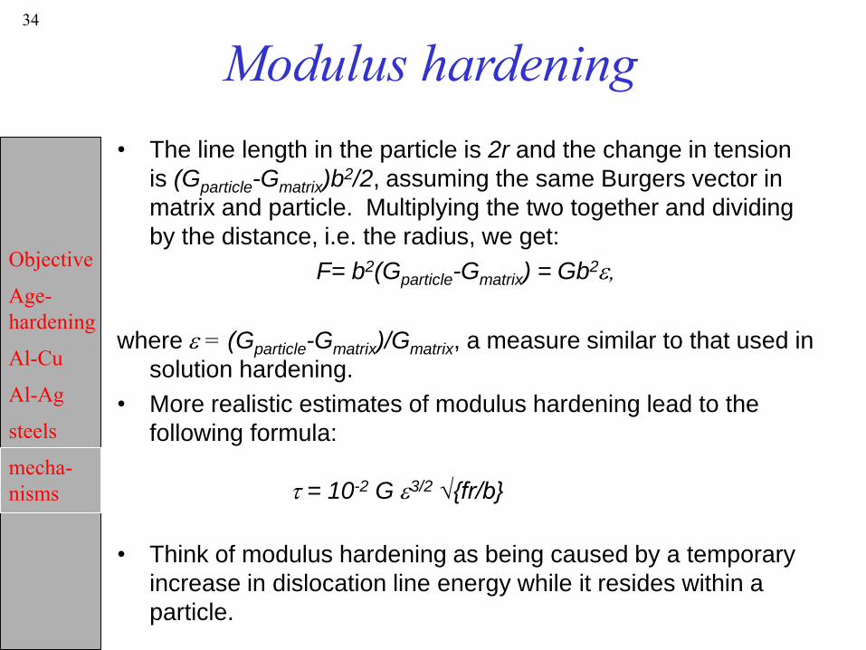
34
Modulus hardening
• The line length in the particle is 2r and the change in tension
is (Gparticle-Gmatrix)b2/2, assuming the same Burgers vector in
matrix and particle. Multiplying the two together and dividing
by the distance, i.e. the radius, we get:
F= b2(Gparticle-Gmatrix) = Gb2e,
where e = (Gparticle-Gmatrix)/Gmatrix, a measure similar to that used in
solution hardening.
• More realistic estimates of modulus hardening lead to the
following formula:
t = 10-2 G e3/2 √{fr/b}
• Think of modulus hardening as being caused by a temporary
increase in dislocation line energy while it resides within a
particle.

Objective
Age-
hardening
Al-Cu
Al-Ag
steels
mecha-
nisms
35
Summary
• A great variety of hardening mechanisms exist.
• Their functional dependence on parameters such
as particle size, spacing, volume fraction, are
similar. It is difficult therefore, to distinguish
experimentally between the mechanisms.
• Microscopy is required in order to determine which
mechanism is operative.
• Particle growth results in stronger particles; in most
cases, however, coarsening takes place
simultaneously which increases the particle
spacing. Orowan bowing takes over from particle
cutting at some point in the aging process.
• Particle hardening is essential to technological
alloys, at least for structural applications.

Objective
Age-
hardening
Al-Cu
Al-Ag
steels
mecha-
nisms
36
Sample Problem• From Dieter, p219 (adapted):
• Question: Al-4%Cu (by wt.) has a yield stress of 600MPa. Estimate
the particle size and spacing.
• Solution: recognize that this stress relates to age hardening beyond
the peak hardness. Therefore use the Orowan bowing stress to
estimate the stress.
s<M> tcrss = <M> Gb/l
• G=27.6GPa; b=0.25nm; <M>=3.1:
spacing = 3.1*27,600*0.25.10-9/ 600= 35.7 nm
• Now we must estimate the volume fraction of particles for which we
use the phase diagram, assuming that we are dealing with the
equilibrium phase, q, which is 54 w/o Cu, and the a in equilibrium
with it, 0.5 w/o Cu.
• Wt. % Al = (54-4)/(54-0.5) = 93.5; wt. % q = 4-0.5/(54-0.5)=6.5
• Volume of a = 93.5gm/2.7 gm/cm3 =34.6 cm3
• Volume of q = 6.5/ 4.443 gm/cm3 = 1.5 cm3
• Volume fraction of a = 0.96; volume fraction of q = 0.04.
• Use l=4r(1-f)/3f (slide 22): r =3*0.04*35.7/4/(1-0.04) = 1.12 nm.
Related Documents