A Fisheye Lens 360 Degree Panoramic Monitoring System Based on the FPGA Da-Peng Lan, Jiang-Hui Deng, Rui-Bin Liu, Feng Li, and Zhi-Yong Pang* School of Physics and Engineering, Sun Yet-Sen University No. 135, Xingang Xi Road, Guangzhou, 510275, P. R. China * Instructor [email protected] 020-84114462 13480268263 Abstract — This paper designs and implements a panoramic monitoring system based on the FPGA fisheye lens. Fisheye images produced suffer from severe distortion. Therefore, it must be corrected to approximately rectilinear versions. Nowadays, most of the algorithms used to correct the fisheyes distortion are realized by software. In this paper, we compared three algorithms used for panoramic monitoring system. And the obtained result of the spherical perspective projection algorithm is promising. The spherical perspective projection algorithm is implemented on a FPGA and a panoramic monitoring has been achieved in a SOPC system. Keywords—FPGA; panoramic monitoring; fisheye; spherical perspective projection; SOPC Ⅰ.INTRODUCTION The fisheye lens are designed to cover the whole hemispherical field in front of the camera, hence, the angle of view is very large, about 180°. So it has more image information and we can use less lens to obtain a wider scene. This will simplify the process of acquiring the image and save hardware resources. Because the fisheye lenses provide very large wide-angle views, the fisheye cameras are finding increasing number of applications in video conference, monitoring and intelligent transportation. This paper designs a 360° high resolution video monitoring system based on the FPGA. A circular fisheye lens angle with 185°is used and the distortion in the circular view image is corrected. The so-called “360° of view” refers to when the fisheye lens suspended overhead shot down without rotation, it will be able to obtain an image with 180°pitching angle and 360°horizontal angle, as shown in Fig. 1. Fig. 1 an image with 180°pitching angle and 360°horizontal angle But fisheye image with distortion will not only influence the human eye observation but also make the image recognition poor. The closer to the edge of the circular area, the greater the distortion. So the fisheye camera image must be corrected to suit for the human eye observation or using image recognition technology to expand the practicability of fisheye lens. According to the wide angle of fisheye image, the fish-eye lens can satisfy the demand of real-time monitoring wide range without blind area. Fisheye lens applied in video monitoring has the advantages: fisheye lens has a broad perspective of more than 180 °; the entire room can be monitored with a fish-eye camera, as shown in Fig. 2. The camera angle used by current monitoring system is generally not more than 75 °. Fig. 2 a fish-eye camera can monitor the whole room

Welcome message from author
This document is posted to help you gain knowledge. Please leave a comment to let me know what you think about it! Share it to your friends and learn new things together.
Transcript
A Fisheye Lens 360 Degree Panoramic Monitoring
System Based on the FPGA
Da-Peng Lan, Jiang-Hui Deng, Rui-Bin Liu, Feng Li, and Zhi-Yong Pang* School of Physics and Engineering, Sun Yet-Sen University
No. 135, Xingang Xi Road, Guangzhou, 510275, P. R. China
* Instructor
[email protected] 020-84114462 13480268263
Abstract—This paper designs and implements a panoramic
monitoring system based on the FPGA fisheye lens. Fisheye
images produced suffer from severe distortion. Therefore, it
must be corrected to approximately rectilinear versions.
Nowadays, most of the algorithms used to correct the fisheyes
distortion are realized by software. In this paper, we compared
three algorithms used for panoramic monitoring system. And
the obtained result of the spherical perspective projection
algorithm is promising. The spherical perspective projection
algorithm is implemented on a FPGA and a panoramic
monitoring has been achieved in a SOPC system.
Keywords—FPGA; panoramic monitoring; fisheye; spherical
perspective projection; SOPC
Ⅰ.INTRODUCTION
The fisheye lens are designed to cover the whole
hemispherical field in front of the camera, hence, the angle
of view is very large, about 180°. So it has more image
information and we can use less lens to obtain a wider scene.
This will simplify the process of acquiring the image and
save hardware resources. Because the fisheye lenses provide
very large wide-angle views, the fisheye cameras are finding
increasing number of applications in video conference,
monitoring and intelligent transportation.
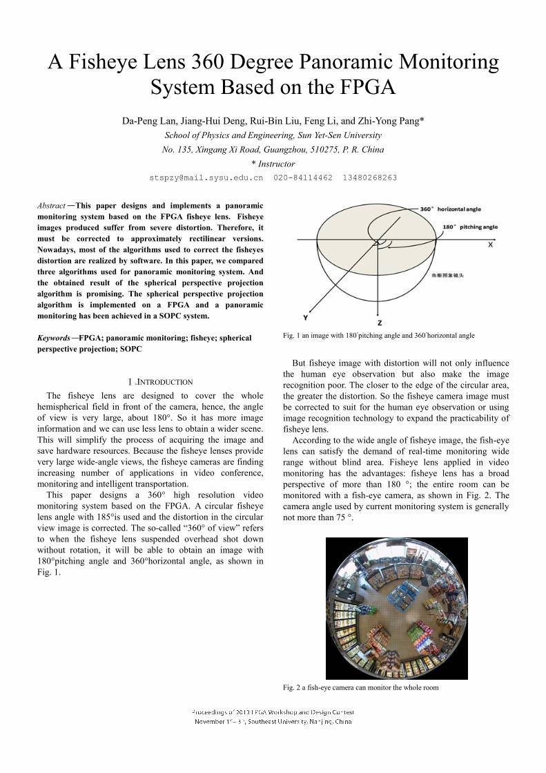
This paper designs a 360° high resolution video
monitoring system based on the FPGA. A circular fisheye
lens angle with 185°is used and the distortion in the circular
view image is corrected. The so-called “360° of view” refers
to when the fisheye lens suspended overhead shot down
without rotation, it will be able to obtain an image with
180°pitching angle and 360°horizontal angle, as shown in
Fig. 1.
Fig. 1 an image with 180°pitching angle and 360°horizontal angle
But fisheye image with distortion will not only influence
the human eye observation but also make the image
recognition poor. The closer to the edge of the circular area,
the greater the distortion. So the fisheye camera image must
be corrected to suit for the human eye observation or using
image recognition technology to expand the practicability of
fisheye lens.
According to the wide angle of fisheye image, the fish-eye
lens can satisfy the demand of real-time monitoring wide
range without blind area. Fisheye lens applied in video
monitoring has the advantages: fisheye lens has a broad
perspective of more than 180 °; the entire room can be
monitored with a fish-eye camera, as shown in Fig. 2. The
camera angle used by current monitoring system is generally
not more than 75 °.
Fig. 2 a fish-eye camera can monitor the whole room
2
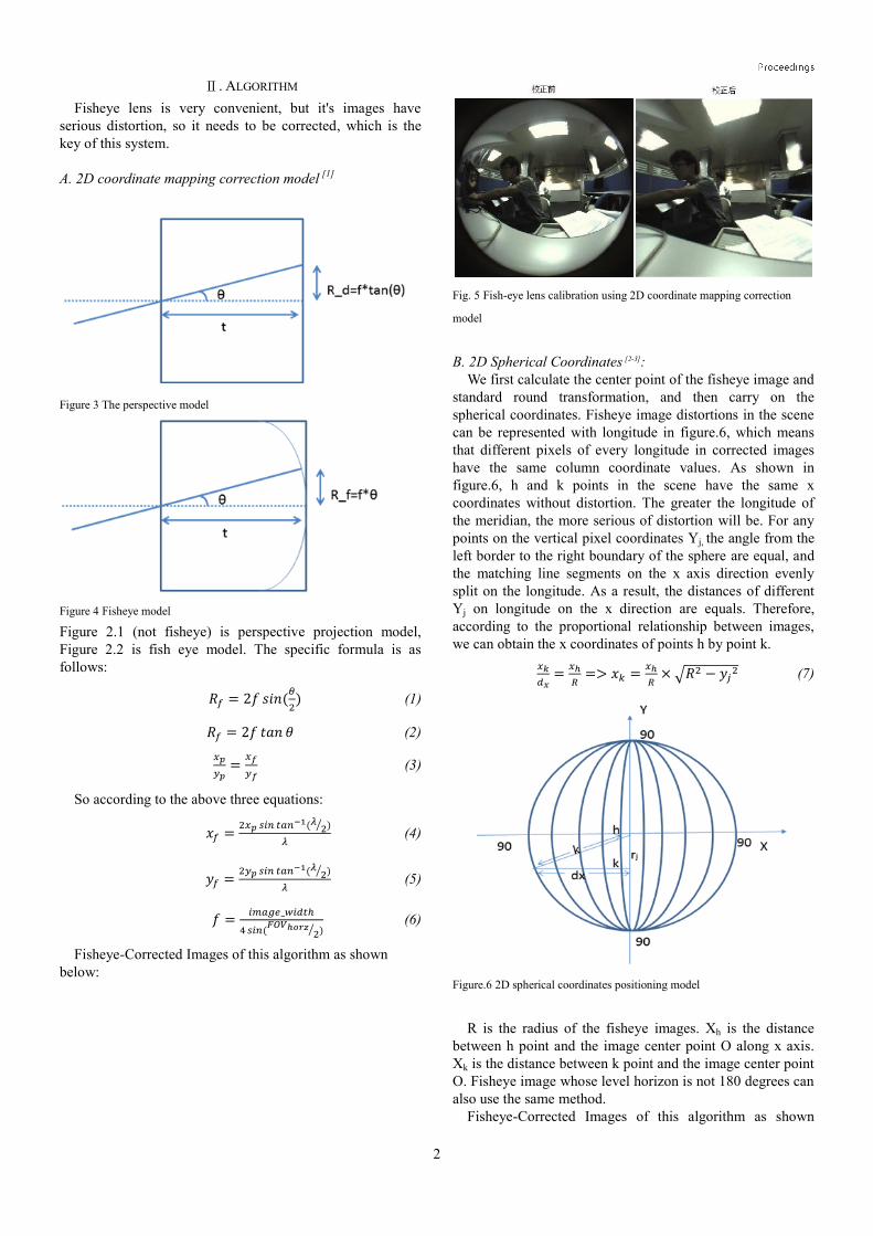
Ⅱ. ALGORITHM
Fisheye lens is very convenient, but it's images have
serious distortion, so it needs to be corrected, which is the
key of this system.
A. 2D coordinate mapping correction model
[1]
Figure 3 The perspective model
Figure 4 Fisheye model
Figure 2.1 (not fisheye) is perspective projection model,
Figure 2.2 is fish eye model. The specific formula is as
follows:
𝑅𝑓 = 2𝑓 𝑠𝑖𝑛(𝜃
2) (1)
𝑅𝑓 = 2𝑓 𝑡𝑎𝑛 𝜃 (2)
𝑥𝑝
𝑦𝑝=
𝑥𝑓
𝑦𝑓 (3)
So according to the above three equations:
𝑥𝑓 =2𝑥𝑝 𝑠𝑖𝑛 𝑡𝑎𝑛−1(𝜆
2⁄ )
𝜆 (4)
𝑦𝑓 =2𝑦𝑝 𝑠𝑖𝑛 𝑡𝑎𝑛−1(𝜆
2⁄ )
𝜆 (5)
𝑓 =𝑖𝑚𝑎𝑔𝑒_𝑤𝑖𝑑𝑡ℎ
4 𝑠𝑖𝑛(𝐹𝑂𝑉ℎ𝑜𝑟𝑧
2⁄ ) (6)
Fisheye-Corrected Images of this algorithm as shown
below:
Fig. 5 Fish-eye lens calibration using 2D coordinate mapping correction
model
B. 2D Spherical Coordinates [2-3]:
We first calculate the center point of the fisheye image and
standard round transformation, and then carry on the
spherical coordinates. Fisheye image distortions in the scene
can be represented with longitude in figure.6, which means
that different pixels of every longitude in corrected images
have the same column coordinate values. As shown in
figure.6, h and k points in the scene have the same x
coordinates without distortion. The greater the longitude of
the meridian, the more serious of distortion will be. For any
points on the vertical pixel coordinates Yj, the angle from the
left border to the right boundary of the sphere are equal, and
the matching line segments on the x axis direction evenly
split on the longitude. As a result, the distances of different
Yj on longitude on the x direction are equals. Therefore,
according to the proportional relationship between images,
we can obtain the x coordinates of points h by point k.
𝑥𝑘
𝑑𝑥=
𝑥ℎ
𝑅=> 𝑥𝑘 =
𝑥ℎ
𝑅× √𝑅2 − 𝑦𝑗
2 (7)
Figure.6 2D spherical coordinates positioning model
R is the radius of the fisheye images. Xh is the distance
between h point and the image center point O along x axis.
Xk is the distance between k point and the image center point
O. Fisheye image whose level horizon is not 180 degrees can
also use the same method.
Fisheye-Corrected Images of this algorithm as shown
3
below:
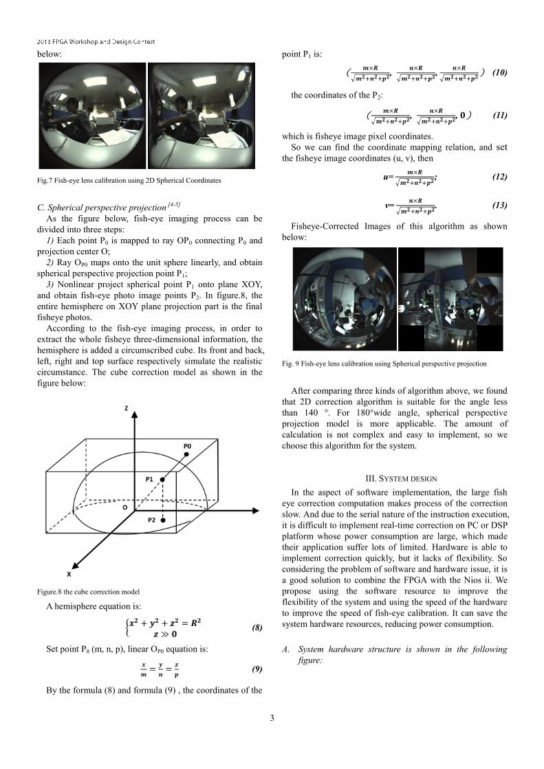
Fig.7 Fish-eye lens calibration using 2D Spherical Coordinates
C. Spherical perspective projection [4-5]
As the figure below, fish-eye imaging process can be
divided into three steps:
1) Each point P0 is mapped to ray OP0 connecting P0 and
projection center O;
2) Ray OP0 maps onto the unit sphere linearly, and obtain
spherical perspective projection point P1;
3) Nonlinear project spherical point P1 onto plane XOY,
and obtain fish-eye photo image points P2. In figure.8, the
entire hemisphere on XOY plane projection part is the final
fisheye photos.
According to the fish-eye imaging process, in order to
extract the whole fisheye three-dimensional information, the
hemisphere is added a circumscribed cube. Its front and back,
left, right and top surface respectively simulate the realistic
circumstance. The cube correction model as shown in the
figure below:
Figure.8 the cube correction model
A hemisphere equation is:
{𝒙𝟐 + 𝒚𝟐 + 𝒛𝟐 = 𝑹𝟐
𝒛 ≫ 𝟎 (8)
Set point P0 (m, n, p), linear OP0 equation is:
𝒙
𝒎=
𝒚
𝒏=
𝒛
𝒑 (9)
By the formula (8) and formula (9) , the coordinates of the
point P1 is:
(𝒎×𝑹
√𝒎𝟐+𝒏𝟐+𝒑𝟐,
𝒏×𝑹
√𝒎𝟐+𝒏𝟐+𝒑𝟐,
𝒏×𝑹
√𝒎𝟐+𝒏𝟐+𝒑𝟐) (10)
the coordinates of the P2:
(𝒎×𝑹
√𝒎𝟐+𝒏𝟐+𝒑𝟐,
𝒏×𝑹
√𝒎𝟐+𝒏𝟐+𝒑𝟐, 𝟎) (11)
which is fisheye image pixel coordinates.
So we can find the coordinate mapping relation, and set the fisheye image coordinates (u, v), then
u= 𝒎×𝑹
√𝒎𝟐+𝒏𝟐+𝒑𝟐; (12)
v= 𝒏×𝑹
√𝒎𝟐+𝒏𝟐+𝒑𝟐. (13)
Fisheye-Corrected Images of this algorithm as shown
below:
Fig. 9 Fish-eye lens calibration using Spherical perspective projection
After comparing three kinds of algorithm above, we found
that 2D correction algorithm is suitable for the angle less
than 140 °. For 180°wide angle, spherical perspective
projection model is more applicable. The amount of
calculation is not complex and easy to implement, so we
choose this algorithm for the system.
III. SYSTEM DESIGN
In the aspect of software implementation, the large fish
eye correction computation makes process of the correction
slow. And due to the serial nature of the instruction execution,
it is difficult to implement real-time correction on PC or DSP
platform whose power consumption are large, which made
their application suffer lots of limited. Hardware is able to
implement correction quickly, but it lacks of flexibility. So
considering the problem of software and hardware issue, it is
a good solution to combine the FPGA with the Nios ii. We
propose using the software resource to improve the
flexibility of the system and using the speed of the hardware
to improve the speed of fish-eye calibration. It can save the
system hardware resources, reducing power consumption.
A. System hardware structure is shown in the following
figure:
4
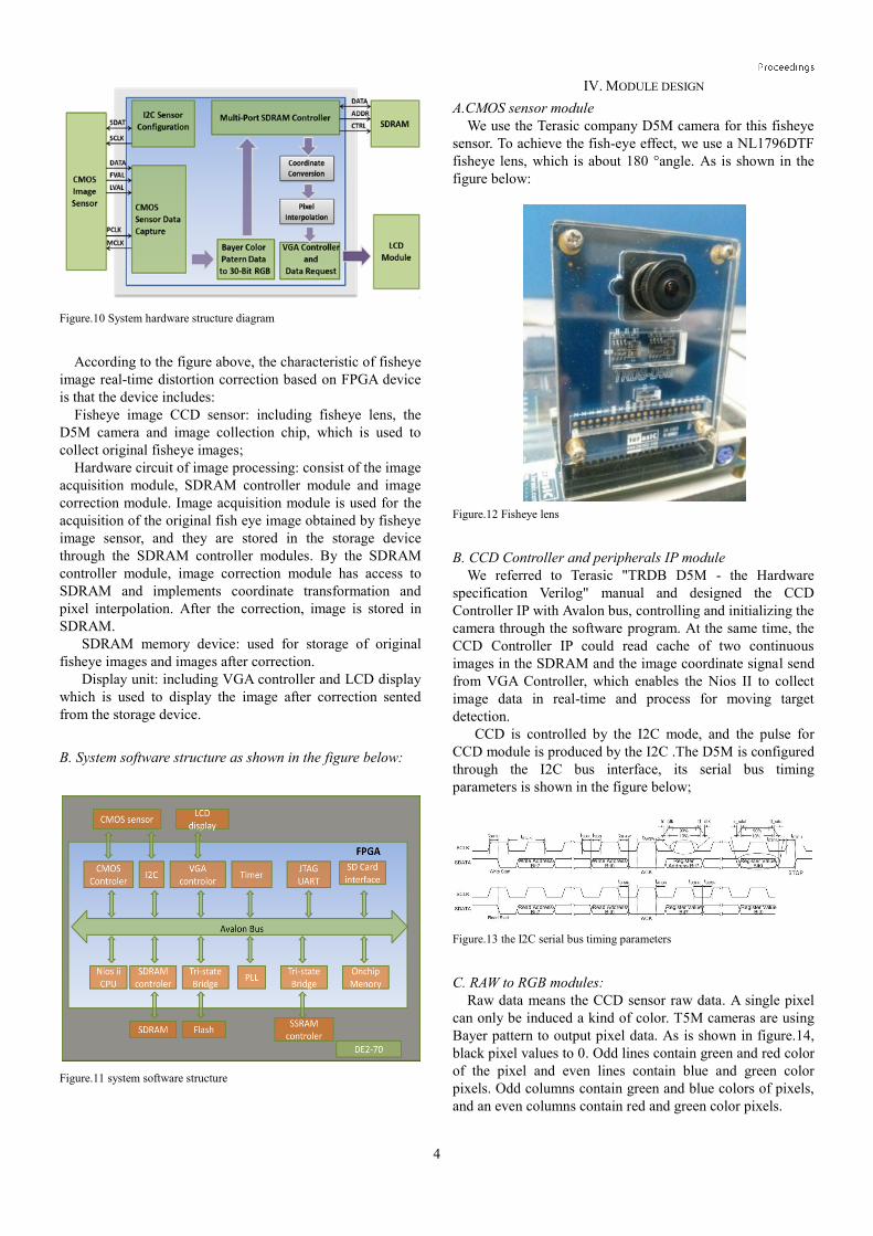
Figure.10 System hardware structure diagram
According to the figure above, the characteristic of fisheye
image real-time distortion correction based on FPGA device
is that the device includes:
Fisheye image CCD sensor: including fisheye lens, the
D5M camera and image collection chip, which is used to
collect original fisheye images;
Hardware circuit of image processing: consist of the image
acquisition module, SDRAM controller module and image
correction module. Image acquisition module is used for the
acquisition of the original fish eye image obtained by fisheye
image sensor, and they are stored in the storage device
through the SDRAM controller modules. By the SDRAM
controller module, image correction module has access to
SDRAM and implements coordinate transformation and
pixel interpolation. After the correction, image is stored in
SDRAM.
SDRAM memory device: used for storage of original
fisheye images and images after correction.
Display unit: including VGA controller and LCD display
which is used to display the image after correction sented
from the storage device.
B. System software structure as shown in the figure below:
Figure.11 system software structure
IV. MODULE DESIGN
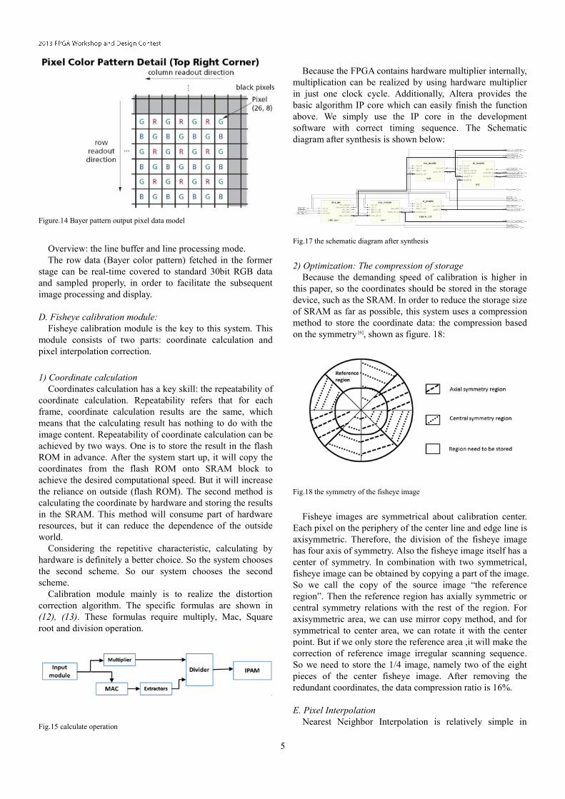
A.CMOS sensor module
We use the Terasic company D5M camera for this fisheye
sensor. To achieve the fish-eye effect, we use a NL1796DTF
fisheye lens, which is about 180 °angle. As is shown in the
figure below:
Figure.12 Fisheye lens
B. CCD Controller and peripherals IP module
We referred to Terasic "TRDB D5M - the Hardware
specification Verilog" manual and designed the CCD
Controller IP with Avalon bus, controlling and initializing the
camera through the software program. At the same time, the
CCD Controller IP could read cache of two continuous
images in the SDRAM and the image coordinate signal send from VGA Controller, which enables the Nios II to collect
image data in real-time and process for moving target
detection.
CCD is controlled by the I2C mode, and the pulse for
CCD module is produced by the I2C .The D5M is configured
through the I2C bus interface, its serial bus timing
parameters is shown in the figure below;
Figure.13 the I2C serial bus timing parameters
C. RAW to RGB modules:
Raw data means the CCD sensor raw data. A single pixel
can only be induced a kind of color. T5M cameras are using
Bayer pattern to output pixel data. As is shown in figure.14,
black pixel values to 0. Odd lines contain green and red color
of the pixel and even lines contain blue and green color
pixels. Odd columns contain green and blue colors of pixels,
and an even columns contain red and green color pixels.
5
Figure.14 Bayer pattern output pixel data model
Overview: the line buffer and line processing mode.
The row data (Bayer color pattern) fetched in the former
stage can be real-time covered to standard 30bit RGB data
and sampled properly, in order to facilitate the subsequent
image processing and display.
D. Fisheye calibration module:
Fisheye calibration module is the key to this system. This
module consists of two parts: coordinate calculation and
pixel interpolation correction.
1) Coordinate calculation
Coordinates calculation has a key skill: the repeatability of
coordinate calculation. Repeatability refers that for each
frame, coordinate calculation results are the same, which
means that the calculating result has nothing to do with the
image content. Repeatability of coordinate calculation can be
achieved by two ways. One is to store the result in the flash
ROM in advance. After the system start up, it will copy the
coordinates from the flash ROM onto SRAM block to
achieve the desired computational speed. But it will increase
the reliance on outside (flash ROM). The second method is
calculating the coordinate by hardware and storing the results
in the SRAM. This method will consume part of hardware
resources, but it can reduce the dependence of the outside
world.
Considering the repetitive characteristic, calculating by
hardware is definitely a better choice. So the system chooses
the second scheme. So our system chooses the second
scheme.
Calibration module mainly is to realize the distortion
correction algorithm. The specific formulas are shown in
(12), (13). These formulas require multiply, Mac, Square
root and division operation.
Fig.15 calculate operation
Because the FPGA contains hardware multiplier internally,
multiplication can be realized by using hardware multiplier
in just one clock cycle. Additionally, Altera provides the
basic algorithm IP core which can easily finish the function
above. We simply use the IP core in the development
software with correct timing sequence. The Schematic
diagram after synthesis is shown below:
Fig.17 the schematic diagram after synthesis
2) Optimization: The compression of storage
Because the demanding speed of calibration is higher in
this paper, so the coordinates should be stored in the storage
device, such as the SRAM. In order to reduce the storage size
of SRAM as far as possible, this system uses a compression
method to store the coordinate data: the compression based
on the symmetry [6], shown as figure. 18:
Fig.18 the symmetry of the fisheye image
Fisheye images are symmetrical about calibration center.
Each pixel on the periphery of the center line and edge line is
axisymmetric. Therefore, the division of the fisheye image
has four axis of symmetry. Also the fisheye image itself has a
center of symmetry. In combination with two symmetrical,
fisheye image can be obtained by copying a part of the image.
So we call the copy of the source image “the reference
region”. Then the reference region has axially symmetric or
central symmetry relations with the rest of the region. For
axisymmetric area, we can use mirror copy method, and for
symmetrical to center area, we can rotate it with the center
point. But if we only store the reference area ,it will make the
correction of reference image irregular scanning sequence.
So we need to store the 1/4 image, namely two of the eight
pieces of the center fisheye image. After removing the
redundant coordinates, the data compression ratio is 16%.
E. Pixel Interpolation
Nearest Neighbor Interpolation is relatively simple in
6
operation. But its treatment effect will cause obvious image
defects. For bicubic interpolation, it is a high order
interpolation method which is more complex. It is not
suitable for this system because it takes all the pixels in the
correlation of all the pixels in the 4×4 image block into
account. Less complex and high speed in operation make
bilinear interpolation being a good choice in our system.
The interpolation module will get a set of interpolated
information per period, including interpolation coordinates
and four image points around it.
And pipeline is used in the interpolation process of this
system.
1) Transverse linear interpolation
Fig. 19 Transverse linear interpolation
As showed in the figure above, two middle points have to
be calculated firstly in the transverse linear interpolation.
𝑝1 = 𝜆𝑝(𝑥1, 𝑦1) + (1 − 𝜆)𝑝(𝑥2, 𝑦2), 𝜆 = 𝑥2 − 𝑥 (14)
𝑝2 = 𝜆𝑝(𝑥3, 𝑦3) + (1 − 𝜆)𝑝(𝑥4, 𝑦4), 𝜆 = 𝑥4 − 𝑥 (15)
Operations of multiplication and addition between two
points are included in this section. In the formula, operations
of two points have to be made simultaneously, which can be
done by four multiplying units and two summing units.
2) The longitudinal linear interpolation
Fig.20 the longitudinal linear interpolation
In this section, it has to figure out the value of the
insertion point which can be realized by multiplication and
addition of a point. That means it should include two
multiplying units and one summing unit.
3) Fixed amplification factor
In order to keep the accuracy, amplification has to be made
before fixed-point calculation. On the contrary, the amplified
data should be restored and dealt with saturated operation
before getting the end result.
F. VGA display module
By using the D5M camera and thronging the RAW to
RGB module, the output data contain a total of 1024 rows,
and each line has 1280 points. The resolution of VGA output
is 1280*1024.The specific timing sequence is as follows:
Fig. 21 VGA timing sequence
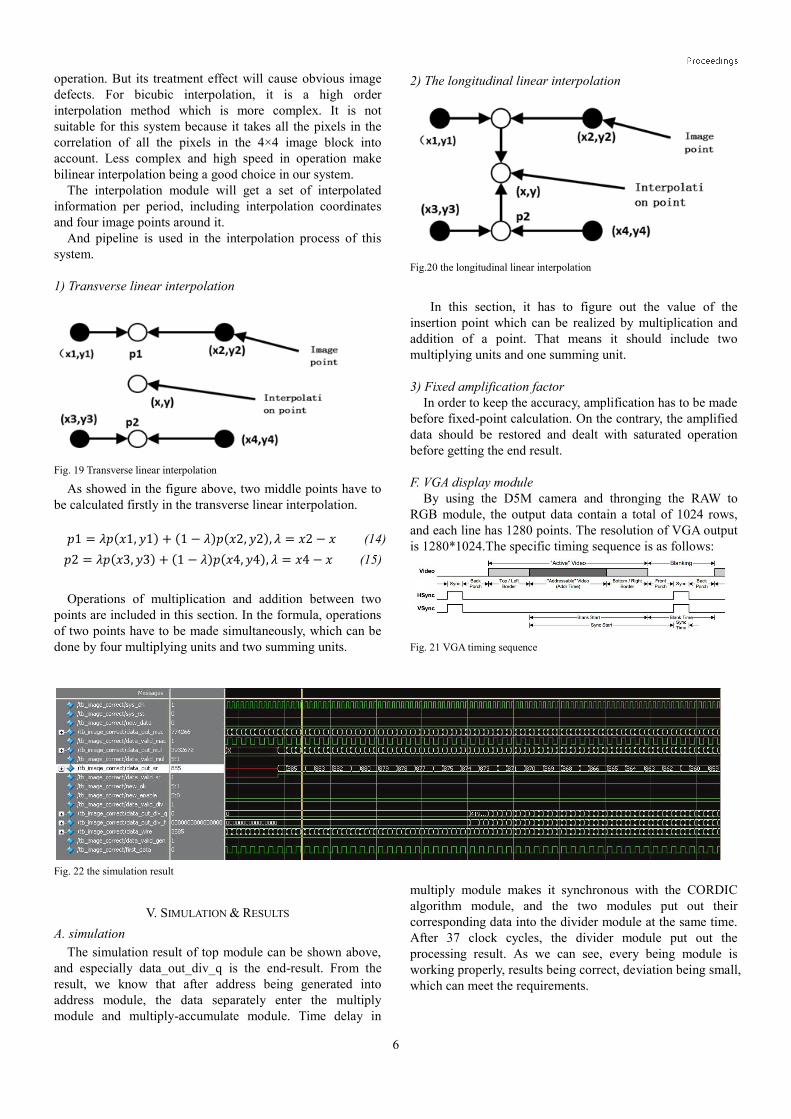
Fig. 22 the simulation result
V. SIMULATION & RESULTS
A. simulation
The simulation result of top module can be shown above,
and especially data_out_div_q is the end-result. From the
result, we know that after address being generated into
address module, the data separately enter the multiply
module and multiply-accumulate module. Time delay in
multiply module makes it synchronous with the CORDIC
algorithm module, and the two modules put out their
corresponding data into the divider module at the same time.
After 37 clock cycles, the divider module put out the
processing result. As we can see, every being module is
working properly, results being correct, deviation being small,
which can meet the requirements.
7
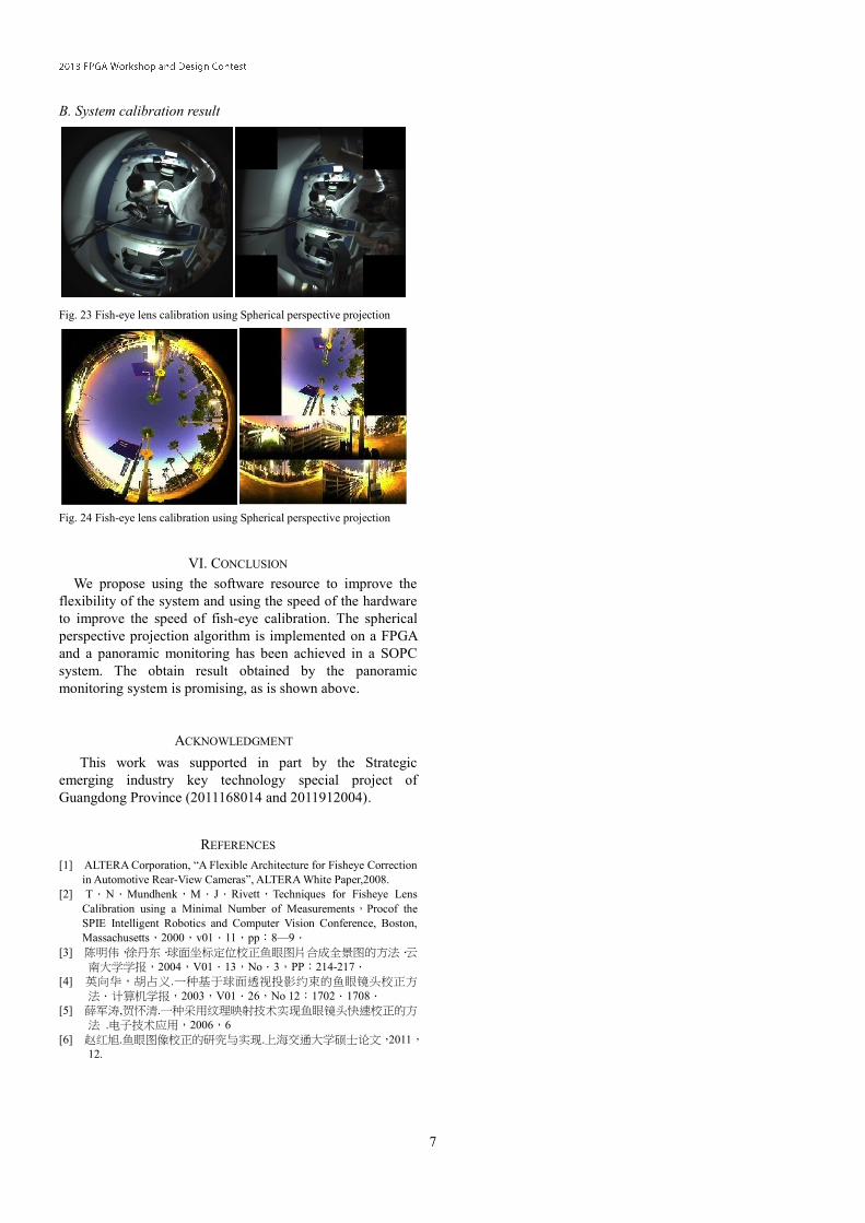
B. System calibration result
Fig. 23 Fish-eye lens calibration using Spherical perspective projection
Fig. 24 Fish-eye lens calibration using Spherical perspective projection
VI. CONCLUSION
We propose using the software resource to improve the
flexibility of the system and using the speed of the hardware
to improve the speed of fish-eye calibration. The spherical
perspective projection algorithm is implemented on a FPGA
and a panoramic monitoring has been achieved in a SOPC
system. The obtain result obtained by the panoramic
monitoring system is promising, as is shown above.
ACKNOWLEDGMENT
This work was supported in part by the Strategic
emerging industry key technology special project of
Guangdong Province (2011168014 and 2011912004).
REFERENCES
[1] ALTERA Corporation, “A Flexible Architecture for Fisheye Correction
in Automotive Rear-View Cameras”, ALTERA White Paper,2008.
[2] T.N.Mundhenk,M.J.Rivett,Techniques for Fisheye Lens
Calibration using a Minimal Number of Measurements,Procof the
SPIE Intelligent Robotics and Computer Vision Conference, Boston,
Massachusetts,2000,v01.11,pp:8—9.
[3] 陈明伟,徐丹东.球面坐标定位校正鱼眼图片合成全景图的方法.云南大学学报,2004,V01.13,No.3,PP:214-217.
[4] 英向华,胡占义.一种基于球面透视投影约束的鱼眼镜头校正方
法.计算机学报,2003,V01.26,No 12:1702.1708.
[5] 薛军涛,贺怀清.一种采用纹理映射技术实现鱼眼镜头快速校正的方法 .电子技术应用,2006,6
[6] 赵红旭.鱼眼图像校正的研究与实现.上海交通大学硕士论文,2011,12.
Related Documents