Engine Management Systems Self Study Program Course Number 841003

841003 Engine Management Systems
Dec 15, 2015
VW Engine Management System
Welcome message from author
This document is posted to help you gain knowledge. Please leave a comment to let me know what you think about it! Share it to your friends and learn new things together.
Transcript
EngineManagementSystems
Self Study ProgramCourse Number 841003
Volkswagen of America, Inc.Service TrainingPrinted in U.S.A.Printed 4/2000Course Number 841003Part Number WSP 521 841 03
All rights reserved. All information containedin this manual is based on the latest productinformation available at the time of printing.The right is reserved to make changes at anytime without notice. No part of this publicationmay be reproduced, stored in a retrievalsystem, or transmitted in any form or by anymeans, electronic, mechanical, photocopying,recording or otherwise, without the priorpermission of the publisher. This includes text,figures and tables.
Always check Technical Bulletins and theVolkswagen Worldwide Repair InformationSystem for information that may supersedeany information included in this booklet.
i
Page
Introduction ................................................................................................1Course goals .................................................................................................2Principles of engine operation ..................................................................3Basic four-stroke principle ............................................................................3Gasoline properties ......................................................................................6Air/fuel mixture formation .............................................................................8Fuel system, overview .................................................................................10Evolution of Engine Management Systems .................................................11Ignition system, overview ............................................................................12Emissions system, overview ........................................................................18Three-way Catalytic Converter, overview .....................................................20On Board Diagnostics ..................................................................................22Review ..........................................................................................................25K-Jetronic/CIS .............................................................................................26K-Jetronic with Lambda control ....................................................................28KE-Jetronic/CIS-E ..........................................................................................29KE-Motronic/CIS-E Motronic .........................................................................29Digifant System Overview .........................................................................31System description .......................................................................................31Inputs/Outputs - Digifant II ...........................................................................33Additional systems ......................................................................................33On Board Diagnostics ...................................................................................35Summary ......................................................................................................35Review ..........................................................................................................37Notes: ...........................................................................................................38Motronic M2.9 Overview ...........................................................................39System description .......................................................................................39Inputs/Outputs - Motronic M2.9 ..................................................................43On-Board Diagnostics ...................................................................................46Signal usage ................................................................................................46Motronic M2.9 Component Summary ......................................................47Fuel system components ............................................................................47Engine Control Module (ECM) J220 .............................................................48Input sensors ................................................................................................49Actuators (outputs) ......................................................................................63Review ..........................................................................................................77Mono-Motronic System Overview ...........................................................79System Description ......................................................................................79Inputs/Outputs ..............................................................................................81Additional Systems ......................................................................................81On Board Diagnostics ...................................................................................81Summary ......................................................................................................81
Table of Contents
ii
Page
OBD-II Overview ........................................................................................83Background ..................................................................................................83OBD-II ...........................................................................................................84OBD-II Function ............................................................................................85Diagnostic Trouble Codes ...........................................................................86Readiness Codes ..........................................................................................87Summary ......................................................................................................88Motronic M5.9 Overview ...........................................................................89System Description ......................................................................................89Input/Outputs - Motronic M5.9 ...................................................................90Additional Systems .......................................................................................91VR-6 system overview ................................................................................92Inputs/Outputs - Motronic M5.9.2 ...............................................................941.8 liter turbo, system overview ..................................................................95Motronic M5.9 Component Differences ...................................................97Engine Control Module J220 ........................................................................97Combined Sensors/Actuators .......................................................................98Input sensors ................................................................................................102Actuators (outputs) .......................................................................................104Motronic M5.9.2 Component Differences ................................................107Engine Control Module J220 ........................................................................107Input Sensors ...............................................................................................108Heated Oxygen Sensors ..............................................................................113Actuators (outputs) .......................................................................................114Review .........................................................................................................121Motronic ME 7 ............................................................................................123Pathways ......................................................................................................123Components of Motronic ME 7 ....................................................................123Electronic throttle control .............................................................................128Review .........................................................................................................132Level one course preparation ....................................................................133Critical Thinking Skills ...................................................................................133Volkswagen Electronic Service Information System (VESIS) navigation .......134Volkswagen HELP line/Tech-tip line .............................................................134Diagnostic and Special Tools ........................................................................135Review questions .........................................................................................135Suggested reading and reference ................................................................135Glossary ......................................................................................................137Volkswagen Engine Management Systems Teletest .............................141
Table of Contents
1
Introduction
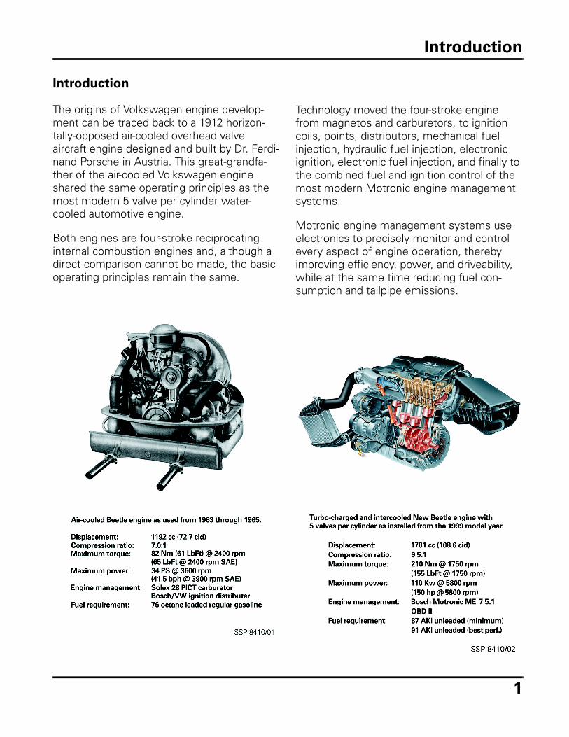
The origins of Volkswagen engine develop-ment can be traced back to a 1912 horizon-tally-opposed air-cooled overhead valve aircraft engine designed and built by Dr. Ferdi-nand Porsche in Austria. This great-grandfa-ther of the air-cooled Volkswagen engine shared the same operating principles as the most modern 5 valve per cylinder water-cooled automotive engine.
Both engines are four-stroke reciprocating internal combustion engines and, although a direct comparison cannot be made, the basic operating principles remain the same.
Technology moved the four-stroke engine from magnetos and carburetors, to ignition coils, points, distributors, mechanical fuel injection, hydraulic fuel injection, electronic ignition, electronic fuel injection, and finally to the combined fuel and ignition control of the most modern Motronic engine management systems.
Motronic engine management systems use electronics to precisely monitor and control every aspect of engine operation, thereby improving efficiency, power, and driveability, while at the same time reducing fuel con-sumption and tailpipe emissions.
Introduction
2
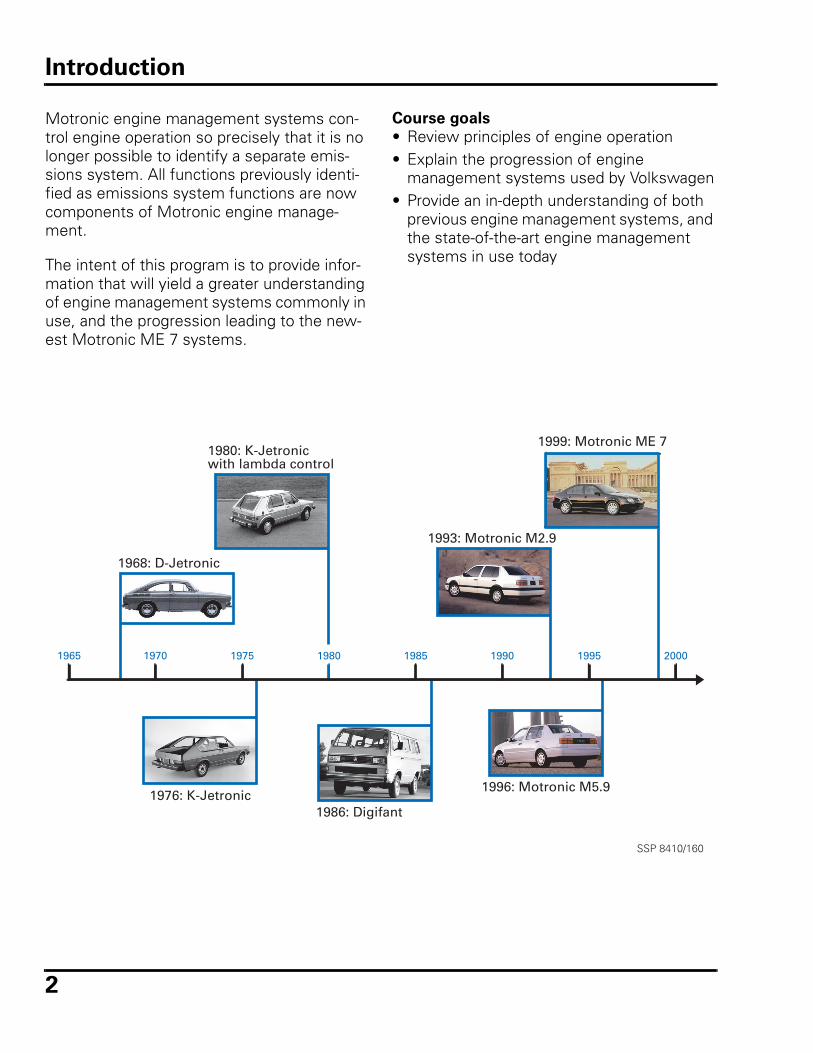
Motronic engine management systems con-trol engine operation so precisely that it is no longer possible to identify a separate emis-sions system. All functions previously identi-fied as emissions system functions are now components of Motronic engine manage-ment.
The intent of this program is to provide infor-mation that will yield a greater understanding of engine management systems commonly in use, and the progression leading to the new-est Motronic ME 7 systems.
1965 1970 1975 1980 1985 1990 1995 2000
1968: D-Jetronic
1976: K-Jetronic
1980: K-Jetronicwith lambda control
1986: Digifant
1993: Motronic M2.9
1996: Motronic M5.9
1999: Motronic ME 7
SSP 8410/160
Course goals
• Review principles of engine operation• Explain the progression of engine
management systems used by Volkswagen• Provide an in-depth understanding of both
previous engine management systems, and the state-of-the-art engine management systems in use today
Introduction
3
Principles of engine operation
Basic four-stroke principle
An internal combustion engine requires the proper ratios of air and fuel, combined with a properly timed spark for efficient combustion.
Operation of most automotive engines is described in two upward and two downward movements of the piston, called strokes. These four strokes occur during two revolu-tions of the crankshaft and one revolution of the camshaft. The complete process of cyclic external spark ignition resulting in internal combustion is called the “Otto cycle.”
All four-stroke engines operate in the same manner, regardless of the number of cylin-ders, although an engine with multiple cylin-ders has more firing pulses, resulting in a smoother running engine.
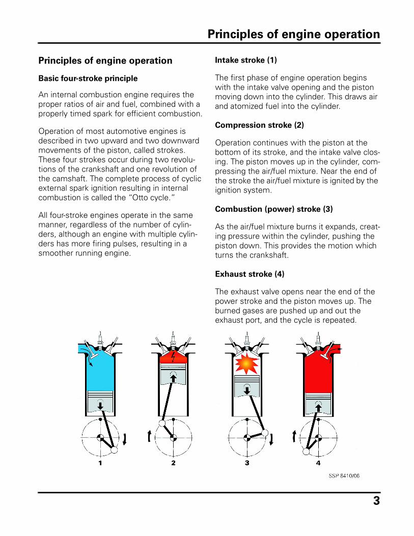
Intake stroke (1)
The first phase of engine operation begins with the intake valve opening and the piston moving down into the cylinder. This draws air and atomized fuel into the cylinder.
Compression stroke (2)
Operation continues with the piston at the bottom of its stroke, and the intake valve clos-ing. The piston moves up in the cylinder, com-pressing the air/fuel mixture. Near the end of the stroke the air/fuel mixture is ignited by the ignition system.
Combustion (power) stroke (3)
As the air/fuel mixture burns it expands, creat-ing pressure within the cylinder, pushing the piston down. This provides the motion which turns the crankshaft.
Exhaust stroke (4)
The exhaust valve opens near the end of the power stroke and the piston moves up. The burned gases are pushed up and out the exhaust port, and the cycle is repeated.
Principles of engine operation
4
Mechanical systems
Several support systems are required to make the combustion process occur continuously. The valvetrain operates the valves, the lubrica-tion system supplies the oil, the cooling sys-tem removes heat, and the electrical system supplies the voltage. The engine manage-ment system delivers fuel and spark to match the air demands of the engine.
Because of heat and drag, the thermal effi-ciency of a typical gasoline engine is around 25% (approximately one fourth of the heat energy of the fuel is converted into usable engine power).
Mechanical integrity
The mechanical condition of the cylinder directly influences the combustion process.
Conditions within the combustion chamber can also be influenced by other factors, including:• Camshaft timing• Oil pressure• Restrictions in the intake or exhaust paths
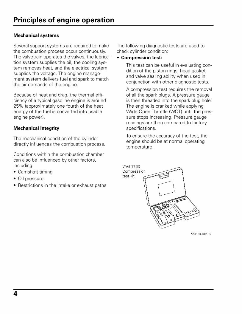
The following diagnostic tests are used to check cylinder condition:• Compression test:
This test can be useful in evaluating con-dition of the piston rings, head gasket and valve sealing ability when used in conjunction with other diagnostic tests.
A compression test requires the removal of all the spark plugs. A pressure gauge is then threaded into the spark plug hole. The engine is cranked while applying Wide Open Throttle (WOT) until the pres-sure stops increasing. Pressure gauge readings are then compared to factory specifications.
To ensure the accuracy of the test, the engine should be at normal operating temperature.
Principles of engine operation
5
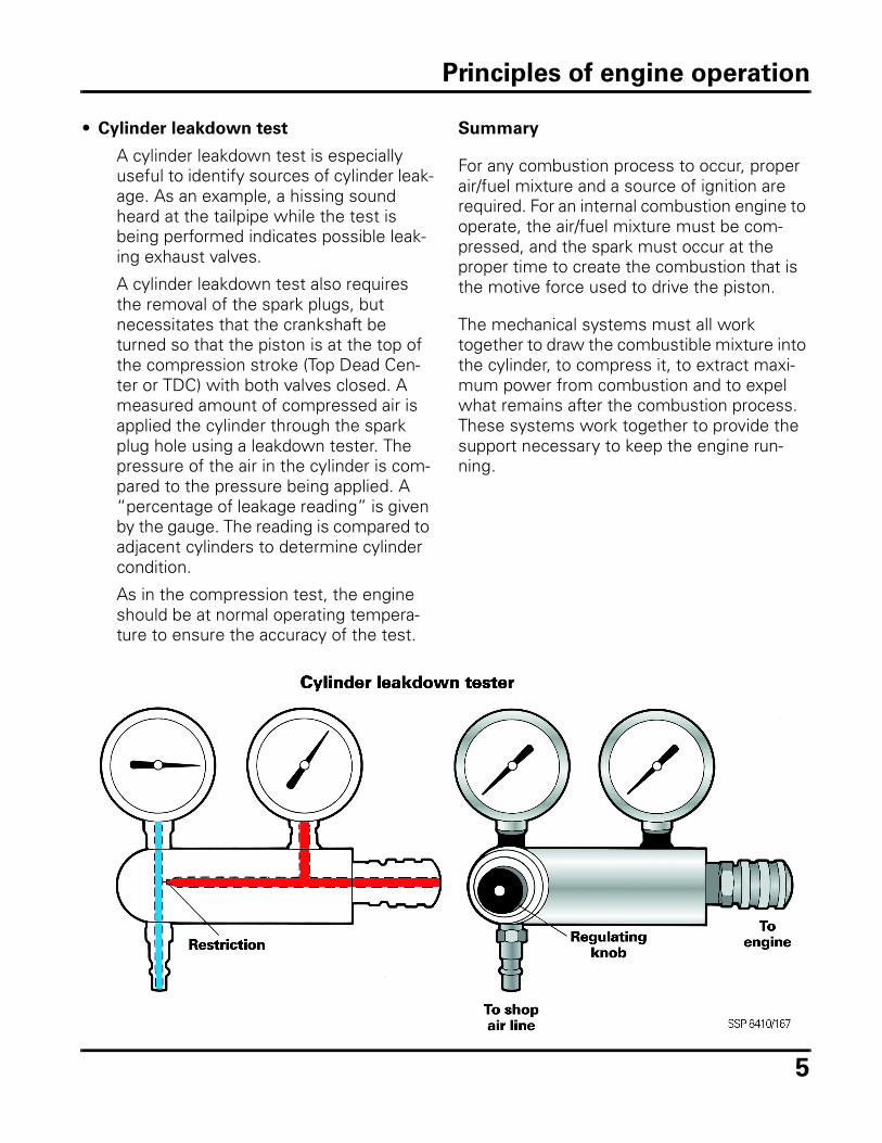
• Cylinder leakdown test
A cylinder leakdown test is especially useful to identify sources of cylinder leak-age. As an example, a hissing sound heard at the tailpipe while the test is being performed indicates possible leak-ing exhaust valves.
A cylinder leakdown test also requires the removal of the spark plugs, but necessitates that the crankshaft be turned so that the piston is at the top of the compression stroke (Top Dead Cen-ter or TDC) with both valves closed. A measured amount of compressed air is applied the cylinder through the spark plug hole using a leakdown tester. The pressure of the air in the cylinder is com-pared to the pressure being applied. A “percentage of leakage reading” is given by the gauge. The reading is compared to adjacent cylinders to determine cylinder condition.
As in the compression test, the engine should be at normal operating tempera-ture to ensure the accuracy of the test.
Summary
For any combustion process to occur, proper air/fuel mixture and a source of ignition are required. For an internal combustion engine to operate, the air/fuel mixture must be com-pressed, and the spark must occur at the proper time to create the combustion that is the motive force used to drive the piston.
The mechanical systems must all work together to draw the combustible mixture into the cylinder, to compress it, to extract maxi-mum power from combustion and to expel what remains after the combustion process. These systems work together to provide the support necessary to keep the engine run-ning.
Principles of engine operation
6
Gasoline properties
For the engine management system to allow the engine to operate at peak efficiency and power, the octane rating of the gasoline must be within factory specifications as outlined in the owner’s manual.
Octane is a relative measure showing the gasoline’s ability to resist self-ignition due to heat and pressure within the cylinder. Self ignition of the fuel is known as knocking (det-onation) or pinging (pre-ignition).• Pinging:
When the air/fuel mixture ignites before the spark occurs.
• Knock:
When a pressure wave from spark ignit-ing the fuel creates a secondary combus-tion, causing the two pressure waves to collide.
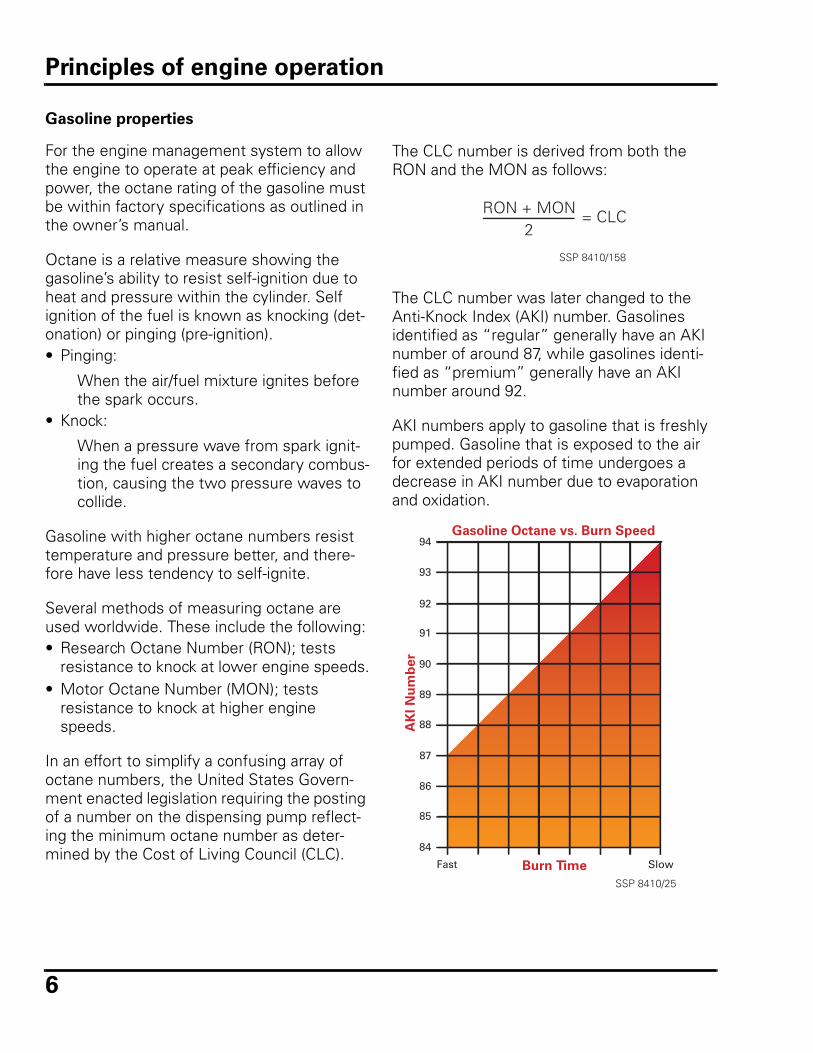
Gasoline with higher octane numbers resist temperature and pressure better, and there-fore have less tendency to self-ignite.
Several methods of measuring octane are used worldwide. These include the following:• Research Octane Number (RON); tests
resistance to knock at lower engine speeds.• Motor Octane Number (MON); tests
resistance to knock at higher engine speeds.
In an effort to simplify a confusing array of octane numbers, the United States Govern-ment enacted legislation requiring the posting of a number on the dispensing pump reflect-ing the minimum octane number as deter-mined by the Cost of Living Council (CLC).
The CLC number is derived from both the RON and the MON as follows:
The CLC number was later changed to the Anti-Knock Index (AKI) number. Gasolines identified as “regular” generally have an AKI number of around 87, while gasolines identi-fied as “premium” generally have an AKI number around 92.
AKI numbers apply to gasoline that is freshly pumped. Gasoline that is exposed to the air for extended periods of time undergoes a decrease in AKI number due to evaporation and oxidation.
RON + MON2
= CLC
SSP 8410/158
94
93
92
91
90
89
88
87
86
85
84
Burn Time SlowFast
AK
I N
um
ber
Gasoline Octane vs. Burn Speed
SSP 8410/25
Principles of engine operation
7
Modern pump gasoline contains a wide vari-ety of additives to help obtain optimal engine and fuel system operation. The additive pack-age added to the base gasoline will include at least the following:• Anti-aging additives• Intake contamination inhibitors (detergents)• Corrosion inhibitors• Icing protection• Anti-knock additives
Different concentrations of additives, along with other blending considerations, are used according to market and seasonal demands.
All Volkswagen Owner’s Manuals list recom-mended fuel grade specifications, along with notes on the use of fuels containing metha-nol, ethanol and MTBE (methyl tertiary butyl ether). • Octane must be between 87 AKI and 93
AKI, but exact requirements depend on model and year.
• MTBE is blended with gasoline and sold in some areas of the country as oxygenated fuel to help reduce tailpipe emissions. This fuel can be used as long as specific percentage requirements are maintained and octane minimums are met.
• Methanol and ethanol are types of alcohol commonly mixed with gasoline. Fuel with these additives can be used as long as specific percentage requirements are maintained and octane minimums are met. These requirements vary from year to year.
The combustion process is dependent on the correct grade and quality of gasoline. If gaso-line sits for an extended period of time, the octane can evaporate from the fuel, creating a varnished residue. This can restrict injector flow and fuel pump/fuel line performance. This can lead to hard starting, reduced perfor-mance and no code driveability complaints.
Note:
MTBE has been identified by the Government as a possible carcinogen and is being phased out in automotive use.
Principles of engine operation
8
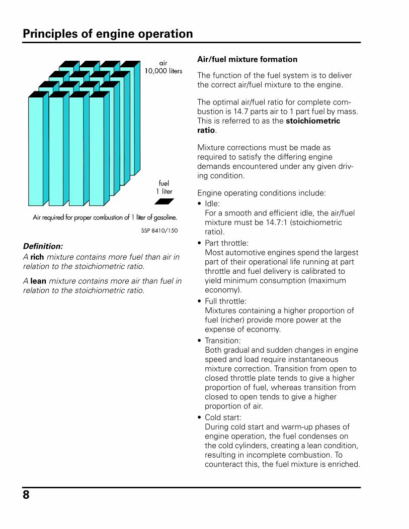
Definition:
A rich mixture contains more fuel than air in relation to the stoichiometric ratio.
A lean mixture contains more air than fuel in relation to the stoichiometric ratio.
Air/fuel mixture formation
The function of the fuel system is to deliver the correct air/fuel mixture to the engine.
The optimal air/fuel ratio for complete com-bustion is 14.7 parts air to 1 part fuel by mass. This is referred to as the stoichiometric
ratio.
Mixture corrections must be made as required to satisfy the differing engine demands encountered under any given driv-ing condition.
Engine operating conditions include:• Idle:
For a smooth and efficient idle, the air/fuel mixture must be 14.7:1 (stoichiometric ratio).
• Part throttle:Most automotive engines spend the largest part of their operational life running at part throttle and fuel delivery is calibrated to yield minimum consumption (maximum economy).
• Full throttle:Mixtures containing a higher proportion of fuel (richer) provide more power at the expense of economy.
• Transition:Both gradual and sudden changes in engine speed and load require instantaneous mixture correction. Transition from open to closed throttle plate tends to give a higher proportion of fuel, whereas transition from closed to open tends to give a higher proportion of air.
• Cold start:During cold start and warm-up phases of engine operation, the fuel condenses on the cold cylinders, creating a lean condition, resulting in incomplete combustion. To counteract this, the fuel mixture is enriched.
Principles of engine operation
9
The fuel system must be able to quickly respond to and satisfy these widely varying operating conditions.
The air/fuel mixture is referred to by the Greek letter λ (Lambda), and is generally referencing the air factor in the ratio. Listed below are several common λ operating ranges: • λ = 1: mixture is optimum (stoichiometric).• λ < 1: mixture is rich (lacking air) typically in
the range λ = 0.85 to 0.95.• λ > 1: mixture has an excess of air; a lean
mixture typically in the range λ = 1.05 to 1.30.
• λ > 1.30: mixture has too much air to support consistent combustion.
On an engine at normal operating tempera-ture, it is important to maintain λ = 1. This allows for optimal catalytic converter opera-tion (although in actual practice, λ factors between 0.9 and 1.1 provide the best engine operation).
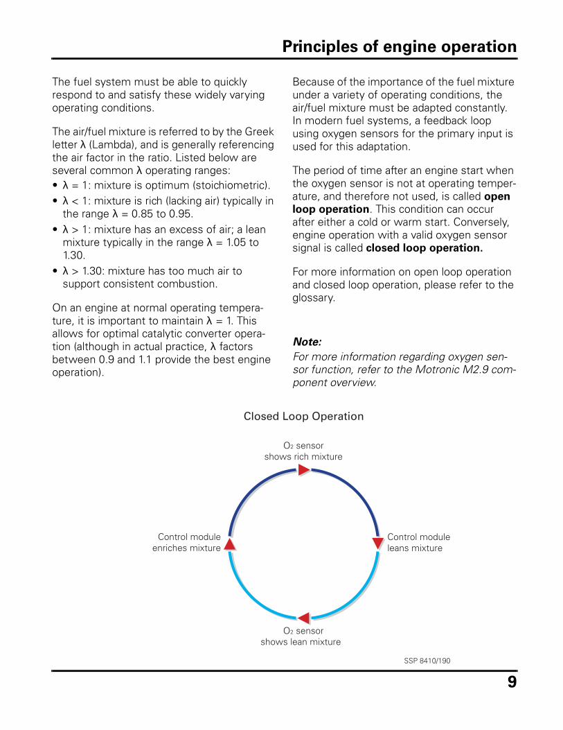
Because of the importance of the fuel mixture under a variety of operating conditions, the air/fuel mixture must be adapted constantly. In modern fuel systems, a feedback loop using oxygen sensors for the primary input is used for this adaptation.
The period of time after an engine start when the oxygen sensor is not at operating temper-ature, and therefore not used, is called open
loop operation. This condition can occur after either a cold or warm start. Conversely, engine operation with a valid oxygen sensor signal is called closed loop operation.
For more information on open loop operation and closed loop operation, please refer to the glossary.
Note:
For more information regarding oxygen sen-sor function, refer to the Motronic M2.9 com-ponent overview.
Closed Loop Operation
O2 sensorshows rich mixture
Control moduleleans mixture
O2 sensorshows lean mixture
Control moduleenriches mixture
SSP 8410/190
Principles of engine operation
10
Fuel system, overview
The fuel system is made up of numerous indi-vidual components. The purpose of these components is to insure delivery of the cor-rect air/fuel mixture formation to the engine at the correct time.
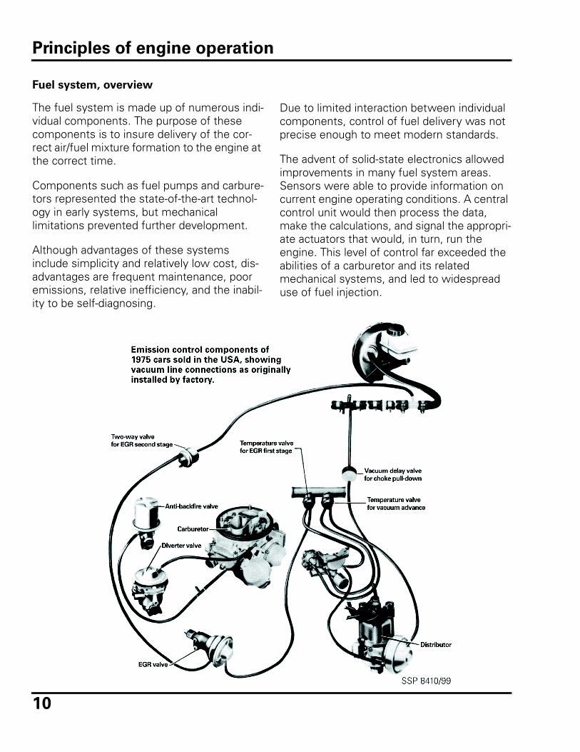
Components such as fuel pumps and carbure-tors represented the state-of-the-art technol-ogy in early systems, but mechanical limitations prevented further development.
Although advantages of these systems include simplicity and relatively low cost, dis-advantages are frequent maintenance, poor emissions, relative inefficiency, and the inabil-ity to be self-diagnosing.
Due to limited interaction between individual components, control of fuel delivery was not precise enough to meet modern standards.
The advent of solid-state electronics allowed improvements in many fuel system areas. Sensors were able to provide information on current engine operating conditions. A central control unit would then process the data, make the calculations, and signal the appropri-ate actuators that would, in turn, run the engine. This level of control far exceeded the abilities of a carburetor and its related mechanical systems, and led to widespread use of fuel injection.
Principles of engine operation
11
Evolution of Engine Management Systems
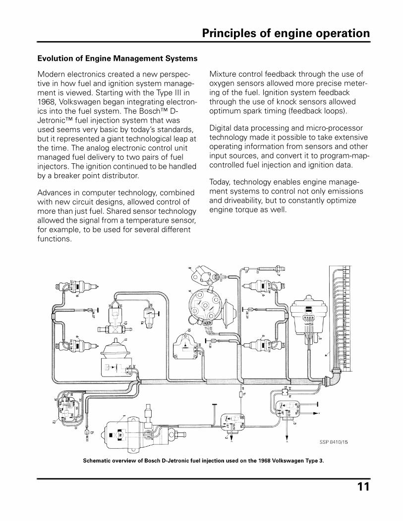
Modern electronics created a new perspec-tive in how fuel and ignition system manage-ment is viewed. Starting with the Type III in 1968, Volkswagen began integrating electron-ics into the fuel system. The Bosch™ D-Jetronic™ fuel injection system that was used seems very basic by today’s standards, but it represented a giant technological leap at the time. The analog electronic control unit managed fuel delivery to two pairs of fuel injectors. The ignition continued to be handled by a breaker point distributor.
Advances in computer technology, combined with new circuit designs, allowed control of more than just fuel. Shared sensor technology allowed the signal from a temperature sensor, for example, to be used for several different functions.
Mixture control feedback through the use of oxygen sensors allowed more precise meter-ing of the fuel. Ignition system feedback through the use of knock sensors allowed optimum spark timing (feedback loops).
Digital data processing and micro-processor technology made it possible to take extensive operating information from sensors and other input sources, and convert it to program-map-controlled fuel injection and ignition data.
Today, technology enables engine manage-ment systems to control not only emissions and driveability, but to constantly optimize engine torque as well.
Principles of engine operation
12
Ignition system, overview
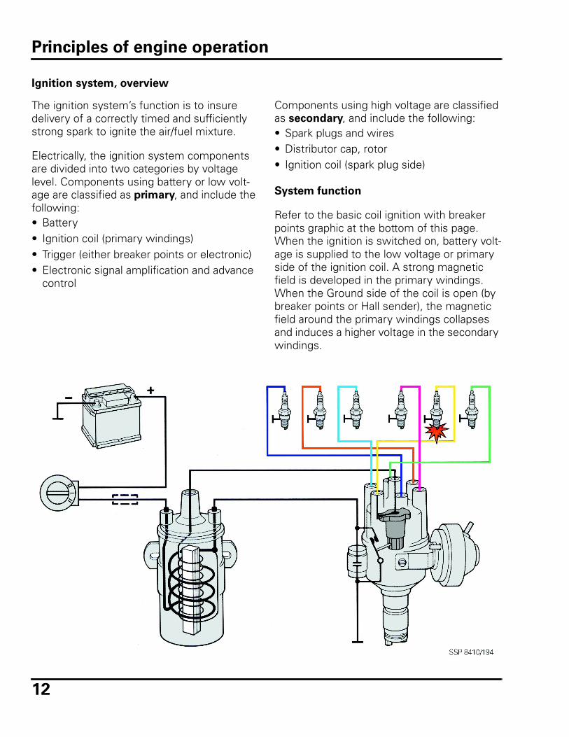
The ignition system’s function is to insure delivery of a correctly timed and sufficiently strong spark to ignite the air/fuel mixture.
Electrically, the ignition system components are divided into two categories by voltage level. Components using battery or low volt-age are classified as primary, and include the following:• Battery• Ignition coil (primary windings)• Trigger (either breaker points or electronic)• Electronic signal amplification and advance
control
Components using high voltage are classified as secondary, and include the following:• Spark plugs and wires• Distributor cap, rotor • Ignition coil (spark plug side)
System function
Refer to the basic coil ignition with breaker points graphic at the bottom of this page. When the ignition is switched on, battery volt-age is supplied to the low voltage or primary side of the ignition coil. A strong magnetic field is developed in the primary windings. When the Ground side of the coil is open (by breaker points or Hall sender), the magnetic field around the primary windings collapses and induces a higher voltage in the secondary windings.
Principles of engine operation
13
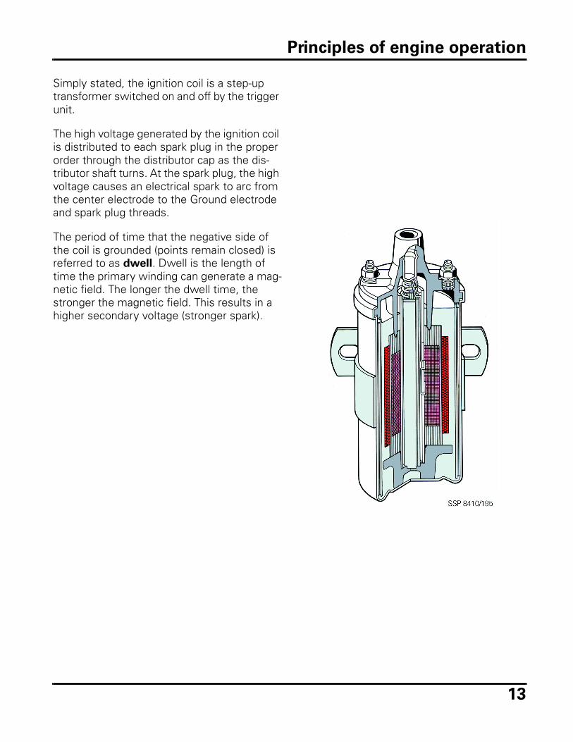
Simply stated, the ignition coil is a step-up transformer switched on and off by the trigger unit.
The high voltage generated by the ignition coil is distributed to each spark plug in the proper order through the distributor cap as the dis-tributor shaft turns. At the spark plug, the high voltage causes an electrical spark to arc from the center electrode to the Ground electrode and spark plug threads.
The period of time that the negative side of the coil is grounded (points remain closed) is referred to as dwell. Dwell is the length of time the primary winding can generate a mag-netic field. The longer the dwell time, the stronger the magnetic field. This results in a higher secondary voltage (stronger spark).
Principles of engine operation
14
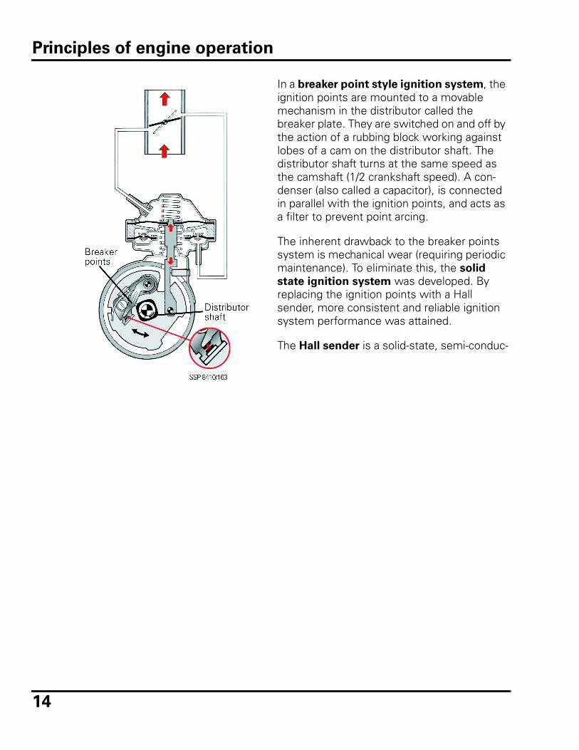
In a breaker point style ignition system, the ignition points are mounted to a movable mechanism in the distributor called the breaker plate. They are switched on and off by the action of a rubbing block working against lobes of a cam on the distributor shaft. The distributor shaft turns at the same speed as the camshaft (1/2 crankshaft speed). A con-denser (also called a capacitor), is connected in parallel with the ignition points, and acts as a filter to prevent point arcing.
The inherent drawback to the breaker points system is mechanical wear (requiring periodic maintenance). To eliminate this, the solid
state ignition system was developed. By replacing the ignition points with a Hall sender, more consistent and reliable ignition system performance was attained.
The Hall sender is a solid-state, semi-conduc-
Principles of engine operation
15
tor device mounted in the distributor housing. A rotating trigger wheel is passed between a magnet and a Hall-effect transistor (see Glos-sary). Windows in the trigger wheel allow the Hall-effect transistor to be exposed to the magnetic field causing current to flow through the transistor. When a shutter wheel vane blocks the magnetic field to the Hall-effect transistor, current flow stops.
Operating voltage is supplied by either an igni-
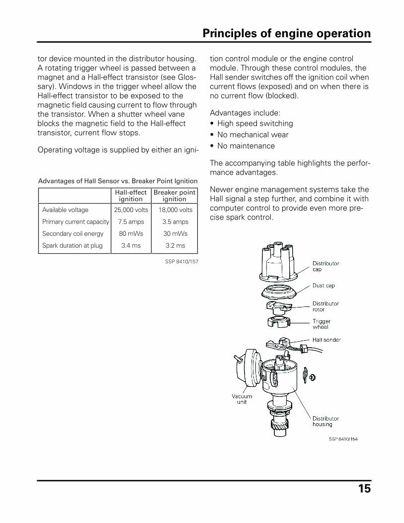
Hall-effectignition
Breaker pointignition
Available voltage
Primary current capacity
Secondary coil energy
Spark duration at plug
25,000 volts
7.5 amps
80 mWs
3.4 ms
18,000 volts
3.5 amps
30 mWs
3.2 ms
SSP 8410/157
Advantages of Hall Sensor vs. Breaker Point Ignition
tion control module or the engine control module. Through these control modules, the Hall sender switches off the ignition coil when current flows (exposed) and on when there is no current flow (blocked).
Advantages include:• High speed switching• No mechanical wear• No maintenance
The accompanying table highlights the perfor-mance advantages.
Newer engine management systems take the Hall signal a step further, and combine it with computer control to provide even more pre-cise spark control.
Principles of engine operation
16
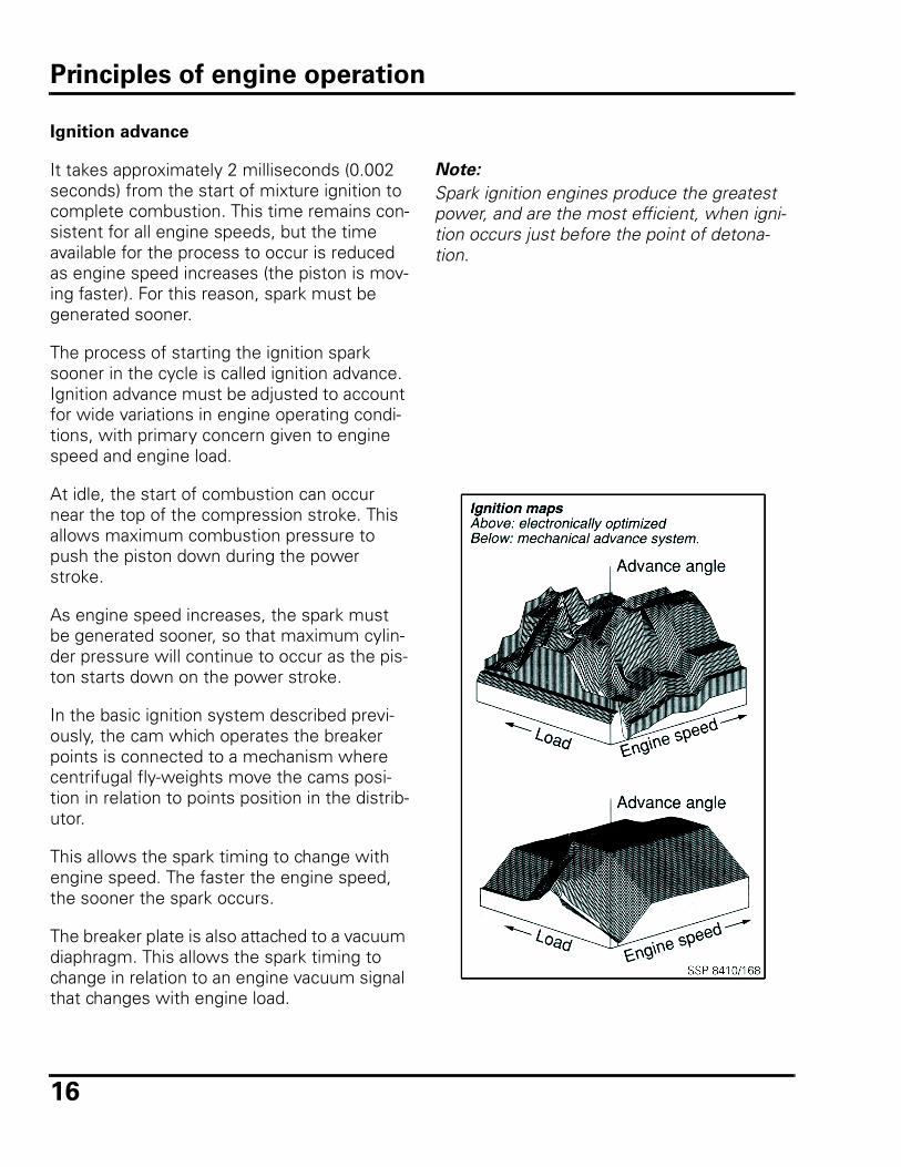
Ignition advance
It takes approximately 2 milliseconds (0.002 seconds) from the start of mixture ignition to complete combustion. This time remains con-sistent for all engine speeds, but the time available for the process to occur is reduced as engine speed increases (the piston is mov-ing faster). For this reason, spark must be generated sooner.
The process of starting the ignition spark sooner in the cycle is called ignition advance. Ignition advance must be adjusted to account for wide variations in engine operating condi-tions, with primary concern given to engine speed and engine load.
At idle, the start of combustion can occur near the top of the compression stroke. This allows maximum combustion pressure to push the piston down during the power stroke.
As engine speed increases, the spark must be generated sooner, so that maximum cylin-der pressure will continue to occur as the pis-ton starts down on the power stroke.
In the basic ignition system described previ-ously, the cam which operates the breaker points is connected to a mechanism where centrifugal fly-weights move the cams posi-tion in relation to points position in the distrib-utor.
This allows the spark timing to change with engine speed. The faster the engine speed, the sooner the spark occurs.
The breaker plate is also attached to a vacuum diaphragm. This allows the spark timing to change in relation to an engine vacuum signal that changes with engine load.
Note:
Spark ignition engines produce the greatest power, and are the most efficient, when igni-tion occurs just before the point of detona-tion.
Principles of engine operation
17
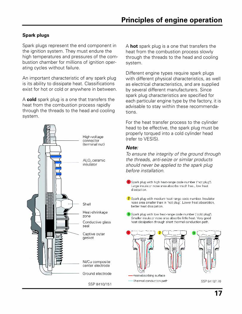
Spark plugs
Spark plugs represent the end component in the ignition system. They must endure the high temperatures and pressures of the com-bustion chamber for millions of ignition oper-ating cycles without failure.
An important characteristic of any spark plug is its ability to dissipate heat. Classifications exist for hot or cold or anywhere in between.
A cold spark plug is a one that transfers the heat from the combustion process rapidly through the threads to the head and cooling system.
A hot spark plug is a one that transfers the heat from the combustion process slowly through the threads to the head and cooling system.
Different engine types require spark plugs with different physical characteristics, as well as electrical characteristics, and are supplied by several different manufacturers. Since spark plug characteristics are specified for each particular engine type by the factory, it is advisable to stay within these recommenda-tions.
For the heat transfer process to the cylinder head to be effective, the spark plug must be properly torqued into a cold cylinder head (refer to VESIS).
Note:
To ensure the integrity of the ground through the threads, anti-seize or similar products should never be applied to the spark plug before installation.
Principles of engine operation
18
Emissions system, overview
Air quality has been an environmental con-cern for many years. Pollution from numerous sources, combined with atmospheric condi-tions, resulted in the degradation of air quality in many of the industrialized areas of the world. The State of California recognized that automobile emissions contributed signifi-cantly to the rising levels of pollution, and enacted legislation to establish air quality standards for motor vehicles. Other states continue to adopt California emissions stan-dards.
The first emissions requirement was to con-trol crankcase emissions through Positive Crankcase Ventilation (PCV). The 1963 Type I Beetle engine pictured on page 1 shows com-pliance with this requirement. This is the first Volkswagen emission controlled engine.
Federal and state clean air legislation contin-ued to be passed with California leading the rest of the nation. In an effort to reduce exhaust emissions, various parts of the fuel and ignition systems were modified.
New systems were added and existing sys-tems were modified to reduce tailpipe and crankcase emissions. Systems were also added to reduce emissions from the fuel tank and vent system.
A basic emissions system may have the fol-lowing components:• Throttle positioners and dashpots• Exhaust gas recirculation• Oxidation catalytic converters• Oxygen sensors• Secondary air injection• Intake air pre-heating • Evaporative emissions (fuel tank)• Crankcase emissions
Principles of engine operation
19
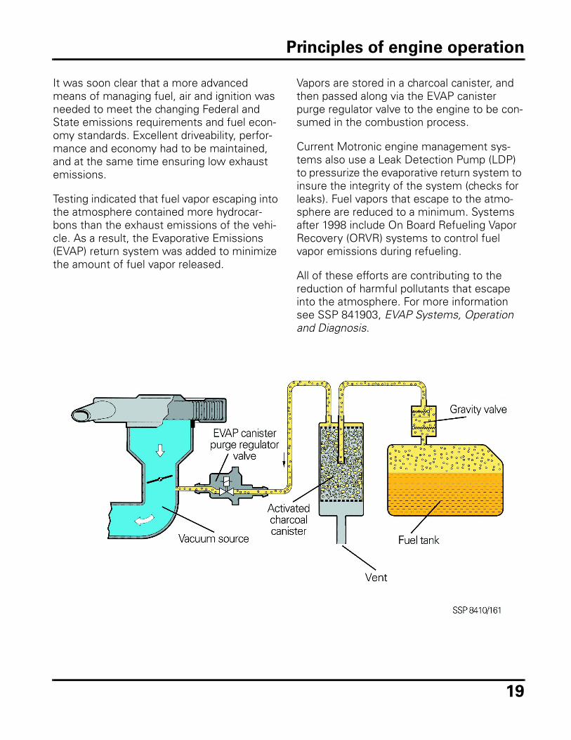
It was soon clear that a more advanced means of managing fuel, air and ignition was needed to meet the changing Federal and State emissions requirements and fuel econ-omy standards. Excellent driveability, perfor-mance and economy had to be maintained, and at the same time ensuring low exhaust emissions.
Testing indicated that fuel vapor escaping into the atmosphere contained more hydrocar-bons than the exhaust emissions of the vehi-cle. As a result, the Evaporative Emissions (EVAP) return system was added to minimize the amount of fuel vapor released.
Vapors are stored in a charcoal canister, and then passed along via the EVAP canister purge regulator valve to the engine to be con-sumed in the combustion process.
Current Motronic engine management sys-tems also use a Leak Detection Pump (LDP) to pressurize the evaporative return system to insure the integrity of the system (checks for leaks). Fuel vapors that escape to the atmo-sphere are reduced to a minimum. Systems after 1998 include On Board Refueling Vapor Recovery (ORVR) systems to control fuel vapor emissions during refueling.
All of these efforts are contributing to the reduction of harmful pollutants that escape into the atmosphere. For more information see SSP 841903, EVAP Systems, Operation and Diagnosis.
Principles of engine operation
20
Three-way Catalytic Converter, overview
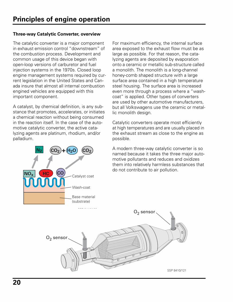
The catalytic converter is a major component in exhaust emission control “downstream” of the combustion process. Development and common usage of this device began with open-loop versions of carburetor and fuel injection systems in the 1970s. Closed loop engine management systems required by cur-rent legislation in the United States and Can-ada insure that almost all internal combustion engined vehicles are equipped with this important component.
A catalyst, by chemical definition, is any sub-stance that promotes, accelerates, or initiates a chemical reaction without being consumed in the reaction itself. In the case of the auto-motive catalytic converter, the active cata-lyzing agents are platinum, rhodium, and/or palladium.
NOx HC
CO2CO2 H2ON2 +
COCatalyst coat
Wash-coat
Base material(substrate)
SSP 8410/189
For maximum efficiency, the internal surface area exposed to the exhaust flow must be as large as possible. For that reason, the cata-lyzing agents are deposited by evaporation onto a ceramic or metallic sub-structure called a monolith. The monolith is a long-channel honey-comb shaped structure with a large surface area contained in a high temperature steel housing. The surface area is increased even more through a process where a “wash-coat” is applied. Other types of converters are used by other automotive manufacturers, but all Volkswagens use the ceramic or metal-lic monolith design.
Catalytic converters operate most efficiently at high temperatures and are usually placed in the exhaust stream as close to the engine as possible.
A modern three-way catalytic converter is so named because it takes the three major auto-motive pollutants and reduces and oxidizes them into relatively harmless substances that do not contribute to air pollution.
O2 sensor
O2 sensor
SSP 8410/121
Principles of engine operation
21
Catalytic Converter Operation
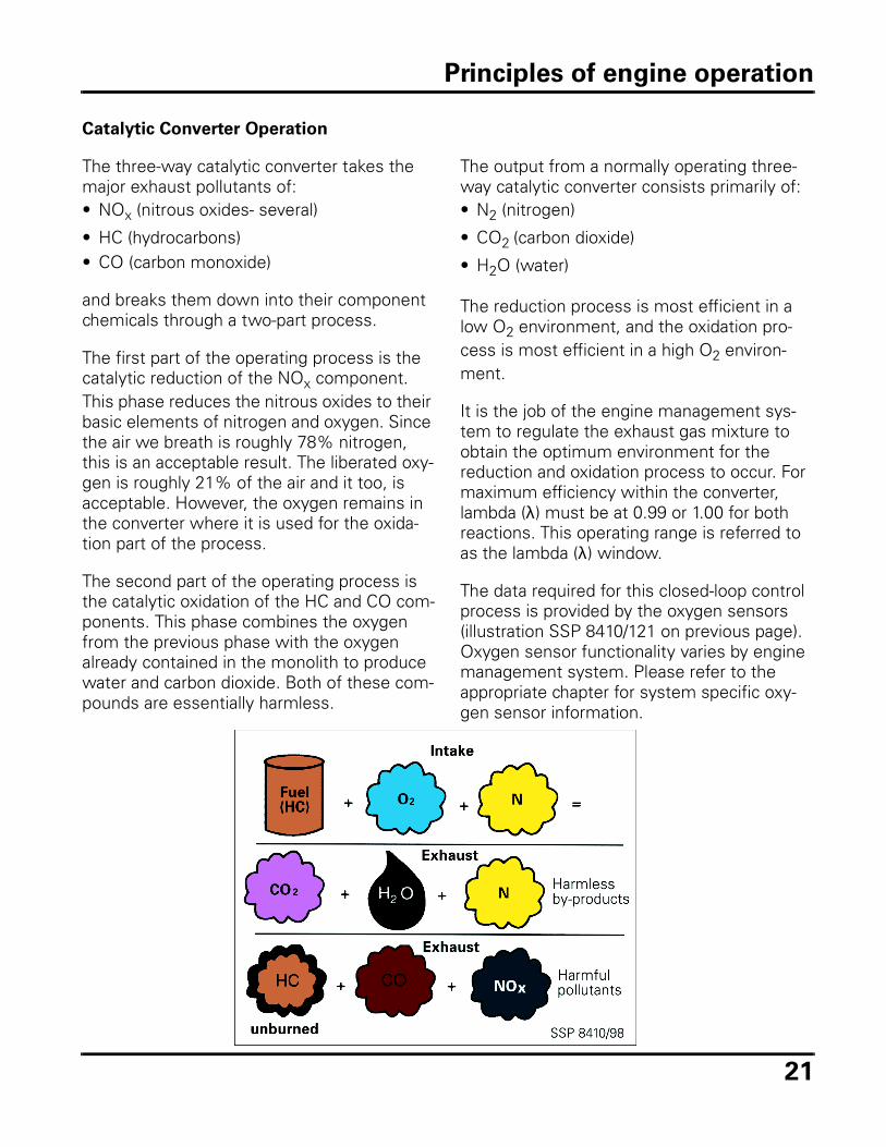
The three-way catalytic converter takes the major exhaust pollutants of:• NOx (nitrous oxides- several)
• HC (hydrocarbons)• CO (carbon monoxide)
and breaks them down into their component chemicals through a two-part process.
The first part of the operating process is the catalytic reduction of the NOx component. This phase reduces the nitrous oxides to their basic elements of nitrogen and oxygen. Since the air we breath is roughly 78% nitrogen, this is an acceptable result. The liberated oxy-gen is roughly 21% of the air and it too, is acceptable. However, the oxygen remains in the converter where it is used for the oxida-tion part of the process.
The second part of the operating process is the catalytic oxidation of the HC and CO com-ponents. This phase combines the oxygen from the previous phase with the oxygen already contained in the monolith to produce water and carbon dioxide. Both of these com-pounds are essentially harmless.
The output from a normally operating three-way catalytic converter consists primarily of:• N2 (nitrogen)
• CO2 (carbon dioxide)
• H2O (water)
The reduction process is most efficient in a low O2 environment, and the oxidation pro-cess is most efficient in a high O2 environ-ment.
It is the job of the engine management sys-tem to regulate the exhaust gas mixture to obtain the optimum environment for the reduction and oxidation process to occur. For maximum efficiency within the converter, lambda (λ) must be at 0.99 or 1.00 for both reactions. This operating range is referred to as the lambda (λ) window.
The data required for this closed-loop control process is provided by the oxygen sensors (illustration SSP 8410/121 on previous page). Oxygen sensor functionality varies by engine management system. Please refer to the appropriate chapter for system specific oxy-gen sensor information.
Principles of engine operation
22
On Board Diagnostics
On Board Diagnostic (OBD) capability allows the Engine Control Module (ECM) to recog-nize faults that could indicate a problem with a component or associated wiring. When a fault is recognized, a Diagnostic Trouble Code (DTC) will be stored in DTC memory.
Current federal regulations require that any fault that affects exhaust emissions, or the monitoring of exhaust emissions, sets a Diag-nostic Trouble Code (DTC), and illuminates a Malfunction Indicator Light (MIL) to alert the operator of an emissions related failure.
Engine Control Module (ECM) fault
recognition
Volkswagen engine management systems have the ability to diagnose and identify sev-eral different component failure conditions, including: • Short circuit to Battery Positive (B+)• Open circuit/Short circuit to Ground
Systems complying with OBD II regulations also identify implausible signals. An implausi-ble signal is a reading that is considered out of range for operating conditions. This is covered in the OBD II section of this SSP.
ECM inputs (sensors) and outputs (actuators) are powered in one of two ways:• The ECM supplies a ground signal and the
B+ is supplied from the fuse/relay panel.• The ECM provides a reference voltage and
monitors the voltage drop across the sensor’s resistance (e.g. engine coolant temperature sensor).
Principles of engine operation
23
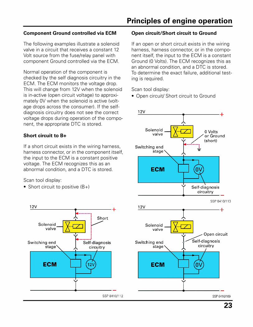
Component Ground controlled via ECM
The following examples illustrate a solenoid valve in a circuit that receives a constant 12 Volt source from the fuse/relay panel with component Ground controlled via the ECM.
Normal operation of the component is checked by the self diagnosis circuitry in the ECM. The ECM monitors the voltage drop. This will change from 12V when the solenoid is in-active (open circuit voltage) to approxi-mately 0V when the solenoid is active (volt-age drops across the consumer). If the self-diagnosis circuitry does not see the correct voltage drops during operation of the compo-nent, the appropriate DTC is stored.
Short circuit to B+
If a short circuit exists in the wiring harness, harness connector, or in the component itself, the input to the ECM is a constant positive voltage. The ECM recognizes this as an abnormal condition, and a DTC is stored.
Scan tool display:• Short circuit to positive (B+)
Open circuit/Short circuit to Ground
If an open or short circuit exists in the wiring harness, harness connector, or in the compo-nent itself, the input to the ECM is a constant Ground (0 Volts). The ECM recognizes this as an abnormal condition, and a DTC is stored. To determine the exact failure, additional test-ing is required.
Scan tool display:• Open circuit/ Short circuit to Ground
Principles of engine operation
24
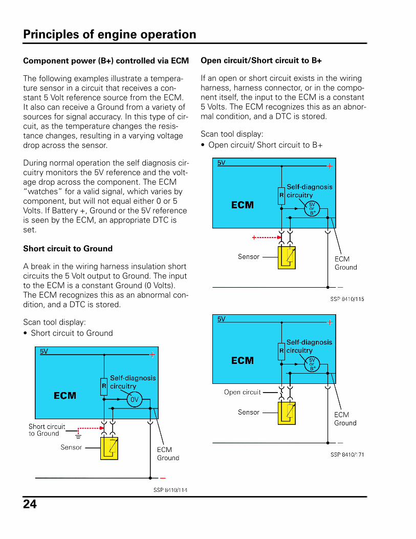
Component power (B+) controlled via ECM
The following examples illustrate a tempera-ture sensor in a circuit that receives a con-stant 5 Volt reference source from the ECM. It also can receive a Ground from a variety of sources for signal accuracy. In this type of cir-cuit, as the temperature changes the resis-tance changes, resulting in a varying voltage drop across the sensor.
During normal operation the self diagnosis cir-cuitry monitors the 5V reference and the volt-age drop across the component. The ECM “watches” for a valid signal, which varies by component, but will not equal either 0 or 5 Volts. If Battery +, Ground or the 5V reference is seen by the ECM, an appropriate DTC is set.
Short circuit to Ground
A break in the wiring harness insulation short circuits the 5 Volt output to Ground. The input to the ECM is a constant Ground (0 Volts). The ECM recognizes this as an abnormal con-dition, and a DTC is stored.
Scan tool display:• Short circuit to Ground
Open circuit/Short circuit to B+
If an open or short circuit exists in the wiring harness, harness connector, or in the compo-nent itself, the input to the ECM is a constant 5 Volts. The ECM recognizes this as an abnor-mal condition, and a DTC is stored.
Scan tool display:• Open circuit/ Short circuit to B+
Principles of engine operation
25
Review
1. Technician A says that Motronic
engine management systems can
identify short circuits to positive with
some system components.
Technician B says that Motronic
engine management systems can
identify short circuits to Ground with
some system components.
Which Technician is correct?
a. Technician A only
b. Technician B only
c. Both Technician A and Technician B
d. Neither Technician A nor Technician B
2. Which of the following is NOT an oper-
ating requirement for efficient opera-
tion of the Three Way Catalyst?
a. High operating temperature.
b. Lambda (λ) window of 0.99 to 1.00.
c. Gasoline without lead or lead com-pounds.
d. Gasoline with a minimum octane of 87 AKI.
3. In the four-stroke gasoline engine, the
camshaft turns at what speed in rela-
tion to the crankshaft?
a. Twice crankshaft
b. Same as crankshaft
c. ¼ crankshaft
d. ½ crankshaft
4. Which of the following components is
NOT a component of gasoline’s ability
to pre-ignite?
a. Research octane number
b. Motor octane number
c. Cetane
d. Anti-knock index
5. Which of the following is NOT a com-
ponent failure condition recognizable
by the scan tool?
a. Short circuit to positive
b. Short circuit to neutral
c. Short circuit to Ground
d. Open circuit
6. Technician A says that the ignition coil
is part of both the primary and the
secondary sides of the ignition sys-
tem.
Technician B says that the distributor
rotor is part of the primary side of the
ignition system.
Which Technician is correct?
a. Technician A only
b. Technician B only
c. Both Technician A and Technician B
d. Neither Technician A nor Technician B
7. Which of the listed exhaust by-prod-
ucts is NOT harmful to the atmo-
sphere?
a. Hydrocarbons (HC)
b. Oxygen (O2)
c. Carbon monoxide (CO)
d. Oxides of Nitrogen (NOx)
Principles of engine operation - Review

26
Notes
27
K-Jetronic/CIS
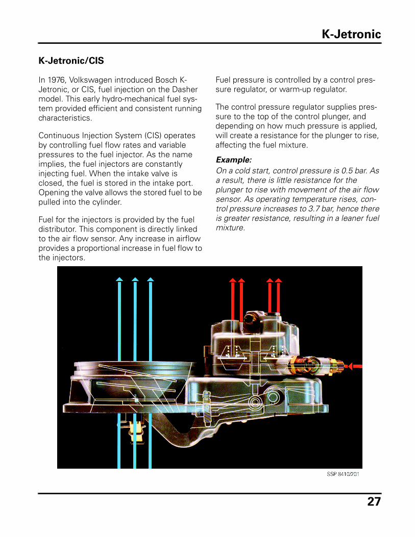
In 1976, Volkswagen introduced Bosch K-Jetronic, or CIS, fuel injection on the Dasher model. This early hydro-mechanical fuel sys-tem provided efficient and consistent running characteristics.
Continuous Injection System (CIS) operates by controlling fuel flow rates and variable pressures to the fuel injector. As the name implies, the fuel injectors are constantly injecting fuel. When the intake valve is closed, the fuel is stored in the intake port. Opening the valve allows the stored fuel to be pulled into the cylinder.
Fuel for the injectors is provided by the fuel distributor. This component is directly linked to the air flow sensor. Any increase in airflow provides a proportional increase in fuel flow to the injectors.
Fuel pressure is controlled by a control pres-sure regulator, or warm-up regulator.
The control pressure regulator supplies pres-sure to the top of the control plunger, and depending on how much pressure is applied, will create a resistance for the plunger to rise, affecting the fuel mixture.
Example:
On a cold start, control pressure is 0.5 bar. As a result, there is little resistance for the plunger to rise with movement of the air flow sensor. As operating temperature rises, con-trol pressure increases to 3.7 bar, hence there is greater resistance, resulting in a leaner fuel mixture.
K-Jetronic
28
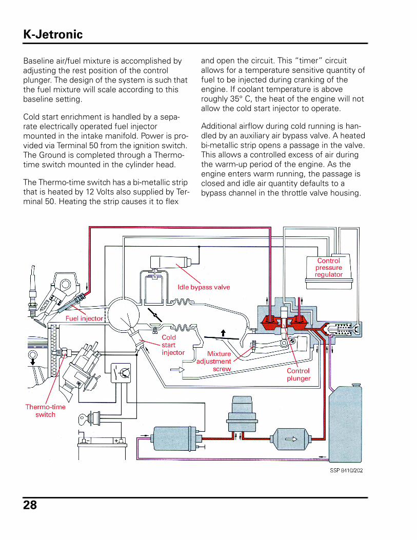
Baseline air/fuel mixture is accomplished by adjusting the rest position of the control plunger. The design of the system is such that the fuel mixture will scale according to this baseline setting.
Cold start enrichment is handled by a sepa-rate electrically operated fuel injector mounted in the intake manifold. Power is pro-vided via Terminal 50 from the ignition switch. The Ground is completed through a Thermo-time switch mounted in the cylinder head.
The Thermo-time switch has a bi-metallic strip that is heated by 12 Volts also supplied by Ter-minal 50. Heating the strip causes it to flex
and open the circuit. This “timer” circuit allows for a temperature sensitive quantity of fuel to be injected during cranking of the engine. If coolant temperature is above roughly 35° C, the heat of the engine will not allow the cold start injector to operate.
Additional airflow during cold running is han-dled by an auxiliary air bypass valve. A heated bi-metallic strip opens a passage in the valve. This allows a controlled excess of air during the warm-up period of the engine. As the engine enters warm running, the passage is closed and idle air quantity defaults to a bypass channel in the throttle valve housing.
K-Jetronic
29
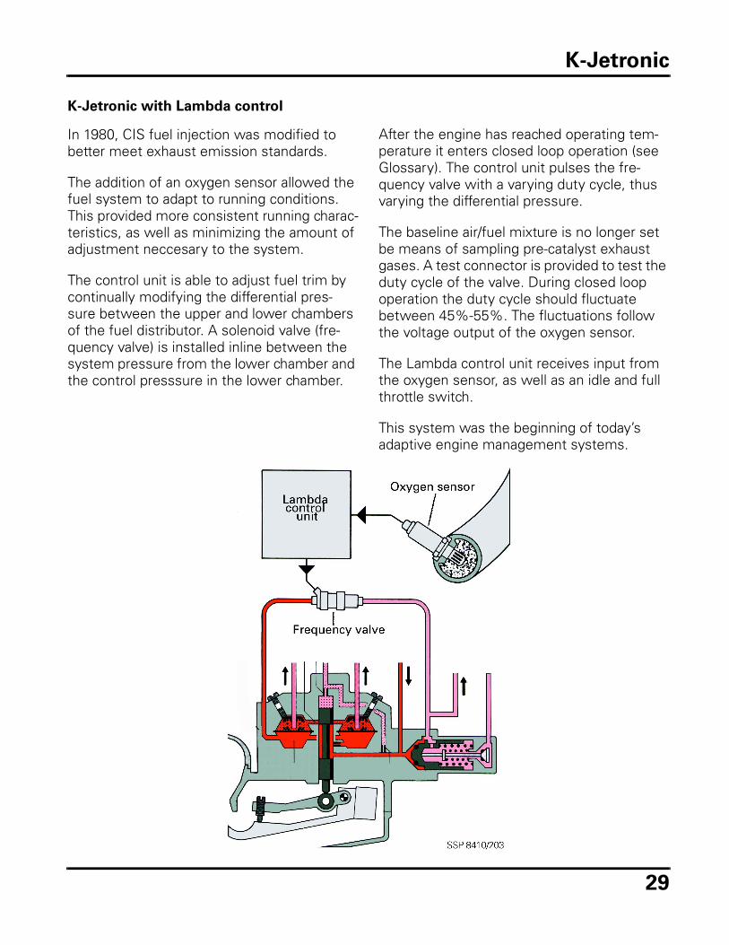
K-Jetronic with Lambda control
In 1980, CIS fuel injection was modified to better meet exhaust emission standards.
The addition of an oxygen sensor allowed the fuel system to adapt to running conditions. This provided more consistent running charac-teristics, as well as minimizing the amount of adjustment neccesary to the system.
The control unit is able to adjust fuel trim by continually modifying the differential pres-sure between the upper and lower chambers of the fuel distributor. A solenoid valve (fre-quency valve) is installed inline between the system pressure from the lower chamber and the control presssure in the lower chamber.
After the engine has reached operating tem-perature it enters closed loop operation (see Glossary). The control unit pulses the fre-quency valve with a varying duty cycle, thus varying the differential pressure.
The baseline air/fuel mixture is no longer set be means of sampling pre-catalyst exhaust gases. A test connector is provided to test the duty cycle of the valve. During closed loop operation the duty cycle should fluctuate between 45%-55%. The fluctuations follow the voltage output of the oxygen sensor.
The Lambda control unit receives input from the oxygen sensor, as well as an idle and full throttle switch.
This system was the beginning of today’s adaptive engine management systems.
K-Jetronic
30
KE-Jetronic/CIS-E
For the 1985 model year, Volkswagen expanded the capabilities of the CIS fuel injec-tion system. New features include:• Warm-up regulator replaced with
electrically operated solenoid valve• Electrically heated oxygen sensor (allows
for faster closed loop operation)• Air flow sensor potentiometer (more
accurate control of Lambda)• Altitude sensor (varies fuel trim with
barometric pressure)• Idle stabilizer valve (more stable idle
characteristics)
The major change for the CIS-E system is the replacement of the control pressure regulator with a Differential Pressure Regulator (DPR). This electro-mechanical valve receives a vary-ing amperage from the CIS-E control unit; as amperage is increased control pressure is decreased. This increases fuel flow to the injectors.
This change allowed for more accurate control of the fuel trim, as well as decreased mainte-nance.
KE-Motronic/CIS-E Motronic
For the 1990 model year, the 16-valve 2.0 liter engine received the last change to the K-Jetronic system.
CIS-E Motronic intergrated fuel and ignition timing in one common control unit, as well as the following features:• Oxygen sensor control with adaptive
learning• Dual map ignition control with cylinder
selective knock control• EVAP purge control• Permanent fault memory with self
diagnosis
For more information regarding knock control, and adaptive learning (refer to Glossary).
K-Jetronic
31
Digifant System Overview
System description
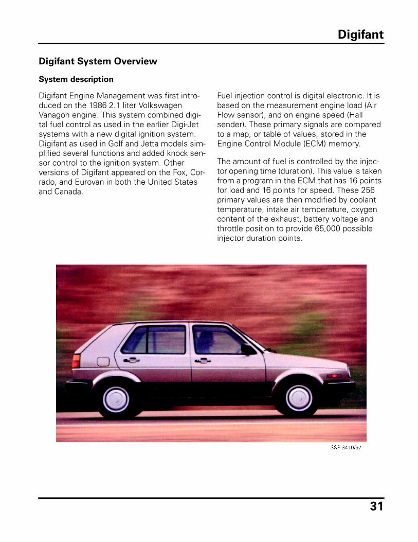
Digifant Engine Management was first intro-duced on the 1986 2.1 liter Volkswagen Vanagon engine. This system combined digi-tal fuel control as used in the earlier Digi-Jet systems with a new digital ignition system. Digifant as used in Golf and Jetta models sim-plified several functions and added knock sen-sor control to the ignition system. Other versions of Digifant appeared on the Fox, Cor-rado, and Eurovan in both the United States and Canada.
Fuel injection control is digital electronic. It is based on the measurement engine load (Air Flow sensor), and on engine speed (Hall sender). These primary signals are compared to a map, or table of values, stored in the Engine Control Module (ECM) memory.
The amount of fuel is controlled by the injec-tor opening time (duration). This value is taken from a program in the ECM that has 16 points for load and 16 points for speed. These 256 primary values are then modified by coolant temperature, intake air temperature, oxygen content of the exhaust, battery voltage and throttle position to provide 65,000 possible injector duration points.
Digifant
32
The fuel injectors are wired in parallel, and are supplied with constant system voltage. The ECM switches the Ground on and off to con-trol duration. All injectors operate at the same time each crankshaft revolution; two com-plete revolutions being needed for each cylin-der to receive the correct amount of fuel for each combustion cycle.
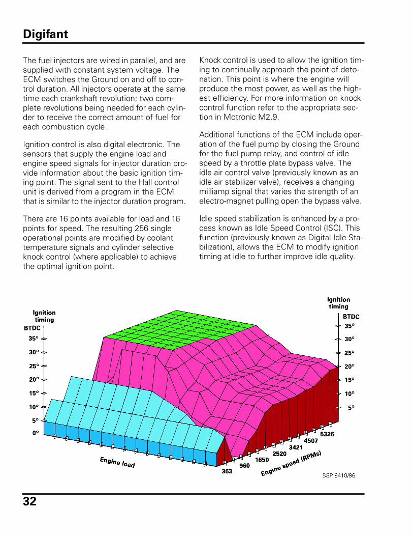
Ignition control is also digital electronic. The sensors that supply the engine load and engine speed signals for injector duration pro-vide information about the basic ignition tim-ing point. The signal sent to the Hall control unit is derived from a program in the ECM that is similar to the injector duration program.
There are 16 points available for load and 16 points for speed. The resulting 256 single operational points are modified by coolant temperature signals and cylinder selective knock control (where applicable) to achieve the optimal ignition point.
Knock control is used to allow the ignition tim-ing to continually approach the point of deto-nation. This point is where the engine will produce the most power, as well as the high-est efficiency. For more information on knock control function refer to the appropriate sec-tion in Motronic M2.9.
Additional functions of the ECM include oper-ation of the fuel pump by closing the Ground for the fuel pump relay, and control of idle speed by a throttle plate bypass valve. The idle air control valve (previously known as an idle air stabilizer valve), receives a changing milliamp signal that varies the strength of an electro-magnet pulling open the bypass valve.
Idle speed stabilization is enhanced by a pro-cess known as Idle Speed Control (ISC). This function (previously known as Digital Idle Sta-bilization), allows the ECM to modify ignition timing at idle to further improve idle quality.
Digifant
33
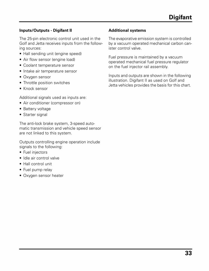
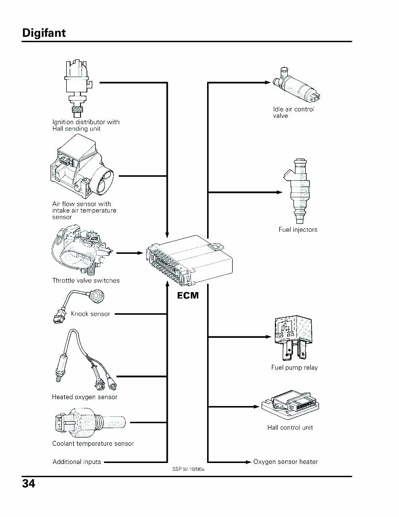
Inputs/Outputs - Digifant II
The 25-pin electronic control unit used in the Golf and Jetta receives inputs from the follow-ing sources:• Hall sending unit (engine speed)• Air flow sensor (engine load)• Coolant temperature sensor• Intake air temperature sensor• Oxygen sensor• Throttle position switches• Knock sensor
Additional signals used as inputs are:• Air conditioner (compressor on)• Battery voltage• Starter signal
The anti-lock brake system, 3-speed auto-matic transmission and vehicle speed sensor are not linked to this system.
Outputs controlling engine operation include signals to the following:• Fuel injectors• Idle air control valve• Hall control unit• Fuel pump relay• Oxygen sensor heater
Additional systems
The evaporative emission system is controlled by a vacuum operated mechanical carbon can-ister control valve.
Fuel pressure is maintained by a vacuum operated mechanical fuel pressure regulator on the fuel injector rail assembly.
Inputs and outputs are shown in the following illustration. Digifant II as used on Golf and Jetta vehicles provides the basis for this chart.
Digifant
34
Digifant
35
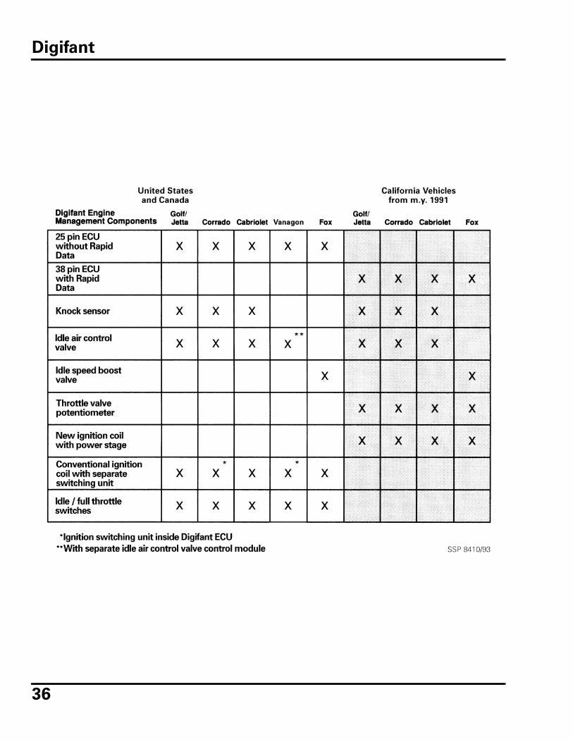
On Board Diagnostics
Golf, Jetta, and Vanagon Digifant systems have no On Board Diagnostic (OBD) capabili-ties, except for a limited number of 1987 to 1990 California Golfs and Jettas. These vehi-cles have blink code capability, with the capacity to store up to 5 Diagnostic Trouble Codes (DTCs). For the most part, diagnostic troubleshooting is done with the VAG 1598 and a digital multimeter. This system can also have carbon monoxide (CO), ignition timing and idle speed adjusted to baseline values.
In 1991, California Golf, Jetta, Fox, Cabriolet and Corrado vehicles were equipped with expanded OBD capabilities. These latest Digi-fant versions have 38-pin ECMs with rapid data transfer and permanent DTC memory. All Eurovans with Digifant also have rapid data transfer and permanent DTC memory. These systems use a throttle plate potentiometer to track throttle position in place of the idle and full throttle switches used on earlier systems.
Summary
Digifant is an engine management system designed originally to take advantage of the first generation of newly developed digital sig-nal processing circuits. Production changes and updates were made to keep it current with the changing California and federal emis-sions requirements. Updates were also made to allow integration of other vehicle systems into the scope of engine operation.
Changes in circuit technology, design and pro-cessing speed along with evolving emissions standards, resulted in the development of new engine management systems. These new systems incorporated adaptive learning, enhanced and expanded diagnostics, and the ability to meet total vehicle emissions stan-dards.
The table on the following page lists some of the major differences between versions of Digifant sold in California and the other states.
Digifant
36
Digifant
37
Review
1. Digifant engine management systems
derive basic fuel injection quantity and
ignition timing points from which two
sensors?
a. Air flow sensor and coolant temper-ature sensor
b. Knock sensor and camshaft position sensor
c. Hall sender and coolant tempera-ture sensor
d. Hall sender and air flow sensor
2. Technician A says that Digifant engine
management systems use digital sig-
nal processing for fuel injection con-
trol.
Technician B says that Digifant engine
management systems use analog sig-
nal processing for ignition control.
Which Technician is correct?
a. Technician A only
b. Technician B only
c. Both Technician A and Technician B
d. Neither Technician A nor Technician B
3. Which of the following items does not
supply an input to the 25-pin Digifant
control unit?
a. Transmission Control Module (TCM)
b. Air conditioner system
c. Battery voltage
d. Starter
4. Technician A says that the Digifant
ECM operates the fuel injectors by
controlling the ground signal.
Technician B says that the Digifant
ECM operates the fuel pump relay by
controlling the ground signal.
Which Technician is correct?
a. Technician A only
b. Technician B only
c. Both Technician A and Technician B
d. Neither Technician A nor Technician B
5. Digifant fuel injectors operate:
a. Sequentially every other crankshaft revolution.
b. At the same time every other crank-shaft revolution.
c. Sequentially every crankshaft revo-lution.
d. At the same time every crankshaft revolution
6. Technician A says that all Digifant
engine management systems use
knock sensors.
Technician B says that all Digifant
engine management systems use idle
and full throttle switches.
Which Technician is correct?
a. Technician A only
b. Technician B only
c. Both Technician A and Technician B
d. Neither Technician A or Technician B
Digifant Review

38
Notes
39
Motronic M2.9 Overview
System description
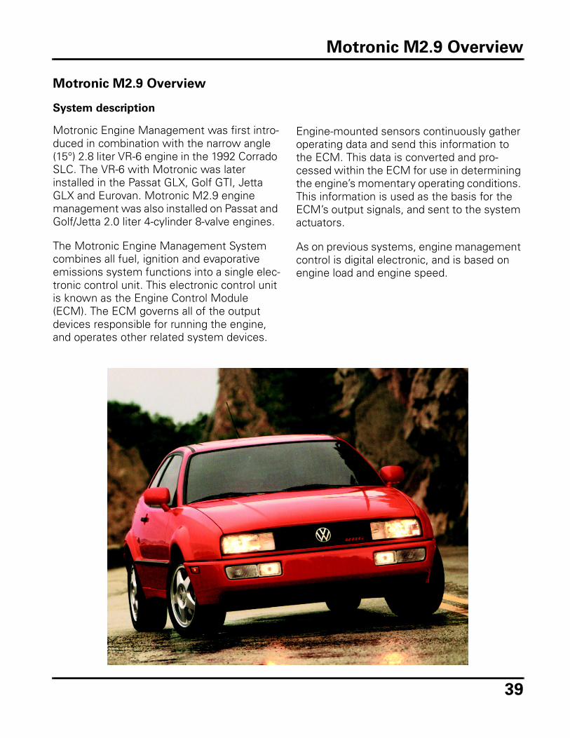
Motronic Engine Management was first intro-duced in combination with the narrow angle (15°) 2.8 liter VR-6 engine in the 1992 Corrado SLC. The VR-6 with Motronic was later installed in the Passat GLX, Golf GTI, Jetta GLX and Eurovan. Motronic M2.9 engine management was also installed on Passat and Golf/Jetta 2.0 liter 4-cylinder 8-valve engines.
The Motronic Engine Management System combines all fuel, ignition and evaporative emissions system functions into a single elec-tronic control unit. This electronic control unit is known as the Engine Control Module (ECM). The ECM governs all of the output devices responsible for running the engine, and operates other related system devices.
Engine-mounted sensors continuously gather operating data and send this information to the ECM. This data is converted and pro-cessed within the ECM for use in determining the engine’s momentary operating conditions. This information is used as the basis for the ECM’s output signals, and sent to the system actuators.
As on previous systems, engine management control is digital electronic, and is based on engine load and engine speed.
Motronic M2.9 Overview
40
Functional overview
Motronic M2.9 uses engine speed and load as its primary inputs. An inductive sensor mounted on the cylinder block measures crankshaft speed, and provides the engine speed signal.
A Hall sender in the distributor provides cam-shaft position information to identify cylinder number one. This allows fuel injection to be sequential, and timed to the opening of the intake valve. This is different than previous systems, in which the injectors all fired at the same time.
Engine load information is received from the Mass Air Flow (MAF) sensor G70, which has no moving parts and is not adjustable.
All Volkswagen engine management systems with an oxygen sensor adapt to changing con-ditions while the engine is running. The ECM uses the oxygen sensor signal to determine the oxygen content of the exhaust gases. It then determines if the injector duration needs to be lengthened or shortened to achieve the optimum air/fuel ratio of 14.7: 1. This is referred to as adaptation (see Glossary).
When the ignition is switched off on Digifant equipped vehicles, all adaptations are erased. During the time before the oxygen sensor sig-nal is reliable (at operating temperature), the ECM relies on baseline values from a calcula-tion map. This air/fuel ratio may or may not reflect the current engine operating condi-tions because it always represents a basic setting.
Motronic M2.9 Overview
41
Motronic M2.9 engine management systems take oxygen sensor adaptation to the next level. Values obtained during engine operation are stored, and used as the basis for engine operation on the next start. These stored val-ues are said to be “learned” values and can change or adapt as often as needed. The pro-cess of storing and using learned values is called adaptive learning (see Glossary).
In addition to mixture adaptation, idle speed and ignition timing also adapt to changes in operating conditions (i.e. changes in altitude and small vacuum leaks). No periodic adjust-ments are required.
Note:
If the battery is disconnected, or if power is interrupted to the ECM, all learned or adapted values will be erased.
The ECM will start from a baseline setting and relearn and adapt to operating conditions.
With the VAG 1551/1552 or VAS 5051 con-nected and set to Basic Settings (function 04), the Motronic system can be made to adapt to current conditions in several minutes. When the Basic Settings function is selected the scan tool instructs the ECM to• disable the A/C compressor • disable the EVAP system• stabilize ignition timing • stabilize idle speed
Advantages of adaptive learning include: • optimal fuel economy• reduced emissions• reduced maintenance• improved driveability
Note:
When diagnosing oxygen sensor adaptation faults, be sure to inspect the following:
• Exhaust system (allows outside air to mix with exhaust gases and affect oxygen sensor readings)
• Engine sealing (oil leaks can create false air leaks when the engine is running, causing un-metered air to enter the intake manifold)
• False air leaks (can include Idle Air Control (IAC) valve, or associated intake manifold)
Any of these systems, if not well sealed, can cause an inaccurate air/fuel mixture, resulting in poor driveability and possible adaptation faults.
Always check the basics first!
Motronic M2.9 Overview
42
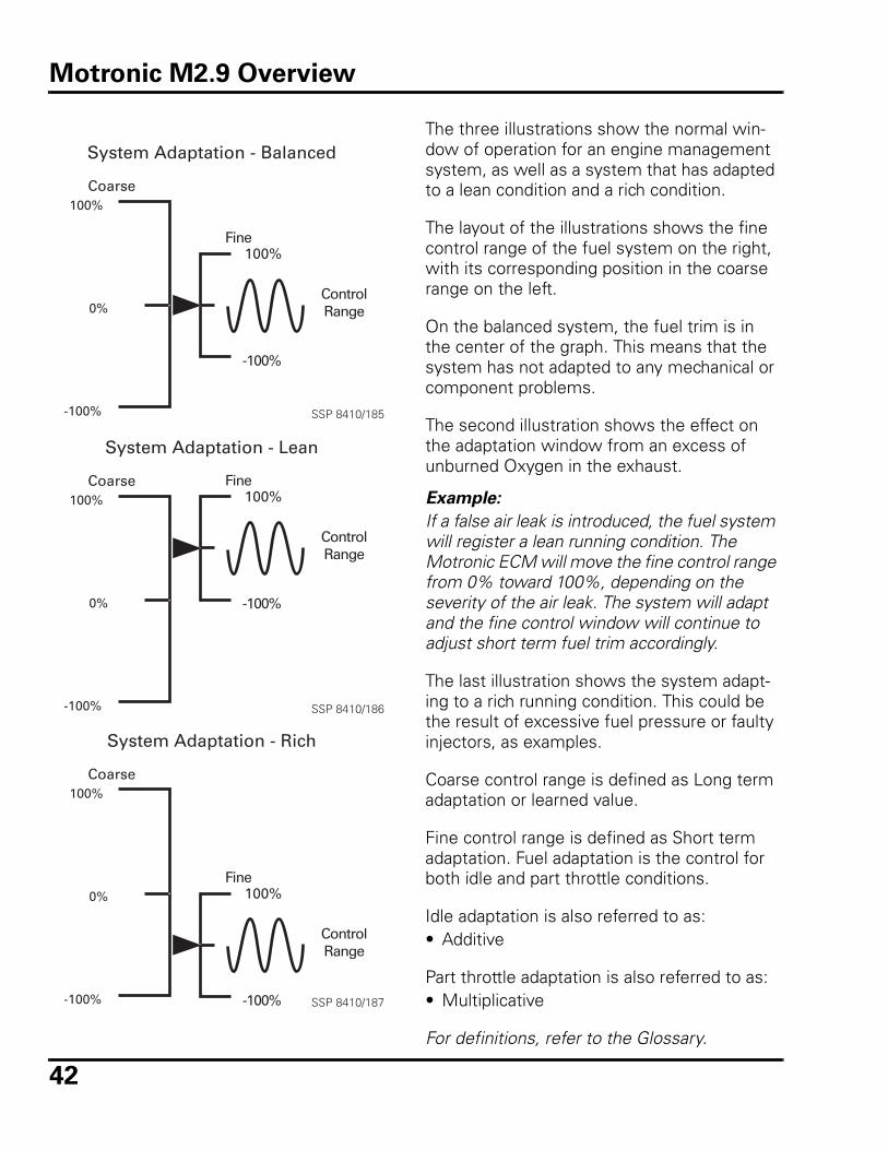
The three illustrations show the normal win-dow of operation for an engine management system, as well as a system that has adapted to a lean condition and a rich condition.
The layout of the illustrations shows the fine control range of the fuel system on the right, with its corresponding position in the coarse range on the left.
On the balanced system, the fuel trim is in the center of the graph. This means that the system has not adapted to any mechanical or component problems.
The second illustration shows the effect on the adaptation window from an excess of unburned Oxygen in the exhaust.
Example:
If a false air leak is introduced, the fuel system will register a lean running condition. The Motronic ECM will move the fine control range from 0% toward 100%, depending on the severity of the air leak. The system will adapt and the fine control window will continue to adjust short term fuel trim accordingly.
The last illustration shows the system adapt-ing to a rich running condition. This could be the result of excessive fuel pressure or faulty injectors, as examples.
Coarse control range is defined as Long term adaptation or learned value.
Fine control range is defined as Short term adaptation. Fuel adaptation is the control for both idle and part throttle conditions.
Idle adaptation is also referred to as:• Additive
Part throttle adaptation is also referred to as:• Multiplicative
For definitions, refer to the Glossary.
System Adaptation - Balanced
100%
0%
-100%
Fine100%
-100%
ControlRange
Coarse
SSP 8410/185
System Adaptation - Lean
100%
0%
-100%
Fine100%
-100%
ControlRange
Coarse
SSP 8410/186
System Adaptation - Rich
100%
0%
-100%
Fine100%
-100%
ControlRange
Coarse
SSP 8410/187
Motronic M2.9 Overview
43
Inputs/Outputs - Motronic M2.9
The 68-pin ECM used in Motronic M2.9 equipped vehicles receives signals from up to nine input sources. These include the follow-ing: • Engine Speed (RPM) sensor G28• Camshaft Position (CMP) sensor G40• Mass Air Flow (MAF) sensor G70• Engine Coolant Temperature (ECT) sensor
G62• Intake Air Temperature (IAT) sensor G42/
G72• Heated Oxygen Sensor (HO2S) G39• Throttle Position (TP) sensor G69• Knock Sensor(s) (KS) G61/G66• EGR Temperature sensor G98
Additional signals used as inputs include:• Air conditioner (compressor and/or system
on)• Battery voltage• Speedometer Vehicle Speed Sensor (VSS)
G22• Transmission Control Module (TCM) J217
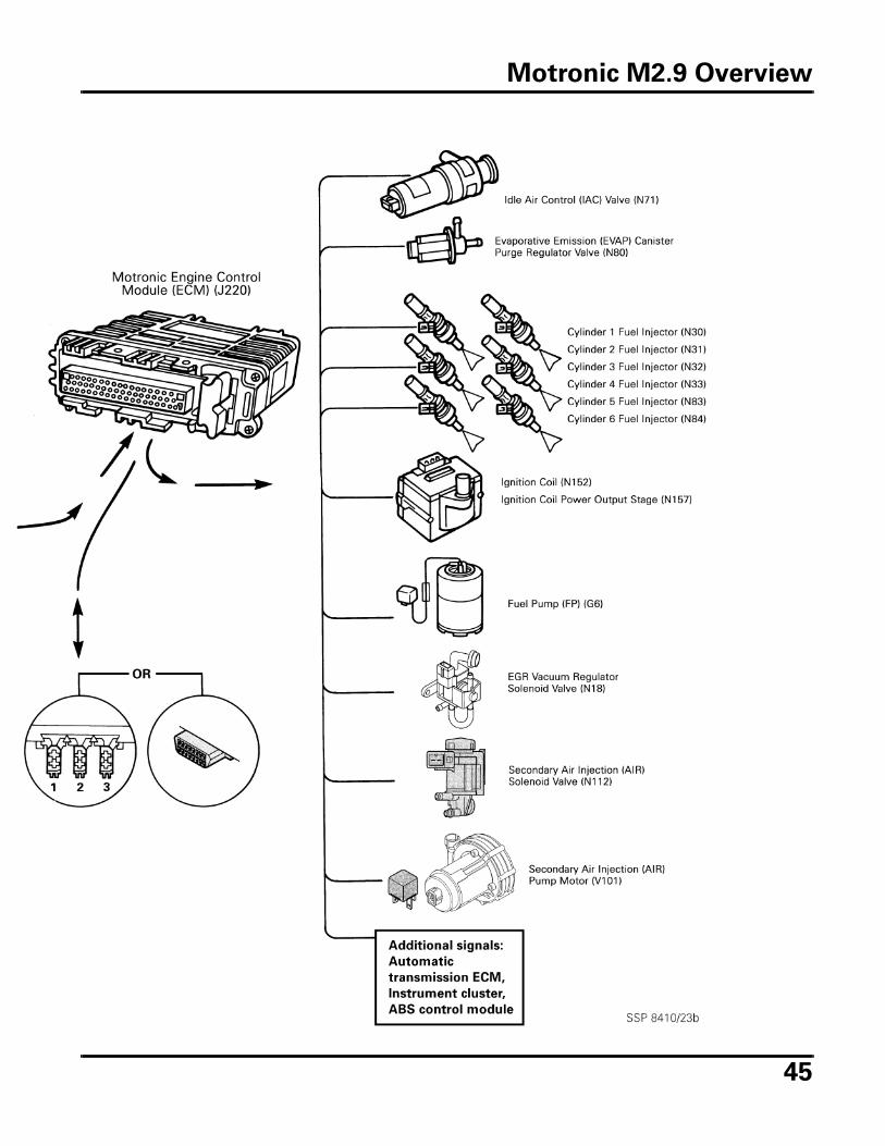
ECM output to actuators controlling engine operation include: • Fuel injectors N30-N33,N83,N84• Idle Air Control (IAC) valve N71• Ignition Coil Power Output Stage N157• Fuel Pump (FP) relay J17• Heated Oxygen sensor (HO2S) control
module J208.• Heated Oxygen sensor (HO2S) relay J278• EGR vacuum regulator solenoid valve N121/
N18• Evaporative Emissions (EVAP) Canister
Purge Regulator Valve N80• Secondary Air Injection (AIR) solenoid valve
N112• Secondary Air Injection (AIR) pump motor
V101
Several other systems require input from the Motronic M2.9 system, or provide input to alter the engine management.
The Transmission Control Module (TCM) requires data corresponding to throttle posi-tion, engine load, and engine RPM for shift control. The TCM uses these inputs to control upshifts as well as downshifts according to driving conditions. The TCM also sends a shift “signal” to the ECM, the ECM retards ignition timing during the shift to help “soften” the shift.
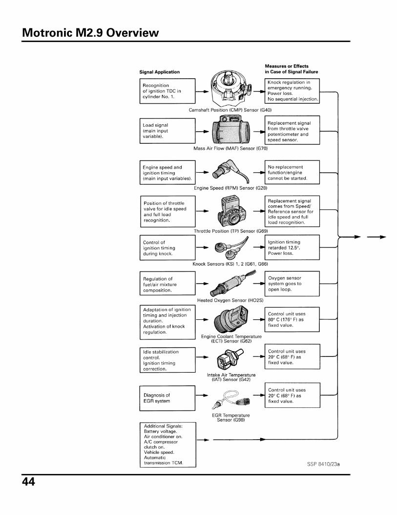
Sensor inputs, other input signals, actuator signals and other output signals are shown in the illustration on the following pages. The illustration represents a composite view of components that are installed on several dif-ferent engine types. Components listed may not be applicable to all engines.
Motronic M2.9 Overview
44
Motronic M2.9 Overview
45
Motronic M2.9 Overview
46
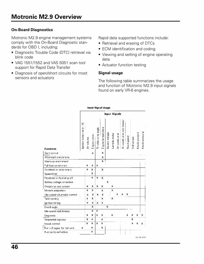
On-Board Diagnostics
Motronic M2.9 engine management systems comply with the On-Board Diagnostic stan-dards for OBD I, including:• Diagnostic Trouble Code (DTC) retrieval via
blink code • VAG 1551/1552 and VAS 5051 scan tool
support for Rapid Data Transfer• Diagnosis of open/short circuits for most
sensors and actuators
Rapid data supported functions include: • Retrieval and erasing of DTCs • ECM identification and coding• Viewing and setting of engine operating
data • Actuator function testing
Signal usage
The following table summarizes the usage and function of Motronic M2.9 input signals found on early VR-6 engines.
Motronic M2.9 Overview
47
Motronic M2.9 Component
Summary
Fuel system components
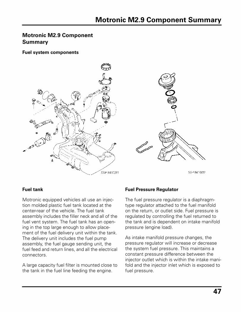
Fuel tank
Motronic equipped vehicles all use an injec-tion molded plastic fuel tank located at the center-rear of the vehicle. The fuel tank assembly includes the filler neck and all of the fuel vent system. The fuel tank has an open-ing in the top large enough to allow place-ment of the fuel delivery unit within the tank. The delivery unit includes the fuel pump assembly, the fuel gauge sending unit, the fuel feed and return lines, and all the electrical connectors.
A large capacity fuel filter is mounted close to the tank in the fuel line feeding the engine.
Fuel Pressure Regulator
The fuel pressure regulator is a diaphragm-type regulator attached to the fuel manifold on the return, or outlet side. Fuel pressure is regulated by controlling the fuel returned to the tank and is dependent on intake manifold pressure (engine load).
As intake manifold pressure changes, the pressure regulator will increase or decrease the system fuel pressure. This maintains a constant pressure difference between the injector outlet which is within the intake mani-fold and the injector inlet which is exposed to fuel pressure.
Motronic M2.9 Component Summary
48
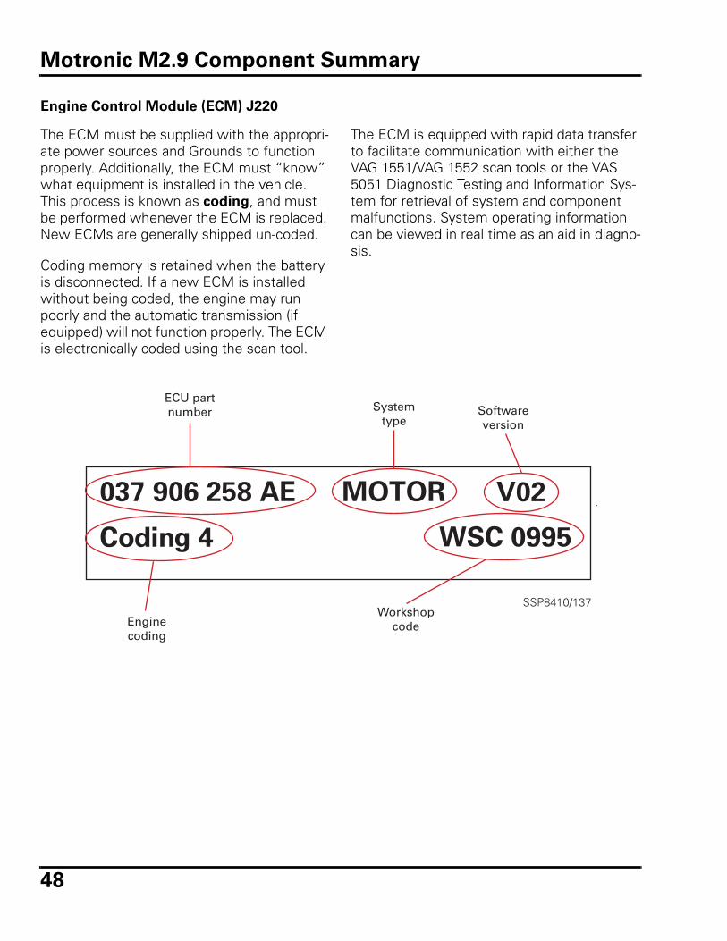
Engine Control Module (ECM) J220
The ECM must be supplied with the appropri-ate power sources and Grounds to function properly. Additionally, the ECM must “know” what equipment is installed in the vehicle. This process is known as coding, and must be performed whenever the ECM is replaced. New ECMs are generally shipped un-coded.
Coding memory is retained when the battery is disconnected. If a new ECM is installed without being coded, the engine may run poorly and the automatic transmission (if equipped) will not function properly. The ECM is electronically coded using the scan tool.
ECU partnumber System
typeSoftwareversion
Enginecoding
Workshopcode
The ECM is equipped with rapid data transfer to facilitate communication with either the VAG 1551/VAG 1552 scan tools or the VAS 5051 Diagnostic Testing and Information Sys-tem for retrieval of system and component malfunctions. System operating information can be viewed in real time as an aid in diagno-sis.
Motronic M2.9 Component Summary
49
Input sensors
Motronic engine management systems rely on up to nine different input sensors for engine operating information. Different Motronic versions have variations of some sensors, but the sig-nal usage and component operation remains essentially the same.
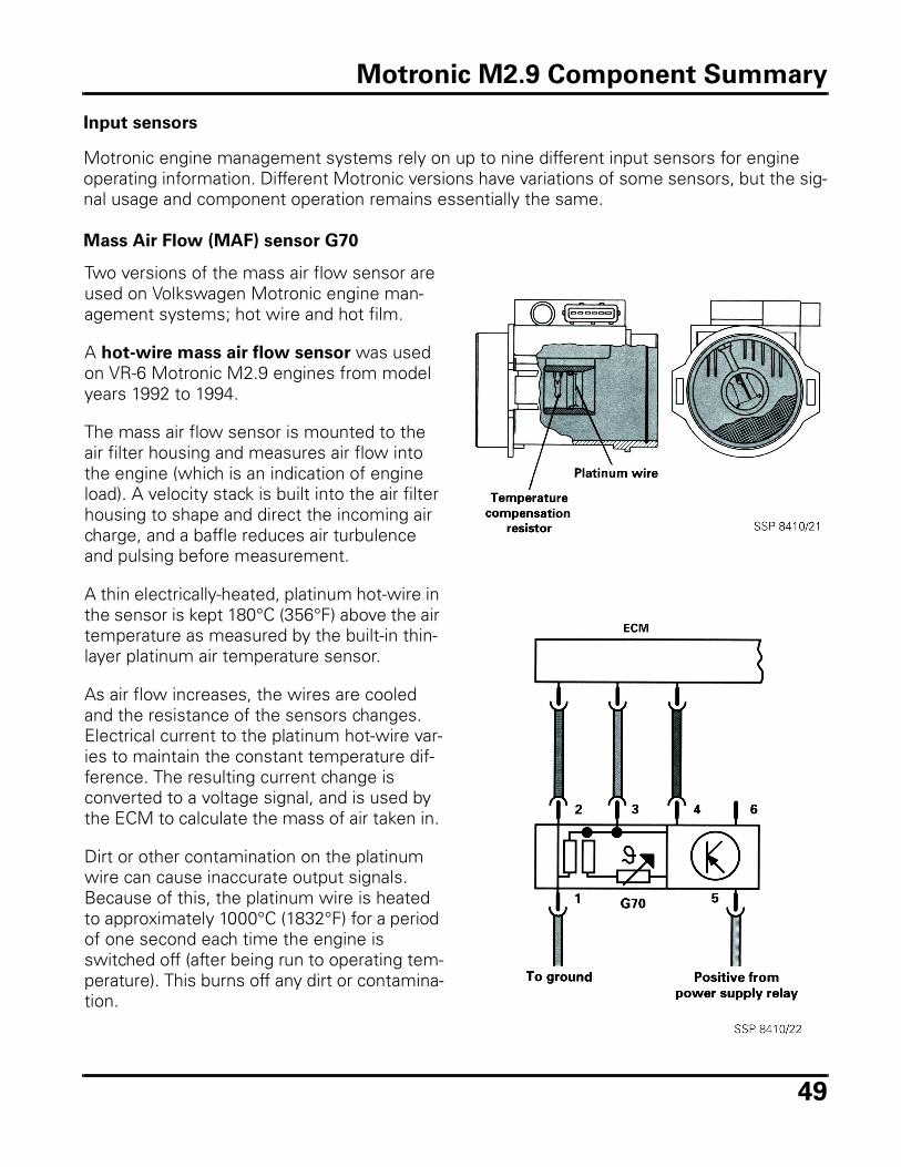
Mass Air Flow (MAF) sensor G70
Two versions of the mass air flow sensor are used on Volkswagen Motronic engine man-agement systems; hot wire and hot film.
A hot-wire mass air flow sensor was used on VR-6 Motronic M2.9 engines from model years 1992 to 1994.
The mass air flow sensor is mounted to the air filter housing and measures air flow into the engine (which is an indication of engine load). A velocity stack is built into the air filter housing to shape and direct the incoming air charge, and a baffle reduces air turbulence and pulsing before measurement.
A thin electrically-heated, platinum hot-wire in the sensor is kept 180°C (356°F) above the air temperature as measured by the built-in thin-layer platinum air temperature sensor.
As air flow increases, the wires are cooled and the resistance of the sensors changes. Electrical current to the platinum hot-wire var-ies to maintain the constant temperature dif-ference. The resulting current change is converted to a voltage signal, and is used by the ECM to calculate the mass of air taken in.
Dirt or other contamination on the platinum wire can cause inaccurate output signals. Because of this, the platinum wire is heated to approximately 1000°C (1832°F) for a period of one second each time the engine is switched off (after being run to operating tem-perature). This burns off any dirt or contamina-tion.
Motronic M2.9 Component Summary
50
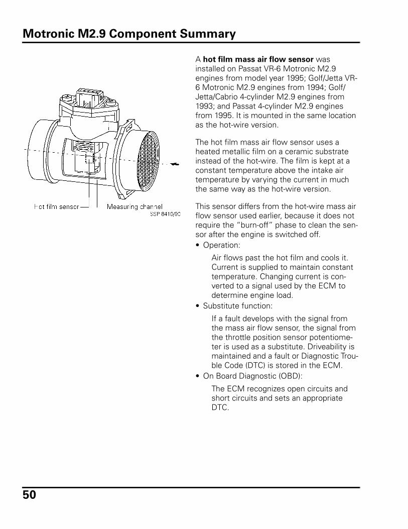
A hot film mass air flow sensor was installed on Passat VR-6 Motronic M2.9 engines from model year 1995; Golf/Jetta VR-6 Motronic M2.9 engines from 1994; Golf/Jetta/Cabrio 4-cylinder M2.9 engines from 1993; and Passat 4-cylinder M2.9 engines from 1995. It is mounted in the same location as the hot-wire version.
The hot film mass air flow sensor uses a heated metallic film on a ceramic substrate instead of the hot-wire. The film is kept at a constant temperature above the intake air temperature by varying the current in much the same way as the hot-wire version.
This sensor differs from the hot-wire mass air flow sensor used earlier, because it does not require the “burn-off” phase to clean the sen-sor after the engine is switched off. • Operation:
Air flows past the hot film and cools it. Current is supplied to maintain constant temperature. Changing current is con-verted to a signal used by the ECM to determine engine load.
• Substitute function:
If a fault develops with the signal from the mass air flow sensor, the signal from the throttle position sensor potentiome-ter is used as a substitute. Driveability is maintained and a fault or Diagnostic Trou-ble Code (DTC) is stored in the ECM.
• On Board Diagnostic (OBD):
The ECM recognizes open circuits and short circuits and sets an appropriate DTC.
Motronic M2.9 Component Summary
51
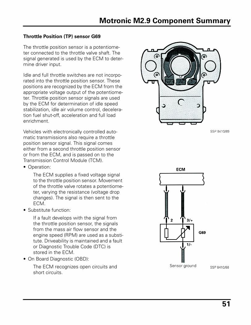
Throttle Position (TP) sensor G69
The throttle position sensor is a potentiome-ter connected to the throttle valve shaft. The signal generated is used by the ECM to deter-mine driver input.
Idle and full throttle switches are not incorpo-rated into the throttle position sensor. These positions are recognized by the ECM from the appropriate voltage output of the potentiome-ter. Throttle position sensor signals are used by the ECM for determination of idle speed stabilization, idle air volume control, decelera-tion fuel shut-off, acceleration and full load enrichment.
Vehicles with electronically controlled auto-matic transmissions also require a throttle position sensor signal. This signal comes either from a second throttle position sensor or from the ECM, and is passed on to the Transmission Control Module (TCM).• Operation:
The ECM supplies a fixed voltage signal to the throttle position sensor. Movement of the throttle valve rotates a potentiome-ter, varying the resistance (voltage drop changes). The signal is then sent to the ECM.
• Substitute function:
If a fault develops with the signal from the throttle position sensor, the signals from the mass air flow sensor and the engine speed (RPM) are used as a substi-tute. Driveability is maintained and a fault or Diagnostic Trouble Code (DTC) is stored in the ECM.
• On Board Diagnostic (OBD):
The ECM recognizes open circuits and short circuits.
Motronic M2.9 Component Summary
52
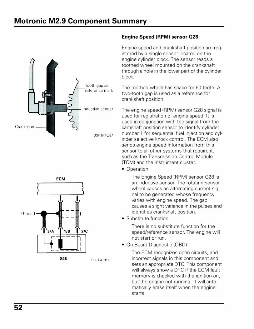
Engine Speed (RPM) sensor G28
Engine speed and crankshaft position are reg-istered by a single sensor located on the engine cylinder block. The sensor reads a toothed wheel mounted on the crankshaft through a hole in the lower part of the cylinder block.
The toothed wheel has space for 60 teeth. A two-tooth gap is used as a reference for crankshaft position.
The engine speed (RPM) sensor G28 signal is used for registration of engine speed. It is used in conjunction with the signal from the camshaft position sensor to identify cylinder number 1 for sequential fuel injection and cyl-inder selective knock control. The ECM also sends engine speed information from this sensor to all other systems that require it, such as the Transmission Control Module (TCM) and the instrument cluster. • Operation:
The Engine Speed (RPM) sensor G28 is an inductive sensor. The rotating sensor wheel causes an alternating current sig-nal to be generated whose frequency varies with engine speed. The gap causes a slight variance in the pulses and identifies crankshaft position.
• Substitute function:
There is no substitute function for the speed/reference sensor. The engine will not start or run.
• On Board Diagnostic (OBD)
The ECM recognizes open circuits, and incorrect signals in this component and sets an appropriate DTC. This component will always show a DTC if the ECM fault memory is checked with the ignition on, but the engine not running. It will auto-matically erase itself when the engine starts.
Motronic M2.9 Component Summary
53
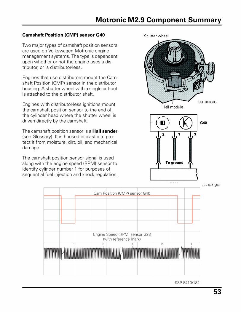
Camshaft Position (CMP) sensor G40
Two major types of camshaft position sensors are used on Volkswagen Motronic engine management systems. The type is dependent upon whether or not the engine uses a dis-tributor, or is distributor-less.
Engines that use distributors mount the Cam-shaft Position (CMP) sensor in the distributor housing. A shutter wheel with a single cut-out is attached to the distributor shaft.
Engines with distributor-less ignitions mount the camshaft position sensor to the end of the cylinder head where the shutter wheel is driven directly by the camshaft.
The camshaft position sensor is a Hall sender (see Glossary). It is housed in plastic to pro-tect it from moisture, dirt, oil, and mechanical damage.
The camshaft position sensor signal is used along with the engine speed (RPM) sensor to identify cylinder number 1 for purposes of sequential fuel injection and knock regulation.
1 43 2 1
SSP 8410/182
Cam Position (CMP) sensor G40
Engine Speed (RPM) sensor G28(with reference mark)
Motronic M2.9 Component Summary
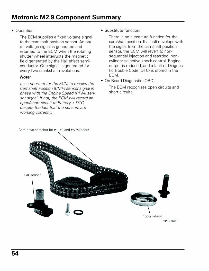
54
• Operation:
The ECM supplies a fixed voltage signal to the camshaft position sensor. An on/off voltage signal is generated and returned to the ECM when the rotating shutter wheel interrupts the magnetic field generated by the Hall effect semi-conductor. One signal is generated for every two crankshaft revolutions.
Note:
It is important for the ECM to receive the Camshaft Position (CMP) sensor signal in phase with the Engine Speed (RPM) sen-sor signal. If not, the ECM will record an open/short circuit to Battery + DTC, despite the fact that the sensors are working correctly.
• Substitute function:
There is no substitute function for the camshaft position. If a fault develops with the signal from the camshaft position sensor, the ECM will revert to non-sequential injection and retarded, non-cylinder selective knock control. Engine output is reduced, and a fault or Diagnos-tic Trouble Code (DTC) is stored in the ECM.
• On Board Diagnostic (OBD):
The ECM recognizes open circuits and short circuits.
Motronic M2.9 Component Summary
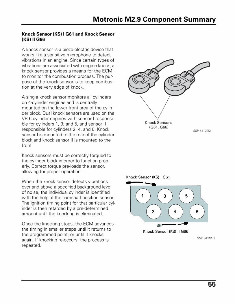
55
Knock Sensor (KS) I G61 and Knock Sensor
(KS) II G66
A knock sensor is a piezo-electric device that works like a sensitive microphone to detect vibrations in an engine. Since certain types of vibrations are associated with engine knock, a knock sensor provides a means for the ECM to monitor the combustion process. The pur-pose of the knock sensor is to keep combus-tion at the very edge of knock.
A single knock sensor monitors all cylinders on 4-cylinder engines and is centrally mounted on the lower front area of the cylin-der block. Dual knock sensors are used on the VR-6-cylinder engines with sensor I responsi-ble for cylinders 1, 3, and 5, and sensor II responsible for cylinders 2, 4, and 6. Knock sensor I is mounted to the rear of the cylinder block and knock sensor II is mounted to the front.
Knock sensors must be correctly torqued to the cylinder block in order to function prop-erly. Correct torque pre-loads the sensor, allowing for proper operation.
When the knock sensor detects vibrations over and above a specified background level of noise, the individual cylinder is identified with the help of the camshaft position sensor. The ignition timing point for that particular cyl-inder is then retarded by a pre-determined amount until the knocking is eliminated.
Once the knocking stops, the ECM advances the timing in smaller steps until it returns to the programmed point, or until it knocks again. If knocking re-occurs, the process is repeated.
Knock Sensors (G61, G66)
SSP 8410/82
Motronic M2.9 Component Summary
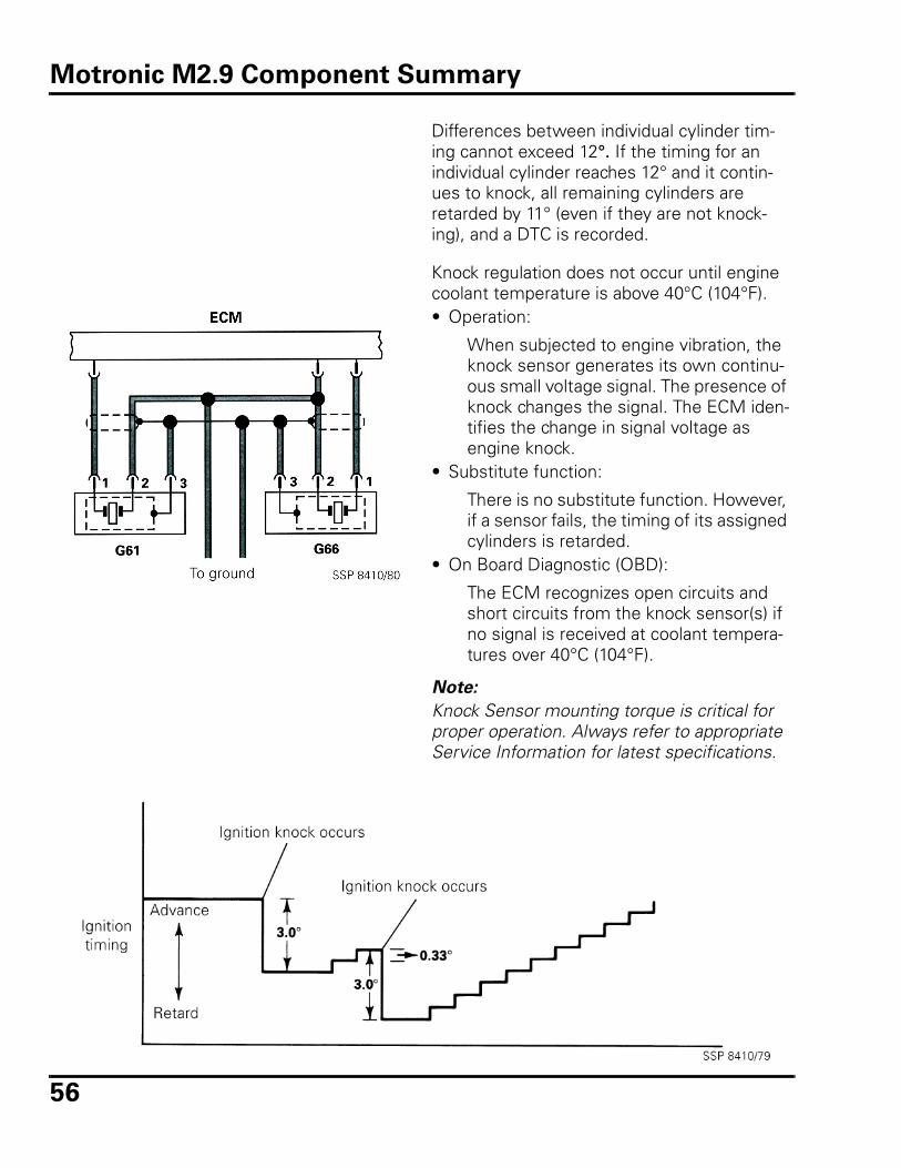
56
Differences between individual cylinder tim-ing cannot exceed 12°. If the timing for an individual cylinder reaches 12° and it contin-ues to knock, all remaining cylinders are retarded by 11° (even if they are not knock-ing), and a DTC is recorded.
Knock regulation does not occur until engine coolant temperature is above 40°C (104°F). • Operation:
When subjected to engine vibration, the knock sensor generates its own continu-ous small voltage signal. The presence of knock changes the signal. The ECM iden-tifies the change in signal voltage as engine knock.
• Substitute function:
There is no substitute function. However, if a sensor fails, the timing of its assigned cylinders is retarded.
• On Board Diagnostic (OBD):
The ECM recognizes open circuits and short circuits from the knock sensor(s) if no signal is received at coolant tempera-tures over 40°C (104°F).
Note:
Knock Sensor mounting torque is critical for proper operation. Always refer to appropriate Service Information for latest specifications.
Motronic M2.9 Component Summary
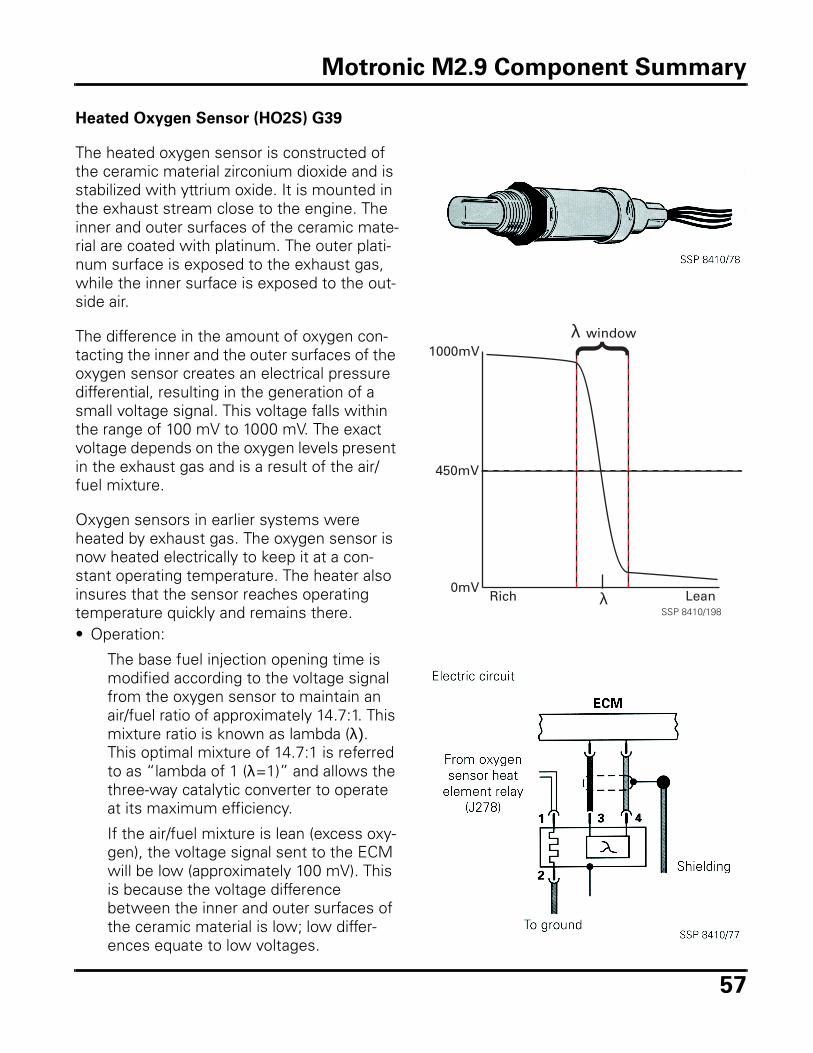
57
Heated Oxygen Sensor (HO2S) G39
The heated oxygen sensor is constructed of the ceramic material zirconium dioxide and is stabilized with yttrium oxide. It is mounted in the exhaust stream close to the engine. The inner and outer surfaces of the ceramic mate-rial are coated with platinum. The outer plati-num surface is exposed to the exhaust gas, while the inner surface is exposed to the out-side air.
The difference in the amount of oxygen con-tacting the inner and the outer surfaces of the oxygen sensor creates an electrical pressure differential, resulting in the generation of a small voltage signal. This voltage falls within the range of 100 mV to 1000 mV. The exact voltage depends on the oxygen levels present in the exhaust gas and is a result of the air/fuel mixture.
Oxygen sensors in earlier systems were heated by exhaust gas. The oxygen sensor is now heated electrically to keep it at a con-stant operating temperature. The heater also insures that the sensor reaches operating temperature quickly and remains there. • Operation:
The base fuel injection opening time is modified according to the voltage signal from the oxygen sensor to maintain an air/fuel ratio of approximately 14.7:1. This mixture ratio is known as lambda (λ). This optimal mixture of 14.7:1 is referred to as “lambda of 1 (λ=1)” and allows the three-way catalytic converter to operate at its maximum efficiency.
If the air/fuel mixture is lean (excess oxy-gen), the voltage signal sent to the ECM will be low (approximately 100 mV). This is because the voltage difference between the inner and outer surfaces of the ceramic material is low; low differ-ences equate to low voltages.
Rich Lean0mV
450mV
1000mV
SSP 8410/198λ
windowλ
Motronic M2.9 Component Summary
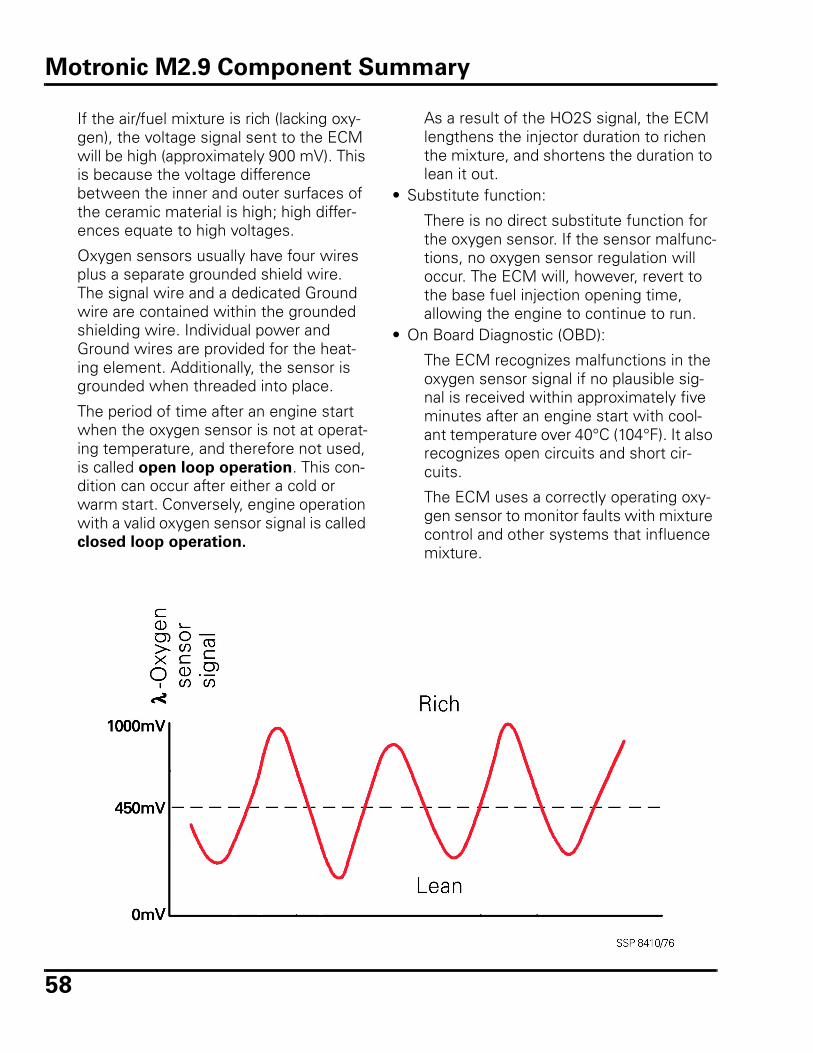
58
If the air/fuel mixture is rich (lacking oxy-gen), the voltage signal sent to the ECM will be high (approximately 900 mV). This is because the voltage difference between the inner and outer surfaces of the ceramic material is high; high differ-ences equate to high voltages.
Oxygen sensors usually have four wires plus a separate grounded shield wire. The signal wire and a dedicated Ground wire are contained within the grounded shielding wire. Individual power and Ground wires are provided for the heat-ing element. Additionally, the sensor is grounded when threaded into place.
The period of time after an engine start when the oxygen sensor is not at operat-ing temperature, and therefore not used, is called open loop operation. This con-dition can occur after either a cold or warm start. Conversely, engine operation with a valid oxygen sensor signal is called closed loop operation.
As a result of the HO2S signal, the ECM lengthens the injector duration to richen the mixture, and shortens the duration to lean it out.
• Substitute function:
There is no direct substitute function for the oxygen sensor. If the sensor malfunc-tions, no oxygen sensor regulation will occur. The ECM will, however, revert to the base fuel injection opening time, allowing the engine to continue to run.
• On Board Diagnostic (OBD):
The ECM recognizes malfunctions in the oxygen sensor signal if no plausible sig-nal is received within approximately five minutes after an engine start with cool-ant temperature over 40°C (104°F). It also recognizes open circuits and short cir-cuits.
The ECM uses a correctly operating oxy-gen sensor to monitor faults with mixture control and other systems that influence mixture.
Motronic M2.9 Component Summary
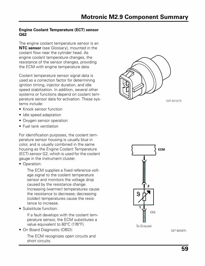
59
Engine Coolant Temperature (ECT) sensor
G62
The engine coolant temperature sensor is an NTC sensor (see Glossary), mounted in the coolant flow near the cylinder head. As engine coolant temperature changes, the resistance of the sensor changes, providing the ECM with engine temperature data.
Coolant temperature sensor signal data is used as a correction factor for determining ignition timing, injector duration, and idle speed stabilization. In addition, several other systems or functions depend on coolant tem-perature sensor data for activation. These sys-tems include: • Knock sensor function• Idle speed adaptation• Oxygen sensor operation• Fuel tank ventilation
For identification purposes, the coolant tem-perature sensor housing is usually blue in color, and is usually combined in the same housing as the Engine Coolant Temperature (ECT) sensor G2, which is used for the coolant gauge in the instrument cluster.• Operation:
The ECM supplies a fixed reference volt-age signal to the coolant temperature sensor and monitors the voltage drop caused by the resistance change. Increasing (warmer) temperatures cause the resistance to decrease; decreasing (colder) temperatures cause the resis-tance to increase.
• Substitute function:
If a fault develops with the coolant tem-perature sensor, the ECM substitutes a value equivalent to 80°C (176°F).
• On Board Diagnostic (OBD):
The ECM recognizes open circuits and short circuits.
SSP 8410/75
Motronic M2.9 Component Summary
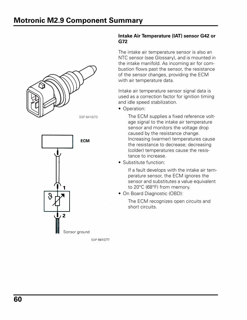
60
Intake Air Temperature (IAT) sensor G42 or
G72
The intake air temperature sensor is also an NTC sensor (see Glossary), and is mounted in the intake manifold. As incoming air for com-bustion flows past the sensor, the resistance of the sensor changes, providing the ECM with air temperature data.
Intake air temperature sensor signal data is used as a correction factor for ignition timing and idle speed stabilization. • Operation:
The ECM supplies a fixed reference volt-age signal to the intake air temperature sensor and monitors the voltage drop caused by the resistance change. Increasing (warmer) temperatures cause the resistance to decrease; decreasing (colder) temperatures cause the resis-tance to increase.
• Substitute function:
If a fault develops with the intake air tem-perature sensor, the ECM ignores the sensor and substitutes a value equivalent to 20°C (68°F) from memory.
• On Board Diagnostic (OBD):
The ECM recognizes open circuits and short circuits.
SSP 8410/73
Motronic M2.9 Component Summary
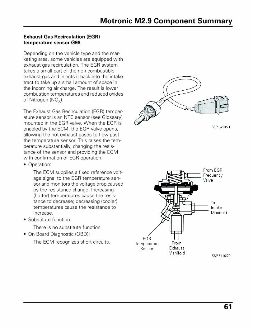
61
Exhaust Gas Recirculation (EGR)
temperature sensor G98
Depending on the vehicle type and the mar-keting area, some vehicles are equipped with exhaust gas recirculation. The EGR system takes a small part of the non-combustible exhaust gas and injects it back into the intake tract to take up a small amount of space in the incoming air charge. The result is lower combustion temperatures and reduced oxides of Nitrogen (NOX).
The Exhaust Gas Recirculation (EGR) temper-ature sensor is an NTC sensor (see Glossary) mounted in the EGR valve. When the EGR is enabled by the ECM, the EGR valve opens, allowing the hot exhaust gases to flow past the temperature sensor. This raises the tem-perature substantially, changing the resis-tance of the sensor and providing the ECM with confirmation of EGR operation. • Operation:
The ECM supplies a fixed reference volt-age signal to the EGR temperature sen-sor and monitors the voltage drop caused by the resistance change. Increasing (hotter) temperatures cause the resis-tance to decrease; decreasing (cooler) temperatures cause the resistance to increase.
• Substitute function:
There is no substitute function. • On Board Diagnostic (OBD):
The ECM recognizes short circuits.
Motronic M2.9 Component Summary
62
Additional input signals
Several other signals are used by the ECM in much the same manner as input sensors. Depending on installed vehicle equipment, these additional signals may include:
• Battery voltage:
Aside from the voltage needed to actually operate the Motronic engine manage-ment system, the ECM monitors voltage to compensate for the quicker operation of some components due to higher or lower available operating voltage. Fuel injectors, for example, cycle slightly faster at 14.5 Volts than they do at 12 Volts or lower. This faster cycle time must be figured into the calculation of duration for accuracy.
• Air conditioner “System ON” signal:
The air conditioner system signal allows the ECM to be prepared for the additional load demands of the air conditioner on the engine.
• Air conditioner compressor “Clutch ON”
signal:
The compressor “clutch on” signal pre-pares the ECM for a quick response to the sudden engine speed changes that occur when the compressor clutch is engaged, particularly at idle.
• Vehicle speed sensor signal:
The vehicle speed sensor signal origi-nates from the instrument cluster and is used by the ECM to control the idle stabi-lizer during deceleration, and to limit vehi-cle top speed.
• Automatic Transmission Control Module
(TCM) signal:
The TCM sends a signal to the ECM dur-ing shifting. This allows the ECM to retard ignition timing for smoother shift-ing.
Motronic M2.9 Component Summary
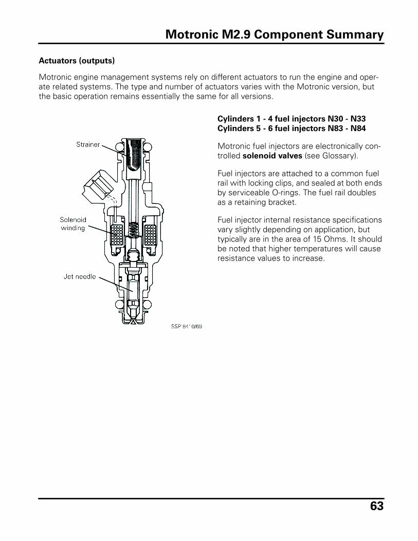
63
Actuators (outputs)
Motronic engine management systems rely on different actuators to run the engine and oper-ate related systems. The type and number of actuators varies with the Motronic version, but the basic operation remains essentially the same for all versions.
Cylinders 1 - 4 fuel injectors N30 - N33
Cylinders 5 - 6 fuel injectors N83 - N84
Motronic fuel injectors are electronically con-trolled solenoid valves (see Glossary).
Fuel injectors are attached to a common fuel rail with locking clips, and sealed at both ends by serviceable O-rings. The fuel rail doubles as a retaining bracket.
Fuel injector internal resistance specifications vary slightly depending on application, but typically are in the area of 15 Ohms. It should be noted that higher temperatures will cause resistance values to increase.
Motronic M2.9 Component Summary
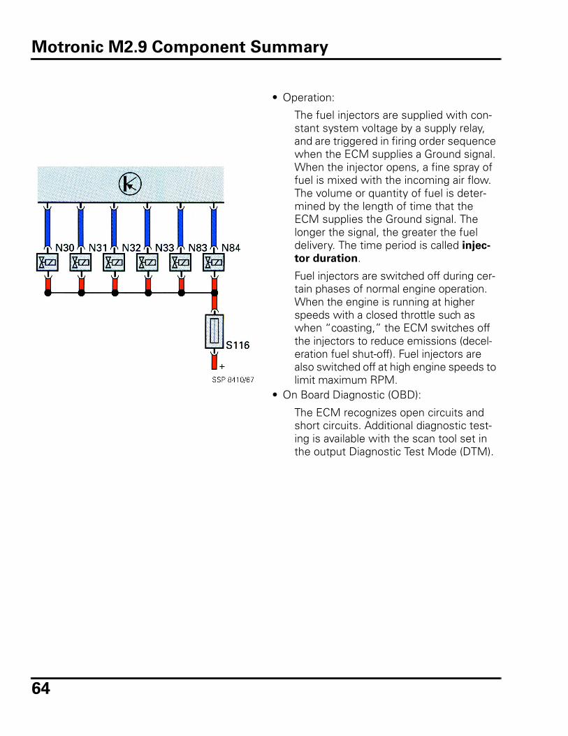
64
• Operation:
The fuel injectors are supplied with con-stant system voltage by a supply relay, and are triggered in firing order sequence when the ECM supplies a Ground signal. When the injector opens, a fine spray of fuel is mixed with the incoming air flow. The volume or quantity of fuel is deter-mined by the length of time that the ECM supplies the Ground signal. The longer the signal, the greater the fuel delivery. The time period is called injec-
tor duration.
Fuel injectors are switched off during cer-tain phases of normal engine operation. When the engine is running at higher speeds with a closed throttle such as when “coasting,” the ECM switches off the injectors to reduce emissions (decel-eration fuel shut-off). Fuel injectors are also switched off at high engine speeds to limit maximum RPM.
• On Board Diagnostic (OBD):
The ECM recognizes open circuits and short circuits. Additional diagnostic test-ing is available with the scan tool set in the output Diagnostic Test Mode (DTM).
Motronic M2.9 Component Summary
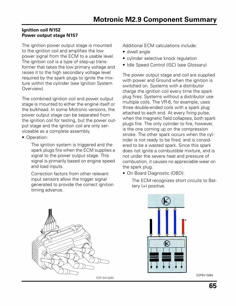
65
Ignition coil N152
Power output stage N157
The ignition power output stage is mounted to the ignition coil and amplifies the low power signal from the ECM to a usable level. The ignition coil is a type of step-up trans-former that takes the low primary voltage and raises it to the high secondary voltage level required by the spark plugs to ignite the mix-ture within the cylinder (see Ignition System Overview).
The combined ignition coil and power output stage is mounted to either the engine itself or the bulkhead. In some Motronic versions, the power output stage can be separated from the ignition coil for testing, but the power out-put stage and the ignition coil are only ser-viceable as a complete assembly. • Operation:
The ignition system is triggered and the spark plugs fire when the ECM supplies a signal to the power output stage. This signal is primarily based on engine speed and load inputs.
Correction factors from other relevant input sensors allow the trigger signal generated to provide the correct ignition timing advance.
Additional ECM calculations include:• dwell angle• cylinder selective knock regulation• Idle Speed Control (ISC) (see Glossary)
The power output stage and coil are supplied with power and Ground when the ignition is switched on. Systems with a distributor charge the ignition coil every time the spark plug fires. Systems without a distributor use multiple coils. The VR-6, for example, uses three double-ended coils with a spark plug attached to each end. At every firing pulse, when the magnetic field collapses, both spark plugs fire. The only cylinder to fire, however, is the one coming up on the compression stroke. The other spark occurs when the cyl-inder is not ready to be fired, and is consid-ered to be a wasted spark. Since this spark does not ignite a combustible mixture, and is not under the severe heat and pressure of combustion, it causes no appreciable wear on the spark plug. • On Board Diagnostic (OBD):
The ECM recognizes short circuits to Bat-tery (+) positive.
SSP 8410/65
Motronic M2.9 Component Summary
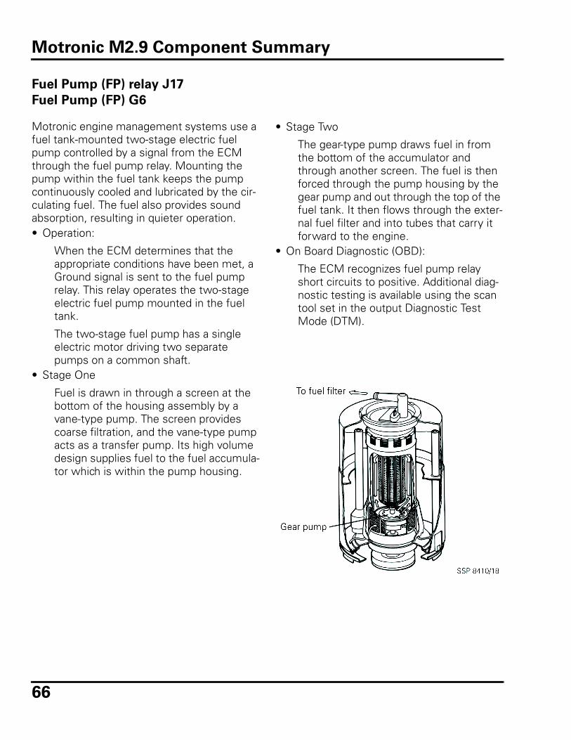
66
Fuel Pump (FP) relay J17
Fuel Pump (FP) G6
Motronic engine management systems use a fuel tank-mounted two-stage electric fuel pump controlled by a signal from the ECM through the fuel pump relay. Mounting the pump within the fuel tank keeps the pump continuously cooled and lubricated by the cir-culating fuel. The fuel also provides sound absorption, resulting in quieter operation. • Operation:
When the ECM determines that the appropriate conditions have been met, a Ground signal is sent to the fuel pump relay. This relay operates the two-stage electric fuel pump mounted in the fuel tank.
The two-stage fuel pump has a single electric motor driving two separate pumps on a common shaft.
• Stage One
Fuel is drawn in through a screen at the bottom of the housing assembly by a vane-type pump. The screen provides coarse filtration, and the vane-type pump acts as a transfer pump. Its high volume design supplies fuel to the fuel accumula-tor which is within the pump housing.
• Stage Two
The gear-type pump draws fuel in from the bottom of the accumulator and through another screen. The fuel is then forced through the pump housing by the gear pump and out through the top of the fuel tank. It then flows through the exter-nal fuel filter and into tubes that carry it forward to the engine.
• On Board Diagnostic (OBD):
The ECM recognizes fuel pump relay short circuits to positive. Additional diag-nostic testing is available using the scan tool set in the output Diagnostic Test Mode (DTM).
Motronic M2.9 Component Summary
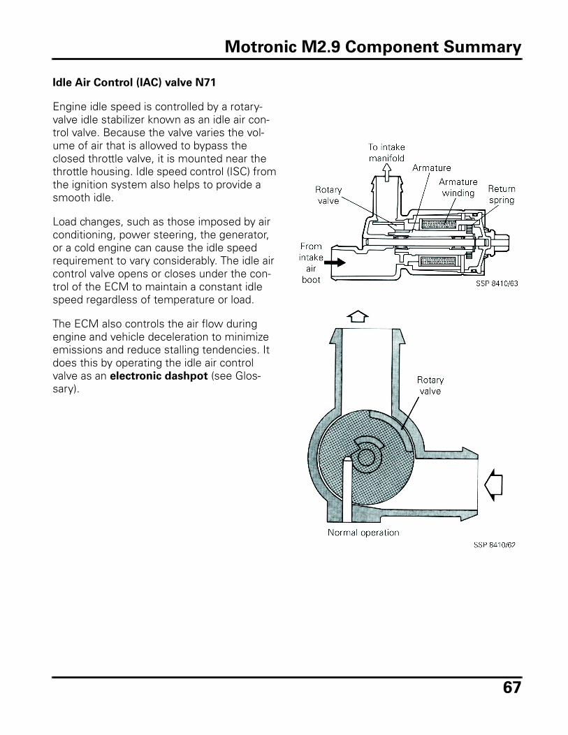
67
Idle Air Control (IAC) valve N71
Engine idle speed is controlled by a rotary-valve idle stabilizer known as an idle air con-trol valve. Because the valve varies the vol-ume of air that is allowed to bypass the closed throttle valve, it is mounted near the throttle housing. Idle speed control (ISC) from the ignition system also helps to provide a smooth idle.
Load changes, such as those imposed by air conditioning, power steering, the generator, or a cold engine can cause the idle speed requirement to vary considerably. The idle air control valve opens or closes under the con-trol of the ECM to maintain a constant idle speed regardless of temperature or load.
The ECM also controls the air flow during engine and vehicle deceleration to minimize emissions and reduce stalling tendencies. It does this by operating the idle air control valve as an electronic dashpot (see Glos-sary).
Motronic M2.9 Component Summary
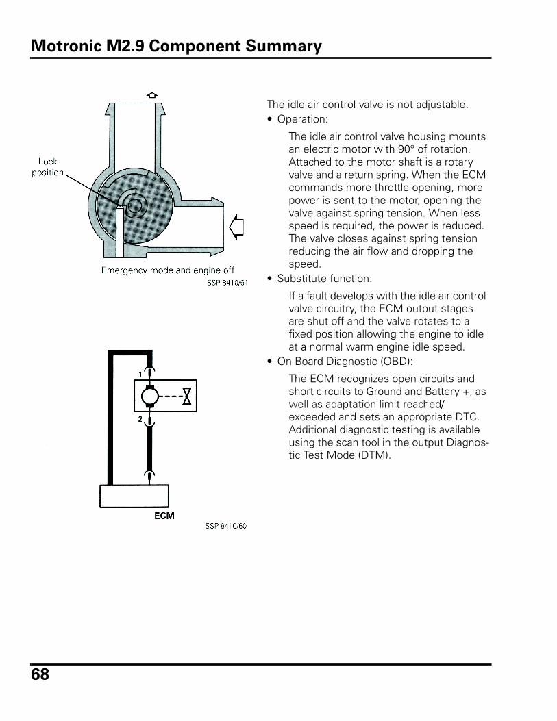
68
The idle air control valve is not adjustable. • Operation:
The idle air control valve housing mounts an electric motor with 90° of rotation. Attached to the motor shaft is a rotary valve and a return spring. When the ECM commands more throttle opening, more power is sent to the motor, opening the valve against spring tension. When less speed is required, the power is reduced. The valve closes against spring tension reducing the air flow and dropping the speed.
• Substitute function:
If a fault develops with the idle air control valve circuitry, the ECM output stages are shut off and the valve rotates to a fixed position allowing the engine to idle at a normal warm engine idle speed.
• On Board Diagnostic (OBD):
The ECM recognizes open circuits and short circuits to Ground and Battery +, as well as adaptation limit reached/exceeded and sets an appropriate DTC. Additional diagnostic testing is available using the scan tool in the output Diagnos-tic Test Mode (DTM).
Motronic M2.9 Component Summary
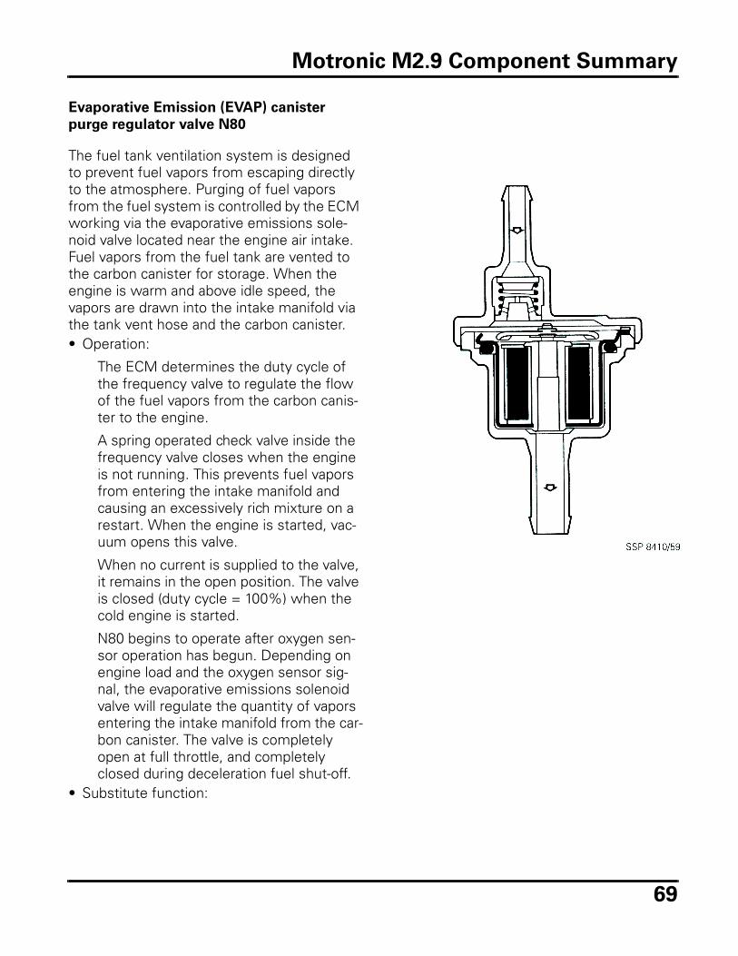
69
Evaporative Emission (EVAP) canister
purge regulator valve N80
The fuel tank ventilation system is designed to prevent fuel vapors from escaping directly to the atmosphere. Purging of fuel vapors from the fuel system is controlled by the ECM working via the evaporative emissions sole-noid valve located near the engine air intake. Fuel vapors from the fuel tank are vented to the carbon canister for storage. When the engine is warm and above idle speed, the vapors are drawn into the intake manifold via the tank vent hose and the carbon canister. • Operation:
The ECM determines the duty cycle of the frequency valve to regulate the flow of the fuel vapors from the carbon canis-ter to the engine.
A spring operated check valve inside the frequency valve closes when the engine is not running. This prevents fuel vapors from entering the intake manifold and causing an excessively rich mixture on a restart. When the engine is started, vac-uum opens this valve.
When no current is supplied to the valve, it remains in the open position. The valve is closed (duty cycle = 100%) when the cold engine is started.
N80 begins to operate after oxygen sen-sor operation has begun. Depending on engine load and the oxygen sensor sig-nal, the evaporative emissions solenoid valve will regulate the quantity of vapors entering the intake manifold from the car-bon canister. The valve is completely open at full throttle, and completely closed during deceleration fuel shut-off.
• Substitute function:
Motronic M2.9 Component Summary
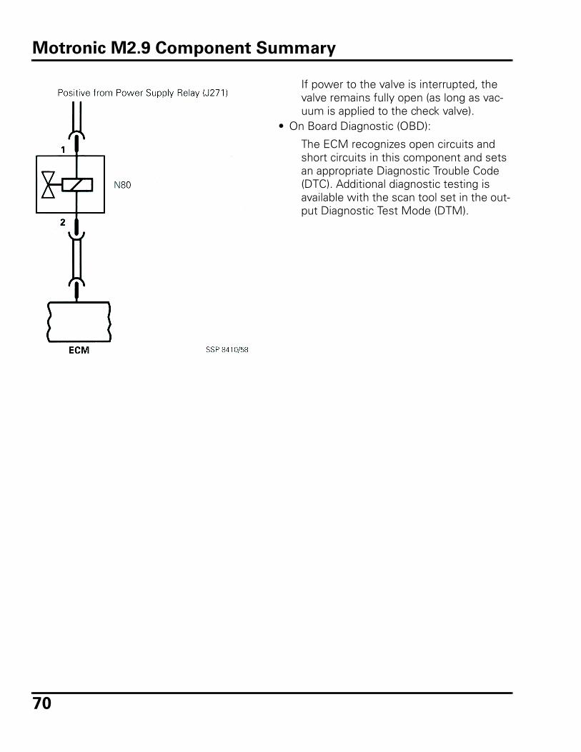
70
If power to the valve is interrupted, the valve remains fully open (as long as vac-uum is applied to the check valve).
• On Board Diagnostic (OBD):
The ECM recognizes open circuits and short circuits in this component and sets an appropriate Diagnostic Trouble Code (DTC). Additional diagnostic testing is available with the scan tool set in the out-put Diagnostic Test Mode (DTM).
Motronic M2.9 Component Summary
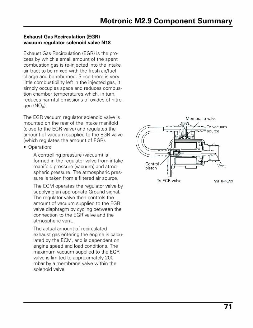
71
Exhaust Gas Recirculation (EGR)
vacuum regulator solenoid valve N18
Exhaust Gas Recirculation (EGR) is the pro-cess by which a small amount of the spent combustion gas is re-injected into the intake air tract to be mixed with the fresh air/fuel charge and be reburned. Since there is very little combustibility left in the injected gas, it simply occupies space and reduces combus-tion chamber temperatures which, in turn, reduces harmful emissions of oxides of nitro-gen (NOX).
The EGR vacuum regulator solenoid valve is mounted on the rear of the intake manifold (close to the EGR valve) and regulates the amount of vacuum supplied to the EGR valve (which regulates the amount of EGR).• Operation:
A controlling pressure (vacuum) is formed in the regulator valve from intake manifold pressure (vacuum) and atmo-spheric pressure. The atmospheric pres-sure is taken from a filtered air source.
The ECM operates the regulator valve by supplying an appropriate Ground signal. The regulator valve then controls the amount of vacuum supplied to the EGR valve diaphragm by cycling between the connection to the EGR valve and the atmospheric vent.
The actual amount of recirculated exhaust gas entering the engine is calcu-lated by the ECM, and is dependent on engine speed and load conditions. The maximum vacuum supplied to the EGR valve is limited to approximately 200 mbar by a membrane valve within the solenoid valve.
Motronic M2.9 Component Summary
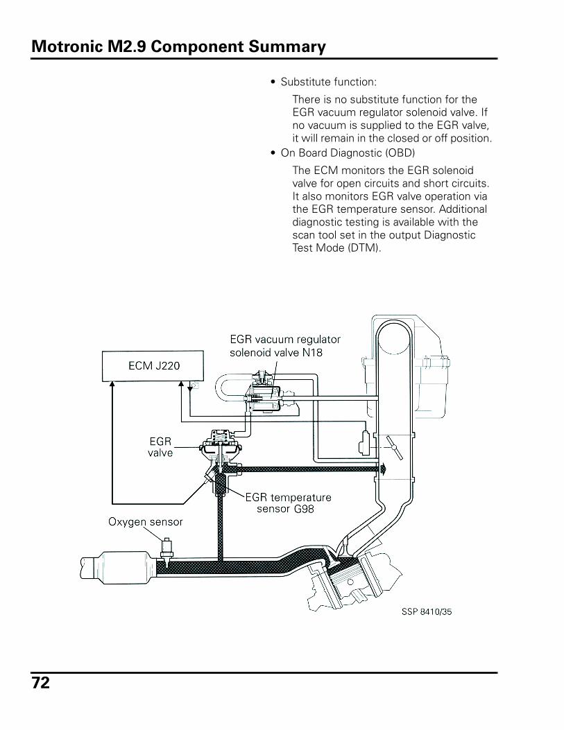
72
• Substitute function:
There is no substitute function for the EGR vacuum regulator solenoid valve. If no vacuum is supplied to the EGR valve, it will remain in the closed or off position.
• On Board Diagnostic (OBD)
The ECM monitors the EGR solenoid valve for open circuits and short circuits. It also monitors EGR valve operation via the EGR temperature sensor. Additional diagnostic testing is available with the scan tool set in the output Diagnostic Test Mode (DTM).
Motronic M2.9 Component Summary
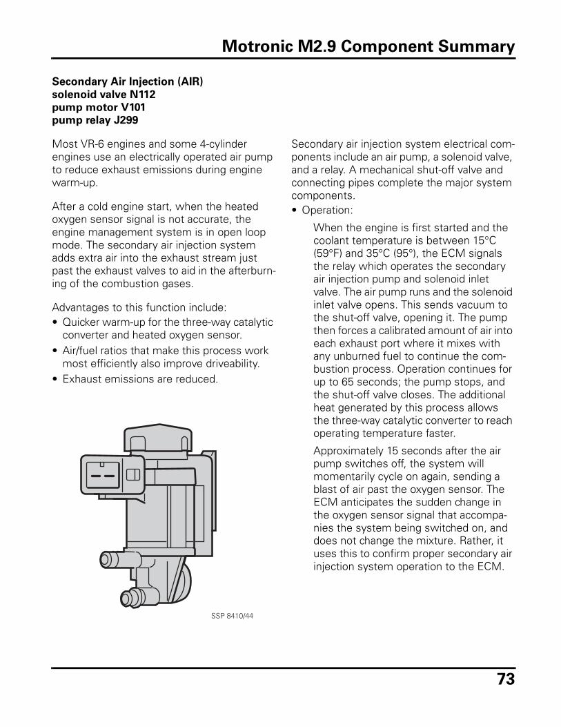
73
Secondary Air Injection (AIR)
solenoid valve N112
pump motor V101
pump relay J299
Most VR-6 engines and some 4-cylinder engines use an electrically operated air pump to reduce exhaust emissions during engine warm-up.
After a cold engine start, when the heated oxygen sensor signal is not accurate, the engine management system is in open loop mode. The secondary air injection system adds extra air into the exhaust stream just past the exhaust valves to aid in the afterburn-ing of the combustion gases.
Advantages to this function include:• Quicker warm-up for the three-way catalytic
converter and heated oxygen sensor. • Air/fuel ratios that make this process work
most efficiently also improve driveability.• Exhaust emissions are reduced.
SSP 8410/44
Secondary air injection system electrical com-ponents include an air pump, a solenoid valve, and a relay. A mechanical shut-off valve and connecting pipes complete the major system components. • Operation:
When the engine is first started and the coolant temperature is between 15°C (59°F) and 35°C (95°), the ECM signals the relay which operates the secondary air injection pump and solenoid inlet valve. The air pump runs and the solenoid inlet valve opens. This sends vacuum to the shut-off valve, opening it. The pump then forces a calibrated amount of air into each exhaust port where it mixes with any unburned fuel to continue the com-bustion process. Operation continues for up to 65 seconds; the pump stops, and the shut-off valve closes. The additional heat generated by this process allows the three-way catalytic converter to reach operating temperature faster.
Approximately 15 seconds after the air pump switches off, the system will momentarily cycle on again, sending a blast of air past the oxygen sensor. The ECM anticipates the sudden change in the oxygen sensor signal that accompa-nies the system being switched on, and does not change the mixture. Rather, it uses this to confirm proper secondary air injection system operation to the ECM.
Motronic M2.9 Component Summary
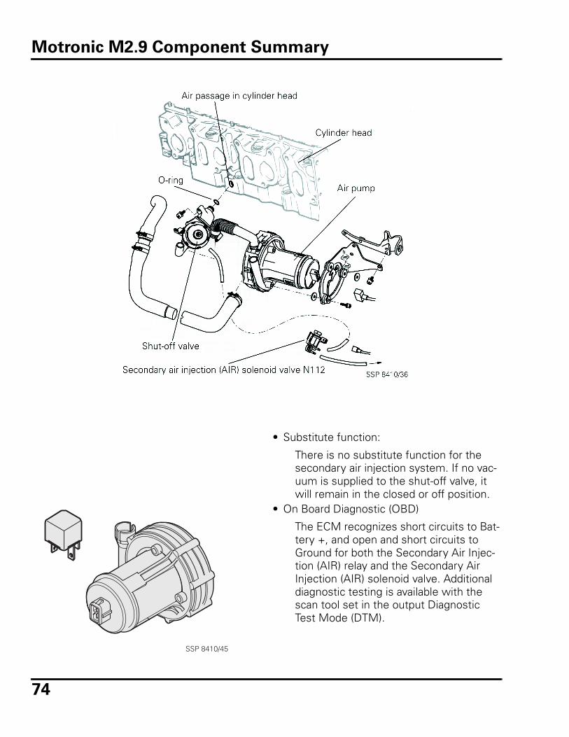
74
• Substitute function:
There is no substitute function for the secondary air injection system. If no vac-uum is supplied to the shut-off valve, it will remain in the closed or off position.
• On Board Diagnostic (OBD)
The ECM recognizes short circuits to Bat-tery +, and open and short circuits to Ground for both the Secondary Air Injec-tion (AIR) relay and the Secondary Air Injection (AIR) solenoid valve. Additional diagnostic testing is available with the scan tool set in the output Diagnostic Test Mode (DTM).
SSP 8410/45
Motronic M2.9 Component Summary
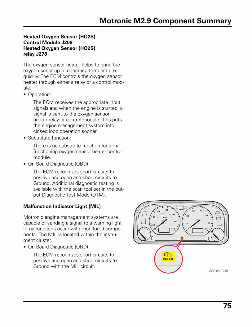
75
Heated Oxygen Sensor (HO2S)
Control Module J208
Heated Oxygen Sensor (HO2S)
relay J278
The oxygen sensor heater helps to bring the oxygen senor up to operating temperature quickly. The ECM controls the oxygen sensor heater through either a relay or a control mod-ule. • Operation:
The ECM receives the appropriate input signals and when the engine is started, a signal is sent to the oxygen sensor heater relay or control module. This puts the engine management system into closed loop operation sooner.
• Substitute function:
There is no substitute function for a mal-functioning oxygen sensor heater control module.
• On Board Diagnostic (OBD)
The ECM recognizes short circuits to positive and open and short circuits to Ground. Additional diagnostic testing is available with the scan tool set in the out-put Diagnostic Test Mode (DTM).
Malfunction Indicator Light (MIL)
Motronic engine management systems are capable of sending a signal to a warning light if malfunctions occur with monitored compo-nents. The MIL is located within the instru-ment cluster. • On Board Diagnostic (OBD)
The ECM recognizes short circuits to positive and open and short circuits to Ground with the MIL circuit.
10
20
40
6080
140
120
100
mph
10
20
30 40
50
60
70
CHECK
CHECK
SSP 8410/46
Motronic M2.9 Component Summary
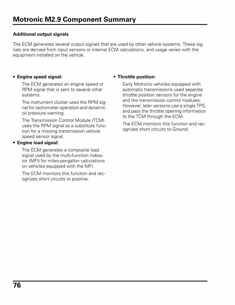
76
Additional output signals
The ECM generates several output signals that are used by other vehicle systems. These sig-nals are derived from input sensors or internal ECM calculations, and usage varies with the equipment installed on the vehicle.
• Engine speed signal:
The ECM generates an engine speed or RPM signal that is sent to several other systems.
The instrument cluster uses the RPM sig-nal for tachometer operation and dynamic oil pressure warning.
The Transmission Control Module (TCM) uses the RPM signal as a substitute func-tion for a missing transmission vehicle speed sensor signal.
• Engine load signal:
The ECM generates a composite load signal used by the multi-function indica-tor (MFI) for miles-per-gallon calculations on vehicles equipped with the MFI.
The ECM monitors this function and rec-ognizes short circuits to positive.
• Throttle position:
Early Motronic vehicles equipped with automatic transmissions used separate throttle position sensors for the engine and the transmission control modules. However, later versions use a single TPS, and pass the throttle opening information to the TCM through the ECM.
The ECM monitors this function and rec-ognizes short circuits to Ground.
Motronic M2.9 Component Summary
77
Review
1. Which of the following components
does NOT receive an output signal
from the Motronic M2.9 engine man-
agement system ECM?
a. Idle air control valve (IAC)
b. Fuel injectors
c. Fuel pump relay
d. Intake air pre-heat servo
2. Technician A says that Motronic M2.9
engine management systems can
adapt to variables such as small vac-
uum leaks and altitude.
Technician B says that Motronic M2.9
engine management systems require
periodic manual carbon monoxide
(CO) adjustments.
Which Technician is correct?
a. Technician A only
b. Technician B only
c. Both Technician A and Technician B
d. Neither Technician A nor Technician B
3. Motronic M2.9 engine management
systems store and use learned values.
This process is called:
a. Stoichiometric
b. Adaptive learning
c. Lambda
d. Default value retention
4. Technician A says that the Motronic
M2.9 ECM retains learned values when
the battery is disconnected.
Technician B says that the Motronic
M2.9 ECM combines all fuel and igni-
tion functions, but uses a separate
ECM for evaporative emissions and
secondary air injection operation.
Which Technician is correct?
a. Technician A only
b. Technician B only
c. Both Technician A and Technician B
d. Neither Technician A nor Technician B
5. Motronic M2.9 fuel injectors operate:
a. Sequentially
b. In groups of two
c. All at the same time
d. None of the above
6. Technician A says that all Motronic
M2.9 engine management systems
use exhaust gas recirculation.
Technician B says that all Motronic
M2.9 engine management systems
use secondary air injection.
Which Technician is correct?
a. Technician A only
b. Technician B only
c. Both Technician A and Technician B
d. Neither Technician A nor Technician B
Motronic M2.9 Review
78
7. Which of the following statements is
NOT applicable to the Motronic M2.9
engine management system?
a. Fuel injection control is digital elec-tronic.
b. All versions are capable of commu-nicating with scan tools VAG 1551/1552 and VAS 5051.
c. The ECM can communicate with the TCM if the vehicle is equipped with an automatic transmission.
d. Ignition timing, idle speed and mix-ture adjustments should not be required until 30,000 miles (48,000 km).
Motronic M2.9 Review
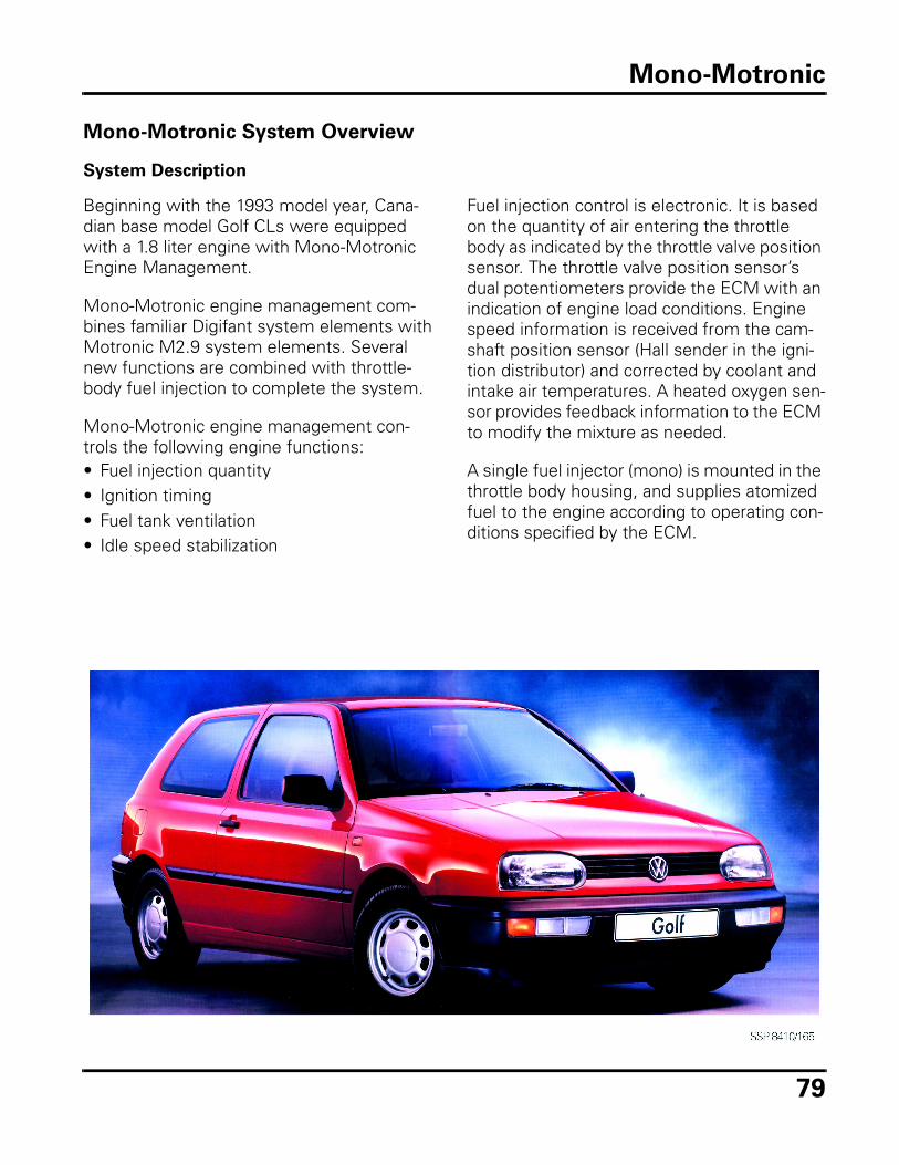
79
Mono-Motronic System Overview
System Description
Beginning with the 1993 model year, Cana-dian base model Golf CLs were equipped with a 1.8 liter engine with Mono-Motronic Engine Management.
Mono-Motronic engine management com-bines familiar Digifant system elements with Motronic M2.9 system elements. Several new functions are combined with throttle-body fuel injection to complete the system.
Mono-Motronic engine management con-trols the following engine functions:• Fuel injection quantity• Ignition timing• Fuel tank ventilation• Idle speed stabilization
Fuel injection control is electronic. It is based on the quantity of air entering the throttle body as indicated by the throttle valve position sensor. The throttle valve position sensor’s dual potentiometers provide the ECM with an indication of engine load conditions. Engine speed information is received from the cam-shaft position sensor (Hall sender in the igni-tion distributor) and corrected by coolant and intake air temperatures. A heated oxygen sen-sor provides feedback information to the ECM to modify the mixture as needed.
A single fuel injector (mono) is mounted in the throttle body housing, and supplies atomized fuel to the engine according to operating con-ditions specified by the ECM.
Mono-Motronic
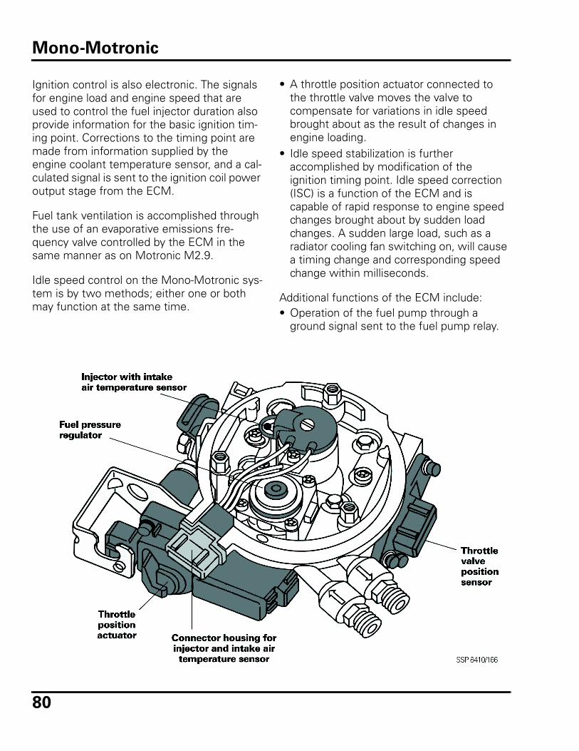
80
Ignition control is also electronic. The signals for engine load and engine speed that are used to control the fuel injector duration also provide information for the basic ignition tim-ing point. Corrections to the timing point are made from information supplied by the engine coolant temperature sensor, and a cal-culated signal is sent to the ignition coil power output stage from the ECM.
Fuel tank ventilation is accomplished through the use of an evaporative emissions fre-quency valve controlled by the ECM in the same manner as on Motronic M2.9.
Idle speed control on the Mono-Motronic sys-tem is by two methods; either one or both may function at the same time.
• A throttle position actuator connected to the throttle valve moves the valve to compensate for variations in idle speed brought about as the result of changes in engine loading.
• Idle speed stabilization is further accomplished by modification of the ignition timing point. Idle speed correction (ISC) is a function of the ECM and is capable of rapid response to engine speed changes brought about by sudden load changes. A sudden large load, such as a radiator cooling fan switching on, will cause a timing change and corresponding speed change within milliseconds.
Additional functions of the ECM include: • Operation of the fuel pump through a
ground signal sent to the fuel pump relay.
Mono-Motronic
81
Inputs/Outputs
The 45-pin electronic control unit used in the Canadian Golf CL receives input signals from the following sources:• Camshaft position sensor (Engine speed)• Throttle position sensor (Engine load)• Engine coolant temperature sensor• Intake air temperature sensor• Heated oxygen sensor• Closed throttle position switch
Additional signals used as inputs are received from the following sources:• Air conditioner• Automatic transmission• Vehicle speed sensor
Outputs or actuators controlling engine opera-tion include signals to the following:• Fuel injector (mono)• Ignition coil power output stage• Throttle position actuator• Fuel pump relay• Early fuel evaporation relay• Evaporative emission canister purge
regulator valve
Additional output signals are generated and include the following: • Malfunction indicator lamp signal• Engine speed (rpm) signal • Automatic transmission TCM signals
Additional Systems
Fuel is sent from the fuel tank to the throttle body by a 2-stage fuel delivery unit that is the same as Motronic M2.9 equipped vehicles.
Fuel pressure is maintained by a mechanical fuel pressure regulator in the throttle body assembly. Pressure is maintained at approxi-mately 1 bar ± 0.2 bar during engine opera-tion by regulation of the of fuel returned to the tank.
On Board Diagnostics
Mono-Motronic Golf CLs have On Board Diag-nostic (OBD) capabilities through the use of Scan Tools VAG 1551/1552 and VAS 5051. Idle speed and carbon monoxide (CO) values are regulated by the ECM and are not adjustable. However, ignition timing can be adjusted to baseline values as needed. Information regarding On Board Diagnostics and engine checks/ adjustments are available in VESIS.
Summary
Mono-Motronic is a basic engine manage-ment system designed originally to be used on smaller displacement engines. This was done to take advantage of newly developed signal processing circuits being introduced into the automotive marketplace that would eliminate the inefficiencies of a carburetor.
Sensor and other signal inputs, along with actuator and other signal outputs, are shown in the illustration on the following page.
Mono-Motronic
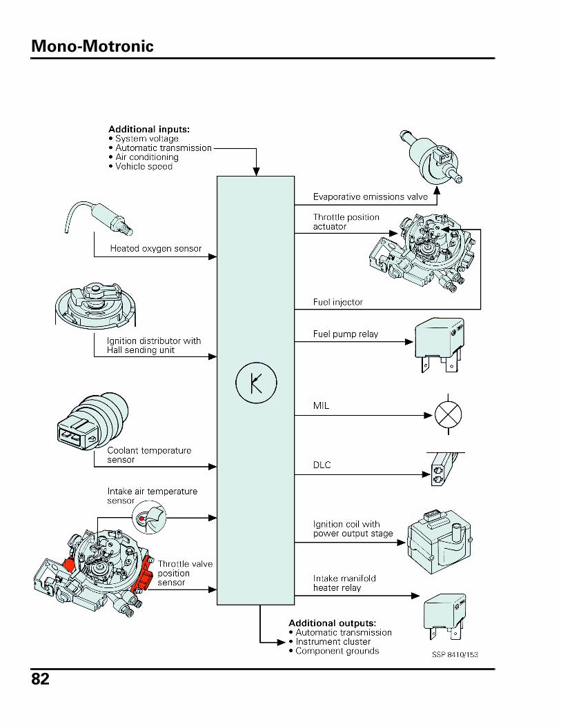
82
Mono-Motronic
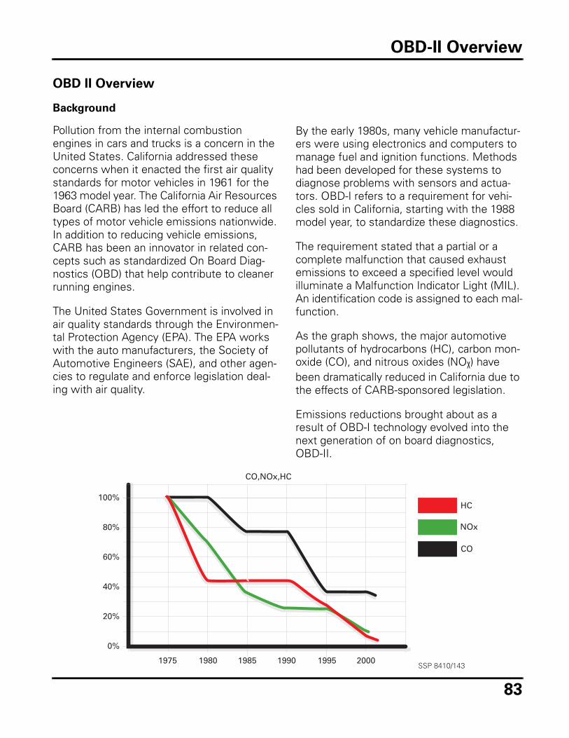
83
OBD II Overview
Background
Pollution from the internal combustion engines in cars and trucks is a concern in the United States. California addressed these concerns when it enacted the first air quality standards for motor vehicles in 1961 for the 1963 model year. The California Air Resources Board (CARB) has led the effort to reduce all types of motor vehicle emissions nationwide. In addition to reducing vehicle emissions, CARB has been an innovator in related con-cepts such as standardized On Board Diag-nostics (OBD) that help contribute to cleaner running engines.
The United States Government is involved in air quality standards through the Environmen-tal Protection Agency (EPA). The EPA works with the auto manufacturers, the Society of Automotive Engineers (SAE), and other agen-cies to regulate and enforce legislation deal-ing with air quality.
By the early 1980s, many vehicle manufactur-ers were using electronics and computers to manage fuel and ignition functions. Methods had been developed for these systems to diagnose problems with sensors and actua-tors. OBD-I refers to a requirement for vehi-cles sold in California, starting with the 1988 model year, to standardize these diagnostics.
The requirement stated that a partial or a complete malfunction that caused exhaust emissions to exceed a specified level would illuminate a Malfunction Indicator Light (MIL). An identification code is assigned to each mal-function.
As the graph shows, the major automotive pollutants of hydrocarbons (HC), carbon mon-oxide (CO), and nitrous oxides (NOX) have been dramatically reduced in California due to the effects of CARB-sponsored legislation.
Emissions reductions brought about as a result of OBD-I technology evolved into the next generation of on board diagnostics, OBD-II.
CO,NOx,HC
100%
80%
60%
40%
20%
0%
1975 1980 1985 1990 1995 2000
HC
NOx
CO
SSP 8410/143
OBD-II Overview
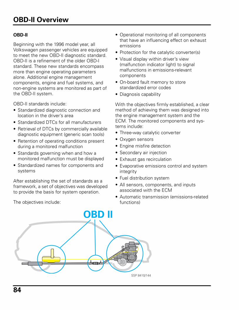
84
OBD-II
Beginning with the 1996 model year, all Volkswagen passenger vehicles are equipped to meet the new OBD-II diagnostic standard. OBD-II is a refinement of the older OBD-I standard. These new standards encompass more than engine operating parameters alone. Additional engine management components, engine and fuel systems, and non-engine systems are monitored as part of the OBD-II system.
OBD-II standards include:• Standardized diagnostic connection and
location in the driver’s area• Standardized DTCs for all manufacturers• Retrieval of DTCs by commercially available
diagnostic equipment (generic scan tools) • Retention of operating conditions present
during a monitored malfunction• Standards governing when and how a
monitored malfunction must be displayed • Standardized names for components and
systems
After establishing the set of standards as a framework, a set of objectives was developed to provide the basis for system operation.
The objectives include:
SSP 8410/144
• Operational monitoring of all components that have an influencing effect on exhaust emissions
• Protection for the catalytic converter(s)• Visual display within driver’s view
(malfunction indicator light) to signal malfunctions in emissions-relevant components
• On-board fault memory to store standardized error codes
• Diagnosis capability
With the objectives firmly established, a clear method of achieving them was designed into the engine management system and the ECM. The monitored components and sys-tems include:• Three-way catalytic converter• Oxygen sensors• Engine misfire detection• Secondary air injection• Exhaust gas recirculation• Evaporative emissions control and system
integrity• Fuel distribution system• All sensors, components, and inputs
associated with the ECM• Automatic transmission (emissions-related
functions)
OBD-II Overview
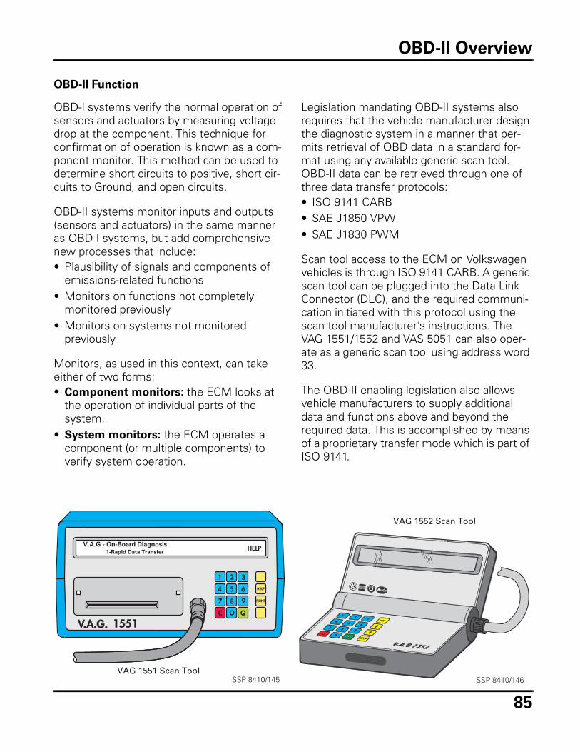
85
OBD-II Function
OBD-I systems verify the normal operation of sensors and actuators by measuring voltage drop at the component. This technique for confirmation of operation is known as a com-ponent monitor. This method can be used to determine short circuits to positive, short cir-cuits to Ground, and open circuits.
OBD-II systems monitor inputs and outputs (sensors and actuators) in the same manner as OBD-I systems, but add comprehensive new processes that include:• Plausibility of signals and components of
emissions-related functions• Monitors on functions not completely
monitored previously • Monitors on systems not monitored
previously
Monitors, as used in this context, can take either of two forms:• Component monitors: the ECM looks at
the operation of individual parts of the system.
• System monitors: the ECM operates a component (or multiple components) to verify system operation.
Legislation mandating OBD-II systems also requires that the vehicle manufacturer design the diagnostic system in a manner that per-mits retrieval of OBD data in a standard for-mat using any available generic scan tool. OBD-II data can be retrieved through one of three data transfer protocols:• ISO 9141 CARB• SAE J1850 VPW• SAE J1830 PWM
Scan tool access to the ECM on Volkswagen vehicles is through ISO 9141 CARB. A generic scan tool can be plugged into the Data Link Connector (DLC), and the required communi-cation initiated with this protocol using the scan tool manufacturer’s instructions. The VAG 1551/1552 and VAS 5051 can also oper-ate as a generic scan tool using address word 33.
The OBD-II enabling legislation also allows vehicle manufacturers to supply additional data and functions above and beyond the required data. This is accomplished by means of a proprietary transfer mode which is part of ISO 9141.
VAG 1551 Scan ToolSSP 8410/145
VAG 1552 Scan Tool
SSP 8410/146
OBD-II Overview
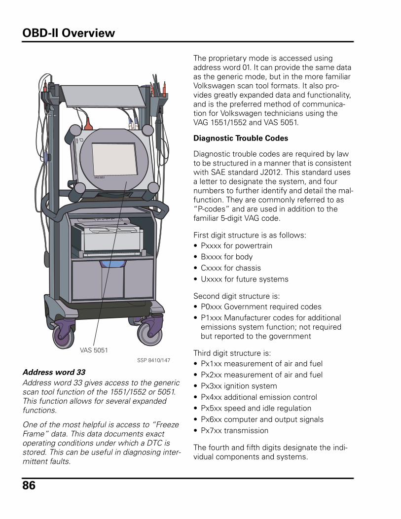
86
Address word 33
Address word 33 gives access to the generic scan tool function of the 1551/1552 or 5051. This function allows for several expanded functions.
One of the most helpful is access to “Freeze Frame” data. This data documents exact operating conditions under which a DTC is stored. This can be useful in diagnosing inter-mittent faults.
The proprietary mode is accessed using address word 01. It can provide the same data as the generic mode, but in the more familiar Volkswagen scan tool formats. It also pro-vides greatly expanded data and functionality, and is the preferred method of communica-tion for Volkswagen technicians using the VAG 1551/1552 and VAS 5051.
Diagnostic Trouble Codes
Diagnostic trouble codes are required by law to be structured in a manner that is consistent with SAE standard J2012. This standard uses a letter to designate the system, and four numbers to further identify and detail the mal-function. They are commonly referred to as “P-codes” and are used in addition to the familiar 5-digit VAG code.
First digit structure is as follows:• Pxxxx for powertrain• Bxxxx for body• Cxxxx for chassis• Uxxxx for future systems
Second digit structure is:• P0xxx Government required codes• P1xxx Manufacturer codes for additional
emissions system function; not required but reported to the government
Third digit structure is:• Px1xx measurement of air and fuel• Px2xx measurement of air and fuel• Px3xx ignition system• Px4xx additional emission control• Px5xx speed and idle regulation• Px6xx computer and output signals• Px7xx transmission
The fourth and fifth digits designate the indi-vidual components and systems.
VAS 5051SSP 8410/147
VAS 5051
OBD-II Overview
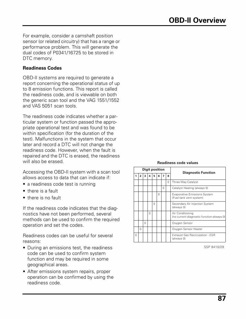
87
For example, consider a camshaft position sensor (or related circuitry) that has a range or performance problem. This will generate the dual codes of P0341/16725 to be stored in DTC memory.
Readiness Codes
OBD-II systems are required to generate a report concerning the operational status of up to 8 emission functions. This report is called the readiness code, and is viewable on both the generic scan tool and the VAG 1551/1552 and VAS 5051 scan tools.
The readiness code indicates whether a par-ticular system or function passed the appro-priate operational test and was found to be within specification (for the duration of the test). Malfunctions in the system that occur later and record a DTC will not change the readiness code. However, when the fault is repaired and the DTC is erased, the readiness will also be erased.
Accessing the OBD-II system with a scan tool allows access to data that can indicate if:• a readiness code test is running• there is a fault• there is no fault
If the readiness code indicates that the diag-nostics have not been performed, several methods can be used to confirm the required operation and set the codes.
Readiness codes can be useful for several reasons: • During an emissions test, the readiness
code can be used to confirm system function and may be required in some geographical areas.
• After emissions system repairs, proper operation can be confirmed by using the readiness code.
Readiness code values
Digit positionDiagnostic Function
1 2 3 4 5 6 7 8
0 Three Way Catalyst
0 Catalyst Heating (always 0)
0 Evaporative Emissions System (Fuel tank vent system)
0 Secondary Air Injection System (always 0)
0 Air Conditioning (no current diagnostic function-always 0)
0 Oxygen Sensor
0 Oxygen Sensor Heater
0 Exhaust Gas Recirculation - EGR (always 0)
SSP 8410/29
OBD-II Overview
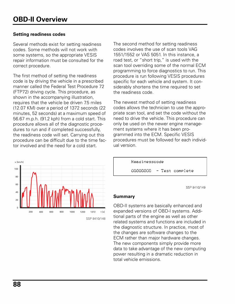
88
Setting readiness codes
Several methods exist for setting readiness codes. Some methods will not work with some systems, so the appropriate VESIS repair information must be consulted for the correct procedure.
The first method of setting the readiness code is by driving the vehicle in a prescribed manner called the Federal Test Procedure 72 (FTP72) driving cycle. This procedure, as shown in the accompanying illustration, requires that the vehicle be driven 7.5 miles (12.07 KM) over a period of 1372 seconds (22 minutes, 52 seconds) at a maximum speed of 56.67 m.p.h. (91.2 kph) from a cold start. This procedure allows all of the diagnostic proce-dures to run and if completed successfully, the readiness code will set. Carrying out this procedure can be difficult due to the time fac-tor involved and the need for a cold start.
100
80
60
40
20
0
200 400 600 800 1000 1200 1372 t [s]
v [km/h]
SSP 8410/148
The second method for setting readiness codes involves the use of scan tools VAG 1551/1552 or VAS 5051. In this instance, a road test, or “short trip,” is used with the scan tool overriding some of the normal ECM programming to force diagnostics to run. This procedure is run following VESIS procedures specific for each vehicle and system. It con-siderably shortens the time required to set the readiness code.
The newest method of setting readiness codes allows the technician to use the appro-priate scan tool, and set the code without the need to drive the vehicle. This procedure can only be used on the newer engine manage-ment systems where it has been pro-grammed into the ECM. Specific VESIS procedures must be followed for each individ-ual version.
Summary
OBD-II systems are basically enhanced and expanded versions of OBD-I systems. Addi-tional parts of the engine as well as other related systems and functions are included in the diagnostic structure. In practice, most of the changes are software changes to the ECM rather than major hardware changes. The new components simply provide more data to take advantage of the new computing power resulting in a dramatic reduction in total vehicle emissions.
OBD-II Overview
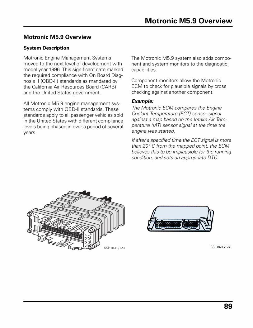
89
Motronic M5.9 Overview
System Description
Motronic Engine Management Systems moved to the next level of development with model year 1996. This significant date marked the required compliance with On Board Diag-nosis II (OBD-II) standards as mandated by the California Air Resources Board (CARB) and the United States government.
All Motronic M5.9 engine management sys-tems comply with OBD-II standards. These standards apply to all passenger vehicles sold in the United States with different compliance levels being phased in over a period of several years.
The Motronic M5.9 system also adds compo-nent and system monitors to the diagnostic capabilities.
Component monitors allow the Motronic ECM to check for plausible signals by cross checking against another component.
Example:
The Motronic ECM compares the Engine Coolant Temperature (ECT) sensor signal against a map based on the Intake Air Tem-perature (IAT) sensor signal at the time the engine was started.
If after a specified time the ECT signal is more than 20° C from the mapped point, the ECM believes this to be implausible for the running condition, and sets an appropriate DTC.
SSP 8410/123
Motronic M5.9 Overview
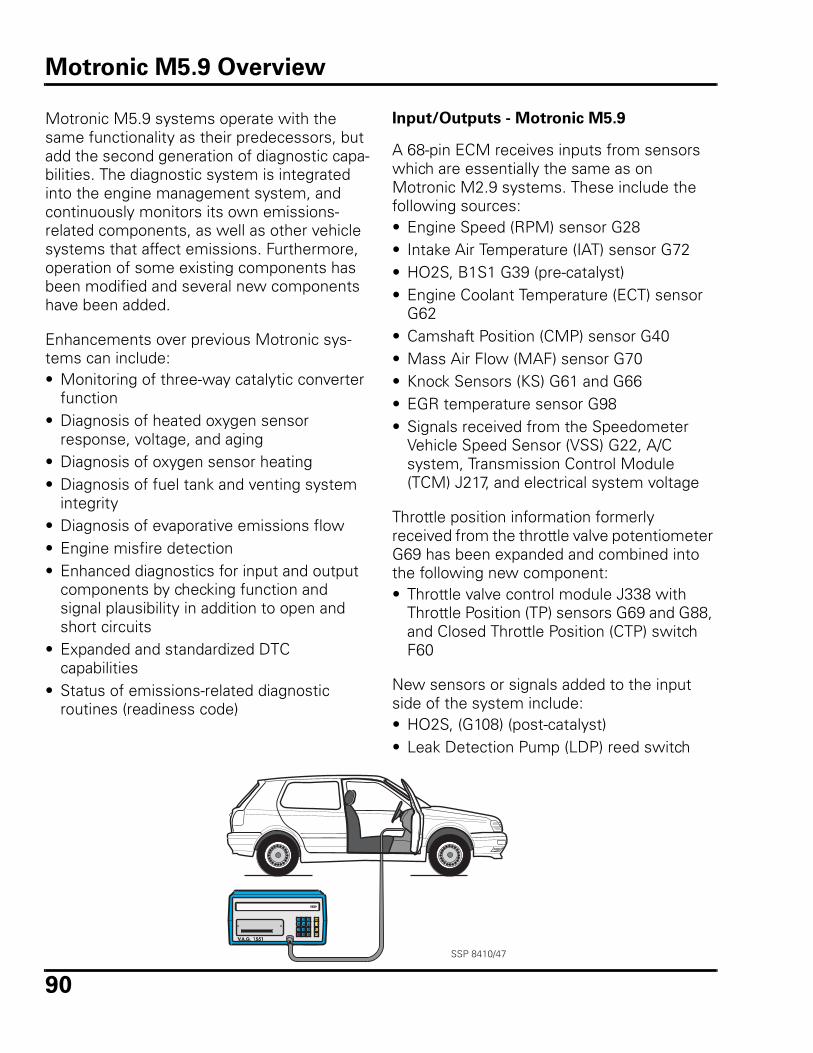
90
Motronic M5.9 systems operate with the same functionality as their predecessors, but add the second generation of diagnostic capa-bilities. The diagnostic system is integrated into the engine management system, and continuously monitors its own emissions-related components, as well as other vehicle systems that affect emissions. Furthermore, operation of some existing components has been modified and several new components have been added.
Enhancements over previous Motronic sys-tems can include:• Monitoring of three-way catalytic converter
function• Diagnosis of heated oxygen sensor
response, voltage, and aging• Diagnosis of oxygen sensor heating• Diagnosis of fuel tank and venting system
integrity • Diagnosis of evaporative emissions flow• Engine misfire detection• Enhanced diagnostics for input and output
components by checking function and signal plausibility in addition to open and short circuits
• Expanded and standardized DTC capabilities
• Status of emissions-related diagnostic routines (readiness code)
Input/Outputs - Motronic M5.9
A 68-pin ECM receives inputs from sensors which are essentially the same as on Motronic M2.9 systems. These include the following sources:• Engine Speed (RPM) sensor G28• Intake Air Temperature (IAT) sensor G72• HO2S, B1S1 G39 (pre-catalyst)• Engine Coolant Temperature (ECT) sensor
G62• Camshaft Position (CMP) sensor G40• Mass Air Flow (MAF) sensor G70• Knock Sensors (KS) G61 and G66• EGR temperature sensor G98• Signals received from the Speedometer
Vehicle Speed Sensor (VSS) G22, A/C system, Transmission Control Module (TCM) J217, and electrical system voltage
Throttle position information formerly received from the throttle valve potentiometer G69 has been expanded and combined into the following new component:• Throttle valve control module J338 with
Throttle Position (TP) sensors G69 and G88, and Closed Throttle Position (CTP) switch F60
New sensors or signals added to the input side of the system include:• HO2S, (G108) (post-catalyst) • Leak Detection Pump (LDP) reed switch
SSP 8410/47
Motronic M5.9 Overview
91
The outputs or actuators are essentially the same as on Motronic M2.9, and include the following:• Evaporative Emission (EVAP) canister purge
regulator valve N80• Fuel injectors (N30 - N33, N83, N84) • Ignition coil N152 with power output stage
N157• Fuel Pump (FP) relay J17 and Fuel Pump G• EGR vacuum regulator solenoid valve N18• Secondary Air Injection (AIR) pump relay
J299 and Secondary Air Injection (AIR) pump V101
• Secondary Air Injection (AIR) solenoid valve N112
• Oxygen sensor heater relay J278• Signals sent to the TCM J217, Instrument
cluster
The IAC valve (idle stabilizer) has been elimi-nated and its function replaced by: • Throttle valve positioner V60, which is part
of the throttle valve control module J338.
New components or signals added to the out-put side of the system include:• Evaporative Emission (EVAP) canister purge
solenoid valve N115• Fuel cut-off valve shut-off relay J335• LDP vacuum solenoid switch
Adaptation of system variables occurs in Motronic M5.9 systems just as in earlier ver-sions, and there are no mechanical engine settings or adjustments to be made. How-ever, if the battery is disconnected, or if power is interrupted to the ECM, the learned or adapted values may be erased. DTCs and readiness codes may also be erased. The adapted value for the throttle valve control module J338 must be reset to avoid driveabil-ity problems.
Additional Systems
Fuel delivery from the tank is the same as the Motronic M2.9 versions, with pressure main-tained by the manifold vacuum-operated fuel pressure regulator on the fuel injector rail assembly.
Sensor inputs, other input signals, actuator signals and other output signals are shown in the illustration on the following pages. The illustration represents components that are installed on several different engine types. Certain engines will not have some of the listed components.
Motronic M5.9 Overview
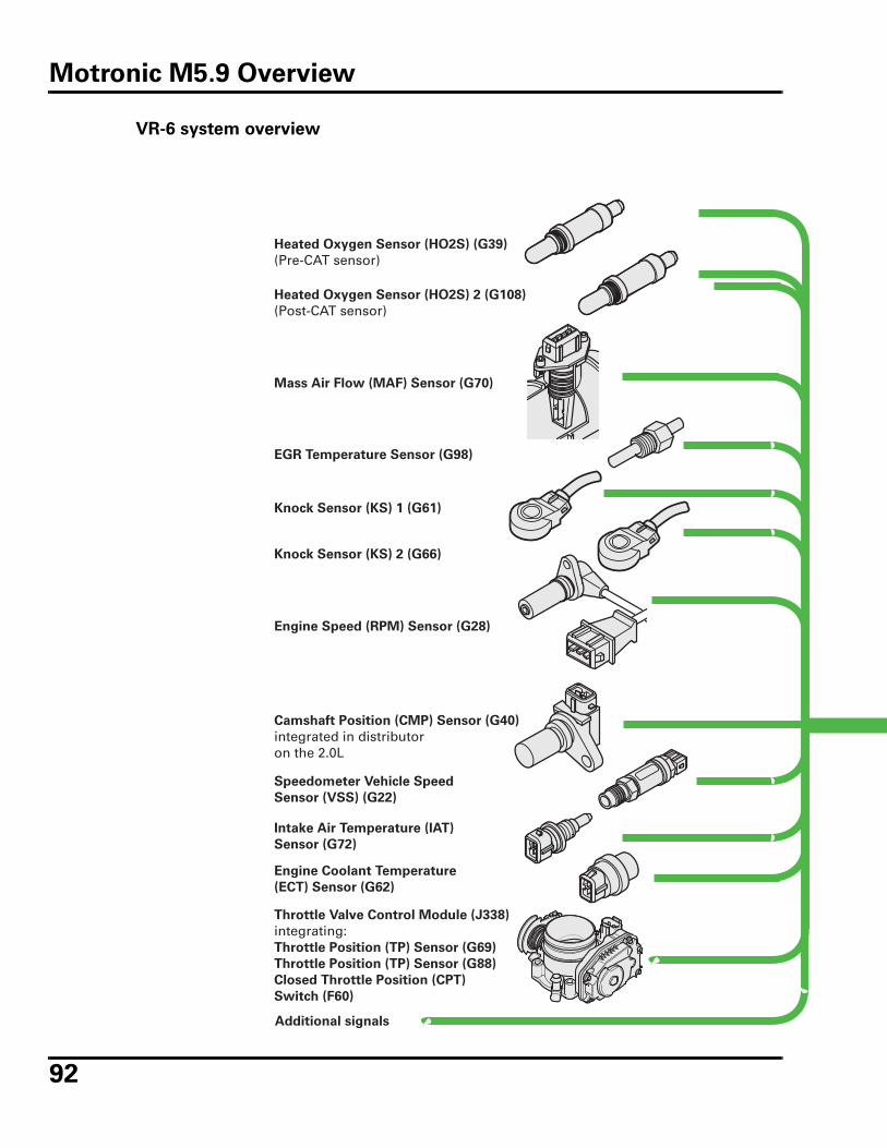
92
VR-6 system overview
Heated Oxygen Sensor (HO2S) (G39)
(Pre-CAT sensor)
Heated Oxygen Sensor (HO2S) 2 (G108)
(Post-CAT sensor)
Mass Air Flow (MAF) Sensor (G70)
EGR Temperature Sensor (G98)
Knock Sensor (KS) 1 (G61)
Knock Sensor (KS) 2 (G66)
Engine Speed (RPM) Sensor (G28)
Camshaft Position (CMP) Sensor (G40)
integrated in distributoron the 2.0L
Speedometer Vehicle Speed
Sensor (VSS) (G22)
Intake Air Temperature (IAT)
Sensor (G72)
Engine Coolant Temperature
(ECT) Sensor (G62)
Throttle Valve Control Module (J338)
integrating:Throttle Position (TP) Sensor (G69)
Throttle Position (TP) Sensor (G88)
Closed Throttle Position (CPT)
Switch (F60)
Additional signals
Motronic M5.9 Overview
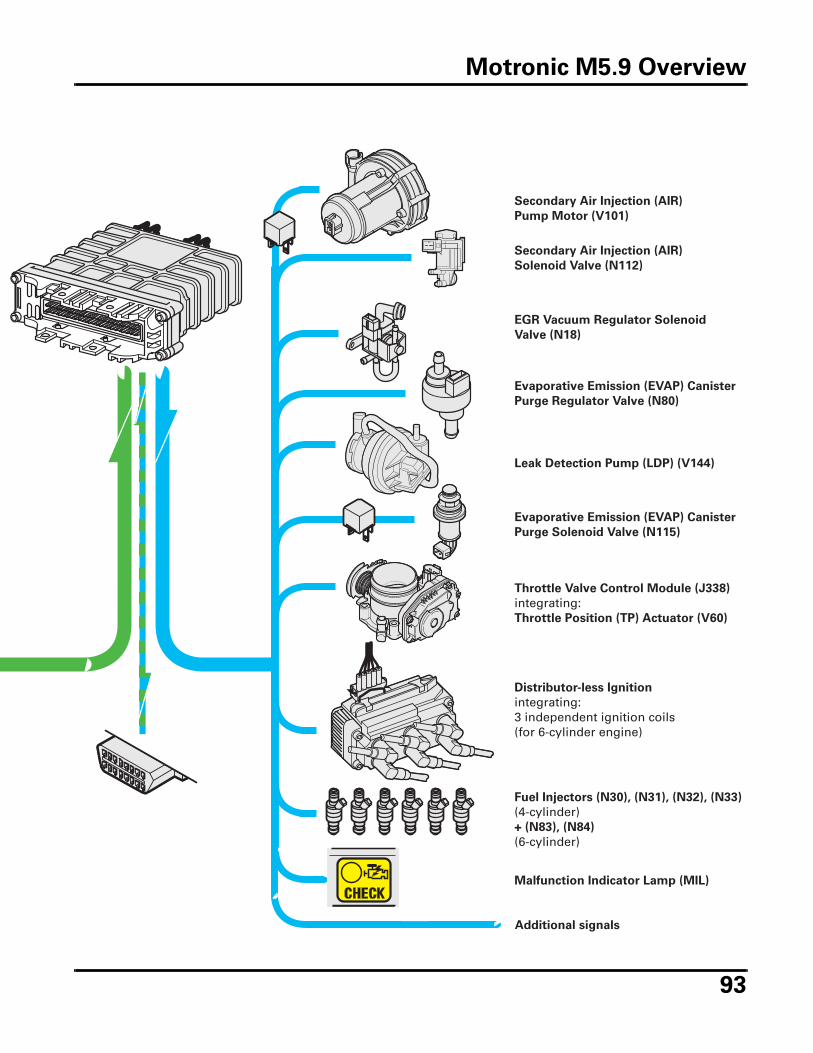
93
Secondary Air Injection (AIR)
Pump Motor (V101)
Secondary Air Injection (AIR)
Solenoid Valve (N112)
EGR Vacuum Regulator Solenoid
Valve (N18)
Evaporative Emission (EVAP) Canister
Purge Regulator Valve (N80)
Leak Detection Pump (LDP) (V144)
Evaporative Emission (EVAP) Canister
Purge Solenoid Valve (N115)
Throttle Valve Control Module (J338)
integrating:Throttle Position (TP) Actuator (V60)
Distributor-less Ignition
integrating:3 independent ignition coils(for 6-cylinder engine)
Fuel Injectors (N30), (N31), (N32), (N33)
(4-cylinder)+ (N83), (N84)
(6-cylinder)
Malfunction Indicator Lamp (MIL)
Additional signals
Motronic M5.9 Overview
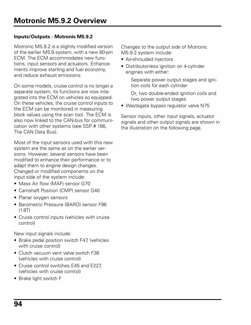
94
Inputs/Outputs - Motronic M5.9.2
Motronic M5.9.2 is a slightly modified version of the earlier M5.9 system, with a new 80-pin ECM. The ECM accommodates new func-tions, input sensors and actuators. Enhance-ments improve starting and fuel economy, and reduce exhaust emissions.
On some models, cruise control is no longer a separate system; its functions are now inte-grated into the ECM on vehicles so equipped. On these vehicles, the cruise control inputs to the ECM can be monitored in measuring block values using the scan tool. The ECM is also now linked to the CAN-bus for communi-cation with other systems (see SSP # 186, The CAN Data Bus).
Most of the input sensors used with this new system are the same as on the earlier ver-sions. However, several sensors have been modified to enhance their performance or to adapt them to engine design changes. Changed or modified components on the input side of the system include:• Mass Air flow (MAF) sensor G70• Camshaft Position (CMP) sensor G40• Planar oxygen sensors• Barometric Pressure (BARO) sensor F96
(1.8T)• Cruise control inputs (vehicles with cruise
control)
New input signals include:• Brake pedal position switch F47, (vehicles
with cruise control) • Clutch vacuum vent valve switch F36
(vehicles with cruise control) • Cruise control switches E45 and E227,
(vehicles with cruise control) • Brake light switch F
Changes to the output side of Motronic M5.9.2 system include:• Air-shrouded injectors• Distributor-less ignition on 4-cylinder
engines with either:
Separate power output stages and igni-tion coils for each cylinder
Or, two double-ended ignition coils and two power output stages
• Wastegate bypass regulator valve N75
Sensor inputs, other input signals, actuator signals and other output signals are shown in the illustration on the following page.
Motronic M5.9.2 Overview
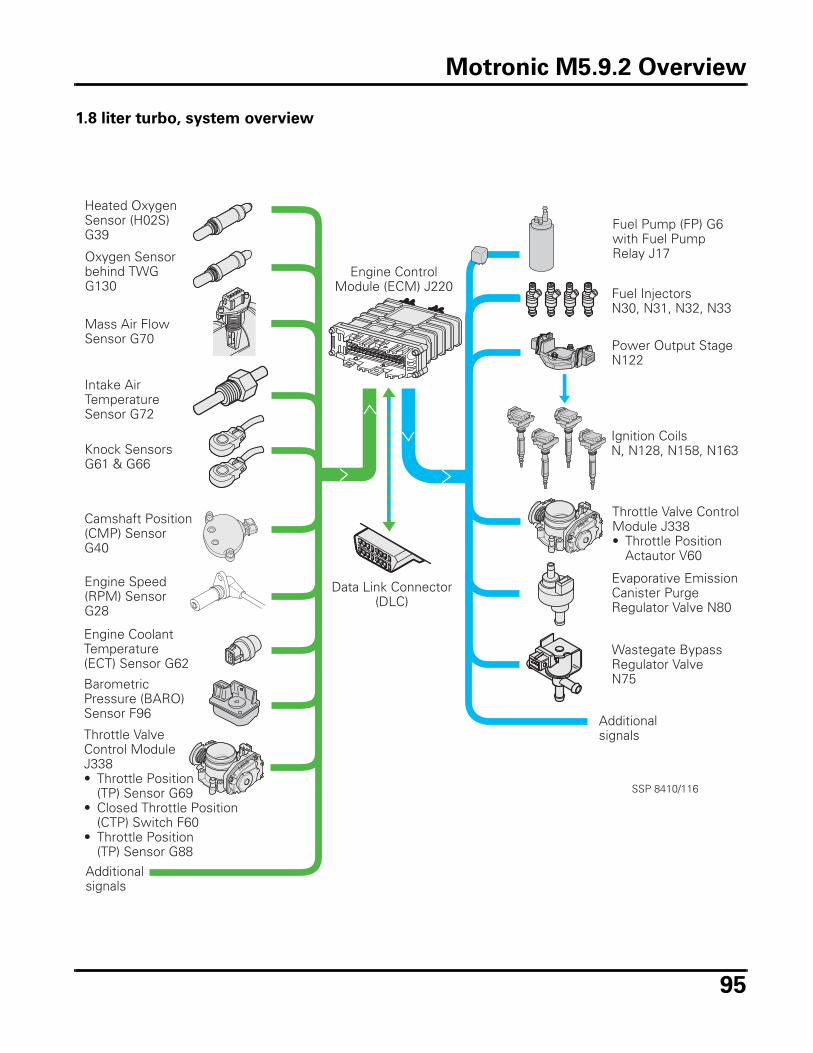
95
1.8 liter turbo, system overview
Heated OxygenSensor (H02S)G39
Mass Air FlowSensor G70
Intake AirTemperatureSensor G72
Knock SensorsG61 & G66
Camshaft Position(CMP) SensorG40
Engine CoolantTemperature(ECT) Sensor G62
Engine Speed(RPM) SensorG28
BarometricPressure (BARO)Sensor F96
Throttle ValveControl ModuleJ338• Throttle Position
(TP) Sensor G69• Closed Throttle Position
(CTP) Switch F60• Throttle Position
(TP) Sensor G88
Oxygen Sensorbehind TWGG130
Additionalsignals
Fuel Pump (FP) G6with Fuel PumpRelay J17
Fuel InjectorsN30, N31, N32, N33
Power Output StageN122
Ignition CoilsN, N128, N158, N163
Throttle Valve ControlModule J338• Throttle Position
Actautor V60
Evaporative EmissionCanister PurgeRegulator Valve N80
Wastegate BypassRegulator ValveN75
Additionalsignals
Engine ControlModule (ECM) J220
Data Link Connector(DLC)
SSP 8410/116
Motronic M5.9.2 Overview

96
Notes
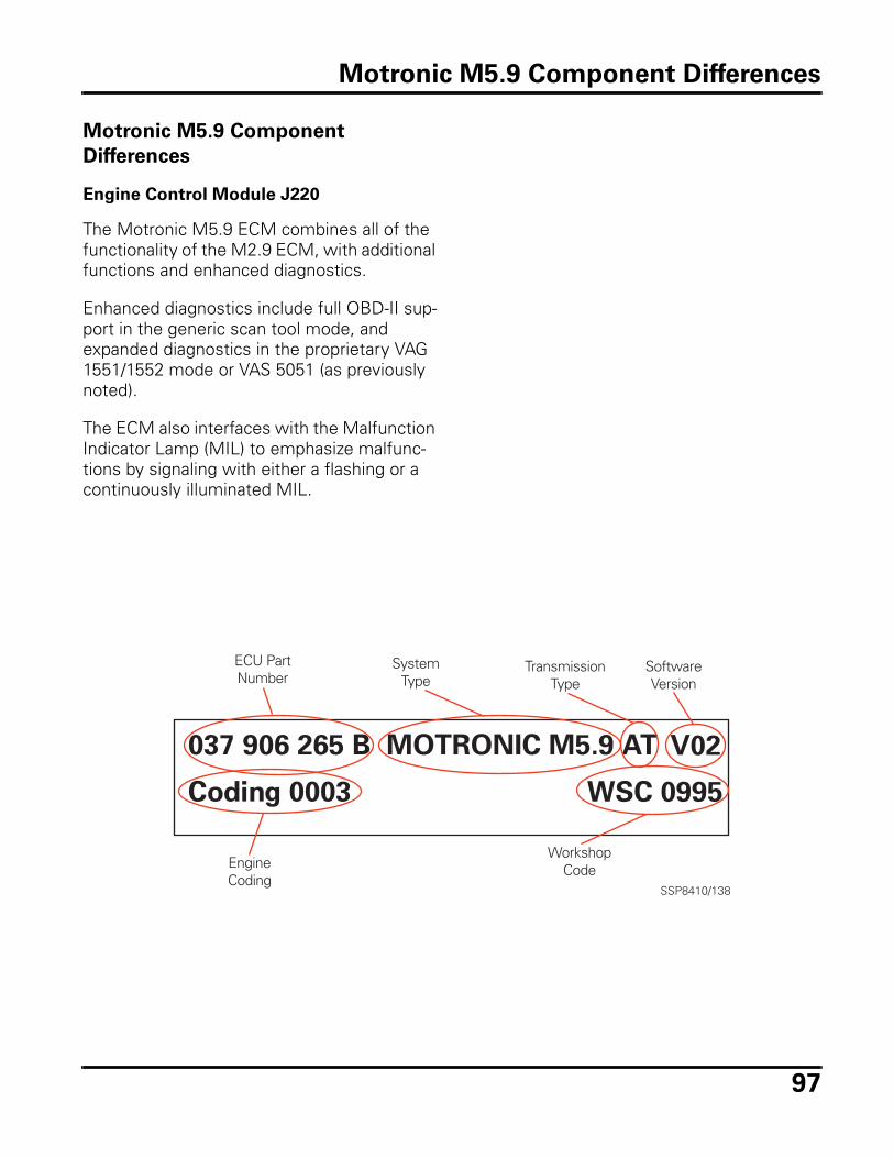
97
Motronic M5.9 Component
Differences
Engine Control Module J220
The Motronic M5.9 ECM combines all of the functionality of the M2.9 ECM, with additional functions and enhanced diagnostics.
Enhanced diagnostics include full OBD-II sup-port in the generic scan tool mode, and expanded diagnostics in the proprietary VAG 1551/1552 mode or VAS 5051 (as previously noted).
The ECM also interfaces with the Malfunction Indicator Lamp (MIL) to emphasize malfunc-tions by signaling with either a flashing or a continuously illuminated MIL.
ECU PartNumber
SystemType
TransmissionType
SoftwareVersion
EngineCoding
WorkshopCode
Motronic M5.9 Component Differences
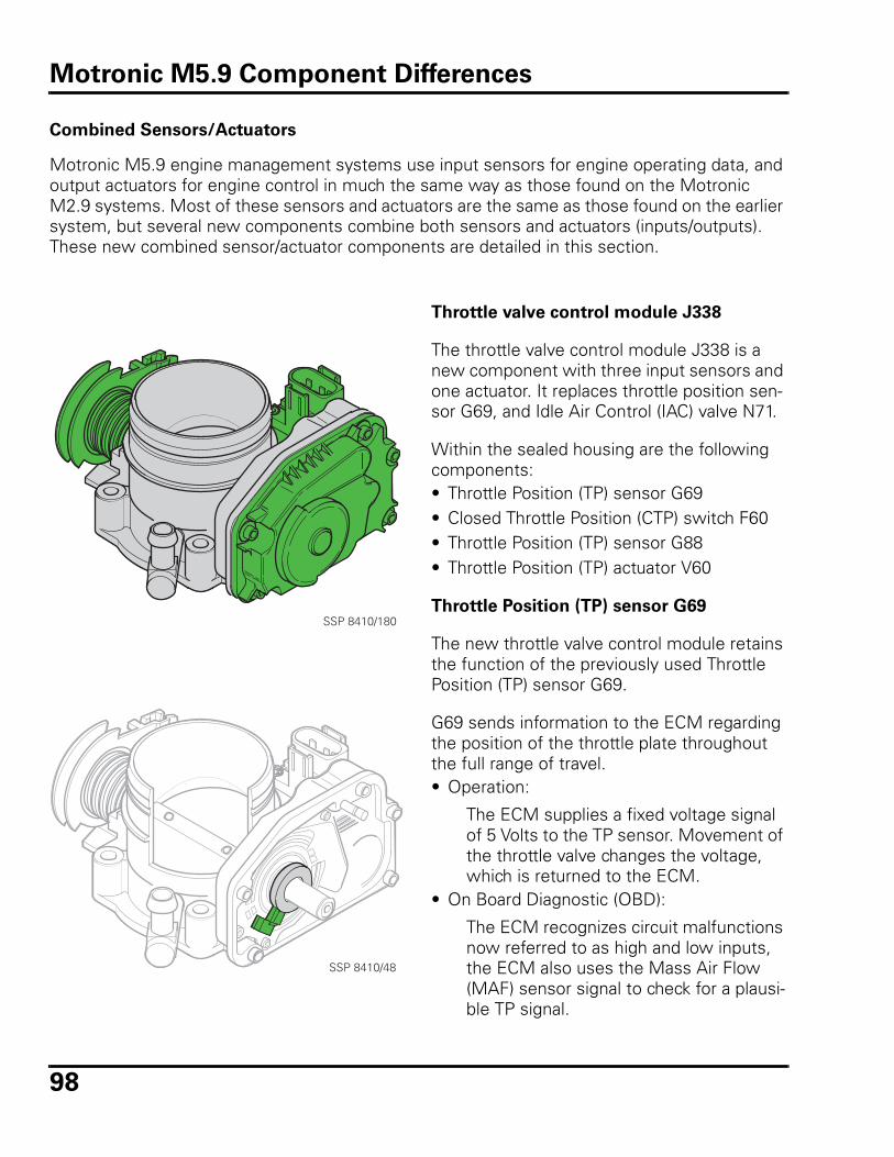
98
Combined Sensors/Actuators
Motronic M5.9 engine management systems use input sensors for engine operating data, and output actuators for engine control in much the same way as those found on the Motronic M2.9 systems. Most of these sensors and actuators are the same as those found on the earlier system, but several new components combine both sensors and actuators (inputs/outputs). These new combined sensor/actuator components are detailed in this section.
Throttle valve control module J338
The throttle valve control module J338 is a new component with three input sensors and one actuator. It replaces throttle position sen-sor G69, and Idle Air Control (IAC) valve N71.
Within the sealed housing are the following components:• Throttle Position (TP) sensor G69• Closed Throttle Position (CTP) switch F60• Throttle Position (TP) sensor G88• Throttle Position (TP) actuator V60
Throttle Position (TP) sensor G69
The new throttle valve control module retains the function of the previously used Throttle Position (TP) sensor G69.
G69 sends information to the ECM regarding the position of the throttle plate throughout the full range of travel. • Operation:
The ECM supplies a fixed voltage signal of 5 Volts to the TP sensor. Movement of the throttle valve changes the voltage, which is returned to the ECM.
• On Board Diagnostic (OBD):
The ECM recognizes circuit malfunctions now referred to as high and low inputs, the ECM also uses the Mass Air Flow (MAF) sensor signal to check for a plausi-ble TP signal.
SSP 8410/180
SSP 8410/48
Motronic M5.9 Component Differences
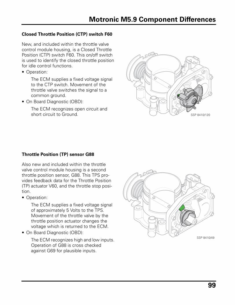
99
Closed Throttle Position (CTP) switch F60
New, and included within the throttle valve control module housing, is a Closed Throttle Position (CTP) switch F60. This on/off switch is used to identify the closed throttle position for idle control functions.• Operation:
The ECM supplies a fixed voltage signal to the CTP switch. Movement of the throttle valve switches the signal to a common ground.
• On Board Diagnostic (OBD):
The ECM recognizes open circuit and short circuit to Ground.
Throttle Position (TP) sensor G88
Also new and included within the throttle valve control module housing is a second throttle position sensor, G88. This TPS pro-vides feedback data for the Throttle Position (TP) actuator V60, and the throttle stop posi-tion.• Operation:
The ECM supplies a fixed voltage signal of approximately 5 Volts to the TPS. Movement of the throttle valve by the throttle position actuator changes the voltage which is returned to the ECM.
• On Board Diagnostic (OBD):
The ECM recognizes high and low inputs. Operation of G88 is cross checked against G69 for plausible inputs.
SSP 8410/120
SSP 8410/49
Motronic M5.9 Component Differences
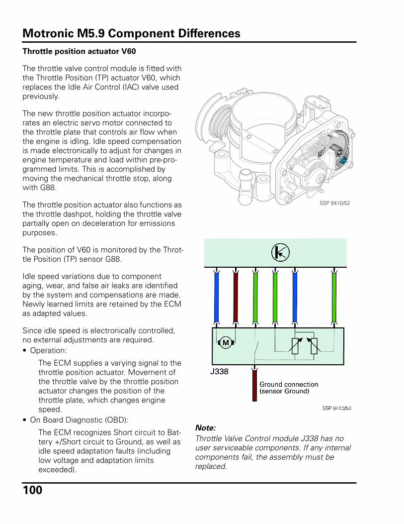
100
Throttle position actuator V60
The throttle valve control module is fitted with the Throttle Position (TP) actuator V60, which replaces the Idle Air Control (IAC) valve used previously.
The new throttle position actuator incorpo-rates an electric servo motor connected to the throttle plate that controls air flow when the engine is idling. Idle speed compensation is made electronically to adjust for changes in engine temperature and load within pre-pro-grammed limits. This is accomplished by moving the mechanical throttle stop, along with G88.
The throttle position actuator also functions as the throttle dashpot, holding the throttle valve partially open on deceleration for emissions purposes.
The position of V60 is monitored by the Throt-tle Position (TP) sensor G88.
Idle speed variations due to component aging, wear, and false air leaks are identified by the system and compensations are made. Newly learned limits are retained by the ECM as adapted values.
Since idle speed is electronically controlled, no external adjustments are required. • Operation:
The ECM supplies a varying signal to the throttle position actuator. Movement of the throttle valve by the throttle position actuator changes the position of the throttle plate, which changes engine speed.
• On Board Diagnostic (OBD):
The ECM recognizes Short circuit to Bat-tery +/Short circuit to Ground, as well as idle speed adaptation faults (including low voltage and adaptation limits exceeded).
SSP 8410/52
Note:
Throttle Valve Control module J338 has no user serviceable components. If any internal components fail, the assembly must be replaced.
Motronic M5.9 Component Differences
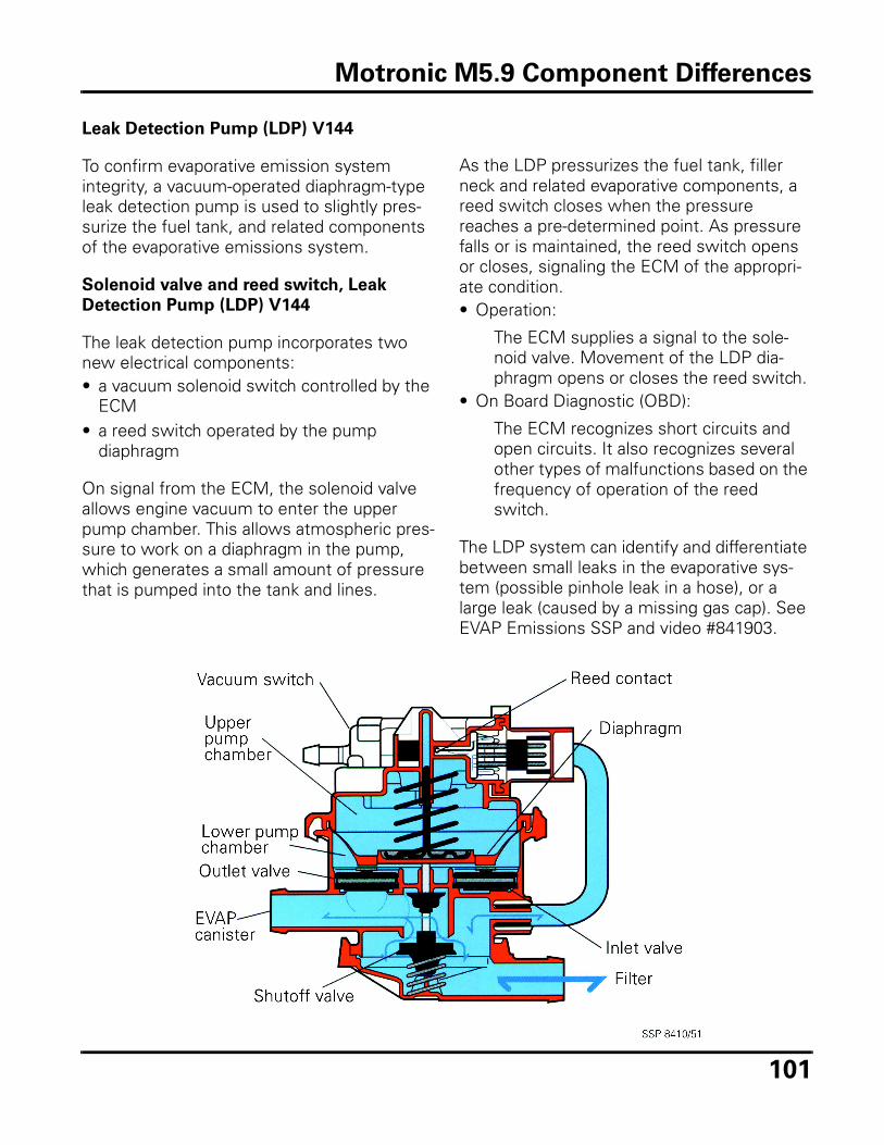
101
Leak Detection Pump (LDP) V144
To confirm evaporative emission system integrity, a vacuum-operated diaphragm-type leak detection pump is used to slightly pres-surize the fuel tank, and related components of the evaporative emissions system.
Solenoid valve and reed switch, Leak
Detection Pump (LDP) V144
The leak detection pump incorporates two new electrical components:• a vacuum solenoid switch controlled by the
ECM• a reed switch operated by the pump
diaphragm
On signal from the ECM, the solenoid valve allows engine vacuum to enter the upper pump chamber. This allows atmospheric pres-sure to work on a diaphragm in the pump, which generates a small amount of pressure that is pumped into the tank and lines.
As the LDP pressurizes the fuel tank, filler neck and related evaporative components, a reed switch closes when the pressure reaches a pre-determined point. As pressure falls or is maintained, the reed switch opens or closes, signaling the ECM of the appropri-ate condition. • Operation:
The ECM supplies a signal to the sole-noid valve. Movement of the LDP dia-phragm opens or closes the reed switch.
• On Board Diagnostic (OBD):
The ECM recognizes short circuits and open circuits. It also recognizes several other types of malfunctions based on the frequency of operation of the reed switch.
The LDP system can identify and differentiate between small leaks in the evaporative sys-tem (possible pinhole leak in a hose), or a large leak (caused by a missing gas cap). See EVAP Emissions SSP and video #841903.
Motronic M5.9 Component Differences
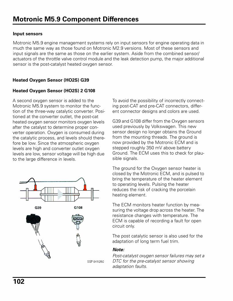
102
Input sensors
Motronic M5.9 engine management systems rely on input sensors for engine operating data in much the same way as those found on Motronic M2.9 versions. Most of these sensors and input signals are the same as those on the earlier system. Aside from the combined sensor/actuators of the throttle valve control module and the leak detection pump, the major additional sensor is the post-catalyst heated oxygen sensor.
Heated Oxygen Sensor (HO2S) G39
Heated Oxygen Sensor (HO2S) 2 G108
A second oxygen sensor is added to the Motronic M5.9 system to monitor the func-tion of the three-way catalytic converter. Posi-tioned at the converter outlet, the post-cat heated oxygen sensor monitors oxygen levels after the catalyst to determine proper con-verter operation. Oxygen is consumed during the catalytic process, and levels should there-fore be low. Since the atmospheric oxygen levels are high and converter outlet oxygen levels are low, sensor voltage will be high due to the large difference in levels.
To avoid the possibility of incorrectly connect-ing post-CAT and pre-CAT connectors, differ-ent connector designs and colors are used.
G39 and G108 differ from the Oxygen sensors used previously by Volkswagen. This new sensor design no longer obtains the Ground from the mounting threads. The ground is now provided by the Motronic ECM and is stepped roughly 350 mV above battery Ground. The ECM uses this to check for plau-sible signals.
The ground for the Oxygen sensor heater is closed by the Motronic ECM, and is pulsed to bring the temperature of the heater element to operating levels. Pulsing the heater reduces the risk of cracking the porcelain heating element.
The ECM monitors heater function by mea-suring the voltage drop across the heater. The resistance changes with temperature. The ECM is capable of recording a fault for open circuit only.
The post catalytic sensor is also used for the adaptation of long term fuel trim.
Note:
Post-catalyst oxygen sensor failures may set a DTC for the pre-catalyst sensor showing adaptation faults.
Motronic M5.9 Component Differences
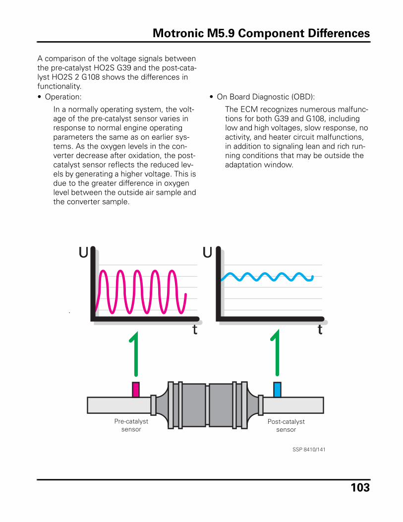
103
A comparison of the voltage signals between the pre-catalyst HO2S G39 and the post-cata-lyst HO2S 2 G108 shows the differences in functionality.• Operation:
In a normally operating system, the volt-age of the pre-catalyst sensor varies in response to normal engine operating parameters the same as on earlier sys-tems. As the oxygen levels in the con-verter decrease after oxidation, the post-catalyst sensor reflects the reduced lev-els by generating a higher voltage. This is due to the greater difference in oxygen level between the outside air sample and the converter sample.
• On Board Diagnostic (OBD):
The ECM recognizes numerous malfunc-tions for both G39 and G108, including low and high voltages, slow response, no activity, and heater circuit malfunctions, in addition to signaling lean and rich run-ning conditions that may be outside the adaptation window.
SSP 8410/141
Pre-catalystsensor
Post-catalystsensor
Motronic M5.9 Component Differences
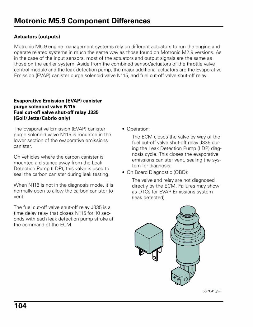
104
Actuators (outputs)
Motronic M5.9 engine management systems rely on different actuators to run the engine and operate related systems in much the same way as those found on Motronic M2.9 versions. As in the case of the input sensors, most of the actuators and output signals are the same as those on the earlier system. Aside from the combined sensor/actuators of the throttle valve control module and the leak detection pump, the major additional actuators are the Evaporative Emission (EVAP) canister purge solenoid valve N115, and fuel cut-off valve shut-off relay.
Evaporative Emission (EVAP) canister
purge solenoid valve N115
Fuel cut-off valve shut-off relay J335
(Golf/Jetta/Cabrio only)
The Evaporative Emission (EVAP) canister purge solenoid valve N115 is mounted in the lower section of the evaporative emissions canister.
On vehicles where the carbon canister is mounted a distance away from the Leak Detection Pump (LDP), this valve is used to seal the carbon canister during leak testing.
When N115 is not in the diagnosis mode, it is normally open to allow the carbon canister to vent.
The fuel cut-off valve shut-off relay J335 is a time delay relay that closes N115 for 10 sec-onds with each leak detection pump stroke at the command of the ECM.
• Operation:
The ECM closes the valve by way of the fuel cut-off valve shut-off relay J335 dur-ing the Leak Detection Pump (LDP) diag-nosis cycle. This closes the evaporative emissions canister vent, sealing the sys-tem for diagnosis.
• On Board Diagnostic (OBD):
The valve and relay are not diagnosed directly by the ECM. Failures may show as DTCs for EVAP Emissions system (leak detected).
Motronic M5.9 Component Differences
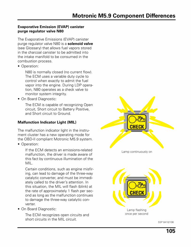
105
Evaporative Emission (EVAP) canister
purge regulator valve N80
The Evaporative Emissions (EVAP) canister purge regulator valve N80 is a solenoid valve (see Glossary) that allows fuel vapors stored in the charcoal canister to be admitted into the intake manifold to be consumed in the combustion process.• Operation:
N80 is normally closed (no current flow). The ECM uses a variable duty cycle to control when exactly to admit the fuel vapor into the engine. During LDP opera-tion, N80 operates as a check valve to monitor system integrity.
• On Board Diagnostic:
The ECM is capable of recognizing Open circuit, Short circuit to Battery Positive, and Short circuit to Ground.
Malfunction Indicator Light (MIL)
The malfunction indicator light in the instru-ment cluster has a new operating mode for the OBD-II compliant Motronic M5.9 system.• Operation:
If the ECM detects an emissions-related malfunction, the driver is made aware of this fact by continuous illumination of the MIL.
Certain conditions, such as engine misfir-ing, can lead to damage of the three-way catalytic converter, and must be immedi-ately called to the driver’s attention. In this situation, the MIL will flash (blink) at the rate of approximately 1 flash per sec-ond as long as the malfunction continues to damage the three-way catalytic con-verter.
• On Board Diagnostic:
The ECM recognizes open circuits and short circuits in the MIL circuit.
Lamp continuously on
Lamp flashingonce per second
SSP 8410/106
Motronic M5.9 Component Differences

106
Notes
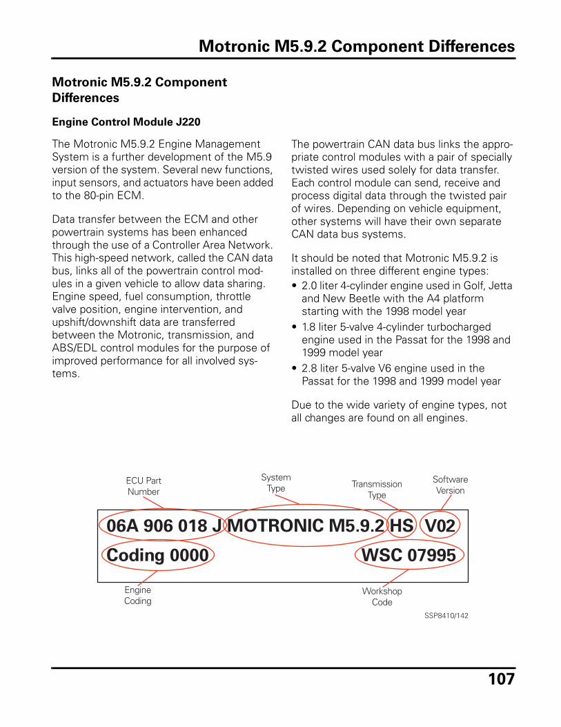
107
Motronic M5.9.2 Component
Differences
Engine Control Module J220
The Motronic M5.9.2 Engine Management System is a further development of the M5.9 version of the system. Several new functions, input sensors, and actuators have been added to the 80-pin ECM.
Data transfer between the ECM and other powertrain systems has been enhanced through the use of a Controller Area Network. This high-speed network, called the CAN data bus, links all of the powertrain control mod-ules in a given vehicle to allow data sharing. Engine speed, fuel consumption, throttle valve position, engine intervention, and upshift/downshift data are transferred between the Motronic, transmission, and ABS/EDL control modules for the purpose of improved performance for all involved sys-tems.
The powertrain CAN data bus links the appro-priate control modules with a pair of specially twisted wires used solely for data transfer. Each control module can send, receive and process digital data through the twisted pair of wires. Depending on vehicle equipment, other systems will have their own separate CAN data bus systems.
It should be noted that Motronic M5.9.2 is installed on three different engine types:• 2.0 liter 4-cylinder engine used in Golf, Jetta
and New Beetle with the A4 platform starting with the 1998 model year
• 1.8 liter 5-valve 4-cylinder turbocharged engine used in the Passat for the 1998 and 1999 model year
• 2.8 liter 5-valve V6 engine used in the Passat for the 1998 and 1999 model year
Due to the wide variety of engine types, not all changes are found on all engines.
SSP8410/142
ECU PartNumber
SystemType Transmission
Type
SoftwareVersion
EngineCoding
WorkshopCode
Motronic M5.9.2 Component Differences
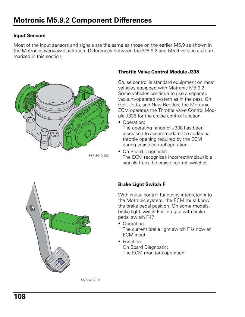
108
Input Sensors
Most of the input sensors and signals are the same as those on the earlier M5.9 as shown in the Motronic overview illustration. Differences between the M5.9.2 and M5.9 version are sum-marized in this section.
Throttle Valve Control Module J338
Cruise control is standard equipment on most vehicles equipped with Motronic M5.9.2. Some vehicles continue to use a separate vacuum-operated system as in the past. On Golf, Jetta, and New Beetles, the Motronic ECM operates the Throttle Valve Control Mod-ule J338 for the cruise control function. • Operation:
The operating range of J338 has been increased to accommodate the additional throttle opening required by the ECM during cruise control operation.
• On Board Diagnostic:The ECM recognizes incorrect/implausible signals from the cruise control switches.
Brake Light Switch F
With cruise control functions integrated into the Motronic system, the ECM must know the brake pedal position. On some models, brake light switch F is integral with brake pedal switch F47.• Operation:
The current brake light switch F is now an ECM input.
• Function:On Board Diagnostic:The ECM monitors operation.
SSP 8410/180
SSP 8410/101
Motronic M5.9.2 Component Differences
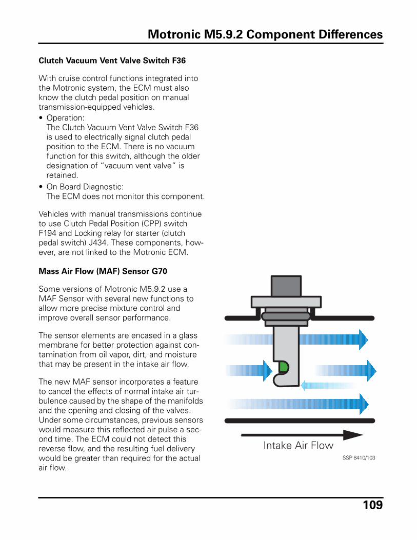
109
Clutch Vacuum Vent Valve Switch F36
With cruise control functions integrated into the Motronic system, the ECM must also know the clutch pedal position on manual transmission-equipped vehicles. • Operation:
The Clutch Vacuum Vent Valve Switch F36 is used to electrically signal clutch pedal position to the ECM. There is no vacuum function for this switch, although the older designation of “vacuum vent valve” is retained.
• On Board Diagnostic:The ECM does not monitor this component.
Vehicles with manual transmissions continue to use Clutch Pedal Position (CPP) switch F194 and Locking relay for starter (clutch pedal switch) J434. These components, how-ever, are not linked to the Motronic ECM.
Mass Air Flow (MAF) Sensor G70
Some versions of Motronic M5.9.2 use a MAF Sensor with several new functions to allow more precise mixture control and improve overall sensor performance.
The sensor elements are encased in a glass membrane for better protection against con-tamination from oil vapor, dirt, and moisture that may be present in the intake air flow.
The new MAF sensor incorporates a feature to cancel the effects of normal intake air tur-bulence caused by the shape of the manifolds and the opening and closing of the valves. Under some circumstances, previous sensors would measure this reflected air pulse a sec-ond time. The ECM could not detect this reverse flow, and the resulting fuel delivery would be greater than required for the actual air flow.
SSP 8410/103
Intake Air Flow
Motronic M5.9.2 Component Differences
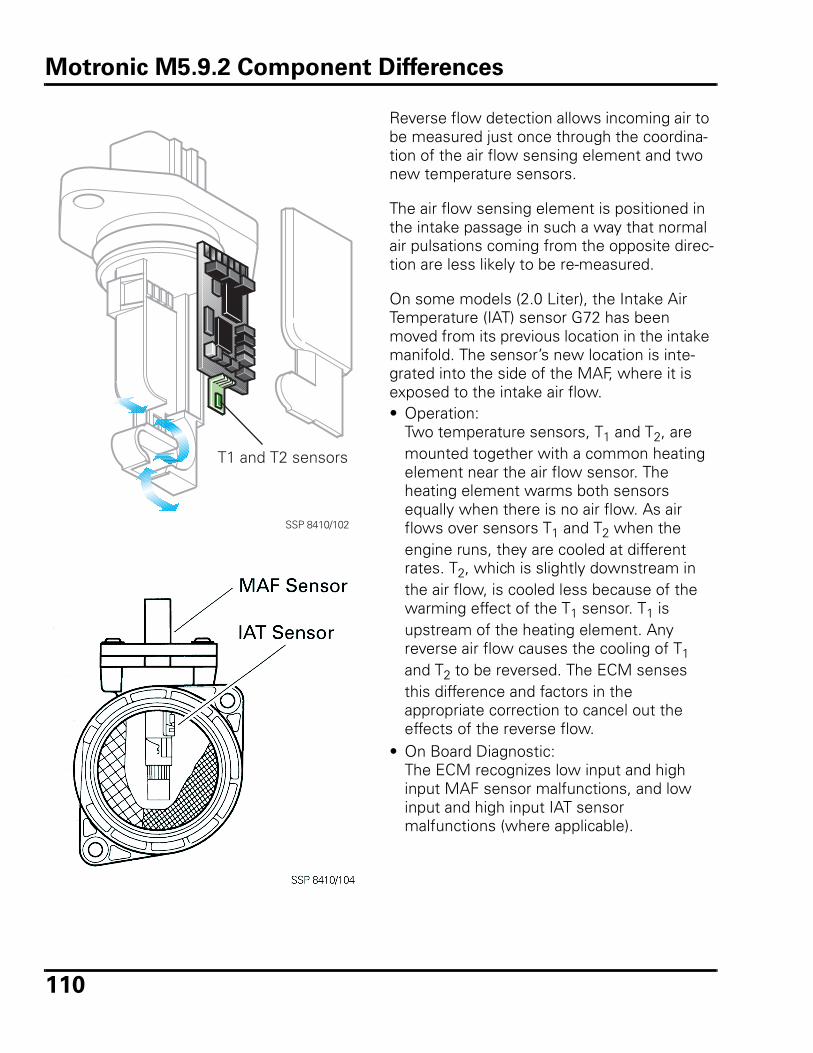
110
Reverse flow detection allows incoming air to be measured just once through the coordina-tion of the air flow sensing element and two new temperature sensors.
The air flow sensing element is positioned in the intake passage in such a way that normal air pulsations coming from the opposite direc-tion are less likely to be re-measured.
On some models (2.0 Liter), the Intake Air Temperature (IAT) sensor G72 has been moved from its previous location in the intake manifold. The sensor’s new location is inte-grated into the side of the MAF, where it is exposed to the intake air flow. • Operation:
Two temperature sensors, T1 and T2, are mounted together with a common heating element near the air flow sensor. The heating element warms both sensors equally when there is no air flow. As air flows over sensors T1 and T2 when the engine runs, they are cooled at different rates. T2, which is slightly downstream in the air flow, is cooled less because of the warming effect of the T1 sensor. T1 is upstream of the heating element. Any reverse air flow causes the cooling of T1 and T2 to be reversed. The ECM senses this difference and factors in the appropriate correction to cancel out the effects of the reverse flow.
• On Board Diagnostic:The ECM recognizes low input and high input MAF sensor malfunctions, and low input and high input IAT sensor malfunctions (where applicable).
SSP 8410/102
T1 and T2 sensors
Motronic M5.9.2 Component Differences
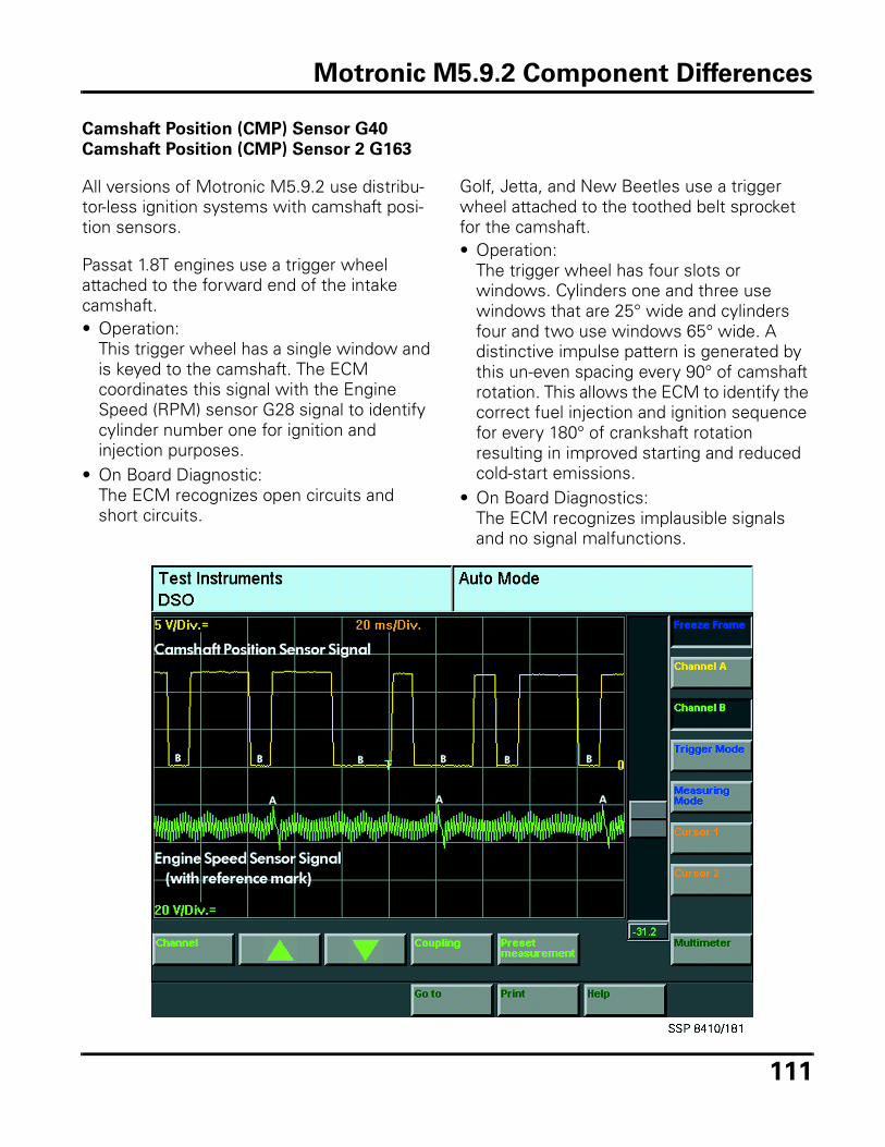
111
Camshaft Position (CMP) Sensor G40
Camshaft Position (CMP) Sensor 2 G163
All versions of Motronic M5.9.2 use distribu-tor-less ignition systems with camshaft posi-tion sensors.
Passat 1.8T engines use a trigger wheel attached to the forward end of the intake camshaft. • Operation:
This trigger wheel has a single window and is keyed to the camshaft. The ECM coordinates this signal with the Engine Speed (RPM) sensor G28 signal to identify cylinder number one for ignition and injection purposes.
• On Board Diagnostic:The ECM recognizes open circuits and short circuits.
Golf, Jetta, and New Beetles use a trigger wheel attached to the toothed belt sprocket for the camshaft. • Operation:
The trigger wheel has four slots or windows. Cylinders one and three use windows that are 25° wide and cylinders four and two use windows 65° wide. A distinctive impulse pattern is generated by this un-even spacing every 90° of camshaft rotation. This allows the ECM to identify the correct fuel injection and ignition sequence for every 180° of crankshaft rotation resulting in improved starting and reduced cold-start emissions.
• On Board Diagnostics:The ECM recognizes implausible signals and no signal malfunctions.
Motronic M5.9.2 Component Differences
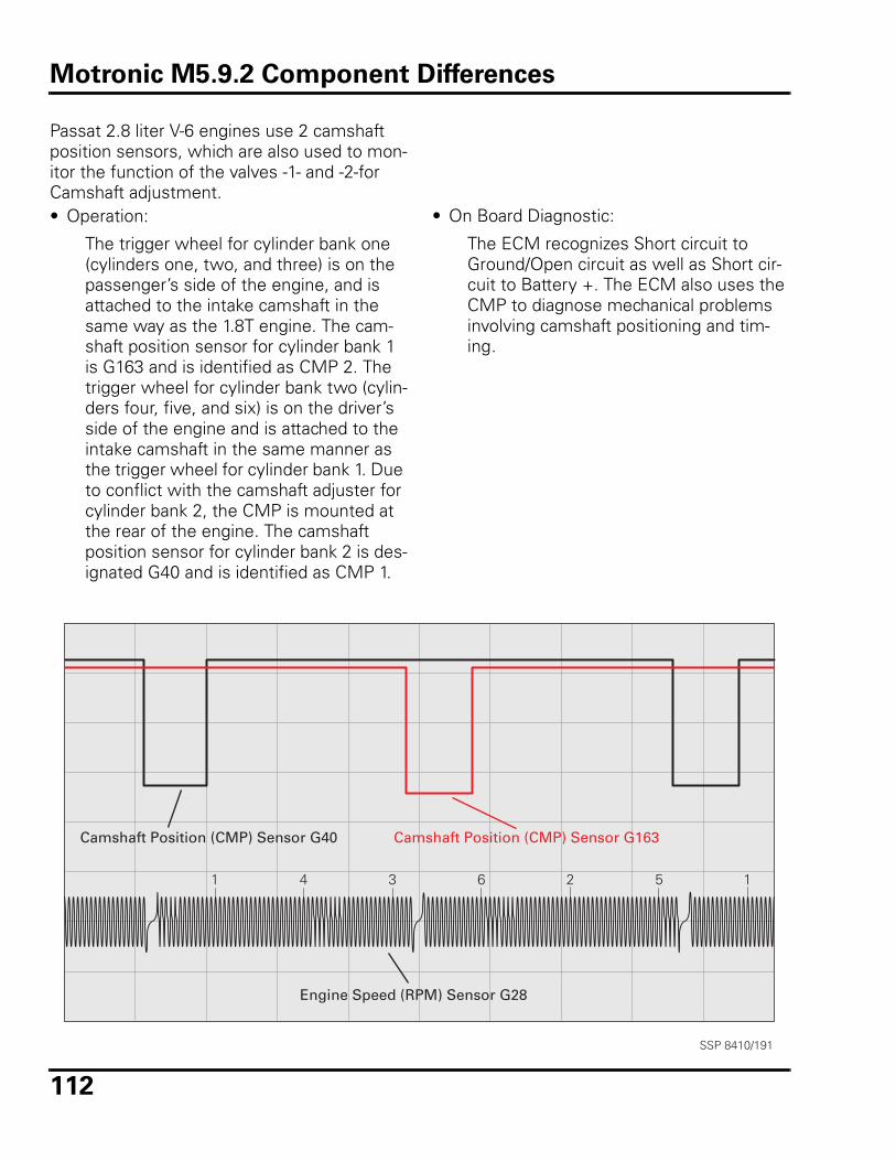
112
Passat 2.8 liter V-6 engines use 2 camshaft position sensors, which are also used to mon-itor the function of the valves -1- and -2-for Camshaft adjustment. • Operation:
The trigger wheel for cylinder bank one (cylinders one, two, and three) is on the passenger’s side of the engine, and is attached to the intake camshaft in the same way as the 1.8T engine. The cam-shaft position sensor for cylinder bank 1 is G163 and is identified as CMP 2. The trigger wheel for cylinder bank two (cylin-ders four, five, and six) is on the driver’s side of the engine and is attached to the intake camshaft in the same manner as the trigger wheel for cylinder bank 1. Due to conflict with the camshaft adjuster for cylinder bank 2, the CMP is mounted at the rear of the engine. The camshaft position sensor for cylinder bank 2 is des-ignated G40 and is identified as CMP 1.
• On Board Diagnostic:
The ECM recognizes Short circuit to Ground/Open circuit as well as Short cir-cuit to Battery +. The ECM also uses the CMP to diagnose mechanical problems involving camshaft positioning and tim-ing.
1 4 3 6 2 5 1
SSP 8410/191
Camshaft Position (CMP) Sensor G40 Camshaft Position (CMP) Sensor G163
Engine Speed (RPM) Sensor G28
Motronic M5.9.2 Component Differences
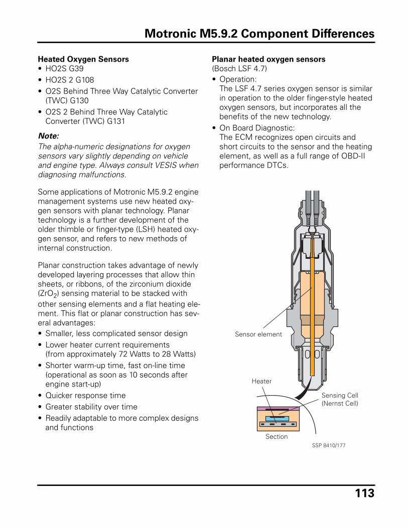
113
Heated Oxygen Sensors
• HO2S G39• HO2S 2 G108• O2S Behind Three Way Catalytic Converter
(TWC) G130• O2S 2 Behind Three Way Catalytic
Converter (TWC) G131
Note:
The alpha-numeric designations for oxygen sensors vary slightly depending on vehicle and engine type. Always consult VESIS when diagnosing malfunctions.
Some applications of Motronic M5.9.2 engine management systems use new heated oxy-gen sensors with planar technology. Planar technology is a further development of the older thimble or finger-type (LSH) heated oxy-gen sensor, and refers to new methods of internal construction.
Planar construction takes advantage of newly developed layering processes that allow thin sheets, or ribbons, of the zirconium dioxide (ZrO2) sensing material to be stacked with other sensing elements and a flat heating ele-ment. This flat or planar construction has sev-eral advantages:• Smaller, less complicated sensor design• Lower heater current requirements
(from approximately 72 Watts to 28 Watts)• Shorter warm-up time, fast on-line time
(operational as soon as 10 seconds after engine start-up)
• Quicker response time • Greater stability over time• Readily adaptable to more complex designs
and functions
Planar heated oxygen sensors
(Bosch LSF 4.7)• Operation:
The LSF 4.7 series oxygen sensor is similar in operation to the older finger-style heated oxygen sensors, but incorporates all the benefits of the new technology.
• On Board Diagnostic:The ECM recognizes open circuits and short circuits to the sensor and the heating element, as well as a full range of OBD-II performance DTCs.
Sensor element
Section
Heater
Sensing Cell(Nernst Cell)
SSP 8410/177
Motronic M5.9.2 Component Differences
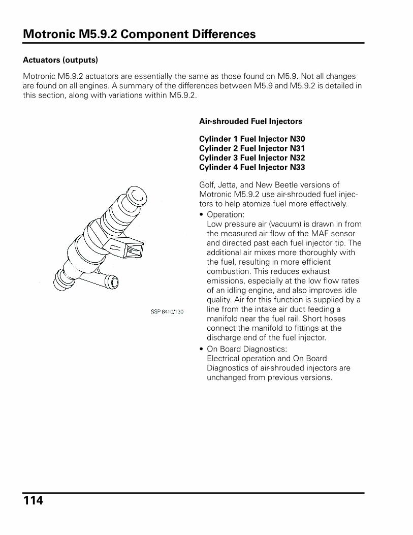
114
Actuators (outputs)
Motronic M5.9.2 actuators are essentially the same as those found on M5.9. Not all changes are found on all engines. A summary of the differences between M5.9 and M5.9.2 is detailed in this section, along with variations within M5.9.2.
Air-shrouded Fuel Injectors
Cylinder 1 Fuel Injector N30
Cylinder 2 Fuel Injector N31
Cylinder 3 Fuel Injector N32
Cylinder 4 Fuel Injector N33
Golf, Jetta, and New Beetle versions of Motronic M5.9.2 use air-shrouded fuel injec-tors to help atomize fuel more effectively.• Operation:
Low pressure air (vacuum) is drawn in from the measured air flow of the MAF sensor and directed past each fuel injector tip. The additional air mixes more thoroughly with the fuel, resulting in more efficient combustion. This reduces exhaust emissions, especially at the low flow rates of an idling engine, and also improves idle quality. Air for this function is supplied by a line from the intake air duct feeding a manifold near the fuel rail. Short hoses connect the manifold to fittings at the discharge end of the fuel injector.
• On Board Diagnostics:Electrical operation and On Board Diagnostics of air-shrouded injectors are unchanged from previous versions.
Motronic M5.9.2 Component Differences
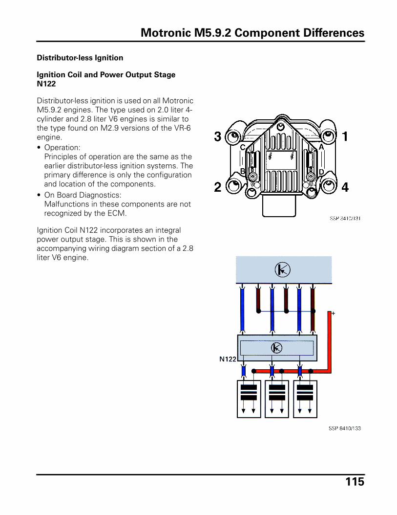
115
Distributor-less Ignition
Ignition Coil and Power Output Stage
N122
Distributor-less ignition is used on all Motronic M5.9.2 engines. The type used on 2.0 liter 4-cylinder and 2.8 liter V6 engines is similar to the type found on M2.9 versions of the VR-6 engine.• Operation:
Principles of operation are the same as the earlier distributor-less ignition systems. The primary difference is only the configuration and location of the components.
• On Board Diagnostics:Malfunctions in these components are not recognized by the ECM.
Ignition Coil N122 incorporates an integral power output stage. This is shown in the accompanying wiring diagram section of a 2.8 liter V6 engine.
Motronic M5.9.2 Component Differences
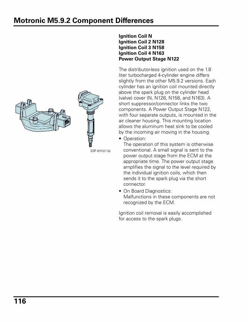
116
Ignition Coil N
Ignition Coil 2 N128
Ignition Coil 3 N158
Ignition Coil 4 N163
Power Output Stage N122
The distributor-less ignition used on the 1.8 liter turbocharged 4-cylinder engine differs slightly from the other M5.9.2 versions. Each cylinder has an ignition coil mounted directly above the spark plug on the cylinder head (valve) cover (N, N128, N158, and N163). A short suppressor/connector links the two components. A Power Output Stage N122, with four separate outputs, is mounted in the air cleaner housing. This mounting location allows the aluminum heat sink to be cooled by the incoming air moving in the housing. • Operation:
The operation of this system is otherwise conventional. A small signal is sent to the power output stage from the ECM at the appropriate time. The power output stage amplifies the signal to the level required by the individual ignition coils, which then sends it to the spark plug via the short connector.
• On Board Diagnostics:Malfunctions in these components are not recognized by the ECM.
Ignition coil removal is easily accomplished for access to the spark plugs.
Motronic M5.9.2 Component Differences
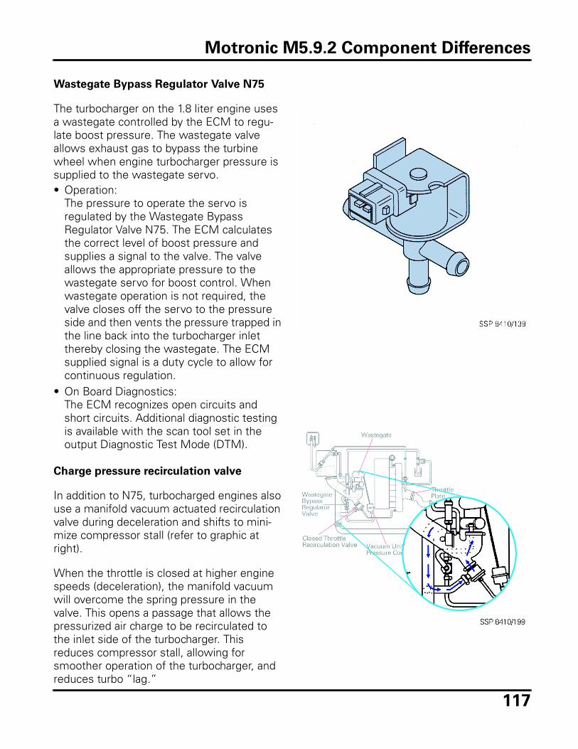
117
Wastegate Bypass Regulator Valve N75
The turbocharger on the 1.8 liter engine uses a wastegate controlled by the ECM to regu-late boost pressure. The wastegate valve allows exhaust gas to bypass the turbine wheel when engine turbocharger pressure is supplied to the wastegate servo. • Operation:
The pressure to operate the servo is regulated by the Wastegate Bypass Regulator Valve N75. The ECM calculates the correct level of boost pressure and supplies a signal to the valve. The valve allows the appropriate pressure to the wastegate servo for boost control. When wastegate operation is not required, the valve closes off the servo to the pressure side and then vents the pressure trapped in the line back into the turbocharger inlet thereby closing the wastegate. The ECM supplied signal is a duty cycle to allow for continuous regulation.
• On Board Diagnostics:The ECM recognizes open circuits and short circuits. Additional diagnostic testing is available with the scan tool set in the output Diagnostic Test Mode (DTM).
Charge pressure recirculation valve
In addition to N75, turbocharged engines also use a manifold vacuum actuated recirculation valve during deceleration and shifts to mini-mize compressor stall (refer to graphic at right).
When the throttle is closed at higher engine speeds (deceleration), the manifold vacuum will overcome the spring pressure in the valve. This opens a passage that allows the pressurized air charge to be recirculated to the inlet side of the turbocharger. This reduces compressor stall, allowing for smoother operation of the turbocharger, and reduces turbo “lag.”
Motronic M5.9.2 Component Differences
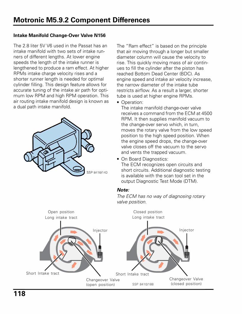
118
Intake Manifold Change-Over Valve N156
The 2.8 liter 5V V6 used in the Passat has an intake manifold with two sets of intake run-ners of different lengths. At lower engine speeds the length of the intake runner is lengthened to produce a ram effect. At higher RPMs intake charge velocity rises and a shorter runner length is needed for optimal cylinder filling. This design feature allows for accurate tuning of the intake air path for opti-mum low RPM and high RPM operation. This air routing intake manifold design is known as a dual path intake manifold.
The “Ram effect” is based on the principle that air moving through a longer but smaller diameter column will cause the velocity to rise. This quickly moving mass of air contin-ues to fill the cylinder after the piston has reached Bottom Dead Center (BDC). As engine speed and intake air velocity increase, the narrow diameter of the intake tube restricts airflow. As a result a larger, shorter tube is used at higher engine RPMs.• Operation:
The intake manifold change-over valve receives a command from the ECM at 4500 RPM. It then supplies manifold vacuum to the change-over servo which, in turn, moves the rotary valve from the low speed position to the high speed position. When the engine speed drops, the change-over valve closes off the vacuum to the servo and vents the trapped vacuum.
• On Board Diagnostics:The ECM recognizes open circuits and short circuits. Additional diagnostic testing is available with the scan tool set in the output Diagnostic Test Mode (DTM).
Note:
The ECM has no way of diagnosing rotary valve position.
Long intake tract
Injector
Long intake tract
Injector
Changeover Valve(open position)
Short Intake tractChangeover Valve(closed position)
Open position Closed position
SSP 8410/188
Short Intake tract
Motronic M5.9.2 Component Differences
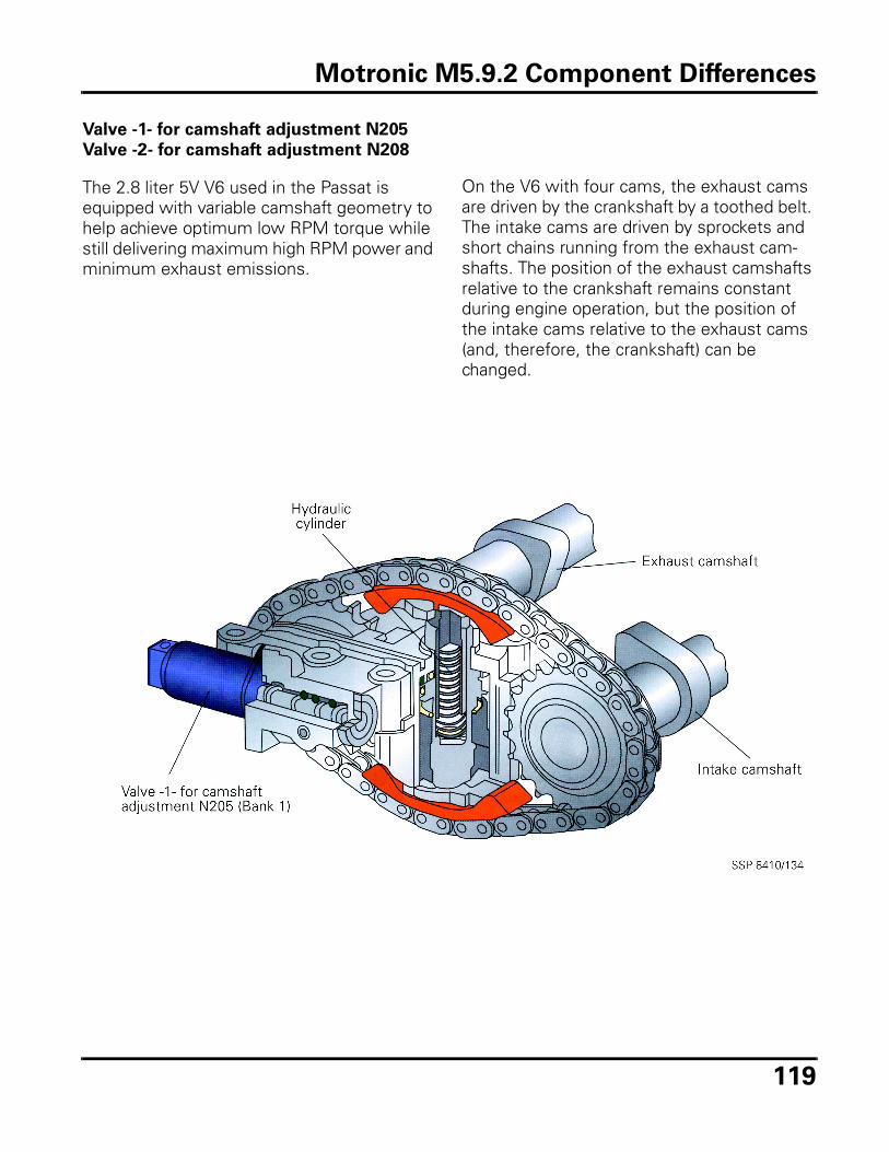
119
Valve -1- for camshaft adjustment N205
Valve -2- for camshaft adjustment N208
The 2.8 liter 5V V6 used in the Passat is equipped with variable camshaft geometry to help achieve optimum low RPM torque while still delivering maximum high RPM power and minimum exhaust emissions.
On the V6 with four cams, the exhaust cams are driven by the crankshaft by a toothed belt. The intake cams are driven by sprockets and short chains running from the exhaust cam-shafts. The position of the exhaust camshafts relative to the crankshaft remains constant during engine operation, but the position of the intake cams relative to the exhaust cams (and, therefore, the crankshaft) can be changed.
Motronic M5.9.2 Component Differences
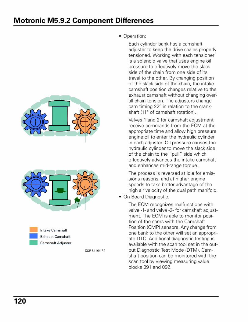
120
• Operation:
Each cylinder bank has a camshaft adjuster to keep the drive chains properly tensioned. Working with each tensioner is a solenoid valve that uses engine oil pressure to effectively move the slack side of the chain from one side of its travel to the other. By changing position of the slack side of the chain, the intake camshaft position changes relative to the exhaust camshaft without changing over-all chain tension. The adjusters change cam timing 22° in relation to the crank-shaft (11° of camshaft rotation).
Valves 1 and 2 for camshaft adjustment receive commands from the ECM at the appropriate time and allow high pressure engine oil to enter the hydraulic cylinder in each adjuster. Oil pressure causes the hydraulic cylinder to move the slack side of the chain to the “pull” side which effectively advances the intake camshaft and enhances mid-range torque.
The process is reversed at idle for emis-sions reasons, and at higher engine speeds to take better advantage of the high air velocity of the dual path manifold.
• On Board Diagnostic:
The ECM recognizes malfunctions with valve -1- and valve -2- for camshaft adjust-ment. The ECM is able to monitor posi-tion of the cams with the Camshaft Position (CMP) sensors. Any change from one bank to the other will set an appropri-ate DTC. Additional diagnostic testing is available with the scan tool set in the out-put Diagnostic Test Mode (DTM). Cam-shaft position can be monitored with the scan tool by viewing measuring value blocks 091 and 092.
Motronic M5.9.2 Component Differences
121
Review
1. Technician A says that the Motronic
M5.9 engine management system is
an enhanced version of Motronic
M2.9.
Technician B says that the Motronic
M5.9 engine management system
complies with OBD-II standards.
Which Technician is correct?
a. Technician A only
b. Technician B only
c. Both Technician A and Technician B
d. Neither Technician A nor Technician B
2. Which of the following is NOT an
advantage of the air shrouded fuel
injectors used in some versions of
Motronic M5.9.2?
a. Improvement in idle quality
b. Reduction in idle emissions
c. More efficient combustion
d. Faster electrical response than pre-vious injector versions
3. Technician A says that the ignition
coils used on the 1.8 liter turbocharged
4-cylinder Motronic M5.9.2 engine use
integrated power output stages.
Technician B says that the ignition
coils must be removed on the 1.8 liter
turbocharged 4-cylinder Motronic
M5.9.2 engine to gain access to the
spark plugs.
Which Technician is correct?
a. Technician A only
b. Technician B only
c. Both Technician A and Technician B
d. Neither Technician A nor Technician B
4. Technician A says that the pre-catalyst
heated oxygen sensor monitors com-
bustion efficiency.
Technician B says that the post-cata-
lyst heated oxygen sensor monitors
three-way catalytic converter effi-
ciency.
Which Technician is correct?
a. Technician A only
b. Technician B only
c. Both Technician A and Technician B
d. Neither Technician A nor Technician B
Review
122
5. Golfs, Jettas and New Beetles
equipped with Motronic M5.9.2 use a
trigger wheel attached to the toothed
belt sprocket for the camshaft. Which
statement best describes the trigger
wheel configuration?
a. Four windows, two 65° wide and two 25° wide
b. Four equally spaced windows
c. Six windows, three 65° wide and three 25° wide
d. Six equally spaced windows
6. Which of the following statements
about the mass air flow sensor with
reverse flow detection in Motronic
M5.9.2 is NOT true:
a. Reverse flow detection allows incoming air to be measured just once.
b. The intake air temperature sensor is now built into the mass air flow sen-sor housing.
c. Two electrically heated pressure sensors within the mass air flow sensor housing help to determine reverse flow.
d. Two electrically heated tempera-ture sensors within the mass air flow sensor housing help to deter-mine reverse flow.
7. Technician A says that the Motronic
M5.9.2 system can have cruise control
as an ECM function.
Technician B says that the Motronic
M2.9 system can have cruise control
as an ECM function.
Which Technician is correct?
a. Technician A only
b. Technician B only
c. Both Technician A and Technician B
d. Neither Technician A nor Technician B
8. Motronic M5.9 evaporative emissions
leak detection pumps are:
a. Operated by an electric motor.
b. Operated by pressure from the sec-ondary air injection pump.
c. Operated by pressure from the fuel pump.
d. Operated by engine vacuum.
9. The Motronic M5.9 ECM will cause the
malfunction indicator light to flash
under which of the following circum-
stances?
a. Engine misfiring.
b. Open circuit in the engine coolant temperature sensor.
c. Leak detection pump records a large or a small leak.
d. Engine speed (RPM) at maximum governed limit.
Review
123
Motronic ME 7
The newest generation of engine manage-ment systems is the Bosch Motronic ME 7. This new system was implemented on the VR-6 engine for the 1999 model year, and model year 2000 for the 2.8 liter 5V V6 and the 1.8 liter 5V turbo.
Motronic ME 7 departs from previous engine management systems in that all subsystems are processed in a sub-processor responsible for all functions of engine performance. Ear-lier systems used separate sub-processors for functions such as ignition, fuel, or emissions.
The main concept of ME 7 is that the previous way of viewing inputs and outputs has been done away with. This new system is a torque
based system.
Motronic ME 7 is continually monitoring inputs from both external sources, like driver input, and transmission control, as well as internal requests such as cruise control, and idle speed. The Motronic ECM interprets these inputs as torque demands, then con-trols actuators accordingly to produce the required torque for the given demand.
The ECM designates signals along two path-ways. This separation of how actuators are handled allows the ECM to better utilize the resources at its disposal.
This new way of viewing inputs as torque demands is a key factor in the functionality of the Motronic ME 7 system.
Pathways
The Motronic ECM coordinates torque demands via two separate pathways.• The charge air path controls all charge
influencing components, such as throttle valve angle and wastegate actuation.
• The crankshaft synchronous path controls all interactions that occur at the same time with the operating cycle of the engine, such as ignition and injector timing and duration.
The crank synchronous path is particularly well suited to meeting short term torque demands, usually having a torque reducing effect.
The charge air path is suited to fulfilling long term torque demands; this path is primarily used for a required torque increase.
For more information on the ME 7 system, refer to the Volkswagen ME 7 SSP #842003.
Components of Motronic ME 7
Motronic ME 7 has brought on several changes or additions in components to both engine management and other related sys-tems.
The changes include:• Electronic throttle control• Cruise control• Charge air pressure sensor G31• Integration of Barometric Pressure (BARO)
sensor F96 as a component of the Motronic ECM J220
• Recirculating Valve for Turbocharger N249
Motronic ME 7
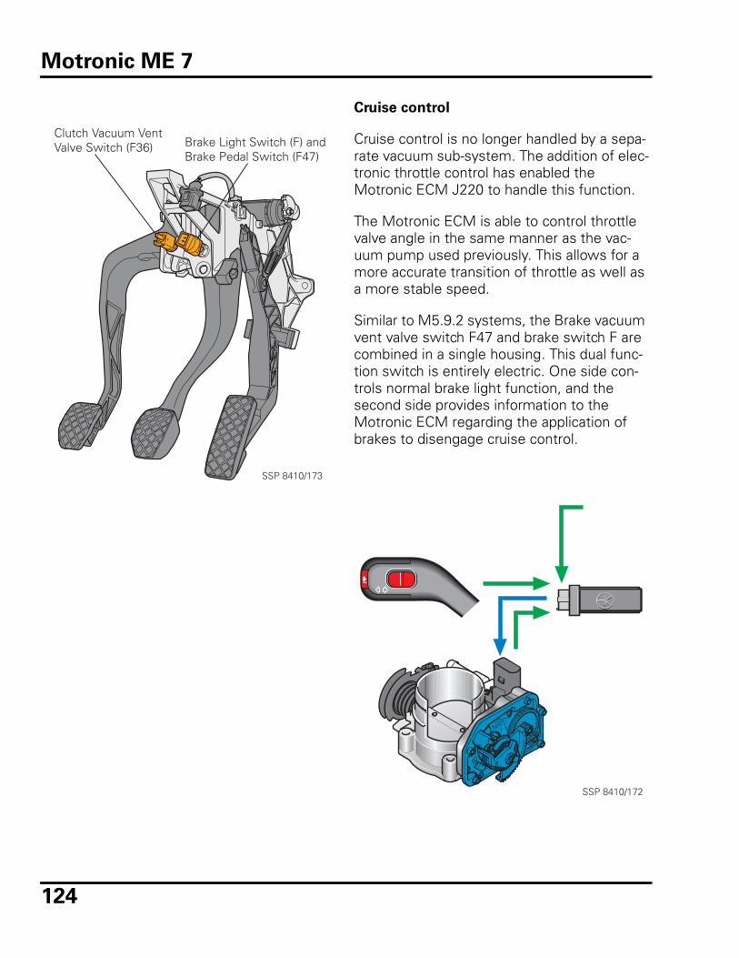
124
Cruise control
Cruise control is no longer handled by a sepa-rate vacuum sub-system. The addition of elec-tronic throttle control has enabled the Motronic ECM J220 to handle this function.
The Motronic ECM is able to control throttle valve angle in the same manner as the vac-uum pump used previously. This allows for a more accurate transition of throttle as well as a more stable speed.
Similar to M5.9.2 systems, the Brake vacuum vent valve switch F47 and brake switch F are combined in a single housing. This dual func-tion switch is entirely electric. One side con-trols normal brake light function, and the second side provides information to the Motronic ECM regarding the application of brakes to disengage cruise control.
SSP 8410/173
Clutch Vacuum VentValve Switch (F36) Brake Light Switch (F) and
Brake Pedal Switch (F47)
SSP 8410/172
Motronic ME 7
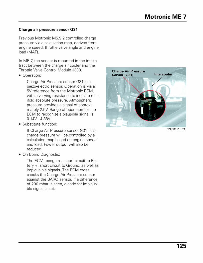
125
Charge air pressure sensor G31
Previous Motronic M5.9.2 controlled charge pressure via a calculation map, derived from engine speed, throttle valve angle and engine load (MAF).
In ME 7, the sensor is mounted in the intake tract between the charge air cooler and the Throttle Valve Control Module J338.• Operation:
Charge Air Pressure sensor G31 is a piezo-electro sensor. Operation is via a 5V reference from the Motronic ECM, with a varying resistance to indicate man-ifold absolute pressure. Atmospheric pressure provides a signal of approxi-mately 2.5V. Range of operation for the ECM to recognize a plausible signal is 0.14V - 4.88V.
• Substitute function:
If Charge Air Pressure sensor G31 fails, charge pressure will be controlled by a calculation map based on engine speed and load. Power output will also be reduced.
• On Board Diagnostic:
The ECM recognizes short circuit to Bat-tery +, short circuit to Ground, as well as implausible signals. The ECM cross checks the Charge Air Pressure sensor against the BARO sensor. If a difference of 200 mbar is seen, a code for implausi-ble signal is set.
Motronic ME 7
126
Barometric Pressure (BARO) sensor F96
The Barometric Pressure (BARO) sensor F96 is no longer a separate component. The BARO sensor is now mounted internally within the Motronic ECM J220.
The BARO sensor is used in conjunction with the Charge Air Pressure sensor G31 for charge pressure control.
In higher elevations charge pressure is reduced to prevent overspinning the turbo-charger.
The BARO sensor is also used for fuel mixture control, leaning out the short term fuel trim with increasing altitudes.• Substitute function:
If the BARO sensor fails, boost is limited to a safe level, and power levels are reduced. Cold running fuel adaptation will no longer take place.
• On Board Diagnostic:
The ECM recognizes implausible signals, as well as short circuit to Battery + and Ground. The fault will display “Control unit defective.”
Recirculating Valve for Turbocharger N249
Previous Motronic M5.9.2 systems used a charge pressure recirculating valve operated by intake manifold vacuum. The key to its functionality was a fully closed throttle valve allowing full engine vacuum to operate the valve.
Electronic throttle control may not allow for this under certain operating conditions. The throttle valve may be held partially open for emissions purposes.
Recirculating Valve for Turbocharger N249 is used to provide vacuum to the recirculating valve using vacuum from a reservoir mounted under the front wheelhousing liner. This allows the Motronic ECM to more accurately control the turbocharger’s performance during throttle transition.• Operation:
N249 is a solenoid valve (see Glossary) similar in design to others used in the engine management system. Power is supplied via the fuel pump relay and the Ground is switched by the Motronic ECM.
• Substitute function:
The system is designed so that if N249 fails, the recirculating valve will continue to function by manifold vacuum.
• On Board Diagnostic:
The ECM recognizes short to Battery + and short circuit to Ground.
Motronic ME 7
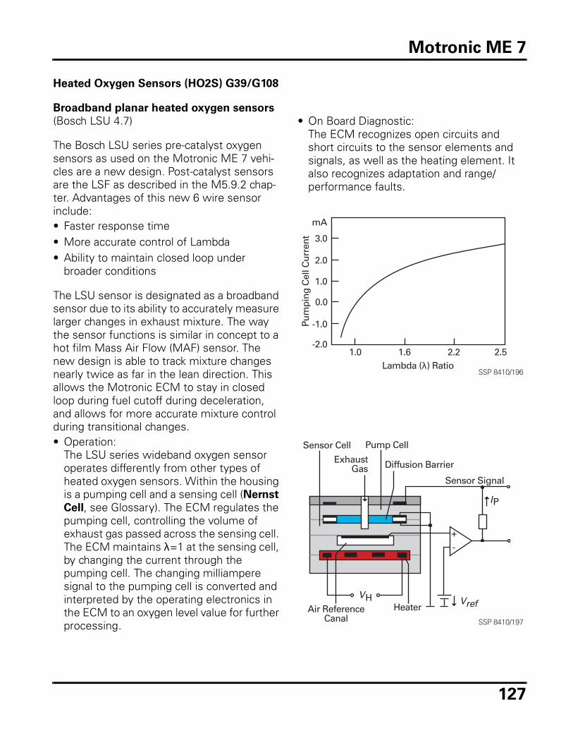
127
Heated Oxygen Sensors (HO2S) G39/G108
Broadband planar heated oxygen sensors
(Bosch LSU 4.7)
The Bosch LSU series pre-catalyst oxygen sensors as used on the Motronic ME 7 vehi-cles are a new design. Post-catalyst sensors are the LSF as described in the M5.9.2 chap-ter. Advantages of this new 6 wire sensor include:• Faster response time• More accurate control of Lambda• Ability to maintain closed loop under
broader conditions
The LSU sensor is designated as a broadband sensor due to its ability to accurately measure larger changes in exhaust mixture. The way the sensor functions is similar in concept to a hot film Mass Air Flow (MAF) sensor. The new design is able to track mixture changes nearly twice as far in the lean direction. This allows the Motronic ECM to stay in closed loop during fuel cutoff during deceleration, and allows for more accurate mixture control during transitional changes.• Operation:
The LSU series wideband oxygen sensor operates differently from other types of heated oxygen sensors. Within the housing is a pumping cell and a sensing cell (Nernst
Cell, see Glossary). The ECM regulates the pumping cell, controlling the volume of exhaust gas passed across the sensing cell. The ECM maintains λ=1 at the sensing cell, by changing the current through the pumping cell. The changing milliampere signal to the pumping cell is converted and interpreted by the operating electronics in the ECM to an oxygen level value for further processing.
• On Board Diagnostic:The ECM recognizes open circuits and short circuits to the sensor elements and signals, as well as the heating element. It also recognizes adaptation and range/performance faults.
1.0 1.6 2.2 2.5-2.0
-1.0
0.0
1.0
2.0
3.0
mA
Lambda (λ) Ratio
Pum
ping
Cel
l Cur
rent
SSP 8410/196
Sensor Cell Pump Cell
Diffusion Barrier
Sensor Signal
+-
Heater
ExhaustGas
Air ReferenceCanal
Vref
IP
VH
SSP 8410/197
Motronic ME 7
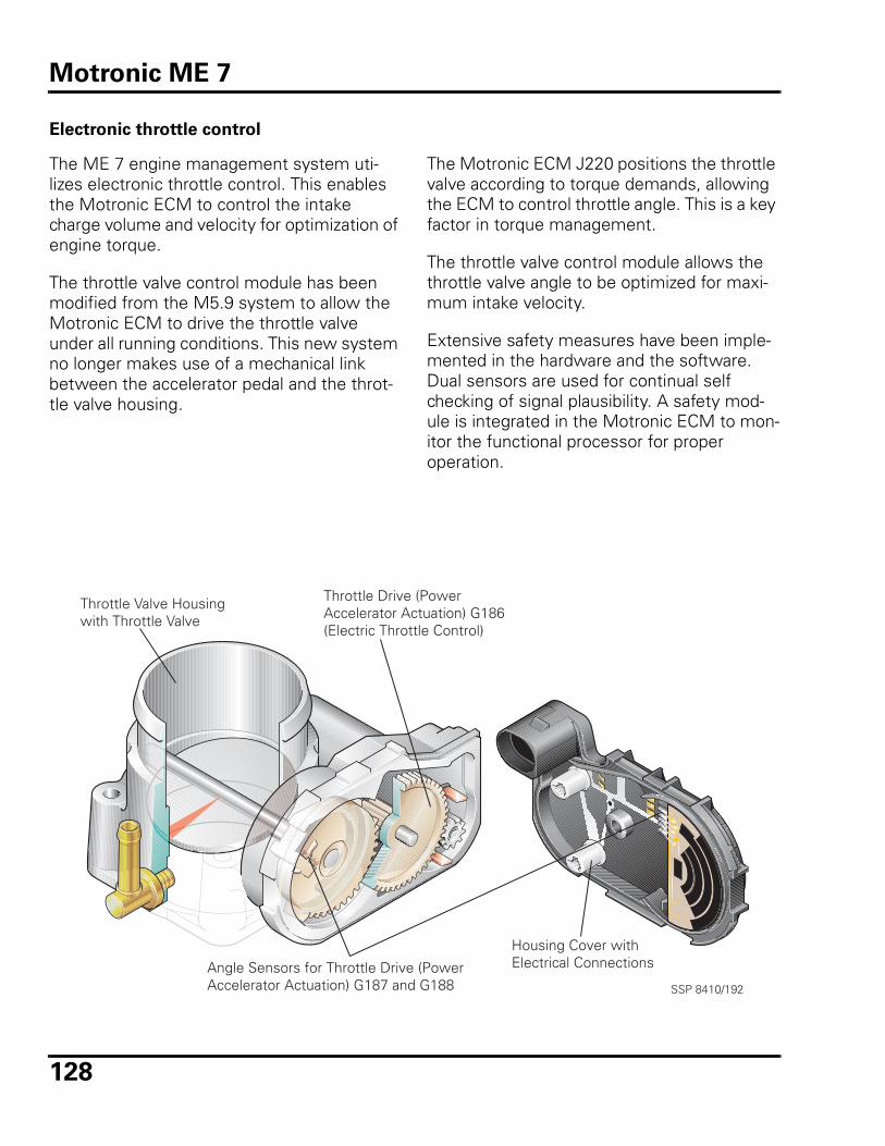
128
Electronic throttle control
The ME 7 engine management system uti-lizes electronic throttle control. This enables the Motronic ECM to control the intake charge volume and velocity for optimization of engine torque.
The throttle valve control module has been modified from the M5.9 system to allow the Motronic ECM to drive the throttle valve under all running conditions. This new system no longer makes use of a mechanical link between the accelerator pedal and the throt-tle valve housing.
The Motronic ECM J220 positions the throttle valve according to torque demands, allowing the ECM to control throttle angle. This is a key factor in torque management.
The throttle valve control module allows the throttle valve angle to be optimized for maxi-mum intake velocity.
Extensive safety measures have been imple-mented in the hardware and the software. Dual sensors are used for continual self checking of signal plausibility. A safety mod-ule is integrated in the Motronic ECM to mon-itor the functional processor for proper operation.
Housing Cover withElectrical ConnectionsAngle Sensors for Throttle Drive (Power
Accelerator Actuation) G187 and G188
Throttle Drive (PowerAccelerator Actuation) G186(Electric Throttle Control)
Throttle Valve Housingwith Throttle Valve
SSP 8410/192
Motronic ME 7
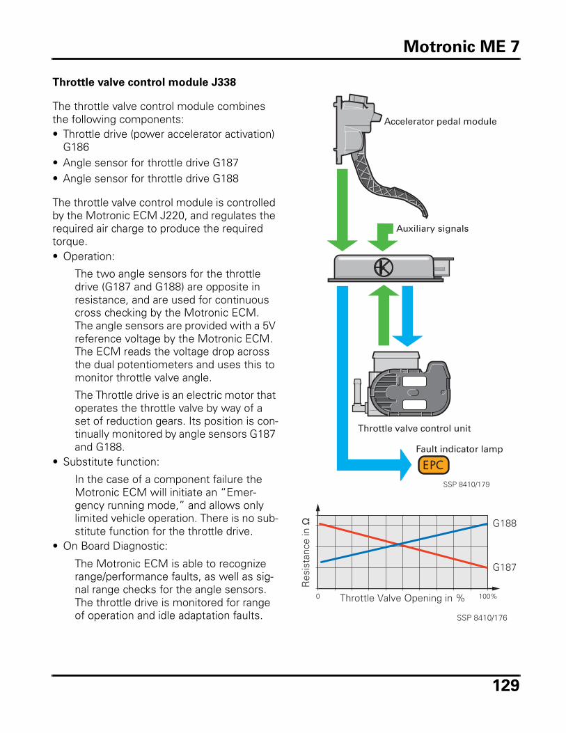
129
Throttle valve control module J338
The throttle valve control module combines the following components:• Throttle drive (power accelerator activation)
G186• Angle sensor for throttle drive G187• Angle sensor for throttle drive G188
The throttle valve control module is controlled by the Motronic ECM J220, and regulates the required air charge to produce the required torque.• Operation:
The two angle sensors for the throttle drive (G187 and G188) are opposite in resistance, and are used for continuous cross checking by the Motronic ECM. The angle sensors are provided with a 5V reference voltage by the Motronic ECM. The ECM reads the voltage drop across the dual potentiometers and uses this to monitor throttle valve angle.
The Throttle drive is an electric motor that operates the throttle valve by way of a set of reduction gears. Its position is con-tinually monitored by angle sensors G187 and G188.
• Substitute function:
In the case of a component failure the Motronic ECM will initiate an “Emer-gency running mode,” and allows only limited vehicle operation. There is no sub-stitute function for the throttle drive.
• On Board Diagnostic:
The Motronic ECM is able to recognize range/performance faults, as well as sig-nal range checks for the angle sensors. The throttle drive is monitored for range of operation and idle adaptation faults.
Throttle valve control unit
Accelerator pedal module
Fault indicator lamp
Auxiliary signals
SSP 8410/179
0 100%
Res
ista
nce
in Ω
Throttle Valve Opening in %
G188
G187
SSP 8410/176
Motronic ME 7
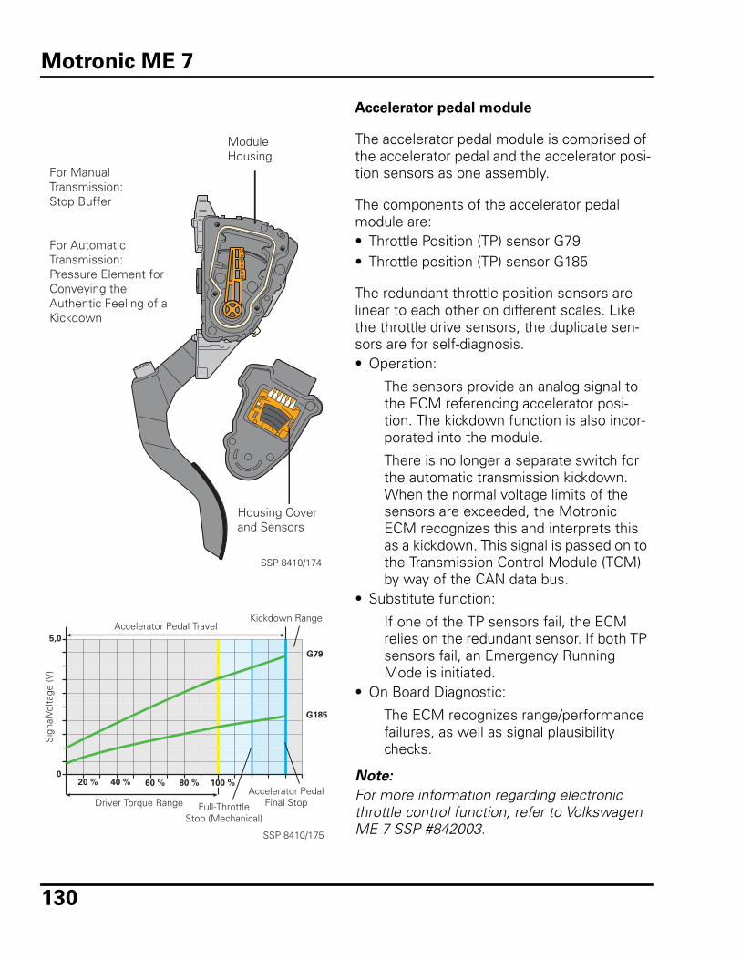
130
Accelerator pedal module
The accelerator pedal module is comprised of the accelerator pedal and the accelerator posi-tion sensors as one assembly.
The components of the accelerator pedal module are:• Throttle Position (TP) sensor G79• Throttle position (TP) sensor G185
The redundant throttle position sensors are linear to each other on different scales. Like the throttle drive sensors, the duplicate sen-sors are for self-diagnosis.• Operation:
The sensors provide an analog signal to the ECM referencing accelerator posi-tion. The kickdown function is also incor-porated into the module.
There is no longer a separate switch for the automatic transmission kickdown. When the normal voltage limits of the sensors are exceeded, the Motronic ECM recognizes this and interprets this as a kickdown. This signal is passed on to the Transmission Control Module (TCM) by way of the CAN data bus.
• Substitute function:
If one of the TP sensors fail, the ECM relies on the redundant sensor. If both TP sensors fail, an Emergency Running Mode is initiated.
• On Board Diagnostic:
The ECM recognizes range/performance failures, as well as signal plausibility checks.
Note:
For more information regarding electronic throttle control function, refer to Volkswagen ME 7 SSP #842003.
ModuleHousing
Housing Coverand Sensors
SSP 8410/174
For ManualTransmission:Stop Buffer
For AutomaticTransmission:Pressure Element for Conveying the Authentic Feeling of a Kickdown
100 %0
G79
G185
5,0
20 % 40 % 60 % 80 %
SSP 8410/175
Driver Torque Range
Sig
nalV
olta
ge (V
)
Accelerator Pedal TravelKickdown Range
Full-ThrottleStop (Mechanical)
Accelerator PedalFinal Stop
Motronic ME 7
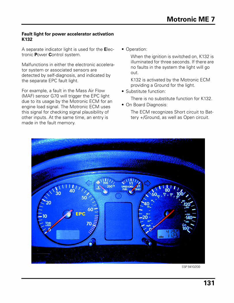
131
Fault light for power accelerator activation
K132
A separate indicator light is used for the Elec-tronic Power Control system.
Malfunctions in either the electronic accelera-tor system or associated sensors are detected by self-diagnosis, and indicated by the separate EPC fault light.
For example, a fault in the Mass Air Flow (MAF) sensor G70 will trigger the EPC light due to its usage by the Motronic ECM for an engine load signal. The Motronic ECM uses this signal for checking signal plausibility of other inputs. At the same time, an entry is made in the fault memory.
• Operation:
When the ignition is switched on, K132 is illuminated for three seconds. If there are no faults in the system the light will go out.
K132 is activated by the Motronic ECM providing a Ground for the light.
• Substitute function:
There is no substitute function for K132.• On Board Diagnosis:
The ECM recognizes Short circuit to Bat-tery +/Ground, as well as Open circuit.
Motronic ME 7
132
Review
1. The ME 7 system is referred to as:
e. A “torque based engine manage-ment system”
f. A “horsepower based engine man-agement system”
g. A “crank synchronous system”
h. A “charge path optimization sys-tem”
2. Component changes for the ME 7 sys-
tem include:
a. Engine Speed (RPM) sensor G28
b. Camshaft Position (CMP) sensor G40/G163
c. Throttle valve control module J338
d. Post catalyst oxygen sensor(s)
3. The resistance curves for throttle
angle drive sensors G187 and G188
are:
a. Opposite
b. Linear, on different scales
c. Identical
d. Flat, with no change
4. The throttle valve control module per-
forms what function?
a. Regulates air charge to produce necessary torque demanded by engine
b. EGR regulation
c. Accelerator pump function
d. Transfers an analog signal to the ECM which corresponds to acceler-ator pedal position.
5. Which of the following components is
not used in the charge air pressure
system?
a. Charge air pressure sensor G31
b. Vehicle Speed Sensor (VSS) G54
c. Wastegate by-pass regulator valve N75
d. Motronic Engine Control Module (ECM) J220
Review
133
Level one course preparation
To be better prepared for the Level One Instructor Led Course, and ultimately, to enable you to succeed in the shop, you are encouraged to utilize the following “tools.”
Critical Thinking Skills
The key to successful, timely problem diagno-sis, and ultimately customer satisfaction, involves “critical thinking.” Getting good infor-mation from service advisors, and diagnosing and solving customer problems is a skill that must be mastered to achieve success.
The four steps to getting good information from service advisors are:1. Focus the discussion on the symptom
description.
2. Ask questions that clarify what, when,
where and how often.
• Use open ended questions to expand discussion.• Use closed ended questions to prompt for specifics.
3. Summarize your understanding and
get agreement.
4. Explain what you will do to proceed
and get acknowledgment.
The five steps to diagnosing and solving cus-tomer problems are:1. Describe the problem.
• List known symptoms.• Avoid opinions or disguised solutions.
2. Verify and analyze.
• Try to duplicate the problem.• List possible causes.
3. Locate the problem.
• Select probable causes.• Prioritize tasks.• Identify the problem.
4. Repair the problem.
• Determine the specific cause.• Perform the repair.
5. Conduct a quality check.
• Recheck for proper operation and reas-sembly.• Check for cleanliness and appearance.
Technician’s Reference
134
Volkswagen Electronic Service Information System (VESIS) navigation
Throughout the Level One Instructor Led Course the technician is required to success-fully navigate through VESIS to diagnose problems, locate components and obtain the latest information pertaining to the subject at hand.
As a technician, you know how important it is to have the proper tools to complete a job in a timely manner. With VESIS, you have fast and simple access to the all the latest repair infor-mation. Advantages include:
• a single source for all Repair Information, including Technical Bulletins, Service Circulars, Component Locations and Suggested Repair Times (SRT).
• frequent updates ensure information is always current.
• simple access to information, as well as hyperlinked cross references, reduce the time spent tracking down procedures and specifications.
Becoming familiar with VESIS will allow you to spend less time searching for information, and more time using the information.
If you have questions regarding the function-ality or setup of VESIS, software support is available from 9:00 AM to 6:00 PM, Monday through Thursday, and 9:00 AM to 5:00 PM, Friday (Eastern Standard Time). The toll-free number is:
• 800-423-1617
Volkswagen HELP line/Tech-tip line
Eventually even the most experienced techni-cians come across a problem that proves extremely difficult to resolve. Volkswagen has created a HELP line to give the technician support during these times. This line con-nects the technician with technical specialists who will work together with the technician to resolve the problem. Hours of operation are eastern time. Phone numbers and times are:
• 800-678-2389 English/French Monday through Friday, 9:00 AM to 7:00 PM Eastern time
• 800-403-4710 English FAX
• 514-331-0477 French FAX
Occasionally the specialists are busy, and the caller will be put on hold. During this time, Volkswagen plays various recorded “Tech-tips.” These tips can include anything from “basics” to the latest problems/solutions being experienced in the field, and can be very useful.
The following information should be recorded and available before you call the Tech Hotline:
• Dealer number (i.e. 401-424).
• Ownership Technical Specialist (OTS) name.
• Repair Order (RO) number.
• Vehicle Identification Number (VIN).
• Production date (from door post label).
• Mileage.
• Engine type and code.
• Transmission type and code.
• Driveline (front wheel drive or 4-Motion).
• Complete VAG 1551/VAS 5051 printout.
• Service history (if possible).
Diagnostic and Special Tools
Technician’s Reference
135
Before attending the Level One Instructor Led Course, be sure you are familiar with all the Diagnostic equipment and Special Tools in your dealership. The following is a list of some of the tools you will be using in class:
• VAS 5051 Vehicle Diagnostic, Testing and Information System, including the Digital Storage Oscilloscope (DSO)
• VAG 1598 pin-out box
• VW 1318 fuel pressure gauges with adapters
• Multimeter (Fluke 83 or equivalent)
• VAG 1594 wiring harness connector test kit
• Leak-down tester
• Compression tester
Review questions
1. In your dealership, locate the tools
listed. Are these tools in good working
order and readily available?
2. Where are the wiring diagrams and
Technical Bulletins stored in your deal-
ership?
3. Where is the service literature (includ-
ing microfiche) stored in your dealer-
ship?
4. What is the phone number for the
Volkswagen Help line?
Suggested reading and reference
There are many resources available for further reading, study, and reference including Self Study Program books published by Volk-swagen of America. Listed below are several that contain Fuel System and/or Engine Man-agement System information:
• EVAP Systems, Operation and Diagnosis
published 11/99, order 841303
• The CAN Data Bus
published 03/99, order WSP 521 419 00
• The New Volkswagen 2.8 Liter V6 Engine
published 12/98, order 821803
• The New 1999 Volkswagen Golf and
Jetta
published 11/98, order 893803
• Service Training SSP for the 1998 New
Beetle
published 02/98, order 891803
• The 1998 Volkswagen Passat
published 08/97, order WSP 521 416 00
• The New Volkswagen Eurovan with the
VR-6 Engine
published 06/98, order WSP 521 414 00
• On Board Diagnosis II
published 12/95, order WSP 521 413 00
• The New Volkswagen Passat
published 10/94, order WSP 521 409 00
• The New Volkswagen Cabrio
published 03/94, order WSP 521 408 00
• 1994 Model Change Information
published 12/93, order WSP 521 407 00
• 1993 Model Change Information
published 11/92, order WSP 521 406 00
• The New Golf III, GTI, Jetta III
published 05/93, order WSP 521 405 00
• 1992 Model Change Information
published 12/91, order WSP 521 404 00
Technician’s Reference
136
• The New Volkswagen VR-6 with
Motronic Engine Management System
published 12/91, order WSP 521 402 00
• The New Eurovan
published 08/92, order WSP 521 401 00
• 1991 Model Change Information
published 12/90, order WSP 521 400 00
• 1990 Model Change Information
published 11/89, order WSP 521 206 00
• The New Volkswagen Passat
published 10/89, order WSP 521 203 00
• The New Volkswagen Corrado
published 08/89, order WSP 521 202 00
• Digifant I & Digifant II - Pro Training
published 12/88, order WSP 521 194 00
• 1988 Product Change
published 09/87, order WSP 521 150 00
• Digifant II Engine Management System
published 02/88, order WSP 521 149 00
• Vanagon/Type II Fuel Systems - Pro
Training
published 03/87, order WSP 521 148 00
• The New Volkswagen Fox
published 08/86, order WSP 521 143 00
• Scirocco 16V
published 05/86, order WSP 521 141 00
• CIS-Electronic Fuel Injection, 2nd Edition
published 06/86, order WSP 521 140 00
• 1986 Vanagon and Vanagon Synchro
published 10/85, order WSP 521 133 00
• 1986 Model Change Information
published 10/85, order WSP 521 132 00
• Service Advisor Technical Reference
Guide
published 04/87, order WSP 521 131 00
• Quantum Synchro
published 08/85, order WSP 521 129 00
• The New Golf, Jetta and GTI
published 1984, order WSP 521 123 00
• The 1984 Volkswagens
published 1983, order WSP 521 118 00
• Water-Cooled Vanagon
published 1983, order WSP 521 112 00
• Solving Driveability Complaints (Digifant
I & II, CIS-E)
published 03/93, order WSP 521 101 00
• The 1983 Rabbits
published 1982, order W42 003 855 1
Many of these titles are available from Dyment Distribution at 800-544-8021. Some titles are no longer in print, but may still be available at the Dealer since all titles were originally sent to the Dealer body.
Several other excellent sources of reference are:
• Bosch Fuel Injection & Engine
Management
by Charles O. Probst, SAE, ISBN 0-8376-0300-5
• Bosch Automotive Handbook
ISBN 0-8376-0333-1
• Bosch Automotive Electric/Electronic
Systems
ISBN 0-8376-0467-2
• Volkswagen Inspection/Maintenance (I/
M) Emission Test Handbook 1980>1997
ISBN 0-8376-0394-3, VW part number LPV 800 901
The above titles can be ordered from book-sellers everywhere including Robert Bentley Publishers, 800-423-4595.
Technician’s Reference
137
Glossary
Adaptation: The ability of an engine management system to continuously modify operating parameters to account for changing operating conditions. For example, an oxygen sensor con-tinuously adjusts or corrects the mixture formation to account for small vacuum leaks, or a knock sensor modifies ignition timing to account for gasoline AKI variances.
Adaptive learning: The ability of an engine management system to continuously modify oper-ating parameters (fine control range) to account for changing operating conditions (i.e. mechan-ical) and the ability to adjust to long term changes by moving the control window within a larger range (coarse control range).
Additive: The effects of the fault (e.g. unmetered air) will reduce as engine speed increases. The injector duration will be modified by a fixed amount for additive learned values. This amount is not dependent upon the basic injection duration.
Barometric pressure sensor: A piezo-electric device used for measuring pressure. A piezo-crystal structure similar to that found in a knock sensor is connected to and sealed within a small diaphragm chamber. An outer chamber surrounds the diaphragm and is connected to the intake tract by a small hose or left open to the atmosphere. Changing pressure conditions act on the diaphragm and, in turn, the crystal. A small voltage signal is generated in relation to air pressure changes. Barometric pressure sensors with sensing elements left open to the atmo-sphere measure changes in air pressure such as those associated with changes in altitude. Sen-sors with elements connected to the intake tract measure manifold pressure changes. Barometric pressure sensors can be either a separate component or built into the ECM.
CARB: California Air Resources Board. Created after the Clean Air Act of 1970 to implement more stringent clean air standards.
Closed loop: A period of engine operation when the ECM is receiving and responding to infor-mation supplied by the oxygen sensor. Loop operation refers to the ECM’s action in response to reaction or feedback supplied by the oxygen sensor.
Dashpot: A mechanical dampening device mounted near the throttle plate. The purpose of the dashpot is to slowly close the throttle, preventing stalling and reducing emissions. Dampening action is accomplished by a spring or a pneumatic diaphragm. Also known as a throttle posi-tioner on some older engines.
Duty cycle: As applied to engine management systems, a duty cycle (or duty factor) is the period of time when a component is switched on or activated. It is usually expressed as a per-centage, such as “a duty cycle of 60%.” Since many automotive components have only two states, on or off, a duty cycle allows accurate control of a function, over a period of time, under conditions that are not always completely on or completely off. For example, the ECM pulses the Ground to the EGR vacuum regulator solenoid valve, switching it on for 10 ms and off for 10 ms continuously, yielding a 50% duty cycle. This effectively operates it at one-half of the flow capacity, even though it does not open half way.
Glossary
138
Hall sensor: A magnetically switched, solid state integrated circuit sensor. When the Hall effect transistor is exposed to a magnetic field, it allows current to flow through the transistor to Ground, completing a circuit. When the magnetic field is not present current flow stops. Trig-ger wheels are often used to pass between the magnet and the transistor. Other applications attach the magnet to a rotating component. When the magnet passes the hall sensor current flow is enabled. Unlike Inductive sensors, Hall sensors require a power source to operate.
I/M 240: (Inspection and Maintenance) A 240 second test period defined in the Federal Test Procedure (FTP), in which a vehicle is tested on a dynomometer under varying engine loads. The test measures the level of emissions of HC, NOx and CO.
Implausible signal: A term used in OBD-I and OBD-II to denote particular types of signal mal-functions. Generally; a signal that falls outside the range of expected values, but is not an open circuit or a short circuit. For example, an ECM sends a 5 Volt reference signal to a sensor and expects a returned signal (voltage drop) of between 0.5 Volts and 4.5 Volts in normal operation. If the ECM “sees” a signal of 4.75 Volts, it is not within the expected range (0.5 to 4.5 Volts), nor is it a short circuit (0 Volts) or an open circuit (5.0 Volts). It is in an area of undefined or implausible signals.
Inductive pickup: Generally, a magnet wrapped with wire. A rotating trigger wheel of ferrous metal causes an alternating current signal to be generated. The signal frequency generated var-ies with the speed of the trigger wheel. The trigger wheel can have a gap which causes a varia-tion in the pulses and identifies a given position. Commonly used for ABS wheel speed sensors and engine RPM and reference sensors.
ISO: International Standards Organization
LSH oxygen sensor (Lambda Sonde Heizung) (Lambda Sensor Heated): Designation given to Bosch™ heated oxygen sensors of the “thimble” or “finger” type of construction where the center electrode is of a circular design. Commonly used in both pre-catalyst and post-catalyst positions.
LSF 4.7 oxygen sensor (Lambda Sonde Finger) (Lambda Sensor Finger): Designation given to Bosch™ heated oxygen sensors using planar (flat) technology but with operation similar to the older finger-style heated oxygen sensors. Commonly used in both pre-catalyst and post-cat-alyst positions.
LSU 4.7 oxygen sensor (Lambda Sonde Universal) (Lambda Sensor Universal): Designation given to Bosch™ universal or wideband heated oxygen sensors using planar (flat) technology and new methods of signal generation. These six-wire heated oxygen sensors operate by using an internal ion pump to supply a measuring cell. The sensor signal is derived from the strength of the signal sent to the ion pump. Used in the pre-catalyst position of some systems.
Multiplicative: The effects of the fault (e.g. faulty injector) will increase with engine speed (RPM). A multiplicative learned value is a proportional change to the injector duration. This change is dependant on the basic injector duration.
Glossary
139
NTC sensor: Negative Temperature Coefficient; a temperature sensing component in which the electrical resistance decreases as the temperature increases.
Nernst Cell: An electro-chemical (Voltaic) cell based on mathematical equations first devised by Walther Hermann Nernst (1864-1941). The equation predicts the flow of gaseous ions and the resulting voltage at very high temperatures. Used as a measuring cell in oxygen sensors.
Open loop: A period of engine operation when the ECM is either not receiving or not respond-ing to information supplied by the oxygen sensor. Generally, an engine management system is in open loop after start-up (hot or cold), because the oxygen sensor is not up to proper operat-ing temperature. In this situation, the ECM is instructed to run the engine with pre-programmed values until it recognizes a valid oxygen sensor signal. An engine management system can also be in open loop during hard acceleration where the ECM is programmed to slightly enrich the mixture. In this situation, the ECM is receiving valid signal information, but is programmed to temporarily disregard it. If an engine management system receives no signal, such as in the case of a disconnected or open circuited oxygen sensor, the ECM is programmed to run on pre-programmed internal values. Open loop operation, in this context, refers to the ECM’s lack of response to feedback supplied by the oxygen sensor or the lack of a signal, thereby breaking the feedback loop.
Range/Performance malfunction: An OBD-II term used to denote particular types of mal-functions that do not seem to be possible under normal operating circumstances. An example of a Range/Performance malfunction is a throttle position sensor that has a low voltage at a engine speed with high rpm and a high mass air flow. High engine speed and high flow through the mass air flow sensor generally equate to high throttle position voltage, so this situation should not occur and will set a DTC as appropriate.
Solenoid valve: An electrically switched electro-magnetic valve. Usually consists of a coil of wire through which an electric current is passed. The resulting magnetic field opens a valve, allowing passage of a gas or liquid.
Solid State: An electronic device or circuit using transistors and similar components. Does not use vacuum tubes.
Stoichiometric: 14.7:1. Theoretical optimum air/fuel ratio for operating a spark ignition gasoline engine.
ϑ - Greek symbol theta: This symbol is placed in or near a component illustration to denote the influence of temperature on the component. Commonly used in wiring diagrams to identify temperature sensors and circuit breakers.
λ - Greek letter lambda: This symbol denotes the air factor in the air/fuel mixture of an internal combustion engine. A λ value of 1 (λ = 1) indicates Stoichiometric.
Glossary

140
< - Mathematical symbol: This symbol denotes “less than.” The text “λ < 1” is read as “lambda is less than 1.”
> - Mathematical symbol: This symbol denotes “greater than.” The text “λ >1” is read as “lambda is greater than 1.
Glossary
141
Volkswagen Engine Management Systems Teletest
The test accompanying this course, #841003, has been prepared and shipped as a separate document. Please refer to your copy of that document and follow the testing instructions to complete the Teletest.
Additional copies are available by contacting:
Certification 2001 Program Headquarters
Toll-free Hotline & Testing: 1-877-CU4-CERT (1-877-284-2378)
Fax:1-877-FX4-CERT (1-877-394-2378)
Hotline assistance is available Monday-Friday
between 9:00 a.m. and 5:00 p.m., EST.
Teletest


Course Number 841003WSP 521 841 03
Related Documents