FUJITSU SEMICONDUCTOR CONTROLLER MANUAL F 2 MC-8L FAMILY 8-BIT MICROCONTROLLER EMBEDDED C PROGRAMMING MANUAL FOR fcc896 CM25-00320-1E

Welcome message from author
This document is posted to help you gain knowledge. Please leave a comment to let me know what you think about it! Share it to your friends and learn new things together.
Transcript
FUJITSU SEMICONDUCTORCONTROLLER MANUAL
F2MC-8L FAMILY8-BIT MICROCONTROLLER
EMBEDDED CPROGRAMMING MANUAL
FOR fcc896
CM25-00320-1E

F2MC-8L FAMILY8-BIT MICROCONTROLLER
EMBEDDED CPROGRAMMING MANUAL
FOR fcc896
FUJITSU LIMITED

PREFACE
■ Objectives and Intended Reader
The F2MC-8L family are 8-bit microcontrollers designed for embedded systems.
This manual provides information required for using the fcc896 F2MC-8L family C compiler tocreate an embedded system. The manual explains how to create C programs that effectively
use the F2MC-8L family architecture and provides notes related to the creation of C programs.
This manual is intended for engineers who use the fcc896 to develop application programs for
the F2MC-8L family. Be sure to read this manual completely.
■ Trademarks
Softune is a registered trademark of Fujitsu Limited.
Other system names and product names in this manual are trademarks of their respectivecompanies or organizations. The symbols ™ and ® are sometimes omitted in the text.
■ Structure of This Manual
This manual consists of the three parts listed below.
PART I "VARIABLE DEFINITIONS AND VARIABLE AREAS"
Part I describes the variable definitions and variable areas for creating C programs.
CHAPTER 1 "OBJECTS MAPPED INTO MEMORY AREAS"
This chapter briefly describes the memory mapping for a systems in which an F2MC-8Lfamily microcontroller was embedded.
CHAPTER 2 "VARIABLE DEFINITIONS AND VARIABLE AREAS"
This chapter describes the variable definitions and variable areas to which the results ofcompilation are output. It also describes the variable areas for variables that are initialized atdefinition and the variable area for those that are not. In addition, the chapter describesvariables declared as "static."
CHAPTER 3 "READ-ONLY VARIABLES AND THEIR VARIABLE AREA"
This chapter describes how to use variables declared with the type-qualifier "const" that areonly read at execution time and provides notes on their use. This chapter also discusses thereduction of the variable area and object efficiency for referencing when the "const" typemodifier is used.
CHAPTER 4 "USING AUTOMATIC VARIABLES TO REDUCE THE VARIABLE AREA"
This chapter explains how to reduce the variable area by using automatic variables. Area isallocated to automatic variables at execution time.
CHAPTER 5 "ACCESSING VARIABLES THAT USE BIT FIELDS"
This chapter describes how to access variables that use bit fields.
PART II "USING THE STACK AREA EFFICIENTLY"
Part II describes how to use the stack area efficiently.
i
CHAPTER 6 "FUNCTION CALLS AND THE STACK"
This chapter briefly describes the stack area used when a function is called.
CHAPTER 7 "REDUCING FUNCTION CALLS BY EXPANDING FUNCTIONS IN LINE"
This chapter describes how to reduce the stack area by using inline expansion of functions infunction calls.
CHAPTER 8 "REDUCING ARGUMENTS TO CONSERVE STACK AREA"
This chapter describes how to reduce the number of arguments in function calls so that lessstack area is required.
CHAPTER 9 "CONSERVING STACK AREA BY IMPROVEMENTS ON THE AREA FOR FUNCTION RETURN VALUES"
This chapter explains the function return values for the register and the stack. Reducing thereturn values for the stack can reduce the used stack area.
PART III "USING LANGUAGE EXTENSIONS"
Part III describes the language extensions specific to the fcc896. Part III also discussesitems in the extended language specifications that require special attention.
CHAPTER 10 "WHAT ARE LANGUAGE EXTENSIONS?"
This chapter describes the fcc896-specific extended language specifications, such as thequalifier for extensions, _ _asm statement, and "#pragma."
CHAPTER 11 "NOTES ON ASSEMBLER CODE IN C PROGRAMS"
This chapter provides notes on including assembler code with the __asm statements and#pragma asm/endasm of the extended language specifications.
CHAPTER 12 "NOTES ON DEFINING AND ACCESSING THE I/O AREA"
This chapter provides notes on specifying and mapping when using the _ _io type qualifier.
CHAPTER 13 "MAPPING VARIABLES QUALIFIED WITH THE TYPE QUALIFIER _ _DIRECT"
This chapter provides notes on specifying and allocating variables declared with the _ _directtype qualifier.
CHAPTER 14 "CREATING AND REGISTERING INTERRUPT FUNCTIONS"
This chapter provides notes on using language extensions of the fcc896 to enable interruptprocessing.
In this manual, the designation <Notes> indicates items requiring special attention.
The sections entitled "Tip" provide information on functions that is useful for creating programs.
The Softune C Checker analyzes C source programs and outputs a warning for items requiringattention to ensure that the fcc896 does not output an error message.
The Softune C Analyzer analyzes function calls within the C source code of the program anddisplays information about such items as variables, relationship between function references,and the used amount of stack areas.
ii
© 2000 FUJITSU LIMITED Printed in Japan
1. The contents of this document are subject to change without notice. Customers are advised to consultwith FUJITSU sales representatives before ordering.
2. The information and circuit diagrams in this document are presented as examples of semiconductordevice applications, and are not intended to be incorporated in devices for actual use. Also, FUJITSU isunable to assume responsibility for infringement of any patent rights or other rights of third partiesarising from the use of this information or circuit diagrams.
3. The contents of this document may not be reproduced or copied without the permission of FUJITSULIMITED.
4. FUJITSU semiconductor devices are intended for use in standard applications (computers, officeautomation and other office equipments, industrial, communications, and measurement equipments,personal or household devices, etc.).CAUTION:Customers considering the use of our products in special applications where failure or abnormaloperation may directly affect human lives or cause physical injury or property damage, or whereextremely high levels of reliability are demanded (such as aerospace systems, atomic energy controls,sea floor repeaters, vehicle operating controls, medical devices for life support, etc.) are requested toconsult with FUJITSU sales representatives before such use. The company will not be responsible fordamages arising from such use without prior approval.
5. Any semiconductor devices have inherently a certain rate of failure. You must protect against injury,damage or loss from such failures by incorporating safety design measures into your facility andequipment such as redundancy, fire protection, and prevention of over-current levels and otherabnormal operating conditions.
6. If any products described in this document represent goods or technologies subject to certainrestrictions on export under the Foreign Exchange and Foreign Trade Control Law of Japan, the priorauthorization by Japanese government should be required for export of those products from Japan.
iii
HOW TO USE THIS MANUAL
■ Page Layout
The contents of each section are summarized underneath the title. You can acquire a basicidea of what the section covers by reading these summaries.
In addition, higher level section headings are also provided in lower level sections so that youknow to which section the text you are currently reading belongs.
iv
CONTENTS
PART I VARIABLE DEFINITIONS AND VARIABLE AREAS ........................................... 1
CHAPTER 1 OBJECTS MAPPED INTO MEMORY AREAS ............................................. 31.1 Program Components ............................................................................................................................ 41.2 Mapping into Memory Areas .................................................................................................................. 61.3 Dynamically Allocated Variables ............................................................................................................ 81.4 Statically Allocated Variables ............................................................................................................... 10
CHAPTER 2 VARIABLE DEFINITIONS AND VARIABLE AREAS ................................ 132.1 External Variables and Their Variable Area ......................................................................................... 142.2 Initial Values and Variable Area for External Variables ....................................................................... 162.3 Initialized Variables and Initialization at Execution .............................................................................. 182.4 Variables Declared as "static" and Their Variable Area ....................................................................... 20
2.4.1 Example of Function with Static Global Variable ............................................................................ 222.4.2 Example of a Function with Static Local Variable ........................................................................... 23
CHAPTER 3 READ-ONLY VARIABLES AND THEIR VARIABLE AREA ...................... 253.1 Numeric Constants and #define Definition .......................................................................................... 263.2 Defining Variables Using the const Type Qualifier .............................................................................. 28
CHAPTER 4 USING AUTOMATIC VARIABLES TO REDUCE THE VARIABLE AREA 314.1 Automatic Variables and Statically Allocated Variables ....................................................................... 324.2 Using Automatic Variables ................................................................................................................... 35
CHAPTER 5 ACCESSING VARIABLES THAT USE BIT FIELDS .................................. 395.1 Boundary Alignment of fcc896 ............................................................................................................. 405.2 Bit Field Definitions and Boundary Alignment ...................................................................................... 415.3 Accessing I/O Areas Using Bit Fields and Unions ............................................................................... 45
PART II USING THE STACK AREA EFFICIENTLY ......................................................... 47
CHAPTER 6 FUNCTION CALLS AND THE STACK ....................................................... 496.1 Areas Allocated on the Stack during Function Calls ............................................................................ 506.2 Stack States When Function Calls Are Nested ................................................................................... 52
CHAPTER 7 REDUCING FUNCTION CALLS BY EXPANDING FUNCTIONS IN LINE ........................................................................................................ 53
7.1 Inline Expansion of Function ................................................................................................................ 547.2 Conditions for Inline Expansion of Function ........................................................................................ 57
v
CHAPTER 8 REDUCING ARGUMENTS TO CONSERVE STACK AREA ..................... 598.1 Passing Arguments During Function Calls ......................................................................................... 60
8.1.1 Normal Argument Passing ............................................................................................................. 618.1.2 Argument Structure Passing .......................................................................................................... 628.1.3 Structure Address Passing ............................................................................................................ 638.1.4 Stack Status During Function Calls ............................................................................................... 64
8.2 Conditions for Structure Address Transfer .......................................................................................... 65
CHAPTER 9 CONSERVING STACK AREA BY IMPROVEMENTS ON THE AREA FOR FUNCTION RETURN VALUES .......................................................... 67
9.1 Return Value of Functions .................................................................................................................. 689.2 Functions Returning Structure-type Values and Stack Conservation ................................................. 729.3 Functions Returning Union-type Values and Stack Conservation ...................................................... 76
PART III USING LANGUAGE EXTENSIONS .................................................................... 81
CHAPTER 10 WHAT ARE LANGUAGE EXTENSIONS? ................................................. 8310.1 Coding Assembler Instructions Using an _ _asm Statement .............................................................. 8410.2 Extended Type Qualifiers .................................................................................................................... 85
10.2.1 _ _io Type Qualifier ........................................................................................................................ 8610.2.2 _ _direct Type Qualifier .................................................................................................................. 8810.2.3 _ _interrupt Type Qualifier ............................................................................................................. 9010.2.4 _ _nosavereg Type Qualifier .......................................................................................................... 92
10.3 Extended Functions Using #pragma ................................................................................................... 9410.3.1 Inserting Assembler Programs Using #pragma asm/endasm ........................................................ 9510.3.2 Specifying Inline Expansion Using #pragma inline ........................................................................ 9610.3.3 Using #pragma section to Change Section Names and Specify Mapping Address ...................... 9810.3.4 Specifying the Interrupt Level Using #pragma ilm/noilm .............................................................. 10010.3.5 Setting the Register Bank Using #pragma register/noregister ..................................................... 10210.3.6 Generating an Interrupt Vector Table Using #pragma intvect/defvect ......................................... 104
10.4 Built-in Functions .............................................................................................................................. 10610.4.1 Disabling Interrupts Using _ _DI( ) ............................................................................................... 10710.4.2 Enabling Interrupts Using _ _EI( ) ................................................................................................ 10810.4.3 Setting the Interrupt Level Using _ _set_il( ) ................................................................................ 10910.4.4 Outputting a Nop Instruction Using _ _wait_nop( ) ...................................................................... 110
CHAPTER 11 NOTES ON ASSEMBLER PROGRAM IN C PROGRAMS ...................... 11111.1 Including Assembler Program in C Programs ................................................................................... 11211.2 Differences Between Using the _ _asm Statement and #pragma asm/endasm ............................... 115
CHAPTER 12 NOTES ON DEFINING AND ACCESSING THE I/O AREA ..................... 11912.1 M89620 Series I/O Areas .................................................................................................................. 12012.2 Defining and Accessing Variables Mapped into the I/O Area ........................................................... 122
vi
CHAPTER 13 MAPPING VARIABLES QUALIFIED WITH THE TYPE QUALIFIER _ _direct ................................................................................ 127
13.1 Output Sections of and Access to Variables Qualified by the _ _direct Type Qualifier ..................... 12813.2 Mapping Variables Qualified by the _ _direct Type Qualifier ............................................................. 130
CHAPTER 14 CREATING AND REGISTERING INTERRUPT FUNCTIONS .................. 13314.1 F2MC-8L Family Interrupts ................................................................................................................ 13414.2 Required Hardware Settings for Interrupts ........................................................................................ 136
14.2.1 Setting the Stack Area .................................................................................................................. 13714.2.2 Initializing Resources .................................................................................................................... 13814.2.3 Setting Interrupt Control Registers ............................................................................................... 13914.2.4 Starting Resource Operation ........................................................................................................ 14114.2.5 Enabling CPU Interrupts ............................................................................................................... 142
14.3 Using the _ _interrupt Type Qualifier to Define Interrupt Functions ................................................... 14714.4 Setting of Interrupt Vectors ................................................................................................................ 151
INDEX .....................................................................................................................153
vii

viii
PART I VARIABLE DEFINITIONS AND VARIABLE AREAS
This part describes the variable definitions and variable areas for creating C programs.This part first briefly describes memory mapping and the variables used for creating
an F2MC-8L family microcontroller embedded system. It then briefly describes the relationship between the variable definitions and variable areas. It concludes by describing how to efficiently create C programs.
CHAPTER 1 "OBJECTS MAPPED INTO MEMORY AREAS"
CHAPTER 2 "VARIABLE DEFINITIONS AND VARIABLE AREAS"
CHAPTER 3 "READ-ONLY VARIABLES AND THEIR VARIABLE AREA"
CHAPTER 4 "USING AUTOMATIC VARIABLES TO REDUCE THE VARIABLE AREA"
CHAPTER 5 "ACCESSING VARIABLES THAT USE BIT FIELDS"
1

2
CHAPTER 1 OBJECTS MAPPED INTO MEMORY AREAS
This chapter briefly describes objects that are mapped into memory areas before taking up the subject of the variable.
1.1 "Program Components"
1.2 "Mapping into Memory Areas"
1.3 "Dynamically Allocated Variables"
1.4 "Statically Allocated Variables"
3
CHAPTER 1 OBJECTS MAPPED INTO MEMORY AREAS
1.1 Program Components
This section briefly describes the program components.Programs can be roughly divided into code and data.
■ Program Components
Programs created in C (C programs hereafter) and programs created in Assembler (assemblerprograms hereafter) can both be roughly divided into code and data sections.
❍ Code
This section in the program contains the machine instructions to be executed by the CPU.
The algorithm, which is coded as functions in a C program, is compiled and converted tomachine instruction code.
The term "Code" refers to a set of execution instructions that are only read at execution.
❍ Data
The data is accessed by the program.
In a C program, the data includes variables, character strings, literal constants, and initialvalues.
Data can be read and written depending on the processing.
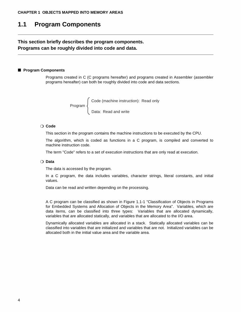
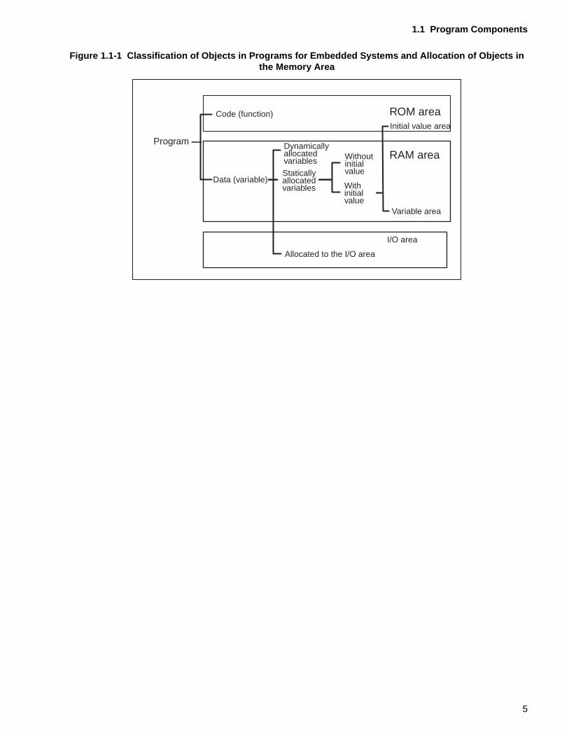
A C program can be classified as shown in Figure 1.1-1 "Classification of Objects in Programsfor Embedded Systems and Allocation of Objects in the Memory Area". Variables, which aredata items, can be classified into three types: Variables that are allocated dynamically,variables that are allocated statically, and variables that are allocated to the I/O area.
Dynamically allocated variables are allocated in a stack. Statically allocated variables can beclassified into variables that are initialized and variables that are not. Initialized variables can beallocated both in the initial value area and the variable area.
ProgramCode (machine instruction): Read only
Data: Read and write
4
1.1 Program Components
Figure 1.1-1 Classification of Objects in Programs for Embedded Systems and Allocation of Objects in the Memory Area
Program
Code (function)
Data (variable)
DynamicallyallocatedvariablesStaticallyallocatedvariables
Allocated to the I/O area
Withoutinitialvalue
Withinitialvalue
ROM areaInitial value area
RAM area
Variable area
I/O area
5
CHAPTER 1 OBJECTS MAPPED INTO MEMORY AREAS
An
p rou-
1.2 Mapping into Memory Areas
This section briefly describes the types of memory areas and the objects that are mapped into them.
In embedded systems that use an F 2MC-8L family microcontroller, the memory area can be mainly classified into ROM, RAM, and I/O area.
■ Mapping into Memory Areas
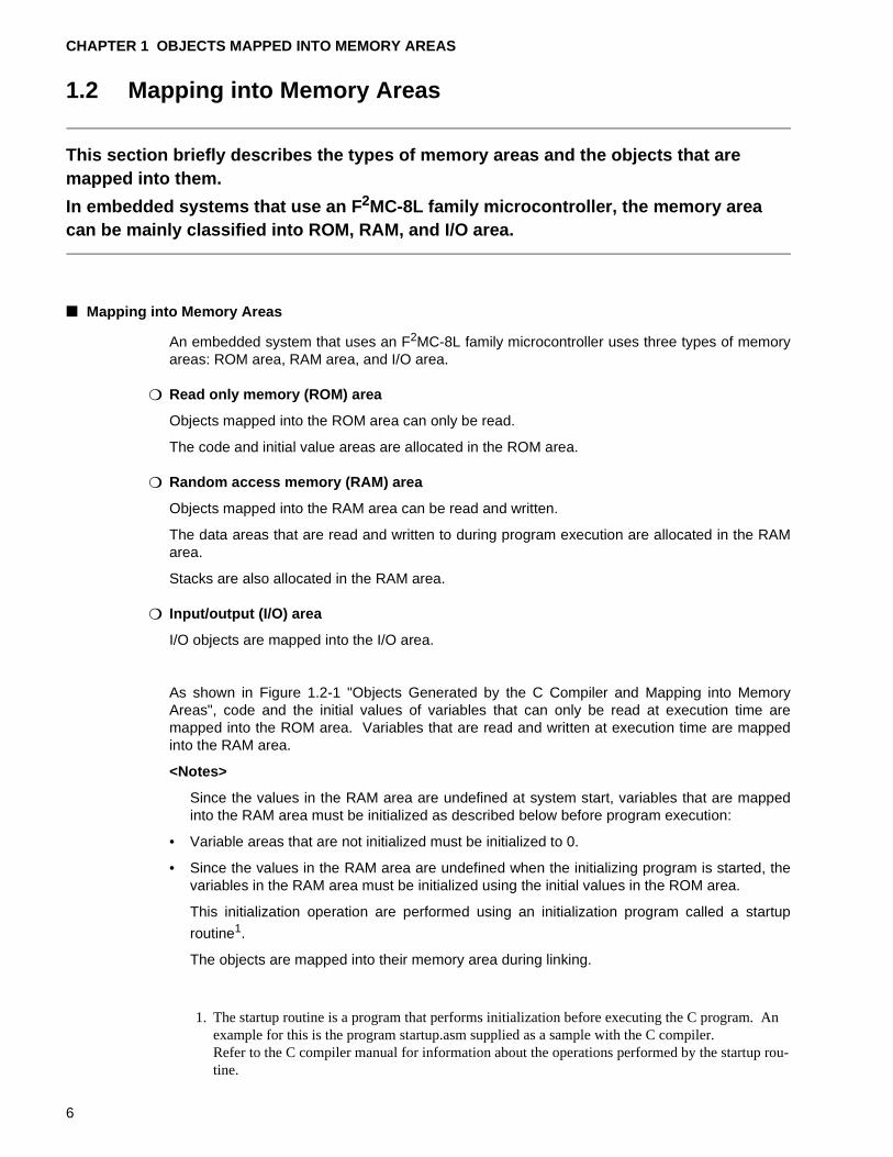
An embedded system that uses an F2MC-8L family microcontroller uses three types of memoryareas: ROM area, RAM area, and I/O area.
❍ Read only memory (ROM) area
Objects mapped into the ROM area can only be read.
The code and initial value areas are allocated in the ROM area.
❍ Random access memory (RAM) area
Objects mapped into the RAM area can be read and written.
The data areas that are read and written to during program execution are allocated in the RAMarea.
Stacks are also allocated in the RAM area.
❍ Input/output (I/O) area
I/O objects are mapped into the I/O area.
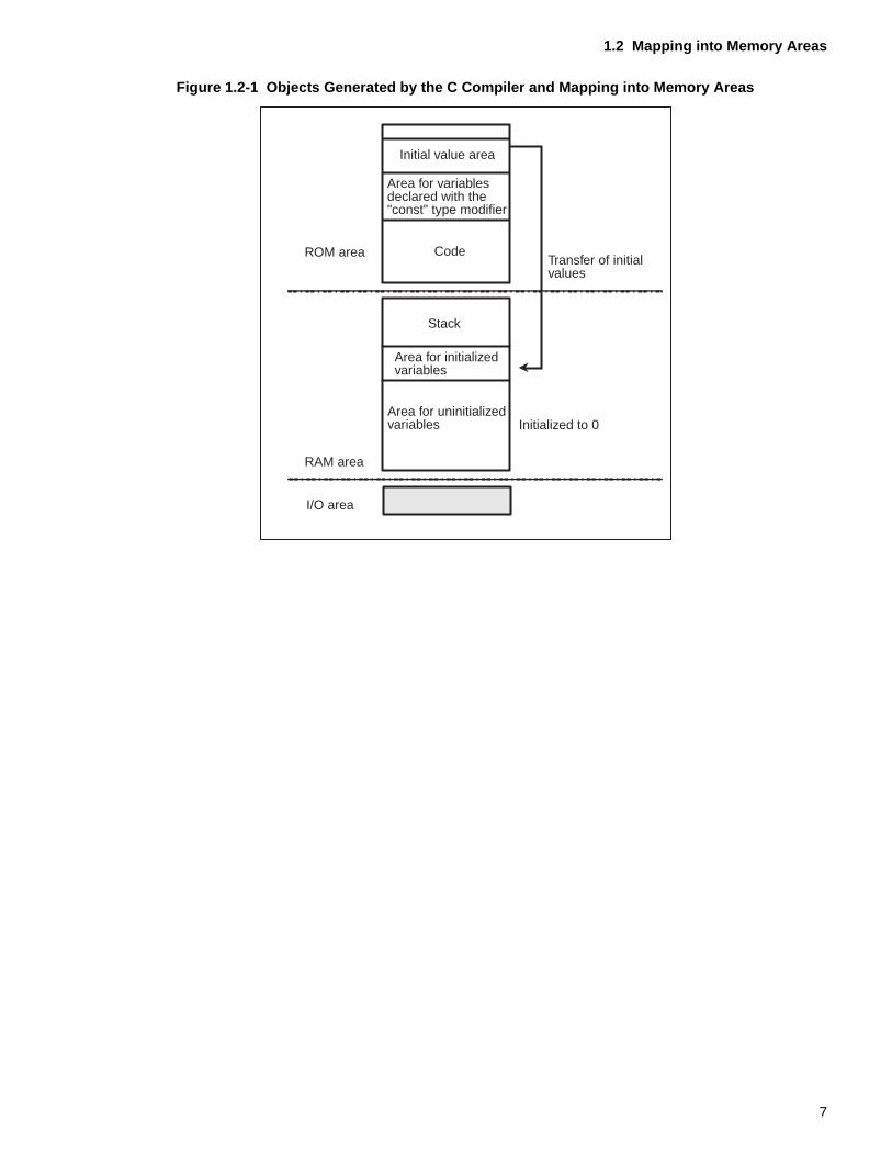
As shown in Figure 1.2-1 "Objects Generated by the C Compiler and Mapping into MemoryAreas", code and the initial values of variables that can only be read at execution time aremapped into the ROM area. Variables that are read and written at execution time are mappedinto the RAM area.
<Notes>
Since the values in the RAM area are undefined at system start, variables that are mappedinto the RAM area must be initialized as described below before program execution:
• Variable areas that are not initialized must be initialized to 0.
• Since the values in the RAM area are undefined when the initializing program is started, thevariables in the RAM area must be initialized using the initial values in the ROM area.
This initialization operation are performed using an initialization program called a startup
routine1.
The objects are mapped into their memory area during linking.
1. The startup routine is a program that performs initialization before executing the C program.example for this is the program startup.asm supplied as a sample with the C compiler.Refer to the C compiler manual for information about the operations performed by the startutine.
6
1.2 Mapping into Memory Areas
Figure 1.2-1 Objects Generated by the C Compiler and Mapping into Memory Areas
Initial value area
Area for variablesdeclared with the"const" type modifier
Code
Stack
Area for initializedvariables
Transfer of initialvalues
ROM area
RAM area
I/O area
Area for uninitializedvariables Initialized to 0
7

CHAPTER 1 OBJECTS MAPPED INTO MEMORY AREAS
1.3 Dynamically Allocated Variables
This section briefly describes the dynamically allocated variables.In a C program, the automatic variables that are defined in functions and the register variables are allocated dynamically.
■ Dynamically allocated variables
In a C program, the dynamically allocated variables are the automatic variables and the registervariables defined in functions.
❍ Automatic variables
• One type of local variable
• Defined in functions
• Able to be accessed only in the function in which they were defined
• Allocated in a stack
❍ Register variables
• One type of local variable
• Defined in functions
• Able to be accessed only in the function in which they were defined
• Allocated in registers
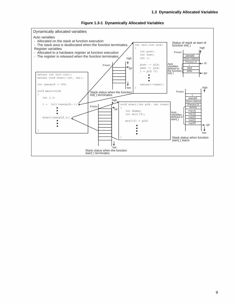
As shown in Figure 1.3-1 "Dynamically Allocated Variables", the stack area is allocated forautomatic variables when a function is called. This area is deallocated when the functionterminates. Automatic variables can be accessed only in the function that defined them.
During a function call, a register variable receives priority allocation to a hardware register. Theregister is released when the function terminates. As with automatic variables, registervariables can be accessed only in the function in which they are defined.
8
1.3 Dynamically Allocated Variables
Figure 1.3-1 Dynamically Allocated Variables
userpidh'xxxx
SP
high
IXh'xxxx
high
SP
low
low
h'xxxx
high
i
prevnext
iuserpid
dummy
moji [4]moji [3]moji [2]moji [1]moji [0]
SP
low
high
SPh'xxxx
Dynamically allocated variables
Auto variables- Allocated on the stack at function execution- The stack area is deallocated when the function terminates.Register variables- Allocated to a hardware register at function execution- The register is released when the function terminates
Stack status when the functioninit( ) terminates
Status of stack at start offunction init( )
Autovariablesdefined inthe functioninit( )
Return address
Previous IX
Previous IXReturn address
Stack status when the functionstart( ) terminates
Autovariablesdefined instart( )
Stack status when functionstart( ) starts
9
CHAPTER 1 OBJECTS MAPPED INTO MEMORY AREAS
1.4 Statically Allocated Variables
This section briefly describes the statically allocated variables.In a C program, external variables that are defined outside a function and variables declared as "static" are both allocated statically in a fixed RAM area.
■ Statically Allocated Variables
In a C program, external variables that are defined outside a function and variables declared as"static" are both allocated statically.
❍ External variables
• Defined outside a function
• Able to be accessed from the entire module
• Statically allocated in a memory
❍ Static variables
• Able to be accessed only within their defined scope
• Statically allocated in a memory
As shown in Figure 1.4-1 "Statically Allocated Variables", external variables and static variablesare allocated in a fixed RAM area at program execution. External variables can be accessed byall functions. Static variables are valid only within their defined scope. For details of staticvariables, see Section 2.4 "Variables Declared as "static" and their Variable Area".
10

1.4 Statically Allocated Variables
Figure 1.4-1 Statically Allocated Variables
;;
;;;
Statically allocated variablesExternal variables Static variables
Allocated in the RAM areaThe variable exist in the RAM area
External variabledefinitions
Variable area in RAMThe values can be read andwritten by all functions.
Area forexternalvariables
Area of static localvariable defined infunction initsem( )
Definitionof "static"local variable
11
CHAPTER 1 OBJECTS MAPPED INTO MEMORY AREAS
12
CHAPTER 2 VARIABLE DEFINITIONS AND VARIABLE AREAS
This chapter briefly describes the variable definitions and variable areas to which variables are output as a result of compilation. It then describes the relationship between initial values and the variable areas used for variables. The chapter also describes variables declared as "static," which is one type of static variables that have a special format.
2.1 "External Variables and their Variable Area"
2.2 "Initial Values and Variable Area for External Variables"
2.3 "Initialized Variables and Initialization at Execution"
2.4 "Variables Declared as "static" and their Variable Area"
13
CHAPTER 2 VARIABLE DEFINITIONS AND VARIABLE AREAS
2.1 External Variables and Their Variable Area
This section briefly describes the external variables and the variable areas.The external variables are defined outside a function. The area for external variables is fixedly allocated in RAM.
■ External Variables
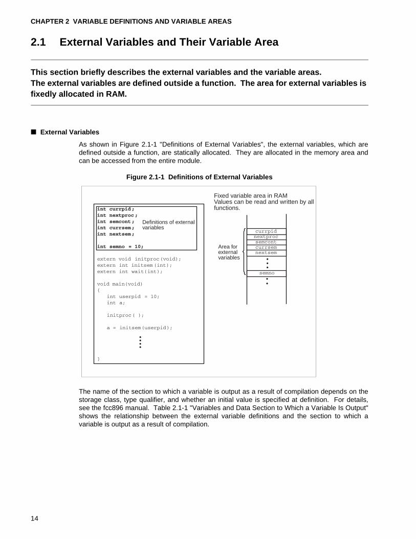
As shown in Figure 2.1-1 "Definitions of External Variables", the external variables, which aredefined outside a function, are statically allocated. They are allocated in the memory area andcan be accessed from the entire module.
Figure 2.1-1 Definitions of External Variables
The name of the section to which a variable is output as a result of compilation depends on thestorage class, type qualifier, and whether an initial value is specified at definition. For details,see the fcc896 manual. Table 2.1-1 "Variables and Data Section to Which a Variable Is Output"shows the relationship between the external variable definitions and the section to which avariable is output as a result of compilation.
Definitions of externalvariables
Fixed variable area in RAMValues can be read and written by allfunctions.
Area forexternalvariables
14
2.1 External Variables and Their Variable Area
[Tip]
Softune C Checker:
The Softune C Checker outputs a warning for variables in an analyzed module that are notaccessed at all during external access. Accordingly, define external variables only afterverifying the intended scope. Meaningless access declarations make a program look poorlywritten.
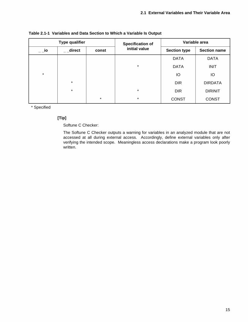
Table 2.1-1 Variables and Data Section to Which a Variable Is Output
Type qualifier Specification of initial value
Variable area
_ _io _ _direct const Section type Section name
DATA DATA
* DATA INIT
* IO IO
* DIR DIRDATA
* * DIR DIRINIT
* * CONST CONST
* Specified
15
CHAPTER 2 VARIABLE DEFINITIONS AND VARIABLE AREAS
2.2 Initial Values and Variable Area for External Variables
This section describes the relationship between the initial values and variable areas of external variables.In fcc896, when an initial value is specified at definition of an external variable, variable area is allocated in both the ROM and RAM areas.
■ Initial Values and the Variable Area for External Variables
Variables can be classified into the following three types according to how initialization ishandled when the variables are defined. Whether an initial value is required depends on theway in which the variable is to be used.
Initial value not required
No initial value specification (The variable does not need to be initialized to 0.)
Initial value 0
No initial value specification (The variable must be initialized to 0.)
Initial value other than 0
An initial value other than 0 is specified
The fcc896, handles two types of external variables: external variables for which an initializationvalue is specified when they are defined (initialized variables hereafter) and external variablesfor which no initialization value is specified when they are defined (uninitialized variableshereafter).
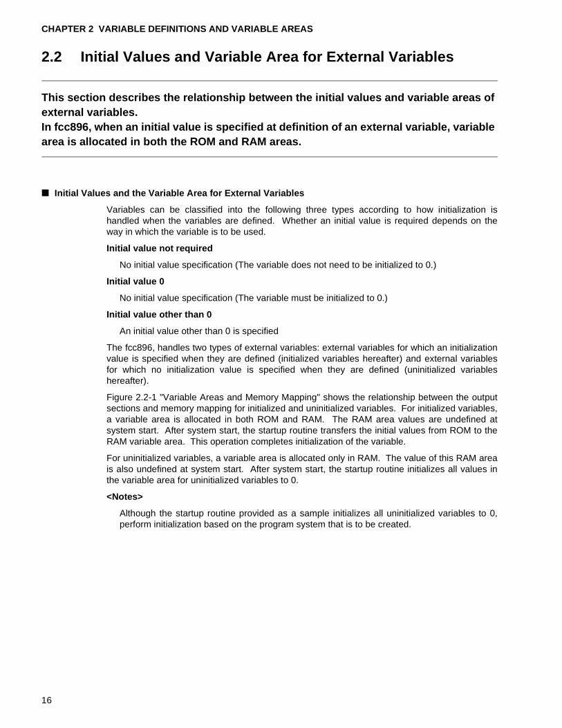
Figure 2.2-1 "Variable Areas and Memory Mapping" shows the relationship between the outputsections and memory mapping for initialized and uninitialized variables. For initialized variables,a variable area is allocated in both ROM and RAM. The RAM area values are undefined atsystem start. After system start, the startup routine transfers the initial values from ROM to theRAM variable area. This operation completes initialization of the variable.
For uninitialized variables, a variable area is allocated only in RAM. The value of this RAM areais also undefined at system start. After system start, the startup routine initializes all values inthe variable area for uninitialized variables to 0.
<Notes>
Although the startup routine provided as a sample initializes all uninitialized variables to 0,perform initialization based on the program system that is to be created.
16
2.2 Initial Values and Variable Area for External Variables
Figure 2.2-1 Variable Areas and Memory Mapping
Uninitialized variable Initialized variable
Link
ROM area The initial value area is allocated in theROM area, and the area accessed atexecution is allocated in the RAM area.For an initialized variable, an area of twicethe size of the defined variable is requiredin the ROM and RAM areas.
RAM areaFor an uninitialized variable, a variablearea is allocated only in RAM.The startup routine initializes all values inthis area to 0.
The startup routine transfers the initialvalues in the ROM area to the variablearea in RAM.
@INIT
INIT
DATA
DATA INIT
17
CHAPTER 2 VARIABLE DEFINITIONS AND VARIABLE AREAS
2.3 Initialized Variables and Initialization at Execution
This section describes initialized variables and the initialization of uninitialized variables at program execution.
■ Initialized Variables and Initialization at Execution
As shown in Figure 2.2-1 "Variable Areas and Memory Mapping", initialized variables require aninitial value area and a variable area, which means that the totally required area is twice that ofdefined variables. For uninitialized variables, only a variable area needs to be allocated.Because the initialization value is only accessed the first time, a method is also provided thatallows to initialize the variable when the respective function is executed, making it unnecessaryto specify an initial value at definition time.
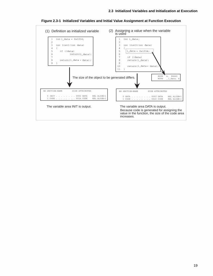
Figure 2.3-1 "Initialized Variables and Initial Value Assignment at Function Execution" shows anexample of a function in a variable is initialized beforehand, and an example of a function inwhich the value is set at the beginning of the function.
See function list1( ) in (1), "Definition as an initialized variable," in Figure 2.3-1 "InitializedVariables and Initial Value Assignment at Function Execution". Function list1( ) allocates a 2-byte area in the INIT section for variable i_data for which an initial value is specified. The INITsection is allocated in both ROM and RAM. The startup routine transfers the initial value fromROM to the variable area in RAM.
See function list2( ) in (2), "Assigning a value when the variable is used," in Figure 2.3-1"Initialized Variables and Initial Value Assignment at Function Execution". Function list2( )allocates only a 2-byte variable area DATA for the variable i_data in RAM. However, a code forassigning a value to the variable is required. Compared with (1), the area for the value issmaller by 2 bytes, but the code area is bigger by 6 bytes.
The startup routine is used to transfer the initial value of the variable to the variable area inRAM. To assign an initial value in the function, a 6-byte code is required whenever a 2-bytevariable is assigned.
If we take the case of a variable that is initialized using 10 different values, code of (6 bytes x10) = 60 bytes is required. When a variable is defined as an initialized variable, the value areain the ROM will increase by 20 bytes. Because the startup routine handles transfer, it isassumed that the size of the code will not increase. Thus, when the increase of 60 bytes incode is conmpared with the increase of 20 bytes in the variable area, it can be said that use ofthe ROM area is more economically when an initialized variable is defined.
<Notes>
Setting an initial value for a variable that does need not to be initialized wastes ROM area.Setting an initial value of 0 at definition time and using the startup routine to initializeuninitialized variables to 0 wastes initial value area. Set the initial value of an externalvariable only after carefully checking whether initialization is necessary.
18
2.3 Initialized Variables and Initialization at Execution
Figure 2.3-1 Initialized Variables and Initial Value Assignment at Function Execution
(1) Definition as initialized variable (2) Assigning a value when the variableis used
The size of the object to be generated differs.
The variable area INIT is output. The variable area DATA is output.Because code is generated for assigning thevalue in the function, the size of the code areaincreases.
19
CHAPTER 2 VARIABLE DEFINITIONS AND VARIABLE AREAS
2.4 Variables Declared as "static" and Their Variable Area
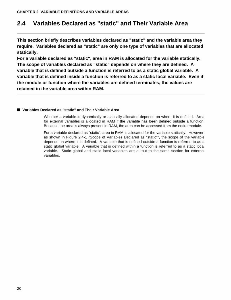
This section briefly describes variables declared as "static" and the variable area they require. Variables declared as "static" are only one type of variables that are allocated statically.For a variable declared as "static", area in RAM is allocated for the variable statically. The scope of variables declared as "static" depends on where they are defined. A variable that is defined outside a function is referred to as a static global variable. A variable that is defined inside a function is referred to as a static local variable. Even if the module or function where the variables are defined terminates, the values are retained in the variable area within RAM.
■ Variables Declared as "static" and Their Variable Area
Whether a variable is dynamically or statically allocated depends on where it is defined. Areafor external variables is allocated in RAM if the variable has been defined outside a function.Because the area is always present in RAM, the area can be accessed from the entire module.
For a variable declared as "static", area in RAM is allocated for the variable statically. However,as shown in Figure 2.4-1 "Scope of Variables Declared as "static"", the scope of the variabledepends on where it is defined. A variable that is defined outside a function is referred to as astatic global variable. A variable that is defined within a function is referred to as a static localvariable. Static global and static local variables are output to the same section for externalvariables.
20
2.4 Variables Declared as "static" and Their Variable Area
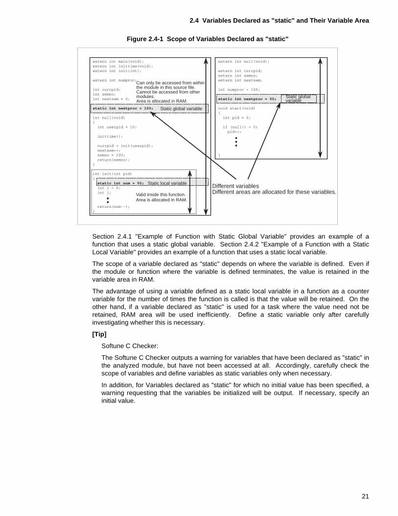
Figure 2.4-1 Scope of Variables Declared as "static"
Section 2.4.1 "Example of Function with Static Global Variable" provides an example of afunction that uses a static global variable. Section 2.4.2 "Example of a Function with a StaticLocal Variable" provides an example of a function that uses a static local variable.
The scope of a variable declared as "static" depends on where the variable is defined. Even ifthe module or function where the variable is defined terminates, the value is retained in thevariable area in RAM.
The advantage of using a variable defined as a static local variable in a function as a countervariable for the number of times the function is called is that the value will be retained. On theother hand, if a variable declared as "static" is used for a task where the value need not beretained, RAM area will be used inefficiently. Define a static variable only after carefullyinvestigating whether this is necessary.
[Tip]
Softune C Checker:
The Softune C Checker outputs a warning for variables that have been declared as "static" inthe analyzed module, but have not been accessed at all. Accordingly, carefully check thescope of variables and define variables as static variables only when necessary.
In addition, for Variables declared as "static" for which no initial value has been specified, awarning requesting that the variables be initialized will be output. If necessary, specify aninitial value.
Static globalvariable
Static global variable
Can only be accessed from withinthe module in this source file. Cannot be accessed from othermodules. Area is allocated in RAM.
Static local variable
Valid inside this function.Area is allocated in RAM.
Different variablesDifferent areas are allocated for these variables.
21
CHAPTER 2 VARIABLE DEFINITIONS AND VARIABLE AREAS
2.4.1 Example of Function with Static Global Variable
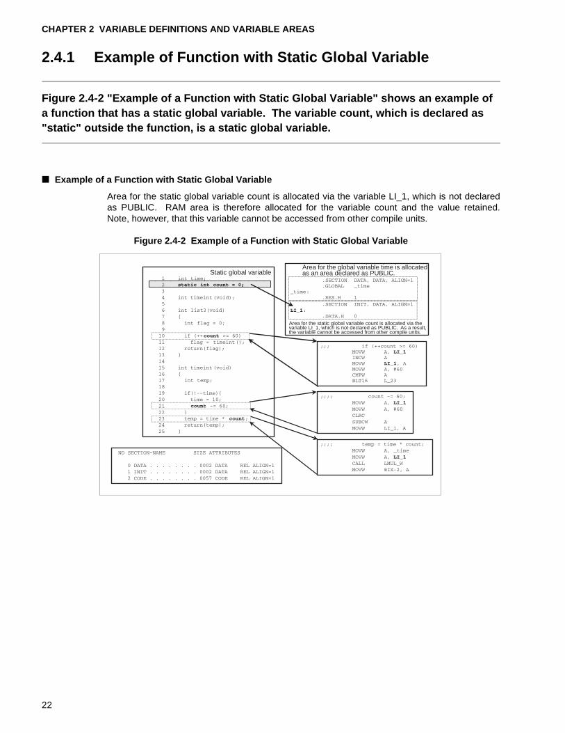
Figure 2.4-2 "Example of a Function with Static Global Variable" shows an example of a function that has a static global variable. The variable count, which is declared as "static" outside the function, is a static global variable.
■ Example of a Function with Static Global Variable
Area for the static global variable count is allocated via the variable LI_1, which is not declaredas PUBLIC. RAM area is therefore allocated for the variable count and the value retained.Note, however, that this variable cannot be accessed from other compile units.
Figure 2.4-2 Example of a Function with Static Global Variable
Static global variableArea for the global variable time is allocatedas an area declared as PUBLIC.
Area for the static global variable count is allocated via thevariable LI_1, which is not declared as PUBLIC. As a result,the variable cannot be accessed from other compile units.
22
2.4 Variables Declared as "static" and Their Variable Area
2.4.2 Example of a Function with Static Local Variable
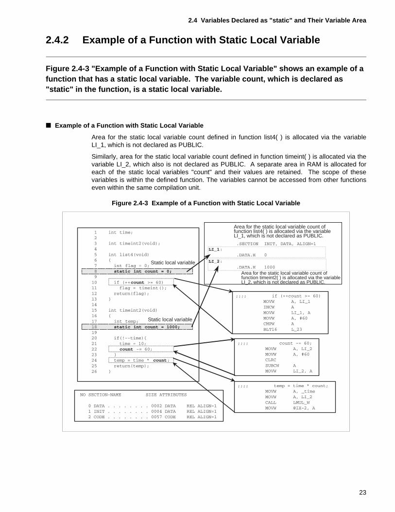
Figure 2.4-3 "Example of a Function with Static Local Variable" shows an example of a function that has a static local variable. The variable count, which is declared as "static" in the function, is a static local variable.
■ Example of a Function with Static Local Variable
Area for the static local variable count defined in function list4( ) is allocated via the variableLI_1, which is not declared as PUBLIC.
Similarly, area for the static local variable count defined in function timeint( ) is allocated via thevariable LI_2, which also is not declared as PUBLIC. A separate area in RAM is allocated foreach of the static local variables "count" and their values are retained. The scope of thesevariables is within the defined function. The variables cannot be accessed from other functionseven within the same compilation unit.
Figure 2.4-3 Example of a Function with Static Local Variable
Static local variable
Static local variable
Area for the static local variable count offunction list4( ) is allocated via the variableLI_1, which is not declared as PUBLIC.
Area for the static local variable count offunction timeint2( ) is allocated via the variableLI_2, which is not declared as PUBLIC.
23
CHAPTER 2 VARIABLE DEFINITIONS AND VARIABLE AREAS
24
CHAPTER 3 READ-ONLY VARIABLES AND THEIR VARIABLE AREA
This chapter describes how to use read-only variables.A value is read or written for a variable at execution. Therefore, the variable areas are mapped into RAM areas, which can be read and written. However, there are variables that are at execution only read and do not need to be changed. Examples for this type of variable are messages, such as opening or error messages. Mapping variables that are read-only in RAM areas in the same way as normal external variables has the result that these RAM areas are only read at execution. As a result, valuable RAM space will be wasted. This chapter describes two methods for reducing the required areas within RAM.
3.1 "Numeric Constants and #define Definition"
3.2 "Defining Variables Using the const Type Qualifier"
25

CHAPTER 3 READ-ONLY VARIABLES AND THEIR VARIABLE AREA
3.1 Numeric Constants and #define Definition
This section describes how to use the #define definition to define read-only variables as numeric constants.Because this method does not allocate variable areas, RAM area usage can be reduced.
■ Numeric Constants and #define Definition
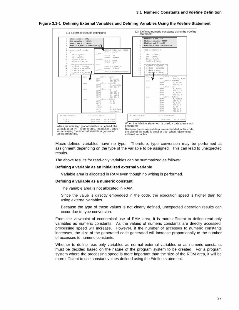
Figure 3.1-1 "Defining External Variables and Defining Variables Using the #define Statement"shows an example of defining read-only variables as initialized external variables and using the#define statement to define the read-only variables as numeric constants in a macro definition.
See the function list5( ) of (1), "External variable definitions," in Figure 3.1-1 "Defining ExternalVariables and Defining Variables Using the #define Statement". Because initialized variableshave been defined for the function list5( ), the variable area INIT is generated. The variablearea INIT is mapped into ROM and RAM areas at linkage. The startup routine transfers theROM initial values to the RAM area. The following variables are defined for the function list5( ):
• char-type variable (1 byte) c_max
• int-type variable (2 bytes) maxaddr
• float-type variable (4 bytes) pai
• double-type variable (8 bytes) d_data
The variable area INIT is allocated in the RAM area for these variables. Read-only variablesare not written to at execution. From the viewpoint of economical use of the RAM area, this 15-byte variable area will be wasted.
The value of an external variable is referenced on the basis of the address of the externalvariable.
As shown below, the size of the code generated at reference depends on the variable type. Toreference an 8-byte double-type variable, the runtime library is called.
• To reference a char-type (1 byte) variable: 5 bytes
• To reference an int-type (2 bytes) variable: 5 bytes
• To reference a float-type (4 bytes) variable: 10 bytes
• To reference a double-type (8 bytes) variable: 12 bytes
See the function list6( ) of (2), "Defining numeric constants using the #define statement," inFigure 3.1-1 "Defining External Variables and Defining Variables Using the #define Statement".Function list6( ) defines c_max, maxaddr, pai, and d_data using the macro definition of the#define statement. The value of the macro-defined numeric constant is embedded in the code,and a variable area is not generated. The code to be generated depends on the numericconstant.
26
3.1 Numeric Constants and #define Definition
Figure 3.1-1 Defining External Variables and Defining Variables Using the #define Statement
Macro-defined variables have no type. Therefore, type conversion may be performed atassignment depending on the type of the variable to be assigned. This can lead to unexpectedresults.
The above results for read-only variables can be summarized as follows:
Defining a variable as an initialized external variable
Variable area is allocated in RAM even though no writing is performed.
Defining a variable as a numeric constant
The variable area is not allocated in RAM.
Since the value is directly embedded in the code, the execution speed is higher than forusing external variables.
Because the type of these values is not clearly defined, unexpected operation results canoccur due to type conversion.
From the viewpoint of economical use of RAM area, it is more efficient to define read-onlyvariables as numeric constants. As the values of numeric constants are directly accessed,processing speed will increase. However, if the number of accesses to numeric constantsincreases, the size of the generated code generated will increase proportionally to the numberof accesses to numeric constants.
Whether to define read-only variables as normal external variables or as numeric constantsmust be decided based on the nature of the program system to be created. For a programsystem where the processing speed is more important than the size of the ROM area, it will bemore efficient to use constant values defined using the #define statement.
(1) External variable definitions (2) Defining numeric constants using the #define statement
When an initialized global variable is defined, thevariable area INIT is generated. In addition, codefor accessing the external variable is generatedduring reference.
Because the numerical data are embedded in the code,the size of the code is smaller than when referencingexternal variables.
When the #define statement is used, a data area is notgenerated.
27
CHAPTER 3 READ-ONLY VARIABLES AND THEIR VARIABLE AREA
3.2 Defining Variables Using the const Type Qualifier
This section describes how to define read-only variables using the "const" type qualifier.Because this method directly accesses the initial value areas allocated in ROM, the size of the RAM area can be reduced.
■ Defining Variables Using the "const" Type Qualifier
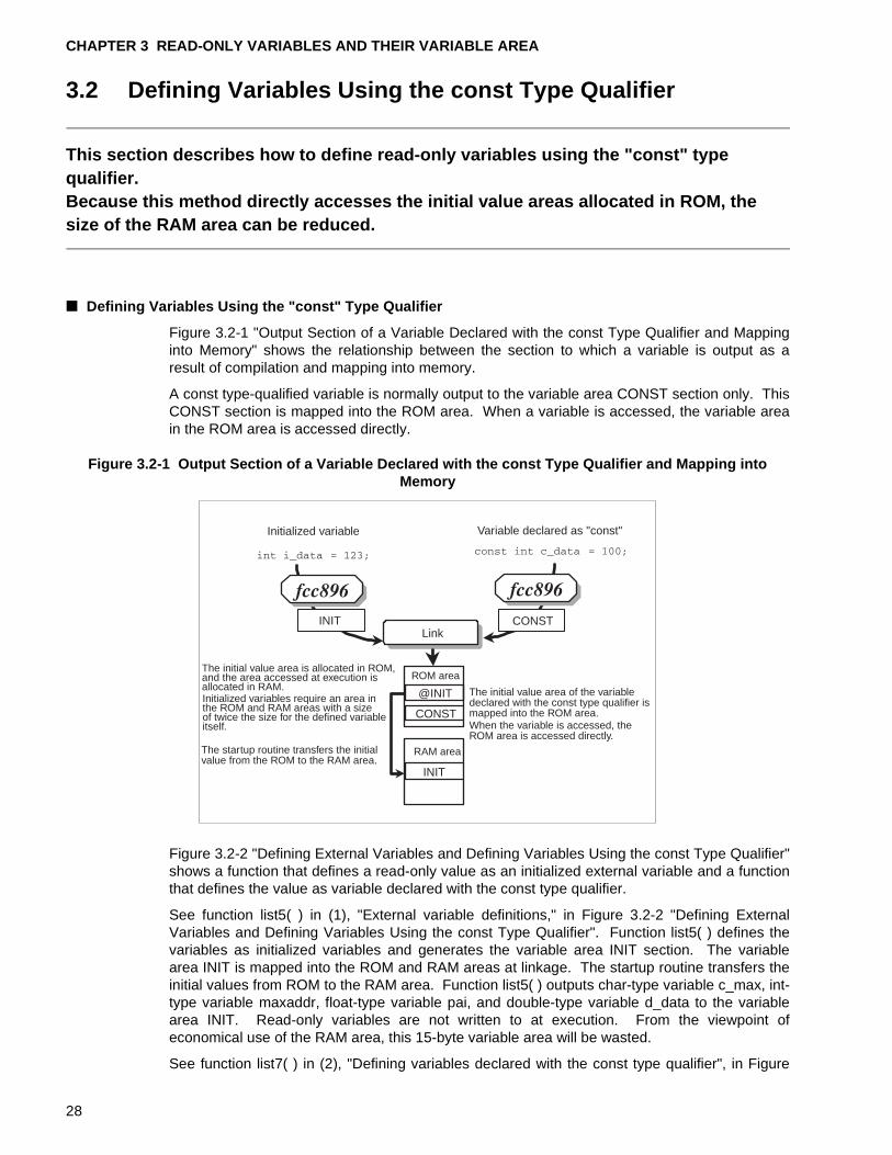
Figure 3.2-1 "Output Section of a Variable Declared with the const Type Qualifier and Mappinginto Memory" shows the relationship between the section to which a variable is output as aresult of compilation and mapping into memory.
A const type-qualified variable is normally output to the variable area CONST section only. ThisCONST section is mapped into the ROM area. When a variable is accessed, the variable areain the ROM area is accessed directly.
Figure 3.2-1 Output Section of a Variable Declared with the const Type Qualifier and Mapping into Memory
Figure 3.2-2 "Defining External Variables and Defining Variables Using the const Type Qualifier"shows a function that defines a read-only value as an initialized external variable and a functionthat defines the value as variable declared with the const type qualifier.
See function list5( ) in (1), "External variable definitions," in Figure 3.2-2 "Defining ExternalVariables and Defining Variables Using the const Type Qualifier". Function list5( ) defines thevariables as initialized variables and generates the variable area INIT section. The variablearea INIT is mapped into the ROM and RAM areas at linkage. The startup routine transfers theinitial values from ROM to the RAM area. Function list5( ) outputs char-type variable c_max, int-type variable maxaddr, float-type variable pai, and double-type variable d_data to the variablearea INIT. Read-only variables are not written to at execution. From the viewpoint ofeconomical use of the RAM area, this 15-byte variable area will be wasted.
See function list7( ) in (2), "Defining variables declared with the const type qualifier", in Figure
Initialized variable Variable declared as "const"
Link
ROM areaThe initial value area is allocated in ROM,and the area accessed at execution isallocated in RAM.Initialized variables require an area inthe ROM and RAM areas with a sizeof twice the size for the defined variableitself.
The initial value area of the variabledeclared with the const type qualifier ismapped into the ROM area.When the variable is accessed, theROM area is accessed directly.
The startup routine transfers the initialvalue from the ROM to the RAM area.
RAM area
CONSTINIT
@INIT
CONST
INIT
28
3.2 Defining Variables Using the const Type Qualifier
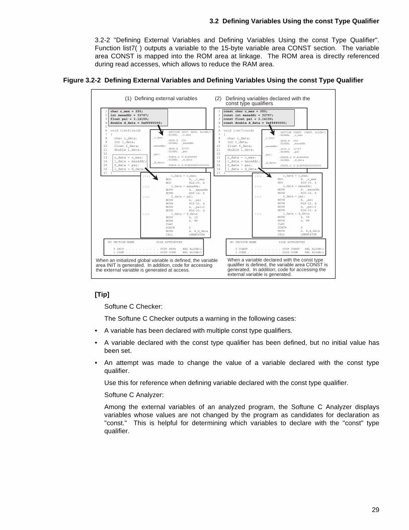
3.2-2 "Defining External Variables and Defining Variables Using the const Type Qualifier".Function list7( ) outputs a variable to the 15-byte variable area CONST section. The variablearea CONST is mapped into the ROM area at linkage. The ROM area is directly referencedduring read accesses, which allows to reduce the RAM area.
Figure 3.2-2 Defining External Variables and Defining Variables Using the const Type Qualifier
[Tip]
Softune C Checker:
The Softune C Checker outputs a warning in the following cases:
• A variable has been declared with multiple const type qualifiers.
• A variable declared with the const type qualifier has been defined, but no initial value hasbeen set.
• An attempt was made to change the value of a variable declared with the const typequalifier.
Use this for reference when defining variable declared with the const type qualifier.
Softune C Analyzer:
Among the external variables of an analyzed program, the Softune C Analyzer displaysvariables whose values are not changed by the program as candidates for declaration as"const." This is helpful for determining which variables to declare with the "const" typequalifier.
(1) Defining external variables (2)
When an initialized global variable is defined, the variablearea INIT is generated. In addition, code for accessingthe external variable is generated at access.
When a variable declared with the const typequalifier is defined, the variable area CONST isgenerated. In addition, code for accessing theexternal variable is generated.
Defining variables declared with theconst type qualifiers
29
CHAPTER 3 READ-ONLY VARIABLES AND THEIR VARIABLE AREA
30
CHAPTER 4 USING AUTOMATIC VARIABLES TO REDUCE THE VARIABLE AREA
This chapter describes how to reduce variable areas using "automatic" variables.For automatic variables, the variable areas are allocated on the stack when the function is called. The variable areas are deallocated at the termination of the function. Variables that are referenced only from within the function are defined as automatic variables to reduce the variable areas.
4.1 "Automatic Variables and Statically Allocated Variables"
4.2 "Using Automatic Variables"
31
CHAPTER 4 USING AUTOMATIC VARIABLES TO REDUCE THE VARIABLE AREA
4.1 Automatic Variables and Statically Allocated Variables
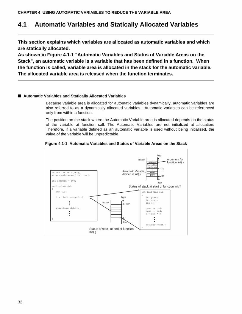
This section explains which variables are allocated as automatic variables and which are statically allocated.As shown in Figure 4.1-1 "Automatic Variables and Status of Variable Areas on the Stack", an automatic variable is a variable that has been defined in a function. When the function is called, variable area is allocated in the stack for the automatic variable. The allocated variable area is released when the function terminates.
■ Automatic Variables and Statically Allocated Variables
Because variable area is allocated for automatic variables dynamically, automatic variables arealso referred to as a dynamically allocated variables. Automatic variables can be referencedonly from within a function.
The position on the stack where the Automatic Variable area is allocated depends on the statusof the variable at function call. The Automatic Variables are not initialized at allocation.Therefore, if a variable defined as an automatic variable is used without being initialized, thevalue of the variable will be unpredictable.
Figure 4.1-1 Automatic Variables and Status of Variable Areas on the Stack
h’xxxxSP
low
userpidh’xxxx
low
IX
SP
inextprev
higt
Argument forfunction init( )
Automatic Variabledefined in init( )
Status of stack at start of function init( )
Status of stack at end of functioninit( )
Return address
Previous IX
high
32
4.1 Automatic Variables and Statically Allocated Variables
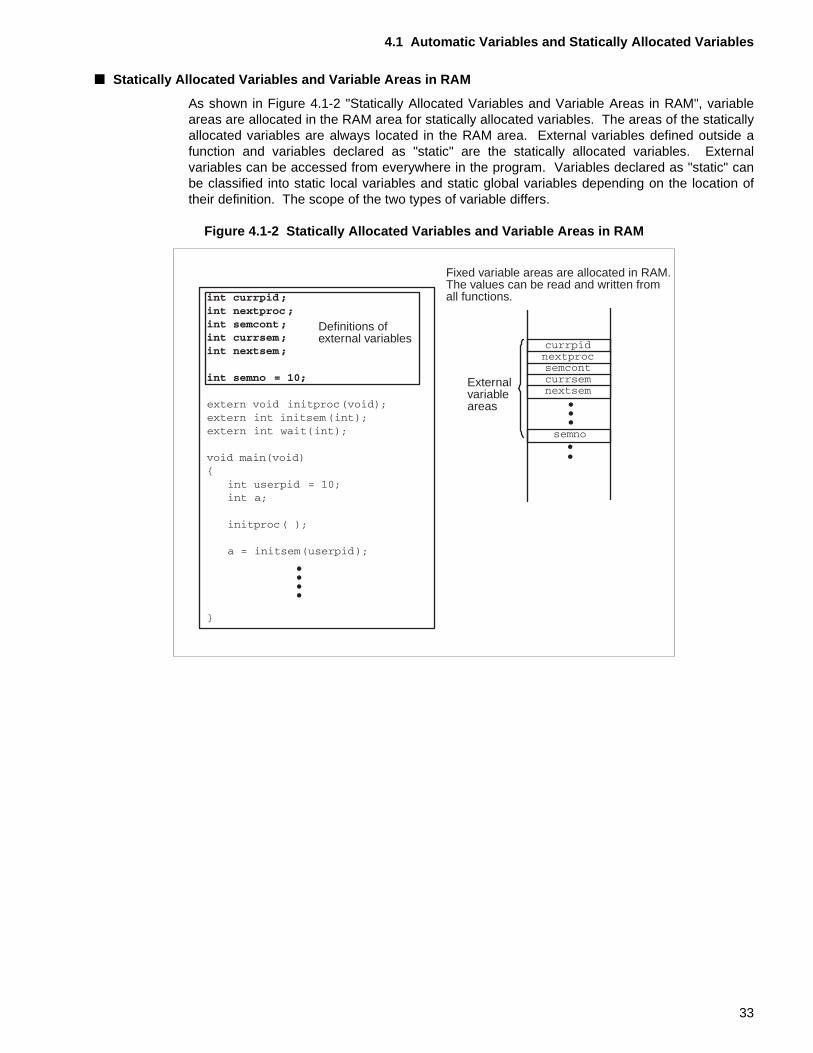
■ Statically Allocated Variables and Variable Areas in RAM
As shown in Figure 4.1-2 "Statically Allocated Variables and Variable Areas in RAM", variableareas are allocated in the RAM area for statically allocated variables. The areas of the staticallyallocated variables are always located in the RAM area. External variables defined outside afunction and variables declared as "static" are the statically allocated variables. Externalvariables can be accessed from everywhere in the program. Variables declared as "static" canbe classified into static local variables and static global variables depending on the location oftheir definition. The scope of the two types of variable differs.
Figure 4.1-2 Statically Allocated Variables and Variable Areas in RAM
Definitions ofexternal variables
Fixed variable areas are allocated in RAM.The values can be read and written fromall functions.
Externalvariableareas
33
CHAPTER 4 USING AUTOMATIC VARIABLES TO REDUCE THE VARIABLE AREA
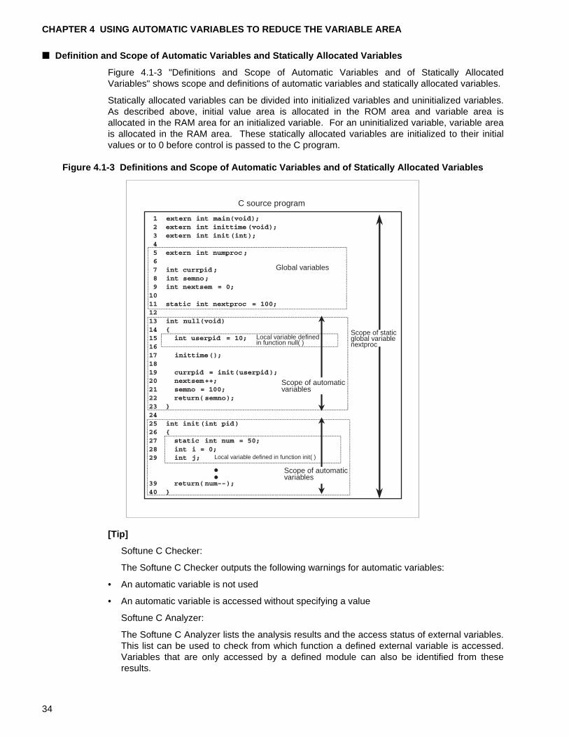
■ Definition and Scope of Automatic Variables and Statically Allocated Variables
Figure 4.1-3 "Definitions and Scope of Automatic Variables and of Statically AllocatedVariables" shows scope and definitions of automatic variables and statically allocated variables.
Statically allocated variables can be divided into initialized variables and uninitialized variables.As described above, initial value area is allocated in the ROM area and variable area isallocated in the RAM area for an initialized variable. For an uninitialized variable, variable areais allocated in the RAM area. These statically allocated variables are initialized to their initialvalues or to 0 before control is passed to the C program.
Figure 4.1-3 Definitions and Scope of Automatic Variables and of Statically Allocated Variables
[Tip]
Softune C Checker:
The Softune C Checker outputs the following warnings for automatic variables:
• An automatic variable is not used
• An automatic variable is accessed without specifying a value
Softune C Analyzer:
The Softune C Analyzer lists the analysis results and the access status of external variables.This list can be used to check from which function a defined external variable is accessed.Variables that are only accessed by a defined module can also be identified from theseresults.
C source program
Global variables
Local variable definedin function null( )
Scope of staticglobal variablenextproc
Scope of automaticvariables
Local variable defined in function init( )
Scope of automaticvariables
34
4.2 Using Automatic Variables
4.2 Using Automatic Variables
This section describes the merits of using automatic variables.Reducing the number of external variables and using automatic variables that can only be locally accessed within a function can result in more economical use of the variable area.
■ External Variables and Automatic Variables
External variables can be divided into external variables declared as "const" and those that arenot. Area for external variables that are not declared with the const type qualifier is allocated inRAM. However, careful review of the created program will often find that variables that areaccessed only within a specific function have nevertheless been defined as external variables.Defining a variable whose usage range is restricted as external variable will increase the size ofthe variable area. Reducing the number of external variables and using automatic variables,which can be accessed only from within a function, can result in more economical use of thevariable area.
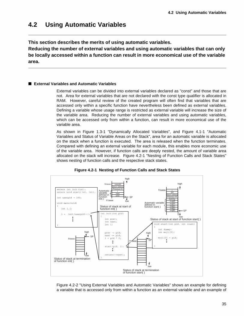
As shown in Figure 1.3-1 "Dynamically Allocated Variables", and Figure 4.1-1 "AutomaticVariables and Status of Variable Areas on the Stack", area for an automatic variable is allocatedon the stack when a function is executed. The area is released when the function terminates.Compared with defining an external variable for each module, this enables more economic useof the variable area. However, if function calls are deeply nested, the amount of variable areaallocated on the stack will increase. Figure 4.2-1 "Nesting of Function Calls and Stack States"shows nesting of function calls and the respective stack states.
Figure 4.2-1 Nesting of Function Calls and Stack States
Figure 4.2-2 "Using External Variables and Automatic Variables" shows an example for defininga variable that is accessed only from within a function as an external variable and an example of
low
low
userpid
h''aaaa
h'xxxx
high
SP
SP
high
h'xxxx
high
SP
ipid
dummy[4][3][2][1]
moji[0]
low
SP
h'aaaa
high
low
inextprev
Return addressPrevious IX
Return addressPrevious IX
mojimojimojimoji
h'aaaa
Automaticvariabledefined infunctioninit( )
Status of stack at start offunction init( )
Automatic variabledefined in function start( )
Status of stack at start of function start( )
Status of stack at terminationof function init( )
Status of stack at terminationof function start( )
35
CHAPTER 4 USING AUTOMATIC VARIABLES TO REDUCE THE VARIABLE AREA
defining the variable as an automatic variable.
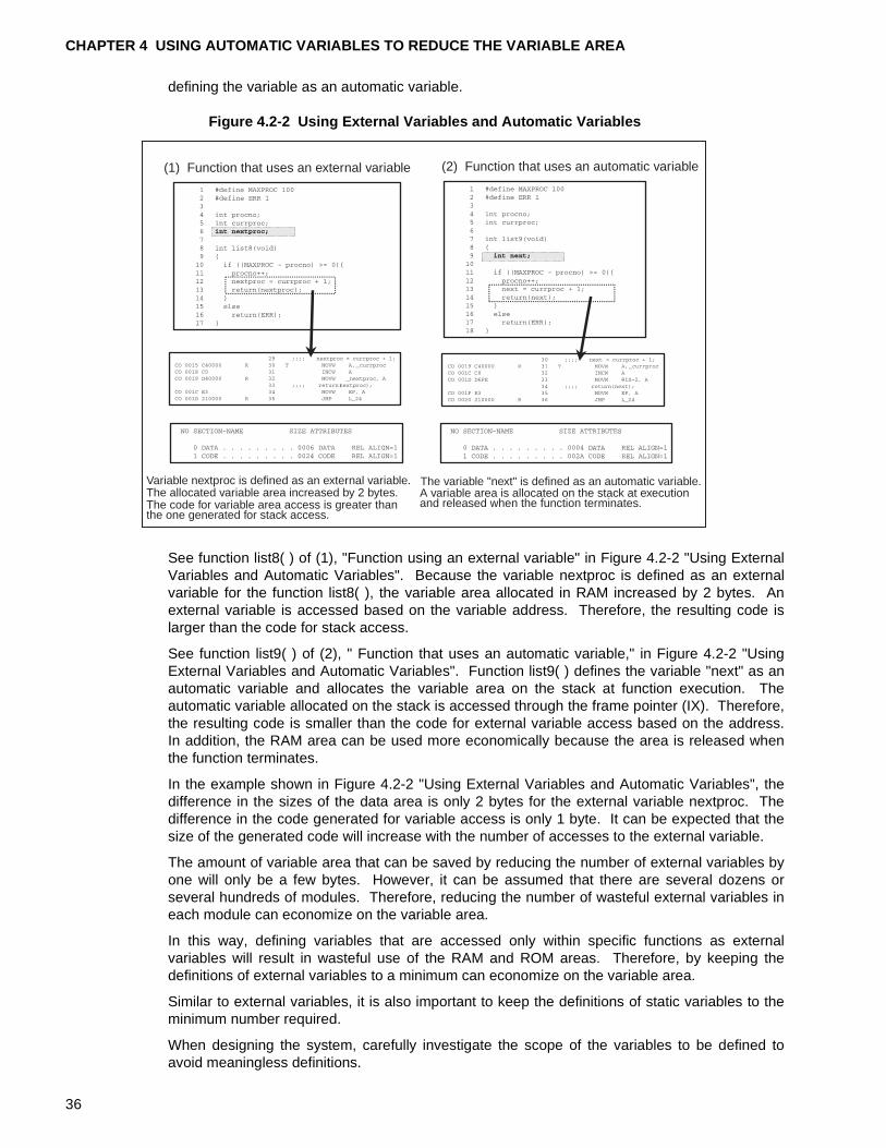
Figure 4.2-2 Using External Variables and Automatic Variables
See function list8( ) of (1), "Function using an external variable" in Figure 4.2-2 "Using ExternalVariables and Automatic Variables". Because the variable nextproc is defined as an externalvariable for the function list8( ), the variable area allocated in RAM increased by 2 bytes. Anexternal variable is accessed based on the variable address. Therefore, the resulting code islarger than the code for stack access.
See function list9( ) of (2), " Function that uses an automatic variable," in Figure 4.2-2 "UsingExternal Variables and Automatic Variables". Function list9( ) defines the variable "next" as anautomatic variable and allocates the variable area on the stack at function execution. Theautomatic variable allocated on the stack is accessed through the frame pointer (IX). Therefore,the resulting code is smaller than the code for external variable access based on the address.In addition, the RAM area can be used more economically because the area is released whenthe function terminates.
In the example shown in Figure 4.2-2 "Using External Variables and Automatic Variables", thedifference in the sizes of the data area is only 2 bytes for the external variable nextproc. Thedifference in the code generated for variable access is only 1 byte. It can be expected that thesize of the generated code will increase with the number of accesses to the external variable.
The amount of variable area that can be saved by reducing the number of external variables byone will only be a few bytes. However, it can be assumed that there are several dozens orseveral hundreds of modules. Therefore, reducing the number of wasteful external variables ineach module can economize on the variable area.
In this way, defining variables that are accessed only within specific functions as externalvariables will result in wasteful use of the RAM and ROM areas. Therefore, by keeping thedefinitions of external variables to a minimum can economize on the variable area.
Similar to external variables, it is also important to keep the definitions of static variables to theminimum number required.
When designing the system, carefully investigate the scope of the variables to be defined toavoid meaningless definitions.
(1) Function that uses an external variable (2) Function that uses an automatic variable
Variable nextproc is defined as an external variable.The allocated variable area increased by 2 bytes.The code for variable area access is greater thanthe one generated for stack access.
The variable "next" is defined as an automatic variable.A variable area is allocated on the stack at executionand released when the function terminates.
36
4.2 Using Automatic Variables
[Tip]
Softune C Analyzer:
The Softune C Analyzer lists the analysis results and the access status of external variables.This list can be used to determine from which function a defined external variable isaccessed. Variables that are only accessed by a defined module can also be identified fromthese results.
The Softune C Analyzer checks for function calls that use large amounts of the stack in theprogram system based on the amount of stack use calculated by the fcc896. The Softune CAnalyzer then visually displays the routes and amounts of usage. This information is usefulfor reducing the amount of stack usage.
37
CHAPTER 4 USING AUTOMATIC VARIABLES TO REDUCE THE VARIABLE AREA
38
CHAPTER 5 ACCESSING VARIABLES THAT USE BIT FIELDS
This chapter describes how to access variables that use bit fields.Using a bit field enables accessing each bit in a byte to be accessed.
5.1 "Boundary Alignment of fcc896"
5.2 "Bit Field Definitions and Boundary Alignment"
5.3 "Accessing I/O Areas Using Bit Fields and Unions"
39
CHAPTER 5 ACCESSING VARIABLES THAT USE BIT FIELDS
5.1 Boundary Alignment of fcc896
This section briefly describes the boundary alignment of the fcc896.For the fcc896 processing, variables are allocated to memory in accordance with the variable allocation size and boundary alignment.
■ Boundary Alignment of fcc896
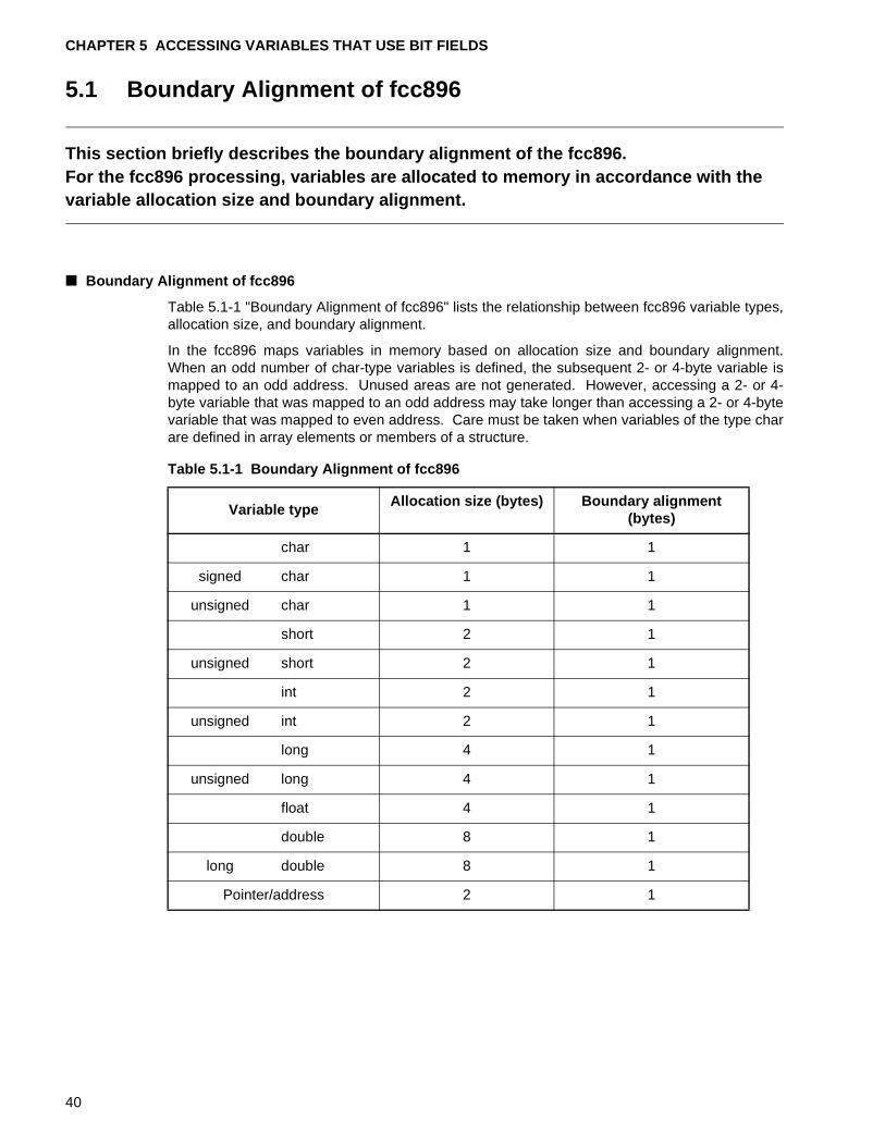
Table 5.1-1 "Boundary Alignment of fcc896" lists the relationship between fcc896 variable types,allocation size, and boundary alignment.
In the fcc896 maps variables in memory based on allocation size and boundary alignment.When an odd number of char-type variables is defined, the subsequent 2- or 4-byte variable ismapped to an odd address. Unused areas are not generated. However, accessing a 2- or 4-byte variable that was mapped to an odd address may take longer than accessing a 2- or 4-bytevariable that was mapped to even address. Care must be taken when variables of the type charare defined in array elements or members of a structure.
Table 5.1-1 Boundary Alignment of fcc896
Variable typeAllocation size (bytes) Boundary alignment
(bytes)
char 1 1
signed char 1 1
unsigned char 1 1
short 2 1
unsigned short 2 1
int 2 1
unsigned int 2 1
long 4 1
unsigned long 4 1
float 4 1
double 8 1
long double 8 1
Pointer/address 2 1
40
5.2 Bit Field Definitions and Boundary Alignment
5.2 Bit Field Definitions and Boundary Alignment
This section describes bit field definitions and boundary alignment for memory allocation.Bit fields allow accessing each bit within a byte. However, depending on the boundary alignment conditions, it may not be possible to access some areas.
■ Bit Field Definitions and Boundary Alignment
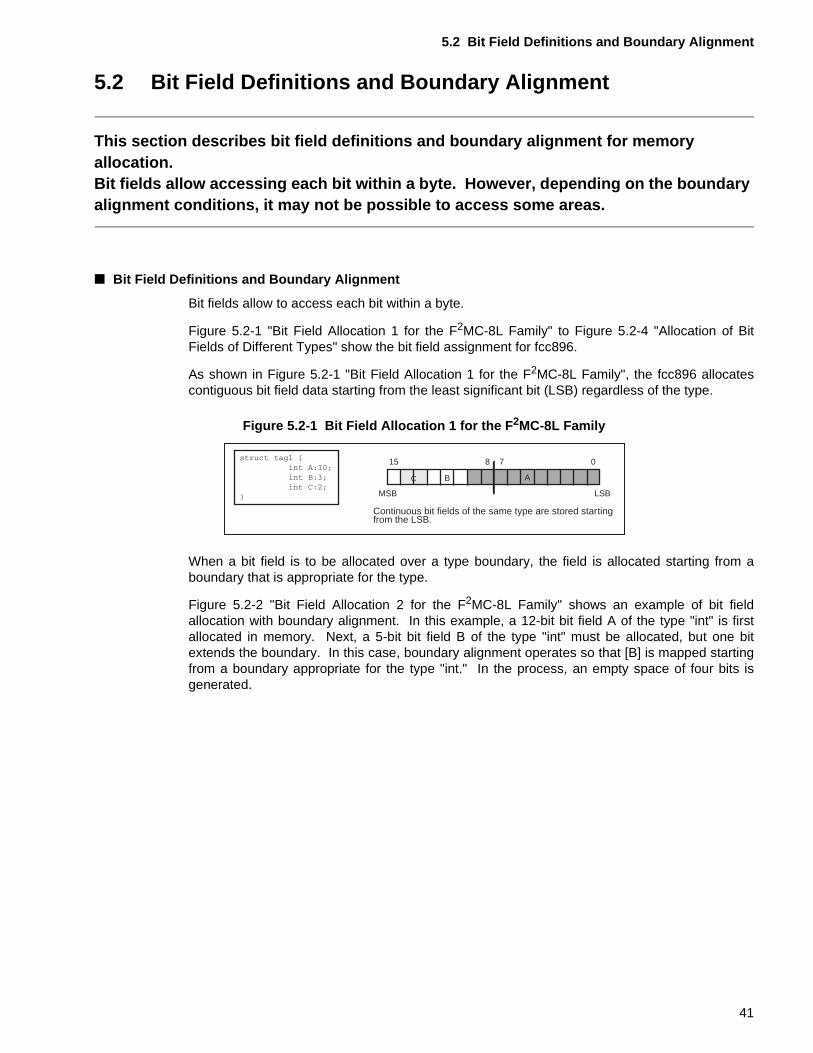
Bit fields allow to access each bit within a byte.
Figure 5.2-1 "Bit Field Allocation 1 for the F2MC-8L Family" to Figure 5.2-4 "Allocation of BitFields of Different Types" show the bit field assignment for fcc896.
As shown in Figure 5.2-1 "Bit Field Allocation 1 for the F2MC-8L Family", the fcc896 allocatescontiguous bit field data starting from the least significant bit (LSB) regardless of the type.
Figure 5.2-1 Bit Field Allocation 1 for the F 2MC-8L Family
When a bit field is to be allocated over a type boundary, the field is allocated starting from aboundary that is appropriate for the type.
Figure 5.2-2 "Bit Field Allocation 2 for the F2MC-8L Family" shows an example of bit fieldallocation with boundary alignment. In this example, a 12-bit bit field A of the type "int" is firstallocated in memory. Next, a 5-bit bit field B of the type "int" must be allocated, but one bitextends the boundary. In this case, boundary alignment operates so that [B] is mapped startingfrom a boundary appropriate for the type "int." In the process, an empty space of four bits isgenerated.
0715 8
LSBMSB
Continuous bit fields of the same type are stored startingfrom the LSB.
ABC
41
CHAPTER 5 ACCESSING VARIABLES THAT USE BIT FIELDS
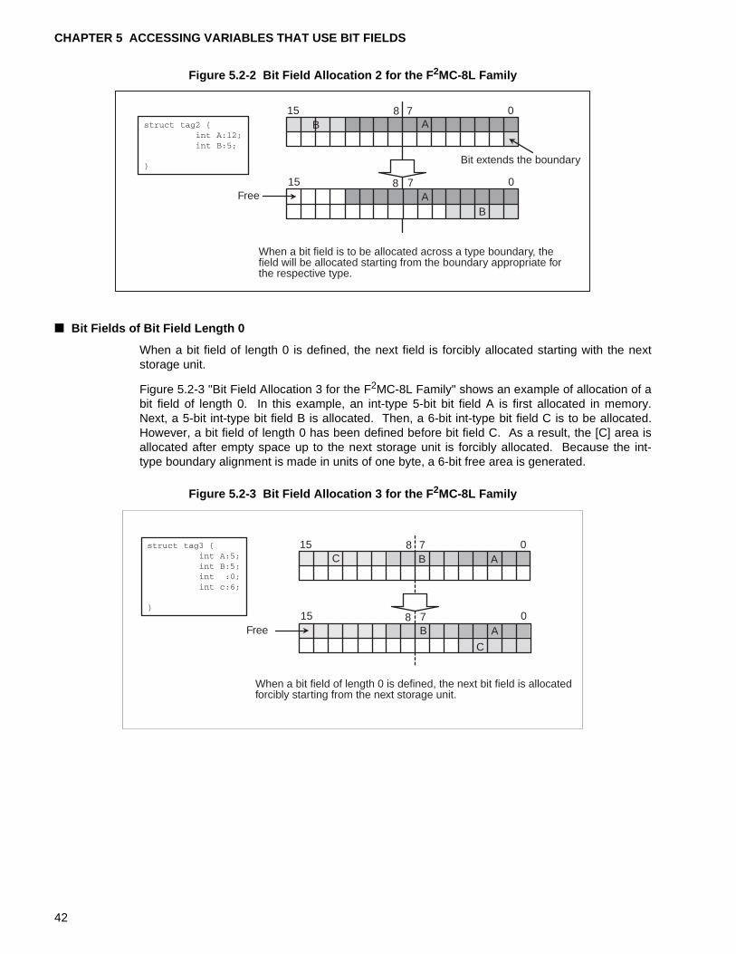
Figure 5.2-2 Bit Field Allocation 2 for the F 2MC-8L Family
■ Bit Fields of Bit Field Length 0
When a bit field of length 0 is defined, the next field is forcibly allocated starting with the nextstorage unit.
Figure 5.2-3 "Bit Field Allocation 3 for the F2MC-8L Family" shows an example of allocation of abit field of length 0. In this example, an int-type 5-bit bit field A is first allocated in memory.Next, a 5-bit int-type bit field B is allocated. Then, a 6-bit int-type bit field C is to be allocated.However, a bit field of length 0 has been defined before bit field C. As a result, the [C] area isallocated after empty space up to the next storage unit is forcibly allocated. Because the int-type boundary alignment is made in units of one byte, a 6-bit free area is generated.
Figure 5.2-3 Bit Field Allocation 3 for the F 2MC-8L Family
When a bit field is to be allocated across a type boundary, thefield will be allocated starting from the boundary appropriate forthe respective type.
Free
0715 8A
0715 8
B
B
Bit extends the boundary
B A
A
C
Free
When a bit field of length 0 is defined, the next bit field is allocatedforcibly starting from the next storage unit.
0715 8
0715 8
A
A
B
B
C
42
5.2 Bit Field Definitions and Boundary Alignment
■ Definitions of Bit Fields of Different Types
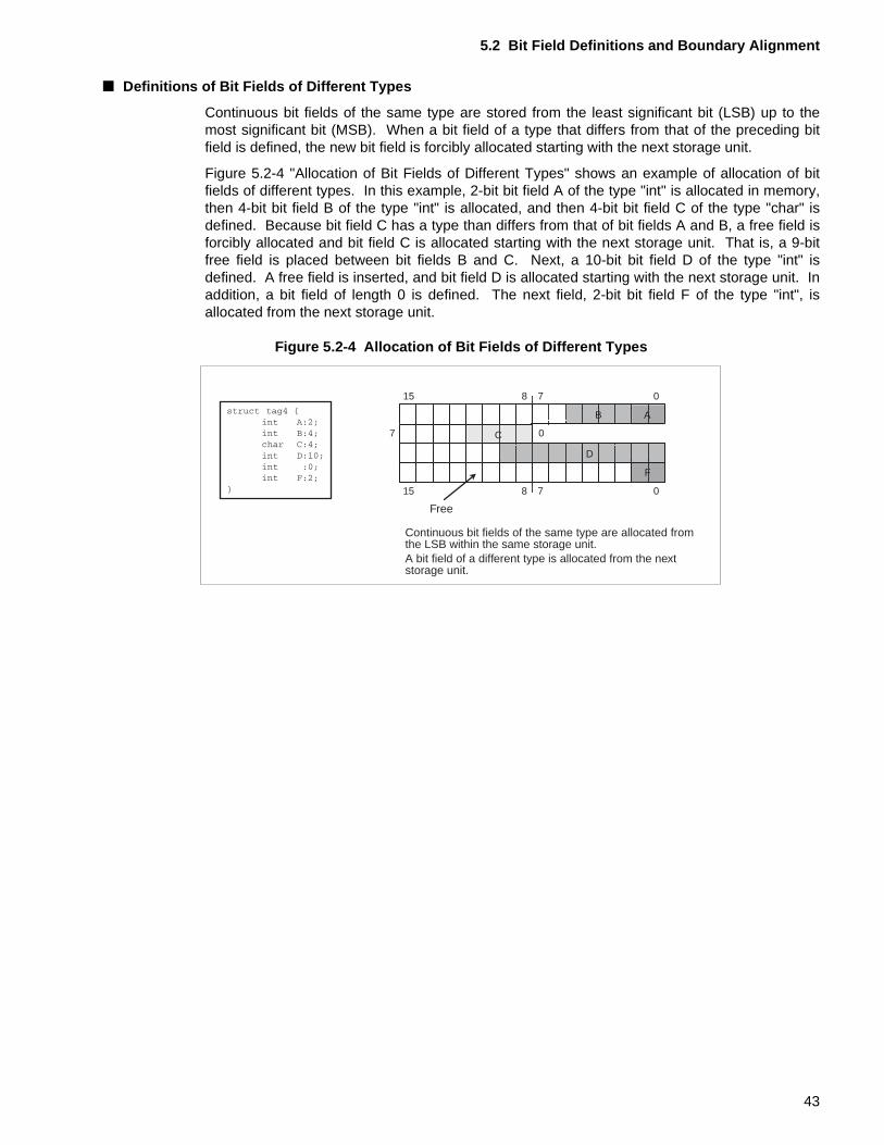
Continuous bit fields of the same type are stored from the least significant bit (LSB) up to themost significant bit (MSB). When a bit field of a type that differs from that of the preceding bitfield is defined, the new bit field is forcibly allocated starting with the next storage unit.
Figure 5.2-4 "Allocation of Bit Fields of Different Types" shows an example of allocation of bitfields of different types. In this example, 2-bit bit field A of the type "int" is allocated in memory,then 4-bit bit field B of the type "int" is allocated, and then 4-bit bit field C of the type "char" isdefined. Because bit field C has a type than differs from that of bit fields A and B, a free field isforcibly allocated and bit field C is allocated starting with the next storage unit. That is, a 9-bitfree field is placed between bit fields B and C. Next, a 10-bit bit field D of the type "int" isdefined. A free field is inserted, and bit field D is allocated starting with the next storage unit. Inaddition, a bit field of length 0 is defined. The next field, 2-bit bit field F of the type "int", isallocated from the next storage unit.
Figure 5.2-4 Allocation of Bit Fields of Different Types
0715 8
A
C
D
F
B
07
0715 8
Free
Continuous bit fields of the same type are allocated fromthe LSB within the same storage unit.A bit field of a different type is allocated from the nextstorage unit.
43
CHAPTER 5 ACCESSING VARIABLES THAT USE BIT FIELDS
■ Signed Bit Fields
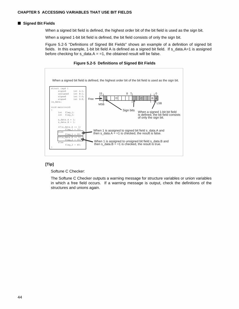
When a signed bit field is defined, the highest order bit of the bit field is used as the sign bit.
When a signed 1-bit bit field is defined, the bit field consists of only the sign bit.
Figure 5.2-5 "Definitions of Signed Bit Fields" shows an example of a definition of signed bitfields. In this example, 1-bit bit field A is defined as a signed bit field. If s_data.A=1 is assignedbefore checking for s_data.A = =1, the obtained result will be false.
Figure 5.2-5 Definitions of Signed Bit Fields
[Tip]
Softune C Checker:
The Softune C Checker outputs a warning message for structure variables or union variablesin which a free field occurs. If a warning message is output, check the definitions of thestructures and unions again.
0715 8
LSBMSB
ABCD
When a signed bit field is defined, the highest order bit of the bit field is used as the sign bit.
Sign bits
Free
When a signed 1-bit bit fieldis defined, the bit field consistsof only the sign bit.
When 1 is assigned to signed bit field s_data.A andthen s_data.A = =1 is checked, the result is false.
When 1 is assigned to unsigned bit field s_data.B andthen s_data.B = =1 is checked, the result is true.
44
5.3 Accessing I/O Areas Using Bit Fields and Unions
5.3 Accessing I/O Areas Using Bit Fields and Unions
This section describes how to access bit fields in bit units and entire bit fields of unions. This method is not directly related to using less RAM area, but it can facilitate access to registers mapped into the I/O area.
■ Accessing I/O Areas Using Bit Fields and Unions
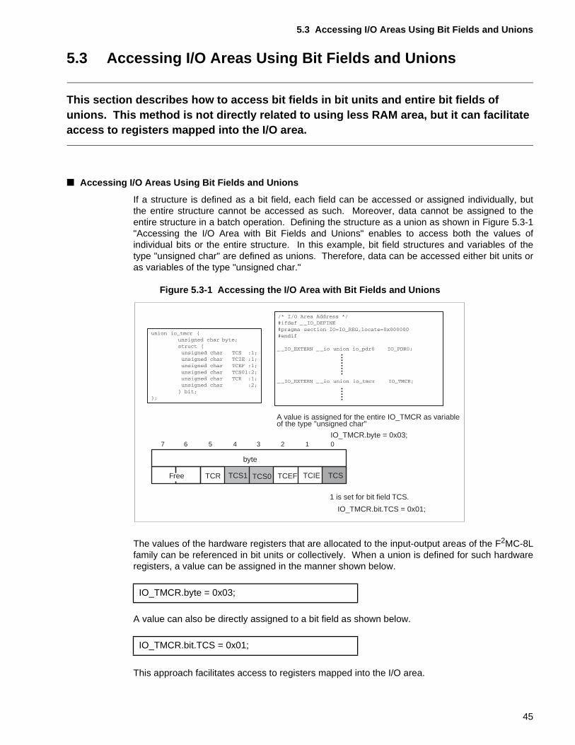
If a structure is defined as a bit field, each field can be accessed or assigned individually, butthe entire structure cannot be accessed as such. Moreover, data cannot be assigned to theentire structure in a batch operation. Defining the structure as a union as shown in Figure 5.3-1"Accessing the I/O Area with Bit Fields and Unions" enables to access both the values ofindividual bits or the entire structure. In this example, bit field structures and variables of thetype "unsigned char" are defined as unions. Therefore, data can be accessed either bit units oras variables of the type "unsigned char."
Figure 5.3-1 Accessing the I/O Area with Bit Fields and Unions
The values of the hardware registers that are allocated to the input-output areas of the F2MC-8Lfamily can be referenced in bit units or collectively. When a union is defined for such hardwareregisters, a value can be assigned in the manner shown below.
A value can also be directly assigned to a bit field as shown below.
This approach facilitates access to registers mapped into the I/O area.
1234567 0
TCSTCEF TCIETCS0TCS1TCR
byte
A value is assigned for the entire IO_TMCR as variableof the type "unsigned char"
IO_TMCR.byte = 0x03;
IO_TMCR.bit.TCS = 0x01;
Free
1 is set for bit field TCS.
IO_TMCR.byte = 0x03;
IO_TMCR.bit.TCS = 0x01;
45

CHAPTER 5 ACCESSING VARIABLES THAT USE BIT FIELDS
46
PART II USING THE STACK AREA EFFICIENTLY
Part II describes how to use stack areas efficiently in C programs.Part II first briefly describes the states of the stack areas at a function call. It then describes how to use the stack areas efficiently.
CHAPTER 6 "FUNCTION CALLS AND THE STACK"
CHAPTER 7 "REDUCING FUNCTION CALLS BY EXPANDING FUNCTIONS IN LINE"
CHAPTER 8 "REDUCING THE NUMBER OF ARGUMENTS TO CONSERVE STACK AREA"
CHAPTER 9 "CONSERVING STACK AREA BY IMPROVEMENTS ON THE AREA FOR FUNCTION RETURN VALUES"
47

48
CHAPTER 6 FUNCTION CALLS AND THE STACK
Before describing how to use the stack area effectively, this chapter describes the areas that are allocated on the stack when a function is called.When a function is called, areas, such as the areas for arguments, are allocated on the stack as necessary.
6.1 "Areas Allocated on the Stack during Function Calls"
6.2 "Stack States When Function Calls Are Nested"
49
CHAPTER 6 FUNCTION CALLS AND THE STACK
6.1 Areas Allocated on the Stack during Function Calls
When a C program calls a function, a return address storage area and a previous frame pointer (IX) save area are always allocated on the stack.
■ Areas Allocated on the Stack at Function Call
When a C program calls a function, the following areas are allocated on the stack as shown inFigure 6.1-1 "Areas Allocated on the Stack when a Function is Called":
❍ Actual arguments and dummy argument areas
Used to hand over arguments during function calls.
• Actual argument: Argument specified by the calling function
• Dummy argument: Argument accessed by the called function
❍ Return address save area
Used to store the address for returning to the calling function.
This area is acquired or released by the calling function.
❍ Previous frame pointer save area
Used to save the value of the frame pointer (IX register) of the source calling the function.
❍ Hidden parameter save area
This area is used to save the beginning address of the area that stores the return value for afunction of the type long, float, double, long-double, structure, or union.
❍ Local variable area
Used to store local variables or work variables.
This area is allocated at function entry, and released at function exit.
The size of this area depends on the number of the local variables to be stored. The greater thenumber of variables defined in the function, the larger the area allocated.
❍ Register save area
This area is used to save registers that must be preserved for the calling source.
This area is not allocated when no registers need to be saved.
50
6.1 Areas Allocated on the Stack during Function Calls
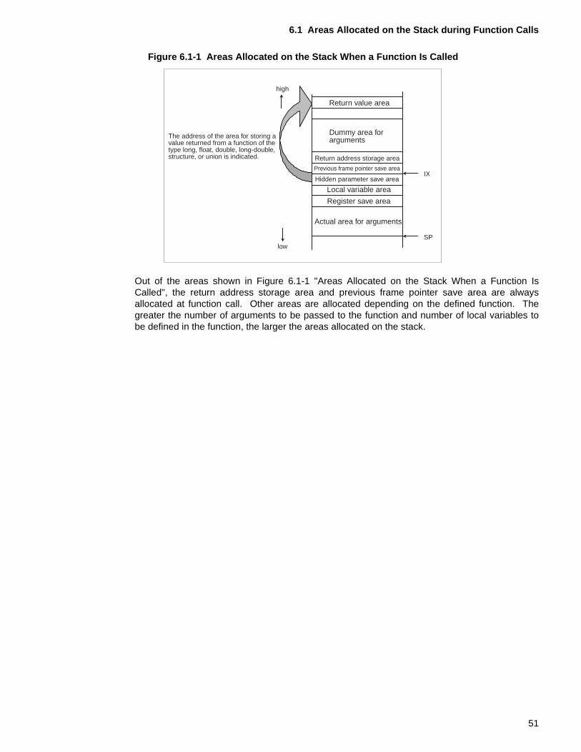
Figure 6.1-1 Areas Allocated on the Stack When a Function Is Called
Out of the areas shown in Figure 6.1-1 "Areas Allocated on the Stack When a Function IsCalled", the return address storage area and previous frame pointer save area are alwaysallocated at function call. Other areas are allocated depending on the defined function. Thegreater the number of arguments to be passed to the function and number of local variables tobe defined in the function, the larger the areas allocated on the stack.
IX
SPlow
high
The address of the area for storing avalue returned from a function of thetype long, float, double, long-double,structure, or union is indicated.
Return value area
Dummy area forarguments
Return address storage area
Previous frame pointer save area
Hidden parameter save area
Local variable area
Register save area
Actual area for arguments
51
CHAPTER 6 FUNCTION CALLS AND THE STACK
6.2 Stack States When Function Calls Are Nested
The areas allocated on the stack for a function are released when the function terminates. The deeper the nesting of function calls nesting, the greater is the amount of stack used.
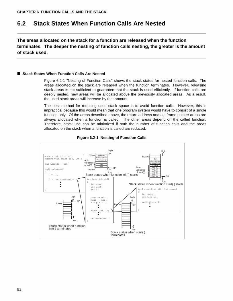
■ Stack States When Function Calls Are Nested
Figure 6.2-1 "Nesting of Function Calls" shows the stack states for nested function calls. Theareas allocated on the stack are released when the function terminates. However, releasingstack areas is not sufficient to guarantee that the stack is used efficiently. If function calls aredeeply nested, new areas will be allocated above the previously allocated areas. As a result,the used stack areas will increase by that amount.
The best method for reducing used stack space is to avoid function calls. However, this isimpractical because this would mean that one program system would have to consist of a singlefunction only. Of the areas described above, the return address and old frame pointer areas arealways allocated when a function is called. The other areas depend on the called function.Therefore, stack use can be minimized if both the number of function calls and the areasallocated on the stack when a function is called are reduced.
Figure 6.2-1 Nesting of Function Calls
low
low
userpid
high
SP
SP
high
high
SP
ipid
dummy[4]moji[3][2][1][0]
low
SP
high
low
inextprev
Previous IXReturn address
Return address
Previous IX
mojimojimojimoji
Autovariablesof init( )
Stack status when function start( ) starts
Stack status when start( )terminates
Stack status when functioninit( ) terminates
Stack status when function init( ) starts
Autovariablesof start( )
h'xxxx
h'xxxxh'aaaa
h'aaaa
h'aaaa
52
CHAPTER 7 REDUCING FUNCTION CALLS BY EXPANDING FUNCTIONS IN LINE
This chapter describes how to use inline expansion of functions to reduce function calls. Expanding functions in line reduces the amount of stack area required.
7.1 "Inline Expansion of Function"
7.2 "Conditions for Inline Expansion of Function"
53
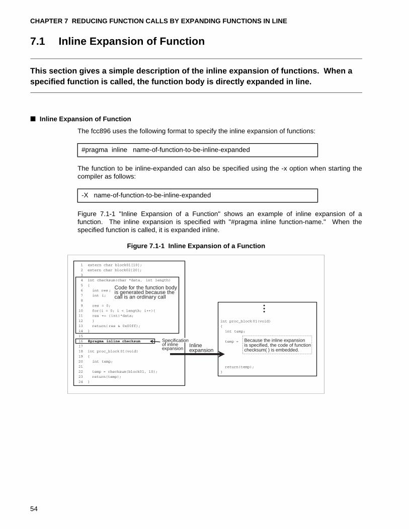
CHAPTER 7 REDUCING FUNCTION CALLS BY EXPANDING FUNCTIONS IN LINE
7.1 Inline Expansion of Function
This section gives a simple description of the inline expansion of functions. When a specified function is called, the function body is directly expanded in line.
■ Inline Expansion of Function
The fcc896 uses the following format to specify the inline expansion of functions:
The function to be inline-expanded can also be specified using the -x option when starting thecompiler as follows:
Figure 7.1-1 "Inline Expansion of a Function" shows an example of inline expansion of afunction. The inline expansion is specified with "#pragma inline function-name." When thespecified function is called, it is expanded inline.
Figure 7.1-1 Inline Expansion of a Function
#pragma inline name-of-function-to-be-inline-expanded
-X name-of-function-to-be-inline-expanded
Code for the function bodyis generated because thecall is an ordinary call
Inlineexpansion
Because the inline expansionis specified, the code of functionchecksum( ) is embedded.
Specificationof inlineexpansion
54
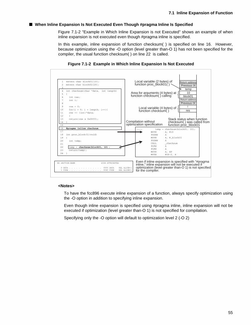
7.1 Inline Expansion of Function
■ When Inline Expansion Is Not Executed Even Though #pragma Inline Is Specified
Figure 7.1-2 "Example in Which Inline Expansion is not Executed" shows an example of wheninline expansion is not executed even though #pragma inline is specified.
In this example, inline expansion of function checksum( ) is specified on line 16. However,because optimization using the -O option (level greater than-O 1) has not been specified for thecompiler, the usual function checksum( ) on line 22 is called.
Figure 7.1-2 Example in Which Inline Expansion Is Not Executed
<Notes>
To have the fcc896 execute inline expansion of a function, always specify optimization usingthe -O option in addition to specifying inline expansion.
Even though inline expansion is specified using #pragma inline, inline expansion will not beexecuted if optimization (level greater than-O 1) is not specified for compilation.
Specifying only the -O option will default to optimization level 2 (-O 2)
Local variable (2 bytes) offunction proc_block01( )
Area for arguments (4 bytes) atfunction checksum( ) calling
Local variable (4 bytes) offunction checksum( )
Return address
Return address
Previous IX
Previous IX
Stack status when functionchecksum( ) was called fromfunction proc_block01
Compilation withoutoptimization specification
Even if inline expansion is specified with "#pragmainline," inline expansion will not be executed ifoptimization (level greater than-O 1) is not specifiedfor the compiler.
temp10
block01
ires
55
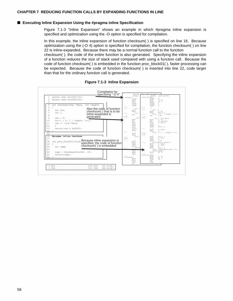
CHAPTER 7 REDUCING FUNCTION CALLS BY EXPANDING FUNCTIONS IN LINE
■ Executing Inline Expansion Using the #pragma inline Specification
Figure 7.1-3 "Inline Expansion" shows an example in which #pragma inline expansion isspecified and optimization using the -O option is specified for compilation.
In this example, the inline expansion of function checksum( ) is specified on line 16. Becauseoptimization using the (-O 4) option is specified for compilation, the function checksum( ) on line22 is inline-expanded. Because there may be a normal function call to the function checksum( ), the code of the entire function is also generated. Specifying the inline expansionof a function reduces the size of stack used compared with using a function call. Because thecode of function checksum( ) is embedded in the function proc_block01( ), faster processing canbe expected. Because the code of function checksum( ) is inserted into line 22, code largerthan that for the ordinary function call is generated.
Figure 7.1-3 Inline Expansion
Compilation byspecifying "-O 4"
Also the code of functionchecksum( ) that is to beinline-expanded isgenerated.
Because inline expansion isspecified, the code of functionchecksum( ) is embedded.
56
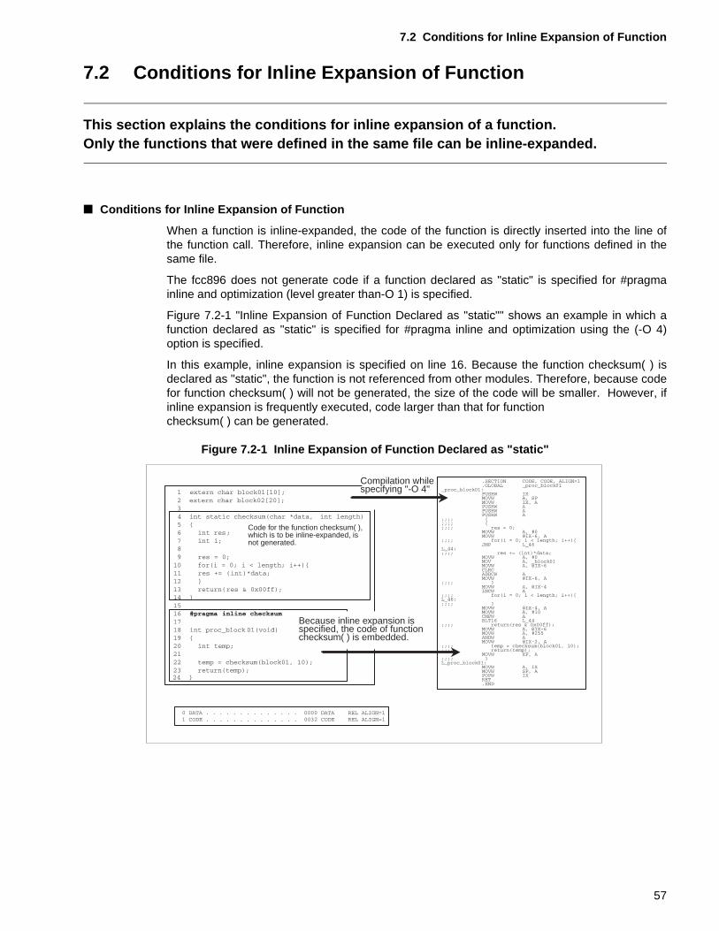
7.2 Conditions for Inline Expansion of Function
7.2 Conditions for Inline Expansion of Function
This section explains the conditions for inline expansion of a function.Only the functions that were defined in the same file can be inline-expanded.
■ Conditions for Inline Expansion of Function
When a function is inline-expanded, the code of the function is directly inserted into the line ofthe function call. Therefore, inline expansion can be executed only for functions defined in thesame file.
The fcc896 does not generate code if a function declared as "static" is specified for #pragmainline and optimization (level greater than-O 1) is specified.
Figure 7.2-1 "Inline Expansion of Function Declared as "static"" shows an example in which afunction declared as "static" is specified for #pragma inline and optimization using the (-O 4)option is specified.
In this example, inline expansion is specified on line 16. Because the function checksum( ) isdeclared as "static", the function is not referenced from other modules. Therefore, because codefor function checksum( ) will not be generated, the size of the code will be smaller. However, ifinline expansion is frequently executed, code larger than that for function checksum( ) can be generated.
Figure 7.2-1 Inline Expansion of Function Declared as "static"
Compilation whilespecifying "-O 4"
Code for the function checksum( ), which is to be inline-expanded, isnot generated.
Because inline expansion isspecified, the code of functionchecksum( ) is embedded.
57
CHAPTER 7 REDUCING FUNCTION CALLS BY EXPANDING FUNCTIONS IN LINE
<Notes>
In the following cases, inline expansion is not executed even if specified:
• Optimization with the "-O" option was not specified for compilation.
• Inline expansion was specified for a recursively called function.
• Inline expansion was specified for a function for which a structure or union was specified asargument.
• Inline expansion was specified for a file in which the setjmp function is called.
• Inline expansion was specified in a file containing the _ _asm statement.
• Arguments between functions do not match.
[Tip]
For the fcc896:
The number of lines of a function to be inline-expanded can be specified with the followingsize option for compilation.
When this option is specified, the functions that are specified with the size option are inline-expanded in compilation units. When the size option is not specified, functions consisting ofthirty lines or less are inline-expanded. Also in this case, the optimization (-O 1 or more)must be specified with the "-O" option.
Specifying the ADDSP option can reduce the overhead for function call processing andgenerate high-speed objects that are smaller than usual. However, this option willcollectively release the actual argument areas accumulated on the stack for function calls. Ifthis option is not specified, the amount of stack used will increase.
Softune C Analyzer:
The upper limit of the number of lines of a function to be inline-expanded can be specified.When analysis is executed with this option specified, the Softune C Analyzer will list thefunctions that are candidates for inline expansion after the analysis is completed. Thisfunction is helpful in determining the functions that will be expanded in line.
-xauto size-option
-K ADDSP-option
58
CHAPTER 8 REDUCING ARGUMENTS TO CONSERVE STACK AREA
This chapter describes how to use fewer arguments in function calls as means of reducing the amount of stack area used.The best way to conserve the stack is to avoid all function calls, but this is not practical. CHAPTER 7 "REDUCING FUNCTION CALLS BY EXPANDING FUNCTIONS IN LINE" already explained described how to use inline expansion to conserve stack area. However, depending on the function size and processing conditions, it may not be possible to conserve stack area by inline expansion. This chapter describes a second method for stack conservation: Conserving stack area by reducing the argument count.
8.1 "Passing Arguments During Function Calls"
8.2 "Conditions for Structure Address Transfer"
59
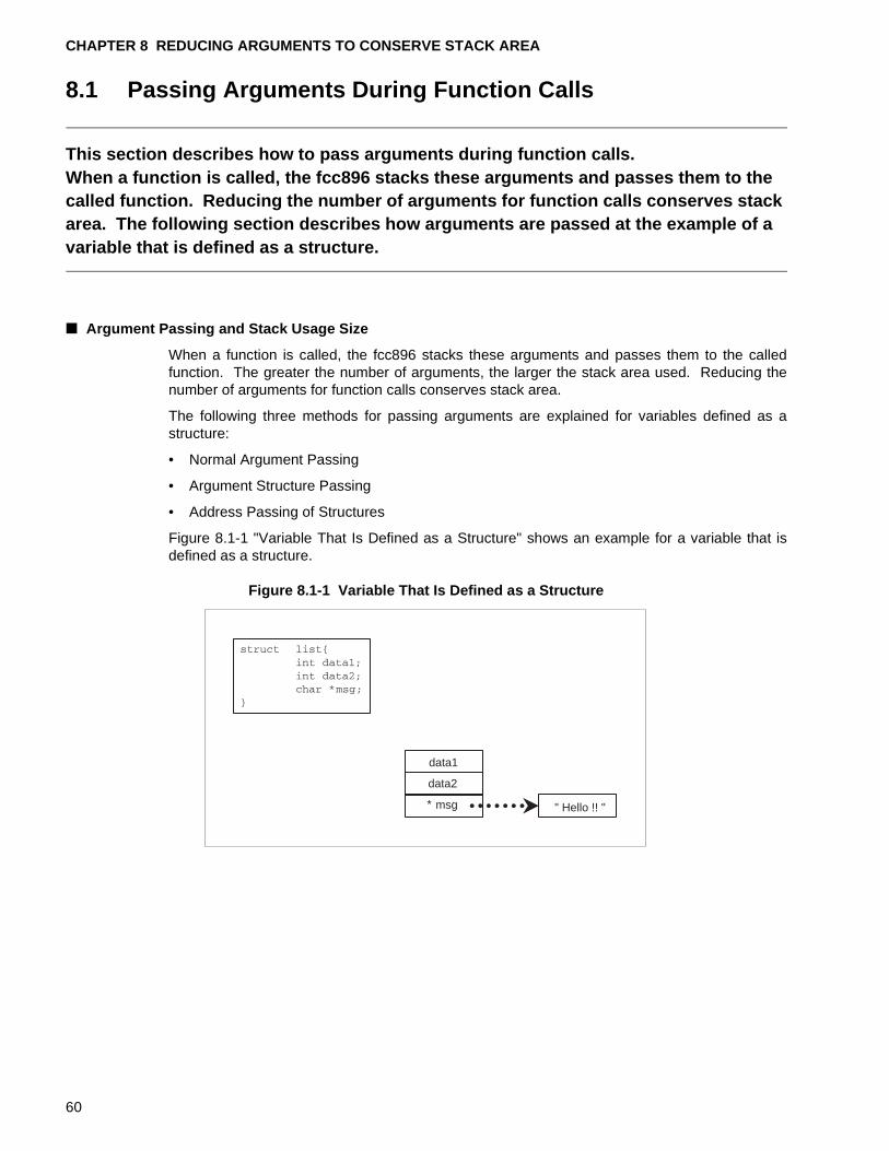
CHAPTER 8 REDUCING ARGUMENTS TO CONSERVE STACK AREA
8.1 Passing Arguments During Function Calls
This section describes how to pass arguments during function calls.When a function is called, the fcc896 stacks these arguments and passes them to the called function. Reducing the number of arguments for function calls conserves stack area. The following section describes how arguments are passed at the example of a variable that is defined as a structure.
■ Argument Passing and Stack Usage Size
When a function is called, the fcc896 stacks these arguments and passes them to the calledfunction. The greater the number of arguments, the larger the stack area used. Reducing thenumber of arguments for function calls conserves stack area.
The following three methods for passing arguments are explained for variables defined as astructure:
• Normal Argument Passing
• Argument Structure Passing
• Address Passing of Structures
Figure 8.1-1 "Variable That Is Defined as a Structure" shows an example for a variable that isdefined as a structure.
Figure 8.1-1 Variable That Is Defined as a Structure
data1
data2
* msg " Hello !! "
60
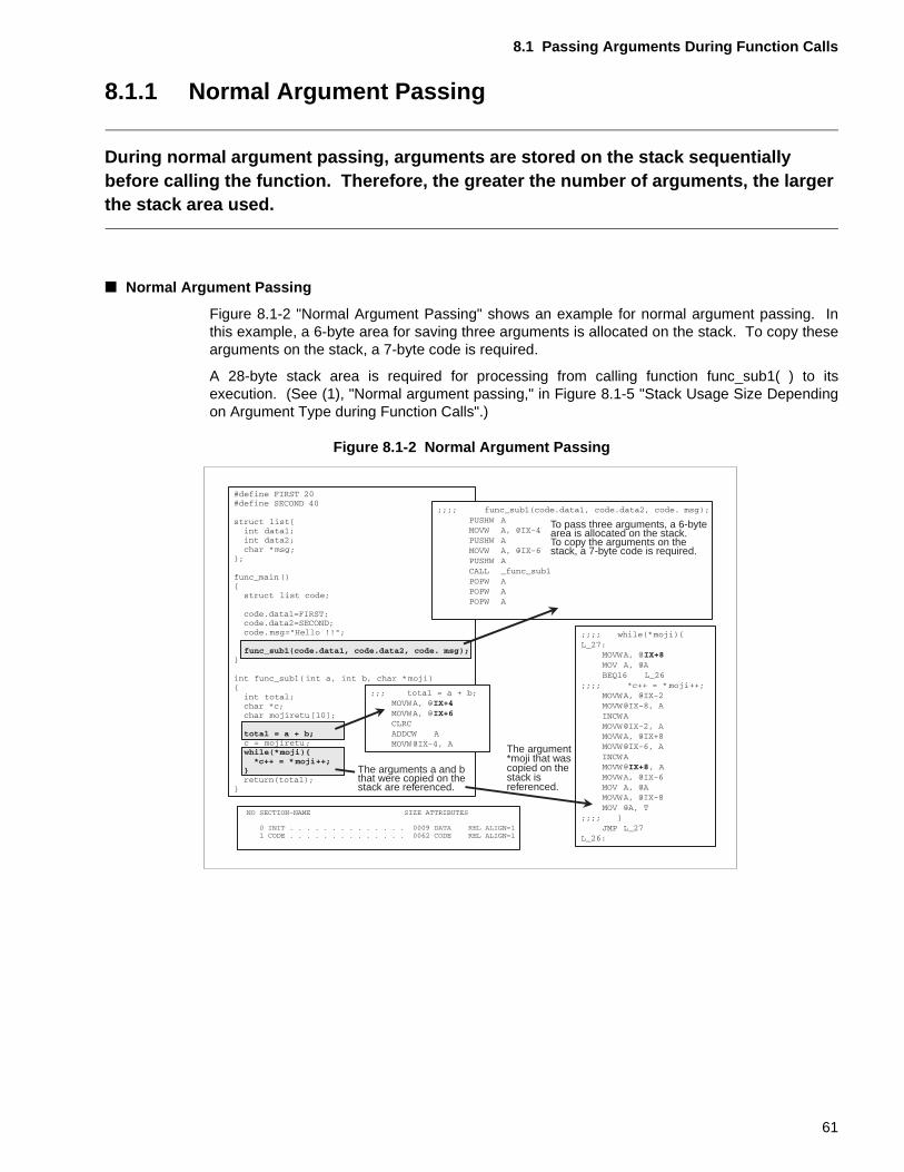
8.1 Passing Arguments During Function Calls
8.1.1 Normal Argument Passing
During normal argument passing, arguments are stored on the stack sequentially before calling the function. Therefore, the greater the number of arguments, the larger the stack area used.
■ Normal Argument Passing
Figure 8.1-2 "Normal Argument Passing" shows an example for normal argument passing. Inthis example, a 6-byte area for saving three arguments is allocated on the stack. To copy thesearguments on the stack, a 7-byte code is required.
A 28-byte stack area is required for processing from calling function func_sub1( ) to itsexecution. (See (1), "Normal argument passing," in Figure 8.1-5 "Stack Usage Size Dependingon Argument Type during Function Calls".)
Figure 8.1-2 Normal Argument Passing
To pass three arguments, a 6-bytearea is allocated on the stack. To copy the arguments on thestack, a 7-byte code is required.
The arguments a and bthat were copied on thestack are referenced.
The argument*moji that wascopied on thestack isreferenced.
61
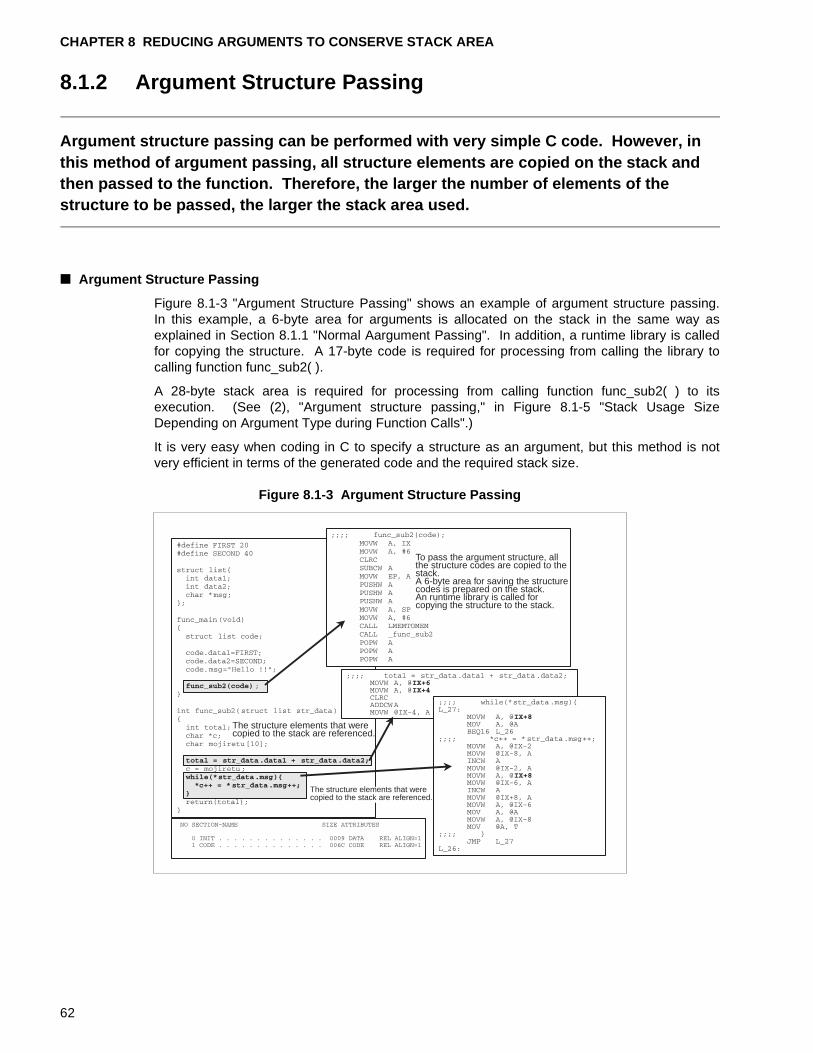
CHAPTER 8 REDUCING ARGUMENTS TO CONSERVE STACK AREA
8.1.2 Argument Structure Passing
Argument structure passing can be performed with very simple C code. However, in this method of argument passing, all structure elements are copied on the stack and then passed to the function. Therefore, the larger the number of elements of the structure to be passed, the larger the stack area used.
■ Argument Structure Passing
Figure 8.1-3 "Argument Structure Passing" shows an example of argument structure passing.In this example, a 6-byte area for arguments is allocated on the stack in the same way asexplained in Section 8.1.1 "Normal Aargument Passing". In addition, a runtime library is calledfor copying the structure. A 17-byte code is required for processing from calling the library tocalling function func_sub2( ).
A 28-byte stack area is required for processing from calling function func_sub2( ) to itsexecution. (See (2), "Argument structure passing," in Figure 8.1-5 "Stack Usage SizeDepending on Argument Type during Function Calls".)
It is very easy when coding in C to specify a structure as an argument, but this method is notvery efficient in terms of the generated code and the required stack size.
Figure 8.1-3 Argument Structure Passing
To pass the argument structure, allthe structure codes are copied to thestack.A 6-byte area for saving the structurecodes is prepared on the stack.An runtime library is called forcopying the structure to the stack.
The structure elements that werecopied to the stack are referenced.
The structure elements that werecopied to the stack are referenced.
62
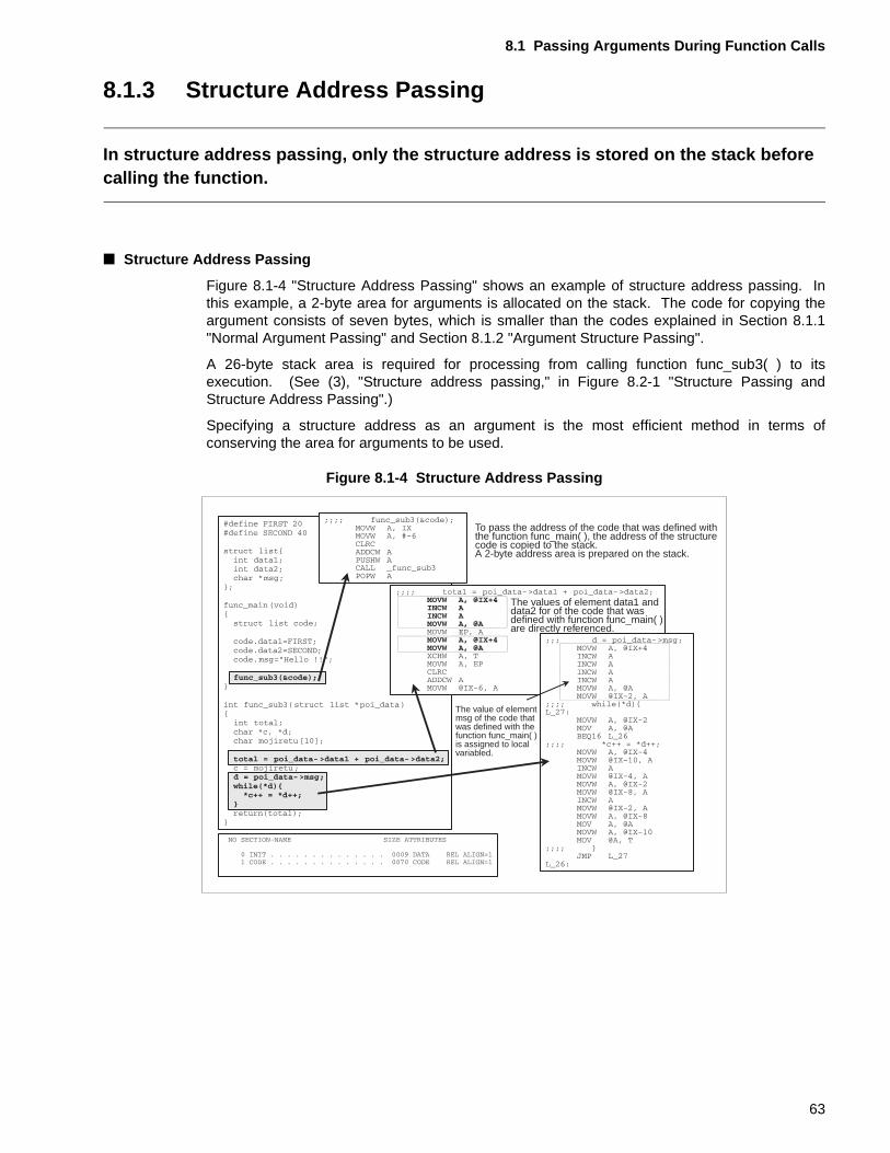
8.1 Passing Arguments During Function Calls
8.1.3 Structure Address Passing
In structure address passing, only the structure address is stored on the stack before calling the function.
■ Structure Address Passing
Figure 8.1-4 "Structure Address Passing" shows an example of structure address passing. Inthis example, a 2-byte area for arguments is allocated on the stack. The code for copying theargument consists of seven bytes, which is smaller than the codes explained in Section 8.1.1"Normal Argument Passing" and Section 8.1.2 "Argument Structure Passing".
A 26-byte stack area is required for processing from calling function func_sub3( ) to itsexecution. (See (3), "Structure address passing," in Figure 8.2-1 "Structure Passing andStructure Address Passing".)
Specifying a structure address as an argument is the most efficient method in terms ofconserving the area for arguments to be used.
Figure 8.1-4 Structure Address Passing
To pass the address of the code that was defined withthe function func_main( ), the address of the structurecode is copied to the stack.A 2-byte address area is prepared on the stack.
The values of element data1 anddata2 for of the code that wasdefined with function func_main( )are directly referenced.
The value of elementmsg of the code thatwas defined with thefunction func_main( )is assigned to localvariabled.
63
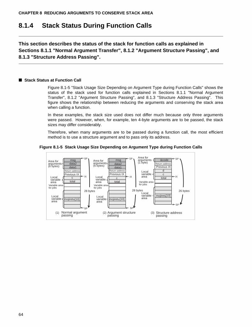
CHAPTER 8 REDUCING ARGUMENTS TO CONSERVE STACK AREA
8.1.4 Stack Status During Function Calls
This section describes the status of the stack for function calls as explained in Sections 8.1.1 "Normal Argument Transfer", 8.1.2 "Argument Structure Passing", and 8.1.3 "Structure Address Passing".
■ Stack Status at Function Call
Figure 8.1-5 "Stack Usage Size Depending on Argument Type during Function Calls" shows thestatus of the stack used for function calls explained in Sections 8.1.1 "Normal ArgumentTransfer", 8.1.2 "Argument Structure Passing", and 8.1.3 "Structure Address Passing". Thisfigure shows the relationship between reducing the arguments and conserving the stack areawhen calling a function.
In these examples, the stack size used does not differ much because only three argumentswere passed. However, when, for example, ten 4-byte arguments are to be passed, the stacksizes may differ considerably.
Therefore, when many arguments are to be passed during a function call, the most efficientmethod is to use a structure argument and to pass only its address.
Figure 8.1-5 Stack Usage Size Depending on Argument Type during Function Calls
msgdata2data1
ctotal
mojiretu[10]
IX
SP
SP
msgdata2data1
ctotal
[10]
IX
SP
SP
&code
dc
total
[10]
SP
SP
mojiretumojiretu
IX
Area forarguments(6 bytes)
Localvariablearea
Variable areafor jobs
Localvariablearea
Return address Return address
Return address
Previous IX Previous IX
Previous IX
(1)
28 bytes
Area forarguments(6 bytes)
Localvariablearea
Variable areafor jobs
Localvariablearea
(2)
28 bytes
Area forarguments(1 byte)
Localvariablearea
Variable areafor jobs
Localvariablearea
(3)
26 bytes
Structure addresspassing
Argument structurepassing
Normal argumentpassing
64
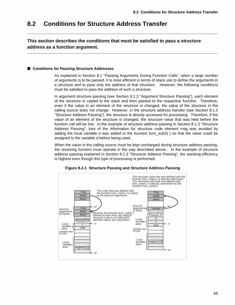
8.2 Conditions for Structure Address Transfer
8.2 Conditions for Structure Address Transfer
This section describes the conditions that must be satisfied to pass a structure address as a function argument.
■ Conditions for Passing Structure Addresses
As explained in Section 8.1 "Passing Arguments During Function Calls", when a large numberof arguments is to be passed, it is most efficient in terms of stack use to define the arguments ina structure and to pass only the address of that structure.. However, the following conditionsmust be satisfied to pass the address of such a structure.
In argument structure passing (see Section 8.1.2 "Argument Structure Passing"), each elementof the structure is copied to the stack and then passed to the respective function. Therefore,even if the value in an element of the structure is changed, the value of the structure in thecalling source does not change. However, in the structure address transfer (see Section 8.1.3"Structure Address Passing"), the structure is directly accessed for processing. Therefore, if thevalue of an element of the structure is changed, the structure value that was held before thefunction call will be lost. In the example of structure address passing in Section 8.1.3 "StructureAddress Passing", loss of the information for structure code element msg was avoided byadding the local variable d was added to the function func_sub3( ) so that the value could beassigned to the variable d before being used.
When the value in the calling source must be kept unchanged during structure address passing,the receiving function must operate in the way described above.. In the example of structureaddress passing explained in Section 8.1.3 "Structure Address Passing", the stacking efficiencyis highest even though this type of processing is performed.
Figure 8.2-1 Structure Passing and Structure Address Passing
IX
SP
SP
IX
SP
SP
msgdata2data1
msgdata2data1
ctotal
mojiretu[10]
msgdata2data1
&code
dc
total
mojiretu [10]
Area forarguments(6 bytes)
Localvariablearea
Variable areafor jobs
Localvariablearea
Return address
Return address
Previous IX
Previous IX
The code that was defined withthe function func_main( ) is copiedto the area for arguments.
Because the function func_sub2( )references this area, the originalstructure code is not affected ifelement values are overwritten.
Area forarguments(1 byte)
Localvariablearea
Variable areafor jobs
Localvariablearea
The structure code that was defined with thefunction func_main( ) is directly referenced. The structure code that was defined withfunc_main( ) is directly overwritten by thefunction func_sub3( ).
65
CHAPTER 8 REDUCING ARGUMENTS TO CONSERVE STACK AREA
[Tip]
Softune C Checker:
The Softune C Checker will output a warning if some arguments were not referenced at allby the called function. Also, if a structure or union was specified in an argument, a warningmessage is output to the effect that performance may be reduced. Examine the method ofargument passing considering the contents of these warning messages.
66
CHAPTER 9 CONSERVING STACK AREA BY IMPROVEMENTS ON THE AREA FOR FUNCTION RETURN VALUES
This chapter describes how to conserve stack area by improvements on the function return value area.As already described, the number of function calls and the number of arguments required for function calls can be reduced by using inline expansion. The size of stack used can also be reduced by improvements with respect to the return values of a function. This chapter describes this third method of stack conservation, reducing the size of the function return value area.
9.1 "Return Value of Functions"
9.2 "Functions Returning Structure-type Values and Stack Conservation"
9.3 "Functions Returning Union-type Values and Stack Conservation"
67
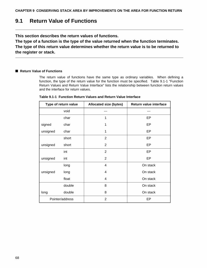
CHAPTER 9 CONSERVING STACK AREA BY IMPROVEMENTS ON THE AREA FOR FUNCTION RETURN
9.1 Return Value of Functions
This section describes the return values of functions.The type of a function is the type of the value returned when the function terminates. The type of this return value determines whether the return value is to be returned to the register or stack.
■ Return Value of Functions
The return value of functions have the same type as ordinary variables. When defining afunction, the type of the return value for the function must be specified. Table 9.1-1 "FunctionReturn Values and Return Value Interface" lists the relationship between function return valuesand the interface for return values.
Table 9.1-1 Function Return Values and Return Value Interface
Type of return value Allocated size (bytes) Return value interface
void --- ---
char 1 EP
signed char 1 EP
unsigned char 1 EP
short 2 EP
unsigned short 2 EP
int 2 EP
unsigned int 2 EP
long 4 On stack
unsigned long 4 On stack
float 4 On stack
double 8 On stack
long double 8 On stack
Pointer/address 2 EP
68
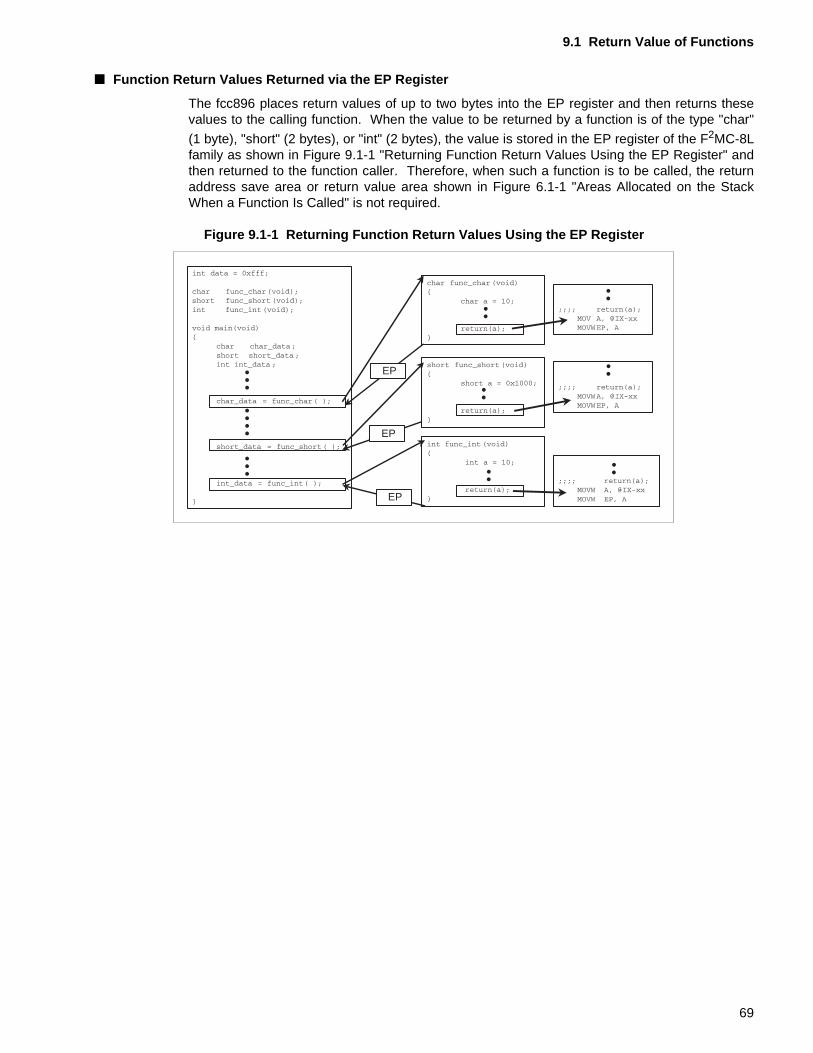
9.1 Return Value of Functions
■ Function Return Values Returned via the EP Register
The fcc896 places return values of up to two bytes into the EP register and then returns thesevalues to the calling function. When the value to be returned by a function is of the type "char"
(1 byte), "short" (2 bytes), or "int" (2 bytes), the value is stored in the EP register of the F2MC-8Lfamily as shown in Figure 9.1-1 "Returning Function Return Values Using the EP Register" andthen returned to the function caller. Therefore, when such a function is to be called, the returnaddress save area or return value area shown in Figure 6.1-1 "Areas Allocated on the StackWhen a Function Is Called" is not required.
Figure 9.1-1 Returning Function Return Values Using the EP Register
EP
EP
EP
69
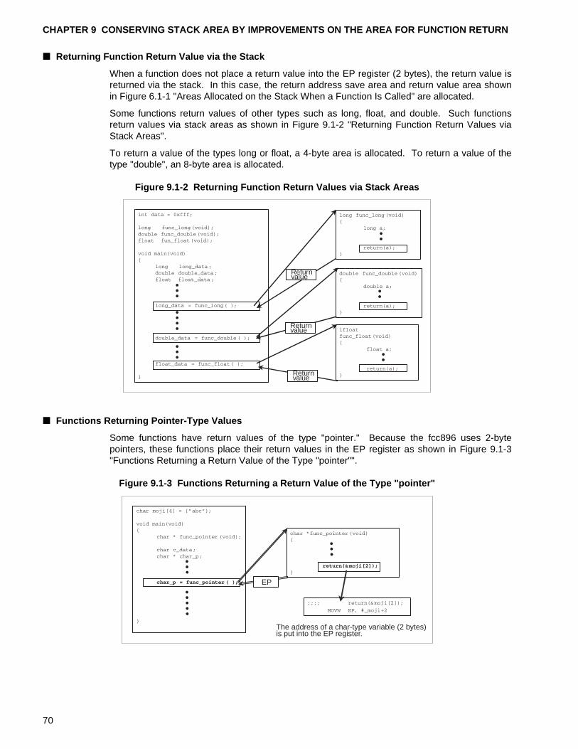
CHAPTER 9 CONSERVING STACK AREA BY IMPROVEMENTS ON THE AREA FOR FUNCTION RETURN
■ Returning Function Return Value via the Stack
When a function does not place a return value into the EP register (2 bytes), the return value isreturned via the stack. In this case, the return address save area and return value area shownin Figure 6.1-1 "Areas Allocated on the Stack When a Function Is Called" are allocated.
Some functions return values of other types such as long, float, and double. Such functionsreturn values via stack areas as shown in Figure 9.1-2 "Returning Function Return Values viaStack Areas".
To return a value of the types long or float, a 4-byte area is allocated. To return a value of thetype "double", an 8-byte area is allocated.
Figure 9.1-2 Returning Function Return Values via Stack Areas
■ Functions Returning Pointer-Type Values
Some functions have return values of the type "pointer." Because the fcc896 uses 2-bytepointers, these functions place their return values in the EP register as shown in Figure 9.1-3"Functions Returning a Return Value of the Type "pointer"".
Figure 9.1-3 Functions Returning a Return Value of the Type "pointer"
Returnvalue
Returnvalue
Returnvalue
EP
The address of a char-type variable (2 bytes)is put into the EP register.
70
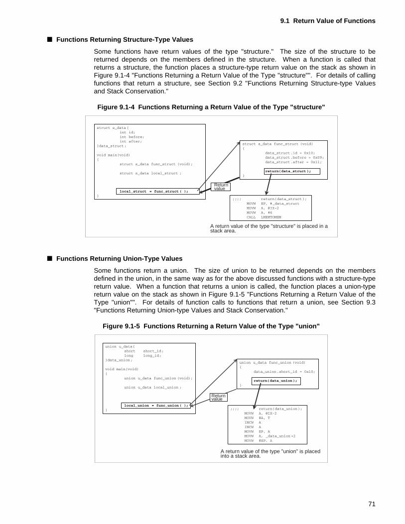
9.1 Return Value of Functions
■ Functions Returning Structure-Type Values
Some functions have return values of the type "structure." The size of the structure to bereturned depends on the members defined in the structure. When a function is called thatreturns a structure, the function places a structure-type return value on the stack as shown inFigure 9.1-4 "Functions Returning a Return Value of the Type "structure"". For details of callingfunctions that return a structure, see Section 9.2 "Functions Returning Structure-type Valuesand Stack Conservation."
Figure 9.1-4 Functions Returning a Return Value of the Type "structure"
■ Functions Returning Union-Type Values
Some functions return a union. The size of union to be returned depends on the membersdefined in the union, in the same way as for the above discussed functions with a structure-typereturn value. When a function that returns a union is called, the function places a union-typereturn value on the stack as shown in Figure 9.1-5 "Functions Returning a Return Value of theType "union"". For details of function calls to functions that return a union, see Section 9.3"Functions Returning Union-type Values and Stack Conservation."
Figure 9.1-5 Functions Returning a Return Value of the Type "union"
Returnvalue
A return value of the type "structure" is placed in astack area.
Returnvalue
A return value of the type "union" is placedinto a stack area.
71
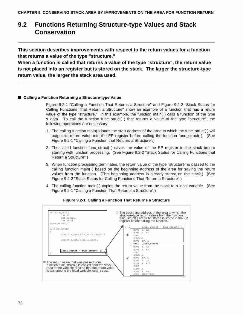
CHAPTER 9 CONSERVING STACK AREA BY IMPROVEMENTS ON THE AREA FOR FUNCTION RETURN
9.2 Functions Returning Structure-type Values and Stack Conservation
This section describes improvements with respect to the return values for a function that returns a value of the type "structure."When a function is called that returns a value of the type "structure", the return value is not placed into an register but is stored on the stack. The larger the structure-type return value, the larger the stack area used.
■ Calling a Function Returning a Structure-type Value
Figure 9.2-1 "Calling a Function That Returns a Structure" and Figure 9.2-2 "Stack Status forCalling Functions That Return a Structure" show an example of a function that has a returnvalue of the type "structure." In this example, the function main( ) calls a function of the types_data. To call the function func_struct( ) that returns a value of the type "structure", thefollowing operations are necessary:
1. The calling function main( ) loads the start address of the area to which the func_struct( ) willoutput its return value into the EP register before calling the function func_struct( ). (SeeFigure 9.2-1 "Calling a Function that Returns a Structure".)
2. The called function func_struct( ) saves the value of the EP register to the stack beforestarting with function processing. (See Figure 9.2-2 "Stack Status for Calling Functions thatReturn a Structure".)
3. When function processing terminates, the return value of the type "structure" is passed to thecalling function main( ) based on the beginning address of the area for saving the returnvalues from the function. (This beginning address is already stored on the stack.) (SeeFigure 9.2-2 "Stack Status for Calling Functions That Return a Structure".)
4. The calling function main( ) copies the return value from the stack to a local variable. (SeeFigure 9.2-1 "Calling a Function That Returns a Structure".)
Figure 9.2-1 Calling a Function That Returns a Structure
The return value that was passed fromfunction func_struct( ) is copied from the stackarea to the variable area so that the return valueis assigned to the local variable local_struct.
The beginning address of the area to which thestructure-type return values from the functionfunc_struct( ) are to be stored is stored in the EPregister before calling the function.
72
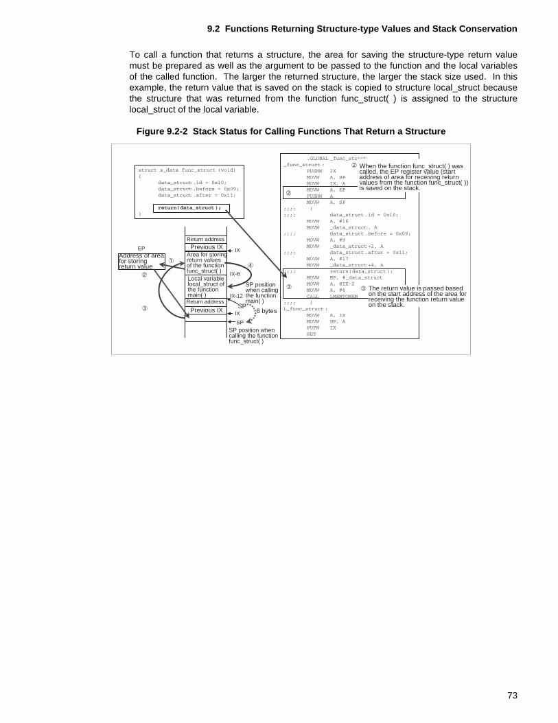
9.2 Functions Returning Structure-type Values and Stack Conservation
To call a function that returns a structure, the area for saving the structure-type return valuemust be prepared as well as the argument to be passed to the function and the local variablesof the called function. The larger the returned structure, the larger the stack size used. In thisexample, the return value that is saved on the stack is copied to structure local_struct becausethe structure that was returned from the function func_struct( ) is assigned to the structurelocal_struct of the local variable.
Figure 9.2-2 Stack Status for Calling Functions That Return a Structure
EP IX
IX-6
IX-12
IX
SP
Address of areafor storingreturn value
Return address
Previous IXArea for storingreturn valuesof the functionfunc_struct( )Local variablelocal_struct ofthe functionmain( )Return address
Previous IX
SP positionwhen callingthe functionmain( )
6 bytes
SP position whencalling the functionfunc_struct( )
When the function func_struct( ) wascalled, the EP register value (startaddress of area for receiving returnvalues from the function func_struct( ))is saved on the stack.
The return value is passed basedon the start address of the area forreceiving the function return valueon the stack.SP
73
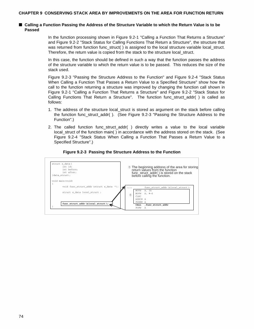
CHAPTER 9 CONSERVING STACK AREA BY IMPROVEMENTS ON THE AREA FOR FUNCTION RETURN
■ Calling a Function Passing the Address of the Structure Variable to which the Return Value is to be Passed
In the function processing shown in Figure 9.2-1 "Calling a Function That Returns a Structure"and Figure 9.2-2 "Stack Status for Calling Functions That Return a Structure", the structure thatwas returned from function func_struct( ) is assigned to the local structure variable local_struct.Therefore, the return value is copied from the stack to the structure local_struct.
In this case, the function should be defined in such a way that the function passes the addressof the structure variable to which the return value is to be passed. This reduces the size of thestack used.
Figure 9.2-3 "Passing the Structure Address to the Function" and Figure 9.2-4 "Stack StatusWhen Calling a Function That Passes a Return Value to a Specified Structure" show how thecall to the function returning a structure was improved by changing the function call shown inFigure 9.2-1 "Calling a Function That Returns a Structure" and Figure 9.2-2 "Stack Status forCalling Functions That Return a Structure". The function func_struct_addr( ) is called asfollows:
1. The address of the structure local_struct is stored as argument on the stack before callingthe function func_struct_addr( ). (See Figure 9.2-3 "Passing the Structure Address to theFunction".)
2. The called function func_struct_addr( ) directly writes a value to the local variablelocal_struct of the function main( ) in accordance with the address stored on the stack. (SeeFigure 9.2-4 "Stack Status When Calling a Function That Passes a Return Value to aSpecified Structure".)
Figure 9.2-3 Passing the Structure Address to the Function
The beginning address of the area for storingreturn values from the functionfunc_struct_addr( ) is stored on the stackbefore calling the function.
74
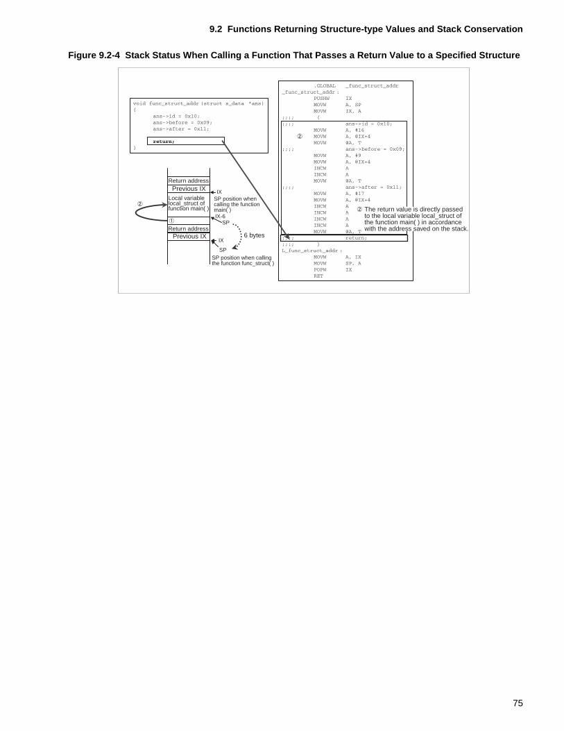
9.2 Functions Returning Structure-type Values and Stack Conservation
Figure 9.2-4 Stack Status When Calling a Function That Passes a Return Value to a Specified Structure
IX
IX-6SP
IX
SP
Return addressPrevious IX
Local variablelocal_struct offunction main( )
Return addressPrevious IX
SP position whencalling the functionmain( )
6 bytes
SP position when callingthe function func_struct( )
The return value is directly passedto the local variable local_struct ofthe function main( ) in accordancewith the address saved on the stack.
75
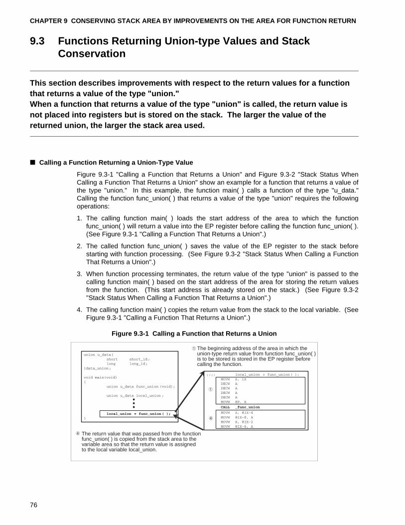
CHAPTER 9 CONSERVING STACK AREA BY IMPROVEMENTS ON THE AREA FOR FUNCTION RETURN
9.3 Functions Returning Union-type Values and Stack Conservation
This section describes improvements with respect to the return values for a function that returns a value of the type "union."When a function that returns a value of the type "union" is called, the return value is not placed into registers but is stored on the stack. The larger the value of the returned union, the larger the stack area used.
■ Calling a Function Returning a Union-Type Value
Figure 9.3-1 "Calling a Function that Returns a Union" and Figure 9.3-2 "Stack Status WhenCalling a Function That Returns a Union" show an example for a function that returns a value ofthe type "union." In this example, the function main( ) calls a function of the type "u_data."Calling the function func_union( ) that returns a value of the type "union" requires the followingoperations:
1. The calling function main( ) loads the start address of the area to which the functionfunc_union( ) will return a value into the EP register before calling the function func_union( ).(See Figure 9.3-1 "Calling a Function That Returns a Union".)
2. The called function func_union( ) saves the value of the EP register to the stack beforestarting with function processing. (See Figure 9.3-2 "Stack Status When Calling a FunctionThat Returns a Union".)
3. When function processing terminates, the return value of the type "union" is passed to thecalling function main( ) based on the start address of the area for storing the return valuesfrom the function. (This start address is already stored on the stack.) (See Figure 9.3-2"Stack Status When Calling a Function That Returns a Union".)
4. The calling function main( ) copies the return value from the stack to the local variable. (SeeFigure 9.3-1 "Calling a Function That Returns a Union".)
Figure 9.3-1 Calling a Function that Returns a Union
The return value that was passed from the functionfunc_union( ) is copied from the stack area to thevariable area so that the return value is assignedto the local variable local_union.
The beginning address of the area in which theunion-type return value from function func_union( )is to be stored is stored in the EP register beforecalling the function.
76

9.3 Functions Returning Union-type Values and Stack Conservation
For calling a function that returns a union, the area for saving the union-type return value mustbe prepared as well as the argument to be passed to the function and the local variables of thecalled function. The larger the returned union, the larger the stack size used. In this example,because the union that was returned from function func_union( ) is assigned to the unionlocal_union of the local variable, the return value that is saved on the stack is copied to theunion local_union.
Figure 9.3-2 Stack Status When Calling a Function That Returns a Union
EP
IX
IX-4
IX-8
IX
SP
SP
Address of areafor saving thereturn value
Return address
Previous IXArea for savingreturn values fromthe function funcunion( )
Return address
Previous IX
Local variablelocal_union offunction main( )
SP positionwhen callingthe functionmain( )
6 bytes
SP position atcalling of functionfunc_union( )
When the function func_union( ) is called,the EP register value (start address of thearea for receiving return values from thefunction func_union( )) is saved on thestack.
The return value is passed based onthe start address of the area for savingthe function return value on the stack.
77
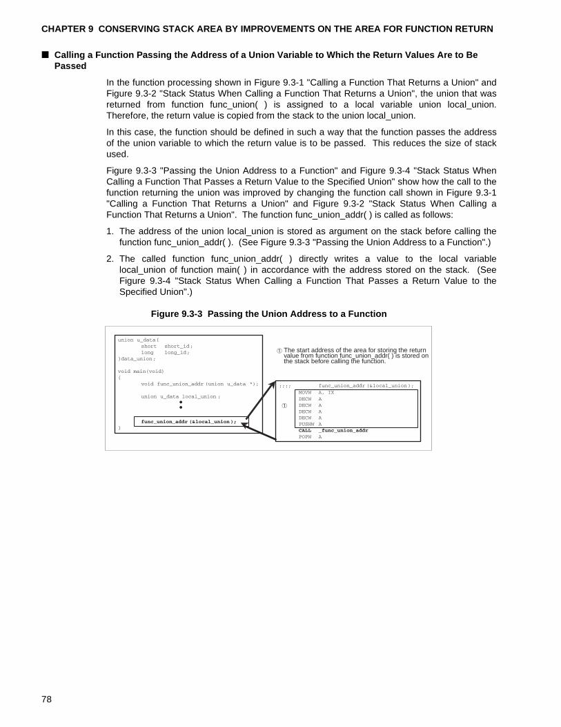
CHAPTER 9 CONSERVING STACK AREA BY IMPROVEMENTS ON THE AREA FOR FUNCTION RETURN
■ Calling a Function Passing the Address of a Union Variable to Which the Return Values Are to Be Passed
In the function processing shown in Figure 9.3-1 "Calling a Function That Returns a Union" andFigure 9.3-2 "Stack Status When Calling a Function That Returns a Union", the union that wasreturned from function func_union( ) is assigned to a local variable union local_union.Therefore, the return value is copied from the stack to the union local_union.
In this case, the function should be defined in such a way that the function passes the addressof the union variable to which the return value is to be passed. This reduces the size of stackused.
Figure 9.3-3 "Passing the Union Address to a Function" and Figure 9.3-4 "Stack Status WhenCalling a Function That Passes a Return Value to the Specified Union" show how the call to thefunction returning the union was improved by changing the function call shown in Figure 9.3-1"Calling a Function That Returns a Union" and Figure 9.3-2 "Stack Status When Calling aFunction That Returns a Union". The function func_union_addr( ) is called as follows:
1. The address of the union local_union is stored as argument on the stack before calling thefunction func_union_addr( ). (See Figure 9.3-3 "Passing the Union Address to a Function".)
2. The called function func_union_addr( ) directly writes a value to the local variablelocal_union of function main( ) in accordance with the address stored on the stack. (SeeFigure 9.3-4 "Stack Status When Calling a Function That Passes a Return Value to theSpecified Union".)
Figure 9.3-3 Passing the Union Address to a Function
The start address of the area for storing the returnvalue from function func_union_addr( ) is stored onthe stack before calling the function.
78
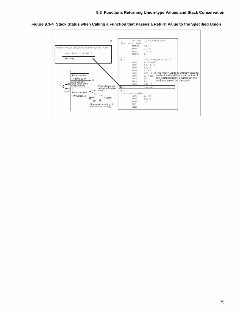
9.3 Functions Returning Union-type Values and Stack Conservation
Figure 9.3-4 Stack Status when Calling a Function that Passes a Return Value to the Specified Union
IX
IX-6
IX
SP
SPIX+4
Return address
Previous IXLocal variablelocal_union of thefunction main( )
Return address
Previous IX
SP position whencalling the functionmain( )
4 bytes
SP position at calling offunction func_union( )
The return value is directly passedto the local variable local_union ofthe function main( ) based on theaddress saved on the stack.
79

CHAPTER 9 CONSERVING STACK AREA BY IMPROVEMENTS ON THE AREA FOR FUNCTION RETURN
80
PART III USING LANGUAGE EXTENSIONS
Part III describes the fcc896 language extensions.
The fcc896 supports specifications for using the F 2MC-8L family architecture. These specifications are referred to as the language extensions. Part 3 begins with an overview of the language extensions. It then provides notes on including assembler code in a C program and on the specification and placement of the _ _io and _ _direct type qualifiers. This part also provides notes on creating and registering interrupt functions.
CHAPTER 10 "WHAT ARE LANGUAGE EXTENSIONS?"
CHAPTER 11 "NOTES ON ASSEMBLER PROGRAM IN C PROGRAMS"
CHAPTER 12 "NOTES ON DEFINING AND ACCESSING THE I/O AREA"
CHAPTER 13 "MAPPING VARIABLES MODIFIED WITH THE TYPE QUALIFIER _ _direct"
CHAPTER 14 "CREATING AND REGISTERING INTERRUPT FUNCTIONS"
81

82
CHAPTER 10 WHAT ARE LANGUAGE EXTENSIONS?
The fcc896 provides the following functionality through language extensions:• Coding of Assembler instructions using an _ _asm statement• Extended type qualifiers• Extended functions using #pragma• Built-in functionsThis chapter describes these functions.
10.1 "Coding Assembler Instructions Using an _ _asm Statement"
10.2 "Extended Type Qualifiers"
10.3 "Extended Functions Using #pragma"
10.4 "Built-in Functions"
83
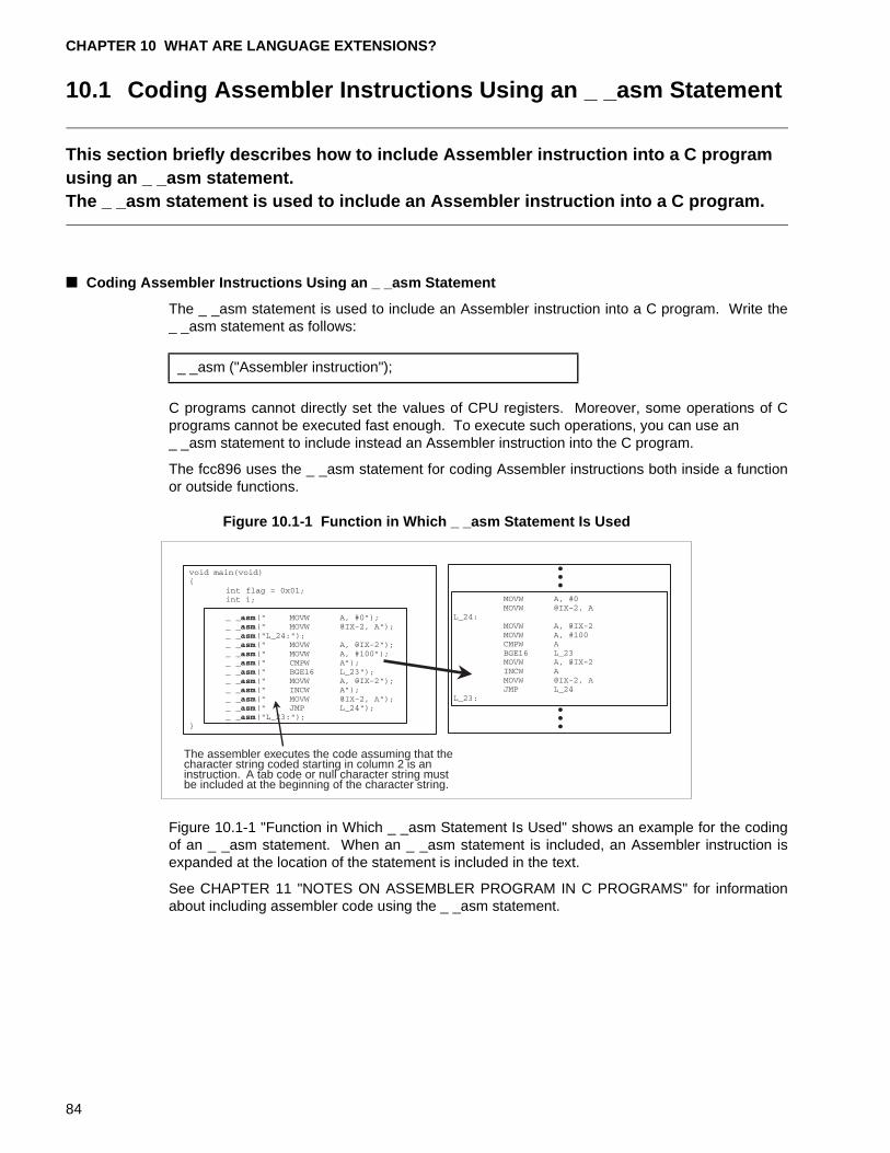
CHAPTER 10 WHAT ARE LANGUAGE EXTENSIONS?
10.1 Coding Assembler Instructions Using an _ _asm Statement
This section briefly describes how to include Assembler instruction into a C program using an _ _asm statement.The _ _asm statement is used to include an Assembler instruction into a C program.
■ Coding Assembler Instructions Using an _ _asm Statement
The _ _asm statement is used to include an Assembler instruction into a C program. Write the_ _asm statement as follows:
C programs cannot directly set the values of CPU registers. Moreover, some operations of Cprograms cannot be executed fast enough. To execute such operations, you can use an _ _asm statement to include instead an Assembler instruction into the C program.
The fcc896 uses the _ _asm statement for coding Assembler instructions both inside a functionor outside functions.
Figure 10.1-1 Function in Which _ _asm Statement Is Used
Figure 10.1-1 "Function in Which _ _asm Statement Is Used" shows an example for the codingof an _ _asm statement. When an _ _asm statement is included, an Assembler instruction isexpanded at the location of the statement is included in the text.
See CHAPTER 11 "NOTES ON ASSEMBLER PROGRAM IN C PROGRAMS" for informationabout including assembler code using the _ _asm statement.
_ _asm ("Assembler instruction");
The assembler executes the code assuming that thecharacter string coded starting in column 2 is aninstruction. A tab code or null character string mustbe included at the beginning of the character string.
84
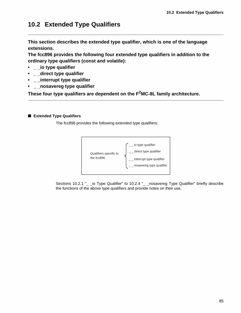
10.2 Extended Type Qualifiers
10.2 Extended Type Qualifiers
This section describes the extended type qualifier, which is one of the language extensions.The fcc896 provides the following four extended type qualifiers in addition to the ordinary type qualifiers (const and volatile):• _ _io type qualifier• _ _direct type qualifier• _ _interrupt type qualifier• _ _nosavereg type qualifier
These four type qualifiers are dependent on the F 2MC-8L family architecture.
■ Extended Type Qualifiers
The fcc896 provides the following extended type qualifiers:
Sections 10.2.1 "_ _io Type Qualifier" to 10.2.4 "_ _nosavereg Type Qualifier" briefly describethe functions of the above type qualifiers and provide notes on their use.
Qualifiers specific tothe fcc896
_ _ io type qualifier
_ _ interrupt type qualifier
_ _ direct type qualifier
_ _ nosavereg type qualifier
85
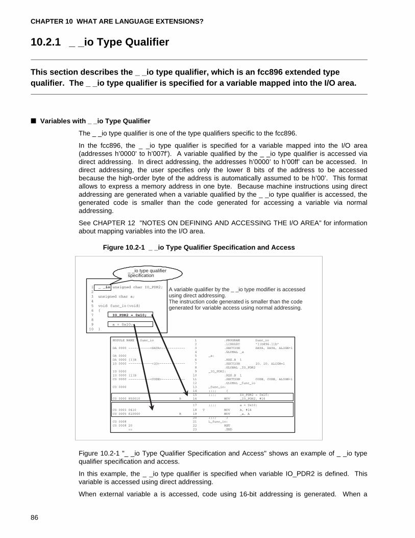
CHAPTER 10 WHAT ARE LANGUAGE EXTENSIONS?
10.2.1 _ _io Type Qualifier
This section describes the _ _io type qualifier, which is an fcc896 extended type qualifier. The _ _io type qualifier is specified for a variable mapped into the I/O area.
■ Variables with _ _io Type Qualifier
The _ _io type qualifier is one of the type qualifiers specific to the fcc896.
In the fcc896, the _ _io type qualifier is specified for a variable mapped into the I/O area(addresses h’0000’ to h’007f’). A variable qualified by the _ _io type qualifier is accessed viadirect addressing. In direct addressing, the addresses h’0000’ to h’00ff’ can be accessed. Indirect addressing, the user specifies only the lower 8 bits of the address to be accessedbecause the high-order byte of the address is automatically assumed to be h’00’. This formatallows to express a memory address in one byte. Because machine instructions using directaddressing are generated when a variable qualified by the _ _io type qualifier is accessed, thegenerated code is smaller than the code generated for accessing a variable via normaladdressing.
See CHAPTER 12 "NOTES ON DEFINING AND ACCESSING THE I/O AREA" for informationabout mapping variables into the I/O area.
Figure 10.2-1 _ _io Type Qualifier Specification and Access
Figure 10.2-1 "_ _io Type Qualifier Specification and Access" shows an example of _ _io typequalifier specification and access.
In this example, the _ _io type qualifier is specified when variable IO_PDR2 is defined. Thisvariable is accessed using direct addressing.
When external variable a is accessed, code using 16-bit addressing is generated. When a
_ _io type qualifierspecification
A variable qualifier by the _ _io type modifier is accessedusing direct addressing.The instruction code generated is smaller than the codegenerated for variable access using normal addressing.
86
10.2 Extended Type Qualifiers
machine instructions are generated using direct addressing when a variable modified by the _ _io type qualifier is accessed, the generated code uses direct addressing and is thereforesmaller than the code generated for variable access using normal addressing.
[Tip]
Softune C Checker:
The Softune C Checker outputs a warning if the _ _io type qualifier, a language extension, isused in a definition and declaration. This check function is useful for creating programs forwhich portability is important.
87
CHAPTER 10 WHAT ARE LANGUAGE EXTENSIONS?
10.2.2 _ _direct Type Qualifier
This section describes the _ _direct type qualifier, which is an fcc896 extended type qualifier. The _ _direct type qualifier is specified for variables mapped into the direct area.
■ Variables with _ _direct Type Qualifier
The _ _direct type qualifier is one of the type qualifiers specific to the fcc896.
In the fcc896, a _ _direct type qualifier is specified to define or access a variable mapped intothe area between addresses h’0080’ and h’00ff’ in the direct area (addresses h’0000’ to h’00ff’).I/O resources are not mapped into this area.
A variable qualified by the_ _direct type qualifier is accessed using direct addressing. In directaddressing, the addresses h’0000’ to h’00ff’ can be accessed. In direct addressing, the userspecifies only the lower 8 bits of the address to be accessed because the high-order byte of theaddress is automatically assumed to be h’00’.. This format allows to express a memory addressin one byte. Because machine instructions are generated using direct addressing when avariable qualified by the _ _io type qualifier is accessed, the code generated is smaller than thecode generated for variable access using normal addressing.
Figure 10.2-2 "Specifying and Accessing a Variable Qualified by the_ _direct Type Qualifier"shows an example of defining and accessing a variable qualified by the_ _direct type qualifier.In this example, the _ _direct type qualifier is specified when the variable d_data is defined.See CHAPTER 13 "MAPPING VARIABLES QUALIFIED WITH THE TYPE QUALIFER _ _direct" for information about variables qualified by the _ _direct type qualifier.
88
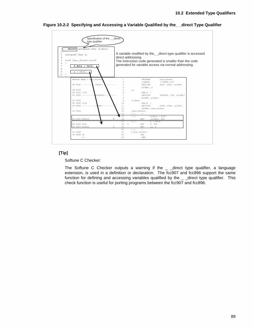
10.2 Extended Type Qualifiers
Figure 10.2-2 Specifying and Accessing a Variable Qualified by the_ _direct Type Qualifier
[Tip]
Softune C Checker:
The Softune C Checker outputs a warning if the _ _direct type qualifier, a languageextension, is used in a definition or declaration. The fcc907 and fcc896 support the samefunction for defining and accessing variables qualified by the _ _direct type qualifier. Thischeck function is useful for porting programs between the fcc907 and fcc896.
Specification of the _ _directtype qualifier
A variable modified by the_ _direct type qualifier is accesseddirect addressing.The instruction code generated is smaller than the codegenerated for variable access via normal addressing.
89
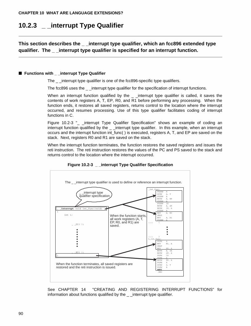
CHAPTER 10 WHAT ARE LANGUAGE EXTENSIONS?
10.2.3 _ _interrupt Type Qualifier
This section describes the _ _interrupt type qualifier, which an fcc896 extended type qualifier. The _ _interrupt type qualifier is specified for an interrupt function.
■ Functions with _ _interrupt Type Qualifier
The _ _interrupt type qualifier is one of the fcc896-specific type qualifiers.
The fcc896 uses the _ _interrupt type qualifier for the specification of interrupt functions.
When an interrupt function qualified by the _ _interrupt type qualifier is called, it saves thecontents of work registers A, T, EP, R0, and R1 before performing any processing. When thefunction ends, it restores all saved registers, returns control to the location where the interruptoccurred, and resumes processing. Use of this type qualifier facilitates coding of interruptfunctions in C.
Figure 10.2-3 "_ _interrupt Type Qualifier Specification" shows an example of coding aninterrupt function qualified by the _ _interrupt type qualifier. In this example, when an interruptoccurs and the interrupt function int_func( ) is executed, registers A, T, and EP are saved on thestack. Next, registers R0 and R1 are saved on the stack.
When the interrupt function terminates, the function restores the saved registers and issues thereti instruction. The reti instruction restores the values of the PC and PS saved to the stack andreturns control to the location where the interrupt occurred.
Figure 10.2-3 _ _interrupt Type Qualifier Specification
See CHAPTER 14 "CREATING AND REGISTERING INTERRUPT FUNCTIONS" forinformation about functions qualified by the _ _interrupt type qualifier.
The _ _interrupt type qualifier is used to define or reference an interrupt function.
_ _interrupt typequalifier specification
When the function starts,all work registers (A, T,EP, R0, and R1) aresaved.
When the function terminates, all saved registers arerestored and the reti instruction is issued.
90
10.2 Extended Type Qualifiers
[Tip]
Softune C Checker:
The Softune C Checker outputs a warning if the _ _interrupt type qualifier, a languageextension, is used in a definition or declaration. The fcc896 supports the same function forcoding interrupt functions qualified by the _ _interrupt-type as the fcc907 and fcc911. Thischeck function is useful for porting programs between the fcc907 or fcc911 and fcc896.
91
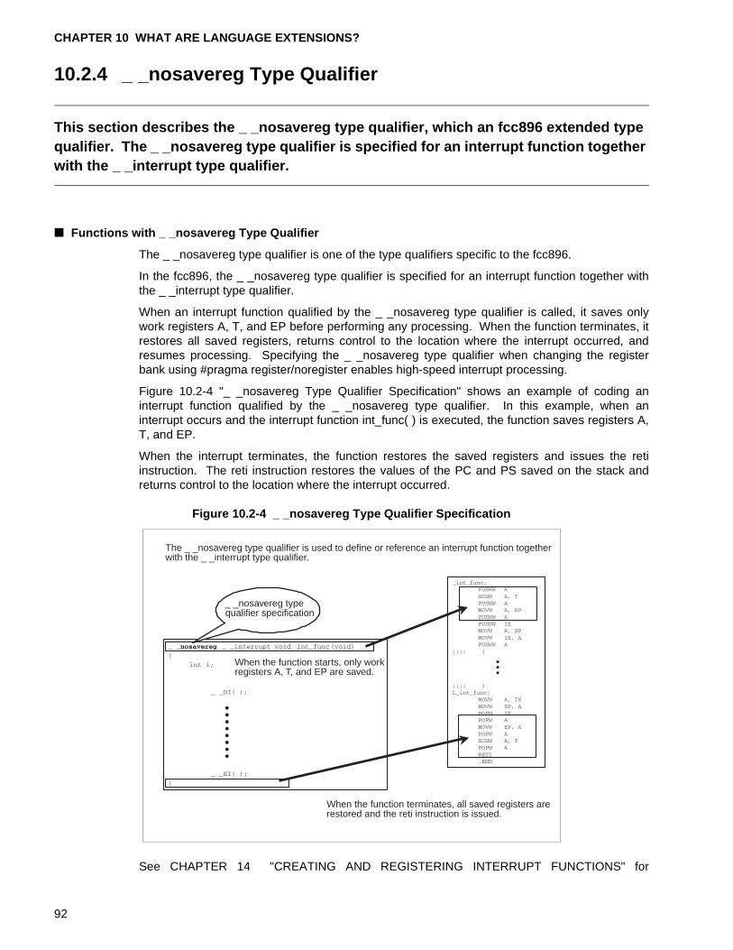
CHAPTER 10 WHAT ARE LANGUAGE EXTENSIONS?
10.2.4 _ _nosavereg Type Qualifier
This section describes the _ _nosavereg type qualifier, which an fcc896 extended type qualifier. The _ _nosavereg type qualifier is specified for an interrupt function together with the _ _interrupt type qualifier.
■ Functions with _ _nosavereg Type Qualifier
The _ _nosavereg type qualifier is one of the type qualifiers specific to the fcc896.
In the fcc896, the _ _nosavereg type qualifier is specified for an interrupt function together withthe _ _interrupt type qualifier.
When an interrupt function qualified by the _ _nosavereg type qualifier is called, it saves onlywork registers A, T, and EP before performing any processing. When the function terminates, itrestores all saved registers, returns control to the location where the interrupt occurred, andresumes processing. Specifying the _ _nosavereg type qualifier when changing the registerbank using #pragma register/noregister enables high-speed interrupt processing.
Figure 10.2-4 "_ _nosavereg Type Qualifier Specification" shows an example of coding aninterrupt function qualified by the _ _nosavereg type qualifier. In this example, when aninterrupt occurs and the interrupt function int_func( ) is executed, the function saves registers A,T, and EP.
When the interrupt terminates, the function restores the saved registers and issues the retiinstruction. The reti instruction restores the values of the PC and PS saved on the stack andreturns control to the location where the interrupt occurred.
Figure 10.2-4 _ _nosavereg Type Qualifier Specification
See CHAPTER 14 "CREATING AND REGISTERING INTERRUPT FUNCTIONS" for
The _ _nosavereg type qualifier is used to define or reference an interrupt function togetherwith the _ _interrupt type qualifier.
_ _nosavereg typequalifier specification
When the function starts, only workregisters A, T, and EP are saved.
When the function terminates, all saved registers arerestored and the reti instruction is issued.
92
10.2 Extended Type Qualifiers
information about functions modified by the _ _nosavereg type qualifier.
[Tip]
Softune C Checker:
The Softune C Checker outputs a warning if the _ _nosavereg type qualifier, a languageextension, is used in a definition or declaration. The fcc896 supports the same function forcoding interrupt functions qualified by the _ _nosavereg type qualifier as the fcc907. Thischeck function is useful for porting programs between the fcc907 and fcc896.
93
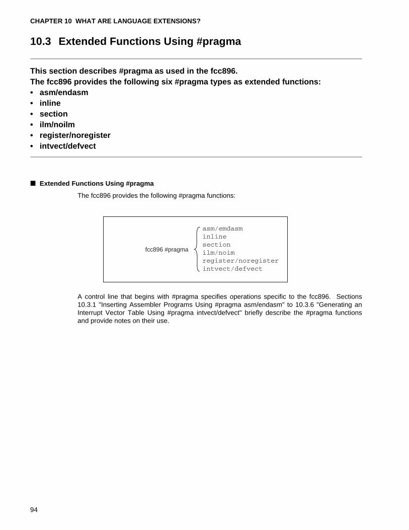
CHAPTER 10 WHAT ARE LANGUAGE EXTENSIONS?
10.3 Extended Functions Using #pragma
This section describes #pragma as used in the fcc896.The fcc896 provides the following six #pragma types as extended functions:• asm/endasm• inline• section• ilm/noilm• register/noregister• intvect/defvect
■ Extended Functions Using #pragma
The fcc896 provides the following #pragma functions:
A control line that begins with #pragma specifies operations specific to the fcc896. Sections10.3.1 "Inserting Assembler Programs Using #pragma asm/endasm" to 10.3.6 "Generating anInterrupt Vector Table Using #pragma intvect/defvect" briefly describe the #pragma functionsand provide notes on their use.
fcc896 #pragma
94
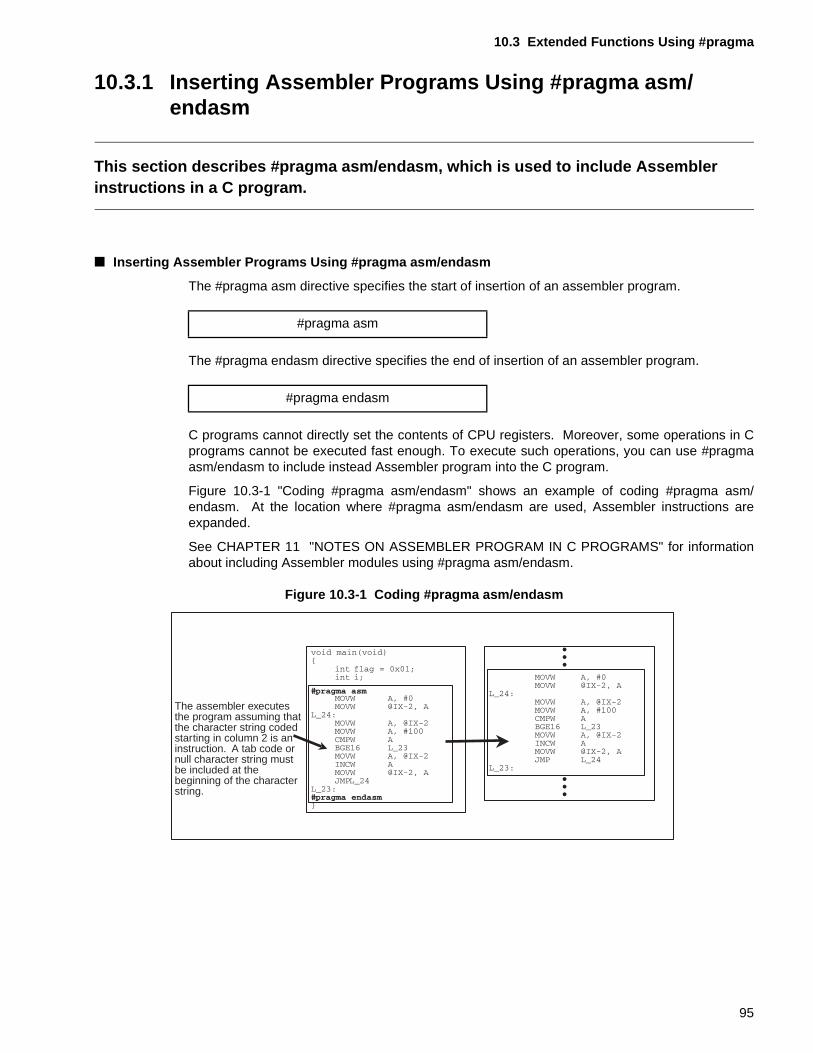
10.3 Extended Functions Using #pragma
10.3.1 Inserting Assembler Programs Using #pragma asm/endasm
This section describes #pragma asm/endasm, which is used to include Assembler instructions in a C program.
■ Inserting Assembler Programs Using #pragma asm/endasm
The #pragma asm directive specifies the start of insertion of an assembler program.
The #pragma endasm directive specifies the end of insertion of an assembler program.
C programs cannot directly set the contents of CPU registers. Moreover, some operations in Cprograms cannot be executed fast enough. To execute such operations, you can use #pragmaasm/endasm to include instead Assembler program into the C program.
Figure 10.3-1 "Coding #pragma asm/endasm" shows an example of coding #pragma asm/endasm. At the location where #pragma asm/endasm are used, Assembler instructions areexpanded.
See CHAPTER 11 "NOTES ON ASSEMBLER PROGRAM IN C PROGRAMS" for informationabout including Assembler modules using #pragma asm/endasm.
Figure 10.3-1 Coding #pragma asm/endasm
#pragma asm
#pragma endasm
The assembler executesthe program assuming thatthe character string codedstarting in column 2 is aninstruction. A tab code ornull character string mustbe included at thebeginning of the characterstring.
95
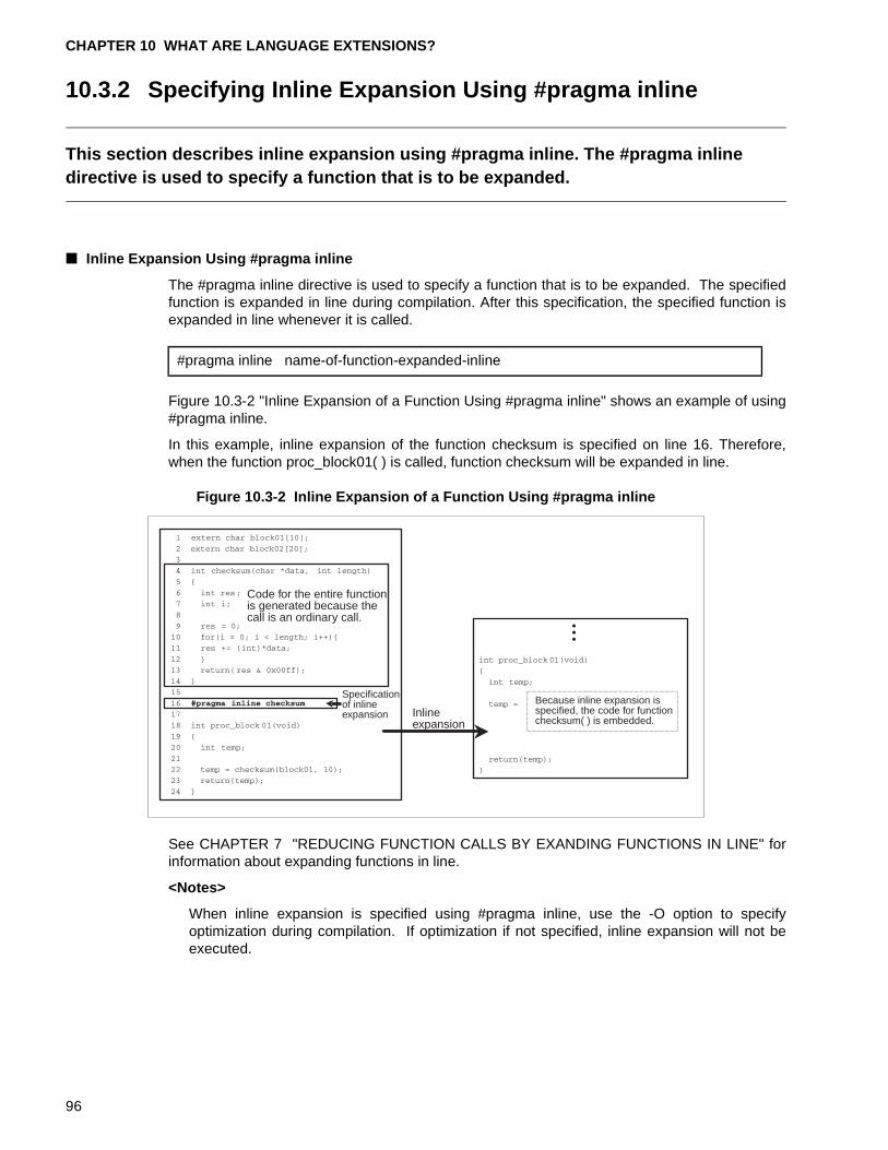
CHAPTER 10 WHAT ARE LANGUAGE EXTENSIONS?
10.3.2 Specifying Inline Expansion Using #pragma inline
This section describes inline expansion using #pragma inline. The #pragma inline directive is used to specify a function that is to be expanded.
■ Inline Expansion Using #pragma inline
The #pragma inline directive is used to specify a function that is to be expanded. The specifiedfunction is expanded in line during compilation. After this specification, the specified function isexpanded in line whenever it is called.
Figure 10.3-2 "Inline Expansion of a Function Using #pragma inline" shows an example of using#pragma inline.
In this example, inline expansion of the function checksum is specified on line 16. Therefore,when the function proc_block01( ) is called, function checksum will be expanded in line.
Figure 10.3-2 Inline Expansion of a Function Using #pragma inline
See CHAPTER 7 "REDUCING FUNCTION CALLS BY EXANDING FUNCTIONS IN LINE" forinformation about expanding functions in line.
<Notes>
When inline expansion is specified using #pragma inline, use the -O option to specifyoptimization during compilation. If optimization if not specified, inline expansion will not beexecuted.
#pragma inline name-of-function-expanded-inline
Code for the entire functionis generated because thecall is an ordinary call.
Specificationof inlineexpansion Inline
expansion
Because inline expansion isspecified, the code for functionchecksum( ) is embedded.
96
10.3 Extended Functions Using #pragma
[Tip]
For the fcc896:
The following option can be used to specify the function to be expanded in line duringcompilation.
Use the following option to specify the number of lines of the function to be expanded in lineduring compilation.
Optimization must be specified using the -O option.
-x function-name option
-xauto size option
97
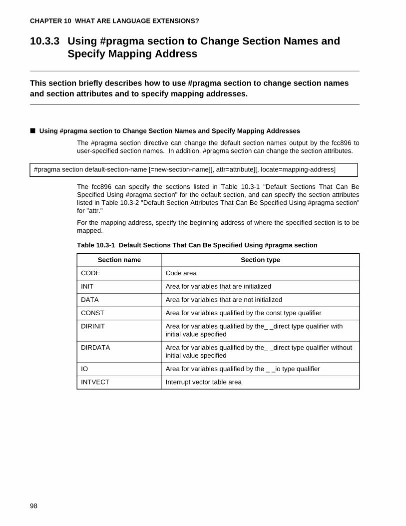
CHAPTER 10 WHAT ARE LANGUAGE EXTENSIONS?
10.3.3 Using #pragma section to Change Section Names and Specify Mapping Address
This section briefly describes how to use #pragma section to change section names and section attributes and to specify mapping addresses.
■ Using #pragma section to Change Section Names and Specify Mapping Addresses
The #pragma section directive can change the default section names output by the fcc896 touser-specified section names. In addition, #pragma section can change the section attributes.
The fcc896 can specify the sections listed in Table 10.3-1 "Default Sections That Can BeSpecified Using #pragma section" for the default section, and can specify the section attributeslisted in Table 10.3-2 "Default Section Attributes That Can Be Specified Using #pragma section"for "attr."
For the mapping address, specify the beginning address of where the specified section is to bemapped.
#pragma section default-section-name [=new-section-name][, attr=attribute][, locate=mapping-address]
Table 10.3-1 Default Sections That Can Be Specified Using #pragma section
Section name Section type
CODE Code area
INIT Area for variables that are initialized
DATA Area for variables that are not initialized
CONST Area for variables qualified by the const type qualifier
DIRINIT Area for variables qualified by the_ _direct type qualifier with initial value specified
DIRDATA Area for variables qualified by the_ _direct type qualifier without initial value specified
IO Area for variables qualified by the _ _io type qualifier
INTVECT Interrupt vector table area
98
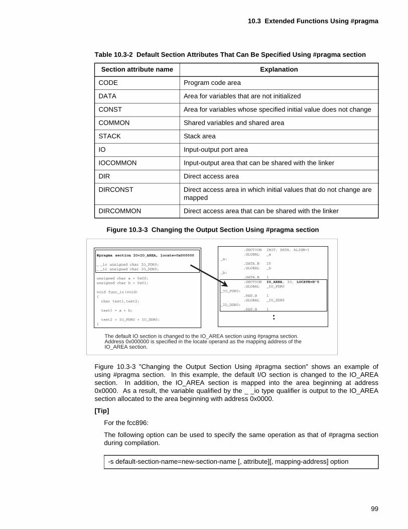
10.3 Extended Functions Using #pragma
Figure 10.3-3 Changing the Output Section Using #pragma section
Figure 10.3-3 "Changing the Output Section Using #pragma section" shows an example ofusing #pragma section. In this example, the default I/O section is changed to the IO_AREAsection. In addition, the IO_AREA section is mapped into the area beginning at address0x0000. As a result, the variable qualified by the _ _io type qualifier is output to the IO_AREAsection allocated to the area beginning with address 0x0000.
[Tip]
For the fcc896:
The following option can be used to specify the same operation as that of #pragma sectionduring compilation.
Table 10.3-2 Default Section Attributes That Can Be Specified Using #pragma section
Section attribute name Explanation
CODE Program code area
DATA Area for variables that are not initialized
CONST Area for variables whose specified initial value does not change
COMMON Shared variables and shared area
STACK Stack area
IO Input-output port area
IOCOMMON Input-output area that can be shared with the linker
DIR Direct access area
DIRCONST Direct access area in which initial values that do not change are mapped
DIRCOMMON Direct access area that can be shared with the linker
The default IO section is changed to the IO_AREA section using #pragma section.Address 0x000000 is specified in the locate operand as the mapping address of the IO_AREA section.
-s default-section-name=new-section-name [, attribute][, mapping-address] option
99
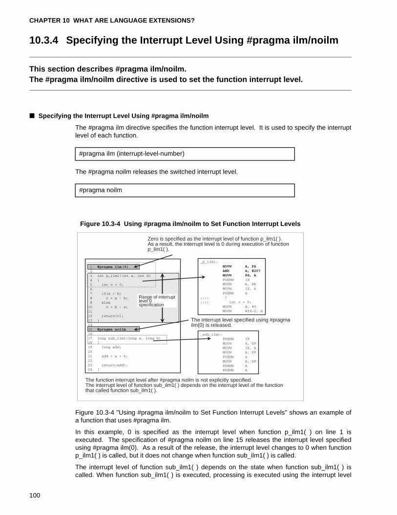
CHAPTER 10 WHAT ARE LANGUAGE EXTENSIONS?
10.3.4 Specifying the Interrupt Level Using #pragma ilm/noilm
This section describes #pragma ilm/noilm.The #pragma ilm/noilm directive is used to set the function interrupt level.
■ Specifying the Interrupt Level Using #pragma ilm/noilm
The #pragma ilm directive specifies the function interrupt level. It is used to specify the interruptlevel of each function.
The #pragma noilm releases the switched interrupt level.
Figure 10.3-4 Using #pragma ilm/noilm to Set Function Interrupt Levels
Figure 10.3-4 "Using #pragma ilm/noilm to Set Function Interrupt Levels" shows an example ofa function that uses #pragma ilm.
In this example, 0 is specified as the interrupt level when function p_ilm1( ) on line 1 isexecuted. The specification of #pragma noilm on line 15 releases the interrupt level specifiedusing #pragma ilm(0). As a result of the release, the interrupt level changes to 0 when functionp_ilm1( ) is called, but it does not change when function sub_ilm1( ) is called.
The interrupt level of function sub_ilm1( ) depends on the state when function sub_ilm1( ) iscalled. When function sub_ilm1( ) is executed, processing is executed using the interrupt level
#pragma ilm (interrupt-level-number)
#pragma noilm
Zero is specified as the interrupt level of function p_ilm1( ).As a result, the interrupt level is 0 during execution of functionp_ilm1( ).
The interrupt level specified using #pragmailm(0) is released.
The function interrupt level after #pragma noilm is not explicitly specified.The interrupt level of function sub_ilm1( ) depends on the interrupt level of the functionthat called function sub_ilm1( ).
Range of interruptlevel 0specification
100
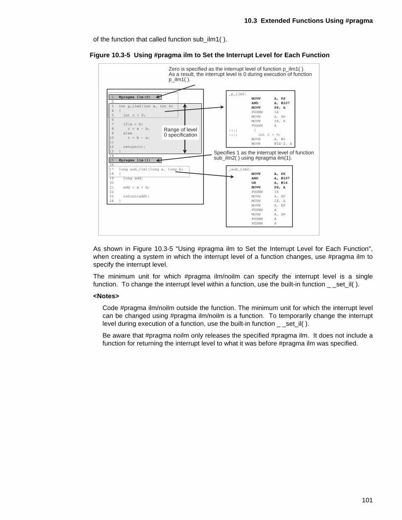
10.3 Extended Functions Using #pragma
of the function that called function sub_ilm1( ).
Figure 10.3-5 Using #pragma ilm to Set the Interrupt Level for Each Function
As shown in Figure 10.3-5 "Using #pragma ilm to Set the Interrupt Level for Each Function",when creating a system in which the interrupt level of a function changes, use #pragma ilm tospecify the interrupt level.
The minimum unit for which #pragma ilm/noilm can specify the interrupt level is a singlefunction. To change the interrupt level within a function, use the built-in function _ _set_il( ).
<Notes>
Code #pragma ilm/noilm outside the function. The minimum unit for which the interrupt levelcan be changed using #pragma ilm/noilm is a function. To temporarily change the interruptlevel during execution of a function, use the built-in function _ _set_il( ).
Be aware that #pragma noilm only releases the specified #pragma ilm. It does not include afunction for returning the interrupt level to what it was before #pragma ilm was specified.
Zero is specified as the interrupt level of function p_ilm1( ).As a result, the interrupt level is 0 during execution of functionp_ilm1( ).
Specifies 1 as the interrupt level of functionsub_ilm2( ) using #pragma ilm(1).
Range of level0 specification
101
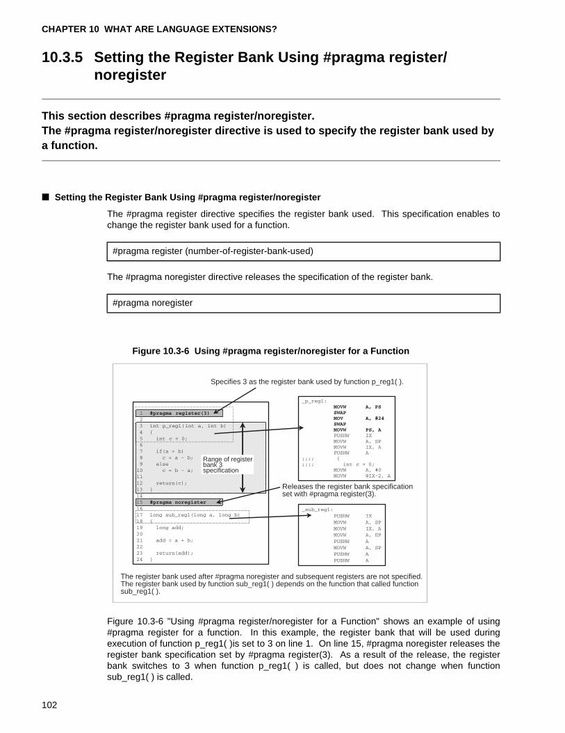
CHAPTER 10 WHAT ARE LANGUAGE EXTENSIONS?
10.3.5 Setting the Register Bank Using #pragma register/noregister
This section describes #pragma register/noregister.The #pragma register/noregister directive is used to specify the register bank used by a function.
■ Setting the Register Bank Using #pragma register/noregister
The #pragma register directive specifies the register bank used. This specification enables tochange the register bank used for a function.
The #pragma noregister directive releases the specification of the register bank.
Figure 10.3-6 Using #pragma register/noregister for a Function
Figure 10.3-6 "Using #pragma register/noregister for a Function" shows an example of using#pragma register for a function. In this example, the register bank that will be used duringexecution of function p_reg1( )is set to 3 on line 1. On line 15, #pragma noregister releases theregister bank specification set by #pragma register(3). As a result of the release, the registerbank switches to 3 when function p_reg1( ) is called, but does not change when functionsub_reg1( ) is called.
#pragma register (number-of-register-bank-used)
#pragma noregister
Specifies 3 as the register bank used by function p_reg1( ).
Releases the register bank specificationset with #pragma register(3).
The register bank used after #pragma noregister and subsequent registers are not specified.The register bank used by function sub_reg1( ) depends on the function that called functionsub_reg1( ).
Range of registerbank 3specification
102
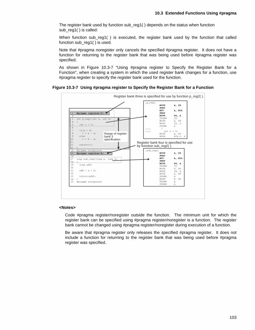
10.3 Extended Functions Using #pragma
The register bank used by function sub_reg1( ) depends on the status when function sub_reg1( ) is called:
When function sub_reg1( ) is executed, the register bank used by the function that calledfunction sub_reg1( ) is used.
Note that #pragma noregister only cancels the specified #pragma register. It does not have afunction for returning to the register bank that was being used before #pragma register wasspecified.
As shown in Figure 10.3-7 "Using #pragma register to Specify the Register Bank for aFunction", when creating a system in which the used register bank changes for a function, use#pragma register to specify the register bank used for the function.
Figure 10.3-7 Using #pragma register to Specify the Register Bank for a Function
<Notes>
Code #pragma register/noregister outside the function. The minimum unit for which theregister bank can be specified using #pragma register/noregister is a function. The registerbank cannot be changed using #pragma register/noregister during execution of a function.
Be aware that #pragma register only releases the specified #pragma register. It does notinclude a function for returning to the register bank that was being used before #pragmaregister was specified.
Register bank three is specified for use by function p_reg2( ).
Register bank four is specified for use by function sub_reg2( ).
Range of registerbank 3specification
103
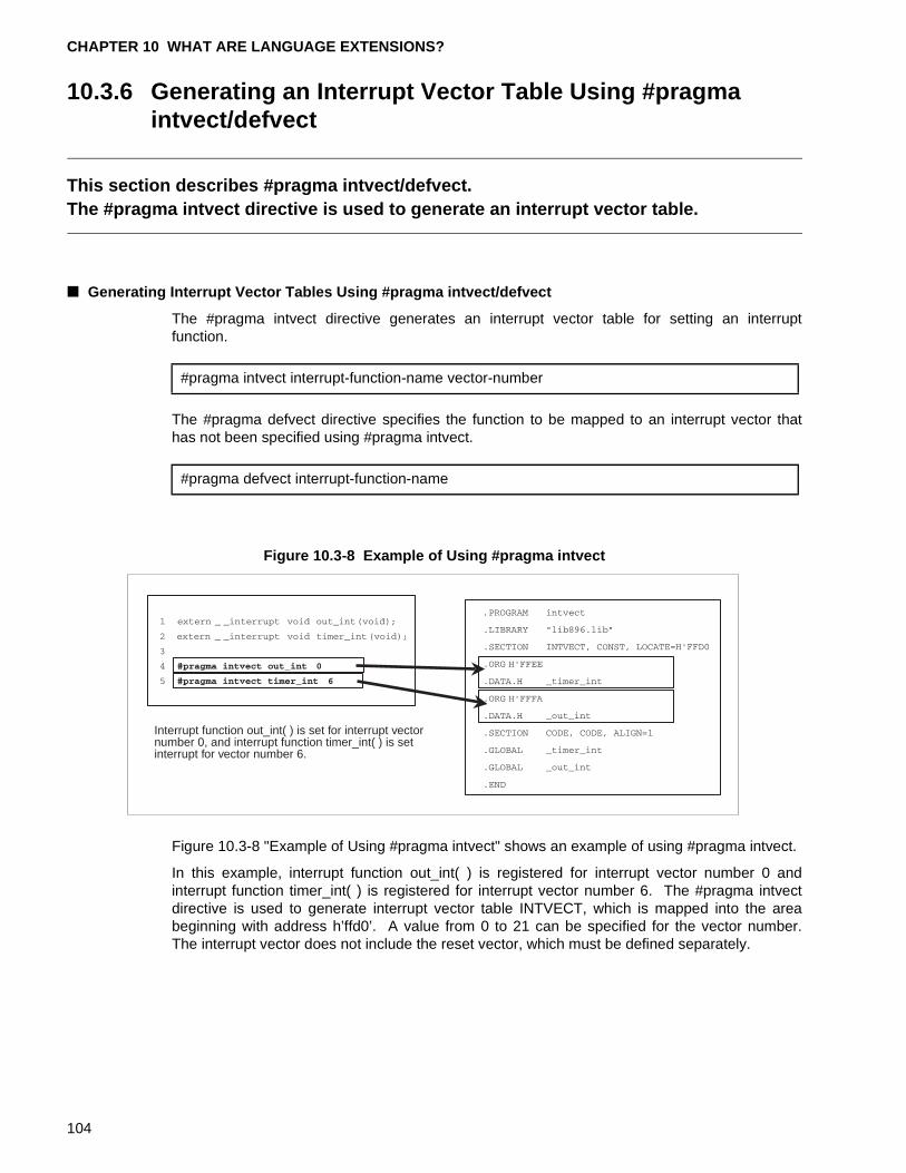
CHAPTER 10 WHAT ARE LANGUAGE EXTENSIONS?
10.3.6 Generating an Interrupt Vector Table Using #pragma intvect/defvect
This section describes #pragma intvect/defvect.The #pragma intvect directive is used to generate an interrupt vector table.
■ Generating Interrupt Vector Tables Using #pragma intvect/defvect
The #pragma intvect directive generates an interrupt vector table for setting an interruptfunction.
The #pragma defvect directive specifies the function to be mapped to an interrupt vector thathas not been specified using #pragma intvect.
Figure 10.3-8 Example of Using #pragma intvect
Figure 10.3-8 "Example of Using #pragma intvect" shows an example of using #pragma intvect.
In this example, interrupt function out_int( ) is registered for interrupt vector number 0 andinterrupt function timer_int( ) is registered for interrupt vector number 6. The #pragma intvectdirective is used to generate interrupt vector table INTVECT, which is mapped into the areabeginning with address h’ffd0’. A value from 0 to 21 can be specified for the vector number.The interrupt vector does not include the reset vector, which must be defined separately.
#pragma intvect interrupt-function-name vector-number
#pragma defvect interrupt-function-name
Interrupt function out_int( ) is set for interrupt vectornumber 0, and interrupt function timer_int( ) is setinterrupt for vector number 6.
104
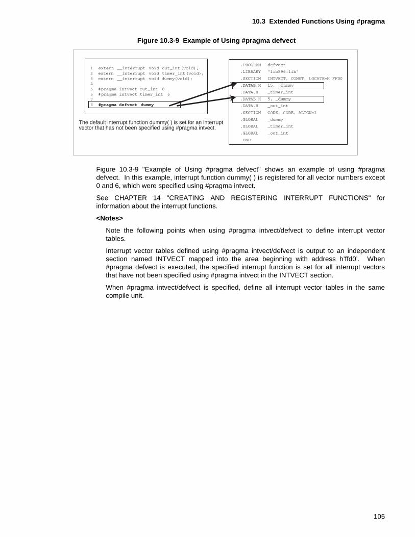
10.3 Extended Functions Using #pragma
Figure 10.3-9 Example of Using #pragma defvect
Figure 10.3-9 "Example of Using #pragma defvect" shows an example of using #pragmadefvect. In this example, interrupt function dummy( ) is registered for all vector numbers except0 and 6, which were specified using #pragma intvect.
See CHAPTER 14 "CREATING AND REGISTERING INTERRUPT FUNCTIONS" forinformation about the interrupt functions.
<Notes>
Note the following points when using #pragma intvect/defvect to define interrupt vectortables.
Interrupt vector tables defined using #pragma intvect/defvect is output to an independentsection named INTVECT mapped into the area beginning with address h’ffd0’. When#pragma defvect is executed, the specified interrupt function is set for all interrupt vectorsthat have not been specified using #pragma intvect in the INTVECT section.
When #pragma intvect/defvect is specified, define all interrupt vector tables in the samecompile unit.
The default interrupt function dummy( ) is set for an interruptvector that has not been specified using #pragma intvect.
105
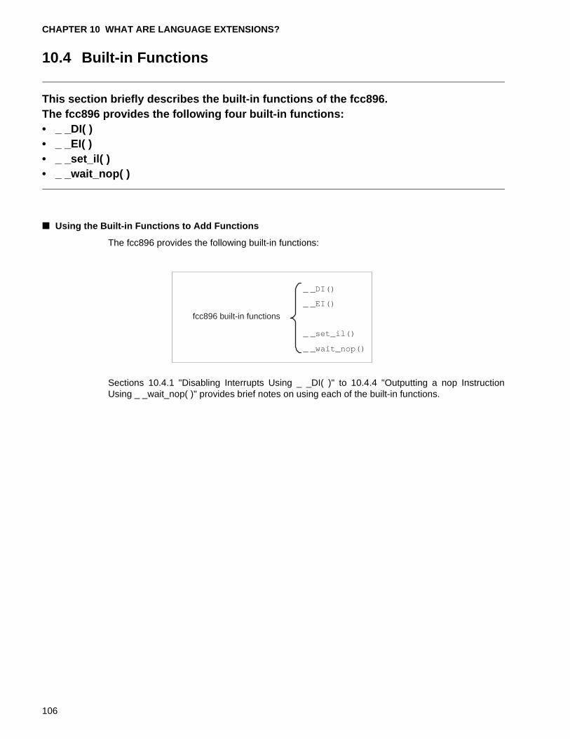
CHAPTER 10 WHAT ARE LANGUAGE EXTENSIONS?
10.4 Built-in Functions
This section briefly describes the built-in functions of the fcc896.The fcc896 provides the following four built-in functions:• _ _DI( )• _ _EI( )• _ _set_il( )• _ _wait_nop( )
■ Using the Built-in Functions to Add Functions
The fcc896 provides the following built-in functions:
Sections 10.4.1 "Disabling Interrupts Using _ _DI( )" to 10.4.4 "Outputting a nop InstructionUsing _ _wait_nop( )" provides brief notes on using each of the built-in functions.
fcc896 built-in functions
_ _DI()
_ _EI()
_ _set_il()
_ _wait_nop()
106
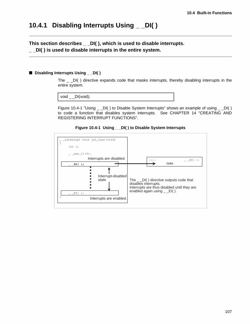
10.4 Built-in Functions
10.4.1 Disabling Interrupts Using _ _DI( )
This section describes _ _DI( ), which is used to disable interrupts._ _DI( ) is used to disable interrupts in the entire system.
■ Disabling Interrupts Using _ _DI( )
The _ _DI( ) directive expands code that masks interrupts, thereby disabling interrupts in theentire system.
Figure 10.4-1 "Using _ _DI( ) to Disable System Interrupts" shows an example of using _ _DI( )to code a function that disables system interrupts. See CHAPTER 14 "CREATING ANDREGISTERING INTERRUPT FUNCTIONS".
Figure 10.4-1 Using _ _DI( ) to Disable System Interrupts
void _ _DI(void);
Interrupts are disabled.
Interrupt-disabledstate
Interrupts are enabled.
The _ _DI( ) directive outputs code that disables interrupts.Interrupts are thus disabled until they areenabled again using _ _EI( ).
107
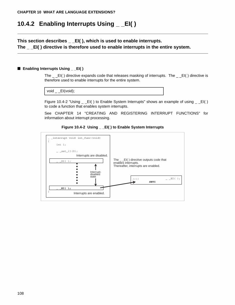
CHAPTER 10 WHAT ARE LANGUAGE EXTENSIONS?
10.4.2 Enabling Interrupts Using _ _EI( )
This section describes _ _EI( ), which is used to enable interrupts. The _ _EI( ) directive is therefore used to enable interrupts in the entire system.
■ Enabling Interrupts Using _ _EI( )
The _ _EI( ) directive expands code that releases masking of interrupts. The _ _EI( ) directive istherefore used to enable interrupts for the entire system.
Figure 10.4-2 "Using _ _EI( ) to Enable System Interrupts" shows an example of using _ _EI( )to code a function that enables system interrupts.
See CHAPTER 14 "CREATING AND REGISTERING INTERRUPT FUNCTIONS" forinformation about interrupt processing.
Figure 10.4-2 Using _ _EI( ) to Enable System Interrupts
void _ _EI(void);
Interrupts are disabled.
Interrupt-disabledstate
Interrupts are enabled.
The _ _EI( ) directive outputs code thatenables interrupts.Thereafter, interrupts are enabled.
108
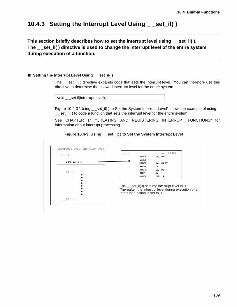
10.4 Built-in Functions
10.4.3 Setting the Interrupt Level Using _ _set_il( )
This section briefly describes how to set the interrupt level using _ _set_il( ).The _ _set_il( ) directive is used to change the interrupt level of the entire system during execution of a function.
■ Setting the Interrupt Level Using _ _set_il( )
The _ _set_il( ) directive expands code that sets the interrupt level. You can therefore use thisdirective to determine the allowed interrupt level for the entire system.
Figure 10.4-3 "Using _ _set_il( ) to Set the System Interrupt Level" shows an example of using _ _set_il( ) to code a function that sets the interrupt level for the entire system.
See CHAPTER 14 "CREATING AND REGISTERING INTERRUPT FUNCTIONS" forinformation about interrupt processing.
Figure 10.4-3 Using _ _set_il( ) to Set the System Interrupt Level
void _ _set il(interrupt-level);
The _ _set_il(0) sets the interrupt level to 0.Thereafter, the interrupt level during execution of aninterrupt function is set to 0.
109
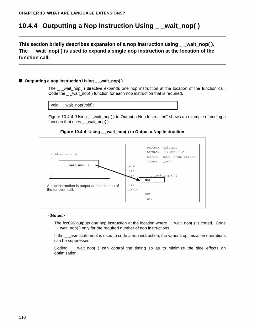
CHAPTER 10 WHAT ARE LANGUAGE EXTENSIONS?
10.4.4 Outputting a Nop Instruction Using _ _wait_nop( )
This section briefly describes expansion of a nop instruction using _ _wait_nop( ).The _ _wait_nop( ) is used to expand a single nop instruction at the location of the function call.
■ Outputting a nop Instruction Using _ _wait_nop( )
The _ _wait_nop( ) directive expands one nop instruction at the location of the function call.Code the _ _wait_nop( ) function for each nop instruction that is required.
Figure 10.4-4 "Using _ _wait_nop( ) to Output a Nop Instruction" shows an example of coding afunction that uses _ _wait_nop( ).
Figure 10.4-4 Using _ _wait_nop( ) to Output a Nop Instruction
<Notes>
The fcc896 outputs one nop instruction at the location where _ _wait_nop( ) is coded. Code_ _wait_nop( ) only for the required number of nop instructions.
If the _ _asm statement is used to code a nop instruction, the various optimization operationscan be suppressed.
Coding _ _wait_nop( ) can control the timing so as to minimize the side effects onoptimization.
void _ _wait_nop(void);
A nop instruction is output at the location ofthe function call.
110
CHAPTER 11 NOTES ON ASSEMBLER PROGRAM IN C PROGRAMS
This chapter provides notes on including Assembler program in C programs.
11.1 "Including Assembler Program in C Programs"
11.2 "Differences Between Using the _ _asm Statement and #pragma asm/endasm"
111
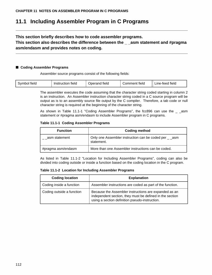
CHAPTER 11 NOTES ON ASSEMBLER PROGRAM IN C PROGRAMS
11.1 Including Assembler Program in C Programs
This section briefly describes how to code assembler programs.This section also describes the difference between the _ _asm statement and #pragma asm/endasm and provides notes on coding.
■ Coding Assembler Programs
Assembler source programs consist of the following fields:
The assembler executes the code assuming that the character string coded starting in column 2is an instruction. An Assembler instruction character string coded in a C source program will beoutput as is to an assembly source file output by the C compiler. Therefore, a tab code or nullcharacter string is required at the beginning of the character string.
As shown in Table 11.1-1 "Coding Assembler Programs", the fcc896 can use the _ _asmstatement or #pragma asm/endasm to include Assembler program in C programs.
As listed in Table 11.1-2 "Location for Including Assembler Programs", coding can also bedivided into coding outside or inside a function based on the coding location in the C program.
Symbol field Instruction field Operand field Comment field Line-feed field
Table 11.1-1 Coding Assembler Programs
Function Coding method
_ _asm statement Only one Assembler instruction can be coded per _ _asm statement.
#pragma asm/endasm More than one Assembler instructions can be coded.
Table 11.1-2 Location for Including Assembler Programs
Coding location Explanation
Coding inside a function Assembler instructions are coded as part of the function.
Coding outside a function Because the Assembler instructions are expanded as an independent section, they must be defined in the section using a section definition pseudo-instruction.
112
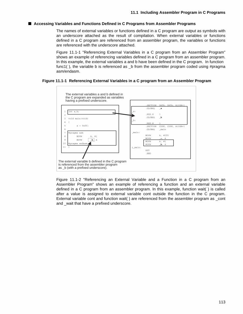
11.1 Including Assembler Program in C Programs
■ Accessing Variables and Functions Defined in C Programs from Assembler Programs
The names of external variables or functions defined in a C program are output as symbols withan underscore attached as the result of compilation. When external variables or functionsdefined in a C program are referenced from an assembler program, the variables or functionsare referenced with the underscore attached.
Figure 11.1-1 "Referencing External Variables in a C program from an Assembler Program"shows an example of referencing variables defined in a C program from an assembler program.In this example, the external variables a and b have been defined in the C program. In function func1( ), the variable b is referenced as _b from the assembler program coded using #pragmaasm/endasm.
Figure 11.1-1 Referencing External Variables in a C program from an Assembler Program
Figure 11.1-2 "Referencing an External Variable and a Function in a C program from anAssembler Program" shows an example of referencing a function and an external variabledefined in a C program from an assembler program. In this example, function wait( ) is calledafter a value is assigned to external variable cont outside the function in the C program.External variable cont and function wait( ) are referenced from the assembler program as _contand _wait that have a prefixed underscore.
The external variables a and b defined in the C program are expanded as variableshaving a prefixed underscore.
The external variable b defined in the C program is referenced from the assembler programas _b (with a prefixed underscore).
113
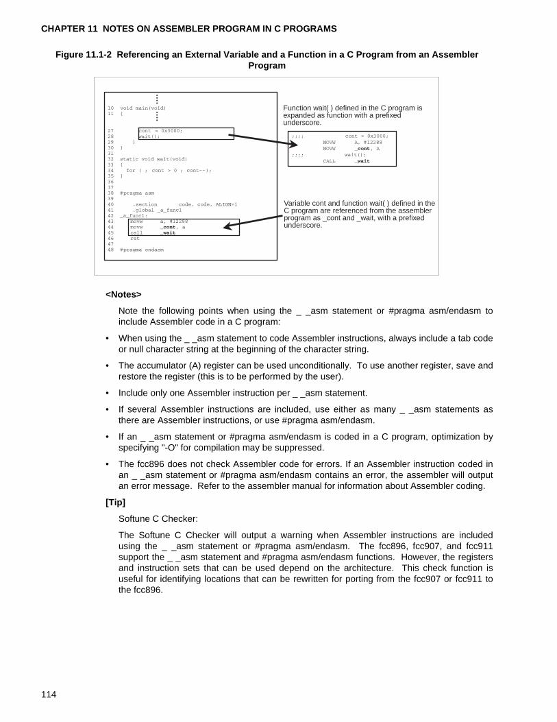
CHAPTER 11 NOTES ON ASSEMBLER PROGRAM IN C PROGRAMS
Figure 11.1-2 Referencing an External Variable and a Function in a C Program from an Assembler Program
<Notes>
Note the following points when using the _ _asm statement or #pragma asm/endasm toinclude Assembler code in a C program:
• When using the _ _asm statement to code Assembler instructions, always include a tab codeor null character string at the beginning of the character string.
• The accumulator (A) register can be used unconditionally. To use another register, save andrestore the register (this is to be performed by the user).
• Include only one Assembler instruction per _ _asm statement.
• If several Assembler instructions are included, use either as many _ _asm statements asthere are Assembler instructions, or use #pragma asm/endasm.
• If an _ _asm statement or #pragma asm/endasm is coded in a C program, optimization byspecifying "-O" for compilation may be suppressed.
• The fcc896 does not check Assembler code for errors. If an Assembler instruction coded inan _ _asm statement or #pragma asm/endasm contains an error, the assembler will outputan error message. Refer to the assembler manual for information about Assembler coding.
[Tip]
Softune C Checker:
The Softune C Checker will output a warning when Assembler instructions are includedusing the _ _asm statement or #pragma asm/endasm. The fcc896, fcc907, and fcc911support the _ _asm statement and #pragma asm/endasm functions. However, the registersand instruction sets that can be used depend on the architecture. This check function isuseful for identifying locations that can be rewritten for porting from the fcc907 or fcc911 tothe fcc896.
Function wait( ) defined in the C program isexpanded as function with a prefixedunderscore.
Variable cont and function wait( ) defined in theC program are referenced from the assemblerprogram as _cont and _wait, with a prefixedunderscore.
114
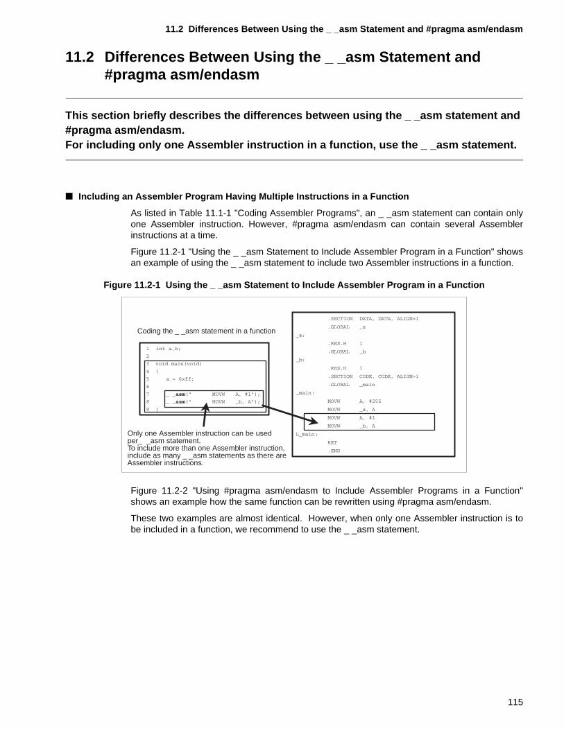
11.2 Differences Between Using the _ _asm Statement and #pragma asm/endasm
11.2 Differences Between Using the _ _asm Statement and #pragma asm/endasm
This section briefly describes the differences between using the _ _asm statement and #pragma asm/endasm.For including only one Assembler instruction in a function, use the _ _asm statement.
■ Including an Assembler Program Having Multiple Instructions in a Function
As listed in Table 11.1-1 "Coding Assembler Programs", an _ _asm statement can contain onlyone Assembler instruction. However, #pragma asm/endasm can contain several Assemblerinstructions at a time.
Figure 11.2-1 "Using the _ _asm Statement to Include Assembler Program in a Function" showsan example of using the _ _asm statement to include two Assembler instructions in a function.
Figure 11.2-1 Using the _ _asm Statement to Include Assembler Program in a Function
Figure 11.2-2 "Using #pragma asm/endasm to Include Assembler Programs in a Function"shows an example how the same function can be rewritten using #pragma asm/endasm.
These two examples are almost identical. However, when only one Assembler instruction is tobe included in a function, we recommend to use the _ _asm statement.
Coding the _ _asm statement in a function
Only one Assembler instruction can be usedper_ _asm statement.To include more than one Assembler instruction,include as many _ _asm statements as there areAssembler instructions.
115
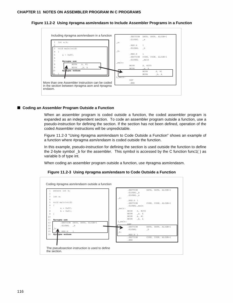
CHAPTER 11 NOTES ON ASSEMBLER PROGRAM IN C PROGRAMS
Figure 11.2-2 Using #pragma asm/endasm to Include Assembler Programs in a Function
■ Coding an Assembler Program Outside a Function
When an assembler program is coded outside a function, the coded assembler program isexpanded as an independent section. To code an assembler program outside a function, use apseudo-instruction for defining the section. If the section has not been defined, operation of thecoded Assembler instructions will be unpredictable.
Figure 11.2-3 "Using #pragma asm/endasm to Code Outside a Function" shows an example ofa function where #pragma asm/endasm is coded outside the function.
In this example, pseudo-instruction for defining the section is used outside the function to definethe 2-byte symbol _b for the assembler. This symbol is accessed by the C function func1( ) asvariable b of type int.
When coding an assembler program outside a function, use #pragma asm/endasm.
Figure 11.2-3 Using #pragma asm/endasm to Code Outside a Function
Including #pragma asm/endasm in a function
More than one Assembler instruction can be codedin the section between #pragma asm and #pragmaendasm.
Coding #pragma asm/endasm outside a function
The pseudosection instruction is used to definethe section.
116
11.2 Differences Between Using the _ _asm Statement and #pragma asm/endasm
[Tip]
Softune C Checker:
The Softune C Checker will output a warning when Assembler instructions are coded using _ _asm statement or #pragma asm/endasm. The fcc896, fcc907, and fcc911 support the _ _asm statement and #pragma asm/endasm. However, the registers and instruction setsthat can be used depend on the architecture. This check function is useful for identifyinglocations that can be rewritten from the fcc911 to the fcc907 or fcc896.
117

CHAPTER 11 NOTES ON ASSEMBLER PROGRAM IN C PROGRAMS
118
CHAPTER 12 NOTES ON DEFINING AND ACCESSING THE I/O AREA
This chapter describes the definition and accessing of resources mapped into the I/O area. The chapter uses as examples the I/O area of the MB89620 series of
microcontrollers, which belong to the F 2MC-8L family of microcontrollers, to explain how resources mapped into the I/O area are defined and accessed.
12.1 "M89620 Series I/O Areas"
12.2 "Defining and Accessing Variables Mapped into the I/O Areas"
119
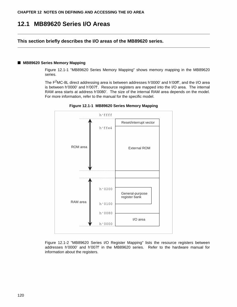
CHAPTER 12 NOTES ON DEFINING AND ACCESSING THE I/O AREA
12.1 MB89620 Series I/O Areas
This section briefly describes the I/O areas of the MB89620 series.
■ MB89620 Series Memory Mapping
Figure 12.1-1 "MB89620 Series Memory Mapping" shows memory mapping in the MB89620series.
The F2MC-8L direct addressing area is between addresses h’0000’ and h’00ff’, and the I/O areais between h’0000’ and h’007f’. Resource registers are mapped into the I/O area. The internalRAM area starts at address h’0080’. The size of the internal RAM area depends on the model.For more information, refer to the manual for the specific model.
Figure 12.1-1 MB89620 Series Memory Mapping
Figure 12.1-2 "MB89620 Series I/O Register Mapping" lists the resource registers betweenaddresses h’0000’ and h’007f’ in the MB89620 series. Refer to the hardware manual forinformation about the registers.
ROM area
Reset/interrupt vector
External ROM
General-purposeregister bank
I/O area
RAM area
120
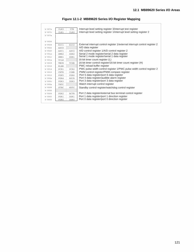
12.1 MB89620 Series I/O Areas
Figure 12.1-2 MB89620 Series I/O Register Mapping
Interrupt level setting register 3/interrupt test registerInterrupt level setting register 1/interrupt level setting register 2
External interrupt control register 1/external interrupt control register 2A/D data registerA/D control register 1/A/D control register 2Serial 2 mode register/serial 2 data registerSerial 1 mode register/serial 1 data register16-bit timer count register (L)16-bit timer control register/16-bit timer count register (H)PWC reload buffer registerPWC pulse width control register 1/PWC pulse width control register 2PWM control register/PWM compare registerPort 5 data register/port 6 data registerPort 4 data register/audible alarm registerPort 3 data register/port 3 data registerWatch interrupt control registerStandby control register/watchdog control register
Port 2 data register/external bus terminal control registerPort 1 data register/port 1 direction registerPort 0 data register/port 0 direction register
121
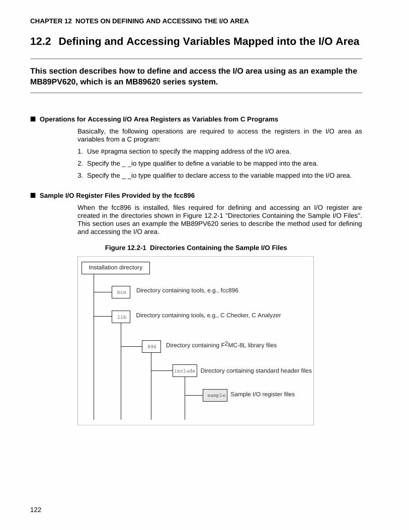
CHAPTER 12 NOTES ON DEFINING AND ACCESSING THE I/O AREA
12.2 Defining and Accessing Variables Mapped into the I/O Area
This section describes how to define and access the I/O area using as an example the MB89PV620, which is an MB89620 series system.
■ Operations for Accessing I/O Area Registers as Variables from C Programs
Basically, the following operations are required to access the registers in the I/O area asvariables from a C program:
1. Use #pragma section to specify the mapping address of the I/O area.
2. Specify the _ _io type qualifier to define a variable to be mapped into the area.
3. Specify the _ _io type qualifier to declare access to the variable mapped into the I/O area.
■ Sample I/O Register Files Provided by the fcc896
When the fcc896 is installed, files required for defining and accessing an I/O register arecreated in the directories shown in Figure 12.2-1 "Directories Containing the Sample I/O Files".This section uses an example the MB89PV620 series to describe the method used for definingand accessing the I/O area.
Figure 12.2-1 Directories Containing the Sample I/O Files
Installation directory
Directory containing tools, e.g., fcc896
Directory containing tools, e.g., C Checker, C Analyzer
Directory containing F2MC-8L library files
Directory containing standard header files
Sample I/O register files
122
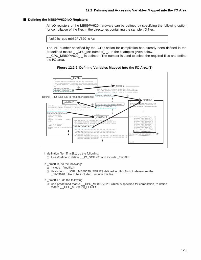
12.2 Defining and Accessing Variables Mapped into the I/O Area
■ Defining the MB89PV620 I/O Registers
All I/O registers of the MB89PV620 hardware can be defined by specifying the following optionfor compilation of the files in the directories containing the sample I/O files:
The MB number specified by the -CPU option for compilation has already been defined in thepredefined macro _ _CPU_MB number_ _. In the examples given below, _ _CPU_MB89PV620_ _ is defined. The number is used to select the required files and definethe I/O area.
Figure 12.2-2 Defining Variables Mapped into the I/O Area (1)
fcc896s -cpu mb89PV620 -c *.c
_ffmc8l.c
_ffmc8l.h
_ffmc8ls.h_mb89620.h
_mb896xx.h
Define _ _IO_DEFINE to read an include file.
In definition file _ffmc8l.c, do the following:Use #define to define _ _IO_DEFINE, and include _ffmc8l.h.
In _ffmc8l.h, do the following:Include _ffmc8ls.h.Use macro _ _CPU_MB89620_SERIES defined in _ffmc8ls.h to determine the_mb89620.h file to be included. Include this file.
In _ffmc8ls.h, do the following:Use predefined macro _ _CPU_MB89PV620, which is specified for compilation, to definemacro _ _CPU_MB89620_SERIES.
123
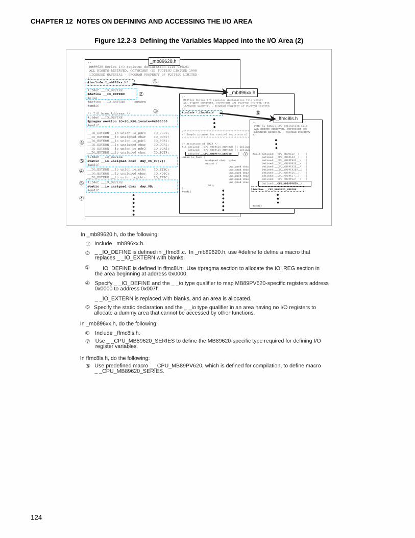
CHAPTER 12 NOTES ON DEFINING AND ACCESSING THE I/O AREA
Figure 12.2-3 Defining the Variables Mapped into the I/O Area (2)
_mb89620.h
_mb896xx.h
_ffmc8ls.h
In _mb89620.h, do the following:
Include _mb896xx.h.
_ _IO_DEFINE is defined in _ffmc8l.c. In _mb89620.h, use #define to define a macro that replaces _ _IO_EXTERN with blanks.
_ _IO_DEFINE is defined in ffmc8l.h. Use #pragma section to allocate the IO_REG section inthe area beginning at address 0x0000.
Specify _ _IO_DEFINE and the _ _io type qualifier to map MB89PV620-specific registers address0x0000 to address 0x007f'.
_ _IO_EXTERN is replaced with blanks, and an area is allocated.
Specify the static declaration and the _ _io type qualifier in an area having no I/O registers toallocate a dummy area that cannot be accessed by other functions.
In _mb896xx.h, do the following:
Include _ffmc8ls.h.
Use _ _CPU_MB89620_SERIES to define the MB89620-specific type required for defining I/Oregister variables.
In ffmc8ls.h, do the following:Use predefined macro _ _CPU_MB89PV620, which is defined for compilation, to define macro_ _CPU_MB89620_SERIES.
124
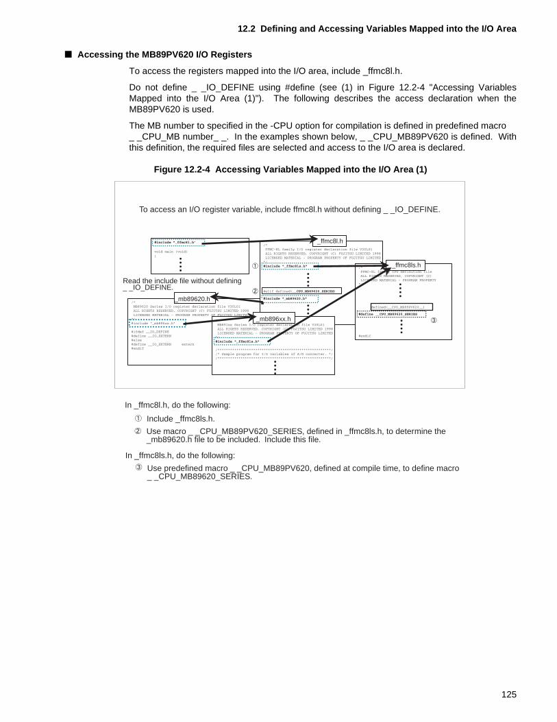
12.2 Defining and Accessing Variables Mapped into the I/O Area
■ Accessing the MB89PV620 I/O Registers
To access the registers mapped into the I/O area, include _ffmc8l.h.
Do not define _ _IO_DEFINE using #define (see (1) in Figure 12.2-4 "Accessing VariablesMapped into the I/O Area (1)"). The following describes the access declaration when theMB89PV620 is used.
The MB number to specified in the -CPU option for compilation is defined in predefined macro _ _CPU_MB number_ _. In the examples shown below, _ _CPU_MB89PV620 is defined. Withthis definition, the required files are selected and access to the I/O area is declared.
Figure 12.2-4 Accessing Variables Mapped into the I/O Area (1)
_mb89620.h
To access an I/O register variable, include ffmc8l.h without defining _ _IO_DEFINE.
_ffmc8l.h
_ffmc8ls.h
_mb896xx.h
Read the include file without defining_ _IO_DEFINE.
In _ffmc8l.h, do the following:
Include _ffmc8ls.h.
Use macro _ _CPU_MB89PV620_SERIES, defined in _ffmc8ls.h, to determine the_mb89620.h file to be included. Include this file.
In _ffmc8ls.h, do the following:
Use predefined macro _ _CPU_MB89PV620, defined at compile time, to define macro_ _CPU_MB89620_SERIES.
125
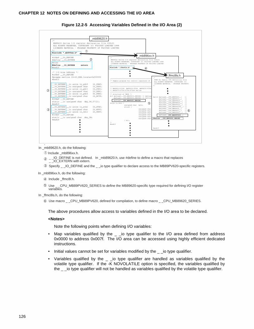
CHAPTER 12 NOTES ON DEFINING AND ACCESSING THE I/O AREA
Figure 12.2-5 Accessing Variables Defined in the I/O Area (2)
The above procedures allow access to variables defined in the I/O area to be declared.
<Notes>
Note the following points when defining I/O variables:
• Map variables qualified by the _ _io type qualifier to the I/O area defined from address0x0000 to address 0x007f. The I/O area can be accessed using highly efficient dedicatedinstructions.
• Initial values cannot be set for variables modified by the _ _io type qualifier.
• Variables qualified by the _ _io type qualifier are handled as variables qualified by thevolatile type qualifier. If the -K NOVOLATILE option is specified, the variables qualified bythe _ _io type qualifier will not be handled as variables qualified by the volatile type qualifier.
_mb89620.h
_mb896xx.h
_ffmc8ls.h
In _mb89620.h, do the following:
Include _mb896xx.h._ _IO_DEFINE is not defined. In _mb89620.h, use #define to define a macro that replaces_ _IO_EXTERN with extern.
Specify _ _IO_DEFINE and the _ _io type qualifier to declare access to the MB89PV620-specific registers.
In _mb896xx.h, do the following:
Include _ffmc8l.h.
Use _ _CPU_MB89PV620_SERIES to define the MB89620-specific type required for defining I/O registervariables.
In _ffmc8ls.h, do the following:
Use macro _ _CPU_MB89PV620, defined for compilation, to define macro _ _CPU_MB89620_SERIES.
126
CHAPTER 13 MAPPING VARIABLES QUALIFIED WITH THE TYPE QUALIFIER _ _direct
This chapter describes the variables qualified by the _ _direct type qualifier and the conditions for mapping them.A variable qualified by the direct type qualifier can be accessed by direct addressing at the specified location in memory it was mapped to.
13.1 "Output Sections of and Access to Variables Qualified by the _ _direct Type Qualifier"
13.2 "Mapping Variables Qualified by the _ _direct Type Qualifier"
127
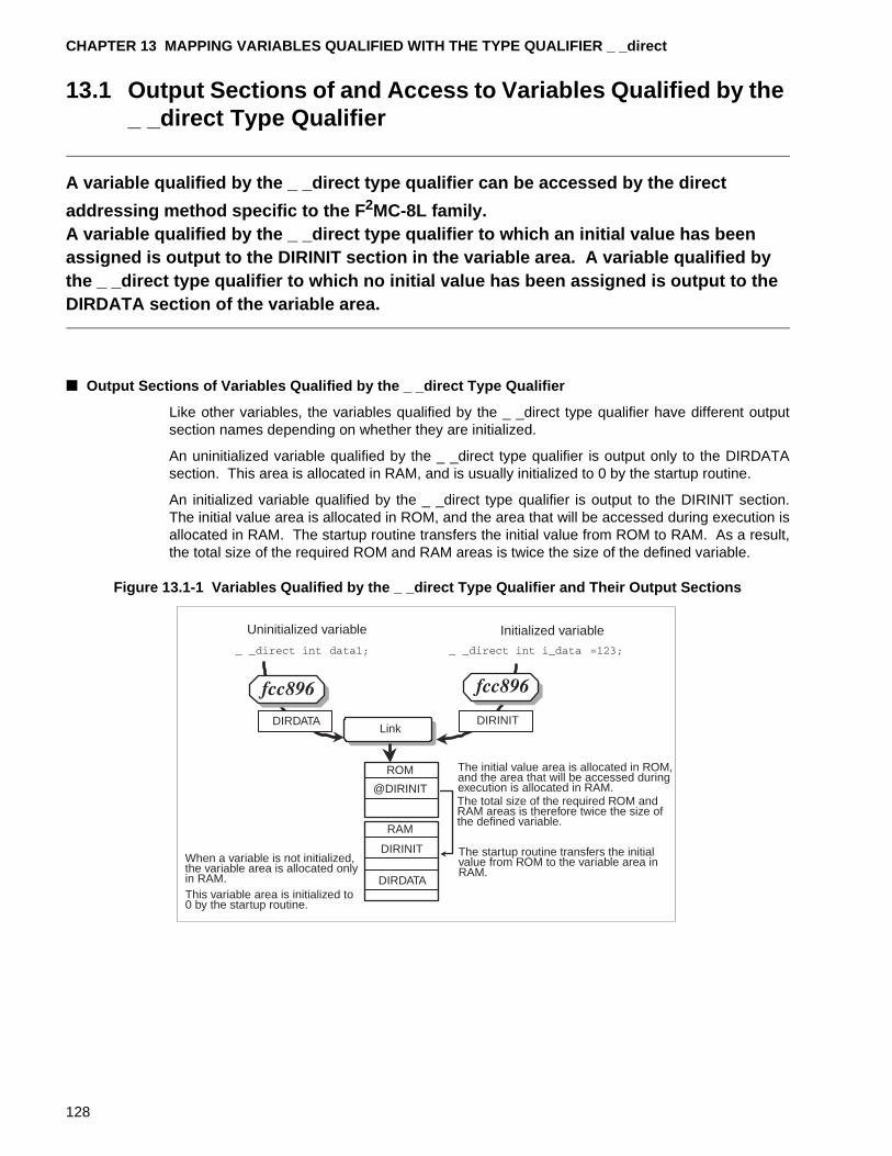
CHAPTER 13 MAPPING VARIABLES QUALIFIED WITH THE TYPE QUALIFIER _ _direct
13.1 Output Sections of and Access to Variables Qualified by the _ _direct Type Qualifier
A variable qualified by the _ _direct type qualifier can be accessed by the direct
addressing method specific to the F 2MC-8L family.A variable qualified by the _ _direct type qualifier to which an initial value has been assigned is output to the DIRINIT section in the variable area. A variable qualified by the _ _direct type qualifier to which no initial value has been assigned is output to the DIRDATA section of the variable area.
■ Output Sections of Variables Qualified by the _ _direct Type Qualifier
Like other variables, the variables qualified by the _ _direct type qualifier have different outputsection names depending on whether they are initialized.
An uninitialized variable qualified by the _ _direct type qualifier is output only to the DIRDATAsection. This area is allocated in RAM, and is usually initialized to 0 by the startup routine.
An initialized variable qualified by the _ _direct type qualifier is output to the DIRINIT section.The initial value area is allocated in ROM, and the area that will be accessed during execution isallocated in RAM. The startup routine transfers the initial value from ROM to RAM. As a result,the total size of the required ROM and RAM areas is twice the size of the defined variable.
Figure 13.1-1 Variables Qualified by the _ _direct Type Qualifier and Their Output Sections
Uninitialized variable Initialized variable
Link
ROM
RAM
When a variable is not initialized,the variable area is allocated onlyin RAM.This variable area is initialized to0 by the startup routine.
The initial value area is allocated in ROM,and the area that will be accessed duringexecution is allocated in RAM.The total size of the required ROM andRAM areas is therefore twice the size ofthe defined variable.
The startup routine transfers the initialvalue from ROM to the variable area inRAM.
@DIRINIT
DIRINIT
DIRDATA
DIRINITDIRDATA
128
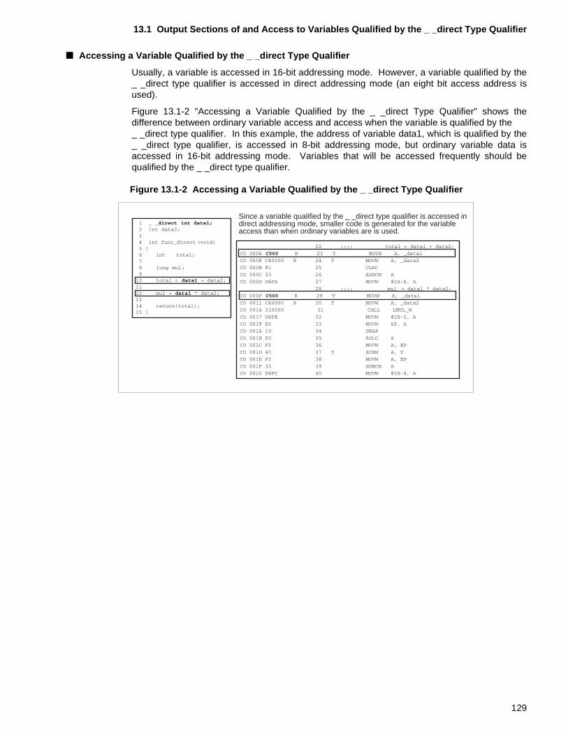
13.1 Output Sections of and Access to Variables Qualified by the _ _direct Type Qualifier
■ Accessing a Variable Qualified by the _ _direct Type Qualifier
Usually, a variable is accessed in 16-bit addressing mode. However, a variable qualified by the_ _direct type qualifier is accessed in direct addressing mode (an eight bit access address isused).
Figure 13.1-2 "Accessing a Variable Qualified by the _ _direct Type Qualifier" shows thedifference between ordinary variable access and access when the variable is qualified by the _ _direct type qualifier. In this example, the address of variable data1, which is qualified by the_ _direct type qualifier, is accessed in 8-bit addressing mode, but ordinary variable data isaccessed in 16-bit addressing mode. Variables that will be accessed frequently should bequalified by the _ _direct type qualifier.
Figure 13.1-2 Accessing a Variable Qualified by the _ _direct Type Qualifier
Since a variable qualified by the _ _direct type qualifier is accessed indirect addressing mode, smaller code is generated for the variableaccess than when ordinary variables are is used.
129
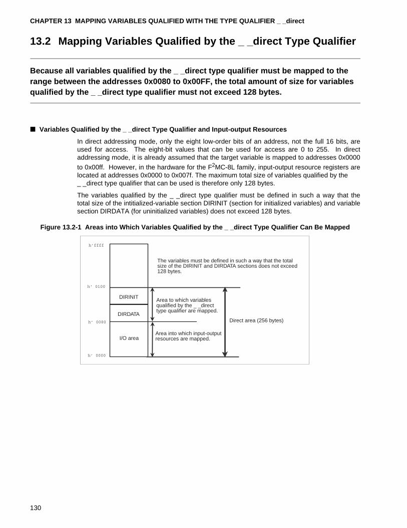
CHAPTER 13 MAPPING VARIABLES QUALIFIED WITH THE TYPE QUALIFIER _ _direct
13.2 Mapping Variables Qualified by the _ _direct Type Qualifier
Because all variables qualified by the _ _direct type qualifier must be mapped to the range between the addresses 0x0080 to 0x00FF, the total amount of size for variables qualified by the _ _direct type qualifier must not exceed 128 bytes.
■ Variables Qualified by the _ _direct Type Qualifier and Input-output Resources
In direct addressing mode, only the eight low-order bits of an address, not the full 16 bits, areused for access. The eight-bit values that can be used for access are 0 to 255. In directaddressing mode, it is already assumed that the target variable is mapped to addresses 0x0000
to 0x00ff. However, in the hardware for the F2MC-8L family, input-output resource registers arelocated at addresses 0x0000 to 0x007f. The maximum total size of variables qualified by the _ _direct type qualifier that can be used is therefore only 128 bytes.
The variables qualified by the _ _direct type qualifier must be defined in such a way that thetotal size of the intitialized-variable section DIRINIT (section for initialized variables) and variablesection DIRDATA (for uninitialized variables) does not exceed 128 bytes.
Figure 13.2-1 Areas into Which Variables Qualified by the _ _direct Type Qualifier Can Be Mapped
The variables must be defined in such a way that the totalsize of the DIRINIT and DIRDATA sections does not exceed128 bytes.
Area to which variablesqualified by the _ _directtype qualifier are mapped.
I/O area
Direct area (256 bytes)
DIRINIT
DIRDATA
Area into which input-outputresources are mapped.
130
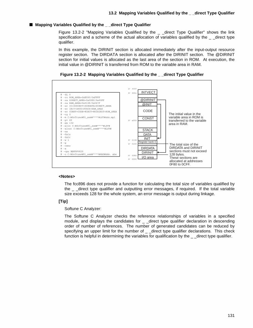
13.2 Mapping Variables Qualified by the _ _direct Type Qualifier
■ Mapping Variables Qualified by the _ _direct Type Qualifier
Figure 13.2-2 "Mapping Variables Qualified by the _ _direct Type Qualifier" shows the linkspecification and a scheme of the actual allocation of variables qualified by the _ _direct typequalifier.
In this example, the DIRINIT section is allocated immediately after the input-output resourceregister section. The DIRDATA section is allocated after the DIRINIT section. The @DIRINITsection for initial values is allocated as the last area of the section in ROM. At execution, theinitial value in @DIRINIT is transferred from ROM to the variable area in RAM.
Figure 13.2-2 Mapping Variables Qualified by the _ _direct Type Qualifier
<Notes>
The fcc896 does not provide a function for calculating the total size of variables qualified bythe _ _direct type qualifier and outputting error messages, if required. If the total variablesize exceeds 128 for the whole system, an error message is output during linkage.
[Tip]
Softune C Analyzer:
The Softune C Analyzer checks the reference relationships of variables in a specifiedmodule, and displays the candidates for _ _direct type qualifier declaration in descendingorder of number of references. The number of generated candidates can be reduced byspecifying an upper limit for the number of _ _direct type qualifier declarations. This checkfunction is helpful in determining the variables for qualification by the _ _direct type qualifier.
INTVECT
@DIRINIT
CONST
CODE
STACK
DIRDATADIRINIT
INITDATA
@INIT
Register bank 0
I/O area
The initial value in thevariable area in ROM istransferred to the variablearea in RAM.
The total size of theDIRDATA and DIRINITsections must not exceed128 bytes.These sections areallocated at addresses0F80 to 0CFF.
131
CHAPTER 13 MAPPING VARIABLES QUALIFIED WITH THE TYPE QUALIFIER _ _direct
132
CHAPTER 14 CREATING AND REGISTERING INTERRUPT FUNCTIONS
This chapter provides notes for creation and registration of interrupt functions.
The F2MC-8L family of microcontrollers has various resources for generating interrupts. The generation and processing of interrupts requires to set initial values for hardware and software.
14.1 "F2MC-8L Family Interrupts"
14.2 "Required Hardware Settings for Interrupts"
14.3 "Using the _ _interrupt Type Qualifier to Define Interrupt Functions"
14.4 "Setting of Interrupt Vectors"
133
CHAPTER 14 CREATING AND REGISTERING INTERRUPT FUNCTIONS
14.1 F2MC-8L Family Interrupts
This section describes interrupt handling in the F 2MC-8L family of microcontrollers.
■ Interrupt Handling in the F 2MC-8L Family
This section mainly describes the handling of internal resource interrupts in the F2MC-8L family,but also covers other types of interrupt handling.
In the F2MC-8L family, when an internal resource interrupt request or external interrupt requestthat is allowed occurs during program execution, control passes to the interrupt handler. Thenecessary interrupt handling is executed, the reti instruction is issued, control returns to thelocation where the interrupt was detected, and the interrupted processing is resumed.
Figure 14.1-1 "F2MC-8L Family Interrupt Handling" shows interrupt handling in the F2MC-8Lfamily.
The following preparations are required before F2MC-8L family internal resource interrupts andexternal interrupts can be handled:
❍ Hardware settings
• Setting of the stack area
• Initialization of internal resources that can generate interrupt requests
• Setting of the resource interrupt level
• Starting of resource operation
• Enabling of internal interrupts in the CPU
❍ Creation of interrupt functions
❍ Registration of the interrupt functions in interrupt vectors
Provided the above preparations have been made, a hardware interrupt request will be issuedwhen an interrupt occurs. If the interrupt is allowed, the CPU saves the contents of registersand passes control to the corresponding interrupt processing handler.
Sections 14.2 "Required Hardware Settings for Interrupts" to 14.4 "Setting of Interrupt Vectors"describe the preparations for interrupt processing.
134
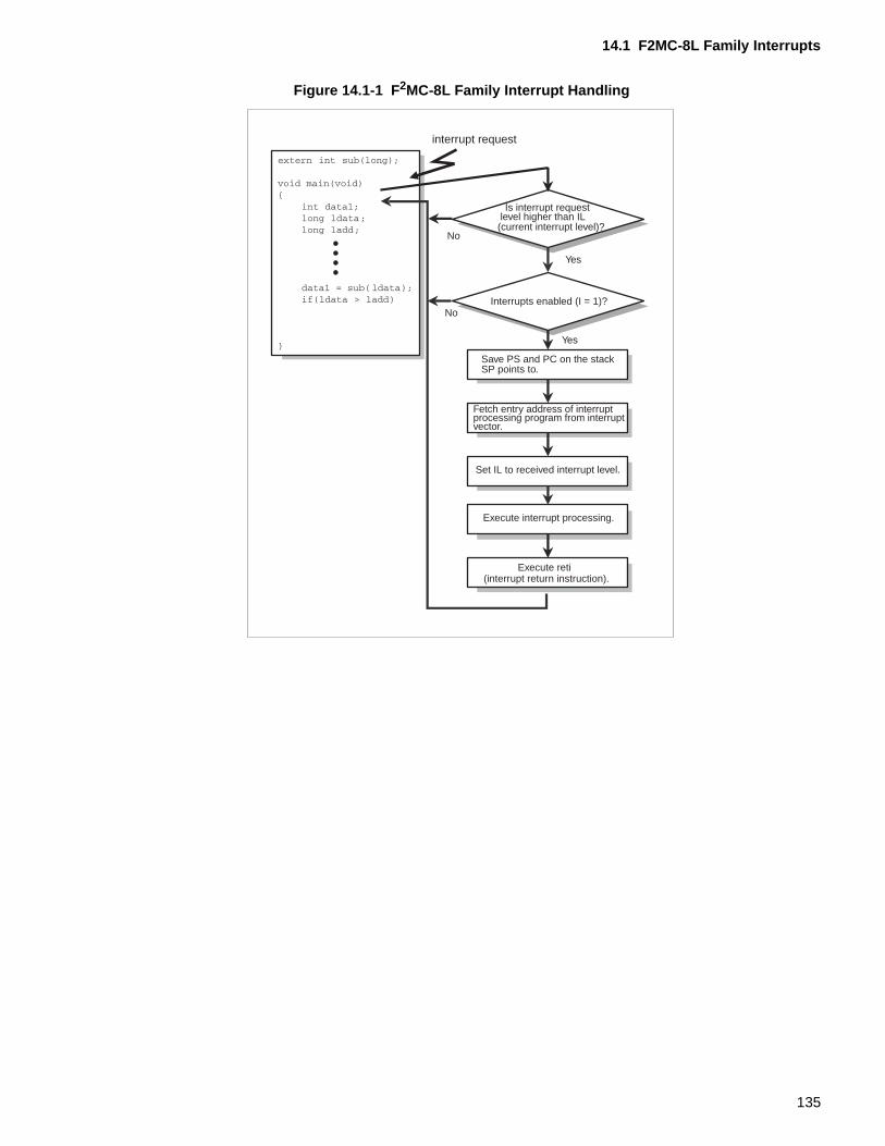
14.1 F2MC-8L Family Interrupts
Figure 14.1-1 F 2MC-8L Family Interrupt Handling
interrupt request
Is interrupt request level higher than IL(current interrupt level)?
No
No
Yes
Yes
Interrupts enabled (I = 1)?
Save PS and PC on the stackSP points to.
Fetch entry address of interruptprocessing program from interruptvector.
Set IL to received interrupt level.
Execute interrupt processing.
(interrupt return instruction).Execute reti
135
CHAPTER 14 CREATING AND REGISTERING INTERRUPT FUNCTIONS
14.2 Required Hardware Settings for Interrupts
This section describes the required hardware setup for interrupt handling.
■ Required Hardware Settings for Interrupts
The following steps must be performed to enable interrupt processing for F2MC-8L familymicrocontrollers:
• Setting the stack area
• Initial value of resources that can generate interrupt requests
• Setting the resource interrupt level
• Starting resource operation
• Enabling CPU interrupts
Sections 14.2.1 "Setting the System Stack Area" to 14.2.5 "Enabling CPU Interrupts" describethe required initializations.
136
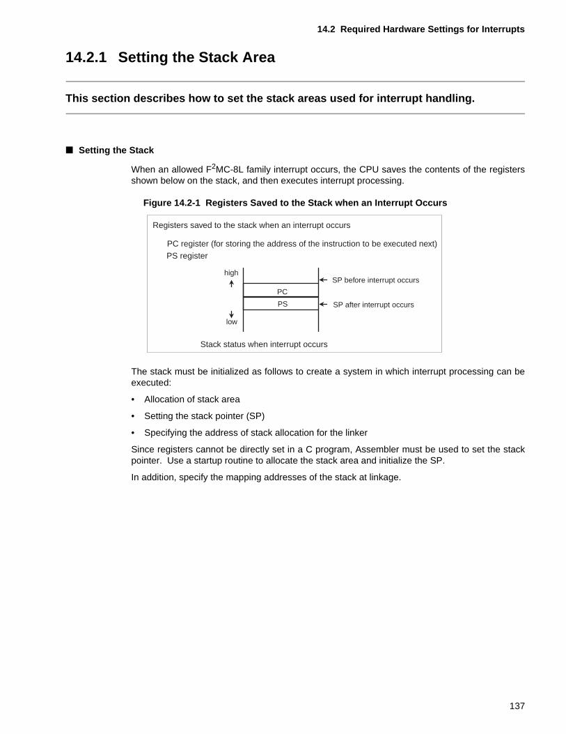
14.2 Required Hardware Settings for Interrupts
14.2.1 Setting the Stack Area
This section describes how to set the stack areas used for interrupt handling.
■ Setting the Stack
When an allowed F2MC-8L family interrupt occurs, the CPU saves the contents of the registersshown below on the stack, and then executes interrupt processing.
Figure 14.2-1 Registers Saved to the Stack when an Interrupt Occurs
The stack must be initialized as follows to create a system in which interrupt processing can beexecuted:
• Allocation of stack area
• Setting the stack pointer (SP)
• Specifying the address of stack allocation for the linker
Since registers cannot be directly set in a C program, Assembler must be used to set the stackpointer. Use a startup routine to allocate the stack area and initialize the SP.
In addition, specify the mapping addresses of the stack at linkage.
PC
PS
high
low
Registers saved to the stack when an interrupt occurs
PC register (for storing the address of the instruction to be executed next)PS register
SP before interrupt occurs
SP after interrupt occurs
Stack status when interrupt occurs
137
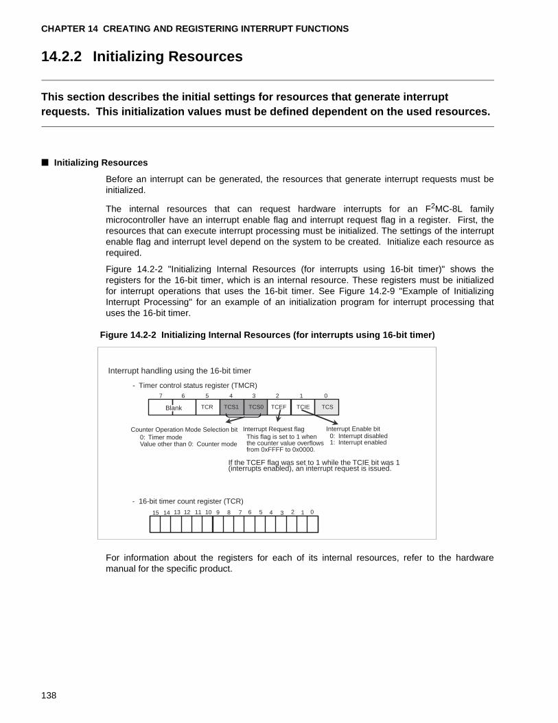
CHAPTER 14 CREATING AND REGISTERING INTERRUPT FUNCTIONS
14.2.2 Initializing Resources
This section describes the initial settings for resources that generate interrupt requests. This initialization values must be defined dependent on the used resources.
■ Initializing Resources
Before an interrupt can be generated, the resources that generate interrupt requests must beinitialized.
The internal resources that can request hardware interrupts for an F2MC-8L familymicrocontroller have an interrupt enable flag and interrupt request flag in a register. First, theresources that can execute interrupt processing must be initialized. The settings of the interruptenable flag and interrupt level depend on the system to be created. Initialize each resource asrequired.
Figure 14.2-2 "Initializing Internal Resources (for interrupts using 16-bit timer)" shows theregisters for the 16-bit timer, which is an internal resource. These registers must be initializedfor interrupt operations that uses the 16-bit timer. See Figure 14.2-9 "Example of InitializingInterrupt Processing" for an example of an initialization program for interrupt processing thatuses the 16-bit timer.
Figure 14.2-2 Initializing Internal Resources (for interrupts using 16-bit timer)
For information about the registers for each of its internal resources, refer to the hardwaremanual for the specific product.
1234567 0
TCSTCEF TCIETCS0TCS1TCR
0123456789101112131415
Interrupt handling using the 16-bit timer
- Timer control status register (TMCR)
Blank
Counter Operation Mode Selection bit0: Timer modeValue other than 0: Counter mode
Interrupt Request flagThis flag is set to 1 whenthe counter value overflowsfrom 0xFFFF to 0x0000.
Interrupt Enable bit0: Interrupt disabled1: Interrupt enabled
If the TCEF flag was set to 1 while the TCIE bit was 1(interrupts enabled), an interrupt request is issued.
- 16-bit timer count register (TCR)
138
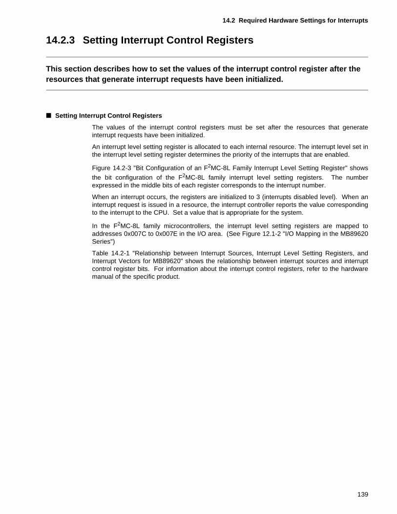
14.2 Required Hardware Settings for Interrupts
14.2.3 Setting Interrupt Control Registers
This section describes how to set the values of the interrupt control register after the resources that generate interrupt requests have been initialized.
■ Setting Interrupt Control Registers
The values of the interrupt control registers must be set after the resources that generateinterrupt requests have been initialized.
An interrupt level setting register is allocated to each internal resource. The interrupt level set inthe interrupt level setting register determines the priority of the interrupts that are enabled.
Figure 14.2-3 "Bit Configuration of an F2MC-8L Family Interrupt Level Setting Register" shows
the bit configuration of the F2MC-8L family interrupt level setting registers. The numberexpressed in the middle bits of each register corresponds to the interrupt number.
When an interrupt occurs, the registers are initialized to 3 (interrupts disabled level). When aninterrupt request is issued in a resource, the interrupt controller reports the value correspondingto the interrupt to the CPU. Set a value that is appropriate for the system.
In the F2MC-8L family microcontrollers, the interrupt level setting registers are mapped toaddresses 0x007C to 0x007E in the I/O area. (See Figure 12.1-2 "I/O Mapping in the MB89620Series")
Table 14.2-1 "Relationship between Interrupt Sources, Interrupt Level Setting Registers, andInterrupt Vectors for MB89620" shows the relationship between interrupt sources and interruptcontrol register bits. For information about the interrupt control registers, refer to the hardwaremanual of the specific product.
139
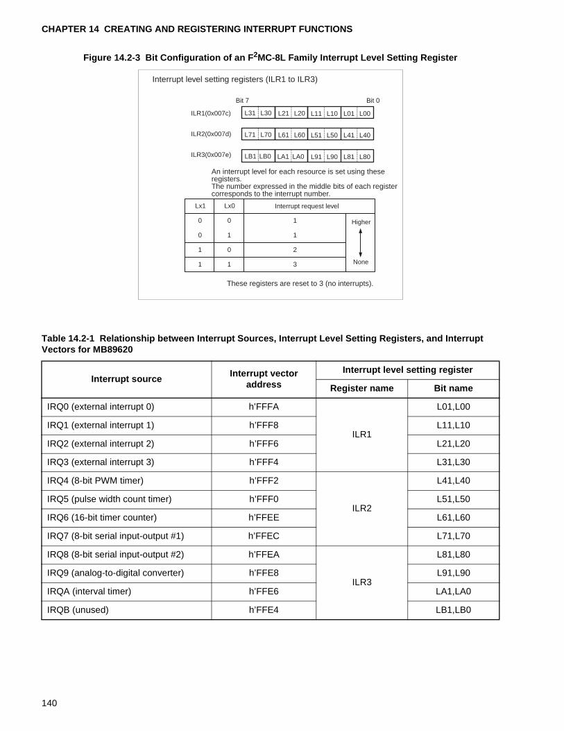
CHAPTER 14 CREATING AND REGISTERING INTERRUPT FUNCTIONS
Figure 14.2-3 Bit Configuration of an F 2MC-8L Family Interrupt Level Setting Register
0 0
0 1 1
1
L41 L40L71 L70 L61 L60 L51 L50
LB1 LB0 LA1 LA0 L91 L90 L81 L80
L31 L30 L21 L20 L11 L10 L01 L00ILR1(0x007c)
ILR2(0x007d)
ILR3(0x007e)
Lx1 Lx0
1 0
1 1
2
3
Interrupt level setting registers (ILR1 to ILR3)
Bit 7 Bit 0
An interrupt level for each resource is set using theseregisters.The number expressed in the middle bits of each registercorresponds to the interrupt number.
Interrupt request level
Higher
None
These registers are reset to 3 (no interrupts).
Table 14.2-1 Relationship between Interrupt Sources, Interrupt Level Setting Registers, and Interrupt Vectors for MB89620
Interrupt sourceInterrupt vector
address
Interrupt level setting register
Register name Bit name
IRQ0 (external interrupt 0) h’FFFA
ILR1
L01,L00
IRQ1 (external interrupt 1) h’FFF8 L11,L10
IRQ2 (external interrupt 2) h’FFF6 L21,L20
IRQ3 (external interrupt 3) h’FFF4 L31,L30
IRQ4 (8-bit PWM timer) h’FFF2
ILR2
L41,L40
IRQ5 (pulse width count timer) h’FFF0 L51,L50
IRQ6 (16-bit timer counter) h’FFEE L61,L60
IRQ7 (8-bit serial input-output #1) h’FFEC L71,L70
IRQ8 (8-bit serial input-output #2) h’FFEA
ILR3
L81,L80
IRQ9 (analog-to-digital converter) h’FFE8 L91,L90
IRQA (interval timer) h’FFE6 LA1,LA0
IRQB (unused) h’FFE4 LB1,LB0
140
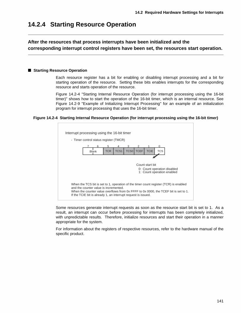
14.2 Required Hardware Settings for Interrupts
14.2.4 Starting Resource Operation
After the resources that process interrupts have been initialized and the corresponding interrupt control registers have been set, the resources start operation.
■ Starting Resource Operation
Each resource register has a bit for enabling or disabling interrupt processing and a bit forstarting operation of the resource. Setting these bits enables interrupts for the correspondingresource and starts operation of the resource.
Figure 14.2-4 "Starting Internal Resource Operation (for interrupt processing using the 16-bittimer)" shows how to start the operation of the 16-bit timer, which is an internal resource. SeeFigure 14.2-9 "Example of Initializing Interrupt Processing" for an example of an initializationprogram for interrupt processing that uses the 16-bit timer.
Figure 14.2-4 Starting Internal Resource Operation (for interrupt processing using the 16-bit timer)
Some resources generate interrupt requests as soon as the resource start bit is set to 1. As aresult, an interrupt can occur before processing for interrupts has been completely initialized,with unpredictable results. Therefore, initialize resources and start their operation in a mannerappropriate for the system.
For information about the registers of respective resources, refer to the hardware manual of thespecific product.
1234567 0
TCSTCEF TCIETCS0TCS1TCR
Interrupt processing using the 16-bit timer
- Timer control status register (TMCR)
Blank
0: Count operation disabled1: Count operation enabled
Count start bit
When the TCS bit is set to 1, operation of the timer count register (TCR) is enabled and the counter value is incremented.When the counter value overflows from 0x FFFF to 0x 0000, the TCEF bit is set to 1.If the TCIE bit is already 1, an interrupt request is issued.
141
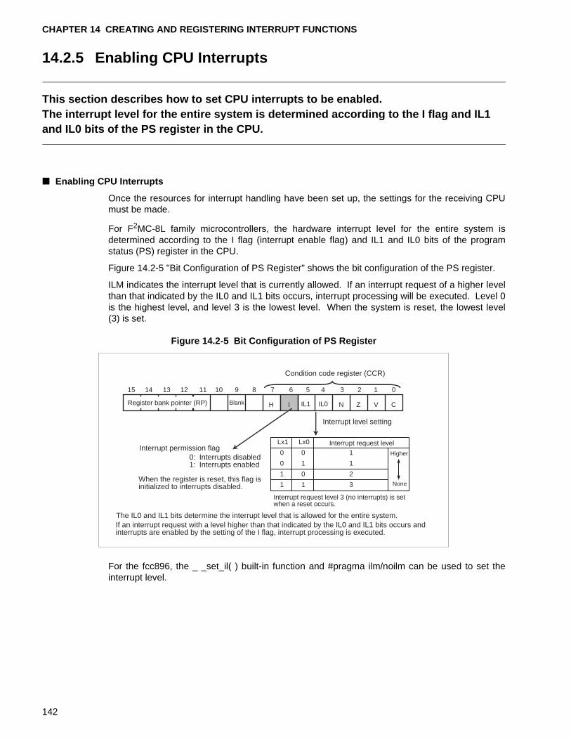
CHAPTER 14 CREATING AND REGISTERING INTERRUPT FUNCTIONS
14.2.5 Enabling CPU Interrupts
This section describes how to set CPU interrupts to be enabled.The interrupt level for the entire system is determined according to the I flag and IL1 and IL0 bits of the PS register in the CPU.
■ Enabling CPU Interrupts
Once the resources for interrupt handling have been set up, the settings for the receiving CPUmust be made.
For F2MC-8L family microcontrollers, the hardware interrupt level for the entire system isdetermined according to the I flag (interrupt enable flag) and IL1 and IL0 bits of the programstatus (PS) register in the CPU.
Figure 14.2-5 "Bit Configuration of PS Register" shows the bit configuration of the PS register.
ILM indicates the interrupt level that is currently allowed. If an interrupt request of a higher levelthan that indicated by the IL0 and IL1 bits occurs, interrupt processing will be executed. Level 0is the highest level, and level 3 is the lowest level. When the system is reset, the lowest level(3) is set.
Figure 14.2-5 Bit Configuration of PS Register
For the fcc896, the _ _set_il( ) built-in function and #pragma ilm/noilm can be used to set theinterrupt level.
CVZNIL0IL1IH
15 14 13 12 11 10 9 8 7 6 5 4 3 2 1 0
0 0
0 1 1
1
Lx1 Lx0
1 0
1 1
2
3
Condition code register (CCR)
Register bank pointer (RP) Blank
Interrupt permission flag0: Interrupts disabled1: Interrupts enabled
When the register is reset, this flag isinitialized to interrupts disabled.
If an interrupt request with a level higher than that indicated by the IL0 and IL1 bits occurs andinterrupts are enabled by the setting of the I flag, interrupt processing is executed.
Interrupt level setting
Interrupt request level
Higher
None
Interrupt request level 3 (no interrupts) is setwhen a reset occurs.
The IL0 and IL1 bits determine the interrupt level that is allowed for the entire system.
142
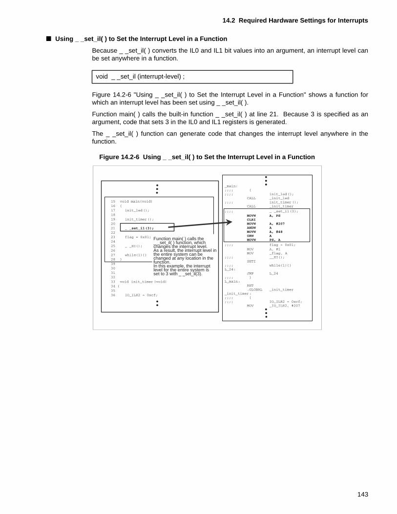
14.2 Required Hardware Settings for Interrupts
■ Using _ _set_il( ) to Set the Interrupt Level in a Function
Because _ _set_il( ) converts the IL0 and IL1 bit values into an argument, an interrupt level canbe set anywhere in a function.
Figure 14.2-6 "Using _ _set_il( ) to Set the Interrupt Level in a Function" shows a function forwhich an interrupt level has been set using _ _set_il( ).
Function main( ) calls the built-in function _ _set_il( ) at line 21. Because 3 is specified as anargument, code that sets 3 in the IL0 and IL1 registers is generated.
The _ _set_il( ) function can generate code that changes the interrupt level anywhere in thefunction.
Figure 14.2-6 Using _ _set_il( ) to Set the Interrupt Level in a Function
void _ _set_il (interrupt-level) ;
Function main( ) calls the_ _set_il( ) function, whichchanges the interrupt level.As a result, the interrupt level inthe entire system can bechanged at any location in thefunction.In this example, the interruptlevel for the entire system isset to 3 with _ _set_il(3).
143
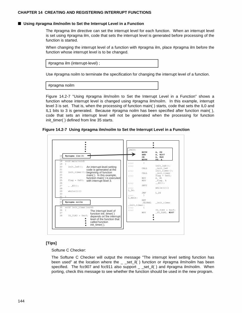
CHAPTER 14 CREATING AND REGISTERING INTERRUPT FUNCTIONS
■ Using #pragma ilm/noilm to Set the Interrupt Level in a Function
The #pragma ilm directive can set the interrupt level for each function. When an interrupt levelis set using #pragma ilm, code that sets the interrupt level is generated before processing of thefunction is started.
When changing the interrupt level of a function with #pragma ilm, place #pragma ilm before thefunction whose interrupt level is to be changed.
Use #pragma noilm to terminate the specification for changing the interrupt level of a function.
Figure 14.2-7 "Using #pragma ilm/noilm to Set the Interrupt Level in a Function" shows afunction whose interrupt level is changed using #pragma ilm/noilm. In this example, interruptlevel 3 is set. That is, when the processing of function main( ) starts, code that sets the IL0 andIL1 bits to 3 is generated. Because #pragma noilm has been specified after function main( ),code that sets an interrupt level will not be generated when the processing for functioninit_timer( ) defined from line 35 starts.
Figure 14.2-7 Using #pragma ilm/noilm to Set the Interrupt Level in a Function
[Tips]
Softune C Checker:
The Softune C Checker will output the message "The interrupt level setting function hasbeen used" at the location where the _ _set_il( ) function or #pragma ilm/noilm has beenspecified. The fcc907 and fcc911 also support _ _set_il( ) and #pragma ilm/noilm. Whenporting, check this message to see whether the function should be used in the new program.
#pragma ilm (interrupt-level) ;
#pragma noilm
An interrupt-level-settingcode is generated at thebeginning of functionmain( ). In this example,function main( ) is executedwith interrupt level 3.
The interrupt level of function init_timer( )depends on the interruptlevel of the function thatcalled functioninit_timer( ).
144
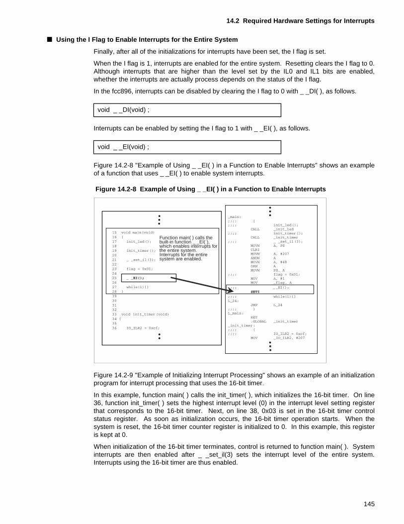
14.2 Required Hardware Settings for Interrupts
■ Using the I Flag to Enable Interrupts for the Entire System
Finally, after all of the initializations for interrupts have been set, the I flag is set.
When the I flag is 1, interrupts are enabled for the entire system. Resetting clears the I flag to 0.Although interrupts that are higher than the level set by the IL0 and IL1 bits are enabled,whether the interrupts are actually process depends on the status of the I flag.
In the fcc896, interrupts can be disabled by clearing the I flag to 0 with _ _DI( ), as follows.
Interrupts can be enabled by setting the I flag to 1 with _ _EI( ), as follows.
Figure 14.2-8 "Example of Using _ _EI( ) in a Function to Enable Interrupts" shows an exampleof a function that uses _ _EI( ) to enable system interrupts.
Figure 14.2-8 Example of Using _ _EI( ) in a Function to Enable Interrupts
Figure 14.2-9 "Example of Initializing Interrupt Processing" shows an example of an initializationprogram for interrupt processing that uses the 16-bit timer.
In this example, function main( ) calls the init_timer( ), which initializes the 16-bit timer. On line36, function init_timer( ) sets the highest interrupt level (0) in the interrupt level setting registerthat corresponds to the 16-bit timer. Next, on line 38, 0x03 is set in the 16-bit timer controlstatus register. As soon as initialization occurs, the 16-bit timer operation starts. When thesystem is reset, the 16-bit timer counter register is initialized to 0. In this example, this registeris kept at 0.
When initialization of the 16-bit timer terminates, control is returned to function main( ). Systeminterrupts are then enabled after _ _set_il(3) sets the interrupt level of the entire system.Interrupts using the 16-bit timer are thus enabled.
void _ _DI(void) ;
void _ _EI(void) ;
Function main( ) calls thebuilt-in function _ _EI( ),which enables interrupts forthe entire system.Interrupts for the entiresystem are enabled.
145
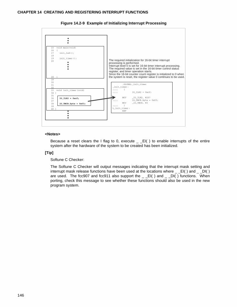
CHAPTER 14 CREATING AND REGISTERING INTERRUPT FUNCTIONS
Figure 14.2-9 Example of Initializing Interrupt Processing
<Notes>
Because a reset clears the I flag to 0, execute _ _EI( ) to enable interrupts of the entiresystem after the hardware of the system to be created has been initialized.
[Tip]
Softune C Checker:
The Softune C Checker will output messages indicating that the interrupt mask setting andinterrupt mask release functions have been used at the locations where _ _EI( ) and _ _DI( )are used. The fcc907 and fcc911 also support the _ _EI( ) and _ _DI( ) functions. Whenporting, check this message to see whether these functions should also be used in the newprogram system.
The required initialization for 16-bit timer interruptprocessing is performed.Interrupt level 0 is set for 16-bit timer interrupt processing.The required value is set in the 16-bit timer control statusregister, and timer operation starts.Since the 16-bit counter count register is initialized to 0 whenthe system is reset, the register value 0 continues to be used.
146
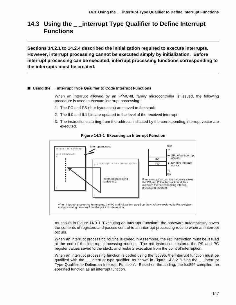
14.3 Using the _ _interrupt Type Qualifier to Define Interrupt Functions
14.3 Using the _ _interrupt Type Qualifier to Define Interrupt Functions
Sections 14.2.1 to 14.2.4 described the initialization required to execute interrupts. However, interrupt processing cannot be executed simply by initialization. Before interrupt processing can be executed, interrupt processing functions corresponding to the interrupts must be created.
■ Using the _ _interrupt Type Qualifier to Code Interrupt Functions
When an interrupt allowed by an F2MC-8L family microcontroller is issued, the followingprocedure is used to execute interrupt processing:
1. The PC and PS (four bytes total) are saved to the stack.
2. The IL0 and IL1 bits are updated to the level of the received interrupt.
3. The instructions starting from the address indicated by the corresponding interrupt vector areexecuted.
Figure 14.3-1 Executing an Interrupt Function
As shown in Figure 14.3-1 "Executing an Interrupt Function", the hardware automatically savesthe contents of registers and passes control to an interrupt processing routine when an interruptoccurs.
When an interrupt processing routine is coded in Assembler, the reti instruction must be issuedat the end of the interrupt processing routine. The reti instruction restores the PS and PCregister values saved to the stack, and restarts execution from the point of interruption.
When an interrupt processing function is coded using the fcc896, the interrupt function must bequalified with the _ _interrupt type qualifier, as shown in Figure 14.3-2 "Using the _ _interruptType Qualifier to Define an Interrupt Function". Based on the coding, the fcc896 compiles thespecified function as an interrupt function.
PC
PS
high
low
Interrupt request
Interrupt processing coded in C
SP before interruptoccurs
SP after interruptoccurs
If an interrupt occurs, the hardware savesthe PC and PS to the stack, and thenexecutes the corresponding interruptprocessing program.
When interrupt processing terminates, the PC and PS values saved on the stack are restored to the registers,and processing resumes from the point of interruption.
147
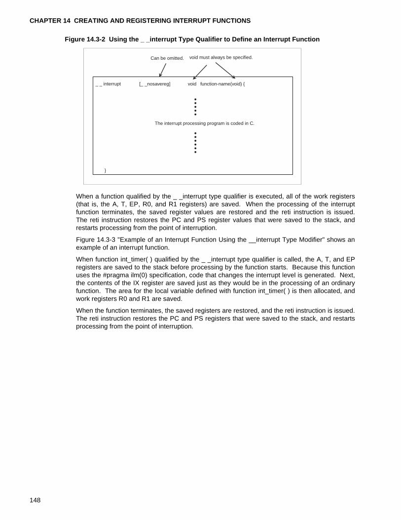
CHAPTER 14 CREATING AND REGISTERING INTERRUPT FUNCTIONS
Figure 14.3-2 Using the _ _interrupt Type Qualifier to Define an Interrupt Function
When a function qualified by the _ _interrupt type qualifier is executed, all of the work registers(that is, the A, T, EP, R0, and R1 registers) are saved. When the processing of the interruptfunction terminates, the saved register values are restored and the reti instruction is issued.The reti instruction restores the PC and PS register values that were saved to the stack, andrestarts processing from the point of interruption.
Figure 14.3-3 "Example of an Interrupt Function Using the __interrupt Type Modifier" shows anexample of an interrupt function.
When function int_timer( ) qualified by the _ _interrupt type qualifier is called, the A, T, and EPregisters are saved to the stack before processing by the function starts. Because this functionuses the #pragma ilm(0) specification, code that changes the interrupt level is generated. Next,the contents of the IX register are saved just as they would be in the processing of an ordinaryfunction. The area for the local variable defined with function int_timer( ) is then allocated, andwork registers R0 and R1 are saved.
When the function terminates, the saved registers are restored, and the reti instruction is issued.The reti instruction restores the PC and PS registers that were saved to the stack, and restartsprocessing from the point of interruption.
_ _ interrupt
}
Can be omitted. void must always be specified.
[_ _nosavereg] void function-name(void) {
The interrupt processing program is coded in C.
148
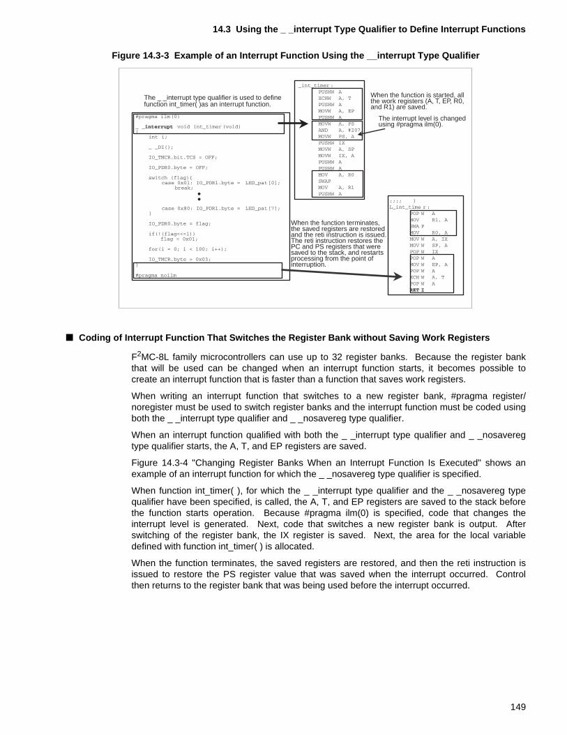
14.3 Using the _ _interrupt Type Qualifier to Define Interrupt Functions
Figure 14.3-3 Example of an Interrupt Function Using the __interrupt Type Qualifier
■ Coding of Interrupt Function That Switches the Register Bank without Saving Work Registers
F2MC-8L family microcontrollers can use up to 32 register banks. Because the register bankthat will be used can be changed when an interrupt function starts, it becomes possible tocreate an interrupt function that is faster than a function that saves work registers.
When writing an interrupt function that switches to a new register bank, #pragma register/noregister must be used to switch register banks and the interrupt function must be coded usingboth the _ _interrupt type qualifier and _ _nosavereg type qualifier.
When an interrupt function qualified with both the _ _interrupt type qualifier and _ _nosaveregtype qualifier starts, the A, T, and EP registers are saved.
Figure 14.3-4 "Changing Register Banks When an Interrupt Function Is Executed" shows anexample of an interrupt function for which the _ _nosavereg type qualifier is specified.
When function int_timer( ), for which the _ _interrupt type qualifier and the _ _nosavereg typequalifier have been specified, is called, the A, T, and EP registers are saved to the stack beforethe function starts operation. Because #pragma ilm(0) is specified, code that changes theinterrupt level is generated. Next, code that switches a new register bank is output. Afterswitching of the register bank, the IX register is saved. Next, the area for the local variabledefined with function int_timer( ) is allocated.
When the function terminates, the saved registers are restored, and then the reti instruction isissued to restore the PS register value that was saved when the interrupt occurred. Controlthen returns to the register bank that was being used before the interrupt occurred.
The _ _interrupt type qualifier is used to definefunction int_timer( )as an interrupt function.
When the function is started, allthe work registers (A, T, EP, R0,and R1) are saved.
The interrupt level is changedusing #pragma ilm(0).
When the function terminates,the saved registers are restoredand the reti instruction is issued. The reti instruction restores thePC and PS registers that weresaved to the stack, and restartsprocessing from the point ofinterruption.
149
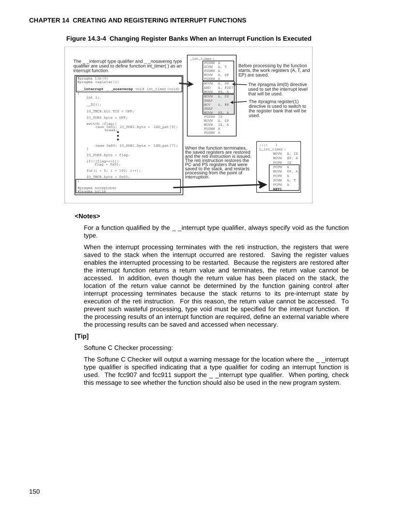
CHAPTER 14 CREATING AND REGISTERING INTERRUPT FUNCTIONS
Figure 14.3-4 Changing Register Banks When an Interrupt Function Is Executed
<Notes>
For a function qualified by the _ _interrupt type qualifier, always specify void as the functiontype.
When the interrupt processing terminates with the reti instruction, the registers that weresaved to the stack when the interrupt occurred are restored. Saving the register valuesenables the interrupted processing to be restarted. Because the registers are restored afterthe interrupt function returns a return value and terminates, the return value cannot beaccessed. In addition, even though the return value has been placed on the stack, thelocation of the return value cannot be determined by the function gaining control afterinterrupt processing terminates because the stack returns to its pre-interrupt state byexecution of the reti instruction. For this reason, the return value cannot be accessed. Toprevent such wasteful processing, type void must be specified for the interrupt function. Ifthe processing results of an interrupt function are required, define an external variable wherethe processing results can be saved and accessed when necessary.
[Tip]
Softune C Checker processing:
The Softune C Checker will output a warning message for the location where the _ _interrupttype qualifier is specified indicating that a type qualifier for coding an interrupt function isused. The fcc907 and fcc911 support the _ _interrupt type qualifier. When porting, checkthis message to see whether the function should also be used in the new program system.
The _ _interrupt type qualifier and _ _nosavereg typequalifier are used to define function int_timer( ) as aninterrupt function.
Before processing by the functionstarts, the work registers (A, T, andEP) are saved.
The #pragma ilm(0) directiveused to set the interrupt levelthat will be used.
The #pragma register(1)directive is used to switch tothe register bank that will beused.
When the function terminates,the saved registers are restoredand the reti instruction is issued.The reti instruction restores thePC and PS registers that weresaved to the stack, and restartsprocessing from the point ofinterruption.
150
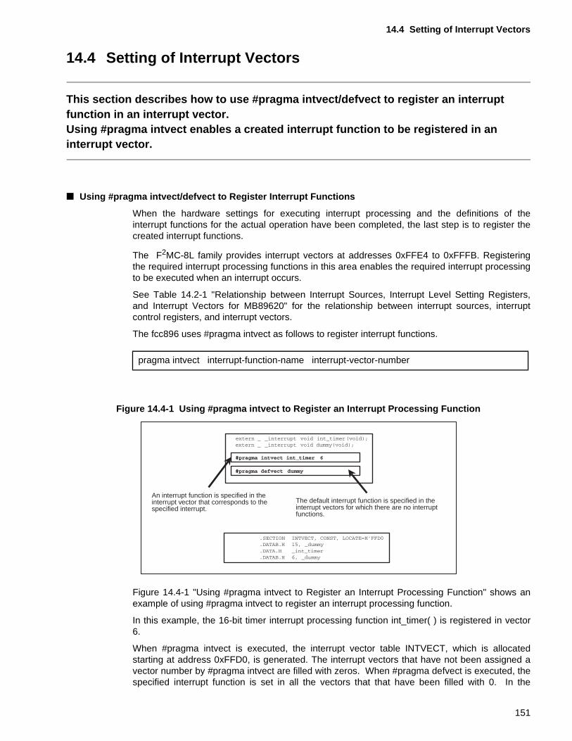
14.4 Setting of Interrupt Vectors
14.4 Setting of Interrupt Vectors
This section describes how to use #pragma intvect/defvect to register an interrupt function in an interrupt vector.Using #pragma intvect enables a created interrupt function to be registered in an interrupt vector.
■ Using #pragma intvect/defvect to Register Interrupt Functions
When the hardware settings for executing interrupt processing and the definitions of theinterrupt functions for the actual operation have been completed, the last step is to register thecreated interrupt functions.
The F2MC-8L family provides interrupt vectors at addresses 0xFFE4 to 0xFFFB. Registeringthe required interrupt processing functions in this area enables the required interrupt processingto be executed when an interrupt occurs.
See Table 14.2-1 "Relationship between Interrupt Sources, Interrupt Level Setting Registers,and Interrupt Vectors for MB89620" for the relationship between interrupt sources, interruptcontrol registers, and interrupt vectors.
The fcc896 uses #pragma intvect as follows to register interrupt functions.
Figure 14.4-1 Using #pragma intvect to Register an Interrupt Processing Function
Figure 14.4-1 "Using #pragma intvect to Register an Interrupt Processing Function" shows anexample of using #pragma intvect to register an interrupt processing function.
In this example, the 16-bit timer interrupt processing function int_timer( ) is registered in vector6.
When #pragma intvect is executed, the interrupt vector table INTVECT, which is allocatedstarting at address 0xFFD0, is generated. The interrupt vectors that have not been assigned avector number by #pragma intvect are filled with zeros. When #pragma defvect is executed, thespecified interrupt function is set in all the vectors that that have been filled with 0. In the
pragma intvect interrupt-function-name interrupt-vector-number
An interrupt function is specified in theinterrupt vector that corresponds to thespecified interrupt.
The default interrupt function is specified in theinterrupt vectors for which there are no interruptfunctions.
151
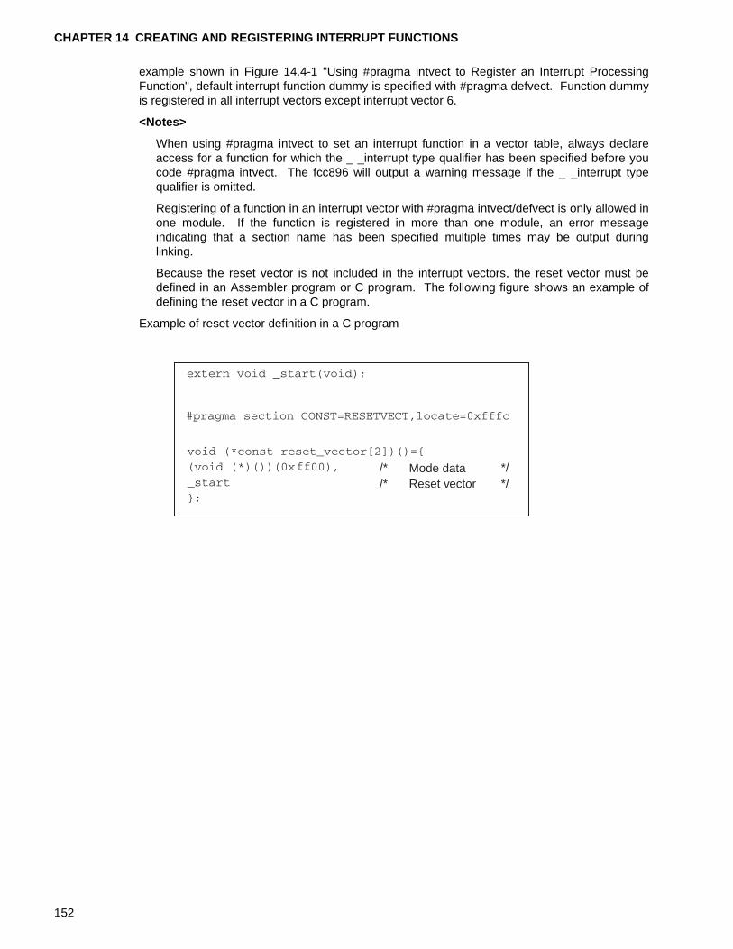
CHAPTER 14 CREATING AND REGISTERING INTERRUPT FUNCTIONS
example shown in Figure 14.4-1 "Using #pragma intvect to Register an Interrupt ProcessingFunction", default interrupt function dummy is specified with #pragma defvect. Function dummyis registered in all interrupt vectors except interrupt vector 6.
<Notes>
When using #pragma intvect to set an interrupt function in a vector table, always declareaccess for a function for which the _ _interrupt type qualifier has been specified before youcode #pragma intvect. The fcc896 will output a warning message if the _ _interrupt typequalifier is omitted.
Registering of a function in an interrupt vector with #pragma intvect/defvect is only allowed inone module. If the function is registered in more than one module, an error messageindicating that a section name has been specified multiple times may be output duringlinking.
Because the reset vector is not included in the interrupt vectors, the reset vector must bedefined in an Assembler program or C program. The following figure shows an example ofdefining the reset vector in a C program.
Example of reset vector definition in a C program
/* */Mode data/* */Reset vector
152

INDEX
INDEX
The index follows on the next page.This is listed in alphabetic order.
153
INDEX
Index
Symbols
#define definition ....................................................26#pragma ilm/noilm to set the interrupt level
in function, using ........................................144#pragma inline is specified, when inline
expansion is not executed even though.......55#pragma inline specification, executing inline
expansion using ...........................................56#pragma intvect/defvect to registeriInterrupt
function, using ............................................151_ _interrupt type qualifier to code interrupt
function, using ............................................147_ _set_il( ) to set interrupt level in function, using 143
A
accessing I/O area register as variable fromC program, operation for ............................122
accessing I/O area using bit field and union ..........45accessing variable and function defined in
C program from assembler program..........113accessing variable qualified by _ _direct
type qualifier...............................................129area allocated on stack at function call ..................50argument passing and stack usage size ................60argument structure passing....................................62automatic variable ..................................................35automatic variable and statically allocated variable32
B
bit field definition and boundary alignment .............41bit field of length 0 ..................................................42boundary alignment................................................41boundary alignment of fcc896 ................................40
C
calling function passing address of structurevariable to which return value is to bepassed .........................................................74
calling function passing taddress of union variableto which return value are to be passed ........78
calling function return structure-type value.............72calling function returning union-type value.............76coding assembler instruction using
_ _asm statement ........................................84coding assembler program...................................112
coding assembler program outside function ........ 116condition for passing structure address ................. 65CPU interrupt, enabling........................................ 142
D
defining MB89PV620 I/O register ........................ 123defining variable using "const" type qualifier.......... 28definition and scope of automatic variable and
statically allocated variable .......................... 34definition of bit field of different type ...................... 43disabling Iiterrupt using _ _DI( ) ........................... 107disabling interrupt using _ _DI( ) .......................... 107
E
enabling interrupt using _ _EI( )........................... 108expandsion function inline, condition for ................ 57extended function using #pragma.......................... 94extended type qualifier........................................... 85external variable..................................................... 14external variable and automatic variable ............... 35
F
function call, stack status at ................................... 64function return value returned via EP register........ 69function returning pointer-type value...................... 70function returning structure-type value................... 71function returning union-type value........................ 71function with _ _interrupt type qualifier .................. 90function with _ _nosavereg type qualifier............... 92function with static global variable, example of...... 22function with static local variable, example of ........ 23
G
generating interrupt vector tables using#pragma intvect/defvect............................. 104
I
I flag to enable interrupt for entire system, using . 145including assembler program having multiple
instruction into function .............................. 115initial value and variable area for external variable 16initialization at execution........................................ 18initialized variable and initialization at execution.... 18initializing resource .............................................. 138
154
INDEX
inline expansion of function.................................... 54inline expansion using #pragma inline ................... 96input-output resource ........................................... 130inserting assembler program module using
#pragma asm/endasm ................................. 95interrupt control register, setting .......................... 139interrupt function that switch register bank
without saving work register, coding of...... 149interrupt handling in F2MC-8L family ................... 134
M
mapping, memory area into ..................................... 6MB89620 series memory mapping ...................... 120MB89PV620 I/O register, accessing .................... 125
N
normal argument passing ...................................... 61numeric constant and #define definition ................ 26
O
outputting nop instruction using _ _wait_nop( ) ... 110
P
passing structure address, condition for ................ 65program component................................................. 4
R
required hardware setting for Interrupt................. 136resource operation, starting ................................. 141return value of function .......................................... 68returning function return value via stack ................ 70
S
sample I/O register file provided by fcc896.......... 122scope of automatic variable and statically
allocated variable......................................... 34
setting interrupt level using _ _set_il( ) .................109setting register bank using
#pragma register/noregister .......................102signed bit field.........................................................44specify mapping address........................................98specifying interrupt level using
#pragma ilm/noilm ......................................100stack state when function call are nested...............52stack status at function call.....................................64stack usage size .....................................................60statically allocated variable.....................................32statically allocated variable and
variable area in RAM....................................33structure address passing ......................................63system stack, setting ............................................137
U
using #pragma section to change section nameand specify mapping address.......................98
using built-in function to add function ...................106
V
variable area for external variable ..........................16variable area in RAM ..............................................33variable area, variable declared as "static".............20variable declared as "static" and their variable
area ..............................................................20variable qualified by _ _direct type qualifier and
input-output resource .................................130variable qualified by _ _direct type qualifier,
mapping......................................................131variable qualified by _ _direct type qualifier,
output section of .........................................128variable with _ _direct type qualifier .......................88variable with _ _io type qualifier .............................86variable, dynamically allocated.................................8variable, statically allocated....................................10
155

INDEX
156
CM25-00320-1E
FUJITSU SEMICONDUCTOR • CONTROLLER MANUAL
F2MC-8L
8-BIT MICROCONTROLLER
EMBEDDED C PROGRAMMING MANUAL
FOR fcc896
October 2000 the first edition
Published FUJITSU LIMITED Electronic Devices
Edited Technical Communication Dept.

FUJITSU SEMICONDUCTOR F2MC-8L 8-BIT MICROCONTROLLER EMBEDDED C PROGRAMMING MANUAL FOR fcc896
Related Documents