350 East Plumeria Drive San Jose, CA 95134 USA June 2010 208-10657-02 7000 Series Managed Switch Software Setup Manual Version 9.0.1 XMS7224S

Welcome message from author
This document is posted to help you gain knowledge. Please leave a comment to let me know what you think about it! Share it to your friends and learn new things together.
Transcript
350 East Plumeria DriveSan Jose, CA 95134USA
June 2010208-10657-02
7000 Series Managed SwitchSof tware Setup Manual
Version 9.0.1
XMS7224S
2
7000 Series Managed Switch
© 2011 NETGEAR, Inc. by NETGEAR, Inc. All rights reserved.No part of this publication may be reproduced, transmitted, transcribed, stored in a retrieval system, or translated into any language in any form or by any means without the written permission of NETGEAR, Inc.P/N: 208-10657-02
Technical SupportWhen you register your product at http://www.netgear.com/register, we can provide you with faster expert technical support and timely notices of product and software upgrades.Email: [email protected]: http://www.netgear.comPhone: 1-888-NETGEAR, for US & Canada only. For other countries, see your Support information card.
TrademarksNETGEAR, the NETGEAR logo, ProSafe, Smart Wizard, and Auto Uplink are trademarks or registered trademarks of NETGEAR, Inc. Microsoft, Windows, Windows NT, and Vista are registered trademarks of Microsoft Corporation. Other brand and product names are registered trademarks or trademarks of their respective holders.
Statement of ConditionsTo improve internal design, operational function, and/or reliability, NETGEAR reserves the right to make changes to the products described in this document without notice. NETGEAR does not assume any liability that may occur due to the use or application of the product(s) or circuit layout(s) described herein.
Contents
Chapter 1 Getting StartedIn-Band and Out-of-Band Connectivity. . . . . . . . . . . . . . . . . . . . . . . . . . . . .5
Configuring the Switch for In-Band Connectivity . . . . . . . . . . . . . . . . . . .5Configuring the Switch for Out-of-Band Connectivity . . . . . . . . . . . . . . . .7
Starting the Switch . . . . . . . . . . . . . . . . . . . . . . . . . . . . . . . . . . . . . . . . . . . . 8Initial Configuration. . . . . . . . . . . . . . . . . . . . . . . . . . . . . . . . . . . . . . . . . . . . 9
Initial Configuration with the Easy Setup Wizard . . . . . . . . . . . . . . . . . . .9Software Installation . . . . . . . . . . . . . . . . . . . . . . . . . . . . . . . . . . . . . . . . . . 10
Quick-Starting the Networking Device . . . . . . . . . . . . . . . . . . . . . . . . . .10System Information and System Setup . . . . . . . . . . . . . . . . . . . . . . . . .10
Using Ezconfig for Switch Setup . . . . . . . . . . . . . . . . . . . . . . . . . . . . . . . .13Changing the Password . . . . . . . . . . . . . . . . . . . . . . . . . . . . . . . . . . . . . 13Setting Up the Switch IP Address. . . . . . . . . . . . . . . . . . . . . . . . . . . . . .14Assigning a Switch Name and Location Information . . . . . . . . . . . . . . .14Saving the Configuration . . . . . . . . . . . . . . . . . . . . . . . . . . . . . . . . . . . . 15
Using the Web Interface . . . . . . . . . . . . . . . . . . . . . . . . . . . . . . . . . . . . . . . 15Configuring for Web Access . . . . . . . . . . . . . . . . . . . . . . . . . . . . . . . . . . 16Starting the Web Interface . . . . . . . . . . . . . . . . . . . . . . . . . . . . . . . . . . . 16Configuring an SNMP V3 User Profile . . . . . . . . . . . . . . . . . . . . . . . . . .18
Chapter 2 Auto Install ConfigurationSwitch IP Address Assignment. . . . . . . . . . . . . . . . . . . . . . . . . . . . . . . . . . 20TFTP IP Address and the Configuration File Name . . . . . . . . . . . . . . . . . .21Handling Conflicting TFTP Server Configurations . . . . . . . . . . . . . . . . . . .21DNS Server Requirements . . . . . . . . . . . . . . . . . . . . . . . . . . . . . . . . . . . . . 21Obtaining a Config File . . . . . . . . . . . . . . . . . . . . . . . . . . . . . . . . . . . . . . . . 21
Host-Specific Configuration File . . . . . . . . . . . . . . . . . . . . . . . . . . . . . . .21Default Network Configuration File. . . . . . . . . . . . . . . . . . . . . . . . . . . . .22
Monitoring and Completing the Auto Install Process . . . . . . . . . . . . . . . . .23Saving Configuration . . . . . . . . . . . . . . . . . . . . . . . . . . . . . . . . . . . . . . . 23Host-Specific Config File Not Found . . . . . . . . . . . . . . . . . . . . . . . . . . .23Terminating the Auto Install Process . . . . . . . . . . . . . . . . . . . . . . . . . . .23Managing Downloaded Config Files. . . . . . . . . . . . . . . . . . . . . . . . . . . .24Restarting the Auto Install Process . . . . . . . . . . . . . . . . . . . . . . . . . . . .24
Logging. . . . . . . . . . . . . . . . . . . . . . . . . . . . . . . . . . . . . . . . . . . . . . . . . . . . 25Auto Install Configuration . . . . . . . . . . . . . . . . . . . . . . . . . . . . . . . . . . . . . . 25
Stacking . . . . . . . . . . . . . . . . . . . . . . . . . . . . . . . . . . . . . . . . . . . . . . . . . 25DHCP Server Configuration . . . . . . . . . . . . . . . . . . . . . . . . . . . . . . . . . . 26TFTP Server Configuration. . . . . . . . . . . . . . . . . . . . . . . . . . . . . . . . . . . 26
3

7000 Series Managed Switch
CLI: Switch Configuration . . . . . . . . . . . . . . . . . . . . . . . . . . . . . . . . . . . . 26Web Interface . . . . . . . . . . . . . . . . . . . . . . . . . . . . . . . . . . . . . . . . . . . . . 27
Chapter 3 Software License ActivationCreating an Account at mynetgear. . . . . . . . . . . . . . . . . . . . . . . . . . . . . . . 28Registering Your Product . . . . . . . . . . . . . . . . . . . . . . . . . . . . . . . . . . . . . . 31Activating a License Key for a Switch . . . . . . . . . . . . . . . . . . . . . . . . . . . . 32
Index
4
1
1. Getting StartedThis manual includes software configuration tasks that are most commonly used when new switches are installed. To configure the switch software, connect a terminal to the switch.
Note: Some products have Release Notes that detail the platform specific functionality of the switching, routing, SNMP, config, management, and other features. It is a good idea to read the Release Notes before setting up the switch.
A number of other publications are available for your switch, including the following:
• The NETGEAR Quick Installation Guide for your switch• The Hardware Installation Guide for your switch• NETGEAR ProSafe 7000 Managed Switch Software Administration Manual• NETGEAR CLI Reference for the Prosafe 7X00 Series Managed Switch. Refer to this
document for information about the command structure. The Command Line Reference provides information about the CLI commands used to configure the switch and the stack. The document provides CLI descriptions, syntax, and default values.
These documents can be found at http://www.NETGEAR.com.
In-Band and Out-of-Band Connectivity
Ask the system administrator to determine whether you will configure the switch for in-band or out-of-band connectivity.
Configuring the Switch for In-Band ConnectivityIn-band connectivity allows you to access the switch from a remote workstation using the Ethernet network. To use in-band connectivity, you must configure the switch with IP information (IP address, subnet mask, and default gateway).
5
7000 Series Managed Switch
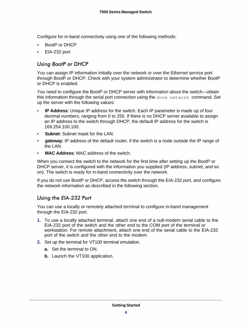
Configure for in-band connectivity using one of the following methods:
• BootP or DHCP• EIA-232 port
Using BootP or DHCP
You can assign IP information initially over the network or over the Ethernet service port through BootP or DHCP. Check with your system administrator to determine whether BootP or DHCP is enabled.
You need to configure the BootP or DHCP server with information about the switch—obtain this information through the serial port connection using the show network command. Set up the server with the following values:
• IP Address: Unique IP address for the switch. Each IP parameter is made up of four decimal numbers, ranging from 0 to 255. If there is no DHCP server available to assign an IP address to the switch through DHCP, the default IP address for the switch is 169.254.100.100.
• Subnet: Subnet mask for the LAN. • gateway: IP address of the default router, if the switch is a node outside the IP range of
the LAN.• MAC Address: MAC address of the switch.
When you connect the switch to the network for the first time after setting up the BootP or DHCP server, it is configured with the information you supplied (IP address, subnet, and so on). The switch is ready for in-band connectivity over the network.
If you do not use BootP or DHCP, access the switch through the EIA-232 port, and configure the network information as described in the following section.
Using the EIA-232 Port
You can use a locally or remotely attached terminal to configure in-band management through the EIA-232 port.
1. To use a locally attached terminal, attach one end of a null-modem serial cable to the EIA-232 port of the switch and the other end to the COM port of the terminal or workstation. For remote attachment, attach one end of the serial cable to the EIA-232 port of the switch and the other end to the modem.
2. Set up the terminal for VT100 terminal emulation.a. Set the terminal to ON.b. Launch the VT100 application.
Getting Started
6
7000 Series Managed Switch
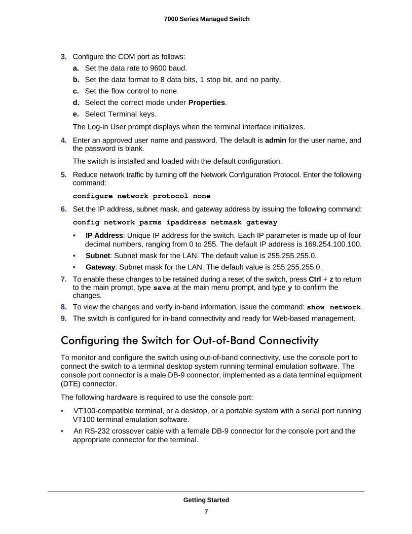
3. Configure the COM port as follows:a. Set the data rate to 9600 baud.b. Set the data format to 8 data bits, 1 stop bit, and no parity.c. Set the flow control to none.d. Select the correct mode under Properties.e. Select Terminal keys.
The Log-in User prompt displays when the terminal interface initializes.
4. Enter an approved user name and password. The default is admin for the user name, and the password is blank.
The switch is installed and loaded with the default configuration.
5. Reduce network traffic by turning off the Network Configuration Protocol. Enter the following command:
configure network protocol none6. Set the IP address, subnet mask, and gateway address by issuing the following command:
config network parms ipaddress netmask gateway • IP Address: Unique IP address for the switch. Each IP parameter is made up of four
decimal numbers, ranging from 0 to 255. The default IP address is 169.254.100.100.• Subnet: Subnet mask for the LAN. The default value is 255.255.255.0.• Gateway: Subnet mask for the LAN. The default value is 255.255.255.0.
7. To enable these changes to be retained during a reset of the switch, press Ctrl + z to return to the main prompt, type save at the main menu prompt, and type y to confirm the changes.
8. To view the changes and verify in-band information, issue the command: show network.9. The switch is configured for in-band connectivity and ready for Web-based management.
Configuring the Switch for Out-of-Band ConnectivityTo monitor and configure the switch using out-of-band connectivity, use the console port to connect the switch to a terminal desktop system running terminal emulation software. The console port connector is a male DB-9 connector, implemented as a data terminal equipment (DTE) connector.
The following hardware is required to use the console port:
• VT100-compatible terminal, or a desktop, or a portable system with a serial port running VT100 terminal emulation software.
• An RS-232 crossover cable with a female DB-9 connector for the console port and the appropriate connector for the terminal.
Getting Started
7
7000 Series Managed Switch
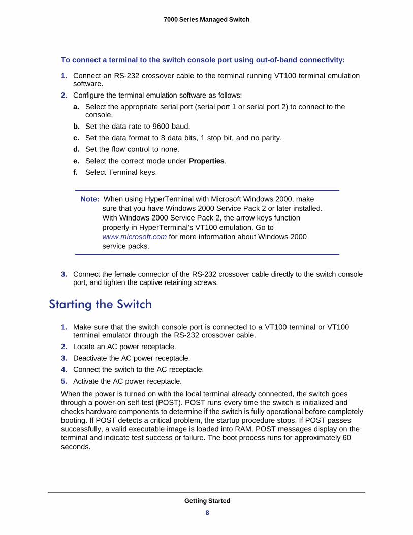
To connect a terminal to the switch console port using out-of-band connectivity:
1. Connect an RS-232 crossover cable to the terminal running VT100 terminal emulation software.
2. Configure the terminal emulation software as follows:a. Select the appropriate serial port (serial port 1 or serial port 2) to connect to the
console.b. Set the data rate to 9600 baud.c. Set the data format to 8 data bits, 1 stop bit, and no parity.d. Set the flow control to none.e. Select the correct mode under Properties.f. Select Terminal keys.
Note: When using HyperTerminal with Microsoft Windows 2000, make sure that you have Windows 2000 Service Pack 2 or later installed. With Windows 2000 Service Pack 2, the arrow keys function properly in HyperTerminal’s VT100 emulation. Go to www.microsoft.com for more information about Windows 2000 service packs.
3. Connect the female connector of the RS-232 crossover cable directly to the switch console port, and tighten the captive retaining screws.
Starting the Switch
1. Make sure that the switch console port is connected to a VT100 terminal or VT100 terminal emulator through the RS-232 crossover cable.
2. Locate an AC power receptacle.3. Deactivate the AC power receptacle.4. Connect the switch to the AC receptacle. 5. Activate the AC power receptacle.
When the power is turned on with the local terminal already connected, the switch goes through a power-on self-test (POST). POST runs every time the switch is initialized and checks hardware components to determine if the switch is fully operational before completely booting. If POST detects a critical problem, the startup procedure stops. If POST passes successfully, a valid executable image is loaded into RAM. POST messages display on the terminal and indicate test success or failure. The boot process runs for approximately 60 seconds.
Getting Started
8
7000 Series Managed Switch
Initial Configuration
The initial simple configuration procedure is based on the following assumptions:
• The switch was not configured before and is in the same state as when you received it.• The switch booted successfully.• The console connection was established and the console prompt displays on the screen
of a VT100 terminal or terminal equivalent.
The initial switch configuration is performed through the console port. After the initial configuration, you can manage the switch either from the already-connected console port or remotely through an interface defined during the initial configuration.
The switch is not configured with a default user name and password.
All of the following settings are necessary to allow the remote management of the switch through Telnet (Telnet client) or HTTP (Web browser).
Before setting up the initial configuration of the switch, obtain the following information from your network administrator:
• The IP address to be assigned to the management interface that will manage the switch• The IP subnet mask for the network• The IP address of the default gateway
Initial Configuration with the Easy Setup WizardYou can perform the initial configuration using the Easy Setup Wizard or by using the command line interface (CLI). The Setup Wizard automatically starts when the switch configuration file is empty. You can exit the wizard at any point by pressing Ctrl + z.
Note: For information about CLI initial configuration, see the NETGEAR CLI Reference for the Prosafe 7X00 Series Managed Switch.
The Setup Wizard sets up the following configuration on the switch:
• Establishes the initial privileged user account with a valid password. The wizard configures one privileged user account during the setup.
• Enables CLI login and HTTP access to use the local authentication setting only.• Sets up the IP address for the management interface.• Sets up the SNMP community string to be used by the SNMP manager at a given IP
address. You can choose to skip this step if SNMP management is not used for this switch.
• Allows you to specify the management server IP address or permit SNMP access from all IP addresses.
• Configures the default gateway IP address.
Getting Started
9
7000 Series Managed Switch
Software Installation
This section contains procedures to help you become acquainted quickly with the switch software. Before installing switch software, you should verify that the switch operates with the most recent firmware.
Quick-Starting the Networking Device1. Configure the switch for in-band or out-of-band connectivity. In-band connectivity allows
access to the software locally or from a remote workstation. You must configure the device with IP information (IP address, subnet mask, and default gateway).
2. Turn the power on.3. Allow the device to load the software until the login prompt displays. The initial state of the
device is called the default mode.4. When the prompt asks for operator login, perform the following steps:
• Type admin at the login prompt. Since a number of the Quick Start commands require administrator account rights, log in to an administrator account.
• Do not enter a password because the default mode does not use a password.• Check that the CLI User EXEC prompt is displayed.• Enter enable to switch to the Privileged EXEC mode from User EXEC. • Enter configure to switch to the Global Config mode from Privileged EXEC. • Enter exit to return to the previous mode.• Enter ? to show a list of commands that are available in the current mode.
System Information and System SetupThis section describes the commands you use to view system information and to set up the network device. The following table contains the Quick Start commands that allow you to view or configure the following information:
• Software versions• Physical port data• User account management• IP address configuration• Uploading from a networking device to out-of-band PC (only XMODEM)• Downloading from an out-of-band PC to networking device (only XMODEM)• Downloading from a TFTP server• Restoring factory default settings
Getting Started
10
7000 Series Managed Switch
n
rking
rs on Read
cess, only users.
ame. e
rs in
.n you
f the
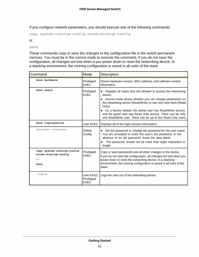
If you configure network parameters, you should execute one of the following commands:
copy system:running-config nvram:startup-config
or
save
These commands copy or save the changes to the configuration file in the switch permanent memory. You must be in the correct mode to execute the command. If you do not save the configuration, all changes are lost when a you power down or reset the networking device. In a stacking environment, the running configuration is saved in all units of the stack.
Command Mode Descriptionshow hardware Privileged
EXECShows hardware version, MAC address, and software versioinformation.
show users Privileged EXEC
• Displays all users who are allowed to access the netwodevice.• Access mode shows whether you can change paramete
the networking device (Read/Write) or can only view them (Only). • As a factory default, the admin user has Read/Write ac
and the guest user has Read Only access. There can beone Read/Write user. There can be up to five Read Only
show loginsession User EXEC Displays all of the login session information.
Username <username> Global Config
• Set the password or change the password for the user nYou are prompted to enter the user’s old password. In thabsence of an old password, leave the area blank. • The password should not be more than eight characte
length.
copy system:running-config nvram:startup-configor
save
Privileged EXEC
Copy or save passwords and all other changes to the deviceIf you do not save the configuration, all changes are lost whepower down or reset the networking device. In a stacking environment, the running configuration is saved in all units ostack.
logout User EXEC Privileged EXEC
Logs the user out of the networking device.
Getting Started
11
7000 Series Managed Switch
0).t:
bled.s.d for
d to
ld be
ch
col is
. The e IP
pe of L
ify
load, e
ad, e
ed
ify ing aded.
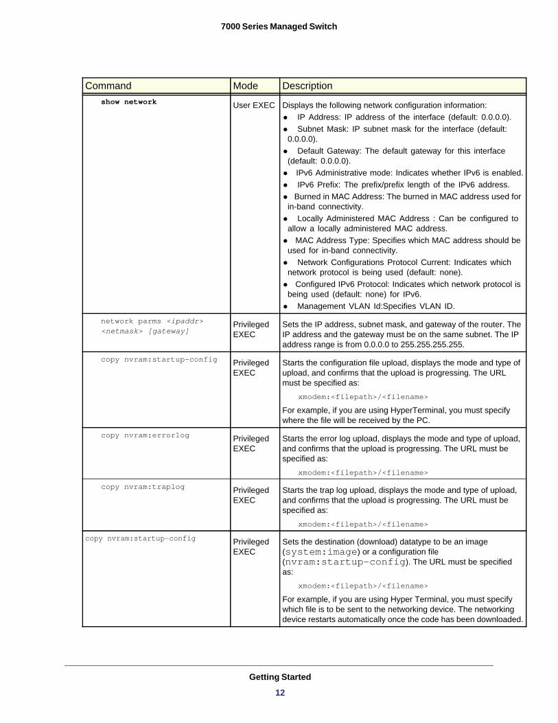
show network User EXEC Displays the following network configuration information:• IP Address: IP address of the interface (default: 0.0.0.• Subnet Mask: IP subnet mask for the interface (defaul
0.0.0.0).• Default Gateway: The default gateway for this interface
(default: 0.0.0.0).• IPv6 Administrative mode: Indicates whether IPv6 is ena• IPv6 Prefix: The prefix/prefix length of the IPv6 addres• Burned in MAC Address: The burned in MAC address use
in-band connectivity.• Locally Administered MAC Address : Can be configure
allow a locally administered MAC address.• MAC Address Type: Specifies which MAC address shou
used for in-band connectivity.• Network Configurations Protocol Current: Indicates whi
network protocol is being used (default: none).• Configured IPv6 Protocol: Indicates which network proto
being used (default: none) for IPv6.• Management VLAN Id:Specifies VLAN ID.
network parms <ipaddr> <netmask> [gateway]
Privileged EXEC
Sets the IP address, subnet mask, and gateway of the routerIP address and the gateway must be on the same subnet. Thaddress range is from 0.0.0.0 to 255.255.255.255.
copy nvram:startup-config Privileged EXEC
Starts the configuration file upload, displays the mode and tyupload, and confirms that the upload is progressing. The URmust be specified as:
xmodem:<filepath>/<filename>
For example, if you are using HyperTerminal, you must specwhere the file will be received by the PC.
copy nvram:errorlog Privileged EXEC
Starts the error log upload, displays the mode and type of upand confirms that the upload is progressing. The URL must bspecified as:
xmodem:<filepath>/<filename>
copy nvram:traplog Privileged EXEC
Starts the trap log upload, displays the mode and type of uploand confirms that the upload is progressing. The URL must bspecified as:
xmodem:<filepath>/<filename>
copy nvram:startup-config Privileged EXEC
Sets the destination (download) datatype to be an image (system:image) or a configuration file (nvram:startup-config). The URL must be specifias:
xmodem:<filepath>/<filename>
For example, if you are using Hyper Terminal, you must specwhich file is to be sent to the networking device. The networkdevice restarts automatically once the code has been downlo
Command Mode Description
Getting Started
12
7000 Series Managed Switch
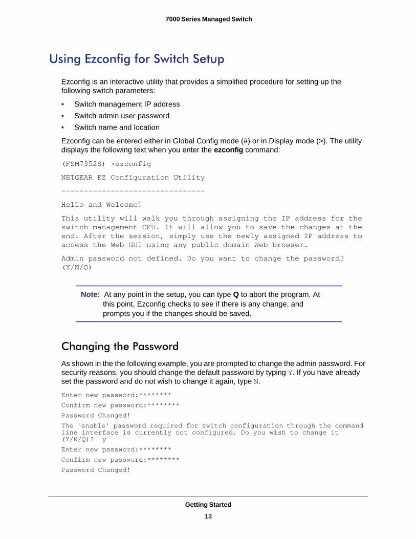
Using Ezconfig for Switch Setup
Ezconfig is an interactive utility that provides a simplified procedure for setting up the following switch parameters:
• Switch management IP address• Switch admin user password• Switch name and location
Ezconfig can be entered either in Global Config mode (#) or in Display mode (>). The utility displays the following text when you enter the ezconfig command:
(FSM7352S) >ezconfig
NETGEAR EZ Configuration Utility
--------------------------------
Hello and Welcome!
This utility will walk you through assigning the IP address for the switch management CPU. It will allow you to save the changes at the end. After the session, simply use the newly assigned IP address to access the Web GUI using any public domain Web browser.
Admin password not defined. Do you want to change the password? (Y/N/Q)
Note: At any point in the setup, you can type Q to abort the program. At this point, Ezconfig checks to see if there is any change, and prompts you if the changes should be saved.
Changing the PasswordAs shown in the the following example, you are prompted to change the admin password. For security reasons, you should change the default password by typing Y. If you have already set the password and do not wish to change it again, type N.
Enter new password:********Confirm new password:********Password Changed!The 'enable' password required for switch configuration through the command line interface is currently not configured. Do you wish to change it (Y/N/Q)? yEnter new password:********Confirm new password:********Password Changed!
Getting Started
13
7000 Series Managed Switch
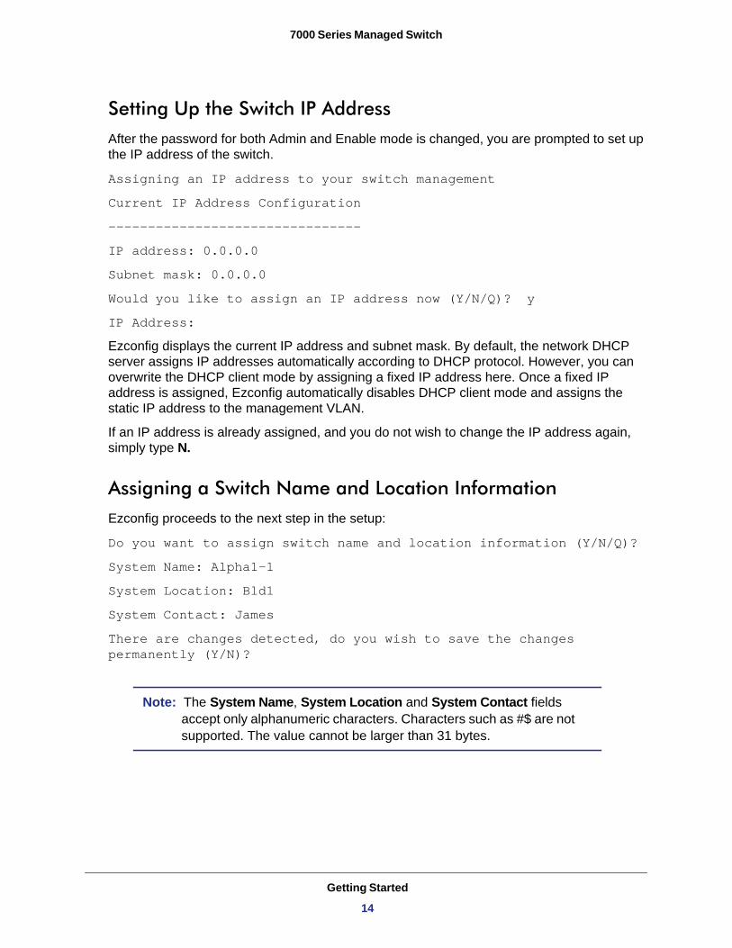
Setting Up the Switch IP AddressAfter the password for both Admin and Enable mode is changed, you are prompted to set up the IP address of the switch.
Assigning an IP address to your switch management
Current IP Address Configuration
--------------------------------
IP address: 0.0.0.0
Subnet mask: 0.0.0.0
Would you like to assign an IP address now (Y/N/Q)? y
IP Address:
Ezconfig displays the current IP address and subnet mask. By default, the network DHCP server assigns IP addresses automatically according to DHCP protocol. However, you can overwrite the DHCP client mode by assigning a fixed IP address here. Once a fixed IP address is assigned, Ezconfig automatically disables DHCP client mode and assigns the static IP address to the management VLAN.
If an IP address is already assigned, and you do not wish to change the IP address again, simply type N.
Assigning a Switch Name and Location InformationEzconfig proceeds to the next step in the setup:
Do you want to assign switch name and location information (Y/N/Q)?
System Name: Alpha1-1
System Location: Bld1
System Contact: James
There are changes detected, do you wish to save the changes permanently (Y/N)?
Note: The System Name, System Location and System Contact fields accept only alphanumeric characters. Characters such as #$ are not supported. The value cannot be larger than 31 bytes.
Getting Started
14
7000 Series Managed Switch
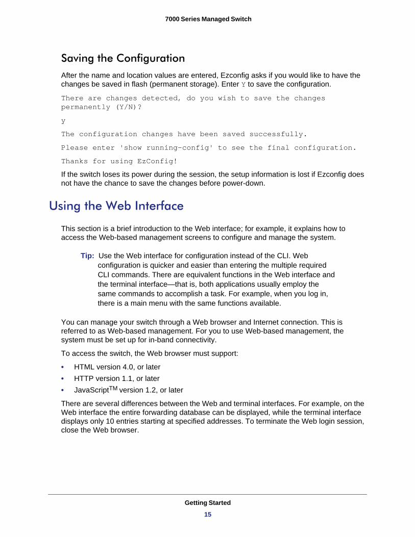
Saving the ConfigurationAfter the name and location values are entered, Ezconfig asks if you would like to have the changes be saved in flash (permanent storage). Enter Y to save the configuration.
There are changes detected, do you wish to save the changes permanently (Y/N)?
y
The configuration changes have been saved successfully.
Please enter 'show running-config' to see the final configuration.
Thanks for using EzConfig!
If the switch loses its power during the session, the setup information is lost if Ezconfig does not have the chance to save the changes before power-down.
Using the Web Interface
This section is a brief introduction to the Web interface; for example, it explains how to access the Web-based management screens to configure and manage the system.
Tip: Use the Web interface for configuration instead of the CLI. Web configuration is quicker and easier than entering the multiple required CLI commands. There are equivalent functions in the Web interface and the terminal interface—that is, both applications usually employ the same commands to accomplish a task. For example, when you log in, there is a main menu with the same functions available.
You can manage your switch through a Web browser and Internet connection. This is referred to as Web-based management. For you to use Web-based management, the system must be set up for in-band connectivity.
To access the switch, the Web browser must support:
• HTML version 4.0, or later • HTTP version 1.1, or later • JavaScriptTM version 1.2, or later
There are several differences between the Web and terminal interfaces. For example, on the Web interface the entire forwarding database can be displayed, while the terminal interface displays only 10 entries starting at specified addresses. To terminate the Web login session, close the Web browser.
Getting Started
15
7000 Series Managed Switch
Configuring for Web AccessTo enable Web access to the switch:
1. Configure the switch for in-band connectivity. (See Configuring the Switch for In-Band Connectivity on page 5.)
2. Enable Web mode:a. At the CLI prompt, enter the show network command.b. Set Web Mode to Enabled.
Starting the Web InterfaceFollow these steps to start the switch Web interface:
1. Enter the IP address of the switch in the Web browser address field. 2. When the Login screen displays, click Login.3. Enter the appropriate user name and password. The user name and associated password
are the same as those used for the terminal interface. Click the Login button. 4. A menu displays, with selections on the left.5. Make a selection by clicking it.
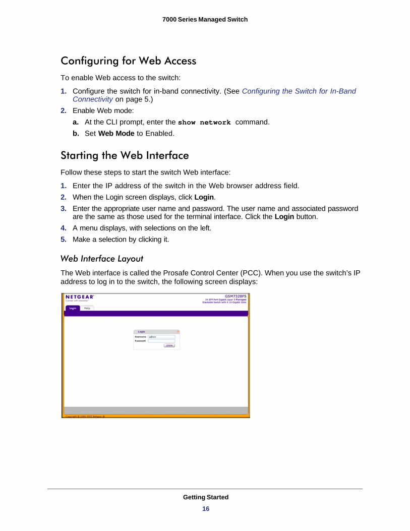
Web Interface Layout
The Web interface is called the Prosafe Control Center (PCC). When you use the switch’s IP address to log in to the switch, the following screen displays:
Getting Started
16
7000 Series Managed Switch
The switch can accommodate two types of users: administrative users and guests. An administrative user can configure the switch for network application, but a guest cannot. The guest can only view the settings and status of the network. As shipped from the factory, both users can log in without a password. NETGEAR strongly recommends that the network administrator create a unique password for the administrative user before placing the switch into production.
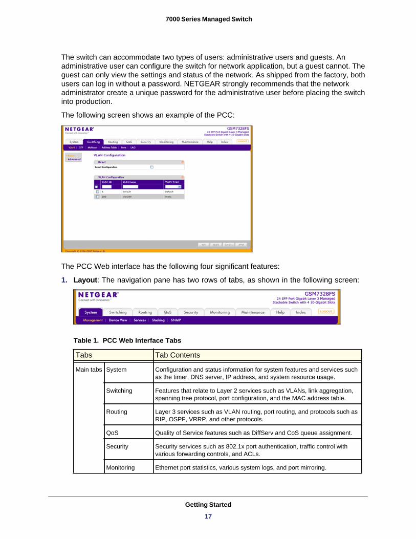
The following screen shows an example of the PCC:
The PCC Web interface has the following four significant features:
1. Layout: The navigation pane has two rows of tabs, as shown in the following screen:
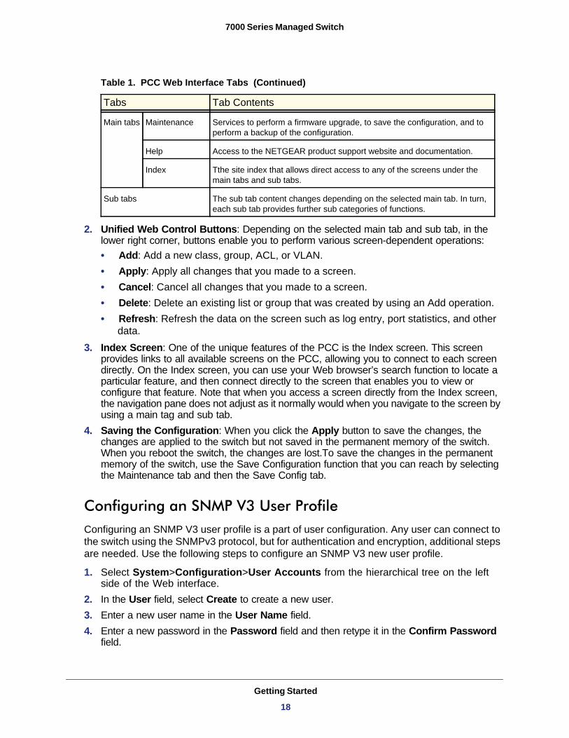
Table 1. PCC Web Interface Tabs
Tabs Tab Contents
Main tabs System Configuration and status information for system features and services such as the timer, DNS server, IP address, and system resource usage.
Switching Features that relate to Layer 2 services such as VLANs, link aggregation, spanning tree protocol, port configuration, and the MAC address table.
Routing Layer 3 services such as VLAN routing, port routing, and protocols such as RIP, OSPF, VRRP, and other protocols.
QoS Quality of Service features such as DiffServ and CoS queue assignment.
Security Security services such as 802.1x port authentication, traffic control with various forwarding controls, and ACLs.
Monitoring Ethernet port statistics, various system logs, and port mirroring.
Getting Started
17
7000 Series Managed Switch
2. Unified Web Control Buttons: Depending on the selected main tab and sub tab, in the lower right corner, buttons enable you to perform various screen-dependent operations:• Add: Add a new class, group, ACL, or VLAN.• Apply: Apply all changes that you made to a screen.• Cancel: Cancel all changes that you made to a screen.• Delete: Delete an existing list or group that was created by using an Add operation.• Refresh: Refresh the data on the screen such as log entry, port statistics, and other
data.3. Index Screen: One of the unique features of the PCC is the Index screen. This screen
provides links to all available screens on the PCC, allowing you to connect to each screen directly. On the Index screen, you can use your Web browser’s search function to locate a particular feature, and then connect directly to the screen that enables you to view or configure that feature. Note that when you access a screen directly from the Index screen, the navigation pane does not adjust as it normally would when you navigate to the screen by using a main tag and sub tab.
4. Saving the Configuration: When you click the Apply button to save the changes, the changes are applied to the switch but not saved in the permanent memory of the switch. When you reboot the switch, the changes are lost.To save the changes in the permanent memory of the switch, use the Save Configuration function that you can reach by selecting the Maintenance tab and then the Save Config tab.
Configuring an SNMP V3 User ProfileConfiguring an SNMP V3 user profile is a part of user configuration. Any user can connect to the switch using the SNMPv3 protocol, but for authentication and encryption, additional steps are needed. Use the following steps to configure an SNMP V3 new user profile.
1. Select System>Configuration>User Accounts from the hierarchical tree on the left side of the Web interface.
2. In the User field, select Create to create a new user.3. Enter a new user name in the User Name field.4. Enter a new password in the Password field and then retype it in the Confirm Password
field.
Main tabs Maintenance Services to perform a firmware upgrade, to save the configuration, and to perform a backup of the configuration.
Help Access to the NETGEAR product support website and documentation.
Index Tthe site index that allows direct access to any of the screens under the main tabs and sub tabs.
Sub tabs The sub tab content changes depending on the selected main tab. In turn, each sub tab provides further sub categories of functions.
Table 1. PCC Web Interface Tabs (Continued)
Tabs Tab Contents
Getting Started
18
7000 Series Managed Switch
Note: If SNMPv3 authentication is to be used for this user, the password must be eight or more alphanumeric characters.
5. If you do not need authentication, go to Step 9.6. To enable authentication, in the Authentication Protocol field select either MD5 or SHA for
the authentication protocol.7. If you do not need encryption, go to Step 9.8. To enable encryption select DES for the encryption scheme in the Encryption Protocol
field. Then, in the Encryption Key field, enter an encryption code of eight or more alphanumeric characters.
9. Click Apply.
Getting Started
19
2
2. Auto Install ConfigurationAuto Install is a software feature that provides for the configuration of a switch automatically when the device is initialized and no configuration file is found on the switch. The downloaded configuration file is not distributed across a stack. When an administrator saves configuration, the config file is distributed across a stack.
The Auto Install process requires DHCP to be enabled by default in order for it to be completed. The downloaded config file is not automatically saved to startup-config. An administrator must explicitly issue a save request in order to save the configuration. The Auto Install process depends on the configuration of other devices in the network, including a DHCP or BOOTP server, a TFTP server and, if necessary, a DNS server.
There are three phases to Auto Install:
1. Configuration or assignment of an IP address for the device.2. Assignment of a TFTP server.3. Obtaining a configuration file for the device from the TFTP server.
Switch IP Address Assignment
If BOOTP or DHCP is enabled on the switch and an IP address has not been assigned, the switch issues requests for an IP address assignment. The behavior of BOOTP or DHCP with respect to IP address assignment is unchanged by the addition of the Auto Install feature. That is, the following information returned from the server is recognized.
• The IP address (yiaddr) and subnet mask (option 1) to be assigned to the switch• The IP address of a default gateway (option 3), if needed for IP communication. Some
network configurations require the specification of a default gateway through which some IP communication can occur. The default gateway is specified by Option 3 of a BOOTP or DHCP response.
After an IP address is assigned to the switch, if a host name is not already assigned, then Auto Install issues a DNS request for the corresponding host name. This host name is also displayed as the CLI prompt the same as if the hostname command was used.
20
7000 Series Managed Switch
TFTP IP Address and the Configuration File Name
The following information is also processed, any of which can be returned by a BOOTP or DHCP server:
• The name of the configuration file (bootfile or option 67) to be downloaded from the TFTP server.
• The identification of the TFTP server from which to obtain the bootfile. This is given by any of the following fields:- The host name of the TFTP server (option 66 or sname). Either the TFTP address or
name is specified, not both, in most network configurations. If a TFTP host name is given, a DNS server is required to translate the name to an IP address.
- The IP address of the TFTP server (option 150).- The address of the TFTP server (siaddr) to be used for Auto Install requests.
No configuration assigned by BOOTP or DHCP is saved in startup-config.
Handling Conflicting TFTP Server Configurations
The TFTP server IP address can be deduced from the multiple sources. It is selected from one of the following fields, listed from the highest priority to the lowest:
• The sname field of a DHCP or BOOTP reply.• The TFTP server name (option 66) of a DHCP reply.• The TFTP server address (option 150) field of a DHCP reply.• The siaddr field of a DHCP or BOOTP reply.
DNS Server Requirements
A DNS server is needed to resolve the IP address of the TFTP server only if the sname or option 66 values are used.
Obtaining a Config File
After obtaining IP addresses for both the switch and the TFTP server, the Auto Install process attempts to download a configuration file. A host-specific configuration file is downloaded, if possible. Otherwise, a network configuration file is used as a bridge to get the final configuration. The methods are described in the following sections.
Host-Specific Configuration FileThe switch attempts to download a host-specific configuration file if a bootfile name was specified by the DHCP or BOOTP server. The switch makes three unicast TFTP requests for
Auto Install Configuration
21
7000 Series Managed Switch
the specified bootfile. If the unicast attempts fail, or if a TFTP server address was not provided, Auto Install process stops. No Broadcast attempts are made.
Note: The bootfile is required to have a file type of *.cfg. The bootfile cannot have the following names: fastpath.cfg, startup-config and hpc_broad.cfg. These are reserved
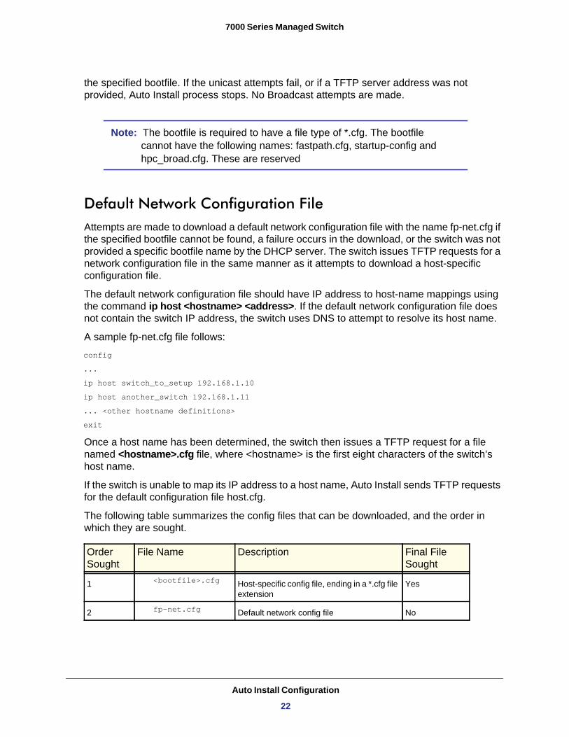
Default Network Configuration FileAttempts are made to download a default network configuration file with the name fp-net.cfg if the specified bootfile cannot be found, a failure occurs in the download, or the switch was not provided a specific bootfile name by the DHCP server. The switch issues TFTP requests for a network configuration file in the same manner as it attempts to download a host-specific configuration file.
The default network configuration file should have IP address to host-name mappings using the command ip host <hostname> <address>. If the default network configuration file does not contain the switch IP address, the switch uses DNS to attempt to resolve its host name.
A sample fp-net.cfg file follows:
config
...
ip host switch_to_setup 192.168.1.10
ip host another_switch 192.168.1.11
... <other hostname definitions>
exit
Once a host name has been determined, the switch then issues a TFTP request for a file named <hostname>.cfg file, where <hostname> is the first eight characters of the switch’s host name.
If the switch is unable to map its IP address to a host name, Auto Install sends TFTP requests for the default configuration file host.cfg.
The following table summarizes the config files that can be downloaded, and the order in which they are sought.
Order Sought
File Name Description Final File Sought
1 <bootfile>.cfg Host-specific config file, ending in a *.cfg file extension
Yes
2 fp-net.cfg Default network config file No
Auto Install Configuration
22
7000 Series Managed Switch
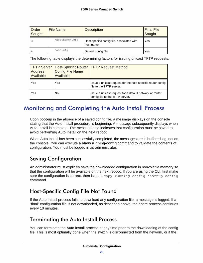
The following table displays the determining factors for issuing unicast TFTP requests.
Monitoring and Completing the Auto Install Process
Upon boot-up in the absence of a saved config file, a message displays on the console stating that the Auto Install procedure is beginning. A message subsequently displays when Auto Install is complete. The message also indicates that configuration must be saved to avoid performing Auto Install on the next reboot.
When Auto Install has been successfully completed, the messages are in buffered log, not on the console. You can execute a show running-config command to validate the contents of configuration. You must be logged in as administrator.
Saving ConfigurationAn administrator must explicitly save the downloaded configuration in nonvolatile memory so that the configuration will be available on the next reboot. If you are using the CLI, first make sure the configuration is correct, then issue a copy running-config startup-config command.
Host-Specific Config File Not FoundIf the Auto Install process fails to download any configuration file, a message is logged. If a “final” configuration file is not downloaded, as described above, the entire process continues every 10 minutes.
Terminating the Auto Install ProcessYou can terminate the Auto Install process at any time prior to the downloading of the config file. This is most optimally done when the switch is disconnected from the network, or if the
3 <hostname>.cfg Host-specific config file, associated with host name
Yes
4 host.cfg Default config file Yes
TFTP Server Address Available
Host-Specific Router Config File Name Available
TFTP Request Method
Yes Yes Issue a unicast request for the host-specific router config file to the TFTP server.
Yes No Issue a unicast request for a default network or router config file to the TFTP server.
Order Sought
File Name Description Final File Sought
Auto Install Configuration
23
7000 Series Managed Switch
requisite configuration files have not been configured on TFTP servers. Termination of the Auto Install process ends further periodic requests for a host-specific file.
Managing Downloaded Config FilesThe configuration files downloaded through Auto Install are stored in the nonvolatile memory. The files can be managed (viewed, displayed, deleted) along with files downloaded through the configuration scripting utility.
A file is not automatically deleted after it is downloaded. However, the file does not take effect upon a reboot. If you opt to save the config file, the saved configuration takes effect upon reboot. If you do not opt to save the config file, the Auto Install process occurs again on a subsequent reboot. This might result in a previously downloaded files being overwritten.
Restarting the Auto Install ProcessThe Auto Install process is automatically started on a subsequent reboot if the configuration file is not found on the switch. This can occur if configuration has not ever been saved on the switch, or if the administrator has issued a command to erase the configuration file.
During a particular session, the Auto Install process can be restarted if the administrator has previously stopped the Auto Install process, and then chooses to restart it. This action re-initiates the process for this login session only. NETGEAR recommends that this action be performed only when the administrator is certain that configuration is clear in order to have predictable results.
Reinitialization of the switch after a clear config automatically activates the Auto Install process if there is no configuration file stored on the switch.
Auto Install Configuration
24
7000 Series Managed Switch
Logging
A message is logged for each of the following events:
• The Auto Install component receiving a config file name and other options upon resolving an IP address by DHCP or BOOTP client. The boot option values are logged.
• The Auto Install component initiating a TFTP request for a boot (config) file, receiving the file, or timing out of that request. File names and server IP addresses and host names are logged.
• The Auto Install component initiating a request for a host name. The IP address and resolved hostname are logged.
• The Auto Install component initiating a TFTP request for a <hostname>.cfg file, receiving the file, or timing out of that request. File names and server IP addresses and host names are logged.
• The beginning of applying a config script.• The failure of the CLI scripting utility to apply a config file.• The completion of AutoInstall.• A conflict in the name of a config file to be downloaded with a reserved config file name.
Auto Install Configuration
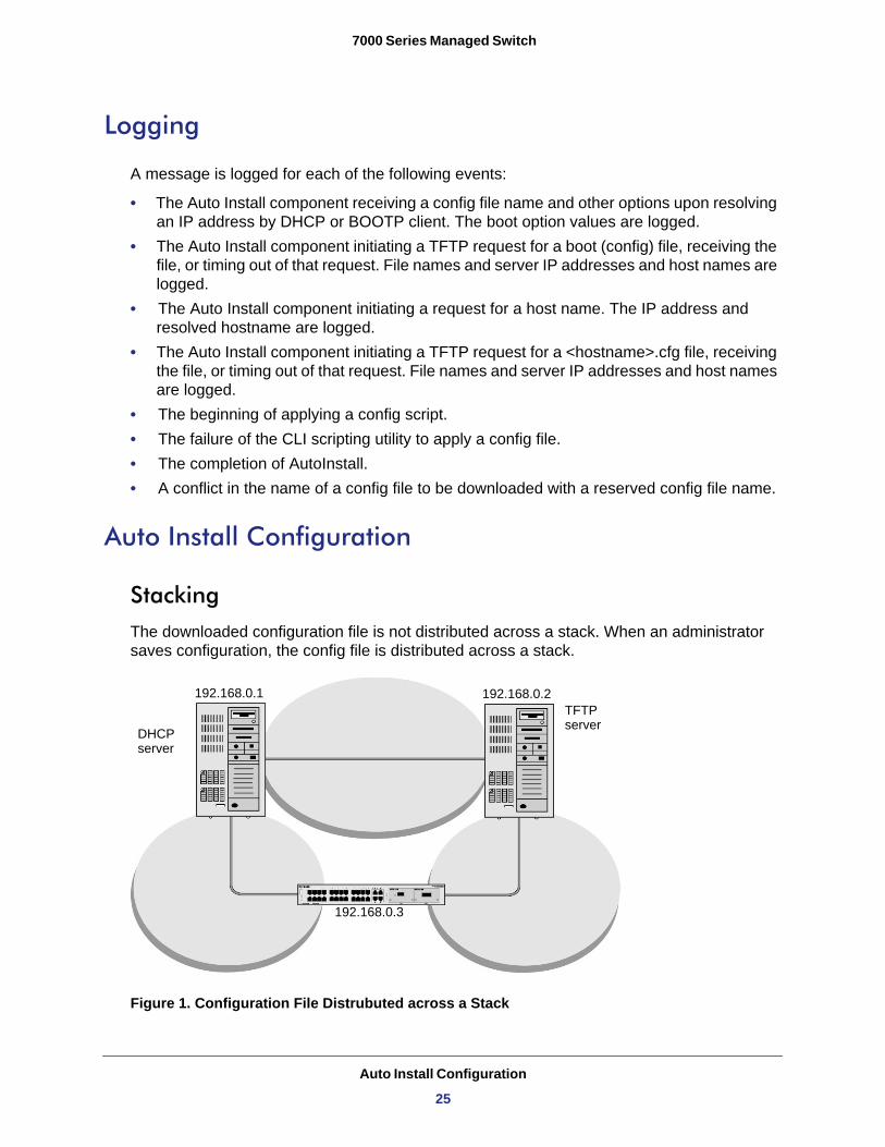
StackingThe downloaded configuration file is not distributed across a stack. When an administrator saves configuration, the config file is distributed across a stack.
Figure 1. Configuration File Distrubuted across a Stack
192.168.0.1 192.168.0.2
192.168.0.3
DHCPserver
TFTPserver
Auto Install Configuration
25
7000 Series Managed Switch
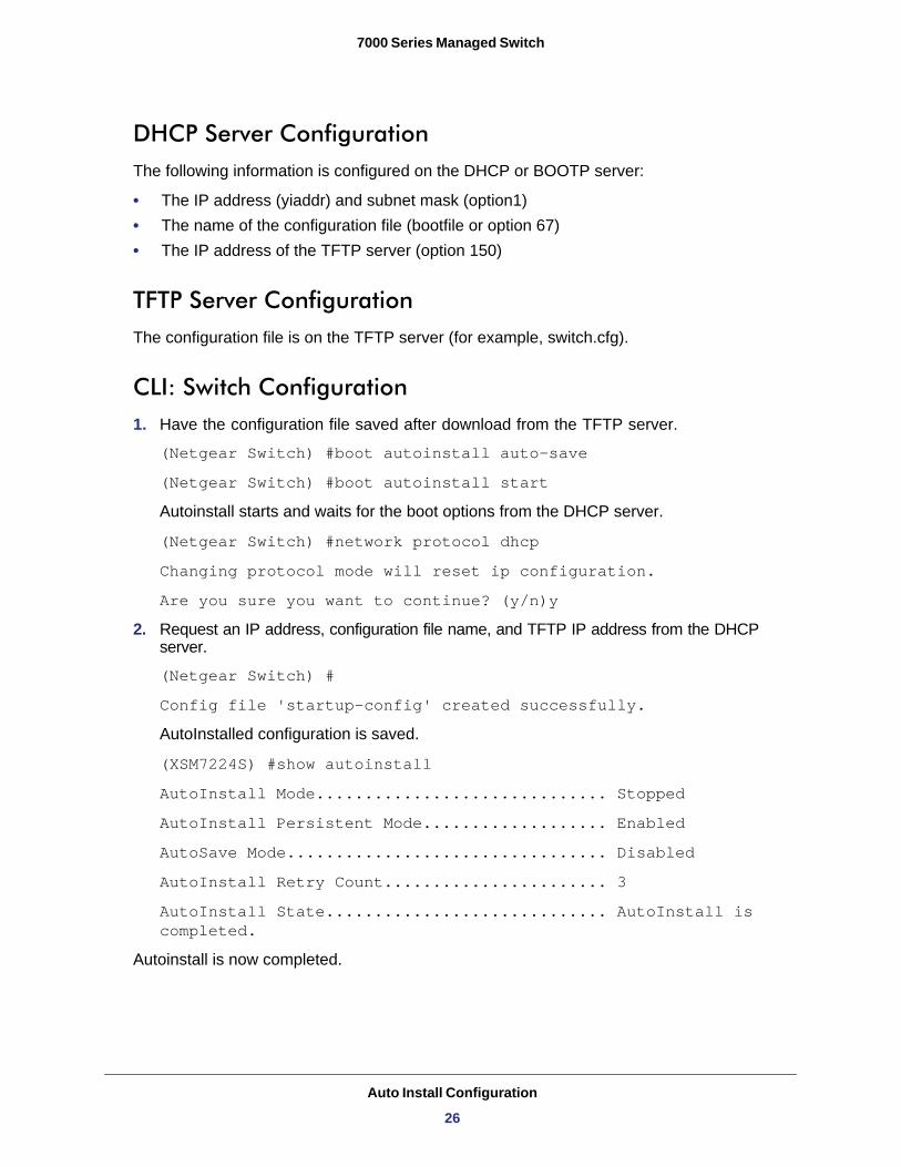
DHCP Server ConfigurationThe following information is configured on the DHCP or BOOTP server:
• The IP address (yiaddr) and subnet mask (option1)• The name of the configuration file (bootfile or option 67)• The IP address of the TFTP server (option 150)
TFTP Server ConfigurationThe configuration file is on the TFTP server (for example, switch.cfg).
CLI: Switch Configuration1. Have the configuration file saved after download from the TFTP server.
(Netgear Switch) #boot autoinstall auto-save
(Netgear Switch) #boot autoinstall start
Autoinstall starts and waits for the boot options from the DHCP server.
(Netgear Switch) #network protocol dhcp
Changing protocol mode will reset ip configuration.
Are you sure you want to continue? (y/n)y
2. Request an IP address, configuration file name, and TFTP IP address from the DHCP server.
(Netgear Switch) #
Config file 'startup-config' created successfully.
AutoInstalled configuration is saved.
(XSM7224S) #show autoinstall
AutoInstall Mode.............................. Stopped
AutoInstall Persistent Mode................... Enabled
AutoSave Mode................................. Disabled
AutoInstall Retry Count....................... 3
AutoInstall State............................. AutoInstall is completed.
Autoinstall is now completed.
Auto Install Configuration
26
7000 Series Managed Switch
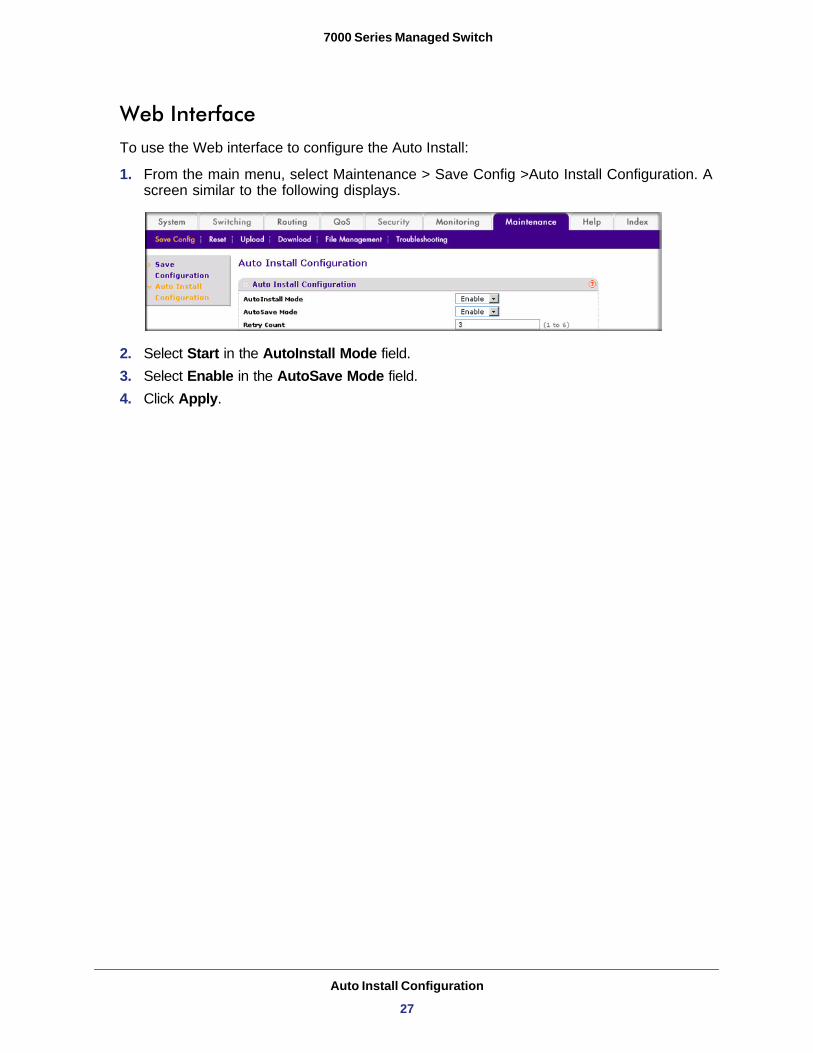
Web InterfaceTo use the Web interface to configure the Auto Install:
1. From the main menu, select Maintenance > Save Config >Auto Install Configuration. A screen similar to the following displays.
2. Select Start in the AutoInstall Mode field.3. Select Enable in the AutoSave Mode field.4. Click Apply.
Auto Install Configuration
27
3
3. Software License ActivationThis chapter describes how to activate software licenses. The products covered in this chapter and the feature the license activates are:
• XSM7224S - IPv4/IPv6 routing and IP multicast routing
Creating an Account at mynetgear
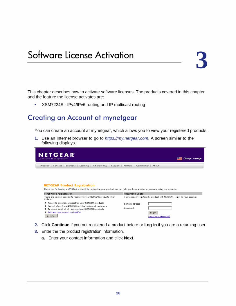
You can create an account at mynetgear, which allows you to view your registered products.
1. Use an Internet browser to go to https://my.netgear.com. A screen similar to the following displays.
2. Click Continue if you not registered a product before or Log in if you are a returning user.3. Enter the the product registration information.
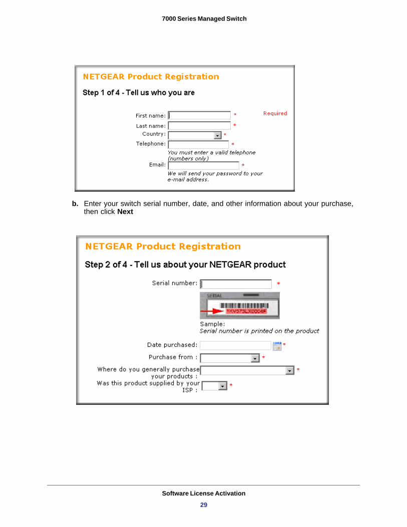
a. Enter your contact information and click Next.
28
7000 Series Managed Switch
b. Enter your switch serial number, date, and other information about your purchase, then click Next
Software License Activation
29
7000 Series Managed Switch
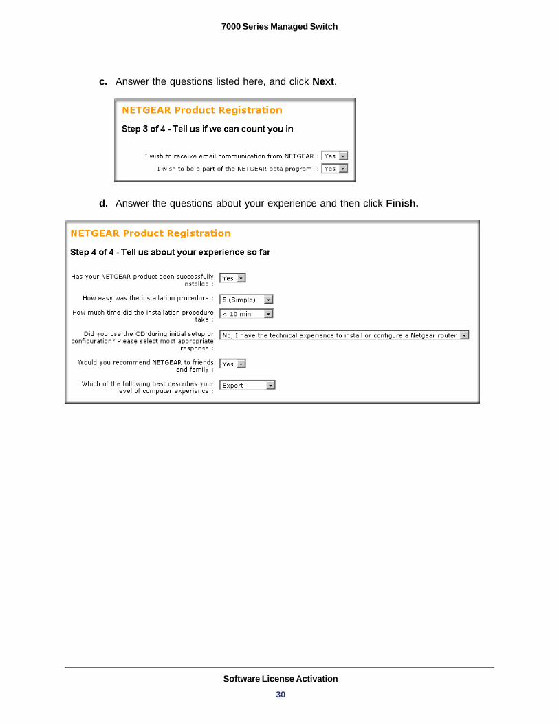
c. Answer the questions listed here, and click Next.
d. Answer the questions about your experience and then click Finish.
Software License Activation
30
7000 Series Managed Switch
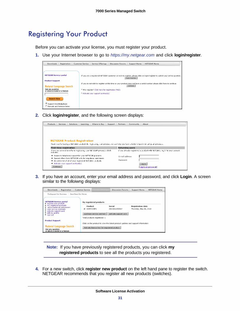
Registering Your Product
Before you can activate your license, you must register your product.
1. Use your Internet browser to go to https://my.netgear.com and click login/register.
2. Click login/register, and the following screen displays:
3. If you have an account, enter your email address and password, and click Login. A screen similar to the folloiwng displays:
Note: If you have previously registered products, you can click my registered products to see all the products you registered.
4. For a new switch, click register new product on the left hand pane to register the switch. NETGEAR recommends that you register all new products (switches).
Software License Activation
31
7000 Series Managed Switch
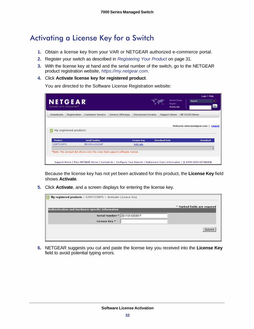
Activating a License Key for a Switch
1. Obtain a license key from your VAR or NETGEAR authorized e-commerce portal.2. Register your switch as described in Registering Your Product on page 31.3. With the license key at hand and the serial number of the switch, go to the NETGEAR
product registration website, https://my.netgear.com. 4. Click Activate license key for registered product.
You are directed to the Software License Registration website:
Because the license key has not yet been activated for this product, the License Key field shows Activate.
5. Click Activate, and a screen displays for entering the license key.
6. NETGEAR suggests you cut and paste the license key you received into the License Key field to avoid potential typing errors.
Software License Activation
32
7000 Series Managed Switch
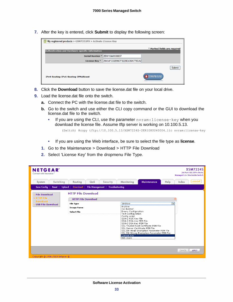
7. After the key is entered, click Submit to display the following screen:
8. Click the Download button to save the license.dat file on your local drive.9. Load the license.dat file onto the switch.
a. Connect the PC with the license.dat file to the switch.b. Go to the switch and use either the CLI copy command or the GUI to download the
license.dat file to the switch. • If you are using the CLI, use the parameter nvram:license-key when you
download the license file. Assume tftp server is working on 10.100.5.13.(Switch) #copy tftp://10.100.5.13/XSM7224S-2ER1080U40004.lic nvram:license-key
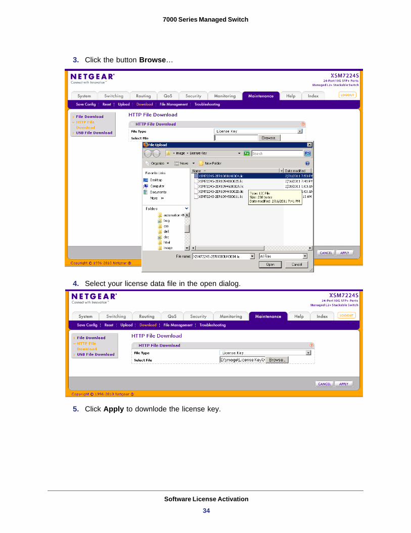
• If you are using the Web interface, be sure to select the file type as license.1. Go to the Maintenance > Download > HTTP File Download2. Select 'License Key' from the dropmenu File Type.
Software License Activation
33
7000 Series Managed Switch
3. Click the button Browse…
4. Select your license data file in the open dialog.
5. Click Apply to downlode the license key.
Software License Activation
34
7000 Series Managed Switch
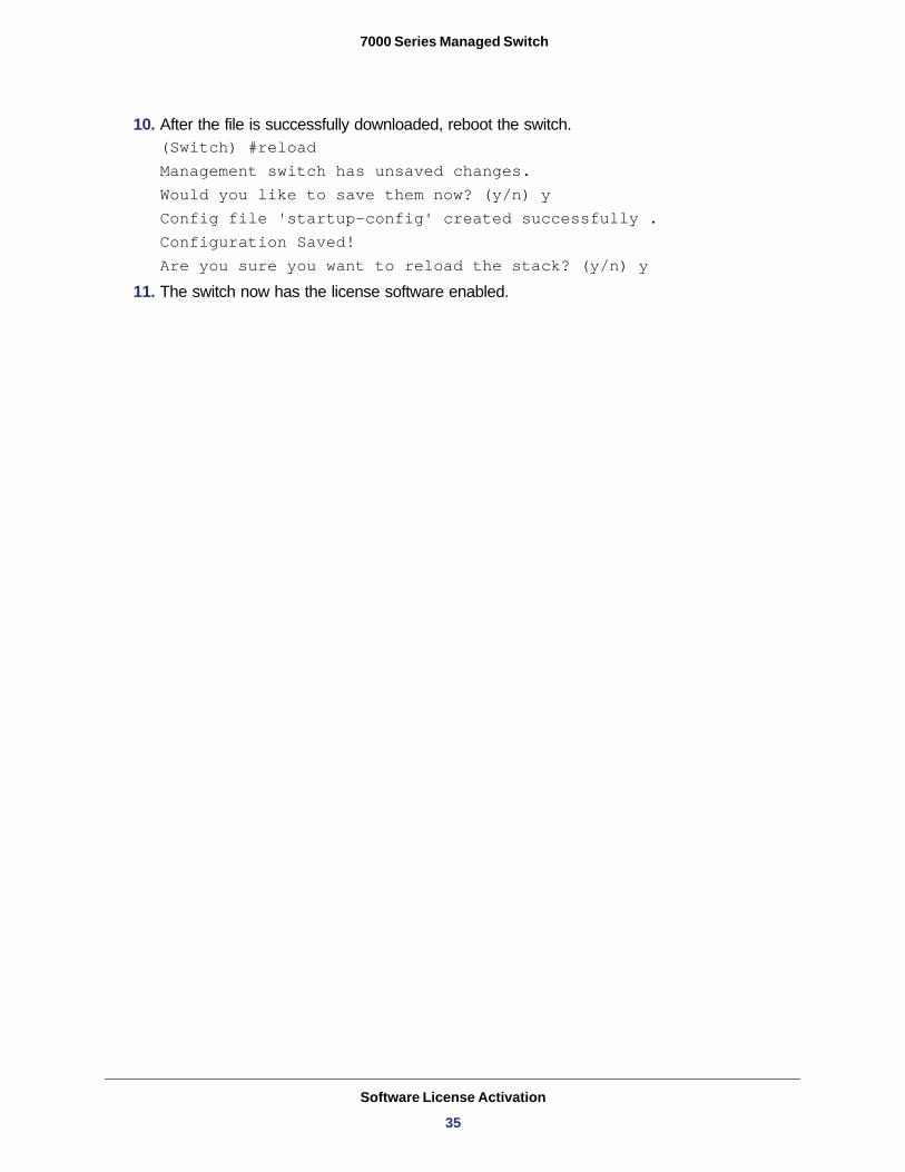
10. After the file is successfully downloaded, reboot the switch. (Switch) #reload Management switch has unsaved changes.Would you like to save them now? (y/n) yConfig file 'startup-config' created successfully .Configuration Saved!Are you sure you want to reload the stack? (y/n) y
11. The switch now has the license software enabled.
Software License Activation
35
Index
Aauto install
logging 25monitoring 23obtaining a config file 21web interface 27
Ccommands, quick start 11connectivity, in-band and out-of-band 5
EEasy Setup Wizard 9Ezconfig 13
Iin-band connectivity 6
BootP 6DHCP 6EIA-232 6
Llogging
auto install 25
Oout-of-band connectivity 7
Ppassword 13
SSNMP V3 user profile 18software installation 10stacking 25switch
Ezconfig 13initial configuration 8
36
IP address 14IP address assignment with auto install 20name 14saving the configuration 15software installation 10
Wweb interface 15
layout 16saving the configuration 18
Related Documents