NOTES 43 Section 2: Design 6. Domestic Water Systems When water is moving in a pipe, two types of flow can exist. One type of flow is known by the various names of streamline, laminar, and viscous. e second type is called turbulent. At various viscosities and temperatures, every pipe size has a certain critical velocity above which turbulent flow occurs and below which laminar flow occurs. is critical velocity occurs within a range of Reynolds numbers of approximately 2,000 to 4,000. Following is the Reynolds formula: Equation 6-1 R = DVP or DV µ γ where R = Reynolds number, dimensionless D = Pipe diameter, ft V = Velocity of flow, feet per second (fps) (average) P = Density of fluid, lb/ft 3 µ = Absolute (dynamic) viscosity, lb-sec/ft 2 γ = Kinematic viscosity, ft 2 /sec Within the limits of accuracy required for plumbing design, it can be assumed that the critical velocity occurs at a Reynolds number of 2,100 for domestic water. In laminar flow, the roughness of the pipe wall has a negligible effect on the flow, but the viscosity has a very significant effect. In turbulent flow, the viscosity has an insignificant effect, but the rough- ness of the pipe wall has a very marked effect on the flow. Very rarely is a velocity of less than 4 fps employed in domestic water piping design. e Reynolds number for a 3-inch pipe with a 4-fps velocity of flow would be: R = 0.25 × 4 × 62.5 = 125,000 0.0005 is is well above the critical range of 2,100. It can be seen that all plumbing design is based on turbulent flow, and only when very viscous liquids or extremely low velocities are encountered does the plumbing engineer deal with laminar flow. Critical velocities of ½-, 1-, and 2-inch pipe at 50°F are 0.676, 0.338, and 0.169 fps respectively, and at 140°F they are 0.247, 0.124, and 0.0617 fps respectively. STATIC HEAD A free surface occurs when the surface of water is exposed to atmospheric pressure. At any point below the free surface, the pressure, or head, is produced by the weight of the water above that point. e pressure is equal and effective in all directions at this point and is pro- portional to the depth below the surface. is pressure is variously called static head, static pressure, hydrostatic head, or hydrostatic pressure. It is the measure of the potential energy. Because pressure is a function of the weight of the water, it is possible to convert the static head expressed as feet of head into pounds per square inch (psi).

Welcome message from author
This document is posted to help you gain knowledge. Please leave a comment to let me know what you think about it! Share it to your friends and learn new things together.
Transcript
NOTES
43
Section 2: Design
6. Domestic Water Systems
When water is moving in a pipe, two types of flow can exist. One type of flow is known by the various names of streamline, laminar, and viscous. The second type is called turbulent. At various viscosities and temperatures, every pipe size has a certain critical velocity above which turbulent flow occurs and below which laminar flow occurs. This critical velocity occurs within a range of Reynolds numbers of approximately 2,000 to 4,000. Following is the Reynolds formula:Equation 6-1
R = DVP or DVµ γ
where R = Reynolds number, dimensionless
D = Pipe diameter, ftV = Velocity of flow, feet per second (fps) (average)
P = Density of fluid, lb/ft3
µ = Absolute (dynamic) viscosity, lb-sec/ft2
γ = Kinematic viscosity, ft2/secWithin the limits of accuracy required for plumbing design, it can be assumed that the
critical velocity occurs at a Reynolds number of 2,100 for domestic water. In laminar flow, the roughness of the pipe wall has a negligible effect on the flow, but the viscosity has a very significant effect. In turbulent flow, the viscosity has an insignificant effect, but the rough-ness of the pipe wall has a very marked effect on the flow.
Very rarely is a velocity of less than 4 fps employed in domestic water piping design. The Reynolds number for a 3-inch pipe with a 4-fps velocity of flow would be:
R = 0.25 × 4 × 62.5 = 125,0000.0005This is well above the critical range of 2,100.It can be seen that all plumbing design is based on turbulent flow, and only when very
viscous liquids or extremely low velocities are encountered does the plumbing engineer deal with laminar flow. Critical velocities of ½-, 1-, and 2-inch pipe at 50°F are 0.676, 0.338, and 0.169 fps respectively, and at 140°F they are 0.247, 0.124, and 0.0617 fps respectively.
Static HeadA free surface occurs when the surface of water is exposed to atmospheric pressure. At any point below the free surface, the pressure, or head, is produced by the weight of the water above that point. The pressure is equal and effective in all directions at this point and is pro-portional to the depth below the surface. This pressure is variously called static head, static pressure, hydrostatic head, or hydrostatic pressure. It is the measure of the potential energy. Because pressure is a function of the weight of the water, it is possible to convert the static head expressed as feet of head into pounds per square inch (psi).
44
CPD Review Manual
NOTES The pressure developed by the weight of a column of water 1 square inch in cross-sec-tional area and “h” feet high may be expressed as:Equation 6-2
p = w x h144where
p = Pressure, psiw = Density of water, lb/ft3
h = Static head, ftAt 50°F, the pressure, expressed in psi, for 1 foot of water column (wc) is then:
p = 62.408 x 1 = 0.433 psi144The height of a column of water at 50°F that will impose a pressure of 1 psi is:
Equation 6-2a
h = p x 144 thus, h = 1 x 144 = 2.31 ftw 62.408To convert from feet of head to psi, multiply the height by 0.433. To convert from psi to
feet of head, multiply the pounds per square inch by 2.31.
Velocity HeadIn a piping system with the water at rest, the water has potential energy. When the water is flowing, it has kinetic energy as well as potential energy. To cause the water to flow, some of the available potential energy must be converted to kinetic energy. The decrease in the potential energy, or static head, is called the velocity head.
When freely falling, a body accelerates via gravity at a rate of 32.2 feet per second per second. The height of the fall and the velocity at any moment may be expressed as:Equation 6-3
h = g t2
2Equation 6-4
V = gt or t= Vg
where t = Time, seconds
g = Gravitational accelera-tion, 32.2 ft/s/s
Substituting t = V/g in the first equation:
h = g x V2
2 g2
Equation 6-5
h = V2
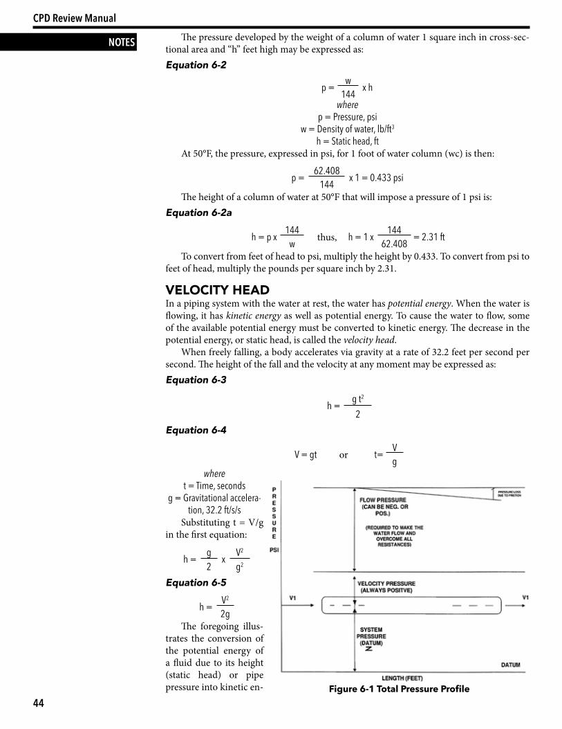
2gThe foregoing illus-
trates the conversion of the potential energy of a fluid due to its height (static head) or pipe pressure into kinetic en- Figure 6-1 Total Pressure Profile
45
Section 2: Design — Chapter 6: Domestic Water Systems
NOTESergy (velocity head). The velocity head, V2/2g, is a measure of the decrease in static or pres-sure head expressed in feet of column of water. (See Figure 6-1.)
Friction HeadWhen water flows in a pipe, friction is produced by the rubbing of water particles against each other and against the walls of the pipe. This friction generates heat, which dissipates in the form of an increase in the temperature of the water and the piping. This temperature rise in plumbing systems is insignificant and can safely be ignored in plumbing design. It requires a potential energy of 778 foot-pounds (ft-lb) to raise 1 pound of water 1°F.
The friction produced by flowing water also causes a pressure loss along the line of flow, which is called friction head. By utilizing Bernoulli’s equation, this friction head loss can be expressed as:Equation 6-6
hF = (Z1 + h1 + V12
) – (Z2 + h2 +V2
2
)2g 2gwhere
hF = Friction head, ft Z = Height of point, ft
h = Static head or height of liquid column, ft V = Velocity at the outlet, fps
g = Gravitational acceleration, 32.2 ft/s/s
Flow in PiPingThe velocity of flow at any point in a system is due to the total energy at that point. This is the sum of the potential and kinetic energies less the friction head loss. The static head is the potential energy, but some of it is converted to kinetic energy to cause flow and some of it is used to overcome friction. It is for these reasons that the pressure during flow is always less than the static pressure. The pressure measured at any point while water is flowing is called the flow, or residual, pressure. This is the pressure that is read on a pressure gauge installed in the piping.
The kinetic energy of water flowing in a piping system is extremely small. Very rarely is the design velocity for water flow in plumbing systems greater than 8 fps. The kinetic energy (velocity head) at this velocity is V2/2g or 82/64.4. This is equal to 1 foot or 0.433 psi, which is less than 0.5 psi. It can be seen that such an insignificant pressure can safely be ignored in all calculations for building systems.
Friction in PiPingWhenever flow occurs, a continuous loss of pressure occurs along the piping in the direc-tion of flow. The amount of this head loss due to friction is affected by:
• The density and temperature of the fluid• The roughness of the pipe• The length of the run• The velocity of the fluidExperiments have demonstrated that the friction head loss is inversely proportional to
the diameter of the pipe and proportional to the roughness and length of the pipe, and it varies approximately with the square of the velocity. Darcy expressed this relationship as:Equation 6-7
h = fLV2 or p = wfLV2
D x 2g 144D x 2gwhere
h = Friction head loss, ftp = Friction head loss, psi
w = Density of the fluid, lb/ft3
46
CPD Review Manual
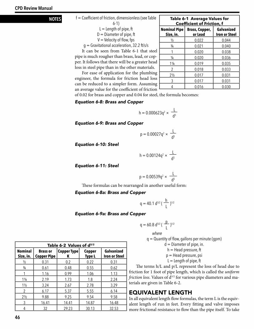
NOTES f = Coefficient of friction, dimensionless (see Table 6-1)
L = Length of pipe, ftD = Diameter of pipe, ftV = Velocity of flow, fps
g = Gravitational acceleration, 32.2 ft/s/sIt can be seen from Table 6-1 that steel
pipe is much rougher than brass, lead, or cop-per. It follows that there will be a greater head loss in steel pipe than in the other materials.
For ease of application for the plumbing engineer, the formula for friction head loss can be reduced to a simpler form. Assuming an average value for the coefficient of friction of 0.02 for brass and copper and 0.04 for steel, the formula becomes:Equation 6-8: Brass and Copper
h = 0.000623q2 × Ld5
Equation 6-9: Brass and Copper
p = 0.00027q2 × Ld5
Equation 6-10: Steel
h = 0.00124q2 × Ld5
Equation 6-11: Steel
p = 0.00539q2 × Ld5
These formulas can be rearranged in another useful form:Equation 6-8a: Brass and Copper
q = 40.1 d5/2 ( h )1/2L
Equation 6-9a: Brass and Copper
q = 60.8 d5/2 ( p )1/2L
where q = Quantity of flow, gallons per minute (gpm)
d = Diameter of pipe, in.h = Head pressure, ft
p = Head pressure, psiL = Length of pipe, ft
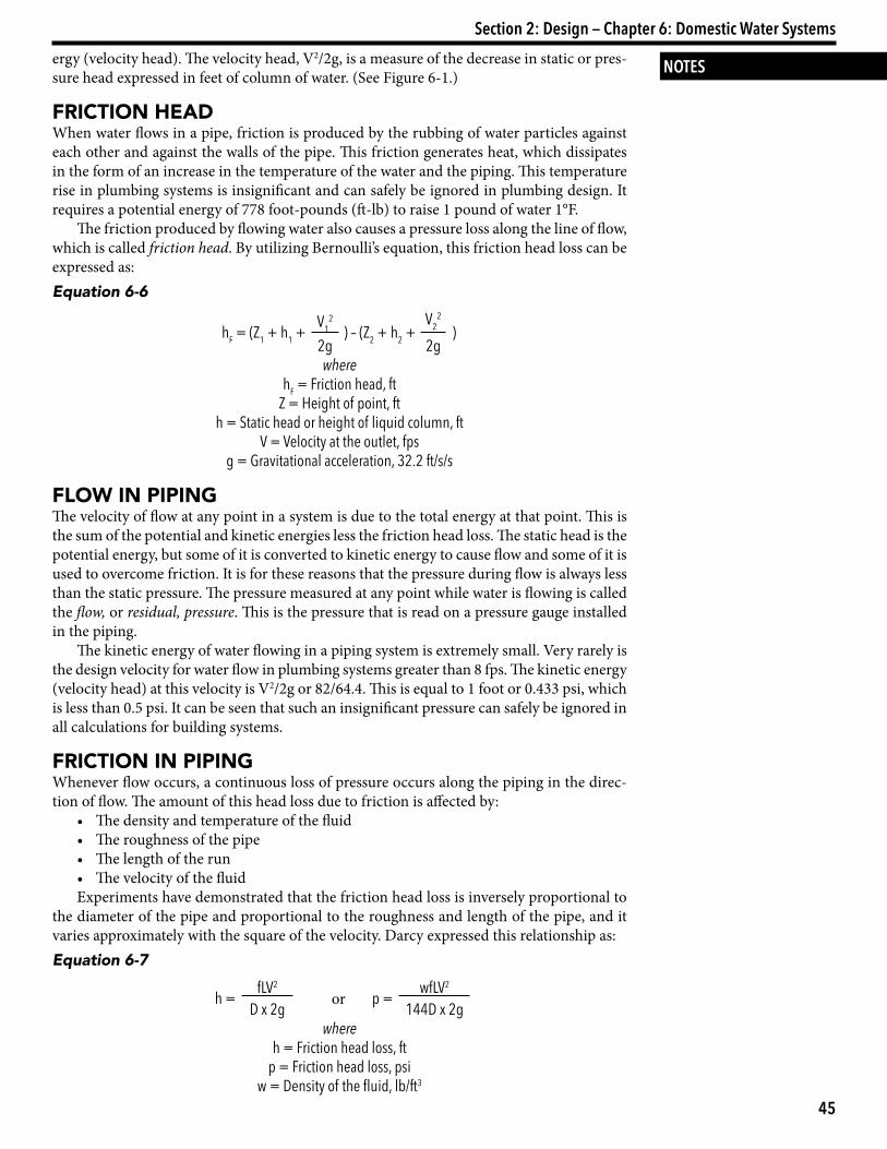
The terms h/L and p/L represent the loss of head due to friction for 1 foot of pipe length, which is called the uniform friction loss. Values of d5/2 for various pipe diameters and ma-terials are given in Table 6-2.
equiValent lengtHIn all equivalent length flow formulas, the term L is the equiv-alent length of run in feet. Every fitting and valve imposes more frictional resistance to flow than the pipe itself. To take
Table 6-2 Values of d5/2
Nominal Size, in.
Brass or Copper Pipe
Copper Type K
Copper Type L
Galvanized Iron or Steel
½ 0.31 0.2 0.22 0.31¾ 0.61 0.48 0.55 0.621 1.16 0.99 1.06 1.13
1¼ 2.19 1.73 1.8 2.241½ 3.24 2.67 2.78 3.292 6.17 5.37 5.55 6.14
2½ 9.88 9.25 9.54 9.583 16.41 14.41 14.87 16.484 32 29.23 30.13 32.53
Table 6-1 Average Values for Coefficient of Friction, f
Nominal Pipe Size, in.
Brass, Copper, or Lead
Galvanized Iron or Steel
½ 0.022 0.044¾ 0.021 0.0401 0.020 0.038¼ 0.020 0.036
1¼ 0.019 0.0352 0.018 0.033
2½ 0.017 0.0313 0.017 0.0314 0.016 0.030
47
Section 2: Design — Chapter 6: Domestic Water Systems
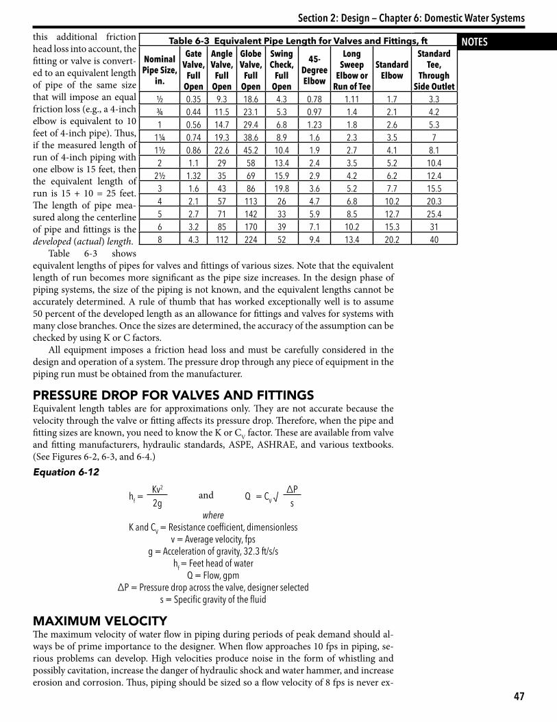
NOTESthis additional friction head loss into account, the fitting or valve is convert-ed to an equivalent length of pipe of the same size that will impose an equal friction loss (e.g., a 4-inch elbow is equivalent to 10 feet of 4-inch pipe). Thus, if the measured length of run of 4-inch piping with one elbow is 15 feet, then the equivalent length of run is 15 + 10 = 25 feet. The length of pipe mea-sured along the centerline of pipe and fittings is the developed (actual) length.
Table 6-3 shows equivalent lengths of pipes for valves and fittings of various sizes. Note that the equivalent length of run becomes more significant as the pipe size increases. In the design phase of piping systems, the size of the piping is not known, and the equivalent lengths cannot be accurately determined. A rule of thumb that has worked exceptionally well is to assume 50 percent of the developed length as an allowance for fittings and valves for systems with many close branches. Once the sizes are determined, the accuracy of the assumption can be checked by using K or C factors.
All equipment imposes a friction head loss and must be carefully considered in the design and operation of a system. The pressure drop through any piece of equipment in the piping run must be obtained from the manufacturer.
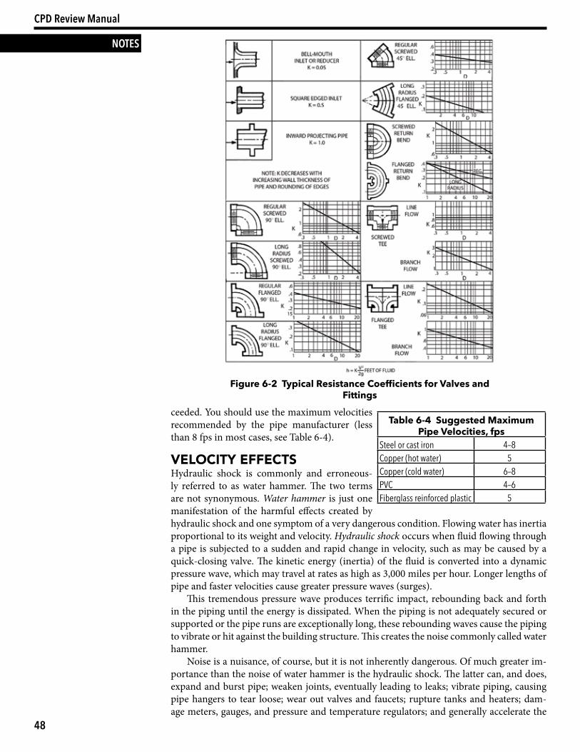
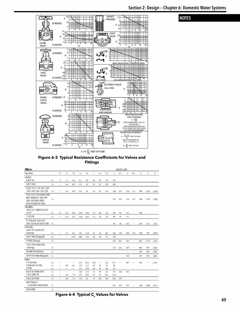
PreSSure droP For ValVeS and FittingSEquivalent length tables are for approximations only. They are not accurate because the velocity through the valve or fitting affects its pressure drop. Therefore, when the pipe and fitting sizes are known, you need to know the K or CV factor. These are available from valve and fitting manufacturers, hydraulic standards, ASPE, ASHRAE, and various textbooks. (See Figures 6-2, 6-3, and 6-4.) Equation 6-12
hf =Kv2
and Q = CV √∆P
2g swhere
K and CV = Resistance coefficient, dimensionlessv = Average velocity, fps
g = Acceleration of gravity, 32.3 ft/s/shf = Feet head of water
Q = Flow, gpm∆P = Pressure drop across the valve, designer selected
s = Specific gravity of the fluid
MaxiMuM VelocityThe maximum velocity of water flow in piping during periods of peak demand should al-ways be of prime importance to the designer. When flow approaches 10 fps in piping, se-rious problems can develop. High velocities produce noise in the form of whistling and possibly cavitation, increase the danger of hydraulic shock and water hammer, and increase erosion and corrosion. Thus, piping should be sized so a flow velocity of 8 fps is never ex-
Table 6-3 Equivalent Pipe Length for Valves and Fittings, ft
Nominal Pipe Size,
in.
Gate Valve,
Full Open
Angle Valve,
Full Open
Globe Valve,
Full Open
Swing Check,
Full Open
45-Degree Elbow
Long Sweep
Elbow or Run of Tee
Standard Elbow
Standard Tee,
Through Side Outlet
½ 0.35 9.3 18.6 4.3 0.78 1.11 1.7 3.3¾ 0.44 11.5 23.1 5.3 0.97 1.4 2.1 4.21 0.56 14.7 29.4 6.8 1.23 1.8 2.6 5.3
1¼ 0.74 19.3 38.6 8.9 1.6 2.3 3.5 71½ 0.86 22.6 45.2 10.4 1.9 2.7 4.1 8.12 1.1 29 58 13.4 2.4 3.5 5.2 10.4
2½ 1.32 35 69 15.9 2.9 4.2 6.2 12.43 1.6 43 86 19.8 3.6 5.2 7.7 15.54 2.1 57 113 26 4.7 6.8 10.2 20.35 2.7 71 142 33 5.9 8.5 12.7 25.46 3.2 85 170 39 7.1 10.2 15.3 318 4.3 112 224 52 9.4 13.4 20.2 40
48
CPD Review Manual
NOTES
ceeded. You should use the maximum velocities recommended by the pipe manufacturer (less than 8 fps in most cases, see Table 6-4).
Velocity eFFectSHydraulic shock is commonly and erroneous-ly referred to as water hammer. The two terms are not synonymous. Water hammer is just one manifestation of the harmful effects created by hydraulic shock and one symptom of a very dangerous condition. Flowing water has inertia proportional to its weight and velocity. Hydraulic shock occurs when fluid flowing through a pipe is subjected to a sudden and rapid change in velocity, such as may be caused by a quick-closing valve. The kinetic energy (inertia) of the fluid is converted into a dynamic pressure wave, which may travel at rates as high as 3,000 miles per hour. Longer lengths of pipe and faster velocities cause greater pressure waves (surges).
This tremendous pressure wave produces terrific impact, rebounding back and forth in the piping until the energy is dissipated. When the piping is not adequately secured or supported or the pipe runs are exceptionally long, these rebounding waves cause the piping to vibrate or hit against the building structure. This creates the noise commonly called water hammer.
Noise is a nuisance, of course, but it is not inherently dangerous. Of much greater im-portance than the noise of water hammer is the hydraulic shock. The latter can, and does, expand and burst pipe; weaken joints, eventually leading to leaks; vibrate piping, causing pipe hangers to tear loose; wear out valves and faucets; rupture tanks and heaters; dam-age meters, gauges, and pressure and temperature regulators; and generally accelerate the
Figure 6-2 Typical Resistance Coefficients for Valves and Fittings
Table 6-4 Suggested Maximum Pipe Velocities, fps
Steel or cast iron 4–8Copper (hot water) 5Copper (cold water) 6–8PVC 4–6Fiberglass reinforced plastic 5
49
Section 2: Design — Chapter 6: Domestic Water Systems
NOTES
Figure 6-3 Typical Resistance Coefficients for Valves and Fittings
Figure 6-4 Typical Cv Values for Valves
50
CPD Review Manual
NOTES deterioration of the entire piping system. The result is costly repair, maintenance, and/or replacement.
Because most straight runs of piping within a building are relatively short and well sup-ported, hydraulic shock generally occurs without any noticeable or alarming noise. Under these conditions, it can virtually destroy a system before the danger is recognized.
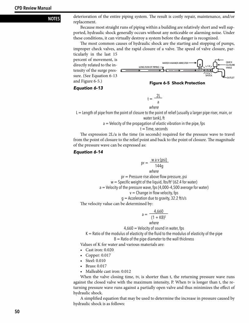
The most common causes of hydraulic shock are the starting and stopping of pumps, improper check valves, and the rapid closure of a valve. The speed of valve closure, par-ticularly in the last 15 percent of movement, is directly related to the in-tensity of the surge pres-sure. (See Equation 6-13 and Figure 6-5.)Equation 6-13
t = 2La
where L = Length of pipe from the point of closure to the point of relief (usually a larger pipe riser, main, or
water tank), fta = Velocity of the propagation of elastic vibration in the pipe, fps
t = Time, secondsThe expression 2L/a is the time (in seconds) required for the pressure wave to travel
from the point of closure to the relief point and back to the point of closure. The magnitude of the pressure wave can be expressed as:Equation 6-14
pr = w a v (psi)144g
where pr = Pressure rise above flow pressure, psi
w = Specific weight of the liquid, lbs/ft3 (62.4 for water)a = Velocity of the pressure wave, fps (4,000–4,500 average for water)
v = Change in flow velocity, fpsg = Acceleration due to gravity, 32.2 ft/s/s
The velocity value can be determined by:
a = 4,660(1 + KB)2
where 4,660 = Velocity of sound in water, fps
K = Ratio of the modulus of elasticity of the fluid to the modulus of elasticity of the pipeB = Ratio of the pipe diameter to the wall thickness
Values of K for water and various materials are:• Cast iron: 0.020 • Copper: 0.017 • Steel: 0.010• Brass: 0.017• Malleable cast iron: 0.012When the valve closing time, tv, is shorter than t, the returning pressure wave runs
against the closed valve with the maximum intensity, P. When tv is longer than t, the re-turning pressure wave runs against a partially open valve and thus minimizes the effect of hydraulic shock.
A simplified equation that may be used to determine the increase in pressure caused by hydraulic shock is as follows:
Figure 6-5 Shock Protection
51
Section 2: Design — Chapter 6: Domestic Water Systems
NOTESEquation 6-15
P = 0.070LVt
where P = Pressure, psiL = Pipe run, ft
V = Velocity, fpst = Time of valve closure, seconds
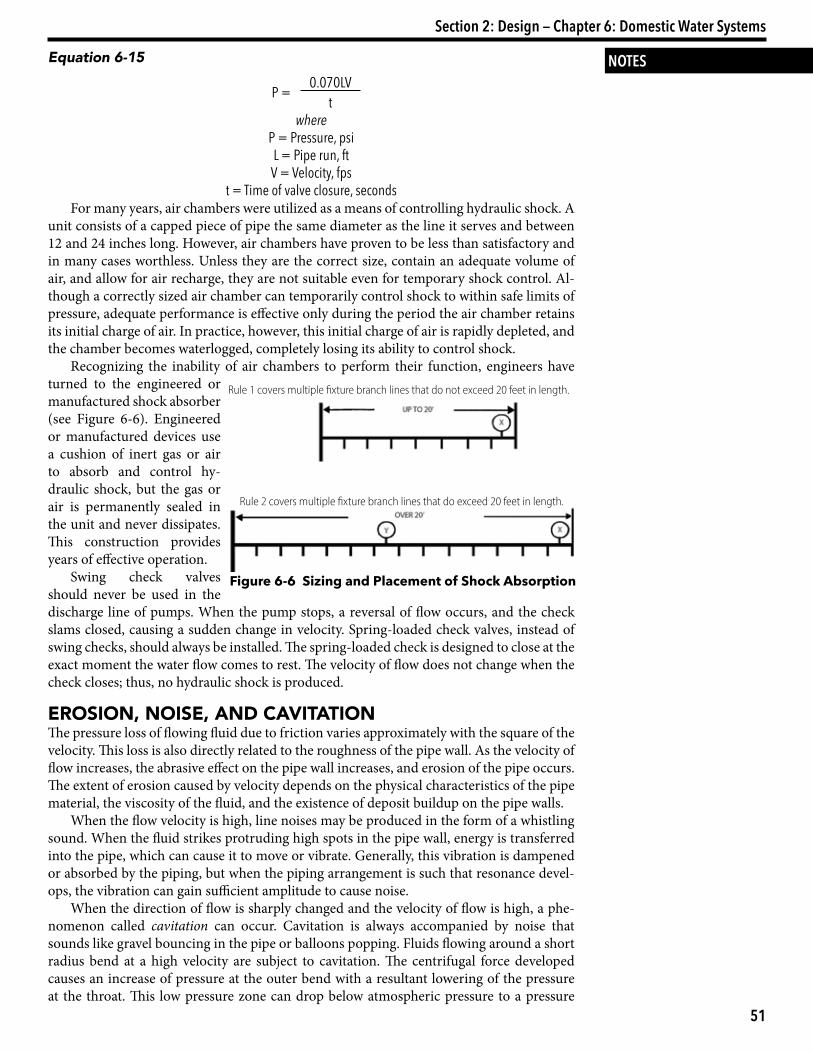
For many years, air chambers were utilized as a means of controlling hydraulic shock. A unit consists of a capped piece of pipe the same diameter as the line it serves and between 12 and 24 inches long. However, air chambers have proven to be less than satisfactory and in many cases worthless. Unless they are the correct size, contain an adequate volume of air, and allow for air recharge, they are not suitable even for temporary shock control. Al-though a correctly sized air chamber can temporarily control shock to within safe limits of pressure, adequate performance is effective only during the period the air chamber retains its initial charge of air. In practice, however, this initial charge of air is rapidly depleted, and the chamber becomes waterlogged, completely losing its ability to control shock.
Recognizing the inability of air chambers to perform their function, engineers have turned to the engineered or manufactured shock absorber (see Figure 6-6). Engineered or manufactured devices use a cushion of inert gas or air to absorb and control hy-draulic shock, but the gas or air is permanently sealed in the unit and never dissipates. This construction provides years of effective operation.
Swing check valves should never be used in the discharge line of pumps. When the pump stops, a reversal of flow occurs, and the check slams closed, causing a sudden change in velocity. Spring-loaded check valves, instead of swing checks, should always be installed. The spring-loaded check is designed to close at the exact moment the water flow comes to rest. The velocity of flow does not change when the check closes; thus, no hydraulic shock is produced.
eroSion, noiSe, and caVitationThe pressure loss of flowing fluid due to friction varies approximately with the square of the velocity. This loss is also directly related to the roughness of the pipe wall. As the velocity of flow increases, the abrasive effect on the pipe wall increases, and erosion of the pipe occurs. The extent of erosion caused by velocity depends on the physical characteristics of the pipe material, the viscosity of the fluid, and the existence of deposit buildup on the pipe walls.
When the flow velocity is high, line noises may be produced in the form of a whistling sound. When the fluid strikes protruding high spots in the pipe wall, energy is transferred into the pipe, which can cause it to move or vibrate. Generally, this vibration is dampened or absorbed by the piping, but when the piping arrangement is such that resonance devel-ops, the vibration can gain sufficient amplitude to cause noise.
When the direction of flow is sharply changed and the velocity of flow is high, a phe-nomenon called cavitation can occur. Cavitation is always accompanied by noise that sounds like gravel bouncing in the pipe or balloons popping. Fluids flowing around a short radius bend at a high velocity are subject to cavitation. The centrifugal force developed causes an increase of pressure at the outer bend with a resultant lowering of the pressure at the throat. This low pressure zone can drop below atmospheric pressure to a pressure
Figure 6-6 Sizing and Placement of Shock Absorption
Rule 1 covers multiple fixture branch lines that do not exceed 20 feet in length.
Rule 2 covers multiple fixture branch lines that do exceed 20 feet in length.
52
CPD Review Manual
NOTES that corresponds with the boiling point of the flow-ing fluid. Under this condition, the cavity that forms at the inside of the bend allows the fluid to flash into vapor or steam bubbles. Once these bubbles flow past the low pressure zone into the normal pressure area downstream, the bubbles collapse. As these bubbles collapse, they literally tear the metal off the pipe, causing pitting. The rapid volumetric changes in bubble formation and collapse cause intense noise effects as well as stresses in the piping.
Cavitation is a very serious problem in pump op-eration as well as in line flow. Cavitation can literally tear a pump apart. Cavitation can also occur at hand valves or control valves.
Most of the noise problems (water hammer, whistling, and cavitation) can be greatly alleviated, if not completely eliminated, by maintaining flow velocities in any part of the pipe system below 8 fps.
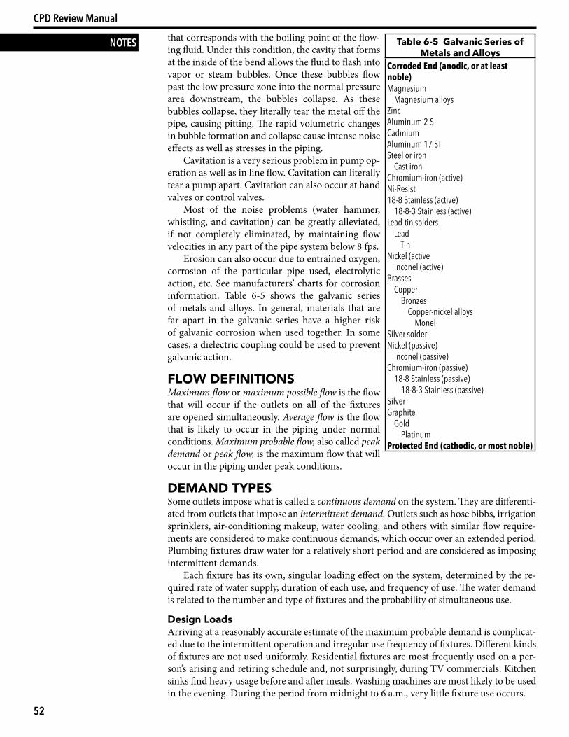
Erosion can also occur due to entrained oxygen, corrosion of the particular pipe used, electrolytic action, etc. See manufacturers’ charts for corrosion information. Table 6-5 shows the galvanic series of metals and alloys. In general, materials that are far apart in the galvanic series have a higher risk of galvanic corrosion when used together. In some cases, a dielectric coupling could be used to prevent galvanic action.
Flow deFinitionSMaximum flow or maximum possible flow is the flow that will occur if the outlets on all of the fixtures are opened simultaneously. Average flow is the flow that is likely to occur in the piping under normal conditions. Maximum probable flow, also called peak demand or peak flow, is the maximum flow that will occur in the piping under peak conditions.
deMand tyPeSSome outlets impose what is called a continuous demand on the system. They are differenti-ated from outlets that impose an intermittent demand. Outlets such as hose bibbs, irrigation sprinklers, air-conditioning makeup, water cooling, and others with similar flow require-ments are considered to make continuous demands, which occur over an extended period. Plumbing fixtures draw water for a relatively short period and are considered as imposing intermittent demands.
Each fixture has its own, singular loading effect on the system, determined by the re-quired rate of water supply, duration of each use, and frequency of use. The water demand is related to the number and type of fixtures and the probability of simultaneous use.
design loadsArriving at a reasonably accurate estimate of the maximum probable demand is complicat-ed due to the intermittent operation and irregular use frequency of fixtures. Different kinds of fixtures are not used uniformly. Residential fixtures are most frequently used on a per-son’s arising and retiring schedule and, not surprisingly, during TV commercials. Kitchen sinks find heavy usage before and after meals. Washing machines are most likely to be used in the evening. During the period from midnight to 6 a.m., very little fixture use occurs.
Table 6-5 Galvanic Series of Metals and Alloys
Corroded End (anodic, or at least noble)Magnesium Magnesium alloysZincAluminum 2 SCadmiumAluminum 17 STSteel or iron Cast ironChromium-iron (active)Ni-Resist18-8 Stainless (active) 18-8-3 Stainless (active)Lead-tin solders Lead TinNickel (active Inconel (active)Brasses Copper Bronzes Copper-nickel alloys MonelSilver solderNickel (passive) Inconel (passive)Chromium-iron (passive) 18-8 Stainless (passive) 18-8-3 Stainless (passive)SilverGraphite Gold PlatinumProtected End (cathodic, or most noble)
53
Section 2: Design — Chapter 6: Domestic Water Systems
NOTESLuckily, fixtures are used intermittently and the total time in operation is relatively small, so it is not necessary to design for the maximum potential load. Maximum flow is therefore of no real interest to the designer. Average flow is also of no concern, for if a sys-tem were designed to meet this criterion it would not satisfy the demand under peak flow conditions. It is therefore necessary to consider only the maximum probable demand (peak demand) imposed by the fixtures on a system.
Two methods of determining peak demand have evolved in the United States that, when used where applicable, have proven to give satisfactory results. They are the empirical meth-od and the method of probability. The empirical method is based on arbitrary decisions arrived at from experience and judgment and is useful only for small groups of fixtures. The method of probability is based on the theory of probabilities and is most accurate for large groups of fixtures.
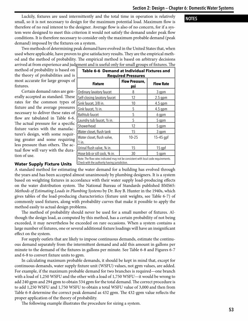
Certain demand rates are gen-erally accepted as standard. These rates for the common types of fixture and the average pressures necessary to deliver these rates of flow are tabulated in Table 6-6. The actual pressure for a specific fixture varies with the manufac-turer’s design, with some requir-ing greater and some requiring less pressure than others. The ac-tual flow will vary with the dura-tion of use.
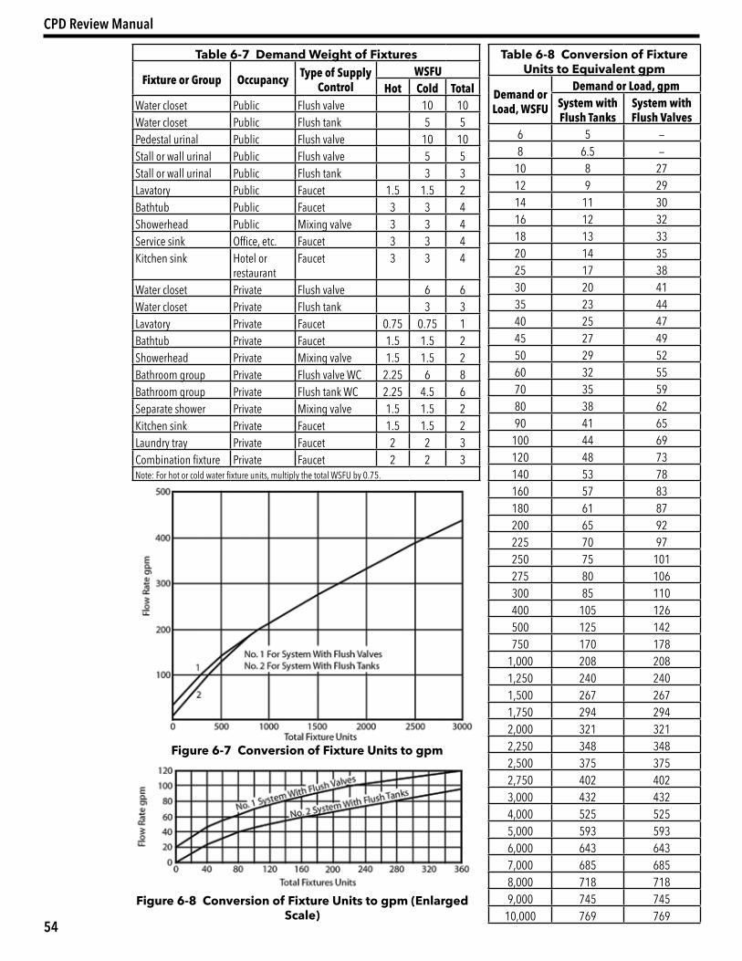
water Supply Fixture unitsA standard method for estimating the water demand for a building has evolved through the years and has been accepted almost unanimously by plumbing designers. It is a system based on weighting fixtures in accordance with their water supply load-producing effects on the water distribution system. The National Bureau of Standards published BMS65: Methods of Estimating Loads in Plumbing Systems by Dr. Roy B. Hunter in the 1940s, which gives tables of the load-producing characteristics (fixture unit weights, see Table 6-7) of commonly used fixtures, along with probability curves that make it possible to apply the method easily to actual design problems.
The method of probability should never be used for a small number of fixtures. Al-though the design load, as computed by this method, has a certain probability of not being exceeded, it may nevertheless be exceeded on rare occasions. When a system contains a large number of fixtures, one or several additional fixture loadings will have an insignificant effect on the system.
For supply outlets that are likely to impose continuous demands, estimate the continu-ous demand separately from the intermittent demand and add this amount in gallons per minute to the demand of the fixtures in gallons per minute. See Table 6-8 and Figures 6-7 and 6-8 to convert fixture units to gpm.
In calculating maximum probable demands, it should be kept in mind that, except for continuous demands, water supply fixture unit (WSFU) values, not gpm values, are added. For example, if the maximum probable demand for two branches is required—one branch with a load of 1,250 WSFU and the other with a load of 1,750 WSFU—it would be wrong to add 240 gpm and 294 gpm to obtain 534 gpm for the total demand. The correct procedure is to add 1,250 WSFU and 1,750 WSFU to obtain a total WSFU value of 3,000 and then from Table 6-8 determine the correct peak demand as 432 gpm. The 432-gpm value reflects the proper application of the theory of probability.
The following example illustrates the procedure for sizing a system.
Table 6-6 Demand at Individual Fixtures and Required Pressures
Fixture Flow Pressure, psi Flow Rate
Ordinary lavatory faucet 8 3 gpmSelf-closing lavatory faucet 12 2.5 gpmSink faucet, 3/8 in. 10 4.5 gpmSink faucet, ½ in. 5 4.5 gpmBathtub faucet 5 6 gpmLaundry tub faucet, ½ in. 5 5 gpmShowerhead 12 5 gpmWater closet, flush tank 15 3 gpmWater closet, flush valve, 1 in.
10–25 15–45 gpf
Urinal flush valve, ¾ in. 15 15 gpfHose bib or sill cock, ¾ in. 30 5 gpmNote: The flow rates indicated may not be consistent with local code requirements. Check with the authority having jurisdiction.
54
CPD Review Manual
Table 6-7 Demand Weight of Fixtures
Fixture or Group Occupancy Type of Supply Control
WSFUHot Cold Total
Water closet Public Flush valve 10 10Water closet Public Flush tank 5 5Pedestal urinal Public Flush valve 10 10Stall or wall urinal Public Flush valve 5 5Stall or wall urinal Public Flush tank 3 3Lavatory Public Faucet 1.5 1.5 2Bathtub Public Faucet 3 3 4Showerhead Public Mixing valve 3 3 4Service sink Office, etc. Faucet 3 3 4Kitchen sink Hotel or
restaurantFaucet 3 3 4
Water closet Private Flush valve 6 6Water closet Private Flush tank 3 3Lavatory Private Faucet 0.75 0.75 1Bathtub Private Faucet 1.5 1.5 2Showerhead Private Mixing valve 1.5 1.5 2Bathroom group Private Flush valve WC 2.25 6 8Bathroom group Private Flush tank WC 2.25 4.5 6Separate shower Private Mixing valve 1.5 1.5 2Kitchen sink Private Faucet 1.5 1.5 2Laundry tray Private Faucet 2 2 3Combination fixture Private Faucet 2 2 3Note: For hot or cold water fixture units, multiply the total WSFU by 0.75.
Table 6-8 Conversion of Fixture Units to Equivalent gpm
Demand or Load, WSFU
Demand or Load, gpmSystem with Flush Tanks
System with Flush Valves
6 5 —8 6.5 —
10 8 2712 9 2914 11 3016 12 3218 13 3320 14 3525 17 3830 20 4135 23 4440 25 4745 27 4950 29 5260 32 5570 35 5980 38 6290 41 65
100 44 69120 48 73140 53 78160 57 83180 61 87200 65 92225 70 97250 75 101275 80 106300 85 110400 105 126500 125 142750 170 178
1,000 208 2081,250 240 2401,500 267 2671,750 294 2942,000 321 3212,250 348 3482,500 375 3752,750 402 4023,000 432 4324,000 525 5255,000 593 5936,000 643 6437,000 685 6858,000 718 7189,000 745 745
10,000 769 769
Figure 6-7 Conversion of Fixture Units to gpm
Figure 6-8 Conversion of Fixture Units to gpm (Enlarged Scale)
55
Section 2: Design — Chapter 6: Domestic Water Systems
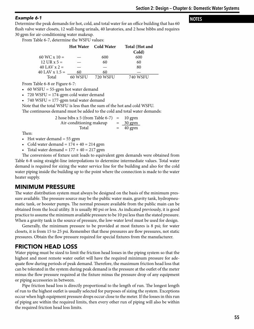
NOTESExample 6-1Determine the peak demands for hot, cold, and total water for an office building that has 60 flush valve water closets, 12 wall-hung urinals, 40 lavatories, and 2 hose bibbs and requires 30 gpm for air-conditioning water makeup.
From Table 6-7, determine the WSFU values:Hot Water Cold Water Total (Hot and
Cold)60 WC x 10 = — 600 60012 UR x 5 = — 60 60
40 LAV x 2 = — — 8040 LAV x 1.5 = 60 60 —
Total 60 WSFU 720 WSFU 740 WSFUFrom Table 6-8 or Figure 6-7:• 60 WSFU = 55-gpm hot water demand• 720 WSFU = 174-gpm cold water demand• 740 WSFU = 177-gpm total water demandNote that the total WSFU is less than the sum of the hot and cold WSFU.The continuous demand must be added to the cold and total water demands:
2 hose bibs x 5 (from Table 6-7) = 10 gpmAir-conditioning makeup = 30 gpm
Total = 40 gpmThen:• Hot water demand = 55 gpm• Cold water demand = 174 + 40 = 214 gpm• Total water demand = 177 + 40 = 217 gpmThe conversions of fixture unit loads to equivalent gpm demands were obtained from
Table 6-8 using straight-line interpolations to determine intermediate values. Total water demand is required for sizing the water service line for the building and also for the cold water piping inside the building up to the point where the connection is made to the water heater supply.
MiniMuM PreSSureThe water distribution system must always be designed on the basis of the minimum pres-sure available. The pressure source may be the public water main, gravity tank, hydropneu-matic tank, or booster pumps. The normal pressure available from the public main can be obtained from the local utility. It is usually 80 psi or less. As indicated previously, it is good practice to assume the minimum available pressure to be 10 psi less than the stated pressure. When a gravity tank is the source of pressure, the low-water level must be used for design.
Generally, the minimum pressure to be provided at most fixtures is 8 psi; for water closets, it is from 15 to 25 psi. Remember that these pressures are flow pressures, not static pressures. Obtain the flow pressure required for special fixtures from the manufacturer.
Friction Head loSSWater piping must be sized to limit the friction head losses in the piping system so that the highest and most remote water outlet will have the required minimum pressure for ade-quate flow during periods of peak demand. Therefore, the maximum friction head loss that can be tolerated in the system during peak demand is the pressure at the outlet of the meter minus the flow pressure required at the fixture minus the pressure drop of any equipment or piping accessories in between.
Pipe friction head loss is directly proportional to the length of run. The longest length of run to the highest outlet is usually selected for purposes of sizing the system. Exceptions occur when high equipment pressure drops occur close to the meter. If the losses in this run of piping are within the required limits, then every other run of piping will also be within the required friction head loss limits.
56
CPD Review Manual
NOTES The selected longest length of run should be sized assuming uniform friction head loss distribution throughout its length for ease of calculation. The permissible uniform friction head loss, in psi per 100 feet, can be found by dividing the total friction head loss available by the equivalent length of run of the longest run and multiplying by 100:
Uniform friction head loss = Total friction head loss × 100Equivalent length of runThe equivalent length of piping is its developed length plus the equivalent lengths of
pipe corresponding to friction head losses for fittings, valves, strainers, etc. When the sizes of fittings and valves are known, their equivalent lengths can be obtained from Table 6-3. When sizing a system where the sizes of fittings and valves are not known, the added fric-tion head losses imposed must be approximated. A general rule of thumb that has proven to be surprisingly accurate is to add 50 percent of the developed length (DL) to allow for all fittings and valves for systems with a lot of close branches. Thus, Equation 6-16
Equivalent length of run = DL+ 0.5 × DL = 1.5 × DL Having established the uniform friction head loss, all that is necessary now is to employ
hydraulic tables to obtain the corresponding rates of flow that will produce that loss for pipes of various sizes and materials.
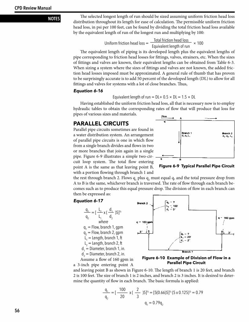
Parallel circuitSParallel pipe circuits sometimes are found in a water distribution system. An arrangement of parallel pipe circuits is one in which flow from a single branch divides and flows in two or more branches that join again in a single pipe. Figure 6-9 illustrates a simple two-cir-cuit loop system. The total flow entering point A is the same as that leaving point B, with a portion flowing through branch 1 and the rest through branch 2. Flows q1 plus q2 must equal q, and the total pressure drop from A to B is the same, whichever branch is traversed. The rate of flow through each branch be-comes such as to produce this equal pressure drop. The division of flow in each branch can then be expressed as:Equation 6-17
q1 = [ L2 x ( d1 )5]½
q2 L1 d2where
q1 = Flow, branch 1, gpmq2 = Flow, branch 2, gpmL1 = Length, branch 1, ftL2 = Length, branch 2, ft
d1 = Diameter, branch 1, in.d2 = Diameter, branch 2, in.
Assume a flow of 160 gpm in a 3-inch pipe entering point A and leaving point B as shown in Figure 6-10. The length of branch 1 is 20 feet, and branch 2 is 100 feet. The size of branch 1 is 2 inches, and branch 2 is 3 inches. It is desired to deter-mine the quantity of flow in each branch. The basic formula is applied:
q1 = [ 100 x ( 2 )5]½ = [5(0.66)5]½ (5 x 0.125)½ = 0.79q2 20 3
q1 = 0.79q2
Figure 6-9 Typical Parallel Pipe Circuit
Figure 6-10 Example of Division of Flow in a Parallel Pipe Circuit
57
Section 2: Design — Chapter 6: Domestic Water Systems
NOTESSince q1 + q2 = 160, then 0.79q2 + q2 = 160, 1.79q2 = 160, q2 = 89.4 gpm, and q1 = 160 – 89.4 = 70.6 gpm or q1 = 0.79 × 89.4 = 70.6 gpm.
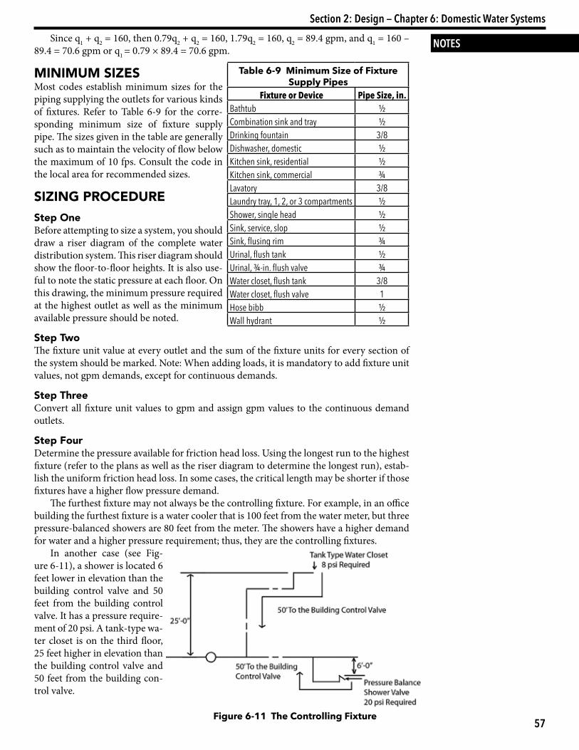
MiniMuM SizeSMost codes establish minimum sizes for the piping supplying the outlets for various kinds of fixtures. Refer to Table 6-9 for the corre-sponding minimum size of fixture supply pipe. The sizes given in the table are generally such as to maintain the velocity of flow below the maximum of 10 fps. Consult the code in the local area for recommended sizes.
Sizing ProcedureStep oneBefore attempting to size a system, you should draw a riser diagram of the complete water distribution system. This riser diagram should show the floor-to-floor heights. It is also use-ful to note the static pressure at each floor. On this drawing, the minimum pressure required at the highest outlet as well as the minimum available pressure should be noted.
Step twoThe fixture unit value at every outlet and the sum of the fixture units for every section of the system should be marked. Note: When adding loads, it is mandatory to add fixture unit values, not gpm demands, except for continuous demands.
Step threeConvert all fixture unit values to gpm and assign gpm values to the continuous demand outlets.
Step FourDetermine the pressure available for friction head loss. Using the longest run to the highest fixture (refer to the plans as well as the riser diagram to determine the longest run), estab-lish the uniform friction head loss. In some cases, the critical length may be shorter if those fixtures have a higher flow pressure demand.
The furthest fixture may not always be the controlling fixture. For example, in an office building the furthest fixture is a water cooler that is 100 feet from the water meter, but three pressure-balanced showers are 80 feet from the meter. The showers have a higher demand for water and a higher pressure requirement; thus, they are the controlling fixtures.
In another case (see Fig-ure 6-11), a shower is located 6 feet lower in elevation than the building control valve and 50 feet from the building control valve. It has a pressure require-ment of 20 psi. A tank-type wa-ter closet is on the third floor, 25 feet higher in elevation than the building control valve and 50 feet from the building con-trol valve.
Figure 6-11 The Controlling Fixture
Table 6-9 Minimum Size of Fixture Supply Pipes
Fixture or Device Pipe Size, in.Bathtub ½Combination sink and tray ½Drinking fountain 3/8Dishwasher, domestic ½Kitchen sink, residential ½Kitchen sink, commercial ¾Lavatory 3/8Laundry tray, 1, 2, or 3 compartments ½Shower, single head ½Sink, service, slop ½Sink, flusing rim ¾Urinal, flush tank ½Urinal, ¾-in. flush valve ¾Water closet, flush tank 3/8Water closet, flush valve 1Hose bibb ½Wall hydrant ½
58
CPD Review Manual
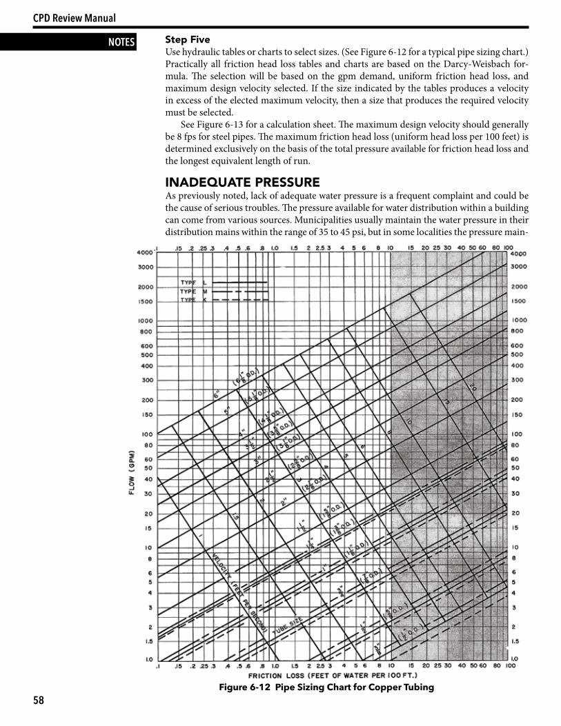
NOTES Step FiveUse hydraulic tables or charts to select sizes. (See Figure 6-12 for a typical pipe sizing chart.) Practically all friction head loss tables and charts are based on the Darcy-Weisbach for-mula. The selection will be based on the gpm demand, uniform friction head loss, and maximum design velocity selected. If the size indicated by the tables produces a velocity in excess of the elected maximum velocity, then a size that produces the required velocity must be selected.
See Figure 6-13 for a calculation sheet. The maximum design velocity should generally be 8 fps for steel pipes. The maximum friction head loss (uniform head loss per 100 feet) is determined exclusively on the basis of the total pressure available for friction head loss and the longest equivalent length of run.
inadequate PreSSureAs previously noted, lack of adequate water pressure is a frequent complaint and could be the cause of serious troubles. The pressure available for water distribution within a building can come from various sources. Municipalities usually maintain the water pressure in their distribution mains within the range of 35 to 45 psi, but in some localities the pressure main-
Figure 6-12 Pipe Sizing Chart for Copper Tubing
59
Section 2: Design — Chapter 6: Domestic Water Systems
NOTES
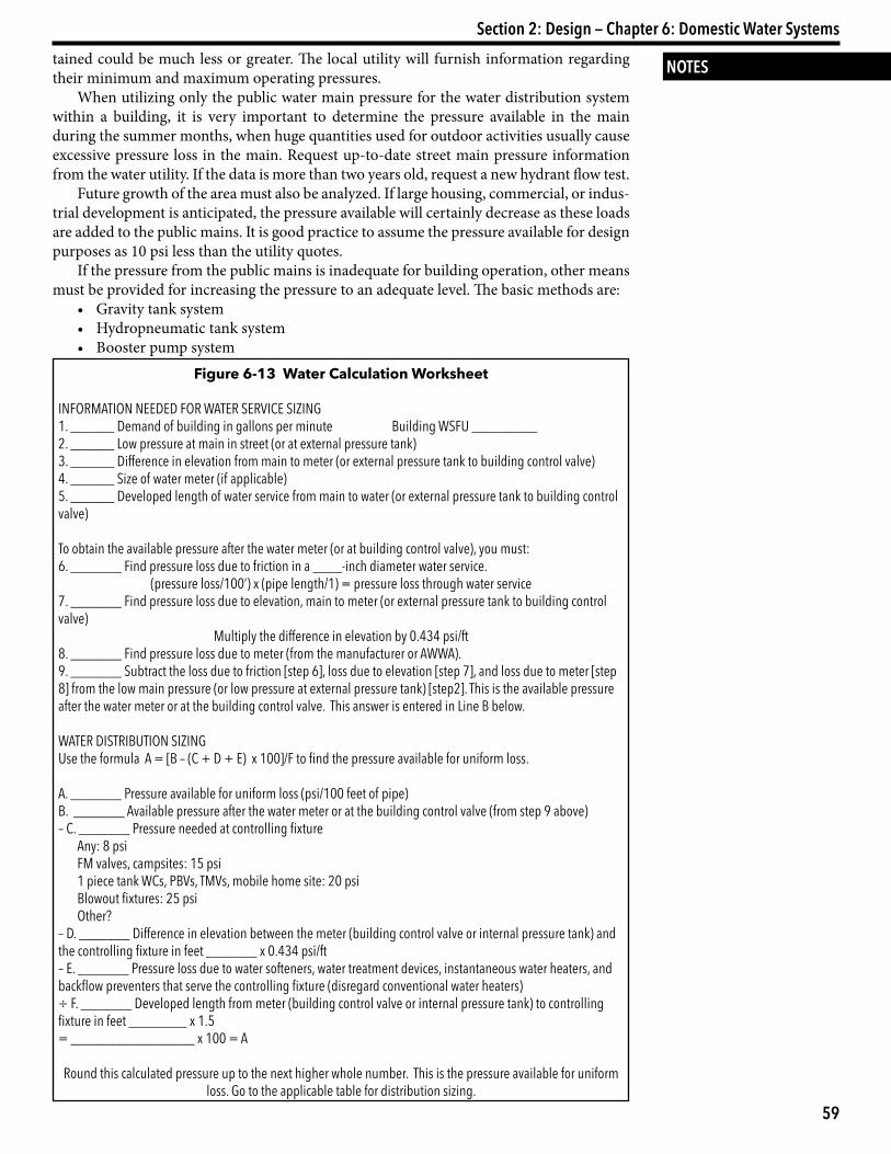
Figure 6-13 Water Calculation Worksheet
INFORMATION NEEDED FOR WATER SERVICE SIZING1. ______ Demand of building in gallons per minute Building WSFU _________2. ______ Low pressure at main in street (or at external pressure tank)3. ______ Difference in elevation from main to meter (or external pressure tank to building control valve)4. ______ Size of water meter (if applicable)5. ______ Developed length of water service from main to water (or external pressure tank to building control valve)
To obtain the available pressure after the water meter (or at building control valve), you must:6. _______ Find pressure loss due to friction in a ____-inch diameter water service.
(pressure loss/100’) x (pipe length/1) = pressure loss through water service7. _______ Find pressure loss due to elevation, main to meter (or external pressure tank to building control valve)
Multiply the difference in elevation by 0.434 psi/ft8. _______ Find pressure loss due to meter (from the manufacturer or AWWA).9. _______ Subtract the loss due to friction [step 6], loss due to elevation [step 7], and loss due to meter [step 8] from the low main pressure (or low pressure at external pressure tank) [step2]. This is the available pressure after the water meter or at the building control valve. This answer is entered in Line B below.
WATER DISTRIBUTION SIZINGUse the formula A = [B – (C + D + E) x 100]/F to find the pressure available for uniform loss.
A. _______ Pressure available for uniform loss (psi/100 feet of pipe)B. _______ Available pressure after the water meter or at the building control valve (from step 9 above)– C. _______ Pressure needed at controlling fixture
Any: 8 psiFM valves, campsites: 15 psi1 piece tank WCs, PBVs, TMVs, mobile home site: 20 psiBlowout fixtures: 25 psiOther?
– D. _______ Difference in elevation between the meter (building control valve or internal pressure tank) and the controlling fixture in feet _______ x 0.434 psi/ft– E. _______ Pressure loss due to water softeners, water treatment devices, instantaneous water heaters, and backflow preventers that serve the controlling fixture (disregard conventional water heaters)÷ F. _______ Developed length from meter (building control valve or internal pressure tank) to controlling fixture in feet ________ x 1.5= _________________ x 100 = A
Round this calculated pressure up to the next higher whole number. This is the pressure available for uniform loss. Go to the applicable table for distribution sizing.
tained could be much less or greater. The local utility will furnish information regarding their minimum and maximum operating pressures.
When utilizing only the public water main pressure for the water distribution system within a building, it is very important to determine the pressure available in the main during the summer months, when huge quantities used for outdoor activities usually cause excessive pressure loss in the main. Request up-to-date street main pressure information from the water utility. If the data is more than two years old, request a new hydrant flow test.
Future growth of the area must also be analyzed. If large housing, commercial, or indus-trial development is anticipated, the pressure available will certainly decrease as these loads are added to the public mains. It is good practice to assume the pressure available for design purposes as 10 psi less than the utility quotes.
If the pressure from the public mains is inadequate for building operation, other means must be provided for increasing the pressure to an adequate level. The basic methods are:
• Gravity tank system • Hydropneumatic tank system • Booster pump system
60
CPD Review Manual
NOTES Each system has its own distinct and special advantages and disadvantages. All three should be evaluated in terms of capital expenditure, operating costs, maintenance costs, and space requirements. The criteria that are the most important will dictate which system is selected.
Hydropneumatic or Booster Pump System The preceding procedure works very well when the street pressure is adequate to supply the requirements of the building or when a gravity tank system is installed. Under these condi-tions, the minimum available pressure is already established; thus, the pressure available for friction head loss can be calculated.
It is an entirely different situation if a hydropneumatic tank or booster pump system is selected to provide the pressure for a water system. The minimum available pressure is no longer a fixed and unchangeable quantity. The pressure available can now be that selected and determined by the designer, and the economic impact of that decision must be evalu-ated.
If the piping system is designed for a high uniform friction head loss, the pipe sizes will be correspondingly smaller than those for a lower uniform pressure loss, but the minimum available pressure must of necessity be higher. Therefore, you are faced with a comparison of initial savings in piping and insulation vs. increased initial costs for pumps as well as increased operating costs.
A design criterion of approximately 4–5 psi per 100 feet for uniform friction head loss generally results in an economically designed system, depending on the length of the pipe run. However, in many specific installations it is far more advantageous to design for much lower or higher pressure drops. Each system must be analyzed and the parameters set in accordance with that analysis.Example 6-2The following example illustrates the procedure for sizing a system with booster pumps as the source of pressure.
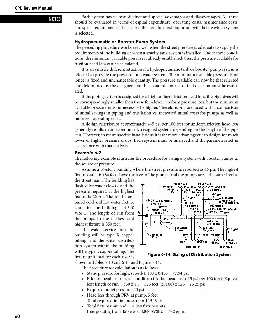
Assume a 16-story building where the street pressure is reported as 45 psi. The highest fixture outlet is 180 feet above the level of the pumps, and the pumps are at the same level as the street main. The building has flush valve water closets, and the pressure required at the highest fixture is 20 psi. The total com-bined cold and hot water fixture count for the building is 4,840 WSFU. The length of run from the pumps to the farthest and highest fixture is 350 feet.
The water service into the building will be type K copper tubing, and the water distribu-tion system within the building will be type L copper tubing. The fixture unit load for each riser is shown in Tables 6-10 and 6-11 and Figure 6-14.
The procedure for calculation is as follows:• Static pressure for highest outlet: 180 x 0.433 = 77.94 psi• Friction head loss (size at a uniform friction head loss of 5 psi per 100 feet): Equiva-
lent length of run = 350 x 1.5 = 525 feet; (5/100) x 525 = 26.25 psi• Required outlet pressure: 20 psi• Head loss through PRV at pump: 5 feet Total required initial pressure = 129.19 psi• Total fixture unit load: = 4,840 fixture units Interpolating from Table 6-8, 4,840 WSFU = 582 gpm.
Figure 6-14 Sizing of Distribution System
61
Section 2: Design — Chapter 6: Domestic Water Systems
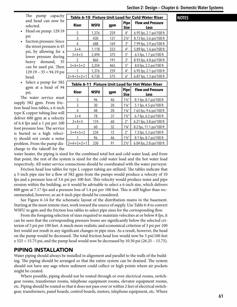
NOTES The pump capacity and head can now be selected.
• Head on pump: 129.19 psi
• Suction pressure: Since the street pressure is 45 psi, by allowing for a lower pressure during heavy demand, 35 can be used psi. Then 129.19 – 35 = 94.19 psi head.
• Select a pump for 582 gpm at a head of 94 psi.
The water service must supply 582 gpm. From fric-tion head loss tables, a 6-inch type K copper tubing line will deliver 600 gpm at a velocity of 6.4 fps and a 1 psi per 100 foot pressure loss. The service is buried so a high veloci-ty should not create a noise problem. From the pump dis-charge to the takeoff for the water heater, the piping is sized for the combined total hot and cold water load, and from that point, the rest of the system is sized for the cold water load and the hot water load respectively. All water service connections should be coordinated with the water purveyor.
Friction head loss tables for type L copper tubing are utilized. The tables indicate that a 5-inch pipe size for a flow of 582 gpm from the pumps would produce a velocity of 10 fps and a pressure loss of 3.6 psi per 100 feet. This velocity would produce noise and pipe erosion within the building, so it would be advisable to select a 6-inch size, which delivers 600 gpm at 7.17 fps and a pressure loss of 1.4 psi per 100 feet. This is still higher than rec-ommended, however, so an 8-inch pipe should be considered.
See Figure 6-14 for the schematic layout of the distribution mains in the basement. Starting at the most remote riser, work toward the source of supply. Use Table 6-8 to convert WSFU to gpm and the friction loss tables to select pipe sizes for the corresponding flow.
From the foregoing selection of sizes required to maintain velocities at or below 8 fps, it can be seen that the corresponding pressure losses are significantly below the selected cri-terion of 5 psi per 100 feet. A much more realistic and economical criterion of 3 psi per 100 feet would not result in any significant changes in pipe sizes. As a result, however, the head on the pump would be decreased. The total friction head loss would now be 3 psi/100 feet x 525 = 15.75 psi, and the pump head would now be decreased by 10.50 psi (26.25 – 15.75).
PiPing inStallationWater piping should always be installed in alignment and parallel to the walls of the build-ing. The piping should be arranged so that the entire system can be drained. The system should not have any sags where sediment could collect or high points where air pockets might be created.
Where possible, piping should not be routed through or over electrical rooms, switch-gear rooms, transformer rooms, telephone equipment rooms, elevator equipment rooms, etc. Piping should be routed so that it does not pass over or within 2 feet of electrical switch-gear, transformers, panel boards, control boards, motors, telephone equipment, etc. Where
Table 6-10 Fixture Unit Load for Cold Water Riser
Riser WSFU gpm Pipe Size
Flow and Pressure Loss
5 1,376 259 4” 6.95 fps, 2.1 psi/100 ft3 430 131 2½” 8.73 fps, 5.6 psi/100 ft4 688 169 3” 7.99 fps, 3.9 psi/100 ft
3+4 1,118 223 4” 5.89 fps, 1.6 psi/100 ft3+4+5 2,494 375 5” 6.5 fps, 1.7 psi/100 ft
2 860 191 3” 8.93 fps, 4.8 psi/100 ft3+4+5+2 3,354 465 5” 8.0 fps, 2.2 psi/100 ft
1 1,376 259 4” 6.95 fps, 2.1 psi/100 ft3+4+5+2+1 4,730 575 6” 6.87 fps, 1.3 psi/100 ft
Table 6-11 Fixture Unit Load for Hot Water Riser
Riser WSFU gpm Pipe Size
Flow and Pressure Loss
5 96 46 1½” 8.1 fps, 8.7 psi/100 ft3 30 20 1¼” 5.1 fps, 4.5 psi/100 ft4 48 28 1¼” 7.65 fps, 9.6 psi/100 ft
3+4 78 37 1½” 6.7 fps, 6.2 psi/100 ft3+4+5 174 60 2” 6.21 fps, 3.8 psi/100 ft
2 60 32 1¼” 8.2 fps, 11.1 psi/100 ft3+4+5+2 234 72 2” 7.3 fps, 5.3 psi/100 ft
1 96 46 1½” 8.1 fps, 8.7 psi/100 ft3+4+5+2+1 330 91 2½” 6.04 fps, 2.8 psi/100 ft
62
CPD Review Manual
NOTES it is impossible to comply with the foregoing, provide a continuous pan, below the piping, that is adequately supported, braced, rimmed, pitched, and drained by a ¾-inch line piped to the nearest floor drain or slop sink.
Piping should be protected where there is danger of external corrosion (such as occurs when it is buried in corrosive soils, floor fill, or concrete) by applying a heavy coating of black asphaltum paint or bitumastic tape or by placing it in a concrete pipe. Select corro-sion-resistant pipe if it is underground.
Mains, risers, and branch connections to risers should be arranged to allow expansion and contraction without strain by means of elbow swings or expansion joints. Provide ade-quate valving to allow sectional isolations.
All horizontal and vertical piping shall be properly supported by means of hangers, anchors, and guides. Supports should be arranged to prevent excessive deflection and ex-cessive bending stresses between supports. Anchored points should be located and con-structed to allow the piping to expand and contract freely in opposite directions away from the anchored points. Guide points should be located and constructed at each side of an expansion joint or loop so only free axial movement occurs without lateral displacement. Hanger lengths (from the structure to the top of the hanger) should not exceed 12 inches, or seismic restraints will be required. Hangers should be of a material compatible with the pipe.
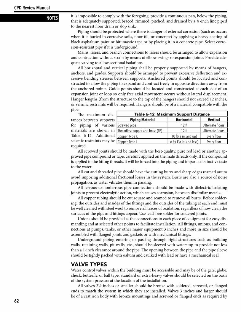
The maximum dis-tances between supports for piping of various materials are shown in Table 6-12. Additional seismic restraints may be required.
All screwed joints should be made with the best-quality, pure red lead or another ap-proved pipe compound or tape, carefully applied on the male threads only. If the compound is applied to the fitting threads, it will be forced into the piping and impart a distinctive taste to the water.
All cut and threaded pipe should have the cutting burrs and sharp edges reamed out to avoid imposing additional frictional losses in the system. Burrs are also a source of noise propagation, as water vibrates them in passing.
All ferrous-to-nonferrous pipe connections should be made with dielectric isolating joints to prevent electrolytic action, which causes corrosion, between dissimilar metals.
All copper tubing should be cut square and reamed to remove all burrs. Before solder-ing, the outsides and insides of the fittings and the outsides of the tubing at each end must be well cleaned with steel wool to remove all traces of oxidation, regardless of how clean the surfaces of the pipe and fittings appear. Use lead-free solder for soldered joints.
Unions should be provided at the connections to each piece of equipment for easy dis-mantling and at selected other points to facilitate installation. All fittings, unions, and con-nections at pumps, tanks, or other major equipment 3 inches and more in size should be assembled with flanged joints and gaskets or with mechanical fittings.
Underground piping entering or passing through rigid structures such as building walls, retaining walls, pit walls, etc., should be sleeved with waterstop to provide not less than a 1-inch clearance around the pipe. The opening between the pipe and the pipe sleeve should be tightly packed with oakum and caulked with lead or have a mechanical seal.
ValVe tyPeSWater control valves within the building must be accessible and may be of the gate, globe, check, butterfly, or ball type. Standard or extra-heavy valves should be selected on the basis of the system pressure at the location of the installation.
All valves 2½ inches or smaller should be bronze with soldered, screwed, or flanged ends to match the system in which they are installed. Valves 3 inches and larger should be of a cast iron body with bronze mountings and screwed or flanged ends as required by
Table 6-12 Maximum Support DistancePiping Material Horizontal Vertical
Screwed pipe 12 ft Alternate floorsThreadless copper and brass (TP) 12 ft Alternate floorsCopper, Type K 10 ft (2 in. and up) Every floorCopper, Type L 6 ft (1½ in. and less) Every floor
63
Section 2: Design — Chapter 6: Domestic Water Systems
NOTESthe system in which they are installed. Valves 3 inches and larger located at pumps, tanks, and major equipment should be of the flanged outside-screw-and-yoke type. Plug cocks or globe valves should be used for water-balancing purposes in the hot water circulating piping system. Check valves should be of the horizontal swing type, except in the discharge piping of pumps, where they should be the spring-loaded, silent check type of the required pressure rating to prevent excessive water hammer problems.
Water service lines should be equipped with a gate valve or ground-key stopcock, as ap-propriate, near the curb line between the property line and the curb line. A curb box frame and cover, including extension enclosure, or a box of the required depth should be provided to enclose and protect the water service valve operating mechanism. The type of valve, curb box, and location should always be coordinated with the local water company or municipal department. The curb valve and valve box should never be located under a driveway, where they may be subjected to heavy concentrated loads, which could result in damage. In addi-tion to the curb valve, a valve should be installed in the line inside the building as close to the point of entry as possible.
An accessible riser control valve should be provided for each riser. In addition, an all-brass drain valve should be installed on each riser and located upstream of the riser control valve to provide a means of draining the riser. The drain valve should be at least ¾ inch in size and should have a hose end. Drain valves should also be provided at all low points of the piping system.
Each floor, zone, or section of the distribution system as well as each group of fixtures should be provided with a shutoff valve, with stop valves at every fixture.
Whether a valve should be installed in any particular location should be evaluated on the basis of ease of maintenance of the water system and the costs for maintenance if the valve is not installed in the particular location being considered. Being overly frugal in the installation of valves often proves to be false economy.
All valves, check valves, pressure-reducing valves, shock absorbers, tempering valves, etc., should always be easily accessible for maintenance or removal. Where valves are in soldered, brazed, or welded piping systems, unions should be provided for ease of removal or replacement. They should always be exposed where possible, and where concealed, an access door of adequate size should be provided.
Strainers should always be provided in the inlet lines to all temperature-regulating, pressure-regulating, automatic-modulating, or open-and-shut control valves. The strainers should generally be of the Y type, full pipe size, and fitted with a blowoff gate or ball valve.
teStSAll water piping in a building should be subjected to a water test to ensure a watertight sys-tem. Any leaks or defects discovered must be corrected. The testing of the piping should be performed before any insulation is applied to the piping and before any part of the system is covered or concealed. Potable water should be used for the test so any possible contam-inants are not introduced into the system. The test should be performed before fixtures, faucets, trim, or final connections are made to equipment. (Check the local code for any deviations from the test procedures listed below.)
The rough piping installation should be subjected to a hydrostatic pressure of 1.5 times the working pressure of the system, but in no case less than 125 psi. The test should extend over a period of at least three hours and demonstrate water tightness without any loss of pressure.
When the system has been completely installed—including all fixtures, faucets, trim, hose connections, and final connections to all equipment—the entire system should be placed in operating condition and thoroughly checked for leaks. All valves, faucets, and trim should be operated and adjusted for maximum efficient performance.
diSinFectionAlthough the utmost caution may be exercised in the installation of piping, some form of contamination may have been introduced into the system, so all drinking water supply
64
CPD Review Manual
NOTES systems shall be thoroughly disinfected and the water proven safe for human consumption. Disinfection should be performed in accordance with local code or health department reg-ulations.
The following is written in the form of a specification for the disinfection of a water system. (Check the local code for any deviations from the industry standard procedures listed below.)
Sample SpecificationGeneral
1. Before being placed in service, all potable water piping shall be chlorinated as speci-fied herein, in accordance with AWWA C601: Standard for Disinfecting Water Mains, and as required by the local building and health department codes.
2. Chlorine may be applied by the use of a chlorine gas/water mixture, a direct chlorine gas feed, or a mixture of calcium hypochlorite and water. If calcium hypochlorite is used, it shall be comparable to commercial products. The powder shall be mixed with water to form a paste thinned to a slurry and pumped or injected into the lines as specified below.
3. If a direct chlorine gas feed is used, it shall be fed either with a solution feed chlorina-tor or by a pressure-feed chlorinator or by a pressure-feed chlorinator with a diffuser in the pipe.
Procedure1. Prior to chlorination, all dirt and foreign matter shall be removed by a thorough
flushing of the potable water system. The chlorinating agent may be applied to the piping systems at any convenient point. Water shall be fed slowly into the potable wa-ter system and the chlorine applied in amounts to produce a dosage of 50 parts per million of available chlorine. Retention shall be for a period of eight hours. During the chlorination process, all valves and accessories shall be operated.
2. After completion of the above requirements, the system shall be flushed until the water in the system gives chemical and bacteriological tests equal to those of the permanent potable water supply.
3. Chemical and bacteriological tests shall be conducted by a state-certified laboratory and approved by the local authorities having jurisdiction. Copies of the tests shall be submitted to the owner, architect, and all governing authorities.
4. Warning signs shall be provided at all outlets while the system is being chlorinated.5. If it is impossible to disinfect the potable water storage tank as provided above, the
entire interior of the tank shall be swabbed with a solution containing 200 parts per million of available chlorine and the solution allowed to stand two hours before flushing and returning to service.
Related Documents