Ultrasonic Tomography Using Lamb Wave Propagation Parameters Antonio BALVANTIN 1 , Arturo BALTAZAR 2 1,2 Robotics and Advanced Manufacturing Program, CINVESTAV-Unidad Saltillo, Carretera Saltillo-Monterrey Km 13.5 Ramos Arizpe, Coah, 25900, México Phone/Fax: +52-844-439-0305 e-mail: 1 [email protected] ; 2 [email protected] Abstract Tomography refers to the cross-sectional imagining of an object from either transmission or reflection data collected by illuminating the object from different directions. In this work, an ultrasonic tomography system based on Lamb waves, developed in our laboratory, is presented. We discuss the inverse problem of tomography imaging using data collected from ultrasonic plate waves interacting with a discontinuity. Here the main focus is on improving the quality of tomography maps using two reconstruction techniques (backprojection and MART). Results of experiments for defect reconstruction on a thin plate are presented. It was found that MART can provide a better reconstruction image than the backprojection technique, with minimal distortion, of a two-step circular discontinuity embedded in an aluminum plate. Keywords: Ultrasonic Lamb waves; tomography; defects; time-frequency representation. 1. Introduction Defect detection and characterization are critical tasks for structural health monitoring of engineering structures. Physical aging during routine operation inflicts deterioration and generates hidden internal and/or superficial defects in these structures. Typically, real time monitoring of engineering structures requires scanning large areas in a short period of time. Lamb waves have the ability to propagate long distances in plates and pipe-like structures, offering a potential solution to defect detection in these types of structures [1]. Several approaches have been proposed to achieve tomography reconstruction on different types of structures. Leonard, et. al. [2], discuss the use of a square perimeter array of transducers to achieve tomography reconstruction of aircraft structures. Malyarenko & Hinders [3] present a methodology for tomography reconstruction with ray bending correction for imaging of objects with moderate ultrasonic scattering. Volker et al. [4] reported the use of ultrasonic tomography for corrosion-type discontinuities reconstruction in pipes using Lamb wave traveltime parameter. In this work, the application of ultrasonic tomography using Lamb waves for reconstruction of artificial discontinuities in aluminum plates was studied. The objective in this study is to improve Lamb wave ultrasonic tomography reconstruction of an artificial discontinuity using 5th Pan American Conference for NDT 2-6 October 2011, Cancun, Mexico

Welcome message from author
This document is posted to help you gain knowledge. Please leave a comment to let me know what you think about it! Share it to your friends and learn new things together.
Transcript
Ultrasonic Tomography Using Lamb Wave Propagation Parameters
Antonio BALVANTIN 1, Arturo BALTAZAR2
1,2 Robotics and Advanced Manufacturing Program, CINVESTAV-Unidad Saltillo, Carretera
Saltillo-Monterrey Km 13.5 Ramos Arizpe, Coah, 25900, México
Phone/Fax: +52-844-439-0305
e-mail: 1 [email protected] ;
Abstract
Tomography refers to the cross-sectional imagining of an object from either transmission or reflection data
collected by illuminating the object from different directions. In this work, an ultrasonic tomography system
based on Lamb waves, developed in our laboratory, is presented. We discuss the inverse problem of tomography
imaging using data collected from ultrasonic plate waves interacting with a discontinuity. Here the main focus is
on improving the quality of tomography maps using two reconstruction techniques (backprojection and MART).
Results of experiments for defect reconstruction on a thin plate are presented. It was found that MART can
provide a better reconstruction image than the backprojection technique, with minimal distortion, of a two-step
circular discontinuity embedded in an aluminum plate.
Keywords: Ultrasonic Lamb waves; tomography; defects; time-frequency representation.
1. Introduction
Defect detection and characterization are critical tasks for structural health monitoring of
engineering structures. Physical aging during routine operation inflicts deterioration and
generates hidden internal and/or superficial defects in these structures. Typically, real time
monitoring of engineering structures requires scanning large areas in a short period of time.
Lamb waves have the ability to propagate long distances in plates and pipe-like structures,
offering a potential solution to defect detection in these types of structures [1].
Several approaches have been proposed to achieve tomography reconstruction on different
types of structures. Leonard, et. al. [2], discuss the use of a square perimeter array of
transducers to achieve tomography reconstruction of aircraft structures. Malyarenko &
Hinders [3] present a methodology for tomography reconstruction with ray bending correction
for imaging of objects with moderate ultrasonic scattering. Volker et al. [4] reported the use of
ultrasonic tomography for corrosion-type discontinuities reconstruction in pipes using Lamb
wave traveltime parameter.
In this work, the application of ultrasonic tomography using Lamb waves for reconstruction
of artificial discontinuities in aluminum plates was studied. The objective in this study is to
improve Lamb wave ultrasonic tomography reconstruction of an artificial discontinuity using
5th Pan American Conference for NDT 2-6 October 2011, Cancun, Mexico
the ray tracing theory. The implementation of a parallel projection tomography scheme as a
data gathering process is used to compare amplitude reconstruction using a backprojection
algorithm with traveltime reconstruction and MART algorithm.
2. Tomography theory
Ultrasonic tomography can be studied in a similar way as x-ray tomography if wave refraction
and diffraction phenomena are ignored in a transmitter-receiver configuration of transducers
[5]. In both cases, a line integral (Figure 1) of the attenuation or traveltime values can be
estimated on the far side of the object by,
,
( , )
( ) ( , )t line
P t f x y ds
(2.1)
( , ) ,P P
P
T s x y dl (2.2)
where ( )P t is the projection amplitude as a function of positions ti, is the projection
angle, ( , )f x y is the inspected object function, ds is the distance from the projection axis
iX to the position ( , )x y in the object, PT is the travel time along an arbitrary path P that
connects a given transmitter and receiver position, ( , )s x y is the slowness distribution of the
propagation media and Pdl is an infinitesimal distance along the path .P A more detailed
description of equations (2.1) and (2.2) is presented in next sections.
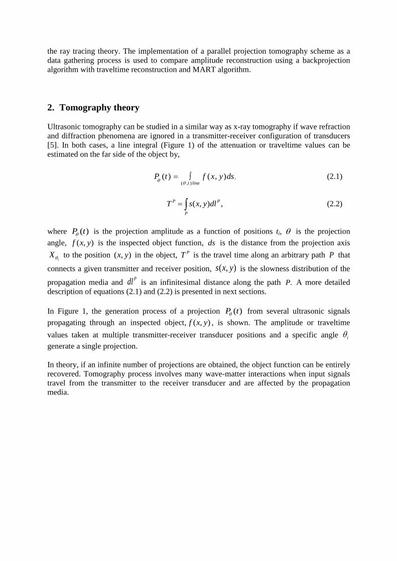
In Figure 1, the generation process of a projection ( )P t from several ultrasonic signals
propagating through an inspected object, ( , )f x y , is shown. The amplitude or traveltime
values taken at multiple transmitter-receiver transducer positions and a specific angle i
generate a single projection.
In theory, if an infinite number of projections are obtained, the object function can be entirely
recovered. Tomography process involves many wave-matter interactions when input signals
travel from the transmitter to the receiver transducer and are affected by the propagation
media.
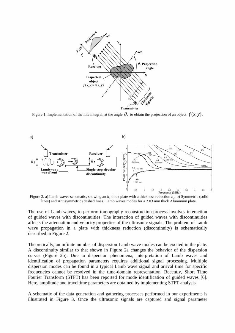
Figure 1. Implementation of the line integral, at the angle , to obtain the projection of an object ( , )f x y .
a)
b)
Figure 2. a) Lamb waves schematic, showing an h1 thick plate with a thickness reduction h2; b) Symmetric (solid
lines) and Antisymmetric (dashed lines) Lamb waves modes for a 2.03 mm thick Aluminum plate.
The use of Lamb waves, to perform tomography reconstruction process involves interaction
of guided waves with discontinuities. The interaction of guided waves with discontinuities
affects the attenuation and velocity properties of the ultrasonic signals. The problem of Lamb
wave propagation in a plate with thickness reduction (discontinuity) is schematically
described in Figure 2.
Theoretically, an infinite number of dispersion Lamb wave modes can be excited in the plate.
A discontinuity similar to that shown in Figure 2a changes the behavior of the dispersion
curves (Figure 2b). Due to dispersion phenomena, interpretation of Lamb waves and
identification of propagation parameters requires additional signal processing. Multiple
dispersion modes can be found in a typical Lamb wave signal and arrival time for specific
frequencies cannot be resolved in the time-domain representation. Recently, Short Time
Fourier Transform (STFT) has been reported for mode identification of guided waves [6].
Here, amplitude and traveltime parameters are obtained by implementing STFT analysis.
A schematic of the data generation and gathering processes performed in our experiments is
illustrated in Figure 3. Once the ultrasonic signals are captured and signal parameter
Y
X
θi
Inspected
object
Transmitter
ReceiverProjection
angle
( , ) / ( , )f x y s x y
h2h1
Transmitter Receiver
Lamb wave wavefront
Single-step circular
discontinuity
0 0.5 1 1.5 2 2.5 3 3.5 4 4.5 50
1
2
3
4
5
6
Frequency (MHz)
Ph
ase
Vel
oci
ty (
m/m
s)
A0
S0
A0
A2 S2
A3S0
1.015 mm
2.03 mmA1
2.03 mm
1.015 mm
2.03 mm
1.015 mmA1
S1
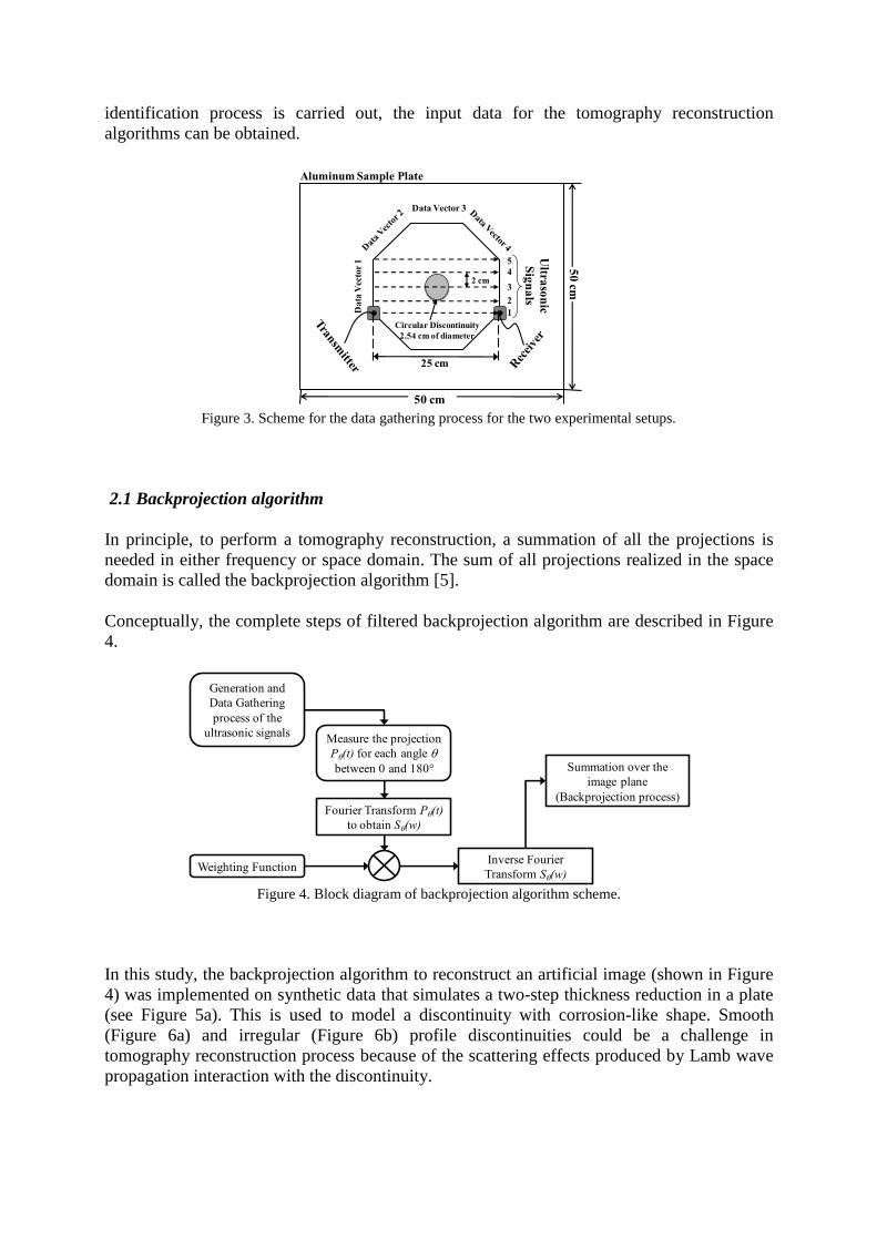
identification process is carried out, the input data for the tomography reconstruction
algorithms can be obtained.
Figure 3. Scheme for the data gathering process for the two experimental setups.
2.1 Backprojection algorithm
In principle, to perform a tomography reconstruction, a summation of all the projections is
needed in either frequency or space domain. The sum of all projections realized in the space
domain is called the backprojection algorithm [5].
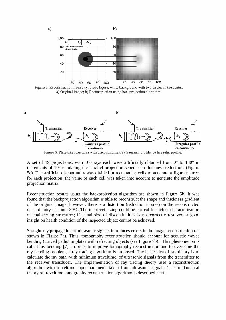
Conceptually, the complete steps of filtered backprojection algorithm are described in Figure
4.
Figure 4. Block diagram of backprojection algorithm scheme.
In this study, the backprojection algorithm to reconstruct an artificial image (shown in Figure
4) was implemented on synthetic data that simulates a two-step thickness reduction in a plate
(see Figure 5a). This is used to model a discontinuity with corrosion-like shape. Smooth
(Figure 6a) and irregular (Figure 6b) profile discontinuities could be a challenge in
tomography reconstruction process because of the scattering effects produced by Lamb wave
propagation interaction with the discontinuity.
50 cm
50
cm1
2
3
4
5
Ultra
son
ic
Sig
na
lsD
ata
Vec
tor
1
Data Vector 3
2 cm
25 cm
Circular Discontinuity
2.54 cm of diameter
Aluminum Sample Plate
Generation and
Data Gathering
process of the
ultrasonic signalsMeasure the projection
P(t) for each angle
between 0 and 180
Fourier Transform P(t)
to obtain S(w)
Weighting FunctionInverse Fourier
Transform S(w)
Summation over the
image plane
(Backprojection process)
a) b)
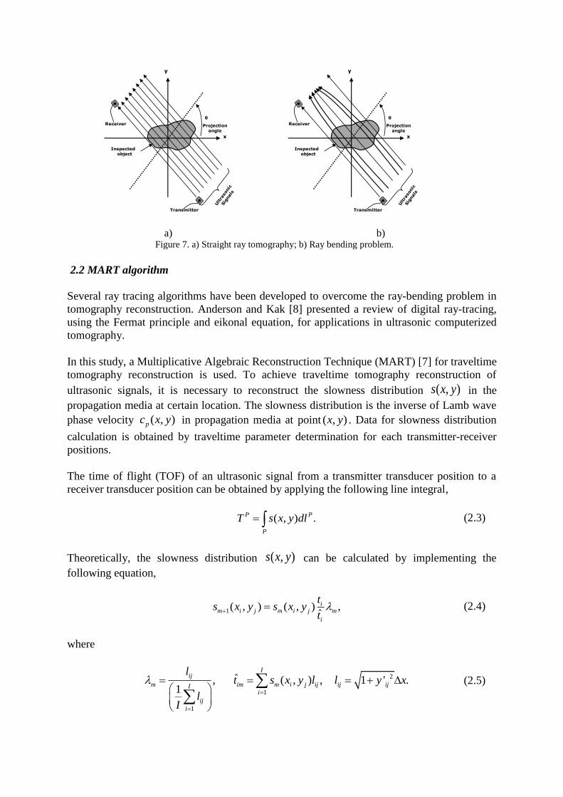
Figure 5. Reconstruction from a synthetic figure, white background with two circles in the center.
a) Original image; b) Reconstruction using backprojection algorithm.
a)
b)
Figure 6. Plate-like structures with discontinuities. a) Gaussian profile; b) Irregular profile.
A set of 19 projections, with 100 rays each were artificially obtained from 0° to 180° in
increments of 10° emulating the parallel projection scheme on thickness reductions (Figure
5a). The artificial discontinuity was divided in rectangular cells to generate a figure matrix;
for each projection, the value of each cell was taken into account to generate the amplitude
projection matrix.
Reconstruction results using the backprojection algorithm are shown in Figure 5b. It was
found that the backprojection algorithm is able to reconstruct the shape and thickness gradient
of the original image; however, there is a distortion (reduction in size) on the reconstructed
discontinuity of about 30%. The incorrect sizing could be critical for defect characterization
of engineering structures; if actual size of discontinuities is not correctly resolved, a good
insight on health condition of the inspected object cannot be achieved.
Straight-ray propagation of ultrasonic signals introduces errors in the image reconstruction (as
shown in Figure 7a). Thus, tomography reconstruction should account for acoustic waves
bending (curved paths) in plates with refracting objects (see Figure 7b). This phenomenon is
called ray bending [7]. In order to improve tomography reconstruction and to overcome the
ray bending problem, a ray tracing algorithm is proposed. The basic idea of ray theory is to
calculate the ray path, with minimum traveltime, of ultrasonic signals from the transmitter to
the receiver transducer. The implementation of ray tracing theory uses a reconstruction
algorithm with traveltime input parameter taken from ultrasonic signals. The fundamental
theory of traveltime tomography reconstruction algorithm is described next.
20
40
60
80
100
20 40 60 80 100
20
40
60
80
100
20 40 60 80 100
h2h1
Two-steps circular
discontinuity
h3
h2h1
Transmitter Receiver
Gaussian profile
discontinuity
h2h1
Transmitter Receiver
Irregular profile
discontinuity
a)
b) Figure 7. a) Straight ray tomography; b) Ray bending problem.
2.2 MART algorithm
Several ray tracing algorithms have been developed to overcome the ray-bending problem in
tomography reconstruction. Anderson and Kak [8] presented a review of digital ray-tracing,
using the Fermat principle and eikonal equation, for applications in ultrasonic computerized
tomography.
In this study, a Multiplicative Algebraic Reconstruction Technique (MART) [7] for traveltime
tomography reconstruction is used. To achieve traveltime tomography reconstruction of
ultrasonic signals, it is necessary to reconstruct the slowness distribution ( , )s x y in the
propagation media at certain location. The slowness distribution is the inverse of Lamb wave
phase velocity ( , )pc x y in propagation media at point ( , )x y . Data for slowness distribution
calculation is obtained by traveltime parameter determination for each transmitter-receiver
positions.
The time of flight (TOF) of an ultrasonic signal from a transmitter transducer position to a
receiver transducer position can be obtained by applying the following line integral,
( , ) .P P
P
T s x y dl (2.3)
Theoretically, the slowness distribution ( , )s x y can be calculated by implementing the
following equation,
1( , ) ( , ) ,
ˆi
m i j m i j m
i
ts x y s x y
t (2.4)
where
2
1
1
ˆ, ( , ) , 1 ' .1
Iij
m im m i j ij ij ijIi
ij
i
lt s x y l l y x
lI
(2.5)
y
x
θ
Inspected object
Transmitter
Receiver Projection angle
y
x
θ
Inspected object
Transmitter
Receiver Projection angle
From equations (2.4) and (2.5) the ( , )i jx y parameter correspond to the cell index in the
discrete representation of the slowness distribution, ijl is the traversed distance over the
( , )i jx y cell, it is the measured TOF for the receiver-transducer position, imt is the minimum
TOF obtained for the generated slowness distribution with minimum TOF ( , )m i js x y and x
is the size of the sample grid to be used to reconstruct the image. The sub-index m in
equations (2.4) and (2.5) refers to the parameters obtained when the minimum TOF for an
ultrasonic ray path is found.
If ray paths are unknowns, straight ray tomography cannot be applied; therefore an iterative
process to compute an approximate slowness distribution is required [7]. As a first step to
tomography reconstruction, we assume 1m in eq. (2.5) (straight ray estimation), and obtain
an initial slowness distribution estimation. Then, ray tracing algorithm can be applied to trace
the ray paths for all transmitter-receiver positions. Once the ray paths are obtained, bend ray
MART reconstruction can be achieved solving equations (2.4) and (2.5). Finally, the ray
tracing algorithm is applied iteratively until a desirable image quality is achieved. The
minimization criteria to determine the appropriate quality of reconstruction is obtained
following equation.
,e a (2.6)
where a is an error criteria value and
1( , ) ( , ),m i j m i je s x y s x y (2.7)
the parameter e is the error value between the current slowness distribution calculation
1( , )m i js x y and the previous one ( , ).m i js x y
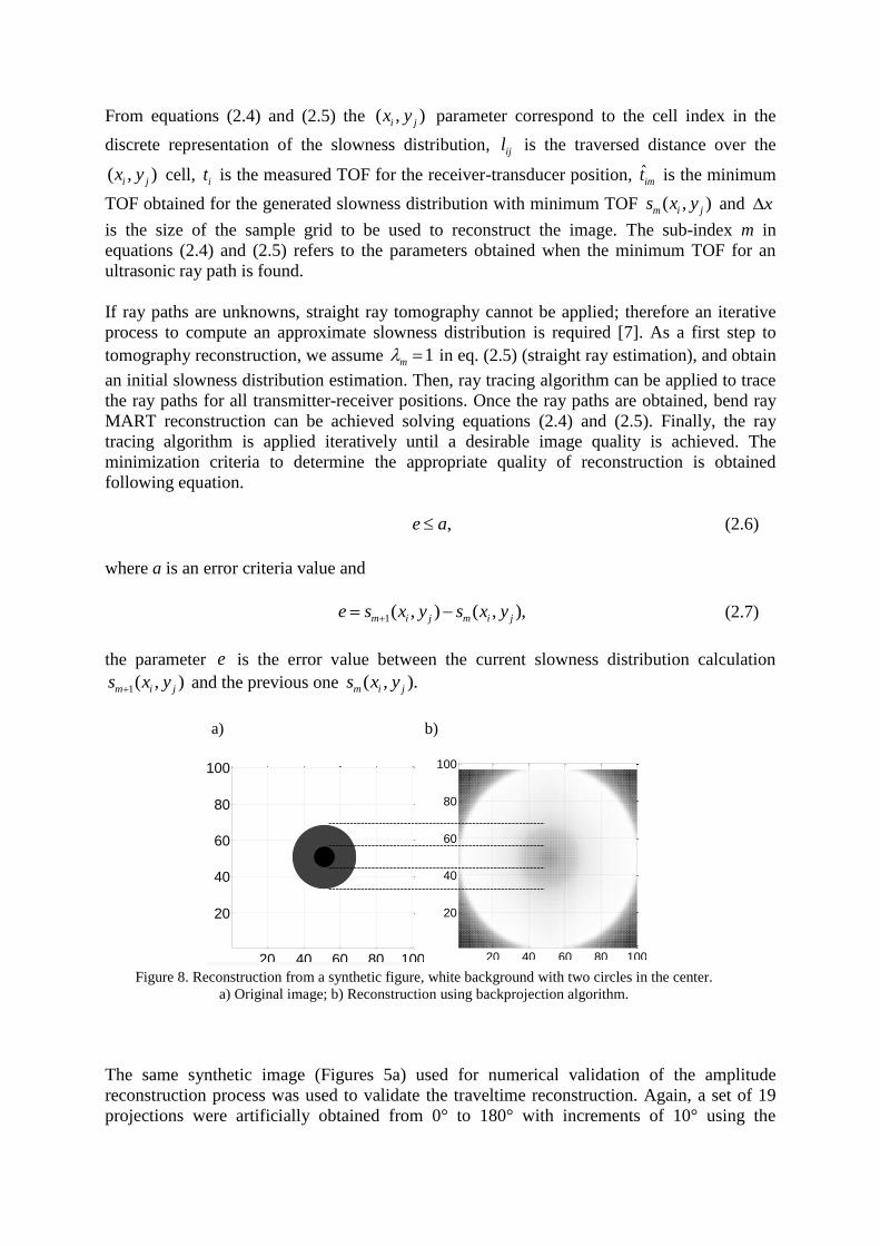
a) b)
Figure 8. Reconstruction from a synthetic figure, white background with two circles in the center.
a) Original image; b) Reconstruction using backprojection algorithm.
The same synthetic image (Figures 5a) used for numerical validation of the amplitude
reconstruction process was used to validate the traveltime reconstruction. Again, a set of 19
projections were artificially obtained from 0° to 180° with increments of 10° using the
20
40
60
80
100
20 40 60 80 100
20
40
60
80
100
20 40 60 80 100
parallel projection scheme. For each projection the sum of each row was obtained to simulate
the TOF vector.
The reconstruction of the synthetic figure with MART algorithm is shown in Figure 8. The
results indicate that MART algorithm can reconstruct the shape and the two step features of
the original images with an error in size prediction of 5% with respect to the original one.
3. Description of experiments and results
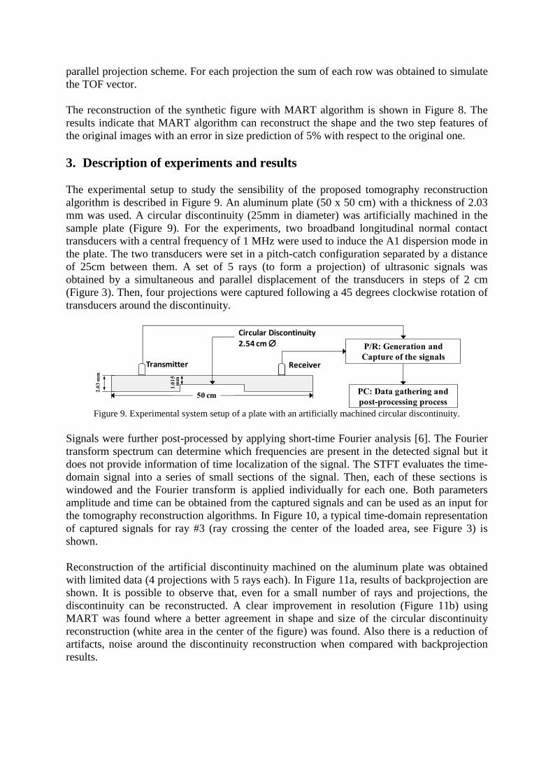
The experimental setup to study the sensibility of the proposed tomography reconstruction
algorithm is described in Figure 9. An aluminum plate (50 x 50 cm) with a thickness of 2.03
mm was used. A circular discontinuity (25mm in diameter) was artificially machined in the
sample plate (Figure 9). For the experiments, two broadband longitudinal normal contact
transducers with a central frequency of 1 MHz were used to induce the A1 dispersion mode in
the plate. The two transducers were set in a pitch-catch configuration separated by a distance
of 25cm between them. A set of 5 rays (to form a projection) of ultrasonic signals was
obtained by a simultaneous and parallel displacement of the transducers in steps of 2 cm
(Figure 3). Then, four projections were captured following a 45 degrees clockwise rotation of
transducers around the discontinuity.
Figure 9. Experimental system setup of a plate with an artificially machined circular discontinuity.
Signals were further post-processed by applying short-time Fourier analysis [6]. The Fourier
transform spectrum can determine which frequencies are present in the detected signal but it
does not provide information of time localization of the signal. The STFT evaluates the time-
domain signal into a series of small sections of the signal. Then, each of these sections is
windowed and the Fourier transform is applied individually for each one. Both parameters
amplitude and time can be obtained from the captured signals and can be used as an input for
the tomography reconstruction algorithms. In Figure 10, a typical time-domain representation
of captured signals for ray #3 (ray crossing the center of the loaded area, see Figure 3) is
shown.
Reconstruction of the artificial discontinuity machined on the aluminum plate was obtained
with limited data (4 projections with 5 rays each). In Figure 11a, results of backprojection are
shown. It is possible to observe that, even for a small number of rays and projections, the
discontinuity can be reconstructed. A clear improvement in resolution (Figure 11b) using
MART was found where a better agreement in shape and size of the circular discontinuity
reconstruction (white area in the center of the figure) was found. Also there is a reduction of
artifacts, noise around the discontinuity reconstruction when compared with backprojection
results.
PC: Data gathering and
post-processing process
P/R: Generation and
Capture of the signals
50 cm
Transmitter
Circular Discontinuity 2.54 cm
2.0
3 m
m
Receiver
1.0
15
mm
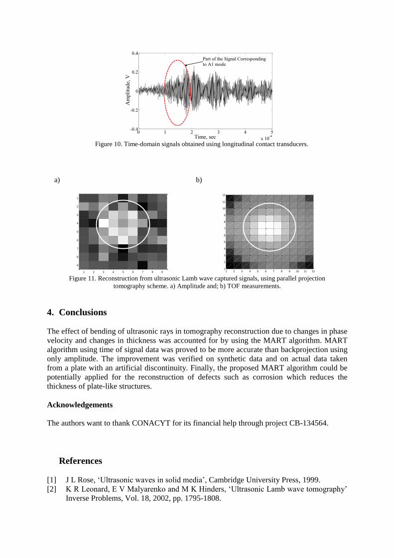
Figure 10. Time-domain signals obtained using longitudinal contact transducers.
a)
b)
Figure 11. Reconstruction from ultrasonic Lamb wave captured signals, using parallel projection
tomography scheme. a) Amplitude and; b) TOF measurements.
4. Conclusions
The effect of bending of ultrasonic rays in tomography reconstruction due to changes in phase
velocity and changes in thickness was accounted for by using the MART algorithm. MART
algorithm using time of signal data was proved to be more accurate than backprojection using
only amplitude. The improvement was verified on synthetic data and on actual data taken
from a plate with an artificial discontinuity. Finally, the proposed MART algorithm could be
potentially applied for the reconstruction of defects such as corrosion which reduces the
thickness of plate-like structures.
Acknowledgements
The authors want to thank CONACYT for its financial help through project CB-134564.
References
[1] J L Rose, ‘Ultrasonic waves in solid media’, Cambridge University Press, 1999.
[2] K R Leonard, E V Malyarenko and M K Hinders, ‘Ultrasonic Lamb wave tomography’
Inverse Problems, Vol. 18, 2002, pp. 1795-1808.
0 1 2 3 4 5
x 10-4
-0.4
-0.2
0
0.2
0.4
Time, sec
Am
pli
tud
e, V
Part of the Signal Correspondingto A1 mode
Ultrasonic Computed Tomogram
1 2 3 4 5 6 7 8 9
1
2
3
4
5
6
7
8
9
1 2 3 4 5 6 7 8 9 10 11 121
2
3
4
5
6
7
8
9
10
11
12
[3] E V Malyarenko and M K Hinders, ‘Ultrasonic Lamb wave diffraction tomography’
Ultrasonics, Vol. 39, 2001, pp. 269-281.
[4] A Volker, A Mast and J Bloom, ‘Experimental results of guided wave travel time
tomography’, AIP Conf. Proc., Vol., 1211, 2010.
[5] A C Kak and M Slaney, ‘Principles of computerized tomography imaging’, IEEE, New
York.
[6] C Treesatayapun, A Balvantín, A Baltazar and J Y Kim, ‘Thickness determination of a
plate with varying thickness using an artificial neural network for time-frequency
representation of lamb waves’, Quantitative NonDestructive Evaluation Conference,
Chicago, Il., USA, 2008.
[7] B Wang, J Takatsubo, and N Toyama, ‘An Improved Ray Tracing Algorithm for
Ultrasonic CT in Nondestructive Inspections’, ICSP Proceedings, 2006.
[8] A H Anderson and A C Kak, ‘Digital ray tracing in two-dimensional refractive fields’,
J. Acoust. Soc. Am, Vol 72, No. 5, 1982.
[9] S Khare, M Razdan, N Jain, P Munshi, B V Soma Sekhar and K Balasubramaniam,
‘Lamb Wave Tomography Reconstruction Using Various MART Algorithms’ Proc.
National Seminar on Non-Destructive Evaluation, Hyderabad, 2006.
[10] A Balvantín and A Baltazar, ‘A study of guided wave propagation on a plate between
two semi-spaces with imperfect boundary conditions’, Submitted for publication to
International Journal of Mechanical Science, 2010.
[11] A Balvantín, A Baltazar and J-Y Kim, ‘Ultrasonic lamb wave tomography of non-
uniform interfacial stiffness between contacting solid bodies’, AIP Conf. Proc., Vol.
1211, 2010, pp. 1463-1470.
Related Documents