ZXWR R8840 Product Description Part B Section 5

5.2.2.5 ZXWR R8840 Product Description
Sep 03, 2014
Welcome message from author
This document is posted to help you gain knowledge. Please leave a comment to let me know what you think about it! Share it to your friends and learn new things together.
Transcript

ZXWR R8840 Product Description
Part B Section 5

ZXWR R8840 Product Description
ZTE Confidential Proprietary © 2009 ZTE Corporation. All rights reserved. I
TABLE OF CONTENTS
1 Overview......................................................................................................................1
2 Highlight Features ......................................................................................................2 2.1 Compact design, light-weight, easy installation ...........................................................2 2.2 4 carriers design...........................................................................................................2 2.3 High efficiency power amplifier & low power consumption ..........................................2 2.4 Multi-band frequency supported...................................................................................2 2.5 Flexible power supply options ......................................................................................3 2.6 Security design.............................................................................................................3
3 Functionality ...............................................................................................................3 3.1 Service Functions.........................................................................................................3 3.2 Other Functions............................................................................................................4
4 System Architecture...................................................................................................4 4.1 Product Physical Structure...........................................................................................4 4.2 System Interfaces.........................................................................................................5 4.3 Hardware Architecture .................................................................................................6 4.3.1 RTR (RRU Transceiver) ...............................................................................................6 4.3.2 DFL (Duplex Filter LNA): ..............................................................................................7 4.3.3 PA (Power Amplifier) ....................................................................................................7 4.3.4 RPW AC/DC (RRU Power AC/DC) ..............................................................................8 4.4 Software Architecture...................................................................................................8 4.4.1 Module software package ............................................................................................8 4.4.2 OMC .............................................................................................................................9 4.4.3 LMT ..............................................................................................................................9
5 Technical Specifications............................................................................................9 5.1 Physical Indices............................................................................................................9 5.2 Capacity Indices ...........................................................................................................9 5.3 Performance Indices ..................................................................................................10 5.4 Power Indices.............................................................................................................10 5.4.1 Working Power ...........................................................................................................10 5.4.2 Power Consumption ...................................................................................................10 5.5 Interface Indices .........................................................................................................11 5.6 Working Environment .................................................................................................11 5.7 EMC Indices ...............................................................................................................11 5.8 Reliability Indices........................................................................................................12
6 Operation and Maintenance.....................................................................................12 6.1 Operation and Maintenance System..........................................................................12 6.2 Operation and Maintenance Function ........................................................................13 6.2.1 Configuration Management........................................................................................13 6.2.2 Performance Management.........................................................................................13 6.2.3 Alarm Management ....................................................................................................14 6.2.4 Maintenance Management.........................................................................................14

ZXWR R8840 Product Description
ZTE Confidential Proprietary © 2009 ZTE Corporation. All rights reserved. II
7 Installation .................................................................................................................15
8 Networking ................................................................................................................16
9 Application Scenes...................................................................................................17 9.1 Scene 1 ......................................................................................................................17 9.2 Scene 2 ......................................................................................................................18 9.3 Capacity Upgrade Capability......................................................................................19 9.3.1 Increase Transmit Power ...........................................................................................19 9.3.2 More Carriers and More Sectors................................................................................19 9.3.3 Transmit Diversity.......................................................................................................20
ZXWR R8840 Product Description
ZTE Confidential Proprietary © 2009 ZTE Corporation. All rights reserved. I
FIGURES
Figure 1 WCDMA system structure..............................................................................................1 Figure 2 R8840 Physical Structure...............................................................................................4 Figure 3 R8840 Internal Structure ................................................................................................5 Figure 4 R8840 System Interfaces ...............................................................................................5 Figure 5 Hardware Structure of R8840.........................................................................................6 Figure 6 R8840 Software Structure ..............................................................................................8 Figure 7 OMC and LMT access..................................................................................................13 Figure 8 R8840 Pole Installation ................................................................................................15 Figure 9 R8840 Wall Installation.................................................................................................16 Figure 10 R8840 and BBUB networking.......................................................................................17 Figure 11 R8840 inside equipment room installation in scenario 1..............................................18 Figure 12 R8840 outside equipment room installation in scenario 1 ...........................................18 Figure 13 R8840 outside equipment room installation in scenario 2 ...........................................19 Figure 14 R8840 Capacity Upgrade Path (40W/60W) .................................................................20 Figure 15 Transmit Diversity of R8840.........................................................................................20
TABLES
Table 1 R8840 External Interface................................................................................................5 Table 2 Physical Indices..............................................................................................................9 Table 3 Capacity Indices .............................................................................................................9 Table 4 Performance Indices ....................................................................................................10 Table 5 Working Power Indices.................................................................................................10 Table 6 Power Consumption Indices.........................................................................................10 Table 7 Interface Indices ...........................................................................................................11 Table 8 Working Environment Indices.......................................................................................11 Table 9 EMC Indices .................................................................................................................11 Table 10 Reliability Indices..........................................................................................................12

ZXWR R8840 Product Description
ZTE Confidential Proprietary © 2009 ZTE Corporation. All rights reserved. 1
1 Overview In general, WCDMA system consists of three parts, which are Core Network, UMTS Terrestrial Radio Access Network and User Equipment. As a subsystem of WCDMA, UTRAN comprises two parts: Node B and RNC. Node B can be an integrated base station or a combination of Base Band Unit and Remote Radio Unit. The WCDMA system general topology is shown as Figure 1. Iub is defined as the interface between Node B and RNC. Uu is the interface between UE and Node B.
Figure 1 WCDMA system structure
So far, ZTE has launched a mature WCDMA commercial system based on 3GPP R4/R5/R6. ZTE provides a complete set of solutions from core network to radio access network. Radio network subsystem (RNS) includes ZXWR RNC and a series of ZXWR Node Bs.
ZXWR series Node B has abundant products categories including: Indoor Macro Node B, Outdoor Macro Node B, BBU and RRU. All Node Bs are designed with unified hardware platform, adopting all IP switching structure. ZXWR series Node B all have the characters of high degree of integration, large capacity, expansion flexibility and high reliability.
ZXWR series Node B adopts modular layout which can be separated as base band module and radio frequency module. The base band module and radio frequency unit are independent processed. This enables the each has the independent evolution capability. Moreover, the high capacity Baseband Process boards, 40% high PA efficiency, multi carriers TRXU, high sensitivity receiver and other innovational technique make ZXWR series Node B become smaller in dimension while achieving low power

ZXWR R8840 Product Description
ZTE Confidential Proprietary © 2009 ZTE Corporation. All rights reserved. 2
consumption. These characters will reduce operators' CAPEX and TCO. ZXWR series Node B adopted advanced baseband algorithm based high capacity BP boards have realized R99/HSDPA/HSUPA BB resource sharing. It will greatly reduce future evolution cost. The DPD+Doherty based high efficiency PA has 40% efficiency. DPD adopts ZTE invented design and algorithms. It is much advance than other vendors' and will provide the lower operation cost solution to the operators.
ZXWR R8840 (R8840 for short) is a member of ZTE WCDMA Distribution Base Station family, which is an outdoor RRU with high power transmission. It can be work with ZTE series Baseband unit to form a distributed base station. BBUB is one of product in ZTE BBU family. This document is a description of R8840 system structure, product function and system indices, and an introduction of R8840’s typical networking and application scenarios.
The protocol of the R8840 is fully compliant with the 3GPP R99/R4/R5/R6 specifications.
2 Highlight Features R8840 is outdoor RRU product with high transmission power. Characteristics of R8840 are as follows:
2.1 Compact design, light-weight, easy installation Only 19 liter in volume and 16.5 kg; supporting the installation mounted on the mast, the wall, the tower top; no dedicated equipment room is needed, easy for site selection, fast network building;
2.2 4 carriers design Support expansion from 1 carrier to 4 carriers; satisfy future network capacity requirement.
2.3 High efficiency power amplifier & low power consumption 40% power efficiency from ZTE self-developed high efficiency Doherty PA and DPD linear technology. With 20W & 40W & 60W PA configuration, the power consumptions are only 105W, 130W and 170W respectively.
2.4 Multi-band frequency supported Support UMTS 850M/900M/1800M/1900M etc, only by software upgrade and some hardware component changed; meet operator’s multi-band frequency networking requirement.

ZXWR R8840 Product Description
ZTE Confidential Proprietary © 2009 ZTE Corporation. All rights reserved. 3
2.5 Flexible power supply options Three kinds of power supply: 110V/220 AC and -48V DC, support local and remote power supply; Safety design with under-voltage protection, over-voltage protection and power reverse protection.
2.6 Security design Design for the scenario of outdoor and no dedicated equipment room. Special key needed to open cabinet; cabinet can be firmed installed by lock and chain.
3 Functionality
3.1 Service Functions R8840 has the following radio frequency related functions:
• Support the configuration of 5MHz/4.8MHz/4.6MHz channel interval;
• Support 20W or 40W or 60W output power configuration, 20W can be obtained by license;
• Single R8840 support two receiving paths and one transmit path;
• Support 4 carriers in 1 sector with 40W output configuration;
• Co-cabinet can support 4-antenna-receiving diversity in 1 sector;
• Co-cabinet can support transmit diversity, without adding antenna achieving same receiving sensitivity;
• Co-cabinet can support non-continuous frequency configuration;
• Support RTWP report interval at 100ms and 2ms;
• Support transmit power reporting function for every carrier;
• Support over loading protection function for power amplifier;
• Support measurement, compensation and adjustment function for channel delay;
• Support transmit channel switching on/off function;
• R8840 software fault for itself will not affect the running of BBU and other R8840 which connected to it;

ZXWR R8840 Product Description
ZTE Confidential Proprietary © 2009 ZTE Corporation. All rights reserved. 4
3.2 Other Functions • Support alarm interface for backup power;
• Support alarm interface for lightning protector;
• Support AISG interface for antenna electrical tilt;
• Support external alarm input/output;
• Support TMA;
4 System Architecture
4.1 Product Physical Structure The R8840 employs compact cabinet design, as shown in Figure 2. Dimension of R8840
is H×W×D=370×320×160 mm3.
Figure 2 R8840 Physical Structure
The main function module of R8840 includes: DFL (Duplex filter LNA), RTR (RRU Transceiver), PA (Power Amplifier) and RPWAC/DC (RRU Power for AC or DC), as shown in Figure 3.
ZXWR R8840 Product Description
ZTE Confidential Proprietary © 2009 ZTE Corporation. All rights reserved. 5
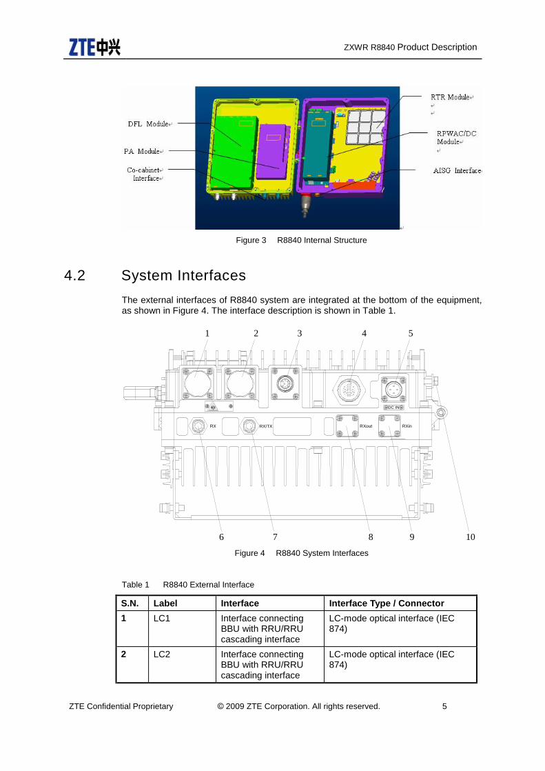
Figure 3 R8840 Internal Structure
4.2 System Interfaces The external interfaces of R8840 system are integrated at the bottom of the equipment, as shown in Figure 4. The interface description is shown in Table 1.
RX RX/TX RXout RXin
DC IN
1 2 3 4 5
9876 10 Figure 4 R8840 System Interfaces
Table 1 R8840 External Interface
S.N. Label Interface Interface Type / Connector 1 LC1 Interface connecting
BBU with RRU/RRU cascading interface
LC-mode optical interface (IEC 874)
2 LC2 Interface connecting BBU with RRU/RRU cascading interface
LC-mode optical interface (IEC 874)
ZXWR R8840 Product Description
ZTE Confidential Proprietary © 2009 ZTE Corporation. All rights reserved. 6
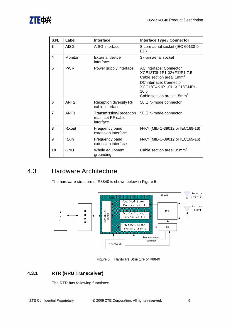
S.N. Label Interface Interface Type / Connector 3 AISG AISG interface 8-core aerial socket (IEC 60130-9-
ED) 4 Monitor External device
interface 37-pin aerial socket
5 PWR Power supply interface AC interface: Connector XCE18T3K1P1-02+FJJP1-7.5 Cable section area: 1mm2 DC interface: Connector XCG18T4K1P1-01+XC18FJJP1-10.5 Cable section area: 1.5mm2
6 ANT2 Reception diversity RF cable interface
50 Ω N-mode connector
7 ANT1 Transmission/Reception main set RF cable interface
50 Ω N-mode connector
8 RXout Frequency band extension interface
N-KY (MIL-C-39012 or IEC169-16)
9 RXin Frequency band extension interface
N-KY (MIL-C-39012 or IEC169-16)
10 GND Whole equipment grounding
Cable section area: 35mm2
4.3 Hardware Architecture The hardware structure of R8840 is shown below in Figure 5:
FIBER
IN
TERFA
CE
Figure 5 Hardware Structure of R8840
4.3.1 RTR (RRU Transceiver)
The RTR has following functions:

ZXWR R8840 Product Description
ZTE Confidential Proprietary © 2009 ZTE Corporation. All rights reserved. 7
• Process received signal and transmit signal;
• Radio signal uplink convert and downlink convert;
• Downlink IQ signal multiplexing, uplink signal de-multiplexing;
• Signal amplifying, filter, A/D convert, D/A convert;
• Convert between optical signal and electric signal;
• Capture reference signal from base band unit and provide the reference clock signal to other units;
• RTWP & TSSI measurement and report;
• Standing wave measurement and report;
• Hardware failure self-detection;
• Alarm report;
• Environment temperature monitor;
• Provide communication interface: 2 CPRI interfaces, 4 external alarm port input nodes, 1 RS485 serial port for external monitor equipment communication, 1 fast Ethernet port and 1 RS232 serial port for LMT, 1 AISG for electrical tilt antenna, 1 co-cabinet port for realization of co-cabinet;
• Reset function.
4.3.2 DFL (Duplex Filter LNA):
The DFL has following function:
• Combined and isolate transmitted and received signal;
• Filter the transmitted signal and received signal;
• LNA (low-noise-amplifier) function;
• LNA alarm report to RTR.
4.3.3 PA (Power Amplifier)
The PA has following function:
• Performs radio signal amplifying function;

ZXWR R8840 Product Description
ZTE Confidential Proprietary © 2009 ZTE Corporation. All rights reserved. 8
• Temperature report function;
• Over-current, over-heat, over-power, over-standing wave protecting function.
4.3.4 RPW AC/DC (RRU Power AC/DC)
The RPWAC/DC has following function:
• RPWAC is the power unit for AC and RPWDC is the power unit for DC;
• AC to DC or AC to AC convert function;
• Alarm report to RTR for low-voltage, over-voltage, over-current etc.
4.4 Software Architecture The R8840 comprises module software package, OMC integrated network management center and local maintenance terminal LMT.
4.4.1 Module software package
The module software package is essential for normal running of the R8840. It can be divided into driver, supporting software and application software. Its functions are shown in the following diagram, Figure 6.
OAM
OSS
VxWorks BSP
Hardware
Application
OS & Driver & Support
Hardware System
RFS
Figure 6 R8840 Software Structure
OSS is the support layer in this entire framework, which is a hardware irrespectively platform for running software and provides basic functions like scheduling, timer,

ZXWR R8840 Product Description
ZTE Confidential Proprietary © 2009 ZTE Corporation. All rights reserved. 9
memory management, communication, sequencing control, monitoring, alarming and logging.
Application layer consists of RFS and OAM subsystems. Its main function contains software downloading, configuration, management, system maintenance, measurement etc.
4.4.2 OMC
R8840 and BBUB constitute a full Node B. In remote maintenance system, R8840 is managed as RF unit of one Node B.
OMC is uniform network management system of Node B system. It has powerful functions. It can not only manage single Node B, but also total Node B network. The uniform management center has many functions, such as security management, alarm management, configuration management and diagnosis etc.
When OMC is running in RNC, it connects with Node B by IPOA. It can be combined with centralized management center of RNC, to build RNS uniform management center.
4.4.3 LMT
LMT realizes single R8840 management. It is suitable for site maintenance. Its functions including: configuration management, alarm management, performance management, diagnosis test, etc.
LMT is running in local site through the interface of 100M Ethernet or RS232 with R8840.
5 Technical Specifications
5.1 Physical Indices
Table 2 Physical Indices
Item Indices
Dimension(H×W×D) 370×320×160 mm3
Weight 16.5 Kg Color Silver Grey
5.2 Capacity Indices
Table 3 Capacity Indices
Item Indices

ZXWR R8840 Product Description
ZTE Confidential Proprietary © 2009 ZTE Corporation. All rights reserved. 10
Sectors Max. 4C1S
5.3 Performance Indices
Table 4 Performance Indices
Item Indices Frequency Band 2100 MHz Transmitter Range 2110MHz-2170MHz
Receiver Range 1920MHz-1980MHz Multi Band Support
UMTS850,UMTS900,UMTS1900,UMTS1800 Receiver Sensitivity -126.5dBm@1-antenna
-129.2dBm@2-antenna -131.9dBm@4-antenna
Max. Transmit Power 20W/40W/60W (top box)
Synchronization Mode Linear clock
5.4 Power Indices
5.4.1 Working Power
Table 5 Working Power Indices
Item Indices Power Supply -48V DC, -35V ~ -60V;
220VAC, 90V ~ 300V; 110VAC, 85VAC ~ 135VAC
5.4.2 Power Consumption
Table 6 Power Consumption Indices
Item Indices Typical Power Consumption (W)
20W Output: 105W (Average), 130W (Max) 40W Output: 130W (Average), 205W (Max) 60W Output: 170W (Average), 260W (Max)

ZXWR R8840 Product Description
ZTE Confidential Proprietary © 2009 ZTE Corporation. All rights reserved. 11
5.5 Interface Indices
Table 7 Interface Indices
Interface Item Number Standard Baseband Radio Interface
1.25 Gbps Optical Connector
2 Support CPRI V2.0 Standard. Expended to support 2.5Gbps
LMT FE 1 IEEE 802.3u, 100BASE-TX, RJ45
5.6 Working Environment
Table 8 Working Environment Indices
Item Indices Environment Temperature Long-term: -40~50°C
Short-term: -40~55°C Environment Relative Humidity Long-term: 5%~100%
Short-term: 5%~100%
Environment Absolute Humidity Long-term: 1~25g/m3 Short-term: 0.5~29g/m3
Waterproof & Dustproof IP65 Grounded Requirement ≤5 Ω Transport Environment Transport environment:
2K4P/2B2/2C3/2S3/2M3 Sustainable transport time: 30 days Intact package
Storage Environment Storage Temperature: -40°~ 70°C Relative Humidity: 10% ~ 100%
5.7 EMC Indices
Table 9 EMC Indices
Item Indices Noise level 55dB
EMC specification
Compliant with following standards: R&TTE Directive 99/5/EC; 3GPP TS 25.113 V4.4.0 (2002-12); ETSI EN 301 489-1/23 ; ETSI EN 301 908-1 V2.2.1 (2003-10)

ZXWR R8840 Product Description
ZTE Confidential Proprietary © 2009 ZTE Corporation. All rights reserved. 12
Static discharge immunity Contact discharge : ±6000V, air discharge:±8000V
Sure(impact) immunity(line-ground)
±2000V
Security Satisfies: EN60950
5.8 Reliability Indices
Table 10 Reliability Indices
Item Indices
Availability 99.9997%
MTBF >180 000 hours
MTTR 30 minutes System service interruption time
Whole system interruption < 1.46 minutes / year
6 Operation and Maintenance
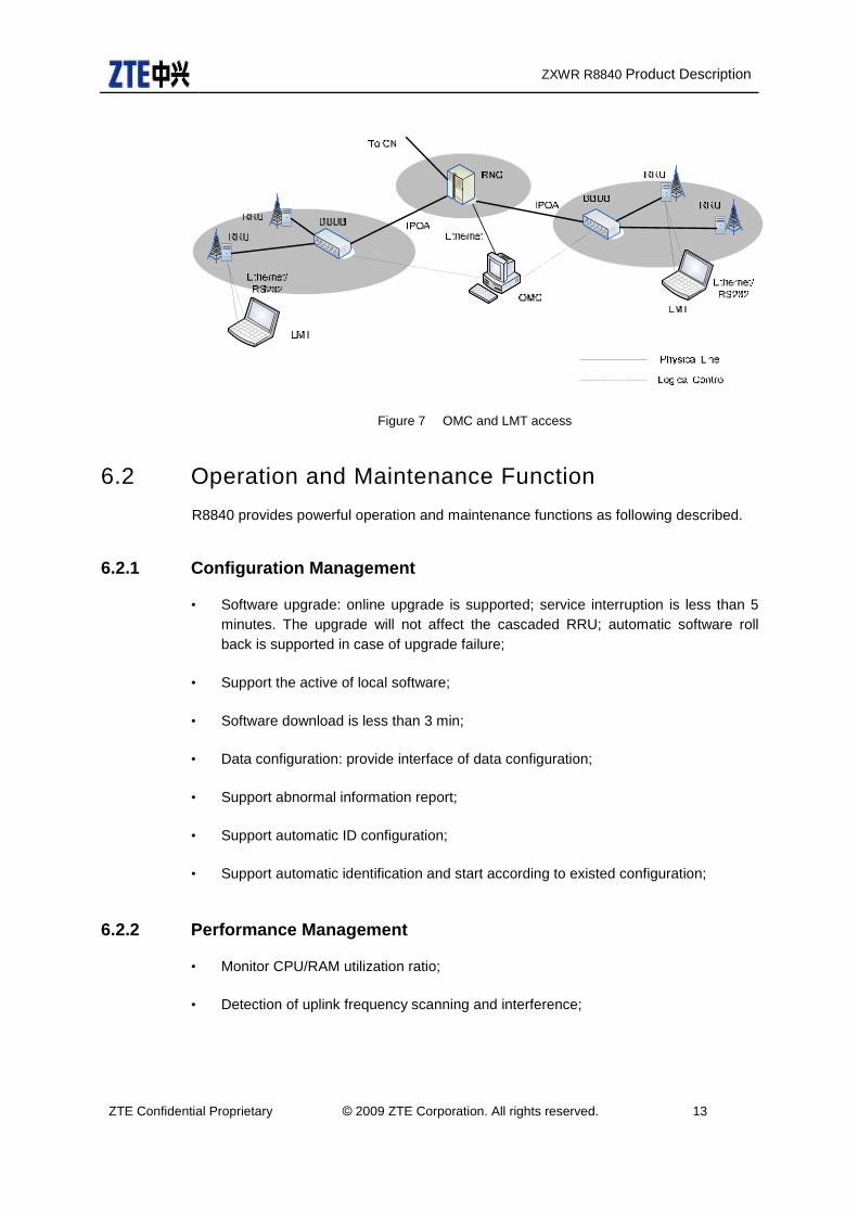
6.1 Operation and Maintenance System R8840 provides two ways for operation and maintenance, one is through centralized OMC and the other is through LMT system, as shown in Figure 7.
Operation and maintenance information and clock control information is transmitted through fiber between R8840 and BBUB. The protocol between baseband and RRU is CPRI.
The main function of background operation including: configuration management, performance management, alarm management and maintenance management. GUI is provided for the background operation.
ZXWR R8840 Product Description
ZTE Confidential Proprietary © 2009 ZTE Corporation. All rights reserved. 13
Figure 7 OMC and LMT access
6.2 Operation and Maintenance Function R8840 provides powerful operation and maintenance functions as following described.
6.2.1 Configuration Management
• Software upgrade: online upgrade is supported; service interruption is less than 5 minutes. The upgrade will not affect the cascaded RRU; automatic software roll back is supported in case of upgrade failure;
• Support the active of local software;
• Software download is less than 3 min;
• Data configuration: provide interface of data configuration;
• Support abnormal information report;
• Support automatic ID configuration;
• Support automatic identification and start according to existed configuration;
6.2.2 Performance Management
• Monitor CPU/RAM utilization ratio;
• Detection of uplink frequency scanning and interference;
ZXWR R8840 Product Description
ZTE Confidential Proprietary © 2009 ZTE Corporation. All rights reserved. 14
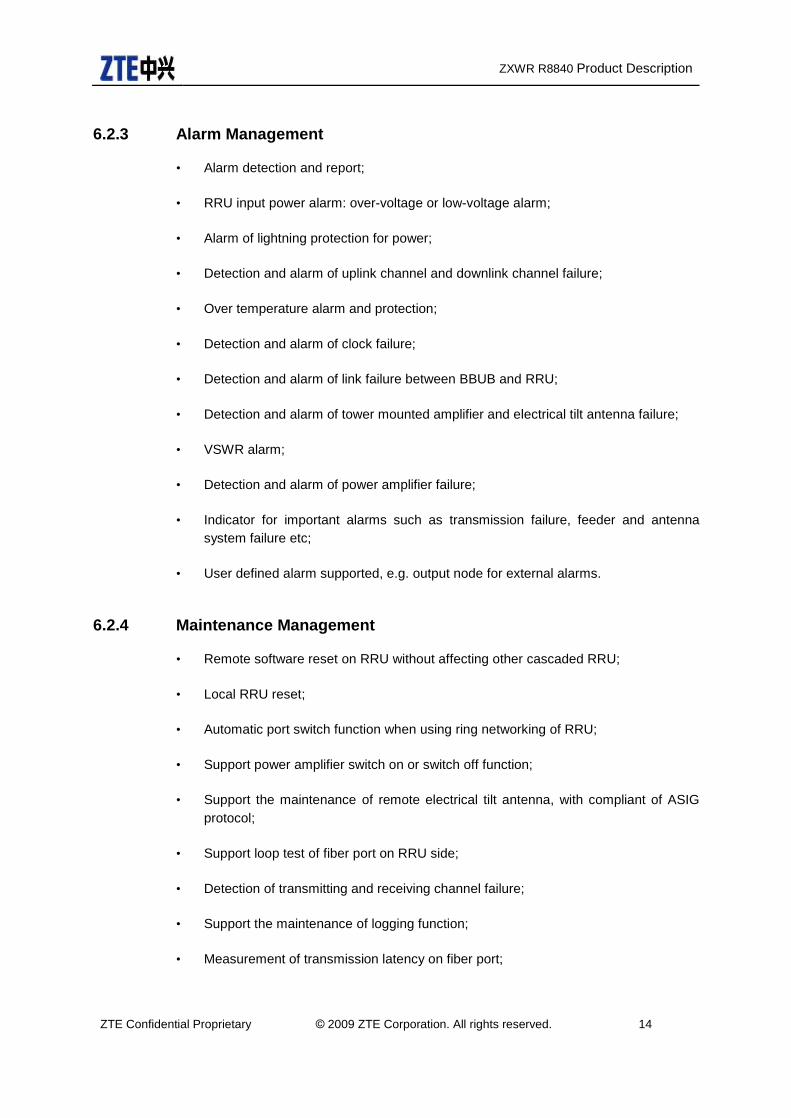
6.2.3 Alarm Management
• Alarm detection and report;
• RRU input power alarm: over-voltage or low-voltage alarm;
• Alarm of lightning protection for power;
• Detection and alarm of uplink channel and downlink channel failure;
• Over temperature alarm and protection;
• Detection and alarm of clock failure;
• Detection and alarm of link failure between BBUB and RRU;
• Detection and alarm of tower mounted amplifier and electrical tilt antenna failure;
• VSWR alarm;
• Detection and alarm of power amplifier failure;
• Indicator for important alarms such as transmission failure, feeder and antenna system failure etc;
• User defined alarm supported, e.g. output node for external alarms.
6.2.4 Maintenance Management
• Remote software reset on RRU without affecting other cascaded RRU;
• Local RRU reset;
• Automatic port switch function when using ring networking of RRU;
• Support power amplifier switch on or switch off function;
• Support the maintenance of remote electrical tilt antenna, with compliant of ASIG protocol;
• Support loop test of fiber port on RRU side;
• Detection of transmitting and receiving channel failure;
• Support the maintenance of logging function;
• Measurement of transmission latency on fiber port;

ZXWR R8840 Product Description
ZTE Confidential Proprietary © 2009 ZTE Corporation. All rights reserved. 15
• Frequency setting and query;
• Setting and query of maximum transmitting power;
• Support VSWR detection and display function.
7 Installation R8840 has two basic installation methods.
• Pole Installation, Figure 8.
• Wall Installation, Figure 9.
Figure 8 R8840 Pole Installation

ZXWR R8840 Product Description
ZTE Confidential Proprietary © 2009 ZTE Corporation. All rights reserved. 16
Figure 9 R8840 Wall Installation
8 Networking R8840 provides 2 interfaces for the connection between baseband and RF. The data rate of the interface can be 1.25Gbps or 2.5Gbps. It supports CPRI standard protocol and can upgrade to support OBSAI protocol.
R8840 supports star, chain and loop networking with BBU. The topologies architecture is shown in Figure 10. The cascade of R8840 supports chain and loop networking. In loop networking mode, R8840 has double fiber loop-protect mechanism which wherever the fiber is broken, it can automatic perform loop-protect switch.
In chain and loop networking mode, 4 RRU can be maximally cascaded and the maximal distance is 100 Km; The maximal distance between BBU and first RRU can reach 40 Km, but it’s kindly suggested that not more than 10 Km.

ZXWR R8840 Product Description
ZTE Confidential Proprietary © 2009 ZTE Corporation. All rights reserved. 17
Figure 10 R8840 and BBUB networking
9 Application Scenes Radio remote unit R8840 is only for radio frequency processing, it cannot be use alone. It should be work together with baseband unit like BBUB or Marco Node B B09 to form a function of Node B.
R8840 can be used in the location like indoor area, outdoor area, with equipment room area or without equipment room area.
The design of R8840 mainly used in outdoor and upper air, so it’s easy to get lightning strike. Due to limited space in R8840, an external level C lightning protection box is preferred. If R8840 install in less lightning area, no external lightning protection box would be fine.
If R8840 use in outdoor area, sun radiation protection is preferred. The sun-shade would be use and install at the top of R8840 cabinet. The sun-shade would have at least 50 mm distance with the cabinet top and can cover 1/3 of the cabinet.
R8840 can use power supply of AC 220V or 110V and DC -48V. In outdoor scenario, if AC is available, R8840 can use AC as power supply and use UPS as backup battery or no consideration of backup battery. If DC is available, R8840 can use DC as power supply and use UPS as backup battery or no consideration of backup battery.
Two typical application scenarios will be consider in following chapter.
9.1 Scene 1 3G equipment uses the existing 2G equipment room or shelter to achieve co-room or co-cabinet with 2G and 3G. Solution:
BBUB can be installing inside of transmission cabinet, inside the 2G equipment or just hang in the wall. R8840 can be mounted on the pole mast outside the equipment room or hang in the wall inside the equipment room/shelter. The power supply of R8840 and UPS can be provided from equipment room. The Figure 11 shows the R8840 install inside the equipment room. The Figure 12 shows the R8840 installed outside the equipment room.

ZXWR R8840 Product Description
ZTE Confidential Proprietary © 2009 ZTE Corporation. All rights reserved. 18
Figure 11 R8840 inside equipment room installation in scenario 1
Figure 12 R8840 outside equipment room installation in scenario 1
9.2 Scene 2 In new 3G site, there is no equipment room and outdoor installation is preferred. Solution:
Adopt ZTE outdoor power supply cabinet W121, where BBUB can be installed inside. At the same time it can solve the problem of power supply and UPS. The R8840 would be mounted on the pole near antenna if optical fiber resource is available.
R8840 use DC power supply and UPS backup battery from W121. The external lightning protection box would be also used DC as power supply from W121 and can be installed on pole or against wall. R8840 and BBUB are connected by optical fiber. W121 would be located in the roof or a room near roof. It’s recommend that the distance between power

ZXWR R8840 Product Description
ZTE Confidential Proprietary © 2009 ZTE Corporation. All rights reserved. 19
supply cabinet and R8840 is 30 – 100 m. The Figure 13 shows the R8840 installed outside in scenario 2.
Figure 13 R8840 outside equipment room installation in scenario 2
9.3 Capacity Upgrade Capability When the amount of traffic increases, R8840’s downlink capacity can be upgraded in a number of different ways. The most typical upgrade options are:
Increases transmit power: use 40W output power instead of 20W output power, use 60W output power instead of 40W/20W output power.
More carriers and more sectors: two or more carriers if the operator’s frequency allocation permits; two or more sectors if needed;
Transmit diversity with a 2nd power amplifier per sector.
9.3.1 Increase Transmit Power
R8840 provide 20W and 40W at the output of cabinet. If 20W PA is configured, it can be upgraded to support 40W output power. If 40W PA is configured, it can be upgraded to support 60W output power.
9.3.2 More Carriers and More Sectors 40W/60W PA configuration:
1 R8840 maximal support 4 carriers in 1 sector; When 2 sectors are required, 2 R8840 are needed; when 3 sectors required, 3 R8840s are needed. Figure 14 shows the capacity upgrade solution for 40W/60W PA.

ZXWR R8840 Product Description
ZTE Confidential Proprietary © 2009 ZTE Corporation. All rights reserved. 20
Figure 14 R8840 Capacity Upgrade Path (40W/60W)
9.3.3 Transmit Diversity
Since R8840 only provides 1 transit channel, the transmit diversity can be realize through co-cabinet. Please refer Figure 15 for detail.
Figure 15 Transmit Diversity of R8840
ZXWR R8840 Product Description
ZTE Confidential Proprietary © 2009 ZTE Corporation. All rights reserved. 21
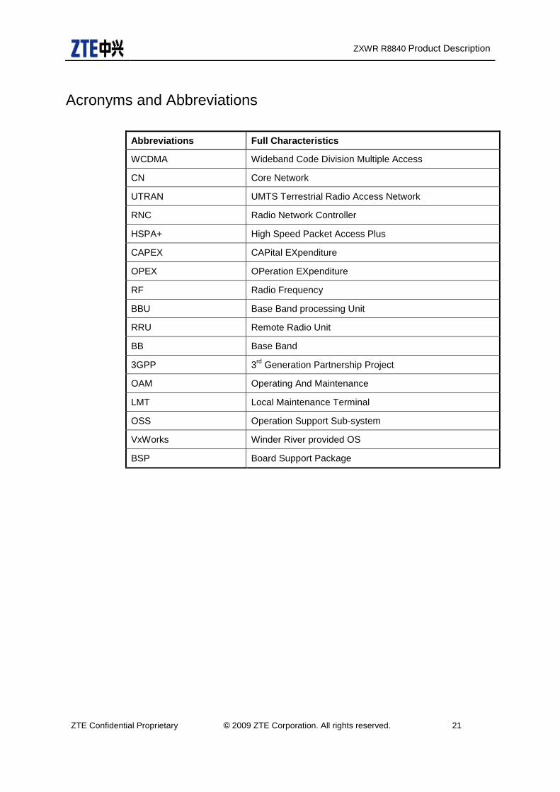
Acronyms and Abbreviations
Abbreviations Full Characteristics
WCDMA Wideband Code Division Multiple Access
CN Core Network
UTRAN UMTS Terrestrial Radio Access Network
RNC Radio Network Controller
HSPA+ High Speed Packet Access Plus
CAPEX CAPital EXpenditure
OPEX OPeration EXpenditure
RF Radio Frequency
BBU Base Band processing Unit
RRU Remote Radio Unit
BB Base Band
3GPP 3rd Generation Partnership Project
OAM Operating And Maintenance
LMT Local Maintenance Terminal
OSS Operation Support Sub-system
VxWorks Winder River provided OS
BSP Board Support Package
Related Documents


![ZXWR RNC (V3[1].09.30) Commissioning Guide — Integration Manual_R1.0](https://static.cupdf.com/doc/110x72/577cd1841a28ab9e7894a163/zxwr-rnc-v310930-commissioning-guide-integration-manualr10.jpg)


