Chapter Five . . . . . . . . . . . . . . . . . . . . API 574 – Inspection of Piping, Tubing, and Flanges Do Not Duplicate 574 These course notes have been prepared by TWI, strictly for the use of attendees to this TWI API-570 Examination Preparation Course. This manual is to be used as an aid to assist those persons wishing to take the API-570 Piping Inspector Certification Examination. This manual is not all-inclusive and may not be used in place of any recognized Code or Standard. This manual may not be reproduced by any means without the express written consent of TWI.

Welcome message from author
This document is posted to help you gain knowledge. Please leave a comment to let me know what you think about it! Share it to your friends and learn new things together.
Transcript
Chapter Five
. . . . . . . . . .
. . . . . .. . . .
API 574 – Inspection of Piping, Tubing, and Flanges
Do Not Duplicate
574
These course notes have been prepared by TWI, strictly for the use of attendees to this TWI API-570 Examination Preparation Course. This manual is to be used as an aid to assist those persons wishing to
take the API-570 Piping Inspector Certification Examination. This manual is not all-inclusive and may not be used in place of any recognized Code or Standard. This manual may not be reproduced by any
means without the express written consent of TWI.
THE WELDING INSTITUTE
REV.002 API-574 2 Copyright © TWI Ltd 2008
FOREWORD
This recommended practice is based on the accumulated knowledge and experience of engineers and other personnel in the petroleum industry.
SECTION 1 – SCOPE API 574 covers the inspection practices for piping, tubing, valves (other than control valves), and fittings used in petroleum refineries and chemical plants.
SECTION 3 – DEFINITIONS
3.1 ASME B31.3: Abbreviation for ASME/ANSI B31.3, Process Piping, published by the American Society of Mechanical Engineers. ASME B31.3 is written for design and construction of piping systems. However, most of the technical requirements on design, welding, examination, and materials also can be applied in the inspection, rerating, repair, and construction of piping systems. When ASME B31.3 cannot be followed because of its new construction coverage, such as revised or new material specifications, inspection requirements, certain heat treatments, and pressure tests, the piping engineer / inspector shall be guided by API 570 in lieu of strict conformance with ASME B31.3. As an example of intent, the term “principles” of ASME B31.3 has been employed in API 570 rather than the phrase “in accordance with” ASME B31.3.
3.2 CUI: Corrosion under insulation, which includes stress corrosion cracking under
insulation. 3.3 deadlegs: Components of a piping system that normally have no significant flow.
Examples include blanked branches, lines with normally closed block valves, lines which have one end blanked, pressurized dummy support legs, stagnate control valve bypass piping, spare pump piping, level bridles, relief valve inlet and outlet header piping, pump trim bypass lines, high point vents, sample points, drains, bleeders, and instrument connections.
3.4 defect: In NDE usage, a defect is an imperfection of a type or magnitude exceeding the
acceptable criteria. 3.5 design temperature: The temperature at which, under the coincident pressure, the
greatest thickness or highest rating of a piping system component is required. It is equivalent to the design temperature, as defined in ASME B31.3 and other code sections, and is subject to the same rules relating to allowances for variations of pressure or temperature or both. Different components in the same piping system or circuit may have different design temperatures. In establishing this temperature, consideration shall be given to process fluid temperatures, and insulation.
THE WELDING INSTITUTE
REV.002 API-574 3 Copyright © TWI Ltd 2008
3.6 imperfection: Flaws or other discontinues noted during inspection that may be subject to acceptance criteria on engineering / inspection analysis.
3.7 injection points: Locations where relatively small quantities of materials are injected
into process streams to control chemistry or other process variables. Injection points do not include the locations where two process streams join (mixing tees). Examples of injection points include chlorine in reformers, water injection in overhead systems, polysulfide injection in catalytic cracking wet gas, anti-foam injections, inhibitors, and neutralizers.
3.8 in-service: Refers to piping systems that have been placed in operation as opposed to
new construction prior to being placed in service. 3.9 inspector: An authorized piping inspector. 3.10 jurisdiction: A legally constituted government administration that may adopt rules
relating to piping systems. 3.11 mixing tees: A component that combines two process streams of differing composition
and / or temperature. 3.12 NDE: Nondestructive examination. 3.13 NPS: Nominal pipe size (followed, when appropriate, by the specific size designation
number without an inch symbol). 3.14 on-stream: Piping containing any amount of process fluid. 3.15 Owner-user: An operator of piping systems who exercises control over the operation,
engineering, inspection, repair, alteration, testing, and rerating of those piping systems. 3.16 PT: Liquid penetrant testing. 3.17 pipe: A pressure-tight cylinder used to convey a fluid or to transmit a fluid pressure,
ordinarily designated “pipe” in applicable material specifications. (Materials designated “tube” or “tubing” in the specifications are treated as pipe when intended for pressure service.)
3.18 piping circuit: Complex process units or piping systems are divided into piping circuits
to manage the necessary inspections, calculations, and record keeping. A piping circuits is a section of piping of which all points are exposed to an environment of similar corrosivity and which is of similar design conditions and construction material. When establishing the boundary of a particular piping circuit, the Inspector may also size it to provide a practical package for recordkeeping and performing field inspection.
THE WELDING INSTITUTE
REV.002 API-574 4 Copyright © TWI Ltd 2008
3.19 piping engineer: One or more persons or organizations acceptable to the owner-user who are knowledgeable and experienced in the engineering disciplines associated with evaluating mechanical and material characteristics which affect the integrity and reliability of piping components and systems. The piping engineer, by consulting with appropriate specialists, should be regarded as a composite of all entities necessary to properly address a technical requirement.
3.20 piping system: An assembly of interconnected piping, subject to the same set or sets of
design conditions, used to convey, distribute, mix, separate, discharge, meter, control, or snub fluid flows. Piping system also includes pipe-supporting elements, but does not include support structures, such as building frames, bents, and foundations.
3.21 PWHT: Post weld heat treatment. 3.22 repair: A repair is the work necessary to restore a piping system to a condition suitable
for safe operation at the design conditions. If any of the restorative changes result in a change of design temperature or pressure, the requirements for rerating also shall be satisfied. Any welding, cutting, or grinding operation on a pressure-containing piping component not specifically considered an alteration is considered a repair.
3.23 rerating: A change in either or both the design temperature or the maximum allowable
working pressure of a piping system. A rerating may consist of an increase, decrease, or a combination. De-rating below original design conditions is a means to provide increased corrosion allowance.
3.24 small bore piping (SBP): Less than or equal to NPS 2. 3.25 soil-to-air (S/A) interface: An area in which external corrosion may occur on partially
buried pipe. The zone of the corrosion will vary depending on factors such as moisture, oxygen content of the soil, and the operating temperature. The zone generally is considered to be from 12 inches (30cm) below to 6 inches (51 cm) above the soil surface. Pipe running parallel with the soil surface that contacts the soil is included.
3.26 spools: A section of piping encompassed by flanges or other connecting fittings, such as
unions. 3.27 temper embrittlement: A loss of ductility and notch toughness in susceptible low-alloy
steels (e.g., 1 1/4 Cr and 2 1/4 Cr) due to prolonged exposure to high temperature service (between 700º to 107º F (371ºC to 577ºC).
3.28 thickness measurement locations (TMLs): Designated areas on piping systems where
periodic inspections and thickness measurements are conducted. 3.29 WFMT or WFMPT: Wet fluorescent magnetic particle testing.
THE WELDING INSTITUTE
REV.002 API-574 5 Copyright © TWI Ltd 2008
SECTION 4 – PIPING COMPONENTS
4.1 Piping
Piping can be made from any material that can be rolled and welded, cast, or drawn through dies to form a tubular section. The different from traditional thickness designations and schedules is indicated. Small bore piping (NPS 2 pipe size and less) is also included. See Table 1 for nominal sizes.
4.2 Tubing
Tubing is generally seamlessly drawn. General information about tubing.
4.3 Valves
The basic types of valves are gate, globe, plug, ball, diaphragm, butterfly, check, and slide valves. See Figures 1 – 8 for cross section view of each of these valves. All of Section 4.3 is general basic information about valves.
4.4 Fittings
Fittings are used to connect pipe sections and change the direction of flow or allow the flow in a piping run to be diverted or added to. The basic types of pipe fittings, cast, forged, seamlessly drawn, or formed and welded. Fittings may be flanged, socket-welded, butt welded or threaded. See Figures 9-16 for cross section view of each of these fittings. All of Section 4.4 and 4.5 is general basic information about pipe fittings.
SECTION 5 – REASONS FOR INSPECTION
5.1 General
The primary purpose of inspection is to achieve the desired quality assurance and ensure plant safety and reliability.
5.2 Safety
Basic information about common sense piping safety. 5.3 Reliability and Efficient Operation
An added benefit to having a regular inspection program, is that it creates a data bank of information regarding the physical condition of equipment and the rate and cause of deterioration. The user can then establish effective preventative maintenance schedules. This effort should result in reduced maintenance costs and more reliable and efficient operations.
THE WELDING INSTITUTE
REV.002 API-574 6 Copyright © TWI Ltd 2008
5.4 Regulatory Requirements
Federal, state, and local statutes and regulations may apply to piping installation an inspection.
SECTION 6 – INSPECTING FOR DETERIORATION IN PIPING 6.1 General
Petro-chemical piping, by nature, often carries highly corrosive materials, it is suggested API IRE Chapter II, Conditions Causing Deterioration or Failures, be reviewed for causes of deterioration.
6.2 Corrosion Monitoring of Process Piping
The most frequent reason for replacing piping is from thinning due to corrosion. A good monitoring system is imperative. Things to consider when establishing a corrosion-monitoring plan: a. Classifying the piping accordance with API 570. b. Categorizing the piping into circuits of similar corrosion behavior. c. Identifying susceptible locations where accelerated corrosion is expected. d. Accessibility of the TML’s for monitoring.
6.2.1 Piping Circuits
The basic factors of pipe wall corrosion are listed. As well as, suggestions for breaking piping systems into circuits, see figure 21 for an example
6.2.2 Piping Classifications
factors to consider when classifying piping are, toxicity, volatility, combustibility, location of the piping with respect to personnel and other
6.3 Inspection for Specific Types of Corrosion and Cracking General information about the following subjects are found in the rest of this section:
a) Injection points. b) Deadlegs. c) Corrosion under insulation (CUI). d) Soil-to-air interfaces. e) Services specific and localized corrosion. f) Erosion and corrosion/erosion. g) Environmental cracking. h) Corrosion beneath linings and deposits.
THE WELDING INSTITUTE
REV.002 API-574 7 Copyright © TWI Ltd 2008
i) Fatigue cracking. j) Creep cracking. k) Brittle fracture. l) Freeze damage. m) Corrosion at support points. n) Dew Point Corrosion.
SECTION 7 – FREQUENCY ANF TIME OF INSPECTION 7.1 General
The frequency and time of inspection should be determined by the following conditions: • The severity of service. • The degree of risk. • The amount of corrosion allowance remaining. • The historical data available. • Regulatory requirements.
7.2 Inspection While Equipment is Operating
Many other conditions in piping systems should be determined while the equipment is operating. On-stream inspection can reduce downtime by the following means:
a. Extending process runs and preventing some unscheduled shutdowns. b. Permitting fabrication of replacement piping before a shutdown. c. Eliminating unnecessary work and reducing personnel requirements. d. Aiding maintenance planning to reduce surges in work load.
7.3 Inspection While Equipment is Shut Down
Piping can often be inspected internally during outages. SECTION 8 – SAFETY PRECAUTIONS AND PREPARATORY WORK
8.1 Safety Precautions
This section outlines some generic, extremely basic safety precautions. 8.2 Preparatory Work
This section outlines some generic, extremely basic preparatory work.
THE WELDING INSTITUTE
REV.002 API-574 8 Copyright © TWI Ltd 2008
SECTION 9 – INSPECTION TOOLS See Table 2, page 30 of API 570.
SECTION 10 – INSPECTION PROCEDURES 10.1 Inspection While Equipment Is Operating 10.1.1 Visual Inspection 10.1.1.1 Leaks
Leaks can be safety or fire hazards, and always result in economic loss. Temporary or permanent repairs can often be made while he lines are in service.
10.1.1.2 Misalignment
Piping should be inspected for misalignment. Pipe dislodged from supports, vessel wall deformation, pipe supports out of plumb, excessive replacement of bearings, etc., shifting of base-plates, foundation damage, cracks in connecting flanges, expansion joints not performing properly, are all indications of misalignment.
10.1.1.3 Supports
Supports are shoes, hangers, and braces, and should be visually inspected for problems.
10.1.1.4 Vibration
Vibrating or swaying piping should be inspected for cracks, at points of restraint, usually in the areas of anchors, or where small bore pipe is attached to the main line.
10.1.1.5 External Corrosion
Defects in the protective coatings and insulation will permit moisture to contact the piping. This can result in corrosion and metal loss.
10.1.1.6 Accumulations of Corrosive Liquids
Some liquids are corrosive to steel piping, spills should be cleaned up or neutralized.
10.1.1.7 Hot Spots
Operating piping at higher than design limits may cause bulging, even to the point of failure. Investigation of these areas is essential.
THE WELDING INSTITUTE
REV.002 API-574 9 Copyright © TWI Ltd 2008
10.1.2 Thickness Measurements 8.2.2.1 Ultrasonic Inspection
UT digital thickness gauges are mentioned with emphasis on high temperature readings.
10.1.2.2 Radiographic Inspection
Wall shot or radiographic profile radiography is discussed in this section, as to the use of the technique, no information about how the technique is performed.
10.1.3 Other On-stream Inspections
This section mentions “new” methods of inspection; halogen leak detectors, magnetic induction, real-time radiography, neutron radiography, thermography, etc.
10.2 Inspection While Equipment Is Shut Down 10.2.1 Visual Inspection 10.2.1.1 Corrosion, Erosion, and Fouling Borescopes are used to inspect piping internally. 10.2.1.2 Cracks
Inspect the susceptible locations, construction tack welds at other than pressure welds, heat affected areas joining welds, and points of restraint or excessive srain. Include locations that are subject to stress-corrosion cracking, hydrogen cracking, and caustic or amine embrittlement, as well as exposed threads.
10.2.1.3 Gasket Faces of Flanges
General inspection. 10.2.1.4 Valves
Inspection techniques for gate valves including the valves being dismantled at specified intervals.
10.2.1.5 Joints, 10.2.1.5.1 Flanged Joints, 10.2.1.5.2 Welded Joints, 10.2.1.5.3 Threaded Joints, 10.2.1.5.4 Clamped Joints
All the listed joints should be inspected, the basic technique is visual examination.
THE WELDING INSTITUTE
REV.002 API-574 10 Copyright © TWI Ltd 2008
10.2.1.6 Misalignment
Misalignment is caused by: a. Inadequate provision for expansion. b. Broken or defective anchors or guides. c. Excessive friction on sliding saddles, indicating a lack of lubrication or a
need for rollers. d. Broken rollers or rollers that cannot turn because of corrosion or lack of
fabrication. e. Broken or improperly adjusted hangers. f. Hangers that are too short and thus limit movement or cause lifting of the
pipe. g. Excessive operating temperature.
10.2.1.7 Vibration
Vibrating or swaying piping should be inspected for cracks, at points of restraint, usually in the areas of anchors, or where small bore pipe is attached to the main line.
10.2.1.8 Hot Spots
A short discussion of areas over heated on piping is discussed. No mention of thermal photography.
10.2.2 Thickness Measurements
UT digital thickness gauges are mentioned with emphasis on high temperature readings and the use of radiography on nipple thickness.
10.2.3 Pressure Tests
Pressure tests are leak tests and may be used on the following: a. Underground lines and other inaccessible piping. b. Water and other non-hazardous utility lines. c. Long oil transfer lines in areas where a leak or spoil would nor be
hazardous to personnel or harmful to the environment. d. Complicated manifold systems. e. Small piping and tubing systems. f. All systems, after a chemical cleaning operation.
Do not over pressure the system!
THE WELDING INSTITUTE
REV.002 API-574 11 Copyright © TWI Ltd 2008
Various fluids may be used for pressure testing: a. Water with or without an inhibitor, freezing-point depressant, or wetting
agent. b. Liquid products normally carried in the system, if non-toxic or
flammable. c. Steam d. Air, carbon dioxide, nitrogen, helium, or another inert gas.
Salt water can create problems like pitting and corrosion. Pneumatic tests should be conducted strictly in accordance with ASME B 31.3.
10.2.4 Hammer Testing
Hammer testing is an old method of testing piping systems, do not use the hammer on cast iron and stress-relieved lines in caustic and corrosive service.
10.3 Inspection Of Underground Piping
Basic information about buried piping, referencing several NACE documents. 10.3.1 Types and Methods of Inspection and Testing 10.3.1.1 Above-Grade Visual Surveillance
Extremely basic information about leaking underground piping.
10.3.1.2 Close-Interval Potential Survey
This type of survey is used to locate corrosion cells, galvanic anodes, stray currents, coating problems, underground contacts, areas of flow pipe-to-soil potentials and other cathodic protection problems. Key phrase “Close-interval potential survey”.
10.3.1.3 Holiday Pipe Coating Survey
Basically, a measurement is taken and compared to other areas of the system, coated as opposed to non-coated piping will give different corrosion rates and readings.
10.3.1.4 Soil Resistivity Testing
The Wenner method, the soil bar and soil box methods are discussed. Basically, each method measures a voltage drop, caused by a known current flow, across a measured volume of soil. The resistance factor is used in a formula to determine the resistivity of the soil.
THE WELDING INSTITUTE
REV.002 API-574 12 Copyright © TWI Ltd 2008
10.3.1.5 Cathodic Protection Monitoring
Refer to NACE RP0169 and Section 11 of API Recommended Practice 651. Section 10.3.2 Inspection Methods, 10.3.21. Intelligent Pigging, 10.3.2.2 Video Cameras, 10.3.2.3 Excavation are all basic with little or no useful information . 10.3.3 Leak Testing
The basic methods of leak testing underground piping are briefly described in this section. The methods are: a. Pressure decay method. b. Volume in/volume out method. c. Single-point volumetric methods. d. A marker chemical (tracer) method. e. Acoustic emission method.
10.4 Inspection Of New Construction 10.4.1 General
Must meet the requirements of ASME B 31.3.
10.4.2 Inspection of Materials
Materials should be checked for conformance with the codes and specifications that are appropriate for the plant. Checks should be made using material test kits or a nuclear alloy analyzer, (PMI).
SECTION 11: DETERMINATION OF RETIREMENT THICKNESS 11.1 Piping
All formulas and data for determining the required wall thickness for piping are found in ASME B 31.3. ASME B 31.3 also into consideration the following:
a. Corrosion. b. Threads. c. Stress caused by mechanical loading, hydraulic surge pressure, thermal
expansion, and other conditions.
THE WELDING INSTITUTE
REV.002 API-574 13 Copyright © TWI Ltd 2008
The Barlow formula: The Barlow formula can be used provided that the value is less than D/6, or P/SE is not greater than 0.385”. The Barlow formula is as follows:
t = PD/2SE
Where: t = pressure design thickness for internal pressure, in inches P = Internal design gauge pressure of the pipe, in pounds per square inch D = outside diameter of the pipe, in inches S = allowable unit stress at the design temperature, in pounds per square inch E = longitudinal joint efficiency.
Metallic pipe for which t > D/6 or P/SE > 0.385 requires special consideration.
11.2 Valves And Flanged Fittings
Refer to ASME B16.34 for minimum valve wall thickness.
SECTION 12: RECORDS
12.1 General
Records should be kept in a detailed and orderly manner. These records will help in evaluating replacement or repair intervals.
12.2 Sketches
Sketches have important functions:
a. They identify particular piping systems in terms of location, size, material specification, general process flow, and service conditions.
b. They inform the mechanical department of points to be opened for visual inspection and parts that require replacement or repair.
c. They serve as field data sheets on which can be recorded the locations of thickness measurements, serious corrosion, and sections requiring immediate replacement. These data can be transferred to continuous records at a later date.
d. They assist at future inspections in determining locations that urgently require examination.
12.3 Numbering Systems
Use any convenient means.
THE WELDING INSTITUTE
REV.002 API-574 14 Copyright © TWI Ltd 2008
12.4 Thickness Data
A record of thickness data may provide a means of corrosion or erosion rates for the piping system. See Figure 25 for an example of sketches and thickness data.
12.5 Review Of Records
General information about when to review records.
THE WELDING INSTITUTE
REV.002 API-574 15 Copyright © TWI Ltd 2008
API 574 – PRACTICE QUESTIONS 1. API 574 covers inspection of:
a. new construction b. new tank construction c. piping d. vessels
2. Cast iron pipe can be joined by:
a. welding b. compression c. epoxy resin d. bell and spigot
3. The primary purpose of inspection is to achieve the desired quality assurance and:
a. ensure plant safety b. supply the necessary paperwork for outside audits c. complicate maintenance activities d. create an avenue for dismissing poor welders
4. Ultrasonic thickness readings at areas with surface temperatures above ___________ are normally higher
than actual thickness.
a. 100ºF b. 200ºF c. 300ºF d. 212ºC
5. Flame detectors used to indicate a furnace or boiler fire may give erroneous indications on control panels
during:
a. Welding or related repairs on piping. b. Piping alterations in the shop. c. Ultrasonic inspection. d. Radiographic inspection
6. Leaks in a threaded joint may be caused by:
a. Back-welding the fitting. b. Lack of thread lubricant. c. Under-pressuring the part. d. Changing the direction of flow in the piping system.
7. A leaking threaded joint should not be tightened while the system is in service under pressure because:
a. The craftsman should not be near the threaded connection. b. Rust or corrosion might be holding the pressure. c. The joint might be unscrewed. d. A crack in a thread root might fail.
THE WELDING INSTITUTE
REV.002 API-574 16 Copyright © TWI Ltd 2008
8. During a pressure test, care should be taken not to:
a. Allow any inert gas into the system. b. Use water in the system. c. Over-pressure the system. d. Under-pressure the system.
9. Which of the following tests should not be used on cast iron piping:
a. Radiographic test b. Leak test c. Ultrasonic test d. Hammer test
10. the details of inspection of in-service piping are provided in:
a. ASME IX b. ASME B31.3 c. API 570 d. ASME B 16.5a
11. t = PD/2SE is the formula for:
a. Required Piping Thickness b. Maximum Piping Thickness c. Arbitrary Renewal Piping Thickness d. Average Piping Thickness
12. API RP 574 is a:
a. Code b. Standard c. Specification d. Recommended Practice
13. During the manufacturing of tubing, the tubing may be welded, but is generally:
a. Riveted. b. Seamlessly drawn. c. Wire drawn. d. Forged.
14. A globe valve is commonly used to:
a. Prevent back flow. b. Allow full flow. c. Stop all flow. d. Regulate fluid flow.
15. A check valve is commonly used to:
a. Prevent back flow. b. Allow full flow. c. Stop all flow. d. Regulate fluid flow.
THE WELDING INSTITUTE
REV.002 API-574 17 Copyright © TWI Ltd 2008
16. API Recommended Practice 574, Inspection of Piping, Tubing Valves, and Fittings, does not cover.
a. control valves. b. Piping smaller than 2" NPS. c. Tubing smaller than 1.5" diameter. d. Fittings smaller than 2" NPS.
17. The refining industry generally uses what type piping for severe service?
a. brass. b. cast. c. Seamless. d. Longitudinal seam welded.
18. Piping made by rolling plates to size and welding the seams is larger than_______________________ inches Outside diameter.
a. 10 b. 16 c. 14 d. 12
19. Steel and alloy piping are also manufactured to standard dimensions in nominal pipe inches.
a. 24 b. 36 c. 48 d. 50
20. Steel and alloy piping are also manufactured to standard thicknesses designated as schedules in nominal pipe sizes up to________________inches.
a. 24 b. 36 c. 48 d. 50
21. The actual thickness of wrought piping may vary from its nominal thickness by a manufacturing under tolerance of as much as_____________ percent.
a. 12.5 b. 12.0 c. 10.0 d. 10.5
22. Cast piping has thickness tolerance of + ______________ inch and - ______ inch.
a. 1/16,0 b. 1/16, 1/16 c. 1/32, 1/32 d. 3/64,0
THE WELDING INSTITUTE
REV.002 API-574 18 Copyright © TWI Ltd 2008
23. For all nominal pipe sizes of ______________ inches and smaller, the size refers to the nominal inside diameter.
a. 10 b. 12 c. 14 d. 16
24. Under tolerance of welded pipe often used in refinery service is ____________________ inch.
a. 0.125 b. 0.050 c. 0.010 d. 0.005
25. For what service is cast iron piping normally used.
a. Non-hazardous service, such as lube oils. b. Non-hazardous service, such as water. c. Corrosive service, such as acids. d. Non-corrosive service, such as low temperature caustic.
26. Tubing is generally seamless drawn, but it may be welded. Its stated size is its actual:
a. outside radius. b. Inside diameter. c. Outside diameter. d. Inside radius.
27. There are many type valves. Which is incorrect valve type listed below?
a. style valve b. gate valve c. check valve d. globe valve
28. What type valve is normally used in a fully open or fully closed position?
a. gate b. globe c. slide d. plug
29. What type gate valves have body and port openings that are smaller than the valves" end opening.
a. Borda tube gate valves b. Reduced-port gate valves c. Weir gate valves d. Sluice gate valves
THE WELDING INSTITUTE
REV.002 API-574 19 Copyright © TWI Ltd 2008
30. What type of gate valve should not be used as block valves associated with pressure relief devices?
a. It is normally used as block valve b. It is commonly used to regulate fluid flow c. It is ordinarily used to measure pressure drop d. It is frequently used in place of a slide valve.
31. What is a globe valve used for?
a. Sluice gate valves b. Weir gate valves c. Borda tube gate valves d. Reduced-port gate valves
32. A plug valve consists:
a. of a slide or slides that operate perpendicularly to the flow and move on rail guides to interrupt flow. b. of a ball with a hole in it that fits into the valve body and interrupts the flow of material. c. of a circular gate that operates in and out in the body to interrupt flow. d. Of a tapered or cylindrical truncated cone with a slot fitting into correspondingly shaped
seat. 33. What type of valve depends upon a spherical type gate has a hole in it and is rotated to open or close it?
a. diaphragm valve b. plug valve c. globe valve d. ball valve
34. What are check valves normally used for?
a. They are generally used in erosive or high-temperature service. b. They are used to automatically prevent backflow. c. They are commonly used to regulate fluid flow. d. They are used for conditions that require quick on/off or bubble-tight service.
35. What are slide valves generally used for?
a. They are used to automatically prevent backflow. b. They are used for conditions that require quick on/off or bubble-tight service. c. They are generally used in erosive or high-temperature service. d. They are commonly used to regulate fluid flow.
36. What type of joint listed below would you NOT used in a 300 psi pipe system?
a. lap-joint flanged b. welded c. bell-and-spigot d. weld-neck flanged

THE WELDING INSTITUTE
REV.002 API-574 20 Copyright © TWI Ltd 2008
37. What type of pipe joint is generally limited to piping in non-critical service and has a nominal size of 2 inches or smaller?
a. flanged joint b. threaded joint c. socket-weld joint d. butt-welded joint
38. Socket welded joints are usually used in nominal pipe size of __________________________ or smaller.
a. 4" b. 3" c. 2.5" d. 2"
39. Which of the joints listed is the most common found in the petroleum industry?
a. compression joints b. butt-welded joints c. bell-and-spigot joints d. sleeve joints
40. The primary purpose of piping inspection is to:
a. satisfy the requirements of jurisdictional regulations. b. achieve ate the lowest cost, piping that is reliable and has the desired quality. c. ensure plant safety and reliability; also achieve desired quality assurance. d. Produce a piping system that meets minimum design and serviceability requirements.
41. Adequate inspection is a prerequisite for maintaining piping:
a. in a leak free condition. b. satisfactory to the owner-user. c. in a satisfactory operating condition. d. in a safe, operable condition.
42. 0SHA 1910.119 mandates that:
a. piping be inspected to a code or standard such as API 570. b. Owner/user adopt API 570. c. Water piping be inspected the same as chemical piping. d. The owner/user immediately shut down corroded piping system.
43. Regularly requirements usually cover only those conditions that affect:
a. Pollution. b. Operations. c. Safety. d. maintenance
THE WELDING INSTITUTE
REV.002 API-574 21 Copyright © TWI Ltd 2008
44. The single most frequent reason for replacing piping is :
a. an over-zealous Inspector. b. in-service cracking. c. H2S deterioration and erosion. d. thinning due to corrosion.
45. On piping that is operating, the key to effective monitoring of piping corrosion is identifying and establishing .
a. L.O.L's b. J.L.G's c. T.M.L's d. C.U.I's
46. Problems can occur when tightening bolts to correct leaking flanges in-service. Which of the below is not
one of these problems?
a. bolt interactions. b. yielding due to overload c. flange deflection d. none of the above.
47. Which one of the following is not a factor for consideration when establishing corrosion-monitoring programs?
a. accessibility b. circuitisation c. transducer diameter d. risk classification.
48. A greater loss in metal thickness will usually be observed near a restriction or change in direction in a pipe line. What usually causes this?
a. The effects of turbulence or velocity. b. The effects of stagnation or fretting. c. The effects of corrosion or declination. d. The effects of oxidation or waning.
49. What type of problem would you expect to find in catalyst, flue-gas, and slurry piping on a Fluid Catalytic Cracking Unit.
a. embrittlement b. cracking c. corrosion d. erosion

THE WELDING INSTITUTE
REV.002 API-574 22 Copyright © TWI Ltd 2008
50. Stainless steel such as type 304 18 Chr.-8 Ni in the presence of temperature above 100 degrees F. may crack because of the presence of:
a. nitrates b. sulphides c. chlorides d. dissolved oxygen
51. A 2" diameter line is injecting a product into an 8" diameter pipe. What type of deterioration would you expect to take place?
a. accelerated corrosion or erosion b. long term corrosion c. chloride cracking d. dissolved oxygen pitting.
52. An inspector is checking a piping system that has had problems with isolated corrosion at or near the welds of piping shoes. Without knowing what product is in the line, what would be the best answer below for the problem?
a. The shoes are at high stress points and thus leaks occur. b. The welds of the shoes to the pipe were too large. c. The welds of the shoes to the pipe burned nearly through the pipe. d. The shoes are acting as cooling fins and causing localized temperature
differences.
53. What type of problem would you expect in piping containing Amine?
a. dissolved oxygen cracking b. stress corrosion cracking c. galvanic corrosion. d. crevice corrosion.
54. What area do you consider to be of most concern when inspecting a piping system?
a. Underneath insulation on lines operating at temperatures above 200° F. b. In a straight run pipe containing motor oil c. At and/or downstream of a chemical injection point. d. Underneath insulation on lines operating below 25 F.
55. Leaks in utility piping (water, steam etc.) are:
a. only of minor concern and may be disregarded. b. always dangerous but losses are negligible. c. seldom hazardous but they do result in lossees. d. usually hazardous and losses result.
THE WELDING INSTITUTE
REV.002 API-574 23 Copyright © TWI Ltd 2008
56. Where do many (maybe the majority) of leaks occur in pipelines?
a. straight runs of piping b. flanges or packing glands c. changes of direction of piping d. downstream of injection points.
57. The prompt repair of will often prevent serious corrosion or erosion of gasket surface or packing glands.
a. supports b. leaks c. guides d. welds
58. The deformation of a vessel wall in the vicinity of a pipe attachment; expansion joints that are not performing properly; a pipe dislodged from its support; etc are evidence of:
a. misalignment b. leaks c. weld problems d. drips
59. Spring hanger loading should be checked under:
a. elevated temperature conditions. b. both cold and hot conditions. c. sub-zero temperature conditions. d. ambient temperature conditions.
60. An inspector finds concrete fireproofing around a structural steel column with openings (cracks). The inspector suspects that water may be entering. What should the inspector do?
a. The inspector should ask his supervisor what he should do. b. All the fireproofing should be stripped from the column c. Enough fireproofing should be removed to determine the extent of the problem. d. No action should be taken.
61. If a steel column in a pipe support rack is corroded. What should the inspector do?
a. Have the corrosion products cleaned off and have the column painted b. No action is required c. Thickness measurements should be taken to determine whether enough
metal is left to safely support the load. d. Call a piping engineer.
THE WELDING INSTITUTE
REV.002 API-574 24 Copyright © TWI Ltd 2008
62. How do you inspect non-destructively for loose or broken foundation bolts?
a. Break out the concrete around the foundation bolt. b. Hammer the bolts vertically with a hammer. c. Lightly rap the bolts sideways with a hammer while holding a finger against
the opposite side. d. Radiograph the foundation.
63. If you find a slotted hole in a base-plate, what would this indicate to you?
a. It indicates that the craftsman making the hole was not sure of it exact location.
b. It indicates that the base-plate may have been designed to accommodate expansion.
c. It indicates that the base-plate was possibly made to be used in multiple locations.
d. It indicates that the base-plate had two holes side by side punched in it by mistake.
64. As an inspector, you find a 6" diameter pipe line that is vibrating and swaying .
What is one of the most important things you would check for and where would you check? a. Fireproofing on the supports should be checked for spalling and breaking. b. Welds should be inspected for cracks, particularly at points of restraint. c. Base-plates of the pipe supports should be checked to see if the bolts are tight. d. valves in the system should be checked to insure they are not vibrating open/closed.
65. An insulated pipe shows evidence of defects in the jacketing covering the insulation. You suspect that water may be getting in through the defects. What you would do?
a. Strip the pipe line complete to allow 100% inspection and renewal of the
insulation. b. If no discoloration is present to indicate corrosion (rust), no action is required c. Strip enough insulation to determine the extent and severity of possible
corrosion. d. Strip at least 50% of the insulation from the pipe to allow examination.
66. While inspecting an underground pipe line right-of-way, you find a discolored spot on the ground near a road that crosses the right-of-way. Which of the items below would be the course you would follow?
a. The inspector should make a note for the records and have the area checked at some future time for
possible leakage. b. It is not unusual to have discoloration on pipe line right-of-ways. If the discoloration is not wet
and there is no evidence of leakage, no action is required. c. The inspector picks up material from the discolored area. If it smells okay and no there is no reaction
on the skin, the area should pose no problem. d. The discoloration should be investigated as a possible spill. Soil or liquid samples should be checked
to see if it is corrosive to the underground.
THE WELDING INSTITUTE
REV.002 API-574 25 Copyright © TWI Ltd 2008
67. An increase in pump pressure at the pump accompanied by a decrease in flow in a pipe line downstream is an indication of ___________ .
a. leakage b. a broken line c. effluence d. fouling
68. Ultrasonic instruments are widely used for thickness measurements and are used extensively by inspection organizations. If a transducer is not equipped with “high temperature" delay-line material, it can be damaged by temperatures over degrees F.
a. 150 b. 1000 c. 250 d. 300
69. What would you expect to happen if you were taking UT readings on piping that was operating higher than 200° F.?
a. The thickness readings could be at least 10% higher or lower. b. The thickness readings would not be influenced. c. The thickness readings could be about 1% to 5% higher depending on the
temperature. d. The thickness readings would be 15% higher or lower.
70. An insulated piping system needs to have its pipe wall thickness checked. The owner-user does no want holes cut in the insulation for UT measurements and they do not want to shut down. What would you do to obtain thickness readings?
a. AE b. MT c. ET d. RT
71. Reduction of strength of the metal in a pipe, scaling, bulging, metal deterioration or complete failure are all symptoms of:
a excessive pressure b. low temperature c. excessive temperature d. blocked effluent.
72. Points of probable external corrosion of underground piping can be located by a series of measurements of the :
a. electrical resistance of surrounding soil or by measurement of pipe-to-soil electrical potential. b. wattage of the surrounding piping or by measurement of pipe-to-conduit electrical resistance. c. potential of the cathodic protection or by wattage of the pipe-to-soil electrical resistance. d. volt-amps readings of the surrounding soil or by measurement of pipe-to-pipe electrical potential.
THE WELDING INSTITUTE
REV.002 API-574 26 Copyright © TWI Ltd 2008
73. One of the most important things that an inspector must do before he actually goes out to make an inspection is:
a. make sure all electrical potentials have been checked and shut off where
necessary to prevent contact. b. check all lines to just before the point they enter the unit limits to make sure
only the unit lines are inspected. c. review the condition of transportation (cars, trucks, scooters, bicycles etc.) to
make sure transportation is not interrupted. d. review the records of previous inspections and of inspections conducted
during the current operating period.
74. When making a visual internal inspection of a pipe and fouling is found, what should the inspector do?
a. Make a note to include in the records; another inspector at the next period may want to investigate further.
b. Check with the operators to see if it is causing problems, if no problems no further action is necessary.
c. Cleaning should be considered, also, the deposits should be checked to find their origin.
d. Have the line cleaned completely immediately, make a complete write up for records.
75. The locations on piping most susceptible to cracking are: a. changes of directions. b. welds c. straight runs. d. flange bolts
76. When checking austenetic materials for cracks using PT methods only liquid penetrants:
a. with low or no nitrides should be used. b. with low or no carbides should be used. c. with high or medium chlorides should be used. d. with low or no chlorides should be used.
77. What type of defect would you expect to find at the problem of a groove of a ring joint flange made from ASTM-347 Stainless Steel?
a. pits b. cracks c. hydrogen blisters d. fouling
THE WELDING INSTITUTE
REV.002 API-574 27 Copyright © TWI Ltd 2008
78. Valves should be dismantled at specified intervals to permit examination of all internal parts. Body thickness should be measured at locations that were inaccessible before dismantling, particularly at:
a. the disk seating surfaces b. flange where the bonnet is attached. c. locations that show evidence of corrosion or erosion. d. random locations throughout the valve.
79. Bodies of valves that operate in severe cyclic temperature service should be checked internally for:
a. erosion b. fouling c. cracks d. pitting
80. Gate valves should be measured for thickness between the seats, since serious deterioration may have
occurred because of:
a. cracks b. turbulence. c. fouling d. corrosion
81. Why is the area between the seats of a gate valve a weak location?
a. Pitting can occur at this location while the valve is operating open. b. Fouling can occur at this location where there is a possibility of high velocity. c. The body of the valve is thinner in this location. d. The wedging action of the disk when is seats causes strain in this area.
82. After a valve has been inspected, repaired, and reassembled, what should be done next?
a. It should be painted inside to prevent corrosion and returned for reinstallation. b. It should be returned to the job for reinstallation c. It should be painted and the inlet and outlet capped. d. It should be tested to API 598 requirements.
83. In addition to checking the gasket surfaces of flanges for defects, and checking for corrosion and erosion, which of the following additional checks:
a. The rating of the flanges must be checked to make sure that they are both class
150 and they both have the same number of bolt holes. b. The bolts should be checked for proper specification, stretching and corrosion.
The gasket must be of the proper type and material. c. The flange bolt holes must match and at least one flange must be a class 15 or
30. d. The bolts should be machine grade and brand-new. The gasket must be a
minimum of a spiral wound grafoil filled.
THE WELDING INSTITUTE
REV.002 API-574 28 Copyright © TWI Ltd 2008
84. A weld is being made in carbon steel piping carrying Amine (MEA). What should the inspector check in addition to insuring that the weld is proper and meets specification?
a. The class of the piping, i.e. 150,300,600 etc should be verified. b. Amine can cause environmental cracking; the weld should be checked for
hardness. c. Welds on the weld hangers should be made checked and the results recorded. d. Check the seating surface and lightness of the joint by WFMT.
85. Welded joints in carbon steel and carbon-molybdenum steel exposed to elevated temperatures of 800° F or over may be subject to:
a. hydrogen attack b. graphitization c. environmental cracking d. graphitic corrosion.
86. Which one of the listed is not a cause for a threaded joint leak?
a. use of the proper lubricant b. improper assembly or loose threads c. corrosion or poor fabrication d. Cross threading or dirty threads at assembly
87. Why should a leaking threaded joint not be tightened while the system is in service under pressure?
a. An undetected crack in a thread root might fail and cause a release of product. b. Tightening may exacerbate the hardness of the threads and cause leaks. c. The pressure on the gasket may be so great that it causes a failure and thus leaks. d. Supports may fail if the threaded joint is lightened-tension on the supports.
88. What type of pipe joint must not be used without adequate axial restraint on the piping?
a. threaded joints. b. Flanged joints. c. Clamped joints. d. Welded joints.
89. Which of the following is not a cause of misalignment?
a. inadequate provision for expansion or broken and/or defective anchors or guides.
b. Too many bolts in the flanges or bolts with the wrong material. c. Excessive friction on sliding saddles or broken or corroded rollers. d. Excessive operating temperatures or broken or improperly adjusted hangers.
THE WELDING INSTITUTE
REV.002 API-574 29 Copyright © TWI Ltd 2008
90. Where excessive vibration or swaying was noted in a piping system during operation, an inspection should be made for points of _____________and ______________and for cracks in welds at locations that could not be inspected during operation.
a. graphitization, graphitic corrosion b. scaling, internal oxidation c. abrasion, external wear d. rusting, hydrogen blisters
91. Piping that has been in service or had hot spots of 800° F and above should be checked for creep or deformation with time under stress by:
a. using a transit to establish correct alignment and elevation or plumbness. b. Measuring the outside diameter of the pipe and comparing established data for life. c. Pressure testing the piping to ensure it is serviceable. d. Examining the piping with acoustic emission equipment.
92. Special attention should be given to small connections such as vents, bleeders, any type of small nipple.
One method for successfully checking the condition and the thickness of nipples is the use of:
a. RT b. AE c. MT d. PT
93. A pressure test for piping, in most cases is a:
a. leak test. b. Stress test c. Ebullition test d. Strength test.
94. Any system being tested needs to be completely isolated to:
a. prevent the testing medium from the entering connecting lines. b. Insure only the system in question is tested. c. Minimize the amount of work by limiting the lines in the test. d. Stop the testing medium from being contaminated with material from other lines.
95. If a pressure test is conducted with air or if excess air is trapped in a system that is being hydrostatically
tested, a failure of the system will be:
a. less violent than in a totally liquid filled system because it does not expand as rapidly as a hydraulic medium.
b. Easy to manage because the air will prevent liquid from being spread of the area and possibly causing an environmental incident.
c. More violent than in a totally liquid filled system because of the expansion of the compressible medium.
d. Of little consequence since it the failure will be similar to air leaking from a nail hole in a motor car tire inner tube.
THE WELDING INSTITUTE
REV.002 API-574 30 Copyright © TWI Ltd 2008
96. Which of the following materials NOT be commonly used for a pressure test?
a. water with or without an inhibitor, freezing-point depressant, or wetting agent. b. Hydrogen, hydrogen sulphide, gasoline, liquid propane or weak hydrogen
chloride. c. Liquid products normally carried in the system, if the are not toxic or likely to
cause a fire in the event of a leak or failure. d. Steam, air, carbon dioxide, nitrogen, helium or another inert gas.
97. In which of the following systems would water be a questionable test medium?
a. Gasoline reflux lines, propane piping, and butane systems. b. Diesel fuel systems, gas oil systems, and kerosene systems. c. Acid lines, cryogenic systems, and air drier systems. d. Re-boiler oil systems, boiler piping, and steam turbine lines.
98. What should be considered when testing carbon steel piping during cold weather or if cold fluids are used in
the testing?
a. The transition temperature of the steel should be considered to prevent brittle failure.
b. The test medium may freeze if it escapes during test. c. The transition temperature of the medium should be considered for brittle
cracking. d. The translation temperature of the test medium may freeze the test gages.
99. What is the preferred medium for a pneumatic test?
a. a flammable gas b. an inert gas. c. Hydrogen gas d. Propane gas
100. What type of piping usually has a pressure recorder attached in which a permanent record of the test is made? a. boiler piping b. underground piping c. light hydrocarbon unit piping d. operating unit piping
101. Which of the following piping should NOT be hammer tested?
a. pipe made from steel on a Fluid Catalytic Cracking Unit. b. Steel pipe and lines off a crude tower on a crude still. c. Cast iron and stress-relieved lines in caustic and corrosive service. d. ASTM A-106 Grade A pipe on a catalytic Reforming Unit.
THE WELDING INSTITUTE
REV.002 API-574 31 Copyright © TWI Ltd 2008
102. New construction piping should meet the requirements of ____________ as a minimum.
a. API 571 b. ASTMA-53 c. ASMEB-31.3 d. ASMEStd607
103. When ASME B31.3 cannot be followed because of its new construction orientation, which document should guide the Engineer/Inspector?
a. API 574 b. API 575 c. ASME VIII d. None of the above.
104. A piping Engineer must be:
a. A degreed Mechanical Engineer. b. Acceptable to the owner/user c. Qualified as an API 570 Inspector. d. A single entity (i.e., cannot be more than one person)
105. Which of the following is not a re-rating?
a. A "scab" patch causing a decrease in design pressure. b. A de-rating for corrosion. c. A change in materials to a lower stress value. d. An increase in the MAWP of the system.
106. A "piping system" does not include which of the following items?
a. piping supports. b. Fittings c. Dents. d. Valves
107. The boundary of a piping circuit should be sized:
a. By the inspector. b. To provide for accurate record-keeping and field inspection c. To minimize TML's d. To remove the threat of CUI
108. When using statistical methods to assess corrosion in piping, it is very important to._________________ .
a. Properly select components to b. Hydrotest all piping c. Ensure an adequate number of TML's are placed. d. Both a & c, above.
THE WELDING INSTITUTE
REV.002 API-574 32 Copyright © TWI Ltd 2008
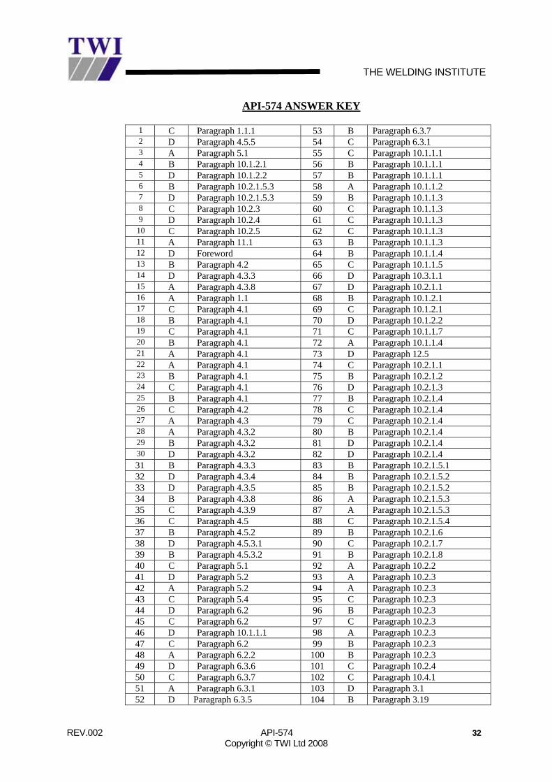
API-574 ANSWER KEY
1 C Paragraph 1.1.1 53 B Paragraph 6.3.7 2 D Paragraph 4.5.5 54 C Paragraph 6.3.1 3 A Paragraph 5.1 55 C Paragraph 10.1.1.1 4 B Paragraph 10.1.2.1 56 B Paragraph 10.1.1.1 5 D Paragraph 10.1.2.2 57 B Paragraph 10.1.1.1 6 B Paragraph 10.2.1.5.3 58 A Paragraph 10.1.1.2 7 D Paragraph 10.2.1.5.3 59 B Paragraph 10.1.1.3 8 C Paragraph 10.2.3 60 C Paragraph 10.1.1.3 9 D Paragraph 10.2.4 61 C Paragraph 10.1.1.3
10 C Paragraph 10.2.5 62 C Paragraph 10.1.1.3 11 A Paragraph 11.1 63 B Paragraph 10.1.1.3 12 D Foreword 64 B Paragraph 10.1.1.4 13 B Paragraph 4.2 65 C Paragraph 10.1.1.5 14 D Paragraph 4.3.3 66 D Paragraph 10.3.1.1 15 A Paragraph 4.3.8 67 D Paragraph 10.2.1.1 16 A Paragraph 1.1 68 B Paragraph 10.1.2.1 17 C Paragraph 4.1 69 C Paragraph 10.1.2.1 18 B Paragraph 4.1 70 D Paragraph 10.1.2.2 19 C Paragraph 4.1 71 C Paragraph 10.1.1.7 20 B Paragraph 4.1 72 A Paragraph 10.1.1.4 21 A Paragraph 4.1 73 D Paragraph 12.5 22 A Paragraph 4.1 74 C Paragraph 10.2.1.1 23 B Paragraph 4.1 75 B Paragraph 10.2.1.2 24 C Paragraph 4.1 76 D Paragraph 10.2.1.3 25 B Paragraph 4.1 77 B Paragraph 10.2.1.4 26 C Paragraph 4.2 78 C Paragraph 10.2.1.4 27 A Paragraph 4.3 79 C Paragraph 10.2.1.4 28 A Paragraph 4.3.2 80 B Paragraph 10.2.1.4 29 B Paragraph 4.3.2 81 D Paragraph 10.2.1.4 30 D Paragraph 4.3.2 82 D Paragraph 10.2.1.4 31 B Paragraph 4.3.3 83 B Paragraph 10.2.1.5.1 32 D Paragraph 4.3.4 84 B Paragraph 10.2.1.5.2 33 D Paragraph 4.3.5 85 B Paragraph 10.2.1.5.2 34 B Paragraph 4.3.8 86 A Paragraph 10.2.1.5.3 35 C Paragraph 4.3.9 87 A Paragraph 10.2.1.5.3 36 C Paragraph 4.5 88 C Paragraph 10.2.1.5.4 37 B Paragraph 4.5.2 89 B Paragraph 10.2.1.6 38 D Paragraph 4.5.3.1 90 C Paragraph 10.2.1.7 39 B Paragraph 4.5.3.2 91 B Paragraph 10.2.1.8 40 C Paragraph 5.1 92 A Paragraph 10.2.2 41 D Paragraph 5.2 93 A Paragraph 10.2.3 42 A Paragraph 5.2 94 A Paragraph 10.2.3 43 C Paragraph 5.4 95 C Paragraph 10.2.3 44 D Paragraph 6.2 96 B Paragraph 10.2.3 45 C Paragraph 6.2 97 C Paragraph 10.2.3 46 D Paragraph 10.1.1.1 98 A Paragraph 10.2.3 47 C Paragraph 6.2 99 B Paragraph 10.2.3 48 A Paragraph 6.2.2 100 B Paragraph 10.2.3 49 D Paragraph 6.3.6 101 C Paragraph 10.2.4 50 C Paragraph 6.3.7 102 C Paragraph 10.4.1 51 A Paragraph 6.3.1 103 D Paragraph 3.1 52 D Paragraph 6.3.5 104 B Paragraph 3.19
THE WELDING INSTITUTE
REV.002 API-574 33 Copyright © TWI Ltd 2008
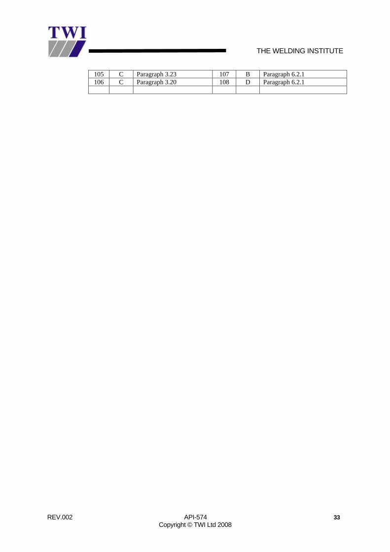
105 C Paragraph 3.23 107 B Paragraph 6.2.1 106 C Paragraph 3.20 108 D Paragraph 6.2.1
Related Documents