Prodigit Electronics Co., Ltd. Hand-held device (notebook computer, mobile phone and tablet computer) has become increasingly and popular, these devices contain an internal rechargeable lithium battery, the other Vehicle devices such as electric bicycles, scooters and electric cars are also equipped with a different capacity rechargeable battery, as the battery is power source, in addition to supply the required power supply device, also need to handle abnormal situations, to avoid a fire hazard, and even explosion occurs, so almost all rechargeable batteries will collocate the battery management system (BMS) to ensure safety. Specifically, the battery management system (BMS) is a circuit board that is connected with the rechargeable batteries, inside the BMS to monitor battery voltage, charging current, discharging current, temperature, and charging and discharging switch control connection, it must disconnect the battery, charger and device when under the dangerous or abnormal situations to avoid burning fire or explosion occurs. The abnormal situations are: a. Over Current, including a charging current and discharging current modes b. The charging voltage is too high c. When discharge, too low voltage over-discharging (Under-Voltage) d. Over High temperature e. Over Low Temperature In order BMS to ensure that the battery can be operated within safe operating area, and it has an internal switch (it usually is a solid-state semiconductor MOSFET Switch), when the battery works outside of the safety zone, this internal switch will open circuit (OPEN) to ensure the safety of the battery. Before the battery collocates with BMS board, it must be individually tested to verify BMS circuits suitable for each variety abnormal conditions that can be operated in accordance with designed so as to ensure safe and secure, after that procedure the battery unit and BMS combination to be finish product, then making a final inspection of the finished product so as to meet the highest quality requirements. PRODIGIT Electronic load with BMS option has two kinds of completed test solutions for testing and certification, they are to increase BMS test function on all series electronic load and BMS on 6010 ATE automated test system, this article is described only on the electronic load increasing BMS tested function. Most functions are described in 3310F series load with BMS optional test function, including battery charging, discharging and temperature and other conditions can be accurately simulated, and the ability to quickly test BMS actual operation parameters, such as over-charge or over-discharge current and response time simulation, meanwhile it also can simulate too high or too low temperature, to verify whether the charging or discharging can be decreased. Regarding to BMS temperature test, please refer to "Battery charger and temperature test solution". The following describes Prodigit 3310F series with BMS functions and operations, providing BMS circuit board test and solutions. 3310F electronic load and 6010 ATE provides BMS verification test solutions (Battery Management System)

Welcome message from author
This document is posted to help you gain knowledge. Please leave a comment to let me know what you think about it! Share it to your friends and learn new things together.
Transcript

Prodig i t E lect ronics Co. , L td .Prodig i t E lect ronics Co. , L td .
Hand-held device (notebook computer, mobile phone and tablet computer) has become increasingly and popular, these devices contain an internal rechargeable lithium battery, the other Vehicle devices such as electric bicycles, scooters and electric cars are also equipped with a different capacity rechargeable battery, as the battery is power source, in addition to supply the required power supply device, also need to handle abnormal situations, to avoid a fire hazard, and even explosion occurs, so almost all rechargeable batteries will collocate the battery management system (BMS) to ensure safety.Specifically, the battery management system (BMS) is a circuit board that is connected with the rechargeable batteries, inside the BMS to monitor battery voltage, charging current, discharging current, temperature, and charging and discharging switch control connection, it must disconnect the battery, charger and device when under the dangerous or abnormal situations to avoid burning fire or explosion occurs. The abnormal situations are:a. Over Current, including a charging current and discharging current modesb. The charging voltage is too highc. When discharge, too low voltage over-discharging (Under-Voltage)d. Over High temperaturee. Over Low Temperature
In order BMS to ensure that the battery can be operated within safe operating area, and it has an internal switch (it usually is a solid-state semiconductor MOSFET Switch), when the battery works outside of the safety zone, this internal switch will open circuit (OPEN) to ensure the safety of the battery.Before the battery collocates with BMS board, it must be individually tested to verify BMS circuits suitable for each variety abnormal conditions that can be operated in accordance with designed so as to ensure safe and secure, after that procedure the battery unit and BMS combination to be finish product, then making a final inspection of the finished product so as to meet the highest quality requirements.
PRODIGIT Electronic load with BMS option has two kinds of completed test solutions for testing and certification, they are to increase BMS test function on all series electronic load and BMS on 6010 ATE automated test system, this article is described only on the electronic load increasing BMS tested function. Most functions are described in 3310F series load with BMS optional test function, including battery charging, discharging and temperature and other conditions can be accurately simulated, and the ability to quickly test BMS actual operation parameters, such as over-charge or over-discharge current and response time simulation, meanwhile it also can simulate too high or too low temperature, to verify whether the charging or discharging can be decreased. Regarding to BMS temperature test, please refer to "Battery charger and temperature test solution".The following describes Prodigit 3310F series with BMS functions and operations, providing BMS circuit board test and solutions.
3310F electronic load and 6010 ATE provides BMS verification test solutions (Battery Management System)
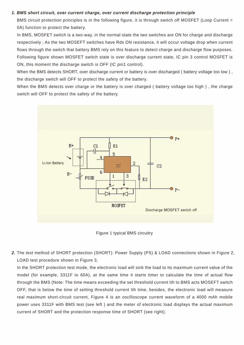
1. BMS short circuit, over current charge, over current discharge protection principleBMS circuit protection principles is in the following figure, it is through switch off MOSFET (Loop Current =
0A) function to protect the battery.
In BMS, MOSFET switch is a two-way, in the normal state the two switches are ON for charge and discharge
respectively ; As the two MOSEFT switches have Rds ON resistance, it will occur voltage drop when current
flows through the switch that battery BMS rely on this feature to detect charge and discharge flow purposes.
Following figure shown MOSFET switch state is over discharge current state, IC pin 3 control MOSFET is
ON, this moment the discharge switch is OFF (IC pin1 control).
When the BMS detects SHORT, over discharge current or battery is over discharged ( battery voltage too low ) ,
the discharge switch will OFF to protect the safety of the battery.
When the BMS detects over charge or the battery is over charged ( battery voltage too high ) , the charge
switch will OFF to protect the safety of the battery.
2. The test method of SHORT protection (SHORT): Power Supply (PS) & LOAD connections shown in Figure 2,
LOAD test procedure shown in Figure 3.
In the SHORT protection test mode, the electronic load will sink the load to its maximum current value of the
model (for example, 3311F to 60A), at the same time it starts timer to calculate the time of actual flow
through the BMS (Note: The time means exceeding the set threshold current Ith to BMS acts MOSEFT switch
OFF, that is below the time of setting threshold current Ith time, besides, the electronic load will measure
real maximum short-circuit current, Figure 4 is an oscilloscope current waveform of a 4000 mAh mobile
power uses 3311F with BMS test (see left ) and the meter of electronic load displays the actual maximum
current of SHORT and the protection response time of SHORT (see right).
Figure 1 typical BMS circuitry
When the battery is accidentally short circuit or over current, IC pin 2 voltage (partial voltage of the
MOSFET threshold resistance) is greater than the over current detection threshold, IC pin 1 output low,
the discharge MOSFET is turned off to stop discharge.
When the battery is accidentally short circuit or over current, IC pin 2 voltage (partial voltage of the
MOSFET threshold resistance) is greater than the over current detection threshold, IC pin 1 output low,
the discharge MOSFET is turned off to stop discharge.

PS Simulates Battery Electronic Load simulates the current of electronic device
SHORT Protection Test Procedure
Figure 3 The procedure of 3311F with BMS for SHORT current test procedure
Figure 4 The waveform of 4000mAh power Bank at real SHORT test
Figure 2 Equivalent Block Diagram for BMS discharge operation
SHORT protection response time is about 0.350ms
Programmed OCCP Current Value(i)and test time (t)
Real BMS protect actionof OCCP
Load VoltageP+ - P-
60A
Simulating abnomal current of Electronic devices by electronic Load
start testing protection action
The response time when BMS detects abnormal discharge current, turn off the MOSFET switch.
test resultoscilloscope measure result : 16.6A,0.350ms
BMS SHORT : SET SHORT TIME 10ms ,ITH=1A,
3311F : 16.811A,0.347ms,
test resultoscilloscope measure result : 16.6A,0.350ms
BMS SHORT : SET SHORT TIME 10ms ,ITH=1A,
3311F : 16.811A,0.347ms,
0.350ms
Short Current
OCP Active time
TrigIth
10ms

3. Over current charge protection (OCCP) Test Method : The test methods are distinguished to be single pulse and continuous Step pulse, single pulse can be used for fast test which is suitable for the production line for a high throughput testing, continuous step pulse can be used to scan the actual over current protection point which is suitable for research and development requiring precise response current and time.Power supply (PS) & LOAD connection and testing procedures shown in Figure 5.3.1 Single - pulse over current protection test mode, the electronic load will sink to the programmed load current
value, (for example, 3311F the current value are between 0 ~ 60A), then the electronic load will measure the actual current values of the over current protection and over current response time, FIG. 6 is a BMS overcharge current test procedure of 3311F single pulse current, and FIG. 7 is the actual measured test results, figure on the left is the oscilloscope current waveform of BMS over current charge protection, figure on the right is the 3311F with BMS actual test of over charge current values and protection the response time.
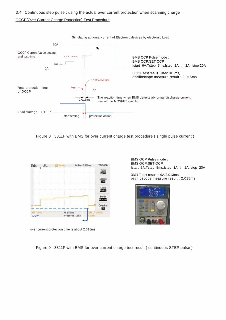
3.2 Continuous STEP pulse over current protection test mode, it is similar to the single-pulse mode, continuous pulse mode Except the start current setting, also the time of each STEP, that is each STEP increases current until the final STEP value. Figure 8 is BMS over charge current test procedure of 3311F single pulse current, and FIG. 9 is the actual test results, on left it shows the current waveform of oscilloscope of BMS over charge current protection, on the right is the actual test 3311F with BMS for over current charge value and the protection response time.Continuous STEP pulse mode, the actual over current protection value and over current response time value measuring by electronic load is the test result under each STEP. For example, if set ISTART is 1.000A OCT TSTEP ISTART as 500ms, OCP ISTEP is 0.1A, OCP ISTOP is 5.000A, the measurement process is the electronic load firstly sink current to 1.000A and check if battery BMS has action within 500ms? if it has action, it can measure the action current value and response time. If the battery BMS in 1.000A does not have action the electronic load will be set according to ISTEP sink current increased to 1.100A, and test whether it has action within next 500ms, If yes, it can measure the operating current value and action time at 1.100A. If the battery BMS does not have action at 1.100A, then according to above same operation method to increase test current to 1.200A until the final test current value of battery BMS is equal to ISTOP 5.000A.
Figure 5 Equivalent Block Diagram for BMS charge operation
BMS
BAT+
BAT-
PS
P+
P-
LOAD
i
Simulating battery charge current by electronic load
Simulating charge operation by power supply (PS)

Programmed OCCP Current Value setting(0~specification value)(i)and test time(t)
Real BMS protect actionof OCCP
Load Voltage
Simulating abnomal current of electronic devices by electronic load
start testing protection action
The response time when BMS detects abnormal discharge current, turn off the MOSFET switch.
over current protection response time is about 0.98ms
Single pulse : use in fast test
Figure 6 3311F with BMS for over current charge test procedure ( single pulse current )
Figure 7 3311F with BMS for over current charge test result ( single pulse current )
OCCP(Over Current Charge Protection) Test Procedure
BMS OCP Pulse mode : SET OCP Istart=15A,Tstep=10ms Istep=0A, Ith=1A
3311F test result3311oscilloscope measure result : 10.980ms
oscilloscope measure result : 0.980ms
F-BMS:0.981ms
BMS OCP Pulse mode : SET OCP Istart=15A,Tstep=10ms Istep=0A, Ith=1A
3311F test result : 0.981ms
0.98ms
OCP Current
OCP Active time
TrigIth
10ms
3.3
5A/V
t
P+ - P-
15
Load Voltage
oscilloscope measure result : 2.015ms
OCCP Current Value settingand test time
20A
6A0A
Real protection time of OCCP
Simulating abnomal current of Electronic devices by electronic Load
start testing protection action
The reaction time when BMS detects abnormal discharge current, turn off the MOSFET switch.
over current protection time is about 2.015ms
Continuous step pulse : using the actual over current protection when scanning charge
Figure 8 3311F with BMS for over current charge test procedure ( single pulse current )
Figure 9 3311F with BMS for over current charge test result ( continuous STEP pulse )
OCCP(Over Current Charge Protection) Test Procedure
F test result
3.4
BMS OCP Pulse mode : BMS OCP:SET OCP Istart=6A,Tstep=5ms,Istep=1A,Ith=1A, Istop 20A
3311 :9A/2.013ms,
2.015ms
OCP Current
OCP Active time
TrigIth
oscilloscope measure result : 2.015mstest result
BMS OCP Pulse mode : BMS OCP:SET OCP Istart=6A,Tstep=5ms,Istep=1A,Ith=1A,Istop=20A
3311F : 9A/2.013ms,
5A/V
P+ - P-

Simulating battery discharge operation bypower supply
Simulating discharge operation byelectronic load
OCCP Current Value settingand test time
Real protection time of OCCP
Simulating abnomal current of Electronics devices by electronic Load
start testing protection action
The response time when BMS detects abnormal discharge current, turn off the MOSFET switch.
Figure 11 3311F with BMS for over current discharge test procedure
test result
Over current discharge protection (OCDP) Test Method : Power (PS) & LOAD connections and test procedure shown in Figure 10.
Figure 10 Equivalent Block Diagram for BMS discharge operation
4
BMS
BAT+
BAT-
P+
P-
PS LOAD
i
4.1 Single Pulse : Use in fast testOCDP (Over Current Discharge Protection) Test ProcedureFigure 11 is a single pulse current of 3311F with BMS for over current discharge test procedure, and FIG. 12 is the actual test results On Left is oscilloscope current waveform of BMS over discharge protection, on the right is the actual test over current discharge value and protection reaction time.
BMS OCP Pulse mode : SET OCP Istart=20A,Tstep=10ms Istep=0A, Ith=2A
3311F : 0.350ms
0.35ms
OCP Current
OCP Active time
TrigIth
10
20A
ms
Load Voltage P+ - P-
oscilloscope measure result : 0.350ms

4.2 Continuous step Pulse : The actual over current protection point when scanning discharge OCDP(Over Current Discharge Protection) Test Procedure, Figure 13 is 3311F continuous pulse current BMS over discharge current test procedure, and FIG. 14 is the actual test Results. In the left is the oscilloscope current waveform of BMS over discharge current protection, in the right is the actual test of 3311F with BMS for over discharge current value and the response time.
test result
20A
5A
OCCP Current Value settingand test time
Real protection time of OCCP
Simulating abnomal current of Electronics devices by electronic Load
start testing protection action
The response time when BMS detects abnormal discharge current, turn off the MOSFET switch.
Figure 13 3311F with BMS for over current discharge test procedure ( continuous STEP pulse )
test result
Figure 12 3311F with BMS for over current discharge test result ( single pulse )
BMS OCP Pulse mode : SET OCP Istart=20A,Tstep=10ms Istep=0A, Ith=2A
3311F : 0.350ms
5A/V
0 over current protection time is about . 350ms
BMS OCP:SET OCP Istart=5A,Tstep=5ms,Istep=2A,ITH=1A,Istop=20A
3311F : 11A/2.055ms,
2.056ms
OCP Current
OCP Active time
TrigIth
Load Voltage P+ - P-
oscilloscope measure result : 2.056ms
oscilloscope measure result : 0.350ms

test result
Figure 14 3311F with BMS for over current discharge test result ( continuous STEP pulse )
2 over current protection time is about . 056ms
BMS OCP:SET OCP Istart=5A,Tstep=5ms,Istep=2A,Ith=1A,Istop 20A
3311F : 11A/2.055ms,
5. The BMS battery functions and response of actual action have detailed explanation previously. The battery BMS indeed can make immediate disconnection protection measures for battery abnormal voltage, current and temperature so as to avoid the hazard occurrence, since the battery BMS is safty issue that shall be 100% fully functional testing and validation in order to ensure security, although the test to verify the battery BMS can be used by oscilloscope to get the current value and response time of action. Needless to say, it can be done by oscilloscope to do detailed testing in the development stage, but in the mass production stage, we need quick and complete test, it has production capacity limits, due to this difficult, Prodigit especially integrates the battery BMS test in electronic load that is exception normal features of all series electronic load there increasing additional battery BMS testing that required test current setting, the current value of the action and response time operation are all integrated into BMS Option, that is to make a lot of quick test to verify battery BMS to be a precise, reliable and fast method. Following are the test functions of 3311F-BMS Short, OCCP, OCDP protection function. Operating instructions are as below :5.1 Set BMS “ ON “ on Config function parameter, this time the front panel OCP / Short Test button is on
BMS test mode, OPP is a OPP test function, when BMS is set to "OFF", that are generally OCP / OPP / Short function.
5.2 SHORT Test: When BMS P +, P- occur short circuit protection status, it needs to measure the short-circuit current, protection time. The setting method: Press Short key, it can be set to Short test time (0.010 ~ 10.000ms, default 1ms), threshold current Ith (0.01 ~ 60A), press Start key to start the BMS short test automatically sink the maximum current 60A, when testing DISPLAYit shows "SHORT " TEST, when Im (I measuring) < Ith, the test is completed, the second line of LCD displays short circuit current, the third line displays the protection time.
oscilloscope measure result : 2.056ms

5.3 OCP (OCCP / OCDP) : The protection status of testing BMS over current charge (OCCP) or over current discharge (OCDP), it needs to measure the current and protection time of over current charge or over current discharge, OCCP / OCDP are using OCP test, the difference is in different connection ways of the power supply (PS) & LOAD and BMS.Setting method: Press OCP key, can be set Istart -> Tstep (1 ~ 1000ms) -> Istep -> Istop -> Ith (0.01A ~ <Istart), press Start key to start Load test from Istart sink current and set time out (Tstep), if it does not occur protection within this time, increase current Istep (if Istep set to 0, get it to end), until it occurs protection (Im (I measuring) < Ith) or to Istop as end, When testing DISPLAY show "OCP" TEST, when end of the test the second line of LCD display OCP current, third line display protection time.
Note: When the test mode is a PULSE, then just set Istart and Tstep, press Start key to start the test (Istep default is 0)

Tablel 1 The specification of 3311F with BMS option
5.5 As the test former description, when testing BMS individually it needs to use power supply as a battery simulator (for discharge test). If the battery cells and BMS combined to be finished product it does not require power supply, the test can be done for finished product directly. Prodigit 6010 ATE posses the DC power supply which required by BMS cells or cell + BMS finished products. The BMS Electronic load test, the charging / discharging connector switches can be executed in 6010 ATE test program.
5.6 From the former detailed test results, you can see that the measure data of Prodigit 3311F electronic Load containing BMS function are almost same as the reading values of oscilloscope, meanwhile the test parameters and conditions can be set one by one that posses flexibility, accuracy, easy and fast testing and certification, in addition to 6010 ATE supports all of Prodigit electronic loads as long as install 3311F with BMS in 6010 ATE that will be able to perform accurate and fast automatic program of BMS.
Almost all series electronic load can be installed with BMS option, such as 3310 series, 34000 series, 36000 series electronic load, please contact Prodigit sales office or distributor in your area.
5.4 Specification of 3311F with BMS option test function is shown in Table 1, it includes SHORT test and OCP test respectively. For the BMS specification of other model, please contact Prodigit sales office for details.
3311F-BMS
60A 0.01~10.000ms
0.01ms 0.001ms
±0.005ms 0.010~60.000A
±1%(reading+60A)
0.1~60A 0.01~10ms/1~1000ms
0.01/1ms 0.001/0.1ms
±0.005/±0.2ms 0.010A ~ <Istart
±0.1%(setting+60A)
ITEMSHORT TESTSink CurrentTime RangeTime ResolutionMeasure ResolutionTime AccuracyIthIpeak AccuracyOCP TESTIstartTimeRange(Tstep)Time ResolutionMeasure ResolutionTime AccuracyIthCurrent Accuracy
Related Documents