Previous Issue: 30 June, 2003 Next Planned Update: 1 January, 2009 Revised paragraphs are indicated in the right margin Page 1 of 22 Primary contact: Mahmoud Y. Naffa'a on 874-7263 Materials System Specification 32-SAMSS-006 31 December, 2003 Manufacture of Low Pressure Tanks Vessels Standards Committee Members Naffa'a, M.Y., Chairman Al-Anizi, S.S. Al-Gahtani, M.S. Al-Musaiid, H.A. Al-Sharhan, Z.S. Jones, S.B. Khanna, R.K. Khouie, S.B. Kim, S.U. Muir, W.R. Walsh, M.P. Saudi Aramco DeskTop Standards Table of Contents 1 Scope............................................................ 2 2 Referenced Publications............................... 3 3 Definitions..................................................... 4 4 Materials....................................................... 5 5 Design........................................................... 7 6 Fabrication.................................................... 12 7 Inspection and Testing................................. 13 8 Marking......................................................... 18 9 Pressure and Vacuum-Relieving Devices.... 18 10 Shell Attachments and Tank Appurtenances..................................... 18 11 Coatings and Painting.................................. 19 12 Shipping Requirements................................ 20 13 Disinfection................................................... 20 Appendix, B – Use of Materials that are not Identified with Listed Specifications............ 21 Appendix R – Low Pressure Storage Tanks for Refrigerated Products........................... 22

Welcome message from author
This document is posted to help you gain knowledge. Please leave a comment to let me know what you think about it! Share it to your friends and learn new things together.
Transcript
Previous Issue: 30 June, 2003 Next Planned Update: 1 January, 2009 Revised paragraphs are indicated in the right margin Page 1 of 22 Primary contact: Mahmoud Y. Naffa'a on 874-7263
Materials System Specification
32-SAMSS-006 31 December, 2003 Manufacture of Low Pressure Tanks
Vessels Standards Committee Members Naffa'a, M.Y., Chairman Al-Anizi, S.S. Al-Gahtani, M.S. Al-Musaiid, H.A. Al-Sharhan, Z.S. Jones, S.B. Khanna, R.K. Khouie, S.B. Kim, S.U. Muir, W.R. Walsh, M.P.
Saudi Aramco DeskTop Standards Table of Contents 1 Scope............................................................ 2 2 Referenced Publications............................... 3 3 Definitions..................................................... 4 4 Materials....................................................... 5 5 Design........................................................... 7 6 Fabrication.................................................... 12 7 Inspection and Testing................................. 13 8 Marking......................................................... 18 9 Pressure and Vacuum-Relieving Devices.... 18 10 Shell Attachments and Tank Appurtenances..................................... 18 11 Coatings and Painting.................................. 19 12 Shipping Requirements................................ 20 13 Disinfection................................................... 20 Appendix, B – Use of Materials that are not Identified with Listed Specifications............ 21 Appendix R – Low Pressure Storage Tanks for Refrigerated Products........................... 22
Document Responsibility: Vessels 32-SAMSS-006 Issue Date: 31 December, 2003 Next Planned Update: 1 January, 2009 Manufacture of Low Pressure Tanks
Page 2 of 22
The following paragraph numbers refer to API STD 620, Tenth Edition, February 2002, which are part of this specification. The text in each paragraph below is an addition or exception to or deletion of a requirement of API STD 620 as noted. Paragraph numbers not appearing in API STD 620 are new paragraphs to be inserted in numerical order.
1 Scope
1.1 General
1.1.1 This specification defines the minimum mandatory requirements governing material, mechanical design, fabrication, erection, inspection, and testing of low-pressure storage tanks.
1.1.2 This specification does not cover tanks designed in accordance with Appendix Q "Low-Pressure Storage Tanks for Liquefied Hydrocarbons Gases" and double wall tanks according to Appendix R "Low-Pressure Storage Tanks for Refrigerated Products" of API 620. Additional requirements for such tanks shall be developed, if necessary, by the Design Engineer. Such requirements shall be submitted to the Saudi Aramco Engineer prior to bidding with sufficient time for review.
1.1.3 This specification shall be attached to and form an integral part of a purchase order.
1.1.4 Conflicts and Deviations
1.1.4.1 Any conflicts between this specification and other Saudi Aramco Materials System Specifications (SAMSSs), Saudi Aramco Engineering Standards (SAESs), Industry codes and standards, and Saudi Aramco Standard Drawings (SASDs) and Forms shall be resolved in writing by the Company or Buyer Representative through the Manager, Consulting Services Department of Saudi Aramco, Dhahran.
1.1.4.2 Direct all requests to deviate from this specification in writing to the Company or Buyer Representative, who shall follow internal company procedure SAEP-302 and forward such requests to the Manager, Consulting Services Department of Saudi Aramco, Dhahran.
1.2 Coverage
1.2.5 (Exception) Horizontal cylindrical tanks used for the storage of hydrocarbon liquids within the scope of API STD 620, with design pressures in their gas or vapor spaces not more than 103 kPa gauge (15 psig).
Document Responsibility: Vessels 32-SAMSS-006 Issue Date: 31 December, 2003 Next Planned Update: 1 January, 2009 Manufacture of Low Pressure Tanks
Page 3 of 22
2 Referenced Publications
Materials or equipment supplied to this specification shall comply with the latest edition of the references listed below, unless otherwise noted.
2.1 Saudi Aramco References
Saudi Aramco Engineering Procedures
SAEP-302 Instructions for Obtaining a Waiver of a Mandatory Saudi Aramco Engineering Requirement
SAEP-1142 Qualification of non-Saudi Aramco NDT Personnel
SAEP-327 Disposal of Waste Water from Cleaning, Flushing and Hydrostatic Tests
Saudi Aramco Engineering Standards
SAES-A-007 Hydrostatic Testing Fluids and Lay-Up Procedures
SAES-A-102 Ambient Air Quality And Source Emission Standard
SAES-A-206 Positive Material Identification
SAES-B-017 Firewater System Design
SAES-B-067 Safety Identification & Safety Colors
SAES-H-001 Selection Requirements for Industrial Coatings
SAES-W-017 Welding Requirements for Tanks
Saudi Aramco Material System Specification
09-SAMSS-107 Fluoropolymer/Ceramic Coating to Fasteners
Saudi Aramco Standard Drawing
AB-036387 Tank Grounding
Saudi Aramco Forms
Form 175-324901 Tanks: Low Pressure, Steel within the Scope of 32-SAMSS-006
Form 2696-ENG Appurtenance Schedule and Orientations
Document Responsibility: Vessels 32-SAMSS-006 Issue Date: 31 December, 2003 Next Planned Update: 1 January, 2009 Manufacture of Low Pressure Tanks
Page 4 of 22
Form 7918-1 Nonmaterial Requirements for Tanks
Form 9580-ENG API 620 Storage Tank Data Sheet
Form NMR-7918-1 Nonmaterial Requirements for Tanks
2.2 Industry Codes and Standards
American Petroleum Institute
API STD 620 Design and Construction of Large, Welded, Low-Pressure Storage Tanks
API STD 2000 Venting Atmospheric and Low-Pressure Storage Tanks
API STD 2510 Design and Construction of LPG Installations
American Society of Civil Engineers
ASCE 7-95 Minimum Design Loads for Buildings and Other Structures
American Society of Mechanical Engineers
ASME B16.47 Large Diameter Steel Flanges
ASME SEC VIII Div.1 Rules for Construction of Pressure Vessels
American Society for Testing and Materials
ASTM A6 General Requirements for Rolled Steel Plates, Shapes, Steel Piling, and Bars for Structural Use
ASTM A20 General Requirements for Steel Plates for Pressure Vessels
American Water Works Association
AWWA C652 Disinfection of Water Storage Facilities
3 Definitions
3.5 Additional Terms
3.5.1 Auto Refrigeration Temperature: Auto-refrigeration temperature is the adiabatic vaporization temperature of the process fluid coincident with a pressure equal to 25 percent of the maximum operating pressure.
Document Responsibility: Vessels 32-SAMSS-006 Issue Date: 31 December, 2003 Next Planned Update: 1 January, 2009 Manufacture of Low Pressure Tanks
Page 5 of 22
3.5.2 Saudi Aramco Engineer: The Supervisor of the Piping and Mechanical Unit, Consulting Services Department, Dhahran.
3.5.3 Saudi Aramco Inspector: The person or company authorized by the Saudi Aramco Inspection Department to inspect tanks to the requirements of this specification.
3.5.4 Design Engineer: The Engineering Company responsible for specifying, on the tank data sheet, the design requirements for tanks.
3.5.5 Design Metal Temperature: The lowest of the following temperature values:
1) The lowest one-day mean atmospheric temperature (LODMAT) per SAES-A-112, or
2) The minimum operating temperature, or
3) The hydrostatic test temperature.
4) Auto-refrigeration temperature for refrigerated storage tanks as defined in section 3 of this standard.
3.5.6 Tank Manufacturer: The company responsible for the fabrication of tanks.
3.6 Drawings and Calculations
3.6.1 The Tank Manufacturer shall prepare and submit for review a complete set of assembly and shop drawings for the tank(s) being manufactured and in accordance with Form 7918-1, Nonmaterial Requirements for Tanks and Saudi Aramco Form 9580-ENG "API STD 620 Storage Tanks Data Sheet".
3.6.2 Drawings and calculations which are approved by the Design Engineer shall not relieve the Tank Manufacturer of the responsibility to comply with the Code and this specification.
4 Materials
4.1 General
4.1.1 The Tank Manufacturer shall submit a complete material specification with the proposal.
Document Responsibility: Vessels 32-SAMSS-006 Issue Date: 31 December, 2003 Next Planned Update: 1 January, 2009 Manufacture of Low Pressure Tanks
Page 6 of 22
The Tank Manufacturer may propose the use of alternative materials to those that are listed in API STD 620. The alternative materials shall comply with all the other requirements of API STD 620 and this specification. The chemical compositions and mechanical properties of non-ASTM materials shall be submitted to be evaluated and approved by the Saudi Aramco Engineer.
Materials proposed by the Tank Manufacturer that are equivalent to those specified in API STD 620 shall be approved by the Saudi Aramco Engineer.
4.1.2 Materials That Cannot Be Completely Identified
(Exception) All materials shall be clearly identified and provided with mill test certificates.
4.1.3 Accessory Pressure Parts
(Exception) Accessory pressure parts shall be clearly identified and provided with mill certificates.
4.1.4 Small Parts
(Exception)Small parts shall be clearly identified and provided with mill certificates.
4.2 Plates
4.2.1 General
4.2.1.1 Annular plate material for cylindrical, flat-bottom tanks shall be of the same material specification, grade, and heat treatment, and meet the same impact test requirements as the lowest shell course.
4.2.1.2 (Exception) The design metal temperature as defined in this specification shall be used as the basis for material selection of materials not in contact with refrigerated liquids.
4.2.1.4 Rimmed or capped steels shall not be used for shell, bottom and roof plates.
4.2.2 Low-Stress Design
a. (Exception) The design metal temperature as defined in this specification shall be used as the basis for material selection of materials not in contact with refrigerated liquids or their vapors.
Document Responsibility: Vessels 32-SAMSS-006 Issue Date: 31 December, 2003 Next Planned Update: 1 January, 2009 Manufacture of Low Pressure Tanks
Page 7 of 22
b. (Exception) No increase to the design metal temperature as defined in this specification is permitted.
4.3 Pipe, Flanges, and Castings
4.3.1 (Exception to Foot note): Materials to be used for design metal temperatures below -29°C (-20°F) shall conform to API STD 620 Table R-1.
4.4 Bolting Material
Flange bolting material shall conform to ASTM A193 Grade B7 bolts with A194 Grade 2H nuts at design temperatures equal to and above -29°C (84°F) Below -29°C (-20°F), A320 Grade L7 bolts with A194 Grade 4 or 7 nuts shall be used. All bolting shall be coated with a fluoropolymer /ceramic coating in accordance with 09-SAMSS-107.
4.6 Gasketing
Gasket materials shall be non-asbestos and compatible with the service conditions.
5 Design
5.1 General
5.1.6 Design Information
5.1.6.1 Information provided by the Design Engineer on the API STD 620 Storage Tank Data Sheet and a completed Saudi Aramco Form 2696-ENG shall be used for the design of cylindrical flat-bottom, spherical, and spheroidal tanks in accordance with API STD 620 and this specification.
5.1.6.2 Low-pressure, horizontal, cylindrical tanks shall be mechanically designed using the rules of ASME VIII D1 and shall be fabricated, inspected and tested in accordance with the requirements of 32-SAMSS-006.
5.4 Loadings
e. (Exception) Tanks shall be designed for wind and earthquake loads in accordance with ASCE- 7. Wind Category Classification to be used in the calculations of wind loads shall be Category III, and the Seismic Hazard Exposure Group to be used in calculations of earthquake loads shall be Group III.
Document Responsibility: Vessels 32-SAMSS-006 Issue Date: 31 December, 2003 Next Planned Update: 1 January, 2009 Manufacture of Low Pressure Tanks
Page 8 of 22
h. Cool-down and cyclic operations, when specified by the Design Engineer on the tank data sheet.
i. All applicable loads sustained by the tank its during erection, start-up, or operation shall be considered as acting simultaneously, including either wind or earthquake, whichever govern.
j. During hydrostatic test, wind pressure may be reduced to 40% of the design wind pressure and shall be considered acting simultaneously with the hydrostatic test load.
k. Roof live loads shall not be less than a concentrated load of 225 kgs (500 lbs) over 0.4 (4.3 sq. ft.) square meters.
l. Associated piping systems loads. (Commentary: Associated piping systems loads shall be specified on the tank data sheet. Tank Manufacturer shall ensure that stresses at nozzle-to-tank connections, due to piping loads specified on the tank data sheet, are within the allowable limits.)
5.7 Corrosion Allowance
Corrosion allowance shall be provided, as specified on the tank data sheet.
5.9 Procedure for Designing Tank Walls
5.9.4 Flat Bottoms of Cylindrical Tanks
5.9.4.5 Delete this paragraph.
5.9.4.6 (Exception) Only butt- welded annular bottom plates in accordance with Paragraph R.3.4 shall be provided under the shell of flat bottom tanks.
5.9.4.7 Bearing plates shall be provided under supports of all internal piping and appurtenances. Bearing plates shall be 13 mm (1/2 inch) thick and twice the diameter of tubular support members or twice the longest dimension of prismatic support members, as applicable, and welded to the tank with 5 mm (3/16 inch) continuous welds.
5.11.5 Special Considerations Applicable to Bottoms That Rest Directly on Foundations
5.11.5.1 A foundation drip ring shall be provided for flat-bottom tanks to prevent the ingress of rainwater or condensation between the tank bottom and foundation. The ring shall meet the following requirements.
Document Responsibility: Vessels 32-SAMSS-006 Issue Date: 31 December, 2003 Next Planned Update: 1 January, 2009 Manufacture of Low Pressure Tanks
Page 9 of 22
1) Material shall be carbon steel, 3.2 mm (1/8 inch) thick.
2) Continuously seal welded to the edge of the tank annular plate. All radial joints between the drip ring sections shall also be seal welded.
3) Extend at least 75 mm (3 inch) beyond the outer periphery of the concrete ring wall.
4) Turn down at its outer diameter at a 45 degree angle.
5) The top of the drip ring and a 75 mm (3 inch) height of the tank shell shall be painted with a 10-12 mil thick epoxy coating in accordance with SAES-H-001.
5.11.5.4 Under-tank leak detection and sub-grade protection
a) Flat-bottom tanks placed directly on soil sub-grade in services other than water shall be provided with under tank leak detection and sub-grade protection according to API STD 650, Appendix I. Acceptable construction details are Figures I-1, I-2, I-3, I-6, I-7, I-8, I-9 and I-10.
b) Flexible membrane leak-barrier (liner) of minimum 1000 microns (40 mils) thickness compatible with the stored product shall be specified under the tank bottom. The liner shall be placed in accordance with SASD AA-036355, extending to the internal top edge of the ring foundation.
c) Joints in the liner shall satisfy the leak tightness, permeability, and chemical resistance requirements for the liner material.
d) Under-tank leak detection and sub-grade protection systems for construction details other those specified in paragraph 5.11.5.4(a) of this specification shall not be permitted without the prior approval of the Saudi Aramco Engineer.
5.12 Design of Roof and Bottom Knuckle Regions and Compression-Ring Girders
5.12.5 Details of Compression-Ring Regions
5.12.5.3 (Exception) Compression-ring junctures shown in Figure 5-6, Detail f-1 and Detail h, shall not be used.
Document Responsibility: Vessels 32-SAMSS-006 Issue Date: 31 December, 2003 Next Planned Update: 1 January, 2009 Manufacture of Low Pressure Tanks
Page 10 of 22
5.12.5.9 Design of the compression ring and the roof-to-shell junction in insulated tanks shall prevent infiltration of rainwater into the insulation.
5.14 Shapes, Locations, and Maximum Sizes of Wall Openings
3.14.4 (Exception) All manways shall be circular.
5.14.9 The number, size, and orientations of nozzles and manways shall be as specified on the tank data sheet and Saudi Aramco Form 2696-ENG.
5.15 Inspection Openings
A 610 mm (24 inch) minimum manway shall be provided at the top and bottom of each non-cylindrical tank. For spheroid tanks, the bottom manway shall be located above the supporting girder stiffeners. The manway covers shall be hinged or provided with davits.
5.16 Reinforcement of Single Openings
5.16.3 Size and Shape of Area of Reinforcement
5.16.3.5 Thickness of reinforcing pads shall not exceed the thickness of the shell or the roof plate to which they are attached.
5.19 Nozzle Necks and Their Attachments to the Tank
5.19.1 General
5.19.1.1 Nozzle and manway necks shall be seamless or welded pipe, or rolled plate with 100% radiography of the longitudinal seam.
5.19.1.4 (Exception) All nozzle and manway necks shall be attached to the shell or roof by full penetration welds through the roof or shell wall. Backing rings, if used, shall be removed.
5.19.3 Outer Ends of Nozzles
5.19.3.1 (Exception) All nozzle connections shall be flanged. Threaded and socket-welded connections are prohibited.
5.19.3.4 Flange bolt holes shall straddle the normal horizontal and vertical centerlines.
5.20 Bolted Flanged Connections
5.20.1 (Exception) Flanges shall be the welding-neck type conforming to the following:
Document Responsibility: Vessels 32-SAMSS-006 Issue Date: 31 December, 2003 Next Planned Update: 1 January, 2009 Manufacture of Low Pressure Tanks
Page 11 of 22
1) ASME B16.5 for flanges 610 mm (24 inch) NPS and smaller.
2) ASME B16.47, Series A or B, for flanges larger than 610 mm (24 inch) NPS.
3) The flange bore shall match the nozzle neck bore.
5.22 Permitted Types of Joints
5.22.1 Definitions
5.22.1.2(b) (Exception) Slot welds are not permitted.
5.22.1.4 (Exception) Backing strips for single-welded butt joints, except for joints in tank's sections placed directly on soil sub-grade, shall be removed after the weld is completed.
5.22.1.7 (Exception) Lap-joints are permitted only in flat-bottom tanks as follows:
a) Single lap-joints between bottom plates to each other and to the annular plates.
b) Double lap-joints between double-curvature roofs' plates.
5.22.1.8 Butt joints shall be used to construct single-curvature shells (cylindrical tank side walls) and double-curvature shells (roofs, spheres, spheroids, heads of horizontal low-pressure tanks, etc.).
5.22.1.9 Annular plates in cylindrical flat-bottom tanks shall be joined by full penetration butt welds.
5.24 Plug Welds and Slot Welds
(Exception) Plug welds and slot welds are not permitted.
5.28 Horizontal Tanks
5.28.1 Minimum thickness of shells and heads shall be 6.4 mm (1/4 inch) including corrosion allowance.
5.28.2 Tanks shall be supported on two saddles. The tank shall be fixed at one saddle support and free to slide at the other saddle.
5.28.3 Locations of the fixed and sliding saddles, and dimensions from tank centerline to underside of saddle base plate, and locations of fixed and sliding saddles shall be according to the tank data sheet.
Document Responsibility: Vessels 32-SAMSS-006 Issue Date: 31 December, 2003 Next Planned Update: 1 January, 2009 Manufacture of Low Pressure Tanks
Page 12 of 22
5.28.4 The shell shall be analyzed in accordance with the L. P. Zick analysis method. Saddle supports and the tank shell shall be analyzed for operating and hydrotest loads including any piping, wind or other external loads.
6 Fabrication
6.3 Cutting Plates
6.3.3 Edges of the bottom plates in cylindrical flat-bottom tanks to be lap welded shall be square and the thickness at the edges shall not be reduced after cutting.
6.5 Dimensional Tolerances
6.5.5.1 All lugs, brackets, nozzles, manways frames, reinforcement around openings, and other appurtenances shall fit and conform to the curvature of the surface to which they are attached.
6.5.5 .2 Reinforcing pads and all other external attachment pads shall have rounded corners with a minimum of 50 mm (2 inch) radius.
6.5.5.3 Nozzles, manways and their reinforcement shall not be located within 50 mm (2 inch) of any weld seam. Where this requirement can not be met, 100% radiography shall be performed on the encroached weld seam according to API STD 650 (Tenth Edition, Addendum 3, September 2003), paragraph 3.7.3.4.
6.5.5.4 All attachment welds to the tank shell, bottom, roof and appurtenances shall be continuously seal welded.
6.5.5.5 Lugs, clips, or any other components used to assist in erection may be attached by welding, but all such attachments shall be removed and the weld areas ground smooth and flush with the base metal and "PT" tested. The removal of attachments by hammering is prohibited.
6.5.6 Foundation
6.5.6.4 Top fill layer 10-15 cm (4-6 inch) for tanks placed directly on soil sub-grade shall be a mixture of sweet sand and 3% cement (33:1 ratio, i.e. 3% cement. The material specifications and mixing requirements shall be as follows:
1) The maximum permissible soil content is 0.1%. Sand shall be dried to a free-moisture content of not more than 2.0% by weight of dry soil.
Document Responsibility: Vessels 32-SAMSS-006 Issue Date: 31 December, 2003 Next Planned Update: 1 January, 2009 Manufacture of Low Pressure Tanks
Page 13 of 22
2) The dry sand must be screened through 6.4 mm (1/4 inch) mesh (maximum). Care must be taken in using clean mixing and handling equipment to ensure mixture remains free from foreign matter.
3) The sand shall then be thoroughly mixed with cement in a 33:1 ratio by weight in a concrete mixer. After laying the mixture it shall be rolled a minimum six times by a 3 ton roller. Vibratory plate tampers may be used in lieu of rollers for areas where a roller cannot reach and/or cover.
6.7 Qualification of Welding Procedure
6.7.5 All welding procedures, procedure qualifications and stress relieving procedures shall be in accordance with SAES-W-017 and be submitted for review/approval by Saudi Aramco.
6.8 Qualification of Welders
6.8.4 Welders and welding operators shall be tested in accordance with SAES-W-017.
6.10.1 The bottom side of the bottom plates shall be cleaned of all foreign matter and grit-blast cleaned prior to being coated and placed in position for welding. The topside surface of bottom plates, regardless whether internal coating of the tank is required or not, shall be grit-blast cleaned prior to welding. Surface preparation shall be according to APCS-3 or APCS-113, as applicable.
7 Inspection and Testing
7.0 General
7.0.1 Inspection shall be in accordance with Saudi Aramco Inspection Requirements Form 175-324901, SAES-W-017 and the additional requirements of this specification.
7.0.2 Prior to final inspection and pressure testing, the inside and outside of the tank shall be thoroughly cleaned of all slag, scale, dirt, grit, weld spatter, paint, oil, etc.
7.2 Qualifications of Examiners
7.2.4 All Nondestructive Examination, including Magnetic Particle and Liquid Penetrant examinations, shall be performed by personnel certified in accordance with SAEP-1142, or equivalent National Certification
Document Responsibility: Vessels 32-SAMSS-006 Issue Date: 31 December, 2003 Next Planned Update: 1 January, 2009 Manufacture of Low Pressure Tanks
Page 14 of 22
Programs that have been approved by the Saudi Aramco Inspection Department. Personnel responsible for interpretation of Nondestructive Examination results shall be certified to a minimum of Level II.
7.3 Access for Inspector
7.3.1 The Saudi Aramco Inspector shall have free access to the work at all times.
7.3.2 All of the rights of Saudi Aramco and their designated representatives for access, documentation, inspection, and rejection shall include any work done by sub-contractors or sub-vendors.
7.4 Facilities for Inspector
The Tank Manufacturer shall furnish, install, and maintain in a safe operating condition all necessary scaffolding, ladders, walkways, and lighting for a safe and thorough inspection.
7.5 Approval of Repairs
7.5.1 Alleviating imperfections that are beyond the limits of ASTM A6 or A20, whichever is applicable, in the tank shall be performed by the tank manufacturer.
7.5.2 All injurious plate imperfections shall be removed by the Tank Manufacturer as required by ASTM A6 or A20, whichever is applicable. Repair welding requires the approval of the Saudi Aramco Inspector.
7.5.3 Requirements for weld repairs shall be according to SAES-W-017.
7.6 Inspection of Materials
Saudi Aramco shall have the right to inspect the fabrication at any stage and to reject the use of any equipment, tools, construction material or workmanship which does not conform to the specified requirements or jeopardize safety of personnel, or impose hazard of damage to Saudi Aramco property.
7.15 Examination Methods and Acceptance Criteria
7.15.1 Radiographic Method
7.1.5.1.6 Delete this paragraph.
7.15.3 Ultrasonic Examination Method
Document Responsibility: Vessels 32-SAMSS-006 Issue Date: 31 December, 2003 Next Planned Update: 1 January, 2009 Manufacture of Low Pressure Tanks
Page 15 of 22
7.15.3.3 Delete this paragraph.
7.16 Inspection of Welds
7.16.1 Butt-welds
(Exception) All annular plate butt joints in cylindrical flat-bottom tanks shall be 100% magnetic particle examined from the topside after completion of the root pass and again after completion of the full weld.
7.17 Radiographic examination requirements
Radiographic examination of welded joints shall be in accordance with SAES-W-017.
7.17.2 Spot examination of welded joints
7.17.2.3 Spot examination of welded joints shall meet the requirements of SAES-W-017.
7.17.4 Spot-examination Retests
Spot-examination retests shall meet the requirements of SAES-W-017.
7.18 Standard Hydrostatic and Pneumatic Tests
7.18.1 General
7.18.1.1 Testing shall be in accordance with Saudi Aramco Inspection Requirements Form 175-324901 and the additional requirements of this specification.
7.18.1.2 Tanks shall be hydrostatically tested using water of quality according to SAES-A-007 and API STD 620. Testing duration shall be minimum 24 hours.
7.18.1.3 The Tank Manufacturer shall furnish all test materials and facilities, including blinds, bolting, and gaskets.
7.18.1.4 The tank shall be completely drained and thoroughly dried immediately after completion of the hydrostatic test.
7.18.1.5 The Tank Manufacturer's plan for disposal of hydrotest water shall be evaluated against SAEP-327 by the engineering contractor.
7.18.2 Test Preliminaries
Document Responsibility: Vessels 32-SAMSS-006 Issue Date: 31 December, 2003 Next Planned Update: 1 January, 2009 Manufacture of Low Pressure Tanks
Page 16 of 22
7.18.2.7 Perform oil-penetrate leak test on the entire length of the first weld pass by applying high flash point penetrant oil such as light diesel oil for a minimum 4 hours (preferably overnight).
7.18.2.8 Perform oil-penetrate leak test on the entire length of the first completed weld, before welding the second fillet weld, by applying high flash point penetrant oil such as light diesel oil for a minimum 4 hours (preferably overnight). Alternatively, apply a vacuum test at 35 kPa gauge (5 psig), using a vacuum box fit to the shell-to-bottom junction.
7.18.2.9 The inside fillet welds of the shell-to-bottom joint in a cylindrical flat-bottom tank shall be examined by either the dye-penetrant or wet-fluorescent magnetic particle method before hydrotest.
7.18.2.10 Upon completion of welding of the tank bottom, all bottom joints including bottom-to-shell joint shall be tested, before hydrotest, by using a vacuum box fit for the joint geometry, with a soap solution, before any surface coating is applied. Water or gas shall not be pumped underneath the bottom to detect leaks.
7.18.2.11 Telltale holes in reinforcing plates shall not be plugged during the tank hydrostatic test.
7.18.4 Completely Hydrostatic Tests
7.18.4.5 Hydrostatic test shall not produce a membrane stress in the bottom course which will exceed 90% of the specified minimum yield strength.
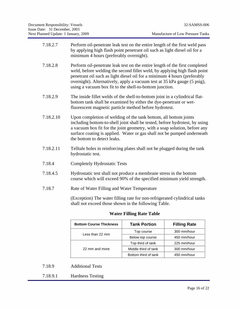
7.18.7 Rate of Water Filling and Water Temperature
(Exception) The water filling rate for non-refrigerated cylindrical tanks shall not exceed those shown in the following Table.
Water Filling Rate Table
Bottom Course Thickness Tank Portion Filling Rate Top course 300 mm/hour
Less than 22 mm Below top course 450 mm/hour Top third of tank 225 mm/hour
Middle third of tank 300 mm/hour 22 mm and more
Bottom third of tank 450 mm/hour
7.18.9 Additional Tests
7.18.9.1 Hardness Testing
Document Responsibility: Vessels 32-SAMSS-006 Issue Date: 31 December, 2003 Next Planned Update: 1 January, 2009 Manufacture of Low Pressure Tanks
Page 17 of 22
Weld hardness testing requirements and acceptance criteria shall be in accordance with SAES-W-017.
7.18.9.2. After completion of test, thoroughly clean all residual examination materials from the as yet to be welded surfaces and from the un-welded gap between the shell and the bottom. Remove defective weld segments and re-weld as required. Re-examine the repaired welds and a minimum of 150 mm (6 inches) to either side in the manner described in paragraph 7.18.2.8. Repeat this clean-remove-examine-and-clean process until there is no evidence of leaking. Complete all welding passes of the joint both inside and outside of the shell. Visually examine the finished weld surfaces of the joint both inside and outside the shell for their entire circumference.
7.18.9.3 Magnetic particle or liquid penetrant examination shall be conducted on all structural attachment welds to the tank pressure components that are attached after hydrostatic test.
7.18.11 Cylindrical Flat-Bottom Tank Settlement Measurements
7.18.11.1 The base elevation shall be established and recorded at equidistant locations of approximately 10 m (33 ft) around the tank circumference but not less than eight (8) locations. The measurement points shall be at well-marked locations on the annular plate or on clips welded to the shell. Elevation readings shall be taken as follows:
1) Before hydrostatic testing has started.
2) At the ½ filled point.
3) At the ¾ water filled point.
4) After 24 hours from filling the tank at the maximum water fill height.
5) After the tank has been emptied of test water.
7.18.11.2 Any differential settlement greater than 13 mm (1/2 inch) per 9 m (30 ft) of circumference, or a uniform settlement in excess of 50 mm (2 inch) shall be reported to the Saudi Aramco Engineer. Filling shall be stopped until clearance to continue has been received.
7.18.11.3 Internal bottom elevation measurements shall be made for tanks of 15 m (49 ft) diameter and larger before and after the hydrostatic test. Measurements shall be made at 3 m (10 ft) intervals along diametric
Document Responsibility: Vessels 32-SAMSS-006 Issue Date: 31 December, 2003 Next Planned Update: 1 January, 2009 Manufacture of Low Pressure Tanks
Page 18 of 22
lines across the bottom. The diametric lines shall be spaced approximately 10 m apart at the tank shell.
8 Marking
8.0 General
8.0.1 Marking shall be done with water soluble materials containing no substances that would attack or harmfully affect the tank at both ambient and operating temperature.
8.0.2 Marking materials shall be free of lead, sulfur, zinc, cadmium, mercury, chlorine, or any other halogens.
8.0.2 Tank number and content shall be painted in both Arabic and English at 90 degree intervals around the tank in accordance with SAES-B-067.
8.1 Nameplates
8.1.1.q All tanks with internal coatings shall have the Saudi Aramco's Approved Coating System (APCS number) marked on the nameplate.
8.3 Manufacturer's Report and Certificate
The Tank Manufacturer shall prepare drawings, calculations, and data in accordance with Form 7918-1, Non-Material Requirements-Tanks. Drawings and calculations, which are approved by the Design Engineer, shall not relieve the Manufacturer of the responsibility to comply with the Code and this specification.
9 Pressure and Vacuum-Relieving Devices
9.2 Pressure Limits
9.2.4 The Tank Manufacturer shall verify the set pressures and sizes of the pressure and vacuum relief devices specified on the tank data sheet in accordance with API STD 620 and API STD 2000.
10 Shell Attachments and Tank Appurtenances
10.1 Platforms, Walkways, and Stairways
10.1.1 Type and location of stairway shall be as specified on the tank data sheet and Saudi Aramco Form 2696.
Document Responsibility: Vessels 32-SAMSS-006 Issue Date: 31 December, 2003 Next Planned Update: 1 January, 2009 Manufacture of Low Pressure Tanks
Page 19 of 22
10.1.2 Stairs and platforms shall be fabricated of hot dipped galvanized open grating. Checker-plate grating is not permitted.
10.1.3 Walkways shall be fabricated of diamond-pattern (checker-plate) grating with anti-skid paint.
10.1.4 Stairways shall satisfy the following requirements:
1) Maximum angle with the horizontal shall be 45 degrees.
2) Minimum effective tread width shall be 200 mm (8 inch).
3) Minimum effective stairway width shall be 710 mm (28 inch).
4) Stairway platforms shall be a minimum of 710 mm (28 inch) as measured in the direction of the stairway.
10.1.5 Stairways on insulated tanks shall be provided with stringers on both sides.
10.2 Grounding
10.2.1 Tanks shall be provided with a grounding lug connection welded to the tank.
10.2.2 Cylindrical flat-bottom tanks shall be provided with grounding lugs in accordance with SASD AB-036387 at a minimum of four points spaced equidistantly around the base of the tank.
10.3 Firewater Deluge and Spray System
10.3.1 The Tank Manufacturer shall furnish and install firewater deluge system piping and components, terminating at laterals at the base of the tank, in accordance with the requirements of SAES-B-017.
11 Coatings and Painting
11.1 Types of coating and painting systems to be applied shall be as specified on the Storage Tank data Sheet.
11.2 Surfaces to be coated shall be cleaned and prepared prior to its coating in accordance with the applicable coating and painting systems.
11.3 Tanks placed directly on soil sub-grade shall be coated with APCS-3 or APCS-113, as applicable, on its soil side leaving minimum 2.5 cm (1 inch) wide strip of uncoated steel along the underside of the floor
Document Responsibility: Vessels 32-SAMSS-006 Issue Date: 31 December, 2003 Next Planned Update: 1 January, 2009 Manufacture of Low Pressure Tanks
Page 20 of 22
plate, centered on, and directly below the weld seam. This will typically require masking a strip along the underside of each end (edge) of each bottom plate approximately 5 cm (2 inch) wide. APCS-3 shall be specified for tank with maximum operation temperature of 70°C (158°F), while APCS-113 shall be specified for higher operation temperatures.
11.4 In tanks placed directly on soil sub-grade and where internal coating is not required, the following surfaces shall be coated according to the applicable coating specifications:
11.4.1 Top side of the bottom and the internal lower portion of the shell in flat bottom tanks, starting from the tank bottom up to minimum one foot above water line, shall be coated.
11.4.2 Internal lower portion of the tank from the lowest point in the tank up to minimum one foot above water line.
11.4.5 Gasket contact surfaces shall not be coated or painted.
12 Shipping Requirements
12.1 Plates and tank material shall be loaded in manner that ensures delivery without damage. Bolts, nuts, nipples, and other small parts shall be boxed or put in kegs or bags for shipment.
12.2 All flange faces and other machined surfaces shall be greased and properly protected for shipping.
13 Disinfection
13.1 All potable water storage tanks shall be disinfected in accordance with AWWA C652.
13.2 The chlorine and bacteriological tests shall be approved by the Environmental Health Department of Saudi Aramco.
Revision Summary 31 December, 2003 Major revision.
Document Responsibility: Vessels 32-SAMSS-006 Issue Date: 31 December, 2003 Next Planned Update: 1 January, 2009 Manufacture of Low Pressure Tanks
Page 21 of 22
Appendix, B – Use of Materials that are not Identified with Listed Specifications
B.4 Marking materials shall be free of lead, sulfur, zinc, cadmium, mercury, chlorine, or any other halogens.
Document Responsibility: Vessels 32-SAMSS-006 Issue Date: 31 December, 2003 Next Planned Update: 1 January, 2009 Manufacture of Low Pressure Tanks
Page 22 of 22
Appendix R – Low Pressure Storage Tanks for Refrigerated Products
R.2 Materials
R.2.1 Primary Components
R.2.1.1 General
R.2.1.1.1 Plate materials shall be limited to the following ASTM material specifications or their approved equivalent:
1) ASTM A516
2) ASTM A131 Grade CS
3) ASTM A537 Class 1 or 2
R.2.1.1.2 Material for permanent structural attachments welded to the tank shell shall be of the same nominal composition as the shell material.
R.2.1.2 Impact Test Requirements for Plates
R.2.1.2.5 (Exception) All plate materials shall be normalized.
R.7.6 Radiographic Inspection of Butt Welds in Plates
R.7.6.5 All annular plate butt joints in cylindrical flat-bottom tanks shall be 100% magnetic particle examined from the topside after completion of the root pass and again after completion of the full weld.
R.10.1.1 Design of foundations shall consider thermal movement of the tank, the insulation required for the bottom, the effects of foundation freezing and possible frost heaving, and the anchorage required to resist uplift according to API Standard 620 and API Standard 2510.
Related Documents