2000 Series Paging Terminals Configuration Guide Zetron, Inc. P.O. Box 97004 Redmond, WA 98073-9704 U.S.A. Contact Zetron for additional information on any product. Specifications are subject to change without notice. Telephone (425) 820-6363 Email: [email protected] Fax: (425) 820-7031 Web: http://www.zetron.com 001-0131B October 1997

Welcome message from author
This document is posted to help you gain knowledge. Please leave a comment to let me know what you think about it! Share it to your friends and learn new things together.
Transcript
2000 SeriesPaging Terminals
Configuration Guide
Zetron, Inc.P.O. Box 97004
Redmond, WA 98073-9704U.S.A.
Contact Zetron for additional information on any product.Specifications are subject to change without notice.
Telephone (425) 820-6363 Email: [email protected]: (425) 820-7031 Web: http://www.zetron.com
001-0131B October 1997
001-0131B October 1997 Page i
TABLE OF CONTENTS
1. OVERVIEW...............................................................................................................................................1
1.1 HOW TO USE THIS GUIDE ...................................................................................................................11.2 PAGING TERMINALS ............................................................................................................................2
2. PART TWO - STANDARD FEATURES ...................................................................................................3
2.1 PAGER CAPACITY ................................................................................................................................32.2 ALPHANUMERIC PAGING ....................................................................................................................32.3 VOICE MESSAGING ..............................................................................................................................52.4 VOICE PROMPTS ..................................................................................................................................52.5 TELCO PORTS.......................................................................................................................................62.6 TRANSMITTERS..................................................................................................................................11
3. PART THREE - ADVANCED FEATURES .............................................................................................13
3.1 NETWORKING .....................................................................................................................................133.2 CALL ROUTING ...................................................................................................................................133.3 ALARM MONITORING .........................................................................................................................17
4. PART FOUR - SYSTEM ORDER GUIDE...............................................................................................20
4.1 VOICE CONTROLLER .........................................................................................................................204.2 CPU CHOICES .....................................................................................................................................214.3 HARD DISKS ........................................................................................................................................214.4 TERMINAL AND EXPANSION OPTIONS ............................................................................................214.5 INPUT POWER REQUIREMENTS.......................................................................................................23
5. PART FIVE - SYSTEM MANAGEMENT - PROGRAMMING, REPORTING, AND BILLING ................24
5.1 DO YOU WANT MULTIPLE USERS SIMULTANEOUSLY ACCESS THE ZBASE MANAGEMENTSOFTWARE?..............................................................................................................................................245.2 DO YOU WANT MULTIPLE AGENTS TO ACCESS ZBASE? .............................................................245.3 DO YOU WANT A REAL-TIME PRINT OUT OF EACH PAGE SENT?................................................245.4 DO YOU WANT AN ACCOUNTS-RECEIVABLE SYSTEM?................................................................24
6. PART SIX - SPARES .............................................................................................................................25
6.1 DO YOU WANT TO HAVE SPARE PARTS AVAILABLE? ...................................................................256.2 SPARES PARTS KIT............................................................................................................................256.3 INDIVIDUAL SPARE PARTS................................................................................................................25
7. PART SEVEN - INSTALLATION, POWER, AND PROTECTION..........................................................27
7.1 DO YOU HAVE LIGHTNING PROTECTION ON YOUR TELCO LINES?............................................277.2 CABLE ASSEMBLIES AND PUNCHDOWN BLOCKS .........................................................................277.3 DO YOU HAVE A BACKUP POWER SUPPLY? ..................................................................................277.4 WHAT KIND OF INPUT POWER WILL SUPPLY THE PAGING TERMINAL?.....................................27
8. PART EIGHT - PRE-INSTALLATION GUIDE........................................................................................28
8.1 OPERATING CONDITIONS .................................................................................................................288.2 MOUNTING ..........................................................................................................................................288.3 WIRING.................................................................................................................................................288.4 RADIO TRANSMITTER ........................................................................................................................288.5 PHONE LINES......................................................................................................................................298.6 MICROWAVE EQUIPMENT .................................................................................................................298.7 MAINTENANCE LINE...........................................................................................................................298.8 MANAGEMENT SOFTWARE...............................................................................................................298.9 IN SHOP TESTING...............................................................................................................................29
PART ONE - OVERVIEW
001-0131B October 1997 Page 1
1. OVERVIEW
This guide is designed to help a paging system operator or dealer to consider all the requirementsnecessary to equip their proposed Zetron 2000 Series Paging Terminal to perform its specified functions.This guide also shows how the 2000 Series options relate to one another, and what requirements areimportant to be aware of when ordering these options.
When used in conjunction with the 2000 Series product specification sheets, this Configuration Guideshould be very helpful in deciding which 2000 Series options are necessary to meet a specific application.As always, Zetron applications engineers are happy to answer any additional questions that may arise.
1.1 HOW TO USE THIS GUIDE
The Configuration Guide consists of eight sections: the Overview, Standard Features, AdvancedFeatures, System Order Guide, System Management, Spares, Installation Power and Protection, and thePre-Installation Guide.
The Standard Features section contains the configuration and part number ordering information for all thestandard terminal features such as pager capacity, alphanumeric paging, voice messaging/prompts, telcoports, and transmitter control.
The Advanced Features section contains information about features that are only used in larger, moresophisticated systems. The advanced features include networking (TNPP and Outdial TAP), call routing(PathFinder), Alarm Monitoring, and redundant backup terminals (Standby System Controller).The System Order Guide section contains information about configuring the CPU, disk drives, andterminal model itself. This section should be completed after the previous sections, becausedetermination of the overall system configuration is dependent on what features will be included.
The Spares section contains information about the spares that are available for your terminal.
The System Management section contains information on system management software that will allowyou to configure and maintain your terminal and subscriber databases in the most effective way.
The Installation, Power, and Protection section addresses miscellaneous parts and pieces such asconnectors and punchdown blocks you may need during installation of your terminal. It also addresseslightning protection and backup power supplies.
The Pre-Installation Guide contains a checklist of things to consider prior to installing your terminal.
PART ONE - OVERVIEW
001-0131B October 1997 Page 2
1.2 PAGING TERMINALS
A typical paging terminal has a telephone input, a paging format encoder, a transmitter output, and somemethod for programming pager numbers into the system. The telephone input may be in the form of oneor more trunks either from the telephone company’s central office, from a PABX, or even from a singletelephone station. The transmitter(s) may be either remote or co-located, and paging may occur on morethan one channel at a time. Programming may be done a personal computer.
Additional features found on some paging terminals include voice storage that allows voice messages tobe left for later retrieval or more than one voice page to be processed at a time, voice prompts to guidethe caller through the paging process, and voice message retrieval for users to play back by telephonevoice messages and pages that had been stored in the system. Numeric and alphanumeric displaypaging may be supported. Alphanumeric messages can be entered by a caller using a PC or through anoperator-controlled device that is either on-site or is located remotely. Display pages also may be initiatedby telephone or automated input from nurse call or monitoring systems that are interfaced to the pagingterminal. Paging terminals can also be equipped to network with other paging terminals, allowing them topass pages back and forth to each other to increase area coverage. Calls may be routed to externaldevices, such as mobile telephone interconnects or telephone answering consoles, to integrate pagingand voice messaging with other services and to consolidate DID trunks onto one system. All of thesefunctions are possible with the 2000 Series Paging Terminals, and are covered in this ConfigurationGuide.
PART TWO - STANDARD FEATURES
001-0131B October 1997 Page 3
2. PART TWO - STANDARD FEATURES
2.1 PAGER CAPACITY
2.1.1 What is the maximum number of pagers/phone numbers you expect to support?� 2,000�� 3,000�� 4,000�� 5,000�� 6,000�� 7,000�� 8,000�� 9,000�� 10,000� 11,000�� 12,000�� 13,000�� 14,000�� 15,000�� 16,000�� 17,000�� 18,000� 19,000�� 20,000�� 25,000�� 30,000�� 35,000�� 40,000�� 45,000�� 50,000
The base terminal comes with 2000 subscribers. Subscribers are available in blocks of 1,000 (-X01) or5,000 (-X50). The legal values are as follows: 2K, 3K, 4K, ..., 19K, 20K, 25K, 30K, 35K, ..., 50K. To goabove 20,000 subscribers you must first buy to an even 5K increment with the -X01 option.
If you plan to use an external system such as the Zetron ZAPP software to enter alphanumeric pages andsend them to the terminal via TNPP then additional users do not have to be purchased for the terminalbecause the subscriber database is maintained by the ZAPP software. In other words, if you will besending pages to the terminal using capcodes then the terminal’s database does not have to beprogrammed with user ID’s.
2.1.2 What will be the ratio of voice pagers to numeric/alphanumeric display pagers?� 100% Voice / 0% Display�� 75% Voice / 25% Display�� 50% Voice / 50% Display� 25% Voice / 75% Display�� 0% Voice / 100% Display
2.1.3 What pager formats do you want to support?� 2 Tone � 5/6 Tone � HSC � NEC D3 � Multitone � Golay� POCSAG 512 � POCSAG 1200 � POCSAG 2400� FLEX 1600 � FLEX 3200 � FLEX 6400� Other
2.2 ALPHANUMERIC PAGING
Alphanumeric messages allow subscribers to view complete text messages on their display pager, notjust a phone number input by the caller. Alphanumeric paging is the mechanism that supports nurse callsystems, alarm monitoring systems, and CAD systems. Generally these alphanumeric messages aresent to the paging terminal via a serial link connected on the other end to a device which can be used totype in the message. Sometimes these are dedicated devices for alphanumeric entry, and sometimesthey are computers such as PCs running specialized software which generates the messages and sendsthem to the terminal. The 2000 Series paging terminal can accept these alphanumeric messages either(1) by modem over a telco line or (2) by direct serial connection (or both). If the alphanumeric entry deviceis located more than 150 feet from the paging terminal, it is recommended that the modem method beused as RS-232 serial data is unreliable over cables longer than 150 feet.
2.2.1 Do you want to transmit voice and numeric display pages from an operator controlled,desktop device that has a display?
� yes�� noYou many want to learn more about the Zetron Model 103 Paging Entry Station (901-9152) which has anLED display, a numeric keypad, and a gooseneck microphone so that an operator can send pageswithout having to dial from a telephone. If desired, order one 2 wire analog telco card (950-9822) forevery two Model 103’s to be used.
PART TWO - STANDARD FEATURES
001-0131B October 1997 Page 4
2.2.2 Alphanumeric Paging Software
2.2.2.1 Do you require alphanumeric paging software that supports large numbers of operatorsentering alphanumeric messages through a server PC?
� yes�� no
The ZAPP! Alphanumeric Paging Program (950-9281) can support up to 24 operators whose PCworkstations are connected to one server PC. The server PC interfaces to the 2000 Series pagingterminal through either the Multiport Serial Interface Card or the Bi-Directional TNPP Network InterfaceCard. See the ZAPP! price and specifications sheets for additional information.
2.2.2.2 Do you require alphanumeric paging software for single or multiple users with PCs on anetwork?
� yes�� no
The AlphaZ Alphanumeric Paging software (930-0001) is single-user software that runs on a PC runningunder DOS. A PC running AlphaZ interfaces to the 2000 Series either through a dial-up modem (the DualAlpha Input Modem) or locally through the Multiport Serial Interface Card. See the AlphaZ price andspecifications sheets for additional information.
The AZNet Alphanumeric Paging software (930-0020 / 930-0021) is multiple-user software that runs on aPC running under DOS. A central “Gateway” PC takes data from all the PCs on the network andinterfaces to the 2000 Series either through a dial-up modem (the Dual Alpha Input Modem) or locallythrough the Multiport Serial Interface Card. See the AZNet price and specifications sheets for additionalinformation.
Either of these pieces of software can be run in a DOS window under Windows 3.1, Windows ‘95, orWindows NT.
2.2.2.3 Do you want to support alpha input devices via dial-up modems?� yes�� no
If you will be supporting alpha input devices via dial-up modems, then you need to decide which trunkgroups or phone lines will have modems. Modems are available for any one or any combination of thefollowing:
1. Digital T1 span(s)
2. DID or E&M trunk group(s)
3. End-to-end line(s)
PART TWO - STANDARD FEATURES
001-0131B October 1997 Page 5
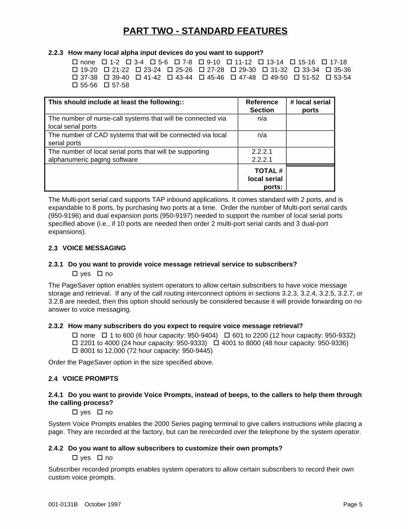
2.2.3 How many local alpha input devices do you want to support?� none�� 1-2�� 3-4�� 5-6�� 7-8�� 9-10�� 11-12�� 13-14�� 15-16�� 17-18� 19-20�� 21-22�� 23-24�� 25-26�� 27-28�� 29-30�� 31-32�� 33-34�� 35-36� 37-38�� 39-40�� 41-42�� 43-44�� 45-46�� 47-48�� 49-50�� 51-52�� 53-54� 55-56�� 57-58
This should include at least the following:: ReferenceSection
# local serialports
The number of nurse-call systems that will be connected vialocal serial ports
n/a
The number of CAD systems that will be connected via localserial ports
n/a
The number of local serial ports that will be supportingalphanumeric paging software
2.2.2.12.2.2.1
TOTAL #local serial
ports:
The Multi-port serial card supports TAP inbound applications. It comes standard with 2 ports, and isexpandable to 8 ports, by purchasing two ports at a time. Order the number of Multi-port serial cards(950-9196) and dual expansion ports (950-9197) needed to support the number of local serial portsspecified above (i.e., if 10 ports are needed then order 2 multi-port serial cards and 3 dual-portexpansions).
2.3 VOICE MESSAGING
2.3.1 Do you want to provide voice message retrieval service to subscribers?� yes�� no
The PageSaver option enables system operators to allow certain subscribers to have voice messagestorage and retrieval. If any of the call routing interconnect options in sections 3.2.3, 3.2.4, 3.2.5, 3.2.7, or3.2.8 are needed, then this option should seriously be considered because it will provide forwarding on noanswer to voice messaging.
2.3.2 How many subscribers do you expect to require voice message retrieval?� none�� 1 to 600 (6 hour capacity: 950-9404)�� 601 to 2200 (12 hour capacity: 950-9332)� 2201 to 4000 (24 hour capacity: 950-9333)�� 4001 to 8000 (48 hour capacity: 950-9336)� 8001 to 12,000 (72 hour capacity: 950-9445)
Order the PageSaver option in the size specified above.
2.4 VOICE PROMPTS
2.4.1 Do you want to provide Voice Prompts, instead of beeps, to the callers to help them throughthe calling process?
� yes�� no
System Voice Prompts enables the 2000 Series paging terminal to give callers instructions while placing apage. They are recorded at the factory, but can be rerecorded over the telephone by the system operator.
2.4.2 Do you want to allow subscribers to customize their own prompts?� yes�� no
Subscriber recorded prompts enables system operators to allow certain subscribers to record their owncustom voice prompts.
PART TWO - STANDARD FEATURES
001-0131B October 1997 Page 6
2.4.3 Voice Prompt Ordering
Do not order these options if any PageSaver options (as specified in section 2.3.2) have been ordered.The voice prompt options are included with PageSaver. If specified in section 2.4.1, then order theSystem Voice Prompts (950-9069) option. If specified in section 2.4.2, order both the System (950-9069)and Subscriber (950-9127) recorded prompts options.
2.4.4 Do you want to have a mirrored disk that backs up system and client prompts?� yes�� no
2.5 TELCO PORTS
The number of telco ports installed in the paging terminal is adjustable. The telco ports are supported oneither a digital T1 chassis which can handle up to 24 telco channels, or on analog telco port cards whichcan handle two telephone lines. Up to 2 digital T1 chassis or up to 29 telco cards can be installed in theterminal. These can be added at any time in the field.
The number of telco ports calculated in this section can be adjusted by the customer based on theirparticular requirements. Or if desired, only some of the telco ports can be purchased as part of the initialsystem installation, and then additional telco ports can be purchased and added later as the systemexpands.
2.5.1 Number of Trunks to Support Paging
An example of how to follow the calculations made in this section is included in section 2.5.1.4 to helpclarify the equations and calculations described in this section. The calculations described in this sectionare primarily to demonstrate how the calculations for telco line traffic are done, and what the averageusage rates for a paging terminal are. The values for things like the length of time a display page or voicepage takes are estimates based on industry averages. For any particular installation, these values mayvary. The customer should consider whether there are special circumstances which might cause thevalues shown in this document to be somewhat different. For example, if the customer plans to use thesystem for extensive voice paging, an average 15 second voice page might not be sufficient. Similarly, ifthe system is to be very heavily used, more than 25% of the system subscribers might receive a pageduring the terminal’s busiest hour.
2.5.1.1 What is the acceptable percentage of calls on which a caller might get a busy signal(known as “grade of service”) ?
� 1% or less�� 2%�� 5%
2.5.1.2 Determine the total offered telco traffic during busy hour for paging and messaging
2.5.1.2.1 Determine the offered telco traffic due to basic paging
The average display page takes 12 seconds to be input by a caller. The average voice page takes 15seconds. Determine the average time per paging call using the following equation (must be between 12and 15 seconds):
average length of call (seconds) = ( 12 seconds x % of display pagers - section 2.1.2) +( 15 seconds x % of voice pagers - section 2.1.2)
Assuming that 25% of your subscriber base receives a page during your busiest hour, determine the totaltrunk in use time for paging using the following equation:
trunk in use time (seconds) = # subscribers (from section 2.1.1) xaverage length of call (from above) x 25%
PART TWO - STANDARD FEATURES
001-0131B October 1997 Page 7
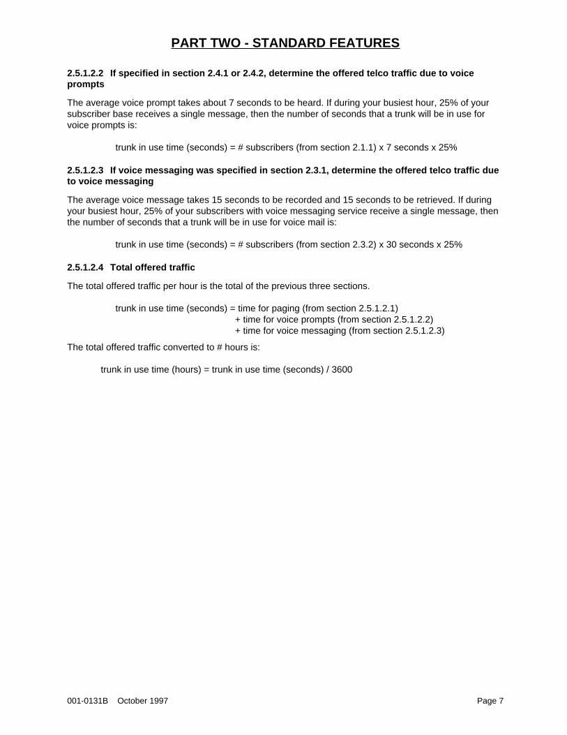
2.5.1.2.2 If specified in section 2.4.1 or 2.4.2, determine the offered telco traffic due to voiceprompts
The average voice prompt takes about 7 seconds to be heard. If during your busiest hour, 25% of yoursubscriber base receives a single message, then the number of seconds that a trunk will be in use forvoice prompts is:
trunk in use time (seconds) = # subscribers (from section 2.1.1) x 7 seconds x 25%
2.5.1.2.3 If voice messaging was specified in section 2.3.1, determine the offered telco traffic dueto voice messaging
The average voice message takes 15 seconds to be recorded and 15 seconds to be retrieved. If duringyour busiest hour, 25% of your subscribers with voice messaging service receive a single message, thenthe number of seconds that a trunk will be in use for voice mail is:
trunk in use time (seconds) = # subscribers (from section 2.3.2) x 30 seconds x 25%
2.5.1.2.4 Total offered traffic
The total offered traffic per hour is the total of the previous three sections.
trunk in use time (seconds) = time for paging (from section 2.5.1.2.1)+ time for voice prompts (from section 2.5.1.2.2)+ time for voice messaging (from section 2.5.1.2.3)
The total offered traffic converted to # hours is:
trunk in use time (hours) = trunk in use time (seconds) / 3600
PART TWO - STANDARD FEATURES
001-0131B October 1997 Page 8
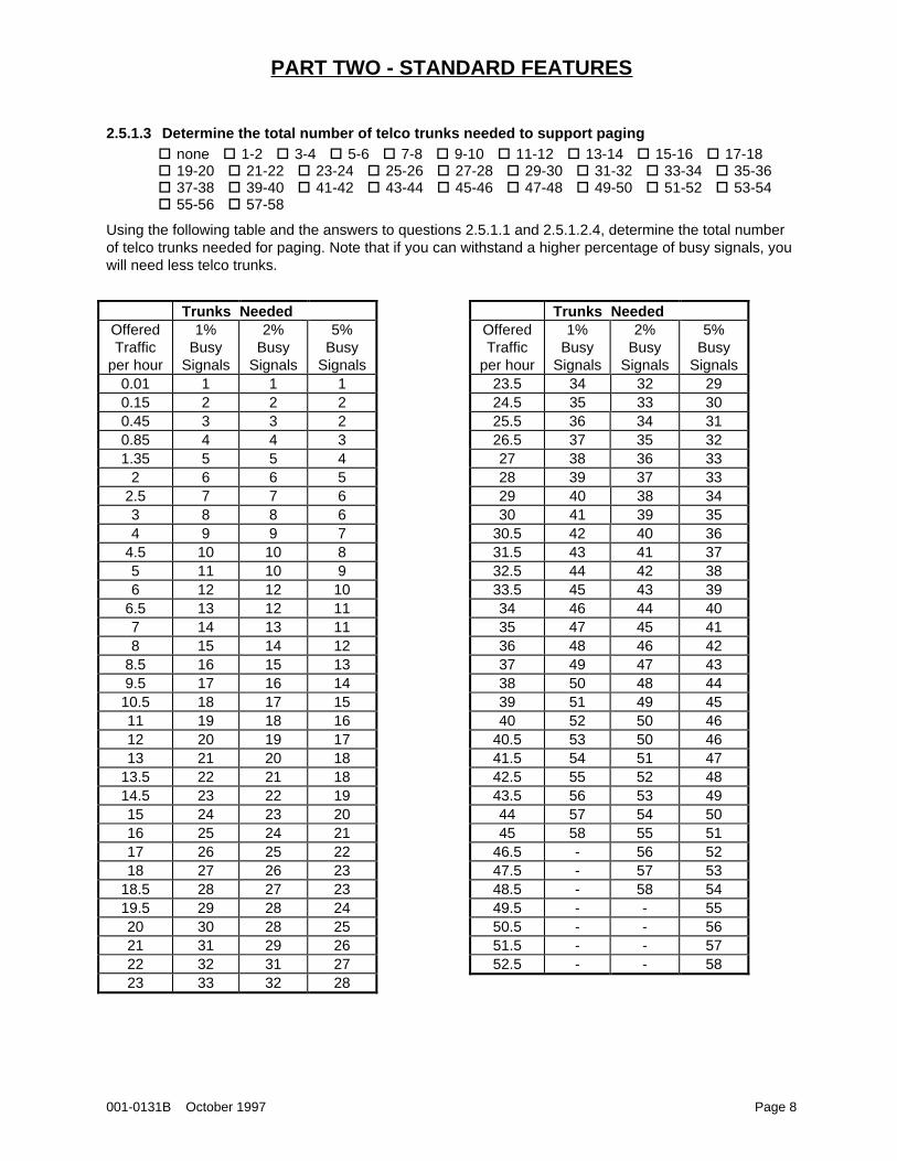
2.5.1.3 Determine the total number of telco trunks needed to support paging� none�� 1-2�� 3-4�� 5-6�� 7-8�� 9-10�� 11-12�� 13-14�� 15-16�� 17-18� 19-20�� 21-22�� 23-24�� 25-26�� 27-28�� 29-30�� 31-32�� 33-34�� 35-36� 37-38�� 39-40�� 41-42�� 43-44�� 45-46�� 47-48�� 49-50�� 51-52�� 53-54� 55-56�� 57-58
Using the following table and the answers to questions 2.5.1.1 and 2.5.1.2.4, determine the total numberof telco trunks needed for paging. Note that if you can withstand a higher percentage of busy signals, youwill need less telco trunks.
Trunks NeededOfferedTraffic
per hour
1%Busy
Signals
2%Busy
Signals
5%Busy
Signals0.01 1 1 10.15 2 2 20.45 3 3 20.85 4 4 31.35 5 5 4
2 6 6 52.5 7 7 63 8 8 64 9 9 7
4.5 10 10 85 11 10 96 12 12 10
6.5 13 12 117 14 13 118 15 14 12
8.5 16 15 139.5 17 16 14
10.5 18 17 1511 19 18 1612 20 19 1713 21 20 18
13.5 22 21 1814.5 23 22 1915 24 23 2016 25 24 2117 26 25 2218 27 26 23
18.5 28 27 2319.5 29 28 2420 30 28 2521 31 29 2622 32 31 2723 33 32 28
Trunks NeededOfferedTraffic
per hour
1%Busy
Signals
2%Busy
Signals
5%Busy
Signals23.5 34 32 2924.5 35 33 3025.5 36 34 3126.5 37 35 3227 38 36 3328 39 37 3329 40 38 3430 41 39 35
30.5 42 40 3631.5 43 41 3732.5 44 42 3833.5 45 43 3934 46 44 4035 47 45 4136 48 46 4237 49 47 4338 50 48 4439 51 49 4540 52 50 46
40.5 53 50 4641.5 54 51 4742.5 55 52 4843.5 56 53 4944 57 54 5045 58 55 51
46.5 - 56 5247.5 - 57 5348.5 - 58 5449.5 - - 5550.5 - - 5651.5 - - 5752.5 - - 58
PART TWO - STANDARD FEATURES
001-0131B October 1997 Page 9
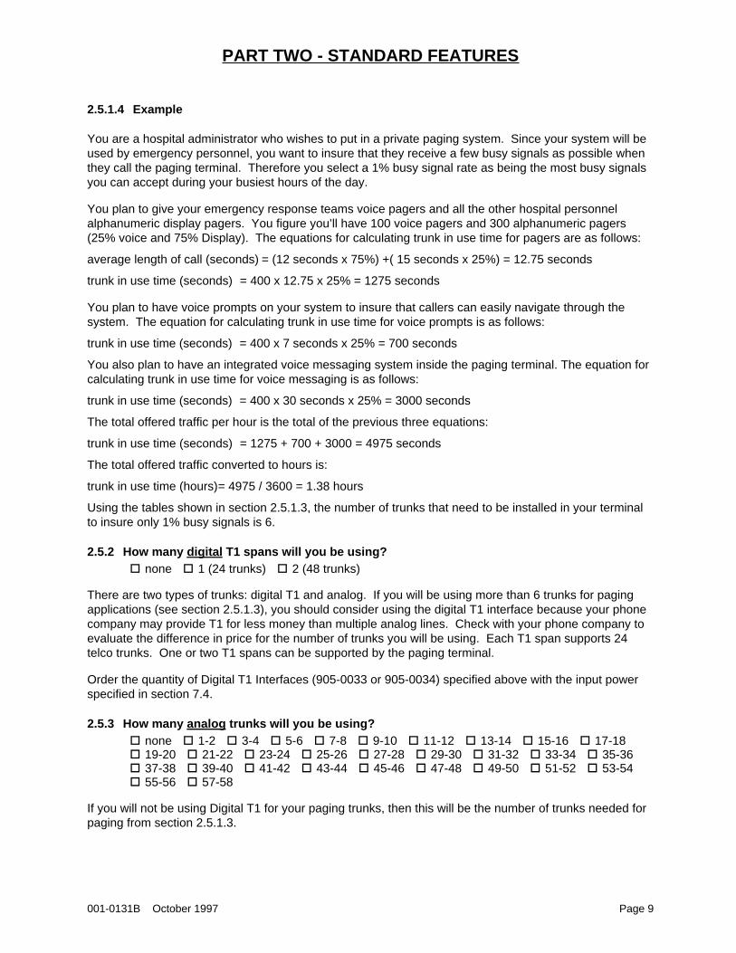
2.5.1.4 Example
You are a hospital administrator who wishes to put in a private paging system. Since your system will beused by emergency personnel, you want to insure that they receive a few busy signals as possible whenthey call the paging terminal. Therefore you select a 1% busy signal rate as being the most busy signalsyou can accept during your busiest hours of the day.
You plan to give your emergency response teams voice pagers and all the other hospital personnelalphanumeric display pagers. You figure you’ll have 100 voice pagers and 300 alphanumeric pagers(25% voice and 75% Display). The equations for calculating trunk in use time for pagers are as follows:
average length of call (seconds) = (12 seconds x 75%) +( 15 seconds x 25%) = 12.75 seconds
trunk in use time (seconds) = 400 x 12.75 x 25% = 1275 seconds
You plan to have voice prompts on your system to insure that callers can easily navigate through thesystem. The equation for calculating trunk in use time for voice prompts is as follows:
trunk in use time (seconds) = 400 x 7 seconds x 25% = 700 seconds
You also plan to have an integrated voice messaging system inside the paging terminal. The equation forcalculating trunk in use time for voice messaging is as follows:
trunk in use time (seconds) = 400 x 30 seconds x 25% = 3000 seconds
The total offered traffic per hour is the total of the previous three equations:
trunk in use time (seconds) = 1275 + 700 + 3000 = 4975 seconds
The total offered traffic converted to hours is:
trunk in use time (hours)= 4975 / 3600 = 1.38 hours
Using the tables shown in section 2.5.1.3, the number of trunks that need to be installed in your terminalto insure only 1% busy signals is 6.
2.5.2 How many digital T1 spans will you be using?� none�� 1 (24 trunks)�� 2 (48 trunks)
There are two types of trunks: digital T1 and analog. If you will be using more than 6 trunks for pagingapplications (see section 2.5.1.3), you should consider using the digital T1 interface because your phonecompany may provide T1 for less money than multiple analog lines. Check with your phone company toevaluate the difference in price for the number of trunks you will be using. Each T1 span supports 24telco trunks. One or two T1 spans can be supported by the paging terminal.
Order the quantity of Digital T1 Interfaces (905-0033 or 905-0034) specified above with the input powerspecified in section 7.4.
2.5.3 How many analog trunks will you be using?� none�� 1-2�� 3-4�� 5-6�� 7-8�� 9-10�� 11-12�� 13-14�� 15-16�� 17-18� 19-20�� 21-22�� 23-24�� 25-26�� 27-28�� 29-30�� 31-32�� 33-34�� 35-36� 37-38�� 39-40�� 41-42�� 43-44�� 45-46�� 47-48�� 49-50�� 51-52�� 53-54� 55-56�� 57-58
If you will not be using Digital T1 for your paging trunks, then this will be the number of trunks needed forpaging from section 2.5.1.3.
PART TWO - STANDARD FEATURES
001-0131B October 1997 Page 10
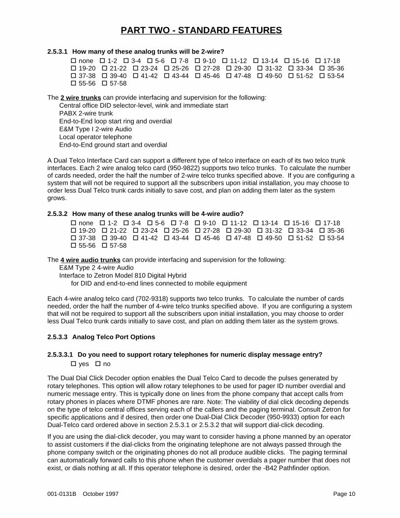
2.5.3.1 How many of these analog trunks will be 2-wire?� none�� 1-2�� 3-4�� 5-6�� 7-8�� 9-10�� 11-12�� 13-14�� 15-16�� 17-18� 19-20�� 21-22�� 23-24�� 25-26�� 27-28�� 29-30�� 31-32�� 33-34�� 35-36� 37-38�� 39-40�� 41-42�� 43-44�� 45-46�� 47-48�� 49-50�� 51-52�� 53-54� 55-56�� 57-58
The 2 wire trunks can provide interfacing and supervision for the following:Central office DID selector-level, wink and immediate startPABX 2-wire trunkEnd-to-End loop start ring and overdialE&M Type I 2-wire AudioLocal operator telephoneEnd-to-End ground start and overdial
A Dual Telco Interface Card can support a different type of telco interface on each of its two telco trunkinterfaces. Each 2 wire analog telco card (950-9822) supports two telco trunks. To calculate the numberof cards needed, order the half the number of 2-wire telco trunks specified above. If you are configuring asystem that will not be required to support all the subscribers upon initial installation, you may choose toorder less Dual Telco trunk cards initially to save cost, and plan on adding them later as the systemgrows.
2.5.3.2 How many of these analog trunks will be 4-wire audio?� none�� 1-2�� 3-4�� 5-6�� 7-8�� 9-10�� 11-12�� 13-14�� 15-16�� 17-18� 19-20�� 21-22�� 23-24�� 25-26�� 27-28�� 29-30�� 31-32�� 33-34�� 35-36� 37-38�� 39-40�� 41-42�� 43-44�� 45-46�� 47-48�� 49-50�� 51-52�� 53-54� 55-56�� 57-58
The 4 wire audio trunks can provide interfacing and supervision for the following:E&M Type 2 4-wire AudioInterface to Zetron Model 810 Digital Hybrid
for DID and end-to-end lines connected to mobile equipment
Each 4-wire analog telco card (702-9318) supports two telco trunks. To calculate the number of cardsneeded, order the half the number of 4-wire telco trunks specified above. If you are configuring a systemthat will not be required to support all the subscribers upon initial installation, you may choose to orderless Dual Telco trunk cards initially to save cost, and plan on adding them later as the system grows.
2.5.3.3 Analog Telco Port Options
2.5.3.3.1 Do you need to support rotary telephones for numeric display message entry?� yes�� no
The Dual Dial Click Decoder option enables the Dual Telco Card to decode the pulses generated byrotary telephones. This option will allow rotary telephones to be used for pager ID number overdial andnumeric message entry. This is typically done on lines from the phone company that accept calls fromrotary phones in places where DTMF phones are rare. Note: The viability of dial click decoding dependson the type of telco central offices serving each of the callers and the paging terminal. Consult Zetron forspecific applications and if desired, then order one Dual-Dial Click Decoder (950-9933) option for eachDual-Telco card ordered above in section 2.5.3.1 or 2.5.3.2 that will support dial-click decoding.
If you are using the dial-click decoder, you may want to consider having a phone manned by an operatorto assist customers if the dial-clicks from the originating telephone are not always passed through thephone company switch or the originating phones do not all produce audible clicks. The paging terminalcan automatically forward calls to this phone when the customer overdials a pager number that does notexist, or dials nothing at all. If this operator telephone is desired, order the -B42 Pathfinder option.
PART TWO - STANDARD FEATURES
001-0131B October 1997 Page 11
2.5.3.3.2 Do you need to support Pulse, DTMF, MFR1, or MFR2 signaling?� Pulse�� DTMF�� MFR1�� MFR2
DTMF (Dual-Tone Multi-Frequency) type phone lines are the most common. However, MFR1 (NorthAmerica) or MFR2 (International) signaling may be available in your area from the phone company.Check with your local phone company to determine which type of phone line you will be getting. Thestandard Dual Telco Interface Card accepts DID feed digits by either pulse or DTMF signaling, whileMFR1 (702-9197) and MFR2 (702-9451) are extra cost options.
2.5.3.3.3 How many of your trunk lines do you want to have supporting alpha modem input?� none�� 1-2�� 3-4�� 5-6�� 7-8�� 9-10�� 11-12�� 13-14�� 15-16�� 17-18� 19-20�� 21-22�� 23-24�� 25-26�� 27-28�� 29-30�� 31-32�� 33-34�� 35-36� 37-38�� 39-40�� 41-42�� 43-44�� 45-46�� 47-48�� 49-50�� 51-52�� 53-54� 55-56�� 57-58
Each Dual Telco Card can be equipped with a Dual Alpha Input Modem (950-9108) option to allow both ofits two telco trunks to handle modem input from remote alphanumeric entry devices (see section 2.2.2.3).When equipped with the Dual Alpha Input Modem option, the Dual Telco Card can still process tone,voice, and numeric pages as usual. Not every trunk need be equipped with alphanumeric modems. Onlythose trunks that will be processing calls from alphanumeric entry devices. On a system with only acouple of alphanumeric applications, such as a few alarm dialers, and a few customers calling up usingalphanumeric entry stations, a single card configured for an end-to-end line equipped with alphanumericmodems may be sufficient.
2.6 TRANSMITTERS
The following items for consideration cover most transmitter control applications. There are, however, analmost infinite number of combinations of multiple and remote transmitter control methods. Please call aZetron Applications Engineer to discuss your specific application if you have any questions.
2.6.1 What is the maximum number of RF channels (frequencies) that you will be paging to?� none�� 1�� 2�� 3�� 4�� 5�� 6�� 7�� 8
Order the quantity of Radio Station Cards (950-9781) specified.
2.6.2 How many paging radio channels specified in section 2.6.1 will support voice pagers?� none�� 1�� 2�� 3�� 4�� 5�� 6�� 7�� 8
2.6.3 How many transmitter zones will be on each channel ?� none�� 1�� 2�� 3�� 4�� 5�� 6�� 7�� 8�� 9�� 10�� 11�� 12� 13�� 14�� 15�� 16
Often there is more than one transmitter on each RF channel to extend coverage. However, if the signalsfrom the various transmitters overlap, interference can result in distorted, lost, or false pages. So zoningis used to only key up transmitters that don’t interfere. Another use is to offer local paging at one priceand wide area paging at another price. However, often multi-transmitter systems are done via simulcastwhich is one zone for all transmitters.
2.6.4 Do each of your remote transmitters have remote-controllers integrated with them?� yes�� no
If a remote transmitter is not equipped with an integrated or outboard device that allows it to decode thecontrol tones generated at the paging terminal end, it can be equipped to do so with the Zetron Model 66Transmitter Control Panel (901-9094). The Model 66 decodes Motorola PURC ® control tones, which aregenerated by the Radio Station Card.
PART TWO - STANDARD FEATURES
001-0131B October 1997 Page 12
2.6.5 Will you want to access remote transmitter sites via dial-up telephone lines instead of byconventional linking methods?
� yes�� no
The DiaLink Base/Remote Unit (901-9283), when used in conjunction with the Zetron Model 66Transmitter Control Panel (or transmitter with integrated remote control), allows the 2000 Series pagingterminal to dial up remote transmitter sites. One Base Unit is required for each Radio Station ControlCard, and one Remote Unit is required for each Model 66. Note that this is designed for low-use sites, orfor temporary use at sites where the permanent links are being installed.
2.6.6 Zetron Model 68 Transmitter System Controller
2.6.6.1 Will you have separate links (wireline, microwave, etc.) to each of your remote transmittersites?
� yes�� no
The Model 68 Transmitter System Controller (901-9102) provides an alternative to the Multiple SiteRemote Control option for the Radio Station Card and the Address Decoder for the Model 66. This willwork in cases where a separate link is available for each transmitter site.
2.6.6.2 How many separate links/sites will be used?� none�� 1�� 2�� 3�� 4�� 5�� 6�� 7�� 8�� 9�� 10�� 11� 12�� 13�� 14�� 15�� 16
The Model 68 is equipped to support two separate links/sites. A Transmitter Control Card (702-9178)must be added for each link beyond the initial two. The Model 68 can support a maximum of 16 separatelinks/sites.
2.6.7 If there are multiple transmitters on a paging channel, will they be keyed up by zone(sequentially) or simultaneously ?
� sequentially�� simultaneously
Each Zetron Model 66 that is controlling a transmitter in a sequential system needs to be equipped withthe Transmitter Address Decoder option (950-9125). Order the number of multiple address options (-B23)for each Radio Station Card specified in section 2.6.1.
2.6.8 Do you want to remotely control dual-frequency transmitters?� yes�� no
When equipped with the Dual-Frequency Address Decoder (950-9331), the Zetron Model 66 can decodea secondary function tone generated by the 2000 Series paging terminal to allow it to select eitherfrequency of a remote dual-frequency transmitter.
2.6.9 If the transmitters are to be keyed up simultaneously, will some transmitters need to bedelayed ?
� yes�� no
When equipped with the Simulcast Delay Module (950-9206), the Zetron Model 66 can delay the audiosignals to account for the difference in link path delays.
PART THREE - ADVANCED FEATURES
001-0131B October 1997 Page 13
3. PART THREE - ADVANCED FEATURES
3.1 NETWORKING
3.1.1 Will you be linking to any other paging terminals using the TNPP networking protocol?� yes�� no
3.1.1.1 How many physical connections to other TNPP terminals or satellites are needed?� none�� 1-2�� 3-4�� 5-6�� 7-8
The Bi-Directional TNPP Network card (950-9346) comes with two serial ports. Each Dual Port Expansionoption (950-9197), equips the Bi-Directional TNPP Network Interface card with two additional serial ports.This option can expand the Bi-Directional TNPP card to a maximum total of eight serial ports (threeadditional Dual Port Expansions). If connection to other TNPP terminals are needed, order a Bi-Directional card with the appropriate number of Dual Port Expansions.
3.1.2 Will you be an affiliate of a satellite-based paging service?� yes�� no
The Unidirectional TNPP Network card (950-9347) equips the 2000 Series paging terminal with a serialinterface to connect with a satellite downlink and receive simplex TNPP transmissions. If a Bi-DirectionalTNPP card has already been ordered, then the Uni-Directional card is not needed.
3.1.3 Do you want to extend the coverage of an in-plant paging system by sending pages to oneor more external paging services?
� yes�� no
The Outdial TAP Card (950-9428) enables the 2000 Series paging terminal to call other paging terminalsover a dial-up telephone line to route pages to them using the TAP protocol. It is designed to send smallto medium volumes of display pages from one terminal to another where a TNPP interface cannot bearranged. It comes with 1 port and a Hayes-compatible modem.
3.2 CALL ROUTING
The PathFinder Call Steering Software allows DID numbers to be routed either to internal paging or voicemailbox functions, or to external devices.
PathFinder has the capability of offering a “fall-back” to a secondary route if certain conditions are not metwhen the first route is tried. The most common application for this is when the call is steered to a mobiletelephone interconnect and the mobile doesn’t answer, then the call is steered to the paging function toset off the mobile telephone owner’s pager. It is strongly recommended to include Subscriber RecordedVoice Prompts in this case to make it clear to the caller that the mobile has not answered and that amessage to a pager will be required. Of course, if fall-back to a voice mailbox is desired, then thePageSaver voice messaging option, with the appropriate prompts and storage options, will be required(see sections 2.2.3 and 2.3).
In order to route calls from the PSTN (Public Switched Telephone Network, or telco central office) throughthe 2000 Series terminal and then back out to the PSTN, a 4-wire E&M circuit must be used to ensureacceptable audio quality. If such a circuit is not available, the Zetron Model 810 Digital Hybrid can beused to convert a 2-wire circuit so that it can connect with a 4-wire audio E&M telco interface. See theZetron Price List for additional information on the Model 810 Digital Hybrid.
PART THREE - ADVANCED FEATURES
001-0131B October 1997 Page 14
3.2.1 Do you want to route calls to a PABX?� yes�� no
If desired, order the routing option below which will handle the type of PABX interface you need.
-B38 dial out on end-to-end line- acting as telephone side of interface- connect as a PABX station (telephone), or into DID with no answer supervisiondetection
-B42 connect into end-to-end line- acting as TELCO side of interface- ring only (no digits dialed after answer)- e.g., live attendant or night ring
-B43 dial out to end-to-end line- acting as TELCO side of interface- ring and dial digits after answer- e.g., automated attendant in use
-B39 dial out on and into an E&M line- two way E&M support
-B40 dial into DID line- with answer supervision monitoring- requires matrix plug shown below
702-9327 End-to-end with loop detect Matrix Plug(connects into a DID line)
3.2.2 Do you want to route calls to a telephone answering service?� yes�� no
If desired, order the routing option below which will handle the type of TAS interface you need.
-B39 dial out on and into an E&M line- two way E&M support
-B40 dial into DID line- with answer supervision monitoring- requires matrix plug shown below
702-9327 End-to-end with loop detect Matrix Plug(connects into a DID line)
3.2.3 Do you want to provide interconnect forwarding from the paging terminal to a Zetron Model49?
� yes�� no
If desired, order the -B45 routing option. If mobile originated calls are also desired, then choose one of thefollowing: -B38 dial out on end-to-end line or -B39 dial out on E&M line
3.2.4 Do you want to provide interconnect forwarding from the paging terminal to a Zetron Model45/46/48?
� yes�� no
If desired, order the -B46 routing option and the matrix plug (702-9335). It should be noted that mobile toland line calls are via M45/46/48 line 1 or 2 and are not routed through the M2000.
PART THREE - ADVANCED FEATURES
001-0131B October 1997 Page 15
3.2.5 Do you want to provide interconnect forwarding from the paging terminal to a Johnson RIC,GEMARC Phone Patch, or other phone patch with an end-to-end line (POTS) interface?
� yes�� no
If desired, order the -B47 routing option.
3.2.6 Do you need to route calls to any devices which require a ringing voltage in order torespond?
� yes�� noSome equipment needs to receive ringing voltage in order to respond to an incoming call. This occurswhen the paging terminal is acting as the TELCO side of the interface on an end-to-end phone line. Thisincludes the phone patches (section 3.2.5), forwarding to a PABX into an end-to-end line (section 3.2.1),and a stand-alone phone manned by an operator (section 2.5.3.3.1). If ring generators are needed, thenorder the quantity of ring generators (901-9212) and power adapters (815-9012) needed for each trunkcard that will be used to route calls to devices needing ring generators.
3.2.7 Do you want to provide the ability for the paged party to rendezvous with their caller?� yes�� no
Rendezvous paging makes it possible for a caller to hold while a subscriber is paged. When the page isreceived, the subscriber calls the paging terminal and is connected with the caller. If desired, order the -B24 routing option.
3.2.8 Do you want to allow a single DID number the ability to route calls between multipledestinations (e.g., mailboxes, pagers, or mobile phone)?
� yes�� no
If desired, order the -B25 caller directed routing option.
3.2.9 Pathfinder Software Ordering
If any of the preceding -BXX options in sections 3.2.1 to 3.2.8, or 2.5.3.3.1 have been ordered, then orderthe basic PathFinder software (950-9181).
3.2.10 Will you be doing talkback paging on any channel?� yes�� no
Talkback paging allows callers to signal to mobile or portable radios and engage them in two-waycommunications. Talkback paging requires the use of a full-duplex repeater. This option supports onlytwo-tone encoding for selective signaling of the mobiles/portables. The radios cannot initiate calls throughthe 2000 Series paging terminal. If desired, order the -B08 talkback paging option.
PART THREE - ADVANCED FEATURES
001-0131B October 1997 Page 16
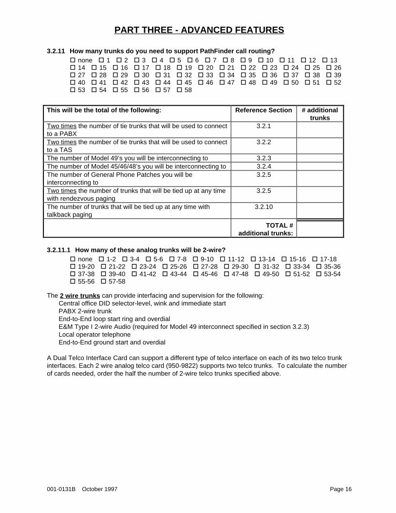
3.2.11 How many trunks do you need to support PathFinder call routing?� none�� 1�� 2�� 3�� 4�� 5�� 6�� 7�� 8�� 9�� 10�� 11�� 12�� 13� 14�� 15�� 16�� 17�� 18�� 19�� 20�� 21�� 22�� 23�� 24�� 25�� 26� 27�� 28�� 29�� 30�� 31�� 32�� 33�� 34�� 35�� 36�� 37�� 38�� 39� 40�� 41�� 42�� 43�� 44�� 45�� 46�� 47�� 48�� 49�� 50�� 51�� 52� 53�� 54�� 55�� 56�� 57�� 58
This will be the total of the following: Reference Section # additionaltrunks
Two times the number of tie trunks that will be used to connectto a PABX
3.2.1
Two times the number of tie trunks that will be used to connectto a TAS
3.2.2
The number of Model 49’s you will be interconnecting to 3.2.3The number of Model 45/46/48’s you will be interconnecting to 3.2.4The number of General Phone Patches you will beinterconnecting to
3.2.5
Two times the number of trunks that will be tied up at any timewith rendezvous paging
3.2.5
The number of trunks that will be tied up at any time withtalkback paging
3.2.10
TOTAL #additional trunks:
3.2.11.1 How many of these analog trunks will be 2-wire?� none�� 1-2�� 3-4�� 5-6�� 7-8�� 9-10�� 11-12�� 13-14�� 15-16�� 17-18� 19-20�� 21-22�� 23-24�� 25-26�� 27-28�� 29-30�� 31-32�� 33-34�� 35-36� 37-38�� 39-40�� 41-42�� 43-44�� 45-46�� 47-48�� 49-50�� 51-52�� 53-54� 55-56�� 57-58
The 2 wire trunks can provide interfacing and supervision for the following:Central office DID selector-level, wink and immediate startPABX 2-wire trunkEnd-to-End loop start ring and overdialE&M Type I 2-wire Audio (required for Model 49 interconnect specified in section 3.2.3)Local operator telephoneEnd-to-End ground start and overdial
A Dual Telco Interface Card can support a different type of telco interface on each of its two telco trunkinterfaces. Each 2 wire analog telco card (950-9822) supports two telco trunks. To calculate the numberof cards needed, order the half the number of 2-wire telco trunks specified above.
PART THREE - ADVANCED FEATURES
001-0131B October 1997 Page 17
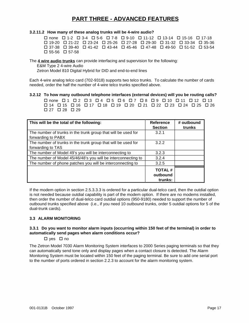
3.2.11.2 How many of these analog trunks will be 4-wire audio?� none�� 1-2�� 3-4�� 5-6�� 7-8�� 9-10�� 11-12�� 13-14�� 15-16�� 17-18� 19-20�� 21-22�� 23-24�� 25-26�� 27-28�� 29-30�� 31-32�� 33-34�� 35-36� 37-38�� 39-40�� 41-42�� 43-44�� 45-46�� 47-48�� 49-50�� 51-52�� 53-54� 55-56�� 57-58
The 4 wire audio trunks can provide interfacing and supervision for the following:E&M Type 2 4-wire AudioZetron Model 810 Digital Hybrid for DID and end-to-end lines
Each 4-wire analog telco card (702-9318) supports two telco trunks. To calculate the number of cardsneeded, order the half the number of 4-wire telco trunks specified above.
3.2.12 To how many outbound telephone interfaces (external devices) will you be routing calls?� none�� 1�� 2�� 3�� 4�� 5�� 6�� 7�� 8�� 9�� 10�� 11�� 12�� 13� 14�� 15�� 16�� 17�� 18�� 19�� 20�� 21�� 22�� 23�� 24�� 25�� 26� 27�� 28�� 29
This will be the total of the following: ReferenceSection
# outboundtrunks
The number of trunks in the trunk group that will be used forforwarding to PABX
3.2.1
The number of trunks in the trunk group that will be used forforwarding to TAS
3.2.2
The number of Model 49’s you will be interconnecting to 3.2.3The number of Model 45/46/48’s you will be interconnecting to 3.2.4The number of phone patches you will be interconnecting to 3.2.5
TOTAL #outbound
trunks:
If the modem option in section 2.5.3.3.3 is ordered for a particular dual-telco card, then the outdial optionis not needed because outdial capability is part of the modem option. If there are no modems installed,then order the number of dual-telco card outdial options (950-9180) needed to support the number ofoutbound trunks specified above (i.e., if you need 10 outbound trunks, order 5 outdial options for 5 of thedual-trunk cards).
3.3 ALARM MONITORING
3.3.1 Do you want to monitor alarm inputs (occurring within 150 feet of the terminal) in order toautomatically send pages when alarm conditions occur?
� yes�� no
The Zetron Model 7030 Alarm Monitoring System interfaces to 2000 Series paging terminals so that theycan automatically send tone only and display pages when a contact closure is detected. The AlarmMonitoring System must be located within 150 feet of the paging terminal. Be sure to add one serial portto the number of ports ordered in section 2.2.3 to account for the alarm monitoring system.
PART THREE - ADVANCED FEATURES
001-0131B October 1997 Page 18
3.3.2 Do you want to monitor alarm inputs(occurring further than 150 feet of the terminal) in orderto automatically send pages when alarm conditions occur?
� yes�� no
The Zetron Model 1516 SentriDial (901-9151), when equipped with the TAP Protocol and Internal Modemoption (950-9176) can dial into the 2000 Series paging terminal to initiate pages in response to alarmsdetected by the SentriDial. The paging terminal must be equipped with at least one telco port with anAlpha Input Modem (950-9108).
3.3.3 Do you want to monitor alarm inputs using an Alarm Dialer in order to automatically sendpages when alarm conditions occur?
� yes�� no
The Dual Alarm Receiver Option equips a Dual Telco Interface card with the capability of receiving alarmcalls from digital communicators using the ADEMCO FAST DTMF (4/9) protocol. This is typically doneusing a single end-to-end line from the phone company that will only be accepting calls from ADEMCOcompatible alarm dialers.
If desired, order one Dual Alarm Receiver option (702-9490) for each Dual-Telco card ordered that willsupport ADEMCO alarm dialers. This is typically done using a single end-to-end line from the phonecompany that will only be accepting calls from ADEMCO alarm dialers. This option cannot co-exist withthe MF options specified in section 2.5.3.3.2.
PART THREE - ADVANCED FEATURES
001-0131B October 1997 Page 19
3.4 REDUNDANT TERMINALS
3.4.1 Do you plan to have a fully redundant 2000 Series terminal to serve as a hot standby systemto back up the primary system?
� yes�� no
If a fully redundant backup system is desired, it is recommended that the backup system duplicates theprimary system in terms of software, features, and interface cards. The Standby System Controller willautomatically switch control from the primary terminal to the backup terminal upon detection of a CPU,power supply, or transmitter failure. The Standby System Controller can be manually switched as well.Note that at present, the Standby System Controller cannot switch over T1 spans to a backup terminaland that when the switch over occurs voice mail messages will not be available because the reside on thehard disk on the primary terminal. In order to maintain voice prompts, they will need to be manuallybacked up to the spare terminal periodically.
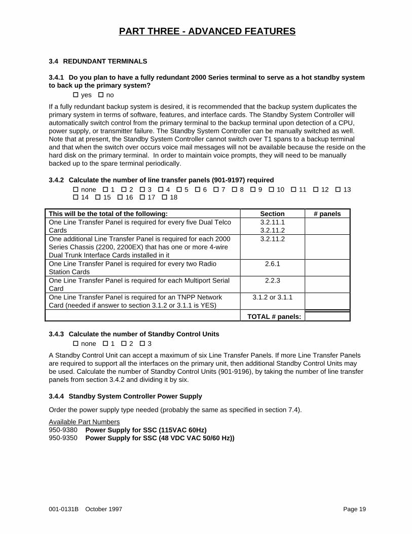
3.4.2 Calculate the number of line transfer panels (901-9197) required� none�� 1�� 2�� 3�� 4�� 5�� 6�� 7�� 8�� 9�� 10�� 11�� 12�� 13� 14�� 15�� 16�� 17�� 18
This will be the total of the following: Section # panelsOne Line Transfer Panel is required for every five Dual TelcoCards
3.2.11.13.2.11.2
One additional Line Transfer Panel is required for each 2000Series Chassis (2200, 2200EX) that has one or more 4-wireDual Trunk Interface Cards installed in it
3.2.11.2
One Line Transfer Panel is required for every two RadioStation Cards
2.6.1
One Line Transfer Panel is required for each Multiport SerialCard
2.2.3
One Line Transfer Panel is required for an TNPP NetworkCard (needed if answer to section 3.1.2 or 3.1.1 is YES)
3.1.2 or 3.1.1
TOTAL # panels:
3.4.3 Calculate the number of Standby Control Units� none�� 1�� 2�� 3
A Standby Control Unit can accept a maximum of six Line Transfer Panels. If more Line Transfer Panelsare required to support all the interfaces on the primary unit, then additional Standby Control Units maybe used. Calculate the number of Standby Control Units (901-9196), by taking the number of line transferpanels from section 3.4.2 and dividing it by six.
3.4.4 Standby System Controller Power Supply
Order the power supply type needed (probably the same as specified in section 7.4).
Available Part Numbers950-9380 Power Supply for SSC (115VAC 60Hz)950-9350 Power Supply for SSC (48 VDC VAC 50/60 Hz))
PART FOUR - SYSTEM ORDER GUIDE
001-0131B October 1997 Page 20
4. PART FOUR - SYSTEM ORDER GUIDE
4.1 VOICE CONTROLLER
4.1.1 Number of Voice Channels
In order to support any voice applications (voice paging, voice messaging, or voice prompts), the 2000Series paging terminal must be equipped with the ADPCM Voice Controller Card.
4.1.1.1 Determine the number of channels that will need voice support.� none�� 1�� 2�� 3�� 4�� 5�� 6�� 7�� 8�� 9�� 10�� 11�� 12�� 13� 14�� 15�� 16�� 17�� 18�� 19�� 20�� 21�� 22�� 23�� 24�� 25�� 26� 27�� 28�� 29�� 30�� 31�� 32�� 33�� 34�� 35�� 36�� 37�� 38�� 39� 40�� 41�� 42�� 43�� 44�� 45�� 46�� 47�� 48�� 49�� 50�� 51�� 52� 53�� 54�� 55�� 56�� 57�� 58�� 59�� 60�� 61�� 62�� 63�� 64
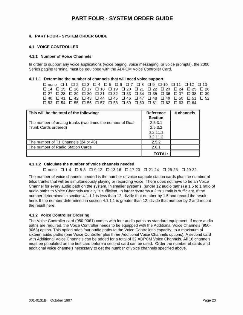
This will be the total of the following: ReferenceSection
# channels
The number of analog trunks (two times the number of Dual-Trunk Cards ordered)
2.5.3.12.5.3.2
3.2.11.13.2.11.2
The number of T1 Channels (24 or 48) 2.5.2The number of Radio Station Cards 2.6.1
TOTAL:
4.1.1.2 Calculate the number of voice channels needed� none�� 1-4�� 5-8�� 9-12�� 13-16�� 17-20�� 21-24�� 25-28�� 29-32
The number of voice channels needed is the number of voice capable station cards plus the number oftelco trunks that will be simultaneously playing or recording voice. There does not have to be an VoiceChannel for every audio path on the system. In smaller systems, (under 12 audio paths) a 1.5 to 1 ratio ofaudio paths to Voice Channels usually is sufficient. In larger systems a 2 to 1 ratio is sufficient. If thenumber determined in section 4.1.1.1 is less than 12, divide that number by 1.5 and record the resulthere. If the number determined in section 4.1.1.1 is greater than 12, divide that number by 2 and recordthe result here.
4.1.2 Voice Controller OrderingThe Voice Controller card (950-9061) comes with four audio paths as standard equipment. If more audiopaths are required, the Voice Controller needs to be equipped with the Additional Voice Channels (950-9063) option. This option adds four audio paths to the Voice Controller’s capacity, to a maximum ofsixteen audio paths (one Voice Controller plus three Additional Voice Channels options). A second cardwith Additional Voice Channels can be added for a total of 32 ADPCM Voice Channels. All 16 channelsmust be populated on the first card before a second card can be used. Order the number of cards andadditional voice channels necessary to get the number of voice channels specified above.
PART FOUR - SYSTEM ORDER GUIDE
001-0131B October 1997 Page 21
4.2 CPU CHOICES
If any of the following conditions are met, the High-Performance CPU will be required:1. More than 10,000 subscribers are needed (see section 2.1.1)2. If using more than 20 analog trunks (see sections 2.5.3 and 3.2.11)3. If using Digital T1 trunks (see section 2.5.2)4. If the number of pages per minute being transmitted by the radio station card (coming from a
TNPP port, telco port, or multi-port card) is greater than 200 pages per minute.5. Anytime your system configuration calls for an EX-Chassis (see section 4.4.3)
Otherwise, the Standard System CPU should be sufficient.
If a PageSaver option of 24 hours or more is used (see section 2.3.2) then the CPU will need to beordered with the high-capacity RAM.
Available Part Numbers950-9656 Standard System CPU, Standard RAM950-9754 Standard System CPU, High Capacity RAM950-9633 High Performance CPU with Standard RAM950-9753 High Performance CPU with High Capacity RAM
4.3 HARD DISKS
One of the following system disks must be ordered. If specified in section 2.4.4 order the mirrored disks,otherwise order the standard disk.
Available Part Numbers950-9618 System Hard Disk950-9737 System Mirrored Disk for System and Client Prompts
4.4 TERMINAL AND EXPANSION OPTIONS
4.4.1 Determine the number of system slots needed
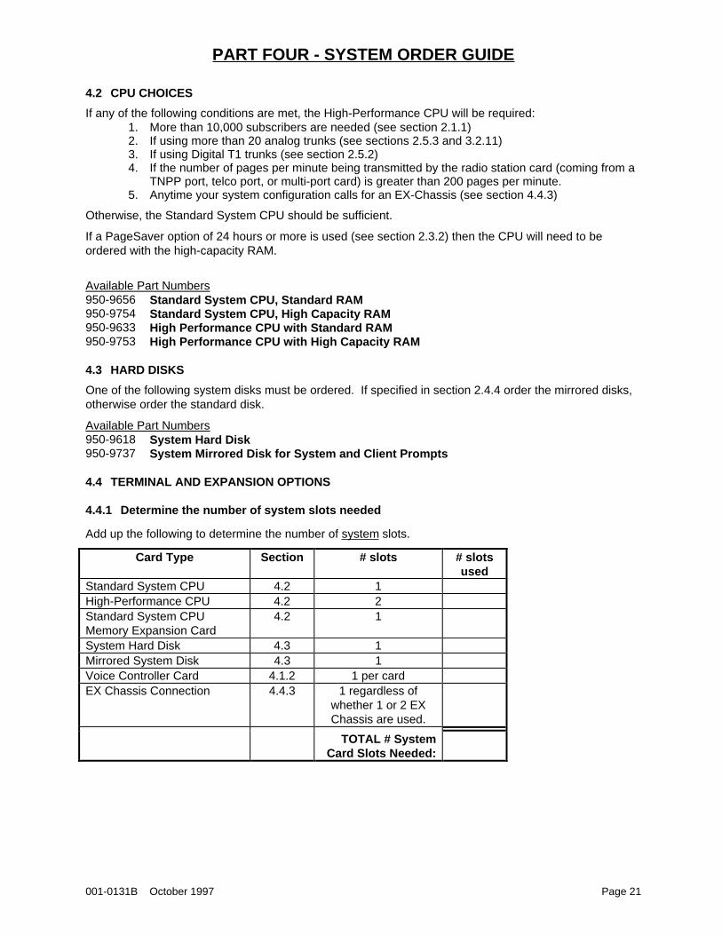
Add up the following to determine the number of system slots.
Card Type Section # slots # slotsused
Standard System CPU 4.2 1High-Performance CPU 4.2 2Standard System CPUMemory Expansion Card
4.2 1
System Hard Disk 4.3 1Mirrored System Disk 4.3 1Voice Controller Card 4.1.2 1 per cardEX Chassis Connection 4.4.3 1 regardless of
whether 1 or 2 EXChassis are used.
TOTAL # SystemCard Slots Needed:
PART FOUR - SYSTEM ORDER GUIDE
001-0131B October 1997 Page 22
4.4.2 Determine the number of interface card slots needed
Add up the following to determine the number of interface slots.
Card Type Section QTYDual Telco Cards 2.5.3
3.2.11Digital T1 Connection 2.5.2Radio Station Card 2.6.1Multiport Serial Card 2.2.3Outdial TAP Card 3.1.3TNPP Interface Card 3.1.1.1
3.1.2
TOTAL # InterfaceCard Slots Needed:
4.4.3 Determine which model paging terminal
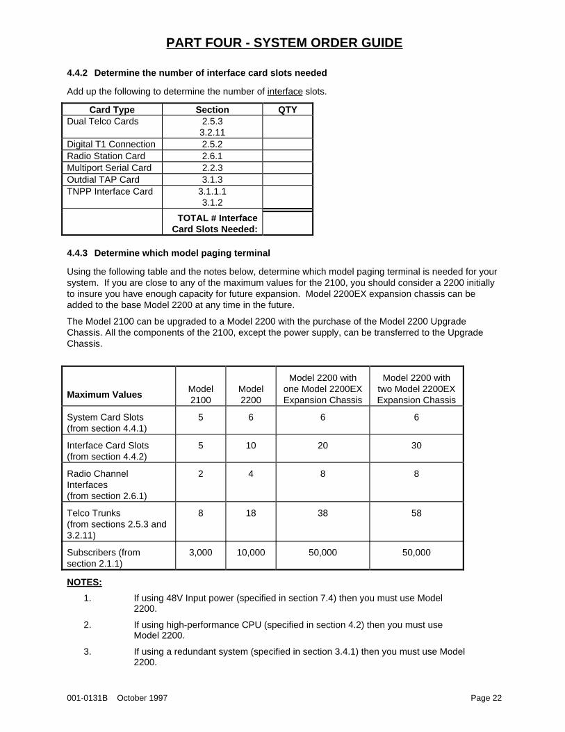
Using the following table and the notes below, determine which model paging terminal is needed for yoursystem. If you are close to any of the maximum values for the 2100, you should consider a 2200 initiallyto insure you have enough capacity for future expansion. Model 2200EX expansion chassis can beadded to the base Model 2200 at any time in the future.
The Model 2100 can be upgraded to a Model 2200 with the purchase of the Model 2200 UpgradeChassis. All the components of the 2100, except the power supply, can be transferred to the UpgradeChassis.
Maximum ValuesModel2100
Model2200
Model 2200 withone Model 2200EXExpansion Chassis
Model 2200 withtwo Model 2200EXExpansion Chassis
System Card Slots(from section 4.4.1)
5 6 6 6
Interface Card Slots(from section 4.4.2)
5 10 20 30
Radio ChannelInterfaces(from section 2.6.1)
2 4 8 8
Telco Trunks(from sections 2.5.3 and3.2.11)
8 18 38 58
Subscribers (fromsection 2.1.1)
3,000 10,000 50,000 50,000
NOTES:
1. If using 48V Input power (specified in section 7.4) then you must use Model2200.
2. If using high-performance CPU (specified in section 4.2) then you must useModel 2200.
3. If using a redundant system (specified in section 3.4.1) then you must use Model2200.
PART FOUR - SYSTEM ORDER GUIDE
001-0131B October 1997 Page 23
4. If using Digital T1 (see section 2.5.2), then no 2200EX Expansion Chassis can beused.
5. If a PageSaver option of more than 6 hours (12 hour and above) is used (seesection 2.3.2) then you must use Model 2200.
6. If using mirrored disk drives (specified in section 4.3) then you must use Model2200.
Available Part Numbers901-9090 Model 2100 Paging Terminal901-9050 Model 2200 Paging Terminal901-9132 Model 2200EX Paging Terminal Expansion Chassis
4.5 INPUT POWER REQUIREMENTS
Order the appropriate input power as specified in section 7.4 for both the main chassis and the expansionchassis as specified in section 4.4.3.
Available Part NumbersStandard 110/120 VAC 50/60Hz Operation for Model 2100Standard 110/120 VAC 50/60Hz Operation for Model 2200Standard 110/120 VAC 50/60Hz Operation for Model 2200 Expansion Chassis950-9312 220/240 VAC 50/60Hz Operation for Model 2100950-9235 220/240 VAC 50/60Hz Operation for Model 2200950-9899 220/240 VAC 50/60Hz Operation for Model 2200 Expansion Chassis950-9087 48VDC Operation for Model 2200 only
PART FIVE - SYSTEM MANAGEMENT
001-0131B October 1997 Page 24
5. PART FIVE - SYSTEM MANAGEMENT - PROGRAMMING, REPORTING, AND BILLING
Zetron provides the ZBASE subscriber database management software (950-9070), at no charge. Thissoftware will run on any personal computer that meets the following requirements:
IBM PC-compatibleMS-DOS or PC-DOS 2.1 or higher operating system3 1/2" floppy disk drive10-megabyte hard diskParallel or serial printer portHayes-compatible modem (for remote access) or asynchronous serial port (for local access).
A dial-up, end-to-end telco line is necessary for remote factory support. It is highly recommended that thisis made available in order to fully benefit from Zetron’s factory support program. Modem access forprogramming and remote factory support is through a telco line that is not connected to any of thesystem’s Dual Telco Cards. The modem that comes with the 2000 Series paging terminal is equippedwith its own telco interface.
5.1 DO YOU WANT MULTIPLE USERS SIMULTANEOUSLY ACCESS THE ZBASE MANAGEMENTSOFTWARE?
� yes�� no
The Networking ZBASE option (950-9473) allows multiple users to access the system managementsoftware through a Local Area Network.
The interconnection between the LAN and the 2000 Series paging terminal can be handled in one of twoways. The first way is for each user’s PC on the LAN to directly access the terminal through either a dial-up modem or direct serial link. The second way is for a single PC on the LAN to act as a communicationsserver that accesses the paging terminal in the same way as would an individual user’s PC.
5.2 DO YOU WANT MULTIPLE AGENTS TO ACCESS ZBASE?� yes�� no
The Multi-Agent ZBASE Software (950-9344) provides the same capabilities as does the Multi-UserZBASE described above, with the additional feature of allowing the system operator to restrict agentaccess.
5.3 DO YOU WANT A REAL-TIME PRINT OUT OF EACH PAGE SENT?� yes�� no
The Logging Printer Port equips the 2000 Series paging terminal with a printer port that connects to aprinter. This option allows the printer to provide an on-going, real-time log of every page that goes throughthe system. If you are using the standard system CPU specified in section 4.2, order the serial loggingprinter port (950-9118). If you are using the high-performance CPU specified in section 4.2, order theparallel printer logging port (-B70).
5.4 DO YOU WANT AN ACCOUNTS-RECEIVABLE SYSTEM?� yes�� no
The Zetron Billing System, ZEBRA, (950-9219) provides accounts-receivable and billing functions insupport of the paging service. It utilizes the data generated by ZBASE, and can run either on themanagement computer or on a similarly-equipped, separate computer. See the ZEBRA BILLINGSYSTEM price and specification sheets for additional information.
PART SIX - SPARES
001-0131B October 1997 Page 25
6. PART SIX - SPARES
6.1 DO YOU WANT TO HAVE SPARE PARTS AVAILABLE?� yes�� no
Spares are available for the 2000 Series paging terminals at the board level, which means that even atechnician with a minimum of training can replace any failed board. Every board that is critical to thefunctioning of the paging terminal is available as a spare.
6.2 SPARES PARTS KIT
The spare parts kit (951-9067) makes the most critical spare parts available at reduced prices. At aminimum the kit must contain the items with single asterisks. Only one card of each type may be orderedas part of this kit at reduced prices, and the original system must have included each part ordered as partof this kit.
Available Part Numbers950-9618 Spare System Hard Disk *950-9781 Spare Radio Station Card *950-9656 Spare Standard System CPU, Standard RAM950-9061 Spare Voice Controller with 4 voice channels and 1MB memory950-9063 Spare Additional 4 voice channels950-9783 Spare 110/120 VAC 50/60Hz Power Supply for Model 2100 *950-9782 Spare 110/120 VAC 50/60Hz Power Supply for Model 2200 *950-9087 Spare 48VDC Power Supply for Model 2200 only950-9822 Spare Dual Telco Interface Card, all 2-wire audio trunk types *950-9108 Spare Dual Alphanumeric Messaging Input Modem (for 950-9822 or 702-9318)950-9836 Spare Bi-Directional TNPP Network Interface950-9835 Spare Serial Card, 2 ports (for Multi-port Serial TAP or Outdial TAP)950-9197 Spare Dual Port Expansion for Multi-port or TNPP950-9786 Spare Extender Card *
6.3 INDIVIDUAL SPARE PARTS
The items with asterisks are recommended spares.
Available Part Numbers950-9618 Spare System Hard Disk950-9781 Spare Radio Station Card *950-9656 Spare Standard System CPU, Standard RAM *950-9754 Spare Standard System CPU, High Capacity RAM *950-9816 Spare Standard System CPU Memory Expansion Card950-9633 Spare High Performance CPU with Standard RAM *950-9753 Spare High Performance CPU with High Capacity RAM *950-9061 Spare Voice Controller with 4 voice channels and 1MB memory *950-9063 Spare Additional 4 voice channels950-9783 Spare 110/120 VAC 50/60Hz Power Supply for Model 2100 *950-9782 Spare 110/120 VAC 50/60Hz Power Supply for Model 2200 *950-9087 Spare 48VDC Operation for Model 2200 only *950-9785 Spare Modem Maintenance Port *950-9822 Spare Dual Telco Interface Card, all 2-wire audio trunk types *702-9318 Spare Dual Telco Interface Card, E&M 4-wire Audio *702-9197 Spare Dual Multifrequency (MFR1) Decoder (for 950-9822 or 702-9318)702-9451 Spare Dual Multifrequency (MFR2) Decoder (for 950-9822 or 702-9318)950-9933 Spare Dual Dial Click Decoder (for 950-9822 or 702-9318)950-9108 Spare Dual Alphanumeric Messaging Input Modem (for 950-9822 or 702-9318)

PART SIX - SPARES
001-0131B October 1997 Page 26
702-9490 Spare Dual Alarm Receiver Option (for 950-9822 or 702-9318)950-9180 Spare Outdial Encoder/Detector950-9811 Spare T1 Hex Trunk Card950-9687 Spare T1 Hex Trunk Card with Alphanumeric Modem950-9814 Spare T1 Host Bus Card950-9812 Spare T1 Framer Card950-9813 Spare T1 Control Bus Interface Card950-9861 Spare T1 AC Power Supply950-9917 Spare T1 48VDC Power Supply901-9333 Spare T1 Chassis950-9835 Spare Multi-port Serial Interface950-9428 Spare Outdial TAP Interface (Includes Hayes-compatible modem)950-9836 Spare Bi-Directional TNPP Network Interface950-9197 Spare Dual Port Expansion for Multi-port & Bi-Directional TNPP702-9133 Spare Z-Bus Backplane for Model 2100702-9071 Spare Z-Bus Backplane for Model 2200702-9503 Spare PC-Bus Backplane for Model 2100702-9502 Spare PC-Bus Backplane for Model 2200950-9786 Spare Extender Card *025-9034 Extra Operating and Programming Manual025-9035 Extra Installation and Service Manual025-9075 Extra Diagrams Manual

PART SEVEN - INSTALLATION, POWER, AND PROTECTION
001-0131B October 1997 Page 27
7. PART SEVEN - INSTALLATION, POWER, AND PROTECTION
7.1 DO YOU HAVE LIGHTNING PROTECTION ON YOUR TELCO LINES?� yes�� no
Zetron can supply a Protection Kit to provide protection from power surges on the telco lines such asthose caused by lightning strikes. The Protection Kit is designed for secondary protection. Primaryprotection (such as gas discharge) or Zetron DeadBolt Lighting Surge Arrestors is recommended.
If there is no primary protection on your telco lines, then order one DeadBolt (901-9325) for each analogphone line as specified in sections 2.5.3 and 3.2.11. If primary protection exists, then order oneprotection kit (950-9040) for every 5 Dual Trunk Cards (see sections 2.5.3 and 3.2.11) plus one protectionkit if there are any 4-wire E&M Dual Trunk Cards (see sections 2.5.3.2 and 3.2.11.2) in the system toprotect them against transient voltage spikes.
7.2 CABLE ASSEMBLIES AND PUNCHDOWN BLOCKS
To calculate the number of needed cable assemblies and punchdown blocks, add up the following:1. One for each TNPP card (see sections 3.1.1.1 and 3.1.2)2. One for each Multi-port serial card (see section 2.2.3)3. One for each TAP Outdial card (see section 3.1.3)4. One for each pair of Radio Station Cards (see section 2.6.1)5. One for every five Dual Trunk Cards (see sections 2.5.3 and 3.2.11) not already protected by
the Protection Kit (see section 7.1)6. One if any 4-wire E&M Dual Trunk Cards will be in the system (see sections 2.5.3.2 and
3.2.11.2) and are not already protected by the Protection Kit (see section 7.1)
If you don’t have RJ2 telco cables available, then order the appropriate number of cable assemblies (709-0004). A minimum of 2 cable assemblies are required. If you don’t have punchdown blocks alreadyavailable, then order the appropriate number of punchdown blocks (802-0093-1).
7.3 DO YOU HAVE A BACKUP POWER SUPPLY?� yes�� no
The Zetron Uninterruptible Power Supply (802-9049) is a 400 VA power supply that provides up to 60minutes of uninterrupted power to a fully-configured Model 2100, or 30 minutes of uninterrupted power toa fully-configured Model 2200.
7.4 WHAT KIND OF INPUT POWER WILL SUPPLY THE PAGING TERMINAL?� 110/220 VAC 50/60Hz�� 220/240 VAC 50/60Hz�� 48V telco-type batteries
PART EIGHT - PREINSTALLATION GUIDE
001-0131B October 1997 Page 28
8. PART EIGHT - PRE-INSTALLATION GUIDE
8.1 OPERATING CONDITIONS
Be sure that the following operating condition limitations will not be exceeded for the paging terminallocation.
8.1.1 Power
� Power conditioning is suggested. Remember, it takes the paging terminal approximately 2 minutes toboot up, so each brown-out or power failure will make the system inoperable for up to 2 minutes.
8.1.2 Ambient Temperature
� +40 to +120 degrees Fahrenheit. +5 to +50 degrees Celsius.
8.1.3 Humidity
� 8% to 80% relative humidity, non-condensing.
8.1.4 Altitude
� 10,000 feet (3,000 m).
8.2 MOUNTING
� The Model 2100 main chassis is 21" tall, 17" wide, and 5.5" deep. The Model 2200 main chassis is30" tall, 22" wide, and 7" deep. The expansion chassis is 21" tall, 22" wide, and 7" deep. The mainand expansion chassis’ generally need to be located adjacently, either side by side or one on top ofthe other.
� The terminal should be mounted to a wall, using the pre-drilled holes and the provided lag bolts.
8.3 WIRING
Because each terminal installation will have its own wiring layout, no specifics are given here. However, afew rules are given to help with the wiring.
* The lengths of cabling should be kept to a minimum, the longer a cable becomes, the chances of RFinterference increases.
* The wiring should be neat.
* When wiring a group of connections, the first connection should be done and tested before doing theentire group.
* Mounting all punch down blocks, etc. onto a sheet of plywood is suggested. This makes it possible towire up the equipment in the shop where it is easier to work on.
* The wiring should be done and tested prior to going live.
* Grounding of the paging terminal is extremely important. This Pre-Installation Guide makes noattempt to cover all issues concerning grounding.
8.4 RADIO TRANSMITTER
� All RF level adjustments and interfacing should be made prior to installation of the terminal.
PART EIGHT - PREINSTALLATION GUIDE
001-0131B October 1997 Page 29
8.5 PHONE LINES
� Any additional or change in phone line types from the phone company should be installed and testedprior to going live.
8.6 MICROWAVE EQUIPMENT
� When using microwave or RF equipment for links, the equipment should be installed and tested priorto going live. This includes directional and azimuth alignment of the dishes, E&M signaling, levels andwiring.
8.7 MAINTENANCE LINE
� Prior to going live, a maintenance line should be installed and tested. Remember, once you havegone live you are beyond the point of no return and if there are problems, spending time getting amaintenance line working for factory support is costly.
8.8 MANAGEMENT SOFTWARE
� The ZBASE installation and conversion should be done prior to going live.
8.9 IN SHOP TESTING
� It is generally suggested that, if at all possible, the terminal and wiring is first tested by the shop.
Related Documents