1GR-FE FUEL – FUEL SYSTEM FU–1 FU FUEL SYSTEM PRECAUTION 1. BEFORE WORKING ON FUEL SYSTEM (a) Before working on the fuel system, disconnect the cable from the negative battery terminal. (b) Do not work on the fuel system near naked flames. Never smoke during the work. (c) Keep rubber and leather parts away from gasoline. 2. DISCHARGE FUEL SYSTEM PRESSURE CAUTION: • DISCHARGE FUEL SYSTEM PRESSURE procedures must be performed before disconnecting any part of the fuel system. • As some pressure remains in the fuel line even after taking precautions to prevent gasoline spillage, use a shop rag or piece of cloth to prevent gasoline splashes when disconnecting the fuel line. (a) Disconnect the cable from the negative battery terminal. (b) Remove the circuit opening relay (see page ES- 443). (c) Connect the cable to the battery negative terminal. Torque: 3.9 N*m (40 kgf*cm, 35 in.*lbf) (d) Start the engine. (e) Turn the ignition switch to ON after the engine stops. HINT: DTC P0171 (system too lean (Bank 1)) or DTC P0174 (system too learn (Bank 2)) may be set. (f) Crank the engine again and check that the engine stops. (g) Remove the fuel tank cap and discharge the pressure in the fuel tank completely. (h) Install the circuit opening relay (see page ES-443). 3. FUEL SYSTEM (a) When disconnecting the high-pressure fuel line, a large amount of gasoline will splash. So take the following precautions. (1) Discharge the fuel system pressure. (2) Disconnect the fuel tank main tube (see page FU-42). (3) Drain the fuel remaining in the fuel tank main tube. (4) Cover the disconnected fuel tank main tube (fuel tube joint and fuel tube connector) with a vinyl bag to prevent damage and the intrusion of foreign objects.

Welcome message from author
This document is posted to help you gain knowledge. Please leave a comment to let me know what you think about it! Share it to your friends and learn new things together.
Transcript
1GR-FE FUEL – FUEL SYSTEM FU–1
U
FFUEL SYSTEMPRECAUTION1. BEFORE WORKING ON FUEL SYSTEM
(a) Before working on the fuel system, disconnect the cable from the negative battery terminal.
(b) Do not work on the fuel system near naked flames. Never smoke during the work.
(c) Keep rubber and leather parts away from gasoline.2. DISCHARGE FUEL SYSTEM PRESSURE
CAUTION:• DISCHARGE FUEL SYSTEM PRESSURE
procedures must be performed before disconnecting any part of the fuel system.
• As some pressure remains in the fuel line even after taking precautions to prevent gasoline spillage, use a shop rag or piece of cloth to prevent gasoline splashes when disconnecting the fuel line.
(a) Disconnect the cable from the negative battery terminal.
(b) Remove the circuit opening relay (see page ES-443).
(c) Connect the cable to the battery negative terminal.Torque: 3.9 N*m (40 kgf*cm, 35 in.*lbf)
(d) Start the engine.(e) Turn the ignition switch to ON after the engine
stops.HINT:DTC P0171 (system too lean (Bank 1)) or DTC P0174 (system too learn (Bank 2)) may be set.
(f) Crank the engine again and check that the engine stops.
(g) Remove the fuel tank cap and discharge the pressure in the fuel tank completely.
(h) Install the circuit opening relay (see page ES-443).3. FUEL SYSTEM
(a) When disconnecting the high-pressure fuel line, a large amount of gasoline will splash. So take the following precautions.(1) Discharge the fuel system pressure.(2) Disconnect the fuel tank main tube (see page
FU-42).(3) Drain the fuel remaining in the fuel tank main
tube.(4) Cover the disconnected fuel tank main tube (fuel
tube joint and fuel tube connector) with a vinyl bag to prevent damage and the intrusion of foreign objects.
FU–2 1GR-FE FUEL – FUEL SYSTEM
FU
(b) Take the following precautions when installing the fuel injector.(1) Do not reuse the O-ring.(2) Do not damage a new O-ring when installing it
into the fuel injector.(3) Before installing a new O-ring, apply gasoline or
spindle oil.NOTICE:Do not use engine oil, gear oil or brake oil.
(4) Install the fuel injector into the fuel delivery pipe and cylinder head as illustrated.NOTICE:Apply gasoline or spindle oil to the contact surface of the fuel delivery pipe and fuel injector before installing the fuel injector.
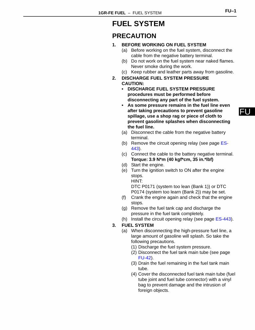
(c) Take the following precautions when disconnecting the fuel tube connector.HINT:The structure of the fuel tube connector is as shown in the illustration.(1) Check the fuel tube connector and pipe for dirt
and mud before removing the fuel tube connector.If dirty, wipe it with a shop rag or piece of cloth.
(2) Pinch the retainer as illustrated, and pull the fuel tube connector out of the pipe.
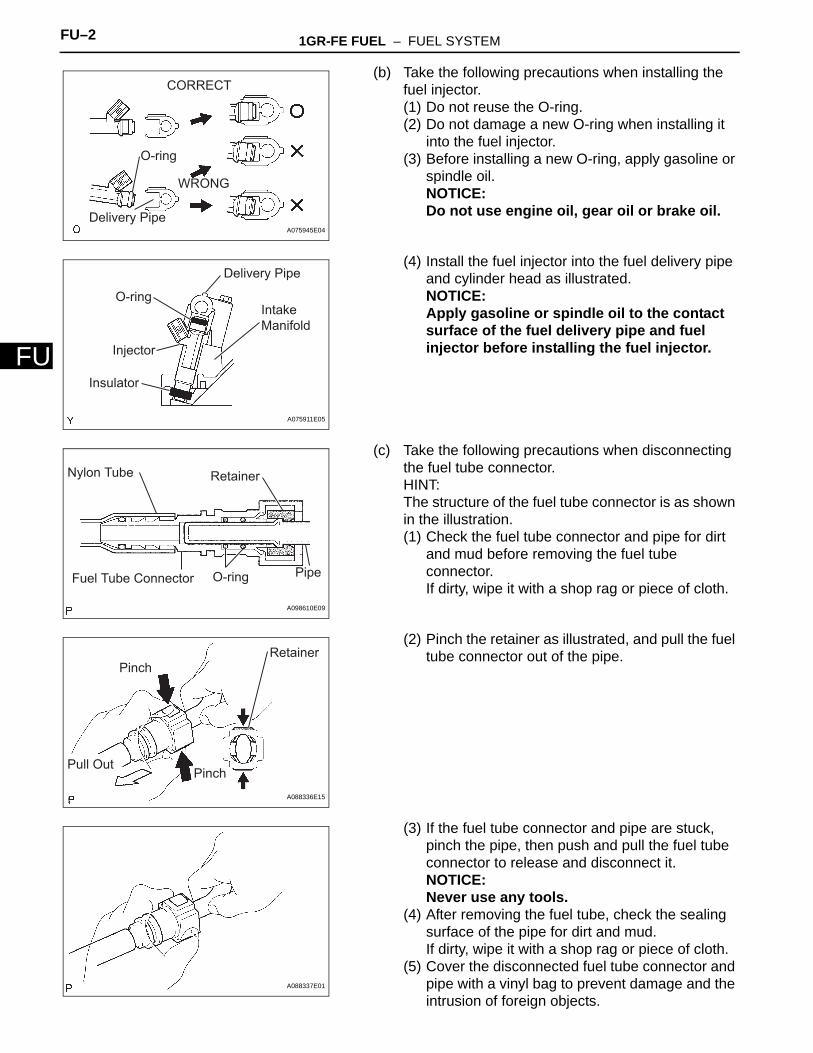
(3) If the fuel tube connector and pipe are stuck, pinch the pipe, then push and pull the fuel tube connector to release and disconnect it.NOTICE:Never use any tools.
(4) After removing the fuel tube, check the sealing surface of the pipe for dirt and mud.If dirty, wipe it with a shop rag or piece of cloth.
(5) Cover the disconnected fuel tube connector and pipe with a vinyl bag to prevent damage and the intrusion of foreign objects.
CORRECT
WRONG
O-ring
Delivery PipeA075945E04
Delivery Pipe
Intake Manifold
O-ring
Injector
Insulator
A075911E05
Pipe
RetainerNylon Tube
Fuel Tube Connector O-ring
A098610E09
RetainerPinch
PinchPull Out
A088336E15
A088337E01
1GR-FE FUEL – FUEL SYSTEM FU–3
U
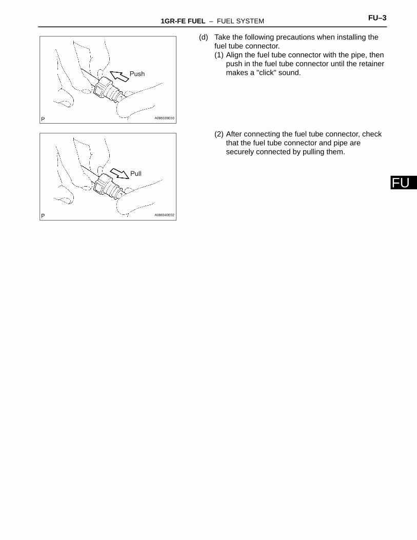
F(d) Take the following precautions when installing the fuel tube connector.(1) Align the fuel tube connector with the pipe, then
push in the fuel tube connector until the retainer makes a "click" sound.
(2) After connecting the fuel tube connector, check that the fuel tube connector and pipe are securely connected by pulling them.
Push
A088339E03
Pull
A088340E02
FU–4 1GR-FE FUEL – FUEL SYSTEM
FU
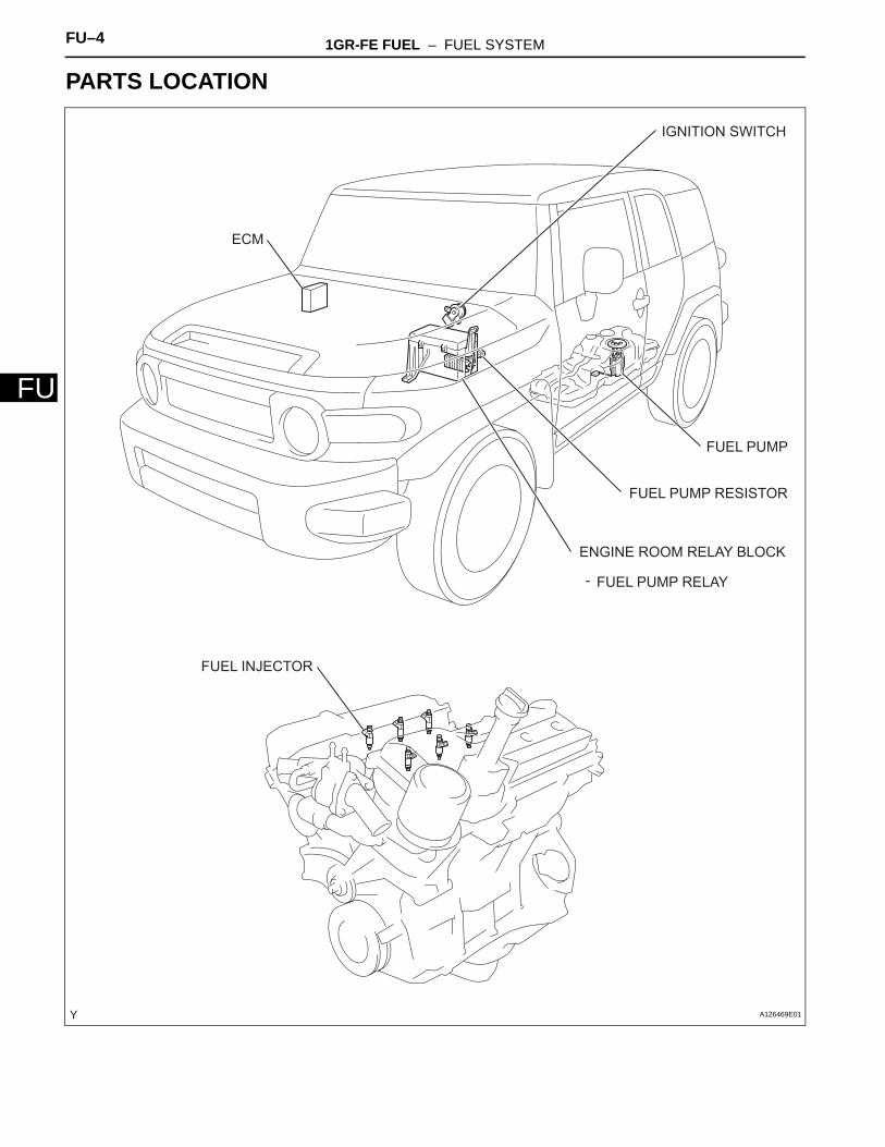
PARTS LOCATION
FUEL INJECTOR
FUEL PUMP
FUEL PUMP RESISTOR
IGNITION SWITCH
ECM
ENGINE ROOM RELAY BLOCK
FUEL PUMP RELAY-
A126469E01
1GR-FE FUEL – FUEL SYSTEM FU–5
U
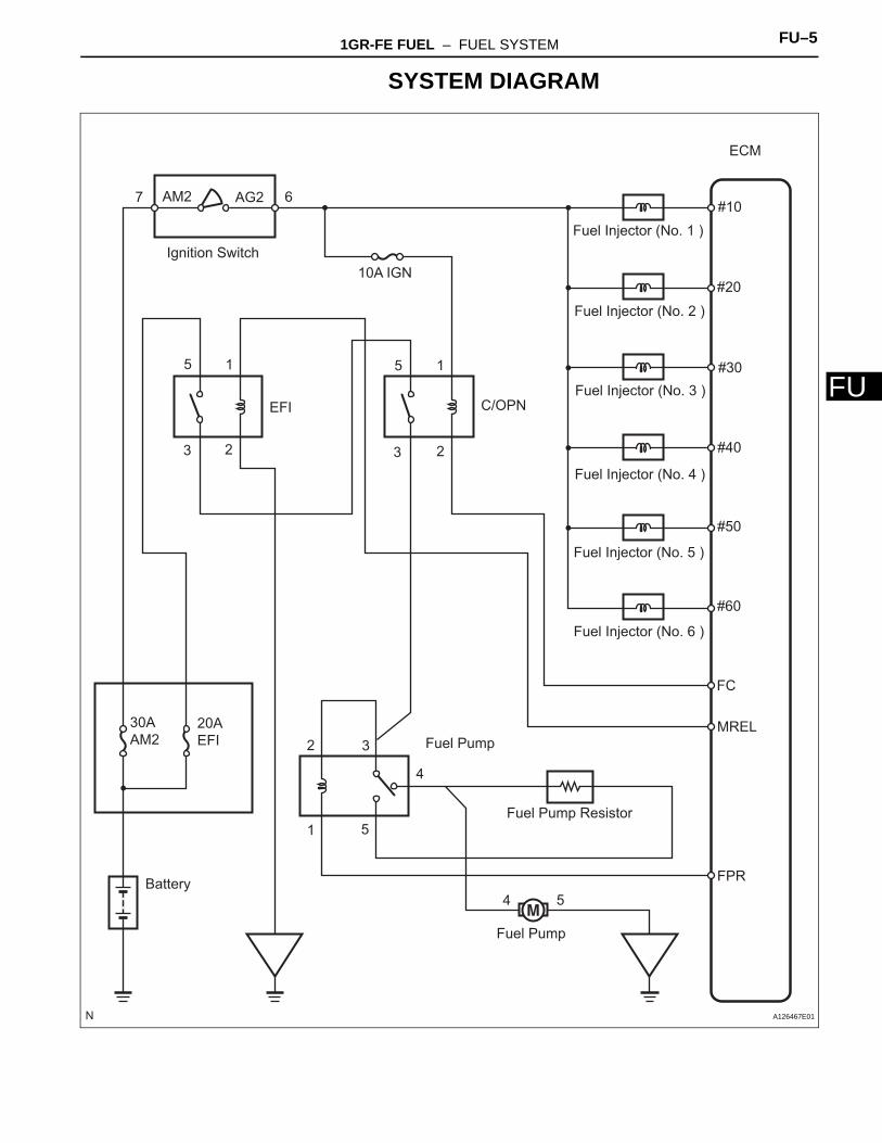
FSYSTEM DIAGRAM
Fuel Injector (No. 1 )
Fuel Injector (No. 2 )
Fuel Injector (No. 3 )
Fuel Injector (No. 4 )
Fuel Injector (No. 5 )
Fuel Injector (No. 6 )
#10
#20
#30
#40
#50
#60
FC
MREL
FPR
ECM
7 6AM2 AG2
Ignition Switch10A IGN
1
23
5
EFI
5
3 2
1
C/OPN
30A AM2
20A EFI
Battery
1
2 3
5
4
Fuel Pump
Fuel Pump Resistor
4 5
Fuel Pump
A126467E01
FU–6 1GR-FE FUEL – FUEL SYSTEM
FU
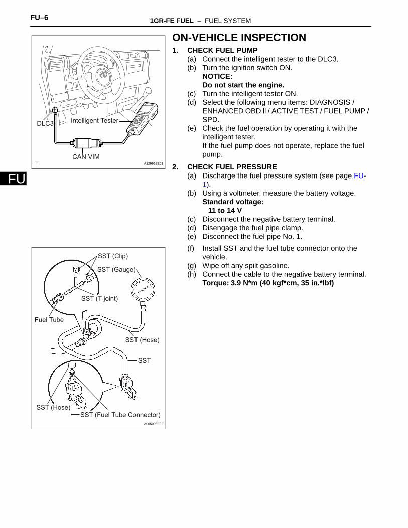
ON-VEHICLE INSPECTION1. CHECK FUEL PUMP
(a) Connect the intelligent tester to the DLC3.(b) Turn the ignition switch ON.
NOTICE:Do not start the engine.
(c) Turn the intelligent tester ON.(d) Select the following menu items: DIAGNOSIS /
ENHANCED OBD ll / ACTIVE TEST / FUEL PUMP / SPD.
(e) Check the fuel operation by operating it with the intelligent tester.If the fuel pump does not operate, replace the fuel pump.
2. CHECK FUEL PRESSURE(a) Discharge the fuel pressure system (see page FU-
1).(b) Using a voltmeter, measure the battery voltage.
Standard voltage:11 to 14 V
(c) Disconnect the negative battery terminal.(d) Disengage the fuel pipe clamp.(e) Disconnect the fuel pipe No. 1.(f) Install SST and the fuel tube connector onto the
vehicle.(g) Wipe off any spilt gasoline.(h) Connect the cable to the negative battery terminal.
Torque: 3.9 N*m (40 kgf*cm, 35 in.*lbf)
Intelligent TesterDLC3
CAN VIMA129958E01
SST (Clip)
SST (T-joint)
SST (Gauge)
SST (Hose)
SST
SST (Hose)SST (Fuel Tube Connector)
Fuel Tube
A065093E02
1GR-FE FUEL – FUEL SYSTEM FU–7
U
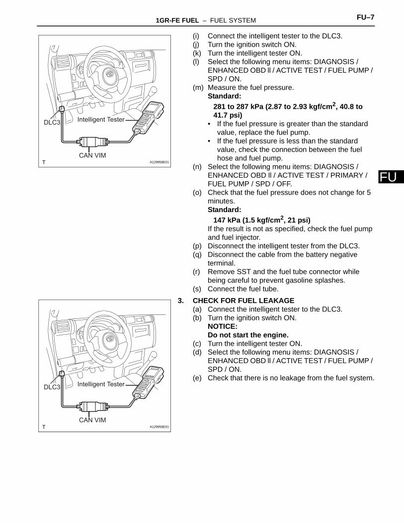
F(i) Connect the intelligent tester to the DLC3.(j) Turn the ignition switch ON.(k) Turn the intelligent tester ON.(l) Select the following menu items: DIAGNOSIS /
ENHANCED OBD ll / ACTIVE TEST / FUEL PUMP / SPD / ON.
(m) Measure the fuel pressure.Standard:
281 to 287 kPa (2.87 to 2.93 kgf/cm2, 40.8 to 41.7 psi)
• If the fuel pressure is greater than the standard value, replace the fuel pump.
• If the fuel pressure is less than the standard value, check the connection between the fuel hose and fuel pump.
(n) Select the following menu items: DIAGNOSIS / ENHANCED OBD ll / ACTIVE TEST / PRIMARY / FUEL PUMP / SPD / OFF.
(o) Check that the fuel pressure does not change for 5 minutes.Standard:
147 kPa (1.5 kgf/cm2, 21 psi)If the result is not as specified, check the fuel pump and fuel injector.
(p) Disconnect the intelligent tester from the DLC3.(q) Disconnect the cable from the battery negative
terminal.(r) Remove SST and the fuel tube connector while
being careful to prevent gasoline splashes.(s) Connect the fuel tube.
3. CHECK FOR FUEL LEAKAGE(a) Connect the intelligent tester to the DLC3.(b) Turn the ignition switch ON.
NOTICE:Do not start the engine.
(c) Turn the intelligent tester ON.(d) Select the following menu items: DIAGNOSIS /
ENHANCED OBD ll / ACTIVE TEST / FUEL PUMP / SPD / ON.
(e) Check that there is no leakage from the fuel system.
Intelligent TesterDLC3
CAN VIMA129958E01
Intelligent TesterDLC3
CAN VIMA129958E01
FU–8 1GR-FE FUEL – FUEL INJECTOR
FU
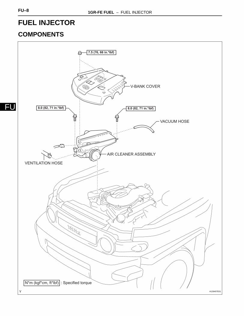
ENGINE1GR-FE FUELFUEL INJECTORCOMPONENTS
AIR CLEANER ASSEMBLY
V-BANK COVER
N*m (kgf*cm, ft*lbf) : Specified torque
8.0 (82, 71 in.*lbf)
7.5 (76, 66 in.*lbf)
VACUUM HOSE
8.0 (82, 71 in.*lbf)
VENTILATION HOSE
A126407E01
1GR-FE FUEL – FUEL INJECTOR FU–9
U
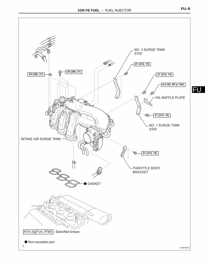
FINTAKE AIR SURGE TANK
NO. 1 SURGE TANK STAY
NO. 2 SURGE TANK STAY
THROTTLE BODY BRACKET
N*m (kgf*cm, ft*lbf) : Specified torque
Non-reusable part
28 (286, 21)
GASKET
9.0 (92, 80 in.*lbf)
28 (286, 21)
21 (214, 15)
OIL BAFFLE PLATE
21 (214, 15)
21 (214, 15)
21 (214, 15)
A126476E01
FU–10 1GR-FE FUEL – FUEL INJECTOR
FU
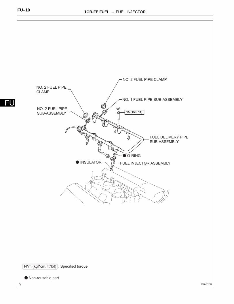
NO. 2 FUEL PIPE CLAMP
NO. 1 FUEL PIPE SUB-ASSEMBLY
FUEL DELIVERY PIPE SUB-ASSEMBLY
FUEL INJECTOR ASSEMBLY
NO. 2 FUEL PIPE CLAMP
NO. 2 FUEL PIPE SUB-ASSEMBLY
x6
N*m (kgf*cm, ft*lbf) : Specified torque
Non-reusable part
15 (153, 11)
O-RING
INSULATOR
A126477E01
1GR-FE FUEL – FUEL INJECTOR FU–11
U
FREMOVAL1. DISCHARGE FUEL SYSTEM PRESSURE
(See page FU-1)
2. DISCONNECT CABLE FROM NEGATIVE BATTERY TERMINAL
3. DRAIN ENGINE COOLANT (See page CO-3)4. REMOVE V-BANK COVER (See page ES-428)5. REMOVE AIR CLEANER ASSEMBLY (See page ES-
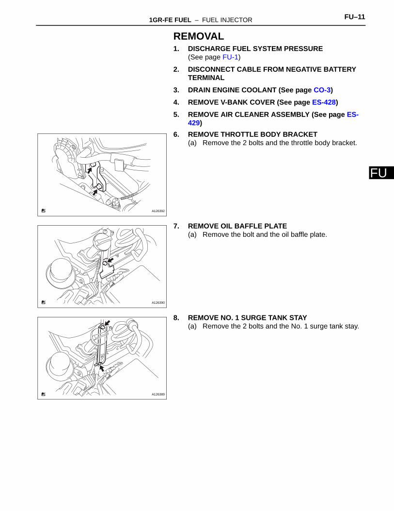
429)6. REMOVE THROTTLE BODY BRACKET
(a) Remove the 2 bolts and the throttle body bracket.
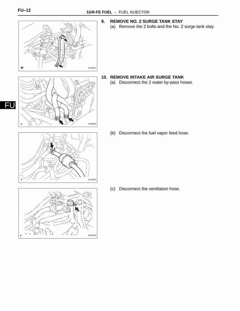
7. REMOVE OIL BAFFLE PLATE(a) Remove the bolt and the oil baffle plate.
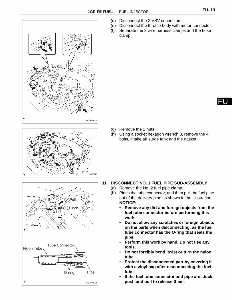
8. REMOVE NO. 1 SURGE TANK STAY(a) Remove the 2 bolts and the No. 1 surge tank stay.
A126392
A126390
A126389
FU–12 1GR-FE FUEL – FUEL INJECTOR
FU
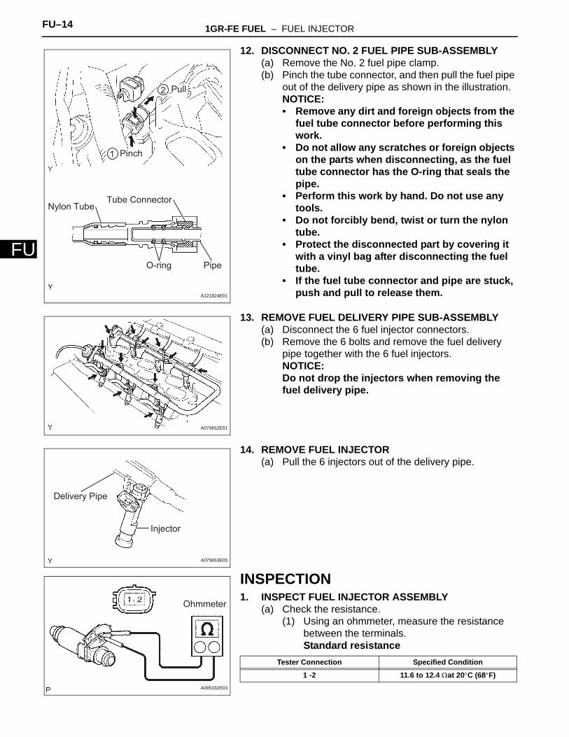
9. REMOVE NO. 2 SURGE TANK STAY(a) Remove the 2 bolts and the No. 2 surge tank stay.
10. REMOVE INTAKE AIR SURGE TANK(a) Disconnect the 2 water by-pass hoses.
(b) Disconnect the fuel vapor feed hose.
(c) Disconnect the ventilation hose.
A126391
A126395
A126449
A075645
1GR-FE FUEL – FUEL INJECTOR FU–13
U
F(d) Disconnect the 2 VSV connectors.(e) Disconnect the throttle body with motor connector.(f) Separate the 3 wire harness clamps and the hose
clamp.
(g) Remove the 2 nuts.(h) Using a socket hexagon wrench 8, remove the 4
bolts, intake air surge tank and the gasket.
11. DISCONNECT NO. 1 FUEL PIPE SUB-ASSEMBLY(a) Remove the No. 2 fuel pipe clamp.(b) Pinch the tube connector, and then pull the fuel pipe
out of the delivery pipe as shown in the illustration.NOTICE:• Remove any dirt and foreign objects from the
fuel tube connector before performing this work.
• Do not allow any scratches or foreign objects on the parts when disconnecting, as the fuel tube connector has the O-ring that seals the pipe.
• Perform this work by hand. Do not use any tools.
• Do not forcibly bend, twist or turn the nylon tube.
• Protect the disconnected part by covering it with a vinyl bag after disconnecting the fuel tube.
• If the fuel tube connector and pipe are stuck, push and pull to release them.
A075646E01
A075648
Nylon TubeTube Connector
O-ring Pipe
1
2
Pinch
Pull
1 Pinch
A121823E01
FU–14 1GR-FE FUEL – FUEL INJECTOR
FU
12. DISCONNECT NO. 2 FUEL PIPE SUB-ASSEMBLY(a) Remove the No. 2 fuel pipe clamp.(b) Pinch the tube connector, and then pull the fuel pipe
out of the delivery pipe as shown in the illustration.NOTICE:• Remove any dirt and foreign objects from the
fuel tube connector before performing this work.
• Do not allow any scratches or foreign objects on the parts when disconnecting, as the fuel tube connector has the O-ring that seals the pipe.
• Perform this work by hand. Do not use any tools.
• Do not forcibly bend, twist or turn the nylon tube.
• Protect the disconnected part by covering it with a vinyl bag after disconnecting the fuel tube.
• If the fuel tube connector and pipe are stuck, push and pull to release them.
13. REMOVE FUEL DELIVERY PIPE SUB-ASSEMBLY(a) Disconnect the 6 fuel injector connectors.(b) Remove the 6 bolts and remove the fuel delivery
pipe together with the 6 fuel injectors.NOTICE:Do not drop the injectors when removing the fuel delivery pipe.
14. REMOVE FUEL INJECTOR(a) Pull the 6 injectors out of the delivery pipe.
INSPECTION1. INSPECT FUEL INJECTOR ASSEMBLY
(a) Check the resistance.(1) Using an ohmmeter, measure the resistance
between the terminals.Standard resistance
Nylon TubeTube Connector
O-ring Pipe
1
2
Pinch
Pull
A121824E01
A075652E01
Injector
Delivery Pipe
A075653E05
Ohmmeter
A095332E03
Tester Connection Specified Condition
1 -2 11.6 to 12.4 Ωat 20°C (68°F)
1GR-FE FUEL – FUEL INJECTOR FU–15
U
FIf the result is not as specified, replace the fuel injector.
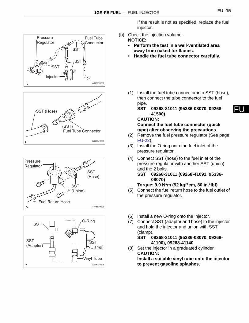
(b) Check the injection volume.NOTICE:• Perform the test in a well-ventilated area
away from naked for flames.• Handle the fuel tube connector carefully.
(1) Install the fuel tube connector into SST (hose), then connect the tube connector to the fuel pipe.SST 09268-31011 (95336-08070, 09268-
41500)CAUTION:Connect the fuel tube connector (quick type) after observing the precautions.
(2) Remove the fuel pressure regulator (See page FU-22).
(3) Install the O-ring onto the fuel inlet of the pressure regulator.
(4) Connect SST (hose) to the fuel inlet of the pressure regulator with another SST (union) and the 2 bolts.SST 09268-31011 (09268-41091, 95336-
08070)Torque: 9.0 N*m (92 kgf*cm, 80 in.*lbf)
(5) Connect the fuel return hose to the fuel outlet of the pressure regulator.
(6) Install a new O-ring onto the injector.(7) Connect SST (adaptor and hose) to the injector
and hold the injector and union with SST (clamp).SST 09268-31011 (95336-08070, 09268-
41100), 09268-41140(8) Set the injector in a graduated cylinder.
CAUTION:Install a suitable vinyl tube onto the injector to prevent gasoline splashes.
SST
SSTSST
Injector
Fuel Tube Connector
Pressure Regulator
A075912E01
Fuel Tube Connector
SST (Hose)
(SST)
B012947E08
SST (Hose)
SST (Union)
Fuel Return Hose
Pressure Regulator
A076630E01
SST
SST (Adapter)
O-Ring
Vinyl Tube
SST (Clamp)
A075914E03
FU–16 1GR-FE FUEL – FUEL INJECTOR
FU
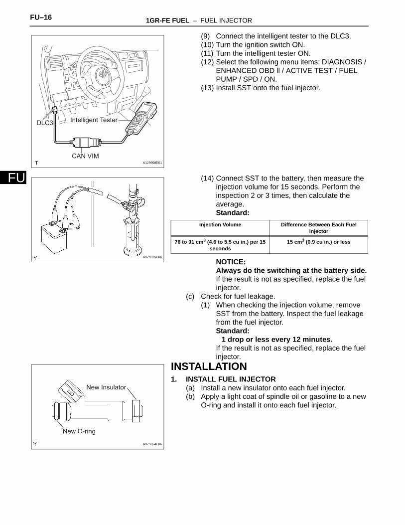
(9) Connect the intelligent tester to the DLC3.(10) Turn the ignition switch ON.(11) Turn the intelligent tester ON.(12) Select the following menu items: DIAGNOSIS /
ENHANCED OBD ll / ACTIVE TEST / FUEL PUMP / SPD / ON.
(13) Install SST onto the fuel injector.
(14) Connect SST to the battery, then measure the injection volume for 15 seconds. Perform the inspection 2 or 3 times, then calculate the average.Standard:
NOTICE:Always do the switching at the battery side.If the result is not as specified, replace the fuel injector.
(c) Check for fuel leakage.(1) When checking the injection volume, remove
SST from the battery. Inspect the fuel leakage from the fuel injector.Standard:
1 drop or less every 12 minutes.If the result is not as specified, replace the fuel injector.
INSTALLATION1. INSTALL FUEL INJECTOR
(a) Install a new insulator onto each fuel injector.(b) Apply a light coat of spindle oil or gasoline to a new
O-ring and install it onto each fuel injector.
Intelligent TesterDLC3
CAN VIMA129958E01
A075915E06
Injection Volume Difference Between Each Fuel Injector
76 to 91 cm3 (4.6 to 5.5 cu in.) per 15 seconds
15 cm3 (0.9 cu in.) or less
New O-ring
New Insulator
A075654E06
1GR-FE FUEL – FUEL INJECTOR FU–17
U
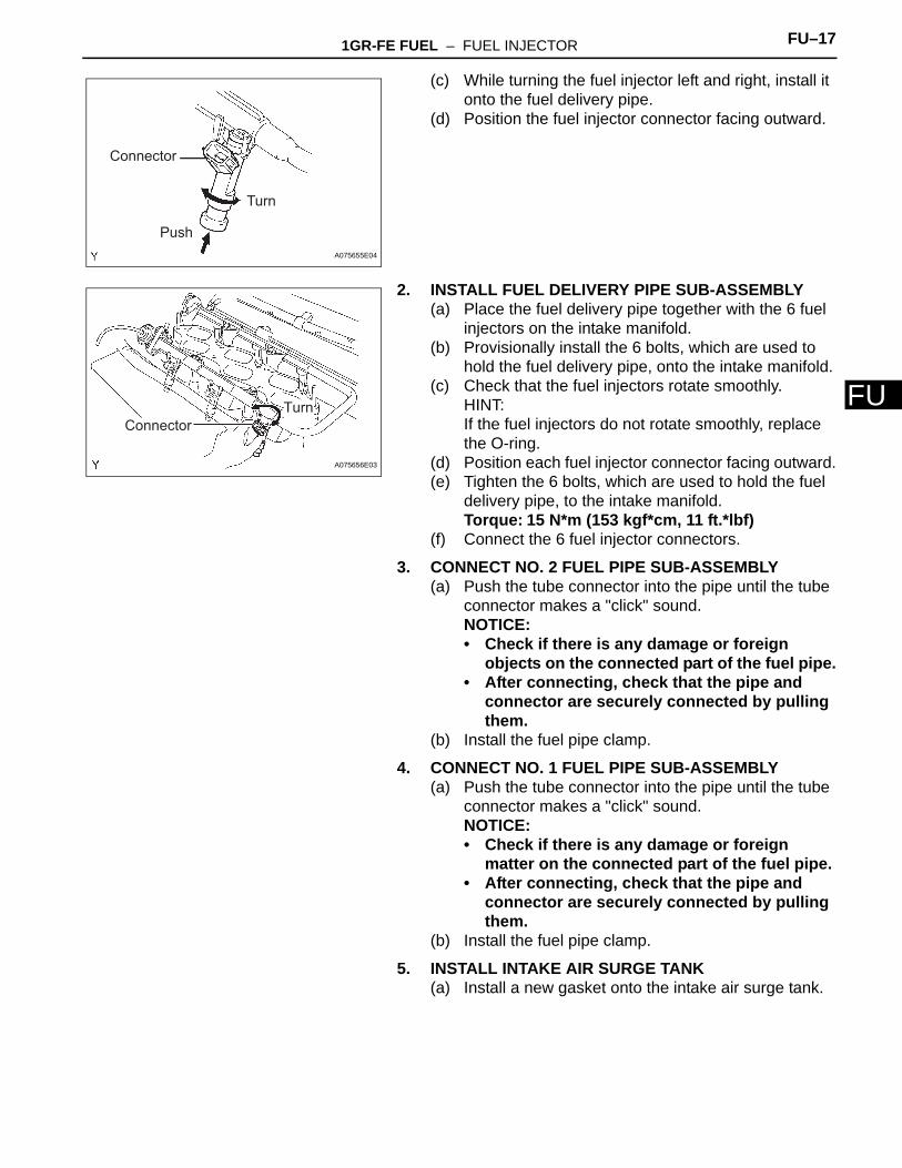
F(c) While turning the fuel injector left and right, install it onto the fuel delivery pipe.
(d) Position the fuel injector connector facing outward.
2. INSTALL FUEL DELIVERY PIPE SUB-ASSEMBLY(a) Place the fuel delivery pipe together with the 6 fuel
injectors on the intake manifold.(b) Provisionally install the 6 bolts, which are used to
hold the fuel delivery pipe, onto the intake manifold.(c) Check that the fuel injectors rotate smoothly.
HINT:If the fuel injectors do not rotate smoothly, replace the O-ring.
(d) Position each fuel injector connector facing outward.(e) Tighten the 6 bolts, which are used to hold the fuel
delivery pipe, to the intake manifold.Torque: 15 N*m (153 kgf*cm, 11 ft.*lbf)
(f) Connect the 6 fuel injector connectors.
3. CONNECT NO. 2 FUEL PIPE SUB-ASSEMBLY(a) Push the tube connector into the pipe until the tube
connector makes a "click" sound.NOTICE:• Check if there is any damage or foreign
objects on the connected part of the fuel pipe.• After connecting, check that the pipe and
connector are securely connected by pulling them.
(b) Install the fuel pipe clamp.
4. CONNECT NO. 1 FUEL PIPE SUB-ASSEMBLY(a) Push the tube connector into the pipe until the tube
connector makes a "click" sound.NOTICE:• Check if there is any damage or foreign
matter on the connected part of the fuel pipe.• After connecting, check that the pipe and
connector are securely connected by pulling them.
(b) Install the fuel pipe clamp.
5. INSTALL INTAKE AIR SURGE TANK(a) Install a new gasket onto the intake air surge tank.
Turn
Connector
PushA075655E04
TurnConnector
A075656E03
FU–18 1GR-FE FUEL – FUEL INJECTOR
FU
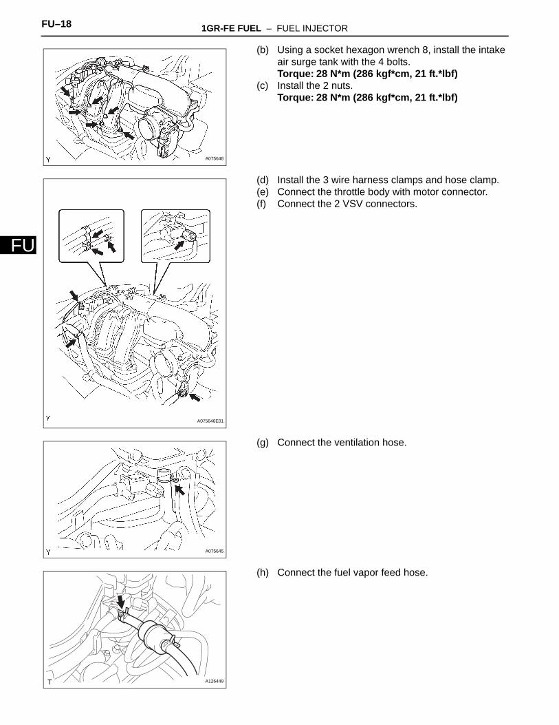
(b) Using a socket hexagon wrench 8, install the intake air surge tank with the 4 bolts.Torque: 28 N*m (286 kgf*cm, 21 ft.*lbf)
(c) Install the 2 nuts.Torque: 28 N*m (286 kgf*cm, 21 ft.*lbf)
(d) Install the 3 wire harness clamps and hose clamp.(e) Connect the throttle body with motor connector.(f) Connect the 2 VSV connectors.
(g) Connect the ventilation hose.
(h) Connect the fuel vapor feed hose.
A075648
A075646E01
A075645
A126449
1GR-FE FUEL – FUEL INJECTOR FU–19
U
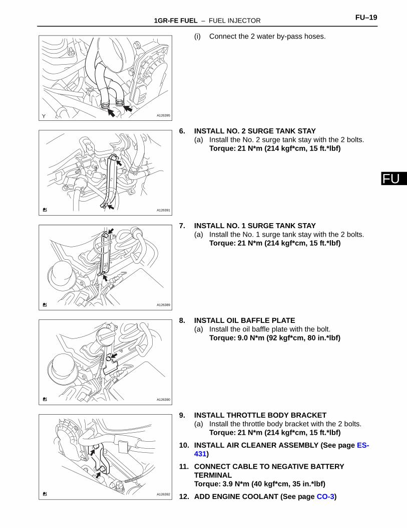
F(i) Connect the 2 water by-pass hoses.
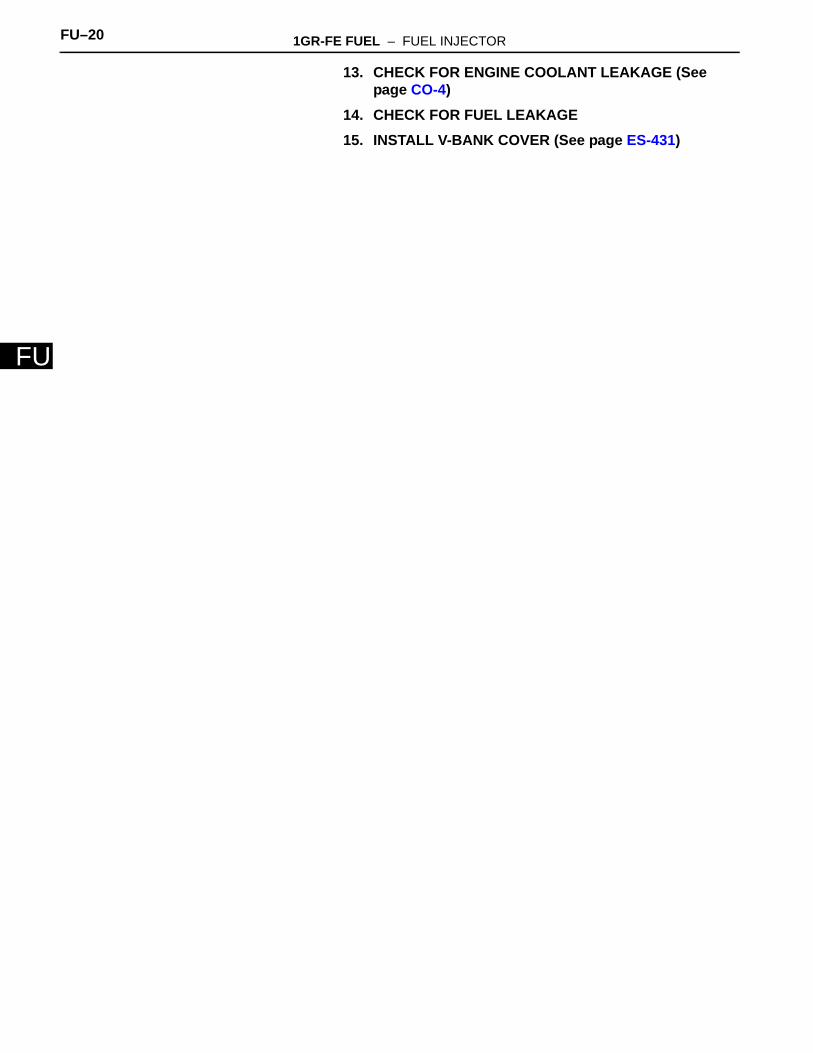
6. INSTALL NO. 2 SURGE TANK STAY(a) Install the No. 2 surge tank stay with the 2 bolts.
Torque: 21 N*m (214 kgf*cm, 15 ft.*lbf)
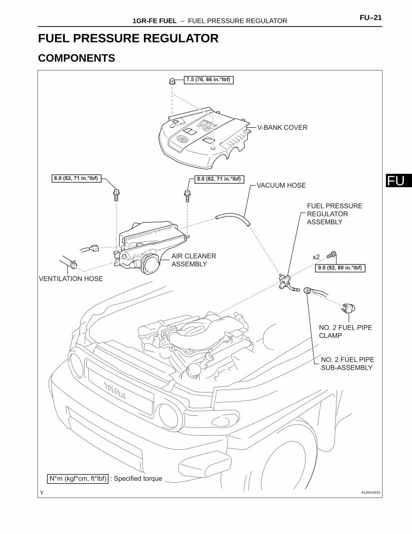
7. INSTALL NO. 1 SURGE TANK STAY(a) Install the No. 1 surge tank stay with the 2 bolts.
Torque: 21 N*m (214 kgf*cm, 15 ft.*lbf)
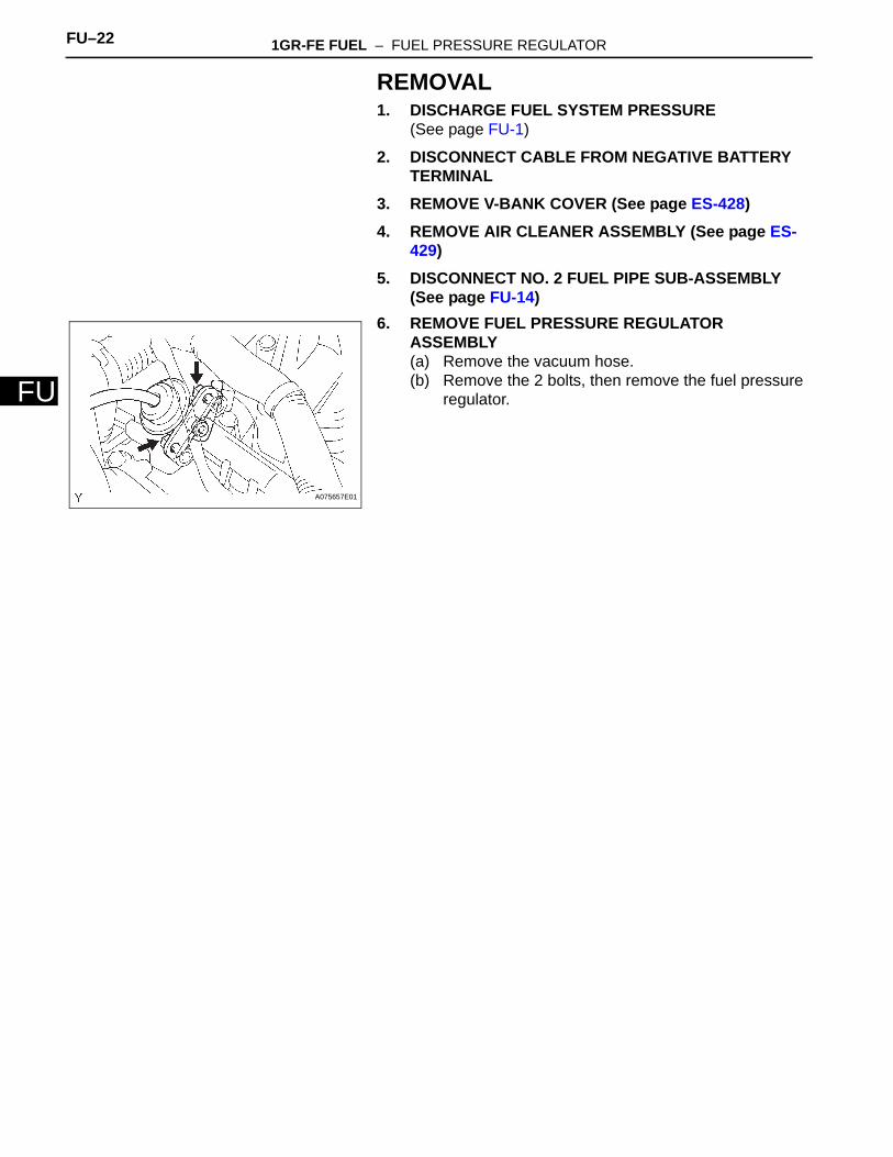
8. INSTALL OIL BAFFLE PLATE(a) Install the oil baffle plate with the bolt.
Torque: 9.0 N*m (92 kgf*cm, 80 in.*lbf)
9. INSTALL THROTTLE BODY BRACKET(a) Install the throttle body bracket with the 2 bolts.
Torque: 21 N*m (214 kgf*cm, 15 ft.*lbf)10. INSTALL AIR CLEANER ASSEMBLY (See page ES-
431)11. CONNECT CABLE TO NEGATIVE BATTERY
TERMINALTorque: 3.9 N*m (40 kgf*cm, 35 in.*lbf)
12. ADD ENGINE COOLANT (See page CO-3)
A126395
A126391
A126389
A126390
A126392
FU–20 1GR-FE FUEL – FUEL INJECTOR
FU
13. CHECK FOR ENGINE COOLANT LEAKAGE (See page CO-4)
14. CHECK FOR FUEL LEAKAGE15. INSTALL V-BANK COVER (See page ES-431)
1GR-FE FUEL – FUEL PRESSURE REGULATOR FU–21
U
FENGINE1GR-FE FUELFUEL PRESSURE REGULATORCOMPONENTS
AIR CLEANER ASSEMBLY
FUEL PRESSURE REGULATOR ASSEMBLY
NO. 2 FUEL PIPE SUB-ASSEMBLY
V-BANK COVER
VENTILATION HOSE
VACUUM HOSE
NO. 2 FUEL PIPE CLAMP
N*m (kgf*cm, ft*lbf) : Specified torque
9.0 (92, 80 in.*lbf)
x2
7.5 (76, 66 in.*lbf)
8.0 (82, 71 in.*lbf) 8.0 (82, 71 in.*lbf)
A126411E01
FU–22 1GR-FE FUEL – FUEL PRESSURE REGULATOR
FU
REMOVAL1. DISCHARGE FUEL SYSTEM PRESSURE
(See page FU-1)
2. DISCONNECT CABLE FROM NEGATIVE BATTERY TERMINAL
3. REMOVE V-BANK COVER (See page ES-428)4. REMOVE AIR CLEANER ASSEMBLY (See page ES-
429)5. DISCONNECT NO. 2 FUEL PIPE SUB-ASSEMBLY
(See page FU-14)6. REMOVE FUEL PRESSURE REGULATOR
ASSEMBLY(a) Remove the vacuum hose.(b) Remove the 2 bolts, then remove the fuel pressure
regulator.
A075657E01
1GR-FE FUEL – FUEL PRESSURE REGULATOR FU–23
U
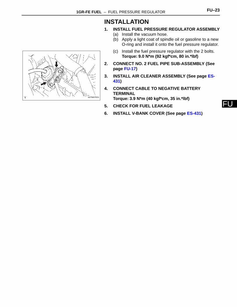
FINSTALLATION1. INSTALL FUEL PRESSURE REGULATOR ASSEMBLY
(a) Install the vacuum hose.(b) Apply a light coat of spindle oil or gasoline to a new
O-ring and install it onto the fuel pressure regulator.(c) Install the fuel pressure regulator with the 2 bolts.
Torque: 9.0 N*m (92 kgf*cm, 80 in.*lbf)2. CONNECT NO. 2 FUEL PIPE SUB-ASSEMBLY (See
page FU-17)3. INSTALL AIR CLEANER ASSEMBLY (See page ES-
431)4. CONNECT CABLE TO NEGATIVE BATTERY
TERMINALTorque: 3.9 N*m (40 kgf*cm, 35 in.*lbf)
5. CHECK FOR FUEL LEAKAGE6. INSTALL V-BANK COVER (See page ES-431)
A075657E01
1GR-FE FUEL – FUEL PRESSURE PULSATION DAMPER FU–23
U
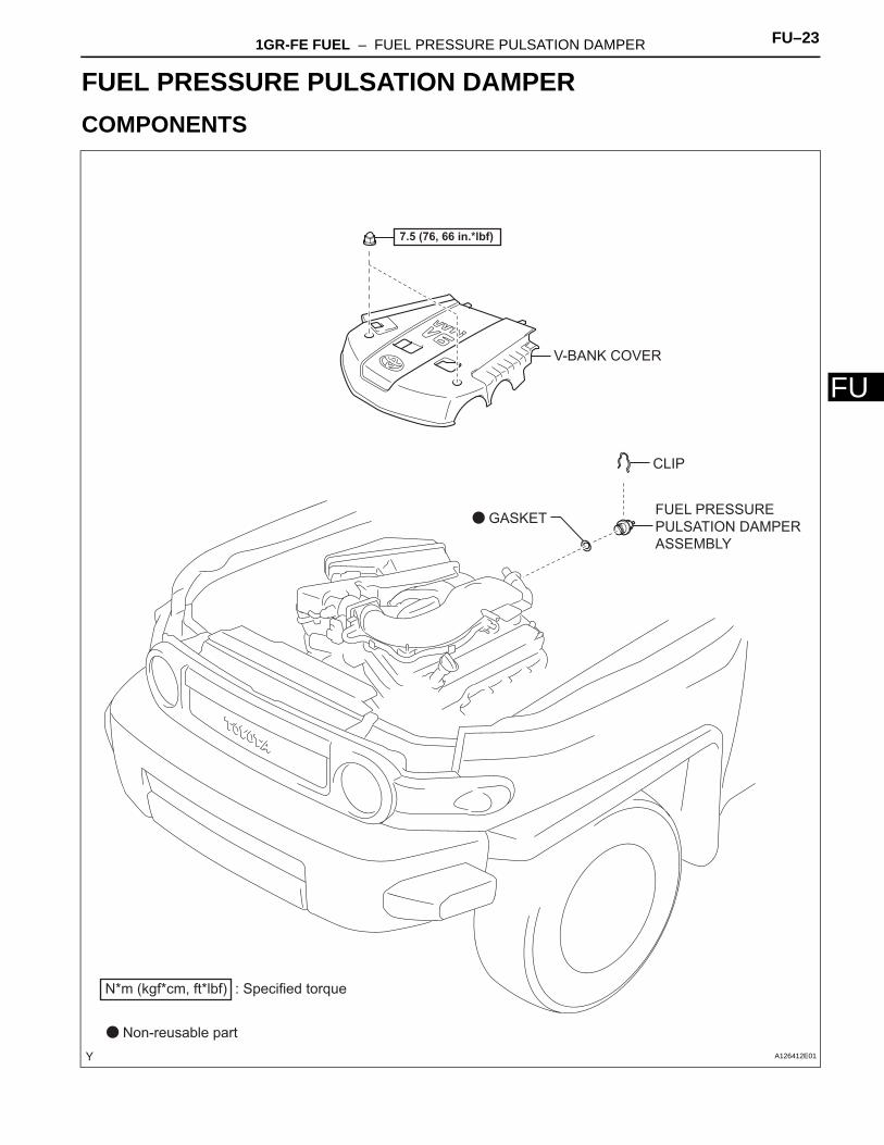
FENGINE1GR-FE FUELFUEL PRESSURE PULSATION DAMPERCOMPONENTS
FUEL PRESSURE PULSATION DAMPER ASSEMBLY
V-BANK COVER
CLIP
N*m (kgf*cm, ft*lbf) : Specified torque
Non-reusable part
GASKET
7.5 (76, 66 in.*lbf)
A126412E01
FU–24 1GR-FE FUEL – FUEL PRESSURE PULSATION DAMPER
FU
REMOVAL1. DISCHARGE FUEL SYSTEM PRESSURE
(See page FU-1)
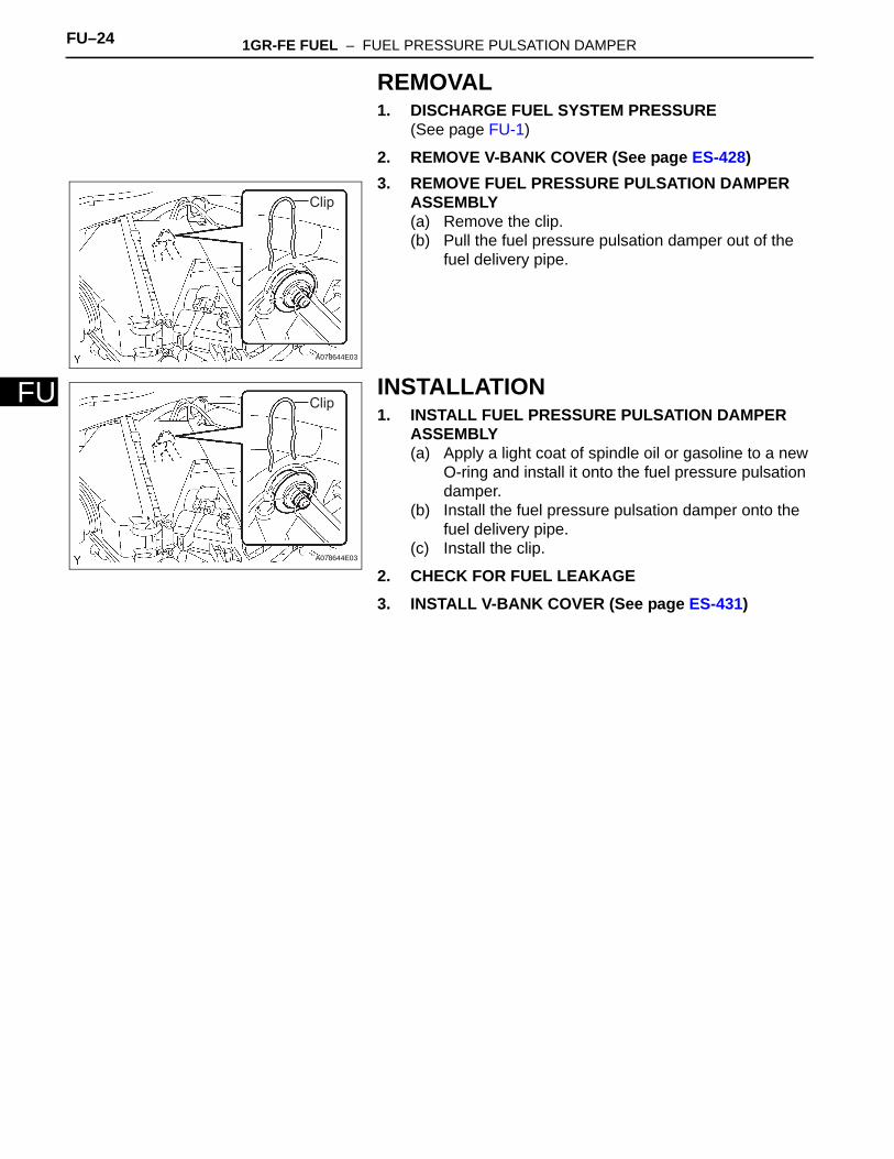
2. REMOVE V-BANK COVER (See page ES-428)3. REMOVE FUEL PRESSURE PULSATION DAMPER
ASSEMBLY(a) Remove the clip.(b) Pull the fuel pressure pulsation damper out of the
fuel delivery pipe.
INSTALLATION1. INSTALL FUEL PRESSURE PULSATION DAMPER
ASSEMBLY(a) Apply a light coat of spindle oil or gasoline to a new
O-ring and install it onto the fuel pressure pulsation damper.
(b) Install the fuel pressure pulsation damper onto the fuel delivery pipe.
(c) Install the clip.
2. CHECK FOR FUEL LEAKAGE3. INSTALL V-BANK COVER (See page ES-431)
Clip
A078644E03
Clip
A078644E03
1GR-FE FUEL – FUEL PUMP FU–25
U
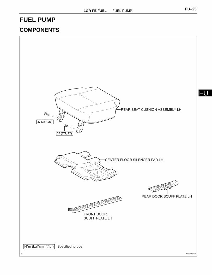
FENGINE1GR-FE FUELFUEL PUMPCOMPONENTS
37 (377, 27)
N*m (kgf*cm, ft*lbf) : Specified torque
FRONT DOOR SCUFF PLATE LH
REAR DOOR SCUFF PLATE LH
REAR SEAT CUSHION ASSEMBLY LH
CENTER FLOOR SILENCER PAD LH
37 (377, 27)
A129922E01
FU–26 1GR-FE FUEL – FUEL PUMP
FU
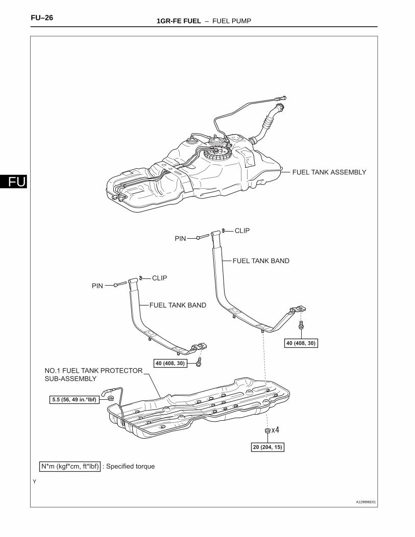
FUEL TANK ASSEMBLYFUEL TANK BAND
FUEL TANK BAND
PIN
PIN
N*m (kgf*cm, ft*lbf) : Specified torque
20 (204, 15)
CLIP
CLIP
40 (408, 30)
40 (408, 30)NO.1 FUEL TANK PROTECTOR SUB-ASSEMBLY
5.5 (56, 49 in.*lbf)
A129896E01
1GR-FE FUEL – FUEL PUMP FU–27
U
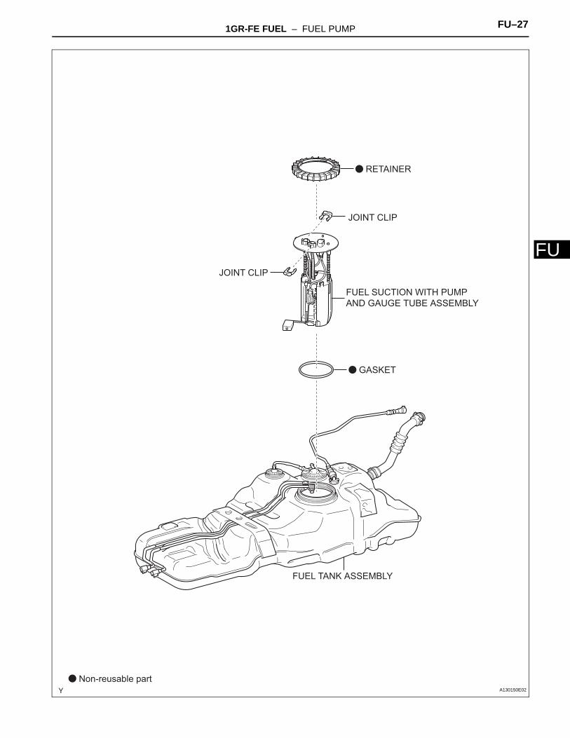
FFUEL TANK ASSEMBLY
GASKET
RETAINER
JOINT CLIP
JOINT CLIP
Non-reusable part
FUEL SUCTION WITH PUMP AND GAUGE TUBE ASSEMBLY
A130150E02
FU–28 1GR-FE FUEL – FUEL PUMP
FU
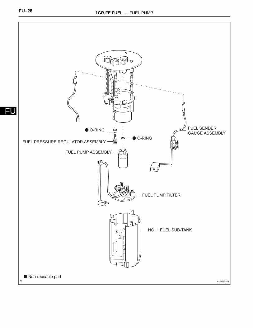
FUEL PUMP ASSEMBLY
FUEL PUMP FILTER
NO. 1 FUEL SUB-TANK
FUEL SENDER GAUGE ASSEMBLY
Non-reusable part
O-RING
O-RING
FUEL PRESSURE REGULATOR ASSEMBLY
A129895E01
1GR-FE FUEL – FUEL PUMP FU–29
U
FREMOVAL1. DISCHARGE FUEL SYSTEM PRESSURE
(See pageFU-1)
2. DISCONNECT CABLE FROM NEGATIVE BATTERY TERMINAL
3. REMOVE FRONT DOOR SCUFF PLATE LH (See page FU-42)
4. REMOVE REAR DOOR SCUFF PLATE LH (See page FU-42)
5. REMOVE REAR SEAT CUSHION ASSEMBLY LH (See page FU-42)
6. REMOVE REAR FLOOR SERVICE HOLE COVER (See page FU-42)
7. DISCONNECT FUEL TANK TO FILLER PIPE HOSE (See page FU-43)
8. DISCONNECT FUEL TANK BREATHER TUBE SUB-ASSEMBLY (See page FU-44)
9. REMOVE NO.1 FUEL TANK PROTECTOR SUB-ASSEMBLY (See page FU-44)
10. DISCONNECT FUEL TANK MAIN TUBE AND FUEL TANK RETURN TUBE (See page FU-45)
11. REMOVE FUEL TANK VENT HOSE (See page FU-45)12. REMOVE FUEL TANK ASSEMBLY (See page FU-45)13. REMOVE FUEL TANK MAIN TUBE AND FUEL TANK
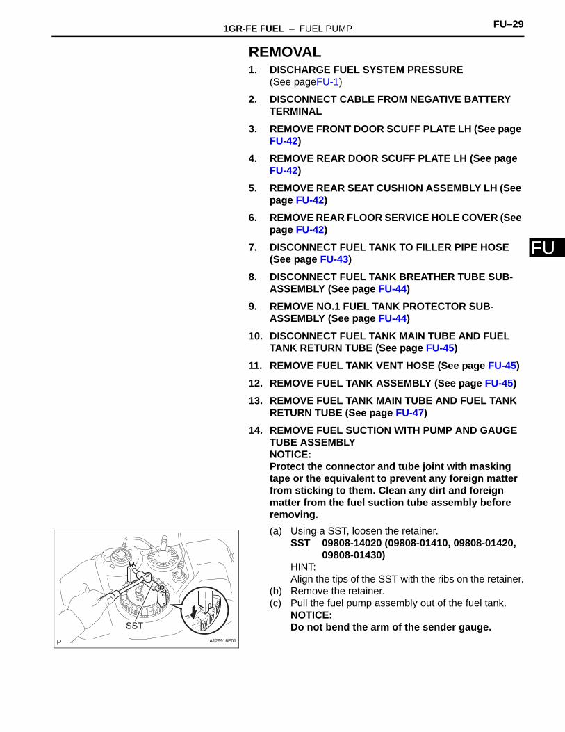
RETURN TUBE (See page FU-47)14. REMOVE FUEL SUCTION WITH PUMP AND GAUGE
TUBE ASSEMBLYNOTICE:Protect the connector and tube joint with masking tape or the equivalent to prevent any foreign matter from sticking to them. Clean any dirt and foreign matter from the fuel suction tube assembly before removing.(a) Using a SST, loosen the retainer.
SST 09808-14020 (09808-01410, 09808-01420, 09808-01430)
HINT:Align the tips of the SST with the ribs on the retainer.
(b) Remove the retainer.(c) Pull the fuel pump assembly out of the fuel tank.
NOTICE:Do not bend the arm of the sender gauge.SST
A129916E01
FU–30 1GR-FE FUEL – FUEL PUMP
FU
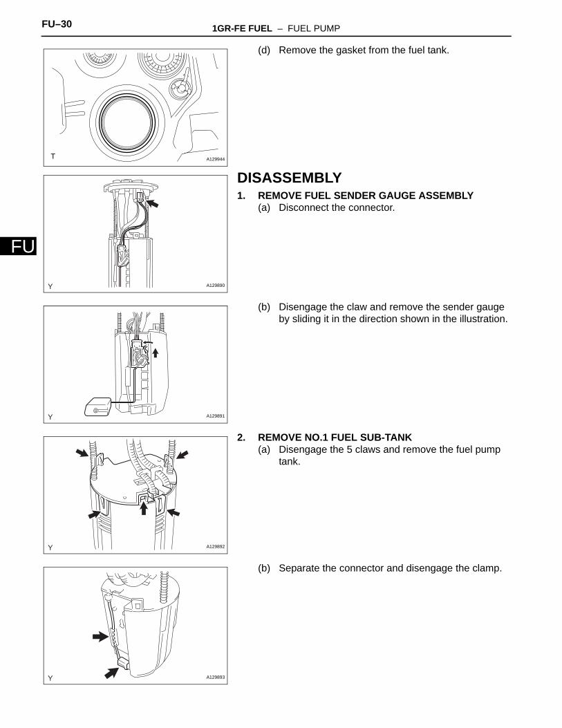
(d) Remove the gasket from the fuel tank.
DISASSEMBLY1. REMOVE FUEL SENDER GAUGE ASSEMBLY
(a) Disconnect the connector.
(b) Disengage the claw and remove the sender gauge by sliding it in the direction shown in the illustration.
2. REMOVE NO.1 FUEL SUB-TANK(a) Disengage the 5 claws and remove the fuel pump
tank.
(b) Separate the connector and disengage the clamp.
A129944
A129890
A129891
A129892
A129893
1GR-FE FUEL – FUEL PUMP FU–31
U
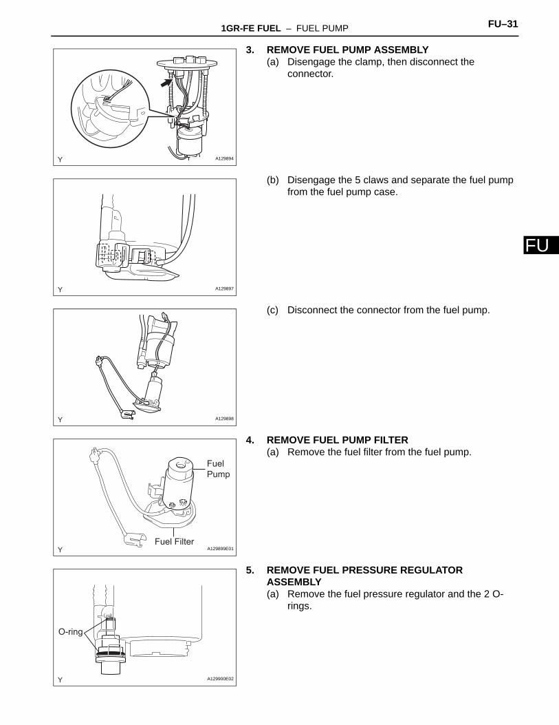
F3. REMOVE FUEL PUMP ASSEMBLY(a) Disengage the clamp, then disconnect the
connector.
(b) Disengage the 5 claws and separate the fuel pump from the fuel pump case.
(c) Disconnect the connector from the fuel pump.
4. REMOVE FUEL PUMP FILTER(a) Remove the fuel filter from the fuel pump.
5. REMOVE FUEL PRESSURE REGULATOR ASSEMBLY(a) Remove the fuel pressure regulator and the 2 O-
rings.
A129894
A129897
A129898
Fuel Pump
Fuel FilterA129899E01
O-ring
A129900E02
FU–32 1GR-FE FUEL – FUEL PUMP
FU
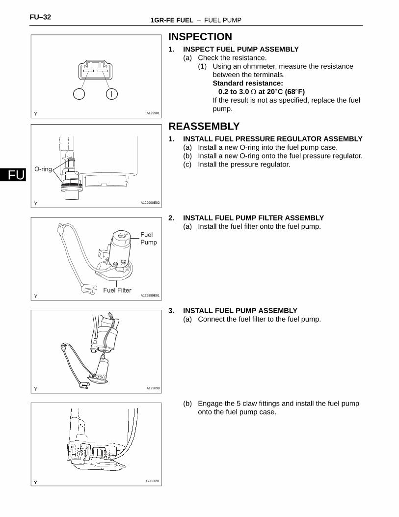
INSPECTION1. INSPECT FUEL PUMP ASSEMBLY
(a) Check the resistance.(1) Using an ohmmeter, measure the resistance
between the terminals.Standard resistance:
0.2 to 3.0 Ω at 20°C (68°F)If the result is not as specified, replace the fuel pump.
REASSEMBLY1. INSTALL FUEL PRESSURE REGULATOR ASSEMBLY
(a) Install a new O-ring into the fuel pump case.(b) Install a new O-ring onto the fuel pressure regulator.(c) Install the pressure regulator.
2. INSTALL FUEL PUMP FILTER ASSEMBLY(a) Install the fuel filter onto the fuel pump.
3. INSTALL FUEL PUMP ASSEMBLY(a) Connect the fuel filter to the fuel pump.
(b) Engage the 5 claw fittings and install the fuel pump onto the fuel pump case.
A129901
O-ring
A129900E02
Fuel Pump
Fuel FilterA129899E01
A129898
G036091
1GR-FE FUEL – FUEL PUMP FU–33
U
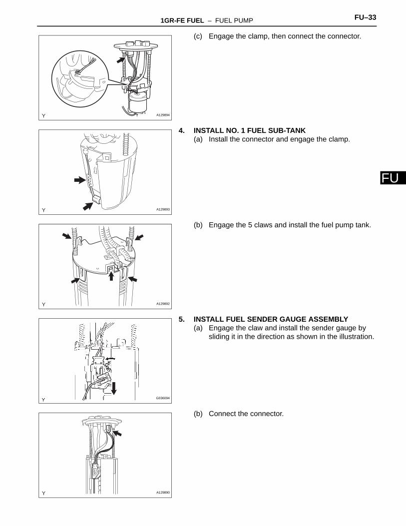
F(c) Engage the clamp, then connect the connector.
4. INSTALL NO. 1 FUEL SUB-TANK(a) Install the connector and engage the clamp.
(b) Engage the 5 claws and install the fuel pump tank.
5. INSTALL FUEL SENDER GAUGE ASSEMBLY(a) Engage the claw and install the sender gauge by
sliding it in the direction as shown in the illustration.
(b) Connect the connector.
A129894
A129893
A129892
G036094
A129890
FU–34 1GR-FE FUEL – FUEL PUMP
FU
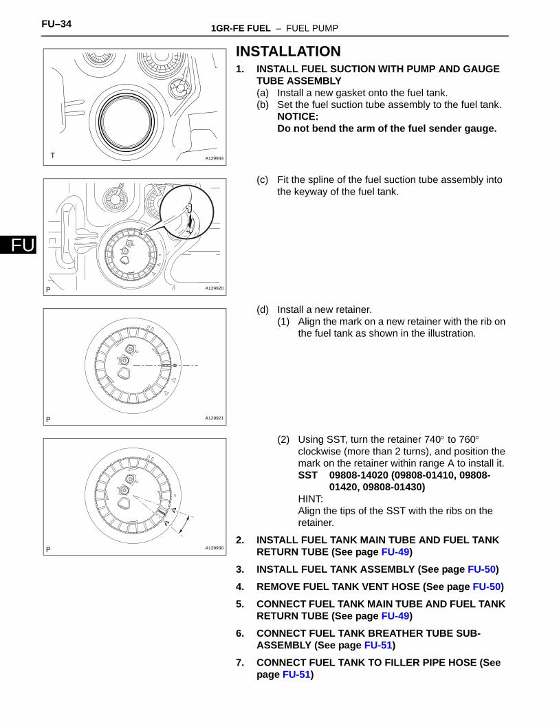
INSTALLATION1. INSTALL FUEL SUCTION WITH PUMP AND GAUGE
TUBE ASSEMBLY(a) Install a new gasket onto the fuel tank.(b) Set the fuel suction tube assembly to the fuel tank.
NOTICE:Do not bend the arm of the fuel sender gauge.
(c) Fit the spline of the fuel suction tube assembly into the keyway of the fuel tank.
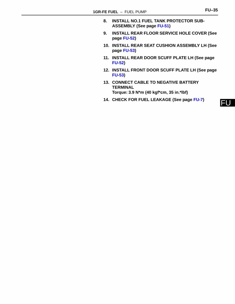
(d) Install a new retainer.(1) Align the mark on a new retainer with the rib on
the fuel tank as shown in the illustration.
(2) Using SST, turn the retainer 740° to 760° clockwise (more than 2 turns), and position the mark on the retainer within range A to install it.SST 09808-14020 (09808-01410, 09808-
01420, 09808-01430)HINT:Align the tips of the SST with the ribs on the retainer.
2. INSTALL FUEL TANK MAIN TUBE AND FUEL TANK RETURN TUBE (See page FU-49)
3. INSTALL FUEL TANK ASSEMBLY (See page FU-50)4. REMOVE FUEL TANK VENT HOSE (See page FU-50)5. CONNECT FUEL TANK MAIN TUBE AND FUEL TANK
RETURN TUBE (See page FU-49)6. CONNECT FUEL TANK BREATHER TUBE SUB-
ASSEMBLY (See page FU-51)7. CONNECT FUEL TANK TO FILLER PIPE HOSE (See
page FU-51)
A129944
A129920
A129921
A129930
1GR-FE FUEL – FUEL PUMP FU–35
U
F8. INSTALL NO.1 FUEL TANK PROTECTOR SUB-ASSEMBLY (See page FU-51)
9. INSTALL REAR FLOOR SERVICE HOLE COVER (See page FU-52)
10. INSTALL REAR SEAT CUSHION ASSEMBLY LH (See page FU-53)
11. INSTALL REAR DOOR SCUFF PLATE LH (See page FU-52)
12. INSTALL FRONT DOOR SCUFF PLATE LH (See page FU-53)
13. CONNECT CABLE TO NEGATIVE BATTERY TERMINALTorque: 3.9 N*m (40 kgf*cm, 35 in.*lbf)
14. CHECK FOR FUEL LEAKAGE (See page FU-7)
FU–36 1GR-FE FUEL – FUEL PUMP RESISTOR
FU
ENGINE1GR-FE FUELFUEL PUMP RESISTORCOMPONENTS
N*m (kgf*cm, ft*lbf) : Specified torque
8.5 (87, 75 in.*lbf)
FUEL PUMP RESISTER
A126459E01
1GR-FE FUEL – FUEL PUMP RESISTOR FU–37
U
FREMOVAL1. DISCONNECT CABLE FROM NEGATIVE BATTERY
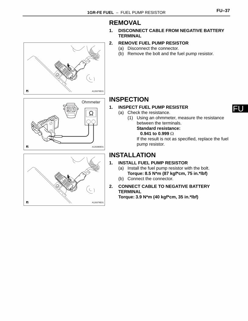
TERMINAL2. REMOVE FUEL PUMP RESISTOR
(a) Disconnect the connector.(b) Remove the bolt and the fuel pump resistor.
INSPECTION1. INSPECT FUEL PUMP RESISTER
(a) Check the resistance.(1) Using an ohmmeter, measure the resistance
between the terminals.Standard resistance:
0.941 to 0.999 ΩIf the result is not as specified, replace the fuel pump resistor.
INSTALLATION1. INSTALL FUEL PUMP RESISTOR
(a) Install the fuel pump resistor with the bolt.Torque: 8.5 N*m (87 kgf*cm, 75 in.*lbf)
(b) Connect the connector.
2. CONNECT CABLE TO NEGATIVE BATTERY TERMINALTorque: 3.9 N*m (40 kgf*cm, 35 in.*lbf)
A126379E01
2 1
Ohmmeter
A126380E01
A126379E01
FU–38 1GR-FE FUEL – FUEL TANK
FU
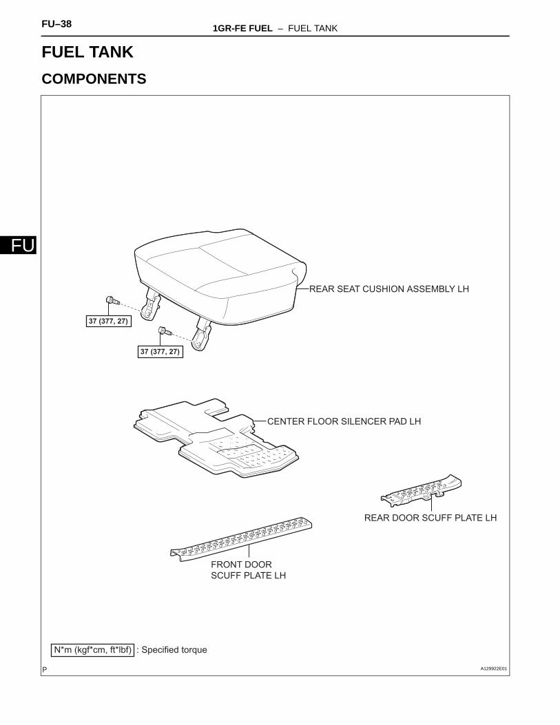
ENGINE1GR-FE FUELFUEL TANKCOMPONENTS
37 (377, 27)
N*m (kgf*cm, ft*lbf) : Specified torque
FRONT DOOR SCUFF PLATE LH
REAR DOOR SCUFF PLATE LH
REAR SEAT CUSHION ASSEMBLY LH
CENTER FLOOR SILENCER PAD LH
37 (377, 27)
A129922E01
1GR-FE FUEL – FUEL TANK FU–39
U
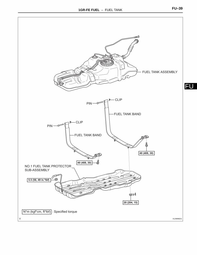
FFUEL TANK ASSEMBLY
FUEL TANK BAND
FUEL TANK BAND
PIN
PIN
N*m (kgf*cm, ft*lbf) : Specified torque
20 (204, 15)
CLIP
CLIP
40 (408, 30)
40 (408, 30)NO.1 FUEL TANK PROTECTOR SUB-ASSEMBLY
5.5 (56, 49 in.*lbf)
A129896E01
FU–40 1GR-FE FUEL – FUEL TANK
FU
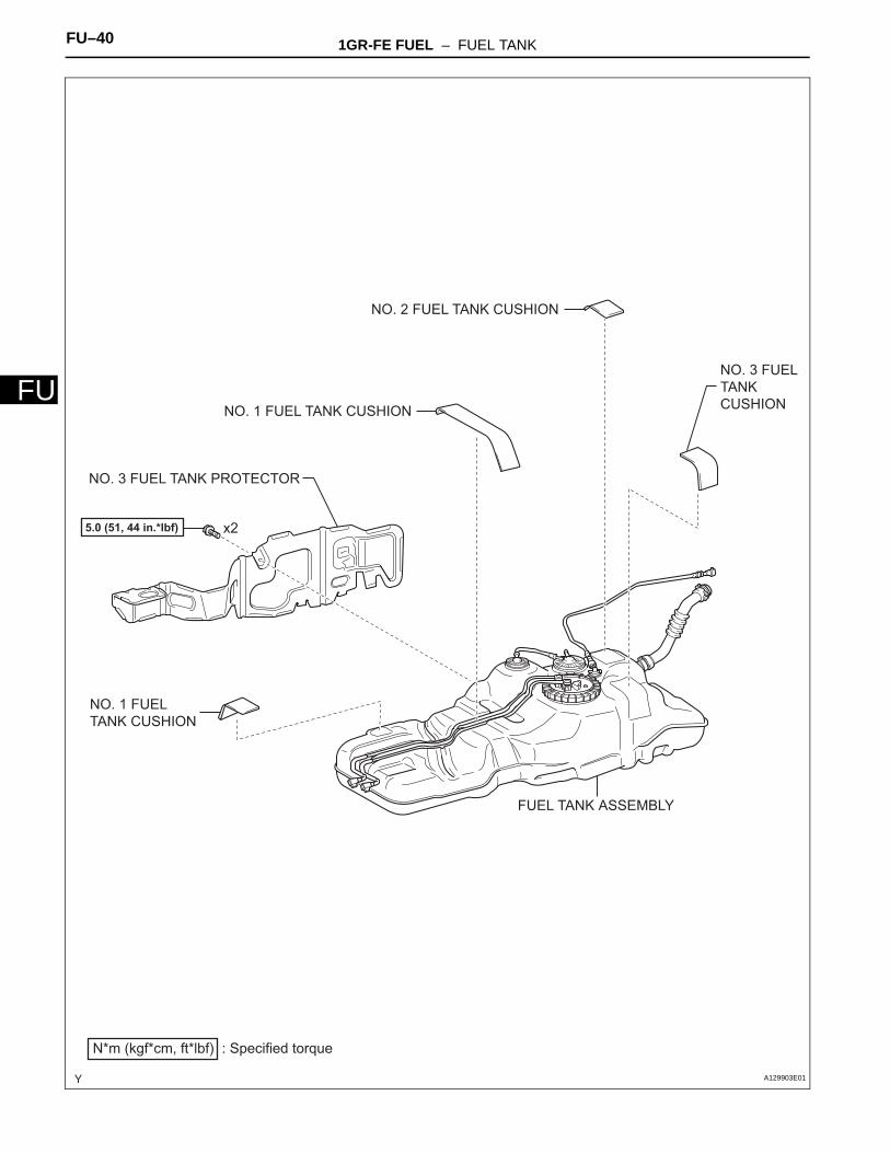
NO. 3 FUEL TANK PROTECTOR
NO. 2 FUEL TANK CUSHION
NO. 1 FUEL TANK CUSHION
NO. 3 FUEL TANK CUSHION
NO. 1 FUEL TANK CUSHION
N*m (kgf*cm, ft*lbf) : Specified torque
x25.0 (51, 44 in.*lbf)
FUEL TANK ASSEMBLY
A129903E01
1GR-FE FUEL – FUEL TANK FU–41
U
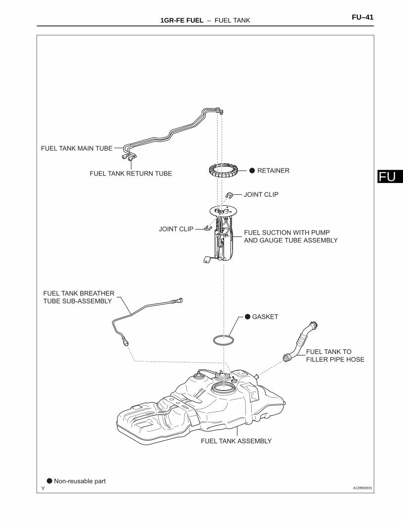
FFUEL TANK ASSEMBLY
Non-reusable part
GASKET
JOINT CLIP
JOINT CLIP
RETAINER
FUEL SUCTION WITH PUMP AND GAUGE TUBE ASSEMBLY
FUEL TANK BREATHER TUBE SUB-ASSEMBLY
FUEL TANK TO FILLER PIPE HOSE
FUEL TANK MAIN TUBE
FUEL TANK RETURN TUBE
A129902E01
FU–42 1GR-FE FUEL – FUEL TANK
FU
REMOVAL1. DISCHARGE FUEL SYSTEM PRESSURE
(See page FU-1)
2. DISCONNECT CABLE FROM NEGATIVE BATTERY TERMINAL
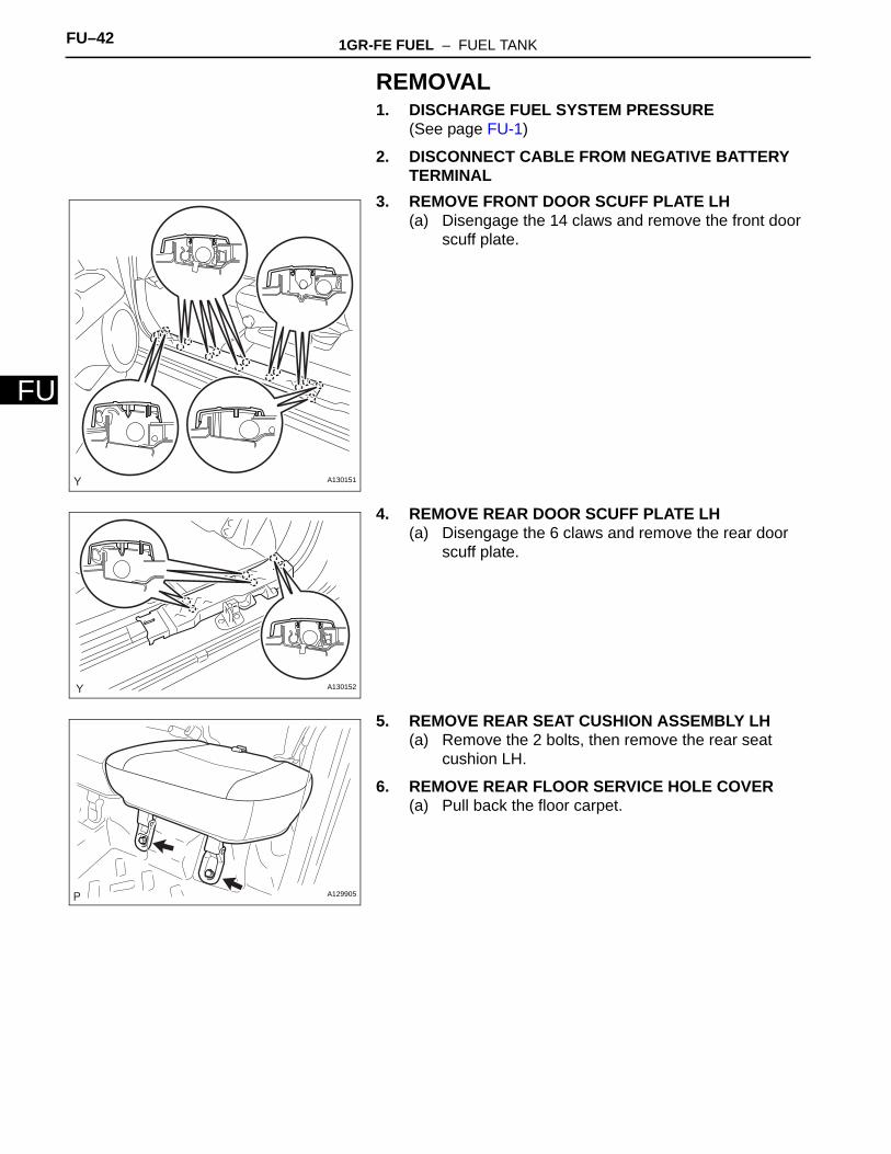
3. REMOVE FRONT DOOR SCUFF PLATE LH(a) Disengage the 14 claws and remove the front door
scuff plate.
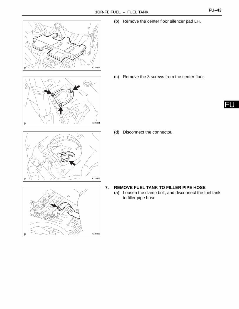
4. REMOVE REAR DOOR SCUFF PLATE LH(a) Disengage the 6 claws and remove the rear door
scuff plate.
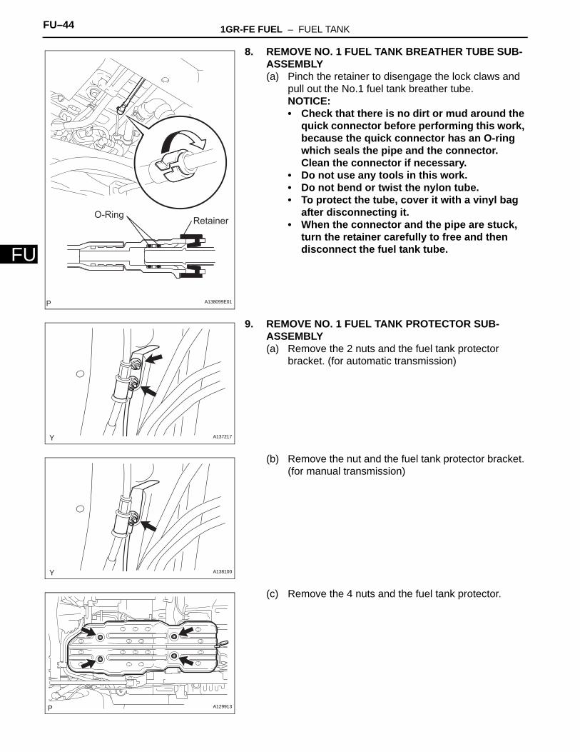
5. REMOVE REAR SEAT CUSHION ASSEMBLY LH(a) Remove the 2 bolts, then remove the rear seat
cushion LH.
6. REMOVE REAR FLOOR SERVICE HOLE COVER(a) Pull back the floor carpet.
A130151
A130152
A129905
1GR-FE FUEL – FUEL TANK FU–43
U
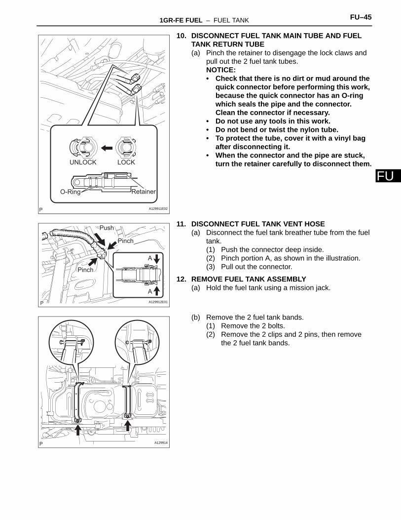
F(b) Remove the center floor silencer pad LH.
(c) Remove the 3 screws from the center floor.
(d) Disconnect the connector.
7. REMOVE FUEL TANK TO FILLER PIPE HOSE(a) Loosen the clamp bolt, and disconnect the fuel tank
to filler pipe hose.
A129907
A129904
A129908
A129909
FU–44 1GR-FE FUEL – FUEL TANK
FU
8. REMOVE NO. 1 FUEL TANK BREATHER TUBE SUB-ASSEMBLY(a) Pinch the retainer to disengage the lock claws and
pull out the No.1 fuel tank breather tube.NOTICE:• Check that there is no dirt or mud around the
quick connector before performing this work, because the quick connector has an O-ring which seals the pipe and the connector. Clean the connector if necessary.
• Do not use any tools in this work.• Do not bend or twist the nylon tube.• To protect the tube, cover it with a vinyl bag
after disconnecting it.• When the connector and the pipe are stuck,
turn the retainer carefully to free and then disconnect the fuel tank tube.
9. REMOVE NO. 1 FUEL TANK PROTECTOR SUB-ASSEMBLY(a) Remove the 2 nuts and the fuel tank protector
bracket. (for automatic transmission)
(b) Remove the nut and the fuel tank protector bracket. (for manual transmission)
(c) Remove the 4 nuts and the fuel tank protector.
O-Ring Retainer
A138099E01
A137217
A138100
A129913
1GR-FE FUEL – FUEL TANK FU–45
U
F10. DISCONNECT FUEL TANK MAIN TUBE AND FUEL TANK RETURN TUBE(a) Pinch the retainer to disengage the lock claws and
pull out the 2 fuel tank tubes.NOTICE:• Check that there is no dirt or mud around the
quick connector before performing this work, because the quick connector has an O-ring which seals the pipe and the connector. Clean the connector if necessary.
• Do not use any tools in this work.• Do not bend or twist the nylon tube.• To protect the tube, cover it with a vinyl bag
after disconnecting it.• When the connector and the pipe are stuck,
turn the retainer carefully to disconnect them.
11. DISCONNECT FUEL TANK VENT HOSE(a) Disconnect the fuel tank breather tube from the fuel
tank.(1) Push the connector deep inside.(2) Pinch portion A, as shown in the illustration.(3) Pull out the connector.
12. REMOVE FUEL TANK ASSEMBLY(a) Hold the fuel tank using a mission jack.
(b) Remove the 2 fuel tank bands.(1) Remove the 2 bolts.(2) Remove the 2 clips and 2 pins, then remove
the 2 fuel tank bands.
UNLOCK LOCK
O-Ring Retainer
A129911E02
Push
Pinch
A
Pinch
AA129912E01
A129914
FU–46 1GR-FE FUEL – FUEL TANK
FU
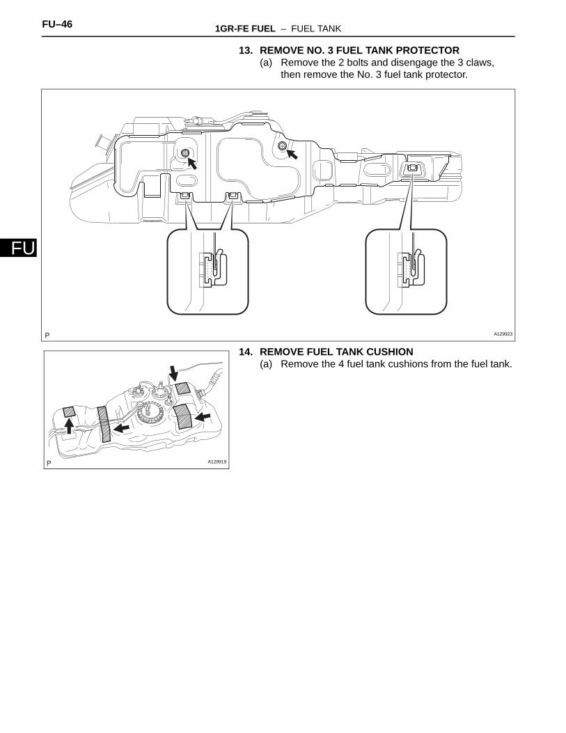
13. REMOVE NO. 3 FUEL TANK PROTECTOR(a) Remove the 2 bolts and disengage the 3 claws,
then remove the No. 3 fuel tank protector.
14. REMOVE FUEL TANK CUSHION(a) Remove the 4 fuel tank cushions from the fuel tank.
A129923
A129919
1GR-FE FUEL – FUEL TANK FU–47
U
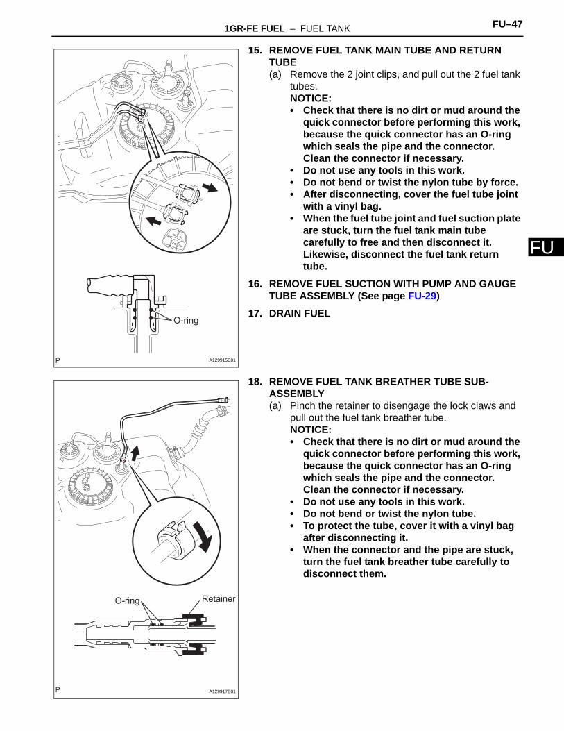
F15. REMOVE FUEL TANK MAIN TUBE AND RETURN TUBE(a) Remove the 2 joint clips, and pull out the 2 fuel tank
tubes.NOTICE:• Check that there is no dirt or mud around the
quick connector before performing this work, because the quick connector has an O-ring which seals the pipe and the connector. Clean the connector if necessary.
• Do not use any tools in this work.• Do not bend or twist the nylon tube by force.• After disconnecting, cover the fuel tube joint
with a vinyl bag.• When the fuel tube joint and fuel suction plate
are stuck, turn the fuel tank main tube carefully to free and then disconnect it. Likewise, disconnect the fuel tank return tube.
16. REMOVE FUEL SUCTION WITH PUMP AND GAUGE TUBE ASSEMBLY (See page FU-29)
17. DRAIN FUEL
18. REMOVE FUEL TANK BREATHER TUBE SUB-ASSEMBLY(a) Pinch the retainer to disengage the lock claws and
pull out the fuel tank breather tube.NOTICE:• Check that there is no dirt or mud around the
quick connector before performing this work, because the quick connector has an O-ring which seals the pipe and the connector. Clean the connector if necessary.
• Do not use any tools in this work.• Do not bend or twist the nylon tube.• To protect the tube, cover it with a vinyl bag
after disconnecting it.• When the connector and the pipe are stuck,
turn the fuel tank breather tube carefully to disconnect them.
O-ring
A129915E01
O-ring Retainer
A129917E01
FU–48 1GR-FE FUEL – FUEL TANK
FU
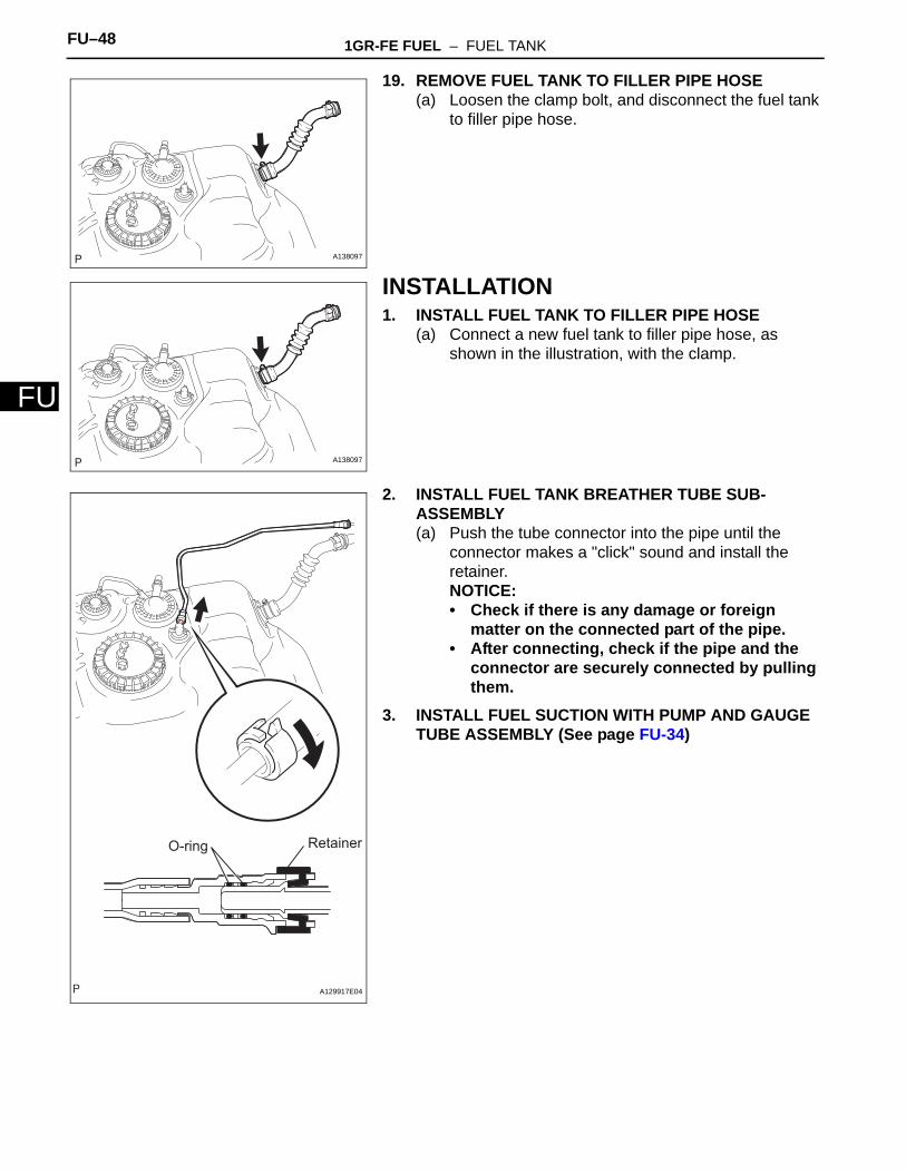
19. REMOVE FUEL TANK TO FILLER PIPE HOSE(a) Loosen the clamp bolt, and disconnect the fuel tank
to filler pipe hose.
INSTALLATION1. INSTALL FUEL TANK TO FILLER PIPE HOSE
(a) Connect a new fuel tank to filler pipe hose, as shown in the illustration, with the clamp.
2. INSTALL FUEL TANK BREATHER TUBE SUB-ASSEMBLY(a) Push the tube connector into the pipe until the
connector makes a "click" sound and install the retainer.NOTICE:• Check if there is any damage or foreign
matter on the connected part of the pipe.• After connecting, check if the pipe and the
connector are securely connected by pulling them.
3. INSTALL FUEL SUCTION WITH PUMP AND GAUGE TUBE ASSEMBLY (See page FU-34)
A138097
A138097
O-ring Retainer
A129917E04
1GR-FE FUEL – FUEL TANK FU–49
U
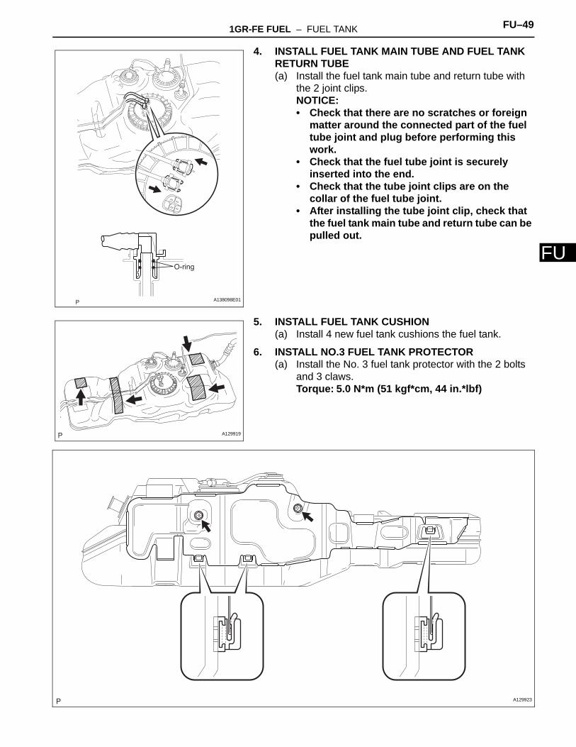
F4. INSTALL FUEL TANK MAIN TUBE AND FUEL TANK RETURN TUBE(a) Install the fuel tank main tube and return tube with
the 2 joint clips.NOTICE:• Check that there are no scratches or foreign
matter around the connected part of the fuel tube joint and plug before performing this work.
• Check that the fuel tube joint is securely inserted into the end.
• Check that the tube joint clips are on the collar of the fuel tube joint.
• After installing the tube joint clip, check that the fuel tank main tube and return tube can be pulled out.
5. INSTALL FUEL TANK CUSHION(a) Install 4 new fuel tank cushions the fuel tank.
6. INSTALL NO.3 FUEL TANK PROTECTOR(a) Install the No. 3 fuel tank protector with the 2 bolts
and 3 claws.Torque: 5.0 N*m (51 kgf*cm, 44 in.*lbf)
O-ring
A138098E01
A129919
A129923
FU–50 1GR-FE FUEL – FUEL TANK
FU
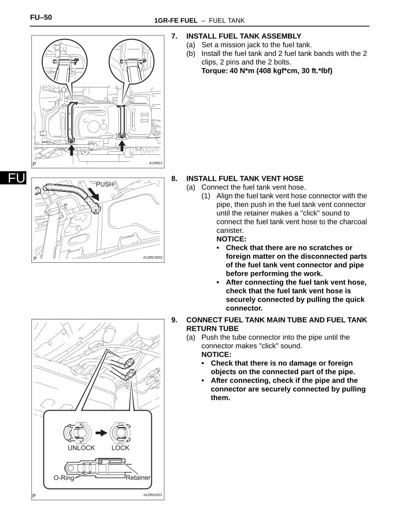
7. INSTALL FUEL TANK ASSEMBLY(a) Set a mission jack to the fuel tank.(b) Install the fuel tank and 2 fuel tank bands with the 2
clips, 2 pins and the 2 bolts.Torque: 40 N*m (408 kgf*cm, 30 ft.*lbf)
8. INSTALL FUEL TANK VENT HOSE(a) Connect the fuel tank vent hose.
(1) Align the fuel tank vent hose connector with the pipe, then push in the fuel tank vent connector until the retainer makes a "click" sound to connect the fuel tank vent hose to the charcoal canister.NOTICE:• Check that there are no scratches or
foreign matter on the disconnected parts of the fuel tank vent connector and pipe before performing the work.
• After connecting the fuel tank vent hose, check that the fuel tank vent hose is securely connected by pulling the quick connector.
9. CONNECT FUEL TANK MAIN TUBE AND FUEL TANK RETURN TUBE(a) Push the tube connector into the pipe until the
connector makes "click" sound.NOTICE:• Check that there is no damage or foreign
objects on the connected part of the pipe.• After connecting, check if the pipe and the
connector are securely connected by pulling them.
A129914
PUSH
A129912E02
UNLOCK LOCK
O-Ring Retainer
A129911E01
1GR-FE FUEL – FUEL TANK FU–51
U
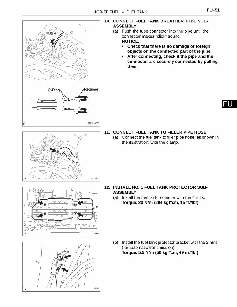
F10. CONNECT FUEL TANK BREATHER TUBE SUB-ASSEMBLY(a) Push the tube connector into the pipe until the
connector makes "click" sound.NOTICE:• Check that there is no damage or foreign
objects on the connected part of the pipe.• After connecting, check if the pipe and the
connector are securely connected by pulling them.
11. CONNECT FUEL TANK TO FILLER PIPE HOSE(a) Connect the fuel tank to filler pipe hose, as shown in
the illustration, with the clamp.
12. INSTALL NO. 1 FUEL TANK PROTECTOR SUB-ASSEMBLY(a) Install the fuel tank protector with the 4 nuts.
Torque: 20 N*m (204 kgf*cm, 15 ft.*lbf)
(b) Install the fuel tank protector bracket with the 2 nuts. (for automatic transmission)Torque: 5.5 N*m (56 kgf*cm, 49 in.*lbf)
O-Ring Retainer
PUSH
O-Ring RetainerO-Ring Retainer
A129910E01
A129909
A129913
A137217
FU–52 1GR-FE FUEL – FUEL TANK
FU
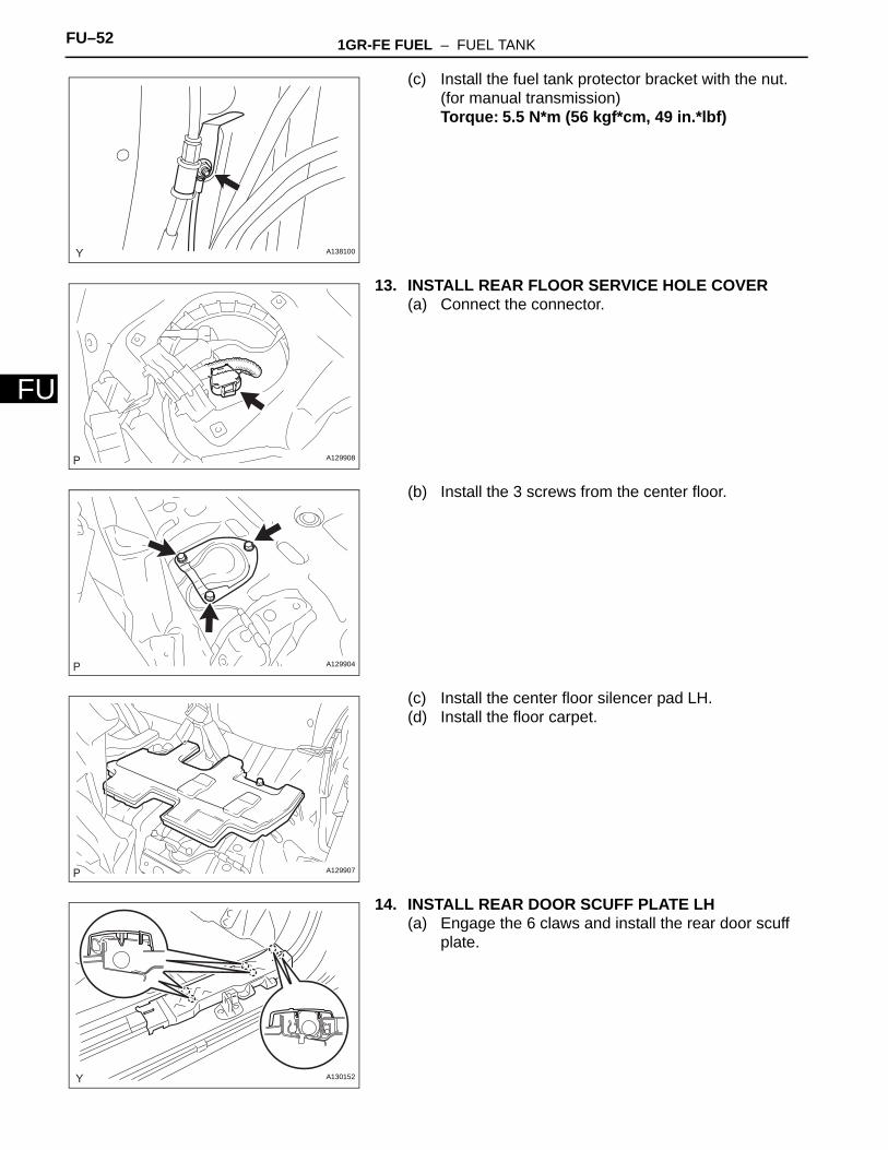
(c) Install the fuel tank protector bracket with the nut. (for manual transmission)Torque: 5.5 N*m (56 kgf*cm, 49 in.*lbf)
13. INSTALL REAR FLOOR SERVICE HOLE COVER(a) Connect the connector.
(b) Install the 3 screws from the center floor.
(c) Install the center floor silencer pad LH.(d) Install the floor carpet.
14. INSTALL REAR DOOR SCUFF PLATE LH(a) Engage the 6 claws and install the rear door scuff
plate.
A138100
A129908
A129904
A129907
A130152
1GR-FE FUEL – FUEL TANK FU–53
U
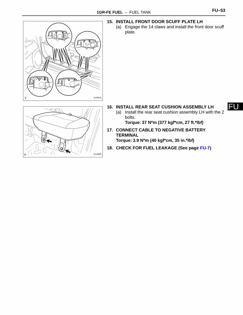
F15. INSTALL FRONT DOOR SCUFF PLATE LH(a) Engage the 14 claws and install the front door scuff
plate.
16. INSTALL REAR SEAT CUSHION ASSEMBLY LH(a) Install the rear seat cushion assembly LH with the 2
bolts.Torque: 37 N*m (377 kgf*cm, 27 ft.*lbf)
17. CONNECT CABLE TO NEGATIVE BATTERY TERMINALTorque: 3.9 N*m (40 kgf*cm, 35 in.*lbf)
18. CHECK FOR FUEL LEAKAGE (See page FU-7)
A130151
A129905
Related Documents