1 STAR HFT STAR HFT HFT Update S. Margetis, Kent State University STAR Regional Meeting, February 11, 2015, Prague

1 STAR HFT S. Margetis, Kent State University STAR Regional Meeting, February 11, 2015, Prague.
Dec 22, 2015
Welcome message from author
This document is posted to help you gain knowledge. Please leave a comment to let me know what you think about it! Share it to your friends and learn new things together.
Transcript
1
STAR HFTSTAR HFT
HFT Update
S. Margetis, Kent State University STAR Regional Meeting, February 11, 2015, Prague
2
STAR HFT
2
STAR HFTTalk Outline
• Project news
• Run-15 calibrations work
• Run-14 work• Goals/Datasets/Timeline• Calibrations update• Embedding
• STI [tracker] work• Geometry• Tracking
• Summary
3
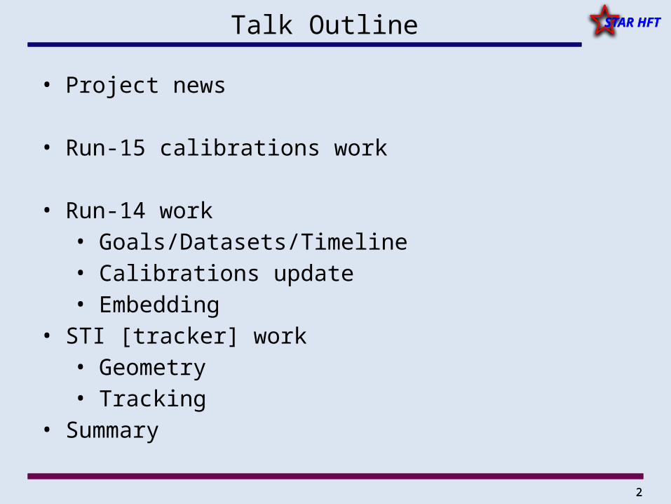
STAR HFTHeavy Flavor Tracker (HFT) [for the students]
SSDIST
PXL
HFT Detector Radius(cm)
Hit Resolution R/ - Z (m - m)
Radiation length
SSD 22 20 / 740 1% X0
IST 14 170 / 1800 <1.5 %X0
PIXEL8 12/ 12 ~0.5 %X0
2.8 12 / 12 ~0.4% X0
SSD• existing single layer detector, double side strips (electronic upgrade)IST • one layer of silicon strips along beam direction, guiding tracks from the SSD through PIXEL
detector. - proven strip technology
PIXEL • two layers• 20.7x20.7 m pixel pitch • 10 sector, delivering ultimate
pointing resolution that allows for direct topological identification of charm.
• new monolithic active pixel sensors (MAPS) technology
4
STAR HFT
4
STAR HFT
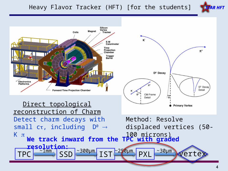
Direct topological reconstruction of Charm
Detect charm decays with small c, including D0 K
Method: Resolve displaced vertices (50-100 microns)
We track inward from the TPC with graded resolution:
TPC SSD IST PXL~1mm ~300µm ~250µm vertex~30µm
Heavy Flavor Tracker (HFT) [for the students]
5
STAR HFT
5
STAR HFTProject News
• Project is completed but DOE reporting is not
• Still have quarterly meetings [last was in January] to report on:
• Performance Parameter Status (UPP)• Run preparation status [hardware/software]• Operations during each run [data sets, problems]• Post-run Calibrations and Analysis activities
6
STAR HFT
6
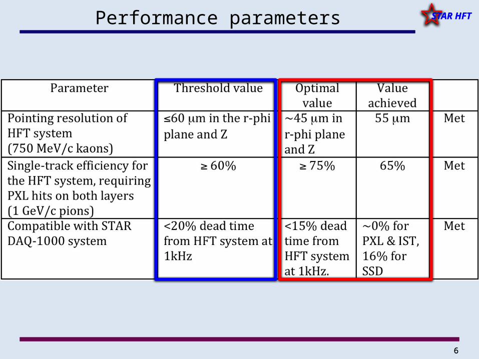
STAR HFTPerformance parameters
7
STAR HFTSTAR HFT
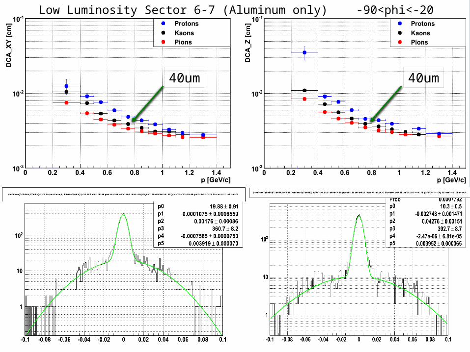
40um 40um
Low Luminosity Sector 6-7 (Aluminum only) -90<phi<-20
8
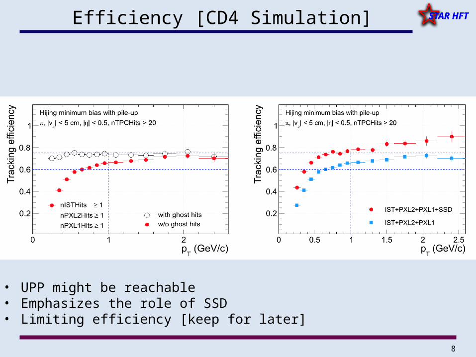
STAR HFTSTAR HFTEfficiency [CD4 Simulation]
• UPP might be reachable • Emphasizes the role of SSD• Limiting efficiency [keep for later]
9
STAR HFT
9
STAR HFTRun-15
• Goals/Datasets/Timelines
• Calibrations– Db Init for Geometry etc.– Alignment of HFT elements– Masking/noise/book-keeping– Recent work [SSD CommonModeNoise[CMN], masking]
10
STAR HFT
10
STAR HFTGoals/Datasets/Timeline
• Initial cosmic runs for Alignment/Masking etc are done– Codes are being put together for production – SSD is included in the chain– It will take a couple of weeks to finish production and a few more
to do alignment for all subsystems [SSD too for first time]
• p-p 200GeV beams just started – detectors are setup/checked
• Goal is to get a good sample of p-A and p-p 200GeV [reference] data
11
STAR HFT
11
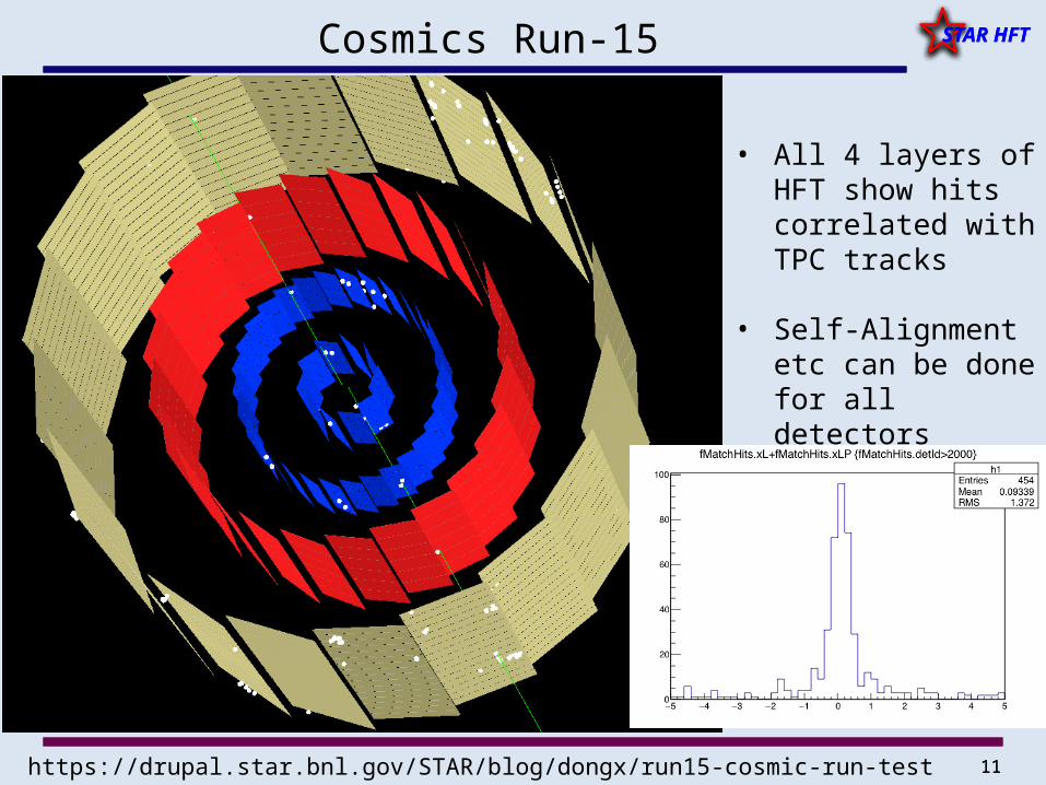
STAR HFTCosmics Run-15
• All 4 layers of HFT show hits correlated with TPC tracks
• Self-Alignment etc can be done for all detectors
https://drupal.star.bnl.gov/STAR/blog/dongx/run15-cosmic-run-test
12
STAR HFT
12
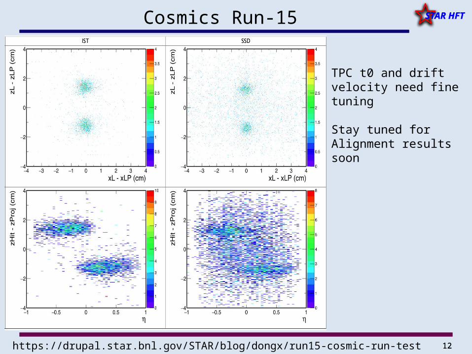
STAR HFTCosmics Run-15
TPC t0 and drift velocity need fine tuning
Stay tuned for Alignment results soon
https://drupal.star.bnl.gov/STAR/blog/dongx/run15-cosmic-run-test
13
STAR HFT
13
STAR HFTRun-14
• Goals/Datasets/Timelines
• Calibrations– Alignment of HFT elements – Masking/noise/book-keeping– Recent work [SSD CMN]
• STI [tracking]– Geometry work– Tracking efficiency optimization– Timing issues
14
STAR HFT
14
STAR HFTGoals/Datasets/Timeline
• We have 1.2 Billion Au+Au @ 200 GeV/c events on tape with PXL+IST– 170 M with the SSD
• We have QM15 in September• Most subsystem calibrations were done back in November• But…Sti tracking with HFT not trivial. We encountered several problems:
– DCA charge asymmetries– Speed issues– Low tracking efficiency
• Most are resolved now [next slides]– We can live with some remaining issues– preproduction test begun to verify masking– production will begin very soon– goal is to have 500Mevents ready for analysis of D0s
– Flow/RCP [~efficiency correction independent] the obvious physics goals
15
STAR HFT
15
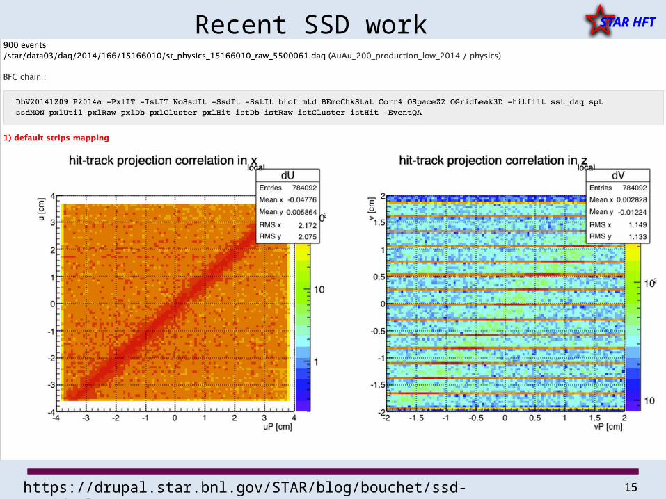
STAR HFTRecent SSD work
https://drupal.star.bnl.gov/STAR/blog/bouchet/ssd-residual
16
STAR HFT
16
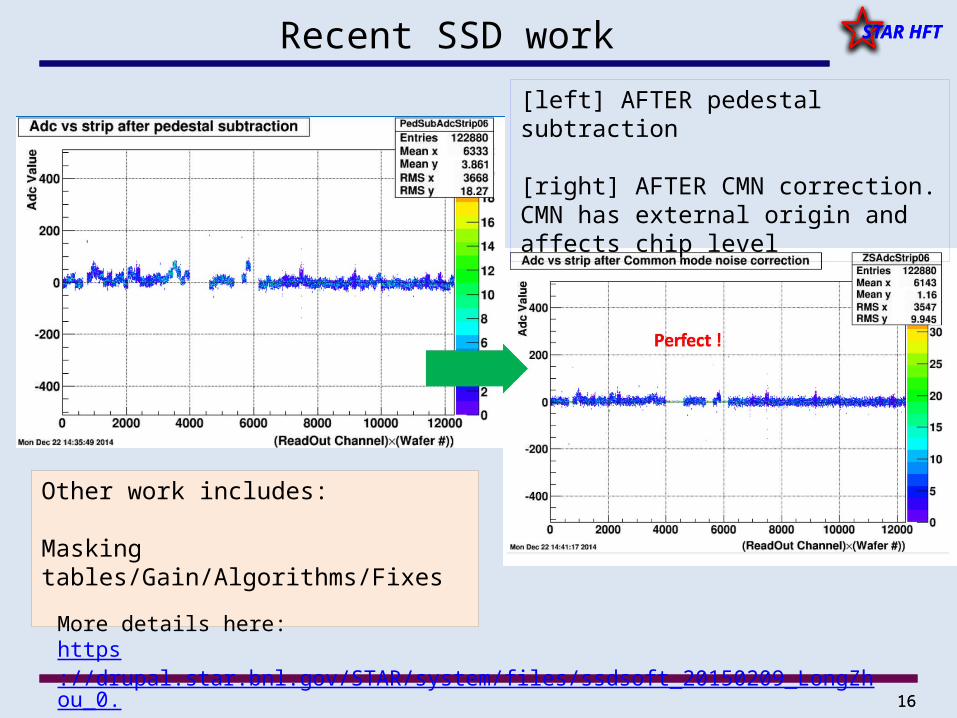
STAR HFTRecent SSD work
[left] AFTER pedestal subtraction
[right] AFTER CMN correction. CMN has external origin and affects chip level
Other work includes:
Masking tables/Gain/Algorithms/Fixes
More details here:https://drupal.star.bnl.gov/STAR/system/files/ssdsoft_20150209_LongZhou_0.pdf
https://drupal.star.bnl.gov/STAR/event/2015/02/09/ssd-meeting
17
STAR HFT
17
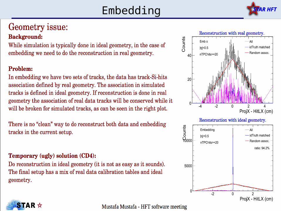
STAR HFTEmbedding
18
STAR HFT
18
STAR HFT
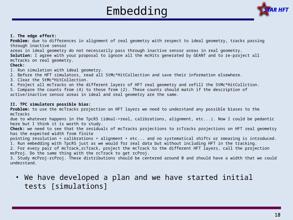
I. The edge effect:Problem: due to differences in alignment of real geometry with respect to ideal geometry, tracks passing through inactive sensor areas in ideal geometry do not necessarily pass through inactive sensor areas in real geometry. Solution: I agree with your proposal to ignore all the mcHits generated by GEANT and to re-project all mcTracks on real geometry. Check:1. Run simulation with ideal geometry. 2. Before the HFT simulators, read all StMc*HitCollection and save their information elsewhere. 3. Clear the StMc*HitCollection.4. Project all mcTracks on the different layers of HFT real geometry and refill the StMc*HitCollction.5. Compare the counts from (4) to those from (2). These counts should match if the description of active/inactive sensor areas in ideal and real geometry are the same.
II. TPC simulators possible bias:Problem: to use the mcTracks projection on HFT layers we need to understand any possible biases to the mcTracks due to whatever happens in the TpcRS (ideal->real, calibrations, alignment, etc...). Now I could be pedantic here but I think it is worth to study. Check: we need to see that the residuals of mcTracks projections to rcTracks projections on HFT real geometry has the expected width from finitepointing resolution + calibrations + alignment + etc... and no systematical shifts or smearing is introduced.1. Run embedding with TpcRS just as we would for real data but without including HFT in the tracking. 2. For every pair of mcTrack,rcTrack, project the mcTrack to the different HFT layers, call the projection mcProj. Do the same thing with the rcTrack to get rcProj.3. Study mcProj-rcProj. These distributions should be centered around 0 and should have a width that we could understand.
Embedding
• We have developed a plan and we have started initial tests [simulations]
19
STAR HFT
19
STAR HFTSTI Tracking
• First let me list the people behind this effort
(Xin, Gene, Dmitri, Jason, Flemming, Hao + helpers)
• Lacking a deployed version of STV we needed to use STI for Run14 production
– Needs its own, by-hand, geometry– Needed QA/debugging/optimization for HFT environment– It turned out to be a non-trivial task
• After production starts we hope to re-assume work on STV-like tracker for several reasons [needs beyond HFT]
20
STAR HFT
20
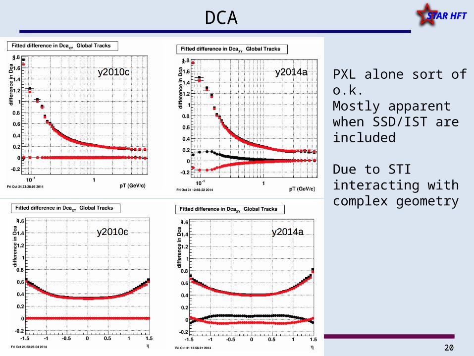
STAR HFTDCA
PXL alone sort of o.k.Mostly apparent when SSD/IST are included
Due to STI interacting with complex geometry
21
STAR HFT
21
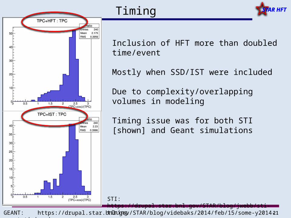
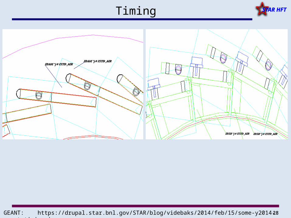
STAR HFTTiming
Inclusion of HFT more than doubled time/event
Mostly when SSD/IST were included
Due to complexity/overlapping volumes in modeling
Timing issue was for both STI [shown] and Geant simulations
STI: https://drupal.star.bnl.gov/STAR/blog/jwebb/sti-timing
GEANT: https://drupal.star.bnl.gov/STAR/blog/videbaks/2014/feb/15/some-y2014-geant-timing-issues
22
STAR HFT
22
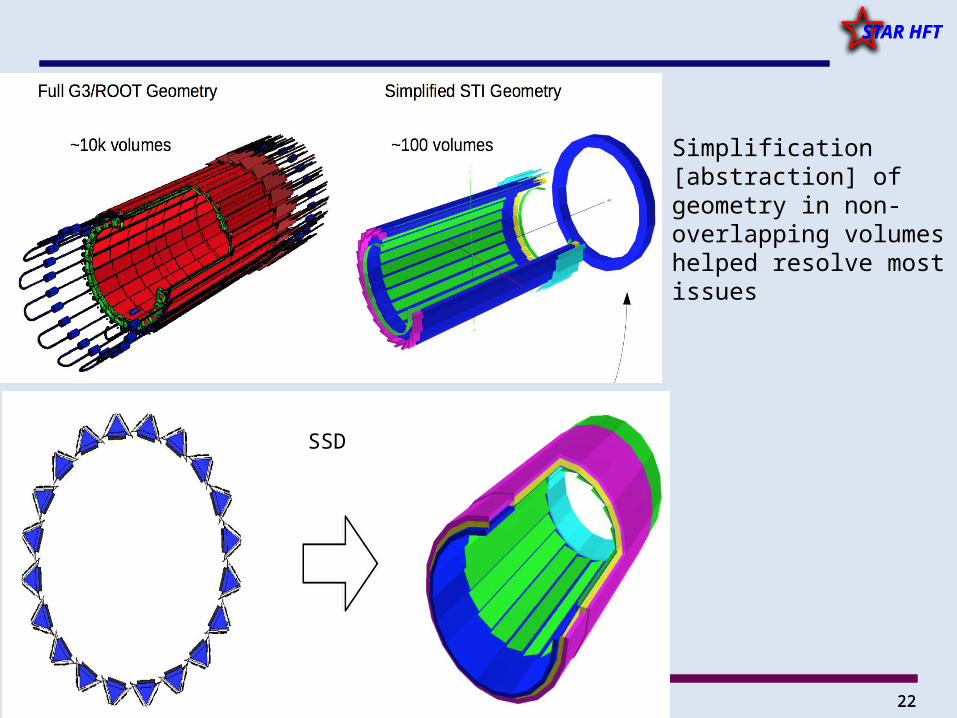
STAR HFT
Simplification [abstraction] of geometry in non-overlapping volumes helped resolve most issues
SSD
23
STAR HFT
23
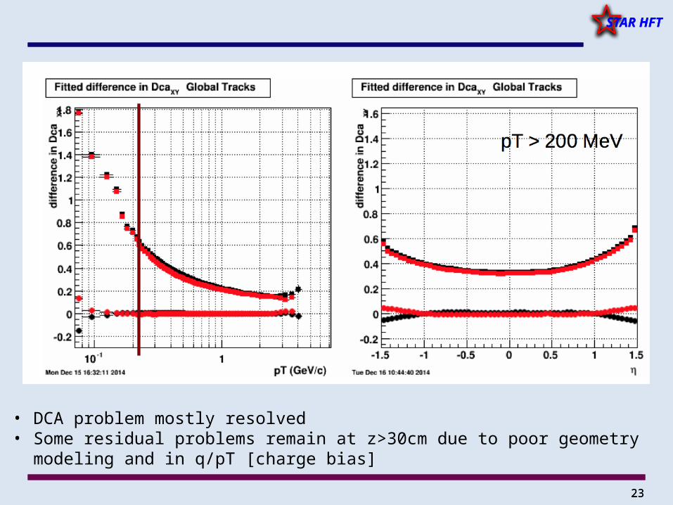
STAR HFT
• DCA problem mostly resolved• Some residual problems remain at z>30cm due to poor geometry modeling and in
q/pT [charge bias]
24
STAR HFT
24
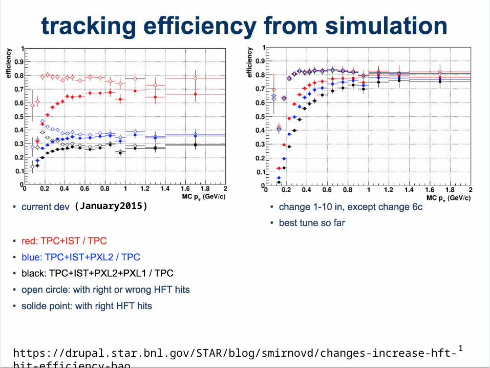
STAR HFT
https://drupal.star.bnl.gov/STAR/blog/smirnovd/changes-increase-hft-hit-efficiency-hao
(January2015)
25
STAR HFT
25
STAR HFT
• Currently working with S&C to implement and test all the changes in production library
• Efficiencies are high enough to start production [close to expectations]
– Work is on-going– Some ghosting at low pt is under investigation
• Longer term ideas to maximize tracking efficiency, eg CA seeding will be investigated soon
– Ivan will touch on this
Tracking Efficiency
26
STAR HFT
26
STAR HFTSummary
• Physics production for part of Run-14 is about to begin
• Run-15– Calibration work underway– Data-taking underway– SSD is fully integrated
• Get ready for Physics
27
STAR HFT
27
STAR HFT
BACKUP SLIDES
28
STAR HFT
28
STAR HFT
GEANT: https://drupal.star.bnl.gov/STAR/blog/videbaks/2014/feb/15/some-y2014-geant-timing-issues
Timing
29
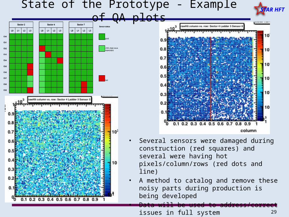
STAR HFTState of the Prototype - Example of QA plots
• Several sensors were damaged during construction (red squares) and several were having hot pixels/column/rows (red dots and line)
• A method to catalog and remove these noisy parts during production is being developed
• Data will be used to address/correct issues in full system
30
STAR HFT
30
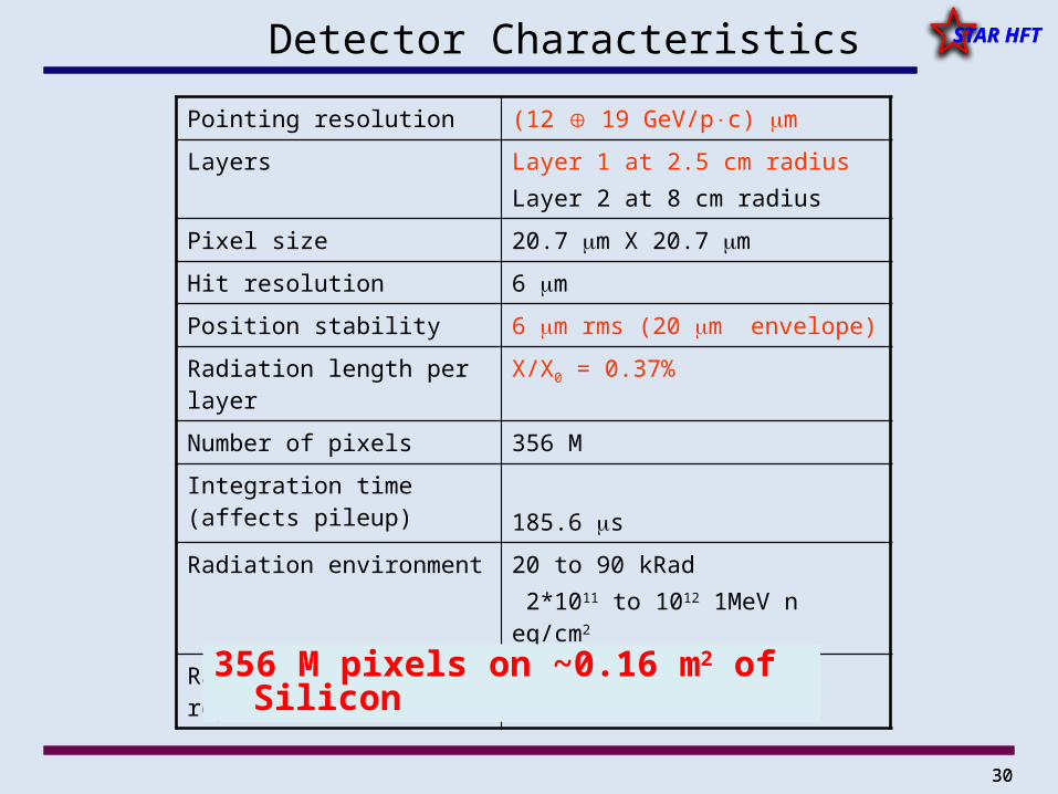
STAR HFTDetector Characteristics
Pointing resolution (12 19 GeV/pc) m
Layers Layer 1 at 2.5 cm radiusLayer 2 at 8 cm radius
Pixel size 20.7 m X 20.7 m
Hit resolution 6 m
Position stability 6 m rms (20 m envelope)
Radiation length per layer X/X0 = 0.37%
Number of pixels 356 M
Integration time (affects pileup) 185.6 s
Radiation environment 20 to 90 kRad 2*1011 to 1012 1MeV n eq/cm2
Rapid detector replacement ~ 1 day
356 M pixels on ~0.16 m2 of Silicon
31
STAR HFT
31
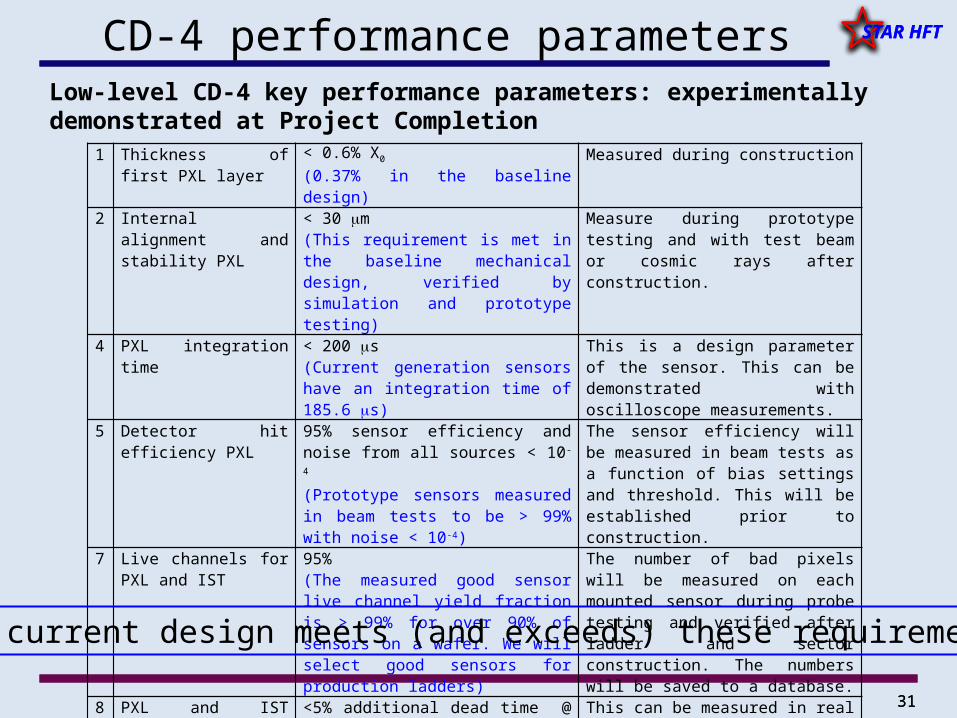
STAR HFTCD-4 performance parameters
1 Thickness of first PXL layer
< 0.6% X0
(0.37% in the baseline design)Measured during construction
2 Internal alignment and stability PXL
< 30 m(This requirement is met in the baseline mechanical design, verified by simulation and prototype testing)
Measure during prototype testing and with test beam or cosmic rays after construction.
4 PXL integration time < 200 s(Current generation sensors have an integration time of 185.6 s)
This is a design parameter of the sensor. This can be demonstrated with oscilloscope measurements.
5 Detector hit efficiency PXL
95% sensor efficiency and noise from all sources < 10-4
(Prototype sensors measured in beam tests to be > 99% with noise < 10-4)
The sensor efficiency will be measured in beam tests as a function of bias settings and threshold. This will be established prior to construction.
7 Live channels for PXL and IST
95%(The measured good sensor live channel yield fraction is > 99% for over 90% of sensors on a wafer. We will select good sensors for production ladders)
The number of bad pixels will be measured on each mounted sensor during probe testing and verified after ladder and sector construction. The numbers will be saved to a database.
8 PXL and IST Readout speed and dead time
<5% additional dead time @ 500 Hz average trigger rate and simulated occupancy
This can be measured in real time with simulated data for verification.
Low-level CD-4 key performance parameters: experimentally demonstrated at Project Completion
Our current design meets (and exceeds) these requirements.
Related Documents