MPLS Architectural Considerations for a Transport Profile References 1.Slides taken from ITU-T - IETF Joint Working Team Report (RFC 5317), By Dave Ward, Malcolm Betts, ed. April 18, 2008 2.RFC 5860 Requirements for OAM in MPLS-TP 3.Operations, Administration and Maintenance Framework for MPLS-based Transport Networks draft-ietf-mpls-tp-oam-framework-09.txt By Urooj Fatima TM8106 – Optical Networking

1 MPLS Architectural Considerations for a Transport Profile References 1.Slides taken from ITU-T - IETF Joint Working Team Report (RFC 5317), By Dave Ward,
Dec 16, 2015
Welcome message from author
This document is posted to help you gain knowledge. Please leave a comment to let me know what you think about it! Share it to your friends and learn new things together.
Transcript
1
MPLS Architectural Considerations for a Transport Profile
References
1.Slides taken from ITU-T - IETF Joint Working Team Report (RFC 5317), By Dave Ward, Malcolm Betts, ed. April 18, 2008
2.RFC 5860 Requirements for OAM in MPLS-TP
3.Operations, Administration and Maintenance Framework for MPLS-based Transport Networks
draft-ietf-mpls-tp-oam-framework-09.txt
ByUrooj Fatima
TM8106 – Optical Networking
2
Table of Contents
• Executive Overview– Recommendation
• Introduction and Background Material• High Level Architecture• OAM Requirements• OAM Mechanisms and Baseline Use Cases• Associated Channel Level (ACH)• Forwarding and OAM
– LSP/PW OAM– Use Case Scenario and Label Stack Diagrams– Use of TTL for MIP OAM alert– Packet Context
• Control Plane• Survivability• Network Management• Summary

3
Introduction andBackground Material
4
What am I reading?
This presentation is a collection of assumptions, discussion points and decisions that the combined group has had during the months of March and April, 2008
This represents the agreed upon starting point for the technical analysis of the T-MPLS requirements from the ITU-T and the MPLS architecture to meet those requirements
The output of this technical analysis is the recommendation given to SG 15 on how to reply to the IETF’s liaison of July 2007
– IETF requested decision on whether the SDOs work together and extend MPLS aka “option 1: or
– ITU-T choose another ethertype and rename T-MPLS to not include the MPLS moniker aka “option 2”
The starting point of the analysis is to attempt to satisfy option 1 by showing the high level architecture, any showstoppers and the design points that would need to be addressed after the decision has been made to work together.
Option 1 was stated as preferred by the IETF and if it can be met; Option 2 will not be explored
5
Some contributors to this architecture
BT Verizon ATT NTT Comcast Acreo AB Alcatel-Lucent Cisco Ericsson Huawei Juniper Nortel Old Dog Consulting
6
How is the effort organized?
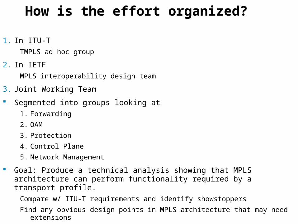
1. In ITU-T
TMPLS ad hoc group
2. In IETF
MPLS interoperability design team
3. Joint Working Team
Segmented into groups looking at
1. Forwarding
2. OAM
3. Protection
4. Control Plane
5. Network Management
Goal: Produce a technical analysis showing that MPLS architecture can perform functionality required by a transport profile.
Compare w/ ITU-T requirements and identify showstoppers
Find any obvious design points in MPLS architecture that may need extensions
7
MPLS - TP Requirements Overview
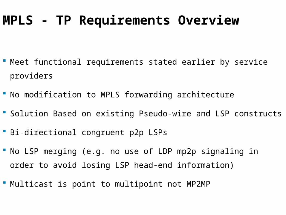
Meet functional requirements stated earlier by service providers
No modification to MPLS forwarding architecture
Solution Based on existing Pseudo-wire and LSP constructs
Bi-directional congruent p2p LSPs
No LSP merging (e.g. no use of LDP mp2p signaling in order to avoid losing
LSP head-end information)
Multicast is point to multipoint not MP2MP
8
MPLS - TP Requirements Overview .2
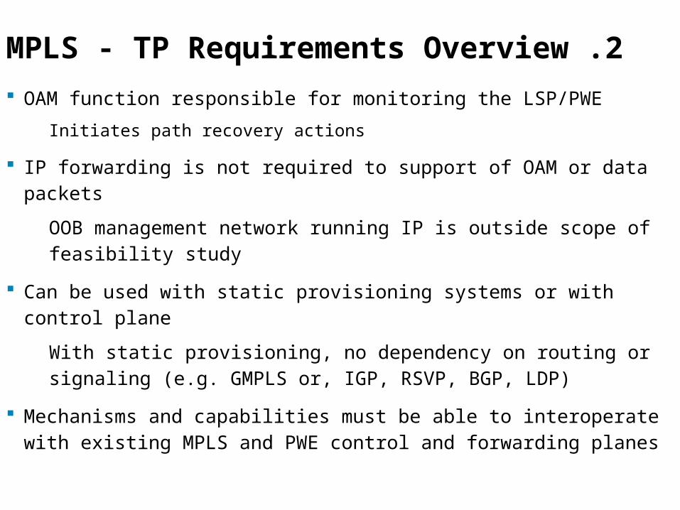
OAM function responsible for monitoring the LSP/PWE
Initiates path recovery actions
IP forwarding is not required to support of OAM or data packets
OOB management network running IP is outside scope of feasibility study
Can be used with static provisioning systems or with control plane
With static provisioning, no dependency on routing or signaling (e.g. GMPLS or, IGP, RSVP, BGP, LDP)
Mechanisms and capabilities must be able to interoperate with existing MPLS and PWE control and forwarding planes
9
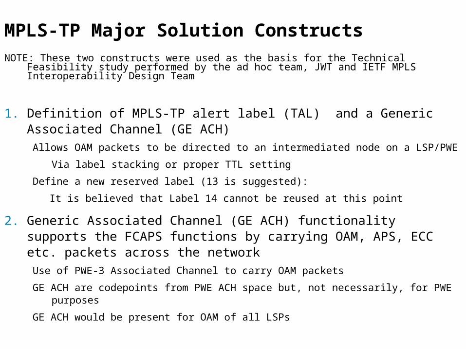
MPLS-TP Major Solution Constructs NOTE: These two constructs were used as the basis for the Technical Feasibility study performed
by the ad hoc team, JWT and IETF MPLS Interoperability Design Team
1. Definition of MPLS-TP alert label (TAL) and a Generic Associated Channel (GE ACH)
Allows OAM packets to be directed to an intermediated node on a LSP/PWE
Via label stacking or proper TTL setting
Define a new reserved label (13 is suggested):
It is believed that Label 14 cannot be reused at this point
2. Generic Associated Channel (GE ACH) functionality supports the FCAPS functions by carrying OAM, APS, ECC etc. packets across the network
Use of PWE-3 Associated Channel to carry OAM packets
GE ACH are codepoints from PWE ACH space but, not necessarily, for PWE purposes
GE ACH would be present for OAM of all LSPs
10
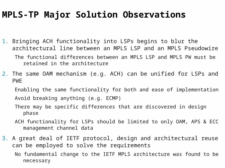
MPLS-TP Major Solution Observations
1. Bringing ACH functionality into LSPs begins to blur the architectural line between an MPLS LSP and an MPLS Pseudowire
The functional differences between an MPLS LSP and MPLS PW must be retained in the architecture
2. The same OAM mechanism (e.g. ACH) can be unified for LSPs and PWE
Enabling the same functionality for both and ease of implementation
Avoid breaking anything (e.g. ECMP)
There may be specific differences that are discovered in design phase
ACH functionality for LSPs should be limited to only OAM, APS & ECC management channel data
3. A great deal of IETF protocol, design and architectural reuse can be employed to solve the requirements
No fundamental change to the IETF MPLS architecture was found to be necessary
11
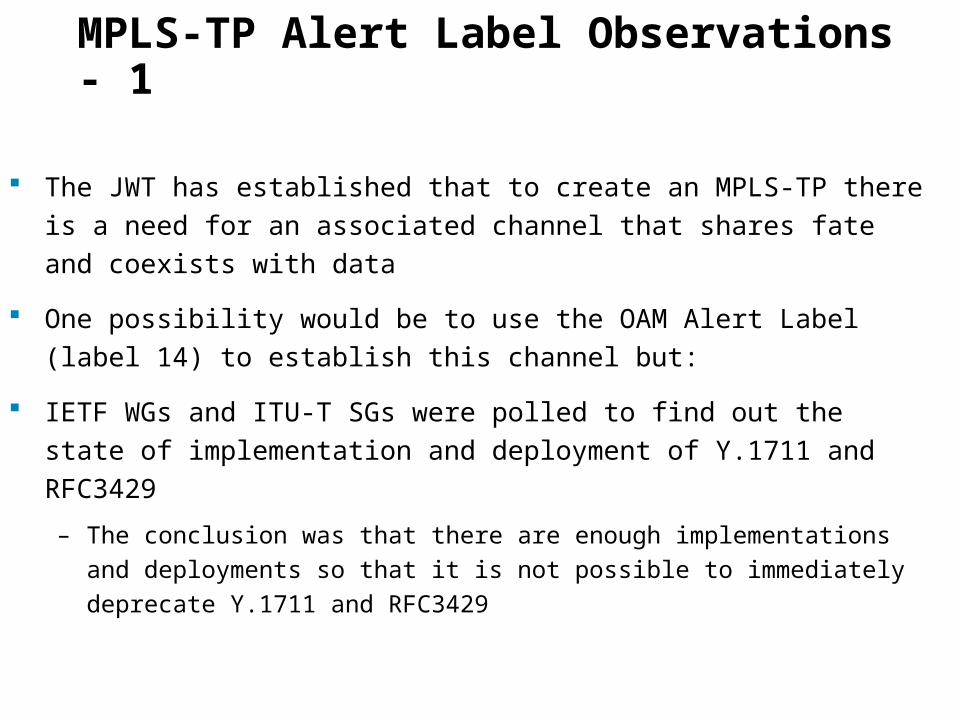
MPLS-TP Alert Label Observations - 1
The JWT has established that to create an MPLS-TP there is a need for an
associated channel that shares fate and coexists with data
One possibility would be to use the OAM Alert Label (label 14) to establish
this channel but:
IETF WGs and ITU-T SGs were polled to find out the state of
implementation and deployment of Y.1711 and RFC3429
– The conclusion was that there are enough implementations and deployments
so that it is not possible to immediately deprecate Y.1711 and RFC3429
12
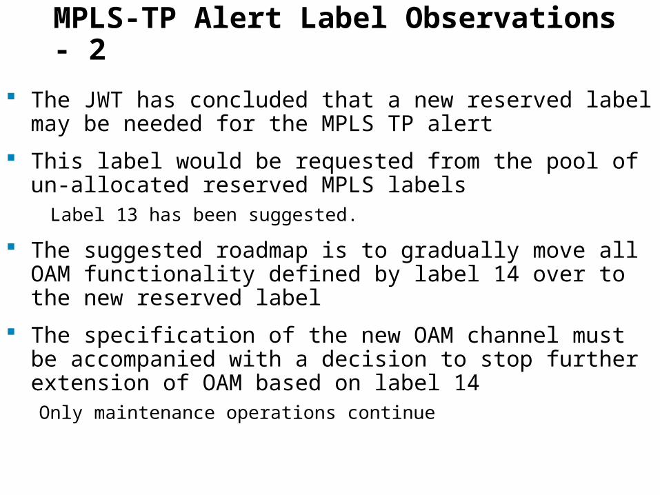
MPLS-TP Alert Label Observations - 2
The JWT has concluded that a new reserved label may be needed for the MPLS TP alert
This label would be requested from the pool of un-allocated reserved MPLS labels Label 13 has been suggested.
The suggested roadmap is to gradually move all OAM functionality defined by label 14 over to the new reserved label
The specification of the new OAM channel must be accompanied with a decision to stop further extension of OAM based on label 14Only maintenance operations continue

13
High Level Architecture
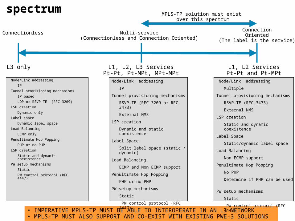
14• IMPERATIVE MPLS-TP MUST BE ABLE TO INTEROPERATE IN AN L3 NETWORK • MPLS-TP MUST ALSO SUPPORT AND CO-EXIST WITH EXISTING PWE-3 SOLUTIONS
MPLS-TP service spectrum
Connectionless Multi-service(Connectionless and Connection Oriented)
ConnectionOriented
(The label is the service)
Node/Link addressing
IP
Tunnel provisioning mechanisms
RSVP-TE (RFC 3209 or RFC 3473)
External NMS
LSP creation
Dynamic and static coexistence
Label Space
Split label space (static / dynamic)
Load Balancing
ECMP and Non ECMP support
Penultimate Hop Popping
PHP or no PHP
PW setup mechanisms
Static
PW control protocol (RFC 4447)
L3 only L1, L2, L3 ServicesPt-Pt, Pt-MPt, MPt-MPt
L1, L2 ServicesPt-Pt and Pt-MPt
Node/Link addressing
IP
Tunnel provisioning mechanisms
IP based
LDP or RSVP-TE (RFC 3209)
LSP creation
Dynamic only
Label space
Dynamic label space
Load Balancing
ECMP only
Penultimate Hop Popping
PHP or no PHP
LSP creation
Static and dynamic coexistence
PW setup mechanisms
Static
PW control protocol (RFC 4447)
MPLS-TP solution must exist over this spectrum
Node/Link addressing
Multiple
Tunnel provisioning mechanisms
RSVP-TE (RFC 3473)
External NMS
LSP creation
Static and dynamic coexistence
Label Space
Static/dynamic label space
Load Balancing
Non ECMP support
Penultimate Hop Popping
No PHP
Determine if PHP can be used
PW setup mechanisms
Static
PW control protocol (RFC 4447)
15
MPLS+TP Static Provisioning
Forwarding Tables
Forwarding Tables
Forwarding Tables
Edge Edge
Network Management SystemControl Plane for PT2PT services
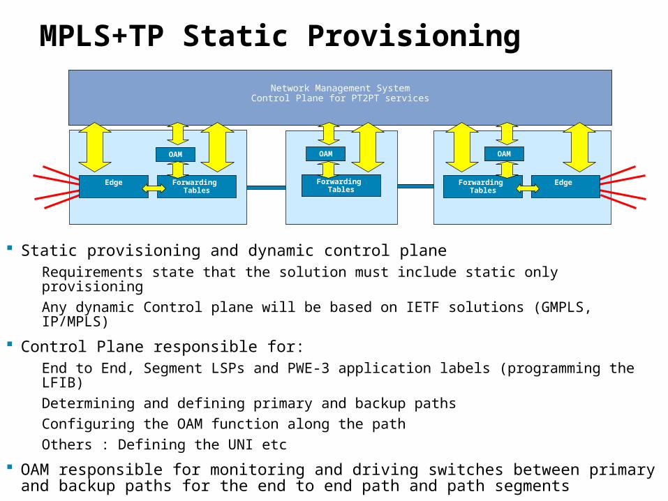
Static provisioning and dynamic control planeRequirements state that the solution must include static only provisioning
Any dynamic Control plane will be based on IETF solutions (GMPLS, IP/MPLS)
Control Plane responsible for:End to End, Segment LSPs and PWE-3 application labels (programming the LFIB)
Determining and defining primary and backup paths
Configuring the OAM function along the path
Others : Defining the UNI etc
OAM responsible for monitoring and driving switches between primary and backup paths for the end to end path and path segments
OAM OAM OAM
16
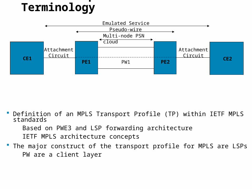
MPLS Transport Profile - Terminology
Definition of an MPLS Transport Profile (TP) within IETF MPLS standardsBased on PWE3 and LSP forwarding architecture IETF MPLS architecture concepts
The major construct of the transport profile for MPLS are LSPsPW are a client layer
Multi-node PSN cloud
Pseudo-wire
PW1
Emulated Service
AttachmentCircuit
PE1 PE2CE1 CE2
AttachmentCircuit
17
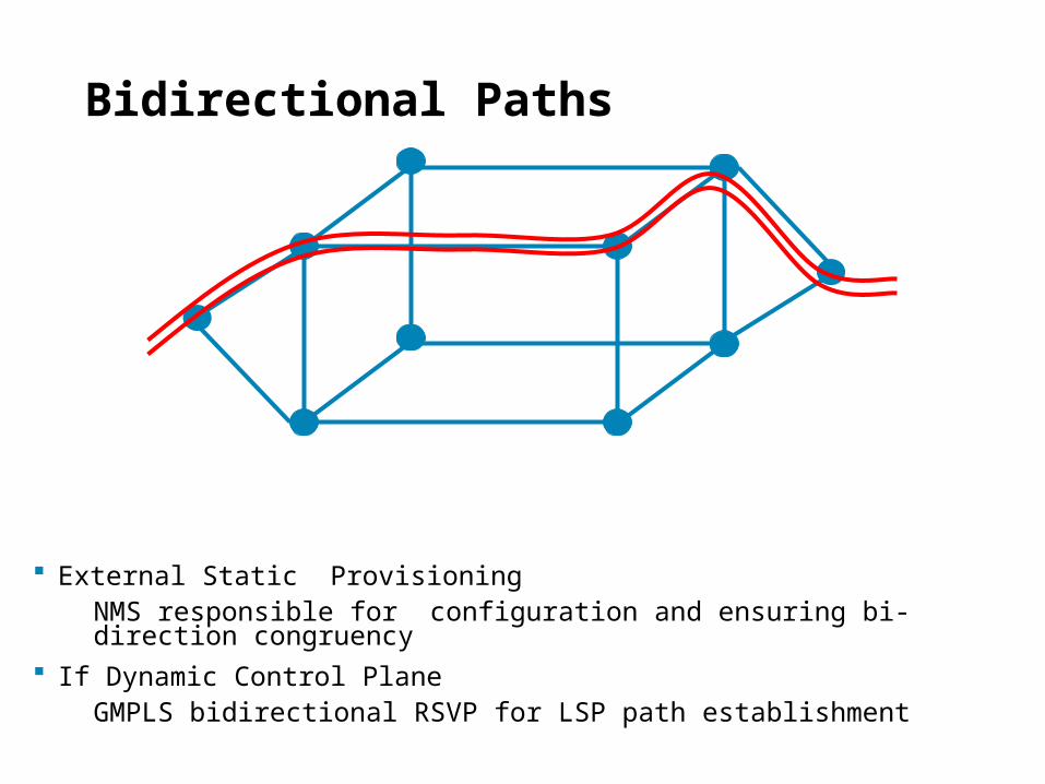
Bidirectional Paths
External Static ProvisioningNMS responsible for configuration and ensuring bi-direction congruency
If Dynamic Control PlaneGMPLS bidirectional RSVP for LSP path establishment

18
OAM requirements
19
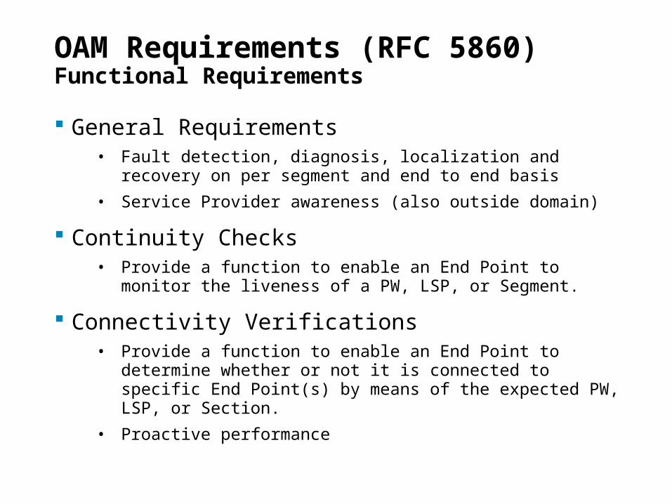
OAM Requirements (RFC 5860)Functional Requirements
General Requirements• Fault detection, diagnosis, localization and recovery on per
segment and end to end basis
• Service Provider awareness (also outside domain)
Continuity Checks• Provide a function to enable an End Point to monitor the liveness of
a PW, LSP, or Segment.
Connectivity Verifications• Provide a function to enable an End Point to determine whether or
not it is connected to specific End Point(s) by means of the expected PW, LSP, or Section.
• Proactive performance
20
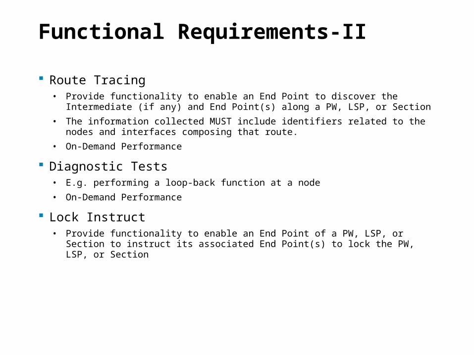
Functional Requirements-II
Route Tracing• Provide functionality to enable an End Point to discover the Intermediate (if any)
and End Point(s) along a PW, LSP, or Section
• The information collected MUST include identifiers related to the nodes and interfaces composing that route.
• On-Demand Performance
Diagnostic Tests• E.g. performing a loop-back function at a node
• On-Demand Performance
Lock Instruct• Provide functionality to enable an End Point of a PW, LSP, or Section to instruct its
associated End Point(s) to lock the PW, LSP, or Section
21
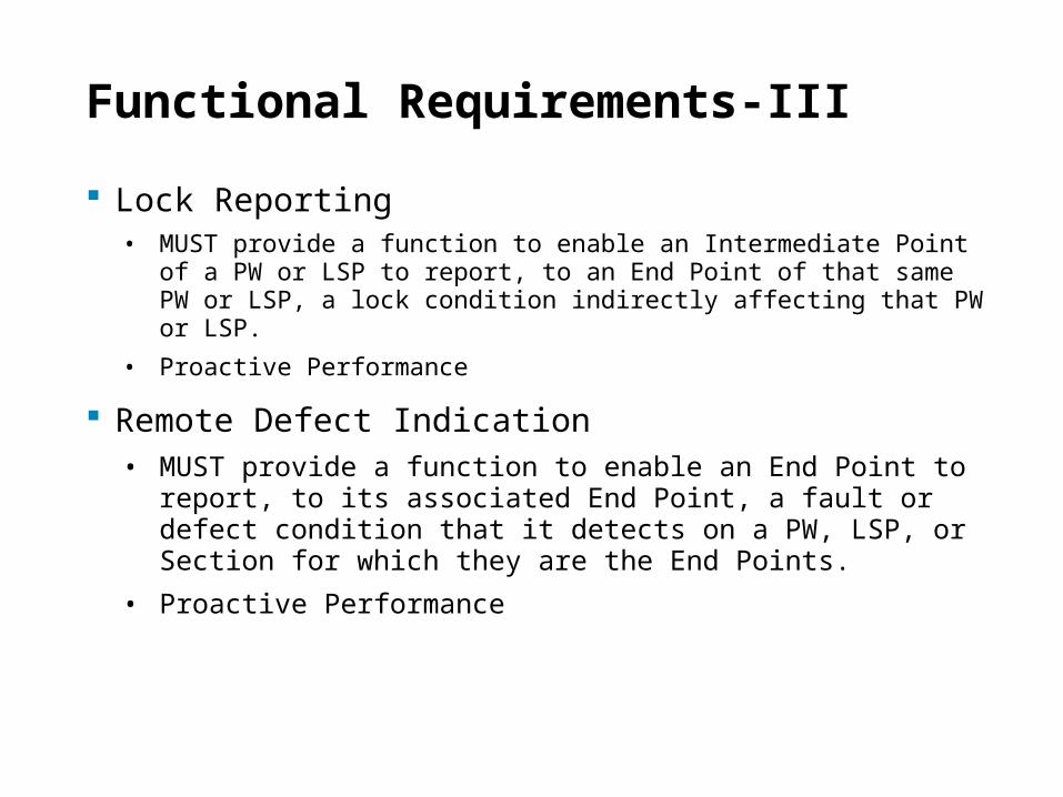
Functional Requirements-III
Lock Reporting• MUST provide a function to enable an Intermediate Point of a PW or
LSP to report, to an End Point of that same PW or LSP, a lock condition indirectly affecting that PW or LSP.
• Proactive Performance
Remote Defect Indication• MUST provide a function to enable an End Point to report, to
its associated End Point, a fault or defect condition that it detects on a PW, LSP, or Section for which they are the End Points.
• Proactive Performance
22
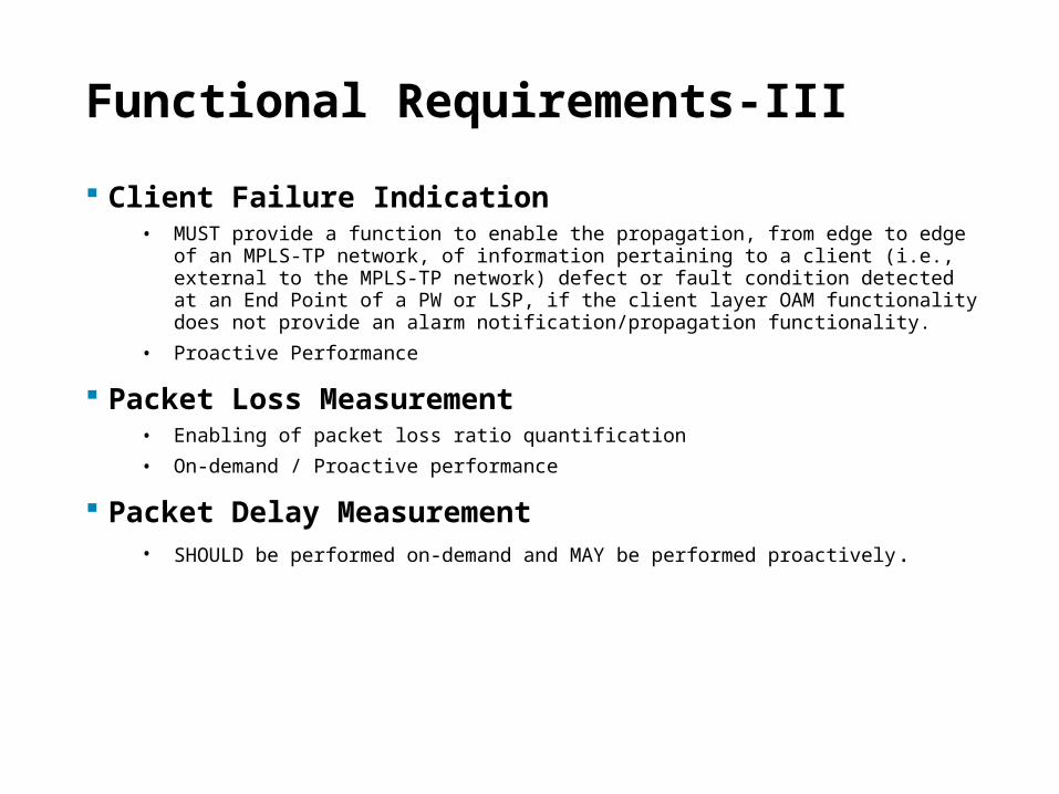
Functional Requirements-III
Client Failure Indication• MUST provide a function to enable the propagation, from edge to edge of an MPLS-
TP network, of information pertaining to a client (i.e., external to the MPLS-TP network) defect or fault condition detected at an End Point of a PW or LSP, if the client layer OAM functionality does not provide an alarm notification/propagation functionality.
• Proactive Performance
Packet Loss Measurement• Enabling of packet loss ratio quantification
• On-demand / Proactive performance
Packet Delay Measurement• SHOULD be performed on-demand and MAY be performed proactively.
23
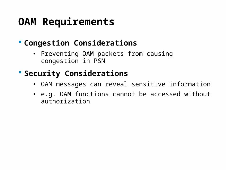
OAM Requirements
Congestion Considerations• Preventing OAM packets from causing congestion in PSN
Security Considerations• OAM messages can reveal sensitive information
• e.g. OAM functions cannot be accessed without authorization
24
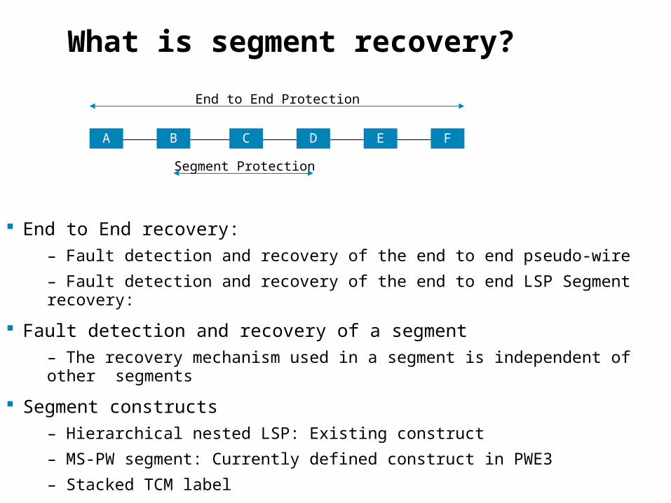
What is segment recovery?
End to End recovery:
– Fault detection and recovery of the end to end pseudo-wire
– Fault detection and recovery of the end to end LSP Segment recovery:
Fault detection and recovery of a segment
– The recovery mechanism used in a segment is independent of other segments
Segment constructs
– Hierarchical nested LSP: Existing construct
– MS-PW segment: Currently defined construct in PWE3
– Stacked TCM label
BA DC FE
End to End Protection
Segment Protection
25
Node identification
Will need to work through identification requirements
A node has multiple identifiers including the following: Management identifier – normally user friendly, based on the location MEP/MIP identifier DCC address - how do management messages reach this node Control plane identifiers - how are the various control components identified Forwarding plane identifier - end points and intermediate points - e.g. NNIs
These are design issues, no “show stoppers” found
26
OAM mechanisms
27
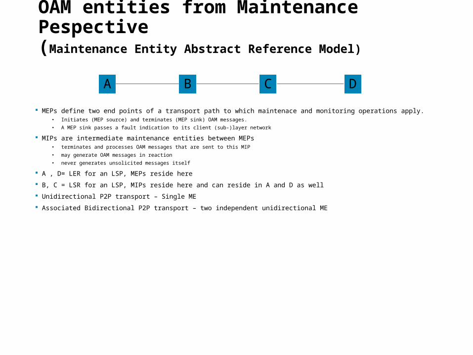
OAM entities from Maintenance Pespective(Maintenance Entity Abstract Reference Model)
MEPs define two end points of a transport path to which maintenace and monitoring operations apply.• Initiates (MEP source) and terminates (MEP sink) OAM messages.
• A MEP sink passes a fault indication to its client (sub-)layer network
MIPs are intermediate maintenance entities between MEPs• terminates and processes OAM messages that are sent to this MIP
• may generate OAM messages in reaction
• never generates unsolicited messages itself
A , D= LER for an LSP, MEPs reside here
B, C = LSR for an LSP, MIPs reside here and can reside in A and D as well
Unidirectional P2P transport – Single ME
Associated Bidirectional P2P transport – two independent unidirectional ME
A B C D
28
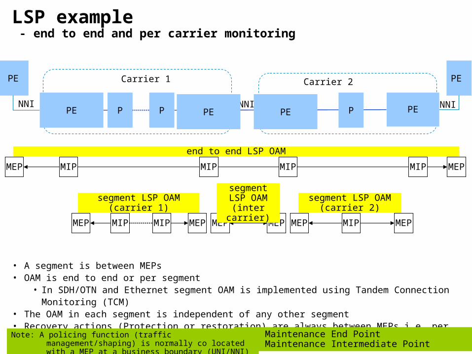
LSP example - end to end and per carrier monitoring
P P
MEP MIP MIP MEP
MEP MEPMEP MEP MEP MEP MIPMIP
• A segment is between MEPs• OAM is end to end or per segment
• In SDH/OTN and Ethernet segment OAM is implemented using Tandem Connection Monitoring (TCM)
• The OAM in each segment is independent of any other segment• Recovery actions (Protection or restoration) are always between MEPs i.e. per segment or end to end
Carrier 1 Carrier 2
NNI
MEP: Maintenance End PointMIP: Maintenance Intermediate Point
end to end LSP OAM
segment LSP OAM
(inter carrier)
Note: A policing function (traffic management/shaping) is normally co located with a MEP at a business boundary (UNI/NNI)
PE PE
segment LSP OAM(carrier 2)
segment LSP OAM(carrier 1)
PE P
MIP
NNI NNI PE PE PE
MIPMIP
29
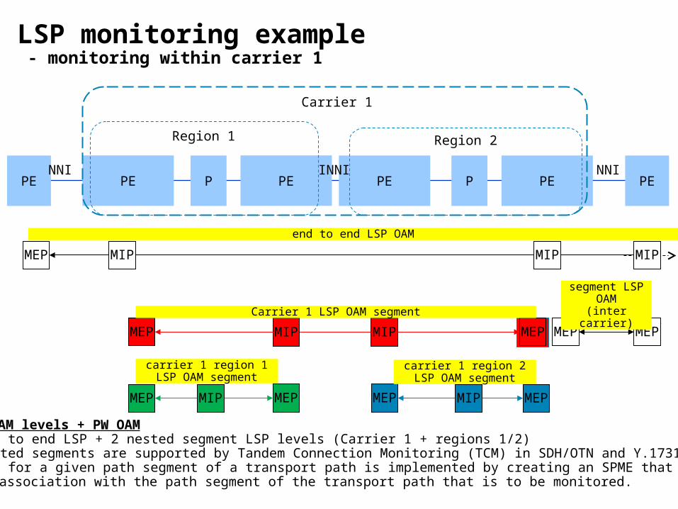
LSP monitoring example - monitoring within carrier 1
PE PE PE P P
MEP
MEPMEP
MEP
MEP MEP
PE PE PE
Region 1 Region 2
NNINNI INNI
Carrier 1
MEP MEPMIP
MIP MIP
MIP MIPMEP
end to end LSP OAM
Carrier 1 LSP OAM segment
carrier 1 region 2LSP OAM segment
3 LSP OAM levels + PW OAM• end to end LSP + 2 nested segment LSP levels (Carrier 1 + regions 1/2)• Nested segments are supported by Tandem Connection Monitoring (TCM) in SDH/OTN and Y.1731• TCM for a given path segment of a transport path is implemented by creating an SPME that has a 1:1 association with the path segment of the transport path that is to be monitored.
carrier 1 region 1LSP OAM segment
segment LSP OAM
(inter carrier)
MIP
MIP
30
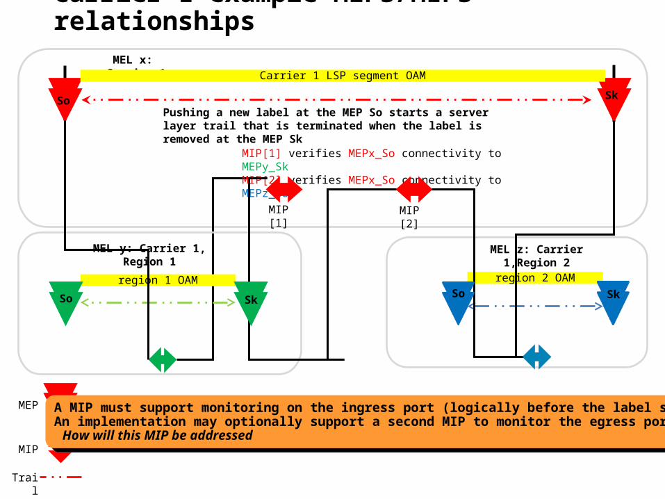
Carrier 1 example MEPs/MIPs relationships
MEP
MIP
Trail
MIP[1] verifies MEPx_So connectivity to MEPy_SkMIP[2] verifies MEPx_So connectivity to MEPz_So
MEL x: Carrier 1
MIP [1] MIP [2]
So Sk
Pushing a new label at the MEP So starts a server layer trail that is terminated when the label is removed at the MEP Sk
Carrier 1 LSP segment OAM
region 1 OAM region 2 OAM
MEL y: Carrier 1, Region 1 MEL z: Carrier 1,Region 2
SkSo SkSo
A MIP must support monitoring on the ingress port (logically before the label swap)An implementation may optionally support a second MIP to monitor the egress port
How will this MIP be addressed
A MIP must support monitoring on the ingress port (logically before the label swap)An implementation may optionally support a second MIP to monitor the egress port
How will this MIP be addressed
31
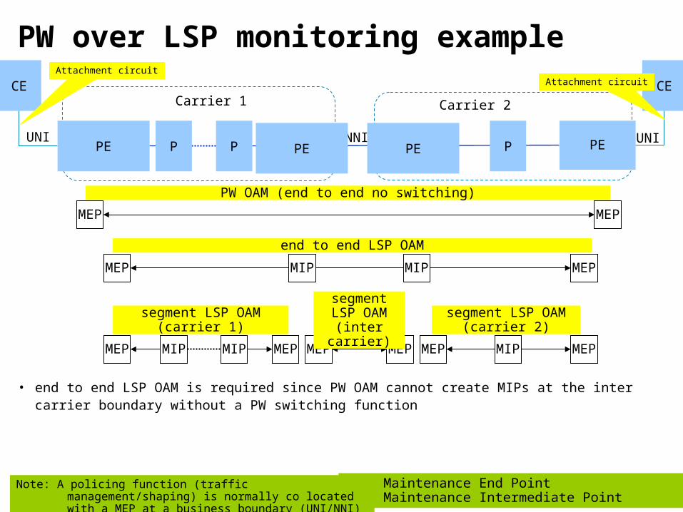
PW over LSP monitoring example
P P
MEP MIP MIP MEP
MEP MEPMEP MEP MEP MEP MIPMIP
• end to end LSP OAM is required since PW OAM cannot create MIPs at the inter carrier boundary without a PW switching function
Carrier 1 Carrier 2
NNI
MEP: Maintenance End PointMIP: Maintenance Intermediate Point
end to end LSP OAM
segment LSP OAM
(inter carrier)
Note: A policing function (traffic management/shaping) is normally co located with a MEP at a business boundary (UNI/NNI)
CE CE Attachment circuit
segment LSP OAM(carrier 2)
segment LSP OAM(carrier 1)
Attachment circuit
PE
MEP MEP
PW OAM (end to end no switching)
P
MIP
UNI UNI PE PE PE
32
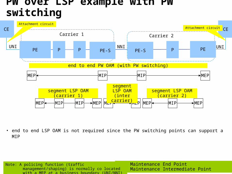
PW over LSP example with PW switching
P P
MEP MIP MIP MEP
MEP MEPMEP MEP MEP MEP MIPMIP
• end to end LSP OAM is not required since the PW switching points can support a MIP
Carrier 1 Carrier 2
NNI
MEP: Maintenance End PointMIP: Maintenance Intermediate Point
segment LSP OAM
(inter carrier)
Note: A policing function (traffic management/shaping) is normally co located with a MEP at a business boundary (UNI/NNI)
CE CE Attachment circuit
segment LSP OAM(carrier 2)
segment LSP OAM(carrier 1)
Attachment circuit
PE
end to end PW OAM (with PW switching)
P
MIP
UNI UNI PE PE-S PE-S
33
Associated Channel Level (ACH)
34
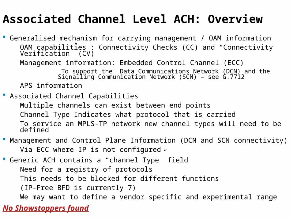
Associated Channel Level ACH: Overview
Generalised mechanism for carrying management / OAM information OAM capabilities : Connectivity Checks (CC) and “Connectivity Verification” (CV)Management information: Embedded Control Channel (ECC)
To support the Data Communications Network (DCN) and the Signalling Communication Network (SCN) – see G.7712
APS information Associated Channel Capabilities
Multiple channels can exist between end pointsChannel Type Indicates what protocol that is carriedTo service an MPLS-TP network new channel types will need to be defined
Management and Control Plane Information (DCN and SCN connectivity)Via ECC where IP is not configured
Generic ACH contains a “channel Type” fieldNeed for a registry of protocolsThis needs to be blocked for different functions(IP-Free BFD is currently 7)
We may want to define a vendor specific and experimental range
No Showstoppers found
35
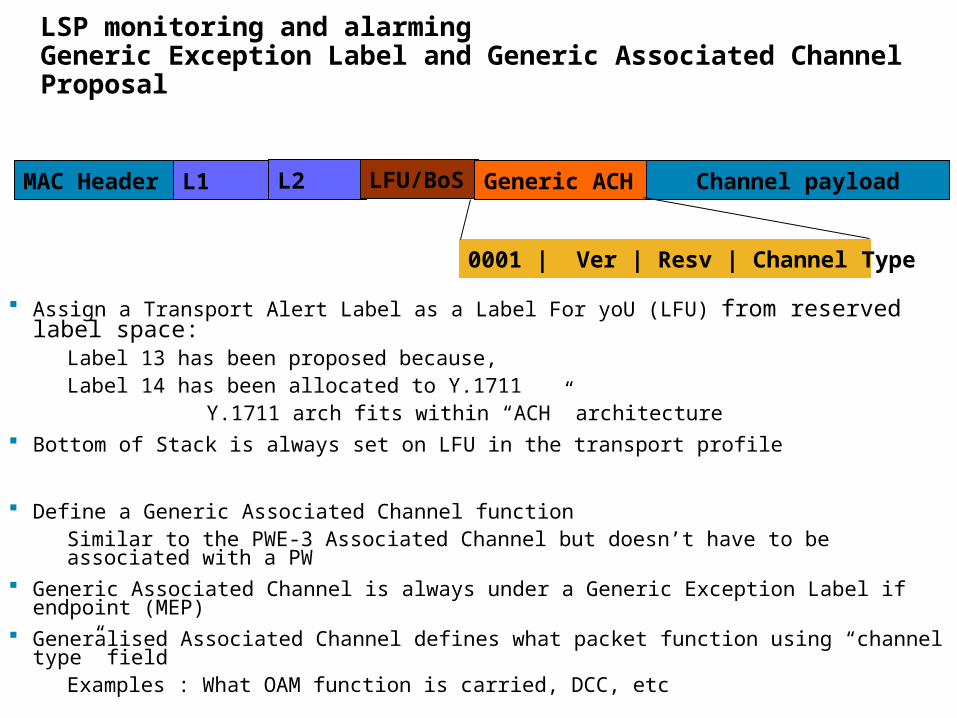
LSP monitoring and alarming Generic Exception Label and Generic Associated Channel Proposal
Assign a Transport Alert Label as a Label For yoU (LFU) from reserved label space:Label 13 has been proposed because, Label 14 has been allocated to Y.1711
Y.1711 arch fits within “ACH” architecture Bottom of Stack is always set on LFU in the transport profile
Define a Generic Associated Channel function Similar to the PWE-3 Associated Channel but doesn’t have to be associated with a PW
Generic Associated Channel is always under a Generic Exception Label if endpoint (MEP) Generalised Associated Channel defines what packet function using “channel type” field
Examples : What OAM function is carried, DCC, etc
MAC Header Channel payloadL1 L2 LFU/BoS Generic ACH
0001 | Ver | Resv | Channel Type
36
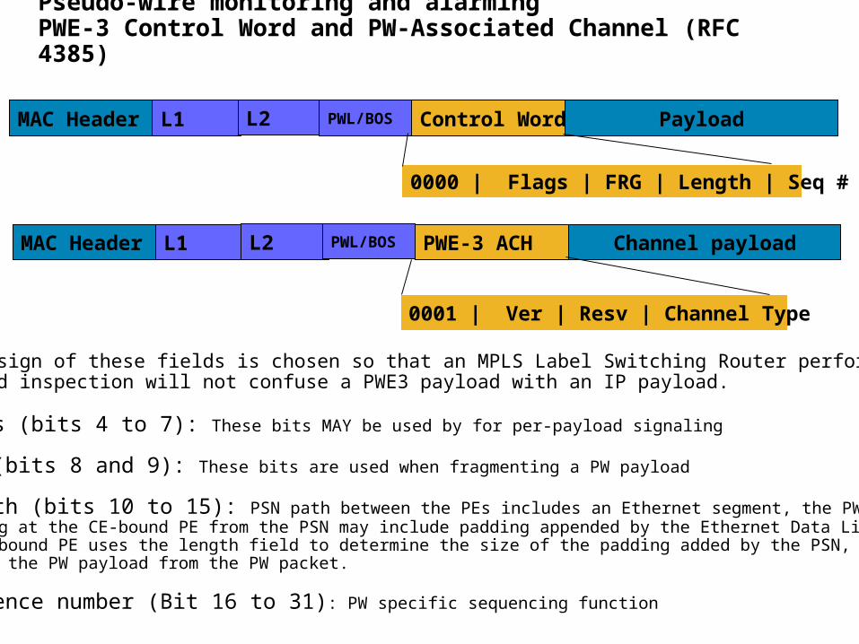
Pseudo-wire monitoring and alarmingPWE-3 Control Word and PW-Associated Channel (RFC 4385)
MAC Header Channel payloadL1 L2 PWL/BOS PWE-3 ACH
MAC Header PayloadL1 L2 PWL/BOS Control Word
0000 | Flags | FRG | Length | Seq #
0001 | Ver | Resv | Channel Type
The design of these fields is chosen so that an MPLS Label Switching Router performing MPLSpayload inspection will not confuse a PWE3 payload with an IP payload. •Flags (bits 4 to 7): These bits MAY be used by for per-payload signaling
•FRG (bits 8 and 9): These bits are used when fragmenting a PW payload
•Length (bits 10 to 15): PSN path between the PEs includes an Ethernet segment, the PW packet arriving at the CE-bound PE from the PSN may include padding appended by the Ethernet Data Link Layer. The CE-bound PE uses the length field to determine the size of the padding added by the PSN, and hence extract the PW payload from the PW packet.
•Sequence number (Bit 16 to 31): PW specific sequencing function
37
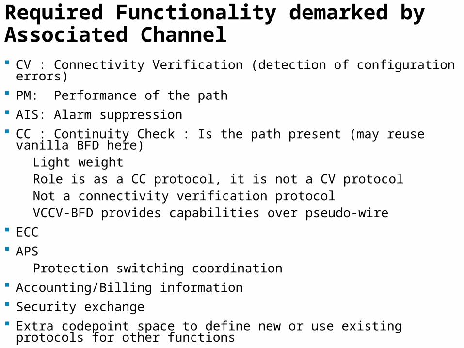
Required Functionality demarked by Associated Channel CV : Connectivity Verification (detection of configuration errors) PM: Performance of the path AIS: Alarm suppression CC : Continuity Check : Is the path present (may reuse vanilla BFD here)
Light weightRole is as a CC protocol, it is not a CV protocol Not a connectivity verification protocolVCCV-BFD provides capabilities over pseudo-wire
ECC APS
Protection switching coordination Accounting/Billing information Security exchange Extra codepoint space to define new or use existing protocols for other
functions
38
Associated Channel Functionality Observations Existing MPLS LSP OAM uses an IP based control channel and
could be used for some OAM functions in transport networks– e.g. CC/CV
– The new Alert label based control channel should be able to co-exist with the existing MPLS LSP OAM functions and protocols
OAM message formats and protocol details carried in the OAM channel will be discussed in the design phase
– We must figure out what the OAM messages/protocols should be used for the new requirements
– Decide whether LSP-Ping or BFD can or should be tweaked or not
39
Forwarding and OAM:LSPs / PWOAM and Label Stacks
40
Scope of next slides
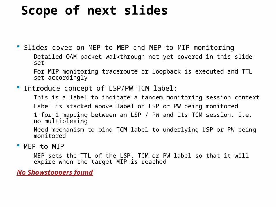
Slides cover on MEP to MEP and MEP to MIP monitoringDetailed OAM packet walkthrough not yet covered in this slide-set
For MIP monitoring traceroute or loopback is executed and TTL set accordingly
Introduce concept of LSP/PW TCM label:This is a label to indicate a tandem monitoring session context
Label is stacked above label of LSP or PW being monitored
1 for 1 mapping between an LSP / PW and its TCM session. i.e. no multiplexing
Need mechanism to bind TCM label to underlying LSP or PW being monitored
MEP to MIPMEP sets the TTL of the LSP, TCM or PW label so that it will expire when the target MIP is reached
No Showstoppers found
41
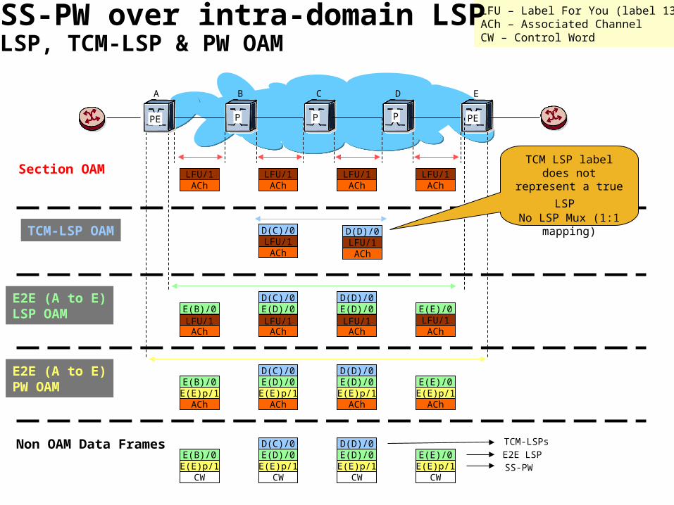
Notation and color conventions
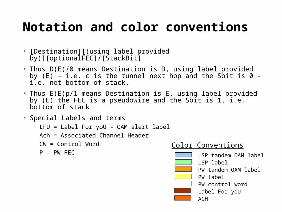
• [Destination][(using label provided by)][optionalFEC]/[StackBit]
• Thus D(E)/0 means Destination is D, using label provided by (E) - i.e. c is the tunnel next hop and the Sbit is 0 - i.e. not bottom of stack.
• Thus E(E)p/1 means Destination is E, using label provided by (E) the FEC is a pseudowire and the Sbit is 1, i.e. bottom of stack
• Special Labels and termsLFU = Label For yoU - OAM alert label
Ach = Associated Channel Header
CW = Control Word
P = PW FECColor Conventions
LSP tandem OAM labelLSP labelPW tandem OAM labelPW labelPW control wordLabel For yoUACH
42
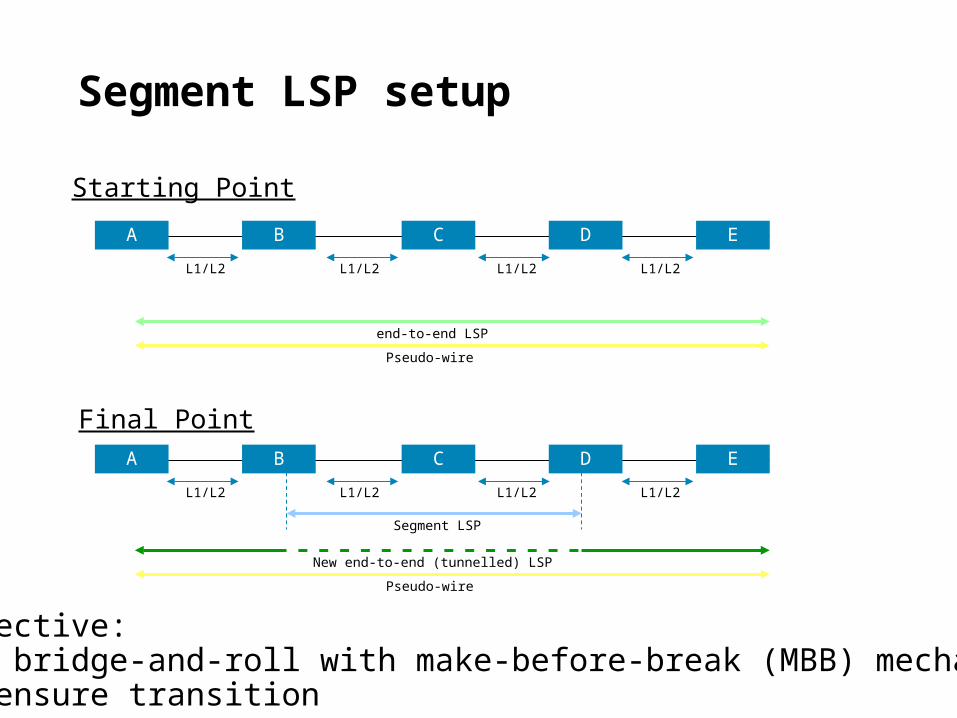
Segment LSP setup
BA DC E
L1/L2 L1/L2 L1/L2L1/L2
end-to-end LSP
Pseudo-wire
BA DC E
L1/L2 L1/L2 L1/L2L1/L2
Segment LSP
Starting Point
Final Point
New end-to-end (tunnelled) LSP
Pseudo-wire
Objective:Use bridge-and-roll with make-before-break (MBB) mechanismto ensure transition
43
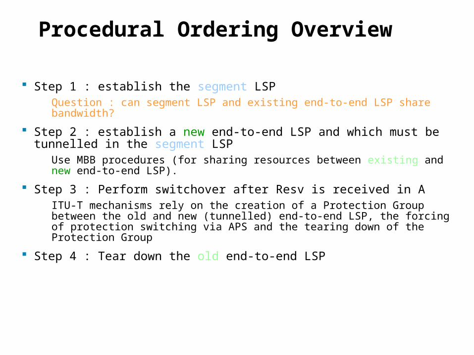
Procedural Ordering Overview
Step 1 : establish the segment LSPQuestion : can segment LSP and existing end-to-end LSP share bandwidth?
Step 2 : establish a new end-to-end LSP and which must be tunnelled in the segment LSP
Use MBB procedures (for sharing resources between existing and new end-to-end LSP).
Step 3 : Perform switchover after Resv is received in AITU-T mechanisms rely on the creation of a Protection Group between the old and new (tunnelled) end-to-end LSP, the forcing of protection switching via APS and the tearing down of the Protection Group
Step 4 : Tear down the old end-to-end LSP
44
LFU/1ACh
LFU/1ACh
LFU/1ACh
LFU/1ACh
Section OAM
TCM-LSP OAM D(C)/0 D(D)/0LFU/1ACh
LFU/1ACh
E2E (A to E)LSP OAM
D(C)/0E(B)/0 E(D)/0 E(E)/0LFU/1ACh
LFU/1ACh
LFU/1ACh
E(D)/0LFU/1ACh
E2E (A to E)PW OAM E(E)p/1
AChE(E)p/1
AChE(E)p/1
AChE(E)p/1
ACh
Non OAM Data Frames
CW CW CWCW
LFU – Label For You (label 13)ACh – Associated ChannelCW – Control Word
TCM-LSPs
E2E LSPSS-PW
A B C D E
D(D)/0
D(C)/0E(B)/0 E(D)/0 E(E)/0E(D)/0
D(D)/0
E(E)p/1 E(E)p/1 E(E)p/1E(E)p/1
D(C)/0E(B)/0 E(D)/0 E(E)/0E(D)/0
D(D)/0
SS-PW over intra-domain LSPLSP, TCM-LSP & PW OAM
TCM LSP label does not
represent a true LSP No LSP Mux (1:1
mapping)
PE PEPPP
45
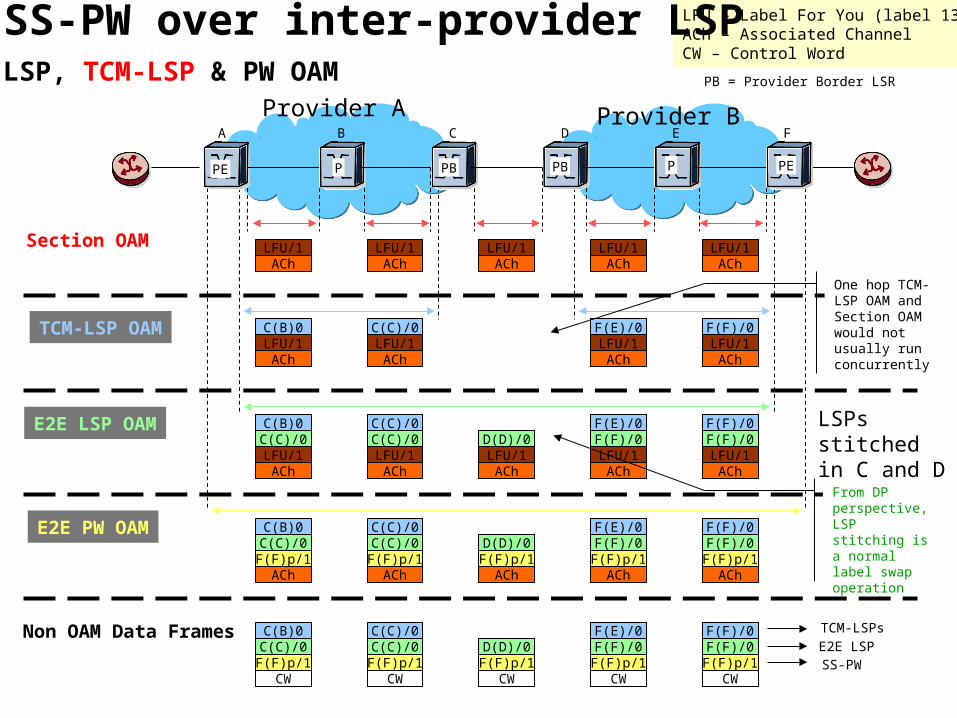
Provider BProvider A
LFU/1ACh
LFU/1ACh
LFU/1ACh
LFU/1ACh
LFU/1ACh
Section OAM
TCM-LSP OAM C(B)0 C(C)/0 F(E)/0 F(F)/0LFU/1ACh
LFU/1ACh
LFU/1ACh
LFU/1ACh
E2E LSP OAM C(B)0 C(C)/0 F(E)/0 F(F)/0C(C)/0 C(C)/0 F(F)/0 F(F)/0LFU/1ACh
LFU/1ACh
LFU/1ACh
LFU/1ACh
D(D)/0LFU/1ACh
E2E PW OAM C(B)0 C(C)/0 F(E)/0 F(F)/0C(C)/0 C(C)/0 F(F)/0 F(F)/0F(F)p/1
AChF(F)p/1
AChF(F)p/1
AChF(F)p/1
ACh
D(D)/0F(F)p/1
ACh
Non OAM Data Frames C(B)0 C(C)/0 F(E)/0 F(F)/0C(C)/0 C(C)/0 F(F)/0 F(F)/0F(F)p/1
CWF(F)p/1
CWF(F)p/1
CWF(F)p/1
CW
D(D)/0F(F)p/1
CW
LFU – Label For You (label 13)ACh – Associated ChannelCW – Control Word
TCM-LSPs
E2E LSPSS-PW
A B C D E F
LSPs stitched in C and D
One hop TCM-LSP OAM and Section OAM would not usually run concurrently
SS-PW over inter-provider LSPLSP, TCM-LSP & PW OAM
PE PEPBP PB P
PB = Provider Border LSR
From DP perspective, LSP stitching is a normal label swap operation
46
LFU/1ACh
LFU/1ACh
LFU/1ACh
LFU/1ACh
Section OAM
MEP-MIP (A to C)LSP OAM LFU/1
AChLFU/1ACh
E2E (A to E)LSP OAM E(B)/0 E(C)/0 E(E)/0
LFU/1ACh
LFU/1ACh
LFU/1ACh
E(D)/0LFU/1ACh
E2E (A to E)PW OAM E(E)p/1
AChE(E)p/1
AChE(E)p/1
AChE(E)p/1
ACh
Non OAM Data Frames
CW CW CWCW
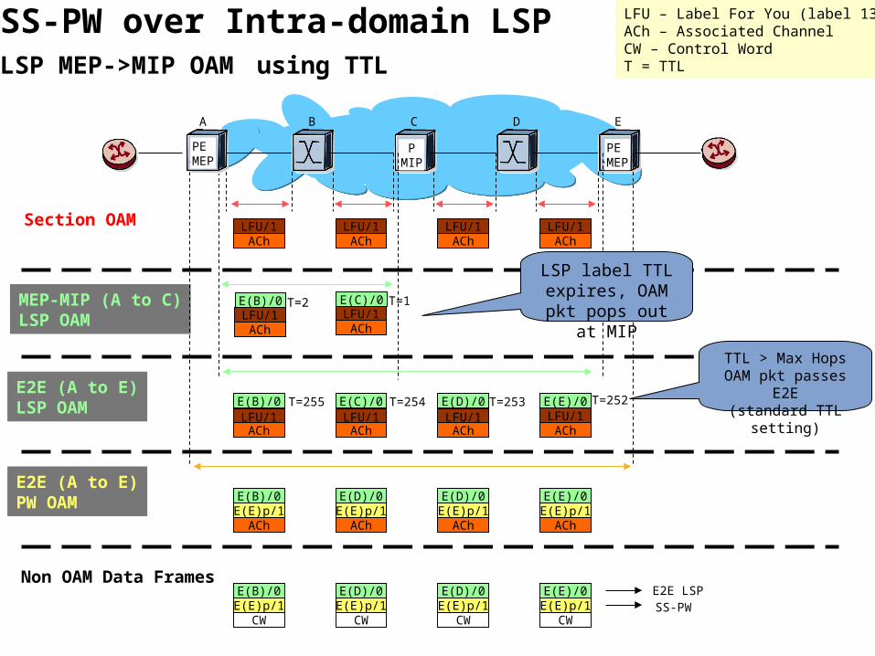
LFU – Label For You (label 13)ACh – Associated ChannelCW – Control WordT = TTL
E2E LSPSS-PW
A B C D E
E(B)/0 E(D)/0 E(E)/0E(D)/0
E(E)p/1 E(E)p/1 E(E)p/1E(E)p/1E(B)/0 E(D)/0 E(E)/0E(D)/0
SS-PW over Intra-domain LSPLSP MEP->MIP OAM using TTL
E(B)/0 E(C)/0
LSP label TTL expires, OAM pkt pops out at MIP
TTL > Max Hops OAM pkt passes E2E
(standard TTL setting)
T=2 T=1
T=255 T=253T=254 T=252
PEMEP
PEMEP
PMIP
47
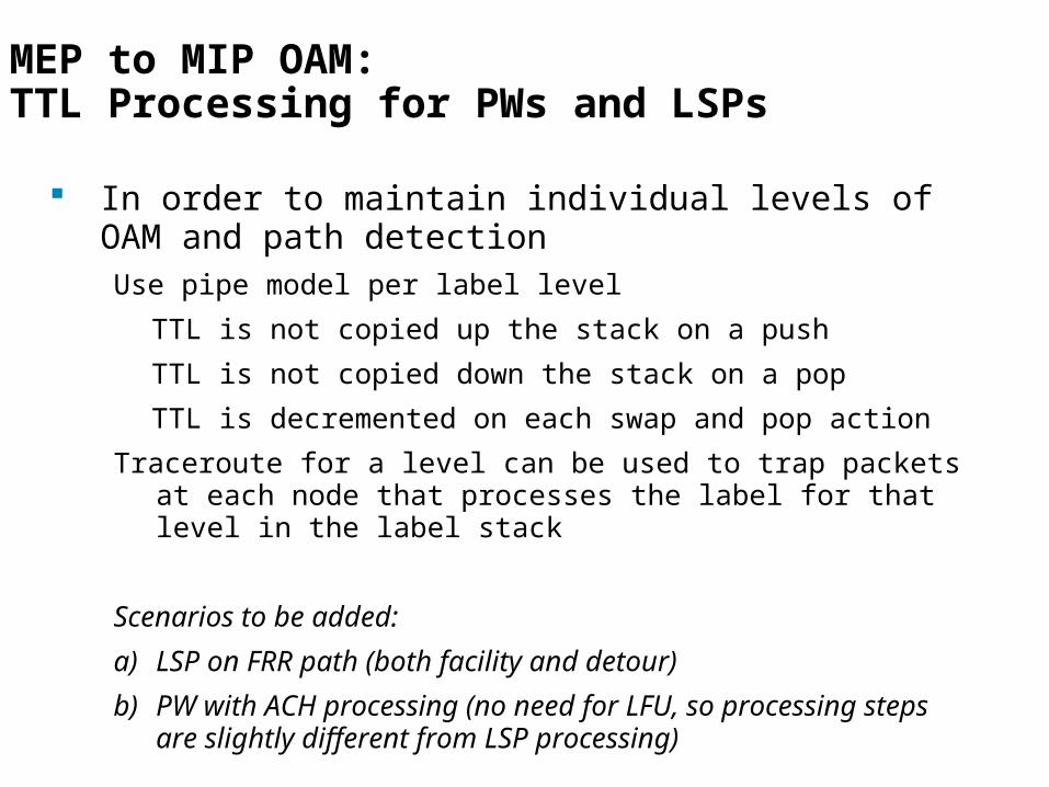
MEP to MIP OAM:TTL Processing for PWs and LSPs
In order to maintain individual levels of OAM and path detectionUse pipe model per label level
TTL is not copied up the stack on a push
TTL is not copied down the stack on a pop
TTL is decremented on each swap and pop action
Traceroute for a level can be used to trap packets at each node that processes the label for that level in the label stack
Scenarios to be added:
a) LSP on FRR path (both facility and detour)
b) PW with ACH processing (no need for LFU, so processing steps are slightly different from LSP processing)
48
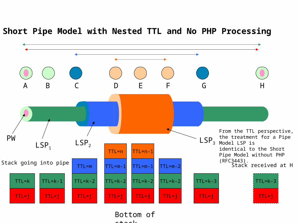
Short Pipe Model with Nested TTL and No PHP Processing
TTL=k-1
TTL=j
TTL=k-2
TTL=j
TTL=m
TTL=k-2
TTL=j
TTL=m-1
TTL=n
TTL=k-2
TTL=j
TTL=m-2
TTL=k-3
TTL=j
TTL=k-3
TTL=j
TTL=k-2
TTL=j
TTL=m-1
TTL=n-1
TTL=k
TTL=j
PWLSP1
LSP2LSP3
A B C D E F G H
Bottom of stack
Stack going into pipe Stack received at H
From the TTL perspective, the treatment for a Pipe Model LSP isidentical to the Short Pipe Model without PHP (RFC3443).
49
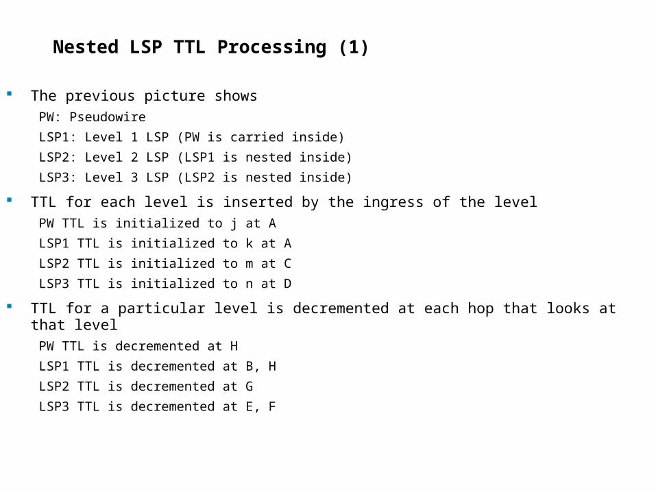
Nested LSP TTL Processing (1)
The previous picture shows
PW: Pseudowire
LSP1: Level 1 LSP (PW is carried inside)
LSP2: Level 2 LSP (LSP1 is nested inside)
LSP3: Level 3 LSP (LSP2 is nested inside)
TTL for each level is inserted by the ingress of the level
PW TTL is initialized to j at A
LSP1 TTL is initialized to k at A
LSP2 TTL is initialized to m at C
LSP3 TTL is initialized to n at D
TTL for a particular level is decremented at each hop that looks at that level
PW TTL is decremented at H
LSP1 TTL is decremented at B, H
LSP2 TTL is decremented at G
LSP3 TTL is decremented at E, F
50
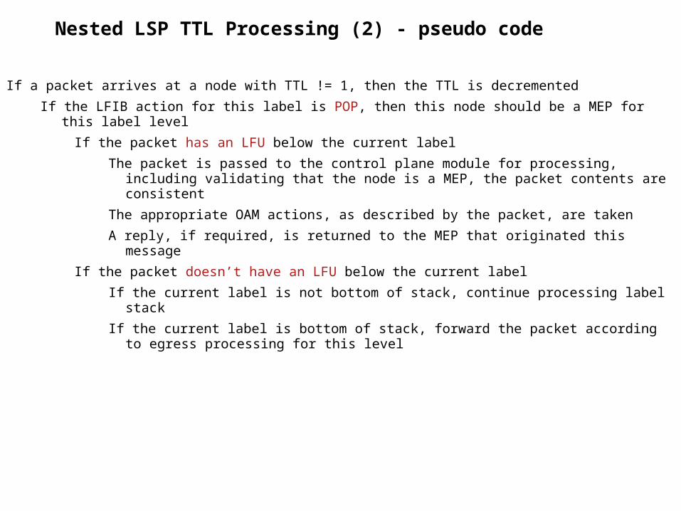
Nested LSP TTL Processing (2) - pseudo code
If a packet arrives at a node with TTL != 1, then the TTL is decremented
If the LFIB action for this label is POP, then this node should be a MEP for this label level
If the packet has an LFU below the current label
The packet is passed to the control plane module for processing, including validating that the node is a MEP, the packet contents are consistent
The appropriate OAM actions, as described by the packet, are taken
A reply, if required, is returned to the MEP that originated this message
If the packet doesn’t have an LFU below the current label
If the current label is not bottom of stack, continue processing label stack
If the current label is bottom of stack, forward the packet according to egress processing for this level
51
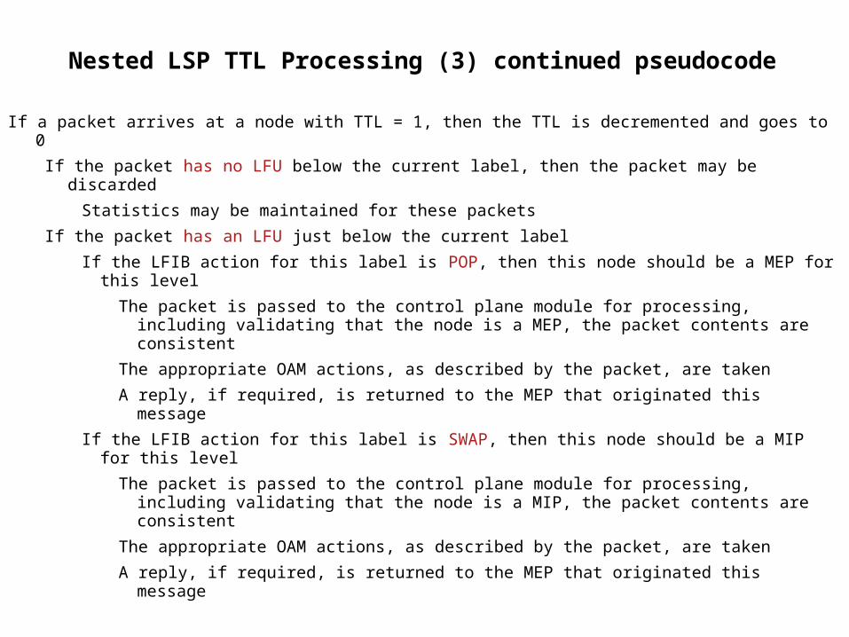
Nested LSP TTL Processing (3) continued pseudocode
If a packet arrives at a node with TTL = 1, then the TTL is decremented and goes to 0
If the packet has no LFU below the current label, then the packet may be discarded
Statistics may be maintained for these packets
If the packet has an LFU just below the current label
If the LFIB action for this label is POP, then this node should be a MEP for this level
The packet is passed to the control plane module for processing, including validating that the node is a MEP, the packet contents are consistent
The appropriate OAM actions, as described by the packet, are taken
A reply, if required, is returned to the MEP that originated this message
If the LFIB action for this label is SWAP, then this node should be a MIP for this level
The packet is passed to the control plane module for processing, including validating that the node is a MIP, the packet contents are consistent
The appropriate OAM actions, as described by the packet, are taken
A reply, if required, is returned to the MEP that originated this message
52
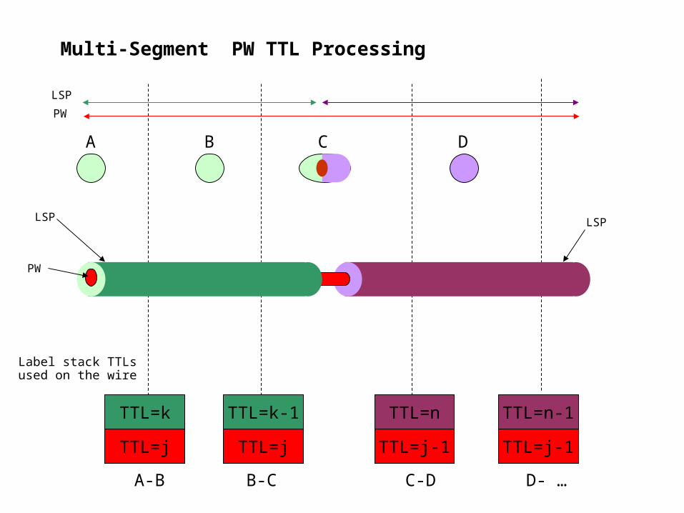
Multi-Segment PW TTL Processing
TTL=k
TTL=j
TTL=k-1
TTL=j
TTL=n
TTL=j-1
TTL=n-1
TTL=j-1
A-B B-C
C D
Label stack TTLsused on the wire
PW
LSP
PW
C-D D- …
BA
LSP LSP
53
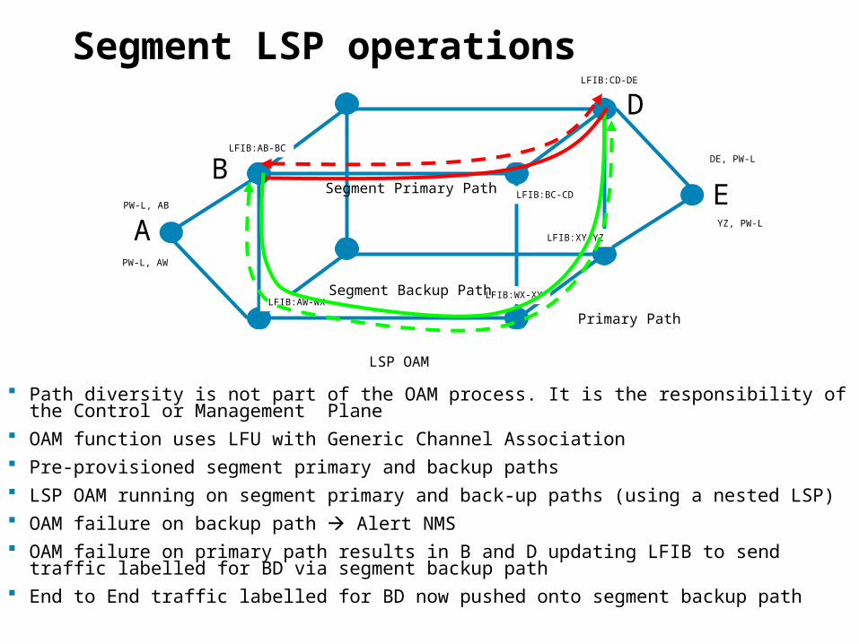
Segment LSP operations
Path diversity is not part of the OAM process. It is the responsibility of the Control or Management Plane
OAM function uses LFU with Generic Channel Association Pre-provisioned segment primary and backup paths LSP OAM running on segment primary and back-up paths (using a nested LSP) OAM failure on backup path Alert NMS OAM failure on primary path results in B and D updating LFIB to send traffic labelled for BD via
segment backup path End to End traffic labelled for BD now pushed onto segment backup path
Primary Path
LSP OAM
LFIB:AB-BC
LFIB:BC-CD
LFIB:CD-DE
PW-L, AB
DE, PW-L
LFIB:AW-WXLFIB:WX-XY
LFIB:XY-YZAE
Segment Backup Path
PW-L, AW
YZ, PW-L
Segment Primary PathB
D
54
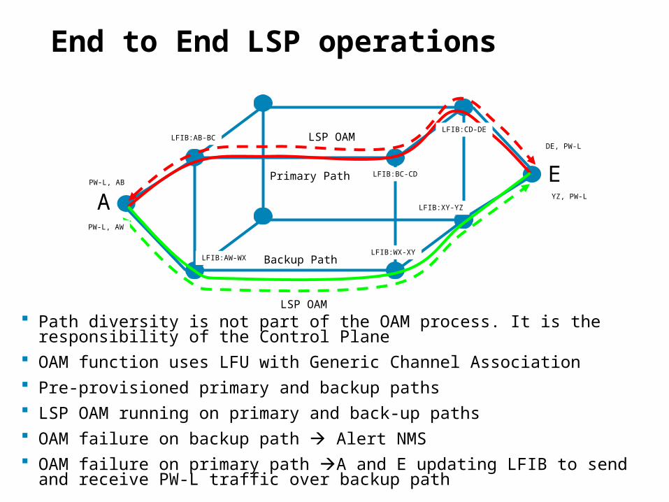
End to End LSP operations
Path diversity is not part of the OAM process. It is the responsibility of the Control Plane
OAM function uses LFU with Generic Channel Association Pre-provisioned primary and backup paths LSP OAM running on primary and back-up paths OAM failure on backup path Alert NMS OAM failure on primary path A and E updating LFIB to send and receive PW-L
traffic over backup path
LSP OAM
LSP OAM
LFIB:AB-BC
LFIB:BC-CD
LFIB:CD-DE
PW-L, AB
DE, PW-L
LFIB:AW-WXLFIB:WX-XY
LFIB:XY-YZAEPrimary Path
Backup Path
PW-L, AW
YZ, PW-L

55
Network Management
56
Advice
Network Management sub team has not found any issues that prevent the creation of an MPLS transport profile
Therefore option 1 can be selected
No Showstoppers found
57
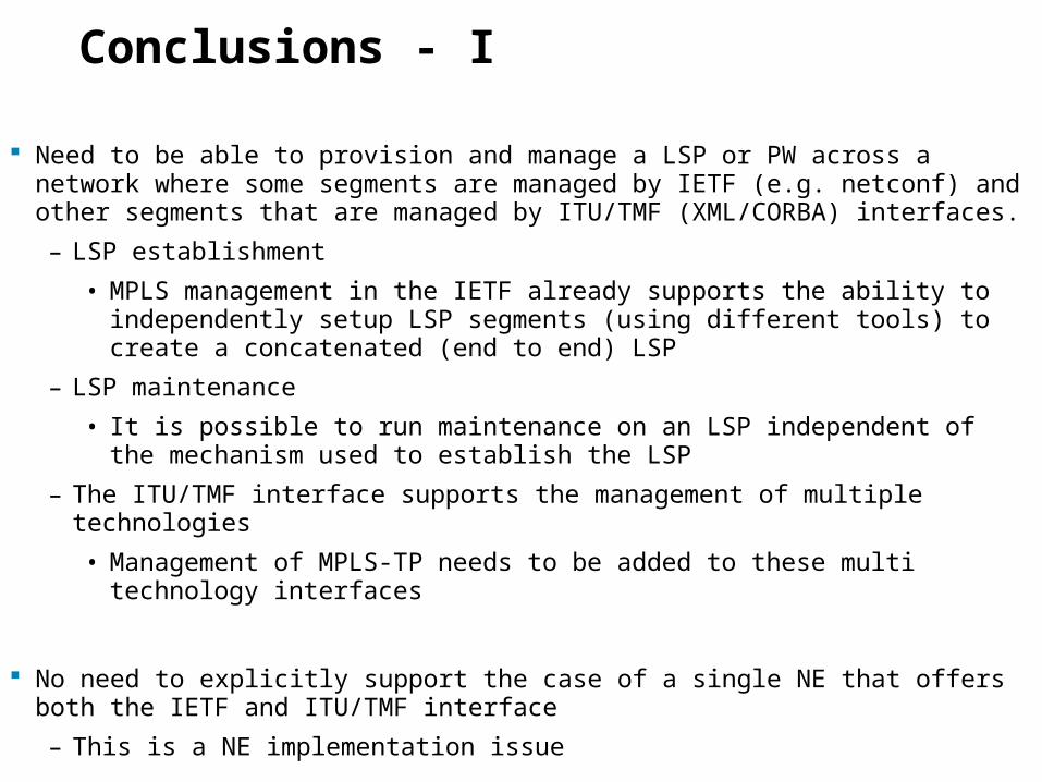
Conclusions - I
Need to be able to provision and manage a LSP or PW across a network where some segments are managed by IETF (e.g. netconf) and other segments that are managed by ITU/TMF (XML/CORBA) interfaces.
– LSP establishment
• MPLS management in the IETF already supports the ability to independently setup LSP segments (using different tools) to create a concatenated (end to end) LSP
– LSP maintenance
• It is possible to run maintenance on an LSP independent of the mechanism used to establish the LSP
– The ITU/TMF interface supports the management of multiple technologies
• Management of MPLS-TP needs to be added to these multi technology interfaces
No need to explicitly support the case of a single NE that offers both the IETF and ITU/TMF interface
– This is a NE implementation issue
58
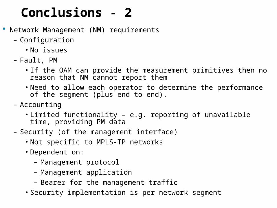
Conclusions - 2 Network Management (NM) requirements
– Configuration
• No issues
– Fault, PM
• If the OAM can provide the measurement primitives then no reason that NM cannot report them
• Need to allow each operator to determine the performance of the segment (plus end to end).
– Accounting
• Limited functionality – e.g. reporting of unavailable time, providing PM data
– Security (of the management interface)
• Not specific to MPLS-TP networks
• Dependent on:
– Management protocol
– Management application
– Bearer for the management traffic
• Security implementation is per network segment

59
Summary
60
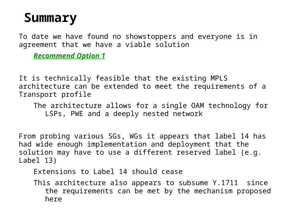
Summary
To date we have found no showstoppers and everyone is in agreement that we have a viable solution
Recommend Option 1
It is technically feasible that the existing MPLS architecture can be extended to meet the requirements of a Transport profile
The architecture allows for a single OAM technology for LSPs, PWE and a deeply nested network
From probing various SGs, WGs it appears that label 14 has had wide enough implementation and deployment that the solution may have to use a different reserved label (e.g. Label 13)
Extensions to Label 14 should cease
This architecture also appears to subsume Y.1711 since the requirements can be met by the mechanism proposed here
61
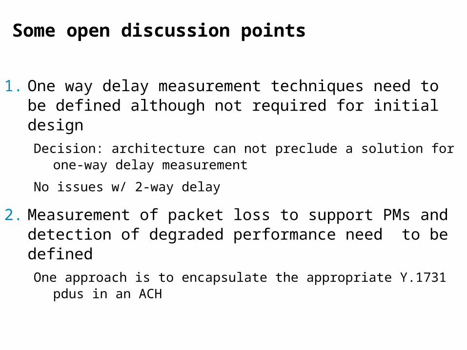
Some open discussion points
1. One way delay measurement techniques need to be defined although not required for initial design
Decision: architecture can not preclude a solution for one-way delay measurement
No issues w/ 2-way delay
2. Measurement of packet loss to support PMs and detection of degraded performance need to be defined
One approach is to encapsulate the appropriate Y.1731 pdus in an ACH

62
The End
Related Documents


![½Ä : Lòæ 3}º¢ ¹ Þ«b ,àÏ¥û4 -P ¢ q ì#×У¯£´¨ë °øÉ8ú ... · [18] IETF RFC 793 (1981): "Transmission Control Protocol" (STD 7). [19] IETF RFC 1034 (1987):](https://static.cupdf.com/doc/110x72/5b5d64387f8b9a16498df0ee/ae-loae-3o-bb-aiu4-p-q-ide-oe8u.jpg)


![Network Working Group M - ETSIdocbox.etsi.org/Reference/IETF/RFC/RFC3435.pdfAndreasen & Foster Informational [Page 1] RFC 3435 MGCP 1.0 January 2003 The basic and general MGCP protocol](https://static.cupdf.com/doc/110x72/5b09f7227f8b9a51508e2418/network-working-group-m-foster-informational-page-1-rfc-3435-mgcp-10-january.jpg)