1 B2.2.4 Hydropower system design Turbines: Greek mill (c. 100BC) Apuntes de Tubomáquinas / 2014-2 Ing. Hipólito Rodríguez

1 Apuntes de Tubomáquinas / 2014-2 Ing. Hipólito Rodríguez B2.2.4 Hydropower system design Turbines: Greek mill (c. 100BC) Apuntes de Tubomáquinas / 2014-2.
Dec 22, 2015
Welcome message from author
This document is posted to help you gain knowledge. Please leave a comment to let me know what you think about it! Share it to your friends and learn new things together.
Transcript

1
B2.2.4 Hydropower system design Turbines: Greek mill (c. 100BC)
Apuntes de Tubomáquinas / 2014-2Ing. Hipólito Rodríguez
2
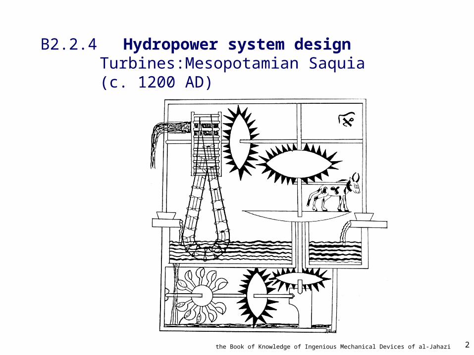
B2.2.4 Hydropower system design Turbines:Mesopotamian Saquia (c. 1200 AD)
the Book of Knowledge of Ingenious Mechanical Devices of al-Jahazi

3
B2.2.4 Hydropower system design Turbines: Water wheels (c. 1800)1-50kW
4
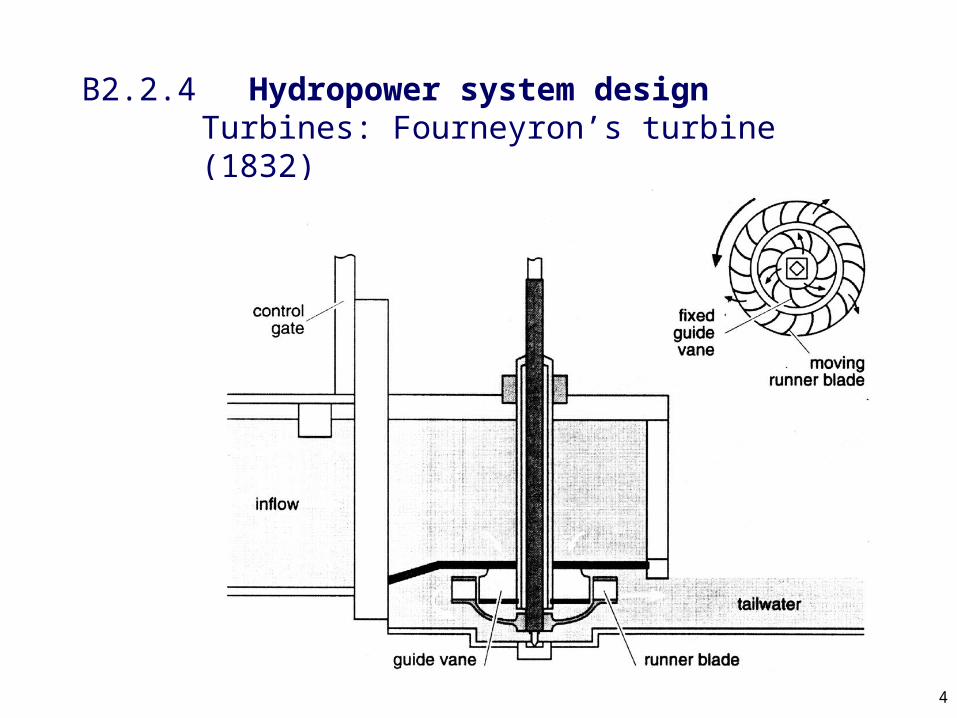
B2.2.4 Hydropower system design Turbines: Fourneyron’s turbine (1832)

5
B2. Hydropower Seminars A206a
• Read summary of case studies– Nepal– Peru
• Discussion– What were the good and bad projects– What makes a “good project”– What were the social benefits of the projects?
Were these valued? – Who benefits and who loses

6
B2. ReservoirsSeminar groups
Group 1 (14:00) Group 2 (14:30)
Gunjan Dhingra
Mike Farrow
Hannah Jones
Matt Knight
Paul Knowles
Peter Adams
Elizabeth Aldridge
Jonathan Bailey
Khesraw Bashir
Christopher Baxter
Richard Buckland
Dafydd Caffery
Samuel Carter
Nedim Dzananovic
Philip Hallgarth
Neil Harding
Martin Hill
Karen Hockey
Ching Hong
Adam Ithier
Peter Jordan
Jan Jozefowski
Rob Morford
Chris Swinburn
Kate Taylor
Celia Way
Marie Wells
Matt Whitley
Eral Kahveci
Imra Karimn
Martin Kendrick
Shua Lii
Beth Mcdowall
Adil Munir
Roger Palmer
Anthony Pearson
Gareth Pilmoor
Ann Ruthven
Matthew Scott
Ben Sheterline
Melanie Sim
Nicholas Thompson
Daniel Tkotsch
Christopher Tompkins
Ian Yeung

7
B2.2.4 Hydropower system design Turbines: Power conversion
P Q gh P T

8
B2.2.4 Hydropower system design Turbines: Power conversion
T Fr
F M
m v
Q v

9
vr1
vr2
B2.2.4 Hydropower system design Turbines: Power conversion:Velocity triangles
Rotation
u1
u2
v1
v2
R1
R21
1
1
2
10
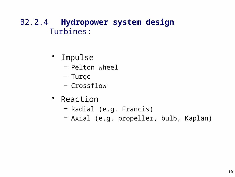
B2.2.4 Hydropower system design Turbines:
• Impulse– Pelton wheel– Turgo– Crossflow
• Reaction– Radial (e.g. Francis)– Axial (e.g. propeller, bulb, Kaplan)

11
B2.2.4 Hydropower system design Turbines: Pelton wheel (1889)
12
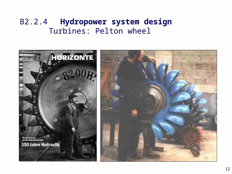
B2.2.4 Hydropower system design Turbines: Pelton wheel
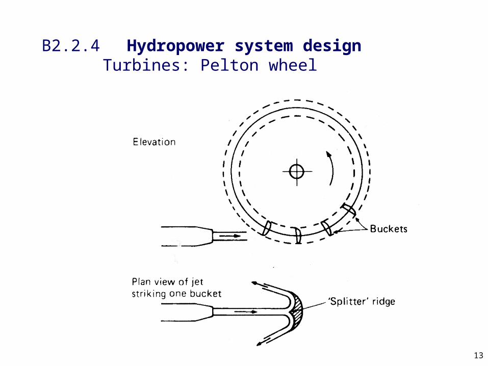
13
B2.2.4 Hydropower system design Turbines: Pelton wheel
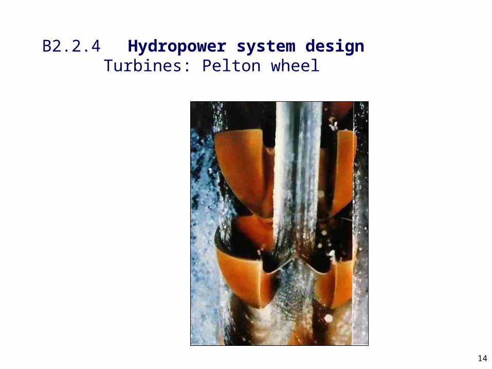
14
B2.2.4 Hydropower system design Turbines: Pelton wheel

15
B2.2.4 Hydropower system design Turbines: Pelton wheel
Rotation
v1 (jet velocity)= vr1
u1R1
u2 = u1
v2
vr2
R2 = R1

16
B2.2.4 Hydropower system design Turbines: Pelton wheel

17
B2.2.4 Hydropower system design Turbines: Pelton wheel:Jet
2jet j penstockv C gh v
0.94-0.98

18
B2.2.4 Hydropower system design Turbines: Pelton wheel

19
B2.2.4 Hydropower system design Turbines: Pelton wheel: Multi jet

20
B2.2.4 Hydropower system design Turbines: Pelton wheel: Multi jet
• Higher rotational speed
• Smaller runner
• Simple flow control possible
• Redundancy
• Can cope with a large range of flows
But
• Needs complex manifold
• May make control/governing complex
21
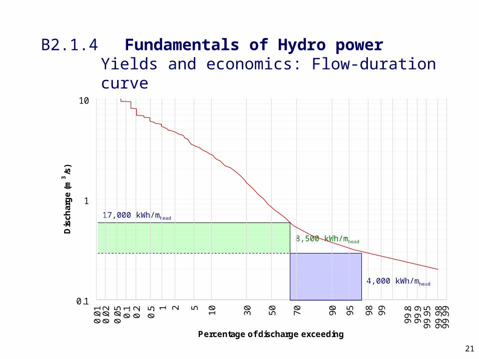
B2.1.4 Fundamentals of Hydro power Yields and economics: Flow-duration curve
0.01
0.05
0.10.2
0.5 1 2 5
10
30
50
70
90
95
9899
99.8
99.9
99.95
99.99
0.02
99.98
0.1
1
10
Percentage of discharge exceeding
Dis
char
ge
(m3/s
)
8,500 kWh/mhead
4,000 kWh/mhead
17,000 kWh/mhead

22
B2.2.4 Hydropower system design Turbines: Pelton wheel: Sri Lankan

23
B2.2.4 Hydropower system design Turbines: Turgo (1904)

24
B2.2.4 Hydropower system design Turbines: Turgo
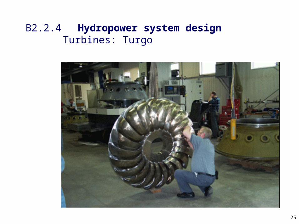
25
B2.2.4 Hydropower system design Turbines: Turgo

26
B2.2.4 Hydropower system design Turbines: Turgo

27
2
B2.2.4 Hydropower system design Turbines: Turgo
Rotation
v1 (jet velocity)
vr2
v2
u2 = u1
u1
R1
R2 = R1
1vr1
1=20

28
B2.2.4 Hydropower system design Turbines: Turgo: MPPU – based on Nepali Ghatta

29
B2.2.4 Hydropower system design Turbines: Crossflow (1941)

30
B2.2.4 Hydropower system design Turbines: Crossflow
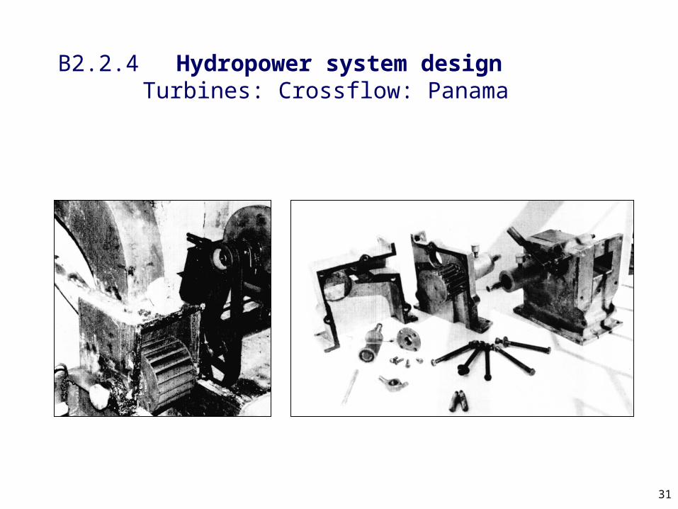
31
B2.2.4 Hydropower system design Turbines: Crossflow: Panama

32
B2.2.4 Hydropower system design Turbines: Crossflow
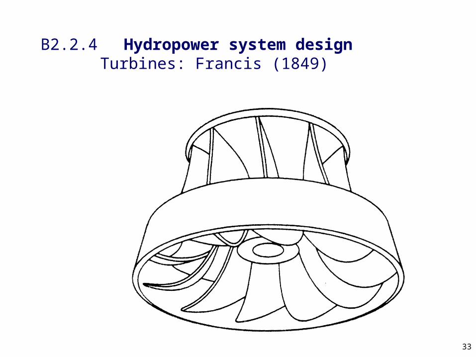
33
B2.2.4 Hydropower system design Turbines: Francis (1849)

34
B2.2.4 Hydropower system design Turbines: Francis
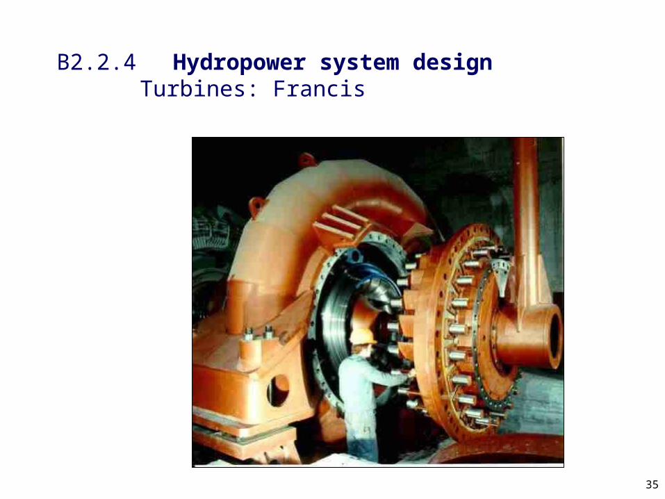
35
B2.2.4 Hydropower system design Turbines: Francis
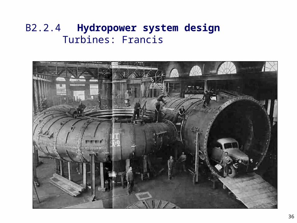
36
B2.2.4 Hydropower system design Turbines: Francis

37
B2.2.4 Hydropower system design Turbines: Francis

38
vr1
vr2
B2.2.4 Hydropower system design Turbines: Francis
Rotation
u1
u2
v1
v2
R1
R2 = R11
1
1
2
39
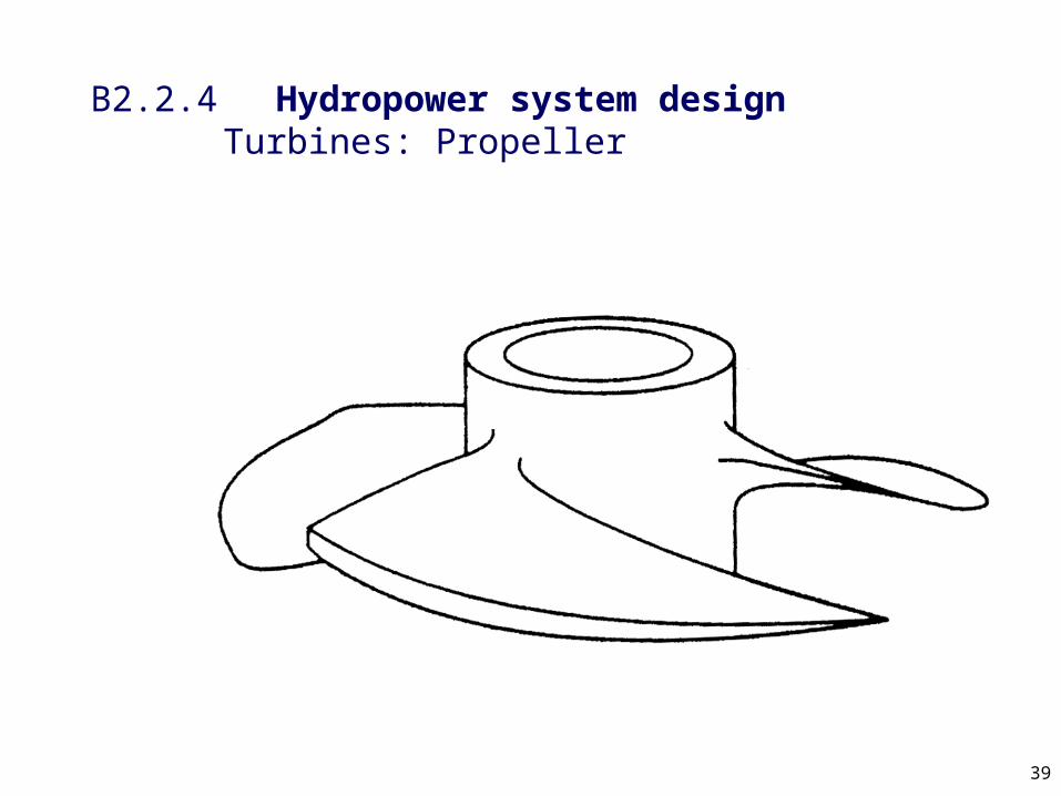
B2.2.4 Hydropower system design Turbines: Propeller

40
B2.2.4 Hydropower system design Turbines: Propeller
41
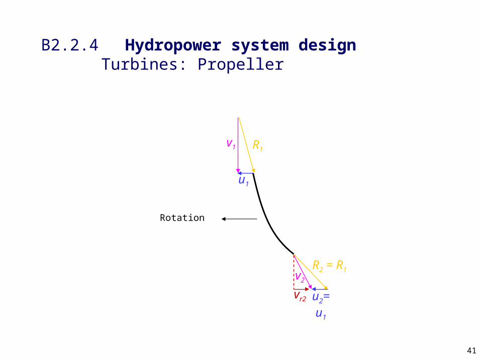
B2.2.4 Hydropower system design Turbines: Propeller
R1
v2
R2 = R1
u1
u2= u1vr2
Rotation
v1

42
B2.2.4 Hydropower system design Turbines: Kaplan (1913)

43
B2.2.4 Hydropower system design Turbines: Kaplan

44
B2.2.4 Hydropower system design Turbines: siting propellers

45
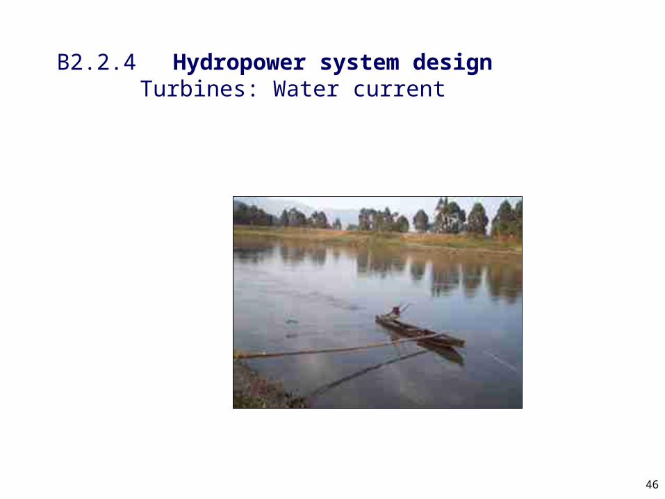
B2.2.4 Hydropower system design Turbines: Water current (1980)
46
B2.2.4 Hydropower system design Turbines: Water current

47
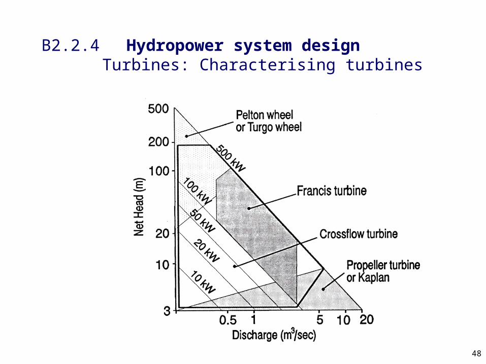
B2.2.4 Hydropower system design Turbines: Characterising turbines
48
B2.2.4 Hydropower system design Turbines: Characterising turbines

49
B2.2.4 Hydropower system design Turbines: Characterising turbines

50
CQ = flow coefficient
CH = head coefficient
CP = power coefficient
Q = dischargeN = rotational speedD = diameterg = gravityH = headP = powerr = density
B2.2.4 Hydropower system design Turbines: Characterising turbines: Dimensionless groups
3
Fluid velocity
Blade velocityQ
QC
ND
2 2H
gHC
N D
3 5PP
CN D

51
Nsp = Specific speed
CH = head coefficient
CP = power coefficient
N = rotational speedP = powerr = densityg = gravityH = head
B2.2.4 Hydropower system design Turbines: Characterising turbines: Dimensionless groups:Specific speed
1 2
5 4
1 2
5 41 2
Psp
H
CN
C
NP
gH
1 2
5 4sp
NPN
H

52
B2.2.4 Hydropower system design Turbines: Characterising turbines: Specific speed: Dimensional specific speedType Typical
headRad Rev Metric British
Pelton >300 <0.2 <0.03 <30 <10
Francis 500-30 0.25-1.3 0.04-0.2 50-250 10-60
Kaplan 50-4 2-6 0.3-1 360-1200
100-300

53
B2.2.4 Hydropower system design Turbines: Characterising turbines

54
B2.2.4 Hydropower system design Turbines: Characterising turbines

55
B2.2.4 Hydropower system design Turbines: Cavitation

56
B2.2.4 Hydropower system design Turbines: Cavitation

57
B2.2.4 Hydropower system design Turbines: Cavitation
58
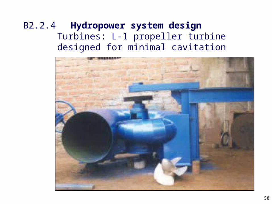
B2.2.4 Hydropower system design Turbines: L-1 propeller turbine designed for minimal cavitation

59
B2.2.4 Hydropower system design Turbines: L-1 propeller turbine designed for minimal cavitation after 25,000 hours
60
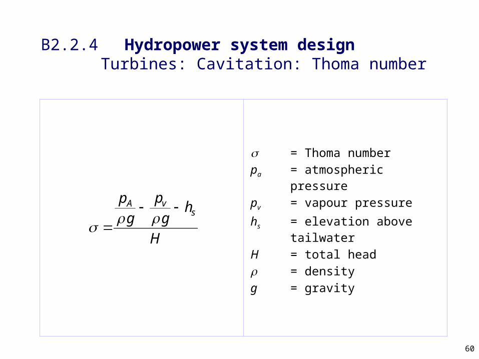
s = Thoma numberpa = atmospheric pressure
pv = vapour pressure
hs = elevation above tailwater
H = total headr = densityg = gravity
B2.2.4 Hydropower system design Turbines: Cavitation: Thoma number
vAs
pph
g g
H
61
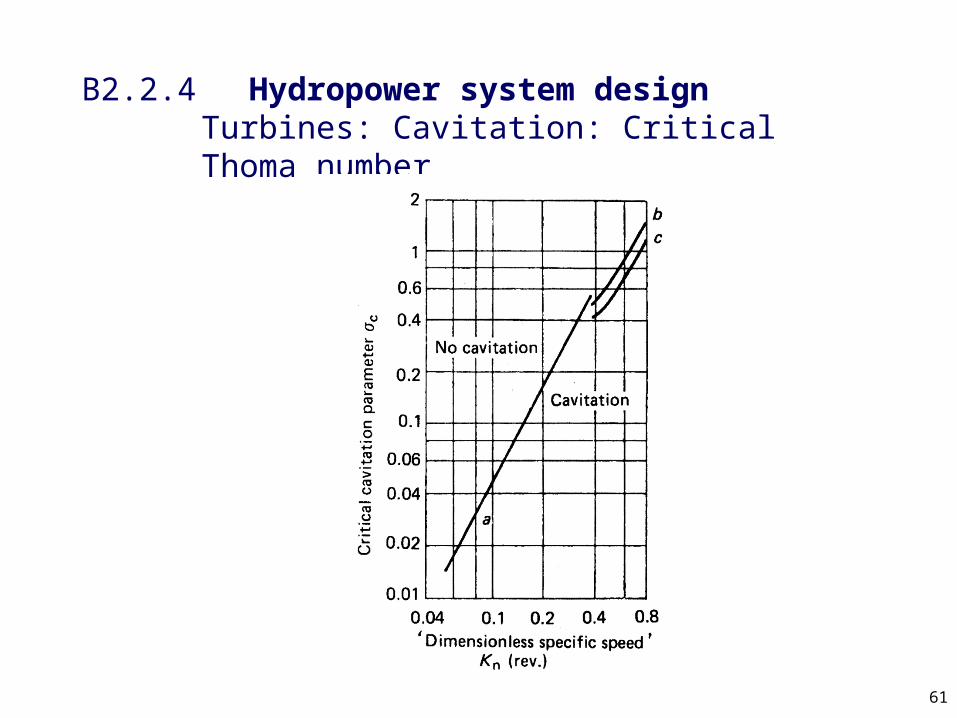
B2.2.4 Hydropower system design Turbines: Cavitation: Critical Thoma number
Related Documents