Latin America Data Center Design and Deployment Seminars 2010

01 Day01 Morning - Virtualized DC Front End Design - Carlos Pereira
Oct 26, 2014
Welcome message from author
This document is posted to help you gain knowledge. Please leave a comment to let me know what you think about it! Share it to your friends and learn new things together.
Transcript
Latin America Data CenterDesign and Deployment
Seminars 2010
© 2010 Cisco Systems, Inc. All rights reserved. Cisco PublicLatin America Data Center Design & Deployment Seminars - 2010 2
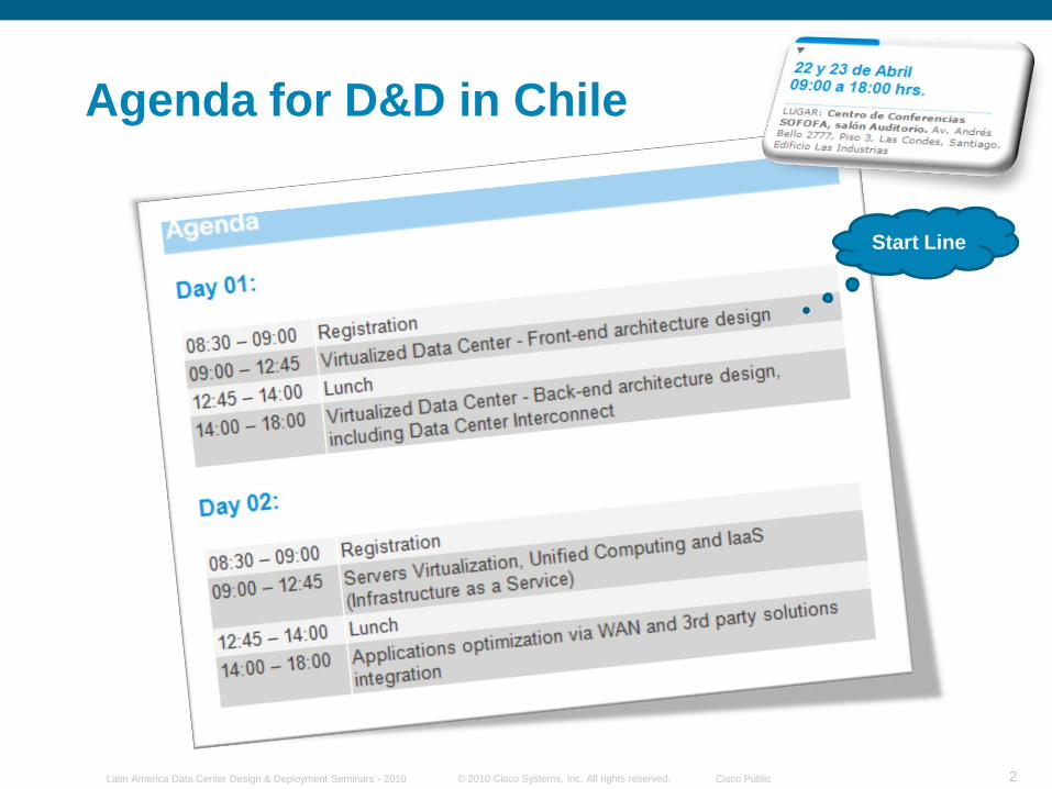
Agenda for D&D in Chile
Start Line
© 2010 Cisco Systems, Inc. All rights reserved. Cisco PublicLatin America Data Center Design & Deployment Seminars - 2010 3
Our Sponsors: A Big Thank You !!!
Please join our technology partners outside to see how we are together building Data Center Solutions that match your requirements.
4© 2010 Cisco Systems, Inc. All rights reserved. Cisco PublicLatin America Data Center Design & Deployment Seminars - 2010
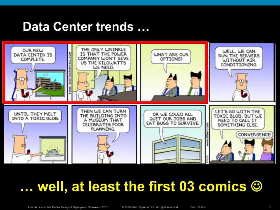
Data Center trends …
… well, at least the first 03 comics
5© 2010 Cisco Systems, Inc. All rights reserved. Cisco PublicLatin America Data Center Design & Deployment Seminars - 2010
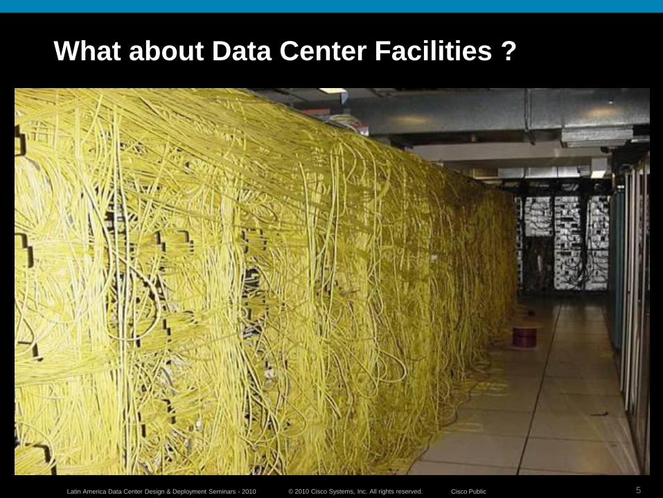
What about Data Center Facilities ?
6© 2010 Cisco Systems, Inc. All rights reserved. Cisco PublicLatin America Data Center Design & Deployment Seminars - 2010
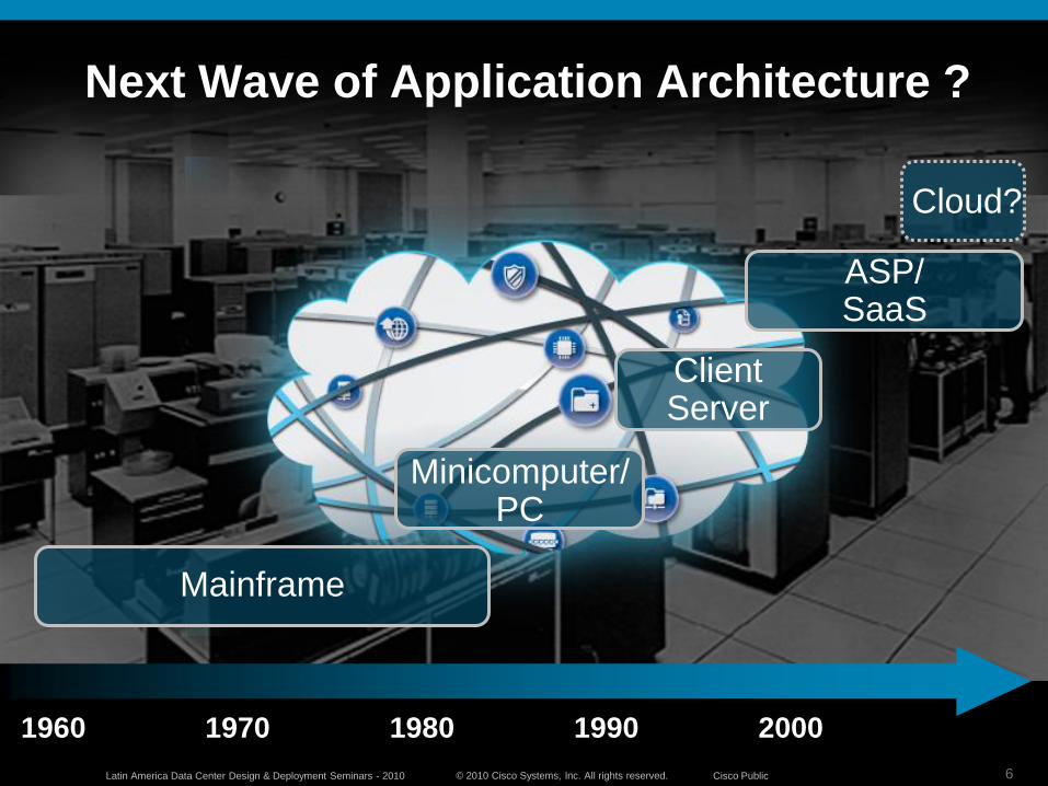
Next Wave of Application Architecture ?
1960 1970 1980 1990 2000
Mainframe
Client Server
ASP/SaaS
Cloud?
Minicomputer/PC
© 2010 Cisco Systems, Inc. All rights reserved. Cisco PublicLatin America Data Center Design & Deployment Seminars - 2010
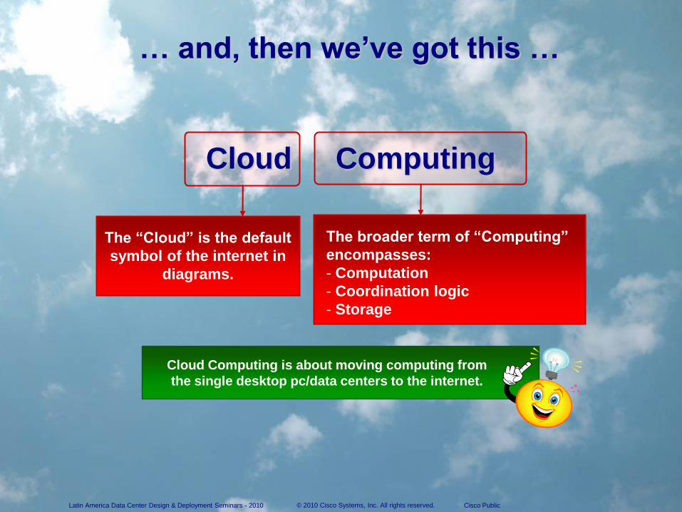
… and, then we’ve got this …
The ―Cloud‖ is the default
symbol of the internet in
diagrams.
The broader term of ―Computing‖
encompasses:
- Computation
- Coordination logic
- Storage
Cloud Computing is about moving computing from
the single desktop pc/data centers to the internet.
Cloud Computing
© 2010 Cisco Systems, Inc. All rights reserved. Cisco PublicLatin America Data Center Design & Deployment Seminars - 2010
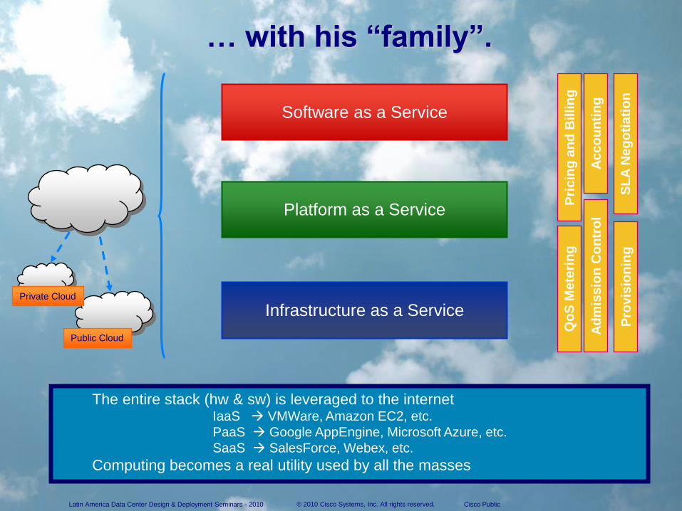
Public Cloud
Private Cloud
Infrastructure as a Service
Platform as a Service
Software as a Service
… with his ―family‖.
Qo
S M
ete
rin
g
SL
A N
eg
oti
ati
on
Ad
mis
sio
n C
on
tro
l
Pri
cin
g a
nd
Bil
lin
g
Ac
co
un
tin
g
Pro
vis
ion
ing
The entire stack (hw & sw) is leveraged to the internetIaaS VMWare, Amazon EC2, etc.
PaaS Google AppEngine, Microsoft Azure, etc.
SaaS SalesForce, Webex, etc.
Computing becomes a real utility used by all the masses
9© 2010 Cisco Systems, Inc. All rights reserved. Cisco PublicLatin America Data Center Design & Deployment Seminars - 2010
9© 2007 Cisco Systems, Inc. All rights reserved. Cisco ConfidentialPresentation_ID
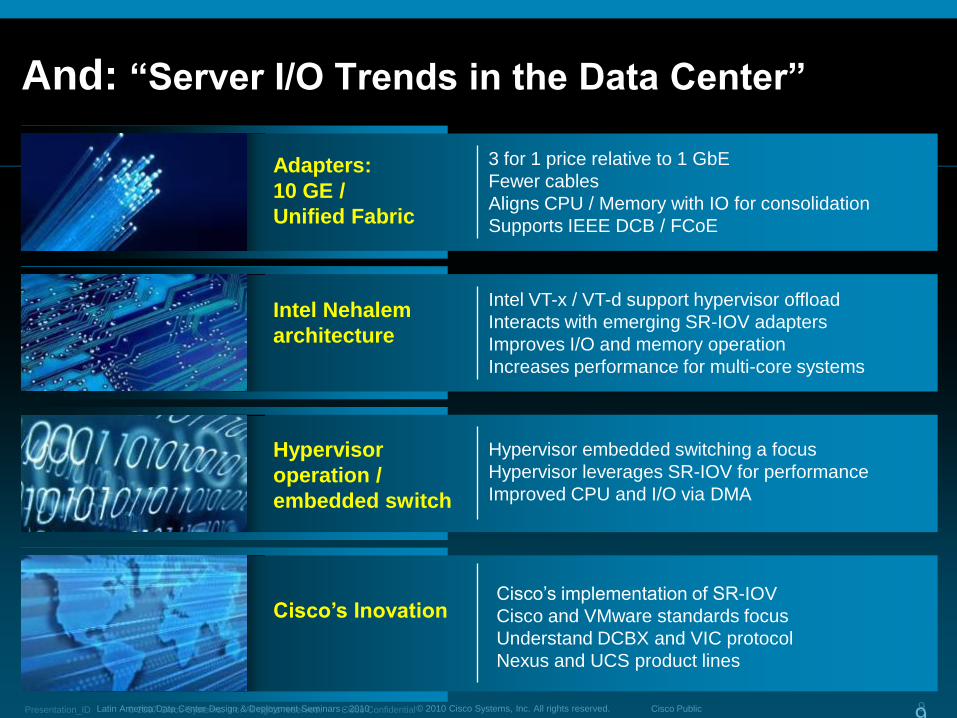
And: ―Server I/O Trends in the Data Center‖
Adapters:
10 GE /
Unified Fabric
Intel Nehalem
architecture
Hypervisor
operation /
embedded switch
Cisco’s Inovation
3 for 1 price relative to 1 GbE
Fewer cables
Aligns CPU / Memory with IO for consolidation
Supports IEEE DCB / FCoE
Intel VT-x / VT-d support hypervisor offload
Interacts with emerging SR-IOV adapters
Improves I/O and memory operation
Increases performance for multi-core systems
Hypervisor embedded switching a focus
Hypervisor leverages SR-IOV for performance
Improved CPU and I/O via DMA
Cisco‟s implementation of SR-IOV
Cisco and VMware standards focus
Understand DCBX and VIC protocol
Nexus and UCS product lines
© 2010 Cisco Systems, Inc. All rights reserved. Cisco PublicLatin America Data Center Design & Deployment Seminars - 2010 10
Choices of transport technology in the Data Center over the last 10 years?
What will be the technology choice for the Data Center in the next 5 years?
iSCSI
ATM/LANE
Fibre Channel
Infiniband
FDDIToken Ring / HSTR
Ethernet
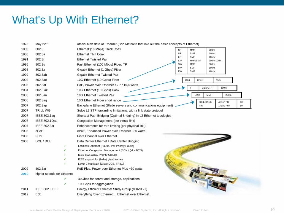
1973 May 22nd official birth date of Ethernet (Bob Metcalfe that laid out the basic concepts of Ethernet)
1983 802.3 Ethernet (10 Mbps) Thick Coax
1986 802.3a Ethernet Thin Coax
1991 802.3i Ethernet Twisted Pair
1995 802.3u Fast Ethernet (100 Mbps) Fiber, TP
1998 802.3z Gigabit Ethernet (1 Gbps) Fiber
1999 802.3ab Gigabit Ethernet Twisted Pair
2002 802.3ae 10G Ethernet (10 Gbps) Fiber
2003 802.3af PoE, Power over Ethernet 4 / 7 / 15,4 watts
2004 802.3 ak 10G Ethernet (10 Gbps) Coax
2006 802.3an 10G Ethernet Twisted Pair
2006 802.3aq 10G Ethernet Fiber short range
2007 802.3ap Backplane Ethernet (Blade servers and communications equipment)
2007 TRILL WG Solve L2 STP forwarding limitations, with a link state protocol
2007 IEEE 802.1aq Shortest Path Bridging (Optimal Bridging) in L2 Ethernet topologies
2007 IEEE 802.1Qau Congestion Management (per virtual link)
2007 IEEE 802.3ar Enhancements for rate limiting (per physical link)
2008 ePoE ePoE, Enhanced Power over Ethernet ~30 watts
2008 FCoE Fibre Channel over Ethernet
2008 DCE / DCB Data Center Ethernet / Data Center Bridging
Lossless Ethernet [Pause, Per Priority Pause]
Ethernet Congestion Management [ECN / (aka BCN)
IEEE 802.1Qau, Priority Groups
IEEE support for (baby) giant frames
Layer 2 Multipath [Cisco DCE, TRILL]
2009 802.3at PoE Plus, Power over Ethernet Plus ~60 watts
2010 higher speeds for Ethernet
40Gbps for server and storage, applications
100Gbps for aggregation
2011 IEEE 802.3 EEE Energy Efficient Ethernet Study Group (0BASE-T)
2012 EoE Everything 'over Ethernet'… Ethernet over Ethernet…
What's Up With Ethernet?
SR
LR
ER
LX4
SW
LW
EW
MMF
SMF
SMF
MMF/SMF
MMF
SMF
SMF
300m
10Km
40km
300m/10km
300m
10km
40km
CX4 Coax 15m
T Cat6 UTP 100m
LRM MMF 220m
KX4 (XAUI)
KR
4-lane FR
1-lane FR4
1m
1m
© 2010 Cisco Systems, Inc. All rights reserved. Cisco PublicLatin America Data Center Design & Deployment Seminars - 2010 11
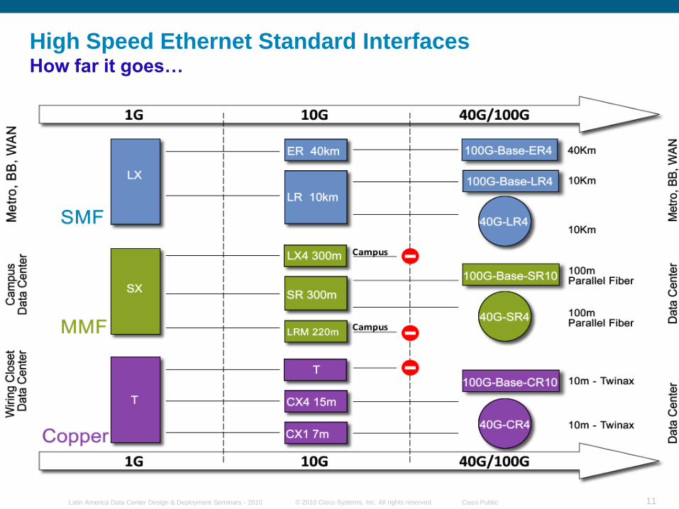
High Speed Ethernet Standard InterfacesHow far it goes…
© 2010 Cisco Systems, Inc. All rights reserved. Cisco PublicLatin America Data Center Design & Deployment Seminars - 2010 12
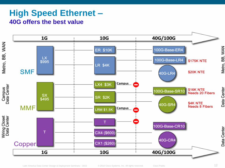
High Speed Ethernet –40G offers the best value
© 2010 Cisco Systems, Inc. All rights reserved. Cisco PublicLatin America Data Center Design & Deployment Seminars - 2010 13
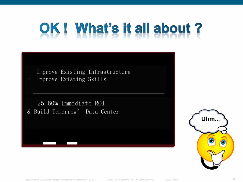
Improve Existing Infrastructure+ Improve Existing Skills
25-60% Immediate ROI& Build Tomorrow’ Data Center
Uhm...
© 2010 Cisco Systems, Inc. All rights reserved. Cisco PublicLatin America Data Center Design & Deployment Seminars - 2010 14
Access LayerService Chain
VM Mobility
VM Mobility
Information Layer
Service Chain
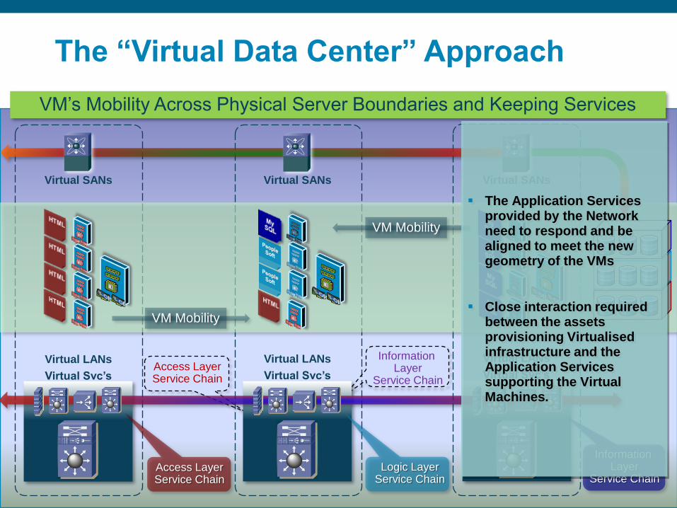
Virtual SANs Virtual SANs Virtual SANs
Information Layer
Service Chain
Virtual LANs
Virtual Svc’s
Virtual LANs
Virtual Svc’s
Virtual LANs
Virtual Svc’s
Logic LayerService Chain
Access LayerService Chain
VM‟s Mobility Across Physical Server Boundaries and Keeping Services
The Application Services provided by the Network need to respond and be aligned to meet the new geometry of the VMs
Close interaction required between the assets provisioning Virtualised infrastructure and the Application Services supporting the Virtual Machines.
The ―Virtual Data Center‖ Approach
© 2010 Cisco Systems, Inc. All rights reserved. Cisco PublicLatin America Data Center Design & Deployment Seminars - 2010 15
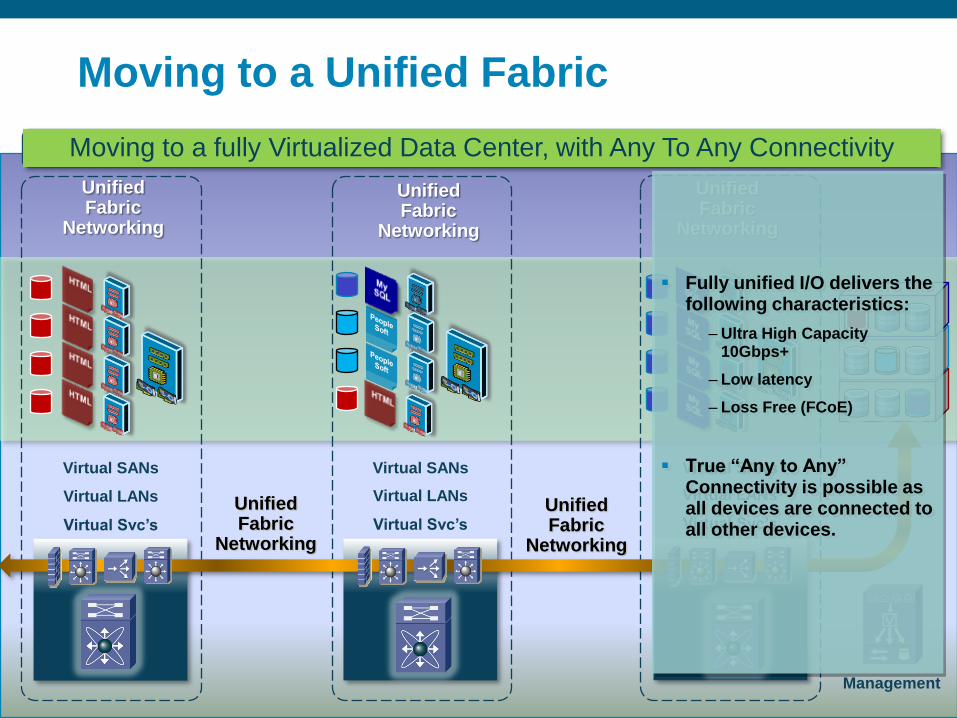
Virtual LANs
Virtual Svc’s
Virtual LANs
Virtual Svc’s
Virtual LANs
Virtual Svc’s
Virtual SANs Virtual SANs Virtual SANs
Moving to a fully Virtualized Data Center, with Any To Any Connectivity
Management
Unified Fabric
Networking
Unified Fabric
Networking
Unified Fabric
Networking
Unified Fabric
Networking
Unified Fabric
Networking
Moving to a Unified Fabric
Fully unified I/O delivers the following characteristics:
– Ultra High Capacity 10Gbps+
– Low latency
– Loss Free (FCoE)
True ―Any to Any‖ Connectivity is possible as all devices are connected to all other devices.
© 2010 Cisco Systems, Inc. All rights reserved. Cisco PublicLatin America Data Center Design & Deployment Seminars - 2010 16
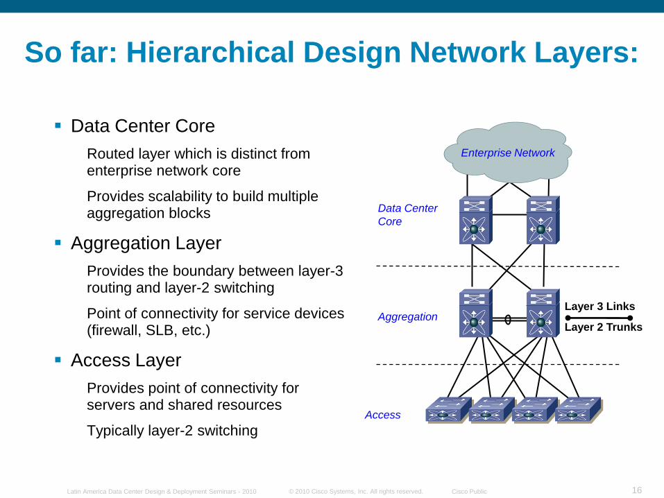
Data Center
Core
Enterprise Network
Aggregation
Access
Layer 3 Links
Layer 2 Trunks
So far: Hierarchical Design Network Layers:
Data Center Core
Routed layer which is distinct from enterprise network core
Provides scalability to build multiple aggregation blocks
Aggregation Layer
Provides the boundary between layer-3 routing and layer-2 switching
Point of connectivity for service devices (firewall, SLB, etc.)
Access Layer
Provides point of connectivity for servers and shared resources
Typically layer-2 switching
© 2010 Cisco Systems, Inc. All rights reserved. Cisco PublicLatin America Data Center Design & Deployment Seminars - 2010 17
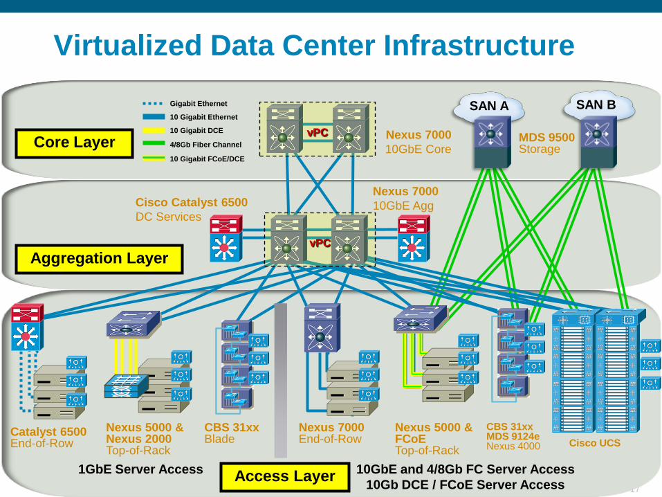
Virtualized Data Center Infrastructure
CBS 31xx Blade
Nexus 5000 & Nexus 2000Top-of-Rack
Nexus 7000End-of-Row
Nexus 5000 &FCoETop-of-Rack
Access Layer
Nexus 7000
10GbE Agg
MDS 9500Storage
Catalyst 6500End-of-Row
CBS 31xxMDS 9124eNexus 4000
10GbE and 4/8Gb FC Server Access
10Gb DCE / FCoE Server Access
1GbE Server Access
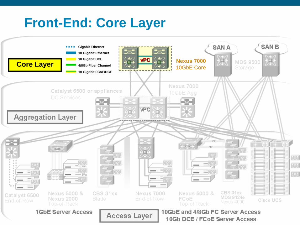
Nexus 7000
10GbE Core
Gigabit Ethernet
10 Gigabit Ethernet
10 Gigabit DCE
4/8Gb Fiber Channel
10 Gigabit FCoE/DCE
SAN BSAN A
Cisco UCS
Cisco Catalyst 6500
DC Services
Aggregation LayervPC
vPCCore Layer
© 2010 Cisco Systems, Inc. All rights reserved. Cisco PublicLatin America Data Center Design & Deployment Seminars - 2010 18
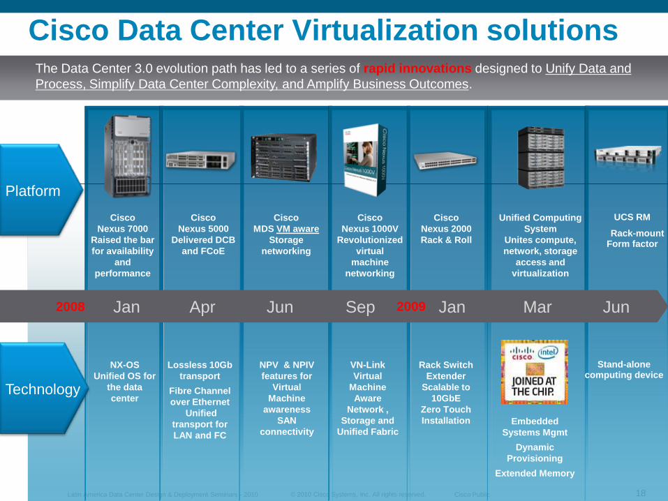
Cisco Data Center Virtualization solutions
Platform
Technology
Cisco
Nexus 7000
Raised the bar
for availability
and
performance
Cisco
Nexus 5000
Delivered DCB
and FCoE
Cisco
Nexus 1000V
Revolutionized
virtual
machine
networking
Cisco
Nexus 2000
Rack & Roll
Unified Computing
System
Unites compute,
network, storage
access and
virtualization
NX-OS
Unified OS for
the data
center
Lossless 10Gb
transport
Fibre Channel
over Ethernet
Unified
transport for
LAN and FC
VN-Link
Virtual
Machine
Aware
Network ,
Storage and
Unified Fabric
Rack Switch
Extender
Scalable to
10GbE
Zero Touch
Installation Embedded
Systems Mgmt
Dynamic
Provisioning
Extended Memory
UCS RM
Rack-mount Form factor
Stand-alone computing device
Jan Apr Sep 2009 Jan Mar2008 Jun
The Data Center 3.0 evolution path has led to a series of rapid innovations designed to Unify Data and
Process, Simplify Data Center Complexity, and Amplify Business Outcomes.
Cisco
MDS VM aware
Storage
networking
NPV & NPIV
features for
Virtual
Machine
awareness
SAN
connectivity
Jun
© 2010 Cisco Systems, Inc. All rights reserved. Cisco PublicLatin America Data Center Design & Deployment Seminars - 2010 19
© 2010 Cisco Systems, Inc. All rights reserved. Cisco PublicLatin America Data Center Design & Deployment Seminars - 2010 20
“The significant problems we have cannot
be solved at the same level of thinking with
which we created them.”
Albert Einstein
© 2010 Cisco Systems, Inc. All rights reserved. Cisco PublicLatin America Data Center Design & Deployment Seminars - 2010 21
Well, this may be an option to some people
© 2010 Cisco Systems, Inc. All rights reserved. Cisco PublicLatin America Data Center Design & Deployment Seminars - 2010 22
What Makes Designing Networks forthe Data Center Different?
Extremely high density of end nodes and switching
Power, cooling, and space management constraints
Mobility of servers a requirement, without DHCP
The most critical shared end-nodes in the network: high availability required with very small service windows
Multiple logical multi-tier application architectures built on top of a common physical topology
Server load balancing, firewall, other services required
© 2010 Cisco Systems, Inc. All rights reserved. Cisco PublicLatin America Data Center Design & Deployment Seminars - 2010 23
Traditional Data Center ServerAccess Models
End-of-Row (EoR)
High density chassis switch at end or middle ofa row of racks, fewer overall switches
Provides port scalability and local switching, maycreate cable management challenges
Top-of-Rack (ToR)
Small fixed or modular switch at the top ofeach rack, more devices to manage
Significantly reduces bulk of cable by keepingconnections local to rack or adjacent rack
Integrated Switching
Switches integrated directly into blade server chassis enclosure
Maintaining feature consistency is critical to network management, sometimes pass-through modules are used
© 2010 Cisco Systems, Inc. All rights reserved. Cisco PublicLatin America Data Center Design & Deployment Seminars - 2010 24
Data Center
Core
Enterprise Network
Aggregation
Access
Client-Server
FlowMulti-tier,
Server-to-Server
Flow
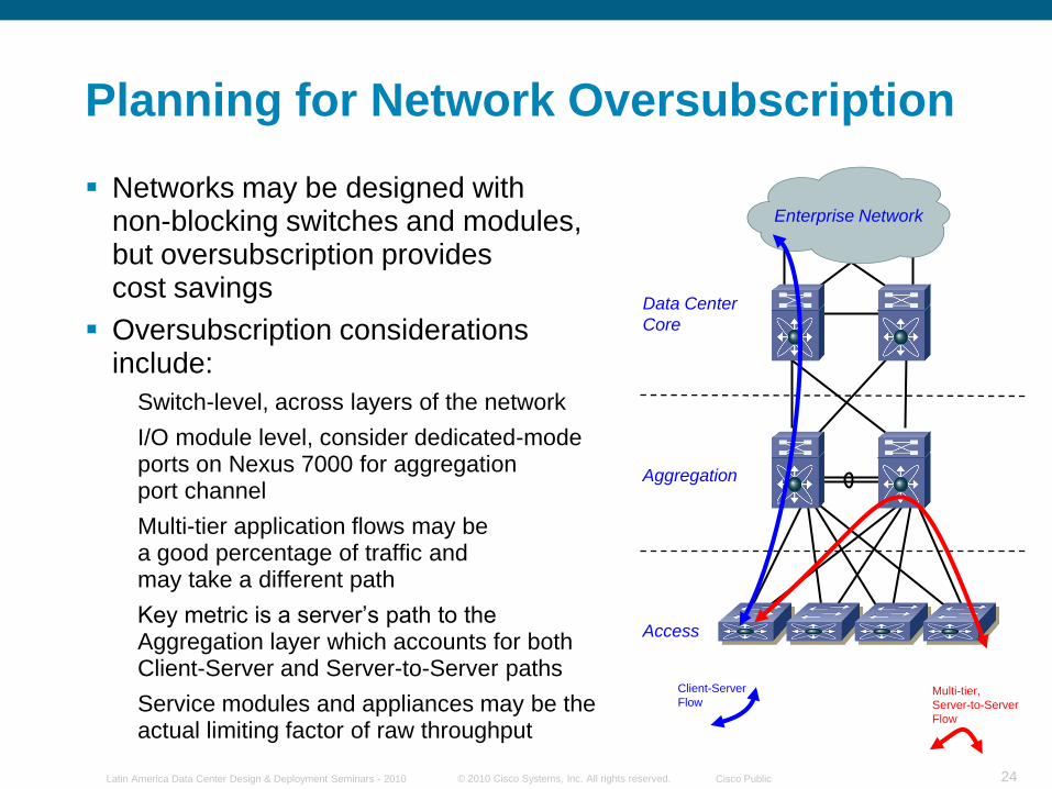
Planning for Network Oversubscription
Networks may be designed withnon-blocking switches and modules, but oversubscription providescost savings
Oversubscription considerations include:
Switch-level, across layers of the network
I/O module level, consider dedicated-mode ports on Nexus 7000 for aggregationport channel
Multi-tier application flows may bea good percentage of traffic andmay take a different path
Key metric is a server‟s path to the Aggregation layer which accounts for both Client-Server and Server-to-Server paths
Service modules and appliances may be the actual limiting factor of raw throughput
© 2010 Cisco Systems, Inc. All rights reserved. Cisco PublicLatin America Data Center Design & Deployment Seminars - 2010 25
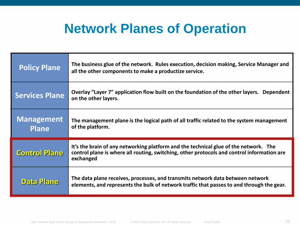
Network Planes of Operation
Policy Plane The business glue of the network. Rules execution, decision making, Service Manager and all the other components to make a productize service.
Services Plane Overlay “Layer 7” application flow built on the foundation of the other layers. Dependent on the other layers.
Management Plane
The management plane is the logical path of all traffic related to the system management of the platform.
Control PlaneIt’s the brain of any networking platform and the technical glue of the network. The control plane is where all routing, switching, other protocols and control information are exchanged
Data Plane The data plane receives, processes, and transmits network data between network elements, and represents the bulk of network traffic that passes to and through the gear.
© 2010 Cisco Systems, Inc. All rights reserved. Cisco PublicLatin America Data Center Design & Deployment Seminars - 2010 26
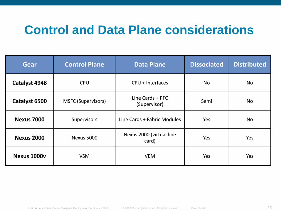
Control and Data Plane considerations
Gear Control Plane Data Plane Dissociated Distributed
Catalyst 4948 CPU CPU + Interfaces No No
Catalyst 6500 MSFC (Supervisors)Line Cards + PFC
(Supervisor)Semi No
Nexus 7000 Supervisors Line Cards + Fabric Modules Yes No
Nexus 2000 Nexus 5000Nexus 2000 (virtual line
card)Yes Yes
Nexus 1000v VSM VEM Yes Yes
© 2010 Cisco Systems, Inc. All rights reserved. Cisco PublicLatin America Data Center Design & Deployment Seminars - 2010 27
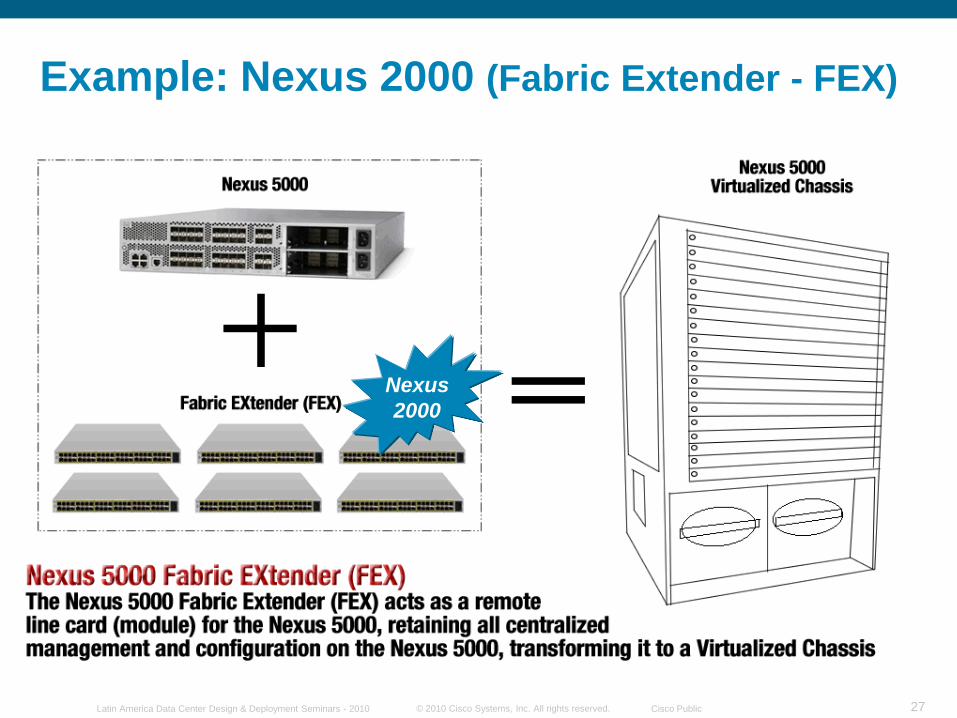
Example: Nexus 2000 (Fabric Extender - FEX)
Nexus
2000
© 2010 Cisco Systems, Inc. All rights reserved. Cisco PublicLatin America Data Center Design & Deployment Seminars - 2010 28
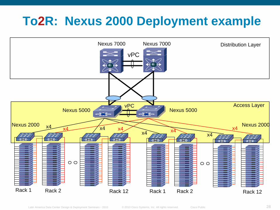
To2R: Nexus 2000 Deployment example
Rack 1 Rack 2
Access Layer
Rack 1 Rack 2Rack 1 Rack 2
Distribution LayerNexus 7000 Nexus 7000
Nexus 5000 Nexus 5000
Nexus 2000 Nexus 2000 x4 x4x4x4
x4 x4x4x4
Rack 1 Rack 2Rack 1 Rack 2 Rack 12 Rack 1 Rack 2 Rack 12
vPC
vPC
© 2010 Cisco Systems, Inc. All rights reserved. Cisco PublicLatin America Data Center Design & Deployment Seminars - 2010 29
© 2010 Cisco Systems, Inc. All rights reserved. Cisco PublicLatin America Data Center Design & Deployment Seminars - 2010 30
LAN
Server
Access
SAN
IP Data and Storage
Aggregation
Ethernet
Fibre Channel
Ethernet plus FCoE
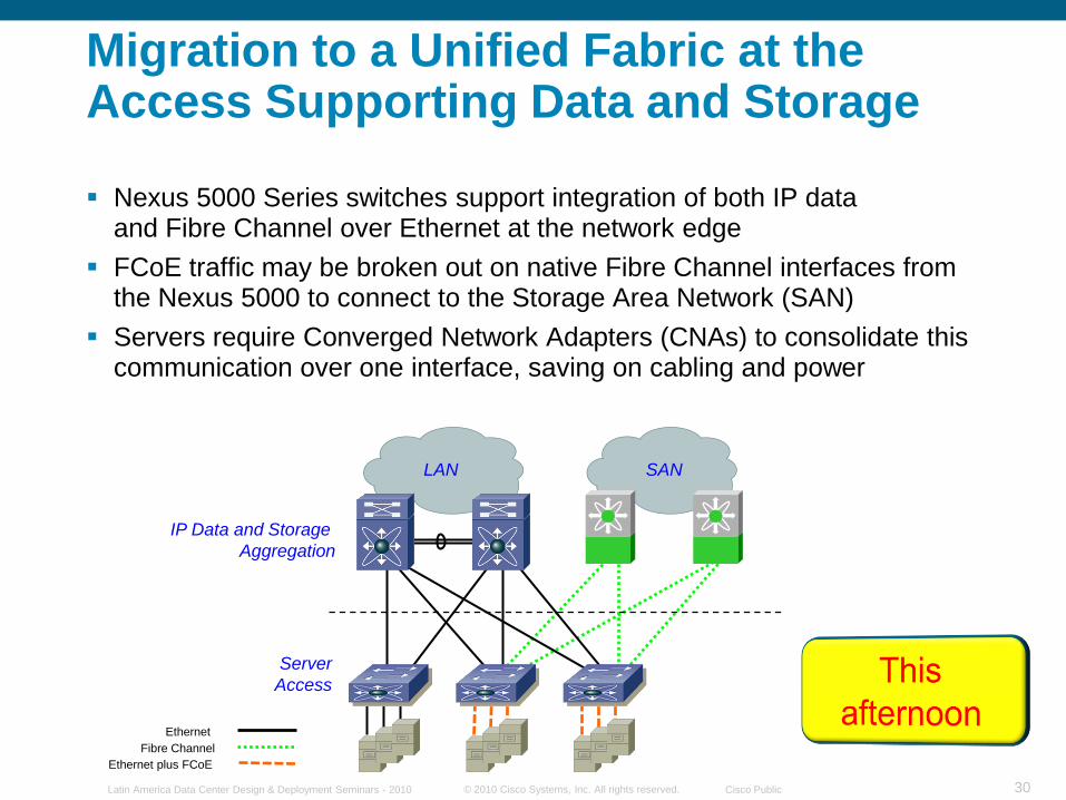
Migration to a Unified Fabric at the Access Supporting Data and Storage
Nexus 5000 Series switches support integration of both IP dataand Fibre Channel over Ethernet at the network edge
FCoE traffic may be broken out on native Fibre Channel interfaces from the Nexus 5000 to connect to the Storage Area Network (SAN)
Servers require Converged Network Adapters (CNAs) to consolidate this communication over one interface, saving on cabling and power
© 2010 Cisco Systems, Inc. All rights reserved. Cisco PublicLatin America Data Center Design & Deployment Seminars - 2010 31
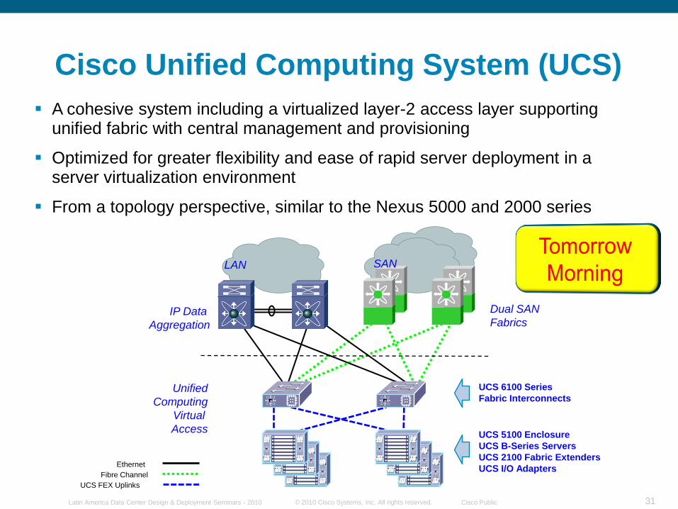
A cohesive system including a virtualized layer-2 access layer supporting unified fabric with central management and provisioning
Optimized for greater flexibility and ease of rapid server deployment in a server virtualization environment
From a topology perspective, similar to the Nexus 5000 and 2000 series
Cisco Unified Computing System (UCS)
LAN
Unified
Computing
Virtual
Access
SAN
IP Data
Aggregation
Ethernet
Fibre Channel
UCS FEX Uplinks
Dual SAN
Fabrics
UCS 6100 Series
Fabric Interconnects
UCS 5100 Enclosure
UCS B-Series Servers
UCS 2100 Fabric Extenders
UCS I/O Adapters
© 2010 Cisco Systems, Inc. All rights reserved. Cisco PublicLatin America Data Center Design & Deployment Seminars - 2010 32
Front-End: Core Layer
Gigabit Ethernet
10 Gigabit Ethernet
10 Gigabit DCE
4/8Gb Fiber Channel
10 Gigabit FCoE/DCE
Nexus 7000
10GbE Core
vPCCore Layer
© 2010 Cisco Systems, Inc. All rights reserved. Cisco PublicLatin America Data Center Design & Deployment Seminars - 2010 33
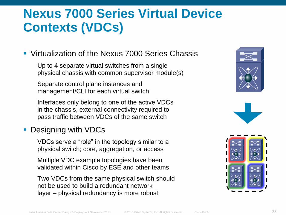
Nexus 7000 Series Virtual Device Contexts (VDCs)
Virtualization of the Nexus 7000 Series Chassis
Up to 4 separate virtual switches from a singlephysical chassis with common supervisor module(s)
Separate control plane instances andmanagement/CLI for each virtual switch
Interfaces only belong to one of the active VDCsin the chassis, external connectivity required topass traffic between VDCs of the same switch
Designing with VDCs
VDCs serve a “role” in the topology similar to aphysical switch; core, aggregation, or access
Multiple VDC example topologies have beenvalidated within Cisco by ESE and other teams
Two VDCs from the same physical switch shouldnot be used to build a redundant networklayer – physical redundancy is more robust
© 2010 Cisco Systems, Inc. All rights reserved. Cisco PublicLatin America Data Center Design & Deployment Seminars - 2010 34
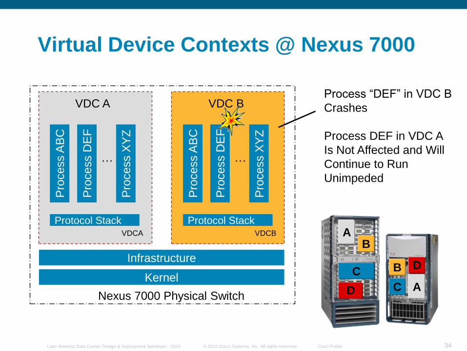
Virtual Device Contexts @ Nexus 7000
Kernel
Infrastructure
Protocol StackVDCA
Nexus 7000 Physical Switch
VDC A
Pro
cess A
BC
Pro
cess D
EF
Pro
cess X
YZ
…
Protocol StackVDCB
VDC B
Pro
cess A
BC
Pro
cess D
EF
Pro
cess X
YZ
…
Process “DEF” in VDC B
Crashes
Process DEF in VDC A
Is Not Affected and Will
Continue to Run
Unimpeded
A
B
CD
AB
CD
© 2010 Cisco Systems, Inc. All rights reserved. Cisco PublicLatin America Data Center Design & Deployment Seminars - 2010 35
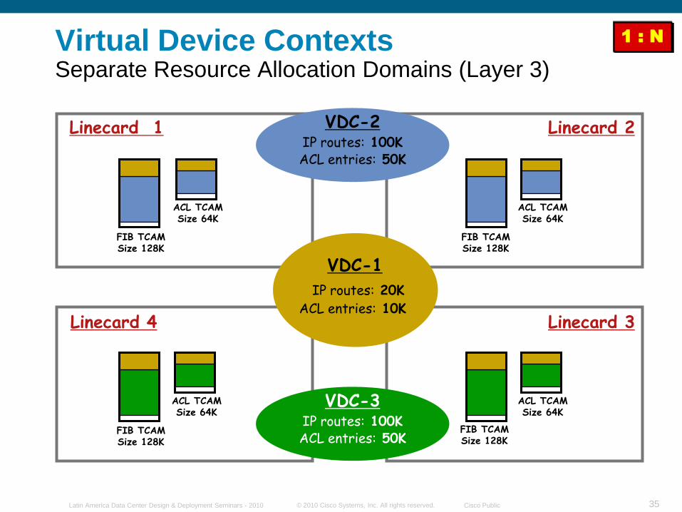
FIB TCAMSize 128K
ACL TCAMSize 64K
FIB TCAMSize 128K
FIB TCAMSize 128K
FIB TCAMSize 128K
VDC-1
IP routes: 20K
ACL entries: 10K
VDC-2IP routes: 100KACL entries: 50K
ACL TCAMSize 64K
VDC-3IP routes: 100KACL entries: 50K
ACL TCAMSize 64K
ACL TCAMSize 64K
Linecard 1 Linecard 2
Linecard 3Linecard 4
1 : NVirtual Device Contexts Separate Resource Allocation Domains (Layer 3)
© 2010 Cisco Systems, Inc. All rights reserved. Cisco PublicLatin America Data Center Design & Deployment Seminars - 2010 36
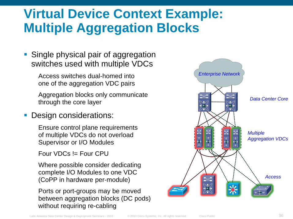
Data Center Core
Multiple
Aggregation VDCs
Access
Enterprise Network
Virtual Device Context Example:Multiple Aggregation Blocks
Single physical pair of aggregation switches used with multiple VDCs
Access switches dual-homed intoone of the aggregation VDC pairs
Aggregation blocks only communicate through the core layer
Design considerations:
Ensure control plane requirementsof multiple VDCs do not overload Supervisor or I/O Modules
Four VDCs != Four CPU
Where possible consider dedicating complete I/O Modules to one VDC(CoPP in hardware per-module)
Ports or port-groups may be moved between aggregation blocks (DC pods) without requiring re-cabling
© 2010 Cisco Systems, Inc. All rights reserved. Cisco PublicLatin America Data Center Design & Deployment Seminars - 2010 37
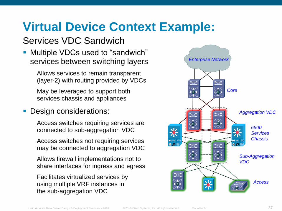
Core
Aggregation VDC
Access
Sub-Aggregation
VDC
6500
Services
Chassis
Enterprise Network
Virtual Device Context Example:
Multiple VDCs used to “sandwich” services between switching layers
Allows services to remain transparent (layer-2) with routing provided by VDCs
May be leveraged to support bothservices chassis and appliances
Design considerations:
Access switches requiring services are connected to sub-aggregation VDC
Access switches not requiring servicesmay be connected to aggregation VDC
Allows firewall implementations not toshare interfaces for ingress and egress
Facilitates virtualized services byusing multiple VRF instances inthe sub-aggregation VDC
Services VDC Sandwich
© 2010 Cisco Systems, Inc. All rights reserved. Cisco PublicLatin America Data Center Design & Deployment Seminars - 2010 38
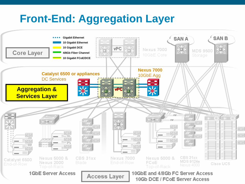
Gigabit Ethernet
10 Gigabit Ethernet
10 Gigabit DCE
4/8Gb Fiber Channel
10 Gigabit FCoE/DCE
Aggregation &
Services Layer
Nexus 7000
10GbE AggCatalyst 6500 or appliances
DC Services
vPC
Front-End: Aggregation Layer
Catalyst 6500 or appliances
DC Services
© 2010 Cisco Systems, Inc. All rights reserved. Cisco PublicLatin America Data Center Design & Deployment Seminars - 2010 39
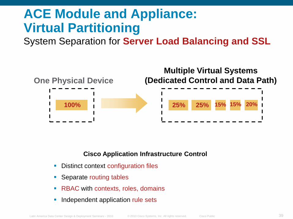
One Physical Device
Multiple Virtual Systems
(Dedicated Control and Data Path)
ACE Module and Appliance: Virtual Partitioning
Distinct context configuration files
Separate routing tables
RBAC with contexts, roles, domains
Independent application rule sets
25% 25% 20%15%15%100%
Cisco Application Infrastructure Control
System Separation for Server Load Balancing and SSL
© 2010 Cisco Systems, Inc. All rights reserved. Cisco PublicLatin America Data Center Design & Deployment Seminars - 2010 40
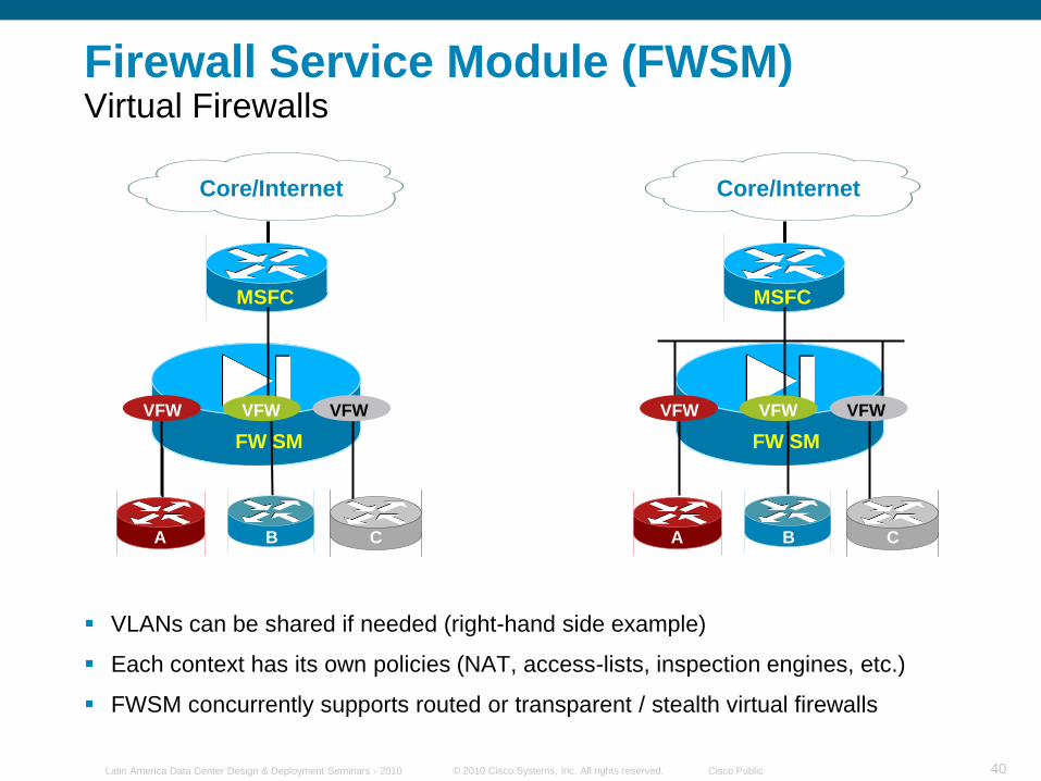
Firewall Service Module (FWSM)Virtual Firewalls
VLANs can be shared if needed (right-hand side example)
Each context has its own policies (NAT, access-lists, inspection engines, etc.)
FWSM concurrently supports routed or transparent / stealth virtual firewalls
Core/Internet
FW SM
VFW VFW VFW
MSFC
Core/Internet
FW SM
VFW VFW VFW
MSFC
A B C A B C
© 2010 Cisco Systems, Inc. All rights reserved. Cisco PublicLatin America Data Center Design & Deployment Seminars - 2010 41
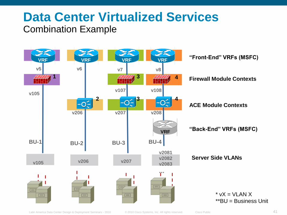
Data Center Virtualized ServicesCombination Example
v5
v105
v6 v7
v107
v2081
v2082
v2083
...
v206 v207
v206
BU-4BU-2 BU-3
v105
v108
BU-1
1
2
3
4
* vX = VLAN X
**BU = Business Unit
VRF
VRF
VRFVRFVRF
v208
―Front-End‖ VRFs (MSFC)
Firewall Module Contexts
ACE Module Contexts
―Back-End‖ VRFs (MSFC)
Server Side VLANs
v207
3
4
v8
© 2010 Cisco Systems, Inc. All rights reserved. Cisco PublicLatin America Data Center Design & Deployment Seminars - 2010 42
Data Center
Core
Aggregation
Access
Services
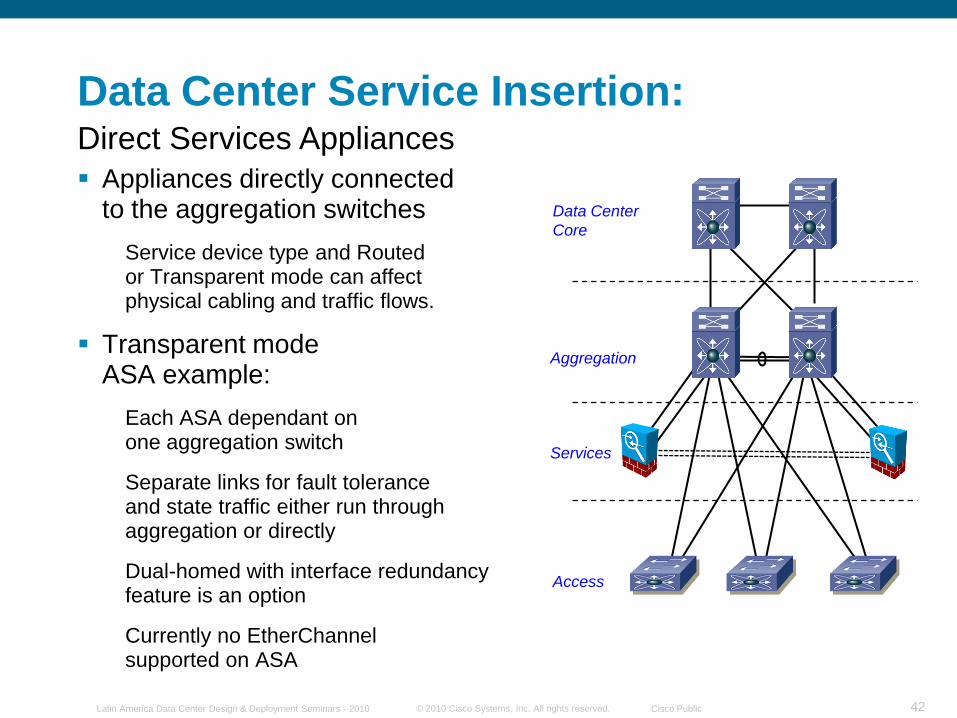
Data Center Service Insertion:
Appliances directly connectedto the aggregation switches
Service device type and Routedor Transparent mode can affectphysical cabling and traffic flows.
Transparent modeASA example:
Each ASA dependant onone aggregation switch
Separate links for fault toleranceand state traffic either run through aggregation or directly
Dual-homed with interface redundancy feature is an option
Currently no EtherChannelsupported on ASA
Direct Services Appliances
© 2010 Cisco Systems, Inc. All rights reserved. Cisco PublicLatin America Data Center Design & Deployment Seminars - 2010 43
Data Center
Core
Aggregation
Access
Services
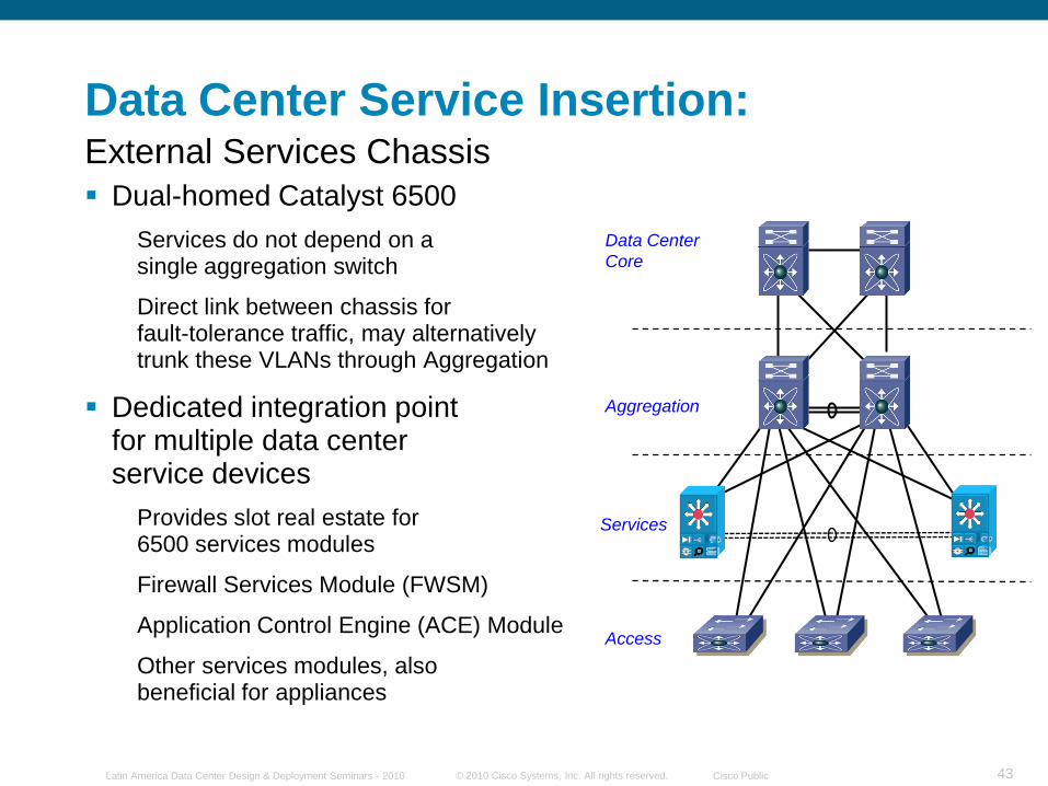
Data Center Service Insertion:
Dual-homed Catalyst 6500
Services do not depend on asingle aggregation switch
Direct link between chassis forfault-tolerance traffic, may alternatively trunk these VLANs through Aggregation
Dedicated integration pointfor multiple data centerservice devices
Provides slot real estate for6500 services modules
Firewall Services Module (FWSM)
Application Control Engine (ACE) Module
Other services modules, alsobeneficial for appliances
External Services Chassis
© 2010 Cisco Systems, Inc. All rights reserved. Cisco PublicLatin America Data Center Design & Deployment Seminars - 2010 44
Enterprise Network
VLAN 161
VLANs
171,172
VLAN 163
VLAN 170
Web Server
Farm
VLAN 162
Transparent
FWSM Context
Transparent
ACE Context
Aggregation
VDC
Services
Sub-Aggregation
VDC
Access
VLAN 180
Data Center
Core
Client-Server
Flow
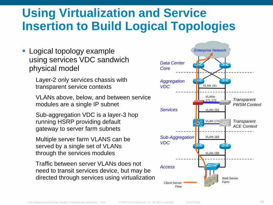
Using Virtualization and Service Insertion to Build Logical Topologies
Logical topology exampleusing services VDC sandwich physical model
Layer-2 only services chassis with transparent service contexts
VLANs above, below, and between service modules are a single IP subnet
Sub-aggregation VDC is a layer-3 hop running HSRP providing defaultgateway to server farm subnets
Multiple server farm VLANS can beserved by a single set of VLANsthrough the services modules
Traffic between server VLANs does not need to transit services device, but may be directed through services using virtualization
© 2010 Cisco Systems, Inc. All rights reserved. Cisco PublicLatin America Data Center Design & Deployment Seminars - 2010 45
FT VLANs
Enterprise Network
VLAN 161
VLAN 163
FT VLAN
Web/App
Server Farm
Transparent
FWSM Contexts
Transparent
ACE Contexts
VRF VRF
VRF Instances
Aggregation VDC
Services
Sub-Agg
VDC
Access
VLAN 180
Data Center Core
VLAN 153
VLAN 152
VRF VRF
VLAN 181
FT VLANs
FT VLAN
DB Server
Cluster
VLAN 151
Client-Server Flow
Server to Server Flow
VLAN 162
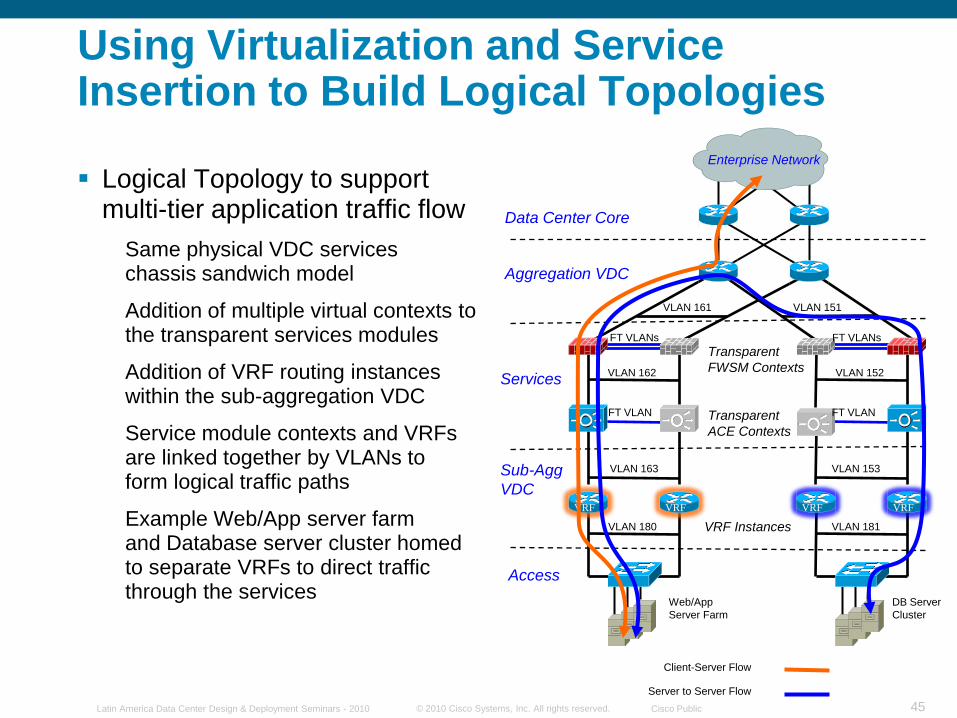
Logical Topology to support multi-tier application traffic flow
Same physical VDC serviceschassis sandwich model
Addition of multiple virtual contexts to the transparent services modules
Addition of VRF routing instances within the sub-aggregation VDC
Service module contexts and VRFs are linked together by VLANs toform logical traffic paths
Example Web/App server farmand Database server cluster homedto separate VRFs to direct traffic through the services
Using Virtualization and Service Insertion to Build Logical Topologies
© 2010 Cisco Systems, Inc. All rights reserved. Cisco PublicLatin America Data Center Design & Deployment Seminars - 2010 46
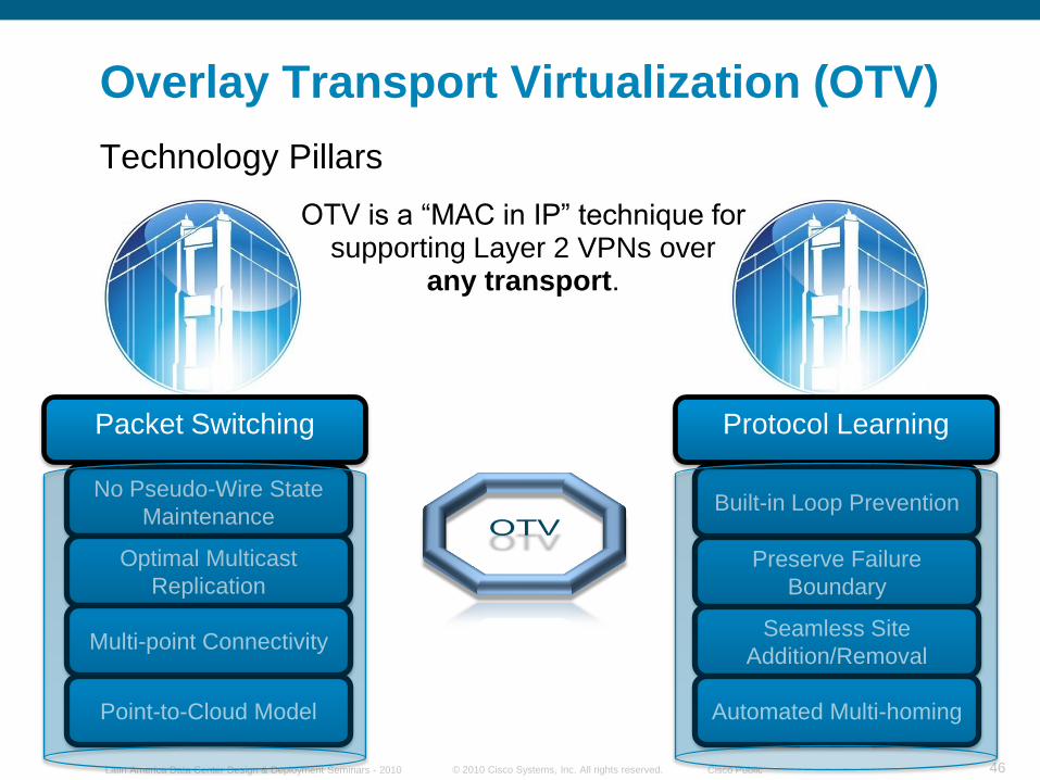
Overlay Transport Virtualization (OTV)
Technology Pillars
Protocol Learning
Built-in Loop Prevention
Preserve Failure
Boundary
Seamless Site
Addition/Removal
Automated Multi-homing
Packet Switching
No Pseudo-Wire State
Maintenance
Optimal Multicast
Replication
OTV is a “MAC in IP” technique for supporting Layer 2 VPNs over
any transport.
Multi-point Connectivity
Point-to-Cloud Model
© 2010 Cisco Systems, Inc. All rights reserved. Cisco PublicLatin America Data Center Design & Deployment Seminars - 2010 47
Eth 4
Eth 3
MAC TABLE
VLAN MAC IF
100 MAC 1 Eth 2
100 MAC 2 Eth 1
100 MAC 3 IP B
100 MAC 4 IP B
MAC 2
MAC 1
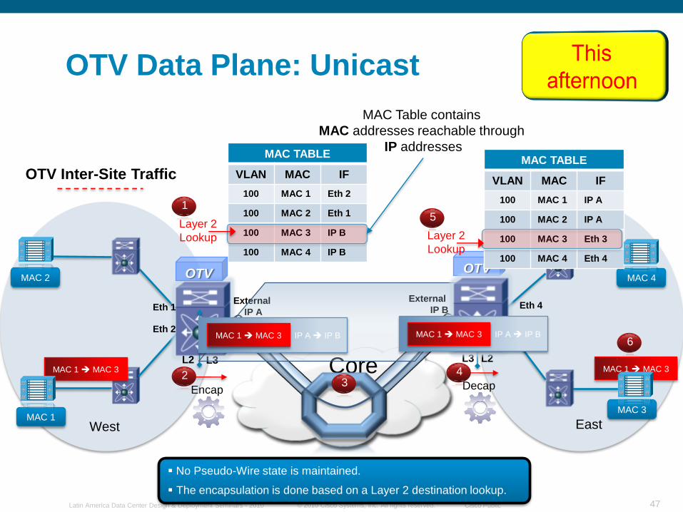
OTV Data Plane: Unicast
Core
MAC 4
MAC 3
OTV
External
IP A
External
IP B
West East
L2 L3 L3 L2
OTV Inter-Site Traffic
MAC Table contains
MAC addresses reachable through
IP addresses
OTV
Encap
2
Layer 2
Lookup
1
No Pseudo-Wire state is maintained.
The encapsulation is done based on a Layer 2 destination lookup.
3 Decap
4 MAC 1 MAC 3
6
MAC TABLE
VLAN MAC IF
100 MAC 1 IP A
100 MAC 2 IP A
100 MAC 3 Eth 3
100 MAC 4 Eth 4
Eth 1
Eth 2
Layer 2
Lookup
5
MAC 1 MAC 3
IP A IP BMAC 1 MAC 3 MAC 1 MAC 3IP A IP BMAC 1 MAC 3
© 2010 Cisco Systems, Inc. All rights reserved. Cisco PublicLatin America Data Center Design & Deployment Seminars - 2010 48
© 2010 Cisco Systems, Inc. All rights reserved. Cisco PublicLatin America Data Center Design & Deployment Seminars - 2010 49
N
NN
RN
Type NetworkN
R Root GuardDesignated
Root port
Alternate
R
N
N
Aggregation
Access
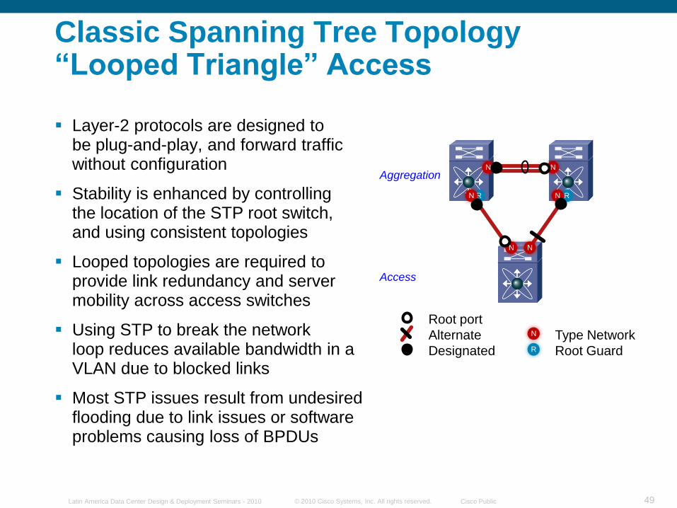
Classic Spanning Tree Topology―Looped Triangle‖ Access
Layer-2 protocols are designed tobe plug-and-play, and forward traffic without configuration
Stability is enhanced by controllingthe location of the STP root switch,and using consistent topologies
Looped topologies are required to provide link redundancy and server mobility across access switches
Using STP to break the networkloop reduces available bandwidth in a VLAN due to blocked links
Most STP issues result from undesired flooding due to link issues or software problems causing loss of BPDUs
© 2010 Cisco Systems, Inc. All rights reserved. Cisco PublicLatin America Data Center Design & Deployment Seminars - 2010 50
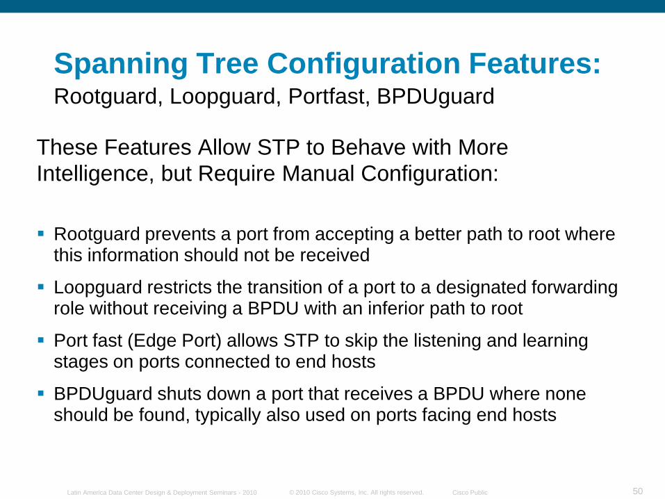
These Features Allow STP to Behave with More
Intelligence, but Require Manual Configuration:
Rootguard prevents a port from accepting a better path to root where this information should not be received
Loopguard restricts the transition of a port to a designated forwarding role without receiving a BPDU with an inferior path to root
Port fast (Edge Port) allows STP to skip the listening and learning stages on ports connected to end hosts
BPDUguard shuts down a port that receives a BPDU where none should be found, typically also used on ports facing end hosts
Spanning Tree Configuration Features:Rootguard, Loopguard, Portfast, BPDUguard
© 2010 Cisco Systems, Inc. All rights reserved. Cisco PublicLatin America Data Center Design & Deployment Seminars - 2010 51
N
NN
RN R
N
N
Network portN
R Root GuardDesignated port
Root port
Alternate port
E Edge port
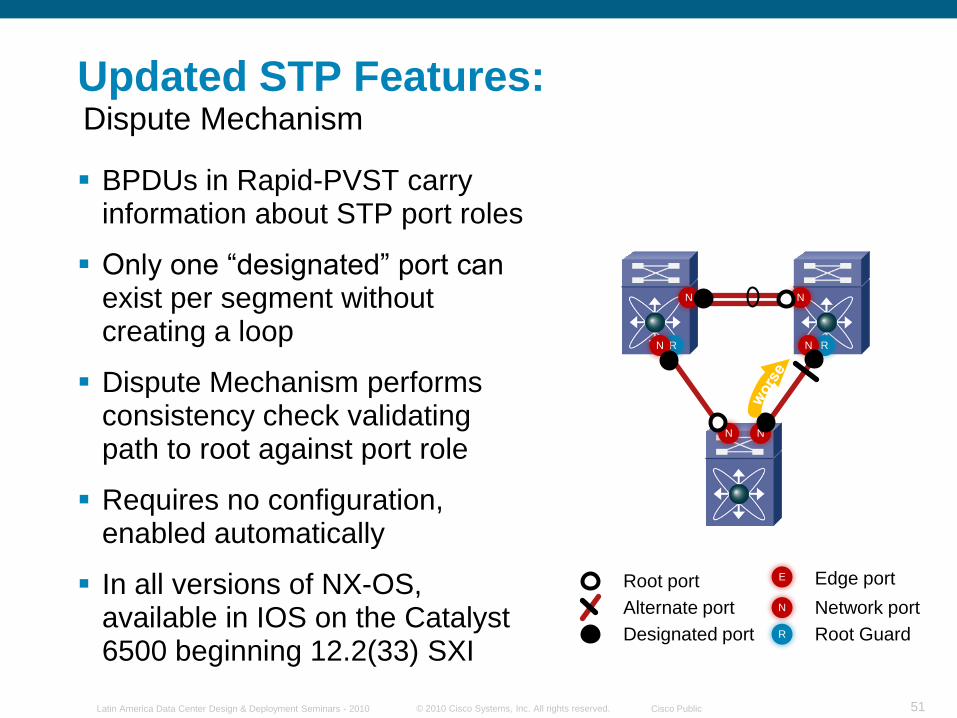
BPDUs in Rapid-PVST carry information about STP port roles
Only one “designated” port can exist per segment without creating a loop
Dispute Mechanism performs consistency check validatingpath to root against port role
Requires no configuration, enabled automatically
In all versions of NX-OS, available in IOS on the Catalyst 6500 beginning 12.2(33) SXI
Updated STP Features:Dispute Mechanism
© 2010 Cisco Systems, Inc. All rights reserved. Cisco PublicLatin America Data Center Design & Deployment Seminars - 2010 52
Network portN
R Root GuardDesignated port
Root port
Alternate port
E Edge port
N
NN
RN R
N
N
E E E
Aggregation
AccessEdge Ports
No BPDUs
Network Ports
All Send BPDUs
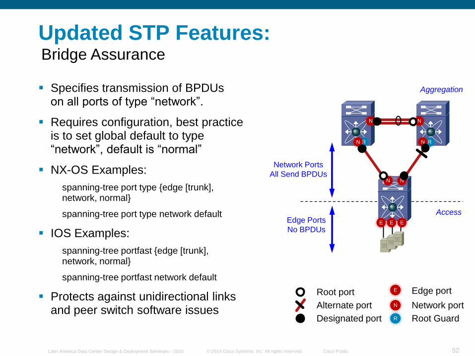
Updated STP Features:Bridge Assurance
Specifies transmission of BPDUson all ports of type “network”.
Requires configuration, best practiceis to set global default to type“network”, default is “normal”
NX-OS Examples:
spanning-tree port type {edge [trunk],network, normal}
spanning-tree port type network default
IOS Examples:
spanning-tree portfast {edge [trunk],network, normal}
spanning-tree portfast network default
Protects against unidirectional linksand peer switch software issues
© 2010 Cisco Systems, Inc. All rights reserved. Cisco PublicLatin America Data Center Design & Deployment Seminars - 2010 53
Aggregation
Access
Data Center
Core B
L
R
N
E
BPDUguard
Loopguard
Rootguard
Network port
Edge port
- Normal port type
B
RR
N N
N N N
N NNN
N N
N N NRRRRRR
--
B
E
B
E
B
E
B
E
Layer 3
Layer 2 (STP + Bridge Assurance)
Layer 2 (STP + BA + Rootguard)
Layer 2 (STP + BPDUguard)
L L
E
Backup
Root
HSRPSTANDBY
Root
HSRPACTIVE
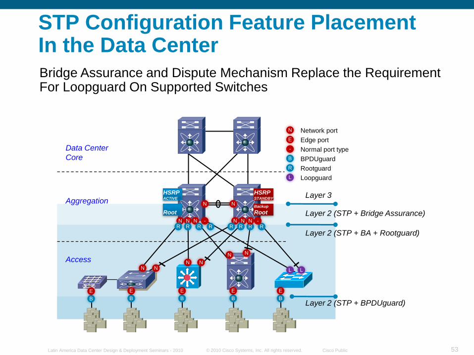
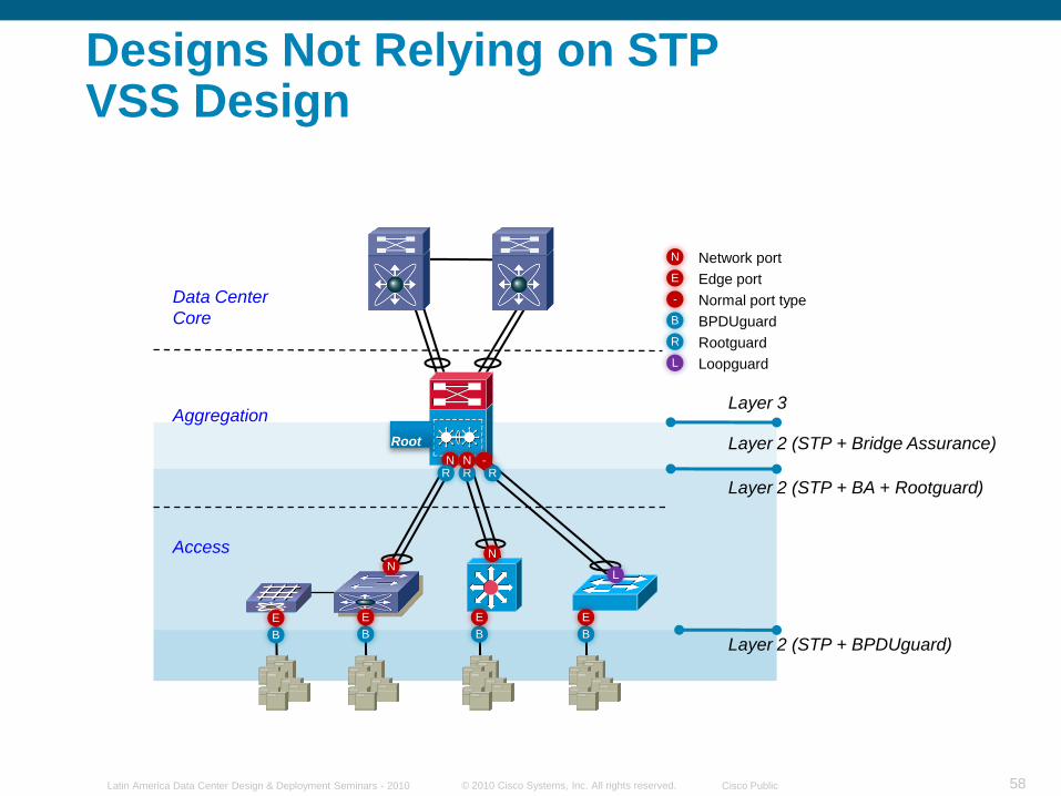
STP Configuration Feature PlacementIn the Data Center
Bridge Assurance and Dispute Mechanism Replace the Requirement For Loopguard On Supported Switches
© 2010 Cisco Systems, Inc. All rights reserved. Cisco PublicLatin America Data Center Design & Deployment Seminars - 2010 54
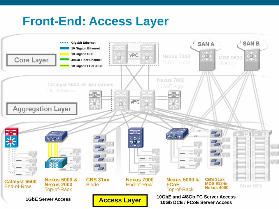
CBS 31xx Blade
Nexus 7000End-of-Row
Access Layer
Catalyst 6500End-of-Row
CBS 31xxMDS 9124eNexus 4000
10GbE and 4/8Gb FC Server Access
10Gb DCE / FCoE Server Access1GbE Server Access
Nexus 5000 & Nexus 2000Top-of-Rack
Nexus 5000 &FCoETop-of-Rack
Gigabit Ethernet
10 Gigabit Ethernet
10 Gigabit DCE
4/8Gb Fiber Channel
10 Gigabit FCoE/DCE
Front-End: Access Layer
© 2010 Cisco Systems, Inc. All rights reserved. Cisco PublicLatin America Data Center Design & Deployment Seminars - 2010 55
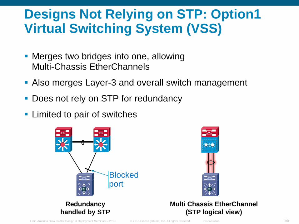
Redundancy
handled by STP
Multi Chassis EtherChannel
(STP logical view)
Blocked port
Merges two bridges into one, allowingMulti-Chassis EtherChannels
Also merges Layer-3 and overall switch management
Does not rely on STP for redundancy
Limited to pair of switches
Designs Not Relying on STP: Option1 Virtual Switching System (VSS)
© 2010 Cisco Systems, Inc. All rights reserved. Cisco PublicLatin America Data Center Design & Deployment Seminars - 2010 56
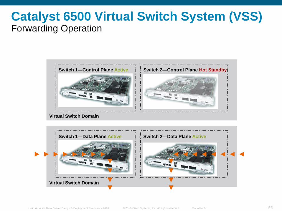
Catalyst 6500 Virtual Switch System (VSS) Forwarding Operation
Virtual Switch Domain
Switch 1—Control Plane Active Switch 2—Control Plane Hot Standby
Virtual Switch Domain
Switch 1—Data Plane Active Switch 2—Data Plane Active
© 2010 Cisco Systems, Inc. All rights reserved. Cisco PublicLatin America Data Center Design & Deployment Seminars - 2010 57
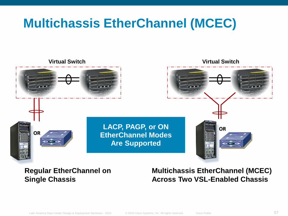
Multichassis EtherChannel (MCEC)
Regular EtherChannel on
Single Chassis
Multichassis EtherChannel (MCEC)
Across Two VSL-Enabled Chassis
Virtual Switch Virtual Switch
LACP, PAGP, or ON EtherChannel Modes
Are Supported
OROR
© 2010 Cisco Systems, Inc. All rights reserved. Cisco PublicLatin America Data Center Design & Deployment Seminars - 2010 58
Aggregation
Access
Data Center
Core B
L
R
N
E
BPDUguard
Loopguard
Rootguard
Network port
Edge port
- Normal port type
BB
E
B
E
B
E
Layer 3
Layer 2 (STP + Bridge Assurance)
Layer 2 (STP + BA + Rootguard)
Layer 2 (STP + BPDUguard)
E
NN
L
RRN N
R-
Root
Designs Not Relying on STP VSS Design
© 2010 Cisco Systems, Inc. All rights reserved. Cisco PublicLatin America Data Center Design & Deployment Seminars - 2010 59
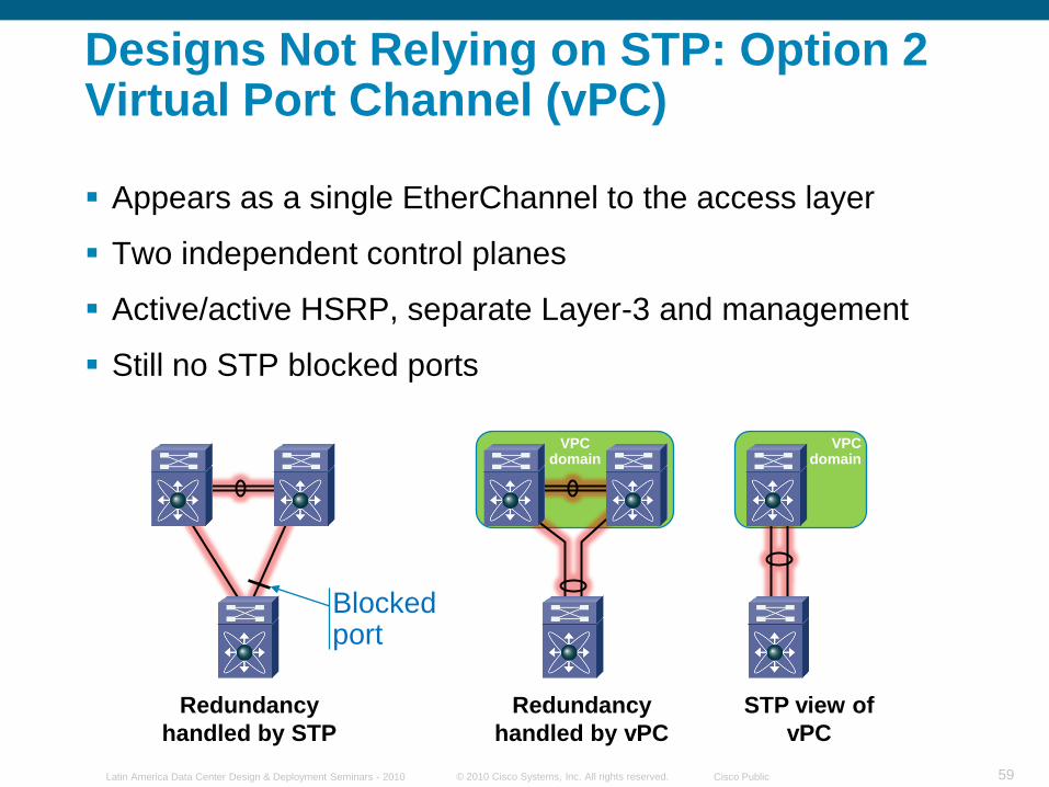
VPCdomain
VPCdomain
Redundancy
handled by STP
Redundancy
handled by vPC
STP view of
vPC
Blocked port
Appears as a single EtherChannel to the access layer
Two independent control planes
Active/active HSRP, separate Layer-3 and management
Still no STP blocked ports
Designs Not Relying on STP: Option 2 Virtual Port Channel (vPC)
© 2010 Cisco Systems, Inc. All rights reserved. Cisco PublicLatin America Data Center Design & Deployment Seminars - 2010 60
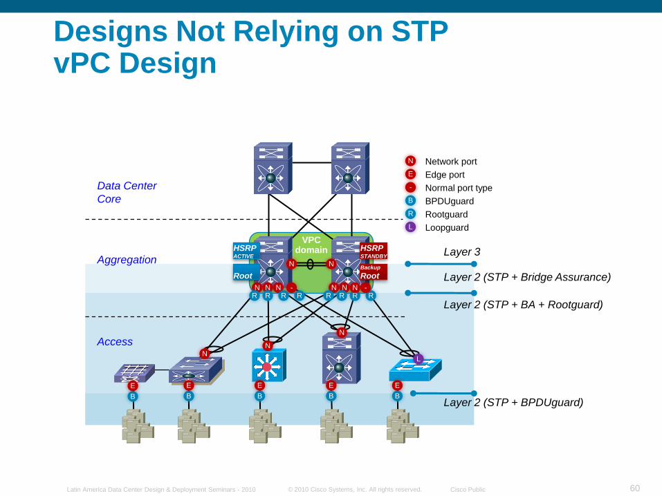
VPCdomain
Aggregation
Access
Data Center
Core B
L
R
N
E
BPDUguard
Loopguard
Rootguard
Network port
Edge port
- Normal port type
B
RR
N N
N N N N N NRRRRRR
--
B
E
B
E
B
E
B
E E
NN
N
L
Layer 3
Layer 2 (STP + Bridge Assurance)
Layer 2 (STP + BA + Rootguard)
Layer 2 (STP + BPDUguard)
Backup
Root
HSRPSTANDBY
Root
HSRPACTIVE
Designs Not Relying on STPvPC Design
© 2010 Cisco Systems, Inc. All rights reserved. Cisco PublicLatin America Data Center Design & Deployment Seminars - 2010 61
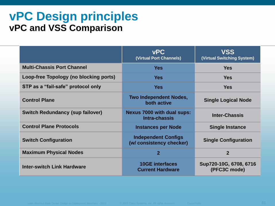
vPC(Virtual Port Channels)
VSS(Virtual Switching System)
Multi-Chassis Port Channel Yes Yes
Loop-free Topology (no blocking ports) Yes Yes
STP as a ―fail-safe‖ protocol only Yes Yes
Control Plane Two Independent Nodes,
both activeSingle Logical Node
Switch Redundancy (sup failover) Nexus 7000 with dual sups:Intra-chassis
Inter-Chassis
Control Plane Protocols Instances per Node Single Instance
Switch ConfigurationIndependent Configs
(w/ consistency checker)Single Configuration
Maximum Physical Nodes 2 2
Inter-switch Link Hardware 10GE interfaces
Current HardwareSup720-10G, 6708, 6716
(PFC3C mode)
vPC Design principles vPC and VSS Comparison
© 2010 Cisco Systems, Inc. All rights reserved. Cisco PublicLatin America Data Center Design & Deployment Seminars - 2010 62
© 2010 Cisco Systems, Inc. All rights reserved. Cisco PublicLatin America Data Center Design & Deployment Seminars - 2010 63
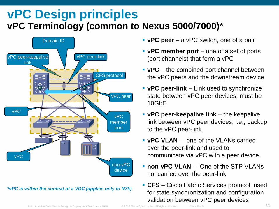
vPC peer – a vPC switch, one of a pair
vPC member port – one of a set of ports
(port channels) that form a vPC
vPC – the combined port channel between
the vPC peers and the downstream device
vPC peer-link – Link used to synchronize
state between vPC peer devices, must be
10GbE
vPC peer-keepalive link – the keepalive
link between vPC peer devices, i.e., backup
to the vPC peer-link
vPC VLAN – one of the VLANs carried
over the peer-link and used to
communicate via vPC with a peer device.
non-vPC VLAN – One of the STP VLANs
not carried over the peer-link
CFS – Cisco Fabric Services protocol, used
for state synchronization and configuration
validation between vPC peer devices
vPC
vPC peer
non-vPC
device
vPC peer-keepalive
link
vPC
member
port
vPCvPC
member
port
CFS protocol
vPC peer-link
vPC Design principlesvPC Terminology (common to Nexus 5000/7000)*
*vPC is within the context of a VDC (applies only to N7k)
Domain ID
© 2010 Cisco Systems, Inc. All rights reserved. Cisco PublicLatin America Data Center Design & Deployment Seminars - 2010 64
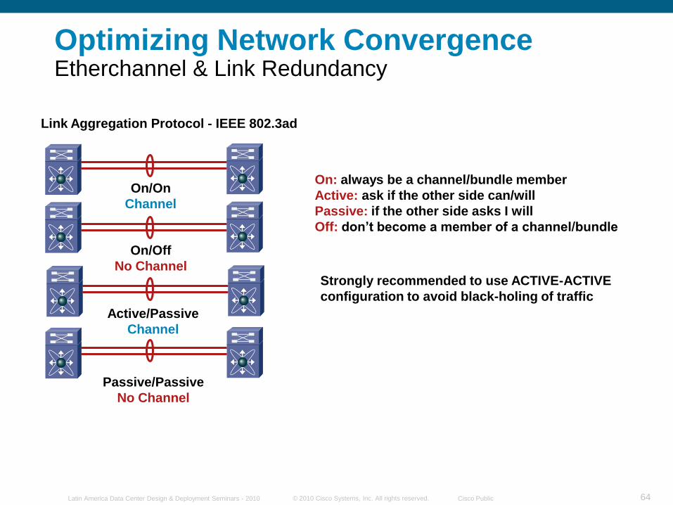
Optimizing Network Convergence Etherchannel & Link Redundancy
On/On
Channel
On/Off
No Channel
Active/Passive
Channel
Passive/Passive
No Channel
Link Aggregation Protocol - IEEE 802.3ad
On: always be a channel/bundle member
Active: ask if the other side can/will
Passive: if the other side asks I will
Off: don’t become a member of a channel/bundle
Strongly recommended to use ACTIVE-ACTIVE
configuration to avoid black-holing of traffic
© 2010 Cisco Systems, Inc. All rights reserved. Cisco PublicLatin America Data Center Design & Deployment Seminars - 2010 65
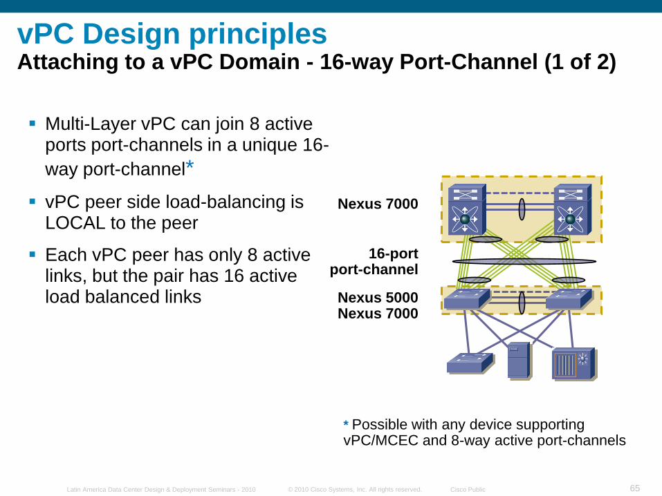
Multi-Layer vPC can join 8 active ports port-channels in a unique 16-
way port-channel*
vPC peer side load-balancing is LOCAL to the peer
Each vPC peer has only 8 active links, but the pair has 16 active load balanced links
Nexus 7000
Nexus 5000Nexus 7000
* Possible with any device supporting vPC/MCEC and 8-way active port-channels
16-portport-channel
vPC Design principlesAttaching to a vPC Domain - 16-way Port-Channel (1 of 2)
© 2010 Cisco Systems, Inc. All rights reserved. Cisco PublicLatin America Data Center Design & Deployment Seminars - 2010 66
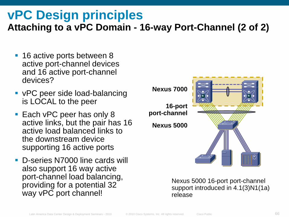
16 active ports between 8 active port-channel devices and 16 active port-channel devices?
vPC peer side load-balancing is LOCAL to the peer
Each vPC peer has only 8 active links, but the pair has 16 active load balanced links to the downstream device supporting 16 active ports
D-series N7000 line cards will also support 16 way active port-channel load balancing, providing for a potential 32 way vPC port channel!
Nexus 7000
Nexus 5000
Nexus 5000 16-port port-channel support introduced in 4.1(3)N1(1a) release
16-portport-channel
vPC Design principlesAttaching to a vPC Domain - 16-way Port-Channel (2 of 2)

© 2010 Cisco Systems, Inc. All rights reserved. Cisco PublicLatin America Data Center Design & Deployment Seminars - 2010 67
Virtual Port Channel - vPCvPC Control Plane - Consistency Check
Both switches in the vPC Domain maintain distinct control planes
CFS provides for protocol state synchronization between both peers (MAC Address table, IGMP state, …)
System configuration must also be kept in sync
Currently a manual process with an automated consistency check to ensure correct network behavior
Two types of interface consistency checks
Type 1 – Will put interfaces into suspend state to prevent invalid forwarding of packets
Type 2 – Error messages to indicate potential for undesired forwarding behavior
© 2010 Cisco Systems, Inc. All rights reserved. Cisco PublicLatin America Data Center Design & Deployment Seminars - 2010 68
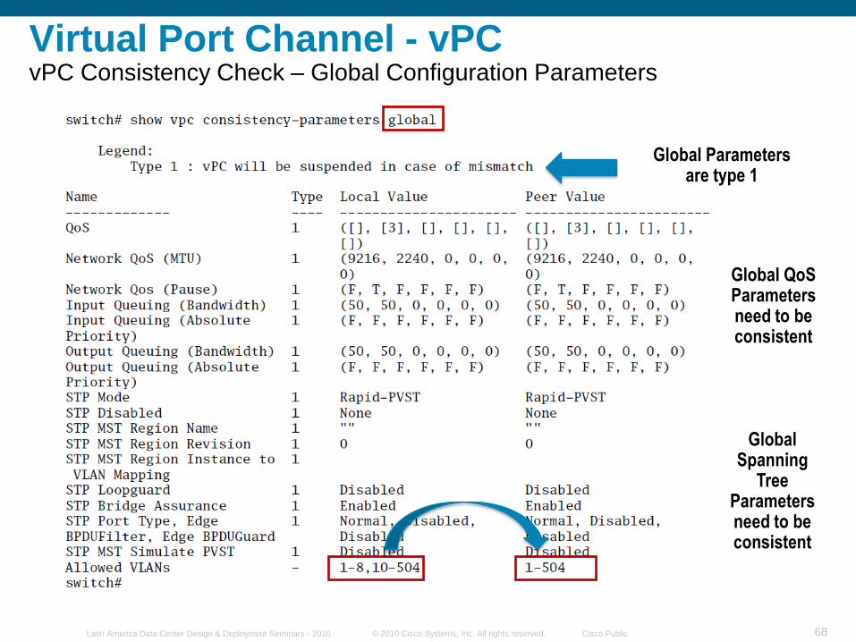
Global Spanning
Tree Parameters need to be consistent
Global QoS Parameters need to be consistent
Virtual Port Channel - vPCvPC Consistency Check – Global Configuration Parameters
Global Parameters are type 1
© 2010 Cisco Systems, Inc. All rights reserved. Cisco PublicLatin America Data Center Design & Deployment Seminars - 2010 69
Virtual Port Channel - vPCvPC„is‟ an Etherchannel
dca-n7k2-vdc2
dc11-5020-1# show running int port-channel 201
version 4.1(3)N1(1)
interface port-channel201
switchport mode trunk
switchport trunk native vlan 100
switchport trunk allowed vlan 100-105
vpc 201
spanning-tree port type network
dc11-5020-2# show running int port-channel 201
version 4.1(3)N1(1)
interface port-channel201
switchport mode trunk
switchport trunk native vlan 100
switchport trunk allowed vlan 100-105
vpc 201
spanning-tree port type network
dca-n7k2-vdc2# sh run interface port-channel 201
version 4.1(5)
interface port-channel201
switchport mode trunk
switchport trunk allowed vlan 100-105
spanning-tree port type network
logging event port link-status
logging event port trunk-status
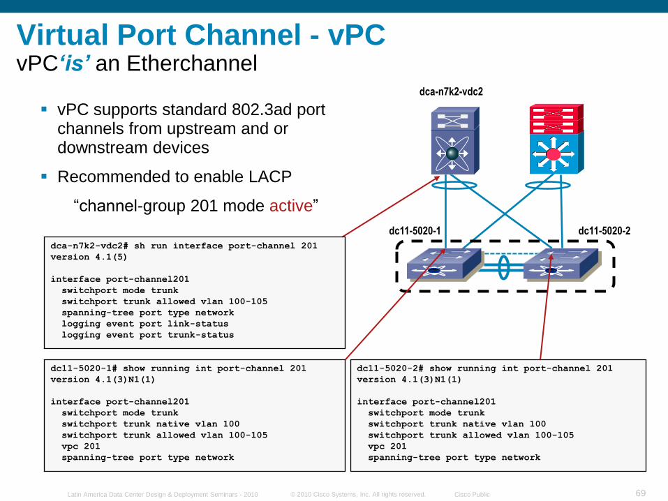
vPC supports standard 802.3ad port channels from upstream and or downstream devices
Recommended to enable LACP
“channel-group 201 mode active”
dc11-5020-2dc11-5020-1
© 2010 Cisco Systems, Inc. All rights reserved. Cisco PublicLatin America Data Center Design & Deployment Seminars - 2010 70
Virtual Port Channel - vPCvPC Control Plane - FHRP
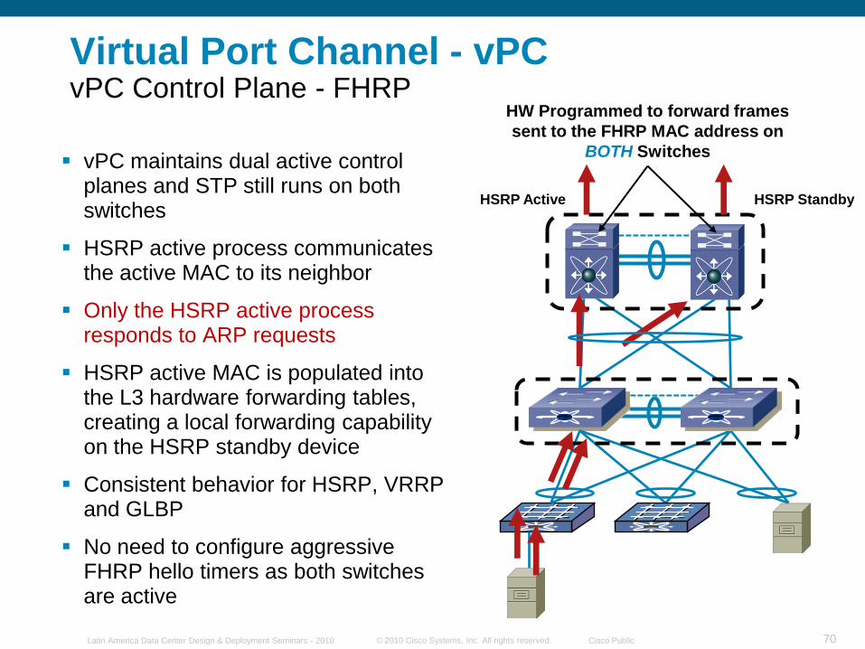
vPC maintains dual active control planes and STP still runs on both switches
HSRP active process communicates the active MAC to its neighbor
Only the HSRP active process responds to ARP requests
HSRP active MAC is populated into the L3 hardware forwarding tables, creating a local forwarding capability on the HSRP standby device
Consistent behavior for HSRP, VRRP and GLBP
No need to configure aggressive FHRP hello timers as both switches are active
HSRP Active HSRP Standby
HW Programmed to forward frames
sent to the FHRP MAC address on
BOTH Switches
© 2010 Cisco Systems, Inc. All rights reserved. Cisco PublicLatin America Data Center Design & Deployment Seminars - 2010 71
vPC on the N7k
vPC on the N5k
N7k01 N7k02
N5k01 N5k02
1 3
1 2 3 4
DESIGN 1
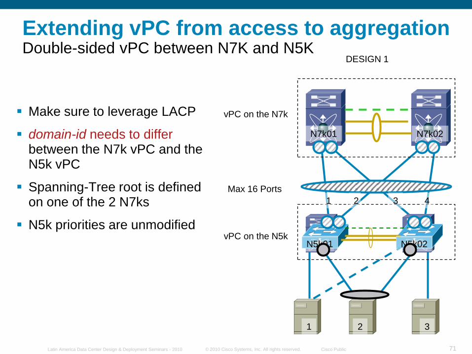
Extending vPC from access to aggregationDouble-sided vPC between N7K and N5K
Make sure to leverage LACP
domain-id needs to differbetween the N7k vPC and the N5k vPC
Spanning-Tree root is defined on one of the 2 N7ks
N5k priorities are unmodified
2
Max 16 Ports
© 2010 Cisco Systems, Inc. All rights reserved. Cisco PublicLatin America Data Center Design & Deployment Seminars - 2010 72
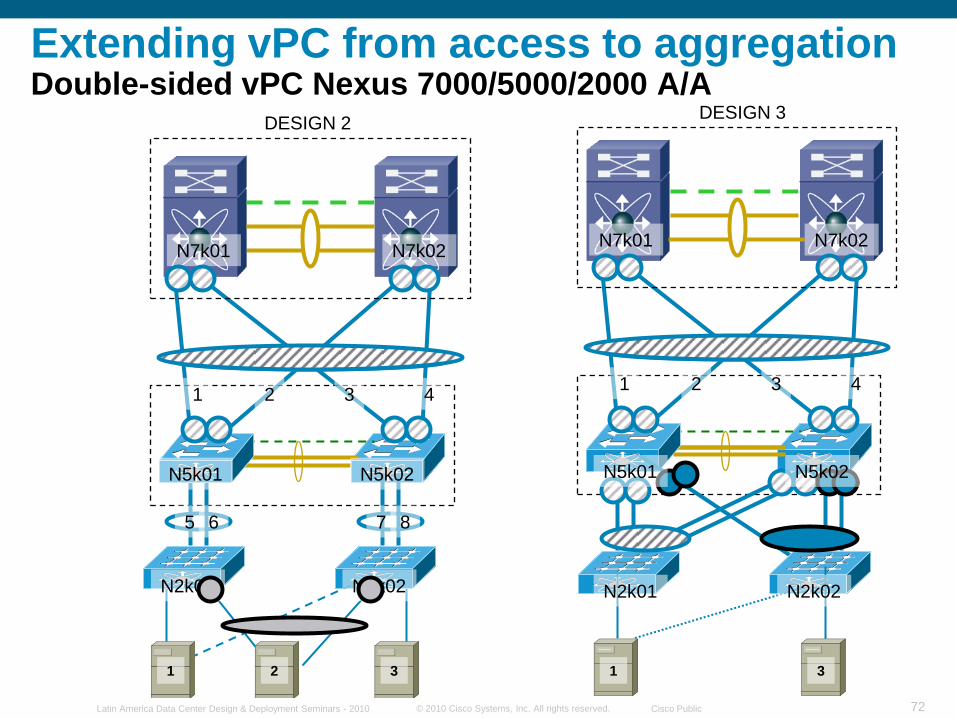
Extending vPC from access to aggregationDouble-sided vPC Nexus 7000/5000/2000 A/A
DESIGN 3
N7k01 N7k02
1 2 3 4
N5k02N5k01
N2k01 N2k02
1 3
N7k01 N7k02
N5k01 N5k02
DESIGN 2
1 2 3 4
5 6 7 8
N2k01 N2k02
1 2 3
© 2010 Cisco Systems, Inc. All rights reserved. Cisco PublicLatin America Data Center Design & Deployment Seminars - 2010 73
vPC on the N7k
N7k01 N7k02
N5k01 N5k02
2/1 2/2 2/1 2/2
Po10
2/9 2/10 2/9 2/10
Po51
Peer Link
primary secondary
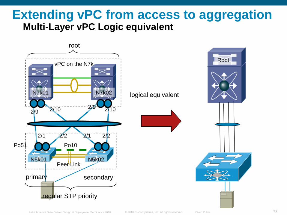
root
regular STP priority
Extending vPC from access to aggregationMulti-Layer vPC Logic equivalent
logical equivalent
Root
© 2010 Cisco Systems, Inc. All rights reserved. Cisco PublicLatin America Data Center Design & Deployment Seminars - 2010 74
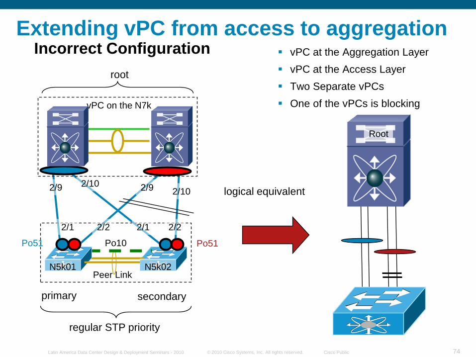
Extending vPC from access to aggregationIncorrect Configuration vPC at the Aggregation Layer
vPC at the Access Layer
Two Separate vPCs
One of the vPCs is blocking
N5k01 N5k02
2/1 2/2 2/1 2/2
Po10
2/9 2/10 2/9 2/10
Po51
Peer Link
primary secondary
regular STP priority
vPC on the N7k
N7k01 N7k02
root
Po51
logical equivalent
Root
© 2010 Cisco Systems, Inc. All rights reserved. Cisco PublicLatin America Data Center Design & Deployment Seminars - 2010 75
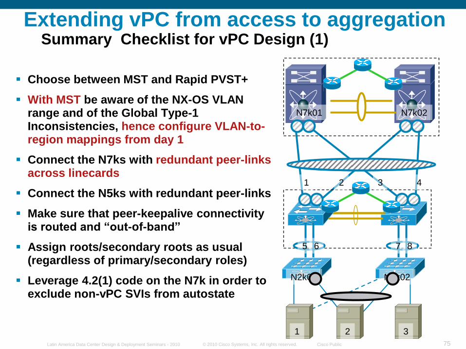
Extending vPC from access to aggregationSummary Checklist for vPC Design (1)
Choose between MST and Rapid PVST+
With MST be aware of the NX-OS VLAN range and of the Global Type-1 Inconsistencies, hence configure VLAN-to-region mappings from day 1
Connect the N7ks with redundant peer-links across linecards
Connect the N5ks with redundant peer-links
Make sure that peer-keepalive connectivity is routed and ―out-of-band‖
Assign roots/secondary roots as usual (regardless of primary/secondary roles)
Leverage 4.2(1) code on the N7k in order to exclude non-vPC SVIs from autostate
N7k01 N7k02
1 2 3 4
5 6 7 8
N2k01 N2k02
1 2 3
© 2010 Cisco Systems, Inc. All rights reserved. Cisco PublicLatin America Data Center Design & Deployment Seminars - 2010 76
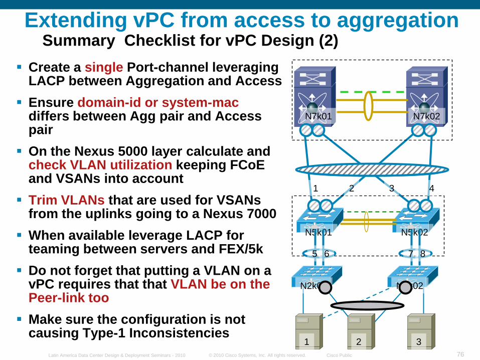
Extending vPC from access to aggregationSummary Checklist for vPC Design (2)
Create a single Port-channel leveraging LACP between Aggregation and Access
Ensure domain-id or system-macdiffers between Agg pair and Access pair
On the Nexus 5000 layer calculate and check VLAN utilization keeping FCoE and VSANs into account
Trim VLANs that are used for VSANs from the uplinks going to a Nexus 7000
When available leverage LACP for teaming between servers and FEX/5k
Do not forget that putting a VLAN on a vPC requires that that VLAN be on the Peer-link too
Make sure the configuration is not causing Type-1 Inconsistencies
N7k01 N7k02
1 2 3 4
N5k02N5k01
5 6 7 8
N2k01 N2k02
1 2 3
© 2010 Cisco Systems, Inc. All rights reserved. Cisco PublicLatin America Data Center Design & Deployment Seminars - 2010 77
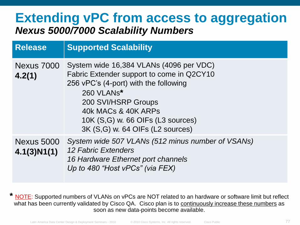
Extending vPC from access to aggregationNexus 5000/7000 Scalability Numbers
Release Supported Scalability
Nexus 7000
4.2(1)
System wide 16,384 VLANs (4096 per VDC)
Fabric Extender support to come in Q2CY10
256 vPC‟s (4-port) with the following
260 VLANs*200 SVI/HSRP Groups
40k MACs & 40K ARPs
10K (S,G) w. 66 OIFs (L3 sources)
3K (S,G) w. 64 OIFs (L2 sources)
Nexus 5000
4.1(3)N1(1)
System wide 507 VLANs (512 minus number of VSANs)
12 Fabric Extenders
16 Hardware Ethernet port channels
Up to 480 “Host vPCs” (via FEX)
* NOTE: Supported numbers of VLANs on vPCs are NOT related to an hardware or software limit but reflect what has been currently validated by Cisco QA. Cisco plan is to continuously increase these numbers as
soon as new data-points become available.
© 2010 Cisco Systems, Inc. All rights reserved. Cisco PublicLatin America Data Center Design & Deployment Seminars - 2010 78
© 2010 Cisco Systems, Inc. All rights reserved. Cisco PublicLatin America Data Center Design & Deployment Seminars - 2010 79
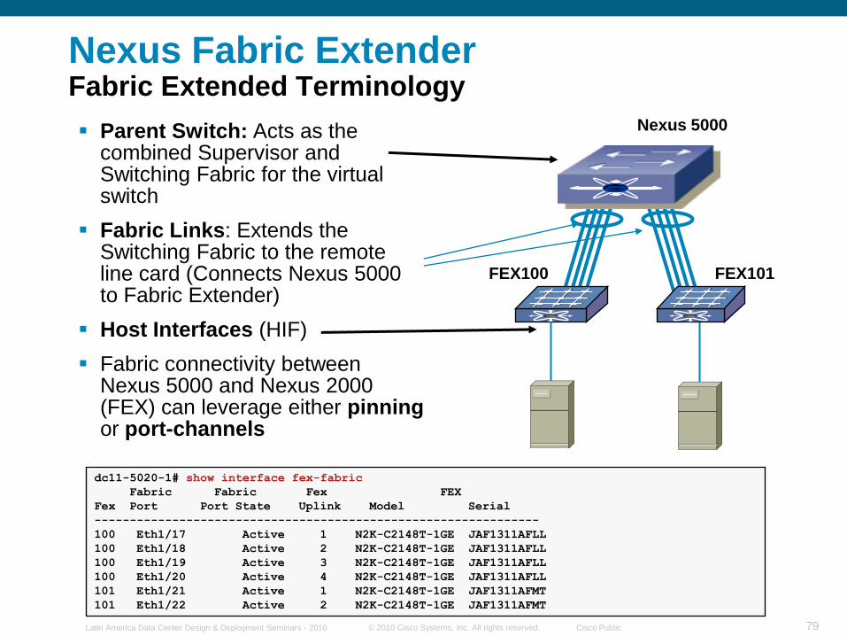
Nexus Fabric ExtenderFabric Extended Terminology
Parent Switch: Acts as the combined Supervisor and Switching Fabric for the virtual switch
Fabric Links: Extends the Switching Fabric to the remote line card (Connects Nexus 5000 to Fabric Extender)
Host Interfaces (HIF)
Fabric connectivity between Nexus 5000 and Nexus 2000 (FEX) can leverage either pinning or port-channels
Nexus 5000
FEX100 FEX101
dc11-5020-1# show interface fex-fabric
Fabric Fabric Fex FEX
Fex Port Port State Uplink Model Serial
---------------------------------------------------------------
100 Eth1/17 Active 1 N2K-C2148T-1GE JAF1311AFLL
100 Eth1/18 Active 2 N2K-C2148T-1GE JAF1311AFLL
100 Eth1/19 Active 3 N2K-C2148T-1GE JAF1311AFLL
100 Eth1/20 Active 4 N2K-C2148T-1GE JAF1311AFLL
101 Eth1/21 Active 1 N2K-C2148T-1GE JAF1311AFMT
101 Eth1/22 Active 2 N2K-C2148T-1GE JAF1311AFMT
© 2010 Cisco Systems, Inc. All rights reserved. Cisco PublicLatin America Data Center Design & Deployment Seminars - 2010 80
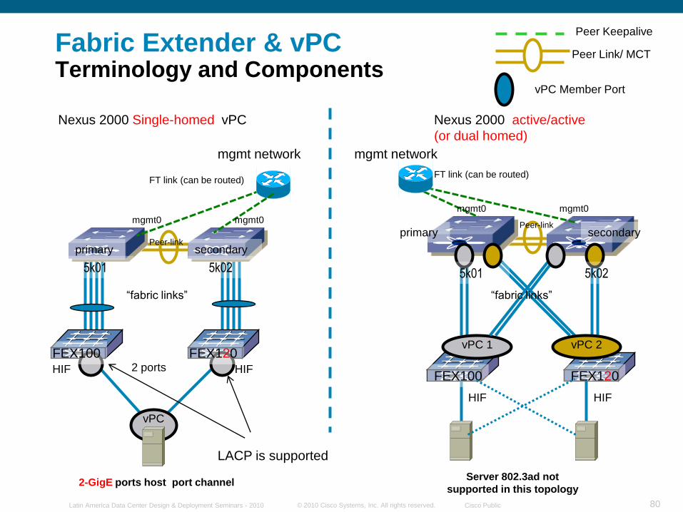
Fabric Extender & vPCTerminology and Components
Nexus 2000 Single-homed vPC Nexus 2000 active/active
(or dual homed)
Peer-link
FT link (can be routed)
2-GigE ports host port channel
FT link (can be routed)
vPC
2 ports
primary
mgmt network mgmt network
FEX120FEX100
mgmt0 mgmt0
mgmt0 mgmt0
vPC 1
Peer-link
FEX120FEX100
secondary
primary secondary
HIF HIF
HIF HIF
“fabric links” “fabric links”
Peer Keepalive
Peer Link/ MCT
vPC Member Port
5k01 5k02 5k01 5k02
Server 802.3ad not
supported in this topology
LACP is supported
vPC 2
© 2010 Cisco Systems, Inc. All rights reserved. Cisco PublicLatin America Data Center Design & Deployment Seminars - 2010 81
Peer-link
FT link (can be routed)
primary
mgmt network
FEX101FEX100
mgmt0 mgmt0
secondary
HIF HIF
Peer Keepalive
Peer Link/ MCT
vPC Member Port
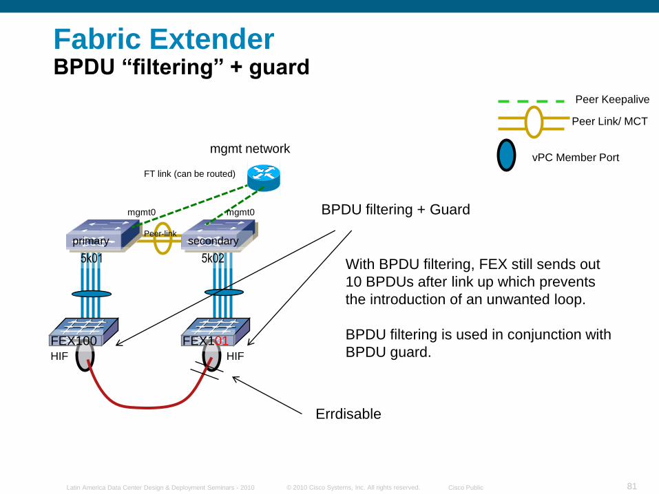
5k01 5k02 With BPDU filtering, FEX still sends out
10 BPDUs after link up which prevents
the introduction of an unwanted loop.
BPDU filtering is used in conjunction with
BPDU guard.
BPDU filtering + Guard
Errdisable
Fabric Extender BPDU ―filtering‖ + guard
© 2010 Cisco Systems, Inc. All rights reserved. Cisco PublicLatin America Data Center Design & Deployment Seminars - 2010 82
Peer-link
FT link (can be routed)
primary
mgmt network
FEX101FEX100
mgmt0 mgmt0
secondary
HIF HIF
Peer Keepalive
Peer Link/ MCT
vPC Member Port
5k01 5k02
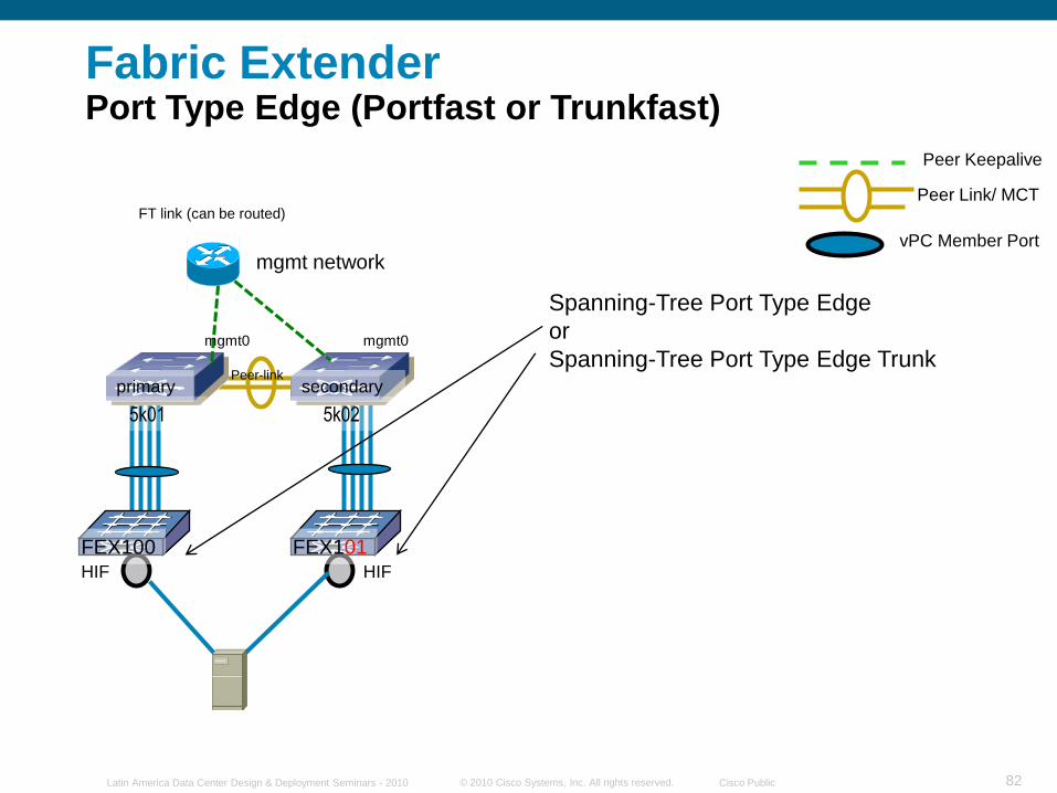
Spanning-Tree Port Type Edge
or
Spanning-Tree Port Type Edge Trunk
Fabric Extender Port Type Edge (Portfast or Trunkfast)
© 2010 Cisco Systems, Inc. All rights reserved. Cisco PublicLatin America Data Center Design & Deployment Seminars - 2010 83
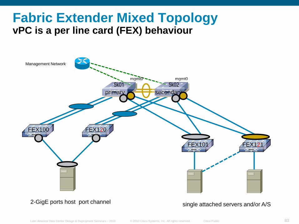
Fabric Extender Mixed TopologyvPC is a per line card (FEX) behaviour
Management Network
primary secondary
mgmt0 mgmt0
2-GigE ports host port channel
FEX120FEX100
FEX101 FEX121
single attached servers and/or A/S
5k01 5k02
© 2010 Cisco Systems, Inc. All rights reserved. Cisco PublicLatin America Data Center Design & Deployment Seminars - 2010 84
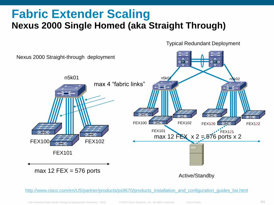
Fabric Extender ScalingNexus 2000 Single Homed (aka Straight Through)
Nexus 2000 Straight-through deployment
n5k01
FEX100
FEX101
FEX102
max 12 FEX = 576 ports
max 4 “fabric links”
Typical Redundant Deployment
http://www.cisco.com/en/US/partner/products/ps9670/products_installation_and_configuration_guides_list.html
Active/Standby
n5k01
FEX100
FEX101
FEX102
n5k02
FEX120
FEX121
FEX122
max 12 FEX x 2 = 576 ports x 2
© 2010 Cisco Systems, Inc. All rights reserved. Cisco PublicLatin America Data Center Design & Deployment Seminars - 2010 85
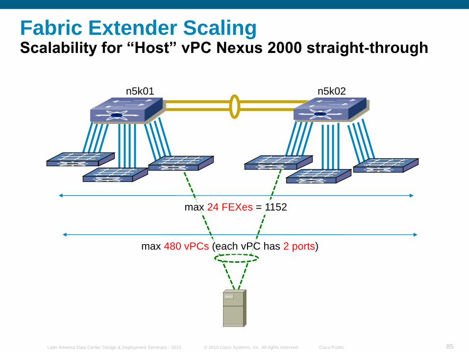
n5k02n5k01
Fabric Extender ScalingScalability for ―Host‖ vPC Nexus 2000 straight-through
max 24 FEXes = 1152
max 480 vPCs (each vPC has 2 ports)
© 2010 Cisco Systems, Inc. All rights reserved. Cisco PublicLatin America Data Center Design & Deployment Seminars - 2010 86
© 2010 Cisco Systems, Inc. All rights reserved. Cisco PublicLatin America Data Center Design & Deployment Seminars - 2010 87
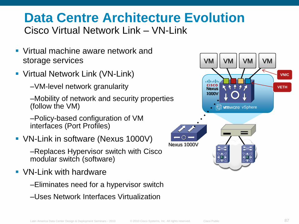
Virtual machine aware network and storage services
Virtual Network Link (VN-Link)
–VM-level network granularity
–Mobility of network and security properties (follow the VM)
–Policy-based configuration of VM interfaces (Port Profiles)
VN-Link in software (Nexus 1000V)
–Replaces Hypervisor switch with Cisco modular switch (software)
VN-Link with hardware
–Eliminates need for a hypervisor switch
–Uses Network Interfaces Virtualization
Data Centre Architecture EvolutionCisco Virtual Network Link – VN-Link
vSphere
Nexus
1000V
Nexus 1000V
VM VM VM VM
VNIC
VETH
© 2010 Cisco Systems, Inc. All rights reserved. Cisco PublicLatin America Data Center Design & Deployment Seminars - 2010 88
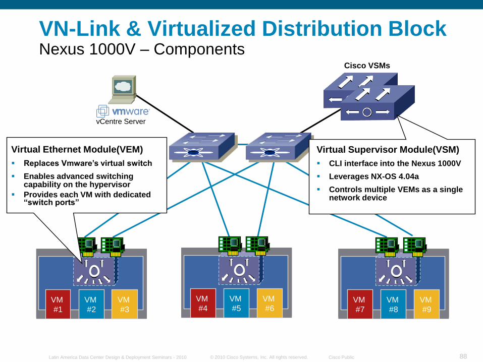
VN-Link & Virtualized Distribution BlockNexus 1000V – Components
vCentre Server
Cisco VSMs
VM
#3
VM
#2
VM
#1
Virtual Ethernet Module(VEM)
Replaces Vmware’s virtual switch
Enables advanced switching capability on the hypervisor
Provides each VM with dedicated ―switch ports‖
VM
#6
VM
#5
VM
#4VM
#9
VM
#8
VM
#7
Virtual Supervisor Module(VSM)
CLI interface into the Nexus 1000V
Leverages NX-OS 4.04a
Controls multiple VEMs as a single network device
© 2010 Cisco Systems, Inc. All rights reserved. Cisco PublicLatin America Data Center Design & Deployment Seminars - 2010 89
Spanning Tree
VM
#4
VM
#3
VM
#2
VM
#5
VM
#7
VM
#6
STP Edge Ports
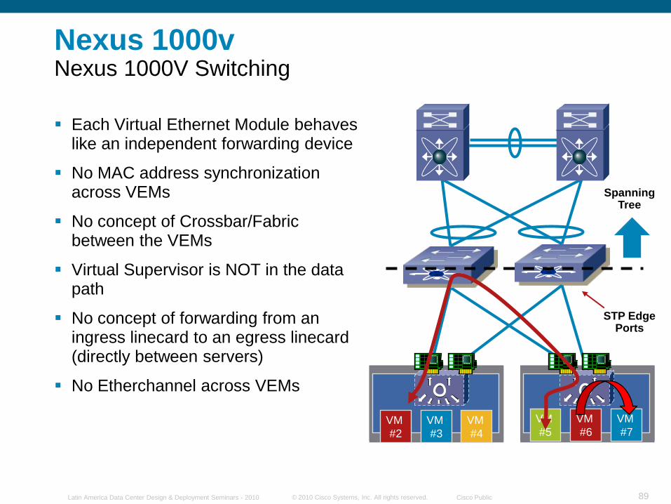
Nexus 1000vNexus 1000V Switching
Each Virtual Ethernet Module behaves like an independent forwarding device
No MAC address synchronization across VEMs
No concept of Crossbar/Fabric between the VEMs
Virtual Supervisor is NOT in the data path
No concept of forwarding from an ingress linecard to an egress linecard (directly between servers)
No Etherchannel across VEMs
© 2010 Cisco Systems, Inc. All rights reserved. Cisco PublicLatin America Data Center Design & Deployment Seminars - 2010 90
Spanning Tree
VM
#4
VM
#3
VM
#2
VM
#5
VM
#7
VM
#6
Packet Dropped
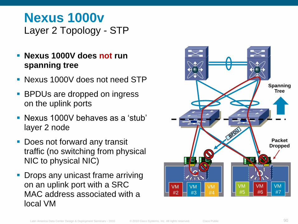
Nexus 1000vLayer 2 Topology - STP
Nexus 1000V does not run spanning tree
Nexus 1000V does not need STP
BPDUs are dropped on ingress on the uplink ports
Nexus 1000V behaves as a „stub‟ layer 2 node
Does not forward any transit traffic (no switching from physical NIC to physical NIC)
Drops any unicast frame arriving on an uplink port with a SRC MAC address associated with a local VM
© 2010 Cisco Systems, Inc. All rights reserved. Cisco PublicLatin America Data Center Design & Deployment Seminars - 2010 91
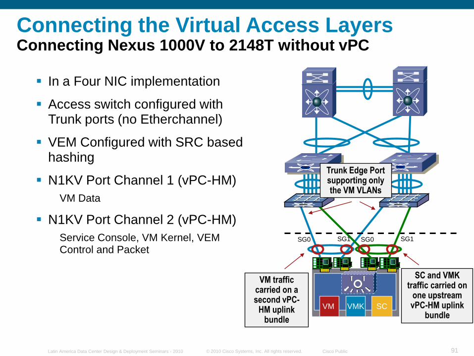
SCVMKVM
In a Four NIC implementation
Access switch configured with Trunk ports (no Etherchannel)
VEM Configured with SRC based hashing
N1KV Port Channel 1 (vPC-HM)
VM Data
N1KV Port Channel 2 (vPC-HM)
Service Console, VM Kernel, VEM Control and Packet
SG1SG0
SC and VMK traffic carried on
one upstream vPC-HM uplink
bundle
Trunk Edge Port supporting only the VM VLANs
VM traffic carried on a second vPC-
HM uplink bundle
SG1SG0
Connecting the Virtual Access LayersConnecting Nexus 1000V to 2148T without vPC
© 2010 Cisco Systems, Inc. All rights reserved. Cisco PublicLatin America Data Center Design & Deployment Seminars - 2010 92
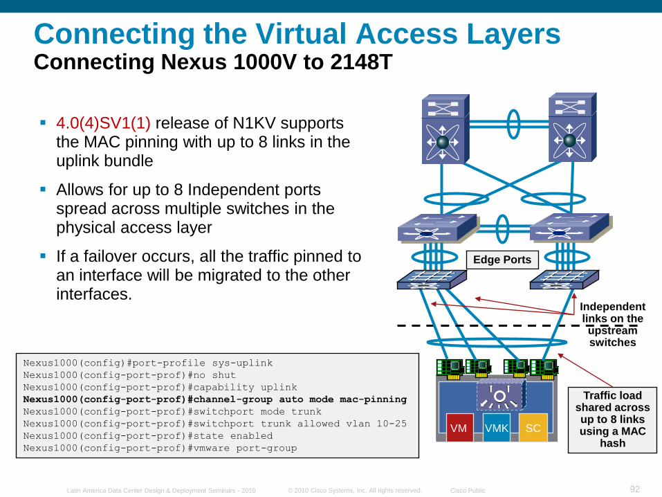
SCVMKVM
Independent links on the upstream switches
Edge Ports
Traffic load shared across up to 8 links using a MAC
hash
Connecting the Virtual Access LayersConnecting Nexus 1000V to 2148T
4.0(4)SV1(1) release of N1KV supports the MAC pinning with up to 8 links in the uplink bundle
Allows for up to 8 Independent ports spread across multiple switches in the physical access layer
If a failover occurs, all the traffic pinned to an interface will be migrated to the other interfaces.
Nexus1000(config)#port-profile sys-uplink
Nexus1000(config-port-prof)#no shut
Nexus1000(config-port-prof)#capability uplink
Nexus1000(config-port-prof)#channel-group auto mode mac-pinning
Nexus1000(config-port-prof)#switchport mode trunk
Nexus1000(config-port-prof)#switchport trunk allowed vlan 10-25
Nexus1000(config-port-prof)#state enabled
Nexus1000(config-port-prof)#vmware port-group
© 2010 Cisco Systems, Inc. All rights reserved. Cisco PublicLatin America Data Center Design & Deployment Seminars - 2010 93
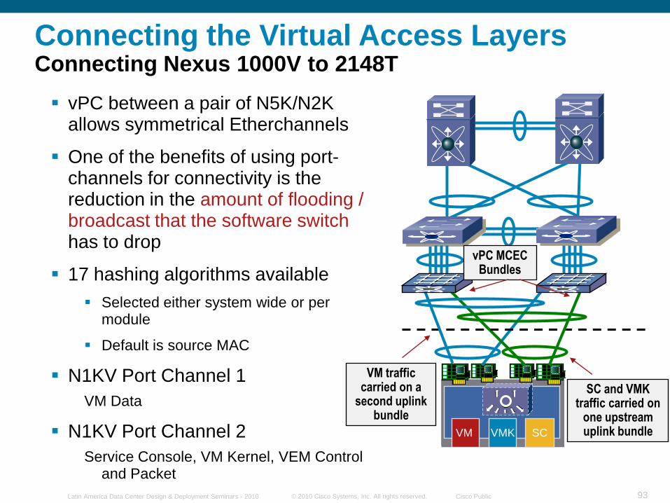
SCVMKVM
vPC between a pair of N5K/N2K allows symmetrical Etherchannels
One of the benefits of using port-channels for connectivity is the reduction in the amount of flooding / broadcast that the software switchhas to drop
17 hashing algorithms available
Selected either system wide or per module
Default is source MAC
N1KV Port Channel 1
VM Data
N1KV Port Channel 2
Service Console, VM Kernel, VEM Control and Packet
SC and VMK traffic carried on
one upstream uplink bundle
vPC MCEC Bundles
VM traffic carried on a
second uplink bundle
Connecting the Virtual Access LayersConnecting Nexus 1000V to 2148T
© 2010 Cisco Systems, Inc. All rights reserved. Cisco PublicLatin America Data Center Design & Deployment Seminars - 2010 94
© 2010 Cisco Systems, Inc. All rights reserved. Cisco PublicLatin America Data Center Design & Deployment Seminars - 2010 95
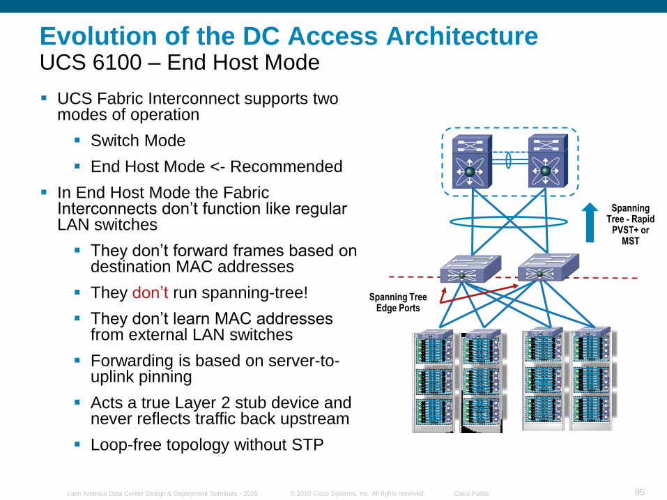
Evolution of the DC Access ArchitectureUCS 6100 – End Host Mode
UCS Fabric Interconnect supports two modes of operation
Switch Mode
End Host Mode <- Recommended
In End Host Mode the Fabric Interconnects don‟t function like regular LAN switches
They don‟t forward frames based on destination MAC addresses
They don‟t run spanning-tree!
They don‟t learn MAC addresses from external LAN switches
Forwarding is based on server-to-uplink pinning
Acts a true Layer 2 stub device and never reflects traffic back upstream
Loop-free topology without STP
slot 1slot 2slot 3slot 4slot 5slot 6slot 7slot 8
blade1blade2blade3blade4blade5blade6blade7blade8
slot 1slot 2slot 3slot 4slot 5slot 6slot 7slot 8
blade1blade2blade3blade4blade5blade6blade7blade8
slot 1slot 2slot 3slot 4slot 5slot 6slot 7slot 8
blade1blade2blade3blade4blade5blade6blade7blade8
slot 1slot 2slot 3slot 4slot 5slot 6slot 7slot 8
blade1blade2blade3blade4blade5blade6blade7blade8
slot 1slot 2slot 3slot 4slot 5slot 6slot 7slot 8
blade1blade2blade3blade4blade5blade6blade7blade8
slot 1slot 2slot 3slot 4slot 5slot 6slot 7slot 8
blade1blade2blade3blade4blade5blade6blade7blade8
slot 1slot 2slot 3slot 4slot 5slot 6slot 7slot 8
blade1blade2blade3blade4blade5blade6blade7blade8
slot 1slot 2slot 3slot 4slot 5slot 6slot 7slot 8
blade1blade2blade3blade4blade5blade6blade7blade8
slot 1slot 2slot 3slot 4slot 5slot 6slot 7slot 8
blade1blade2blade3blade4blade5blade6blade7blade8
slot 1slot 2slot 3slot 4slot 5slot 6slot 7slot 8
blade1blade2blade3blade4blade5blade6blade7blade8
slot 1slot 2
slot 3slot 4
slot 5slot 6slot 7slot 8
blade1blade2blade3blade4blade5blade6blade7
blade8
slot 1slot 2slot 3slot 4slot 5slot 6slot 7slot 8
blade1blade2blade3blade4blade5
blade6blade7blade8
Spanning Tree - Rapid
PVST+ or MST
Spanning Tree Edge Ports
© 2010 Cisco Systems, Inc. All rights reserved. Cisco PublicLatin America Data Center Design & Deployment Seminars - 2010 96
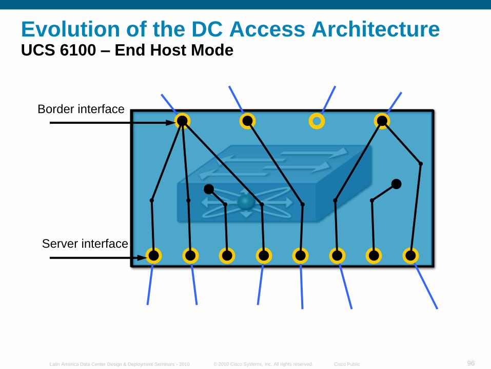
Evolution of the DC Access ArchitectureUCS 6100 – End Host Mode
Border interface
Server interface
© 2010 Cisco Systems, Inc. All rights reserved. Cisco PublicLatin America Data Center Design & Deployment Seminars - 2010 97
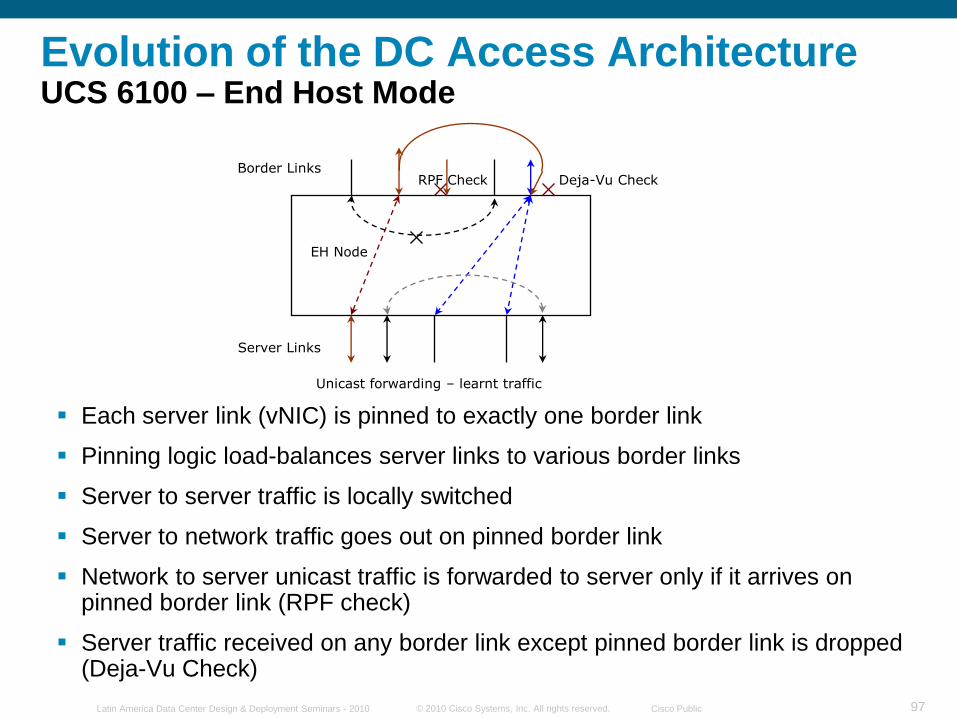
Evolution of the DC Access ArchitectureUCS 6100 – End Host Mode
Each server link (vNIC) is pinned to exactly one border link
Pinning logic load-balances server links to various border links
Server to server traffic is locally switched
Server to network traffic goes out on pinned border link
Network to server unicast traffic is forwarded to server only if it arrives on pinned border link (RPF check)
Server traffic received on any border link except pinned border link is dropped (Deja-Vu Check)
RPF Check Deja-Vu CheckBorder Links
Server Links
Unicast forwarding – learnt traffic
EH Node
© 2010 Cisco Systems, Inc. All rights reserved. Cisco PublicLatin America Data Center Design & Deployment Seminars - 2010 98
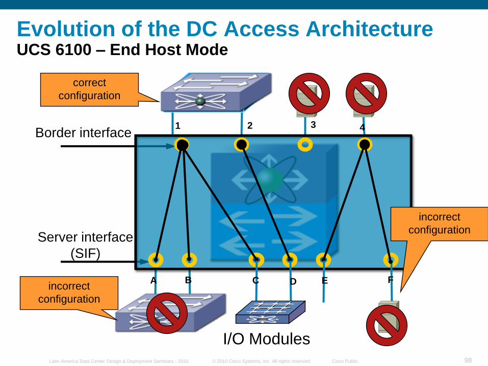
Evolution of the DC Access ArchitectureUCS 6100 – End Host Mode
Border interface
Server interface
(SIF)
1 2 3 4
A B C D E Fincorrect
configuration
correct
configuration
I/O Modules
incorrect
configuration
© 2010 Cisco Systems, Inc. All rights reserved. Cisco PublicLatin America Data Center Design & Deployment Seminars - 2010 99
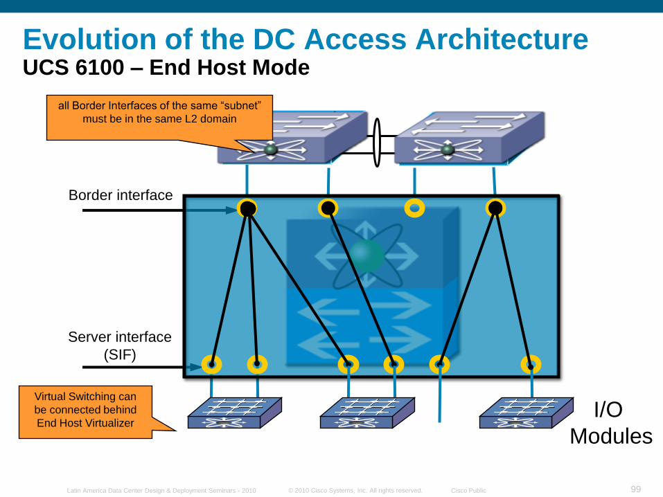
Evolution of the DC Access ArchitectureUCS 6100 – End Host Mode
Border interface
Server interface
(SIF)
Virtual Switching can
be connected behind
End Host Virtualizer
all Border Interfaces of the same “subnet”
must be in the same L2 domain
I/O
Modules
© 2010 Cisco Systems, Inc. All rights reserved. Cisco PublicLatin America Data Center Design & Deployment Seminars - 2010 100
© 2010 Cisco Systems, Inc. All rights reserved. Cisco PublicLatin America Data Center Design & Deployment Seminars - 2010 101
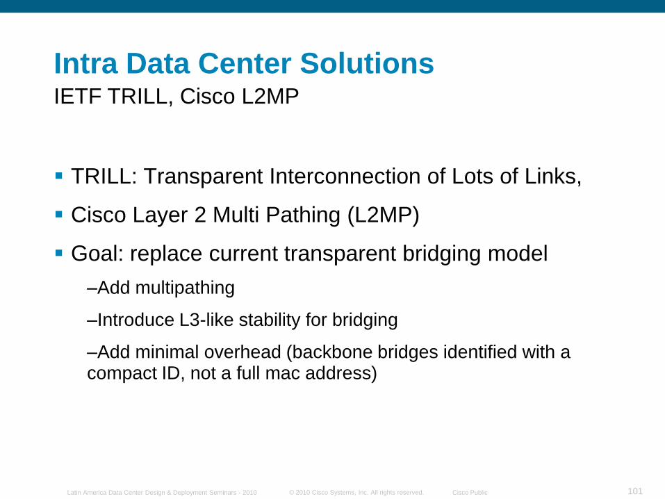
Intra Data Center Solutions
TRILL: Transparent Interconnection of Lots of Links,
Cisco Layer 2 Multi Pathing (L2MP)
Goal: replace current transparent bridging model
–Add multipathing
–Introduce L3-like stability for bridging
–Add minimal overhead (backbone bridges identified with a compact ID, not a full mac address)
IETF TRILL, Cisco L2MP
© 2010 Cisco Systems, Inc. All rights reserved. Cisco PublicLatin America Data Center Design & Deployment Seminars - 2010 102
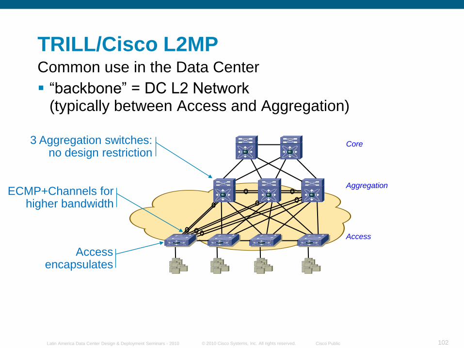
TRILL/Cisco L2MP
“backbone” = DC L2 Network (typically between Access and Aggregation)
Common use in the Data Center
Access encapsulates
ECMP+Channels for higher bandwidth
3 Aggregation switches: no design restriction
Aggregation
Core
Access
© 2010 Cisco Systems, Inc. All rights reserved. Cisco PublicLatin America Data Center Design & Deployment Seminars - 2010 103
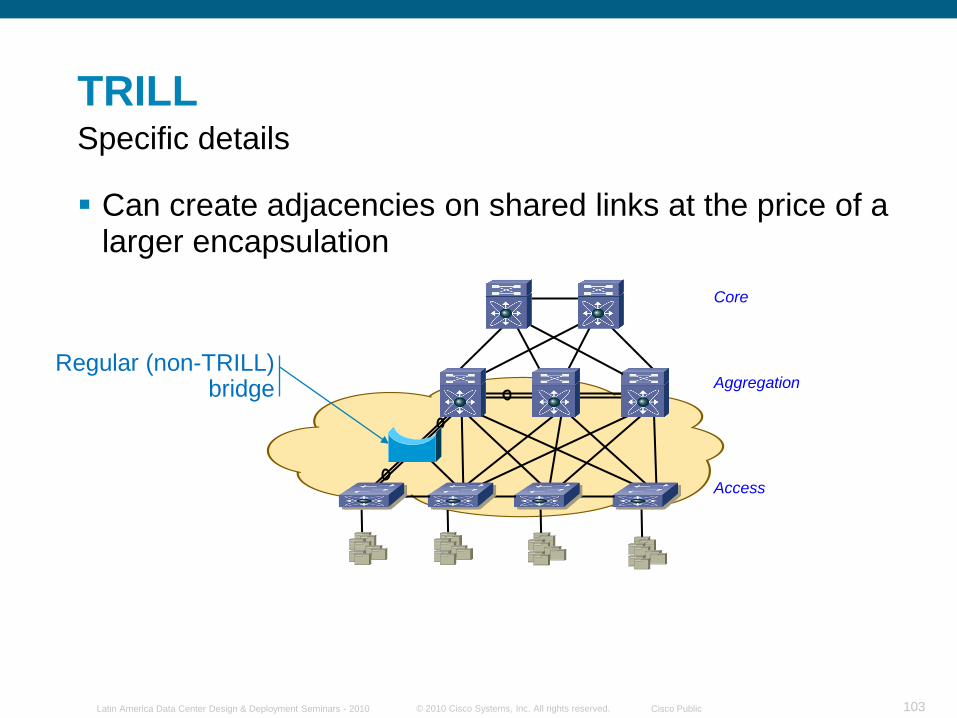
TRILL
Can create adjacencies on shared links at the price of a larger encapsulation
Specific details
Regular (non-TRILL) bridge Aggregation
Core
Access
© 2010 Cisco Systems, Inc. All rights reserved. Cisco PublicLatin America Data Center Design & Deployment Seminars - 2010 104
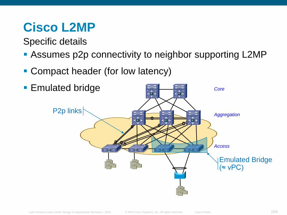
Cisco L2MP
Assumes p2p connectivity to neighbor supporting L2MP
Compact header (for low latency)
Emulated bridge
Specific details
Emulated Bridge(≈ vPC)
P2p links Aggregation
Core
Access
© 2010 Cisco Systems, Inc. All rights reserved. Cisco PublicLatin America Data Center Design & Deployment Seminars - 2010 105
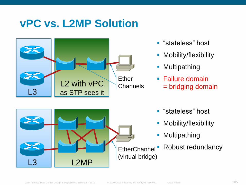
vPC vs. L2MP Solution
EtherChannel
(virtual bridge)L2MPL3
“stateless” host
Mobility/flexibility
Multipathing
Robust redundancy
Ether
ChannelsL2 with vPCas STP sees itL3
“stateless” host
Mobility/flexibility
Multipathing
Failure domain = bridging domain
© 2010 Cisco Systems, Inc. All rights reserved. Cisco PublicLatin America Data Center Design & Deployment Seminars - 2010 106
© 2010 Cisco Systems, Inc. All rights reserved. Cisco PublicLatin America Data Center Design & Deployment Seminars - 2010 107
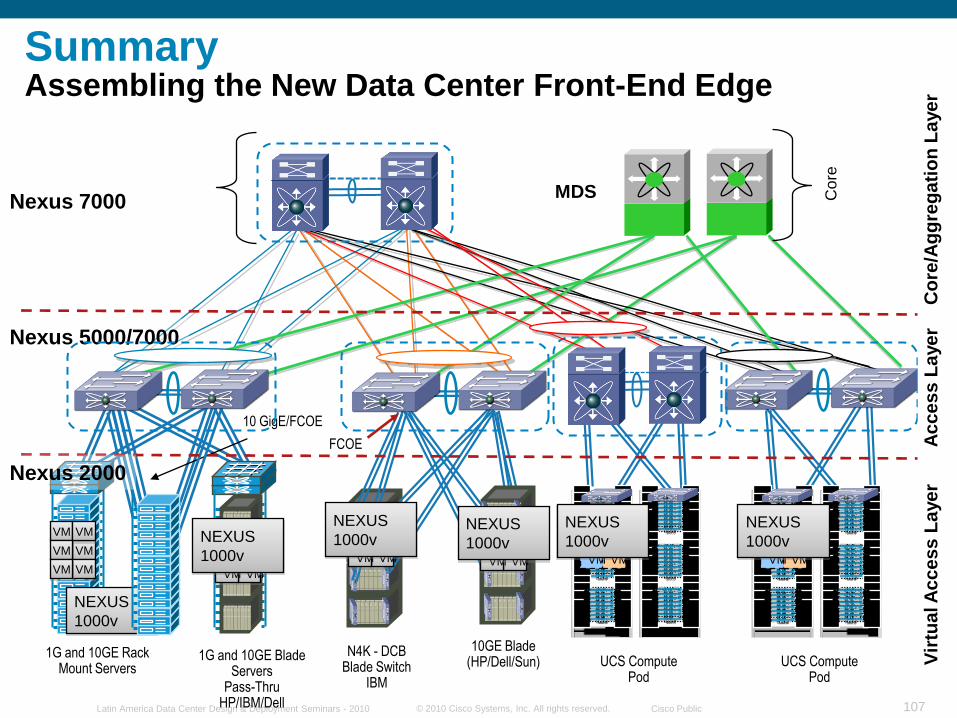
SummaryAssembling the New Data Center Front-End Edge
FCOE
10 GigE/FCOE
1G and 10GE Rack Mount Servers
1G and 10GE Blade Servers
Pass-ThruHP/IBM/Dell
10GE Blade(HP/Dell/Sun)
N4K - DCB Blade Switch
IBM
MDSNexus 7000
VM
VM
VM
VM
VMVM
NEXUS
1000v
slot 1slot 2slot 3slot 4slot 5slot 6slot 7slot 8
blade1blade2blade3blade4blade5blade6blade7blade8
slot 1slot 2slot 3slot 4slot 5slot 6slot 7slot 8
blade1blade2blade3blade4blade5blade6blade7blade8
slot 1slot 2slot 3slot 4slot 5slot 6slot 7slot 8
blade1blade2blade3blade4blade5blade6blade7blade8
slot 1slot 2slot 3slot 4slot 5slot 6slot 7slot 8
blade1blade2blade3blade4blade5blade6blade7blade8
slot 1slot 2slot 3slot 4slot 5slot 6slot 7slot 8
blade1blade2blade3blade4blade5blade6blade7blade8
slot 1slot 2slot 3slot 4slot 5slot 6slot 7slot 8
blade1blade2blade3blade4blade5blade6blade7blade8
UCS Compute Pod
VM
VM
VM
VM
VMVM
NEXUS
1000v
VM
VM
VM
VM
VMVM
NEXUS
1000v
Core
slot 1slot 2slot 3slot 4slot 5slot 6slot 7slot 8
blade1blade2blade3blade4blade5blade6blade7blade8
slot 1slot 2slot 3slot 4slot 5slot 6slot 7slot 8
blade1blade2blade3blade4blade5blade6blade7blade8
slot 1slot 2slot 3slot 4slot 5slot 6slot 7slot 8
blade1blade2blade3blade4blade5blade6blade7blade8
slot 1slot 2slot 3slot 4slot 5slot 6slot 7slot 8
blade1blade2blade3blade4blade5blade6blade7blade8
slot 1slot 2slot 3slot 4slot 5slot 6slot 7slot 8
blade1blade2blade3blade4blade5blade6blade7blade8
slot 1slot 2slot 3slot 4slot 5slot 6slot 7slot 8
blade1blade2blade3blade4blade5blade6blade7blade8
UCS Compute Pod
VM
VM
VM
VM
VMVM
NEXUS
1000v
Nexus 5000/7000
Nexus 2000
Ac
ce
ss
La
ye
rV
irtu
al A
cc
es
s L
aye
rC
ore
/Ag
gre
ga
tio
n L
aye
r
VM
VM
VM
VM
VMVM
NEXUS
1000vVM
VM
VM
VM
VMVM
NEXUS
1000v

© 2010 Cisco Systems, Inc. All rights reserved. Cisco PublicLatin America Data Center Design & Deployment Seminars - 2010 108
Questions ?
© 2010 Cisco Systems, Inc. All rights reserved. Cisco PublicLatin America Data Center Design & Deployment Seminars - 2010 109
Related Documents